| phenolic motor protectors · 2018-10-17 · | phenolic motor protectors hermetically sealed motor...
TRANSCRIPT

Page 1
www.sensata.comCopyright © 2017 Sensata Technologies Inc.
| PHENOLIC MOTOR PROTECTORS Hermetically Sealed Motor Protector for Single-Phase On-Winding Protection
Features
Introduction
• Normally closed “make or break” Klixon® contact system, which is operated by a snap action disc, is sensitive to both temperature and current.
• Precision calibration – temperature calibrated and inspected under controlled conditions for dependable performance.
• Automatic or manual reset series available• Easy to install•
37 amperes maximum locked rotor 230 VAC, File 4464.4-4510-1013, License No. 3938 UG for 3/4” M.P. only.
• Inherent protection devices for approximately 1/2 to 5 h.p. motors used in applications such as industrial motors, agricultural equipment, well and sump pumps, fans, air conditioners, refrigerators, home appliances, etc.
• When properly applied, protector shuts off motor when temperature exceeds maximum safe level due to an overload or stalled (locked rotor) condition.
Klixon Phenolic Motor Protectors are equipped with a bimetallic snap acting disc, on which the contacts are mounted, and through which the current
temperature to rise.
When the disc reaches the calibrated setpoint, the Klixon protector automatically opens and shuts down the motor, limiting the winding and shell temperature.
When the motor has cooled to an acceptable operating level, allowing the protector to cool to its reset temperature, the Klixon protector resets automatically to a closed contact position allowing the motor to restart.
Manual reset versions are also available for applications where automatic restarting may be hazardous to equipment or operations.

www.sensata.com
Page 2
Copyright © 2017 Sensata Technologies Inc.
Automatic ResetExploded View
Cover (Optional)
Bimetal Disc
Heater Terminal
Terminal
Terminal
Adjusting Screw
Phenolic Base
Contacts Open
Contacts Closed
Manual Reset
SPECIFICATIONSDiagrams
www.sensata.com
Page 3
Copyright © 2017 Sensata Technologies Inc.
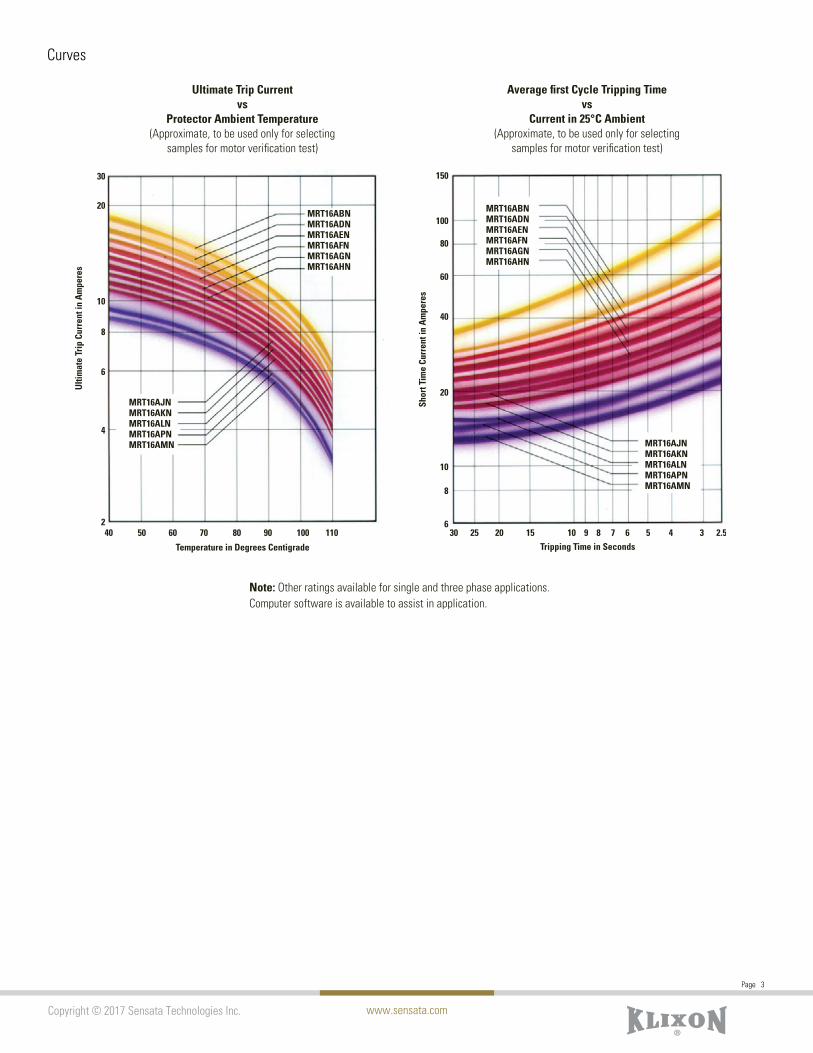
Curves

www.sensata.com
Page 4
Copyright © 2017 Sensata Technologies Inc.
Metric Dimensions in ParenthesesDIMENSIONS
Type
MRCRBRLR
Size
3/4”
1”1-1/4”
1-1/2”
A
1.031 ±.0101.312 ±.0101.640 ±.0101.983 ±.010
B
.970 ±.0061.218 ±.0101.555 ±.0101.881 ±.010
C
.125 ±.005
.125 ±.005
.156 ±.010
.154 ±.010
D
.625 ±.010
.640 ±.010
.930 ±.015
.830 ±.015
E Max.
.171
.218
.313
.375
F
23/64 ±1/3231/64 ±1/3227/64 ±1/3215/32 ±3/64
G
.375 ±.006
.442 ±.006
.442 ±.006
.781 ±.006
Round Base
Eared Base
.065 ±.005/-.000 (.164 ±.254) Dia. Holes
.062 ±.010 (1.57 ±.254) Deep(Type ME 4-Holes. Type CE 2-Holes at #1Terminal End only. Other Types No Holes)
DE
C .025 ± .005 (.635 ± .127)
BA
F
G
A
C
D F
E
B
.265 ±.002(7.24 ±.051)
R1
R2 HJ
.113 ± .005 (2.87 ± .127) K
L G
Size
3/4”
1”1-1/4”
1-1/2”
B
1.390 ±.0151.390 ±.0152.125 ±.0102.125 ±.020
C
.175 ±.010
.175 ±.010
.223 ±.010
.267 ±.010
D
.450 ±.015
.464 ±.015
.715 ±.010
.890 ±.010
E
.354
.406
.552
.683
F
––
.332 ±010.517 ±.010
G
.436 ±.007
.440 ±.008
.440 ±.008
.781 ±.006
H
.625 ±.010
.625 ±.0101.000 ±.0101.250 ±.010
J
.176 ±.010
.176 ±.010
.218 ±.010
.218 ±.010
K
.9531.0001.1801.370
L
.970 ±.0061.187 ±.0101.552 ± .0101.875 ± .010
R1
.656 ±.010 .656 ±.010 .844 ±.0101.000 ±.010
R2
.845 ±.010 .845 ±.0101.344 ±.0101.344 ±.010
A
.970 ±.0101.187 ±.010 1.594 ±.010 1.875 ±.010
Type
MECEBELE
www.sensata.com
Page 5
Copyright © 2017 Sensata Technologies Inc.
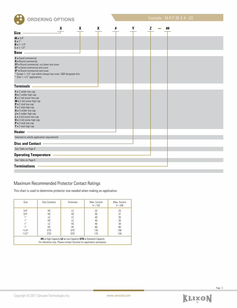
ORDERING OPTIONS Example : M R P 36 A X - 63
Size
Base
Terminals
Heater
Disc and Contact
Operating Temperature
Terminations
M = 3/4”C = 1”B = 1–1/4”L = 1–1/2”
E = Eared commercialR = Round commercialC† = Round commercial, cut down and coverG* = Eared commercial and coverS* = Round commercial and cover* Except 1–1/4” size which always has cover. E&R designate this.* Only 1–1/2” applications.
F = 2 solder low capH = 2 solder high capK = 2 std screw low capM = 2 std screw high capP = 2 stub low capT = 2 stub high capG = 3 solder low capJ = 3 solder high capL = 3 std screw low capO = 3 std screw high capP = 3 stub low capT = 3 stub high cap
Selected to satisfy application requirements
See Table on Page 6
See Table on Page 6
X X X # Y Z ##
Maximum Recommended Protector Contact RatingsThis chart is used to determine protector size needed when making an application.
Size Disc Contacts Terminals Max. Current V = 120
Max. Current V = 240
3/4”3/4”1”1”1”1”
11/4”11/2”
HCHCLCHCLCHC
STDSTD
LCHCLCLCHCHC
STDSTD
325040404080
135175
253730303060100130
HC = High Capacity LC = Low Capacity STD = Standard CapacityFor reference only. Please contact Sensata for application assistance.
www.sensata.com
Page 6
Copyright © 2017 Sensata Technologies Inc.
3/4” 1”
High Cap Low Cap High Cap
ABCDE
J
L
R
ABADAEAFAGAHAIAJAKALAMAP
FGJPLSOT
ABAEAFAGAHAIAJAKALAMAN
CDEHIK
X
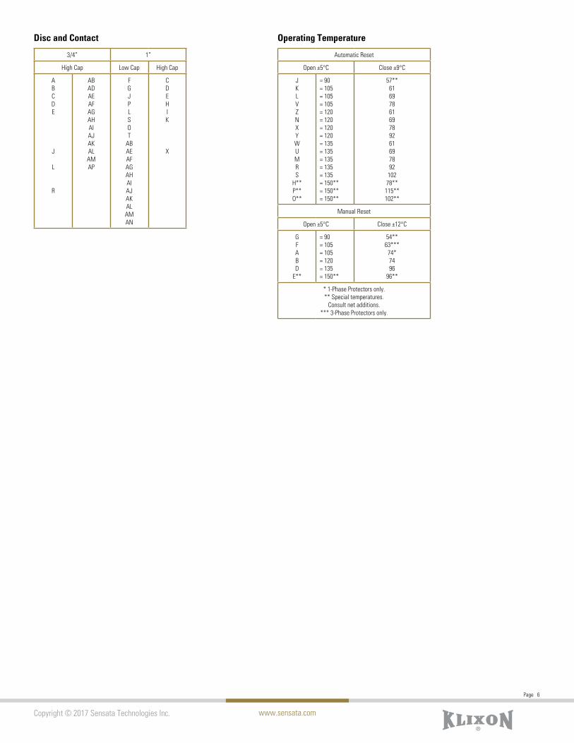
Automatic Reset
Open ±5°C Close ±9°C
JKLVZNXYWUMRS
H**P**O**
= 90= 105= 105= 105= 120= 120= 120= 120= 135= 135= 135= 135= 135= 150**= 150**= 150**
57**616978616978926169789210278**115**102**
Manual Reset
Open ±5°C Close ±12°C
GFABD
E**
= 90= 105= 105= 120= 135= 150**
54**63***
74*7496
96**
* 1-Phase Protectors only.** Special temperatures.
Consult net additions.*** 3-Phase Protectors only.
Disc and Contact Operating Temperature

Page 7
www.sensata.comCopyright © 2017 Sensata Technologies, Inc.
Sensata Technologies, Inc. (“Sensata”) data sheets are solely intended to assist designers (“Buyers”) who are developing systems that incorporate Sensata products (also referred to herein as “components”). Buyer understands and agrees that Buyer remains responsible for using its independent analysis, evaluation and judgment in designing Buyer’s systems and products. Sensata data sheets have been created using standard laboratory conditions and engineering practices. Sensata has not conducted any testing other than that
improvements and other changes to its data sheets or components without notice.
of sale supplied at www.sensata.com
CONTACT US
Americas
Europe, Middle East & Africa
APPLICATION WORKSHEET
A sample worksheet provides the information needed for a proper application. It is not possible to apply a Klixon protector based on horsepower, amperage, or name plate data only.
Motor Data
A. Locked Rotor Requirements
1. Locked Rotor Current Cold: the current which exists the instant the motor is turned on.
2. Locked Rotor Current Hot: The current level that exists at end of 1st cycle
3. Time elapsed during above test to raise motor winding temperature from room temperature to around maximum allowed temperature for the UL class of motor insulation. An example would be, for a class A motor, 25ºC to 175ºC in 12.5 seconds.
4. Ambient Temperature During test: Room temperature (usually 25ºC).
B. Running Overload Requirements
1. Load Current: With the motor running, the load on the motor is to be increased in small increments until the motor winding has completely stabilized at approximately 10ºC below the maximum allowed by the UL class of the motor. An example would be, for a class A motor, the maximum allowed is 140øC. The motor winding temperature was completely stabilized at 130ºC and the current draw at that time would be recorded.
2&3. Protector Location Temperatures: These temperatures are taken at the conclusion of the above load current test while the motor is running under the above load.
4. Ambient Temperature: Room temperature (usually 25ºC).
C. Abnormal Conditions for Protection.
1. Max/min Ambient Temperatures: temperature in the surroundings of protector.
2. Max/min Line Volts: The highest and lowest voltages for which protection should be effective.
3. Other environmental considerations: i.e., exposed to agricultural weather conditions.
Name Plate Data
A. HorsepowerB. VoltageC. Single or three phaseD. FLA (full load amps)E. LRA (locked rotor amps)F. Insulation class (UL/CSA) (indicate one)
Protector Requirements
A. Automatic or manual resetB. Round or eared baseC. Termination type
Motor Data Required
A. Locked rotor requirements1. Locked rotor current cold2. Locked rotor current hot3. Time required to raise motor winding to max.
temperature4. Ambient temperature during test
B. Running overload requirements1. Load current required to stabilize main
winding temp. at 10ºC below maximum allowed
2. Protector location temperature below protector surface
3. Protector location temperature above protector (air temp)
4. Ambient temp during testC. Abnormal conditions for protection
1. Max/min ambient temperatures2. Max/min line volts3. Other environmental considerations
Note: Application assistance available from Sensata.
H.PVolts
PhaseAmpsAmpsABFH
AmpsAmps
SecDeg
Amps
Deg
DegDeg
DegVolts
+1 508 236 [email protected]
+3 174 357 [email protected]
[email protected] +86 (21)2306 1651India +91 (40)4033 9611Japan +81 (45)277 7104Korea +82 (53) 644 9685Rest of Asia +65(6478)6860