ˆˇ˘ overpressure dampers - · pdf fileoverpressure dampers jnŽ-6, anŽ-3, anŽ-4 ......
TRANSCRIPT

JNŽ-6 ANŽ-3, ANŽ-4
H /
B
H /
B
7
B = B1+28H = H1+28
B2 = B1+23H2 = H1+23
H1 /
B1
H /
B
H2 /
B2
35
82.5
28
H1
/B
1
H1
/B
1
H1
+1
5/
B1
+1
5
120
82
.5
38
H1
/B
13
8
82
.5
JNŽ-6 ANŽ-3 ANŽ-4
■ Overpressure dampers JNŽ-6, ANŽ-3, ANŽ-4
ApplicationOverpressure dampers are used in all kinds of low pressure air conditioning, air heating ind ventilation, where it is necesary to equalise the pressure between adjacent rooms. They can be applied where the automatic break of the supply and exhaust air is required after conditioning-, heating- or ventilation device has been turned off.
DescriptionOverpressure dampers consist of supporting frame made of galvanized sheet steel (steel overpressure dampers JNŽ-6) or aluminium section anodised in natural aluminium colour (aluminium overpressure dampers ANŽ-3 and ANŽ-4) and horizontal swinging vanes of sheet aluminium. The horizontal vanes are inserted into plastic bearings, temperature resistant to 80 °C. Sealing stripe, attached on lower part of vanes reduces noise.
CautionIn the cases of effective velocities exceeding the values provided in the diagram of the determination of the total pressure drop on page 298, or in the cases of a likely exposure of the louvres to strong wind gusts, we recommend the installation of a constraint crossbar.
SizesAll combinations of B1 and H1 according to the table of dimensions are possible. Non-standard dimensions are available on request.
Sizes JNŽ-6, ANŽ-3, ANŽ-4H1 (mm) 100 150 200 250 300 400 500 600 700 800 900 1000 1100 1200
B1 (mm) 200 250 300 400 500 600 700 800 900 1000 1100 1200
n 1 1 2 3 3 5 6 7 8 10 11 12 13 14
n – number of vanes
Overpressure dampers
296
IMP Klima
Air flow control unitsOverpressure dampers
H /
B
H /
B
7
B = B1+28H = H1+28
B2 = B1+23H2 = H1+23
H1 /
B1
H /
B
H2 /
B2
35
82.5
28
H1
/B
1
H1
/B
1
H1
+1
5/
B1
+1
5
120
82
.5
38
H1
/B
13
8
82
.5
H /
B
H /
B
7
B = B1+28H = H1+28
B2 = B1+23H2 = H1+23
H1 /
B1
H /
B
H2 /
B2
35
82.5
28
H1
/B
1
H1
/B
1
H1
+1
5/
B1
+1
5
120
82
.5
38
H1
/B
13
8
82
.5
H /
B
H /
B
7
B = B1+28H = H1+28
B2 = B1+23H2 = H1+23
H1 /
B1
H /
B
H2 /
B2
35
82.5
28
H1
/B
1
H1
/B
1
H1
+1
5/
B1
+1
5
120
82
.5
38
H1
/B
13
8
82
.5
H1H1
H3
H /
B
B1
B / H
B1 B1
B3
H1
1 2 3 4 5 60.55
20
30
40
50
80
10
100
Hitrost zraka v (m/s) v efektivnem preseku Aef
Pade
c tla
ka ∆
p cel (
Pa)
H1H1
H3
H /
B
B1
B / H
B1 B1
B3
H1
1 2 3 4 5 60.55
20
30
40
50
80
10
100
Hitrost zraka v (m/s) v efektivnem preseku Aef
Pade
c tla
ka ∆
p cel (
Pa)
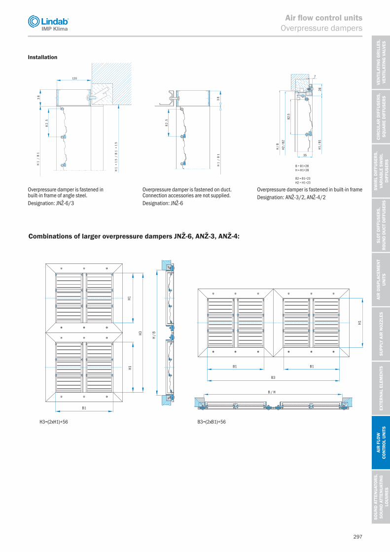
Overpressure damper is fastened in built-in frame of angle steel.Designation: JNŽ-6/3
Overpressure damper is fastened on duct. Connection accessories are not supplied.Designation: JNŽ-6
Overpressure damper is fastened in built-in frameDesignation: ANŽ-3/2, ANŽ-4/2
H3=(2xH1)+56 B3=(2xB1)+56
Combinations of larger overpressure dampers JNŽ-6, ANŽ-3, ANŽ-4:
Installation
297
VEN
TILA
TIN
G G
RIL
LES,
VE
NTI
LATI
NG
VAL
VES
VEN
TILA
TIN
G G
RIL
LES,
VE
NTI
LATI
NG
VAL
VES
CIR
CULA
R D
IFFU
SER
S,
SQU
ARE
DIF
FUSE
RS
SWIR
L D
IFFU
SER
S,
VAR
IAB
LE S
WIR
L
DIF
FUSE
RS
SLO
T D
IFFU
SER
S,
ROU
ND D
UCT
DIF
FUSE
RS
AIR
DIS
PLAC
EMEN
T
UN
ITS
SUPP
LY A
IR N
OZZ
LES
EXTE
RN
AL E
LEM
ENTS
AIR
FLO
W
CON
TRO
L U
NIT
S
SOU
ND
ATT
ENU
ATO
RS,
SO
UN
D A
TTEN
UAT
ING
LO
UVR
ES
IMP Klima
Air flow control unitsOverpressure dampers

H1H1
H3
H /
B
B1
B / H
B1 B1
B3
H1
1 2 3 4 5 60.55
20
30
40
50
80
10
100
Air velocity v (m/s) at the effective area Aef
Pres
sure
dro
p∆p
cel (P
a)
Example of calculation for JNŽ-6, ANŽ-3, ANŽ-4
Aef = B1 x (H1-10-(13 x n)) in m² where n is a number of vanes.B1 = 500 mm, H1 = 400 mm, n = 5Q = 2000 m³/hAef = 500 x (400 -10-(13 x 5)) = 162500 mm² ≥ 0.16 m²v = (Q / 3600) / Aef = (2000 / 3600) / 0.16 = 3.47 m/s
Δpcel (Pa) Pressure drop
Ordering example
Steel overpressure damperwith installation frame: JNŽ-6/3 B1xH1Size: B1=500 H1=428Pcs: 4
Aluminium overpressure damper with installation frame: ANŽ-4/2 B1xH1Size: B1=500 H1=428Pcs: 4
Pressure drop diagramUse the diagram to determine the total pressure drop in respect of air velocity at the free sectional area.
298
IMP Klima
Air flow control unitsOverpressure dampers

B1 B1+76
H1
H1
+76
B1 B1+76
120
H1
H1
+76
120
Vgradnje:
Standardne dimenzije:
Mo`ne so vse kombinacije {irin B1 in vi{in H1 potabeli dimenzij.Po `elji izdelujemo nadtla~ne `aluzije poljubnihvmesnih dimenzij.
n ... {tevilo lamel
H1
/B
1
H1
+1
5/
B1
+1
5
120
82
.5
38
H1
/B
13
8
82
.5
n... number of vanes
100 150 200 250 300 400 500 600 700 800 900 1000200 250 300 400 500 600 700 800 900 1000
1 1 2 3 3 5 6 7 8 10 11 12
H1(mm)B1(mm)
n
Size JN @-6W
■ Louvre for maintaining the preset pressure difference JNŽ-6W
ApplicationThe JNŽ-6W louvre for maintaining the preset pressure difference is designed for maintaining the preset pressure difference between two rooms or between indoors and outdoors. Depending on its orientation, the louvre can support overpressure or underpressure. It is a rapid-response precisely adjustable passive element for maintaining the pressure difference and is not airtight. Standard dimensions: from 200x100 to 1000x1000 with 50 mm steps. Other dimensions available upon request.
It can be used as• an underpressure louvre – to prevent the egress of
substances (chemicals, smoke, etc.);• an overpressure louvre for rooms where preventing the
ingress of polluted air is desired;• an overpressure valve – to prevent the ingress of gases
into smokeless areas.
Description• The blades are interconnected using connecting rods. • Precise adjustments are performed on-site.• Easy to set up: weights are placed on the threaded rods
and secured against unscrewing using nuts.
Size JNŽ-6W
H1 (mm) 100 150 200 250 300 400 500 600 700 800 900 1000
B1 (mm) 200 250 300 400 500 600 700 800 900 1000
n 1 1 2 3 3 5 6 7 8 10 11 12
n – number of vanes
SizesAll combinations of B1 and H1 according to the table of dimensions are possible. Non-standard dimensions are available on request.
Installation
299
VEN
TILA
TIN
G G
RIL
LES,
VE
NTI
LATI
NG
VAL
VES
VEN
TILA
TIN
G G
RIL
LES,
VE
NTI
LATI
NG
VAL
VES
CIR
CULA
R D
IFFU
SER
S,
SQU
ARE
DIF
FUSE
RS
SWIR
L D
IFFU
SER
S,
VAR
IAB
LE S
WIR
L
DIF
FUSE
RS
SLO
T D
IFFU
SER
S,
ROU
ND D
UCT
DIF
FUSE
RS
AIR
DIS
PLAC
EMEN
T
UN
ITS
SUPP
LY A
IR N
OZZ
LES
EXTE
RN
AL E
LEM
ENTS
AIR
FLO
W
CON
TRO
L U
NIT
S
SOU
ND
ATT
ENU
ATO
RS,
SO
UN
D A
TTEN
UAT
ING
LO
UVR
ES
IMP Klima
Air flow control unitsOverpressure dampers

JN@-6W/DP B1xH1
JN@-6W/3 B1xH1B1=500 H1=4284
Diagram za določitev celotnega padca tlaka:
Air velocity (m/s) at the effective area Aef
1 2 3 4 5 60.55
20
30
40
50
80
10
100 Iz diagrama dobimo celotni padec tlaka v odvisnosti od hitrosti zra~nega curka
B1 = 500 mm, H1 = 400mm, n = 5Q = 2000 m3/hAef = 500 x (400 -10 -(13x5)) = 162500 mm2 => 0,16 m2
v = (Q / 3600) / Aef = (2000 / 3600) / 0,16 = 3,47 m/s
na prostem preseku.
Primer naro~ila:
Žaluzija za vzdrževanje nastavljene tlačne razlike JNŽ-6W:Žaluzija za vzdrževanje nastavljene tlačne razlike z vgradnim okvirjem JNŽ-6W/3:Dimenzije:[tevilo kosov:
DP: Nastavljena tlačna razlikaOpomba: Vrednost želene nastavljene tlačne razlike mora biti nastavljena posebej pri naročilu.
B1 x (H1-10-(13 x n)) izra`en v m2 pri ~emer je n {tevilo lamel.A =ef
Primer izračuna za JNŽ-6W
Pres
sure
dro
p∆p
cel (P
a)
Example of calculation for JNŽ-6W
B1 = 500 mm, H1 = 400mm, n = 5Q = 2000 m³/hAef = 500 x (400 -10 -(13 x 5)) = 162500 mm² ≥ 0.16 m²v = (Q / 3600) / Aef = (2000 / 3600) / 0.16 = 3.47 m/s
Δpcel pressure drop
Ordering example
Louvre for maintaining the presetpressure difference JNŽ-6W: JNŽ-6W/DP B1xH1Louvre for maintaining the presetpressure difference withinstallation frame JNŽ-6W/3: JNŽ-6W/3 B1xH1Dimensions: B1=500 H1=428Pcs: 4
DP: Preset pressure differenceNote: Value of the desired preset pressure difference must be determined extra by the order.
Use the diagram to determine the total pressure drop in respect of air velocity at the free sectional area.Aef = B1 x (H1-10-(13 x n)) in m² where n is a number of vanes.
Pressure drop diagram:
300
IMP Klima
Air flow control unitsOverpressure dampers