overpressure protection-low temp effects
TRANSCRIPT
8/13/2019 Overpressure Protection-Low Temp Effects
http://slidepdf.com/reader/full/overpressure-protection-low-temp-effects 1/4
In designing and sizing relief-device and effluent-handlingsystems, one commonly over-looked aspect of the perfor-
mance is examining the potential for
low temperatures that can cause thecomponents of the system to reachtemperatures below their respective,minimum-design metal tempera-tures (MDMT), which may result inbrittle fracture with subsequent lossof containment. This article pointsout limitations of the typical over-pressure-protection-analysis philos-ophy, discusses common sources oflow temperatures for further inves-tigation, and addresses possible de-sign remedies for MDMT concerns.
The primary objectives of a processengineering evaluation of an efflu-ent handling system (such as a flaresystem) include ensuring that opera-tion of the pressure relief devices dis-charging into the collection system(flare headers, for example) is not ad-
versely affected; and that the effluenthandling equipment are properly de-signed to perform safely. The results ofan overpressure-protection design arethe primary input for this engineeringevaluation; however, there are severalpotential gaps in the ability of thesedata to identify situations in whichthe MDMT may be exceeded.
Current-practice limitations
Common practices for pressure re-lief and effluent handling are foundin numerous references [1–5]. Theprocesses for estimating a dischargetemperature and performing the out-let pressure-drop calculations in thepressure-relief-device discharge pip-ing are limited in their ability to ac-curately predict flowing temperaturesfor many situations.
First, the discharge calculationsare quite often only performed for thecontrolling contingency for which the
pressure relief device was sized, whichdoes not necessarily represent themost likely cause of overpressure orthe cause resulting in the lowest dis-charge temperatures.
Second, the outlet pressure-dropcalculations for individual pressurerelief valves consider the outlet dis-charge piping and potentially excludethe remaining, downstream pipingsystem. This practice can result in atemperature discontinuity betweenthe calculated discharge temperaturefor the individual relief device andthat calculated for the same sectionof piping considering the entire down-
stream piping system using an efflu-
ent-handling hydraulic model.Third, the temperature estimates are
typically made for isothermal pressure-drop equations and do not account foreffects like retrograde condensation.
Fourth, some simplifications of thecalculations that are used for the pur-poses of estimating the outlet pres-sure drop do not represent flashingeffects (for example, highly subcooledflashing liquids are often choked atthe bubblepoint; therefore, the sizingof the valve may assume the backpres-
sure is at the bubblepoint).Finally, the temperature estimates
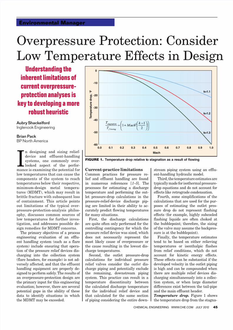
tend to be based on either relievingtemperatures or isenthalpic flashesfrom relief conditions, which do notaccount for kinetic energy effects.These effects can be substantial if thedeveloped velocity in the outlet pipingis high and can be compounded whenthere are multiple relief devices dis-charging simultaneously into a collec-tion system, or when large diameterdifferences exist between the tail-pipeand the main effluent header.Temperature drop. Figure 1 showsthe temperature drop from the stagna-
Solids Processing
Understanding the
inherent limitations of
current overpressure-
protection analyses is
key to developing a more
robust heuristic
Aubry ShackelfordInglenook Engineering
Brian Pack BP North America
CHEMICAL ENGINEERING WWW.CHE.COM JULY 2012 45
Environmental Manager
FIGURE 1. Temperature drop relative to stagnation as a result of flowing
Overpressure Protection: Consider
Low Temperature Effects in Design
-60
-50
-40
-30
-20
-10
0
0.0 0.1 0.2 0.3 0.4 0.5 0.6 0.7 0.8 0.9 1.0
T e m p e r a t u r e d r o p ,
° F k=1.1
k=1.2
k=1.3
Mach
8/13/2019 Overpressure Protection-Low Temp Effects
http://slidepdf.com/reader/full/overpressure-protection-low-temp-effects 2/4
46 CHEMICAL ENGINEERING WWW.CHE.COM JULY 2012
tion temperature (T stagnation) causedby the kinetic energy developed duringadiabatic compressible flow of an idealgas as a function of the Mach numberfor ideal gases having different ideal-gas specific-heat ratios (k) (see Ref. 6,Equation 6–128). For the purposes ofillustrating the temperature drop, astagnation temperature of 0°F (460R)was chosen.
It is useful to note that while a stag-nation temperature of 0°F seems un-likely for many cases, this stagnation
temperature is established after thefluid has been relieved into the collec-tion system (in other words, after theisentropic process of flowing throughthe pressure-relief-valve nozzle andthe subsequent adiabatic process ofexpanding from the nozzle throat tothe total backpressure that results inJoule-Thompson (JT) cooling, both ofwhich can result in significantly lowerstagnation temperatures of the fluidentering into the discharge piping). Additional limitations. Additionalgaps in the overpressure protectionanalysis include the common practiceof not considering the potential for
pressure relief valves to leak, or theeffects of other inputs to the effluenthandling system (such as pressurecontrol valves, depressuring valves,pump seals and manual purge valves).
A leaking pressure-relief valve is typi-cally considered an operational andmechanical issue, not a cause of over-pressure that needs to be evaluated forthe sizing of the pressure relief valveor for the effects on the downstreamcollection system; however, many of usin the warm Gulf Coast region of the
U.S. recognize an ice-covering as indic-ative of a leaking valve, and the fluidsused in the evaluation of the pressure-relief-device sizing may not be repre-sentative of the normal process fluid(for example, the external fire case,which is a common design basis).
Pressure control valves may also becalled upon to “relieve” fluids, yet arecommonly not accounted for in over-pressure protection studies based onthe desire to not include the positiveresponse of control systems in prevent-
ing overpressure. In actual situations,the basic process-control systems areexpected to function as intended, and
thus represent a more likely source offluid input to the collection system.
In addition, these control valves arenot necessarily sized to handle the fullflow of an overpressure scenario, re-sulting in flow from both the control
valve and the pressure relief valve,thereby exacerbating velocity effects.
Finally, depressuring is a dynamicprocess, releasing fluids of differentpressures and temperatures as a func-tion of time. Considering the mostlikely behavior of a depressuring sys-
tem to be an isentropic expansion ofthe residing fluid, the inlet fluid tem-peratures can drop significantly as thedepressuring progresses.
Low temperaturesWhile the potential for low flowingtemperatures falling below the MDMTexists in a variety of processing facili-ties, the issue is especially apparent innatural-gas processing facilities wherehigh pressure, low temperature, low-molecular-weight gases and volatileliquids are present. Design considerations. Based onrecent evaluations of several natural-
Sweetening
Sweeten-
ing
Demethanizer
Dehydration
Flash
tank
Stabilizer
Amine still
Deethanizer
Depropanizer
Propaneloading
Refrig-
erant
NRU
HeN2LPHP Auto-
refrig-
eration
NGL
surge
Emergency storage
1
2
3
4
5
6
7
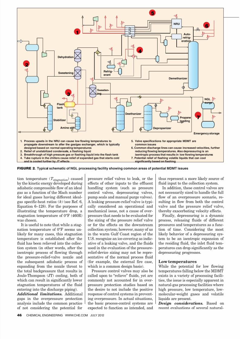
1. Process upsets in the NRU can cause low flowing temperatures to
propagate downstream to after the gas/gas exchanger, which is typically
designed based on normal operating temperatures
2. Relief of unstabilized condensate, a flashing liquid
3. Breakthrough of high pressure gas or flashing liquid into the flash tank
4. Tube rupture in the chillers cause relief of expanded gas that starts cold
and is cooled further by JT effects
5. Valve specifications for appropriate MDMT are
common issues
6. Common discharge lines can cause increased velocities, further
reducing flowing temperatures. Also depressuring is an
isentropic process that results in low flowing temperatures
7. Potential relief of flashing volatile liquids that can cool
significantly based on flashing
FIGURE 2. Typical schematic of NGL processing facility showing common areas of potential MDMT issues
8/13/2019 Overpressure Protection-Low Temp Effects
http://slidepdf.com/reader/full/overpressure-protection-low-temp-effects 3/4
gas processing facilities with ethanerecovery capabilities, the authorshave identified several common areasof concern that may provide a start-
ing point for other gas processors’investigations into this aspect of col-lection system design, as well as forprocess piping. These areas includethe following: multiple inputs (suchas pressure relief devices or control
valves) discharging into subheadershaving diameters close in size to theindividual discharge piping diameter;flashing liquid relief (unstablized con-densate, natural gas liquids [NGL] orliquid propane); internal-boundary-failure cases (tube rupture, for ex-
ample) in gas chillers; cryogenic drainoperations (such as draining expandercasing for maintenance); pressure-relief-device MDMT specifications notcommensurate with discharge pipingMDMT; and pressure relief devices or
vents on the outlet of cryogenic cold-box sections where the normal process
fluid is at elevated temperatures, yetduring process upsets may experiencesignificantly lower temperatures.
Figure 2 provides an overview of
these common areas of concern relatedto low flowing temperatures. NGLand propane processing-and-storageequipment are examples of commonlyoverlooked systems that can achievelow flowing-discharge temperatures.These equipment usually have pres-sure relief devices that are sized basedon an external fire case, yet also havethe potential for relieving the liquideither due to blocked discharges, leak-ing relief valves or depressuring. Alternative solutions. While the
design issues related to low flowingtemperatures can be dealt with byspecifying appropriate metallurgy,there are other alternatives for con-sideration. These alternatives caninclude identifying ways to elimi-nate the cause of overpressure inthe first place (for example, preven-
tion of overfilling of vessels), mitiga-tion of relieving conditions causingthe low temperature excursion viasafety instrumented systems (SIS),
performing mechanical stress analy-ses to establish a better estimate ofthe MDMT per ASME B31.3 (with re-placement of components not coveredby stress analysis as needed), add-ing supplemental fluid (such as gasor methanol) to raise the stagnationtemperature, rerouting the dischargeto a different location (such as to theatmosphere), or conducting Charpytesting on the piping in question toestablish the actual MDMT.
For potentially leaking pressure-
relief valves, the options also includerecognizing the additional conse-quences in a risk-based inspectionprotocol, installing rupture disks, oradding skin thermocouples and lowtemperature alarms on the dischargepiping to notify personnel of leakagebefore the MDMT is crossed.
I N T E R N A T
I O N A L T R A
O MPLI A N T
TAR
BRAND PRODUCTS
®
Circle 3 on p. 56 or go to adlinks.che.com/40269-03
8/13/2019 Overpressure Protection-Low Temp Effects
http://slidepdf.com/reader/full/overpressure-protection-low-temp-effects 4/4
48 CHEMICAL ENGINEERING WWW.CHE.COM JULY 2012
Environmental Manager
Final analysisIn summary, established overpressure-protection-analysis philosophies are
not well suited to identify possible ma-
terial concerns as a result of processfluid flashing and depressuring. Relief-device and effluent-handling sizingconventions and simplified calculation
methodologies limit the ability of thedesigner to recognize potential MDMT
concerns. Understanding the inherentlimitations of current overpressure-pro-
tection-analysis practice is key to devel-
oping a more robust overpressure pro-
tection analysis heuristic, which morefully recognizes the effects of low tem-perature flashing on material design.
It is the experience of the authorsthat modification of the typical over-
pressure-protection-analysis philoso-phy to identify and propose alterna-
tive solutions for conditions resultingin excursions beyond MDMT is pru-
dent in promotion of enhanced facilityprocess-safety management. ■
Edited by Dorothy Lozowski
NoteThe views in this paper are entirelythe authors and do not necessarily re-
flect the views of BP America Produc-tion Co. or its affiliates.
Authors Aubry Shackelford is aprincipal engineer for Ingle-nook Engineering, Inc., whichprovides process engineer-ing consulting with a specific
focus on process safety man-agement (15306 AmesburyLane, Sugar Land, TX 77478;Email: [email protected]; Phone: 713-805-8277).He holds a B.S.Ch.E. fromNortheastern University and
is a professional engineer licensed in the state ofTexas and the province of Alberta (Canada).
Brian Pack is the area engi-neering-support team leaderfor the Mid-Continent opera-tions area in North Americagas region for BP AmericaProduction Co. (501 West-lake Park Blvd., Houston, TX77079; Email: brian.pack@ bp.com; Phone: 281-366-1604).He holds a B.S.Ch.E. from theUniversity of Oklahoma andis a professional engineer li-
censed in the states of Texas and Oklahoma.
References1. API Standard 520, “Sizing, Selection, and
Installation of Pressure-Relieving Devicesin Refineries, Part I — Sizing and Selection”,8th Ed., December 2008.
2. API Standard 520, “Sizing, Selection, andInstallation of Pressure-Relieving Devices inRefineries, Part II — Installation”, 5th Ed.,
August 2003.
3. ISO 23251:2006 (API Standard 521), “Petro-leum, Petrochemical and Natural Gas Indus-tries — Pressure-relieving and DepressuringSystems”, 1st Ed., August 2006.
4. Coats, and others, “Guidelines for Pressure
Relieving Systems and Effluent Handling”,1st Ed., Center for Chemical Process Safetyof the American Institute of Chemical Engi-neers, 1998.
5. Gas Processors Suppliers Association, “Engi-neering Data Book”, 12th Ed., 2004.
6. Perry, R.H., D.W. Green, and J.O. Maloney,editors, “Perry’s Chemical EngineeringHandbook”, McGraw-Hill, 7th Ed., 1997.
7. ASME B31.3-2008, “Process Piping”, Decem-ber 31, 2008.
EACH INFORMATION PACKED PDF ARTICLE includes
graphs, charts, tables, equations and columns on the full
chemical engineering processes you deal with on a daily basis.
This is the tool you will come to rely on, referring back to the
information again and again with just the click of a mouse.
Facts at Your Fingertips Topics Include:
Conservation Economics:
Carbon Pricing Impacts
Distillation Tray Design
Burner Operating
Characteristics
Measurement Guide for
Replacement Seals
Steam Tracer Lines and Traps
Positive Displacement Pumps
Low-Pressure Measurement
for Control Valves
Creating Installed Gain Graphs
Aboveground and
Underground Storage Tanks
Chemical Resistance of
Thermoplastics
Heat Transfer: System
Design II
Adsorption
Flowmeter Selection
Specialty Metals
Plus much, much more…
RECEIVE FULL ACCESS
Receive full access today by visiting www.omeda.com/cbm/facts
17872
to A LL o f Chemical Eng ineering ’s Fac ts a t Your Fing er tips ar ticles in one co
n venien t loca tion.
Receive full access today by visiting http://store.che.com/product/