- lampoldshausen · orbital propulsion fluidic equipment pyrovalves fill, drain and vent valves...
TRANSCRIPT

ARIANEGROUPORBITAL PROPULSIONROBERT-KOCH-STRASSE 182024 TAUFKIRCHENGERMANY
SUSANA CORTÉS [email protected]: +49 (0)89 6000 29244WWW.SPACE-PROPULSION.COM
www.ariane.group

ORBITAL PROPULSION FLUIDIC EQUIPMENT
PYROVALVES FILL, DRAIN AND VENT VALVES LATCH VALVES FLOW CONTROL VALVE

Pyrovalve Fill and Drain Valve Ground Half Coupling Latch Valve Flow Control Valve
To assure the highest possible quality, reliability and performance of our spacecraft propulsion systems and thrusters, ArianeGroup designs, develops and produces its own valves for the control of propellants and pressurant’s. These space qualified valves, proven over again in major international programs, are available separately or as part of a complete propulsion system.
The range of valves available include: › Pyrovalves › Fill, Drain and Vent Valves › Latch Valves › Flow Control Valve
ORBITAL PROPULSION FLUIDIC EQUIPMENTPYROVALVES FILL, DRAIN AND VENT VALVES LATCH VALVES FLOW CONTROL VALVE

Pyrovalve Fill and Drain Valve Ground Half Coupling Latch Valve Flow Control Valve

Pyrovalve Key Technical Characteristics
Initiators Redundant ESA Standard Initiators
Design All-welded Titanium design
Fluid CompabilityHelium, Argon, Xenon, Nitrogen, MON, MMH, Hydrazine, Deionized Water, IPA
Response Time (Mechanical) < 7ms
Mass < 0.160 kg (depending on type)
Qualified Operating Temperature -90°C ≤ T ≤ 100°C
Qualified Operating Pressure (MEOP)
310 bar
Proof Pressure 1.5 x MEOP (465 bar)
Burst Pressure (NO and NC)
Pre firing
Post firing
> 4x MEOP (rupture pressure: > 1240 bar)
> 2.5x MEOP (rupture pressure: > 775 bar)
Leakage
Normally Open Internal leak after firing: < 1x10⁻⁶ scc/s (GHe)External leak before/after firing: < 1x10⁻⁶ scc/s (GHe)
Normally Closed Internal leak before firing: < 1x10⁻⁶ scc/s (GHe)External leak before/after firing: < 1x10⁻⁶ scc/s (GHe)
Pyrovalves are widely used on spacecrafts and launchers where reliable one shot devices are needed for permanent opening or closing of a fluid circuit. Due to its excellent leak tightness capability prior to and after firing in combination with its low mass and low complexity, the pyrovalve pre-sents state of the art propulsion system equipment suitable to fulfil the various mission needs.
ArianeGroup offers a family of Normally Closed (NC) and Normally Open (NO) Pyrotechnical Valves with various different interfaces in order to fulfil the specific custom-er needs. The available product portfolio covers screwed as well as weldable interfaces (1/4” and 3/8”). All valve types are provided with redundant ESA standard initiators (squibs) which provides the energy needed for actuation.
The main function of the Pyrotechnical Valve is to definitely shut down or open a fluid circuit. Furthermore, as part of the propulsion subsystem they must ensure a minimal pres-sure drop as well as perfect external and internal leaktigth-ness prior to and after actuation. The latter is achieved by an all welded design in combination with a flexible titanium membrane, which pysically separates the combustion chamber from the hydraulic flow section. This membrane ensures a perfect pressure tightness between the pyrotech-nic chambers and the fluid circuits before, during and after the actuation.
The Pyrotechnical Valve provides a highly reliable, fast act-ing, zero liquid leakage compact design at low equipment mass. Only a small pulse of electrical power is required for valve actuation.
PYROTECHNICAL VALVES

Pyrovalve Heritage and Future Missions
The heritage of ArianeGroup regarding Pyrotechnical Valves goes back to 1984, when the 1st generation has been developed by Aerospatial Les Mureaux with support from ESA. Following successful qualification in 1987, the first generation of Pyrovalves was produced until the year 2000. In 1999 a harmonisation and improvement of the first Pyrovalve generation was introduced and successfully qual-ified in 2001. Following 2 years of production all Pyrovalve activities were transferred from ArianeGroup Les Mureaux to ArianeGroup Lampoldshausen in 2004. The transfer was finished in 2006 with a successfully performed First Article validation program.
As of today, ArianeGroup has delivered more than 600 NC and more than 600 NO Pyrotechnical valves to leading satellite manufactures. More 500 FM units were already sucessfully actuated on various spacecrafts without any failure. The production stability is continuously monitored and verified throughout specific Destructive Lot Accept-ance Test (DLAT) campaigns. Meanwhile more than 200 units were successfully actuated during extensive DLAT testing including vibration and shock testing, low and high temperature firings as well as under- and overcharge testing. This demonstrates the excellent reliability of the Pyrotechnical Valves manufactured by ArianeGroup.
Spacecraft Launch Year Spacecraft Launch Year Spacecraft Launch Year
Ariane-5 since 1996 Arabsat 5A 2010 Eutelsat W5A 2012
Arabsat 4B 2006 Arabsat 5B 2010 Eutelsat W6A 2012
Anik F3 2007 COM-5 2010 METOP-B 2012
Skynet 5B 2007 Alsat 2B 2010 Skynet 5D 2012
Arabsat 4 AR 2008 Eutelssat W3B 2010 VEGA 2012
Astra 1M 2008 KA-SAT 2010 Yamal 402 2012
ATV FM1 2008 ATV FM 2 2011 ATV FM 4 2013
HotBird 9 2008 Ekspress AM4 2011 Alphasat 2013
Nimiq-4 2008 Arabsat 5C 2011 AMOS 4 2013
Skynet 5C 2008 SSOT (Myriade) 2011 Astra 2E 2013
Amazonas-2 2009 YAHSAT 1A 2011 GAIA 2013
Eutelsat W7 2009 YAHSAT 1B 2011 SES-6 2013
HotBird 10 2009 Astra 1N 2011 ARSAT 1 2014
MILSAT-A 2009 Elisa FM1 2011 Astra 2G 2014
Palapa D 2009 Elisa FM2 2011 Astra 5B 2014
Spirale 1 2009 Elisa FM3 2011 ATV FM5 2014
Spirale 2 2009 Elisa FM4 2011 Arabsat 6B 2015
Thor-6 2009 Atlantic Bird 2011 LISA-Pathfinder 2015
Alsat 2A 2010 Eutelsat W3C 2011 BepiColombo 2016
Nilesat 201 2010 Apstar 7A 2012 ExoMars 2016
RASCOM-2 2010 Astra 2F 2012 METOP-C 2017
MILSAT-B 2010 ATV FM 3 2012

ArianeGroup offers a wide range of Fill and Drain / Vent valves for spacecraft applications incorporating either two or three inhibits against leakage pending on customer demand. Propellant loading / venting valves are designed to provide three independent inhibts, while gas type or test port FCVs provide 2 independent ones.
With regard to the selected materials, the propellant type and test port FDVs provide an excellant compatibility with state of the art storable propellants such as MMH / Hy-drazine / MON-1 as well as MON-3. Special high pressure gas type FDV are available for operation with Helium (He) and Xenon (Xe). In general all types are compatible with standard test agents (IPA / HFE 7100 / deionized water) and gases (He, N2).
In general six different valves types are available, each providing a different interface to prevent misconnection on spacecraft level. These types differ mainly in thread size and orientation.
The following design attributes and features are common to all six FDV types:
› All piece parts of the valve are machined from titanium al-loy (Ti6Al4V) leading to a light weight unit with 0.25 inch/ 6.4mm outlet diameter tube stub which forms a weldable connection to the titanium tubing of the subsystem › The interface to the subsystem structure is provided by a triangular flange with triple-screw attachment (thread size M4) › An all welded housing containing a spring supported guided valve poppet equipped with the primary seal. This ensures that the valve is kept closed in non actuated contions › In flight configuration the valve poppet sealing will be additionally protected and sealed by mounting a cap, thus providing a metal-to-metal seal (secondary seal) › Low pressure drop even at high mass flows ensured by design. The flow area is at least as large as the connected tubing
For servicing a dedicated Ground Half Coupling (GHC) has to be mounted. For each FDV type there is a respective GHC permitting only mating of the correct type. By this means a safe and easy to handle, leak-tight connection between the propulsion system and the ground support equipment is guaranteed.
Each GHC provides a robust specific opening / closing mechanism to safely operate the FDV. No specific tooling is required.
FILL AND DRAIN VALVE

Fill & Drain Valves - 2 Failure Tolerant (3 inhibits against external leakage)
Operating MediaVarious fluids(Propellants and Pressurants)
Mass < 0.09 kg
Total Length 109 ± 1 mm
Standard Tube Dimensions
- outer diameter
- inner diameter
- inner diameter (at weld i/f)
6.4 ± 0.02mm
4.9 + 0.01mm
5.58 ± 0.02mm
Tube Length 43 mm
Adapter Thread
Fuel Loading 9/16“ - 18 UNJF - 3A - RH. Fuel Venting 7/16“ - 20 UNJF - 3A - RH. Ox Loading 9/16“ - 18 UNJF - 3A - LH. Ox Venting 7/16“ - 20 UNJF - 3A - LH.
Note: All of the above threads require corresponding ground half couplings
MEOP- Fuel / Ox Loading / Venting
Up to 33 bar
Burst pressure 1240 bar
Sinusoidal Vibration Up to 20 g
Random Vibration Up to 5 g²/Hz (56.3g RMS)
Pyrotechnic Shock Up to 3250 g
All European Yes
FDV Fuel Venting
Low Pressure Helium Valve
Fill and Drain Valve Propellant Loading
Ground Half Coupling
Fill and Drain Valve Heritage and Future Missions
Since their original qualification in 1983, thousands of fill, drain and vent valves have been produced and delivered for a variety of spacecraft programmes including Eutelsat W3A, Amazonas, Inmarsat 4 F1, Anik F3, Skynet 5A, Skynet 5B, Amos 2, Astar, Star 1, Galaxy 17, Hispasat, MSG-4, Microsats, Herschel Planck, Pleiades, Spacebus, Eurostar communication satellites, Mars Express, Venus Express and ESA’s Automated Transfer Vehicle. The outstanding flight heritage underlines the excellent reliability of the Ariane-Group Fill and Drain / Vent valves.

Fuel Fill Valve Fuel Vent Valve High Pressure Helium Valve
Operating Media Monomethyl Hydrazine (MMH) Monomethyl Hydrazine (MMH) Helium (High Pressure)
Mass ≤ 0.09 kg ≤ 0.09 kg ≤ 0.06 kg
Total Length 108.8 ± 1 mm 107.2 ± 1 mm 94.5 ± 1 mm
Standard Tube Dimensions
- outer diameter
- inner diameter
6.4 ± 0.02mm
5.58 + 0.11 mm
6.4 ± 0.02 mm
5.58 + 0.02 mm
6.4 ± 0.02 mm
4.98 + 0.02 mm
Tube Length 43 mm 43 mm 43 mm
Adapter Thread9/16” - 18 UNJF - 3A - RH. Re-quires corresponding ground half coupling
7/16“ - 20 UNJF - 3A - RH. Requi-res corresponding ground half coupling
M 12 x 1.5 - RH. Requires corresponding ground half coupling
Life
- Operational Life
- Storage Life
About 16 years
Up to 5 years in a protected environment
About 16 years
Up to 5 years in a protected environment
About 16 years
Up to 5 years in a protected environment
Open/Close Cycles 40 Cycles 40 Cycles 40 Cycles
Standard Operating Temp. -30°C to 80°C -30°C to 80°C -30°C to 80°C
Leakage
- external Leakage
- internal Leakage
< 1x10⁻⁶ scc/sec GHe
< 2.8x10⁻⁴ scc/sec GHe
< 1x10⁻⁶ scc/sec GHe
< 2.8x10⁻⁴ scc/sec GHe
< 1x10⁻⁶ scc/sec GHe
< 2.8x10⁻⁴ scc/sec GHe
FILL AND DRAIN VALVETECHNICAL CHARACTERISTICS.

Low Pressure Helium Valve Oxidiser Fill Valve Oxidiser Vent Valve High Pressure Xenon Valve
Helium (Low Pressure) Nitrogen Tetroxide (MON) Nitrogen Tetroxide (MON) Xenon (High Pressure)
≤ 0.06 kg < 0.09 kg < 0.09 kg ≤ 0.06 kg
94.5 ± 1 mm 108.8 ± 1 mm 107.2 ± 1 mm 115 ± 1 mm
6.4 ± 0.02 mm
5.58 + 0.02 mm
6.4 ± 0.02 mm
5.58 + 0.02 mm
6.4 ± 0.02 mm
5.58 + 0.02 mm
6.4 ± 0.02 mm
4.9 + 0.1 mm
43 mm 43 mm 43 mm 61 mm
7/16“ - 20 UNJF - 3A - RH. Requi-res corresponding ground half coupling
9/16“ - 18 UNJF - 3A - LH. Requi-res corresponding ground half coupling
7/16“ - 20 UNJF - 3A - LH. Re-quires corresponding ground half coupling
M 14 x 1.5 - RH. Requires corresponding ground half coupling
About 16 years
Up to 5 years in a protected environment
About 16 years
Up to 5 years in a protected environment
About 16 years
Up to 5 years in a protected environment
About 16 years
Up to 5 years in a protected environment
40 Cycles 40 Cycles 40 Cycles 40 Cycles
-30°C to 80°C -30°C to 80°C -30°C to 80°C -30°C to 80°C
< 1x10⁻⁶ scc/sec GHe
< 2.8x10⁻⁴ scc/sec GHe
< 1x10⁻⁶ scc/sec GHe
< 2.8x10⁻⁴ scc/sec GHe
< 1x10⁻⁶ scc/sec GHe
< 2.8x10⁻⁴ scc/sec GHe
< 1x10⁻⁶ scc/sec GHe
< 2.8x10⁻⁴ scc/sec GHe
Latch Valve Technical Characteristics
Characteristics Nominal Value Remarks
Tubing Interface 1/4 inch Screwed or welded versions available
Mass 545 g
Operating voltage 22-32 VDC Up to 50VDC for 50ms switching pulses
Response time < 30 ms Opening and Closing;
Coil resistance 37,5 Ω ± 1,5 Ω At ambient temperature
Max.operating pressure 24,25 bar Specified value; higher values possible
Back-Relief Pressure 8 to 14 bar
Flow Rate and Pressure Drop < 0.15 bar at 4.5 g/s Flow rates up to > 20g/s usable
Fluid CompatibilityWater, hydrazine, MMH, NTO, IPA, He, N2, Xe and others
Opening/Closing cycles > 500
Operating Temperature 9° C to 50° C for use with hydrazine
Electrical connection Flying leads AWG26, 2m long
Leakage
- external Leakage- internal Leakage
< 10-6 scc/s< 5 scc/h GHe
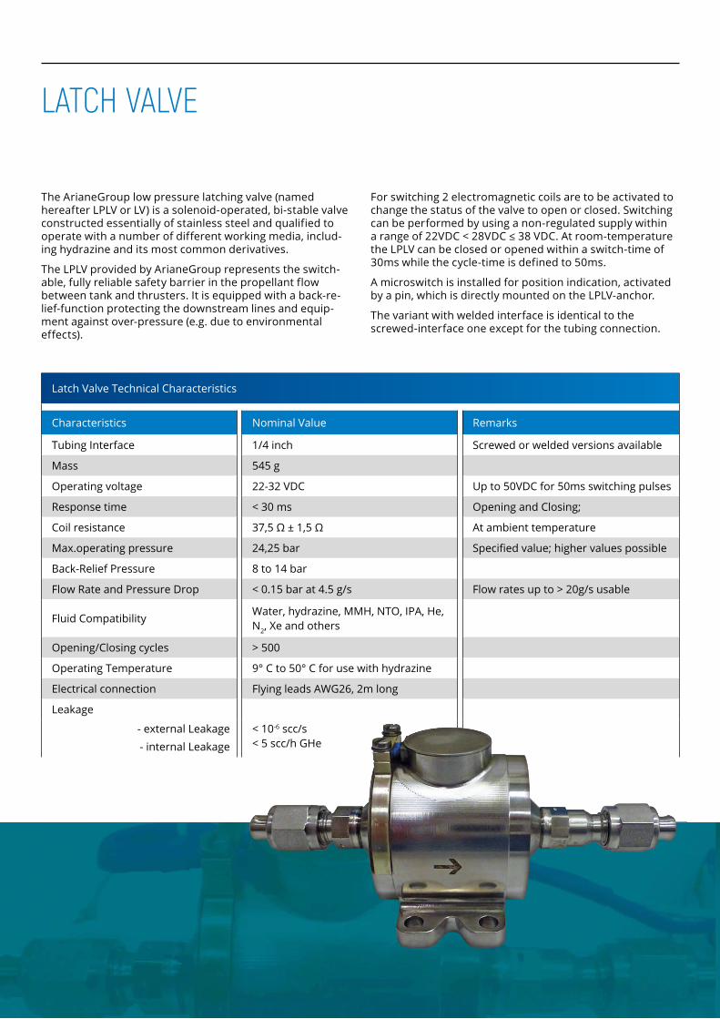
The ArianeGroup low pressure latching valve (named hereafter LPLV or LV) is a solenoid-operated, bi-stable valve constructed essentially of stainless steel and qualified to operate with a number of different working media, includ-ing hydrazine and its most common derivatives.
The LPLV provided by ArianeGroup represents the switch-able, fully reliable safety barrier in the propellant flow between tank and thrusters. It is equipped with a back-re-lief-function protecting the downstream lines and equip-ment against over-pressure (e.g. due to environmental effects).
For switching 2 electromagnetic coils are to be activated to change the status of the valve to open or closed. Switching can be performed by using a non-regulated supply within a range of 22VDC < 28VDC ≤ 38 VDC. At room-temperature the LPLV can be closed or opened within a switch-time of 30ms while the cycle-time is defined to 50ms.
A microswitch is installed for position indication, activated by a pin, which is directly mounted on the LPLV-anchor.
The variant with welded interface is identical to the screwed-interface one except for the tubing connection.
LATCH VALVE

400N Apogee Engine Flow Control Valve (FCV) Key Technical Characteristics
Valve typeDual-coil-solenoid monostable bipropellant engine valve (Normally-Closed), non sliding fit
Operating Voltage per Coil VDC 21 to 27
Coil resistance Ohms 20 ± 1 at 21°C
Power dissipation Watt 38.4 at 27 VDC
Response time (20°C) ms < 30
Pull-in VDC ≤ 18,3
Drop-out VDC > 1.5, < 5
Holding Voltage per Coil VDC ≥ 7.5
Max inlet pressure (operational domain) bar 34
Burst pressure bar 88
Flow Rate / Pressure Drop max 1.1 bar at 70 g/s H2O
Compatible Media NTO, MMH, water
Seat material PTFE
Other materials in contact with media AISI 430, AISI 347, Elgiloy
Leakage
- external Leakage- internal Leakage
scc/sscc/s
< 1x10E−6
< 5x10E−4
Electrical connectionAWG24 flying leads acc. ESA ECSS 3901.002 1.7m (4 single wires)
Media inlet connector AN4 7/16 - 20 UNJF - 3A
Inlet filter Mesh type, stainless steel, <40µm
Temperatures
Operating Acceptance Qualification
°C °C °C
0°C to 115°C -5°C to 120°C -10°C to 125°C
Number of open/close cycles 5000
Life time years 16
014 Orbital Propulsion Fluidic Equipment Orbital Propulsion Fluidic Equipment
400N APOGEE ENGINE FLOW CONTROL VALVE
400N Apogee Engine Flow Control Valve (FCV) Key Technical Characteristics
Valve typeDual-coil-solenoid monostable bipropellant engine valve (Normally-Closed), non sliding � t
Operating Voltage per Coil VDC 21 to 27
Coil resistance Ohms 20 ± 1 at 21°C
Power dissipation Watt 38.4 at 27 VDC
Response time (20°C) ms < 30
Pull-in VDC ≤ 18,3
Drop-out VDC > 1.5, < 5
Holding Voltage per Coil VDC ≥ 7.5
Max inlet pressure (operational domain) bar 34
Burst pressure bar 88
Flow Rate / Pressure Drop max 1.1 bar at 70 g/s H2O
Compatible Media NTO, MMH, water
Seat material PTFE
Other materials in contact with media AISI 430, AISI 347, Elgiloy
Leakage
- external Leakage
- internal Leakage
scc/s
scc/s
< 1x10E−6
< 5x10E−4
Electrical connectionAWG24 � ying leads acc. ESA ECSS 3901.002 1.7m (4 single wires)
Media inlet connector AN4 7/16 - 20 UNJF - 3A
Inlet � lter Mesh type, stainless steel, <40µm
Temperatures
Operating Acceptance Quali� cation
°C°C°C
0°C to 115°C-5°C to 120°C-10°C to 125°C
Number of open/close cycles 5000
Life time years 16
The 400N � ow control valve is an electromagnetic controlled, normally closed valve with a non sliding � t suspended armature design and has redundant electric coils. The moving part, called magnetic plunger, is actuated with the magnetic force induced by the coil when supplied by direct current voltage.
With no voltage applied, the magnetic plunger returns to closed position thanks to the two preloaded membrane springs. The spring preload compresses the PTFE poppet on the me-tallic seats and enables to meet the required tightness level. After energizing of the coil, the valve opens and the � ow passes through an annular gap. At the inlet of the valve a 40µ � lter is located to protect the PTFE seat for any pollution.
More than 100 units were successfully build and more than 80 successfully used on Airbus DS 400N engine in orbit.
The 400N � ow control valve is an electromagnetic controlled, normally closed valve with a non sliding � t suspended armature design and has redundant electric coils. The moving part, called magnetic plunger, is actuated with the magnetic force induced by the coil when supplied by direct current voltage.
With no voltage applied, the magnetic plunger returns to closed position thanks to the two preloaded membrane springs. The spring preload compresses the PTFE poppet on the me-tallic seats and enables to meet the required tightness level. After energizing of the coil, the valve opens and the � ow passes through an annular gap. At the inlet of the valve a 40µ
More than 100 units were successfully build and more than 80 successfully used on
G15_AIRD_K001_Broschuere_Fluidic_v08_RZ.indd 14 16.04.2015 12:13:57
The 400N flow control valve is an electromagnetic controlled, normally closed valve with a non sliding fit suspended armature design and has redundant electric coils. The moving part, called magnetic plunger, is actuated with the magnetic force in-duced by the coil when supplied by direct current voltage.
With no voltage applied, the magnetic plunger returns to closed position thanks to the two preloaded membrane springs. The spring preload compresses the PTFE poppet on the metallic seats and enables to meet the required tightness level. After energizing of the coil, the valve opens and the flow passes through an annular gap. At the inlet of the valve a 40µ filter is located to protect the PTFE seat for any pollu-tion.
More than 100 units were successfully build and more than 80 successfully used on ArianeGroup 400N engine in orbit.
400N APOGEE ENGINE FLOW CONTROL VALVE