Серводвигатели серий ngb/top magnetic
TRANSCRIPT

NGBePermanent magnetbrushless servomotors
Creator of Italianperformance

3
INDICE — INDEX
P. 08 Soluzioni costruttive— Constructive solutions
P. 22 Accessori — Accessories
P. 06 Caratteristiche principali— Main features
P. 13 Definizione dei parametri— Parameter definition
P. 14 NGBe96
P. 04 Linea NGBe — NGBe series
P. 26 Codice d’ordine — Ordering code
P. 16 NGBe123 P. 18 NGBe143 P. 20 NGBe143 TEBC
96
mm
123
143
INDEX
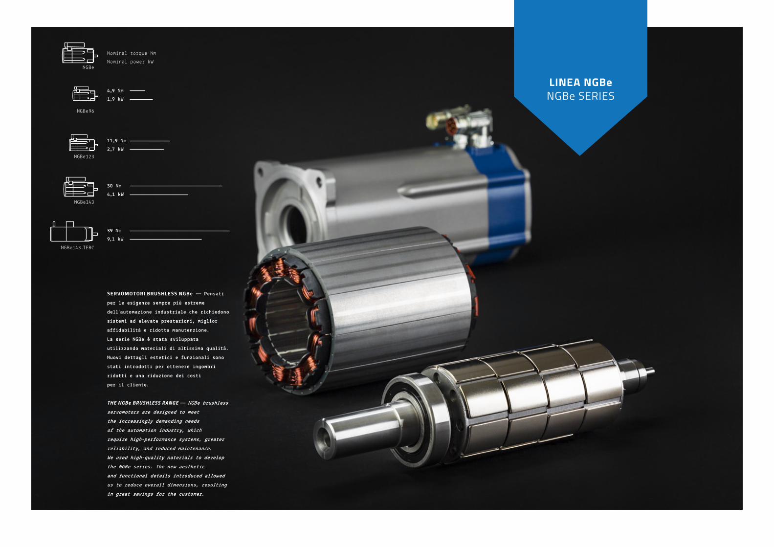
SERVOMOTORI BRUSHLESS NGBe — Pensati
per le esigenze sempre più estreme
dell’automazione industriale che richiedono
sistemi ad elevate prestazioni, miglior
affidabilità e ridotta manutenzione.
La serie NGBe è stata sviluppata
utilizzando materiali di altissima qualità.
Nuovi dettagli estetici e funzionali sono
stati introdotti per ottenere ingombri
ridotti e una riduzione dei costi
per il cliente.
THE NGBe BRUSHLESS RANGE — NGBe brushless
servomotors are designed to meet
the increasingly demanding needs
of the automation industry, which
require high-performance systems, greater
reliability, and reduced maintenance.
We used high-quality materials to develop
the NGBe series. The new aesthetic
and functional details introduced allowed
us to reduce overall dimensions, resulting
in great savings for the customer.
NGBe96
NGBe
Nominal torque NmNominal power kW
30 Nm4,1 kW
39 Nm9,1 kW
11,9 Nm2,7 kW
4,9 Nm1,9 kW
NGBe123
NGBe143
NGBe143.TEBC
LINEA NGBeNGBe SERIES

76
NGBeMAGNETIC SRL
Affidabilità — Reliability
Magneti Realizzati in terre rare NeFeB, rivestiti superficialmente per garantire elevate prestazioni e una protezione totale del magnete da fenomeni di ossidazionee corrosione, vengono inoltre contenuti da un elemento tubolare.
Colle epossidicheDedicate all’incollaggio dei magnetial rotore per consentire un bloccaggio strutturale degli stessi, il riempimento dei giochi ed un’ottima protezione del magnete.
CuscinettiDi tipo a sfere con schermi,prelubrificati a vita.Il cuscinetto lato accoppiamento è stato scelto con un’adeguata capacità di carico radiale e sul lato opposto un cuscinetto speciale con grasso per alte temperature.
Magnets Magnets are made of NeFeB rare earthand are surface-coated to guarantee high performance and protect themagainst oxidation and corrosion.Moreover, they are contained in a tubular element.
Epoxy gluesUsed to glue the magnets to the rotorand lock them in place, fill in gaps,and protect the magnet.
Bearings The shielded ball bearings are lubricatedfor life. The bearing on the coupling sidehas a suitable radial load capacity,whereas the special bearing on the opposite side has high-temperature grease.
Stator — The motorsare manufactured
with the stator’s
monolithic structure,
thus guaranteeing
reliability and greater
structural rigidity.
References standard —
Our brushless
servomotors comply
with the IEC 60034
standard concerning
rotating electrical
machines. Therefore,
they comply with the
regulations of most
EU Countries.
Modularità — Modularità
Isolamento — Insulation
NGBe è progettato prevedendo un’uguale predisposizione meccanica per il montaggio di 4 differenti tipi di feedback motore.
Il f issaggio del motore alle macchineè agevole grazie all’accesso diretto delle viti di fissaggio della flangia B5, V1 o V3.
Le connessioni previste per i connettori M23 hanno la funzionalità di aggancio rapido, garantendo praticità anche nelle situazioni di impianti con difficile accessibilità.
Tutta la serie NGBe è in classe termica F, pertanto la massima sovratemperatura dell’avvolgimento ammessa è di 105°C (temperatura max ambiente 40°C).
L’avvolgimento dello statore è progettato con un doppio isolamento elettrico. Una prima impregnazione di vernice isolante seguita da un secondo riempimento con resina epossidica, in ambiente sottovuoto. Queste attenzioni garantiscono un eccellente grado di affidabilità dell’avvolgimento. Un’ottima soluzione per la protezione dello statore anche nei momenti di smontaggio perle operazioni di manutenzione.
NGBe has an equal mechanical set-upfor assembling 4 types of motor feedback .
The motor can be easily fastenedto machines thanks to the direct access to the B5, V1 or V3 flange fastening screws .
The connections of the M23 connectorshave the quick coupling function ,which guarantees practicality, evenwhen systems are difficult to access.
The entire NGBe series has a class F thermal protection; therefore, the maximum windingover-temperature permitted is 105 °C (maximum room temperature: 40°C).
The winding of the stator is designedwith double electrical insulation .It is first impregnated with an insulating paint and then it is filled with an epoxy resinin a vacuum environment.These details make the winding extremely reliable. An excellent solution even to protectthe stator during disassembly operationsfor maintenance purposes.
Caratteristiche principali — Main features
MAIN FEATURES

98
NGBeMAGNETIC SRL
Magnet phase shiftNello stesso modulo di rotore i magneti sono collocati in posizione asimmetrica. The magnets are placed in an asymmetricposition in the same rotor module.
Stepped skewingPosizione disallineata dei moduli del rotoreMisaligned position of the rotor modules.
Soluzioni costruttive — Constructive solutionsDummy slot Sono previste delle nicchie sullo statoreper produrre effetti sulla coppia similia quelli dovuti alle cave, compensandoli.The slots on the stator produce effectson the torque similar to those on the hollows, thereby compensating them.
“I servomotori NGBe sono progettati per ottenereun ridotto rippledi coppia, a favoredi un’ottima rotondità di moto”..“NGBe servomotors are designed to reducetorque ripple and promote excellent rotation regularity”.
MAIN FEATURES
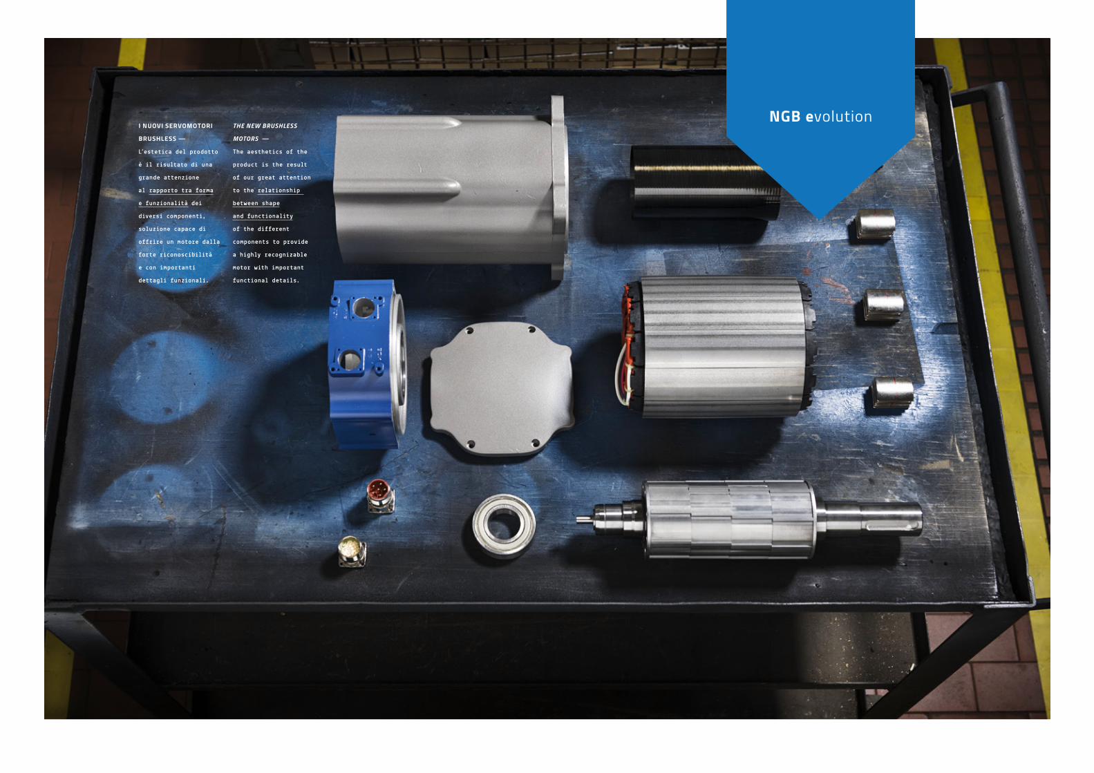
I NUOVI SERVOMOTORI
BRUSHLESS — L’estetica del prodotto
è il risultato di una
grande attenzione
al rapporto tra forma
e funzionalità dei
diversi componenti,
soluzione capace di
offrire un motore dalla
forte riconoscibilità
e con importanti
dettagli funzionali.
THE NEW BRUSHLESS
MOTORS — The aesthetics of the
product is the result
of our great attention
to the relationship
between shape
and functionality
of the different
components to provide
a highly recognizable
motor with important
functional details.
NGB evolution
13
“L’attenzione che poniamo nella scelta dei materiali, ci consente di proporre servomotori dalle ottime performance, elevata robustezza e massima affidabilità”.“Our attention in choosing the materialsallows us to provide high-performance,solid and reliable servomotors”.
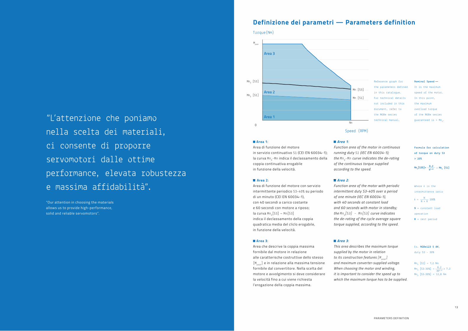
Definizione dei parametri — Parameters definition
Area 1:Area di funzione del motorein servizio continuativo S1 (CEI EN 60034-1);la curva Mn0–Mn indica il declassamento della coppia continuativa erogabile in funzione della velocità.
Area 2:Area di funzione del motore con serviziointermittente periodico S3-40% su periododi un minuto (CEI EN 60034-1),con 40 secondi a carico costantee 60 secondi con motore a riposo;la curva Mn0[S3] – Mn[S3]indica il declassamento della coppiaquadratica media del cliclo erogabile,in funzione della velocità.
Area 3:Area che descrive la coppia massimafornibile dal motore in relazionealle caratterische costruttive dello stesso [Mpeak] e in relazione alla massima tensione fornibile dal convertitore. Nella scelta del motore e avvolgimento si deve considerare la velocità fino a cui viene richiesta l’erogazione della coppia massima.
Area 1:Function area of the motor in continuous running duty S1 (IEC EN 60034-1);the Mn0-Mn curve indicates the de-ratingof the continuous torque suppliedaccording to the speed.
Area 2:Function area of the motor with periodic intermittent duty S3-40% over a periodof one minute (IEC EN 60034-1),with 40 seconds at constant loadand 60 seconds with motor in standby;the Mn0[S3] – Mn[S3] curve indicatesthe de-rating of the cycle average square torque supplied, according to the speed.
Area 3:This area describes the maximum torque supplied by the motor in relationto its construction features [Mpeak]
and maximum converter-supplied voltage.When choosing the motor and winding,it is important to consider the speed up towhich the maximum torque has to be supplied.
Reference graph for
the parameters defined
in this catalogue.
For technical details
not included in this
document, refer to
the NGBe series
technical manual.
Nominal Speed —
It is the maximum
speed of the motor.
In this point,
the maximum
overload torque
of the NGBe series
guaranteed is > Mn0.
Where k is the
intermittence ratio
N = constant load
operation
R = rest period
Es. NGBe123 S AK,
duty S3 - 30%
Mn0 [S1] = 7,2 Nm
Mn0 [S3-30%] =
Mn0 [S3-30%] = 12,8 Nm
Formula for calculation
of torque on duty S3
> 20%
Torque(Nm)
Speed (RPM)0
Area 1
Area 2Mn [S1]
Mn0 [S1]
Mn [S3]
Nn
Mn0 [S3]
Mpeak
Area 3
PARAMETERS DEFINITION

1514
NGBeMAGNETIC SRL
NGBe96 – 3x360VRMS motor power supply
Torque costant —
The torque
is proportional
to the motor current
Kt =
Further information:
more data are available
on technical manual of
NGBe motors.
Max torque
S3 - 40% 1’
S1 torque
code Nominal speed
Nn
Stall torque
Mn0
Nominal torque
Mn
Stallcurrent
In0
Stall torqueMn0 [S3]
Nominal torqueMn [S3]
Peak torque
Mpeak
Torque costant
Kt
Inertia
J
Weight
m
NGBe96S AL 3000 Rpm 2.2 Nm 1.9 Nm 2.2 ARMS 3.2 Nm 2.9 Nm 6.6 Nm 0.99 Nm/ARMS 1.3 kgcm2 3.6 kg
NGBe96M AI 3000 Rpm 3.6 Nm 3.2 Nm 2.8 ARMS 5.5 Nm 4.9 Nm 10.8 Nm 1.30 Nm/ARMS 2.3 kgcm2 4.8 kg
NGBe96L AH 3000 Rpm 4.9 Nm 4.2 Nm 3.7 ARMS 7.5 Nm 6.5 Nm 14.7 Nm 1.34 Nm/ARMS 3.4 kgcm2 5.4 kg
NGBe96S AM 5000 Rpm 2.2 Nm 1.8 Nm 3 ARMS 3.2 Nm 2.7 Nm 6.6 Nm 0.71 Nm/ARMS 1.3 kgcm2 3.6 kg
NGBe96M AF 5000 Rpm 3.6 Nm 2.8 Nm 4.6 ARMS 5.5 Nm 4.3 Nm 10.8 Nm 0.79 Nm/ARMS 2.3 kgcm2 4.8 kg
NGBe96L AD 5000 Rpm 4.9 Nm 3.5 Nm 5.9 ARMS 7.5 Nm 5.5 Nm 14.7 Nm 0.83 Nm/ARMS 3.4 kgcm2 5.4 kg
Duty cycle S1
Duty cycleS3-40%, 1 min
Mn [Nm]
In [ARMS]
Torque(Nm)
0 50002236
6.6
2.2
3.22.7
1.8
NGBe96 S – AM
Speed (RPM)
Torque(Nm)
0 30001500
6.6
2.2
3.2
NGBe96 S – AL
Speed (RPM)
2.9
1.9
Torque(Nm)
Speed (RPM)0 1683 3000
10.8
3.6
5.5
3.2
4.9
NGBe96 M – AI Torque(Nm)
Speed (RPM)0 50002980
10.8
3.6
5.5
2.8
4.3
NGBe96 M – AF
Torque(Nm)
Speed (RPM)0 50003163
14.7
4.9
7.5
3.5
5.5
NGBe96 L – ADTorque(Nm) NGBe96 L – AH
Speed (RPM)0 30001763
14.7
4.9
6.7
4.2
6.5
Version B —
Standard execution.
Version D —
Motor with rotatable
right angle connectors.
Motor with brake — Left: Version B
Right: Version D
NGBe96 S — B: 152 mm
L: 182 mm
LB: 232 mm
NGBe96 M — B: 179 mm L: 209 mm
LB: 259 mm
NGBe96 L — B: 206 mm
L: 236 mm
LB: 286 mm
NGBe 96
CENTRE M4 UNI 9321
SHAFT END
14j6
16
5h9
30
9
B
L
142
114
96
16 32
3
2,5 25
16148
32
89
LB
16 82
8216
198
35
SIGNALSPOWER
100
6,6
96,5
98
35
80j6
Ø

1716
NGBeMAGNETIC SRL
Max torque
S3 - 40% 1’
S1 torque
NGBe123 – 3x360VRMS motor power supply
code Nominal speed
Nn
Stall torque
Mn0
Nominal torque
Mn
Stallcurrent
In0
Stall torqueMn0 [S3]
Nominal torqueMn [S3]
Peak torque
Mpeak
Torque costant
Kt
Inertia
J
Weight
m
NGBe123S AK 3000 Rpm 7.2 Nm 5.7 Nm 5.3 ARMS 10.9 Nm 8.8 Nm 18 Nm 1.36 Nm/ARMS 8.2 kgcm2 6.7 kg
NGBe123M AJ 3000 Rpm 9.6 Nm 7.2 Nm 6.5 ARMS 14.8 Nm 11.3 Nm 25 Nm 1.48 Nm/ARMS 12.1 kgcm2 8.7 kg
NGBe123L AG 3000 Rpm 11.9 Nm 8.5 Nm 8 ARMS 18.4 Nm 13.4 Nm 36 Nm 1.49 Nm/ARMS 16.1 kgcm2 10.7 kg
NGBe123S AI 5000 Rpm 7.2 Nm 4.5 Nm 8.7 ARMS 10.9 Nm 7.0 Nm 18 Nm 0.83 Nm/ARMS 8.2 kgcm2 6.7 kg
NGBe123M AF 5000 Rpm 9.6 Nm 4.9 Nm 10.5 ARMS 14.8 Nm 7.8 Nm 25 Nm 0.91 Nm/ARMS 12.1 kgcm2 8.7 kg
NGBe123L AD 5000 Rpm 11.9 Nm 4.5 Nm 13.2 ARMS 18.4 Nm 7.3 Nm 36 Nm 0.90 Nm/ARMS 16.1 kgcm2 10.7 kg
Duty cycle S1
Duty cycleS3-40%, 1 min
Mn [Nm]
In [ARMS]
Torque(Nm)
Speed (RPM)0 30001889
18
7.2
10.9
5.7
8.8
NGBe123 S – AK Torque(Nm)
Speed (RPM)0 50003198
18
7.2
10.9
4.5
7.0
NGBe123 S – AI
Torque(Nm)
Speed (RPM)0 50003508
25
9.6
14.8
4.9
7.8
NGBe123 M – AF
Torque(Nm)
Speed (RPM)0 30001838
36
11.9
18.4
8.5
13.4
NGBe123 L – AG Torque(Nm)
Speed (RPM)0 50003068
36
11.9
18.4
4.57.3
NGBe123 L – AD
Torque(Nm)
Speed (RPM)0 30002115
25
9.6
14.8
7.2
11.3
NGBe123 M – AJ
Version B —
Standard execution.
Version D —
Motor with rotatable
right angle connectors.
Motor with brake — Left: Version B
Right: Version D
NGBe123S — B: 183 mm
L: 233 mm
LB: 287 mm
NGBe123M — B: 210 mm L: 260 mm
LB: 314 mm
NGBe123L — B: 236 mm L: 286 mm
LB: 340 mm
NGBe 123
24j6
27
8h9SHAFT END
CENTRE M8 UNI 9321
110j6
3
10
405
50 B
L
12 36
128 156
124
SIGNALSPOWER
52
123
130
9
147
103
12 36 52
12 90
LB
12 90
201
Torque costant —
The torque
is proportional
to the motor current
Kt =
Further information:
more data are available
on technical manual of
NGBe motors.

1918
NGBeMAGNETIC SRL
NGBe143 – 3x360VRMS motor power supply
code Nominal speed
Nn
Stall torque
Mn0
Nominal torque
Mn
Stallcurrent
In0
Stall torqueMn0 [S3]
Nominal torqueMn [S3]
Peak torque
Mpeak
Torque costant
Kt
Inertia
J
Weight
m
NGBe143S BD 3000 Rpm 12.5 Nm 9.5 Nm 9.4 ARMS 19.7 Nm 15.1 Nm 36.9 Nm 1.33 Nm/ARMS 28 kgcm2 8.8 kg
NGBe143M BC 3000 Rpm 18.8 Nm 11.5 Nm 13.9 ARMS 29.5 Nm 18.3 Nm 56.3 Nm 1.35 Nm/ARMS 38 kgcm2 12 kg
NGBe143L AE 3000 Rpm 25 Nm 12.7 Nm 16.6 ARMS 39.4 Nm 20.2 Nm 75 Nm 1.51 Nm/ARMS 49 kgcm2 15.1 kg
NGBe143P AD 3000 Rpm 30 Nm 13.1 Nm 19.8 ARMS 47.3 Nm 20.8 Nm 90 Nm 1.52 Nm/ARMS 60 kgcm2 18.2 kg
Duty cycle S1
Duty cycleS3-40%, 1 min
Max torque
S3 - 40% 1’
S1 torque
Mn [Nm]
In [ARMS]
Torque(Nm)
Speed (RPM)0 30002110
36.9
12.5
19.7
9.5
15.1
NGBe143 S – BD
Torque(Nm)
Speed (RPM)0 30001917
90
30
47.3
13.1
20.8
NGBe143 P – AD
Torque(Nm)
Speed (RPM)0 30002115
56.3
18.8
29.5
11.5
18.3
NGBe143 M – BC
Torque(Nm)
Speed (RPM)0 30001951
75
25
39.4
12.7
20.2
NGBe143 L – AE
Version B —
Standard execution
Version D —
Motor with rotatable
right angle connectors
Motor with brake — Left: Version B
Right: Version D
NGBe143S — B: 221 mm
L: 279 mm
LB: 344 mm
NGBe143M — B: 258 mm L: 316 mm
LB: 381 mm
NGBe143L — B: 295 mm L: 353 mm
LB: 418 mm
NGBe143P — B: 332 mm L: 390 mm
LB: 455 mm
NGBe 143
CENTRE M12 UNI 9321
32k6
35
SHAFT END
10h9
12 36
3,5
12
138 166
50
130j
6
58 B
L
4
144
SIGNALSPOWER
52
165
11
143
12 36
113
148
52
12 101
LB
12 101
213
Torque costant —
The torque
is proportional
to the motor current
Kt =
Further information:
more data are available
on technical manual of
NGBe motors.

2120
NGBeMAGNETIC SRL
NGBe143 TEBC – 3x360VRMS motor power supply
code Nominal speed
Nn
Stall torque
Mn0
Nominal torque
Mn
Stallcurrent
In0
Stall torqueMn0 [S3]
Nominal torqueMn [S3]
Peak torque
Mpeak
Torque costant
Kt
Inertia
J
Weight
m
NGBe143S BD 3000 Rpm 17.3 Nm 14.7 Nm 13 ARMS 26.9 Nm 23.1 Nm 36.9 Nm 1.33 Nm/ARMS 28 kgcm2 11.8 kg
NGBe143M BC 3000 Rpm 24.7 Nm 19.9 Nm 18.3 ARMS 38.5 Nm 31.3 Nm 56.3 Nm 1.35 Nm/ARMS 38 kgcm2 15.3 kg
NGBe143L AE 3000 Rpm 31.8 Nm 24.6 Nm 21.3 ARMS 49.7 Nm 39.8 Nm 75 Nm 1.49 Nm/ARMS 49 kgcm2 18.7 kg
NGBe143P AD* 3000 Rpm 38.7 Nm 29 Nm 25.5 ARMS 60.5 Nm 46.3 Nm 90 Nm 1.52 Nm/ARMS 60 kgcm2 22.1 kg
Duty cycle S1
* Only with terminal box solution
Duty cycleS3-40%, 1 min
Totaly Enclosed Blower Cooled
La versione ventilata del NGBe143 consente di raggiungere coppie continuative più elevate in tutto il range di velocità.Si presta ad applicazioni dove il ciclo macchina è particolarmente oneroso.
The NGBe143 ventilated version reaches higher continuous torque in the entire speed range. It is suitable for applications where machine cycle is particularly heavy.
Max torque
S3 - 40% 1’
S1 torque
Mn [Nm]
In [ARMS]
Torque(Nm)
Speed (RPM)0 30002113
56.3
24.7
38.5
19.9
31.3
NGBe143 M – BCTEBC
Torque(Nm)
Speed (RPM)0 30001937
75
31.8
49.7
24.6
39.8
NGBe143 L – AETEBC Torque(Nm)
Speed (RPM)0 30001919
90
38.7
60.5
29.0
46.3
NGBe143 P – ADTEBC
Torque(Nm)
Speed (RPM)0 30002118
36.9
17.3
26.9
14.7
23.1
NGBe143 S – BDTEBC
Version S —
Motor with terminal box
and electrofan:
at 230Vac 50/50Hz
on M16 3 pins
industrial connector.
NGBe143L — B: 406mm L: 464mm
LB: 529mm
NGBe143P — B: 443 mm L: 501mm
LB: 566mm
NGBe143S — B: 332mm
L: 390mm
LB: 577mm
NGBe143M — B: 369mm L: 427mm
LB: 492mm
NGBe 143 TEBC
CENTRE M12 UNI 9321
32k6
35
SHAFT END
10h9
Motor with brake —
For dimensions of motors
with B and D connector
version, please contact
Magnetic s.r.l.
POWERM25 x 1.5
SIGNALS
AIROUTLET
3,5
12 60
130j6
4 50
B
40
11090
142
146
58
L
60
LB
40
17590
POWERM25 x 1.5
SIGNALS24
88
171
119
11
165
143
175
106
Torque costant —
The torque
is proportional
to the motor current
Kt =
Further information:
more data are available
on technical manual of
NGBe motors.
23
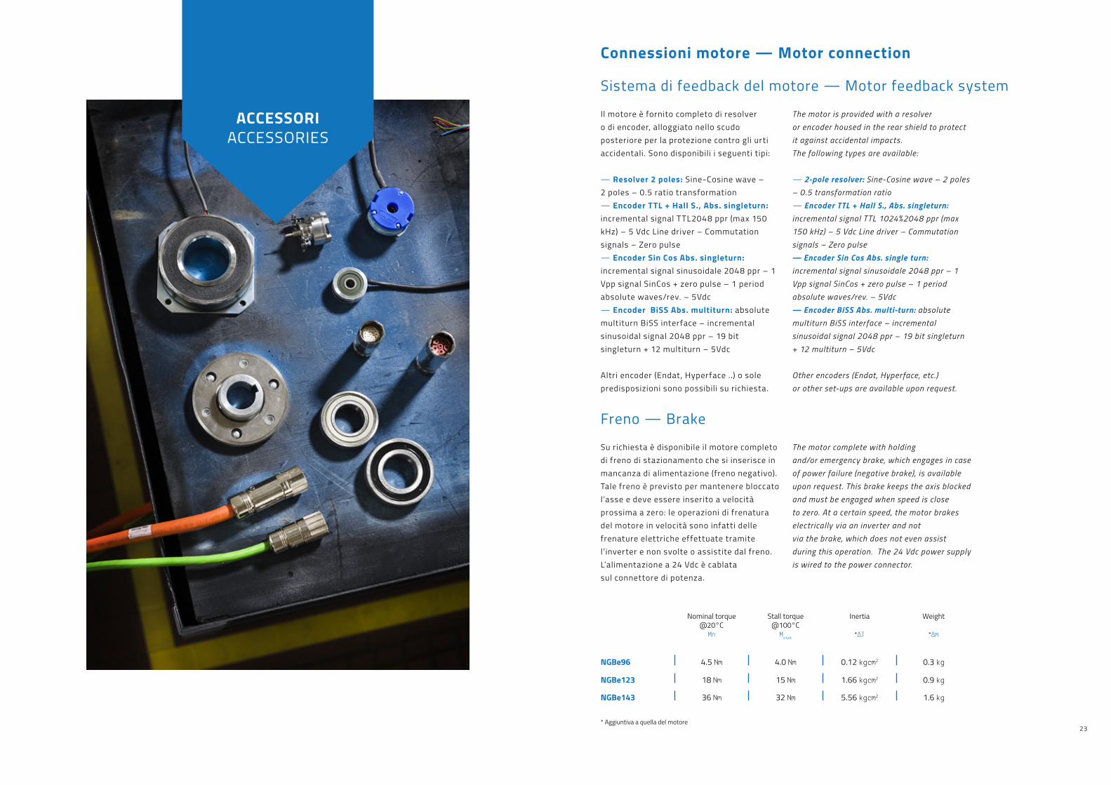
ACCESSORIACCESSORIES
Sistema di feedback del motore — Motor feedback system
Il motore è fornito completo di resolvero di encoder, alloggiato nello scudo posteriore per la protezione contro gli urti accidentali. Sono disponibili i seguenti tipi:
— Resolver 2 poles: Sine-Cosine wave –2 poles – 0.5 ratio transformation— Encoder TTL + Hall S., Abs. singleturn: incremental signal TTL2048 ppr (max 150 kHz) – 5 Vdc Line driver – Commutation signals – Zero pulse— Encoder Sin Cos Abs. singleturn: incremental signal sinusoidale 2048 ppr – 1 Vpp signal SinCos + zero pulse – 1 period absolute waves/rev. – 5Vdc— Encoder BiSS Abs. multiturn: absolute multiturn BiSS interface – incremental sinusoidal signal 2048 ppr – 19 bit singleturn + 12 multiturn – 5Vdc
Altri encoder (Endat, Hyperface ..) o sole predisposizioni sono possibili su richiesta.
The motor is provided with a resolveror encoder housed in the rear shield to protect it against accidental impacts.The following types are available:
— 2-pole resolver: Sine-Cosine wave – 2 poles – 0.5 transformation ratio— Encoder TTL + Hall S . , Abs . singleturn: incremental signal TTL 1024%2048 ppr (max 150 kHz) – 5 Vdc Line driver – Commutation signals – Zero pulse— Encoder Sin Cos Abs. single turn: incremental signal sinusoidale 2048 ppr – 1 Vpp signal SinCos + zero pulse – 1 period absolute waves/rev. – 5Vdc— Encoder BiSS Abs. multi-turn: absolute multiturn BiSS interface – incremental sinusoidal signal 2048 ppr – 19 bit singleturn + 12 multiturn – 5Vdc
Other encoders (Endat, Hyperface, etc.)or other set-ups are available upon request.
Su richiesta è disponibile il motore completo di freno di stazionamento che si inserisce in mancanza di alimentazione (freno negativo). Tale freno è previsto per mantenere bloccato l’asse e deve essere inserito a velocità prossima a zero: le operazioni di frenatura del motore in velocità sono infatti delle frenature elettriche effettuate tramite l’inverter e non svolte o assistite dal freno. L’alimentazione a 24 Vdc è cablatasul connettore di potenza.
The motor complete with holdingand/or emergency brake, which engages in case of power failure (negative brake), is available upon request. This brake keeps the axis blocked and must be engaged when speed is close to zero. At a certain speed, the motor brakes electrically via an inverter and notvia the brake, which does not even assist during this operation. The 24 Vdc power supply is wired to the power connector.
Freno — Brake
Nominal torque@20°C
Mn
Stall torque@100°C
Mstat
Inertia
*∆J
Weight
*∆m
NGBe96 4.5 Nm 4.0 Nm 0.12 kgcm2 0.3 kg
NGBe123 18 Nm 15 Nm 1.66 kgcm2 0.9 kg
NGBe143 36 Nm 32 Nm 5.56 kgcm2 1.6 kg
* Aggiuntiva a quella del motore
Connessioni motore — Motor connection

2524
NGBeMAGNETIC SRL
I servomotori possono essere forniticon uno dei seguenti tipi di sensore termico: Termoresistenza tipo KTY 84-130Termocontatto N.C. klixon
The servo motors can be supplied with oneof the following types of thermal sensor: Resistance thermometer type KTY 84-130Temperature Switch N.C . klixon
Anello paraolio — Sealing ring
Inerzia supplementare — Extra inertia
Tutti i motori possono essere equipaggiati con anello di tenuta paraolio con molla per applicazioni dove è previsto il bagno d’olio, mentre su richiesta è possibile fornire anche la versione solo per tenuta IP65 sull’albero.
Su richiesta è possibile prevedere un’inerzia aggiuntiva per migliorare il controllo del motore (opzione disponibile solo nella versione senza freno).
All motors can be equipped with oil seal ring with a spring for applications requiring oil bath. The specific version for IP65 protection degree on the shaft can be supplied upon request.
Extra inertia can be added upon requestto improve motor control (option availableonly in the brakeless version).
Protezione termica — Thermal protection
ACCESSORIES
Verniciatura — Painting
I motori vengono forniti verniciatibi-colore blu RAL 5000 + grigio RAL 9007con vernici a polvere che assicuranoelevate caratteristiche meccaniche (durezza, elasticità) e una buonafinitura delle superfici del motore.A richiesta possiamo realizzareuna verniciatura smalto monocolore su specifiche a richiesta del cliente.
The motors are painted with two colours,blue RAL 5000 and grey RAL 9007,with powder paints that ensure high mechanical features (hardness, elasticity)and a good finish of the motor’s surfaces.Single-colour enamel paint available upon request.
Additional inertia
∆J
Additionalweight
∆m
NGBe96 + 1.1 kgcm2 + 0.4 kg
NGBe123 + 7.5 kgcm2 + 1.0 kg
NGBe143 + 22.8 kgcm2 + 1.9 kg
Connessioni motore — Motor connection
Connettori volanti opzionali — Optional mobile connectors
Cavi opzionali — Optional cables
Connessione di potenza+ connessione freno di stazionamento.
Connessione trasduttore velocità/posizione.
A richiesta possiamo fornire cavidi alimentazione e di controllo servomotore della lunghezza desiderata completidi connettore ad innesto rapido lato motore.
Power connections+ parking brake connection.
Speed/position transducer connection.
Servomotor control and power cables(of the required length) completewith quick coupling connector on themotor side can be supplied upon request.
connector M23 —
Straight or adjustable
to 90 °, fitted for
both quick-coupling for
in thread engagement.
connector M23 —
Straight or adjustable
to 90 °, fitted for
both quick-coupling for
in thread engagement.
Free connector M23 —
6 pins power connector,
quick coupling.
Free connector M23 —
17 pins signal connector,
quick coupling.
Terminal adjustable box
2 positions —
Available only
on NGBe143
Connessioni di potenza 6 pins — 6 pins power connection
Connessioni di segnale 17 pins — 17 pins signal connection

26
NGBeMAGNETIC SRL
Brake options NGBe143SV3ABECA B S02A < Without brake
B < With brake
Connections NGBe143SV3ABECAB S 02B < Straight M23 connector output
D < 90° angular M23 connector output
(rotable)
S < Terminal box
(available on NGBe143 only)
Painting NGBe143SV3ABECABS 0 20 < Std double-color
1 < Black RAL 5009
2 < Blue RAL5002
S < Special
External female connectors NGBe143SV3ABECABS0 20 < Without
1 < With on
2 < Cable connector kit for generic drive
3 < Cable connector kit for DDM drive
Degree of protection NGBe143SV3ABEC A BS02A < IP65 (shaft end excluded)
B < IP65 with seal ring on the shaft end
C < IP65 with oil seal ring on the shaft end
Shaft NGBe143SV3ABECAB S 02C < Shaft with key
N < Shaft without key
S < Special
Flange NGBe143SV3AB E CABS02A < F100 – N=80j6 – NGBe96
B < F115 – N=95j6 – NGBe96
C < F130 – N=110j6 – NGBe123
D < F145 – N=110j6 – NGBe123
E < F165 – N=130j6 – NGBe143
S < Special
Codice di ordinazione — Ordering code
Stall torque NGBe 143SV 3ABECABS02
Mn0 = 2.2Nm – Natural convection > 96S
Mn0 = 3.6Nm – Natural convection > 96M
Mn0 = 4.9Nm – Natural convection > 96L
Mn0 = 7.2Nm – Natural convection > 123S
Mn0 = 9.6Nm – Natural convection > 123M
Mn0 = 11.9Nm – Natural convection > 123L
Mn0 = 12.5Nm – Natural convection > 143S
Mn0 = 18.8Nm – Natural convection > 143M
Mn0 = 25Nm – Natural convection > 143L
Mn0 = 30Nm – Natural convection > 143P
Mn0 = 17.3Nm – Forced ventilation > 143SV
Mn0 = 24.7Nm – Forced ventilation > 143MV
Mn0 = 31.8Nm – Forced ventilation > 143LV
Mn0 = 38.7Nm – Forced ventilation > 143PV
Nominal speed NGBe143SV 3 ABECABS02
3000 rpm > 3
5000 rpm > 5
Special > S
Feedback device NGBe143SV3 A BECABS02
– Resolver 2 poles > A
– Incremental encoder 2048 ppr > B
Hall sensor
– Absolute encoder SinCos > C
Single turn 2048 ppr
– Absolute encoder BiSS Multi turn > D
– Special > S
Thermal protector NGBe143SV3A B ECABS02
– Without > 0
– KT Y84/130 > A
– Klixon > B
NGBe 143SV 3 A B E C A B S 0 2
Type
Magnetic S.r.l.
Head officeVia del Lavoro, 736054 Montebello Vicentino (VI) Italy
T. 0444 649399F. 0444 440495
Credits —
Art direction,concept & graphic:OAF design
Photography:Commesso fotografo
Print:Faltracco srlMarzo 2016

www.magnetic.it