量測與儀表實驗 measurementsand instrumentation l
TRANSCRIPT

2020/3/31
1
量測與儀表實驗MEASUREMENTS AND
INSTRUMENTATION LAB
劉承揚國立陽明大學生物醫學工程學系
http://www.ym.edu.tw/cyliu66
2
Thermal Expansion of Materials
熱膨脹原理介紹及實驗

2020/3/31
2
3
Consider a homogeneous rod AB of uniform cross section that rests freely on a smooth horizontal surface.
If the temperature of the rod is raised by ΔT, the rod elongates by an amount δT that is proportional to both the temperature change ΔT and the length L of the rod.
Here where α is a constant characteristic of the material called the
coefficient of thermal expansion. The physical unit of α represents 1/°C or per degree F,
depending whether the temperature change is expressed in degrees Celsius or Fahrenheit.
THERMAL EXPANSION
𝜹𝑻 𝜶 𝚫𝑻 𝑳
4
When a sign convention is needed for thermal strains, we usually assume that expansion is positive and contraction is negative.
But since the deformation (expansion) is due to the temperature change ΔT rather than the absolute value of temperature T, a reference temperature is needed for the measure of thermal expansion.
The room (ambient) temperature 25°C is commonly used as a reference.
Thermal expansion is not restricted to solids, but also for liquidsand gases.
For example, water is also an unusual material from a thermal standpoint—it expands when heated at temperatures above 4° C and also expands when cooled below 4°C.
Thus, water has its maximum density at 4°C.
THERMAL EXPANSION
2020/3/31
3
5
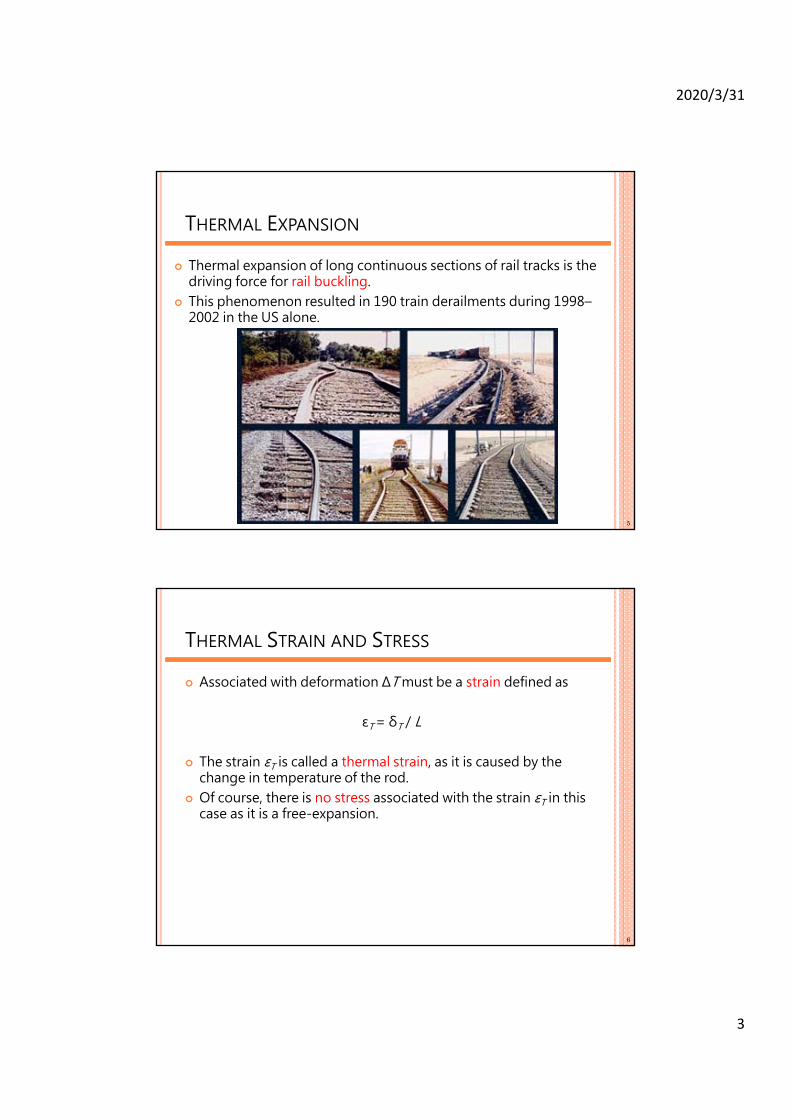
Thermal expansion of long continuous sections of rail tracks is the driving force for rail buckling.
This phenomenon resulted in 190 train derailments during 1998–2002 in the US alone.
THERMAL EXPANSION
6
Associated with deformation ΔT must be a strain defined as
εT = δT / L
The strain εT is called a thermal strain, as it is caused by the change in temperature of the rod.
Of course, there is no stress associated with the strain εT in this case as it is a free-expansion.
THERMAL STRAIN AND STRESS

2020/3/31
4
7
Now assume the same rod AB of length L is placed between two fixed supports at a distance L from each other.
Again, there is neither stress nor strain in this initial condition. If we raise the temperature by ΔT, the rod cannot elongate because
of the restraints imposed on its ends; the elongation δT of the rod is zero and stress develops in the rod.
THERMAL STRAIN AND STRESS
8
We can think of this problem as a superposition of two problems. First consider a free expended rod without constraints. Since the rod is homogeneous and of uniform cross section, the
strain εT = δT /L is constant at any point thus the stress also zero. However, the rod becomes longer. We need to push it back to its
original length L. Therefore, two equal and opposite forces P and P′ are exerted on
the two ends of rod. Assuming the length change due to these two equal opposite
forces is δ then magnitude of force is
δ = PL / EA
where E and A are Young’s modulus and cross sectional area of the rod.
THERMAL STRAIN AND STRESS

2020/3/31
5
9
But this length change should be the elimination of thermal expansion δT, that is,
δ + δT = 0
In other words, δT + PL/EA = 0
THERMAL STRAIN AND STRESS
This equation allows us to determine the force P exerted by the constraints on the rod to keep it from elongating, due to the expansion after temperature has been raised.
P = - EA α(ΔT )L
10
It follows that a state of stress (with no corresponding strain) is created in the rod.
The problem created by the temperature change ΔT is statically indeterminate.
Therefore, the magnitude P of the reactions at the supports is determined from the condition that the elongation of the rod is zero.
Once we determine the constraint force, we can calculate the stress as
σ = P/A = -E α(ΔT )L
The absence of any strain in the rod applies only in the case of a homogeneous rod of uniform cross section.
THERMAL STRAIN AND STRESS

2020/3/31
6
11
Any other problems involving a restrained structure undergoing a change in temperature must be analyzed on its own merits.
However, the same general approach can be used by considering the deformation due to the temperature change and the deformation due to the reaction forces separately and superposing the two solutions obtained.
In general, we might be able to write down the principle of thermal stress calculations as
δMechanical + δThermal = 0
where δMechanical and δThermal are the deformation due to external forces (loadings) and temperature change.
THERMAL STRAIN AND STRESS
12
APPLICATIONS

2020/3/31
7
13
The purpose of this activity is to determine the thermal expansion coefficient of a material subjected to uniform heating.
Most materials expand somewhat when heated through a temperature range that does not produce a change in phase.
The added heat increases the average amplitude of vibration of the atoms in the material which increases the average separation between the atoms.
Suppose an object of length L undergoes a temperature change of magnitude ΔT.
If ΔT is reasonably small, the change in length, ΔL, is generally proportional to L and ΔT. Stated mathematically:
ΔL = α L ΔT
where α is called the coefficient of linear expansion for the material.
THERMAL EXPANSION TEST
14
For materials that are not isotropic, such as an asymmetric crystal for example, α can have a different value depending on the axis along which the expansion is measured.
The coefficient α can also vary somewhat with temperature so that the degree of expansion depends not only on the magnitude of the temperature change, but on the absolute temperature as well.
In this experiment, you will measure α for aluminum, brass, and copper.
These metals are isotropic so that a need only be measured along one dimension.
THERMAL EXPANSION TEST

2020/3/31
8
15
A thermistor’s resistance varies reliable with temperature. The electrical resistance can be measured with an ohmmeter and
converted to a temperature measurement using the empirical data as shown in the table provided at the end of this notes.
Although the relationship between temperature and resistance is not linear, a linear approximation can be accurately used to interpolate between table data points with an accuracy of approximately ±0.2°C.
NOTES ON TEMPERATURE MEASUREMENT
16
THERMISTOR CONVERSION TABLE
2020/3/31
9
17
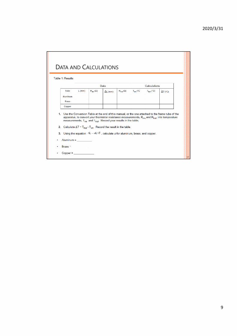
DATA AND CALCULATIONS