electricalpartmanuals iq energy sentinel™. * ,. iq data plus ii metering and voltage protection.*...
TRANSCRIPT

www . El
ectric
alPar
tMan
uals
. com

Your main objective is to produce a cost effective, high quality product. Several things stand In your way- unexpected equipment downtime, energy costs, reduced maintenance personnel and budgets, and limited capital. Downtime or power outage costs range from a few thousand to hundreds of thousands of dollars per hour in lost production and related costs.
Consider these facts: Energy costs are growing at an average 8 percent to 10 percent per year and any increase in power demand is dramatically more expensive (up to $40/kW). Engineering and maintenance staffs are being asked to do more with less personnel. Product quality is very dependent on the consistency of the power supply at a time when the utilities are being pushed to deliver more with no increase in generating C�Waeity.
tl\e rise in energy costs and the ,$l\FinklllQ energy availability, increasingly
reporting and cost saving Oi&, require elaborate monitoring and
''fiArNIJm• .. J in tills Bnvirttnment?
and making it .who need
in a sim-
IMPACC provides a complete family of solidstate products including protective relays, meters. and control relays designed to provide superior protection and metering from the utility incoming line down to a 15 ampere breaker or fractional HP motor. When connected together over the only communication network designed for power distribution duty. it provides the necessary information to the right person in real time to insure your plant and facility operates efficiently. It's also "open" to communicate with other communications systems used in your plant.
IMPACC is designed to help you manage your entire electrical system investmentequipment operational and manpower costs. energy costs. and the electrical impact on product quality.
www . El
ectric
alPar
tMan
uals
. com

Some Significant Benefits of an IMPACC System
Improved Energy Management
111 Historical trending functions used to develop daily or seasonal load profiles.
• Rapid reaction to utility load shedding requirements.
1111 Accurate allocation of energy costs within a facility.
11 Reduce loads to cut peak demand. 111 Equalize loads to reduce potential
downtime.
Scheduled Maintenance Reduces Costs
111 Preventive maintenance schedules can be developed from the data base of real time mechanical and electrical equipment usage.
111 Alerts are provided to remind when preventive maintenance is required on monitored equipment.
111 Costs can be reduced through· elimination of unnecessary maintenance dictated only by time instead of actual use.
111 Emergency maintenance problems are dramatically reduced.
Early Warning Alerts to Potential Problems
1111 The operator is alerted to problems before they occur such as a breaker beginning to time out or a load about to be exceeded.
111 Problems can be corrected by shedding or equalizing loads while the cause is identified and corrected.
111 Isolation and correction of problems help assure that a process or facility will not shutdown.
Instantaneous Troubleshooting Information
111 Information on which breaker tripped, the cause, and magnitude is available instantaneously.
111 Alarms with time stamping provide an indication of which event occurred.first, second, and so forth. This narrows the potential cause of a given trip.
1111 Maintenance personnel are provided with information to identify the prob lem and have the system up and operating in minutes instead of hours.
Increased Personnel Productivity
1111 Time-consuming data collection by dedicated personnel is unnecessary,.
111 Maintenance personnel are tn .��•n��tm.i actual maintenance funlctiollls the equipment and f.ll �llifiUH\i
www . El
ectric
alPar
tMan
uals
. com

www . El
ectric
alPar
tMan
uals
. com

IMPACC AT WORK PROVEN PERFORMANCE IN INDUSTRIAL, COMMERCIAL, AND INSTITUTIONAL FACILITIES
IMPACC is being utilized in a variety of applications ... monitoring and controlling complete electrical distribution systems or those parts of a system selected by the operator.
As a high frequency-based system, IMPACC is unaffected by the electromagnetic fields that result when current flows through conductors. This helps provide for increased reliability while significantly reducing equipment and installation costs.
A master control unit is used to monitor, control, and communicate with the compatible devices and equipment on the IMPACC System. The master control unit (located onsite or off-site) may be a personal computer, or a user's already existing building management system, programmable logic controller, or distributed control system. Through a variety of available software ranging from simple monitoring to complex power management applications, an operator has access to all the data that is monitored and can perform control functions as permitted by the operator's security access level.
The Westinghouse IMPACC System can be easily upgraded as communications requirements increase or when new equipment is added to the system. It can also be retrofitted into existing electrical distribution system equipment.
IMPACC System Support
Available support programs include program design, device configuring, network troubleshooting, 24 hour service and training on IMPACC compatible devices and software.
IMPACC is ideal for use in new construction and existing buildings. Some specific facility applications include:
Petrochemical Plants
Waste Water Treatment Facilities
Steel Mills
Manufacturing Plants
Airports
Financial Institutions
Health and Medical Facilities
Public Buildings
Office Complexes
Shopping Centers
Museums
A Consistent Commitment to Our Customers
IMPACC is a further example of the CutlerHammer commitment to meeting the present and future requirements of customers' electrical distribution systems. Cutler-Hammer has been, and will continue to be, at the forefront of innovation and the design of products and systems that provide flexible, reliable solutions to the challenges you face.
5 www . El
ectric
alPar
tMan
uals
. com

6
IMPAC ONE OF THE INDUSTRY'S WIDEST SELECTIONS OF DISTRIBUTION EQUIPMENT CAN BE PROVIDED WITH FACTORY INSTALLED COMMUNICATIONS CAPABILITIES
Low Voltage Switchgear Type osn
" Largest installed base of low voltage switchgear.
" Rated up to 600 VAG.
" 800 through 4,000 amperes continuous.
.. 30,000 through 200,000 symmetrical amperes interrupting capacity.
" Utilize OS and DSL air power circuit breakers.
a Breaker compartment provides for four positions of the removable element for easy breaker testing, maintenance, and inspection.
11 Conforms to NEMA, ANSI, IEEE, and UL standards.
"' Digitrip RMS Trip Unit.*
" IQ Data Plus II metering and voltage protection.*
" Assemblies Electronic Monitor I I .*
<11 WU Load Interrupter Switchgear
" Dependable, reliable, and safe switching for primary circuits rated from 2.4 kV through 38 kV in 600 or 1,200 amperes interrupting ratings .
., An integrated assembly of switches, bus, and fuses that are coordinated electrically and mechanically .
.. A full range of fuses - current-limiting or boric acid .
., Optional fixed mounted VCP-W Vacuum Circuit Breaker.
., Rugged, compact design.
" Proven switch mechanism is metal-to-metal linkage, eliminating the need for unreliable chains or cables.
'" IQ Data Plus II™ metering and voltage protection.*
111 Addressable Relay I I . *
Low Voltage Switchboards -Pow-R-M-S and Pow-R-M-S/F
., Drawout (Pow-R-M-S) or fixed (Pow-R-M-S/F) b reakers.
111 600 VAG maximum.
11 800 through 4,000 amperes continuous.
.. 100,000 symmetrical amperes interrupting capacity.
.. Minimizes floor space requirements.
'" Conforms to UL and NEMA standards.
111 Digitrip RMS Trip Unit.*
11 IQ Data Plus II metering and voltage protection.*
11 Assemblies Electronic Monitor I I .*
Low Voltage Switch boards and Pow-R-Line 4 Panelboards
., 240-480-600 VAG, 250 VDC.
" Mains- 400 through 6,000 amperes.
.. Accommodates Series C® Circuit Breakers to provide higher ratings in a standard chassis and increased series ratings .
,. Front or rear accessible.
111 Modular construction, requires less floor space.
.. UL tested and approved. Meets NEG and NEMA standards.
111 IQ Energy Sentinel™. *
,. IQ Data Plus II metering and voltage protection.*
111 IQ Central Energy Display.*
www . El
ectric
alPar
tMan
uals
. com

..,. Medium Voltage VacCiad-W Metal-Clad Switchgear
" Voltages: 2.4 kV through 27.5 kV.
• lEG ratings of 25 kA through 40 kA. • ANSI interrupting ratings of 250 MVA
through 1,000 MVA.
• 1 ,200 through 3,000 amperes continuous.
" Conforms to NEMA, ANSI, and IEEE standards.
,. Standardized design, interchangeable parts.
" Circuit breaker and auxiliary drawer drawouts.
.. High reliability, low maintenance.
" Space saving structure.
"' Special ratings available.
,. Digitrip MV Trip Unit.*
• 10-1000 II™ motor protection.*
" 10 Data Plus II metering and voltage protection.*
Motor Control CentersAdvantage® and Series 2100
,. Utilizes revolutionary Advantage starters.
• Standard breaker feeder units at 65,000 amperes interrupting capacity.
" Standard 65,000 amperes bus bracing. Optional 1 00 kA designs.
" Standard pull apart terminal blocks speed installation and startup, reduce downtime.
11 Multispeed, reduced voltage, solid-state reduced voltage controllers and adjustable speed drives are available.
" Electromechanical/vacuum contactors with IQ 500 solid-state overload relay.*
11 ACM Control Modules.*
" IQ Data Plus II metering and voltage protection.*
'" IQ Energy Sentinel.*
• IQ Central Energy Display.*
Accutrol PWM Adjustable Frequency Controllers
" Easy-to-program and operate digital keypad.
,. Superior performance and operator diagnostics annunciation.
11 Adjustable parameters to meet customer requirements.
.. Trip log readouts for troubleshooting ease.
• 480/380 VAC, 50/60 Hz application.
• Full range line from 3-500 HP.
.. 100 percent testing of printed circuit boards and final assemblies means total customer satisfaction.
.. Multiple communications options built in.
..,. AMPGARD® Medium Voltage Starters
11 Complete units precisely matched to motor ratings.
• Engineered to provide component-tocomponent circuitry and front accessibility of all components and terminals.
,. Rated at 2,200 through 7,200 volts up to 8,000 HP.
• Complete front access and works-in-a-drawer low voltage control panel eases installation and maintenance .
.. Positive mechanical isolation switch grounds and isolates starter from line connectors.
• Operating personnel safety is enhanced by separate high and low voltage compartments and mechanical interlocks.
11 Roll out and slide out vacuum contactors available.
11 10-1000 II motor protection.*
11 10 Data Plus I I metering and voltage protection.*
Transfer Switches
,. Industry's highest withstand, closing, and interrupting ratings.
" Flexible logic system provides for customers to select those functions that are required.
" UL listed for service entrance applications.
11 Capacity to integrate overcurrent protection.
11 30 through 4,000 amperes - 2-, 3-, 4-pole configuration.
,. Available in a drawout or fixed mounted arrangement.
11 IQ Generator.*
m IQ Data Plus II metering and voltage protection.*
• Addressable Relay II.*
* IMPACC compatible device.
7 www . El
ectric
alPar
tMan
uals
. com

8
IMPAC DISTRIBUTION SYSTEM EQUIPMENT IS TIED TOGETHER IN ONE CENTRAL LOCATION WITH NETWORKING CAPABILITIES TO REMOTE STATIONS
Some Significant Features • CENTRALIZED DATA COLLECTION • EARLY WARNING
An IMPACC System collects, processes, and stores distribution system operational data. Trend data can help analyze overall electrical distribution system operation or a specific load's historical performance.
Constant monitoring can alert an operator to potential problems before they occur, thus m inimizing costly downtime while keeping the distribution system running smoothly.
• TROUBLESHOOTING
Time and date stamped event data is provided to efficiently help troubleshoot problems within a distribution system.
MONITORING, CONTROLLING, AND COMMUNICATING FROM A CENTRAL LOCATION- ON-SITE OR OFF-SITE
• ON-SITE LOCATION
From a master control PC, either on-site or off-site, the plant operator, facilities engineer, and/or maintenance engineer can monitor and/or control the entire power distribution system. Information can be made available to other PCs at different locations within a facility.
Shielded twisted pair communications wire in an IMPACC System can extend 7,500 feet without the use of repeaters. Phone lines and modems may be used to extend an IMPACC System to monitor and control off-site locations that may be hundreds or thousands of miles from the master control unit.
WLI Load Interrupter Medium Voltage VacCiad-W Switchgear Metal-Clad Switchgear
Metering I nformation Breaker Status
Switch Position (Open/Close/Trip)
Blown Fuse Indication Cause and Magnitude of Trip
Breaker Control (Open/Close)
Metering Values
Time Stamping of Events
Setup Values (configured remotely)
AMPGARD Medium Voltage Starters
Motor Status (Stop/Run/Trip)
Cause and Magnitude of Trip
Motor Control (Trip/Reset)
Operational Data (Motor Run Time, Number of Operations)
Metering Data
Time Stamping of Events
Trip Setup Values
Motor Winding/Bearing Temperatures
• OFF-SITE LOCATION
Low Voltage Switchgear Low Voltage Switchboards-Type DSll Pow-R-M-S and Pow-R-M-S/F
Breaker Status Breaker Status (Open/Close/Trip) (Open/Close/Trip)
Cause and Magnitude Cause and Magnitude of Trip of Trip Breaker Control Breaker Control (Open/Control) (Open/Close) Metering Values Metering Values Trip Rating Trip Rating Time Stamping of Events Time Stamping of Events
www . El
ectric
alPar
tMan
uals
. com

• NETWORK INTEGRATION
IMPACC can be integrated with other area networks through an approved personal computer or PLC.
• SCHEDULED MAINTENANCE
Preventive maintenance schedules can be developed easily from the stored data base to improve equipment performance and prevent downtime.
With IMPACC compatible devices, you have the ability to monitor, control and obtain information at the individual equipment or equipment lineup.
• TIME SAVINGS
An IMPACC System eliminates the necessity to individually read, record, and compile data from electrical distribution assemblies and equipment.
• ENERGY CONSUMPTION
I nexpensive monitoring of energy consumption can be performed at desired locations in the electrical distribution system providing for energy cost reductions and/or allocation of energy costs to specific departments or functions .
• LOCAL
• PASSWORD PROTECTION
Password flexibility allows maximum system util ization and integrity. Up to 30 different passwords can be assigned and can be based on equipment function and/or location.
• EASE OF INSTALLATION
IMPACC compatible devices are daisy chain connected with a shielded twisted pair wire. Since INCOM is a high frequency-based system, wiring is simplified because there are no polarity considerations.
Low Voltage Switchboards and Pow-R-Line 4 Panelboards
Metering Values
Energy Values
Motor Control Centers
Motor Status (Stop/Run/Trip)
Motor Control (Stop/Start/Reset)
PWM Adjustable Frequency Controllers
Drive Status
Metering Values
Cause and Magnitude of T rip
Transfer Switches
Metering Data
Transfer Switch Status
Remote Test
Busway Systems
Energy Usage Readings
Power Usage Readings
Cause and Magnitude of Trip
Operational Data (Motor Run Time, Number of Operations)
Metering Data
Time Stamping of Events
Trip Setup Values
Start, Stop, Speed Control of Drive
Time Stamping of Events
9
www . El
ectric
alPar
tMan
uals
. com

10
IMPAC LOW COST MICROPROCESSOR-BASED DEVICES PROVIDE MORE USABLE SYSTEM INFORMATION WITH GREATER ACCURACY, SIGNIFICANTLY REDUCE INVENTORY COSTS, AND FACILITATE SCHEDULING OF PREVENTIVE MAINTENANCE
Information from the Entire Power Distribution System
IMPACC compatible devices (circuit breakers with Digitrip Trip Units, 10 Meters and Motor Protective Relays, Advantage Motor Control and Accutrol) perform monitoring, protection, and control functions. 10 devices, for example, replace individual meters, relays, and switches, providing opportunities to literally save hundreds of dollars.
Communications between IMPACC compatible devices and the master control unit is made possible by the INCOM chip. It provides for highly reliable high frequency-based, two-way communications (even in noisy industrial environments) between the master control unit and devices via a shielded twisted pair communications wire.
Up to 1,000 individual IMPACC compatible devices, installed in multiple assemblies, can be monitored and controlled in an IMPACC System.
IMPACC compatible devices provide the maximum flexibility to meet immediate or future electrical distribution system requirements. They can be factory installed in new equipment or retrofitted into existing distribution system equipment. New IMPACC compatible devices can be easily incorporated into an existing IMPACC System.
The IMPACC compatible devices provide a means to collect information from all levels of equipment. Once this data is available, decisions can then be made regarding such issues as energy management, scheduled downtime, and preventive maintenance.
Metering
These devices all provide true rms sensing and are UL and GSA recognized.
IQ Data Plus II Metering and Voltage Protection
Door-mounted device that provides complete metering and system voltage protection (14.4 kV and below, CTs 5,000 amperes and below). It replaces individually mounted and wired ammeters, voltmeters, ammeter and voltmeter switches, wattmeters, varmeters, power factor meters, frequency meters, watthour and demand meters. External PTs are not required for 600 volts and below.
IQ Data Plus II HV Designed for High Voltage Applications
Provides the identical features as the 10 Data Plus II except that it is designed for voltages ranging from 12 kVAC to 240 kVAC (CTs - 5,000 amperes and below).
IQ Data™ Voltage and Current Metering
Performs the voltage and current metering functions of the 10 Data Plus II. Eliminates the need for voltmeters, ammeters, instrument switches. PTs are not required for 600 volts and below.
IQ Generator Simultaneous Current, Voltage, and Frequency Metering
Metering device that provides an alternative to individually mounted and wired ammeters, voltmeters, ammeter and voltmeter switches, and frequency meters.
IQ Energy Sentinel Monitors Power and Energy Readings
Breaker-mounted device that provides an alternative to wattmeters, watthour meters, and watt demand meters. Does not require CTs, PTs, or control power
Protection
All of these devices provide true rms sensing and are ULand GSA listed.
Digitrip MV Trip Units Increased Protection for Medium and High Voltage Circuit Breakers
Digitrip MV provides selectable circuit protection, information, and operator conducted testing. A single trip unit replaces some 30 styles of conventional electromagnetic and induction disk overcurrent relays, 12 styles of ammeters, and ammeter switches. Standard zone selective interlocking as an alternative to high cost bus differential protection.
Digitrip RMS Trip Units Increased Protection for Low Voltage Circuit Breakers
For use in Types DS, DSL, SPB, and Series C R-Frame Circuit Breakers. Digitrip RMS Trip Units offer circuit protection, information, integral testing, remote communications, and energy monitoring functions.
IQ-1000 II Complete Motor Protection and Monitoring
Door-mounted device that replaces conventional motor protection relays including overload, ground fault, unbalance, instantaneous overcur-
www . El
ectric
alPar
tMan
uals
. com

rent, jam, and underload. It also replaces threephase ammeters, timers, and elapsed time meters and displays trip and alarm information . With the optional Universal RTD Module, it monitors RTDs and provides overtemperature protection .
IQ 500 Multifunction Protective Relay for Motor Control Centers
Monitors three-phase current and makes trip decisions based on selectable current values. Protection functions include overload, phase unbalance, ground fault, underload and overtorque with up to four relay outputs.
Universal RTD Module Provides Temperature Data
The Universal RTD (resistance temperature detector) monitors RTD inputs from motor windings, bearings, transformer winding, ambient, etc. One module can transmit information from up to 11 RTDs to a single IQ-1 000 II or directly to a remote computer.
Control
Advantage Motor Starters Smaller Size and Longer Contact Life
Advantage provides significant improvements in motor protection and starter life while virtually eliminating problems like coil burnout, contact chatter, and welding. The need for costly heaters has been eliminated and the sizes are from 20 to 80 percent smaller than conventional NEMA and I EC starters.
Addressable Relay II Direct On/Off Capabilities
An industrial control relay with two inputs to monitor the status of external contacts and one output controllable over the communication network. The relay is AC/DC powered with AC/DC contacts rated to directly switch/monitor switchgear breakers, motor starters, etc.
Monitoring
Assemblies Electronic Monitor II Centralized Local or Remote Monitoring and Information Display
Communications center that monitors up to 40 circuit breakers equipped with Digitrip RMS Trip Units and displays status, cause of trip, and current metered values (including current at time of trip) from each monitored circuit breaker. It can be mounted locally at the switchgear or, for example, remotely at the maintenance engineer's office.
Central Monitoring Unit (CMU) Monitoring and Displaying of Starter Information
Monitors and displays information from up to 99 Advantage Starters, contactors, or IQ 500 devices. Centralized information displayed includes current, cause of trip, status, operations data. It can be mounted locally at the motor control center or remotely.
IQ Central Energy Display Monitoring and Displaying of Energy Information
Monitors and displays energy information (watts, peak demand, and watthours) from up to 58 IQ Energy Sentinels, and IQ Data Plus I I devices. It can be mounted locally at the switchboard or panelboard, or remotely. Centralized display includes energy information as well as the ability to sum together energy information from multiple IQ Energy Sentinels, and provide alarms.
11 www . El
ectric
alPar
tMan
uals
. com

12
IMPAC UNIQUE HIGH FREQUENCY-BASED SYSTEM PROVIDES FOR RELIABILITY, EASIER INSTALLATION AND SUBSTANTIAL SAVINGS
Since INCOM technology is utilized, the IMPACC system is immune to noise generated by electromagnetic fields.
This helps provide a high degree of reliability, often unobtainable with conventional voltagebased systems (RS 232, RS 422, RS 485, etc.) whose signal integrity can be adversely affected by electromagnetic fields. IMPACC communications insures that the values/status you read remotely are the true values transmitted.
Easiest and Most Inexpensive to Configure and Install Installation Is Uncomplicated and Inexpensive
IMPACC compatible devices and the master control unit are simply connected daisy chain style with a shielded single twisted pair. The twisted pair can be routed through existing electrical gear wireways, conduits, etc. It is also polarity insensitive, insuring whatever connection you make is the right one.
Up to 1,000 Devices without Costly Repeaters
When structured as a main network with subnetworks, an IMPACC System may contain up to 1,000 IMPACC compatible devices connected through up to 7,500 feet of communications wire. The actual number and type of IMPACC compatible devices used will depend upon the user's specific requirements and the layout of the facility's electrical distribution system.
Only an IMPACC System provides the capability for up to 1 ,000 compatible devices without the need for data concentrators.
IMPACC Systems are designed so that users can analyze data quickly and inexpensively. Data line routing through existing conduits, simple daisy chain, polarity insensitive wiring, 1 ,000 compatible devices, 7,500 feet capability, and ease of adding new devices makes IMPACC a "plug and play" power monitoring system designed for electrical distribution use. Installation costs are considerably less than comparable PLC/data concentrator based systems, while providing the flexibility and power to provide all the information and control to meet your needs. Wiring should be in accordance with local electrical codes and requirements.
www . El
ectric
alPar
tMan
uals
. com

IMPACC Software Levels Software that Meets Virtually Every Requirement
IMPACC System software is available to meet specific requirements and provides for easy expansion as system and requirements increase. This software ranges from simple monitoring to complex power management applications. An IMPACC System will bring intelligence to any distribution system, including energy monitoring, preventive maintenance, expert system diagnosis, and custom control applications.
IMPACC can begin, for example, with a simple monitoring application monitoring a few devices or include up to 1 ,000 IMPACC compatible devices with multiple computer displays and customized graphic displays.
Also offered are application specific software such as the Custom Billing Software used for multiple tenant or departmental billing. IMPACC information is also directly available to spreadsheets and word processing software.
Series Ill The Complete Electrical Distribution System Software Program Configured by the User to Meet Specific Distribution System Monitoring and Control Requirements
Series II I software provides monitoring and controlling functions (turning devices off, on, reset, etc.) from a master control unit PC and logs vital system data as it is occurring. This data can be stored to generate standard or customized reports, charts, or graphs. Series Ill is a flexible Microsoft® Windows™* based program providing a very user friendly operation and the ability to share data with other Windows™ based software programs.
Series II I features and benefits include:
Complete monitoring and control capability for devices provides a single, centralized source for information to facilitate troubleshooting and preventive maintenance.
Device setpoints can be viewed real time, providing the ability to check setpoints remotely.
Configuration of software is point and click using straight forward descriptions rather than high level programming.
Analog value alarming provides early warning, letting the operator know an event is about to occur, providing information the operator can use to identify and correct the problem before it interrupts production.
System alarms let the operator know when an event occurs, such as a breaker timing out to a trip.
* Microsoft Windows is a trademark of Microsoft Corporation.
Device/operator event logging with time stamping provides retention of historical information. Event information can be stored on a disk or provided immediately on a printer.
Logged data is stored in Comma Separated Variable (CSV) file format used in spreadsheets. It provides information that can be used to develop reports which analyze patterns of system alarms, system loadings, power flow, peak demand, kWH usage. The information can be user shared among several departments as well as manipulated in commercially available spreadsheet programs.
Password protected security helps prevent
. accidental or improper usage.
Dynamic Data Exchange (DDE) link to pass all data to other Windows™ applications such as Microsoft Word, Excel, etc.
Dedicated computer not required. Word processing or other programs can be run while Series Ill continues to monitor and log events. An alarm will show graphically or sound audibly should an event occur.
Serial gateway link enables an operator to send information direct to other information systems.
Start small and grow. Series Ill is available in three packages - 20 device, 200 device, and 1 ,000 device and there is no "penalty" to upgrade.
Enhanced Graphics Custom Graphic Screens Provides Information in a Way Your Operators Can Use It
This optional graphics package supports Series Ill by providing the capability to view an entire distribution system through custom color graphic screens configurable to your power distribution system.
Real time information that can be viewed in a format that is easy-to-understand and use including one line diagrams, elevation drawings, physical plant layouts, and pop up instruction windows triggered by alarms. The immediate availability of this information eliminates the necessity for time-consuming searches for drawings and resultant unnecessary downtime.
Enhanced Graphics also supports functions such as real time and historical trending, data logging, and alarming to provide for direct monitoring and control to help reduce downtime. It also acts as an operating platform for interfacing with other systems.
IMPACC-Dynamic Data Exchange Electrical Distribution System Monitoring
This easy-to-configure, stand alone software driver is used when the only requirement is to obtain information about an electrical distribution system for display in other Windows™ based software packages. IMPACC-Dynamic Data Exchange (DDE) is Microsoft® Windows™ compatible and is the basic building block for opening an electrical distribution system to the powerful world of Windows™. Data gathered by an IMPACC System can be easily linked to spreadsheets, word processors, presentation graphics, or communications applications . Additionally, IMPACC-DDE can be used to send information from IMPACC over a network or other Windows™ based packages that support DDE.
Custom Billing Software Accurate Tenant and Departmental Energy Usage and Billing
This stand alone, application specific software package provides the capabilities to determine energy usage data by individual departments or tenants in a facility .. . and then creates "electric bills" based on this data. Custom Billing Software monitors energy and power data from IQ Energy Sentinels and IQ Data Plus lis, then allocates billing between tenants/departments, common loads, and loads not directly monitored. This information is stored in CSV files for use with spreadsheet programs or it can be printed on a standard bill layout.
No more searching system drawings.
No more meter rooms or meter reading.
13 www . El
ectric
alPar
tMan
uals
. com
14
IMPAC IMPACC SOFTWARE PROVIDES INFORMATION, REAL TIME OR HISTORICAL, TO KEEP YOU IN CONTROL
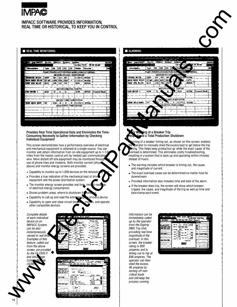
• REAL TIME MONITORING
Provides Real Time Operational Data and Eliminates the TimeConsuming Necessity to Gather Information by Checking Individual Equipment
This screen demonstrates how a performance overview of electrical and mechanical equipment is obtained at a single source. You can monitor and obtain information from on-site equipment up to 1-1/2 miles from the master control unit by twisted pair communications wire. More distant off-site equipment may be monitored through the use of phone lines and modems. Both monitor current (shown above) and monitor energy screens are provided.
Capability to monitor up to 1,000 devices on the network real time.
Provides a true indication of the mechanical load of driven equipment and the power distribution system .
The monitor energy screen provides real time, instant readings of electrical energy consumption.
Shows problem areas, where to shutdown if necessary.
Capability to call up and read the entire faceplate of every device.
Capability to open and close circuit breakers, motors, and operate other compatible devices.
Complete details of each individual device on an IMPACC System can be also instantaneously viewed in real time. Examples of this feature, called out from the above screen, are provided by the IQ-1 000 II and Advantage Control Module (ACM).
.ALARMING
Early Warning of a Breaker Trip Helps Avoid a Total Production Shutdown
Alarming of a breaker timing out, as shown on this screen, enables the operator to manually shed the excess load to get below the trip setting. This helps keep production up while the exact cause of the overload is determined. This eliminates costly troubleshooting, resulting in a system that is back up and operating within minutes instead of hours.
'" The warning includes which breaker is timing out, the cause, and magnitude of current.
.. The exact overload cause can be determined no matter how far downstream.
Provided information also includes time and date of the alarm.
111 I f the breaker does trip, the screen will show which breaker tripped, the cause, and magnitude of the trip as well as time and date stamp each event.
Information can be immediately called up by the operator from the Digitrip RMS Trip Unit, providing real time magnitude of the overload. In this screen, the breaker rating is BOO amperes and is timing out to trip at 846 amperes. The operator can then shed the excess 46 amperes by turning off non-critical loads and still keep the process running.
www . El
ectric
alPar
tMan
uals
. com

• HISTORICAl lOGGING- SPREADSHEET
Time Saving Breaker Profile Development
Information about every breaker in a system is saved and can be reviewed in a chart format (as shown) or a graphic display format. Instantaneous accumulation of this data eliminates the need for dedicated personnel gathering power distribution data, normally only once a day, that usually does not reflect accurate load data.
'" Maintenance personnel are freed to perform actual maintenance to help keep the plant up and running.
• Monitoring breaker loads can help equalize these loads, significantly minimizing chances for overloads and resultant downtime.
• Up to 12,000 events can be stored per file before copying.
• A reliable breaker maintenance profile can be developed from trip and trip magnitude data.
Information that will help set trend lagging can be generated and printed aut in standard formats or customized to meet specific customer information requirements.
• HISTORICAl lOGGING - GRAPHIC
Provides Data Used to Help Control Energy Costs
Energy consumption is a major cost. IMPACC provides for monitoring and tracking of a power distribution system, enabling allocation of energy costs by department, process, or area of a facility. Monitored times (shown every 10 minutes on the screen) are customer set. Energy profiles provide data that helps to rearrange loads, often providing for additional capacity without investing in new equipment.
111 Breaker profile data permits power company load shedding under short notice without disruption of essential processes.
The entire power distribution system can be monitored. Capable of monitoring energy usage on every breaker down to a 15 ampere molded case circuit breaker.
" Data used to reschedule loads to cut peak demand, determine the magnitude of nonessential loads, and is provided to personnel responsible for energy consumption in their individual departments.
Cost effective substitute for data gathering for any power distribution study.
Historical lagging graphs are available in several formats and the information helps track energy usage throughout the power distribution system. The examples shown are a feeder load flaw/time and fan motor winding temperatures/ time, providing information used to obtain an overall plant and individual equipment load profiles.
15 www . El
ectric
alPar
tMan
uals
. com

16
IMPAC
• REAL TIME POWER FLOW
Immediate Information About the Power Distribution System
Graphic screens show the power flow of an entire distribution system in an easy-to-understand format. Graphic screens can be customized to each plant, conforming to plant standards for color coding, symbols, etc. Breaker status, bus status, etc., are live, changing color and/or shape on status changes. A symbol library is available for electrical symbols. Any other graphic representations are easily drawn. A mouse is used to quickly reach subsequent layers of the distribution system, eliminating time-consuming reviews of one line diagrams.
The operator can focus on the overload in progress by calling up an elevation graphic of the gear and real time device faceplate, such as the IQ Data Plus II example shown here. The device itself can be controlled by the operator from the master control unit.
THREE TYPES OF ALARMS HELP KEEP YOUR DISTRIBUTION SYSTEM AND FACILITY UP AND OPERATING*
• ANALOG ALARMING
A Demand Alarm -Action Required
This alarm is set independent of a trip and alerts when an overload is in progress. This enables the operator to determine the cause of an overload and, if appropriate, simply switch loads to halt the impending overload condition. Alarm displays can be text or illustrated graphically.
The alarm can also identify an overload on a motor that indicates a mechanical problem such as drawing too much current for the load. This enables maintenance personnel to determine if there is a problem with the motor or driven equipment before a serious situation and resultant downtime occurs.
* IMPACC provides the capability to set multiple levels of alarms. IMPACC System alarms may be independent of actual device alarms. These system alarms can be used to alert operators prior to an emergency or problem situation, thereby allowing maintenance to avert a potentially costly situation.
www . El
ectric
alPar
tMan
uals
. com

• REAl TIME AlARM
An Emergency Alarm - Immediate Action Required
This alarm warns that a serious problem exists and should be corrected immediately or else the plant and processes may shutdown. The operator is shown when and where an overload condition is about to be reached and tells, in an easy-to-understand format, the magnitude of the overload and what loads to shed. This enables downtime to be avoided while the overload cause is identified and corrected.
Should an actual trip occur, as shown in this example, the magnitude of the current that caused the overload can be immediately obtained. This information can help identity the overload cause, thus saving diagnostic time and helping to get the process back on-line.
• MAINTENANCE AlARM
Scheduled Maintenance Reduces Maintenance Costs
The maintenance alarm tells exactly when maintenance is required on all monitored equipment based on actual use data. This preventive maintenance helps prolong equipment life while avoiding costly downtime due to equipment failure. IMPACC monitors actual equipment use and this data base can be used to develop a maintenance profile on all electrical equipment. For example, the maintenance alarm can tell when to regrease motor bearings or when to replace circuit breaker contacts. Maintenance is performed when needed as opposed to an emergency basis.
Time stamping of analog alarms, as shown on the screen, provides the reason and the date and time the alarm occurred. Since the actual number of operations are retained, parts replacement and maintenance can be scheduled on an as needed basis as opposed to an emergency situation that often results in costly downtime.
�- Ll:��:;�:'[email protected]!ll...,. !!���.• .. -����.� -� TolalNuml;l�rO!Alarms• 1 Alaomssm!Arnv<. 1
\Alarm loevi o •• nljlno� \:.cr;u"od :Adn<>Wl I Clo&r I Anson '
17 www . El
ectric
alPar
tMan
uals
. com

18
IMPAC IMPACC CONNECTIVITY SOLUTIONS
The Flexibility to Interface with Existing Building Management or Distributed Control Systems or Programmable Controllers
IMPACC makes communications easier by providing a wide range of interfaces to other vendors that make the centralization of power distribution information possible. An IMPACC System can easily be linked to building management systems, programmable logic controllers, and distributed control systems. This provides the capability to move data between and across different levels within an installation.
Interfaces have been developed with several vendors including Wonderware, Johnson Controls, Honeywell, Allen-Bradley, Bailey, Expert Edge, Fisher-Provox, Siemens, Foxboro, !conics, lntellution, and Modicon.
IMPACC connectivity provides for maximum flexibility, meaning computers and PLCs can communicate with each other; or multiple computers in various locations communicating with each other.
Information from Series Ill can be exchanged via DDE with other Windows™ based programs such as Excel, Word, or any other DDE compatible program. For higher performance, information can be shared via NET BIOS which connects Series Ill to Ethernet, Arcnet, or any other compatible network.
• IMPACC CONNECTIVITY
IMPACC Devices Treated as Remote 1/0
IMPACC Compatible Devices
www . El
ectric
alPar
tMan
uals
. com

• IMPACC CONNECTIVITY
IMPACC Devices Treated as Remote 1/0
PLC, DCS, Building Management System
IMPACC Network Via Shielded Twisted Pair
IMPACC Compatible Devices
.IMPACC CONNECTIVITY
Localized Operator Workstation
PLC
Computer Workstation
IMPACC Network Via Shielded Twisted Pair
IMPACC Compatible Devices
• IMPACC CONNECTIVITY
IMPACC Used as a Gateway to Other Systems
Computer Workstation
Process Unit
IMPACC Network Via Shielded Twisted Pair
IMPACC Compatible Devices
19 www . El
ectric
alPar
tMan
uals
. com

20
IMPAC IMPACC COMMUNICATIONS CAN BE EASILY AND INEXPENSIVELY RETROFITIED INTO EXISTING ASSEMBLED EQUIPMENT
In addition to communications, Distribution & Control provides opportunities for customers to effectively and economically modernize and extend the life of older equipment with industry leading technology.
Medium Voltage Switchgear
Digitrip MV Trip Units Can Be Retrofitted to All Medium Voltage Switchgear
Digitrip MV combines protective functions, current monitoring , and IMPACC communications capability in a single, compact package. Protective functions provide both three-phase and ground protection so that just one Digitrip MV is required per three-phase circuit. Protection curves are slope selectable (Flat, It, 12t, and 14t) to coordinate with existing electromagnetic overcurrent relays and power fuses.
Other Digitrip MV features include:
Ampere demand.
True rms sensing of each phase and ground current.
Programmable protection settings (local and remote).
I ntegral testing.
Zone interlocking for short time and ground fault protection .
Alphanumeric digital display.
A single Digitrip MV replaces some 30 styles of conventional electromagnetic and induction disc overcurrent relays, 12 styles of ammeters, and ammeter switches . . . and provides greater accuracy.
Digitrip MV Trip Units can be mounted in new or existing panels or on the panel itself. A wiring harness and connection diagram are provided.
This Type DHP medium voltage switchgear lineup has been modernized with replacement panel doors (top) that include Digitrip MV Trip Units and IQ Data Plus II metering and protection devices. The operator is shown rolling a new DHP-VR Vacuum Replacement Circuit Breaker into the DHP cell.
AMPGARD Medium Voltage Starter Retrofit Kit
It includes all parts necessary to easily retrofit an IQ Data Plus II and IQ-1 000 II into an AMPGARD Medium Voltage Starter. The IQ devices are prewired to the terminal blocks on the Works-In-A-Drawer drawout control panel and easily installed in place of the existing control panel.
DHP-VR™ Vacuum Replacement Circuit Breakers and Digitrip MV Trip Units Provide Switchgear Modernization and Life Extension
DHP-VR Vacuum Replacement Circuit Breakers are direct replacements for the DHPTM Air Magnetic Circuit Breakers found in Westinghouse DHP Medium Voltage Switchgear. They provide opportunities to cost effectively modernize existing DHP Switchgear with industry leading vacuum technology while further increasing service life. When installed with Digitrip MV Trip Units, circuit breaker protection and electrical distribution system reliability is fu rthe r increased.
Direct Roll In Replacement
The DHP-VR Vacuum Circuit Breaker is a direct roll in replacement for DHP Air Magnetic and DVP™ Vacuum Circuit Breakers. It is wheel mounted for ease of handling and installation and rolls in and out of the cell on the floor exactly like a DHP (or DVP) Circuit Breaker.
The DHP-VR Vacuum Circuit Breaker correctly interfaces with compartment cell switches (MDC and TOG). Circuit breaker coding plates are maintained to prevent a nonrated circuit breaker from being installed in the switchgear.
Safety interlocks, inherent in the original switchgear design and required by ANSI standards, are also maintained.
A Brand New Replacement Vacuum Circuit Breaker- Not a Retrofit
The DHP-VR Vacuum Circuit Breaker is a brand new, factory designed and tested replacement circuit breaker. It is not a retrofit circuit breaker. This reduces out-of-service time and parts costs normally required when an air magnetic circuit breaker is retrofitted.
Complete Factory Testing and ANSI Design Testing
All DHP-VR Vacuum Circuit Breakers meet or exceed applicable ANSI standards. Tests include: mechanical endurance, power interruption, momentary current, and BIL. Certification to the applicable ANSI design tests are available from Cutler-Hammer upon request. Certified factory production test reports are also available.
Vacuum Interrupters Provide Environmentally Friendly Operation
Because the arc is in a vacuum, there are no arc by-products such as ionized gas discharges, commonly associated with air magnetic circuit breakers.
www . El
ectric
alPar
tMan
uals
. com

Low Voltage Switchgear
Digitrip RMS Retrofit Kits for Low Voltage Power Circuit Breakers Provide IMPACC Communications Capability
These kits provide the opportun ity to expand the communications system throughout your facility regardless of the manufacturer of your existing equipment . . . while i ncreasing older circuit breaker and electrical distribution system reliabi lity. Digitrip RMS Retrofit Kits are custom designed to replace electromechanical or solidstate trip systems on existing breakers. They provide maximum flexibility to meet specific distribution system requ i rements ranging from simple overcurrent protection to ful l communications and monitoring capabilities.
Digitrip RMS features include:
True rms current sensing.
Integral testing.
Flat or 12t response or short and ground fault delay functions.
Selective zone interlocking on short and ground fault delay functions.
Contacts for high load and mode of trip indication.
Alphanumeric digital display.
Communicating, controlling, and extracting current and energy usage data.
Digitrip RMS Retrofit Kits Feature Digitrip RMS Trip Units
At the heart of each retrofit kit is the trip unit. Circuit breaker retrofits are customized in the mounting and orientation of the trip unit and other retrofit components to fit the host breaker selected for retrofit.
Digitrip RMS Retrofit Kits Are Easy to Install
These retrofit kits are designed for easy installation by a qualified individual and include detailed instructions for retrofitting. Most installations can be completed in four hours or less per circuit breaker, depending on the circuit breaker and retrofit kit selected.
Three Digitrip RMS models are available to provide flexibility in retrofit applications.
Retrofit kits are available for over 100 circuit breaker designs. Below are just a few examples.
Westinghouse OS and DSL Drawout Circuit Breakers Upgrade from original peak sensing AmptectorrM trip systems.
General Electric Drawout Circuit Breakers Replace obsolete electromechanical and solidstate peak sensing trip systems on GE circuit breakers.
Westinghouse DB and DBL Drawout Circuit Breakers Replace obsolete electromechanical trip systems.
1-T-E K-Line Drawout Circuit Breakers Replace obsolete 1-T-E electromechanical trip devices and peak sensing solid-state trip systems.
21 www . El
ectric
alPar
tMan
uals
. com

22
IMPAC
Advantage Control Retrofits for Motor Control Centers Add IMPACC Communications Capability
The revolutionary Advantage Motor Control provides numerous operational advantages not available with conventional motor starters including: increased motor p rotection, greater accuracy, no heaters, easier maintenance, reduced heating, flexibi l ity, and endurance.
Advantage UL listed retrofits utilize all new UL recognized components and are available for both Westinghouse and non-Westinghouse motor control centers. With the addition of an Advantage PONI card, these retrofitted starters can be integrated into an IMPACC System.
Advantage Replacement Units for Westinghouse Motor Control Centers
New, UL labeled replacement units with Advantage Motor Control are offered for every plug-in motor control center design Westinghouse has offered since 1950: 11-300, Type W, Five-Star, and Series 2100. The key benefits to users of Westinghouse replacement starter units are readily apparent.
Minimal Downtime. I nstallation of a Westinghouse replacement unit is literally a "pull the plug and put in a new one" operation.
Minimal Capital Investment. Upgrading your MCC with state-of-the-art replacement units is less expensive than installing a new MCC for two obvious reasons: (1) there is less hardware and materials and (2) labor cost is reduced to negligible.
Performance. Replacement units include only new, UL listed state-of-the-art components such as the Advantage Motor Control and Series C HMCP ci rcuit protection. In addition, each unit is supplied with a new advanced design stab assuring positive connection to the MCC vertical bus.
Communications added via Advantage PONI.
Advantage Panel Retrofits for Non-Westinghouse Motor Control Centers
An Advantage panel retrofit provides several benefits in upgrading existing motor control center starter units from other manufacturers including: General Electric, Gould/ITE/Telemechanique, Allen-Bradley, and Square D. This panel upgrade provides the user with several benefits over motor control center replacement.
Reduced Downtime. The preassembled, UL labeled panel retrofit design provides for user installation within a short period of time. Installation flexibility could provide a complete assembly of new Advantage Starter units within a few hours.
Upgraded System Performance. Retrofitt ing provides most of the benefits of a new motor control center. All new components are used and a UL listed Series C HMCP Motor Circuit Protector/ Advantage Motor Starter combination is provided. State-of-the-art Advantage Motor Control provides all features and benefits inherent in the Advantage breakthrough technology.
General Electric starter unit before retrofit.
General Electric starter unit after Advantage retrofit with new door and handle mechanism.
Life Extension. Over time, even the best motor control center design ages and its components fail, even though structurally it may be sound. The expense of maintaining obsolete equipment is high. Retrofitting with an Advantage panel retrofit replaces all vintage control equipment with state-of-the-art, readily maintainable, and available components.
www . El
ectric
alPar
tMan
uals
. com

The Distribution & Control Family of 10 Devices Includes IMPACC Communications Capability
10 devices can be retrofitted into any manufacturers' new or existing equipment including medium and low voltage switchgear, switchboards, panelboards, medium voltage motor starters, motor control centers, transfer switches, adjustable frequency controllers, and reduced voltage starters.
These devices replace many electromechanical, thermal, or analog devices including relays, meters, and instrumentation. I nstallation is accomplished qu ickly and easily with the addition of an 10 device in a surface or floormounted enclosure. All devices can use existing instrument transformers/CPTs, substantially reducing installation cost.
10 devices can be applied to virtually any 480 volt to 230 kV electrical distribution system. They provide increased accuracy plus enhanced control, metering, and protection functions . . . and include communications capabilities.
Several retrofitting options are available to meet specific customer requ i rements:
Component Level - An existing device is removed and replaced with an 10 device.
Surface Mounting - 10 devices can be mounted on walls, panels, or doors in a special surface mounted enclosure that e l iminates the need for cutouts.
Replacement Panels - Provided with the I 0 devices installed and prewired, including a wiring harness and connection diagram.
Free Standing Enclosure - Designed as an equipment l ineup extension for mounting 10 devices. Each section includes two doors, each with three standard 10 cutouts with device panels.
IQ Energy Sentinel
This power monitoring and energy reading device can be easily mounted on circuit breakers in existing panelboards, switchboards, enclosed circuit breakers, bus plugs, and motor circuit protectors.
IQ-1 000 II and IQ Data Plus II Drawout Case Modules
For appl ications where downtime is critical, these d rawout devices provide all the protection and monitoring features of the standard devices, but give the user the added abil ity to change out the un its quickly. For most applications, the devices can be replaced without shutting down the motor or load.
Surface mounting units.
Replacement panels.
IQ Energy Sentinel.
IQ-1000 II and 10 Data Plus II drawout case modules.
Installation and Startup Services
Cutler-Hammer provides a complete package of retrofitting and startup services, by factory trained engineers and technicians, for Westinghouse or non-Westinghouse equipment.
Additionally, IMPACC startup services include:
Setting addresses.
Troubleshooting the data l ine.
Loading and configuring the software.
Preparing Custom G raphic screens.
Training operators and programmers.
Tra ining
The following training courses are available regularly in Pittsburgh. Alternatively, the courses may be held on-site at the user's location as desired.
WCOM371 Series I l l and IMPACC Commun ications
WCOM376 System I ntegrator IMPACC Training
WCOM377 Enhanced G raphics
WDIG374 I nstallation and Testing of Digitrip Retrofit Kits
WCBS375 Custom Bi l l ing Software
Additional Retrofitting Information
Catalog 26-000 is a summary of Westinghouse capabil ity for renewal parts, replacement components, retrofit kits, equipment upgrades and modernization, and factory manufacture and repair information. Contact your sales representative for a copy of Catalog 26-000.
23 www . El
ectric
alPar
tMan
uals
. com

www . El
ectric
alPar
tMan
uals
. com