can be produced from renewable natural re-
TRANSCRIPT
THEORETICAL MODELING AND EXPERIMENTAL ANALYSES OF LAMINATED WOOD COMPOSITE POLES'
Cheng Piao Postdoctoral Research Scientist
Todd F. Shupet Associate Professor
School of Renewable Natural Resources Louisiana State University AgCenter
Baton Rouge, LA 70803
Vijaya Gopu Professor and Chair
Civil and Environmental Engineering Tulane University
New Orleans, LA 701 18
and
Chung Y. Hset Principle Wood Scientist
USDA Forest Service Southern Research Station
Pineville, LA 7 1360
(Received April 2003)
ABSTRACT
Wood laminated composite poles consist of trapezoid-shaped wood strips bonded with synthetic resin. The thick-walled hollow poles had adequate strength and stiffness properties and were a promising substitute for solid wood poles. It was necessary to develop theoretical models to facilitate the manufac- ture and future installation and maintenance of this novel engineered wood product. A higher-order governing differential equation (GDE) model was developed for this purpose based on the principle of minimum potential energy. Transverse shear and glue-line effects were taken into account in the devel- opment of the model. A simplified theoretical model was also derived to further validate the higher-order GDE model. Thirty-six small-scale wood laminated composite poles were made and tested to validate the models developed. Strip thickness and number of strips were chosen as experimental variables. The deflection predicted by the theoretical models agreed well with those measured in experiment. The agreement with the results predicted by the simplified theoretical model was better than that with those predicted by the higher-order GDE model.
Keywords: Beams, composites, energy methods, higher-order differential equation, poles, thick-shell, Timoshenko beam theory, variational methods.
INTRODUCTION The hollow poles have adequate strength and Wood laminated composite poles are thick- stiffness properties but are lower in weight,
walled members with a polygonal cross-section. when compand to solid wood poles. The zidvan- tages of wood composite poles include: (1) they can be produced from renewable natural re-
' This paper (NO. 03-40-1172) is published with the ap- sources;-(2) they can be made from low quality proval of the Director of the Louisiana Agricultural Experi- ment Station. materials, such as small logs and processing
t Member of SWST. residues; and (3) they can be easily treated.
Woad arrd Fiber Science, 37(4), 2005, pp. 662-672 O 2005 by the Society of Wood Science aod Technology

Piao et aL-MODELING AND ANALYSES OF LAMINATED WOOD COMPOSITE POLES 663
These advantages make the hollow pole superior to solid wood poles or poles made from other materials for similar applications. To enhance material and structural efficiencies of these members, theoretical research is needed.
The classical Bernoulli-Euler theory has long been used in structural analysis and design of slender beams. The main assumption in this theory is that transverse plane sections that are normal to the beam middle plane before bending remain plane and normal to beam middle plane after bending. This assumption implies that the transverse shear strain and deformation are neg- ligible. The Bernoulli-Euler theory may lead to serious discrepancies in the case of deep beams with small slender ratios (Uh). Grashof (1878) and Rankine (1 895) conducted earlier investiga- tions of the shear effect on the elastic deflection curve of beams. Timoshenko (1921) improved the validity of the Bernoulli-Euler theory by in- corporating the effect of transverse shear into the governing equations. The Timoshenko theory assumed that the cross-section remains plane af- ter bending and the shear stress is uniform throughout the thickness of the beam. In order to recognize the nonuniform shear stress distribu- tion at a section, a factor was introduced into the shear stress formula. Numerous other theories have been proposed to include the transverse shear and to improve upon the Timoshenko theory in the last three decades (Rehfield and Murthy 1982; Kant and Gupta 1988; Valisetty 1990; Kathnelson 1996). None of these theories have dealt with thick-walled and polygonal beams. A classical theory of shear stress distri- bution in a cross-section was developed by Ti- moshenko (1976). The shear stress distribution can be related to the deformation of a beam and thus can be included in a higher-order governing differential equation, from which the governing equation can be obtained.
One of the earliest studies of shear effects on deflection in wood members was done by Biblis (1965). Two methods were used in his study, i.e., an elementary method and the energy method. In the elementary method, it was as- sumed that all cross-sections were free to deform and the curve due to shear was represented by
two straight lines, whereas the energy method had no such assumptions and was more accurate.
This study deals with development of a higher-order governing differential equation (GDE) model that takes into account the effects of shear. The higher-order GDE was derived based on the principle of minimum potential en- ergy. A simplified beam model was also derived to validate the higher-order GDE model. Energy concepts were also used to derive the simplified model, and a factor was introduced to correct the errors caused by the assumption of uniform- shear.
The objectives of the study were to:
1. Develop a theoretical model to analyze hol- low, polygonal-shaped composite poles based on higher-order governing differential equations and the principle of minimum po- tential energy.
2. Utilize the simplified beam theory to com- pare the results predicted by the higher-order GDE model.
3. Evaluate effects of glue-lines on the deflec- tion of composite poles.
4. Evaluate transverse shear effects on the de- flection of hollow irregular-shaped wood composite poles.
HIGHER-ORDER GOVERNING DIFFERENTIAL EQUATION MODEL
The composite poles (Fig. I) investigated in this study are composed of a number of wood strips bonded with an adhesive such as resor- cinol-phenol-formaldehyde resin. Since the thickness of the strips is less than the outer ra- dius of the circle enclosing the cross-section, the poles are hollow inside. Figure 1 shows a typical geometry and lay-up of a polygonal wood com- posite pole and its right-hand set of coordinate axes x, y, and z . The corresponding axial dis- placements are u, v, and w.
The lateral displacement (w) of the pole was assumed to consist of four parts: bending and shear deformations of the wood strips and glue layers. In this study, the normal and shear strain energies for wood and glue layers were derived.

664 WOOD AND FIBER SCIENCE, OCTOBER 2005, V. 37(4)
FIG. 1. A schematic diagram of a wood composite pole and its coordinates.
Since the thickness of each glue layer is much thinner than that of a wood strip, glue layer thickness was neglected in the analysis of strain energy of wood strips. Strain energy stored in glue layers was analyzed separately from wood strips.
The normal stress in the pole can be expressed as
where M is bending moment, z the z coordinate, and I is the moment of inertia of the cross- section of the pole with respect to the y axis. The shear stress is given as
calculated. In the Cartesian coordinate system, they are defined as (elementary mechanics)
where E, is the normal strain and y, the shear strain. They are expressed as follows:
where G is the modulus of rigidity of wood (764.8 MPa (0.11 Mpsi) (Bodig and Jayne (1982))). Thus, the strain energy functions be- come
where E is the Young's modulus of the wood. E values were determined in an experimental study of the composite poles. Equation (8) is still a formula, which can be transformed and related to the deformation of the poles. Substituting V = - ~ I ( d ~ w l d r ~ ) in Eq. (8) we have
where Vis the shear force, b the width of After integrating Eqs. (7) and (9) with respect to
the wood shell measured at z and parallel to the Y and z and substituting the of I* the nor-
y axis, Q the first moment of the pole cross- ma1 strain energy and shear strain energy the
section, and R the radius of the enclosing circle be as
of the pole. Equation (2) can be used to calculate the shear strain energy of the pole and included in the higher-order differential equation by re-
(10)
lating the shear stress distribution to the defor- mation of a beam. The normal and shear strain d3w
energy density functions for a beam are first O T = r r ( - ) 2G o dx3 dxsA$dydZ (11)

Piao et aL-MODELING AND ANALYSES OF LAMINATED WOOD COMPOSlTE POLES 665
Let k, = I , ( ~ ~ / b ~ ) d ~ d z and substitute it in ~ q . U, = 2uM1 + 4UBBr + 4 u c c ~ + ZLr,, . (1 I), then shear strain energy for the wood in the d2w d3w pole has the form = k 6 ~ r ( (, dx + k 7 ~ r (,) dX
where
In this study, the pole has 3n (n = 1,2,3, . . .) strips, and thus 3n glue layers. The integer n is an arbitrary number and chosen based on avail- able raw materials, pole sizes, and esthetic re- quirements. Take the 12-strip pole (n = 4) as an example, it has 12 strips and glue layers, as shown in Fig. 2. The strain energy of each glue layer is the sum of strain energy caused by nor- mal and shear strains. The total strain energy of the glue layers is the sum of the strain energy for each glue layer:
where Uv-M,, UT,l, . . . are the normal strain energy of glue-line AA', shear strain energy of AA', etc., and U,,, UBB,, . . . are the sum of normal and shear strain energy of AA', the sum of normal and shear strain energy of BB', etc. Since some of them are equal, the total strain energy of the glue layers can be expressed as
FIG. 2. A schematic diagram of the cross section of a 12-strip pole shell.
and I,,, I,,, and I,, are the moment of inertia of glue layers, Q,,, Qg2, Q,,, and Q,, are the first moment of each of the glue lines, E, is the Young's modulus of glue (approximated at 38.6 TPa (5.6 Mpsi)), G, is the modulus of rigidity of glue (approximated at 2.1 TPa (0.3 1 Mpsi)), A is the area of the glue-layer cross-section, and t is the thickness of the glue layers.
The two external forces applied to the pole system were body force of pole @,) and the applied concentrated load (P) at the free end (Fig. 3). The work done by the external force is as follows:
L H = -So - Pw (L) (14)
where
H = work done by the external force p, = body force of the pole w = transverse displacement along the
length of the pole L w(L) = transverse displacement at point L at
the end of the pole

666 WOOD AND FIBER SCIENCE, OCTOBER 2005, V. 37(4)
Equation (17) yields one 6"-order differential equation, which is the governing differential equation for the pole loading system.
FIG. 3. The loading system and shear and moment dis- tribution of a cantilever beam. with boundary conditions
d5w P The total potential energy is given as (19)
. rr=U,+U,+U,+H (15)
Substituting Eqs. (lo), (12), (13), and (14) into Eq. (15) and rearranging, the total potential en- dx2
(20)
ergy is given by ,
where wfId = 0 (23)
The principle of minimum potential energy states that "of all the displacements which sat- isfy the boundary conditions of a structural sys- tem, those corresponding to stable equilibrium configurations make the total potential energy a relative minimum." According to this principle, the system is in equilibrium when the first varia- tion in .rr vanishes. Thus the equilibrium condi- tion is
Equation 18 is a non-homogenous higher-order differential equation. Solving Eq. (18) using the boundary conditions, Eqs. (19)-(24), the fol- lowing solution is obtained
where

Piao er a1.-MODELING AND ANALYSES OF LAMTNATED WOOD COMPOSITE POLES 667
and Cl - C, are constants and are given as The total strain energy of the pole may be ex- pressed as
klo(p& + P) (eklOL - e-klOL) + 2po C, =
2k8k:o(ek10L + e-klOL) n = J J v ~ ( ~ x E x + 7 x z ~ n ) d * d ~ d ~
-" 2k8G0 According to principle of minimum potential en-
p d 2 + 2PL Po ergy, the system is in equilibrium when the first C, = +- variation in 71 vanishes:
8k8 2k860 n n rn
Sn = J J vJ (U~SE. + ~ ~ ~ h ~ ~ ) d x d ~ d ~
- J,"PoS~dx - PSw = 0 (30)
k,,(p& + ~ ) e - ~ ' $ - p0 C, = Substituting Eq. (28) into Eq. (30), we obtain the
2k8k;o(ek10L + ebklDL) following equation
where A SIMPLIFED THEORETICAL MODEL
The displacement in the x, y, and z directions N = SsJ oJydz, M = S S s u j d y d z ,
are U, V, and W, respectively. Since U is a func- tion of (x, y, z), we expand U into a Tylor series Q = J'J .,,dydz (32% b, c)
(Washizu 1968; and Gupta I9881 about Z N is the axial force, M the bending moment, and = 0: Q the shear force. Integrate Eq. (31) and rear-
range, and the following Equation can be ob- u(x, Y, Z) = U(x, Y, 0) + (:Id tained
1 d Z u , S;[N[N'SU - (Q - Mf)Sul + (Q' + po)Sw]dx .+- (-) z + . . . (26)
2! dz2 - [NSU - (P - Q ) ~ w + MSu,LL
After retaining the first two terms of Eq. (26), + [NSu + QSw + MSu,l, = 0 (33)
+ + -. where U1 = uli, + w,i,. Equation (27) is an expression that includes the effect of transverse shear deformation. Two assumptions were made: (1) a cross-section perpendicular to un- deformed central line remains perpendicular to the deformed locus, and (2) the displacement is small. Then we have
Then the governing differential equations are as follows:
Q' =-Po (34a)
M' = Q (34b)
N1=O (34c)
and boundary conditions P = elx= ,, also
u ( o ) = w ( o ) = u , ( o ) ~ , = ~ (35a)
MI,, = 0 (33))
668 WOOD AND EIBER SCIENCE, OCTOBER 2005, V. 37(4)
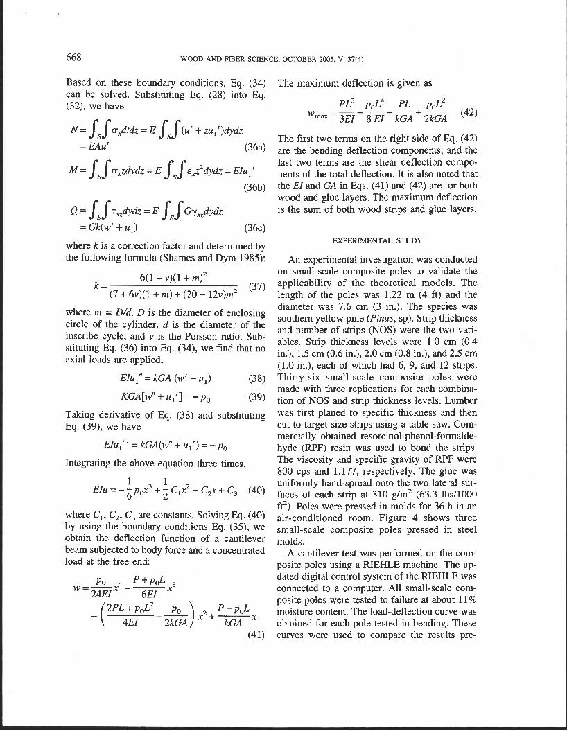
Based on these boundary conditions, Eq. (34) can be solved. Substituting Eq. (28) into Eq. (32), we have
where k is a correction factor and determined by the following formula (Shames and Dym 1985):
where m = D/d. D is the diameter of enclosing circle of the cylinder, d is the diameter of the inscribe cycle, and v is the Poisson ratio. Sub- stituting Eq. (36) into Eq. (34), we find that no axial loads are applied,
EIull' = kGA (w' + u,) (38)
Taking derivative of Eq. (38) and substituting Eq. (39), we have
Integrating the above equation three times,
1 1 EZu = - -pG3 + - c,2 + C2x + C3 (40) 6 2
where C,, C,, C, are constants. Solving Eq. (40) by using the boundary conditions Eq. (35), we obtain the deflection function of a cantilever beam subjected to body force and a concentrated load at the free end:
The maximum deflection is given as
The first two terms on the right side of Eq. (42) are the bending deflection components, and the last two terms are the shear deflection compo- nents of the total deflection. It is also noted that the EZ and GA in Eqs. (41) and (42) are for both wood and glue layers. The maximum deflection is the sum of both wood strips and glue layers.
EXPERIMENTAL STUDY
An experimental investigation was conducted on small-scale composite poles to validate the applicability of the theoretical models. The length of the poles was 1.22 m (4 ft) and the diameter was 7.6 cm (3 in.). The species was southern yellow pine (Pinus, sp). Strip thickness and number of strips (NOS) were the two vari- ables. Strip thickness levels were 1.0 cm (0.4 in.), 1.5 cm (0.6 in.), 2.0 cm (0.8 in.), and 2.5 cm (1.0 in.), each of which had 6, 9, and 12 strips. Thirty-six small-scale composite poles were made with three replications for each combina- tion of NOS and strip thickness levels. Lumber was first planed to specific thickness and then cut to target size strips using a table saw. Com- mercially obtained resorcinol-phenol-formalde- hyde (RPF) resin was used to bond the strips. The viscosity and specific gravity of RPF were 800 cps and 1.177, respectively. The glue was uniformly hand-spread onto the two lateral sur- faces of each strip at 310 g/m2 (63.3 lbs/1000 ft2). Poles were pressed in molds for 36 h in an air-conditioned room. Figure 4 shows three small-scale composite poles pressed in steel molds.
A cantilever test was performed on the com- posite poles using a RIEHLE machine. The up- dated digital control system of the RIEHLE was connected to a computer. All small-scale com- posite poles were tested to failure at about 11 % moisture content. The load-deflection curve was obtained for each pole tested in bending. These curves were used to compare the results pre-

Piao et a1.-MODELING AND ANALYSES OF LAMINATED WOOD COMPOSITE POLES 669
FIG. 4. Small-scale wood composite poles being pressed in steel molds.
dicted by the theoretical models in a specific load range. In the theoretical study, the Young's modulus obtained in the experiment of each pole was used to predict the deformation of the pole. Figure 5 shows a small-scale composite pole be- ing tested in the RIEHLE machine.
RESULTS
Results of theoretical study
The maximum experimental deflections under different loads are compared with those pre- dicted by the theoretical models in Table 1. In
FIG. 5. A small-scale composite pole being tested in a RIEHLE machine.
TABLE 1. Comparison among the defection values from experiment and theoretical models of small-scale composite poles with three strip-number levels and four thickness levels.'
Ship Slrip thickness number (cm)
12 1 .o 1.5 2.0 2.5
9 1 .o 1.5 2.0 2.5
6 1 .O 1.5
Load Exp. deflection (N) (cm)
178 1.28 178 1.07 445 0.92 445 0.93 178 1.92 178 1.16 445 1.38 445 1.09 178 1.96 178 1.94
' Tabled experiment and predicted deflection, and errors are the average of three values. ' Higher-order governing differential equation model. ' Simplified beam theory madel.
this table, each experimental value was the av- erage of three test results. The results predicted by the higher-order GDE model were found to be lower than those predicted by the simplified model. The experimental values were higher than those predicted by the theoretical models.
Table 2 presents the calculated maximum bending stress values based on the elementary mechanics theory and from the higher-order GDE model. Stress values calculated agreed well with those predicted by the models.
The deflections of small-scale composite poles predicted by the higher-order GDE model for different strips and thickness levels are shown in Fig. 6. Figure 6 indicates that the de- flection decreased with the increase of strip thickness.
Comparisons were made between results pre- dicted by the higher-order GDE model and the simplified model. Figure 7 shows the results. The values predicted by the two theoretical pro- cedures were very close.
Shear effects on the deflection of small-scale poles were calculated by the simplified beam model and are shown in Fig. 8. Both strip thick- ness and NOS influence the shear deflection. Shear effects increased with the decrease of strip thickness and with the increase of NOS. Deflec-

670 WOOD AND FIBER SCIENCE, OCTOBER 2005, V. 37(4)
TABLE 2. Comparison between the maximum bending stress values calculated by experimental data and predicted by the higher-order governing dgerential equation model of small-scale composite poles.
Ship thickness (cm) 1 .o 1.5 2.0 2.5
Sample number 1 2 3 1 2 3 1 2 3 1 2 3
6-strip poles Theoretical 58.71 59.84 58.35 63.61 59.14 74.99 86.16 75.35 70.88 92.05 93.40 93.76 (MPa)
Experimental 60.40 60.79 58.61 61.42 59.72 70.33 85.34 76.26 70.16 92.03 94.70 93.47 (MPa)
9-strip poles Theoretical 48.35 46.73 44.72 64.60 65.69 63.78 69.14 71.62 69.74 86.56 84.86 93.26 (MPa)
Experimental 48.24 46.13 44.91 65.49 67.26 66.49 70.22 67.72 68.57 87.95 84.50 95.37 (MPa)
12-strip poles Theoretical 44.10 33.30 44.30 55.45 44.05 52.09 84.91 75.82 72.93 92.91 69.57 89.78 (MPa)
Experimental 43.00 32.44 43.57 53.78 43.39 49.62 81.53 73.21 69.93 90.62 66.86 85.62 (MPa)
tion due to shear accounted for only 0.8 to 1.9% of the total deflection for the pole tested.
Glue-layer effects on the deflection of com- posite poles were analyzed by the higher-order GDE model. In the analysis, thickness of the glue layer was set at 0.10 mm (0.004 in.), and Young's modulus and modulus of rigidity of cured resorcinol-phenol-formaldehyde resin were approximated as 38.6 and 2.1 TPa (5.6 and 0.31 Mpsi). The first and second moments, and normal and shear energies of glue lines, were calculated and included in the models. For the
small-scale poles, deflection attributed to the glue layers was from 2.3 to 5.5% of the total. No regular patterns were found on the effects of strip thickness and number. These results show that glue-layer effects cannot be neglected. The strong correlation is attributable to the modulus of elasticity (MOE) of the adhesive. Since the MOE value of resorcinol-phenol-formaldehyde is higher than that of southern yellow pine, the glue lines in the poles essentially serve as rein- forcing for the poles. This shows that the wood composite poles may benefit from being rein- forced by thin layers of a high strength material in the pole structure.
FIG. 6. Deflection of 12-sided small-scale composite FIG. 7. Comparison of deflection of 12-sided small- poles predicted by a higher-order governing differential scale composite poles predicted by a higher-order governing equation model. differential equation model and a simplified beam model.

Piao et a1.-MODELING AND ANALYSES OF LAMINATED WOOD COMPOSl'IE POLES 67 1
are predicted to have a higher deflection than those with thicker shells for a given load.
SUMMARY AND CONCLUSIONS
FIG. 8. Effects of strip thickness and number of strips on the shear deflection of small-scale composite poles.
Remarks on theoretical analysis procedures
A higher-order GDE model developed re- quires no correction factors that are required by the simplified theory and Timoshenko beam theory. Results of this study show that both the higher-order GDE model and simplified model agreed well with the experimental results.
Results also show that the simplified model was more accurate in predicting the deflection of small-scale composite poles than the higher- order GDE model. As shown in Eq. (36), the correction factor in the simplified model was approximated by a circular thick-shell cross- section. In practice, the calculation of the cor- rection factor was not an easy task, especially when pole cross-section varies along the length, as in the case of a tapered pole. There was no such difficulty when using the higher-order GDE model. Since the dimension of the cross- section changes, k, and k, in Eq. (16) are no longer constants and can be calculated by inte- gration. Thus, the higher-order GDE model has a wider application since variations in the cross- sections can be accounted for. Development of simplified theoretical models for tapered com- posite poles will be a good follow-up study.
The predicted deflection patterns for the small-scale composite poles are shown in Fig. 6. As expected, poles with thinner shell thickness
A theoretical model was developed for wood laminated composite poles based on the prin- ciple of minimum potential energy. In addition to the transverse shear effects, the uniform grav- ity load and glue-line effects were included in the model. A simplified beam theory was also derived using the variational method and utilized to further validate the higher-order GDE model. These models and analyses will enable future investigation of composite poles with tapered forms and joined strips.
The theoretical model was developed based on Bernoulli-Euler theory and Timoshenko shear stress distribution theory. The governing equations were derived and solved, and the de- formation function was obtained. The method provides solutions for the cantilever beam with a uniform load andlor concentrated load at the free end. Small-scale composite poles were fabri- cated and tested to validate the theoretical mod- els. Strip thickness and number of strips (NOS) were chosen as experimental variables. The ex- perimental results agreed very well with both theoretical models. The higher-order GDE model, though less accurate than the simplified model in this study, was found to be clearly more suitable for analyzing complex pole geom- etries.
Based on the results of this study, the follow- ing conclusions are made:
1. A higher-order governing differential equa- tion model was developed and verified by the experimental results. The correlation of the higher-order governing differential equation model with the experimental results was good.
2. The higher-order governing differential equa- tion model correlated well with the simplified beam model. However, the simplified model was more accurate than the higher-order GDE model in predicting the deflection of small-scale composite poles.
672 WOOD AND FIBER SCIENCE, OCTOBER 2005, V. 37(4)
3. The higher-order GDE model was more suit- KANT, T., AND A. GUPTA. 1988. A finite element model for -
able for analyzing complex pole geometries. a higher-order shear-deformable beam theory. J. Sound Vibr. 125(2): 193-202.
4' the layers KATHNEW, A. N. 1996. Improved engineering theory for counted for about 4% of the total deflection beams. Acts Mech. 14:225-229. of the composite poles. RANKINE, W. J. M. 1895. Applied mechanics. 15" ed. Grif-
5. Shear deflection accounted for 1 to 2% of fin and Co., London, England. total deflection. REHFIELD, L. w., AND P. L. N. MURTHY. 1982. Toward a new
6 . ~ ~ ~ i ~ ~ ~ ~ d poles may be rein- engineering theory of bending: fundamentals. AIAA Journal 20(5):693 -699.
forced by inrrOducing a thin layer of a high SHAM=, I. H.. AND C. L. DYM. 1985. Energy and finite strength material in the pole structure. element methods in structural mechanics. Hemisphere
REFERENCES
BIBLIS, E. J. 1965. Shear deflection of wood beams. Forest Prod. J. 15(11):492-498.
BODIG, J, AND B. A. JAYNE. 1982. Mechanics of wood and wood composites. Van Nostrand Reinhold, New York, NY. 712 pp.
GRASHOF, F. 1878. Elastizitat und Festigkent. 2nd ed. Au- flage der "Festigkeitslehre," Berlin, Germany.
Publishing Corporation, 757 pp. TIMOSHENKO, S. P. 1921. On the correction for shear of the
differential equation for transverse vibrations of prismatic bars. Philos. Mag. 41(6):744-746.
. 1976. Strength of materials. Part I, 3d ed., Robert E. Krieger Publishing Co., New York, NY.
Vn~rsem, R. R. 1990. Refined bending theory for beams of circular cross section. J. Eng. Mech. 116(9):2072-2079.
WASHIZU, K. 1968. Variational methods in elasticity and plasticity. Pergamon Press. Oxford, New York, 349 pp.