> Ø 8 63 mm > standard magnetic > saves 20% …cdn.norgren.com › pdf ›...
TRANSCRIPT

RT/57200/M, RM/57200/M, Roundline cylinder Magnetic piston, double acting
05/16en 1.5.041.01
Our policy is one of continued research and development. We therefore reserve the right to amend, without notice, the specifications given in this document. (1998 - 1204f) © 2015 Norgren GmbH
Medium:Compressed air, filtered, lubricated or non-lubricatedOperation:Double acting with buffer cushioning
Operating pressure:1 ... 10 bar (14 ... 145 psi)Cylinder diameters:8, 10, 12, 16, 20, 25, 32, 40, 50, 63 mm Strokes:See page belowNon-standard strokes:up to 500 mm max. on request
Operating temperature:+80°C max. (+176°F) Air supply must be dry enough to avoid ice formation at temperatures below +2°C (+35°F).
Materials: Piston rod: stainless steel(8 ... 16 mm bore austenitic,20 ... 63 mm bore martensitic)End covers: aluminiumBarrel: stainless steel(austenitic)Wiper: PURSeals and ‘O’-rings: NBR
Technical features
> Ø 8 ... 63 mm
> Saves 20% space over the basic length of a corresponding ISO/VDMA cylinder
> Low friction, long life seals
> High strength, double crimped end cap design
> Standard magnetic piston for full control system versatility
Standard strokes CylinderØ (mm)
Stroke length (mm)10 25 40 50 80 100 125 160 200 250 320
8 • • • • • • — — — — —
10 • • • • • • — — — — —
12 • • • • • • • • • — —
16 • • • • • • • • • — —
20 • • • • • • • • • • •
25 • • • • • • • • • • •
32 • • • • • • • • • • •
40 • • • • • • • • • • •
50 • • • • • • • • • • •
63 • • • • • • • • • • •
Technical data Cylinder Ø (mm) 8 10 12 16 20 25 32 40 50 63
Port size RT/572** (RM/572**) M3 (M3) M5 (M5) M5 (M5) M5 (M5) Rc 1/8 (M6) Rc 1/8 (M6) Rc 1/8 (G 1/8)
Rc 1/8 (G 1/8)
Rc 1/4 (G 1/4)
Rc 1/4 (G 1/4)
Piston rod Ø (mm) 3 4 4 6 8 10 12 14 16 20
Piston rod thread M3 M4 M4 M6 M8 M10 x 1,25 M10 x 1,25 M12 x 1,25 M 12 x 1,25 M 16 x 1,5
Theoretical thrusts at 6 bar outstroke (N) 30 46,8 67,8 120 188 294 482 754 1178 1870
Theoretical thrusts at 6 bar instroke (N) 25,9 39,6 60 103 158 247 414 661 1057 1680
Air consumption at 6 bar outstroke (l/cm) 0,004 0,005 0,008 0,014 0,022 0,035 0,056 0,087 0,137 0,218
Air consumption at 6 bar instroke (l/cm) 0,003 0,004 0,006 0,013 0,019 0,02 0,048 0,074 0,114 0,195
RT/57200/M, RM/57200/M, Roundline cylinder Magnetic piston, double acting
Our policy is one of continued research and development. We therefore reserve the right to amend, without notice, the specifications given in this document. (1998 - 1204f) © 2015 Norgren GmbHen 1.5.041.02
05/16
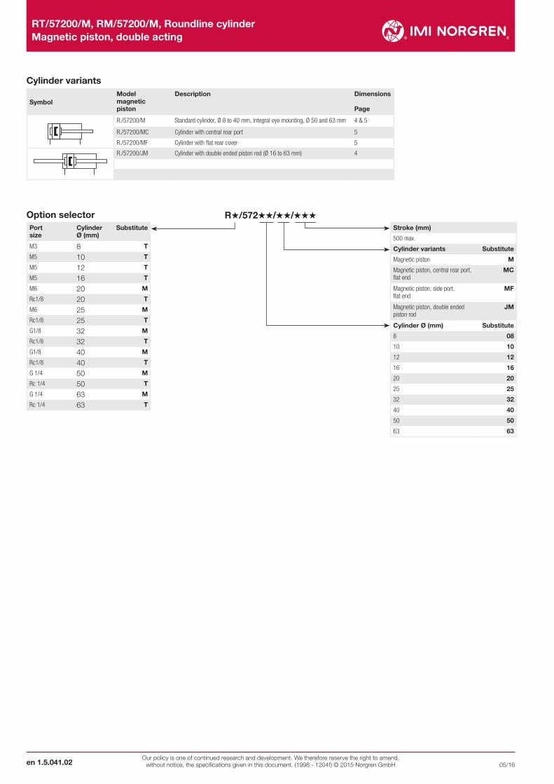
Cylinder variants
SymbolModel magneticpiston
Description Dimensions
Page
R./57200/M Standard cylinder, Ø 8 to 40 mm, integral eye mounting, Ø 50 and 63 mm 4 & 5
R./57200/MC Cylinder with central rear port 5
R./57200/MF Cylinder with flat rear cover 5
R./57200/JM Cylinder with double ended piston rod (Ø 16 to 63 mm) 4
R˙/572˙˙/˙˙/˙˙˙Option selectorPortsize
Cylinder Ø (mm)
Substitute
M3 8 T
M5 10 T
M5 12 T
M5 16 T
M6 20 M
Rc1/8 20 T
M6 25 M
Rc1/8 25 T
G1/8 32 M
Rc1/8 32 T
G1/8 40 M
Rc1/8 40 T
G 1/4 50 M
Rc 1/4 50 T
G 1/4 63 M
Rc 1/4 63 T
Stroke (mm)
500 max.
Cylinder variants Substitute
Magnetic piston M
Magnetic piston, central rear port, flat end
MC
Magnetic piston, side port, flat end
MF
Magnetic piston, double ended piston rod
JM
Cylinder Ø (mm) Substitute
8 08
10 10
12 12
16 16
20 20
25 25
32 32
40 40
50 50
63 63
Our policy is one of continued research and development. We therefore reserve the right to amend, without notice, the specifications given in this document. (1998 - 1204f) © 2015 Norgren GmbH
RT/57200/M, RM/57200/M, Roundline cylinder Magnetic piston, double acting
en 1.5.041.0305/16
1112
3
5
15
147
9
811
1
1
3
3
6
7 14
9
8
Cyl.
Ø
AK
1 2 3 4 5 6 7 8 9 10
11 12 13 14 15 16 17 18 19 20
20
30
21 22 23 24 25 26 27 28 29
31 32 33 34 35 36 37 38 39
Page 6
C
1 2 3 4 5 6 7 8 9 10
11 12 13 14 15 16 17 18 19 20
20
30
21 22 23 24 25 26 27 28 29
31 32 33 34 35 36 37 38 39
Page 6
F
1 2 3 4 5 6 7 8 9 10
11 12 13 14 15 16 17 18 19 20
20
30
21 22 23 24 25 26 27 28 29
31 32 33 34 35 36 37 38 39
Page 6
H
1 2 3 4 5 6 7 8 9 10
11 12 13 14 15 16 17 18 19 20
20
30
21 22 23 24 25 26 27 28 29
31 32 33 34 35 36 37 38 39
Page 6
L
1 2 3 4 5 6 7 8 9 10
11 12 13 14 15 16 17 18 19 20
20
30
21 22 23 24 25 26 27 28 29
31 32 33 34 35 36 37 38 39
Page 6
N
1 2 3 4 5 6 7 8 9 10
11 12 13 14 15 16 17 18 19 20
20
30
21 22 23 24 25 26 27 28 29
31 32 33 34 35 36 37 38 39
Page 7
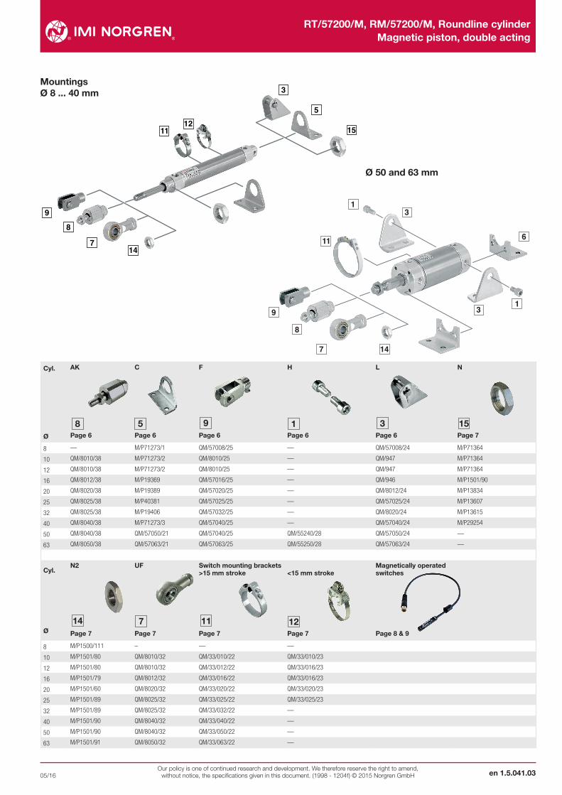
8 — M/P71273/1 QM/57008/25 — QM/57008/24 M/P71364
10 QM/8010/38 M/P71273/2 QM/8010/25 — QM/947 M/P71364
12 QM/8010/38 M/P71273/2 QM/8010/25 — QM/947 M/P71364
16 QM/8012/38 M/P19369 QM/57016/25 — QM/946 M/P1501/90
20 QM/8020/38 M/P19389 QM/57020/25 — QM/8012/24 M/P13834
25 QM/8025/38 M/P40381 QM/57025/25 — QM/57025/24 M/P13607
32 QM/8025/38 M/P19406 QM/57032/25 — QM/8020/24 M/P13615
40 QM/8040/38 M/P71273/3 QM/57040/25 — QM/57040/24 M/P29254
50 QM/8040/38 QM/57050/21 QM/57040/25 QM/55240/28 QM/57050/24 —
63 QM/8050/38 QM/57063/21 QM/57063/25 QM/55250/28 QM/57063/24 —
Cyl.
Ø
N2
1 2 3 4 5 6 7 8 9 10
11 12 13 14 15 16 17 18 19 20
20
30
21 22 23 24 25 26 27 28 29
31 32 33 34 35 36 37 38 39
Page 7
UF
1 2 3 4 5 6 7 8 9 10
11 12 13 14 15 16 17 18 19 20
20
30
21 22 23 24 25 26 27 28 29
31 32 33 34 35 36 37 38 39
Page 7
Switch mounting brackets >15 mm stroke
1 2 3 4 5 6 7 8 9 10
11 12 13 14 15 16 17 18 19 20
20
30
21 22 23 24 25 26 27 28 29
31 32 33 34 35 36 37 38 39
Page 7
<15 mm stroke
1 2 3 4 5 6 7 8 9 10
11 12 13 14 15 16 17 18 19 20
20
30
21 22 23 24 25 26 27 28 29
31 32 33 34 35 36 37 38 39
Page 7
Magnetically operated switches
Page 8 & 9
8 M/P1500/111 – — —
10 M/P1501/80 QM/8010/32 QM/33/010/22 QM/33/010/23
12 M/P1501/80 QM/8010/32 QM/33/012/22 QM/33/016/23
16 M/P1501/79 QM/8012/32 QM/33/016/22 QM/33/016/23
20 M/P1501/60 QM/8020/32 QM/33/020/22 QM/33/020/23
25 M/P1501/89 QM/8025/32 QM/33/025/22 QM/33/025/23
32 M/P1501/89 QM/8025/32 QM/33/032/22 —
40 M/P1501/90 QM/8040/32 QM/33/040/22 —
50 M/P1501/90 QM/8040/32 QM/33/050/22 —
63 M/P1501/91 QM/8050/32 QM/33/063/22 —
Mountings Ø 8 ... 40 mm
Ø 50 and 63 mm

RT/57200/M, RM/57200/M, Roundline cylinder Magnetic piston, double acting
Our policy is one of continued research and development. We therefore reserve the right to amend, without notice, the specifications given in this document. (1998 - 1204f) © 2015 Norgren GmbHen 1.5.041.04
05/16
Basic dimensions
# Stroke
Dimensions in mm Projection/First angle
Ø A Ø B/Ø BA
BE BF Ø CD h9 Ø D Ø D1 RT/5... EE
RM/5... EE
EW -0,1 EW1 G G1 H KK L
8 8 10 M10 x 1 7,5 3 12 9,5 M3 M3 6 10 7,5 3 5 M3 –
10 9 10 M10 x 1 8 4 15 11,5 M5 M5 8 12,5 9,5 4,5 6,5 M4 –
12 9 10 M10 x 1 8 4 15 13 M5 M5 8 – 9,5 4,5 6,5 M4 –
16 12 12 M12 x 1,25 10 5 17,5 17,5 M5 M5 10 – 11,5 4 – M6 –
20 14 16 M16 x 1,5 12 6 22 21,5 Rc 1/8 M6 12 – 15,5 8 – M8 –
25 16 18 M18 x 1,5 12 8 26,5 26,5 Rc 1/8 M6 14 – 15,5 8 – M10 x 1,25 –
32 22 22 M22 x 1,5 15 8 33,5 33,5 Rc 1/8 G 1/8 16 – 17,5 5,5 – M10 x 1,25 12
40 23 30 M30 x 1,5 15 10 41,5 41,5 Rc 1/8 G 1/8 20 – 18 5,5 – M12 x 1,25 14
Ø LB L12 Ø MM h9 MR PL VA/VD WF XC XC1 XC2 kg at 0 mm
kg per 25 mm
Model
8 4,5 – 3 3 4 – 1,5 8,5 48 39 43,5 0,02 0,02 RT/57208/M/*
10 5 – 4 4 5,5 – 1,5 10 54 44 49 0,02 0,03 RT/57210/M/*
12 5 – 4 4 5,5 – 1,5 10 54 44 49 0,02 0,03 RT/57212/M/*
16 7 5 6 5 5,5 5 2 13,5 64,5 50 57,5 0,04 0,05 RT/57216/M/*
20 7 5 8 6 9 7 3 15,5 75,5 61 68,5 0,08 0,07 R./57220/M/*
25 9 5 10 8 9 9 3 16,5 78,5 62 69,5 0,12 0,11 R./57225/M/*
32 7 5 12 8 9 10 3 23 93 74 86 0,21 0,16 R./57232/M/*
40 5 6 14 10 10 12 3 24 96 78,5 91 0,33 0,20 R./57240/M/*
* Please insert standard stroke length.
Ø 8 ... 12 mm - RT/572../M RT/572../MC
Ø 16 ... 40 mm - R./572../M R./572../MC
RT/572../MF
RT/572../MF
EW - 0,1
BE
KK
A
WF
BF G
PL EE EE PL
G
ø B
- 0,
1
ø B
A -
0,1
MR
CD
h9
BE
XC + #
EE
G 1
XC 1 + # XC 2 + #
EE
PL
G
ø M
M h
9
VD
VA
ø D
1
EW 1
H
D
LB
EE
PL
EE
XC 1 + # XC 2 + #
G 1 G
XC + #
WF
BF
VD
PL
G
EEA
BE
ø M
M h
9
KK
D
EW- 0,1
ø B
- 0
,1
ø B
A -
0,1 C
D h9
BE
G
PL
EE L MR
L 12
VA
ø D
1LB

Our policy is one of continued research and development. We therefore reserve the right to amend, without notice, the specifications given in this document. (1998 - 1204f) © 2015 Norgren GmbH
RT/57200/M, RM/57200/M, Roundline cylinder Magnetic piston, double acting
en 1.5.041.0505/16
Dimensions in mm Projection/First angle
# Stroke
Ø 50 and 63 mm - R./57200/M
Ø A Ø B/BA -0,1 BG BG 1 Ø D RT/57... EE
RM/57... EE
FB G KK Ø MM h9 PL
50 23 28 12 8 52,5 Rc 1/4 G 1/4 M 6 22 M 12 x 1,25 16 13
63 30 35 12 9,5 65,5 Rc 1/4 G 1/4 M 8 22 M 16 x 1,5 20 13
Ø RT RT 1 SW TG TC VA/VD WF XH XL kg at 0 mm
kg per 100 mm
Model
50 M 10 x 1 13 13 28,5 49 2 13 26 84 0,39 0,31 R./57250/M/*
63 M 12 x 1,5 15 17 35,5 62 2 13 26 86 0,89 0,44 R./57263/M/*
* Please insert standard stroke length.
ø B
- 0
,1
ø M
M h9
KK
A
EE EE
WF PL
VD
G
VA
XC + #
PL
G
FB
TC
D
BG
RT
XH
XL + #
TG
ø B
A -
0,1
ø R
T 1
BG 1
Ø 16 ... 63 mm - R./57200/JM
ZM + 2 x #
L 8 + #
ZM + 2 x #
L 8 + #
Ø L8 ZM Model
16 44 71 R./57216/JM/*
20 53 84 R./57220/JM/*
25 53 86 R./57225/JM/*
32 63 109 R./57232/JM/*
40 67 115 R./57240/JM/*
50 84 110 R./57250/JM/*
63 86 112 R./57263/JM/*
* Please insert standard stroke length.
RT/57200/M, RM/57200/M, Roundline cylinder Magnetic piston, double acting
Our policy is one of continued research and development. We therefore reserve the right to amend, without notice, the specifications given in this document. (1998 - 1204f) © 2015 Norgren GmbHen 1.5.041.06
05/16
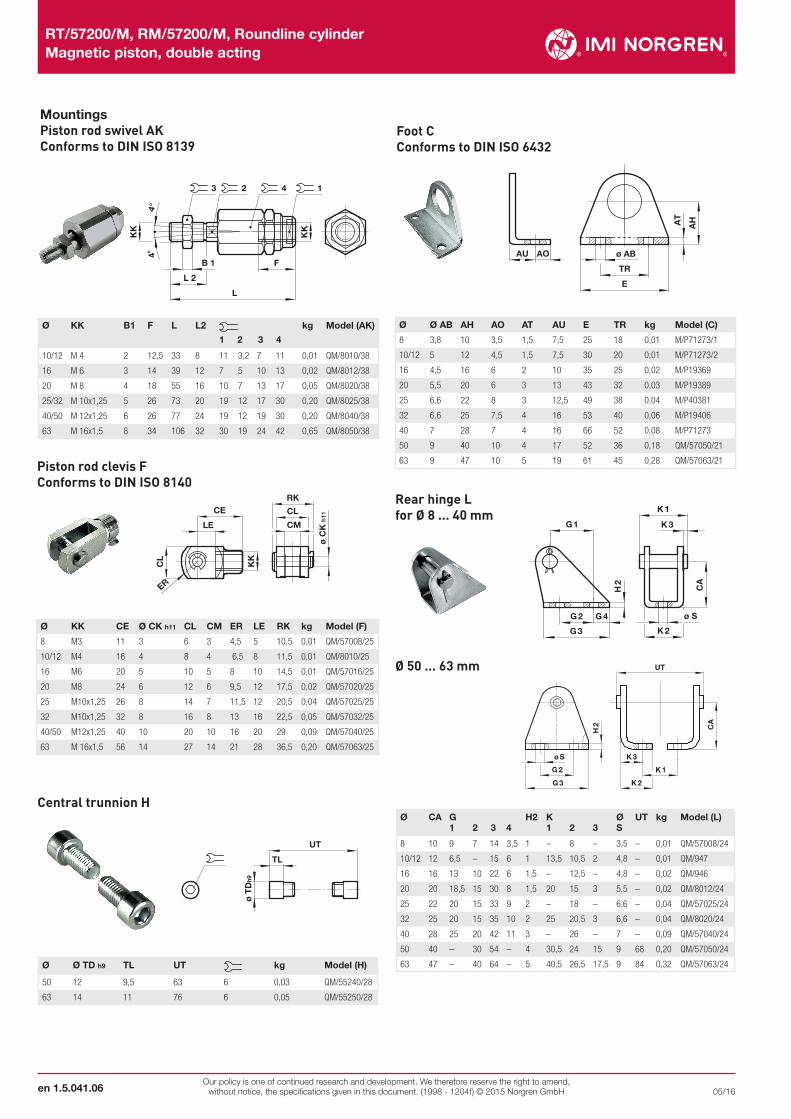
Ø Ø AB AH AO AT AU E TR kg Model (C)
8 3,8 10 3,5 1,5 7,5 25 18 0,01 M/P71273/1
10/12 5 12 4,5 1,5 7,5 30 20 0,01 M/P71273/2
16 4,5 16 6 2 10 35 25 0,02 M/P19369
20 5,5 20 6 3 13 43 32 0,03 M/P19389
25 6,6 22 8 3 12,5 49 38 0,04 M/P40381
32 6,6 25 7,5 4 16 53 40 0,06 M/P19406
40 7 28 7 4 16 66 52 0,08 M/P71273
50 9 40 10 4 17 52 36 0,18 QM/57050/21
63 9 47 10 5 19 61 45 0,28 QM/57063/21
Ø KK CE Ø CK h11 CL CM ER LE RK kg Model (F)
8 M3 11 3 6 3 4,5 5 10,5 0,01 QM/57008/25
10/12 M4 16 4 8 4 6,5 8 11,5 0,01 QM/8010/25
16 M6 20 5 10 5 8 10 14,5 0,01 QM/57016/25
20 M8 24 6 12 6 9,5 12 17,5 0,02 QM/57020/25
25 M10x1,25 26 8 14 7 11,5 12 20,5 0,04 QM/57025/25
32 M10x1,25 32 8 16 8 13 16 22,5 0,05 QM/57032/25
40/50 M12x1,25 40 10 20 10 16 20 29 0,09 QM/57040/25
63 M 16x1,5 56 14 27 14 21 28 36,5 0,20 QM/57063/25
Rear hinge L for Ø 8 ... 40 mm
Ø 50 ... 63 mm
Central trunnion H
ø S
G 2
G 3
K 3
K 2
K 1
CA
H 2
UT
Mountings Piston rod swivel AK Conforms to DIN ISO 8139
B 1
L 2
L
F
KK
4°4°
KK
3 2 4 1
Foot C Conforms to DIN ISO 6432
AO ø AB
TR
E
AU
AT
AH
Piston rod clevis F Conforms to DIN ISO 8140
CE
LE
CL
ER
KK
ø C
K h
11
RK
CL
CM
CA
ø S
K 2
K 3
K 1
G 1
G 2 G 4
G 3
H 2
UT
TL
ø T
Dh9
Ø KK B1 F L L2 1 2 3 4
kg Model (AK)
10/12 M 4 2 12,5 33 8 11 3,2 7 11 0,01 QM/8010/38
16 M 6 3 14 39 12 7 5 10 13 0,02 QM/8012/38
20 M 8 4 18 55 16 10 7 13 17 0,05 QM/8020/38
25/32 M 10x1,25 5 26 73 20 19 12 17 30 0,20 QM/8025/38
40/50 M 12x1,25 6 26 77 24 19 12 19 30 0,20 QM/8040/38
63 M 16x1,5 8 34 106 32 30 19 24 42 0,65 QM/8050/38
Ø CA G 1 2 3 4
H2 K 1 2 3
Ø S
UT kg Model (L)
8 10 9 7 14 3,5 1 – 8 – 3,5 – 0,01 QM/57008/24
10/12 12 6,5 – 15 6 1 13,5 10,5 2 4,8 – 0,01 QM/947
16 16 13 10 22 6 1,5 – 12,5 – 4,8 – 0,02 QM/946
20 20 18,5 15 30 8 1,5 20 15 3 5,5 – 0,02 QM/8012/24
25 22 20 15 33 9 2 – 18 – 6,6 – 0,04 QM/57025/24
32 25 20 15 35 10 2 25 20,5 3 6,6 – 0,04 QM/8020/24
40 28 25 20 42 11 3 – 26 – 7 – 0,09 QM/57040/24
50 40 – 30 54 – 4 30,5 24 15 9 68 0,20 QM/57050/24
63 47 – 40 64 – 5 40,5 26,5 17,5 9 84 0,32 QM/57063/24Ø Ø TD h9 TL UT kg Model (H)
50 12 9,5 63 6 0,03 QM/55240/28
63 14 11 76 6 0,05 QM/55250/28

Our policy is one of continued research and development. We therefore reserve the right to amend, without notice, the specifications given in this document. (1998 - 1204f) © 2015 Norgren GmbH
RT/57200/M, RM/57200/M, Roundline cylinder Magnetic piston, double acting
en 1.5.041.0705/16
Ø BE KW kg Model (N)
8...12 M10x1 14 4 0,01 M/P71364
16 M12x1,25 19 6 0,01 M/P1501/90
20 M16x1,5 22 5 0,01 M/P13834
25 M18x1,5 24 5 0,01 M/P13607
32 M22x1,5 27 8 0,02 M/P13615
40 M30x1,5 36 8 0,03 M/P29254
Locknut N2
Ø BE KW kg Model (N)
8 M3 6 2 0,01 M/P1500/111
10/12 M4 7 2 0,01 M/P1501/80
16 M6 10 3 0,01 M/P1501/79
20 M8 13 4 0,01 M/P1501/60
25/32 M10x1,25 17 5 0,01 M/P1501/89
40/50 M12x1,25 19 6 0,01 M/P1501/90
63 M16x1,5 24 8 0,02 M/P1501/91
Ø KK AX CE Ø CN H7 EN -0,1 ER LE Z kg Model (UF)
10/12 M4 14 27 5 8 8 10 5˚ 0,02 QM/8010/32
16 M6 14 30 6 9 9 11 5˚ 0,02 QM/8012/32
20 M8 16 36 8 12 11 13 5˚ 0,05 QM/8020/32
25/32 M10x1,25 25 42 10 14 14 15 13˚ 0,08 QM/8025/32
40/50 M12x1,25 22 50 12 16 16 17 13° 0,12 QM/8040/32
63 M16x1,5 28 64 16 21 21 22 15° 0,33 QM/8050/32
Universal piston rod eye UF Conforms to DIN ISO 8139
EN h12
EP
ZZ
CE
CN H 7
LE AXER
KK
Nose nut N
BEKW BEKW
Ø B R max. kg Model
10 8 16 0,01 QM/33/010/22
12 8 18 0,01 QM/33/012/22
16 10 20 0,01 QM/33/016/22
20 10 22 0,01 QM/33/020/22
25 10 24 0,01 QM/33/025/22
32 10 29 0,01 QM/33/032/22
40 10 32 0,01 QM/33/040/22
50 10 38 0,01 QM/33/050/22
63 10 46 0,01 QM/33/063/22
Switch mounting brackets - Brackets > 15 mm stroke Switch mounting brackets - Brackets < 15 mm stroke
Ø S T kg Model
10 27,5 19,5 0,01 QM/33/010/23
12 28,5 21,5 0,01 QM/33/016/23
16 29,5 23,5 0,01 QM/33/016/23
20 29,5 26 0,01 QM/33/020/23
25 31,5 28,5 0,01 QM/33/025/23
1 Magnetically operated switch2 Switch mounting bracket
1 Magnetically operated switch2 Switch mounting bracket
R max.
B 1
2
10
T
S
1
2

RT/57200/M, RM/57200/M, Roundline cylinder Magnetic piston, double acting
Our policy is one of continued research and development. We therefore reserve the right to amend, without notice, the specifications given in this document. (1998 - 1204f) © 2015 Norgren GmbHen 1.5.041.08
05/16
1 Fixing screw 2 + BN = brown; - BU = blue (output) 3 - BK = black; + BN = brown; - ≠BU = blue4 Plug M8 x 1, color code: BK = black; BN = brown; BU = blue
Technical data - Reed switches - additional informations see data sheet N/en 4.3.005 Symbol Voltage
(V a.c.) (V d.c.)
Current maximum (mA)
Function Operatingtemperature(°C)
LED Protection class
Plug Cable length(m)
Cabletype
Weight
(g)
Model
BU
BN~+
~
10 ... 240 10 ... 170 180 Closer -25 ... +80 • IP66 — 2, 5 or 10 PVC 2 x 0,25 37 M/50/LSU/*V
10 ... 240 10 ... 170 180 Closer -25 ... +80 • IP66 — 5 PUR 2 x 0,25 37 M/50/LSU/5U
BU BN
10 ... 240 10 ... 170 180 Closer -25 ... +150 — IP66 — 2 Silicon 2 x 0,25 37 TM/50/RAU/2S
BU BN
BK 10 ... 240 10 ... 170 180 Changeover -25 ... +80 — IP66 — 5 PVC 3 x 0,25 37 M/50/RAC/5V
BK
BN+1
4 ~
~10 ... 60 10 ... 60 180 Closer -25 ... +80 • IP66 M8 x 1 0,3 PVC 3 x 0,25 16 M/50/LSU/CP *1)
* Insert cable length; *1) Plug-in connector see page 11; Color code: BK = black, BN = brown, BU = blue
M/50/LSU/*V, M/50/LSU/5U, TM/50/RAU/2SCable length L = 2, 5 or 10 m
Drawings
M/50/RAC/5V Cable length L = 5 m
M/50/LSU/CP
5,1
ø 6
,4
30
300 ±15
1 BN 3 BU
4 BK
X
A
X
B
A-B31,5 ... 361
41,5
5,1
ø 6
,4
A
B
A-B50 +10L
30
+30
1
1,53
5,1
ø 6
,4
A
B
A-B
50 +10
L
30
+30
1
1,52
Dimensions in mm Projection/First angle
Ø B R max. kg Model
10 8 16 0,01 QM/33/010/22
12 8 18 0,01 QM/33/012/22
16 10 20 0,01 QM/33/016/22
20 10 22 0,01 QM/33/020/22
25 10 24 0,01 QM/33/025/22
Switch mounting brackets - Brackets > 15 mm stroke Switch mounting brackets - Brackets < 15 mm stroke
Ø S T kg Model
10 27,5 19,5 0,01 QM/33/010/23
12 28,5 21,5 0,01 QM/33/016/23
16 29,5 23,5 0,01 QM/33/016/23
20 29,5 26 0,01 QM/33/020/23
25 31,5 28,5 0,01 QM/33/025/23
1 Magnetically operated switch2 Switch mounting bracket
1 Magnetically operated switch2 Switch mounting bracket
R max.
B 1
2
10
T
S
1
2

Our policy is one of continued research and development. We therefore reserve the right to amend, without notice, the specifications given in this document. (1998 - 1204f) © 2015 Norgren GmbH
RT/57200/M, RM/57200/M, Roundline cylinder Magnetic piston, double acting
en 1.5.041.0905/16
Technical data - Solid state - additional informations see data sheet N/en 4.3.007 Symbol Voltage
(V d.c.)
Current maximum(mA)
Function Operatingtemperature(°C)
LED Protection class
Plug Cable length
(m)
Cabletype
Weight
(g)
Model
BN BU
BK
+ pnp A
10 ... 30 150 PNP -40 ... +80 • IP67 — 2, 5 or 10 PVC 3 x 0,12 37 M/50/EAP/*V
10 ... 30 150 PNP -40 ... +80 • IP68 — 5 PUR 3 x 0,14 37 M/50/EAP/5U
pnp
BN BU
BK
+ 13
4A
10 ... 30 150 PNP -40 ... +80 • IP67 M8 x 1 0,3 PVC 3 x 0,14 16 M/50/EAP/CP *1)
10 ... 30 150 PNP -40 ... +80 • IP67 M12 x 1 0,3 PVC 3 x 0,14 16 M/50/EAP/CC *1)
BU BN
BK
+ npn A
10 ... 30 150 NPN -40 ... +80 • IP67 — 2, 5 or 10 PVC 3 x 0,12 37 M/50/EAN/*V
npn
BU BN
BK
+ 31
4A
10 ... 30 150 Closer -40 ... +80 • IP67 M8 x 1 0,3 PVC 3 x 0,14 16 M/50/EAN/CP *1)
* Insert cable length; *1) Plug-in connector below; Color code: BK = black, BN = brown, BU = blue
M/50/EAP/CP, M/50/EAN/CP
M/50/EAP/CC
DrawingsM/50/EAP/*V, M/50/EAN/*V Cable length L = 2, 5 or 10 m
5,1
ø 6
,4
A
B
A-B42 ±4L
30
+30
1
1,52
5,1
ø 6
,4
30
300 ±15
1 BN 3 BU
4 BK
X
A
X
B
A-B31,5 ... 361
31,5
5,1
ø 6
,4
30 47,5
300 ±15 X
A
X
A-B1
1,54
1 BN
3 BU4 BK
1 Fixing screw2 Color code: BK = black; BN = brown; BU = blue3 Plug M8 x 1 4 Plug M12 x 1
Dimensions in mm Projection/First angle
Plug-in connector cable with nut
Outer cover Cable length (m) Weight (kg) Connector Connector
PVC 3 x 0,25 5 m 0,18 M8 x 1 M/P73001/5
PUR 3 x 0,25 5 m 0,18 M8 x 1 M/P73002/5
PUR 3 x 0,34 5 m 0,21 M12 x 1 M/P34594/5
Accessories
WarningThese products are intended for use in industrial compressed air systems only. Do not use these products where pressures and temperatures can exceed those listed under »Technical features/data«.Before using these products with fluids other than those specified, for non-industrial applications, life-support systems or other applications not within published specifications, consult IMI Precision Engineering, Norgren GmbH.Through misuse, age, or malfunction, components used in fluid power systems can fail in various modes.
The system designer is warned to consider the failure modes of all component parts used in fluid power systems and to provide adequate safeguards to prevent personal injury or damage to equipment in the event of such failure.System designers must provide a warning to end users in the system instructional manual if protection against a failure mode cannot be adequately provided.System designers and end users are cautioned to review specificwarnings found in instruction sheets packed and shipped with these products.
Diese Produkte sind ausschließlich in Druckluftsystemen zu verwenden. Sie sind dort einzusetzen, wo die unter »Technische Merkmale/-Daten« aufgeführten Werte nicht überschritten werden. Berücksichtigen Sie bitte die entsprechende Katalogseite. Vor dem Einsatz der Produkte bei nicht industriellen Anwendungen, in lebenser-
Anleitungsunterlagen enthalten sind, wenden Sie sich bitte direkt an IMI Precision Engineering, Norgren GmbH.Durch Missbrauch, Verschleiß oder Störungen können in Pneumatik-
systemen verwendete Komponenten auf verschiedene Arten versagen.Systemauslegern wird dringend empfohlen, die Störungsarten aller in Pneumatiksystemen verwendeten Komponententeile zu berück-
Verletzungen von Personen sowie Beschädigungen der Geräte im Falle einer solchen Störung zu verhindern. Systemausleger sind verpflichtet, Sicherheitshinweise für den End-benutzer im Betriebshandbuch zu vermerken, wenn der Störungs-schutz nicht ausreichend gewährleistet ist.