3/2,5/2and5/3spoolvalves solenoidactuatedandairpilotoperated...
TRANSCRIPT

Our policy is one of continued research and development. We therefore reserve the right to amend,without notice, the specifications given in this document.10/09 N/US 5.3.541.01
®®V50 ... V53 Series
3/2, 5/2 and 5/3 Spool valvesSolenoid actuated and air pilot operated
1/8 ... 1/2
Technical dataConnections:1/8", 1/4", 3/8", and 1/2" NPT and ISO G
Medium:Compressed air, filtered to 40 µm,lubricated or non-lubricatedOperation:Softseal spool valve, solenoid and air pilot actuatedMounting:In-line or fixed length manifoldOperating pressure:116 psi (8 bar)Flow Characteristics:Size Function l/min Cv1/8 3/2 & 5/2 480 0.481/8 5/3 270 0.271/4 3/2 & 5/2 1020 1.021/4 5/3 755 0.753/8 3/2 & 5/2 1705 1.703/8 5/3 1190 1.191/2 3/2 & 5/2 2480 2.481/2 5/3 1910 1.91Ambient & medium temperature:23°F to 140°F (-5°C to 60°C) pilot models23°F to 122°F (-5°C to 50°C) solenoid models(consult our Technical Service for use below 36°F (2°C)
MaterialsBody/sub-base: die-cast aluminum alloy or aluminum alloySoftseal spool: NBR/aluminum alloyMounting sheets/screws: steelSprings: stainless steel
High flow in-line valves
Compact and robust design
Low power energy efficient solenoids
Very high cycle life
Flexible in-line and fixed length manifoldmounting options
Ordering informationSee page 3 (solenoid actuated valves) and4 (pneumatic actuated valves)
4
5 1 3
214 1
3/2 5/2
5/3 COE5/3 APB
5/3 COP

10/09
®®
N/US 5.3.541.02
V50 ... V53 Series
Our policy is one of continued research and development. We therefore reserve the right to amend,without notice, the specifications given in this document.
Electrical details for V50solenoid operators
Electrical details for V51 to V53solenoid operators
Voltage tolerances +/- 10%Rating 100 % Continuous dutyInlet orifice 0.8 mmMaterials PPS (body, FKM and NBR (seal)Insulation class F classConnector type DIN 43650 Table “C”Protection class IP65 (with sealed plugs)
Solenoid actuated valves
V50P413AA2* 3/2 NC Solenoid Internal 29 to 116 0.48 Push & turn 0.26 1
V51R417AA2* 3/2 NC Solenoid/spring Internal 29 to 116 1.02 Push & turn 0.45 2V52S417AA2* 3/2 NC Solenoid/spring Internal 29 to 116 1.70 Push & turn 0.77 2V53T417AA2* 3/2 NC Solenoid/spring Internal 29 to 116 2.48 Push & turn 0.79 2V50P411AA2* 3/2 Solenoid/solenoid Internal 29 to 116 0.48 Push & turn 0.38 3V51R411AA2* 3/2 Solenoid/solenoid Internal 29 to 116 1.02 Push & turn 0.65 4V52S411AA2* 3/2 Solenoid/solenoid Internal 29 to 116 1.70 Push & turn 0.97 4V53T411AA2* 3/2 Solenoid/solenoid Internal 29 to 116 2.48 Push & turn 0.96 4V50P513AA2* 5/2 Solenoid/air Internal 29 to 116 0.48 Push & turn 0.27 5
V51R517AA2* 5/2 Solenoid/spring Internal 29 to 116 1.02 Push & turn 0.41 6.V52S517AA2* 5/2 Solenoid/spring Internal 29 to 116 170 Push & turn 0.65 6V53T517AA2* 5/2 Solenoid/spring Internal 29 to 116 2.48 Push & turn 0.67 6V50P511AA2* 5/2 Solenoid/solenoid Internal 29 to 116 0.48 Push & turn 0.39 7V51R511AA2* 5/2 Solenoid/solenoid Internal 29 to 116 1.02 Push & turn 0.64 8V52S511AA2* 5/2 Solenoid/solenoid Internal 29 to 116 1.70 Push & turn 1.0 8V53T511AA2* 5/2 Solenoid/solenoid Internal 29 to 116 2.48 Push & turn 0.42 8V50P611AA2* 5/3 APB Solenoid/solenoid Internal 44 to 116 0.27 Push & turn 0.75 9V51R611AA2* 5/3 APB Solenoid/solenoid Internal 44 to 116 0.75 Push & turn 0.85 10V52S611AA2* 5/3 APB Solenoid/solenoid Internal 44 to 116 1.19 Push & turn 1.25 11V53T611AA2* 5/3 APB Solenoid/solenoid Internal 44 to 116 1.91 Push & turn 1.40 11V50P711AA2* 5/3 COE Solenoid/solenoid Internal 44 to 116 0.27 Push & turn 0.75 9V51R711AA2* 5/3 COE Solenoid/solenoid Internal 44 to 116 0.75 Push & turn 0.85 10V52S711AA2* 5/3 COE Solenoid/solenoid Internal 44 to 116 1.19 Push & turn 1.25 11V53T711AA2* 5/3 COE Solenoid/solenoid Internal 44 to 116 1.91 Push & turn 1.40 11V50P811AA2* 5/3 COP Solenoid/solenoid Internal 44 to 116 0.27 Push & turn 0.75 9V51R811AA2* 5/3 COP Solenoid/solenoid Internal 44 to 116 0.75 Push & turn 0.85 10V52S811AA2* 5/3 COP Solenoid/solenoid Internal 44 to 116 1.19 Push & turn 1.25 11V53T811AA2* 5/3 COP Solenoid/solenoid Internal 44 to 116 1.91 Push & turn 1.40 11
ModelSymbol Function Actuation Pilot supply Operatingpressure(psi)
Flow(Cv)
DrawingNo.
Manualoverride
Weight(lb)
* Insert coil code from below tablesAPB = All Ports Blocked, COE = Center Open Exhaust, COP = Center Open Pressure.
2
13
12 10
24
15 3
14 12
2
13
12 10
24
15 3
14 12
Voltage tolerances +/- 10%Rating 100 % Continuous dutyInlet orifice 0.8 mmMaterials PPS (body), FKM and NBR (seal)Insulation class F classConnector type 22 mm industrial standardProtection class IP65 (with sealed plugs)
2
13
12 10
24
15 3
14 12
4 2
15 3
14 12
4 2
15 3
14 12
1 2
15 3
14 12
Voltage codes and spare solenoid kitsPower Solenoid Kit
Voltage Code Inrush/hold Model12 V d.c. 12A 2.5 W V12958-A1224 V d.c. 13A 2.5 W V12958-A13110/120 V a.c. 50/60 Hz 18A 3.7/3.1 VA V12958-A18
Voltage codes and spare solenoid kits
Power Solenoid KitVoltage Code Inrush/hold Model12 V d.c. 12J 2.0 W 54469-0124 V d.c. 13J 2.0 W 54469-02110/120 V a.c. 50/60 Hz 18J 4.0/2.5 VA 54469-03
V50 series only V51 ... V53 series

10/09
®®
N/US 5.3.541.03
V50 ... V53 Series
Our policy is one of continued research and development. We therefore reserve the right to amend,without notice, the specifications given in this document.
Solenoid Valve Options selectorV5˙˙˙1˙A A2˙˙˙ ˙
Voltage (V50 valve series) Substitute12 V d.c 2.5 W 12A24 V d.c 2.5 W 13A110/120 V a.c (50/60 Hz) 3.7/3.2 VA 18A
Voltage (V51 ... V53 valve series) Substitute12 V d.c 2.0 W 12J24 V d.c 2.0 W 13J110/120 V a.c (50/60 Hz) 4.0/2.5 VA 18J
Actuation SubstituteSolenoid/Air spring* 3Solenoid/Spring 7Solenoid/Solenoid 1
Function Substitute3/2 Normally closed 45/2 55/3 All ports blocked 65/3 Center open exhaust 75/3 Center open pressure 8
Connectors, 15 mm, DIN 43650, Form ‘C’ SubstituteNo connector A0 to 240 V a.c./d.c. w/ cable grip B0 to 240 V a.c./d.c. w/ 6 ft.molded cable C12 to 24 Vac/Vdc w/indicator light and cable grip H120 Vac/Vdc w/indicator light and cable grip J
Connectors, 22 mm industrial standard SubstituteNo connector A0 to 240 V a.c./d.c. B0 to 240 V a.c./d.c., 6 ft. [1m] molded cable C12 to 24 Vac/Vdc w/indicator light and cable grip H120 Vac/Vdc w/indicator light and cable grip J
Thread size Substitute1/8" 01/4" 13/8" 21/2" 3
Thread type Substitute1/8 NPT P1/4 NPT R3/8 NPT S1/2 NPT TG 1/8 AG 1/4 BG 3/8 CG 1/2 D
Ordering exampleTo order a 5/2 solenoid valve, 1/4 NPT ports,spring return, 24 V d.c., with DIN connector.quote: V51R517AA213JB
* V50 Series only

N/US 5.3.541.04
®®
V50 ... V53 Series
10/09 Our policy is one of continued research and development. We therefore reserve the right to amend,without notice, the specifications given in this document.
Pilot actuated valves
V50P4D3AXP0900 3/2 Air Air spring 0 to 116 22 to 116 0.48 0.13 12
V51R4D3AXP0900 3/2 Air Spring 0 to 116 22 to 116 1.02 0.27 13V52S4D7AXP0900 3/2 Air Spring 0 to 116 29 to 116 1.70 0.65 13V53T4D7AXP0900 3/2 Air Spring 0 to 116 29 to 116 2.48 0.66 13V50P4DDAXP0200 3/2 Air Air 0 to 116 22 to 116 0.48 0.16 14V51R4DDAXP0200 3/2 Air Air 0 to 116 22 to 116 1.02 0.30 15V52S4DDAXP0200 3/2 Air Air 0 to 116 29 to 116 1.70 0.71 15V53T4DDAXP0200 3/2 Air Air 0 to 116 29 to 116 2.48 0.72 15
V50P5D3AXP0900 5/2 Air Air spring 0 to 116 22 to 116 0.48 0.16 16
V51R5D7AXP0900 5/2 Air Spring 0 to 116 22 to 116 1.02 0.23 17V52S5D7AXP0900 5/2 Air Spring 0 to 116 29 to 116 1.70 0.52 17V53T5D7AXP0900 5/2 Air Spring 0 to 116 29 to 116 2.480 0.61 17V50P5DDAXP0200 5/2 Air Air 0 to 116 22 to 116 0.48 0.19 18V51R5DDAXP0200 5/2 Air Air 0 to 116 22 to 116 1.02 0.30 19V52S5DDAXP0200 5/2 Air Air 0 to 116 29 to 116 1.70 0.52 19V53T5DDAXP0200 5/2 Air Air 0 to 116 29 to 116 2.48 1.65 19V50P6DDAXP0200 5/3 Air APB Air 0 to 116 22 to 116 0.27 ??? 20V51R6DDAXP0200 5/3 Air APB Air 0 to 116 22 to 116 0.75 0.39 21V52S6DDAXP0200 5/3 Air APB Air 0 to 116 29 to 116 1.19 0.66 22V53T6DDAXP0200 5/3 Air APB Air 0 to 116 29 to 116 1.91 0.75 22V50P7DDAXP0200 5/3 Air COE Air 0 to 116 22 to 116 0.27 ??? 20V51R7DDAXP0200 5/3 Air COE Air 0 to 116 22 to 116 0.75 0.39 21V52S7DDAXP0200 5/3 Air COE Air 0 to 116 29 to 116 1.19 0.66 22V53T7DDAXP0200 5/3 Air COE Air 0 to 116 29 to 116 1.91 0.75 22V50P8DDAXP0200 5/3 Air COP Air 0 to 116 22 to 116 0.27 ??? 20V51R8DDAXP0200 5/3 Air COP Air 0 to 116 22 to 116 0.75 0.39 21V52S8DDAXP0200 5/3 Air COP Air 0 to 116 29 to 116 1.19 0.66 22V53T8DDAXP0200 5/3 Air COP Air 0 to 116 29 to 116 1.91 0.75 22
ModelSymbol Function Pilot Midposition
Return Operatingpressure(psi)
Pilotpressure(psi)
DrawingNo.
Flow(Cv)
Weight(lb)
APB = All Ports Blocked, COE = Center Open Exhaust, COP = Center Open Pressure.
2
13
12 10
2
13
12 10
24
15 3
14 12
24
15 3
14 12
4
5 1 3
214 12
Air Pilot Valve Options selectorV5˙˙˙D˙A X˙0˙00
Return SubstituteDouble air pilot 0200Single air pilot 0900
Thread size Substitute1/8" 01/4" 13/8" 21/2" 3
Thread type Substitute1/8 NPT P1/4 NPT R3/8 NPT S1/2 NPT TG 1/8 AG 1/4 BG 3/8 CG 1/2 D
Function Substitute3/2 Normally closed 45/2 55/3 All ports blocked 65/3 Center open exhaust 75/3 Center open pressure 8
Pilot SubstituteSolenoid/Air spring* 3Single air 7Double air D
Pilot port thread Substitute1/8 NPT PG 1/8 A
Ordering exampleTo order a 5/2 valve, 3/8 NPT ports, air pilot,spring returnquote: V52S5D7A-XA0900
24
15 3
14 12
4 2
15 3
14 12
4 2
15 3
14 12
2
13
12 10
* V50 Series only
N/US 5.3.541.05
®®
V50 ... V53 Series
10/09 Our policy is one of continued research and development. We therefore reserve the right to amend,without notice, the specifications given in this document.
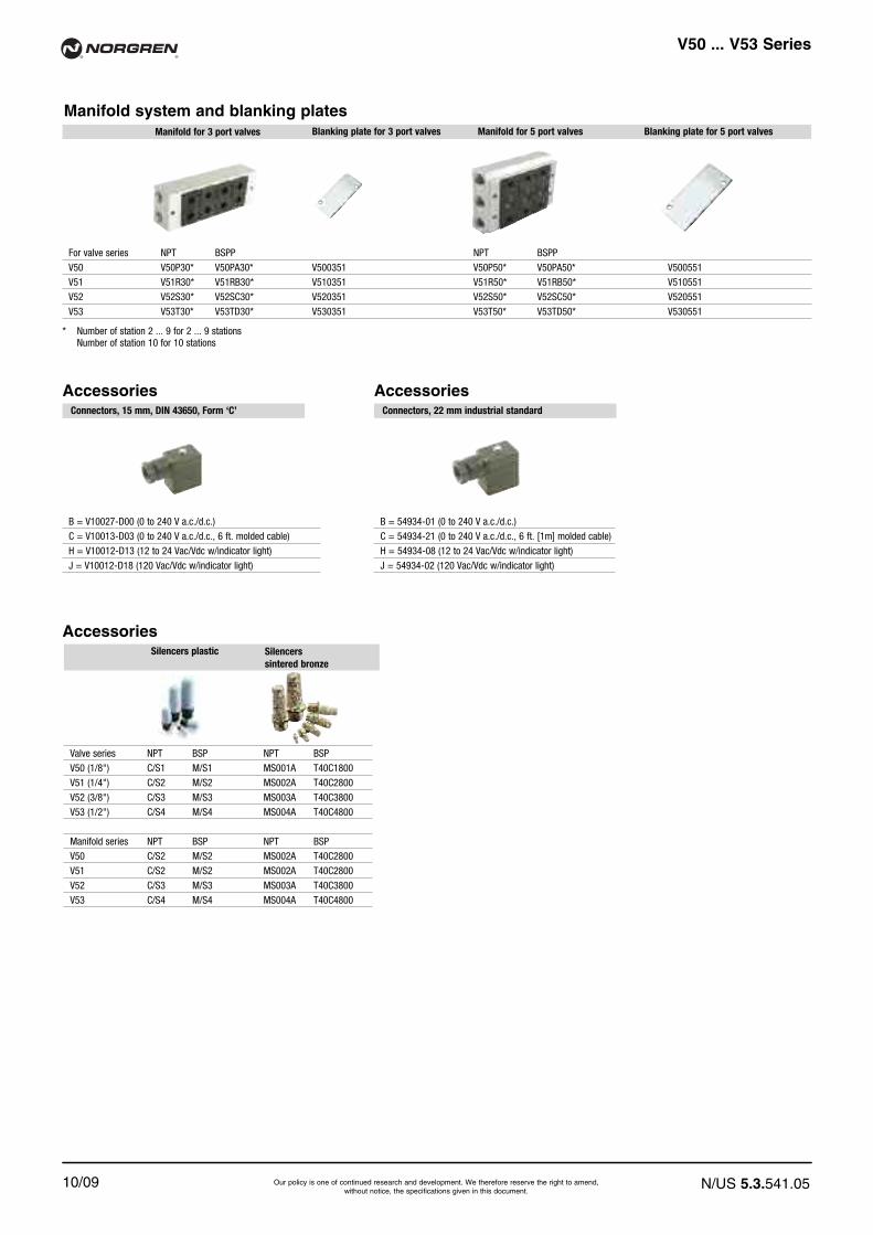
Manifold system and blanking plates
AccessoriesConnectors, 15 mm, DIN 43650, Form ‘C’
B = V10027-D00 (0 to 240 V a.c./d.c.)C = V10013-D03 (0 to 240 V a.c./d.c., 6 ft. molded cable)H = V10012-D13 (12 to 24 Vac/Vdc w/indicator light)J = V10012-D18 (120 Vac/Vdc w/indicator light)
AccessoriesConnectors, 22 mm industrial standard
B = 54934-01 (0 to 240 V a.c./d.c.)C = 54934-21 (0 to 240 V a.c./d.c., 6 ft. [1m] molded cable)H = 54934-08 (12 to 24 Vac/Vdc w/indicator light)J = 54934-02 (120 Vac/Vdc w/indicator light)
For valve series NPT BSPP NPT BSPPV50 V50P30* V50PA30* V500351 V50P50* V50PA50* V500551V51 V51R30* V51RB30* V510351 V51R50* V51RB50* V510551V52 V52S30* V52SC30* V520351 V52S50* V52SC50* V520551V53 V53T30* V53TD30* V530351 V53T50* V53TD50* V530551
Blanking plate for 3 port valves Manifold for 5 port valves Blanking plate for 5 port valvesManifold for 3 port valves
* Number of station 2 ... 9 for 2 ... 9 stationsNumber of station 10 for 10 stations
AccessoriesSilencerssintered bronze
Silencers plastic
Valve series NPT BSP NPT BSPV50 (1/8") C/S1 M/S1 MS001A T40C1800V51 (1/4") C/S2 M/S2 MS002A T40C2800V52 (3/8") C/S3 M/S3 MS003A T40C3800V53 (1/2") C/S4 M/S4 MS004A T40C4800
Manifold series NPT BSP NPT BSPV50 C/S2 M/S2 MS002A T40C2800V51 C/S2 M/S2 MS002A T40C2800V52 C/S3 M/S3 MS003A T40C3800V53 C/S4 M/S4 MS004A T40C4800

10/09
®®
N/US 5.3.541.06
V50 ... V53 Series
Our policy is one of continued research and development. We therefore reserve the right to amend,without notice, the specifications given in this document.
Dimensions in Inches
Valve dimensions
� �
3
2
1
4
Manual override(Push and Turn)
4-6 mm cable dia.
Solenoid rotates2 x 180° (V50) 4 x 90° (V51...V53)
6-8 mm cable dia.
N AD
R
APR
Q
C AB
D
P
M
B
V
A
S
T UWH
GX
F
E
2
3
1
J
L AC
N AD
R
APR
Q
C AB
D
P
J
M
L AC
V
S
T U
HI
G F
E
A
1
2
3B
W
Series Drawing A AB AC AD B C D E F G H I JV50 1 3.92 0.53 0.85 0.59 2.56 0.59 0.13 2.19 1.06 0.20 0.12 - 1/8“
V51 2 4.23 0.53 0.67 0.53 2.72 0.98 0.17 2.68 1.38 0.33 0.12 0.12 1/4“
V52 2 4.98 0.51 1.02 0.59 3.50 1.02 0.18 2.87 1.83 1.56 0.16 0.12 3/8“
V53 2 5.24 0.49 1.06 0.59 3.78 1.14 0.18 2.87 1.83 1.56 0.16 0.12 1/2“Series Drawing L M N P Q R S T U V W XV50 1 0.57 4.25 0.91 1/8" 0.13 0.24 0.04 0.51 0.71 1.16 0.63 0.02
V51 2 0.71 4.72 0.98 1/4" 0.13 0.24 0.08 0.67 0.89 1.02 0.87 -
V52 2 1.02 5.49 1.61 3/8" 0.18 0.31 - 0.91 1.18 1.61 0.87 -
V53 2 1.14 5.75 1.89 1/2" 0.17 0.31 0.10 0.91 1.18 1.59 0.87 -
3/2 Single solenoid pilot valve,1/4"... 1/2" portsMechanical spring return
3/2 Single solenoid pilot valve,1/8" portAir Spring return

Dimensions in Inches
N/US 5.3.541.07
®®
V50 ... V53 Series
10/09 Our policy is one of continued research and development. We therefore reserve the right to amend,without notice, the specifications given in this document.
NAD
APR
CAB
D
P
M
B
V
A
S
T U
H
GX
F
E
1
2
W
3
R
Q
J
LAC
W
NAD
R
Q
APR
P
M
LAC
B
A
S
T U
HI
G F
E
J
1
2
3
CAB
DV
Series Drawing A AB AC AD B C D E F G H I JV50 3 5.69 1.44 1.14 1.06 3.01 0.59 0.13 2.19 1.06 0.20 0.12 - 1/8"
V51 4 5.75 1.20 1.34 1.20 3.39 0.98 0.17 2.68 1.38 0.33 0.12 0.12 1/4"
V52 4 7.17 1.22 1.73 1.30 4.21 1.02 0.18 2.87 1.83 1.56 0.16 0.12 3/8"
V53 4 7.40 1.20 1.77 1.30 4.49 1.14 0.18 2.87 1.83 1.56 0.16 0.12 1/2"Series Drawing L M N P Q R S T U V W XV50 3 0.58 6.46 0.92 1/8" 0.13 0.24 0.04 0.52 0.72 1.42 0.64 0.02
V51 4 0.72 7.52 1.00 1/4" 0.13 0.24 0.08 0.68 0.90 1.72 0.88 -
V52 4 1.04 8.32 1.64 3/8" 0.18 0.32 - 0.92 1.20 2.38 0.88 -
V53 4 1.16 8.56 1.92 1/2" 0.17 0.32 0.10 0.92 1.20 2.34 0.88 -
� �
3/2 Double solenoid pilot valve,1/4"... 1/2" ports
3/2 Double solenoid pilot valve,1/8" port
3
2
1
4
Manual override(Push and Turn)
4-6 mm cable dia.
Solenoid rotates2 x 180° (V50) 4 x 90° (V51...V53)
6-8 mm cable dia.

10/09
®®
N/US 5.3.541.08
V50 ... V53 Series
Our policy is one of continued research and development. We therefore reserve the right to amend,without notice, the specifications given in this document.
Dimensions in Inches
� �
5/2 Single solenoid pilot valve,1/4"... 1/2" portsMechanical spring return
5/2 Single solenoid pilot valve,1/8" portAir spring return
N
B APR2 R1
C
V
D
M
B
A
S
T U
H
G
F
E
1
2
W
3
R
O
QP
J
L
K
N
Q P
J
R
ABP R1R2
O
C
D
V
K
B
A
M
S
T U
L
GH
I
F
E
2
1
3
W
Series Drawing A B C D E F G H I J K LV50 5 4.25 2.99 0.57 0.13 2.17 1.06 0.20 0.12 - 1/8" 1/8" 1.14
V51 6 4.55 3.19 0.79 0.17 2.64 1.38 0.28 0.12 0.12 1/4" 1/8" 1.42
V52 6 5.59 4.25 1.02 0.22 2.83 1.83 0.18 0.16 0.12 3/8" 3/8" 2.05
V53 6 6.18 4.72 1.14 0.18 2.87 1.83 0.28 0.16 0.12 1/2" 1/2" 2.28Series Drawing M N O P Q R S T U V WV50 5 4.72 1.34 0.63 1/8" 0.13 0.24 0.08 0.51 0.71 1.30 0.63
V51 6 5.12 1.50 0.83 1/4" 0.13 0.24 0.12 0.67 0.89 1.26 0.87
V52 6 6.14 0.51 1.18 3/8" 0.18 0.31 - 0.91 1.18 1.77 0.87
V53 6 6.69 2.83 1.10 1/2" 0.17 0.31 0.18 0.91 1.18 2.01 0.87
3
2
1
4
Manual override(Push and Turn)
4-6 mm cable dia.
Solenoid rotates2 x 180° (V50) 4 x 90° (V51...V53)
6-8 mm cable dia.
Dimensions in Inches
N/US 5.3.541.09
®®
V50 ... V53 Series
10/09 Our policy is one of continued research and development. We therefore reserve the right to amend,without notice, the specifications given in this document.
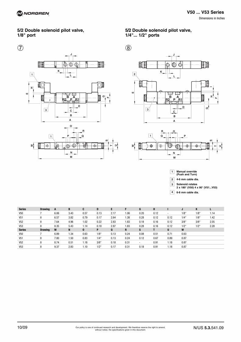
�
5/2 Double solenoid pilot valve,1/4"... 1/2" ports
5/2 Double solenoid pilot valve,1/8" port
N
B APR2 R1
C
D
M
B
A
S
T U
H
G F
E
1
1
W
3
R
O
QP
J
K
L
W
N
Q P
R
ABR1PR2
O
C
B
A
M
S
T U
L
J
G
HI
F
E
D
K2
3
1
Series Drawing A B C D E F G H I J K LV50 7 6.06 3.43 0.57 0.13 2.17 1.06 0.20 0.12 - 1/8" 1/8" 1.14
V51 8 6.57 3.82 0.79 0.17 2.64 1.38 0.28 0.12 0.12 1/4" 1/8" 1.42
V52 8 7.64 4.96 1.02 0.22 2.83 1.83 0.18 0.16 0.12 3/8" 3/8" 2.05
V53 8 8.35 5.43 1.14 0.18 2.87 1.83 0.28 0.16 0.12 1/2" 1/2" 2.28Series Drawing M N O P Q R S T U WV50 7 6.89 1.34 0.63 1/8" 0.13 0.24 0.08 0.51 0.71 0.63
V51 8 7.80 1.50 0.83 1/4" 0.13 0.24 0.12 0.67 0.89 0.87
V52 8 8.74 0.51 1.18 3/8" 0.18 0.31 - 0.91 1.18 0.87
V53 8 9.37 2.83 1.10 1/2" 0.17 0.31 0.18 0.91 1.18 0.87
3
2
1
4
Manual override(Push and Turn)
4-6 mm cable dia.
Solenoid rotates2 x 180° (V50) 4 x 90° (V51...V53)
6-8 mm cable dia.

10/09
®®
N/us 5.3.541.10
V50 ... V53 Series
Our policy is one of continued research and development. We therefore reserve the right to amend,without notice, the specifications given in this document.
Dimensions in Inches
�
5/3 Double solenoid pilot valve,1/4" ports
5/3 Double solenoid pilot valve,1/8" port
11
5/3 Double solenoid pilot valve,3/8"and 1/2" ports
B APR2 R1
C
D
V
J
L
K
B
A
H
G
F
E
2
N
R
O
QP
M
S
T U
1
W
3
N
Q P
J
R O
C
PAB
R2 R1
D
K
B
A
M
S
T U
L
V
G
HI
F
E1
2
3
W
N
Q P
J
R O
C
PAB
R2 R1
D
K
B
A
M
S
T U
L
G
HI
F
E
1
2
3
W
Series Drawing A B C D E F G H I J K LV50 9 6.42 3.78 0.57 0.13 2.17 1.06 0.20 0.12 - 1/8" 1/8" 1.14V51 10 7.40 4.69 0.79 0.17 2.64 1.38 0.28 0.12 0.12 1/4" 1/8" 1.42
V52 11 9.61 7.07 1.02 0.22 2.83 1.83 0.18 0.16 0.12 3/8" 3/8" 2.05
V53 11 10.45 7.54 1.14 0.18 2.87 1.83 0.28 0.16 0.12 1/2" 1/2" 2.28Series Drawing M N O P Q R S T U V WV50 9 7.24 1.34 0.63 1/8" 0.13 0.24 0.08 0.51 0.71 1.71 0.63
V51 10 8.62 1.50 0.83 1/4" 0.13 0.24 0.12 0.67 0.89 1.91 0.87
V52 11 10.83 0.51 1.18 3/8" 0.18 0.31 #VALUE! 0.91 1.18 - 0.87
V53 11 11.48 2.83 1.10 1/2" 0.17 0.31 0.18 0.91 1.18 - 0.87
3
2
1
4
Manual override(Push and Turn)
4-6 mm cable dia.
Solenoid rotates2 x 180° (V50) 4 x 90° (V51...V53)
6-8 mm cable dia.

Dimensions in Inches
N/us 5.3.541.11
®®
V50 ... V53 Series
10/09 Our policy is one of continued research and development. We therefore reserve the right to amend,without notice, the specifications given in this document.
12
3/2 Single air pilot valve,1/4"... 1/2" portsMechanical spring return
3/2 Single air pilot valve,1/8" portAir spring return
Series Drawing AB AC AD B C D F G H J LV50 12 0.53 0.85 0.59 2.44 0.59 0.13 1.06 0.20 0.12 1/8" 0.57
V51 13 0.53 0.67 0.53 2.58 0.98 0.17 1.38 0.33 0.12 1/4" 0.71
V52 13 0.51 1.02 0.59 3.43 1.02 0.18 1.83 1.56 0.16 3/8" 1.02
V53 13 0.49 1.06 0.59 0.16 1.14 0.18 1.83 1.56 0.16 1/2" 1.14Series Drawing N P Q R S T U V X Y ZV50 12 0.91 1/8" 0.13 0.24 0.04 0.51 0.71 1.16 0.02 1/8" 0.53
V51 13 0.98 1/4" 0.13 0.24 0.08 0.67 0.89 1.02 - 1/8" 0.69
V52 13 1.61 3/8" 0.18 0.31 - 0.91 1.18 1.61 - 1/8" 0.67
V53 13 1.89 1/2" 0.17 0.31 0.10 0.91 1.18 1.59 - 1/8" 0.79
R
APR
Q
V
C AB
D
S
T U
G
F
N AD
B
P
Y
H
Z
X
J
L AC
P
B
N AD
D
C AB
Q
V
R
S
T U
APRY
Z
G
F
H
J
L AC
13

10/09
®®
N/us 5.3.541.12
V50 ... V53 Series
Our policy is one of continued research and development. We therefore reserve the right to amend,without notice, the specifications given in this document.
Dimensions in Inches
R
APR
Q
V
C AB
D
S
T U
G
F
N AD
B
P
Y
H
Z
X
J
L AC
P
B
N AD
D
C AB
Q
V
R
S
T U
APRY
Z
G
F
H
J
L AC
Series Drawing AB AC AD B C D F G H J LV50 12 0.53 0.85 0.59 2.72 0.59 0.13 1.06 0.20 0.12 1/8" 0.57
V51 13 0.53 0.67 0.53 3.11 0.98 0.17 1.38 0.33 0.12 1/4" 0.71
V52 13 0.51 1.02 0.59 4.06 1.02 0.18 1.83 1.56 0.16 3/8" 1.02
V53 13 0.49 1.06 0.59 4.33 1.14 0.18 1.83 1.56 0.16 1/2" 1.14Series Drawing N P Q R S T U V X Y ZV50 12 0.91 1/8" 0.13 0.24 0.04 0.51 0.71 1.16 0.02 1/8" 0.53
V51 13 0.98 1/4" 0.13 0.24 0.08 0.67 0.89 1.02 - 1/8" 0.69
V52 13 1.61 3/8" 0.18 0.31 - 0.91 1.18 1.61 - 1/8" 0.67
V53 13 1.89 1/2" 0.17 0.31 0.10 0.91 1.18 1.59 - 1/8" 0.79
14 15
3/2 Double air pilot valve,1/4"... 1/2" ports
3/2 Double air pilot valve,1/8" port

Dimensions in Inches
N/us 5.3.541.13
®®
V50 ... V53 Series
10/09 Our policy is one of continued research and development. We therefore reserve the right to amend,without notice, the specifications given in this document.
Series Drawing B C D F G H J K L NV50 16 2.87 0.57 0.13 1.06 0.20 0.12 1/8" 1/8" 1.14 1.34
V51 17 3.05 0.79 0.17 1.38 0.28 0.12 1/4" 1/8" 1.42 1.50
V52 17 4.17 1.02 0.22 1.83 0.18 0.16 3/8" 3/8" 2.05 0.51
V53 17 4.65 1.14 0.18 1.83 0.28 0.16 1/2" 1/2" 2.28 2.83Series Drawing O P Q R S T U V Y ZV50 16 0.63 1/8" 0.13 0.24 0.08 0.51 0.71 1.30 1/8" 0.53
V51 17 0.83 1/4" 0.13 0.24 0.12 0.67 0.89 1.26 1/8" 0.69
V52 17 1.18 3/8" 0.18 0.31 - 0.91 1.18 1.77 1/8" 0.67
V53 17 1.10 1/2" 0.17 0.31 0.18 0.91 1.18 2.01 1/8" 0.79
B APR2 R1
C
D
J
L
K
S
T U
G FY
H
Z
R
O
V
QP
N
B
N
D
C
B
S
T U
ABPR2 R1Y
Z
G
F
H
Q P
R
V
O
J
K
L
16 17
5/2 Single air pilot valve,1/4"... 1/2" portsMechanical spring return
5/2 Single air pilot valve,1/8" portAir spring return

10/09
®®
N/US 5.3.541.014
V50 ... V53 Series
Our policy is one of continued research and development. We therefore reserve the right to amend,without notice, the specifications given in this document.
Dimensions in Inches
Series Drawing B C D F G H J K L NV50 18 3.15 0.57 0.13 1.06 0.20 0.12 1/8" 1/8" 1.14 1.34
V51 19 3.58 0.79 0.17 1.38 0.28 0.12 1/4" 1/8" 1.42 1.50
V52 19 4.80 1.02 0.22 1.83 0.18 0.16 3/8" 3/8" 2.05 0.51
V53 19 5.28 1.14 0.18 1.83 0.28 0.16 1/2" 1/2" 2.28 2.83Series Drawing O P Q R S T U Y ZV50 18 0.63 1/8" 0.13 0.24 0.08 0.51 0.71 1/8" 0.53
V51 19 0.83 1/4" 0.13 0.24 0.12 0.67 0.89 1/8" 0.69
V52 19 1.18 3/8" 0.18 0.31 - 0.91 1.18 1/8" 0.67
V53 199 1.10 1/2" 0.17 0.31 0.18 0.91 1.18 1/8" 0.79
B APR2 R1
C
D
G F
J
Y
H
Z
S
T U
R
O
QP
N
B
L
K
N
D
C
B
S
T U
ABPR2 R1
J
K
L
Q P
R O
G
F
HY
Z
18 19
5/2 Double air pilot valve,1/4"... 1/2" ports
5/2 Double air pilot valve,1/8" port

10/09
®®
N/US 5.3.541.015
V50 ... V53 Series
Our policy is one of continued research and development. We therefore reserve the right to amend,without notice, the specifications given in this document.
Dimensions in Inches
Series Drawing B C D F G H J K L NV50 19 3.50 0.57 0.13 1.06 0.20 0.12 1/8“ 1/8“ 1.14 1.34
V51 20 4.41 0.79 0.17 1.38 0.28 0.12 1/4“ 1/8“ 1.42 1.50
V52 21 6.91 1.02 0.22 1.83 0.18 0.16 3/8“ 3/8“ 2.05 0.51
V53 21 7.38 1.14 0.18 1.83 0.28 0.16 1/2“ 1/2“ 2.28 2.83Series Drawing O P Q R S T U V Y ZV50 19 0.63 1/8“ 0.13 0.24 0.08 0.51 0.71 1.30 1/8“ 0.53
V51 20 0.83 1/4“ 0.13 0.24 0.12 0.67 0.89 1.30 1/8“ 0.69
V52 21 1.18 3/8“ 0.18 0.31 - 0.91 1.18 1.77 1/8“ 0.67
V53 21 1.10 1/2“ 0.17 0.31 0.18 0.91 1.18 2.01 1/8“ 0.79
B APR2 R1
C
V
D
G F
J
Y
H
Z
S
T U
R
O
QP
N
B
L
K
N
D
C
B
J
K
L
S
T U
G
F
H
Y
Z
ABPR2 R1
Q P
R O
V
20 21
5/3 Double air pilot valve,1/4" port
5/3 Double air pilot valve,1/8" port
N
D
C
B
J
K
L
S
T U
G
F
H
Y
Z
ABPR2 R1
Q P
R O
5/3 Double air pilot valve,3/8" and 1/2" ports
22

Dimensions in Inches
N/US 5.3.541.016
®®
V50 ... V53 Series
10/09 Our policy is one of continued research and development. We therefore reserve the right to amend,without notice, the specifications given in this document.
Manifold system, 3/2 valvesFor V50 and V51 for V52 and V53
C
A
F
K
B
J
PHG
L
D
EA
F
K
B
J
PHG
L
D
E
C
Manifold system, 5/2 valves
F
B
A
C
G
KJ
P
E
D N
L
H
Series A B C D E F Ø G H J K L P Weight (lb)V50 1/4” 1.57 2.28 0.43 0.98 0.79 0.18 0.20 0.75 0.75 0.75 + (N x 0.75) 0.35 + (N x 0.75) 0.89 + (N x 0.89)V51 1/4” 1.69 2.36 0.39 0.98 0.83 0.18 0.24 0.91 0.91 0.91 + (N x 1.22) 0.43 + (N x 0.91) 0.15 + (N x 0.13)
V52 3/8” 2.40 3.31 0.47 1.06 1.18 0.18 0.20 0.98 1.22 0.75 + (N x 1.22) 0.35 + (N x 1.22) 0.13 + (N x 0.20)
V53 1/2” 2.28 3.78 0.51 1.18 1.18 0.18 0.20 0.98 1.22 0.75 + (N x 1.22) 0.35 + (N x 1.22) 0.18 + (N x 0.33)
Series A B C D E Ø G H J K L P Weight (lb)V50 1/4” 0.87 1.65 0.39 1.10 0.18 0.20 0.75 0.75 0.75 + (N x 0.75) 0.35 + (N x 0.75) 0.11 + (N x 0.11)V51 1/4” 0.87 1.65 0.39 1.10 0.18 0.24 1.06 0.91 1.22 + (N x 0.91) 0.75 + (N x 0.91) 0.18 + (N x 0.13)
V52 3/8” 1.02 2.60 0.45 1.06 0.18 0.20 0.98 1.22 0.75 + (N x 1.22) 0.35 + (N x 1.22) 0.13 + (N x 0.24)
V53 1/2” 1.18 2.83 0.59 1.26 0.18 0.20 0.98 1.22 0.75 + (N x 1.22) 0.35 + (N x 1.22) 0.15 + (N x 0.31)
N = Number of stations 2 to 10
N = Number of stations 2 to 10

Dimensions in Inches
N/US 5.3.541.017
®®
V50 ... V53 Series
10/09 Our policy is one of continued research and development. We therefore reserve the right to amend,without notice, the specifications given in this document.
Blanking plate
B
A
F EC
Type For function A B C E F Weight (lb)V500351 3/2 0.91 1.38 0.08 0.51 0.71 0.02V510351 3/2 0.98 1.50 0.08 0.67 0.89 0.03V520351 3/2 1.61 2.17 0.08 0.91 1.18 0.07V530351 3/2 1.89 2.44 0.08 091 1.18 0.13V500551 5/2 1.33 1.69 0.08 0.51 0.71 0.02V510551 5/2 1.50 2.0 0.08 0.67 0.89 0.04V520551 5/2 0.51 2.91 0.08 0.91 1.18 0.07V530551 5/2 2.83 3.39 0.08 0.91 1.20 0.18
Warning
These products are intended for use in industrial compressed airsystems only. Do not use these products where pressures andtemperatures can exceed those listed under ‘Technical Data’.
Before using these products with fluids other than those specified, fornon-industrial applications, life-support systems, or other applicationsnot within published specifications, consult NORGREN.
Through misuse, age, or malfunction, components used in fluid powersystems can fail in various modes. The system designer is warned toconsider the failure modes of all component parts used in fluid power
systems and to provide adequate safeguards to prevent personalinjury or damage to equipment in the event of such failure.
System designers must provide a warning to end users in thesystem instructional manual if protection against a failure modecannot be adequately provided.
System designers and end users are cautioned to review specificwarnings found in instruction sheets packed and shipped with theseproducts.