zucchini scp busbar - legrand · scp super compact busbar feeder lengths high power busbar from 630...
TRANSCRIPT
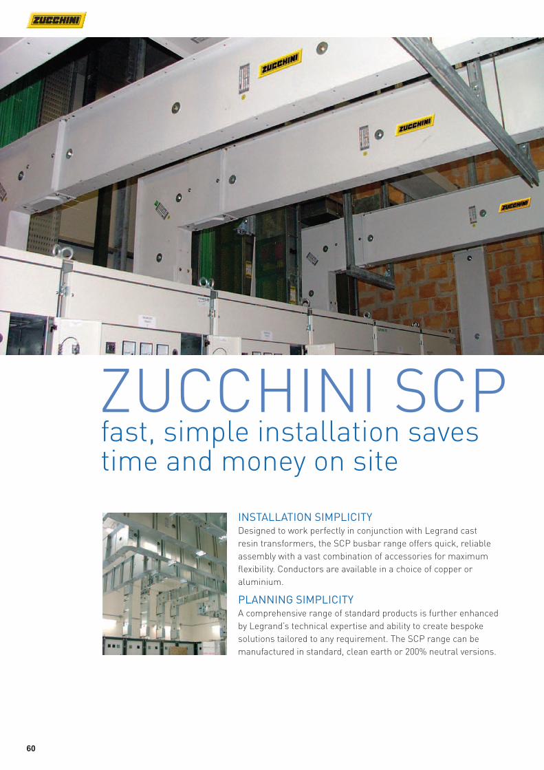
ZUCCHINI SCPfast, simple installation saves time and money on site
INSTALLATION SIMPLICITYDesigned to work perfectly in conjunction with Legrand cast
resin transformers, the SCP busbar range offers quick, reliable
assembly with a vast combination of accessories for maximum
flexibility. Conductors are available in a choice of copper or
aluminium.
PLANNING SIMPLICITYA comprehensive range of standard products is further enhanced
by Legrand’s technical expertise and ability to create bespoke
solutions tailored to any requirement. The SCP range can be
manufactured in standard, clean earth or 200% neutral versions.
60

Trunking lengths available
with aluminium or copper
conductors and in single or
double sided versions
Self-shearing bolts
ensure the correct
torque is applied at
the joint
Pre-installed monobloc
for fast, rigid and
reliable connections
SWITCHBOARD - TRANSFORMER FEED UNIT
HORIZONTAL ELBOW VERTICAL ELBOW JOINT
TRUSTED BY LEADING DEVELOPERSZucchini SCP high power busbar meets the quality and
specification requirements of leading property developers
and is installed in prestigious projects across the world.
61

62
Type 1 male Type 2 female Type 1 male Type 2 female
Standard dimensions Bespoke dimensionsRating (A)
CONNECTION INTERFACES
Right hand Left hand Right hand Left hand Left + right hand Right + left hand
Standard dimensions Bespoke dimensions
Horizontal elbows
Connection interfaces
Type 1 female Type 2 female Type 3 male Type 4 male
Connection interfaces + horizontal elbows
Right hand Left hand Right hand Left hand
Standard dimensions Bespoke dimensionsBespoke dimensions
Double horizontal elbowsVertical elbows
Rating (A)
ELBOWS AND TEES
630 60280300P 60280310P 60280320P 60280330P 60280400P 60280410P 60280420P 60280430P 60280350P 60280340P
800 60280301P 60280311P 60280321P 60280331P 60280401P 60280411P 60280421P 60280431P 60280351P 60280341P
1 000 60280302P 60280312P 60280322P 60280332P 60280402P 60280412P 60280422P 60280432P 60280352P 60280342P
1 250 60280304P 60280314P 60280324P 60280334P 60280404P 60280414P 60280424P 60280434P 60280354P 60280344P
1 600 60280306P 60280316P 60280326P 60280336P 60280406P 60280416P 60280426P 60280436P 60280356P 60280346P
2 000 60280307P 60280317P 60280327P 60280337P 60280407P 60280417P 60280427P 60280437P 60280357P 60280347P
2 500 60390304P 60390314P 60390324P 60390334P 60390404P 60390414P 60390424P 60390434P 60390354P 60390344P
3 200 60390306P 60390316P 60390326P 60390336P 60390406P 60390416P 60390426P 60390436P 60390356P 60390346P
4 000 60390307P 60390317P 60390327P 60390337P 60390407P 60390417P 60390427P 60390437P 60390357P 60390347P
630 60281010P 60281000P 60281030P 60281020P 60281300P 60281310P 60281320P 60281330P
800 60281011P 60281001P 60281031P 60281021P 60281301P 60281311P 60281321P 60281331P
1 000 60281012P 60281002P 60281032P 60281022P 60281302P 60281312P 60281322P 60281332P
1 250 60281014P 60281004P 60281034P 60281024P 60281304P 60281314P 60281324P 60281334P
1 600 60281016P 60281006P 60281036P 60281026P 60281306P 60281316P 60281326P 60281336P
2 000 60281017P 60281007P 60281037P 60281027P 60281307P 60281317P 60281327P 60281337P
2 500 60391014P 60391004P 60391034P 60391024P 60391304P 60391314P 60391324P 60391334P
3 200 60391016P 60391006P 60391036P 60391026P 60391306P 60391316P 60391326P 60391336P
4 000 60391017P 60391007P 60391037P 60391027P 60391307P 60391317P 60391327P 60391337P
SCP super compact busbaraluminium conductors
Standard 3 m Bespoke dimensions 1 to 1·5 m Bespoke dimensions 1·5 to 2 m Bespoke dimensions 2 to 2·5 m Bespoke dimensions 2·5 to 3 m
Feeder lengthsRating (A)
TRUNKING LENGTHS
630 60280100P 60280170P 60280120P 60280180P 60280150P
800 60280101P 60280171P 60280121P 60280181P 60280151P
1 000 60280102P 60280172P 60280122P 60280182P 60280152P
1 250 60280104P 60280174P 60280124P 60280184P 60280154P
1 600 60280106P 60280176P 60280126P 60280186P 60280156P
2 000 60280107P 60280177P 60280127P 60280187P 60280157P
2 500 60390104P 60390174P 60390124P 60390184P 60390154P
3 200 60390106P 60390176P 60390126P 60390186P 60390156P
4 000 60390107P 60390177P 60390127P 60390187P 60390157P
Bespoke dimensions

63
Type 1 female Type 2 female Type 3 male Type 4 male Type 1 male Type 2 female
CONNECTION INTERFACES FEED UNITS AND END STOPS
Connection interfaces + vertical elbows End feed units End stops
Left + right hand Right + left hand
Bespoke dimensions
Double vertical elbows Vertical tees Horizontal tees
ELBOWS AND TEES
60280450P 60280440P 60280800P 60280810P 60280820P 60280830P 60280700P 60280710P 60280720P 60280730P
60280451P 60280441P 60280801P 60280811P 60280821P 60280831P 60280701P 60280711P 60280721P 60280731P
60280452P 60280442P 60280802P 60280812P 60280822P 60280832P 60280702P 60280712P 60280722P 60280732P
60280454P 60280444P 60280804P 60280814P 60280824P 60280834P 60280704 P 60280714P 60280724P 60280734P
60280456P 60280446P 60280806P 60280816P 60280826P 60280836P 60280706P 60280716P 60280726P 60280736P
60280457P 60280447P 60280807P 60280817P 60280827P 60280837P 60280707P 60280717P 60280727P 60280737P
60390454P 60390444P 60390804P 60390814P 60390824P 60390834P 60390704P 60390714P 60390724P 60390734P
60390456P 60390446P 60390806P 60390816P 60390826P 60390836P 60390706P 60390716P 60390726P 60390736P
60390457P 60390447P 60390807P 60390817P 60390827P 60390837P 60390707P 60390717P 60390727P 60390737P
60281400P 60281410P 60281420P 60281430P 60281110P 60281100P 65283101P
60281401P 60281411P 60281421P 60281431P 60281111P 60281101P 65283101P
60281402P 60281412P 60281422P 60281432P 60281112P 60281102P 65283101P
60281404P 60281414P 60281424P 60281434P 60281114P 60281104P 65283101P
60281406P 60281416P 60281426P 60281436P 60281116P 60281106P 65283102P
60281407P 60281417P 60281427P 60281437P 60281117P 60281107P 65283104P
60391404P 60391414P 60391424P 60391434P 60391114P 60391104P 65393102P
60391406P 60391416P 60391426P 60391436P 60391116P 60391106P 65393103P
60391407P 60391417P 60391427P 60391437P 60391117P 60391107P 65393104P
Phase transposition Neutral rotation Internal External3 m – 3 + 3 outlets 2 m – 2 + 2 outlets 1 m – 1 + 1 outlets
Distribution lengths
TRUNKING LENGTHS
Expansion lengths Transposition lengths Fire barriers
60280130P 60280260P 60280280P 60280290P 60287100P 60287140P 653IFB01 652EFB01
60280131P 60280261P 60280281P 60280291P 60287101P 60287141P – 652EFB01
60280132P 60280262P 60280282P 60280292P 60287102P 60287142P – 652EFB01
60280134P 60280264P 60280284P 60280294P 60287104P 60287144P – 652EFB01
60280136P 60280266P 60280286P 60280296P 60287106P 60287146P – 652EFB02
60280137P 60280267P 60280287P 60280297P 60287107P 60287147P – 652EFB04
60390134P 60390264P 60390284P 60390294P 60397104P 60397144P 653IFB01 653EFB02
60390136P 60390266P 60390286P 60390296P 60397106P 60397146P 653IFB01 653EFB03
60390137P 60390267P 60390287P 60390297P 60397107P 60397147P 653IFB01 653EFB04
Bespoke dimensions Bespoke dimensions
Right hand female 550 to 1 049 mm
Right hand male 550 to 1 049 mm
Left hand male 550 to 1 049 mm
Left hand female 550 to 1 049 mm
Right hand female 300 to 1 499 mm
Right hand male 300 to 1 499 mm
Left hand male 300 to 1 499 mm
Left hand female 300 to 1 499 mm
Bespoke dimensions
Key : How to select the correct configuration of bar The 4th digit of an SCP Cat. No. determines the busbar configuration All examples on this page show 4 conductor versions, ie. 8 or 9; 5 conductor and 200% neutral versions are available by substituting the 4th digit with 4, 5, 6 or 7, as shown opposite
3L + N + PE 3L + N + FE+ PE 3L + 2N + PE
Single bar 8 4 5
Double bar 9 6 7

64
Type 1 male Type 2 female Type 1 male Type 2 female
Standard dimensions Bespoke dimensionsRating (A)
CONNECTION INTERFACES
Right hand Left hand Right hand Left hand Left + right hand Right + left hand
Standard dimensions Bespoke dimensions
Horizontal elbows
Connection interfaces
Type 1 female Type 2 female Type 3 male Type 4 male
Connection interfaces + horizontal elbows
Right hand Left hand Right hand Left hand
Standard dimensions Bespoke dimensionsBespoke dimensions
Double horizontal elbowsVertical elbows
Rating (A)
ELBOWS AND TEES
800 65280300P 65280310P 65280320P 65280330P 65280400P 65280410P 65280420P 65280430P 65280350P 65280340P
1 000 65280301P 65280311P 65280321P 65280331P 65280401P 65280411P 65280421P 65280431P 65280351P 65280341P
1 250 65280303P 65280313P 65280323P 65280333P 65280403P 65280413P 65280423P 65280433P 65280353P 65280343P
1 600 65280305P 65280315P 65280325P 65280335P 65280405P 65280415P 65280425P 65280435P 65280355P 65280345P
2 000 65280306P 65280316P 65280326P 65280336P 65280406P 65280416P 65280426P 65280436P 65280356P 65280346P
2 500 65280308P 65280318P 65280328P 65280338P 65280408P 65280418P 65280428P 65280438P 65280358P 65280348P
3 200 65390305P 65390315P 65390325P 65390335P 65390405P 65390415P 65390425P 65390435P 65390355P 65390345P
4 000 65390306P 65390316P 65390326P 65390336P 65390406P 65390416P 65390426P 65390436P 65390356P 65390346P
5 000 65390308P 65390318P 65390328P 65390338P 65390408P 65390418P 65390428P 65390438P 65390358P 65390348P
800 65281010P 65281000P 65281030P 65281020P 65281300P 65281310P 65281320P 65281330P
1 000 65281011P 65281001P 65281031P 65281021P 65281301P 65281311P 65281321P 65281331P
1 250 65281013P 65281003P 65281033P 65281023P 65281303P 65281313P 65281323P 65281333P
1 600 65281015P 65281005P 65281035P 65281025P 65281305P 65281315P 65281325P 65281335P
2 000 65281016P 65281006P 65281036P 65281026P 65281306P 65281316P 65281326P 65281336P
2 500 65281018P 65281008P 65281038P 65281028P 65281308P 65281318P 65281328P 65281338P
3 200 65391015P 65391005P 65391035P 65391025P 65391305P 65391315P 65391325P 65391335P
4 000 65391016P 65391006P 65391036P 65391026P 65391306P 65391316P 65391326P 65391336P
5 000 65391018P 65391008P 65391038P 65391028P 65391308P 65391318P 65391328P 65391338P
SCP super compact busbarcopper conductors
Standard 3 m Bespoke dimensions 1 to 1·5 m Bespoke dimensions 1·5 to 2 m Bespoke dimensions 2 to 2·5 m Bespoke dimensions 2·5 to 3 m
Feeder lengthsRating (A)
TRUNKING LENGTHS
800 65280100P 65280170P 65280120P 65280180P 65280150P
1 000 65280101P 65280171P 65280121P 65280181P 65280151P
1 250 65280103P 65280173P 65280123P 65280183P 65280153P
1 600 65280105P 65280175P 65280125P 65280185P 65280155P
2 000 65280106P 65280176P 65280126P 65280186P 65280156P
2 500 65280108P 65280178P 65280128P 65280188P 65280158P
3 200 65390105P 65390175P 65390125P 65390185P 65390155P
4 000 65390106P 65390176P 65390126P 65390186P 65390156P
5 000 65390108P 65390178P 65390128P 65390188P 65390158P
Bespoke dimensions

65
Type 1 female Type 2 female Type 3 male Type 4 male Type 1 male Type 2 female
CONNECTION INTERFACES FEED UNITS AND END STOPS
Connection interfaces + vertical elbows End feed units End stops
Left + right hand Right + left hand
Bespoke dimensions
Double vertical elbows Vertical tees Horizontal tees
ELBOWS AND TEES
65280450P 65280440P 65280800P 65280810P 65280820P 65280830P 65280700P 65280710P 65280720P 65280730P
65280451P 65280441P 65280801P 65280811P 65280821P 65280831P 65280701P 65280711P 65280721P 65280731P
65280453P 65280443P 65280803P 65280813P 65280823P 65280833P 65280703P 65280713P 65280723P 65280733P
65280455P 65280445P 65280805P 65280815P 65280825P 65280835P 65280705 P 65280715P 65280725P 65280735P
65280456P 65280446P 65280806P 65280816P 65280826P 65280836P 65280706P 65280716P 65280726P 65280736P
65280458P 65280448P 65280808P 65280818P 65280828P 65280838P 65280708P 65280718P 65280728P 65280738P
65390455P 65390445P 65390805P 65390815P 65390825P 65390835P 65390705P 65390715P 65390725P 65390735P
65390456P 65390446P 65390806P 65390816P 65390826P 65390836P 65390706P 65390716P 65390726P 65390736P
65390458P 65390448P 65390808P 65390818P 65390828P 65390838P 65390708P 65390718P 65390728P 65390738P
65281400P 65281410P 65281420P 65281430P 65281110P 65281100P 65283101P
65281401P 65281411P 65281421P 65281431P 65281111P 65281101P 65283101P
65281403P 65281413P 65281423P 65281433P 65281113P 65281103P 65283101P
65281405P 65281415P 65281425P 65281435P 65281115P 65281105P 65283102P
65281406P 65281416P 65281426P 65281436P 65281116P 65281106P 65283102P
65281408P 65281418P 65281428P 65281438P 65281118P 65281108P 65283104P
65391405P 65391415P 65391425P 65391435P 65391115P 65391105P 65393102P
65391406P 65391416P 65391426P 65391436P 65391116P 65391106P 65393103P
65391408P 65391418P 65391428P 65391438P 65391118P 65391108P 65393104P
Phase transposition Neutral rotation Internal External3 m – 3 + 3 outlets 2 m – 2 + 2 outlets 1 m – 1 + 1 outlets
Distribution lengths
TRUNKING LENGTHS
Expansion lengths Transposition lengths Fire barriers
65280130P 65280260P 65280280P 65280290P 65287100P 65287140P 653IFB01 652EFB51
65280131P 65280261P 65280281P 65280291P 65287101P 65287141P – 652EFB51
65280133P 65280263P 65280283P 65280293P 65287103P 65287143P – 652EFB51
65280135P 65280265P 65280285P 65280295P 65287105P 65287145P – 652EFB52
65280136P 65280266P 65280286P 65280296P 65287106P 65287146P – 652EFB52
65280138P 65280268P 65280288P 65280298P 65287108P 65287148P – 652EFB54
65390135P 65390265P 65390285P 65390295P 65397105P 65397145P 653IFB01 653EFB52
65390136P 65390266P 65390286P 65390296P 65397106P 65397146P 653IFB01 653EFB53
65390138P 65390268P 65390288P 65390298P 65397108P 65397148P 653IFB01 653EFB54
Bespoke dimensions Bespoke dimensions
Right hand female 550 to 1 049 mm
Right hand male 550 to 1 049 mm
Left hand male 550 to 1 049 mm
Left hand female 550 to 1 049 mm
Right hand female 300 to 1 499 mm
Right hand male 300 to 1 499 mm
Left hand male 300 to 1 499 mm
Left hand female 300 to 1 499 mm
Bespoke dimensions
Key : How to select the correct configuration of bar The 4th digit of an SCP Cat. No. determines the busbar configuration All examples on this page show 4 conductor versions, ie. 8 or 9; 5 conductor and 200% neutral versions are available by substituting the 4th digit with 4, 5, 6 or 7, as shown opposite
3L + N + PE 3L + N + FE+ PE 3L + 2N + PE
Single bar 8 4 5
Double bar 9 6 7

66
SCP super compact busbarfeeder lengths
High power busbar from 630 A to 4 000 A with aluminium alloy conductors and from 800 A to 5 000 A with copper conductors SCP complies with IEC 61439-6 (BS EN 61439-6)Supplied with electrical junction monobloc system pre-installed
Single bar feeder length
Selection charts p. 62-65Dimensions and technical information p. 95Technical data p. 112-117
The SCP system is also avail-able in 5 conductor versions and up to 6 300 A (copper)
Contact us on +44 (0) 370 608 9020
Key : How to select the correct configuration of bar The 4th digit of an SCP Cat. No. determines the busbar configuration All examples on this page show 4 conductor versions, ie. 8 or 9; 5 conductor and 200% neutral versions are available by substituting the 4th digit with 4, 5, 6 or 7, as shown below
3L + N + PE 3L + N + FE+ PE 3L + 2N + PE
Single bar 8 4 5
Double bar 9 6 7
Pack Cat. Nos. Feeder lengths – bespoke dimensions (continued)
Please specify required length when ordering
1 501 - 2 000 mm double bar Aluminium Copper Rating (A)
1 60390124P 2 500 1 60390126P 65390125P 3 200 1 60390127P 65390126P 4 000 1 65390128P 5 000
2 001 - 2 500 mm single bar Rating (A)
1 60280180P 630 1 60280181P 65280180P 800 1 60280182P 65280181P 1 000 1 60280184P 65280183P 1 250 1 60280186P 65280185P 1 600 1 60280187P 65280186P 2 000 1 65280188P 2 500
2 001 - 2 500 mm double bar Rating (A)
1 60390184P 2 500 1 60390186P 65390185P 3 200 1 60390187P 65390186P 4 000 1 65390188P 5 000
2 501 - 2 999 mm single bar Rating (A)
1 60280150P 630 1 60280151P 65280150P 800 1 60280152P 65280151P 1 000 1 60280154P 65280153P 1 250 1 60280156P 65280155P 1 600 1 60280157P 65280156P 2 000 1 65280158P 2 500
2 501 - 2 999 mm double bar Rating (A)
1 60390154P 2 500 1 60390156P 65390155P 3 200 1 60390157P 65390156P 4 000 1 65390158P 5 000
Pack Cat. Nos. Feeder lengths – standard 3 m
For runs exceeding 40 m an expansion length should be included (see p. 68)
3 000 mm single bar Aluminium Copper Rating (A)
1 60280100P 630 1 60280101P 65280100P 800 1 60280102P 65280101P 1 000 1 60280104P 65280103P 1 250 1 60280106P 65280105P 1 600 1 60280107P 65280106P 2 000 1 65280108P 2 500
3 000 mm double bar Rating (A)
1 60390104P 2 500 1 60390106P 65390105P 3 200 1 60390107P 65390106P 4 000 1 65390108P 5 000
Feeder lengths – bespoke dimensions
Please specify required length when ordering
1 000 - 1 500 mm single bar Aluminium Copper Rating (A)
1 60280170P 630 1 60280171P 65280170P 800 1 60280172P 65280171P 1 000 1 60280174P 65280173P 1 250 1 60280176P 65280175P 1 600 1 60280177P 65280176P 2 000 1 65280178P 2 500
1 000 - 1 500 mm double bar Rating (A)
1 60390174P 2 500 1 60390176P 65390175P 3 200 1 60390177P 65390176P 4 000 1 65390178P 5 000
1 501 - 2 000 mm single bar Rating (A)
1 60280120P 630 1 60280121P 65280120P 800 1 60280122P 65280121P 1 000 1 60280124P 65280123P 1 250 1 60280126P 65280125P 1 600 1 60280127P 65280126P 2 000 1 65280128P 2 500

67
High power busbar from 630 A to 4 000 A with aluminium alloy conductors and from 800 A to 5 000 A with copper conductors SCP complies with IEC 61439-6 (BS EN 61439-6)Supplied with electrical junction monobloc system pre-installed
SCP super compact busbardistribution lengths
Single bar distribution length
Selection charts p. 62-65Dimensions and technical information p. 95Technical data p. 112-117
Key : How to select the correct configuration of bar The 4th digit of an SCP Cat. No. determines the busbar configuration All examples on this page show 4 conductor versions, ie. 8 or 9; 5 conductor and 200% neutral versions are available by substituting the 4th digit with 4, 5, 6 or 7, as shown below
3L + N + PE 3L + N + FE+ PE 3L + 2N + PE
Single bar 8 4 5
Double bar 9 6 7
Pack Cat. Nos. Distribution lengths (continued)
2 001 - 2 500 mm double bar – 2 + 2 outlets2
Aluminium Copper Rating (A)
1 60390984P 2 500 1 60390986P 65390985P 3 200 1 60390987P 65390986P 4 000 1 65390988P 5 000
1 501 - 2 000 mm single bar – 2 + 2 outlets2
Rating (A)
1 60280920P1 630 1 60280921P 65280920P1 800 1 60280922P 65280921P 1 000 1 60280924P 65280923P 1 250 1 60280926P 65280925P 1 600 1 60280927P 65280926P 2 000 1 65280928P 2 500
1 501 - 2 000 mm double bar – 2 + 2 outlets2
Rating (A)
1 60390924P 2 500 1 60390926P 65390925P 3 200 1 60390927P 65390926P 4 000 1 65390928P 5 000
1 001 - 1 500 mm single bar – 1 + 1 outlets
Rating (A)
1 60280970P1 630 1 60280971P 65280970P1 800 1 60280972P 65280971P 1 000 1 60280974P 65280973P 1 250 1 60280976P 65280975P 1 600 1 60280977P 65280976P 2 000 1 65280978P 2 500
1 001 - 1 500 mm double bar – 1 + 1 outlets
Rating (A)
1 60390974P 2 500 1 60390976P 65390975P 3 200 1 60390977P 65390976P 4 000 1 65390978P 5 000
For feed units and tap-off boxes p. 77, 78-79
Pack Cat. Nos. Distribution lengths
For plug-in type tap-off boxes
For runs exceeding 40 m an expansion length should be included Tap-off outlets are spaced at 850 mm intervals on both sides and are provided with hinged covers to ensure maximum safety and maintain IP 55 protection
3 000 m single bar – 3 + 3 outlets2
Aluminium Copper Rating (A)
1 60280130P1 630 1 60280131P 65280130P1 800 1 60280132P 65280131P 1 000 1 60280134P 65280133P 1 250 1 60280136P 65280135P 1 600 1 60280137P 65280136P 2 000 1 65280138P 2 500
3 000 m double bar – 3 + 3 outlets2
Rating (A)
1 60390134P 2 500 1 60390136P 65390135P 3 200 1 60390137P 65390136P 4 000 1 65390138P 5 000
2 501 - 2 999 mm single bar – 3 + 3 outlets2
Rating (A)
1 60280950P1 630 1 60280951P 65280950P1 800 1 60280952P 65280951P 1 000 1 60280954P 65280953P 1 250 1 60280956P 65280955P 1 600 1 60280957P 65280956P 2 000 1 65280958P 2 500
2 501 - 2 999 mm double bar – 3 + 3 outlets2
Rating (A)
1 60390954P 2 500 1 60390956P 65390955P 3 200 1 60390957P 65390956P 4 000 1 65390958P 5 000
2 001 - 2 500 mm single bar – 2 + 2 outlets2
Rating (A)
1 60280980P1 630 1 60280981P 65280980P1 800 1 60280982P 65280981P 1 000 1 60280984P 65280983P 1 250 1 60280986P 65280985P 1 600 1 60280987P 65280986P 2 000 1 65280988P 2 500
1 : Lengths with tap-off outlets on top side only (3, 2 or 1 + 0)2 : For other combination of outlets please contact us +44 (0) 370 608 9020

68
SCP super compact busbarexpansion and transposition lengths
1 2
3 N
N 1
2 3
Single bar expansion length
Single bar phase transposition length
N 1
2 3
N 3
1 2
Single bar neutral rotation length
High power busbar from 630 A to 4 000 A with aluminium alloy conductors and from 800 A to 5 000 A with copper conductors SCP complies with IEC 61439-6 (BS EN 61439-6)Supplied with electrical junction monobloc system pre-installed
Selection charts p. 62-65Dimensions and technical information p. 95Technical data p. 112-117
Key : How to select the correct configuration of bar The 4th digit of an SCP Cat. No. determines the busbar configuration All examples on this page show 4 conductor versions, ie. 8 or 9; 5 conductor and 200% neutral versions are available by substituting the 4th digit with 4, 5, 6 or 7, as shown below
3L + N + PE 3L + N + FE+ PE 3L + 2N + PE
Single bar 8 4 5
Double bar 9 6 7
Pack Cat. Nos. Expansion lengths
Standard – 3 m
Absorb the thermal expansion during normal use that, on long runs, would otherwise cumulate and put abnormal force on the connection points Expansion length is to be placed in straight runs of more than 40 m and repeated every 40 m
Single bar Aluminium Copper Rating (A)
1 60280290P 630 1 60280291P 65280290P 800 1 60280292P 65280291P 1 000 1 60280294P 65280293P 1 250 1 60280296P 65280295P 1 600 1 60280297P 65280296P 2 000 1 65280298P 2 500
Double bar Rating (A)
1 60390294P 2 500 1 60390296P 65390295P 3 200 1 60390297P 65390296P 4 000 1 65390298P 5 000
Pack Cat. Nos. Transposition lengths
Phase transposition – 1·2 m
In runs exceeding 100 m it is recommended to include two transposition lengths to balance mutual phase reactance and electric impedance (one at 1/3 and one at 2/3 distance of the run)
Single bar Aluminium Copper Rating (A)
1 60287100P 630 1 60287101P 65287100P 800 1 60287102P 65287101P 1 000 1 60287104P 65287103P 1 250 1 60287106P 65287105P 1 600 1 60287107P 65287106P 2 000 1 65287108P 2 500
Double bar Rating (A)
1 60397104P 2 500 1 60397106P 65397105P 3 200 1 60397107P 65397106P 4 000 1 65397108P 5 000
Neutral rotation – 1·0 m
When the sequence of the distribution board phases is different to that of the transformer
Single bar Rating (A)
1 60287140P 630 1 60287141P 65287140P 800 1 60287142P 65287141P 1 000 1 60287144P 65287143P 1 250 1 60287146P 65287145P 1 600 1 60287147P 65287146P 2 000 1 65287148P 2 500
Double bar Rating (A)
1 60397144P 2 500 1 60397146P 65397145P 3 200 1 60397147P 65397146P 4 000 1 65397148P 5 000

69
SCP super compact busbarfire barriers and end stops
Single bar external fire barrier
End stop
High power busbar from 630 A to 4 000 A with aluminium alloy conductors and from 800 A to 5 000 A with copper conductors SCP complies with IEC 61439-6 (BS EN 61439-6)Supplied with electrical junction monobloc system pre-installed
Selection charts p. 62-65Dimensions and technical information p. 96Technical data p. 112-117
Key : How to select the correct configuration of bar The 4th digit of an SCP Cat. No. determines the busbar configuration All examples on this page show 4 conductor versions, ie. 8 or 9; 5 conductor and 200% neutral versions are available by substituting the 4th digit with 4, 5, 6 or 7, as shown below
3L + N + PE 3L + N + FE+ PE 3L + 2N + PE
Single bar 8 4 5
Double bar 9 6 7
Pack Cat. Nos. Internal fire barrier
Meets class S120 (EN 1366-3, DIN 4102-09) Internal fire barriers are not required for 800 to 2 000 A aluminium systems, or 1 000 to 2 500 A copper systems but can be supplied with all other trunking components
1 653IFB01 Internal fire barrier
External fire barriers
Meets class S120 (EN 1366-3, DIN 4102-09) External fire barriers can be used on any trunking component in compliance with the operating instructions (see p. 96) Please specify the required position of the fire barrier when ordering (see p. 96)
External single bar
Aluminium Copper Rating (A)
1 652EFB01 630, 800, 1 000, 1 250 1 652EFB02 1 600 1 652EFB04 2 000 1 652EFB51 800, 1 000, 1 250 1 652EFB52 1 600, 2 000 1 652EFB54 2 500
External double bar Rating (A)
1 653EFB02 2 500 1 653EFB03 3 200 1 653EFB04 4 000 1 653EFB52 3 200 1 653EFB53 4 000 1 653EFB54 5 000
Pack Cat. Nos. End stops
Maintain IP 55 protection at the end of the run
Single bar
Aluminium Copper Rating (A)
1 65283101P 630 to 1 250 1 65283101P 800 to 1 250 1 65283102P 1 600 1 65283102P 1 600 to 2 000 1 65283104P 2 000 1 65283104P 2 500
Double bar Rating (A)
1 65393102P 2 500 1 65393102P 3 200 1 65393103P 3 200 1 65393103P 4 000 1 65393104P 4 000 1 65393104P 5 000

70
SCP super compact busbarhorizontal elbows
Single bar - horizontal elbow
High power busbar from 630 A to 4 000 A with aluminium alloy conductors and from 800 A to 5 000 A with copper conductors SCP complies with IEC 61439-6 (BS EN 61439-6)Elbows are supplied with pre-installed monobloc and are able to change direction with standard or bespoke dimensions
Selection charts p. 62-65Dimensions and technical information p. 96Technical data p. 112-117
Key : How to select the correct configuration of bar The 4th digit of an SCP Cat. No. determines the busbar configuration All examples on this page show 4 conductor versions, ie. 8 or 9; 5 conductor and 200% neutral versions are available by substituting the 4th digit with 4, 5, 6 or 7, as shown below
3L + N + PE 3L + N + FE+ PE 3L + 2N + PE
Single bar 8 4 5
Double bar 9 6 7
Pack Cat. Nos. Horizontal elbows – standard 300 x 300 mm
Right hand – single bar Aluminium Copper Rating (A)
1 60280300P 630 1 60280301P 65280300P 800 1 60280302P 65280301P 1 000 1 60280304P 65280303P 1 250 1 60280306P 65280305P 1 600 1 60280307P 65280306P 2 000 1 65280308P 2 500
Right hand – double bar Rating (A)
1 60390304P 2 500 1 60390306P 65390305P 3 200 1 60390307P 65390306P 4 000 1 65390308P 5 000
Left hand – single bar Rating (A)
1 60280310P 630 1 60280311P 65280310P 800 1 60280312P 65280311P 1 000 1 60280314P 65280313P 1 250 1 60280316P 65280315P 1 600 1 60280317P 65280316P 2 000 1 65280318P 2 500
Left hand – double bar Rating (A)
1 60390314P 2 500 1 60390316P 65390315P 3 200 1 60390317P 65390316P 4 000 1 65390318P 5 000
Pack Cat. Nos. Horizontal elbows – bespoke dimensions
Please specify required length when ordering (see p. 96 for configuration)
Right hand – single bar 250 to 1 299 mm
Aluminium Copper Rating (A)
1 60280320P 630 1 60280321P 65280320P 800 1 60280322P 65280321P 1 000 1 60280324P 65280323P 1 250 1 60280326P 65280325P 1 600 1 60280327P 65280326P 2 000 1 65280328P 2 500
Right hand – double bar 250 to 1 449 mm
Rating (A)
1 60390324P 2 500 1 60390326P 65390325P 3 200 1 60390327P 65390326P 4 000 1 65390328P 5 000
Left hand – single bar 250 to 1 299 mm
Rating (A)
1 60280330P 630 1 60280331P 65280330P 800 1 60280332P 65280331P 1 000 1 60280334P 65280333P 1 250 1 60280336P 65280335P 1 600 1 60280337P 65280336P 2 000 1 65280338P 2 500
Left hand – double bar 250 to 1 449 mm
Rating (A)
1 60390334P 2 500 1 60390336P 65390335P 3 200 1 60390337P 65390336P 4 000 1 65390338P 5 000

71
SCP super compact busbarvertical elbows
Single bar – vertical elbow
High power busbar from 630 A to 4 000 A with aluminium alloy conductors and from 800 A to 5 000 A with copper conductors SCP complies with IEC 61439-6 (BS EN 61439-6)Elbows are supplied with pre-installed monobloc and are able to change direction with standard or bespoke dimensions
Selection charts p. 62-65Dimensions and technical information p. 96Technical data p. 112-117
Key : How to select the correct configuration of bar The 4th digit of an SCP Cat. No. determines the busbar configuration All examples on this page show 4 conductor versions, ie. 8 or 9; 5 conductor and 200% neutral versions are available by substituting the 4th digit with 4, 5, 6 or 7, as shown below
3L + N + PE 3L + N + FE+ PE 3L + 2N + PE
Single bar 8 4 5
Double bar 9 6 7
Pack Cat. Nos. Vertical elbows – bespoke dimensions
Please specify required length when ordering (see p. 96 for configuration)
Left hand – single bar 300 to 1 299 mm
Aluminium Copper Rating (A)
1 60280430P 630 1 60280431P 65280430P 800 1 60280432P 65280431P 1 000 1 60280434P 65280433P 1 250 1 60280436P 65280435P 1 600 1 60280437P 65280436P 2 000 1 65280438P 2 500
Left hand – double bar 450 to 1 449 mm
Rating (A)
1 60390434P 2 500 1 60390436P 65390435P 3 200 1 60390437P 65390436P 4 000 1 65390438P 5 000
Right hand – single bar 300 to 1 299 mm
Rating (A)
1 60280420P 630 1 60280421P 65280420P 800 1 60280422P 65280421P 1 000 1 60280424P 65280423P 1 250 1 60280426P 65280425P 1 600 1 60280427P 65280426P 2 000 1 65280428P 2 500
Right hand – double bar 450 to 1 449 mm
Rating (A)
1 60390424P 2 500 1 60390426P 65390425P 3 200 1 60390427P 65390426P 4 000 1 65390428P 5 000
Pack Cat. Nos. Vertical elbows – standard
Left hand – single bar 300 x 300 mm
Aluminium Copper Rating (A)
1 60280410P 630 1 60280411P 65280410P 800 1 60280412P 65280411P 1 000 1 60280414P 65280413P 1 250 1 60280416P 65280415P 1 600 1 60280417P 65280416P 2 000 1 65280418P 2 500
Left hand – double bar 450 x 450 mm
Rating (A)
1 60390414P 2 500 1 60390416P 65390415P 3 200 1 60390417P 65390416P 4 000 1 65390418P 5 000
Right hand – single bar 300 x 300 mm
Rating (A)
1 60280400P 630 1 60280401P 65280400P 800 1 60280402P 65280401P 1 000 1 60280404P 65280403P 1 250 1 60280406P 65280405P 1 600 1 60280407P 65280406P 2 000 1 65280408P 2 500
Right hand – double bar 450 x 450 mm
Rating (A)
1 60390404P 2 500 1 60390406P 65390405P 3 200 1 60390407P 65390406P 4 000 1 65390408P 5 000
72
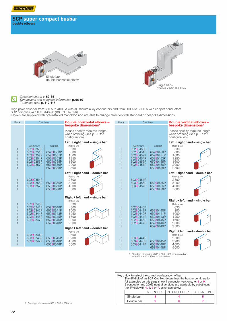
SCP super compact busbardouble elbows
High power busbar from 630 A to 4 000 A with aluminium alloy conductors and from 800 A to 5 000 A with copper conductors SCP complies with IEC 61439-6 (BS EN 61439-6)Elbows are supplied with pre-installed monobloc and are able to change direction with standard or bespoke dimensions
Single bar – double horizontal elbow
Single bar – double vertical elbow
1 : Standard dimensions 300 + 300 + 300 mm
Selection charts p. 62-65Dimensions and technical information p. 96-97Technical data p. 112-117
Key : How to select the correct configuration of bar The 4th digit of an SCP Cat. No. determines the busbar configuration All examples on this page show 4 conductor versions, ie. 8 or 9; 5 conductor and 200% neutral versions are available by substituting the 4th digit with 4, 5, 6 or 7, as shown below
3L + N + PE 3L + N + FE+ PE 3L + 2N + PE
Single bar 8 4 5
Double bar 9 6 7
Pack Cat. Nos. Double horizontal elbows – bespoke dimensions1
Please specify required length when ordering (see p. 96 for configuration)
Left + right hand – single bar Aluminium Copper Rating (A)
1 60280350P 630 1 60280351P 65280350P 800 1 60280352P 65280351P 1 000 1 60280354P 65280353P 1 250 1 60280356P 65280355P 1 600 1 60280357P 65280356P 2 000 1 65280358P 2 500
Left + right hand – double bar Rating (A)
1 60390354P 2 500 1 60390356P 65390355P 3 200 1 60390357P 65390356P 4 000 1 65390358P 5 000
Right + left hand – single bar Rating (A)
1 60280340P 630 1 60280341P 65280340P 800 1 60280342P 65280341P 1 000 1 60280344P 65280343P 1 250 1 60280346P 65280345P 1 600 1 60280347P 65280346P 2 000 1 65280348P 2 500
Right + left hand – double bar Rating (A)
1 60390344P 2 500 1 60390346P 65390345P 3 200 1 60390347P 65390346P 4 000 1 65390348P 5 000
Pack Cat. Nos. Double vertical elbows – bespoke dimensions2
Please specify required length when ordering (see p. 97 for configuration)
Left + right hand – single bar Aluminium Copper Rating (A)
1 60280450P 630 1 60280451P 65280450P 800 1 60280452P 65280451P 1 000 1 60280454P 65280453P 1 250 1 60280456P 65280455P 1 600 1 60280457P 65280456P 2 000 1 65280458P 2 500
Left + right hand – double bar Rating (A)
1 60390454P 2 500 1 60390456P 65390455P 3 200 1 60390457P 65390456P 4 000 1 65390458P 5 000
Right + left hand – single bar Rating (A)
1 60280440P 630 1 60280441P 65280440P 800 1 60280442P 65280441P 1 000 1 60280444P 65280443P 1 250 1 60280446P 65280445P 1 600 1 60280447P 65280446P 2 000 1 65280448P 2 500
Right + left hand – double bar Rating (A)
1 60390444P 2 500 1 60390446P 65390445P 3 200 1 60390447P 65390446P 4 000 1 65390448P 5 000
2 : Standard dimensions 300 + 300 + 300 mm single bar and 450 + 450 + 450 mm double bar

73
SCP super compact busbarvertical tees
High power busbar from 630 A to 4 000 A with aluminium alloy conductors and from 800 A to 5 000 A with copper conductors SCP complies with IEC 61439-6 (BS EN 61439-6)Tees are supplied with pre-installed monobloc and are able to change direction with standard or bespoke dimensions
Single bar - vertical tee
1 : Standard dimensions 300 + 300 + 300 mm single bar and 600 + 600 + 600 mm double bar
Selection charts p. 62-65Dimensions and technical information p. 97Technical data p. 112-117
Key : How to select the correct configuration of bar The 4th digit of an SCP Cat. No. determines the busbar configuration All examples on this page show 4 conductor versions, ie. 8 or 9; 5 conductor and 200% neutral versions are available by substituting the 4th digit with 4, 5, 6 or 7, as shown below
3L + N + PE 3L + N + FE+ PE 3L + 2N + PE
Single bar 8 4 5
Double bar 9 6 7
Pack Cat. Nos. Vertical tees – bespoke dimensions (continued)1
Please specify required length when ordering (see p. 97 for configuration)
Left hand male – single bar 300 to 1 299 mm
Aluminium Copper Rating (A)
1 60280820P 630 1 60280821P 65280820P 800 1 60280822P 65280821P 1 000 1 60280824P 65280823P 1 250 1 60280826P 65280825P 1 600 1 60280827P 65280826P 2 000 1 65280828P 2 500
Left hand male – double bar 450 to 1 449 mm
Rating (A)
1 60390824P 2 500 1 60390826P 65390825P 3 200 1 60390827P 65390826P 4 000 1 65390828P 5 000
Left hand female – single bar 300 to 1 299 mm
Rating (A)
1 60280830P 630 1 60280831P 65280830P 800 1 60280832P 65280831P 1 000 1 60280834P 65280833P 1 250 1 60280836P 65280835P 1 600 1 60280837P 65280836P 2 000 1 65280838P 2 500
Left hand female – double bar 450 to 1 449 mm
Rating (A)
1 60390834P 2 500 1 60390836P 65390835P 3 200 1 60390837P 65390836P 4 000 1 65390838P 5 000
Pack Cat. Nos. Vertical tees – bespoke dimensions1
Please specify required length when ordering (see p. 97 for configuration)
Right hand female – single bar 300 to 1 299 mm
Aluminium Copper Rating (A)
1 60280800P 630 1 60280801P 65280800P 800 1 60280802P 65280801P 1 000 1 60280804P 65280803P 1 250 1 60280806P 65280805P 1 600 1 60280807P 65280806P 2 000 1 65280808P 2 500
Right hand female – double bar 450 to 1 449 mm
Rating (A)
1 60390804P 2 500 1 60390806P 65390805P 3 200 1 60390807P 65390806P 4 000 1 65390808P 5 000
Right hand male – single bar 300 to 1 299 mm
Rating (A)
1 60280810P 630 1 60280811P 65280810P 800 1 60280812P 65280811P 1 000 1 60280814P 65280813P 1 250 1 60280816P 65280815P 1 600 1 60280817P 65280816P 2 000 1 65280818P 2 500
Right hand male – double bar 450 to 1 449 mm
Rating (A)
1 60390814P 2 500 1 60390816P 65390815P 3 200 1 60390817P 65390816P 4 000 1 65390818P 5 000

74
SCP super compact busbarhorizontal tees
High power busbar from 630 A to 4 000 A with aluminium alloy conductors and from 800 A to 5 000 A with copper conductors SCP complies with IEC 61439-6 (BS EN 61439-6)Tees are supplied with pre-installed monobloc and are able to change direction with standard or bespoke dimensions
Single bar - horizontal tee
1 : Standard dimensions 600 + 600 + 600 mm
Selection charts p. 62-65Dimensions and technical information p. 98Technical data p. 112-117
Key : How to select the correct configuration of bar The 4th digit of an SCP Cat. No. determines the busbar configuration All examples on this page show 4 conductor versions, ie. 8 or 9; 5 conductor and 200% neutral versions are available by substituting the 4th digit with 4, 5, 6 or 7, as shown below
3L + N + PE 3L + N + FE+ PE 3L + 2N + PE
Single bar 8 4 5
Double bar 9 6 7
Pack Cat. Nos. Horizontal tees – bespoke dimensions (continued)1
Please specify required length when ordering (see p. 98 for configuration)
Left hand male – single bar 550 to 1 049 mm
Aluminium Copper Rating (A)
1 60280720P 630 1 60280721P 65280720P 800 1 60280722P 65280721P 1 000 1 60280724P 65280723P 1 250 1 60280726P 65280725P 1 600 1 60280727P 65280726P 2 000 1 65280728P 2 500
Left hand male – double bar 550 to 1 049 mm
Rating (A)
1 60390724P 2 500 1 60390726P 65390725P 3 200 1 60390727P 65390726P 4 000 1 65390728P 5 000
Left hand female – single bar 550 to 1 049 mm
Rating (A)
1 60280730P 630 1 60280731P 65280730P 800 1 60280732P 65280731P 1 000 1 60280734P 65280733P 1 250 1 60280736P 65280735P 1 600 1 60280737P 65280736P 2 000 1 65280738P 2 500
Left hand female – double bar 550 to 1 049 mm
Rating (A)
1 60390734P 2 500 1 60390736P 65390735P 3 200 1 60390737P 65390736P 4 000 1 65390738P 5 000
Pack Cat. Nos . Horizontal tees – bespoke dimensions1
Please specify required length when ordering (see p. 98 for configuration)
Right hand female – single bar 550 to 1 049 mm
Aluminium Copper Rating (A)
1 60280700P 630 1 60280701P 65280700P 800 1 60280702P 65280701P 1 000 1 60280704P 65280703P 1 250 1 60280706P 65280705P 1 600 1 60280707P 65280706P 2 000 1 65280708P 2 500
Right hand female – double bar 550 to 1 049 mm
Rating (A)
1 60390704P 2 500 1 60390706P 65390705P 3 200 1 60390707P 65390706P 4 000 1 65390708P 5 000
Right hand male – single bar 550 to 1 049 mm
Rating (A)
1 60280710P 630 1 60280711P 65280710P 800 1 60280712P 65280711P 1 000 1 60280714P 65280713P 1 250 1 60280716P 65280715P 1 600 1 60280717P 65280716P 2 000 1 65280718P 2 500
Right hand male – double bar 550 to 1 049 mm
Rating (A)
1 60390714P 2 500 1 60390716P 65390715P 3 200 1 60390717P 65390716P 4 000 1 65390718P 5 000
75
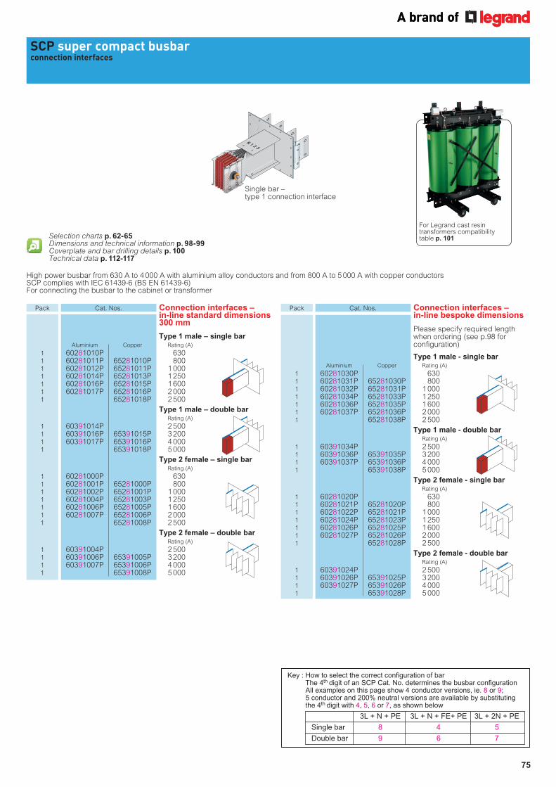
SCP super compact busbarconnection interfaces
Single bar – type 1 connection interface
High power busbar from 630 A to 4 000 A with aluminium alloy conductors and from 800 A to 5 000 A with copper conductors SCP complies with IEC 61439-6 (BS EN 61439-6)For connecting the busbar to the cabinet or transformer
Selection charts p. 62-65Dimensions and technical information p. 98-99Coverplate and bar drilling details p. 100Technical data p. 112-117
For Legrand cast resin transformers compatibility table p. 101
Key : How to select the correct configuration of bar The 4th digit of an SCP Cat. No. determines the busbar configuration All examples on this page show 4 conductor versions, ie. 8 or 9; 5 conductor and 200% neutral versions are available by substituting the 4th digit with 4, 5, 6 or 7, as shown below
3L + N + PE 3L + N + FE+ PE 3L + 2N + PE
Single bar 8 4 5
Double bar 9 6 7
Pack Cat. Nos. Connection interfaces – in-line bespoke dimensions
Please specify required length when ordering (see p.98 for configuration)
Type 1 male - single bar Aluminium Copper Rating (A)
1 60281030P 630 1 60281031P 65281030P 800 1 60281032P 65281031P 1 000 1 60281034P 65281033P 1 250 1 60281036P 65281035P 1 600 1 60281037P 65281036P 2 000 1 65281038P 2 500
Type 1 male - double bar Rating (A)
1 60391034P 2 500 1 60391036P 65391035P 3 200 1 60391037P 65391036P 4 000 1 65391038P 5 000
Type 2 female - single bar Rating (A)
1 60281020P 630 1 60281021P 65281020P 800 1 60281022P 65281021P 1 000 1 60281024P 65281023P 1 250 1 60281026P 65281025P 1 600 1 60281027P 65281026P 2 000 1 65281028P 2 500
Type 2 female - double bar Rating (A)
1 60391024P 2 500 1 60391026P 65391025P 3 200 1 60391027P 65391026P 4 000 1 65391028P 5 000
Pack Cat. Nos. Connection interfaces – in-line standard dimensions 300 mm
Type 1 male – single bar Aluminium Copper Rating (A)
1 60281010P 630 1 60281011P 65281010P 800 1 60281012P 65281011P 1 000 1 60281014P 65281013P 1 250 1 60281016P 65281015P 1 600 1 60281017P 65281016P 2 000 1 65281018P 2 500
Type 1 male – double bar Rating (A)
1 60391014P 2 500 1 60391016P 65391015P 3 200 1 60391017P 65391016P 4 000 1 65391018P 5 000
Type 2 female – single bar Rating (A)
1 60281000P 630 1 60281001P 65281000P 800 1 60281002P 65281001P 1 000 1 60281004P 65281003P 1 250 1 60281006P 65281005P 1 600 1 60281007P 65281006P 2 000 1 65281008P 2 500
Type 2 female – double bar Rating (A)
1 60391004P 2 500 1 60391006P 65391005P 3 200 1 60391007P 65391006P 4 000 1 65391008P 5 000
76
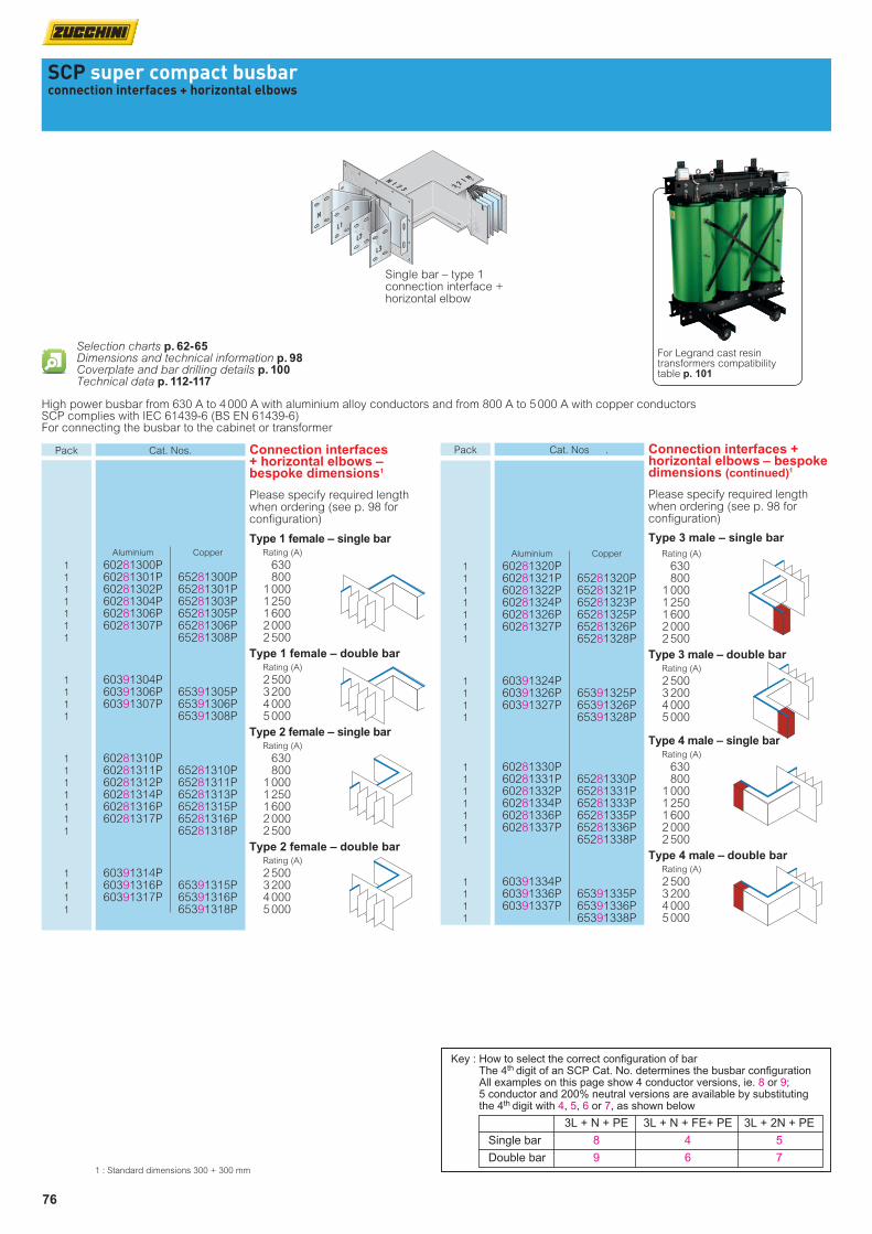
SCP super compact busbarconnection interfaces + horizontal elbows
Single bar – type 1 connection interface + horizontal elbow
High power busbar from 630 A to 4 000 A with aluminium alloy conductors and from 800 A to 5 000 A with copper conductors SCP complies with IEC 61439-6 (BS EN 61439-6)For connecting the busbar to the cabinet or transformer
Selection charts p. 62-65Dimensions and technical information p. 98Coverplate and bar drilling details p. 100Technical data p. 112-117
Key : How to select the correct configuration of bar The 4th digit of an SCP Cat. No. determines the busbar configuration All examples on this page show 4 conductor versions, ie. 8 or 9; 5 conductor and 200% neutral versions are available by substituting the 4th digit with 4, 5, 6 or 7, as shown below
3L + N + PE 3L + N + FE+ PE 3L + 2N + PE
Single bar 8 4 5
Double bar 9 6 7
Pack Cat. Nos . Connection interfaces + horizontal elbows – bespoke dimensions (continued)1
Please specify required length when ordering (see p. 98 for configuration)
Type 3 male – single bar
Aluminium Copper Rating (A)
1 60281320P 630 1 60281321P 65281320P 800 1 60281322P 65281321P 1 000 1 60281324P 65281323P 1 250 1 60281326P 65281325P 1 600 1 60281327P 65281326P 2 000 1 65281328P 2 500
Type 3 male – double bar Rating (A)
1 60391324P 2 500 1 60391326P 65391325P 3 200 1 60391327P 65391326P 4 000 1 65391328P 5 000
Type 4 male – single bar Rating (A)
1 60281330P 630 1 60281331P 65281330P 800 1 60281332P 65281331P 1 000 1 60281334P 65281333P 1 250 1 60281336P 65281335P 1 600 1 60281337P 65281336P 2 000 1 65281338P 2 500
Type 4 male – double bar Rating (A)
1 60391334P 2 500 1 60391336P 65391335P 3 200 1 60391337P 65391336P 4 000 1 65391338P 5 000
Pack Cat. Nos. Connection interfaces + horizontal elbows – bespoke dimensions1
Please specify required length when ordering (see p. 98 for configuration)
Type 1 female – single bar Aluminium Copper Rating (A)
1 60281300P 630 1 60281301P 65281300P 800 1 60281302P 65281301P 1 000 1 60281304P 65281303P 1 250 1 60281306P 65281305P 1 600 1 60281307P 65281306P 2 000 1 65281308P 2 500
Type 1 female – double bar Rating (A)
1 60391304P 2 500 1 60391306P 65391305P 3 200 1 60391307P 65391306P 4 000 1 65391308P 5 000
Type 2 female – single bar Rating (A)
1 60281310P 630 1 60281311P 65281310P 800 1 60281312P 65281311P 1 000 1 60281314P 65281313P 1 250 1 60281316P 65281315P 1 600 1 60281317P 65281316P 2 000 1 65281318P 2 500
Type 2 female – double bar Rating (A)
1 60391314P 2 500 1 60391316P 65391315P 3 200 1 60391317P 65391316P 4 000 1 65391318P 5 000
1 : Standard dimensions 300 + 300 mm
For Legrand cast resin transformers compatibility table p. 101

77
SCP super compact busbarconnection interfaces + vertical elbows and feed units
Single bar – type 1 connection interface + vertical elbow
Single bar - type 1 end feed unit
High power busbar from 630 A to 4 000 A with aluminium alloy conductors and from 800 A to 5 000 A with copper conductors SCP complies with IEC 61439-6 (BS EN 61439-6)For connecting the busbar to the cabinet or transformerEnd feed units have rear cable input and aluminium gland plate(s) for cable entry – 170 x 410 mm. Single bar 1 plate, double bar 2 plates
Selection charts p. 62-65Dimensions and technical information p. 99Coverplate and bar drilling details p. 100Technical data p. 112-117
Pack Cat. Nos. Connection interfaces + vertical elbows – bespoke dimensions (continued)1
Please specify required length when ordering (see p. 99 for configuration)
Type 4 male – single bar
Aluminium Copper Rating (A)
1 60281430P 630 1 60281431P 65281430P 800 1 60281432P 65281431P 1 000 1 60281434P 65281433P 1 250 1 60281436P 65281435P 1 600 1 60281437P 65281436P 2 000 1 65281438P 2 500
Type 4 male – double bar Rating (A)
1 60391434P 2 500 1 60391436P 65391435P 3 200 1 60391437P 65391436P 4 000 1 65391438P 5 000
End feed unit – standard 300 mm
Type 1 male – single bar Aluminium Copper Rating (A)
1 60281110P 630 1 60281111P 65281110P 800 1 60281112P 65281111P 1 000 1 60281114P 65281113P 1 250 1 60281116P 65281115P 1 600 1 60281117P 65281116P 2 000 1 65281118P 2 500
Type 1 male – double bar Rating (A)
1 60391114P 2 500 1 60391116P 65391115P 3 200 1 60391117P 65391116P 4 000 1 65391118P 5 000
Type 2 female – single bar Rating (A)
1 60281100P 630 1 60281101P 65281100P 800 1 60281102P 65281101P 1 000 1 60281104P 65281103P 1 250 1 60281106P 65281105P 1 600 1 60281107P 65281106P 2 000 1 65281108P 2 500
Type 2 female – double bar Rating (A)
1 60391104P 2 500 1 60391106P 65391105P 3 200 1 60391107P 65391106P 4 000 1 65391108P 5 000
Pack Cat. Nos. Connection interfaces + vertical elbows – bespoke dimensions1
Please specify required length when ordering (see p. 99 for configuration)
Type 1 female – single bar Aluminium Copper Rating (A)
1 60281400P 630 1 60281401P 65281400P 800 1 60281402P 65281401P 1 000 1 60281404P 65281403P 1 250 1 60281406P 65281405P 1 600 1 60281407P 65281406P 2 000 65281408P 2 500
Type 1 female – double bar Rating (A)
1 60391404P 2 500 1 60391406P 65391405P 3 200 1 60391407P 65391406P 4 000 1 65391408P 5 000
Type 2 female – single bar Rating (A)
1 60281410P 630 1 60281411P 65281410P 800 1 60281412P 65281411P 1 000 1 60281414P 65281413P 1 250 1 60281416P 65281415P 1 600 1 60281417P 65281416P 2 000 1 65281418P 2 500
Type 2 female – double bar Rating (A)
1 60391414P 2 500 1 60391416P 65391415P 3 200 1 60391417P 65391416P 4 000 1 65391418P 5 000
Type 3 male – single bar Rating (A)
1 60281420P 630 1 60281421P 65281420P 800 1 60281422P 65281421P 1 000 1 60281424P 65281423P 1 250 1 60281426P 65281425P 1 600 1 60281427P 65281426P 2 000 1 65281428P 2 500
Type 3 male – double bar Rating (A)
1 60391424P 2 500 1 60391426P 65391425P 3 200 1 60391427P 65391426P 4 000 1 65391428P 5 000
1 : Standard dimensions 300 + 300 mm single bar and 450 + 450 mm double bar
78
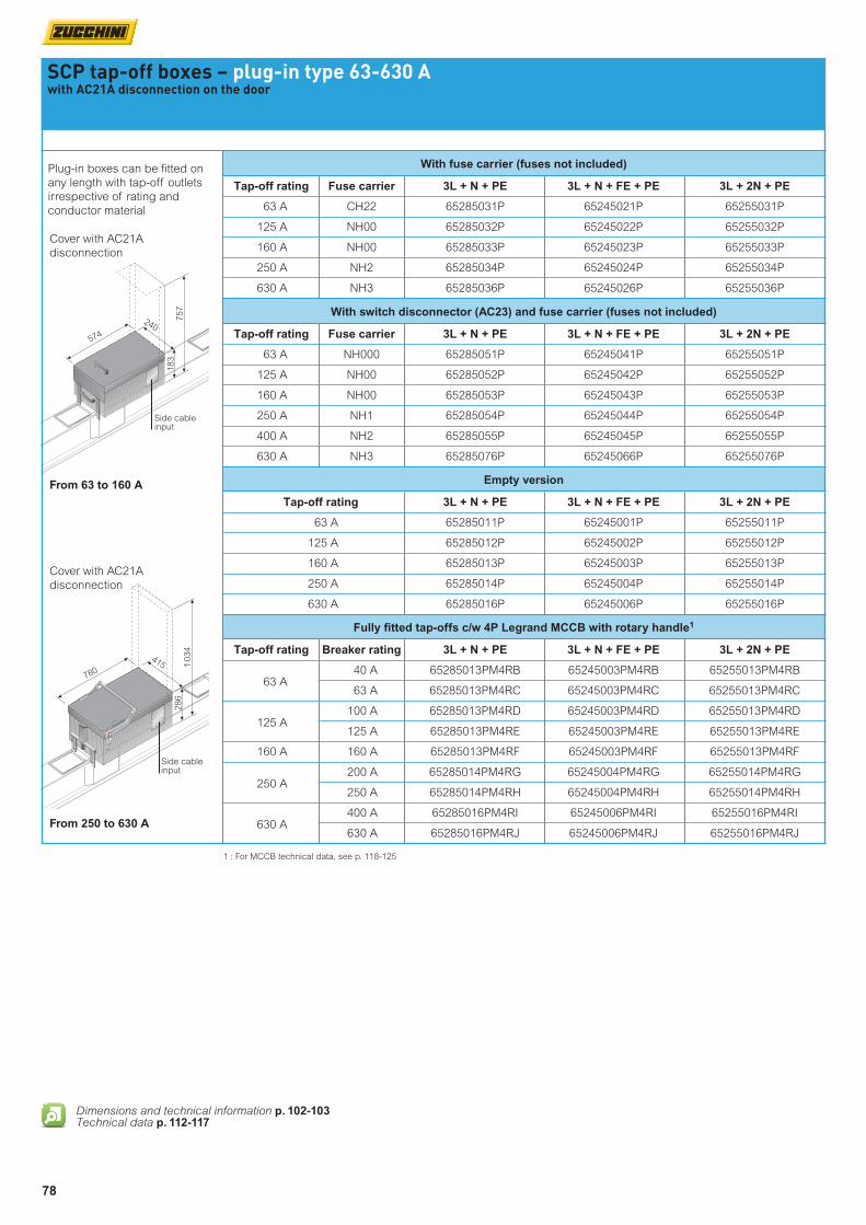
Fully itted tap-offs c/w 4P Legrand MCCB with rotary handle1
Tap-off rating Breaker rating 3L + N + PE 3L + N + FE + PE 3L + 2N + PE
63 A
40 A 65285013PM4RB 65245003PM4RB 65255013PM4RB
63 A 65285013PM4RC 65245003PM4RC 65255013PM4RC
125 A
100 A 65285013PM4RD 65245003PM4RD 65255013PM4RD
125 A 65285013PM4RE 65245003PM4RE 65255013PM4RE
160 A 160 A 65285013PM4RF 65245003PM4RF 65255013PM4RF
250 A
200 A 65285014PM4RG 65245004PM4RG 65255014PM4RG
250 A 65285014PM4RH 65245004PM4RH 65255014PM4RH
630 A
400 A 65285016PM4RI 65245006PM4RI 65255016PM4RI
630 A 65285016PM4RJ 65245006PM4RJ 65255016PM4RJ
Empty version
Tap-off rating 3L + N + PE 3L + N + FE + PE 3L + 2N + PE
63 A 65285011P 65245001P 65255011P
125 A 65285012P 65245002P 65255012P
160 A 65285013P 65245003P 65255013P
250 A 65285014P 65245004P 65255014P
630 A 65285016P 65245006P 65255016P
With switch disconnector (AC23) and fuse carrier (fuses not included)
Tap-off rating Fuse carrier 3L + N + PE 3L + N + FE + PE 3L + 2N + PE
63 A NH000 65285051P 65245041P 65255051P
125 A NH00 65285052P 65245042P 65255052P
160 A NH00 65285053P 65245043P 65255053P
250 A NH1 65285054P 65245044P 65255054P
400 A NH2 65285055P 65245045P 65255055P
630 A NH3 65285076P 65245066P 65255076P
SCP tap-off boxes – plug-in type 63-630 Awith AC21A disconnection on the door
With fuse carrier (fuses not included)
Tap-off rating Fuse carrier 3L + N + PE 3L + N + FE + PE 3L + 2N + PE
63 A CH22 65285031P 65245021P 65255031P
125 A NH00 65285032P 65245022P 65255032P
160 A NH00 65285033P 65245023P 65255033P
250 A NH2 65285034P 65245024P 65255034P
630 A NH3 65285036P 65245026P 65255036P
Plug-in boxes can be itted on
any length with tap-off outlets
irrespective of rating and
conductor material
Cover with AC21A
disconnection
Cover with AC21A
disconnection
From 63 to 160 A
From 250 to 630 A
780
415
286
574
183
240
Side cable input
757
1 0
34
Side cable input
1 : For MCCB technical data, see p. 118-125
Dimensions and technical information p. 102-103Technical data p. 112-117
79
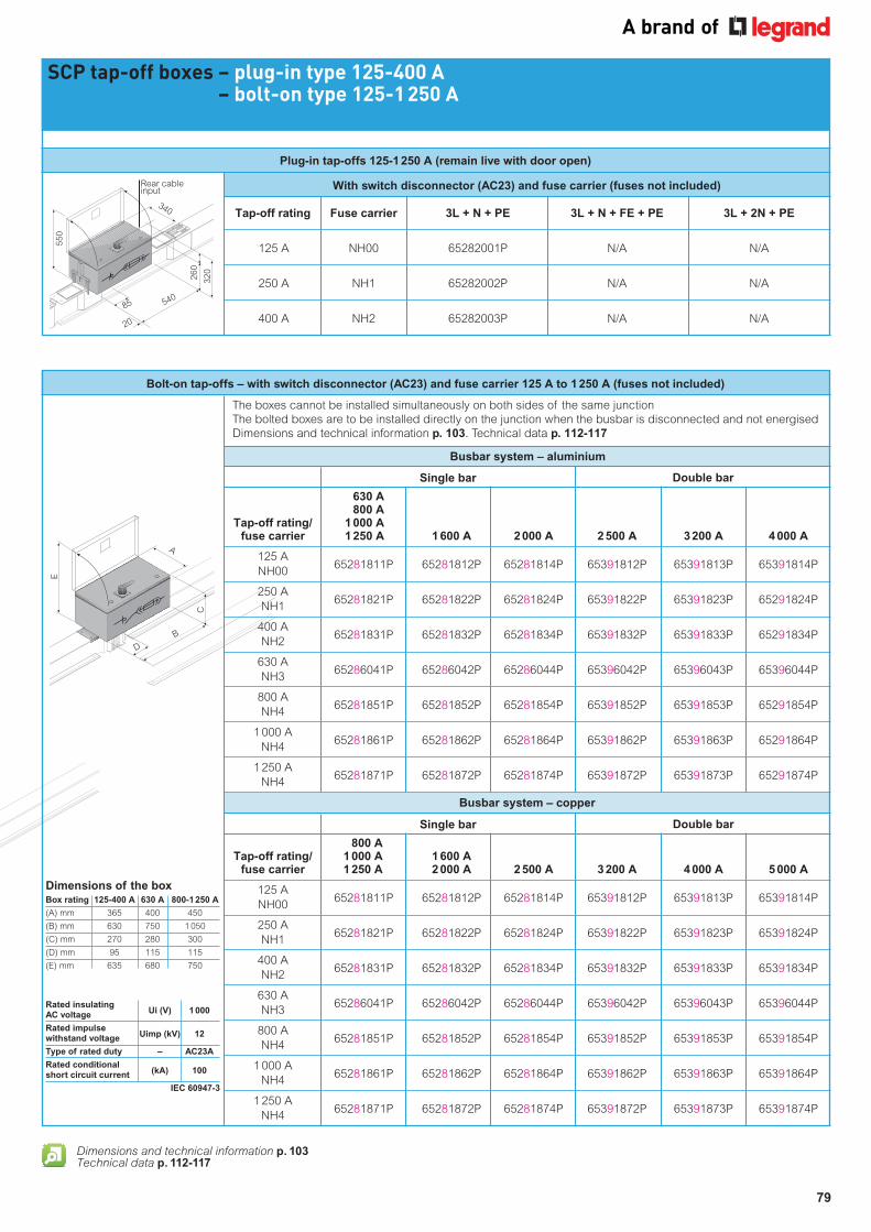
Bolt-on tap-offs – with switch disconnector (AC23) and fuse carrier 125 A to 1 250 A (fuses not included)
630 A 800 A Tap-off rating/ 1 000 A fuse carrier 1 250 A 1 600 A 2 000 A 2 500 A 3 200 A 4 000 A
125 A 65281811P 65281812P 65281814P 65391812P 65391813P 65391814P
NH00
250 A 65281821P 65281822P 65281824P 65391822P 65391823P 65291824P
NH1
400 A 65281831P 65281832P 65281834P 65391832P 65391833P 65291834P
NH2
630 A 65286041P 65286042P 65286044P 65396042P 65396043P 65396044P
NH3
800 A 65281851P 65281852P 65281854P 65391852P 65391853P 65291854P
NH4
1 000 A 65281861P 65281862P 65281864P 65391862P 65391863P 65291864P
NH4
1 250 A 65281871P 65281872P 65281874P 65391872P 65391873P 65291874P
NH4
SCP tap-off boxes – plug-in type 125-400 A – bolt-on type 125-1 250 A
With switch disconnector (AC23) and fuse carrier (fuses not included)
Tap-off rating Fuse carrier 3L + N + PE 3L + N + FE + PE 3L + 2N + PE
125 A NH00 65282001P N/A N/A
250 A NH1 65282002P N/A N/A
400 A NH2 65282003P N/A N/A
The boxes cannot be installed simultaneously on both sides of the same junction
The bolted boxes are to be installed directly on the junction when the busbar is disconnected and not energised
Dimensions and technical information p. 103. Technical data p. 112-117
Busbar system – aluminium
Single bar Double bar
800 A Tap-off rating/ 1 000 A 1 600 A fuse carrier 1 250 A 2 000 A 2 500 A 3 200 A 4 000 A 5 000 A
125 A 65281811P 65281812P 65281814P 65391812P 65391813P 65391814P
NH00
250 A 65281821P 65281822P 65281824P 65391822P 65391823P 65391824P
NH1
400 A 65281831P 65281832P 65281834P 65391832P 65391833P 65391834P
NH2
630 A 65286041P 65286042P 65286044P 65396042P 65396043P 65396044P
NH3
800 A 65281851P 65281852P 65281854P 65391852P 65391853P 65391854P
NH4
1 000 A 65281861P 65281862P 65281864P 65391862P 65391863P 65391864P
NH4
1 250 A 65281871P 65281872P 65281874P 65391872P 65391873P 65391874P
NH4
Busbar system – copper
Single bar Double bar
Dimensions of the boxBox rating 125-400 A 630 A 800-1 250 A
(A) mm 365 400 450
(B) mm 630 750 1 050
(C) mm 270 280 300
(D) mm 95 115 115
(E) mm 635 680 750
Rated insulating AC voltage
Ui (V) 1 000
Rated impulse withstand voltage
Uimp (kV) 12
Type of rated duty – AC23A
Rated conditional short circuit current
(kA) 100
IEC 60947-3
85 540
340320
260
550
20
Rear cable input
B
D
A
C
E
Plug-in tap-offs 125-1 250 A (remain live with door open)
Dimensions and technical information p. 103Technical data p. 112-117
80
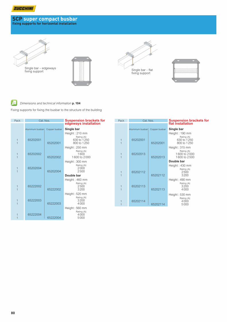
SCP super compact busbarfixing supports for horizontal installation
Fixing supports for fixing the busbar to the structure of the building
Single bar – edgeways fixing support Single bar – flat
fixing support
Dimensions and technical information p. 104
Pack Cat. Nos. Suspension brackets for flat installation
Aluminium busbar Copper busbar Single bar
Height : 190 mm Rating (A)
1 65202001 630 to 1 250 1 65202001 800 to 1 250
Height : 315 mm Rating (A)
1 65202013 1 600 to 2 000 1 65202013 1 600 to 2 500
Double bar
Height : 430 mm Rating (A)
1 65202112 2 500 1 65202112 3 200
Height : 490 mm Rating (A)
1 65202113 3 200 1 65202113 4 000
Height : 530 mm Rating (A)
1 65202114 4 000 1 65202114 5 000
Pack Cat. Nos. Suspension brackets for edgeways installation
Aluminium busbar Copper busbar Single bar
Height : 210 mm Rating (A)
1 65202001 630 to 1 250 1 65202001 800 to 1 250
Height : 250 mm Rating (A)
1 65202002 1 600 1 65202002 1 600 to 2 000
Height : 300 mm Rating (A)
1 65202004 2 000 1 65202004 2 500
Double bar
Height : 460 mm Rating (A)
1 65222002 2 500 1 65222002 3 200
Height : 520 mm Rating (A)
1 65222003 3 200 1 65222003 4 000
Height : 560 mm Rating (A)
1 65222004 4 000 1 65222004 5 000

81
SCP super compact busbarfixing supports for vertical installation
Fixing supports for fixing the busbar to the structure of the building For vertical installations and special applications
Fixing support with bracket and springs
Fixing support with bracket Fixing support with springs
Fixing support – bracket only
Dimensions and technical information p. 105-106
Pack Cat. Nos. Fixing supports with bracket and springs
Aluminium Copper Single bar Rating (A)
1 65213711 630 to 1 250 1 65213712 1 600 1 65213711 800 to 1 250 1 65213712 1 600 to 2 000 1 65213714 2 000 1 65213714 2 500
Double bar Rating (A)
1 65213742 2 500 1 65213742 3 200 1 65213743 3 200 1 65213743 4 000 1 65213744 4 000 1 65213744 5 000
Fixing supports with bracket
Aluminium Copper Single bar – anti-seismic rated Rating (A)
1 65213721 630 to 1 250 1 65213721 800 to 1 250 1 65213722 1 600 1 65213722 1 600 to 2 000 1 65213724 2 000 1 65213724 2 500
Double bar – not anti-seismic rated
Rating (A)
1 65213752 2 500 1 65213752 3 200 1 65213753 3 200 1 65213753 4 000 1 65213754 4 000 1 65213754 5 000
Double bar – anti-seismic rated
Rating (A)
1 65213792 2 500 1 65213792 3 200 1 65213793 3 200 1 65213793 4 000 1 65213794 4 000 1 65213794 5 000
Pack Cat. Nos. Fixing supports with springs
Aluminium Copper Single bar Rating (A)
1 65213701 630 to 1 250 1 65213701 800 to 1 250 1 65213702 1 600 1 65213702 1 600 to 2 000 1 65213704 2 000 1 65213704 2 500
Double bar Rating (A)
1 65213732 2 500 1 65213732 3 200 1 65213733 3 200 1 65213733 4 000 1 65213734 4 000 1 65213734 5 000
Fixing supports – bracket only
Aluminium Copper Single bar Rating (A)
1 65213761 630 to 1 250 1 65213761 800 to 1 250 1 65213762 1 600 1 65213762 1 600 to 2 000 1 65213764 2 000 1 65213764 2 500
Double bar Rating (A)
1 65213772 2 500 1 65213772 3 200 1 65213773 3 200 1 65213773 4 000 1 65213774 4 000 1 65213774 5 000

82
SCP super compact busbarfixing supports for vertical installation (continued)
SCP super compact busbarprotective bellows
Fixing support for Naval applications
Dimensions and technical information p. 105-106 Dimensions and technical information p. 107
Protective covers for outdoor applications available on request
Contact us on +44 (0) 370 608 9020
Protective bellows – single bar
Fixing supports for fixing the busbar to the structure of the building High power busbar from 630 A to 4 000 A with aluminium alloy conductors and from 800 A to 5 000 A with copper conductors SCP complies with IEC 61439-6
Pack Cat. Nos. Fixing supports for naval applications
Aluminium Copper Double bar
Rating (A)
1 65213782 2 500 1 65213782 3 200 1 65213783 3 200 1 65213783 4 000 1 65213784 4 000 1 65213784 5 000
Pack Cat. Nos. Protective bellows
Recommended for protection of the interface connection on panel boards, dry-type transformer with enclosure and oil-type transformers For Legrand cast resin transformers, custom-made connections are available upon request (see p. 83)
Aluminium Copper Single bar
Rating (A)
1 SF766040 630 to 2 000
1 SF766040 800 to 2 500
Double bar Rating (A)
1 SF927140 2 500 to 4 000 1 SF927140 3 200 to 5 000

83
SCP super compact busbartransformer connections
Transformer
Installation example
Flexible braid connection
Dimensions and technical information p. 108
High power busbar from 630 A to 4 000 A with aluminium alloy conductors and from 800 A to 5 000 A with copper conductors SCP complies with IEC 61439-6 (BS EN 61439-6)
Pack Cat. Nos. Flexible braid connections (continued)
Aluminium Copper Length : 601 - 750 mm
Rating (A) No. of braids per phase
1 FC100030 630 1
1 FC100030 FC100030 800 1
1 FC200030 FC200030 1 000 1
1 FC300030 FC300030 1 250 1
1 FC500030 FC500030 1 600 1
1 FC600030 FC600030 2 000 1
1 FC400030 FC400030 2 500 2
1 FC500030 FC500030 3 200 2
1 FC600030 FC600030 4 000 2
1 FC700030 5 000 2
Length : over 750 mm
Rating (A) No. of braids per phase
1 FC100099 630 1
1 FC100099 FC100099 800 1
1 FC200099 FC200099 1 000 1
1 FC300099 FC300099 1 250 1
1 FC500099 FC500099 1 600 1
1 FC600099 FC600099 2 000 1
1 FC400099 FC400099 2 500 2
1 FC500099 FC500099 3 200 2
1 FC600099 FC600099 4 000 2
1 FC700099 5 000 2
Pack Cat. Nos. Flexible braid connections
When ordering, please specify hole dimensions on transformer side (A, B, Ø D) and length L (see p. 108)
Aluminium Copper Length : 300 - 450 mm
Rating (A) No. of braids per phase
1 FC100010 630 1
1 FC100010 FC100010 800 1
1 FC200010 FC200010 1 000 1
1 FC300010 FC300010 1 250 1
1 FC500010 FC500010 1 600 1
1 FC600010 FC600010 2 000 1
1 FC400010 FC400010 2 500 2
1 FC500010 FC500010 3 200 2
1 FC600010 FC600010 4 000 2
1 FC700010 5 000 2
Length : 451 - 600 mm
Rating (A) No. of braids per phase
1 FC100020 630 1
1 FC100020 FC100020 800 1
1 FC200020 FC200020 1 000 1
1 FC300020 FC300020 1 250 1
1 FC500020 FC500020 1 600 1
1 FC600020 FC600020 2 000 1
1 FC400020 FC400020 2 500 2
1 FC500020 FC500020 3 200 2
1 FC600020 FC600020 4 000 2
1 FC700020 5 000 2
84
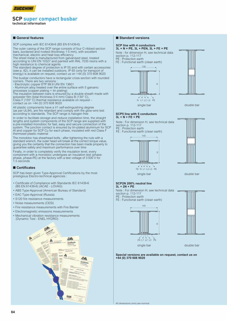
SCP super compact busbartechnical information
Special versions are available on request, contact us on +44 (0) 370 608 9020
SCP5 line with 5 conductors 3L + N + FE + PE
single bar double bar
Note : For dimension H, see technical data section p. 112-117PE : Protection earthFE : Functional earth (clean earth)
140
H
FE PEL2L1N L3
SCP2N 200% neutral line 3L + 2N + PE
single bar double bar
Note : For dimension H, see technical data section p. 112-117PE : Protection earthFE : Functional earth (clean earth)
140
H
2N PEL2L1 L3
n Standard versions
SCP line with 4 conductors 3L + N + PE, 3L + PEN, 3L + FE + PE
single bar double bar
Note : for dimension H, see technical data section p. 112-117PE : Protection earthFE : Functional earth (clean earth)
130
H
N PEL3L2L1
All dimensions (mm) are nominal
n General features
SCP complies with IEC 61439-6 (BS EN 61439-6)
The outer casing of the SCP range consists of four C-ribbed section bars, bordered and riveted (thickness 1·5 mm), with excellent mechanical, electric and heat loss efficiencyThe sheet metal is manufactured from galvanised steel, treated according to UNI EN 10327 and painted with RAL 7035 resins with a high resistance to chemical agentsThe standard degree of protection is IP 55 and with certain accessories (see p. 82), it can be installed outdoors. IP 65 (only for transport of energy) is available on request, contact us on +44 (0) 370 608 9020
The busbar conductors have a rectangular cross-section with rounded corners. There are two versions : - Electrolytic copper ETP 99.9 UNI EN 13601- Aluminum alloy treated over the entire surface with 5 galvanic processes (copper plating + tin plating)The insulation between bars is ensured by a double sheath made with polyester film (total thickness 0·4 mm) Class B (130° C), Class F (155° C) thermal resistance available on request – contact us on +44 (0) 370 608 9020
All plastic components have a V1 self-extinguishing degree (as per UL94), are fire retardant and comply with the glow-wire test according to standards. The SCP range is halogen free
In order to facilitate storage and reduce installation time, the straight lengths and system components of the SCP range are supplied with a pre-installed monobloc for fast, easy and secure connection of the system. The junction contact is ensured by tin-plated aluminium for SCP Al and copper for SCP Cu for each phase, insulated with red Class F thermoset plastic material
The monobloc has shearhead bolts : after tightening the nuts with a standard wrench, the outer head will break at the correct torque value, giving you the certainty that the connection has been made properly to guarantee safety and maximum performance over time
Finally, in order to completely verify the insulation level, every component with a monobloc undergoes an insulation test (phase-phase, phase-PE) at the factory with a test voltage of 3 500 V for 1.5 seconds
n Certificates
SCP has been given Type-Approval Certifications by the most prestigious Electro-technical agencies :
• Certificate of Compliance with Standards IEC 61439-6 (BS EN 61439-6) (ACAE - LOVAG)
• ABS Type-Approval (American Bureau of Standard)
• EAC Type-Approval (Russia)
• S120 fire resistance measurements
• Noise measurements (CESI)
• Fire resistance measurements with Fire Barrier
• Electromagnetic emissions measurements
• Mechanical vibration resistance measurements (Dynamic Test - ENEL HYDRO)

85
Ue ≤ 1 000 V
630 < In < 5 000 A
36 < lcw < 160 kA
–5 < T < + 50 °C
IP = 55
SCP
Busbar material selection
COPPER
800 < In < 5 000 A
ALUMINIUM
630 < In < 4 000 A
Double bar
3 200 < In < 5000 A
Single bar
630 < In < 2 000 A
Double bar
2 500 < In < 4 000 A
Single bar
800 < In < 2 500 A
n Electric design criteria

86
SCP super compact busbartechnical information
n Losses based on the installation method
Thermal dispersion, rating and IP protection degree are independent from the type of installation (edgeways, flat, vertical)This means that it is possible to install the SCP busbar trunking system as preferred, without having to consider a possible system downgrade
Edgeways
n Joule effect losses in busbars
Losses due to the Joule effect are essentially caused by the electrical resistance of the busbarLost energy is transformed into heat and contributes to the heating of the conduit of the environmentThe calculation of power loss is useful data for correct sizing of the building air conditioning system
Three-phase regime losses are :
Pj = 3 • Rt • Ib2 • L
1 000
In single-phase regime :
Pj = 2 • Rt •Ib2 • L
1 000
Where :Ib = utilisation current (A) Rt = phase resistance for unit of length of the busbar trunking system,
measured at thermal regime (mΩ/m)L = busbar length (m)
For accurate calculation, losses must be assessed trunk by trunk, taking into account the transiting currents ; for example, in the case of the distribution of the loads represented in the table below
Total losses in the busbar trunking system Pt = P1 + P2 + P3
L1
L2
L3
L L L
l1 l3l2
I1+I2+I3 I2+I3 I3
Length Transiting Losses current
1st trunk L1 I1+I2+I3 P1 = 3RtL1(I1+I2+I3)2
2nd trunk L2-L1 I2+I3 P2 = 3Rt(L2-L1) (I2+I3)2
3rd trunk L3-L2 I3 P3 = 3Rt(L3-L2) (I3)2
Flat

87
n Overload protection
Busbar overload protection is ensured following the same criteria used for cables. It will be necessary to check the relationship :
Ib ≤ In ≤ Iz
Where :
Ib = circuit utilisation currentIn = switch rated current Iz = rating at permanent cable regime
The lb utilisation current in a 3 phase system is calculated based on the following formula :
Ib = (A)
Where :
Pt = sum of the active powers of the loads installed (W)d = power supply factor equal to 1 if the trunking is : •only powered from one side •powered from the centre or from both ends at the same timeUe = operating voltage in (V)cosϕm = average power factor of the loadsIb = utilisation current (A) α = diversity coefficient of the loads (.)β = coefficient of utilisation of the loads (.)
Pt•α•β•d
√3•Ue•cosϕ medium
Ambient temperature (°C) 15 20 25 30 35 40 45 50 55 60
kt thermal correction factor 1·15 1·12 1·08 1·05 1·025 1 0·975 0·95 0·93 0·89
Kt correction coefficient for ambient temperature other than 40°C
The ambient temperature where the busbar trunking system is installed impacts on its ratingDuring the design stages, it is necessary to multiply the rating value at the reference temperature by a correction coefficient referred to the final operating temperatureAll Zucchini products have been sized and tested for an average ambient temperature of 40 °C. For installation in environments with average daily temperatures lower than 40 °C, the rated current of the busbar must be multiplied by a kt factor, which is higher than the unit for temperatures lower than 40 °C, and lower than the unit if the ambient temperature is higher than 40 °C
Iz = Iz0 · Kt
Where :• Iz0 is the current that the busbar trunking system can carry for an indefinite time at its reference temperature (40 °C)• Kt is the correction coefficient for ambient temperature values other than the reference temperature, as shown in the following table
I
Ib Iz 1.45 Iz
88
L L L
SCP super compact busbartechnical information
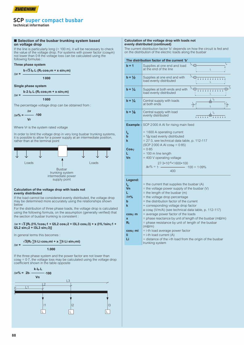
n Selection of the busbar trunking system based on voltage drop
If the line is particularly long (> 100 m), it will be necessary to check the value of the voltage drop. For systems with power factor (cosϕm) not lower than 0·8 the voltage loss can be calculated using the following formulas :
Three phase system
Single phase system
The percentage voltage drop can be obtained from :
Where Vr is the system rated voltage
In order to limit the voltage drop in very long busbar trunking systems, it is possible to allow for a power supply at an intermediate position, rather than at the terminal point
Calculation of the voltage drop with loads not evenly distributed (continued)
The current distribution factor ‘b’ depends on how the circuit is fed and on the distribution of the electric loads along the busbar
b•√3•Ib•L•(Rt•cosϕm + x•sinϕm)∆v =
1 000
b•2•Ib•L•(Rt•cosϕm + x•sinϕm)∆v =
1 000
∆v
∆v% = •100
Vr
Loads Loads
Busbar trunking system
intermediate power supply point
Calculation of the voltage drop with loads not evenly distributed
If the load cannot be considered evenly distributed, the voltage drop may be determined more accurately using the relationships shown below
For the distribution of three phase loads, the voltage drop is calculated
using the following formula, on the assumption (generally verified) that
the section of busbar trunking is consistent :
∆v = √3 [Rt (I1L1cosϕ1 + I2L2 cosϕ2 + I3L3 cosϕ3) + x (I1L1sinϕ1 + I2L2 sinϕ2 + I3L3 sinϕ3)]
In general terms this becomes :
√3(Rt•∑Ii•Li•cosϕmi + x•∑Ii•Li•sinϕmi)∆v =
1.000
If the three phase system and the power factor are not lower than cosϕ = 0·7, the voltage loss may be calculated using the voltage drop coefficient shown in the table opposite
k•Ib•L
∆v% = 2b• ·100
Vn
L2L3
L L L
l1 l2 l3
L1
Ib
L
Ib
L
Ib
L
L
Ib2
Ib
Ib
Ib
Ib2
Ib
The distribution factor of the current ‘b’
b = 1 Supplies at one end and load at the end of the line
b = 2 Supplies at one end and with load evenly distributed
b = 4 Supplies at both ends and with load evenly distributed
b = 4 Central supply with loads at both ends
b = 8 Central supply with load evenly distributed
Example : SCP 2 000 A Al for rising main feed
Ib = 1 600 A operating current
b = 2 load evenly distributed
k = 27·3, see technical data table, p. 112-117
(SCP 2 000 A Al cosϕ = 0·85)
Cosϕ = 0·85
L = 100 m line length
Vn = 400 V operating voltage
Legend:
Ib = the current that supplies the busbar (A)
Vn = the voltage power supply of the busbar (V)
L = the length of the busbar (m)
∆v% = the voltage drop percentage
b = the distribution factor of the current
k = corresponding voltage drop factor
a cosϕ (V/m/A) (see technical data table, p. 112-117)
cosϕ m = average power factor of the loads
x = phase reactance by unit of length of the busbar (mΩ/m)
Rt = phase resistance by unit of length of the busbar (mΩ/m)
cosϕ mi = i-th load average power factor
li = i-th load current (A)
Li = distance of the i-th load from the origin of the busbar trunking system
27·3•10-6•1 600•100∆v% = 1· ·100 = 1·09% 400
89
All dimensions (mm) are nominal
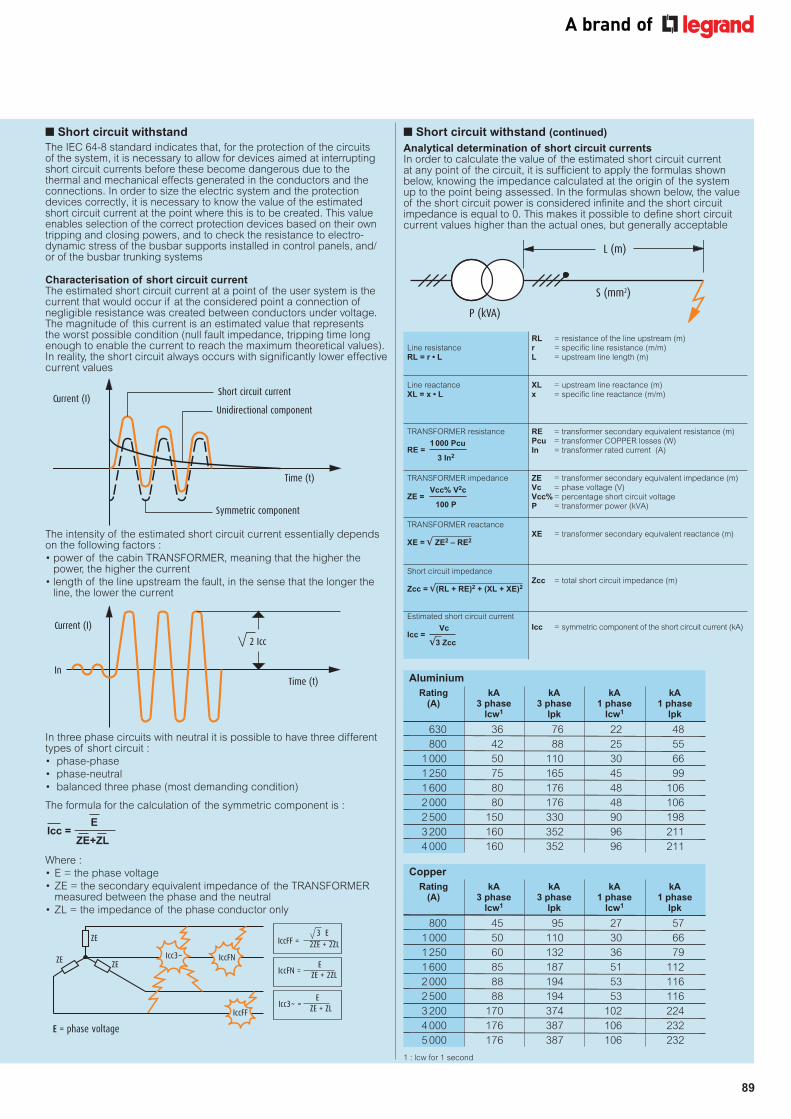
n Short circuit withstand
The IEC 64-8 standard indicates that, for the protection of the circuits of the system, it is necessary to allow for devices aimed at interrupting short circuit currents before these become dangerous due to the thermal and mechanical effects generated in the conductors and the connections. In order to size the electric system and the protection devices correctly, it is necessary to know the value of the estimated short circuit current at the point where this is to be created. This value enables selection of the correct protection devices based on their own tripping and closing powers, and to check the resistance to electro-dynamic stress of the busbar supports installed in control panels, and/or of the busbar trunking systems
Characterisation of short circuit currentThe estimated short circuit current at a point of the user system is the current that would occur if at the considered point a connection of negligible resistance was created between conductors under voltage.The magnitude of this current is an estimated value that represents the worst possible condition (null fault impedance, tripping time long enough to enable the current to reach the maximum theoretical values).In reality, the short circuit always occurs with significantly lower effective current values
The intensity of the estimated short circuit current essentially depends on the following factors :
• power of the cabin TRANSFORMER, meaning that the higher the power, the higher the current
• length of the line upstream the fault, in the sense that the longer the line, the lower the current
In three phase circuits with neutral it is possible to have three different types of short circuit :
• phase-phase
• phase-neutral
• balanced three phase (most demanding condition)
The formula for the calculation of the symmetric component is :
Where :
• E = the phase voltage
• ZE = the secondary equivalent impedance of the TRANSFORMER measured between the phase and the neutral
• ZL = the impedance of the phase conductor only
Short circuit current
Unidirectional component
Symmetric component
Time (t)
Current (I)
Time (t)
Current (I)
Andamento reale
In
2 Icc
ZE
Icc3~ IccFN
IccFF
IccFF = 2ZE + 2ZL
3 E
IccFN = ZE + 2ZL E
Icc3~ = ZE + ZL E
E = phase voltage
ZEZE
Icc =E
ZE+ZL
1 : lcw for 1 second
L (m)
S (mm2)
P (kVA)
n Short circuit withstand (continued)
Analytical determination of short circuit currentsIn order to calculate the value of the estimated short circuit current at any point of the circuit, it is sufficient to apply the formulas shown below, knowing the impedance calculated at the origin of the system up to the point being assessed. In the formulas shown below, the value of the short circuit power is considered infinite and the short circuit impedance is equal to 0. This makes it possible to define short circuit current values higher than the actual ones, but generally acceptable
RL = resistance of the line upstream (m) Line resistance r = specific line resistance (m/m) RL = r • L L = upstream line length (m) Line reactance XL = upstream line reactance (m) XL = x • L x = specific line reactance (m/m) TRANSFORMER resistance RE = transformer secondary equivalent resistance (m) Pcu = transformer COPPER losses (W) In = transformer rated current (A) TRANSFORMER impedance ZE = transformer secondary equivalent impedance (m) Vc = phase voltage (V) Vcc% = percentage short circuit voltage P = transformer power (kVA) TRANSFORMER reactance XE = transformer secondary equivalent reactance (m) Short circuit impedance Zcc = total short circuit impedance (m) Estimated short circuit current Icc = symmetric component of the short circuit current (kA)
VcIcc =
√3 Zcc
1 000 PcuRE =
3 In2
XE = √ ZE2 – RE2
Zcc = √(RL + RE)2 + (XL + XE)2
Vcc% V2cZE =
100 P
Aluminium
Rating kA kA kA kA (A) 3 phase 3 phase 1 phase 1 phase lcw1 lpk lcw1 lpk
630 36 76 22 48
800 42 88 25 55
1 000 50 110 30 66
1 250 75 165 45 99
1 600 80 176 48 106
2 000 80 176 48 106
2 500 150 330 90 198
3 200 160 352 96 211
4 000 160 352 96 211
Copper
Rating kA kA kA kA (A) 3 phase 3 phase 1 phase 1 phase lcw1 lpk lcw1 lpk
800 45 95 27 57
1 000 50 110 30 66
1 250 60 132 36 79
1 600 85 187 51 112
2 000 88 194 53 116
2 500 88 194 53 116
3 200 170 374 102 224
4 000 176 387 106 232
5 000 176 387 106 232

90
SCP super compact busbartechnical information
Note200% neutral versions are available for systems with harmonics present on the neutral
Choice of rating when in the presence of harmonics
When in the presence of harmonics, and when using the chosen Int rated current, the SCP busbar to be used shall have the rating specified in the table below
u
t
Fundamental (50 Hz)
Third harmonic (150 Hz)
Fifth harmonic (250 Hz)
Resulting wave shape
100%
23%
11%
50 100 200 300 350 400 450 500 550 600 650 700 750 800 850 900 950 1000250150 Hz
THD% = 100H
h = 2
Uh
U1( )
2 23
100( )2
+11
100( )2
= 100 = 25.5 %
Total distortion (THD) = 25.5%
Distortion of the individual harmonics
Measurement of harmonic distortion carried out with a network analyser
Rated current (A) 630 A 800 A 1 000 A 1 250 A 1 600 A 2 000 A 2 500 A 3 200 A 4 000 A 5 000 A
SCP busbar to be used
THD ≤ 15% 630 800 1 000 1 250 1 600 2 000 2 500 3 200 4 000 5 000
15% < THD ≤ 33% 800 1 000 1 250 1 600 2 000 2 500 3 200 4 000 5 000 –
THD > 33% 1 000 1 250 1 600 2 000 2 500 3 200 4 000 5 000 – –
n Harmonics
In a distribution system, currents and voltages should have a perfectly sinusoidal shape. However, in practice the equipment contains electric devices such as changeover devices or dimmers that make the load not linearThe currents absorbed, although at regular intervals and with frequencies equal to that of the rated voltage, sometimes have a non-sinusoidal wave form, which has the following negative effects :• worsening of the power factor• heating of the neutral• additional losses in electric machinery (transformers and motors)• instable operation of the protection elements (thermal magnetic and earth leakage circuit breakers)In industrial plants these conditions have been occurring for a long time. However, they are now occurring more and more in service sector distribution systems, where, from backbone distribution (which uses 3 phase lines), single phase loads are often distributed, which contributes to increasing the unbalance of the electric systemEach type of non-sinusoidal periodical wave may be split into a more or less large number of sinusoids (called harmonic components)A deformed current at a frequency of 50 Hz, like the example represented by the magenta line on the figure, consists of many sinusoidal currents with frequency of 50 Hz (fundamental), 100 Hz (second harmonic component), 150 Hz (third harmonic), and so onThe presence of current harmonics represents an important problem, causing overload conditions both on phase conductors, and on any neutral conductor, and results in the reduction of the conductor’s permitted load

91
All dimensions (mm) are nominal
One-dimensional trend of the magnetic induction near the junction. The blue dash shows the ‘objective’ level and the red dash shows the ‘quality objective’ required by law
n Measurement of magnetic induction
Since 1994, with a study carried out by Chalmers University of Technology of Goteborg, Legrand has taken an interest in the issues linked with the electromagnetic emissions in their Zucchini products, keeping at the forefront of the latest legislative directive, which has only recently imposed the quality standards that were already widely met by Zucchini busbar trunking systems
The ACAE (Association for the Certification of Electric and Electronic Equipment) certified internal laboratory is capable of carrying out the measurement of the electromagnetic emissions of busbar trunking systems. This measurement is nowadays one of the tests to which the products are subjected before they reach the market
The busbar trunking system in itself already minimises electromagnetic emissions, which are much lower when compared with those generated by cables with the same current intensity
It is a well-known fact that the electromagnetic field is the result of the superimposition of two fields : the electric and the magnetic fieldThe first is totally shielded by the equipotential metal casing of the busbar trunking system, while the second is very low due to the intrinsic characteristic of the busbar trunking system. More precisely, due to the fact that busbar conductors are extremely close inside the busbar package, the three busbar conductors, crossed by three balanced currents displaced by 120°, induce fields that tend to overlap, cancelling one another, therefore resulting in an extremely low external impact
However, also in conditions of imperfect current balance, the metal casing of the busbar trunking system is capable of reducing most of the magnetic field, which otherwise would spread through the surrounding environment
The laboratory tests carried out show how the magnetic induction emitted by SCP busbar trunking systems, measured at a distance of approximately one metre, is well below the critical value of 3 μT
With Legislative Decree DPCM dated 8/7/2003, Italian law set the first exposure limit at 100 μTIn addition, in locations where attendance is expected for no less than four hours a day, an attention value of 10 μT has been set, to avoid possible long term effects on healthIn the decree, the 3 μT threshold is indicated as the ‘quality objective’. However, as the product is intended for the European and world market, low magnetic emission is a fundamental point that cannot be disregarded, to ensure a presence in foreign countries : one example of this is Germany, where for over 10 years the regulation has set a cautionary limit of 3 μT as the maximum permitted threshold in certain structures, for example hospitals, so much so that in these types of environments the busbar trunking system has become a mandatory choice, as well as a high quality one
Testing at Legrand’s laboratory in Italy for the approval certification of Zucchini SCP busbar trunking systems
n Measurement of magnetic induction (continued)
The high quality standard guaranteed by busbar trunking systems can be further appreciated by comparing the emission values measured against those of other commonly used equipment, as taken from table 7·1 of IEC 211-6 standardThe measurements obtained on aluminium SCP busbar trunking systems with ratings of 2 500 A – carried out in compliance with the requirements of the technical product standard IEC 61439-6 (BS EN 61439-6) – show that the magnetic induction generated by the busbar is in the range of 1·5 - 2 μT at a distance of one metre from the busbar itselfThese values also apply near the junction, which is considered the critical point due to the wider distance between the busbar conductors in this position
Levels of exposure to industrial frequency magnetic field sources (table 7.1 from IEC 211-6 standard)
Magnetic Source induction Distance (µT)
Electric shaver 150-240 on the face
Hairdryer 1-13 10-20 cm
Blender 0·9 40 cm
12 V, 20 W halogen lamp 0·5 30 cm
Aerosol therapy equipment 20-50 20-30 cm
Electric blanket 2 on contact
21 inch television set 0·3 50 cm
Washing machine 3·4 50 cm
Dishwasher 0·05 50 cm
Electric oven 0·4 20 cm
600 W drill 2 on the chest
100 W welding machine 14·5 on the chest
225 W grinder 0·8 40 cm
1 100 W compressor 8·2 40 cm
2 150 W arc welding machine 23·2 40 cm
75 MW, 55-65 kA, 150 t arc oven 100-270 in proximity
Electric scalpel 2·9 in proximity
Battery charger 22·9 in proximity
Echograph 0·8 operator position
Projector 2·3 20 cm
B (μ T)
Objective level
Quality objective level
25
20
15
10
5
0
20 40 60 80 100 120 CM
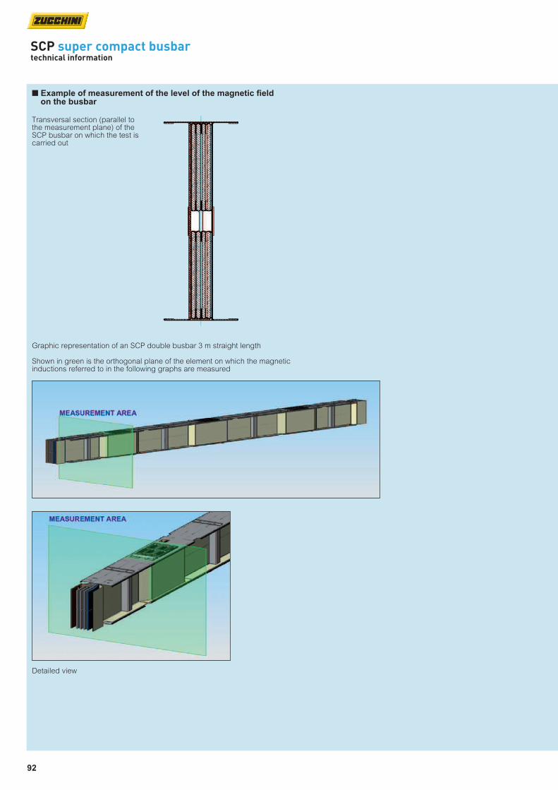
92
SCP super compact busbartechnical information
n Example of measurement of the level of the magnetic field on the busbar
Transversal section (parallel to the measurement plane) of the SCP busbar on which the test is carried out
Graphic representation of an SCP double busbar 3 m straight length
Shown in green is the orthogonal plane of the element on which the magnetic inductions referred to in the following graphs are measured
Detailed view

93
n Magnetic induction graphs at 60 cm from the busbar
The graphs shown refer to the measurements carried out on the aluminium SCP prefabricated electric busbar with rated load of 2 500 A, crossed by a 2 500 A current
The measurements carried out at 60 cm from the junction are to be considered as higher due to the magnetic induction generated by the busbar power supply : due to the intrinsic geometry of the measurement laboratory structure, it must be assumed that the measurement area is also affected by a magnetic induction of no less than 1·5 μT generated by the line power supply
In view of this observation, in case of actual operating line the quality objective indicated by Legislative Decree DPCM dated 8/7/2003 is widely met at less than one metre from the axis of the busbar
All dimensions (mm) are nominal
3 dimensional development of magnetic induction around the busbar at 60 cm from the junction
2 dimensional map of the magnetic induction around the busbar at 60 cm from the junctionAt the centre of the graphic is a schematic representation of the busbar
x
y
The cells making up the measurement grid are 20 cm squares
n Magnetic induction graphs at 60 cm from the busbar (continued)
As it can be seen on the graph below, up to a distance of approximately 40 cm from the axis of the busbar, the field appears generated by two separate sources. This is due to the fact that the busbar being analysed consists of two series of busbar conductors set in parallel at a distance of approximately 5 cm from each other
12
11
10
9
8
7
6
5
4
3
2
1
0
1211·611·210·810·4109·69·28·88·487·67·26·86·465·65·24·84·443·63·22·82·421·61·20·80·4
01
23
45
67
8910
1112
1314
1516
1211·611·210·810·4109·69·28·88·487·67·26·86·465·65·24·84·443·63·22·82·421·61·20·80·4
12
11
10
9
8
7
6
5
4
3
2
1
0 1615
141312
111098
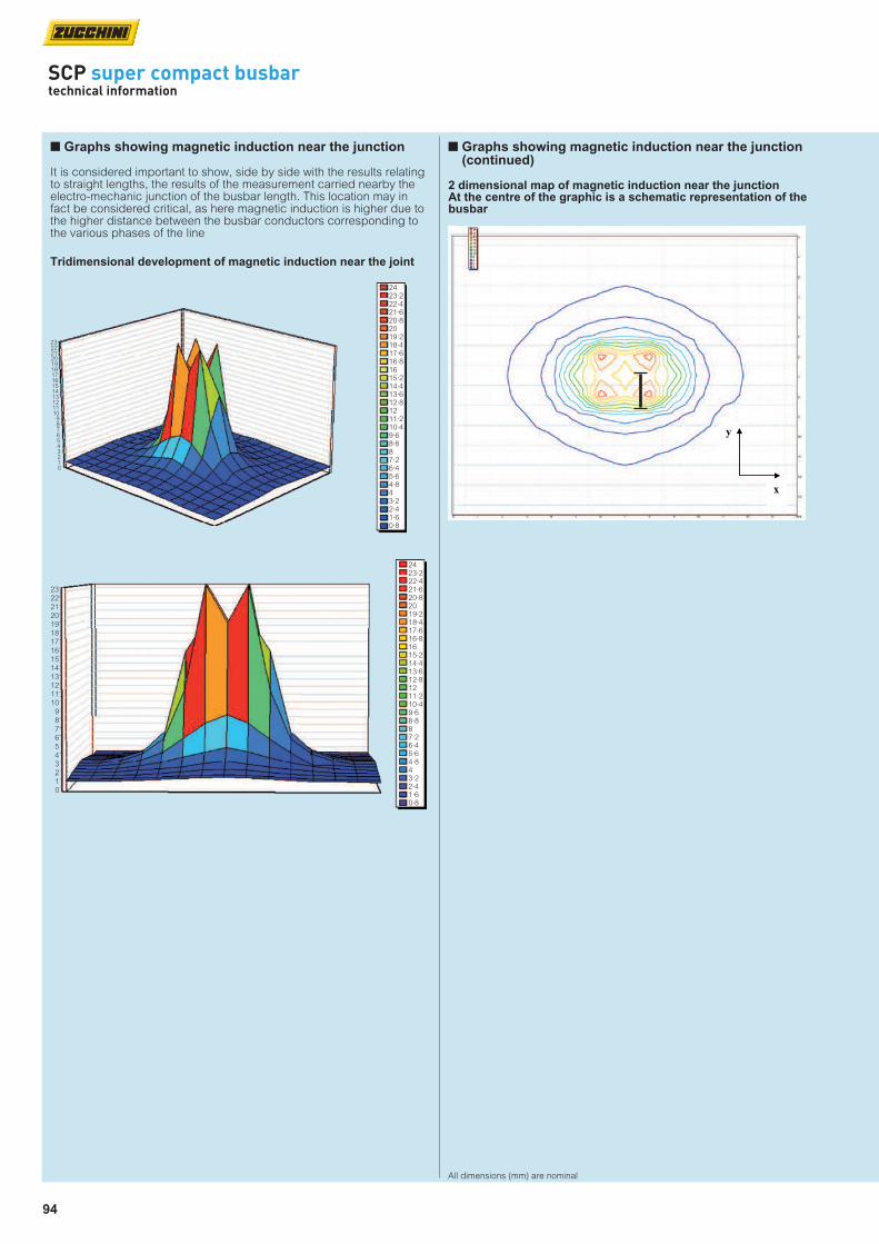
94
SCP super compact busbartechnical information
n Graphs showing magnetic induction near the junction
It is considered important to show, side by side with the results relating to straight lengths, the results of the measurement carried nearby the electro-mechanic junction of the busbar length. This location may in fact be considered critical, as here magnetic induction is higher due to the higher distance between the busbar conductors corresponding to the various phases of the line
All dimensions (mm) are nominal
Tridimensional development of magnetic induction near the joint
2 dimensional map of magnetic induction near the junctionAt the centre of the graphic is a schematic representation of the busbar
x
y
2423·222·421·620·82019·218·417·616·81615·214·413·612·81211·210·49·68·887·26·45·64·843·22·41·60·8
2322212019181716151413121110
9876543210
2423·222·421·620·82019·218·417·616·81615·214·413·612·81211·210·49·68·887·26·45·64·843·22·41·60·8
2322212019181716151413121110
9876543210
n Graphs showing magnetic induction near the junction (continued)

95
n Feeder lengths
3 000 (L
)
Dimension H changes with the rating, and is specified on p. 112-117
10
H
3 000 (L
)
10
HMinimum and maximum dimensions of single and double bars
Aluminium 630 A to 4 000 A
Copper 800 A to 5 000 A
(L) min./max. (mm) 1 000 / 3 000
n Distribution lengths
Dimension H changes with the rating, and is specified on p. 112-117
Minimum and maximum dimensions of single and double bars
Aluminium 630 A to 4 000 A
Copper 800 A to 5 000 A
(L) min./max. (mm) 1 000 / 3 000
3 000 (L
)
650
850
850
650 10
H
n Expansion lengths
Absorb the thermal expansion during normal use that, on long runs, would otherwise cumulate and put abnormal force on the connection points
Expansion lengths should be placed in straight runs of more than 40 m and repeated every 40 m
e.g. 70 m straight section should contain 1 expansion length in the middle
e.g. 120 m straight section should contain 2 expansion lengths, spaced every 40 m
All dimensions (mm) are nominal
n Transposition lengths
N 1
2 3
N 3
1 2
1 200
10
H
Phase transposition
1 2
3 N
N 1
2 3
10
1 000
H
Neutral rotation
175
n End stops
Maintain IP 55 protection at the end of a run
In runs exceeding 100 m it is recommended to include two transposition lengths to balance mutual phase reactance and electric impedance (one at 1/3 and one at 2/3 distance of the run)
Dimension H changes with the rating and is specified on p. 112-117
Neutral rotation can be used when the sequence of the distribution board phases is different to that of the transformer
For more information please contact us on +44 (0) 370 608 9020
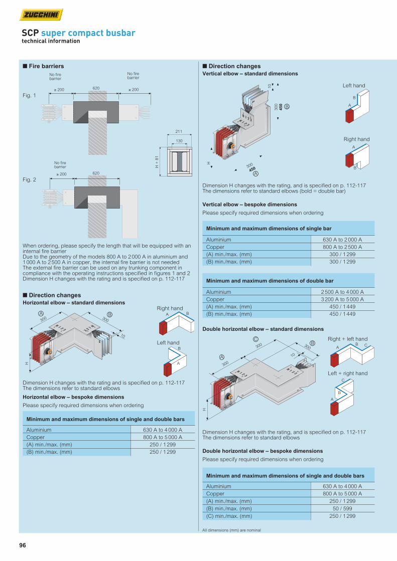
96
SCP super compact busbartechnical information
n Fire barriers
Dimension H changes with the rating and is specified on p. 112-117 The dimensions refer to standard elbows
Horizontal elbow – bespoke dimensions
Please specify required dimensions when ordering
Minimum and maximum dimensions of single and double bars
Aluminium 630 A to 4 000 A
Copper 800 A to 5 000 A
(A) min./max. (mm) 250 / 1 299
(B) min./max. (mm) 250 / 1 299
When ordering, please specify the length that will be equipped with an internal fire barrierDue to the geometry of the models 800 A to 2 000 A in aluminium and 1 000 A to 2 500 A in copper, the internal fire barrier is not needed The external fire barrier can be used on any trunking component in compliance with the operating instructions specified in figures 1 and 2 Dimension H changes with the rating and is specified on p. 112-117
211
130
H +
81
Fig. 2
620≥ 200
No fire barrier
≥ 200
Fig. 1
No fire barrier
No fire barrier
≥ 200 620
n Direction changes
Horizontal elbow – standard dimensions
H
10
300 300
A B
Right handA B
Left hand
A
B
All dimensions (mm) are nominal
Dimension H changes with the rating, and is specified on p. 112-117 The dimensions refer to standard elbows (bold = double bar)
Minimum and maximum dimensions of single bar
Aluminium 630 A to 2 000 A
Copper 800 A to 2 500 A
(A) min./max. (mm) 300 / 1 299
(B) min./max. (mm) 300 / 1 299
Minimum and maximum dimensions of double bar
Aluminium 2 500 A to 4 000 A
Copper 3 200 A to 5 000 A
(A) min./max. (mm) 450 / 1 449
(B) min./max. (mm) 450 / 1 449
n Direction changes
Vertical elbow – standard dimensions
10
300
450
H
A
300
450
B
Left hand
A
B
Right hand
A
B
Vertical elbow – bespoke dimensions
Please specify required dimensions when ordering
Dimension H changes with the rating, and is specified on p. 112-117The dimensions refer to standard elbows
Minimum and maximum dimensions of single and double bars
Aluminium 630 A to 4 000 A
Copper 800 A to 5 000 A
(A) min./max. (mm) 250 / 1 299
(B) min./max. (mm) 50 / 599
(C) min./max. (mm) 250 / 1 299
Double horizontal elbow – standard dimensions
Right + left hand
AB C
Left + right hand
A
B
C
10
300
H
300300
A
CB
Double horizontal elbow – bespoke dimensions
Please specify required dimensions when ordering

97
Dimension H changes with the rating, and is specified on p. 112-117The dimensions refer to standard elbows (bold = double bar)
Dimension H changes with the rating, and is specified on p. 112-117The dimensions refer to standard tees (bold = double bar)
Minimum and maximum dimensions of single bar
Aluminium 630 A to 2 000 A
Copper 800 A to 2 500 A
(A) min./max. (mm) 300 / 1 299
(B) min./max. (mm) 50 / 599
(C) min./max. (mm) 300 / 1 299
Minimum and maximum dimensions of double bar
Aluminium 2 500 A to 4 000 A
Copper 3 200 A to 5 000 A
(A) min./max. (mm) 450 / 1 449
(B) min./max. (mm) 50 / 899
(C) min./max. (mm) 450 / 1 449
Double vertical elbow – standard dimensions
Minimum and maximum dimensions of single bar
Aluminium 630 A to 2 000 A
Copper 800 A to 2 500 A
(A) min./max. (mm) 250 / 1 299
(B) min./max. (mm) 200 / 599
(C) min./max. (mm) 300 / 1 299
Minimum and maximum dimensions of double bar
Aluminium 2 500 A to 4 000 A
Copper 3 200 A to 5 000 A
(A) min./max. (mm) 250 / 1 449
(B) min./max. (mm) 330 / 749
(C) min./max. (mm) 450 / 1 449
Vertical tees – standard dimensions
H
300
450
300
450
A
B
300
450
C
10
Left + right hand
A
B
C
Right + left handA
B
C
A
B
C
Right hand - female
Left hand - male
A
B
C
Right hand - male
A
B
C
Left hand - female
A
B
C
H
300
600
300
600
A
C
300
600
B
10
10
Double vertical elbow – bespoke dimensions
Please specify required dimensions when ordering
Vertical tees – bespoke dimensions
Please specify required dimensions when ordering
All dimensions (mm) are nominal

98
SCP super compact busbartechnical information
n Direction changes (continued)
Horizontal tees – standard dimensions
Minimum and maximum dimensions of single and double bars
Aluminium 630 A to 4 000 A
Copper 800 A to 5 000 A
(A) min. / max. (mm) 550 / 1 049
(B) min. / max. (mm) 550 / 1 049
(C) min. / max. (mm) 550 / 1 049
Dimension H changes with the rating, and is specified on p. 112-117The dimensions refer to standard tees (bold = double bar)
H
600
A
C600B
10
600
10
A
B
C
Right hand – female
Left hand – male
A
B
C
Right hand – male
A
B
C
Left hand – female
A
B
C
Minimum and maximum dimensions of single and double bars
Aluminium 630 A to 4 000 A
Copper 800 A to 5 000 A
(A) min. / max. (mm) 300 / 1 299
(U) min. / max. (mm) 150 / 400
n Connection interfaces – in-line
Standard dimensions
F
ED
G
Dimensions to be provided when requesting a non-standard centre distance
Non-standard centre distance
H
300
100
200
100100A
U(1)
(2)
Type 2 – female
UA
A
Type 1 – maleU
Horizontal tees – bespoke dimensions
Please specify required dimensions when ordering
Connection interfaces – in-line bespoke dimensions
Please specify required dimensions when ordering
All dimensions (mm) are nominal
H
(1)
(2)
300
100
200
100100
A
U300
10
B
n Connection interfaces + horizontal elbows
Minimum and maximum dimensions of single and double bars
Aluminium 630 A to 4 000 A
Copper 800 A to 5 000 A
(A) min. / max. (mm) 150 / 1 299
(B) min. / max. (mm) 250 / 1 299
(U) min. / max. (mm) 150 / 400
A
Type 3 – maleU
B
Type 1 – female
AU
B
Type 2 – female
AU
B
Type 4 – male
A
U
B
Dimension H changes with the rating and is specified on p. 112-117The dimensions are referred to standard elementsSee p. 100 for dimensions of cover plate (1) and bars (2)
Connection interfaces + horizontal elbows – bespoke dimensions
Please specify required dimensions when ordering
Dimension H changes with the rating, and is specified on p. 112-117See p. 100 for dimensions of cover plate (1) and bars (2)

99
All dimensions (mm) are nominal
n Connection interfaces + vertical elbows
Minimum and maximum dimensions of single bar
Aluminium 630 A to 2 000 A
Copper 800 A to 2 500 A
(A) min. / max. (mm) 150 / 1 299
(B) min. / max. (mm) 300 / 1 299
(U) min. / max. (mm) 150 / 400
Minimum and maximum dimensions of double bar
Aluminium 2 500 A to 4 000 A
Copper 3 200 A to 5 000 A
(A) min. / max. (mm) 300 / 1 449
(B) min. / max. (mm) 450 / 1 449
(U) min. / max. (mm) 150 / 400
H(1)(2)
200
300
450
U
B
300
450
A
10
100100
100
A
Type 3 – maleU
B
Type 1 – female
A
U B
Type 2 – female
AU
B
Type 4 – male
A
U
B
Dimension H changes with the rating and is specified on p. 112-117The dimensions refer to standard tees (bold = double bar)See p. 100 for dimensions of cover plate (1) and bars (2)
Connection interfaces + vertical elbows – bespoke dimensions
Please specify required dimensions when ordering
n Feed units
End feed unit
Dimensions of the box
Aluminium 630 A to 1 250 A 1 600 A to 2 000 A 2 500 A to 4 000 A
Copper 800 A to 1 250 A 1 600 A to 2 500 A 3 200 A to 5 000 A
(A) (mm) 320 320 600
(B) (mm) 600 600 600
(C) (mm) 610 810 810
Dimension H changes with the rating and is specified on p. 112-117
Rear cable inputAluminium gland plate(s) for cable entry170mm x 410mmSingle bar : 1 plateDouble bar : 2 plates
100
H
C
300
100
200
100
B
A
For dimensions of holes for connections, see p. 100
Type 2 – femaleType 1 – male
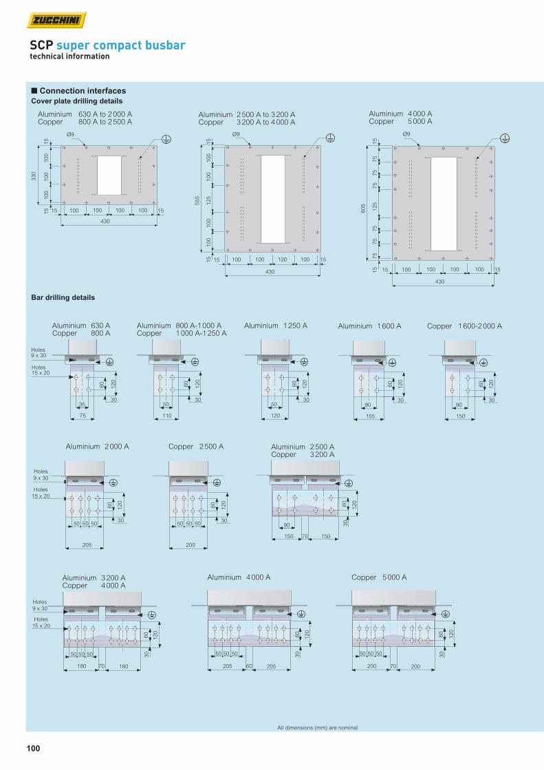
100
All dimensions (mm) are nominal
SCP super compact busbartechnical information
n Connection interfaces
Cover plate drilling details
330
Aluminium 630 A to 2 000 ACopper 800 A to 2 500 A
100
100
100
430
100 100100 10015
15
15 15
Ø9
555
100
100
125
430
100 100100 10015
15
15 15
Ø9
100
100
Aluminium 2 500 A to 3 200 ACopper 3 200 A to 4 000 A
605
75
75
125
430
100 100100 10015
15
15 15
Ø9
75
75
75
75
Aluminium 4 000 ACopper 5 000 A
Bar drilling details
35
75
30
60
120
Holes9 x 30
Holes15 x 20
Aluminium 630 ACopper 800 A
50
110
30
60
120
Aluminium 800 A-1 000 ACopper 1 000 A-1 250 A
50
120
30
60
120
Aluminium 1 250 A
90
155
30
60
120
Aluminium 1 600 A
90
150
30
60
120
Copper 1 600-2 000 A
Holes
9 x 30
Holes
15 x 20
90
150
30
60
120
Aluminium 2 500 ACopper 3 200 A
70 150
50
205
30
60
120
50 50
Aluminium 2 000 A
50
200
30
60
120
50 50
Copper 2 500 A
50 5050
205
30
60
120
Aluminium 4 000 A
20560
50 5050
180
30
60
120
Aluminium 3 200 ACopper 4 000 A
18070
50 5050
200
30
60
120
Copper 5 000 A
20070
Holes
9 x 30
Holes
15 x 20
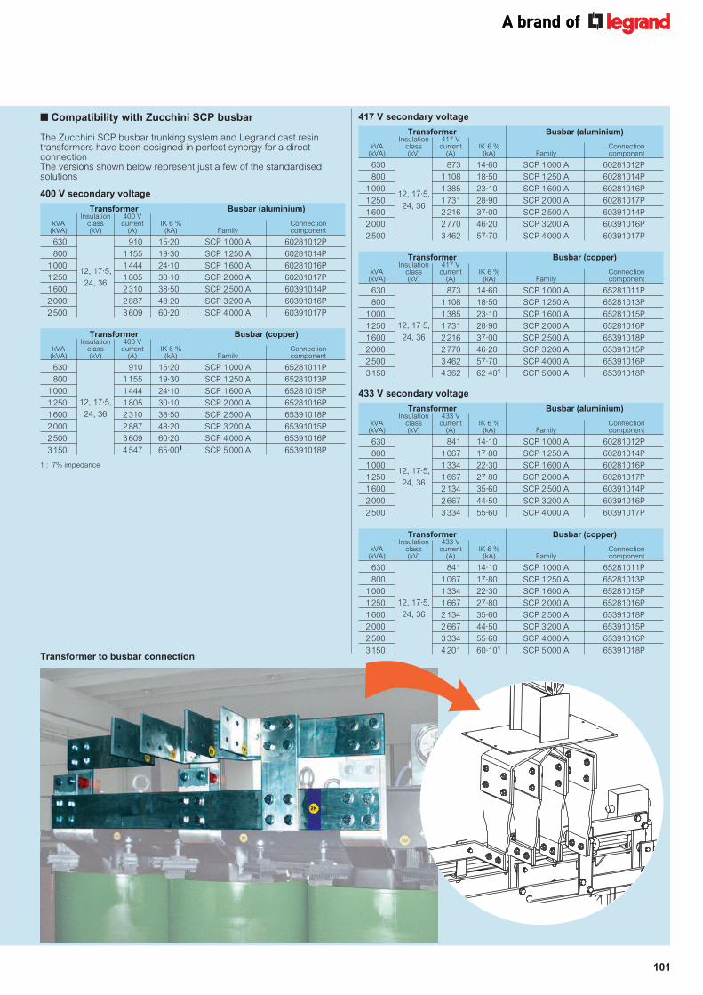
101
n Compatibility with Zucchini SCP busbar
Transformer Busbar (copper) Insulation 433 V kVA class current IK 6 % Connection (kVA) (kV) (A) (kA) Family component
630 841 14·10 SCP 1 000 A 65281011P
800 1 067 17·80 SCP 1 250 A 65281013P
1 000 1 334 22·30 SCP 1 600 A 65281015P
1 250 1 667 27·80 SCP 2 000 A 65281016P
1 600 2 134 35·60 SCP 2 500 A 65391018P
2 000 2 667 44·50 SCP 3 200 A 65391015P
2 500 3 334 55·60 SCP 4 000 A 65391016P
3 150 4 201 60·101 SCP 5 000 A 65391018P
12, 17·5,
24, 36
Transformer Busbar (copper) Insulation 417 V kVA class current IK 6 % Connection (kVA) (kV) (A) (kA) Family component
630 873 14·60 SCP 1 000 A 65281011P
800 1 108 18·50 SCP 1 250 A 65281013P
1 000 1 385 23·10 SCP 1 600 A 65281015P
1 250 1 731 28·90 SCP 2 000 A 65281016P
1 600 2 216 37·00 SCP 2 500 A 65391018P
2 000 2 770 46·20 SCP 3 200 A 65391015P
2 500 3 462 57·70 SCP 4 000 A 65391016P
3 150 4 362 62·401 SCP 5 000 A 65391018P
12, 17·5,
24, 36 Transformer Busbar (copper) Insulation 400 V kVA class current IK 6 % Connection (kVA) (kV) (A) (kA) Family component
630 910 15·20 SCP 1 000 A 65281011P
800 1 155 19·30 SCP 1 250 A 65281013P
1 000 1 444 24·10 SCP 1 600 A 65281015P
1 250 1 805 30·10 SCP 2 000 A 65281016P
1 600 2 310 38·50 SCP 2 500 A 65391018P
2 000 2 887 48·20 SCP 3 200 A 65391015P
2 500 3 609 60·20 SCP 4 000 A 65391016P
3 150 4 547 65·001 SCP 5 000 A 65391018P
12, 17·5,
24, 36
Transformer Busbar (aluminium) Insulation 400 V kVA class current IK 6 % Connection (kVA) (kV) (A) (kA) Family component
630 910 15·20 SCP 1 000 A 60281012P
800 1 155 19·30 SCP 1 250 A 60281014P
1 000 1 444 24·10 SCP 1 600 A 60281016P
1 250 1 805 30·10 SCP 2 000 A 60281017P
1 600 2 310 38·50 SCP 2 500 A 60391014P
2 000 2 887 48·20 SCP 3 200 A 60391016P
2 500 3 609 60·20 SCP 4 000 A 60391017P
12, 17·5,
24, 36
Transformer Busbar (aluminium) Insulation 433 V kVA class current IK 6 % Connection (kVA) (kV) (A) (kA) Family component
630 841 14·10 SCP 1 000 A 60281012P
800 1 067 17·80 SCP 1 250 A 60281014P
1 000 1 334 22·30 SCP 1 600 A 60281016P
1 250 1 667 27·80 SCP 2 000 A 60281017P
1 600 2 134 35·60 SCP 2 500 A 60391014P
2 000 2 667 44·50 SCP 3 200 A 60391016P
2 500 3 334 55·60 SCP 4 000 A 60391017P
12, 17·5,
24, 36
Transformer Busbar (aluminium) Insulation 417 V kVA class current IK 6 % Connection (kVA) (kV) (A) (kA) Family component
630 873 14·60 SCP 1 000 A 60281012P
800 1 108 18·50 SCP 1 250 A 60281014P
1 000 1 385 23·10 SCP 1 600 A 60281016P
1 250 1 731 28·90 SCP 2 000 A 60281017P
1 600 2 216 37·00 SCP 2 500 A 60391014P
2 000 2 770 46·20 SCP 3 200 A 60391016P
2 500 3 462 57·70 SCP 4 000 A 60391017P
12, 17·5,
24, 36
1 : 7% impedance
The Zucchini SCP busbar trunking system and Legrand cast resin transformers have been designed in perfect synergy for a direct connection The versions shown below represent just a few of the standardised solutions
400 V secondary voltage
417 V secondary voltage
433 V secondary voltage
Transformer to busbar connection

102
SCP super compact busbartechnical information
All dimensions (mm) are nominal
n Tap-off boxes
Empty tap-off box 63 A to 630 A
Tap-off boxes can be pre-equipped with DPX MCCBs on request, contact us on +44 (0) 370 608 9020Can be installed and removed when the busbar is energizedTo be used with components with any rating, with tap-off outlets
574
183
240
Aluminium cable entry plates on both sides
757
From 63 A to 160 A
Cover with AC21A disconnectionConnection terminals for cables max 50 mm2
780
415
286
Aluminium cable entry plates on both sides
1034
From 250 A to 630 A
Cover with AC21A disconnection
n Tap-off boxes
63 A to 630 A : plug-in type
574
183
240
Side cable input
757
With fuse carrier
From 63 A to 160 A
Cover with AC21A disconnection
Polyester coated, galvanised steel structure. Metal boxes are suitable for heavy loads and are used to shield electromagnetic fields caused by flows of current Fuses not included. Please contact us on +44 (0) 370 608 9020 for details of available fuses
These tap-off boxes are equipped with a switch disconnector (AC23) and a fuse carrier. The disconnector switch is operated through a rotary handle on the cover (not shown in the picture) N.B. Cover with AC21A disconnection : it is not possible to open, close, install or pull out the tap-off box if the switch is in ‘ON’ positionCan be installed and removed when the busbar is energizedTo be used with components with any rating, with tap-off outletsFuses not included. Please contact us on +44 (0) 370 608 9020 for details of available fuses
With switch disconnector From 250 A to 630 A
780
415
286
Side cable input
1 0
34
Cover with AC21A disconnection

103
All dimensions (mm) are nominal
n Tap-off boxes
With AC23A switch disconnector and fuse carrier, 125 A to 400 A : plug-in type
Specification
Rated insulating AC voltage Ui (V) 1000
Rated impulse withstand voltage Uimp (kV) 12
Type of rated duty AC23A
Rated conditional short circuit current (kA) 100
IEC 60947-3
85
540
340
320260
550
20
Rear cable input
Can be installed and removed when the busbar is energized because the protective earth makes contact before other conductorsTo be applied on components with any rating, with tap-off outletsFor operating voltages (Ue) different from 400 V, please contact us on +44 (0) 370 608 9020Fuses not included. Please contact us on +44 (0) 370 608 9020 for details of available fuses
Specification
Rated insulating AC voltage Ui (V) 1 000
Rated impulse withstand voltage Uimp (kV) 12
Type of rated duty AC23A
Rated conditional short circuit current (kA) 100
IEC 60947-3
n Bolt-on tap-off boxes
With AC23 switch disconnector and fuse carrier : 125 A to 1 250 A
Dimensions of the box
Box rating 125 A to 400 A 630 A 800 A to 1 250 A
(A) (mm) 365 400 450
(B) (mm) 630 750 1 050
(C) (mm) 270 280 300
(D) (mm) 95 115 115
(E) (mm) 635 680 750
B
D
A
C
E
Please specify SCP type when orderingBoxes cannot be installed simultaneously on both sides of the same junction
For operating voltages (Ue) different from 400 V please contact us on +44 (0) 370 608 9020Fuses not included. Please contact us on +44 (0) 370 608 9020 for details of available fuses
The bolted boxes are to be installed directly on the junction when the busbar is disconnected and not energized

104
SCP super compact busbartechnical information
All dimensions (mm) are nominal
n Fixing supports
Suspension bracket for edgeways installation
Aluminium busbar rating (A) 630 800 1 000 1 250 1 600 2 000 2 500 3 200 4 000 5 000
Dimension A (mm) 190 190 190 190 315 315 430 490 530 –
Copper busbar rating (A) 630 800 1 000 1 250 1 600 2 000 2 500 3 200 4 000 5 000
Dimension A (mm) – 190 190 190 315 315 315 430 490 530
Single bar
Suspension bracket for flat installation
Double bar
Single bar Double bar
Aluminium busbar rating (A) 630 800 1 000 1 250 1 600 2 000 2 500 3 200 4 000 5 000
Dimension A (mm) 210 210 210 210 250 300 460 520 560 –
Copper busbar rating (A) 630 800 1 000 1 250 1 600 2 000 2 500 3 200 4 000 5 000
Dimension A (mm) – 210 210 210 250 250 300 460 520 560
Single bar
Suspension bracket for edgeways installation
Double bar
Single bar Double bar
2 000
(max. 3
000)
A
40
110
190
Slot 9x20
15
M10
Suspension bracket for flat installation
2 000
(max. 3
000)
Flat length
210
40
A
Slot 9x20
15
M10
100100
130

105
All dimensions (mm) are nominal
Fixing supports for vertical lengths – dimensions
Version 1
170
84x
Slot 9 x 30
30
170
210
50
131
240 1
40 265
Ø9
Version 2
170
84
x
Slot 9 x 30
30
170
210
50
131
240 1
40 307
Ø9
x
Version 3174
84
Y
Slot 9 x 30
30
214
50
131
375
160
460
Ø9
x
Y
160
174
Version 4174
84
Y
Slot 9 x 30
30
174
214
50
131
375
160
560
Ø9
Y
X
160
Y
Y
X and Y dimensions of the brackets
Version 1 Version 1 Version 2 Version 2 Version 3 Version 4 Version 4
Aluminium 630 A to 1 000 A 1 250 A 1 600 A 2 000 A 2 500 A 3 200 A 4 000 A
Copper 800 A to 1 250 A 1 600 A 2 000 A 2 500 A 3 200 A 4 000 A 5 000 A
x (mm) 90 120 80 90 80 80 80
y (mm) - - - - 110 80 90
Type AWith bracket and spring
Type BStandard with anti-seismic bracket1
Type CWith springs
Type DBracket only
Type ENaval applications
Type A and B brackets are used for wall installation, while type C and D are used for floor installation
1 : For single bar lengths, the standard bracket is also anti-seismic rated For double bar loads there are two separate Cat. Nos. see p. 82
n Fixing supports

106
SCP super compact busbartechnical information
All dimensions (mm) are nominal
Aluminium Copper
Rating (A) (m) Rating (A) (m)
630 17 – –
800 16 800 10
1 000 16 1 000 9
1 250 15 1 250 9
1 600 12 1 600 7
2 000 10 2 000 6
2 500 14 2 500 4
3 200 12 3 200 7
4 000 10 4 000 6
– – 5 000 5
Horizontal installation fixing
Fixing recommended : 1 bracket every 1·5 m
n Fixing in standard conditions
For vertical path sections of less than 2 m the use of standard suspension brackets is sufficient
Edgeways length Flat length
Vertical installation fixing (rising mains)
In the case of rising mains, in addition to the standard brackets, it will also be necessary to use other screw fixed brackets to prevent the busbar slidingDue to their pre-loaded springs, the brackets absorb the forces pressing on the busbar and direct any expansion in a precise directionThey therefore operate as a limitation, and support the traction and compression forces of the busbar trunking system
• Section between 2 and 4 m In the lowest point Type B vertical bracket if secured to the wall, or Type D if secured to the floor and one edgeways installation bracket
• Section of over 4 m In the lowest point Type A vertical bracket if secured to the wall, or Type C if secured to the floor and one edgeways installation bracket every 1·5 m of the path and one Type A or C bracket based on the following table
Edgeways length
n Fixing for installation in seismic environments
Vertical installation (section lengths > 2 m)
Fit 1 bracket every 1·5 m of the busbarEvery 2 anti-seismic brackets with bracket (Type B) use one bracket with bracket and spring (Type A)

107
n Protective cover for outdoor applications
Covering accessory to be used for outdoor installations and wherever the standard IP 55 protection is not adequate For more information, please contact us on +44 (0) 370 608 9020
Edgeways length Flat length
215 150 150 21515
135
150
150
135
15
540
600 (
A)
700
760 (B)
Single barCat. No. SF766040
145 150 150 14515
190
150
150
190
15
650
710 (
A)
860
920 (B)
150 150
Double barCat. No. SF927140
Recommended for protection of the interface connection on panel boards, dry-type transformers with enclosure and oil-type transformersFor Legrand cast resin transformers, custom-made connections are available upon request (see p. 83)
A B
400
n Protective bellows
Single bar Double bar
Aluminium 630 A to 2 000 A 2 500 A to 4 000 A
Cat. No. SF766040 Cat. No. SF927140
Copper 800 A to 2 500 A 3 200 A to 5 000 A
Cat. No. SF766040 Cat. No. SF927140
All dimensions (mm) are nominal

108
SCP super compact busbartechnical information
n The system : the Legrand transformer advantagen Flexible braid connections
When ordering, please specify hole dimensions on transformer side (A, B, Ø D) and length L
The Legrand Group offer meets the needs of any installation. Legrand cast resin transformers have specifically designed connections for Zucchini busbars
The versions shown represent some of the standardised solutions
For the outgoing busbar run from the transformer, see p. 98-100
The distance between the phases can be designed according to your needs
Transformer
Example of a vertical connection
Holes on busbar side
see p. 100
L
Holes on transformer sideto be specified
A
Ø D
B
Lv side
Type A setup
Lv side
Type B setup
Lv side
Type C setup
Cast resin transformer
ATR connection interface
A technical drawing of the transformer is needed when creating an ATR connection interface
All dimensions (mm) are nominal
For Legrand cast resin transformers contact us on +44 (0) 370 608 9020

109
Use a right hand end feed unit (without monobloc) To position the tap-off boxes correctly, the neutral conductor of the riser mains must be on the left side of the length
Use one or more suspension brackets for the vertical lengths, according to the weight of the whole riser mains For risers that are shorter than 4 m, fix to the base with type B brackets (see p. 81)When longer, use a type A suspension bracket (see p. 81) every 300 kg of riser (including boxes)
Use a standard suspension bracket to hang the busbar every 2 metres of riser mains
Use lengths with tap-off outlets (see p. 66)
Use S120 fire barrier kit for each compartment floor (see p. 69)
Tap-off boxes can be installed in the tap-off outlets and near the connection between lengths In both cases, the boxes extend downward
Position the IP 55 end cover at the end of the riser mains
1
2
3
4
5
6
7
SCP super compact busbarinstallation guidelines
7
5
3
4
6
2
1
N
N
N
N
N L1 L2 L3
n Installation design
For further information, please contact us on +44 (0) 370 608 9020

110
SCP super compact busbarinstallation guidelines
Minimum installation distance when there are several adjacent lines
100
300
80
Wall
Ceiling
100
300
Wall
Wall
100
80
Wall
100
300
Wall
Ceiling
300
100
Wall
Ceiling
100
Wall
100
300
60
For further information, please contact us on +44 (0) 370 608 9020
Wall
Ceiling
Minimum installation distance when there are several overlapped lines
When there are tap-off units along the busbars, the minimum distances depend on the dimensions of the tap-offs selected.
300
300
* * When there is a tap-off box installed above the busbar, check the overall dimension of the open cover of the tap-off unit used (see p. 47-48)
Ceiling
Wall
n Minimum distance of the wall / ceiling lengths
All dimensions (mm) are nominal

111
Fig. 1
Fig. 2
Fig. 3
270 mm
Fig. 5
Fig. 6
Fig. 4 85Nm
n Installation sequence of the junction
Installation instructions are included near the junction (Fig.1)
Make sure that the contacts are clean before joining lengths
Install the junction covers (Fig. 5)
Completed IP 55 installation (Fig. 6)
For further information, please contact us on +44 (0) 370 608 9020
Tighten the bolt of the monobloc until the 1st head breaks off (Fig. 4)
The bolt that tightens the monobloc has a second head which is used when carrying out operations or inspections on the line
The nominal tightening torque is 85Nm
Make sure that the earth plate of the trunking length is inserted behind the front plate of the junction monobloc (Fig.2)
The positioning pin on the monobloc should be fitted into the corresponding slot on the earth plate. Verify the distance between lengths, 270 mm, before tightening the monobloc completely (Fig.3)
30 mm
Measurement of trunking lengths
The exact length to be ordered can be determined by measuring the distance between the components (as shown below) and then subtracting 270 mm
Length = Q - 270 mm
Example : dimension measured = 2 500 mm length required = 2 230 mm
n Measurement of bespoke components
N 1 2 3
dimension Q
Q2
Q1
B = Q2 - 70 mm
A =
Q1 -
70 m
m
Horizontal elbow
The exact length to be ordered can be determined by measuring the dimensions Q1 and Q2 (as shown below) and then subtracting 70 mm from each dimension
A = Q1 - 70 mmB = Q2 - 70 mm
For further information, please contact us on +44 (0) 370 608 9020
Instructions
All dimensions (mm) are nominal
1
2
3
4

112
SCP super compact busbar – 4 conductor (aluminium)technical data
n 3L + N + PE aluminium
Rated current In [A] 630 800 1 000 1 250 1 600 2 000 2 500 3 200 4 000
Casing overall dimensions L x H [mm] 130 x 130 130 x 130 130 x 130 130 x 130 130 x 170 130 x 220 130 x 380 130 x 440 130 x 480
Operating voltage Ue [V] 1 000 1 000 1 000 1 000 1 000 1 000 1 000 1 000 1 000
Insulation voltage Ui [V] 1 000 1 000 1 000 1 000 1 000 1 000 1 000 1 000 1 000
Frequency f [Hz] 50/60 50/60 50/60 50/60 50/60 50/60 50/60 50/60 50/60
Rated short-time current for three-phase fault (1 s) Icw [kA]rms 36 42 50 75 80 80 150 160 160
Allowable peak current for three-phase fault Ipk [kA] 76 88 110 165 176 176 330 352 352
Rated short-time current for single-phase fault (1 s) Icw [kA]rms 22 25 30 45 48 48 90 96 96
Allowable peak current for single-phase fault Ipk [kA] 48 55 66 99 106 106 198 211 211
Allowable specific energy for three-phase fault I2t [MA2s] 1 296 1 764 2 500 5 625 6 400 6 400 22 500 25 600 25 600
Phase resistance R20 [mΩ/m] 0·077 0·057 0·057 0·046 0·033 0·025 0·021 0·016 0·013
Phase reactance (50 Hz) X [mΩ/m] 0·023 0·017 0·017 0·015 0·014 0·011 0·006 0·006 0·006
Phase impedance Z [mΩ/m] 0·080 0·059 0·059 0·048 0·036 0·027 0·022 0·017 0·014
Phase resistance at thermal conditions Rt [mΩ/m] 0·084 0·063 0·068 0·055 0·039 0·030 0·024 0·019 0·016
Phase impedance at thermal conditions Z [mΩ/m] 0·087 0·066 0·070 0·057 0·041 0·032 0·025 0·020 0·018
Neutral resistance R20 [mΩ/m] 0·077 0·057 0·057 0·046 0·033 0·025 0·021 0·016 0·013
Resistance of the protective conductor (PE 1) RPE [mΩ/m] 0·125 0·125 0·125 0·125 0·113 0·101 0·075 0·069 0·065
Resistance of the protective conductor (PE 2) RPE [mΩ/m] 0·036 0·036 0·036 0·036 0·028 0·023 0·014 0·012 0·011
Resistance of the protective conductor (PE 3) RPE [mΩ/m] 0·050 0·050 0·050 0·050 0·041 0·033 0·021 0·018 0·017
Reactance of the protective conductor (50 Hz) XPE [mΩ/m] 0·080 0·078 0·078 0·048 0·039 0·028 0·020 0·015 0·016
Resistance of the fault loop (PE 1) Ro [mΩ/m] 0·209 0·188 0·193 0·180 0·152 0·131 0·099 0·088 0·081
Resistance of the fault loop (PE 2) Ro [mΩ/m] 0·120 0·099 0·104 0·091 0·067 0·053 0·038 0·031 0·027
Resistance of the fault loop (PE 3) Ro [mΩ/m] 0·134 0·113 0·118 0·105 0·080 0·063 0·045 0·037 0·033
Reactance of the fault loop (50 Hz) Xo [mΩ/m] 0·10 0·10 0·10 0·06 0·05 0·04 0·03 0·02 0·02
Impedance of the fault loop (PE 1) Zo [mΩ/m] 0·233 0·211 0·215 0·191 0·161 0·137 0·103 0·091 0·084
Impedance of the fault loop (PE 2) Zo [mΩ/m] 0·158 0·137 0·141 0·111 0·085 0·066 0·046 0·038 0·035
Impedance of the fault loop (PE 3) Zo [mΩ/m] 0·169 0·148 0·152 0·123 0·096 0·074 0·052 0·043 0·040
Zero-sequence resistance phase - N Ro [mΩ/m] 0·306 0·257 0·257 0·238 0·172 0·140 0·107 0·080 0·070
Zero-sequence reactance phase - N Xo [mΩ/m] 0·174 0·160 0·160 0·128 0·106 0·108 0·083 0·073 0·060
Zero-sequence Impedance phase - N Zo [mΩ/m] 0·352 0·303 0·303 0·270 0·202 0·177 0·135 0·108 0·092
Zero-sequence resistance phase - PE Ro [mΩ/m] 0·581 0·519 0·519 0·369 0·321 0·270 0·217 0·196 0·164
Zero-sequence reactance phase - PE Xo [mΩ/m] 0·263 0·229 0·229 0·191 0·175 0·212 0·155 0·148 0·146
Zero-sequence Impedance phase - PE Zo [mΩ/m] 0·638 0·567 0·567 0·416 0·366 0·343 0·267 0·246 0·22
cosϕ = 0·70 65·3 48·9 51·9 42·9 32·3 25·1 18·4 15·4 13·7
cosϕ = 0·75 67·9 50·9 54·1 44·6 33·4 25·9 19·2 16·0 14·1
cosϕ = 0·80 70·3 52·7 56·1 46·2 34·3 26·7 19·9 16·5 14·5
cosϕ = 0·85 72·5 54·4 58·0 47·7 35·1 27·3 20·6 16·9 14·9
cosϕ = 0·90 74·3 55·8 59·6 48·9 35·7 27·7 21·2 17·3 15·1
cosϕ = 0·95 75·5 56·7 60·8 49·7 35·9 27·8 21·6 17·5 15·2
cosϕ = 1·00 72·9 54·9 59·1 48·0 33·8 26·2 21·0 16·7 14·3
Weight (PE 1) p [kg/m] 17·3 17·0 17·0 18·7 20·3 30·7 43·7 52·3 62·7
Weight (PE 2) p [kg/m] 20·8 20·5 20·5 23·2 24·9 36·7 53·9 64·3 75·7
Weight (PE 3) p [kg/m] 18·4 18·1 18·1 20·8 21·8 32·6 46·9 56·1 66·8
Fire load [kWh/m] 4·5 5·5 5·5 6·0 8·5 10·5 16·0 19·0 21·0
Degree of protection IP 55 55 55 55 55 55 55 55 55
Thermal resistance class of the insulating materials – B/F1 B/F1 B/F1 B/F1 B/F1 B/F1 B/F1 B/F1 B/F1
Joule effect losses at rated current P [W/m] 100 122 205 260 300 363 455 592 790
Min./max. ambient temperature [°C] -5/50 -5/50 -5/50 -5/50 -5/50 -5/50 -5/50 -5/50 -5/50
Voltage drop factor with distributed load k [V/m/A]10-6
∆V = k.L.Ie.10-6 [V]
Single barAluminium Double bar
Regulations and conformity : IEC 61439-6 (BS EN 61439-6)Suitable for the following climates :
Constant humid climate (IEC 60068 2 – 11)Cyclical humid climate (IEC 60068 2 – 30)Degree of protection :
IP 55; IP x7 carrying lines available with accessories, on request - +44 (0) 370 608 9020Insulation and surface treatment of the conductors : Insulated conductors for the whole length, aluminum copper-plated and tin-plated Busbar casing material :
1·5 mm galvanised steel plate, pre-painted or stainless steel(available, if required, with special paint and/or with thickness 2 mm)
1 : Class F thermal resistance (155°C) available on request -
+44 (0) 370 608 9020 In : rated current referred to a room temperature of 40°C
PE 1
Standard versionPE 2
Extra earth - copper
PE 3Extra earth - aluminium
N PEL3L2L1
130
H
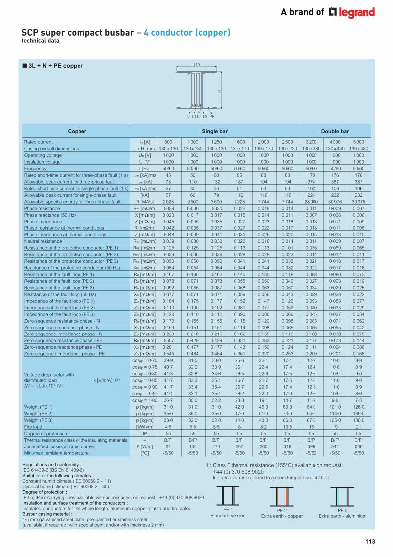
113
SCP super compact busbar – 4 conductor (copper)technical data
n 3L + N + PE copper
Rated current In [A] 800 1 000 1 250 1 600 2 000 2 500 3 200 4 000 5 000
Casing overall dimensions L x H [mm] 130 x 130 130 x 130 130 x 130 130 x 170 130 x 170 130 x 220 130 x 380 130 x 440 130 x 480
Operating voltage Ue [V] 1 000 1 000 1 000 1 000 1000 1 000 1 000 1 000 1 000
Insulation voltage Ui [V] 1 000 1 000 1 000 1 000 1000 1 000 1 000 1 000 1 000
Frequency f [Hz] 50/60 50/60 50/60 50/60 50/60 50/60 50/60 50/60 50/60
Rated short-time current for three-phase fault (1 s) Icw [kA]rms 45 50 60 85 88 88 170 176 176
Allowable peak current for three-phase fault Ipk [kA] 95 110 132 187 194 194 374 387 387
Rated short-time current for single-phase fault (1 s) Icw [kA]rms 27 30 36 51 53 53 102 106 106
Allowable peak current for single-phase fault [kA] 57 66 79 112 116 116 224 232 232
Allowable specific energy for three-phase fault I2t [MA2s] 2 025 2 500 3 600 7 225 7 744 7 744 28 900 30 976 30 976
Phase resistance R20 [mΩ/m] 0·039 0·030 0·030 0·022 0·018 0·014 0·011 0·009 0·007
Phase reactance (50 Hz) X [mΩ/m] 0·023 0·017 0·017 0·015 0·014 0·011 0·007 0·006 0·006
Phase impedance Z [mΩ/m] 0·045 0·035 0·035 0·027 0·023 0·018 0·013 0·011 0·009
Phase resistance at thermal conditions Rt [mΩ/m] 0·042 0·035 0·037 0·027 0·022 0·017 0·013 0·011 0·008
Phase impedance at thermal conditions Z [mΩ/m] 0·048 0·039 0·041 0·031 0·026 0·020 0·015 0·013 0·010
Neutral resistance R20 [mΩ/m] 0·039 0·030 0·030 0·022 0·018 0·014 0·011 0·009 0·007
Resistance of the protective conductor (PE 1) RPE [mΩ/m] 0·125 0·125 0·125 0·113 0·113 0·101 0·075 0·069 0·065
Resistance of the protective conductor (PE 2) RPE [mΩ/m] 0·036 0·036 0·036 0·028 0·028 0·023 0·014 0·012 0·011
Resistance of the protective conductor (PE 3) RPE [mΩ/m] 0·050 0·050 0·050 0·041 0·041 0·033 0·021 0·018 0·017
Reactance of the protective conductor (50 Hz) XPE [mΩ/m] 0·054 0·054 0·054 0·044 0·044 0·032 0·022 0·017 0·016
Resistance of the fault loop (PE 1) Ro [mΩ/m] 0·167 0·160 0·162 0·140 0·135 0·118 0·088 0·080 0·073
Resistance of the fault loop (PE 2) Ro [mΩ/m] 0·078 0·071 0·073 0·055 0·050 0·040 0·027 0·023 0·019
Resistance of the fault loop (PE 3) Ro [mΩ/m] 0·092 0·085 0·087 0·068 0·063 0·050 0·034 0·029 0·025
Reactance of the fault loop (50 Hz) Xo [mΩ/m] 0·077 0·071 0·071 0·059 0·058 0·043 0·029 0·023 0·022
Impedance of the fault loop (PE 1) Zo [mΩ/m] 0·184 0·175 0·177 0·152 0·147 0·126 0·093 0·083 0·077
Impedance of the fault loop (PE 2) Zo [mΩ/m] 0·110 0·100 0·102 0·081 0·077 0·059 0·040 0·033 0·029
Impedance of the fault loop (PE 3) Zo [mΩ/m] 0·120 0·110 0·112 0·090 0·086 0·066 0·045 0·037 0·034
Zero-sequence resistance phase - N Ro [mΩ/m] 0·170 0·155 0·155 0·115 0·120 0·098 0·083 0·071 0·062
Zero-sequence reactance phase - N Xo [mΩ/m] 0·159 0·151 0·151 0·114 0·098 0·065 0·056 0·055 0·042
Zero-sequence Impedance phase - N Zo [mΩ/m] 0·233 0·216 0·216 0·162 0·155 0·118 0·100 0·090 0·075
Zero-sequence resistance phase - PE Ro [mΩ/m] 0·507 0·429 0·429 0·331 0·283 0·221 0·177 0·178 0·144
Zero-sequence reactance phase - PE Xo [mΩ/m] 0·201 0·177 0·177 0·143 0·150 0·124 0·111 0·094 0·086
Zero-sequence Impedance phase - PE Zo [mΩ/m] 0·545 0·464 0·464 0·361 0·320 0·253 0·209 0·201 0·168
cosϕ = 0·70 39·9 31·5 33·0 25·6 22·1 17·1 12·2 10·5 8·9
cosϕ = 0·75 40·7 32·2 33·9 26·1 22·4 17·4 12·4 10·8 8·9
cosϕ = 0·80 41·3 32·8 34·6 26·5 22·6 17·5 12·6 10·9 9·0
cosϕ = 0·85 41·7 33·3 35·1 26·7 22·7 17·5 12·8 11·0 9·0
cosϕ = 0·90 41·7 33·4 35·4 26·7 22·5 17·4 12·8 11·0 8·9
cosϕ = 0·95 41·1 33·1 35·1 26·2 22·0 17·0 12·6 10·9 8·6
cosϕ = 1·00 36·7 30·0 32·2 23·3 19·1 14·7 11·2 9·8 7·3
Weight (PE 1) p [kg/m] 31·0 31·0 31·0 42·0 46·0 69·0 84·0 101·0 126·0
Weight (PE 2) p [kg/m] 35·0 35·0 35·0 47·0 51·0 70·0 94·0 114·0 139·0
Weight (PE 3) p [kg/m] 33·0 32·0 32·0 44·0 48·0 66·0 87·0 105·0 130·0
Fire load [kWh/m] 4·5 5·5 5·5 8 8·2 10·5 16 19 21
Degree of protection IP 55 55 55 55 55 55 55 55 55
Thermal resistance class of the insulating materials – B/F1 B/F1 B/F1 B/F1 B/F1 B/F1 B/F1 B/F1 B/F1
Joule effect losses at rated current P [W/m] 81 104 174 207 265 319 399 541 636
Min./max. ambient temperature [°C] -5/50 -5/50 -5/50 -5/50 -5/50 -5/50 -5/50 -5/50 -5/50
Voltage drop factor with distributed load k [V/m/A]10-6
∆V = k.L.Ie.10-6 [V]
Single barCopper Double bar
Regulations and conformity : IEC 61439-6 (BS EN 61439-6)Suitable for the following climates :
Constant humid climate (IEC 60068 2 – 11)Cyclical humid climate (IEC 60068 2 – 30)Degree of protection :
IP 55; IP x7 carrying lines available with accessories, on request - +44 (0) 370 608 9020Insulation and surface treatment of the conductors : Insulated conductors for the whole length, aluminum copper-plated and tin-plated Busbar casing material :
1·5 mm galvanised steel plate, pre-painted or stainless steel(available, if required, with special paint and/or with thickness 2 mm)
1 : Class F thermal resistance (155°C) available on request -
+44 (0) 370 608 9020 In : rated current referred to a room temperature of 40°C
PE 1
Standard versionPE 2
Extra earth - copper
PE 3Extra earth - aluminium
N PEL3L2L1
130
H

114
SCP super compact busbar – 5 conductor (aluminium)technical data
n SCP technical data functional earth clean earth / low noise SCP5C (3L + N + PE + FE) aluminium
Regulations and conformity : IEC 61439-6 (BS EN 61439-6)Suitable for the following climates :
Constant humid climate (IEC 60068 2 – 11)Cyclical humid climate (IEC 60068 2 – 30)Degree of protection :
IP 55; IP x7 carrying lines available with accessories, on request - +44 (0) 370 608 9020Insulation and surface treatment of the conductors : Insulated conductors for the whole length, aluminum copper-plated and tin-plated Busbar casing material :
1·5 mm galvanised steel plate, pre-painted or stainless steel(available, if required, with special paint and/or with thickness 2 mm)
1 : Class F thermal resistance (155°C) available on request -
+44 (0) 370 608 9020 In : rated current referred to a room temperature of 40°C
PE 1
Standard versionPE 2
Extra earth - copper
PE 3Extra earth - aluminium
140
H
FE PEL2L1N L3
Rated current In [A] 630 800 1 000 1 250 1 600 2 000 2 500 3 200 4 000
Casing overall dimensions L x H [mm] 140 x 130 140 x 130 140 x 130 140 x 130 140 x 170 140 x 220 140 x 380 140 x 440 140 x 480
Operating voltage Ue [V] 1 000 1 000 1 000 1 000 1 000 1 000 1 000 1 000 1 000
Insulation voltage Ui [V] 1 000 1 000 1 000 1 000 1 000 1 000 1 000 1 000 1 000
Frequency f [Hz] 50/60 50/60 50/60 50/60 50/60 50/60 50/60 50/60 50/60
Rated short-time current for three-phase fault (1 s) ICW [kA]rms 36 42 50 75 80 80 150 160 160
Allowable peak current for three-phase fault Ipk [kA] 76 88 110 165 176 176 330 352 352
Rated short-time current for single-phase fault (1 s) ICW [kA]rms 22 25 30 45 48 48 90 96 96
Allowable peak current for single-phase fault Ipk [kA] 48 55 66 99 106 106 198 211 211
Allowable specific energy for three-phase fault I2t [MA2s] 1 296 1 764 2 500 5 625 6 400 6 400 22 500 25 600 25 600
Phase resistance R20 [mΩ/m] 0·077 0·057 0·057 0·046 0·033 0·025 0·021 0·016 0·013
Phase reactance (50 Hz) X [mΩ/m] 0·023 0·017 0·017 0·015 0·014 0·011 0·006 0·006 0·006
Phase impedance Z [mΩ/m] 0·080 0·059 0·059 0·048 0·036 0·027 0·022 0·017 0·014
Phase resistance at thermal conditions Rt [mΩ/m] 0·084 0·063 0·068 0·055 0·039 0·030 0·024 0·019 0·016
Phase impedance at thermal conditions Z [mΩ/m] 0·087 0·066 0·070 0·057 0·041 0·032 0·025 0·020 0·018
Neutral resistance R20 [mΩ/m] 0·077 0·057 0·057 0·046 0·033 0·025 0·021 0·016 0·013
Functional earthing resistance (FE) R20 [mΩ/m] 0·077 0·057 0·057 0·046 0·033 0·025 0·021 0·016 0·013
Functional earthing reactance (FE) X [mΩ/m] 0·023 0·017 0·017 0·015 0·014 0·011 0·006 0·006 0·006
Resistance of the protective conductor (PE type 1) RPE [mΩ/m] 0·121 0·121 0·121 0·121 0·110 0·098 0·074 0·068 0·064
Resistance of the protective conductor (PE type 2) RPE [mΩ/m] 0·035 0·035 0·035 0·035 0·028 0·023 0·014 0·012 0·011
Resistance of the protective conductor (PE type 3) RPE [mΩ/m] 0·050 0·050 0·050 0·050 0·040 0·033 0·020 0·018 0·017
Reactance of the protective conductor (50 Hz) XPE [mΩ/m] 0·080 0·078 0·078 0·048 0·039 0·028 0·020 0·015 0·016
Resistance of the fault loop (PE 1) Ro [mΩ/m] 0·131 0·102 0·107 0·089 0·064 0·050 0·041 0·032 0·027
Resistance of the fault loop (PE 2) Ro [mΩ/m] 0·108 0·085 0·090 0·075 0·054 0·042 0·033 0·026 0·022
Resistance of the fault loop (PE 3) Ro [mΩ/m] 0·115 0·090 0·095 0·079 0·057 0·044 0·034 0·028 0·024
Reactance of the fault loop (50 Hz) Xo [mΩ/m] 0·10 0·10 0·10 0·06 0·05 0·04 0·03 0·02 0·02
Impedance of the fault loop (PE 1) Zo [mΩ/m] 0·167 0·139 0·143 0·109 0·083 0·064 0·048 0·038 0·035
Impedance of the fault loop (PE 2) Zo [mΩ/m] 0·149 0·128 0·131 0·098 0·076 0·057 0·042 0·034 0·031
Impedance of the fault loop (PE 3) Zo [mΩ/m] 0·154 0·131 0·134 0·101 0·078 0·059 0·043 0·035 0·032
Zero-sequence resistance phase - N Ro [mΩ/m] 0·306 0·257 0·257 0·238 0·172 0·140 0·107 0·080 0·070
Zero-sequence reactance phase - N Xo [mΩ/m] 0·174 0·160 0·160 0·128 0·106 0·108 0·083 0·073 0·060
Zero-sequence Impedance phase - N Zo [mΩ/m] 0·352 0·303 0·303 0·270 0·202 0·177 0·135 0·108 0·092
Zero-sequence resistance phase - PE Ro [mΩ/m] 0·468 0·387 0·387 0·246 0·213 0·173 0·113 0·107 0·070
Zero-sequence reactance phase - PE Xo [mΩ/m] 0·263 0·229 0·229 0·191 0·175 0·212 0·155 0·148 0·146
Zero-sequence Impedance phase - PE Zo [mΩ/m] 0·537 0·450 0·450 0·311 0·276 0·274 0·192 0·183 0·162
cosϕ = 0·70 65·3 48·9 51·9 42·9 32·3 25·1 18·4 15·4 13·7
cosϕ = 0·75 67·9 50·9 54·1 44·6 33·4 25·9 19·2 16·0 14·1
cosϕ = 0·80 70·3 52·7 56·1 46·2 34·3 26·7 19·9 16·5 14·5
cosϕ = 0·85 72·5 54·4 58·0 47·7 35·1 27·3 20·6 16·9 14·9
cosϕ = 0·90 74·3 55·8 59·6 48·9 35·7 27·7 21·2 17·3 15·1
cosϕ = 0·95 75·5 56·7 60·8 49·7 35·9 27·8 21·6 17·5 15·2
cosϕ = 1·00 72·9 54·9 59·1 48·0 33·8 26·2 21·0 16·7 14·3
Weight (PE 1) p [kg/m] 21·6 21·3 21·3 23·4 25·4 38·4 54·6 65·4 78·4
Weight (PE 2) p [kg/m] 23·0 22·8 22·8 26·4 28·6 41·4 60·1 72·1 84·9
Weight (PE 3) p [kg/m] 20·6 20·4 20·4 24·0 25·5 37·4 53·1 64·0 76·0
Fire load [kWh/m] 5·6 6·9 6·9 7·5 10·6 13·1 20·0 23·8 26·3
Degree of protection IP 55 55 55 55 55 55 55 55 55
Thermal resistance class of the insulating materials – B/F1 B/F1 B/F1 B/F1 B/F1 B/F1 B/F1 B/F1 B/F1
Joule effect losses at rated current P [W/m] 100 122 205 260 300 363 455 592 790
Min./max. ambient temperature [°C] -5/50 -5/50 -5/50 -5/50 -5/50 -5/50 -5/50 -5/50 -5/50
Voltage drop factor with distributed load k [V/m/A]10-6
∆V = k.L.Ie.10-6 [V]
Single barAluminium Double bar

115
SCP super compact busbar – 5 conductor (copper)technical data
n SCP technical data functional earth clean earth / low noise SCP5C (3L + N + PE + FE) copper
Rated current In [A] 800 1 000 1 250 1 600 2 000 2 500 3 200 4 000 5 000
Casing overall dimensions L x H [mm] 140 x 130 140 x 130 140 x 130 140 x 170 140 x 170 140 x 220 140 x 380 140 x 440 140 x 480
Operating voltage Ue [V] 1 000 1 000 1 000 1 000 1 000 1 000 1 000 1 000 1 000
Insulation voltage Ui [V] 1 000 1 000 1 000 1 000 1 000 1 000 1 000 1 000 1 000
Frequency f [Hz] 50/60 50/60 50/60 50/60 50/60 50/60 50/60 50/60 50/60
Rated short-time current for three-phase fault (1 s) Icw [kA]rms 45 50 60 85 88 88 170 176 176
Allowable peak current for three-phase fault Ipk [kA] 95 110 132 187 194 194 374 387 387
Rated short-time current for single-phase fault (1 s) Icw [kA]rms 27 30 36 51 53 53 102 106 106
Allowable peak current for single-phase fault Ipk [kA] 57 66 79 112 116 116 224 232 232
Allowable specific energy for three-phase fault I2t [MA2s] 2025 2 500 3 600 7 225 7 744 7 744 28 900 30 976 30 976
Phase resistance R20 [mΩ/m] 0·039 0·030 0·030 0·022 0·018 0·014 0·011 0·009 0·007
Phase reactance (50 Hz) X [mΩ/m] 0·023 0·017 0·017 0·015 0·014 0·011 0·007 0·006 0·006
Phase impedance Z [mΩ/m] 0·045 0·035 0·035 0·027 0·023 0·018 0·013 0·011 0·009
Phase resistance at thermal conditions Rt [mΩ/m] 0·042 0·035 0·037 0·027 0·022 0·017 0·013 0·011 0·008
Phase impedance at thermal conditions Z [mΩ/m] 0·048 0·039 0·041 0·031 0·026 0·020 0·015 0·013 0·010
Neutral resistance R20 [mΩ/m] 0·039 0·030 0·030 0·022 0·018 0·014 0·011 0·009 0·007
Functional earthing resistance (FE) R20 [mΩ/m] 0·039 0·030 0·030 0·022 0·018 0·014 0·011 0·009 0·007
Functional earthing reactance (FE) X [mΩ/m] 0·023 0·017 0·017 0·015 0·014 0·011 0·007 0·006 0·006
Resistance of the protective conductor (PE type 1) RPE [mΩ/m] 0·125 0·125 0·125 0·113 0·113 0·101 0·075 0·069 0·065
Resistance of the protective conductor (PE type 2) RPE [mΩ/m] 0·036 0·036 0·036 0·028 0·028 0·023 0·014 0·012 0·011
Resistance of the protective conductor (PE type 3) RPE [mΩ/m] 0·050 0·050 0·050 0·041 0·041 0·033 0·021 0·018 0·017
Reactance of the protective conductor (50 Hz) XPE [mΩ/m] 0·054 0·054 0·054 0·044 0·044 0·032 0·022 0·017 0·016
Resistance of the fault loop (PE 1) Ro [mΩ/m] 0·072 0·059 0·062 0·045 0·038 0·029 0·023 0·019 0·015
Resistance of the fault loop (PE 2) Ro [mΩ/m] 0·061 0·051 0·054 0·039 0·033 0·026 0·019 0·016 0·013
Resistance of the fault loop (PE 3) Ro [mΩ/m] 0·064 0·054 0·056 0·041 0·035 0·027 0·020 0·017 0·013
Reactance of the fault loop (50 Hz) Xo [mΩ/m] 0·077 0·071 0·071 0·059 0·058 0·043 0·029 0·023 0·022
Impedance of the fault loop (PE 1) Zo [mΩ/m] 0·105 0·092 0·094 0·074 0·069 0·052 0·037 0·030 0·026
Impedance of the fault loop (PE 2) Zo [mΩ/m] 0·098 0·087 0·089 0·071 0·067 0·050 0·035 0·028 0·025
Impedance of the fault loop (PE 3) Zo [mΩ/m] 0·100 0·089 0·090 0·072 0·068 0·051 0·035 0·029 0·026
Zero-sequence resistance phase - N Ro [mΩ/m] 0·170 0·155 0·155 0·115 0·120 0·098 0·083 0·071 0·062
Zero-sequence reactance phase - N Xo [mΩ/m] 0·159 0·151 0·151 0·114 0·098 0·065 0·056 0·055 0·042
Zero-sequence Impedance phase - N Zo [mΩ/m] 0·233 0·216 0·216 0·162 0·155 0·118 0·100 0·090 0·075
Zero-sequence resistance phase - PE Ro [mΩ/m] 0·408 0·320 0·320 0·220 0·188 0·142 0·092 0·077 0·061
Zero-sequence reactance phase - PE Xo [mΩ/m] 0·196 0·158 0·158 0·126 0·135 0·136 0·104 0·088 0·075
Zero-sequence Impedance phase - PE Zo [mΩ/m] 0·453 0·357 0·357 0·254 0·231 0·197 0·139 0·117 0·097
cosϕ = 0·70 39·9 31·5 33·0 25·6 22·1 17·1 12·2 10·5 8·9
cosϕ = 0·75 40·7 32·2 33·9 26·1 22·4 17·4 12·4 10·8 8·9
cosϕ = 0·80 41·3 32·8 34·6 26·5 22·6 17·5 12·6 10·9 9·0
cosϕ = 0·85 41·7 33·3 35·1 26·7 22·7 17·5 12·8 11·0 9·0
cosϕ = 0·90 41·7 33·4 35·4 26·7 22·5 17·4 12·8 11·0 8·9
cosϕ = 0·95 41·1 33·1 35·1 26·2 22·0 17·0 12·6 10·9 8·6
cosϕ = 1·00 36·7 30·0 32·2 23·3 19·1 14·7 11·2 9·8 7·3
Weight (PE 1) p [kg/m] 39·0 39·0 39·0 53·0 58·0 86·0 105·0 126·0 158·0
Weight (PE 2) p [kg/m] 41·0 41·0 41·0 55·0 60·0 83·0 111·0 134·0 174·0
Weight (PE 3) p [kg/m] 38·0 38·0 38·0 52·0 57·0 79·0 104·0 126·0 163·0
Fire load [kWh/m] 5·6 6·9 6·9 10·0 10·3 13·1 20·0 23·8 26·3
Degree of protection IP 55 55 55 55 55 55 55 55 55
Thermal resistance class of the insulating materials – B/F1 B/F1 B/F1 B/F1 B/F1 B/F1 B/F1 B/F1 B/F1
Joule effect losses at rated current P [W/m] 81 104 174 207 265 319 399 541 636
Min./max. ambient temperature [°C] -5/50 -5/50 -5/50 -5/50 -5/50 -5/50 -5/50 -5/50 -5/50
Voltage drop factor with distributed load k [V/m/A]10-6
∆V = k.L.Ie.10-6 [V]
Single barCopper Double bar
Regulations and conformity : IEC 61439-6 (BS EN 61439-6)Suitable for the following climates :
Constant humid climate (IEC 60068 2 – 11)Cyclical humid climate (IEC 60068 2 – 30)Degree of protection :
IP 55; IP x7 carrying lines available with accessories, on request - +44 (0) 370 608 9020Insulation and surface treatment of the conductors : Insulated conductors for the whole length, aluminum copper-plated and tin-plated Busbar casing material :
1·5 mm galvanised steel plate, pre-painted or stainless steel(available, if required, with special paint and/or with thickness 2 mm)
1 : Class F thermal resistance (155°C) available on request -
+44 (0) 370 608 9020 In : rated current referred to a room temperature of 40°C
PE 1
Standard versionPE 2
Extra earth - copper
PE 3Extra earth - aluminium
140
H
FE PEL2L1N L3
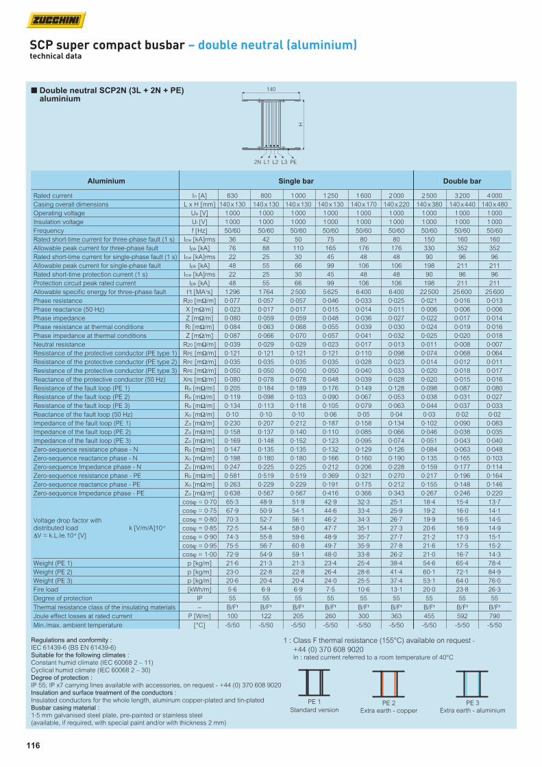
116
SCP super compact busbar – double neutral (aluminium)technical data
n Double neutral SCP2N (3L + 2N + PE) aluminium
Regulations and conformity : IEC 61439-6 (BS EN 61439-6)Suitable for the following climates :
Constant humid climate (IEC 60068 2 – 11)Cyclical humid climate (IEC 60068 2 – 30)Degree of protection :
IP 55; IP x7 carrying lines available with accessories, on request - +44 (0) 370 608 9020Insulation and surface treatment of the conductors : Insulated conductors for the whole length, aluminum copper-plated and tin-plated Busbar casing material :
1·5 mm galvanised steel plate, pre-painted or stainless steel(available, if required, with special paint and/or with thickness 2 mm)
1 : Class F thermal resistance (155°C) available on request -
+44 (0) 370 608 9020 In : rated current referred to a room temperature of 40°C
PE 1
Standard versionPE 2
Extra earth - copper
PE 3Extra earth - aluminium
Rated current In [A] 630 800 1 000 1 250 1 600 2 000 2 500 3 200 4 000
Casing overall dimensions L x H [mm] 140 x 130 140 x 130 140 x 130 140 x 130 140 x 170 140 x 220 140 x 380 140 x 440 140 x 480
Operating voltage Ue [V] 1 000 1 000 1 000 1 000 1 000 1 000 1 000 1 000 1 000
Insulation voltage Ui [V] 1 000 1 000 1 000 1 000 1 000 1 000 1 000 1 000 1 000
Frequency f [Hz] 50/60 50/60 50/60 50/60 50/60 50/60 50/60 50/60 50/60
Rated short-time current for three-phase fault (1 s) Icw [kA]rms 36 42 50 75 80 80 150 160 160
Allowable peak current for three-phase fault Ipk [kA] 76 88 110 165 176 176 330 352 352
Rated short-time current for single-phase fault (1 s) Icw [kA]rms 22 25 30 45 48 48 90 96 96
Allowable peak current for single-phase fault Ipk [kA] 48 55 66 99 106 106 198 211 211
Rated short-time protection current (1 s) Icw [kA]rms 22 25 30 45 48 48 90 96 96
Protection circuit peak rated current Ipk [kA] 48 55 66 99 106 106 198 211 211
Allowable specific energy for three-phase fault I2t [MA2s] 1 296 1 764 2 500 5 625 6 400 6 400 22 500 25 600 25 600
Phase resistance R20 [mΩ/m] 0·077 0·057 0·057 0·046 0·033 0·025 0·021 0·016 0·013
Phase reactance (50 Hz) X [mΩ/m] 0·023 0·017 0·017 0·015 0·014 0·011 0·006 0·006 0·006
Phase impedance Z [mΩ/m] 0·080 0·059 0·059 0·048 0·036 0·027 0·022 0·017 0·014
Phase resistance at thermal conditions Rt [mΩ/m] 0·084 0·063 0·068 0·055 0·039 0·030 0·024 0·019 0·016
Phase impedance at thermal conditions Z [mΩ/m] 0·087 0·066 0·070 0·057 0·041 0·032 0·025 0·020 0·018
Neutral resistance R20 [mΩ/m] 0·039 0·029 0·029 0·023 0·017 0·013 0·011 0·008 0·007
Resistance of the protective conductor (PE type 1) RPE [mΩ/m] 0·121 0·121 0·121 0·121 0·110 0·098 0·074 0·068 0·064
Resistance of the protective conductor (PE type 2) RPE [mΩ/m] 0·035 0·035 0·035 0·035 0·028 0·023 0·014 0·012 0·011
Resistance of the protective conductor (PE type 3) RPE [mΩ/m] 0·050 0·050 0·050 0·050 0·040 0·033 0·020 0·018 0·017
Reactance of the protective conductor (50 Hz) XPE [mΩ/m] 0·080 0·078 0·078 0·048 0·039 0·028 0·020 0·015 0·016
Resistance of the fault loop (PE 1) Ro [mΩ/m] 0·205 0·184 0·189 0·176 0·149 0·128 0·098 0·087 0·080
Resistance of the fault loop (PE 2) Ro [mΩ/m] 0·119 0·098 0·103 0·090 0·067 0·053 0·038 0·031 0·027
Resistance of the fault loop (PE 3) Ro [mΩ/m] 0·134 0·113 0·118 0·105 0·079 0·063 0·044 0·037 0·033
Reactance of the fault loop (50 Hz) Xo [mΩ/m] 0·10 0·10 0·10 0·06 0·05 0·04 0·03 0·02 0·02
Impedance of the fault loop (PE 1) Zo [mΩ/m] 0·230 0·207 0·212 0·187 0·158 0·134 0·102 0·090 0·083
Impedance of the fault loop (PE 2) Zo [mΩ/m] 0·158 0·137 0·140 0·110 0·085 0·066 0·046 0·038 0·035
Impedance of the fault loop (PE 3) Zo [mΩ/m] 0·169 0·148 0·152 0·123 0·095 0·074 0·051 0·043 0·040
Zero-sequence resistance phase - N Ro [mΩ/m] 0·147 0·135 0·135 0·132 0·129 0·126 0·084 0·063 0·048
Zero-sequence reactance phase - N Xo [mΩ/m] 0·198 0·180 0·180 0·166 0·160 0·190 0·135 0·165 0·103
Zero-sequence Impedance phase - N Zo [mΩ/m] 0·247 0·225 0·225 0·212 0·206 0·228 0·159 0·177 0·114
Zero-sequence resistance phase - PE Ro [mΩ/m] 0·581 0·519 0·519 0·369 0·321 0·270 0·217 0·196 0·164
Zero-sequence reactance phase - PE Xo [mΩ/m] 0·263 0·229 0·229 0·191 0·175 0·212 0·155 0·148 0·146
Zero-sequence Impedance phase - PE Zo [mΩ/m] 0·638 0·567 0·567 0·416 0·366 0·343 0·267 0·246 0·220
cosϕ = 0·70 65·3 48·9 51·9 42·9 32·3 25·1 18·4 15·4 13·7
cosϕ = 0·75 67·9 50·9 54·1 44·6 33·4 25·9 19·2 16·0 14·1
cosϕ = 0·80 70·3 52·7 56·1 46·2 34·3 26·7 19·9 16·5 14·5
cosϕ = 0·85 72·5 54·4 58·0 47·7 35·1 27·3 20·6 16·9 14·9
cosϕ = 0·90 74·3 55·8 59·6 48·9 35·7 27·7 21·2 17·3 15·1
cosϕ = 0·95 75·5 56·7 60·8 49·7 35·9 27·8 21·6 17·5 15·2
cosϕ = 1·00 72·9 54·9 59·1 48·0 33·8 26·2 21·0 16·7 14·3
Weight (PE 1) p [kg/m] 21·6 21·3 21·3 23·4 25·4 38·4 54·6 65·4 78·4
Weight (PE 2) p [kg/m] 23·0 22·8 22·8 26·4 28·6 41·4 60·1 72·1 84·9
Weight (PE 3) p [kg/m] 20·6 20·4 20·4 24·0 25·5 37·4 53·1 64·0 76·0
Fire load [kWh/m] 5·6 6·9 6·9 7·5 10·6 13·1 20·0 23·8 26·3
Degree of protection IP 55 55 55 55 55 55 55 55 55
Thermal resistance class of the insulating materials – B/F1 B/F1 B/F1 B/F1 B/F1 B/F1 B/F1 B/F1 B/F1
Joule effect losses at rated current P [W/m] 100 122 205 260 300 363 455 592 790
Min./max. ambient temperature [°C] -5/50 -5/50 -5/50 -5/50 -5/50 -5/50 -5/50 -5/50 -5/50
Voltage drop factor with distributed load k [V/m/A]10-6
∆V = k.L.Ie.10-6 [V]
Single barAluminium Double bar
140
H
2N PEL2L1 L3
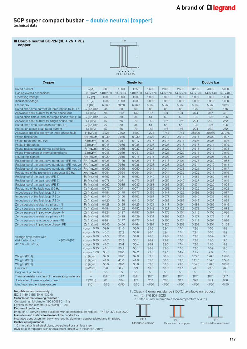
117
SCP super compact busbar – double neutral (copper)technical data
n Double neutral SCP2N (3L + 2N + PE) copper
Rated current In [A] 800 1 000 1 250 1 600 2 000 2 500 3 200 4 000 5 000
Casing overall dimensions L x H [mm] 140 x 130 140 x 130 140 x 130 140 x 170 140 x 170 140 x 220 140 x 380 140 x 440 140 x 480
Operating voltage Ue [V] 1 000 1 000 1 000 1 000 1 000 1 000 1 000 1 000 1 000
Insulation voltage Ui [V] 1 000 1 000 1 000 1 000 1 000 1 000 1 000 1 000 1 000
Frequency f [Hz] 50/60 50/60 50/60 50/60 50/60 50/60 50/60 50/60 50/60
Rated short-time current for three-phase fault (1 s) Icw [kA]rms 45 50 60 85 88 88 170 176 176
Allowable peak current for three-phase fault Ipk [kA] 95 110 132 187 194 194 374 387 387
Rated short-time current for single-phase fault (1 s) Icw [kA]rms 27 30 36 51 53 53 102 106 106
Allowable peak current for single-phase fault Ipk [kA] 57 66 79 112 116 116 224 232 232
Rated short-time protection current (1 s) Icw [kA]rms 27 30 36 51 53 53 102 106 106
Protection circuit peak rated current Ipk [kA] 57 66 79 112 116 116 224 232 232
Allowable specific energy for three-phase fault I2t [MA2s] 2 025 2 500 3 600 7 225 7 744 7 744 28 900 30 976 30 976
Phase resistance R20 [mΩ/m] 0·039 0·030 0·030 0·022 0·018 0·014 0·011 0·009 0·007
Phase reactance (50 Hz) X [mΩ/m] 0·023 0·017 0·017 0·015 0·014 0·011 0·007 0·006 0·006
Phase impedance Z [mΩ/m] 0·045 0·035 0·035 0·027 0·023 0·018 0·013 0·011 0·009
Phase resistance at thermal conditions Rt [mΩ/m] 0·042 0·035 0·037 0·027 0·022 0·017 0·013 0·011 0·008
Phase impedance at thermal conditions Z [mΩ/m] 0·048 0·039 0·041 0·031 0·026 0·020 0·015 0·013 0·010
Neutral resistance R20 [mΩ/m] 0·020 0·015 0·015 0·011 0·009 0·007 0·006 0·005 0·003
Resistance of the protective conductor (PE type 1) RPE [mΩ/m] 0·125 0·125 0·125 0·113 0·113 0·101 0·075 0·069 0·065
Resistance of the protective conductor (PE type 2) RPE [mΩ/m] 0·036 0·036 0·036 0·028 0·028 0·023 0·014 0·012 0·011
Resistance of the protective conductor (PE type 3) RPE [mΩ/m] 0·050 0·050 0·050 0·041 0·041 0·033 0·021 0·018 0·017
Reactance of the protective conductor (50 Hz) XPE [mΩ/m] 0·054 0·054 0·054 0·044 0·044 0·032 0·022 0·017 0·016
Resistance of the fault loop (PE 1) Ro [mΩ/m] 0·167 0·160 0·162 0·140 0·135 0·118 0·088 0·080 0·073
Resistance of the fault loop (PE 2) Ro [mΩ/m] 0·078 0·071 0·073 0·055 0·050 0·040 0·027 0·023 0·019
Resistance of the fault loop (PE 3) Ro [mΩ/m] 0·092 0·085 0·087 0·068 0·063 0·050 0·034 0·029 0·025
Reactance of the fault loop (50 Hz) Xo [mΩ/m] 0·077 0·071 0·071 0·059 0·058 0·043 0·029 0·023 0·022
Impedance of the fault loop (PE 1) Zo [mΩ/m] 0·184 0·175 0·177 0·152 0·147 0·126 0·093 0·083 0·077
Impedance of the fault loop (PE 2) Zo [mΩ/m] 0·110 0·100 0·102 0·081 0·077 0·059 0·040 0·033 0·029
Impedance of the fault loop (PE 3) Zo [mΩ/m] 0·120 0·110 0·112 0·090 0·086 0·066 0·045 0·037 0·034
Zero-sequence resistance phase - N Ro [mΩ/m] 0·128 0·125 0·125 0·121 0·117 0·094 0·088 0·065 0·046
Zero-sequence reactance phase - N Xo [mΩ/m] 0·184 0·152 0·152 0·143 0·127 0·122 0·078 0·076 0·073
Zero-sequence Impedance phase - N Zo [mΩ/m] 0·224 0·197 0·197 0·187 0·173 0·154 0·118 0·100 0·086
Zero-sequence resistance phase - PE Ro [mΩ/m] 0·507 0·429 0·429 0·331 0·283 0·221 0·177 0·178 0·144
Zero-sequence reactance phase - PE Xo [mΩ/m] 0·201 0·177 0·177 0·143 0·150 0·124 0·111 0·094 0·086
Zero-sequence Impedance phase - PE Zo [mΩ/m] 0·545 0·464 0·464 0·361 0·320 0·253 0·209 0·201 0·168
cosϕ = 0·70 39·9 31·5 33·0 25·6 22·1 17·1 12·2 10·5 8·9
cosϕ = 0·75 40·7 32·2 33·9 26·1 22·4 17·4 12·4 10·8 8·9
cosϕ = 0·80 41·3 32·8 34·6 26·5 22·6 17·5 12·6 10·9 9·0
cosϕ = 0·85 41·7 33·3 35·1 26·7 22·7 17·5 12·8 11·0 9·0
cosϕ = 0·90 41·7 33·4 35·4 26·7 22·5 17·4 12·8 11·0 8·9
cosϕ = 0·95 41·1 33·1 35·1 26·2 22·0 17·0 12·6 10·9 8·6
cosϕ = 1·00 36·7 30·0 32·2 23·3 19·1 14·7 11·2 9·8 7·3
Weight (PE 1) p [kg/m] 39·0 39·0 39·0 53·0 58·0 86·0 105·0 126·0 158·0
Weight (PE 2) p [kg/m] 41·0 41·0 41·0 55·0 60·0 83·0 111·0 134·0 174·0
Weight (PE 3) p [kg/m] 38·0 38·0 38·0 52·0 57·0 79·0 104·0 126·0 163·0
Fire load [kWh/m] 5·6 6·9 6·9 10·0 10·3 13·1 20·0 23·8 26·3
Degree of protection IP 55 55 55 55 55 55 55 55 55
Thermal resistance class of the insulating materials – B/F1 B/F1 B/F1 B/F1 B/F1 B/F1 B/F1 B/F1 B/F1
Joule effect losses at rated current P [W/m] 81 104 174 207 265 319 399 541 636
Min./max. ambient temperature [°C] -5/50 -5/50 -5/50 -5/50 -5/50 -5/50 -5/50 -5/50 -5/50
Voltage drop factor with distributed load k [V/m/A]10-6
∆V = k.L.Ie.10-6 [V]
Single barCopper Double bar
Regulations and conformity : IEC 61439-6 (BS EN 61439-6)Suitable for the following climates :
Constant humid climate (IEC 60068 2 – 11)Cyclical humid climate (IEC 60068 2 – 30)Degree of protection :
IP 55; IP x7 carrying lines available with accessories, on request - +44 (0) 370 608 9020Insulation and surface treatment of the conductors : Insulated conductors for the whole length, aluminum copper-plated and tin-plated Busbar casing material :
1·5 mm galvanised steel plate, pre-painted or stainless steel(available, if required, with special paint and/or with thickness 2 mm)
1 : Class F thermal resistance (155°C) available on request -
+44 (0) 370 608 9020 In : rated current referred to a room temperature of 40°C
PE 1
Standard versionPE 2
Extra earth - copper
PE 3Extra earth - aluminium
140
H
2N PEL2L1 L3