z/os mvs assembler services guide - united states · g ui d e v e r s i o n 2 r e l e a s e 3...
TRANSCRIPT

z/OS
MVS Programming: Assembler ServicesGuideVersion 2 Release 3
SA23-1368-30
IBM

NoteBefore using this information and the product it supports, read the information in “Notices” on page 551.
This edition applies to Version 2 Release 3 of z/OS (5650-ZOS) and to all subsequent releases and modificationsuntil otherwise indicated in new editions.
Last updated: July 17, 2017
© Copyright IBM Corporation 1988, 2017.US Government Users Restricted Rights – Use, duplication or disclosure restricted by GSA ADP Schedule Contractwith IBM Corp.

Contents
Figures . . . . . . . . . . . . . . . ix
Tables . . . . . . . . . . . . . . . xi
About this information. . . . . . . . xiiiWho should use this information . . . . . . . xiiiHow to use this information . . . . . . . . xiiiz/OS information . . . . . . . . . . . . xiii
How to send your comments to IBM . . xvIf you have a technical problem . . . . . . . xv
Summary of changes . . . . . . . . xviiSummary of changes for z/OS MVS Programming:Assembler Services Guide for z/OS Version 2Release 3 . . . . . . . . . . . . . . . xviiSummary of changes for z/OS Version 2 Release 2(V2R2), as updated December, 2015 . . . . . . xviiSummary of changes for z/OS MVS Programming:Assembler Services Guide for z/OS Version 2Release 2 . . . . . . . . . . . . . . . xviiz/OS Version 2 Release 1 summary of changes xviii
Chapter 1. Introduction . . . . . . . . 1
Chapter 2. Linkage conventions . . . . 5Saving the calling program's registers . . . . . . 6
Caller-provided save area . . . . . . . . . 6Linkage convention for floating point registers . . 7Linkage convention for the floating point controlregister . . . . . . . . . . . . . . . 7System-provided linkage stack . . . . . . . 7
Using the linkage stack . . . . . . . . . . . 7Example of using the linkage stack . . . . . . 8
Using a caller-provided save area . . . . . . . 8If not changing ARs or bits 0–31 of the 64–bitGPRs . . . . . . . . . . . . . . . . 9If changing the contents of bits 0-31 of the 64-bitGPRs but not changing ARs . . . . . . . . 10If starting in AMODE 64 . . . . . . . . . 14If changing ARs without using the linkage stack 16
Establishing a base register . . . . . . . . . 19Linkage procedures for primary mode programs . . 19
Primary mode programs receiving control . . . 19Primary mode programs returning control . . . 21Primary mode programs calling another program 21
Linkage procedures for AR mode programs . . . 22AR mode programs receiving control and usingthe linkage stack. . . . . . . . . . . . 22AR mode programs returning control and usingthe linkage stack. . . . . . . . . . . . 22AR mode programs receiving control and notusing the linkage stack . . . . . . . . . 22
AR mode programs returning control and notusing the linkage stack . . . . . . . . . 23AR mode programs calling another program . . 23
Conventions for passing information through aparameter list. . . . . . . . . . . . . . 24
Program in primary ASC mode. . . . . . . 24Programs in AR mode . . . . . . . . . . 25
Chapter 3. Subtask creation andcontrol . . . . . . . . . . . . . . . 27Creating the task . . . . . . . . . . . . 27Priorities . . . . . . . . . . . . . . . 27
Address space priority. . . . . . . . . . 28Task priority . . . . . . . . . . . . . 28Subtask priority . . . . . . . . . . . . 28Assigning and changing priority . . . . . . 28
Stopping and restarting a subtask (STATUS macro) 29Task and subtask communications . . . . . . . 29
Chapter 4. Program management . . . 33Residency and addressing mode of programs . . . 33
Residency mode definitions . . . . . . . . 33Addressing mode definitions . . . . . . . 34
Linkage considerations . . . . . . . . . . 34Floating point considerations . . . . . . . 35Passing control between programs with the sameAMODE . . . . . . . . . . . . . . 35Passing control between programs with differentAMODEs . . . . . . . . . . . . . . 35Passing control between programs with allregisters intact . . . . . . . . . . . . 36
Load module structure types . . . . . . . . 38Simple structure . . . . . . . . . . . . 38Dynamic structure . . . . . . . . . . . 39
Load module execution . . . . . . . . . . 39Passing control in a simple structure . . . . . . 39
Passing control without return . . . . . . . 39Passing control with return . . . . . . . . 41
Passing control in a dynamic structure . . . . . 47Bringing the load module into virtual storage . . 47Passing control with return . . . . . . . . 54Passing control without return . . . . . . . 58
APF-authorized programs and libraries . . . . . 60Additional Entry Points . . . . . . . . . . 61Entry Point and Calling Sequence Identifiers asDebugging Aids . . . . . . . . . . . . . 61Retrieving Information About Loaded Modules . . 62
Using the CSVINFO macro . . . . . . . . 62Coding a MIPR for the CSVINFO macro. . . . 64
Chapter 5. Understanding 31-bitaddressing . . . . . . . . . . . . . 67Virtual storage . . . . . . . . . . . . . 67
Addressing mode and residency mode . . . . 67
© Copyright IBM Corp. 1988, 2017 iii

Requirements for execution in 31-bit addressingmode . . . . . . . . . . . . . . . 69Rules and conventions for 31-bit addressing . . 70Mode sensitive instructions . . . . . . . . 70Branching instructions . . . . . . . . . . 71Use of 31-bit addressing . . . . . . . . . 71
Planning for 31-bit addressing . . . . . . . . 72Converting existing programs . . . . . . . 72Writing new programs that use 31-bit addressing 75Writing programs for MVS/370 and MVSsystems with 31-bit addressing . . . . . . . 76
Addressing mode and residency mode . . . . . 78Addressing mode - AMODE. . . . . . . . 78Residency mode - RMODE . . . . . . . . 78AMODE and RMODE combinations . . . . . 78AMODE and RMODE combinations at executiontime . . . . . . . . . . . . . . . . 78Determining the AMODE and RMODE of a loadmodule . . . . . . . . . . . . . . . 79Assembler support of AMODE and RMODE . . 79Linkage editor and binder support of AMODEand RMODE . . . . . . . . . . . . . 80Loader support for AMODE and RMODE . . . 84System support of AMODE and RMODE . . . 85How to change addressing mode . . . . . . 87
Establishing linkage . . . . . . . . . . . 87Using the BASSM and BSM instructions . . . . 89Using pointer-defined linkage . . . . . . . 92Using supervisor-assisted linkage . . . . . . 94Linkage assist routines . . . . . . . . . 95Using capping - linkage using a prologue andepilogue . . . . . . . . . . . . . . 100
Performing I/O in 31-bit addressing mode . . . 101Using the EXCP macro . . . . . . . . . 101Using EXCPVR . . . . . . . . . . . . 102
Understanding the use of central storage . . . . 111Central storage considerations for user programs 111
Chapter 6. Resource control . . . . . 115Synchronizing tasks (WAIT, POST, and EVENTSmacros) . . . . . . . . . . . . . . . 116Synchronizing tasks (Pause, Release, and Transfer) 118
Pause elements and pause element tokens . . . 118Using the services . . . . . . . . . . . 120
Serializing access to resources (ISGENQ macro) 123Naming the resource . . . . . . . . . . 124Defining the scope of a resource . . . . . . 125Requesting exclusive or shared control . . . . 126Limiting concurrent requests for resources. . . 127Processing the requests . . . . . . . . . 127Serializing access to resources through theISGENQ macro . . . . . . . . . . . . 132
Collecting information about resources and theirrequestors (ISGQUERY and GQSCAN macros) . . 133
How ISGQUERY returns resource information 133How GQSCAN returns resource information 134How GRS determines the scope of an ENQ orRESERVE request . . . . . . . . . . . 137
Chapter 7. Program interruptionservices. . . . . . . . . . . . . . 139Specifying user exit routines . . . . . . . . 139
Using the SPIE macro . . . . . . . . . 140Using the ESPIE macro . . . . . . . . . 141Environment upon entry to user's exit routine 142Functions performed in user exit routines . . . 143
Chapter 8. Providing recovery . . . . 145Understanding general recovery concepts . . . . 146
Deciding whether to provide recovery . . . . 147Understanding errors in MVS . . . . . . . 148Understanding recovery routine states . . . . 149Understanding the various routines in arecovery environment . . . . . . . . . 149Choosing the appropriate recovery routine . . 150Understanding recovery routine options . . . 152Understanding how routines in a recoveryenvironment interact . . . . . . . . . . 153
Writing recovery routines . . . . . . . . . 155Understanding what recovery routines do . . . 156Understanding the means of communication 162Special considerations for ESTAE-type recoveryroutines . . . . . . . . . . . . . . 170
Understanding the recovery environment . . . . 173Register contents . . . . . . . . . . . 174Other environmental factors in recovery . . . 180
Understanding recovery through a coded example 185Understanding advanced recovery topics . . . . 188
Invoking RTM (ABEND macro) . . . . . . 188Providing multiple recovery routines . . . . 189Providing recovery for recovery routines . . . 189Providing recovery for multitasking programs 190
Using STAE/STAI routines . . . . . . . . . 190
Chapter 9. Dumping virtual storage(ABEND, SNAPX, SNAP, andIEATDUMP macros) . . . . . . . . . 195ABEND dumps. . . . . . . . . . . . . 196
Obtaining a symptom dump . . . . . . . 196Suppressing dumps that duplicate previousdumps . . . . . . . . . . . . . . 196
SNAP dumps . . . . . . . . . . . . . 202Finding information in a SNAP dump . . . . 202Obtaining a summary dump for an ABEND orSNAP dump. . . . . . . . . . . . . 202
Transaction dumps . . . . . . . . . . . 203
Chapter 10. Reporting symptomrecords (SYMRBLD and SYMRECmacros) . . . . . . . . . . . . . . 205Writing symptom records to Logrec data set . . . 205The format of the symptom record . . . . . . 206
Symptom strings — SDB format . . . . . . 207Building a symptom record using the SYMRBLDmacro . . . . . . . . . . . . . . . . 207Building a symptom record using the ADSR andSYMREC macros . . . . . . . . . . . . 208
Programming notes for section 1 . . . . . . 208
iv z/OS MVS Assembler Services Guide
Programming notes for section 2 . . . . . . 209Programming notes for section 2.1 . . . . . 209Programming notes for section 3 . . . . . . 211Programming notes for section 4 . . . . . . 211Programming notes for section 5 . . . . . . 212
Chapter 11. Virtual storagemanagement. . . . . . . . . . . . 213Explicit requests for virtual storage . . . . . . 214
Obtaining storage through the GETMAIN macro 214Obtaining storage through the STORAGE macro 216Using the CPOOL macro . . . . . . . . 218Subpool handling . . . . . . . . . . . 219
Implicit requests for virtual storage . . . . . . 223Reenterable load modules . . . . . . . . 223Reenterable macros . . . . . . . . . . 223Non-reenterable load modules. . . . . . . 225Freeing of virtual storage . . . . . . . . 225
Chapter 12. Using the 64-bit addressspace. . . . . . . . . . . . . . . 227What is the 64-bit address space?. . . . . . . 227Why would you use virtual storage above the bar? 228Memory objects . . . . . . . . . . . . 229
Using large pages . . . . . . . . . . . 229Using assembler instructions in the 64-bit addressspace . . . . . . . . . . . . . . . . 230
64-bit binary operations . . . . . . . . . 23064-bit addressing mode (AMODE) . . . . . 232
Issuing MVS macros in AMODE 64 . . . . . . 235Example of using SYSSTATE AMODE64= . . . 235
IARV64 services . . . . . . . . . . . . 236Protecting storage above the bar . . . . . . 236Preventing execution of code from the memoryobject . . . . . . . . . . . . . . . 236Relationship between the memory object and itsowner . . . . . . . . . . . . . . . 236Creating memory objects . . . . . . . . 237Using a memory object . . . . . . . . . 238
Discarding data in a memory object . . . . . . 240Releasing the physical resources that back pages ofmemory objects. . . . . . . . . . . . . 240Freeing a memory object . . . . . . . . . 241
Example of freeing a memory object. . . . . 241Creating a guard area and changing its size . . . 241
Example of creating a memory object with aguard area . . . . . . . . . . . . . 242
An example of creating, using, and freeing amemory object . . . . . . . . . . . . . 243
Chapter 13. Callable cell pool services 245Comparison of callable cell pool services and theCPOOL macro . . . . . . . . . . . . . 246Storage considerations . . . . . . . . . . 247Link-editing callable cell pool services . . . . . 248Using callable cell pool services . . . . . . . 249Handling return codes . . . . . . . . . . 251Callable cell pool services coding examples . . . 251
Chapter 14. Data-in-virtual . . . . . . 257When to use data-in-virtual . . . . . . . . 258
Factors affecting performance . . . . . . . 258Creating a linear data set . . . . . . . . 259
Using the services of data-in-virtual . . . . . . 259Identify . . . . . . . . . . . . . . 260Access. . . . . . . . . . . . . . . 260Map . . . . . . . . . . . . . . . 260Save, savelist, and reset . . . . . . . . . 261Unmap . . . . . . . . . . . . . . 262Unaccess . . . . . . . . . . . . . . 262Unidentify . . . . . . . . . . . . . 262
The IDENTIFY service . . . . . . . . . . 262The ACCESS service . . . . . . . . . . . 263The MAP service . . . . . . . . . . . . 266The SAVE service . . . . . . . . . . . . 270The SAVELIST service . . . . . . . . . . 272The RESET service . . . . . . . . . . . 273
Effect of RETAIN mode on RESET . . . . . 273The UNMAP service . . . . . . . . . . . 274The UNACCESS and UNIDENTIFY services . . . 275Sharing data in an object . . . . . . . . . 276Miscellaneous restrictions for using data-in-virtual 276DIV macro programming examples . . . . . . 276
General program description . . . . . . . 276Data-in-virtual sample program code . . . . 277Executing the program . . . . . . . . . 282
Chapter 15. Using access registers 285Access lists . . . . . . . . . . . . . . 287
Types of access lists . . . . . . . . . . 287Writing programs in AR mode . . . . . . . 288Coding instructions in AR mode . . . . . . . 289Manipulating the contents of ARs . . . . . . 290
Loading an ALET into an AR . . . . . . . 291Loading the value of zero into an AR . . . . 291
The ALESERV macro . . . . . . . . . . . 291Adding an entry to an access list . . . . . . 292Deleting an entry from an access list . . . . 292
Issuing MVS macros in AR mode. . . . . . . 293Example of using SYSSTATE . . . . . . . 293Using X-macros . . . . . . . . . . . 293
Formatting and displaying AR information . . . 294
Chapter 16. Data spaces andhiperspaces . . . . . . . . . . . . 295What are data spaces and hiperspaces? . . . . . 295What can a program do with a data space or ahiperspace? . . . . . . . . . . . . . . 296
How does a program obtain a data space and ahiperspace? . . . . . . . . . . . . . 296How does a program move data into a dataspace or hiperspace? . . . . . . . . . . 296Who owns a data space or hiperspace? . . . . 296Can an installation limit the use of data spacesand hiperspaces? . . . . . . . . . . . 297How does a program manage the storage in adata space or hiperspace? . . . . . . . . 297
Differences between data spaces and hiperspaces 298
Contents v
||||

Comparing data space and hiperspace use ofphysical storage . . . . . . . . . . . 299
Which one should your program use? . . . . . 299An example of using a data space . . . . . 300An example of using a hiperspace . . . . . 300
Creating and using data spaces . . . . . . . 300Manipulating data in a data space . . . . . 301Rules for creating, deleting, and managing dataspaces . . . . . . . . . . . . . . . 301Creating a data space. . . . . . . . . . 302Establishing addressability to a data space. . . 306Examples of moving data into and out of a dataspace . . . . . . . . . . . . . . . 306Extending the current size of a data space . . . 308Releasing data space storage . . . . . . . 309Paging data space storage areas into and out ofcentral storage . . . . . . . . . . . . 309Deleting a data space. . . . . . . . . . 310Using callable cell pool services to manage dataspace areas . . . . . . . . . . . . . 310Sharing data spaces among problem-stateprograms with PSW key 8-F . . . . . . . 312Sharing data spaces through the PASN-AL . . 314Example of mapping a data-in-virtual object to adata space . . . . . . . . . . . . . 314Using data spaces efficiently . . . . . . . 316Example of creating, using, and deleting a dataspace . . . . . . . . . . . . . . . 316Dumping storage in a data space . . . . . . 317Using checkpoint/restart . . . . . . . . 317
Creating and using hiperspaces . . . . . . . 318Standard hiperspaces . . . . . . . . . . 319Creating a hiperspace . . . . . . . . . 320Transferring data to and from hiperspaces . . . 321Extending the current size of a hiperspace. . . 325Releasing hiperspace storage . . . . . . . 325Deleting a hiperspace. . . . . . . . . . 326Example of creating a standard hiperspace andusing it . . . . . . . . . . . . . . 326Using data-in-virtual with hiperspaces . . . . 328Using checkpoint/restart . . . . . . . . 331
Chapter 17. Window services . . . . 333Data objects . . . . . . . . . . . . . . 333
Permanent . . . . . . . . . . . . . 333Temporary data objects . . . . . . . . . 333Structure of a data object . . . . . . . . 333What does window services provide? . . . . 334The ways that window services can map anobject . . . . . . . . . . . . . . . 335Access to permanent data objects . . . . . . 338Access to temporary data objects . . . . . . 339
Using window services . . . . . . . . . . 339Obtaining access to a data object . . . . . . 341Defining a view of a data object . . . . . . 342Defining the expected reference pattern . . . 344Defining multiple views of an object . . . . 345Saving interim changes to a permanent dataobject . . . . . . . . . . . . . . . 346Updating a temporary data object . . . . . 347Refreshing changed data . . . . . . . . 347
Updating a permanent object on DASD . . . 348Changing a view in a window . . . . . . 348Terminating access to a data object . . . . . 350Link-editing callable window services . . . . 350
Window services coding example. . . . . . . 351
Chapter 18. Sharing application data(name/token callable services) . . . . 353Understanding name/token pairs and levels . . . 353
Name/token pairs. . . . . . . . . . . 353Levels for name/token pairs . . . . . . . 354Determining what your program can do withname/token pairs . . . . . . . . . . . 354
Deciding what name/token level you need . . . 355Task-level name/token pair . . . . . . . 355Home-level name/token pair . . . . . . . 356
Owning and deleting name/token pairs . . . . 357Using checkpoint/restart with name/token pairs 358Link-editing name/token services . . . . . . 358
Chapter 19. Processor storagemanagement. . . . . . . . . . . . 359Freeing virtual storage . . . . . . . . . . 360Releasing storage . . . . . . . . . . . . 360Protecting a range of virtual storage pages . . . 361Loading/paging out virtual storage areas . . . . 362Virtual subarea list . . . . . . . . . . . 363Page service list (PSL) . . . . . . . . . . 363Defining the reference pattern (REFPAT) . . . . 364
How does the system handle the data in anarray? . . . . . . . . . . . . . . . 365Using the REFPAT macro . . . . . . . . 368Examples of using REFPAT to define a referencepattern . . . . . . . . . . . . . . 372Removing the definition of the reference pattern 372
Chapter 20. Sharing data in virtualstorage (IARVSERV macro) . . . . . 375Understanding the concepts of sharing data withIARVSERV . . . . . . . . . . . . . . 376Storage you can use with IARVSERV . . . . . 376Obtaining storage for the source and target . . . 377Defining storage for sharing data and access . . . 377Changing storage access . . . . . . . . . . 378How to share and unshare data . . . . . . . 380Accessing data in a sharing group . . . . . . 381Example of sharing storage with IARVSERV . . . 381Use with data-in-virtual (DIV macro) . . . . . 382Diagnosing problems with shared data . . . . . 383Converting a central to virtual storage address(IARR2V macro) . . . . . . . . . . . . 383
Chapter 21. Timing andcommunication . . . . . . . . . . 385Checking for timer synchronization . . . . . . 385Obtaining time of day and date . . . . . . . 385Converting between time of day and date andTOD clock formats . . . . . . . . . . . 386Interval timing . . . . . . . . . . . . . 386
vi z/OS MVS Assembler Services Guide

Obtaining accumulated processor time . . . . . 388Writing and deleting messages (WTO, WTOR,DOM, and WTL) . . . . . . . . . . . . 388
Routing the message . . . . . . . . . . 389Writing a multiple-line message . . . . . . 392Embedding label lines in a multiple-linemessage . . . . . . . . . . . . . . 393
Communicating in a sysplex environment . . . . 393Writing to the programmer . . . . . . . . . 393Writing to the system log . . . . . . . . . 393
Deleting messages already written . . . . . 394Retrieving console information (CONVCON andCnzConv macros) . . . . . . . . . . . . 394
Using console names instead of console IDs . . 395Determining the name or ID of a console . . . 395Validating a console name or ID and obtainingthe active system name . . . . . . . . . 397
Chapter 22. Translating messages . . 399Allocating data sets for an application . . . . . 401Creating install message files . . . . . . . . 402
Creating a version record . . . . . . . . 402Creating message skeletons. . . . . . . . 402Message skeleton format . . . . . . . . 403Message text in a skeleton . . . . . . . . 404
Validating message skeletons . . . . . . . . 405Allocating storage for validation run-timemessage files . . . . . . . . . . . . 406Compiling message files . . . . . . . . . 406Checking the message compiler return codes 410
Updating the system run-time message files . . . 410Using MMS translation services in an application 411
Determining which languages are available(QRYLANG macro) . . . . . . . . . . 411Retrieving translated messages (TRANMSGmacro). . . . . . . . . . . . . . . 411Example of displaying messages . . . . . . 413
Using message parameter blocks for new messages(BLDMPB and UPDTMPB macros) . . . . . . 414Support for additional languages . . . . . . . 415Example of an application that uses MMStranslation services . . . . . . . . . . . 416
Chapter 23. Data compression andexpansion services . . . . . . . . . 419Services provided by CSRCESRV . . . . . . . 419
Using these services . . . . . . . . . . 420Services provided by CSRCMPSC . . . . . . 420
Compression and expansion dictionaries . . . 421Building the CSRYCMPS area . . . . . . . 421Determining if the CSRCMPSC macro can beissued on a system . . . . . . . . . . 424Compression processing . . . . . . . . . 424Expansion processing. . . . . . . . . . 425Dictionary entries . . . . . . . . . . . 425
Chapter 24. Accessing unit controlblocks (UCBs) . . . . . . . . . . . 437Detecting I/O configuration changes . . . . . 437Scanning UCBs . . . . . . . . . . . . . 438
Obtaining UCB information for a specified device 439Obtaining eligible device table information . . . 439
Using the EDTINFO macro . . . . . . . . 440
Chapter 25. Setting up and using aninternal reader . . . . . . . . . . . 443Allocating the internal reader data set . . . . . 443Opening the internal reader data set. . . . . . 444Sending job output to the internal reader . . . . 445
Obtaining a job identifier . . . . . . . . 445Closing the internal reader data set . . . . . . 446
Chapter 26. Using the symbolsubstitution service . . . . . . . . 449What are symbols? . . . . . . . . . . . 449
Types of symbols . . . . . . . . . . . 449Examples of user symbols . . . . . . . . 450
Calling the ASASYMBM or ASASYMBF service 451Setting up the ASASYMBP mapping macro . . 451Providing a symbol table to ASASYMBM /ASASYMBF . . . . . . . . . . . . . 453Using symbols in programs . . . . . . . 458
Chapter 27. Using system loggerservices. . . . . . . . . . . . . . 463What is system logger? . . . . . . . . . . 463
The log stream . . . . . . . . . . . . 464The system logger configuration . . . . . . . 466
The system logger component . . . . . . . 468Overview of system logger services . . . . . . 469
Summary of system logger services . . . . . 469Define authorization to system logger resources 47064 bit virtual addressing support for systemlogger services . . . . . . . . . . . . 471Synchronous and asynchronous processing . . 474How system logger handles gaps in the logstream. . . . . . . . . . . . . . . 475Dumping on data loss (804–type) conditions . . 476Using the system logger answer area(ANSAREA parameter) . . . . . . . . . 478Using ENF event code 48 in system loggerapplications . . . . . . . . . . . . . 480
IXGINVNT: Managing the LOGR policy . . . . 480Defining a model log stream in the LOGRcouple data set . . . . . . . . . . . . 480Defining a log stream as DASD-only . . . . 481Upgrading an existing log stream configuration 482Renaming a log stream dynamically . . . . . 484Updating a log stream's attributes . . . . . 484
IXGCONN: Connecting to and disconnecting froma log stream . . . . . . . . . . . . . . 486
Examples of ways to connect to the log stream 486How system logger allocates structure space fora new log stream at connection time. . . . . 487Connect process and staging data sets . . . . 488Requesting authorization to the log stream foran application . . . . . . . . . . . . 488Requesting a write or import connection -IMPORTCONNECT parameter . . . . . . 488Specifying user data for a log stream . . . . 489
Contents vii

System logger processing at disconnection andexpired stream token . . . . . . . . . . 489
IXGWRITE: Writing to a log stream . . . . . . 491The log block buffer . . . . . . . . . . 491Ensuring chronological sequence of log blocks 492Write triggers . . . . . . . . . . . . 492When is data committed to the log stream? . . 493When the log stream coupling facility storagelimit is reached . . . . . . . . . . . . 493When the staging data set storage limit isreached . . . . . . . . . . . . . . 494When the staging data set is formatting . . . 494Limiting asynchronous IXGWRITE requests . . 495
IXGBRWSE: Browsing/reading a log stream . . . 495IXGBRWSE terminology . . . . . . . . . 496IXGBRWSE requests . . . . . . . . . . 496Browsing both active and inactive data . . . . 497Browsing for a log block by time stamp . . . 497Browsing multiple log blocks . . . . . . . 498Return and reason code considerations . . . . 499Using IXGBRWSE and IXGWRITE . . . . . 499Using IXGBRWSE and IXGDELET requeststogether . . . . . . . . . . . . . . 500
IXGDELET: Deleting log blocks from a log stream 500Using the BLOCKS parameter . . . . . . . 500
IXGIMPRT: Import log blocks . . . . . . . . 501Making sure log blocks are imported insequence - Understanding log block identifiers . 501Making sure log data is safe to import . . . . 502
IXGQUERY: Get information about a log stream orsystem logger . . . . . . . . . . . . . 503
The safe import point: Using IXGQUERY andIXGIMPRT together . . . . . . . . . . 504The coupling facility list structure versionnumber . . . . . . . . . . . . . . 506
IXGOFFLD: Initiate offload to DASD log data sets 507Managing a target log stream: Using IXGIMPRT,IXGOFFLD, and IXGQUERY together . . . . 507
IXGUPDAT: Modify log stream control information 508Rebuilds and IXGUPDAT processing . . . . 509
Setting up the system logger configuration . . . 509Reading data from log streams in data set format 509
Is my application eligible for the LOGRsubsystem? . . . . . . . . . . . . . 509Using the LOGR subsystem . . . . . . . 510JCL for the LOGR Subsystem . . . . . . . 511LOGR SUBSYS dynamic allocationconsiderations . . . . . . . . . . . . 513
When things go wrong — Recovery scenarios forsystem logger . . . . . . . . . . . . . 515
When a system logger application fails . . . . 515When an MVS system or sysplex fails . . . . 516Recovery performed for DASD-only log streams 516When the system logger address space fails . . 516When the coupling facility structure fails . . . 517
When the coupling facility space for a logstream becomes full . . . . . . . . . . 519When a staging data set becomes full . . . . 519When a log stream is damaged . . . . . . 519When DASD log data set space fills . . . . . 520When unrecoverable DASD I/O errors occur 521
Chapter 28. Unicode instructionservices: CSRUNIC . . . . . . . . . 523
Chapter 29. Transactional execution 525Nonconstrained transactions . . . . . . . . 525Constrained transactions . . . . . . . . . 526Planning to use transactional execution. . . . . 527Transactional execution debugging . . . . . . 528Transactional execution diagnostics . . . . . . 528
Appendix A. Using the unitverification service . . . . . . . . . 531Functions of unit verification . . . . . . . . 531
Check groups - Function code 0 . . . . . . 531Check units - Function code 1 . . . . . . . 531Return unit name - Function code 2 . . . . . 532Return unit control block (UCB) addresses -Function code 3 . . . . . . . . . . . 532Return group ID - Function code 4 . . . . . 532Indicate unit name is a look-up value - Functioncode 5 . . . . . . . . . . . . . . . 532Return look-up value - Function code 6 . . . 532Convert device type to look up value - Functioncode 7 . . . . . . . . . . . . . . . 532Return attributes - Function code 8 . . . . . 532Specify subpool for returned storage - Functioncode 10 . . . . . . . . . . . . . . 532Return unit names for a device class - Functioncode 11 . . . . . . . . . . . . . . 532
Appendix B. Accessibility . . . . . . 547Accessibility features . . . . . . . . . . . 547Consult assistive technologies . . . . . . . . 547Keyboard navigation of the user interface . . . . 547Dotted decimal syntax diagrams . . . . . . . 547
Notices . . . . . . . . . . . . . . 551Terms and conditions for product documentation 553IBM Online Privacy Statement. . . . . . . . 554Policy for unsupported hardware. . . . . . . 554Minimum supported hardware . . . . . . . 554Programming interface information . . . . . . 555Trademarks . . . . . . . . . . . . . . 555
Index . . . . . . . . . . . . . . . 557
viii z/OS MVS Assembler Services Guide

Figures
1. Format of the Save Area. . . . . . . . . 92. Format of the Format 5 save area (F5SA) 103. Format of the Format 8 save area (F8SA) 114. Format of the Format 4 Save Area (F4SA) 145. Format of the Format 7 save area (F7SA) 176. Primary Mode Parameter List EXEC PGM= 247. AR Mode Parameter List when Not AMODE
64 . . . . . . . . . . . . . . . . 258. Levels of Tasks in a Job Step . . . . . . . 309. Assembler Definition of AMODE/RMODE 33
10. Example of Addressing Mode Switch . . . . 3611. Passing Control in a Simple Structure . . . . 4012. Passing Control With a Parameter List . . . 4113. Passing Control With Return . . . . . . . 4314. Passing Control With CALL . . . . . . . 4315. Test for Normal Return . . . . . . . . 4416. Return Code Test Using Branching Table 4417. Establishing a Return Code . . . . . . . 4518. Using the RETURN Macro . . . . . . . 4619. RETURN Macro with Flag . . . . . . . 4620. Search for Module, EP or EPLOC Parameter
With DCB=0 or DCB Parameter Omitted . . . 4921. Search for Module, EP or EPLOC Parameters
With DCB Parameter Specifying PrivateLibrary . . . . . . . . . . . . . . 50
22. Search for Module Using DE Parameter 5223. Use of the LINK Macro with the Job or Link
Library . . . . . . . . . . . . . . 5524. Use of the LINK Macro with a Private Library 5525. Use of the BLDL Macro . . . . . . . . 5626. The LINK Macro with a DE Parameter 5627. Misusing Control Program Facilities Causes
Unpredictable Results . . . . . . . . . 6028. Processing flow for the CSVINFO macro and
the caller's MIPR . . . . . . . . . . . 6329. Two Gigabyte Virtual Storage Map. . . . . 6830. Maintaining Correct Interfaces to Modules that
Change to AMODE 31 . . . . . . . . . 7331. AMODE and RMODE Combinations . . . . 7932. AMODE and RMODE Processing by the
Linkage Editor . . . . . . . . . . . 8233. AMODE and RMODE Processing by the
Loader . . . . . . . . . . . . . . 8434. Mode Switching to Retrieve Data from Above
16 Megabytes . . . . . . . . . . . . 8735. Linkage Between Modules with Different
AMODEs and RMODEs . . . . . . . . 8936. BRANCH and SAVE and Set Mode
Description . . . . . . . . . . . . 9037. Branch and Set Mode Description . . . . . 9138. Using BASSM and BSM . . . . . . . . 9239. Example of Pointer-Defined Linkage . . . . 9440. Example of Supervisor-Assisted Linkage 9541. Example of a Linkage Assist Routine . . . . 9742. Cap for an AMODE 24 Module . . . . . 100
43. Performing I/O while residing above 16megabytes . . . . . . . . . . . . 103
44. Event Control Block (ECB) . . . . . . . 11645. Using LINKAGE=SYSTEM on the WAIT and
POST Macros . . . . . . . . . . . 11746. Pause and Release Example . . . . . . . 12147. Release and Pause Example . . . . . . . 12248. Transfer without Pause Example . . . . . 12349. ISGENQ Macro Processing . . . . . . . 12850. Interlock Condition . . . . . . . . . 13151. Two Requests For Two Resources . . . . . 13252. One Request For Two Resources . . . . . 13253. Work Area Contents for GQSCAN with a
Scope of STEP, SYSTEM, SYSTEMS, or ALL . 13654. Using the SPIE Macro. . . . . . . . . 14155. Mainline Routine with One Recovery Routine 15456. Mainline Routine with Several Recovery
Routines . . . . . . . . . . . . . 15557. Example of Using the GETMAIN Macro 21658. Virtual Storage Control . . . . . . . . 22059. Using the List and the Execute Forms of the
DEQ Macro . . . . . . . . . . . . 22460. The 64-bit address space . . . . . . . . 22861. Cell pool storage . . . . . . . . . . 24862. Mapping from an address space . . . . . 26663. Mapping from a data space or hiperspace 26764. Multiple mapping . . . . . . . . . . 26865. Using an ALET to Identify an Address Space
or a Data Space . . . . . . . . . . . 28666. An Illustration of a DU-AL . . . . . . . 28767. Using Instructions in AR Mode . . . . . 28968. Accessing Data in a Data Space . . . . . 29869. Accessing Data in a Hiperspace . . . . . 29970. Example of Specifying the Size of a Data
Space . . . . . . . . . . . . . . 30571. Example of Extending the Current Size of a
Data Space . . . . . . . . . . . . 30972. Example of Using Callable Cell Pool Services
for Data Spaces . . . . . . . . . . . 31273. Two Problem Programs Sharing a
SCOPE=SINGLE Data Space . . . . . . 31374. Example of Scrolling through a Standard
Hiperspace . . . . . . . . . . . . 31975. Illustration of the HSPSERV Write and Read
Operations . . . . . . . . . . . . 32276. Example of Creating a Standard Hiperspace
and Transferring Data. . . . . . . . . 32777. Example of Mapping a Data-in-Virtual Object
to a Hiperspace . . . . . . . . . . . 32978. A Standard Hiperspace as a Data-in-Virtual
Object . . . . . . . . . . . . . . 33079. Structure of a Data Object . . . . . . . 33480. Mapping a Permanent Object That Has No
Scroll Area . . . . . . . . . . . . 33581. Mapping a Permanent Object That Has A
Scroll Area . . . . . . . . . . . . 336
© Copyright IBM Corp. 1988, 2017 ix

82. Mapping a Temporary Object . . . . . . 33683. Mapping an Object To Multiple Windows 33784. Mapping Multiple Objects . . . . . . . 33885. Using the Name and the Token . . . . . 35386. Using the Task Level in a Single Address
Space . . . . . . . . . . . . . . 35687. Using Home-Level and Task-Level
Name/Token Pairs . . . . . . . . . . 35788. Releasing Virtual Storage . . . . . . . 36189. Example of using REFPAT with a Large Array 36590. Illustration of a Reference Pattern with a Gap 36791. Illustration of Forward Direction in a
Reference Pattern . . . . . . . . . . 36892. Illustration of Backward Direction in a
Reference Pattern . . . . . . . . . . 36993. Two Typical Reference Patterns . . . . . 36994. Data Sharing with IARVSERV . . . . . . 37695. Sharing Storage with IARVSERV . . . . . 38296. Interval Processing. . . . . . . . . . 38797. Writing to the Operator . . . . . . . . 39198. Writing to the Operator With a Reply 39299. Preparing Messages for Translation . . . . 401
100. Sample job to invoke IDCAMS to obtain adata set for the run-time message files . . . 406
101. Using JCL to Invoke the Compiler with asingle PDS as input . . . . . . . . . 407
102. Using JCL to Invoke the Compiler with aconcatenation of partitioned Data Sets asinput . . . . . . . . . . . . . . 407
103. Using a TSO/E CLIST to Invoke theCompiler with a single PDS input . . . . 407
104. Using a TSO/E CLIST to Invoke theCompiler with a concatenation of partitionedData Set as input . . . . . . . . . . 408
105. Using a REXX exec to Invoke the Compilerwith a single PDS as input . . . . . . . 408
106. Using a REXX exec to Invoke the Compilerwith a concatenation of partitioned Data Setsas input . . . . . . . . . . . . . 409
107. Using the TRANMSG Macro . . . . . . 413108. Contiguous Symbol Table . . . . . . . 456109. Non-contiguous Symbol Table . . . . . . 457110. System Logger Log Stream . . . . . . . 464111. Log Stream Data on the Coupling Facility and
DASD . . . . . . . . . . . . . . 465112. Log Stream Data in Local Storage Buffers and
DASD Log Data Sets . . . . . . . . . 466
113. A Complete Coupling Facility Log StreamConfiguration . . . . . . . . . . . 467
114. A DASD-Only Configuration . . . . . . 468115. Define a Log Stream as a Model and then
Model a Log Stream After It . . . . . . 481116. Searching for a Log Block by Time . . . . 498117. Deleting a Range of Log Blocks . . . . . 501118. How Source and Target Log Streams Can Get
Out of Sync . . . . . . . . . . . . 505119. Input Parameter List . . . . . . . . . 534120. Requesting function code 0 (check groups) 535121. Requesting function code 1 (check units) 536122. Requesting function code 2 (return unit
name) . . . . . . . . . . . . . . 536123. Output from Function Code 2 (Return Unit
Name) . . . . . . . . . . . . . . 537124. Requesting function code 3 (return UCB
addresses) . . . . . . . . . . . . 537125. Output from Function Code 3 (Return UCB
Addresses) . . . . . . . . . . . . 538126. Requesting function code 4 (return group ID) 538127. Output from Function Code 4 (Return Group
ID) . . . . . . . . . . . . . . . 539128. Requesting function code 5 (indicate unit
name is a look-up value). . . . . . . . 539129. Requesting function code 6 (return look-up
value) . . . . . . . . . . . . . . 540130. Output from Function Code 6 (Return
Look-up Value) . . . . . . . . . . . 540131. Requesting function code 7 (convert device
type to look-up value) . . . . . . . . 541132. Output from Function Code 7 (Convert
Device Type to Look-up Value) . . . . . 541133. Requesting function code 8 (return attributes) 542134. Requesting function code 10 (specify subpool
for returned storage) . . . . . . . . . 543135. Requesting Function Code 11 (Return Unit
Names for a Device Class) . . . . . . . 543136. Output from Function Code 11 (Return Unit
Names for a Device Class) . . . . . . . 543137. Input for Function Codes 0 and 1 . . . . . 544138. Output from Function Codes 0 and 1 545139. Input for Function Codes 3 and 10 . . . . 545140. Output from Function Codes 3 and 10 545141. Input for Function Codes 1 and 5 . . . . . 546142. Output from Function Codes 1 and 5 546
x z/OS MVS Assembler Services Guide
Tables
1. Characteristics of Load Modules . . . . . 382. CSVINFO Recovery . . . . . . . . . . 653. Establishing Correct Interfaces to Modules
That Move Above 16 Megabytes . . . . . 744. Task Synchronization Techniques . . . . . 1155. Pause, Release, and Transfer callable services 1186. Pause Element (PE) and Event Control Block
(ECB) . . . . . . . . . . . . . . 1197. GQSCAN Results with a Scope of STEP,
SYSTEM, SYSTEMS, or ALL . . . . . . 1358. Summary of Recovery Routine States 1529. Contents of GPR 0 on Entry to a Retry
Routine . . . . . . . . . . . . . 16110. Key fields in the SDWA . . . . . . . . 16611. Restoring quiesced restorable I/O operations 17212. Where to Find Register Content Information 17413. Register Contents—ESTAE-Type Recovery
Routine With an SDWA . . . . . . . . 17514. Register Contents—ESTAE-Type Recovery
Routine Without an SDWA . . . . . . . 17515. Register Contents—Retry from an
ESTAE-Type Recovery Routine Without anSDWA . . . . . . . . . . . . . . 177
16. Register Contents—Retry from anESTAE-Type Recovery Routine With anSDWA, RETREGS=NO, and FRESDWA=NO . 178
17. Register Contents—Retry from anESTAE-Type Recovery Routine With anSDWA, RETREGS=NO, and FRESDWA=YES . 178
18. Register Contents—Retry from anESTAE-Type Recovery Routine With anSDWA and RETREGS=YES . . . . . . . 179
19. Register Contents—Retry from anESTAE-Type Recovery Routine With anSDWA and RETREGS=64 in z/Architecturemode . . . . . . . . . . . . . . 180
20. Environments of ESTAE-type RecoveryRoutines and their Retry Routines . . . . 183
21. Reasons for Selecting the Type of Dump 19522. Register 15 contents on entry in AMODE=64 23423. Comparing Tasks and Concepts: Below the
Bar and Above the Bar . . . . . . . . 23824. Cell pool services versus the CPOOL macro,
based on program requirements . . . . . 24625. Characteristics of DU-ALs and PASN-ALs 28826. Base and Index Register Addressing in AR
Mode . . . . . . . . . . . . . . 29027. Rules for How Problem State Programs with
Key 8-F Can Use Data Spaces . . . . . . 30128. Facts about a Non-shared Standard
Hiperspace . . . . . . . . . . . . 32029. Summary of What Programs Do with
Name/Token Pairs . . . . . . . . . . 35430. Format of a virtual subarea list (VSL) entry 36331. Allowed Source/Target View Combinations
for Share . . . . . . . . . . . . . 37832. Characters Printed or Displayed on an MCS
Console . . . . . . . . . . . . . 38833. Descriptor Code Indicators . . . . . . . 39134. Format of Version Record Fields . . . . . 40235. Version Record Example . . . . . . . . 40236. Message Skeleton Fields . . . . . . . . 40337. Languages Available to MVS Message Service 41538. Required SAF authorization for system logger
resources . . . . . . . . . . . . . 47139. How IXGBRWSE Requests Handle Gaps in a
Log Stream . . . . . . . . . . . . 47640. How IXGDELET Requests Handle Gaps in a
Log Stream . . . . . . . . . . . . 476
© Copyright IBM Corp. 1988, 2017 xi

xii z/OS MVS Assembler Services Guide

About this information
This information describes the operating system services that an unauthorizedprogram can use. An unauthorized program is one that does not run in supervisorstate, or have PSW key 0-7, or run with APF authorization. To use a service, theprogram issues a macro. A companion document, z/OS MVS Programming:Assembler Services Reference ABE-HSP, provides the detailed information for codingthe macros.
Some of the topics discussed in this document are also discussed in z/OS MVSProgramming: Authorized Assembler Services Guide and in the following otherdocuments:v z/OS MVS Programming: Authorized Assembler Services Reference ALE-DYN
v z/OS MVS Programming: Authorized Assembler Services Reference EDT-IXG
v z/OS MVS Programming: Authorized Assembler Services Reference LLA-SDU
v z/OS MVS Programming: Authorized Assembler Services Reference SET-WTO
However, the services and macros in those documents are for authorizedprograms.
Who should use this informationThis information is for the programmer who is coding in assembler language, andwho needs to become familiar with the operating system and the services thatprograms running under it can invoke.
The information assumes that the reader understands system concepts and writesprograms in assembler language.
System macros require High Level Assembler. For more information aboutassembler language programming, see High Level Assembler and Toolkit Featurein IBM Knowledge Center (www.ibm.com/support/knowledgecenter/SSENW6).
Using this information also requires you to be familiar with the operating systemand the services that programs running under it can invoke.
How to use this informationThis information is one of the set of programming documents for MVS™. This setdescribes how to write programs in assembler language or high-level languages,such as C, FORTRAN, and COBOL. For more information about the content of thisset of documents, see z/OS Information Roadmap.
z/OS informationThis information explains how z/OS references information in other documentsand on the web.
When possible, this information uses cross document links that go directly to thetopic in reference using shortened versions of the document title. For completetitles and order numbers of the documents for all products that are part of z/OS,see z/OS Information Roadmap.
© Copyright IBM Corp. 1988, 2017 xiii

To find the complete z/OS® library, go to IBM Knowledge Center(www.ibm.com/support/knowledgecenter/SSLTBW/welcome).
xiv z/OS MVS Assembler Services Guide
How to send your comments to IBM
We appreciate your input on this documentation. Please provide us with anyfeedback that you have, including comments on the clarity, accuracy, orcompleteness of the information.
Use one of the following methods to send your comments:
Important: If your comment regards a technical problem, see instead “If you havea technical problem.”v Send an email to [email protected] Send an email from the Contact z/OS web page (www.ibm.com/systems/z/os/
zos/webqs.html).
Include the following information:v Your name and addressv Your email addressv Your phone or fax numberv The publication title and order number:
z/OS MVS Assembler Services GuideSA23-1368-30
v The topic and page number or URL of the specific information to which yourcomment relates
v The text of your comment.
When you send comments to IBM®, you grant IBM a nonexclusive right to use ordistribute the comments in any way appropriate without incurring any obligationto you.
IBM or any other organizations use the personal information that you supply tocontact you only about the issues that you submit.
If you have a technical problemDo not use the feedback methods that are listed for sending comments. Instead,take one or more of the following actions:v Visit the IBM Support Portal (support.ibm.com).v Contact your IBM service representative.v Call IBM technical support.
© Copyright IBM Corp. 1988, 2017 xv

xvi z/OS MVS Assembler Services Guide

Summary of changes
This information includes terminology, maintenance, and editorial changes.Technical changes or additions to the text and illustrations for the current editionare indicated by a vertical line to the left of the change.
Summary of changes for z/OS MVS Programming: Assembler ServicesGuide for z/OS Version 2 Release 3
The following information is new, changed, or no longer appears in z/OS MVSProgramming: Assembler Services Guide in z/OS Version 2 Release 3 (V2R3).
New
The following information is new:v Added section “Issuing MVS macros in AMODE 64” on page 235v Added sub-section “Example of using SYSSTATE AMODE64=” on page 235v Added section “Preventing execution of code from the memory object” on page
236
Changedv Changed dispatcher selection for priority order from searching to selecting from
top in the “Task priority” on page 28 section.v Changed the description for the “Program mask” on page 183 section.v The DDNAME parameter of the data-in-virtual (DIV) IDENTIFY service now
supports encrypted data sets. See “The IDENTIFY service” on page 262.
Summary of changes for z/OS Version 2 Release 2 (V2R2), as updatedDecember, 2015
The following changes are made for z/OS Version 2 Release 2 (V2R2), as updatedDecember, 2015. In this revision, all technical changes for z/OS V2R2 are indicatedby a vertical line to the left of the change.
Changedv “Using the services” on page 120 is modified to add two callable services for
Pause_Multiple_Elements, IEAVPME2 and IEA4PME2.
Summary of changes for z/OS MVS Programming: Assembler ServicesGuide for z/OS Version 2 Release 2
The following information is new, changed, or no longer appears in z/OS MVSProgramming: Assembler Services Guide in z/OS Version 2 Release 2 (V2R2).
New
The following information is new:v Information about new macro ASASYMBF substituting text for system symbols
added to Chapter 26, “Using the symbol substitution service,” on page 449.
© Copyright IBM Corp. 1988, 2017 xvii

v Information about new IXGINVNT option REQUEST=CHECKDEF was added to“Authorization for system logger application programs” on page 471 and“IXGINVNT: Managing the LOGR policy” on page 480.
Changedv Guidance about the contents of word 1 of the Format 5 and Format 8 save areas
has been clarified in “If changing the contents of bits 0-31 of the 64-bit GPRs butnot changing ARs” on page 10.
v Updates to guidance for macro ASASYMBM substituting text for systemsymbols added to Chapter 26, “Using the symbol substitution service,” on page449.
v Clarification was added to Chapter 29, “Transactional execution,” on page 525.v “Renaming a log stream dynamically” on page 484 and “Updating a log stream's
attributes” on page 484 are reorgainzed and updated for items including theLOGSTREAM LS_ALLOCAHEAD attribute.
z/OS Version 2 Release 1 summary of changesSee the Version 2 Release 1 (V2R1) versions of the following publications for allenhancements related to z/OS V2R1:v z/OS Migration
v z/OS Planning for Installation
v z/OS Summary of Message and Interface Changes
v z/OS Introduction and Release Guide
xviii z/OS MVS Assembler Services Guide

Chapter 1. Introduction
The system controls the flow of work through the computer so that all programsobtain a fair share of the processing. To make efficient use of the system, you mustunderstand the services that the system provides and observe the programmingconventions for their use.
Linkage Conventions — A program must follow register and save areaconventions when it is called by another program or when it calls anotherprogram. These conventions ensure that the programs can successfully pass controlto each other while preserving the register contents and the parameter datarequired for successful execution.
Subtask Creation and Control — Because the system can handle small programseasier than large ones, a large program might execute faster if you divide it intoparts, called tasks. By following the appropriate conventions, you can break yourprograms into tasks that compete more efficiently for the resources of the system.
Program Management — Program residence and addressing modes are discussedin this chapter, as well as the linkage between programs. Save areas, addressability,and conventions for passing control from one program to another are alsodiscussed.
Understanding 31-Bit Addressing — 31-bit addressing terms are defined in thischapter. Read this chapter before modifying existing programs to use 31-bitaddresses.
Resource Control — Anything necessary for program execution, such as a table, astorage device, or another program, can be considered a resource. If a programdepends on an event that occurs in another program, it might need to defer part ofits execution until the event, which is considered a resource, is completed. Becausemany programs might need the same resource, and because some resources canonly be used by one program at a time, synchronization is often necessary.Resource control helps to regulate access to the resources that your programsdepend on for successful execution. By using the GQSCAN macro, you can obtaininformation about resources and their requestors.
Program Interruption Services — The system offers many services to detect andprocess abnormal conditions during system processing. Some conditionsencountered in a program cause program interruptions or program exceptions.This topic includes how to specify user exit routines, using the SPIE or ESPIEmacros, and function performed in user exit routines.
Providing Recovery — When your program encounters an error, the programmight end abnormally unless you provide recovery. To recover from errors, youcan write recovery routines that get control when the error occurs. These routinescan attempt to correct the error and allow your program to resume normalprocessing. This topic explains recovery concepts and how to write recoveryroutines.
Dumping Virtual Storage (ABEND, SNAPX, and SNAP Macros) — If yourprogram makes serious errors, the system terminates it. If you request it, thesystem generates a dump to accompany the termination, and the resulting dump is
© Copyright IBM Corp. 1988, 2017 1

called an abend dump. You can also request another type of dump, called a SNAPdump. Programs can request a SNAP dump at any time, and they can specify thesource, the format, and the destination of the information in the dump.
Reporting Symptom Records (SYMRBLD and SYMREC Macros) — Anapplication can write a symptom record for each error to the logrec data set, theonline repository where MVS collects error information. The unit of informationstored in the logrec data set is called a symptom record. The data in the symptomrecord is a description of some programming failure combined with a descriptionof the environment where the failure occurred. An application can build and writesymptom records in the logrec data set by invoking either the SYMRBLD orSYMREC macro.
Virtual Storage Management — The system combines central storage andauxiliary storage to make the addressable memory appear larger than it really is.The apparent memory capacity is called virtual storage. By managing storage inthis way, the system relaxes the size limit on programs and data. The storage thatthe system gives to each related group of programs is called an address space. As aprogram executes, its storage requirements might vary. Conventions described inthis chapter allow a program to obtain any extra storage it might require, and toreturn storage that is no longer required.
Using the 64–bit Address Space — As of z/OS Release 2, virtual storageaddressing is extended to allow access to “chunks” of virtual storage calledmemory objects above 2 gigabytes. This chapter describes how to use the virtualstorage addressing above 2 gigabytes and to control the physical frames that backthis storage.
Callable Cell Pool Services — Callable cell pool services manage user-obtainedareas of virtual storage efficiently, provide high performance service, and allowyou to use storage in both address spaces and data spaces. This chapter describescallable cell pool services and helps you make the decision between using theCPOOL macro or callable cell pool services.
Data-In-Virtual — By using a simple technique that lets you create, read, orupdate external storage data without the traditional GET and PUT macros, you canwrite programs that use very large amounts of this type of data. The data, which isnot broken up into individual records, appears in your virtual storage all at once.This technique also provides better performance than the traditional accessmethods for many applications.
Using Access Registers — If you need to access data in a data space, you need touse the set of registers called “access registers” and be in the address space control(ASC) mode called “AR mode”. This chapter helps you access data in data spacesand use the system services while you are in AR mode.
Data Spaces and Hiperspaces — If you need more virtual storage than a singleaddress space allows, and if you want to prevent other users from accessing thisstorage, you can use data spaces and hiperspaces.
Window Services — Window services enable assembler language programs toaccess or create permanent or temporary data objects. By invoking the serviceprograms provided by window services, a program can:v Read or update an existing data-in-virtual objectv Create and save a new permanent data-in-virtual object
2 z/OS MVS Assembler Services Guide

v Create and use a temporary data-in-virtual object
Sharing Application Data (Name/Token Callable Services) — Name/tokencallable services allow a user to share data between two programs running underthe same task, or between two or more tasks or address spaces. This topic includesunderstanding what a name/token pair is, descriptions of the levels ofname/token pairs, ownership and deletion of the pairs, using checkpoint/restartwith name/token pairs, and an example of JCL that can link-edit a reentrantprogram with linkage-assist routines.
Processor Storage Management — The system administers the use of processorstorage (that is, central and expanded storage) and directs the movement of virtualpages between auxiliary storage and central storage in page-size blocks. You canrelease virtual storage contents, load virtual storage areas into central storage,make virtual storage pages read-only or modifiable, and page out virtual storageareas from central storage. Reference pattern services allow programs to define areference pattern for a specified area that the program is about to reference.
Sharing Data in Virtual Storage (IARVSERV Macro) — This topic describes theIARVSERV macro, which provides services that allow programs to share virtualstorage in address spaces or data spaces. The topic also includes information forthe IARR2V macro, which converts a central storage address to a virtual storageaddress.
Timing and Communication — The system has an internal clock. Your programcan use it to obtain the date and time, or use it as an interval timer. You can set atime interval, test how much time is left in an interval, or cancel it.Communication services let you send a message to the system operator, to aTSO/E terminal, or to the system log.
Translating Messages — The MVS message service (MMS) enables you to displayMVS or MVS-based application messages that have been translated from U.S.English into a foreign language. The service also allows application programs tostore messages in and retrieve them from the MMS run-time message file.
Using Data Compression and Expansion Services — Data compression andexpansion services allow you to compress certain types of data so that the dataoccupies less space while you are not using it. You can then restore the data to itsoriginal state when you need it.
Accessing Unit Control Blocks (UCBs) — Each device in a configuration isrepresented by a unit control block (UCB). This chapter contains information aboutscanning UCBs and detecting I/O configuration changes.
The Internal Reader — The internal reader facility is a logical device similar to acard reader, a tape drive, or a TSO/E terminal that allows you to submit jobs toJES. This chapter describes how to set up and use an internal reader, allocating theinternal reader data set, opening and closing the internal reader data set, andsending job output to the internal reader.
Using the Symbol Substitution Service — This topic describes types of symbolsyou can use in application and vendor programs, and describes how to call theASASYMBM service, which substitutes text for those symbols.
Using System Logger Services — System logger services allow an application tomanage log data in a sysplex environment. This topic describes how to plan the
Chapter 1. Introduction 3

system logger configuration, plan and set up a system logger application, and planfor recovery for system logger applications.
Appendixes — The appendix includes the following topics:v Using the Unit Verification Service
v Using the Virtual Fetch Service.
Note to reader
The information uses the following terms:v The term registers means general purpose registers. In some context where
general purpose registers might be confused with other kinds of registers (suchas access registers), the information uses the longer term general purposeregisters.
v Unless otherwise specified, the address space control (ASC) mode of a programis primary mode.
End of Note to reader
4 z/OS MVS Assembler Services Guide

Chapter 2. Linkage conventions
Linkage conventions are the register and save area conventions a program mustfollow when it receives control from another program or when it calls anotherprogram. It is important that all programs follow the linkage conventionsdescribed here to ensure that the programs can successfully pass control from oneto the other while preserving register contents and parameter data that they needto run successfully.
One program can call another program through any one of the following branchinstructions or macros:v BALR, BASR, or BASSM instructionsv LINK, LINKX, XCTL, XCTLX, and CALL macros
The program that issues the branch instruction or the macro is the callingprogram. The program that receives control is the target program. A programshould follow these conventions when it:v Receives control from a calling programv Returns control to the calling programv Calls another program
The PC instruction provides another means of program linkage. Linkageconventions for the PC instruction are described in z/OS MVS Programming:Extended Addressability Guide.
In this chapter, programs are classified by their address space control (ASC) modeas follows:v A primary mode program is one that executes all its instructions in primary
ASC mode and does not change the contents of ARs 2 through 13.v An AR mode program is one that executes one or more instructions in AR mode
or it changes the contents of ARs 2 through 13. A program that switches fromone mode to another is considered to be an AR mode program. A program thatruns in AR mode can access data that is outside its primary address space.
The ASC mode at the time a program issues the call determines whether addressespassed by the program must be qualified by access list entry tokens (ALETs). AnALET identifies the address space or data space that contains the passed addresses.An ALET-qualified address is an address for which the calling program hasprovided an ALET. The ASC mode at the time of the call also determines whetherthe program can call a primary mode program or an AR mode program.v A calling program that is in primary ASC mode at the time of the call can call
either another primary mode program or an AR mode program. Addressespassed by the calling program are not ALET-qualified.
v A calling program that is in AR mode at the time of the call can call onlyanother AR mode program. Addresses passed by the calling program areALET-qualified.
An AR mode program can call a primary mode program, but the calling programmust first switch to primary ASC mode and then follow the linkage conventionsfor a primary mode caller. Addresses passed by the calling program cannot beALET-qualified.
© Copyright IBM Corp. 1988, 2017 5

When one program calls another, the target program receives control in the caller'sASC mode at the time the call was made. If the calling program is in AR mode atthe time of the call, the target program receives control in AR mode. If the callingprogram is in primary ASC mode at the time of the call, the target programreceives control in primary ASC mode. After a target program receives control, itcan switch its ASC mode by issuing the Set Address Control (SAC) instruction. Formore information about ASC mode, see Chapter 15, “Using access registers,” onpage 285.
Saving the calling program's registersUnless otherwise defined by the individual interface, the calling program expectsupon return:v The low halves (Bits 32-63) of GPRs 2 - 13 are unchangedv The high halves (Bits 0-31) of GPRs 2 - 14 are unchangedv ARs 2 - 13 are unchangedv FPRs 8 - 15 are unchanged; The Floating Point Control (FPC) Register is
unchanged except for two fields: the IEEE exception flags and the data exceptioncode (DXC).
v Vector registers (VRs) 8 - 15, bytes 0 - 7, and the entirety of VRs 16 - 23 areunchanged.
v When return information is provided in GPR 0, 1, or 15 (for example return andreason codes), only bits 32-63 of the register contain the returned value.
Individual interfaces can define that extra registers are unchanged, or that extraregisters are not unchanged, or that returned information in registers uses morethan bits 32-63.
At entry, all target programs save the caller's registers; at exit, they restore thoseregisters. The two places where a program can save registers are in acaller-provided save area or in a system-provided linkage stack. The ASC modeof the target program determines how the target program saves the registers. Aprimary mode program can use the linkage stack or the save area its callingprogram provides. An AR mode program must use the linkage stack, unless thecaller provides a save area large enough to save both the access registers (ARs) andthe 64-bit general-purpose registers (GPR).
Caller-provided save areaA calling program provides its target program with a 72-byte register save areaunless the target program's interface requirements are otherwise specified.. It is thecaller's responsibility to provide a save area that meets the specifications providedby the target program. The calling program obtains storage for the save area fromits primary address space. The save area must begin on a word boundary. Beforeinvoking the target program, the calling program loads the address of the savearea into general-purpose register 13. An AR mode program that is obtaining asave area would put 0 into access register 13. When the target program requires asave area of at least 144 bytes, the save area begins on a doubleword boundary. AnAMODE 64 target program is an example of a program that might require thecalling program to provide a save area of at least 144 bytes.
When a program receives control as the target of the EXEC statement,general-purpose register 13 contains the address of a 144 bytes save area, which isprovided by the system.
6 z/OS MVS Assembler Services Guide

Linkage convention for floating point registersWith 16 Floating Point Registers (FPRs), registers 0 - 7 are volatile, and registers 8 -15 are non-volatile. That is, if a called routine uses any of FPRs 8 - 15, it must savethose FPRs before use and restore them before returning to the caller. The calledroutine can use any of FPRs 0 - 7 without saving and restoring them. If the callerwants to keep data in FPRs 0 - 7, it must save those FPRs before a call and restorethem afterward.
Linkage convention for the floating point control registerThe Floating Point Control (FPC) Register is non-volatile across calls except for twofields: the IEEE exception flags and the DXC, which are volatile. That is, if a calledroutine changes any fields in the FPC register other than the IEEE exception flagsand the DXC, it must save the caller's values before the change and restore thembefore returning to the caller. The called routine can change the IEEE exceptionflags and DXC, explicitly or by triggering exception conditions, without saving andrestoring the caller's values.
Note: A program can rely on the FPC register of zero (IEEE default) ONLY when ithas reason to know that the MVS task under which it is running is not enabled touse the AFP and FPC registers.
System-provided linkage stackThe system provides the linkage stack where a target program can save the callingprogram's access registers (ARs) and general-purpose registers (GPRs). Use of thelinkage stack has the following advantages:v The linkage stack saves both ARs and 64-bit GPRs, whereas many forms of the
caller-provided save area save only GPRs.v The system provides the linkage stack for use by all programs. The stack
eliminates the need for the AR mode call program to obtain storage for a savearea and then pass the address to its target program.
v The save areas are located in one place, rather than chained throughout theuser's address space.
v User programs cannot accidentally change the linkage stack.
Using the linkage stackTo add an entry to the linkage stack, the target program issues the BAKRinstruction. The BAKR instruction stores all ARs and 64-bit GPRs and the ASCmode on the linkage stack. The target program must then indicate that it used thelinkage stack, which is useful information for anyone who later needs to trace theprogram linkages. The procedure for indicating use of the linkage stack isdescribed in:v “Primary mode programs receiving control” on page 19v “AR mode programs receiving control and using the linkage stack” on page 22
When the target program is ready to return to the calling program, it issues the PRinstruction. The PR instruction restores the calling program's ARs 2-14 and 64-bitGPRs 2-14 and ASC mode from the linkage stack, removes the entry from thelinkage stack, and returns control to the calling program.
Chapter 2. Linkage conventions 7

Example of using the linkage stackIn this example, an AR mode target program receives control from anotherprogram, either in primary ASC mode or AR mode. The calling program can callthrough the following two instructions:L 15,=V(PGM)BASR 14,15
The target program uses the linkage stack to save the calling program's registers. Ituses the STORAGE macro to obtain storage for its own save area. The code is in31-bit addressing mode and is reentrant.PGM CSECTPGM AMODE 31PGM RMODE ANY
BAKR 14,0 SAVE CALLER’S ARS AND GPRS* AND ASC MODE ON LINKAGE STACK
SAC 512 SWITCH TO AR ADDRESSING MODELAE 12,0(15,0) SET UP PROGRAM BASE REGISTER
* AND ADDRESSING REGISTERUSING PGM,12STORAGE OBTAIN,LENGTH=72 GET MY REENTRANT SAVEAREALAE 13,0(0,1) PUT MY SAVEAREA ADDRESS IN AR/GPR13MVC 4(4,13),=C’F1SA’ PUT ACRONYM INTO MY SAVEAREA BACKWARD
* POINTER INDICATING REGS SAVED ON STACK* END OF ENTRY CODE, BEGIN PROGRAM CODE HERE...* BEGIN EXIT CODE
LR 1,13 COPY MY SAVEAREA ADDRESSSTORAGE RELEASE,ADDR=(1),LENGTH=72 FREE MY REENTRANT SAVEAREASLR 15,15 SET RETURN CODE OF ZEROPR RESTORE CALLER’S ARs AND GPRS 2-14
* AND ASC MODE AND RETURN TO CALLEREND
Using a caller-provided save areaThe contents of the caller-provided save area and the rules for using it differwhether the program is or is not changing bits 0–31 of the 64–bit GPRs or ARs.The differences can be summarized as affecting: how you save and restore registerinformation for a program interface, how you pass information to the targetprogram, and where the target program can place output information.v For programs that do not change bits 0–31 of the 64–bit GPRs and do not change
ARs, see “If not changing ARs or bits 0–31 of the 64–bit GPRs” on page 9v For programs that change the contents of bits 0–31 of the 64–bit GPRs and do
not change ARs:– For AMODE 24 or AMODE 31 programs, see “If changing the contents of bits
0-31 of the 64-bit GPRs but not changing ARs” on page 10– For programs that start running in AMODE 64 see “If starting in AMODE 64”
on page 14v For programs that change the contents of the ARs and do not want to use the
linkage stack, see “If changing ARs without using the linkage stack” on page 16.v For programs that change the contents of the ARs and want to use the linkage
stack, see “AR mode programs receiving control and using the linkage stack” onpage 22.
In all save areas, the second word (the word at offset 4) of each save area providesan indication of how the program that created the save area saved the caller'sregisters. It does not describe the contents of this save area. In the case where the
8 z/OS MVS Assembler Services Guide

program saves its registers in a 72-byte save area (mapped by the SAVER DSECTin macro IHASAVER), the second word contains the address of the previous savearea. Because that previous save area was on a word or doubleword boundary, bit31 of the address (and thus bit 31 of the second word) is 0. In the case whereanother save area format was used, bit 31 of the second word contains 1 due to thefour character string that is to be placed there.
If not changing ARs or bits 0–31 of the 64–bit GPRsWhen the target program receives control, it saves the 32-bit GPRs (bits 32-63 ofthe 64-bit GPRs) into the 72-byte caller-provided save area pointed to by GPR 13.The format of this area is shown in Figure 1. As indicated by this figure, thecontents of each 32-bit GPR, except GPR 13, must be saved in a specific locationwithin the save area. GPR 13 is not saved into the save area; it holds the address ofthe save area.
Word Contents0 Used by language products1 Address of previous save area (stored by calling program)2 Address of next save area (stored by target program)3 GPR 14 (return address)4 GPR 15 (entry address)5-17 GPRs 0 - 12
You can save 32-bit GPRs either with a store-multiple (STM) instruction or with theSAVE macro. Use the following STM instruction to place the contents of all 32-bitGPRs except GPR 13 into the proper words of the caller's 72-byte save area:STM 14,12,12(13)
When SYSSTATE AMODE64=NO is in effect, the SAVE macro stores 32-bit GPRsinto the save area. Code the GPRs to be saved in the same order as in an STMinstruction. The following example of the SAVE macro places the contents of allGPRs except GPR 13 in the proper words of the save area.PROGNAME SAVE (14,12)
Later, the program can use the RETURN macro to restore 32-bit GPRs and returnto the caller.
Whether the target program creates a save area, it must save the address of thecalling program's save area. If the target program creates a save area, it:1. Stores the address of the calling program's save area (the address that is passed
in GPR 13) into the second word of its own save area.2. Stores the address of its own save area (the address the target program places
in GPR 13) into the third word of the calling program's save area.
These steps enable the target program to find the calling program's save area whenthe target program needs the calling program to restore the caller's registers, andthey enable a trace from save area to save area should one be necessary whileexamining a dump.
If the target program does not create a save area, it can keep the address of thecalling program's save area in GPR 13 or store it in a location in virtual storage.
Figure 1. Format of the Save Area
Chapter 2. Linkage conventions 9
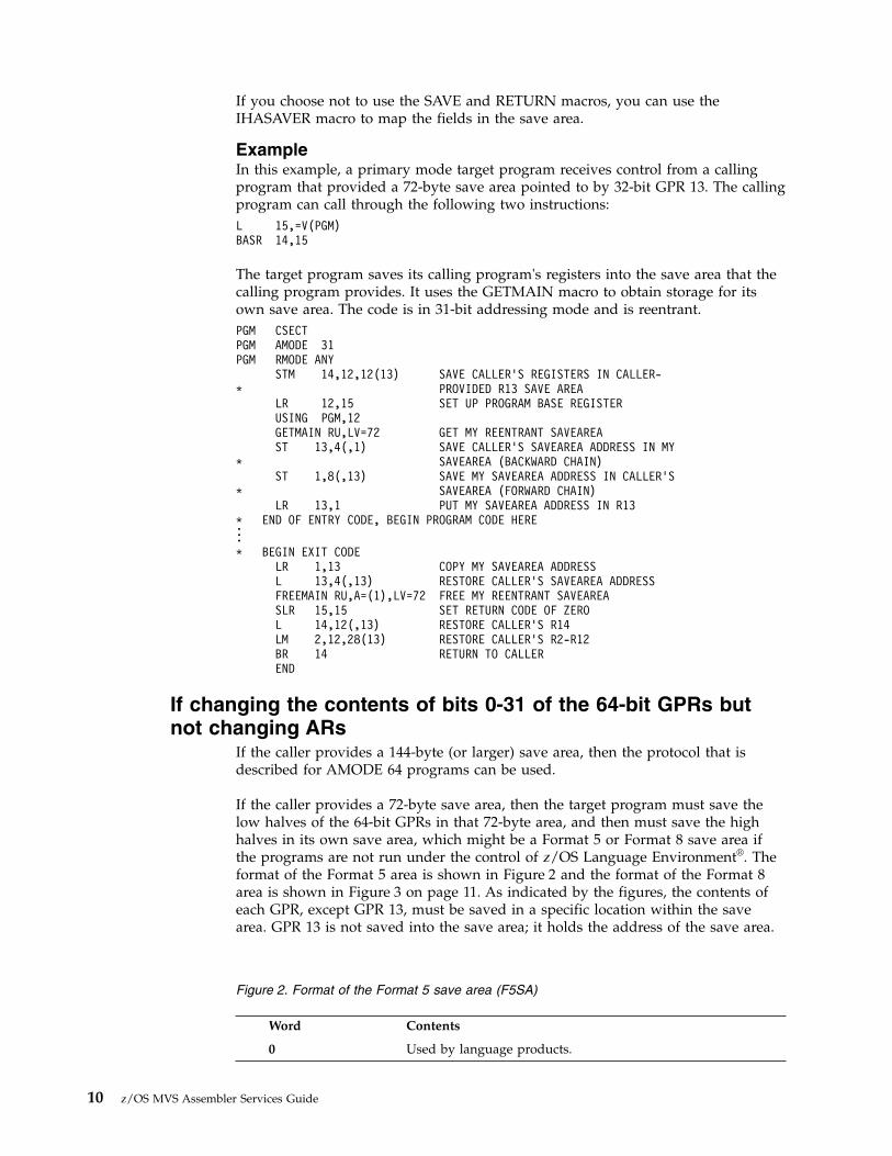
If you choose not to use the SAVE and RETURN macros, you can use theIHASAVER macro to map the fields in the save area.
ExampleIn this example, a primary mode target program receives control from a callingprogram that provided a 72-byte save area pointed to by 32-bit GPR 13. The callingprogram can call through the following two instructions:L 15,=V(PGM)BASR 14,15
The target program saves its calling program's registers into the save area that thecalling program provides. It uses the GETMAIN macro to obtain storage for itsown save area. The code is in 31-bit addressing mode and is reentrant.PGM CSECTPGM AMODE 31PGM RMODE ANY
STM 14,12,12(13) SAVE CALLER’S REGISTERS IN CALLER-* PROVIDED R13 SAVE AREA
LR 12,15 SET UP PROGRAM BASE REGISTERUSING PGM,12GETMAIN RU,LV=72 GET MY REENTRANT SAVEAREAST 13,4(,1) SAVE CALLER’S SAVEAREA ADDRESS IN MY
* SAVEAREA (BACKWARD CHAIN)ST 1,8(,13) SAVE MY SAVEAREA ADDRESS IN CALLER’S
* SAVEAREA (FORWARD CHAIN)LR 13,1 PUT MY SAVEAREA ADDRESS IN R13
* END OF ENTRY CODE, BEGIN PROGRAM CODE HERE...* BEGIN EXIT CODE
LR 1,13 COPY MY SAVEAREA ADDRESSL 13,4(,13) RESTORE CALLER’S SAVEAREA ADDRESSFREEMAIN RU,A=(1),LV=72 FREE MY REENTRANT SAVEAREASLR 15,15 SET RETURN CODE OF ZEROL 14,12(,13) RESTORE CALLER’S R14LM 2,12,28(13) RESTORE CALLER’S R2-R12BR 14 RETURN TO CALLEREND
If changing the contents of bits 0-31 of the 64-bit GPRs butnot changing ARs
If the caller provides a 144-byte (or larger) save area, then the protocol that isdescribed for AMODE 64 programs can be used.
If the caller provides a 72-byte save area, then the target program must save thelow halves of the 64-bit GPRs in that 72-byte area, and then must save the highhalves in its own save area, which might be a Format 5 or Format 8 save area ifthe programs are not run under the control of z/OS Language Environment®. Theformat of the Format 5 area is shown in Figure 2 and the format of the Format 8area is shown in Figure 3 on page 11. As indicated by the figures, the contents ofeach GPR, except GPR 13, must be saved in a specific location within the savearea. GPR 13 is not saved into the save area; it holds the address of the save area.
Word Contents
0 Used by language products.
Figure 2. Format of the Format 5 save area (F5SA)
10 z/OS MVS Assembler Services Guide
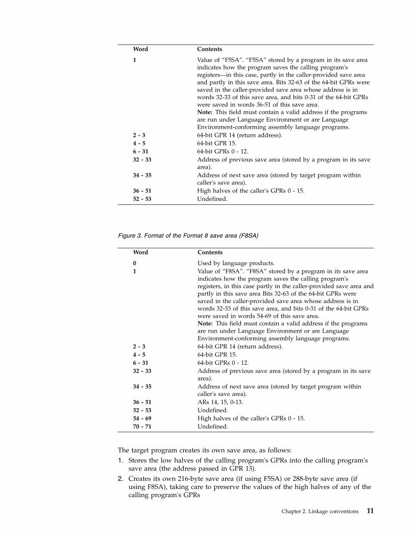
Word Contents
1 Value of “F5SA”. “F5SA” stored by a program in its save areaindicates how the program saves the calling program'sregisters—in this case, partly in the caller-provided save areaand partly in this save area. Bits 32-63 of the 64-bit GPRs weresaved in the caller-provided save area whose address is inwords 32-33 of this save area, and bits 0-31 of the 64-bit GPRswere saved in words 36-51 of this save area.Note: This field must contain a valid address if the programsare run under Language Environment or are LanguageEnvironment-conforming assembly language programs.
2 - 3 64-bit GPR 14 (return address).4 - 5 64-bit GPR 15.6 - 31 64-bit GPRs 0 - 12.32 - 33 Address of previous save area (stored by a program in its save
area).34 - 35 Address of next save area (stored by target program within
caller's save area).36 - 51 High halves of the caller's GPRs 0 - 15.52 - 53 Undefined.
Word Contents
0 Used by language products.1 Value of “F8SA”. “F8SA” stored by a program in its save area
indicates how the program saves the calling program'sregisters, in this case partly in the caller-provided save area andpartly in this save area Bits 32-63 of the 64-bit GPRs weresaved in the caller-provided save area whose address is inwords 32-33 of this save area, and bits 0-31 of the 64-bit GPRswere saved in words 54-69 of this save area.Note: This field must contain a valid address if the programsare run under Language Environment or are LanguageEnvironment-conforming assembly language programs.
2 - 3 64-bit GPR 14 (return address).4 - 5 64-bit GPR 15.6 - 31 64-bit GPRs 0 - 12.32 - 33 Address of previous save area (stored by a program in its save
area).34 - 35 Address of next save area (stored by target program within
caller's save area).36 - 51 ARs 14, 15, 0-13.52 - 53 Undefined.54 - 69 High halves of the caller's GPRs 0 - 15.70 - 71 Undefined.
The target program creates its own save area, as follows:1. Stores the low halves of the calling program's GPRs into the calling program's
save area (the address passed in GPR 13).2. Creates its own 216-byte save area (if using F5SA) or 288-byte save area (if
using F8SA), taking care to preserve the values of the high halves of any of thecalling program's GPRs
Figure 3. Format of the Format 8 save area (F8SA)
Chapter 2. Linkage conventions 11

3. Stores the address of the calling program's save area (the address passed inGPR 13) into words 32 and 33 of its own save area.
4. Stores the address of its own save area into the 3rd word of the callingprogram's save area if the target program's own save area is below 2G.
5. Saves the string "F5SA" (if using F5SA) or the string “F8SA” (if using F8SA)into the 2nd word of its own save area.. “F5SA” or “F8SA” indicates how thetarget program has saved the calling program's registers, in this case saving bits32-63 of the 64-bit GPRs in the caller-provided save area whose address is inwords 32-33 of this save area, and bits 0-31 of the 64-bit GPRs in words 36-51(for “F5SA”) or 54-69 (for “F8SA”) of this save area.
Note: The F8SA area is exactly like the F5SA area except for the identificationstring saved into the second word and the fact that the F8SA area providesspace into which a program called by the creator of the save area can save bothARs and 64-bit GPRs whereas the F5SA area provides space only for the 64-bitGPRs.
These steps enable the target program to find the calling program's save area whenit needs it to restore the caller's registers, and they enable a trace backward fromthe most recent save area to previous save areas should one be necessary whileexamining a dump.
Example of F5SAIn this example, a primary mode target program receives control from callingprogram that provided a 72-byte word-aligned save area pointed to by GPR 13 .The calling program can call through the following two instructions:L 15,=V(PGM)BASR 14,15
The target program saves the calling program's registers into the save area that thecalling program provides. It uses the GETMAIN macro to obtain storage for itsown save area. The code is in 31-bit addressing mode and is reentrant.PGM CSECTPGM AMODE 31PGM RMODE 31
SYSSTATE ARCHLVL=2STM 14,12,SAVGRS14-SAVER(13)
* Save caller’s registers in caller-* provided R13 savearea
CNOP 0,4BRAS 12,*+8DC A(STATIC_DATA)L 12,0(12,0) Set up to address of static dataUSING STATIC_DATA,12SRLG 0,0,32 Move high half of GPR 0 into low half of GPR 0LR 2,0 Save high half of GPR 0 in low half of GPR 2SRLG 1,1,32 Move high half of GPR 1 into low half of GPR 1LR 3,1 Save high half of GPR 1 in low half of GPR 3SRLG 15,15,32 Move high half of GPR 15 into low half of GPR 15LR 4,15 Save high half of GPR 15 in low half of GPR 4GETMAIN RU,LV=SAVF5SA_LEN Get my reentrant saveareaSTG 13,SAVF5SAPREV-SAVF5SA(,1)
* Save caller’s savearea address in my* savearea (backward chain)
STMH 2,14,SAVF5SAG64HS2-SAVF5SA(1)ST 2,SAVF5SAG64HS0-SAVF5SA(1)ST 3,SAVF5SAG64HS1-SAVF5SA(1)ST 4,SAVF5SAG64HS15-SAVF5SA(1)MVC SAVF5SAID-SAVF5SA(4,1),=A(SAVF5SAID_VALUE)
* Set ID into savearea to indicate how* caller’s regs are saved
12 z/OS MVS Assembler Services Guide

LGR 13,1 Put my savearea address in R13* End of entry code. Begin program code here . . .***** Begin exit code
LGR 1,13 Copy my savearea addressLMH 2,14,SAVF5SAG64HS2-SAVF5SA(13)
* Restore high halvesLG 13,SAVF5SAPREV-SAVF5SA(,13)
* Restore caller’s savearea addressFREEMAIN RU,A=(1),LV=SAVF5SA_LEN Free my reentrant saveareaSLR 15,15 Set return code of zeroL 14,SAVGRS14-SAVER(,13) Restore caller’s R14LM 2,12,SAVGRS2-SAVER(13) Restore caller’s R2-R12BR 14 Return to caller
*STATIC_DATA DS 0D* Begin static data here* ...*
IHASAVERPGM CSECT
LTORG ,END
Example of F8SAIn this example of F8SA, a primary mode target program receives control from acalling program that provided a 72-byte word-aligned save area pointed to by GPR13. The calling program can call through the following two instructions:L 15,=V(PGM)BASR 14,15
The target program saves the calling program's registers into the save area that thecalling program provides. It uses the GETMAIN macro to obtain storage for itsown save area. The code is in 31-bit addressing mode and is reentrant.PGM CSECTPGM AMODE 31PGM RMODE 31
SYSSTATE ARCHLVL=2STM 14,12,SAVGRS14-SAVER(13)
* Save caller’s registers in caller-* provided R13 savearea
LARL 12,STATIC_DATA Set up to address of static dataUSING STATIC_DATA,12SRLG 0,0,32 Move high half of GPR 0 into low half of GPR 0LR 2,0 Save high half of GPR 0 in low half of GPR 2SRLG 1,1,32 Move high half of GPR 1 into low half of GPR 1LR 3,1 Save high half of GPR 1 in low half of GPR 3SRLG 15,15,32 Move high half of GPR 15 into low half of GPR 15LR 4,15 Save high half of GPR 15 in low half of GPR 4GETMAIN RU,LV=SAVF8SA_LEN Get my reentrant saveareaSTG 13,SAVF8SAPREV-SAVF8SA(,1)
* Save caller’s savearea address in my* savearea (backward chain)
STMH 2,14,SAVF8SAG64HS2-SAVF8SA(1)ST 2,SAVF8SAG64HS0-SAVF8SA(1)ST 3,SAVF8SAG64HS1-SAVF8SA(1)ST 4,SAVF8SAG64HS15-SAVF8SA(1)MVC SAVF8SAID-SAVF8SA(4,1),=A(SAVF8SAID_VALUE)
* Set ID into savearea to indicate how* caller’s regs are saved
LGR 13,1 Put my savearea address in R13* End of entry code. Begin program code here . . .
Chapter 2. Linkage conventions 13

***** Begin exit code
LGR 1,13 Copy my savearea addressLMH 2,14,SAVF8SAG64HS2-SAVF8SA(13)
* Restore high halvesLG 13,SAVF8SAPREV-SAVF8SA(,13)
* Restore caller’s savearea addressFREEMAIN RU,A=(1),LV=SAVF8SA_LEN Free my reentrant saveareaSLR 15,15 Set return code of zeroL 14,SAVGRS14-SAVER(,13) Restore caller’s R14LM 2,12,SAVGRS2-SAVER(13) Restore caller’s R2-R12BR 14 Return to caller
*STATIC_DATA DS 0D* Begin static data here* ...*
IHASAVERPGM CSECT
LTORG ,END
If starting in AMODE 64An AMODE 64 program must specify SYSSTATE AMODE64=YES.
When it receives control, the target program saves the 64-bit GPRs into the144-bytes (or larger) doubleword-aligned caller-provided save area pointed to by64-bit GPR 13. The format of this area is shown in Figure 4. As indicated by thisfigure, the contents of each GPR, except GPR 13, must be saved in a specificlocation within the save area. GPR 13 is not saved into the save area; it holds theaddress of the save area.
Word Contents
0 Used by language products.1 Value of “F4SA”. “F4SA”, stored by a program in its save
area, indicates how the program saved the calling program'sregisters. Saving the 64-bit GPRs in the caller-provided savearea whose address is in words 32-33 of this save area.
2 - 3 64-bit GPR 14 (return address).4 - 5 64-bit GPR 15.6 - 31 64-bit GPRs 0 - 12.32 - 33 Address of previous save area (stored by a program in its
save area).34 - 35 Address of next save area (stored by target program within
caller's save area).
You can save 64-bit GPRs either with a store-multiple (STMG) instruction or withthe SAVE macro. Use the following STMG instruction to place the contents of all64-bit GPRs except GPR 13 into the proper words of the save area:STMG 14,12,8(13)
When SYSSTATE AMODE64=YES is in effect, the SAVE macro stores 64-bit GPRsinto the save area. Code the GPRs to be saved in the same order as in an STMG
Figure 4. Format of the Format 4 Save Area (F4SA)
14 z/OS MVS Assembler Services Guide

instruction. The following example of the SAVE macro places the contents of all64-bit GPRs except GPR 13 into the proper words of the save area.PROGNAME SAVE (14,12)
Note: The SAVE macro uses STMG and store that uses the F4SA format whenSYSSTATE AMODE64=YES is in effect, but uses STM and use the format that ismapped by the SAVER DSECT in macro IHASAVER when it is not. Thus aprogram that wants to use F4SA format but is not AMODE 64 should not use theSAVE macro.
Later, the program can use the RETURN macro (or the load-multiple (LMG)instruction) to restore 64-bit GPRs and return to the caller. Similar to the note forSAVE, a program that is using F4SA format but is not AMODE 64 should not usethe RETURN macro.
Whether the target program creates its own save area, it must save the address ofthe calling program's save area. If the target program is creating a save area, it:1. Stores the address of the calling program's save area (the address passed in
64-bit GPR 13) into words 32 and 33 of its own save area.2. Stores the address of its own save area (the address the target program places
into 64-bit GPR 13) into words 34 and 35 of the calling program's save area.3. Saves the string “F4SA” into the second word of its own save area. “F4SA”
indicates how the target program saves the calling program's registers, in thiscase saving the 64-bit GPRs in the caller-provided save area whose address is inwords 32-33 of this save area.
These steps enable the target program to find the calling program's save area whenit needs it to restore the caller's registers, and they enable a trace backward fromthe most recent save area to previous save areas should one be necessary whileexamining a dump. If the target program is not creating a save area, it can keepthe address of the calling program's save area in GPR 13 or store it in a location invirtual storage.
If you choose not to use the SAVE and RETURN macros, you can use theIHASAVER macro to map the fields in the save area.
ExampleIn this example, a primary mode target program receives control from a callingprogram that provided 144-bytes doubleword-aligned save area pointed to 64-bitGPR 13. The calling program can call through the following two instructions:L 15,=V(PGM)BASR 14,15
The target program saves its calling program's registers into the save area that thecalling program provides. It uses the GETMAIN macro to obtain storage for itsown save area. The code is in 64-bit addressing mode and is reentrant.PGM CSECTPGM AMODE 64PGM RMODE 31
SYSSTATE AMODE64=YESSTMG 14,12,SAVF4SAG64RS14-SAVF4SA(13)
* Save caller’s registers in caller-* provided R13 save area
CNOP 0,4BRAS 12,*+8DC A(STATIC_DATA)L 12,0(12,0) Set up to address of static data
Chapter 2. Linkage conventions 15
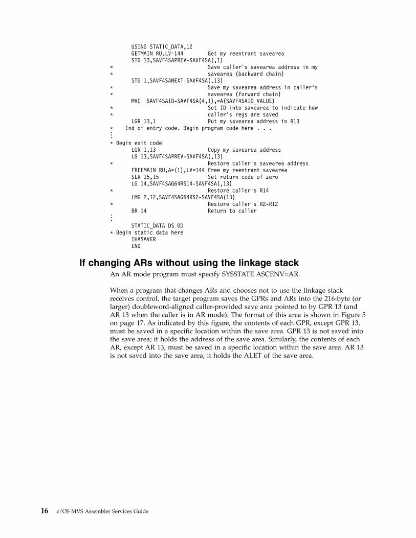
USING STATIC_DATA,12GETMAIN RU,LV=144 Get my reentrant saveareaSTG 13,SAVF4SAPREV-SAVF4SA(,1)
* Save caller’s savearea address in my* savearea (backward chain)
STG 1,SAVF4SANEXT-SAVF4SA(,13)* Save my savearea address in caller’s* savearea (forward chain)
MVC SAVF4SAID-SAVF4SA(4,1),=A(SAVF4SAID_VALUE)* Set ID into savearea to indicate how* caller’s regs are saved
LGR 13,1 Put my savearea address in R13* End of entry code. Begin program code here . . ....* Begin exit code
LGR 1,13 Copy my savearea addressLG 13,SAVF4SAPREV-SAVF4SA(,13)
* Restore caller’s savearea addressFREEMAIN RU,A=(1),LV=144 Free my reentrant saveareaSLR 15,15 Set return code of zeroLG 14,SAVF4SAG64RS14-SAVF4SA(,13)
* Restore caller’s R14LMG 2,12,SAVF4SAG64RS2-SAVF4SA(13)
* Restore caller’s R2-R12BR 14 Return to caller...STATIC_DATA DS 0D
* Begin static data hereIHASAVEREND
If changing ARs without using the linkage stackAn AR mode program must specify SYSSTATE ASCENV=AR.
When a program that changes ARs and chooses not to use the linkage stackreceives control, the target program saves the GPRs and ARs into the 216-byte (orlarger) doubleword-aligned caller-provided save area pointed to by GPR 13 (andAR 13 when the caller is in AR mode). The format of this area is shown in Figure 5on page 17. As indicated by this figure, the contents of each GPR, except GPR 13,must be saved in a specific location within the save area. GPR 13 is not saved intothe save area; it holds the address of the save area. Similarly, the contents of eachAR, except AR 13, must be saved in a specific location within the save area. AR 13is not saved into the save area; it holds the ALET of the save area.
16 z/OS MVS Assembler Services Guide

You can save 64-bit GPRs with a store-multiple (STMG) instruction. Use thefollowing STMG instruction to place the contents of all GPRs except GPR 13 intothe proper words of the save area:STMG 14,12,8(13)
You can save ARs with a store-access-register-multiple (STAM) instruction. Use thefollowing STAM instruction to place the contents of all AR into the proper wordsof the save area:STAM 14,12,144(13)
Later, the program can use the LAM and LMG instructions to restore ARs andGPRs and return to the caller.
Whether the target program creates its own save area, it must save the address ofthe calling program's save area. If the target program creates a save area it:1. Stores the 64-bit address of the calling program's save area (the address passed
in 64-bit GPR 13) into words 32 and 33 of its own save area.2. Stores the ASC mode of the calling program into word 52 of its own save area.3. Stores the ALET of the calling program's save area (the value in AR 13) into
word 51 of its own save area4. Stores the address of its own save area (the address the target program places
in GPR 13) into words 34 and 35 of the calling program's save area.5. Saves the string “F7SA” into the second word of its own save area. “F7SA”
indicates how the target program saves the calling program's registers. Savingthe 64-bit GPRs and the ARs in the caller-provided save area whose address isin words 32-33 of this save area.
These steps enable the target program to find the calling program's save area whenit needs it to restore the caller's registers, and they enable a trace backward fromthe most recent save area to a previous save area if one is necessary while
Word Contents
0 Used by language products.
1 Value of “F7SA”. “F7SA”, stored by a program in its save area, indicates how theprogram saves the calling program's registers. Saving the 64-bit GPRs and the ARsin the caller-provided save area whose address is in words 32-33 of this save area.
2 - 3 64-bit GPR 14 (return address).
4 - 5 64-bit GPR 15.
6 - 31 64-bit GPRs 0 - 12.
32 - 33 Address of previous save area (stored by a program in its save area).
34 - 35 Address of next save area (stored by target program within caller's save area).
36 - 50 ARs 14, 15, 0-12.
51 ALET of previous save area.
52 ASC mode of calling program.
53 Undefined.
Figure 5. Format of the Format 7 save area (F7SA)
Chapter 2. Linkage conventions 17

examining a dump. If the target program is not creating a save area, it can keepthe address of the calling program's save area in GPR 13 or store it in a location invirtual storage.
Use the IHASAVER macro to map the fields in the save area.
If your program is AR mode but the calling program is not known to be AR mode(it might be known to be primary ASC mode or it might be either primary ASC orAR mode), you need to save the calling program's mode on entry and restore it onexit.
ExampleIn this example, an AR mode target program receives control from a callingprogram that provides a 216-byte doubleword-aligned save area pointed to by GPR13.
The target program saves the calling program's registers (GPRs and ARs) into thesave area that the calling program provides. It uses the STORAGE OBTAIN macroto obtain storage for its own save area. The code is in 31-bit addressing mode andis reentrant.PGM CSECTPGM AMODE 31PGM RMODE 31
SYSSTATE AMODE64=NO,ASCENV=ARSTMG 14,12,SAVF7SAG64RS14-SAVF7SA(13)
* Save caller’s registers in caller-* provided R13 save area
STAM 14,12,SAVF7SAAR14-SAVF7SA(13) Save caller’s ARsIAC 2 Save caller’s ASC modeSAC 512 Make sure we are in AR modeLARL 12,STATIC_DATA Set up to address of static dataLAE 12,0(12,0) Make sure AR12 is 0USING STATIC_DATA,12STORAGE OBTAIN,LENGTH=216 Get my reentrant saveareaSTG 13,SAVF7SAPREV-SAVF7SA(,1)
* Save caller’s savearea address in my* savearea (backward chain)
ST 2,SAVF7SAASC-SAVF7SA(,1) Save caller’s ASC modeSTAM 13,13,SAVF7SAAR13-SAVF7SA(1) Save caller’s AR13STG 1,SAVF7SANEXT-SAVF7SA(,13)
* Save my savearea address in caller’s* savearea (forward chain)
MVC SAVF7SAID-SAVF7SA(4,1),=A(SAVF7SAID_VALUE)* Set ID into savearea to indicate how* caller’s regs are saved
LAE 13,0(0,1) Put my savearea address/ALET in R13* End of entry code. Begin program code here . . ....* Begin exit code
LGR 1,13 Copy my savearea addressLAM 2,2,SAVF7SAAR13-SAVF7SA(13) Fetch caller’s AR13L 2,SAVF7SAASC-SAVF7SA(,13) Fetch caller’s ASC modeLG 13,SAVF7SAPREV-SAVF7SA(,13)
* Restore caller’s savearea addressSTORAGE RELEASE,ADDR=(1),LENGTH=216 Free my saveareaSLR 15,15 Set return code of zeroSAC 0(2) Restore caller’s ASC modeCPYA 13,2 Restore caller’s AR13LAM 14,12,SAVF7SAAR14-SAVF7SA(13) Restore caller’s ARsLG 14,SAVF7SAG64RS14-SAVF7SA(,13) Restore caller’s R14LMG 2,12,SAVF7SAG64RS2-SAVF7SA(13) Restore caller’s R2-R12BR 14 Return to caller
18 z/OS MVS Assembler Services Guide

...STATIC_DATA DS 0D
* Begin static data hereIHASAVEREND
Establishing a base registerEach program establishes a base register immediately after it saves the callingprogram's registers. Remember when you select a base register:v Some instructions alter register contents (for example, TRT alters register 2). A
list of instructions and their processing is available in Principles of Operation.v Registers 13 - 1 are used during program linkage.v Register 12 is reserved for Language Environment (LE) use when writing an
LE-conforming assembler program. For more information see z/OS LanguageEnvironment Programming Guide.
Register 12 is generally a good choice for base register when not writing anLE-conforming assembler program.
Your program should use the relative and immediate instruction set and thus notneed code addressability in general. If the program is AMODE 64, this is expected.But the program does need to establish addressability to any static data that itmight need. The program might also need temporary code addressability wheninvoking system macros. Macros such as STORAGE require the invoker to havecode addressability surround the macro invocation. Nevertheless, you should alsohelp out system macros by identifying the architecture level under which yourprogram is known to run. SYSSTATE ARCHLVL=2 can be used for all programsthat run only on supported z/OS releases.
When your program is entered in one AMODE and will change to another, be sureto set your base registers properly for the eventual AMODE. For example, supposethat your program is entered in AMODE 31 and will switch to AMODE 64. If youuse the LA or LARL instruction to set the base register while in AMODE 31, thatwill not clear bits 0-31 of the 64-bit register. All 64 bits must be set properly whenbeing used in AMODE 64. After the LA or LARL, you could use the LLGTRinstruction to clear bits 0-32 of the 64-bit register.
Linkage procedures for primary mode programsA primary mode program can be called only by a program running in primaryASC mode. Thus an AR mode program must switch to primary ASC mode beforecalling a primary mode program.
The information summarizes the linkage procedures a primary mode programfollows when it receives control, when it returns control to a caller, and when itcalls another program.
Primary mode programs receiving controlWhen a primary mode program receives control, it can save the calling program'sregisters on the linkage stack or in the caller-provided save area. If using thecaller-provided save area, then distinctions are made whether the primary modeprogram is or is not changing the 64-bit GPRs.
Chapter 2. Linkage conventions 19

Note: The linkage conventions assume that a primary mode program does not useARs. By leaving the contents of the ARs untouched, the program preserves ARs 2 -13 across program linkages.
Primary mode programs that use the linkage stack
A primary mode program that uses the linkage stack must perform the followingactions:v Issue a BAKR instruction, which saves the caller's ARs and 64-bit GPRs on the
linkage stack.v Establish a GPR as a base register.v Set GPR 13 to indicate that the caller's registers are saved on the linkage stack:
– If the program creates a save area, obtain a 72-byte save area on a wordboundary (or 144 byte or larger on a doubleword boundary if routines calledby the program need that extra space) in the primary address space:1. Set the second word of the save area to the character string F1SA if
obtaining a 72-byte save area or F6SA if obtaining a 144 byte or larger savearea
2. Load GPR 13 with the save area address.– If the program does not create a save area, do one of following actions:
- Load 0 into GPR 13.- Set the second word of a two-word area in the primary address space to
the character string F1SA. Load the address of the two-word area into GPR13.
Primary mode programs that use the caller-provided save area
The actions to be taken by a primary mode program that uses the caller-providedsave area depend on the following conditions:v If the program does not change 64-bit GPRs and that uses the 72-byte
caller-provided save area, the program must perform the following actions:– Save 32-bit GPRs 0-12, 14, and 15 into the caller-provided save area pointed to
by GPR 13.– Establish a base register.– Obtain a 72-byte save area on a word boundary (or 144 byte or larger on a
doubleword boundary if routines called by the program need that extraspace) in the primary address space.
– Store the address of the caller's save area into the back chain field of its ownsave area.
– Store the address of its save area into the forward chain field of the caller'ssave area.See “Example” on page 10.
v If the program changes 64-bit GPRs and that uses the 72-byte caller-providedsave area, the program must perform the following actions:– Save the low halves (bits 32 - 63) of GPRs 0-12, 14, and 15 into the
caller-provided save area pointed to by GPR 13.– Obtain a 216 byte (if using F5SA) or 288 byte (if using F8SA) save area on a
doubleword boundary in the primary address space– Save the high halves (bits 0 - 31) of GPRs 0 - 15 into its own save area.– Store the address of the caller's save area into the back chain field of its own
save area.
20 z/OS MVS Assembler Services Guide

– Store the address of its save area into the forward chain field of the caller'ssave area.
– Set the word at offset 4 to F5SA or F8SA to indicate how the caller's registerswere saved.See “Example of F5SA” on page 12 and “Example of F8SA” on page 13.
v If the program changes 64-bit GPRs and that uses the 144 byte caller-providedsave area, the program must perform the following actions:– Save 64-bit GPRs 0-12, 14, and 15 into the caller-provided save area pointed to
by GPR 13 in F4SA format.– Obtain a 144 byte save area on a doubleword boundary (or larger if routines
called by the program need that extra space) in the primary address space.– Store the address of the caller's save area into the back chain field of its own
save area.– Store the address of its save area into the forward chain field of the caller's
save area.– Set the word at offset 4 to F4SA to indicate how the caller's registers were
saved.See “Example” on page 15.
Primary mode programs returning controlThe method that a primary mode program uses to return control to a callerdepends on whether the primary mode program used the linkage stack or thecaller-provided save area.
A primary mode program that uses the linkage stack must:v Place return information (if any) for the caller into GPR 0, 1, or both. For
information about passing information through a parameter list, see“Conventions for passing information through a parameter list” on page 24.
v Load the return code, if any, into GPR 15.v Issue the PR instruction. The PR instruction restores the caller's ARs 2 - 14 and
64-bit GPRs 2-14 and ASC mode from the linkage stack. The PR instructionremoves the entry from the linkage stack, and returns control to the caller.
A primary mode program that uses a caller-provided save area must:v Place return information (if any) for the caller into GPR 0, 1, or both. For
information about passing information through a parameter list, see“Conventions for passing information through a parameter list” on page 24.
v Load GPR 13 with the address of the save area the calling program passes whenmaking the call.
v Load the return code, if any, into GPR 15.v Restore GPRs 2 - 12 and 14 from the caller's save area.v Return to the calling program.
Primary mode programs calling another programWhen a primary mode program calls another program, the calling program must:v Place the address of its save area into GPR 13.v Load parameter information, if any, into GPR 0, GPR 1, or both.v Place the entry point address of the target program into GPR 15.v Call the target program.
Chapter 2. Linkage conventions 21

Linkage procedures for AR mode programsAn AR mode program can be called by other AR mode programs or by primarymode programs. The information summarizes the linkage procedures an AR modeprogram can follow when it receives control, when it returns control to a caller,and when it calls another program.
AR mode programs receiving control and using the linkagestack
When an AR mode program receives control and uses the linkage stack, it would:v Issue a BAKR instruction, which saves the caller's 64-bit GPRs and ARs on the
linkage stack. (Although a primary mode caller provides a save area, an ARmode target program would not use the area.
v Establish a GPR as a base register and load an ALET of 0 into the correspondingAR. (An ALET of 0 causes the system to reference an address within the primaryaddress space).
v Set GPR 13 to indicate that the caller's registers are saved on the linkage stack:– If the program creates a save area, obtain a 72-byte save area on a word
boundary (or 144 byte or larger save area on a doubleword boundary ifroutines called by this program need it) in the primary address space.- Set the second word of the save area to the character string “F1SA” if
obtaining a 72-byte save area or “F6SA” if obtaining a 144 byte or largersave area
- Load GPR 13 with the save area address.- Set AR 13 to zero to indicate that the storage resides in the primary address
space.– If the program does not create a save area, do one of following actions:
- Load 0 into GPR 13.- Set the second word of a two word area in the primary address space to
the character string “F1SA”. Load the address of the two word area intoGPR 13.
AR mode programs returning control and using the linkagestack
To return control to the calling program after saving registers on the linkage stack,an AR mode program would:v Place return information, if any, for the caller into AR/GPR 0, AR/GPR 1, or
both. For information about passing information through a parameter list, see“Conventions for passing information through a parameter list” on page 24.
v Load the return code, if any, into GPR 15.v Issue the PR instruction. The PR instruction restores the caller's ARs 2-14 and
64-bit GPRs 2-14 and ASC mode from the linkage stack, removes the entry fromthe linkage stack, and returns control to the caller.
AR mode programs receiving control and not using thelinkage stack
When an AR mode program receives control, and does not want to use the linkagestack, its caller must provide an area large enough for the target program to savethe 64-bit GPRs and the ARs into (at least 216 bytes). The AR mode programwould:
22 z/OS MVS Assembler Services Guide
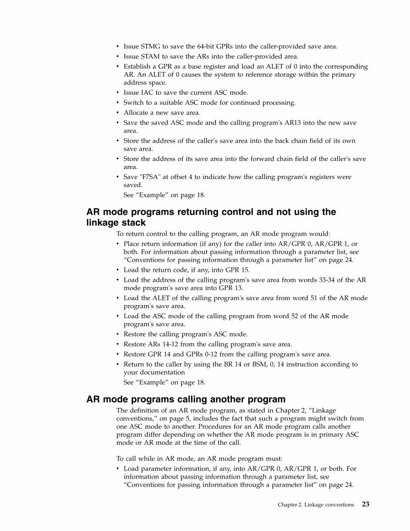
v Issue STMG to save the 64-bit GPRs into the caller-provided save area.v Issue STAM to save the ARs into the caller-provided area.v Establish a GPR as a base register and load an ALET of 0 into the corresponding
AR. An ALET of 0 causes the system to reference storage within the primaryaddress space.
v Issue IAC to save the current ASC mode.v Switch to a suitable ASC mode for continued processing.v Allocate a new save area.v Save the saved ASC mode and the calling program's AR13 into the new save
area.v Store the address of the caller's save area into the back chain field of its own
save area.v Store the address of its save area into the forward chain field of the caller's save
area.v Save "F7SA" at offset 4 to indicate how the calling program's registers were
saved.See “Example” on page 18.
AR mode programs returning control and not using thelinkage stack
To return control to the calling program, an AR mode program would:v Place return information (if any) for the caller into AR/GPR 0, AR/GPR 1, or
both. For information about passing information through a parameter list, see“Conventions for passing information through a parameter list” on page 24.
v Load the return code, if any, into GPR 15.v Load the address of the calling program's save area from words 33-34 of the AR
mode program's save area into GPR 13.v Load the ALET of the calling program's save area from word 51 of the AR mode
program's save area.v Load the ASC mode of the calling program from word 52 of the AR mode
program's save area.v Restore the calling program's ASC mode.v Restore ARs 14-12 from the calling program's save area.v Restore GPR 14 and GPRs 0-12 from the calling program's save area.v Return to the caller by using the BR 14 or BSM, 0, 14 instruction according to
your documentationSee “Example” on page 18.
AR mode programs calling another programThe definition of an AR mode program, as stated in Chapter 2, “Linkageconventions,” on page 5, includes the fact that such a program might switch fromone ASC mode to another. Procedures for an AR mode program calls anotherprogram differ depending on whether the AR mode program is in primary ASCmode or AR mode at the time of the call.
To call while in AR mode, an AR mode program must:v Load parameter information, if any, into AR/GPR 0, AR/GPR 1, or both. For
information about passing information through a parameter list, see“Conventions for passing information through a parameter list” on page 24.
Chapter 2. Linkage conventions 23

v Place the entry point address of the target program into GPR 15. There is noneed to load an ALET into AR 15.
v Call the target program.
To call while in primary ASC mode, an AR mode program must follow the linkageconventions described in “Primary mode programs calling another program” onpage 21.
Conventions for passing information through a parameter listThe ASC mode of a calling program at the time it calls determines whetheraddresses that the program passes are ALET-qualified. The following two sectionsdescribe how programs in primary ASC mode and AR mode pass parametersthrough a parameter list.
Program in primary ASC modeIf the calling program is in primary ASC mode, the parameter list must be in theprimary address space. All addresses that are passed by the programs must becontained in the primary address space and must not be ALET-qualified. Theprogram that passes parameter data can use GPRs 0 and 1, or both. To pass theaddress of a parameter list, the program should use GPR 1.
As an example, consider the way that the system uses a register to passinformation in the PARM field of an EXEC statement to your program. When yourprogram receives control from the system, register 1 contains the address of aparameter list that points to one parameter. The parameter list is a fullword on afullword boundary in your program's address space see Figure 6. The high-orderbit (bit 0) of this word is set to 1. For a program that is not AMODE 64, the systemuses this convention to indicate the last word in a variable-length parameter list.Bits 1-31 of the fullword contain the address of a 2-byte length field on a halfwordboundary. The length field contains a binary count of the number of data bytes inthe PARM field. The data bytes immediately follow the length field. If the PARMfield was omitted in the EXEC statement, the count is set to zero. To preventpossible errors, always use the count as a length attribute in acquiring theinformation in the PARM field.
4 Bytes
2 Bytes 0 to 32760 Bytes
GPR1
@
1 @
Length Field PARM Field
Full-WordBoundary
Half-WordBoundary
Figure 6. Primary Mode Parameter List EXEC PGM=
24 z/OS MVS Assembler Services Guide
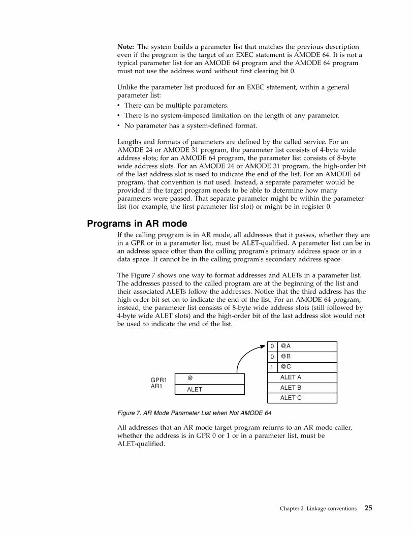
Note: The system builds a parameter list that matches the previous descriptioneven if the program is the target of an EXEC statement is AMODE 64. It is not atypical parameter list for an AMODE 64 program and the AMODE 64 programmust not use the address word without first clearing bit 0.
Unlike the parameter list produced for an EXEC statement, within a generalparameter list:v There can be multiple parameters.v There is no system-imposed limitation on the length of any parameter.v No parameter has a system-defined format.
Lengths and formats of parameters are defined by the called service. For anAMODE 24 or AMODE 31 program, the parameter list consists of 4-byte wideaddress slots; for an AMODE 64 program, the parameter list consists of 8-bytewide address slots. For an AMODE 24 or AMODE 31 program, the high-order bitof the last address slot is used to indicate the end of the list. For an AMODE 64program, that convention is not used. Instead, a separate parameter would beprovided if the target program needs to be able to determine how manyparameters were passed. That separate parameter might be within the parameterlist (for example, the first parameter list slot) or might be in register 0.
Programs in AR modeIf the calling program is in AR mode, all addresses that it passes, whether they arein a GPR or in a parameter list, must be ALET-qualified. A parameter list can be inan address space other than the calling program's primary address space or in adata space. It cannot be in the calling program's secondary address space.
The Figure 7 shows one way to format addresses and ALETs in a parameter list.The addresses passed to the called program are at the beginning of the list andtheir associated ALETs follow the addresses. Notice that the third address has thehigh-order bit set on to indicate the end of the list. For an AMODE 64 program,instead, the parameter list consists of 8-byte wide address slots (still followed by4-byte wide ALET slots) and the high-order bit of the last address slot would notbe used to indicate the end of the list.
All addresses that an AR mode target program returns to an AR mode caller,whether the address is in GPR 0 or 1 or in a parameter list, must beALET-qualified.
@
ALET
@A
@B
@C
ALET A
ALET B
ALET C
GPR1
AR1
0
0
1
Figure 7. AR Mode Parameter List when Not AMODE 64
Chapter 2. Linkage conventions 25

26 z/OS MVS Assembler Services Guide

Chapter 3. Subtask creation and control
The control program creates one task in the address space as a result of initiatingexecution of the job step task. You can create additional tasks in your program.However, if you do not, the job step task is the only task in the address spacebeing executed. The benefits of a multiprogramming environment are still availableeven with only one task in the job step; work is still being performed for otheraddress spaces when your task is waiting for an event, such as an input operation,to occur.
The advantage in creating additional tasks within the job step is that more tasksare competing for control. When a wait state occurs in one of your tasks, it is notnecessarily a task from some other address space that gets control. It can be one ofyour tasks, a portion of your job.
The general rule is that you should choose parallel execution of a job step (that is,more than one task in an address space) only when a significant amount of overlapbetween two or more tasks can be achieved. You must take into account theamount of time that is taken by the control program in establishing and controllingadditional tasks, and your increased effort to coordinate the tasks and provide forcommunications between them.
Creating the taskA new task is created by issuing an ATTACH, or, if your program runs in accessregister ASC mode, an ATTACHX macro. The task that is active when theATTACH or ATTACHX issued is the originating task; the newly created task is thesubtask of the originating task. The subtask competes for control in the samemanner as any other task in the system, by priority (both address space priorityand task priority within the address space) and the current ability to use aprocessor. The address of the task control block for the subtask is returned inregister 1.
If the ATTACH or ATTACHX executes successfully, control returns to the user witha return code of 0 in register 15.
The entry point in the load module to be given control when the subtask becomesactive is specified as it is in a LINK or LINKX macro, that is, by using the EP,EPLOC, and DE parameters. The use of these parameters is discussed in Chapter 4,“Program management,” on page 33. You can pass parameters to the subtask usingthe PARAM and VL parameters, also described under the LINK macro. Additionalparameters deal with the priority of the subtask, provide for communicationbetween tasks, specify libraries to be used for program linkages, and establish anerror recovery environment for the new subtask.
PrioritiesThis information considers three priorities: address space priorities, task priorities,and subtask priorities.
© Copyright IBM Corp. 1988, 2017 27
Address space priorityWhen a job is initiated, the control program creates an address space. Allsuccessive steps in the job execute in the same address space. The address spacehas a dispatching priority, which is normally determined by the control program.The control program selects, and alters, the priority to achieve the best loadbalance in the system. This makes the most efficient use of processor time andother system resources.
You might want some jobs to execute at a different address space priority than thedefault priority assigned. The active workload management (WLM) service policydetermines the dispatching priority assigned to the job. For additional information,see z/OS MVS Planning: Workload Management.
Task priorityEach task in an address space has a limit priority and a dispatching priorityassociated with it. The control program sets these priorities when a job step isinitiated. When you use the ATTACH or ATTACHX macro to create other tasks inthe address space, you can use the LPMOD and DPMOD parameters to give themdifferent limit and dispatching priorities.
The dispatching priorities of the tasks in an address space do not affect the orderin which the control program selects jobs for execution. The order is selected basedon the work unit (WEB) that is at the top of the work unit queue (WUQ). Thedispatcher not longer selects from within an address space the top priority taskawaiting execution. Thus, task priorities cannot affect processing within an addressspace.
Note: In a multiprocessing system, task priorities might not be in the order ofwhich the tasks run. More than one task might be running simultaneously in thesame address space on different processors. Page faults can alter the order inwhich the tasks run.
Subtask priorityWhen a subtask is created, the limit and dispatching priorities of the subtask arethe same as the current limit and dispatching priorities of the originating taskexcept when the subtask priorities are modified by the LPMOD and DPMODparameters of the ATTACH and ATTACHX macro. The LPMOD parameterspecifies the signed number to be subtracted from the current limit priority of theoriginating task. The result of the subtraction is assigned as the limit priority of thesubtask. If the result is zero or negative, zero is assigned as the limit priority. TheDPMOD parameter specifies the signed number to be added to the currentdispatching priority of the originating task. The result of the addition is assignedas the dispatching priority of the subtask, unless the number is greater than thelimit priority or less than zero. In that case, the limit priority or 0, respectively, isused as the dispatching priority.
Assigning and changing priorityAssign tasks with many I/O operations a higher priority than tasks with little I/Obecause the tasks with much I/O are in a wait state for a greater amount of time.The lower priority tasks are executed when the higher priority tasks are in a waitstate. As the I/O operations are completed, the higher priority tasks get control sothat more I/O can be started.
28 z/OS MVS Assembler Services Guide

You can change the priorities of subtasks by using the CHAP macro. The CHAPmacro changes the dispatching priority of the active task or one of its subtasks byadding a positive or negative value. The dispatching priority of an active task canbe made less than the dispatching priority of another task. If this occurs and theother task is dispatchable, it would be given control after execution of the CHAPmacro.
You can also use the CHAP macro to increase the limit priority of any of an activetask's subtasks. An active task cannot change its own limit priority. Thedispatching priority of a subtask can be raised above its own limit priority, but notabove the limit of the originating task. When the dispatching priority of a subtaskis raised above its own limit priority, the subtask's limit priority is automaticallyraised to equal its new dispatching priority.
Stopping and restarting a subtask (STATUS macro)To stop a subtask means to change its dispatch-ability status from ready to notready. You might need to stop a subtask that is ready or running, and then torestart, or make ready, that subtask. Stopping a subtask is a programmingtechnique to control the dispatch-ability of other related tasks or subtasks in amultitasking environment when the tasks are in problem state.
To stop all subtasks of an originating task, issue the STATUS macro with the STOPparameter. To stop a specific subtask, issue the STATUS macro with the STOP, TCBparameter, which identifies a specific subtask.
To restart the stopped subtask or subtasks, issue STATUS START. As with STATUSSTOP, use the TCB parameter to restart a specific subtask.
Task and subtask communicationsThe task management information is required only for establishingcommunications among tasks in the same job step. The relationship of tasks in ajob step is shown in Figure 8 on page 30. The horizontal lines in Figure 8 on page30 separate originating tasks and subtasks. They have no bearing on task priority.Tasks A, A1, A2, A2a, B, B1, and B1a are all subtasks of the job-step task; tasks A1,A2, and A2a are subtasks of task A. Tasks A2a and B1a are the lowest level tasks inthe job step. Although task B1 is at the same level as tasks A1 and A2, it is notconsidered a subtask of task A.
Task A is the originating task for both tasks A1 and A2, and task A2 is theoriginating task for task A2a. A hierarchy of tasks exists within the job step.Therefore, the job step task, task A, and task A2 are predecessors of task A2a,while task B has no direct relationship to task A2a.
Chapter 3. Subtask creation and control 29

All of the tasks in the job step compete independently for processor time; if noconstraints are provided, the tasks are performed and are terminatedasynchronously. However, since each task is performing a portion of the same jobstep, some communication and constraints between tasks are required, such asnotifying each other when a subtask completes. If a predecessor task attempts toterminate before all of its subtasks are complete, those subtasks and thepredecessor task are abnormally terminated.
Two parameters, the ECB and ETXR parameters, are provided in the ATTACH orATTACHX macro to help communication between a subtask and the originatingtask. These parameters are used to indicate the normal or abnormal termination ofa subtask to the originating task. If you coded the ECB or ETXR parameter, orboth, in the ATTACH or ATTACHX macro, the task control block of the subtask isnot removed from the system when the subtask is terminated. The originating taskmust remove the task control block from the system after termination of thesubtask by issuing a DETACH. If you specified the ECB parameter in the ATTACHor ATTACHX macro, the ECB must be in storage addressable by the attaching taskand control program so that the issuer of ATTACH can wait on it (using the WAITmacro) and the control program can post it on behalf of the terminating task. Thetask control blocks for all subtasks must be removed before the originating taskcan terminate normally.
The ETXR parameter specifies the address of an end-of-task exit routine in theoriginating task, which is to be given control when the subtask being created isterminated. Therefore, the end-of-task routine is given control asynchronously after
Job
Step
Task
Task A Task B
Task A1 Task A2 Task B1
Task A2a Task B1a
Figure 8. Levels of Tasks in a Job Step
30 z/OS MVS Assembler Services Guide

the subtask has terminated and must be in virtual storage when it is required.After the control program terminates the subtask, the end-of-task routine that isspecified is scheduled to be executed. It competes for CPU time using the priorityof the originating task and of its address space and can receive control eventhough the originating task is in the wait state. Although the DETACH does nothave to be issued in the end-of-task routine, this is a good place for it.
The ECB parameter specifies the address of an event control block (discussedunder “Task Synchronization”), which is posted by the control program when thesubtask is terminated. After posting occurs, the event control block contains thecompletion code specified for the subtask.
If you specified not the ECB or the ETXR parameter in the ATTACH or ATTACHXmacro, the task control block for the subtask is removed from the system when thesubtask terminates. Its originating task does not have to issue a DETACH. Areference to the task control block in a CHAP or a DETACH macro in this case isas risky as task termination. Since the originating task is not notified of subtasktermination, you can refer to a task control block that is removed from the system,which would cause the active task to be abnormally terminated.
Note: The originating task is abended if it attempts to normally terminate when ithas active subtasks.
Chapter 3. Subtask creation and control 31

32 z/OS MVS Assembler Services Guide

Chapter 4. Program management
This chapter discusses facilities that will help you to design your programs. Itincludes descriptions of the residency mode and addressing mode of programs,linkage considerations, load module structures, facilities for passing controlbetween programs, and the use of the associated macro.
Residency and addressing mode of programsThe control program ensures that each load module is loaded above or below 16megabytes virtual as appropriate and that it is invoked in the correct addressingmode (24-bit or 31-bit). The placement of the module above or below 16 megabytesdepends on the residency mode (RMODE) that you define for the module.Whether a module executes in 24-bit or 31-bit addressing mode depends on theaddressing mode (AMODE) that you define for the module.
When a program is executing in 24-bit addressing mode, the system treats bothinstruction and data addresses as 24-bit addresses. This allows programs executingin 24-bit addressing mode to address 16 megabytes (16,777,216 bytes) of storage.Similarly, when a program is executing in 31-bit addressing mode, the systemtreats both instruction and data addresses as 31-bit addresses. This allows aprogram executing in 31-bit addressing mode to address 2 gigabytes (2,147,483,648bytes or 128 x 16 megabytes) of storage.
You can define the residency mode and the addressing mode of a program in thesource code. Figure 9 shows an example of the definition of the AMODE andRMODE attributes in the source code. This example defines the addressing modeof the load module as 31-bit and the residency mode of the load module as 24-bit.Therefore, the program will receive control in 31-bit addressing mode and willreside below 16 megabytes.
The assembler places the AMODE and RMODE in the external symbol dictionary(ESD) of the output object module for use by the linkage editor. The linkage editorpasses this information on to the control program through the directory entry forthe partitioned data set (PDS) that contains the load module and the compositeexternal symbol dictionary (CESD) record in the load module. You can also specifythe AMODE/RMODE attributes of a load module by using linkage editor controlcards. Chapter 5, “Understanding 31-bit addressing,” on page 67 containsadditional information about residency and addressing mode; z/OS MVS ProgramManagement: User's Guide and Reference and z/OS MVS Program Management:Advanced Facilities contain information about the linkage editor control cards.
Residency mode definitionsThe control program uses the RMODE attribute from the PDS directory entry forthe module to load the program above or below 16 megabytes. The RMODEattribute can have one of the following values:
24 specifies that the program must reside in 24-bit addressable virtual storage.
SAMPLE CSECTSAMPLE AMODE 31SAMPLE RMODE 24
Figure 9. Assembler Definition of AMODE/RMODE
© Copyright IBM Corp. 1988, 2017 33

ANY specifies that the program can reside anywhere in virtual storage becausethe code has no virtual storage residency restrictions.
Note: The default value for RMODE is 24.
Addressing mode definitionsThe AMODE attribute, located in the PDS directory entry for the module, specifiesthe addressing mode that the module expects at entry. Bit 32 of the program statusword (PSW) indicates the addressing mode of the program that is executing. Thesystem supports programs that execute in either 24-bit or 31-bit addressing mode.The AMODE attribute can have one of the following values:
24 specifies that the program is to receive control in 24-bit addressing mode.
31 specifies that the program is to receive control in 31-bit addressing mode.
ANY specifies that the program is to receive control in either 24-bit or 31-bitaddressing mode.
Note: The default value for AMODE is 24.
Linkage considerationsThe system supports programs that execute in either 24-bit or 31-bit addressingmode. The following branch instructions take addressing mode into consideration:v Branch and link (BAL)v Branch and link, register form (BALR)v Branch and save (BAS)v Branch and save, register form (BASR)v Branch and set mode (BSM)v Branch and save and set mode (BASSM)v Branch and stack (BAKR)
See Principles of Operation for a complete description of how these instructionsfunction. The following paragraphs provide a general description of these branchinstructions.
The BAL and BALR instructions are unconditional branch instructions (to theaddress in operand 2). BAL and BALR function differently depending on theaddressing mode in which you are executing. The difference is in the linkageinformation passed in the link register when these instructions execute. In 31-bitaddressing mode, the link register contains the AMODE indicator (bit 0) and theaddress of the next sequential instruction (bits 1-31); in 24-bit addressing mode, thelink register contains the instruction length code, condition code, program mask,and the address of the next sequential instruction.
BAS and BASR perform the same function that BAL and BALR perform when BALand BALR execute in 31-bit addressing mode.
The BSM instruction provides problem programs with a way to change theAMODE bit in the PSW. BSM is an unconditional branch instruction (to theaddress in operand 2) that saves the current AMODE in the high-order bit of thelink register (operand 1), and sets the AMODE indicator in the PSW to agree withthe AMODE of the address to which you are transferring control (that is, the highorder bit of operand 2).
34 z/OS MVS Assembler Services Guide

The BASSM instruction functions in a manner similar to the BSM instruction. Inaddition to saving the current AMODE in the link register, setting the PSWAMODE bit, and transferring control, BASSM also saves the address of the nextsequential instruction in the link register thereby providing a return address.
BASSM and BSM are used for entry and return linkage in a manner similar toBALR and BR. The major difference from BALR and BR is that BASSM and BSMcan save and change addressing mode.
The BAKR instruction is an unconditional branch to the address in operand 2. Inaddition to the branching action, it adds an entry to the linkage stack.
For more information on the linkage stack, see “System-provided linkage stack” onpage 7.
Floating point considerationsThe application program and run-time environment are responsible for managingthe contents of the Floating Point Control (FPC) register. The system will normallynot change the FPC register settings of an existing MVS task or SRB.
The S/390® linkage convention for the Floating Point Registers and the FPCregister in described in Chapter 2, “Linkage conventions,” on page 5. Tosummarize the convention, FPRs 0 to 7 are volatile and FPRs 8 to 15 arenon-volatile across a call. The FPC register is non-volatile except for two fields: theIEEE exception flags and the DXC, which are volatile.
Passing control between programs with the same AMODEIf you are passing control between programs that execute in the same addressingmode, there are several combinations of instructions that you can use. Some ofthese combinations are:
TransferReturn
BAL/BALRBR
BAS/BASRBR
Passing control between programs with different AMODEsIf you are passing control between programs executing in different addressingmodes, you must change the AMODE indicator in the PSW. The BASSM and BSMinstructions perform this function for you. You can transfer to a program inanother AMODE using a BASSM instruction and then return by means of a BSMinstruction. This sequence of instructions ensures that both programs execute in thecorrect AMODE.
Figure 10 on page 36 shows an example of passing control between programs withdifferent addressing modes. In the example, TEST executes in 24-bit AMODE andEP1 executes in 31-bit AMODE. Before transferring control to EP1, the TESTprogram loads register 15 with EPA, the pointer defined entry point address (thatis, the address of EP1 with the high order bit set to 1 to indicate 31-bit AMODE).This is followed by a BASSM 14,15 instruction, which performs the followingfunctions:
Chapter 4. Program management 35

v Sets the high-order bit of the link register (register 14) to 0 (because TEST iscurrently executing in 24-bit AMODE) and puts the address of the nextsequential instruction into bits 1-31.
v Sets the PSW AMODE bit to 1 to agree with bit 0 of register 15.v Transfers to EP1 (the address in bits 1-31 of register 15).
The EP1 program executes in 31-bit AMODE. Upon completion, EP1 sets a returncode in register 15 and executes a BSM 0,14 instruction, which performs thefollowing functions:v Sets the PSW AMODE bit to 0 to correspond to the high-order bit of register 14.v Transfers control to the address following the BASSM instruction in the TEST
program.
Passing control between programs with all registers intactThe CSRL16J callable service allows you to transfer control to another programrunning under the same request block (RB) as the calling program. The CSRL16Jcallable service functions much like a branch instruction except that you canspecify the contents of all 16 registers when you transfer control. You do not haveto use one register to specify the address of the target routine, as you do with abranch instruction.
When you transfer control to the other routine, use the CSRL16J callable service to:v Define the entry characteristics and register contents for the target routine.v Optionally free dynamic storage associated with the calling program.
When the CSRL16J callable service is successful, control transfers to the targetroutine. After the target routine runs, it can transfer control to any programrunning under the same RB, including the calling program.
TEST CSECTTEST AMODE 24TEST RMODE 24
.
.L 15,EPA OBTAIN TRANSFER ADDRESSBASSM 14,15 SWITCH AMODE AND TRANSFER..EXTRN EP1
EPA DC A(X’80000000’+EP1) POINTER DEFINED ENTRY POINT ADDRESS..END
____________________________________________________________EP1 CSECTEP1 AMODE 31EP1 RMODE ANY
.
.SLR 15,15 SET RETURN CODE 0BSM 0,14 RETURN TO CALLER’S AMODE AND TRANSFEREND
Figure 10. Example of Addressing Mode Switch
36 z/OS MVS Assembler Services Guide

Defining the entry characteristics of the target routineBefore calling CSRL16J, you must build the L16J data area to form a parameter listthat defines the entry characteristics and register contents for the target routine.Include the CSRYL16J mapping macro to map data area L16J. To build the L16Jparameter list, first initialize the parameter list with zeroes and then fill in thedesired fields. This processing ensures that all fields requiring zeroes are correct.You can specify the following characteristics for the target routine in the indicatedfields of data area L16J:
L16JLENGTHLength of the L16J parameter list. Initialize this field with constantL16J_LEN.
L16JGRSGeneral purpose registers (GPRs) 0-15 on entry to the target routine.
L16JARSAccess registers (ARs) 0-15 on entry to the target routine, if you set theL16JPROCESSARS bit on.
L16JPSWIncludes the following PSW information for the target routine. SeePrinciples of Operation for more information about the contents of the PSW.v PSW address and AMODEv PSW ASC mode — primary or ARv PSW program maskv PSW condition code
APF-authorized callers, callers in supervisor state, PSW key 0-7, or PKMallowing key 0-7, can specify:v PSW state - problem or supervisorv PSW key.
For unauthorized callers, the PSW state and key of the calling program areused for the target routine.
L16JPROCESSARSA bit indicating whether or not you want to specify the contents of theaccess registers (ARs) for the target routine. Set the bit on if you want tospecify the contents of the ARs. If you set the bit off, the access registers(ARs) contents are determined by the system.
When CSRL16J passes control to the target routine, the GPRs contain:
RegisterContents
0-15 Values specified by the caller
If the L16JPROCESSARS bit is set on, when CSRL16J passes control to the targetroutine the access registers (ARs) contain:
RegisterContents
0-15 Values specified by the caller
If the L16JPROCESSARS bit is set off, when CSRL16J passes control to the targetroutine the access registers (ARs) contain:
Chapter 4. Program management 37
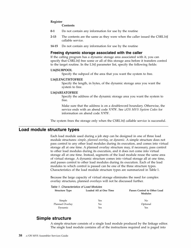
RegisterContents
0-1 Do not contain any information for use by the routine
2-13 The contents are the same as they were when the caller issued the CSRL16Jcallable service.
14-15 Do not contain any information for use by the routine
Freeing dynamic storage associated with the callerIf the calling program has a dynamic storage area associated with it, you canspecify that CSRL16J free some or all of this storage area before it transfers controlto the target routine. In the L16J parameter list, specify the following fields:
L16JSUBPOOLSpecify the subpool of the area that you want the system to free.
L16JLENGTHTOFREESpecify the length, in bytes, of the dynamic storage area you want thesystem to free.
L16JAREATOFREESpecify the address of the dynamic storage area you want the system tofree.
Make sure that the address is on a doubleword boundary. Otherwise, theservice ends with an abend code X'978'. See z/OS MVS System Codes forinformation on abend code X'978'.
The system frees the storage only when the CSRL16J callable service is successful.
Load module structure typesEach load module used during a job step can be designed in one of three loadmodule structures: simple, planned overlay, or dynamic. A simple structure does notpass control to any other load modules during its execution, and comes into virtualstorage all at one time. A planned overlay structure may, if necessary, pass controlto other load modules during its execution, and it does not come into virtualstorage all at one time. Instead, segments of the load module reuse the same areaof virtual storage. A dynamic structure comes into virtual storage all at one time,and passes control to other load modules during its execution. Each of the loadmodules to which control is passed can be one of the three structure types.Characteristics of the load module structure types are summarized in Table 1.
Because the large capacity of virtual storage eliminates the need for complexoverlay structures, planned overlays will not be discussed further.
Table 1. Characteristics of Load ModulesStructure Type Loaded All at One Time Passes Control to Other Load
Modules
Simple Yes NoPlanned Overlay No Optional
Dynamic Yes Yes
Simple structureA simple structure consists of a single load module produced by the linkage editor.The single load module contains all of the instructions required and is paged into
38 z/OS MVS Assembler Services Guide

central storage by the control program as it is executed. The simple structure canbe the most efficient of the two structure types because the instructions it uses topass control do not require control-program assistance. However, you shoulddesign your program to make most efficient use of paging.
Dynamic structureA dynamic structure requires more than one load module during execution. Eachrequired load module can operate as either a simple structure or another dynamicstructure. The advantages of a dynamic structure over a simple structure increaseas the program becomes more complex, particularly when the logical path of theprogram depends on the data being processed. The load modules required in adynamic structure are paged into central storage when required, and can bedeleted from virtual storage when their use is completed.
Load module executionDepending on the configuration of the operating system and the macros used topass control, execution of the load modules is serial or in parallel. Execution isserial in the operating system unless you use an ATTACH or ATTACHX macro tocreate a new task. The new task competes for processor time independently withall other tasks in the system. The load module named in the ATTACH orATTACHX macro is executed in parallel with the load module containing theATTACH or ATTACHX macro. The execution of the load modules is serial withineach task.
The following paragraphs discuss passing control for serial execution of a loadmodule. For information on creating and managing new tasks, see “Creating thetask” on page 27.
Passing control in a simple structureThere are certain procedures to follow when passing control to an entry point inthe same load module. The established conventions to use when passing controlare also discussed. These procedures and conventions are the framework for allprogram interfaces.
Passing control without returnSome control sections pass control to another control section of the load moduleand do not receive control back. An example of this type of control section is ahousekeeping routine at the beginning of a program that establishes values,initializes switches, and acquires buffers for the other control sections in theprogram. Use the following procedures when passing control without return.
Preparing to pass controlv Restore the contents of register 14.
Because control will not be returned to this control section, you must restore thecontents of register 14. Register 14 originally contained the address of thelocation in the calling program (for example, the control program) to whichcontrol is to be passed when your program is finished. Since the current controlsection does not make the return to the calling program, the return address mustbe passed on to the control section that does make the return.
v Restore the contents of registers 2-12.In addition, the contents of registers 2-12 must be unchanged when yourprogram eventually returns control, so you must also restore these registers.
Chapter 4. Program management 39

If control were being passed to the next entry point from the control program,register 15 would contain the entry address. You should use register 15 in thesame way, so that the called routine remains independent of the program thatpassed control to it.
v Use register 1 to pass parameters.Establish a parameter list and place the address of the list in register 1. Theparameter list should consist of consecutive fullwords starting on a fullwordboundary, each fullword containing an address to be passed to the called controlsection. When executing in 24-bit AMODE, each address is located in the threelow-order bytes of the word. When executing in 31-bit AMODE, each address islocated in bits 1-31 the word. In both addressing modes, set the high-order bit ofthe last word to 1 to indicate that it is the last word of the list. The systemconvention is that the list contain addresses only. You may, of course, deviatefrom this convention; however, when you deviate from any system convention,you restrict the use of your programs to those programmers who know aboutyour special conventions.
v Pass the address of the save area in register 13 just as it was passed to you.Since you have reloaded all the necessary registers, the save area that youreceived on entry is now available, and should be reused by the called controlsection. By passing the address of the old save area, you save the 72 bytes ofvirtual storage for a second, unnecessary, save area.
Note: If you pass a new save area instead of the one received on entry, errorscould occur.
Passing controlv Load register 15 with a V-type address constant for the name of the external
entry point, then branch to the address in register 15.This is the common way to pass control between one control section and anentry point in the same load module. The external entry point must have beenidentified using an ENTRY instruction in the called control section if the entrypoint is not the same as the control section's CSECT name.
Figure 11 shows an example of loading registers and passing control. In thisexample, no new save area is used, so register 13 still contains the address of theold save area. It is also assumed for this example that the control section will passthe same parameters it received to the next entry point. First, register 14 isreloaded with the return address. Next, register 15 is loaded with the address ofthe external entry point NEXT, using the V-type address constant at the locationNEXTADDR. Registers 0-12 are reloaded, and control is passed by a branchinstruction using register 15. The control section to which control is passedcontains an ENTRY instruction identifying the entry point NEXT.
Figure 12 on page 41 shows an example of passing a parameter list to an entrypoint with the same addressing mode. Early in the routine the contents of register
.
.L 14,12(13) LOAD CALLER’S RETURN ADDRESSL 15,NEXTADDR ENTRY NEXTLM 0,12,20(13) RETURN CALLER’s REGISTERSBR 15 NEXT SAVE (14,12)..
NEXTADDR DC V(NEXT)
Figure 11. Passing Control in a Simple Structure
40 z/OS MVS Assembler Services Guide

1 (that is, the address of the fullword containing the PARM field address) werestored at the fullword PARMADDR. Register 13 is loaded with the address of theold save area, which had been saved in word 2 of the new save area. The contentsof register 14 are restored, and register 15 is loaded with the entry address.
The address of the list of parameters is loaded into register 1. These parametersinclude the addresses of two data control blocks (DCBs) and the original register 1contents. The high-order bit in the last address parameter (PARMADDR) is set to 1using an OR-immediate instruction. The contents of registers 2-12 are restored.(Since one of these registers was the base register, restoring the registers earlierwould have made the parameter list unaddressable.) A branch register instructionusing register 15 passes control to entry point NEXT.
Passing control with returnThe control program passed control to your program, and your program willreturn control when it is through processing. Similarly, control sections within yourprogram will pass control to other control sections, and expect to receive controlback. An example of this type of control section is a monitoring routine; themonitor determines the order of execution of other control sections based on thetype of input data. Use the following procedures when passing control with return.
Preparing to pass controlv Use registers 15 and 1 in the same manner they are used to pass control without
return.Register 15 contains the entry address in the new control section and register 1 isused to pass a parameter list.
v Ensure that register 14 contains the address of the location to which control is tobe returned when the called control section completes execution.The address can be the instruction following the instruction which causes controlto pass, or it can be another location within the current control section designedto handle all returns.Registers 2-12 are not involved in the passing of control; the called controlsection should not depend on the contents of these registers in any way.
.
.USING *,12 Establish addressability
EARLY ST 1,PARMADDR Save parameter address..L 13,4(13) Reload address of old save areaL 0,20(13)L 14,12(13) Load return addressL 15,NEXTADDR Load address of next entry pointLA 1,PARMLIST Load address of parameter listOI PARMADDR,X’80’ Turn on last parameter indicatorLM 2,12,28(13) Reload remaining registersBR 15 Pass control..
PARMLIST DS 0ADCBADDRS DC A(INDCB)
DC A(OUTDCB)PARMADDR DC A(0)NEXTADDR DC V(NEXT)
Figure 12. Passing Control With a Parameter List
Chapter 4. Program management 41

v Provide a new save area for use by the called control section as previouslydescribed, and pass the address of that save area in register 13.Note that the same save area can be reused after control is returned by thecalled control section. One new save area is ordinarily all you will requireregardless of the number of control sections called.
Passing controlYou may use two standard methods for passing control to another control sectionand providing for return of control. One is an extension of the method used topass control without a return, and requires a V-type address constant and a branch,a branch and link, or a branch and save instruction provided both programsexecute in the same addressing mode. If the addressing mode changes, use abranch and save and set mode instruction. The other method uses the CALL macroto provide a parameter list and establish the entry and return addresses. Witheither method, you must identify the entry point by an ENTRY instruction in thecalled control section if the entry name is not the same as the control sectionCSECT name. Figure 13 on page 43 and Figure 14 on page 43 illustrate the twomethods of passing control; in each example, assume that register 13 alreadycontains the address of a new save area.
Figure 13 on page 43 also shows the use of an inline parameter list and an answerarea. The address of the external entry point is loaded into register 15 in the usualmanner. A branch and link instruction is then used to branch around the parameterlist and to load register 1 with the address of the parameter list. An inlineparameter list, such as the one shown in Figure 13 on page 43, is convenient whenyou are debugging because the parameters involved are located in the listing (orthe dump) at the point they are used, instead of at the end of the listing or dump.Note that the high-order bit of the last address parameter (ANSWERAD) is set to 1to indicate the end of the list. The area pointed to by the address in theANSWERAD parameter is an area to be used by the called control section to passparameters back to the calling control section. This is a possible method to usewhen a called control section must pass parameters back to the calling controlsection. Parameters are passed back in this manner so that no additional registersare involved. The area used in this example is twelve words. The size of the areafor any specific application depends on the requirements of the two controlsections involved.
42 z/OS MVS Assembler Services Guide

The CALL macro in Figure 14 provides the same functions as the instructions inFigure 13. When the CALL macro is expanded, the parameters cause the followingresults:v NEXT - A V-type address constant is created for NEXT, and the address is
loaded into register 15.v (INDCB,OUTDCB,AREA) - A-type address constants are created for the three
parameters coded within parentheses, and the address of the first A-typeaddress constant is placed in register 1.
v VL - The high-order bit of the last A-type address constant is set to 1.
Control is passed to NEXT using a branch and link instruction. (Optionally, youcan specify either a BASR or BASSM instruction, with the LINKINST= parameter.)The address of the instruction following the CALL macro is loaded into register 14before control is passed.
In addition to the results described earlier, the V-type address constant generatedby the CALL macro requires the load module with the entry point NEXT to be linkedited into the same load module as the control section containing the CALLmacro. The z/OS MVS Program Management: User's Guide and Reference and z/OSMVS Program Management: Advanced Facilitiespublications tell more about thisservice.
The parameter list constructed from the CALL macro in Figure 14, contains onlyA-type address constants. A variation on this type of parameter list results fromthe following coding:CALL NEXT,(INDCB,(6),(7)),VL
.
.L 15,NEXTADDR Entry address in register 15CNOP 0,4BAL 1,GOOUT Parameter list address in register 1
PARMLIST DS 0A Start of parameter listDCBADDRS DC A(INDCB) Input DCB address
DC A(OUTDCB) Output DCB addressANSWERAD DC A(AREA+X’80000000’) Answer area address with
high-order bit onNEXTADDR DC V(NEXT) Address of entry pointGOOUT BALR 14,15 Pass control; register 14 contains
return address and current AMODERETURNPT ...AREA DC 12F’0’ Answer area from NEXT
Note: This example assumes that you are passing control to a program that executes in thesame addressing mode as your program. See “Linkage considerations” on page 34 forinformation on how to handle branches between programs that execute in differentaddressing modes.
Figure 13. Passing Control With Return
CALL NEXT,(INDCB,OUTDCB,AREA),VLRETURNPT ...AREA DC 12F’0’
Note: If you are using the CALL macro to pass control to a program that executes in adifferent addressing mode, you must include the LINKINST=BASSM parameter.
Figure 14. Passing Control With CALL
Chapter 4. Program management 43

In the preceding CALL macro, two of the parameters to be passed are coded asregisters rather than symbolic addresses. The expansion of this macro again resultsin a three-word parameter list; in this example, however, the expansion alsocontains instructions that store the contents of registers 6 and 7 in the second andthird words, respectively, of the parameter list. The high-order bit in the thirdword is set to 1 after register 7 is stored. You can specify as many addressparameters as you need, and you can use symbolic addresses or register contentsas you see fit.
Analyzing the returnWhen the control program returns control to a caller after it invokes a systemservice, the contents of registers 2-13 are unchanged. When control is returned toyour control section from the called control section, registers 2-14 contain the sameinformation they contained when control was passed, as long as systemconventions are followed. The called control section has no obligation to restoreregisters 0 and 1; so the contents of these registers may or may not have beenchanged.
When control is returned, register 15 can contain a return code indicating theresults of the processing done by the called control section. If used, the return codeshould be a multiple of four, so a branching table can be used easily, and a returncode of zero should be used to indicate a normal return. The control programfrequently uses this method to indicate the results of the requests you make usingsystem macros; an example of the type of return codes the control programprovides is shown in the description of the IDENTIFY macro.
The meaning of each of the codes to be returned must be agreed upon in advance.In some cases, either a “good” or “bad” indication (zero or nonzero) will besufficient for you to decide your next action. If this is true, the coding in Figure 15could be used to analyze the results. Many times, however, the results and thealternatives are more complicated, and a branching table, such as shown inFigure 16 could be used to pass control to the proper routine.
Note: Explicit tests are required to ensure that the return code value does notexceed the branch table size.
How control is returnedIn the discussion of the return under “Analyzing the return,” it was indicated thatthe control section returning control must restore the contents of registers 2-14.Because these are the same registers reloaded when control is passed without a
RETURNPT LTR 15,15 Test return code for zeroBNZ ERRORTN Branch if not zero to error routine..
Figure 15. Test for Normal Return
RETURNPT B RETTAB(15) Branch to table using return codeRETTAB B NORMAL Branch to normal routine
B COND1 Branch to routine for condition 1B COND2 Branch to routine for condition 2B GIVEUP Branch to routine to handle impossible situations...
Figure 16. Return Code Test Using Branching Table
44 z/OS MVS Assembler Services Guide

return, refer to the discussion under “Passing Control without Return” for detailedinformation and examples. The contents of registers 0 and 1 do not have to berestored.
Register 15 can contain a return code when control is returned. As indicatedpreviously, a return code should be a multiple of four with a return code of zeroindicating a normal return. The return codes other than zero that you use can haveany meaning, as long as the control section receiving the return codes is aware ofthat meaning.
The return address is the address originally passed in register 14; you shouldalways return control to that address. If an addressing mode switch is notinvolved, you can either use a branch instruction such as BR 14, or you can use theRETURN macro. An example of each of these methods of returning control isdiscussed in the following paragraphs. If an addressing mode switch is involved,you can use a BSM 0,14 instruction to return control. See Figure 10 on page 36 foran example that uses the BSM instruction to return control.
Figure 17 shows a portion of a control section used to analyze input data cards andto check for an out-of-tolerance condition. Each time an out-of-tolerance conditionis found, in addition to some corrective action, one is added to the one-byte valueat the address STATUSBY. After the last data card is analyzed, this control sectionreturns to the calling control section, which bases its next action on the number ofout-of-tolerance conditions encountered. The coding shown in Figure 17 loadsregister 14 with the return address. The contents of register 15 are set to zero, andthe value at the address STATUSBY (the number of errors) is placed in thelow-order eight bits of the register. The contents of register 15 are shifted to the lefttwo places to make the value a multiple of four. Registers 2-12 are reloaded, andcontrol is returned to the address in register 14.
The RETURN macro saves coding time. The expansion of the RETURN macroprovides instructions that restore a designated range of registers, load a returncode in register 15, and branch to the address in register 14. If T is specified, theRETURN macro flags the save area used by the returning control section (that is,the save area supplied by the calling routine). It does this by setting the low-orderbit of word four of the save area to one after the registers have been restored. Theflag indicates that the control section that used the save area has returned to thecalling control section. The flag is useful when tracing the flow of your program ina dump. For a complete record of program flow, a separate save area must beprovided by each control section each time control is passed.
.
.L 13,4(13) Load address of previous save areaL 14,12(13) Load return addressSR 15,15 Set register 15 to zeroIC 15,STATUSBY Load number of errorsSLA 15,2 Set return code to multiple of 4LM 2,12,28(13) Reload registers 2-12BR 14 Return..
STATUSBY DC X’00’
Note: This example assumes that you are returning to a program with the same AMODE. Ifnot, use the BSM instruction to transfer control.
Figure 17. Establishing a Return Code
Chapter 4. Program management 45
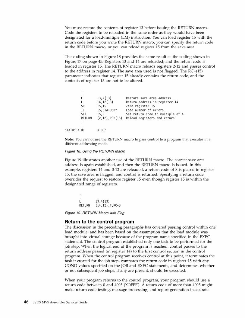
You must restore the contents of register 13 before issuing the RETURN macro.Code the registers to be reloaded in the same order as they would have beendesignated for a load-multiple (LM) instruction. You can load register 15 with thereturn code before you write the RETURN macro, you can specify the return codein the RETURN macro, or you can reload register 15 from the save area.
The coding shown in Figure 18 provides the same result as the coding shown inFigure 17 on page 45. Registers 13 and 14 are reloaded, and the return code isloaded in register 15. The RETURN macro reloads registers 2-12 and passes controlto the address in register 14. The save area used is not flagged. The RC=(15)parameter indicates that register 15 already contains the return code, and thecontents of register 15 are not to be altered.
Figure 19 illustrates another use of the RETURN macro. The correct save areaaddress is again established, and then the RETURN macro is issued. In thisexample, registers 14 and 0-12 are reloaded, a return code of 8 is placed in register15, the save area is flagged, and control is returned. Specifying a return codeoverrides the request to restore register 15 even though register 15 is within thedesignated range of registers.
Return to the control programThe discussion in the preceding paragraphs has covered passing control within oneload module, and has been based on the assumption that the load module wasbrought into virtual storage because of the program name specified in the EXECstatement. The control program established only one task to be performed for thejob step. When the logical end of the program is reached, control passes to thereturn address passed (in register 14) to the first control section in the controlprogram. When the control program receives control at this point, it terminates thetask it created for the job step, compares the return code in register 15 with anyCOND values specified on the JOB and EXEC statements, and determines whetheror not subsequent job steps, if any are present, should be executed.
When your program returns to the control program, your program should use areturn code between 0 and 4095 (X'0FFF'). A return code of more than 4095 mightmake return code testing, message processing, and report generation inaccurate.
.
.L 13,4(13) Restore save area addressL 14,12(13) Return address in register 14SR 15,15 Zero register 15IC 15,STATUSBY Load number of errorsSLA 15,2 Set return code to multiple of 4RETURN (2,12),RC=(15) Reload registers and return..
STATUSBY DC X’00’
Note: You cannot use the RETURN macro to pass control to a program that executes in adifferent addressing mode.
Figure 18. Using the RETURN Macro
.
.L 13,4(13)RETURN (14,12),T,RC=8
Figure 19. RETURN Macro with Flag
46 z/OS MVS Assembler Services Guide

Passing control in a dynamic structureThe discussion of passing control in a simple structure provides the backgroundfor the discussion of passing control in a dynamic structure. Within each loadmodule, control should be passed as in a simple structure. If you can determinewhich control sections will make up a load module before you code the controlsections, you should pass control within the load module without involving thecontrol program. The macros discussed provide increased linkage capability, butthey require control program assistance and possibly increased execution time.
Bringing the load module into virtual storageThe control program automatically brings the load module containing the entryname you specified on the EXEC statement into virtual storage. Each load moduleor program object resides in a library, either a partitioned data set (PDS) orpartitioned data set extended (PDSE). A load module resides in a PDS, and aprogram object resides in a PDSE. In most cases, references to load modules applyto both load modules and program objects. Any exceptions are specifically noted.As the control program brings the load module into virtual storage, it places theload module above or below 16 megabytes according to its RMODE attribute. Anyother load modules you require during your job step are brought into virtualstorage by the control program when requested. Make these requests by using theLOAD, LINK, LINKX, ATTACH, ATTACHX, XCTL, and XCTLX macros. TheLOAD macro sets the high-order bit of the entry point address to indicate theaddressing mode of the load module. The ATTACH, ATTACHX, LINK, LINKX,XCTL, and XCTLX macros use this information to set the addressing mode for themodule that gets control. If the AMODE is ANY, the module will get control in thesame addressing mode as the program that issued the ATTACH, ATTACHX, LINK,LINKX, XCTL, or XCTLX macro. If a copy of the load module must be broughtinto storage, the control program places the load module above or below 16megabytes according to its RMODE attribute. The following paragraphs discuss theproper use of these macros.
Location of the load moduleLoad modules and program objects can reside in the link library, the job or steplibrary, the task library, or a private library.v The link library (defined by the LNKLSTxx or PROGxx member of
SYS1.PARMLIB) is always present and is available to all job steps of all jobs. Thecontrol program provides the data control block for the library and logicallyconnects the library to your program, making the members of the libraryavailable to your program. For more information, see z/OS MVS Initialization andTuning Guide.
v The job and step libraries are explicitly established by including //JOBLIB and//STEPLIB DD statements in the input stream. The //JOBLIB DD statement isplaced immediately after the JOB statement, while the //STEPLIB DD statementis placed among the DD statements for a particular job step. The job library isavailable to all steps of your job, except those that have step libraries. A steplibrary is available to a single job step; if there is a job library, the step libraryreplaces the job library for the step. For either the job library or the step library,the control program provides the data control block and issues the OPEN macroto logically connect the library to your program.Authorization: To invoke a program, an authorized program (supervisor state,APF-authorized, PSW key 0 - 7, or PKM allowing key 0 - 7) must reside in anAPF-authorized library or in the link pack area. The system treats any module inthe link pack area (pageable LPA, modified LPA, fixed LPA, or dynamic LPA) asthough it come from an APF-authorized library. Ensure that you properly protect
Chapter 4. Program management 47

SYS1.LPALIB and any other library that contributes modules to the link packarea to avoid system security and integrity exposures, just as you protect anyAPF-authorized library. See “APF-authorized programs and libraries” on page 60for more information about APF-authorized libraries.
v Unique task libraries can be established by using the TASKLIB parameter of theATTACH or ATTACHX macro. The issuer of the ATTACH or ATTACHX macrois responsible for providing the DD statement and opening the data set or sets.If the TASKLIB parameter is omitted, the task library of the attaching task ispropagated to the attached task. In the following example, task A's job library isLIB1. Task A attaches task B, specifying TASKLIB=LIB2 in the ATTACH orATTACHX macro. Task B's task library is therefore LIB2. When task B attachestask C, LIB2 is searched for task C before LIB1 or the link library. Because task Bdid not specify a unique task library for task C, its own task library (LIB2) ispropagated to task C and is the first library searched when task C requests thata module be brought into virtual storage.Task A ATTACH EP=B,TASKLIB=LIB2Task B ATTACH EP=C
v Including a DD statement in the input stream defines a private library that isavailable only to the job step in which it is defined. You must provide the datacontrol block and issue the OPEN macro for each data set. You may use morethan one private library by including more than one DD statement and anassociated data control block.
A library can be a single partitioned data set, or a collection of such data sets.When it is a collection, you define each data set by a separate DD statement, butyou assign a name only to the statement that defines the first data set. Thus, a joblibrary consisting of three partitioned data sets would be defined as follows://JOBLIB DD DSNAME=PDS1,...// DD DSNAME=PDS2,...// DD DSNAME=PDS3...
The three data sets (PDS1, PDS2, PDS3) are processed as one, and are said to beconcatenated. Concatenation and the use of partitioned data sets is discussed inmore detail in z/OS DFSMS Using Data Sets.
Some of the load modules from the link library may already be in virtual storagein an area called the link pack area. The contents of these areas are determinedduring the nucleus initialization process and will vary depending on therequirements of your installation. The link pack area contains all reenterable loadmodules from the LPA library, along with installation selected modules. These loadmodules can be used by any job step in any job.
With the exception of those load modules contained in this area, copies of all of thereenterable load modules you request are brought into your area of virtual storageand are available to any task in your job step. The portion of your area containingthe copies of the load modules is called the job pack area. Any program loaded bya particular task is also represented within that task's load list.
The search for the load moduleIn response to your request for a copy of a load module, the control programsearches the task's load list and the job pack area. If a copy of the load module isfound, the control program determines whether that copy can be used (see “Usingan Existing Copy”). If an existing copy can be used, the search stops. If it cannotbe used, the search continues until the module is located in a library or the linkpack area. The load module is then brought into the job pack area or placed intothe load list.
48 z/OS MVS Assembler Services Guide

The order in which the control program searches the libraries, load list, and packareas depends on the parameters used in the macro (LINK, LINKX, LOAD, XCTL,XCTLX, ATTACH or ATTACHX) requesting the load module. The parameters thatdefine the order of the search are EP, EPLOC, DE, DCB, and TASKLIB.
Use the TASKLIB parameter only for ATTACH or ATTACHX. If you know thelocation of the load module, you should use parameters that eliminate as many ofthese searches as possible, as indicated in Figure 20, Figure 21 on page 50, andFigure 22 on page 52.
The EP, EPLOC, or DE parameter specifies the name of the entry point in the loadmodule. Code one of the three every time you use a LINK, LINKX, LOAD, XCTL,XCTLX, ATTACH, or ATTACHX macro. The optional DCB parameter indicates theaddress of the data control block for the library containing the load module.Omitting the DCB parameter or using the DCB parameter with an address of zerospecifies that the system is to do its normal search. If you specified TASKLIB and ifthe DCB parameter contains the address of the data control block for the linklibrary, the control program searches no other library.
To avoid using “system copies” of modules resident in LPA and LINKLIB, you canspecifically limit the search for the load module to the load list and the job packarea and the first library on the normal search sequence by specifying theLSEARCH parameter on the LINK, LOAD, or XCTL macro with the DCB for thelibrary to be used.
The following paragraphs discuss the order of the search when the entry nameused is a member name.
The EP and EPLOC parameters require the least effort on your part; you provideonly the entry name, and the control program searches for a load module havingthat entry name. Figure 20 shows the order of the search when EP or EPLOC iscoded, and the DCB parameter is omitted or DCB=0 is coded.
When used without the DCB parameter, the EP and EPLOC parameters providethe easiest method of requesting a load module from the link, job, or step library.The control program searches the task libraries before the job or step library,beginning with the task library of the task that issued the request and continuingthrough the task libraries of all its antecedent tasks. It then searches the job or steplibrary, followed by the link library.
A job, step, or link library or a data set in one of these libraries can be used to holdone version of a load module, while another can be used to hold another version
The control program searches:
1. The requesting task's load list for an available copy.
2. The job pack area for an available copy.
3. The requesting task's task library and all the unique task libraries of its precedingtasks. (For the ATTACH or ATTACHX macro, the attached task's library and all theunique task libraries of its preceding tasks are searched.)
4. The step library; if there is no step library, the job library (if any).
5. The link pack area.
6. The link library.
Figure 20. Search for Module, EP or EPLOC Parameter With DCB=0 or DCB ParameterOmitted
Chapter 4. Program management 49

with the same entry name. If one version is in the link library, you can ensure thatthe other will be found first by including it in the job or step library. However, ifboth versions are in the job or step library, you must define the data set thatcontains the version you want to use before the data set that contains the otherversion. For example, if the wanted version is in PDS1 and the unwanted versionis in PDS2, a step library consisting of these data sets should be defined as follows://STEPLIB DD DSNAME=PDS1,...// DD DSNAME=PDS2,...
Use extreme caution when specifying duplicate module names. Even if you codethe DCB parameter, the wrong module can still receive control. For example,suppose there are two modules with the same name you want to invoke, one afterthe other. To distinguish between them in this example they are called PROG2 andPROG2'. PROG1 issues a LOAD for PROG2 and BALRs to it. PROG2 issues aLINK specifying a DCB for the library with the other copy of PROG2 (which weare calling PROG2'). The LINK will find a useable copy of PROG2 in the Job PackArea and invoke it again, regardless of the DCB parameter. PROG2 again issues aLINK for PROG2'. This time the copy of PROG2 in the Job Pack Area is marked"not reusable" and PROG2' is loaded using the DCB parameter and given control.
The problem encountered in the previous example could be avoided by any one ofthe following sequences:v PROG1 links to PROG2 and PROG2 links to PROG2'v PROG1 loads and branches to PROG2. PROG2 loads and branches to PROG2'v PROG1 links to PROG2 and PROG2 loads and branches to PROG2'
Once a module has been loaded from a task library, step library, or job library, themodule name is known to all tasks in the address space and may be used as longas the module is considered usable. Generally speaking, reenterable modules arealways usable. Serially reusable modules are usable when they are currently in use.Non-reentrant, non-serially reusable modules are considered usable for LOAD ifthe use count is zero. A module is considered usable for ATTACH, LINK, or XCTLif it has not been marked NOT REUSABLE by a previous ATTACH, LINK, orXCTL. The use count is not considered.
If you know that the load module you are requesting is a member of one of theprivate libraries, you can still use the EP or EPLOC parameter, this time inconjunction with the DCB parameter. Specify the address of the data control blockfor the private library in the DCB parameter. The order of the search for EP orEPLOC with the DCB parameter (when the DCB parameter is not 0) is shown inFigure 21.
Searching a job or step library slows the retrieval of load modules from the linklibrary; to speed this retrieval, you should limit the size of the job and step
The control program searches:
1. The requesting task's load list for an available copy.
2. The job pack area for an available copy.
3. The specified library.
4. The link pack area.
5. The link library.
Figure 21. Search for Module, EP or EPLOC Parameters With DCB Parameter SpecifyingPrivate Library
50 z/OS MVS Assembler Services Guide

libraries. You can best do this by eliminating the job library altogether andproviding step libraries where required. You can limit each step library to the datasets required by a single step. Some steps (such as compilation) do not require astep library and therefore do not require searching and retrieving modules fromthe link library. For maximum efficiency, you should define a job library only whena step library would be required for every step, and every step library would bethe same.
The DE parameter requires more work than the EP and EPLOC parameters, but itcan reduce the amount of time spent searching for a load module. Before you canuse this parameter, you must use the BLDL macro to obtain the directory entry forthe module. The directory entry is part of the library that contains the module. Seez/OS DFSMS Macro Instructions for Data Sets for more information about the BLDLmacro.
To save time, the BLDL macro must obtain directory entries for more than oneentry name. Specify the names of the load modules and the address of the datacontrol block for the library when using the BLDL macro; the control programplaces a copy of the directory entry for each entry name requested in a designatedlocation in virtual storage. If you specify the link library and the job or step libraryby specifying DCB=0, the directory information indicates from which library thedirectory entry was taken. The directory entry always indicates the relative trackand block location of the load module in the library. If the load module is notlocated on the library you indicate, a return code is given. You can then issueanother BLDL macro specifying a different library.
To use the DE parameter, provide the address of the directory entry and code oromit the DCB parameter to indicate the same library specified in the BLDL macro.The task using the DE parameter should be the same as the one which issued theBLDL or one which has the same job, step, and task library structure as the taskissuing the BLDL. The order of the search when the DE parameter is used isshown in Figure 22 on page 52 for the link, job, step, and private libraries.
The preceding discussion of the search is based on the premise that the entry nameyou specified is the member name. The control program checks for an alias entrypoint name when the load module is found in a library. If the name is an alias, thecontrol program obtains the corresponding member name from the librarydirectory, and then searches to determine if a usable copy of the load module existsin the job pack area. If a usable copy does not exist in a pack area, a new copy isbrought into the job pack area. Otherwise, the existing copy is used, conservingvirtual storage and eliminating the loading time.
Chapter 4. Program management 51

As the discussion of the search indicates, you should choose the parameters for themacro that provide the shortest search time. The search of a library actuallyinvolves a search of the directory, followed by copying the directory entry intovirtual storage, followed by loading the load module into virtual storage. If youknow the location of the load module, you should use the parameters thateliminate as many of these unnecessary searches as possible, as indicated inFigure 20 on page 49, Figure 21 on page 50, and Figure 22. Examples of the use ofthese figures are shown in the following discussion of passing control.
Using an existing copyThe control program uses a copy of the load module already in the requestingtask's load list or the job pack area if the copy can be used. Whether the copy canbe used or not depends on the reusability and current status of the load module,
Searching when Directory Entry is provided. First two steps are *always* search load listand search job pack queue.
v No DCB specified and no job/step/tasklib exists, or if DCB is specified and selects theLNKLST
– Search LPA
– Search LNKLST
v No DCB specified, job/step/tasklib exists
– DE indicates LNKLST
- Search LPA
- Search LNKLST
– DE indicates job/step/tasklib
- Search that job/step/tasklib
- Unless precluded by LSEARCH=YES
v Search other job/step/tasklibs
v Search LPA
v Search LNKLST
– DE indicates private library
- Search library specified by TCBJLB
- Unless precluded by LSEARCH=YES
v Search LPA
v Search LNKLST
v DCB specified, does not select LNKLST
– DE indicates LNKLST
- Search LPA
- Search LNKLST
– DE indicates job/step/tasklib
- Search that job/step/tasklib
- Unless precluded by LSEARCH=YES
v Search LPA
v Search LNKLST
– DE indicates private library
- Search library specified by DCB
- Unless precluded by LSEARCH=YES
v Search LPA
v Search LNKLST
Figure 22. Search for Module Using DE Parameter
52 z/OS MVS Assembler Services Guide

that is, the load module attributes, as designated using linkage editor controlstatements, and whether the load module has already been used or is in use. Thestatus information is available to the control program only when you specify theload module entry name on an EXEC statement, or when you use ATTACH,ATTACHX, LINK, LINKX, XCTL, or XCTLX macros to transfer control to the loadmodule. The control program protects you from obtaining an unusable copy of aload module if you always “formally” request a copy using these macros (or theEXEC statement). If you pass control in any other manner (for instance, a branchor a CALL macro), the control program, because it is not informed, cannot protectyour copy. If your program is in AR mode, and the SYSSTATE ASCENV=ARmacro has been issued, use the ATTACHX, LINKX, and XCTLX macros instead ofATTACH, LINK, and XCTL. The macros whose names end with "X" generate codeand addresses that are appropriate for AR mode.
All reenterable modules (modules designated as reenterable using the linkageeditor) from any library are completely reusable. Only one copy is normally placedin the link pack area or brought into your job pack area, and you get immediatecontrol of the load module. However, there might be circumstances beyond yourcontrol that can cause an additional copy to be placed into your job pack area. Thecontrol program might do this, for example, to preserve system integrity.
If the module is serially reusable, only one copy is ever placed in the job pack area;this copy is always used for a LOAD macro. If the copy is in use, however, and therequest is made using a LINK, LINKX, ATTACH, ATTACHX, XCTL, or XCTLXmacro, the task requiring the load module is placed in a wait condition until thecopy is available. You should not issue a LINK or LINKX macro for a seriallyreusable load module currently in use for the same task; the task will beabnormally terminated. (This could occur if an exit routine issued a LINK orLINKX macro for a load module in use by the main program.)
If the load module is not reusable, a LOAD macro will always bring in a new copyof the load module; an existing copy is used only if you issued a LINK, LINKX,ATTACH, ATTACHX XCTL or XCTLX macro and the copy has not been usedpreviously. Remember, the control program can determine if a load module hasbeen used or is in use only if all of your requests are made using LINK, LINKX,ATTACH, ATTACHX, XCTL or XCTLX macros.
Using the LOAD macroIf a copy of the specified load module is not already in the link pack area, use theLOAD macro to place a copy in the address space. When you issue a LOADmacro, the control program searches for the load module as discussed previouslyand brings a copy of the load module into the address space if required. Normally,you should use the LOAD macro only for a reenterable or serially reusable loadmodule, because the load module is retained even though it is not in use.
The control program places the copy of the load module in subpool 244 or subpool251, unless the following three conditions are true:v The module is reentrantv The library is authorizedv You are not running under TSO/E test
In this case, the control program places the module in subpool 252. When choosingbetween subpools 244 and 251. the control program uses:v subpool 244 only when within a task that was created by ATTACHX with the
KEY=NINE parameter
Chapter 4. Program management 53

v subpool 251 in all other cases.
Subpool 244 is not fetch protected and has a storage key equal to your PSW key.Subpool 251 is fetch protected and has a storage key equal to your PSW key.Subpool 252 is not fetch protected and has storage key 0.
The use count for the copy is lowered by one when you issue a DELETE macroduring the task which was active when the LOAD macro was issued. When a taskis terminated, the count is lowered by the number of LOAD macros issued for thecopy when the task was active minus the number of deletions. When the use countfor a copy in a job pack area reaches zero, the virtual storage area containing thecopy is made available.
Passing control with returnUse the LINK or LINKX macro to pass control between load modules and toprovide for return of control. You can also pass control using branch, branch andlink, branch and save, or branch and save and set mode instructions or the CALLmacro. However, when you pass control in this manner, you must protect againstmultiple uses of non-reusable or serially reusable modules. You must also becareful to enter the routine in the proper addressing mode. The followingparagraphs discuss the requirements for passing control with return in each case.
Using the LINK or LINKX macroWhen you use the LINK or LINKX macro, you are requesting the system to assistyou in passing control to another load module. There is some similarity betweenpassing control using a LINK or LINKX macro and passing control using a CALLmacro in a simple structure. These similarities are discussed first.
The convention regarding registers 2-12 still applies; the control program does notchange the contents of these registers, and the called load module should restorethem before control is returned. Unless you are an AR mode program calling anAR mode program that uses the linkage stack, you must provide the address inregister 13 of the save area for use by the called load module; the system does notuse this save area. You can pass address parameters in a parameter list to the loadmodule using register 1. The LINK or LINKX macro provides the same facility forconstructing this list as the CALL macro. Register 0 is used by the control programand the contents may be modified. In certain cases, the contents of register 1 maybe altered by the LINK or LINKX macro.
There is also some difference between passing control using a LINK or LINKXmacro and passing control using a CALL macro. When you pass control using theCALL macro, register 15 contains the entry address and register 14 contains thereturn address. When the called load module gets control, that is still whatregisters 14 and 15 contain. When you use the LINK or LINKX macro, it is thecontrol program that establishes the values in registers 14 and 15. When you codethe LINK or LINKX macro, you provide the entry name and possibly some libraryinformation using the EP, EPLOC, or DE, and DCB parameters, but you have toget this entry name and library information to the control program. The expansionof the LINK or LINKX macro does this by creating a control program parameterlist (the information required by the control program) and passing its address tothe control program. After the control program determines the entry point address,it places the address in register 15 if the target routine is to run in 24-bit or 31-bitaddressing mode. If the target routine is to run in 64-bit addressing mode, thatroutine is expected to use relative branching, and register 15 contains a value thatcan be used to determine the addressing mode of the issuer of the LINK or LINKXmacro as follows:
54 z/OS MVS Assembler Services Guide

v Issuer AMODE 24: X'FFFFF000'v Issuer AMODE 31: X'FFFFF002'v Issuer AMODE 64: X'FFFFF004'
Note: For assistance in converting a program to use relative branching, refer to theIEABRC and IEABRCX macros.
The return address in your control section is always the instruction following theLINK or LINKX; that is not, however, the address that the called load modulereceives in register 14. The control program saves the address of the location inyour program in its own save area, and places in register 14 the address of aroutine within the control program that will receive control. Because control waspassed using the control program, return must also be made using the controlprogram. The control program also handles all switching of addressing mode whenprocessing the LINK or LINKX macro.
Note: A program that is LINKed to will get control with the caller's Floating PointRegisters and Floating Point Control register. The S/390 linkage conventionapplies. For more information, see Chapter 2, “Linkage conventions,” on page 5.
The control program establishes a use count for a load module when control ispassed using the LINK or LINKX macro. This is a separate use count from thecount established for LOAD macros, but it is used in the same manner. The countis increased by one when a LINK or LINKX macro is issued and decreased by onewhen return is made to the control program or when the called load module issuesan XCTL or XCTLX macro.
Figure 23 and Figure 24 show the coding of a LINK or LINKX macro used to passcontrol to an entry point in a load module. In Figure 23, the load module is fromthe link, job, or step library; in Figure 24, the module is from a private library.Except for the method used to pass control, this example is similar to Figures 10and 11. A problem program parameter list containing the addresses INDCB,OUTDCB, and AREA is passed to the called load module; the return point is theinstruction following the LINK or LINKX macro. A V-type address constant is notgenerated, because the load module containing the entry point NEXT is not to beedited into the calling load module. Note that the EP parameter is chosen, sincethe search begins with the job pack area and the appropriate library as shown inFigure 20 on page 49.
LINK EP=NEXT,PARAM=(INDCB,OUTDCB,AREA),VL=1RETURNPT ...AREA DC 12F’0’
Figure 23. Use of the LINK Macro with the Job or Link Library
OPEN (PVTLIB)..LINK EP=NEXT,DCB=PVTLIB,PARAM=(INDCB,OUTDCB,AREA),VL=1..
PVTLIB DCB DDNAME=PVTLIBDD,DSORG=PO,MACRF=(R)
Figure 24. Use of the LINK Macro with a Private Library
Chapter 4. Program management 55

Figure 25 and Figure 26 show the use of the BLDL and LINK macros to passcontrol. Assuming that control is to be passed to an entry point in a load modulefrom the link library, a BLDL macro is issued to bring the directory entry for themember into virtual storage. (Remember, however, that time is saved only if morethan one directory entry is requested in a BLDL macro. Only one is requested herefor simplicity.)
The first parameter of the BLDL macro is a zero, which indicates that the directoryentry is on the link, job, step, or task library. The second parameter is the addressin virtual storage of the list description field for the directory entry. The secondtwo bytes at LISTADDR indicate the length of each entry. A character constant isestablished to contain the directory information to be placed there by the controlprogram as a result of the BLDL macro. The LINK macro in Figure 26 can now bewritten. Note that the DE parameter refers to the name field, not the listdescription field, of the directory entry.
Using CALL, BALR, BASR, or BASSMWhen a module is reenterable, you can save time by passing control to a loadmodule without using the control program. Pass control without using the controlprogram as follows.v Issue a LOAD macro to obtain a copy of the load module, preceded by a BLDL
macro if you can shorten the search time by using it.The control program returns the address of the entry point and the addressingmode in register 0 and the length in doublewords in register 1.
v Load this address into register 15.The linkage requirements are the same when passing control between loadmodules as when passing control between control sections in the same loadmodule: register 13 must contain a save area address, register 14 must containthe return address, and register 1 is used to pass parameters in a parameter list.A branch instruction, a branch and link instruction (BALR), a branch and saveinstruction (BASR), a branch and save and set mode instruction (BASSM), or aCALL macro can be used to pass control, using register 15. Use BASSM (or theCALL macro with the LINKINST=BASSM parameter specified) only if there is tobe an addressing mode switch. The return will be made directly to yourprogram.
Note:
1. You must use a branch and save and set mode instruction (or the CALL macrowith the LINKINST=BASSM parameter specified) if passing control to amodule in a different addressing mode.
BLDL 0,LISTADDR..DS 0H List description field:
LISTADDR DC H’01’ Number of list entriesDC H’60’ Length of each entry
NAMEADDR DC CL8’NEXT’ Member nameDS 26H Area required for directory information
Figure 25. Use of the BLDL Macro
LINK DE=NAMEADDR,DCB=0,PARAM=(INDCB,OUTDCB,AREA),VL=1
Figure 26. The LINK Macro with a DE Parameter
56 z/OS MVS Assembler Services Guide

2. When control is passed to a load module without using the control program,you must check the load module attributes and current status of the copyyourself, and you must check the status in all succeeding uses of that loadmodule during the job step, even when the control program is used to passcontrol.
The reason you have to keep track of the usability of the load module has beendiscussed previously; you are not allowing the control program to determinewhether you can use a particular copy of the load module. The followingparagraphs discuss your responsibilities when using load modules with variousattributes. You must always know what the reusability attribute of the load moduleis. If you do not know, you should not attempt to pass control yourself.
If the load module is reenterable, one copy of the load module is all that is everrequired for a job step. You do not have to determine the status of the copy; it canalways be used. You can pass control by using a CALL macro, a branch, a branchand link instruction, a branch and save instruction, or a branch and save and setmode instruction (BASSM). Use BASSM (or the CALL macro with theLINKINST=BASSM parameter specified) only if there is to be an addressing modeswitch.
If the load module is serially reusable, one use of the copy must be completedbefore the next use begins. If your job step consists of only one task, make surethat the logic of your program does not require a second use of the same loadmodule before completion of the first use. This prevents simultaneous use of thesame copy. An exit routine must not require the use of a serially reusable loadmodule also required in the main program.
Preventing simultaneous use of the same copy when you have more than one taskin the job step requires more effort on your part. You must still be sure that thelogic of the program for each task does not require a second use of the same loadmodule before completion of the first use. You must also be sure that no more thanone task requires the use of the same copy of the load module at one time. You canuse the ENQ macro for this purpose. Properly used, the ENQ macro prevents theuse of a serially reusable resource, in this case a load module, by more than onetask at a time. For information on the ENQ macro, see Chapter 6, “Resourcecontrol,” on page 115 You can also use a conditional ENQ macro to check forsimultaneous use of a serially reusable resource within one task.
If the load module is non-reusable, each copy can only be used once; you must besure that you use a new copy each time you require the load module. You canensure that you always get a new copy by using a LINK macro or by doing thefollowing:1. Issue a LOAD macro before you pass control.2. Pass control using a branch, branch and link, branch and save, branch and save
and set mode instruction, or a CALL macro.3. Issue a DELETE macro as soon as you are through with the copy.
How control is returnedThe return of control between load modules is the same as return of controlbetween two control sections in the same load module. The program in the loadmodule returning control is responsible for restoring registers 2-14, possiblyloading a return code in register 15, passing control using the address in register 14and possibly setting the correct addressing mode. The program in the load moduleto which control is returned can expect registers 2-13 to be unchanged, register 14
Chapter 4. Program management 57
to contain the return address, and optionally, register 15 to contain a return code.Control can be returned using a branch instruction, a branch and set modeinstruction or the RETURN macro. If control was passed without using the controlprogram, control returns directly to the calling program. However, if control wasoriginally passed using the control program, control returns first to the controlprogram, then to the calling program.
Passing control without returnUse the XCTL or XCTLX macro to pass control to a target load module whenreturn of control is not required. You can also pass control using a branchinstruction. However, when you pass control in this manner, you must ensure thatmultiple uses of non-reusable or serially reusable modules does not occur. Thefollowing paragraphs discuss the requirements for passing control without returnin each case.
Passing control using a branch instructionThe same requirements and procedures for protecting against reuse of anon-reusable copy of a load module apply when passing control without return aswere stated under “Passing Control With Return.” The procedures for passingcontrol are as follows.
Issue a LOAD macro to obtain a copy of the load module. The entry address andaddressing mode returned in register 0 are loaded into register 15. The linkagerequirements are the same when passing control between load modules as whenpassing control between control sections in the same load module; register 13 mustbe reloaded with the old save area address, then registers 14 and 2-12 restoredfrom that old save area. Register 1 is used to pass parameters in a parameter list. Ifthe addressing mode does not change, a branch instruction is issued to passcontrol to the address in register 15; if the addressing mode does change, a branchand save and set mode macro is used.
Note: Mixing branch instructions and XCTL or XCTLX macros is hazardous. Thenext topic explains why.
Using the XCTL or XCTLX macroThe XCTL or XCTLX macro, in addition to being used to pass control, is used toindicate to the control program that this use of the load module containing theXCTL or XCTLX macro is completed. Because control will not be returned, theXCTL issuer must load the address of the old save area into register 13 prior toissuing the XCTL. The return address must be loaded into register 14 from the oldsave area, as must the contents of registers 2-12. The XCTL or XCTLX macro can bewritten to request the loading of registers 2-12, or you can do it yourself. If yourestore all registers yourself, do not use the EP parameter. This creates an inlineparameter list that can only be addressed using your base register, and your baseregister is no longer valid. If EP is used, you must have XCTL or XCTLX restorethe base register for you.
Note: A program that is XCTLed to will get control with the caller's Floating PointRegisters and Floating Point Control register. The program that issued the XCTLmacro is not returned to, instead the XCTLed program will return to the programthat caused the issuer of the XCTL macro to run. The S/390 linkage conventionapplies except that the non-volatile FPRs and FPC register that must be restoredare different. The issuer of the XCTL macro must restore its caller's non-volatileFPRs and FPC register before issuing the XCTL (just as if it were returning to itscaller). For more information on linkage conventions, see Chapter 2, “Linkageconventions,” on page 5.
58 z/OS MVS Assembler Services Guide

When using the XCTL or XCTLX macro, pass parameters to the target module in aparameter list. In this case, however, the parameter list (or the parameter data)must be established in remote storage, a portion of virtual storage outside thecurrent load module containing the XCTL or XCTLX macro. This is because thecopy of the current load module may be deleted before the called load module canuse the parameters (more details follow).
The XCTL or XCTLX macro is similar to the LINK macro in the method used topass control: control is passed by the control program using a control parameterlist. The control program loads a copy of the target load module, if necessary, savesthe address passed in register 14, and determines the entry address. When theentry address is to run in 24-bit or 31-bit addressing mode, the control programloads the entry address in register 15 and passes control to that address. When theentry address is to run in 64-bit addressing mode, the 64-bit program is expectedto use relative branching and the control program puts into register 15 a value thatcan be used to determine the address mode of the issuer of the XCTL or XCTLXmacro as follows:v Issuer AMODE 24: X’FFFFF000’v Issuer AMODE 31: X’FFFFF002’v Issuer AMODE 64: X’FFFFF004’
Note: For assistance in converting a program to use relative branching, refer to theIEABRC and IEABRCX macros.
The control program then passes control to the entry address. The control programadds one to the use count for the copy of the target load module and subtracts onefrom the use count for the current load module. The current load module in thiscase is the load module last given control using the control program in theperformance of the active task. If you have been passing control between loadmodules without using the control program, chances are the use count will belowered for the wrong load module copy. And remember, when the use count of acopy reaches zero, that copy may be deleted, causing unpredictable results if youtry to return control to it.
Figure 27 on page 60 shows how this could happen. Control is given to loadmodule A, which passes control to the load module B (step 1) using a LOADmacro and a branch and link instruction. Register 14 at this time contains theaddress of the instruction following the branch and link. Load module B thenexecutes, independently of how control was passed, and issues an XCTL or XCTLXmacro when it is finished (step 2) to pass control to target load module C. Thecontrol program knowing only of load module A, lowers the use count of A byone, resulting in its deletion. Load module C is executed and returns to theaddress which used to follow the branch and link instruction. Step 3 of Figure 27on page 60 indicates the result.
Chapter 4. Program management 59

Two methods are available for ensuring that the proper use count is lowered. Oneway is to always use the control program to pass control with or without return.The other method is to use only LOAD and DELETE macros to determine whetheror not a copy of a load module should remain in virtual storage.
Note: The control program abnormally terminates the task if the XCTL issueradded entries to the linkage stack and did not remove them before issuing theXCTL.
APF-authorized programs and librariesThe authorized program facility (APF) helps your installation protect the system.APF-authorized programs can access system functions that can affect the securityand integrity of the system. APF-authorized programs must reside inAPF-authorized libraries, which are defined in an APF list, or in the link pack area.The system treats any module in the link pack area (pageable LPA, modified LPA,fixed LPA, or dynamic LPA) as though it comes from an APF-authorized library.Ensure that you properly protect SYS1.LPALIB and any other library thatcontributes modules to the link pack area to avoid system security and integrityexposures, just as you protect any APF-authorized library.
Unauthorized programs can issue the CSVAPF macro to:
Control Program
ControlProgram
ControlProgram
ControlProgram
To routine whichlast issued a BALRinstruction.
A
LOAD BBALR B
B
A
BALR B
XCTL C
B
XCTL C
C
RETURN
C
Step 1
Step 2
Step 3
Figure 27. Misusing Control Program Facilities Causes Unpredictable Results
60 z/OS MVS Assembler Services Guide
v Determine whether or not a library is in the APF listv Determine the current format (dynamic or static) of the APF listv Obtain a list of all library entries in the APF list
APF also prevents authorized programs (supervisor state, APF-authorized, PSWkey 0-7, or PKM 0-7) from accessing a load module that is not in anAPF-authorized library. The application development documentation forprogrammers who use authorized programs provide more information about APFauthorization.
Additional Entry PointsThrough the use of linkage editor facilities you can specify as many as 17 differentnames (a member name and 16 aliases) and associated entry points within a loadmodule. Take note that all names are expected to be unique across all possiblelibraries where a module may be retrieved from; and all aliases are expected tohave the related primary module name in the same library. It is only through theuse of the member name or the aliases that a copy of the load module can bebrought into virtual storage. Once a copy has been brought into virtual storage,however, additional entry points can be provided for the load module, subject toone restriction. The load module copy to which the entry point is to be addedmust be one of the following:v A copy that satisfied the requirements of a LOAD macro issued during the same
taskv The copy of the load module most recently given control through the control
program in performance of the same task.
Add the entry point by using the IDENTIFY macro. The IDENTIFY macro cannotbe issued by supervisor call routines, SRBs, or asynchronous exit routinesestablished using other supervisor macros.
When you use the IDENTIFY macro, you specify the name to be used to identifythe entry point, and the virtual storage address of the entry point in the copy ofthe load module. The address must be within a copy of a load module that meetsthe previously stated requirements; if it is not, the entry point will not be added,and you will be given a return code of 0C (hexadecimal). The name can be anyvalid symbol of up to eight characters, and does not have to correspond to a nameor symbol within the load module. You are responsible for not duplicating amember name or an alias in any of the libraries. Duplicate names cause the systemto return a return code of 8.
The IDENTIFY service sets the addressing mode of the alias entry point equal tothe addressing mode of the major entry point.
If an authorized program creates an alias for a module in the pageable link packarea or active link pack area, the IDENTIFY service places an entry for the alias onthe active link pack area queue. If an unauthorized user creates an alias for amodule in the pageable link pack area or active link pack area, the IDENTIFYservice places an entry for the alias on the job pack queue of the requesting job.
Entry Point and Calling Sequence Identifiers as Debugging AidsAn entry point identifier is a character string of up to 70 characters that can bespecified in a SAVE macro. The character string is created as part of the SAVEmacro expansion.
Chapter 4. Program management 61

A calling sequence identifier is a 16-bit binary number that can be specified in aCALL, LINK, or LINKX macro. When coded in a CALL, LINK, or LINKX macro,the calling sequence identifier is located in the two low-order bytes of the fullwordat the return address. The high-order two bytes of the fullword form a NOPinstruction.
Retrieving Information About Loaded ModulesBoth the CSVINFO and CSVQUERY macros return information about loadedmodules. A loaded module is a load module that has been loaded into storage.Use CSVQUERY if you need information about a particular loaded module or ifyour program is running in access register (AR) mode. Use CSVINFO to obtaininformation about a group of loaded modules or when you want informationabout the loaded module associated with a particular program request block (PRB)or information that the CSVQUERY macro does not provide.
The following information is available only through the CSVINFO macro:v Whether the entry point is an alias created using the IDENTIFY macro.v The starting address of every extent and the number of extents for loaded
modules with multiple extents. (CSVQUERY provides only the entry pointaddress and the total module length.)
v The load count, system count, and total use count for the loaded module.v The name of the major entry point, if the entry point is an alias.v The full entry point name for modules with names longer than 8 characters.
In addition to the information you request, the CSVINFO macro returns the filename for modules in the OpenMVS file system.
Using the CSVINFO macroThe CSVINFO macro provides information about loaded modules associated witha job step or a task. You can invoke CSVINFO from a program or an IPCS exit.
Note: IBM recommends that you use the CSVINFO macro rather than write yourown program to scan control blocks for information about loaded modules. Usingthe CSVINFO macro enables you to retrieve module information withoutdepending on the details or structures of data areas.
The CSVINFO service requires a user-written module information processingroutine (MIPR). The CSVINFO service obtains information about loaded modulesand uses the CSVMODI data area to pass that information to the MIPR. The MIPRexamines this data and returns control to CSVINFO, either requesting informationabout an additional loaded module or indicating that no more information isneeded. This loop continues until the CSVINFO service has returned to the MIPRall requested information or all available information.
For example, if you request information about all loaded modules in your job packarea (JPA), the CSVINFO service uses the CSVMODI data area to pass informationabout the first loaded module to the MIPR. The MIPR processes the informationand returns control to CSVINFO to obtain information about the next loadedmodule in the JPA. Processing continues until CSVINFO indicates that allinformation has been obtained or until the MIPR determines that no moreinformation is required.
62 z/OS MVS Assembler Services Guide

When you issue the CSVINFO macro, use the FUNC parameter to specify theinformation you want, and the ENV parameter to specify whether CSVINFO isbeing issued from a program or from an IPCS exit. Use the MIPR parameter topass the address of your MIPR. You can pass 16 bytes of information to the MIPRusing the USERDATA parameter. Information could include register contents,parameter list addresses, or other information your MIPR requires. CSVINFOplaces your user data into the CSVMODI data area.
Figure 28 shows the processing that occurs when your program or exit issues theCSVINFO macro. The figure includes numbered steps which are explainedfollowing the figure.
Figure 28 depicts the following steps:1. The application or IPCS exit invokes the CSVINFO macro.2. CSVINFO retrieves the module information you want.3. CSVINFO places the information into the CSVMODI data area.4. CSVINFO passes control to your MIPR.5. The MIPR reads the information that is in the CSVMODI data area.6. The MIPR places the information into your storage or otherwise processes the
information.7. The MIPR sets a return code for CSVINFO:v A return code of zero to request information about another loaded modulev A nonzero return code to indicate that no more information is needed.
Some processing
Application orIPCS Exit Code
MIPR
1. Call CSVINFO
11. Check thereturn codeand continueprocessing
CSVINFO
2. Retrieve requestedinformation
3. Place informationinto CSVMODIdata area
4. Pass control to theMIPR
5. Obtain informationfrom CSVMODIdata area
6. Process theinformation fromCSVMODI
7. Set return code
8. Return control toCSVINFO
9. Repeat steps 2through 8 until theMIPR indicates nomore informationis needed or allinformation hasbeen passed tothe MIPR.
10. Return controlto the caller.
Figure 28. Processing flow for the CSVINFO macro and the caller's MIPR
Chapter 4. Program management 63

8. The MIPR returns control to CSVINFO.9. Steps 2 through 8 are repeated until the MIPR indicates to CSVINFO that no
more information is needed, or CSVINFO indicates to the MIPR that allinformation has been retrieved.
10. CSVINFO sets a return code and returns control to your program when theMIPR passes CSVINFO a return code indicating that no more information isneeded, or when CSVINFO has passed all the information to the MIPR.
11. The application or IPCS exit continues processing.
Reference information:
v The CSVMODI data area serves as the interface between the CSVINFO serviceand the MIPR. For more information about the CSVMODI mapping macro, seez/OS MVS Data Areas in the z/OS Internet library (www.ibm.com/systems/z/os/zos/library/bkserv).
v z/OS MVS IPCS Commands explains how to verify the correct use of theCSVINFO macro in an IPCS exit. See the TRAPON, TRAPOFF, and TRAPLISTsubcommand descriptions.
v z/OS MVS IPCS Customization provides information about writing IPCS exits.
SerializationInformation about loaded modules in common storage is serialized by the LOCALand CMS locks. Information about other loaded modules is serialized by theLOCAL lock. When the CSVINFO service runs with serialization, you areguaranteed that the information CSVINFO obtains is not in the process of beingupdated.
If your program runs in problem state and invokes the CSVINFO macro, yourprogram cannot hold the appropriate locks and the CSVINFO service does notobtain them. Thus, the CSVINFO service retrieves information without serializingon it. If you are requesting information about loaded modules in common storageor if multi-tasking is taking place in your address space, the module informationyou request might be changing while the CSVINFO service is retrievinginformation. In rare instances, the CSVINFO service could return incorrectinformation or end abnormally.
If your program runs in supervisor state and invokes the CSVINFO macro, theCSVINFO service obtains the appropriate locks if your program does not alreadyhold them.
Coding a MIPR for the CSVINFO macroThis topic contains information about coding a MIPR.
Installing the MIPRYou can either link-edit your MIPR with the program that invokes the CSVINFOmacro or include the MIPR in mainline code.
MIPR environmentThe MIPR receives control running under the unit of work that invoked theCSVINFO macro, in the following environment:
Environment requirements:Minimum authorization: Problem state and any PSW key.Dispatchable unit mode: Task or SRBCross memory mode: PASN=HASN=SASN
64 z/OS MVS Assembler Services Guide

Environment requirements:AMODE: 31-bitASC mode: PrimaryInterrupt status: Enabled for I/O and external interruptsControl parameters: Control parameters must be in the primary address space.
Recovery for MIPR provided by CSVINFOTable 2 shows the recovery environment that the CSVINFO service establishes foritself and the MIPR.
Table 2. CSVINFO Recovery
ENV Keyword Caller State/Key Recovery Provided
ENV=MVS Supervisor state The caller's MIPR gets control withCSVINFO's FRR in effect.
ENV=MVS Problem state The caller's MIPR gets control withCSVINFO's ESTAE routine in effect.
ENV=IPCS Problem orsupervisor state
No recovery provided
Entry specificationsThe MIPR gets control through standard branch entry linkage. Input to the MIPRis the address of the CSVMODI data area, containing information from theCSVINFO service.
Registers at entryWhen the MIPR receives control, the general purpose registers (GPRs) contain thefollowing information:
GPR Contents
0 Does not contain any information for use by the routine
1 Address of the CSVMODI data area
2 - 12 Does not contain any information for use by the routine
13 Address of a standard 72-byte save area
14 Return address to the CSVINFO service
15 Entry point address of MIPR
Return specificationsUpon return from MIPR processing, you must ensure that the register contents areas follows:
Registers at exitGPR Contents
0-1 The MIPR does not have to place any information into these registers, anddoes not have to restore their contents to what they were when the MIPRreceived control.
2-13 The MIPR must restore the register contents to what they were when theMIPR received control.
14 Return address to the CSVINFO service
15 Return code from the MIPR
Chapter 4. Program management 65
Note: The CSVINFO service continues processing until either of the followingoccurs:v It receives a non-zero return code from the MIPR.v It has returned all available data
When CSVINFO receives a non-zero return code, it returns control to the programthat invoked the CSVINFO macro.
CSVINFO service coding exampleThe CSVSMIPR member of SAMPLIB contains a coded example of the use of theCSVINFO service and its associated MIPR. The sample program is a reentrantprogram that has its MIPR included within the same module.
66 z/OS MVS Assembler Services Guide

Chapter 5. Understanding 31-bit addressing
Note to reader
This information documents the programming considerations for running 31-bitaddressing mode programs on previous versions and releases of MVS. Because thisinformation might be useful for programmers who maintain or update legacyprograms, the chapter is preserved to reflect the programming environment ofprevious MVS versions. If you intend to design and code a new program to run onz/OS releases, consider the following:v Always design a program to run in 31-bit addressing mode, to take full
advantage of the virtual storage capacity of MVS.v Use the IBM High Level Assembler, instead of Assembler H, to assemble the
new program. As of MVS/SP 5.2, Assembler H is not supported.v Use the program management binder, instead of the linkage editor and loader, to
prepare the program for execution.
End of Note to reader
z/Architecture® supports 64-bit real and virtual addresses. For compatibility withEnterprise Systems Architecture (ESA) and 370/Extended Architecture (XA),z/Architecture also supports 31-bit real and virtual addresses, which provide amaximum real and virtual address of two gigabytes minus one. For compatibilitywith older systems, z/Architecture also supports 24-bit real and virtual addresses.
The basic characteristics of the system that provide for 64-bit and 31-bit addressesand the continued use of 24-bit addresses are:v A virtual storage map of two gigabytes with most MVS services to support
programs executing or residing anywhere in the first two gigabytes of virtualstorage. A virtual storage map of a theoretical 16 exabytes to support programsexecuting in 64-bit mode.
v Two program attributes that specify expected address length on entry(addressing mode) and intended location in virtual storage (residence mode).
v Trimodal operation, a capability of the processor that permits the execution ofprograms with 24-bit addresses as well as programs with 31-bit and 64-bitaddresses.
Virtual storageIn the MVS virtual storage map:v Each address space has its own two gigabytes of virtual storage.v Each private area has a portion below 16 megabytes and an extended portion
above 16 megabytes but, logically, these areas can be thought of as one area.
Figure 29 on page 68 shows the virtual storage map.
Addressing mode and residency modeThe processor can treat addresses as having either 24 or 31 bits. Addressing mode(AMODE) describes whether the processor is using 24-bit or 31-bit addresses.Programs can reside in 24-bit addressable areas or beyond the 24-bit addressable
© Copyright IBM Corp. 1988, 2017 67

area (above 16 megabytes). Residency mode (RMODE) specifies whether theprogram must reside in the 24-bit addressable area or can reside anywhere in31-bit addressable storage.
Addressing mode (AMODE) and residency mode (RMODE) are programattributes specified (or defaulted) for each CSECT, load module, and load modulealias. These attributes are the programmer's specification of the addressing mode inwhich the program is expected to get control and where the program is expectedto reside in virtual storage.
AMODE defines the addressing mode (24, 31, or ANY) in which a programexpects to receive control. Addressing mode refers to the address length that aprogram is prepared to handle on entry: 24-bit addresses, 31-bit addresses, or both(ANY). Programs with an addressing mode of ANY have been designed to receivecontrol in either 24- or 31-bit addressing mode.
A 370-XA or 370-ESA processor can operate with either 24-bit addresses (16megabytes of addressability) or 31-bit addresses (2 gigabytes of addressability).This ability of the processor to permit the execution of programs in 24-bitaddressing mode as well as programs in 31-bit addressing mode is called bimodaloperation. A program's AMODE attribute determines whether the program is toreceive control with 24-bit or 31-bit addresses. Once a program gets control, theprogram can change the AMODE if necessary.
ELSQA/ESWA 229/230
ECSA
EPLPA/EFLPA/EMLPA
ESQA
Extended Nucleus
Nucleus
SQA
PLPA/FLPA/MLPA/BLDL
CSA
LSQA/SWA/229/230
PSA
ExtendedPrivate
Extended
Common
Common
Private
Common
2 gigabytes
24-BitAddressingRange
31-BitAddressingRange
0
Figure 29. Two Gigabyte Virtual Storage Map
68 z/OS MVS Assembler Services Guide

In 24-bit addressing mode, the processor treats all virtual addresses as 24-bitvalues. This makes it impossible for a program in 24-bit addressing mode toaddress virtual storage with an address greater than 16,777,215 (16 megabytes)because that is the largest number that a 24-bit binary field can contain.
In 31-bit addressing mode, the processor treats all virtual addresses as 31-bitvalues.
The processor supports bimodal operation so that both new programs and mostold programs can execute correctly. Bimodal operation is necessary because certaincoding practices in existing programs depend on 24-bit addresses. For example:v Some programs use a 4-byte field for a 24-bit address and place flags in the
high-order byte.v Some programs use the LA instruction to clear the high-order byte of a register.
(In 24-bit addressing mode, LA clears the high-order byte; in 31-bit addressingmode, it clears only the high-order bit.)
v Some programs depend on BAL and BALR to return the ILC (instruction lengthcode), the CC (condition code), and the program mask. (BAL and BALR returnthis information in 24-bit addressing mode. In 31-bit addressing mode they donot.)
Each load module and each alias entry has an AMODE attribute.
A CSECT can have only one AMODE, which applies to all its entry points.Different CSECTs in a load module can have different AMODEs.
RMODE specifies where a program is expected to reside in virtual storage. TheRMODE attribute is not related to central storage requirements. (RMODE 24indicates that a program is coded to reside in virtual storage below 16 megabytes.RMODE ANY indicates that a program is coded to reside anywhere in virtualstorage.)
Each load module and each alias entry has an RMODE attribute. The alias entry isassigned the same RMODE as the main entry.
The following kinds of programs must reside in the range of addresses below 16megabytes (addressable by 24-bit callers):v Programs that have the AMODE 24 attributev Programs that have the AMODE ANY attributev Programs that use system services that require their callers to be AMODE 24v Programs that use system services that require their callers to be RMODE 24v Programs that must be addressable by 24-bit addressing mode callers
Programs without these characteristics can reside anywhere in virtual storage.
“Addressing mode and residency mode” on page 78 describes AMODE andRMODE processing and 31-bit addressing support of AMODE and RMODE indetail.
Requirements for execution in 31-bit addressing modeIn general, to execute in 31-bit addressing mode a program must:v Be assembled using Assembler H Version 2 or High Level Assembler and using
the z/OS macro library.
Chapter 5. Understanding 31-bit addressing 69

v Be linked using the binder or linkage editor supplied with the operating systemor be loaded using the loader.
In general, to execute in 64-bit addressing mode a program must:v Be assembled using High Level Assembler and the z/OS macro library.v Be linked using the binder or linkage editor supplied with the operating system
or be loaded using the loader.
Rules and conventions for 31-bit addressingIt is important to distinguish the rules from the conventions when describing 31-bitaddressing. There are only two rules, and they are associated with hardware:1. The length of address fields is controlled by the A-mode bit (bit 32) in the PSW.
When bit 32=1, addresses are treated as 31-bit values. When bit 32=0, addressesare treated as 24-bit values.Any data passed from a 31-bit addressing mode program to a 24-bit addressingmode program must reside in virtual storage below 16 megabytes. (A 24-bitaddressing mode program cannot reference data above 16 megabytes withoutchanging addressing mode.)
2. The A-mode bit affects the way some instructions work.
The conventions, on the other hand, are more extensive. Programs using systemservices must follow these conventions.v A program must return control in the same addressing mode in which it
received control.v A program expects 24-bit addresses from 24-bit addressing mode programs and
31-bit addresses from 31-bit addressing mode programs.v A program should validate the high-order byte of any address passed by a 24-bit
addressing mode program before using it as an address in 31-bit addressingmode.
Mode sensitive instructionsThe processor is sensitive to the addressing mode that is in effect (the setting of thePSW A-mode bit). The current PSW controls instruction sequencing. Theinstruction address field in the current PSW contains either a 24-bit address or a31-bit address depending on the current setting of the PSW A-mode bit. For thoseinstructions that develop or use addresses, the addressing mode in effect in thecurrent PSW determines whether the addresses are 24 or 31 bits long.
Principles of Operation contains a complete description of the 370-XA and 370-ESAinstructions. The following topics provide an overview of the mode sensitiveinstructions.
BAL and BALRBAL and BALR are addressing-mode sensitive. In 24-bit addressing mode, BALand BALR work the same way as they do when executed on a processor runningin 370 mode. BAL and BALR put link information into the high-order byte of thefirst operand register and put the return address into the remaining three bytesbefore branching.
70 z/OS MVS Assembler Services Guide

In 31-bit addressing mode, BAL and BALR put the return address into bits 1through 31 of the first operand register and save the current addressing mode inthe high-order bit. Because the addressing mode is 31-bit, the high-order bit isalways a 1.
First operand register (31-bit addressing mode)
0 1 31
1 next sequential instruction address
When executing in 31-bit addressing mode, BAL and BALR do not save theinstruction length code, the condition code, or the program mask. IPM (insertprogram mask) can be used to save the program mask and the condition code.
LA: The LA (load address) instruction, when executed in 31-bit addressing mode,loads a 31-bit value and clears the high-order bit. When executed in 24-bitaddressing mode, it loads a 24-bit value and clears the high-order byte (as inMVS/370 mode).
LRA: The LRA (load real address) instruction always results in a 31-bit realaddress regardless of the issuing program's AMODE. The virtual address specifiedis treated as a 24-bit or 31-bit address based on the value of the PSW A-mode bit atthe time the LRA instruction is executed.
Branching instructionsBASSM (branch and save and set mode) and BSM (branch and set mode) arebranching instructions that manipulate the PSW A-mode bit (bit 32). Programs canuse BASSM when branching to modules that might have different addressingmodes. Programs invoked through a BASSM instruction can use a BSM instructionto return in the caller's addressing mode. BASSM and BSM are described in moredetail in “Establishing linkage” on page 87.
BAS (branch and save) and BASR:v Save the return address and the current addressing mode in the first operand.v Replace the PSW instruction address with the branch address.
The high-order bit of the return address indicates the addressing mode. BAS andBASR perform the same function that BAL and BALR perform in 31-bit addressingmode. In 24-bit mode, BAS and BASR put zeroes into the high-order byte of thereturn address register.
Use of 31-bit addressingIn addition to providing support for the use of 31-bit addresses by user programs,MVS includes many system services that use 31-bit addresses.
First operand register (24-bit addressing mode)
0 2 4 8 31
ILC CC PGM next sequential instruction addressMask
ILC - instruction length codeCC - condition codePGM Mask - program mask
Chapter 5. Understanding 31-bit addressing 71

Some system services are independent of the addressing mode of their callers.These services accept callers in either 24-bit or 31-bit addressing mode and use31-bit parameter address fields. They assume 24-bit addresses from 24-bitaddressing mode callers and 31-bit addresses from 31-bit addressing mode callers.Most supervisor macros are in this category.
Other services have restrictions with respect to address parameter values. Some ofthese services accept SVC callers and allow them to be in either 24-bit or 31-bitaddressing mode. However, the same services might require branch entry callers tobe in 24-bit addressing mode or might require one or more parameter addresses tobe less than 16 megabytes.
Some services do not support 31-bit addressing at all. To determine a service'saddressing mode requirements, see the documentation that explains how to invokethe service. (VSAM accepts entry by a program that executes in either 24-bit or31-bit addressing mode.)
z/OS provides instructions that support 31-bit addressing mode and bimodaloperation (31-bit and 24-bit). Your program also can be trimodal (64-bit, 31-bit and24-bit) but that can be complicated so it is rare. These instructions are supportedby High Level Assembler. The binder and linkage editor functions for z/OS aredescribed in z/OS MVS Program Management: User's Guide and Reference.
Planning for 31-bit addressingMost programs that run on MVS/370 will run in 24-bit addressing mode withoutchange. Some programs need to be modified to execute in 31-bit addressing modeto provide the same function. Still other programs need to be modified to run in24-bit addressing mode.
The MVS conversion notebook helps you identify programs that need to bechanged. You will need to consult one or more versions of the MVS conversionnotebook. The versions you need depend on your current version of MVS and theversion of MVS to which you are migrating. See the appropriate version of theMVS conversion notebook for your migration.
“Planning for 31-bit addressing” helps you determine what changes to make to amodule you are converting to 31-bit addressing and indicates 31-bit addressconsiderations when writing new code.
Some reasons for converting to 31-bit addressing mode are:v The program can use more virtual storage for tables, arrays, or additional logic.v The program needs to reference control blocks that have been moved above 16
megabytes.v The program is invoked by other 31-bit addressing mode programs.v The program must run in 31-bit addressing mode because it is a user exit
routine that the system invokes in 31-bit mode.v The program needs to invoke services that expect to get control in 31-bit
addressing mode.
Converting existing programsKeeping in mind that 31-bit addressing mode programs can reside either below orabove 16 megabytes, you can convert existing programs as follows:
72 z/OS MVS Assembler Services Guide

1. Converting the program to use 31-bit addresses - a change in addressing modeonly.v You can change the entire module to use 31-bit addressing.v You can change only that portion that requires 31-bit addressing mode
execution.Be sure to consider whether or not the code has any dependencies on 24-bitaddresses. Such code does not produce the same results in 31-bit mode as it didin 24-bit mode. See “Mode sensitive instructions” on page 70 for an overviewof instructions that function differently depending on addressing mode.Figure 30 summarizes the things that you need to do to maintain the properinterface with a program that you plan to change to 31-bit addressing mode.
2. Moving the program above 16 megabytes - a change in both addressing modeand residency mode
In general, you move an existing program above 16 megabytes because there is notenough room for it below 16 megabytes. For example:v An existing program or application is growing so large that soon it will not fit
below 16 megabytes.v An existing application that now runs as a series of separate programs, or that
executes in an overlay structure, would be easier to manage as one largeprogram.
v Code is in the system area, and moving it would provide more room for theprivate area below 16 megabytes.
The techniques used to establish proper interfaces to modules that move above 16megabytes depend on the number of callers and the ways they invoke the module.Table 3 on page 74 summarizes the techniques for passing control. The programsinvolved must ensure that any addresses passed as parameters are treatedcorrectly. (High-order bytes of addresses to be used by a 31-bit addressing modeprogram must be validated or zeroed.)
Calling Module Invoked Module
Parameters are passed
AMODE 24RMODE 24
(intends toswitch toAMODE31)
CALL or BALRto another CSECT
Requires indicated changes:
AMODE 24RMODE 24
AMODE 31RMODE 24
Minor recodingat the sourcelevel tozerobits1-7of thehigh-order bytes ofaddressesusedby AMODE31 modulethat point to locations below16 megabytes.
Minor recoding at the sourcelevel to switch addressingmodes and to zero bits 1-7 ofthe high-order bytes ofaddresses used by AMODE 31module that point to locationsbelow 16 megabytes.
LINKX, XCTLX, ATTACHX,LINK, XCTL, or ATTACH
AMODE 24RMODE 24
Figure 30. Maintaining Correct Interfaces to Modules that Change to AMODE 31
Chapter 5. Understanding 31-bit addressing 73

Table 3. Establishing Correct Interfaces to Modules That Move Above 16 Megabytes
Means of Entry to Moved Module(AMODE 31,RMODE ANY) Few AMODE 24,RMODE 24 Callers Many AMODE 24,RMODE 24 Callers
LOAD macro and BALR v Have caller use LINK OR LINKX
or
v Have caller use LOAD macro andBASSM (invoked program returns viaBSM)
or
v Change caller to AMODE 31,RMODE24 before BALR
Create a linkage assist routine (describedin “Establishing linkage” on page 87).Give the linkage assist routine the nameof the moved module.
BALR using an address in a commoncontrol block
v Have caller switch to AMODE 31 wheninvoking
or
v Change the address in the control blockto a pointer-defined value (described in“Establishing linkage” on page 87) anduse BASSM. (The moved module willuse BSM to return.)
Create a linkage assist routine (describedin “Establishing linkage” on page 87).
ATTACH, ATTACHX, LINK, LINKX,XCTL, or XCTLX
No changes required. No changes required.
SYNCH or SYNCHX in AMODE 24 v Have caller use SYNCH or SYNCHXwith AMODE=31 parameter
or
v Have caller switch to AMODE 31 beforeissuing SYNCH or SYNCHX.
v Change address in the control block toa pointer-defined value and useSYNCH or SYNCHX withAMODE=DEFINED.
Create a linkage assist routine (describedin “Establishing linkage” on page 87).
In deciding whether or not to modify a program to execute in 31-bit addressingmode either below or above 16 megabytes, there are several considerations:1. How and by what is the module entered?2. What system and user services does the module use that do not support 31-bit
callers or parameters?3. What kinds of coding practices does the module use that do not produce the
same results in 31-bit mode as in 24-bit mode?4. How are parameters passed? Can they reside above 16 megabytes?
Among the specific practices to check for are:1. Does the module depend on the instruction length code, condition code, or
program mask placed in the high order byte of the return address register by a24-bit mode BAL or BALR instruction? One way to determine some of thedependencies is by checking all uses of the SPM (set program mask)instruction. SPM might indicate places where BAL or BALR were used to savethe old program mask, which SPM might then have reset. The IPM (insertprogram mask) instruction can be used to save the condition code and theprogram mask.
2. Does the module use an LA instruction to clear the high-order byte of aregister? This practice will not clear the high-order byte in 31-bit addressingmode.
74 z/OS MVS Assembler Services Guide

3. Are any address fields that are less than 4 bytes still appropriate? Make surethat a load instruction does not pick up a 4-byte field containing a 3-byteaddress with extraneous data in the high-order byte. Make sure that bits 1-7 arezero.
4. Does the program use the ICM (insert characters under mask) instruction? Theuse of this instruction is sometimes a problem because it can put data into thehigh-order byte of a register containing an address, or it can put a 3-byteaddress into a register without first zeroing the register. If the register is thenused as a base, index, or branch address register in 31-bit addressing mode, itmight not indicate the proper address.
5. Does the program invoke 24-bit addressing mode programs? If so, shared datamust be below 16 megabytes.
6. Is the program invoked by 24-bit or 31-bit addressing mode programs? Is thedata in an area addressable by the programs that need to use it? (The datamust be below 16 megabytes if used by a 24-bit addressing mode program.)
Writing new programs that use 31-bit addressingYou can write programs that execute in either 24-bit or 31-bit addressing mode.However, to maintain an interface with existing programs and with some systemservices, your 31-bit addressing mode programs need subroutines or portions ofcode that execute in 24-bit addressing mode. If your program resides below 16megabytes, it can change to 24-bit addressing mode when necessary.
If your program resides above 16 megabytes, it needs a separate load module toperform the linkage to an unchanged 24-bit addressing mode program or service.Such load modules are called linkage assist routines and are described in“Establishing linkage” on page 87.
When writing new programs, there are some things you can do to simplify thepassing of parameters between programs that might be in different addressingmodes. In addition, there are functions that you should consider and that youmight need to accomplish your program's objectives. Following is a list ofsuggestions for coding programs:v Use fullword fields for addresses even if the addresses are only 24 bits in length.v When obtaining addresses from 3-byte fields in existing areas, use SR (subtract
register) to zero the register followed by ICM (insert characters under mask) inplace of the load instruction to clear the high-order byte. For example:Rather than: L 1,A
use: SR 1,1ICM 1,7,A+1
The 7 specifies a 4-bit mask of 0111. The ICM instruction shown inserts bytesbeginning at location A+1 into register 1 under control of the mask. The bytes tobe filled correspond to the 1 bits in the mask. Because the high-order byte inregister 1 corresponds to the 0 bit in the mask, it is not filled.
v If the program needs storage above 16 megabytes, obtain the storage using theSTORAGE macro or the VRU, VRC, RU, and RC forms of GETMAIN andFREEMAIN, or the corresponding functions on STORAGE. In addition, you canobtain storage above 16 megabytes by using CPOOL services. These are the onlyforms that allow you to obtain and free storage above 16 megabytes. Do not usestorage areas above 16 megabytes for save areas and parameters passed to otherprograms.
v Do not use the STAE macro; use ESTAE or ESTAEX. STAE has 24-bit addressingmode dependencies.
Chapter 5. Understanding 31-bit addressing 75

v Do not use SPIE; use ESPIE. SPIE has 24-bit addressing mode dependencies.v Do not use previous paging services macros; use PGSER.v To make debugging easier, switch addressing modes only when necessary.v Identify the intended AMODE and RMODE for the program in a prologue.v 31-bit addressing mode programs should use ESTAE, ESTAEX or the ESTAI
parameter on the ATTACH, or ATTACHX macro rather than STAE or STAI. STAIhas 24-bit addressing mode dependencies. When recovery routines refer to theSDWA for PSW-related information, they should refer to SDWAEC1 (EC modePSW at the time of error) and SDWAEC2 (EC mode PSW of the program requestblock (PRB) that established the ESTAE-type recovery.When writing new programs, you need to decide whether to use 24-bitaddressing mode or 31-bit addressing mode.The following are examples of kinds of programs that you should write in 24-bitaddressing mode:– Programs that must execute on MVS/370 and do not require any new MVS
functions.– Service routines, even those in the common area, that use system services
requiring entry in 24-bit addressing mode or that must accept control directlyfrom unchanged 24-bit addressing mode programs.
When you use 31-bit addressing mode, you must decide whether the newprogram should reside above or below 16 megabytes (unless it is so large that itwill not fit below). Your decision depends on what programs and systemservices the new program invokes and what programs invoke it.
New programs below 16 megabytesThe main reason for writing new 31-bit addressing mode programs that residebelow 16 megabytes is to be able to address areas above 16 megabytes or to invoke31-bit addressing mode programs while, at the same time, simplifyingcommunication with existing 24-bit addressing mode programs or system services,particularly data management. For example, VSAM macros accept callers in 24-bitor 31-bit addressing mode.
Even though your program resides below 16 megabytes, you must be concernedabout dealing with programs that require entry in 24-bit addressing mode or thatrequire parameters to be below 16 megabytes. Figure 35 on page 89 in“Establishing linkage” on page 87 contains more information about parameterrequirements.
New programs above 16 megabytesWhen you write new programs that reside above 16 megabytes, your mainconcerns are:v Dealing with programs that require entry in 24-bit addressing mode or that
require parameters to be below 16 megabytes. Note that these are concerns ofany 31-bit addressing mode program no matter where it resides.
v How routines that remain below 16 megabytes invoke the new program.
Writing programs for MVS/370 and MVS systems with 31-bitaddressing
You can write new programs that will run on systems that use 31-bit addressing. Ifthese programs do not need to use any new MVS functions, the best way to avoiderrors is to assemble the programs on MVS/370 with macro libraries from a 31-bitaddressing system. You can also assemble these programs on 31-bit addressing
76 z/OS MVS Assembler Services Guide

systems with macro libraries from MVS/370, but you must generateMVS/370-compatible macro expansions by specifying the SPLEVEL macro at thebeginning of the programs.
Programs designed to execute on either 24 or 31-bit addressing systems must usefullword addresses where possible and use no new functions on macros except theLOC parameter on GETMAIN. These programs must also be aware of downwardincompatible macros and use SPLEVEL as needed.
SPLEVEL macroSome macros are downward incompatible. The level of the macro expansiongenerated during assembly depends on the value of an assembler language globalSET symbol.
The SPLEVEL macro allows programmers to change the value of the SET symbol.The SPLEVEL macro sets a default value of 5 for the SET symbol. Therefore, unlessa program or installation specifically changes the default value, the macrosgenerated are z/OS macro expansions.
The SPLEVEL macro sets the SET symbol value for that program's assembly onlyand affects only the expansions within the program being assembled. A singleprogram can include multiple SPLEVEL macros to generate different macroexpansions. The following example shows how to obtain different macroexpansions within the same program by assembling both expansions and making atest at execution time to determine which expansion to execute.* DETERMINE WHICH SYSTEM IS EXECUTING
TM CVTDCB,CVTMVSE (CVTMVSE is bit 0 in theBO SP2 CVTDCB field.)
* INVOKE THE MVS/370 VERSION OF THE WTOR MACROSPLEVEL SET=1WTOR .....B CONTINUE
SP2 EQU ** INVOKE THE VERSION OF THE WTOR MACRO
SPLEVEL SET=2WTOR ......
CONTINUE EQU *
z/OS MVS Programming: Assembler Services Guide and z/OS MVS Programming:Assembler Services Reference IAR-XCT describe the SPLEVEL macro.
Certain macros produce a “map” of control blocks or parameter lists. Thesemapping macros do not support the SPLEVEL macro. Mapping macros fordifferent levels of MVS systems are available only in the macro libraries for eachsystem. When programs use mapping macros, a different version of the programmay be needed for each system.
Dual programsSometimes two programs may be required, one for each system. In this case, useone of the following approaches:v Keep each in a separate libraryv Keep both in the same library but under different names
Chapter 5. Understanding 31-bit addressing 77

Addressing mode and residency modeEvery program that executes is assigned two program attributes: an addressingmode (AMODE) and a residency mode (RMODE). Programmers can specify theseattributes for new programs. Programmers can also specify these attributes for oldprograms through reassembly, linkage editor PARM values, linkage editor MODEcontrol statements, or loader PARM values. MVS assigns default attributes to anyprogram that does not have AMODE and RMODE specified.
Addressing mode - AMODEAMODE is a program attribute that can be specified (or defaulted) for each CSECT,load module, and load module alias. AMODE states the addressing mode that isexpected to be in effect when the program is entered. AMODE can have one of thefollowing values:v AMODE 24 - The program is designed to receive control in 24-bit addressing
mode.v AMODE 31 - The program is designed to receive control in 31-bit addressing
mode.v AMODE ANY - The program is designed to receive control in either 24-bit or
31-bit addressing mode.
Residency mode - RMODERMODE is a program attribute that can be specified (or defaulted) for each CSECT,load module, and load module alias. RMODE states the virtual storage location(either above 16 megabytes or anywhere in virtual storage) where the programshould reside. RMODE can have the following values:v RMODE 24 - The program is designed to reside below 16 megabytes in virtual
storage. MVS places the program below 16 megabytes.v RMODE ANY - The program is designed to reside at any virtual storage
location, either above or below 16 megabytes. MVS places the program above 16megabytes unless there is no suitable virtual storage above 16 megabytes.
AMODE and RMODE combinationsFigure 31 on page 79 shows all possible AMODE and RMODE combinations andindicates which are valid.
AMODE and RMODE combinations at execution timeAt execution time, there are only three valid AMODE/RMODE combinations:1. AMODE 24, RMODE 24, which is the default2. AMODE 31, RMODE 243. AMODE 31, RMODE ANY
The ATTACH, ATTACHX, LINK, LINKX, XCTL, and XCTLX macros give theinvoked module control in the AMODE previously specified. However, specifyinga particular AMODE does not guarantee that a module that gets control by othermeans will receive control in that AMODE. For example, an AMODE 24 modulecan issue a BALR to an AMODE 31, RMODE 24 module. The AMODE 31 modulewill get control in 24-bit addressing mode.
78 z/OS MVS Assembler Services Guide

Determining the AMODE and RMODE of a load moduleUse the AMBLIST service aid to find out the AMODE and RMODE of a loadmodule. The module summary produced by the LISTLOAD control statementcontains the AMODE of the main entry point and the AMODE of each alias, aswell as the RMODE specified for the load module. Refer to z/OS MVS Diagnosis:Tools and Service Aids for information about AMBLIST.
You can look at the source code to determine the AMODE and RMODE that theprogrammer intended for the program. However, the linkage editor or the loadercan override these specifications.
Assembler support of AMODE and RMODEAssembler H Version 2 and High Level Assembler support AMODE and RMODEassembler instructions. Using AMODE and RMODE assembler instructions, youcan specify an AMODE and an RMODE to be associated with a control section, anunnamed control section, or a named common control section.
AMODE and RMODE in the object moduleThe only combination of AMODE and RMODE that is not valid is AMODE 24/RMODE ANY.
AMODE 24
AMODE 31
AMODE ANY
RMODE 24
Valid
Valid
Valid 2
Invalid 1
Valid
It Depends 3
RMODE ANY
1. This combination is invalid because an AMODE 24 module cannot reside above 16megabytes.
2. This is a valid combination in that the assembler, linkage editor, and loader acceptit from all sources. However, the combination is not used at execution time.Specifying ANY is a way of deferring a decision about the actual AMODE until thelast possible moment before execution. At execution time, however, the modulemust execute in either 24-bit or 31-bit addressing mode.
3. The attributes AMODE ANY/RMODE ANY take on a special meaning when usedtogether. (This meaning might seem to disagree with the meaning of either takenalone.) A module with the AMODE ANY/RMODE ANY attributes will execute oneither an MVS/370 or a system that uses 31-bit addressing if the module isdesigned to:
v Use no facilities that are unique.
v Execute entirely in 31-bit addressing mode on a system that uses 31-bitaddressing and return control to its caller in 31-bit addressing mode. (TheAMODE could be different from invocation to invocation.)
v Execute entirely in 24-bit addressing mode on an MVS/370 system.
The linkage editor and loader accept this combination from the object module orload module but not from the PARM field of the linkage editor EXEC statement orthe linkage editor MODE control statement. The linkage editor converts AMODEANY/RMODE ANY to AMODE 31/RMODE ANY.
Figure 31. AMODE and RMODE Combinations
Chapter 5. Understanding 31-bit addressing 79
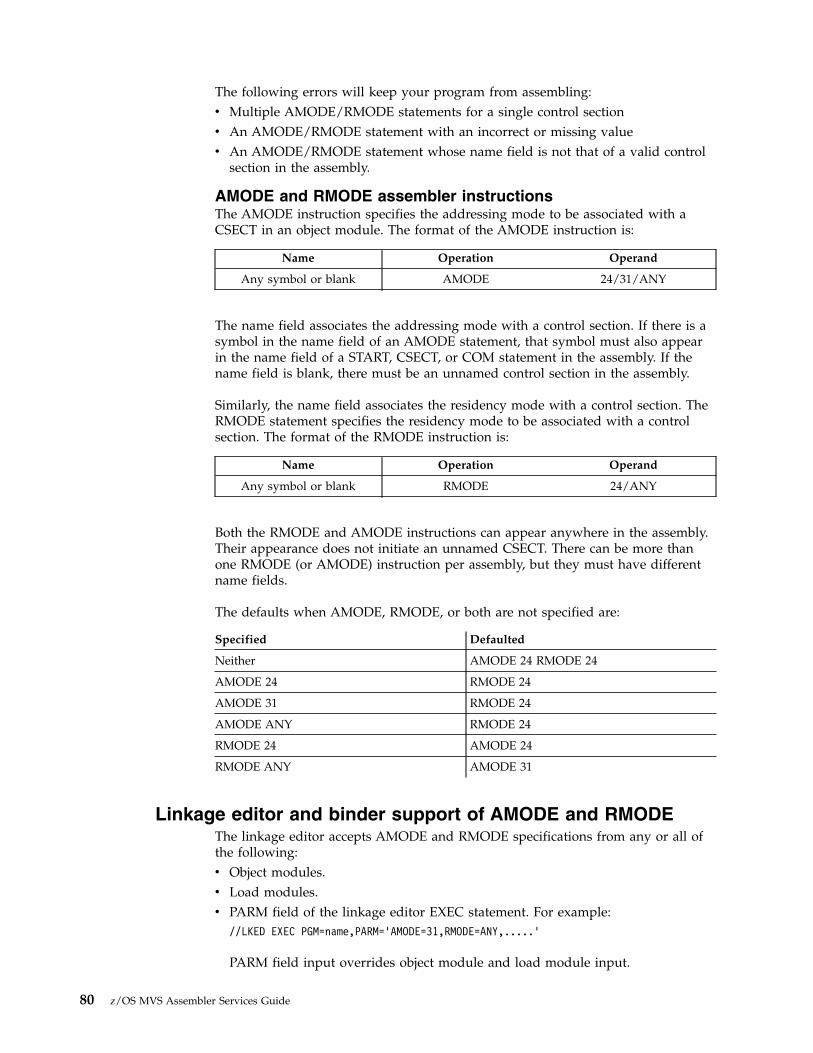
The following errors will keep your program from assembling:v Multiple AMODE/RMODE statements for a single control sectionv An AMODE/RMODE statement with an incorrect or missing valuev An AMODE/RMODE statement whose name field is not that of a valid control
section in the assembly.
AMODE and RMODE assembler instructionsThe AMODE instruction specifies the addressing mode to be associated with aCSECT in an object module. The format of the AMODE instruction is:
Name Operation Operand
Any symbol or blank AMODE 24/31/ANY
The name field associates the addressing mode with a control section. If there is asymbol in the name field of an AMODE statement, that symbol must also appearin the name field of a START, CSECT, or COM statement in the assembly. If thename field is blank, there must be an unnamed control section in the assembly.
Similarly, the name field associates the residency mode with a control section. TheRMODE statement specifies the residency mode to be associated with a controlsection. The format of the RMODE instruction is:
Name Operation Operand
Any symbol or blank RMODE 24/ANY
Both the RMODE and AMODE instructions can appear anywhere in the assembly.Their appearance does not initiate an unnamed CSECT. There can be more thanone RMODE (or AMODE) instruction per assembly, but they must have differentname fields.
The defaults when AMODE, RMODE, or both are not specified are:
Specified Defaulted
Neither AMODE 24 RMODE 24
AMODE 24 RMODE 24
AMODE 31 RMODE 24
AMODE ANY RMODE 24
RMODE 24 AMODE 24
RMODE ANY AMODE 31
Linkage editor and binder support of AMODE and RMODEThe linkage editor accepts AMODE and RMODE specifications from any or all ofthe following:v Object modules.v Load modules.v PARM field of the linkage editor EXEC statement. For example:
//LKED EXEC PGM=name,PARM=’AMODE=31,RMODE=ANY,.....’
PARM field input overrides object module and load module input.
80 z/OS MVS Assembler Services Guide

v Linkage editor MODE control statements in the SYSLIN data set. For example:MODE AMODE(31),RMODE(24)
MODE control statement input overrides object module, load module and PARMinput.
Linkage editor processing results in two sets of AMODE and RMODE indicatorslocated in:v The load modulev The PDS entry for the member name and any PDS entries for alternate names or
alternate entry points that were constructed using the linkage editor ALIAScontrol statement.
These two sets of indicators might differ because they can be created from differentinput. The linkage editor creates indicators in the load module based on inputfrom the input object module and load module. The linkage editor createsindicators in the PDS directory based not only on input from the object moduleand load module but also on the PARM field of the linkage editor EXEC statement,and the MODE control statements in the SYSLIN data set. The last two sources ofinput override indicators from the object module and load module. Figure 32 onpage 82 shows linkage editor processing of AMODE and RMODE.
Chapter 5. Understanding 31-bit addressing 81

The linkage editor and binder use default values of AMODE 24 and RMODE 24for:v Object modules produced by assemblers older than Assembler H Version 2 and
High Level Assemblerv Object modules produced by Assembler H Version 2 or High Level Assembler
where source statements did not specify AMODE or RMODEv Load modules produced by linkage editors older than the MVS/XA linkage
editorv Load modules produced by the linkage editor that did not have AMODE or
RMODE specified from any input sourcev Load modules in overlay structure
Assemble Input Linkage Editor Input
For each CSECT,AMODE/RMODEspecified byassembler statementsor defaulted to24/24
Assembler
Optional AMODE/RMODE PARMvalues from JCLEXEC statementand/or MODEcontrol statement.
Linkage Editor Processing
Object module -contains AMODE/RMODE.
Processes optional PARM valuesand/or MODE control statementsthat override object module andload module values. PutsAMODE/RMODE in the PDS.
ProcessesAMODE/RMODEvalues from object moduleand load module. PutsAMODE/RMODE into outputload module. (The linkageeditor does not useAMODE/RMODE values fromthe PDS.)
System obtains AMODE and RMODEfrom PDS.
Contains AMODE/RMODE of eachexecutable control section andnamed common control second(derived from object module andload module input values.)
PDS contains AMODE/RMODEvalue from object module orload module or from overridingPARM values or MODE controlstatements.
PARM values or MODE controlstatements.
Load Module:
Figure 32. AMODE and RMODE Processing by the Linkage Editor
82 z/OS MVS Assembler Services Guide

Treat programs in overlay structure as AMODE 24, RMODE 24 programs. Putting aprogram into overlay structure destroys any AMODE and RMODE specificationscontained in the load module.
The linkage editor recognizes as valid the following combinations of AMODE andRMODE:
AMODE 24RMODE 24
AMODE 31RMODE 24
AMODE 31RMODE ANY
AMODE ANYRMODE 24
AMODE ANYRMODE ANY
The linkage editor accepts the ANY/ANY combination from the object module orload module and places AMODE 31, RMODE ANY into the PDS (unlessoverridden by PARM values or MODE control statements). The linkage editor doesnot accept ANY/ANY from the PARM value or MODE control statement.
Any AMODE value specified alone in the PARM field or MODE control statementimplies an RMODE of 24. Likewise, an RMODE of ANY specified alone implies anAMODE of 31. However, for RMODE 24 specified alone, the linkage editor doesnot assume an AMODE value. Instead, it uses the AMODE value specified in theCSECT in generating the entry or entries in the PDS.
When the linkage editor creates an overlay structure, it assigns AMODE 24,RMODE 24 to the resulting program.
Linkage editor RMODE processingIn constructing a load module, the linkage editor frequently is requested tocombine multiple CSECTs, or it may process an existing load module as input,combining it with additional CSECTs or performing a CSECT replacement.
The linkage editor determines the RMODE of each CSECT. If the RMODEs are allthe same, the linkage editor assigns that RMODE to the load module. If theRMODEs are not the same (ignoring the RMODE specification on commonsections), the more restrictive value, RMODE 24, is chosen as the load module'sRMODE.
The RMODE chosen can be overridden by the RMODE specified in the PARM fieldof the linkage editor EXEC statement. Likewise, the PARM field RMODE can beoverridden by the RMODE value specified on the linkage editor MODE controlstatement.
The linkage editor does not alter the RMODE values obtained from the objectmodule or load module when constructing the new load module. Any choice thatthe linkage editor makes or any override processing that it performs affects onlythe PDS.
Chapter 5. Understanding 31-bit addressing 83

Loader support for AMODE and RMODEThe loader's processing of AMODE and RMODE is similar to the linkage editor's.The loader accepts AMODE and RMODE specifications from:v Object modulesv Load modulesv PARM field of the JCL EXEC statement
Unlike the linkage editor, the loader does not accept MODE control statementsfrom the SYSLIN data set, but it does base its loading sequence on the sequence ofitems in SYSLIN.
The loader passes the AMODE value to MVS. The loader processes the RMODEvalue as follows. If the user specifies an RMODE value in the PARM field, thatvalue overrides any previous RMODE value. Using the value of the first RMODEit finds in the first object module or load module it encounters that is not for acommon section, the loader obtains virtual storage for its output. As the loadingprocess continues, the loader may encounter a more restrictive RMODE value. If,for example, the loader begins loading based on an RMODE ANY indicator andlater finds an RMODE 24 indicator in a section other than a common section, itissues a message and starts over based on the more restrictive RMODE value.Figure 33 shows loader processing of AMODE and RMODE.
Loader Input
For each CSECT,AMODE/RMODEspecified byassemblerstatements ordefaulted to 24/24.
Assembler HVersion 2
Optional AMODE/RMODE PARMvalues from JCLEXEC statement.
Load Module:
Loader Processing
Object module -contains AMODE/RMODE.
Contains AMODE/RMODEof each CSECT (derivedfrom object module or loadmodule input values.)
PDS information is notused.
Processes object module andload module AMODE/RMODEvalues.
Processes optional AMODE/RMODE PARM values thatoverride object moduleand load module values.
Loader constructs program in virtualstorage with AMODE/RMODE from objectmodule, load module, or overridingPARM values.
Assembler Input
Figure 33. AMODE and RMODE Processing by the Loader
84 z/OS MVS Assembler Services Guide

System support of AMODE and RMODEThe following are examples of system support of AMODE and RMODE:v The system obtains storage for the module as indicated by RMODE.v ATTACH, ATTACHX, LINK, LINKX, XCTL, and XCTLX give the invoked
module control in the addressing mode specified by its AMODE.v LOAD brings a module into storage based on its RMODE and sets bit 0 in
register 0 to indicate its AMODE.v CALL passes control in the AMODE of the caller.v SYNCH or SYNCHX has an AMODE parameter that you can use to specify the
AMODE of the invoked module.v For SVCs, the system saves and sets the addressing mode.v SRBs are dispatched in the addressing mode indicated by the SRB specified to
the SCHEDULE macro.v The cross memory instructions PC and PT establish the addressing mode for the
target program.v Access methods support all valid combinations of AMODE and RMODE with
these exceptions:– AMODE 64 and RMODE 64 are not supported unless otherwise documented
for the interface.– Some devices such as unit record devices and TSO terminals have
documented restrictions.v Dumping is based on the AMODE specified in the error-related PSW.
Program FetchThe system uses RMODE information from the PDS to determine whether toobtain storage above or below 16 megabytes.
ATTACH, ATTACHX, LINK, LINKX, XCTL, and XCTLXIssuing an ATTACH or ATTACHX macro causes the control program to createa new task and indicates the entry point to be given control when the new taskbecomes active. If the entry point is a member name or an alias in the PDS.ATTACH or ATTACHX gives it control in the addressing mode specified in thePDS or in the mode specified by the loader. If the invoked program has theAMODE ANY attribute, it gets control in the AMODE of its caller.
The LINK, LINKX, XCTL, and XCTLX macros also give the invoked programcontrol in the addressing mode indicated by its PDS for programs brought inby fetch or in the AMODE specified by the loader. The entry point specifiedmust be a member name or an alias in the PDS passed by the loader, orspecified in an IDENTIFY macro. If the entry point is an entry name specifiedin an IDENTIFY macro, IDENTIFY sets the addressing mode of the entry nameequal to the addressing mode of the main entry point.
LOADIssuing the LOAD macro causes MVS to bring the load module containing thespecified entry point name into virtual storage (if a usable copy is not alreadythere). LOAD sets the high-order bit of the entry point address in register 0 toindicate the module's AMODE (0 for 24, 1 for 31), which LOAD obtains fromthe module's PDS entry. If the module's AMODE is ANY, LOAD sets thehigh-order bit in register 0 to correspond to the caller's AMODE.
Chapter 5. Understanding 31-bit addressing 85

LOAD places the module in virtual storage either above or below 16megabytes as indicated by the module's RMODE, which is specified in the PDSfor the module.
Specifying the ADDR parameter indicates that you want the module loaded ata particular location. If you specify an address above 16 megabytes, be surethat the module being loaded has the RMODE ANY attribute. If you do notknow the AMODE and RMODE attributes of the module, specify an addressbelow 16 megabytes or omit the ADDR parameter.
CALLThe CALL macro passes control to an entry point via BALR. Thus control istransferred in the AMODE of the caller. CALL does not change AMODE.
SYNCH or SYNCHXUsing the AMODE parameter on the SYNCH or SYNCHX macro, you canspecify the addressing mode in which the invoked module is to get control.Otherwise, SYNCH or SYNCHX passes control in the caller's addressing mode.
SVCFor SVCs (supervisor calls), the system saves and restores the issuer'saddressing mode and makes sure that the invoked service gets control in thespecified addressing mode.
SRBWhen an SRB (service request block) is dispatched, the system sets theaddressing mode based on the high-order bit of the SRBEP field. This bit, setby the issuer of the SCHEDULE macro, indicates the addressing mode of theroutine operating under the dispatched SRB.
PC and PTFor a program call (PC), the entry table indicates the target program'saddressing mode. The address field in the entry table must be initialized bysetting the high-order bit to 0 for 24-bit addressing mode or to 1 for 31-bitaddressing mode.
The PC instruction sets up register 14 with the return address and AMODE foruse with the PT (program transfer) instruction. If PT is not preceded by a PCinstruction, the PT issuer must set the high-order bit of the second operandregister to indicate the AMODE of the program being entered (0 for 24-bitaddressing mode or 1 for 31-bit addressing mode).
Data Management Access MethodsUser programs can be in AMODE 24 or AMODE 31 when invoking accessmethods except with certain devices. The non-VSAM access methods requirecertain parameter lists, control blocks and user exit routines to reside in virtualstorage below 16 megabytes. Some interfaces support only AMODE 24 andsome support AMODE 64. See z/OS DFSMS Using Data Sets and z/OS DFSMSMacro Instructions for Data Sets.
AMODE's Effect on DumpsThe only time AMODE has an effect on dumps is when data on either side ofthe address in each register is dumped. If the addresses in registers are treatedas 24-bit addresses, the data dumped may come from a different storagelocation than when the addresses are treated as 31-bit addresses. If a dumpoccurs shortly after an addressing mode switch, some registers may contain31-bit addresses and some may contain 24 bit addresses, but dumping servicesdoes not distinguish among them. Dumping services uses the AMODE from
86 z/OS MVS Assembler Services Guide

the error-related PSW. For example, in dumping the area related to theregisters saved in the SDWA, dumping services uses the AMODE from theerror PSW stored in the SDWA.
How to change addressing modeTo change addressing mode you must change the value of the PSW A-mode bit.The following list includes all the ways to change addressing mode.v The mode setting instructions BASSM and BSM.v Macros (ATTACH, ATTACHX, LINK, LINKX, XCTL, or XCTLX). The system
makes sure that routines get control in the specified addressing mode. Usersneed only ensure that parameter requirements are met. MVS restores theinvoker's mode on return from LINK or LINKX.
v SVCs. The supervisor saves and restores the issuer's addressing mode andensures that the service routine receives control in the addressing mode specifiedin its SVC table entry.
v SYNCH or SYNCHX with the AMODE parameter to specify the addressingmode in which the invoked routine is to get control.
v The CIRB macro and the stage 2 exit effector. The CIRB macro is described inz/OS MVS Programming: Authorized Assembler Services Guide and z/OS MVSProgramming: Authorized Assembler Services Reference ALE-DYN.
v A PC, PT, or PR instruction. These three instructions establish the specifiedaddressing mode.
v An LPSW instruction (not recommended).
The example in Figure 34 illustrates how a change in addressing mode in a 24-bitaddressing mode program enables the program to retrieve data from the ACTLBcontrol block, which might reside above 16 megabytes. The example workscorrectly whether or not the control block is actually above 16 megabytes. Theexample uses the BSM instruction to change addressing mode. In the example, theinstruction L 2,4(,15) must be executed in 31-bit addressing mode. Mode settingcode (BSM) before the instruction establishes 31-bit addressing mode and codefollowing the instruction establishes 24-bit addressing mode.
Establishing linkageThis information describes the mechanics of correct linkage in 31-bit addressingmode. Keep in mind that there are considerations other than linkage, such aslocations of areas that both the calling module and the invoked module need toaddress.
USER CSECTUSER RMODE 24USER AMODE 24
L 15,ACTLBL 1,LABEL1 SET HIGH-ORDER BIT OF REGISTER 1 TO 1
AND PUT ADDRESS INTO BITS 1-31BSM 0,1 SET AMODE 31 (DOES NOT PRESERVE AMODE)
LABEL1 DC A(LABEL2 + X’80000000’)LABEL2 DS 0H
L 2,4(,15) OBTAIN DATA FROM ABOVE 16 MEGABYTESLA 1,LABEL3 SET HIGH-ORDER BIT OF REGISTER 1 TO 0
AND PUT ADDRESS INTO BITS 1-31BSM 0,1 SET AMODE 24 (DOES NOT PRESERVE AMODE)
LABEL3 DS 0H
Figure 34. Mode Switching to Retrieve Data from Above 16 Megabytes
Chapter 5. Understanding 31-bit addressing 87

As shown in Figure 35 on page 89, it is the linkage between modules whoseaddressing modes are different that is an area of concern. The areas of concern thatappear in Figure 35 on page 89 fall into two basic categories:v Addresses passed as parameters from one routine to another must be addresses
that both routines can use.– High-order bytes of addresses must contain zeroes or data that the receiving
routine is programmed to expect.– Addresses must be less than 16 megabytes if they could be passed to a 24-bit
addressing mode program.v On transfers of control between programs with different AMODEs, the receiving
routine must get control in the AMODE it needs and return control to the callingroutine in the AMODE the calling routine needs.
There are a number of ways of dealing with the areas of concern that appear inFigure 35 on page 89:v Use the branching instructions (BASSM and BSM)v Use pointer-defined linkagev Use supervisor-assisted linkage (ATTACH, ATTACHX, LINK, LINKX, XCTL, and
XCTLX)v Use linkage assist routinesv Use “capping.”
88 z/OS MVS Assembler Services Guide

Using the BASSM and BSM instructionsThe BASSM (branch and save and set mode) and the BSM (branch and set mode)instructions are branching instructions that set the addressing mode. They aredesigned to complement each other. (BASSM is used to call and BSM is used toreturn, but they are not limited to such use.)
AMODE 31
AMODE 31 AMODE 31
AMODE 31
AMODE 31 AMODE 31
AMODE 24
AMODE 24 AMODE 24
AMODE 24
ok
16 megabytes ok
Possibleof
AreaConcern
Definiteof
AreaConcern
Possibleof
AreaConcern
ok
ok
1.
2.
3.
4.
4 1 2
3
4
When an AMODE 31 module that resides above 16 megabytes invokes an AMODE 24 module, the concerns are:
The AMODE 24 program needs to receive control 24-bit mode.
The location of shared data (including control blocks, register save areas, and parameters). Can the AMODE 24module address the data?
The AMODE 24 module cannot return control unless an addressing mode change occurs.
An AMODE 24 module cannot invoke an AMODE 31 module that resides above the line unless the AMODE 24module changes its addressing mode either directly or using supervisor-assisted linkage.
When both modules are below 16 megabytes the concerns are:
Which module cleans out bits 1-7 of the high-order bytes of 24-bit values used as addresses?
Can both modules address shared data?
While there are no restrictions on the mechanics of linkage between two AMODE 31 modules, there might berestrictions on parameter values.
Figure 35. Linkage Between Modules with Different AMODEs and RMODEs
Chapter 5. Understanding 31-bit addressing 89
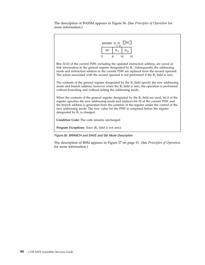
The description of BASSM appears in Figure 36. (See Principles of Operation formore information.)
The description of BSM appears in Figure 37 on page 91. (See Principles of Operationfor more information.)
R ,R1 2
BASSM RR
'0C' R R1 2
0 8 12 15
Bits 32-63 of the current PSW, including the updated instruction address, are saved aslink information in the general register designated by R1. Subsequently, the addressingmode and instruction address in the current PSW are replaced from the second operand.The action associated with the second operand is not performed if the R2 field is zero.
The contents of the general register designated by the R2 field specify the new addressingmode and branch address; however when the R2 field is zero, the operation is performedwithout branching and without setting the addressing mode.
When the contents of the general register designated by the R2 field are used, bit 0 of theregister specifies the new addressing mode and replaces bit 32 of the current PSW, andthe branch address is generated from the contents of the register under the control of thenew addressing mode. The new value for the PSW is computed before the registerdesignated by R1 is changed.
Condition Code: The code remains unchanged.
Program Exceptions: Trace (R2 field is not zero).
Figure 36. BRANCH and SAVE and Set Mode Description
90 z/OS MVS Assembler Services Guide
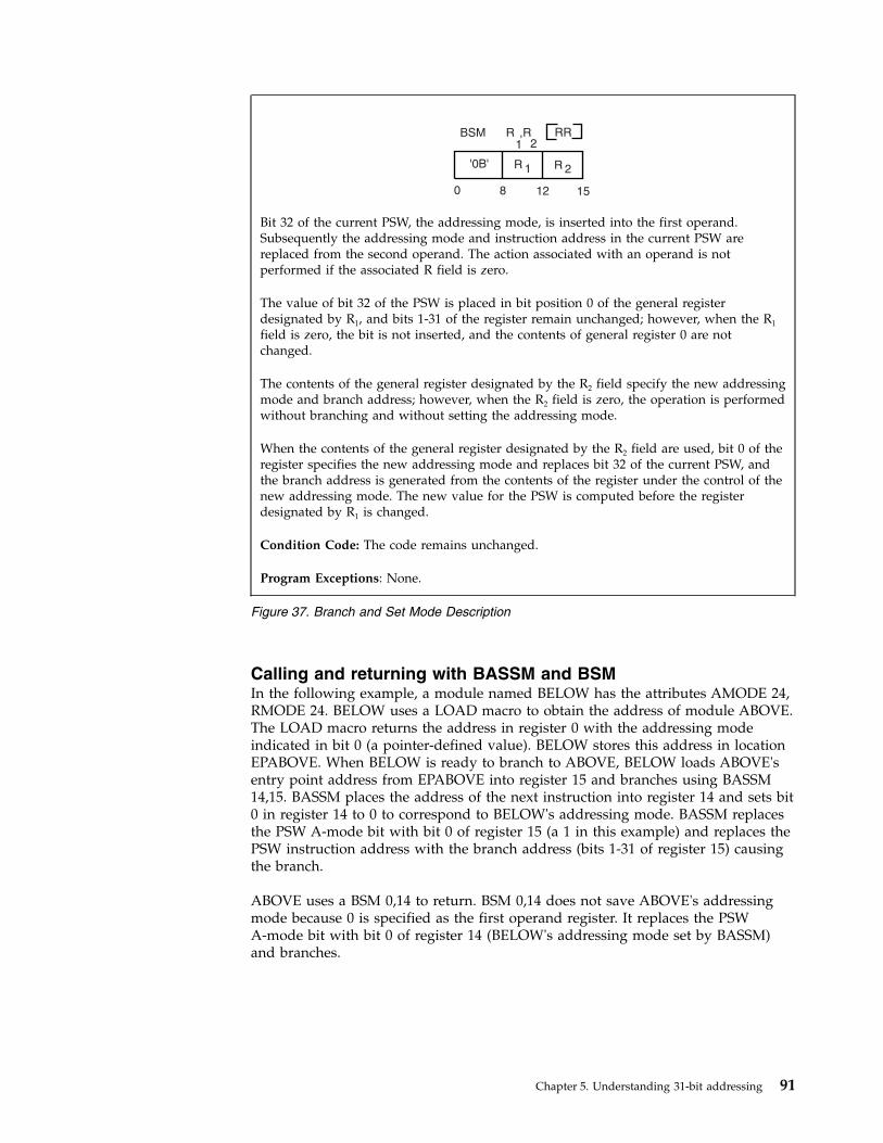
Calling and returning with BASSM and BSMIn the following example, a module named BELOW has the attributes AMODE 24,RMODE 24. BELOW uses a LOAD macro to obtain the address of module ABOVE.The LOAD macro returns the address in register 0 with the addressing modeindicated in bit 0 (a pointer-defined value). BELOW stores this address in locationEPABOVE. When BELOW is ready to branch to ABOVE, BELOW loads ABOVE'sentry point address from EPABOVE into register 15 and branches using BASSM14,15. BASSM places the address of the next instruction into register 14 and sets bit0 in register 14 to 0 to correspond to BELOW's addressing mode. BASSM replacesthe PSW A-mode bit with bit 0 of register 15 (a 1 in this example) and replaces thePSW instruction address with the branch address (bits 1-31 of register 15) causingthe branch.
ABOVE uses a BSM 0,14 to return. BSM 0,14 does not save ABOVE's addressingmode because 0 is specified as the first operand register. It replaces the PSWA-mode bit with bit 0 of register 14 (BELOW's addressing mode set by BASSM)and branches.
R ,R1 2
RR
R R1 2
0 8 12 15
BSM
'0B'
Bit 32 of the current PSW, the addressing mode, is inserted into the first operand.Subsequently the addressing mode and instruction address in the current PSW arereplaced from the second operand. The action associated with an operand is notperformed if the associated R field is zero.
The value of bit 32 of the PSW is placed in bit position 0 of the general registerdesignated by R1, and bits 1-31 of the register remain unchanged; however, when the R1
field is zero, the bit is not inserted, and the contents of general register 0 are notchanged.
The contents of the general register designated by the R2 field specify the new addressingmode and branch address; however, when the R2 field is zero, the operation is performedwithout branching and without setting the addressing mode.
When the contents of the general register designated by the R2 field are used, bit 0 of theregister specifies the new addressing mode and replaces bit 32 of the current PSW, andthe branch address is generated from the contents of the register under the control of thenew addressing mode. The new value for the PSW is computed before the registerdesignated by R1 is changed.
Condition Code: The code remains unchanged.
Program Exceptions: None.
Figure 37. Branch and Set Mode Description
Chapter 5. Understanding 31-bit addressing 91
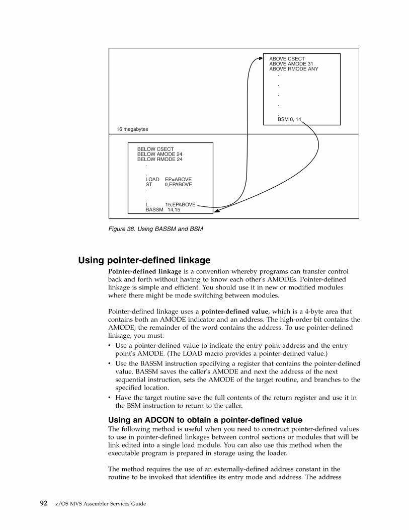
Using pointer-defined linkagePointer-defined linkage is a convention whereby programs can transfer controlback and forth without having to know each other's AMODEs. Pointer-definedlinkage is simple and efficient. You should use it in new or modified moduleswhere there might be mode switching between modules.
Pointer-defined linkage uses a pointer-defined value, which is a 4-byte area thatcontains both an AMODE indicator and an address. The high-order bit contains theAMODE; the remainder of the word contains the address. To use pointer-definedlinkage, you must:v Use a pointer-defined value to indicate the entry point address and the entry
point's AMODE. (The LOAD macro provides a pointer-defined value.)v Use the BASSM instruction specifying a register that contains the pointer-defined
value. BASSM saves the caller's AMODE and next the address of the nextsequential instruction, sets the AMODE of the target routine, and branches to thespecified location.
v Have the target routine save the full contents of the return register and use it inthe BSM instruction to return to the caller.
Using an ADCON to obtain a pointer-defined valueThe following method is useful when you need to construct pointer-defined valuesto use in pointer-defined linkages between control sections or modules that will belink edited into a single load module. You can also use this method when theexecutable program is prepared in storage using the loader.
The method requires the use of an externally-defined address constant in theroutine to be invoked that identifies its entry mode and address. The address
16 megabytes
ABOVE CSECTABOVE AMODE 31ABOVE RMODE ANY
.
.
.
.
.BSM 0, 14
BELOW CSECTBELOW AMODE 24BELOW RMODE 24
.
.LOAD EP=ABOVEST 0,EPABOVE.
.L 15,EPABOVEBASSM 14,15
Figure 38. Using BASSM and BSM
92 z/OS MVS Assembler Services Guide

constant must contain a pointer-defined value. The calling program loads thepointer-defined value and uses it in a BASSM instruction. The invoked routinereturns using a BSM instruction.
In Figure 39 on page 94, RTN1 obtains pointer-defined values from RTN2 andRTN3. RTN1, the invoking routine does not have to know the addressing modes ofRTN2 and RTN3. Later, RTN2 or RTN3 could be changed to use differentaddressing modes, and at that time their address constants would be changed tocorrespond to their new addressing mode. RTN1, however, would not have tochange the sequence of code it uses to invoke RTN2 and RTN3.
You can use the techniques that the previous example illustrates to handle routinesthat have multiple entry points (possibly with different AMODE attributes). Youneed to construct a table of address constants, one for each entry point to behandled.
As with all forms of linkage, there are considerations in addition to the linkagemechanism. These include:v Both routines must have addressability to any parameters passed.v Both routines must agree which of them will clean up any 24-bit addresses that
might have extraneous information bits 1-7 of the high-order byte. (This is aconsideration only for AMODE 31 programs.)
When a 24-bit addressing mode program invokes a module that is to execute in31-bit addressing mode, the calling program must ensure that register 13 contains avalid 31-bit address of the register save area with no extraneous data in bits 1-7 ofthe high-order byte. In addition, when any program invokes a 24-bit addressingmode program, register 13 must point to a register save area located below 16megabytes.
Chapter 5. Understanding 31-bit addressing 93

Using the LOAD macro to obtain a pointer-defined valueLOAD returns a pointer-defined value in register 0. You can preserve thispointer-defined value and use it with a BASSM instruction to pass control withouthaving to know the target routine's AMODE.
Using supervisor-assisted linkageFigure 40 on page 95 shows a “before” and “after” situation involving twomodules, MOD1 and MOD2. In the BEFORE part of the figure both modulesexecute in 24-bit addressing mode. MOD1 invokes MOD2 using the LINK orLINKX macro. The AFTER part of the figure shows MOD2 moving above 16megabytes and outlines the steps that were necessary to make sure both modulescontinue to perform their previous function.
RTN1 CSECTEXTRN RTN2ADEXTRN RTN3AD..L 15,=A(RTN2AD) LOAD ADDRESS OF POINTER-DEFINED VALUEL 15,0(,15) LOAD POINTER-DEFINED VALUEBASSM 14,15 GO TO RTN2 VIA BASSM..L 15,=A(RTN3AD) LOAD ADDRESS OF POINTER-DEFINED VALUEL 15,0(,15) LOAD POINTER DEFINED-VALUEBASSM 14,15 GO TO RTN3 VIA BASSM.
__________________________________________________________________RTN2 CSECTRTN2 AMODE 24
ENTRY RTN2AD.BSM 0,14 RETURN TO CALLER IN CALLER’S MODE
RTN2AD DC A(RTN2) WHEN USED AS A POINTER-DEFINED VALUE,INDICATES AMODE 24 BECAUSE BIT 0 IS 0
__________________________________________________________________RTN3 CSECTRTN3 AMODE 31
ENTRY RTN3AD.BSM 0,14 RETURN TO CALLER IN CALLER’S MODE
RTN3AD DC A(X’80000000’+RTN3) WHEN USED AS A POINTER-DEFINED VALUEINDICATES AMODE 31 BECAUSE BIT 0 IS 1
Figure 39. Example of Pointer-Defined Linkage
94 z/OS MVS Assembler Services Guide

Linkage assist routinesA linkage assist routine, sometimes called an addressing mode interface routine, isa module that performs linkage for modules executing in different addressing or
BEFORE
MOD1 CSECT
LINK EP=MOD2
AFTER MOD2 moves above 16 megabytes.
MOD2 CSECT
MOD2 AMODE 31
MOD2 RMODE ANY
line
4.
3.
2.
1.
5.
MOD1 CSECT
LINK EP=MOD2
AMODE 24
RMODE 24by default
MOD1 links to MOD2. Both MOD1 and MOD2 reside below 16 megabytes and have theattributes AMODE 24, RMODE 24 by default.
MOD2 CSECT
When MOD2 moves above 16 megabytes, you must make sure it will executecorrectly. Specifically, you must:
Review any mode-sensitive instructions to be sure they perform as intended inAMODE 31, RMODE ANY.
Review system services used to be sure they can be invoked in AMODE 31,RMODE ANY and make the any necessary changed. (For example, change SPIEto ESPIE). Review the Conversion Notebook chapters on incompatibilities,coexistence considerations, and programming considerations. Move any servicesthat do not permit callers to be in 31-bit mode to modules residing below 16megabytes.
Make sure all parameters and control blocks needed by MOD1 reside below 16megabytes.
Make sure all addresses passed by MOD1 have high-order bytes that are free ofextraneous data or code MOD2 to clean up the high-order bytes to any addressshared with MOD1.
Make sure that all fields containing addresses of areas above 16 megabytes arefullword fields.
16 megabytes
LINK or LINKX handles the mode switching between MOD1 and MOD2 asfollows:
1. LINK or LINKX obtains MOD2's AMODE from the PDS directory entry.2. LINK or LINKX ensures that MOD2 is entered in the specified AMODE.3. On completion, LINK or LINKX restores MOD1's AMODE by default and
returns control.
Figure 40. Example of Supervisor-Assisted Linkage
Chapter 5. Understanding 31-bit addressing 95

residency modes. Using a linkage assist routine, a 24-bit addressing mode modulecan invoke a 31-bit addressing mode module without having to make any changes.The invocation results in an entry to a linkage assist routine that resides below 16megabytes and invokes the 31-bit addressing mode module in the specifiedaddressing mode.
Conversely, a 31-bit addressing mode module, such as a new user module, can usea linkage assist routine to communicate with other user modules that execute in24-bit addressing mode. The caller appears to be making a direct branch to thetarget module, but branches instead to a linkage assist routine that changes modesand performs the branch to the target routine.
The main advantage of using a linkage assist routine is to insulate a module fromaddressing mode changes that are occurring around it.
The main disadvantage of using a linkage assist routine is that it adds overhead tothe interface. In addition, it takes time to develop and test the linkage assistroutine. Some alternatives to using linkage assist routines are:v Changing the modules to use pointer-defined linkage (described in “Using
pointer-defined linkage” on page 92).v Adding a prologue and epilogue to a module to handle entry and exit mode
switching, as described later in this chapter under “Capping.”
Example of using a linkage assist routineFigure 41 on page 97 shows a “before” and “after” situation involving modulesUSER1 and USER2. USER1 invokes USER2 by using a LOAD and BALR sequence.The “before” part of the figure shows USER1 and USER2 residing below 16megabytes and lists the changes necessary if USER2 moves above 16 megabytes.USER1 does not change.
The “after” part of the figure shows how things look after USER2 moves above 16megabytes. Note that USER2 is now called USER3 and the newly created linkageassist routine has taken the name USER2.
The figure continues with a coding example that shows all three routines after themove.
96 z/OS MVS Assembler Services Guide

USER1 (This module will not change):* USER MODULE USER1 CALLS MODULE USER2 00000100USER1 CSECT 00000200BEGIN SAVE (14,12),,* (SAVE REGISTER CONTENT, ETC.) 00000300
BEFORE
Existing Application - USER1 invokes USER2 repeatedly
USER1 USER2
LOAD EP=USER2
BALRRETURN
AFTER
Changed Application
USER1 USER2 (NEW)
USER2 CSECTUSER2 AMODE 24USER2 RMODE 24LOAD USER3
BASSMBSM TONEXTSEQUENTIALINSTRUCTION
RETURN
USER3 (formerly USER2)
USER3 CSECTUSER3 AMODE 31USER3 RMODE ANY
RETURN
Change Reason
USER1 CSECTLOAD EP=USER2
BALR
Change name of USER2 TO USER3.
Write a linkage assist routine called USER2.
Change USER3 (formerly USER2) as follows:
- Make sure all control blocks and parameters neededby USER1 and USER2 are located below16 megabytes line.
- Check mode-sensitive instructions to be sure theyperform the intended function in AMODE 31,REMODE ANY.
- Check system services used to be sure they can beinvoked in AMODE 31, RMODE ANY and make anynecessary changes. (For example, change SPIE toESPIE.) Review the Conversion Notebook chapterson incompatibilities, coexistence considerations, andprogramming considerations.
- Make sure that all fields containing addressesof areas above 16 megabytes are fullword fields.
USER1 does not have to change the LOADUSER2 macro.
USER1 remains unchanged; new USER2 switchesAMODEs and branches to USER3 (the formerUSER).
- USER1 and USER2 are AMODE 24; they cannotaccess parameters or data above 16 megabytes.
- USER3 was moved above 16 megabytes andhas the attributes AMODE 31, REMODE ANY.
- USER3 has the attributes AMODE 31, RMODEANY. SPIE and some other system services willnot work in AMODE 31.
Figure 41. Example of a Linkage Assist Routine
Chapter 5. Understanding 31-bit addressing 97

* ESTABLISH BASE REGISTER(S) AND NEW SAVE AREA (NORMAL 00000400* ENTRY CODING) 00000500
.
.* ISSUE LOAD FOR MODULE USER2 00000700
LOAD EP=USER2 ISSUE LOAD FOR MODULE "USER2" 00000800* The LOAD macro returns a* pointer-defined value. However, because module USER1* has not been changed and executes in AMODE 24, the* pointer-defined value has no effect on the BALR* instruction used to branch to module USER2.
ST 0,EPUSER2 PRESERVE ENTRY POINT 00000900.
* MAIN PROCESS BEGINS 00001000PROCESS DS 0H 00001100
.
.
.
.
.
.* PREPARE TO GO TO MODULE USER2 00002000
L 15,EPUSER2 LOAD ENTRY POINT 00002100BALR 14,15 00002200....
TM TEST FOR END 00003000BC PROCESS CONTINUE IN LOOP 00003100.
DELETE EP=USER2L 13,4(13)RETURN (14,12),T,RC=0 MODULE USER1 COMPLETED 00005000
EPUSER2 DC F’0’ ADDRESS OF ENTRY POINT TO USER2 00007000END BEGIN 00007100
USER2 (Original application module):* USER MODULE USER2 (INVOKED FREQUENTLY FROM USER1) 00000100USER2 CSECT 00000200
SAVE (14,12),,* SAVE REGISTER CONTENT, ETC. 00000300* ESTABLISH BASE REGISTER(S) AND NEW SAVE AREA (NORMAL 00000400* ENTRY CODING)
.
.
.
.
.L 13,4(13)RETURN (14,12),T,RC=0 MODULE USER2 COMPLETED 00008100END 00008200
USER2 (New linkage assist routine):* THIS IS A NEW LINKAGE ASSIST ROUTINE 0000100* (IT WAS NAMED USER2 SO THAT MODULE USER1 WOULD NOT 0000200* HAVE TO BE CHANGED) 0000300USER2 CSECT 0000400USER2 AMODE 24 0000500USER2 RMODE 24 0000600
SAVE (14,12),,* (SAVE REGISTER CONTENT, ETC.) 0000700* ESTABLISH BASE REGISTER(S) AND NEW SAVE AREA (NORMAL 0000800* ENTRY CODING)
.* FIRST TIME LOGIC, PERFORMED ON INITIAL ENTRY ONLY, 0002000* (AFTER INITIAL ENTRY, BRANCH TO PROCESS (SHOWN BELOW)) 0002100
.
98 z/OS MVS Assembler Services Guide

GETMAIN NEW REGISTER SAVE AREA 0003000.
LOAD EP=USER3 0004000* USER2 LOADS USER3 BUT DOES NOT DELETE IT. USER2 CANNOT* DELETE USER3 BECAUSE USER2 DOES NOT KNOW WHICH OF ITS USES* OF USER3 IS THE LAST ONE.
ST 0,EPUSER3 PRESERVE POINTER DEFINED VALUE 0004100.
* PROCESS (PREPARE FOR ENTRY TO PROCESSING MODULE) 0005000.
(FOR EXAMPLE, VALIDITY CHECK REGISTER CONTENTS)..
* PRESERVE AMODE FOR USE DURING RETURN SEQUENCE 0007000LA 1,XRETURN SET RETURN ADDRESS 0008000BSM 1,0 PRESERVE CURRENT AMODE 0008100ST 1,XSAVE PRESERVE ADDRESS 0008200L 15,EPUSER3 LOAD POINTER DEFINED VALUE 0009000
* GO TO MODULE USER3 0009100BASSM 14,15 TO PROCESSING MODULE 0009200
* RESTORE AMODE THAT WAS IN EFFECT 0009300L 1,XSAVE LOAD POINTER DEFINED VALUE 0009400BSM 0,1 SET ADDRESSING MODE 0009500
XRETURN DS 0H 0009600L 13,4(13).
RETURN (14,12),T,RC=0 MODULE USER2 HAS COMPLETED 0010000EPUSER3 DC F’0’ POINTER DEFINED VALUE 0010100XSAVE DC F’0’ ORIGINAL AMODE AT ENTRY 0010200
END 0010500_________________________________________________________________________
v Statements 8000 through 8200: These instructions preserve the AMODE in effectat the time of entry into module USER2.
v Statement 9200: This use of the BASSM instruction:– Causes the USER3 module to be entered in the specified AMODE (AMODE
31 in this example). This occurs because the LOAD macro returns apointer-defined value that contains the entry point of the loaded routine, andthe specified AMODE of the module.
– Puts a pointer-defined value for use as the return address into Register 14.v Statement 9400: Module USER3 returns to this point.v Statement 9500: Module USER2 re-establishes the AMODE that was in effect at
the time the BASSM instruction was issued (STATEMENT 9200).
USER3 (New application module):* MODULE USER3 (PERFORMS FUNCTIONS OF OLD MODULE USER2) 00000100USER3 CSECT 00000200USER3 AMODE 31 00000300USER3 RMODE ANY 00000400
SAVE (14,12),,* (SAVE REGISTER CONTENT, ETC.) 00000500* ESTABLISH BASE REGISTER(S) AND NEW SAVE AREA 00000600
.
.
.
.
.
.* RESTORE REGISTERS AND RETURN 00008000
.RETURN (14,12),T,RC=0 00008100END 00008200
_________________________________________________________________________
Chapter 5. Understanding 31-bit addressing 99
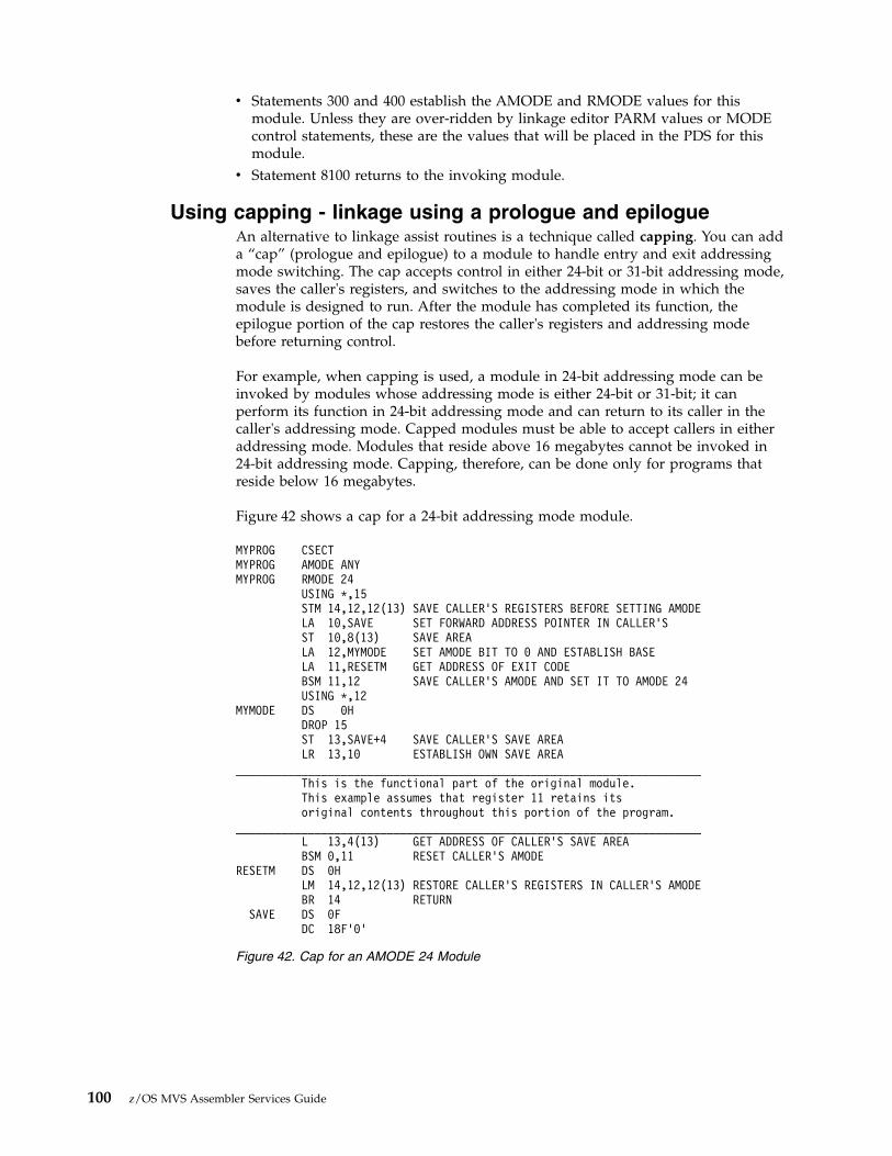
v Statements 300 and 400 establish the AMODE and RMODE values for thismodule. Unless they are over-ridden by linkage editor PARM values or MODEcontrol statements, these are the values that will be placed in the PDS for thismodule.
v Statement 8100 returns to the invoking module.
Using capping - linkage using a prologue and epilogueAn alternative to linkage assist routines is a technique called capping. You can adda “cap” (prologue and epilogue) to a module to handle entry and exit addressingmode switching. The cap accepts control in either 24-bit or 31-bit addressing mode,saves the caller's registers, and switches to the addressing mode in which themodule is designed to run. After the module has completed its function, theepilogue portion of the cap restores the caller's registers and addressing modebefore returning control.
For example, when capping is used, a module in 24-bit addressing mode can beinvoked by modules whose addressing mode is either 24-bit or 31-bit; it canperform its function in 24-bit addressing mode and can return to its caller in thecaller's addressing mode. Capped modules must be able to accept callers in eitheraddressing mode. Modules that reside above 16 megabytes cannot be invoked in24-bit addressing mode. Capping, therefore, can be done only for programs thatreside below 16 megabytes.
Figure 42 shows a cap for a 24-bit addressing mode module.
MYPROG CSECTMYPROG AMODE ANYMYPROG RMODE 24
USING *,15STM 14,12,12(13) SAVE CALLER’S REGISTERS BEFORE SETTING AMODELA 10,SAVE SET FORWARD ADDRESS POINTER IN CALLER’SST 10,8(13) SAVE AREALA 12,MYMODE SET AMODE BIT TO 0 AND ESTABLISH BASELA 11,RESETM GET ADDRESS OF EXIT CODEBSM 11,12 SAVE CALLER’S AMODE AND SET IT TO AMODE 24USING *,12
MYMODE DS 0HDROP 15ST 13,SAVE+4 SAVE CALLER’S SAVE AREALR 13,10 ESTABLISH OWN SAVE AREA
_______________________________________________________________________This is the functional part of the original module.This example assumes that register 11 retains itsoriginal contents throughout this portion of the program.
_______________________________________________________________________L 13,4(13) GET ADDRESS OF CALLER’S SAVE AREABSM 0,11 RESET CALLER’S AMODE
RESETM DS 0HLM 14,12,12(13) RESTORE CALLER’S REGISTERS IN CALLER’S AMODEBR 14 RETURN
SAVE DS 0FDC 18F’0’
Figure 42. Cap for an AMODE 24 Module
100 z/OS MVS Assembler Services Guide

Performing I/O in 31-bit addressing modePrograms in 31-bit addressing mode sometimes need to use 24-bit addressingmode programs to perform an I/O operation.
A 31-bit addressing mode program can perform an I/O operation by:v Using VSAM, QSAM, BSAM, BPAM and BDAM services that accept callers in
either 24-bit or 31-bit addressing mode. (z/OS DFSMS Using Data Sets describesthese services and shows examples. The functions that require 24-bit mode areISAM, some BDAM functions and BSAM and QSAM with a TSO terminal orIBM 3886 or 3890 Document Processor.)
v Using the EXCP macro. All parameter lists, control blocks, CCWs, virtualIDAWs, and EXCP appendage routines must reside in virtual storage below 16megabytes. See “Using the EXCP macro” for a description of using EXCP toperform I/O. CCWs can reside above the 16 MB line and virtual IDAWs canpoint above the 16 MB line or above the 2 GB bar.
v Using the EXCPVR macro. All parameter lists, control blocks, CCWs, IDALs(indirect data address lists), and appendage routines must reside in virtualstorage below 16 megabytes. See “Using EXCPVR” on page 102 for a descriptionof using EXCPVR to perform I/O. CCWs can reside above the 16 MB line andvirtual and real IDAWs can point above the 16 MB line or above the 2 GB bar.
v Invoking a routine that executes in 24-bit addressing mode as an interface to the24-bit access methods, which accept callers executing in 24-bit addressing modeonly. See “Establishing linkage” on page 87 for more information about thismethod.
v Using the method shown in Figure 43 on page 103.
Using the EXCP macroEXCP macro users can perform I/O to virtual storage areas above 16 megabytes.With the virtual IDAW support, CCWs in the EXCP channel program can use a24-bit address to point to a virtual IDAW that contains the 31-bit virtual address ofan I/O buffer. The CCWs and IDAWs themselves must reside in virtual storagebelow 16 megabytes. The EXCP service routine supports format 0 and format 1CCWs.
Any CCW that causes data to be transferred can point to a virtual IDAW. VirtualIDAW support is limited to non-VIO data sets.
Although the I/O buffer can be in virtual storage above 16 megabytes, the virtualIDAW that contains the pointer to the I/O buffer and all the other areas related tothe I/O operation (CCWs, IOBs, DEBs, and appendages) must reside in virtualstorage below 16 megabytes.
CCW (Format 0)
Address ofan IDAW
IDAW
Virtual address ofan I/O buffer
Chapter 5. Understanding 31-bit addressing 101

Note: EXCP can translate your virtual channel program to a real channel programthat uses 64-bit IDAWs if you are running in z/Architecture mode and the devicesupport code allows them.
For more EXCP information, see z/OS DFSMSdfp Advanced Services.
Using EXCPVRThe EXCPVR interface supports format 0 CCWs. Format 0 CCWs support only24-bit addresses. All CCWs and IDAWs used with EXCPVR must reside in virtualor central storage below 16 megabytes. The largest virtual or central storageaddress you can specify directly in your channel program is 16 megabytes minusone. However, using IDAWs (indirect data address words) you can specify anycentral storage address and therefore you can perform I/O to any location in realor virtual storage. EXCPVR channel programs must use IDAWs to specify bufferaddresses above 16 megabytes in central storage.
The format 0 CCW may contain the address of an IDAL (indirect address list),which is a list of IDAWs (indirect data address words).
You must assume that buffers obtained by data management access methods havereal storage addresses above 16 megabytes.
For more EXCPVR information, see z/OS DFSMSdfp Advanced Services.
Example of performing I/O while residing above 16 megabytesFigure 43 on page 103 shows a “before” and “after” situation that involves twofunctions, USER1 and USER2. In the BEFORE part of the example, USER1 containsboth functions and resides below 16 megabytes. In the AFTER part of the exampleUSER1 has moved above 16 megabytes. The portion of USER1 that requests datamanagement services has been removed and remains below 16 megabytes.
Following the figure is a detailed coding example that shows both USER1 andUSER2.
CCW (Format 0)
Address ofIDAL
0 8 32 48 63
IDAL
IDAW
IDAW
IDAW
I/O bufferaddress
102 z/OS MVS Assembler Services Guide

USER1 application module:*Module USER1 receives control in 31-bit addressing mode, resides in*storage above 16 megabytes, and calls module USER2 to perform data*management services.*In this example, note that no linkage assist routine is needed.USER1 CSECTUSER1 AMODE 31USER1 RMODE ANY** Save the caller’s registers in save area provided*#100 SAVE (14,12) Save registers
BASR 12,0 Establish baseUSING *,12 Addressability
Storage will be obtained via GETMAIN for USER2's work area (which will alsocontain the save area that module USER2 will store into as well as parameter areasin which information will be passed.) Since module USER2 must access data in thework area, the work area must be obtained below 16 megabytes.
BEFORE
AFTER
USER1
USER2 CSECTUSER2 AMODE 24USER2 RMODE 24
USER1 CSECTUSER1 AMODE 31USER1 RMODE ANY
Data managementservices
Data managementservices
(AMODE 24, RMODE 24by default)
16 megabytes
USER1 is an application program that occasionally requests data management services toperform data base I/O. USER1 and data management services reside below 16 megabytes.
USER1 moves above 16 megabytes and moves its interface to data management into a new module, USER2.USER2 remains below 16 megabtyes because some data management services must be invoked 24-bitaddressing mode. The following coding example shows USER1 and USER2 after USER1 has moved.
Figure 43. Performing I/O while residing above 16 megabytes
Chapter 5. Understanding 31-bit addressing 103
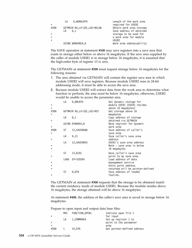
LA 0,WORKLNTH Length of the work area* required for USER2#200 GETMAIN RU,LV=(0),LOC=BELOW Obtain work area storage
LR 6,1 Save address of obtained* storage to be used for* a work area for module* USER2
USING WORKAREA,6 Work area addressability
The SAVE operation at statement #100 may save registers into a save area thatexists in storage either below or above 16 megabytes. If the save area supplied bythe caller of module USER1 is in storage below 16 megabytes, it is assumed thatthe high-order byte of register 13 is zero.
The GETMAIN at statement #200 must request storage below 16 megabytes for thefollowing reasons:1. The area obtained via GETMAIN will contain the register save area in which
module USER2 will save registers. Because module USER2 runs in 24-bitaddressing mode, it must be able to access the save area.
2. Because module USER2 will extract data from the work area to determine whatfunction to perform, the area must be below 16 megabytes, otherwise, USER2would be unable to access the parameter area.
LA 0,GMLNTH Get dynamic storage for* module USER1 (USER1 resides* above 16 megabytes)#300 GETMAIN RU,LV=(0),LOC=RES Get storage above 16* megabytes
LR 8,1 Copy address of storage* obtained via GETMAIN
USING DYNAREA,8 Base register for dynamic* work area#400 ST 13,SAVEBKWD Save address of caller’s* save area
LR 9,13 Save caller’s save area* address
LA 13,SAVEAREA USER1’s save area address* Note - save area is below* 16 megabytes
ST 13,8(9) Have caller’s save area* point to my save area
LOAD EP=IOSERV Load address of data* management service* Entry point address* returned will be pointer-defined
ST 0,EPA Save address of loaded* routine.
The GETMAIN at statement #300 requests that the storage to be obtained matchthe current residency mode of module USER1. Because the module resides above16 megabytes, the storage obtained will be above 16 megabytes.
At statement #400, the address of the caller's save area is saved in storage below 16megabytes.
Prepare to open input and output data base files:MVC FUNCTION,OPEN1 Indicate open file 1
* for inputLA 1,COMMAREA Set up register 1 to
* point to the parameter* area#500 L 15,EPA Get pointer-defined address
104 z/OS MVS Assembler Services Guide

* of the I/O service* routine#600 BASSM 14,15 Call the service routine* Note: AMODE will change#650 MVC FUNCTION,OPEN2 Indicate open file 2* for output
LA 1,COMMAREA Setup register 1 to* point to the parameter* area#700 L 15,EPA Get pointer-defined address* of the I/O service* routine
BASSM 14,15 Call the service routine* Note: AMODE will change
The entry point address loaded at statements #500 and #700 is pointer-defined, asreturned by the LOAD service routine. That is, the low-order three bytes of thesymbolic field EPA will contain the virtual address of the loaded routine while thehigh order bit (bit 0) will be zero to indicate the loaded module is to receivecontrol in 24-bit addressing mode. The remaining bits (1-7) will also be zero in thesymbolic field EPA.
The BASSM at statement #600 does the following:v Places into bit positions 1-31 of register 14 the address of statement #650.v Sets the high-order bit of register 14 to one to indicate the current addressing
mode.v Replaces bit positions 32-63 of the current PSW with the contents of register 15
(as explained earlier)
The BSM instruction used by the called service routine USER2 to return to USER1will reestablish 31-bit addressing mode.
Prepare to read a record from data base file 1:READRTN DS 0H
MVC FUNCTION,READ1 Indicate read to file 1XC BUFFER,BUFFER Clear input bufferLA 1,COMMAREA Set up register 1 to
* point to the parameter areaL 15,EPA Get pointer-defined address
* of the I/O service routineBASSM 14,15 Call the service routine
* Note: The BASSM will change* the AMODE to 24-bit. The* BSM issued in the service* routine will reestablish* 31-bit addressing mode.#900 CLC STATUS,ENDFILE End of file encountered* by module USER2 ?
BE EODRTN Close files and exitMVC BUFFR31A,BUFFER Move record returned to
* storage above 16 megabytes
At statement #900, a check is made to determine if called module USER2encountered the end of file. The end of file condition in this example can only beintercepted by USER2 because the EOD exit address specified on the DCB macromust reside below 16 megabytes. The end of file condition must then becommunicated to module USER1.
Call a record analysis routine that exists above 16 megabytes:
Chapter 5. Understanding 31-bit addressing 105

LA 1,BUFFR31A Get address of first bufferST 1,BUFPTR+0 Store into parameter listLA 1,UPDATBFR Get address of output
* bufferST 1,BUFPTR+4 Store into parameter listLA 1,BUFPTR Set up pointers to work
* buffers for the analysis* routine
L 15,ANALYZE Address of analysis routine#1000 BASR 14,15 Call analysis routine
MVC BUFFER,UPDATBFR Move updated record to* storage below 16 megabytes* so that the updated record can* be written back to the data base
At statement #1000 a BASR instruction is used to call the analysis routine since noAMODE switching is required. A BALR could also have been used. A BALRexecuted while in 31-bit addressing mode performs the same function as a BASRinstruction. The topic “Mode Sensitive Instructions” describes the instructiondifferences.
MVC FUNCTION,WRITE1 Indicate write to file 1LA 1,COMMAREA Set up register 1 to
* point to the parameter areaL 15,EPA Get pointer-defined address
* of the I/O service routine* routine
BASSM 14,15 Call the service routine* Note: The BASSM will set* the AMODE to 24-bit. The* BSM issued in the service* routine will reestablish* 31-bit addressing mode
B READRTN Get next record to process
Prepare to close input and output data base files:EODRTN DS 0H End of data routine
MVC FUNCTION,CLOSE1 Indicate close file 1LA 1,COMMAREA Set up register 1 to
* point to the parameter areaL 15,EPA Get pointer-defined address
* of the I/O service routineBASSM 14,15 Call the service routine
* Note: The BASSM sets* the AMODE to 24-bit. The* BSM issued in the service* routine will reestablish* 31-bit addressing mode
MVC FUNCTION,CLOSE2 Indicate close file 2LA 1,COMMAREA Set up register 1 to
* point to the parameter areaL 15,EPA Get pointer-defined address
* of the I/O service routineBASSM 14,15 Call the service routine
* Note: The BASSM sets* the AMODE to 24-bit. The* BSM issued in the service* routine will reestablish* 31-bit addressing mode
Prepare to return to the caller:L 13,SAVEBKWD Restore save area address
* of the caller of module* USER1
LA 0,WORKLNTH Length of work area and
106 z/OS MVS Assembler Services Guide

* parameter area used by* module USER2
FREEMAIN RC,LV=(0),A=(6) Free storageDROP 6LA 0,GMLNTH Length of work area used
* by USER1FREEMAIN RC,LV=(0),A=(8) Free storageDROP 8XR 15,15 Set return code zeroRETURN (14,12),RC=(15)
Define DSECTs and constants for module to module communication. Defineconstants used to communicate the function module USER2 is to perform.
DS 0FREAD1 DC C’R1’ Read from file 1 opcodeWRITE1 DC C’W1’ Write to file 1 opcodeOPEN1 DC C’O1’ Open file 1 opcodeOPEN2 DC C’O2’ Open file 2 opcodeCLOSE1 DC C’C1’ Close file 1 opcodeCLOSE2 DC C’C2’ Close file 2 opcodeANALYZE DC V(ANALYSIS) Address of record* analysis routineENDFILE DC C’EF’ End of file indicatorWORKAREA DSECTSAVEREGS DS 0F This storage exists* below 16 megabytesSAVEAREA EQU SAVEREGSSAVERSVD DS F ReservedSAVEBKWD DS FSAVEFRWD DS FSAVE1412 DS 15F Save area for registers 14-12COMMAREA DS 0F Parameter area used to* communicate with module* USER2FUNCTION DS CL2 Function to be performed* by USER2STATUS DS CL2 Status of read operationBUFFER DS CL80 Input/output bufferWORKLNTH EQU *-WORKAREA Length of this DSECT
Define DSECT work area for module USER1:DYNAREA DSECT This storage exists* above 16 megabytesEPA DS F Address of loaded routineBUFFR31A DS CL80 Buffer - above 16* megabytesBUFPTR DS 0F
DS A Address of input bufferDS A Address of updated buffer
UPDATBFR DS CL80 Updated buffer returned* by the analysis routineGMLNTH EQU *-DYNAREA Length of dynamic area
END
USER2 service routine:*Module USER2 receives control in 24-bit addressing mode, resides below*16 megabytes, and is called by module USER1 to perform data*management services.
USER2 CSECTUSER2 AMODE 24USER2 RMODE 24** Save the caller’s registers in save area provided*
Chapter 5. Understanding 31-bit addressing 107

SAVE (14,12) Save registersBASR 12,0 Establish baseUSING *,12 AddressabilityLR 10,1 Save parameter area pointer
* around GETMAINsUSING COMMAREA,10 Establish parameter area
* addressability
Storage will be obtained via GETMAIN for a save area that module USER2 canpass to external routines it calls.
LA 0,WORKLNTH Length of the work area* required
GETMAIN RU,LV=(0),LOC=RES Obtain save area storage,* which must be below* 16 megabytes
LR 6,1 Save address of obtained* storage to be used for* a save area for module* USER2
USING SAVEREGS,6 Save area addressabilityLA 0,GMLNTH Get dynamic storage for
* module USER2 below* 16 megabytes.
Note: This GETMAIN will only be done on the initial call to this module.#2000 GETMAIN RU,LV=(0),LOC=RES Obtain storage below* 16 megabytes
LR 8,1 Copy address of storage* obtained via GETMAIN
USING DYNAREA,8 Base register for the* dynamic work area
ST 13,SAVEBKWD Save address of caller’s* save area
LR 9,13 Save caller’s save area* address
LA 13,SAVEAREA USER1’s save area address* Note - save area is* below 16 megabytes
The GETMAIN at statement #2000 requests that storage be obtained to match thecurrent residency mode of module USER2. Because the module resides below 16megabytes, storage obtained will be below 16 megabytes.
Note: The following store operation is successful because module USER1 obtainedsave area storage below 16 megabytes.
ST 13,8(9) Have caller’s save area* point to my save area
.
.
.
.* Process input requests
.
.
.
.READ1 DS 0H Read a record routine
.L 13,SAVEBKWDLM 14,12,12(13) Reload USER1’s registersBSM 0,14 Return to caller - this
* instruction sets AMODE 31WRITE1 DS 0H Write a record routine
.
108 z/OS MVS Assembler Services Guide

L 13,SAVEBKWDLM 14,12,12(13) Reload USER1’s registersBSM 0,14 Return to caller - this
* instruction sets AMODE 31OPEN1 DS 0H Open file 1 for input
.L 13,SAVEBKWDLM 14,12,12(13) Restore caller’s registersBSM 0,14 Return to caller - this
* instruction sets AMODE 31CLOSE1 DS 0H Close file 1 for input
.L 13,SAVEBKWDLM 14,12,12(13) Restore caller’s registersBSM 0,14 Return to caller - this
* instruction sets AMODE 31OPEN2 DS 0H Open file 2 for input
.L 13,SAVEBKWDLM 14,12,12(13) Restore caller’s registersBSM 0,14 Return to caller - this
* instruction sets AMODE 31CLOSE2 DS 0H Close file 2 for input
.L 13.SAVEBKWDLM 14,12,12(13) Restore caller’s registersBSM 0,14 Return to caller - this
* instruction sets AMODE 31..
Note: This FREEMAIN will only be done on the final call to this module.LA 0,GMLNTH Length of work area used
* by USER2FREEMAIN RC,LV=(0),A=(8) Free storage...
DCB END OF FILE and ERROR ANALYSIS ROUTINES:ENDFILE DS 0H End of file encountered
.
.MVC STATUS,ENDFILE Indicate end of file to
* module USER1.L 13,SAVWBKWDLM 14,12,12(13) Reload USER1’s registersBSM 0,14 Return to USER1
* indicating end of file* has been encountered
.
.
.
.ERREXIT1 DS 0H SYNAD error exit one
.
.MVC STATUS,IOERROR Indicate I/O error to
* module ’USER1’.L 13,SAVWBKWDLM 14,12,12(13) Reload USER1’s registersBSM 0,14 Return to USER1
* indicating an I/O error* has been encountered
Chapter 5. Understanding 31-bit addressing 109

.
.
.
.ERREXIT2 DS 0H SYNAD error exit two
.
.MVC STATUS,IOERROR Indicate I/O error to
* module ’USER1’.L 13,SAVWBKWDLM 14,12,12(13) Reload USER1’s registersBSM 0,14 Return to USER1
* indicating an I/O error* has been encountered
Note: Define the required DCBs that module USER2 will process. The DCBs existin storage below 16 megabytes. The END OF DATA and SYNAD exit routines alsoexist in storage below 16 megabytes.INDCB DCB DDNAME=INPUT1,DSORG=PS,MACRF=(GL),EODAD=ENDFILE, x
SYNAD=ERREXIT1OUTDCB DCB DDNAME=OUTPUT1,DSORG=PS,MACRF=(PL),SYNAD=ERREXIT2* Work areas and constants for module USER2IOERROR DC C’IO’ Constant used to indicate* an I/O errorENDFILE DC C’EF’ Constant used to indicate* end of file encounteredSAVEREGS DSECT This storage exists* below 16 megabytesSAVEAREA EQU SAVEREGSSAVERSVD DS F ReservedSAVEBKWD DS FSAVEFRWD DS FSAVE1412 DS 15F Save area for registers 14-12WORKLNTH EQU *-SAVEREGS Length of dynamic area
.
.
.
.
.COMMAREA DSECT Parameter area used to* communicate with module* USER1FUNCTION DS CL2 Function to be performed* by USER2STATUS DS CL2 Status of read operationBUFFER DS CL80 Input/output buffer
.
.DYNAREA DSECT This storage exists* below 16 megabytes
.
.
.
.
.
.GMLNTH EQU *-DYNAREA Length of dynamic area
.
.END
110 z/OS MVS Assembler Services Guide
Understanding the use of central storageMVS programs and data reside in virtual storage that, when necessary, is backedby central storage. Most programs and data do not depend on their real addresses.Some MVS programs, however, do depend on real addresses and some requirethese real addresses to be less than 16 megabytes. MVS reserves as much centralstorage below 16 megabytes as it can for such programs and, for the most part,handles their central storage dependencies without requiring them to make anychanges.
The system uses the area of central storage above 16 megabytes to back virtualstorage with real frames whenever it can. All virtual areas above 16 megabytes canbe backed with real frames above 16 megabytes. In addition, the following virtualareas below 16 megabytes can also be backed with real frames above 16megabytes:v SQAv LSQAv Nucleusv Pageable private areasv Pageable CSAv PLPAv MLPAv Resident BLDL
The following virtual areas are always backed with real frames below 16megabytes:v V=R regionsv FLPAv Subpool 226v Subpools 227 and 228 (unless specified otherwise by the GETMAIN macro with
the LOC parameter)
When satisfying page-fix requests, MVS backs pageable virtual pages that residebelow 16 megabytes with central storage below 16 megabytes, unless theGETMAIN macro specifies LOC=(24,31) or the PGSER macro specifies theANYWHER parameter. If the GETMAIN or STORAGE macro specifies or implies areal location of 31, MVS backs pageable virtual pages with real frames above 16megabytes even when the area is page fixed.
Central storage considerations for user programsAmong the things to think about when dealing with central storage in 31-bitaddressing mode are the use of the load real address (LRA) instruction, the use ofthe LOC parameter on the GETMAIN macro, the location of the DAT-off portion ofthe nucleus, and using EXCPVR to perform I/O. (EXCPVR was described in thesection Performing I/O in 31-Bit Addressing Mode.)
Load real address (LRA) instructionThe LRA instruction works differently depending on addressing mode you use. In64-bit mode, the LRA instruction results in a 64-bit real address stored in a 64-bitGPR. In 24-bit and 31-bit modes, the LRA instruction results in a 31-bit realaddress stored in a 32-bit GPR. The LRA instruction cannot be used to obtain thereal address of locations backed by real frames above 2 gigabytes in 24-bit or 31-bit
Chapter 5. Understanding 31-bit addressing 111

addressing mode. For those situations, use the LRAG instruction instead of LRA.All programs that issue an LRA instruction must be prepared to handle a 31-bitresult if the virtual storage address specified could have been backed with centralstorage above 16 megabytes, or a 64-bit result if the virtual storage addressspecified could have been backed with central storage above 2 gigabytes. IssueLRA only against areas that are fixed. The TPROT instruction can be used toreplace the LRA instruction when a program is using it to verify that the virtualaddress is translatable and the page backing it is in real storage.
GETMAIN macroThe LOC parameter on the RU, RC, VRU, and VRC forms of the GETMAIN macrospecifies not only the virtual storage location of the area to be obtained, but alsothe central storage location when the storage is page fixed.v LOC=24 indicates that the virtual storage is to be located below 16 megabytes.
When the area is page fixed, it is to be backed with central storage below 16megabytes.
v LOC=(24,31) indicates that virtual storage is to be located below 16 megabytesbut that central storage can be located either above or below 16 megabytes, butbelow 2 gigabytes.
v LOC=(24,64) indicates that virtual storage is to be located below 16 megabytesbut that central storage can be located anywhere.
v LOC=31 and LOC=(31,31) indicate that both virtual and central storage can belocated either above or below 16 megabytes, but below 2 gigabytes in centralstorage.
v LOC=(31,64) indicates that virtual storage is to be located below 2 gigabytes butthat central storage can be located anywhere.
v LOC=RES indicates that the location of virtual and central storage depends onthe location (RMODE) of the GETMAIN issuer. If the issuer has an RMODE of24, LOC=RES indicates the same thing as LOC=24; if the issuer has an RMODEof ANY, LOC=RES indicates the same thing as LOC=31.
v LOC=(RES,31) indicates that the location of virtual storage depends on thelocation of the issuer but that central storage can be located anywhere below 2gigabytes.
v LOC=(RES,64) indicates that the location of virtual storage depends on thelocation of the issuer but that central storage can be located anywhere.
Note: There is exception to the meaning of LOC=RES and LOC=(RES,31). A callerresiding below 16 megabytes but running with 31-bit addressing can specifyLOC=RES (either explicitly or by taking the default) or LOC=(RES,31) to obtainstorage from a subpool supported only above 16 megabytes. In this case, thecaller's AMODE determines the location of the virtual storage.
LOC is optional except in the following case: A program that resides above 16megabytes and uses the RU, RC, VRU, and VRC forms of GETMAIN must specifyeither LOC=24 or LOC=(24,31) on GETMAIN requests for storage that will be usedby programs running in 24-bit addressing mode. Otherwise, virtual storage wouldbe assigned above 16 megabytes and 24-bit addressing mode programs could notuse it.
The location of virtual storage can also be specified on the PGSER (page services)macro. The ANYWHER parameter on PGSER specifies that a particular virtualstorage area can be placed either above or below 16 megabytes on future page-ins.This parameter applies to virtual storage areas where LOC=(24,31) or LOC=(31,31)was not specified on GETMAIN.
112 z/OS MVS Assembler Services Guide
DAT-off routinesThe z/OS nucleus is mapped and fixed in central storage without attempting tomake its virtual storage addresses equal to its real addresses. Systems that use31-bit addressing save a V=F (virtual=fixed) nucleus.
Because the z/OS nucleus is not V=R, the nucleus code cannot turn DAT-off andexpect the next instruction executed to be the same as if DAT was on.
To allow for the execution of DAT-off nucleus code, the z/OS nucleus consists oftwo load modules, one that runs with DAT on and one that runs with DAT off.Nucleus code that needs to run with DAT off must reside in the DAT-off portion ofthe nucleus.
When the system is initialized, the DAT-off portion of the nucleus is loaded intothe highest contiguous central storage. Therefore, you must modify any usermodules in the nucleus that run with DAT off so that they operate correctly above16 megabytes. Among the things you may have to consider are:v All modules in the DAT-off portion of the nucleus have the attributes AMODE
31, RMODE ANY. They may reside above 16 megabytes.v These modules must return control via a BSM 0,14.v Register 0 must not be destroyed on return.
To support modules in the DAT-off nucleus:v Move the DAT-off code to a separate module with AMODE 31, RMODE ANY
attributes. Use as its entry point, IEAVEURn where n is a number from 1 to 4.(MVS reserves four entry points in the DAT-off nucleus for users.) Use BSM 0,14as the return instruction. Do not destroy register 0.
v Code a DATOFF macro to invoke the DAT-off module:DATOFF INDEX=INDUSRn
The value of n in INDUSRn must be the same as the value of n in IEAVEURn,the DAT-off module's entry point.
v Link edit the DAT-off module (IEAVEURn) into the IEAVEDAT member ofSYS1.NUCLEUS (the DAT-off nucleus).
See z/OS MVS Programming: Authorized Assembler Services Guide and z/OS MVSProgramming: Authorized Assembler Services Reference ALE-DYN for more informationabout modifying the DAT-off portion of the nucleus and the DATOFF macro.
Chapter 5. Understanding 31-bit addressing 113

114 z/OS MVS Assembler Services Guide

Chapter 6. Resource control
When your program executes, other programs are executing concurrently in theMVS multiprogramming environment. Each group of programs, including yours, isa competitor for resources available at execution time. A resource is anything that aprogram needs as it executes — such as processor time, a data set, anotherprogram, a table, or a hardware device, etc. The competitor for resources isactually the task that represents the program.
If you subdivide a program into separate logical parts, and code it as several smallprograms instead of one large program, you can make the parts execute asseparate tasks and with greater efficiency. However, you must ensure that eachpart executes in correct order relative to the others:v The WAIT, POST, and EVENTS macros introduce a strategic delay in the
running of a program. This delay forces a program to wait using an eventcontrol block (ECB), for a particular event to occur. When the event occurs, theprogram can run once again. The event can be the availability of a necessaryresource.
v Pause, Release, and Transfer are services you can call, using a pause element(PE), to synchronize task processing with minimal overhead. Table 4 comparesthe use of the Pause, Release, and Transfer services with the WAIT and POSTmacros.
v The ISGENQ macro allows your program to serialize resources by:– Obtaining a single ENQ or multiple ENQs with or without associated device
reserves.– Changing the control from shared to exclusive on one or more resources.– Releasing a single ENQs, or multiple ENQs.– Testing the availability of one or more resources.– Testing how the resource request would be altered by RNL processsing or
dynamic global resource serialization exits.
Note: As of z/OS Release 6, the ENQ, DEQ, and RESERVE interfaces willcontinue to be supported, though IBM recommends using the ISGENQ servicefor unauthorized serialization requests.
v The ISGQUERY macro allows you to obtain information about the use ofresources.
Table 4. Task Synchronization Techniques
Pause, Release, and Transfer WAIT and POST
Can change the dispatchability of a task. Can change the dispatchability of a task.
Can release a task before it is paused. Can post a task before it waits.
An unauthorized caller can pause and release any task inthe caller's home address space.
An unauthorized caller can WAIT and POST any task inthe caller's home address space.
A task can only pause on a single PE at a time. A task may wait on multiple ECBs. If the wait countnumbers are posted, the task is made dispatchable.
The Transfer service can simultaneously pause one taskand release another.
There is no single service with comparable capability forWAIT and POST.
The Transfer service can release a task and immediatelypass control to the released task.
There is no single service with comparable capability forWAIT and POST.
© Copyright IBM Corp. 1988, 2017 115

Table 4. Task Synchronization Techniques (continued)
Pause, Release, and Transfer WAIT and POST
The system ensures the Pause Elements are not reusedimproperly, thus avoiding improper releases caused byunexpected termination or asynchronous ABENDs.
Ability to pass control directly from one task to anotherpaused task.
High performance. No local lock contentions effects. Lower performance, possible local lock contention.
Callers may use ECBLIST or EVENTS service to wait onmultiple ECBs.
Synchronizing tasks (WAIT, POST, and EVENTS macros)Some planning on your part is required to determine what portions of one task aredependent on the completion of portions of all other tasks. The POST macro isused to signal completion of an event; the WAIT and EVENTS macros are used toindicate that a task cannot proceed until one or more events have occurred. Anevent control block (ECB) is used with the WAIT, EVENTS or POST macros; it is afullword on a fullword boundary, as shown in Figure 44.
An ECB is also used when the ECB parameter is coded in an ATTACH orATTACHX macro (see the z/OS MVS Programming: Assembler Services ReferenceABE-HSP for information on how to use the ATTACH or ATTACHX macro tocreate a new task and indicate the entry point in the program to be given controlwhen the new task becomes active). In this case, the control program issues thePOST macro for the event (subtask termination). Either the 24-bit (bits 8 to 31)return code in register 15 (if the task completed normally) or the completion codespecified in the ABEND macro (if the task was abnormally terminated) is placed inthe ECB as shown in Figure 44. The originating task can issue a WAIT macro orEVENTS macro with WAIT=YES parameter specifying the ECB; the task will notregain control until after the event has taken place and the ECB is posted (except ifan asynchronous event occurs, for example, timer expiration).
When an ECB is originally created, bits 0 (wait bit) and 1 (post bit) must be set tozero. If an ECB is reused, bits 0 and 1 must be set to zero before a WAIT, EVENTSECB= or POST macro can be specified. If, however, the bits are set to zero beforethe ECB has been posted, any task waiting for that ECB to be posted will remainin the wait state. When a WAIT macro is issued, bit 0 of the associated ECB is setto 1. When a POST macro is issued, bit 1 of the associated ECB is set to 1 and bit 0is set to 0. For an EVENTS type ECB, POST also puts the completed ECB addressin the EVENTS table.
A WAIT macro can specify more than one event by specifying more than one ECB.(Only one WAIT macro can refer to an ECB at a time, however.) If more than oneECB is specified in a WAIT macro, the WAIT macro can also specify that all oronly some of the events must occur before the task is taken out of the wait
completion codeW P
0 1 2 31
Figure 44. Event Control Block (ECB)
116 z/OS MVS Assembler Services Guide

condition. When a sufficient number of events have taken place (ECBs have beenposted) to satisfy the number of events indicated in the WAIT macro, the task istaken out of the wait condition.
An optional parameter, LONG=YES or NO, allows you to indicate whether thetask is entering a long wait or a regular wait. A long wait should never beconsidered for I/O activity. However, you might want to use a long wait whenwaiting for an operator response to a WTOR macro.
Through the LINKAGE parameter, POST and WAIT allow you to specify how themacro passes control to the control program. You can specify that control is to bepassed by an SVC or a PC instruction.
When you issue the WAIT or POST macro and specify LINKAGE=SVC (or use thedefault), your program must not be in cross memory mode. The primary,secondary, and home address spaces must be the same, your program must be inprimary ASC mode, and it must not have an enabled unlocked task (EUT)functional recovery routine (FRR) established. You may use WAIT and POST whenthe primary and the home address spaces are different by specifyingLINKAGE=SYSTEM. This option generates a PC interface to the WAIT or POSTservice and requires that the program be enabled, unlocked, in primary ASC modeand, for WAIT only, in task mode. For POST, the control program assumes that theECB is in the primary address space. For WAIT, it assumes that the ECB is in thehome address space.
Figure 45 shows an example of using LINKAGE=SYSTEM. The program that runsunder TCB1 in ASN1 PCs to a program in ASN2. Now the primary address spaceis ASN2 and home address space is ASN1. When the PC routine posts ECB2, ituses LINKAGE=SYSTEM because home and primary are different. The PC routinewaits on ECB1 using LINKAGE=SYSTEM because home and primary are stilldifferent. Note that ECB1 is in the home address space.
PR
ASN1 ASN2
home address space
TCB1
PC
ECB1 ECB2
POST ECB2,LINKAGE=SYSTEM
WAIT ECB1,LINKAGE=SYSTEM
Figure 45. Using LINKAGE=SYSTEM on the WAIT and POST Macros
Chapter 6. Resource control 117

Synchronizing tasks (Pause, Release, and Transfer)Pause, Release, and Transfer are callable services that enable you to synchronizetask processing with minimal overhead. If you have, for example, an applicationthat requires two or more tasks to trade control back and forth, these servicesprovide efficient transfers of control.
These services, which are available to both unauthorized and authorized callers inAssembler as well as C or C++, use a system-managed object called a pauseelement to synchronize processing of tasks. The services provide the followingfunctions:
Table 5. Pause, Release, and Transfer callable services
Callable service64-bit version callableservice Description
IEAVAPE, IEAVAPE2 IEA4APE, IEA4APE2 Obtains a pause element token (PET), which uniquelyidentifies a pause element (PE).
IEAVDPE, IEAVDPE2 IEA4DPE, IEA4DPE2 Frees a pause element (PE) that is no longer needed.
IEAVPSE, IEAVPSE2 IEA4PSE, IEA4PSE2 Pauses the current task or SRB.
IEAVPME2 IEA4PME2 Pauses the current task or SRB using multiple PETs.
IEAVRLS, IEAVRLS2 IEA4RLS, IEA4RLS2 Releases a paused task or SRB.
IEAVRPI, IEAVRPI2 IEA4RPI, IEA4RPI2 Retrieves information about a pause element (PE).
IEAVTPE IEA4TPE Tests a pause element (PE) and determines its state.
IEAVXFR, IEAVXFR2 IEA4XFR, IEA4XFR2 Releases a paused task and, when possible, gives it immediatecontrol, while optionally pausing the task under which theTransfer request is made.
The services use a system-managed pause element (PE) rather than anapplication-managed control block, such as an event control block (ECB), thusreducing the possibility of error that might come from improper reuse of thecontrol block.
As a PE is much like an ECB, the Pause service is much like the WAIT macro, andthe Release service is much like the POST macro. Just as you can use POST to keepa task from waiting by preposting, you can use Release to keep a task frompausing by prereleasing.
The Transfer service can both release a paused task and pass control directly to thereleased task. The Transfer service can also pause the task that calls the service.Thus, Transfer enables quick dispatches, saving the overhead of work search. Italso allows two tasks to trade control back and forth with minimal overhead.
To understand how to use the services, you need to know more about pauseelements, (PEs) and the pause element tokens (PETs) that identify them.
Pause elements and pause element tokensA pause element (PE) is a system-managed object used to pause and release awork unit, which can be either a task or SRB. Like an ECB, a PE is used by thesystem to control whether or not a work unit is dispatchable. You can use a PE,like an ECB, to prerelease a work unit before it is paused. There are, however,significant differences between an ECB and a PE Table 6 on page 119 compares thetwo:
118 z/OS MVS Assembler Services Guide

Table 6. Pause Element (PE) and Event Control Block (ECB)
Pause Element (PE) Event Control Block (ECB)
Managed by the system. Managed by application programs.
Identified by a pause element token (PET). Identified by a simple address.
Cannot be reused once invalidated by an asynchronousABEND.
Can be reused after a task is removed from the wait stateby an asynchronous ABEND, although reuse requiresvery complicated programming.
To prevent errors related to reuse, a PET can be usedonly once to identify a PE. Once a task is paused andreleased, an updated PET is needed to identify the PE.The system returns the updated PET to the callerthrough the Pause or Transfer service.
There is no control on the reuse of an ECB; the sameECB address can be used over and over.
PEs are allocated and deallocated through calls to systemservices.
ECBs are allocated by application programs.
The total number of PEs available to all unauthorizedprograms in a system is limited to 130560.
The system imposes no limits on the number of ECBs.
PEs are not directly addressable through PETs. The userof a PE does not know its actual address and cannotmodify it except through the use of system services.
ECBs can be modified at will by application programs.
A PE allocated by an unauthorized caller can be used to pause and release anywork unit in the caller's home address space. An unauthorized caller cannot pauseor release using a PE allocated with auth_level=IEA_AUTHORIZED orpause_element_auth_level=IEA_AUTHORIZED.
When a PE is allocated with auth_level=IEA_AUTHORIZED (callable servicesIEAVAPE and IEA4APE) or pause_element_auth_level=IEA_AUTHORIZED(callable services IEAVAPE2 and IEA4APE2), the PE can be used to pause andrelease any task or SRB in the system. The same PE can be used, for example, topause a task in address space 10. After being released, the same PE can be used topause an SRB in, say, address space 23. There is, however, a small performancepenalty imposed when a PE is used to pause a task or SRB in one space and thenreused to pause a task or SRB in another space. This cost is accrued upon eachspace transition.
The following services (IEAVAPE2, IEAVDPE2, IEAVPME2, IEAVPSE2, IEAVRLS2,IEAVRPI2, IEAVXFR2, IEA4APE2, IEA4DPE2, IEA4PME2, IEA4PSE2, IEA4RLS2,IEA4RPI2, and IEA4XFR2) have a 'LINKAGE=' keyword that specifies whether thecaller is authorized (LINKAGE=BRANCH requires the caller to be in key 0supervisor state). The authorization of the PET is not specified, except when it isallocated via the IEAVAPE2 (or IEA4APE2) service. Instead, the authorization ofthe PET is implied. Authorized users can use any PET, but unauthorized usersonly can use a PET that was allocated for unauthorized use.
When an authorized program is passed a PET from an unauthorized program, theauthorized program must ensure that the PET is valid to be used by theunauthorized program. The authorized program can validate this by invoking theIEAVRPI2 (or IEA4RPI2) service and specifying a special value for the linkageparameter. When an authorized program needs to validate that a PET can be usedby an unauthorized program, add IEA_UNTRUSTED_PET to the value specifiedfor LINKAGE and invoke the IEAVRPI2 service. The data returned by theIEAVRPI2 service identifies whether the unauthorized caller is able to use the PET:v Return_code must be 0.
Chapter 6. Resource control 119
v Pause_element_auth_level must be IEA_PET_UNAUTHORIZED.
A PE can be used to pause only one task or SRB at a time; the system does notallow more then one dispatchable unit to be paused under a single PE.
Pause elements are not supported by checkpoint/restart. However, support hasbeen added with APAR OA19821 to permit the allocation of pause elements thatcan allow a successful checkpoint/restart. This is possible for applications that cantolerate the fact that the pause element will not be restored upon a restart after acheckpoint. An application can tell if this support is available by checking ifCVTPAUS4 has been set in the CVT. A new type is introduced for the auth_levelparameter of the Allocate Pause Element service. The new level is created byadding the value of the new type (IEA_CHECKPOINTOK) to the existing value (atone time, only IEA_AUTHORIZED or IEA_UNAUTHORIZED can be specified).When pause elements are allocated, a checkpoint is accepted only if allencountered pause elements have been allocated indicating theIEA_CHECKPOINTOK type.
Using the servicesThere are 28 callable services available for task synchronization:v Allocate_Pause_Element – IEAVAPE, IEAVAPE2, IEA4APE, or IEA4APE2v Deallocate_Pause_Element – IEAVDPE, IEAVDPE2, IEA4DPE, or IEA4DPE2v Pause – IEAVPSE, IEAVPSE2, IEA4PSE, or IEA4PSE2v Pause_Multiple_Elements– IEAVPME2 or IEA4PME2v Release – IEAVRLS, IEAVRLS2, IEA4RLS, or IEA4RLS2v Retrieve_Pause_Element_Information - IEAVRPI, IEAVRPI2, IEA4RPI, or
IEA4RPI2v Test_Pause_Element - IEAVTPE or IEA4TPEv Transfer – IEAVXFR, IEAVXFR2, IEA4XFR, or IEA4XFR2
To use Pause, Release, and Transfer, a program must first allocate a PE by callingthe Allocate_Pause_Element service. In response, the system allocates a PE andreturns a pause element token (PET) that identifies the pause element (PE).
You use the PET returned from Allocate_Pause_Element to identify the allocatedPE until either:v The PE has been used to pause (through Pause or Transfer) and release (through
Release or Transfer) a task.v A paused task has been released through an asynchronous ABEND.
When you are finished with the PE, call the Deallocate_Pause_Element service toreturn the PE to the system. If a task is asynchronously ABENDed while it ispaused, the system itself invalidates the PE, and it cannot be reused for pauserequests. Thus, return an invalidated PE to the system as soon as possible by a callto Deallocate_Pause_Element.
Though the PE remains allocated until you deallocate it, you can use a PET foronly one pair of calls, which result in a pause and a release of a task. When youspecify a PET on a successful call to the Pause service or to pause a task through asuccessful call to the Transfer service, the system invalidates the input PET andreturns an updated PET to identify the PE. Use the updated PET to reuse the PE orto deallocate the PE.
120 z/OS MVS Assembler Services Guide

Figure 46 shows, in pseudocode, the sequence of calls to allocate a PE, pause thecurrent task, release the task, and deallocate the PE.
The Pause, Release, and Transfer services also provide a release code field thatprograms can use to communicate, to indicate, for example, the reason for arelease. The program that calls the Release service can set a release code.
The release code is particularly useful when a task might be released before it ispaused (prereleased). When a subsequent call to the Pause service occurs, thesystem does not pause the task; instead, it returns control immediately to thecalling program and provides the release code specified on the release call.
Figure 47 on page 122 shows, in pseudocode, the sequence of calls needed toallocate a PE, prerelease a task, and deallocate the PE
/* Common variables */ ||
Dcl PET char(16); ||
Workunit #1 | Workunit #2|
/* Workunit #1 variables */ | /* Workunit #2 variables */Dcl Auth1 char(4); | Dcl Auth2 char(4);Dcl RC1 fixed(32); | Dcl RC2 fixed(32;Dcl Updated_pet char(16); | Dcl RelCode binary(24);Dcl RetRelCode binary(24); |
|Auth1 = IEA_UNAUTHORIZED; | Auth2 = IEA_UNAUTHORIZED;
. | .
. | .
. | ./* Allocate a Pause Element */ |Call IEAVAPE (RC1,Auth1,PET); |
|/* Pause Workunit #1 */ |Call IEAVPSE (RC1,Auth1,PET, |
Updated_PET,RetRelCode); ||
/*processing pauses until released*/ | RelCode = ’123’;| /* Release Workunit #1 */| Call IEAVRLS (RC2,Auth2,PET,
. | RelCode);
. |
. |PET = UPET; |Call IEAVPSE (RC1,Auth1,PET); |
Updated_PET,RetRelCode); ||
/*processing pauses until released*/ | RelCode = ’345’;. | /* Release Workunit #1 */. | Call IEAVRLS (RC2,Auth2,PET,. | RelCode);
/* Deallocate the pause element */ |Call IEAVDPE (RC1,Auth1, |
Updated_PET) |
Figure 46. Pause and Release Example
Chapter 6. Resource control 121
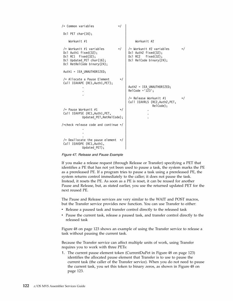
If you make a release request (through Release or Transfer) specifying a PET thatidentifies a PE that has not yet been used to pause a task, the system marks the PEas a prereleased PE. If a program tries to pause a task using a prereleased PE, thesystem returns control immediately to the caller; it does not pause the task.Instead, it resets the PE. As soon as a PE is reset, it can be reused for anotherPause and Release, but, as stated earlier, you use the returned updated PET for thenext reused PE.
The Pause and Release services are very similar to the WAIT and POST macros,but the Transfer service provides new function. You can use Transfer to either:v Release a paused task and transfer control directly to the released taskv Pause the current task, release a paused task, and transfer control directly to the
released task
Figure 48 on page 123 shows an example of using the Transfer service to release atask without pausing the current task.
Because the Transfer service can affect multiple units of work, using Transferrequires you to work with three PETs:1. The current pause element token (CurrentDuPet in Figure 48 on page 123)
identifies the allocated pause element that Transfer is to use to pause thecurrent task (the caller of the Transfer service). When you do not need to pausethe current task, you set this token to binary zeros, as shown in Figure 48 onpage 123.
/* Common variables */ ||
Dcl PET char(16); ||
Workunit #1 | Workunit #2|
/* Workunit #1 variables */ | /* Workunit #2 variables */Dcl Auth1 fixed(32); | Dcl Auth2 fixed(32);Dcl RC1 fixed(32); | Dcl RC2 fixed(32);Dcl Updated_PET char(16); | Dcl RelCode binary(24);Dcl RetRelCode binary(24); |
|Auth1 = IEA_UNAUTHORIZED; |
|/* Allocate a Pause Element */ |Call IEAVAPE (RC1,Auth1,PET); |
. | Auth2 = IEA_UNAUTHORIZED;
. | RelCode =’123’;
. || /* Release Workunit #1 */| Call IEAVRLS (RC2,Auth2,PET,| RelCode);
/* Pause Workunit #1 */ | .Call IEAVPSE (RC1,Auth1,PET, | .
Updated_PET,RetRelCode); | .|
/*check release code and continue */ |. |. |. |
/* Deallocate the pause element */ |Call IEAVDPE (RC1,Auth1, |
Updated_PET); |
Figure 47. Release and Pause Example
122 z/OS MVS Assembler Services Guide

2. The updated pause element token (UPET2 in Figure 48), which the systemreturns when you specify a current pause element token. You need thisupdated token to reuse the pause element on a subsequent Pause or Transfer orto deallocate the pause element. If you set the current token to binary zeros, asdone in Figure 48, the contents of the updated pause element token are notmeaningful.
3. The target token (TargetDuPET in Figure 48) identifies the allocated pauseelement that Transfer is to use to release a task. In Figure 48, it contains thePET that identifies the PE used to pause Workunit #1.
A current release code and a target release code are also available on the call toTransfer. Whether or not each code contains valid data depends on conventions setby the different parts of your program
Serializing access to resources (ISGENQ macro)When one or more programs using a serially reusable resource modify theresource, they must not use the resource simultaneously with other programs.Consider a data area in virtual storage that is being used by programs associatedwith several tasks of a job step. Some of the programs are only reading records inthe data area; because they are not updating the records, they can access the dataarea simultaneously. Other programs using the data area, however, are reading,updating, and replacing records in the data area. Each of these programs mustserially acquire, update, and replace records by locking out other programs. In
/* Common variables */ ||
Dcl PET char(16); ||
Workunit #1 | Workunit #2|
/* Workunit #1 variables */ | /* Workunit #2 variables */Dcl Auth1 char(4); | Dcl Auth2 char(4);Dcl RC1 char(4); | Dcl RC2 char(4);Dcl UPET1 char(16); | Dcl CurrentDuRelCode binary(24);Dcl RetRelCode binary(24); | Dcl CurrentDuPET char(16);
. | Dcl UPET2 char(16);
. | Dcl TargetDuPET char(16);
. | Dcl TargetDuRelCode char(3);Auth1 = IEA_UNAUTHORIZED; |/* Allocate a Pause Element */ | Auth2 = IEA_UNAUTHORIZED;Call IEAVAPE (RC1,Auth1,PET); | .
| ./* Pause Workunit #1 */ | .Call IEAVPSE (RC1,Auth1,PET,UPET1, | TargetDuRelCode = ’123’;
RetRelCode); | /* no pause-set token to zeros */| CurrentDuPet =’’B;| TargetDuPET = PET
/*processing pauses until transfer*/ || /* Transfer to Workunit #1 */| Call IEAVXFR (RC2,Auth2,| CurrentDuPET,UPET2,| CurrentDuRelCode,| TargetDuPET,| TargetDuRelCode);
/*processing continues */ | .| .
/* Deallocate the Pause Element */ | .Call IEAVDPE (RC1,Auth1,UPET1); |
Figure 48. Transfer without Pause Example
Chapter 6. Resource control 123

addition, none of the programs that are only reading the records want to use arecord that another program is updating until after the record has been replaced.
If your program uses a serially reusable resource, you must prevent incorrect useof the resource. You must ensure that the logic of your program does not requirethe second use of the resource before completion of the first use. Be especiallycareful when using a serially reusable resource in an exit routine; because exitroutines get control asynchronously with respect to your program logic, the exitroutine could obtain a resource already in use by the main program. When morethan one task is involved, using the ISGENQ macro correctly can preventsimultaneous use of a serially reusable resource.
z/OS Automatic Tape Switching (ATS STAR) uses the ISGDGRSRES exit to addadditional device information to the DISPLAY GRS command. For information andan example, see Providing ENQ resource information on DISPLAY GRS commandin z/OS MVS Programming: Authorized Assembler Services Guide.
The ISGENQ macro assigns control of a resource to the current task. The controlprogram determines the status of the resource and does one of the following:v If the resource is available, the control program grants the request by returning
control to the active task.v If the resource has been assigned to another task, the control program delays
assignment of control by placing the active task in a wait condition until theresource becomes available.
v Passes back a return code indicating the status of the resource.v Abends the caller on unconditional requests that would otherwise result in a
non-zero return code.
When the status of the resource changes so that the waiting task can get control,the task is taken out of the wait condition and placed in the ready condition.
Naming the resourceThe ISGENQ macro identifies the resource by qname, rname, and a scope value.The qname and rname need not have any relation to any actual name of theresource. The control program does not associate a name with an actual resource; itmerely processes requests having the same qname, rname, and scope on a first-in,first-out basis. It is up to you to associate the names with the resource by ensuringthat all users of the resource use the same qname, rname, and scope value torepresent the same resource. The control program treats requests having differentqname, rname, and scope combinations as requests for different resources. Becausethe control program cannot determine the actual name of the resource from theqname, rname, and scope, a task could use the resource by specifying a differentqname, rname, and scope combination or by accessing the resource without usingISGENQ. In this case, the control program cannot provide any protection.
In many cases it is impossible for you to determine what resources are beingserialized by the resource identified by the QNAME and RNAME. As such, GRSprovides the ISGDGRSRES installation exit to allow authorized programs to addadditional resource information on the DISPLAY GRS command. For moreinformation and an example, see Providing ENQ resource information on DISPLAYGRS command in z/OS MVS Programming: Authorized Assembler Services Guide.
124 z/OS MVS Assembler Services Guide

Defining the scope of a resourceYou can request a scope of STEP, SYSTEM, SYSTEMS, or SYSPLEX value on theISGENQ macro.v Use a scope of STEP if the resource is used only in your address space. The
control program uses the address space identifier to make your resource uniquein case someone else in another address space uses the same qname and rnameand a scope of STEP.
v Use a scope of SYSTEM if the resource is serialized across all address spaces in asystem. For example, to prevent two jobs from using a named resourcesimultaneously, use SYSTEM.
v Use a scope of SYSTEMS or SYSPLEX if the resource is available to more thanone system. All programs that serialize on the resource must use the sameqname and rname and a scope of SYSTEMS. For example, to prevent twoprocessors from using a named resource simultaneously, use SYSTEMS orSYSPLEX.
Note: Note that the control program considers a resource with a SYSTEMS scopeto be different from a resource represented by the same qname and rname but witha scope of STEP or SYSTEM.
Local and global resourcesThe ISGENQ macro recognize two types of resources: local resources and globalresources.
A local resource is a resource identified on ISGENQ, ENQ or DEQ by a scope ofSTEP or SYSTEM. A local resource is recognized and serialized only within therequesting operating system. The local resource queues are updated to reflect eachrequest for a local resource. If a system is not operating under global resourceserialization (that is, the system is not part of a global resource serializationcomplex), all resources requested are treated as local resources.
If a system is part of a global resource serialization complex, a global resource iseither identified on the ENQ or DEQ macro by a scope of SYSTEMS, or on theISGENQ macro by a scope of SYSTEMS or SYSPLEX.
If your system is part of a global resource serialization complex, global resourceserialization might change the scope value during its resource name list (RNL)processing. If the resource appears in the SYSTEM inclusion RNL, a resource witha scope of SYSTEM can have its scope converted to SYSTEMS or SYSPLEX. If theresource appears in the SYSTEMS or SYSPLEX exclusion RNL, a scope ofSYSTEMS or SYSPLEX can have its scope changed to SYSTEM. This procedure isdescribed in Selecting the data section of z/OS MVS Planning: Global ResourceSerialization.
Through the RNL parameter on ISGENQ, you can request that global resourceserialization not perform RNL processing and, therefore, not change the scopevalue of a resource. It is recommended that you use RNL=YES, the default, whichtells global resource serialization to perform RNL processing. Use RNL=NO onlywhen you are sure that you never want the scope value to change. An example ofthe use of RNL=NO is in a cross-system coupling facility (XCF) complex, whereyou can be certain that certain data sets always need a scope value of SYSTEMS orSYSPLEX and other data sets always need a scope value of SYSTEM or SYSPLEX.In a sense, RNL=NO overrides decisions your system programmer makes whenthat programmer places resource names in the RNLs.
Chapter 6. Resource control 125

Alternate serialization products have the ability to provide additional globalresource serialization. As such, a resource may be local (SYSTEM scope) from aglobal resource serialization perspective but actually be globally managed by analternate serialization product. See “Determining the resulting scope” for moredetails.
Determining the resulting scopeYou can determine the resulting scope of your ISGENQ request and what causedany scope change to take place by using one or both of the ISGQUERY andISGENQ REQUEST=TEST services. Use these services to insure that the resultingscope is correct for the current configuration of your product. For RNL=YESrequests, the scope can change by the RNL or installation exit.
Note that alternate serialization products use installation exits to control the scopethat global resource serialization uses. For example, an alternate serializationproduct can extend the scope such that it would indicate to global resourceserialization that the scope should be local so it could extend it to its global scope.This scope might be larger than the global resource serialization complex. You cancheck the following ISGQUERY output fields related to an ISGQUERY of theinterested resource to determine if its scope is global:1. Is ISGYQUAARqxAltSerExtended on? This indicates that it is globally managed
by an alternate serialization product.2. Is ISGYQUAARSSCOPE=ISGYQUAA_kSYSTEMS or ISGYQUAA_kSYSPLEX
on? This indicates that it is globally managed by global resource serialization.
You can use various fields within the ISGYQUAA mapping to determine whatcaused the scope to be altered.
You can test what the potential resulting scope of an ISGENQ REQUEST=TESTrequest for resource would be by checking the following ISGYENQ fields:1. Is ISGYENQAAALTSEREXTENDED on? This indicates it would be globally
managed by an alternate serialization product.2. Is ISGYENQAAFinalScope=ISGENQ_SYSTEMS on? This indicates that it would
be globally managed by global resource serialization.
You can use various fields within the ISGYENQ mapping to determine whatcaused the scope to be altered.
Requesting exclusive or shared controlOn ISGENQ, you specify either exclusive or shared control of a resource throughthe CONTROL parameter.
When your program has exclusive control of a resource, it is the only one that canuse that resource; all other programs that issue ENQs for the resource (either forexclusive or shared control) must wait until your program releases the resource. Ifyour program will change the resource, it should request exclusive control.
When your program has shared control of a resource other programs can haveconcurrent use of the resource. If another program requests exclusive control overthe resource during the time your program has shared use of the resource, thatprogram will have to wait until all the current users have released the resource. Ifyour program will not change the resource, it should request shared control.
For an example of how the control program processes requests for exclusive andshared control of a resource, see “Processing the requests” on page 127.
126 z/OS MVS Assembler Services Guide
Limiting concurrent requests for resourcesTo prevent any one job, started task, or TSO/E user from generating too manyconcurrent requests for resources, the control program counts and limits thenumber of ENQ requests in each address space. When a user issues an ENQrequest, the control program increases the count of outstanding requests for thataddress space by one and decreases the count by one when the user issues a DEQrequest.
ENQ RET=TEST, RET=CHNG, and ISGENQ equivalents do not cause this count toincrease because they do not queue up a new request block. A GQSCAN resultingin a continuation TOKEN however, along with the ISGQUERY equivalent, doescause to count to increase.
Prior to an abend, messages ISG368E and ISG369I monitor address spaces that areapproaching the request maximum. If a particular subsystem requires more ENQsthan normal, use the ISGADMIN service to raise that subsystem's maximum forunauthorized and authorized requesters. As a temporary workaround, you canraise the overall system maximum by issuing the following commands:v SETGRS ENQMAXA for authorizedv SETGRS ENQMAXU for unauthorized
When the computed count reaches the threshold value or limit, the controlprogram processes subsequent requests as follows:v Unconditional requests are abnormally ended with a system code of X'538'.v Conditional requests are rejected and the user receives a return code of X'18'.v For ISGENQ, see the return code of X'C01' explained in ISGENQ — Global
resource serialization ENQ service in z/OS MVS Programming: Assembler ServicesReference IAR-XCT.
Processing the requestsThe control program constructs a unique list for each qname, rname, and scopecombination it receives. When a task makes a request, the control program searchesthe existing lists for a matching qname, rname, and scope. If it finds a match, thecontrol program adds the task's request to the end of the existing list; the list is notordered by the priority of the tasks on it. If the control program does not find amatch, it creates a new list, and adds the task's request as the first (and only)element. The task gets control of the resource based on the following:v The position of the task's request on the listv Whether or not the request was for exclusive or shared control
The best way to describe how the control program processes the list of requests fora resource is through an example. Figure 49 on page 128 shows the status of a listbuilt for a qname, rname, and scope combination. The S or E next to the entryindicates that the request was for either shared or exclusive control. The taskrepresented by the first entry on the list always gets control of the resource, so thetask represented by ENTRY1 (Figure 49 on page 128, Step 1) is assigned theresource. The request that established ENTRY2 (Figure 49 on page 128, Step 1) wasfor exclusive control, so the corresponding task is placed in the wait condition,along with the tasks represented by all the other entries in the list.
Chapter 6. Resource control 127
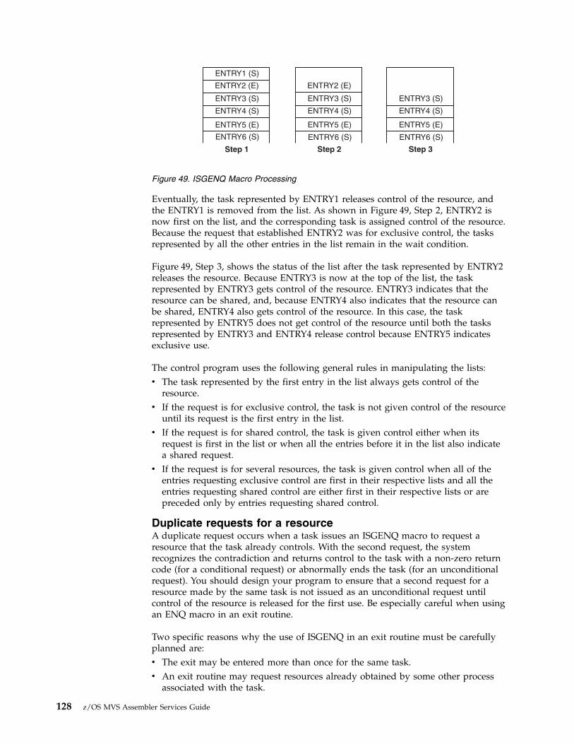
Eventually, the task represented by ENTRY1 releases control of the resource, andthe ENTRY1 is removed from the list. As shown in Figure 49, Step 2, ENTRY2 isnow first on the list, and the corresponding task is assigned control of the resource.Because the request that established ENTRY2 was for exclusive control, the tasksrepresented by all the other entries in the list remain in the wait condition.
Figure 49, Step 3, shows the status of the list after the task represented by ENTRY2releases the resource. Because ENTRY3 is now at the top of the list, the taskrepresented by ENTRY3 gets control of the resource. ENTRY3 indicates that theresource can be shared, and, because ENTRY4 also indicates that the resource canbe shared, ENTRY4 also gets control of the resource. In this case, the taskrepresented by ENTRY5 does not get control of the resource until both the tasksrepresented by ENTRY3 and ENTRY4 release control because ENTRY5 indicatesexclusive use.
The control program uses the following general rules in manipulating the lists:v The task represented by the first entry in the list always gets control of the
resource.v If the request is for exclusive control, the task is not given control of the resource
until its request is the first entry in the list.v If the request is for shared control, the task is given control either when its
request is first in the list or when all the entries before it in the list also indicatea shared request.
v If the request is for several resources, the task is given control when all of theentries requesting exclusive control are first in their respective lists and all theentries requesting shared control are either first in their respective lists or arepreceded only by entries requesting shared control.
Duplicate requests for a resourceA duplicate request occurs when a task issues an ISGENQ macro to request aresource that the task already controls. With the second request, the systemrecognizes the contradiction and returns control to the task with a non-zero returncode (for a conditional request) or abnormally ends the task (for an unconditionalrequest). You should design your program to ensure that a second request for aresource made by the same task is not issued as an unconditional request untilcontrol of the resource is released for the first use. Be especially careful when usingan ENQ macro in an exit routine.
Two specific reasons why the use of ISGENQ in an exit routine must be carefullyplanned are:v The exit may be entered more than once for the same task.v An exit routine may request resources already obtained by some other process
associated with the task.
ENTRY1 (S)
ENTRY2 (E) ENTRY2 (E)
ENTRY6 (S) ENTRY6 (S) ENTRY6 (S)
ENTRY5 (E) ENTRY5 (E) ENTRY5 (E)
ENTRY4 (S) ENTRY4 (S) ENTRY4 (S)
Step 1 Step 2 Step 3
ENTRY3 (S) ENTRY3 (S) ENTRY3 (S)
Figure 49. ISGENQ Macro Processing
128 z/OS MVS Assembler Services Guide

For more information on this topic, see “ENQ and DEQ conditional andunconditional requests.”
Releasing the resourceUse the RELEASE request to release a serially reusable resource that you obtainedby using ISGENQ macro. If a task tries to release a resource which it does notcontrol, the control program either returns a non-zero return code or abends thetask. The control program might place many tasks in a wait condition while itassigns control of the resource to one task. Having many tasks in the wait statemight reduce the amount of work being done by the system, therefore, you shouldrelease the resource, so that another task can use it.
If a task terminates without releasing a resource, the control program releases theresource automatically. By default, outstanding ENQs have affinity to the task thatissued the ENQ. The system releases any outstanding ENQs during termination asfollows:v Task termination: The user should provide a recovery routine to back out or
complete any processing that requires the serialization and then release anyENQs before the program gives up control. The system automatically releases allof a task's outstanding ENQs after all recovery routines and task relateddynamic resources managers have executed.
v Memory termination: The system releases all ENQs during memory terminationprocessing in cases where task related recovery and termination resourcemanagers may not have run. The ENQs are released after all memorytermination dynamic resource managers have executed.Note that authorized routines that may get control under a resource managermust prevent themselves from getting deadlocked. They may need toconditionally request an ENQ or query if it is already outstanding by theaddress space that is in memory termination. They cannot obtain nor release anENQ that was obtained by the terminating space. However, they are guaranteedthat no processing can take place in the space that is terminating. As such, theycan use the outstanding serialization to perform any required back out orcompletion processing.
ENQ and DEQ conditional and unconditional requestsUp to this point, only unconditional requests have been considered. You can,however, make conditional requests by using the COND parameter on ISGENQand the RET parameter on the ENQ and DEQ macros. One reason for making aconditional request is to avoid the abnormal termination that occurs if you issuetwo ENQ macros for the same resource within the same task or when a DEQmacro is issued for a resource for which you do not have control.
See “ISGENQ conditional and unconditional requests” on page 130 for detailedinformation on conditional requests for ISGENQ.
The RET parameter of ENQ provides the following options:
RET=TESTIndicates the availability of the resource is to be tested, but control of theresource is not requested.
RET=USEIndicates control of the resource is to be assigned to the active task only ifthe resource is immediately available. If any of the resources are notavailable, the active task is not placed in a wait condition.
Chapter 6. Resource control 129
RET=CHNGIndicates the status of the resource specified is changed from shared toexclusive control.
RET=HAVEIndicates that control of the resource is requested conditionally; that is,control is requested only if the same task does not already have control ofor an outstanding request for the same resource.
For the following descriptions, the term “active task” means the task issuing theENQ macro. No reference is intended to other tasks that might be active in otherprocessors of a multiprocessor.
Use RET=TEST to test the status of the corresponding qname, rname, and scopecombination, without changing the list in any way or waiting for the resource.RET=TEST is most useful for determining if the task already has control of theresource. It is less useful for determining the status of the list and taking actionbased on that status. In the interval between the time the control program checksthe status and the time your program checks the return code and issues anotherENQ macro, another task could have been made active, and the status of the listcould have changed.
Use RET=USE if you want your task to receive control of the resource only if theresource is immediately available. If the resource is not immediately available, noentry will be made on the list and the task will not be made to wait. RET=USE ismost useful when there is other processing that can be done without using theresource. For example, by issuing a preliminary ENQ with RET=USE in aninteractive task, you can attempt to gain control of a needed resource withoutlocking your terminal session. If the resource is not available, you can do otherwork rather than enter a long wait for the resource.
Use RET=CHNG to change a previous request from shared to exclusive control.
Use RET=HAVE to specify a conditional request for control of a resource when youdo not know whether you have already requested control of that resource. If theresource is owned by another task, you will be put in a wait condition until theresource becomes available.
The RET=HAVE parameter on DEQ allows you to release control and prevents thecontrol program from abnormally ending the active task if a DEQ attempts torelease a resource not held. If ENQ and DEQ are used in an asynchronous exitroutine, code RET=HAVE to avoid possible abnormal termination.
ISGENQ conditional and unconditional requestsThe ISGENQ macro uses the COND keyword to determine if a request isconditional or unconditional. The COND keyword is set to either YES or NO. Nois the default.
Use the following descriptions to guide your ISGENQ conditional requests.
Use REQUEST(OBTAIN) TEST(YES) to test the status of the corresponding qname,rname, and scope combination. When you specify TEST(YES) on the OBTAINrequest an answer area is mapped in ISGYENQ. The answer area can providedetailed information about the RNL and global resource serialization exitprocessing. When you use an answer area you must also indicate the length of the
130 z/OS MVS Assembler Services Guide
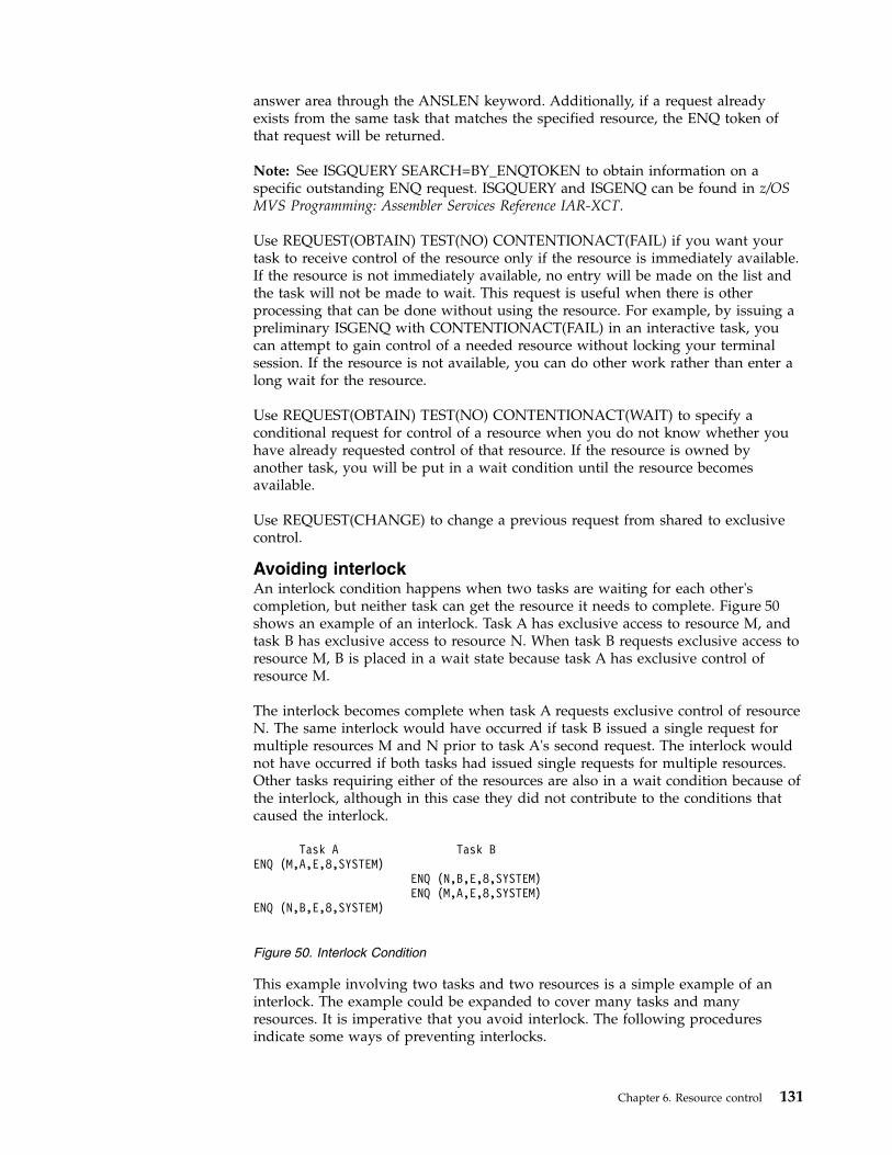
answer area through the ANSLEN keyword. Additionally, if a request alreadyexists from the same task that matches the specified resource, the ENQ token ofthat request will be returned.
Note: See ISGQUERY SEARCH=BY_ENQTOKEN to obtain information on aspecific outstanding ENQ request. ISGQUERY and ISGENQ can be found in z/OSMVS Programming: Assembler Services Reference IAR-XCT.
Use REQUEST(OBTAIN) TEST(NO) CONTENTIONACT(FAIL) if you want yourtask to receive control of the resource only if the resource is immediately available.If the resource is not immediately available, no entry will be made on the list andthe task will not be made to wait. This request is useful when there is otherprocessing that can be done without using the resource. For example, by issuing apreliminary ISGENQ with CONTENTIONACT(FAIL) in an interactive task, youcan attempt to gain control of a needed resource without locking your terminalsession. If the resource is not available, you can do other work rather than enter along wait for the resource.
Use REQUEST(OBTAIN) TEST(NO) CONTENTIONACT(WAIT) to specify aconditional request for control of a resource when you do not know whether youhave already requested control of that resource. If the resource is owned byanother task, you will be put in a wait condition until the resource becomesavailable.
Use REQUEST(CHANGE) to change a previous request from shared to exclusivecontrol.
Avoiding interlockAn interlock condition happens when two tasks are waiting for each other'scompletion, but neither task can get the resource it needs to complete. Figure 50shows an example of an interlock. Task A has exclusive access to resource M, andtask B has exclusive access to resource N. When task B requests exclusive access toresource M, B is placed in a wait state because task A has exclusive control ofresource M.
The interlock becomes complete when task A requests exclusive control of resourceN. The same interlock would have occurred if task B issued a single request formultiple resources M and N prior to task A's second request. The interlock wouldnot have occurred if both tasks had issued single requests for multiple resources.Other tasks requiring either of the resources are also in a wait condition because ofthe interlock, although in this case they did not contribute to the conditions thatcaused the interlock.
This example involving two tasks and two resources is a simple example of aninterlock. The example could be expanded to cover many tasks and manyresources. It is imperative that you avoid interlock. The following proceduresindicate some ways of preventing interlocks.
Task A Task BENQ (M,A,E,8,SYSTEM)
ENQ (N,B,E,8,SYSTEM)ENQ (M,A,E,8,SYSTEM)
ENQ (N,B,E,8,SYSTEM)
Figure 50. Interlock Condition
Chapter 6. Resource control 131

v Do not request resources that you do not need immediately. If you can use theserially reusable resources one at a time, request them one at a time and releaseone before requesting the next.
v Share resources as much as possible. If the requests in the lists shown inFigure 50 on page 131 had been for shared control, there would have been nointerlock. This does not mean you should share a resource that you will modify.It does mean that you should analyze your requirements for the resourcescarefully, and not request exclusive control when shared control is enough.
v If you need concurrent use of more than one resource, use the ENQ macro torequest control of all such resources at the same time. The requesting program isplaced in a wait condition until all of the requested resources are available.Those resources not being used by any other program immediately becomeexclusively available to the waiting program. For example, instead of coding thetwo ENQ macros shown in Figure 51, you could code the one ENQ macroshown in Figure 52. If all requests were made in this manner, the interlockshown in Figure 50 on page 131 could not occur. All of the requests from onetask would be processed before any of the requests from the second task. TheDEQ macro can release a resource as soon as it is no longer needed; multipleresources requested in a single ENQ invocation can be released individuallythrough separate DEQ instructions.
v If the use of one resource always depends on the use of a second resource, thenyou can define the pair of resources as one resource. On the ENQ and DEQmacros, define the pair with a single rname and qname. You can use thisprocedure for any number of resources that are always used in combination.However, the control program cannot then protect these resources if they arealso requested independently. Any requests must always be for the set ofresources.
v If there are many users of a group of resources and some of the users requirecontrol of a second resource while retaining control of the first resource, it is stillpossible to avoid interlocks. In this case, each user should request control of theresources in the same order. For instance, if resources A, B, and C are requiredby many tasks, the requests should always be made in the order of A, B, andthen C. An interlock situation will not develop, since requests for resource A willalways precede requests for resource B.
v When multiple resources are ENQed, all users must acquire the resources in thesame manner. If one user gets resources individually, all users must acquire theresources individually. If one user gets the resources through a single list, allusers must acquire the resources in a single list, but the sequence of resourcenames within the lists can be different.
Serializing access to resources through the ISGENQ macroIBM recommends using ISGENQ RESERVEVOLUME=NO, but you can also useISGENQ RESERVEVOLUME=YES or the RESERVE macro to serialize access whenthe following is true:
ENQ (NAME1ADD,NAME2ADD,E,8,SYSTEM)ENQ (NAME3ADD,NAME4ADD,E,10,SYSTEM)
Figure 51. Two Requests For Two Resources
ENQ (NAME1ADD,NAME2ADD,E,8,SYSTEM,NAME3ADD,NAME4ADD,E,10,SYSTEM)
Figure 52. One Request For Two Resources
132 z/OS MVS Assembler Services Guide

v The resource needs to be shared outside of the GRS complex. See z/OS MVSPlanning: Global Resource Serialization for more information about GRS Complexesand the use of RESERVE.
v Your installation is not using SMS to manage the shared data sets.
Obtaining a reserve increases the probability of contention for resources and thepossibility of interlocks. If you use a reserve to serialize access to data sets onshared DASD, use ISGENQ REQUEST=RELEASE or the DEQ macro to release theresource.
When different systems in your installation access data sets on shared DASD, youcan specify the keyword RESERVEVOLUME=YES with a scope of SYSTEMS orSYSPLEX on the ISGENQ macro to serialize access to those resources. That is,RESERVEVOLUME=YES is used when a hardware reserve is required to allowglobal resource serialization to share a DASD volume outside of the complex.
Collecting information about resources and their requestors(ISGQUERY and GQSCAN macros)
ISGQUERY is the IBM recommended replacement for the GQSCAN service.
Global resource serialization enables an installation to share symbolically namedresources. Programs issue the ENQ and RESERVE macros to request access toresources; global resource serialization adds information about each requestor tothe appropriate resource queue. The only way you can extract information fromthe resource queues is by using the ISGQUERY or GQSCAN macro.
The ISGQUERY macro allows you to obtain information about the status of eachresource identified to global resource serialization, which includes informationabout the tasks that have requested the resource. ISGQUERY fully supports 64-bitcallers.
How ISGQUERY returns resource informationUsing ISGQUERY the system returns information you request about the status ofeach resource identified to global resource serialization, which includes informationabout the tasks that have requested the resource. ISGQUERY fully supports 64-bitcallers. Use the ISGQUERY service to inquire about:v A particular scope of resources (such as STEP, SYSTEM, or SYSTEMS).v A specific resource by name.v A specific system or systems resource.v A specific address space resource.v Resources that are requested through the RESERVE macro.
The system collects the information you request from the resource queues andconsolidates that information before returning it. The ISGQUERY service returnsthe following types of global resource serialization information:v REQINFO=RNLSEARCH: To determine if a given resource name is in the
current Resource Name Lists (RNL).v REQINFO=ENQSTATS: To obtain information related to ENQ counts.v REQTYPE=QSCAN: To obtain information on resources and requesters of
outstanding ENQ requests.v REQINFO=LATCHECA: To obtain enhanced contention analysis data for latch
waiters that might indicate contention issues.
Chapter 6. Resource control 133

v REQINFO=USAGESTATS: To obtain information for address space levelcontention information related to ENQs (all scopes) and latches (all latch sets).
See z/OS MVS Programming: Assembler Services Reference IAR-XCT for additionalinformation.
How GQSCAN returns resource informationUsing GQSCAN, you can inquire about a particular scope of resources (such asSTEP, SYSTEM, or SYSTEMS), a specific resource by name, a specific system'sresources, a specific address space's resources, or resources requested through theRESERVE macro. The system collects the information you request from theresource queues and consolidates that information before returning it. Theinformation returned might not reflect changes in the resource queue that occurwhile the system collects the information.
The system returns the information you request in an area whose location and sizeyou specify using the AREA parameter. The size of the area, the scope of theresource, and whether you code the TOKEN parameter determine the informationyou receive from GQSCAN. Use the TOKEN parameter when you design yourprogram to issue repeated calls to GQSCAN for the same request. For example, ifyou request information about a resource that is shared across systems, the amountof information might be more than will fit in the area that you provide. Using theTOKEN parameter allows you to issue subsequent calls to receive additionalinformation about that resource.
GQSCAN returns the information in the form of resource information blocks (RIB)and resource information block extensions (RIBE), as shown in the followingfigure. The RIB and the RIBE are described in z/OS MVS Data Areas in the z/OSInternet library (www.ibm.com/systems/z/os/zos/library/bkserv).
In the RIB, the following fields contain information on RIBEs:v RIBTRIBE contains the total number of RIBEs associated with this RIB.v RIBNRIBE contains the total number of RIBEs associated with this RIB that
GQSCAN could fit into the area specified on the AREA parameter.
RIB A Resource Information block (RIB) describes a resource
RIB extension (RIBE) describes resource requestorRIBE A1
RIBE A2
RIBE A3
RIBE B1
RIB B
RIBE B2
134 z/OS MVS Assembler Services Guide

v RIBEDEVN contains a 4-digit EBCDIC device number for RESERVEs issued onthe system. For RESERVEs issued on other systems, RIBEDEVN contains zero.
If the value in RIBNRIBE is less than the value in RIBTRIBE, you may need tospecify a larger area with the AREA parameter.
The number of RIBs and RIBEs you receive for a particular resource depends onthe size of the area you provide, and the scope and token values you specify onthe GQSCAN macro.
How area size determines the information GQSCAN returnsThe size of the area you provide must be large enough to hold one RIB and atleast one of its associated RIBEs; otherwise, you might lose information aboutresource requestors, or you might have to call GQSCAN repeatedly to receive all ofthe information you requested. To determine whether you have received all RIBEsfor a particular RIB, check the values in the RIBTRIBE and RIBNRIBE fields. Todetermine whether you have received all of the information on the resource queue,check the return code from GQSCAN.
IBM recommends that you use a minimum area size of 1024 bytes.
The information that GQSCAN returns in the area also depends on what valuesyou specify for the SCOPE and TOKEN parameters.
How scope and token values determine the information GQSCANreturnsTable 7 summarizes the possible values and the information returned for aGQSCAN request.
Table 7. GQSCAN Results with a Scope of STEP, SYSTEM, SYSTEMS, or ALL
GQSCANInvocation
TOKEN ParameterCoded? Information Returned
Initial call No At least the first RIB that represents the firstrequestor on the resource queue, and as many ofthat RIB's associated RIBEs as will fit. Any RIBEsthat do not fit are not returned to the caller.
If all of the RIBEs fit, GQSCAN returns the nextRIB on the resource queue, as long as theremaining area is large enough to hold that RIBand at least one of its RIBEs.
Initial call Yes; value is zero At least the first RIB that represents the firstrequestor on the resource queue, and as many ofthat RIB's associated RIBEs as will fit. Any RIBEsthat do not fit are not returned to the caller.
If all of the RIBEs fit, GQSCAN returns the nextRIB on the resource queue, as long as theremaining area is large enough to hold that RIBand all of its RIBEs.
Chapter 6. Resource control 135
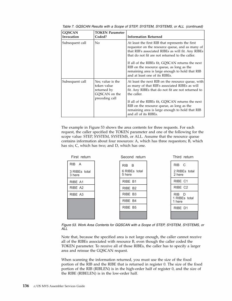
Table 7. GQSCAN Results with a Scope of STEP, SYSTEM, SYSTEMS, or ALL (continued)
GQSCANInvocation
TOKEN ParameterCoded? Information Returned
Subsequent call No At least the first RIB that represents the firstrequestor on the resource queue, and as many ofthat RIB's associated RIBEs as will fit. Any RIBEsthat do not fit are not returned to the caller.
If all of the RIBEs fit, GQSCAN returns the nextRIB on the resource queue, as long as theremaining area is large enough to hold that RIBand at least one of its RIBEs.
Subsequent call Yes; value is thetoken valuereturned byGQSCAN on thepreceding call
At least the next RIB on the resource queue, withas many of that RIB's associated RIBEs as willfit. Any RIBEs that do not fit are not returned tothe caller.
If all of the RIBEs fit, GQSCAN returns the nextRIB on the resource queue, as long as theremaining area is large enough to hold that RIBand all of its RIBEs.
The example in Figure 53 shows the area contents for three requests. For eachrequest, the caller specified the TOKEN parameter and one of the following for thescope value: STEP, SYSTEM, SYSTEMS, or ALL. Assume that the resource queuecontains information about four resources: A, which has three requestors; B, whichhas six; C, which has two; and D, which has one.
Note that, because the specified area is not large enough, the caller cannot receiveall of the RIBEs associated with resource B, even though the caller coded theTOKEN parameter. To receive all of those RIBEs, the caller has to specify a largerarea and reissue the GQSCAN request.
When scanning the information returned, you must use the size of the fixedportion of the RIB and the RIBE that is returned in register 0. The size of the fixedportion of the RIB (RIBLEN) is in the high-order half of register 0, and the size ofthe RIBE (RIBELEN) is in the low-order half.
First return Second return Third return
3 RIBEs total
3 here
6 RIBEs total
5 here
2 RIBEs total
2 here
1 RIBEs total
1 here
RIBE B1 RIBE C1
RIBE C2
RIBE D1
RIB D
RIBE A1
RIBE A2
RIBE A3
RIB B RIB CRIB A
RIBE B2
RIBE B3
RIBE B4
RIBE B5
Figure 53. Work Area Contents for GQSCAN with a Scope of STEP, SYSTEM, SYSTEMS, orALL
136 z/OS MVS Assembler Services Guide

The first RIB starts at the beginning of the workarea you specify on the AREAparameter. To find the first RIBE, add the value of RIBLEN and the variableportion of RIB (as found in the RIBVLEN field of the RIB) to the address of theworkarea. To find the second RIBE, add the value of RIBELEN to the address ofthe first RIBE.
To find the second RIB, add the following to the location of the first RIB:RIBLEN + RIBVLEN + (the number of RIBEs × RIBELEN)
How GRS determines the scope of an ENQ or RESERVErequest
Global resource serialization may change the scope of an ENQ or RESERVE requestthat was issued with a SCOPE of SYSTEM or SYSTEMS (unless the requestspecified RNL=NO).
If an ENQ is issued with a scope of SYSTEM, and matches an entry in the SYSTEMinclusion RNL but does not match an entry in the SYSTEMS exclusion RNL, thenglobal resource serialization changes the scope of the request from SYSTEM toSYSTEMS (and processes the resource as a global resource). A GQSCAN withSCOPE=SYSTEM will not find a match on such a request.
If an ENQ or RESERVE is issued with a scope of SYSTEMS, and either it matchesan entry in the SYSTEMS exclusion RNL, or the system is running withGRSRNL=EXCLUDE, then GRS changes the scope of the request from SYSTEMS toSYSTEM (and processes the resource as a local resource). A GQSCAN withSCOPE=SYSTEMS will not find a match on such a request.
When issuing a GQSCAN for a resource whose scope might have been changed,you might find it desirable to specify SCOPE=ALL in order to match requestswhether or not they have been changed.
Chapter 6. Resource control 137

138 z/OS MVS Assembler Services Guide

Chapter 7. Program interruption services
Some conditions encountered in a program cause a program interruption. Theseconditions include incorrect parameters and parameter specifications, as well asexceptional results, and are known generally as program exceptions. The programstatus word's (PSW) program mask provide bits to control certain programexceptions. When MVS gives control to programs, these bits are usually off,disabling the program exceptions. However, MVS also provides the ESPIE andSPIE services to enable program exceptions and to allow a user exit routine toreceive control when those exceptions occur. This chapter describes the use ofESPIE and SPIE services.
Specifying user exit routinesBy issuing the SPIE1 or ESPIE macro, you can specify your own exit routine to begiven control for one or more types of program exceptions. If you issue an ESPIEmacro, you can also pass the address of a parameter list to the exit routine. Whenone of the specified program exceptions occurs in a problem state program beingexecuted in the performance of a task, the exit routine receives control in the keyof the active task and in the addressing mode in effect when the SPIE or ESPIEwas issued. (If a SPIE macro was issued, this is 24-bit addressing mode.)
For other program interruptions, the recovery termination manager (RTM), getscontrol.
If the SPIE or ESPIE macro specifies an exception for which the interruption hasbeen disabled, the system enables the interruption when the macro is issued.
If a program interruption occurs, the exit routine receives control on interruptcodes 0 through F. For the SPIE macro, the exit routine receives control only if theinterrupted program is in primary address space control (ASC) mode. For theESPIE macro, the exit routine receives control if the interrupted program is ineither primary or access register (AR) ASC mode. For both the SPIE and ESPIEmacros, the exit routine receives control only for interrupts that occur when theprimary, home, and secondary address spaces are the same.
The environment established by an ESPIE macro exists for the entire task, until theenvironment is changed by another SPIE/ESPIE macro, or until the programcreating the ESPIE returns. Each succeeding SPIE or ESPIE macro completelyoverrides specifications in the previous SPIE or ESPIE macro. You can intermixSPIE and ESPIE macros in one program. Only one SPIE or ESPIE environment isactive at a time. If an exit routine issues an ESPIE macro, the new ESPIEenvironment does not take effect until the exit routine completes.
The system automatically deletes the SPIE/ESPIE exit routine when the requestblock (RB) that established the exit terminates. If a caller attempts to delete aspecific SPIE/ESPIE environment established under a previous RB, the caller isabended with a system completion code of X'46D'. A caller can delete all previousSPIE and ESPIE environments (regardless of the RB under which they were
1. The ESPIE macro is the preferred programming interface.
© Copyright IBM Corp. 1988, 2017 139

established) by specifying a token of zero with the RESET option of the ESPIEmacro or an exit address of zero with the SPIE macro.
A program, executing in either 24-bit or 31-bit addressing mode in the performanceof a task, can issue the ESPIE macro. If your program is executing in 31-bitaddressing mode, you cannot issue the SPIE macro. The SPIE macro is restricted inuse to callers executing in 24-bit addressing mode in the performance of a task.The following topics describe how to use the SPIE and ESPIE macros.
Using the SPIE macroThe program interruption control area (PICA) and the program interruptionelement (PIE) contain the information that enables the system to interceptuser-specified program interruptions established using the SPIE macro. You canmodify the contents of the active PICA to change the active SPIE environment. ThePICA and the PIE are described in the following topics.
Program interruption control areaThe expansion of each standard or list form of the SPIE macro contains a systemparameter list called the program interruption control area (PICA). The PICAcontains the new program mask for the interruption types that can be disabled inthe PSW, the address of the exit routine to be given control when one of thespecified interruptions occurs, and a code for interruption types (exceptions)specified in the SPIE macro. For the mapping provided by the IHAPICA mappingmacro, see PICA in z/OS MVS Data Areas in the z/OS Internet library(www.ibm.com/systems/z/os/zos/library/bkserv).
The system maintains a pointer (in the PIE) to the PICA referred to by the lastSPIE macro executed. This PICA might have been created by the last SPIE or mighthave been created previously and referred to by the last SPIE. Before returningcontrol to the calling program or passing control to another program through anXCTL or XCTLX macro, each program that issues a SPIE macro must cause thesystem to adjust the SPIE environment to the condition that existed previously orto eliminate the SPIE environment if one did not exist on entry to the program.When you issue the standard or execute form of the SPIE macro to establish a newSPIE environment, the system returns the address of the previous PICA in register1. If no SPIE/ESPIE environment existed when the program was entered, thesystem returns zeroes in register 1.
You can cancel the effect of the last SPIE macro by issuing a SPIE macro with noparameters. This action does not reestablish the effect of the previous SPIE; it doescreate a new PICA that contains zeroes, thus indicating that you do not want anexit routine to process interruptions. You can reestablish any previous SPIEenvironment, regardless of the number or type of subsequent SPIE macros issued,by using the execute form of the SPIE specifying the PICA address that the systemreturned in register 1. The PICA whose address you specify must still be valid (notoverlaid). If you specify zeroes as the PICA address, the SPIE environment iseliminated.
Figure 54 on page 141 shows how to restore a previous PICA. The first SPIE macrodesignates an exit routine called FIXUP that is to be given control if fixed-pointoverflow occurs. The address returned in register 1 is stored in the fullword calledHOLD. At the end of the program, the execute form of the SPIE macro is used torestore the previous PICA.
140 z/OS MVS Assembler Services Guide

Program interruption elementThe first time you issue a SPIE macro during the performance of a task, the systemcreates a program interruption element (PIE) in the virtual storage area assigned toyour job step. The system also creates a PIE whenever you issue a SPIE macro andno PIE exists. For the format of the PIE, see z/OS MVS Data Areas in the z/OSInternet library (www.ibm.com/systems/z/os/zos/library/bkserv).
The PICA address in the PIE is the address of the program interruption controlarea used in the last execution of the SPIE macro for the task. When control ispassed to the routine indicated in the PICA, the ESA/390 (basic control) mode oldprogram status word contains the interruption code in bits 16-31 (the first byte isthe exception extension code and the second is the exception code); you can testthese bits to determine the cause of the program interruption. See z/ArchitecturePrinciples of Operations SA22–7832 for an explanation of the format of the oldprogram status word. The system stores the contents of registers 14, 15, 0, 1, and 2at the time of the interruption as indicated.
Using the ESPIE macroThe ESPIE macro extends the functions of the SPIE macro to callers in 31-bitaddressing mode. The options that you can specify using the ESPIE macro are:v SET to establish an ESPIE environment (that is, specify the interruptions for
which the user-exit routine will receive control)v RESET to delete the current ESPIE environment and restore the SPIE/ESPIE
environment specifiedv TEST to determine the active SPIE/ESPIE environment
If you specify ESPIE SET, you pass the following information to the system:v A list of the program interruptions to be handled by the exit routinev The location of the exit routinev The location of a user-defined parameter list
The system returns either a token representing the previously active SPIE or ESPIEenvironment, or a token of zeroes if there was none.
If you code ESPIE RESET, you pass the token, which was returned when the ESPIEenvironment was established, back to the system. The SPIE or ESPIE environmentcorresponding to the token is restored. If you pass a token of zero with RESET, allSPIE and ESPIE environments are deleted. ESPIE RESET must not be issued from
.
.SPIE FIXUP,(8) Provide exit routine for fixed-point overflowST 1,HOLD Save address returned in register 1..L 5,HOLD Reload returned addressSPIE MF=(E,(5)) Use execute form and old PICA address..
HOLD DC F’0’
Figure 54. Using the SPIE Macro
Chapter 7. Program interruption services 141
an ESPIE exit. To remove the current ESPIE exit, set the EPIEPERC bit and specifythe RESET token in EPIETOK. See “Requesting percolation from an ESPIE exit” onpage 143 for more information.
If you specify ESPIE TEST, you will be able to determine the active SPIE or ESPIEenvironment. ESPIE TEST sets return codes to indicate which type of exit is active,if any, and if one or the other is active, provides information about the exit in aparameter list. Refer to the TEST parameter on the ESPIE macro for a descriptionof the return codes, and the information that is returned in the parameter list.
If an ESPIE environment is active and you issue a SPIE macro to specifyinterruptions for which a SPIE exit routine is to receive control, the system returnsthe address of a system-generated PICA in register 1. Do not modify the contentsof the system-generated PICA; use the address to restore the previous ESPIEenvironment.
For a data exception,an ESPIE routine will receive the DXC value in its parameterarea, and should use this value rather than the value in the Floating Point Control(FPC) register.
If a retry is to be done, an ESPIE routine can manually change the value(s) of theFPR(s) and FPC register. Changes to the non-volatile fields (i.e., the IEEE settings)in the FPC register must be made carefully since this could affect the processing ofthe rest of the current program, and possibly subsequent programs.
The extended program interruption element (EPIE)The system creates an EPIE the first time you issue an ESPIE macro during theperformance of a task or whenever you issue an ESPIE macro and no EPIE exists.The EPIE is freed when you eliminate the ESPIE environment.
The EPIE contains the information that the system passes to the ESPIE exit routinewhen it receives control after a program interrupt. When the exit routine receivescontrol, register 1 contains the address of the EPIE. (See the topic “Environmentupon entry to user's exit routine” for the contents of the other registers.) Theformat of the EPIE is shown in z/OS MVS Data Areas in the z/OS Internet library(www.ibm.com/systems/z/os/zos/library/bkserv).
Environment upon entry to user's exit routineWhen control is passed to your routine, the register contents are as follows:
Register 0:Used as a work register by the system.
Register 1:Address of the PIE or EPIE for the task that caused the interruption.
Registers 2-13:Unchanged.
Register 14:Return address.
Register 15:Address of the exit routine.
The access registers and linkage stack have the values that were current at the timeof the program interruption. Both SPIE and ESPIE exits always receive control inprimary ASC mode.
142 z/OS MVS Assembler Services Guide

The SPIE or ESPIE routine must maintain the return address supplied in GPR 14.The routine does not have to place any information in any of the return registersfor use by the system.
Functions performed in user exit routinesYour exit routine must determine the type of interruption that occurred beforetaking corrective action. Determining the type of interruption depends on whetherthe exit is associated with an ESPIE or a SPIE macro.v For an ESPIE, your exit routine can check the two-byte interruption code (the
first byte is the exception extension code and the second is the exception code)in the second halfword of the EPIEINT field in the EPIE.
v For a SPIE, your exit routine can test bits 16 through 31 (the first byte is theexception extension code and the second is the exception code) of the oldprogram status word (OPSW in ESA/390 mode) in the PIE.
Note: For both ESPIE and SPIE – If you are using vector instructions and anexception of 8, 12, 13, 14, or 15 occurs, your exit routine can check the exceptionextension code (the first byte of the two-byte interruption code in the EPIE or PIE)to determine whether the exception was a vector or scalar type of exception.
For more information about the exception extension code, see IBM System/370Vector Operations.
Your exit routine can alter the contents of the registers when control is returned tothe interrupted program. The procedure for altering the registers also depends onwhether the exit is associated with an ESPIE or a SPIE.v For an ESPIE exit, the exit routine can alter the contents of general purpose and
access registers 0 through 15 in the save area in the EPIE.v For a SPIE exit, the exit routine can alter general purpose registers 14 through 2
in the register save area in the PIE. To change registers 3 through 13, the exitroutine must alter the contents of the registers themselves.
The exit routine can also alter the last four bytes of the OPSW in the PIE or EPIE.For an ESPIE, the exit routine alters the condition code and program mask startingat the third byte in the OPSW. By changing the OPSW, the routine can select anyreturn point in the interrupted program. In addition, for ESPIE exits, the routinemust set the AMODE bit of this four-byte address to indicate the addressing modeof the interrupted program.
ESPIE exit routines can alter the ASC mode when control is returned to theinterrupted program if the EPIEVERS field in the EPIE contains a value greaterthan zero. This value is set by the system. To alter the ASC mode of theinterrupted program, the exit must do the following:v Set bit 17 of the EPIEPSW field in the EPIE. If this bit is 0 when control is
returned to the interrupted program, the program receives control in primaryASC mode. If this bit is 1 when control is returned to the interrupted program,the program receives control in AR ASC mode.
v Set the EPIERCTL bit in the EPIE to indicate that the ASC mode for theinterrupted program has been set by the exit routine.
Requesting percolation from an ESPIE exitESPIE exits can request percolation of a program exception to the recoverytermination manager (RTM) instead of returning control to the interruptedprogram.
Chapter 7. Program interruption services 143

If an ESPIE exit determines that a program exception must be handled by RTM,the ESPIE exit can turn on the EPIEPERC bit to request that the exception bepassed to RTM for normal recovery processing. When an ESPIE exit requestspercolation, RTM converts the program exception to an abend code (for example,PIC 1 becomes abend 0C1) and passes control to ESTAE-type recovery routines.
Note: When the EPIEPERC bit is set, the ESPIE exit routine must not modify thePSW and registers in the EPIE.
When functional recovery routines (FRR) and ESTAE-type recovery routinespercolate, the system deletes the exit routines. When an ESPIE exit percolates, theESPIE exit remains active and is not deleted. To request that the ESPIE exit isdeleted when it percolates, set the EPIERSET bit and optionally specify a RESETTOKEN in the EPIERTOK field.
Note: ESPIE exits must not issue ESPIE RESET.
144 z/OS MVS Assembler Services Guide

Chapter 8. Providing recovery
In an ideal world, the programs you write would run perfectly, and neverencounter an error, either software or hardware. In the real world, programs doencounter errors that can result in the premature end of the program's processing.These errors could be caused by something your program does, or they could bebeyond your program's control.
MVS allows you to provide something called recovery for your programs; thatmeans you can anticipate and possibly recover from software errors that couldprematurely end a program. To recover from these errors, you must have one ormore user-written routines called recovery routines. The general idea is that, whensomething goes wrong, you have a recovery routine standing by to take over, fixthe problem, and return control to your program so that processing can completenormally; if the problem cannot be fixed, the recovery routine would provideinformation about what went wrong. If correctly set up, your recovery should, atthe very least, provide you with more information about what went wrong withyour program than you would have had otherwise.
Part of recovery is also the "cleaning up" of any resources your program mighthave acquired. By "clean up" of resources, we mean that programs might need torelease storage that was obtained, release ENQs, close data sets, and so on. If yourprogram encounters an error before it has the opportunity to clean up resources,your recovery routine can do the clean up.
MVS provides the recovery termination manager (RTM) to handle the process bywhich recovery routines and resource managers receive control.
This chapter is devoted to explaining why you might want to provide recovery foryour programs in anticipation of encountering one or more errors, and how you goabout doing that. An important point to note is that providing recovery issomething to be considered at the design stage of your program. You should makethe decision about whether to provide recovery before you begin designing theprogram. Trying to provide recovery for an existing program is much moredifficult because recovery must be an integral part of your program.
The following table provides a roadmap to the information in this chapter. If youalready understand recovery concepts, you might want to skip directly to thosetopics of specific interest to you.
© Copyright IBM Corp. 1988, 2017 145
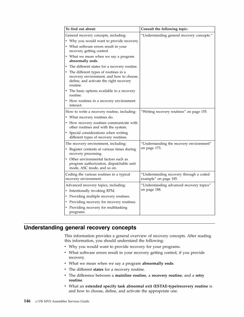
To find out about: Consult the following topic:
General recovery concepts, including:
v Why you would want to provide recovery.
v What software errors result in yourrecovery getting control.
v What we mean when we say a programabnormally ends.
v The different states for a recovery routine.
v The different types of routines in arecovery environment, and how to choose,define, and activate the right recoveryroutine.
v The basic options available to a recoveryroutine.
v How routines in a recovery environmentinteract.
“Understanding general recovery concepts.”
How to write a recovery routine, including:
v What recovery routines do.
v How recovery routines communicate withother routines and with the system.
v Special considerations when writingdifferent types of recovery routines.
“Writing recovery routines” on page 155.
The recovery environment, including:
v Register contents at various times duringrecovery processing.
v Other environmental factors such asprogram authorization, dispatchable unitmode, ASC mode, and so on.
“Understanding the recovery environment”on page 173.
Coding the various routines in a typicalrecovery environment.
“Understanding recovery through a codedexample” on page 185.
Advanced recovery topics, including:
v Intentionally invoking RTM.
v Providing multiple recovery routines.
v Providing recovery for recovery routines.
v Providing recovery for multitaskingprograms
“Understanding advanced recovery topics”on page 188.
Understanding general recovery conceptsThis information provides a general overview of recovery concepts. After readingthis information, you should understand the following:v Why you would want to provide recovery for your programs.v What software errors result in your recovery getting control, if you provide
recovery.v What we mean when we say a program abnormally ends.v The different states for a recovery routine.v The difference between a mainline routine, a recovery routine, and a retry
routine.v What an extended specify task abnormal exit (ESTAE-type)recovery routine is
and how to choose, define, and activate the appropriate one.
146 z/OS MVS Assembler Services Guide

v The difference between what it means to retry and what it means to percolate.v How routines in a recovery environment interact.
Deciding whether to provide recoveryMVS does all that it can to ensure the availability of programs, and to protect theintegrity of system resources. However, MVS cannot provide effective recovery forevery individual application program, so programs need recovery routines of theirown.
To decide whether you need to provide recovery for a particular program, and theamount of recovery to provide, you should:v Determine what the consequences will be if the program encounters an error
and ends.v Compare the cost of tolerating those consequences to the cost of providing
recovery.
In general, if you have a large, complex program upon which a great number ofusers depend, such as a subsystem, a database manager, or any application thatprovides an important service to many other programs or end users, you willalmost certainly want to provide recovery. For small, simple programs upon whichvery few users depend, you might not get enough return on your investment.Between these two extremes is a whole spectrum of possibilities.
Consider the following points in making your decision. Providing recovery:v Increases your program's availability.
Depending on the nature of the error, your recovery routine might successfullycorrect the error and allow your program to continue processing normally.Maintaining maximum availability is one of the major objectives of providingrecovery.
v Is a way to protect both system and application resources.In general, recovery routines should clean up any resources your program isholding that might be requested by another program, or another user of yourprogram. The purpose of clean up is to:– Allow your program to run again successfully without requiring a re-IPL– Allow the system to continue to run other work (consider especially other
work related to the failing program).Virtual storage and ENQs are examples of important resources shared by otherprograms. A program should provide for the release of these resources if anerror occurs so that other programs can access them.
Note: ENQs are used for serialization. See Chapter 6, “Resource control,” onpage 115 for more information about serialization.Recovery routines should also ensure the integrity of any data being accessed.Consider the case of a database application that is responsible for protecting itsdatabase resources. The application must ensure the integrity and consistency ofthe data in the event an error occurs. Data changes that were made prior to theerror might have to be backed out from the database.
v Provides for communication between different processes.
An example of this would be a task that sends a request to another task. If thesecond task encounters an error, a recovery routine could inform the first taskthat its request will not be fulfilled.
Chapter 8. Providing recovery 147

When dealing with a multi-tasking environment, you must plan your recoveryin terms of the multiple tasks involved. You must have a cohesive scheme thatprovides recovery for the set of tasks rather than thinking only in terms of asingle task.
v Is a way to help you determine what went wrong when an error occurs inyour program.
Recovery routines can do such things as save serviceability data and requestdumps to help determine what went wrong in your program. These actions areexplained in greater detail later in this chapter.
v Facilitates validity checking of user parameters.
Consider the case of a program that must verify input from its callers. Theprogram does parameter validation, but might not catch all variations. Forexample, the caller might pass the address of an input data area that appears tobe valid; however, the caller did not have access to that storage. When theprogram attempts to update the data area, a protection exception occurs. Arecovery routine could intercept this error, and allow the program to pass back areturn code to the caller indicating the input was not valid.Providing recovery in a case like this improves the reliability of your program.
If you do not provide recovery for your program, and your program encounters anerror, MVS handles the problem to some extent, but the result is that your programends before you expected it to, and application resources might not be cleaned up.
Understanding errors in MVSCertain errors, which your program or the system can detect, trigger the system tointerrupt your program and pass control to your recovery routine (or routines) ifyou have any; if you do not have any recovery routines, the system abnormallyends your program. This chapter uses the term abnormal end when your programends for either of the following reasons:v Your program encounters an error for which it has no recovery routinesv Your program encounters an error for which its recovery routines are not
successful.
The errors for which you, or the system, might want to interrupt your program aregenerally those that might degrade the system or destroy data.
The following are some examples of errors that would cause your recovery routine(if you have one) to get control:v Unanticipated program checks (except those resolved by SPIE or ESPIE routines;
see Chapter 7, “Program interruption services,” on page 139 for informationabout SPIE and ESPIE routines.)
v Machine checks (such as a storage error that occurs while your program isrunning)
v Various types of CANCEL (such as operator or time out)v An error when issuing an MVS macro or callable service (for example,
specifying parameters that are not valid)
Each of the preceding errors has associated with it one or more system completioncodes. All system completion codes are described in z/OS MVS System Codes. Youcan write your recovery routine to specifically handle one or more of these systemcompletion codes, or define your own user completion codes and handle one ormore of them. Completion codes associated with errors are also referred to as abendcodes.
148 z/OS MVS Assembler Services Guide

As stated earlier, the system can detect errors, but your program also can detecterrors and request that the system pass control to recovery routines. To do so, yourprogram can issue the ABEND macro.
Use the ABEND macro to request recovery processing on behalf of the current unitof work. Your program might choose to issue the ABEND macro if it detects animpossible or illogical situation and cannot proceed further. For example, yourprogram might be passed parameters that are not valid, or might detect somethingin the environment that is not valid. Your program might also choose to issue theABEND macro so that its recovery routine can get control to save serviceabilityinformation.
Understanding recovery routine statesIn this chapter we talk about recovery routines being in one of the following states:v Defined
A recovery routine is defined when you make it known to the system. Forexample, you might issue a macro on which you specify a particular recoveryroutine. At the point of issuing that macro, the recovery routine is defined to thesystem.
v Activated
A recovery routine is activated when it is available to receive control; if an erroroccurs, the system can pass control to an activated recovery routine. Dependingon the type of recovery routine, it might be defined to the system but not yetactivated. Some recovery routines are both defined and activated by issuing asingle macro.
v In control
A recovery routine is in control when it is running; an error has occurred andthe system passed control to the recovery routine.
v No longer in control
A recovery routine is no longer in control when it returns control to the system.The recovery routine returns control either by requesting to percolate or retry(terms defined later in this chapter) and issuing a BR 14 instruction, or byencountering an error itself.
v Deactivated
A recovery routine is deactivated when it is no longer available to receivecontrol; if an error occurs, the system will not pass control to a deactivatedrecovery routine. Depending on the type of recovery routine, it might bedeactivated but still defined to the system. For some recovery routines, issuing asingle macro results in the routine becoming both deactivated and no longerdefined.
v No longer defined
A recovery routine is no longer defined when it is no longer known to thesystem. The routine might still exist and be in virtual storage, but the system nolonger recognizes it as a recovery routine.
Understanding the various routines in a recovery environmentThis chapter discusses the following different types of routines that interact in arecovery environment:v Mainline routinev Recovery routinev Retry routine (also known as a retry point)
Chapter 8. Providing recovery 149

All of these routines are user-written routines.
Mainline routineThe mainline routine is that portion of your program that does the work, orprovides the required function. In general, the mainline routine defines andactivates the recovery routine. Before returning to its caller, the mainline shouldalso deactivate the recovery routine and request that it be no longer defined. Whenan error occurs in the mainline routine, the system passes control to the recoveryroutine.
Recovery routineA recovery routine is the routine to which the system passes control when an erroroccurs in the mainline routine. The recovery routine's objective is to intercept theerror and potentially perform one or more of the following tasks:v Eliminate or minimize the effects of the errorv Allow the mainline routine to resume normal processingv Clean up resourcesv Communicate with other programs as appropriatev Provide serviceability datav Request a dumpv Validate user parametersv Provide one or more recovery routines for itself.
The recovery routine can be an entry point in your program that processes onlywhen an error occurs, or it can be a separate routine that gets control when theerror occurs.
Retry routineA retry routine is essentially an extension of the mainline routine. When an erroroccurs, the system passes control to your recovery routine, which can then requestthe system to pass control back to the mainline routine to resume processing. Thatportion of the mainline that gets control back is referred to as the retry routine.When the retry routine gets control, it is as if the mainline routine branched thereafter encountering the error; to the mainline routine, it appears as though the errornever occurred.
The retry routine does whatever processing your mainline routine would continuedoing at that point.
Once the retry routine is running, if another error occurs, the system again passescontrol to your recovery routine, just as it did when the mainline routineencountered an error.
Choosing the appropriate recovery routineThe recovery routines you can provide are called ESTAE-type recovery routines.This information describes the different types of ESTAE-type recovery routines,and for each type, describes how you define it, activate it, deactivate it, andrequest that it no longer be defined. A summary of this information is in Table 8 onpage 152.
When you provide one or more recovery routines for your program, you have theopportunity to identify a user parameter area for the system to pass from themainline routine to the recovery routine. Creating such a parameter area withinformation for the recovery routine is a very important part of providing recovery.
150 z/OS MVS Assembler Services Guide

See “Setting up, passing, and accessing the parameter area” on page 162 for moreinformation about what this parameter area should contain, and how to pass it.
Define ESTAE-type recovery routines in the following ways:v STAE, ESTAE, and ESTAEX macrosv ATTACH and ATTACHX macros with STAI and ESTAI parametersv IEAARR macro
The following describes the recovery routines you can define with these macros:v STAE, ESTAE, and ESTAEX macros
To provide recovery to protect itself and any other programs running under thesame task, a program can issue either the STAE, ESTAE, or ESTAEX macro withthe CT parameter. Each of these macros both defines and activates the recoveryroutine. The recovery routine is defined and activated until one of the followingevents occurs:– You deactivate it and request that it be no longer defined (issue STAE 0,
ESTAE 0, or ESTAEX 0).– The recovery routine fails to or chooses not to retry (explained under
“Understanding recovery routine options” on page 152).– The request block (RB) under which the caller of the macro is running
terminates.A program cannot protect other tasks with recovery routines defined throughthese macros.IBM recommends you always use ESTAEX unless your program and yourrecovery routine are in 24-bit addressing mode, in which case, you should useESTAE. ESTAE and ESTAEX provide the same function, except that ESTAEX canbe issued in AR ASC mode.The remainder of this chapter refers to the recovery routines you define andactivate through the ESTAE and ESTAEX macros as ESTAE routines or ESTAEXroutines, respectively.
v ATTACH and ATTACHX macros with STAI and ESTAI parameters
To attach a task and provide recovery to protect the attached task and all of itssubtasks, a program can issue either the ATTACH or the ATTACHX macro witheither the STAI or the ESTAI parameter. You define the recovery routine whenyou issue the macro. The recovery routine is not activated until the attached taskgets control. The recovery routine remains activated as long as the attached taskis still running, or until the recovery routine fails to or chooses not to retry. Thesystem deactivates the recovery routine when the attached task ends. At thatpoint, the recovery routine is no longer defined.The program attaching the task is not protected by the recovery defined in thismanner. Only the attached task and its subtasks are protected.IBM recommends you always use the ESTAI, rather than the STAI, parameteron ATTACHX, rather than ATTACH. ATTACH and ATTACHX provide the samefunction, except that ATTACHX can be issued in AR ASC mode.The remainder of this chapter refers to the recovery routines you define throughATTACHX with ESTAI as ESTAI routines. All references to the ATTACHXmacro apply also to the ATTACH macro.
v IEAARR macro
Use the IEAARR macro to define and activate an associated recovery routine(ARR) to protect the currently running program and any programs it callsrunning under the same task. ARRs provide recovery for stacking PC routines.
Chapter 8. Providing recovery 151
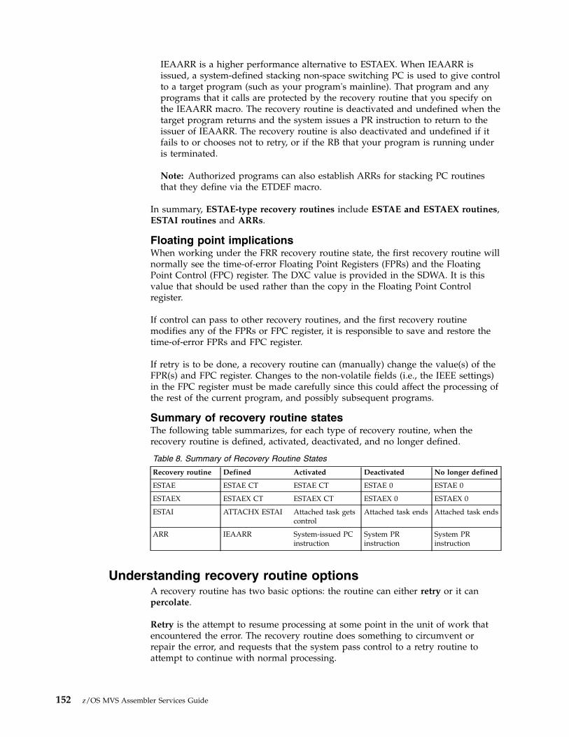
IEAARR is a higher performance alternative to ESTAEX. When IEAARR isissued, a system-defined stacking non-space switching PC is used to give controlto a target program (such as your program's mainline). That program and anyprograms that it calls are protected by the recovery routine that you specify onthe IEAARR macro. The recovery routine is deactivated and undefined when thetarget program returns and the system issues a PR instruction to return to theissuer of IEAARR. The recovery routine is also deactivated and undefined if itfails to or chooses not to retry, or if the RB that your program is running underis terminated.
Note: Authorized programs can also establish ARRs for stacking PC routinesthat they define via the ETDEF macro.
In summary, ESTAE-type recovery routines include ESTAE and ESTAEX routines,ESTAI routines and ARRs.
Floating point implicationsWhen working under the FRR recovery routine state, the first recovery routine willnormally see the time-of-error Floating Point Registers (FPRs) and the FloatingPoint Control (FPC) register. The DXC value is provided in the SDWA. It is thisvalue that should be used rather than the copy in the Floating Point Controlregister.
If control can pass to other recovery routines, and the first recovery routinemodifies any of the FPRs or FPC register, it is responsible to save and restore thetime-of-error FPRs and FPC register.
If retry is to be done, a recovery routine can (manually) change the value(s) of theFPR(s) and FPC register. Changes to the non-volatile fields (i.e., the IEEE settings)in the FPC register must be made carefully since this could affect the processing ofthe rest of the current program, and possibly subsequent programs.
Summary of recovery routine statesThe following table summarizes, for each type of recovery routine, when therecovery routine is defined, activated, deactivated, and no longer defined.
Table 8. Summary of Recovery Routine States
Recovery routine Defined Activated Deactivated No longer defined
ESTAE ESTAE CT ESTAE CT ESTAE 0 ESTAE 0
ESTAEX ESTAEX CT ESTAEX CT ESTAEX 0 ESTAEX 0
ESTAI ATTACHX ESTAI Attached task getscontrol
Attached task ends Attached task ends
ARR IEAARR System-issued PCinstruction
System PRinstruction
System PRinstruction
Understanding recovery routine optionsA recovery routine has two basic options: the routine can either retry or it canpercolate.
Retry is the attempt to resume processing at some point in the unit of work thatencountered the error. The recovery routine does something to circumvent orrepair the error, and requests that the system pass control to a retry routine toattempt to continue with normal processing.
152 z/OS MVS Assembler Services Guide

Percolate is the opposite of retry. To percolate means to continue with errorprocessing. A recovery routine percolates under one of the following circumstances:v The system does not allow a retryv The recovery routine chooses not to retry, perhaps because the environment is so
damaged that the routine cannot circumvent or repair the error, or perhapsbecause the recovery routine was designed only to capture serviceability data,and is not intended to retry.
When a recovery routine percolates, the system checks to see if any other recoveryroutines are activated. If so, the system passes control to that recovery routine,which then has the option to either retry or percolate. Think of the process ofpercolation, then, as the system passing control to one recovery routine afteranother.
The system gives control to ESTAE-type recovery routines in the following order:1. ESTAE-type recovery routines that are not ESTAI routines, in last-in-first-out
(LIFO) order, which means the most recently activated routine gets control first2. ESTAI routines, in LIFO order.
Once all routines have percolated, the system proceeds to abnormally end yourprogram. See “Providing multiple recovery routines” on page 189 for moreinformation about having multiple recovery routines.
Understanding how routines in a recovery environmentinteract
Figure 55 on page 154 is a very simplified illustration of how routines in a recoveryenvironment interact. In this figure, only one recovery routine exists, and it is anESTAE-type recovery routine. The following sequence of events might occur:1. The mainline routine encounters an error.2. The system gets control.3. The system looks for recovery routines and finds an ESTAE-type recovery
routine called ESTAEX.4. The ESTAEX routine either retries or percolates.
a. If the ESTAEX routine retries, it returns control to a retry point in themainline routine. The mainline routine continues processing.
b. If the ESTAEX routine percolates, the system gets control and abnormallyends the mainline routine.
Chapter 8. Providing recovery 153
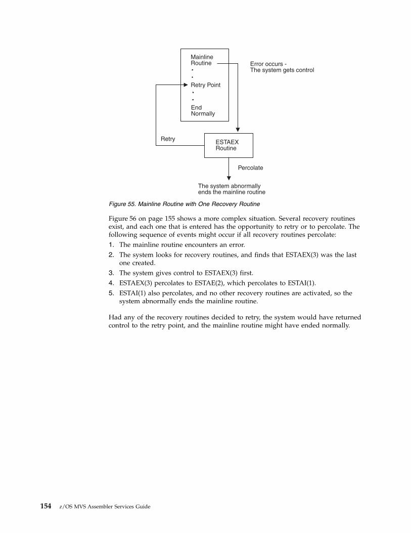
Figure 56 on page 155 shows a more complex situation. Several recovery routinesexist, and each one that is entered has the opportunity to retry or to percolate. Thefollowing sequence of events might occur if all recovery routines percolate:1. The mainline routine encounters an error.2. The system looks for recovery routines, and finds that ESTAEX(3) was the last
one created.3. The system gives control to ESTAEX(3) first.4. ESTAEX(3) percolates to ESTAE(2), which percolates to ESTAI(1).5. ESTAI(1) also percolates, and no other recovery routines are activated, so the
system abnormally ends the mainline routine.
Had any of the recovery routines decided to retry, the system would have returnedcontrol to the retry point, and the mainline routine might have ended normally.
MainlineRoutine
Retry Point
Error occurs -The system gets control
The system abnormallyends the mainline routine
EndNormally
ESTAEXRoutine
Retry
Percolate
Figure 55. Mainline Routine with One Recovery Routine
154 z/OS MVS Assembler Services Guide

Writing recovery routinesSo far, this chapter has discussed general recovery concepts, including how todecide what type of recovery you need, and how to provide that recovery. But youhave to write the recovery routines that you provide. To do so, you mustunderstand all of the following items:v What a recovery routine is supposed to do.
So far we talked about how recovery routines can either retry or percolate. But,they do a lot more than that. We also talked about recovery routines correctingor repairing errors, but we have not said how exactly they go about doing that.
v How the recovery routine communicates with the mainline routine, the retryroutine, and the system.
The means of communication available to a recovery routine are:– A user parameter area, built by the mainline routine and passed to the
recovery routine.– A data area called the system diagnostic work area (SDWA), which is
provided by the system. The recovery routine communicates with the system,with other recovery routines, and with the retry routine through the SDWA.The recovery routine uses the SETRP macro to update information in theSDWA.
– Registers, when no SDWA is provided.v The special considerations you must make when writing an ESTAE-type
recovery routine.
One important consideration is the presence of an SDWA. The case where anSDWA is not provided is rare; nevertheless, when you design an ESTAE-typerecovery routine, you must allow for the possibility of not receiving an SDWA.
ESTAI(1)
ESTAI(1)
MainlineRoutine..Retry Point..EndNormally
The systemgives control
to ESTAE-typeroutines
Error occursThe system gets control
Retry
All ESTAE-type routines percolate -The system abnormally ends the mainline routine
ESTAI(1)
ESTAE(2)
ESTAEX(3)
Figure 56. Mainline Routine with Several Recovery Routines
Chapter 8. Providing recovery 155

Special considerations for ESTAE-type recovery routines also include RBconsiderations, linkage stack considerations, and outstanding I/Os at time offailure.
Note: When an error occurs for which the system passes control to your recoveryroutine, the recovery routine must be in virtual storage. It can either be an entrypoint in your program, or a separate routine. You are responsible for ensuring thatthe recovery routine is in virtual storage when needed.
Understanding what recovery routines doThe following is a list of some of the things a recovery routine should do if therecovery is to be effective. The items are arranged in a way that suggests the orderin which you might do them; however, you must decide yourself the order thatwould work best for your particular routine.v Preserve the return address to the system.v Check for the presence of an SDWA.v Establish addressability to the parameter area passed by the mainline routine.
How you do that depends on whether an SDWA is present.v Check the contents of important fields in the SDWA.
– Determine the location of the parameter area.– Determine why the routine was entered.– Determine if this is the first recovery routine to get control.
v Check the contents of the parameter area passed by the mainline.– Determine if this is a repeated error (to avoid recursion).– Determine when and where the error occurred.
v Provide information to help determine the cause of the error:– Save serviceability data in the SDWA.– Request a dump of storage.
v Try to correct or minimize the effects of the error.v Determine whether the recovery routine can retry, decide whether to retry or
percolate, and take the appropriate actions (such as cleaning up resources).
Saving the return address to the systemWhen writing a recovery routine, you must save the return address to the system,which you find in general purpose register (GPR) 14. The system sets up the returnaddress so that the recovery routine can return, at the appropriate time, using a BR14 instruction.
Checking for the SDWAFor an ESTAE-type recovery routine, if the system cannot obtain storage for anSDWA, the system does not provide one. The case where an SDWA is not providedis rare. Nevertheless, when you design an ESTAE-type recovery routine, you mustallow for the possibility of not receiving an SDWA; almost every action anESTAE-type recovery routine takes must be set up differently to handle the twopossibilities.
To check for the presence of the SDWA, the recovery routine checks the contents ofGPR 0. If GPR 0 contains 12 (X'0C') the system could not obtain an SDWA. WhenGPR 0 contains any value other than 12, an SDWA is present, and its address is inGPR 1. When the system provides an SDWA, the system also provides a registersave area whose address is in GPR 13.
156 z/OS MVS Assembler Services Guide

If an SDWA was not provided GPR 13 does not point to a save area, and yourroutine must not use the area pointed to by GPR 13.
Establishing addressability to the parameter areaThe recovery routine also must establish addressability to the parameter areapassed by the mainline routine. To determine the location of the parameter area:v If an SDWA is present, the recovery routine checks either the contents of
SDWAPARM or the contents of GPR/AR 2. GPR 2 contains the address of theparameter area, and for AR-mode callers, AR 2 contains the ALET.
v If no SDWA is present, the recovery routine checks the contents of GPR/AR 2.GPR 2 contains the address of the parameter area, and for AR-mode callers, AR2 contains the ALET.
Refer to “Setting up, passing, and accessing the parameter area” on page 162 forfurther detail on accessing the parameter area.
The following are examples of information a mainline routine can pass to arecovery routine through the parameter area:v A dynamic storage areav An input parameter list (that is, a parameter list that might have been passed to
the mainline routine)v The addresses of important data areas.
Checking important fields in the SDWAAssuming an SDWA is present, your routine can obtain a great deal of informationfrom this data area. Some of the key information a recovery routine can check forin the SDWA includes:v Why the routine was entered.
The routine can check the SDWACMPC field, which contains the completioncode that existed when the system gave control to the routine, and theSDWACRC field, which contains the reason code associated with the completioncode. SDWACRC contains a reason code only if the SDWARCF bit is on.
v The location of the parameter area that was passed by the mainline.
The routine can check the SDWAPARM field, which provides the informationthe routine needs to locate the parameter area. The contents of this field varydepending on the way in which the recovery was defined.
v Whether this is the first recovery routine to get control.
If the SDWAPERC bit is off, this recovery routine is the first to get control. If theSDWAPERC bit is on, percolation has occurred.The first recovery routine to get control usually has a more direct relationshipwith the error; being the first recovery routine to get control for an error can bean indication that the error occurred in the mainline routine that activated thisparticular recovery routine, rather than in a routine that was subsequentlycalled.This information can be useful in determining what action the recovery routineshould take. A recovery routine is more likely to take corrective action orcapture serviceability data if it is the first to get control for an error. Subsequentrecovery routines are further removed from the error, and might limit theiractivities to releasing resources, or attempting a retry if possible.
See “Important fields in the SDWA” on page 166 for a list of some of the fields inthe SDWA, and an explanation of their contents.
Chapter 8. Providing recovery 157
Checking the contents of the parameter areaGenerally the mainline routine sets up a parameter area containing information foruse by the recovery routine. Key information that a recovery routine mightdetermine from the parameter area includes:v When and where the error occurredv Whether this is a repeated error.
The recovery routine can tell when and where the error occurred through“footprints,” a technique explained under “Deciding what to include in theparameter area” on page 162. Footprints can help the recovery routine to avoidgetting into a loop in which the routine requests a retry, and the same error occursagain (recursion). For example, if the recovery routine supplies a bad retry addressto the system, and the processing of the first instruction at the given addresscauses a program check, the first recovery routine to get control is the one that justrequested the retry. If the recovery routine requests another retry at the sameaddress, the loop is created.
See “Setting up, passing, and accessing the parameter area” on page 162 for moreinformation about what the parameter area can contain, and the techniques youcan use to provide the most useful information to the recovery routine.
Saving serviceability dataOne of the objectives of providing recovery is to obtain as much information aspossible to help you determine what went wrong. The SDWA has certain areaswhere the recovery routine can save such information. Your recovery routine canupdate the SDWA with serviceability information in three different ways:v By issuing the SETRP macro with the RECPARM parameter. Use the RECPARM
parameter to supply the load module name, the active CSECT name, and therecovery routine CSECT name. See “Using the SETRP macro to update theSDWA” on page 165 for more information about using SETRP.
v By issuing the VRADATA macro to update the SDWA variable recording area.See the VRADATA macro in z/OS MVS Programming: Assembler Services ReferenceIAR-XCT for more information.
v By directly manipulating other fields in the SDWA. Important fields to fill in areSDWACID, SDWASC, SDWAMLVL, and SDWARRL. See “Important fields in theSDWA” on page 166 for a description of each of these fields.
Part of saving serviceability data includes providing information for dump analysisand elimination (DAE). DAE depends on information that users provide inrecovery routines to construct symptom strings needed to describe softwarefailures. DAE uses these symptom strings to analyze dumps and suppressduplicate dumps as requested. You should provide information for DAE prior torequesting a dump of storage. See “Suppressing dumps that duplicate previousdumps” on page 196 for more information about DAE and dump suppression.
Requesting a dumpYour recovery routine can also request a dump of storage to help determine thecause of the error. In most cases, the system does not automatically request dumpson behalf of your program. To request an ABEND dump, the recovery routine canissue the SETRP macro with the DUMP=YES parameter.
For more information about requesting dumps, see Chapter 9, “Dumping virtualstorage (ABEND, SNAPX, SNAP, and IEATDUMP macros),” on page 195.
158 z/OS MVS Assembler Services Guide
Before requesting a dump of storage, the recovery routine should check theSDWAEAS bit. The SDWAEAS bit is on when a previous recovery routine hasprovided sufficient diagnostic data related to this error. The recovery routine thatanalyzes the problem and captures sufficient diagnostic data is responsible forsetting the SDWAEAS bit so that subsequent recovery routines know they do nothave to capture any further data.
Note that if your program calls a system service (by issuing a macro or callableservice), that system service might encounter a user-induced error and endabnormally. Generally, the system does not take dumps for user-induced errors. Ifyou require such a dump, then it is your responsibility to request one in yourrecovery routine.
Correcting or minimizing the errorAnother important activity for a recovery routine is to attempt to correct orminimize the error. What the recovery routine actually does to correct or minimizethe error depends on what the mainline routine is doing and what the error is.Some examples of possible situations where the recovery routine could take actionare the following:v The mainline routine might be working with a queue of data areas. The recovery
routine might be able to scan the queue and determine if one or more of thedata areas contains information that is not valid.For example, one of the data areas might contain an address that is not valid.Or, the mainline routine might have set up the data areas with some sort ofvalidating information that could be checked, and possibly corrected. Certaindata areas might have to be deleted from the queue, or the entire queue mighthave to be deleted and rebuilt.
v The mainline routine might be running under a task that is communicating withanother task when an error occurs. The recovery routine might then take theaction of alerting the other task that a problem exists, so the other task does notwait for any further communication.
v The mainline routine might have initiated I/O, and the recovery routine mighthave to ensure that the I/O completes to protect the integrity of the I/Oresources.
v The recovery routine might back out changes made to a database to ensure itsintegrity.
Deciding to retry or percolateUnder certain circumstances (such as CANCEL), the system does not allow a retry.The SDWACLUP bit is on when the system prohibits a retry, and off when thesystem allows a retry.
If a recovery routine requests retry when it is not allowed, the system ignores therequest and continues with percolation.
A recovery routine must determine whether it will attempt a retry. Thedetermination might be very simple: if the SDWACLUP bit is on, retry is not evenan option. But if retry is an option, the routine must make the decision based onthe information it has gathered in the preceding steps.
By no means is a recovery routine required to attempt a retry, even when one ispermitted. The recovery routine might decide not to retry if no SDWA is present,going on the assumption that serious problems probably exist. The routine mightmake the decision based on the particular completion code it finds inSDWACMPC, or based on information in the parameter area, or based on how
Chapter 8. Providing recovery 159
successful the routine was in determining the cause of the error and fixing it.Perhaps the environment is so badly damaged that repair is beyond the scope ofthe recovery routine.
Once the decision is made, the recovery routine now does different thingsdepending on whether it will retry or percolate.
Note: If the recovery routine does not specify retry or percolate, the default is topercolate.
Recovery routines that retry: When a recovery routine decides to retry, it shoulddo the following:v Eliminate or minimize the cause of the error with complete or partial repair, as
explained in “Correcting or minimizing the error” on page 159.v Ensure that the retry routine's environment is restored. For example, restore
registers and re-establish addressability to mainline resources. See “Registercontents” on page 177 for details about how a recovery routine can control theregister contents on entry to the retry routine.
v Know the condition of resources being held by the mainline. For example, theroutine might have to repair data structures, back out changes to data sets, andso on.
v Indicate to the system that a retry is to be attempted. If an SDWA is present, therecovery routine issues the SETRP macro with the RC=4 parameter to indicateretry, and the RETADDR parameter to specify the address of the retry routine.You can specify RC=4 even when the SDWACLUP bit is on, indicating that retryis not allowed. If you do so, however, the system ignores the retry request.If no SDWA is present, the recovery routine has to set a return code of 4 in GPR15, and place the address of the retry routine in GPR 0.
v Decide whether to pass the SDWA to the retry routine, and so indicate on theSETRP macro with the FRESDWA parameter.
What the retry routine does: Once the retry routine gets control, it continues withmainline processing, and can free resources, deactivate recovery routines, and soon. As stated earlier, the retry routine is really an extension of the mainline routine,and its purpose is to re-establish the mainline environment.
When the retry routine gets control, the following are true:v The retry routine runs under the same unit of work that activated the recovery
routine. See “Special considerations for ESTAE-type recovery routines” on page170 for further details related to ESTAE-type recovery routines.
v The retry routine might or might not have access to the SDWA, and the recoveryroutine might or might not have directed that register contents be restored forthe retry routine.For ESTAE-type recovery routines that specify FRESDWA=YES on SETRP, thesystem frees the SDWA before entering the retry routine. For ESTAE-typerecovery routines that specify RETREGS=YES, the system restores the registersfrom the SDWA.For ESTAE-type recovery routines that specify FRESDWA=NO on SETRP, thesystem does not free the SDWA, and the retry routine can access it. In that case,the retry routine also has the responsibility of freeing the storage for theSDWA when it is no longer needed. The subpool number and length to use tofree the storage are in the SDWA, in fields SDWASPID and SDWALNTH,respectively.
160 z/OS MVS Assembler Services Guide

Note: IBM recommends that the recovery routine use FRESDWA=YES on theSETRP macro, thus alleviating the retry routine's responsibility to free theSDWA. If your recovery routine retries multiple times and the SDWA is notfreed, out-of-storage failures can result.The retry routine can determine what action the recovery routine took in regardto freeing the SDWA and restoring registers by examining the contents of GPR 0:
Table 9. Contents of GPR 0 on Entry to a Retry Routine
GPR 0 Contents Meaning
0 The system provided an SDWA. The recovery routine specifiedRETREGS=NO and FRESDWA=NO. Registers are not restored from theSDWA, and the retry routine must free the SDWA. GPR 1 contains theaddress of the SDWA.
12 (X'0C') The system did not provide an SDWA.
20 (X'14') The system provided an SDWA. The recovery routine specifiedRETREGS=NO and FRESDWA=YES. Registers are not restored from theSDWA, and the retry routine does not have to free the SDWA.
Value restored fromSDWA (field SDWASR00)
The system provided an SDWA. The recovery routine specifiedRETREGS=YES, and either FRESDWA=NO or FRESDWA=YES. If therecovery routine specifies FRESDWA=NO, the recovery routine must alertthe retry routine to free the SDWA. Some sort of protocol must beestablished between the recovery routine and the retry routine. Forexample, the recovery routine can set a unique value in SDWASR00 (thefield that represents GPR 0 in SDWASRSV) to distinguish this case from theprevious cases where GPR 0 contains either 0, 12, or 20. The recoveryroutine can pass the address of the SDWA to the retry routine in aparameter area (use the parameter area pointed to by SDWAPARM) or in aregister (consider using register 0).
For complete details about register contents see “Understanding the recoveryenvironment” on page 173.
v The recovery routine that requested the retry is still activated and can be enteredagain, so be aware of the possibility of looping back to the same recoveryroutine. That recovery routine remains activated and can be entered again unlessthe recovery routine issued SETRP with REMREC=YES. If the recovery routinespecified REMREC=YES, the system deactivated that recovery routine beforegiving control to the retry routine.
v Any previous recovery routines (those that percolated to the recovery routinethat requested the retry) are deactivated.
Note:
1. You can have as many retry points in your program as needed, and you canchange the designated retry point as your mainline processing continues.
2. The retry routine can be a separate routine. The only requirement is that itmust be in virtual storage. You are responsible for ensuring that the retryroutine is in virtual storage when needed.
Recovery routines that percolate: When a recovery routine decides to percolate(or takes the default), it should do the following:v Release resources that were acquired by the mainline, such as ENQs.v Repair the cause of the error, if possible.v Indicate the percolate option to the system. If an SDWA is present, the recovery
routine issues the SETRP macro with the RC=0 parameter to indicatepercolation. If no SDWA is present, the recovery routine has to set a return codeof 0 in register 15.
Chapter 8. Providing recovery 161

Note:
1. Once a recovery routine percolates, it is no longer activated; it cannot receivecontrol again for this error.
2. An ESTAI routine can request that the system not give control to any furtherESTAI routines by specifying RC=16 on the SETRP macro. The system thenabnormally ends the task.
Understanding the means of communicationAn important aspect of writing a recovery routine is understanding how therecovery routine communicates with the mainline routine, the retry routine, andthe system. This information discusses the following means of communication:v Parameter area
The parameter area is set up by the mainline routine and passed to the recoveryroutine. See “Setting up, passing, and accessing the parameter area.”
v SDWA
The SDWA provides information to the recovery routine, and the recoveryroutine can communicate with the system, and with subsequent recoveryroutines, by placing information into the SDWA. See “Using the SDWA” on page165.
v Registers
When a recovery routine gets control, GPR 0 indicates whether an SDWA isavailable. When an SDWA is not available, the recovery routine cancommunicate its recovery options to the system only through registers. Asidefrom this circumstance, the recovery routine cannot use registers tocommunicate with the system; the routine must use the SDWA. Also, themainline routine should not place information in registers and expect thatinformation to be in the registers when the recovery routine gets control.Complete details about registers are in “Understanding the recoveryenvironment” on page 173.
You should understand that communications are handled differently depending onthe following circumstances:v Whether your recovery routine received an SDWAv Whether the communication is with the recovery routine or with the retry
routine.
Setting up, passing, and accessing the parameter areaThe primary means of communication between the mainline routine and therecovery routine is the parameter area that the mainline sets up and passes to therecovery routine. This information discusses:v What your mainline routine should put into the parameter areav How your mainline passes the parameter area to the recovery routinev How your recovery routine accesses the parameter area.
Deciding what to include in the parameter area: Your mainline routine can putwhatever information it wants in the parameter area. Remember that the object isto provide the recovery routine with as much useful information as possible so therecovery routine can be effective. Here are some suggestions for importantinformation to place in the parameter area:v The base registers for the mainline. The recovery routine must be able to
establish addressability to whatever resources the mainline is holding.v The addresses of all dynamically acquired storage.
162 z/OS MVS Assembler Services Guide

v The location of a workarea for use by the recovery routine.v Indications of what resources are held or serialized, such as ENQs, data sets, and
so on.v Footprints indicating the processing being performed by the mainline when the
error occurred. Using footprints is a technique whereby the mainline sets bits asit goes through its processing. When the recovery routine gets control, it cancheck the parameter area to see which bits have been turned on, and thus cantell how far along the mainline was. The recovery routine can pinpoint what themainline was doing at the time of error. If the mainline was done with itsprocessing when the error occurred, the recovery routine might not need toretry, but might just clean up resources.
v An indication of whether a retry is desired.v The input parameter list to the mainline. When the mainline received control, it
might have received an input parameter list. The mainline can preserve this inthe parameter area intended for use by the recovery routine. The recoveryroutine can then inspect the input parameter list to determine if the mainlinereceived input that was not valid.
v Whatever register contents (both GPRs and ARs) the mainline wants to save(they might need to be restored upon retry).
v The location of important data areas used by the mainline. Errors often occurbecause of damage to information in a data area. The recovery routine mightneed to repair one or more of these data areas, and so must be able to accessthem. The recovery routine might also want to include these data areas when itspecifies the areas of storage to dump.
v The addresses of any user-written routines available to repair damage. Youmight have separate routines designed to scan and repair queues, repair dataareas, and so on. The recovery routine might want to call these other routinesfor assistance.
Passing the parameter area: When you provide a recovery routine, you have theopportunity to identify to the system the parameter area you want passed to therecovery routine. Here are the ways to accomplish that:v ESTAE and ESTAEX routines
Use the PARAM parameter on the ESTAE or ESTAEX macro to specify theaddress of the parameter area you have constructed.
v ESTAI routines
Use the ESTAI parameter on the ATTACHX macro to specify both the address ofthe recovery routine to get control, and the address of the parameter area youhave constructed.
v IEAARR routines
Use the ARRPARAMPTR parameter on the IEAARR macro to specify the 31-bitaddress of the parameter area you constructed, or use the ARRPARAMPTR64parameter to specify the 64-bit address of the parameter area you constructed.
Accessing the parameter area: Once the recovery routine gets control, the routinemust know how to access the parameter area. That varies according to whether thesystem provided an SDWA, and according to how the recovery routine wasdefined:v SDWA is present
– ESTAE macro
SDWAPARM and GPR 2 contain the address of the parameter area youspecified on the PARAM parameter on ESTAE.
Chapter 8. Providing recovery 163

– ESTAEX macro
SDWAPARM contains the address of an 8-byte field, which contains theaddress and ALET of the parameter area you specified on the PARAMparameter on ESTAEX, and GPR 2 contains the address of the parameter areayou specified on the PARAM parameter on ESTAEX. AR 2 contains the ALETqualifying the address in GPR 2.
– ESTAEX macro issued in AMODE 64
SDWAPARM contains the address of an 8-byte area, which contains theaddress of the parameter area you specified on the PARAM parameter ofESTAEX. GPR 2 contains the 64-bit address of the parameter area.
– ATTACHX macro with ESTAI parameter
SDWAPARM and GPR 2 contain the address of the parameter area youspecified on the ESTAI parameter on ATTACHX. When ATTACHX is issuedin AMODE 64 the parameter list address is still treated as a 31-bit address.The parameter area specified on ATTACHX is always assumed to be in theprimary address space, so for AR-mode callers, the ALET is always zero.
– IEAARR macro
SDWAPARM contains the address of an 8-byte area. The first word of thisarea contains the address of the parameter area you specified on theARRPARAMPTR parameter of IEAARR and the second word does notcontain interface information. GPR 2 contains the address of the parameterarea.
– IEAARR macro issued in AMODE 64
SDWAPARM contains the address of an 8-byte area, which contains theaddress of the parameter area you specified on the ARRPARAMPTR64parameter of IEAARR. GPR 2 contains the 64-bit address of the parameterarea.
v SDWA is not present
– ESTAE macro
GPR 2 contains the address of the parameter area you specified on thePARAM parameter on ESTAE.
– ESTAEX macro
GPR 2 contains the address of the parameter area you specified on thePARAM parameter on ESTAEX. AR 2 contains the ALET qualifying theaddress in GPR 2.
– ESTAEX macro issued in AMODE 64
GPR2 contains the 64-bit address of the parameter area you specified on thePARAM parameter of ESTAEX.
– ATTACHX macro with ESTAI parameter
SDWAPARM and GPR 2 contain the address of the parameter area youspecified on the ESTAI parameter on ATTACHX. When ATTACHX is issuedin AMODE 64 the parameter list address is still treated as a 31-bit address.The parameter area specified on ATTACHX is always assumed to be in theprimary address space, so for AR-mode callers, the ALET is always zero.
– IEAARR macro
GPR 2 contains the address of the parameter area you specified on theARRPARAMPTR parameter of IEAARR.
– IEAARR macro issued in AMODE 64
GPR 2 contains the 64-bit address of the parameter area you specified on theARRPARAMPTR64 parameter of IEAARR.
164 z/OS MVS Assembler Services Guide

Using the SDWAThe SDWA is both a means by which the recovery routine can provide informationto the system and to subsequent recovery routines, and a provider of informationto the recovery routine. To access and update the SDWA, the recovery routine mustinclude the IHASDWA mapping macro as a DSECT. For complete informationabout the SDWA, see z/OS MVS Data Areas in the z/OS Internet library(www.ibm.com/systems/z/os/zos/library/bkserv).The SDWA is always in theprimary address space.
Updating the SDWA: A recovery routine can update the SDWA in various ways:v By issuing the SETRP macro (See “Using the SETRP macro to update the
SDWA.”)v By issuing the VRADATA macro (See the VRADATA macro in z/OS MVS
Programming: Assembler Services Reference IAR-XCT and use of the VRADATAmacro in “Symptoms provided by a recovery routine” on page 199.)
v By directly updating specific fields (see “Important fields in the SDWA” on page166).
Using the SETRP macro to update the SDWA: Recovery routines issue theSETRP macro to communicate recovery options to the system, and to saveserviceability data. The routine must have an SDWA to issue SETRP. The followingare some of the things a recovery routine can do using the SETRP macro:v Indicate retry or percolate
Use the RC parameter on SETRP to let the system know whether the recoveryroutine wants to percolate (RC=0) or retry (RC=4). If attempting a retry, theroutine must also specify a retry address on the RETADDR parameter.For ESTAI routines, you can also specify RC=16 to ask the system not to givecontrol to any further ESTAI routines.
v Specify register contents for the retry routine and free the SDWA
ESTAE-type recovery routines can use parameters on the SETRP macro to restoreregisters from the SDWA (RETREGS=YES), and to free the SDWA before controlis given to the retry routine (FRESDWA=YES). See “Register contents” on page177 for information about using the RETREGS and FRESDWA parameters.
v Save serviceability data
Use the RECPARM parameter to supply the load module name, the activeCSECT name, and the recovery routine CSECT name.
v Change the completion and reason codes
You can specify both completion and reason code values on the ABEND macro.The system passes these values to recovery routines in the SDWA. Recoveryroutines can change the values of the completion code and the reason code byusing the SETRP macro. The COMPCOD parameter allows you to specify a newcompletion code; the REASON parameter allows you to specify a new reasoncode.The reason code has no meaning by itself, but must be used together with acompletion code. To maintain meaningful completion and reason codes, thesystem propagates changes to these values according to the following rules:– If a user changes both the completion code and the reason code, the system
accepts both new values.– If a user changes the reason code but not the completion code, the system
accepts the new reason code and uses the unchanged completion code.– If a user changes the completion code but not the reason code, the system
accepts the new completion code and uses a zero for the reason code.
Chapter 8. Providing recovery 165

Symptom data required in the SDWA for dump suppression: If the installationis using DAE to suppress duplicate dumps, the recovery routine must provide thefollowing minimum data to enable dump suppression. See “Suppressing dumpsthat duplicate previous dumps” on page 196 for more information about dumpsuppression.
SDWA Field Data ExampleSDWAMODN Failing module name IEAVTCXXSDWACSCT Failing CSECT name IEAVTC22SDWACID Product or component identifier SCDMPSDWACIBSDWACIDB Component identifier base 5655SDWAREXN Recovery routine name IEAVTC2RSDWASC Subcomponent or module subfunction RSM-PGFIX
Important fields in the SDWA: The following table summarizes some of the keyfields in the SDWA. Note that certain fields are in an extension of the SDWA calledSDWARC1, which is a different DSECT. Here is how to access SDWARC1:v SDWAXPAD in the SDWA contains the address of SDWAPTRS.v SDWAPTRS is a DSECT which contains SDWASRVP.v SDWASRVP contains the address of SDWARC1.
The following fields described in Table 10 are in SDWARC1:v SDWACRCv SDWAARERv SDWAARSVv SDWACIDv SDWASCv SDWAMLVLv SDWARRL
Table 10. Key fields in the SDWA
Field Name Use
SDWAPARM For routines defined by the ESTAEX macro, this field contains theaddress of an 8-byte area. If the ESTAEX was established by a routinerunning in AMODE 64, the area contains the address of the parameterarea you specified on the PARAM parameter of ESTAEX. Otherwise,the first four bytes of this 8-byte area contain the address of theparameter area and the next four bytes contain the ALET for theparameter area.
For routines defined by the IEAARR macro, if the IEAARR was issuedin AMODE 64, the 8-byte area contains the 64-bit address of theparameter area specified on the ARRPARMPTR64 parameter ofIEAARR. Otherwise, this field contains the address of an 8-byte area.The first word of this areacontains the address of the parameter areayou specified on the ARRPARAMPTR parameter of IEAARR, and thesecond word does not contain interface information.
Refer to “Setting up, passing, and accessing the parameter area” onpage 162 for details on the parameter area passed by recovery routines.
166 z/OS MVS Assembler Services Guide

Table 10. Key fields in the SDWA (continued)
Field Name Use
SDWACMPC This 3-byte field contains the completion code that existed when thesystem gave control to the recovery routine. The recovery routine canchange the completion code by issuing the SETRP macro with theCOMPCOD parameter. The system completion code appears in the firsttwelve bits, and the user completion code appears in the second twelvebits.
SDWARPIV This bit tells the recovery routine that the registers and PSW at the timeof error are not available. When this bit is on, the contents ofSDWAGRSV, SDWAG64, SDWAARER, and SDWAEC1 areunpredictable.
SDWACRC This 4-byte field contains the reason code associated with thecompletion code in SDWACMPC. The reason code is set through theREASON parameter of the ABEND macro, and is valid only when bitSDWARCF is on. The recovery routine may change this reason code byspecifying a new value for the REASON parameter of the SETRPmacro.Note: This reason code is not the same as the return code thatprograms may set in GPR 15 before they issue the ABEND macro.
SDWARCF If on, this bit indicates that SDWACRC contains a reason code.
SDWAGRSV This field contains the contents of the general purpose registers (GPRs)0-15 as they were at the time of the error.
SDWAG64 This field contains the contents of the general purpose registers (GPRs)0-15 as they were at the time of the error for AMODE 64 recoveryroutines. It is also used for retry instead of SDWASRSV whenRETREGS=64 is specified with SETRP.
SDWAARER This field contains the contents of the access registers (ARs) 0-15 asthey were at the time of the error.
SDWAEC1 This field contains the PSW that existed at the time of the error.
SDWAEC2 The contents of this field vary according to the type of recoveryroutine:
v For ESTAE-type recovery routines (except for ESTAI routines): If aprogram establishes an ESTAE routine, and subsequently performs astacking operation while running under the same RB as when itestablished the ESTAE routine, SDWAEC2 contains the PSW from thelinkage stack entry immediately following the entry that was currentwhen the ESTAE routine was established. Otherwise, SDWAEC2contains the current RBOPSW from the RB that activated therecovery routine, and the PSW is the one from the time of the lastinterruption of that RB that occurred while the RB was unlocked andenabled. Bit SDWAINTF in SDWAXFLG indicates whether thecontents of SDWAEC2 are from the linkage stack (SDWAINTF is 1)or from an RB (SDWAINTF is 0).
v For an ESTAI routine, this field contains zero.
Chapter 8. Providing recovery 167

Table 10. Key fields in the SDWA (continued)
Field Name Use
SDWASRSV The contents of this field vary according to the type of recoveryroutine:
v For ESTAE-type recovery routines (except for ESTAI routines): If aprogram establishes an ESTAE routine, and subsequently performs astacking operation while running under the same RB as when itestablished the ESTAE routine, SDWASRSV contains GPRs 0-15 fromthe linkage stack entry immediately following the entry that wascurrent when the ESTAE routine was established. Otherwise,SDWASRSV contains GPRs 0-15 from the RB that activated therecovery routine, and the GPRs are the same as they were at the timeof the last interruption of that RB that occurred while the RB wasunlocked and enabled. Bit SDWAINTF in SDWAXFLG indicateswhether the contents of SDWASRSV are from the linkage stack(SDWAINTF is 1) or from an RB (SDWAINTF is 0).Note: SDWASRSV is not available for ESTAE-type recovery routinesrunning in AMODE 64. SDWAG64 is used for retry instead ofSDWASRSV when RETREGS=64 is specified with SETRP.
v For an ESTAI routine, this field contains zeros.
If the recovery routine requests a retry, the system might use thecontents of this field to load the GPRs for the retry routine. See theRETREGS parameter description in the SETRP macro in z/OS MVSProgramming: Assembler Services Reference IAR-XCT for details. To changethe contents of the GPRs for the retry routine, you must make thechanges to SDWASRSV and then issue SETRP with RETREGS=YES. Youcan update the registers directly or with the RUB parameter on SETRP.
SDWAARSV The contents of this field depend on the type of recovery routine:
v For ESTAE-type recovery routines (except for ESTAI routines): If aprogram establishes an ESTAE routine, and subsequently performs astacking operation while running under the same RB as when itestablished the ESTAE routine, SDWAARSV contains ARs 0-15 fromthe linkage stack entry immediately following the entry that wascurrent when the ESTAE routine was established. Otherwise,SDWAARSV contains ARs 0-15 from the RB that activated therecovery routine, and the ARs are the same as they were at the timeof the last interruption of that RB that occurred while the RB wasunlocked and enabled. Bit SDWAINTF in SDWAXFLG indicateswhether the contents of SDWAARSV are from the linkage stack(SDWAINTF is 1) or from an RB (SDWAINTF is 0).
v For an ESTAI routine, this field contains zeros.
If the recovery routine requests a retry, the system might use thecontents of this field to load the ARs for the retry routine. See theRETREGS parameter description in the SETRP macro in z/OS MVSProgramming: Assembler Services Reference IAR-XCT for details. To changethe contents of the ARs for the retry routine, you must make thechanges in SDWAARSV, and then issue SETRP with RETREGS=YES.
SDWASPID This field contains the subpool ID of the storage used to obtain theSDWA, for use whenever the retry routine is responsible for freeing theSDWA.
SDWALNTH This field contains the length, in bytes, of this SDWA, the SDWAextensions, and the variable recording area, for use whenever the retryroutine is responsible for freeing the SDWA. (This allows the retryroutine to free the extensions along with the SDWA.)
168 z/OS MVS Assembler Services Guide

Table 10. Key fields in the SDWA (continued)
Field Name Use
SDWACOMU The recovery routines can use this 8-byte field to communicate witheach other when percolation occurs. The system copies this field fromone SDWA to the next on all percolations. When the field contains allzeros, either no information is passed or the system has not been ableto pass the information.
SDWATRAN This field contains one of the following if a translation exceptionoccurred:
v The valid translation exception address if the SDWATEAV bit is 1.
v The ASID of the address space in which the translation exceptionoccurred if the SDWATEIV bit is 1.
If both the SDWATEAV and SDWATEIV bits are 0, ignore theSDWATRAN field.
SDWATEAR For translation exceptions that occur in AR mode, this 1-byte fieldidentifies the number of the AR that the program was using when thetranslation exception occurred.
SDWACLUP If on, this bit indicates that the recovery routine cannot retry.
SDWAPERC If on, this bit indicates that a recovery routine has already percolatedfor this error.
SDWAEAS If on, this bit indicates that a previous recovery routine providedsufficient diagnostic information pertaining to this error. The recoveryroutine providing the information is responsible for setting the bit.
SDWACID The recovery routine can use this 5-byte field to provide the componentID of the component involved in the error.
SDWASC The recovery routine can use this 23-byte field to provide the name ofthe component and a description of the function or subfunctioninvolved in the error.
SDWAMLVL The recovery routine can use this 16-byte field to indicate the level ofthe module involved in the error. The first 8 bytes contains the date(SDWAMDAT) and the second 8 bytes contains the version(SDWAMVRS).
SDWARRL The recovery routine can use this 8-byte field to indicate the recoveryroutine's entry point label.
SDWALSLV The recovery routine can use this 2-byte field to control the linkagestack state upon retry. See “Linkage stack at time of retry” on page 184for additional information.
SDWAG64 When running in z/Architecture mode, this field contains the full64–bit contents of the general purpose registers at the time of error. Italso contains the 64–bit registers to be used for retry if you specifyRETREGS=64 on the SETRP macro or turn on the SDWAUPRG andSDWAUP 64 bits.
SDWATXG64 When bits SDWAPCHK and SDWAPTX2 are on, indicating that theprogram interrupt occurred while within transactional execution, thisfield contains the full 64-bit contents of the general purpose registersthat result from the transaction abort. For more information abouttransactional execution, see Chapter 29, “Transactional execution,” onpage 525.
SDWATXPSW16 When bits SDWAPCHK and SDWAPTX2 are on, this field contains the16-byte PSW that results from the transaction abort. For moreinformation about transactional execution, see Chapter 29,“Transactional execution,” on page 525.
Chapter 8. Providing recovery 169
Special considerations for ESTAE-type recovery routinesThis information discusses some special considerations for writing ESTAE-typerecovery routines:v RB considerationsv Linkage stack considerationsv Outstanding I/Os at time of failurev Other considerations for ESTAE-type recovery routinesv Using ARRs
RB considerationsA program must activate and deactivate ESTAE-type recovery routines under thesame RB level. If you try to deactivate an ESTAE-type recovery routine that is notassociated with your RB, you get a return code that indicates your request is notvalid.
ESTAE-type recovery routines are deactivated when their associated RBs terminate.This is important because a program expects one of its own ESTAE-type recoveryroutines to get control rather than one left behind by a called program. A programmight, however, invoke a service routine that does not create an RB. If that routinethen issues an ESTAEX or ESTAE macro and fails to deactivate the resultingESTAE-type recovery routine, a problem could develop if the original programencounters an error. The ESTAE-type recovery routine left behind by the serviceroutine would receive control rather than the ESTAE-type recovery routineassociated with the program, because the recovery routine specified by the mostrecently issued ESTAE or ESTAEX macro gets control.
IBM recommends that every program that activates an ESTAE-type recoveryroutine also deactivate it.
For retry from an ESTAE-type recovery routine, the retry routine runs as acontinuation of the code that activated the recovery routine. That is, the retryroutine runs under the same RB that defined the ESTAE-type recovery routine, andthe system purges all RBs created after the retry RB before giving control to theretry routine.
Note that ESTAI is an exception; a retry request from a recovery routine defined bythe ESTAI parameter of the ATTACHX macro must run under a program requestblock (PRB). The retry routine cannot run under the PRB of the routine thatdefined the ESTAI routine, because that PRB is associated with a different task. Thesystem scans the RB queue associated with the task under which the retry is tooccur, starting with the RB that was interrupted (the newest RB). The system thenuses the following rules to select a PRB for the retry routine:v If one or more PRBs exist that represent an ESTAE-type recovery routine, use the
newest one.v If no PRBs exist that represent ESTAE-type recovery routines, use the newest
PRB that does not have any non-PRBs (such as SVRBs) that are older.
If the RB queue contains no PRBs at all, retry is suppressed.
Linkage stack considerationsConsider the following information about the linkage stack when writing anESTAE-type recovery routine or a retry routine, or when deactivating anESTAE-type recovery routine:
170 z/OS MVS Assembler Services Guide

Recovery routine: IBM recommends that your recovery routine not modify orextract from the linkage stack entry that is current when the routine is entered. Insome cases, the system might prevent an ESTAE-type recovery routine frommodifying or extracting from that linkage stack entry. If your recovery routineattempts to modify or extract from the linkage stack entry when the system doesnot allow it, the result is a linkage stack exception.
IBM recommends that if your recovery routine adds entries to the linkage stack,through a stacking PC or BAKR instruction, it should also remove them. If therecovery routine adds entries to the stack and does not remove them, the systemrecognizes an error when the recovery routine returns control. If the recoveryroutine retries, the additional entries are not given to the retry routine. If therecovery routine percolates, subsequent recovery routines receive a linkage stackwith entries more recent than the entry that was current at the time of error.
Retry routine: When the system gives control to your retry routine, the linkagestack level is set to the level that was current when your program activated therecovery routine, unless the recovery routine sets the SDWALSLV field.
Deactivating an ESTAE-type recovery routine: A program may deactivate anESTAE-type recovery routine only under the same linkage stack level as the levelthat existed when the program activated the recovery routine. This rule affectsprograms that add entries to the linkage stack either through the BAKR or PCinstruction. Failure to follow this rule results in an error return code of 36 from theESTAE or ESTAEX macro.
When you issue a PR, the system automatically deactivates all ESTAE-typerecovery routines that were previously activated under that current linkage stackentry.
Outstanding I/Os at the time of failureBefore the most recently activated ESTAE-type recovery routine receives control,the system can handle outstanding I/Os at the time of the failure. You request thisthrough the macro that defines the routine (that is, through the PURGE parameteron ESTAE, ESTAEX, or ATTACHX). The system performs the requested I/Oprocessing only for the first ESTAE-type recovery routine that gets control.Subsequent routines that get control receive an indication of the I/O processingpreviously done, but no additional processing is performed.
Note: You should understand PURGE processing before using this parameter.PURGE processing is documented in z/OS DFSMSdfp Advanced Services.
If there are quiesced restorable I/O operations (because you specifiedPURGE=QUIESCE on the macro for the most recently defined ESTAE-typerecovery routine), the retry routine can restore them as follows:v If the recovery routine specified FRESDWA=YES and RETREGS=NO on the
SETRP macro, or the system did not provide an SDWA, the system supplies theaddress of the purged I/O restore list in GPR 2 on entry to the retry routine.
v If the recovery routine specified FRESDWA=NO and RETREGS=NO on theSETRP macro, GPR 1 contains the address of the SDWA, and the address of thepurged I/O restore list is in the SDWAFIOB field on entry to the retry routine.
v If the recovery routine specified FRESDWA=NO and RETREGS=YES on theSETRP macro, the recovery routine must pass the address of the SDWA to theretry routine (in the user parameter area, or in GPR 0). The address of thepurged I/O restore list is in the SDWAFIOB field on entry to the retry routine.
Chapter 8. Providing recovery 171

v If the recovery routine specified FRESDWA=YES and RETREGS=YES on theSETRP macro, the retry routine cannot access the purged I/O restore list.
The following table provides a summary of how the retry routine can accessquiesced restorable I/O operations:
Table 11. Restoring quiesced restorable I/O operations
Parameter on SETRP Macro RETREGS=NO RETREGS=YES
FRESDWA=YES GPR 2 contains the address ofthe purged I/O restore list
Retry routine cannot access thepurged I/O restore list.
FRESDWA=NO GPR 1 contains the address ofthe SDWA; SDWAFIOB containsthe address of the purged I/Orestore list
The recovery routine must passthe address of the SDWA to theretry routine; SDWAFIOBcontains the address of thepurged I/O restore list.
Note: If the system did not provide an SDWA and RETREGS=NO, then GPR 2contains the address of the purged I/O restore list.
You can use the RESTORE macro to have the system restore all I/O requests onthe list. For information about the RESTORE macro, see z/OS DFSMSdfp AdvancedServices.
Additional considerations specific to ESTAE-type recoveryroutinesConsider the following points that are specific to ESTAE-type recovery routines:v During processing of the first and all subsequent recovery routines, the system
allows or disallows asynchronous processing (such as a timer exit) depending onhow you specify the ASYNCH parameter when you define the routine (that is,through the ASYNCH parameter on ESTAE, ESTAEX, and ATTACHX).
v The following list describes what the system does when it is done processing aparticular recovery routine (either because the recovery routine percolates, orbecause the recovery routine itself encounters an error and has no recoveryroutine of its own that retries):– Accumulates dump options– Resets the asynchronous exit indicator according to the request of the next
recovery routine– Ignores the I/O options for the next recovery routine– Initializes a new SDWA– Gives control to the next recovery routine.If all recovery routines fail or percolate, the task is terminated.
v If a non-job step task issues an ABEND macro with the STEP parameter, thesystem gives control to recovery routines for the non-job step task. If therecovery routines do not request a retry, the job step is terminated with thespecified completion code. Subsequent recovery routines for the job step task getcontrol only when you specify TERM=YES on the macros that defined thoserecovery routines. You can specify TERM=YES on ESTAE, ESTAEX, andATTACHX.If the recovery routines for the job step task do not retry, subsequent recoveryroutines for any other non-job step tasks get control in the same way they wouldif the job step task itself encountered the error and then did not retry.
v For some situations, the system gives control to ESTAE-type recovery routinesonly when the TERM=YES parameter was specified. The situations are:
172 z/OS MVS Assembler Services Guide
– System-initiated logoff– Job step timer expiration– Wait time limit for job step exceeded– DETACH macro was issued from a higher level task (possibly by the system
if the higher level task encountered an error)– Operator cancel– Error occurred on a higher level task– Error in the job step task when a non-job step task issued the ABEND macro
with the STEP parameter– z/OS UNIX is canceled and the user's task is in a wait in the z/OS UNIX
kernel.When the system gives control to the recovery routines defined with theTERM=YES parameter as a result of these errors, the system takes the followingactions:– Sets the SDWACLUP bit– Gives control to all such routines in LIFO order– Does not enter any ESTAI routine previously suppressed by a return code of
16, or any previously entered recovery routine that requested percolation– Ignores any request for retry.
Using ARRsAn ARR is an ESTAE-type recovery routine that provides recovery for a stackingPC routine and receives control if the stacking PC routine encounters an error.Unauthorized programs can define an ARR using a system-provided PC via theIEAARR macro. An ARR receives all of the defaults of the ESTAEX macro, with theexception of the TERM parameter. For ARRs, the system uses TERM=YES.
To define an ARR, Issue the IEAARR macro to establish an ARR to cover a targetroutine, as described in z/OS MVS Programming: Authorized Assembler ServicesReference EDT-IXG.
An ARR receives control in 31-bit or 64-bit addressing mode depending on themode at the time that IEAARR was issued. If it is passed an SDWA, the SDWA isin 31-bit addressable storage.
The system does not give control to an ARR established with the IEAARR macro ifthe caller of the program using the IEAARR macro has established any FRRs.
Understanding the recovery environmentWhen you write a recovery routine, you must take into consideration a number ofenvironmental factors that are present when the recovery routine gets control, andthat are present when a retry routine gets control. This information discussesenvironmental factors in two broad categories, distinguishing register contentsfrom all other environmental factors:v Register contents.
Recovery routines are interested in register contents at the following times:– When the error occurs
When the recovery routine gets control, certain fields in the SDWA containthe register contents at the time the error occurs. SDWAGRSV contains thecontents of the GPRs; SDWAARER contains the contents of the ARs.
– On entry to and return from the recovery routine
Chapter 8. Providing recovery 173
See “Register contents on entry to a recovery routine” and “Register contentson return from a recovery routine” on page 176 for details.
– On entry to the retry routineSee “Register contents” on page 177 for details.
v All other environmental factors.
The other environmental factors important in a recovery environment are:– Authorization: problem state or supervisor state, PSW key, and PSW key
mask (PKM)– SDWA storage key– Dispatchable unit mode– AMODE– ASC mode– Interrupt status– DU-AL– Program mask– Condition of the linkage stack
This information discusses each of the environmental factors, and makesdistinctions, where necessary, that depend on the following:v Whether the system provided an SDWAv Whether you are dealing with the recovery routine or the retry routine.
Register contentsThis information describes register contents for the following:v On entry to a recovery routinev On return from a recovery routine (see “Register contents on return from a
recovery routine” on page 176)v On entry to a retry routine.
The following table provides a roadmap to all the tables containing register contentinformation on entry to a recovery routine or on entry to a retry routine:
Table 12. Where to Find Register Content Information
Registers Described For: Table Number:
ESTAE-type recovery routine with an SDWA Table 13 on page 175
ESTAE-type recovery routine without an SDWA Table 14 on page 175
Retry from an ESTAE-type recovery routine without an SDWA Table 15 on page 177
Retry from an ESTAE-type recovery routine with an SDWA,RETREGS=NO, and FRESDWA=NO
Table 16 on page 178
Retry from an ESTAE-type recovery routine with an SDWA,RETREGS=NO, and FRESDWA=YES
Table 17 on page 178
Retry from an ESTAE-type recovery routine with an SDWA andRETREGS=YES
Table 18 on page 179
Register contents on entry to a recovery routineThe register contents on entry to an ESTAE-type recovery routine are differentdepending on whether the system supplied and SDWA. The following tablesdescribe the register contents on entry to the recovery routine for both situations.
174 z/OS MVS Assembler Services Guide

Table 13. Register Contents—ESTAE-Type Recovery Routine With an SDWA
Register Contents
GeneralPurposeRegisters
GPR 0 A code indicating the type of I/O processing performed:
0 Active I/O has been quiesced and is restorable.
4 Active I/O has been halted and is not restorable.
8 No I/O was active when the abend occurred.
16 (X'10')No I/O processing was performed.
GPR 1 Address of the SDWA.
GPR 2 One of the following:
v If you specified the PARM parameter on ESTAE or ESTAEX, the addressof the user-supplied parameter area.
v For ESTAI issued via ATTACHX, the address of the user-suppliedparameter area. Note this is a 31-bit address for ESTAI issued in eitherAMODE31 or AMODE64.
v If you issued FESTAE without the PARAM parameter, the address of the24-byte parameter area in the SVRB (RBFEPARM).
v If you issued ESTAE, ESTAEX, or ATTACHX without the PARAMparameter, zero.
v For IEAARR issued in AMODE 31, the 31-bit address of the parameterarea specified on the ARRPARAMPTR parameter of IEAARR.
v For IEAARR issued in AMODE 64, the 64-bit address of the parameterarea specified on the ARRPARAMPTR64 parameter of IEAARR.
GPRs 3 - 12 Do not contain any information for use by the routine.
GPR 13 Address of a 144-byte register save area.
GPR 14 Return address to the system.
GPR 15 Entry point address of the ESTAE-type recovery routine, except forESTAEX issued in AMODE 64, in which case the low order bit will be on.
Accessregisters
ARs 0 - 1 Zero
AR 2 One of the following:
v If you issued the ESTAEX macro in AR ASC mode, an ALET thatqualifies the address in GPR 2.
v Otherwise, this register does not contain any information for use by theroutine.
ARs 3 - 15 Zero.
Table 14. Register Contents—ESTAE-Type Recovery Routine Without an SDWA
Register Contents
GeneralPurposeRegisters
GPR 0 12 (X'0C'). The system could not obtain an SDWA.
Chapter 8. Providing recovery 175
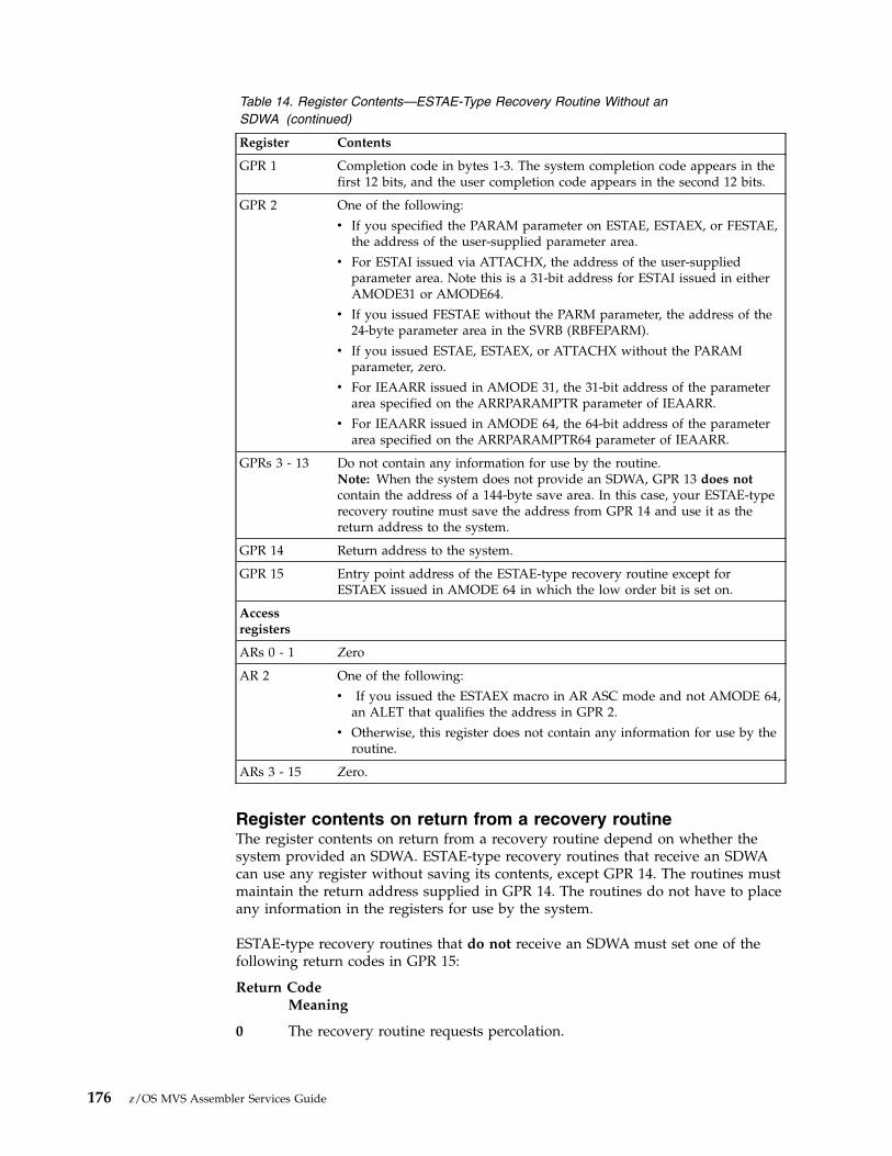
Table 14. Register Contents—ESTAE-Type Recovery Routine Without anSDWA (continued)
Register Contents
GPR 1 Completion code in bytes 1-3. The system completion code appears in thefirst 12 bits, and the user completion code appears in the second 12 bits.
GPR 2 One of the following:
v If you specified the PARAM parameter on ESTAE, ESTAEX, or FESTAE,the address of the user-supplied parameter area.
v For ESTAI issued via ATTACHX, the address of the user-suppliedparameter area. Note this is a 31-bit address for ESTAI issued in eitherAMODE31 or AMODE64.
v If you issued FESTAE without the PARM parameter, the address of the24-byte parameter area in the SVRB (RBFEPARM).
v If you issued ESTAE, ESTAEX, or ATTACHX without the PARAMparameter, zero.
v For IEAARR issued in AMODE 31, the 31-bit address of the parameterarea specified on the ARRPARAMPTR parameter of IEAARR.
v For IEAARR issued in AMODE 64, the 64-bit address of the parameterarea specified on the ARRPARAMPTR64 parameter of IEAARR.
GPRs 3 - 13 Do not contain any information for use by the routine.Note: When the system does not provide an SDWA, GPR 13 does notcontain the address of a 144-byte save area. In this case, your ESTAE-typerecovery routine must save the address from GPR 14 and use it as thereturn address to the system.
GPR 14 Return address to the system.
GPR 15 Entry point address of the ESTAE-type recovery routine except forESTAEX issued in AMODE 64 in which the low order bit is set on.
Accessregisters
ARs 0 - 1 Zero
AR 2 One of the following:
v If you issued the ESTAEX macro in AR ASC mode and not AMODE 64,an ALET that qualifies the address in GPR 2.
v Otherwise, this register does not contain any information for use by theroutine.
ARs 3 - 15 Zero.
Register contents on return from a recovery routineThe register contents on return from a recovery routine depend on whether thesystem provided an SDWA. ESTAE-type recovery routines that receive an SDWAcan use any register without saving its contents, except GPR 14. The routines mustmaintain the return address supplied in GPR 14. The routines do not have to placeany information in the registers for use by the system.
ESTAE-type recovery routines that do not receive an SDWA must set one of thefollowing return codes in GPR 15:
Return CodeMeaning
0 The recovery routine requests percolation.
176 z/OS MVS Assembler Services Guide

4 The recovery routine requests a retry. The recovery routine must thenplace the address of the retry routine in GPR 0.
16 (X'10')Valid only for an ESTAI recovery routine. The system should not givecontrol to any further ESTAI routines, and should abnormally end the task.
Register contentsThe register contents on entry to a retry routine vary according to the following:v Whether an SDWA is present.v If an SDWA is present, what the recovery routine specifies on the SETRP macro.
The parameters on SETRP that affect register contents on entry to the retry routinefrom an ESTAE-type recovery routine are the following:v The RETREGS parameter controls whether registers are restored from the SDWA.
If you specify RETREGS=NO, registers are not restored from the SDWA.If you specify RETREGS=YES, GPRs are restored from SDWASRSV, and ARs arerestored from SDWAARSV. If you specify RETREGS=YES,RUB, you canmanipulate the contents of SDWASRSV to whatever you wish the GPRs to bebefore they are restored. Or, you can directly manipulate the contents of bothSDWASRSV and SDWAARSV. When you specify RETREGS=YES and arerunning in z/Architecture mode, the upper halves of the 64–bit registers at retrywill contain the upper halves of the 64–bit registers from the time of error.If you are running in z/Architecture mode and specify RETREGS=64, the 64–bitGPRs at retry are restored from SDWAG64 and the ARs are restored fromSDWAARSV.See the description of the SETRP macro in z/OS MVS Programming: AssemblerServices Reference IAR-XCT for complete details.
v The FRESDWA parameter controls whether the system frees the SDWA beforegiving control to the retry routine. FRESDWA=YES instructs the system to freethe SDWA; FRESDWA=NO instructs the system not to free the SDWA. This hasan affect on the register contents on entry to the retry routine.
The following tables describe the register contents under various circumstances onentry to a retry routine from an ESTAE-type recovery routine:
Table 15. Register Contents—Retry from an ESTAE-Type Recovery Routine Without anSDWA
Register Contents
GeneralPurposeRegisters
GPR 0 12 (X'0C').
GPR 1 If you specified the PARAM parameter on ESTAE, ESTAEX, or ATTACHX,the address of the user-supplied parameter area. Note that when ESTAEXwas issued in AMODE 64, GPR 1 contains a 64-bit value.
If you issued ESTAE, ESTAEX, or ATTACHX without the PARAMparameter, zero.
For IEAARR issued in AMODE 31, the 31-bit address of the parameterarea specified on the ARRPARAMPTR parameter of IEAARR.
For IEAARR issued in AMODE 64, the 64-bit address of the parameterarea specified on the ARRPARAMPTR64 parameter of IEAARR.
Chapter 8. Providing recovery 177

Table 15. Register Contents—Retry from an ESTAE-Type Recovery Routine Without anSDWA (continued)
Register Contents
GPR 2 Address of the purged I/O restore list if I/O was quiesced and isrestorable; otherwise, zero.
GPRs 3 - 14 Do not contain any information for use by the routine.
GPR 15 Entry point address of the retry routine, except for when ESTAEX wasissued in AMODE 64, in which case the low order bit is set on.
AccessRegisters
AR 0 Zero.
AR 1 One of the following:
v If you issued the ESTAEX macro in AR ASC mode and not AMODE 64,an ALET that qualifies the address in GPR 1.
v Otherwise, this register does not contain any information for use by theroutine.
ARs 2 - 13 Do not contain any information for use by the routine.
ARs 14 - 15 Zero.
Table 16. Register Contents—Retry from an ESTAE-Type Recovery Routine With an SDWA,RETREGS=NO, and FRESDWA=NO
Register Contents
GeneralPurposeRegisters
GPR 0 Zero.
GPR 1 Address of the SDWA.
GPRs 2 - 14 Do not contain any information for use by the routine.
GPR 15 Entry point address of the retry routine, except for when ESTAEX wasissued in AMODE 64, in which case the low order bit is set on.
AccessRegisters
ARs 0 - 1 Zero.
ARs 2 - 13 Do not contain any information for use by the routine.
ARs 14 - 15 Zero.
Table 17. Register Contents—Retry from an ESTAE-Type Recovery Routine With an SDWA,RETREGS=NO, and FRESDWA=YES
Register Contents
GeneralPurposeRegisters
GPR 0 20 (X'14').
178 z/OS MVS Assembler Services Guide
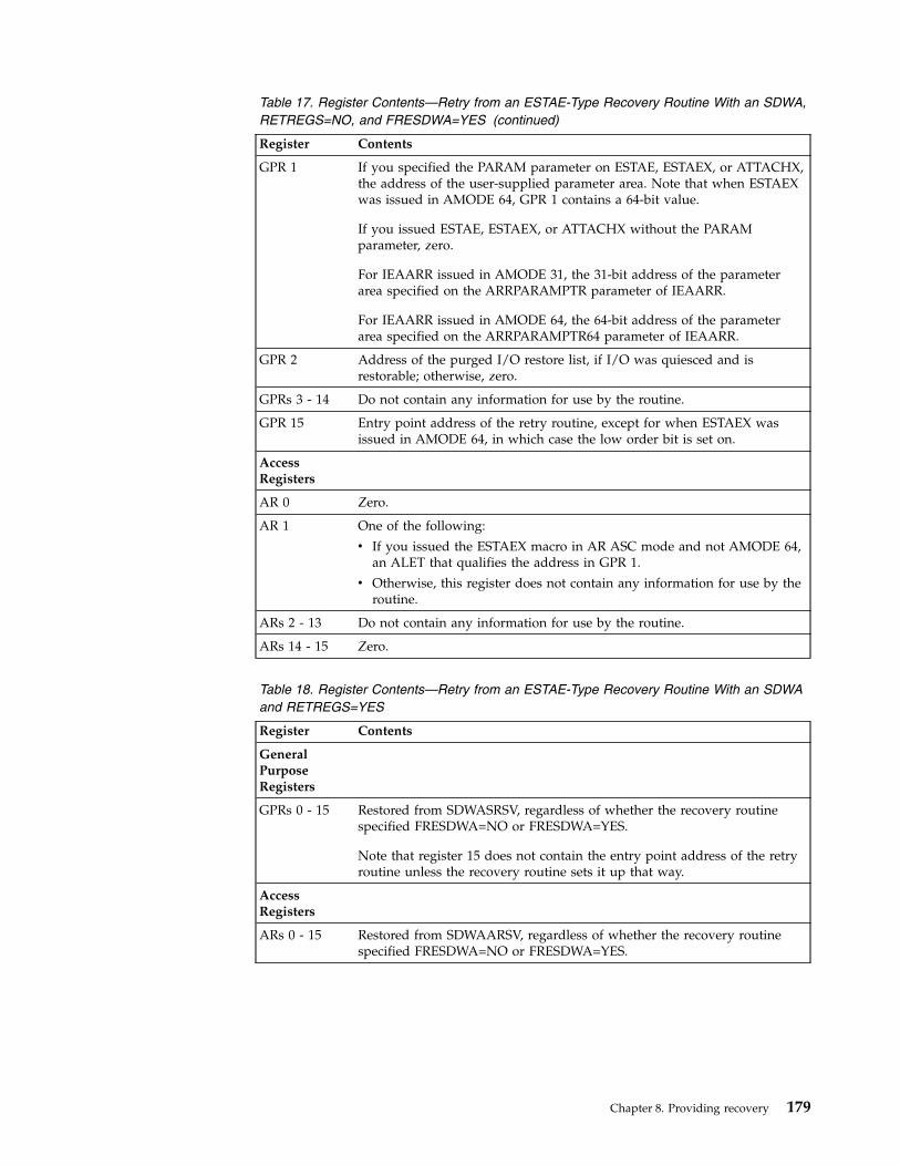
Table 17. Register Contents—Retry from an ESTAE-Type Recovery Routine With an SDWA,RETREGS=NO, and FRESDWA=YES (continued)
Register Contents
GPR 1 If you specified the PARAM parameter on ESTAE, ESTAEX, or ATTACHX,the address of the user-supplied parameter area. Note that when ESTAEXwas issued in AMODE 64, GPR 1 contains a 64-bit value.
If you issued ESTAE, ESTAEX, or ATTACHX without the PARAMparameter, zero.
For IEAARR issued in AMODE 31, the 31-bit address of the parameterarea specified on the ARRPARAMPTR parameter of IEAARR.
For IEAARR issued in AMODE 64, the 64-bit address of the parameterarea specified on the ARRPARAMPTR64 parameter of IEAARR.
GPR 2 Address of the purged I/O restore list, if I/O was quiesced and isrestorable; otherwise, zero.
GPRs 3 - 14 Do not contain any information for use by the routine.
GPR 15 Entry point address of the retry routine, except for when ESTAEX wasissued in AMODE 64, in which case the low order bit is set on.
AccessRegisters
AR 0 Zero.
AR 1 One of the following:
v If you issued the ESTAEX macro in AR ASC mode and not AMODE 64,an ALET that qualifies the address in GPR 1.
v Otherwise, this register does not contain any information for use by theroutine.
ARs 2 - 13 Do not contain any information for use by the routine.
ARs 14 - 15 Zero.
Table 18. Register Contents—Retry from an ESTAE-Type Recovery Routine With an SDWAand RETREGS=YES
Register Contents
GeneralPurposeRegisters
GPRs 0 - 15 Restored from SDWASRSV, regardless of whether the recovery routinespecified FRESDWA=NO or FRESDWA=YES.
Note that register 15 does not contain the entry point address of the retryroutine unless the recovery routine sets it up that way.
AccessRegisters
ARs 0 - 15 Restored from SDWAARSV, regardless of whether the recovery routinespecified FRESDWA=NO or FRESDWA=YES.
Chapter 8. Providing recovery 179

Table 19. Register Contents—Retry from an ESTAE-Type Recovery Routine With an SDWAand RETREGS=64 in z/Architecture mode
Register Contents
GeneralPurposeRegisters
GPRs 0 - 15 Restored from SDWAG64, regardless of whether the recovery routinespecified FRESDWA=NO or FRESDWA=YES.
Note that register 15 does not contain the entry point address of the retryroutine unless the recovery routine sets it up that way.
AccessRegisters
ARs 0 - 15 Restored from SDWAARSV, regardless of whether the recovery routinespecified FRESDWA=NO or FRESDWA=YES.
Other environmental factors in recoveryAs mentioned previously, the other environmental factors to be concerned about ina recovery environment are:v Authorization: problem state or supervisor state, PSW key, and PKMv SDWA storage keyv Dispatchable unit modev AMODEv ASC modev Interrupt statusv DU-ALv Program maskv Condition of the linkage stack
These environmental factors differ depending on whether you are dealing with therecovery routine or the retry routine.
Environment on entry to an ESTAE-type recovery routineThe following is a description of each environmental factor on entry to anESTAE-type recovery routine.
Authorization:
Problem or supervisor stateThe ESTAE-type recovery routines you can write are entered in problemstate.
PSW keyAn ESTAE-type recovery routine is entered with the PSW key that existedat the time the recovery routine was defined.
PKM An ESTAE-type recovery routine is entered with the PKM that existed atthe time the recovery routine was defined.
SDWA storage key: An ESTAE-type recovery routine receives an SDWA in thesame storage key as the TCB key at the time the related task made the first storagerequest from subpool 0.
180 z/OS MVS Assembler Services Guide

Dispatchable unit mode: All ESTAE-type recovery routines receive control in taskmode.
AMODE: ESTAE-type recovery exits receive control in the AMODE that wascurrent at the time-of-set (time-of-PC AMODE for ARRs) with the followingexceptions:v ARR, IEAARR, and ESTAEX exits receive control in AMODE 31 instead of
AMODE 24 when established for AMODE 24 programs
ASC mode: A recovery routine defined through the ESTAE macro is entered inprimary ASC mode. A recovery routine defined through the ESTAEX macro, theIEAARR macro, or the ESTAI parameter on ATTACHX is entered in the ASC modethat existed at the time the macro was issued.
Interrupt status: All ESTAE-type recovery routines are entered enabled for I/Oand external interrupts.
DU-AL: ESTAE-type recovery routines receive control with the DU-AL that wascurrent at the time of the error, as modified by any previous recovery routines,with the following exception. For an ESTAE-type recovery routine activated by anIRB, or activated by an IRB's ESTAE-type recovery routine, the ESTAE-typerecovery routine receives the IRB's DU-AL (IRBs get control with their ownDU-AL). The system does not modify the contents of the DU-AL during recoveryprocessing.
Program mask: The program mask on entry to an ESTAE-type recovery routine isthe same as the program mask at the time of error.
Condition of the linkage stack: On entry to an ESTAE-type recovery routine, thecurrent linkage stack entry is the same as it was at the time of the error, unless aprevious recovery routine added entries to the linkage stack through a PC orBAKR instruction and did not remove them. In such a case, when percolationoccurs and the recovery routine gets control, the linkage stack contains additionalentries beyond what was the current entry at the time of the error for which therecovery routine received control. IBM recommends that any recovery routinesthat add entries to the linkage stack also remove them.
Restricted environments: During normal task termination, a resource managermight end abnormally; its own recovery routines, if any exist, will receive control.If they do not retry, or if the resource manager has no recovery routines, thesystem now considers this situation to be an abnormal termination, and passescontrol to the newest ESTAI routine. Because the abending resource manager, andany previous resource managers, might have completed some processing, theESTAI routine will run in an unpredictable environment. In this situation, IBMrecommends that you restrict the ESTAI routine's processing. For the ESTAI routineto run in this environment, design it to:1. Check the STCBRMET field in the STCB; if the bit is on, the ESTAI routine is
running after a resource manager has ended abnormally and its recoveryroutines have not retried. In this situation, the ESTAI routine does not need tohold a lock to check the STCBRMET field. For the mapping of the STCB, seez/OS MVS Data Areas in the z/OS Internet library (www.ibm.com/systems/z/os/zos/library/bkserv).
2. Do as little processing as possible, and nothing that might depend on aresource that might have been cleaned up already.
3. Do not request to retry. The system will not allow a retry in this situation.
Chapter 8. Providing recovery 181
Note that no other ESTAE-type routines receive control in this situation; only thoseestablished through the ATTACHX macro still exist at this point in terminationprocessing.
Environment on entry to a retry routine from an ESTAE-typerecovery routineThe following is a description of each environmental factor on entry to a retryroutine that was specified by an ESTAE-type recovery routine.
Authorization:
Problem or supervisor stateThe retry routine from an ESTAE-type recovery routine that you can writeis entered in problem state.
PSW keyIf the recovery routine was defined through the ESTAE, ESTAEX, orIEAARR macro, the retry routine is entered with the same PSW key thatexisted when the macro was issued.
If the recovery routine was defined through the ESTAI parameter of theATTACHX macro, the retry routine is entered with the same PSW key asthe one in RBOPSW of the retry RB, if the RBOPSW of the retry RB has akey greater than or equal to 8 and is in problem state, and the PKM of thatRB does not have authority to keys less than 8. Otherwise, the PSW key ofthe retry routine is that of the task in error.
PKM If the recovery routine was defined through the ESTAE, ESTAEX, orIEAARR macro, the retry routine is entered with the PKM that existedwhen the macro was issued.
If the recovery routine was defined through the ESTAI parameter of theATTACHX macro, the retry routine is entered with the PKM from the retryRB if the RBOPSW of the retry RB has a key greater that or equal to 8 andis in problem state, and the PKM of that RB does not have authority tokeys less than 8. Otherwise, the PKM of the retry routine has authority thatis equivalent to that of the task in error.
SDWA storage key: If the recovery routine does not request that the system freethe SDWA, the retry routine receives the SDWA in the same storage key as thatwhich the recovery routine received.
Dispatchable unit mode: The retry routine is always entered in task mode.
AMODE: Retry routines are entered in the same addressing mode that existedwhen the recovery routine was entered, unless the SETRP RETRYAMODE=parmeter is used by the recovery routine. See the description of RETRYAMODE=on the SETRP section of the z/OS MVS Programming: Assembler Services ReferenceIAR-XCT.
ASC mode: For recovery routines defined through the ESTAE macro, the retryroutine is entered in primary ASC mode. For recovery routines defined through theESTAEX macro or through the ESTAI parameter on ATTACHX, the retry routine isentered with the ASC mode of the caller when the macro was issued.
Interrupt status: The retry routine is always entered enabled for I/O and externalinterrupts.
182 z/OS MVS Assembler Services Guide

DU-AL: The retry routine is entered with the same DU-AL that the ESTAE-typerecovery routine received, as modified by the ESTAE-type recovery routine. Thesystem does not modify the contents of the DU-AL during recovery processing.
Program mask: When the retry routine receives control, the program mask is theone in the RBOPSW for the retry RB, either saved at the time of the lastinterruption of the RB that occurs while the RB was unlocked and enabled orupdated due to an ESPIE routine setting the EPIERSET bit.
Condition of the linkage stack: For recovery routines defined through theESTAE, ESTAEX or IEAARR macro, on entry to the retry routine, the currentlinkage stack entry is the same as it was at the time the macro was issued, unlessthe recovery routine has set the SDWALSLV field.
For recovery routines defined through the ESTAI parameter on ATTACHX, onentry to the retry routine, the current linkage stack entry is the same as it was atthe time the selected retry RB was entered, unless the recovery routine has set theSDWALSLV field.
Summary of environment on entry to an ESTAE-type recoveryroutine and its retry routineTable 20 summarizes some of the environmental factors for ESTAE-type recoveryroutines under different conditions. Specifically, the table lists the statusinformation of:v The caller at the time of issuing the macrov The recovery routine at entryv The retry routine at entry.
Table 20. Environments of ESTAE-type Recovery Routines and their Retry Routines
Type ofRecovery When macro was issued At entry to recovery routine At entry to retry routine
ESTAE ASC mode=primary ASC mode=primary
Linkage stack at time of error (seeNote 1 on page 184)
PKM at time macro was issued
ASC mode=primary
Linkage stack at time macro wasissued (see Note 2 on page 184)
PKM at time macro was issued
ESTAEX orIEAARR
ASC mode=primary or AR ASC mode at time macro was issued
Linkage stack at time of error (seeNote 1 on page 184)
PKM at time macro was issued
ASC mode at time macro was issued
Linkage stack at time macro wasissued (see Note 2 on page 184)
PKM at time macro was issued
ESTAI(throughATTACHX)
ASC mode=primary or AR ASC mode at time macro was issued
Linkage stack at time of error (seeNote 1 on page 184)
PKM at time macro was issued
For possible environmentrestrictions, see “Restrictedenvironments” on page 181.
ASC mode at time macro was issued
Linkage stack at time the retry RBwas entered (see Note 2 on page184)
Note:
Chapter 8. Providing recovery 183
||||

1. The linkage stack presented to the recovery routine might have additionalentries, beyond what was the current entry at the time of the error, if aprevious recovery routine added entries through a PC or BAKR instruction anddid not remove them.
2. The linkage stack presented to the retry routine might have additional entries,beyond what was current at the time that the routine was activated, when therecovery routine set the SDWALSLV field.
3. At time of entry to the recovery routine, the AMODE will be the same as thetime of invocation, except for ESTAEX and IEAARR routines. ESTAEX andIEAARR routines that were established in AMODE 64 receive control inAMODE 64; otherwise, ESTAEX and IEAARR routines always receive control inAMODE 31.
4. The AMODE at the retry point is the same as the AMODE on entry to therecovery routine, unless the SETRP RETRYAMODE= parameter specifies aspecific retry AMODE.
5. An ESTAE-type recovery routine is entered with the PSW key that existed atthe time it was defined.
Linkage stack at time of retryThere is one retry situation you must avoid: the situation where the retry routineruns with a linkage stack entry that is inappropriate. Consider the followingexample, where PGM1 activates an ESTAEX routine that handles recovery forPGM1, PGM2, and PGM3.
Both PGM2 and PGM3 use the BAKR instruction to save status; each BAKR addsan entry to the linkage stack. Within PGM3, “retry point” indicates the locationwhere the ESTAEX routine is to retry. After PGM3 issues the BAKR instruction, thelast entries in the linkage stack are:v Entry 1 -- caused by PGM1's BAKRv Entry 2 -- caused by PGM2's BAKRv Entry 3 -- caused by PGM3's BAKR
When the abend occurs in PGM3, unless you take special measures, the linkagestack level is reset to the level that was current when PGM1 activated the ESTAEXrecovery routine. However, retry from the abend in PGM3 occurs within PGM3.The linkage stack level and the retry routine are not “in synch”. Measures you taketo avoid this situation involve:1. Passing the recovery routine a value that represents the difference between the
level of the linkage stack that the retry routine in PGM3 needs and the level ofthe stack at the time PGM1 activated the ESTAEX routine. (In our example, thedifference is 2 entries.)
caller ---> PGM1BAKR:ESTAEX:BALR --------> PGM2
BAKR:BALR --------> PGM3
BAKR***abend***
:retry point:
<-------- PR
184 z/OS MVS Assembler Services Guide

2. Having the recovery routine set the value “2” in the SDWALSLV field in theSDWA.
At a retry, the system uses the value in SDWALSLV to adjust the linkage stack. Inthis way, the retry routine has the appropriate current linkage stack entry.
Two ways your program can track the entries in the linkage stack are:v Count the number of entries added to the stack through BAKRs since PGM1
activated the ESTAEX routine. Subtract from that total the number of entriestaken from the stack through corresponding PRs.
v Issue the IEALSQRY macro, which returns the number as output.
In either case, the recovery routine must receive the value and must place it inSDWALSLV. In summary, the value in SDWALSLV is the difference between thenumber of linkage stack entries present when the retry routine gets control and thenumber that were present when the recovery routine was activated. The systempreserves the additional entries on the linkage stack for use by the retry routine.These linkage stack entries must exist at the time of the error; the system does notcreate any new entries.
The following rules apply to the value in SDWALSLV, as it pertains to linkagestack entries:v The system ignores the SDWALSLV field when retry is from a STAE or STAI
recovery routine.v The value must not reflect entries that were placed on the linkage stack through
a PC instruction.v The value must reflect only those entries associated with programs that are
problem state and running with the same PSW key as the program thatactivated the ESTAE-type recovery routine.
v For ESTAE-type routines, the value must reflect only those entries associatedwith programs that have been established by a program running under the RBof the retry routine. See “RB considerations” on page 170.
If any of these rules are broken, retry still occurs but the system ignores the entrythat did not conform and all subsequent entries.
Understanding recovery through a coded exampleThis information provides a coded example illustrating a mainline routine withboth a recovery routine and a retry routine as entry points in the mainline code.
The code in this example does not contain any real function. The mainline codedoes little more than save status, establish addressability, obtain a dynamic area(making the code reentrant), define a recovery routine, and issue the ABENDmacro to pass control to the system.
The purpose of the example is just to illustrate how you might code a programthat contains both a recovery routine and a retry routine, and how the threeroutines interact. The example also illustrates how you design an ESTAE-typerecovery routine to allow for the possibility that the system might not provide anSDWA.EXAMPLE CSECT * SAMPLE PROGRAM THAT USES ESTAEXEXAMPLE AMODE 31EXAMPLE RMODE ANY
USING EXAMPLE,15 * ESTABLISH TEMPORARY ADDRESSABILITY
Chapter 8. Providing recovery 185

B @PROLOG * BRANCH AROUND EYE CATCHERDC CL24’EXAMPLE 04/10/92.01’ * EYE CATCHER
** USE THE LINKAGE STACK TO SAVE STATUS ON ENTRY TO THE PROGRAM.*@PROLOG BAKR 14,0 * SAVE REGISTER/PSW STATUS** ESTABLISH ADDRESSABILITY FOR THIS PROGRAM.*
LR 12,15 * REG 12 BECOMES BASE REGISTERDROP 15 *USING EXAMPLE,12 * ESTABLISH ADDRESSABILITY
** OBTAIN DYNAMIC STORAGE AREA FOR THIS REENTRANT PROGRAM.*
L 2,DYNSIZE * LENGTH TO OBTAINSTORAGE OBTAIN,ADDR=(1),SP=0,LENGTH=(2)LR 13,1 * SAVE DYNAMIC AREA ADDRESSUSING DYNAREA,13 * ADDRESSABILITY TO DYNAMIC AREA
** SET UP THE REMOTE PARAMETER LIST FOR THE ESTAEX MACRO.*
MVC RMTESTAEX(@LSTSIZE),LSTESTAEX** DEFINE AND ACTIVATE AN ESTAEX RECOVERY ROUTINE AT LABEL ’RECOVERY’.*
ESTAEX RECOVERY,PARAM=DYNAREA,MF=(E,RMTESTAEX)************************************************************************* CODE FOR THE MAINLINE ROUTINE FUNCTION CAN BE INSERTED HERE** IF AN ERROR OCCURS IN THE MAINLINE ROUTINE, THEN THE SYSTEM WILL* PASS CONTROL TO RECOVERY.*************************************************************************RETRYPT DS 0H************************************************************************* CODE FOR THE RETRY ROUTINE FUNCTION CAN BE INSERTED HERE************************************************************************
ESTAEX 0 * DELETE THE ESTAEXLR 1,13 * FREE DYNAMIC AREA, ADDRESS TO FREEL 2,DYNSIZE * LENGTH TO FREESTORAGE RELEASE,ADDR=(1),SP=0,LENGTH=(2)PR * RESTORE STATUS & RETURN TO CALLER
************************************************************************* RECOVERY ROUTINE************************************************************************RECOVERY DS 0H * ENTRY POINT FOR ESTAEX RECOVERY ROUTINE** HANDLE INPUT FROM THE SYSTEM AND RE-ESTABLISH ADDRESSABILITY FOR* BASE REGISTER (12) AND DYNAMIC AREA REGISTER (13)*
PUSH USINGDROP , * ENSURE NO SPURIOUS USING REFERENCESUSING RECOVERY,15 * TEMPORARY ADDRESSABILITYL 12,#BASE * RELOAD THE BASE REGISTERDROP 15 * RELEASE TEMPORARY ADDRESSABILITYUSING EXAMPLE,12 * USE THE BASE REGISTERUSING DYNAREA,13 * DYNAMIC AREA ADDRESSABILITYC 0,TESTNOSDWA * IS THERE AN SDWA PRESENT?BE NOSDWA * NO, DO NOT USE THE SDWA
HAVESDWA DS 0H
186 z/OS MVS Assembler Services Guide

USING SDWA,1 * ADDRESSABILITY TO SDWAL 13,SDWAPARM * ADDRESS OF PARAMETER ADDRESSL 13,0(13) * PARAMETER ADDRESS (DYNAREA)MVC SAVE_ABCC,SDWAABCC * SAVE THE COMPLETION CODEB RECOV1 * CONTINUE WITH COMMON RECOVERY
NOSDWA LR 13,2 * PARAMETER ADDRESS (DYNAREA)ST 1,SAVE_ABCC * SAVE THE COMPLETION CODESR 1,1 * NO SDWA IS AVAILABLE, CLEAR REGISTER
** COMMON RECOVERY PROCESSING*RECOV1 DS 0H * COMMON RECOVERY PROCESSING
ST 1,SAVE_SDWA * SAVE THE SDWA ADDRESSST 14,SAVE_RETURNR14 * RETURN ADDRESS TO THE SYSTEM
************************************************************************** CODE FOR THE RECOVERY ROUTINE FUNCTION SHOULD BE INSERTED HERE************************************************************************** IF THERE IS NO SDWA, THEN SET UP FOR PERCOLATION*
L 1,SAVE_SDWA * RESTORE SDWA REGISTER (1)LTR 1,1 * IS THERE AN SDWA?BZ NORETRY * NO, DO NOT ATTEMPT TO RETRY
** CHECK SDWACLUP TO SEE IF RETRY IS ALLOWED*
TM SDWAERRD,SDWACLUP * IS RETRY ALLOWED?BNZ NORETRY * NO, DO NOT ATTEMPT TO RETRY
** SET UP THE RETURN PARAMETERS TO THE SYSTEM. THE SETRP MACRO UPDATES* THE SDWA. NOTE: THE WKAREA PARAMETER DEFAULTS TO REGISTER 1, WHICH* HAS THE ADDRESS OF THE SDWA. ALSO NOTE THAT OTHER REGISTERS MIGHT* NEED TO BE UPDATED TO MEET THE NEEDS OF DIFFERENT PROGRAMS.*
ST 12,SDWASR12 * BASE REGISTER 12 FOR RETRYST 13,SDWASR13 * DYNAMIC AREA REGISTER 13 FOR RETRYSETRP RETREGS=YES,RC=4,RETADDR=RETRYPT,FRESDWA=YESB RECOV2 * CONTINUE WITH COMMON RECOVERY
NORETRY DS 0H * BRANCH HERE WHEN NOT GOING TO RETRYLA 15,0 * RETURN CODE TO INDICATE PERCOLATION
RECOV2 DS 0H * COMPLETE THE RETURN TO THE SYSTEML 14,SAVE_RETURNR14 * SET THE RETURN ADDRESS TO THE SYSTEMBR 14 * RETURN TO THE SYSTEM
** STATIC STORAGE AREA*TESTNOSDWA DC F’12’ * TEST FOR NO SDWA CONDITION#BASE DC A(EXAMPLE) * BASE REGISTER VALUEDYNSIZE DC AL4(@DYNSIZE) * DYNAMIC AREA SIZELSTESTAEX ESTAEX RECOVERY,MF=L * LIST FORM OF ESTAEX PARAMETER LIST@LSTSIZE EQU *-LSTESTAEX * SIZE OF ESTAEX PARAMETER LIST** DYNAMIC AREA STORAGE FOR REENTRANT PROGRAM*DYNAREA DSECT * DYNAMIC STORAGESAVEAREA DS 18F * REGISTER SAVE AREASAVE_SDWA DS F * SDWA ADDRESS ON ENTRY TO RECOVERYSAVE_ABCC DS F * COMPLETION CODESAVE_RETURNR14 DS F * RETURN ADDR. TO SYSTEM FROM RECOVERYRMTESTAEX DS CL(@LSTSIZE) * REMOTE ESTAEX PARAMETER LISTSTATUS DS F * MAINLINE STATUS INDICATOR@ENDDYN DS 0X * USED TO CALCULATE DYNAMIC AREA SIZE@DYNSIZE EQU ((@ENDDYN-DYNAREA+7)/8)*8 * DYNAMIC AREA SIZE*
Chapter 8. Providing recovery 187

* INCLUDE MACROS*
IHASDWAEND
Understanding advanced recovery topicsThis information contains information about the following advanced recoverytopics:v “Invoking RTM (ABEND macro)”v “Providing multiple recovery routines” on page 189v “Providing recovery for recovery routines” on page 189v “Providing recovery for multitasking programs” on page 190.
Invoking RTM (ABEND macro)Any routine can issue the ABEND macro to direct the recovery terminationservices to itself (cause entry into its recovery routine) or to its callers. The issuerof ABEND should remove its own recovery routine if it wishes its caller to beended abnormally or to enter recovery. Control does not return to the issuer of themacro (except as a result of a retry).
The position within the job step hierarchy of the task for which the ABEND macrois issued determines the exact function of the abnormal termination routine. If anABEND macro is issued when the job step task (the highest level or only task) isactive, or if the STEP parameter is coded in an ABEND macro issued during theperformance of any task in the job step, all the tasks in the job step are terminated.For example, if the STEP parameter is coded in an ABEND macro under TSO/E,the TSO/E job is terminated. An ABEND macro (without a STEP parameter) that isissued in performance of any task in the job step task usually causes only that taskand its subtasks to be abnormally terminated. However, if the abnormaltermination cannot be fulfilled as requested, it might be necessary for the system toend the job step task abnormally.
If you have provided a recovery routine for your program, the system passescontrol to your routine. If you have not provided a recovery routine, the systemhandles the problem. The action the system takes depends on whether the job stepis going to be terminated.
If the job step is not going to be terminated, the system:v Releases the resources owned by the terminating task and all of its subtasks,
starting with the lowest level task.v Places the system or user completion code specified in the ABEND macro in the
task control block (TCB) of the active task (the task for which the ABEND macrowas issued).
v Posts the event control block (ECB) with the completion code specified in theABEND macro, if the ECB parameter was coded in the ATTACHX macro issuedto create the active task.
v Schedules the end-of-task exit routine to be given control when the originatingtask becomes active, if the ETXR parameter was coded in the ATTACHX macroissued to create the active task.
v Calls a routine to free the storage of the terminating task's TCB, if neither theECB nor ETXR parameter were specified by the ATTACHX macro.
If the job step is to be terminated, the system:
188 z/OS MVS Assembler Services Guide

v Releases the resources owned by each task, starting with the lowest level task,for all tasks in the job step. The system does not give control to any end-of-taskexit.
v Writes the system or user completion code specified in the ABEND macro on thesystem output device.
The remaining steps in the job are skipped unless you can define your ownrecovery routine to perform similar functions and any other functions that yourprogram requires. Use either the ESTAE or ESTAEX macro, or the ATTACHXmacro with the ESTAI option to provide a recovery routine that gets controlwhenever your program issues an ABEND macro. If your program is running inAR ASC mode, use the ESTAEX or ATTACHX macro.
Providing multiple recovery routinesA single program can activate more than one ESTAE-type recovery routine byissuing the ESTAE or ESTAEX macro more than once with the CT parameter. Theprogram can also overlay recovery routines by issuing ESTAE or ESTAEX with theOV parameter, or deactivate recovery routines by issuing ESTAE or ESTAEX withan address of zero.
ESTAE-type recovery routines get control in LIFO order, so the last ESTAE-typerecovery routine activated is the first to get control. Remember that ESTAE-typerecovery routines include ESTAE and ESTAEX routines, and ESTAI routines. ESTAIroutines are entered after all other ESTAE-type recovery routines that exist for agiven task have received control and have either failed or percolated.
MVS functions provide their own recovery routines; thus, percolation can passcontrol to both installation-written and system-provided recovery routines. If allrecovery routines percolate -- that is, no recovery routine can recover from theerror -- then the task is terminated.
When a recovery routine gets control and cannot recover from the error (that is, itdoes not retry), it must free the resources held by the mainline routine and requestthat the system continue with error processing (percolate). Note that a recoveryroutine entered with the SDWACLUP bit set to one, indicating that retry is notpermitted, has no choice but to percolate. When the recovery routine requestspercolation, the previously activated recovery routine gets control. When a retry isnot requested and the system has entered all possible recovery routines, the taskends abnormally.
When a recovery routine requests percolation, it is deactivated; that is, it can nolonger get control for this error. A deactivated recovery routine is not entered againunless that recovery routine is activated again after a retry.
Providing recovery for recovery routinesIn some situations, the function a recovery routine performs is so essential that youshould provide a recovery routine to recover from errors in the recovery routine.Two examples of such situations are:1. The availability of some resources can be so critical to continued system or
subsystem operation that it might be necessary to provide a recovery routinefor the recovery routine, thus ensuring the availability of the critical resources.
2. A recovery routine might perform a function that is, in effect, an extension ofthe mainline routine's processing. For example, a system service might elect tocheck a caller's parameter list for fetch or store protection. The service
Chapter 8. Providing recovery 189

references the user's data in the user's key and, as a result of protection, suffersa program check. The recovery routine gets control and requests a retry to passa particular return code to the mainline routine. If this recovery routine endsabnormally and does not provide its own recovery, then the caller's recoveryroutine gets control, and the caller does not get an opportunity to check thereturn code that it was expecting.
You can activate an ESTAE-type recovery routine from another ESTAE-typerecovery routine. Any recovery routine activated from a recovery routine is called anested recovery routine. Nested ESTAE or ESTAEX routines can retry; the retryroutine runs under the RB of the ESTAE-type recovery routine that activated thenested recovery routine.
Providing recovery for multitasking programsThere are situations where the system does not provide serialization betweenrecovery routines for different TCBs in an address space. When possible youshould write your recovery routines so that serialization is not required.
When a recovery routine requires serialization with other TCBs in the addressspace then the recovery routine must provide its own serialization. Serializationmust be carefully designed to avoid causing deadlock situations.
One serialization technique to ensure the order of termination processing is to usethe DETACH macro. Issuing DETACH ensures that the detached task and itsrecovery routines complete before processing for the issuing task proceeds.DETACH can only be used for tasks that were directly attached by the recoveryroutine's TCB.
Another important aspect of recovery is releasing resources. Releasing serializationresources (locks, ENQs, latches) in ESTAE-type recovery routines, rather thanleaving them to be released by a resource manager, helps avoid deadlocks inrecovery processing.
Using STAE/STAI routines
Note to reader
v IBM recommends that you use the ESTAEX or ESTAE macro, or the ESTAIparameter on ATTACHX.
v Under certain circumstances, STAE or STAI routines might receive control in arestricted environment. See “Restricted environments” on page 181 for moreinformation.
End of Note to reader
The STAE macro causes a recovery routine address to be made known to thesystem. This recovery routine is associated with the task and the RB that issuedSTAE. Use of the STAI option on the ATTACH macro also causes a recoveryroutine to be made known to the system, but the routine is associated with thesubtask created through ATTACH. Furthermore, STAI recovery routines arepropagated to all lower-level subtasks of the subtask created with ATTACH thatspecified the STAI parameter.
If a task is scheduled for abnormal termination, the recovery routine specified bythe most recently issued STAE macro gets control and runs under a program
190 z/OS MVS Assembler Services Guide

request block created by the SYNCH service routine. Only one STAE routinereceives control. The STAE routine must specify, by a return code in register 15,whether a retry routine is to be scheduled. If no retry routine is to be scheduled(return code = 0) and this is a subtask with STAI recovery routines, the STAIrecovery routine is given control. If there is no STAI recovery routine, abnormaltermination continues.
If there is more than one STAI recovery routine existing for a task, the newest onereceives control first. If it requests that termination continue (return code = 0), thenext STAI routine receives control. This continues until either all STAI routineshave received control and requested that the termination continue, a STAI routinerequests retry (return code = 4 or 12), or a STAI routine requests that thetermination continue but no further STAI routines receive control (return code =16).
Programs running under a single TCB can issue more than one STAE macro withthe CT parameter to define more than one STAE routine. Each issuancetemporarily deactivates the previous STAE routine. The previous STAE routinebecomes active when the current STAE routine is deactivated.
A STAE routine is deactivated (it cannot receive control again for this error) underany of the following circumstances:v When the RB that activated it goes away (unless it issued XCTL and specified
the XCTL=YES parameter on the STAE macro)v When the STAE macro is issued with an address of 0v When the STAE routine receives control.
If a STAE routine receives control and requests retry, the retry routine reissues theSTAE macro if it wants continued STAE protection.
A STAI routine is deactivated if the task completes or if the STAI routine requeststhat termination continue and no further STAI processing be done. In the lattercase, all STAI recovery routines for the task are deactivated.
STAE and STAI routine environment:
Prior to entering a STAE or STAI recovery routine, the system attempts to obtainand initialize a work area that contains information about the error. The first 4bytes of the SDWA contains the address of the user parameter area specified on theSTAE macro or the STAI parameter on the ATTACH macro.
Upon entry to the STAE or STAI routine, the GPRs contain the following:
If an SDWA was obtained:
GPR Contents
0 A code indicating the type of I/O processing performed:
0 Active I/O has been quiesced and is restorable.
4 Active I/O has been halted and is not restorable.
8 No active I/O at abend time.
16 (X'10')Active I/O, if any, was allowed to continue.
Chapter 8. Providing recovery 191

1 Address of the SDWA.
2 Address of the parameter area you specified on the PARAM parameter.
3 - 12 Do not contain any information for use by the routine.
13 Save area address.
14 Return address.
15 Address of STAE recovery routine.
If no SDWA was available:
GPR Contents
0 12 (X'0C') to indicate that no SDWA was obtained.
1 Completion code.
2 Address of user-supplied parameter list.
3 - 13 Do not contain any information for use by the routine.
14 Return address.
15 Address of STAE recovery routine.
When the STAE or STAI routine has completed, it should return to the systemthrough the contents of GPR 14. GPR 15 should contain one of the following returncodes:
Return CodeAction
0 Continue the termination. The next STAI, ESTAI, or ESTAE routine will begiven control. No other STAE routines will receive control.
4,8,12 A retry routine is to be scheduled.
Note: These values are not valid for STAI/ESTAI routines that receivecontrol when a resource manager fails during normal termination of a task.See “Restricted environments” on page 181 for more information.
16 No further STAI/ESTAI processing is to occur. This code may be issuedonly by a STAI/ESTAI routine
For the following situations, STAE/STAI routines are not entered:v If the abnormal termination is caused by an operator's CANCEL command, job
step timer expiration, or the detaching of an incomplete task without theSTAE=YES option.
v If the failing task has been in a wait state for more than 30 minutes.v If the STAE macro was issued by a subtask and the attaching task abnormally
terminates.v If the recovery routine was specified for a subtask, through the STAI parameter
of the ATTACH macro, and the attaching task abnormally terminates.v If a problem other than those already described arises while the system is
preparing to give control to the STAE routine.v If another task in the job step terminates without the step option.
STAE and STAI retry routines:
192 z/OS MVS Assembler Services Guide

If the STAE retry routine is scheduled, the system automatically deactivates theactive STAE routine; the preceding STAE routine, if one exists, then becomesactivated. Users wanting to maintain STAE protection during retry must reactivatea STAE routine within the retry routine, or must issue multiple STAE requestsprior to the time that the retry routine gains control.
Like the STAE/STAI recovery routine, the STAE/STAI retry routine must be instorage when the recovery routine determines that retry is to be attempted. If notalready resident in your program, the retry routine may be brought into storagethrough the LOAD macro by either the mainline routine or the recovery routine.
If the STAE/STAI routine indicates that a retry routine has been provided (returncode = 4, 8, or 12), register 0 must contain the address of the retry routine. TheSTAE routine that requested retry is deactivated and the request block queue ispurged up to, but not including, the RB of the program that issued the STAEmacro. In addition, open DCBs that can be associated with the purged RBs areclosed and queued I/O requests associated with the DCBs being closed are purged.
The RB purge is an attempt to cancel the effects of partially run programs that areat a lower level in the program hierarchy than the program under which the retryoccurs. However, certain effects on the system are not canceled by this RB purge.Generally, these effects are TCB-related and are not identifiable at the RB level.Examples of these effects are as follows:v Subtasks created by a program to be purged. Subtasks cannot be associated with
an RB; the structure is defined through TCBs.v Resources allocated by the ENQ macro. ENQ resources are associated with the
TCB and are not identifiable at the RB level.v DCBs that exist in dynamically acquired virtual storage. Only DCBs in the
program, as defined by the RB through the CDE itself, are closed.
If there are quiesced restorable input/output operations (as specified byPURGE=QUIESCE on the macro invocation), the retry routine can restore them inthe same manner as the retry routine from an ESTAE routine. See “OutstandingI/Os at the time of failure” on page 171.
If an SDWA was obtained upon entry to the STAE/STAI retry routine, the contentsof the GPRs are as follows:
GPR Contents
0 0
1 Address of the first 104 bytes of the SDWA.
2 - 14 Do not contain any information for use by the routine.
15 Address of the STAE/STAI retry routine.
When the storage is no longer needed, the retry routine should use the FREEMAINmacro with the default subpool to free the first 104 bytes of the SDWA.
If the system was not able to obtain storage for the work area, GPR contents are asfollows:
GPR Contents
0 12 (X'0C')
1 Completion code.
Chapter 8. Providing recovery 193
2 Address of purged I/O restore list or 0 if I/O is not restorable.
3 - 14 Do not contain any information for use by the routine.
15 Address of the STAE/STAI retry routine.
The retry routine is entered with the same PSW key as the one in the RBOPSW ofthe retry RB if the RBOPSW of the retry RB has a key greater than or equal to 8and is in problem program state, and the PKM of that RB does not have authorityto keys less than 8.
Otherwise, the PSW key of the retry routine is that of the task in error.
194 z/OS MVS Assembler Services Guide

Chapter 9. Dumping virtual storage (ABEND, SNAPX, SNAP,and IEATDUMP macros)
A problem-state and PSW key 8-15 program can request three types of storagedumps:v An ABEND dump obtained through the DUMP parameter in the ABEND macro,
or the DUMP=YES parameter on the SETRP macro in a recovery exitv A SNAP dump obtained through the SNAPX macro.v A Transaction dump obtained througfh the IEATDUMP macro.
Table 21 summarizes reasons for selecting an ABEND, SNAP, or Transaction dump.
Table 21. Reasons for Selecting the Type of Dump
Type of Dump Reasons for Selecting the Type of Dump
ABEND dumps Use an ABEND dump when abnormally ending a program because of an unpredictableerror. The DD statement in the program's job step determines the type of ABEND dumpand the dump contents, as follows:
v SYSUDUMP ABEND dumps
These are the smallest of the ABEND dumps, containing data and areas only about thefailing program. You can either print or view the dump if it's in a SYSOUT data set or ona tape or direct access data set (DASD).
v SYSABEND ABEND dumps
These are the largest of the ABEND dumps, containing all the areas in a SYSUDUMPdump and system areas that are used to analyze the processing in the failing program.You can either print or view the dump if it's in a SYSOUT data set or on a tape orDASD.
v SYSMDUMP ABEND dumps
These contain data and areas in the failing program, plus some system areas. TheSYSMDUMP dumps can be more useful for diagnosis than other ABEND dumps becauseyou can use IPCS to gather diagnostic information. Use IPCS to format, view, and printdumps.
SNAP dumps Use a SNAP dump to show one or more user-specified areas in the problem-state programwhile it is running. A series of SNAP dumps can show a storage area at different stages todisplay a program's processing. For example, you can use SNAP dumps to show fieldsholding calculations and the counter in a loop to check processing in the loop.
Transaction dumps(IEATDUMP)
Use Transaction dumps to request unformatted dumps of virtual storage, similar to whatSDUMPX offers for authorized programs. IPCS is used to analyze, view and print thedump information. This enables more program analysis possibilities than a formatted SNAPdump. Plus, by adding symptoms using the SYMREC parameter, duplicate dumps can besuppressed by DAE.
z/OS MVS Diagnosis: Tools and Service Aids shows, in detail, the contents of dumps.z/OS MVS IPCS User's Guide describes how to use IPCS. z/OS MVS Programming:Authorized Assembler Services Guide describes macros that authorized programs canuse to dump virtual storage.
© Copyright IBM Corp. 1988, 2017 195

ABEND dumpsAn ABEND macro initiates error processing for a task. The DUMP option ofABEND requests a dump of storage and the DUMPOPT or DUMPOPX option maybe used to specify the areas to be displayed. These dump options may beexpanded by an ESTAE or ESTAI routine. The system usually requests a dump foryou when it issues an ABEND macro. However, the system can provide anABEND dump only if you include a DD statement (SYSABEND, SYSMDUMP, orSYSUDUMP) in the job step. The DD statement determines the type of dumpprovided and the system dump options that are used. When the dump is taken,the dump options that you requested (specified in the ABEND macro or byrecovery routines) are added to the installation-selected options.
When writing an ESTAE-type recovery routine, note that the system accumulatesthe SYSABEND/SYSUDUMP/SYSMDUMP dump options specified by means ofthe SETRP macro and places them in the SDWA. During percolation, these optionsare merged with any dump options specified on an ABEND or CALLRTM macroor by other recovery routines. Also, the CHNGDUMP operator command can addto or override the options. The system takes one dump as specified by theaccumulated options. If the recovery routine requests a retry, the system processesthe dump before the retry. If the recovery routine does not request a retry, thesystem percolates through all recovery routines before processing the dump.
Note: If your program calls a system service (by issuing a macro or callableservice), that system service might encounter a user-induced error and endabnormally. Generally, the system does not take dumps for user-induced errors. Ifyou require such a dump, then it is your responsibility to request one in yourrecovery routine. See Chapter 8, “Providing recovery,” on page 145 for informationabout writing recovery routines.
Obtaining a symptom dumpWith all ABEND dumps, you will automatically receive a symptom dump throughmessage IEA995I. This symptom dump provides a summary of error information,which will help you to identify duplicate problems.
You will receive this dump even without a DD statement unless your installationchanges the default via the CHNGDUMP operator command or the dump parmlibmember for SYSUDUMP.
Suppressing dumps that duplicate previous dumpsIf your installation is using dump analysis and elimination (DAE), code yourprogram to provide symptom data that DAE can compare with the symptom datafrom previous dumps. Through this comparison, DAE can reduce the number ofduplicate dumps. Another benefit is that the symptom data, which is stored in theDAE data set, provides a consistent set of data for identifying a failure.
DAE suppresses dumps that match a dump you already have. Each time DAEsuppresses a duplicate dump, the system does not collect data for the duplicate orwrite the duplicate to a data set. In this way, DAE can improve dump managementby only dumping unique situations and by minimizing the number of dumps.
To perform dump suppression, DAE builds a symptom string, if the data for it isavailable. If the symptom string contains the minimum problem data, DAE usesthe symptom string to recognize a duplicate SVC dump, SYSMDUMP dump, or
196 z/OS MVS Assembler Services Guide
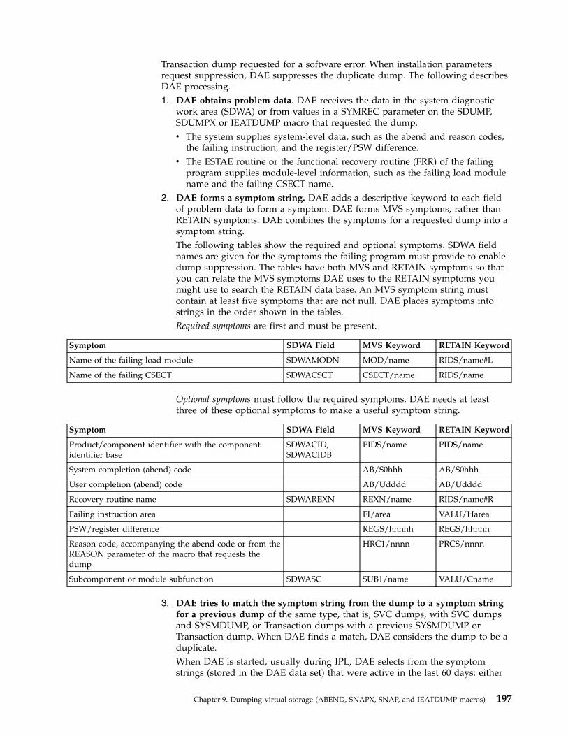
Transaction dump requested for a software error. When installation parametersrequest suppression, DAE suppresses the duplicate dump. The following describesDAE processing.1. DAE obtains problem data. DAE receives the data in the system diagnostic
work area (SDWA) or from values in a SYMREC parameter on the SDUMP,SDUMPX or IEATDUMP macro that requested the dump.v The system supplies system-level data, such as the abend and reason codes,
the failing instruction, and the register/PSW difference.v The ESTAE routine or the functional recovery routine (FRR) of the failing
program supplies module-level information, such as the failing load modulename and the failing CSECT name.
2. DAE forms a symptom string. DAE adds a descriptive keyword to each fieldof problem data to form a symptom. DAE forms MVS symptoms, rather thanRETAIN symptoms. DAE combines the symptoms for a requested dump into asymptom string.The following tables show the required and optional symptoms. SDWA fieldnames are given for the symptoms the failing program must provide to enabledump suppression. The tables have both MVS and RETAIN symptoms so thatyou can relate the MVS symptoms DAE uses to the RETAIN symptoms youmight use to search the RETAIN data base. An MVS symptom string mustcontain at least five symptoms that are not null. DAE places symptoms intostrings in the order shown in the tables.Required symptoms are first and must be present.
Symptom SDWA Field MVS Keyword RETAIN Keyword
Name of the failing load module SDWAMODN MOD/name RIDS/name#L
Name of the failing CSECT SDWACSCT CSECT/name RIDS/name
Optional symptoms must follow the required symptoms. DAE needs at leastthree of these optional symptoms to make a useful symptom string.
Symptom SDWA Field MVS Keyword RETAIN Keyword
Product/component identifier with the componentidentifier base
SDWACID,SDWACIDB
PIDS/name PIDS/name
System completion (abend) code AB/S0hhh AB/S0hhh
User completion (abend) code AB/Udddd AB/Udddd
Recovery routine name SDWAREXN REXN/name RIDS/name#R
Failing instruction area FI/area VALU/Harea
PSW/register difference REGS/hhhhh REGS/hhhhh
Reason code, accompanying the abend code or from theREASON parameter of the macro that requests thedump
HRC1/nnnn PRCS/nnnn
Subcomponent or module subfunction SDWASC SUB1/name VALU/Cname
3. DAE tries to match the symptom string from the dump to a symptom stringfor a previous dump of the same type, that is, SVC dumps, with SVC dumpsand SYSMDUMP, or Transaction dumps with a previous SYSMDUMP orTransaction dump. When DAE finds a match, DAE considers the dump to be aduplicate.When DAE is started, usually during IPL, DAE selects from the symptomstrings (stored in the DAE data set) that were active in the last 60 days: either
Chapter 9. Dumping virtual storage (ABEND, SNAPX, SNAP, and IEATDUMP macros) 197
the string was created for a unique dump within the last 60 days, or its dumpcount was updated within the last 60 days. The selected symptom strings areplaced in virtual storage.The systems in a sysplex can share the DAE data set to suppress duplicatedumps across the sysplex. While each system in a sysplex can use its own DAEdata set, IBM recommends that systems in a sysplex share a DAE data set sothat:v DAE can write a dump on one system and suppress duplicates on other
systems in the sysplex.v Only one DAE data set is required, rather than a data set for each system.
4. DAE updates the symptom strings in storage and, later, in the DAE data set,if updating is requested.v For a unique symptom string, DAE adds a new record. The record contains
the symptom string, the dates of the first and last occurrences, the incidencecount for the number of occurrences, and the name of the system thatprovided the string.
v For a duplicate symptom string, DAE updates the incidence count for thestring, the last-occurrence date, and the name of the last system that foundthe string.
In a sysplex, changes to the in-storage strings are propagated to the in-storagestrings throughout the sysplex.
5. DAE suppresses a duplicate dump, if DAE is enabled for dump suppression.Note that, if you specify an ACTION of SVCD, TRDUMP, NOSUP, orRECOVERY on a SLIP command, the command overrides DAE suppressionand the system writes the dump. Also, dumps requested by the DUMPoperator command are not eligible for suppression.When DAE does not suppress a dump, the symptom string is in the dumpheader; you can view it with the IPCS VERBEXIT DAEDATA subcommand.DAE also issues informational messages to indicate why the dump was notsuppressed.DAE suppresses a dump when all of the following are true:v DAE located in the dump the minimum set of symptoms.v The symptom string for the dump matches a symptom string for a previous
dump of the same type.v Either of the following is true:
– The current ADYSETxx parmlib member specifies SUPPRESS for the typeof dump being requested and the VRADAE key is present in the SDWA.To set the VRADAE key, a recovery routine issues the following macro:VRADATA KEY=VRADAE
– A VRADATA VRAINIT must be done prior to any VRADATA KEY=request in order for the VRA data to be properly processed by both DAEand the SDWA formatter.
– The current ADYSETxx parmlib member specifies SUPPRESSALL for thetype of dump being requested and the VRANODAE key is absent fromthe SDWA. The VRANODAE key specifies that the dump is not to besuppressed.
The following table shows the effect of the VRADAE and VRANODAE keys ondump suppression when SUPPRESS and SUPPRESSALL keywords are specifiedin the ADYSETxx parmlib member. For SUPPRESS, the VRANODAE key canbe present or absent; the system does not check it. The table assumes that thesymptom string from the dump has matched a previous symptom string.
198 z/OS MVS Assembler Services Guide
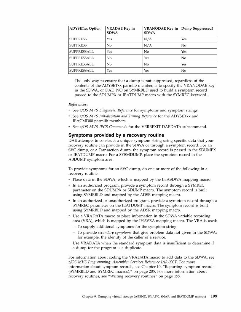
ADYSETxx Option VRADAE Key inSDWA
VRANODAE Key inSDWA
Dump Suppressed?
SUPPRESS Yes N/A Yes
SUPPRESS No N/A No
SUPPRESSALL Yes No Yes
SUPPRESSALL No Yes No
SUPPRESSALL No No Yes
SUPPRESSALL Yes Yes No
The only way to ensure that a dump is not suppressed, regardless of thecontents of the ADYSETxx parmlib member, is to specify the VRANODAE keyin the SDWA, or DAE=NO on SYMRBLD used to build a symptom recordpassed to the SDUMPX or IEATDUMP macro with the SYMREC keyword.
References:
v See z/OS MVS Diagnosis: Reference for symptoms and symptom strings.v See z/OS MVS Initialization and Tuning Reference for the ADYSETxx and
IEACMD00 parmlib members.v See z/OS MVS IPCS Commands for the VERBEXIT DAEDATA subcommand.
Symptoms provided by a recovery routineDAE attempts to construct a unique symptom string using specific data that yourrecovery routine can provide in the SDWA or through a symptom record. For anSVC dump, or a Transaction dump, the symptom record is passed in the SDUMPXor IEATDUMP macro. For a SYSMDUMP, place the symptom record in theABDUMP symptom area.
To provide symptoms for an SVC dump, do one or more of the following in arecovery routine:v Place data in the SDWA, which is mapped by the IHASDWA mapping macro.v In an authorized program, provide a symptom record through a SYMREC
parameter on the SDUMPX or SDUMP macro. The symptom record is builtusing SYMRBLD and mapped by the ADSR mapping macro.
v In an authorized or unauthorized program, provide a symptom record through aSYMREC parameter on the IEATDUMP macro. The symptom record is builtusing SYMRBLD and mapped by the ADSR mapping macro.
v Use a VRADATA macro to place information in the SDWA variable recordingarea (VRA), which is mapped by the IHAVRA mapping macro. The VRA is used:– To supply additional symptoms for the symptom string.– To provide secondary symptoms that give problem data not given in the SDWA;
for example, the identity of the caller of a service.Use VRADATA when the standard symptom data is insufficient to determine ifa dump for the program is a duplicate.
For information about coding the VRADATA macro to add data to the SDWA, seez/OS MVS Programming: Assembler Services Reference IAR-XCT. For moreinformation about symptom records, see Chapter 10, “Reporting symptom records(SYMRBLD and SYMREC macros),” on page 205. For more information aboutrecovery routines, see “Writing recovery routines” on page 155.
Chapter 9. Dumping virtual storage (ABEND, SNAPX, SNAP, and IEATDUMP macros) 199

VRADATA macro: Use the VRAREQ key to tell DAE that the symptom is requiredand the VRAOPT key to tell DAE that the symptom is optional.
A VRADATA macro with VRAREQ adds a symptom following the two requiredsymptoms (see the previous table). For example, to add a symptom, in this casethe name of a data set, and to define the symptom as required:VRADATA KEY=VRAREQ,DATA=TAG1,LEN=L’TAG1VRADATA KEY=VRADSN,DATA=MYDSN,LEN=L’MYDSN...TAG1 DC AL2(VRADSN)MYDSN DC C’DEPT27.PAYROLL’
A VRADATA macro with VRAOPT adds an optional symptom following theoptional symptoms (see the previous table). For example, to add an optionalsymptom with the data at the address in register 5, and to define the symptom asoptional:LA R5,VRAOPTKEYVRADATA KEY=VRAOPT,LEN=2,DATA=(5)VRADAYA KEY=VRACA,DATA=PGMCALLR...VRAOPTKEY DC AL2(VRACA)PGMCALLR DS A
If the symptom is to be the caller's address, the data pointed to would consist ofX'003C', which represents the key VRACA.
See z/OS MVS Diagnosis: Reference for the VRADATA keys.
Required symptom data: The recovery routine must provide the followingminimum data to enable dump suppression by DAE:
SDWA Field Data ExampleSDWAMODN Failing module name IEAVTCXXSDWACSCT Failing CSECT name IEAVTC22SDWACID Product or component identifier SCDMPSDWACIB Component identifier base 5655SDWAREXN Recovery routine name IEAVTC2RSDWASC Subcomponent or module subfunction RSM-PGFIX
To obtain the failing module name, the failing CSECT name, and the recoverymodule name, the recovery routine can set up a RECPARM parameter list andspecify it on a SETRP macro. For information, see the RECPARM parameter of theSETRP macro in z/OS MVS Programming: Authorized Assembler Services ReferenceSET-WTO.
Correct module and CSECT names: Obtaining the correct module and CSECTnames may be difficult, especially when the PSW does not point within theprogram areas. Problems can also occur when the program uses the following:v User exits: When the program calls a user exit, which in turn invokes system
services, such as getting a lock, the recovery routine often cannot identify theexit as the failing module and CSECT. To avoid this problem, the programshould save the name of the user exit, so that the recovery routine can use thesaved name.
v Common recovery routines: The program should maintain footprints or requirethat all modules using a common recovery routine update a common parameter
200 z/OS MVS Assembler Services Guide

list with the name of the current module, CSECT, subfunction, and so on. Therecovery routine can obtain data from the common parameter list when filling inthe SDWA.
Symptoms: When you provide symptom information, select each symptomcarefully. If a symptom is too precise, no other failure will have that symptom; ifthe symptom is too general, many failures will have the same symptom. Forexample, do not use addresses as symptoms; instead, use names of modules andcomponents.
DAE accumulates up to 20 specified required and optional symptoms and up to 20additional symptoms, if specified. The maximum string length is 150, so that notall of the additional symptoms may appear in the string. A recovery routine canchange the minimum number of symptoms and the minimum string lengths thatDAE is to use for symptom matching for a particular dump. To make thesechanges, code the following VRADATA macro keys in the recovery routine:v The VRAMINSC key controls the minimum number of symptoms.v The VRAMINSL key controls the minimum string length.
Control of suppression: When the ADYSETxx parmlib member being used by theinstallation contains SUPPRESS, a recovery routine must indicate that enough datais available to suppress a duplicate dump. To indicate to DAE that the SDWAcontains enough data, set the VRADAE indicator in the SDWA variable recordingarea by issuing the following:VRADATA KEY=VRADAE
If the recovery routine cannot provide enough data in the SDWA suppression, therecovery routine should indicate that its dump is not eligible for suppression, evenwhen the ADYSETxx member contains SUPPRESSALL. The routine should set theVRANODAE indicator by issuing the following:VRADATA KEY=VRANODAE
The VRANODAE key is useful for error environments that generate identicalsymptoms but represent different problems.
When a dump is not suppressedWhen DAE is active but does not suppress a dump, DAE adds the reason that thedump is not suppressed to the dump header record. When viewing a dump onlineor printing a dump, specify the IPCS VERBEXIT DAEDATA subcommand to seethe reason that a dump was not suppressed.
Some reasons for not suppressing a dump are:v The dump is unique. DAE found no match for the symptom string.v The current ADYSETxx member does not specify SUPPRESS or SUPPRESSALL
for the type of dump being requested.v A SLIP operator command specifies that the dump is not to be suppressed. A
SLIP command with ACTION=SVCD, ACTION=SYNCSVCD,ACTION=STDUMP, ACTION=RECOVERY, or ACTION=TRDUMP alwaysproduces a dump. ACTION=NOSUP stops suppression.
v DAE could not find all required symptoms.v DAE could not find the minimum number of symptoms.v The symptom string built by DAE was shorter than the minimum length.
Chapter 9. Dumping virtual storage (ABEND, SNAPX, SNAP, and IEATDUMP macros) 201
v DAE found certain errors. For example, a required symptom had a key that wasnot valid.
v The VRADAE key in the SDWA is absent, signifying that the dump should notbe suppressed, and the DAE parameter of the ADYSETxx parmlib member doesnot specify SUPPRESSALL.
v The VRANODAE key is present in the SDWA, specifying that the dump shouldnot be suppressed.
SNAP dumpsA program can request a SNAP dump at any time during its processing by issuinga SNAPX or SNAP macro. For a SNAP dump, the DD statement can have anyname except SYSABEND, SYSMDUMP, and SYSUDUMP.
If your program is in AR ASC mode, use the SNAPX macro instead of SNAP.Ensure that the SYSSTATE ASCENV=AR macro has been issued to tell the macroto generate code and addresses appropriate for callers in AR mode.
Like the ABEND dump, the data set containing the dump can reside on any devicethat is supported by BSAM. The dump is placed in the data set described by theDD statement you provide. If you select a printer, the dump is printedimmediately. However, if you select a direct access or tape device, you mustschedule a separate job to obtain a listing of the dump, and to release the space onthe device.
To obtain a dump using the SNAP macro, you must provide a data control block(DCB) and issue an OPEN macro for the data set before issuing any SNAP macros.If the standard dump format is requested, 120 characters per line are printed. TheDCB must contain the following parameters: DSORG=PS, RECFM=VBA,MACRF=W, BLKSIZE=882 or 1632, and LRECL=125. (The DCB is described in z/OSDFSMS Using Data Sets, and z/OS DFSMS Macro Instructions for Data Sets). If ahigh-density dump is to be printed on a 3800 Printing Subsystem, 204 charactersper line are printed. To obtain a high-density dump, code CHARS=DUMP on theDD statement describing the dump data set. The BLKSIZE= must be either 1470 or2724, and the LRECL= must be 209. CHARS=DUMP can also be coded on the DDstatement describing a dump data set that will not be printed immediately. IfCHARS=DUMP is specified and the output device is not a 3800, print lines aretruncated and print data is lost. If your program is to be processed by the loader,you should also issue a CLOSE macro for the SNAP DCB.
Finding information in a SNAP dumpYou will obtain a dump index with each SNAP dump. The index will help youfind information in the dump more quickly. Included in the information in thedump index is an alphabetical list of the active load modules in the dump alongwith the page number in the dump where each starts.
Obtaining a summary dump for an ABEND or SNAP dumpYou can request a summary dump for an abending task by coding the SUM optionof the SNAP macro. You can also obtain a summary dump by coding theDUMPOPT option on the ABEND or SETRP macro and specifying a list form ofSNAP that contains the SUM option. Use the DUMPOPX parameter on ABEND orSETRP to obtain an ABEND dump that contains data space storage. When you useDUMPOPX, specify a list form of SNAPX that contains the SUM option.
202 z/OS MVS Assembler Services Guide

If SUM is the only option that you specify, the dump will contain a dump header,control blocks, and certain other areas. The contents of the summary dump aredescribed in z/OS Problem Management.
Transaction dumpsTransaction dump is a service used to request an unformatted dump of virtualstorage to a data set, similar to a SYSMDUMP. It is invoked with the IEATDUMPassembler macro which issues SVC 51. You can either request that the dump bewritten to a preallocated data set or to automatically allocated data sets. To requesta preallocated data set, specify the DDNAME parameter that identifies a data setthat contains sufficient space in one or more extents for the entire dump to bewritten. If you don't provide a large enough data set, you will receive a partialdump. To request automatic allocation, specify the DSN and DSNAD parameters,which ensure a dump will not be truncated due to data set space constraints.Automatic allocation is done to SYSALLDA. When using DSN or DSNAD, themaximum size is 2 GB, unless the dump is split among several data sets, in whichcase there is no restriction. DDNAME also does not have the 2 GB size restriction.
When a Transaction dump is written, a dump directory record describing thedump may be written. Specify the dump directory to be used with the IDXkeyword on the dump request. If you do not specify a dump directory, thedirectory allocated to IPCSDDIR in the current job step will be used. If no dumpdirectory is specified and IPCSDDIR is not allocated, no record describing thedump will be written.
Dump suppression occurs using symptoms available in the current SDWA or asymptom string may be provided (via the SYMREC keyword). If you provide asymptom string, and an SDWA exists, the symptom string is used for suppressionpurposes. Statistics for dump suppression are contained in the DAE data set andare not differentiated from SYSMDUMPs.
Authorized users may specify the REMOTE keyword on the IEATDUMP macro torequest other address spaces on the current or other MVS images (in the samesysplex) be dumped. When you request remote dumps, automatic allocation mustalso be used.
Transaction dump uses an incident token to associate this dump with otherdiagnostic information. Automatic allocation also uses this incident token forsymbol substitution in the data set name pattern. You can generate an incidenttoken using the IEAINTKN macro and providing the INTOKEN keyword on thedump request. If you do not provide an incident token, one will be generated andused internally. While an incident token may always be specified, it may beespecially important when remote dumps are requested.
Chapter 9. Dumping virtual storage (ABEND, SNAPX, SNAP, and IEATDUMP macros) 203

204 z/OS MVS Assembler Services Guide
Chapter 10. Reporting symptom records (SYMRBLD andSYMREC macros)
An installation's programmers can write authorized or unauthorized applicationsthat detect and collect information about errors in their processing. Through theSYMRBLD or SYMREC macro, the applications can write a symptom record foreach error to the logrec data set, the online repository where MVS collects errorinformation. Programmers can analyze the records in the logrec data set todiagnose and debug problems in the installation's applications.
The unit of information stored in the logrec data set is called a symptom record.The data in the symptom record is a description of some programming failurecombined with a description of the environment where the failure occurred. Someof the information in the symptom record is in a special format called thestructured data base (SDB) format.
An installation's programmers can do the following:v Build the symptom records using the SYMRBLD macro.v Record the symptom records on the logrec data set using SYMRBLD or
SYMREC.v Format the symptom records into various reports using EREP and IPCS.
Writing symptom records to Logrec data setYour application can build and write symptom records to the logrec data set one oftwo ways:v Through invoking the SYMRBLD macro servicesv By filling in fields of the ADSR mapping macro, then invoking SYMREC.
Using the SYMRBLD macro: SYMRBLD services use both the ADSR mappingmacro and SYMREC, thus decreasing the amount of code your application requiresto write symptom records. IBM recommends that you use SYMRBLD rather thancoding your application to use ADSR and SYMREC directly.
By invoking the SYMRBLD macro multiple times, you can generate code to buildthe symptom record. After storing all symptoms into the symptom record by usingthe SYMRBLD macro, invoke the SYMRBLD macro with the INVOKE=YESparameter one last time to write the data from the symptom record to the logrecdata set.
For more information about SYMRBLD and SYMREC, see z/OS MVS Programming:Assembler Services Reference IAR-XCT.
Using EREP or IPCS: The Environmental Record Editing and Printing (EREP)program processes and presents software error records in the following reports:v Detail edit report for an abendv Detail edit report for a symptom recordv System summary reportv Event history reportv Detail summary report
© Copyright IBM Corp. 1988, 2017 205

EREP User's Guide describes how to use EREP.
IPCS formats the software error records. You can use the IPCS VERBEXITLOGDATA subcommand to format and print or view the logrec data set records ina dump. For more information about the subcommand, see z/OS MVS IPCSCommands.
The format of the symptom recordThe symptom record consists of six sections that are structured according to theformat of the ADSR DSECT. These sections are numbered 1 through 5, includingan additional section that is numbered 2.1. Because sections 2.1, 3, 4, and 5 of thesymptom record are non-fixed, they do not need to be sequentially ordered withinthe record. In section 2, the application supplies the offset and the length of thenon-fixed sections. The ADSR format is described in z/OS MVS Data Areas in thez/OS Internet library (www.ibm.com/systems/z/os/zos/library/bkserv). Thepurpose of each section is as follows:
Section 1 (Environmental Data): Section 1 contains the record header with basicenvironmental data. The environmental data provides a system context withinwhich the software errors can be viewed. The SYMREC caller initializes this area tozero and stores the characters "SR" into the record header. The environmental dataof section 1 is filled in automatically when you invoke the SYMREC macro. Section1 includes items such as:v CPU model and serial numberv Date and time, with a time zone conversion factorv Customer assigned system namev Product ID of the control program
Section 2 (Control Data): Section 2 contains control information with the lengthsand offsets of the sections that follow. The application must initialize the controlinformation before invoking SYMREC for the first time. You can initialize thecontrol information by using SYMRBLD with the INITIAL parameter. Section 2immediately follows section 1 in the symptom record structure.
Section 2.1 (Component Data): Section 2.1 contains the name of the component inwhich the error occurred, as well as other specific component-related data. Theapplication must also initialize section 2.1 before invoking SYMREC. You caninitialize the control information by using SYMRBLD with the INITIAL parameter.
Section 3 (Primary SDB Symptoms): Section 3 contains the primary string ofproblem symptoms, which may be used to perform tasks such as duplicateproblem recognition. When an application detects an error, it must store a string ofsymptoms in section 3, and this string becomes the primary symptom for the error.This string should be a unique and complete description of the error. Allincidences of that error should produce the same string in section 3. Whenproblems are analyzed, problems that have identical strings in section 3 representthe same error. Note that an application does not store any primary symptomstring or invoke SYMREC unless it detects an error in its own processing. You caninvoke SYMRBLD with the PRIMARY parameter to store symptoms into section 3.
Section 4 (Secondary SDB Symptoms): Section 4 contains an optional secondarysymptom string. The purpose of the secondary string is to provide additionalsymptoms that might supplement the symptoms in section 3.
206 z/OS MVS Assembler Services Guide

Section 5 (Free-Format Data): Section 5 contains logical segments of optionalproblem-related data to aid in problem diagnosis. However, the data in section 5 isnot in the SDB format, which is found in only sections 3 and 4. Each logicalsegment in section 5 is structured in a key-length-data format.
Symptom strings — SDB formatThe symptom strings placed in sections 3 and 4 of the symptom record must be inthe SDB (structured data base) format. In this format, the individual symptoms insections 3 and 4 consist of a prefix and its associated data. Examples of typicalprefixes are:
Prefix Data
PIDS/ A component name
RIDS/ A routine name
AB/ An abend code
PRCS/ A return code
For more information about the prefixes and all valid SDB key names, see z/OSMVS Programming: Assembler Services Reference IAR-XCT. For a full explanation ofsymptom strings and how to format and print the four basic symptom recordreports, see z/OS Problem Management and z/OS MVS Diagnosis: Tools and ServiceAids.
Building a symptom record using the SYMRBLD macroInput to the SYMRBLD macro is a storage area for the symptom record, and thediagnostic data for sections 2.1, 3, 4, and 5 of the symptom record. The SYMRBLDmacro must be invoked several times to build a complete symptom record. Thefollowing describes the sequence:1. Invoke SYMRBLD with the INITIAL parameter to initialize sections 1 and 2,
and provide application data for section 2.1.2. Invoke SYMRBLD with the PRIMARY parameter to store symptoms into
section 3. You may invoke this parameter more than once for one error.3. Optionally invoke SYMRBLD with the SECONDARY parameter to store
symptoms into section 4.4. Optionally invoke SYMRBLD with the VARIABLE parameter to store data into
section 5.5. Invoke SYMRBLD with the COMPLETE parameter to set the lengths of sections
3, 4, and 5 in section 2.1 and optionally code SYMRBLD to invoke the SYMRECmacro for recording to the logrec data set. If you do not code SYMRBLD toinvoke the SYMREC macro, your records will not be recorded to the logrecdata set.
6. Invoke SYMRBLD with the RESET parameter to rebuild the symptom recordusing the same storage and application information that was specified usingthe INITIAL parameter. The RESET parameter is useful when the primary,secondary, and variable sections of the symptom record are to be changed butthe application information in section 2.1 remains the same.
Chapter 10. Reporting symptom records (SYMRBLD and SYMREC macros) 207

Building a symptom record using the ADSR and SYMREC macrosThis information contains programming notes on how the various fields of theADSR data area (symptom record) are set. Some fields of the ADSR data area(symptom record) must be set by the caller of the SYMREC macro, and other fieldsare set by the system when the application invokes the SYMREC service. The fieldsthat the SYMREC caller must always set are indicated by an RC code in thefollowing sections. The fields that are set by SYMREC are indicated by an RS code.
The RA code designates certain flag fields that need to be set only when certainkinds of alterations and substitutions are made in the symptom record after theincident occurs. These alterations and substitutions must be obvious to the userwho interprets the data. Setting these flag fields is the responsibility of theprogram that alters or substitutes the data. If a program changes a symptom recordthat is already written on the repository, it should set the appropriateRA-designated flag-bit fields as an indication of how the record has been altered.
The remaining fields, those not marked by RC, RS, or RA, are optionally set by thecaller of the SYMREC macro. When SYMREC is invoked, it checks that all therequired input fields in the symptom record are set by the caller. If the requiredinput fields are not set, SYMREC issues appropriate return and reason codes.
Programming notes for section 1Notes in this section pertain to the following fields, which are in section 1 of theADSR data area.ADSRID Record header (RC)ADSRGMT Local Time Conversion FactorADSRTIME Time stamp (RS)ADSRTOD Time stamp (HHMMSSTH)ADSRDATE Date (YYMMDD)ADSRSID Customer Assigned System/Node Name (RS)ADSRSYS Product ID of Base System (BCP) (RS)ADSRCML Feature and level of Symrec Service (RS)ADSRTRNC Truncated flag (RS)ADSRPMOD Section 3 modified flag (RA)ADSRSGEN Surrogate record flag (RA)ADSRSMOD Section 4 modified flagADSRNOTD ADSRTOD & ADSRDATE not computed flag (RS)ADSRASYN Asynchronous event flag (RA)ADSRDTP Name of dump
Note:
1. SYMREC stores the TOD clock value into ADSRTIME when the incident occurs.However, it does not compute ADSRTOD and ADSRDATE when the incidentoccurs, but afterwards, when it formats the output. When the incident occurs,SYMREC also sets ADSRNOTD to 1 as an indication that ADSRTOD andADSRDATE have not been computed.
2. SYMREC stores the customer-assigned system node name into ADSRSID.3. SYMREC stores the first four digits of the base control program component id
into ADSRSYS. The digits are 5752, 5759 and 5745 respectively for MVS, VMand DOS/VSE.
4. The ADSRDTP field is not currently used by the system.5. If some application creates the record asynchronously, that application should
set ADSRASYN to 1. 1 means that the data is derived from sources outside thenormal execution environment, such as human analysis or some type ofmachine post-processing.
208 z/OS MVS Assembler Services Guide

6. If SYMREC truncates the symptom record, it sets ADSRTRNC to 1. This canhappen when the size of the symptom record provided by the invokingapplication exceeds SYMREC's limit.
7. ADSRSGEN indicates that the symptom record was not provided as ‘first timedata capture’ by the invoking application. Another program created thesymptom record. For instance, the system might have abended the program,and created a symptom record for it because the failing program neverregained control. Setting the field to 1 means that another program surrogatecreated the record. The identification of the surrogate might be included withother optional information, for example, in section 5.
8. The application invoking SYMREC must provide the space for the entiresymptom record, and initialize that space to hex zeroes. The application mustalso store the value SR into ADSRID.
9. The fields ADSRCPM through ADSRFL2, which appear in the record that iswritten to the logrec data set, are also written back into the input symptomrecord as part of the execution of SYMREC.
Programming notes for section 2Notes in this section pertain to the following fields, which are in section 2 of theADSR data area.ADSRARID Architectural level designation (RS)ADSRL Length of section 2 (RC)ADSRCSL Length of section 2.1 (RC)ADSRCSO Offset of section 2.1 (RC)ADSRDBL Length of section 3 (RC)ADSRDBO Offset of section 3 (RC)ADSRROSL Length of section 4ADSRROSA Offset of section 4ADSRRONL Length of section 5ADSRRONA Offset of section 5ADSRRISL Length of section 6ADSRRISA Offset of section 6ADSRSRES Reserved for system use
Note:
1. The invoking application must ensure that the actual lengths of supplied dataagree with the lengths indicated in the ADSR data area. The application shouldnot assume that the SYMREC service validates these lengths and offsets.
2. The lengths and offsets in section 2 are intended to make the indicated portionsof the record indirectly addressable. Invoking applications should not programto a computed absolute offset, which may be observed from the byteassignments in the data area.
3. The value of the ADSRARID field is the architectural level at which theSYMREC service is operating. The architecture level is always 10.
4. Section 2 has a fixed length of 48 bytes. Optional fields (not marked with RC,RS, or RA) will contain zeroes when the invoking application provides novalues for them.
Programming notes for section 2.1Notes in this section pertain to the following fields, which are in section 2.1 of theADSR data area.ADSRC C’SR21’ Section 2.1 Identifier (RC)ADSRCRL Architectural Level of Record (RC)ADSRCID Component identifierADSRFLC Component Status FlagsADSRFLC1 Non-IBM program flag (RC)
Chapter 10. Reporting symptom records (SYMRBLD and SYMREC macros) 209
ADSRLVL Component Release Level (RC)ADSRPTF Service LevelADSRPID PID number (RC)ADSRPIDL PID release level (RC)ADSRCDSC Text descriptionADSRRET Return Code (RS)ADSRREA Reason Code (RS)ADSRPRID Problem IdentifierADSRID Subsystem identifier
Note:
1. This section has a fixed length of 100 bytes, and cannot be truncated. Optionalfields (not marked with RC, RS, or RA) will appear as zero if no values areprovided.
2. ADSRCID is the component ID of the application that incurred the error.Under some circumstances, there can be more than one component IDinvolved. For ADSRCID, select the component ID that is most indicative of thesource of the error. The default is the component ID of the detecting program.In no case should the component ID represent a program that onlyadministratively handles the symptom record. Additional and clarifying data(such as, other component ID involved) is optional, and may be placed inoptional entries such as ADSRCDSC of section 2.1, section 4, or section 5.For example: if component A receives a program check; control is taken bycomponent B, which is the program check handler. Component C provides aservice to various programs by issuing SYMREC for them. In this case, thecomponent ID of A should be given. Component B is an error handler that isunrelated to the source of the error. Component C is only an administrator.Note that, in this example, it was possible for B to know A was the programin control and the source of the program check. This precise definition is notalways possible. B is the detector, and the true source of the symptom record.If the identity of A was unknown, then B would supply, as a default, its owncomponent ID.ADSRCID is not a required field in this section, although it is required insection 3 after the PIDS/ prefix of the symptom string. Repeating this value insection 2.1 is desirable but not required. Where the component ID is not givenin section 2.1, this field must contain zeroes.ADSRPID is the program identification number assigned to the program thatincurred the error. ADSRPID must be provided only by IBM programs that donot have an assigned component ID. Therefore, ADSRCID contains hex zeroesif ADSRPID is provided.
3. ADSRLVL is the release level of the component indicated in ADSRCID.4. ADSRPIDL is the release level of the program designated by ADSRPID, and it
should be formatted using the characters, V, R, and M as separators, where V,R, and M represent the version, release, and modification level respectively.For example, V1R21bbbbb is Version 1 Release 2.1 without any modification.No punctuation can appear in this field, and ADSRPIDL must be providedonly when ADSRPID is provided.
5. ADSRPTF is the service level. It may differ from ADSRLVL because theprogram may be at a higher level than the release. ADSRPTF can contain anynumber indicative of the service level. For example, a PTF, FMID, APARnumber, or user modification number. This field is not required, but it shouldbe provided if possible.
6. ADSRCDSC is a 32-byte area that contains text, and it is only provided at thediscretion of the reporting component. It provides clarifying information.
210 z/OS MVS Assembler Services Guide

7. ADSRREA is the reason code, and ADSRRET is the return code from theexecution of SYMREC. SYMREC places these values in registers 0 and 15 andin these two fields as part of its execution. The fields are right justified, andidentical to the contents of registers 0 and 15.
8. ADSRCRL is the architectural level of the record, which is always 10. Notethat ADSRARID (section 2) is the architectural level of the SYMREC service.
9. ADSRPRID is a value that can be used to associate the symptom record withother symptom records. This value must be in EBCDIC, but it is not otherwiserestricted.
10. ADSRNIBM is a flag indicating that a non-IBM program originated thesymptom record.
11. ADSRSSID is the name of a subsystem. The primary purpose of this field is toallow subsystems to intercept the symptom record from programs that run onthe subsystem. They may then add their own identification in this field aswell as additional data in sections 4 and 5. The subsystem can then pass thesymptom record to the system via SYMREC. A zero value is interpreted as noname.
Programming notes for section 3Section 3 of the symptom record contains the primary symptoms associated withthe error, and is provided by the application that incurred the error, or someprogram that acts on its behalf. The internal format of the data in section 3 is theSDB format, with a blank separating each entry. Once this data has been passed toSYMREC by the invoker, it may not be added to or modified without settingADSRPMOD to '1'. The data in this section is EBCDIC, and no hex zeros mayappear. The symptoms are in the form K/D where K is a keyword of 1 to 8characters and D is at least 1 character. D can only be an alphanumeric or @, $,and #.
Note:
1. The symptom K/D can have no imbedded blanks, but the '#' can be used tosubstitute for desired blanks. Each symptom (K/D) must be separated by atleast one blank. The first symptom may start at ADSRRSCS with no blank, butthe final symptom must have at least one trailing blank. The total length ofeach symptom (K/D combination) can not exceed 15 characters.
2. This section is provided by the component that reports the failure to thesystem. Once a SYMREC macro is issued, the reported information will not beadded to or modified, even if the information is wrong. It is the basis forautomated searches, and even poorly chosen information will compare correctlyin such processing because the component consistently produces the samesymptoms regardless of what information was chosen.
3. The PIDS/ entry is required, with the component ID following the slash. It isrequired from all programs that originate a symptom record and havecomponent a ID assigned. Further, it must be identical to the value inADSRCID (section 2.1) if that is provided. (ADSRCID is not a required field.)
Programming notes for section 4Section 4 of the symptom record contains the secondary symptoms associated withthe error incident, and it is provided by the application that incurred the error, orsome program that acts in its behalf. The internal format of the data in section 4 isthe SDB format, with a single blank separating each entry. Once this data has beenpassed to SYMREC by the invoker, it may not be added to or modified withoutsetting ADSRSMOD to 1.
Chapter 10. Reporting symptom records (SYMRBLD and SYMREC macros) 211

Programming notes for section 5Section 5 of the symptom record contains logical segments of data that areprovided by the component or some program that acts in its behalf. Thecomponent stores data in section 5 before SYMREC is invoked.
Note:
1. The first segment must be stored at symbolic location ADSR5ST. In eachsegment, the first two characters are a hex key value, and the second twocharacters are the length of the data string, which must immediately follow thetwo-byte length field. Adjacent segments must be packed together. The lengthof section 5 is in the ADSRRONL field in section 2, and this field should becorrectly updated as a result of all additions or deletions to section 5.
2. There are 64K key values grouped in thirteen ranges representing thirteenpotential SYMREC user categories. The data type (that is, hexadecimal,EBCDIC, etc.) of section 5 is indicated by the category of the key value. Thus,the key value indicates both the user category and the data type that areassociated with the information in section 5. Because the component ID is ahigher order qualifier of the key, it is only necessary to control the assignmentof keys within each component ID or, if a component ID is not assigned, withineach PID number.
Key ValueUser Category and Data Type
0001-00FFReserved
0100-0FFFMVS system programs
1000-18FFVM system programs
1900-1FFFDOS/VSE system programs
2000-BFFFReserved
C000-CFFFProduct programs and non-printable hex data
D000-DFFFProduct programs and printable EBCDIC data
E000-EFFFReserved
F000 Any program and printable EBCDIC data
F001-F0FFNNot assignable
F100-FEFFReserved
FF00 Any program and non-printable hex data
FF01-FFFFNot assignable
212 z/OS MVS Assembler Services Guide

Chapter 11. Virtual storage management
You use the virtual storage area assigned to your job step by making implicit andexplicit requests for virtual storage. (In addition to the virtual storage requests thatyou make, the system also can request virtual storage to contain the control blocksrequired to manage your tasks.)
Some macros represent implicit requests for storage. For example, when youinvoke LINK to pass control to another load module, the system allocates storagebefore bringing the load module into your job pack area.
The GETMAIN or STORAGE macro is an explicit request for virtual storage belowthe 2 gigabyte address. When you make an explicit storage request, the systemallocates to your task the number of virtual storage bytes that you request. Themacros also allow you to specify where the central storage that backs the virtualstorage resides; below 16 megabytes, below 2 gigabytes, or anywhere.
The CPOOL macro and callable cell pool services are also explicit requests forstorage below the 2 gigabyte address. The macro and the services provide an areacalled a cell pool from which you can obtain cells of storage. “Using the CPOOLmacro” on page 218 and Chapter 13, “Callable cell pool services,” on page 245describe how you can create and manage cell pools.
The IARV64 macro is an explicit request for virtual storage above the 2-gigabyteaddress. You make the request for a chunk of storage called a “memory object”.The system creates the memory object you request and assigns ownership to yourtask or a task you specify. It is expected that most programs will continue to usevirtual storage below the 2-gigabyte address, which is the topic of this chapter. Ifyou are interested in using virtual storage above the 2-gigabyte address, seeChapter 12, “Using the 64-bit address space,” on page 227.
The DSPSERV macro is an explicit request for virtual storage that is not part ofyour address space. It is available for storing data, but not executing code. The twokinds of data-only spaces are data spaces and hiperspaces. For information onhow to obtain and manage these virtual storage areas, see Chapter 16, “Data spacesand hiperspaces,” on page 295.
Note: If your job step is to be executed as a non-pageable (V=R) task, the REGIONparameter value specified on the JOB or EXEC statement determines the amount ofvirtual (real) storage reserved for the job step. If you run out of storage, increasethe REGION parameter size.
This chapter describes techniques you can use to obtain and release virtual storagebelow the 2 gigabyte address and make efficient use of the virtual storage areareserved for your job step.
© Copyright IBM Corp. 1988, 2017 213

Explicit requests for virtual storageTo explicitly request virtual storage below the 2 gigabyte address, issue aGETMAIN or a STORAGE macro. When you make an explicit request, the systemsatisfies the request by allocating a part of the virtual storage area reserved for thejob step. The virtual storage area is usually not set to zero when allocated. (Thesystem sets storage to zero only when it initially assigns a frame to a virtualstorage page.)
You explicitly release virtual storage by issuing a FREEMAIN macro or aSTORAGE macro. For information about using these macros, see “Releasingstorage through the FREEMAIN and STORAGE macros” on page 218.
Specifying the size of the area: Virtual storage areas are always allocated to thetask in multiples of eight bytes and may begin on either a doubleword or pageboundary. You request virtual storage in bytes; if the number you specify is not amultiple of eight, the system rounds it up to the next higher multiple of eight. Youcan make repeated requests for a small number of bytes as you need the area, oryou can make one large request to completely satisfy the requirements of the task.There are two reasons for making one large request. First, it is the only way youcan be sure to get contiguous virtual storage and avoid fragmenting your addressspace. Second, you make only one request, and thus minimize the amount ofsystem overhead.
Obtaining storage through the GETMAIN macroThere are several methods of explicitly requesting virtual storage using theGETMAIN macro. Each method, which you select by coding a parameter, hascertain advantages.
You can specify the location, above or below 16 megabytes, of the virtual areaallocated by using the LOC parameter. (LOC is valid only with the RU, RC, VRU,and VRC parameters.)
To request virtual storage that can be above 16 megabytes, use LOC=31. To requestvirtual storage below 16 megabytes, use LOC=24.
If you code LOC=31 and indicate a subpool that is supported above 16 megabytes,GETMAIN tries to allocate the virtual storage area above 16 megabytes. If itcannot, and if the subpool is supported below 16 megabytes, GETMAIN allocatesthe area from virtual storage below 16 megabytes.
The element, variable, and list type of methods do not produce reenterable codingunless coded in the list and execute forms. (See “Implicit requests for virtualstorage” on page 223 for additional information.) When you use the last threetypes, you can allocate storage below 16 megabytes only.
The methods and the characters associated with them follow:1. Register Type: There are several kinds of register requests. In each case the
address of the area is returned in register 1. All of the register requests producereenterable code because the parameters are passed to the system in registers,not in a parameter list. The register requests are as follows:
R specifies a request for a single area of virtual storage of a specifiedlength, located below 16 megabytes.
214 z/OS MVS Assembler Services Guide

RU or RCspecifies a request for a single area of virtual storage of a specifiedlength, located above or below 16 megabytes according to the LOCparameter.
VRU or VRCspecifies a request for a single area of virtual storage with lengthbetween two values that you specify, located above or below 16megabytes according to the LOC parameter. GETMAIN attempts toallocate the maximum length you specify. If not enough storage isavailable to allocate the maximum length, GETMAIN allocates thelargest area with a length between the two values that you specified.GETMAIN returns the length in register 0.
2. Element Type: EC or EU specifies a request for a single area of virtual storage,below 16 megabytes, of a specified length. GETMAIN places the address of theallocated area in a fullword that you supply.
3. Variable Type: VC or VU specifies a request for a single area of virtual storagebelow 16 megabytes with a length between two values you specify. GETMAINattempts to allocate the maximum length you specify; if not enough storage isavailable to allocate the maximum length, the largest area with a lengthbetween the two values is allocated. GETMAIN places the address of the areaand the length allocated in two consecutive fullwords that you supply.
4. List Type: LC or LU specifies a request for one or more areas of virtual storage,below 16 megabytes, of specified lengths.
The LOC parameter also allows you to indicate whether the real frames that backthe virtual storage are below 16 megabytes, below 2 gigabytes, or anywhere.
To request virtual storage at a specific address, use LOC with the EXPLICITparameter and specify the address desired on the INADDR parameter. When youspecify EXPLICIT on a request for storage from the same virtual page aspreviously requested storage, you must request it in the same key, subpool, andcentral storage areas as on the previous storage request. For example, if yourequest virtual storage backed with central storage below 16 megabytes, anysubsequent requests for storage in that virtual page must be specified asLOC=(EXPLICIT,24).
The virtual storage address specified on INADDR and the central storage backingspecified on LOC=EXPLICIT must be a valid combination. For example, if theaddress specified on INADDR is for storage above 16 megabytes, you must specifyLOC=EXPLICIT or LOC=(EXPLICIT,31). The following combinations are valid:v virtual 31, central 31v virtual 31, central 64v virtual 24, central 24v virtual 24, central 31v virtual 24, central 64
For more information, see the description of the GETMAIN macro in z/OS MVSProgramming: Assembler Services Reference ABE-HSP.
In combination with these methods of requesting virtual storage, you can designatethe request as conditional or unconditional. If the request is unconditional andsufficient virtual storage is not available to fill the request, the active task isabnormally terminated. If the request is conditional, however, and insufficient
Chapter 11. Virtual storage management 215

virtual storage is available, a return code of 4 is provided in register 15; a returncode of 0 is provided if the request was satisfied.
Figure 57 shows an example of using the GETMAIN macro. The example assumesa program that operates most efficiently with a work area of 16,000 bytes, with afair degree of efficiency with 8,000 bytes or more, inefficiently with less than 8,000bytes. The program uses a reentrant load module having an entry name ofREENTMOD, and will use it again later in the program; to save time, the loadmodule was brought into the job pack area using a LOAD macro so that it will beavailable when it is required.
The code shown in Figure 57 makes a conditional request for a single element ofstorage with a length of 16,000 bytes. The return code in register 15 is tested todetermine if the storage is available; if the return code is 0 (the 16,000 bytes wereallocated), control is passed to the processing routine. If sufficient storage is notavailable, an attempt to obtain more virtual storage is made by issuing a DELETEmacro to free the area occupied by the load module REENTMOD. A secondGETMAIN macro is issued, this time an unconditional request for an area between4,000 and 16,000 bytes in length. If the minimum size is not available, the task isabnormally terminated. If at least 4,000 bytes are available, the task can continue.The size of the area actually allocated is determined, and one of the twoprocedures (efficient or inefficient) is given control.
Note: If you issue GETMAIN for less than a single page and you then issue thePGSER macro with the PROTECT option, the entire page is made read-only,whether you have issued GETMAIN for it or not. IBM recommends that you usePROTECT for full pages only. This usage avoids making other areas of storageread-only unintentionally. If you update the page using real addresses after thepage has been protected, the page must be fixed until it is unprotected; otherwisedata might be lost.
Obtaining storage through the STORAGE macroThere are several ways of requesting virtual storage through the STORAGE macrowith the OBTAIN parameter. In the most simple request, you issue the macrogiving the length of storage you want and accepting the defaults for the optionalparameters. This request is as follows:STORAGE OBTAIN,LENGTH=length
.
.GETMAIN EC,LV=16000,A=ANSWADD Conditional request for 16,000
bytes in central storageLTR 15,15 Test return codeBZ PROCEED1 If 16,000 bytes allocated, proceedDELETE EP=REENTMOD If not, delete module and tryGETMAIN VU,LA=SIZES,A=ANSWADD to get less virtual storageL 4,ANSWADD+4 Load and test allocated lengthCH 4,MIN If 8,000 or more, use procedure 1BNL PROCEED1 If less than 8,000 use procedure 2
PROCEED2 ...PROCEED1 ...MIN DC H’8000’ Min. size for procedure 1SIZES DC F’4000’ Min. size for procedure 2
DC F’16000’ Size of area for maximum efficiencyANSWADD DC F’0’ Address of allocated area
DC F’0’ Size of allocated area
Figure 57. Example of Using the GETMAIN Macro
216 z/OS MVS Assembler Services Guide

When you issue this macro, the system uses certain defaults. The following listsummarizes the defaults for optional parameters and identifies the parameters thatoverride the system defaults.v After STORAGE completes, you will find the address of the storage in register 1
(ADDR parameter).v The storage is located in subpool 0 (SP parameter).v The storage is aligned on a doubleword boundary (BNDRY parameter).v After the macro executes, you will find the return code in register 15 (RTCD
parameter).v Whether the storage is located above or below 16 megabytes depends on the
location of the caller (LOC parameter). For example, if the caller is above 16megabytes, the virtual storage and the real frames that back the virtual storageis also above 16 megabytes.
v Execution of code from the obtained storage (EXECUTABLE parameter) is notrestricted.
v The request for storage is unconditional (COND parameter). If the request isunconditional and sufficient virtual storage is not available to fill the request, thesystem abends the active task.
The SP, BNDRY, and COND parameters on STORAGE OBTAIN provide the samefunction as the SP, BNDRY and COND parameters on GETMAIN.
To make a variable length request for storage, use the LENGTH=(maximum length,minimum length) parameter. The maximum, which is limited by the REGIONparameter on the JOB or EXEC JCL statement, is the storage amount that youwould prefer. The minimum is the smallest amount that you can tolerate.
The STORAGE OBTAIN PAGEFRAMESIZE1MB parameter specifies to back virtualstorage by 1 MB-page frame, if available. However, once virtual storage issuccessfully backed with 1 MB-page frames it is still possible for the backingstorage to be demoted to 4 KB-page frames due to real storage requirements orapplication storage requirements. To optimize 1 MB-page frame backing storage,configure applications to perform page operations (pgser) by specifying fullmegabyte ranges of storage. Additionally, configure application usage of selectsystem services, such as IARSUBSP, IARVSERV, BPX1FRK, BPX1MAT andBPX1MMP, to avoid accessing the backing storage.
To specify where the virtual and central storage come from, use the LOCparameter. You can specify that the storage is above or below 16 megabytes or inthe same location as the caller. You can also specify backing in central storageabove 2 gigabytes using the LOC parameter. Additionally, you can use the LOCparameter to back central storage with 1-megabyte page frames, if available.Youcan request virtual storage at a specific address by using EXPLICIT on the LOCparameter and specifying the address on the INADDR parameter. The LOCparameter on STORAGE is similar to the LOC parameter on GETMAIN with theRU and RC parameters that are described in “Obtaining storage through theGETMAIN macro” on page 214.
To prevent unauthorized execution of code from within the obtained storage, useEXECUTABLE=NO. Any attempt to execute instructions causes a system abend tooccur. This abend provides additional system integrity by not allowing unexpectedexecution from areas such as heaps and stacks that contain only data.
Chapter 11. Virtual storage management 217
||
||||

To request storage conditionally, use COND =YES. If the request is conditionaland insufficient virtual storage is available, the system returns a code of 4 inregister 15 or the location you specify on the RTCD parameter. If the system is ableto satisfy the request, it returns a code of 0.
The system returns the address of the storage in the location specified by theADDR parameter or, by default, to register 1.
The STORAGE macro is described in z/OS MVS Programming: Assembler ServicesReference IAR-XCT. The macro description includes several examples of how to usethe STORAGE macro.
Releasing storage through the FREEMAIN and STORAGE macrosYou release virtual storage by issuing a FREEMAIN macro or a STORAGE macrowith the RELEASE parameter. Neither request releases the area from control of thejob step but does make the area available to satisfy the requirements of additionalrequests for any task in the job step. The virtual storage assigned to a task is alsoreleased when the task terminates, except as indicated under “Subpool handling”on page 219. Implicit releasing of virtual storage is described under “Freeing ofvirtual storage” on page 225.
To release storage with the STORAGE macro, specify the amount, the address, andthe subpool (SP parameter). If you are releasing all of the storage in a subpool, youcan issue the SP parameter without specifying the length and the address.Releasing all of the storage in a subpool is called a subpool release.
Note: FREEMAIN can free a page that has been protected through the PGSERmacro with the PROTECT option.
Using the CPOOL macroThe cell pool macro (CPOOL) provides programs with another way of obtainingvirtual storage. This macro provides centralized, high-performance cellmanagement services.
What is a cell pool? A cell pool is a block of virtual storage that is divided intosmaller, fixed-size blocks of storage, called cells. You specify the size of the cells.You then can request cells of storage from this cell pool as you need them. If therequest for cells exceeds the storage available in the cell pool, you can increase thesize of the cell pool.
The CPOOL macro allows you to:v Create a cell pool (BUILD), where all cells have the size you specifyv Obtain a cell from a cell pool if storage is available (GET,COND)v Obtain a cell from a cell pool and extend the cell pool if storage is not available
(GET,UNCOND)v Return a cell to the cell pool (FREE)v Free all storage for a cell pool (DELETE)v Place the starting and ending addresses of the cell pool extents in a buffer (LIST)
You can also create and manage cell pools by using callable cell pool services.These services offer advantages over using CPOOL in some cases. Chapter 13,“Callable cell pool services,” on page 245 describes these services. “Comparison ofcallable cell pool services and the CPOOL macro” on page 246 can help you decidewhether to use the callable cell pool services or the CPOOL macro.
218 z/OS MVS Assembler Services Guide

Subpool handlingThe system provides subpools of virtual storage to help you manage virtualstorage and communicate between tasks in the same job step. Because the use ofsubpools requires some knowledge of how the system manages virtual storage, adiscussion of virtual storage control is presented here.
Virtual storage control: When the job step is given a region of virtual storage inthe private area of an address space, all of the storage area available for your usewithin that region is unassigned. Subpools are created only when a GETMAIN,STORAGE, or CPOOL macro is issued designating a subpool number (other than0) not previously specified. If no subpool number is designated, the virtual storageis allocated from subpool 0, which is created for the job step by the system whenthe job-step task is initiated.
For purposes of control and virtual storage protection, the system considers allvirtual storage within the region in terms of 4096-byte blocks. These blocks areassigned to a subpool, and space within the blocks is allocated to a task by thesystem when requests for virtual storage are made. When there is sufficientunallocated virtual storage within any block assigned to the designated subpool tofill a request, the virtual storage is allocated to the active task from that block. Ifthere is insufficient unallocated virtual storage within any block assigned to thesubpool, a new block (or blocks, depending on the size of the request) is assignedto the subpool, and the storage is allocated to the active task. The blocks assignedto a subpool are not necessarily contiguous unless they are assigned as a result ofone request. Only blocks within the region reserved for the associated job step canbe assigned to a subpool.
Figure 58 on page 220 is a simplified view of a virtual storage region containingfour 4096-byte blocks of storage. All the requests are for virtual storage fromsubpool 0. The first request from some task in the job step is for 1008 bytes; therequest is satisfied from the block shown as Block A in the figure. The secondrequest, for 4000 bytes, is too large to be satisfied from the unused portion of BlockA, so the system assigns the next available block, Block B, to subpool 0, andallocates 4000 bytes from Block B to the active task. A third request is thenreceived, this time for 2000 bytes. There is enough area in Block A (blocks arechecked in the order first in, first out), so an additional 2000 bytes are allocated tothe task from Block A. All blocks are searched for the closest fitting free area whichwill then be assigned. If the request had been for 96 bytes or less, it would havebeen allocated from Block B. Because all tasks may share subpool 0, Request 1 andRequest 3 do not have to be made from the same task, even though the areas arecontiguous and from the same 4096 byte block. Request 4, for 6000 bytes, requiresthat the system allocate the area from 2 contiguous blocks which were previouslyunassigned, Block D and Block C. These blocks are assigned to subpool 0.
As indicated in the preceding example, it is possible for one 4096-byte block insubpool 0 to contain many small areas allocated to many different tasks in the jobstep, and it is possible that numerous blocks could be split up in this manner.Areas acquired by a task other than the job step task are not released automaticallyon task termination. Even if FREEMAIN or STORAGE RELEASE macros wereissued for each of the small areas before a task terminated, the probable resultwould be that many small unused areas would exist within each block while thecontrol program would be continually assigning new blocks to satisfy newrequests. To avoid this situation, you can define subpools for exclusive use byindividual tasks.
Chapter 11. Virtual storage management 219

Any subpool can be used exclusively by a single task or shared by several tasks.Each time that you create a task, you can specify which subpools are to be shared.Unlike other subpools, subpool 0 is shared by a task and its subtask, unless youspecify otherwise. When subpool 0 is not shared, the system creates a new subpool0 for use by the subtask. As a result, both the task and its subtask can requeststorage from subpool 0 but both will not receive storage from the same 4096-byteblock. When the subtask terminates, its virtual storage areas in subpool 0 arereleased; since no other tasks share this subpool, complete 4096-byte blocks aremade available for reallocation.
Note: If the storage is shared, it is not released until the owning task terminates.
When there is a need to share subpool 0, you can define other subpools forexclusive use by individual tasks. When you first request storage from a subpoolother than subpool 0, the system assigns new 4096-byte blocks to that subpool, andallocates storage from that block. The task that is then active is assigned ownershipof the subpool and, therefore, of the block. When additional requests are made bythe same task for the same subpool, the requests are satisfied by allocating areasfrom that block and as many additional blocks as are required. If another task isactive when a request is made with the same subpool number, the system assigns anew block to a new subpool, allocates storage from the new block, and assignsownership of the new subpool to the second task.
FREEMAIN or STORAGE RELEASE macros can be issued to release any completesubpool except subpool 0, thus releasing complete 4096-byte blocks.
Subpool characteristics: Problem-state programs running under PSW key 8-15 canspecify subpool numbers 0-127, 131, and 132. Subpools 0-127 are task related,meaning that when a task terminates, the system automatically releases any of thesubpools from 0 through 127 that are unshared and are associated with the task.Subpools 131 and 132 are job-step related; the system does not release thesesubpools until the job-step task terminates, even if the task that created thesesubpools has terminated. All the subpools are pageable, and all are fetch protectedexcept subpool 132.
Request 11008 bytes
Request 32000 bytes
Request 24000 bytes
Request 46000 bytes
Block A Block B Block C Block D
Figure 58. Virtual Storage Control
220 z/OS MVS Assembler Services Guide
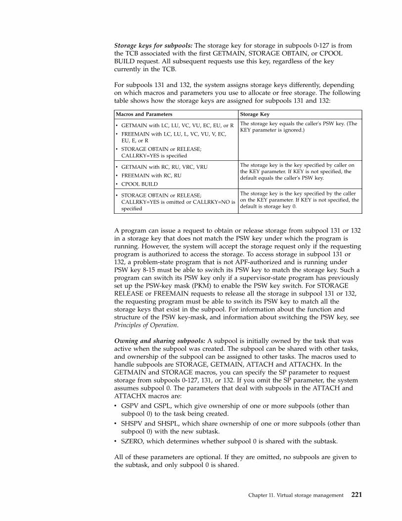
Storage keys for subpools: The storage key for storage in subpools 0-127 is fromthe TCB associated with the first GETMAIN, STORAGE OBTAIN, or CPOOLBUILD request. All subsequent requests use this key, regardless of the keycurrently in the TCB.
For subpools 131 and 132, the system assigns storage keys differently, dependingon which macros and parameters you use to allocate or free storage. The followingtable shows how the storage keys are assigned for subpools 131 and 132:
Macros and Parameters Storage Key
v GETMAIN with LC, LU, VC, VU, EC, EU, or R
v FREEMAIN with LC, LU, L, VC, VU, V, EC,EU, E, or R
v STORAGE OBTAIN or RELEASE;CALLRKY=YES is specified
The storage key equals the caller's PSW key. (TheKEY parameter is ignored.)
v GETMAIN with RC, RU, VRC, VRU
v FREEMAIN with RC, RU
v CPOOL BUILD
The storage key is the key specified by caller onthe KEY parameter. If KEY is not specified, thedefault equals the caller's PSW key.
v STORAGE OBTAIN or RELEASE;CALLRKY=YES is omitted or CALLRKY=NO isspecified
The storage key is the key specified by the calleron the KEY parameter. If KEY is not specified, thedefault is storage key 0.
A program can issue a request to obtain or release storage from subpool 131 or 132in a storage key that does not match the PSW key under which the program isrunning. However, the system will accept the storage request only if the requestingprogram is authorized to access the storage. To access storage in subpool 131 or132, a problem-state program that is not APF-authorized and is running underPSW key 8-15 must be able to switch its PSW key to match the storage key. Such aprogram can switch its PSW key only if a supervisor-state program has previouslyset up the PSW-key mask (PKM) to enable the PSW key switch. For STORAGERELEASE or FREEMAIN requests to release all the storage in subpool 131 or 132,the requesting program must be able to switch its PSW key to match all thestorage keys that exist in the subpool. For information about the function andstructure of the PSW key-mask, and information about switching the PSW key, seePrinciples of Operation.
Owning and sharing subpools: A subpool is initially owned by the task that wasactive when the subpool was created. The subpool can be shared with other tasks,and ownership of the subpool can be assigned to other tasks. The macros used tohandle subpools are STORAGE, GETMAIN, ATTACH and ATTACHX. In theGETMAIN and STORAGE macros, you can specify the SP parameter to requeststorage from subpools 0-127, 131, or 132. If you omit the SP parameter, the systemassumes subpool 0. The parameters that deal with subpools in the ATTACH andATTACHX macros are:v GSPV and GSPL, which give ownership of one or more subpools (other than
subpool 0) to the task being created.v SHSPV and SHSPL, which share ownership of one or more subpools (other than
subpool 0) with the new subtask.v SZERO, which determines whether subpool 0 is shared with the subtask.
All of these parameters are optional. If they are omitted, no subpools are given tothe subtask, and only subpool 0 is shared.
Chapter 11. Virtual storage management 221

Creating a subpool: If the subpool specified does not exist for the active task, anew subpool is created whenever SHSPV or SHSPL is coded on ATTACH orATTACHX, or when a GETMAIN or STORAGE macro is issued. A new subpoolzero is created for the subtask if SZERO=NO is specified on ATTACH orATTACHX. If one of the ATTACH or ATTACHX parameters that specifies sharedownership of a subpool causes the subpool to be created, the subpool number isentered in the list of subpools owned by the task, but no blocks are assigned andno storage is actually allocated. If a GETMAIN or STORAGE macro results in thecreation of a subpool, the subpool number is assigned to one or more 4096-byteblocks, and the requested storage is allocated to the active task. In either case,ownership of the subpool belongs to the active task; if the subpool is createdbecause of an ATTACH or ATTACHX macro, ownership is transferred or retaineddepending on the parameter used.
Transferring ownership: An owning task gives ownership of a subpool to a directsubtask by using the GSPV or GSPL parameters on ATTACH or ATTACHX issuedwhen that subtask is created. Ownership of a subpool can be given to any subtaskof any task, regardless of the control level of the two tasks involved and regardlessof how ownership was obtained. A subpool cannot be shared with one or moresubtasks and then transferred to another subtask, however; an attempt to do thisresults in abnormal termination of the active task. Ownership of a subpool canonly be transferred if the active task has sole ownership; if the active task issharing a subpool and an attempt is made to transfer it to a subtask, the subtaskreceives shared control and the originating task relinquishes the subpool. Onceownership is transferred to a subtask or relinquished, any subsequent use of thatsubpool number by the originating task results in the creation of a new subpool.When a task that has ownership of one or more subpools terminates, all of thevirtual storage areas in those subpools are released. Therefore, the task withownership of a subpool should not terminate until all tasks or subtasks sharing thesubpool have completed their use of the subpool.
If GSPV or GSPL specifies a subpool that does not exist for the active task, noaction is taken.
Sharing a subpool: A task can share ownership of a subpool with a subtask that itattaches. Subtasks cannot share ownership of a subpool with the task that causedthe attach. A program shares ownership by specifying the SHSPV or SHSPLparameters on the ATTACH or ATTACHX macro issued when the subtask iscreated. Any task with ownership or shared control of the subpool can add to orreduce the size of the subpool through the use of the GETMAIN, FREEMAIN, orSTORAGE macros. When a task that has shared control of the subpool terminates,the subpool is not affected.
Subpools in task communication: The advantage of subpools in virtual storagemanagement is that, by assigning separate subpools to separate subtasks, thebreakdown of virtual storage into small fragments is reduced. An additionalbenefit from the use of subpools can be realized in task communication. A subpoolcan be created for an originating task and all parameters to be passed to thesubtask placed in the subpool. When the subtask is created, the ownership of thesubpool can be passed to the subtask. After all parameters have been acquired bythe subtask, a FREEMAIN or STORAGE RELEASE macro can be issued, undercontrol of the subtask, to release the subpool virtual storage areas. In a similarmanner, a second subpool can be created for the originating task, to be used as ananswer area in the performance of the subtask. When the subtask is created, thesubpool ownership would be shared with the subtask. Before the subtask isterminated, all parameters to be passed to the originating task are placed in the
222 z/OS MVS Assembler Services Guide
subpool area; when the subtask is terminated, the subpool is not released, and theoriginating task can acquire the parameters. After all parameters have beenacquired for the originating task, a FREEMAIN or STORAGE RELEASE macroagain makes the area available for reuse.
Implicit requests for virtual storageYou make an implicit request for virtual storage every time you issue LINK,LINKX, LOAD, ATTACH, ATTACHX, XCTL or XCTLX. In addition, you make animplicit request for virtual storage when you issue an OPEN macro for a data set.This information discusses some of the techniques you can use to cut down on theamount of central storage required by a job step, and the assistance given you bythe system.
Reenterable load modulesA reenterable load module does not modify itself. Only one copy of the loadmodule is loaded to satisfy the requirements of any number of tasks in a job step.This means that even though there are several tasks in the job step and each taskconcurrently uses the load module, the only central storage needed is an area largeenough to hold one copy of the load module (plus a few bytes for control blocks).The same amount of central storage would be needed if the load module wereserially reusable; however, the load module could not be used by more than onetask at a time.
Note: If your module is reenterable or serially reusable, the load module must belink edited, with the desired attribute, into a library. The default linkage editorattributes are non-reenterable and non-reusable.
Reenterable macrosAll of the macros described in this information can be written in re-enterable form.These macros are classified as one of two types: macro that pass parameters inregisters 0 and 1, and macros that pass parameters in a list. The macros that passparameters in registers present no problem in a reenterable program; when themacro is coded, the required parameter values should be contained in registers.For example, the POST macro requires that the ECB address be coded as follows:POST ecb address
One method of coding this in a reenterable program would be to require thisaddress to refer to a portion of storage that has been allocated to the active taskthrough the use of a GETMAIN macro. The address would change for each use ofthe load module. Therefore, you would load one of the general registers 2-12 withthe address, and designate that register when you code the macro. If register 4contains the ECB address, the POST macro is written as follows:POST (4)
The macros that pass parameters in a list require the use of special forms of themacro when used in a reenterable program. The macros that pass parameters in alist are identified within their descriptions in z/OS MVS Programming: AssemblerServices Reference ABE-HSP and z/OS MVS Programming: Assembler Services ReferenceIAR-XCT.The expansion of the standard form of these macros results in an in-lineparameter list and executable instructions to branch around the list, to saveparameter values in the list, to load the address of the list, and to pass control tothe required system routine. The expansions of the list and execute forms of themacro simply divide the functions provided in the standard form expansion: thelist form provides only the parameter list, and the execute form provides
Chapter 11. Virtual storage management 223

executable instructions to modify the list and pass control. You provide theinstructions to load the address of the list into a register.
The list and execute forms of a macro are used in conjunction to provide the sameservices available from the standard form of the macro. The advantages of usinglist and execute forms are as follows:v Any parameters that remain constant in every use of the macro can be coded in
the list form. These parameters can then be omitted in each of the execute formsof the macro which use the list. This can save appreciable coding time when youuse a macro many times. (Any exceptions to this rule are listed in thedescription of the execute form of the applicable macro.)
v The execute form of the macro can modify any of the parameters previouslydesignated. (Again, there are exceptions to this rule.)
v The list used by the execute form of the macro can be located in a portion ofvirtual storage assigned to the task through the use of the GETMAIN macro.This ensures that the program remains reenterable.
Figure 59 shows the use of the list and execute forms of a DEQ macro in areenterable program. The length of the list constructed by the list form of themacro is obtained by subtracting two symbolic addresses; virtual storage isallocated and the list is moved into the allocated area. The execute form of theDEQ macro does not modify any of the parameters in the list form. The list had tobe moved to allocated storage because the system can store a return code in the listwhen RET=HAVE is coded. Note that the coding in a routine labeled MOVERTN isvalid for lengths up to 256 bytes only. Some macros do produce lists greater than256 bytes when many parameters are coded (for example, OPEN and CLOSE withmany data control blocks, or ENQ and DEQ with many resources), so in actualpractice a length check should be made. The move long instruction (MVCL) shouldbe considered for moving large data lists.
.
.LA 3,MACNAME Load address of list formLA 5,NSIADDR Load address of end of listSR 5,3 Length to be moved in register 5BAL 14,MOVERTN Go to routine to move listDEQ ,MF=(E,(1)) Release allocated resource..
* The MOVERTN allocates storage from subpool 0 and moves up to 256* bytes into the allocated area. Register 3 is from address,* register 5 is length. Area address returned in register 1.MOVERTN GETMAIN R,LV=(5)
LR 4,1 Address of area in register 4BCTR 5,0 Subtract 1 from area lengthEX 5,MOVEINST Move list to allocated areaBR 14 Return
MOVEINST MVC 0(0,4),0(3)..
MACNAME DEQ (NAME1,NAME2,8,SYSTEM),RET=HAVE,MF=LNSIADDR ... ...NAME1 DC CL8’MAJOR’NAME2 DC CL8’MINOR’
Figure 59. Using the List and the Execute Forms of the DEQ Macro
224 z/OS MVS Assembler Services Guide

Non-reenterable load modulesThe use of reenterable load modules does not automatically conserve virtualstorage; in many applications it will actually prove wasteful. If a load module isnot used in many jobs and if it is not employed by more than one task in a jobstep, there is no reason to make the load module reenterable. The allocation ofvirtual storage for the purpose of moving coding from the load module to theallocated area is a waste of both time and virtual storage when only one taskrequires the use of the load module.
You do not need to make a load module reenterable or serially reusable ifreusability is not really important to the logic of your program. Of course, ifreusability is important, you can issue a LOAD macro to load a reusable module,and later issue a DELETE macro to release its area.
Note:
1. If your module is reenterable or serially reusable, the load module must be linkedited, with the desired attribute, into a library. The default linkage editorattributes are non-reenterable and non-reusable.
2. A module that does not modify itself (a refreshable module) reduces pagingactivity because it does not need to be paged out.
Freeing of virtual storageThe system establishes two responsibility counts for every load module broughtinto virtual storage in response to your requests for that load module. Theresponsibility counts are lowered as follows:v If the load module was requested in a LOAD macro, that responsibility count is
lowered when using a DELETE macro.v If the load module was requested on LINK, LINKX, ATTACH, ATTACHX,
XCTL, or XCTLX, that responsibility count is lowered when using XCTL orXCTLX or by returning control to the system.
v When a task is terminated, the responsibility counts are lowered by the numberof requests for the load module made by LINK, LINKX, LOAD, ATTACH,ATTACHX, XCTL, or XCTLX during the performance of that task, minus thenumber of deletions indicated previously.
The virtual storage area occupied by a load module is released when theresponsibility counts reach zero. When you plan your program, you can design theload modules to give you the best trade-off between execution time and efficientpaging. If you use a load module many times in the course of a job step, issue aLOAD macro to bring it into virtual storage; do not issue a DELETE macro untilthe load module is no longer needed. Conversely, if a load module is used onlyonce during the job step, or if its uses are widely separated, issue LINK or LINKXto obtain the module and issue an XCTL or XCTLX from the module (or returncontrol to the system) after it has been executed.
There is a minor problem involved in the deletion of load modules containing datacontrol blocks (DCBs). An OPEN macro instruction must be issued before the DCBis used, and a CLOSE macro issued when it is no longer needed. If you do notissue a CLOSE macro for the DCB, the system issues one for you when the task isterminated. However, if the load module containing the DCB has been removedfrom virtual storage, the attempt to issue the CLOSE macro causes abnormaltermination of the task. You must either issue the CLOSE macro yourself beforedeleting the load module, or ensure that the data control block is still in virtual
Chapter 11. Virtual storage management 225

storage when the task is terminated (possibly by issuing a GETMAIN and creatingthe DCB in the area that had been allocated by the GETMAIN).
226 z/OS MVS Assembler Services Guide
Chapter 12. Using the 64-bit address space
This chapter describes how to use the address space virtual storage above 2gigabytes and control the physical frames that back this storage.
What is the 64-bit address space?Because of changes in the architecture that supports the z/OS operating system,there have been two different address spaces prior to the 64-bit address space. Theaddress space of the 1970s began at address 0 and ended at 16 megabytes. Thearchitecture that created this address space provided 24-bit addresses.
In the early 1980s, extended architecture (XA) provided an address space thatbegan at address 0 and ended at two gigabytes. The architecture that created thisaddress space provided 31-bit addresses. To maintain compatibility, the operatingsystem provided two addressing modes (AMODEs) for programs: programs thatuse only the first 16 megabytes of the address space run in AMODE 24 andprograms that use the entire 31–bit address space run in AMODE 31.
As of z/OS Version 1 Release 2 (V1R1), the address space expands to a large size,new terms are needed to describe it. Each address space is 16 exabytes in size; anexabyte is slightly more than one billion gigabytes. The new address space haslogically 264 addresses. It is 8 billion times the size of the former 2-gigabyte addressspace that logically has 231 addresses. The number is 18,466,744,073,709,551,616bytes. Programs that use virtual storage above the 2-gigabyte address run inAMODE 64. The architecture that creates this address space provides 64-bitaddresses. The address space structure below the 2 gigabyte address has notchanged; all programs in AMODE 24 and AMODE 31 continue to run withoutchange. In some fundamental ways, the address space is much the same as the XAaddress space.
In the 64-bit address space, a virtual line called the bar marks the 2-gigabyteaddress. The bar separates storage below the 2-gigabyte address, called below thebar, from storage above the 2-gigabyte address, called above the bar. In the 31-bitaddress space, a virtual line marks the 16-megabyte address. The area above thebar is intended for data; no programs run above the bar. There is no area abovethe bar that is common to all address spaces, and no system control blocks existabove the bar. IBM reserves an area of storage above the bar for special uses to bedeveloped in the future.
Figure 60 on page 228 shows the 64-bit address space, including the line that marksthe 16-megabyte address and the bar that marks the 2-gigabyte address.
© Copyright IBM Corp. 1988, 2017 227

All programs start in 24-bit or 31-bit AMODE; then, they are unable to work withdata above the bar. To use virtual storage above the bar, a program must change toAMODE 64 and use the z/Architecture assembler instructions.
There are no practical limits to the virtual storage above the bar, but practicallimits to the real storage frames that back that area. To control the amount of realand auxiliary storage that an address space can use, your installation can set alimit, called a MEMLIMIT. The MEMLIMIT is set on the total number of usablevirtual pages above the bar for a single address space. The installation can alsoclassify your address space to a WLM resource group with a real memory limit tocontrol the amount of real storage. To learn the MEMLIMIT value and WLMresource group classification rules, see a system programmer at your installation.
Why would you use virtual storage above the bar?The reason why someone designing an application would want to use the areaabove the bar is simple: the program needs more virtual storage than the first 2gigabytes in the address space provides.
Before z/OS V1R2, a program's need for storage beyond what the former2-gigabyte address space provided was sometimes met by creating one or moredata spaces or hiperspaces and then designing a memory management schema tokeep track of the data in those spaces. Sometimes these programs used complexalgorithms to manage storage, reallocate and reuse areas, and check storageavailability.
With the 16-exabyte address space, these kinds of programming complexities areunnecessary. A program can potentially have as much virtual storage as it needs,while containing the data within the program's primary or home address space.
Figure 60. The 64-bit address space
228 z/OS MVS Assembler Services Guide
||||||||

Memory objectsPrograms obtain storage above the bar in chunks of virtual storage called memoryobjects. The system allocates a memory object as a number of virtual segments;each segment is a megabyte in size and begins on a megabyte boundary. Amemory object can be as large as the memory limits set by your installation and assmall as one megabyte.
Using the IARV64 macro, a program can create and free a memory object andmanage the physical frames that back the virtual storage. You can think of IARV64as the GETMAIN/FREEMAIN or STORAGE macro for virtual storage above thebar. (GETMAIN/FREEMAIN and STORAGE do not work on virtual storage abovethe bar; neither do CPOOL or callable cell pool services.)
When a program creates a memory object, it provides an area in which the systemreturns the memory object's low address. You can think of that address as thename of the memory object. After creating the memory object, the program can usethe storage in the memory object much as it used storage in the 2-gigabyte addressspace; see “Using a memory object” on page 238. The program cannot safelyoperate on storage areas that span more than one memory object.
To help the system manage the physical pages that back ranges of addresses inmemory objects, a program can alert the system to its use of some of those pages,making them available for the system to steal and then return.
The program can free the physical pages that back ranges of memory objects and,optionally, clear those ranges to zeros. Later, the program can ask the system toreturn the physical backing from auxiliary storage. When it no longer needs thememory object, the program frees it in its entirety.
While your program can obtain only one memory object at a single invocation ofIARV64, it can, for management purposes, relate a set of two or more memoryobjects to each other by specifying a user token, a value you choose. A program canthen delete all memory objects that have the same user token value.
Using large pagesLarge page is a special purpose performance feature for memory objects.Authorized programs and unauthorized programs with READ authority to theIARRSM.LRGPAGES resource profile in the FACILITY class can ask the system touse one megabyte page frames to back the memory object by using thePAGEFRAMESIZE parameter when issuing the IARV64 GETSTOR request.Authorized programs can also use the PAGEFRAMESIZE parameter to requestlarge pages for common or shared memory objects with the IARV64GETCOMMON or IARV64 GETSHARED requests.
These large pages consume real storage and are non-pageable. The systemprogrammer should carefully consider what applications are granted access tolarge pages. Not all applications benefit from using large pages. Long-running,memory-intensive applications benefit most from using large pages. Short-livedprocesses with a small memory working set are not good candidates. The systemprogrammer defines the amount of real storage that can be used for large pageswith the LFAREA system parameter. See the description of the IEASYSxx memberin z/OS MVS Initialization and Tuning Reference.
The key factors to consider when you grant access to large pages are:
Chapter 12. Using the 64-bit address space 229

v Memory usagev Page translation overhead of the workloadv Available large frame area
Using assembler instructions in the 64-bit address spaceWith z/Architecture, two facts are prominent: the address space is 16 exabytes insize and the general purpose registers (GPRs) are 64 bits in length. You can ignorethese facts and continue to use storage below the bar. If, however, you want toenhance old programs or design new ones to use the virtual storage above the bar,you will need to use the new Assembler instructions. This information introducesthe concepts that provide context for your use of these instructions.
z/Architecture provides two new major capabilities that are related but are alsosomewhat independent:v 64-bit binary operationsv 64-bit addressing mode (AMODE).
64-bit binary operations64-bit binary operations perform arithmetic and logical operations on 64-bit binaryvalues. 64-bit AMODE allows access to storage operands that reside anywhere inthe 16-exabyte address space. In support of both, z/Architecture extends the GPRsto 64 bits. There is a single set of 16 64-bit GPRs, and the bits in each arenumbered from 0 to 63.
All S/390 instructions are carried forward into z/Architecture and continue tooperate using the low-order half of the z/Architecture 64-bit GPRs. That is, anS/390 instruction that operates on bit positions 0 through 31 of a 32-bit GPR inS/390 operates instead on bit positions 32 through 63 of a 64-bit GPR inz/Architecture. You can think of the S/390 32-bit GPRs as being imbedded in thenew 64-bit GPRs.
Throughout the discussion of GPRs, bits 0 through 31 of the 64-bit GPR are calledthe high-order half, and bits 32 through 63 are called the low-order half.
The purpose of this information is help you use the 64-bit GPR and the 64-bitinstructions as you want to save registers, perform arithmetic operations, accessdata. It is not a tutorial about how to use the new instruction set. Principles ofOperation is the definitive reference information for these instructions. Thisinformation, however, describes some concepts that provide the foundation you
0 6332
low-order halfhigh-order halfz/Architecture 64-bit GPR
230 z/OS MVS Assembler Services Guide

need. After you understand these, you can go to Principles of Operation and readthe introduction to z/Architecture and then refer to the specific instructions youneed to write your program.
How z/Architecture processes S/390 instructionsFirst of all, your existing programs work, unchanged, in z/Architecture mode. Thisinformation describes how z/Architecture processes S/390 instructions. The bestway to describe this processing is through examples of common S/390 instructions.First, consider a simple Add instruction: A R3,NUM31. This instruction takes thevalue of a fullword binary integer at location NUM31 and adds it to the contentsof the low-order half of GPR3, placing the sum in the low-order half of GPR3. Thehigh-order half of GPR3 is unchanged.
Second, consider the LOAD instruction: L R3,MYDATA. This instruction takes the 4bytes of data at location MYDATA and puts them into the low order bits of GPR3.
The high-order half is not changed by the ADD instruction or the LOADinstruction. The register forms of these instructions (AR and LR) work similarly, asdo Add Logical instructions (AL and ALR).
z/Architecture instructions that use the 64-bit GPRz/Architecture provides many new instructions that use two 64-bit binary integersto produce a 64-bit binary integer. These instructions include a “G” in theinstruction mnemonic (AG and LG). Some of these instructions are similar to S/390instructions. Consider the example of an Add G instruction: AG R3,NUM64. Thisinstruction takes the value of a doubleword binary integer at location NUM64 andadds it to the contents of GPR3, placing the sum in GPR3:
The second example, LG R3,TWOWORDS, takes a doubleword at locationTWOWORDS and puts it into GPR3.
Chapter 12. Using the 64-bit address space 231
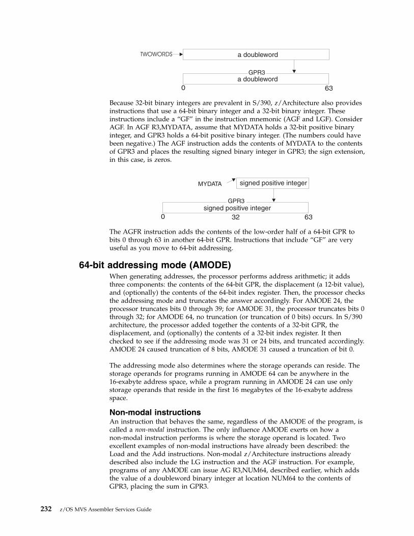
Because 32-bit binary integers are prevalent in S/390, z/Architecture also providesinstructions that use a 64-bit binary integer and a 32-bit binary integer. Theseinstructions include a “GF” in the instruction mnemonic (AGF and LGF). ConsiderAGF. In AGF R3,MYDATA, assume that MYDATA holds a 32-bit positive binaryinteger, and GPR3 holds a 64-bit positive binary integer. (The numbers could havebeen negative.) The AGF instruction adds the contents of MYDATA to the contentsof GPR3 and places the resulting signed binary integer in GPR3; the sign extension,in this case, is zeros.
The AGFR instruction adds the contents of the low-order half of a 64-bit GPR tobits 0 through 63 in another 64-bit GPR. Instructions that include “GF” are veryuseful as you move to 64-bit addressing.
64-bit addressing mode (AMODE)When generating addresses, the processor performs address arithmetic; it addsthree components: the contents of the 64-bit GPR, the displacement (a 12-bit value),and (optionally) the contents of the 64-bit index register. Then, the processor checksthe addressing mode and truncates the answer accordingly. For AMODE 24, theprocessor truncates bits 0 through 39; for AMODE 31, the processor truncates bits 0through 32; for AMODE 64, no truncation (or truncation of 0 bits) occurs. In S/390architecture, the processor added together the contents of a 32-bit GPR, thedisplacement, and (optionally) the contents of a 32-bit index register. It thenchecked to see if the addressing mode was 31 or 24 bits, and truncated accordingly.AMODE 24 caused truncation of 8 bits, AMODE 31 caused a truncation of bit 0.
The addressing mode also determines where the storage operands can reside. Thestorage operands for programs running in AMODE 64 can be anywhere in the16-exabyte address space, while a program running in AMODE 24 can use onlystorage operands that reside in the first 16 megabytes of the 16-exabyte addressspace.
Non-modal instructionsAn instruction that behaves the same, regardless of the AMODE of the program, iscalled a non-modal instruction. The only influence AMODE exerts on how anon-modal instruction performs is where the storage operand is located. Twoexcellent examples of non-modal instructions have already been described: theLoad and the Add instructions. Non-modal z/Architecture instructions alreadydescribed also include the LG instruction and the AGF instruction. For example,programs of any AMODE can issue AG R3,NUM64, described earlier, which addsthe value of a doubleword binary integer at location NUM64 to the contents ofGPR3, placing the sum in GPR3.
232 z/OS MVS Assembler Services Guide

The LGF instruction is another example of a non-modal instruction. In LGFR3,MYDATA, assume MYDATA is a signed negative binary integer. Thisinstruction places MYDATA into the low-order half of GPR3 and propagates thesign (1s) to the high-order half, as follows:
If the current AMODE is 64, MYDATA can reside anywhere in the address space; ifthe AMODE is 31, MYDATA must reside below 2 gigabytes; if the AMODE is 24,MYDATA must reside below 16 megabytes.
Other 64-bit instructions that are non-modal are the register form of AGF, which isAGFR, and the register form of LGF, which is LGFR. Others are LGR, AGR, ALGR,and ALG.
Modal instructionsModal instructions are instructions where addressing mode is a factor in the outputof the instruction. The AMODE determines the width of the output registeroperands. A good example of a modal instruction is Load Address (LA). If youspecify LA R3,VIRT_PTR successively in the three AMODEs, what are the threeresults?
AMODE 24: The address of VIRT_PTR is a 24-bit address that is loaded into bits40 through 63 of GPR3 (or bits 8 through 31 of the 32-bit register imbedded in the64-bit GPR). The processor places zeroes into bits 32 through 39, and leaves thefirst 31 bits unchanged, as follows:
AMODE 31: The address of VIRT_PTR is loaded into bits 33 through 63 of GPR3.The processor places zero into bit 32 and leaves the first 32 bits unchanged, asfollows:
AMODE 64: the address of VIRT_PTR fill the entire 64-bit GPR3:
Chapter 12. Using the 64-bit address space 233

Other modal instructions are Move Long (MVCL), Branch and Link (BALR), andBranch and Save (BASR).
Setting and checking the addressing modez/Architecture provides three new Set Addressing Mode instructions that allowyou to change addressing mode. The instructions are SAM24, which changes thecurrent AMODE to 24, SAM31, which changes the current AMODE to 31, andSAM64, which changes the current AMODE to 64.
The AMODE indicator in the PSW tells the processor what AMODE is currently ineffect. You can obtain the current addressing mode of a program by using the TestAddressing Mode (TAM) instruction. In response, TAM sets a condition code basedon the setting in the PSW; 0 indicates AMODE 24, 1 indicates AMODE 31, and 3indicates AMODE 64.
Linkage conventionsIn z/OS R2, program entry is in AMODE 31; therefore linkage conventions youhave used in S/390 apply, which means passing 4-byte parameter lists and a72-byte savearea.
A older program changing into AMODE 64 to exploit z/Architecture instructionsshould expect to receive 31-bit addresses and the 72-byte save area from its callers.If you are running in AMODE 64 and want to use an address a caller has passedto you, the high-order half of the GPR will probably not be cleared to zeroes. Assoon as you receive this address, use the Load Logical G Thirty One Bits (LLGTR)instruction to change this 31-bit address into a 64-bit address that you can use.
Register 15 contents on entry: In AMODE 64, the ATTACH(X), LINK(X),SYNCH(X), and XCTL(X) macros provide control to the target routine with register15 (R15) containing the "OR" value of X'00000000FFFFF000' with theaddressing-mode values shown in Table 22; it does not contain the module entrypoint address as it did in AMODE 31.
Table 22. Register 15 contents on entry in AMODE=64
Addressing mode of macro issuerR15 contains the value in this columnORed with X'00000000FFFFF000'
31 X’00000002’
64 X’00000004’
Pitfalls to avoidAs you begin to use the 64-bit instructions, consider the following:1. Some instructions reference or change all 64 bits of a GPR regardless of the
AMODE.2. Some instructions reference or change only the low-order half of a GPR
regardless of the AMODE.3. Some instructions reference or change only the high-order half of a GPR
regardless of the AMODE.
234 z/OS MVS Assembler Services Guide

4. When you are using signed integers in arithmetic operations, you can't mixinstructions that handle 64-bit integers with instructions that handle 31-bitintegers. The interpretation of a 32-bit signed number differs from theinterpretation of a 64-bit signed number. With the 32-bit signed number, thesign is extended in the low half of the doubleword. With the 64-bit signednumber, the sign is extended to the left for the entire doubleword.
Consider the following example, where a 31-bit subtraction instruction has left a31-bit negative integer in bits 32 through 63 of GPR3 and has left the high-orderhalf unchanged.
Next, the instruction AG R3,MYDOUBLEWORD, mentioned earlier, adds thedoubleword at the location MYDOUBLEWORD to the contents of the GPR3 andplaces the sum at GPR3. Because the high-order half of the GPR has uncertaincontents, the result of the AG instruction is incorrect. To change the value in theGPR3 so that the AG instruction adds the correct integers, before you use the AGinstruction, use the Load G Fullword Register (LGFR) instruction to propagate thesign to the high-order half of GPR3.
Issuing MVS macros in AMODE 64Many MVS macro services support callers in either AMODE 24, AMODE 31, orAMODE 64. When the caller is in AMODE 64, the macro service might need togenerate different instructions. At assembly time, a macro service that needs toknow whether a caller is in AMODE 64 checks the global indicator that SYSSTATEAMODE64=YES sets. The system expects that a program issue SYSSTATEAMODE64=YES when it issues macros while in AMODE 64. When the programswitches out of AMODE 64, issue SYSSTATE AMODE64=NO to reset the globalindicator.
When your program is in AMODE 64, keep in mind these two facts:v Before you use a macro in AMODE 64, check the description of the macro in
z/OS MVS Programming: Assembler Services Reference ABE-HSP or z/OS MVSProgramming: Assembler Services Reference IAR-XCT. If the description of themacro does not specifically state that the macro supports callers in AMODE 64,use the SAM31 or SAM24 instruction to change the AMODE and use the macroin the changed AMODE.
v GR 15-1 bits 0-31 of the 64-bit GRs are volatile across all macro calls, whetherthe caller is or is not in AMODE 64. Do not count on the contents of these highhalves to be the same after the call as they were before.
Example of using SYSSTATE AMODE64=Consider that a program changes AMODE from AMODE 31 to AMODE 64 andwhile in AMODE 64, issues the TIMEUSED macro. When it changes to AMODE64, it issues the following:SAM64SYSSTATE AMODE64=YES
The TIMEUSED macro generates different code, depending on the AMODE of thecaller. During the assembly of TIMEUSED, the TIMEUSED macro service checks
Chapter 12. Using the 64-bit address space 235
|
||||||||
|
||||||
|||
|
|||
||
||

the setting of the global indicator. Because the global indicator indicates that thecaller is in AMODE 64, TIMEUSED generates code that is appropriate for callers inAMODE 64.
When the program changes back to AMODE 31, it issues the following:SAM31SYSSTATE AMODE64=NO
IARV64 servicesThe IARV64 macro provides all the virtual storage services for your programs. Thisinformation introduces these services and the rules for what programs can do withthe memory objects your programs create and use.
Your program can use:v The GETSTOR service to create a memory object in the primary address space.
The memory object has a storage key that matches your PSW key. You canassign ownership of the memory object to the TCB of the job step task or themother task (the task of the program that issued the ATTACHX). You can createa memory object that contains two areas: a usable area and a guard area thatcannot be used while in that state.
v The PAGEOUT service to alert the system that physical pages will not be usedso that the system can optimize the use of the physical pages.
v The PAGEIN service to alert the system that pages will be needed soon.v The DISCARDATA service to discard in physical pages and optionally clear the
pages to zeros.v The CHANGEGUARD service to changev The DETACH service to free one or more memory objects that you own.
The remaining pages of this chapter describe how you use IARV64 services. It doesnot describe environmental or programming requirements, register usage, orsyntax rules. For that information, turn to the descriptions of the IARV64 macro inz/OS MVS Programming: Assembler Services Reference IAR-XCT.
Protecting storage above the barTo limit access to the memory object, the creating program can use the FPROTparameter on IARV64. FPROT specifies whether the storage in the memory objectis to be fetch-protected. The fetch protection attribute applies for the entirememory object. A program cannot reference storage in a fetch-protected memoryobject without holding the PSW key that matches the storage key of the memoryobject.
Preventing execution of code from the memory objectTo prevent code execution from the memory object, the creating program can useEXECUTABLE=NO on IARV64. Attempts to execute code from a memory object,which is obtained as EXECUTABLE=NO, results in a system abend. This abendprovides additional system integrity by not allowing unexpected execution fromareas such as heaps and stacks that contain only data.
Relationship between the memory object and its ownerOwnership issues are important. If you don't understand them, a memory objectthat your program creates and uses might cause an abend. A program creates a
236 z/OS MVS Assembler Services Guide
|||
|
||
|
|||||

memory object, but a TCB owns the memory object. The TCB that represents theprogram is the owner of the memory object, unless the program assigns ownershipto another TCB.
The memory object is available to a program whose PSW key matches the storagekey of the memory object. The memory object can be accessed by programsrunning under the owning TCB and other programs running in the same addressspace.
When a TCB terminates, the system deletes the memory objects that the TCB owns.The system swaps a memory object in and out as it swaps in and out the addressspace that dispatched the owning TCB.
A memory object can remain active even after the creating TCB terminates if aprogram assigns ownership of the memory object to a TCB that will outlive thecreating TCB. In this case, termination of the creating TCB does not affect thememory object.
Creating memory objectsTo create a memory object, use the IARV64 GETSTOR service. When you create amemory object, request a size large enough to meet long-term needs; the system,however, abends a program that unconditionally tries to obtain more storage abovethe bar than the MEMLIMIT allows. IBM recommends that you specifyCOND=YES on the request to avoid the abend. In this case, if the request exceedsthe MEMLIMIT, the system rejects the request but the program continues to run.The IARV64 service returns to the caller with a non-zero return code. The recoveryroutine would be similar to one that would respond to unsuccessful STORAGEmacro conditional requests for storage.
The SEGMENTS parameter specifies the size, in megabytes, of the memory objectyou are creating. The system returns the address of the memory object in theORIGIN parameter.
Other parameters further define the memory object:v FPROT=YES gives it fetch protection.v TTOKEN=ttoken indicates what task is to own the memory object.v USERTKN=usertoken is an 8-byte token that relates two or more memory objects
to each other. Later, the program can request a list of memory objects that havethat same token and can delete them as a group.
When a program creates a memory object, it can specify, through the GUARDSIZEand GUARDHIGH and GUARDLOW parameters, that the memory object is toconsist of two different areas. One area is called a guard area; this storage is notaccessible; the other area is called the usable area. A later request can change theguard area into a usable area. “Creating a guard area and changing its size” onpage 241 can help you understand the important purposes for this kind of memoryobject.
Before issuing IARV64, issue SYSSTATE ARCHLVL=2 so that the macro generatesthe correct parameter addresses.
Example of creating a memory objectThe following example creates a memory object one megabyte in size. It specifies aconstant with value of one as a user token.
Chapter 12. Using the 64-bit address space 237

IARV64 REQUEST=GETSTOR,SEGMENTS=ONE_SEG,USERTKN=USER_TOKEN,ORIGIN=VIRT64_ADDR,COND=YES
ONE_SEG DC ADL8(1)USER_TOKEN DC ADL8(1)VIRT64_ADDR DS AD
Using a memory objectTo use the storage in a memory object, the program must be in AMODE 64. To getthere, a program in AMODE 24 or AMODE 31 uses the assembler instructionSAM64. While in AMODE 64, a program can issue only the IARV64 macro. Theparameter lists the program passes to IARV64 can reside above or below the bar.
To invoke macros other than IARV64, a program must be in AMODE 31 orAMODE 24. This restriction might mean that the program must first issue SAM31to return to AMODE 31. After a program issues a macro other than IARV64, it canreturn to AMODE 64 through SAM64. To learn whether a program is in AMODE64, see “Setting and checking the addressing mode” on page 234.
Managing the data, such as serializing the use of a memory object, is no differentfrom serializing the use of an area obtained through GETMAIN or STORAGE.
Although only one macro can be issued in AMODE 64, other interfaces supportstorage above the bar. For example, the DUMP command with theSTOR=(beg,end[,beg,end]...) parameter specifies ranges of virtual storage to bedumped. Those ranges can be above the bar.
In summary, there are major differences between how you manage storage belowthe bar and how you manage storage above the bar. Table 23 can help youunderstand the differences, as well as, some similarities. The first column identifiesa task of concept, the second column applies to storage below the bar; the thirdcolumn applies to storage above the bar.
Table 23. Comparing Tasks and Concepts: Below the Bar and Above the Bar
Task or concept Below the bar Above the bar
Obtaining storage GETMAIN, STORAGE,CPOOL macros and callablecell pool services. OnGETMAIN and STORAGE,you can ask to have a returncode tell you whether thestorage is cleared to zeros.
IARV64 GETSTOR servicecreates memory objects;storage is cleared to zeros.
Increments of storageallocation
In 8–byte increments. In 1-megabyte increments.
Requirements for requestor GETMAIN cannot be issuedby an AR mode caller.STORAGE can be issued byan AR mode program.CPOOL cannot be issued bya program in AR mode.Callable cell pool servicescan be issued in either mode.
IARV64 can be issued by aprogram in AR mode.
238 z/OS MVS Assembler Services Guide

Table 23. Comparing Tasks and Concepts: Below the Bar and Above the Bar (continued)
Task or concept Below the bar Above the bar
Freeing storage FREEMAIN, STORAGE,CPOOL macros, and callablecell pool services. Any 8-byteincrement of theoriginally-obtained storagecan be freed. An entiresubpool can be freed with asingle request. At tasktermination, storage ownedby task is freed; somestorage (common, forexample) does not have anowner.
IARV64 DETACH service.Storage can be freed only in1-megabyte increments. Allmemory objects obtainedwith a specified user-definedtoken can be freed with asingle request. At tasktermination, storage ownedby task is freed; all storagehas an owner and that owneris a task.
Notifying the system of ananticipated use of storage
PGSER LOAD requestPGSER OUT request.
IARV64 PAGEIN andIARV64 PAGEOUT services.
Making a range of storageread-only or modifiable
PGSER PROTECT requestand PGSER UNPROTECTrequest.
IARV64REQUEST=PROTECT option.
Discard data in physicalpages and optionally clearthe pages to zeros.
PGSER RELEASE requestalways clears the storage tozeros.
Note: PGRLSE, PGSERRELEASE, PGSER FREE withRELEASE=Y, and PGFREERELEASE=Y may ignoresome or all of the pages inthe input range and will notnotify the caller if this wasdone.
Any pages in the input rangethat match any of thefollowing conditions will beskipped, and processingcontinues with the next pagein the range:
v Storage is not allocated orall pages in a segmenthave not yet beenreferenced.
v Page is in PSA, SQA orLSQA.
v Page is V=R. Effectively,it's fixed.
v Page is in BLDL, (E)PLPA,or (E)MLPA.
v Page has a page fix inprogress or a nonzero FIXcount.
v Pages with COMMIT inprogress or withDISASSOCIATE inprogress.
IARV64 DISCARDDATAservice. CLEAR=YES mustbe specified to guarantee thestorage is cleared to zeros onthe next usage.
Chapter 12. Using the 64-bit address space 239

Table 23. Comparing Tasks and Concepts: Below the Bar and Above the Bar (continued)
Task or concept Below the bar Above the bar
Fetch protection attributes Apply to the entire allocatedarea.
Apply to the entire allocatedarea.
What the area consists of System programs and data,user programs and data.
User data only.
Performing I/O VSAM, BSAM, BPAM,QSAM, VTAM®, and EXCP,EXCPVR services.
EXCP and EXCPVR services.
Accessing storage To access data in the2–gigabyte address space, aprogram must run inAMODE 31 or AMODE 64.S/390 and z/Architectureinstructions can be used.
To access data in the16-exabyte address space, aprogram must run inAMODE 64. To load anaddress of a location abovethe bar into a GPR, aprogram must use az/Architecture instruction.
Discarding data in a memory objectYour program can use the IARV64 DISCARDDATA service to tell the system thatyour program no longer needs the data in certain pages and that the system canfree them. Optionally, you can use the CLEAR parameter to clear the area to zeros.You can also use the KEEPREAL parameter to specify whether to free the realframes that back the pages to be discarded.
The RANGLIST parameter provides a list of page ranges, in the following format:
Releasing the physical resources that back pages of memory objectsA program uses the IARV64 PAGEOUT service to tell the system that the data incertain pages will not be used for some time (as measured in seconds) and that thepages are candidates for paging out of real storage. A pageout does not affectpages that are fixed in real storage. On the RANGLIST parameter, the programprovides a list of page ranges.
A program uses the IARV64 PAGEIN service to tell the system that it will soonreference the data in certain pages and that the system should page them into realstorage if the pages are not already backed by real storage.
Virtual address Number of pages
Virtual address Number of pages
0 8 15
Range list format - 1 to 16 pairs
240 z/OS MVS Assembler Services Guide

Freeing a memory objectWhen your program no longer needs the memory object, it uses IARV64 DETACHto free (delete) the memory object. You can free memory objects that are related toeach other through the user token defined on the IARV64 GETSTOR service.Additionally, all programs can use the following parameters:v MATCH=SINGLE,MEMOBJSTART frees a specific memory object, as identified
by its origin address.v MATCH=USERTOKEN, USERTKN frees a related set of memory objects by
providing the user token specified when the memory objects were created.v COND=YES makes the request conditional, but only when you also pass a user
token. IBM recommends you use COND to avoid having the program abendbecause it asked to free a memory object that doesn't exist.
Three conditions to avoid when you try to free a memory object are:v Freeing a memory object that does not exist.
If you try to free a memory object that doesn't exist, the system abends yourprogram.
v Freeing a memory object that has I/O in progress.
If you specify the COND=YES parameter, you must also specify a user token. Inthe recovery routine that gets control at an abend, you can ignore the abend andleave the memory object in an unusable state.
As part of normal task termination, RTM frees the memory objects owned by theterminating task.
Example of freeing a memory objectThe program frees all memory objects that have the user token specified in“USER_TOKEN”:IARV64 REQUEST=DETACH,
MATCH=USERTOKEN,USERTKN=USER_TOKEN
USER_TOKEN DC ADL8(1)
Creating a guard area and changing its sizeA program can create a memory object that consists of two areas: an area it can useimmediately, called the usable area, and a second area, called a guard area. Thesystem does not allow programs to use storage in the guard area.
To create a memory object with a guard area, use the IARV64 GETSTOR orGETCOMMON request with either the SEGMENTS or UNITS parameter to specifythe size of the memory object, and either the GUARDSIZE or GUARDSIZE64parameter to specify the size of the initial guard area. Use GUARDLOC=LOW orGUARDLOC=HIGH to specify whether the initial guard area is to be at the lowend or the high end of the memory object.
One reason for specifying a guard area is to reserve the area for future use. Forexample, a program can manage the parceling out of pages of the memory object.Another reason for using a guard area is so that the program requesting thememory object can protect itself from accidentally referencing storage beyond theend of the memory object, and possibly overlaying data in another adjacentmemory object. For that, the program would use GUARDLOC=HIGH. If the
Chapter 12. Using the 64-bit address space 241

program wanted to protect itself from another program that might be using anadjacent memory at a lower address, it would likely use GUARDLOC=LOW.
Use COND=YES, conditionally requesting the change, to avoid an abend if therequest exceeds the MEMLIMIT established by the installation or if there areinsufficient frames to back the additional usable area of the memory object. If itcannot grant a conditioned request, the system rejects the request, but the programcontinues to run.
The following illustration shows a memory object, three segments in size.GUARDLOC=HIGH creates the guard area at the highest addresses of the memoryobject. The memory object has two segments of usable storage and one segment onreserve for later use.
Use the IARV64 CHANGEGUARD service to increase or decrease the amount ofusable space in a memory object by adjusting the size of the guard area. Yourprogram cannot reference an address in the guard area; if it does, the programreceives a program exception (0C4 abend). To avoid the abend, code a recoveryroutine to get control upon receiving the program exception; the recovery routinecan retry and can then increase the usable part of the memory object (decreasingthe guard area.)
The guard area does not count towards the MEMLIMIT set by the installation; theusable area does count toward the MEMLIMIT.
Example of creating a memory object with a guard areaThe following example creates a 3-megabyte memory object with a 2-megabyteguard area. The guard area is at the high end of the memory object:IARV64 REQUEST=GETSTOR, +
SEGMENTS=NUM_SEG, +USERTKN=USER_TOKEN, +GUARDSIZE=GUARDPAGES, +GUARDLOC=HIGH, +ORIGIN=VIRT64_ADDR
The following example increases the size of the guard area by the specifiedamount.
242 z/OS MVS Assembler Services Guide

IARV64 REQUEST=CHANGEGUARD, +CONVERT=FROMGUARD, +MEMOBJSTART=VIRT64_ADDR, +CONVERTSIZE=SEGMENT_SIZE
An example of creating, using, and freeing a memory objectThe following program creates a 1-megabyte memory object and writes thecharacter string "Hi Mom" into each 4k page of the memory object. The programthen frees the memory object.
TITLE ’TEST CASE DUNAJOB’ACONTROL FLAG(NOALIGN)
DUNAJOB CSECTDUNAJOB AMODE 31DUNAJOB RMODE 31
SYSSTATE ARCHLVL=2* Begin entry linkage
BAKR 14,0CNOP 0,4BRAS 12,@PDATADC A(@DATA)
@PDATA LLGF 12,0(12)USING @DATA,12LHI 0,DYNAREALSTORAGE OBTAIN,LENGTH=(0),SP=0,CALLRKY=YESLLGTR 13,1USING @DYNAREA,13MVC 4(4,13),=C’F6SA’
* End entry linkage*
SAM64 Change to amode64IARV64 REQUEST=GETSTOR, +
SEGMENTS=ONE_SEG, +USERTKN=USER_TOKEN, +ORIGIN=VIRT64_ADDR
LG 4,VIRT64_ADDR Get address of memory objLHI 2,256 Set loop counter
LOOP DS 0HMVC 0(10,4),=C’HI_MOM! ’ Store HI MOM!AHI 4,4096BRCT 2,LOOP
* Get rid of all memory objects created with this* user token
IARV64 REQUEST=DETACH, +MATCH=USERTOKEN, +USERTKN=USER_TOKEN, +COND=YES
** Begin exit linkage
LHI 0,DYNAREALLR 1,13STORAGE RELEASE,LENGTH=(0),ADDR=(1),SP=0,CALLRKY=YESPR
* End exit linkage@DATA DS 0DONE_SEG DC FD’1’USER_TOKEN DC FD’1’
LTORG@DYNAREA DSECTSAVEAREA DS 36FVIRT64_ADDR DS ADDYNAREAL EQU *-@DYNAREA
END DUNAJOB
Chapter 12. Using the 64-bit address space 243

244 z/OS MVS Assembler Services Guide

Chapter 13. Callable cell pool services
Note to reader
In this section, the notation CSRPxxx/CSRC4xxx is used to indicate either theCSRPxxx service in AMODE 24 or 31, or the CSRC4xxx service in AMODE 64.
End of Note to reader
Callable cell pool services manage areas of virtual storage in the primary addressspace, in data spaces and in address spaces other than the primary address space.A cell pool is an area of virtual storage that is subdivided into fixed-sized areas ofstorage called cells, where the cells are the size you specify. A cell pool contains:v An anchorv At least one extentv Any number of cells, all having the same size.
The anchor is the starting point or foundation on which you build a cell pool. Eachcell pool has only one anchor. An extent contains information that helps callablecell pool services manage cells and provides information you might request aboutthe cell pool. A cell pool can have up to 65,536 extents, each responsible for itsown cell storage. Your program determines the size of the cells and the cellstorage. Figure 61 on page 248 illustrates the three parts of a cell pool.
Through callable cell pool services, you build the cell pool. You can then obtaincells from the pool. When there are no more cells available in a pool, you can usecallable cell pool services to enlarge the pool.
To use callable cell pool services, your program issues the CALL macro to invokeone of the following services:v Build a cell pool and initialize an anchor (CSRPBLD/CSRC4BLD service)v Expand a cell pool by adding an extent (CSRPESP/CSRC4EXP service)v Connect cell storage to an extent (CSRPCON/CSRC4CON service)v Activate previously connected storage (CSRPACT/CSRC4ACT service)v Deactivate an extent (CSRPDAC/CSRC4DAC service)v Disconnect the cell storage for an extent (CSRPDIS/CSRC4DIS service)v Allocate a cell from a cell pool (CSRPGET/CSRC4GET, CSRPGT1/CSRC4GT1, or
CSRPGT2/CSRC4GT2 and CSRPRGT/CSRC4RGT or CSRPRGT1/CSRC4RG1services)
v Return a cell to the cell pool (CSRPFRE/CSRC4FRE or CSRPFR1/CSRC4FR1, orCSRPFR2/CSRC4FR2 and CSRPRFT/CSRC4RFR or CSRPRFR1/CSRC4RF1services)
v Query the cell pool (CSRPQPL/CSRC4QPL service)v Query a cell pool extent (CSRPQEX/CSRC4QEX service)v Query a cell (CSRPQCL/CSRC4QCL service).
Your system's AMODE will determine which set of services to use, as follows:
© Copyright IBM Corp. 1988, 2017 245
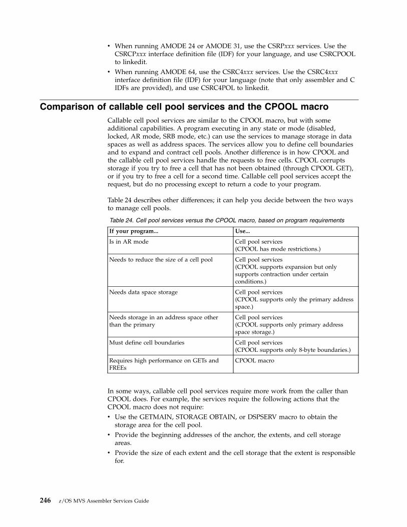
v When running AMODE 24 or AMODE 31, use the CSRPxxx services. Use theCSRCPxxx interface definition file (IDF) for your language, and use CSRCPOOLto linkedit.
v When running AMODE 64, use the CSRC4xxx services. Use the CSRC4xxxinterface definition file (IDF) for your language (note that only assembler and CIDFs are provided), and use CSRC4POL to linkedit.
Comparison of callable cell pool services and the CPOOL macroCallable cell pool services are similar to the CPOOL macro, but with someadditional capabilities. A program executing in any state or mode (disabled,locked, AR mode, SRB mode, etc.) can use the services to manage storage in dataspaces as well as address spaces. The services allow you to define cell boundariesand to expand and contract cell pools. Another difference is in how CPOOL andthe callable cell pool services handle the requests to free cells. CPOOL corruptsstorage if you try to free a cell that has not been obtained (through CPOOL GET),or if you try to free a cell for a second time. Callable cell pool services accept therequest, but do no processing except to return a code to your program.
Table 24 describes other differences; it can help you decide between the two waysto manage cell pools.
Table 24. Cell pool services versus the CPOOL macro, based on program requirements
If your program... Use...
Is in AR mode Cell pool services(CPOOL has mode restrictions.)
Needs to reduce the size of a cell pool Cell pool services(CPOOL supports expansion but onlysupports contraction under certainconditions.)
Needs data space storage Cell pool services(CPOOL supports only the primary addressspace.)
Needs storage in an address space otherthan the primary
Cell pool services(CPOOL supports only primary addressspace storage.)
Must define cell boundaries Cell pool services(CPOOL supports only 8-byte boundaries.)
Requires high performance on GETs andFREEs
CPOOL macro
In some ways, callable cell pool services require more work from the caller thanCPOOL does. For example, the services require the following actions that theCPOOL macro does not require:v Use the GETMAIN, STORAGE OBTAIN, or DSPSERV macro to obtain the
storage area for the cell pool.v Provide the beginning addresses of the anchor, the extents, and cell storage
areas.v Provide the size of each extent and the cell storage that the extent is responsible
for.
246 z/OS MVS Assembler Services Guide

Storage considerationsThe virtual storage for the cell pool must reside in an address space or a dataspace.v The anchor and extents must reside within the same address space or data
space.v The cells must reside within one address space or data space; that space can be
different from the one that contains the anchor and extents.
Figure 61 on page 248 illustrates the anchor and extents in Data/Address Space Aand the cell storage in Data/Address Space B.
Before you can obtain the first cell from a cell pool, you must plan the location ofthe anchor, the extents, and the cell storage. You must obtain the storage for thefollowing areas and pass the following addresses to the services:v The anchor, which requires 64 bytes of storagev The extent, which requires 128 bytes plus one byte for every eight cells of cell
storagev The cell storage.
Chapter 13. Callable cell pool services 247

When you plan the size of the cell storage, consider the total requirements of yourapplication for this storage and some performance factors. Although a single extentmay contain any number of cells (up to 2²⁴ bytes, or 16,777,216), you might wishto have multiple extents for performance purposes. Avoid having a large numberof extents, where each extent is responsible for a small number of cells. In general,a greater requirement for cells should mean a proportionately smaller number ofextents. The following two examples illustrate this point.v If you have 10,000 cells in the pool, a good extent size is 2,500 cells per extent.v If you have 100,000 cells in the pool, a good extent size is 10,000 cells per extent.
“Using callable cell pool services to manage data space areas” on page 310 containsan example of using callable cell pool services with data spaces. It also describessome storage considerations.
Link-editing callable cell pool servicesAny program that invokes callable cell pool services must be link-edited with anIBM-provided linkage-assist routine. The linkage-assist routine provides the logicneeded to locate and invoke the callable services. The linkage-assist routine residesin SYS1.CSSLIB.
Extent1
Extent2
Extent3
Extent4
Anchor
Data/AddressSpace A
Data/AddressSpace B
CellStorage
CellStorage
CellStorage
CellStorage
Figure 61. Cell pool storage
248 z/OS MVS Assembler Services Guide
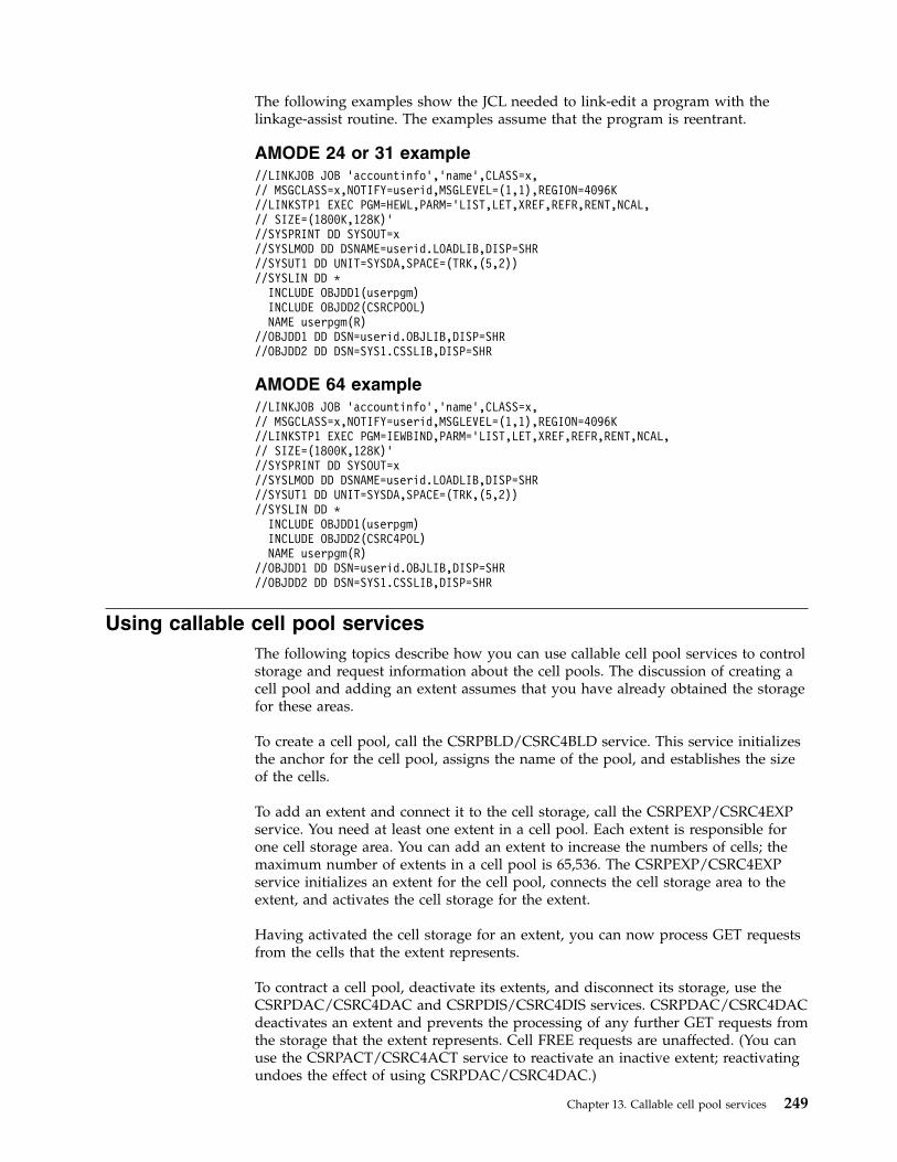
The following examples show the JCL needed to link-edit a program with thelinkage-assist routine. The examples assume that the program is reentrant.
AMODE 24 or 31 example//LINKJOB JOB 'accountinfo','name',CLASS=x,// MSGCLASS=x,NOTIFY=userid,MSGLEVEL=(1,1),REGION=4096K//LINKSTP1 EXEC PGM=HEWL,PARM='LIST,LET,XREF,REFR,RENT,NCAL,// SIZE=(1800K,128K)'//SYSPRINT DD SYSOUT=x//SYSLMOD DD DSNAME=userid.LOADLIB,DISP=SHR//SYSUT1 DD UNIT=SYSDA,SPACE=(TRK,(5,2))//SYSLIN DD *
INCLUDE OBJDD1(userpgm)INCLUDE OBJDD2(CSRCPOOL)NAME userpgm(R)
//OBJDD1 DD DSN=userid.OBJLIB,DISP=SHR//OBJDD2 DD DSN=SYS1.CSSLIB,DISP=SHR
AMODE 64 example//LINKJOB JOB 'accountinfo','name',CLASS=x,// MSGCLASS=x,NOTIFY=userid,MSGLEVEL=(1,1),REGION=4096K//LINKSTP1 EXEC PGM=IEWBIND,PARM='LIST,LET,XREF,REFR,RENT,NCAL,// SIZE=(1800K,128K)'//SYSPRINT DD SYSOUT=x//SYSLMOD DD DSNAME=userid.LOADLIB,DISP=SHR//SYSUT1 DD UNIT=SYSDA,SPACE=(TRK,(5,2))//SYSLIN DD *
INCLUDE OBJDD1(userpgm)INCLUDE OBJDD2(CSRC4POL)NAME userpgm(R)
//OBJDD1 DD DSN=userid.OBJLIB,DISP=SHR//OBJDD2 DD DSN=SYS1.CSSLIB,DISP=SHR
Using callable cell pool servicesThe following topics describe how you can use callable cell pool services to controlstorage and request information about the cell pools. The discussion of creating acell pool and adding an extent assumes that you have already obtained the storagefor these areas.
To create a cell pool, call the CSRPBLD/CSRC4BLD service. This service initializesthe anchor for the cell pool, assigns the name of the pool, and establishes the sizeof the cells.
To add an extent and connect it to the cell storage, call the CSRPEXP/CSRC4EXPservice. You need at least one extent in a cell pool. Each extent is responsible forone cell storage area. You can add an extent to increase the numbers of cells; themaximum number of extents in a cell pool is 65,536. The CSRPEXP/CSRC4EXPservice initializes an extent for the cell pool, connects the cell storage area to theextent, and activates the cell storage for the extent.
Having activated the cell storage for an extent, you can now process GET requestsfrom the cells that the extent represents.
To contract a cell pool, deactivate its extents, and disconnect its storage, use theCSRPDAC/CSRC4DAC and CSRPDIS/CSRC4DIS services. CSRPDAC/CSRC4DACdeactivates an extent and prevents the processing of any further GET requests fromthe storage that the extent represents. Cell FREE requests are unaffected. (You canuse the CSRPACT/CSRC4ACT service to reactivate an inactive extent; reactivatingundoes the effect of using CSRPDAC/CSRC4DAC.)
Chapter 13. Callable cell pool services 249

CSRPDIS/CSRC4DIS disconnects the cell storage from an extent and makes cellstorage unavailable. After you disconnect an extent, you can free the cell storageassociated with the extent.
Note: Do not free the extent itself until you have finished using the entire pool.
To reuse a deactivated, disconnected extent, call the CSRPCON/CSRC4CON andCSRPACT/CSRC4ACT services, not CSRPEXP/CSRC4EXP. This is generally theonly time you will need to use these two services. CSRPCON/CSRC4CONreconnects an extent to cell pool storage that you have not explicitly freed or thatconnects the extent to cells in newly-obtained storage. If you reconnect the extentto new cell storage, be sure that the extent is large enough to support the size ofthe cell storage. (CSRPCON/CSRC4CON undoes the effects of usingCSRPDIS/CSRC4DIS.) CSRPACT/CSRC4ACT activates the cell storage for theextent. You can now issue GET requests for the cells.
To allocate (or obtain) cells and deallocate (or free) previously allocated cells, youhave a choice of two forms of the same services. One service form supports thestandard CALL interface. The other supports a register interface and is appropriatefor programs that cannot obtain storage for a parameter list. The two servicefunctions are identical; however, the calling interface is different.
The CSRPGET/CSRC4GET (standard CALL interface) and CSRPRGT/CSRC4RGT(register interface) services allocate a cell from the cell pool. You can allocate cellsonly from extents that have not been deactivated. Such an extent is called an activeextent. The services return to the caller the address of the allocated cell. TheCSRPGT1/CSRC4GT1 and CSRPGT2/CSRC4GT2 (standard CALL interface) andCSRPRGT1/CSRC4RG1 (register interface) services provide the same function withslightly improved performance.
The CSRPFRE/CSRC4FRE (standard CALL interface) and CSRPRFR/CSRC4RFR(register interface) services return a previously allocated cell to a cell pool. Theyreturn a code to the caller if they cannot find the cell associated with an extent. Ifyou free the last allocated cell in an inactive extent, you will receive a unique code.You may use this information to initiate cell pool contraction. TheCSRPFR1/CSRC4FR1 and CSRPFR2/CSRC4FR2 (standard CALL interface) andCSRPRFR1/CSRC4RF1 (register interface) services provide the same function withslightly improved performance.
To obtain status about a cell pool, use one of three services. These services do notprevent the cell pool from changing during a status query. They return status as itis at the time you issue the CALL.
The CSRPQPL/CSRC4QPL service returns the following information about theentire cell pool:v Pool namev Cell sizev Total number of cells in active extentsv Total number of available cells associated with active extentsv Number of extents in the cell pool
The CSRPQEX/CSRC4QEX service returns the following information about aspecific extent:v Address and length of the extent
250 z/OS MVS Assembler Services Guide

v Address and length of the cell storage areav Total number of cells associated with the extentv Number of available cells associated with the extent
The CSRPQCL/CSRC4QCL service returns the following information about a cell:v Number of the extent that represents the cellv Cell allocation status
Handling return codesEach time you call a service, you receive a return code. The return code indicateswhether the service completed successfully, encountered an unusual condition, orwas unable to complete successfully.
Standard CALL interface services pass return codes in both the parameter list andregister 15.
When you receive a return code that indicates a problem or an unusual condition,your program can either attempt to correct the problem, or can terminate itsprocessing.
Callable cell pool services coding examplesThe code in these examples invokes callable cell pool services. The anchor, the oneextent, and the cell storage are all in a data space. The caller obtains a cell from thecell storage area and requests information about the pool, the extent, and the cell.
AMODE 24 or 31 exampleCSRCPASM INVOKE CELL POOL SERVICES ASSEMBLER DECLARESSAC 512 SET AR ASC MODESYSSTATE ASCENV=AR
** Establish addressability to code. **
LAE AR12,0BASR R12,0USING *,R12
** Get data space for the cell pool. **GETDSP DSPSERV CREATE,NAME=DSPCNAME,STOKEN=DSPCSTKN, X
BLOCKS=DSPBLCKS,ORIGIN=DSPCORG** Add the data space to caller’s access list. **GETALET ALESERV ADD,STOKEN=DSPCSTKN,ALET=DSPCALET,AL=WORKUNIT
L 2,DSPCORG ORIGIN OF SPACE IN GR2ST 2,DSPCMARK DSPCMARK IS MARK FOR DATA SPACE
** Copy ALET to ANCHALET for calls to cell pool services. **
MVC ANCHALET(4),DSPCALET** Set address and size of the anchor*
L R4,DSPCMARKST R4,ANCHADDRA R4,ANCHSIZEST R4,DSPCMARK
*
Chapter 13. Callable cell pool services 251
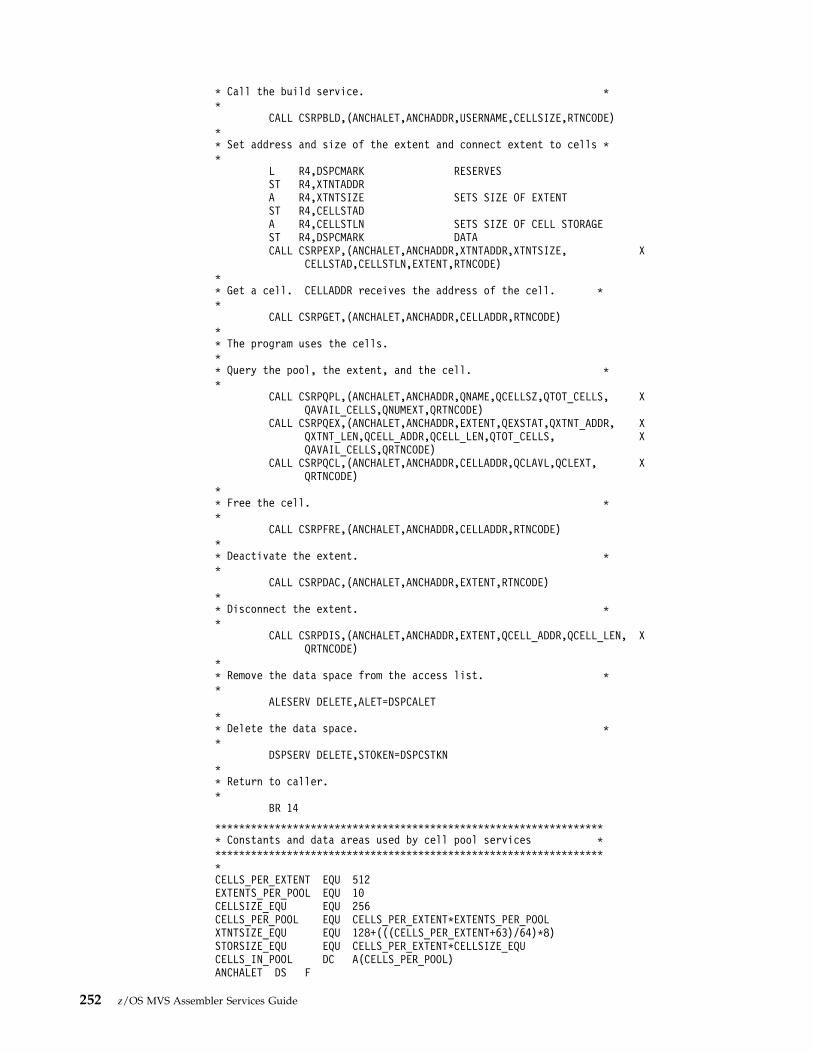
* Call the build service. **
CALL CSRPBLD,(ANCHALET,ANCHADDR,USERNAME,CELLSIZE,RTNCODE)** Set address and size of the extent and connect extent to cells **
L R4,DSPCMARK RESERVESST R4,XTNTADDRA R4,XTNTSIZE SETS SIZE OF EXTENTST R4,CELLSTADA R4,CELLSTLN SETS SIZE OF CELL STORAGEST R4,DSPCMARK DATACALL CSRPEXP,(ANCHALET,ANCHADDR,XTNTADDR,XTNTSIZE, X
CELLSTAD,CELLSTLN,EXTENT,RTNCODE)** Get a cell. CELLADDR receives the address of the cell. **
CALL CSRPGET,(ANCHALET,ANCHADDR,CELLADDR,RTNCODE)** The program uses the cells.** Query the pool, the extent, and the cell. **
CALL CSRPQPL,(ANCHALET,ANCHADDR,QNAME,QCELLSZ,QTOT_CELLS, XQAVAIL_CELLS,QNUMEXT,QRTNCODE)
CALL CSRPQEX,(ANCHALET,ANCHADDR,EXTENT,QEXSTAT,QXTNT_ADDR, XQXTNT_LEN,QCELL_ADDR,QCELL_LEN,QTOT_CELLS, XQAVAIL_CELLS,QRTNCODE)
CALL CSRPQCL,(ANCHALET,ANCHADDR,CELLADDR,QCLAVL,QCLEXT, XQRTNCODE)
** Free the cell. **
CALL CSRPFRE,(ANCHALET,ANCHADDR,CELLADDR,RTNCODE)** Deactivate the extent. **
CALL CSRPDAC,(ANCHALET,ANCHADDR,EXTENT,RTNCODE)** Disconnect the extent. **
CALL CSRPDIS,(ANCHALET,ANCHADDR,EXTENT,QCELL_ADDR,QCELL_LEN, XQRTNCODE)
** Remove the data space from the access list. **
ALESERV DELETE,ALET=DSPCALET** Delete the data space. **
DSPSERV DELETE,STOKEN=DSPCSTKN** Return to caller.*
BR 14
****************************************************************** Constants and data areas used by cell pool services *******************************************************************CELLS_PER_EXTENT EQU 512EXTENTS_PER_POOL EQU 10CELLSIZE_EQU EQU 256CELLS_PER_POOL EQU CELLS_PER_EXTENT*EXTENTS_PER_POOLXTNTSIZE_EQU EQU 128+(((CELLS_PER_EXTENT+63)/64)*8)STORSIZE_EQU EQU CELLS_PER_EXTENT*CELLSIZE_EQUCELLS_IN_POOL DC A(CELLS_PER_POOL)ANCHALET DS F
252 z/OS MVS Assembler Services Guide

ANCHADDR DS FCELLSIZE DC A(CELLSIZE_EQU)USERNAME DC CL8’MYCELLPL’ANCHSIZE DC F’64’XTNTSIZE DC A(XTNTSIZE_EQU)XTNTADDR DS FCELLSTAD DS FCELLSTLN DC A(STORSIZE_EQU)CELLADDR DS FEXTENT DS FSTATUS DS FRTNCODE DS F******************************************************************* Constant data and areas for data space *******************************************************************
DS 0DDSPCSTKN DS CL8 DATA SPACE STOKENDSPCORG DS F DATA SPACE ORIGIN RETURNEDDSPCSIZE EQU STORSIZE_EQA*EXTENTS_PER_POOL 1.28MEG DATA SPACEDSPBLCKS DC A((DSPCSIZE+4095)/4096) BLOCKS FOR 10K DATA SPACEDSPCALET DS FDSPCMARK DS F HIGH WATER MARK FOR DATA SPACEDSPCNAME DC CL8’DATASPC1’ DATA SPACE NAME*
****************************************************************** Values returned by queries *******************************************************************QNAME DS CL8QCELLSZ DS FQNUMEXT DS FQEXTNUM DS FQEXSTAT DS FQXTNT_ADDR DS FQXTNT_LEN DS FQCELL_ADDR DS FQCELL_LEN DS FQTOT_CELLS DS FQAVAIL_CELLS DS FQRTNCODE DS FRC DS FQCLADDR DS FQCLEXT DS FQCLAVL DS F
AMODE 64 exampleTEST CSECTTEST AMODE 64TEST RMODE 31
BSM R14,0 Save caller’s AMODE indicationBAKR R14,0 Save regs on linkage stackSAM64 Into AMODE 64SYSSTATE AMODE64=YES
** Establish addressability to static data. We use relative* branching to avoid needing addressability to the code*
CNOP 0,4BRAS R12,PAST1DC A(STATIC_DATA)
PAST1 DS 0HLLGT R12,0(R12,0)USING STATIC_DATA,R12
*
Chapter 13. Callable cell pool services 253
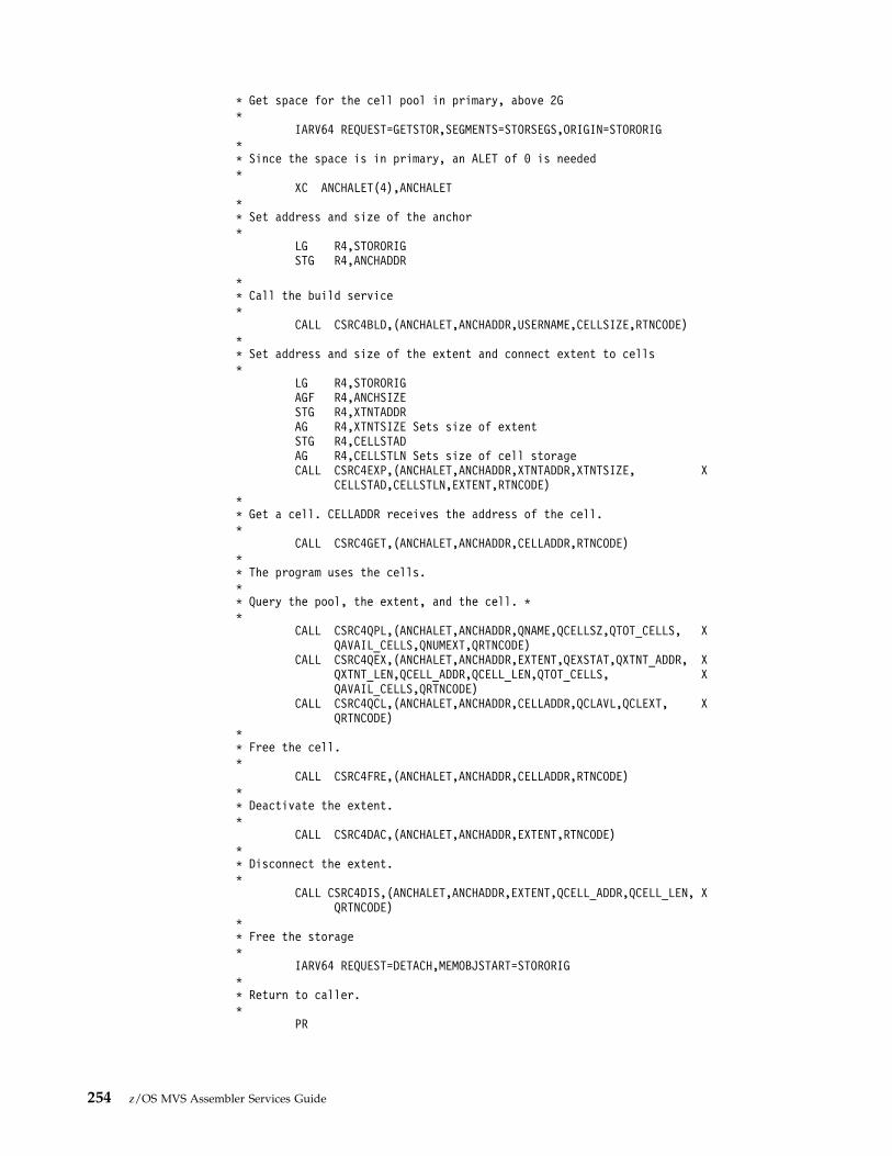
* Get space for the cell pool in primary, above 2G*
IARV64 REQUEST=GETSTOR,SEGMENTS=STORSEGS,ORIGIN=STORORIG** Since the space is in primary, an ALET of 0 is needed*
XC ANCHALET(4),ANCHALET** Set address and size of the anchor*
LG R4,STORORIGSTG R4,ANCHADDR
** Call the build service*
CALL CSRC4BLD,(ANCHALET,ANCHADDR,USERNAME,CELLSIZE,RTNCODE)** Set address and size of the extent and connect extent to cells*
LG R4,STORORIGAGF R4,ANCHSIZESTG R4,XTNTADDRAG R4,XTNTSIZE Sets size of extentSTG R4,CELLSTADAG R4,CELLSTLN Sets size of cell storageCALL CSRC4EXP,(ANCHALET,ANCHADDR,XTNTADDR,XTNTSIZE, X
CELLSTAD,CELLSTLN,EXTENT,RTNCODE)** Get a cell. CELLADDR receives the address of the cell.*
CALL CSRC4GET,(ANCHALET,ANCHADDR,CELLADDR,RTNCODE)** The program uses the cells.** Query the pool, the extent, and the cell. **
CALL CSRC4QPL,(ANCHALET,ANCHADDR,QNAME,QCELLSZ,QTOT_CELLS, XQAVAIL_CELLS,QNUMEXT,QRTNCODE)
CALL CSRC4QEX,(ANCHALET,ANCHADDR,EXTENT,QEXSTAT,QXTNT_ADDR, XQXTNT_LEN,QCELL_ADDR,QCELL_LEN,QTOT_CELLS, XQAVAIL_CELLS,QRTNCODE)
CALL CSRC4QCL,(ANCHALET,ANCHADDR,CELLADDR,QCLAVL,QCLEXT, XQRTNCODE)
** Free the cell.*
CALL CSRC4FRE,(ANCHALET,ANCHADDR,CELLADDR,RTNCODE)** Deactivate the extent.*
CALL CSRC4DAC,(ANCHALET,ANCHADDR,EXTENT,RTNCODE)** Disconnect the extent.*
CALL CSRC4DIS,(ANCHALET,ANCHADDR,EXTENT,QCELL_ADDR,QCELL_LEN, XQRTNCODE)
** Free the storage*
IARV64 REQUEST=DETACH,MEMOBJSTART=STORORIG** Return to caller.*
PR
254 z/OS MVS Assembler Services Guide

****************************************************************** Constants and data areas used by cell pool services *******************************************************************STATIC_DATA DS 0D*CELLS_PER_EXTENT EQU 512EXTENTS_PER_POOL EQU 10CELLSIZE_EQU EQU 256CELLS_PER_POOL EQU CELLS_PER_EXTENT*EXTENTS_PER_POOLXTNTSIZE_EQU EQU CSRC4_EXTENT_BASE+(((CELLS_PER_EXTENT+63)/64)*8)STORSIZE_EQU EQU CELLS_PER_EXTENT*CELLSIZE_EQUCELLS_IN_POOL DC AD(CELLS_PER_POOL)ANCHADDR DS ADCELLSIZE DC AD(CELLSIZE_EQU)USERNAME DC CL(CSRC4_POOL_NAME_LEN)’MYCELLPL’ANCHALET DS FANCHSIZE DC A(CSRC4_ANCHOR_LENGTH)XTNTSIZE DC AD(XTNTSIZE_EQU)XTNTADDR DS ADCELLSTAD DS ADCELLSTLN DC AD(STORSIZE_EQU)CELLADDR DS ADSTATUS DS DEXTENT DS FRTNCODE DS F******************************************************************* Constant data and areas******************************************************************
DS 0DSTORORIG DS AD Storage OriginSTORSIZE EQU STORSIZE_EQU*EXTENTS_PER_POOLSTORSEGS DC AD((STORSIZE+1024*1024-1)/(1024*1024)) 1M Segments needed*
****************************************************************** VALUES RETURNED BY QUERIES******************************************************************QNAME DS CL(CSRC4_POOL_NAME_LEN)QCELLSZ DS DQNUMEXT DS DQEXSTAT DS DQXTNT_ADDR DS DQXTNT_LEN DS DQCELL_ADDR DS DQCELL_LEN DS DQTOT_CELLS DS DQAVAIL_CELLS DS DQCLADDR DS DQCLAVL DS DQCLEXT DS FQRTNCODE DS F****************************************************************** Registers*****************************************************************R4 EQU 4R12 EQU 12R14 EQU 14****************************************************************** Declares for CSRC4xxx services*****************************************************************
CSRC4ASM Assembler declares for AMODE 64END TEST
Chapter 13. Callable cell pool services 255

256 z/OS MVS Assembler Services Guide

Chapter 14. Data-in-virtual
Data-in-virtual simplifies the writing of applications that use large amounts of datafrom permanent storage. Applications can create, read, and update data withoutthe I/O buffer, blocksize, and record considerations that the traditional GET andPUT types of access methods require.
By using the services of data-in-virtual, certain applications that access largeamounts of data can potentially improve their performance and their use of systemresources. Such applications have an accessing pattern that is non-sequential andunpredictable. This kind of pattern is a function of conditions and values that arerevealed only in the course of the processing. In these applications, the sequentialrecord subdivisions of conventional access methods are meaningless to the centralprocessing algorithm. It is difficult to adapt this class of applications toconventional record management programming techniques, which require allpermanent storage access to be fundamentally record-oriented. Through the DIVmacro, data-in-virtual provides a way for these applications to manipulate the datawithout the constraints of record-oriented processing.
An application written for data-in-virtual views its permanent storage data as aseamless body of data without internal record boundaries. By using thedata-in-virtual MAP service, the application can make any portion of the objectappear in virtual storage in an area called a virtual storage window. The window canexist in an address space, a data space, or a shared or non-shared standardhiperspace. (See “Example of mapping a data-in-virtual object to a data space” onpage 314 and “Using data-in-virtual with hiperspaces” on page 328 for moreinformation.) When the window is in a data space, the application can referenceand update the data in the window by using assembler instructions. When thewindow is in a hiperspace, the application uses the HSPSERV macro to referenceand update the data. To copy the updates to the object, the application uses thedata-in-virtual SAVE service.
An application written for data-in-virtual might also benefit by using theIARVSERV macro to share virtual storage, when that storage is in an address spaceor data space. For information about sharing data in virtual storage throughIARVSERV, particularly the restrictions for using the data-in-virtual MAP andUNMAP services, see Chapter 20, “Sharing data in virtual storage (IARVSERVmacro),” on page 375.
The data-in-virtual services process the application data in 4096-byte (4K-byte)units on 4K-byte boundaries called blocks. The application data resides in what iscalled a data-in-virtual object, a data object, or simply an object. The data-in-virtualobject is a continuous string of uninterrupted data. The data object can be either aVSAM linear data set or a non-shared standard hiperspace. Choosing a linear dataset as an object or a non-shared standard hiperspace as an object depends on yourapplication. If your application requires the object to retain data, choose a lineardata set, which provides permanent storage on DASD. A hiperspace objectprovides temporary storage.
© Copyright IBM Corp. 1988, 2017 257
When to use data-in-virtualWhen an application reads more input and writes more output data thannecessary, the unnecessary reads and writes impact performance. You can expectimproved performance from data-in-virtual because it reduces the amount ofunnecessary I/O.
As an example of unnecessary I/O, consider the I/O performed by an interactiveapplication that requires immediate access to several large data sets. The programknows that some of the data, although not all of it, will be accessed. However, theprogram does not know ahead of time which data will be accessed. A possiblestrategy for gaining immediate access to all the data is to read all the data ahead oftime, reading each data set in its entirety insofar as this is possible. Once read intoprocessor storage, the data can be accessed quickly. However, if only a smallpercentage of the data is likely to be accessed during any given period, the I/Operformed on the unaccessed data is unnecessary.
Furthermore, if the application changes some data in main storage, it might notkeep track of the changes. Therefore, to guarantee that all the changes arecaptured, the application must then write entire data sets back onto permanentstorage even though only relatively few bytes are changed in the data sets.
Whenever such an application starts up, terminates, or accesses different data setsin an alternating manner, time is spent reading data that is not likely to beaccessed. This time is essentially wasted, and the amount of it is proportional tothe amount of unchanged data for which I/O is performed. Such applications aresuitable candidates for a data-in-virtual implementation.
Factors affecting performanceWhen you write applications using the techniques of data-in-virtual, the I/O takesplace only for the data referenced and saved. If you run an application usingconventional access methods, and then run it a second time using data-in-virtualtechniques, you will notice a difference in performance. This difference depends ontwo factors: the size of the data set and its access pattern (or reference pattern). Sizerefers to the magnitude of the data sets that the application must process. Theaccess pattern refers to how the application references the data.
In order to improve performance by using the data-in-virtual application, yourdata sets must be large and the pattern must be scattered throughout the data set.
Engineering and scientific applications often use data access patterns that aresuitable for data-in-virtual. Among the applications that can be considered for adata-in-virtual implementation are:v Applications that process large arraysv VSAM relative record applicationsv BDAM fixed length record applications
Commercial applications sometimes use data access patterns that are not suitablebecause they are predictable and sequential. If the access pattern of a proposedapplication is fundamentally sequential or if the data set is small, a conventionalVSAM (or other sequential access method) implementation may perform betterthan a data-in-virtual implementation. However, this does not rule out commercialapplications as data-in-virtual candidates. If the performance factors are favorable,any type of application, commercial or scientific, is suitable for a data-in-virtualimplementation.
258 z/OS MVS Assembler Services Guide

Before you can use the DIV macro to process a linear data set object or ahiperspace object, you must create either the data set or the hiperspace. Chapter 16,“Data spaces and hiperspaces,” on page 295 explains how to create a hiperspace.“Creating a linear data set” explains how to create a linear data set.
Creating a linear data setTo create the data set, you need to specify the DEFINE CLUSTER function ofIDCAMS with the LINEAR parameter. When you code the SHAREOPTIONSparameter for DEFINE CLUSTER, the cross-system value must be 3; that is, youmay code SHAREOPTIONS as (1,3), (2,3), (3,3), or (4,3). Normally, you should useSHAREOPTIONS (1,3).
When creating a linear data set for DIV, you can use the LOCVIEW parameter ofthe DIV macro in conjunction with the other SHAREOPTIONS. LOCVIEW isdescribed under the topic “The ACCESS service” on page 263. For a completeexplanation of SHAREOPTIONS, see z/OS DFSMS Using Data Sets.
The following is a sample job that invokes Access Method Services (IDCAMS) tocreate the linear data set named DIV.SAMPLE on the volume called DIVPAK.When IDCAMS creates the data set, it creates it as an empty data set. Note thatthere is no RECORDS parameter; linear data sets do not have records.
For further information on creating linear VSAM data sets and alteringentry-sequenced VSAM data sets, see z/OS DFSMS Access Method ServicesCommands.
Using the services of data-in-virtualEach invocation of the DIV macro requests any one of the services provided bydata-in-virtual:v IDENTIFYv ACCESSv MAPv SAVEv SAVELISTv RESETv UNMAPv UNACCESSv UNIDENTIFY
//JNAME JOB ’ALLOCATE LINEAR’,MSGLEVEL=(1,1),// CLASS=R,MSGCLASS=D,USER=JOHNDOE//*//* ALLOCATE A VSAM LINEAR DATASET//*//CLUSTPG EXEC PGM=IDCAMS,REGION=4096K//SYSPRINT DD SYSOUT=*//DIVPAK DD UNIT=3380,VOL=SER=DIVPAK,DISP=OLD//SYSIN DD *
DEFINE CLUSTER (NAME(DIV.SAMPLE) -VOLUMES(DIVPAK) -TRACKS(1,1) -SHAREOPTIONS(1,3) -LINEAR)
/*
Chapter 14. Data-in-virtual 259

IdentifyAn application must use IDENTIFY to tell the system which data-in-virtual objectit wants to process. IDENTIFY generates a unique ID, or token, that uniquelyrepresents an application's request to use the given data object. The system returnsthis ID to the application. When the application requests other kinds of serviceswith the DIV macro, the application supplies this ID to the system as an inputparameter. Specify DDNAME for a linear data set object and STOKEN for ahiperspace object.
AccessTo gain the right to view or update the object, an application must use theACCESS service. You normally invoke ACCESS after you invoke IDENTIFY andbefore you invoke MAP. ACCESS is similar to the OPEN macro of VSAM. It has amode parameter of READ or UPDATE, and it gives your application the right toread or update the object.
If the object is a data set and if the SHAREOPTIONS parameter used to allocatethe linear data set implies serialization, the system automatically serializes youraccess to the object. If access is not automatically serialized, you can serializeaccess to the object by using the ISGENQ, ENQ, DEQ, and the RESERVE macros. Ifyou do not serialize access to the object, you should consider using the LOCVIEWparameter to protect your window data against the unexpected changes that canoccur when access to the object is not serialized. LOCVIEW is described under thetopic “The ACCESS service” on page 263.
If the object is a hiperspace, DIV ensures that only one program can write to theobject and that multiple users can only read the object. Only the task that owns thecorresponding ID can issue ACCESS.
MapThe data object is stored in units of 4096-byte blocks. An application uses the MAPservice to specify the part of the object that is to be processed in virtual storage. Itcan specify the entire object (all of the blocks), or a part of the object (anycontinuous range of blocks). Because parts of the same object can be viewedsimultaneously through several different windows, the application can set upseparate windows on the same object. However, a specific page of virtual storagecannot be in more than one window at a time.
After ACCESS, the application obtains a virtual storage area large enough tocontain the window. The size of the object, which ACCESS optionally returns, candetermine how much virtual storage you need to request. After requesting virtualstorage, the application invokes MAP. MAP establishes a one to onecorrespondence between blocks in the object and pages in virtual storage. Acontinuous range of pages corresponds to a continuous range of blocks. Thiscorrespondence is called a virtual storage window, or a window.
After MAP, the application can look into the virtual storage area that the windowcontains. When it looks into this virtual storage area, it sees the same data that isin the object. When the application references this virtual storage area, it isreferencing the data from the object. To reference the area in the window, theapplication simply uses any conventional processor instructions that access storage.
Although the object data becomes available in the window when the applicationinvokes MAP, no actual movement of data from the object into the window occurs
260 z/OS MVS Assembler Services Guide

at that time. Actual movement of data from the object to the window occurs onlywhen the application refers to data in the window. When the application referencesa page in the window for the first time, a page fault occurs. When the page faultoccurs, the system reads the permanent storage block into central storage.
When the system brings data into central storage, the data movement involvesonly the precise block that the application references. The system updates thecontents of the corresponding page in the window with the contents of the lineardata set object. Thus, the system brings in only the blocks that an applicationreferences into central storage. The sole exception to the system bringing in onlythe referenced blocks occurs when the application specifies LOCVIEW=MAP withthe ACCESS service for a data set object.
Notes:
1. If the application specifies LOCVIEW=MAP with ACCESS, the entire windowis immediately filled with object data when the application invokes MAP.
2. If, when an application invokes MAP, it would rather keep in the window thedata that existed before the window was established (instead of having theobject data appear in the window), it can specify RETAIN=YES. SpecifyingRETAIN=YES is useful when creating an object or overlaying the contents of anobject.
3. An important concept for data-in-virtual is the concept of freshly obtainedstorage. When virtual storage has been obtained and not subsequentlymodified, the storage is considered to be freshly-obtained. The storage is also inthis state when it has been obtained as a data space by using a DSPSERVCREATE and not subsequently modified. After a DSPSERV RELEASE, thestorage is still considered freshly obtained until it has been modified. Whenreferring to this storage or any of its included pages, this information uses“freshly obtained storage” and “freshly obtained pages”. If a program storesinto a freshly obtained page, only that page loses its freshly obtained-status,while other pages still retain it.
4. You can map virtual storage pages that are protected only when you specifyRETAIN=YES. When the system establishes the virtual window, you can usethe PGSER PROTECT macro to protect the data in the window. However, youmust ensure that the data in the window is not protected when you issue theRESET form of the DIV macro.
Save, savelist, and resetAfter using the MAP service, the application can access the data inside thewindow directly through normal programming techniques. When the applicationchanges some data in the window, however, the data on the object does notconsequently change. If the application wants the data changes in the window toappear in the object, it must use the SAVE service. SAVE writes all changed blockswithin the range to be saved inside the window to the object. It does not writeunchanged blocks. When SAVE completes, the object contains any changes that theapplication made inside the virtual storage window. If a SAVE is preceded byanother SAVE, the second SAVE will pick up only the changes that occurred sincethe previous SAVE.
Optionally, SAVE accepts a user list as input. To provide a user list, the applicationuses the SAVELIST service. SAVELIST returns the addresses of the first and lastchanged pages in each range of changed pages within the window. The applicationcan then use these addresses as the user list for SAVE. The SAVE operation can be
Chapter 14. Data-in-virtual 261

more efficient when using the list of addresses, so an application can improve itsperformance by using SAVELIST and then SAVE.
When specifying a user list and when a data space or hiperspace contains thewindow, the caller must use an STOKEN with SAVE to identify the data space orhiperspace.
If the application changes some data in a virtual storage window but then decidesnot to keep those changes, it can use the RESET service to reload the window withdata from the object. RESET reloads only the blocks that have been changed unlessyou specify or have specified RELEASE=YES.
UnmapWhen the application is finished processing the part of the object that is in thewindow, it eliminates the window by using UNMAP. To process a different part ofthe object, one not already mapped, the application can use the MAP service again.The SAVE, RESET, MAP, and UNMAP services can be invoked repeatedly asrequired by the processing requirements of the application.
If you issued multiple MAPs to different STOKENs, use STOKEN with UNMAP toidentify the data space or hiperspace you want to unmap.
Note: If you do not want to retain the data in the virtual window, use the PGSERUNPROTECT macro to “unprotect” any protected pages in the window, before youuse the UNMAP service.
If you issue UNMAP with RETAIN=NO and there are protected pages in thevirtual storage window, the system loses the data in the protected pages andpreserves the protection status. If you try to reference the protected pages, thesystem issues abend X'028'. To access the protected pages again, remove theprotection status. Then issue the PGSER RELEASE or DSPSERV RELEASE macroto release all physical paging resources.
UnaccessIf the application has temporarily finished processing the object but still has otherprocessing to perform, it uses UNACCESS to relinquish access to the object. Thenother programs can access the object. If the application needs to access the sameobject again, it can regain access to the object by using the ACCESS service againwithout having to use the IDENTIFY service again.
UnidentifyUNIDENTIFY ends the use of a data-in-virtual object under a previously assignedID that the IDENTIFY service returned.
The IDENTIFY serviceYour program uses IDENTIFY to select the data-in-virtual object that you want toprocess. IDENTIFY has four parameters: ID, TYPE, DDNAME, and STOKEN.
The following examples show two ways to code the IDENTIFY service:
For a hiperspace object:DIV IDENTIFY,ID=DIVOBJID,TYPE=HS,STOKEN=HSSTOK
262 z/OS MVS Assembler Services Guide

For a data set object:DIV IDENTIFY,ID=DIVOBJID,TYPE=DA,DDNAME=DDAREA
The parameters are as follows:
ID The ID parameter specifies the address where the IDENTIFY service returns aunique eight-byte name that connects a particular user with a particular object.This name is an output value from IDENTIFY, and it is also a required inputvalue to all other services.
Simultaneous requests for different processing activities against the samedata-in-virtual object can originate from different tasks or from differentroutines within the same task or the same routine. Each task or routinerequesting processing activity against the object must first invoke the identifyservice. To correlate the various DIV macro invocations and processingactivities, the eight-byte IDs generated by IDENTIFY are sufficiently unique toreflect the individuality of the IDENTIFY request, yet they all reflect the samedata-in-virtual object.
TYPEThe TYPE parameter indicates the type of data-in-virtual object, either a lineardata set (TYPE=DA) or a hiperspace (TYPE=HS). DIV does not support VSAMextended format linear data sets for use as a DIV object for which the size isgreater than 4GB.
DDNAMEWhen you specify TYPE=DA for a data set object, you must specify DDNAMEto identify your data-in-virtual object. If you specify TYPE=HS with IDENTIFY,do not specify DDNAME. (Specify STOKEN instead.) Do not specify aDDNAME that corresponds to a VSAM extended format linear data set forwhich the size is greater than 4GB, because DIV does not support them for useas a DIV object.
Encrypted linear VSAM data sets are supported. For more information, seez/OS DFSMS Using Data Sets.
STOKENWhen you specify TYPE=HS for a hiperspace object, you must specifySTOKEN to identify that hiperspace. The STOKEN must be addressable inyour primary address space. The hiperspace must be a non-shared standardhiperspace and must be owned by the task issuing the IDENTIFY. The systemdoes not verify the STOKEN until your application uses the associated ID toaccess the object.
The ACCESS serviceYour program uses the ACCESS service to request permission to read or updatethe object. ACCESS has two required parameters: ID and MODE, and two optionalparameters: SIZE and LOCVIEW.
The following example shows one way to code the ACCESS service.DIV ACCESS,ID=DIVOBJID,MODE=UPDATE,SIZE=OBJSIZE
ID: When you issue a DIV macro that requests the ACCESS service, you must alsospecify, on the ID parameter, the identifier that the IDENTIFY service returned. TheID parameter tells the system what object you want access to. When you requestpermission to access the object under a specified ID, the system checks thefollowing conditions before it grants the access:
Chapter 14. Data-in-virtual 263
||

v You previously established the ID specified with your ACCESS request byinvoking IDENTIFY.
v You have not already accessed the object under the same unique eight-byte ID.Before you can reaccess an already-accessed object under the same ID, you mustfirst invoke UNACCESS for that ID.
v If your installation uses RACF® and the object is a linear data set, you musthave the proper RACF authorization to access the object.
v If you are requesting read access, the object must not be empty. Use the MODEparameter to request read or update access.
v If the data object is a hiperspace, the system rejects the request if the hiperspace:– Has ever been the target of an ALESERV ADD.– Has one or more readers and one updater. (That is, the hiperspace can have
readers and it can have one updater, but it can't have both.)v If the data object is a linear data set, the system rejects the request if the linear
data set:– Is a VSAM extended format linear data set for which the size is greater than
4GB.
MODE: The MODE parameter specifies how your program will access the object.You can specify a mode parameter of READ or UPDATE. They are described asfollows:v READ lets you read the object, but prevents you from using SAVE, to change the
object.v UPDATE, like READ, lets you read the object, but it also allows you update the
object with SAVE.
Whether you specify READ or UPDATE, you can still make changes in thewindow, because the object does not change when you change the data in thewindow.
SIZE: The SIZE parameter specifies the address of the field where the systemstores the size of the object. The system returns the size in this field whenever youspecify SAVE or ACCESS with SIZE. If you omit SIZE or specify SIZE=*, thesystem does not return the size.
If you specified TYPE=DA with IDENTIFY for a data set object, SIZE specifies theaddress of a four-byte field. When control is returned to your program after theACCESS service executes, the four-byte field contains the current size of the object.The size is the number of blocks that the application must map to ensure themapping of the entire object.
If you specified TYPE=HS with IDENTIFY for a hiperspace object, ACCESS returnstwo sizes. The first is the current size of the hiperspace (in blocks). The second isthe maximum size of the hiperspace (also in blocks). When specifying SIZE withan ID associated with a hiperspace object, you must provide an eight-byte field inwhich the system can return the sizes (4 bytes each).
LOCVIEW: The LOCVIEW parameter allows you to specify whether the system isto create a local copy of the data-in-virtual object.
If your object is a hiperspace, you cannot specify LOCVIEW=MAP.
If your object is a data set, you can code the LOCVIEW parameter two ways:
264 z/OS MVS Assembler Services Guide
v LOCVIEW=MAPv LOCVIEW=NONE (the default if you do not specify LOCVIEW)
If another program maps the same block of a data-in-virtual object as yourprogram has mapped, a change in the object due to a SAVE by the other programcan sometimes appear in the virtual storage window of your program. The changecan appear when you allocate the data set object with a SHAREOPTIONS(2,3),SHAREOPTIONS(3,3), or SHAREOPTIONS(4,3) parameter, and when the otherprogram is updating the object while your program is accessing it.
If the change appears when your program is processing the data in the window,processing results might be erroneous because the window data at the beginningof your processing is inconsistent with the window data at the end of yourprocessing. The relationship between SHAREOPTIONS and LOCVIEW is asfollows:v When you allocate the data set object by SHAREOPTIONS(2,3),
SHAREOPTIONS(3,3), or SHAREOPTIONS(4,3), the system does not serializethe accesses that programs make to the object. Under these options, if theprograms do not observe any serialization protocol, the data in your virtualstorage window can change when other programs invoke SAVE. To ensure thatyour program has a consistent view of the object, and protect your window fromchanges that other programs make on the object, use LOCVIEW=MAP. If you donot use LOCVIEW=MAP when you invoke ACCESS, the system provides areturn code of 4 and a reason code of hexadecimal 37 as a reminder that noserialization is in effect even though the access was successful.
v When you allocate the object by SHAREOPTIONS(1,3), object changes made bythe other program cannot appear in your window because the system performsautomatic serialization of access. Thus, when any program has update access tothe object, the system automatically prevents all other access. UseLOCVIEW=NONE when you allocate the data set by SHAREOPTIONS(1,3).
Note: The usual method of programming data-in-virtual is to useLOCVIEW=NONE and SHAREOPTIONS(1,3). LOCVIEW=MAP is provided forprograms that must access a data object simultaneously. Those programs wouldnot use SHAREOPTIONS(1,3).
LOCVIEW=MAP requires extra processing that degrades performance. UseLOCVIEW=NONE whenever possible although you can use LOCVIEW=MAP forsmall data objects without significant performance loss. When you write a programthat uses LOCVIEW=MAP, be careful about making changes in the object size.Consider the following:v When a group of programs, all using LOCVIEW=MAP, have simultaneous
access to the same object, no program should invoke any SAVE or MAP thatextends or truncates the object unless it informs the other programs by somecoding protocol of a change in object size. When the other programs areinformed, they can adjust their processing based on the new size.
v All the programs must create their maps before any program changes the objectsize. Subsequently, if any program wants to reset the map or create a new map,it must not do so without observing the protocol of a size check. If the sizechanged, the program should invoke UNACCESS, followed by ACCESS to getthe new size. Then the program can reset the map or create the new map.
Chapter 14. Data-in-virtual 265

The MAP serviceThe MAP service makes an association between part or all of an object, the portionbeing specified by the OFFSET and SPAN parameters, and your program's virtualstorage. This association, which is called a virtual storage window, takes the form ofa one-to-one correspondence between specified blocks on the object and specifiedpages in virtual storage. After the MAP is complete, your program can thenprocess the data in the window. The RETAIN parameter specifies whether datathat is in the window when you issue MAP is to remain or be replaced by the datafrom the associated object.
Note: You cannot map virtual storage pages that are page-fixed into a virtualstorage window. Once the window exists, you can page-fix data inside the windowso long as it is not fixed when you issue SAVE, UNMAP, or RESET.
If your window is in an address space, you can map either a linear data set or ahiperspace object. See Figure 62.
If your window is in a data space or a hiperspace, you can map only a linear dataset. See Figure 63 on page 267.
Hiperspace
Temporary ObjectAddress Space
Linear Data Set
Permanent ObjectAddress Space
window
window
OR
Figure 62. Mapping from an address space
266 z/OS MVS Assembler Services Guide

If your window is in a data space or hiperspace, you can issue multiple MAPsunder the same ID to different data spaces or hiperspaces. You cannot mix dataspace maps or hiperspace maps with address space maps under the same ID atany one time. However, you can mix data space maps and hiperspace maps. SeeFigure 64 on page 268.
The MAP service has two required parameters: ID and OFFSET, and five optionalparameters: SPAN, AREA, RETAIN, STOKEN, and PFCOUNT.
The following examples show two ways to code the MAP service.
Hiperspace or data set object:DIV MAP,ID=DIVOBJID,AREA=MAPPTR1,SPAN=SPANVAL,OFFSET=*,PFCOUNT=7
Data set object:DIV MAP,ID=DIVOBJID,AREA=MAPPTR1,SPAN=SPANVAL,OFFSET=*,STOKEN=DSSTOK,PFCOUNT=7
ID: The ID parameter specifies the storage location containing the uniqueeight-byte value that was returned by IDENTIFY. The map service uses this valueto determine which object is being mapped under which request.
If you specify the same ID on multiple invocations of the MAP service, you cancreate simultaneous windows corresponding to different parts of the object.However, an object block that is mapped into one window cannot be mapped intoany other window created under the same ID. If you use different IDs, however,an object block can be included simultaneously in several windows.
OFFSET and SPAN: The OFFSET and SPAN parameters indicate a range of blockson the object. Blocks in this range appear in the window. OFFSET indicates thefirst object block in the range, while SPAN indicates how many contiguous blocksmake up the range. An offset of zero indicates the beginning of the object. Forexample, an offset of zero and a span of ten causes the block at the beginning ofthe object to appear in the window, together with the next nine object blocks. Thewindow would then be ten pages long.
Data Spaceor Hiperspace
Permanent Object
window
Linear Data Set
Figure 63. Mapping from a data space or hiperspace
Chapter 14. Data-in-virtual 267

Specifying OFFSET=* or omitting OFFSET causes the system to use a defaultOFFSET of zero. Specifying SPAN=0, SPAN=*, or omitting SPAN results in adefault SPAN of the number of blocks needed to MAP the entire object, startingfrom the block indicated by OFFSET. Specifying both OFFSET=* and SPAN=* oromitting both causes the entire object to appear in the window.
You may use the OFFSET and SPAN parameters to specify a range spanning anyportion of the object, the entire object, or extending beyond the object. Specifying arange beyond the object enables a program to add data to the object, increasing thesize of the object. If data in a mapped range beyond the object is saved (using theSAVE service), the size of the object is updated to reflect the new size.
To use the OFFSET parameter, specify the storage location containing the blockoffset of the first block to be mapped. The offset of the first block in the data objectis zero. To use the SPAN parameter, specify the storage location containing thenumber of blocks in the mapped range.
Note: Data-in-virtual always allocates an extra block beyond the requested blocknumber range to ensure that there is enough space for an end-of-file (EOF) record.
window
window
Permanent Object
Linear Data Set
Data Spaceor Hiperspace
Data Spaceor Hiperspace
Data Spaceor Hiperspace
window
Figure 64. Multiple mapping
268 z/OS MVS Assembler Services Guide

Therefore, when a DIV object is created without extents, the largest possible spanvalue is the total number of blocks contained in the DIV object minus one.
AREA: When you specify MAP, you must also specify an AREA parameter. AREAindicates the beginning of a virtual storage space large enough to contain the entirewindow. Before invoking MAP, you must ensure that your task owns this virtualstorage space. The storage must belong to a single, pageable private area subpool.It must begin on a 4096-byte boundary (that is, a page boundary) and have alength that is a multiple of 4096 bytes.
Note that any virtual storage space assigned to one window cannot besimultaneously assigned to another window. If your MAP request specifies avirtual storage location, via the AREA parameter, that is part of another window,the system rejects the request.
You cannot free virtual storage that is mapped into a window as long as the mapexists. Attempts to do this will cause your program to abend. Subsequent attemptsto reference the mapped virtual space will cause an ABEND.
RETAIN: The RETAIN parameter determines what data you can view in thewindow. It can be either the contents of the virtual storage area (that correspondsto the window) the way it was before you invoked MAP, or it can be the contentsof the object. The following table shows how using the RETAIN parameter withMAP affects the contents of the window.
RETAIN= Window view
NO (default) Contents of mapped object
YES Contents of virtual storage
If you specify RETAIN=NO, or do not specify the RETAIN parameter at all (whichdefaults to RETAIN=NO), the contents of the object replace the contents of thevirtual storage whenever your program references a page in the window. Virtualstorage that corresponds to a range beyond the end of the object appears as binaryzeroes when referenced. You can use RETAIN=NO to change some data and save itback to the object.
If you specify RETAIN=YES, the window retains the contents of virtual storage.The contents of the window are not replaced by data from the object. If you issue asubsequent SAVE, the data in the window replaces the data on the object. If thewindow extends beyond the object and your program has not referenced the pagesin the extending part of the window, the system does not save the extendingpages. However, if your program has referenced the extending pages, the systemdoes save them on the object, extending the object so it can hold the additionaldata.
You can also use RETAIN=YES to reduce the size of (truncate) the object. If thepart you want to truncate is mapped with RETAIN=YES and the window consistsof freshly obtained storage, the data object size is reduced at SAVE time.
If you want to have zeroes written at the end of the object, the correspondingvirtual storage must be explicitly set to zero prior to the SAVE.
STOKEN: To reference an entire linear data set through a single window, aprogram might require a considerable amount of virtual storage. In this case, theprogram can use a data space or hiperspace to contain the window. If you want
Chapter 14. Data-in-virtual 269

the virtual storage window to be in a data space or hiperspace, specify STOKENwhen you invoke MAP. When you specify STOKEN, you provide an eight-byteinput parameter that identifies the data space or hiperspace, and that was returnedfrom DSPSERV CREATE.
However, do not place the window in a data space or hiperspace under thefollowing circumstances:v If the data space is a disabled reference (DREF) data space.v If the object is accessed with LOCVIEW=MAP.v If the data space or hiperspace belongs to another task. However, if your
program is in supervisor state or has a system storage key, it can use a dataspace or hiperspace that belongs to another task provided that the other task isin the same primary address space as your program.
PFCOUNT: PFCOUNT is useful for referencing sequential data. Because you get apage fault the first time you reference each page, preloading successive pagesdecreases the number of page faults.
The PFCOUNT parameter (nnn) is an unsigned decimal number up to 255. Whenan application references a mapped object, PFCOUNT tells the system that theprogram will be referencing this object in a sequential manner. PFCOUNT mightimprove performance because it asks the system to preload nnn pages, if possible.The system reads in nnn successive pages only to the end of the virtual range ofthe mapped area containing the originally referenced page, and only as resourcesare available.
You can use REFPAT INSTALL to define a reference pattern for the mapped area.In response to REFPAT, the system brings multiple pages into central storage whenreferenced. In this case, the PFCOUNT value you specify on DIV is not in effect aslong as the reference pattern is in effect. When REFPAT REMOVE removes thedefinition of the reference pattern, the PFCOUNT you specify on DIV is again ineffect. For information on the REFPAT macro, see “Defining the reference pattern(REFPAT)” on page 364.
The SAVE serviceThe SAVE service writes changed pages from the window to the object if thechanged pages are within the range to be saved. When you invoke SAVE, youspecify one of the following:v A single and continuous range of blocks in the data-in-virtual object with the
use of OFFSET and SPAN. Any virtual storage windows inside this range areeligible to participate in the save.
v A user list supplied through the use of LISTADDR and LISTSIZE. The list mustcontain the addresses of the first and last changed pages for each range ofchanged pages within the window. The SAVELIST service can provide theseaddresses for the user list.
For a SAVE request to be valid, the object must currently be accessed withMODE=UPDATE, under the same ID as the one specified on this SAVE request.Because you can map an object beyond its current end, the object might beextended when the SAVE completes if there are changed pages beyond the currentend at the time of the ACCESS. On the other hand, the SAVE truncates the object iffreshly obtained pages are being saved that are mapped in a range that extends toor beyond the end of the object and additional non-freshly obtained pages beyond
270 z/OS MVS Assembler Services Guide

the object area are not also being saved. In either case, the new object size isreturned to your program if you specify the SIZE parameter.
When the system writes the pages from the window to the object, it clears (sets tozeroes) blocks in the object that are mapped to freshly obtained pages in thewindow if either one of the following conditions is true:v There are subsequent pages in the range being saved that are not freshly
obtainedv The blocks mapped to the freshly obtained pages are not at the end of the object.
That is, they are imbedded in the object somewhere before the last block of theobject. If the blocks mapped to freshly obtained pages do extend to the end ofthe object and no subsequent non-freshly obtained pages are being saved, thenthe object is truncated by that number of blocks.
If you specified RETAIN=YES with MAP, SAVE treats pages in the window thatyou have not previously saved as changed pages and will write them to the object.
Notes:
1. Do not specify SAVE for a storage range that contains DREF or page fixedstorage.
2. If data to be saved has not changed since the last SAVE, no I/O will beperformed. The performance advantages of using data-in-virtual are primarilybecause of the automatic elimination of unnecessary read and write I/Ooperations.
3. The range specified with SAVE can extend beyond the end of the object.4. The system does not save pages of an object that is not mapped to any
window.5. The system does not save pages in a window that lies outside the specified
range.
The following example shows how to code the SAVE service for a hiperspace ordata set object.
DIV SAVE,ID=DIVOBJID,SPAN=SPAVAL,OFFSET=*,SIZE=OBJSIZE
ID: The ID parameter tells the SAVE service which data object the system iswriting to under which request. Use ID to specify the storage location containingthe unique eight-byte name that was returned by IDENTIFY. You must havepreviously accessed the object with MODE=UPDATE under the same ID as the onespecified for SAVE.
OFFSET and SPAN: Use the OFFSET and SPAN parameters to select a continuousrange of object blocks within which the SAVE service can operate. OFFSETindicates the first block and SPAN indicates the number of blocks in the range. Asin the MAP service, the offset and span parameters refer to object blocks; they donot refer to pages in the window. You cannot specify OFFSET and SPAN when youspecify LISTADDR and LISTSIZE.
Specifying OFFSET=* or omitting OFFSET causes the system to use the defaultoffset (zero). The zero offset does not omit or skip over any of the object blocks,and it causes the range to start right at the beginning of the object. SpecifyingSPAN=0, SPAN=*, or omitting SPAN gives you the default span. The default spanincludes the first object block after the part skipped by the offset, and it includesthe entire succession of object blocks up to and including the object block thatcorresponds to the last page of the last window.
Chapter 14. Data-in-virtual 271
When SAVE executes, it examines each virtual storage window established for theobject. In each window, it detects every page that corresponds to an object block inthe selected range. Then, if the page has changed since the last SAVE, the systemwrites the page on the object. (If the page has not changed since the last SAVE, it isalready identical to the corresponding object block and there is no need to save it.)Although SAVE discriminates between blocks on the basis of whether they havechanged, it has the effect of saving all window pages that lie in the selected range.Specifying both OFFSET=* and SPAN=* or omitting both causes the system to saveall changed pages in the window without exceptions.
To use the OFFSET parameter, specify the storage location containing the blockoffset of the first block to be saved. The offset of the first block in the object is zero.To use the SPAN parameter, specify the storage location containing the number ofblocks in the range to be saved.
SIZE: When you specify SIZE after the SAVE completes, the system returns thesize of the data object in the virtual storage location specified by the SIZEparameter. If you omit SIZE or specify SIZE=*, the system does not return the sizevalue. If TYPE=DA, invoking SAVE can change the size of the object. If TYPE=HS,invoking SAVE has no effect on the size of the object.
LISTADDR: The LISTADDR parameter specifies the address of the first entry inthe user list. Use this parameter and the LISTSIZE parameter when you specify auser list as input for SAVE.
LISTSIZE: The LISTSIZE parameter specifies the number of entries in the user list.Use this parameter and the LISTADDR parameter when you specify a user list asinput for SAVE.
STOKEN: If you specify a user list as input for SAVE and a data space orhiperspace contains the window, you must specify STOKEN when you invokeSAVE. When you specify STOKEN, you provide an eight-byte input parameter thatidentifies the data space or hiperspace, and that was returned from DSPSERVCREATE.
The SAVELIST serviceThe advantage of using SAVELIST with SAVE is improved performance, especiallyfor applications that manipulate graphic images. The SAVELIST service allows theapplication to inspect and verify data only in pages that have been changed. In auser list provided by the application, SAVELIST returns the addresses of the firstand last page in each range of changed pages within the window. The mappedranges may be either address spaces, data spaces or hiperspaces. If more than onedata space or hiperspace is mapped onto a DIV object, the selected range must becontained within a single data space or hiperspace.
The application must set up a user list before issuing SAVELIST. Upon return fromSAVELIST, the first word of each list entry holds the virtual storage address of thefirst page in a range of changed pages. The second word of the entry holds thevirtual storage address of the last changed page in that range. In the last validentry of the user list, the high-order bit of the first word is set to one.
If the reason code indicates that there are more changed pages that can fit in thislist, the first word of the last entry in the list contains an offset (in block numberformat) into the DIV object from which more changed pages might exist. Thesecond word of the last entry contains the span from the new offset to the block
272 z/OS MVS Assembler Services Guide

pointed to by the original OFFSET/SPAN combination. If more changed pages canfit in the user list, you can issue SAVE with the current list, and then issueSAVELIST and SAVE again to obtain the additional changed pages and to savethem.
ID: Use ID to specify the storage location containing the unique eight-byte namethat was returned by IDENTIFY, which connects a particular user with a particularobject.
LISTADDR: The LISTADDR parameter specifies the address of the first entry inthe user list.
LISTSIZE: The LISTSIZE parameter specifies the number of entries in the list. Thesize of the list must be a minimum of three entries and a maximum of 255 entries.The SAVELIST service can place addresses in all but the last two entries, which themacro uses as a work area.
The RESET serviceAt times during program processing, your program might have made changes topages in the virtual storage window, and might no longer want to keep thosechanges. RESET, which is the opposite of SAVE, replaces data in the virtual storagewindow with data from the object. As with SAVE and MAP, the range to be resetrefers to the object rather than the virtual storage. RESET resets only windows thatare within the specified range, and it resets all the windows in the range that yourprogram changed.
Do not specify RESET for a storage range that contains DREF storage.
Effect of RETAIN mode on RESETYou actually specify RETAIN on MAP, not on RESET, but the RETAIN mode ofeach individual window affects how the system resets the window. The followingtable shows the effect that issuing RETAIN with MAP has on RESET.
RETAIN= RESET results
NO (default) The data in the window matches the object data as of the lastSAVE.
YES Unless saved, the data in the window become freshly obtained.Any pages previously saved re-appear in their correspondingwindow. All other pages appear freshly obtained.
The system resets the window as follows:v If you specified RETAIN=NO with MAP, after the RESET, the data in the
window matches the object data as of the last SAVE. This applies to all thepages in the window.
v If you specified RETAIN=YES with MAP, the pages in the window acquire afreshly obtained status after the RESET unless you have been doing SAVEoperations on this window. Individual object blocks changed by those SAVEoperations re-appear after the RESET in their corresponding window pages,together with the other pages. However, the other pages appear freshlyobtained.
Chapter 14. Data-in-virtual 273

Note: Regardless of the RETAIN mode of the window, any window page thatcorresponds to a block beyond the end of the object appears as a freshly obtainedpage.
The following example shows how to code the RESET service for a hiperspace ordata set object:
DIV RESET,ID=DIVOBJID,SPAN=SPANVAL,OFFSET=*,RELEASE=YES
ID: The ID parameter tells the RESET service what data object is being written to.Use ID to specify the storage location containing the unique eight-byte name thatwas returned by IDENTIFY and used with previous MAP requests. You must havepreviously accessed the object (with either MODE=READ or MODE=UPDATE)under the same ID as the one currently specified for RESET.
OFFSET and SPAN: The OFFSET and SPAN parameters indicate the RESET range,the part of the object that is to supply the data for the RESET. As with MAP andSAVE, OFFSET indicates the first object block in the range, while SPAN indicateshow many contiguous blocks make up the range, starting from the block indicatedby OFFSET. The first block of the object has an offset of zero.
To use OFFSET, specify the storage location containing the block offset of the firstblock to be reset. To use SPAN, specify the storage location containing the numberof blocks in the range to be RESET. Specifying OFFSET=* or omitting OFFSETcauses the system to use a default OFFSET of zero. Specifying SPAN=* or omittingSPAN sets the default to the number of blocks needed to reset all the virtualstorage windows that are mapped under the specified ID starting only with theblock number indicated by OFFSET. Specifying both OFFSET=* and SPAN=* oromitting both resets all windows that are currently mapped under the specified ID.
RELEASE: RELEASE=YES tells the system to release all pages in the reset range.RELEASE=NO does not replace unchanged pages in the window with a new copyof pages from the object. It replaces only changed pages. Another ID might havechanged the object itself while you viewed data in the window. SpecifyRELEASE=YES to reset all pages. Any subsequent reference to these pages causesthe system to load a new copy of the data page from the object.
The UNMAP serviceYour program uses the UNMAP service to remove the association between awindow in virtual storage and the object. Each UNMAP request must correspondto a previous MAP request. Note that UNMAP has no effect on the object. If youmade changes in virtual storage but have not yet saved them, the system does notsave them on the object when you issue UNMAP. UNMAP has two requiredparameters: ID and AREA, and two optional parameters: RETAIN and STOKEN.
The following examples show two ways to code the UNMAP service.
Hiperspace or data set object:DIV UNMAP,ID=DIVOBJID,AREA=MAPPTR1
Data set object:DIV UNMAP,ID=DIVOBJID,AREA=MAPPTR1,STOKEN=DSSTOK
ID: The ID parameter you specify is the address of an eight-byte field in storage.That field contains the identifier associated with the object. The identifier is the
274 z/OS MVS Assembler Services Guide

same value that the IDENTIFY service returned, which is also the same value youspecified when you issued the corresponding MAP request.
AREA: The AREA parameter specifies the address of a four-byte field in storagethat contains a pointer to the start of the virtual storage to be unmapped. Thisaddress must point to the beginning of a window. It is the same address that youprovided when you issued the corresponding MAP request.
RETAIN: RETAIN specifies the state that virtual storage is to be left in after it isunmapped, that is, after you remove the correspondence between virtual storageand the object.
Specifying RETAIN=NO with UNMAP indicates that the data in the unmappedwindow is to be freshly obtained.
If your object is a hiperspace, you cannot specify RETAIN=YES. If your object is adata set, you can specify RETAIN=YES.
Specifying RETAIN=YES on the corresponding UNMAP transfers the data of theobject into the unchanged pages in the window. In this case, RETAIN=YES withUNMAP specifies that the virtual storage area corresponding to the unmappedwindow is to contain the last view of the object. After UNMAP, your program canstill reference and change the data in this virtual storage but can no longer save iton the object unless the virtual area is mapped again.
Notes:
1. If you issue UNMAP with RETAIN=NO, and there are unsaved changes in thevirtual storage window, those changes are lost.
2. If you issue UNMAP with RETAIN=YES, and there are unsaved changes in thewindow, they remain in the virtual storage.
3. Unmapping with RETAIN=YES has certain performance implications. It causesthe system to read unreferenced pages, and maybe some unchanged ones, fromthe object. You must not unmap with RETAIN=YES if your object is ahiperspace.
4. If the window is in a deleted data space, UNMAP works differently dependingon whether you specify RETAIN=YES or RETAIN=NO. If you specifyRETAIN=YES, the unmap fails and the program abends. Otherwise, the unmapis successful.
STOKEN: If you issued multiple maps under the same ID with different STOKENs,use STOKEN with UNMAP. If you do not specify STOKEN in this case, the systemwill scan the mapped ranges and unmap the first range that matches the specifiedvirtual area regardless of the data space it is in. Issuing UNACCESS orUNIDENTIFY automatically unmaps all mapped ranges.
The UNACCESS and UNIDENTIFY servicesUse UNACCESS to terminate your access to the object for the specified ID.UNACCESS automatically includes an implied UNMAP. If you issue anUNACCESS with outstanding virtual storage windows, any windows that exist forthe specified ID are unmapped with RETAIN=NO. The ID parameter is the soleparameter of the UNACCESS service, and it designates the same ID that youspecified in the corresponding ACCESS. As in the other services, use ID to specifythe storage location containing the unique eight-byte name that was returned byIDENTIFY.
Chapter 14. Data-in-virtual 275

Use UNIDENTIFY to notify the system that your use of an object under thespecified ID has ended. If the object is still accessed as an object under this ID,UNIDENTIFY automatically includes an implied UNACCESS. The UNACCESS, inturn, issues any necessary UNMAPs using RETAIN=NO. The ID parameter is theonly parameter for UNIDENTIFY, and it must designate the same ID as the onespecified in the corresponding ACCESS. As in the other services, use ID to specifythe storage location containing the unique eight-byte name that was returned byIDENTIFY.
The following example shows how to code the UNACCESS and UNIDENTIFYservices for a hiperspace or data set object:
DIV UNACCESS,ID=DIVOBJIDDIV UNIDENTIFY,ID=DIVOBJID
Sharing data in an objectWhen a user issues IDENTIFY, the system returns an ID and establishes anassociation between the ID and the user's task. All data-in-virtual services for aspecific ID must be requested by the task that issued the IDENTIFY and obtainedthe ID.
Any task can reference or change the data in a mapped virtual storage window,even if the window was mapped by another task, and even if the object wasidentified and accessed by another task. Any task that has addressability to thewindow can reference or change the included data. However, only the task thatissued the IDENTIFY can issue the SAVE to change the object.
When more than one user has the ability to change the data in a storage area, takethe steps necessary to serialize the use of the shared area.
Miscellaneous restrictions for using data-in-virtualv When you attach a new task, you cannot pass ownership of a mapped virtual
storage window to the new task. That is, you cannot use the GSPV and GSPLparameters on ATTACH and ATTACHX to pass the mapped virtual storage.
v You cannot invoke data-in-virtual services in cross memory mode. There are norestrictions, however, against referencing and updating a mapped virtual storagewindow in cross memory mode.
v You cannot specify a non-shared standard hiperspace as a DIV object (DIVACCESS) if you have issued ALESERV ADD for that hiperspace. You cannotissue ALESERV ADD for a non-shared standard hiperspace while it is a DIVobject.
DIV macro programming examplesThe programming examples illustrate how to code and execute a program thatprocesses a data-in-virtual object. You can find additional examples, includingillustrations, in:v “Example of mapping a data-in-virtual object to a data space” on page 314v “Using data-in-virtual with hiperspaces” on page 328
General program descriptionThis is a description of the program shown in “Data-in-virtual sample programcode” on page 277.
276 z/OS MVS Assembler Services Guide

1. The program issues a DIV IDENTIFY and DIV ACCESS for the data-in-virtualobject. The ACCESS returns the current size of the object in units of 4K bytes.
2. If the object contains any data (the size returned by ACCESS is non-zero), theprogram issues a DIV MAP to associate the object with storage the programacquires using GETMAIN. The size of the MAP (and the acquired storage area)is the same as the size of the object.
3. The program now processes the input statements from SYSIN. The processingdepends upon the function requests (S, D, or E). If the program encounters anend-of-file, it treats it as if an “E” function was requested.S function — Set a character in the object:
4. If the byte to change is past the end of the mapped area, the user asked toincrease the size of the object. Therefore:a. If any changes have been made in the mapped virtual storage area but not
saved to the object, the program issues a DIV SAVE. This save writes thechanged 4K pages in the mapped storage to the object.
b. The program issues a DIV UNMAP for the storage area acquired withGETMAIN, and then releases that area using FREEMAIN. The programskips this is step if the current object size is 0.
c. The program acquires storage using GETMAIN to hold the increased size ofthe object, and issues a DIV MAP for this storage.
5. The program changes the associated byte in the mapped storage. Note that thisdoes not change the object. The program actually writes the changes to theobject when you issue a DIV SAVE.D function — Display a character in the object:
6. If the requested location is within the MAP size, the program references thespecified offset into the storage area. If the data is not already in storage, apage fault occurs. Data-in-virtual processing brings the required 4K block fromthe object into storage. Then the storage reference is re-executed. The contentsof the virtual storage area (i.e. the contents of the object) are displayed.E function — End the program:
7. If the program has made any changes in the mapped virtual storage area buthas not saved them to the object, the program issues a DIV SAVE.
8. The program issues a DIV UNIDENTIFY to terminate usage of the object. Notethat data-in-virtual processing internally generates a DIV UNMAP andDIV UNACCESS.
9. The program terminates.
Data-in-virtual sample program codeThe first part of DIVSAMPL identifies the linear data set and accesses the object. Ifthe object is not empty, the program obtains the virtual storage required to view(MAP) the entire object. Then it opens the input and message sequential data sets.
Chapter 14. Data-in-virtual 277
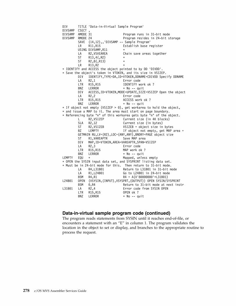
Data-in-virtual sample program code (continued)The program reads statements from SYSIN until it reaches end-of-file, orencounters a statement with an “E” in column 1. The program validates thelocation in the object to set or display, and branches to the appropriate routine toprocess the request.
DIV TITLE ’Data-in-Virtual Sample Program’DIVSAMP CSECT ,DIVSAMP AMODE 31 Program runs in 31-bit modeDIVSAMP RMODE 24 Program resides in 24-bit storage
SAVE (14,12),,’DIVSAMP -- Sample Program’LR R11,R15 Establish base registerUSING DIVSAMP,R11 *LA R2,VSVEAREA Chain save areas togetherST R13,4(,R2) *ST R2,8(,R13) *LR R13,R2 *
* IDENTIFY and ACCESS the object pointed to by DD ’DIVDD’.* Save the object’s token in VTOKEN, and its size in VSIZEP.
DIV IDENTIFY,TYPE=DA,ID=VTOKEN,DDNAME=CDIVDD Specify DDNAMELA R2,1 Error codeLTR R15,R15 IDENTIFY work ok ?BNZ LERROR * No -- quitDIV ACCESS,ID=VTOKEN,MODE=UPDATE,SIZE=VSIZEP Open the objectLA R2,2 Error codeLTR R15,R15 ACCESS work ok ?BNZ LERROR * No -- quit
* If object not empty (VSIZEP > 0), get workarea to hold the object,* and issue a MAP to it. The area must start on page boundary.* Referencing byte "n" of this workarea gets byte "n" of the object.
L R2,VSIZEP Current size (in 4K blocks)SLA R2,12 Current size (in bytes)ST R2,VSIZEB VSIZEB = object size in bytesBZ LEMPTY If object not empty, get MAP area =GETMAIN RU,LV=(R2),LOC=(ANY,ANY),BNDRY=PAGE object sizeST R1,VAREAPTR Save MAP areaDIV MAP,ID=VTOKEN,AREA=VAREAPTR,SPAN=VSIZEPLA R2,3 Error codeLTR R15,R15 MAP work ok ?BNZ LERROR * No -- quit
LEMPTY EQU * Mapped, unless empty* OPEN the SYSIN input data set, and SYSPRINT listing data set.* Must be in 24-bit mode for this. Then return to 31-bit mode.
LA R4,L31B01 Return to L31B01 in 31-bit modeLA R1,L24B01 Go to L24B01 in 24-bit modeBSM R4,R1 R4 = A(X’80000000’+L31B01)
L24B01 OPEN (VSYSIN,(INPUT),VSYSPRT,(OUTPUT)) OPEN SYSIN/SYSPRINTBSM 0,R4 Return to 31-bit mode at next instr
L31B01 LA R2,4 Error code from SYSIN OPENLTR R15,R15 OPEN ok ?BNZ LERROR * No -- quit
278 z/OS MVS Assembler Services Guide
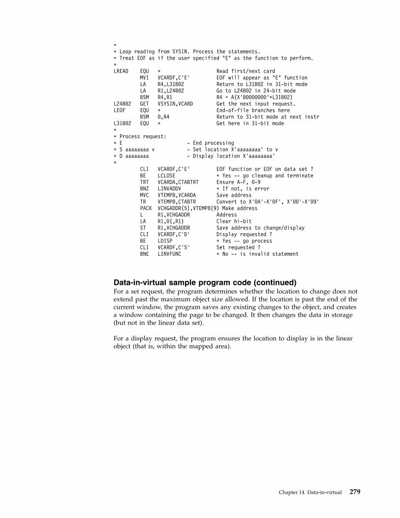
Data-in-virtual sample program code (continued)For a set request, the program determines whether the location to change does notextend past the maximum object size allowed. If the location is past the end of thecurrent window, the program saves any existing changes to the object, and createsa window containing the page to be changed. It then changes the data in storage(but not in the linear data set).
For a display request, the program ensures the location to display is in the linearobject (that is, within the mapped area).
** Loop reading from SYSIN. Process the statements.* Treat EOF as if the user specified "E" as the function to perform.*LREAD EQU * Read first/next card
MVI VCARDF,C’E’ EOF will appear as "E" functionLA R4,L31B02 Return to L31B02 in 31-bit modeLA R1,L24B02 Go to L24B02 in 24-bit modeBSM R4,R1 R4 = A(X’80000000’+L31B02)
L24B02 GET VSYSIN,VCARD Get the next input request.LEOF EQU * End-of-file branches here
BSM 0,R4 Return to 31-bit mode at next instrL31B02 EQU * Get here in 31-bit mode** Process request:* E - End processing* S aaaaaaaa v - Set location X’aaaaaaaa’ to v* D aaaaaaaa - Display location X’aaaaaaaa’*
CLI VCARDF,C’E’ EOF function or EOF on data set ?BE LCLOSE * Yes -- go cleanup and terminateTRT VCARDA,CTABTRT Ensure A-F, 0-9BNZ LINVADDV * If not, is errorMVC VTEMP8,VCARDA Save addressTR VTEMP8,CTABTR Convert to X’0A’-X’0F’, X’00’-X’09’PACK VCHGADDR(5),VTEMP8(9) Make addressL R1,VCHGADDR AddressLA R1,0(,R1) Clear hi-bitST R1,VCHGADDR Save address to change/displayCLI VCARDF,C’D’ Display requested ?BE LDISP * Yes -- go processCLI VCARDF,C’S’ Set requested ?BNE LINVFUNC * No -- is invalid statement
Chapter 14. Data-in-virtual 279

Data-in-virtual sample program code (continued)For both the set and display requests, the program displays the character at thespecified location. For an invalid request, the program displays an error message.For all requests, the program then goes to process another statement.
When requested to terminate, the program saves any changes in the linear data set,terminates its use of the object (using UNIDENTIFY), and returns to the operatingsystem.
* SET: See if the location to change is within the range of the current* MAP. If not, save any changes, get a larger area and issue a new MAP.
C R1,VSIZEB Area to change within current MAP?BL LGUPDCHR * Yes -- continueC R1,CSIZEMX Area to change within max allowed?BNL LINVADDR * No -- is errorCLI VSWUPDT,0 Any updates to current MAP ?BE LNOSVE1 * Yes -- thenDIV SAVE,ID=VTOKEN Save any changesLA R2,5 Error code from SAVELTR R15,R15 SAVE ok ?BNZ LERROR * No -- quitMVI VSWUPDT,0 Clear update flag
LNOSVE1 L R3,VSIZEB Eliminate old map and storageLTR R3,R3 Any to free ?BZ LNOFREE * Yes -- thenDIV UNMAP,ID=VTOKEN,AREA=VAREAPTR Release the MAPLA R2,6 Error code from UNMAPLTR R15,R15 UNMAP ok ?BNZ LERROR * No -- quitL R1,VAREAPTR R1 -> acquired storageFREEMAIN RU,A=(1),LV=(R3) Free the storage
LNOFREE L R2,VCHGADDR Address of byte to changeSRL R2,12 R2 = page number - 1LA R2,1(,R2) R2 = page number to useST R2,VSIZEP VSIZEP = MAP area in 4K unitsSLL R2,12 R2 = size in bytesST R2,VSIZEB VSIZEB = MAP area in bytesGETMAIN RU,LV=(R2),LOC=(ANY,ANY),BNDRY=PAGE get MAP areaST R1,VAREAPTR Save MAP areaDIV MAP,ID=VTOKEN,AREA=VAREAPTR,SPAN=VSIZEPLA R2,3 Error codeLTR R15,R15 MAP work ok ?BNZ LERROR * No -- quit
LGUPDCHR L R1,VCHGADDR R1 = byte to changeA R1,VAREAPTR R1 -> byte to changeMVC 0(1,R1),VCARDV Change the byteMVI VSWUPDT,X’FF’ Show change madeB LGOODINP Go print accept message
LDISP EQU * Display location contentsL R1,VCHGADDR R1 = location to displayC R1,VSIZEB Ensure within current MAPBNL LINVADDR * If not, is errorA R1,VAREAPTR R1 -> location to displayMVC VCARDV,0(R1) Put into the card
280 z/OS MVS Assembler Services Guide

Data-in-virtual sample program code (continued)These are the program's variables.
LGOODINP EQU *MVC M1A,VCARDA Address changed/displayedMVC M1B,VCARDV Storage valueCLI M1B,X’00’ If X’00’ (untouched),BNE LGOODIN1 * change to "?".MVI M1B,C’?’ *
LGOODIN1 LA R2,M1 R2 -> message to printB LTELL Go tell user status
LINVFUNC LA R2,M2 Unknown functionB LTELL Go tell user status
LINVADDV LA R2,M3 Invalid addressB LTELL Go tell user status
LINVADDR LA R2,M4 Address out of rangeLTELL EQU * R2 -> message to print
LA R4,L31B03 Return to L31B03 in 31-bit modeLA R1,L24B03 Go to L24B03 in 24-bit modeBSM R4,R1 R4 = A(X’80000000’+L31B03)
L24B03 PUT VSYSPRT,(R2) Print the messageBSM 0,R4 Return to 31-bit mode at next instr
L31B03 B LREAD Continue* End-of-file on SYSIN, or "E" function requested.* Save any changes (DIV SAVE). Then issue UNIDENTIFY, which internally* issues UNMAP and UNIDENTIFY.LCLOSE EQU *
CLI VSWUPDT,0 Any updates outstanding ?BE LCLOSE1 * No -- skip SAVEDIV SAVE,ID=VTOKEN Save any changesLA R2,5 Error code from SAVELTR R15,R15 SAVE ok ?BNZ LERROR * No -- quit
LCLOSE1 DIV UNIDENTIFY,ID=VTOKEN All done with objectLA R2,6 Error code from UNIDENTIFYLTR R15,R15 UNIDENTIFY ok ?BNZ LERROR * No -- quitL R13,4(,R13) Unchain save areas and returnLM R14,R12,12(R13) *SR R15,R15 *BR R14 *
LERROR ABEND (R2),DUMP Take a dump
Chapter 14. Data-in-virtual 281

Executing the programThe following JCL executes the program called DIVSAMPL. The function ofDIVSAMPL is to change and display bytes (characters) in the data-in-virtual object,DIV.SAMPLE, that was allocated in “Creating a linear data set” on page 259.
* Variables and constants for the programVSVEAREA DC 18A(0) Save areaVTOKEN DC XL8’00’ Object tokenVAREAPTR DC A(*-*) -> MAP areaVSIZEP DC F’0’ Size of MAP area, in pages (4K)VSIZEB DC F’0’ Size of MAP area, in bytesVSWUPDT DC X’00’ X’FF’ -> map area updatedVCHGADDR DC A(*-*),C’ ’ Address of byte to change/displayVTEMP8 DC CL8’ ’,C’ ’ Temp area with bufferVCARD DC CL80’ ’ Input cardVCARDF EQU VCARD+0,1 + Function (E/S/D)VCARDA EQU VCARD+2,8 + Address to change/displayVCARDV EQU VCARD+11,1 + Character to changeCDIVDD DC X’5’,C’DIVDD’ Linear Data Set DD pointer* CTABTRT to verify string only has A thru F and 0 thru 9 (hex chars)CTABTRT DC (C’A’)X’FF’,6X’00’,(C’0’-C’F’-1)X’FF’,10X’00’,6X’FF’* CTABTR & next line convert chars A:F,0:9 -> X’0A0B...0F000102...09’CTABTR EQU *-C’A’
DC X’0A0B0C0D0E0F’,(C’0’-C’F’)X’00’,X’010203040506070809’CSIZEMX DC A(4096*1000) Max size allowed for the DIV objectM1 DC Y(M1E-*,0),C’ Location ’M1A DC CL8’ ’,C’ contains: ’M1B DC C’ ’M1E EQU *M2 DC Y(M2E-*,0),C’ Unknown function (not E/S/D)’M2E EQU *M3 DC Y(M3E-*,0),C’ Address not 8 hex characters’M3E EQU *M4 DC Y(M4E-*,0),C’ Address too big to set or display’M4E EQU *VSYSIN DCB MACRF=GM,DSORG=PS,RECFM=FB,LRECL=80,DDNAME=SYSIN, *
EODAD=LEOFVSYSPRT DCB MACRF=PM,DSORG=PS,RECFM=VA,LRECL=133,DDNAME=SYSPRINTR0 EQU 0 RegistersR1 EQU 1R2 EQU 2R3 EQU 3R4 EQU 4R5 EQU 5R6 EQU 6R7 EQU 7R8 EQU 8R9 EQU 9R10 EQU 10R11 EQU 11R12 EQU 12R13 EQU 13R14 EQU 14R15 EQU 15
END ,
282 z/OS MVS Assembler Services Guide

DIVSAMPL reads statements from SYSIN that tell the program what to do. Theformat of each statement is f aaaaaaaa v, where:
f Function to perform:
S Set a character in the object.
D Display a character in the object.
E End the program.
aaaaaaaaThe hexadecimal address of the storage to set or display. Leading 0s arerequired. The value must be less than X'003E8000'.
v For Set, the character to put into the object.
Note: The program actually saves the change requested by the S function wheneither the user asks to change a byte past the current size of the object, or the userasks to terminate the program (E function).
//DIV JOB .....//DIV EXEC PGM=DIVSAMPL//STEPLIB DD DISP=SHR,DSN=DIV.LOAD//DIVDD DD DISP=OLD,DSN=DIV.SAMPLE//SYSABEND DD SYSOUT=*//SYSPRINT DD SYSOUT=*//SYSIN DD *S 00001000 A Changes byte X’1000’ to "A"D 00000F00 Displays "?" since byte X’F00’ contains X’00’S 00000F00 B Changes byte X’F00’ to "B"S 00010000 C Saves previous changes, gets new map,
changes byte X’10000’D 00001000 Displays "A" which was set by first statementD 00000F00 Displays "B" which was set by third statementE Saves changes since last save (stmt 4), and terminates pgm/*
Chapter 14. Data-in-virtual 283

284 z/OS MVS Assembler Services Guide

Chapter 15. Using access registers
For storing data, MVS offers a program the use of a virtual storage area called adata space. Assembler instructions (such as Load, Store, Add, and Move Character)manipulate the data in a data space. When you use instructions to manipulate datain a data space, your program must use the set of general purpose registers (GPRs)plus another set of registers called access registers. This chapter describes how touse access registers to manipulate data in data spaces.
Through access registers, your program can use assembler instructions to performbasic data manipulation, such as:v Moving data into and out of a data space, and within a data spacev Performing arithmetic operations with values that are located in data spaces
To fully understand how to use the macros and instructions that control dataspaces and access registers, you must first understand some concepts.
What is an access register (AR)? An AR is a hardware register that a program usesto identify an address space or a data space. Each processor has 16 ARs, numbered0 through 15, and they are paired one-to-one with the 16 GPRs. When yourprogram uses ARs, it must be in the address space control mode called accessregister (AR) mode.
ARs are used when fetching and storing data, but they are not used when doingbranches.
What is address space control (ASC) mode? The ASC mode controls where thesystem looks for the data that the program is manipulating. Two ASC modes areavailable for your use: primary mode and access register (AR) mode.v In primary mode, your program can access data that resides in the program's
primary address space. When it resolves the addresses in data-referencinginstructions, the system does not use the contents of the ARs.
v In AR mode, your program can access data that resides in the address space ordata space that the ARs indicate. For data-referencing instructions, the systemuses the AR and the GPR together to locate an address in an address space ordata space.
How does your program switch ASC mode? Use the SAC instruction to changeASC modes:v SAC 512 sets the ASC mode to AR mode.v SAC 0 sets the ASC mode to primary mode.
AccessRegisters
GeneralPurposeRegisters
Identify locations within an address or data space0 1
0 1
14 15
14 15Identify address spaces or data spaces
© Copyright IBM Corp. 1988, 2017 285

What does an AR contain? An AR contains a token, an access list entry token(ALET). An ALET is an index to an entry on the access list. An access list is a tableof entries, each one of which points to an address space, data space, or hiperspaceto which a program has access.
Figure 65 shows an ALET in the AR and the access list entry that points to anaddress space or a data space. It also shows the address in the GPR that points tothe data within the address/data space.
For programs in AR mode, when the GPR is used as a base register in aninstruction, the corresponding AR must contain an ALET. Conversely, when theGPR is not used as a base register, the corresponding AR is ignored.
By placing an entry on an access list and obtaining an ALET for the entry, aprogram builds the connection between the program and an address space, dataspace, or hiperspace. The process of building this connection is called establishingaddressability to an address space, data space, or hiperspace. To add the entry tothe access list, your program uses the ALESERV macro, which is described in “TheALESERV macro” on page 291.
A program adds an entry to an access list so that it can:v Gain access to a data space or an address space through assembler instructions.v Obtain the ALET for a hiperspace. With that ALET, the program can use the
HSPALET parameter on HSPSERV to:– Gain additional performance from the transfer of data to and from expanded
storage. Information on when and how you use an access list entry forhiperspaces is described in “Obtaining additional HSPSERV performance” onpage 323.
– Improve its ability to share hiperspaces with other programs. The subject ofsharing hiperspaces is described in “Shared and non-shared standardhiperspaces” on page 320.
For the rest of this information, assume that entries in access lists point to dataspaces, not hiperspaces or address spaces.v The subject of inter-address space communication, appropriate only for
programs in supervisor state or with PSW key 0 - 7, is described in z/OS MVSProgramming: Extended Addressability Guide.
@
Address/Data Space
Access List
Data
ALET
GPR
AR
Figure 65. Using an ALET to Identify an Address Space or a Data Space
286 z/OS MVS Assembler Services Guide
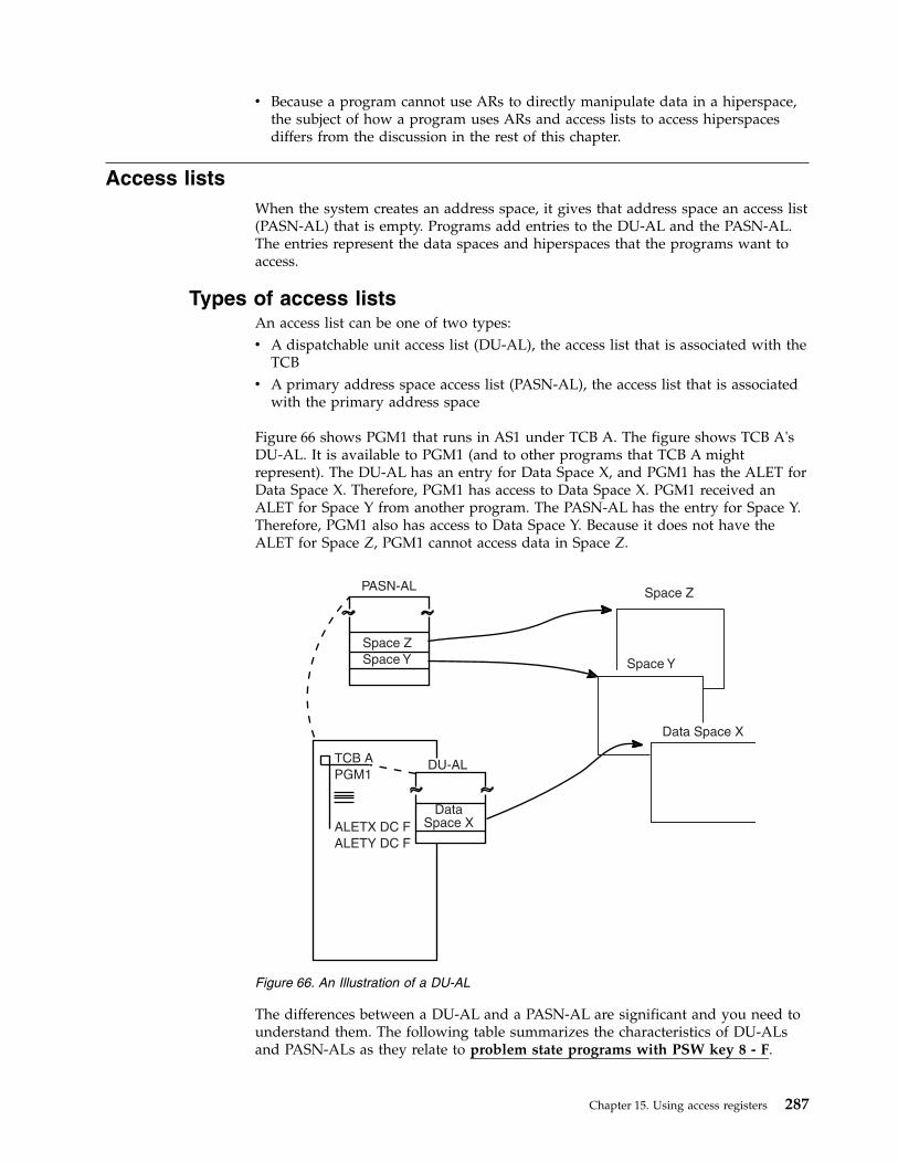
v Because a program cannot use ARs to directly manipulate data in a hiperspace,the subject of how a program uses ARs and access lists to access hiperspacesdiffers from the discussion in the rest of this chapter.
Access listsWhen the system creates an address space, it gives that address space an access list(PASN-AL) that is empty. Programs add entries to the DU-AL and the PASN-AL.The entries represent the data spaces and hiperspaces that the programs want toaccess.
Types of access listsAn access list can be one of two types:v A dispatchable unit access list (DU-AL), the access list that is associated with the
TCBv A primary address space access list (PASN-AL), the access list that is associated
with the primary address space
Figure 66 shows PGM1 that runs in AS1 under TCB A. The figure shows TCB A'sDU-AL. It is available to PGM1 (and to other programs that TCB A mightrepresent). The DU-AL has an entry for Data Space X, and PGM1 has the ALET forData Space X. Therefore, PGM1 has access to Data Space X. PGM1 received anALET for Space Y from another program. The PASN-AL has the entry for Space Y.Therefore, PGM1 also has access to Data Space Y. Because it does not have theALET for Space Z, PGM1 cannot access data in Space Z.
The differences between a DU-AL and a PASN-AL are significant and you need tounderstand them. The following table summarizes the characteristics of DU-ALsand PASN-ALs as they relate to problem state programs with PSW key 8 - F.
Space Z
Space Y
ALETX DC F
ALETY DC F
Space Z
Space Y
DU-AL
DataSpace X
TCB A
PGM1
PASN-AL
Data Space X
Figure 66. An Illustration of a DU-AL
Chapter 15. Using access registers 287
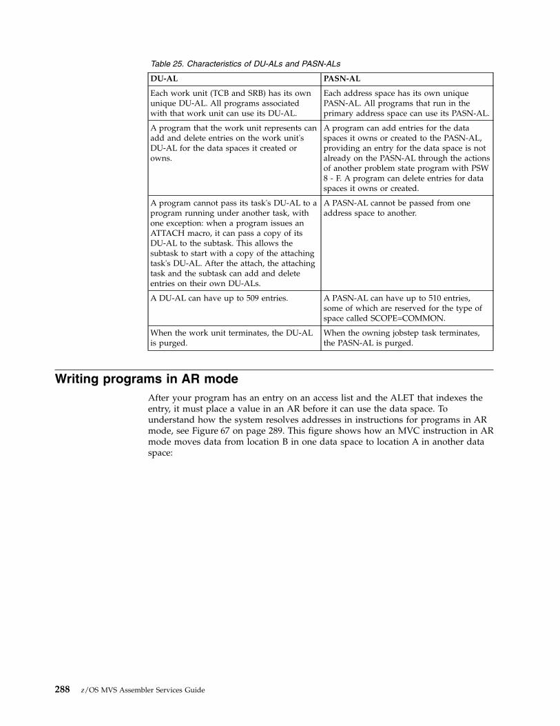
Table 25. Characteristics of DU-ALs and PASN-ALs
DU-AL PASN-AL
Each work unit (TCB and SRB) has its ownunique DU-AL. All programs associatedwith that work unit can use its DU-AL.
Each address space has its own uniquePASN-AL. All programs that run in theprimary address space can use its PASN-AL.
A program that the work unit represents canadd and delete entries on the work unit'sDU-AL for the data spaces it created orowns.
A program can add entries for the dataspaces it owns or created to the PASN-AL,providing an entry for the data space is notalready on the PASN-AL through the actionsof another problem state program with PSW8 - F. A program can delete entries for dataspaces it owns or created.
A program cannot pass its task's DU-AL to aprogram running under another task, withone exception: when a program issues anATTACH macro, it can pass a copy of itsDU-AL to the subtask. This allows thesubtask to start with a copy of the attachingtask's DU-AL. After the attach, the attachingtask and the subtask can add and deleteentries on their own DU-ALs.
A PASN-AL cannot be passed from oneaddress space to another.
A DU-AL can have up to 509 entries. A PASN-AL can have up to 510 entries,some of which are reserved for the type ofspace called SCOPE=COMMON.
When the work unit terminates, the DU-ALis purged.
When the owning jobstep task terminates,the PASN-AL is purged.
Writing programs in AR modeAfter your program has an entry on an access list and the ALET that indexes theentry, it must place a value in an AR before it can use the data space. Tounderstand how the system resolves addresses in instructions for programs in ARmode, see Figure 67 on page 289. This figure shows how an MVC instruction in ARmode moves data from location B in one data space to location A in another dataspace:
288 z/OS MVS Assembler Services Guide

GPR 1 is used as a base register to locate the destination of the data, and AR 1 isused to identify space X. GPR 2 is used to locate the source of the data, and AR 2identifies Space Y. In AR mode, a program can use a single MVC instruction tomove data from one address/data space to another.
Note: The address space that contains the MVC instruction does not have to beeither Space X or Space Y.
In similar ways, you can use instructions that compare, test-under-mask, copy,move, and perform arithmetic operations.
When the instructions reference data in the primary address space, the ALET in theAR must indicate that the data is in that address space. For this purpose, thesystem provides a special ALET with a value of zero. Other than using this valueto identify the primary address space, a program should never depend on thevalue of an ALET.
The “Loading the value of zero into an AR” on page 291 shows several examplesof loading a value of zero in an AR.
Coding instructions in AR modeAs you write your AR mode programs, use the advice and warnings in thisinformation.v For an instruction that references data, the system uses the contents of an AR to
identify the address/data space that contains the data that the associated GPRpoints to.
v Use ARs only for data reference; do not use them with branching instructions.
Space Y
Space X
Address Space
Space Y
B
A
Space X
Access List
AR
GPR
. . .
. . .
MVC A(LEN,1),B(2)
GPR 1 is used as a base register tolocate the destination of the MVC andAR 1 is used to identify Space X.
GPR 2 is used to locate the data tobe moved and AR 2 identifies Space Ythat contains the data.
ALET ALETX Y
Figure 67. Using Instructions in AR Mode
An ALET of zero designates the primary address space.
Chapter 15. Using access registers 289

v Just as you do not use GPR 0 as a base register, do not use AR/GPR 0 foraddressing.
v An AR should contain only ALETs; do not store any other kinds of data in anAR.
Because ARs that are associated with index registers are ignored, when you codeassembler instructions in AR mode, place the commas very carefully. In thoseinstructions that use both a base register and an index register, the comma thatseparates the two values is very important. Table 26 shows four examples of how amisplaced comma can change how the processor resolves addresses on the loadinstruction.
Table 26. Base and Index Register Addressing in AR Mode
Instruction Address Resolution
L 5,4(,3) or L 5,4(0,3) There is no index register. GPR 3 is the base register. AR 3indicates the address/data space.
L 5,4(3) or L 5,4(3,0) GPR 3 is the index register. Because there is no base register, datais fetched from the primary address space.
L 5,4(6,8) GPR 6 is the index register. GPR 8 is the base register. AR 8indicates the address/data space.
L 5,4(8,6) GPR 8 is the index register. GPR 6 is the base register. AR 6indicates the address/data space.
For the first two entries in Table 26:v In primary mode, the examples of the load instruction give the same result.v In AR mode, the data is fetched using different ARs. In the first entry, data is
fetched from the address/data space represented by the ALET in AR 3. In thesecond entry, data is fetched from the primary address space (because AR/GPR0 is not used as a base register).
For the last two entries in Table 26:v In primary mode, the examples of the load instruction give the same result.v In AR mode, the first results in a fetch from the address/data space represented
by AR 8, while the second results in a fetch from the address/data spacerepresented by AR 6.
Manipulating the contents of ARsWhether the ASC mode of a program is primary or AR, it can use assemblerinstructions to save, restore, and modify the contents of the 16 ARs. The set ofinstructions that manipulate ARs include:v CPYA — Copy the contents of an AR into another AR.v EAR — Copy the contents of an AR into a GPR.v LAE — Load a specified ALET and address into an AR/GPR pair.v SAR — Place the contents of a GPR into an AR.v LAM — Load the contents of one or more ARs from a specified storage location.v STAM — Store the contents of one or more ARs to a specified storage location.
For their syntax and help with how to use these instruction, see Principles ofOperation.
290 z/OS MVS Assembler Services Guide

Loading an ALET into an ARAn action that is very important when a program is in AR mode, is the loading ofan ALET into an AR. The following example shows how the LAM instructionloads an ALET into AR 2:
LAM 2,2,DSALET LOAD ALET OF DATA SPACE INTO AR2*DSALET DS F DATA SPACE ALET
Loading the value of zero into an ARWhen the code you are writing is in AR mode, you must be very conscious of thecontents of the ARs. For instructions that reference data, the ARs must alwayscontain the ALET that identifies the data space that contains the data. When thedata is in the primary address space, the AR that accompanies the GPR that hasthe address of the data must contain the value zero.
The following examples show several ways of placing the value zero in an AR.
Example 1: Set AR 5 to value of zero, when GPR 5 can be changed.SLR 5,5 SET GPR 5 TO ZEROSAR 5,5 LOAD GPR 5 INTO AR 5
Example 2: Set AR 5 to value of zero, without changing value in GPR 5.LAM 5,5,=F’0’ LOAD AR 5 WITH A VALUE OF ZERO
Another way of doing this is the following:LAM 5,5,ZERO
ZERO DC F’0’
Example 3: Set AR 5 to value of zero, when AR 12 is already zero.CPYA 5,12 COPY AR 12 INTO AR 5
Example 4: Set AR 12 to zero and set GPR 12 to the address contained in GPR 15.This sequence is useful to establish a program's base register GPR and AR from anentry point address contained in register 15.
PGMA CSECT ENTRY POINT..LAE 12,0(15,0) ESTABLISH PROGRAM’S BASE REGISTERUSING PGMA,12
Another way to establish AR/GPR module addressability through register 12 is asfollows:
LAE 12,0BASR 12,0USING *,12
Example 5: Set AR 5 and GPR 5 to zero.LAE 5,0(0,0) Set GPR and AR 5 to zero
The ALESERV macroUse the ALESERV macro to add an entry to an access list and delete that entry.The information describes the parameters on the ALESERV macro and givesexamples of its use.
Chapter 15. Using access registers 291

Adding an entry to an access listThe ALESERV ADD macro adds an entry to the access list. Two parameters arerequired: STOKEN, an input parameter, and ALET, an output parameter.v STOKEN - the eight-byte STOKEN of the address/data space represented by the
entry. You might have received the STOKEN from DSPSERV or from anotherprogram.
v ALET - index to the entry that ALESERV added to the access list. The systemreturns this value at the address you specify on the ALET parameter.
The best way to describe how you add an entry to an access list is through anexample. The following code adds an entry to a DU-AL. Assume that theDSPSERV macro has created the data space and has returned the STOKEN of thedata space in DSPCSTKN and the origin of the data space in DSPCORG. ALESERVADD returns the ALET in DSPCALET. The program then establishes addressabilityto the data space by loading the ALET into AR 2 and the origin of the data spaceinto GPR 2.* ESTABLISH ADDRESSABILITY TO THE DATA SPACE
.ALESERV ADD,STOKEN=DSPCSTKN,ALET=DSPCALET.LAM 2,2,DSPCALET LOAD ALET OF SPACE INTO AR2L 2,DSPCORG LOAD ORIGIN OF SPACE INTO GR2USING DSPCMAP,2 INFORM ASSEMBLER.L 5,DSPWRD1 GET FIRST WORD FROM DATA SPACE
USES AR/GPR 2 TO MAKE THE REFERENCE.
DSPCSTKN DS CL8 DATA SPACE STOKENDSPCALET DS F DATA SPACE ALETDSPCORG DS F DATA SPACE ORIGIN RETURNEDDSPCMAP DSECT DATA SPACE STORAGE MAPPINGDSPWRD1 DS F WORD 1DSPWRD2 DS F WORD 2DSPWRD3 DS F WORD 3
Using the DSECT that the program established, the program can easily manipulatedata in the data space.
It is possible to use ALESERV ADD to obtain an entry for a hiperspace. Forinformation on how hiperspaces use ALETs, see “Obtaining additional HSPSERVperformance” on page 323.
Deleting an entry from an access listUse ALESERV DELETE to delete an entry on an access list. The ALET parameteridentifies the specific entry. It is a good programming practice to delete entriesfrom an access list when the entries are no longer needed.
The following example deletes the entry that was added in the previous example.ALESERV DELETE,ALET=DSPCALET REMOVE DS FROM ALDSPSERV DELETE,STOKEN=DSPCSTKN DELETE THE DS.
DSPCSTKN DS CL8 DATA SPACE STOKENDSPCALET DS F DATA SPACE ALET
If the program does not delete an entry,v An entry on the DU-AL remains on the access list until the work unit
terminates. At that time, the system frees the access list entry.
292 z/OS MVS Assembler Services Guide

v An entry on the PASN-AL remains on the access list until the owning jobsteptask terminates. At that time, the system frees the access list entry.
Issuing MVS macros in AR modeMany MVS macro services support callers in both primary and AR modes. Whenthe caller is in AR mode, the macro service must generate larger parameter lists atassembly time. The increased size of the list reflects the addition of ALET-qualifiedaddresses. At assembly time, a macro service that needs to know whether a calleris in AR mode checks the global indicator that SYSSTATE ASCENV=AR sets. Thesystem expects that you have issued SYSSTATE ASCENV=AR when a macro isissued while in AR mode. Then, when the program returns to primary mode, issueSYSSTATE ASCENV=P to reset the global indicator.
When your program is in AR mode, keep in mind these two facts:v Before you use a macro in AR mode, check the description of the macro in z/OS
MVS Programming: Assembler Services Reference ABE-HSP or z/OS MVSProgramming: Assembler Services Reference IAR-XCT. If the description of themacro does not specifically state that the macro supports callers in AR mode,use the SAC instruction to change the ASC mode and use the macro in primarymode.
v ARs 14 - 1 are volatile across all macro calls, whether the caller is in AR mode orprimary mode. Don't count on the contents of these ARs being the same afterthe call as they were before.
Example of using SYSSTATEConsider a program that changes ASC mode from primary to AR mode and whilein AR mode, issues the LINKX and STORAGE macros. When it changes ASCmode, it issues the following:SAC 512SYSSTATE ASCENV=AR
The LINKX macro generates different code and addresses, depending on the ASCmode of the caller. During the assembly of LINKX, the LINKX macro servicechecks the setting of the global indicator. Because the global indicator indicates thatthe caller is in AR mode, LINKX generates code and addresses that are appropriatefor callers in AR mode.
The STORAGE macro generates different code, depending on the ASC mode of thecaller. During the assembly of STORAGE, the STORAGE macro service checks thesetting of the global indicator. Because the global indicator indicates that the calleris in AR mode, STORAGE generates code that is appropriate for callers in ARmode.
When the program changes back to primary mode, it issues the following:SAC 0SYSSTATE ASCENV=P
Using X-macrosSome macro services, such as LINK and LINKX, offer two macros, one for callersin primary mode and one for callers in either primary or AR mode. The names ofthe two macros are the same, except the macro that supports both primary and ARmode caller ends with an “X”. This information refers to these macros as“X-macros”. The rules for using all X-macros, except ESTAEX, are:
Chapter 15. Using access registers 293
v Callers in primary mode can invoke either macro.Some parameters on the X-macros, however, are not valid for callers in primarymode. Some parameters on the non X-macros are not valid for callers in ARmode. Check the macro descriptions in z/OS MVS Programming: AssemblerServices Reference ABE-HSP or z/OS MVS Programming: Assembler ServicesReference IAR-XCT for these exceptions.
v Callers in AR mode should issue the X-macro after issuing the SYSSTATEASCENV=AR macro.If a caller in AR mode issues the non X-macro, the system substitutes theX-macro and issues a message during assembly that informs you of thesubstitution.
IBM recommends you always use ESTAEX unless your program and yourrecovery routine are in 24-bit addressing mode, in which case, you should useESTAE.
If your program issues macros while it is in AR mode, make sure the macrossupport AR mode callers and that SYSSTATE ASCENV=AR is coded.
If you rewrite programs and use the X-macro instead of the non X-macro, youmust change both the list and execute forms of the macro. If you change only theexecute form of the macro, the system will not generate the longer parameter listthat the X-macro requires.
Note that an X-macro generates a larger parameter list than the corresponding nonX-macro. A program using the X-macros must provide a larger parameter list thanif it used the non X-macro.
Formatting and displaying AR informationThe interactive problem control system (IPCS) can format and display AR data.Use the ARCHECK subcommand to:v Display the contents of an ARv Display the contents of an access list entry
See z/OS MVS IPCS Commands for more information about the ARCHECKsubcommand.
294 z/OS MVS Assembler Services Guide

Chapter 16. Data spaces and hiperspaces
For storing data, MVS offers a program a choice of two kinds of virtual storageareas for data only: data spaces and hiperspaces. In making the decision whetherto use a hiperspace or data space, you might have the following questions:v Does my program need virtual storage outside the address space?v Which kind of virtual storage is appropriate for my program?
The first part of the chapter helps you make these decisions. Then, if you decidethat one of these virtual storage areas would benefit your program, use thefollowing information to create, use, and delete the area:v “Creating and using data spaces” on page 300v “Creating and using hiperspaces” on page 318
What are data spaces and hiperspaces?Data spaces and hiperspaces are similar in that both are areas of virtual storagethat the program can ask the system to create. The size of this space can rangefrom four kilobytes to two gigabytes, according to the user's request. Unlike anaddress space, a data space or hiperspace contains only user data or user programsstored as data. Program code cannot run in a data space or a hiperspace.
The following diagram shows, at an overview level, the difference between anaddress space and a data space or hiperspace.
The major difference between a data space and a hiperspace is the way yourprogram accesses data in the two areas. This difference is described later in thischapter. But before you can understand the differences, you need to understandwhat your program can do with these virtual storage areas.
Address Space
4 kilobytesto
2 gigabytes
User programsand data
System programsand data
User programsand data
User data2 gigabytes
Data Spaceor
Hiperspace
© Copyright IBM Corp. 1988, 2017 295

What can a program do with a data space or a hiperspace?Programs can use data spaces and hiperspaces to:v Obtain more virtual storage than a single address space gives a user.v Isolate data from other tasks in the address space.
Data in an address space is accessible to all programs executing in that addressspace. You might want to move some data to a data space or hiperspace forsecurity or integrity reasons. Use this space as a way to separate your datalogically by its own particular use.
v Provide an area in which to map a data-in-virtual object.
You can place all types of data in a data space or hiperspace, rather than in anaddress space or on DASD. Examples of such data include:v Tables, arrays, or matrixesv Data base buffersv Temporary work filesv Copies of permanent data sets
Because data spaces and hiperspaces do not include system areas, the cost ofcreating and deleting them is less than that of an address space.
To help you decide whether you need this additional storage area, some importantquestions are answered in the following topics.
How does a program obtain a data space and a hiperspace?Data spaces and hiperspaces are created through the same system service: theDSPSERV macro. On this macro, you request either a data space (TYPE=BASIC) ora hiperspace (TYPE=HIPERSPACE). You also specify some characteristics of thespace, such as its size and its name.
The DSPSERV macro service gives you contiguous 31-bit addressable virtualstorage of the size you specify and initializes the storage to binary zeros.
z/OS MVS Programming: Assembler Services Reference ABE-HSP contains the syntaxand parameter descriptions for the macros that are mentioned in this chapter.
How does a program move data into a data space orhiperspace?
One way to move data into a data space or a hiperspace is through buffers in theprogram's address space. Another way avoids using address space virtual storageas an intermediate buffer area: through data-in-virtual services, a program canmove data into a data space or hiperspace directly. This second way reduces theamount of I/O.
Who owns a data space or hiperspace?Although programs create data spaces and hiperspaces, they do not own them.When a program creates the space, the system assigns ownership to the TCB thatrepresents the program, or to the TCB of the job step task of the program, if youchoose. You can assign ownership of the data space to the job step TCB byspecifying the TTOKEN option on the DSPSERV CREATE macro. All storagewithin a data space or hiperspace is available to programs that run under that TCBand, in some cases, the storage is available to other users. When the TCB
296 z/OS MVS Assembler Services Guide

terminates, the system deletes any data spaces or hiperspaces the TCB owns. If youwant the data space to exist after the creating TCB terminates, assign the space tothe job step TCB. The job step will continue to be active beyond the termination ofthe creating TCB.
Because data spaces and hiperspaces belong to TCBs, keep in mind the relationshipbetween the program and the TCB under which it runs. For simplicity, however,this chapter describes hiperspaces and data spaces as if they belong to programs.For example, “a program's data space” means “the data space that belongs to theTCB under which a program is running”.
Can an installation limit the use of data spaces andhiperspaces?
The use of data spaces and hiperspaces consumes system resources such asexpanded and auxiliary storage. Programmers responsible for tuning andmaintaining MVS can set limits on the amount of virtual storage that programs ineach address space can use for data spaces and hiperspaces. They can limit:v The size of a single hiperspace or data space. (The default is 956K bytes, or 239
blocks.)v The amount of storage available per address space for all hiperspaces and data
spaces with a storage key of 8 - F. (The default is 2²⁴ - 1 megabytes, or 16777215megabytes.)
v The combined number of hiperspaces and data spaces with storage key 8 - Fthat can exist per address space at one time. (The default is (2**32)-1 data spacesand hiperspaces.)
You should know the limits your installation establishes and the return codes thatyou can check to learn why the DSPSERV macro might not create the data space orhiperspace you requested.
How does a program manage the storage in a data space orhiperspace?
Managing storage in data spaces or hiperspaces differs from managing storage inaddress spaces. Keep the following advisory notes in mind when you handle yourdata space storage:v When you create a data space or hiperspace, use the DSPSERV macro to request
a large enough size to handle your application.The amount of storage you specify when you create a data space or a hiperspaceis the maximum amount the system will allow you to use in that space.
v You are responsible for keeping track of the allocating and freeing of data spaceand hiperspace storage. You cannot use the services of virtual storagemanagement (VSM), such as the STORAGE, GETMAIN, or FREEMAIN macros,to manage this area. You can, however, use callable cell pool services to define acell pool within a data space. You can then obtain the cells, as well as expandand contract the cell pool. “Using callable cell pool services to manage dataspace areas” on page 310 describes the use of callable cell pool services for dataspaces. Information on how to code the services is in Chapter 13, “Callable cellpool services,” on page 245.
v If you are not going to use an area of a data space or hiperspace again, releasethat area.
v When you are finished using a data space or hiperspace, delete it.
Chapter 16. Data spaces and hiperspaces 297

Differences between data spaces and hiperspacesUp to this point, the chapter has focused on similarities between data spaces andhiperspaces. By now, you should know whether your program needs the kind ofvirtual storage that a data space or hiperspace offers. Only by understanding thedifferences between the two types of spaces, can you decide which one mostappropriately meets your program's needs, or whether the program can use themboth.
The main difference between data spaces and hiperspaces is the way a programreferences data. A program references data in a data space directly, in much thesame way it references data in an address space. It addresses the data by the byte,manipulating, comparing, and performing arithmetic operations. The program usesthe same instructions (such as load, compare, add, and move character) that itwould use to access data in its own address space. To reference the data in a dataspace, the program must be in the ASC mode called access register (AR) mode.Pointers that associate the data space with the program must be in place and thecontents of ARs that the instructions use must identify the specific data space.
Figure 68 shows a program in AR ASC mode using the data space. The CLCinstruction compares data at two locations in the data space; the MVC instructionmoves the data at location D in the data space to location C in the address space.
In contrast, a program does not directly access data in a hiperspace. MVS providesa system service, the HSPSERV macro, to transfer the data between an addressspace and a hiperspace in 4K byte blocks. The HSPSERV macro read operationtransfers the blocks of data from a hiperspace into an address space buffer wherethe program can manipulate the data. The HSPSERV write operation transfers thedata from the address space buffer area to a hiperspace for storage. You can thinkof hiperspace storage as a high-speed buffer area where your program can store 4Kbyte blocks of data.
Figure 69 on page 299 shows a program in an address space using the data in ahiperspace. The program uses the HSPSERV macro to transfer an area in thehiperspace to the address space, compares the values at locations A and B, anduses the MVC instruction to move data at location D to location C. After it finishes
C
Address Space Data Space
AB
D
Program
CLC A,BMVC C,D
CLC and MVC access datawhile data is in data space.
Figure 68. Accessing Data in a Data Space
298 z/OS MVS Assembler Services Guide

using the data in those blocks, the program transfers the area back to thehiperspace. The program could be in either primary or AR ASC mode.
On one HSPSERV macro, the program can transfer the data in more than one areabetween the hiperspace and the address space.
Comparing data space and hiperspace use of physical storageTo compare the performance of manipulating data in data spaces with themanipulating of data in hiperspaces, you should understand how the system“backs” these two virtual storage areas. (That is, what kind of physical storage thesystem uses to maintain the data in virtual storage.) The system uses the sameresources to back data space virtual storage as it uses to back address space virtualstorage: a combination of central and expanded storage (if available) frames, andauxiliary storage slots. The system can release low-use pages of data space storageto auxiliary storage and bring them in again when your program references thosepages. The paging activity for a data space includes I/O between auxiliary storagepaging devices and central storage.
The system backs hiperspace virtual storage with expanded storage (if available),and auxiliary storage when expanded storage is not available. When you create ahiperspace, the system knows that the space will not be the target of assemblerinstructions and therefore will not need the backing of real frames. Therefore, datamovement through HSPSERV does not include I/O activity between DASD andthe storage that backs the hiperspace pages. For this reason, hiperspaces are veryefficient.
Which one should your program use?If your program needs to manipulate or access data often by the byte, data spacesmight be the answer. Use a data space if the program frequently addresses data ata byte level, such as you would in a workfile.
If your program can easily handle the data in 4K byte blocks, a hiperspace mightgive you the best performance. Use a hiperspace if the program needs a place tostore data, but not to manipulate data. A hiperspace has other advantages:
C
Address Space Hiperspace
HSPSERVre
adopera
tion
HSPSERVwrit
eopera
tion
A
D
B
HSPSERV...
Program
CLC A,BMVC C,D
HSPSERV...
CLC and MVC access dataonly after data has beentransferred from hiperspaceto address space.
Figure 69. Accessing Data in a Hiperspace
Chapter 16. Data spaces and hiperspaces 299

v The program can stay in primary mode and ignore the access registers.v The program can benefit from the high-speed access.v The system can use the unused processor storage for other needs.
An example of using a data spaceSuppose an existing program updates several rate tables that reside on DASD.Updates are random throughout the tables. The tables are too large and too manyfor your program to keep in contiguous storage in its address space. When theprogram updates a table, it reads that part of the table into a buffer area in theaddress space, updates the table, and writes the changes back to DASD. Each timeit makes an update, it issues instructions that cause I/O operations.
If the tables were to reside in data spaces, one table to each data space, the tableswould then be accessible to the program through assembler instructions. Theprogram could move the tables to the data spaces (through buffers in the addressspace) once at the beginning of the update operations and then move them back(through buffers in the address space) at the end of the update operations.
If the tables are VSAM linear data sets, data-in-virtual can map the tables andmove the data into the data space where a program can access the data.Data-in-virtual can then move the data from the data space to DASD. Withdata-in-virtual, the program does not have to move the data into the data spacethrough address space buffers, nor does it have to move the data to DASD throughaddress space buffers.
An example of using a hiperspaceSuppose an existing program uses a data base that resides on DASD. The data basecontains many records, each one containing personnel information about oneemployee. Access to the data base is random and programs reference but do notupdate the records. Each time the program wants to reference a record, it reads therecord in from DASD.
If the data base were to exist in a hiperspace, the program would still bring onerecord into its address space at a time. Instead of reading from DASD, however,the program would bring in the records from the hiperspace on expanded storage(or auxiliary storage, when expanded storage is not available.) In effect, thistechnique can eliminate many I/O operations and reduce execution time.
Creating and using data spacesA data space is an area of virtual storage that a program can ask the system tocreate. Its size can range from 4K bytes to 2 gigabytes, according to the program'srequest. Unlike an address space, a data space contains only user data. Programcode cannot run in a data space.
The DSPSERV macro manages data spaces. The TYPE=BASIC parameter (thedefault) tells the system that it is to manage a data space rather than a hiperspace.Use DSPSERV to:v Create a data spacev Release an area in a data spacev Delete a data spacev Expand the amount of storage in a data space currently available to a programv Load an area of a data space into central storage
300 z/OS MVS Assembler Services Guide

v Page an area of a data space out of central storage
Before it describes how your program can perform these actions, this chapterdescribes how your program will reference data in the data space it creates.
Manipulating data in a data spaceAssembler instructions (such as load, store, add, and move character) manipulatethe data in a data space. When you use instructions to manipulate data in a dataspace, your program must use the set of general purpose registers (GPRs) plusanother set of registers called access registers. Chapter 15, “Using access registers,”on page 285 describes how to use access registers to manipulate data in dataspaces.
Rules for creating, deleting, and managing data spacesThe SCOPE parameter determines what kind of data space a program creates. Thethree kinds of data spaces are SCOPE=SINGLE, SCOPE=ALL, andSCOPE=COMMON:v SCOPE=SINGLE data spaces
All programs can create, use, and delete SCOPE=SINGLE data spaces. Yourprogram would use data spaces in much the same way as it uses private storagein an address space.
v SCOPE=ALL and SCOPE=COMMON data spacesSupervisor state or PSW key 0 - 7 programs can create, use, and delete dataspaces that they can share with other programs. These data spaces have usessimilar to MVS common storage.
To protect data in data spaces, the system places certain restrictions on problemstate programs with PSW key 8 - F. The problem state programs with PSW key 8 -F can use SCOPE=ALL and SCOPE=COMMON data spaces, but they cannot createor delete them. They use them only under the control of supervisor state or PSWkey 0 - 7 programs. This chapter assumes that the data spaces your programcreates, uses, and deletes are SCOPE=SINGLE data spaces.
The following figure summarizes the rules for problem state programs with PSWkey 8 - F:
Table 27. Rules for How Problem State Programs with Key 8-F Can Use Data Spaces
Function Rules
CREATE Can create SCOPE=SINGLE data spaces.
DELETE Can delete the data spaces it creates or owns, provided the PSWkey of the program matches the storage key of the data space.
RELEASE Can release storage in the data spaces it creates or owns, providedthe PSW key of the program matches the storage key of the dataspace.
EXTEND Can extend the current size of the data spaces it owns.
Add entries to theDU-AL
Can add entries to its DU-AL for the data spaces it created orowns.
Chapter 16. Data spaces and hiperspaces 301

Table 27. Rules for How Problem State Programs with Key 8-F Can Use DataSpaces (continued)
Function Rules
Add entries to thePASN-AL
Can add entries to the PASN-AL for the data spaces it created orowns, providing an entry is not already on the PASN-AL as aresult of an ALESERV ADD by a problem state program with PSWkey 8 - F. If the ALET is already on the PASN-AL, the system doesnot create a duplicate entry, but the program can still access thedata space using the ALET that already exists.
Access a data spacethrough a DU-AL orPASN-AL
Can access a data space through its DU-AL and PASN-AL. Theentry for a SCOPE=ALL or SCOPE=COMMON data space accessedthrough the PASN-AL must have been added to the PASN-AL by aprogram in supervisor state or PSW key 0 - 7. This program wouldhave passed an ALET to the problem state PSW key 8 - F program.
LOAD Can page areas into central storage from a data space created byany other task in that address space.
OUT Can page areas out of central storage to a data space created byany other task in that address space.
There are other things that programs can do with data spaces. To do them,however, your program must be supervisor state or have a PSW key 0 - 7. Forinformation on how these programs can use data spaces, see z/OS MVSProgramming: Extended Addressability Guide.
Creating a data spaceTo create a data space, issue the DSPSERV CREATE macro. MVS gives youcontiguous 31-bit virtual storage of the size you specify and initializes the storageto hexadecimal zeros.
On the DSPSERV macro, you are required to specify:v The name of the data space (NAME parameter).
To ask DSPSERV to generate a data space name unique to the address space, usethe GENNAME parameter. DSPSERV will return the name it generates at thelocation you specify on the OUTNAME parameter. See “Choosing the name of adata space” on page 303.
v A location where DSPSERV can return the STOKEN of the data space (STOKENparameter).DSPSERV CREATE returns a STOKEN that you can use to identify the dataspace to other DSPSERV services and to the ALESERV and DIV macros.
Other information you might specify on the DSPSERV macro is:v The maximum size of the data space and its initial size (BLOCKS parameter). If
you do not code BLOCKS, the data space size is determined by defaults set byyour installation. In this case, use the NUMBLKS parameter to tell the systemwhere to return the size of the data space. See “Specifying the size of a dataspace” on page 303.
v A location where DSPSERV can return the address (either 0 or 4096) of the firstavailable block of the data space (ORIGIN parameter). See “Identifying theorigin of a data space” on page 305.
v The TTOKEN of the caller's job step task. If you want the data space to existafter your task terminates, or to be made concurrently available to any existingtask in the job step as well as the creating task, assign ownership of the data
302 z/OS MVS Assembler Services Guide

space to the job step task. “Sharing data spaces among problem-state programswith PSW key 8-F” on page 312 describes a program that requests the TTOKENof the job step task and then assigns ownership of a data space to the job steptask. To request the TTOKEN of the job step task, issue the TCBTOKEN macrousing the TYPE=JOBSTEP option.
Choosing the name of a data spaceThe names of data spaces and hiperspaces must be unique within an addressspace. You have a choice of choosing the name yourself or asking the system togenerate a unique name. To keep you from choosing names that it uses, MVS hassome specific rules for you to follow. These rules are listed in the DSPSERVdescription under the NAME parameter in z/OS MVS Programming: AssemblerServices Reference ABE-HSP.
Use the GENNAME parameter to ask the system to generate a unique name.GENNAME=YES generates a unique name that has, as its last one to threecharacters, the first one to three characters of the name you specify on the NAMEparameter.
Example 1: If PAY����� is the name you supply on the NAME parameter and youcode GENNAME=YES, the system generates the following name:nccccPAY
where the system generates the digit n and the characters cccc, and appends thecharacters PAY that you supplied.
Example 2: If J������� is the name you supply on the NAME parameter and youcode GENNAME=YES, the system generates the following name:nccccJ
GENNAME=COND checks the name you supply on the NAME parameter. If it isalready used for a data space or a hiperspace, DSPSERV supplies a name with theformat described for the GENNAME=YES parameter.
To learn the unique name that the system generates for the data space orhiperspace you are creating, use the OUTNAME parameter.
Specifying the size of a data spaceWhen you create a data space or hiperspace, you tell the system on the BLOCKSparameter how large to make that space, the largest size being 524,288 blocks. (Theproduct of 524288 times 4K bytes is 2 gigabytes.) The addressing range for the dataspace or hiperspace depends on the processor. If your processor does not supportan origin of zero, the limit is actually 4096 bytes less than 2 gigabytes. Before youcode BLOCKS, you should know two facts about how an installation controls theuse of virtual storage for data spaces and hiperspaces.v An installation can set limits on the amount of storage available for each address
space for all data spaces and hiperspaces with a storage key of 8 through F. Ifyour request for this kind of space (either on the DSPSERV CREATE orDSPSERV EXTEND) would cause the installation limit to be exceeded, thesystem rejects the request with a nonzero return code and a reason code.
v An installation sets a default size for data spaces and hiperspaces; you shouldknow this size. If you do not use the BLOCKS parameter, the system creates adata space with the default size. (The IBM default size is 239 blocks.)
Chapter 16. Data spaces and hiperspaces 303

The data spaces and hiperspaces your programs create have a storage key greaterthan 7. The system adds the initial size of these spaces to the cumulative total ofall data spaces and hiperspaces for the address space and checks this total againstthe installation limit. For information on the IBM defaults, see “Can an installationlimit the use of data spaces and hiperspaces?” on page 297.
The BLOCKS parameter allows you to specify a maximum size and initial sizevalue.v The maximum size identifies the largest amount of storage you will need in the
data space.v An initial size identifies the amount of the storage you will immediately use.
As you need more space in the data space or hiperspace, you can use theDSPSERV EXTEND macro to increase the available storage. The amount ofavailable storage is called the current size. (At the creation of a data space orhiperspace, the initial size is the same as the current size.) When it calculates thecumulative total of data space and hiperspace storage, the system uses the currentsize.
If you know the default size and want a data space or hiperspace smaller than orequal to that size, use the BLOCKS=maximum size or omit the BLOCKS parameter.
If you know what size data space or hiperspace you need and are not concernedabout exceeding the installation limit, set the maximum size and the initial size thesame. BLOCKS=0, the default, establishes a maximum size and initial size both setto the default size.
If you do not know how large a data space or hiperspace you will eventually needor you are concerned with exceeding the installation limit, set the maximum size tothe largest size you might possibly use and the initial size to a smaller amount, theamount you currently need.
Use the NUMBLKS parameter to request that the system return the size of thespace it creates for you. You would use NUMBLKS, for example, if you did notspecify BLOCKS and do not know the default size.
Figure 70 on page 305 shows an example of using the BLOCKS parameter torequest a data space with a maximum size of 100,000 bytes of space and a currentsize (or initial size) of 20,000 bytes. You would code the BLOCKS parameter onDSPSERV as follows:
DSPSERV CREATE,. . .,BLOCKS=(DSPMAX,DSPINIT).
DSPMAX DC A((100000+4095)/4096) DATA SPACE MAXIMUM SIZEDSPINIT DC A((20000+4095)/4096) DATA SPACE INITIAL SIZE
304 z/OS MVS Assembler Services Guide

As your program uses more of the data space storage, it can use DSPSERVEXTEND to extend the current size. “Extending the current size of a data space”on page 308 describes extending the current size and includes an example of howto extend the current size of the data space in Figure 70.
Identifying the origin of a data spaceSome processors do not allow the data space or hiperspace to start at zero; thesespaces start at address 4096 bytes. When you use DSPSERV CREATE, you cancount on the origin of the data space or hiperspace staying the same within thesame IPL. To learn the starting address, either:v Create a data space 1 block larger than you need and then assume that the space
starts at address 4096, orv Use the ORIGIN parameter.
If you use ORIGIN, the system returns the beginning address of the data space orhiperspace at the location you specify.
Unless you specify a size of 2 gigabytes and the processor does not support anorigin of zero, the system gives you the size you request, regardless of the locationof the origin.
An example of the problem you want to avoid in addressing data space storage isas follows:v Suppose a program creates a data space of 1 megabyte and assumes the data
space starts at address 0 when it really begins at the address 4096. Then, if theprogram uses an address lower than 4096 in the data space, the system abendsthe program.
Example of creating a data spaceIn the following example, a program creates a data space named TEMP. Thesystem returns the origin of the data space (either 0 or 4096) at location DSPCORG.
DSPSERV CREATE,NAME=DSPCNAME,STOKEN=DSPCSTKN, XBLOCKS=DSPBLCKS,ORIGIN=DSPCORG
.DSPCNAME DC CL8’TEMP ’ DATA SPACE NAMEDSPCSTKN DS CL8 DATA SPACE STOKENDSPCORG DS F DATA SPACE ORIGIN RETURNED
Current size20,000 bytes
Data Space
Maximum size100,000 bytes
Not available for immediateuse by the program
Available for immediateuse by the program
Figure 70. Example of Specifying the Size of a Data Space
Chapter 16. Data spaces and hiperspaces 305

DSPCSIZE EQU 10000000 10 MILLION BYTES OF SPACEDSPBLCKS DC A((DSPCSIZE+4095)/4096) NUMBER OF BLOCKS NEEDED FOR* A 10 MILLION BYTE DATA SPACE
Establishing addressability to a data spaceCreating a data space does not give you access to the data space. You must use theALESERV macro and issue certain assembler instructions before you can use thedata space. The ALESERV macro adds an entry to an access list, either the DU-ALor the PASN-AL. The STOKEN parameter identifies the data space and the ALETparameter tells ALESERV where to return the access list entry token (that is, theALET).
Your program can add entries for the data spaces it created or owns to either theDU-AL or the PASN-AL. Programs that the work unit represents can use theDU-AL. All programs running in the primary address space can use the PASN-ALfor that address space. If you want all programs in the address space to haveaccess to the data space entries, your program should put the entries on thePASN-AL. If you want to restrict the use of the entries, your program should putthe entries on the DU-AL. When you add an entry to the PASN-AL, however, thesystem checks to see if an entry for that data space already exists on the PASN-AL.If the ALET is already on the PASN-AL, the system does not create a duplicateentry, but the program can still access the data space.
When your program wants to manipulate data in the data space, it places theALET in an AR and changes its ASC mode to AR mode. For examples of how toestablish addressability to data spaces and manipulate data in those data spaces,see Chapter 15, “Using access registers,” on page 285. “The ALESERV macro” onpage 291 describes how to add access list entries and gives an example.
Examples of moving data into and out of a data spaceWhen using data spaces, you sometimes have large amounts of data to transferbetween the address space and the data space. This information contains examplesof two subroutines, both named COPYDATA, that show you how to use the Move(MVC) and Move Long (MVCL) instructions to move a variable number of bytesinto and out of a data space. (You can also use the examples to help you movedata within an address space.) The two examples perform exactly the samefunction; both are included here to show you the relative coding effort required touse each instruction.
The use of registers for the two examples is as follows:Input: AR/GR 2 Target area location
AR/GR 3 Source area locationGR 4 Signed 32-bit length of area
(Note: A negative length is treated as zero.)GR 14 Return address
Output: AR/GR 2-14 RestoredGR 15 Return code of zero
The routines can be called in either primary or AR mode; however, during the timethey manipulate data in a data space, they must be in AR mode. The source andtarget locations are assumed to be the same length (that is, the target location isnot filled with a padding character).
Example 1: Using the MVC Instruction: The first COPYDATA example uses the MVCinstruction to move the specified data in groups of 256 bytes:
306 z/OS MVS Assembler Services Guide

COPYDATA DS 0DBAKR 14,0 SAVE CALLER’S STATUSLAE 12,0(0,0) BASE REG ARBALR 12,0 BASE REG GRUSING *,12 ADDRESSABILITY
.
LTR 4,4 IS LENGTH NEGATIVE OR ZERO?BNP COPYDONE YES, RETURN TO CALLER
.S 4,=F’256’ SUBTRACT 256 FROM LENGTHBNP COPYLAST IF LENGTH NOW NEGATIVE OR ZERO
* THEN GO COPY LAST PART
.COPYLOOP DS 0H
MVC 0(256,2),0(3) COPY 256 BYTESLA 2,256(,2) ADD 256 TO TARGET ADDRESSLA 3,256(,3) ADD 256 TO SOURCE ADDRESSS 4,=F’256’ SUBTRACT 256 FROM LENGTHBP COPYLOOP IF LENGTH STILL GREATER THAN
* ZERO, THEN LOOP BACK
COPYLAST DS 0HLA 4,255(,4) ADD 255 TO LENGTHEX 4,COPYINST EXECUTE A MVC TO COPY THE
* LAST PART OF THE DATAB COPYDONE BRANCH TO EXIT CODE
COPYINST MVC 0(0,2),0(3) EXECUTED INSTRUCTIONCOPYDONE DS 0H
.* EXIT CODE
LA 15,0 SET RETURN CODE OF 0PR RETURN TO CALLER
Example 2: Using the MVCL Instruction: The second COPYDATA example uses theMVCL instruction to move the specified data in groups of 1048576 bytes:COPYDATA DS 0D
BAKR 14,0 SAVE CALLER’S STATUSLAE 12,0(0,0) BASE REG ARBALR 12,0 BASE REG GRUSING *,12 ADDRESSABILITY
.LA 6,0(,2) COPY TARGET ADDRESSLA 7,0(,3) COPY SOURCE ADDRESSLTR 8,4 COPY AND TEST LENGTHBNP COPYDONE EXIT IF LENGTH NEGATIVE OR ZERO
.LAE 4,0(0,3) COPY SOURCE AR/GRL 9,COPYLEN GET LENGTH FOR MVCLSR 8,9 SUBTRACT LENGTH OF COPYBNP COPYLAST IF LENGTH NOW NEGATIVE OR ZERO
* THEN GO COPY LAST PART.
COPYLOOP DS 0HLR 3,9 GET TARGET LENGTH FOR MVCLLR 5,9 GET SOURCE LENGTH FOR MVCLMVCL 2,4 COPY DATAALR 6,9 ADD COPYLEN TO TARGET ADDRESSALR 7,9 ADD COPYLEN TO SOURCE ADDRESSLR 2,6 COPY NEW TARGET ADDRESSLR 4,7 COPY NEW SOURCE ADDRESSSR 8,9 SUBTRACT COPYLEN FROM LENGTHBP COPYLOOP IF LENGTH STILL GREATER THAN
* ZERO, THEN LOOP BACK.
COPYLAST DS 0HAR 8,9 ADD COPYLEN
Chapter 16. Data spaces and hiperspaces 307

LR 3,8 COPY TARGET LENGTH FOR MVCLLR 5,8 COPY SOURCE LENGTH FOR MVCLMVCL 2,4 COPY LAST PART OF THE DATAB COPYDONE BRANCH TO EXIT CODE
COPYLEN DC F’1048576’ AMOUNT TO MOVE ON EACH MVCLCOPYDONE DS 0H
.* EXIT CODE
LA 15,0 SET RETURN CODE OF 0PR RETURN TO CALLER
Programming Notes for Example 2:
v The MVCL instruction uses GPRs 2, 3, 4, and 5.v The ALR instruction uses GPRs 6, 7, 8, and 9.v The maximum amount of data that one execution of the MVCL instruction can
move is 2²⁴-1 bytes (16777215 bytes).
Extending the current size of a data spaceWhen you create a data space and specify a maximum size larger than the initialsize, you can use DSPSERV EXTEND to increase the current size as your programuses more storage in the data space. The BLOCKS parameter specifies the amountof storage you want to add to the current size of the data space.
The system increases the data space by the amount you specify, unless that amountwould cause the system to exceed one of the following:v The data space maximum size, as specified by the BLOCKS parameter on
DSPSERV CREATE when the data space was createdv The installation limit for the combined total of data space and hiperspace storage
with storage key 8 -F per address space. These limits are either the systemdefault or are set in the installation exit IEFUSI.
If one of those limits would be exceeded, the VAR parameter tells the system howto satisfy the EXTEND request.v VAR=YES (the variable request) tells the system to extend the data space as
much as possible, without exceeding the limits set by the data space maximumsize or the installation limits. In other words, the system extends the data spaceto one of the following sizes, depending on which is smaller:– The maximum size specified on the BLOCKS parameter– The largest size that would still keep the combined total of data space and
hiperspace storage within the installation limit.v VAR=NO (the default) tells the system to:
– Abend the caller, if the extended size would exceed the maximum sizespecified at the creation of the data space
– Reject the request, if the data space has storage key 8 - F and the requestwould exceed the installation limits.
If you use VAR=YES when you issue the EXTEND request, use the NUMBLKSparameter to find out the size by which the system extended the data space.
Figure 70 on page 305 is an example of using the EXTEND request, where thecurrent (and initial) size is 20,000 bytes and the maximum size is 100,000 bytes. Ifyou want to increase the current size to 50,000 bytes, adding 30,000 blocks to thecurrent size, you could code the following:
308 z/OS MVS Assembler Services Guide

DSPSERV EXTEND,STOKEN=DSSTOK,BLOCKS=DSPDELTA.
DSPDELTA DC A((30000+4095)/4096) DATA SPACE ADDITIONAL SIZEDSSTOK DS CL8 DATA SPACE STOKEN
The program can now use 50,000 bytes in the 100,000-byte data space, as shown inFigure 71:
Because the example did not include the VAR parameter, the system uses thedefault, VAR=NO.
Releasing data space storageYour program needs to release storage when it used a data space for one purposeand wants to reuse it for another purpose, or when your program is finished usingthe area. To release the virtual storage of a data space, use the DSPSERV RELEASEmacro. (Data space release is similar to PGSER RELEASE for an address space.)Specify the STOKEN to identify the data space and the START and BLOCKSparameters to identify the beginning and the length of the area you need torelease.
Releasing storage in a data space requires that a problem state program with PSWkey 8 - F be the owner or creator of the data space and have the PSW key thatmatches the storage key of the data space.
Use DSPSERV RELEASE instead of the MVCL instruction to clear large areas ofdata space storage because:v DSPSERV RELEASE is faster than MVCL for very large areas.v Pages released through DSPSERV RELEASE do not occupy space in real,
expanded, or auxiliary storage.
Paging data space storage areas into and out of centralstorage
If you expect to be processing through one or more 4K blocks of data spacestorage, you can use DSPSERV LOAD to load these pages into central storage. Byloading an area of a data space into central storage, you reduce the number of
Current size50,000 bytes
Data Space
Maximum size100,000 bytes
Figure 71. Example of Extending the Current Size of a Data Space
Chapter 16. Data spaces and hiperspaces 309

page faults that occur while you sequentially process through that area. DSPSERVLOAD requires that you specify the STOKEN of the data space (on the STOKENparameter), the beginning address of the area (on the START parameter), and thesize of the area (on the BLOCKS parameter). The beginning address has to be on a4K-byte boundary, and the size has to be an increment of 4K blocks. (Note thatDSPSERV LOAD performs the same action for a data spaces as the PGSER macrowith the LOAD parameter does for an address space.)
Issuing DSPSERV LOAD does not guarantee that the pages will be in centralstorage; the system honors your request according to the availability of centralstorage. Also, after the pages are loaded, page faults might occur elsewhere in thesystem and cause the system to move those pages out of central storage.
If you finish processing through one or more 4K blocks of data space storage, youcan use DSPSERV OUT to page the area out of central storage. The system willmake these real storage frames available for reuse. DSPSERV OUT requires thatyou specify the STOKEN, the beginning address of the area, and the size of thearea. (Note that DSPSERV OUT corresponds to the PGSER macro with the OUTparameter.)
Any task in an address space can page areas into (and out of) central storage from(or to) a data space created by any other task in that address space. Therefore, youcan attach a subtask that can preload pages from a data space into central storagefor use by another subtask.
When your program has no further need for the data in a certain area of a dataspace, it can use DSPSERV RELEASE to free that storage.
Deleting a data spaceWhen a program does not need the data space any more, it should free the virtualstorage and remove the entry from the access list. The required parameter on theDSPSERV DELETE macro specifies the STOKEN of the data space to be deleted. Aproblem-state program with PSW key 8 - F must be the owner or creator of thedata space and have a PSW key that matches the storage key of the data space.
IBM recommends that you explicitly delete a data space before the owning taskterminates to free resources as soon as they are no longer needed, and to avoidexcess processing at termination time. However, if you do not delete the dataspace, the system does it for you.
Using callable cell pool services to manage data space areasYou can use the callable cell pool services to manage the virtual area in a dataspace. Callable cell pool services allow you to divide data space storage into areas(cells) of the size you choose. Specifically, you can:v Create cell pools within a data spacev Expand a cell pool, or make it smallerv Make the cells available for use by your program or by other programs.
A cell pool consists of one anchor, up to 65,536 extents, and areas of cells, all ofwhich are the same size. The anchor and the extents allow callable cell poolservices to keep track of the cell pool.
This information gives an example of one way a program would use the callablecell pool services. This example has only one cell pool with one extent. In the
310 z/OS MVS Assembler Services Guide

example, you will see that the program has to reserve storage for the anchor andthe extent and get their addresses. For more information on how to use theservices and an example that includes assembler instructions, see Chapter 13,“Callable cell pool services,” on page 245.
Example of Using Callable Cell Pool Services with a Data Space: Assume that you havean application that requires up to 4,000 records 512 bytes in length. You havedecided that a data space is the best place to hold this data. Callable cell poolservices can help you build a cell pool, each cell having a size of 512 bytes. Thesteps are as follows:1. Create a data space (DSPSERV CREATE macro)
Specify a size large enough to hold 2,048,000 bytes of data (4000 times 512) plusthe data structures that the callable cell pool services need.
2. Add the data space to an access list (ALESERV macro)The choice of DU-AL or PASN-AL depends on how you plan to share the dataspace.
3. Reserve storage for the anchor and obtain its addressThe anchor (of 64 bytes) can be in the address space or the data space. Forpurposes of this example, the anchor is in the data space.
4. Initialize the anchor (CSRPBLD service) for the cell poolInput to CSRPBLD includes the ALET of the data space, the address of theanchor, the name you assign to the pool, and the size of each cell (in this case,512 bytes). Because the anchor is in the data space, the caller must be in ARmode.
5. Reserve storage for the extent and obtain the address of the extentThe size of the extent is 128 bytes plus 1 byte for every eight cells. 128 bytesplus 500 (4000 ÷ 8) bytes equals 628 bytes. Callable cell pool services roundsthis number to the next doubleword — 632 bytes.
6. Obtain the address of the beginning of the cell storageAdd the size of the anchor (64 bytes) and the size of the extent (628 bytes) toget the location where the cell storage can start. You might want to make thisstarting address on a given boundary, such as a doubleword or page.
7. Add an extent for the cell pool and establish a connection between the extentand the cells (CSRPEXP service)Input to CSRPEXP includes the ALET for the data space, the address of theanchor, the address of the extent, the size of the extent (in this case, 632 bytes),and the starting address of the cell storage. Because the extent is in the dataspace, the caller must be in AR mode.
At this point, the cell pool structures are in place and users can begin to requestcells. Figure 72 on page 312 describes the areas you have defined in the data space.
Chapter 16. Data spaces and hiperspaces 311

A program that has addressability to the data space can then obtain a cell (or cells)through the CSRPGET service. Input to CSRPGET includes the ALET of the spaceand the address of the anchor. CSRPGET returns the address of the cell (or cells) itallocates.
Programming Notes for the Example:
v The origin of the data space might not be zero for the processor the program isrunning on. To allow the program to run on more than one processor, use anorigin of 4K bytes or use the ORIGIN parameter on DSPSERV to obtain theaddress of the origin.
v If you need more than one extent, you might have a field that contains theending address of the last cell pool storage. A program then could use thataddress to set up another extent and more cells.
v To use callable cell pool services, the caller must be executing in a state or modeor key in which it can write to the storage containing the anchor and the extentdata areas.
v The anchor and the extents must be in the same address space or data space.The cells can be in another space.
Sharing data spaces among problem-state programs withPSW key 8-F
Problem-state programs with PSW key 8 - F can share data spaces with otherprograms in several ways:v A problem-state program with PSW key 8 - F can create a data space and place
an entry for the data space on its DU-AL. Then the program can attach asubtask and pass a copy of its DU-AL to this subtask, and pass the ALET.However, no existing task in the job step can use this new ALET value.
v A problem-state program with PSW key 8 - F can create a data space, add anentry to the PASN-AL, and pass the ALET to other problem-state programsrunning under any task in the job step.
v A problem-state program with PSW key 8 - F can create a data space and passthe STOKEN to a program in supervisor state. The supervisor-state program canadd the entry to either of its access lists.
By attaching a subtask and passing a copy of the DU-AL, a program can share itsexisting data spaces with a program that runs under the subtask. In this way, thetwo programs can share the SCOPE=SINGLE data spaces that were represented on
AR
ALET
anchor
Access List
Data Space
632 bytes
64 bytes
extent
The pool of4000 cells,each 512bytes in size
2048000 bytes
Figure 72. Example of Using Callable Cell Pool Services for Data Spaces
312 z/OS MVS Assembler Services Guide

the DU-AL at the time of the attach. The ALCOPY=YES parameter on the ATTACHor ATTACHX macro allows a problem-state program to pass a copy of its DU-ALto the subtask the problem-state program is attaching. Passing only a part of theDU-AL is not possible.
A program can use the ETXR option on ATTACH or ATTACHX to specify theaddress of an end-of-task routine to be given control after the new task is normallyor abnormally terminated. The exit routine receives control when the originatingtask becomes active after the subtask is terminated. The routine runsasynchronously under the originating task. Upon entry, the routine has an emptydispatchable unit access list (DU-AL). To establish addressability to a data spacecreated by the originating task and shared with the terminating subtask, theroutine can use the ALESERV macro with the ADD parameter, and specify theSTOKEN of the data space.
In the following example, shown in Figure 73, assume that program PGM1(running under TCBA) has created a SCOPE=SINGLE data space DS1 andestablished addressability to it. PGM1's DU-AL has several entries on it, includingone for DS1. PGM1 uses the ATTACHX macro with the ALCOPY=YES parameterto attach subtask TCBB and pass a copy of its DU-AL to TCBB. It can also passALETs in a parameter list to PGM2. Upon return from ATTACHX, PGM1 andPGM2 have access to the same data spaces.
The figure shows the two programs, PGM1 and PGM2, sharing the same dataspace.
An example of the code that attaches TCBB and passes a copy of the DU-AL is asfollows:
DSPSERV CREATE,NAME=DSNAME,BLOCKS=DSSIZE,STOKEN=DSSTOK, *ORIGIN=DSORG
ALESERV ADD,STOKEN=DSSTOK,ALET=DSALETATTACHX EP=PGM2,ALCOPY=YES..
DSNAME DC CL8’TEMP ’ DATA SPACE NAMEDSSTOK DS CL8 DATA SPACE STOKEN
Address SpaceDS1
DS1
TCBA
TCBB
PGM1
PGM2
ATTACHX..ALCOPY=YES
ALETDS1DSF
DU-AL
DU-AL
DS1
SCOPE=SINGLE
Figure 73. Two Problem Programs Sharing a SCOPE=SINGLE Data Space
Chapter 16. Data spaces and hiperspaces 313
DSALET DS F DATA SPACE ALETDSORG DS F ORIGIN RETURNEDDSSIZE DC F’2560’ DATA SPACE 10 MEGABYTES IN SIZE
The DU-ALs do not necessarily stay identical. After the attach, PGM1 and PGM2can add and delete entries on their own DU-ALs; these changes are not made tothe other DU-AL.
If TCBA terminates, the system deletes the data space that belonged to TCBA andterminates PGM2.
Sharing data spaces through the PASN-ALOne way many problem-state programs with PSW key 8 - F can share the data in adata space is by placing the entry for the data space on the PASN-AL andobtaining the ALET. In this way, the programs can pass the ALET to otherproblem-state programs in the address space, allowing them to share the data inthe data space.
The following example describes a problem-state program with PSW key 8 - Fcreating a data space and sharing the data in that space with other programs in theaddress space. Additionally, the program assigns ownership of the data space to itsjob step task. This assignment allows the data space to be used by other programseven after the creating program's task terminates. In the example, PGM1 creates a10-megabyte data space named SPACE1. It uses the TTOKEN parameter onDSPSERV to assign ownership to its job step task. Before it issued the DSPSERVCREATE, however, it had to find out the TTOKEN of its job step task. To do this, itissued the TCBTOKEN macro.TCBTOKEN TTOKEN=JSTTTOK,TYPE=JOBSTEP.DSPSERV CREATE,NAME=DSNAME,BLOCKS=DSSIZE,STOKEN=DSSTOK,ORIGIN=DSORG,
TTOKEN=JSTTTOKALESERV ADD,STOKEN=DSSTOK,ALET=DSALET,AL=PASN..DSNAME DC CL8’SPACE1 ’ DATA SPACE NAMEDSSTOK DS CL8 DATA SPACE STOKENDSALET DS F DATA SPACE ALETDSORG DS F ORIGIN RETURNEDDSSIZE DC F’2560’ DATA SPACE 10 MEGABYTES IN SIZEJSTTTOK DS CL8 TTOKEN OF JOB STEP TASK
Unless PGM1 or a program running under the job step TCB explicitly deletes thedata space, the system deletes the data space when the job step task terminates.
Note that when PGM1 issues the ALESERV ADD to add the entry for DS1 to thePASN-AL, the system checks to see if an entry for DS1 already exists on thePASN-AL. If an entry already exists, and a problem-state program with PSW key 8- F added the entry, the system rejects the ALESERV ADD request. However,PGM1 can still access the data space. The system will simply not create a duplicateentry.
Example of mapping a data-in-virtual object to a data spaceThrough data-in-virtual, your program can map a VSAM linear data set to a dataspace. Use DIV macros to set up the relationship between the object and the dataspace. Setting up this relationship is called “mapping”. In this case, the virtual
314 z/OS MVS Assembler Services Guide
storage area through which you view the object (called the “window”) is in thedata space. The STOKEN parameter on the DIV MAP macro identifies the dataspace.
The task that issues the DIV IDENTIFY owns the pointers and structuresassociated with the ID that DIV returns. Any program can use DIV IDENTIFY;however, the system checks the authority of programs that try to use subsequentDIV services for the same ID.
For problem-state programs with PSW key 8 - F, data-in-virtual allows only theissuer of the DIV IDENTIFY to use other DIV services for the ID. That means, forexample, that if a problem-state program with PSW key 8 issues the DIVIDENTIFY, another problem-state program with PSW key 8 cannot issue DIV MAPfor the same ID. The issuer of DIV IDENTIFY can use DIV MAP to map a VSAMlinear data set to a data space window, providing the program owns or created thedata space.
Your program can map one data-in-virtual object into more than one data space.Or, it can map several data-in-virtual objects within a single data space. In thisway, data spaces can provide large reference areas available to your program.
Mapping a data-in-virtual object to a data spaceThe following example maps a data-in-virtual object in a data space. The size ofthe data space is 10 megabytes, or 2560 blocks. (A block is 4K bytes.)* CREATE A DATA SPACE, ADD AN ACCESS LIST ENTRY FOR IT* AND MAP A DATA-IN-VIRTUAL OBJECT INTO DATA SPACE STORAGE
.DSPSERV CREATE,NAME=DSNAME,STOKEN=DSSTOK,BLOCKS=DSSIZE,ORIGIN=DSORGALESERV ADD,STOKEN=DSSTOK,ALET=DSALET,AL=WORKUNIT,ACCESS=PUBLIC.
* EQUATE DATA SPACE STORAGE TO OBJAREA.L 4,DSORGLAM 4,4,DSALETUSING OBJAREA,4.
* MAP THE OBJECT.DIV IDENTIFY,ID=OBJID,TYPE=DA,DDNAME=OBJDDDIV ACCESS,ID=OBJID,MODE=UPDATEDIV MAP,ID=OBJID,AREA=OBJAREA,STOKEN=DSSTOK.
* USE THE ALET IN DSALET TO REFERENCE THE* DATA SPACE STORAGE MAPPING THE OBJECT.
.* SAVE ANY CHANGES TO THE OBJECT WITH DIV SAVE
.DIV SAVE,ID=OBJIDDIV UNMAP,ID=OBJID,AREA=DSORGDIV UNACCESS,ID=OBJIDDIV UNIDENTIFY,ID=OBJID.
* DELETE THE ACCESS LIST ENTRY AND THE DATA SPACE.ALESERV DELETE,ALET=DSALETDSPSERV DELETE,STOKEN=DSSTOK.
DSNAME DC CL8’MYSPACE ’ DATA SPACE NAMEDSSTOK DS CL8 DATA SPACE STOKENDSALET DS F DATA SPACE ALETDSORG DS F DATA SPACE ORIGIN
Chapter 16. Data spaces and hiperspaces 315

DSSIZE DC F’2560’ DATA SPACE 10 MEGABYTES IN SIZEOBJID DS CL8 DIV OBJECT IDOBJDD DC AL1(7),CL7’MYDD ’ DIV OBJECT DDNAMEOBJAREA DSECT WINDOW IN DATA SPACEOBJWORD1 DS FOBJWORD2 DS F
Using data spaces efficientlyAlthough a task can own many data spaces, it is important that it reference thesedata spaces carefully. It is much more efficient for the system to reference the samedata space ten times than it is to reference each of ten data spaces one time. Forexample, an application might have a master application region that has manyusers, each one having a data space. If each program completes its work with onedata space before it starts work with another data space, performance is optimized.
Example of creating, using, and deleting a data spaceThis information contains an example of a problem state program creating,establishing addressability to, using, and deleting the data space named TEMP. Thefirst lines of code create the data space and establish addressability to the dataspace. To keep the example simple, the code does not include the checking of thereturn code from the DSPSERV macro or the ALESERV macro. You should,however, always check return codes.
The lines of code in the middle of the example illustrate how, with the code in ARmode, the familiar assembler instructions store, load, and move a simple characterstring into the data space and move it within the data space. The example endswith the program deleting the data space entry from the access list, deleting thedata space, and returning control to the caller.DSPEXMPL CSECTDSPEXMPL AMODE 31DSPEXMPL RMODE ANY
BAKR 14,0 SAVE CALLER’S STATUS ON STACKSAC 512 SWITCH INTO AR MODESYSSTATE ASCENV=AR ENSURE PROPER CODE GENERATION.
LAE 12,0 SET BASE REGISTER ARBASR 12,0 SET BASE REGISTER GPRUSING *,12.DSPSERV CREATE,NAME=DSPCNAME,STOKEN=DSPCSTKN, X
BLOCKS=DSPBLCKS,ORIGIN=DSPCORGALESERV ADD,STOKEN=DSPCSTKN,ALET=DSPCALET,AL=WORKUNIT.
* ESTABLISH ADDRESSABILITY TO THE DATA SPACE.LAM 2,2,DSPCALET LOAD ALET OF SPACE INTO AR2L 2,DSPCORG LOAD ORIGIN OF SPACE INTO GPR2USING DSPCMAP,2 INFORM ASSEMBLER.
* MANIPULATE DATA IN THE DATA SPACE.L 3,DATAINST 3,DSPWRD1 STORE INTO DATA SPACE WRD1.MVC DSPWRD2,DATAIN COPY DATA FROM PRIMARY SPACE
* INTO THE DATA SPACEMVC DSPWRD3,DSPWRD2 COPY DATA FROM ONE LOCATION
* IN THE DATA SPACE TO ANOTHERMVC DATAOUT,DSPWRD3 COPY DATA FROM DATA SPACE
* INTO THE PRIMARY SPACE.
316 z/OS MVS Assembler Services Guide

* DELETE THE ACCESS LIST ENTRY AND THE DATA SPACE.ALESERV DELETE,ALET=DSPCALET REMOVE DS FROM ALDSPSERV DELETE,STOKEN=DSPCSTKN DELETE THE DS.PR RETURN TO CALLER.
DS 0DDSPCNAME DC CL8’TEMP ’ DATA SPACE NAMEDSPCSTKN DS CL8 DATA SPACE STOKENDSPCALET DS F DATA SPACE ALETDSPCORG DS F DATA SPACE ORIGIN RETURNEDDSPCSIZE EQU 10000000 10 MILLION BYTES OF SPACEDSPBLCKS DC A((DSPCSIZE+4095)/4096) NUMBER OF BLOCKS NEEDED FOR* A 10 MILLION BYTE DATA SPACEDATAIN DC CL4’ABCD’DATAOUT DS CL4
.DSPCMAP DSECT MAPPING OF DATA SPACE STORAGEDSPWRD1 DS F WORD 1DSPWRD2 DS F WORD 2DSPWRD3 DS F WORD 3
END
Note that you cannot code ACCESS=PRIVATE on the ALESERV macro when yourequest an ALET for a data space; all data space entries are public.
Dumping storage in a data spaceOn the SNAPX macro, use the DSPSTOR parameter to dump storage from anyaddressable data space that the caller can access.
For the syntax of SNAPX, see z/OS MVS Programming: Assembler Services ReferenceIAR-XCT.
Using checkpoint/restartA program can use checkpoint/restart while it has one or more entries for a dataspace on its access list (DU-AL or PASN-AL). If the program has specified on theALESERV macro that the system is to ignore entries made to the access list for thedata space for checkpoint/restart processing (CHKPT=IGNORE), the CHKPTmacro processes successfully.
A program that specifies CHKPT=IGNORE assumes full responsibility formanaging the data space storage. Managing the data space storage includes thefollowing:v If any program depends on the contents of the data space and the data cannot
be recreated or obtained elsewhere, the responsible program must save thecontents of the data space prior to the checkpoint operation.
v Once the checkpoint operation has completed, the responsible program mustperform the following during restart processing to successfully manage the dataspace storage.1. Ensure that the data space exists. The original data space might or might not
exist. If the original data space does not exist, the responsible program mustissue DSPSERV CREATE to recreate the data space.
2. Issue ALESERV ADD of the data space, original or recreated, to theprogram's access list to obtain a new ALET.
3. If, in addition to having a dependency on the data space, any program alsodepends on the contents of the data space storage, the responsible program
Chapter 16. Data spaces and hiperspaces 317

must refresh the contents of the data space storage. The program must usethe new ALET to reference the data space.
4. The responsible program must make the new ALET available to any programthat has a dependency on the data space. The STOKEN, changed orunchanged, must be made available to any program that needs to issueALESERV ADD to access the data space.
See z/OS DFSMSdfp Checkpoint/Restart information about the CHKPT macro.
Creating and using hiperspacesA hiperspace is a range of up to two gigabytes of contiguous virtual storageaddresses that a program can use as a buffer. Like a data space, a hiperspace holdsonly data, not common areas or system data; code does not execute in ahiperspace. Unlike data in a data space, data in a hiperspace is not directlyaddressable.
The DSPSERV macro manages hiperspaces. The TYPE=HIPERSPACE parametertells the system that it is to manage a hiperspace rather than a data space. UseDSPSERV to:v Create a hiperspacev Release an area in a hiperspacev Delete a hiperspacev Expand the amount of storage in a hiperspace currently available to a program.
To manipulate data in a hiperspace, your program brings the data, in blocks of 4Kbytes, into a buffer area in the address space. The program can use the data onlywhile it is in the address space. You can think of this buffer area as a “view” intothe hiperspace. The HSPSERV macro read operation manages the transfer of thedata to the address space buffer area. If you make updates to the data, you canwrite it back to the hiperspace through the HSPSERV write operation.
The data in the hiperspace and the buffer area in the address space must both starton a 4K byte boundary.
This information helps you create, use, and delete hiperspaces. It describes some ofthe characteristics of hiperspaces, how to move data in and out of a hiperspace;and how data-in-virtual can help you control data in hiperspaces. In addition, z/OS
Address Space Hiperspace
HSPSERV...
HSPSERV...
buffer area
data area
write
operatio
n
readopera
tion
318 z/OS MVS Assembler Services Guide
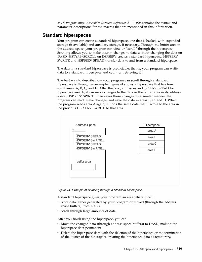
MVS Programming: Assembler Services Reference ABE-HSP contains the syntax andparameter descriptions for the macros that are mentioned in this information.
Standard hiperspacesYour program can create a standard hiperspace, one that is backed with expandedstorage (if available) and auxiliary storage, if necessary. Through the buffer area inthe address space, your program can view or “scroll” through the hiperspace.Scrolling allows you to make interim changes to data without changing the data onDASD. HSTYPE=SCROLL on DSPSERV creates a standard hiperspace. HSPSERVSWRITE and HSPSERV SREAD transfer data to and from a standard hiperspace.
The data in a standard hiperspace is predictable; that is, your program can writedata to a standard hiperspace and count on retrieving it.
The best way to describe how your program can scroll through a standardhiperspace is through an example. Figure 74 shows a hiperspace that has fourscroll areas, A, B, C, and D. After the program issues an HSPSERV SREAD forhiperspace area A, it can make changes to the data in the buffer area in its addressspace. HSPSERV SWRITE then saves those changes. In a similar manner, theprogram can read, make changes, and save the data in areas B, C, and D. Whenthe program reads area A again, it finds the same data that it wrote to the area inthe previous HSPSERV SWRITE to that area.
A standard hiperspace gives your program an area where it can:v Store data, either generated by your program or moved (through the address
space buffers) from DASDv Scroll through large amounts of data
After you finish using the hiperspace, you can:v Move the changed data (through address space buffers) to DASD, making the
hiperspace data permanentv Delete the hiperspace data with the deletion of the hiperspace or the termination
of the owner of the hiperspace, treating the hiperspace data as temporary.
Address Space Hiperspace
buffer area
HSPSERV SREAD...
HSPSERV SREAD...
HSPSERV SWRITE...
HSPSERV SWRITE...
area A
area B
area C
area D
Figure 74. Example of Scrolling through a Standard Hiperspace
Chapter 16. Data spaces and hiperspaces 319

If your application wants to save a permanent copy of the data in the hiperspace,consider using the services of data-in-virtual. See “Using data-in-virtual withhiperspaces” on page 328.
A second type of hiperspace, the expanded storage only (ESO) hiperspace isbacked with expanded storage only (if available) and is available tosupervisor-state programs or programs with PSW key 0 - 7. These hiperspaces aredescribed in the books that are available to writers of authorized programs.
Shared and non-shared standard hiperspacesStandard hiperspaces are either non-shared or shared. Your program can create anddelete non-shared standard hiperspaces; it can use HSPSERV to access thenon-shared standard hiperspaces that it owns. With help from a supervisor-stateprogram or a program with PSW key 0 - 7, your program can also access anon-shared standard hiperspace that it does not own. Shared standard hiperspacescan be shared among programs in many address spaces. Although your programscan use the shared standard hiperspaces, they cannot create and delete them.Therefore, the sharing of hiperspaces must be done under the control ofsupervisor-state programs or programs with PSW key 0 - 7.
This information describes how you create and delete the non-shared standardhiperspaces and use these hiperspaces for your own program. Shared standardhiperspaces and the subject of sharing hiperspaces are described in the applicationdevelopment books that are available to writers of authorized programs.
Table 28 shows some important facts about non-shared standard hiperspaces:
Table 28. Facts about a Non-shared Standard Hiperspace
Question Answer
Can it map a VSAM linear data set? Yes
Can it be a data-in-virtual object? Yes, if the hiperspace has notbeen the target of ALESERVADD.
How do you write data to the hiperspace? By using HSPSERV SWRITE
How do you read data from the hiperspace? By using HSPSERV SREAD
What happens to the data in the hiperspace when thesystem swaps the owning address space out?
The system preserves the data.
Creating a hiperspaceTo create a non-shared standard hiperspace, issue the DSPSERV CREATE macrowith the TYPE=HIPERSPACE and HSTYPE=SCROLL parameters. The HSTYPEparameter tells the system you want a standard hiperspace. HSTYPE=SCROLL isthe default. MVS allocates contiguous 31-bit virtual storage of the size you specifyand initializes the storage to hexadecimal zeros. The entire hiperspace has thestorage key 8. Because many of the same rules that apply to creating data spacesalso apply to creating hiperspaces, this information sometimes refers you to“Creating a data space” on page 302.
On the DSPSERV macro, you are required to specify:v The name of the hiperspace (NAME parameter)
To ask DSPSERV to generate a hiperspace name unique to the address space, usethe GENNAME parameter. DSPSERV will return the name it generates at thelocation you specify on the OUTNAME parameter. Specifying a name for a
320 z/OS MVS Assembler Services Guide

hiperspace follows the same rules as specifying a name for a data space. See“Choosing the name of a data space” on page 303.
v A location where DSPSERV is to return the STOKEN of the hiperspace (STOKENparameter)DSPSERV CREATE returns a STOKEN that you can use to identify thehiperspace to other DSPSERV services and to the HSPSERV and DIV macros.
Other information you might specify on the DSPSERV macro is:v The maximum size of the hiperspace and its initial size (BLOCKS parameter). If
you do not code BLOCKS, the hiperspace size is determined by defaults set byyour installation. In this case, use the NUMBLKS parameter to tell the systemwhere to return the size of the hiperspace. Specifying the size of a hiperspacefollows the same rules as specifying the size of a data space. See “Specifying thesize of a data space” on page 303.
v A location where DSPSERV can return the address (either 0 or 4096) of the firstavailable block of the hiperspace (ORIGIN parameter). Locating the origin of ahiperspace is the same as locating the origin of a data space. See “Identifying theorigin of a data space” on page 305.
Example of creating a standard hiperspaceThe following example creates a non-shared standard hiperspace, 20 blocks in size,named SCROLLHS.*
DSPSERV CREATE,NAME=HSNAME,TYPE=HIPERSPACE,HSTYPE=SCROLL, XBLOCKS=20,STOKEN=HSSTOKEN
*HSNAME DC CL8’SCROLLHS’ * NAME FOR THE HIPERSPACEHSSTOKEN DS CL8 * STOKEN OF THE HIPERSPACE
Transferring data to and from hiperspacesBefore it can reference data or manipulate data in a hiperspace, the program mustbring the data into the address space. The HSPSERV macro performs the transferof data between the address space and the hiperspace.
On the HSPSERV macro, the write operation transfers data from the address spaceto the hiperspace. The read operation transfers the data from the hiperspace to theaddress space. HSPSERV allows multiple reads and writes to occur at one time.This means that one HSPSERV request can read more than one data area in ahiperspace to an equal number of data areas in an address space. Likewise, oneHSPSERV request can write data from more than one buffer area in an addressspace to an equal number of areas in a hiperspace.
Figure 75 on page 322 shows three virtual storage areas that you identify on theHSPSERV macro when you request a data transfer:v The hiperspacev The buffer area in the address space that is the source of the write operation and
the target of the read operationv The data area in the hiperspace that is the target of the write operation and the
source of the read operation.
Chapter 16. Data spaces and hiperspaces 321

On the HSPSERV macro, you identify the hiperspace and the areas in the addressspace and the hiperspace:v STOKEN specifies the STOKEN of the hiperspace.v NUMRANGE specifies the number of data areas the system is to read or write.v RANGLIST specifies a list of ranges that indicate the boundaries of the buffer
areas in the address space and the data area in the hiperspace.
HSPSERV has certain restrictions on these areas. Two restrictions are that the dataareas must start on a 4K byte boundary and their size must be in multiples of 4Kbytes. Other requirements are listed in the description of HSPSERV in z/OS MVSProgramming: Assembler Services Reference ABE-HSP. Read the requirements carefullybefore you issue the macro.
The system does not always preserve the data in the areas that are the source forthe read and write operations. Figure 75 tells you what the system does with theareas after it completes the transfer.
Read and write operations for standard hiperspacesAfter the write operation for standard hiperspaces, the system does not preservethe data in the address space. It assumes that you have another use for that bufferarea, such as using it as the target of another HSPSERV SREAD operation.
After the read operation for standard hiperspaces, the system gives you a choice ofsaving the source data in the hiperspace. If you will use the data in the hiperspaceagain, ask the system to preserve the data; specify RELEASE=NO on HSPSERVSREAD. Unless a subsequent SWRITE request changes the data in the source area,that same data will be available for subsequent SREAD requests. RELEASE=NOprovides your program with a backup copy of the data in the hiperspace.
If you specify RELEASE=YES on HSPSERV SREAD, the system releases thehiperspace pages after the read operation and returns the expanded storage (orauxiliary storage) that backs the source area in the hiperspace. RELEASE=YES tells
Address Space Hiperspace
HSPSERV...
HSPSERV...
buffer area
data area
write
operatio
n
read opera
tion
After a read operation,the data is preservedunless you specifyRELEASE=YES.
After a write operation,the data is unpredictable.The buffer area isavailable for reuse.
Figure 75. Illustration of the HSPSERV Write and Read Operations
322 z/OS MVS Assembler Services Guide
the system that your program does not plan to use the source area in thehiperspace as a copy of the data after the read operation.
See “Example of creating a standard hiperspace and using it” on page 326 for anexample of the HSPSERV SREAD and HSPSERV SWRITE macros.
Obtaining additional HSPSERV performanceYou can use HSPSERV to improve the performance of data transfer betweencentral and expanded storage. Specify the ALET of the hiperspace on theHSPALET parameter on HSPSERV.
To obtain the ALET, issue the following:ALESERV ADD,ALET=. . .,STOKEN=. . .
STOKEN is the eight-byte identifier of the hiperspace, and ALET is the four-byteindex into the DU-AL, the access list that is associated with the task. The STOKENis input to ALESERV ADD; the ALET is output.
Before you issue the HSPSERV macro with the HSPALET parameter, obtain a144-byte workarea for the HSPSERV macro service and place the address of thisarea in GPR 13 and a zero in AR 13.
Note: When the HSPALET parameter is specified, the application's RANGLISTdata may be modified by the system.
Do not specify RELEASE=YES with the HSPALET parameter.
Programming Notes for Obtaining ALETs for Hiperspaces:
v A program never uses an ALET to directly access data in a hiperspace as itwould use the ALET to access the data in a data space.
v To use hiperspaces, you do not need to switch into AR mode.v When you are finished using the hiperspace, use ALESERV DELETE to delete
the entry on the DU-AL.v The system places certain restrictions on the combined use of hiperspaces and
data-in-virtual. These restrictions are listed in “Using data-in-virtual withhiperspaces” on page 328.
v By obtaining an ALET, you can share a hiperspace with a subtask in the sameway you share a data space. Use the ALCOPY parameter on the ATTACHXmacro to pass a copy of your DU-AL to the subtask. Follow the proceduresuggested in “Sharing data spaces among problem-state programs with PSW key8-F” on page 312.
Example of a HSPSERV with the HSPALET Parameter: The following example createsa non-shared hiperspace. To get additional performance from HSPSERV, theprogram obtains an ALET from the ALESERV macro and uses that ALET as inputto HSPSERV. The example assumes the ASC mode is primary....* DSPSERV CREATES A NON-SHARED STANDARD HIPERSPACE OF 20 4096-BYTE BLOCKS*
DSPSERV CREATE,NAME=HSNAME,TYPE=HIPERSPACE,BLOCKS=20, XSTOKEN=HSSTOKEN,ORIGIN=HSORIG1
** ALESERV RETURNS AN ALET ON THE DU-AL FOR THE HIPERSPACE*
ALESERV ADD,STOKEN=HSSTOKEN,ALET=HSALET,AL=WORKUNIT*
Chapter 16. Data spaces and hiperspaces 323
* THE STORAGE MACRO OBTAINS FOUR PAGES OF ADDRESS SPACE STORAGE,* THE BNDRY=PAGE PARAMETER ALIGNS PAGES ON A 4K BOUNDARY* - THE FIRST AND SECOND PAGES ARE THE SWRITE SOURCE* - THE THIRD AND FOURTH PAGES ARE THE SREAD TARGET* COPY INTO FIRST AND SECOND PAGES THE DATA TO BE WRITTEN TO HIPERSPACE
.STORAGE OBTAIN,LENGTH=4096*4,BNDRY=PAGEST 1,ASPTR * SAVE ADDR SPACE STORAGE ADDRESSMVC 0(20,1),SRCTEXT1 * INIT FIRST ADDR SPACE PAGEA 1,ONEBLK * COMPUTE PAGE TWO ADDRESSMVC 0(20,1),SRCTEXT2 * INIT SECOND ADDR SPACE PAGE
.* SET UP THE SWRITE RANGE LIST TO WRITE FROM THE FIRST AND SECOND* ADDRESS SPACE PAGES INTO THE HIPERSPACE
.L 1,ASPTR * GET FIRST ADDR PAGE ADDRESSST 1,ASPTR1 * PUT ADDRESS INTO RANGE LIST
.* SAVE CONTENTS OF AR/GPR 13 BEFORE RESETTING THEM FOR HSPSERV
.ST 13,SAVER13 * SAVE THE CONTENTS OF GPR 13EAR 13,13 * LOAD GPR 13 FROM AR 13ST 13,SAVEAR13 * SAVE THE CONTENTS OF AR 13
.* ESTABLISH ADDRESS OF 144-BYTE SAVE AREA, AS HSPALET ON HSPSERV REQUIRES* AND WRITE TWO PAGES FROM THE ADDRESS SPACE TO THE HIPERSPACE
.SLR 13,13 * SET GPR 13 TO 0SAR 13,13 * SET AR 13 TO 0LA 13,WORKAREA * SET UP AR/GPR 13 TO WORKAREA ADDRHSPSERV SWRITE,STOKEN=HSSTOKEN,RANGLIST=RANGPTR1,HSPALET=HSALET
.* AFTER THE SWRITE, THE FIRST TWO ADDRESS SPACE PAGES MIGHT BE OVERLAID
.
* RESTORE ORIGINAL CONTENTS OF AR/GPR 13.
L 13,SAVEAR13 * SET GPR 13 TO SAVED AR 13SAR 13,13 * RESET AR 13L 13,SAVER13 * RESET GPR 13
.* SET UP THE SREAD RANGE LIST TO READ INTO THE THIRD AND FOURTH* ADDRESS SPACE PAGES WHAT WAS PREVIOUSLY WRITTEN TO THE HIPERSPACE
.MVC HSORIG2,HSORIG1 * COPY ORIGIN OF HIPERSPACE TO HSORIG2L 1,ASPTR * GET FIRST ADDR PAGE ADDRESSA 1,TWOBLKS * COMPUTE THIRD PAGE ADDRESSST 1,ASPTR2 * PUT ADDRESS INTO RANGE LIST
.* SAVE CONTENTS OF AR/GPR 13
.ST 13,SAVER13 * SAVE THE CONTENTS OF GPR 13EAR 13,13 * LOAD GPR 13 FROM AR 13ST 13,SAVEAR13 * SAVE THE CONTENTS OF AR 13
.* ESTABLISH ADDRESS OF 144-BYTE SAVE AREA, AS HSPALET ON HSPSERV REQUIRES,* AND READ TWO BLOCKS OF DATA FROM THE HIPERSPACE INTO THE* THIRD AND FOURTH PAGES IN THE ADDRESS SPACE STORAGE USING HSPALET
.SLR 13,13 * SET GPR 13 TO 0SAR 13,13 * SET AR 13 TO 0LA 13,WORKAREA * SET UP AR/GPR 13 TO WORKAREA ADDRHSPSERV SREAD,STOKEN=HSSTOKEN,RANGLIST=RANGPTR2,HSPALET=HSALET
.* RESTORE ORIGINAL CONTENTS OF AR/GPR 13
.L 13,SAVEAR13 * SET GPR 13 TO SAVED AR 13SAR 13,13 * RESET AR 13
324 z/OS MVS Assembler Services Guide

L 13,SAVER13 * RESET GPR 13.
* FREE THE ALET, FREE ADDRESS SPACE STORAGE, AND DELETE THE HIPERSPACE...* DATA AREAS AND CONSTANTS
.HSNAME DC CL8’SCROLLHS’ * NAME FOR THE HIPERSPACEHSSTOKEN DS CL8 * STOKEN FOR THE HIPERSPACEHSALET DS CL4 * ALET FOR THE HIPERSPACEASPTR DS 1F * LOCATION OF ADDR SPACE STORAGESAVER13 DS 1F * LOCATION TO SAVE GPR 13SAVEAR13 DS 1F * LOCATION TO SAVE AR 13WORKAREA DS CL144 * WORK AREA FOR HSPSERVONEBLK DC F’4096’ * LENGTH OF ONE BLOCK OF STORAGETWOBLKS DC F’8192’ * LENGTH OF TWO BLOCKS OF STORAGESRCTEXT1 DC CL20’ INVENTORY ITEMS ’SRCTEXT2 DC CL20’ INVENTORY SURPLUSES’
DS 0FRANGPTR1 DC A(SWRITLST) * ADDRESS OF SWRITE RANGE LISTRANGPTR2 DC A(SREADLST) * ADDRESS OF SREAD RANGE LIST
DS 0F
SWRITLST DS 0CL12 * SWRITE RANGE LISTASPTR1 DS F * START OF ADDRESS SPACE SOURCEHSORIG1 DS F * TARGET LOCATION IN HIPERSPACENUMBLKS1 DC F’2’ * NUMBER OF 4K BLOCKS IN SWRITE
DS 0FSREADLST DS 0CL12 * SREAD RANGE LISTASPTR2 DS F * TARGET LOCATION IN ADDR SPACEHSORIG2 DS F * START OF HIPERSPACE SOURCENUMBLKS2 DC F’2’ * NUMBER OF 4K BLOCKS IN SREAD
DS 0F
Extending the current size of a hiperspaceWhen you create a hiperspace and specify a maximum size larger than the initialsize, you can use DSPSERV EXTEND to increase the current size as your programuses more storage in the hiperspace. The BLOCKS parameter specifies the amountof storage you want to add to the current size of the hiperspace. The VARparameter tells the system whether the request is variable. For information about avariable request and help in using DSPSERV EXTEND, see “Extending the currentsize of a data space” on page 308.
Releasing hiperspace storageYour program needs to release storage when it used a hiperspace for one purposeand wants to reuse it for another purpose, or when your program is finished usingthe area. To release the virtual storage of a hiperspace, use the DSPSERV RELEASEmacro. (Hiperspace™ release is similar to a PGSER RELEASE for an address space.)Specify the STOKEN to identify the hiperspace and the START and BLOCKSparameters to identify the beginning and the length of the area you need torelease.
Releasing storage in a hiperspace requires that a program have the followingauthority:v The program must be the owner of the hiperspace.v The program's PSW key must equal the storage key of the hiperspace the system
is to release. Otherwise, the system abends the caller.
After the release, a released page does not occupy expanded (or auxiliary) storageuntil your program references it again. When you again reference a page you havereleased, the page contains hexadecimal zeroes.
Chapter 16. Data spaces and hiperspaces 325

Use DSPSERV RELEASE instead of the MVCL instruction to clear 4K byte blocksof storage to zeroes because:v DSPSERV RELEASE is faster than MVCL for very large areas.v Pages released through DSPSERV RELEASE do not occupy space in expanded or
auxiliary storage.
Deleting a hiperspaceWhen a program doesn't need the hiperspace any more, it can delete it. Yourprogram can delete only the hiperspaces it owns, providing the program's PSWkey matches the storage key of the hiperspace.
Example of Deleting a Hiperspace: The following example shows you how to delete ahiperspace:
DSPSERV DELETE,STOKEN=HSSTKN DELETE THE HS.
HSSTKN DS CL8 HIPERSPACE STOKEN
IBM recommends that you explicitly delete a hiperspace before the owning taskterminates to free resources as soon as they are no longer needed, and to avoidexcess processing at termination time. However, if you do not delete thehiperspace, the system automatically does it for you.
Example of creating a standard hiperspace and using itThe following example creates a standard hiperspace named SCROLLHS. The sizeof the hiperspace is 20 blocks. The program:v Creates a standard hiperspace 20 blocks in sizev Obtains four pages of address space storage aligned on a 4K byte addressv Sets up the SWRITE range list parameter area to identify the first two pages of
the address space storagev Initializes the first two pages of address space storage that will be written to the
hiperspacev Issues the HSPSERV SWRITE macro to write the first two pages to locations
4096 through 12287 in the hiperspace
Later on, the program:v Sets up the SREAD range list parameter area to identify the last two pages of
the four-page address space storagev Issues the HSPSERV SREAD macro to read the blocks at locations 4096 through
12287 in the hiperspace to the last two pages in the address space storage
Figure 76 on page 327 shows the four-page area in the address space and the twoblock area in the hiperspace. Note that the first two pages of the address spacevirtual storage are unpredictable after the SWRITE operation.
326 z/OS MVS Assembler Services Guide

* DSPSERV CREATES A STANDARD TYPE HIPERSPACE OF 20 4096-BYTE BLOCKS.DSPSERV CREATE,NAME=HSNAME,TYPE=HIPERSPACE,HSTYPE=SCROLL, X
BLOCKS=20,STOKEN=HSSTOKEN.
* THE STORAGE MACRO OBTAINS FOUR PAGES OF ADDRESS SPACE STORAGE.* THE BNDRY=PAGE PARAMETER ALIGNS PAGES ON A 4K BOUNDARY* - THE FIRST AND SECOND PAGES ARE THE SWRITE SOURCE* - THE THIRD AND FOURTH PAGES ARE THE SREAD TARGET
.STORAGE OBTAIN,LENGTH=4096*4,BNDRY=PAGEST 1,ASPTR1 * SAVES THE SWRITE SOURCE ADDRESSMVC 0(20,1),SRCTEXT1 * INITIALIZES SOURCE PAGE ONEA 1,ONEBLOCK * COMPUTES SOURCE PAGE TWO ADDRESSMVC 0(20,1),SRCTEXT2 * INITIALIZES SOURCE PAGE TWO.
* HSPSERV WRITES TWO PAGES FROM THE ADDRESS SPACE TO THE HIPERSPACE.HSPSERV SWRITE,STOKEN=HSSTOKEN,RANGLIST=RANGPTR1.
* AFTER THE SWRITE, THE FIRST TWO ADDRESS SPACE PAGES MIGHT BE OVERLAID.
.* SET UP THE SREAD RANGE LIST TO READ INTO THE THIRD AND FOURTH* ADDRESS SPACE PAGES
.L 2,ASPTR1 * OBTAINS THE ADDRESS OF PAGE 1A 2,ONEBLOCK * COMPUTES THE SREAD TARGET ADDRESSA 2,ONEBLOCK * COMPUTES THE SREAD TARGET ADDRESSST 2,ASPTR2 * SAVES IN SREAD RANGE LIST.
* HSPSERV READS TWO BLOCKS OF DATA FROM THE HIPERSPACE TO THETHIRD AND FOURTH PAGES IN THE ADDRESS SPACE STORAGE
.HSPSERV SREAD,STOKEN=HSSTOKEN,RANGLIST=RANGPTR2.
* DATA AREAS AND CONSTANTS*HSNAME DC CL8’SCROLLHS’ * NAME FOR THE HIPERSPACEHSSTOKEN DS CL8 * STOKEN FOR THE HIPERSPACEONEBLOCK DC F’4096’ * LENGTH OF ONE BLOCK OF STORAGESRCTEXT1 DC CL20’ INVENTORY ITEMS ’SRCTEXT2 DC CL20’ INVENTORY SURPLUSES’
Address Space
PROG1
HSPSERV SWRITE
HSPSERV SREAD
SWRITE range list
SREAD range list
SWRITE
SREAD
StandardHiperspace
DSPSERV
Figure 76. Example of Creating a Standard Hiperspace and Transferring Data
Chapter 16. Data spaces and hiperspaces 327
DS 0FRANGPTR1 DC A(SWRITLST) * ADDRESS OF THE SWRITE RANGE LISTRANGPTR2 DC A(SREADLST) * ADDRESS OF THE SREAD RANGE LIST
DS 0F
SWRITLST DS 0CL12 * SWRITE RANGE LISTASPTR1 DS F * START OF ADDRESS SPACE SOURCEHSPTR1 DC F’4096’ * TARGET LOCATION IN HIPERSPACENUMBLKS1 DC F’2’ * NUMBER OF 4K BLOCKS IN SWRITE
DS 0FSREADLST DS 0CL12 * SREAD RANGE LISTASPTR2 DS F * TARGET LOCATION IN ADDRESS SPACEHSPTR2 DC F’4096’ * START OF HIPERSPACE SOURCENUMBLKS2 DC F’2’ * NUMBER OF 4K PAGES IN SREAD
Using data-in-virtual with hiperspacesData-in-virtual allows you to map a large amount of data into a virtual storagearea and then deal with the portion of the data that you need. The virtual storageprovides a “window” through which you can “view” the object and make changes,if you want. The DIV macro manages the data object, the window, and themovement of data between the window and the object.
You can use standard hiperspaces with data-in-virtual in two ways:v You can map a VSAM linear data set to hiperspace virtual storage.v You can map a non-shared hiperspace to virtual storage in an address space.
The task that issues the DIV IDENTIFY owns the pointers and structuresassociated with the ID that DIV returns. Any program can use DIV IDENTIFY.However, the system checks the authority of programs that try to use the otherDIV services for the same ID. For problem-state programs with PSW key 8 - F,data-in-virtual allows only the issuer of the DIV IDENTIFY to use subsequent DIVservices for the same ID. That means, for example, that if a problem-state programwith PSW key 8 issues the DIV IDENTIFY, another problem-state program withPSW key 8 cannot issue DIV MAP for the same ID.
Problem-state programs with PSW key 8 - F can use DIV MAP to:v Map a VSAM linear data set to a window in a hiperspace, providing the
program owns the hiperspace.v Map a non-shared hiperspace object to an address space window, providing:
– The program owns the hiperspace,– The program or its attaching task obtained the storage for the window, and– No program has ever issued ALESERV ADD for the hiperspace
The rules for using data-in-virtual and HSPSERV with the HSPALET parameter(for additional performance) are as follows:v Your program can use HSPSERV with the HSPALET parameter with non-shared
hiperspaces when a data-in-virtual object is mapped to a hiperspace, providing aDIV SAVE is not in effect.
v Once any program issues ALESERV ADD for a hiperspace, that hiperspacecannot be a data-in-virtual object.
v If a program issues ALESERV ADD for a hiperspace that is currently a dataobject, the system rejects the request.
For information on the use of ALETs with hiperspaces, see “Obtaining additionalHSPSERV performance” on page 323.
328 z/OS MVS Assembler Services Guide

Mapping a data-in-virtual object to a hiperspaceThrough data-in-virtual, a program can map a VSAM linear data set residing onDASD to a hiperspace. The program uses the read and write operations of theHSPSERV macro to transfer data between the address space buffer area and thehiperspace window.
When a program maps a data-in-virtual object to a standard hiperspace, the systemdoes not bring the data physically into the hiperspace; it reads the data into theaddress space buffer when the program uses HSPSERV SREAD for that area thatcontains the data.
Your program can map a single data-in-virtual object to several hiperspaces. Or, itcan map several data-in-virtual objects to one hiperspace.
An example of mapping a data-in-virtual object to a hiperspace: The followingexample shows how you would create a standard hiperspace with a maximum sizeof one gigabyte and an initial size of 4K bytes. Figure 77 shows the hiperspacewith a window that begins at the origin of the hiperspace.
Initially, the window in the hiperspace and the buffer area in the address space areboth 4K bytes. (That is, the window takes up the entire initial size of thehiperspace.) The data-in-virtual object is a VSAM linear data set on DASD.* CREATE A STANDARD HIPERSPACE
.DSPSERV CREATE,TYPE=HIPERSPACE,HSTYPE=SCROLL,NAME=HS1NAME, X
STOKEN=HS1STOK,BLOCKS=(ONEGIG,FOURK),ORIGIN=HS1ORG.
* MAP THE HIPERSPACE TO THE OBJECT.DIV IDENTIFY,ID=OBJID,TYPE=DA,DDNAME=OBJDDDIV ACCESS,ID=OBJID,MODE=UPDATEDIV MAP,ID=OBJID,AREA=HS1ORG,STOKEN=HS1STOK.
* OBTAIN A 4K BUFFER AREA IN ADDRESS SPACE TO BE* USED TO UPDATE THE DATA IN THE HIPERSPACE WINDOW
.* DECLARATION STATEMENTS
.HS1NAME DC CL8’MYHSNAME’ HIPERSPACE NAMEHS1STOK DS CL8 HIPERSPACE STOKENHS1ORG DS F HIPERSPACE ORIGINONEGIG DC F’262144’ MAXIMUM SIZE OF 1G IN BLOCKS
Address Space
Permanent Object
VSAM lineardata set
window
Standard Hiperspace
Program
DSPSERV...
DIV IDENTIFY...DIV ACCESS...DIV MAP...
HSPSERV SWRITE...
HSPSERV SREAD...
HSPSERV SREAD
HSPSERV SWRITE
Figure 77. Example of Mapping a Data-in-Virtual Object to a Hiperspace
Chapter 16. Data spaces and hiperspaces 329
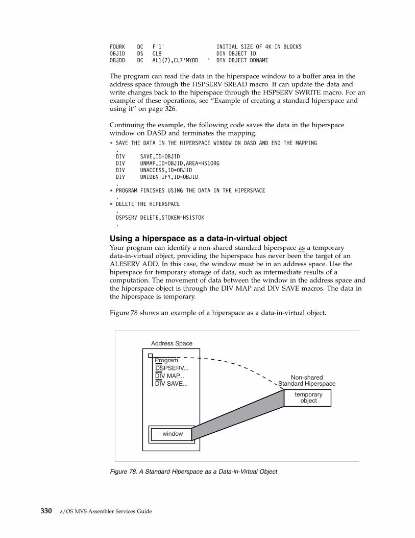
FOURK DC F’1’ INITIAL SIZE OF 4K IN BLOCKSOBJID DS CL8 DIV OBJECT IDOBJDD DC AL1(7),CL7’MYDD ’ DIV OBJECT DDNAME
The program can read the data in the hiperspace window to a buffer area in theaddress space through the HSPSERV SREAD macro. It can update the data andwrite changes back to the hiperspace through the HSPSERV SWRITE macro. For anexample of these operations, see “Example of creating a standard hiperspace andusing it” on page 326.
Continuing the example, the following code saves the data in the hiperspacewindow on DASD and terminates the mapping.* SAVE THE DATA IN THE HIPERSPACE WINDOW ON DASD AND END THE MAPPING
.DIV SAVE,ID=OBJIDDIV UNMAP,ID=OBJID,AREA=HS1ORGDIV UNACCESS,ID=OBJIDDIV UNIDENTIFY,ID=OBJID.
* PROGRAM FINISHES USING THE DATA IN THE HIPERSPACE.
* DELETE THE HIPERSPACE.DSPSERV DELETE,STOKEN=HS1STOK.
Using a hiperspace as a data-in-virtual objectYour program can identify a non-shared standard hiperspace as a temporarydata-in-virtual object, providing the hiperspace has never been the target of anALESERV ADD. In this case, the window must be in an address space. Use thehiperspace for temporary storage of data, such as intermediate results of acomputation. The movement of data between the window in the address space andthe hiperspace object is through the DIV MAP and DIV SAVE macros. The data inthe hiperspace is temporary.
Figure 78 shows an example of a hiperspace as a data-in-virtual object.
Address Space
window
Program
DSPSERV...
DIV MAP...
DIV SAVE...
temporaryobject
Non-sharedStandard Hiperspace
Figure 78. A Standard Hiperspace as a Data-in-Virtual Object
330 z/OS MVS Assembler Services Guide
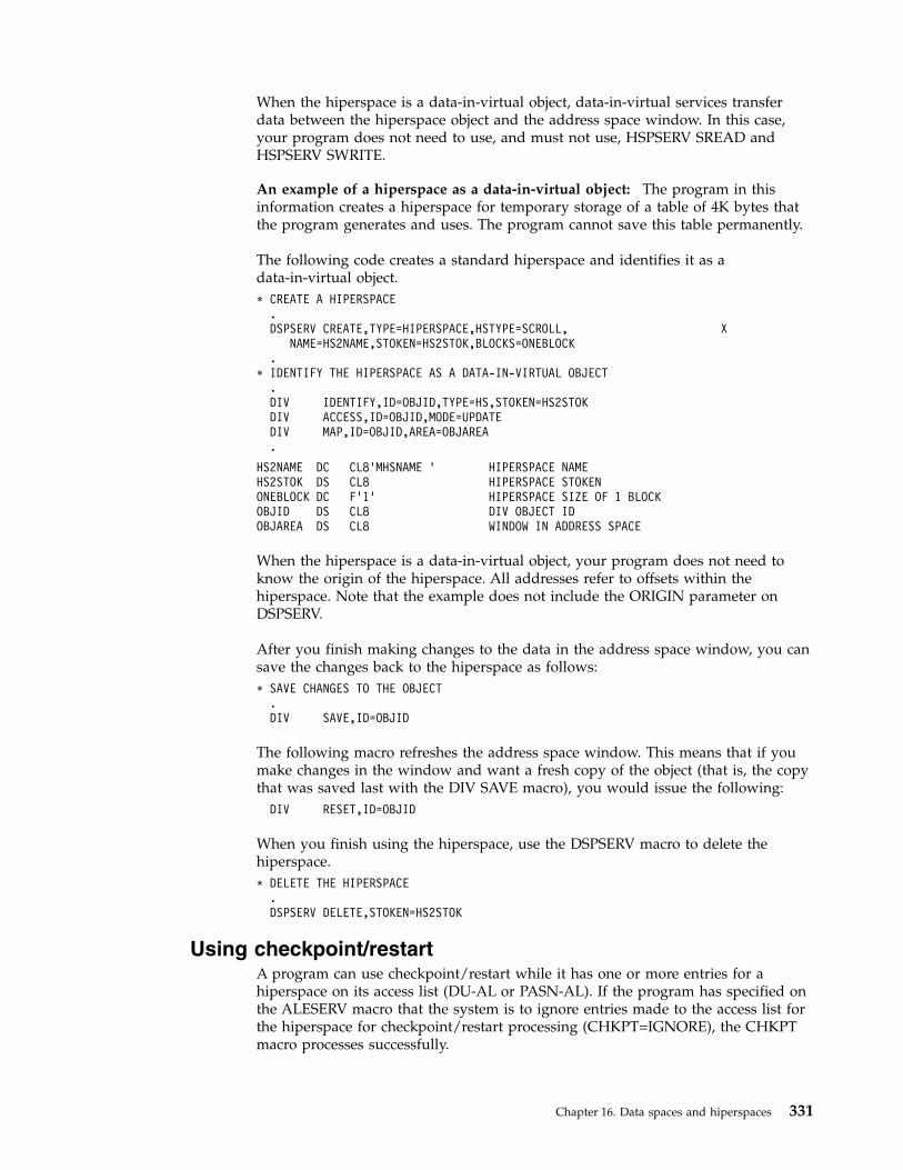
When the hiperspace is a data-in-virtual object, data-in-virtual services transferdata between the hiperspace object and the address space window. In this case,your program does not need to use, and must not use, HSPSERV SREAD andHSPSERV SWRITE.
An example of a hiperspace as a data-in-virtual object: The program in thisinformation creates a hiperspace for temporary storage of a table of 4K bytes thatthe program generates and uses. The program cannot save this table permanently.
The following code creates a standard hiperspace and identifies it as adata-in-virtual object.* CREATE A HIPERSPACE
.DSPSERV CREATE,TYPE=HIPERSPACE,HSTYPE=SCROLL, X
NAME=HS2NAME,STOKEN=HS2STOK,BLOCKS=ONEBLOCK.
* IDENTIFY THE HIPERSPACE AS A DATA-IN-VIRTUAL OBJECT.DIV IDENTIFY,ID=OBJID,TYPE=HS,STOKEN=HS2STOKDIV ACCESS,ID=OBJID,MODE=UPDATEDIV MAP,ID=OBJID,AREA=OBJAREA.
HS2NAME DC CL8’MHSNAME ’ HIPERSPACE NAMEHS2STOK DS CL8 HIPERSPACE STOKENONEBLOCK DC F’1’ HIPERSPACE SIZE OF 1 BLOCKOBJID DS CL8 DIV OBJECT IDOBJAREA DS CL8 WINDOW IN ADDRESS SPACE
When the hiperspace is a data-in-virtual object, your program does not need toknow the origin of the hiperspace. All addresses refer to offsets within thehiperspace. Note that the example does not include the ORIGIN parameter onDSPSERV.
After you finish making changes to the data in the address space window, you cansave the changes back to the hiperspace as follows:* SAVE CHANGES TO THE OBJECT
.DIV SAVE,ID=OBJID
The following macro refreshes the address space window. This means that if youmake changes in the window and want a fresh copy of the object (that is, the copythat was saved last with the DIV SAVE macro), you would issue the following:
DIV RESET,ID=OBJID
When you finish using the hiperspace, use the DSPSERV macro to delete thehiperspace.* DELETE THE HIPERSPACE
.DSPSERV DELETE,STOKEN=HS2STOK
Using checkpoint/restartA program can use checkpoint/restart while it has one or more entries for ahiperspace on its access list (DU-AL or PASN-AL). If the program has specified onthe ALESERV macro that the system is to ignore entries made to the access list forthe hiperspace for checkpoint/restart processing (CHKPT=IGNORE), the CHKPTmacro processes successfully.
Chapter 16. Data spaces and hiperspaces 331
A program that specifies CHKPT=IGNORE assumes full responsibility formanaging the hiperspace storage. Managing the hiperspace storage includes thefollowing:v If any program depends on the contents of the hiperspace and the data cannot
be recreated or obtained elsewhere, the responsible program must save thecontents of the hiperspace prior to the checkpoint operation.
v Once the checkpoint operation has completed, the responsible program mustperform the following during restart processing to successfully manage thehiperspace storage.1. Ensure that the hiperspace exists. The original hiperspace might or might not
exist. If the original hiperspace does not exist, the responsible program mustissue DSPSERV CREATE TYPE=HIPERSPACE to recreate the hiperspace.
2. Issue ALESERV ADD of the hiperspace, original or recreated, to theprogram's access list to obtain a new ALET.
3. If, in addition to having a dependency on the hiperspace, any program alsodepends on the contents of the hiperspace storage, the responsible programmust refresh the contents of the hiperspace storage. The program must usethe new ALET to reference the hiperspace.
4. The responsible program must make the new ALET available to any programthat has a dependency on the hiperspace. The STOKEN, changed orunchanged, must be made available to any program that needs to issueALESERV ADD to access the hiperspace.
See z/OS DFSMSdfp Checkpoint/Restart information about the CHKPT macro.
332 z/OS MVS Assembler Services Guide

Chapter 17. Window services
Callable window services enables assembler language programs to use the CALLmacro to access data objects. By calling the appropriate window services program,an assembler language program can:v Read or update an existing permanent data objectv Create and save a new permanent data objectv Create and use a temporary data object
Window services enable your program to access data objects without yourprogram performing any input or output (I/O) operations. All your program needsto do is issue a CALL to the appropriate service program. The service performsany I/O operations that are required to make the data object available to yourprogram. When you want to update or save a data object, window services againperforms any required I/O operations.
Data objects
PermanentA permanent data object is a virtual storage access method (VSAM) linear data setthat resides on DASD. (This type of data set is also called a data-in-virtual object.)You can read data from an existing permanent object and also update the contentof the object. You can create a new permanent object and when you are finished,save it on DASD. Because you can save this type of object on DASD, windowservices calls it a permanent object. Window services can handle very largepermanent objects that contain as many as four gigabytes (4294967296 bytes).
Note: Installations whose high level language programs, such as FORTRAN, useddata-in-virtual objects prior to MVS/SP 3.1.0 had to write an Assembler languageinterface program to allow the FORTRAN program to invoke the data-in-virtualprogram. Window services eliminates the need for this interface program.
Temporary data objectsA temporary data object is an area of expanded storage that window servicesprovides for your program. You can use this storage to hold temporary data, suchas intermediate results of a computation, instead of using a DASD workfile. Oryou might use the storage area as a temporary buffer for data that your programgenerates or obtains from some other source. When you finish using the storagearea, window services deletes it. Because you cannot save the storage area,window services calls it a temporary object. Window services can handle verylarge temporary objects that contain as many as 16 terabytes (17592186044416bytes).
Structure of a data objectThink of a data object as a contiguous string of bytes organized into blocks, each4096 bytes long. The first block contains bytes 0 to 4095 of the object, the secondblock contains bytes 4096 to 8191, and so forth.
Your program references data in the object by identifying the block or blocks thatcontain the desired data. Window services makes the blocks available to your
© Copyright IBM Corp. 1988, 2017 333

program by mapping a window in your program storage to the blocks. A windowis a storage area that your program provides and makes known to windowservices. Mapping the window to the blocks means that window services makesthe data from those blocks available in the window when you reference the data.You can map a window to all or part of a data object depending on the size of theobject and the size of the window. You can examine or change data that is in thewindow by using the same instructions that you use to examine or change anyother data in your program storage.
The following figure shows the structure of a data object and shows a windowmapped to two of the object's blocks.
What does window services provide?Window services allows you to view and manipulate data objects in a number ofways. You can have access to one or more data objects at the same time. You canalso define multiple windows for a given data object. You can then view a differentpart of the object through each window. Before you can access any data object, youmust request access from window services.
When you request access to a permanent data object, you must indicate whetheryou want a scroll area. A scroll area is an area of expanded storage that windowservices obtains and maps to the permanent data object. You can think of thepermanent object as being available in the scroll area. When you request a view ofthe object, window services maps the window to the scroll area. If you do notrequest a scroll area, window services maps the window directly to the object onDASD.
A scroll area enables you to save interim changes to a permanent object withoutchanging the object on DASD. Also, when your program accesses a permanentobject through a scroll area, your program might attain better performance than itwould if the object were accessed directly on DASD.
When you request a temporary object, window services provides an area ofexpanded storage. This area of expanded storage is the temporary data object.When you request a view of the object, window services maps the window to thetemporary object. Window services initializes a temporary object to binary zeroes.
Note:
window
data object
1st block
3rd block
4th block
last block
2nd block
2nd block
1st block
4096 bytes
4096 bytes
4096 bytes
4096 bytes
4096 bytes
/ /
/ /
.
.
.
your addressspace
Figure 79. Structure of a Data Object
334 z/OS MVS Assembler Services Guide

1. Window services does not transfer data from the object on DASD, from thescroll area, or from the temporary object until your program references thedata. Then window services transfers the blocks that contain the data yourprogram requests.
2. The expanded storage that window services uses for a scroll area or for atemporary object is called a hiperspace. A hiperspace is a range of contiguousvirtual storage addresses that a program can use like a buffer. Window servicesuses as many hiperspaces as needed to contain the data object.
The ways that window services can map an objectWindow services can map a data object a number of ways. The following examplesshow how window services can:v Map a permanent object that has no scroll areav Map a permanent object that has a scroll areav Map a temporary objectv Map an object to multiple windowsv Map multiple objects
Example 1 — Mapping a permanent object that has no scrollareaIf a permanent object has no scroll area, window services maps the object fromDASD directly to your window. In this example, your window provides a view ofthe first and second blocks of an object.
Example 2 — Mapping a permanent object that has a scroll areaIf the object has a scroll area, window services maps the object from DASD to thescroll area. Window services then maps the blocks that you wish to view from thescroll area to your window. In this example, your window provides a view of thethird and fourth blocks of an object.
window1st block
2nd block
1st block
2nd block
3rd block
.
.
last block
your addressspace
permanent objecton DASD
Figure 80. Mapping a Permanent Object That Has No Scroll Area
Chapter 17. Window services 335

Example 3 — Mapping a temporary objectWindow services uses a hiperspace as a temporary object. In this example, yourwindow provides a view of the first and second blocks of a temporary object.
Example 4 — Mapping multiple windows to an objectWindow services can map multiple windows to the same object. In this example,one window provides a view of the second and third blocks of an object, and asecond window provides a view of the last block.
1st block
DIVobject
3rd block
4th block
2nd block
4th block
scroll area
window3rd block
last block
/ /
/ /
.
.
.
your addressspace
permanent objecton DASD
Figure 81. Mapping a Permanent Object That Has A Scroll Area
your addressspace
1st block
2nd block
temporary object
window
1st block
3rd block
4th block
2nd block
/ /
/ /
.
.
.
last block
Figure 82. Mapping a Temporary Object
336 z/OS MVS Assembler Services Guide

Example 5 — Mapping multiple objectsWindow services can map multiple objects to windows in the same address space.The objects can be temporary objects, permanent objects, or a combination oftemporary and permanent objects. In this example, one window provides a view ofthe second block of a temporary object, and a second window provides a view ofthe fourth and fifth blocks of a permanent object.
temporary object
1st block
3rd block
4th block
last block
2nd block
firstwindow
2nd block
3rd block
last blocksecondwindow / /
/ /
.
.
.
.
your addressspace
Figure 83. Mapping an Object To Multiple Windows
Chapter 17. Window services 337

Access to permanent data objectsWhen you have access to a permanent data object, you can:v View the object through one or more windows. Depending on the object size
and the window size, a single window can view all or part of a permanentobject. If you define multiple windows, each window can view a different partof the object. For example, one window might view the first block of thepermanent object and another window might view the second block. You canalso have several windows view the same part of the object or have views inmultiple windows overlap. For example, one window might view the first andsecond blocks of a data object while another window views the second and thirdblocks.
v Change data that appears in a window. You can examine or change data that isin a window by using the same instructions you use to examine or change anyother data in your program's storage. These changes do not alter the object onDASD or in the scroll area.
v Save interim changes in a scroll area. After changing data in a window, you canhave window services save the changed blocks in a scroll area, if you haverequested one. Window services replaces blocks in the scroll area withcorresponding changed blocks from the window. Saving changes in the scrollarea does not alter the object on DASD or alter data in the window.
1st block
3rd block
4th block
2nd block
scroll area
5th block
1st block
3rd block
4th block
2nd block
temporary object
secondwindow
firstwindow
your addressspace
2nd block
4th block
5th block
Permanent objecton DASD
/ /
/ /
.
.
.
last block
last block
/ /
/ /
.
.
DIVobject
Figure 84. Mapping Multiple Objects
338 z/OS MVS Assembler Services Guide

v Refresh a window or the scroll area. After you change data in a window or savechanges in the scroll area, you may discover that you no longer need thosechanges. In that case, you can have window services refresh the changed data.To refresh the window or the scroll area, window services replaces changed datawith data from the object as it appears on DASD.
v Replace the view in a window. After you finish using data that's in a window,you can have window services replace the view in the window with a differentview of the object. For example, if you are viewing the third, fourth, and fifthblocks of an object and are finished with those blocks, you might have windowservices replace that view with a view of the sixth, seventh, and eighth blocks.
v Update the object on DASD. If you have changes available in a window or inthe scroll area, you can save the changes on DASD. Window services replacesblocks on DASD with corresponding changed blocks from the window and thescroll area. Updating an object on DASD does not alter data in the window or inthe scroll area.
Access to temporary data objectsWhen you have access to a temporary data object, you can:v View the object through one or more windows. Depending on the object size
and the window size, a single window can view all or part of a temporaryobject. If you define multiple windows, each window can view a different partof the object. For example, one window might view the first block of thetemporary object and another window might view the second block. Unlike apermanent object, however, you cannot define multiple windows that haveoverlapping views of a temporary object.
v Change data that appears in a window. This function is the same for atemporary object as it is for a permanent object: you can examine or change datathat is in a window by using the same instructions you use to examine orchange any other data in your address space. These changes do not alter theobject on DASD or in the scroll area.
v Update the temporary object. After you have changed data in a window, youcan have window services update the object with those changes. Windowservices replaces blocks in the object with corresponding changed blocks fromthe window. The data in the window remains as it was.
v Refresh a window or the object. After you change data in a window or savechanges in the object, you may discover that you no longer need those changes.In that case, you can have window services refresh the changed data. To refreshthe window or the object, window services replaces changed data with binaryzeroes.
v Change the view in a window. After you finish using data that's in a window,you can have window services replace the view in the window with a differentview of the object. For example, if you are viewing the third, fourth, and fifthblocks of an object and are finished with those blocks, you might have windowservices replace that view with a view of the sixth, seventh, and eighth blocks.
Using window servicesTo use, create, or update a data object, you call a series of programs that windowservices provides. These programs enable you to:v Access an existing object, create and save a new permanent object, or create a
temporary objectv Obtain a scroll area where you can make interim changes to a permanent objectv Define windows and establish views of an object in those windows
Chapter 17. Window services 339

v Change or terminate the view in a windowv Update a scroll area or a temporary object with changes you have made in a
windowv Refresh changes that you no longer need in a window or a scroll areav Update a permanent object on DASD with changes that are in a window or a
scroll areav Terminate access to an object
The window services programs that you call and the sequence in which you callthem depends on your use of the data object. For descriptions of the windowservices, see z/OS MVS Programming: Assembler Services Reference ABE-HSP. For anexample of invoking window services from an assembler language program, see“Window services coding example” on page 351.
The first step in using any data object is to gain access to the object. To gain access,you call CSRIDAC. The object can be an existing permanent object, or a newpermanent or temporary object you want to create. For a permanent object, youcan request an optional scroll area. A scroll area enables you to make interimchanges to an object's data without affecting the data on DASD. When CSRIDACgrants access, it provides an object identifier that identifies the object. You use thatidentifier to identify the object when you request other services from windowservice programs.
After obtaining access to an object, you must define one or more windows andestablish views of the object in those windows. To establish a view of an object,you tell window services which blocks you want to view and in which windows.You can view multiple objects and multiple parts of each object at the same time.To define windows and establish views, you call CSRVIEW or CSREVW. Afterestablishing a view, you can examine or change data that is in the window usingthe same instructions you use to examine or change other data in your program'sstorage.
After making changes to the part of an object that is in a window, you willprobably want to save those changes. How you save changes depends on whetherthe object is permanent, is temporary, or has a scroll area.
If the object is permanent and has a scroll area, you can save changes in the scrollarea without affecting the object on DASD. Later, you can update the object onDASD with changes saved in the scroll area. If the object is permanent and has noscroll area, you can update it on DASD with changes that are in a window. If theobject is temporary, you can update it with changes that are in a window. Toupdate an object on DASD, you call CSRSAVE. To update a temporary object or ascroll area, you call CSRSCOT.
After making changes in a window and possibly saving them in a scroll area orusing them to update a temporary object, you might decide that you no longerneed those changes. In this case, you can refresh the changed blocks. Afterrefreshing a block of a permanent object or a scroll area to which a window ismapped, the refreshed block contains the same data that the corresponding blockcontains on DASD. After refreshing a block of a temporary object to which awindow is mapped, the block contains binary zeroes. To refresh a changed block,you call CSRREFR.
After finishing with a view in a window, you can use the same window to view adifferent part of the object or to view a different object. Before changing the view
340 z/OS MVS Assembler Services Guide

in a window, you must terminate the current view. If you plan to view a differentpart of the same object, you terminate the current view by calling CSRVIEW. If youplan to view a different object or will not reuse the window, you can terminate theview by calling CSRIDAC.
When you finishing using a data object, you must terminate access to the object bycalling CSRIDAC.
The following restrictions apply to using window services:1. When you attach a new task, you cannot pass ownership of a mapped virtual
storage window to the new task. That is, you cannot use the ATTACH orATTACHX keywords GSPV and GSPL to pass the mapped virtual storage.
2. While your program is in cross-memory mode, your program cannot invokedata-in-virtual services; however, your program can reference and update datain a mapped virtual storage window.
3. The task that obtains the ID (through DIV IDENTIFY) is the only one that canissue other DIV services for that ID.
4. When you identify a data-in-virtual object using the IDENTIFY service, youcannot request a checkpoint until you invoke the corresponding UNIDENTIFYservice.
Obtaining access to a data objectTo obtain access to a permanent or temporary data object, call CSRIDAC. Indicatethat you want to access an object, by specifying BEGIN as the value for op_type.
Identifying the objectYou must identify the data object you wish to access. How you identify the objectdepends on whether the object is permanent or temporary.
Permanent Object: For a permanent object, object_name and object_type work together.For object_name you have a choice: specify either the data set name of the object orthe DDNAME to which the object is allocated. The object_type parameter must thenindicate whether object_name is a DDNAME or a data set name:v If object_name is a DDNAME, specify DDNAME as the value for object_type.v If object_name is a data set name, specify DSNAME as the value for object_type.
If you specify DSNAME for object_type, indicate whether the object already existsor whether window services is to create it:v If the object already exists, specify OLD as the value for object_state.v If window services is to create the object, specify NEW as the value for
object_state.
Requirement for NEW Objects: If you specify NEW as the value for object_state, yoursystem must include SMS, and SMS must be active.
Temporary Object: To identify a temporary object, specify TEMPSPACE as the valuefor object_type. Window services assumes that a temporary object is new and mustbe created. Therefore, window services ignores the value assigned to object_state.
Specifying the object's sizeIf the object is permanent and new or is temporary, you must tell window servicesthe size of the object. You specify object size through the object_size parameter. Thesize specified becomes the maximum size that window services will allow for thatobject. You express the size as the number of 4096-byte blocks needed to contain
Chapter 17. Window services 341

the object. If the number of blocks needed to contain the object is not an exactmultiple of 4096, round object_size to the next whole number. For example:v If the object size is to be less than 4097 bytes, specify 1.v If the object size is 5000 bytes, specify 2.v If the object size is 410,000 bytes, specify 101.
Specifying the type of accessFor an existing (OLD) permanent object you must specify how you intend toaccess the object. You specify your intentions through the access_mode parameter:v If you intend to only read the object, specify READ for access_mode.v If you intend to update the object, specify UPDATE for access_mode.
For a new permanent object and for a temporary object, window services assumesyou will update the object. In these cases, window services ignores the valueassigned to access_mode.
Obtaining a scroll areaA scroll area is storage that window services provides for your use. This storage isoutside your program's storage area and is accessible only through windowservices.
For a permanent object, a scroll area is optional. A scroll area allows you to makeinterim changes to a permanent object without altering the object on DASD. Later,if you want, you can update the object on DASD with the interim changes. A scrollarea might also improve performance when your program accesses a permanentobject.
For a temporary object, the scroll area is the object. Therefore, for a temporaryobject, a scroll area is required.
To indicate whether you want a scroll area, provide the appropriate value forscroll_area:v To request a scroll area, supply a value of YES. YES is required for a temporary
object.v To indicate you do not want a scroll area, supply a value of NO.
Defining a view of a data objectTo view all or part of a data object, you must provide window services withinformation about the object and how you want to view it. You must providewindow services with the following information:v The object identifierv Where the window is in your address spacev Window disposition — that is, whether window services is to initialize the
window the first time you reference data in the windowv Whether you intend to reference blocks of data sequentially or randomlyv The blocks of data that you want to viewv Whether you want to extend the size of the object
To define a view of a data object, call CSRVIEW or CSREVW. To determine whichservice you should use, see “Defining the expected reference pattern” on page 344.Specify BEGIN as the value for operation_type.
342 z/OS MVS Assembler Services Guide
Identifying the data objectTo identify the object you want to view, specify the object identifier as the valuefor object_id. Use the same value CSRIDAC returned in object_id when yourequested access to the object.
Identifying a windowYou must identify the window through which you will view the object. Thewindow is a virtual storage area in your address space. You are responsible forobtaining the storage, which must meet the following requirements:v The storage must not be page fixed.v Pages in the window must not be page loaded (must not be loaded by the
PGLOAD macro).v The storage must start on a 4096 byte boundary and must be a multiple of 4096
bytes in length.
To identify the window, use the window_name parameter. The value supplied forwindow_name must be the symbolic name you assigned to the window storage areain your program.
Defining a window in this way provides one window through which you can viewthe object. To define multiple windows that provide simultaneous views ofdifferent parts of the object, see “Defining multiple views of an object” on page345.
Defining the disposition of a window's contentsYou must specify whether window services is to replace or retain the windowcontents. You do this by selecting either the replace or retain option. This optiondetermines how window services handles the data that is in the window the firsttime you reference the data. You select the option by supplying a value ofREPLACE or RETAIN for disposition.
Replace option: If you specify the replace option, the first time you reference ablock to which a window is mapped, window services replaces the data in thewindow with corresponding data from the object. For example, assume you haverequested a view of the first block of a permanent object and have specified thereplace option. The first time you reference the window, window services replacesthe data in the window with the first 4096 bytes (the first block) from the object.
If you've selected the replace option and then call CSRSAVE to update apermanent object, or call CSRSCOT to update a scroll area, or call CSRSCOT toupdate a temporary object, window services updates only the specified blocks thathave changed and to which a window is mapped.
Select the replace option when you want to examine, use, or change data that'scurrently in an object.
Retain option: If you select the retain option, window services retains data that isin the window. When you reference a block in the window the first time, the blockcontains the same data it contained before the reference.
When you select the retain option, window services considers all of the data in thewindow as changed. Therefore, if you call CSRSCOT to update a scroll area or atemporary object, or call CSRSAVE to update a permanent object, window servicesupdates all of the specified blocks to which a window or scroll area are mapped.
Chapter 17. Window services 343

Select the retain option when you want to replace data in an object without regardfor the data that it currently contains. You also use the retain option when youwant to initialize a new object.
Defining the expected reference patternYou must tell window services whether you intend to reference the blocks of anobject sequentially or randomly. An intention to access randomly tells windowservices to transfer one block (4096 bytes) of data into the window at a time. Anintention to access sequentially tells window services to transfer more than oneblock into your window at one time. The performance gain is in having blocks ofdata already in central storage at the time the program needs to reference them.You specify the intent on either CSRVIEW or CSREVW, two services that differ onhow to specify sequential access.v CSRVIEW allows you a choice between random or sequential access.
If you specify RANDOM, when you reference data that is not in your window,window services brings in one block — the one that contains the data yourprogram references.If you specify SEQ for sequential, when you reference data that is not in yourwindow, window services brings in up to 16 blocks — the one that contains thedata your program requests, plus the next 15 consecutive blocks. The number ofconsecutive blocks varies, depending on the size of the window and availabilityof central storage. Use CSRVIEW if you are going to do one of the following:– Access randomly– Access sequentially, and you are satisfied with a maximum of 16 blocks
coming into the window at a time.v CSREVW is for sequential access only. It allows you to specify the maximum
number of consecutive blocks that window services brings into the window atone time. The number ranges from one block through 256 blocks. Use CSREVWif you want fewer than 16 blocks or more than 16 blocks at one time. Programsthat benefit from having more than 16 blocks come into a window at one timereference arrays that are greater than one megabyte. Often these programsperform significant amounts of numerically intensive computations.
To specify the reference pattern on CSRVIEW, supply a value of SEQ or RANDOMfor usage.
To specify the reference pattern on CSREVW, supply a number from 0 through 255for pfcount. pfcount represents the number of blocks window services will bringinto the window, in addition to the one that it always brings in.
Note that window services brings in multiple pages differently depending onwhether your object is permanent or temporary and whether the system hasmoved pages of your data from central storage to make those pages of centralavailable for other programs. The rule is that SEQ on CSRVIEW and pfcount onCSREVW apply to:v A permanent object when movement is from the object on DASD to central
storagev A temporary object when your program has scrolled the data out and references
it again.
SEQ and pfcount do not apply after the system has moved data (either changed orunchanged) to auxiliary or expanded storage, and your program again referencesit, requiring the system to bring the data back to central storage.
344 z/OS MVS Assembler Services Guide

End the view whether established with CSRVIEW or CSREVW, with CSRVIEWEND.
Identifying the blocks you want to viewTo identify the blocks of data you want to view, use offset and span. The values youassign to offset and span, together, define a contiguous string of blocks that youwant to view:v The value assigned to offset specifies the relative block at which to start the view.
An offset of 0 means the first block; an offset of 1 means the second block; anoffset of 2 means the third block, and so forth.
v The value assigned to span specifies the number of blocks to view. A span of 1means one block; a span of 2 means two blocks, and so forth. A span of 0 hasspecial meaning: it means the view is to start at the specified offset and extenduntil the currently defined end of the object.
The following table shows examples of several offset and span combinations andthe resulting view in the window.
Offset Span Resulting view in the window
0 0 view the entire object0 1 view the first block only1 0 view the second block through the last block1 1 view the second block only2 2 view the third and fourth blocks only
Extending the size of a data objectYou can use offset and span to extend the size of an object up to the previouslydefined maximum size for the object. You can extend the size of either permanentobjects or temporary objects. For objects created through CSRIDAC, the valueassigned to object_size defines the maximum allowable size. When you callCSRIDAC to gain access to an object, CSRIDAC returns a value in high_offset thatdefines the current size of the object.
For example, assume you have access to a permanent object whose maximumallowable size is four 4096-byte blocks. The object is currently two blocks long. Ifyou define a window and specify an offset of 1 and a span of 2, the windowcontains a view of the second block and a view of a third block which does not yetexist in the permanent object. When you reference the window, the content of thesecond block, as seen in the window, depends on the disposition you selected,replace or retain. The third block, as seen in the window, initially contains binaryzeroes. If you later call CSRSAVE to update the permanent object with changesfrom the window, window services extends the size of the permanent object tothree blocks by appending the new block of data to the object.
Defining multiple views of an objectYou might need to view different parts of an object at the same time. For apermanent object, you can define windows that have non-overlapping views aswell as windows that have overlapping views. For a temporary object, you candefine windows that have only non-overlapping views.v A non-overlapping view means that no two windows view the same block of the
object. For example, a view is non-overlapping when one window views the firstand second blocks of an object and another window views the ninth and tenthblocks of the same object. Neither window views a common block.
Chapter 17. Window services 345

v An overlapping view means that two or more windows view the same block ofthe object. For example, the view overlaps when the second window in theprevious example views the second and third blocks. Both windows view acommon block, the second block.
Non-overlapping viewsTo define multiple windows that have a non-overlapping view, call CSRIDAC onceto obtain the object identifier. Then call CSRVIEW or CSREVW once to define eachwindow. On each call, specify BEGIN to define the type of operation, and specifythe same object identifier for object_id, and a different value for window_name.Define each window's view by specifying values for offset and span that createwindows with non-overlapping views.
Overlapping viewsTo define multiple windows that have an overlapping view of a permanent object,define each window as though it were viewing a different object. That is, defineeach window under a different object identifier. To obtain the object identifiers, callCSRIDAC once for each identifier you need. Only one of the calls to CSRIDAC canspecify an access mode of UPDATE. Other calls to CSRIDAC must specify anaccess mode of READ.
After calling CSRIDAC, call CSRVIEW or CSREVW once to define each window.On each call, specify BEGIN to define the operation, and specify a different objectidentifier for object_id, and a different value for window_name. Define eachwindow's view by specifying values for offset and span that create windows withthe required overlapping views.
To define multiple windows that have an overlapping view, define each window asthough it were viewing a different object. That is, define each window under adifferent object identifier. To obtain the object identifiers, call CSRIDAC once foreach identifier you need. Then call CSRVIEW or CSREVW once to define eachwindow. On each call, specify the value BEGIN for the operation type, and specifya different object identifier for object_id, and a different value for window_name.Define each window's view by specifying values for offset and span that createwindows with the required overlapping views.
Saving interim changes to a permanent data objectWindow services allows you to save interim changes you make to a permanentobject. You must have previously requested a scroll area for the object, however.You request a scroll area when you call CSRIDAC to gain access to the object.Window services saves changes by replacing blocks in the scroll area withcorresponding changed blocks from a window. Saving changes in the scroll areadoes not alter the object on DASD.
After you have a view of the object and have made changes in the window, youcan save those changes in the scroll area. To save changes in the scroll area, callCSRSCOT. To identify the object, you must supply an object identifier for object_id.The value supplied for object_id must be the same value CSRIDAC returned inobject_id when you requested access to the object.
To identify the blocks in the object that you want to update, use offset and span.The values assigned to offset and span, together, define a contiguous string ofblocks in the object:
346 z/OS MVS Assembler Services Guide

v The value assigned to offset specifies the relative block at which to start. Anoffset of 0 means the first block; an offset of 1 means the second block; an offsetof 2 means the third block, and so forth.
v The value assigned to span specifies the number of blocks to save. A span of 1means one block; a span of 2 means two blocks, and so forth. A span of 0 hasspecial meaning: it requests that window services save all changed blocks towhich a window is mapped.
Window services replaces each block within the range specified by offset and spanproviding the block has changed and a window is mapped to the block.
Updating a temporary data objectAfter making changes in a window to a temporary object, you can update theobject with those changes. You must identify the object and must specify the rangeof blocks that you want to update. To be updated, a block must be mapped to awindow and must contain changes in the window. Window services replaces eachblock within the specified range with the corresponding changed block from awindow.
To update a temporary object, call CSRSCOT. To identify the object, you mustsupply an object identifier for object_id. The value you supply for object_id must bethe same value CSRIDAC returned in object_id when you requested access to theobject.
To identify the blocks in the object that you want to update, use offset and span.The values assigned to offset and span, together, define a contiguous string ofblocks in the object:v The value assigned to offset specifies the relative block at which to start. An
offset of 0 means the first block; a offset of 1 means the second block; an offsetof 2 means the third block, and so forth.
v The value assigned to span specifies the number of blocks to save. A span of 1means one block; a span of 2 means two blocks, and so forth. A span of 0 hasspecial meaning: it requests that window services update all changed blocks towhich a window is mapped.
Window services replaces each block within the range specified by offset and spanproviding the block has changed and a window is mapped to the block.
Refreshing changed dataYou can refresh blocks that are mapped to either a temporary object or to apermanent object. You must identify the object and specify the range of blocks youwant to refresh. When you refresh blocks mapped to a temporary object, windowservices replaces, with binary zeros, all changed blocks that are mapped to thewindow. When you refresh blocks mapped to a permanent object, window servicesreplaces specified changed blocks in a window or in the scroll area withcorresponding blocks from the object on DASD.
To refresh an object, call CSRREFR. To identify the object, you must supply anobject identifier for object_id. The value supplied for object_id must be the samevalue CSRIDAC returned in object_id when you requested access to the object.
To identify the blocks of the object that you want to refresh, use offset and span.The values assigned to offset and span, together, define a contiguous string ofblocks in the object:
Chapter 17. Window services 347

v The value assigned to offset specifies the relative block at which to start. Anoffset of 0 means the first block; an offset of 1 means the second block; an offsetof 2 means the third block, and so forth.
v The value assigned to span specifies the number of blocks to save. A span of 1means one block; a span of 2 means two blocks, and so forth. A span of 0 hasspecial meaning: it requests that window services refresh all changed blocks towhich a window is mapped, or refresh all changed blocks that have been savedin a scroll area.
Window services refreshes each block within the range specified by offset and spanproviding the block has changed and a window or a scroll area is mapped to theblock. At the completion of the refresh operation, blocks from a permanent objectthat have been refreshed appear the same as the corresponding blocks on DASD.Refreshed blocks from a temporary object contain binary zeroes.
Updating a permanent object on DASDYou can update a permanent object on DASD with changes that appear in awindow or in the object's scroll area. You must identify the object and specify therange of blocks that you want to update.
To update an object, call CSRSAVE. To identify the object, you must supply anobject identifier for object_id. The value you provide for object_id must be the samevalue CSRIDAC returned when you requested access to the object.
To identify the blocks of the object that you want to update, use offset and span.The values assigned to offset and span, together, define a contiguous string ofblocks in the object:v The value assigned to offset specifies the relative block at which to start. An
offset of 0 means the first block; an offset of 1 means the second block; an offsetof 2 means the third block, and so forth.
v The value assigned to span specifies the number of blocks to save. A span of 1means one block; a span of 2 means two blocks, and so forth. A span of 0 hasspecial meaning: it requests that window services update all changed blocks towhich a window is mapped, or update all changed blocks that have been savedin the scroll area.
When there is a scroll areaWhen the object has a scroll area, window services first updates blocks in the scrollarea with corresponding blocks from windows. To be updated, a scroll area blockmust be within the specified range, a window must be mapped to the block, andthe window must contain changes. Window services next updates blocks on DASDwith corresponding blocks from the scroll area. To be updated, a DASD block mustbe within the specified range and have changes in the scroll area. Blocks in thewindow remain unchanged.
When there is no scroll areaWhen there is no scroll area, window services updates blocks of the object onDASD with corresponding blocks from a window. To be updated, a DASD blockmust be within the specified range, mapped to a window, and have changes in thewindow. Blocks in the window remain unchanged.
Changing a view in a windowTo change the view in a window so you can view a different part of the sameobject or view a different object, you must first terminate the current view. Toterminate the view, whether the view was established by CSRVIEW or CSREVW,
348 z/OS MVS Assembler Services Guide

call CSRVIEW and supply a value of END for operation_type. You must alsoidentify the object, identify the window, identify the blocks you are currentlyviewing, and specify a disposition for the data that is in the window.
To identify the object, supply an object identifier for object_id. The value suppliedfor object_id must be the value you supplied when you established the view.
To identify the window, supply the window name for window_name. The valuesupplied for window_name must be the same value you supplied when youestablished the view.
To identify the blocks you are currently viewing, supply values for offset and span.The values you supply must be the same values you supplied for offset and spanwhen you established the view.
To specify a disposition for the data you are currently viewing, supply a value fordisposition. The value determines what data will be in the window after the CALLto CSRVIEW completes.v For a permanent object that has no scroll area:
– To retain the data that's currently in the window, supply a value of RETAINfor disposition.
– To discard the data that's currently in the window, supply a value ofREPLACE for disposition. After the operation completes, the window contentsare unpredictable.
For example, assume that a window is mapped to one block of a permanentobject that has no scroll area. The window contains the character stringAAA......A and the block to which the window is mapped contains BBB......B. Ifyou specify a value of RETAIN, upon completion of the CALL, the window stillcontains AAA......A, and the mapped block contains BBB......B. If you specify avalue of REPLACE, upon completion of the CALL, the window contents areunpredictable and the mapped block still contains BBB......B.
v For a permanent object that has a scroll area or for a temporary object:– To retain the data that's currently in the window, supply a value of RETAIN
for disposition. CSRVIEW or CSREVW also updates the mapped blocks of thescroll area or temporary object so that they contain the same data as thewindow.
– To discard the data that's currently in the window, supply a value ofREPLACE for disposition. Upon completion of the operation, the windowcontents are unpredictable.
For example, assume that a window is mapped to one block of a temporaryobject. The window contains the character string AAA......A and the block towhich the window is mapped contains BBB......B. If you specify a value ofRETAIN, upon completion of the CALL, the window still contains AAA......Aand the mapped block of the object also contains AAA......A. If you specify avalue of REPLACE, upon completion of the CALL, the window contents areunpredictable and the mapped block still contains BBB......B.
CSRVIEW ignores the values you assign to the other parameters.
When you terminate the view of an object, the type of object that is mapped andthe value you specify for disposition determine whether CSRVIEW updates themapped blocks. CSRVIEW updates the mapped blocks of a temporary object or a
Chapter 17. Window services 349

permanent object's scroll area if you specify a disposition of RETAIN. In all othercases, to update the mapped blocks, call the appropriate service before terminatingthe view:v To update a temporary object, or to update the scroll area of a permanent object,
call CSRSCOT.v To update an object on DASD, call CSRSAVE.
Upon successful completion of the CSRVIEW operation, the content of the windowdepends on the value specified for disposition. The window is no longer mappedto a scroll area or to an object, however. The storage used for the window isavailable for other use, perhaps to use as a window for a different part of the sameobject or to use as a window for a different object.
Terminating access to a data objectWhen you finish using a data object, you must terminate access to the object.When you terminate access, window services returns to the system any virtualstorage it obtained for the object: storage for a temporary object or storage for ascroll area. If the object is temporary, window services deletes the object. If theobject is permanent and window services dynamically allocated the data set whenyou requested access to the object, window services dynamically unallocates thedata set. Your window is no longer mapped to the object or to a scroll area.
When you terminate access to a permanent object, window services does notupdate the object on DASD with changes that are in a window or the scroll area.To update the object, call CSRSAVE before terminating access to the object.
To terminate access to an object, call CSRIDAC and supply a value of END foroperation_type. To identify the object, supply an object identifier for object_id. Thevalue you supply for object_id must be the same value CSRIDAC returned whenyou obtained access to the object.
Upon successful completion of the call, the storage used for the window isavailable for other use, perhaps as a window for viewing a different part of thesame object or to use as a window for viewing a different object.
Link-editing callable window servicesAny program that invokes window services must be link-edited with anIBM-provided linkage-assist routine. The linkage-assist routine provides the logicneeded to locate and invoke the callable services. The linkage-assist routine residesin SYS1.CSSLIB. The following example shows the JCL needed to link-edit aprogram with the linkage-assist routine.
The example JCL assumes that the program you are link-editing is reentrant.
//LINKJOB JOB ’accountinfo’,’name’,CLASS=x,// MSGCLASS=x,NOTIFY=userid,MSGLEVEL=(1,1),REGION=4096K//LINKSTP1 EXEC PGM=HEWL,PARM=’LIST,LET,XREF,REFR,RENT,NCAL,// SIZE=(1800K,128K)’//SYSPRINT DD SYSOUT=x//SYSLMOD DD DSNAME=userid.LOADLIB,DISP=SHR//SYSUT1 DD UNIT=SYSDA,SPACE=(TRK,(5,2))//SYSLIN DD *
INCLUDE OBJDD1(userpgm)LIBRARY OBJDD2(CSRIDAC,CSRREFR,CSREVW,CSRSCOT,CSRSAVE,CSRVIEW)NAME userpgm(R)
//OBJDD1 DD DSN=userid.OBJLIB,DISP=SHR//OBJDD2 DD DSN=SYS1.CSSLIB,DISP=SHR
350 z/OS MVS Assembler Services Guide
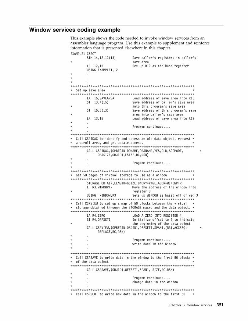
Window services coding exampleThis example shows the code needed to invoke window services from anassembler language program. Use this example to supplement and reinforceinformation that is presented elsewhere in this chapter.EXAMPLE1 CSECT
STM 14,12,12(13) Save caller’s registers in caller’s* save area
LR 12,15 Set up R12 as the base registerUSING EXAMPLE1,12
* .* .* .********************************************************************* Set up save area *********************************************************************
LA 15,SAVEAREA Load address of save area into R15ST 13,4(15) Save address of caller’s save area
* into this program’s save areaST 15,8(13) Save address of this program’s save
* area into caller’s save areaLR 13,15 Load address of save area into R13
* .* . Program continues....* .********************************************************************* Call CSRIDAC to identify and access an old data object, request ** a scroll area, and get update access. *********************************************************************
CALL CSRIDAC,(OPBEGIN,DDNAME,OBJNAME,YES,OLD,ACCMODE, *OBJSIZE,OBJID1,LSIZE,RC,RSN)
* .* . Program continues....* .********************************************************************* Get 50 pages of virtual storage to use as a window *********************************************************************
STORAGE OBTAIN,LENGTH=GSIZE,BNDRY=PAGE,ADDR=WINDWPTRL R3,WINDWPTR Move the address of the window into
* register 3USING WINDOW,R3 Sets up WINDOW as based off of reg 3
********************************************************************* Call CSRVIEW to set up a map of 50 blocks between the virtual ** storage obtained through the STORAGE macro and the data object. *********************************************************************
LA R4,ZERO LOAD A ZERO INTO REGISTER 4ST R4,OFFSET1 Initialize offset to 0 to indicate
* the beginning of the data objectCALL CSRVIEW,(OPBEGIN,OBJID1,OFFSET1,SPAN1,(R3),ACCSEQ, *
REPLACE,RC,RSN)* .* . Program continues....* . write data in the window* .
********************************************************************* Call CSRSAVE to write data in the window to the first 50 blocks ** of the data object *********************************************************************
CALL CSRSAVE,(OBJID1,OFFSET1,SPAN1,LSIZE,RC,RSN)* .* . Program continues....* . change data in the window* .********************************************************************* Call CSRSCOT to write new data in the window to the first 50 *
Chapter 17. Window services 351

* blocks of the scroll area *********************************************************************
CALL CSRSCOT,(OBJID1,OFFSET1,SPAN1,RC,RSN)* .* . Program continues....* . change data in the window* .********************************************************************* Call CSRREFR to refresh the window, that is, get back the last ** SAVEd data in the data object *********************************************************************
CALL CSRREFR,(OBJID1,OFFSET1,SPAN1,RC,RSN)* .* . Program continues....* .********************************************************************* Call CSRIDAC to unidentify and unaccess the data object *********************************************************************
CALL CSRIDAC,(OPEND,DDNAME,OBJNAME,YES,OLD,ACCMODE, *OBJSIZE,OBJID1,LSIZE,RC,RSN)
* .* . Program continues....* .
L 13,SAVEAREA+4LM 14,12,12(13)BR 14 End of EXAMPLE1
ZERO EQU 0 Constant zeroGSIZE EQU 204800 Storage for window of 50 pages (blocks)R3 EQU 3 Register 3R4 EQU 4 Register 4
DS 0DOPBEGIN DC CL5’BEGIN’ Operation type BEGINOPEND DC CL4’END ’ Operation type ENDDDNAME DC CL7’DDNAME ’ Object type DDNAMEOBJNAME DC CL8’MYDDNAME’ DDNAME of data objectYES DC CL3’YES’ Yes for a scroll areaOLD DC CL3’OLD’ Data object already existsACCSEQ DC CL4’SEQ ’ Sequential accessACCMODE DC CL6’UPDATE’ Update mode
REPLACE DC CL7’REPLACE’ Replace data in window on a mapOBJSIZE DC F’524288’ Size of data object is 2 gigSPAN1 DC F’50’ Set up a span of 50 blocksOBJID1 DS CL8 Object identifierLSIZE DS F Logical size of data objectOFFSET1 DS F Offset into data objectRC DS F Return code from serviceRSN DS F Reason code from serviceSAVEAREA DS 18F This program’s save areaWINDWPTR DS F Address of window’s storageWINDOW DSECT Mapping of window to view the
DS 204800C object dataEND
352 z/OS MVS Assembler Services Guide

Chapter 18. Sharing application data (name/token callableservices)
Name/token callable services allow you to share data between two programsrunning under the same task, or between two or more tasks or address spaces. Toshare data, programs often need to locate data or data structures acquired andbuilt by other programs. These data structures and the programs using them neednot reside in the same address space. Name/token callable services provide a wayfor programs to save and retrieve the information needed to locate this data.
Both unauthorized (problem state and PSW key 8-15) and authorized programs(supervisor state or PSW key 0-7) can use name/token callable services.Name/token callable services provide additional function that is available toauthorized programs only. For a description of those functions, see z/OS MVSProgramming: Authorized Assembler Services Guide.
Understanding name/token pairs and levelsName/token callable services enable programs to save and retrieve 16 bytes ofapplication-related data. A program can associate a 16-byte character string (thename) with 16 bytes of user data (the token). Later, the same or a differentprogram can retrieve the token by using the name and calling a name/tokenservice.
By using the appropriate name/token callable service, a program can:v Create a name/token pair (IEANTCR)v Retrieve a token from a name/token pair (IEANTRT)v Delete a name/token pair (IEANTDL).
Name/token pairsA name/token pair consists of a 16-byte character string (name) with 16 bytes ofuser data (token). One program creates the name/token pair, assigns the name,and initializes the token field. Typically, the token is an address of a data structure.
Figure 85 shows the name/token pair and indicates its intended use.
The bytes of the name can have any hexadecimal value and consist of alphabetic ornumeric characters. The name may contain blanks, integers, or addresses.
Name chosen byprogram
Program data
Name
16 bytes 16 bytes
Token
A program can use thename to retrieve theapplication data.
An application can storedata, such as addressesand PC numbers, in thetoken.
Figure 85. Using the Name and the Token
© Copyright IBM Corp. 1988, 2017 353

Names must be unique within a level. Here are some examples.v Two task-level name/token pairs owned by the same task cannot have the same
name. However, two task-level name/token pairs owned by different tasks canhave the same name.
v Two home-address-space-level name/token pairs in the same address spacecannot have the same name. However, two home-address-space-levelname/token pairs in different address spaces can have the same name.
Because of these unique requirements you must avoid using the same names thatIBM uses for name/token pairs. Do not use the following names:v Names that begin with A through Iv Names that begin with X'00'.
The token can have any value.
Levels for name/token pairsName/token pairs have a level attribute associated with them. The level definesthe relationship of the creating program (that is, the program that creates thename/token pair) to the retrieving program (that is, the program that retrieves thedata). Depending on the level you select, the retrieving program can run under thesame task as the creating program, or in the same home address space, in the sameprimary address space, or in the same system.v A task-level name/token pair allows the creating program and retrieving
program to run under the same task.v A home-address-space-level name/token pair allows the creating program and
the retrieving program to run in the same home address space.v A primary-address-space-level name/token pair allows the creating program
and the retrieving program to run in the same primary address space.v A system-level name/token pair allows the creating program and the retrieving
program to run in the same system. That is, the two programs run in separateaddress spaces.
The various name/token levels allow for sharing data between programs that rununder a single task, between programs that run within an address space, andbetween programs that run in different address spaces. Some examples of usingname/token levels are:v Different programs that run under the same task can share data through the use
of a task-level pair.v Any number of tasks that run within an address space can share data through
the use of an address-space pair.
Determining what your program can do with name/token pairsThe following table shows the name/token callable services your program can useto manipulate different levels of name/token pairs:
Table 29. Summary of What Programs Do with Name/Token Pairs
Service Level of pairs
Create (IEANTCR) v Task
v Home
v Primary
354 z/OS MVS Assembler Services Guide

Table 29. Summary of What Programs Do with Name/Token Pairs (continued)
Service Level of pairs
Retrieve (IEANTRT) v Task
v Home
v Primary
v System
Delete (IEANTDL) v Task
v Home
v PrimaryNote: Unauthorized programs cannot delete any pairscreated by authorized programs.
Note: The primary-address-space-level and system-level name/token pairs areintended to be used in a cross-memory environment established by authorizedprograms. For complete descriptions of the primary-level and system-levelname/token pairs, see z/OS MVS Programming: Authorized Assembler Services Guide.
Deciding what name/token level you needTo determine the level to use, consider the relationship between the code thatcreates the pair and the code that retrieves the pair:v If the retrieving code will be running under the same task as the creator's code,
use the task levelv If the retrieving code will have the same home address space but run under a
different task, use the home address space level.
Task-level name/token pairA task-level name/token pair can be used to anchor data that relates to only onetask. Your application program can create and retrieve the data as often as needed.
Figure 86 on page 356 shows the task-level name/token pair for TASK 1.
Chapter 18. Sharing application data (name/token callable services) 355

In a single address space, TASK 1:1. Creates the task-level name/token pair (N1,T1) using the IEANTCR callable
service.2. Retrieves the token at a later time by calling its name (N1) using the IEANTRT
callable service.3. Deletes the name/token pair by calling its name (N1) using the IEANTDL
callable service.
Home-level name/token pairA home-level name/token pair can anchor data for use by programs running inthe creating program's home address space.
Figure 87 on page 357 shows the name/token pairs associated with TASK 1 andTASK 2 running in the address space.
N1 T1
TASK 1
ADDRESS SPACE
TASK-LEVEL NAME/TOKEN PAIR
CALL IEANTCR, (TASKLEV, N1, T1, NOPERSIST, RC)
CALL IEANTRT, (TASKLEV, N1, T1, RC)
CALL IEANTDL, (TASKLEV, N1, RC)
Figure 86. Using the Task Level in a Single Address Space
356 z/OS MVS Assembler Services Guide

In Figure 87, TASK 1:1. Creates a task-level name/token pair (N1,T1) and a home-level name/token
pair (N2,T2) using the IEANTCR callable service. The home-level name/tokenpair is associated with the address space.
2. Retrieves the token from N1,T1 any time during the task's processing.
TASK 2 does the following:1. Retrieves the home-level token from N2,T2 that was created by TASK 1. TASK
2 can retrieve that token because both tasks are running in the same homeaddress space.
2. Creates its own home-level name/token pair (N3,T3) that other tasks runningin the home address space can access.
Owning and deleting name/token pairsName/token pairs created by a program are automatically deleted by the system.The level of the pair determines when the system deletes the pair:
N1 T1
TASK 1
TASK 2
TASK-LEVEL NAME/TOKEN PAIR
ADDRESS SPACE NAME/TOKEN PAIR
CALL IEANTCR, (TASKLEV, N1, T1, NOPERSIST, RC)CALL IEANTCR, (HOMELEV,N2,T2,NOPERSIST,RC)
CALL IEANTRT, (TASKLEV, N1, T1, RC)
CALL IEANTRT, (HOMELEV, N2, T2, TC)
CALL IENTCR, (HOMELEV, N3, T3, NOPERSIST, RC)
N1
N3
T2
T3
Figure 87. Using Home-Level and Task-Level Name/Token Pairs
Chapter 18. Sharing application data (name/token callable services) 357

Note: The words job step in this topic refers to the cross memory resource owning(CMRO) task. While the CMRO task is generally the main job step task, at times itmay be either the initiator task or started task control task (such as between jobs).v Task-level pairs are owned by the task that created them and are deleted when
the owning task terminates.v Home-address-space-level name/token pairs are owned by the job step task of
the home address space that created them and are deleted when the job steptask, rather than the creating task, in the address space terminates; that is,home-level pairs created by subtasks of a task are not automatically deletedwhen the subtask terminates.
v Primary-address-space-level name/token pairs are owned by the job step task ofthe primary address space that created them and are deleted when the job steptask, rather than the creating task, in the address space terminates; that is,primary-level pairs created by subtasks of a task are not automatically deletedwhen the subtask terminates.
Using checkpoint/restart with name/token pairsA program cannot complete a checkpoint operation, by issuing the CHKPT macro,if certain name/token pairs are owned by the program at the time of thecheckpoint. The pairs are:v Task-level name/token pairs not created with a persist_option value of 2 are
owned by the task issuing the CHKPT macro.v Home- or primary-address-space-level name/token pairs owned by the job step
task of the home address space of the task issuing the CHKPT macro.
A checkpoint fails if task- or address-space-level pairs exist because theinformation in the pairs is not saved in the checkpoint data set when thecheckpoint is taken. Because the pair information is not saved, the program cannotbe restored when the restart occurs. For more information aboutcheckpoint/restart, see z/OS DFSMSdfp Checkpoint/Restart.
Link-editing name/token servicesA program that calls the name/token services must be link-edited withIBM-provided name/token linkage-assist routines. The linkage-assist routinesreside in SYS1.CSSLIB. The following example shows the JCL that can link-edit areentrant program with the linkage-assist routines:
//userid JOB ’accounting-info’,’name’,CLASS=x,// MSGCLASS=x,NOTIFY=userid,MSGLEVEL=(1,1),REGION=4096K//LINKSTEP EXEC PGM=HEWL,// PARM=’LIST,LET,XREF,REFR,RENT,SIZE=(1800K,128K)’//SYSPRINT DD SYSOUT=x//SYSLMOD DD DSN=userid.LOADLIB,DISP=OLD//SYSLIB DD DSN=SYS1.CSSLIB,DISP=SHR//OBJLIB DD DSN=userid.OBJLIB,DISP=SHR//SYSUT1 DD UNIT=SYSDA,SPACE=(TRK,(5,2))//SYSLIN DD *
INCLUDE OBJLIB(userpgm)ENTRY userpgmNAME userpgm(R)
/*
358 z/OS MVS Assembler Services Guide
Chapter 19. Processor storage management
The system administers the use of processor storage (that is, central and expandedstorage) and it directs the movement of virtual pages between auxiliary, expanded,and central storage in page size (4096 byte or 4 K-byte) blocks. It makes alladdressable virtual storage in each address space and data space or hiperspaceappear as central storage. Virtual pages necessary for program execution are keptin processor storage while:v The program references the pages frequently enoughv Other programs do not need that same central storage.
The system performs the paging I/O necessary to transfer pages in and out ofcentral storage and also provides DASD allocation and management for pagingI/O space on auxiliary storage.
The system assigns real frames upon request from a pool of available real frames,which associates virtual addresses with real addresses. A limit on the number ofreal frames that can be used by an address space is related to its virtual storagelimits and its memory limits. For more information on these limits, see theChapter 11, “Virtual storage management,” on page 213 section and the z/OS MVSInitialization and Tuning Guide. Frames are repossessed upon termination of use,when freed by a user, when a user is swapped-out, or when needed to replenishthe available pool. While a virtual page occupies a real frame, the page isconsidered pageable unless specified otherwise as a system page that must beresident in central storage. The system also allocates virtual equals central (V=R)regions upon request by those programs that cannot tolerate dynamic relocation.Such a region is allocated contiguously from a predefined area of central storageand is not pageable. Programs in this region do run in dynamic address translation(DAT) mode, although real and virtual addresses are equivalent.
This chapter describes how you can:v Free the virtual storage in your address space and the virtual storage in any data
space that you might have access to– FREEMAIN and STORAGE RELEASE frees specific portions of virtual storage
in address spaces.– DSPSERV DELETE frees all of the virtual storage in a data space or
hiperspace.v Release the central and expanded storage that holds the data that your program
has in virtual storage.– PGRLSE or PGSER RELEASE releases specified portions of virtual storage
contents of an address space.– DSPSERV RELEASE releases specified portions of virtual storage contents of a
data space or hiperspace.v Request that a range of virtual storage pages be made read-only or be made
modifiable.– PGSER PROTECT allows the caller to request that a range of virtual storage
pages be made read-only.– PGSER UNPROTECT allows the caller to request that a range of virtual
storage pages be made modifiable.v Request that the system preload or page out central storage
© Copyright IBM Corp. 1988, 2017 359
|||||

– PGLOAD or PGSER LOAD loads specified virtual storage areas of an addressspace into central storage.
– PGOUT or PGSER OUT pages out specified virtual storage areas of anaddress space from central storage.
– DSPSERV LOAD loads specified virtual storage areas of a data space intocentral storage.
– DSPSERV OUT pages out specified virtual storage areas of a data space fromcentral storage.
v Request that the system preload multiple pages on a page fault.– REFPAT causes the system to preload pages according to a program's
reference pattern. REFPAT is intended for numerically intensive programs.
Freeing virtual storageAll storage obtained for your program by GETMAIN, STORAGE OBTAIN, orDSPSERV CREATE is automatically freed by the system when the job stepterminates. Freeing storage in this manner requires no action on your part.
FREEMAIN or STORAGE RELEASE perform the equivalent of a page release forany resulting free page. The page is no longer available to the issuer. FREEMAINcan free a page that has been protected through the PGSER macro with thePROTECT option. DSPSERV DELETE performs the same action for a data spacethat FREEMAIN and STORAGE RELEASE do for address space virtual storageexcept that for a data space or hiperspace, all of the storage is released.
Releasing storageWhen your program is finished using an area of virtual storage, it can release thestorage to make the central, expanded, or auxiliary storage that actually holds thedata available for other uses. The decision to release the storage depends on thesize of the storage and when the storage will be used again:v For large areas (over 100 pages, for example) that will not be used for five or
more seconds of processor time, consider releasing the storage. If you do notrelease those pages after you are finished using them:– Your program might be using central storage that could better be used for
other purposes.– Your program might have delays later when the system moves your pages
from central storage to expanded or auxiliary storage.v Generally, for smaller amounts of storage that will be used again in five seconds
or less, do not release the storage.
Note that releasing storage does not free the virtual storage.
When releasing storage for an address space, use PGRLSE or PGSER with theRELEASE parameter. As shown in Figure 88 on page 361, if the specified addressesare not on page boundaries, the low address is rounded up and the high address isrounded down; then, the pages contained between the addresses are released.
Note: PGRLSE, PGSER RELEASE, PGSER FREE with RELEASE=Y, and PGFREERELEASE=Y may ignore some or all of the pages in the input range and will notnotify the caller if this was done.
Any pages in the input range that match any of the following conditions will beskipped, and processing continues with the next page in the range:
360 z/OS MVS Assembler Services Guide

v Storage is not allocated or all pages in a segment have not yet been referenced.v Page is in PSA, SQA or LSQA.v Page is V=R. Effectively, it's fixed.v Page is in BLDL, (E)PLPA, or (E)MLPA.v Page has a page fix in progress or a nonzero FIX count.v Pages with COMMIT in progress or with DISASSOCIATE in progress.
When releasing storage for a data space or hiperspace, use the DSPSERVRELEASE macro to release the central, expanded or auxiliary storage that actuallyholds the data. PGSER RELEASE rejects any attempt to release protected storage,including storage that is dynamically protected through PGSER PROTECT. Thestarting address must be on a 4K-byte boundary and you can release data spacestorage only in increments of 4K bytes.
For both address spaces and data spaces, the virtual space remains, but its contentsare discarded. When the using program can discard the contents of a large virtualarea (one or more complete pages) and reuse the virtual space without thenecessity of paging operations, the page release function may improve operatingefficiency.
Protecting a range of virtual storage pagesThe PROTECT option of PGSER makes a range of virtual storage pages read-onlyand helps to improve data integrity. The UNPROTECT option of PGSER makes arange of virtual storage pages modifiable. You can protect private storage bothabove and below 16 megabytes.
IBM recommends that you use PGSER PROTECT only for full pages of storage onpage boundaries. This usage avoids making other areas of storage read-onlyunintentionally. For instance, if you obtain a virtual storage area smaller than apage and then issue PGSER PROTECT, the entire page is made read-only,including the portion of the page that is not part of your storage area.
The system does not keep track of how many times a page has been protected orunprotected. One UNPROTECT cancels all PROTECTs for a given page.
1 page
address 1(low)
address 2(high)
Released virtual storage
Figure 88. Releasing Virtual Storage
Chapter 19. Processor storage management 361

Loading/paging out virtual storage areasThe PGLOAD, PGSER LOAD, and DSPSERV LOAD essentially provide apage-ahead function. By loading specified address space and data space areas intocentral storage, you can attempt to ensure that certain pages will be in centralstorage when needed. Page faults can still occur, however, because these pagesmay be paged out if not referenced soon enough.
Loading and paging for address spaces: With the page load function, you have theoption of specifying that the contents of the virtual area is to remain intact or bereleased. If you specify RELEASE=Y with PGLOAD or PGSER LOAD, the currentcontents of entire virtual 4K pages to be brought in may be discarded and new realframes assigned without page-in operations; if you specify RELEASE=N, thecontents are to remain intact and be used later. If you specify RELEASE=Y, thepage release function will be performed before the page load function. That is, nopage-in is needed for areas defining entire virtual pages since the contents of thosepages are expendable.
Note: PGRLSE, PGSER RELEASE, PGSER FREE with RELEASE=Y, and PGFREERELEASE=Y may ignore some or all of the pages in the input range and will notnotify the caller if this was done.
Any pages in the input range that match any of the following conditions will beskipped, and processing continues with the next page in the range:v Storage is not allocated or all pages in a segment have not yet been referenced.v Page is in PSA, SQA or LSQA.v Page is V=R. Effectively, it's fixed.v Page is in BLDL, (E)PLPA, or (E)MLPA.v Page has a page fix in progress or a nonzero FIX count.v Pages with COMMIT in progress or with DISASSOCIATE in progress.
Loading and paging for data spaces: DSPSERV LOAD requests the starting address ofthe data space area to be loaded and the number of pages that the system is toload. It does not offer a RELEASE=Y or a RELEASE=N function.
PGOUT, PGSER OUT, and DSPSERV OUT initiate page-out operations for specifiedvirtual areas that are in central storage. For address spaces, the real frames will bemade available for reuse upon completion of the page-out operation unless youspecify the KEEPREL parameter in the macro. An area that does not encompassone or more complete pages will be copied to auxiliary storage, but the real frameswill not be freed. DSPSERV LOAD does not have the KEEPREL function.
The proper use of the page load and page out functions tend to decrease systemoverhead by helping the system keep pages currently in use, or soon to be in use,in central storage. An example of the misuse of the page load function is to loadten pages and then use only two.
For more information on DSPSERV LOAD and DSPSERV OUT, see “Paging dataspace storage areas into and out of central storage” on page 309.
362 z/OS MVS Assembler Services Guide

Virtual subarea listThe virtual subarea list (VSL) provides the basic input to the page service functionsthat use a 24-bit interface: PGLOAD, PGRLSE, and PGOUT. The list consists of oneor more doubleword entries, with each entry describing an area of virtual storage.The list must be non-pageable and contained in the address space of the subarea tobe processed.
Each VSL entry has the following format. The flag bits that are described are theonly flag bits that are intended for customer use.
Table 30. Format of a virtual subarea list (VSL) entry
Byte: 0 1 2 3 4 5 6 7
Contents: Flags StartAddress
Flags EndAddress + 1
Byte Contents
Byte 0 Flags:
Bit Meaning when set1... .... Bit 0 indicates that bytes 1 - 3 are a chain pointer to the next VSL
entry to be processed; bytes 4-7 are ignored. This feature allowsseveral parameter lists to be chained as a single logical parameterlist.
Byte 1 Start address: The address of the origin of the virtual area to be processed.
Byte 3 Flags
Bit Meaning when set1... .... Bit 0 indicates the last entry of the list. It is set in the last
doubleword entry in the list..1.. .... Bit 1 indicates that this entry is to be ignored....1 .... Bit 3 indicates that a return code of 4 was issued from a page
service function other than PGRLSE.
Byte 4 End address + 1: The address of the byte immediately following the end ofthe virtual area.
Page service list (PSL)The page services list provides the basic input to the page service function for thePGSER macro. Specify 31-bit addresses in the PSL entries. Within a PSL entry, youcan also nullify a service on a range of addresses by indicating that you do notwant to perform the service for that range.
Each 12-byte PSL entry has the following form:
Bytes Meaning
0-3 Bit 0 of byte 0 must be 0. Each PSL entry specifies the range of addressesfor which a service is to be performed or points to the first PSL entry in anew list of concatenated PSL entries that are to be processed.
4-7 Bit 0 of byte 4 must be 0. If bytes 0-3 contain the starting address, thesebytes contain the address of the last byte for which the page service is tobe performed. You do not need to do anything with bytes 4-7 if yousupplied a pointer in bytes 0-3.
Chapter 19. Processor storage management 363

8 Flags set by the caller as follows. The flag bits that are described are theonly flag bits intended for customer use.
Bit Meaning
0 Set to 1 to indicate that this is the last PSL entry in a concatenationof PSL entries.
1 Set to 1 to indicate that no services are to be performed for therange of addresses specified.
2 Set to 1 to indicate that bytes 0-3 contain a pointer to the next PSL.
9-11 For IBM use only.
Defining the reference pattern (REFPAT)The REFPAT macro allows a program to define a reference pattern for a specifiedarea that the program is about to reference. Additionally, the program specifieshow much data it wants the system to attempt to bring into central storage on apage fault. The system honors the request according to the availability of centralstorage. By bringing in more data at a time, the system takes fewer page faults;fewer page faults means possible improvement in performance.
Programs that benefit from REFPAT are those that reference amounts of data thatare greater than one megabyte. The program should reference the data in asequential manner, either forward or backward. In addition, if the program “skipsover” certain areas, and these areas are of uniform size and are repeated at regularintervals, REFPAT might provide additional performance improvement. AlthoughREFPAT affects movement of pages from auxiliary and expanded storage, thegreatest gain is for movement of pages from auxiliary storage.
There are two REFPAT services:v REFPAT INSTALL identifies the data area and the reference pattern, and
specifies the number of bytes that the system is to try to bring into centralstorage at one time. These activities are called “defining the reference pattern”.
v REFPAT REMOVE removes the definition; it tells the system that the programhas stopped using the reference pattern for the specified data area.
A program might have a number of different ways of referencing a particular area.In this case, the program can issue multiple pairs of REFPAT INSTALL andREFPAT REMOVE macros for that area.
Each pattern, as defined on REFPAT INSTALL, is associated with the task thatrepresents the caller. A task can have up to 100 reference patterns defined formultiple data areas at one time, but cannot have more than one pattern defined forthe same area. Other tasks can specify a different reference pattern for the samedata area. REFPAT REMOVE removes the association between the pattern and thetask.
The data area can be in the primary address space or in a data space owned by atask that was dispatched in the primary address space. If the data area is in a dataspace, identify the data space through its STOKEN. You received the STOKENeither from DSPSERV or from another program.
Although REFPAT can be used for data structures other than arrays, for simplicity,examples in this chapter use REFPAT for an array or part of an array.
364 z/OS MVS Assembler Services Guide
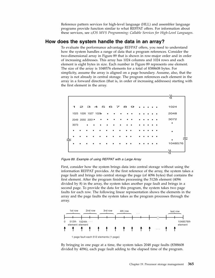
Reference pattern services for high-level language (HLL) and assembler languageprograms provide function similar to what REFPAT offers. For information aboutthese services, see z/OS MVS Programming: Callable Services for High-Level Languages.
How does the system handle the data in an array?To evaluate the performance advantage REFPAT offers, you need to understandhow the system handles a range of data that a program references. Consider thetwo-dimensional array in Figure 89 that is shown in row-major order and in orderof increasing addresses. This array has 1024 columns and 1024 rows and eachelement is eight bytes in size. Each number in Figure 89 represents one element.The size of the array is 1048576 elements for a total of 8388608 bytes. Forsimplicity, assume the array is aligned on a page boundary. Assume, also, that thearray is not already in central storage. The program references each element in thearray in a forward direction (that is, in order of increasing addresses) starting withthe first element in the array.
First, consider how the system brings data into central storage without using theinformation REFPAT provides. At the first reference of the array, the system takes apage fault and brings into central storage the page (of 4096 bytes) that contains thefirst element. After the program finishes processing the 512th element (4096divided by 8) in the array, the system takes another page fault and brings in asecond page. To provide the data for this program, the system takes two pagefaults for each row. The following linear representation shows the elements in thearray and the page faults the system takes as the program processes through thearray.
By bringing in one page at a time, the system takes 2048 page faults (8388608divided by 4096), each page fault adding to the elapsed time of the program.
1025 1026 1027 1028
2049 2050 2051
3073
1024
2048
3072
1048576. . . . .. . . . .. . . . .. . . . .. . . . .. . . . .. . . . .
. . . . . . . . . .
. . . . . . . . . .
. . . . . . . . . .. . . . . . . .
. . . . . . .. . . . . .
.
.
.
1 2 3 4 5 6 7 8 9
Figure 89. Example of using REFPAT with a Large Array
0 512th 1024th . . .
. . .
element element
. . .
1 page fault each 512 elements (1 page)
1048576th
element
1st row 2nd row 3rd row 4th row last row
Chapter 19. Processor storage management 365

Suppose, through REFPAT, the system knew in advance that a program would beusing the array in a consistently forward direction. The system could then assumethat the program's use of the pages of the array would be sequential. To decreasethe number of page faults, each time the program requested data that was not incentral storage, the system could bring in more than one page at a time. Supposethe system brought the next 20 consecutive pages (81920 bytes) of the array intocentral storage on each page fault. In this case, the system takes not 2048 pagefaults, but 103 (8388608 divided by 81920=102.4). Page faults occur in the array asfollows:
The system brings in successive pages only to the end of the array.
Consider another way of referencing this same array. The program references thefirst twenty elements in each row, then skips over the last 1004 elements, and soforth through the array. REFPAT allows you to tell the system to bring in only thepages that contain the data in the first 20 columns of the array, and not the pagesthat contain only data in columns 21 through 1024. In this case, the referencepattern includes a repeating gap of 8032 bytes (1004×8) every 8192 bytes (1024×8).The pattern looks like this:
The grouping of consecutive bytes that the program references is called a referenceunit. The grouping of consecutive bytes that the program skips over is called agap. Reference units and gaps alternate throughout the data area. The referencepattern is as follows:v The reference unit is 20 elements in size — 160 consecutive bytes that the
program references.v The gap is 1004 elements in size — 8032 consecutive bytes that the program
skips over.
Figure 90 on page 367 illustrates this reference pattern and shows the pages thatthe system does not bring into central storage.
What pages does the system bring in when a gap exists?When no gap exists, the system brings into central storage all the pages thatcontain the data in the range you specify on REFPAT. When there is a gap, theanswer depends on the size of the gap, the size of the reference unit, and thealignment of reference units and gaps on page boundaries. The following examplesillustrate those factors.
Example 1: The following illustration shows the 1024-by-1024 array of eight-byteelements, where the program references the first 20 elements in each row and skips
. . .
rows 1-10 rows 21-30 rows 31-40 rows 1021-1024rows 11-20
1 page fault each 10240 elements
skip skip skip
. . .
skip
309330732069204910451025
elements ...211
366 z/OS MVS Assembler Services Guide

over the next 1004 elements. The reference pattern, therefore, includes a referenceunit of 160 bytes and a gap of 8032 bytes. The reference units begin on every otherpage boundary.
Every other page of the data does not come into central storage; those pagescontain only the “skipped over” data.
Example 2: The reference pattern includes a reference unit of 4800 bytes and a gapof 3392 bytes. The example assumes that the area to be referenced starts on a pageboundary.
Because each page contains data that the program references, the system brings inall pages.
Example 3: The area to be referenced does not begin on a page boundary. Thereference pattern includes a reference unit of 2000 bytes and a gap of 5000 bytes.Because the reference pattern includes a gap, the first byte of the reference patternmust begin a reference unit, as the following illustration shows:
Because the gap is larger than 4095 bytes, some pages do not come into centralstorage. Notice that the system does not bring in the fifth page.
Summary of how the size of the gap affects the pages the system brings intocentral storage:v If the gap is less than 4096 bytes, the system has to bring into central storage all
pages of the array. (See Example 2.)
1st 2nd 3rd 4th 5th 6th 7thpagepagepage page page page page
all pages brought into central storage
reference units
page2048th
Figure 90. Illustration of a Reference Pattern with a Gap
1st 2nd 3rd 4th 5th 6th 7thpagepagepage page page page page
all pages brought into central storage
reference units
page2048th
1st 2nd 3rd 4th 5th 6th 7thpagepagepage page page page page
most pages brought into central storage
Start of
reference
pattern
Chapter 19. Processor storage management 367

v If the gap is greater than 4095 bytes and less than 8192, the system might nothave to bring in certain pages. Pages that contain only data in the gap are notbrought in. (See Examples 1 and 3.)
v If the gap is greater than 8191 bytes, the system definitely does not have to bringin certain pages that contain the gap.
Using the REFPAT macroOn the REFPAT macro, you tell the system:v The starting and ending addresses of the data area to be referencedv The reference patternv The number of reference units the system is to bring into central storage on a
page fault.
Specify the reference pattern carefully on REFPAT. If you identify a pattern and donot adhere to it, the system will have to work harder than if you had not issuedthe macro. “Defining the reference pattern” on page 369 can help you define thereference pattern.
The system will not process the REFPAT macro unless the values you specify canresult in a performance gain for your program. To make sure the system processesthe macro, ask the system to bring in more than three pages (that is, 12288 bytes)on each page fault. “Choosing the number of bytes on a page fault” on page 370can help you meet that requirement.
Identifying the data area and direction of referenceOn the PSTART and PEND parameters, you specify the starting and endingaddresses of the area to be referenced. If the reference is in a backward direction,the ending address will be smaller than the starting address.
PSTART identifies the first byte of the data area that the program references withthe defined pattern; PEND identifies the last byte.
When a gap exists, define PSTART and PEND according to the following rules:v If direction is forward, PSTART must be the first byte (low-address end) of a
reference unit; PEND can be any part of a reference unit or a gap.v If direction is backward, PSTART must be the last byte (high-address end) of a
reference unit; PEND can be any part of a reference unit or a gap.
Figure 91 illustrates a reference pattern that includes a reference unit of 2000 bytesand a gap of 5000 bytes. When direction is forward, PSTART must be thebeginning of a reference unit. PEND can be any part of a gap or reference unit.
1st 2nd 3rd 4th 5th 6th 7thpagepagepage page page page page
PSTART PEND
forward direction
low address of range
Figure 91. Illustration of Forward Direction in a Reference Pattern
368 z/OS MVS Assembler Services Guide

Figure 92 illustrates the same reference pattern and the same area; however, thedirection is backward. Therefore, PSTART must be the last byte of a reference unitand PEND can be any part of a gap or reference unit.
If the data area is in a data space, use the STOKEN parameter to identify the dataspace. You received the STOKEN of the data space from another program or fromthe DSPSERV macro when you created the data space. STOKEN=0, the default,tells the system that the data is in the primary address space.
Defining the reference patternThis information assumes that your program's reference pattern meets the basicrequirement of consistent direction. Figure 93 identifies tw o reference patterns thatcharacterize most of the reference patterns that REFPAT applies to. The marks onthe line indicate referenced elements.
How you define the reference pattern depends on whether your program'sreference pattern is like Pattern #1 or Pattern #2.v With Pattern #1 where no uniform gap exists, the program uses every element,
every other element, or at least most elements on each page of array data. No
1st 2nd 3rd 4th 5th 6th 7thpagepagepage page page page page
PSTARTPEND
backward direction
high address of range
Figure 92. Illustration of Backward Direction in a Reference Pattern
Pattern #1:
0 4096 8192 12288 16384 20480
. . .
Uniform gap
0 20 5020 10040 10060 15080bytes bytes bytes bytes bytes bytes bytes bytes
. . .
xxxxxxxxxxxxxxxxxxxxxxxxxxxxxxxxxxxxxxxxxxxxxxxxxxxxxxxxxxxxxxxxxxxxxxxxxxxxxxxxxxxxxxx
Pattern #2:
No uniform gap
5040 15060 20080
xxxxx xxxxx xxxxxxxxxx
Characteristics of pattern:- Gaps of uniform size- Reference units, uniform in size, that occur in a repeating pattern
Characteristics of pattern:- No uniform gap- Reference in regular intervals (such as every element) or in irregular intervals
Figure 93. Two Typical Reference Patterns
Chapter 19. Processor storage management 369

definable gap exists. Do not use REFPAT if the reference pattern is irregular andincludes skipping over many areas larger than a page.– The UNITSIZE parameter alone identifies the reference pattern. (Either omit
the GAP parameter or take the default, GAP=0.) UNITSIZE indicates thenumber of bytes you want the system to use as a reference unit. Look atlogical groupings of bytes, such as one row, a number of rows, or oneelement, if the elements are large in size. Or, you might choose to divide upthe total area, bringing in all the data on a certain number of page faults.
– The UNITS parameter tells the system how many reference units to try tobring in on a page fault. For a reference pattern that begins on a pageboundary and has no gap, the total number of bytes the system tries to bringinto central storage at a time is the value on UNITSIZE times the number onUNITS, rounded up to the nearest multiple of 4096. See “Choosing thenumber of bytes on a page fault” for more information on how to choose thetotal number of bytes.
v With Pattern #2 where a uniform gap exists, you tell the system the sizes ofreference units and gaps.– UNITSIZE and GAP parameters identify the reference pattern. Pattern #2 in
Figure 93 on page 369 includes a reference unit of 20 bytes and a gap of 5000bytes. Because the gap is greater than 4095, some pages of the array mightnot come into central storage.
– The UNITS parameter tells the system how many reference units to try tobring into central storage at a time. “What pages does the system bring inwhen a gap exists?” on page 366 can help you understand how many bytescome into central storage at one time.
Although the system brings in pages 4096 bytes at a time, you do not have tospecify GAP, UNITS, and UNITSIZE values in increments of 4096.
Choosing the number of bytes on a page faultAn important consideration in using REFPAT is how many bytes to ask the systemto bring in on a page fault. To determine this, you need to understand some factorsthat affect the performance of your program.
Pages do not stay in central storage if they are not referenced frequently enoughand other programs need that central storage. The longer it takes for a program tobegin referencing a page in central storage, the greater the chance that the page hasbeen moved out to auxiliary storage before being referenced. When you tell thesystem how many bytes it should try to bring into central at one time, you have toconsider the following:1. Contention for central storage
Your program contends for central storage along with all other submitted jobs.The greater the size of central storage, the more bytes you can ask the systemto bring in on a page fault. The system responds to REFPAT with as much ofthe data you request as possible, given the availability of central storage.
2. Contention for processor time
Your program contends for the processor's attention along with all othersubmitted jobs. The more competition, the less the processor can do for yourprogram and the smaller the number of bytes you should request.
3. The elapsed time of processing one page of your data
How long it takes a program to process a page depends on the number ofreferences per page and the elapsed time per reference. If your program usesonly a small percentage of elements on a page and references them only once
370 z/OS MVS Assembler Services Guide

or twice, the program completes its use of pages quickly. If the processing ofeach referenced element includes processor-intensive operations or atime-intensive operation, such as I/O, the time the program takes to process apage gets longer.
Conditions might vary between the peak activity of the daytime period and thelow activity of other periods. For example, you might be able to request a greaternumber in the middle of the night than during the day.
What if you specify too many bytes? What if you ask the system to bring in so manypages that, by the time your program needs to use some of those pages, they haveleft central storage? The answer is that the system will have to bring them inagain. This action causes an extra page fault and extra system overhead andreduces the benefit of reference pattern services.
For example, suppose you ask the system to bring in 204800 bytes, or 50 pages, ata time. But, by the time your program begins referencing the data on the 30thpage, the system has moved that page and the ones after it out of central storage.(It moved them out because the program did not use them soon enough.) In thiscase, your program has lost the benefit of moving the last 21 pages in. Yourprogram would get more benefit by requesting fewer than 30 pages.
What if you specify too few bytes? If you specify too small a number, the system willtake more page faults than it needs to and you are not taking full advantage ofreference pattern services.
For example, suppose you ask the system to bring in 40960 bytes (10 pages) at atime. Your program's use of each page is not time-intensive, meaning that theprogram finishes using the pages quickly. The program can request a numbergreater than 10 without causing additional page faults.
IBM recommends that you use one of the following approaches, depending onwhether you want to involve your system programmer in the decision.v The first approach is the easier one. Choose a conservative number of bytes,
around 81920 (20 pages), and run the program. Look for an improvement in theelapsed time. If you like the results, you might increase the number of bytes. Ifyou continue to increase the number, at some point you will notice adiminishing improvement or even an increase in elapsed time. Do not ask for somuch that your program or other programs suffer from degraded performance.
v A second approach is for the program that needs very significant performanceimprovements — those programs that require amounts in excess of 50 pages. Ifyou have such a program, you and your system programmer must examine theprogram's elapsed time, paging speeds, and processor execution times. In fact,the system programmer can tune the system with your program in mind andprovide needed paging resources. See z/OS MVS Initialization and Tuning Guidefor information on tuning the system.REFPAT affects movement of pages from auxiliary and your system programmerwill need the kind of information that the SMF Type 30 record provides. A Type30 record reports counts of pages moved (between expanded and central andbetween auxiliary and central) in anticipation of your program's use of thosepages. It also provides elapsed time values. Use this information to calculaterates of movement in determining whether to specify a very large number ofbytes — for example, an amount greater than 204800 bytes (50 pages).
Chapter 19. Processor storage management 371

Examples of using REFPAT to define a reference patternTo clarify the relationships between the UNITSIZE, UNITS, and GAP parameters,this information contains three examples of defining a reference pattern. So thatyou can compare the three examples with what the system does withoutinformation from REFPAT, the following REFPAT invocation approximates thesystem's normal paging operation:REFPAT INSTALL,PSTART=. . .,PEND=. . .,UNITSIZE=4096,GAP=0,UNITS=1
Each time the system takes a page fault, it brings in 4096 bytes, the system'sreference unit. It brings in one reference unit at a time.
Example 1: The program processes an array in a consistently forward direction fromone reference unit to the next. The processing of each element is fairly simple. Theprogram runs during the peak hours and many programs compete for processortime and central storage. A reasonable value to choose for the number of bytes tobe brought into central storage on a page fault might be 80000 bytes (around 20pages). A logical grouping of bytes (the UNITSIZE parameter) is 4000 bytes. Thefollowing REFPAT macro communicates this pattern to the system:REFPAT INSTALL,PSTART=FIRSTB,PEND=LASTB,UNITSIZE=4000,GAP=0,UNITS=20
Example 2: The program performs the same process as in the first example, exceptthe program references few elements on each page. The program runs during thenight hours when contention for the processor and for central storage is light. Inthis case, a reasonable value to choose for the number of bytes to come into centralstorage on a page fault might be 200000 bytes (around 50 pages). UNITSIZE can be4000 bytes and UNITS can be 500. The following REFPAT macro communicates thispattern:REFPAT INSTALL,PSTART=FIRSTB,PEND=LASTB,UNITSIZE=4000,GAP=0,UNITS=500
Example 3: The program references in a consistently forward direction through thesame large array as in the second example. The pattern of reference includes a gap.The program references 8192 bytes, then skips the next 4096 bytes, references thenext 8192 bytes, skips the next 4096 bytes, and so forth throughout the array. Theprogram chooses to bring in data eight pages at a time. Because of the size of thegap and the placement of reference units and gaps on page boundaries, the systemdoes not bring in the data in the gaps. The following illustration shows thisreference pattern:
The following REFPAT macro reflects this reference pattern:REFPAT INSTALL,PSTART=FIRSTB,PEND=LASTB,UNITSIZE=8192,GAP=4096,UNITS=4
where the system is to bring into central storage 32768 (4×8192) bytes on a pagefault.
Removing the definition of the reference patternWhen a program is finished referencing the data area in the way you specified onthe REFPAT INSTALL macro, use REFPAT REMOVE to tell the system to return to
12288
bytes20480
bytes
24576
bytes
32768
bytes
36864
bytes
0
bytes. . .
8192
bytes
FIRSTB LASTB
372 z/OS MVS Assembler Services Guide

normal paging. On the PSTART and PEND parameters, you specify the samevalues that you specified on the PSTART and PEND parameters that defined thereference pattern for the area. If you used the STOKEN parameter on REFPATINSTALL, use it on REFPAT REMOVE.
The following REFPAT invocation removes the reference pattern that was definedin Example 3 in “Examples of using REFPAT to define a reference pattern” on page372:REFPAT REMOVE,PSTART=FIRSTB,PEND=LASTB
Chapter 19. Processor storage management 373

374 z/OS MVS Assembler Services Guide

Chapter 20. Sharing data in virtual storage (IARVSERV macro)
With the shared pages function, which is available through the IARVSERV macro,you can define virtual storage areas through which data can be shared byprograms within or between address spaces or data spaces. Also, the type ofstorage access can be changed.
Sharing reduces the amount of processor storage required and the I/O necessary tosupport data applications that require access to the same data. For example,IARVSERV provides a way for a program running below 16 megabytes, in 24-bitaddressing mode, to access data above 16 megabytes that it shares with 31-bitmode programs. IARVSERV allows the sharing of data without the central storageconstraints and processor overhead of other existing methods of sharing data.
The sharing of data benefits many types of applications, because data is availableto all sharing applications with no increase in storage usage. This function is usefulfor applications in either a sysplex environment or a single-system environment.Additionally, IARVSERV allows you to control whether a sharing program:v Has read access onlyv Has both read and write access and receives updates immediatelyv Can modify the data without modifying the original, and without allowing the
sharing programs to view the updatesv Can modify the original while sharing programs see the change, but without
allowing the sharing programs to change the datav Can change the current storage access
An additional macro, IARR2V, is provided as an aid to converting central storageaddresses to virtual storage addresses. See “Converting a central to virtual storageaddress (IARR2V macro)” on page 383 for information on the IARR2V macro.
The IARVSERV topics described in this chapter are:v Understanding the concepts of sharing data with IARVSERVv Storage you can use with IARVSERVv Obtaining storage for the source and targetv Defining storage for sharing data and accessv Changing storage accessv How to share and unshare datav Accessing data in a sharing groupv Example of sharing storage with IARVSERVv Use with data-in-virtual (DIV macro)v Diagnosing problems with shared data
For coding information about the IARVSERV and IARR2V macros, see z/OS MVSProgramming: Assembler Services Reference IAR-XCT.
© Copyright IBM Corp. 1988, 2017 375

Understanding the concepts of sharing data with IARVSERVAs you read this information, refer to Figure 94 for an illustration of the sharingdata through the IARVSERV macro.
Suppose that Addr Space A contains data that is required by programs in AddrSpace B. A program in Addr Space A can use IARVSERV to define that data to beshared; that data and the storage it resides in are called the source. The programalso defines storage in Addr Space B to receive a copy of the source; that storageand its copy of source data are called the target.
The source and its corresponding target form a sharing group. A sharing groupcan consist of several target areas and one source. For example, suppose anotherprogram in Addr Space A defines a portion of data1 (in Addr Space A) as source,and defines a target in Data Space X. That target becomes a member of the sharinggroup established previously.
All sharing of data is done on a page (4K) basis. If the source page is already amember of an existing sharing group, the target becomes a member of that existingsharing group. A page is called a sharing page if it is a member of a sharinggroup.
Programs that access the source or targets are called sharing programs. Eachsharing program accesses the shared virtual storage as it would any other storage,and may not need to know that the storage is being shared. So, you can allowprograms to share data through IARVSERV without having to rewrite existingprograms.
Storage you can use with IARVSERVYou can share data in address spaces and data spaces. You can use any storage towhich you have valid access, except for a hiperspace, a VIO window, a V=Rregion, the PSA or the nucleus (read-only, extended read-only, read-write andextended read-write areas).
The maximum number of shared pages for a program in problem state with PSWkey 8-15 is 32, unless this number is modified by your installation. This numberincludes both the source and targets, so the actual number of unique pages is 16.
Addr SpaceA
Addr SpaceB
data1
source
data1
target
Data SpaceX
data1
target
SHARE SHARE
Figure 94. Data Sharing with IARVSERV
376 z/OS MVS Assembler Services Guide

In order to expedite the return of all internal control blocks for the shared storageback to the system, IBM recommends issuing IARVSERV UNSHARE against allviews for both source and target that are originally shared. For an example of howto code the UNSHARE parameter, see z/OS MVS Programming: Assembler ServicesReference IAR-XCT.
Obtaining storage for the source and targetBefore you can issue IARVSERV to define storage as shared, you must obtain orcreate both the source and target areas. For address space storage, use theGETMAIN or STORAGE macro; for data space storage, use the DSPSERV macro.The source and target areas must be as follows:v Start on a page boundary,v Have the same storage protect key and fetch-protection status (except for
TARGET_VIEW=UNIQUEWRITE or TARGET_VIEW=LIKESOURCE and thesource has UNIQUEWRITE view),
v Meet one of the following requirements:– Reside within pageable private storage of an address space.– Reside within the valid size of an existing data space and be pageable
storage.
The source and the target must be two different storage areas. They must bedifferent virtual storage addresses or reside in different address or data spaces.
Then initialize the source with data. Make sure any storage you obtain or dataspace you create can be accessed by the intended sharing programs. For example,if you want to allow sharing programs to both read and modify a target, theprograms' PSW key value must match or override the target's storage protectionkey. For information on data spaces, see Chapter 16, “Data spaces andhiperspaces,” on page 295.
Note: Do not allocate key 8 or key 9 storage in the common area because it can beread or written by any program in any address space.
Defining storage for sharing data and accessWith the IARVSERV macro, you can define multiple types of data sharing andaccess. As you read this information, use Figure 94 on page 376 to see how eachIARVSERV parameter acts on the current state of the data. Each type of datasharing access is called a specific view of the source data. A view is the way yourprogram accesses, or sees, the data. You define the view in the TARGET_VIEWparameter on IARVSERV, by specifying one of the following:v Read-only view (READONLY value) — where the target data may not be
modified.v Shared-write view (SHAREDWRITE value) — where the target data can be read
and modified through the view.v Copy-on-write view (UNIQUEWRITE value) — where the source data
modifications are not seen by other source - sharing programs. Any attempt tomodify the shared source data in this view causes MVS to create a unique targetcopy of the affected page for that address or data space.An example of two different cases:
Chapter 20. Sharing data in virtual storage (IARVSERV macro) 377
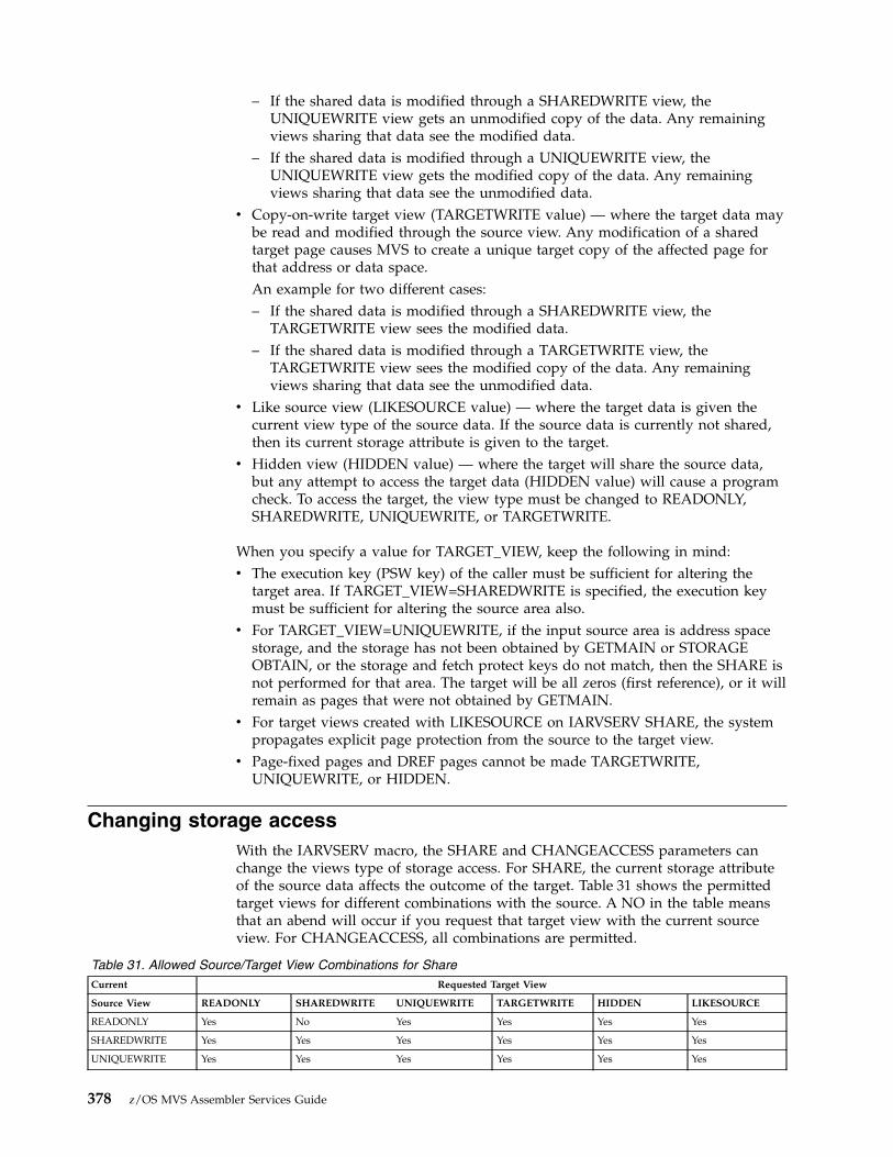
– If the shared data is modified through a SHAREDWRITE view, theUNIQUEWRITE view gets an unmodified copy of the data. Any remainingviews sharing that data see the modified data.
– If the shared data is modified through a UNIQUEWRITE view, theUNIQUEWRITE view gets the modified copy of the data. Any remainingviews sharing that data see the unmodified data.
v Copy-on-write target view (TARGETWRITE value) — where the target data maybe read and modified through the source view. Any modification of a sharedtarget page causes MVS to create a unique target copy of the affected page forthat address or data space.An example for two different cases:– If the shared data is modified through a SHAREDWRITE view, the
TARGETWRITE view sees the modified data.– If the shared data is modified through a TARGETWRITE view, the
TARGETWRITE view sees the modified copy of the data. Any remainingviews sharing that data see the unmodified data.
v Like source view (LIKESOURCE value) — where the target data is given thecurrent view type of the source data. If the source data is currently not shared,then its current storage attribute is given to the target.
v Hidden view (HIDDEN value) — where the target will share the source data,but any attempt to access the target data (HIDDEN value) will cause a programcheck. To access the target, the view type must be changed to READONLY,SHAREDWRITE, UNIQUEWRITE, or TARGETWRITE.
When you specify a value for TARGET_VIEW, keep the following in mind:v The execution key (PSW key) of the caller must be sufficient for altering the
target area. If TARGET_VIEW=SHAREDWRITE is specified, the execution keymust be sufficient for altering the source area also.
v For TARGET_VIEW=UNIQUEWRITE, if the input source area is address spacestorage, and the storage has not been obtained by GETMAIN or STORAGEOBTAIN, or the storage and fetch protect keys do not match, then the SHARE isnot performed for that area. The target will be all zeros (first reference), or it willremain as pages that were not obtained by GETMAIN.
v For target views created with LIKESOURCE on IARVSERV SHARE, the systempropagates explicit page protection from the source to the target view.
v Page-fixed pages and DREF pages cannot be made TARGETWRITE,UNIQUEWRITE, or HIDDEN.
Changing storage accessWith the IARVSERV macro, the SHARE and CHANGEACCESS parameters canchange the views type of storage access. For SHARE, the current storage attributeof the source data affects the outcome of the target. Table 31 shows the permittedtarget views for different combinations with the source. A NO in the table meansthat an abend will occur if you request that target view with the current sourceview. For CHANGEACCESS, all combinations are permitted.
Table 31. Allowed Source/Target View Combinations for ShareCurrent Requested Target View
Source View READONLY SHAREDWRITE UNIQUEWRITE TARGETWRITE HIDDEN LIKESOURCE
READONLY Yes No Yes Yes Yes Yes
SHAREDWRITE Yes Yes Yes Yes Yes Yes
UNIQUEWRITE Yes Yes Yes Yes Yes Yes
378 z/OS MVS Assembler Services Guide

Table 31. Allowed Source/Target View Combinations for Share (continued)Current Requested Target View
TARGETWRITE No No Yes No No Yes
HIDDEN (Shared) No No No No No Yes
Non-Shared Yes Yes Yes Yes Yes Yes
HIDDEN(Non-Shared)
No No No No No Yes
The following apply when using IARVSERV SHARE when changing storageaccess:v For source views to be either UNIQUEWRITE or TARGETWRITE, the processor
must have the Suppression-On-Protection (SOP) hardware feature, and aprevious IARVSERV SHARE must have created a view of UNIQUEWRITE orTARGETWRITE.
v For target views to be TARGETWRITE, the processor must have the SOPhardware feature. If a request is made to create a TARGETWRITE view and theSOP feature is not installed, the request fails with a return code of 8.
v For target views to be UNIQUEWRITE, the SOP hardware feature must beinstalled. Also, the request must not specify COPYNOW. If the request specifiesCOPYNOW, or the SOP feature is not installed, a UNIQUEWRITE view is notestablished, and a separate copy of the data is made.
v For target views created with LIKESOURCE on IARVSERV SHARE, the systempropagates explicit page protection from the source to the target view.
v For source pages that are not shared, if the page is page-protected, the viewcreated for that page is a SHAREDWRITE view, but the view is flagged as anexplicitly protected view (one that cannot be modified).
The following apply when changing the storage access with IARVSERVCHANGEACCESS:v To remove hidden status, you must use an IARVSERV CHANGEACCESS,
FREEMAIN, or DSPSERV DELETE macro.v To remove explicit read-only protection status, you must use an IARVSERV
CHANGEACCESS, FREEMAIN, DSPSERV DELETE, or PGSER UNPROTECTmacro.
v If a hidden page is hidden because of loss of access to 'mapped' data (such asthrough DIV UNMAP), and, if the page is changed from hidden, the data in thepage might be lost.
v Hidden pages cannot be released via a PGSER RELEASE or DSPSERV RELEASEmacro. An attempt would result in an abend with the same reason code as isused for protected pages.
v Issuing an IARVSERV UNSHARE macro for the original mapped page causesthe data to be retained for that page. The data for the other sharing pages is lost.References to hidden pages cause an X'0C4' abend, and references to lost pagescause in a X'028' abend.
v Page-fixed pages and DREF pages cannot be made TARGETWRITE,UNIQUEWRITE, or HIDDEN.
Chapter 20. Sharing data in virtual storage (IARVSERV macro) 379
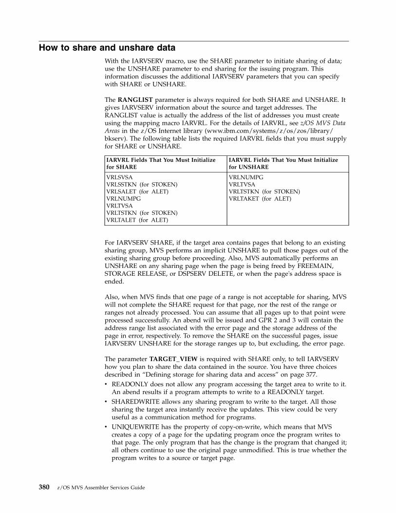
How to share and unshare dataWith the IARVSERV macro, use the SHARE parameter to initiate sharing of data;use the UNSHARE parameter to end sharing for the issuing program. Thisinformation discusses the additional IARVSERV parameters that you can specifywith SHARE or UNSHARE.
The RANGLIST parameter is always required for both SHARE and UNSHARE. Itgives IARVSERV information about the source and target addresses. TheRANGLIST value is actually the address of the list of addresses you must createusing the mapping macro IARVRL. For the details of IARVRL, see z/OS MVS DataAreas in the z/OS Internet library (www.ibm.com/systems/z/os/zos/library/bkserv). The following table lists the required IARVRL fields that you must supplyfor SHARE or UNSHARE.
IARVRL Fields That You Must Initializefor SHARE
IARVRL Fields That You Must Initializefor UNSHARE
VRLSVSAVRLSSTKN (for STOKEN)VRLSALET (for ALET)VRLNUMPGVRLTVSAVRLTSTKN (for STOKEN)VRLTALET (for ALET)
VRLNUMPGVRLTVSAVRLTSTKN (for STOKEN)VRLTAKET (for ALET)
For IARVSERV SHARE, if the target area contains pages that belong to an existingsharing group, MVS performs an implicit UNSHARE to pull those pages out of theexisting sharing group before proceeding. Also, MVS automatically performs anUNSHARE on any sharing page when the page is being freed by FREEMAIN,STORAGE RELEASE, or DSPSERV DELETE, or when the page's address space isended.
Also, when MVS finds that one page of a range is not acceptable for sharing, MVSwill not complete the SHARE request for that page, nor the rest of the range orranges not already processed. You can assume that all pages up to that point wereprocessed successfully. An abend will be issued and GPR 2 and 3 will contain theaddress range list associated with the error page and the storage address of thepage in error, respectively. To remove the SHARE on the successful pages, issueIARVSERV UNSHARE for the storage ranges up to, but excluding, the error page.
The parameter TARGET_VIEW is required with SHARE only, to tell IARVSERVhow you plan to share the data contained in the source. You have three choicesdescribed in “Defining storage for sharing data and access” on page 377.v READONLY does not allow any program accessing the target area to write to it.
An abend results if a program attempts to write to a READONLY target.v SHAREDWRITE allows any sharing program to write to the target. All those
sharing the target area instantly receive the updates. This view could be veryuseful as a communication method for programs.
v UNIQUEWRITE has the property of copy-on-write, which means that MVScreates a copy of a page for the updating program once the program writes tothat page. The only program that has the change is the program that changed it;all others continue to use the original page unmodified. This is true whether theprogram writes to a source or target page.
380 z/OS MVS Assembler Services Guide
A copy-on-write hardware facility is provided for additional performanceimprovement. If you need to determine if your processor has the feature, youcan use the CVT mapping macro, and test the CVTSOPF bit. For details on theCVT mapping macro, see z/OS MVS Data Areas in the z/OS Internet library(www.ibm.com/systems/z/os/zos/library/bkserv).
RETAIN is a parameter available only with UNSHARE. RETAIN=NO requests thatMVS remove the target from sharing. The target data is lost. RETAIN=YES requeststhat MVS leave the data in the target untouched.
Accessing data in a sharing groupData is accessed in a sharing group just as it would be if sharing did not exist.Trying to write to a READONLY view will cause an abend.
You can create a sharing group that permits programs in 24-bit addressing mode toaccess data above 16 megabytes. To do this, you would define the source in storageabove 16 megabytes, and obtain a target in storage below 16 megabytes. Theninitialize the source with data, so programs in 24-bit mode can share the datathrough the target.
Example of sharing storage with IARVSERVSuppose you are updating a program called PGMA, that controls all the accountdeposits for a savings bank. Your program must work with two older programsthat are complex and do not have source code available. The first program, calledSUBPGMA, was updated six years ago and runs in 31-bit addressing mode; itrecords deposits in money market accounts. It cannot use data spaces. The otherprogram, SUBPGMB, is much older and records deposits in standard savingsaccounts. It runs in 24-bit addressing mode. See Figure 95 on page 382 for arepresentation of the storage.
Program PGMA, the main program, was written to keep all of its data in one largedata space. PGMA must continually obtain appropriate storage in the addressspace that is addressed by SUBPGMA and SUBPGMB. After SUBPGMA andSUBPGMB finish, PGMA must copy all the updated data back to the data space.This is degrading performance and needs to be fixed. By using IARVSERV, you caneliminate the copying, and reduce the complexity of PGMA.
Your update to PGMA would cause the programs to work together this way:1. PGMA creates a data space and initializes it with data.2. Before PGMA calls SUBPGMA to do a money market deposit, PGMA issues
GETMAIN for storage in the private area for a buffer. This buffer is BUFFER31.3. PGMA issues IARVSERV SHARE to share the source in the data space with the
target, BUFFER31. Use TARGET_VIEW=SHAREDWRITE so updates can bemade directly into the data space.
4. PGMA now calls SUBPGMA to update the data, passing the address ofBUFFER31 as the area to be updated.
5. Once SUBPGMA updates the data in BUFFER31, PGMA issues IARVSERVUNSHARE followed by FREEMAIN to release the storage.
6. When PGMA needs to call SUBPGMB to do a savings account deposit, the onlydifference is that PGMA must obtain storage below 16 megabytes for the buffer.This buffer is BUFFER24.
Chapter 20. Sharing data in virtual storage (IARVSERV macro) 381

7. PGMA again issues IARVSERV SHARE with TARGET_VIEW=SHAREDWRITE,but identifies the target as BUFFER24.
8. PGMA calls SUBPGMB to update the data, passing the address of BUFFER24 asthe area to be updated.
9. Once SUBPGMB updates the data in BUFFER24, PGMA issues IARVSERVUNSHARE and FREEMAIN to release the storage as before.
Note that all three programs could share the data in the data space at the sametime. Sharing continues until PGMA issues IARVSERV UNSHARE for that bufferarea.
Use with data-in-virtual (DIV macro)There are several restrictions for programs that use data-in-virtual MAP servicewith data shared using the IARVSERV SHARE service:v A sharing page must reside in non-swappable storage and have a
SHAREDWRITE view mode.v Only one member of a sharing group can be mapped. Any attempt to map
another member of the same sharing group results in a X'08B' abend.v You cannot use the IARVSERV macro to share data mapped to a hiperspace
object.v You cannot map a sharing page whose sharing group contains a page that is
currently a fixed or disabled reference page.v If the owning address space of a sharing page that was mapped by DIV MAP
terminates prior to a DIV UNMAP, the data is lost. Any further reference to theshared data results in a X'028' abend.
There are also restrictions for programs that use the data-in-virtual UNMAPfunction.
If a sharing page is currently mapped, and the owner of the map issues DIVUNMAP with RETAIN for that page, the value of RETAIN affects all sharinggroup members as follows:
Addr Space
data
target
target
data
Buffer31
Buffer24
16 meg
Data Space
data
source
0
Figure 95. Sharing Storage with IARVSERV
382 z/OS MVS Assembler Services Guide

v For RETAIN=NO, all pages of the target become unpredictable in content.v For RETAIN=YES, all pages of the target get the data as it last appeared within
the sharing page. This can be useful for saving an instance of data, such as acheck point. Use of RETAIN=YES can affect performance if it consumes largeamounts of central storage by repeated retaining of the storage.
Diagnosing problems with shared dataYou can use IPCS reports to see how data is being shared through IARVSERV. TheIPCS RSMDATA subcommand with the SHRDATA parameter provides a detailedreport on the status of IARVSERV data sharing. The following RSMDATA reportsalso provide shared data information: ADDRSPACE, EXPFRAME, REALFRAME,RSMREQ, SUMMARY, and VIRTPAGE. See z/OS MVS IPCS Commands for moreinformation about the SHRDATA subcommand.
You may also collect information about data shared through IARVSERV by issuingthe DISPLAY command, and by specifying certain optional parameters on theIARR2V macro. See z/OS MVS System Commands and “Converting a central tovirtual storage address (IARR2V macro)” for more information.
Converting a central to virtual storage address (IARR2V macro)The IARR2V macro provides a simple method to obtain a virtual storage addressfrom a central storage address. This conversion can be useful, for example, whenyou are working with an I/O or diagnostic program that provides central storageaddresses, but you want to use virtual storage addresses.
The details of the syntax and parameters of IARR2V are in z/OS MVS Programming:Assembler Services Reference IAR-XCT. In its simplest form, the IARR2V macrorequires only the RSA parameter. The RSA parameter specifies the central storageaddress that you want to convert.
The system returns the virtual storage address in a register or in a storage locationyou specify through the VSA parameter. Also, you can request the system to returnthe ASID or STOKEN of the address space or data space associated with theaddress.
If you require knowledge of whether the central storage address you have is beingshared through the IARVSERV macro, you can get that information using theWORKREG, NUMVIEW, and NUMVALID parameters. To use the NUMVIEW andNUMVALID parameters, you must use the WORKREG parameter to specify thework register for the system to use. The NUMVIEW parameter requests the totalnumber of pages sharing the view of your central storage address. NUMVALIDrequests the number of pages currently addressable (accessed), which is called thenumber of valid views. With NUMVIEW and NUMVALID, you can check howeffectively programs are using shared storage. Pages that are not accessed have notbeen read or updated by any program.
Chapter 20. Sharing data in virtual storage (IARVSERV macro) 383

384 z/OS MVS Assembler Services Guide
Chapter 21. Timing and communication
This chapter describes timing services and communication services. Use timingservices to determine whether the basic or extended time-of-day (TOD) clock issynchronized with an External Time Reference hardware facility (ETR2), obtain thepresent date and time, convert date and time information to various formats, or forinterval timing. Interval timing lets you set a time interval, test how much time isleft in the interval, or cancel the interval. Use communication services to sendmessages to the system operator, to TSO/E terminals, and to the system log.
Checking for timer synchronizationSeveral processors can share work in a data processing complex. Each of theseprocessors has access to a TOD clock. Thus, when work is shared among differentprocessors, multiple TOD clocks can be involved. However, these clocks might notbe synchronized with one another. The External Time Reference (ETR) is a singleexternal time source that can synchronize the TOD clocks of all processors in acomplex.
For programs that are dependent upon synchronized TOD clocks in a multi-systemenvironment, it is important that the clocks are in ETR synchronization. Use theSTCKSYNC macro to obtain the TOD clock contents and determine if the clock issynchronized with an ETR. STCKSYNC also provides an optional parameter,ETRID, that returns the ID of the ETR source with which the TOD clock iscurrently synchronized.
Note: IBM recommends the use of the STCKSYNC macro instead of the STCKinstruction for all multi-system programs that are dependent upon synchronizedclocks.
Obtaining time of day and dateWhen an ETR is used, the time of day and date are set automatically at systeminitialization. In other configurations, the operator is responsible for initiallysupplying the correct time of day and date in terms of a 24-hour clock.
You can use the TIME macro to obtain the time of day and date for programs thatrequire this information. If you specify ZONE=UTC or GMT with TIME, thereturned time of day and date will be for Universal Coordinated Time. If youspecify ZONE=LT or omit the ZONE parameter, the TIME macro returns the localtime of day and date. However, if you specify STCK or STCKE, the ZONEparameter has no meaning. When you specify LINKAGE=SYSTEM with the TIMEmacro, you can select the format for the returned date by using the DATETYPEparameter.
All references to time of day use the time-of-day (TOD) clock, either the basicformat (unsigned 64-bit binary number) or the extended format (unsigned 128-bitbinary number). The TOD clock runs continuously while the power is on, and theclock is not affected by system-stop conditions. Normally, the clock is reset onlywhen an interruption of processor power has caused the clock to stop, and
2. External time reference (ETR) is the MVS generic name for the IBM Sysplex Timer.
© Copyright IBM Corp. 1988, 2017 385

restoration of power has restarted the clock at a later time. When an ETR is used,the clock reset happens automatically; in other configurations, the operator resetsthe clock. (For more information about the TOD clock, see Principles of Operation.)
Converting between time of day and date and TOD clock formatsYou can use the STCKCONV macro to convert a TOD clock value to time of dayand date, specifying the format in which the information will be returned. Thisconversion is useful, for example, for producing a report that requires the time anddate to be printed in a certain format.
You can use the CONVTOD macro to convert a time of day and date value to TODor ETOD clock format. The macro accepts a time of day and date value in any ofthe formats returned by the STCKCONV and TIME macros, and converts thatvalue to either TOD clock format.
It is recommended that you begin to convert your applications to using the ETODformat. The extended time-of-day format was required both to address the timewrapping problem that would occur in the year 2042 and also to provide inprovedresolution necessary for the faster processors as they become available.
Note that if you request ETOD information and your processor is not configuredwith the 128-bit extended time-of-day clock, timer services will return the contentsof the 64-bit TOD and will simulate the remaining 64 bits of the ETOD. Conversely,if you request TOD information and your processor is configured with theextended time-of-day clock, timer services will return only that portion of the128-bit ETOD that corresponds to the 64-bit TOD.
Interval timingTime intervals can be established for any task in the job step through the use of theSTIMER or STIMERM SET macros. The time remaining in an interval establishedvia the STIMER macro can be tested or cancelled through the use of TTIMERmacro. The time remaining in an interval established via the STIMERM SET macrocan be cancelled or tested through the use of the STIMERM CANCEL or STIMERMTEST macros.
The value of the CPU timer can be obtained by using the CPUTIMER macro. TheCPU timer is used to track task-related time intervals.
The TASK, REAL, or WAIT parameters of the STIMER macro and theWAIT=YES|NO parameter of the STIMERM SET macro specify the manner inwhich the time interval is to be decreased. REAL and WAIT indicate the interval isto be decreased continuously, whether the associated task is active or not. TASKindicates the interval is to be decreased only when the associated task is active.STIMERM SET can establish real time intervals only.
If REAL or TASK is specified on STIMER or WAIT=NO is specified on STIMERMSET, the task continues to compete with the other ready tasks for control; if WAITis specified on STIMER, or WAIT=YES is specified on STIMERM SET, the task isplaced in a WAIT condition until the interval expires, at which time the task isplaced in the ready condition.
When TASK or REAL is specified on STIMER or WAIT=NO is specified onSTIMERM SET, the address of an asynchronous timer completion exit routine canalso be specified. This routine is given control sometime after the time interval
386 z/OS MVS Assembler Services Guide

completes. The delay is dependent on the system's work load and the relativedispatching priority of the associated task. If an exit routine is not specified, thereis no notification of the completion of the time interval. The exit routine must be invirtual storage when specified, must save and restore registers as well as returncontrol to the address in register 14.
Timing services does not serialize the use of asynchronous timer completionroutines.
When you cancel a timer request that specified a timer exit:1. Specify the TU or MIC parameters to determine whether the cancel operation
was successful. If the STIMERM or TTIMER macro returns a value of zero tothe storage area designated by TU or MIC, then the asynchronous timercompletion exit routine has run or will run because its interval expired beforethe cancel operation completed.
2. It is your responsibility to set up a program to determine whether the timerexit has run; you can have the exit set an indicator to tell you that it has run.
If the STIMERM or TTIMER macro returns a non-zero value to the storage areadesignated by TU or MIC, then the time interval was cancelled and theasynchronous exit will not run.
Figure 96 shows the use of a time interval when testing a new loop in a program.The STIMER macro sets a time interval of 5.12 seconds, which is to be decreasedonly when the task is active, and provides the address of a routine called FIXUP tobe given control when the time interval expires. The loop is controlled by a BXLEinstruction.
The loop continues as long as the value in register 12 is less than or equal to thevalue in register 6. If the loop stops, the TTIMER macro causes any time remainingin the interval to be canceled; the exit routine is not given control. If, however, theloop is still in effect when the time interval expires, control is given to the exitroutine FIXUP. The exit routine saves registers and turns on the switch tested inthe loop. The FIXUP routine could also print out a message indicating that the
.
.STIMER TASK,FIXUP,BINTVL=TIME Set time interval
LOOP ...TM TIMEXP,X’01’ Test if FIXUP routine enteredBC 1,NG Go out of loop if time interval expiredBXLE 12,6,LOOP If processing not complete, repeat loopTTIMER CANCEL If loop completes, cancel remaining time..
NG .....USING FIXUP,15 Provide addressability
FIXUP SAVE (14,12) Save registersOI TIMEXP,X’01’ Time interval expired, set switch in loop..RETURN (14,12) Restore registers..
TIME DC X’00000200’ Timer is 5.12 secondsTIMEXP DC X’00’ Timer switch
Figure 96. Interval Processing
Chapter 21. Timing and communication 387

loop did not go to completion. Registers are restored and control is returned to thecontrol program. The control program returns control to the main program andexecution continues. When the switch is tested this time, the branch is taken out ofthe loop. Caution should be used to prevent a timer exit routine from issuing anSTIMER specifying the same exit routine. An infinite loop may occur.
The priorities of other tasks in the system may also affect the accuracy of the timeinterval measurement. If you code REAL or WAIT, the interval is decreasedcontinuously and may expire when the task is not active. (This is certain to happenwhen WAIT is coded.) After the time interval expires, assuming the task is not inthe wait condition for any other reason, the task is placed in the ready conditionand then competes for CPU time with the other tasks in the system that are also inthe ready condition. The additional time required before the task becomes activewill then depend on the relative dispatching priority of the task.
Obtaining accumulated processor timeThe TIMEUSED macro enables you to record execution times and to measureperformance. TIMEUSED returns the amount of processor or vector time a task hasused since being created (attached).
Example of measuring performance with the TIMEUSED macro
Use TIMEUSED to measure the efficiency of a routine or other piece of code. Ifyou need to sort data, you may now code several different sorting algorithms, andthen test each one. The logic for a test of one algorithm might look like this:1. Issue TIMEUSED2. Save old time3. Run sort algorithm4. Issue TIMEUSED5. Save new time6. Calculate time used (new time - old time)7. Issue a WTO with the time used and the algorithm used.
After running this test scenario for all of the algorithms available, you candetermine which algorithm has the best performance.
Note: The processor time provided by TIMEUSED does not include any activityfor execution in SRB mode (such as I/O interrupt processing).
Writing and deleting messages (WTO, WTOR, DOM, and WTL)The WTO and the WTOR macros allow you to write messages to the operator. TheWTOR macro also allows you to request a reply from the operator. The DOMmacro allows you to delete a message that is already written to the operator. Onlystandard, printable EBCDIC characters, shown in Table 32, appear on the MCSconsole. All other characters are replaced by blanks. If the terminal does not havedual-case capability, it prints lowercase characters as uppercase characters.
Table 32. Characters Printed or Displayed on an MCS ConsoleHexCode
EBCDICCharacter
HexCode
EBCDICCharacter
HexCode
EBCDICCharacter
HexCode
EBCDICCharacter
40 (space) 7B # 99 r D5 N4A > 7C @ A2 s D6 O
388 z/OS MVS Assembler Services Guide
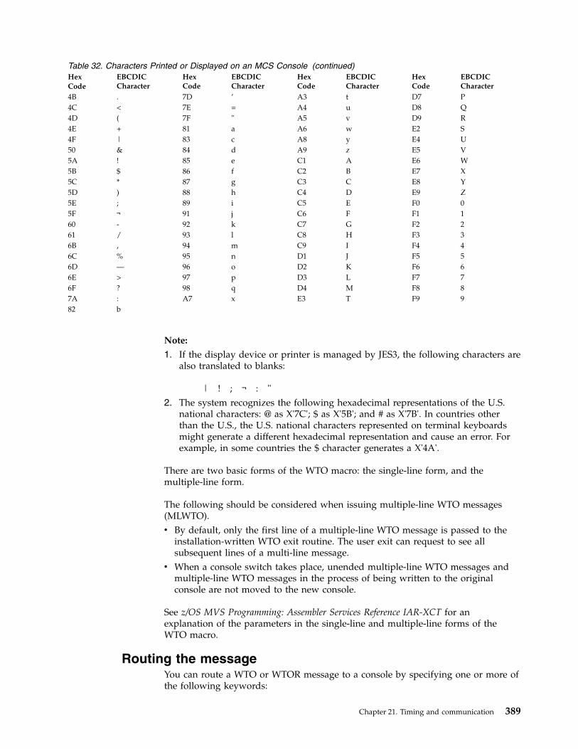
Table 32. Characters Printed or Displayed on an MCS Console (continued)HexCode
EBCDICCharacter
HexCode
EBCDICCharacter
HexCode
EBCDICCharacter
HexCode
EBCDICCharacter
4B . 7D ’ A3 t D7 P4C < 7E = A4 u D8 Q4D ( 7F " A5 v D9 R4E + 81 a A6 w E2 S4F | 83 c A8 y E4 U50 & 84 d A9 z E5 V5A ! 85 e C1 A E6 W5B $ 86 f C2 B E7 X5C * 87 g C3 C E8 Y5D ) 88 h C4 D E9 Z5E ; 89 i C5 E F0 05F ¬ 91 j C6 F F1 160 - 92 k C7 G F2 261 / 93 l C8 H F3 36B , 94 m C9 I F4 46C % 95 n D1 J F5 56D — 96 o D2 K F6 66E > 97 p D3 L F7 76F ? 98 q D4 M F8 87A : A7 x E3 T F9 982 b
Note:
1. If the display device or printer is managed by JES3, the following characters arealso translated to blanks:
| ! ; ¬ : "2. The system recognizes the following hexadecimal representations of the U.S.
national characters: @ as X'7C'; $ as X'5B'; and # as X'7B'. In countries otherthan the U.S., the U.S. national characters represented on terminal keyboardsmight generate a different hexadecimal representation and cause an error. Forexample, in some countries the $ character generates a X'4A'.
There are two basic forms of the WTO macro: the single-line form, and themultiple-line form.
The following should be considered when issuing multiple-line WTO messages(MLWTO).v By default, only the first line of a multiple-line WTO message is passed to the
installation-written WTO exit routine. The user exit can request to see allsubsequent lines of a multi-line message.
v When a console switch takes place, unended multiple-line WTO messages andmultiple-line WTO messages in the process of being written to the originalconsole are not moved to the new console.
See z/OS MVS Programming: Assembler Services Reference IAR-XCT for anexplanation of the parameters in the single-line and multiple-line forms of theWTO macro.
Routing the messageYou can route a WTO or WTOR message to a console by specifying one or more ofthe following keywords:
Chapter 21. Timing and communication 389

v ROUTCDE to route messages by routing codev CONSID to route messages by console IDv CONSNAME to route messages by console namev MCSFLAG to route messages by message type.
The ROUTCDE parameter allows you to specify the routing code or codes for aWTO or WTOR message. The routing codes determine which console or consolesreceive the message. Each code represents a predetermined subset of the consolesthat are attached to the system, and that are capable of displaying the message.The installation must define which routing codes are being received by eachconsole.
You can also use either the CONSID or CONSNAME parameter to route messages.These mutually exclusive parameters let you specify a 4-byte field or register thatcontains the ID or the pointer to a name of the console that is to receive themessage. When you issue a WTO or WTOR macro that uses either the CONSID orCONSNAME parameters with the ROUTCDE parameter, the message or messageswill go to all of the consoles specified by both parameters.
The MCSFLAG parameter specifies various attributes of the message, such aswhether the message is:v For a particular consolev For all active consolesv A command responsev For the hard-copy log.
Control is returned to the issuer with a return code of X‘20’ and a reason code inregister 0. The reason code is equal to the number of active WTO buffers for theissuer's address space. WTO processing may place the WTP invocation in a waitstate until WTO buffers are again available.
Note: For the convenience of the operator, you can associate messages withindividual keynames. A keyname consists of 1 to 8 alphanumeric characters, and itappears with the message on the console. The keyname can be used as an operandin the DISPLAY R console command, which operators can issue at the console. Usethe KEY parameter on the WTO or WTOR macro for this purpose.
During system initialization, each operator's console in the system is assignedrouting codes that correspond to the functions that the installation wants thatconsole to perform. When any of the routing codes assigned to a message matchany of the routing codes assigned to a console, the message is sent to that console.
Disposition of the message is indicated through the descriptor codes specified inthe WTO macro. Descriptor codes classify WTO messages so that they can beproperly presented on, and deleted from, display devices. The descriptor code isnot printed or displayed as part of the message text.
If the user supplies a descriptor code in the WTO macro, an indicator is inserted atthe start of the message. The indicators are: a blank, an at sign (@), an asterisk (*),or a blank followed by a plus sign (+). The indicator inserted in the messagedepends on the descriptor code that the user supplies and whether the user is aprivileged or APF-authorized program or a non-authorized problem program.Table 33 on page 391 shows the indicator that is used for each descriptor code.
390 z/OS MVS Assembler Services Guide

Table 33. Descriptor Code Indicators
Descriptor Code Non-AuthorizedProblem Program
1 @2 @3-10 blank+11 @12-13 blank+
A critical eventual action is an action that the operator must perform, as soon aspossible, in response to a critical situation during the operation of the system. Forexample, if the dump data set is full, the operator is notified to mount a new tapeon a specific unit. This is considered a critical action because no dumps can betaken until the tape is mounted; it is eventual rather than immediate because thesystem continues to run and processes jobs that do not require dumps.
Action messages to the operator, which are identified by the @ or * indicator, canbe individually suppressed by the installation. When a program invokes WTO orWTOR to send a message, the system determines if the message is to besuppressed. If the message is to be suppressed, the system writes the message tothe hardcopy log and the operator does not receive it on the screen. For moreinformation on suppressing messages, see z/OS MVS Planning: Operations.
If a program issues a message with descriptor code of 1 or 2, the message isdeleted at address space or task termination. For more information concerningrouting and descriptor codes, see any of the volumes of MVS System Messages.
If an application that uses WTO needs to alter a message each time the message isissued, the list form of the WTO macro may be useful. You can alter the messagearea, which is referenced by the WTO parameter list, before you issue the WTO.The message length, which appears in the WTO parameter list, does not need to bealtered if you pad out the message area with blanks.
A sample WTO macro is shown in Figure 97.
Altering message textIf an application that uses WTO needs to alter the same message or numerousmessages repetitively, using the TEXT parameter on the WTO macro may beuseful. You can alter the message or messages in one of two ways:v If you issue 3 different messages, all with identical parameters other than TEXT,
you can create a list form of the macro, move the text into the list form, thenexecute the macro. Using the TEXT parameter you can use the standard form ofthe macro, and specify the address of the message text. By reducing the numberof list and execute forms of the WTO macro in your code, you reduce thestorage requirements for your program.
Single-line WTO ’BREAKOFF POINT REACHED. TRACKING COMPLETED.’,format ROUTCDE=14,DESC=7
Multiple- WTO (’SUBROUTINES CALLED’,C),line format (’ROUTINE TIMES CALLED’,L),(’SUBQUER’,D),(list form) (’ENQUER’,D),(’WRITER’,D),
(’DQUER’,DE),ROUTCDE=(2,14),DESC=(7,8,9),MF=L
Figure 97. Writing to the Operator
Chapter 21. Timing and communication 391

v If you need to modify a parameter in message text, using the TEXT parameterenables you to modify the parameter in the storage that you define in yourprogram to contain the message text, rather than modify the WTO parameterlist.
Using the TEXT parameter on WTO can reduce your program's storagerequirements because of fewer lines of code or fewer list forms of the WTO macro.
To use the WTOR macro, code the message exactly as designated in the single-lineWTO macro. (The WTOR macro cannot be used to pass multiple-line messages.)When the message is written, the system adds a message identifier before themessage to associate the reply with the message. The system also inserts anindicator as the first character of all WTOR messages, thereby informing theoperator that immediate action is required. You must, however, indicate theresponse desired. In addition, you must supply the address of the area in whichthe system is to place the reply, and you must indicate the maximum length of theexpected reply. The length of the reply may not be zero. You also supply theaddress of an event control block which the system posts after the reply has beenplaced, left-adjusted, in your designated area.
You can also supply a command and response token, or CART, with any message.You may have received a CART as input in cases where you issued a message inresponse to a command. In these cases, you should specify this CART on anymessages you issue. Using the CART guarantees that these messages are associatedwith the command.
A sample WTOR macro is shown in Figure 98. The reply is not necessarilyavailable at the address you specified until the specified ECB has been posted.
When a WTOR macro is issued, any console receiving the message has theauthority to reply. The first reply received by the system is returned to the issuerof the WTOR, providing the syntax of the reply is correct. If the syntax of the replyis not correct, another reply is accepted. The WTOR is satisfied when the systemmoves the reply into the issuer's reply area and posts the event control block. Eachconsole that received the original WTOR also receives the accepted reply unless itis a security message. A security message is a WTO or WTOR message withrouting code 9. No console receives the accepted reply to a security message. Aconsole with master authority may answer any WTOR, even if it did not receivethe original message.
Writing a multiple-line messageTo write a multiple-line message to one or more operator consoles, issue WTO orWTOR with all lines of text.
.
.XC ECBAD,ECBAD Clear ECBWTOR ’STANDARD OPERATING CONDITIONS? REPLY YES OR NO’,
REPLY,3,ECBAD,ROUTCDE=(1,15)WAIT ECB=ECBAD..
ECBAD DC F’0’ Event control blockREPLY DC C’bbb’ Answer area
Figure 98. Writing to the Operator With a Reply
392 z/OS MVS Assembler Services Guide

Embedding label lines in a multiple-line messageLabel lines provide column headings in tabular displays. You can change thecolumn headings used to describe different sections of a tabular display byembedding label lines in the existing multiple-line WTO message for a tabulardisplay.
Note: You cannot use the WTO macro to embed label lines. The WTO macrohandles label lines at the beginning of the message only.
Communicating in a sysplex environmentThe WTO macro allows applications to send messages to consoles within a sysplex,without having to be aware that more than one system is up and running.
You can direct a WTO message to a specific console by specifying the console ID orname when issuing the message. For example, you can use the CONSID orCONSNAME parameter on the WTO macro to direct the WTO message to consolesdefined by those parameters. If the console is not active anywhere within thesysplex, the system writes the message to the system log unless it is an importantinformation message, an action message or WTOR message. An importantinformation message is a WTO or WTOR message with descriptor codes 1, 2, 3, 11,or 12. Action messages, messages with descriptor code 12, and WTORs are writtento the system log.
You can also broadcast WTOs to all active consoles using MCSFLAG=BRDCST onthe WTO macro. Unsolicited messages are directed by routing code, message level,and message type to the appropriate consoles anywhere within the sysplex. Theremay be some unsolicited messages that will not be queued to any console at areceiving system. In this case, all of the messages are written to the system log.
Writing to the programmerThe WTO and the WTOR macros allow you to write messages to a programmerwho is logged onto a TSO/E terminal, as well as to the operator. However, onlythe operator can reply to a WTOR message.
To write a message to the programmer, you must specify ROUTCDE=11 in theWTO or the WTOR macro.
Writing to the system logThe system log consists of one SYSOUT data set on which the communicationbetween the operator and the system is recorded. You can send a message to thesystem log by coding the information that you wish to log in the “text” parameterof the WTL macro.
The WTO macro with the MCSFLAG=HRDCPY parameter also writes messages tothe system log. Because WTO allows you to supply more information on the macroinvocation than WTL, IBM recommends that you use WTO instead of WTL.
The system writes the text of your WTL macro on the master console instead of onthe system log if the system log is not active.
Chapter 21. Timing and communication 393
Although when using the WTL macro you code the message within apostrophes,the written message does not contain the apostrophes. The message can includeany character that is valid for the WTO macro and is assembled and written thesame way as the WTO macro.
Note: The exact format of the output of the WTL macro varies depending on thejob entry system (JES2 or JES3) that is being used, the output class that is assignedto the log at system initialization, and whether DLOG is in effect for JES3. If JES3DLOG is being used, system log entries are preceded by a prefix that includes atime stamp and routing information. If the combined prefix and message exceeds126 characters, the log entry is split at the first blank or comma encountered whenscanning backward from the 126th character of the combined prefix and message.See z/OS JES3 Commands for information about the DLOG format of the log entrywhen using JES3.
Deleting messages already writtenThe DOM macro deletes the messages that were created using the WTO or WTORmacros. Depending on the timing of a DOM macro relative to the WTO or WTOR,the message may or may not have already appeared on the operator's console.v When a message already exists on the operator screen, it has a format that
indicates to the operator whether the message still requires that some action betaken. When the operator responds to a message, the message format changes toremind the operator that a response was already given. When DOM deletes amessage, it does not actually erase the message. It only changes its format,displaying it like a non-action message.
v If the message is not yet on the screen, DOM deletes the message before itappears. The DOM processing does not affect the logging action. That is, if themessage is supposed to be logged, it will be, regardless of when or if a DOM isissued. The message is logged in the format of a message that is waiting foroperator action.
The program that generates an action message is responsible for deleting thatmessage. To delete a message, identify the message by using the MSG, MSGLIST,or TOKEN parameters on the DOM macro, and issue DOM.
When you issued WTO or WTOR to write the message, the system returned amessage ID in general purpose register 1. Use this ID as input on the MSG orMSGLIST parameters on the DOM macro. MSGLIST (message list) associatesseveral message IDs with the delete request. The number of message IDs in themessage list is defined by the COUNT parameter or it is defined by a 1 in thehigh-order bit position of the last message ID in the list. The COUNT parametercannot exceed 60. If you specified the TOKEN parameter on WTO to generate yourown message ID, use the same value on the TOKEN parameter on DOM to deletethat message.
Retrieving console information (CONVCON and CnzConv macros)Programs that either process commands or issue messages might need informationabout MCS, SMCS or extended MCS consoles. CONVCON and CnzConv obtaininformation about these consoles.
IBM recommends using the CnzConv macro to retrieve console information. TheCONVCON service will no longer be enhanced. Future enhancement will beprovided only on the CnzConv service.
394 z/OS MVS Assembler Services Guide

You can use both the CnzConv and CONVCON macros to do the following tasks:v Obtain the console name associated with an input console ID.v Obtain the console ID associated with an input console name.v Obtain the status of a console (active or inactive) of an input console ID or
name.v Obtain the system name on which the queried console is active.
In addition to these tasks, you can use the CnzConv macro to obtain the followinginformation, with an input console ID or name:v The console type (MCS, SMCS, EMCS, Subsystem, or Special).v The console subtype (Internal, Instream, or Unknown. Applies to a console type
of special only).v The logical unit of an SMCS console.v The owner name of a subsystem console.v The ASID of a Subsystem console.
You must set up a parameter list before invoking the macros. Depending upon theinformation you want, you must initialize certain fields in the parameter list, andthe macros return information in other fields of the parameter list. For moreinformation on the CONVCON parameter list, which is mapped by IEZVG200, seez/OS MVS Data Areas in the z/OS Internet library (www.ibm.com/systems/z/os/zos/library/bkserv).
The following topics describe possible uses for the CnzConv and CONVCONmacroS, and tell you how to fill in the parameter list for each use. The parameterlist values for both macros are discussed in z/OS MVS Programming: AssemblerServices Reference ABE-HSP.
Using console names instead of console IDsInstallation operators and programmers previously referred to MVS consoles onlyby console IDs. IBM now requires that you use names when referring to MCSconsoles. Using names can help operators and programmers:v Remember which console they want to reference in commands or programs. For
example, if your installation establishes one console to receive information abouttapes, and uses the console name TAPE, operators and programmers can moreeasily remember TAPE than a console ID such as 03.
v Connect information in messages and the hardcopy log to the correct console. Ifyour installation uses console IDs, operators and programmers might havedifficulty identifying the console to which messages and hardcopy loginformation applies, because the system uses console names in messages and thehardcopy log.
Using console names rather than IDs can also avoid confusion when a console IDmight change. If your installation has set up a sysplex environment, and usesconsole IDs to identify consoles, those IDs can change from one IPL to the next, orwhen systems are added or removed from the sysplex. A console ID is notguaranteed to be associated with one console for the life of a sysplex.
Determining the name or ID of a consoleYou can use both CnzConv and CONVCON macros to determine the name or IDof a console.
Chapter 21. Timing and communication 395

Using CnzConv: To obtain the console ID for an input console name, do thefollowing steps:1. Clear the CnzConv parameter list by setting it to zeros.2. Specify the following parameters:v CnzConv InConsoleName=MyConsoleNamev OutConsoleId=OutConsoleIdv Rtncode=CnzConvReturnCodev Rsncode=CnzConvReasonCode
3. Issue the CnzConv macro.
When CnzConvReturnCode is equal to CnzConvRc0_Ok, OutConsoleId containsthe output console id.
To obtain the console name for an input console ID, do the following steps:1. Clear the CnzConv parameter list by setting it to zeros.2. Specify the following parameters:v CnzConv InConsoleId=MyConsoleIdv OutConsoleName=OutConsoleNamev Rtncode=CnzConvReturnCodev Rsncode=CnzConvReasonCode
3. Issue the CnzConv macro.
When CnzConvReturnCode is equal to CnzConvRc0_Ok, OutConsoleNamecontains the output console name.
Using CONVCON: To obtain the console ID for an input console name, do thefollowing steps:1. Clear the CONVCON parameter list by setting it to zeros.2. Initialize the following fields in the parameter list:v The version ID (CONVVRSN)v The acronym (CONVACRO)v The console ID (CONVID)v The flag indicating that you are supplying the console ID (flag CONVPID in
CONVFLGS)3. Issue the CONVCON macro.
When CONVCON completes, the console name is in the parameter list fieldCONVNAME, and register 15 contains a return code.
To obtain the console name for an input console ID, do the following steps:1. Clear the CONVCON parameter list by setting it to zeros.2. Initialize the following fields in the parameter list:v The version ID (CONVVRSN)v The acronym (CONVACRO)v The console name (CONVFLD)v The flag bit indicating that you are supplying the console name (flag
CONVPFLD in CONVFLGS)If the console name in CONVFLD is less than 10 characters, pad the name withblanks.
396 z/OS MVS Assembler Services Guide

The installation defines console names at initialization time in the CONSOLxxmember of parmlib. You can use the DISPLAY CONSOLES command to receivea list of defined names.
3. Issue the CONVCON macro.
When CONVCON completes, the console ID will be in the parameter fieldCONVID.
Validating a console name or ID and obtaining the activesystem name
Before issuing a message to a specific console, you might want to validate if it hasbeen defined. An active console is one that is defined and running. An applicationcan use the CnzConv or CONVCON macro to obtain the console status (active orinactive) and the active system name, with an input console name or ID.
Using CnzConv: To obtain the console status and active system name of an inputconsole name or ID, do the following steps:1. Clear the CnzConv parameter list by setting it to zeros.2. Specify the following parameters:v CnzConv InConsoleName=MyConsoleName or CnzConv
InConsoleId=MyConsoleId, depending on what information you currentlyhave
v ConsoleStatus=OutConsoleStatusv SysName=OutSysNamev Rtncode=CnzConvReturnCodev Rsncode=CnzConvReasonCode
3. Issue the CONVCON macro.
When CnzConvReturnCode is equal to CnzConvRc0_Ok, the input console nameor id is defined. If OutConsoleStatus is equal to CnzConv_kStatus_Active,OutSysName contains the system on which the console is active.
Using CONVCON: To obtain the console status and active system name of aninput console name or ID, do the following steps:1. Clear the CONVCON parameter list by setting it to zeros.2. Initialize the following fields in the parameter list:v The version ID (CONVVRSN)v The acronym (CONVACRO)v Either the console name (CONVFLD) or the console ID (CONVID)
depending on what information you currently have. The installation definesconsole names at initialization time in the CONSOLxx member of Parmlib.You can use the DISPLAY CONSOLES command to receive a list of definednames.
v The appropriate flag in CONVFLGS indicating whether you are specifyingthe console name (CONVPFLD) or the ID (CONVPID) as input.
3. Issue the CONVCON macro.
When CONVCON completes, CONVSYSN contains the name of the system towhich the console is attached, if the console you specified is active. Register 15contains a return code. If you receive the following return codes, check the reasoncode in CONVRSN for an explanation.
Chapter 21. Timing and communication 397

v Return code 0 indicates that the console name or ID is valid and the console isactive.
v Return code 4 indicates that the name or ID is valid, but the console is notactive.
v Return code 8 indicates that the console name is incorrect.v Return code 0C indicates that the console ID is incorrect.
See z/OS MVS Programming: Assembler Services Reference ABE-HSP for anexplanation of all return codes.
398 z/OS MVS Assembler Services Guide

Chapter 22. Translating messages
The MVS message service (MMS) provides a method of translating message text,and provides a convenient method of storing message text.v MMS enables you to translate U.S. English messages into other languages. These
messages can be IBM-supplied messages or application messages. An applicationcan format message text for any language, including English, by issuing theTRANMSG macro.
v MMS enables you to store message text in MMS message files rather than in theapplication code. By using MMS to store message text, you eliminate the need toinclude the message text as part of the application code. Any program thatneeds to issue a particular message can get it from one place: a run-timemessage file. A run-time message file contains messages in a format that MMScan use. You can also update your messages in the install message files ratherthan in the source code. An install message file is a partitioned data set (PDS)that contains message skeletons. A message skeleton contains message text andsubstitution data.
Applications running on TSO/E can have their messages translated automaticallyif the primary language associated with the TSO/E session is the same language asthe language of the run-time message file. A primary language is one that isdefined in your TSO/E profile. Therefore, even if you are issuing messages byusing the WTO macro, you can present a message in the primary languageassociated with the TSO/E session. If you are routing system messages to a TSO/Eextended MCS console, and MMS is active, users of extended MCS consoles onTSO/E can select available languages for message translation and the system willdisplay translated messages on the user's screen.
Applications based on products not already using MMS must translate their ownmessages by invoking the TRANMSG macro.
MMS can handle multi-line and multiple format messages. Multi-line messages aremessages displayed over a number of lines on an output device. Multiple formatmessages are messages that have the same message ID, but have differing textcontent depending on the circumstances under which they are issued.
Preparing IBM-supplied messages for translation: To prepare IBM messages fortranslation, perform the following tasks:1. Ensure that the appropriate IBM-supplied system install message files have
been installed on your system.For MVS messages (MVS, JES2, TSO/E), IBM provides an install message filefor U.S. English messages. IBM will also supply Japanese versions of thosemessages, if requested. When you install MVS, these messages areautomatically put into install message files. The U.S. English file is calledSYS1.MSGENU.
2. Create a system run-time message file for each language by running thesystem's install message files through the message compiler. See “Compilingmessage files” on page 406 for details on using the compiler.
Preparing application messages for translation: To prepare an application'smessages for translation, perform the following tasks.
© Copyright IBM Corp. 1988, 2017 399

1. Create a PDS for the English version, and a PDS for the translated version ofthe application's messages. To make it easy to locate and update messages,group messages for each program, component, or other category into separatePDS members. These data sets are the application's install message files. Thelogical record length of the data set should be variable length of 259, and theblock size 23476. IBM recommends that you put IBM messages first in a PDSconcatenation. If you are not translating IBM messages, you can still use thesame recommended logical record length and block size.
2. Validate the application's install message files by running each PDS through themessage compiler. See “Compiling message files” on page 406 for details onusing the compiler. The MMS message compiler replaces the entire run-timemessage file, so create a test run-time message file for each language, usingnames different from those containing IBM-supplied messages. Creating a testrun-time message file enables you to verify the new messages withoutdisturbing the existing system run-time message files and current messagetranslation.
3. After a clean compile, add your PDS members into the system's install messagefiles as new members.
4. Update the system run-time message files by running the system's installmessage files through the message compiler. See “Updating the systemrun-time message files” on page 410 for details on updating the systemrun-time message files.
Figure 99 on page 401 illustrates the process of preparing messages for translation.
400 z/OS MVS Assembler Services Guide

Translating application messages using the MVS message service: To use MMS inan application, modify the application to exploit the translation service that MMSprovides:v Use the QRYLANG macro to determine which languages are currently available
at your installation. For more information on QRYLANG, see “Determiningwhich languages are available (QRYLANG macro)” on page 411.
v Use the TRANMSG macro to obtain from MMS the translated version or thecomplete U.S. English message text of an application's message or messages. Formore information on TRANMSG, see “Retrieving translated messages(TRANMSG macro)” on page 411.
The installation can translate messages into more than one language. See “Supportfor additional languages” on page 415.
Allocating data sets for an applicationFor an application whose messages will be translated, you must allocate a PDS foreach language in which the messages might appear. For example, if you want themessages to be available in both English and Japanese, you must allocate two datasets: one to contain the English message skeletons, and one to contain the Japanese.
See z/OS MVS JCL User's Guide and z/OS MVS JCL Reference for information aboutallocating data sets.
PDS PDS
Eng
Msgs
JPN
Msgs
Error
Report
(Sysout
dataset)
PDS PDS
Eng
MsgsJPN
Msgs
Lang
X
Lang
X
Lang
X
PDS
IBM
Installmessagefiles
MMS
message
compiler
formatted
messages
Application
installmessagefiles
Install
MVS
Tape
IBMmessages
Run-time
messagefiles
Eng
MsgsJPN
Msgs
PDS
Figure 99. Preparing Messages for Translation
Chapter 22. Translating messages 401
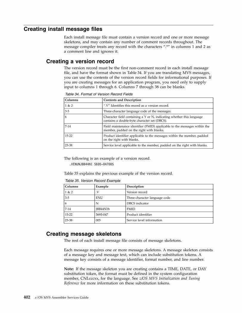
Creating install message filesEach install message file must contain a version record and one or more messageskeletons, and may contain any number of comment records throughout. Themessage compiler treats any record with the characters “.*” in columns 1 and 2 asa comment line and ignores it.
Creating a version recordThe version record must be the first non-comment record in each install messagefile, and have the format shown in Table 34. If you are translating MVS messages,you can use the contents of the version record fields for informational purposes. Ifyou are creating messages for an application program, you need only to supplyinput to columns 1 through 6. Columns 7 through 38 can be blanks.
Table 34. Format of Version Record Fields
Columns Contents and Description
1 & 2 “.V” Identifies this record as a version record.
3-5 Three-character language code of the messages.
6 Character field containing a Y or N, indicating whether this languagecontains a double-byte character set (DBCS).
7-14 Field maintenance identifier (FMID) applicable to the messages within themember, padded on the right with blanks.
15-22 Product identifier applicable to the messages within the member, paddedon the right with blanks.
23-38 Service level applicable to the member, padded on the right with blanks.
The following is an example of a version record..VENUNJBB44N1 5695-047005
Table 35 explains the previous example of the version record.
Table 35. Version Record Example
Columns Example Description
1 & 2 .V Version record
3-5 ENU Three-character language code
6 N DBCS indicator
7-14 JBB44N1� FMID
15-22 5695-047 Product identifier
23-38 005 Service level information
Creating message skeletonsThe rest of each install message file consists of message skeletons.
Each message requires one or more message skeletons. A message skeleton consistsof a message key and message text, which can include substitution tokens. Amessage key consists of a message identifier, format number, and line number.
Note: If the message skeleton you are creating contains a TIME, DATE, or DAYsubstitution token, the format must be defined in the system configurationmember, CNLcccxx, for the language. See z/OS MVS Initialization and TuningReference for more information on these substitution tokens.
402 z/OS MVS Assembler Services Guide

Message skeleton formatEach message skeleton must follow the column format shown in Table 36.
Table 36. Message Skeleton Fields
Columns Contents and Description
1-10 Message identifier (msgid). A message identifier can be 1 to 10 characters long, padded with EBCDICblanks, if necessary, so that it totals ten characters. The first character must be alphabetic. A messageidentifier cannot contain double-byte characters and cannot contain embedded blanks.
Ensure that the message identifiers for your application program messages do not conflict with existingMVS message identifiers. To avoid conflict, do not begin a message identifier with the letters A through I.
Examples of message identifiers are:
v IKJ52301I
v IEF12345W
v HASP000
v IEF123I
v OLDMSGID
Note that MMS will remove the first character of any message identifier in the form xmsgid beforeprocessing, and will replace it after processing. “x” is any character that is not uppercase alphabetic, suchas $ or 1.
11 & 12 Line number (ll). If the message is a single-line message, leave columns 11 and 12 blank. For a multi-linemessage, assign line numbers sequentially within the message. Line numbers do not have to be contiguous.Valid numbers are 01 to 99.
Ensure that message line numbers for a translated skeleton match the line numbers of the correspondingU.S. English message skeleton.Note: Ensure that corresponding skeletons (same message identifier and line number) of multi-linemessages contain the same substitution tokens. For example, if substitution tokens &1. and &2=date. are online 01 of a two-line U.S. English message skeleton, these tokens must appear on line 01 of a translatedskeleton. The following is an example of a multi-line message skeleton:
MSGID01 01 THIS IS LINE ONE OF THIS MULTI-LINE MESSAGEMSGID01 02 THIS IS LINE TWO OF THIS MULTI-LINE MESSAGEMSGID01 03 THIS IS LINE THREE OF THIS MULTI-LINE MESSAGE
13-15 Format number (fff). If only one format is defined for a particular message identifier, leave columns 13-15blank.
Use format numbers to maintain compatibility with existing messages. Using format numbers for newmessages is not recommended.
Format numbers distinguish among message skeletons that have one message identifier but have severaldifferent text strings or substitution tokens. The message identifier alone cannot identify the message asunique in these cases. The format number, together with the message identifier, identifies the message.
If more than one format is defined for a particular message identifier, assign a unique format number toeach skeleton for that message identifier. Valid numbers are 001 to 999. You do not have to assign thenumbers sequentially. Ensure that the format number in the translated skeleton matches the format numberin the U.S. English message skeleton.
Each message ID might have several format numbers if that message has variable text.
16 Blank (�). Column 16 must contain an EBCDIC blank.
Chapter 22. Translating messages 403
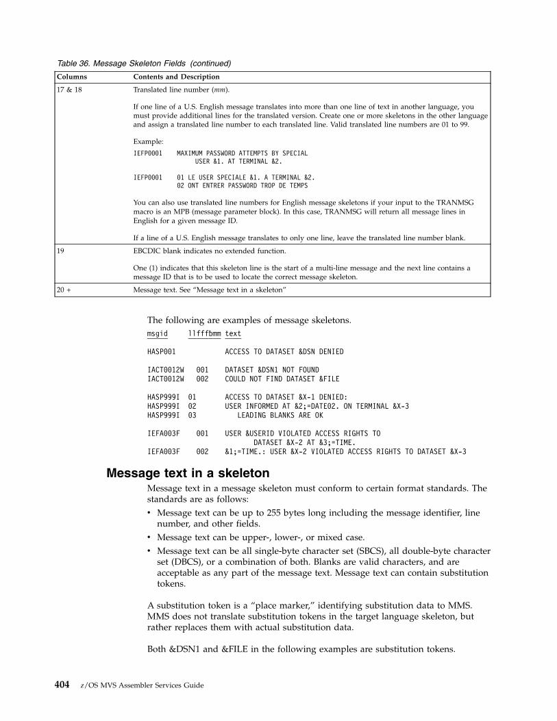
Table 36. Message Skeleton Fields (continued)
Columns Contents and Description
17 & 18 Translated line number (mm).
If one line of a U.S. English message translates into more than one line of text in another language, youmust provide additional lines for the translated version. Create one or more skeletons in the other languageand assign a translated line number to each translated line. Valid translated line numbers are 01 to 99.
Example:
IEFP0001 MAXIMUM PASSWORD ATTEMPTS BY SPECIALUSER &1. AT TERMINAL &2.
IEFP0001 01 LE USER SPECIALE &1. A TERMINAL &2.02 ONT ENTRER PASSWORD TROP DE TEMPS
You can also use translated line numbers for English message skeletons if your input to the TRANMSGmacro is an MPB (message parameter block). In this case, TRANMSG will return all message lines inEnglish for a given message ID.
If a line of a U.S. English message translates to only one line, leave the translated line number blank.
19 EBCDIC blank indicates no extended function.
One (1) indicates that this skeleton line is the start of a multi-line message and the next line contains amessage ID that is to be used to locate the correct message skeleton.
20 + Message text. See “Message text in a skeleton”
The following are examples of message skeletons.msgid llfff�mm text
HASP001 ACCESS TO DATASET &DSN DENIED
IACT0012W 001 DATASET &DSN1 NOT FOUNDIACT0012W 002 COULD NOT FIND DATASET &FILE
HASP999I 01 ACCESS TO DATASET &X-1 DENIED:HASP999I 02 USER INFORMED AT &2;=DATE02. ON TERMINAL &X-3HASP999I 03 LEADING BLANKS ARE OK
IEFA003F 001 USER &USERID VIOLATED ACCESS RIGHTS TODATASET &X-2 AT &3;=TIME.
IEFA003F 002 &1;=TIME.: USER &X-2 VIOLATED ACCESS RIGHTS TO DATASET &X-3
Message text in a skeletonMessage text in a message skeleton must conform to certain format standards. Thestandards are as follows:v Message text can be up to 255 bytes long including the message identifier, line
number, and other fields.v Message text can be upper-, lower-, or mixed case.v Message text can be all single-byte character set (SBCS), all double-byte character
set (DBCS), or a combination of both. Blanks are valid characters, and areacceptable as any part of the message text. Message text can contain substitutiontokens.
A substitution token is a “place marker,” identifying substitution data to MMS.MMS does not translate substitution tokens in the target language skeleton, butrather replaces them with actual substitution data.
Both &DSN1 and &FILE in the following examples are substitution tokens.
404 z/OS MVS Assembler Services Guide

IACT0012W 001 DATASET &DSN1. NOT FOUNDIACT0012W 002 COULD NOT FIND DATASET &FILE;
Substitution tokens indicate substitution, or variable, data, such as a data set nameor a date in the message text. Substitution tokens must start with a token starttrigger character, an ampersand (&), and end with a token end trigger character, aperiod (.). These characters are part of the token and are not included in themessage text display. You may include an ampersand (&) in the text as long as itdoes not have a period following it in the format of a substitution token.Substitution tokens must be SBCS characters and follow the form &name[=format]where:
name is the name of the substitution token. This name is an alphanumeric SBCSstring. The name must not contain imbedded blanks or DBCS characters.
format is an optional format descriptor for the substitution token. Formatdescriptors are:v TEXT for tokens other than dates and times (default format)v DATExxxxxx for datesv TIMExxxxxx for timesv DAY for the day of the week
If you use these format descriptors, you must also define them in theCNLcccxx parmlib member for the language. See z/OS MVS Initializationand Tuning Reference for more information on format descriptors.
The total length of name and =format must not be greater than 16 bytes.
If you do not include a format descriptor for a particular substitution token, theMVS message service treats the token as TEXT.
The date and time tokens are formatted according to the language. There are nodefaults. You must supply your own formats in the CNLcccxx member.
Examples of substitution tokens are:&1.&USERID.&1=DATE1.&5=TIMESHORT.
Validating message skeletonsAfter creating message skeletons for both the U.S. English and translated versionof each message, validate the skeletons. To validate the skeletons, run each of theapplication's install message files through the message compiler for syntaxchecking. Otherwise you might be adding incorrect skeletons to the files that MMSuses, and your messages might be either incorrectly translated or untranslatable.You should also validate skeletons when you add or change skeletons in anexisting install message file.
To make sure your message skeletons are valid, complete the following process foreach install message file:1. Allocate storage for run-time message files, which the compiler produces as
output.2. Compile the install message file by invoking the compiler.3. Check the return code from the message compiler.
Chapter 22. Translating messages 405
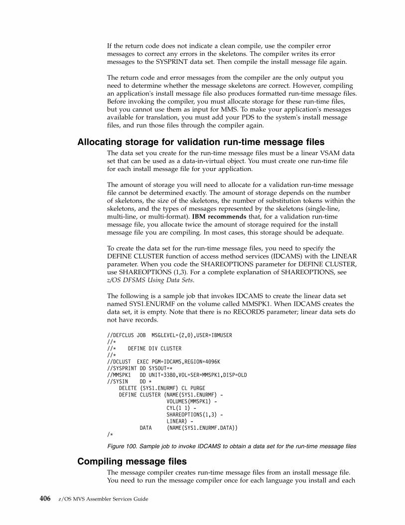
If the return code does not indicate a clean compile, use the compiler errormessages to correct any errors in the skeletons. The compiler writes its errormessages to the SYSPRINT data set. Then compile the install message file again.
The return code and error messages from the compiler are the only output youneed to determine whether the message skeletons are correct. However, compilingan application's install message file also produces formatted run-time message files.Before invoking the compiler, you must allocate storage for these run-time files,but you cannot use them as input for MMS. To make your application's messagesavailable for translation, you must add your PDS to the system's install messagefiles, and run those files through the compiler again.
Allocating storage for validation run-time message filesThe data set you create for the run-time message files must be a linear VSAM dataset that can be used as a data-in-virtual object. You must create one run-time filefor each install message file for your application.
The amount of storage you will need to allocate for a validation run-time messagefile cannot be determined exactly. The amount of storage depends on the numberof skeletons, the size of the skeletons, the number of substitution tokens within theskeletons, and the types of messages represented by the skeletons (single-line,multi-line, or multi-format). IBM recommends that, for a validation run-timemessage file, you allocate twice the amount of storage required for the installmessage file you are compiling. In most cases, this storage should be adequate.
To create the data set for the run-time message files, you need to specify theDEFINE CLUSTER function of access method services (IDCAMS) with the LINEARparameter. When you code the SHAREOPTIONS parameter for DEFINE CLUSTER,use SHAREOPTIONS (1,3). For a complete explanation of SHAREOPTIONS, seez/OS DFSMS Using Data Sets.
The following is a sample job that invokes IDCAMS to create the linear data setnamed SYS1.ENURMF on the volume called MMSPK1. When IDCAMS creates thedata set, it is empty. Note that there is no RECORDS parameter; linear data sets donot have records.
Compiling message filesThe message compiler creates run-time message files from an install message file.You need to run the message compiler once for each language you install and each
//DEFCLUS JOB MSGLEVEL=(2,0),USER=IBMUSER//*//* DEFINE DIV CLUSTER//*//DCLUST EXEC PGM=IDCAMS,REGION=4096K//SYSPRINT DD SYSOUT=*//MMSPK1 DD UNIT=3380,VOL=SER=MMSPK1,DISP=OLD//SYSIN DD *
DELETE (SYS1.ENURMF) CL PURGEDEFINE CLUSTER (NAME(SYS1.ENURMF) -
VOLUMES(MMSPK1) -CYL(1 1) -SHAREOPTIONS(1,3) -LINEAR) -
DATA (NAME(SYS1.ENURMF.DATA))/*
Figure 100. Sample job to invoke IDCAMS to obtain a data set for the run-time message files
406 z/OS MVS Assembler Services Guide

time you update the application's install message files. The compiler expects a PDSor a concatenation of PDSs as input. If the compiler cannot process a messageskeleton, it issues an error message. It also sets a return code. See “Checking themessage compiler return codes” on page 410 for a description of compiler returncodes.
Invoking the message compilerThe message compiler is an executable program. You can use JCL, a TSO/E CLIST,or a REXX EXEC to invoke the message compiler. The syntax for each type ofinvocation follows. The meaning of the variables (shown in lowercase in theexamples) follows the examples.
//COMPILE EXEC PGM=CNLCCPLR,// PARM=(lang,dbcs)//SYSUT1 DD DSN=msg_pds,DISP=SHR//SYSUT2 DD DSN=msg_div_obj,DISP=(OLD,KEEP,KEEP)//SYSPRINT DD SYSOUT=*
Figure 101. Using JCL to Invoke the Compiler with a single PDS as input
//COMPILE EXEC PGM=CNLCCPLR,// PARM=(lang,dbcs)//SYSUT1 DD DSN=msg_pds1,DISP=SHR// DD DSN=msg_pds2,DISP=SHR
::
// DD DSN=msg_pdsn,DISP=SHR//SYSUT2 DD DSN=msg_div_obj,DISP=(OLD,KEEP,KEEP)//SYSPRINT DD SYSOUT=*
Figure 102. Using JCL to Invoke the Compiler with a concatenation of partitioned Data Setsas input
PROC 0FREE DD(SYSUT1,SYSUT2,SYSPRINT) /* FREE DD’S */ALLOC DD(SYSUT1) DSN(’msg_pds’) SHR /* ALLOC INPUT FILE */ALLOC DD(SYSUT2) DSN(’msg_div_obj’) OLD /* ALLOC OUTPUT FILE */ALLOC DD(SYSPRINT) DSN(*) /* ALLOC SYSPRINT */CALL ’SYS1.LINKLIB(CNLCCPLR)’ ’lang,dbcs’
/* CALL MESSAGE COMPILER */SET &RCODE = &LASTCC /* SET RETURN CODE */FREE DD(SYSUT1,SYSUT2,SYSPRINT) /* FREE FILES */EXIT CODE(&RCODE) /* EXIT */
Figure 103. Using a TSO/E CLIST to Invoke the Compiler with a single PDS input
Chapter 22. Translating messages 407

PROC 0FREE DD(SYSUT1,SYSUT2,SYSPRINT) /* FREE DD’S */ALLOC DD(SYSUT1) DSN(’msg_pds1’ + /* ALLOC INPUT FILE */ALLOC DD(SYSUT1) DSN ’msg_pds1’ + /* ALLOC INPUT FILE */
::
ALLOC DD(SYSUT1) DSN ’msg_pdsn’) SHR /* ALLOC INPUT FILE */ALLOC DD(SYSUT2) DSN(’msg_div_obj’) OLD /* ALLOC OUTPUT FILE */ALLOC DD(SYSPRINT) DSN(*) /* ALLOC SYSPRINT */CALL ’SYS1.LINKLIB(CNLCCPLR)’ ’lang,dbcs’
/* CALL MESSAGE COMPILER */SET &RCODE = &LASTCC /* SETRETURN CODE */FREE DD(SYSUT1,SYSUT2,SYSPRINT) /* FREE FILES */EXIT CODE(&RCODE) /* EXIT */
Figure 104. Using a TSO/E CLIST to Invoke the Compiler with a concatenation of partitionedData Set as input
/* MESSAGE COMPILER INVOCATION EXEC */
MSGCMPLR:
"FREE DD(SYSUT1,SYSUT2,SYSPRINT)"
"ALLOC DD(SYSUT1) DSN(’"msg_pds"’) SHR""ALLOC DD(SYSUT2) DSN(’"msg_div_obj"’) OLD""ALLOC DD(SYSPRINT) DSN(*)"
"CALL ’SYS1.LINKLIB(CNLCCPLR)’ ’lang,dbcs’"
compiler_rc=rc
"FREE DD(SYSUT1,SYSUT2,SYSPRINT)"
return(compiler_rc)
Figure 105. Using a REXX exec to Invoke the Compiler with a single PDS as input
408 z/OS MVS Assembler Services Guide

The lowercase variables used in the preceding examples are defined as follows:
msg_pdsis the name of the install message file containing all the application's messageskeletons for a specific language. msg_pds must be a partitioned data set.
msg_pds1is the name of the install message file containing the the first application'smessage skeletons for a specific language. msg_pds1 must be a partitioned dataset.
msg_pds2is the name of the install message file containing the the second application'smessage skeletons for a specific language. msg_pds2 must be a partitioned dataset.
msg_pdsnis the name of the install message file containing the the last application'smessage skeletons, in the message skeleton PDS concatenation, for a specificlanguage. msg_pdsn must be a partitioned data set.
Note: When you specify a concatenation of partitioned data set as input to theMVS message service (MMS) compiler, all members within the partitioned dataset will be processed. The MMS compiler will process all members within theconcatenation of partitioned data sets without regard to uniqueness of membernames. If two partitioned data sets specified in the concatenation havemembers with the same name, both members will be processed by the MMScompiler.
msg_div_objspecifies the name of the run-time message file that is to contain the compiledmessage skeletons for the language. msg_div_obj must be a linear VSAM dataset suitable for use as a data-in-virtual object.
lang,dbcsspecifies two parameters. lang is the 3-character language code of the messages
/* MESSAGE COMPILER INVOCATION EXEC */
MSGCMPLR:
"FREE DD(SYSUT1,SYSUT2,SYSPRINT)"
"ALLOC DD(SYSUT1) DSN(’msg_pds1’,","’msg_pds2’,",
::
"’msg_pdsn’) SHR"
"ALLOC DD(SYSUT2) DSN(’"msg_div_obj"’) OLD""ALLOC DD(SYSPRINT) DSN(*)"
"CALL ’SYS1.LINKLIB(CNLCCPLR)’ ’lang,dbcs’"
compiler_rc=rc
"FREE DD(MSGIN,MSGOUT,SYSPRINT)"
return(compiler_rc)
Figure 106. Using a REXX exec to Invoke the Compiler with a concatenation of partitionedData Sets as input
Chapter 22. Translating messages 409

contained in the install message file. dbcs indicates whether this languagecontains double-byte characters. The values for dbcs are y for yes and n for no.
After creating run-time message files by compiling the install message file,determine the amount of storage the run-time message files used. This calculationis necessary when compiling these messages in the system's run-time message files.The following JCL example shows you how to run a report showing the storageused.//LISTCAT JOB MSGLEVEL=(1,1)//MCAT EXEC PGM=IDCAMS,REGION=4096K//SYSPRINT DD SYSOUT=*//SYSIN DD *
LISTCAT LEVEL(msg_div_obj) ALL/*
Checking the message compiler return codesThe message compiler generates a return code in register 15. The return codes areas follows:
Code Meaning
0 Successful completion.
4 Processing complete. Run-time message files are complete but the compilergenerated warnings.
8 Processing complete. The run-time message files are usable but incomplete.
12 Processing ended prematurely. The run-time message files are unusable.
You should correct all errors and recompile if you receive any return code otherthan 0.
Updating the system run-time message filesAfter validating your application install message files, update the system run-timemessage files. The TRANMSG macro can retrieve messages from the run-timemessage files. You need to do the following:v Add the application's install message files to the system's install message files, or
add a DD statement to the JCL used to compile the system's install messagefiles.
v Allocate a data set for the new system run-time message files. Assign uniquenames to the run-time message files, ensuring that the names are different fromthose your installation is currently using. Use the storage requirements youreceived from running the IDCAMS report.
v Compile the system's install message files into new system run-time messagefiles using the message compiler for each install message file. See “Compilingmessage files” on page 406.
v Identify your new run-time message files to the system by creating a newMMSLSTxx parmlib member. See z/OS MVS Initialization and Tuning Reference forinformation on creating a parmlib member.
v Activate your new parmlib member and run-time message files by issuing theSET MMS=xx command. See z/OS MVS System Commands for information on theSET MMS=xx command.
410 z/OS MVS Assembler Services Guide

You are using the same invocations to update the system run-time message files asyou do to verify message skeletons. The difference is that the resulting systemrun-time message files are what MMS can use to translate messages for the systemand applications.
Using MMS translation services in an applicationAfter you have compiled the translated messages and updated the system run-timemessage files, your program can use MMS services to retrieve translated messagetext from the system run-time message files. You need to do the following:v Determine the language in which you want the application's messages
translated, and use the QRYLANG macro to check its availability.v Retrieve translated messages using the TRANMSG macro.
You must also determine the action the application will take if the requestedfunction does not complete, or if an output device cannot support the language.
Determining which languages are available (QRYLANG macro)You need to determine if the language in which you want to issue messages isavailable to MMS. The message query function (QRYLANG) allows you to verifythat the language you want is active, and also to receive a list of all availablelanguages.
QRYLANG returns the information you request in the language query block (LQB),mapped by CNLMLQB. This block contains the following:v The standard 3-character code for the languagev The name of the languagev A flag indicating whether the language contains double-byte characters
If you ask for a list of all available languages, QRYLANG returns an LQB with onelanguage entry for each language.
You need to define storage for an LQB before issuing QRYLANG. To determinehow much storage you need for the LQB if you want a list of all active languages:v Calculate the length of the header section in mapping macro CNLMLQB.v Determine the total number of languages by looking in the MCAALCNT (active
language count) field of the MCA, mapped by CNLMMCA. Your program mustbe in 31-bit addressing mode to reference the MCA.
v Multiply the total number of languages you intend to query by the LQBEBL (thelength of one entry). This will give you the length of the LQB substitution dataarea.
v Add the length of the LQB substitution data area to the length of the header.
To determine how much storage you need for the LQB if you want to query onelanguage:v Calculate the length of the header section in mapping macro CNLMLQB.v Add the length of the LQB substitution data area to the length of the header.
Retrieving translated messages (TRANMSG macro)TRANMSG takes the application messages that you provide, and retrieves thecorresponding translated messages from the system run-time message files.TRANMSG returns the translated message in a message text block (MTB).
Chapter 22. Translating messages 411

If the requested language is not available, TRANMSG returns the messageunchanged. To check the availability of specific languages, use the QRYLANGmacro described in “Determining which languages are available (QRYLANGmacro)” on page 411.
In your application, call TRANMSG as close to the point of message presentationas possible to avoid presenting a translated version of the message to MVSfunctions (for example, installation exits, automation CLISTs, MCS consoles) thatexpect English text.
A message input/output block (MIO), mapped by CNLMMIO, serves as bothinput to and output from TRANMSG. You can either build the MIO yourself orhave TRANMSG do it for you. If you do not supply a formatted MIO, TRANMSGconstructs one by using the information you supply through the macro parameters.Build the MIO yourself if you are translating multi-line messages that havecontinuation lines. You will need to set the MIOCONT flag in the MIO.
If you build the MIO yourself, the MIO must contain the following when you issueTRANMSG:v The code of the language into which you want the message translatedv The addresses of the messages you want translatedv The address of an output buffer in the calling program's address space where
TRANMSG is to return the translated message or messages.
For a mapping of the MIO, see z/OS MVS Data Areas in the z/OS Internet library(www.ibm.com/systems/z/os/zos/library/bkserv).
The application's input messages can be in one of the following forms:v Message text blocks (MTBs, mapped by CNLMMTB)v Message parameter blocks (MPBs, mapped by CNLMMPB)v Self-defined text (a 2-byte length field followed by message text)v A combination of any of the three.
When TRANMSG completes, the MIO contains the address of the translatedmessage in the output buffer. The translated message is in the form of an MTB.
Translating a multi-line message is a little different from translating a single-linemessage. You must take one of the following steps in preparing the multi-linemessage for translation:v Add the message identifier to the beginning of the message text for each line
subsequent to the first. You can invoke TRANMSG once for all message lines, oronce for each message line. For the previous example, the modified messagewould appear as follows:MSGID01 THIS IS LINE ONE OF THIS MULTI-LINE MESSAGEMSGID01 THIS IS LINE TWO OF THIS MULTI-LINE MESSAGEMSGID01 THIS IS LINE THREE OF THIS MULTI-LINE MESSAGE
When you invoke TRANMSG, MMS will process this message as three separatelines of text.
v Set the MIOCONT flag on the MIO message entry structure for lines subsequentto the first (lines two and three in the following example). The MIOCONT flaginforms MMS that a specific line of text is associated with the previous line oftext. MMS associates the message identifier of the first line with the message textof the subsequent lines. z/OS MVS Programming: Assembler Services ReferenceIAR-XCT provides a coding example that translates a multi-line message.
412 z/OS MVS Assembler Services Guide

The following is an example of a multi-line message that contains continuationlines, that is, only the first line contains a message identifier in the skeleton. Youmust include all lines in the TRANMSG invocation.MSGID01 THIS IS LINE ONE OF THIS MULTI-LINE MESSAGE
THIS IS LINE TWO OF THIS MULTI-LINE MESSAGETHIS IS LINE THREE OF THIS MULTI-LINE MESSAGE
Figure 107 shows how an application program uses the TRANMSG macro.
Example of displaying messagesThe following table shows two ways a general application program (a program notusing WTO to issue messages) can display messages.
Formatted
messages
System run-time
message fileApplication Program
MPBs
MTBs
Self-defined
text
MIO
Japanese messages
TRANMSG
MIO
MTB
Language
code
English messages
Address of
English
messages
Address of
output buffer
Address of
Japanese
Messages
Figure 107. Using the TRANMSG Macro
Chapter 22. Translating messages 413

Displaying a message without using MMS Displaying a message using MMS
v Build a buffer for an English messagecontaining a message ID, fixed text, andsubstitution data.
v Display the English message (for example,by using TSO/E PUTLINE). Theapplication supports only English.
v Build a buffer for an English message. Youmust match the message format of theEnglish message buffer to the format ofthe English message skeleton.
v Issue the TRANMSG macro using theEnglish message buffer as input, andgetting a translated message buffer asoutput.
v Present the translated message, ensuringthat your output device supports thechosen language. By “presenting” amessage, you might choose to write themessage to a data set, or write it to ascreen.
OR
v Build an MPB. See “Using messageparameter blocks for new messages(BLDMPB and UPDTMPB macros)” forinformation on creating and MPB.
v Issue the TRANMSG macro using an MPBas input. TRANMSG will format thesubstitution data contained in the MPB.The output is a Japanese message buffer(if language code is JPN). You should notuse WTO to issue the translated message.
Using message parameter blocks for new messages (BLDMPB andUPDTMPB macros)
You can create message parameter blocks (MPBs) instead of storing messages inyour application code. MPBs contain a message identifier, and, if needed, a formatnumber, line number, and any substitution data. The actual message text residesonly in the message skeletons in the run-time message file. Using MPBs providesthe convenience of having to modify only the install message file if any of yourmessage text requires a change. It also allows you to have a single repository formessage text.
If you use message text blocks (MTBs) or self-defined text as input to theTRANMSG macro, and your message text requires a change, you will have tochange it in both the message skeleton and the MTB or self-defined text.Modifying just the existing run-time message files to adapt changed message textcan result in unpredictable errors when using the TRANSMSG service.
To build a message parameter block (MPB), allocate storage for the MPB, and issueBLDMPB and UPDTMPB. BLDMPB initializes the MPB and adds the fixedmessage data (called the message header), and UPDTMPB adds one substitutiontoken to the MPB for each invocation.
Issue BLDMPB once for each MPB you will build and before you issue UPDTMPB.Issue UPDTMPB once for each substitution token in the message. You can also use
414 z/OS MVS Assembler Services Guide

UPDTMPB to replace or change the value of a particular substitution token in anexisting MPB. However, you must ensure that the new value is not longer than theoriginal value to maintain the integrity of the MPB. You might use UPDTMPB ifyou want to invoke TRANMSG several times with one MPB. For example, if youhave an MPB associated with a message that you will translate in severallanguages, you can change only the language code in the MIO, and issueTRANMSG.
Once you have built an MPB for a message, you can issue TRANMSG to return thetext of the message in a message text block (MTB). If the requested language is notavailable, TRANMSG returns the message number and its substitution data as atext string in the output area.
Support for additional languagesYou can also translate messages into languages not currently available throughIBM. You can do this in the following way:v Select the language code in Table 37 that matches the language into which you
plan to translate messages. Though you may supply your own language code,IBM recommends that you use these codes. You will need that language code forthe version record. Table 37 is not an all-inclusive list of languages.
v If the messages you want to translate are MVS system messages, there mayalready be U.S. English skeletons for them, so all you need to supply are thetranslated skeletons. If the messages are from an application you have written,you need to supply both the English and translated skeletons. Follow theprocedures described in “Creating install message files” on page 402, “Validatingmessage skeletons” on page 405, and “Updating the system run-time messagefiles” on page 410.
v Ask the installation's system programmer to:– Modify the parmlib member, MMSLSTxx, adding the language code.– Create a new config member, CNLcccxx, for the new language.– Restart MMS using the SET MMS command.
See z/OS MVS Initialization and Tuning Reference for more information on setting upconfig members, and parmlib members.
Table 37. Languages Available to MVS Message Service. These languages may notnecessarily be available to your installation.
Code Language Name Country or Region
CHS Simplified Chinese China (PRC)
CHT Traditional Chinese Taiwan
DAN Danish Denmark
DEU German Germany
DES Swiss German Switzerland
ELL Greek Greece
ENG UK English United Kingdom
ENU US English United States
ESP Spanish Spain
FIN Finnish Finland
FRA French France
Chapter 22. Translating messages 415

Table 37. Languages Available to MVS Message Service (continued). These languagesmay not necessarily be available to your installation.
Code Language Name Country or Region
FRB Belgian French Belgium
FRC Canadian French Canada
FRS Swiss French Switzerland
ISL Icelandic Iceland
ITA Italian Italy
ITS Swiss Italian Switzerland
JPN Japanese Japan
KOR Korean Korea
NLD Dutch Netherlands
NLB Belgian Dutch Belgium
NOR Norwegian Norway
PTG Portuguese Portugal
PTB Brazil Portuguese Brazil
RMS Rhaeto-Romanic Switzerland
RUS Russian Russian Federation
SVE Swedish Sweden
THA Thai Thailand
TRK Turkish Turkey
For more information on translation, see NLS Reference Manual.
Example of an application that uses MMS translation servicesThe following example builds and updates and MPB, then invokes the MMStranslate function to obtain the translated message. There are more examples foreach MMS macro (BLDMPB, QRYLANG, TRANMSG, UPDTMPB) in the z/OS MVSProgramming: Assembler Services Reference ABE-HSP and the z/OS MVS Programming:Assembler Services Reference IAR-XCT.TRANSMPB CSECTTRANSMPB AMODE 31TRANSMPB RMODE ANY
STM 14,12,12(13)BALR 12,0USING *,12ST 13,SAVE+4LA 15,SAVEST 15,8(13)LR 13,15
************************************************************************* OBTAIN WORKING STORAGE AREA ************************************************************************
GETMAIN RU,LV=STORLEN,SP=SP230LR R4,R1
************************************************************************* CREATE MPB HEADER SECTION *************************************************************************
416 z/OS MVS Assembler Services Guide

BLDMPB MPBPTR=(R4),MPBLEN=MPBL,MSGID=MSGID, CMSGIDLEN=MIDLEN
************************************************************************* ADD SUBSTITUTION DATA TO MPB FOR DAY 3, TUESDAY *************************************************************************
LR R2,R4A R2,MPBLUSING VARS,R2
*UPDTMPB MPBPTR=(R4),MPBLEN=MPBL,SUBOOFST=VARS, C
TOKEN=TOKN,TOKLEN=TOKL,TOKTYPE=TOKT, CSUBSDATA=SDATA,SUBSLEN=SDATAL
*USING MIO,R3LA R3,VARSLEN OBTAIN LENGTH OF VARS AREAAR R3,R2 CALCULATE ADDRESS MIOLA R5,MLEN GET LENGTH OF MIOAR R5,R3 CALCULATE ADDRESS OF OUTPUT BUFFERST R4,VARSINBF CREATE ADDRESS LIST
************************************************************************* ISSUE TRANSLATE TO OBTAIN MESSAGE TEXT REPRESENTED BY THE ** CREATED MPB *************************************************************************
TRANMSG MIO=MIO,MIOL=MIOLEN,INBUF=(VARSINBF,ONE), COUTBUF=(R5),OUTBUFL=OUTAREAL,LANGCODE=LC
************************************************************************* FREE STORAGE AREA *************************************************************************
FREEMAIN RU,LV=STORLEN,SP=SP230,A=(4)*
L 13,SAVE+4LM 14,12,12(13)BR 14DROP
***********************************************************************MPBL DC A(MPBLEN)MSGID DC CL10’MSGID2’MIDLEN DC A(MIDL)TOKN DC CL3’DAY’TOKL DC F’3’TOKT DC CL1’3’SDATA DC CL1’3’SDATAL DC A(SDL)MIOLEN DC A(MLEN)OUTAREAL DC A(STORLEN-(MPBLEN+VARSLEN+MLEN))ONE DC F’1’LC DC CL3’JPN’SAVE DC 18F’0’SP230 EQU 230STORLEN EQU 512SDL EQU 6MIDL EQU 6MPBLEN EQU (MPBVDAT-MPB)+(MPBMID-MPBMSG)+(MPBSUB-MPBSB)+MIDL+SDLMLEN EQU (MIOVDAT-MIO)+MIOMSGLR1 EQU 1R2 EQU 2R3 EQU 3R4 EQU 4R5 EQU 5***********************************************************************
DSECT
Chapter 22. Translating messages 417

CNLMMPBCNLMMCACNLMMIO
VARS DSECTVARSINBF DS FVARSAREA DS CL24VARSLEN EQU *-VARS
END TRANSMPB
418 z/OS MVS Assembler Services Guide

Chapter 23. Data compression and expansion services
z/OS supports compression using two different algorithms. The first algorithmexploits the occurrence of repeated characters in a data stream. Encoded datacontains a combination of symbols that represent strings of repeated characters andthe original characters that are not repeated. The CSRCESRV service uses thisalgorithm to compress data.
Data that contains many repeat characters can exploit these services mosteffectively. Examples include:v Data sets with fixed field lengths that might contain many blanksv 80-byte source code images of assembler language programs.
Using these services with other types of data might not result in appreciable datavolume reduction. In some cases, data volume might even be increased.
The second algorithm encodes data by replacing strings of characters with shorterfixed-length symbols. A key component of this technique is the symbol table,usually referred to as a dictionary. Encoded data contains symbols that correspondto entries in the dictionary. The CSRCMPSC service uses this algorithm tocompress data.
This service requires more storage than the CSRCESRV services, but is a goodchoice if you know what your data looks like and storage is not a concern.
Services provided by CSRCESRVData compression and expansion services, which your program invokes throughthe CSRCESRV macro, are described as follows:v Data Compression Service
This service compresses a block of data that you identify and stores that data incompressed form in an output area. The service uses an algorithm called runlength encoding, which is a compression technique that compresses repeatingcharacters, such as blanks. In some cases, the service uses an interim work area.
v Data Expansion Service
This service expands a block of data that you identify; the data must have beencompressed by the data compression service. The data expansion servicereverses the algorithm that the data compression service used, and stores thedata in its original form in an output area. In some cases, the service uses aninterim work area.
v Query Service
This service queries the system to determine the following:– Whether data compression is supported by the system currently installed– The size of the work area required by the compression or expansion service.To use the data compression and data expansion services, you need theinformation that the query service provides. Invoke the query service beforeinvoking either the data compression or data expansion services.
Note: These services do not provide a recovery routine (for example, ESTAE orFRR) because it would not contribute to reliability or availability.
© Copyright IBM Corp. 1988, 2017 419

Using these servicesThe data compression, data expansion, and query services resides in SYS1.LPALIB.Your program can invoke these services by using the CSRCESRV macro.
See z/OS MVS Programming: Assembler Services Reference ABE-HSP for completeinstructions on how to use the CSRCESRV macro.
To invoke the data compression or data expansion services, follow these steps:1. Invoke the query service by coding the CSRCESRV macro specifying
SERVICE=QUERY. The macro returns the information you need to invoke thedata compression or data expansion service.
2. If you plan to compress data, check the information returned to ensure thatcompression is supported.
3. Invoke the data compression service (or the data expansion service) by codingthe CSRCESRV macro specifying SERVICE=COMPRESS (orSERVICE=EXPAND).
Services provided by CSRCMPSCCompression takes an input string of data and, using a data area called adictionary, produces an output string of compression symbols. Each symbolrepresents a string of one or more characters from the input.
Expansion takes an input string of compression symbols and, using a dictionary,produces an output string of the characters represented by those compressionsymbols.
Parameters for the CSRCMPSC macro are in an area mapped by DSECT CMPSC ofthe CSRYCMPS macro and specified by the CBLOCK parameter of the CSRCMPSCmacro. This area contains such information as:v The address, ALET, and length of a source area. The source area contains the
data to be compressed for a compression operation, or to be expanded for anexpansion operation.
v The address, ALET, and length of a target area. After the macro runs, the targetarea contains the compressed data for a compression operation, or the expandeddata for an expansion operation.
v An indication of whether to perform compression or expansion.v The address and format of a dictionary to be used to perform the compression
or expansion. The dictionary must be in the same address space as the sourcearea.
Compressing and expanding data is described in the following topics:v “Compression and expansion dictionaries” on page 421v “Building the CSRYCMPS area” on page 421v “Determining if the CSRCMPSC macro can be issued on a system” on page 424
To help you use the compression services, the SYS1.SAMPLIB system librarycontains the following REXX execs:v CSRBDICT for building example dictionariesv CSRCMPEX for measuring the degree of compression that the dictionaries
provide
420 z/OS MVS Assembler Services Guide
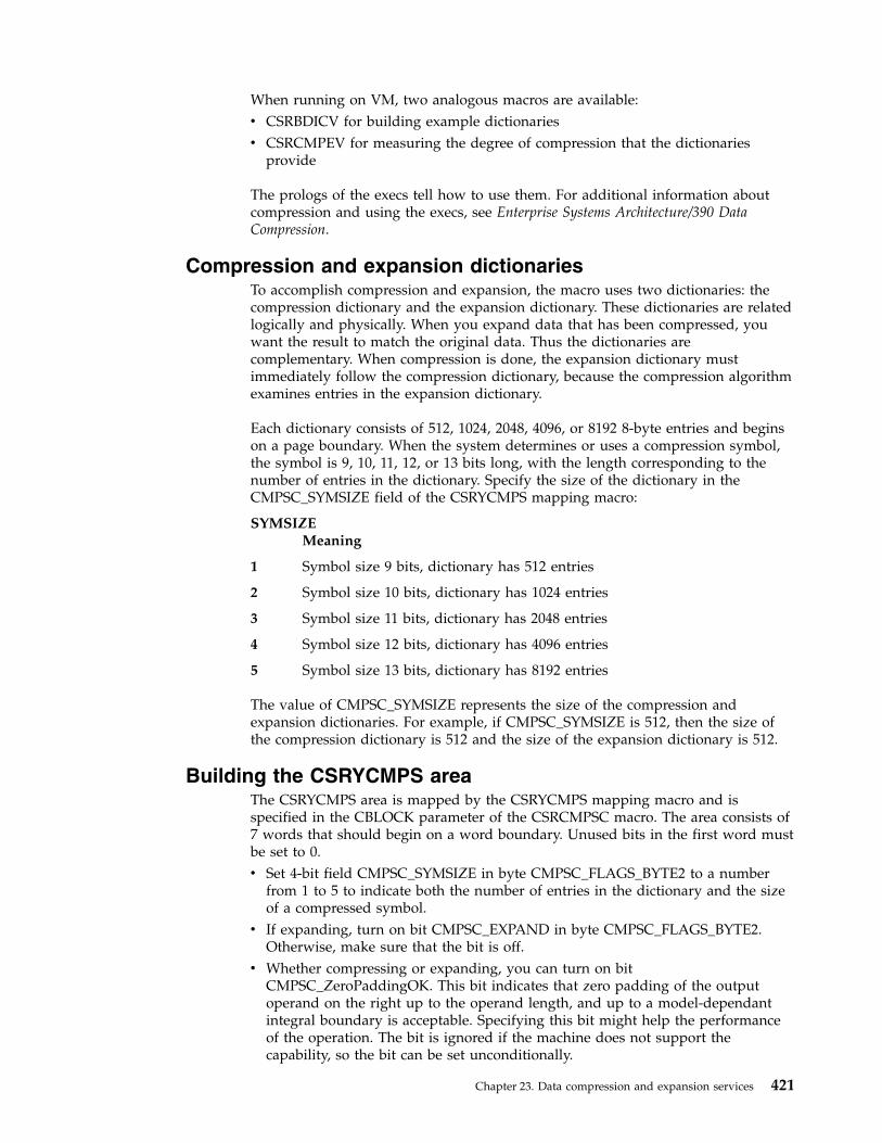
When running on VM, two analogous macros are available:v CSRBDICV for building example dictionariesv CSRCMPEV for measuring the degree of compression that the dictionaries
provide
The prologs of the execs tell how to use them. For additional information aboutcompression and using the execs, see Enterprise Systems Architecture/390 DataCompression.
Compression and expansion dictionariesTo accomplish compression and expansion, the macro uses two dictionaries: thecompression dictionary and the expansion dictionary. These dictionaries are relatedlogically and physically. When you expand data that has been compressed, youwant the result to match the original data. Thus the dictionaries arecomplementary. When compression is done, the expansion dictionary mustimmediately follow the compression dictionary, because the compression algorithmexamines entries in the expansion dictionary.
Each dictionary consists of 512, 1024, 2048, 4096, or 8192 8-byte entries and beginson a page boundary. When the system determines or uses a compression symbol,the symbol is 9, 10, 11, 12, or 13 bits long, with the length corresponding to thenumber of entries in the dictionary. Specify the size of the dictionary in theCMPSC_SYMSIZE field of the CSRYCMPS mapping macro:
SYMSIZEMeaning
1 Symbol size 9 bits, dictionary has 512 entries
2 Symbol size 10 bits, dictionary has 1024 entries
3 Symbol size 11 bits, dictionary has 2048 entries
4 Symbol size 12 bits, dictionary has 4096 entries
5 Symbol size 13 bits, dictionary has 8192 entries
The value of CMPSC_SYMSIZE represents the size of the compression andexpansion dictionaries. For example, if CMPSC_SYMSIZE is 512, then the size ofthe compression dictionary is 512 and the size of the expansion dictionary is 512.
Building the CSRYCMPS areaThe CSRYCMPS area is mapped by the CSRYCMPS mapping macro and isspecified in the CBLOCK parameter of the CSRCMPSC macro. The area consists of7 words that should begin on a word boundary. Unused bits in the first word mustbe set to 0.v Set 4-bit field CMPSC_SYMSIZE in byte CMPSC_FLAGS_BYTE2 to a number
from 1 to 5 to indicate both the number of entries in the dictionary and the sizeof a compressed symbol.
v If expanding, turn on bit CMPSC_EXPAND in byte CMPSC_FLAGS_BYTE2.Otherwise, make sure that the bit is off.
v Whether compressing or expanding, you can turn on bitCMPSC_ZeroPaddingOK. This bit indicates that zero padding of the outputoperand on the right up to the operand length, and up to a model-dependantintegral boundary is acceptable. Specifying this bit might help the performanceof the operation. The bit is ignored if the machine does not support thecapability, so the bit can be set unconditionally.
Chapter 23. Data compression and expansion services 421

v Set field CMPSC_DICTADDR to the address of the necessary dictionary. Ifcompressing, this should be the compression dictionary, which must beimmediately followed by the expansion dictionary. If expanding, this should bethe expansion dictionary. In either case, the dictionary must begin on a pageboundary, as the low order 12 bits of the address are assumed to be 0 whendetermining the address of the dictionary.If running in AR mode, set field CMPSC_SOURCEALET to the ALET of thenecessary dictionary. Note that the input area is also accessed using this ALET. Ifnot in AR mode, make sure that the field contains 0.Using the linkage editor can help you get the dictionary on the proper boundary.For example, you may have an object deck for each compression dictionary(CD), and expansion dictionary (ED), and a DD statement for file OBJS, whichrepresents the library containing the object decks. The following instructionslinkage editor control statements define a dictionary with the name DICT that,when loaded, will have the compression dictionary followed by the expansiondictionary, and will begin on a page boundary.ORDER CD(P),EDINCLUDE OBJS(CD)INCLUDE OBJS(ED)NAME DICT(R)
v In most cases, make sure that 3-bit field CMPSC_BITNUM in byteCMPSC_DICTADDR_BYTE3 is zero. This field has the following meaning:– If compressing, place the first compression symbol at this bit in the leftmost
byte of the target operand. Normally this field should be set to 0 for the startof compression.
– If expanding, expand beginning with the compression symbol that beginswith this bit in the leftmost byte of the source operand. Normally this fieldshould be set to the value used for the start of compression.
v Set word CMPSC_TARGETADDR to the address of the output area. Forcompression, the output area contains the compressed data; for expansion, itcontains the expanded data.If running in AR mode, set field CMPSC_TARGETALET to the ALET of theoutput area. If not in AR mode, make sure that the field contains 0.
v Set word CMPSC_TARGETLEN to the length of the output area.v Set word CMPSC_SOURCEADDR to the address of the input area. For
compression, the input area contains the data to be compressed; for expansion, itcontains the compressed data.If running in AR mode, set field CMPSC_SOURCEALET to the ALET of theinput area. Note that the dictionary will also be accessed using this ALET. If notin AR mode, make sure that the field contains 0.
v Set word CMPSC_SOURCELEN to the length of the input area. For expansion,the length should be the difference between CMPSC_TARGETLEN at thecompletion of compression and CMPSC_TARGETLEN at the start ofcompression, increased by 1 if field CMPSC_BITNUM was nonzero uponcompletion of compression.
v Set word CMPSC_WORKAREAADDR to the address of a 192-byte work area foruse by the CSRCMPSC macro. The work area should begin on a doublewordboundary. This area does not need to be provided and the field does not have tobe set if your code has verified that the hardware CMPSC instruction is present.The program can do the verification by checking that bit CVTCMPSH inmapping macro CVT is on.
422 z/OS MVS Assembler Services Guide
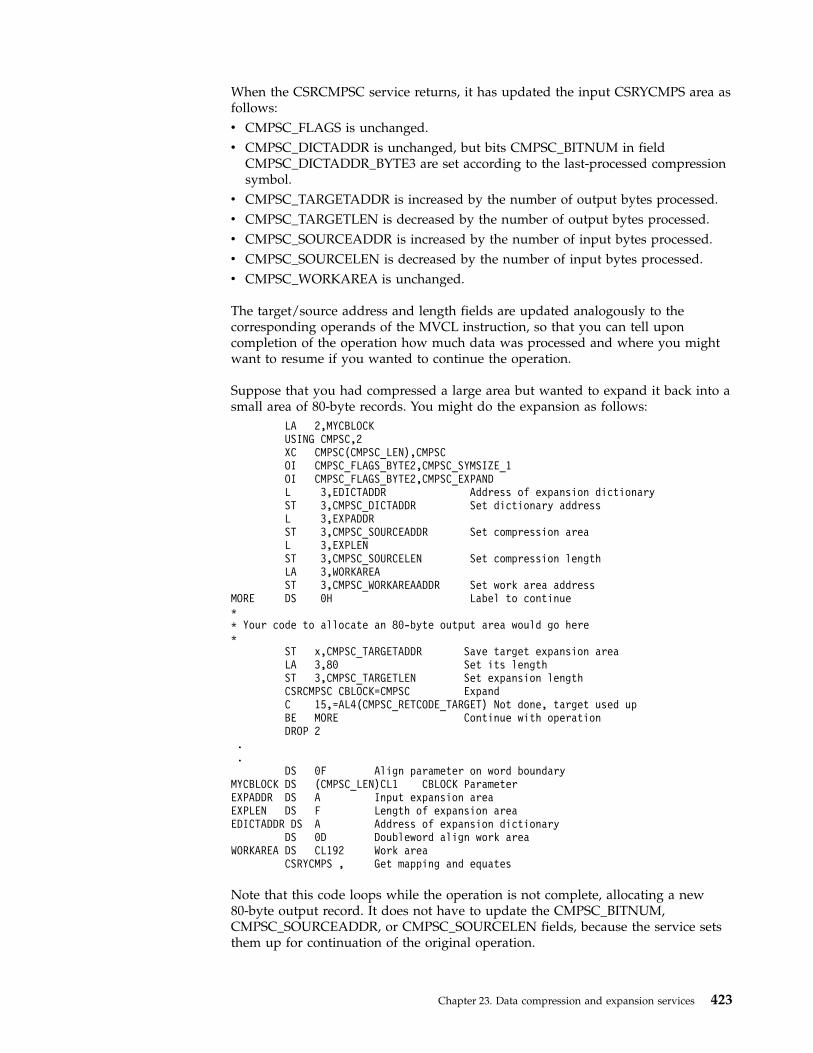
When the CSRCMPSC service returns, it has updated the input CSRYCMPS area asfollows:v CMPSC_FLAGS is unchanged.v CMPSC_DICTADDR is unchanged, but bits CMPSC_BITNUM in field
CMPSC_DICTADDR_BYTE3 are set according to the last-processed compressionsymbol.
v CMPSC_TARGETADDR is increased by the number of output bytes processed.v CMPSC_TARGETLEN is decreased by the number of output bytes processed.v CMPSC_SOURCEADDR is increased by the number of input bytes processed.v CMPSC_SOURCELEN is decreased by the number of input bytes processed.v CMPSC_WORKAREA is unchanged.
The target/source address and length fields are updated analogously to thecorresponding operands of the MVCL instruction, so that you can tell uponcompletion of the operation how much data was processed and where you mightwant to resume if you wanted to continue the operation.
Suppose that you had compressed a large area but wanted to expand it back into asmall area of 80-byte records. You might do the expansion as follows:
LA 2,MYCBLOCKUSING CMPSC,2XC CMPSC(CMPSC_LEN),CMPSCOI CMPSC_FLAGS_BYTE2,CMPSC_SYMSIZE_1OI CMPSC_FLAGS_BYTE2,CMPSC_EXPANDL 3,EDICTADDR Address of expansion dictionaryST 3,CMPSC_DICTADDR Set dictionary addressL 3,EXPADDRST 3,CMPSC_SOURCEADDR Set compression areaL 3,EXPLENST 3,CMPSC_SOURCELEN Set compression lengthLA 3,WORKAREAST 3,CMPSC_WORKAREAADDR Set work area address
MORE DS 0H Label to continue** Your code to allocate an 80-byte output area would go here*
ST x,CMPSC_TARGETADDR Save target expansion areaLA 3,80 Set its lengthST 3,CMPSC_TARGETLEN Set expansion lengthCSRCMPSC CBLOCK=CMPSC ExpandC 15,=AL4(CMPSC_RETCODE_TARGET) Not done, target used upBE MORE Continue with operationDROP 2
.
.DS 0F Align parameter on word boundary
MYCBLOCK DS (CMPSC_LEN)CL1 CBLOCK ParameterEXPADDR DS A Input expansion areaEXPLEN DS F Length of expansion areaEDICTADDR DS A Address of expansion dictionary
DS 0D Doubleword align work areaWORKAREA DS CL192 Work area
CSRYCMPS , Get mapping and equates
Note that this code loops while the operation is not complete, allocating a new80-byte output record. It does not have to update the CMPSC_BITNUM,CMPSC_SOURCEADDR, or CMPSC_SOURCELEN fields, because the service setsthem up for continuation of the original operation.
Chapter 23. Data compression and expansion services 423
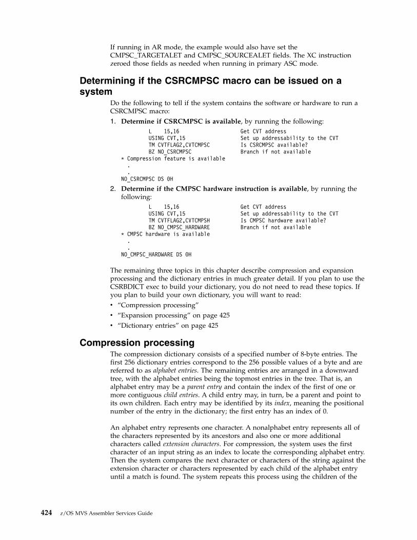
If running in AR mode, the example would also have set theCMPSC_TARGETALET and CMPSC_SOURCEALET fields. The XC instructionzeroed those fields as needed when running in primary ASC mode.
Determining if the CSRCMPSC macro can be issued on asystem
Do the following to tell if the system contains the software or hardware to run aCSRCMPSC macro:1. Determine if CSRCMPSC is available, by running the following:
L 15,16 Get CVT addressUSING CVT,15 Set up addressability to the CVTTM CVTFLAG2,CVTCMPSC Is CSRCMPSC available?BZ NO_CSRCMPSC Branch if not available
* Compression feature is available..
NO_CSRCMPSC DS 0H
2. Determine if the CMPSC hardware instruction is available, by running thefollowing:
L 15,16 Get CVT addressUSING CVT,15 Set up addressability to the CVTTM CVTFLAG2,CVTCMPSH Is CMPSC hardware available?BZ NO_CMPSC_HARDWARE Branch if not available
* CMPSC hardware is available..
NO_CMPSC_HARDWARE DS 0H
The remaining three topics in this chapter describe compression and expansionprocessing and the dictionary entries in much greater detail. If you plan to use theCSRBDICT exec to build your dictionary, you do not need to read these topics. Ifyou plan to build your own dictionary, you will want to read:v “Compression processing”v “Expansion processing” on page 425v “Dictionary entries” on page 425
Compression processingThe compression dictionary consists of a specified number of 8-byte entries. Thefirst 256 dictionary entries correspond to the 256 possible values of a byte and arereferred to as alphabet entries. The remaining entries are arranged in a downwardtree, with the alphabet entries being the topmost entries in the tree. That is, analphabet entry may be a parent entry and contain the index of the first of one ormore contiguous child entries. A child entry may, in turn, be a parent and point toits own children. Each entry may be identified by its index, meaning the positionalnumber of the entry in the dictionary; the first entry has an index of 0.
An alphabet entry represents one character. A nonalphabet entry represents all ofthe characters represented by its ancestors and also one or more additionalcharacters called extension characters. For compression, the system uses the firstcharacter of an input string as an index to locate the corresponding alphabet entry.Then the system compares the next character or characters of the string against theextension character or characters represented by each child of the alphabet entryuntil a match is found. The system repeats this process using the children of the
424 z/OS MVS Assembler Services Guide

last matched entry, until the last possible match is found, which might be a matchon only the alphabet entry. The system uses the index of the last matched entry asthe compression symbol.
The first extension character represented by a child entry exists as either a childcharacter in the parent or as a sibling character. A parent can contain up to four orfive child characters. If the parent has more children than the number of childcharacters that can be in the parent, a dictionary entry named a sibling descriptorfollows the entry for the last child character in the parent. The sibling descriptorcan contain up to six additional child characters, and a dictionary entry named asibling descriptor extension can contain eight more child characters for a total offourteen. These characters are called sibling characters. The corresponding additionalchild entries follow the sibling descriptor. If necessary, another sibling descriptorfollows the additional child entries, and so forth. The dictionary entries that are notsibling descriptors or sibling descriptor extensions are called character entries.
If a nonalphabet character entry represents more than one extension character, theextension characters after the first are in the entry; they are called additionalextension characters. The first extension character exists as a child character in theparent or as a sibling character in a sibling descriptor or sibling descriptorextension. The nonalphabet character entries represent either:v If the entry has no children or one child, from one to five extension characters.v If the entry has more than one child, one or two extension characters. If the
entry represents one extension character, it can contain five child characters. If itrepresents two extension characters, it can contain four child characters.
Expansion processingThe dictionary used for expansion also consists of a specified number of 8-byteentries. The two types of entries used for expansion are:v Unpreceded entriesv Preceded entries
The compression symbol, which is an index into the dictionary, locates that index'sdictionary entry. The symbol represents a character string of up to 260 characters.If the entry is an unpreceded entry, the expansion process places at offset 0 fromthe current processing point the characters designated by that entry. Note that thefirst 256 correspond to the 256 possible values of a byte and are assumed todesignate only the single character with that byte value.
If the entry is a preceded entry, the expansion process places the designatedcharacters at the specified offset from the current processing point. It then uses theinformation in that entry to locate the preceding entry, which may be either anunpreceded or a preceded entry, and continues as described previously.
The sibling descriptor extension entries described earlier are also physically locatedwithin the expansion dictionary.
Dictionary entriesThe following notation is used in the diagrams of dictionary entries:
{cc} Character may be present
... The preceding field may be repeated
Chapter 23. Data compression and expansion services 425
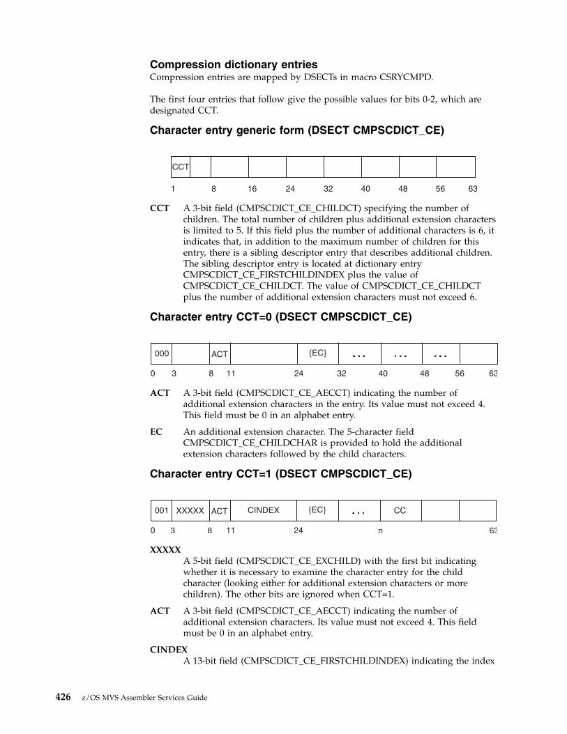
Compression dictionary entriesCompression entries are mapped by DSECTs in macro CSRYCMPD.
The first four entries that follow give the possible values for bits 0-2, which aredesignated CCT.
Character entry generic form (DSECT CMPSCDICT_CE)
CCT A 3-bit field (CMPSCDICT_CE_CHILDCT) specifying the number ofchildren. The total number of children plus additional extension charactersis limited to 5. If this field plus the number of additional characters is 6, itindicates that, in addition to the maximum number of children for thisentry, there is a sibling descriptor entry that describes additional children.The sibling descriptor entry is located at dictionary entryCMPSCDICT_CE_FIRSTCHILDINDEX plus the value ofCMPSCDICT_CE_CHILDCT. The value of CMPSCDICT_CE_CHILDCTplus the number of additional extension characters must not exceed 6.
Character entry CCT=0 (DSECT CMPSCDICT_CE)
ACT A 3-bit field (CMPSCDICT_CE_AECCT) indicating the number ofadditional extension characters in the entry. Its value must not exceed 4.This field must be 0 in an alphabet entry.
EC An additional extension character. The 5-character fieldCMPSCDICT_CE_CHILDCHAR is provided to hold the additionalextension characters followed by the child characters.
Character entry CCT=1 (DSECT CMPSCDICT_CE)
XXXXXA 5-bit field (CMPSCDICT_CE_EXCHILD) with the first bit indicatingwhether it is necessary to examine the character entry for the childcharacter (looking either for additional extension characters or morechildren). The other bits are ignored when CCT=1.
ACT A 3-bit field (CMPSCDICT_CE_AECCT) indicating the number ofadditional extension characters. Its value must not exceed 4. This fieldmust be 0 in an alphabet entry.
CINDEXA 13-bit field (CMPSCDICT_CE_FIRSTCHILDINDEX) indicating the index
CCT
1 8 16 24 4032 48 56 63
000 ACT {EC}
0 8 113 24 4032 48 56 63
001 XXXXX ACT CINDEX {EC} CC
0 8 113 24 n 63
426 z/OS MVS Assembler Services Guide
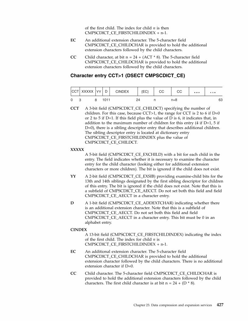
of the first child. The index for child n is thenCMPSCDICT_CE_FIRSTCHILDINDEX + n-1.
EC An additional extension character. The 5-character fieldCMPSCDICT_CE_CHILDCHAR is provided to hold the additionalextension characters followed by the child characters.
CC Child character, at bit n = 24 + (ACT * 8). The 5-character fieldCMPSCDICT_CE_CHILDCHAR is provided to hold the additionalextension characters followed by the child characters.
Character entry CCT>1 (DSECT CMPSCDICT_CE)
CCT A 3-bit field (CMPSCDICT_CE_CHILDCT) specifying the number ofchildren. For this case, because CCT>1, the range for CCT is 2 to 6 if D=0or 2 to 5 if D=1. If this field plus the value of D is 6, it indicates that, inaddition to the maximum number of children for this entry (4 if D=1, 5 ifD=0), there is a sibling descriptor entry that describes additional children.The sibling descriptor entry is located at dictionary entryCMPSCDICT_CE_FIRSTCHILDINDEX plus the value ofCMPSCDICT_CE_CHILDCT.
XXXXXA 5-bit field (CMPSCDICT_CE_EXCHILD) with a bit for each child in theentry. The field indicates whether it is necessary to examine the characterentry for the child character (looking either for additional extensioncharacters or more children). The bit is ignored if the child does not exist.
YY A 2-bit field (CMPSCDICT_CE_EXSIB) providing examine-child bits for the13th and 14th siblings designated by the first sibling descriptor for childrenof this entry. The bit is ignored if the child does not exist. Note that this isa subfield of CMPSCDICT_CE_AECCT. Do not set both this field and fieldCMPSCDICT_CE_AECCT in a character entry.
D A 1-bit field (CMPSCDICT_CE_ADDEXTCHAR) indicating whether thereis an additional extension character. Note that this is a subfield ofCMPSCDICT_CE_AECCT. Do not set both this field and fieldCMPSCDICT_CE_AECCT in a character entry. This bit must be 0 in analphabet entry.
CINDEXA 13-bit field (CMPSCDICT_CE_FIRSTCHILDINDEX) indicating the indexof the first child. The index for child n isCMPSCDICT_CE_FIRSTCHILDINDEX + n-1.
EC An additional extension character. The 5-character fieldCMPSCDICT_CE_CHILDCHAR is provided to hold the additionalextension character followed by the child characters. There is no additionalextension character if D=0.
CC Child character. The 5-character field CMPSCDICT_CE_CHILDCHAR isprovided to hold the additional extension characters followed by the childcharacters. The first child character is at bit n = 24 + (D * 8).
CCT XXXXX YY D CINDEX {EC} CCCC
0 8 10113 24 n n+8 63
Chapter 23. Data compression and expansion services 427
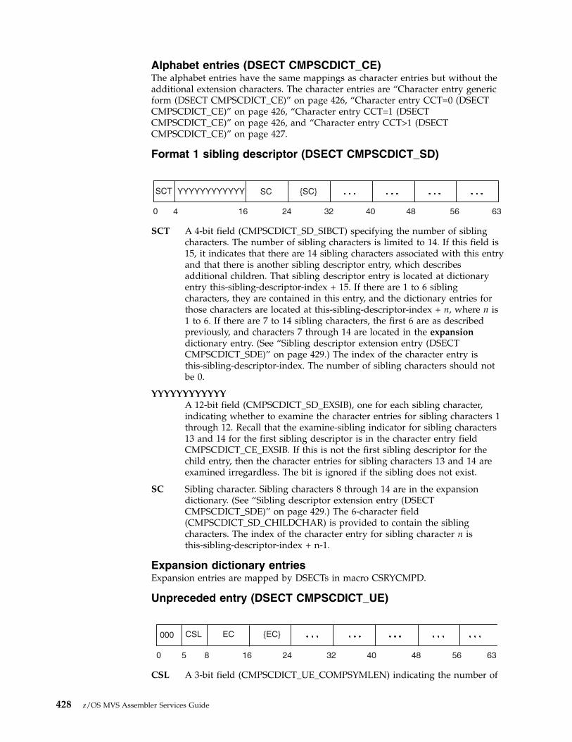
Alphabet entries (DSECT CMPSCDICT_CE)The alphabet entries have the same mappings as character entries but without theadditional extension characters. The character entries are “Character entry genericform (DSECT CMPSCDICT_CE)” on page 426, “Character entry CCT=0 (DSECTCMPSCDICT_CE)” on page 426, “Character entry CCT=1 (DSECTCMPSCDICT_CE)” on page 426, and “Character entry CCT>1 (DSECTCMPSCDICT_CE)” on page 427.
Format 1 sibling descriptor (DSECT CMPSCDICT_SD)
SCT A 4-bit field (CMPSCDICT_SD_SIBCT) specifying the number of siblingcharacters. The number of sibling characters is limited to 14. If this field is15, it indicates that there are 14 sibling characters associated with this entryand that there is another sibling descriptor entry, which describesadditional children. That sibling descriptor entry is located at dictionaryentry this-sibling-descriptor-index + 15. If there are 1 to 6 siblingcharacters, they are contained in this entry, and the dictionary entries forthose characters are located at this-sibling-descriptor-index + n, where n is1 to 6. If there are 7 to 14 sibling characters, the first 6 are as describedpreviously, and characters 7 through 14 are located in the expansiondictionary entry. (See “Sibling descriptor extension entry (DSECTCMPSCDICT_SDE)” on page 429.) The index of the character entry isthis-sibling-descriptor-index. The number of sibling characters should notbe 0.
YYYYYYYYYYYYA 12-bit field (CMPSCDICT_SD_EXSIB), one for each sibling character,indicating whether to examine the character entries for sibling characters 1through 12. Recall that the examine-sibling indicator for sibling characters13 and 14 for the first sibling descriptor is in the character entry fieldCMPSCDICT_CE_EXSIB. If this is not the first sibling descriptor for thechild entry, then the character entries for sibling characters 13 and 14 areexamined irregardless. The bit is ignored if the sibling does not exist.
SC Sibling character. Sibling characters 8 through 14 are in the expansiondictionary. (See “Sibling descriptor extension entry (DSECTCMPSCDICT_SDE)” on page 429.) The 6-character field(CMPSCDICT_SD_CHILDCHAR) is provided to contain the siblingcharacters. The index of the character entry for sibling character n isthis-sibling-descriptor-index + n-1.
Expansion dictionary entriesExpansion entries are mapped by DSECTs in macro CSRYCMPD.
Unpreceded entry (DSECT CMPSCDICT_UE)
CSL A 3-bit field (CMPSCDICT_UE_COMPSYMLEN) indicating the number of
SCT YYYYYYYYYYYY SC {SC}
0 164 24 32 40 48 56 63
000 CSL EC {EC}
0 168 32 405 24 48 56 63
428 z/OS MVS Assembler Services Guide

characters contained in CMPSCDICT_UE_CHARS. These characters will beplaced at offset 0 in the expanded output. This field should not have avalue of 0.
EC Expansion character. The 7-character field (CMPSCDICT_UE_CHARS) isprovided to contain the expansion characters.
Preceded entry (DSECT CMPSCDICT_PE)
PSL A 3-bit field (CMPSCDICT_PE_PARTSYMLEN) indicating the number ofcharacters contained in CMPSCDICT_PE_CHARS. These characters will beplaced at the offset indicated by CMPSCDICT_PE_OFFSET in theexpanded output. This field must not be 0, because 0 indicates anunpreceded entry.
PrecIndexA 13-bit field (CMPSCDICT_UE_PRECENTINDEX) indicating the index ofthe dictionary entry with which processing is to continue.
EC Expansion character. The 5-character field (CMPSCDICT_PE_CHARS) isprovided to contain the expansion characters.
Offset A 1-byte field (CMPSCDICT_PE_OFFSET) indicating the offset in theexpanded output for characters in CMPSCDICT_PE_CHARS.
Sibling descriptor extension entry (DSECT CMPSCDICT_SDE)
SC Sibling character. The 8-character field (CMPSCDICT_SDE_CHARS) isprovided to contain the sibling characters. The nth sibling character in thisentry is actually overall sibling character number 6 + n, because the first 6characters were contained in the corresponding sibling descriptor entry.The index of the character entry for the nth character isthis-sibling-descriptor-index + 6 + n-1.
Dictionary restrictionsSet up the compression dictionary so that:v The algorithm does not create a compression symbol that represents a string of
more than 260 characters.v No character entry has more than 260 total children, including all sibling
descriptors for that character entry.v No character entry has a child count greater than 6.v No character entry has more than 4 additional extension characters when there
are 0 or 1 child characters.v No sibling descriptor indicates 0 sibling characters.
Set up the expansion dictionary so that:
PSL PrecIndex EC {EC} Offset
0 16 32 403 24 48 56 63
{SC}
0 16 32 408 24 48 56 63
Chapter 23. Data compression and expansion services 429

v Expansion of a compression symbol does not use more than 127 dictionaryentries.
Other considerationsIf the first child character matches, but its additional extension characters do notmatch and the next child character is the same as the first, the system continuescompression match processing to try to find a compression symbol that containsthat child character. If, however, the next child character is not the same,compression processing uses the current compression symbol as the result. You canset up the child characters for an entry to take advantage of this processing.
If a parent entry does not have the examine child bit (CMPSCDICT_CE_EXCHILD)on for a particular child character, then the child character entry should not haveany additional extension characters or children. The system will not check theentry itself for additional extension characters or children.
If a parent or sibling descriptor entry does not have the examine sibling bit(CMPSCDICT_CE_EXSIB) on for a particular sibling character, then the characterentry for that sibling character should not to have any additional extensioncharacters or children. The system will not check the entry itself for additionalextension characters or children.
Compression dictionary examplesIn the following examples, most fields contain their hexadecimal values. However,for clarity, the examine-child bit fields are displayed with their bit values.
Example 1Suppose the dictionary looks like the following:
Hexadecimal EntryDescription
C1 Alphabet entry for character A; 2 child characters B and C. The first childindex is X'100'.
100 Entry for character B; no additional extension characters; no children.
101 Entry for character C; additional extension character 1; 2 child characters Dand E. The first child index is X'200'.
200 Entry for character D; 2 additional extension characters 1 and 2; nochildren.
201 Entry for character E; 4 additional extension characters 1, 2, 3, and 4; nochildren.
430 z/OS MVS Assembler Services Guide

If the input string is AD, the output string will consist of 2 compression symbols:one for A and one for D. When examining the dictionary entry for character A, thesystem determines that none of A's children match the next input character, D, andso returns the compression symbol for A. When examining the dictionary entry forcharacter D, the system determines that it has no children, and so returns thecompression symbol for D.
If the input string is AB, the output string will consist of 1 compression symbol forboth input characters. When examining the dictionary input for character A, thesystem determines that A's first child character matches the next input character, B,and so looks at entry X'100'. Because that entry has no additional extensioncharacters, a match is determined. Because there are no further input characters,the scan concludes.
If the input string is AC, the output string will consist of 2 compression symbols:one for A and one for C. When examining the dictionary input for character A, thesystem determines that A's second child character matches the next input character,C, and so looks at entry X'101'. Because that entry has an additional extensioncharacter, but the input string does not contain this character, no match is made,and the output is the compression symbol for A. Processing character C results inthe compression symbol for C.
If the input string is AC1, the output string will consist of 1 compression symbol.When examining the dictionary input for character A, the system determines thatA's second child character matches the next input character, C, and so looks atentry X'101'. Because that entry has an additional extension character, and theinput string does contain this character, 1, a match is made, and the output is thecompression symbol for AC1.
Similarly, the set of input strings longer than one character compressed by thisdictionary are:
Hexadecimal SymbolString
100 AB
CCT2
CCT2
CCT0
CCT0
YY00
YY00
ACT2
ACT4
CC'B'
EC'1'
EC'1'
EC'1'
CC'C'
CC'D''
CC'D''
EC'2'
EC'3'
EC'4'
CC'E'
D0
D1
XXXXX01000
Child character B entry contents irrelevant; examine child bit is off.
XXXXX11000
XXXXX00000
XXXXX00000
CINDEX100
CINDEX200
0
0
0
0
1011
1011
11
11
3
3
C1
HexadecimalEntry
100
101
200
201
3
3
24
24
24
24
8
8
8
8
32
32
32
32
40
40
40
40
48
48
56
56
63
63
63
63
Chapter 23. Data compression and expansion services 431

101 AC1
200 AC1D12
201 AC1E1234
The compression symbol is the index of the dictionary entry. Based on this, youcan see that the expansion dictionary must result in the reverse processing; forexample, if a compression symbol of X'201' is found, the output must be the stringAC1E1234. See “Expansion dictionary example” on page 435 for expansiondictionary processing.
Example 2 for more than 5 childrenSuppose the dictionary looks like the following:
Hexadecimal EntryDescription
C2 Alphabet entry for character B; child count of 6 (indicating 5 children plusa sibling descriptor); first child index is X'400', children are 1, 2, 3, 4, and 5.
400 Entry for character 1; no additional extension characters; no children.
401-404Entries for characters 2 through 5; no additional extension characters; nochildren.
405 Sibling descriptor; child count of 15, which indicates 14 children plusanother sibling descriptor; sibling characters A, B, C, D, E, and F.
405 Sibling descriptor extension. In the expansion dictionary entry X'405', thesibling characters are G, H, I, J, K, L, M, and N.
406 Entry for character A; no additional extension characters; no children.
407-413Entries for characters B through N; no additional extension characters; nochildren.
414 Next sibling descriptor; child count of 2; child characters O and P.
415 Entry for character O; no additional extension characters; no children.
416 Entry for character P; no additional extension characters; no children.
432 z/OS MVS Assembler Services Guide
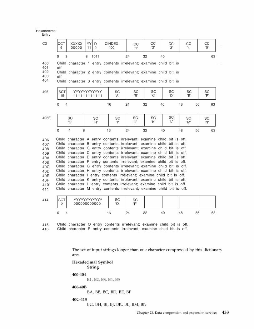
The set of input strings longer than one character compressed by this dictionaryare:
Hexadecimal SymbolString
400-404B1, B2, B3, B4, B5
406-40BBA, BB, BC, BD, BE, BF
40C-413BG, BH, BI, BJ, BK, BL, BM, BN
CCT6
SCT15
SC'G'
SCT2
YY11
SC'O'
SC'P'
CC'1'
CC'3'
CC'4'
CC'5'
SC'B'
SC'I'
SC'K'
CC'2'
SC'C'
SC'J'
SC'L'
SC'N'
SC'M'
SC'D'
SC'E'
SC'F'
D0
XXXXX00000
YYYYYYYYYYYY1 1 1 1 1 1 1 1 1 1 1 1
SC'H'
YYYYYYYYYYYY000000000000
CINDEX400
SC'A'
0
0
0
0
1011
16
16
3
4
C2
HexadecimalEntry
400
401
402
403
404
405
405E
414
415
416
4
4
24
24
24
24
8
16
8
32
32
32
32
40
40
40
40
48
48
48
56
56
56
63
63
63
63
Child character 1 entry contents irrelevant; examine child bit is
off.
Child character 2 entry contents irrelevant; examine child bit is
off.
Child character 3 entry contents irrelevant; examine child bit is
Child character A entry contents irrelevant; examine child bit is off.
Child character B entry contents irrelevant; examine child bit is off.
Child character C entry contents irrelevant; examine child bit is off.
Child character C entry contents irrelevant; examine child bit is off.
Child character E entry contents irrelevant; examine child bit is off.
Child character F entry contents irrelevant; examine child bit is off.
Child character G entry contents irrelevant; examine child bit is off.
Child character H entry contents irrelevant; examine child bit is off.
Child character I entry contents irrelevant; examine child bit is off.
Child character K entry contents irrelevant; examine child bit is off.
Child character L entry contents irrelevant; examine child bit is off.
Child character M entry contents irrelevant; examine child bit is off.
Child character O entry contents irrelevant; examine child bit is off.
Child character P entry contents irrelevant; examine child bit is off.
406
407
408
409
40A
40B
40C
40D
40E
40F
410
411
Chapter 23. Data compression and expansion services 433

415-416BO, BP
There are no compression symbols for 405 and 414. These are the sibling descriptorentries. Because their sibling descriptor extensions are located at those indices inthe expansion dictionary (not the preceded or unpreceded entries required forexpansion), it is important that no compression symbol have that value.
Example 3 for children with the same valueSuppose the dictionary looks like the following:
Hexadecimal EntryDescription
C3 Alphabet entry for character C; child count of 4. The first child index isX'600' and the child characters are 1, 1, 1, and 2.
600 Entry for character 1; 4 additional extension characters A, B, C, and D; nochildren.
601 Entry for character 1; 3 additional extension characters A, B, and C; nochildren.
602 Entry for character 1; 2 additional extension characters A and B; nochildren.
603 Entry for character 2; no additional extension characters; no children.
The set of input strings longer than one character compressed by this dictionaryare:
Hexadecimal SymbolString
600 C1ABCD
601 C1ABC
602 C1AB
603 C2
By taking advantage of the special processing when the second and subsequentchild characters match the first, you can reduce the number of dictionary entriessearched to determine the compression symbols. For example, to find that X'601' isthe compression symbol for the characters C1ABC, the processing examines entryX'C3', then entry X'600', then entry X'601'. Entry X'600' does not match because the
CCT4
YY00
CC'1'
CC'1'
CC'2'
CC'1'
D0
XXXXX00000
CINDEX600
0 10113
C3
600
601
602
603
248 32 40 63
Child character 1 entry contents irrelevant; examine child bit is off.
Second child character 1 entry contents irrelevant; examine child bit is off.
Third child character 1 entry contents irrelevant; examine child bit is off.
Child character 2 entry contents irrelevant; examine child bit is off.
434 z/OS MVS Assembler Services Guide
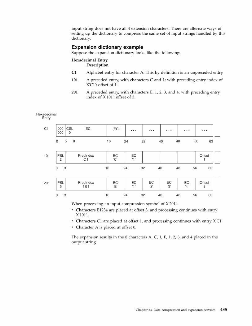
input string does not have all 4 extension characters. There are alternate ways ofsetting up the dictionary to compress the same set of input strings handled by thisdictionary.
Expansion dictionary exampleSuppose the expansion dictionary looks like the following:
Hexadecimal EntryDescription
C1 Alphabet entry for character A. This by definition is an unpreceded entry.
101 A preceded entry, with characters C and 1; with preceding entry index ofX'C1'; offset of 1.
201 A preceded entry, with characters E, 1, 2, 3, and 4; with preceding entryindex of X'101'; offset of 3.
When processing an input compression symbol of X'201':v Characters E1234 are placed at offset 3, and processing continues with entry
X'101'.v Characters C1 are placed at offset 1, and processing continues with entry X'C1'.v Character A is placed at offset 0.
The expansion results in the 8 characters A, C, 1, E, 1, 2, 3, and 4 placed in theoutput string.
PSL2
EC'1'
Offset1
PrecIndexC 1
EC'C'
0 3 2416 32 40 48
48 56
56 63
PSL5
EC'1'
EC'2'
EC'3'
EC'4'
Offset3
PrecIndex1 0 1
EC'E'
0 3 2416 32 40 48 56 63
000000
EC {EC}CSL0
0 8 16
C1
HexadecimalEntry
101
201
245 32 40 63
Chapter 23. Data compression and expansion services 435

436 z/OS MVS Assembler Services Guide

Chapter 24. Accessing unit control blocks (UCBs)
Each device in a configuration is represented by a unit control block (UCB). In adynamic configuration environment, a service obtaining UCB information needs tobe able to detect any changes in the configuration that could affect the returnedinformation. The MVS I/O configuration token provides this capability. You canscan UCBs with the UCBSCAN macro to obtain information about the devices inthe configuration. You can also use the UCBINFO macro to obtain deviceinformation from a UCB.
The eligible device table (EDT) contains the definitions for the installation's devicegroups. The EDTINFO macro allows you to obtain information from the EDT.
Detecting I/O configuration changesYou can use the MVS I/O configuration token to detect I/O configuration changes.The MVS I/O configuration token is a 48-byte token that uniquely identifies anI/O configuration to the system. The token will change whenever the softwareconfiguration definition changes. Thus, if your program obtains the current MVSI/O configuration token and compares it to one previously obtained, the programcan determine whether there has been a change in the I/O configuration: If thetokens do not match, the I/O configuration has changed.
An optional parameter, IOCTOKEN, is available with the UCBSCAN macro.Specifying IOCTOKEN ensures that the system will notify the caller through areturn code and will not return any data if the current I/O configuration is notconsistent with the configuration represented by the token specified as input bythe caller.
Use the following ways to obtain the current MVS I/O configuration token:v Issue the IOCINFO macro.v Issue the UCBSCAN macro, setting the input specified by the IOCTOKEN
parameter to binary zeroes. The macro will then return the current I/Oconfiguration token at the start of the scan.
v Issue EDTINFO macro, setting the input specified by the IOCTOKEN parameterto binary zeroes.
Use of the MVS I/O configuration token can help prevent data inconsistencies thatmight occur if the I/O configuration changes between the time the caller obtainedthe token and the time the service returns the information. For example, you canuse the configuration token to determine whether the I/O configuration changesduring a UCB scan. If the IOCTOKEN parameter is specified with UCBSCAN, thecaller will be notified through a return code if the set of UCBs changes while thescan is in progress. Checking for this return code allows the caller to restart thescan to ensure that copies of all UCBs in the current configuration are obtained.
An unauthorized program can use the MVS I/O configuration token to regularlycheck whether a configuration change has occurred, as in the following example:v The program issues the IOCINFO macro to obtain the MVS I/O configuration
token.
© Copyright IBM Corp. 1988, 2017 437
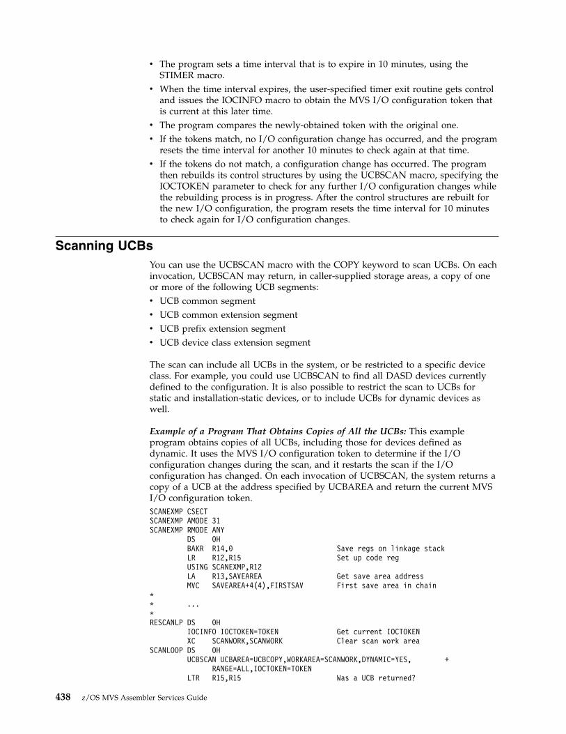
v The program sets a time interval that is to expire in 10 minutes, using theSTIMER macro.
v When the time interval expires, the user-specified timer exit routine gets controland issues the IOCINFO macro to obtain the MVS I/O configuration token thatis current at this later time.
v The program compares the newly-obtained token with the original one.v If the tokens match, no I/O configuration change has occurred, and the program
resets the time interval for another 10 minutes to check again at that time.v If the tokens do not match, a configuration change has occurred. The program
then rebuilds its control structures by using the UCBSCAN macro, specifying theIOCTOKEN parameter to check for any further I/O configuration changes whilethe rebuilding process is in progress. After the control structures are rebuilt forthe new I/O configuration, the program resets the time interval for 10 minutesto check again for I/O configuration changes.
Scanning UCBsYou can use the UCBSCAN macro with the COPY keyword to scan UCBs. On eachinvocation, UCBSCAN may return, in caller-supplied storage areas, a copy of oneor more of the following UCB segments:v UCB common segmentv UCB common extension segmentv UCB prefix extension segmentv UCB device class extension segment
The scan can include all UCBs in the system, or be restricted to a specific deviceclass. For example, you could use UCBSCAN to find all DASD devices currentlydefined to the configuration. It is also possible to restrict the scan to UCBs forstatic and installation-static devices, or to include UCBs for dynamic devices aswell.
Example of a Program That Obtains Copies of All the UCBs: This exampleprogram obtains copies of all UCBs, including those for devices defined asdynamic. It uses the MVS I/O configuration token to determine if the I/Oconfiguration changes during the scan, and it restarts the scan if the I/Oconfiguration has changed. On each invocation of UCBSCAN, the system returns acopy of a UCB at the address specified by UCBAREA and return the current MVSI/O configuration token.SCANEXMP CSECTSCANEXMP AMODE 31SCANEXMP RMODE ANY
DS 0HBAKR R14,0 Save regs on linkage stackLR R12,R15 Set up code regUSING SCANEXMP,R12LA R13,SAVEAREA Get save area addressMVC SAVEAREA+4(4),FIRSTSAV First save area in chain
** ...*RESCANLP DS 0H
IOCINFO IOCTOKEN=TOKEN Get current IOCTOKENXC SCANWORK,SCANWORK Clear scan work area
SCANLOOP DS 0HUCBSCAN UCBAREA=UCBCOPY,WORKAREA=SCANWORK,DYNAMIC=YES, +
RANGE=ALL,IOCTOKEN=TOKENLTR R15,R15 Was a UCB returned?
438 z/OS MVS Assembler Services Guide

BNZ SCANDONE No, either a configuration* change has occurred* or no more UCBs** Process UCB*
B SCANLOOPSCANDONE DS 0H
LA R02,12 Return code for a* configuration change
CR R15,R02 Did a configuration change* occur?
BE RESCANLP Yes, start scan againFINISHED DS 0H** ...*ENDIT DS 0H
PR Return to callerEJECT
** Register equates*R02 EQU 2R03 EQU 3R09 EQU 9R12 EQU 12R13 EQU 13R14 EQU 14R15 EQU 15
DS 0FFIRSTSAV DC CL4’F1SA’ First save area IDSAVEAREA DS 18F Save areaTOKEN DS 48C IOCTOKEN areaUCBCOPY DS 48C UCB Copy returned by* SCANSCANWORK DS CL100 Work area for SCAN
END SCANEXMP
Obtaining UCB information for a specified deviceYou can use the UCBINFO macro to obtain information from a UCB for a specifieddevice. You can use UCBINFO to obtain:v A count of the UCBs for a device classv Reasons why a device is offlinev Device path informationv Channel path type informationv A copy of the UCB prefix extensionv Information about the alias UCBs for a parallel access volume.
When you call UCBINFO, you provide the device number of the device for whichyou want the information.
Obtaining eligible device table informationThe installation's device groups are defined in the eligible device table (EDT). AnEDT is an installation-defined and named representation of the devices that areeligible for allocation. This table also defines the relationship of generic devicetypes and esoteric group names. The term “generic device type” refers to thegeneral identifier IBM gives a device; for example, 3380. An esoteric device group
Chapter 24. Accessing unit control blocks (UCBs) 439
is an installation-defined and named collection of I/O devices; TAPE is an exampleof an esoteric group name. See z/OS HCD Planning for further information on theEDT.
Using the EDTINFO macroThe EDTINFO macro enables you to obtain information from the EDT and tocheck your device specification against the information in the EDT. You can use theEDTINFO macro to perform the following functions:v Check groups. The EDTINFO macro determines whether the input device
numbers constitute a valid allocation group. The device numbers are a validallocation group if either of the following is true:– For any allocation group in the EDT that contains at least one of the device
numbers specified in the input device number list, all of the device numbersin that group in the EDT are contained in the input device number list
– None of the allocation groups in the EDT contain any of the numbersspecified in the input device number list.
If neither of these is the case, the device numbers are not a valid allocationgroup.
v Check units. The EDTINFO macro determines whether the input device numberscorrespond to the specified unit name. The unit name is the EBCDICrepresentation of the IBM generic device type or esoteric group name.
v Return unit name. The EDTINFO macro returns the unit name associated withthe UCB device type provided as input.
v Return unit control block (UCB) addresses. The EDTINFO macro returns a list ofUCB addresses associated with the unit name or device type provided as input.
Note: The EDTINFO macro returns UCB addresses only for below 16 megabyteUCBs for static and installation-static devices with 3-digit device numbers.However, you can use the RTNDEVN keyword with the EDTINFO macro toreturn a device number list for devices that are dynamic, 4-digit or described byUCBs residing above the 16-megabyte line.
The UCBINFO macro can then be used to obtain device number information fora specific device number.
If your program is authorized, running in supervisor state or with a programkey mask of 0-7, you can use the UCBLOOK macro to the obtain the actual UCBaddress from a given device number. See, z/OS MVS Programming: AuthorizedAssembler Services Reference SET-WTO, and z/OS MVS Programming: AuthorizedAssembler Services Guide for the UCBLOOK macro.
v Return group ID. The EDTINFO macro returns the allocation group IDcorresponding to each UCB address specified as input.
v Return attributes. The EDTINFO macro returns general information about theunit name or device type specified as input.
v Return unit names for a device class. The EDTINFO macro returns a list ofgeneric device types or esoteric group names associated with the device classspecified as input.
v Return UCB device number list. The EDTINFO macro returns the UCB devicenumber list associated with the unit name or UCB device type specified asinput. You can also specify that the following be included in the list:– Devices defined to the system as dynamic– Devices defined with 4-digit device numbers
440 z/OS MVS Assembler Services Guide

– Devices with UCBs defined above 16 megabytesv Return maximum eligible device type. The EDTINFO macro returns the
maximum eligible device type (for the allocation and cataloging of a data set)associated with the unit name or device type, recording mode, and densityprovided as input. The maximum eligible device type is the tape device typethat contains the greatest number of eligible devices compatible with thespecified recording mode and density.
Chapter 24. Accessing unit control blocks (UCBs) 441

442 z/OS MVS Assembler Services Guide
Chapter 25. Setting up and using an internal reader
The internal reader is a software substitute for a card punch and a card reader, atape drive, or a TSO/E terminal. Instead of entering a job into the system (throughJES) on punched cards, or through tape, you can use the output of one job or stepas the input to another job, which JES will process directly.
The internal reader facility is useful for several kinds of applications:v You can use it to generate another job or a series of jobs from an
already-executing job. An online application program may submit another job toproduce a report, for example, so it does not have to do it itself.
v A job that produces a series of jobs can put its output to an internal reader forimmediate execution. For example, a job that updates data bases and starts otherapplications based upon some input parameters or real-time events, can use theinternal reader for its output.
v The operator can start utility programs to read jobs from disk or tape files andsubmit them to the system. The IBM-supplied procedure ‘RDR’ is an example ofa program that does this (see z/OS JES2 Initialization and Tuning Guide).
v The operating system itself uses internal readers for submitting the JCL to startup started tasks or TSO/E logons.
Following is a discussion of the batch job internal reader, which is the facility youcan use to submit a job from within another job.
The process of setting up and using an internal reader involves five tasks:v Creating and allocating a data setv Opening the data setv Putting records into the data setv Closing/deallocating the data setv Passing the data set/records to the job entry subsystem for processing
Started tasks that run under the MSTR subsystem have the ability to set up aninternal reader. To accomplish this they must first successfully invoke the RequestJob ID SSI call, and then perform allocation. For more information on the RequestJob ID call (SSI function code 20), see z/OS MVS Using the Subsystem Interface.
Allocating the internal reader data setYou can allocate an internal reader data set, in any address space, either with JCLor dynamically, as follows:v Define the data set in the JCL for a job:
//JOBJCL DD SYSOUT=(A,INTRDR)
Note:
1. “INTRDR” is an IBM-reserved name identifying the internal reader as theprogram to process this data set after it is created and written to.
2. The SYSOUT class on this DD statement becomes the message class for thesubmitted job unless you specify MSGCLASS on the JOB statement.
© Copyright IBM Corp. 1988, 2017 443

v Use the following dynamic allocation text unit keys to dynamically allocate aninternal reader data set:
– DALSYSOU — define the SYSOUT data set and its class.– DALSPGNM — specify the SYSOUT program name (INTRDR).– DALCLOSE — request that INTRDR be deallocated at close.– DALRTDDN — request the return of the ddname assigned by dynamic
allocation.– DALLRECL — specify the record length of any instream data set.– DALRECFM — specify the record format of any instream data set.
Note: DALCLOSE, DALRTDDN, DALLRECL and DALRECFM are optionaldynamic allocation text unit keys.For the format details of dynamic allocation text unit keys, see z/OS MVSProgramming: Authorized Assembler Services Guide.
Note:
1. An INTRDR data set can contain any number of jobs.2. The output destination of the INTRDR data set becomes the default
print/punch routing of all jobs contained within it.3. INTRDR data sets contain sequential, fixed-length, or variable-length records.
Instream data records can be up to 254 bytes long. Note, however, that JCLimages in the data sets must be exactly 80 bytes long.
Opening the internal reader data setYou can write to an internal reader using BSAM or QSAM or an ACB interface.With BSAM or QSAM, you code DSORG=PS in the DCB. There is no advantage tospecifying multiple buffers. The most efficient number of QSAM buffers (BUFNOin the DCB) is 1. You can use any of these interfaces in 24-bit or 31-bit addressingmode. If you call in 31-bit mode, the ACB can be above the 16 MB line.
The DCB macro requires that you code the DDNAME keyword. If you codeDALRTDDN on the dynamic allocation call, it means that you are requestingdynamic allocation to return the new DD name. If you do this, you might chooseto code a dummy DD name on the DCB or ACB macro. For example, you mightcode DDNAME=*.
If you code DALRTDDN, move the returned DDNAME from the DALRTDDN textunit to the DCB or ACB before issuing the OPEN macro. The offset to theDDNAME field in the DCB is the same as the offset in the ACB. You can use theDCBD mapping macro for either one and copy the DD name to the DCBDDNAMfield. For information on using the OPEN, DCB, ACB, and DCBD macros, see z/OSDFSMS Macro Instructions for Data Sets.
Opening the INTRDR data set identifies it to the JES and prepares it to receiverecords.
Opening an internal reader that is already open has no effect. Multiple taskscannot have the same internal reader open at the same time.
444 z/OS MVS Assembler Services Guide

Sending job output to the internal readerCode a WRITE (BSAM), PUT (QSAM), or PUT(ACB interface) macro to sendrecords to the internal reader. You code the PUT macro differently for QSAM andfor the ACB interface. See the VSAM documentation for how to code PUT for theACB interface.
Obtaining a job identifierIf you want to obtain the job identifier for a job, you must use an ENDREQ macro.see z/OS DFSMS Macro Instructions for Data Sets.
Issue an ENDREQ macro after writing a complete job to the internal reader. Thejob identifier is returned in the RPLRBAR field of the request parameter list (RPL).See z/OS JES2 Commands or z/OS JES3 Commands for details about the job identifier.
RPLRBAR is an 8-byte field. The first 3 bytes, xxx, are the characters JOB, TSU orSTC. The remaining 5 bytes, nnnnn, represent the five digits of the job number. Seez/OS JES2 Initialization and Tuning Guide or z/OS JES3 Initialization and Tuning Guidefor more information.
If you submit JCL, and JES does not recognize it as a job, RPLRBAR containsblanks or a job id from an earlier job submitted through the internal reader.
Note that the RPL cannot have records longer than 80 bytes. Specify the followingoptions on the RPL macro when creating an RPL:
OPTCD=(ADR,SEQ,SYN,NUP),RECLEN=80
Where:
ADR Specifies addressed data processing with no index references.
SEQ Specifies sequential processing.
SYN Specifies a synchronous request and that control should be returned aftercompletion of the request.
NUP Specifies non-update mode (records retrieved are not updated or deleted).
RECLEN=80Specifies that the submitted JCL records are 80 bytes.
Note that you must issue a CLOSE macro after the last ENDREQ.
The format of job numbers being displayed as part of command responses ormessages can change depending on whether JES2 is set up to support greater than65K jobs. When job numbers are potentially greater than 99,999, the format for jobnumbers is as follows: if the maximum allowed job number (high value of theJOBDEF RANGE= statement) is above 99,999, the job number format is J0nnnnnn.This format is used unless the job number range is decreased below 100,000.Similarly, STCnnnnn becomes S0nnnnnn and TSUnnnnn becomes T0nnnnnn.
Note: If you use the PUT macro with the ACB interface to send the job output tothe internal reader, allocate the RPL below the 16 MB line or a system abend X'36F'might occur in certain environments, such as JES3 levels earlier than z/OS V1R13(HJS7780). Starting with z/OS V1R13, JES3 supports allocating the RPL above theline.
Chapter 25. Setting up and using an internal reader 445

Closing the internal reader data setWhile your program is writing records to the internal reader data set, the internalreader facility is writing them into a buffer in your address space. Issue the CLOSEmacro to close the internal reader data set, and to send the contents of the buffer toJES.
Filling the buffer in your address space sends the records to the JES for processing.JES considers a closed data set to be a completed job stream and treats it as input.You can also send an internal reader data set to the JES for processing by codingone of the following:1. Code /*EOF as the last record in the job.
This control statement delimits the current job and makes it eligible forimmediate processing by the JES2 input service. The internal reader data setremains open.
2. Code /*DEL as the last record in the job.This control statement cancels the job, and requests the output from the job.The job is immediately scheduled for output processing. The output will consistof any JCL submitted so far, followed by a message indicating that the job hasbeen deleted before execution.
3. Code /*PURGE as the last record in the job.This control statement is used only by JES2 internal readers. It cancels thecurrent job and schedules it for purge processing; no output is generated forthe job.
4. Code /*SCAN as the last record in the job.This statement also applies only to JES2 internal readers. It requests that thecurrent job be scanned for JCL errors, but not executed.
You can put several groups of output records into the internal reader data setsimply by starting each group with another JCL JOB statement. The followingexample illustrates this.//JOBA JOB D58ELM1,MORRIS//GENER EXEC PGM=IEBGENER//SYSIN DD DUMMY//SYSPRINT DD SYSOUT=A,DEST=2NDFLOOR//SYSUT2 DD SYSOUT=(M,INTRDR)//SYSUT1 DD DATA//JOBB JOB D58ELM1,MORRIS,MSGLEVEL=(1,1)//REPORT1 EXEC PGM=SUMMARY//OUTPUT DD SYSOUT=*//INPUT DD DSN=REPORTA,DISP=OLD//JOBC JOB D58ELM1,MORRIS,MSGLEVEL=(1,1)//REPORT2 EXEC PGM=SUMMARY//OUTPUT DD SYSOUT=A,DEST=3RDFLOOR//INPUT DD DSN=REPORTB,DISP=OLD/*EOF
In the preceding example, the IBM-supplied utility program IEBGENER isexecuted by job A. It reads from SYSUT1, and submits to the internal reader, jobs Band C, which are report-producing programs. Note that the message class for jobsB and C will be M, the SYSOUT class on the internal reader DD statement. Also,the OUTPUT data set from job B, because it specifies “*” (defaulting to the job'smessage class), will be class M.
446 z/OS MVS Assembler Services Guide

The /*EOF control statement following the JCL indicates that the preceding jobscan be sent immediately to the job entry subsystem for input processing. Codingthe CLOSE macro would have the same effect.
See z/OS JES2 Initialization and Tuning Guide or z/OS JES3 Initialization and TuningGuide for more information about setting up and using internal readers.
Chapter 25. Setting up and using an internal reader 447

448 z/OS MVS Assembler Services Guide

Chapter 26. Using the symbol substitution service
The ASASYMBM and ASASYMBF services substitute text for symbols in characterstrings. This chapter explains how to explicitly call ASASYMBM or ASASYMBF tosubstitute text for symbols that you specify in application and vendor programs. It:v Describes what symbols arev Lists the symbols that the system providesv Describes how to call ASASYMBM or ASASYMBF to substitute text for symbols.
Note: The system automatically substitutes text for symbols in dynamicallocations, parmlib members, system commands, and job control language (JCL).The system does not provide automatic support for other interfaces, such asapplication and vendor programs. Those interfaces must call ASASYMBM orASASYMBF to perform symbolic substitution.
What are symbols?Symbols are elements that allow the system to use the same source code for two ormore unique instances of the same program. Symbols represent the variableinformation in a program. The program calls the ASASYMBM or ASASYMBFmacro to substitute text for the symbols.
For example, suppose you define the following data set name, with the&TCASEID. symbol as the low-level qualifier:TEST.&TCASEID.
Then suppose that two different instances of a program each call ASASYMBM orASASYMBF, one with TEST001 as the substitution text for &TCASEID and theother with TEST002 as the substitution text. The resulting data set names are:TEST.TEST001TEST.TEST002
Notice that one data set definition produces two unique instances of data sets to beused in the programs.
Types of symbolsThere are two types of symbols that you can specify in application or vendorprograms:v System symbols are defined to the system at initialization. Your installation
specifies substitution texts for system symbols or accepts their default values.When a program calls ASASYMBM or ASASYMBF, it can accept theinstallation-defined substitution texts or override them. There are two types ofsystem symbols:– Static system symbols have substitution texts that are defined at system
initialization and remain fixed for the life of an IPL. Static system symbolsrepresent fixed values such as system names and sysplex names.The DISPLAY SYMBOLS command displays the static system symbols andassociated substitution texts that are currently in effect. See z/OS MVS SystemCommands for details about DISPLAY SYMBOLS.
© Copyright IBM Corp. 1988, 2017 449
– Dynamic system symbols have substitution texts that can change at any pointin an IPL. They represent values that can change often, such as dates andtimes. A set of dynamic system symbols is defined to the system; yourinstallation cannot provide additional dynamic system symbols.
See the information on using system symbols in z/OS MVS Initialization andTuning Reference for lists of dynamic and static system symbols.
v User symbols are symbols that a caller defines on a call to ASASYMBM orASASYMBF. They are valid only for the specific call. The caller specifies thenames and substitution texts for user symbols in a symbol table. If the names ofuser symbols are the same as the names of system symbols, the substitutiontexts for the user symbols override the substitution texts for the system symbols.
The ASASYMBM service supports the use of sub-strings for both system and usersymbols as described in z/OS MVS Initialization and Tuning Reference in sectionUsing substrings of system symbols.
If your program accepts the substitution texts for the installation-defined systemsymbols, there is no need to specify those system symbols in the symbol table thatyou provide to ASASYMBM or ASASYMBF; substitution for those system symbolsis performed automatically. However, if your program wants to override theinstallation-defined substitution texts for system symbols, you must specify thosesystem symbols in the symbol table. The symbol table is the only place where youcan specify user symbols.
Examples of user symbolsLike system symbols, user symbols can represent any type of variable informationin a program. When planning to define user symbols, you should first determine ifthe system symbols provided by the system, and their associated substitution texts,meet your needs. Define user symbols only if you need additional values.
Suppose you are writing a program that is to access several data sets each time itruns. The user is to provide the name of the specific data set to be used.
Your first step is to create a pattern, or “skeleton”, for the data set name. Youdecide to use the name of the system on which the program runs as a high-levelqualifier, and the name of the data set that the user provides as a low-levelqualifier.
You decide to use the &SYSNAME system symbol to identify the system on whichthe program runs. Because &SYSNAME is already defined to the system, and youdo not want to override its substitution text, you do not need to provide it toASASYMBM or ASASYMBF. Because the system does not define a symbol toidentify the input from the user, you provide the following user symbol toASASYMBM or ASASYMBF:TESTDATA DC C’&&DATAID.’ Define the symbol &DATAID
You begin by specifying, in your program, references to three data sets:&SYSNAME..&DATAID..DS1&SYSNAME..&DATAID..DS2&SYSNAME..&DATAID..DS3
You then specify that the user is to provide, as input to the program, thesubstitution text for the &DATAID user symbol. For example:EXEC PGM=MYPGM,PARM=’DATA1’
450 z/OS MVS Assembler Services Guide
|||

Your program provides, as input to ASASYMBM or ASASYMBF, a symbol tablethat contains the &DATAID user symbol, with the substitution text that the userprovided as input to the program:DATAIDSUBTEXT DC C’DATA1’ Substitution text for &DATAID
To determine the data set name to be used, your program also provides toASASYMBM or ASASYMBF the pattern for the data set name, including thesymbols for which substitution is to occur. For example:SYS1.&SYSNAME..&DATAID..DS1SYS1.&SYSNAME..&DATAID..DS2SYS1.&SYSNAME..&DATAID..DS3
The data set names resolve to the following names after symbolic substitution:SYS1.DATA1.DS1SYS1.DATA1.DS2SYS1.DATA1.DS3
“Calling the ASASYMBM or ASASYMBF service” explains how to callASASYMBM or ASASYMBF to perform the substitution described in the example.
Calling the ASASYMBM or ASASYMBF serviceA call to ASASYMBM/ASASYMBF:1. Defines, to the system, the system symbols that ASASYMBM/ASASYMBF is to
use.2. Defines, to the system, user symbols that are specified in the symbol table (as
described later).3. Substitutes values for the symbols in the symbol table, based on an input
character string (pattern).4. Places the results of the substitution in an output buffer that the caller specifies.5. Places the length of the output buffer in a field.6. Provides a return code to the calling program.
You must include the ASASYMBP mapping macro to build the user parameter area(SYMBP) for ASASYMBM/ASASYMBF. The information describes how to set upASASYMBP to enable the desired functions.
The two services differ as follows:v ASASYMBM obtains and releases dynamic storage for use by the symbol
substitution service. Input is mapped using either the SYMBP or SYMBFPDSECT of the ASASYMBP mapping macro.
v ASASYMBF allows callers to pass in a 1024 byte work area for the symbolsubstitution service to use as dynamic storage, so that there is no need to obtain(and release) storage for that purpose. For ASASYMBF, input is mapped by theSYMBFP DSECT of the ASASYMBP mapping macro.
Because the SYMBP and SYMBFP DSECTs are much the same, except for differentfield names and one extra field (SymbfpWorkareaAddr) in SYMBFP, you can buildthe SYMBFP area in advance and then decide at runtime whether to call or LINKto ASASYMBM or ASASYMBF.
Setting up the ASASYMBP mapping macroBefore calling ASASYMBM/ASASYMBF to substitute text for a symbol, the callermust provide the symbol pattern and its length, an output buffer and its length,
Chapter 26. Using the symbol substitution service 451

and an area in which to place the return code from ASASYMBM/ASASYMBF. Thecaller can optionally provide a symbol table and a time stamp.
The caller must code the following fields in the ASASYMBP mapping macro:
Field Description
SYMBPPATTERN@Specifies the address of the input character string (pattern) that containssymbols to be resolved.
SYMBPPATTERNLENGTHSpecifies the length of the input pattern specified in the PATTERN@ field.
SYMBPTARGET@Specifies the address of the buffer that is to contain the output fromASASYMBM/ASASYMBF (the results of the symbolic substitution).
SYMBPTARGETLENGTH@Specifies the address of a fullword that:v On input, contains the length of the output buffer specified in the
TARGET@ fieldv On output, contains the length of the substituted text within the output
buffer.
SYMBPRETURNCODE@Specifies the address of a fullword that is to contain the return code fromASASYMBM/ASASYMBF.
Before calling ASASYMBM/ASASYMBF, you can optionally code the followingfields in the ASASYMBP mapping macro:
Field Description
SYMBPSYMBOLTABLE@Specifies the address of a symbol table mapped by the SYMBT or SYMBT1DSECT. Specify an address in this field if you want to do one or both ofthe following:v Provide symbols in addition to the system symbols that are defined to
the system, or override the system symbols that are defined to thesystem.
v Use additional functions of ASASYMBM/ASASYMBF, which aredescribed in “Providing a symbol table to ASASYMBM / ASASYMBF”on page 453.
Otherwise, specify an address of 0 in this field.
SYMBPTIMESTAMP@Specifies the address of an eight-character area that contains the timestamp to be used. The format of the time stamp is the same as the formatof the system time of day clock (in other words, the format of the valuereturned by the STCK instruction). Specify an address of zero to have thesystem use the current time stamp when substituting for system symbolsthat relate to the time or date. By default, the input time stamp isGreenwich Mean Time. Use the TIMESTAMPISLOCAL orTIMESTAMPISSTCK bits to indicate that the input time stamp is local, orobtained from the system time of day clock.
After the call to ASASYMBM/ASASYMBF, the caller can examine the following:v The fullword pointed to by the SYMBPRETURNCODE@ field
452 z/OS MVS Assembler Services Guide

v The fullword pointed to by the SYMBPTARGETLENGTH@ fieldv The area pointed to by the SYMBPTARGET@ field.
Providing a symbol table to ASASYMBM / ASASYMBFA program that calls ASASYMBM/ASASYMBF can optionally provide usersymbols and their associated substitution texts in a symbol table. TheSYMBPSYMBOLTABLE@ field, in the user parameter area of the ASASYMBPmapping macro, specifies the address of a symbol table, which is mapped by eitherDSECT SYMBT or SYMBT1. DSECT SYMBT is the default; turn on bitSymbt1Symbt1 to indicate that you are using the SYMBT1 DSECT.
Note that only the first two bytes of the SYMBT1 DSECT are compatible withSYMBT DSECT.
When you use a SYMBT1 DSECT, symbols provided within a user-built symboltable are required to begin with an ampersand and end with a period and allsymbol names must be less than 256 bytes (except for an input symbol areareturned by the IEFSJSYM macro; see Input symbol area returned by IEFSJSYM).
The SYMBT1 DSECT supports the following functions beyond those provided bySYMBT:
Multiple symbol tables:In addition to the system symbol table, you can specify multipleuser-provided symbol tables with one call to ASASYMBM/ASASYMBF.Specify user-provided symbol tables in field Symbt1NextSymbtAddr. Thisaddress can point to a symbol table mapped by either the SYMBT orSYMBT1 DSECT, as indicated by bit Symbt1Symbt1.v If a SYMBT DSECT is found, then this is the last table in the queue.v If a SYMBT1 DSECT is found, then a zero in Symbt1NextSymbtAddr
indicates that this is the last table in the queue. When you specifymultiple user-provided symbol tables, many of the options that may bespecified within an individual SYMBT1/SYMBT DSECT are honoredwithin the first SYMBT1 only. These are all identified within thecommentary for the SYMBT1 DSECT.
Continue after full:When the target buffer is not long enough to contain the full result, thesystem continues processing in order to determine how long the targetbuffer must be to contain the full result. The system outputs in register 0the length required to fit the full result.
Preserve alignment:Text position is less sensitive to the length of the symbol's substitution text.If there is a chain of SYMBT1s, this function is honored only for the firstSYMBT1 of the chain. This function also implies the continue after fullfunction.
Uncompressed double ampersand:Double ampersands are not compressed into one ampersand. If there is achain of SYMBT1s, this is honored for the first SYMBT1 of that chain only.This function also implies the continue after full function.
Input symbol area returned by IEFSJSYM:The input symbol area is returned by the IEFSJSYM service, which extractsJCL symbols and their values. This area is mapped by IEFSJSYD. Thisfunction also implies the continue after full function.
Chapter 26. Using the symbol substitution service 453

Notes:
v The input symbol area returned by IEFSJYSM is not in the same formatas the symbol area normally required by ASASYMBM/ASASYMBFusing a SYMBT DSECT.
v The area returned by the IEFSJSYM macro is not considered a user-builtsymbol table and symbols in this area do not begin with an ampersandand end with a period.
Setting up the symbol tableWhen you provide a symbol table to the ASASYMBM/ASASYMBF service (that is,when you specify a non-zero address in the SYMBPSYMBOLTABLE@ field), youcan specify either DSECT SYMBT or SYMBT1 with bit Symbt1Symbt1 and code thefollowing fields in the ASASYMBP mapping macro:
Field Description
SYMBTNUMBEROFSYMBOLSSpecifies the number of entries in the symbol table. The number can bezero.
SYMBTTABLEENTRIESSpecifies the beginning of the entries in the symbol table. If theSYMBTINDIRECTSYMBOLAREA bit is off, the symbol table entries mustbe contiguous to the header, beginning at this field. Otherwise, place theSYMBTESYMBOLAREAADDR field in this field;SYMBTESYMBOLAREAADDR must point to an area that contains thesymbol table entries. SYMBTESYMBOLAREAADDR is a field in theSYMBTE structure; for details about the ASASYMBP mapping, see z/OSMVS Data Areas in the z/OS Internet library (www.ibm.com/systems/z/os/zos/library/bkserv).
SYMBTESpecifies an entry in the symbol table. Code one symbol table entry(SYMBTE) for each symbol in the symbol table. The number of entries isspecified in the SYMBTNUMBEROFSYMBOLS field. If theSYMBTINDIRECTSYMBOLAREA bit is off, the symbol table entries mustbe contiguous to the header, beginning at the SYMBTTABLEENTRIES field.Otherwise, the symbol table entries begin at the area pointed to by theSYMBTESYMBOLAREAADDR field.
Each symbol table entry (SYMBTE) must set the following fields:v SYMBTESYMBOLPTR, when the SYMBTPTRSAREOFFSETS flag is off; it
specifies the address of the area that contains the name of the symbolv SYMBTESYMBOFFSET, when the SYMBTPTRSAREOFFSETS flag is on;
it specifies the offset to the symbol from the beginning of the symbolarea; you must also set up the area pointed to by the offset
v SYMBTESYMBOLLENGTH, which specifies the length of the symbolv SYMBTESUBTEXTPTR, when the SYMBTPTRSAREOFFSETS flag is off;
it specifies the address of the area that contains the substitution text forthe symbol
v SYMBTESUBTEXTOFFSET, when the SYMBTPTRSAREOFFSETS flag ison; it specifies the offset to the substitution text from the beginning ofthe symbol area; you must also set up the area pointed to by the offset
v SYMBTESUBTEXTLENGTH, which specifies the length of thesubstitution text.
454 z/OS MVS Assembler Services Guide

If you specify an address in the SYMBPSYMBOLTABLE@ field, you must alsoprovide a symbol table header (SYMBTHEADER). Optionally, set one or more ofthe flags in the symbol table header to indicate that ASASYMBM is to performadditional functions.
Note: The field and bit names in the following list are all prefixed by thecharacters SYMBT in the ASASYMBP mapping macro. The SYMBT prefix is notused out of consideration for readability.
Flag Function
CHECKNULLSUBTEXTSpecifies that ASASYMBM is to return a return code of X'0C' if thesubstitution text for a symbol is a null string (has a length of zero).
The default is to not check if the substitution text for a symbol is a nullstring.
INDIRECTSYMBOLAREASpecifies that the symbol area is not contiguous; it is pointed to by theSYMBTESYMBOLAREAADDR field. For an example of a symbol area thatis not contiguous, see Figure 109 on page 457.
The default is that the symbol area is contiguous.
NODEFAULTSYMBOLSSpecifies that ASASYMBM is not to use the default set of system symbols.In other words, ASASYMBM uses only the symbols that are defined in theuser-provided symbol table.
When you do not set this flag, ONLYDYNAMICSYMBOLS, orONLYSTATICSYMBOLS to on, the default is to use both dynamic andstatic system symbols.
ONLYDYNAMICSYMBOLSSpecifies that ASASYMBM is not to substitute text for the static systemsymbols.
ONLYSTATICSYMBOLSSpecifies that ASASYMBM is not to substitute text for the dynamic systemsymbols.
PTRSAREOFFSETSSpecifies that the pointer fields in the symbol table are offsets. The systemadds the offset to the address of the symbol area to obtain the actualaddress of the operand.
The default is to indicate that the pointer fields in the symbol table arepointers.
MIXEDCASESYMBOLSSpecifies that the system is to recognize, within an input pattern, symbolsthat contain:v All upper-case characters, andv Both upper-case and lower-case characters.
The default is to recognize symbols that match the symbols in the symboltable.
TIMESTAMPISGMTSpecifies that the input time stamp is Coordinated Universal Time (UTC)or Greenwich Mean Time (GMT). TIMESTAMPISGMT is the default when
Chapter 26. Using the symbol substitution service 455

you provide a time stamp (in the area pointed to bySYMBPTIMESTAMP@) and you do not set this flag,TIMESTAMPISLOCAL, or TIMESTAMPISSTCK to on.
TIMESTAMPISLOCALSpecifies that the input time stamp is local time.
TIMESTAMPISSTCKSpecifies that the input time stamp is obtained from the system time of day(TOD) clock.
WARNNOSUBSpecifies that ASASYMBM is to return a X'10' return code when the systemdoes not perform symbolic substitution.
The default is to not return a return code when the system does notperform symbolic substitution.
WARNSUBSTRINGSSpecifies that ASASYMBM is to return a X'04' return code when the systemfinds a substring error. See the information on using symbols in z/OS MVSInitialization and Tuning Reference for information about how the systemperforms symbolic substitution when errors occur in substringing.
The default is to not return a return code when the system finds asubstring error.
The following is an example of a symbol table that is contiguous:
The following is an example of a symbol table that is not contiguous:
10
0
0
SYMBTFLAGS
04
SYMBTE
(Entry 1)
SYMBPSYMBOLTABLE@
SYMBTE
(Entry 2)
Symbol Table (Contigous)
SYMBTNUMBEROFSYMBOLS
SYMBTHEADER
SYMBP
o
o
o
Figure 108. Contiguous Symbol Table
456 z/OS MVS Assembler Services Guide

Rules for entering symbols in the symbol tableFollow these rules when specifying entries in the symbol table:1. The names of the symbols must:v Begin with an ampersand (&)v End with a period (.)v Contain 1-253 additional characters (in other words, you cannot create the
symbol “&.”).
Note: It is important that all symbols end with a period. If a symbol does notend with a period, syntax errors could result.
2. Specify the names of system symbols only if you want to override theinstallation-defined substitution texts for those system symbols. Ask theoperator to enter a DISPLAY SYMBOLS command to display the systemsymbols and associated substitution texts that are currently in effect.
3. Do not begin the names of user symbols with the characters &SYS. The &SYSprefix is reserved for system symbols; use the &SYS prefix only whenoverriding substitution texts for system symbols.
4. The length of the substitution text cannot exceed the length of the symbol nameplus the ampersand (&) unless the symbol name ends with an underscore, inwhich case the substitution text can be up to 44 characters long.Except for symbols ending with an underscore, this restriction prevents theflow of characters beyond established limits for text entry. For example, assumethat the limit for text entry is column 71. If a line that contains a four-charactersymbol extends to column 70, a substitution text of greater than six characterswould force the text beyond column 71.
SYMBP
SYMBTHEADER
0
04
02
0
10
Symbol Table (Not Contiguous)
SYMBTE
(Entry 1)
SYMBTFLAGS
SYMBTE
(Entry 2)
SYMBPSYMBOLTABLE@
SYMBTESYMBOLAREADDR
SYMBTNUMBEROFSYMBOLS
SYMBOL TABLE
SYMBTINDIRECTSYMBOLAREA = ON
o
o
o
Figure 109. Non-contiguous Symbol Table
Chapter 26. Using the symbol substitution service 457

When using a symbol that ends with an underscore, note that you must handleunintended results, such as truncation with no warning, which might occur ifthe resulting substitution causes flow of characters to extend beyond anintended limit. For example, in a parmlib member, make sure that the resultingsubstitution would not cause characters to extend beyond column 71. Whileprograms are not expected to accommodate such line overflow, you can codeyour program to handle it.IBM provides ISPF exec ASASYMUN to help you locate data that mightencounter unexpected results if symbol names have underscores. ASASYMUNscans a PDS or PDSE looking for situations where a symbol name containingan underscore could cause different results than expected. For example, it looksfor a symbol (an ampersand followed by other characters) followedimmediately by an underscore with no delimiting period. You should changelines like these to add a period before the underscore to delimit the symbol.The ASASYMUN exec works on any z/OS release but is only shipped in thez/OS V2R2 release or later.The syntax of ASASYMUN is as follows:EXEC execdsn(ASASYMUN) ’scandsn’
Where:
execdsnis the cataloged data set containing the ASASYMUN exec. Useexecdsn(ASASYMUN) if the data set name is fully qualified. You can usealternate forms of execdsn(ASASYMUN) if the data set is in the SYSEXEC orSYSPROC concatenation of the user. For example, you might be able tospecify just '(ASASYMUN)'.
scandsnis the PDS or PDSE you want to scan. Specify a data set contain statementssubject to symbol substitution, like JCL or parmlib statements. If the dataset name is fully-qualified, double the quotes around the name in additionto the single quotes surrounding the parameter. For example, specify'''fully.qual.dsn''' for a fully qualified data set.
Using symbols in programsYour program can call ASASYMBM to substitute text for the symbols that arespecified in the program. The following examples show how to call ASASYMBM invarious situations.
Example 1
Operation: Set up the area that is to contain the substitution text. The caller doesnot provide a symbol table or time stamp.
LA 3,MYSYMBPUSING SYMBP,3XC SYMBP(SYMBP_LEN),SYMBP Initialize to zeroLA 4,PATTERN Address of patternST 4,SYMBPPATTERN@ Save in SYMBP areaLA 4,L’PATTERN Length of patternST 4,SYMBPPATTERNLENGTH Save in SYMBP areaLA 4,TARGET Address of targetST 4,SYMBPTARGET@ Save in SYMBP areaMVC TARGETLENGTH,=A(L’TARGET) Set length of targetLA 4,TARGETLENGTH Address of target lengthST 4,SYMBPTARGETLENGTH@ Save in SYMBP area
** Because the caller did not provide a symbol table, we know that
458 z/OS MVS Assembler Services Guide
||

* we are using only the system symbols provided by MVS. Since we have* initialized the entire SYMBP area to 0, we do not have to* set up the SYMBPSYMBOLTABLE@ field.** Because the caller did not provide a timestamp, and because we* have initialized the entire SYMBP area to 0, we do not have to* set up the SYMBPTIMESTAMP@ field.*
LA 4,RETURNCODE Address of return codeST 4,SYMBPRETURNCODE@ Save in SYMBP areaDROP 3...
** Note that to avoid the assembler substituting* for &SYSNAME, &YYMMDD, &HHMMSS, two ampersands are specified.* The resulting pattern, then, is actually* USERID.&SYSNAME..D&YYMMDD..T&HHMMSS*PATTERN DC C’USERID.&&SYSNAME..D&&YYMMDD..T&&HHMMSS’DYNAREA DSECT
DS 0FMYSYMBP DS CL(SYMBP_LEN) SYMBP areaRETURNCODE DS F Return codeTARGETLENGTH DS F Length of targetTARGET DS CL80 An area big enough to hold the target no* matter what is substituted. Since &DATE* and &TIME are not used, it need be no* longer than the pattern area.
ASASYMBP , Mapping of SYMBP area
Example 2
Operation: Set up the SYMBP area. Provide a symbol table and a time stamp.LA 3,MYSYMBPUSING SYMBP,3XC SYMBP(SYMBP_LEN),SYMBP Initialize to zeroLA 4,PATTERN Address of patternST 4,SYMBPPATTERN@ Save in SYMBP areaLA 4,L’PATTERN Length of patternST 4,SYMBPPATTERNLENGTH Save in SYMBP areaLA 4,TARGET Address of targetST 4,SYMBPTARGET@ Save in SYMBP areaMVC TARGETLENGTH,=A(L’TARGET) Set length of targetLA 4,TARGETLENGTH Address of target lengthST 4,SYMBPTARGETLENGTH@ Save in SYMBP areaLA 5,MYSYMBT Address of symbol tableST 5,SYMBPSYMBOLTABLE@ Save in SYMBP area
** Initialize symbol table to indicate that the input timestamp* is local time, not UTC or GMT, and to contain two system symbols.*
USING SYMBT,5XC SYMBTHEADER,SYMBTHEADER Clear symbol table headerOI SYMBTFLAGS,SYMBTTIMESTAMPISLOCAL Local timestampLA 6,2 Number of symbolsSTH 6,SYMBTNUMBEROFSYMBOLS Save in SYMBT areaLA 5,SYMBTTABLEENTRIES Address of first symbol entryUSING SYMBTE,5 A symbol table entry
** Initialize first entry in symbol table.*
LA 6,SYMBOL1 Address of first symbolST 6,SYMBTESYMBOLPTR Save in SYMBTE areaLA 6,L’SYMBOL1 Length of first symbolST 6,SYMBTESYMBOLLENGTH Save in SYMBTE areaLA 6,SYMBOL1SUBTEXT Address of substitution text
Chapter 26. Using the symbol substitution service 459

ST 6,SYMBTESUBTEXTPTR Save in SYMBTE areaLA 6,L’SYMBOL1SUBTEXT Length of substitution textST 6,SYMBTESUBTEXTLENGTH Save in SYMBTE area
** Move to next entry in symbol table.*
LA 5,SYMBTE_LEN(,5) Address of next symbol entry** Initialize second entry in symbol table.*
LA 6,SYMBOL2 Address of symbolST 6,SYMBTESYMBOLPTR Save in SYMBTE areaLA 6,L’SYMBOL2 Length of symbolST 6,SYMBTESYMBOLLENGTH Save in SYMBTE areaLA 6,SYMBOL2SUBTEXT Address of substitution textST 6,SYMBTESUBTEXTPTR Save in SYMBTE areaLA 6,L’SYMBOL2SUBTEXT Length of substitution textST 6,SYMBTESUBTEXTLENGTH Save in SYMBTE areaDROP 5 No longer need addressability
** Complete parameter area initialization.*
LA 4,MYTIMESTAMP Address of timestampST 4,SYMBPTIMESTAMP@ Save in SYMBP areaLA 4,RETURNCODE Address of return codeST 4,SYMBPRETURNCODE@ Save in SYMBP areaDROP 3 No longer need addressability...
** Note that in order to avoid the assembler’s substituting* for &YYMMDD, &HHMMSS, &S1, &S2, two ampersands are specified.* The resulting pattern, then, is actually* USERID.&YYMMDD..&S1..&S2* Similarly, the resulting symbol names are* &S1; and &S2;*PATTERN DC C’USERID.D&&YYMMDD..T&&HHMMSS..&&S1..&&S2’SYMBOL1 DC C’&&S1.’ First symbol is &S1SYMBOL1SUBTEXT DC C’S1V’ Substitution text for &S1SYMBOL2 DC C’&&S2.’ Second symbol is &S2SYMBOL2SUBTEXT DC C’S2V’ Substitution text for &S2* Note that the substitution text values above are no longer than* the symbol names (counting the "&" but not the "."). This* helps to ensure that the substituted length is not greater* than the pre-substitution length.*DYNAREA DSECT
DS 0FMYSYMBP DS CL(SYMBP_LEN) SYMBP area
DS 0FMYSYMBT DS CL(SYMBT_LEN+2*SYMBTE_LEN) Symbol table with* room for two symbol entriesMYTIMESTAMP DS CL8 Time stamp that was set previously* Assume it represents local timeRETURNCODE DS F Return codeTARGETLENGTH DS F Input/Output Target LengthTARGET DS CL80 An area big enough to hold the target no* matter what is substituted
ASASYMBP , Mapping of SYMBP, SYMBT, SYMBTE
Example 3
Operation: Use the LINK macro to invoke the ASASYMBM service:* Set up MYSYMBP as in previous examples....
LINK EP=ASASYMBM,MF=(E,MYSYMBP)
460 z/OS MVS Assembler Services Guide

...DYNAREA DSECT
DS 0FMYSYMBP DS CL(SYMBP_LEN) SYMBP area
ASASYMBP , Mapping of SYMBP area
Example 4
Operation: Use the LINKX macro to invoke the ASASYMBM service:* Set up MYSYMBP as in previous examples....
MVC MYLIST(MYSLIST_LEN),MYSLIST Initialize execute formLINKX EP=ASASYMBM,MF=(E,MYSYMBP),SF=(E,MYLIST) call service...
MYSLIST LINKX SF=L Initialized list formMYSLIST_LEN EQU *-MYSLIST Length of list formDYNAREA DSECTMYLIST LINKX SF=L List form in dynamic area
DS 0FMYSYMBP DS CL(SYMBP_LEN) SYMBP area
ASASYMBP , Mapping of SYMBP area
Chapter 26. Using the symbol substitution service 461

462 z/OS MVS Assembler Services Guide

Chapter 27. Using system logger services
This chapter covers the information you need to write a system logger application,including the following topics:v “What is system logger?”v “The system logger configuration” on page 466.v “Overview of system logger services” on page 469.v “IXGINVNT: Managing the LOGR policy” on page 480.v “IXGCONN: Connecting to and disconnecting from a log stream” on page 486.v “IXGWRITE: Writing to a log stream” on page 491.v “IXGBRWSE: Browsing/reading a log stream” on page 495.v “IXGDELET: Deleting log blocks from a log stream” on page 500.v “IXGIMPRT: Import log blocks” on page 501.v “IXGQUERY: Get information about a log stream or system logger” on page 503.v “IXGOFFLD: Initiate offload to DASD log data sets” on page 507.v “IXGUPDAT: Modify log stream control information” on page 508.v “Setting up the system logger configuration” on page 509.v “Reading data from log streams in data set format” on page 509.v “When things go wrong — Recovery scenarios for system logger” on page 515.
What is system logger?System logger is a set of services that allows an application to write, browse, anddelete log data. You can use system logger services to merge data from multipleinstances of an application, including merging data from different systems across asysplex.
For example, suppose you are concurrently running multiple instances of anapplication in a sysplex, and each application instance can update a commondatabase. It is important for your installation to maintain a common log of allupdates to the database from across the sysplex, so that if the database should bedamaged, it can be restored from the backup copy. You can merge the log datafrom applications across the sysplex into a log stream, which is simply a collectionof data in log blocks residing in the coupling facility and on DASD (see Figure 110on page 464).
© Copyright IBM Corp. 1988, 2017 463

The log streamA log stream is an application specific collection of data that is used as a log. Thedata is written to and read from the log stream by one or more instances of theapplication associated with the log stream. A log stream can be used for suchpurposes as a transaction log, a log for re-creating databases, a recovery log, orother logs needed by applications.
A system logger application can write log data into a log stream, which is simply acollection of data. Data in a log stream spans two kinds of storage:v Interim storage, where data can be accessed quickly without incurring the
overhead of DASD I/O.v DASD log data set storage, where data is hardened for longer term access.
When the interim storage medium for a log stream reaches a user-definedthreshold, the log data is offloaded to DASD log data sets.
There are two types of log streams; coupling facility log streams and DASD-onlylog streams. The main difference between the two types of log streams is thestorage medium system logger uses to hold interim log data:v In a coupling facility log stream, interim storage for log data is in coupling
facility list structures. See “Coupling facility log stream” on page 465.v In a DASD-only log stream interim storage for log data is contained in local
storage buffers on the system. Local storage buffers are data space areasassociated with the system logger address space, IXGLOGR. See “DASD-only logstream” on page 466.
Your installation can use just coupling facility log streams, just DASD-only logstreams, or a combination of both types of log streams. The requirements andpreparation steps for the two types of log streams are somewhat different; see“Setting up the system logger configuration” on page 509.
Some key considerations for choosing either coupling facility log steams orDASD-only log streams are:v The location and concurrent activity of writers and readers to a log stream's log
data
ApplicationInstance
2
ApplicationInstance 1
log block4
Log stream
log block3
log block2
log block1
Figure 110. System Logger Log Stream
464 z/OS MVS Assembler Services Guide

v The volume of log data written to a log stream.
Coupling Facility log streams are required when:1. You require more than one concurrent log writer or log reader to the log stream
from more than one system in the sysplex.2. You are recording high volumes of log data being to the log stream.
You can use DASD-only log streams when:1. You require no more than one concurrent log writer or log reader to the log
stream from more than one system in the sysplex.2. You are recording low volumes of log data to the log stream.
Note: Since DASD-only log streams always use staging data sets, high volumewriters of log data may be throttled back by the I/O required to record each recordsequentially to the log stream's staging data sets.
With z/OS Release 3 and higher, you can also upgrade existing coupling facilitylog streams to use a different coupling facility structure. See “Updating an existingstructure-based log stream to another structure” on page 483.
Coupling facility log streamFigure 111 shows how a coupling facility log stream spans two levels of storage;the coupling facility for interim storage and DASD log data sets for morepermanent storage. When the coupling facility space for the log stream fills, thedata is offloaded to DASD log data sets. A coupling facility log stream can containdata from multiple systems, allowing a system logger application to merge datafrom systems across the sysplex.
When a system logger application writes a log block to a coupling facility logstream, system logger writes it first to a coupling facility list structure. Systemlogger requires that a coupling facility list structure be associated with each logstream. When the coupling facility structure space allocated for the log streamreaches the installation-defined threshold, system logger moves (offloads) the log
DASD log data sets
Sys 1
Application
Structure
Coupling Facility
Youngest data Oldest data
Log stream
Figure 111. Log Stream Data on the Coupling Facility and DASD
Chapter 27. Using system logger services 465

blocks from the coupling facility structure to VSAM linear DASD data sets, so thatthe coupling facility space for the log stream can be used to hold new log blocks.From a user's point of view, the actual location of the log data in the log stream istransparent.
DASD-only log streamFigure 112 shows a DASD-only log stream spanning two levels of storage; localstorage buffers for interim storage, which is then offloaded to DASD log data setsfor more permanent storage.
A DASD-only log stream has a single-system scope; only one system at a time canconnect to a DASD-only log stream. Multiple applications from the same systemcan, however, simultaneously connect to a DASD-only log stream.
When a system logger application writes a log block to a DASD-only log stream,system logger writes it first to the local storage buffers for the system andduplexes it to a DASD staging data set associated with the log stream. When thestaging data set space allocated for the log stream reaches the installation-definedthreshold, system logger offloads the log blocks from local storage buffers toVSAM linear DASD data sets. From a user's point of view, the actual location ofthe log data in the log stream is transparent.
Both a DASD-only log stream and a coupling facility log stream can have data inmultiple DASD log data sets; as a log stream fills log data sets on DASD, systemlogger automatically allocates new ones for the log stream.
The system logger configurationThe system logger configuration you use depends on whether or not you use acoupling facility.
Coupling facility log stream configuration: Figure 113 on page 467 shows all theparts involved when a system logger application writes to a coupling facility log
DASD log data sets
Sys 1
Application
SYS1 localstorage buffers
Youngest data Oldest data
Log stream
Figure 112. Log Stream Data in Local Storage Buffers and DASD Log Data Sets
466 z/OS MVS Assembler Services Guide

stream. In this example, a system logger application runs on two systems in asysplex. Both instances of the application write data to the same log stream,TRANSLOG. Each system contains a system logger address space. A system loggerapplication uses system logger services to access the system logger capabilities.
When a system logger application writes data to a coupling facility log stream,system logger writes the data to a coupling facility list structure associated withthe log stream. Then, when the coupling facility structure fills with data, systemlogger offloads the data to DASD log data sets.
You can optionally elect to have coupling facility data duplexed to DASD stagingdata sets for a coupling facility log stream.
DASD-only log stream configuration: Figure 114 on page 468 shows all the partsinvolved when a system logger application writes to a DASD-only log stream.System logger writes the data to the local storage buffers on the system, duplexingit at the same time to the DASD staging data sets associated with the log stream.Then, when the staging data set fills with data, system logger offloads the data toDASD log data sets. Note that where duplexing to DASD staging data sets is anoption for a coupling facility log stream, it is a required automatic part of aDASD-only log stream. A system logger application uses system logger services toaccess the system logger capabilities.
Sysplex
Coupling Facility StructureDASD log data sets
LOGRcouple
data set
SYS2/TRANSLOGstaging
data set
Sys 1
Application1
Application2
LocalStoragebuffers
LocalStoragebuffers
System
System
logger
logger
Sys 2
TRANSLOG Log Stream
SYS1/TRANSLOGStaging
Data Set
Figure 113. A Complete Coupling Facility Log Stream Configuration
Chapter 27. Using system logger services 467

For general configuration information, see the following references:v The LOGR couple data set (LOGR policy) in z/OS MVS Setting Up a Sysplex
v Log data on the coupling facility in z/OS MVS Setting Up a Sysplex
v Log data on DASD log data sets in z/OS MVS Setting Up a Sysplex
v Duplexing log data in z/OS MVS Setting Up a Sysplex
The system logger componentThe system logger component resides in its own address space on each system in asysplex. Some of the component processing will differ, depending on whether agiven log stream is a coupling facility log stream or a DASD-only log stream. Thesystem logger component does the following:v Provides a set of system services that allows a system logger application to use
the system logger component. See z/OS MVS Programming: Assembler ServicesReference IAR-XCT.
v Maintains information in the LOGR policy about the current use of log streamsand if used, coupling facility list structures.
v For coupling facility log streams, system logger interacts with cross-systemextended services (XES) to connect to and use the coupling facility for systemlogger applications.
v Obtains local storage buffer space. For a coupling facility log stream, localstorage buffers can be used for duplexing log data. For a DASD-only log stream,local storage buffers are used as interim storage for log data before it isoffloaded to DASD log data sets.
v Offloads data to DASD log data sets as follows:For coupling facility log streams, system logger offloads log data from thecoupling facility to DASD log data sets as the coupling facility structure spaceassociated with the log stream reaches the installation-defined thresholds.For DASD-only log streams, system logger offloads log data from the localstorage buffers to DASD log data sets as the DASD staging data set spacereaches the installation-defined thresholds.
Application
LocalStoragebuffers
System
logger
DASDstaging
data sets
Sysplex
Sys 1
LOGRcouple
data set
SYS1staging
dataset
Figure 114. A DASD-Only Configuration
468 z/OS MVS Assembler Services Guide

v Automatically allocates new DASD log data sets for log streams.v Maintains a backup copy of (duplexes) log data that is in interim storage for
recovery. Log data in interim storage is vulnerable to loss due to system orsysplex failure because it has not yet been hardened to DASD log data sets.System logger duplexes interim storage log data for both coupling facility andDASD-only log streams.
v Produces SMF record type 88 for system logger accounting on a single system.Record type 88 focuses on the usage of interim storage (coupling facility or localstorage buffers) and log stream data for a system in the sysplex. Using therecord can help an installation avoid the STRUCTURE FULL or STAGING DATASET FULL exceptions, and perform other tuning and/or capacity planninganalysis.See z/OS MVS System Management Facilities (SMF) for more information onrecord type 88 and system logger accounting. Sample program IXGRPT1 inSYS1.SAMPLIB shows an example of producing a report from SMF record type88.
v Ensures that:– When the last connection from a system disconnects from the log stream, all
log data written by that system to the log stream is offloaded to DASD logdata sets.System logger also deletes any staging data sets in use for a system at thistime.
– When the last connection to a coupling facility log stream in the sysplexdisconnects, all coupling facility log data is offloaded to DASD log data setsand the coupling facility space is returned to XES for reallocation.
v Provides recovery support in the event of application, system, sysplex, orcoupling facility structure failure for coupling facility log streams. (See“Recovery performed for DASD-only log streams” on page 516 for informationabout recovery for DASD-only log streams.)
Overview of system logger servicesThis information provides an overview of general information about system loggerservices, including:v “Summary of system logger services.”v “Define authorization to system logger resources” on page 470.v “Synchronous and asynchronous processing” on page 474.v “How system logger handles gaps in the log stream” on page 475.v “Using the system logger answer area (ANSAREA parameter)” on page 478.v “Using ENF event code 48 in system logger applications” on page 480.
Summary of system logger servicesSystem logger provides the following set of services:
IXGINVNTDefine and maintain log stream and coupling facility structure informationin the LOGR policy dynamically. See page “IXGINVNT: Managing theLOGR policy” on page 480.
You can also use the IXCMIAPU utility to specify log stream and structuredefinitions in the LOGR policy. IXCMIAPU also enables you to request areport of current log stream definitions.
Chapter 27. Using system logger services 469

IXGCONNConnect and disconnect an application to and from a log stream. See page“IXGCONN: Connecting to and disconnecting from a log stream” on page486.
IXGWRITEWrite user-defined log data to a log stream. See page “IXGWRITE: Writingto a log stream” on page 491.
IXGBRWSEBrowse (read) data from a log stream. See page “IXGBRWSE:Browsing/reading a log stream” on page 495.
IXGDELETDelete data from a log stream. See page “IXGDELET: Deleting log blocksfrom a log stream” on page 500.
IXGIMPRTImport (write) log blocks to a log stream, with a log block identifier andtime stamp. See page “IXGIMPRT: Import log blocks” on page 501.
IXGQUERYRetrieve information from a log stream. See page “IXGQUERY: Getinformation about a log stream or system logger” on page 503.
IXGOFFLDInitiate an offload of log data from the coupling facility structure forcoupling facility log streams and from local storage buffers for DASD-onlylog streams to DASD log data sets. See page “IXGOFFLD: Initiate offloadto DASD log data sets” on page 507.
IXGUPDATModify the UTC time stamp maintained in the control information for alog stream. See page “IXGUPDAT: Modify log stream control information”on page 508.
The following services contain parameters for both authorized and unauthorizedprograms:v IXGCONNv IXGBRWSEv IXGWRITEv IXGDELET
All other system logger services and their parameters can be used by any program.All the unauthorized guidance for System Logger is contained in this chapter. Seethe z/OS MVS Programming: Authorized Assembler Services Guide for guidance onusing the authorized services.
Define authorization to system logger resourcesInstallations need to define authorization to system logger resources for both thesystem logger address space and logging functions and applications using thesystem logger services:v For information on authorization for the system logger address space, see the
chapter on planning for system logger functions in z/OS MVS Setting Up aSysplex.
470 z/OS MVS Assembler Services Guide

v If you are using the IXCMIAPU utility to update the LOGR couple data set, youmust define authorization to system logger resources for IXCMIAPU users. Seethe chapter on planning for system logger functions in z/OS MVS Setting Up aSysplex.
v To define authorization for system logger application programs, see“Authorization for system logger application programs.”
Authorization for system logger application programsIBM recommends that installations use System Authorization Facility (SAF) tocontrol access to system logger resources, such as log streams and coupling facilitystructures associated with log streams.
Define access for applications to the classes and resources for each service, asshown in Table 38. Note that only applications writing to coupling facility logstreams need access to coupling facility structures.
Table 38. Required SAF authorization for system logger resources
System logger service Access type SAF class and resource
IXGINVNT REQUEST=DEFINE TYPE=LOGSTREAM
IXGINVNT REQUEST=UPDATE TYPE=LOGSTREAM
IXGINVNT REQUEST=DELETE TYPE=LOGSTREAM
ALTER RESOURCE(log_stream_name) CLASS(LOGSTRM)
IXGINVNT REQUEST=DEFINE TYPE=LOGSTREAM
IXGINVNT REQUEST=UPDATE TYPE=LOGSTREAMSTRUCTNAME=structure_name
ALTER
UPDATE
RESOURCE(log_stream_name) CLASS(LOGSTRM)
RESOURCE(IXLSTR.structure_name) CLASS(FACILITY)
IXGINVNT REQUEST=DEFINE TYPE=LOGSTREAMLIKE=like_log_stream_name DASDONLY=NO and whenlike_log_stream_name has a structure name, that is,like_structure_name
ALTER
UPDATE
RESOURCE(log_stream_name) CLASS(LOGSTRM)
RESOURCE(IXLSTR.like_structure_name)CLASS(FACILITY)
IXGINVNT REQUEST=DEFINE TYPE=LOGSTREAM
IXGINVNT REQUEST=UPDATE TYPE=LOGSTREAMZAI=YES
ALTER
UPDATE
RESOURCE(log_stream_name) CLASS(LOGSTRM)
RESOURCE(IXGZAWARE_CLIENT) CLASS(FACILITY)
IXGINVNT REQUEST=DEFINE TYPE=STRUCTURE
IXGINVNT REQUEST=DELETE TYPE=STRUCTURE
ALTER RESOURCE(MVSADMIN.LOGR) CLASS(FACILITY)
IXGINVNT REQUEST=CHECKDEF TYPE=LOGSTREAM
IXGINVNT REQUEST=CHECKDEF TYPE=STRUCTURE
READ RESOURCE(MVSADMIN.LOGR) CLASS(FACILITY)
IXGCONN REQUEST=CONNECT AUTH=WRITE UPDATE RESOURCE(log_stream_name) CLASS(LOGSTRM)
IXGCONN REQUEST=CONNECT AUTH=READ READ RESOURCE(log_stream_name) CLASS(LOGSTRM)
64 bit virtual addressing support for system logger servicesSystem logger provides 64-bit addressing mode support for IXGBRWSE,IXGWRITE, and IXGIMPRT with the BUFFER64 keyword. The BUFFER64 keywordallows callers to pass a data buffer whose address is a 64-bit address. The 64-bitaddress can be anywhere in 64-bit storage, above or below the bar. BUFFER64 ismutually exclusive with the BUFFER keyword. The size of the input field (4 bytes)specified on the BUFFLEN parameter remains unchanged.
If you code the IXGBRWSE, IXGWRITE, or IXGIMPRT services with the BUFFER64keyword, you then must recompile the modules invoking these services.
Chapter 27. Using system logger services 471

You can call any of the system logger services in AMODE 64, but all addressespassed to the services will be in 31-bit addresses, except for those coded in theBUFFER64 keyword on the IXGBRWSE, IXGWRITE, and IXGIMPRT services.
The following example shows a program in which system logger services areinvoked using the BUFFER64 keyword:
TITLE ’IXGASM64 - Logger Services Samples’IXGASM64 CSECT ,IXGASM64 AMODE 31IXGASM64 RMODE ANY** IXGASM64 - Logger Services Samples for Amode 64 and BUFFER64.** This program contains samples of how to invoke Logger Services in* 64 bit mode and samples of the use of the BUFFER64 keyword.** This program runs on z/OS Release 1.6 or higher. It has been tested* on that release and all services returned a successful return code.** Note that for your installation, you may have to do considerable* setup for this program to run correctly.** It does not need to run Authorized, although various security* permissions may need to be granted for it to run successfully.** This program is REENTRANT.** It is entered in AMODE 31 and switches to AMODE 64. R15 is assumed* to point to the entry point.** It will alter Registers 14, 15, 0, and 1.** General Initialization*
J PROLOGDC AL1(20)DC C’IXGASM64 SAMPLE PGM ’
PROLOG BSM 14,0BAKR 14,0LAE 12,0LR 12,15USING IXGASM64,12L 00,SIZDATD+4LA 15,0CPYA 01,12STORAGE OBTAIN,LENGTH=(0),SP=(15),LINKAGE=SYSTEMLAE 13,0(,01)USING DATD,13LLGTR 12,12 Static area registerLLGTR 13,13 Data area register
* Specify AMODE 64 for Macros, establish 64-bit Mode, obtain storage* above the Bar, and then place data in the storage.
SYSSTATE ASCENV=ANY,AMODE64=YES,ARCHLVL=,OSREL=SAM64IARV64 REQUEST=GETSTOR,SEGMENTS=1,ORIGIN=ORIGIN, x
RETCODE=RETCODE,RSNCODE=RSNCODELG 2,ORIGINMVC BUFFER64(50,2),TESTDATA
* Prepare for issuing IXGxxxxx ServicesLA 08,40
472 z/OS MVS Assembler Services Guide

ST 08,ANSLENMVC STRUCTNAME(16),STRUCTMVC STREAMNAME(26),STREAM
* Issue IXGxxxxx ServicesIXGINVNT REQUEST=DELETE,TYPE=LOGSTREAM, X
ANSLEN=ANSLEN,ANSAREA=ANSAA,STREAMNAME=STREAMNAME, XRETCODE=RETCODE,RSNCODE=RSNCODE,MF=(E,PLIST,COMPLETE)
IXGINVNT REQUEST=DEFINE,TYPE=LOGSTREAM,DASDONLY=YES, XANSLEN=ANSLEN,ANSAREA=ANSAA,STREAMNAME=STREAMNAME, XSTG_SIZE=16,LS_SIZE=16, XRETCODE=RETCODE,RSNCODE=RSNCODE,MF=(E,PLIST,COMPLETE)
IXGCONN REQUEST=CONNECT,STREAMNAME=STREAMNAME,AUTH=WRITE, XSTREAMTOKEN=STREAMTOKEN,ANSAREA=ANSAA,ANSLEN=ANSLEN, XRETCODE=RETCODE,RSNCODE=RSNCODE,MF=(E,PLIST,COMPLETE)
IXGWRITE BUFFER64=(2),BLOCKLEN=50, XSTREAMTOKEN=STREAMTOKEN,ANSAREA=ANSAA,ANSLEN=ANSLEN, XRETCODE=RETCODE,RSNCODE=RSNCODE,MF=(E,PLIST,COMPLETE)
IXGOFFLD STREAMTOKEN=STREAMTOKEN,ANSAREA=ANSAA,ANSLEN=ANSLEN, XRETCODE=RETCODE,RSNCODE=RSNCODE,MF=(E,PLIST,COMPLETE)
IXGCONN REQUEST=DISCONNECT, xSTREAMTOKEN=STREAMTOKEN,ANSAREA=ANSAA,ANSLEN=ANSLEN, XRETCODE=RETCODE,RSNCODE=RSNCODE,MF=(E,PLIST,COMPLETE)
IXGCONN REQUEST=CONNECT,AUTH=WRITE,IMPORTCONNECT=YES, xSTREAMNAME=STREAMNAME, xSTREAMTOKEN=STREAMTOKEN,ANSAREA=ANSAA,ANSLEN=ANSLEN, XRETCODE=RETCODE,RSNCODE=RSNCODE,MF=(E,PLIST,COMPLETE)
STCK STCK1IXGUPDAT GMT_TIMESTAMP=STCK1, x
STREAMTOKEN=STREAMTOKEN,ANSAREA=ANSAA,ANSLEN=ANSLEN, XRETCODE=RETCODE,RSNCODE=RSNCODE,MF=(E,PLIST,COMPLETE)
IXGQUERY CHECKCONNSTATUS=YES, xSTREAMTOKEN=STREAMTOKEN,ANSAREA=ANSAA,ANSLEN=ANSLEN, XRETCODE=RETCODE,RSNCODE=RSNCODE,MF=(E,PLIST,COMPLETE)
IXGBRWSE REQUEST=START,OLDEST,BROWSETOKEN=BROWSETOKEN, xSTREAMTOKEN=STREAMTOKEN,ANSAREA=ANSAA,ANSLEN=ANSLEN, XRETCODE=RETCODE,RSNCODE=RSNCODE,MF=(E,PLIST,COMPLETE)
STCK STCK1IXGIMPRT BUFFER64=(2),BLOCKLEN=50,BLOCKID=BLOCKID, X
GMT_TIMESTAMP=STCK1,LOCALTIME=STCK1, xSTREAMTOKEN=STREAMTOKEN,ANSAREA=ANSAA,ANSLEN=ANSLEN, xRETCODE=RETCODE,RSNCODE=RSNCODE,MF=(E,PLIST,COMPLETE)
IXGBRWSE REQUEST=READCURSOR,BROWSETOKEN=BROWSETOKEN, xBUFFER64=(2),BUFFLEN=50,DIRECTION=OLDTOYOUNG, xBLKSIZE=RETURNSIZE,RETBLOCKID=RETBLOCKID, xSTREAMTOKEN=STREAMTOKEN,ANSAREA=ANSAA,ANSLEN=ANSLEN, XRETCODE=RETCODE,RSNCODE=RSNCODE,MF=(E,PLIST,COMPLETE)
IXGBRWSE REQUEST=END,BROWSETOKEN=BROWSETOKEN, xSTREAMTOKEN=STREAMTOKEN,ANSAREA=ANSAA,ANSLEN=ANSLEN, XRETCODE=RETCODE,RSNCODE=RSNCODE,MF=(E,PLIST,COMPLETE)
IXGDELET BLOCKS=ALL, xSTREAMTOKEN=STREAMTOKEN,ANSAREA=ANSAA,ANSLEN=ANSLEN, XRETCODE=RETCODE,RSNCODE=RSNCODE,MF=(E,PLIST,COMPLETE)
IXGCONN REQUEST=DISCONNECT, xSTREAMTOKEN=STREAMTOKEN,ANSAREA=ANSAA,ANSLEN=ANSLEN, XRETCODE=RETCODE,RSNCODE=RSNCODE,MF=(E,PLIST,COMPLETE)
IXGINVNT REQUEST=DELETE,STREAMNAME=STREAMNAME,TYPE=LOGSTREAM, xANSAREA=ANSAA,ANSLEN=ANSLEN, XRETCODE=RETCODE,RSNCODE=RSNCODE,MF=(E,PLIST,COMPLETE)
* Cleanup and return to callerL 00,SIZDATD+4
Chapter 27. Using system logger services 473

LA 15,0LR 01,13CPYA 01,13STORAGE RELEASE,LENGTH=(0),ADDR=(1),SP=(15),LINKAGE=SYSTEMSLR 15,15PR
* Static dataSTATDATA DS 0FSIZDATD DS 0A
DC AL1(0)DC AL3(DYNSIZE)DC A(DYNSIZE)
TESTDATA DC CL50’TEST DATA FOR TESTCASE IXGASM64 ’STREAM DC CL26’LOGGER.STREAMA ’STRUCT DC CL16’LIST01 ’BLOCKID DC A(0) Blockid is 8 bytes in length
DC A(256)BUFFER64 EQU 0* Dynamic DataDATD DSECTSA00001 DS 36F Save area must be first in DATDRSNCODE DS FRETCODE DS FANSLEN DS FRETURNSIZE DS F
DS 0DSTCK1 DS CL8ORIGIN DS CL8RETBLOCKID DS CL8STRUCTNAME DS CL16STREAMNAME DS CL26STREAMTOKEN DS CL16
IXGANSAA DSECT=NOBROWSETOKEN DS CL4PLIST DS CL256BUFFER DS CL50
ORG *+1-(*-DATD)/(*-DATD)ENDDATD DS 0XDYNSIZE EQU ((ENDDATD-DATD+7)/8)*8IXGASM64 CSECT ,
END
Synchronous and asynchronous processingDepending on the operating environment, an event control block (ECB) can beresident in one of two places: the home address space (in private storage) or incommon storage.
Use the MODE parameter on the IXGWRITE, IXGBRWSE, and IXGDELET servicesto choose one of the following:v MODE=SYNCv MODE=SYNCECBv MODE=SYNCEXITv MODE=ASYNCNORESPONSE
The following conditions shows where the ECB might appear in an environmentthat includes a caller address space, a server address space, and the system loggeraddress space. In these conditions, the server provides services to the caller.v Choosing MODE=SYNC
474 z/OS MVS Assembler Services Guide

Choose MODE=SYNC to specify that the request be processed synchronously.When control returns to the caller, all processing on behalf of the request iscomplete.
v Choosing MODE=SYNCECB
Choose MODE=SYNCECB to specify that the request be processedsynchronously, if possible. If the system logger request cannot be completedsynchronously, processing on behalf of the request might still be in progresswhen control returns to the caller (see MODE=ASYNCNORESPONSE). Whenthe asynchronous processing for the request completes, the ECB specified on thesystem logger request is posted. Once the ECB is posted, the caller can examinethe answer area to verify whether the request completed successfully.
v Choosing MODE=ASYNCNORESPONSE
Choose MODE=ASYNCNORESPONSE on the IXGWRITE and IXGDELETrequests to specify that the request be processed asynchronously. The caller willnot be informed when the request completes. The answer area returned in theANSAREA parameter and mapped by IXGANSAA is not valid when youspecify MODE=ASYNCNORESPONSE.
When a system logger request cannot be completed synchronously, system loggerindicates this by returning to the invoking program with a specific return codeX’4’ and reason code X’401’ (IxgRetCodeWarning andIxgRsnCodeProcessedAsynch, re: macro IXGCON).
Before system logger returns control to the caller it schedules an SRB to completeprocessing of the request. While the SRB runs independent of the requesting task,the SRB might encounter an error from which it cannot recover. The SRB ensuresthat the error condition is percolated to the task that issued the system loggerrequest.
Note: Depending on the exploiter's structure, this task might not be the same taskthat originally issued the IXGCONN request to connect to a log stream.
Prior to percolating the error to the requesting task, system logger issues theSETRP macro, specifying SERIAL=YES. System logger also places additionaldiagnostic information in the SDWA, as follows:
SDWACMPCThe completion code, set to X’1C5’.
SDWACRCThe reason code, set to X’85F’.
SDWACOMUThe ECB address specified on the ECB keyword when system logger wasinvoked.
If the caller receives a return code indicating that system logger will process therequest asynchronously, the application cannot free certain storage areas.
Reference information: See z/OS MVS Programming: Assembler Services ReferenceIAR-XCT for the specific service's return code.
How system logger handles gaps in the log streamSystem logger might find data unexpectedly missing from or inaccessible in a logstream. These areas of missing information are called gaps and result from thefollowing:
Chapter 27. Using system logger services 475
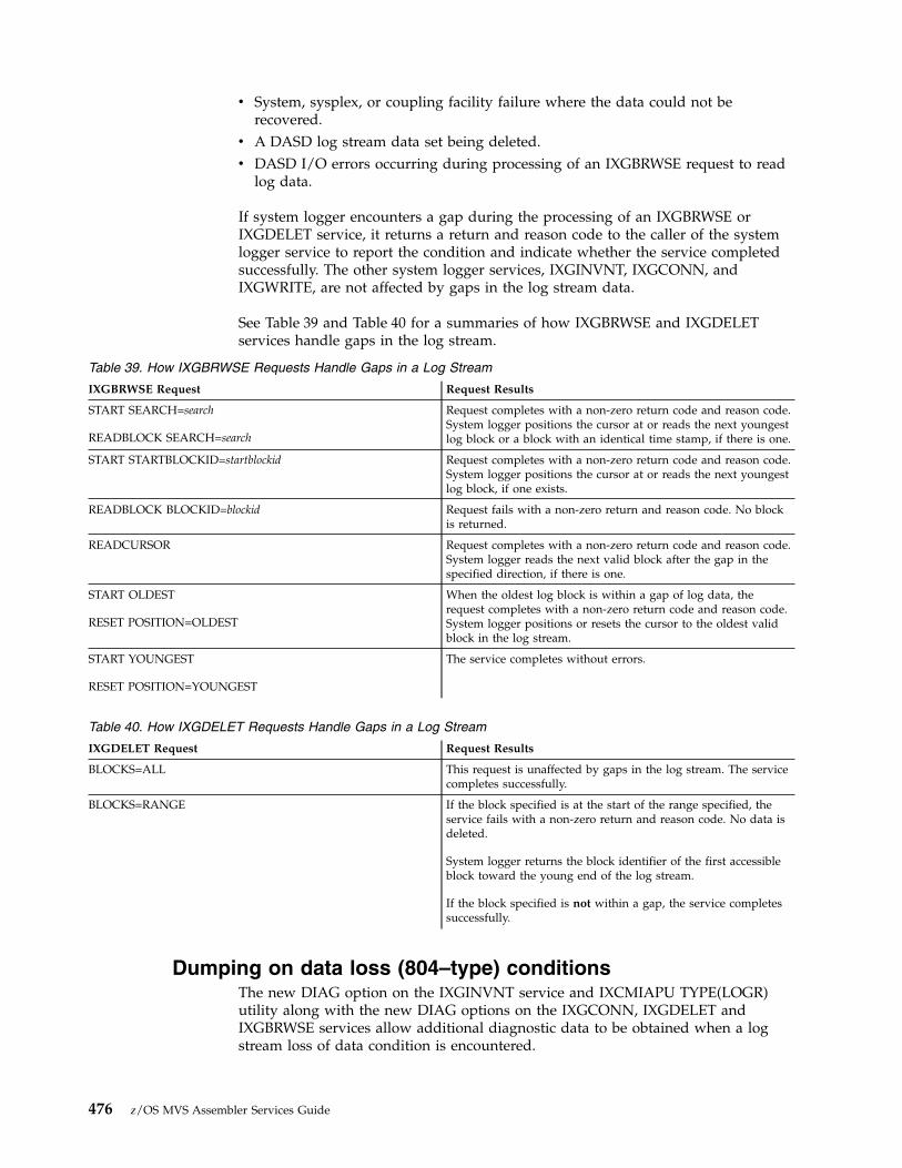
v System, sysplex, or coupling facility failure where the data could not berecovered.
v A DASD log stream data set being deleted.v DASD I/O errors occurring during processing of an IXGBRWSE request to read
log data.
If system logger encounters a gap during the processing of an IXGBRWSE orIXGDELET service, it returns a return and reason code to the caller of the systemlogger service to report the condition and indicate whether the service completedsuccessfully. The other system logger services, IXGINVNT, IXGCONN, andIXGWRITE, are not affected by gaps in the log stream data.
See Table 39 and Table 40 for a summaries of how IXGBRWSE and IXGDELETservices handle gaps in the log stream.
Table 39. How IXGBRWSE Requests Handle Gaps in a Log Stream
IXGBRWSE Request Request Results
START SEARCH=search
READBLOCK SEARCH=search
Request completes with a non-zero return code and reason code.System logger positions the cursor at or reads the next youngestlog block or a block with an identical time stamp, if there is one.
START STARTBLOCKID=startblockid Request completes with a non-zero return code and reason code.System logger positions the cursor at or reads the next youngestlog block, if one exists.
READBLOCK BLOCKID=blockid Request fails with a non-zero return and reason code. No blockis returned.
READCURSOR Request completes with a non-zero return code and reason code.System logger reads the next valid block after the gap in thespecified direction, if there is one.
START OLDEST
RESET POSITION=OLDEST
When the oldest log block is within a gap of log data, therequest completes with a non-zero return code and reason code.System logger positions or resets the cursor to the oldest validblock in the log stream.
START YOUNGEST
RESET POSITION=YOUNGEST
The service completes without errors.
Table 40. How IXGDELET Requests Handle Gaps in a Log Stream
IXGDELET Request Request Results
BLOCKS=ALL This request is unaffected by gaps in the log stream. The servicecompletes successfully.
BLOCKS=RANGE If the block specified is at the start of the range specified, theservice fails with a non-zero return and reason code. No data isdeleted.
System logger returns the block identifier of the first accessibleblock toward the young end of the log stream.
If the block specified is not within a gap, the service completessuccessfully.
Dumping on data loss (804–type) conditionsThe new DIAG option on the IXGINVNT service and IXCMIAPU TYPE(LOGR)utility along with the new DIAG options on the IXGCONN, IXGDELET andIXGBRWSE services allow additional diagnostic data to be obtained when a logstream loss of data condition is encountered.
476 z/OS MVS Assembler Services Guide

The following shows the default settings for all the services and the relationshipbetween the service specifications in terms of whether or not Logger will request adump for certain loss of data type conditions.
Default settings:DEFINE LOG STREAM DIAG(NO)IXGCONN (CONNECT) DIAG(NO_DIAG)IXGBRWSE (START) DIAG(NO_DIAG)IXGDELET DIAG(NO_DIAG)
Assuming a data loss (804) type condition was encountered on an IXGDELETrequest or on any IXGBRWSE request for a browse session, the following showswhether or not a dump would be taken by Logger for this condition, where:
No No dump is taken for the condition.
Yes Dump is taken for the condition.DEFINE LOG STREAM NO YES
----------------- -----------------IXGCONN CONNECT NO_DIAG NO YES NO_DIAG NO YES----------------------------------------------------------------
IXGBRWSE START NO_DIAG no no no no no yesNO no no no no no noYES no no no yes no yes
IXGDELET NO_DIAG no no no no no yesNO no no no no no noYES no no no yes no yes
Note: The specification on DIAG(YES) in the log stream definition also results inadditional non-abend diagnostics being collected for the log stream. For moreinformation, see 'Enabling additional log stream diagnostics' in z/OS MVSDiagnosis: Reference.
Define a log stream to allow additional dumpingv IXGINVNT
Specify IXGINVNT REQUEST=DEFINE,TYPE=LOGSTREAM,...,DIAG=YESv IXCMIAPU Utility Program
Specify DEFINE LOGSTREAM ... DIAG(YES)
Define a log stream to allow additional dumping using LIKEv IXGINVNT
Specify IXGINVNTREQUEST=DEFINE,TYPE=LOGSTREAM,NAME=like.log.stream,...,DIAG=YESThen IXGINVNT REQUEST=DEFINE,TYPE=LOGSTREAM,LIKE=like.log.stream
v IXCMIAPU Utility ProgramSpecify DEFINE LOGSTREAM NAME (like.log.stream) ... DIAG(YES)Then DEFINE LOGSTREAM LIKE(like.log.stream)
Update a log stream to allow additional dumpingv IXGINVNT
Specify IXGINVNT REQUEST=UPDATE,TYPE=LOGSTREAM,...,DIAG=YESv IXCMIAPU Utility Program
Chapter 27. Using system logger services 477

Specify UPDATE LOGSTREAM ... DIAG(YES)
The update will take affect as each system obtains its first connection to the logstream. For example, assume there are two systems in an installation's sysplex,SYSA and SYSB, and SYSA had a connection to the log stream prior to the updaterequest and SYSB did not have any connections to the log stream. If SYSBestablishes a new (first) connection to the log stream, then the DIAG options willbe in affect on SYSB. The DIAG settings prior to the update request will remain inaffect on SYSA even if there is another connection to the log stream on SYSA.However, if all the connections to the log stream on SYSA are disconnected andthen a new (first) connection is established to the logstream on SYSA, then the newDIAG options would then be in affect on SYSA.
Connect to a log stream and request additional dumpingv IXGCONN
Specify IXGCONN REQUEST=CONNECT,...,DIAG=YES
Assuming the log stream that is being connected has been defined as DIAG(YES),then Logger will provide a dump when a loss of data condition is encountered onbrowse and delete requests, unless the specific browse (start) or delete requestspecifies otherwise.
Browsing a log stream and request additional dumpingv IXGBRWSE
Specify IXGBRWSE REQUEST=START,...,DIAG=YES when IXGCONNREQUEST=CONNECT,...,DIAG=NO_DIAG
v IXGCONNSpecify IXGCONN REQUEST=CONNECT,...,DIAG=YES then no specific DIAGoptions need to be coded on the IXGBRWSE REQUEST=START invocation.
Assuming the log stream that is being browsed has been defined as DIAG(YES),then Logger will provide a dump when a loss of data condition is encountered onany browse for this browse session.
Deleting log data from a log stream and request additionaldumpingv IXGDELET
Specify IXGDELET,...,DIAG=YES when IXGCONNREQUEST=CONNECT,...,DIAG=NO_DIAG
v IXGCONNSpecify IXGCONN REQUEST=CONNECT,...,DIAG=YES then no specific DIAGoptions need to be coded on the IXGDELET invocation.
Assuming the log stream that is having log data deleted has been defined asDIAG(YES), then Logger will provide a dump when a loss of data condition isencountered on this delete request.
Using the system logger answer area (ANSAREA parameter)Every system logger service issued must include an answer area output fieldspecified on the ANSAREA parameter. In this answer area, mapped by theIXGANSAA macro, system logger returns status and diagnostic data.
Some generic answer area fields include:
478 z/OS MVS Assembler Services Guide

ANSAA_PREFERRED_SIZEThe optimal size for the answer area field specified on the ANSAREAparameter. IXGCONN REQUEST=CONNECT returns this value.
The answer area must be at least 40 bytes long. If you specify a field that isless than that, the service fails with a non-zero return code. To ascertain theoptimal answer area size, look at the ANSAA_PREFERRED_SIZE field of theanswer area returned by the first system logger service your application issues,either the IXGINVNT or IXGCONN REQUEST=CONNECT service.
ANSAA_ASYNCH_RETCODEFor asynchronously processed requests, system logger returns the return codein this field.
ANSAA_ASYNCH_RSNCODEFor asynchronously processed requests, system logger returns the reason codein this field.
ANSAA_DIAGxDiagnostic data. The content of these fields depend on any return and reasoncodes returned for a request.
Specific service indicators include:
ANSAA_BLKFROMINACTIVEIndicates that the log block returned from an IXGBRWSE request came fromthe inactive portion of the log stream. For MULTIBLOCK=YES requests, thisflag indicates that at least one log block returned in the buffer came from aninactive portion of the log stream. Flag IXGBRMLT_FROMINACTIVE inIXBRMLT (from the IXGBRMLT macro) indicates which log blocks were in theinactive portion. This field is only valid for IXGBRWSE requests that result in alog block being returned.
ANSAA_DYNMGMTOFENTRYTOELACTIVEIndicates that system logger is dynamically managing the entry-to-elementratio for the coupling facility structure. The structure was defined in a LOGRcouple data set. This field is only valid for IXGCONN requests, and isundefined when ANSA_DASDONLYLOGSTREAM is on.
ANSAA_DASDONLYLOGSTREAMThis flag in ANSAA_FLAGS1 indicates whether a log stream is DASD-only. Itis output from an IXGCONN REQUEST=CONNECT service.
ANSAA_BROWSEMULTIBLOCKThis flag in ANSAA_FLAGS1 indicates whether this level of system loggersupports IXGBRWSE MULTIBLOCK=YES requests. It is valid only for anIXGBRWSE REQUEST=START service.
ANSAA_BLKFROMDASDThis flag in ANSAA_FLAGS1 indicates that the log block returned from anIXGBRWSE request came from a log stream DASD offload data set. ForMULTIBLOCK=YES requests, this flag indicates that at least one log blockreturned in the buffer came from a log stream DASD offload data set. FlagIXGBRMLT_FROMDASD in IXBRMLT (from the IXGBRMLT macro) indicateswhich log blocks were read from DASD. This field is only valid for IXGBRWSErequests that result in a log block being returned.
For a complete description of the IXGANSAA macro, see z/OS MVS Data Areas inthe z/OS Internet library (www.ibm.com/systems/z/os/zos/library/bkserv).
Chapter 27. Using system logger services 479
Using ENF event code 48 in system logger applicationsSystem logger issues ENF event code 48 to broadcast status changes in the systemlogger address space, log streams, and coupling facility structures. Since thesestatus changes can affect the outcome of system logger service requests, IBMrecommends that you use ENF event code 48 to receive notification of these statuschanges, using the ENFREQ service to listen for event 48. Note that your programmust be authorized to use the ENFREQ service. Applications should issue theENFREQ service to listen for event 48 before connecting to a log stream.
Applications that do not want to use ENF event code 48 or that are unauthorizedand cannot use ENFREQ will still receive logger service return and reason codesindicating failure or resource shortages. These applications can then simply set atimer and then retry the requests to see if the problem has resolved itself.
References:
v See the z/OS MVS Programming: Authorized Assembler Services Guide for guidanceabout using the ENFREQ macro.
v See the z/OS MVS Programming: Authorized Assembler Services Reference EDT-IXGfor reference information on the ENFREQ macro.
Note: The following topic has been moved to Coding a system logger completeexit for IXGBRWSE, IXGWRITE, and IXGDELET in z/OS MVS Programming:Authorized Assembler Services Guide.
IXGINVNT: Managing the LOGR policyThe IXGINVNT service allows your application program to manage and updatethe LOGR policy dynamically. You can also use the IXCMIAPU utility to managethe LOGR policy (see z/OS MVS Setting Up a Sysplex). The reason and return codesfor both the IXGINVNT service and the IXCMIAPU utility are documented withthe reference information on the IXGINVNT service in z/OS MVS Programming:Assembler Services Reference IAR-XCT.
For guidance on specifying information in the LOGR couple data set usingIXGINVNT or IXCMIAPU, see the system logger chapter of z/OS MVS Setting Up aSysplex.
Using IXGINVNT, your application program can:v Define and update log streams definitions using REQUEST=DEFINE or
REQUEST=UPDATE with TYPE=LOGSTREAM.v Define a coupling facility structure associated with a log stream using
REQUEST=DEFINE with TYPE=STRUCTURE.v Check whether a particular log stream or logger (coupling facility) structure
definition exists in the LOGR policy using REQUEST=CHECKDEF.v Delete log stream and coupling facility structure definitions using
REQUEST=DELETE.
Defining a model log stream in the LOGR couple data setUse the MODEL parameter on the IXGINVNT REQUEST=DEFINE service todefine a dummy log stream that other log stream definitions can reference. Using amodel allows you to specify common log stream characteristics for many logstreams only once.
480 z/OS MVS Assembler Services Guide

This can streamline the process of defining new log streams in the LOGR policy,because you can specify the name of the model log stream on the LIKE keywordwhen you issue the IXGINVNT service to define a new log stream. Note that anyexplicit definitions for the log stream you are defining override the definitions ofthe model log stream.
Figure 115 shows how you can use the IXGINVNT service to define a log stream asa model and then define a log stream modeled after it. The LS_DATACLASparameter specifying the data class for the log data sets for log stream STREAM1overrides the LS_DATACLAS specified in the IXGINVNT request for log streamMODEL1.
You cannot connect to a model log stream or use it to store log data. It is strictlyfor use as a model to streamline the process of defining log streams.
You can use the LIKE parameter to reference a log stream that has not beendefined as a model log stream using the MODEL parameter. Any log stream can bereferenced on the LIKE parameter.
Defining a log stream as DASD-onlyYou can define a log stream as either a coupling facility log stream or DASD-onlylog stream using the DASDONLY parameter on the IXGINVNTREQUEST=DEFINE TYPE=LOGSTREAM service (see “The log stream” on page464).
Specify or default to DASDONLY=NO, to define a coupling facility log stream. Youmust also specify a structure name on the STRUCTNAME parameter in the logstream definition for a coupling facility log stream.
IXGINVNT REQUEST=DEFINETYPE=LOGSTREAM,STREAMNAME=MODEL1,STRUCTNAME=STRUCT1,MODEL=YES,HLQ=SYSPLEX1,STG_DUPLEX=YES,DUPLEXMODE=COND,STG_DATACLAS=STGDATA,STG_MGMTCLAS=STGMGMT,STG_STORCLAS=STGSTOR,LS_MGMTCLAS=LSMGMT,LS-STORCLAS=LSSTOR,LS_DATACLAS=LSDATA,STG_MGMTCLAS=LSMGMT,STG_STORCLAS=LSSTOR,ANSAREA=ANSAREA,ANSLEN=ANSLEN,RETCODE=RETCODE,RSNCODE=RSNCODE
IXGINVNT REQUEST=DEFINETYPE=LOGSTREAM,STREAMNAME=STREAM1,LS_DATACLAS=LSDATA1LIKE=MODEL1,ANSAREA=ANSARE1,ANSLEN=ANSLE1,RETCODE=RETCDE,RSNCODE=RSNCDE
Figure 115. Define a Log Stream as a Model and then Model a Log Stream After It
Chapter 27. Using system logger services 481
Specify DASDONLY=YES, to define a DASD-only log stream, which is notassociated with a coupling facility structure. When you define a DASD-only logstream, you can also specify MAXBUFSIZE to define the maximum buffer size thatcan be written to the DASD-only log stream. (For a coupling facility log stream,MAXBUFSIZE is specified on the IXGINVNT REQUEST=DEFINETYPE=STRUCTURE request to define the maximum log block size that can bewritten to the log stream.)
Note that a DASD-only log stream is single-system in scope - only one system maywrite to a DASD-only log stream.
For set up steps for a DASD-only log stream, see the system logger chapter in z/OSMVS Setting Up a Sysplex.
Upgrading an existing log stream configurationYou can upgrade a DASD-only log stream to use coupling facility storage, makingit a coupling facility log stream, or you can upgrade an existing structure-based logstream to use a different coupling facility structure. To upgrade to astructure-based log stream, associate the structure with the log stream by updatingthe log stream definition in the LOGR policy. Use the UPDATE request on eitherthe IXGINVNT service or the IXCMIAPU utility to specify the name of thecoupling facility structue with the STRUCTNAME parameter. All connectors toeither the DASD-only log stream or the existing structure-based log stream beingupgraded must be disconnected in order to make the upgrade. No failed or activeconnections can exist for the log stream.
When updating an existing log stream configuration, the GROUP attribute must betaken into account.
For details about updating the GROUP parameter, see "Parameters forREQUEST=UPDATE" under the topic of IXGINVNT in z/OS MVS Programming:Assembler Services Reference IAR-XCT.
For examples of log stream configuration changes, see Upgrading an existing logstream configuration in z/OS MVS Setting Up a Sysplex.
Upgrading a log stream from DASD-only to coupling facilityYou can upgrade a log stream defined as DASD-only (DASDONLY=YES parameteron the log stream definition) to a coupling facility log stream. Do this by issuingthe IXGINVNT REQUEST=UPDATE service with the STRUCTNAME parameter toassociate a structure with the log stream.
To upgrade a log stream from DASD-only to coupling facility, the following mustbe true:v The structure specified on the STRUCTNAME parameter must be defined in a
structure definition in the LOGR policy.v All connections (active or failed) to the log stream must be disconnected.
Before connecting to or issuing any system logger services against an upgraded logstream, you must also make sure that the structure associated with the log streamis specified in the CFRM policy couple data set.
For guidance on upgrading a DASD-only log stream to a coupling facility basedone, see the system logger chapter in z/OS MVS Setting Up a Sysplex.
482 z/OS MVS Assembler Services Guide

Updating an existing structure-based log stream to anotherstructureYou can update an existing structure-based log stream to use a different couplingfacility structure. Do this by issuing the IXGINVNT REQUEST=UPDATE servicewith the STRUCTNAME parameter to identify the new structure to be associatedwith the log stream.
To upgrade a structure-based log stream to use a new coupling facility structure,the following must be true:v The LOGR couple data set must be formatted at a z/OS Version 1 Release 2
(HBB7705) level or later.v The IXGINVNT request must be submitted on a system at z/OS Version 1
Release 3 or later.v The structure specified on the STRUCTNAME parameter must be defined in a
structure definition in the LOGR policy.v All connections (active or failed) to the log stream must be disconnected.
Before connecting to or issuing any system logger services against an upgraded logstream, you must also make sure that the structure associated with the log streamis specified in the CFRM policy couple data set.
Sample procedures to update an existing structure-based log stream to anotherstructure:
You can use one of the these sample procedures to perform a non-destructive ordestructive update of an existing structure-based log stream to another structure.
Steps for a non-destructive update of an existing structure-based log stream:
Use this sample procedure to perform a non-destructive update, which willmaintain any existing log stream data.1. Define a new new-structure-name structure definition in the CFRM policy that
has the appropriate SIZE, INITSIZE, and other attributes defined, and ensurethat this new structure is in the current CFRM policy for the sysplex.
2. Define a new new-structure-name structure in the LOGR policy with attributesMAXBUFSIZE, AVGBUFSIZE, and LOGSNUM, as needed.
3. Cause the exploiter to disconnect from the persistent-log-stream log stream.4. Confirm that no connections remain to the log stream in the sysplex. For
example, you can issue the following system command:DISPLAY LOGGER,L,LSN=persistent-log-stream
The status will be AVAILABLE when there are no more connections.5. Update the persistent-log-stream log stream definition in the LOGR policy to
map it to the newly defined new-structure-name structure. For example:IXCMIAPU type(logr)UPDATE LOGSTREAM NAME(persistent-log-stream) STRUCTNAME(new-structure-name)
6. Cause the exploiter to connect to the persistent-log-stream log stream.7. Confirm that the exploiter is connected on the expected z/OS images. For
example:DISPLAY LOGGER,L,LSN=persistent-log-stream
Chapter 27. Using system logger services 483

Steps for a destructive update of an existing structure-based log stream:
Use this sample procedure to perform a destructive update, which will delete thelog stream and any existing data.1. Cause the exploiter to disconnect from the original-log-stream log stream.2. Confirm that no connections remain to the log stream in the sysplex. For
example, you can issue the following system command:DISPLAY LOGGER,L,LSN=original-log-stream
The status will be AVAILABLE when there are no more connections.3. Delete the original-log-stream log stream from the LOGR policy.4. Delete the original-structure structure from the LOGR policy.5. Redefine the structure in the LOGR policy with the original-structure name and
attributes MAXBUFSIZE, AVGBUFSIZE, and LOGSNUM, as needed.6. Redefine the log stream in the LOGR policy with the original-log-stream name
and map it to the redefined original-structure structure.7. Cause the exploiter to connect to the newly defined original-log-stream log
stream.8. Confirm that the exploiter is connected on the expected z/OS images. For
example:DISPLAY LOGGER,L,LSN=original-log-stream
Renaming a log stream dynamicallyYou can rename a log stream dynamically using the NEWSTREAMNAMEkeyword on the IXGINVNT REQUEST=UPDATE request. Since many loggingprograms use a fixed log stream name, this function can be very useful for logstream recovery. For example, if a log stream fails, the system might not be able toperform any logging for the log stream that has failed. Using the log streamrename function, you can rename the failing log stream and then use IXGINVNTREQUEST=DEFINE to define a new log stream with the old name in order to startlogging again. This function allows you to perform the following functions:v Save the current data in a renamed log stream and start logging quickly by
defining a new log stream with the expected namev Let existing services and utilities access the data in the renamed log stream to
reduce the effect of having some data missing from the log streamv Perform problem diagnosis, such as data missing conditions, on the original
(renamed) log stream resources at the same time that new work continues
You must have an active primary TYPE=LOGR couple data formatted at anHBB7705 level or higher in order to specify the NEWSTREAMNAME parameter.
For information, see:v Renaming a log stream dynamically in z/OS MVS Setting Up a Sysplex.v IXGINVNT – Managing the LOGR inventory couple data set in z/OS MVS
Programming: Assembler Services Reference IAR-XCT.v The IXCMIAPU UPDATE LOGSTREAM request in z/OS MVS Setting Up a
Sysplex.
Updating a log stream's attributesYou can update certain attributes of a DASD-only or coupling facility log streamusing either the IXGINVNT UPDATE service or the IXCMIAPU utility. Theupdates are immediately reflected in the log stream definition in the LOGR couple
484 z/OS MVS Assembler Services Guide

data set, but some remain pending and do not take effect until specific eventsoccur during processing as described in this section.
The following attributes can be updated while there is an outstanding (active orfailed-persistent) connection to the log stream. Some of the updates will not takeeffect immediately if there is an outstanding connection. In order to update theseattributes, the LOGR couple data set must be formatted at least at a certain formatlevel. See LOGR parameters for format utility in z/OS MVS Setting Up a Sysplex formore details.
Note: If this requirement is not met, the UPDATE request fails.
Pending updates will take effect at different points for each log stream attribute asfollows:v The RETPD and AUTODELETE attribute updates take effect when a new offload
data set is allocated (data set switch event) or on the subsequent first connectionto the log stream in the sysplex.
v The LS_DATACLASS, LS_SIZE, LS_MGMTCLASS, LS_STORCLASS, andLS_ALLOCAHEAD attribute updates will remain pending until a new offloaddata set is allocated (data set switch event) or on the subsequent first connectionto the log stream in the sysplex. For a coupling facility log stream, the updatealso takes effect during the next structure rebuild (user-managed orsystem-managed).
v The LOWOFFLOAD, HIGHOFFLOAD, OFFLOADRECALL, STG_DATACLAS,STG_MGMTCLAS, STG_STORCLAS, STG_SIZE, and WARNPRIMARY attributeupdates remain pending until the subsequent first connection to the log streamin the sysplex. For a coupling facility log stream, the update also takes effectduring the next structure rebuild (user-managed or system-managed). TheSTG_DATACLAS, STG_MGMTCLAS, STG_STORCLAS, and STG_SIZE attributeupdates are also committed when a new staging data set needs to be allocatedfollowing one of the preceding conditions. In the case of a DASD-onlylogstream, the HIGHOFFLOAD, LOWOFFLOAD, OFFLOADRECALL, andWARNPRIMARY attribute updates are also committed on the next offload dataset switch.
v The LOGGERDUPLEX, STG_DUPLEX, and DUPLEXMODE attribute updates fora structure-based logstream remain pending until the subsequent first connectionto the log stream in a sysplex or until the next successful structure rebuild(user-managed).
v The MAXBUFSIZE attribute update remains pending until the subsequent firstconnection to the DASD-only log stream in the sysplex.
v The ZAI and ZAIDATA attributes can be updated while there is an outstandingconnection to the log stream. In this case, the change will immediately bereflected in the log stream definition. The updated specification will take effecton the following logger events for this log stream:1. On the subsequent first connection to the log stream on a system (z/OS
image).2. As a result of a SETLOGR FORCE,ZAICONN,LSN= command on the target
system. or3. As a result of a SETLOGR FORCE,ZAICONN,ALL command when there is a
connection to this log stream currently using the ZAI=YES setting on thetarget system.
Chapter 27. Using system logger services 485

Note: Since the updated value can be used on a system by system basis, theinstallation should ensure the proper actions are taken on all the systems withconnections to the log stream in order to make use of the current value.
IXGCONN: Connecting to and disconnecting from a log streamUse the IXGCONN service to connect to or disconnect from a log stream. Anapplication must issue IXGCONN with REQUEST=CONNECT before it can read,write, or delete data in a log stream.
When the IXGCONN REQUEST=CONNECT request completes, it returns a uniqueconnection identifier, called a STREAMTOKEN, to the calling program. Theapplication uses the token in subsequent logger service requests to identify itsconnection to the log stream.
In the answer area (IXGANSAA) returned by IXGCONN, bitAnsaa_DynMgmtOffEntryToEleActive is on when system logger is dynamicallymanaging the entry-to-element ratio. See the system logger chapter in z/OS MVSSetting Up a Sysplex for information about dynamic management of theentry-to-element ratio.
For IXGCONN REQUEST=CONNECT AUTH=WRITE, bitAnsaa_WriteTriggersReturned indicates IXGWRITE requests may have theAnsaa_WriteTriggers filled in the answer area of the IXGWRITE. See “Writetriggers” on page 492 for additional information.
Note: The following services contain parameters for both authorized andunauthorized programs: IXGCONN, IXGBRWSE, IXGWRITE, and IXGDELET. Allother system logger services and their parameters can be used by any program. Allthe unauthorized guidance for system logger is contained in this chapter. Thefollowing topics have moved to the Authorized Assembler Services Guide:v Connecting as a resource manager in z/OS MVS Programming: Authorized
Assembler Services Guide
v Using ENF event 48 when a connect request is rejected in z/OS MVSProgramming: Authorized Assembler Services Guide
v Coding a resource manager exit for IXGCONN in z/OS MVS Programming:Authorized Assembler Services Guide.
Examples of ways to connect to the log streamAn application can connect to the log stream in different ways. Some of these are:v One connection per address space: Once a program has connected to a log
stream, any task running in the same address space shares the connect statusand can use the same stream token to issue other system logger services. Anytask in the address space can disconnect the entire address space from the logstream by issuing the IXGCONN REQUEST=DISCONNECT service.
v One connection per program: One or more tasks in a single address space canissue IXGCONN REQUEST=CONNECT individually to connect to the same logstream and receive separate stream tokens. Each program must disconnect fromthe log stream individually.
v Multiple systems connecting to a log stream: Multiple address spaces on one ormore MVS systems can connect to a single coupling facility log stream, but eachone must issue IXGCONN individually to connect and then disconnect from thelog stream. Each one receives a unique stream token; address spaces cannotshare a stream token.
486 z/OS MVS Assembler Services Guide

When an application issues IXGCONN to connect to a coupling facility log stream,the system logger address space connects to the coupling facility list structure forthe log stream.
Each task that issues IXGCONN REQUEST=CONNECT to connect to a log streammust later issue IXGCONN REQUEST=DISCONNECT to disconnect from the logstream. When a task disconnects from the log stream, the stream token thatidentified the connection is invalidated. Any requests that use the stream tokenafter the disconnect will be rejected.
If a task that issued the IXGCONN REQUEST=CONNECT request ends beforeissuing a disconnect request, system logger will automatically disconnect the taskfrom the log stream. This means that the unique log stream connection identifier,or the STREAMTOKEN, will no longer be valid. The application will receive an“expired logstream token” error response if it then uses this same STREAMTOKENafter the task has been disconnected on subsequent logger service requests.
Additional considerations for connecting to a DASD-only logstreamIf you are writing an application for a DASD-only log stream, you must keep inmind that a DASD-only log stream is single-system in scope, meaning that onlyone system at a time can connect to a DASD-only log stream. (See “The logstream” on page 464 for a description of the two different types of log streams.)Multiple applications from the same system can connect to a DASD-only logstream, but only from one system at a time. An application trying to connect to aDASD-only log stream that already has another system connected will fail. Asecond system cannot connect to the DASD-only log stream until the first onedisconnects.
The ANSAA_DASDONLYLOGSTREAM flag in the IXGANSAA mapping macroindicates whether a log stream is DASD-only.
When an application issues the IXGCONN request to connect to a DASD-only logstream, the STUCTNAME, AVGBUFSIZE, and ELEMENTSIZE will be returnedcontaining hexidecimal zeros, because they are all coupling facility structurerelated fields.
How system logger allocates structure space for a new logstream at connection time
The first IXGCONN request in a sysplex issued for a coupling facility log streaminitiates the allocation of coupling facility space for the log stream.
If there are multiple coupling facility log streams assigned to one coupling facilitystructure, system logger divides the structure space evenly between each logstream that has applications connected to it via IXGCONN. This means that thefirst log stream that has an IXGCONN service issued against it gets 100% of thecoupling facility structure space available. When a second log stream mapping tothe coupling facility structure has an IXGCONN service issued against it, systemlogger divides the structure evenly between the two log streams. The first logstream's available coupling facility space will be reduced by half to reapportion therest of the space to the second log stream. This can result in some of the data beingoff-loaded to DASD if the coupling facility space allocated to a log stream reachesits high threshold as a result of the reapportionment of the structure space.
Chapter 27. Using system logger services 487
For example, if an installation defines two log streams to a single structure in theLOGR policy, but only one of the log streams actually has a connected application,then that one log stream can use the entire coupling facility structure. When thesecond log stream connect occurs against the coupling facility structure, the spaceis gradually divided between the two log streams. Likewise, when the lastdisconnect is issued against one of the two log streams, all coupling facilitystructure space is again available to the first log stream.
Note that this process of reallocation of coupling facility space and subsequentoffloading of coupling facility data might not take place immediately after the logstream connect. The reallocation of space might occur gradually, with an offloadingtaking place some time after the original log stream connect.
Connect process and staging data setsCoupling Facility Log Streams: If an installation defines DASD staging data setsfor a coupling facility log stream, the data sets are created, if necessary, duringconnection processing for the first IXGCONN request issued against a log streamfrom a particular system.
DASD-Only Log Stream: For a DASD-only log stream, the staging data set isautomatically created during the first connect issued against the log stream. Astaging data set is not optional for a DASD-only log stream.
Requesting authorization to the log stream for an applicationUse the AUTH parameter to specify whether the application issuing IXGCONNshould have read or write access to the log stream:v If you specify AUTH=READ for an application, that application will only be able
to issue IXGCONN, IXGBRWSE, and IXGQUERY requests. For AUTH=READ,the caller must have SAF read access to RESOURCE(log_stream_name) inCLASS(LOGSTRM).
v If you specify AUTH=WRITE for an application, that application can issue anysystem logger service. For AUTH=WRITE, the caller must have SAF UPDATEaccess to RESOURCE(log_stream_name) in CLASS(LOGSTRM).
Requesting a write or import connection - IMPORTCONNECTparameter
Use the IMPORTCONNECT parameter to specify whether a connection is a writeor an import connection. The IMPORTCONNECT parameter is only valid withAUTH=WRITE.v A write connection, (AUTH=WRITE IMPORTCONNECT=NO) specifies that you
want to use the IXGWRITE request to write to a log stream. You must specify ordefault to IMPORTCONNECT=NO at connect time in order to use theIXGWRITE request against a log stream.You can have multiple write connects against a log stream, but only if there isno import connection established for that log stream anywhere in the sysplex.Once one or more applications connect to a log stream as a write connection,any subsequent attempts to connect as an import connection will fail.You cannot use the IXGIMPRT service against a log stream that has beenconnected to as a write connection from anywhere in the sysplex.An import connection, (AUTH=WRITE IMPORTCONNECT=YES) specifies thatyou want to use the IXGIMPRT request to import log data from one log streamto another, maintaining the same log block identifier and UTC time stamp. You
488 z/OS MVS Assembler Services Guide
might do this to create a copy of a log stream. You must specifyIMPORTCONNECT=YES at connect time in order to use the IXGIMPRT requestagainst a log stream.You can have only one import connection for a log stream from anywhere in thesysplex. An import connection cannot coexist with a write connection. Once anapplication connects to a log stream as an import connect, all subsequentAUTH=WRITE IMPORTCONNECT=YES|NO connect requests will fail.You cannot use the IXGWRITE service against a log stream that has beenconnected to as an import connection.
You cannot have both a write and an import connection to a log stream and youcannot issue both write and import requests to the same log stream.
Specifying user data for a log streamSystem logger allows 64 bytes of user specified data to be associated with a logstream and stored in the LOGR policy. The user data can be:v Specified or changed using the USERDATA parameter on the disconnect request
of IXGCONN.v Read using the USERDATA output parameter on the connect request of
IXGCONN.
If an application codes the USERDATA parameter on a connect request when thereis no user data associated with the log stream, IXGCONN returns a USERDATAfield containing all zeros.
Only one copy of the log stream user data exists and any application connected tothe log stream can update this copy when they disconnect. If you will havemultiple connectors to a log stream, you should consider using serialization oranother protocol to protect the USERDATA field.
System logger processing at disconnection and expiredstream token
If your program runs authorized (supervisor state, system PKM), see Writing anENF event 48 listen exit in z/OS MVS Programming: Authorized Assembler ServicesGuide for more details related to log stream disconnect processing and expiredstream tokens.
Disconnection for an applicationWhen an application issues IXGCONN REQUEST=DISCONNECT to disconnectfrom a log stream for a specific STREAMTOKEN, system logger rejects any newrequests from that application for the specific STREAMTOKEN.
If the application disconnects with outstanding asynchronous requests, thedisconnect is accepted. Asynchronous requests then complete without notifying thedisconnecting application.
Last disconnection for log stream on a systemSystem logger rejects any new requests from the system for that log stream. All thelog data from this system is then offloaded to DASD log stream data sets. Thismay include log data written from other systems connected to the log stream. Forcoupling facility log streams, the coupling facility resident data is offloaded toDASD log data sets. For DASD-only log streams, the log data in local storagebuffers is written to DASD log data sets.
Chapter 27. Using system logger services 489

If the application disconnects with outstanding asynchronous requests, thedisconnect is accepted. Asynchronous requests then complete without notifying thedisconnecting application.
Last disconnection for a system in the sysplexSystem logger offloads all the log data to DASD log stream data sets.
For coupling facility log streams, the coupling facility resident data is offloaded toDASD log data sets. Any coupling facility resources allocated for a coupling facilitylog stream are released. If a coupling facility structure is being shared amongmultiple log streams, the structure space is re-divided evenly among couplingfacility log streams with connected applications at that time.
For DASD-only log streams, the log data in local storage buffers is offloaded toDASD log data sets.
Expired log stream tokenThere are conditions that will cause a log stream connection token to no longer bevalid. This means that the unique log stream connection identifier, or theSTREAMTOKEN, is no longer considered valid by system logger and theapplication receives an "expired log stream token" error response (refer toIxgRsnCodeExpiredStmToken in IXGCON macro) for Logger service requests usinga stream token as input.
An expired log stream token can be the result of an application explicitly orimplicitly disconnecting from a log stream, or it can be the result of an actionwithin system logger from either the CFRM policy, system environmentalconditions, or from internal or system logger component errors. When anapplication encounters an "expired stream token" condition unexpectedly, then itshould re-connect to the log stream and obtain a valid stream token before makingany subsequent Logger service requests.
An expired log stream can occur under the following conditions:v The log stream connector disconnects from the log stream by issuing an
IXGCONNREQUEST=DISCONNECT,STREAMTOKEN=xstreamtoken and thenissues another system logger services attempting to use the sameSTREAMTOKEN value.
v The task (represented by a TCB or Task Control Block) that connected to the logstream terminates. This is often a problem that surfaces early in the coding of anapplication. Typically the application creates an initialization task to obtainresources. That task connects to the log stream, stores the log stream inpersistent storage, and then terminates.Because in this situation the "owning" task ended (through an end-of-taskresource management operation), system logger automatically disconnects fromthe log stream. The correction for this is to connect to the log stream from a taskthat does not terminate until the log stream is no longer needed.
v Any job step task (JST) terminates within the address space that has aconnection to the log stream. System logger treats any job step task terminationin a manner similar to an address space termination. That is, all log streamconnections are disconnected and logger associations are terminated with theaddress space.If this condition occurs and there remains an expected use of a log stream, anew log stream connection will be required.
v Based on how and where the log stream token is maintained in the connector'sstorage, the system might pass an incorrect log stream to system logger. If the
490 z/OS MVS Assembler Services Guide
incorrect log stream token meets the format expected by system logger, then areturn code X'04', reason code X'82D' (IxgRsnCodeExpiredStmToken) condition isreturned. Otherwise, the incorrect log stream token results in the return codeX'08', reason code X'806' (IxgRsnCodeBadStmToken) condition.
An expired log stream token not caused by application can occur under thefollowing conditions:v For coupling facility log streams, that you are not currently using, Logger can
also disconnect a requestor when certain structure failure conditions occur.v After an I/O or access error occurs for a staging data set, if system logger is
unable to allocate a new data set for DASD-only log streams, system loggerautomatically disconnects the log stream.
v System logger disconnects all connectors on the target system as a result of anoperator SETLOGR FORCE,DISConnect,LSN=logstreamname command.
v When the system logger address space terminates and is restarted while the logstream connector was persistent (that is the application address space andconnecting task remained intact) then any subsequent use of a log stream tokenobtained before system logger terminated would be considered expired.
v Severe error conditions can also occur within the Logger component that mightcause the log stream to be disconnected unexpectedly.
Note that system logger will not disconnect a connector for log stream offload dataset allocation errors or data set "full" conditions. The allocation of log streamoffload data sets does not result in an "expired log stream token" condition.
IXGWRITE: Writing to a log streamUse the IXGWRITE service to write data from the user's buffer to a log stream. Theway system logger processes an IXGWRITE request depends on whether the logstream is coupling facility or DASD-only:
For coupling facility log streams, system logger writes the data to the couplingfacility structure space associated with the log stream when an IXGWRITE requestis issued. System logger also duplexes the data to either local storage buffers orstaging data sets.
For DASD-only log streams, system logger writes the data to interim storage inlocal storage buffers for the system associated with the log stream. It issimultaneously duplexed to DASD staging data sets. The safe import point for aDASD-only log stream is changed for every successful write request.
The log block bufferBefore you issue the IXGWRITE service to write your data to the log stream, youmust place the data in a buffer to form the log block. This buffer must follow theseguidelines:v The storage key for the buffer, specified on the BUFFKEY parameter, must be
one of the following:– If the caller is in problem program state, the buffer must be in the same
storage key as the caller's PSW key.– If the caller is running in supervisor state, the buffer can be in any key (0
through 15).v The buffer must be either ALET qualified (BUFFALET parameter), or reside in
the caller's primary address space.
Chapter 27. Using system logger services 491

v The buffer length specified on the BUFFLEN parameter must not exceed themaximum buffer size defined in the LOGR policy for the coupling facilitystructure.
The format of the data in the log block is entirely the choice of the application;system logger does not have rules about how data looks in a log block.
For each log block written to the log stream, IXGWRITE returns a unique log blockidentifier which can be used on subsequent IXGDELET and IXGBRWSE requests tosearch for, delete, read, or set the browse cursor position to that log block.
Ensuring chronological sequence of log blocksWhen an application writes log blocks to a log stream, system logger generates atime stamp for the block, in both local and Coordinated universal time (UTC),showing the time that system logger processed the block. The local time stamp isthe local time of the system where the IXGWRITE was issued. Note that local timestamps can repeat because of daylight saving time. In such a case of duplicate timestamps, system logger will return the first block with a matching time stamp that itfinds.
Log blocks are placed in the log stream in the order they were received by systemlogger. System logger generates a UTC time stamp for each log block it receives.Note that the order in which the log blocks are received is not necessarily the sameorder in which log blocks were written, because when multiple applications writeto the same log stream, the log blocks might not be received in the same order thatthey were written.
An application imbedded time stamp will not affect the order of the log blocks inthe log stream. If an application needs to ensure that log blocks are received intothe log stream in the order written, IBM recommends that applications serialize onthe log stream before they write to it.
Applications can optionally request that IXGWRITE return the time stamp thatsystem logger generates for a log block using the TIMESTAMP parameter.
Write triggersIn the answer area (IXGANSAA) returned by IXGWRITE, bitAnsaa_WriteTriggersReturned indicates that the Ansaa_WriteTriggers section hasbeen filled in.
The write triggers are returned for successful IXGWRITE requests (RETCODE = 0or 4) and show log stream primary storage consumption information.
ANSAA_STRUCTUSEPERCENT is returned for coupling facility structure basedlog streams and indicates the percentage of CF structure elements in use (between0 and 100) for the log stream.
ANSAA_STAGINGUSEPERCENT is returned for DASDONLY log streams and forCF structure based log streams that duplex to staging data sets. The value indicatesthe percentage of staging data set space in use (between 0 and 100).
The flags ANSAA_WRITEABOVEHIGHOFFLOAD,ANSAA_WRITEELEVATEDCAPACITY andANSAA_WRITEIMMINENTCAPACITY are filled in based on current primarystorage usage and log stream definition HIGHOFFLOAD percentage. For CF
492 z/OS MVS Assembler Services Guide

structure based log streams, the flags are based onANSAA_STRUCTUSEPERCENT. For DASDONLY log streams, the flags are basedon ANSAA_STAGINGUSEPERCENT. ANSAA_WRITEABOVEHIGHOFFLOADindicates the usage is greater than HIGHOFFLOAD.ANSAA_WRITEELEVATEDCAPACITY indicates the usage above the 1/2 pointbetween HIGHOFFLOAD and the log steam imminent threshold.
ANSAA_WRITEIMMINENTCAPACITY indicates the usage above the imminentthreshold. The derived value for the imminent threshold is the 2/3 point betweenHIGHOFFLOAD and 100% full.
When is data committed to the log stream?When you issue the IXGWRITE service to write data to a log stream, you cannotconsider the data committed until system logger returns control to the user with asuccessful return code. Particularly when dealing with a coupling facility logstream, you should never rely on a block ID associated with uncommitted data.For example, consider the following scenario involving a coupling facility logstream:1. Application 1 issues an IXGWRITE service, and the data is written to the
coupling facility.2. Before the data can be duplexed to staging data sets and control returned to the
user, application 2 issues IXGBRWSE for that block of data and successfullyreads the data.
3. Now, suppose the coupling facility fails - the data that application 2 read wasnever committed and is now lost! Application 2 is using log data which nolonger exists.
4. At this point, system logger might assign the identical block ID to a differentlog block and applications 1 and 2, which are trying to share a log, are now outof sync.
For a DASD-only log stream there is less likelihood of losing data, because logdata is duplexed automatically to a staging data set. Data is committed when thelog data has been written to local storage buffers and duplexed to the staging dataset. Note that for a DASD-only data set, log data cannot be browsed until it iscommitted.
See “Synchronous and asynchronous processing” on page 474 for more details onthe methods used by system logger to provide return code information to theinvoking program. When an IXGWRITE request cannot be completedsynchronously, system logger indicates this by returning to the invoking programwith the specific return code X'4' and reason code X'401' (IxgRetCodeWarning andIxgRsnCodeProcessedAsynch, re: macro IXGCON). IXGWRITE requests that arecompleted synchronously will result in system logger returning a return code X'0'or a return code of X'4' with a reason code other than X'401' (IxgRetCodeOK, orIxgRetCodeWarning and not IxgRsnCodeProcessedAsynch).
When the log stream coupling facility storage limit is reachedAn IXGWRITE request will be rejected with return code X'08' and reason codeX'0860' when the storage limit for the coupling facility structure associated with acoupling facility log stream is reached. Although the data offload to DASD processgenerally ensures that data gets written to DASD before the coupling facilitystructure fills up, this condition can occur due to sudden bursts of activity or when
Chapter 27. Using system logger services 493

another log stream is activated and defined to the coupling facility. When thishappens, system logger offloads data from the coupling facility to DASDimmediately.
Applications should not issue any further write requests until the temporarycondition has been resolved. Applications that do not want to use ENF event code48 or that are unauthorized and cannot use ENFREQ would still receive systemlogger service return and reason codes indicating failure or resource shortages.These applications can then set a time and then retry the requests to see if theproblem has resolved itself.
If system logger is unable to offload the log data because of log data set directoryspace shortages or other log stream offload issues, then the IXGWRITE requestmay also be rejected with return code X'08' and reason code X'085C' or X'085D'.You can retry your IXGWRITE (or IXGIMPRT) request periodically or wait for theENF signal that the log stream is available, or disconnect from this log stream andconnect to another log stream. For additional actions related to log stream offloads,refer to system messages IXG257I, IXG261E, IXG262A and IXG301I.
When the staging data set storage limit is reachedIf the staging data set storage limit for a coupling facility or DASD-only log streamconnection is reached, an IXGWRITE request will be rejected with a return code ofX'08' and a reason code of X'0865'. When this happens, system logger initiates theoffload process to move log data to DASD log data sets and delete correspondingstaging data set log data immediately. When offload processing completes, writerequests can complete successfully and the staging data set is available to holdduplexed log data again.
Applications should not resume issuing write requests until the temporarycondition has been resolved. Applications that do not want to use ENF event code48 or that are unauthorized and cannot use ENFREQ will still receive loggerservice return and reason codes indicating failure or resource shortages. Theseapplications can then set a timer and then retry the requests to see if the problemhas resolved itself.
If system logger is unable to offload the log data because of log data set directoryspace shortages or other log stream offload issues, then the IXGWRITE requestmay also be rejected with return code X'08' and reason code X'085C' or X'o85D'.You can retry your IXGWRITE (or IXGIMPRT) request periodically or wait for theENF signal that the log stream is available, or disconnect from this log stream andconnect to another log stream. For additional actions related to log stream offloadsrefer to system messages IXG257I, IXG261E, IXG262A and IXG301I.
When the staging data set is formattingAn IXGWRITE request will be rejected with a return code of X'08' and a reasoncode of X'0868 ' while the log stream's staging datasets are being formatted. Thefirst application to connect to a log stream on a particular system causes logger toformat the log stream's staging data sets on that system. Each system has its ownset of staging datasets. Applications should not resume issuing write requests untilthe temporary condition has been resolved. Applications that do not want to useENF event code 48 or that are unauthorized and cannot use ENFREQ will stillreceive system logger service return and reason codes indicating failure or resourceshortages. These applications can simply set a timer and retry the requests to see ifthe problem has resolved itself.
494 z/OS MVS Assembler Services Guide
Limiting asynchronous IXGWRITE requestsThe number of concurrent IXGWRITE requests for each connector to a log streamthat requires asynchronous logger activity is limited. The limit is decided beforethe log block write request is accepted. If the amount of previous in-flightasynchronous writes is above the acceptable limit, then the newly requested writeis rejected (the log data is not placed in the log stream). The limit of theconnections for authorized IXGWRITE invokers is 10,000, and for unauthorizedIXGWRITE invokers is 2000. An unauthorized invoker is the caller who is insupervisor state and has a PSW key 8 or larger.
Logger counts the number of IXGWRITE requests that require logger asynchronousactivity based on a log stream connection. As the asynchronous activity is neededfor an IXGWRITE request, logger increases the count for that log stream connector,and logger decreases this count when the asynchronous write activity completes.Examples of logger asynchronous activity for a write request include, but are notlimited to, IXGWRITE threads that are waiting on completion of logger's XES write(IXLLIST WRITE) requests or logger's staging data set I/O (via Media Manager)requests.
If logger and the storage media used to hold the log blocks cannot keep pace withthe incoming write requests, logger can eventually reach an asynchronous writethreshold of 2000 for unauthorized callers or 10,000 for authorized callers. Thelimits are triggered for a short period of any new IXGWRITE requests for the logstream connector. IXGWRITE requests that complete synchronously are notincluded in the limit counting. However, when the limit is reached, all newIXGWRITE requests for the invoker are rejected with return code X'08', reason codeX'0867'. For information about the return code X'08', reason code X'0867', seeReturn and Reason codes table in IXGWRITE in z/OS MVS Programming: AuthorizedAssembler Services Reference EDT-IXG.
Logger allows new or reissued IXGWRITE requests for this connector when thenumber of in-flight asynchronous writes is adequately reduced. The number is nomore than 85% of the limit threshold in-flight, which must be no more than 1700for unauthorized callers and 8500 for authorized callers. A logger ENF signal 48 isissued at this point indicating the log stream resources are available. Then, loggercan track sufficient write requests and only reject the requests whose write rateand volume are beyond the limitation of logger.
Logger writes software symptom records to logrec and to logger's component tracearea when logger has encountered this limit condition and when the limit isresolved. Sample portions of logger symptom records for these conditions afterrunning EREP reports as the following output:5752SCLOG RIDS/IXGF2WRT RIDS/IXGINLPA#L LVLS/709FLDS/RETCODE VALU/H00000004 FLDS/REASON VALU/H04030017IXGF2WRT ASYNC LIMIT REACHED
5752SCLOG RIDS/IXGF2WRT RIDS/IXGINLPA#L LVLS/709FLDS/RETCODE VALU/H00000004 FLDS/REASON VALU/H04030018IXGWRITE ASYNC LIMIT RELIEVED
IXGBRWSE: Browsing/reading a log streamUse the IXGBRWSE macro to read and browse a log stream for log blockinformation. Applications can:v Start a browse session and select the initial cursor position - (REQUEST=START)v Reset the browse cursor position - (REQUEST=RESET)
Chapter 27. Using system logger services 495
v Read consecutive log blocks - (REQUEST=READCURSOR)v Select and read a specific log block - (REQUEST=READBLOCK)v End a browse session - (REQUEST=END)
IXGBRWSE reads the specified log block into an output buffer specified by theapplication.
IXGBRWSE terminologyBefore you can read information from the log stream, you start a browse sessionusing the REQUEST=START request of IXGBRWSE. A browse session lasts fromthe time that an application issues IXGBRWSE REQUEST=START until it issuesIXGBRWSE REQUEST=END. A log stream can have multiple browse sessionsoccurring at the same time.
The REQUEST=START request returns a browse token, which is a unique 4-byteidentifier for a particular browse session. Subsequent IXGBRWSE requests in abrowse session use the browse token to identify the session to system logger. Oncean application issues the REQUEST=END request, the browse session ends andsystem logger will no longer accept IXGBRWSE requests with the browse token forthat session.
The browse cursor indicates where in the log stream IXGBRWSE will resumebrowsing on the next request. Each browse session has a browse cursor.
IXGBRWSE requestsREQUEST=START starts the browse session for the application and sets thebrowse cursor to the desired starting point. You can specify the browse cursorposition for a session using one of the following optional parameters:v OLDEST - which is the default, starts the browse session at the oldest (earliest)
log block.v YOUNGEST - starts the browse session at the youngest (latest) log block. Note
that the record that is the youngest when the browse session starts might nolonger be the youngest record at the end of the browse session because ofconcurrent write activity to the log stream.
v STARTBLOCKID - specifies that the browse session start at a specified log blockidentifier. The block identifier for a log block is returned by system logger whenit is written to the log stream (IXGWRITE) in the field specified by theRETBLOCKID parameter.
v SEARCH - specifies that the browse session start at the log block with thespecified time stamp. See “Browsing for a log block by time stamp” on page 497for details on how IXGBRWSE processes time stamps.
Field ANSAA_BROWSEMULTIBLOCK in the answer area will be set on if the levelof system logger supports MUTLIBLOCK=YES requests forREQUEST=READCURSOR.
REQUEST=RESET positions the browse cursor to either the oldest or youngest(POSITION=OLDEST or POSITION=YOUNGEST) log block in the log stream.
REQUEST=READBLOCK reads a selected log block in the log stream. Youidentify the block you want to read by either the block identifier (BLOCKIDparameter) or the time stamp (SEARCH parameter). The block identifier for a log
496 z/OS MVS Assembler Services Guide
block is returned by system logger in the field specified by the RETBLOCKIDparameter when the log block is written to the log stream (IXGWRITE).
REQUEST=READCURSOR reads the next oldest or youngest log block or blocksin the log stream, depending on the direction specified on the request(DIRECTION=OLDTOYOUNG or YOUNGTOOLD). The block or blocks read alsodepends on the position of the cursor at the time you issue the request. TheMULTIBLOCK value determines whether one or more blocks will be returned.
Applications must take into account that reading a series of consecutive log blocksusing REQUEST=READCURSOR might not yield blocks in sequence by local timestamp. This can happen, for example, because of daylight saving time.
Browsing both active and inactive dataUsing the VIEW parameter on IXGBRWSE, you can choose to browse just activelog data or both active and inactive log data. Active data is data that has not beendeleted via IXGDELET. Inactive data is data that has been deleted via IXGDELETbut is still in the log stream because of a retention period specified in the logstream definition in the LOGR couple data set. See z/OS MVS Setting Up a Sysplexfor information about the retention period.
VIEW=ACTIVESpecifies that the browse request browse just active data. VIEW=ACTIVE isthe default.
VIEW=ALLSpecifies that the browse request browse all data, both active and inactive.
The flag ANSAA_BLKFROMINACTIVE in the answer area indicates if thereturned log block (or any of the returned log blocks when MULTIBLOCK=YES isspecified) came from inactive data. If MULTIBLOCK=YES is specified,IXGBRMLT_FROMINACTIVE will indicate if a particular log block came frominactive data.
The VIEW parameter can be specified on both the REQUEST=START andREQUEST=RESET requests of IXGBRWSE. For the duration of a browse session,the VIEW specification remains in effect.
Browsing for a log block by time stampSystem logger generates a time stamp in both local and Coordinated universal time(UTC) for each log block in the log stream. The time stamp is returned in theTIMESTAMP output field when the block is written to the log stream usingIXGWRITE. Note that the local time stamp is the local time of the system wherethe IXGWRITE was issued.
You can use either the local or UTC time stamp on the SEARCH keyword to searchfor a system logger generated time stamp. You can specify the SEARCH keywordon the following IXGBRWSE requests:v REQUEST=START, to set the cursor at a particular log block. or
REQUEST=READBLOCK (to read a particular log block),v REQUEST=START, to set the cursor at a particular log block.
When you use a time stamp as a search criteria, IXGBRWSE searches in theoldest-to-youngest direction, searching for a log block with a matching time stamp.If no match is found, IXGBRWSE reads the next latest (younger) time stamp. When
Chapter 27. Using system logger services 497

you search by time stamp, the search always starts with the oldest log block in thelog stream. Searches by time are not sensitive to the current browse cursorposition.
See Figure 116 for an example.
If the time stamp specified is older than any time stamp in the log stream, then theoldest time stamp is returned.
If the time stamp specified is younger than any existing time stamps, the request isrejected and the caller receives a return code of X'08' and a reason code of X'0804'.
Given the example log stream in Figure 116, system logger would do the following:v If you specify 8:00 on the SEARCH keyword, this is older (earlier) than any log
block in the log stream and IXGBRWSE will set the cursor at or returns theoldest time stamp, in this case, 9:00.
v If you specify 10:30 on the SEARCH keyword, IXGBRWSE sets the cursor at orreturns the next latest (youngest) log block, 11:00.
v If you specify 12:00 on the SEARCH keyword, this time stamp is younger (later)than any existing log block and IXGBRWSE rejects the request with a returncode of X'08' and a reason code of X'0804'.
Browsing multiple log blocksUse IXGBRWSE REQUEST=READCURSOR with MULTIBLOCK=YES to read a setof consecutive log blocks in the specified direction and view. Mapping macroIXGBRMLT provides a mapping at the start of the buffer area (IXGBRMHD), thatindicates the number of log blocks that are returned plus an offset to the lastIXGBRMLT area in the buffer. IXGBRMLT also provides a mapping of theinformation returned for each log block on a MULTIBLOCK=YES request.
You can control how much information is returned about each log block with theRETBLOCKINFO parameter. When RETBLOCKINFO=NO is specified, systemlogger will return only enough information about each log block to allow theinvoker to navigate through the buffer. If RETBLOCKINFO=YES is specified,system logger will return more information about each log block in the outputbuffer, but it will use more space in the caller's buffer since more information perlog block is returned.
MAXNUMLOGBLOCKS can be used to limit the number of log blocks that will bereturned in the buffer area. When a non-zero value is specified, system logger will
Logstream
Browse direction:
9:00 10:00 11:00
OLDEST YOUNGEST
Figure 116. Searching for a Log Block by Time
498 z/OS MVS Assembler Services Guide
not return more than this requested number of log blocks, even if there are morelog blocks that meet the browse parameter criteria. If enough room is provided inthe caller's buffer and there are sufficient log blocks that meet the browse criteria,system logger will return the requested maximum number of log blocks. If there isnot enough room in the buffer, or there are fewer log blocks remaining than therequested maximum number, system logger will return as many of the remaininglog blocks as fit into the caller's buffer.
Return and reason code considerationsOn IXGBRWSE REQUEST=READCURSOR requests, more than one log block maybe returned to the requestor. Logger may encounter different conditions fordifferent log blocks.
The following return and reason codes may be issued to indicate the particularcondition:v IXGBRWSE MODE=SYNCECB or MODE=SYNCEXIT requests that are processed
asynchronously will result in a return code of X'04' and a reason code of X'401',and will be handled in the same manner as MULTIBLOCK=NO requests.
v When an IXGBRWSE request results in a return code of X'0' with a reason codeof X'0', then the return and reason codes are always 0 for each IXGBMRLT forthe log blocks, and data is always returned.
v When an IXGBRWSE request results in a return code of X'04' with a reason codeof X'416', data is always returned. Any combination of return code X'04' andreason code X'4xx' or return code X'00' and reason code X'000' may be returnedin the output buffer area.
v If a return code of X'04' with a reason code of X'417' is returned, then only thelast IXGBMRLT has a return code of X'08'. There may be an earlier log recordwith an IXGBMRLT return code X'04' and reason code X'4xx'.
v It is possible to have some log records read back and then get an IXGBRMLTreturn and reason code that requires a wait for an ENF 48 event. TheIXGBRWSE return code would be X'04' with a reason code of X'417', and the lastIXGBRMLT would contain the ENF 48 condition (8/8xx).
v When the browse request reaches the end of log after moving some data into thebuffer, the last IXGBRMLT will have a return code of X'08' with a reason code ofX'848' and IXGBRWSE will have a return code of X'04' with a reason code ofX'417'. If another IXGBRWSE is issued and there are still no more log records toread, the IXGBRWSE service will have a return code of X'08' with a reason codeof X'848'. The buffer area is undefined for this return/reason code, so you cannottrust its contents.
Using IXGBRWSE and IXGWRITEIf you have applications issuing IXGWRITE and IXGBRWSE requests concurrentlyfor the same coupling facility log stream, ensure that the browse requests areissued only for committed log data. Data is committed to the log stream whensystem logger returns control to the application following an IXGWRITE requestwith a successful return code. This is important because data can be lost due tosystem or coupling facility failure between the time data appears on the structureassociated with the log stream and a commit occurs. If you read uncommitted datathat is subsequently lost, applications sharing the same log stream can havedifferent versions of log data. See also “When is data committed to the logstream?” on page 493.
Chapter 27. Using system logger services 499

Using IXGBRWSE and IXGDELET requests togetherIf you issue IXGDELET and IXGBRWSE requests concurrently, be careful not todelete information before you try to read it. An IXGDELET request can also affect abrowse session for a log stream by deleting a requested log block or the log blockwhere the browse cursor is positioned. When an application issues an IXGBRWSErequest for log data which has been deleted, the IXGBRWSE request will returnnon-zero return and reason codes.
Applications might want to provide serialization on the log stream or some otherinstallation protocol to prevent deletes (IXGDELET service) from being performedby other applications on the log stream during a browse session.
IXGDELET: Deleting log blocks from a log streamUsing the IXGDELET service, you can mark some or all of the log blocks in the logstream for deletion. For a coupling facility log stream, the group of blocks youspecify for deletion can reside on both the coupling facility and DASD log datasets. For a DASD-only log stream, the group of blocks you specify for deletion canreside on both the local storage buffers and DASD log data sets. The way systemlogger processes log data that is marked for deletion depends on the level of thecurrent primary LOGR couple data set for the sysplex and whether a retentionperiod and automatic deletion have been specified for a log stream in the LOGRcouple data set. See Deleting log data and log data sets in z/OS MVS Setting Up aSysplex for more information.
Note: The following topic has been moved to Delete requests and resourcemanager exit processing in z/OS MVS Programming: Authorized Assembler ServicesGuide.
Using the BLOCKS parameterIf you specify BLOCKS(ALL) to delete all of the blocks in the log stream, systemlogger immediately marks as deleted all the blocks that exist at the time of therequest. If other applications are writing to the log stream concurrently with thedelete request, there might be log blocks in the log stream even after theIXGDELET BLOCKS(ALL) request is processed.
When you want to delete a subset of log blocks, specify BLOCKS(RANGE) and ablock identifier on the BLOCKID parameter. System logger marks as deleted allthe log blocks older (written earlier) than the specified log block. See Figure 117on page 501 for an illustration of how BLO CKS(RANGE) works. Note that theblock specified in BLOCKID is not deleted.
500 z/OS MVS Assembler Services Guide

IXGIMPRT: Import log blocksUse the IXGIMPRT service to write data to a log stream, specifying a log blockidentifier and UTC time stamp for each log block. This service can be used toimport copies of log data from one log stream to another, preserving the UTC timestamp and log block identifier assigned when the log block was written to thesource log stream. The source log stream is the original log stream, the log streamare importing blocks from. The log stream you import blocks to is the target logstream.
In order to use the IXGIMPRT service, the connection to the log stream must be animport connection, issued with AUTH=WRITE IMPORTCONNECT=YES. Note thatwhen you specify AUTH=WRITE IMPORTCONNECT=YES for a connection, youcannot issue the IXGWRITE request against the connected log stream. See“IXGCONN: Connecting to and disconnecting from a log stream” on page 486 forinformation about the IMPORTCONNECT parameter.
You must be in task mode to issue the IXGIMPRT service or else the request isrejected.
Making sure log blocks are imported in sequence -Understanding log block identifiers
When you import data to a log stream (using IXGIMPRT), the requests are issuedwith a log block identifier and UTC time stamp identical to the matching log block
Block ID: 2 Block ID: 3
OLDEST YOUNGEST
9:00 10:00 10:30 11:00 12:00
Log blocks:
Block ID: 1 Block ID: 2 Block ID: 3 Block ID: 4 Block ID: 5
IXGDELET BLOCKS=RANGE BLOCKID=3
Log stream
OLDEST YOUNGEST
9:00 10:00 10:30 11:00 12:00
Log blocks:
Block ID: 1 Block ID: 2 Block ID: 3 Block ID: 4 Block ID: 5
Log stream
Figure 117. Deleting a Range of Log Blocks
Chapter 27. Using system logger services 501

in the source log stream. The application must make sure to import these logblocks in ascending log block/UTC time stamp order.
For example, if the importing application has log blocks with identifiers 1, 2, and 4ready to import, the application might need to wait and check for log block 3before importing 1, 2, and 4 into a log stream. Once log block 4 has been imported,log block 3 can never be imported into the log stream (unless you delete andredefine the log stream). In order to determine whether it is importing log blocksin the correct order, the application must understand the way system loggergenerates log block identifiers.
The block identifier consists of the logical relative byte address of the log block inrelation to the start of the log stream. The first log block written to a log stream isassigned a block identifier of one. Whenever a system logger application writes alog block successfully to the log stream, system logger adds additional controlinformation to the log block. To generate the sysplex-wide unique block identifier,system logger uses:v The block identifier of the last log block written.v The length of the current log block (specified by the caller).v The length of control information (determined by system logger).
The formula is as follows:Length of current log block
+length of control information
+last log block identifier.
How do I know what the length of the control information is?Applications can ascertain the length of the control information generated bysystem logger using the IXGQUERY service, which returns the information in abuffer mapped by the IXGQBUF macro (QBUF_CONTROL_INFO_SIZE field).
Example: How log block identifiers are generatedThe following is an example of how log block identifiers are generated:v The log block identifier generated for the first log block is one.v The first log block is one hundred bytes. The length of the control information
system logger adds to a log block for this log stream is 25 bytes: this informationwas found using the IXGQUERY service.
v The block identifier for the second log block is generated by adding the first logblock identifier to the length of the first log block and the length of the controlinformation: 1+100+25 or 126.
v The 2ND log block is 50 bytes in length, and system logger again added 25bytes of control information. The block identifier for the third block is 50+25+126or 201.
Making sure log data is safe to importIf your application is using IXGIMPRT to create a duplicate log, copyinginformation from a source to a target log stream, you must make sure that the datais safe to import. See “The safe import point: Using IXGQUERY and IXGIMPRTtogether” on page 504.
502 z/OS MVS Assembler Services Guide

IXGQUERY: Get information about a log stream or system loggerUse the IXGQUERY service to retrieve information about a log stream in thesysplex, or retrieve the system logger ZAI SERVER and PORT values pertaining tothe z/OS IBM zAware server location.
When using the IXGQUERY service to retrieve information about a log stream inthe sysplex, the information is returned in a buffer mapped by IXGQBUF. Theinformation returned by IXGQUERY for a log stream includes:v Safe import point. See “The safe import point: Using IXGQUERY and IXGIMPRT
together” on page 504.v Control information size: This value shows the number of bytes that system
logger adds to each log block written to the log stream.v Structure version number for coupling facility log streams. See “The coupling
facility list structure version number” on page 506.For DASD-only log streams, this value shows the STCK format time stamp thatthe staging data set for the DASD-only log stream was allocated.
v Group information about the log stream. Every log stream is in either groupTEST or PRODUCTION. See the QBUF_GROUPVALUE field in the IXGQBUFmapping macro. TEST indicates that the log stream is a test log stream.PRODUCTION indicates that the log stream is a production log stream. Notethat you must specify a BUFFLEN value of 200 bytes or more to retrieve thegroup data for the log stream. See the GROUP keyword in IXGINVNT –Managing the LOGR inventory couple data set in z/OS MVS Programming:Assembler Services Reference IAR-XCT.
v Information related to the size of the current offload data set and staging dataset in the IXGQBUF. Note that the maximum value returned in fieldsQBUF_LS_DS_SIZE and QBUF_STG_DS_SIZE is 2GB-1 ('7FFFFFFF'x ). For dataset sizes greater than 2GB, '7FFFFFFF'X will be returned, but the full value willbe available in fields QBUF_FULL_LS_DS_SIZE andQBUF_FULL_STG_DS_SIZE.
v When QBUF_LS_Offload_Returned is turned on in the IXGQBUF, the fieldsQBUF_LS_HighOffload and QBUF_LS_LowOffload are filled in with the logstream definitional HIGHOFFLOAD and LOWOFFLOAD fields.
v Information about the log stream definition values for the elevated andimminent capacity points, which correspond to the IXGWRITE ANSAA flagsANSAA_WRITEELEVATEDCAPACITY andANSAA_WRITEIMMINENTCAPACITY. See “Write triggers” on page 492 formore information on the how the ANSAA_WRITEELEVATEDCAPACITY andANSAA_WRITEIMMINENTCAPACITY fields are set.
When using the IXGQUERY service to retrieve system logger parameter options,the information is returned in a buffer mapped by IXGQZBUF. The informationreturned by IXGQUERY includes system logger parameter options for:v ZAI SERVER value and significant length of value.v ZAI PORT value and significant length of value.
Since the system logger parameter options can change as a result of (SET orSETLOGR) commands, refer to topic “Using ENF event code 48 in system loggerapplications” on page 480 for details on keeping informed of when changes tothese parameters occur.
Chapter 27. Using system logger services 503

You must be in task mode to issue the IXGQUERY service or else the request isrejected.
For information about the IXGQBUF and IXGQZBUF fields, see z/OS MVS DataAreas in the z/OS Internet library (www.ibm.com/systems/z/os/zos/library/bkserv).
The safe import point: Using IXGQUERY and IXGIMPRTtogether
If you have an application (a resource manager, for example) that uses theIXGIMPRT service to import log data from a source log stream to a target logstream, creating a duplicate or back-up log stream, you can use IXGQUERY toascertain the safe import point for a log block before importing it, to make sure thetwo log streams are synchronized.
See:v “Coupling facility log streams and the safe import point.”v “DASD-only log streams and the safe import point” on page 506.
Coupling facility log streams and the safe import pointKeeping the log streams synchronized can be particularly difficult when thesituation involved coupling facility log streams. If the importing applicationimports data from a source to a target log stream before it is safely hardened onDASD log data sets or staging data sets, you might get inconsistencies between thesource and target log streams. For example, if an importing application involvescoupling facility log streams, it is particularly difficult to keep the two log streamssynchronized. For example, Figure 118 on page 505 illustrates the problem. Thisfigure shows a source log stream, SOURCE1, that is written to by applications ontwo systems, SYS1 and SYS2. SYS1 also contains the coupling facility containingthe structure associated with SOURCE1. That means that SYS1 contains a singlepoint of failure and is therefore backed up by a staging data set. SYS2 is a failureindependent connection and is not using a staging data set for SOURCE1.
SYS2 has written log blocks 4, 5, and 6 to the log stream coupling facility structureassociated with SOURCE1. SYS1 wrote 1, 2, and 3 to the SOURCE1's couplingfacility structure. The importing application on SYS3 browses log streamSOURCE1, seeing log blocks 1 through 6 and imports them to log streamTARGET1.
Meanwhile, on SYS1 log blocks 1 and 2 got duplexed to the staging data set, butbefore 3 could be duplexed, a failure in SYS1 knocked out both the MVS systemand the coupling facility. When a rebuild is initiated, only SYS2 can participate torepopulate the log stream. SYS2 repopulates the new structure with the data itwrote (log blocks 4, 5, and 6) and gets blocks 1 and 2 from the staging data set forSYS1. But log block 3 is not repopulated to the rebuilt structure because the datawas not committed to the staging data set. Thus, after the rebuild, log streamSOURCE1 contains blocks 1, 2, 4, 5, and 6, while TARGET1 contains 1-6. Thesource and target log streams are now out of sync.
504 z/OS MVS Assembler Services Guide

To prevent this problem, system logger provides the safe import point. This helpsan application ensure that log data is safe to import. The safe import point is thehighest log block identifier that is no longer in the coupling facility structure for alog stream. Any blocks with a block identifier less than or equal to the safe importpoint can be safely imported to the target log stream. In the preceding example,log streams SOURCE1 and TARGET1 are potentially out of sync unless theimporting application on SYS3 determines the safe import point before importingthe data to the target log stream. An application can determine the safe import bydoing one of the following:v Issue IXGQUERY, which returns the safe import point.v Listen for ENF event 48 indicating that the safe import point has been updated,
(field IXGENFWrOffLoadSafeImportPoint in the parameter list mapped bymacro IXGENF contains the latest safe import point.) The ENF is issued whenan offload operation completes. Notification that the offload has completed ispresented on all systems in the sysplex that have a connection to the log stream.
For example, using the example in Figure 118 again, log blocks 1-6 have beenwritten to log stream SOURCE1. Log blocks 1 and 2 have been offloaded to DASDlog data sets, so log stream SOURCE1 starts with a safe import point of 2. Asbefore, only blocks 1 and 2 from SYS1 are duplexed to SYS1's staging data set. Logblock 3 has not yet been duplexed. The importing application has browsed logstream SOURCE 1 and seen blocks 1-6, but this time, before importing them all, itissues IXGQUERY to find that the safe import point is 2. The resource managerexit imports only log blocks 1 and 2.
When the rebuild occurs, SYS2 repopulates the new structure with log blocks 1, 2,4, 5, and 6. Again, log block 3 is not repopulated to the rebuilt structure becausethe data was not committed to the staging data sets. When the browsing
Structure A
Structure B
Structure A
Structure B
SOURCE1 Log stream
TARGET1 Log stream
SOURCE1 Log stream
TARGET1 Log stream
Sys 1
1
1
1
1
1
1
21 3 2
2
2
2
2
2
3
3
3
3 3
4
4
4
4
4
4
5
5
5
5
5
5
6
6
6
6
6
6
CPC 1
Coupling Facility
Coupling Facility
Coupling Facility
Coupling Facility
After Rebuild
CPC 4CPC 3
1XG1MPRT
Before Rebuild
CPC 2
DataSet
Sys 2
Sys 3
SYS2/Source1Staging
1 2
4
665
. . . . . .
. . .
Figure 118. How Source and Target Log Streams Can Get Out of Sync
Chapter 27. Using system logger services 505

application is informed of the rebuild via ENF event (bitIXGENFStrRebuildComplete is on in the parameter list mapped by macro IXGENF)it should then do the following to keep the target log stream synchronized withsource log stream SOURCE1:v Issue IXGQUERY for the new safe import point. Let's say the new safe import
point is 6.v Browse log stream SOURCE1 from the last safe import point it knew about (2) to
the new safe import point (6). After the rebuild, SOURCE1 contains 4, 5, and 6.v Import log blocks 4, 5, and 6 to TARGET1.
The end result is that both SOURCE1 and TARGET1 match, containing log blocks1, 2, 4, 5, and 6.
Note that an application can also try to change the safe import point by initiatingan offload using the IXGOFFLD service.
DASD-only log streams and the safe import pointFor a DASD-only log stream data is duplexed to DASD staging data sets as it iswritten to the log stream. This means that the chance of losing data because of asystem failure is far less; There is no lag time between a successful write andhardening of the data on DASD. And of course, a coupling facility failure will notaffect a DASD-only log stream. However, it can be helpful for an application to usethe IXGQUERY service to ensure that log data is safe to import from a DASD-onlysource log stream. For a DASD-only log stream, the safe import point is the highestlog block identifier that has been successfully written to the log stream. The safeimport point for a DASD-only is updated with each successful write, because thelog data is simultaneously duplexed to DASD staging data sets. Any log blocks inthe source log stream with a block identifier less than or equal to the safe importpoint can be safely imported to the target log stream. An application can determinethe safe import point by doing one of the following:v Issue IXGQUERY, which returns the safe import point.v Listen for ENF event 48 indicating that the safe import point has been updated,
(field IXGENFWrOffLoadSafeImportPoint in the parameter list mapped bymacro IXGENF contains the latest safe import point.) The ENF is issued whenan offload operation completes. Notification that the offload has completed ispresented on all systems in the sysplex that have a connection to the log stream.
The coupling facility list structure version numberThe buffer returned by IXGQUERY (IXGQBUF) contains a version number. Themeaning varies for DASD-only and coupling facility log streams, but the value isreturned in field QBUF_STRUCT_VERSION_NUMBER for both. An alternate namefor the field is QBUF_INSTANCE_VERSION_NUMBER.
For a DASD-only log stream, the version number is the time stamp in STCKformat when the staging data set for the DASD-only log stream was created.
For a coupling facility log stream, the version number is the coupling facility liststructure version number. This value shows the list structure version number of thecoupling facility structure assigned to the log stream. A version number is assignedwhen a structure is initially allocated in the coupling facility and increases everytime a structure is rebuilt or reallocated.
506 z/OS MVS Assembler Services Guide

Using the coupling facility version numberThe coupling facility list structure version number returned for coupling facilitylog streams is helpful in situations where a rebuild occurs while the resourcemanager responsible for gathering data for a log stream was inactive at the time ofthe rebuild. A browsing application can tell if a rebuild has occurred since it waslast connected by checking to see if the coupling facility list structure versionnumber has increased since the last browse session. If a browsing applicationconnects to a log stream and issues IXGQUERY to find that the version numberhas increased, it should then begin browsing from the last valid safe import pointit knew about for the most up to date version of the log stream contents.
For example, imagine an application browses log blocks 1 through 6 in a sourcelog stream in anticipation of importing them. Before importing the log blocks tothe target log stream, the application checks for the safe import point usingIXGQUERY and imports only blocks 1 and 2. Then, the browsing application iscancelled or fails and disconnects from the log stream, saving the current couplingfacility list structure version number and safe import point it knows about (2).
A rebuild then occurs and the new content of the source log stream consists of 1, 2,4, 5, and 6. The browsing application then reconnects to the log stream and issuesIXGQUERY for the new list structure version number and safe import point. Sincea rebuild has occurred, the version number will have increased. The browsingapplication begins browsing again from the last safe import point (2) to the newsafe import point (6), and only imports log blocks 4, 5, and 6.
IXGOFFLD: Initiate offload to DASD log data setsUse the IXGOFFLD service to initiate an offload of log data to DASD log data sets.
For coupling facility log streams log data is offloaded from the coupling facilitystructure associated with a log stream to DASD log data sets. Because offloadinghardens log data on DASD log data sets, it updates the safe import point for a logstream. You can use IXGOFFLD to initiate an offload on a source log stream toincrease the safe import point. This makes more log data available for safe importfrom the source to the target log stream.
For DASD-only log streams log data is offloaded from local storage buffers toDASD log data sets. Offloading does not update the safe import point, because forDASD-only log streams, when an IXGWRITE service is issued to write data to localstorage buffer, the log data is automatically hardened on DASD staging data sets atthe same time. For DASD-only log streams, the safe import point is updated afterevery successful write request.
The number of off-loads initiated via IXGOFFLD are tracked in a field in SMFrecord 88.
You must be in task mode to issue the IXGOFFLD service or else the request isrejected.
Managing a target log stream: Using IXGIMPRT, IXGOFFLD,and IXGQUERY together
An application managing a target log stream can monitor the offloads occurring onthe source log stream via ENF event 48 writer offload completion events as anindication of when there will be more data to import (IXGIMPRT) to the target log
Chapter 27. Using system logger services 507
stream. But the application must also check the safe import point of the source logstream. The application can do this in one of two ways:v Listen for ENF event 48, notifying them of a change to the safe import point
(field IXGENFWrOffLoadSafeImportPoint in the parameter list mapped bymacro IXGENF contains the latest safe import point).
v Issuing the IXGQUERY service (see “The safe import point: Using IXGQUERYand IXGIMPRT together” on page 504) to verify that the data is safe to import tothe target log stream.
You must verify the safe import point because it is not always updated for anIXGOFFLD initiated offload even though the safe import point is tied tooffloading. This is true because of the way system logger manages log data setcontrol intervals that are not yet full.
IXGUPDAT: Modify log stream control informationUse the IXGUPDAT service to modify the UTC time stamp control information fora log stream. Once modified, the next log block written to the log stream will beassigned a UTC time stamp equal to or greater than the one specified on theIXGUPDAT request.
For coupling facility log streams, the time stamp for a log stream maintained inthe coupling facility list controls.
For DASD-only log streams, the time stamp for a log stream maintained in thelocal control blocks for the system associated with the log stream and the stagingdata set control records.
On the IXGUPDAT service, you must supply a time stamp that is equal to orgreater than the current time stamp maintained in the Log Stream Controlinformation. You can obtain the current time stamp for the log stream by issuingthe IXGQUERY service.
You must be in task mode to issue the IXGUPDAT service or else the request isrejected. The program issuing IXGUPDAT must also have specified AUTH=WRITEon the IXGCONN request to connect to the log stream to issue this request.
Why would I need to change a time stamp on a log stream? The IXGUPDATservice is useful mainly to coupling facility log streams. If an application writes tomultiple coupling facility log streams at the time of a failure necessitating recoveryprocessing, database recovery processing truncates the log streams to the latestpoint consistent across all the log streams. This can mean a loss of data. Forexample, let's say an application writes to two log streams. In log stream 1, the lastlog block written was at 9 A.M.. In log stream 2, the last log block was written at9:15 A.M.. The recovery process logically truncates log stream 2 data to 9 A.M., tobe consistent with log stream 1 for recovery. This means that the data written tolog stream 2 between 9:00 and 9:15 is lost.
In this situation, you would use IXGUPDAT to update the time stamp for logstream 1 to 9:15 or greater so that all data for both log streams can be recovered.All data written to the two log streams up until 9:15 A.M can then be recovered.IXGUPDAT lets you advance the time stamp for a log stream or streams to thelatest time among all the log streams. This ensures that log streams have aconsistent time stamp and include all the data written to any of the log streams.
508 z/OS MVS Assembler Services Guide
Rebuilds and IXGUPDAT processingFor a coupling facility log stream, when a rebuild occurs after you update a timestamp using IXGUPDAT, the time stamp for the log stream will be set for the timeof the last log block written and recovered to the log stream. This will be the lastlog block written, unless rebuild processing indicates a loss of data condition forthe log stream.
If the rebuild occurs after one or more successful write requests have occurredsince the IXGUPDAT request, the time stamp is reset for the last post-IXGUPDATwritten and recovered log block time stamp. If however, the rebuild occurs beforeany write requests to the log stream since the IXGUPDAT request, the time stampfor the log stream reverts to the last pre-IXGUPDAT written and recovered writerequest.
Setting up the system logger configurationv To set up a system logger configuration for a logging function or application, see
see the chapter on planning for system logger functions in z/OS MVS Setting Upa Sysplex.
v For system logger applications, IBM recommends that you use ENF event code48 and write an ENF event code 48 listen exit. See the topic on Writing an ENFevent 48 listen exit in the z/OS MVS Programming: Authorized Assembler ServicesGuide.
Reading data from log streams in data set formatThere are two ways that you can read data from log streams:v Write a new application to read data that supports the log stream data format
using the system logger services, particularly IXGBRWSE. See “IXGBRWSE:Browsing/reading a log stream” on page 495.
v Use the LOGR subsystem to access log stream data in data set format forexisting applications that need to read log data but do not support the logstream format.
This information describes how to use the LOGR subsystem to access log streamdata in data set format. For example, you might have existing applications thatread logrec data in data set format. The LOGR subsystem interface allows you touse your existing applications to read log stream output without having to re-writethem.
Is my application eligible for the LOGR subsystem?You can use the LOGR subsystem to access log stream data for programs thatconform to the following:v Use only BSAM or QSAM access methods.v Use only record lengths allowed by QSAM or BSAM in the log stream.
QSAM and BSAM access methods support up to approximately 32K record sizeswhile a log stream can use a record size up to 64K-4. Make sure that the logstream uses a record size compatible with the access method if you want to usethe LOGR subsystem to read log stream data. See z/OS DFSMS MacroInstructions for Data Sets for more information about access methods.
v Use only the following macros to access data:
– DCB– DCBE
Chapter 27. Using system logger services 509

– RDJFCB– OPEN– GET (QSAM)– READ (BSAM)– CHECK (BSAM)– TRUNC (BSAM)– SYNADAF– SYNADRLS– CLOSEYour program is NOT eligible for use with the LOGR subsystem if it uses theNOTE, POINT, and CNTRL macros.
Preparing to use the LOGR subsystemIf you want to use the LOGR subsystem to read log stream data in data set format,make sure of the following:v The LOGR subsystem must be activated on each system where you expect to use
it.Note that you cannot use either the SETSSI ACTIVATE or SETSSI DEACTIVATEcommand to activate or deactivate the LOGR subsystem. See the chapter onsystem logger functions in z/OS MVS Setting Up a Sysplex.Each system must have LOGR defined as a subsystem on the SUBSYS statementin the job that runs the subsystem.
v The log stream owner must supply an exit that generates a view of its log data.You can use this to ensure that the new application program is written with thecorrect data format in mind. See z/OS MVS Programming: Assembler ServicesGuide.
v The system where the new log data reading application runs on must be in thesame sysplex as the log stream.
v The application must have the appropriate SAF authority (READ/WRITE) to thelog stream, SAF CLASS(LOGSTRM) RESOURCE(log_stream_name).If there is no log stream class defined to a security product such as RACF, noaccess checking is performed.
v Make sure the LOGR subsystem is activated.
References:
v See the chapter on planning for system logger functions in z/OS MVS Setting Upa Sysplex.
v See z/OS MVS Initialization and Tuning Reference for information about theIEFSSNxx parmlib member.
v See z/OS MVS System Commands for information about the SETSSI command.v See z/OS MVS Installation Exits for information about the LOGR subsystem exit.
Using the LOGR subsystemDo the following to use the LOGR subsystem:1. Obtain the following information from the log stream owner:v Name of the log stream.v Name of the exit routine.
510 z/OS MVS Assembler Services Guide
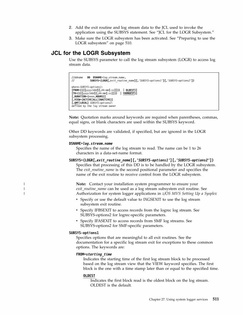
2. Add the exit routine and log stream data to the JCL used to invoke theapplication using the SUBSYS statement. See “JCL for the LOGR Subsystem.”
3. Make sure the LOGR subsystem has been activated. See “Preparing to use theLOGR subsystem” on page 510.
JCL for the LOGR SubsystemUse the SUBSYS parameter to call the log stream subsystem (LOGR) to access logstream data.
Note: Quotation marks around keywords are required when parentheses, commas,equal signs, or blank characters are used within the SUBSYS keyword.
Other DD keywords are validated, if specified, but are ignored in the LOGRsubsystem processing.
DSNAME=log.stream.nameSpecifies the name of the log stream to read. The name can be 1 to 26characters in a data-set-name format.
SUBSYS=(LOGR[,exit_routine_name][,'SUBSYS-options1'][,'SUBSYS-options2'])Specifies that processing of this DD is to be handled by the LOGR subsystem.The exit_routine_name is the second positional parameter and specifies thename of the exit routine to receive control from the LOGR subsystem.
Note: Contact your installation system programmer to ensure yourexit_routine_name can be used as a log stream subsystem exit routine. SeeAuthorization for system logger applications in z/OS MVS Setting Up a Sysplex
v Specify or use the default value to IXGSEXIT to use the log streamsubsystem exit routine.
v Specify IFBSEXIT to access records from the logrec log stream. SeeSUBSYS-options2 for logrec-specific parameters.
v Specify IFASEXIT to access records from SMF log streams. SeeSUBSYS-options2 for SMF-specific parameters.
SUBSYS-options1Specifies options that are meaningful to all exit routines. See thedocumentation for a specific log stream exit for exceptions to these commonoptions. The keywords are:
FROM=starting_timeIndicates the starting time of the first log stream block to be processedbased on the log stream view that the VIEW keyword specifies. The firstblock is the one with a time stamp later than or equal to the specified time.
OLDESTIndicates the first block read is the oldest block on the log stream.OLDEST is the default.
//ddname DD DSNAME=log.stream.name,// SUBSYS=(LOGR[,exit_routine_name][,’SUBSYS-options1’][,’SUBSYS-options2’])
where:SUBSYS-options1:[FROM={({[yyyy/ddd][,hh:mm[:ss]]}) | OLDEST}][TO={({[yyyy/ddd][,hh:mm[:ss]]}) | YOUNGEST}][,DURATION=(nnnn,HOURS)][,VIEW={ACTIVE|ALL|INACTIVE}][,GMT|LOCAL] SUBSYS-options2:defined by the log stream owner
Chapter 27. Using system logger services 511
|||

yyyy/dddSpecifies the start date. If the date is omitted, the current date isassumed. yyyy is a 4-digit year number and ddd is a 3-digit daynumber from 001 through 366 (366 is valid only on leap years). Forexample, code February 20, 2000 as 2000/051, and code December 31,1996 as 1996/366.
hh:mm[:ss]Specifies the start time. If the time is omitted, the first block writtenafter midnight is used. hh is a 2–digit hour number from 00 to 23, mmis a two digit minute number from 00 to 59, and ss is a 2–digit secondnumber from 00 to 59. The seconds field and associated : delimiter canbe omitted if it is not required by the log stream owner.
The FROM keyword is mutually exclusive with the DURATION keyword.
TO=ending_timeIndicates the ending time of the last log stream block to be processedbased on the log stream view that the VIEW keyword specifies. The lastblock is the one with a time stamp earlier than or equal to the specifiedtime.
YOUNGESTIndicates the last block read will be the youngest block on the logstream at the time the allocation for the DD occurs. YOUNGEST is thedefault.
yyyy/dddSpecifies the end date. If the date is omitted, the current date isassumed. yyyy is a 4-digit year number and ddd is a 3-digit daynumber from 001 through 366 (366 is valid only on leap years). Forexample, code March 7, 2001 as 2001/066, and code November 12, 2000as 2000/317.
hh:mm[:ss]Specifies the end time. If the time is omitted, the last block writtenbefore midnight will be used. If the end date is the same as the currentday, then the youngest block on the log stream at the time theallocation for the DD occurs will be used. hh is a 2–digit hour numberfrom 00 to 23, mm is a two digit minute number from 00 to 59, and ssis a 2–digit second number from 00 to 59. The seconds field andassociated: delimiter can be omitted if it is not required by the logstream owner.
The TO keyword is mutually exclusive with the DURATION keyword.
Note: If the value specified for the FROM keyword is greater than thevalue specified for the TO keyword, the system ends the jobstep with aJCL error.
DURATION=(nnnn,HOURS)Specifies which blocks are to be processed. Each n is a numeric from 0 to 9.Specifying (nnnn,HOURS) requests the blocks for the last nnnn hours up tothe youngest block that is to be processed based on the log stream viewthat the VIEW keyword specifies. The last nnnn hours are calculated fromthe current time of the allocation for the DD.
512 z/OS MVS Assembler Services Guide
The first block is the one with a time stamp greater than or equal to thecalculated start time. The last block read is the youngest block on the logstream at the time the allocation for the DD occurs.
The DURATION keyword is mutually exclusive with the TO and theFROM keywords.
VIEW=ACTIVE|ALL|INACTIVESpecifies the view or portion of log data to be used to obtain records fromthe log stream. System logger maintains two kinds of log stream data in alog stream: an active portion and an inactive portion. The active portion ofthe log stream is the log data that the log stream owner has not logicallydeleted through an IXGDELET request. The inactive portion of the logstream is the log data that the log stream owner has logically deleted butthat has not yet been physically deleted from the log stream because theretention period (RETPD) specified for the log stream has not yet expired.
The VIEW option designates the portion(s) of the log stream to be used toobtain log data from the log stream, in addition to applying the otherparameters.
Because the other parameters also apply, the combination of the FROM,TO, or DURATION parameters and the VIEW parameter might mean thatthe log stream subsystem exit returns no log data or only a portion of theintended log data. For example, if FROM=starting_time andVIEW=INACTIVE are both specified, and the starting_time is later(younger) than the log data in the inactive portion of the log stream, thenthere is no log data to meet the access criteria. In the same way, ifTO=ending_time and VIEW=ACTIVE are both specified, and theending_time is earlier (older) than the log data in the active portion of thelog stream, then there is no log data to meet the access criteria.
ACTIVEThe view of the log stream is to include only active log data, inaddition to applying the other log stream access parameters. ACTIVEis the default.
ALLThe view of the log stream is to include both active and inactive logdata, in addition to applying the other log stream access parameters.
INACTIVEThe view of the log stream is to include only the inactive log data, inaddition to applying the other log stream access parameters.
GMT|LOCALSpecifies whether the time is local time (based on the time zone offset atthe time the log was written) or GMT time. GMT is the default.
SUBSYS-options2Specifies unique exit routine options. See the following:v For information about obtaining records from the logrec log stream, see z/OS
MVS Diagnosis: Tools and Service Aids.v For information about obtaining records from SMF log streams, see Using
SMF log streams in z/OS MVS System Management Facilities (SMF).
LOGR SUBSYS dynamic allocation considerationsDynamic allocation (SVC99) can also be used to allocate a LOGR SUBSYS DD foraccessing log stream data.
Chapter 27. Using system logger services 513
Refer to the information in z/OS MVS Programming: Authorized Assembler ServicesGuide dealing with the SVC 99 parameter list for details about using dynamicallocation.
IBM recommends using, at minimum, the following text unit keys:
DALDDNAMDDNAME
DALDSNAMDSNAME - log stream name
DALSTATSData set status - SHR
DALRECFMRecord format (RECFM)
DALBLKSZBlock size (BLKSIZE)
DALSSNMSubsystem name - LOGR
DALSSPRMSubsystem parameters: exit name, SUBSYS-options 1, SUBSYS-options 2
The following examples show how to code the text units related to the LOGRSUBSYS options. The text unit key is identified followed by an example of theEBCDIC characters that would be used for the particular example. The text unitswould need to be coded as required by the Dynamic Allocation processing. Notethat spaces between the characters is for readability purposes.
Subsystem Name Request Specification - Key = '005F'
Example: To request subsystem LOGR, code:KEY # LEN PARM005F 0001 0004 D3 D6 C7 D9
Subsystem Parameter Specification - Key = '0060'
To specify these three parameters for the LOGR subsystemIFBSEXIT,'FROM=OLDEST,TO=YOUNGEST',DEVICESTATS, code:
Example 1:KEY # LEN PARM0060 0003 0008 C9 C6 C2 E2 C5 E7 C9 E3
LEN PARM0017 C6 D9 D6 D4 7E D6 D3 C4 C5 E2 E3
6B E3 D6 7E E8 D6 E4 D5 C7 C5 E2 E3
LEN PARM000B C4 C5 E5 C9 C3 C5 E2 E3 C1 E3 E2
Example 2: Here are a few examples of how to code the SUBSYS parameters whenreading CICS® log streams.
Assume the corresponding JCL DD options are desired (ignoring the JCL columnalignment) and the Subsystem name text unit (key = '005F') is also coded as shownearlier.
514 z/OS MVS Assembler Services Guide

aSUBSYS=(LOGR,DFHLG520,"FROM=(1998/350,12:00:00),GMT",
COMPAT41)KEY # LEN PARM0060 0003 0008 C4 C6 C8 D3 C7 F5 F2 F0
LEN PARM001C C6 D9 D6 D4 7E 4D F1 F9 F9 F8 61 F3 F5 F0
6B F1 F2 7A F0 F0 7A F0 F0 5D 6B C7 D4 E3
LEN PARM0008 C3 D6 D4 D7 C1 E3 F4 F1
b.SUBSYS=(LOGR,DFHLGCNV,"FROM=(1998/287,00:00:00),
TO=(1998/287,17:30:00),LOCAL’,DELETE)
KEY # LEN PARM0060 0003 0008 C4 C6 C8 D3 C7 C3 D5 E5
LEN PARM0035 C6 D9 D6 D4 7E 4D F1 F9 F9 F8 61 F2 F8 F7
6B F0 F0 7A F0 F0 7A F0 F0 5D 6B E3 D67E 4D F1 F9 F9 F8 61 F2 F8 F7 6B F1 F77A F3 F0 7A F0 F0 5D 6B D3 D6 C3 C1 D3
LEN PARM0006 C4 C5 D3 C5 E3 C5
c.SUBSYS=(LOGR,DFHLG520,,LASTRUN)
KEY # LEN PARM0060 0003 0008 C4 C6 C8 D3 C7 F5 F2 F0
LEN PARM LEN PARM0000 - 0007 D3 C1 E2 E3 D9 E4 D5
When things go wrong — Recovery scenarios for system loggerThis information describes some of the failures that can affect system loggerapplications and the action taken by system logger in response.
System logger performs recovery differently for DASD-only versus couplingfacility log streams. Recovery for DASD-only log streams need to be done by theapplication. Therefore, most of the information applies to coupling facility logstreams only. For DASD-only log streams, see “Recovery performed for DASD-onlylog streams” on page 516. Other recovery information pertinent to DASD-only logstreams are noted under each of the following topics.
For many of the failures, an application can listen for an ENF 48 event to find outwhen problems are resolved or resources are available again.
Note: The following topic has moved to When a resource manager fails in z/OSMVS Programming: Authorized Assembler Services Guide.
When a system logger application failsIf a system logger application fails while holding active connections to one or morelog streams, system logger automatically disconnects the application from the logstreams.
Chapter 27. Using system logger services 515

If the connection was the last connection to a log stream from a system, all logdata written by that system to the log stream is offloaded to DASD log data sets.
When an MVS system or sysplex failsThis information applies to coupling facility log streams only; for DASD-only logstreams, see “Recovery performed for DASD-only log streams.”
When a system fails, system logger tries to safeguard all the coupling facility logdata for the failed system by offloading it to DASD log data sets so that it is on apersistent media.
Recovery processing for the failing system is done by a peer connector, which isanother system in the sysplex with a connection to a coupling facility structure thatthe failing system was also connected to. Note that a peer connector need only beconnected to the same coupling facility structure, not the same log stream. See thechapter on planning for system logger functions in z/OS MVS Setting Up a Sysplexfor more information.
When all the systems in a sysplex fail, there are no peer connectors to perform therecovery processing for the failing systems, which would consist of offloading thecoupling facility data for log streams to DASD log data sets. Coupling facilityresident log data continues to exist. Further recovery processing depends onwhether or not the coupling facility also failed.
Recovery performed for DASD-only log streamsLike a coupling facility log stream, a DASD-only log stream is subject to system orsystem logger failure. A DASD-only log stream is not subject, however, to couplingfacility or structure failures. When a failure occurs involving a DASD-only logstream, system logger releases the exclusive ENQ on the log stream nameserializing the log stream for one system. No system-level or peer recovery isperformed for a DASD-only log stream after a failure or as part of systeminitialization. System logger does not perform system-level recovery for aDASD-only log stream because data is already safeguarded on DASD staging datasets, a non-volatile medium. For a DASD-only log stream, offload of log data toDASD log data sets is not done as part of recovery processing for the same reason- log data is already on DASD staging data sets. Peer recovery is both unnecessaryand not possible for a DASD-only log stream, because there are no peer systemsconnected to the log stream.
Recovery for a DASD-only log stream only takes place when an applicationreconnects to the log stream. As part of connect processing, system logger readslog data from the staging data set (associated with the last connection to the logstream) into the local storage buffers of the current connecting system. This allowsthe application to control recovery, by selecting which system they wish to havereconnect to the log stream and when. Note that for another system to connect tothe log stream and perform recovery, the staging data sets must reside on devicesaccessible by both systems.
When the system logger address space failsThis information applies to both coupling facility and DASD-only log streams.
516 z/OS MVS Assembler Services Guide

If the system logger address space fails, any system logger requests from thesystem where the system logger component failed are rejected. See z/OS MVSProgramming: Assembler Services Reference IAR-XCT for information on systemlogger services.
When the coupling facility structure failsThis information applies to coupling facility log streams only.
The following coupling facility problems can occur, resulting in rebuild processingfor the structure:v Damage to or failure of the coupling facility structure.v Loss of connectivity to a coupling facility.v A coupling facility becomes volatile.
For complete information on rebuild processing, see z/OS MVS Programming:Sysplex Services Guide.
Damage to or failure of the coupling facility structureIf a coupling facility fails or is damaged, all systems connected to the couplingfacility structure detect the failure. The first system whose system loggercomponent detects the failure initiates the structure rebuild process. The structurerebuild process results in the recovery of one or more of the affected couplingfacility structure's log streams. All the systems in the sysplex that are connected tothe list structure participate in the process of rebuilding the log streams in a newcoupling facility list structure.
When the rebuild starts, system logger issues an event 48 signal to informapplications that the rebuild is starting and that the log streams associated to thecoupling facility structure that is being rebuilt are not available. BitsIXGENFStrRebuildStart and IXGENFLogStreamsNotAvailable are on in the event48 parameter list mapped by macro IXGENF.
While the rebuild is in progress, system logger rejects any system logger servicerequests against the log stream. Applications must listen for another ENF event 48to learn the status of the log stream after rebuild processing is complete. The statuswill be one of the following:v The structure rebuild has completed successfully, the coupling facility structure
and associated log streams are available, and system logger requests will beaccepted. Bits IXGENFLogStreamsAvailable and IXGENFStrRebuildComplete areon in the event 48 parameter list mapped by macro IXGENF.
v The structure rebuild was unsuccessful and connection to the structure is notpossible because the structure is in a failed state. Log data still resides in stagingdata sets if they are used to duplex the log data for the log stream. If stagingdata sets were not used, the data persists in the local storage buffers on eachsystem. All system logger service requests against the log streams will berejected. Bits IXGENFLogStreamsNotAvailable, IXGENFStrRebuildFailed, andIXGENFRebuildFailStrFail are on in the event 48 parameter list mapped bymacro IXGENF.In this case, applications connected to the affected log streams must wait for thestructure to be rebuilt successfully and the system to issue an ENF 48 event toindicate that the log streams are available.
Chapter 27. Using system logger services 517
Loss of connectivity to the coupling facility structureIf a system loses connectivity to the coupling facility structure due to a hardwarelink failure, all the systems connected to the log streams associated with thecoupling facility detect the failure.
Then, based on the rebuild threshold specified, if any, in the structure definition inthe CFRM policy, the system that lost connectivity may initiate a rebuild for thestructure.
If a rebuild is initiated, the event 48 parameter list mapped by macro IXGENF hasbits IXGENFLogStreamsNotAvailable, and IXGENFStrRebuildStart, on, and fieldIXGENFStrName contains the name of the coupling facility structure affected.System logger rejects logger service requests issued during the rebuild process.
If XES cannot allocate a new coupling facility that all the systems affected canconnect to, system logger does one of the following, depending on whether thesystem or systems that cannot connect to the new coupling facility structure wereusing staging data sets:v If the system was using staging data sets, the rebuild process continues and the
coupling facility log data for the system is recovered from the staging data sets.v If the system was not using staging data sets, the rebuild process is stopped. The
systems go back to using the source structure.The systems that do not have connectivity to the old coupling facility structureissue an ENF 48 event indicating that they do not have connectivity to the logstream.The systems that can connect to the source structure issue an ENF 48 eventindicating that the log stream is available to that system and can resume use ofthe log stream.The installation should either update the CFRM to make the new couplingfacility structure available to all the systems or else fix the hardware linkproblem and then have the operator initiate a rebuild for the structure so that allthe original systems will have connectivity.
Applications must listen for another ENF event 48 to learn the status of the logstream after rebuild processing is complete. The status will be one of the following:v The structure rebuild has completed successfully, the coupling facility structure
and associated log streams are available, and system logger requests will beaccepted. Bits IXGENFLogStreamsAvailable and IXGENFStrRebuildComplete areon in the event 48 parameter list mapped by macro IXGENF.
v The structure rebuild was unsuccessful. Connections to the structure are notavailable because the system receiving the ENF event code has lost connectivityto the structure.All system logger service requests against the log streams will be rejected. BitsIXGENFLogStreamsNotAvailable, IXGENFStrRebuildFailed, andIXGENFRebuildFailLossConn are on in the event 48 parameter list mapped bymacro IXGENF.
A coupling facility becomes volatileIf a coupling facility changes to the volatile state, the system logger on each systemusing the coupling facility structure is notified. A dynamic rebuild of the structureis initiated so that the log data can be moved to a non-volatile coupling facility.During rebuild processing, system logger rejects any logger service requests.
518 z/OS MVS Assembler Services Guide

If there is not a structure available in a non-volatile coupling facility, system loggerwill still rebuild the data on a new volatile coupling facility. System logger maythen change the way it duplexes coupling facility data since the volatile couplingfacility constitutes a single point of failure:v For log streams defined with STG_DUPLEX=YES, system logger will begin
duplexing data to staging data sets, if they were not already in use.v For log streams defined with STG_DUPLEX=NO, system logger will keep on
duplexing data to local storage buffers on each system.
When the coupling facility space for a log stream becomesfull
This information applies to coupling facility log streams only.
Ordinarily, system logger offloads coupling facility resident log stream data toDASD log data sets before the coupling facility storage allocated to the log streamis fully utilized. Occasionally however, the coupling facility storage allocated to alog stream reaches 100% utilization, for reasons such as a sudden burst of loggingactivity or because your coupling facility is sized too small for the volume of logdata.
Applications are notified of a filled log stream by system logger service returncode of X'08' and a reason code of IXGRsnCodeCFLogStreamStorFull (X'0860').System logger will not accept write requests until offload processing can becompleted and applications receive an ENF signal with bitIXGENFStructureNotFull on.
When a staging data set becomes fullThis information applies to both coupling facility and DASD-only log streams.
The staging data sets for each system should not fill up. If they do, you probablyhave them sized too small for your volume of log data and should enlarge them.
When a DASD staging data set becomes full, IXGWRITE requests from the systemwith a staging data set full condition will be rejected with a return code ofX'08'and a reason code of IXGRsnCodeStagingDsFull (X'0865').
System logger will immediately begin offloading log data to DASD log data sets. Ifyour staging data set is too small, you may find that offloading occurs veryfrequently.
System logger will not accept write requests from the system associated with thestaging data set until offload processing can be completed and applications receivean ENF signal indicating that the staging data set full condition has ended.
When a log stream is damagedThis information applies to both coupling facility and DASD-only log streams.damaged when it cannot recover log data from either DASD staging data sets orthe local storage buffers after a system, sysplex, or coupling facility failure.Applications are notified of the damage by the following means:v When they issue IXGCONN, they receive return code, X'04', reason code,
IXGRsnCodePossibleLossOfDatav When they issue IXGBRWSE, they receive return code, X'04', reason code,
IXGRsnCodeWarningGap
Chapter 27. Using system logger services 519

v Their listen exit detects ENF event 48.
Applications should do the following to respond to a damaged log streamcondition, depending on how critical a data loss is to the application:v Applications that absolutely cannot tolerate any data loss whatsoever, some
short term transaction logs for example, should stop issuing system loggerservices to the affected log stream, disconnect from the log stream, performrecovery for the application, and then reconnect to a new log stream.
v Applications that can tolerate some data loss, such as archive logs that do notread a great deal of data from the log stream, may be able to continue using thelog stream. See “How system logger handles gaps in the log stream” on page475 for a summary of the results of reading a damaged log stream.
When DASD log data set space fillsThis step applies to both coupling facility and DASD-only log streams.
The number of DASD log data sets available for log streams in a sysplex dependson whether you use the default (168 per log stream) or have provided additionaldirectory extents in the LOGR couple data set.
System logger monitors usage of the available log stream directory space, notifyingyou as follows if you start to run out of space:v If you are using the DSEXTENT parameter in the LOGR couple data set system
logger issues messages IXG261E and IXG262A indicating that usage of directoryextents is over 85% and 95% respectively.
v If you are using the default number of log data sets allowed for a log stream(168), system logger issues message IXG257I indicating that the data setdirectory for the log stream is over 90% full.
If you have run out of log stream directory space, offloads may fail. When thisoccurs, system logger issues message IXG301I. Offload processing for the logstream cannot complete until more log stream directory space or directory extentsare made available. If the last disconnect to a log stream occurs and the offloadcannot complete successfully, the log stream is in a failed state. In this case, the logstream is considered 'in use' and there may be a failed-persistent connection to astructure associated with the log stream.
You can make more directory space available for a log stream in one of thefollowing ways. Use the IXCMIAPU utility to run a report of the log streamdefinitions in the LOGR couple data set to help you with this step. The LISTLOGSTREAM NAME(*) DETAIL(YES) statement outputs information showingwhich log streams might be using large numbers of data sets and directory extents.See LOGR keywords and parameters for the administrative data utility in z/OSMVS Setting Up a Sysplex for more information about IXCMIAPU.v Format another set of LOGR couple data sets with a higher DSEXTENT value
and bringing them into the sysplex as the active primary and alternate LOGRcouple data sets. You must have a LOGR couple data set to use the DSEXTENTparameter. See Administrative data utility in z/OS MVS Setting Up a Sysplex forthe IXCL1DSU utility and the DSEXTENT parameter.
v Free directory extents currently in use in one of the following ways:– Use a program that issues the IXGDELET service to delete enough data from
the log stream to free up space in the log stream data set directory.
520 z/OS MVS Assembler Services Guide

Some products provide a program to delete log stream data. See Deleting logdata and log data sets in z/OS MVS Setting Up a Sysplex for information ondeletion programs provided for IBM products. See the documentation for theproduct to see if it provides a deletion program.
– Delete log stream definitions from the LOGR couple data set.Identify and delete the definitions for unused or unnecessary log streams.This will free the directory space associated with the log streams, which mayfree up directory extents for use by other log streams.
Note: Deleting DASD log data sets using a non-system logger method will notwork because system logger will still count the data sets toward the data setdirectory entry limit. You cannot, for example:– Use a TSO/E DELETE command to delete a log data set.– Use DFHSM to migrate log stream data sets to tape.
When unrecoverable DASD I/O errors occurThis information applies to both coupling facility and DASD-only log streams, withdifferences noted.
DASD I/O errors may occur against either log data sets or staging data sets.System logger tries to recover from the error, but if it cannot, the error ischaracterized as an unrecoverable I/O error. See the following:v “When unrecoverable DASD I/O errors occur during offload”v “When staging data set unrecoverable DASD I/O errors occur”
When unrecoverable DASD I/O errors occur during offloadDASD I/O errors may occur during offload processing, while log data is beingwritten to DASD log data sets. When this happens, system logger tries to recoverby closing the current log data set and allocating a new one. If this process fails,the I/O error is characterized as an unrecoverable I/O error.
In the case of unrecoverable I/O errors, system logger will accept subsequentIXGWRITE requests as follows:v For a coupling facility log stream, system logger will accept IXGWRITE requests
if the log stream is connected to a coupling facility where there is still room forlog data. If the coupling facility is full or no coupling facility exists, systemlogger rejects IXGWRITE requests.
v For a DASD-only log stream, system logger will accept IXGWRITE requests untilthe staging data set for the system writing to the log stream is filled.
IXGBRWSE and IXGDELET requests may continue to work. I/O errorsencountered in the process of completing these requests are reported to theapplication in return and reason codes.
To correct an unrecoverable I/O problem, delete the log stream definition in theLOGR policy and redefine it with different log data set attributes, such asLS_DATACLAS, in order to get the log stream data set allocated in a usablelocation.
When staging data set unrecoverable DASD I/O errors occurDASD I/O errors may occur when log data is being duplexed to DASD stagingdata sets. When this occurs, system logger tries to recover by doing the following:1. Offload current log data to DASD log data sets.
Chapter 27. Using system logger services 521

2. Delete and unallocate the staging data set.3. Re-allocate a new instance of the staging data set.
In the meantime, system logger continues to accept write and other requestsagainst the log stream.
If system logger cannot re-allocate a new staging data set, the I/O error ischaracterized as unrecoverable. In the case of an unrecoverable staging data setI/O error, system logger does the following:v For a coupling facility based log stream, system logger switches the duplexing
mode to duplex log data to local storage buffers. The system issues messageIXG255I indicating that the duplexing mode has changed. Normal system loggerprocessing continues. The log stream may be more vulnerable to data loss due tosystem, sysplex, or coupling facility failure.
v For a DASD-only log stream, system logger disconnects connectors from the logstream. The system issues message IXG216I to indicate that connectors are beingdisconnected because a staging data set could not be allocated.
522 z/OS MVS Assembler Services Guide

Chapter 28. Unicode instruction services: CSRUNIC
The CSRUNIC macro provides support for processing hardware instructionsrelated to unicode data. Unicode data uses the binary codes of the UnicodeWorldwide Character Standard; these codes support the characters of most of theworld's written languages.
See z/OS MVS Programming: Authorized Assembler Services Reference ALE-DYN orz/OS MVS Programming: Assembler Services Reference ABE-HSP for more informationabout the CSRUNIC macro.
© Copyright IBM Corp. 1988, 2017 523

524 z/OS MVS Assembler Services Guide
Chapter 29. Transactional execution
The transactional execution facility is a hardware-based facility that supports thenotion of "transactions" through the use of such instructions as TBEGIN, TBEGINC,TABORT, and TEND (all of which are described in z/Architecture Principles ofOperation). A transaction either completes successfully or it aborts. When atransaction aborts, with the exception of a new instruction classified as a"non-transactional store", storage is unchanged from the time of the transactionbegin from the program's perspective (except for a diagnostic block that can beprovided). Only when bit CVTTX is on (in the CVT data area) or bit PSATX is on(in the PSA data area) does z/OS support the use of the TBEGIN instruction. Youcan check either bit; you do not have to check both. Only when bit CVTTXC is on(in the CVT data area) or bit PSATXC is on (in the PSA data area) does z/OSsupport the use of the TBEGINC instruction. You can check either bit; you do nothave to check both.
The transactional execution facility applies special rules to instructions that areexecuted within transactional execution mode. Some of these rules are describedhere. For a complete description, read the section entitled "Restricted Instructions"in chapter 5 of z/Architecture Principles of Operation. Specifically, you can think ofinstructions executed within a transaction as block concurrent (as observed byother CPUs and the channel subsystem), with the transactional execution facilityproviding the serialization that you might otherwise implement yourself toaccomplish block concurrency (whether that be an instruction such as CS, or anENQ, latch, or system lock). The details of the block concurrency are important tounderstand and are part of z/Architecture Principles of Operation. For example, twotransactions conflict with each other if both need access to a particular cache lineand at least one of them needs to write to that cache line. When such a conflict isdetected, the transaction cannot complete successfully, but it might completesuccessfully upon being retried. The benefit of transactions is that, when noconflict exists, one processor might be able to complete its operation in a simpleway, without having to obtain software-managed serialization or utilize serializinginstructions to protect itself.
There are two kinds of transactions: nonconstrained and constrained. Constrainedtransactions have additional restrictions. Many instructions are restricted frombeing used within a transaction.
Nonconstrained transactionsA nonconstrained transaction begins with a TBEGIN instruction, ends normallywith a TEND instruction, can be aborted (ended abnormally) with a TABORTinstruction and may abort for many system-defined reasons.
The TBEGIN instruction may provide a "transaction diagnostics block" (TDB,mapped by macro IHATDB).
The instruction after the TBEGIN instruction usually is a conditional relativebranch (BRC instruction) that can handle the condition codes with which aTBEGIN instruction may complete:v CC=0 (transaction initiation successful) should "fall through".
© Copyright IBM Corp. 1988, 2017 525

v CC=1 (abort due to an indeterminate condition) should branch somewhere todeal with this situation.
v CC=2 (abort due to a transient condition) should branch somewhere to deal withthis situation (dealing with this might retry, but should eventually "time out"and go to the fall-back path). While there is no "right number" for the question"how many times should I retry", a small number, such as 5, is consideredwithin reason in general.
v CC=3 (abort due to a persistent condition) should branch somewhere to dealwith this situation, eventually winding up in a "fall-back" path because for somereason, the system believes that the transaction is unlikely ever to succeed.
Note: This applies to the current circumstances. For example, a list search on ahash table might not succeed for the current hash, but for most other hashesmight succeed.
v This needs a fall-back path.
Upon transaction abort, control flows to the instruction after the TBEGINinstruction.
Constrained transactionsA constrained transaction begins with a TBEGINC instructions and, as with anonconstrained transaction, ends normally with a TEND instruction and may abortfor many system-defined reasons.
The key difference is that, in the absence of repeated interruptions or otherconstraint violations, a constrained transaction is assured of eventual completion.Thus, it does not need a fall-back path.
The TBEGINC instruction always completes with CC=0 so it does not need aconditional branch following it.
The following restrictions apply to constrained transactions only:v The transaction executes no more than 32 instructions.v All instructions within the transaction must be within 256 contiguous bytes of
storage.v The only branches you may use are relative branches that branch forward (so
there can be no loops).v All SS and SSE-format instructions may not be used.v Additional general instructions may not be used.v The transaction's storage operands may not access more than four octowords.v The transaction may not access storage operands in any 4 K-byte blocks that
contain the 256 bytes of storage beginning with the TBEGINC instruction.v Operand references must be within a single doubleword, except for some of the
"multiple" instructions for which the limitation is a single octoword.
Because there is no condition code other than 0 and no need for a conditionalbranch after the TBEGINC, a constrained transaction has no fall-back path.Therefore, you must be prepared for running in an environment that does notsupport constrained transactions (bit CVTTXC not on).
Upon abort, control flows to the TBEGINC instruction.
526 z/OS MVS Assembler Services Guide
Planning to use transactional executionThe HLASM element of z/OS provides a print exit named ASMAXTXP, which youcan use in your assembly. It flags as errors things that violate a transactionalexecution restriction, to the extent it can determine those violations.
The user of transactions has control over such things as:v The general register pairs that are to be saved at the initiation of a transaction
(TBEGIN or TBEGINC instruction) and restored upon a transaction abort.v Whether access register modification is allowed within the transaction.
Note: Upon transaction abort, access register values are never restored.v Whether floating point operations are allowed within the nonconstrained
transaction.
Note: Upon transaction abort, floating point register values are never restored.v Program interrupt filtering for a nonconstrained transaction. For example, the
application may ask that certain classes of program interrupts be presented tothe application as an abort, rather than processed by the system as a programinterrupt.
Consider the following simple transaction:LA 2,Source_Data_WordLA 3,Target_Data_WordTBEGIN theTDB,X’8000’ <<The "80" indicates to restore GRs 0-1 upon abort, each
bit in that byte corresponds to a double register pair.>>BRC 7,Transaction_abortedL 1,0(,2)ST 1,0(,3)TEND<<When you get here, register 1 will have been changed by the "L", and the target
word will have been set.>>...Transaction_aborted DS 0H<<When you get here, all the registers will have the value they had before theTBEGIN instruction, the target word will be unchanged, and the TDB, identified onthe TBEGIN instruction, will contain information about the transaction abort.>>
You can think of stores within a transaction as being "rolled back" upon transactionabort. Similarly, you can think of the registers as being saved at the transactionbegin and then (optionally) rolled back to their pre-transaction begin values.
When using nonconstrained transactions, the transaction must be serialized againstthe fall-back path. For example, if one processor is within a transaction andanother within the fall-back path, each needs to know enough to protect itselfagainst the other. Also, typically, a fall-back path needs to be serialized againstother concurrent execution of that fall-back path. You can think of the fall-backpath as needing "real" serialization (hardware or software-provided) and thetransaction needing to be able to tell that the fall-back path is running. One way ofaccomplishing this is for the fall-back path to set a footprint when it has obtained"real" serialization and for the transaction to query that footprint. For example,consider a group of updates that need to be done atomically:Fall-Back Path
ENQSet bit I_Have_ENQthe group of updatesReset bit I_Have_ENQ
Chapter 29. Transactional execution 527
DEQ
Transaction
TBEGINBRC xx,Transaction_AbortedIf I_Have_ENQ is on then TABORTthe group of updatesTEND
Even this simple example is incomplete. To avoid cases where a spin would result(when the ENQ holder does not get a chance to reset the bit), the transaction pathneeds to limit the number of times that the transaction is started over. This can bedone using a counter in a register that is not restored upon the abort or anon-transactional store. Thus, at "Transaction_Aborted", there might be a test to seeif flow should proceed to the fall-back path or back to the TBEGIN.
Note: With this sort of approach, multiple transactional users do not conflict witheach other with respect to the I_Have_ENQ bit (as, to them, it is just being read),but of course they do conflict with each other with respect to the stores in theupdate group. A fall-back path does conflict with the transaction such that itssetting of I_Have_ENQ will cause an in-process transaction to be aborted.
Transactional execution debuggingYou can use the non-transactional store instruction (NTSTG) to save data (such as acount of passes through the transaction) that does not get rolled back when thetransaction aborts. Somewhat similarly, you can place information in generalregisters that are designated not to be restored, or in access registers or floatingpoint registers if you need it to persist even if the transaction aborts.
Transactional execution diagnosticsA program interrupt within a transaction is identified by bit 6 of the 16-bitinterrupt code's being on. Thus, for example, a protection exception withintransactional execution mode would be interrupt code X'0204'.
If the transaction gets a program interrupt that is not filtered (TBEGIN can identifysome filtering of program interrupts), normal z/OS program interrupt processingoccurs (and the transaction is aborted). Information about the PSW and registers atthe time of the program interrupt are captured by the system and made availableto your recovery routines, and certain diagnostic "rules" are applied.
ESPIE exit routines will get both the time of error registers/PSW and thetransaction-begin registers/PSW.v Bit EPIEPITX: The program interrupt occurred while within transactional
execution.v Existing fields EPIEGPR, EPIEG64S contain the time of error register
information. When bit EPIEPITX is off, these are the registers current when theprogram interrupt occurred. When bit EPIEPITX is on, these are the registersthat resulted from the transaction abort due to the program interrupt. Resume isdone using these fields whether or not bit EPIEPITX is on.
v Existing fields EPIEPSW, EPIEPSW16 contain the time of error PSW information.When bit EPIEPITX is off, this is the PSW current when the program interruptoccurred. When bit EPIEPITX is on, this is the PSW that resulted from thetransaction abort due to the program interrupt (for a nonconstrained transaction,
528 z/OS MVS Assembler Services Guide

the address will be of the instruction following the TBEGIN; for a constrainedtransaction, the address will be of the TBEGINC instruction). Resume is doneusing these fields whether or not bit EPIEPITX is on.
v When bit EPIEPITX is on, new field EPIETXG64 contains the registers currentwhen the program interrupt occurred.
v When bit EPIEPITX is on, new field EPIETXPSW16 contains the PSW currentwhen the program interrupt occurred.
Note: A SPIE exit routine will not get control for a program interrupt duringtransactional execution.
For a recovery routine (whether FRR-type or ESTAE-type), there will be additionalinformation in the SDWA:v Bits SDWAPTX1 (within byte SDWAIC1H in field SDWAAEC1) and SDWAPTX2
(within byte SDWAIC2H in field SDWAAEC2): The program interrupt occurredwhile within transactional execution and therefore bit SDWAPTX1 is valid onlywhen bit SDWAPCHK is on.
v Existing fields SDWAG64, SDWAG64H, and SDWAGRSV contain the time oferror register information. These are the registers current when the programinterrupt occurred.
v Existing field SDWAPSW16 contains the time of error register information. Thisis the PSW current when the program interrupt occurred.
v When bits SDWAPCHK and SDWAPTX2 are on, new field SDWATXG64contains the registers that resulted from the transaction abort due to the programinterrupt.
v When bits SDWAPCHK and SDWAPTX2 are on, new field SDWATXPSW16contains the PSW that resulted from the transaction abort due to the programinterrupt.
The IEATXDC service is provided to help you test your applications. Anonconstrained transaction has both a transactional path and a fallback(non-transactional) path. With the IEATXDC service, you can request randomaborts of transactions for your work unit so that, upon repeated runnings, you arelikely to exercise both the non-abort and abort paths.
Debugging of problems that might occur within transactional execution mode canbe much more difficult than others since any stores done within the transactionhave been rolled back by the time that the system gets to examine the time of errordata. SLIP provides some help in this area:v A new ERRTYP option, TXPROG, is supported. When specified, the SLIP trap
will match only if the event was a program interrupt error event that occurredwithin transactional execution mode.
v The SLIP DISPLAY of an active trap will display, when non-0, the number oftimes that the SLIP trap was examined, but did not match because of the DATAkeyword (in a transactional execution case, this could be normal, because thestores were rolled back when the error or PER program interrupt occurred). Thisis referred to as the transactional execution DATA filter mismatch count.
Note: If the value is 255, the count of events could have exceeded 255.v SLIP provides a new keyword TXIGD, Transactional eXecution IGnore Data,
which indicates that a SLIP trap is to ignore the DATA keyword filter that is alsopresent in this trap if the event (whether error or PER) occurred while within
Chapter 29. Transactional execution 529

transactional execution. This keyword may be specified on SLIP SET, and alsomay be used on SLIP MOD. You might use TXIGD in the following case:– Your SLIP trap with a DATA filter did not match, but the event still occurred.– The display of the SLIP trap showed a non-0 transactional execution count.– You think that roll back of stores when the transaction aborted might have led
to the DATA filter's not matching.– By ignoring the DATA keyword, the trap might match and even though it
will not have a DATA filter applied as a result, it might match the right event.
The NOTXIGD keyword may also be specified.
The SLIP GTF record, at offset (decimal) 135, has a 1-byte count that is thetransactional execution DATA filter mismatch count.
530 z/OS MVS Assembler Services Guide
Appendix A. Using the unit verification service
The information in this appendix describes using the unit verification service toobtain information from the eligible device table. IBM recommends that you usethe EDTINFO macro instead; EDTINFO provides more services and is easier to usethan the unit verification service.
EDTINFO must be used to obtain information on units that are defined as:v Dynamic,v Have 4-digit device addresses, orv Are described by unit control blocks (UCBs) that reside above the 16-megabyte
line.
The IEFEB4UV routine interface maybe used, only, to obtain information on unitsthat are static, have 3-digit device addresses and are described as UCBs residingbelow the 16-megabyte line.
Functions of unit verificationThe unit verification service (IEFEB4UV routine) enables you to obtain informationfrom the eligible device table (EDT) and to check your device specification againstthe information in the EDT. See z/OS HCD Planning for information on the EDT.
The unit verification service performs the following functions:v Check groupsv Check unitsv Return unit namev Return unit control block (UCB) addressesv Return group IDv Indicate that unit name is a look-up valuev Return look-up valuev Convert device type to look up valuev Return attributesv Specify subpool for returned storagev Return unit names for a device class
Check groups - Function code 0This function determines whether the input device numbers make a validallocation group. To be valid, the device grouping must include either all thedevice numbers being verified, or none of them. If not, the allocation group is split,and the input device numbers do not make up a valid allocation group.
Check units - Function code 1This function determines whether the input device numbers correspond to the unitname in the EDT. In addition to a return code in register 15, it sets to one thehigh-order flag bit of any device numbers in the parameter list that are not valid.
© Copyright IBM Corp. 1988, 2017 531

Return unit name - Function code 2This function returns the unit name associated with a look-up value provided asinput. The unit name is the EBCDIC representation of the IBM generic device type(for example, 3390) or the esoteric group name (for example, TAPE) from the EDT.
A look-up value is an internal representation of the unit name, which is used as anindex into the EDT. Because teleprocessing devices do not have generic devicenames, you cannot use this function to request information about teleprocessingdevices.
Note: Do not use this function to determine whether a returned unit name is ageneric CTC device or an esoteric group name that contains CTC devices. Instead,use the return attributes function (function code 8) for this purpose.
Return unit control block (UCB) addresses - Function code 3This function returns the UCB pointer list that is associated with the unit nameprovided as input.
Return group ID - Function code 4This function returns the allocation group ID corresponding to each UCB addressspecified in the input list.
Indicate unit name is a look-up value - Function code 5The input to the check units and return UCB addresses functions can be specifiedas a 4-byte internal representation of the unit name rather than as the unit nameitself.
Return look-up value - Function code 6This function returns the 4-byte internal representation of the unit name that servesas an index into the EDT. It is the converse of the return unit name function.
Convert device type to look up value - Function code 7This function converts a 4-byte UCB device type to an internal representation ofthe unit name to serve as an index into the EDT. The convert device type to lookup value function allows programs that have only a 4-byte UCB device type toquery the EDT. It can be used whenever a look-up value is required as input to theunit verification service.
Return attributes - Function code 8This function returns general information about the specified unit name.
Specify subpool for returned storage - Function code 10This function is used with the return UCB addresses function or with the returnunit names for a device class function. You are able to specify for a particularsubpool to return the requested information.
Return unit names for a device class - Function code 11This function returns a list of IBM generic device types (for example, 3390) and /or esoteric group names (for example, TAPE) associated with the input deviceclass.
532 z/OS MVS Assembler Services Guide

Callers of IEFEB4UVThe unit verification routine, IEFEB4UV, is for both problem program callers andfor authorized callers. It runs in task mode in the caller's key.
To use IEFEB4UV, the calling program must do the following:v Create the input data structures and parameter listv Place the address of an 18-word save area in register 13v Provide a recovery environmentv Pass control to IEFEB4UV using the LINK and LINKX macro.
On return, IEFEB4UV restores all registers except register 15, which contains areturn code.
Input to and output from unit verification service routinesYou must supply a two-word parameter list when you invoke the unit verificationroutine (IEFEB4UV).
The first word contains the address of a unit table. The contents vary according toone or more functions requested.
The second word contains the address of a 2-byte field (FLAGS), in which youspecify one or more functions requested.
The bits in the FLAGS parameter field have the following meanings:
Bit Function Requested0 Check groups.1 Check units.2 Return unit name.3 Return UCB addresses.4 Return group ID.5 Indicate that unit name is a look-up value.6 Return look-up value.7 Convert device name to a look-up value.8 Return attributes.10 Specify subpool for returned storage.11 Return unit names for a device class.12 -15 Reserved for IBM use.
Input parameter listFigure 119 on page 534 shows the input parameter list that is needed to invoke theunit verification service routine.
Appendix A. Using the unit verification service 533
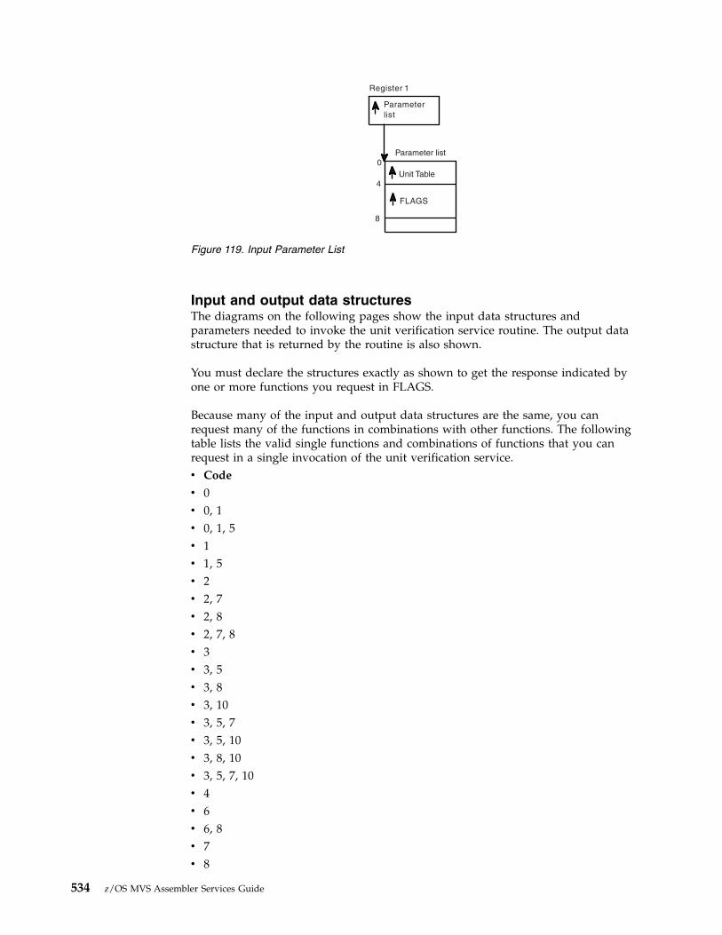
Input and output data structuresThe diagrams on the following pages show the input data structures andparameters needed to invoke the unit verification service routine. The output datastructure that is returned by the routine is also shown.
You must declare the structures exactly as shown to get the response indicated byone or more functions you request in FLAGS.
Because many of the input and output data structures are the same, you canrequest many of the functions in combinations with other functions. The followingtable lists the valid single functions and combinations of functions that you canrequest in a single invocation of the unit verification service.v Code
v 0v 0, 1v 0, 1, 5v 1v 1, 5v 2v 2, 7v 2, 8v 2, 7, 8v 3v 3, 5v 3, 8v 3, 10v 3, 5, 7v 3, 5, 10v 3, 8, 10v 3, 5, 7, 10v 4v 6v 6, 8v 7v 8
Register 1
Parameter
list
FLAGS
0
4
8
Parameter list
Unit Table
Figure 119. Input Parameter List
534 z/OS MVS Assembler Services Guide
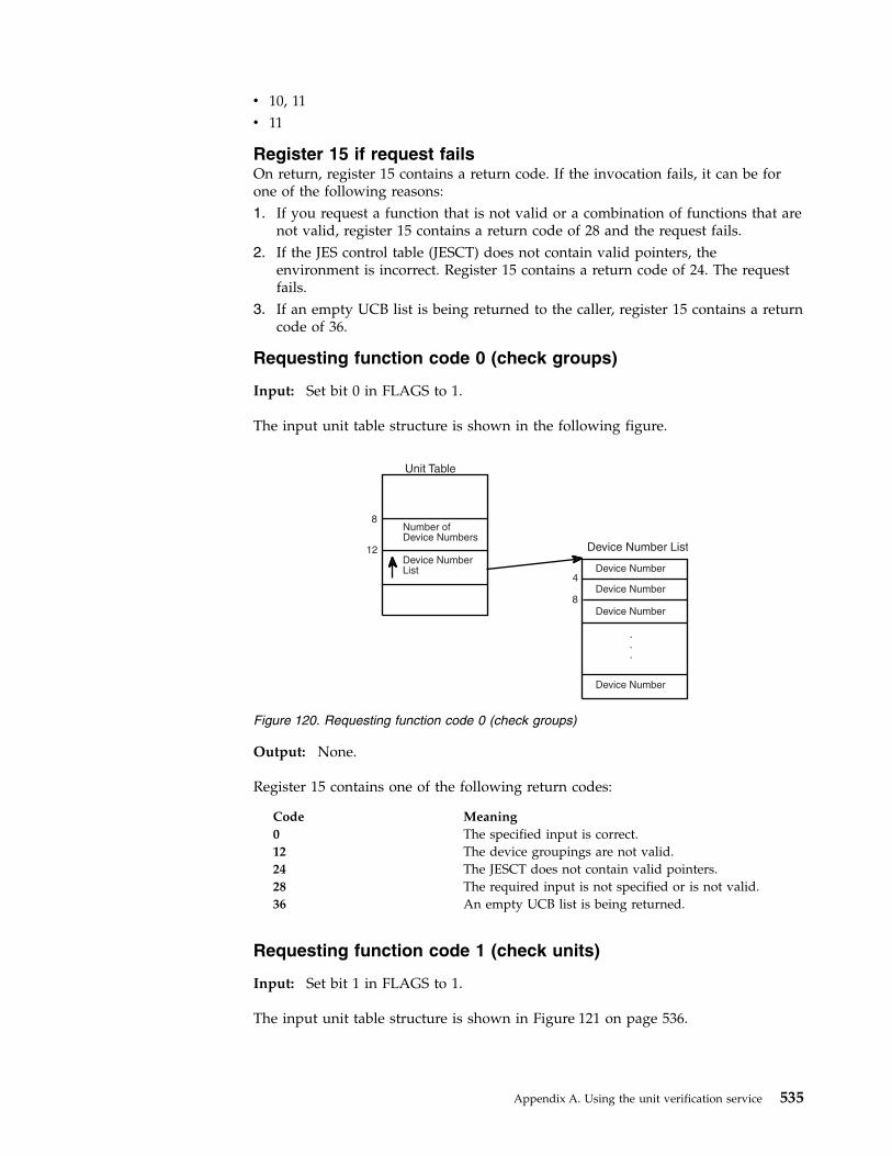
v 10, 11v 11
Register 15 if request failsOn return, register 15 contains a return code. If the invocation fails, it can be forone of the following reasons:1. If you request a function that is not valid or a combination of functions that are
not valid, register 15 contains a return code of 28 and the request fails.2. If the JES control table (JESCT) does not contain valid pointers, the
environment is incorrect. Register 15 contains a return code of 24. The requestfails.
3. If an empty UCB list is being returned to the caller, register 15 contains a returncode of 36.
Requesting function code 0 (check groups)
Input: Set bit 0 in FLAGS to 1.
The input unit table structure is shown in the following figure.
Output: None.
Register 15 contains one of the following return codes:
Code Meaning0 The specified input is correct.12 The device groupings are not valid.24 The JESCT does not contain valid pointers.28 The required input is not specified or is not valid.36 An empty UCB list is being returned.
Requesting function code 1 (check units)
Input: Set bit 1 in FLAGS to 1.
The input unit table structure is shown in Figure 121 on page 536.
Device Number List
Device Number
Device Number
Device Number
Device Number
.
.
.
4
8
8
12
Device Number
List
Number of
Device Numbers
Unit Table
Figure 120. Requesting function code 0 (check groups)
Appendix A. Using the unit verification service 535
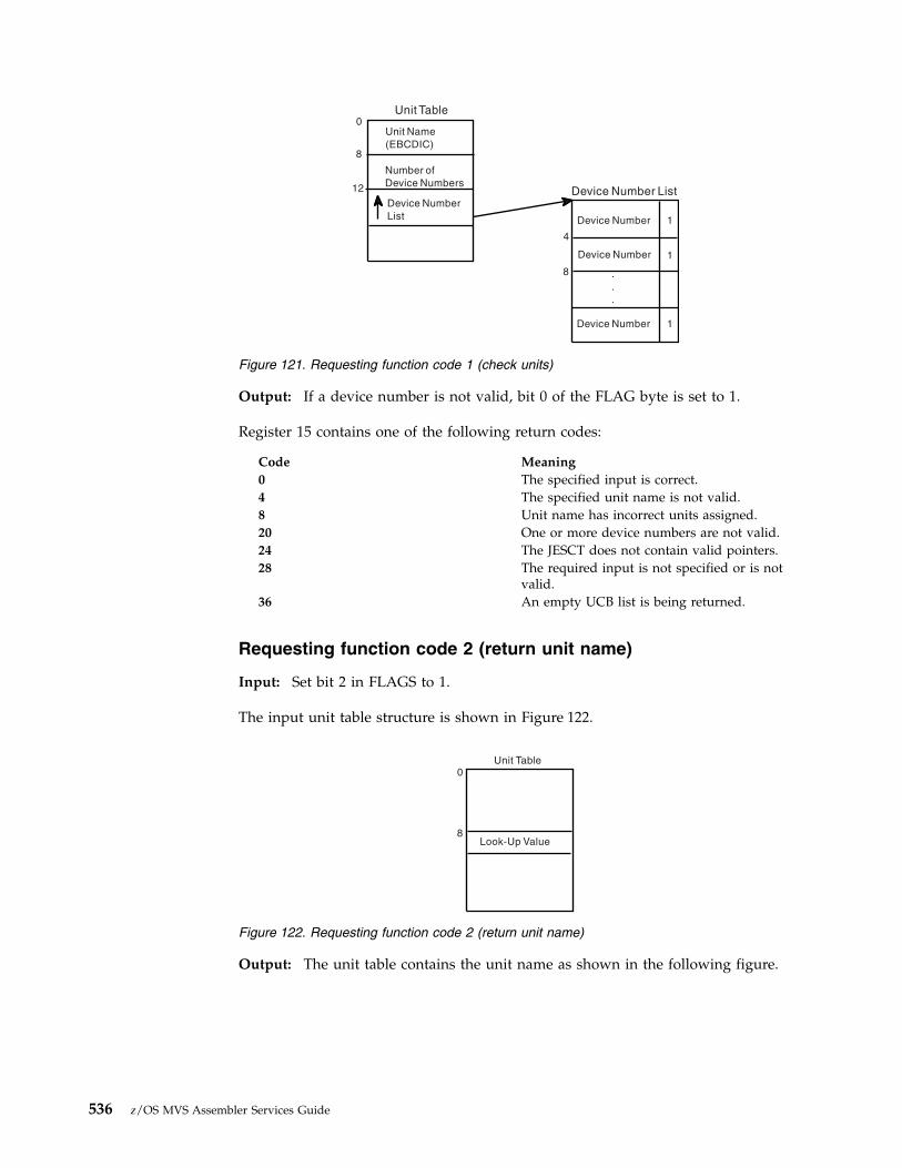
Output: If a device number is not valid, bit 0 of the FLAG byte is set to 1.
Register 15 contains one of the following return codes:
Code Meaning0 The specified input is correct.4 The specified unit name is not valid.8 Unit name has incorrect units assigned.20 One or more device numbers are not valid.24 The JESCT does not contain valid pointers.28 The required input is not specified or is not
valid.36 An empty UCB list is being returned.
Requesting function code 2 (return unit name)
Input: Set bit 2 in FLAGS to 1.
The input unit table structure is shown in Figure 122.
Output: The unit table contains the unit name as shown in the following figure.
Unit Table0
Device Number List
.
.
.
12
4
8
8
Unit Name
(EBCDIC)
Number of
Device Numbers
Device Number
List Device Number
Device Number
Device Number
1
1
1
Figure 121. Requesting function code 1 (check units)
Unit Table0
8Look-Up Value
Figure 122. Requesting function code 2 (return unit name)
536 z/OS MVS Assembler Services Guide

Register 15 contains one of the following return codes:
Code Meaning0 The unit table contains the EBCDIC unit name.4 The look-up value could not be found in the EDT.24 The JESCT does not contain valid pointers.28 The required input is not specified or is not valid.36 An empty UCB list is being returned.
Requesting function code 3 (return UCB addresses)
Input: Set bit 3 in FLAGS to 1.
The input unit table structure is shown in Figure 124.
Output: The unit table contains a pointer to the UCB Pointer List as shown in thefollowing figure.
0Unit Table
Unit Name
(EBCDIC)
8
Figure 123. Output from Function Code 2 (Return Unit Name)
0Unit Table
Unit Name
(EBCDIC)
8
Figure 124. Requesting function code 3 (return UCB addresses)
Appendix A. Using the unit verification service 537

For unauthorized callers, the subpool default is 0. See function code 10 for adescription of how to change the default subpool. The caller must free the numberof bytes in the length field from the subpool before exiting.
Register 15 contains one of the following return codes:
Code Meaning0 The unit table contains the pointer to the UCB pointer
list.4 The unit name could not be found in the EDT.16 Storage was not available for the UCB pointer list.24 The JESCT does not contain valid pointers.28 The required input is not specified or is not valid.36 An empty UCB list is being returned.
Requesting function code 4 (return group ID)
Input: Set bit 4 in FLAGS to 1.
The input unit table structure is shown in Figure 126.
Unit Table0
Unit Name
(EBCDIC)
Returned UCB
Pointer List
UCB Pointer List
Sub
poolLength
Number of entries
UCB
UCB
.
.
.
12
8
Figure 125. Output from Function Code 3 (Return UCB Addresses)
Unit Table0
4
0
4
Group ID List
UCB List
UCB List
Number of
entries
UCB
UCB
Group ID List
0
0
.
.
.
.
.
.
Figure 126. Requesting function code 4 (return group ID)
538 z/OS MVS Assembler Services Guide

Note: One fullword is provided in the group id list for each UCB in the UCB list.Initialize all entries to zero.
Output: The group id list contains the group id corresponding to each UCB in theinput UCB list.
Note: If the UCB is not in the EDT, the group id for that particular entry remainszero.
Register 15 contains one of the following return codes:
Code Meaning0 Processing is successful.24 The JESCT does not contain valid pointers.28 The required input is not specified or is not valid.36 An empty UCB list is being returned.
Requesting function code 5 (indicate unit name is a look-upvalue)
Input: Set bit 5 in FLAGS to 1.
The input unit table structure is shown in Figure 128.
This function is not valid by itself. It must be used in combination with otherfunctions that require a unit name as input. If you know the look-up valuecorresponding to the unit name, you can substitute it for the unit name in theinput unit table. The following figure represents the first two fullwords of the unittable when function code 5 is requested.
Output: None specifically associated with this function.
Group ID List
Group ID
Group ID
.
.
.
Figure 127. Output from Function Code 4 (Return Group ID)
Unit Table0
4
Look-up Value
0
Figure 128. Requesting function code 5 (indicate unit name is a look-up value)
Appendix A. Using the unit verification service 539

Register 15 contains one of the following return codes:
Code Meaning
0 Processing is successful.
4 The input look-up value could not be found in the EDT.
24 The JESCT does not contain valid pointers.
28 The required input is not specified or is not valid.
36 An empty UCB list is being returned.
Requesting function code 6 (return look-up value)
Input: Set bit 6 in FLAGS to 1.
The input unit table structure is shown in Figure 129.
This function is the opposite of the return unit name function (Code 2). Thefollowing figure represents the unit table structure when you request function code6.
Output: The unit table contains the look-up value.
Register 15 contains one of the following return codes:
Code Meaning
0 Processing is successful.
4 The unit name could not be found; no look-up value is returned.
24 The JESCT does not contain valid pointers.
28 The required input is not specified or is not valid.
Unit Table0
8
Unit Name
(EBCDIC)
Figure 129. Requesting function code 6 (return look-up value)
Unit Table0
8
Look-up Value
Figure 130. Output from Function Code 6 (Return Look-up Value)
540 z/OS MVS Assembler Services Guide

36 An empty UCB list is being returned.
Requesting function code 7 (convert device type to look-upvalue)
Input: Set bit 7 in FLAGS to 1.
The input unit table structure is shown in Figure 131.
Note: The device type is in the format of the UCBTYP field of the UCB.
Output: The unit table contains the look-up value.
The conversion of the device type to a look-up value is done in place. There is noerror checking of the device type.
Register 15 contains one of the following return codes:
Code Meaning
0 Processing is successful.
4 The input device type is not valid; no look-up value is returned.
24 The JESCT does not contain valid pointers.
28 The required input is not specified or is not valid.
36 An empty UCB list is being returned.
Requesting function code 8 (return attributes)
Input: Set bit 8 in FLAGS to 1.
The input unit table structure is shown in Figure 133 on page 542.
Unit Table
Device Type
8
Figure 131. Requesting function code 7 (convert device type to look-up value)
Unit Table
Look-up Value
8
Figure 132. Output from Function Code 7 (Convert Device Type to Look-up Value)
Appendix A. Using the unit verification service 541

Output: The attribute area contains the following:
Byte Contents
0 Length of the attribute area (X'0A') This must be filled in prior to callingthe unit verification service.
1-2 Flags describing the unit name:v Bit 0 on — unit name is an esoteric group namev Bit 1 on — unit name is VIO-eligiblev Bit 2 on — unit name contains 3330V unitsv Bit 3 on — unit name contains TP class devicesv Bits 4-7 are not used.
3 Number of device classes in the unit name
4-7 Number of generic device types in the unit name
8-9 Reserved
Register 15 contains one of the following return codes:
Code Meaning
0 The unit name was found; the attributes are returned.
4 The unit name was not found; no attributes are returned.
24 The JESCT does not contain valid pointers.
28 The required input is not specified or is not valid.
36 An empty UCB list is being returned.
Requesting function code 10 (specify subpool for returnedstorage)
Input: Set bit 10 in FLAGS to 1. This function is not valid alone and must be usedwith either the return UCB addresses function (code 3) or the return unit namefunction for a device class (code 11). The input unit table structure is shown inFigure 134 on page 543.
Unit Table
Attribute
Area
0
12
Attribute Area
X '0A'
0
0
0
0
0
2
4
6
8
10
Unit Name
(EBCDIC)8
Figure 133. Requesting function code 8 (return attributes)
542 z/OS MVS Assembler Services Guide

Output: See the output from the function that this is invoked in combinationwith.
The subpool field of the returned list contains the input subpool, and the returnedlist resides in that subpool. No error checking of the subpool is performed. If thesubpool is not valid, the unit verification routine fails.
Requesting function code 11 (return unit names for a deviceclass)
Input: Set bit 11 in FLAGS to 1.
The following figure shows the input unit table structure.
Output: The unit table contains the pointer to the names list as shown in thefollowing figure.
Unit Table
Sub-
pool
16
Figure 134. Requesting function code 10 (specify subpool for returned storage)
Unit Table
Device
Class
16
Figure 135. Requesting Function Code 11 (Return Unit Names for a Device Class)
UnitTable
NamesList
Device
Class
4
16
NamesList
Subpool Length
Number ofEntries
UnitName
UnitName
.
.
.
4
8
16
Figure 136. Output from Function Code 11 (Return Unit Names for a Device Class)
Appendix A. Using the unit verification service 543

For unauthorized callers, the default subpool is 0. To change this default, see thedescription for function code 10 (specify subpool for returned storage). The callermust free the number of bytes in the length field from the subpool before exiting.
Register 15 contains one of the following return codes:
Code Meaning
0 The pointer to the names list is stored in the unit table.
16 Storage was not available for the names list.
24 The JESCT does not contain valid pointers.
28 The required input is not specified or is not valid.
36 An empty UCB list is being returned.
Requesting multiple functions - ExamplesThe following examples show the input to and output from multiple functions.
Example 1 shows the multiple functions of codes 0 and 1.
Example 2 shows the multiple functions of codes 3 and 10.
Example 3 shows the multiple functions of codes 1 and 5.
Example 1 - Function codes 0 and 1
Input:
FLAGS
X 'C000
Unit Table
C 'DASD'
3
Device Number
List
8
12
Device Number List
C '300'
C '301'
C '302'
0
0
0
Figure 137. Input for Function Codes 0 and 1
544 z/OS MVS Assembler Services Guide
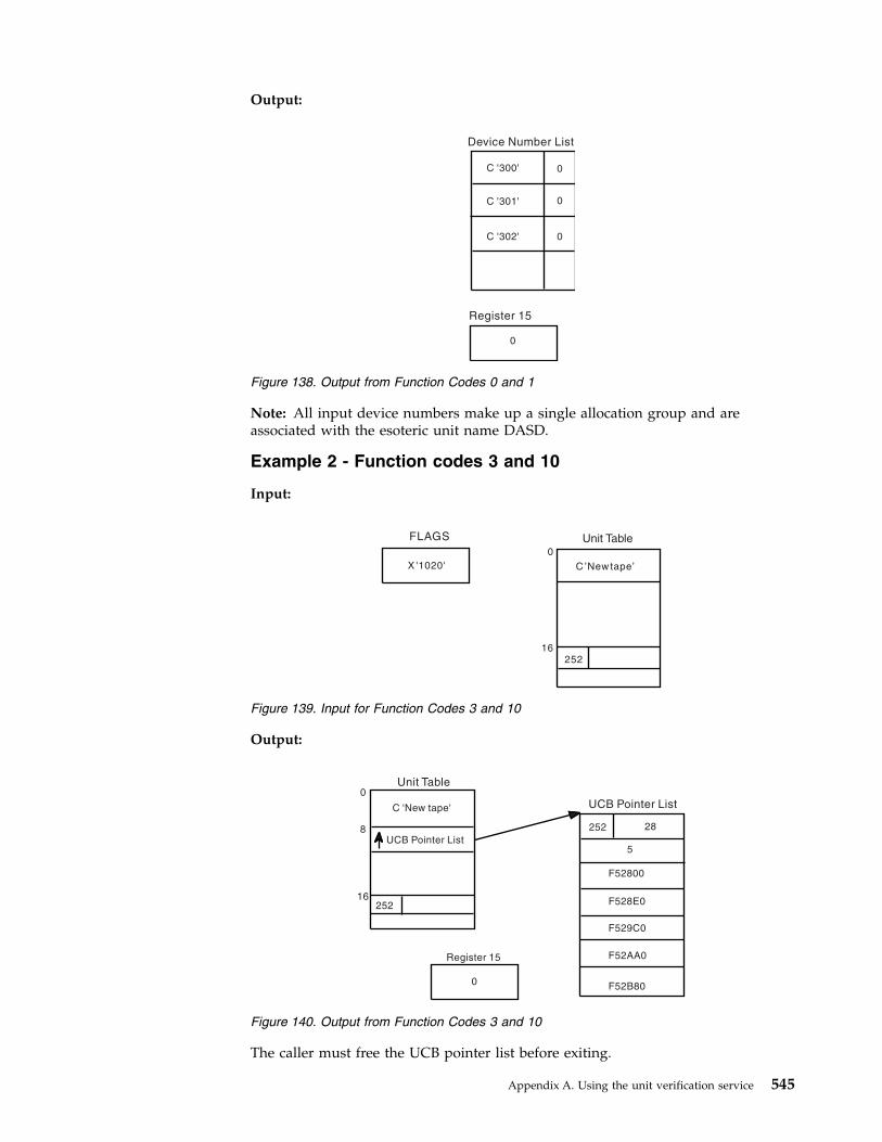
Output:
Note: All input device numbers make up a single allocation group and areassociated with the esoteric unit name DASD.
Example 2 - Function codes 3 and 10
Input:
Output:
The caller must free the UCB pointer list before exiting.
Device Number List
C '300'
C '301'
C '302'
0
0
0
Register 15
0
Figure 138. Output from Function Codes 0 and 1
FLAGS
X '1020'
0
16
252
C 'New tape'
Unit Table
Figure 139. Input for Function Codes 3 and 10
Unit Table
C 'New tape'
UCB Pointer List
252
0
8
16
UCB Pointer List
252 28
5
F52800
F528E0
F529C0
F52AA0
F52B80
Register 15
0
Figure 140. Output from Function Codes 3 and 10
Appendix A. Using the unit verification service 545
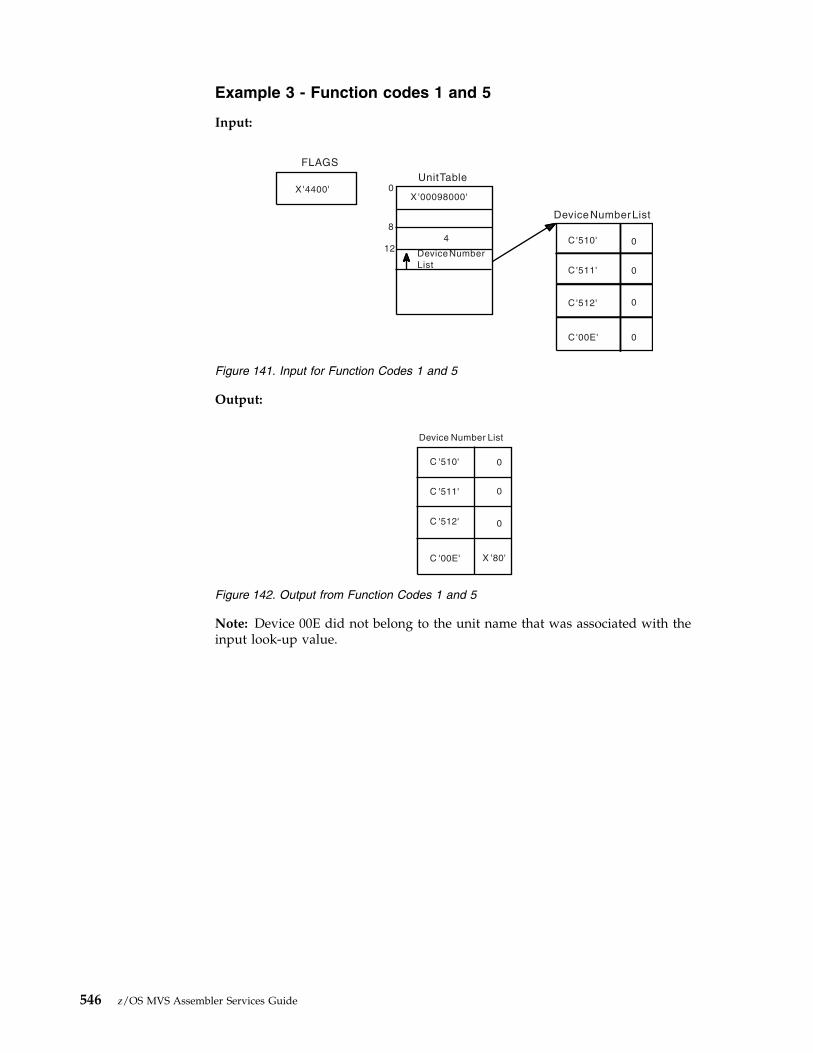
Example 3 - Function codes 1 and 5
Input:
Output:
Note: Device 00E did not belong to the unit name that was associated with theinput look-up value.
FLAGS
X '4400'
UnitTable
0
8
12
X '00098000'
4
DeviceNumber
List
DeviceNumberList
C'510'
C '511'
C '512'
C '00E' 0
0
0
0
Figure 141. Input for Function Codes 1 and 5
Device Number List
C '510'
C '511'
C '512'
C '00E' X '80'
0
0
0
Figure 142. Output from Function Codes 1 and 5
546 z/OS MVS Assembler Services Guide
Appendix B. Accessibility
Accessible publications for this product are offered through IBM KnowledgeCenter (www.ibm.com/support/knowledgecenter/SSLTBW/welcome).
If you experience difficulty with the accessibility of any z/OS information, send adetailed message to the Contact z/OS web page (www.ibm.com/systems/z/os/zos/webqs.html) or use the following mailing address.
IBM CorporationAttention: MHVRCFS Reader CommentsDepartment H6MA, Building 7072455 South RoadPoughkeepsie, NY 12601-5400United States
Accessibility features
Accessibility features help users who have physical disabilities such as restrictedmobility or limited vision use software products successfully. The accessibilityfeatures in z/OS can help users do the following tasks:v Run assistive technology such as screen readers and screen magnifier software.v Operate specific or equivalent features by using the keyboard.v Customize display attributes such as color, contrast, and font size.
Consult assistive technologiesAssistive technology products such as screen readers function with the userinterfaces found in z/OS. Consult the product information for the specific assistivetechnology product that is used to access z/OS interfaces.
Keyboard navigation of the user interfaceYou can access z/OS user interfaces with TSO/E or ISPF. The followinginformation describes how to use TSO/E and ISPF, including the use of keyboardshortcuts and function keys (PF keys). Each guide includes the default settings forthe PF keys.v z/OS TSO/E Primer
v z/OS TSO/E User's Guide
v z/OS ISPF User's Guide Vol I
Dotted decimal syntax diagramsSyntax diagrams are provided in dotted decimal format for users who access IBMKnowledge Center with a screen reader. In dotted decimal format, each syntaxelement is written on a separate line. If two or more syntax elements are alwayspresent together (or always absent together), they can appear on the same linebecause they are considered a single compound syntax element.
Each line starts with a dotted decimal number; for example, 3 or 3.1 or 3.1.1. Tohear these numbers correctly, make sure that the screen reader is set to read out
© Copyright IBM Corp. 1988, 2017 547

punctuation. All the syntax elements that have the same dotted decimal number(for example, all the syntax elements that have the number 3.1) are mutuallyexclusive alternatives. If you hear the lines 3.1 USERID and 3.1 SYSTEMID, yoursyntax can include either USERID or SYSTEMID, but not both.
The dotted decimal numbering level denotes the level of nesting. For example, if asyntax element with dotted decimal number 3 is followed by a series of syntaxelements with dotted decimal number 3.1, all the syntax elements numbered 3.1are subordinate to the syntax element numbered 3.
Certain words and symbols are used next to the dotted decimal numbers to addinformation about the syntax elements. Occasionally, these words and symbolsmight occur at the beginning of the element itself. For ease of identification, if theword or symbol is a part of the syntax element, it is preceded by the backslash (\)character. The * symbol is placed next to a dotted decimal number to indicate thatthe syntax element repeats. For example, syntax element *FILE with dotted decimalnumber 3 is given the format 3 \* FILE. Format 3* FILE indicates that syntaxelement FILE repeats. Format 3* \* FILE indicates that syntax element * FILErepeats.
Characters such as commas, which are used to separate a string of syntaxelements, are shown in the syntax just before the items they separate. Thesecharacters can appear on the same line as each item, or on a separate line with thesame dotted decimal number as the relevant items. The line can also show anothersymbol to provide information about the syntax elements. For example, the lines5.1*, 5.1 LASTRUN, and 5.1 DELETE mean that if you use more than one of theLASTRUN and DELETE syntax elements, the elements must be separated by a comma.If no separator is given, assume that you use a blank to separate each syntaxelement.
If a syntax element is preceded by the % symbol, it indicates a reference that isdefined elsewhere. The string that follows the % symbol is the name of a syntaxfragment rather than a literal. For example, the line 2.1 %OP1 means that you mustrefer to separate syntax fragment OP1.
The following symbols are used next to the dotted decimal numbers.
? indicates an optional syntax elementThe question mark (?) symbol indicates an optional syntax element. A dotteddecimal number followed by the question mark symbol (?) indicates that allthe syntax elements with a corresponding dotted decimal number, and anysubordinate syntax elements, are optional. If there is only one syntax elementwith a dotted decimal number, the ? symbol is displayed on the same line asthe syntax element, (for example 5? NOTIFY). If there is more than one syntaxelement with a dotted decimal number, the ? symbol is displayed on a line byitself, followed by the syntax elements that are optional. For example, if youhear the lines 5 ?, 5 NOTIFY, and 5 UPDATE, you know that the syntax elementsNOTIFY and UPDATE are optional. That is, you can choose one or none of them.The ? symbol is equivalent to a bypass line in a railroad diagram.
! indicates a default syntax elementThe exclamation mark (!) symbol indicates a default syntax element. A dotteddecimal number followed by the ! symbol and a syntax element indicate thatthe syntax element is the default option for all syntax elements that share thesame dotted decimal number. Only one of the syntax elements that share thedotted decimal number can specify the ! symbol. For example, if you hear thelines 2? FILE, 2.1! (KEEP), and 2.1 (DELETE), you know that (KEEP) is the
548 z/OS MVS Assembler Services Guide

default option for the FILE keyword. In the example, if you include the FILEkeyword, but do not specify an option, the default option KEEP is applied. Adefault option also applies to the next higher dotted decimal number. In thisexample, if the FILE keyword is omitted, the default FILE(KEEP) is used.However, if you hear the lines 2? FILE, 2.1, 2.1.1! (KEEP), and 2.1.1(DELETE), the default option KEEP applies only to the next higher dotteddecimal number, 2.1 (which does not have an associated keyword), and doesnot apply to 2? FILE. Nothing is used if the keyword FILE is omitted.
* indicates an optional syntax element that is repeatableThe asterisk or glyph (*) symbol indicates a syntax element that can berepeated zero or more times. A dotted decimal number followed by the *symbol indicates that this syntax element can be used zero or more times; thatis, it is optional and can be repeated. For example, if you hear the line 5.1*data area, you know that you can include one data area, more than one dataarea, or no data area. If you hear the lines 3* , 3 HOST, 3 STATE, you knowthat you can include HOST, STATE, both together, or nothing.
Notes:
1. If a dotted decimal number has an asterisk (*) next to it and there is onlyone item with that dotted decimal number, you can repeat that same itemmore than once.
2. If a dotted decimal number has an asterisk next to it and several itemshave that dotted decimal number, you can use more than one item from thelist, but you cannot use the items more than once each. In the previousexample, you can write HOST STATE, but you cannot write HOST HOST.
3. The * symbol is equivalent to a loopback line in a railroad syntax diagram.
+ indicates a syntax element that must be includedThe plus (+) symbol indicates a syntax element that must be included at leastonce. A dotted decimal number followed by the + symbol indicates that thesyntax element must be included one or more times. That is, it must beincluded at least once and can be repeated. For example, if you hear the line6.1+ data area, you must include at least one data area. If you hear the lines2+, 2 HOST, and 2 STATE, you know that you must include HOST, STATE, orboth. Similar to the * symbol, the + symbol can repeat a particular item if it isthe only item with that dotted decimal number. The + symbol, like the *symbol, is equivalent to a loopback line in a railroad syntax diagram.
Appendix B. Accessibility 549

550 z/OS MVS Assembler Services Guide

Notices
This information was developed for products and services that are offered in theUSA or elsewhere.
IBM may not offer the products, services, or features discussed in this document inother countries. Consult your local IBM representative for information on theproducts and services currently available in your area. Any reference to an IBMproduct, program, or service is not intended to state or imply that only that IBMproduct, program, or service may be used. Any functionally equivalent product,program, or service that does not infringe any IBM intellectual property right maybe used instead. However, it is the user's responsibility to evaluate and verify theoperation of any non-IBM product, program, or service.
IBM may have patents or pending patent applications covering subject matterdescribed in this document. The furnishing of this document does not grant youany license to these patents. You can send license inquiries, in writing, to:
IBM Director of LicensingIBM CorporationNorth Castle Drive, MD-NC119Armonk, NY 10504-1785United States of America
For license inquiries regarding double-byte character set (DBCS) information,contact the IBM Intellectual Property Department in your country or sendinquiries, in writing, to:
Intellectual Property LicensingLegal and Intellectual Property LawIBM Japan Ltd.19-21, Nihonbashi-Hakozakicho, Chuo-kuTokyo 103-8510, Japan
The following paragraph does not apply to the United Kingdom or any othercountry where such provisions are inconsistent with local law:INTERNATIONAL BUSINESS MACHINES CORPORATION PROVIDES THISPUBLICATION "AS IS" WITHOUT WARRANTY OF ANY KIND, EITHEREXPRESS OR IMPLIED, INCLUDING, BUT NOT LIMITED TO, THE IMPLIEDWARRANTIES OF NON-INFRINGEMENT, MERCHANTABILITY OR FITNESSFOR A PARTICULAR PURPOSE. Some states do not allow disclaimer of express orimplied warranties in certain transactions, therefore, this statement may not applyto you.
This information could include technical inaccuracies or typographical errors.Changes are periodically made to the information herein; these changes will beincorporated in new editions of the publication. IBM may make improvementsand/or changes in the product(s) and/or the program(s) described in thispublication at any time without notice.
© Copyright IBM Corp. 1988, 2017 551

This information could include missing, incorrect, or broken hyperlinks.Hyperlinks are maintained in only the HTML plug-in output for the KnowledgeCenters. Use of hyperlinks in other output formats of this information is at yourown risk.
Any references in this information to non-IBM websites are provided forconvenience only and do not in any manner serve as an endorsement of thosewebsites. The materials at those websites are not part of the materials for this IBMproduct and use of those websites is at your own risk.
IBM may use or distribute any of the information you supply in any way itbelieves appropriate without incurring any obligation to you.
Licensees of this program who wish to have information about it for the purposeof enabling: (i) the exchange of information between independently createdprograms and other programs (including this one) and (ii) the mutual use of theinformation which has been exchanged, should contact:
IBM CorporationSite Counsel2455 South RoadPoughkeepsie, NY 12601-5400USA
Such information may be available, subject to appropriate terms and conditions,including in some cases, payment of a fee.
The licensed program described in this document and all licensed materialavailable for it are provided by IBM under terms of the IBM Customer Agreement,IBM International Program License Agreement or any equivalent agreementbetween us.
Any performance data contained herein was determined in a controlledenvironment. Therefore, the results obtained in other operating environments mayvary significantly. Some measurements may have been made on development-levelsystems and there is no guarantee that these measurements will be the same ongenerally available systems. Furthermore, some measurements may have beenestimated through extrapolation. Actual results may vary. Users of this documentshould verify the applicable data for their specific environment.
Information concerning non-IBM products was obtained from the suppliers ofthose products, their published announcements or other publicly available sources.IBM has not tested those products and cannot confirm the accuracy ofperformance, compatibility or any other claims related to non-IBM products.Questions on the capabilities of non-IBM products should be addressed to thesuppliers of those products.
All statements regarding IBM's future direction or intent are subject to change orwithdrawal without notice, and represent goals and objectives only.
This information contains examples of data and reports used in daily businessoperations. To illustrate them as completely as possible, the examples include thenames of individuals, companies, brands, and products. All of these names arefictitious and any similarity to the names and addresses used by an actual businessenterprise is entirely coincidental.
552 z/OS MVS Assembler Services Guide

COPYRIGHT LICENSE:
This information contains sample application programs in source language, whichillustrate programming techniques on various operating platforms. You may copy,modify, and distribute these sample programs in any form without payment toIBM, for the purposes of developing, using, marketing or distributing applicationprograms conforming to the application programming interface for the operatingplatform for which the sample programs are written. These examples have notbeen thoroughly tested under all conditions. IBM, therefore, cannot guarantee orimply reliability, serviceability, or function of these programs. The sampleprograms are provided "AS IS", without warranty of any kind. IBM shall not beliable for any damages arising out of your use of the sample programs.
Terms and conditions for product documentationPermissions for the use of these publications are granted subject to the followingterms and conditions.
Applicability
These terms and conditions are in addition to any terms of use for the IBMwebsite.
Personal use
You may reproduce these publications for your personal, noncommercial useprovided that all proprietary notices are preserved. You may not distribute, displayor make derivative work of these publications, or any portion thereof, without theexpress consent of IBM.
Commercial use
You may reproduce, distribute and display these publications solely within yourenterprise provided that all proprietary notices are preserved. You may not makederivative works of these publications, or reproduce, distribute or display thesepublications or any portion thereof outside your enterprise, without the expressconsent of IBM.
Rights
Except as expressly granted in this permission, no other permissions, licenses orrights are granted, either express or implied, to the publications or anyinformation, data, software or other intellectual property contained therein.
IBM reserves the right to withdraw the permissions granted herein whenever, in itsdiscretion, the use of the publications is detrimental to its interest or, asdetermined by IBM, the above instructions are not being properly followed.
You may not download, export or re-export this information except in fullcompliance with all applicable laws and regulations, including all United Statesexport laws and regulations.
IBM MAKES NO GUARANTEE ABOUT THE CONTENT OF THESEPUBLICATIONS. THE PUBLICATIONS ARE PROVIDED "AS-IS" AND WITHOUTWARRANTY OF ANY KIND, EITHER EXPRESSED OR IMPLIED, INCLUDINGBUT NOT LIMITED TO IMPLIED WARRANTIES OF MERCHANTABILITY,
Notices 553

NON-INFRINGEMENT, AND FITNESS FOR A PARTICULAR PURPOSE.
IBM Online Privacy StatementIBM Software products, including software as a service solutions, (“SoftwareOfferings”) may use cookies or other technologies to collect product usageinformation, to help improve the end user experience, to tailor interactions withthe end user, or for other purposes. In many cases no personally identifiableinformation is collected by the Software Offerings. Some of our Software Offeringscan help enable you to collect personally identifiable information. If this SoftwareOffering uses cookies to collect personally identifiable information, specificinformation about this offering’s use of cookies is set forth below.
Depending upon the configurations deployed, this Software Offering may usesession cookies that collect each user’s name, email address, phone number, orother personally identifiable information for purposes of enhanced user usabilityand single sign-on configuration. These cookies can be disabled, but disablingthem will also eliminate the functionality they enable.
If the configurations deployed for this Software Offering provide you as customerthe ability to collect personally identifiable information from end users via cookiesand other technologies, you should seek your own legal advice about any lawsapplicable to such data collection, including any requirements for notice andconsent.
For more information about the use of various technologies, including cookies, forthese purposes, see IBM’s Privacy Policy at ibm.com/privacy and IBM’s OnlinePrivacy Statement at ibm.com/privacy/details in the section entitled “Cookies,Web Beacons and Other Technologies,” and the “IBM Software Products andSoftware-as-a-Service Privacy Statement” at ibm.com/software/info/product-privacy.
Policy for unsupported hardwareVarious z/OS elements, such as DFSMS, JES2, JES3, and MVS, contain code thatsupports specific hardware servers or devices. In some cases, this device-relatedelement support remains in the product even after the hardware devices pass theirannounced End of Service date. z/OS may continue to service element code;however, it will not provide service related to unsupported hardware devices.Software problems related to these devices will not be accepted for service, andcurrent service activity will cease if a problem is determined to be associated without-of-support devices. In such cases, fixes will not be issued.
Minimum supported hardwareThe minimum supported hardware for z/OS releases identified in z/OSannouncements can subsequently change when service for particular servers ordevices is withdrawn. Likewise, the levels of other software products supported ona particular release of z/OS are subject to the service support lifecycle of thoseproducts. Therefore, z/OS and its product publications (for example, panels,samples, messages, and product documentation) can include references tohardware and software that is no longer supported.v For information about software support lifecycle, see: IBM Lifecycle Support for
z/OS (www.ibm.com/software/support/systemsz/lifecycle)
554 z/OS MVS Assembler Services Guide

v For information about currently-supported IBM hardware, contact your IBMrepresentative.
Programming interface informationThis information is intended to help the customer to code macros that are availableto all assembler language programs. This information documents intendedprogramming interfaces that allow the customer to write programs to obtainservices of z/OS.
TrademarksIBM, the IBM logo, and ibm.com are trademarks or registered trademarks ofInternational Business Machines Corp., registered in many jurisdictions worldwide.Other product and service names might be trademarks of IBM or other companies.A current list of IBM trademarks is available on the Web at Copyright andTrademark information (www.ibm.com/legal/copytrade.shtml).
UNIX is a registered trademark of The Open Group in the United States and othercountries.
Notices 555

556 z/OS MVS Assembler Services Guide

Index
Special characters//JOBLIB DD statement 47//STEPLIB DD statement 47/*DEL statement 446/*EOF statement 446/*PURGE statement 446/*SCAN statement 446
Numerics24-bit addressing mode
description 33SPIE routine consideration 139
31-bit addressing modedescription 33SPIE consideration 139
46D system completion code 13964-bit address space
description 227using assembler instructions 230
binary operations 23064-bit addressing mode (AMODE) 232
modal instructions 233AMODE 24 233AMODE 31 233AMODE 64 233
non-modal instructions 23264-bit instructions
pitfalls to avoid 23464–bit virtual addressing support
system logger servicesexample 472
AABDUMP symptom area 199ABEND dump
requesting 196ABEND macro
choosing to issue 149invoking RTM 188STEP parameter 172
abnormal conditiondetect 139percolation 143process 139
abnormal terminationways to avoid with ENQ/DEQ 129when deleting a SPIE/ESPIE
environment 139when issuing CLOSE 225
access listadding an entry 292adding entry for data space 292adding entry for hiperspace 323definition 286type 287
access list entryadding 292deleting 292
access registeruse 286, 300using 285
access to a data objectpermanent object 338temporary object 339
accessibility 547contact IBM 547features 547
add an entry to an access listdescription 292example 292
addressAMODE indicator 35
address space control modedefinition 285switching 285
address space priority 28addressing mode
affect on BAL and BALRinstruction 34
bit in the PSW 34changing 34, 35, 61, 139considerations when passing
control 35indicator 34, 35, 61, 139of alias entry point 61of SPIE routine 139specifying 34, 35, 61, 139
ALESERV macroADD request
example 292, 323use 292, 323
DELETE requestexample 292
example 313ALET
ALET qualified address 5purpose 5when ALET qualification is
required 5ALET (access list entry token)
definition 286example of loading a zero into an
AR 291loading into an AR 291use 286
ALET (address list entry token)for primary address space 289with a value of zero 289
ALET-qualified addressused in macro parameter list 293
algorithmrun length encoding 419used by data compression
service 419used by data expansion service 419
aliasaddressing mode 61establishing 61
AMODE 64issuing macros 235linkage conventions
register 15 contents 234AMODE program attribute
changing 33, 34indicator 33, 34purpose 33specifying 33, 34value 34
anchor 245answer area
system loggersize 479
APF-authorizationwhen needed by problem state
program 47application resource
releasing through recovery 147AR (access register)
example of loading an ALET of zerointo 291
rules for coding 289use 286, 300using 285
AR informationformatting and displaying 294
AR instructionfor manipulating contents of
ARs 290AR mode
coding instructions 289description 285example 288importance of comma 290importance of the contents of
ARs 291issuing macros 293rules for coding 289use 286writing programs 288
AR mode programcall a primary mode program 24call an AR mode program 23defined 5linkage procedure 22pass parameters 25receive control from a caller 22return control to a caller 22, 23
ARCHECK subcommandformatting and displaying AR
information 294architecture level 205ARR (associated recovery routine)
choosing 151using 173
ASC modeAR mode program defined 5definition 285primary mode program, defined 5switching 285
© Copyright IBM Corp. 1988, 2017 557

ASC mode (continued)switching mode 6when control is received 6
assembler examplewindow service 351
assembler instructionexamples of use in AR mode 291use in AR mode 288, 289, 291
assistive technologies 547ATTACH and ATTACHX macros
ASYNCH parameter 172defining a recovery routine 151ECB parameter 188ESTAI parameter 151, 163ETXR parameter 188PURGE parameter 171STAI parameter 151TERM parameter 172
ATTACH macroaddressing mode consideration 47creating subpools 222DPMOD parameter 28ECB parameter, use 30ETXR parameter, use 30example of sharing DU-ALs 313GSPL parameter 221GSPV parameter 221LPMOD parameter 28requesting subpool ownership 221sharing a DU-AL with subtask 313SHSPL parameter 221SHSPV parameter 221specify subpools 221SZERO parameter 221TASKLIB parameter 48, 49use 27, 39, 47
authorization requirementsIXGCONN service 488system logger 470system logger application
program 471system logger couple data set 470system logger, IXCMIAPU utility 470
availabilityincreasing through recovery 147
BBAL instruction 34BALR instruction 34BAS (branch and save) instruction 34BAS instruction 34base register
establishing 19BASR (branch and save instruction
register form) 34BASR instruction 34BASSM (branch and save and set
mode) 35BASSM instruction 35, 56BLDL macro 51, 56BLDMPB macro 414blocks of an object
definition 333identifying blocks to be viewed 345size 333
blocks of an object (continued)updating blocks in a temporary
object 347updating blocks on DASD 348
BLOCKS parameter on DSPSERV 303,309, 321, 325
branch instructionBAL (branch and link) 34BALR (branch and link register) 34BAS instruction 34BASR instruction 34BASSM instruction 35BSM instruction 34use 56use with XCTL, danger 59
branching tableuse in analyzing return codes 44
bring a load module into virtualstorage 47
BSM (branch and set mode) 34BSM instruction 34build a symptom record 207
CCALL macro
use 42, 43, 54, 56callable cell pool service
advantages of using 245compared to the CPOOL macro 245data space 310data space example 311
calling programdefinition 5
calling sequence identifier 62cell 218, 246
allocating 250deallocating 250
cell pool 246activating 249anchor 245contracting 249creating 249deactivating 249disconnecting 249expanding 249extent 245obtaining 218obtaining status about 250size 247storage 247
cell pool serviceCSRC4ACT service 250CSRC4BLD service 249CSRC4CON service 250CSRC4DAC service 249CSRC4DIS service 249CSRC4EXP service 249CSRC4FR1 service 250CSRC4FR2 service 250CSRC4FRE service 250CSRC4GET service 250CSRC4GT1 service 250CSRC4GT2 service 250CSRC4RF1 service 250CSRC4RFR service 250CSRC4RG1 service 250
cell pool service (continued)CSRC4RGT service 250CSRPACT service 250CSRPBLD service 249CSRPCON service 250CSRPDAC service 249CSRPDIS service 249CSRPEXP service 249CSRPFR1 service 250CSRPFR2 service 250CSRPFRE service 250CSRPGET service 250CSRPGT1 service 250CSRPGT2 service 250CSRPRFR service 250CSRPRFR1 service 250CSRPRGT service 250CSRPRGT1 service 250query 250return code 251type of service 246
control 249cell storage 247central storage
sharing through IARVSERVmacro 375
changingexample 35, 36using BSM or BASSM 34
CHAP macrouse 29
characters printed on an MCSconsole 388
check groups function of unit verificationservice 531
check units function of unit verificationservice 531
checkpoint 358checkpoint/restart
manage storage 317, 331CHKPT macro 358CHNGDUMP command 196choose the name of a data space 303CnzConv macro
retrieving console information 394code
descriptor 390message routing 389
code instructions in AR mode 289comma
careful use of in AR mode 290communication
in a recovery environment 162in a sysplex environment 393provided by recovery 147
compilermessage 406
invoking 407compress data
steps required 420using the data compression
service 419compression
of datadescription 424
symbols 421concatenated data sets 48
558 z/OS MVS Assembler Services Guide

concurrent request for resourcelimiting 127
connectallocating coupling facility space 487to a log stream 486
consoleCnzConv macro 394CONVCON macro 394determining status 397determining the name or ID 395parameter list
initializing field 395retrieving information 394validating a name or ID 397
constrained transactions 526contact
z/OS 547control
in a dynamic structure 57in a simple structure 44return 44, 46, 57
control virtual storage 219CONVCON macro
parameter list 395retrieving console information 394
conventionfor passing control 39
convert device type to look-up valuefunction of unit verificationservice 532
converting central to virtual address 383CONVTOD macro
using 386coupling facility
structure storage limit reached 493system logger
damage 517failure 517, 519full condition 519loss of connectivity to 518
system logger data on 465coupling facility structure
system loggerstorage limit reached 493
coupling facility version numberIXGQUERY service 506
CPOOL macrouse 218
CPUTIMER macrousing 386
CPYA instructiondescription 290example 291
createhiperspace 318subpool 222task 27
create data spaceexample 292, 305, 316rules for 302
create hiperspaceexample 320
CSRCESRV macro 420CSRCMPSC macro 420, 424CSREVW window service
defining a view of an object 342
CSRIDAC window serviceobtaining access to a data object 341terminating access to an object 350
CSRL16J servicepassing control with all registers
intact 36CSRREFR window service
refreshing changed data 347CSRSAVE window service
updating a permanent object onDASD 348
CSRSCOT window servicesaving interim changes in a scroll
area 346updating a temporary object 347
CSRVIEW window servicedefining a view of an object 342terminating a view of an object 348
CSVINFO macroComparison with CSVQUERY 62MIPR 62
CSVQUERY macroComparison with CSVINFO 62
current size of data space 304
DDAE (dump analysis and elimination)
dump not suppressed 201dump suppression 196providing information through
recovery 158DASD (direct access storage device)
data transfer from by windowservices 335
updating a permanent object onDASD 348
DASD log data setspace 520
DASD-onlylog stream 481
DASD-only log streamsystem logger data on 466
data compression and expansion servicedata which can exploit 419recovery routine 419
data compression and expansion servicesusing 419
data compression servicesteps required to compress data 420using 419
data control blockdeleting load modules that
contain 225SNAP dump 202
data expansion service 420using 419
data objectaccess to a data object, procedure
for 341defining a view 342defining multiple views 345extending the size 345identifying 341mapping 333, 335, 336, 337multiple objects, example 337
data object (continued)multiple windows to an object,
example 336obtaining
access to a data object,overview 340, 341, 342
refreshing changed data 347saving interim changes 346scroll area 342scroll area to DASD, example 335specifying type of access 342structure 333temporary object, example 336terminating access to an object 350updating a temporary object 347window to a scroll area, example 335window to DASD, example 335
data setdump 202
data sharing with IARVSERV macro 375data space
access data 301choosing the name for 303compared to address space 295create 301creating 302default size 297definition 295, 300delete 301deleting 310dumping storage 317establish addressability 306example 292, 296example of creating 316example of deleting 316example of moving data into and
out 306example of using 316extending current size 308identifying the origin 305illustration 295loading pages into central
storage 309managing storage 297paging out of central storage 309release storage 301restoring 317rules for using 301saving 317SCOPE=ALL 303SCOPE=COMMON 303SCOPE=SINGLE 303shared between two programs 312,
313sharing with IARVSERV macro 375specify size 303storage available for 297use 296, 300using efficiently 316
data space storagemanaging 297release 301releasing 309rules for releasing 309
data to be viewed 345
Index 559

data-in-virtualmapping a hiperspace object to an
address space window 330mapping into hiperspace 328, 329
data-in-virtual objectdefinition 257, 333mapped into data space storage 314,
315data-in-virtual window
requirements for 257date and time of day
obtaining 385DCB parameter 50DD statements required for dumps 196DE parameter 51debugging aid for call sequence 61define multiple views of an object 345define the expected window reference
pattern 344define view of a data object 342define window disposition 343delete
access list entry 292example 292
data space 297example 292
hiperspace 297description 326example 331
delete data spaceexample 316
delete data spacesrules 310
DELETE macrolowering the responsibility count 225
delete message 388delete messages already written 394deleting
from a log stream 500illustration 501
DEQ macro 133descriptor code 390DETACH macro
use 30device
verification 531device class
unit name 532DFP requirement for window
service 341dictionary
compression 421entries 425expansion 421
directory entryPDS (partitioned data set) 33
disconnectingfrom a log stream 486
dispatching priority 28assign 28
display AR information 294DIV (data-in-virtual) service
restrictionswhen using IARVSERV
macro 382DIV macro
example 331
DIV macro (continued)example of mapping object into data
space 315mapping a data-in-virtual object to a
hiperspaceexample 329
mapping a hiperspace as adata-in-virtual object
example 331mapping object to a data space 314programming example 276retain mode 269, 273, 275rules for invoking 276sharing data in a window among
tasks 276use 259, 328
save 270unaccess 275unidentify 275unmap 274
using data-in virtual 257when to use data-in-virtual 258
DOM macrofunction 394
DPMOD parameter on ATTACH 28DSPSERV macro
CREATE requestexample 292, 305, 321, 326, 329,
331DELETE request
example 292, 326, 330, 331use 359
EXTEND requestexample 308
LOAD serviceuse 309
OUT serviceuse 309
RELEASE requestuse 325, 360
rules 309DU-AL
add entry 301compared with a PASN-AL 287definition 287illustration 287
dumpABEND dump 195data sets for 202index in SNAP dump 202not suppressed 201requesting 195requesting in recovery 158select type 195SNAP dump 195, 202summary 202suppression 196symptom 196SYSABEND dump 195SYSMDUMP dump 195SYSUDUMP dump 195Transaction dump 195, 203types a problem program can
request 195dump service 195dump storage in a data space 317
duplicatenames in unique task libraries, 50resource request 128
dynamic I/O configuration changedetecting 437
dynamic load module structureadvantage 39description 38, 39
EEAR instruction
description 290ECB (event control block)
description 116parameter of ATTACH 30, 31, 116
EDT (eligible device table)description 439obtaining information 440unit verification service
IEFEB4UV routine 531EDTINFO macro 440end-of-task exit routine 30ENF event code 48
system logger application 480ENQ macro 133
example 128use 57
entry pointadding 61address 42, 61alias use 61identifier 61identify 42
EP parameter 49EPIE (extended program interruption
element) 142EPLOC parameter 49error
recovering from software 145ESD (external symbol dictionary)
AMODE/RMODE indicator 33ESO hiperspace
definition 320ESPIE environment
deleting 139establishing 139
ESPIE macrooption 139, 141use 139using 141
ESPIE percolation 143establish addressability to a data
space 306definition 286example 316
ESTAE and ESTAEX macros0 parameter 151ASYNCH parameter 172CT parameter 151, 189defining a recovery routine 151OV parameter 189PARAM parameter 163PURGE parameter 171TERM parameter 172
ESTAE and ESTAEX routinedefinition 151
560 z/OS MVS Assembler Services Guide

ESTAE-type recovery routine (extendedspecify task abnormal exit)
providing 150ESTAI routine
definition 151ETR (External Time Reference hardware
facility)checking for TOD-clock
synchronization 385ETXR parameter of ATTACH
use 30event
signal completion 116EVENTS macro
use 116exabyte
description 227example
data object mapped to a window 334mapping
permanent object that has no scrollarea 335, 336, 337
multiple objects 337object to multiple windows 336permanent object that has a scroll
area 335structure of a data object 334system logger services
64–bit virtual addressingsupport 472
temporary object 336window services coding example 351
exclusive resource control 126EXCP macro 101EXCPVR macro 102exit routine
altering register content 143altering the old PSW 143end-of-task 30functions performed by 143register contents on entry 142specifying 139
expand datasteps required 420
expanded datausing the data expansion service 419
expansionof data
description 425explicit requests for virtual storage 214extend current size of data space
example 308procedure 308
extend current size of hiperspaceprocedure for 325
EXTEND parameter on DSPSERV 308,325
extend the size of an object 345extent 245
Ffind
load module 48form
execute 223list 223
form (continued)standard 223
format AR information 294frame
assigning 359repossessing 359
FREEMAIN macrouse 214, 218
functionscheck groups 531, 535check units 531, 535convert device type to look-up
value 532, 541indicate unit name is a look-up
value 532, 539return attributes 532, 541return group ID 532, 538return look-up value 532, 540return unit control block (UCB)
address 532, 537return unit name 532, 536return unit names for a device
class 532, 543specify subpool for returned
storage 532, 542
Ggap in reference pattern service
defining 366definition 366
gap in reference pattern servicesdefinition 366
GENNAME parameter onDSPSERV 302, 303, 320
GETMAIN macrocreating subpools 222LOC parameter 214, 215requesting storage at an address 215type 214use 214
gigabyte 33global resource 125global resource serialization 133GQSCAN macro
function 133GRS effects scope 137result 136TOKEN parameter 134
GRSaffects scope on GQSCAN macro 137
guard areachanging its size 241
Hhiperspace
as data-in-virtual object 330compared to address space 295creating 318, 320default size 297definition 295, 318deleting 326extending current size 325fast data transfer 323illustration 295
hiperspace (continued)managing storage 297manipulating data
illustration 318mapping data-in-virtual object
into 328, 329referencing data 321releasing storage 325restoring 331saving 331shared between two programs 323specify size 303storage available for 297two types 319window services use 335
hiperspace storagemanaging 297releasing 325rules for releasing 325
HSPALET parameter on HSPSERVmacro 323
HSPSERV macro 323example 323read operation 321, 322SREAD and SWRITE operation
example 326illustration 321
write operation 321HSTYPE parameter on DSPSERV 320
II/O configuration change
detecting 437I/O configuration token
detecting I/O configuration changeswith 437
IARR2V macroASID parameter 383converting a central storage address to
virtual 383IARVSERV sharing effectiveness 383NUMVALID parameter 383NUMVIEW parameter 383RSA parameter 383STOKEN parameter 383VSA parameter 383WORKREG parameter 383
IARV64 macrousing 236
IARVSERV macroCHANGEACCESS parameter 378copy-on-write 380
CVT mapping macro hardwarecheck 381
data sharing 375diagnostics 383example of use 381IARVRL mapping macro
required fields 380parameters description 380RANGLIST parameter 380READONLY parameter 380restrictions using DIV (data-in-virtual)
service 382restrictions using DIV (data-in-virtual)
services 382
Index 561

IARVSERV macro (continued)RETAIN parameter 381SHARE parameter 378SHAREDWRITE parameter 380sharing effectiveness 383SHRDATA IPCS subcommand 383TARGET_VIEW parameter 380types of views 377UNIQUEWRITE parameter 380
identify a data object 341identify a window 343identify blocks to be viewed 345identify the origin of the data space 305IEAARR macros
defining a recovery routine 151IEALSQRY macro
tracking entries in the linkagestack 185
IEANTCR callable service 353IEANTDL callable service 353IEANTRT callable service 353IEFEB4UV routine 531
authorized caller 533caller's function 533key 533mode 533problem program caller 533
implicit requests for virtual storage 223import connection
IXGCONN serviceIMPORTCONNECT
parameter 488import log blocks
IXGIMPRT service 501, 502INADDR parameter on the GETMAIN
macro 215INADDR parameter on the STORAGE
macro 217indicator
in a PDS entry 33in an entry point address 35, 47
initial size of data space 304initiate offload
IXGOFFLD service 507inline parameter list
use 42installation limit
amount of storage for data space andhiperspace 303
on amount of storage for data spaceand hiperspace 297
on size of data space andhiperspace 297
size of data space 303interlock
avoiding 131illustration 131
internal reader facilityallocating the data set 443, 444closing the data set 446coding /*DEL 446coding /*EOF 446coding /*PURGE 446definition 443example 446opening the data set 444sending records to the data set 445
internal reader facility (continued)setting up and using 443tasks involved in using 443through dynamic allocation 444through JCL 443
interval timing, establish 386INTRDR data set 443IOCINFO macro 437IPCS (interactive program control system)
formatting and displaying ARinformation 294
ISGENQ macrocompared to the ENQ macro 132using for shared resources 132using with the DEQ macro 132
issue macros in AMODE 64 235issue macros in AR mode 293IXGANSAA macro
answer area mapping 478IXGBRWSE service
browse cursor 496browse session 496browse token 496MULTIBLOCK parameter 498read data from a log stream 495REQUEST=READBLOCK 496REQUEST=READCURSOR 497REQUEST=RESET 496REQUEST=START 496searching for a log block by time
stamp 497illustration 498
with IXGDELET service 500with IXGWRITE service 499
IXGCONN serviceallocating coupling facility space at
connection 487authorization requirements 488connect process and staging data
sets 488connecting to and disconnection from
a log stream 486disconnect from a log stream 489import connection 488user data for a log stream
USERDATA parameter 489write connection 488
IXGDELET servicedelete data from a log stream
illustration 501deleting data from a log stream 500
IXGIMPRT service 501import log blocks 501, 502manage a target log stream 507safe import point 504
IXGINVNT serviceDASDONLY parameter 481managing the LOGR policy 480MODEL parameter 480
example 481IXGOFFLD service
initiate offload 507manage a target log stream 507
IXGQUERY servicecoupling facility version number 506log stream information 503manage a target log stream 507
IXGQUERY service (continued)safe import point 504
IXGUPDAT servicemodify log stream control
information 508time stamp 508
IXGWRITE serviceBUFFALET parameter 491log block buffer 491
BUFFKEY parameter 491BUFFLEN parameter 492
sequence of log blocks 492write to a log stream 491
JJES (job entry subsystem)
and the internal reader 443, 444, 445job library
reason for limiting size 50use 47when to define 51
job outputsending to the internal reader 445
job step taskcreate 27
JPA (job pack area) 48
Kkeyboard
navigation 547PF keys 547shortcut keys 547
LLAE instruction
description 290example 291
LAM instructiondescription 290example 291, 292
languagechecking availability 411
librarydescription 48search 48
limit priority 28linear data set
creating a 259link library 47LINK macro
addressing mode consideration 47use 47, 54, 55, 56when to use 225
linkageconsideration 34editor 33
linkage conventionsadvantages of using the linkage
stack 7AR mode program linkage
procedure 22AR mode program, defined 5establish a base register 19
562 z/OS MVS Assembler Services Guide

linkage conventions (continued)for branch instruction 5in AMODE 64 234
register 15 contents 234introduction 5parameter convention 24primary mode program linkage
procedure 19primary mode program, defined 5register save area, provide 6register, saving 6using a caller-provided save area 8using the linkage stack 7
linkage stackadvantages of using 7at time of retry 184considerations for ESTAE-type
recovery routines 170example of using the 8how to use 7
LINKX macrouse 54
loadregisters and pass control 40virtual storage 362
load an ALET into an AR 291load instruction in AR mode
example 290load list 48LOAD macro
indicating addressing mode 47use 47, 53, 56when to use 225
load modulealias 61characteristic 38execution 39how to avoid getting an unusable
copy 53location 47more than one version 49name 61search for 48structure type 38use count 55, 59using an existing copy 52
load module execution 39loaded module
information 62LOC parameter on the GETMAIN
macro 214, 215LOC parameter on the STORAGE macro
requesting storage at an address 217local resource 125location of a load module 47log block buffer 491
BUFFALET parameter 491BUFFKEY parameter 491BUFFLEN parameter 492
log dataon DASD log data sets 465, 466
log data sets 465allocation 466
log stream 464connection to
IXGCONN service 486DASD-only 481
log stream (continued)definition 463delete data from
illustration 501deleting data from
IXGDELET service 500different ways of connecting to 486disconnection from
IXGCONN service 486gaps in 475illustration 463JCL specification 511model 480
example 481read from
IXGBRWSE service 495write to
IXGWRITE service 491writing to
sequence of log blocks 492log stream information
IXGQUERY service 503log stream time stamp
IXGUPDAT service 508LOGR policy
managingIXGINVNT service 480
LOGR subsystem 509read log data in data set format
eligible applications 509using 510
Logrec Data Setdescription 205
look-up value for the EDTdefined 532obtaining 532
LPA (link pack area) 48LPMOD parameter on ATTACH 28LQB (language query block) 411
Mmacro
form 223issuing in AMODE 64 235issuing in AR mode 293reenterable form 223way of passing parameters 223
mainline routinedefinition in a recovery
environment 150manage a target log stream 507managing the LOGR policy
IXGINVNT service 480manipulate data in hiperspace 318manipulate the contents of ARs 290map data-in-virtual object into data space
rules for problem state program 315map data-in-virtual object into
hiperspace 329example 329rules for problem state program 328
map hiperspace as data-in-virtualobject 330
example 331map object into data space
using DIV macro 315
map object to a data spaceusing DIV macro 314
maximum size of data space 304MCS console
characters displayed 388megabyte 33member names
establish 61MEMLIMIT
definition 228memory object
attributes 229creating 237
example of 237deleting a 241discard pages that back pages 240example of creating with a guard
area 242example of creating, using and freeing
a 243example of deleting a 241ownership 236releasing physical resources that back
pages of 240message
deleting 388, 394descriptor code 390disposition 390example of WTO 391identifier 392indicator in first character 390MLWTO (multiple-line) 389replying 392routing 389, 390single-line 389translating 399writing 388
message compiler 406invoking 407
message filecompiling 406
message skeletoncreating 402format 403validating 405
message textformat 404
messagesz/OS MVS Programming: Assembler
Services Guide xviiMIPR
CSVINFO macro 62MLWTO (multiple-line) message
considerations for using 389MMS (MVS message service) 399, 419
coding example 416support for additional language 415
modeprimary 285
MODE parameter 474MODE=ASNYCNORESPONSE
parameter 475modify log stream control information
IXGUPDAT service 508module
obtaining a copy 53pass control 57
Index 563

move data between hiperspace andaddress space 321
MPB (message parameter block) 414building 414
using BLDMPB andUPDTMPB 414
using for new message 414multiple versions of load modules 49MVS macro
issuing in AMODE 64 235issuing in AR mode 293
Nname
resource 124name a data space 303NAME parameter on DSPSERV 302,
303, 320name/token callable service
link-editing with yourapplication 358
use of the service 353name/token pair
creating 354deciding which to use 355definition 353deleting 354home 357level 357
home address space 354primary address space 354system 354task 354, 355
retrieving the token 354navigation
keyboard 547non-reenterable load module 225non-shared standard hiperspace
creating 320definition 320
nonconstrained transactions 525NUMRANGE parameter on
HSPSERV 322
Oobtain access to a data object 341operator
consoles, characters displayed 388messages, writing 388
optionRESET parameter 141SET parameter 141TEST parameter 141
origin of data space 305originating task 27OUTNAME parameter on
DSPSERV 302, 303overlay load module structure 38
Ppage
faults, decreasing 364movement 359
page (continued)size 359
page out virtual storage 362page-ahead function 362paging I/O 359paging service
input 363list of services 359
parallel executionwhen to choose 27
parameter convention 24parameter list
description 40example of passing 40indicate end 42inline, use 42location 59
parameter list for AR mode programillustration 25
PASN-ALadd entry 301compared with a DU-AL 287definition 287
pass controlbetween control sections 40between programs with all registers
intact 36between programs with different
AMODEs 35, 56between programs with the same
AMODE 35in a dynamic structure 47, 54, 58, 60in a simple structure 39, 41, 46preparation 39prepare 41using a branch instruction 42, 58using CALL 43using LINK 54using the CSRL16J service 36with a parameter list 41with return 41, 54without control program
assistance 39, 56, 57without return 39, 58
pass parameterlist 223register 223
pass return address 39PDS directory entry
AMODE indicator 33RMODE indicator 33
percolatedefinition in a recovery
environment 153percolation
ESPIE 143permanent object
access to a permanent object,procedure for 341
accessing an existing object 341creating a new object 341data transfer 335data-in-virtual object,
relationship 333defining a view 342defining multiple views 345definition 333
permanent object (continued)extending the size 345functions supported for 338identifying 341mapping a scroll area to a permanent
object, example 335mapping with no scroll area,
example 335new object, creating 341obtaining
access to a permanent object,overview 340, 341, 342
overview of supported function 338refreshing changed data 347refreshing, overview 340requirements for new object 341saving changes, overview 340saving interim changes 346scroll area 342size, maximum 333specifying new or old status 341specifying type of access for an
existing object 342structure 333terminating access to a permanent
object 350updating on DASD 348
PGLOAD macropage-ahead function 362use 360
PGOUT macrouse 360
PGRLSE macrouse 359
PGSER macroinput 363page-ahead function 362protecting a range of virtual storage
pages 361use 360
PICA (program interruption control area)pointer 140purpose 140restore previous 140
PIE (program interruption element)purpose 140
planned overlay load modulestructure 38
pointer-defined entry point address 35post bit 116POST macro
use 116prepare to pass control
with return 41without return 39
primary modedescription 285
primary mode programcall a program 21defined 5linkage procedure 19pass parameters 24receive control from a caller 19return control to a caller 21
priorityaddress space 28assign 28
564 z/OS MVS Assembler Services Guide

priority (continued)change 28control program's influence 28dispatch 28higher, when to assign 28limit 28subtask 28task 28
private library 47processor storage management 359, 375program availability
increasing through recovery 147program design 39program interruption
cause 139determine cause 141determining the type 143
program management 33program mask 140program object
definition 47protecting
via serialization 123PSL (page service list) 363PSW (program status word)
addressing mode bit 34, 35PUT macro 445
Qqname of a resource
purpose 124QRYLANG macro 411query service 420
using 419
Rrange list entry 380RANGLIST parameter on HSPSERV 322,
327RB (request block)
considerations for ESTAE-typerecovery routines 170
relationship to ESTAE-type recoveryroutines 151
readfrom a log stream 495log data in data set format
LOGR subsystem 509LOGR subsystem
eligible applications 509read from a standard hiperspace 322,
326read operation
for standard hiperspace 321, 322recovery 145, 194
ABEND dumprequesting 158
ABEND macrochoosing to issue 149invoking RTM 188STEP parameter 172
activatedstate of recovery routine 149
advanced topics 188
recovery (continued)advantages of providing 147AMODE
ESTAE-type recovery routine 181retry from an ESTAE-type recovery
routine 182ARR
choosing 151using 173
ASC modeESTAE-type recovery routine 181retry from an ESTAE-type recovery
routine 182ATTACH and ATTACHX macros
ASYNCH parameter 172ECB parameter 188ESTAI parameter 151, 163ETXR parameter 188PURGE parameter 171STAI parameter 151TERM parameter 172
attached task 151authorization
ESTAE-type recovery routine 180retry from an ESTAE-type recovery
routine 182availability
increasing 147communication
between processes 147means available to recovery
routines 162parameter area 150, 162registers 162SDWA 155, 162SETRP macro 155
concepts 146condition of the linkage stack
ESTAE-type recovery routine 181retry from an ESTAE-type recovery
routine 183correcting errors 159DAE
providing information 158deactivated
state of recovery routine 149deciding whether to provide 147defined
state of recovery routine 149designing into your program 145dispatchable unit mode
ESTAE-type recovery routine 181retry from an ESTAE-type recovery
routine 182DU-AL
ESTAE-type recovery routine 181retry from an ESTAE-type recovery
routine 183dump
ABEND dump 158checking for previous 159requesting 158
environmentESTAE-type recovery routine 180factors other than register
contents 180register contents 174
recovery (continued)environment (continued)
retry from an ESTAE-type recoveryroutine 182
STAE and STAI routines 191summary for ESTAE-type recovery
routine and its retry routine 183understanding 173
errors 148examples 148
ESTAE and ESTAEX macros0 parameter 151ASYNCH parameter 172CT parameter 151, 189defining a recovery routine 151OV parameter 189PARAM parameter 163PURGE parameter 171TERM parameter 172
ESTAE and ESTAEX routineactivated 151deactivated 151defined 151definition 151no longer defined 151
ESTAE-type recovery routineadditional considerations 172linkage stack considerations 170outstanding I/Os 171providing 150RB considerations 170RB relationship 151return codes 176special considerations 170
ESTAI routineactivated 151deactivated 151defined 151definition 151no longer defined 151rules for retry RB 170
examplecoded 185mainline routine with one recovery
routine 154mainline routine with several
recovery routines 155footprints 158, 163from software errors 145general concepts 146IEALSQRY macro 185in control
state of recovery routine 149interrupt status
ESTAE-type recovery routine 181retry from an ESTAE-type recovery
routine 182mainline routine
definition 150minimizing errors 159multiple recovery routines 189MVS-provided 147no longer defined
state of recovery routine 149no longer in control
state of recovery routine 149not providing 148
Index 565
recovery (continued)outstanding I/O
restoring quiesced restorable I/Ooperations 171
outstanding I/Oscontrolling 171
parameter areaaccessing 162, 163checking the contents 158contents 162footprints 158, 163passing 150, 162, 163setting up 162
percolatecompared with retry 159definition 153
program availabilityincreasing 147
program maskESTAE-type recovery routine 181retry from an ESTAE-type recovery
routine 183quiesced restorable I/O operation
restoring 171recovery routine
choosing 150definition 150nested 190objectives 156options 152order of control 153percolating 161providing 145providing recovery for a recovery
routine 189retrying 160states 149summary of states 152writing 155
recursionavoiding 158definition 158
register contents 174entry to a recovery routine 174entry to a retry routine 177restoring 160return from a recovery
routine 176STAE or STAI retry routines 193STAE routine 191summary of where to find
information 174retry
compared with percolate 159definition 152
retry pointdefinition 150
retry routinedefinition 150description 160
routines in a recovery environmentdefinition 149interaction 153mainline routine 150recovery routine 150retry routine 150
RTM 145
recovery (continued)invoking 188
SDWAaccessing 165accessing the SDWARC1
DSECT 166checking important fields 157directly manipulating fields 158freeing 160IHASDWA mapping macro 165summary of important fields 166updating 155, 165updating through SETRP
macro 158updating through VRADATA
macro 158using 165
SDWA storage keyESTAE-type recovery routine 180retry from an ESTAE-type recovery
routine 182serviceability data
providing 148saving 158updating the SDWA 158
SETRP macrocommunicating recovery options to
the system 165COMPCOD parameter 165DUMP parameter 158FRESDWA parameter 160, 177indicating percolation 161indicating retry 160RC parameter 160, 161REASON parameter 165RECPARM parameter 158REMREC parameter 161RETADDR parameter 160RETREGS parameter 160, 177supplying a retry address 160updating the SDWA 155, 165
STAE macro0 parameter 151CT parameter 151defining a recovery routine 151
STAE retry routine 192STAE routine
return codes 192using 190work area 191
STAI retry routine 192STAI routine
return codes 192using 190work area 191
state of recovery routineactivated 149deactivated 149defined 149in control 149no longer defined 149no longer in control 149
system logger 515application failure 515coupling facility failure 517coupling facility full 519DASD log data set space fills 520
recovery (continued)system logger (continued)
log stream damage 519peer connector 516staging data set full 519system failure 516system logger address space
failure 516unrecoverable I/O errors 521
task 151validity checking of user
parameters 148VRADATA macro
updating the SDWA variablerecording area 158
writing recovery routines 155checking for the SDWA 156checking important fields in the
SDWA 157checking the parameter area 158comparison of retry and
percolate 159correcting or minimizing
errors 159determining if the recovery routine
can retry 159determining the first recovery
routine to get control 157determining why the routine was
entered 157establishing addressability to the
parameter area 157locating the parameter area 157providing information for
DAE 158requesting a dump 158saving serviceability data 158saving the return address to the
system 156recursion
avoiding in recovery 158definition in recovery 158
reenterableload module 53, 57, 223macro 223
reenterable codeuse 214, 218, 223
reenterable load moduleuse 216, 223
reference pattern service 364, 375reference unit in reference pattern service
choosing 366definition 366
reference unit in reference patternservices
definition 366REFPAT macro
example 372use 364using 368
refresh changed data in an object 347refreshable module 225REGION system parameter 213register
altering the content 143provide a save area 6save 6
566 z/OS MVS Assembler Services Guide
register 1pass parameters 40
register 14use 41when to restore 39
register 15use 40
registers 2-12 41release
data space and hiperspacestorage 297
data space storage 309rules 309
hiperspace storage 325rules for 325
resource 129virtual storage 359
RELEASE parameter on HSPSERVmacro 322
release storage in data spacesrules 309
removeentry from access list 292
REPLACE option for a window 343reply to WTOR message 392request
dump 195request for resource
limit concurrent 127requesting
conditionally 129exclusive control 126pair 132shared control 126unconditionally 129
requirements for window serviceDFP requirement 341SMS requirement 341
RESERVE macro 133resource
cleaning up 145collecting information 133control 115duplicate request 128global 125local 125name list 125naming 124process request 127protecting 115, 124, 125, 127, 128, 129release 129releasing through recovery 147requesting 115, 124, 125, 127, 128,
129scope 134serially reusable 115, 124, 125, 127,
128, 129types that can be shared 125using 123, 132
resource protectionvia serialization 123
resource queueextracting information 133
resource serializationavoiding an interlock 131requesting exclusive control 126requesting shared control 126
responsibility count for a loadedmodule 225
restoredata space 317hiperspace 331PICA (program interrupt control
area) 140registers upon return 44
RETAIN option for a window 343retry
definition in recoveryenvironment 152
retry pointdefinition 150
retry routinedefinition 150ensure correct level of the linkage
stack 184return address
pass 39return attributes function of unit
verification service 532return code
analyzing 44establish 45for cell pool service 251using 44
return group ID function of unitverification service 532
return look-up value function of unitverification service 532
RETURN macrouse 45
return UCB addresses function of unitverification service 532
return unit name function of unitverification service 532
returned storagespecify subpool 532
reusability attributes of a loadmodule 57
reusable module 53reuse of a save area 42RIB (resource information block)
used with GQSCAN macro 134RMODE program attribute
indicator in PDS entry 33purpose 33specifying 33, 47use 47value 33
routecode 389message 389
route message 390route the message 390RTM (recovery termination manager)
MVS component that handlesrecovery 145
run length encoding 419run-time message file
updating 410
SSAC instruction
example 292
SAC instruction (continued)use 285
safe import pointIXGIMPRT service 504IXGQUERY service 504
SAR instructiondescription 290example 291
savedata space 317hiperspace 331
save areaexample of using a 8, 10, 12, 13, 18how to tell if used 45pass address 40reuse 42using a caller-provided save area 8who must provide 6
save interim changes to a permanentobject 346
SAVE macroexample of using 9use 61
scopeALL parameter value on GQSCAN
macro 136on GQSCAN macro
as affected by GRS 137STEP parameter value on GQSCAN
macro 134, 136SYSTEM parameter value on
GQSCAN macro 134, 136SYSTEMS parameter value on
GQSCAN macro 134, 136scope of a resource
changing 125STEP, when to use 125SYSPLEX, when to use 126SYSTEMS, when to use 126
SCOPE parameter on DSPSERV 302scroll area
data transfer 335definition 334mapping a scroll area to DASD,
example 335mapping a window to a scroll area,
example 335obtaining a scroll area 342refreshing a scroll area 347saving changes in, overview 340saving interim changes in a 346storage used for 334updating a permanent object from a
scroll area 348updating DASD from, overview 340use 334
SCROLL hiperspace 319SDB (structured data base) format
description 207SDWA (system diagnostic work area)
providing symptom data for adump 199
SDWAARER field 167SDWAARSV field 168SDWACID field 158, 169SDWACLUP bit 159, 169SDWACMPC field 157, 167
Index 567
SDWA (system diagnostic work area)(continued)
SDWACOMU field 169SDWACRC field 157, 167SDWAEAS bit 159, 169SDWAEC1 field 167SDWAEC2 field 167SDWAG64 field 167, 169SDWAGRSV field 167SDWAINTF bit 167, 168SDWALNTH field 168SDWALSLV field 169, 185SDWAMLVL field 158, 169SDWAPARM field 157, 166SDWAPERC bit 157, 169SDWARPIV bit 167SDWARRL field 158, 169SDWASC field 158, 169SDWASPID field 168SDWASR00 field 161SDWASRSV field 168SDWATEAR field 169SDWATEAV bit 169SDWATEIV bit 169SDWATRAN field 169SDWATXG64 field 169SDWATXPSW16 field 169SDWAXFLG field 167, 168
search for a load module 48, 52areas/libraries searched 49limiting 49order 49
sending comments to IBM xvserially reusable
use 123serviceability data
providing through recovery 148saving in the SDWA 158
set upaddressability to a data space
example 292system logger configuration 509
SETRP macroCOMPCOD parameter 165DUMP parameter 158FRESDWA parameter 160, 177RC parameter 160, 161REASON parameter 165RECPARM parameter 158REMREC parameter 161RETADDR parameter 160RETREGS parameter 160, 177updating the SDWA 155
share subpools 220, 222shared pages 375shared resource control
through the ENQ macro 126through the RESERVE macro 132
shared standard hiperspacedefinition 320
shared storagewith IARVSERV macro 375
sharing data in virtual storagesummary 3
sharing data in virtual storage(IARVSERV macro) 375
sharing data spaces 313
shortcut keys 547simple load module structure 38SMS requirement for window
service 341SNAP data control block 202SNAP dump
index 202requesting 202
SNAP macrouse 202
SNAPX macrouse 202
software errorrecovering 145
specify subpool for returned storage 532specifying
in source code 33using linkage editor control card 33
SPIE (specify program interruption exit)environment
addressing mode 139adjusting 140canceling 140definition 140reestablishing 140
SPIE macroaddressing mode restriction 139use 139, 140
STAE macro0 parameter 151CT parameter 151defining a recovery routine 151
STAE routineusing 190
staging data setsformatting 494full condition 519storage limit reached 494
STAI routineusing 190
STAM instructiondescription 290
standard hiperspacedefinition 319example of creating 321non-shared 320read and write operation 322shared 320use 319
START parameter on DSPSERV 309, 325STATUS macro 29STCKCONV macro
using 386STCKSYNC macro
using 385step library
reason for limiting size 50use 47
STIMER macrousing 386
STIMERM macrousing 386
STOKEN parameter on ALESERV 292STOKEN parameter on DSPSERV 292,
302, 320STOKEN parameter on HSPSERV 322
storagefreshly obtained 261managing data space 310subpool returned storage 532
storage available for data space andhiperspace 297
STORAGE macroOBTAIN request
example 327use 214, 216, 218
storage requestexplicit 213, 214implicit 213
storage subpool 219structure of a data object 333subpool
characteristic 220creating 222handling 219in task communication 222ownership 221sharing 220, 222storage key for 221transferring ownership 222
subpool releasedefinition 218
substitution token 402subtask
communication with tasks 29control 27create 27priority 28starting 29stopping 29terminating 30, 116
summary dump 202summary of changes xviiSummary of changes xviiisuppression
of dumps 196symbol substitution
summary 3symptom
provided by a recovery routine 199required for dump suppression 166
symptom dump 196symptom record 207
description 205SYMRBLD macro
building a symptom record 205, 207SYMREC macro
symptom recording 205SYSABEND ABEND dump 195SYSMDUMP ABEND dump 195sysplex environment
communication 393SYSSTATE AMODE64= macro
example 235use 235
SYSSTATE macroexample 293use 53, 202, 293
system convention for parameter list 40SYSTEM inclusion resource name
list 125system log
writing 393
568 z/OS MVS Assembler Services Guide

system loggerANSAREA parameter 478answer area 478
size 479answer area mapping
IXGANSAA macro 478authorization requirements 470component 468configuration 466
illustration 467, 468connecting to and disconnection from
a log stream 486DASD-only log stream 466definition 463delete data from a log stream
illustration 501IXGDELET service 500
disconnect service 489IXGBRWSE service
MULTIBLOCK parameter 498REQUEST=READBLOCK 496REQUEST=READCURSOR 497REQUEST=RESET 496REQUEST=START 496searching for a log block by time
stamp 497with IXGDELET service 500with IXGWRITE service 499
log data setsallocation 466
log stream 463, 464illustration 463
LOGR subsystem 509eligible applications 509using 510
managing the LOGR policyIXGINVNT service 480
model log streamexample 481
peer connectorin recovery 516
readlog data in data set format 509
read from a log streambrowse cursor 496browse session 496browse token 496IXGBRWSE service 495
recovery 515application failure 515coupling facility failure 517coupling facility full 519DASD log data set space fills 520log stream damage 519staging data set full 519system failure 516system logger address space
failure 516unrecoverable I/O errors 521
searching for a log block by timestamp
illustration 498services
overview 469staging data sets
formatting 494storage limit reached 494
system logger (continued)status changes
ENF event code 48 480summary 3user data for a log stream 489writing to a log stream
IXGWRITE service 491system logger application
ENF event code 48 480example 463
system logger configurationset up 509
system logger services 46364–bit virtual addressing support
example 472authorization requirements 470gaps in the log stream 475IXGBRWSE service 495
browse cursor 496browse session 496browse token 496MULTIBLOCK parameter 498REQUEST=READBLOCK 496REQUEST=READCURSOR 497REQUEST=RESET 496REQUEST=START 496searching for a log block by time
stamp 497with IXGDELET service 500with IXGWRITE service 499
IXGCONN service 486allocating coupling facility space at
connection 487authorization requirements 488connect process and staging data
sets 488disconnect from a log stream 489import connection 488user data for a log stream 489write connection 488
IXGDELET service 500illustration 501
IXGWRITE service 491BUFFALET parameter 491BUFFKEY parameter 491BUFFLEN parameter 492committing data 493coupling facility structure storage
limit reached 493log block buffer 491sequence of log blocks 492staging data set is formatting 494staging data set storage limit
reached 494mode parameter 474MODE=ASYNCNORESPONSE
parameter 475MODE=SYNC parameter 474MODE=SYNCECB parameter 475overview 469searching for a log block by time
stampillustration 498
synchronous and asynchronousprocessing 474
system logger applications 463
system resourcereleasing through recovery 147
system-generated PICA 142SYSUDUMP ABEND dump 195
Ttarget program
definition 5task
advantage of creating additional 27communication with subtasks 29create 27library, establishing 48priority, affect on processing 28synchronization 116
TASKLIB parameter of ATTACH 48, 49tasks in a job step
illustration 30TCB (task control block)
address 27remove 30
temporary objectaccess to a temporary object,
procedure for 341accessing a temporary object 341creating a temporary object 341data transfer 335defining a view 342defining multiple views 345definition 333extending the size 345functions supported for 339initialized value 334mapping a window, example 336obtaining
access to a temporary object,overview 340, 341, 342
overview of supported function 339refreshing changed data 347refreshing, overview 340saving changes, overview 340scroll area 342size of, maximum 333specifying the object size 341storage used for 334structure 333terminating access to a temporary
object 350updating a temporary object 347
terminate access to an object 350terminate view of an object 348test return codes 44time interval
example of using 387TIME macro
using 385time of day and date
obtaining 385timer synchronization
checking 385TIMEUSED macro
using 388TOD (time-of-day) clock
checking for synchronization withETR 385
converting value 386
Index 569
TOD (time-of-day) clock (continued)obtaining content 385
tokenused with GQSCAN macro 135
TRANMSG macro 411Transaction dump 195transactional execution 525transactional execution debugging 528transactional execution diagnostics 528transfer data between hiperspace and
address space 321translate message 399TTIMER macro
using 386
UUCB (unit control block)
obtaining device information 439scanning 438
UCBINFO macro 439UCBSCAN macro 438unit name 532
device class 532is a look-up value function of unit
verification service 532unit verification service
description 531examples 544FLAGS parameter field 533functions 531, 533, 534, 544IEFEB4UV routine 533input and output 533
data structure 534parameter list required 533purpose 531requesting multiple functions 544
update a permanent object onDASD 348
update a temporary object 347UPDTMPB macro 414use an entry to an access list
example 292use count 55use count for a loaded module 59use data spaces efficiently 316use of data space and hiperspace 297user interface
ISPF 547TSO/E 547
user list 261, 270, 272use
access 263identify 262map 266reset 273savelist 272
using a memory objectuse the storage 238
using transactional executiong 527
VV-type address constant
use to pass control 42
V=R (virtual=central) storageallocation 359
VERBEXIT DAEDATA subcommandindicating why dump was not
suppressed 201verification
device 531version record
format 402virtual storage
controlling 219explicit requests for 214freeing 225implicit requests for 223loading 360, 362obtaining via CPOOL 218page-ahead function 362paging out 362releasing 359, 360sharing with IARVSERV macro 375specifying the amount allocated to a
task 213, 214subpool 219using efficiently 213why use above the bar 228
virtual storage window 257, 260VRADATA macro
to customize dump suppression 200using in a recovery environment 158
VSL (virtual subarea list) 363VSM (virtual storage management) 213,
226
Wwait
bit 116condition 116long 117
WAIT macrouse 116
ways that window services can map anobject 335
windowaffect of terminating access to an
object 350blocks to be viewed, identifying 345changing a view in a window 348changing the view, overview 340data to be viewed, identifying 345defining
window, overview 340, 343, 344,345, 346
definition 333identifying a window 343identifying blocks to be viewed 345mappping
to a window, example 335, 336,337
multiple objects, example 337multiple windows 345refreshing a window 347REPLACE option 343RETAIN option 343size 343storage for 343terminating a view in a window 348
window (continued)to multiple windows, example 336updating a permanent object from a
window 348use 333window disposition 343window reference pattern 344windows with overlapping view 346
window serviceintroduction 333overview 333use 339
window servicesfunctions provided 334overview 333services provided 334using window services 339ways to map an object 335
WLM goal modedispatching priority 28
work areaused by data compression
service 419used by data expansion service 419
writeto the operator with reply 388to the operator without reply 391to the programmer 393to the system log 393
write connectionIXGCONN service
IMPORTCONNECTparameter 488
WRITE macro 445write message 388write operation
for standard hiperspace 321write programs in AR mode 288write to a standard hiperspace 322, 326writing
to a log stream 491WTL macro
writing to the system log 393WTO macro
descriptor code for 390example 391MLWTO (multiple-line) form 389single-line form 389use 388
WTOR macroexample 392use 388
XX-macro
definition 293rules for using 293
XCTL macroaddressing mode consideration 47lowering the responsibility count 225use 47, 58use with branch instructions,
danger 59XCTLX macro
use 58
570 z/OS MVS Assembler Services Guide

Zz/Architecture
setting and checking the addressingmode 234
z/Architecture instructionsusing the 64-bit GPR 231
z/Architecture processes S/390instructions, how 231
examples 231z/OS MVS Programming: Assembler
Services Guidemessages xvii
Index 571

572 z/OS MVS Assembler Services Guide


IBM®
Product Number: 5650-ZOS
Printed in USA
SA23-1368-30