zorbas 2e web chapter 1w - cengage learning current through the resistor of the circuit in ......
TRANSCRIPT

Zorbas/Electric Machines, 2e
© 2015 Cengage Learning. All Rights Reserved. May not be scanned, copied or duplicated, or posted to a publicly accessible website, in whole or in part.
5
Chapter 1W Basic Electromagnetic Concepts
1W Basic Electromagnetic Concepts 1W.1 Examples and Problems on Electric Circuits 1W.2 Examples on Magnetic Concepts
This chapter includes additional examples and problems that will complement the
understanding of the corresponding concepts found in the chapter on Basic
Electromagnetic Concepts in the book.

Zorbas/Electric Machines, 2e
© 2015 Cengage Learning. All Rights Reserved. May not be scanned, copied or duplicated, or posted to a publicly accessible website, in whole or in part.
6
1W.1 Examples and Problems on Electric Circuits
EXAMPLE 1W-1
Find the polar form of
a) 3 + j 4
b) –1 – j1
Solution:
Refer to Fig. 1W-1.
a) 3 + j 4 = r ∠θ
! = 3! + 4! = 5
θ = arc tan !! = 53°
Thus,
3 + j 4 = 5 ∠53°
b) −1 − j1 = r ∠θ
! = 1! + 1! = 2
θ = arc tan !!!!
= –135°
Thus,
–1 – j1 = 2 ∠−135°

Zorbas/Electric Machines, 2e
© 2015 Cengage Learning. All Rights Reserved. May not be scanned, copied or duplicated, or posted to a publicly accessible website, in whole or in part.
7
FIG. 1W-‐1
EXAMPLE 1W-2
Find the rectangular form of
a) 10 ∠37° b) 5 ∠135°
Solution:
a) 10 ∠37° = 10 (cos 37° + j sin 37°)
= 8 + j 6
b) 5 ∠135° = 10 (cos 135° + j sin 135°)
= −7.07 + j 7.07

Zorbas/Electric Machines, 2e
© 2015 Cengage Learning. All Rights Reserved. May not be scanned, copied or duplicated, or posted to a publicly accessible website, in whole or in part.
8
EXAMPLE 1W-3
Find Z1 + Z2 , Z1 Z2 and Z1Z2
if
Z1 = 5 ∠37° Ω
Z2 = 10 ∠53° Ω
Solution:
Z1 = 5 ∠37° = 4 + j3 Ω
Z2 = 10 ∠53° = 6 + j8 Ω
I) Z1 + Z2 = 4 + 6 + j(3 + 8) = 10 + j11 Ω
II) Z1 × Z2 = 5 × 10 ∠37°+ ∠53°
= 50 ∠90°
= 0 + j50
= j50
III) Z1Z2
= 510 ∠37°− ∠53° = 0.5 ∠16°
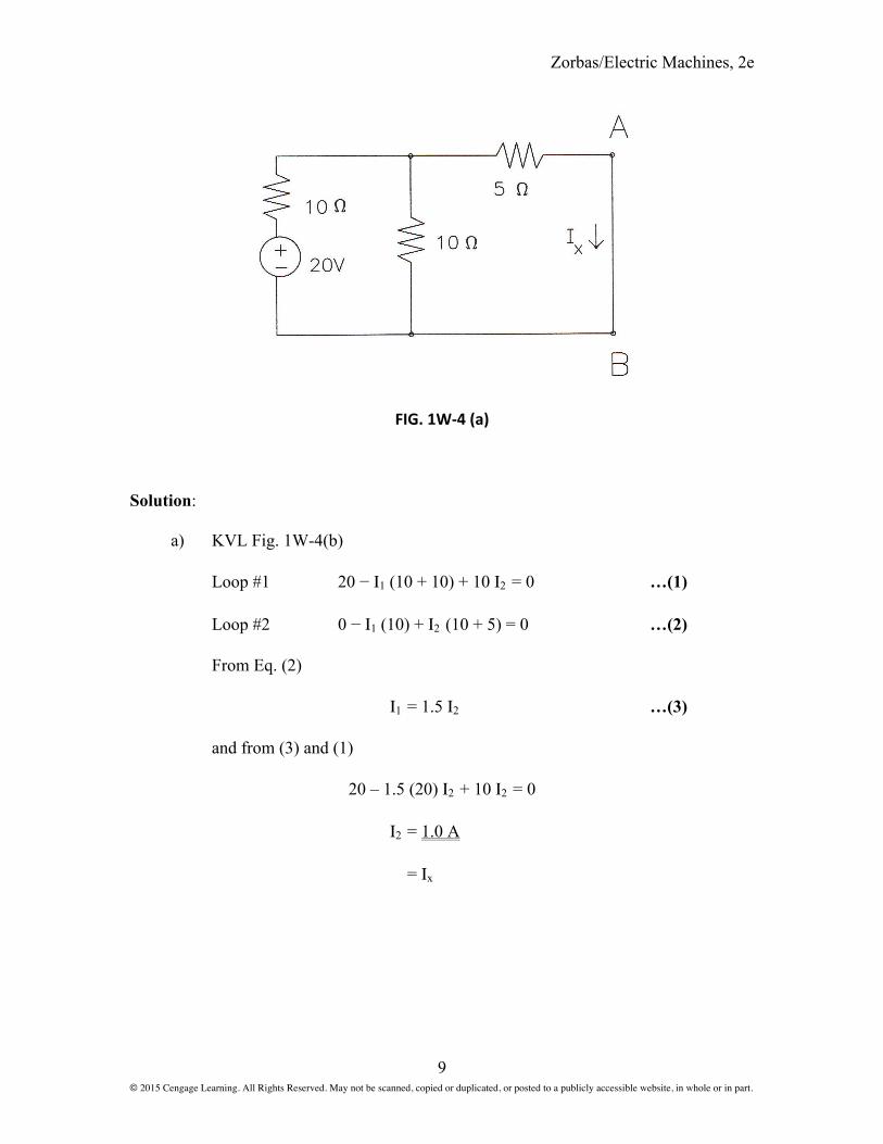
EXAMPLE 1W-4
In Fig. 1W-4(a) find the current Ιx by using
a) KVL
b) KCL
c) Thévenin’s theorem
d) Current-divider technique
Zorbas/Electric Machines, 2e
© 2015 Cengage Learning. All Rights Reserved. May not be scanned, copied or duplicated, or posted to a publicly accessible website, in whole or in part.
9
FIG. 1W-‐4 (a)
Solution:
a) KVL Fig. 1W-4(b)
Loop #1 20 − Ι1 (10 + 10) + 10 Ι2 = 0 …(1)
Loop #2 0 − Ι1 (10) + Ι2 (10 + 5) = 0 …(2)
From Eq. (2)
Ι1 = 1.5 Ι2 …(3)
and from (3) and (1)
20 – 1.5 (20) Ι2 + 10 Ι2 = 0
Ι2 = 1.0 A
= Ιx

Zorbas/Electric Machines, 2e
© 2015 Cengage Learning. All Rights Reserved. May not be scanned, copied or duplicated, or posted to a publicly accessible website, in whole or in part.
10
FIG. 1W-‐4 (b)
b) Refer to Fig. 1W-4(c).
As reference voltage is selected that of Node Z2, that is
Vz 2 = 0
Writing the nodal equations, we obtain
Node Z1
!!!10 +
!!!5 +
!!! − 2010 = 0
Vz 1 = 5 volts
and
!! =!!!5 = 1 A

Zorbas/Electric Machines, 2e
© 2015 Cengage Learning. All Rights Reserved. May not be scanned, copied or duplicated, or posted to a publicly accessible website, in whole or in part.
11
FIG. 1W-‐4 (c)
c) Using Thévenin’s (Fig. 1W-4(d)) to find:
Rth (Fig. 1W-4(e)):
!!! = 5+10 1010+ 10
= 10Ω
Vth (Fig. 1W-4(f)):
Vth= I 10
=20
10+10 10
=10 volts
!! =!!!!!!
=1010 = 1 A
!! = !!

Zorbas/Electric Machines, 2e
© 2015 Cengage Learning. All Rights Reserved. May not be scanned, copied or duplicated, or posted to a publicly accessible website, in whole or in part.
12
FIG. 1W-‐4 (d)
FIG. 1W-‐4 (e) and (f)
d) Using the current-divider concept (Fig. 1W-4(a)):
!! = !10
10+ 5
=20
10+ 10//5×10
10+ 5
= 1.0 A

Zorbas/Electric Machines, 2e
© 2015 Cengage Learning. All Rights Reserved. May not be scanned, copied or duplicated, or posted to a publicly accessible website, in whole or in part.
13
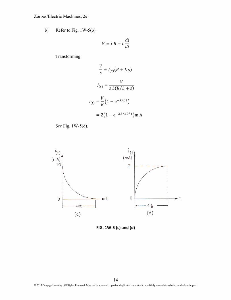
EXAMPLE 1W-5
Find ι in Figs. 1W-5(a) and 1W-5(b).
FIG. 1W-‐5 (a) and (b)
Solution:
Refer to Fig. 1W-5(a)
a) ! = !" + !!∫ ! !"
Taking Laplace transforms
!! = ! ! ! +
1!"
!(!) =!
! 1!" + !
Inverting
! ! =!! !
!! !"
= 10!!!/! m A
See Fig. 1W-5(c).
Zorbas/Electric Machines, 2e
© 2015 Cengage Learning. All Rights Reserved. May not be scanned, copied or duplicated, or posted to a publicly accessible website, in whole or in part.
14
b) Refer to Fig. 1W-5(b).
! = ! ! + !!"!"
Transforming
!! = ! ! ! + ! !
! ! =!
! ! ! ! + !
! ! =!! 1− !!! ! !
= 2 1− !!!.!×!"! ! m A
See Fig. 1W-5(d).
FIG. 1W-‐5 (c) and (d)

Zorbas/Electric Machines, 2e
© 2015 Cengage Learning. All Rights Reserved. May not be scanned, copied or duplicated, or posted to a publicly accessible website, in whole or in part.
15
EXAMPLE 1W-6
The current through the resistor of the circuit in Fig. 1W-6(a) is
!! = 2 sin 377! +!6 !
a) Determine the rms value of the total current.
b) Determine the power factor of the circuit.
c) Draw the phasor diagram of all voltages and currents.
FIG. 1W-‐6 (a)
Solution:
a) !! =!!∠30 = 1.414 ∠30°A
!! = 150(1.414)∠30 = 212.13∠30°A
!! =!"!.!"/!"
!"" !""×!"!! ∠!"= 5.6268 ∠−60°A
! = 1.414∠30°+ 5.6268∠−30°
= 4.038− !4.1658 = 5.8 ∠−45.89°A
b) cos (30º + 45.89º) = cos 75.89º = 0.2437 lagging
c) See Fig. 1W-6(b).

Zorbas/Electric Machines, 2e
© 2015 Cengage Learning. All Rights Reserved. May not be scanned, copied or duplicated, or posted to a publicly accessible website, in whole or in part.
16
FIG. 1W-‐6 (b)
PROBLEM 1W-1
A factory operates at a power factor of 0.8 lagging. When a capacitor of 860 kVAR is
connected in parallel to the load, the power factor becomes 0.95 leading and the utility’s
meter indicates an average power of 800 kW.
Determine the factory’s apparent power before and after the hook-up of the
capacitor bank.

Zorbas/Electric Machines, 2e
© 2015 Cengage Learning. All Rights Reserved. May not be scanned, copied or duplicated, or posted to a publicly accessible website, in whole or in part.
17
PROBLEM 1W-2
Refer to the partial power distribution of a residence (Fig. P1W-2). Determine the voltage
across Z1 when:
a) The neutral is disconnected (switch A is open and breakers b1 and b2 are
closed).
b) Switch A and breaker b2 are closed, while the breaker b1 is open.
FIG. P1W-‐2
PROBLEM 1W-3
For the circuit shown in Fig. P1W-3, determine an expression for the voltage across the
inductor, following the closing of the switch at t = 0. Sketch it and show all pertinent
values.
Zorbas/Electric Machines, 2e
© 2015 Cengage Learning. All Rights Reserved. May not be scanned, copied or duplicated, or posted to a publicly accessible website, in whole or in part.
18
FIG. P1W-‐3
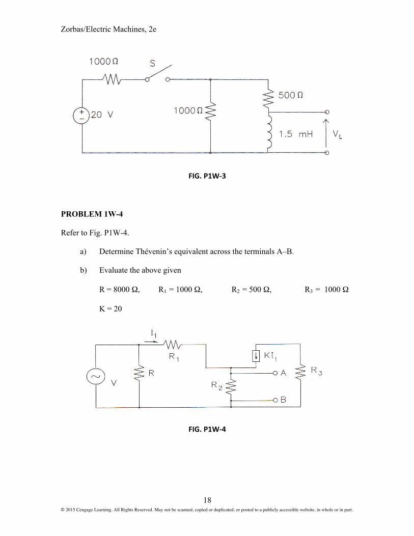
PROBLEM 1W-4
Refer to Fig. P1W-4.
a) Determine Thévenin’s equivalent across the terminals A–B.
b) Evaluate the above given
R = 8000 Ω, R1 = 1000 Ω, R2 = 500 Ω, R3 = 1000 Ω
K = 20
FIG. P1W-‐4

Zorbas/Electric Machines, 2e
© 2015 Cengage Learning. All Rights Reserved. May not be scanned, copied or duplicated, or posted to a publicly accessible website, in whole or in part.
19
PROBLEM 1W-5
a) Determine the voltage VAB, in the circuit of Fig. P1W-5(a), by nodal analysis.
b) Using Thévenin’s theorem, determine the current Ι in Fig. P1W-5(b).
FIG. P1W-‐5

Zorbas/Electric Machines, 2e
© 2015 Cengage Learning. All Rights Reserved. May not be scanned, copied or duplicated, or posted to a publicly accessible website, in whole or in part.
20
PROBLEM 1W-6
Refer to circuit in Fig. P1W-6. Determine
a) The current through the 10 Ω resistor.
b) The power consumed by the capacitor.
c) The current through the 20 Ω resistor.
d) The average power, reactive power, and complex power supplied by the
voltage source.
e) The input impedance of the circuit.
f) The current through the capacitor by using Thévenin’s theorem.
g) The voltage across the capacitor.
h) The phasor diagram of voltages and currents in each element.
FIG. P1W-6
PROBLEM 1W-7
a) Briefly explain the reasons that an individual is always capacitively and
magnetically coupled to his or her environment.
b) What are some of the applications of these natural phenomena?
Zorbas/Electric Machines, 2e
© 2015 Cengage Learning. All Rights Reserved. May not be scanned, copied or duplicated, or posted to a publicly accessible website, in whole or in part.
21
1W.2 Examples on Magnetic Concepts
EXAMPLE 1W-7
In the electrical power distribution of the 1976 Olympics, the 12 kV monoconductor
power cables were routed under the steel cover plate of a manhole. Upon the system’s
energization, the cables were damaged and the power supply to various buildings was
interrupted. Explain the reasons for it.
Solution:
1) The flux (Φ1) of the current through the monoconductor cables closed its loop
by cutting through the steel cover plate of the manhole. (Magnetic flux lines
form closed loops.)
2) This flux disturbed the magnetic domains of the steel plate and because action
is equal and opposite to reaction, the plate produced its own opposing flux
(Φ2).
3) This flux was generated by the so-called circular (eddy) currents (Ιε).
4) The circular currents in turn produced rate of heat (Ιε2 RE) within the material.
5) The alternating nature of the flux also produced alignment and realignment of
the magnetic domains and thus additional rate of heat produced (hysteresis
losses) due to frictional forces.
6) The generation of eddy current and hysteresis losses overheated the cables,
their insulation was damaged, and a flashover took place between the steel
plates and the monoconductor cables.