zone a removal action engineering design report
TRANSCRIPT
Pasco Sanitary Landfill NPL Site
Zone A Removal Action Engineering Design Report
Prepared for
Industrial Waste Area Generators Group III
Prepared by Floyd|Snider and PBS Engineering and Environmental, Inc.
with contributions from GHD
August 2020
Final
100% RecycledPaper

LIMITATIONS
This report has been prepared for the exclusive use of the Industrial Waste Area Generators Group III, their authorized agents, and regulatory agencies. It has been prepared following the described methods and information available at the time of the work. No other party should use this report for any purpose other than that originally intended, unless Floyd|Snider and PBS Engineering and Environmental Inc. agree in advance to such reliance in writing. The information contained herein should not be utilized for any purpose or project except the one originally intended. Under no circumstances shall this document be altered, updated, or revised without written authorization of Floyd|Snider and PBS Engineering and Environmental Inc.
The interpretations and conclusions contained in this report are based in part on site characterization data collected by others and provided by the Industrial Waste Area Generators Group III. Floyd|Snider and PBS Engineering and Environmental Inc. cannot assure the accuracy of this information.

Pasco Sanitary Landfill NPL Site
August 2020 FINAL
Zone A Removal Action
Engineering Design Report
Zone A Removal Action Engineering Design Report
PROFESSIONAL ENGINEER CERTIFICATION
This document has been prepared for the Industrial Waste Area Generators Group III (IWAG) under the direction of:
Name: Jessi Massingale, PE Date: August 18,2020
Name: Mark Leece Date: August 18, 2020 Sections 6.2–6.2.3, 6.15.5, 7.2, 7.6–7.8 Figures 3.2, 3.3, 6.1, 6.2, 7.1 Appendices B.2, B.6–B.9, F
Name: Jason Mattox, PE Date: August 18, 2020 Appendix E

Pasco Sanitary Landfill NPL Site
August 2020 FINAL
Zone A Removal Action
Engineering Design Report Page i
Table of Contents
1.0 Introduction ............................................................................................................ 1-1
1.1 PURPOSE AND OBJECTIVES .................................................................................. 1-1
1.2 REGULATORY CONTEXT AND STATUS .................................................................. 1-1
1.3 REPORT ORGANIZATION ...................................................................................... 1-2
2.0 Goals of the Zone A Removal Action ........................................................................ 2-1
3.0 Zone A Background .................................................................................................. 3-1
3.1 SITE DESCRIPTION AND BACKGROUND ............................................................... 3-1
3.1.1 Location ................................................................................................. 3-1
3.1.2 General Facility Information ................................................................. 3-1
3.1.3 Surrounding and Future Land Use ........................................................ 3-2
3.1.4 Property Ownership .............................................................................. 3-3
3.2 GEOLOGIC/HYDROGEOLOGIC SETTING ............................................................... 3-3
3.3 PREVIOUS RELEVANT INVESTIGATIONS ............................................................... 3-4
3.3.1 Key Site Remedial Investigation Findings ............................................. 3-4
3.3.2 Overview of Interim Actions ................................................................. 3-6
3.4 UPDATE TO CURRENT CONDITIONS..................................................................... 3-8
3.4.1 Current Status of Interim Action Operations ........................................ 3-8
3.4.2 Current Environmental Conditions ....................................................... 3-9
4.0 Selection of Zone A Removal Action ......................................................................... 4-1
4.1 GENERAL .............................................................................................................. 4-1
4.2 ZONE A REMOVAL ACTION .................................................................................. 4-1
4.2.1 Characteristics, Quantities, and Locations of Materials Targeted........ 4-1
4.2.2 Components .......................................................................................... 4-4
4.3 INFLUENCE OF FACILITY-SPECIFIC CHARACTERISTICS ON CLEANUP ACTION SELECTED .............................................................................................................. 4-5
4.3.1 Existing Facility Operations ................................................................... 4-5
4.3.2 Regional Climate Information ............................................................... 4-6
4.3.3 Soil and Groundwater Characteristics .................................................. 4-6

Pasco Sanitary Landfill NPL Site
August 2020 FINAL
Zone A Removal Action
Engineering Design Report Page ii
5.0 Planning and Management for Zone A Removal Action ............................................ 5-1
5.1 ENTITIES RESPONSIBLE FOR OWNING, OPERATING, AND MAINTAINING THE CLEANUP ACTION ......................................................................................... 5-1
5.2 ACCESS AGREEMENTS .......................................................................................... 5-1
5.3 PERMITS AND EXEMPT PERMITS ......................................................................... 5-1
5.4 UTILITIES............................................................................................................... 5-3
5.5 ROLES AND RESPONSIBILITIES ............................................................................. 5-4
5.5.1 General Contractor Oversight ............................................................... 5-6
5.5.2 Oversight by Professional Engineer Registered in the State of Washington ........................................................................................... 5-6
5.6 CONTACT INFORMATION DURING ACTIVITIES .................................................... 5-7
5.7 PUBLIC NOTICE AND PARTICIPATION .................................................................. 5-7
5.8 PROJECT DOCUMENTATION ................................................................................ 5-8
5.9 SITE SECURITY, ACCESS CONTROL, AND COMMUNICATION ............................... 5-9
5.10 SCHEDULE ............................................................................................................ 5-9
6.0 Zone A Removal Action Engineering Design .............................................................. 6-1
6.1 ENGINEERING JUSTIFICATION .............................................................................. 6-1
6.1.1 Design Criteria ....................................................................................... 6-1
6.1.2 Expected Efficiencies and Degree of Effectiveness .............................. 6-1
6.1.3 Zone A Removal Action Compliance with Cleanup Requirements ....... 6-2
6.2 ADVANCE WORK ACTIVITIES ................................................................................ 6-2
6.2.1 Installation of Groundwater Wells........................................................ 6-3
6.2.2 Reconfiguration of SVE System ............................................................. 6-4
6.2.3 Abandonment of Existing Wells and Monitoring Locations ................. 6-9
6.2.4 Utility Relocation and Support Areas.................................................. 6-11
6.3 CONSTRUCTION MOBILIZATION AND SITE PREPARATION ................................ 6-11
6.4 REMOVAL OF EXISTING ZONE A COVER AND PRE-EXCAVATION TEST TRENCHING ........................................................................................................ 6-12
6.4.1 Cover Removal and Working Platform ............................................... 6-12
6.4.2 Pre-Excavation Test Trenching and CPT Investigation ........................ 6-13
6.5 TEMPORARY STRUCTURE ................................................................................... 6-14
6.5.1 Temporary Structure Air Handling and Treatment System ................ 6-15
6.5.2 Relocation of Temporary Structure .................................................... 6-16

Pasco Sanitary Landfill NPL Site
August 2020 FINAL
Zone A Removal Action
Engineering Design Report Page iii
6.6 TEMPORARY COVER OF EXCAVATED AREAS ...................................................... 6-17
6.7 SHORING OF EXCAVATION PERIMETER ............................................................. 6-17
6.8 EXCAVATION PROCEDURES FOR DRUMS AND MATERIALS INSIDE THE TEMPORARY STRUCTURE ................................................................................... 6-18
6.8.1 Activities Conducted Within the Temporary Structure ...................... 6-19
6.8.2 Pre-Excavation Planning ..................................................................... 6-20
6.8.3 Excavation Procedures ........................................................................ 6-21
6.8.4 Drum Removal .................................................................................... 6-21
6.9 EXCAVATING AREAS OUTSIDE THE TEMPORARY STRUCTURE........................... 6-23
6.10 WASTE HANDLING, CHARACTERIZATION, AND DISPOSAL ................................ 6-24
6.10.1 Waste Characterization....................................................................... 6-24
6.10.2 Waste Management Outside Temporary Structure ........................... 6-25
6.10.3 Waste Transportation and Offsite Disposal ........................................ 6-25
6.11 INSTALLATION OF INTERIM COVER FOR SUBSEQUENT THERMAL IN SITU TREATMENT ....................................................................................................... 6-26
6.12 CHARACTERIZATION OF CONTAMINATED MEDIA AND MIXED DEBRIS REMAINING WITHIN ZONE A FOR THERMAL TREATMENT DESIGN .................. 6-27
6.13 BENCH-SCALE TREATABILITY TESTING ............................................................... 6-28
6.14 SITE RESTORATION AND DEMOBILIZATION ....................................................... 6-29
6.15 CONTROL PLANS AND PROCEDURES ................................................................. 6-29
6.15.1 VOC, Odor, and Particulate Matter Control ....................................... 6-30
6.15.2 Stormwater Runoff Management Plan ............................................... 6-31
6.15.3 Incidental Spill Response Plan ............................................................ 6-32
6.15.4 Traffic Control Plan ............................................................................. 6-32
6.15.5 Construction Quality Assurance Project Plan ..................................... 6-32
7.0 Zone A Removal Action Compliance Monitoring Plan ............................................... 7-1
7.1 HEALTH AND SAFETY PLAN REQUIREMENTS ....................................................... 7-1
7.1.1 Personal Protective Equipment ............................................................ 7-1
7.1.2 Air/Exposure Monitoring for Worker Protection ................................. 7-2
7.2 CONTINGENCY PLAN ............................................................................................ 7-3
7.3 PERFORMANCE MONITORING PLAN ................................................................... 7-5

Pasco Sanitary Landfill NPL Site
August 2020 FINAL
Zone A Removal Action
Engineering Design Report Page iv
7.4 PERIMETER AIR MONITORING PLAN.................................................................... 7-6
7.4.1 Contaminants of Potential Concern ..................................................... 7-7
7.4.2 VOC Action Levels and Monitoring Methods........................................ 7-8
7.4.3 Particulate Action Level and Monitoring Method ................................ 7-9
7.5 TREATABILITY TESTING PLAN ............................................................................. 7-10
7.6 ZONE A REMOVAL ACTION SUPPLEMENTAL GROUNDWATER MONITORING PLAN ........................................................................................... 7-10
7.7 POST-EXCAVATION CHARACTERIZATION SAP AND QAPP ................................. 7-11
7.8 ZONE A DECOMMISSIONING AND WELL INSTALLATION PLAN ......................... 7-11
8.0 Additional Information ............................................................................................ 8-1
8.1 GREEN AND SUSTAINABLE REMEDIATION AND RESILIENCY ............................... 8-1
8.2 FINANCIAL ASSURANCE AND INSTITUTIONAL CONTROLS ................................... 8-2
9.0 References .............................................................................................................. 9-1
List of Figures
Figure 1.1 Pasco Sanitary Landfill Property Location
Figure 1.2 Industrial Waste Area Zone A Location at the Site
Figure 3.1 Groundwater Protection Areas
Figure 3.2 Shallow Groundwater Flow Direction Using April 2019 Contours
Figure 3.3 Cumulative VOC Mass Removed Since October 2015 by Zone A SVE System
Figure 6.1 Proposed Locations of Post-Excavation Characterization Boreholes
Figure 6.2 Proposed Intervals for Post-Excavation Characterization Samples
Figure 7.1 Proposed Locations for Perimeter Air Monitoring Stations

Pasco Sanitary Landfill NPL Site
August 2020 FINAL
Zone A Removal Action
Engineering Design Report Page v
List of Appendices
Appendix A Applicable or Relevant and Appropriate Requirements and Permitting Documentation
Appendix A.1 Applicable or Relevant and Appropriate Requirements
Appendix A.2 City and County Permitting Documentation
Appendix B Compliance Monitoring Plan
Appendix B.1 Site-Specific Health and Safety Plan Requirements
Appendix B.2 Contingency Plan
Appendix B.3 Perimeter Air Monitoring Plan
Appendix B.4 Performance Monitoring Plan
Appendix B.5 Bench-Scale Treatability Testing Plan
Appendix B.6 Zone A Removal Action Supplemental Groundwater Monitoring Plan
Appendix B.7 Post-Excavation Characterization Sampling and Analysis Plan and Quality Assurance Project Plan
Appendix B.8 Zone A Decommissioning and Well Installation Plan
Appendix B.9 Soil Vapor Extraction System Reconfiguration Plan
Appendix C Waste Handling, Characterization, and Disposal Plan
Appendix D Control Plans
Appendix D.1 Zone A Removal Action Stormwater Runoff Management Plan
Appendix D.2 Traffic Control Plan Requirements
Appendix D.3 Construction Quality Assurance Project Plan
Appendix E Zone A Removal Action Design Drawings
Appendix F Zone A Cone Penetration Testing Investigation Plan
List of Acronyms and Abbreviations
Acronym/ Abbreviation Definition
AIA Additional Interim Action
Anguil Anguil Environmental Systems, Inc.
ARAR Applicable or relevant and appropriate requirement
BACT Best Available Control Technology
BDI Basin Disposal, Inc.
bgs Below ground surface

Pasco Sanitary Landfill NPL Site
August 2020 FINAL
Zone A Removal Action
Engineering Design Report Page vi
Acronym/ Abbreviation Definition
BGMS Below-grade moisture separator
BMP Best management practice
CAMU Corrective Action Management Unit
CAP Cleanup Action Plan – Pasco Landfill NPL Site
CMP Compliance Monitoring Plan
CNG Cascade Natural Gas Corporation
COC Contaminant of concern
COI Compound of interest
CPT Cone penetration testing
CQA Construction quality assurance
CQAPP Construction Quality Assurance Project Plan
CQC Construction quality control
CUL Cleanup level
Ecology Washington State Department of Ecology
EDR Zone A Removal Action Engineering Design Report
EO Enforcement Order No. DE 16899
ERH Electrical Resistance Heating
eV Electron volts
°F Degrees Fahrenheit
FFS Focused Feasibility Study
GAC Granular activated carbon
GC General Contractor
GCE Gulf Coast Environmental Systems
GCL Geosynthetic clay liner
GPA Groundwater Protection Area
GSR Green and sustainable remediation
HAP Hazardous Air Pollutant
HASP Health and Safety Plan
HazCat Hazard Categorization
HDPE High‑density polyethylene

Pasco Sanitary Landfill NPL Site
August 2020 FINAL
Zone A Removal Action
Engineering Design Report Page vii
Acronym/ Abbreviation Definition
IA Interim Action
IC Institutional control
IDW Investigation‑derived waste
IWAG Industrial Waste Area Generators Group III
LEL Lower explosive limit
LFG Landfill Group
LNAPL Light non‑aqueous-phase liquid
mg/m3 Milligrams per cubic meter
mph Miles per hour
MSW Municipal solid waste
MTCA Model Toxics Control Act
NAAQS National Ambient Air Quality Standard
NAPL Non-aqueous-phase liquid
NAVD 88 North American Vertical Datum of 1988
NPL National Priorities List
O&M Operation and maintenance
OSHA Occupational Safety and Health Administration
PAH Polycyclic aromatic hydrocarbon
PAMP Perimeter Air Monitoring Plan
PBS PBS Engineering and Environmental, Inc.
PCB Polychlorinated biphenyl
PEL Permissible exposure limit
PID Photoionization detector
PLP Potentially liable person
PMP Performance Monitoring Plan
PPE Personal protective equipment
ppmv Parts per million by volume
Property Pasco landfill property
PSLI Pasco Sanitary Landfill, Inc.
QAPP Quality Assurance Project Plan

Pasco Sanitary Landfill NPL Site
August 2020 FINAL
Zone A Removal Action
Engineering Design Report Page viii
Acronym/ Abbreviation Definition
RCRA Resource Conservation and Recovery Act
RCW Revised Code of Washington
RE Resident Engineer
RI Remedial Investigation
RTO regenerative thermal oxidizer
SAP Sampling and Analysis Plan
SCB barrier Soil cement bentonite protection barrier
scfm standard cubic feet per minute
Site Pasco Sanitary Landfill National Priorities List Site
SOW Scope of Work and Schedule
SQER Small quantity emission rate
SVE Soil vapor extraction
SVOC Semivolatile organic compound
SWRMP Zone A Removal Action Stormwater Runoff Management Plan
TCH Thermal Conductance Heating
TIGG TIGG LLC
TO Thermal oxidizer
TPH Total petroleum hydrocarbons
TSDF Treatment, storage, and disposal facility
USEPA U.S. Environmental Protection Agency
VOC Volatile organic compound
WAC Washington Administrative Code
Waste Plan Waste Handling, Characterization, and Disposal Plan
ZCS Zircon casting sands
Zone A Industrial Waste Area Zone A
Zone A Supplemental GMP
Zone A Removal Action Supplemental Groundwater Monitoring Plan

Pasco Sanitary Landfill NPL Site
August 2020 FINAL Zone A Removal Action Engineering Design Report
Page 1-1
1.0 Introduction
1.1 PURPOSE AND OBJECTIVES
This Zone A Removal Action Engineering Design Report (EDR) presents engineering concepts and design objectives and criteria for the removal action for the Industrial Waste Area Zone A (Zone A) at the Pasco Sanitary Landfill National Priorities List (NPL) Site (Site). The Site is located at Kahlotus Road and U.S. Highway 12 northeast of the City of Pasco, in Franklin County, Washington. The Site location is presented on Figure 1.1. The location of Zone A at the Site is presented on Figure 1.2.
The purpose of this EDR is to provide information for implementation of the Zone A Removal Action described in the Cleanup Action Plan – Pasco Landfill NPL Site (CAP) and associated Scope of Work and Schedule (SOW) for the Site (Ecology 2019a, 2019b).
The objectives of this EDR include the following:
• Provide plans and specificity that will serve as direction to a General Contractor (GC) and subcontractors to implement the work in a protective and safe manner in accordance with the CAP and SOW.
• Allow sufficient flexibility to permit a GC and subcontractors to be adaptive and use suitable means and methods consistent with industry standards and accepted engineering practices and techniques while protecting the safety and health of workers and the general public.
• Comply with applicable sections of the Washington Administrative Code (WAC); the Model Toxics Control Act (MTCA; Chapter 70.105D Revised Code of Washington [RCW]); and applicable state, federal, and local requirements.
1.2 REGULATORY CONTEXT AND STATUS
The Zone A Removal Action is being conducted under Enforcement Order No. DE 16899 (EO) issued by the Washington State Department of Ecology (Ecology) to potentially liable persons (PLPs) that are members of the Industrial Waste Area Generators Group III (IWAG), the Landfill Group (LFG), and other PLPs involved at the Site. The EO was issued to PLPs on November 8, 2019. The EO includes a CAP and associated SOW. The EO, CAP, and SOW describe cleanup actions required for all disposal areas at the Site. This EDR is for the Industrial Waste Area referred to as Zone A. The Zone A Removal Action is presented in Task A in the SOW. Task A is subdivided into Tasks A.1 through A.8. This EDR was developed to satisfy the requirements of Task A.1 Preparing a Zone A Removal Action EDR and Task A.2 Preparation of a Zone A Removal Action Compliance Monitoring Plan (CMP). The remaining Tasks A.3 through A.8 will be completed following Ecology approval of this EDR.

Pasco Sanitary Landfill NPL Site
August 2020 FINAL Zone A Removal Action Engineering Design Report
Page 1-2
This EDR is required by the CAP and EO and is a required part of the cleanup process under MTCA cleanup regulations, Chapter 173-340 WAC, implemented by Ecology. The selected remedy for Zone A presented in the CAP and associated SOW will be protective of human health and the environment, is consistent with the State of Washington’s preference for permanent solutions (RCW 70.105D.030(1)(b)), and is based on the Focused Feasibility Study (FFS; Anchor QEA et al. 2017) and other relevant documents in the administrative record for the Site. The selected remedy for Zone A was developed to meet the threshold and other requirements of WAC 173-340-360.
1.3 REPORT ORGANIZATION
This document presents the EDR and was prepared by Floyd|Snider with contributions from GHD, and PBS Engineering and Environmental, Inc. (PBS) on behalf of the IWAG and is organized as follows:
• Section 1.0 Introduction
• Section 2.0 Goals of the Zone A Removal Action
• Section 3.0 Zone A Background
• Section 4.0 Selection of Zone A Removal Action
• Section 5.0 Planning and Management for Zone A Removal Action
• Section 6.0 Zone A Removal Action Engineering Design
• Section 7.0 Zone A Removal Action Compliance Monitoring Plan
• Section 8.0 Additional Information
• Section 9.0 References
Appendices A through D included with this document contain more detailed information and plans required by the SOW in support of the EDR:
• Appendix A Applicable or Relevant and Appropriate Requirements and Permitting Documentation
o Appendix A.1 Applicable or Relevant and Appropriate Requirements
o Appendix A.2 City and County Permitting Documentation
• Appendix B Compliance Monitoring Plan
o Appendix B.1 Site-Specific Health and Safety Plan Requirements
o Appendix B.2 Contingency Plan
o Appendix B.3 Perimeter Air Monitoring Plan
o Appendix B.4 Performance Monitoring Plan
o Appendix B.5 Bench-Scale Treatability Testing Plan
o Appendix B.6 Zone A Removal Action Supplemental Groundwater Monitoring Plan
Pasco Sanitary Landfill NPL Site
August 2020 FINAL Zone A Removal Action Engineering Design Report
Page 1-3
o Appendix B.7 Post-Excavation Characterization Sampling and Analysis Plan and Quality Assurance Project Plan
o Appendix B.8 Zone A Decommissioning and Well Installation Plan
o Appendix B.9 Soil Vapor Extraction System Reconfiguration Plan
• Appendix C Waste Handling, Characterization, and Disposal Plan
• Appendix D Control Plans
o Appendix D.1 Zone A Removal Action Stormwater Runoff Management Plan
o Appendix D.2 Traffic Control Plan Requirements
o Appendix D.3 Construction Quality Assurance Project Plan
• Appendix E Zone A Removal Action Design Drawings
• Appendix F Zone A Cone Penetration Testing Investigation Plan

Pasco Sanitary Landfill NPL Site
August 2020 FINAL Zone A Removal Action Engineering Design Report
Page 2-1
2.0 Goals of the Zone A Removal Action
The goals of the Zone A Removal Action are to:
• Conduct safe and environmentally protective work activities in compliance with the Occupational Safety and Health Act administered by the Occupational Safety and Health Administration (OSHA) and the Washington Industrial Safety and Health Act administered by Washington Department of Labor and Industries.
• Ensure the health and safety of workers and the surrounding community during work activities by using safety procedures and engineering controls and by monitoring the air in and around Zone A.
• Remove drums, drummed waste, pooled free liquids, and readily separable (by mechanical means) potentially combustible material from Zone A for offsite treatment and/or disposal at facilities authorized to receive these wastes. This includes removal of sludge/solid material found immediately adjacent to a drum that clearly originated from the drum based on visual observations. Alternatively, similar material that is possibly sourced from a drum but not visually definitive shall be verified by Hazard Categorization (HazCat) analysis.
• Protect groundwater during drum removal activities by operating a soil vapor extraction (SVE) system below Zone A and an associated regenerative thermal oxidizer (RTO) treatment system.
• Prepare Zone A for subsequent thermal in situ treatment.
These Zone A Removal Action implementation goals are consistent with the SOW; discussions with Ecology during August, September, and October 2019 EDR work sessions; and the Remedial Action Goals for Zone A presented in the FFS, which include the following:
• Preventing direct exposure to waste materials and soil
• Preventing contaminant releases to the atmosphere
• Removing and destroying contaminants from beneath the industrial waste
• Minimizing transport of contaminants to subsurface soils and groundwater
• Preventing ingestion, inhalation, or dermal absorption of soils groundwater
• Preventing inhalation of contaminated exhaust air emissions from treatment systems

Pasco Sanitary Landfill NPL Site
August 2020 FINAL Zone A Removal Action Engineering Design Report
Page 3-1
3.0 Zone A Background
This Zone A background provides general information about the Site with emphasis on Zone A including relevant information from the FFS, investigations, and interim actions (IAs), updated as necessary to reflect the current Site conditions. This includes a description of the Site and history, the geological and hydrogeological setting, and discussion of previous relevant investigations and IAs.
3.1 SITE DESCRIPTION AND BACKGROUND
3.1.1 Location
The Pasco landfill property (Property) is located along the northeast limit of the City of Pasco, in the southwest quarter of Section 15, the northeast quarter of Section 21, and the northwest quarter of Section 22, Township 9 North, Range 30 East, Willamette Meridian, in Franklin County, Washington. The Site, as defined by the EO, encompasses where a hazardous substance, other than a consumer product in consumer use, has been deposited, stored, disposed of, or placed or has otherwise come to be located. The Site does not include Industrial Waste Area Zone B. The Groundwater Protection Area (GPA) that encompasses the historical groundwater plume area was created by the City of Pasco and Franklin County to restrict use of groundwater at and downgradient of the Site. The location of the GPA relative to the Site is presented on Figure 3.1. The landfill is closed, and an operating transfer station and recycling facility, operated by Basin Disposal, Inc. (BDI), are located at the south end of the Property.
3.1.2 General Facility Information
The Property occupies an approximate 200-acre area of gently rolling hills and flat terrain. The industrial and municipal waste disposal areas are presented on Figure 1.2. Only Zone A and corresponding waste is addressed in this EDR. The disposal areas and corresponding waste materials at the Site are as follows:
• MSW Landfill Area: Contains household and commercial municipal solid waste (MSW)
• Balefill Area and Inert Waste Disposal Area: Contains household waste, tires, and construction debris. Garbage placed into the Balefill Area typically was compacted into bales, stacked, and covered with soil
• Burn Trenches BT-1 and BT-2: Contain MSW that was disposed and openly burned in the 1950s and 1960s
• Industrial Waste Areas:
o Zone A: Contains an estimated 35,000 drums and containers that originally contained solvent and paint sludges, cleaners, and a broad variety of hazardous industrial waste
o Zones C/D: Contains residues from disposing approximately 3 million gallons of plywood resin waste, wood treatment and preservative waste, lime sludge,

Pasco Sanitary Landfill NPL Site
August 2020 FINAL Zone A Removal Action Engineering Design Report
Page 3-2
cutting oils, paint and paint solvent waste, and other bulk liquid waste; zones combined in 2002
o Zone E: Contains approximately 11,000 tons of chlor-alkali waste, a mercury-enriched barium sludge from paper manufacturing
Industrial Waste Area Zone B is located on the eastern boundary of the Property; however, it is not part of the EO, CAP, and SOW and will be addressed separately.
Although the groundwater point of compliance for the Site is the standard point of compliance under MTCA, defined as “throughout the site from the uppermost level of the saturated zone to the lowest depth potentially affected by the site” (WAC 173-340-720(8)(b)), there are two groundwater areas also referred to at the Site:
• Central Area Groundwater: Includes groundwater between the southern end of the MSW Landfill southward to north of Zone A and from the western Property boundary to east of the Landspread Area
• Off-Property Groundwater Area: Groundwater downgradient of the Property within the Groundwater Protection Area.
The New Waste Landfill, a separate, lined solid waste landfill area operated by New Waste, Inc., was constructed north of the MSW Landfill in 1993 and closed in 2001. Although located within the Property boundary, the New Waste Landfill is not part of the Site cleanup.
The FFS provides a timeline of Site operations (refer to Figure 2.3-2 in the FFS), including various cleanup milestones and related activities through 2017. The Findings of Fact section in the EO contains a timeline through 2018. Activities conducted in 2019 include continued operation and maintenance (O&M) of the Zone A SVE system and the MSW Landfill gas collection and flare system, cover maintenance, Site monitoring, and institutional controls (ICs) maintenance.
3.1.3 Surrounding and Future Land Use
The majority of the Property is located within Franklin County, with a portion within the City of Pasco, north of the intersection of Kahlotus Road and U.S. Highway 12. The landfill no longer accepts waste and is closed to the public. Gates, fencing, and signs restrict access to the Site.
The Property is surrounded by agriculture and light-industrial businesses. The BDI transfer station and recycling facility are on Dietrich Road at the southern end of the former landfill.
Residential and commercial areas are located to the south and southwest of the Site; the closest residential property lies approximately 0.5 miles from the landfill boundary. The Columbia River is located approximately 2.5 miles south of the Site. The off-Property areas are zoned light industrial (I-1), residential (RT, R-1, and R-2), and general business (C-3). On-Property areas are zoned for light industrial or agricultural production.

Pasco Sanitary Landfill NPL Site
August 2020 FINAL Zone A Removal Action Engineering Design Report
Page 3-3
3.1.4 Property Ownership
The Property encompasses several Franklin County parcels owned by Pasco Sanitary Landfill, Inc. (PSLI) and one Franklin County parcel owned by Leonard and Glenda Dietrich. Parcel 113580091, owned by PSLI, includes the northern two-thirds of Zone A and portions of the Balefill Area and Inert Waste Disposal Area. Parcel 113580037 includes the southern one-third of Zone A, the southern portion of the North–South Burn Trench (BT-2), portions of the Balefill Area and Inert Waste Disposal Area, and the BDI transfer station and recycling facility.
3.2 GEOLOGIC/HYDROGEOLOGIC SETTING
The Site is located in the central portion of the Columbia Plateau, a broad plain situated between two mountain ranges—the Cascade Range to the west and the Rocky Mountains to the east. The Columbia Plateau occupies an area of about 64,500 square miles, mainly in eastern Washington and northeastern Oregon (refer to Figure 2.4.2-1 in the FFS). Detailed descriptions regarding the regional geology of the Site and adjacent areas are provided in the FFS and the 1993 Phase I Remedial Investigation (RI; Burlington 1993; refer to Table 2.4.2-1 of the FFS). Detailed descriptions of the regional hydrogeology are provided in the FFS and Phase I RI. Figure 3.2 shows typical shallow groundwater elevations and general flow direction across the Property.
As summarized in the CAP, the Site is located within the Pasco Basin geologic province on the Columbia Plateau. The Site is underlain by a thick sequence of basalts that are covered by a relatively thin sequence of semi-consolidated and unconsolidated sediments. From oldest (bottom) to youngest (top), the primary stratigraphic units beneath the Site include the following:
• Surficial Sand and Silt: imported fill material (0 to 10 feet thick)
• Touchet Beds: interbedded fine sand and silt (15 to 30 feet thick)
• Upper Pasco Gravels: fine to coarse sand with occasional gravel (15 to 40 feet thick)
• Lower Pasco Gravels: sand and gravel, gravel increases with depth (10 to 35 feet thick)
• Columbia River Basalt: Yakima Basalt subgroup (>4,000 feet)
The Touchet Beds and Upper Pasco Gravels are the hydrostratigraphic units of primary interest at the Site. The physical and chemical characteristics of these units influence the fate and transport of Site contaminants both within the unsaturated (vadose) zone and within the regional groundwater system. Remedial actions in the CAP focus largely on the distribution and concentration of various Site contaminants within these two units. Groundwater is typically first encountered in an alluvial aquifer system that has developed within the Pasco Gravels. This uppermost regional aquifer system extends well outside the boundaries of the Property to the west and north. The Columbia River, located approximately 2.5 miles south of the Property, serves as the primary discharge zone for groundwater that flows generally southward from the Property. The Snake River, located approximately 2.5 miles southeast of the Property, forms a separate hydrologic boundary for the regional alluvial groundwater system.

Pasco Sanitary Landfill NPL Site
August 2020 FINAL Zone A Removal Action Engineering Design Report
Page 3-4
The depth to groundwater beneath the Property varies primarily due to topography and the overall southwesterly groundwater gradient. The water table is typically encountered at depths ranging from approximately 30 feet below ground surface (bgs) to 70 feet bgs. The shallowest depth to groundwater is observed on the north end of the MSW Landfill, at a depth of less than 20 feet bgs. The water table fluctuates seasonally approximately 1 to 3.5 feet.
Direct recharge of the unconfined aquifer at the Site occurs from precipitation and from irrigation. Infiltration from precipitation in the Pasco Basin is minimal. Irrigated farmland is located adjacent to the north, east, and west of the Property. The U.S. Bureau of Reclamation estimated that 20 to 40 percent of irrigation water reaches the water table during irrigation periods (U.S. Bureau of Reclamation 1971). Similarly, Bauer and Vaccaro calculated that, from an estimated 23.7 inches of irrigation water applied to agricultural areas in the Pasco Basin annually, approximately 12 inches reach the regional aquifer system through direct infiltration (Bauer and Vaccaro 1990).
The horizontal hydraulic gradient beneath the Site varies from about 0.003 to 0.004 feet per foot and becomes flatter in areas closer to the Columbia River. Vertical hydraulic gradients tend to be of small magnitude and vary seasonally. The 1993 Phase I RI presented a horizontal hydraulic conductivity of approximately 1,200 feet per day for the unconfined alluvial aquifer based on the results of a single pumping test. Within the Property, groundwater flow rates (seepage velocity) are estimated to range from 5 to 15 feet per day. Beneath the Site, groundwater flows generally to the southwest; the flow becomes more southerly in areas south of the Site.
Groundwater flow rates in off-property areas to the south are expected to be lower due to the flatter horizontal hydraulic gradient in areas closer to the river.
3.3 PREVIOUS RELEVANT INVESTIGATIONS
The Site has a long and complex history of environmental investigations, beginning in the 1980s. The Findings of Fact section in the EO contains a timeline through 2018. Key RI findings considered most relevant to EDR development are summarized in the following sections.
3.3.1 Key Site Remedial Investigation Findings
The Site has undergone multiple RI phases and data collection since 1984 (Burlington 1993; PSC 1998). Moreover, Zone A has undergone additional data collection as a component of the Phase I and Phase II Additional Interim Actions (AIAs; EPI 2009, 2012), the 2012 subsurface heating evaluation (Anchor QEA et al. 2012), the 2015 Cover Evaluation (SCS 2017), the 2017 Zone A combustion investigation (GSI and SCS 2017), and subsequent continued Site monitoring under the Site-Wide Groundwater Performance and Protection Monitoring Operations and Maintenance Manual (PBS 2017a).

Pasco Sanitary Landfill NPL Site
August 2020 FINAL Zone A Removal Action Engineering Design Report
Page 3-5
The key Zone A investigative findings resulting from those multiple data collection efforts are as follows:
• Approximately 35,000 drums of industrial waste were placed in Zone A between April 1972 and December 1974. The drums contain a variety of chemicals, including casting sands including natural occurring radioactive material (NORM), paint waste, metal cleaning and finishing waste, wood preserving waste, metal etching solutions, and pesticides.
• The Zone A cell was placed on reworked native soils, some of which included burned municipal waste. No leachate collection or control system was constructed beneath the Zone A cell.
• Zone A is bordered on the eastern side with baled MSW, on the southeastern side by inert waste (some of which lies on top of baled MSW), and on the northern side by areas of mixed MSW and tires. The 2015 Balefill Area combustion extinguishment action and installation of the soil cement-bentonite barrier wall found that a significant number of tires were disposed of in these areas near the barrier wall.
• Borings through Zone A, advanced as part of the 2017 Zone A combustion investigation, encountered variable thicknesses of mixed debris outside of the stacked drum area and within the randomly placed drum area.
• Contaminants of concern (COCs) have been detected in the soil beneath Zone A. These COCs include volatile organic compounds (VOCs), semivolatile organic compounds (SVOCs), pesticides, herbicides, polychlorinated biphenyls (PCBs), polycyclic aromatic hydrocarbon (PAHs), and metals.
• COC concentrations in the soil beneath Zone A are potentially greatest immediately above or within the Touchet Beds and transition zone soils, with substantial decreases in concentrations within the Upper Pasco Gravels. An SVE system has been in operation at Zone A since 1997, resulting in the removal of more than 1 million pounds of VOCs and aiding in the protection of the Upper Pasco Gravels and groundwater.
• Historical migration of COCs in the soil column beneath Zone A potentially occurred through several mechanisms, with the primary mechanisms being gravity liquid and vapor-phase migration.
• The lateral extent of COCs in soil beneath Zone A is believed to be limited to the general “footprint” of the low permeability cap (the cap includes a 40-millimeter-thick high-density polyethylene [HDPE] liner in combination with a geosynthetic clay liner [GCL]).
• Beginning in 2011, lidar monitoring of the Zone A cover system has documented areas of differential settlement. The March 2017 Updated Cover Settlement Evaluation by SCS Engineers identified seven closed depressions where settlement between December 2011 and October 2016 was greater than 1 foot. Areas of greatest differential settlement were observed in the southern and northern depressions, at

Pasco Sanitary Landfill NPL Site
August 2020 FINAL Zone A Removal Action Engineering Design Report
Page 3-6
5.23 and 5.71 feet, respectively. The remaining area of Zone A experienced settlement of less than 1 foot, or an average of less than 2.45 inches per year.
• COCs in groundwater beneath Zone A are largely limited to VOCs at concentrations below or near Site cleanup levels (CULs). Low concentrations of compounds other than VOCs, such as SVOCs and PAHs, have also been detected in groundwater.
• In addition to active SVE operation and VOC removal, degradation of COCs in groundwater beneath Zone A is likely also occurring as evidenced by low dissolved oxygen and oxidation-reduction potential at some wells in the vicinity of Zone A and the presence of COC daughter products such as cis-1,2-dichloroethene in groundwater.
• Light non-aqueous-phase liquid (LNAPL) is present at the groundwater surface within Zone A source well MW-52S. LNAPL was first measured in MW-52S in June 2017; groundwater levels rose as the year progressed, and the LNAPL was no longer measured in the well after September 2017. However, in the summer of 2018, LNAPL was again measured in MW-52S and has continued to be present in the well through June 2020, as supported by continued accumulation on sorbent socks. In August 2018, an LNAPL-sorbent sock was deployed in MW-52S, and replacement socks continue to recover LNAPL. LNAPL samples were collected for chemical analyses in 2017 and 2018. Detected COCs included various VOCs (including pesticides under Method 8260), SVOCs (naphthalenes and chlorobenzenes), one PCB, aromatic and aliphatic hydrocarbons, and total petroleum hydrocarbons (TPH).
• Temperature monitoring at thermocouple arrays installed in 2017 indicate that elevated temperatures are present in the subsurface of Zone A. During testing for the Zone A combustion evaluation in April 2017, a maximum temperature of 160 degrees Fahrenheit (°F) was measured at TC-3. Field measurements of rotosonic soil boring cores at the time of their retrieval were greater than 200 °F at several locations. The thermocouple arrays continue to be monitored. Maximum temperatures of up to 151 °F have been measured since November 2019 in the subsurface interval underlying the drums at approximately 29 to 37 feet bgs in Zone A.
3.3.2 Overview of Interim Actions
The Site remedies presented in a Final Draft Feasibility Study Report (PSC 1999) were accepted by Ecology and approved as ongoing IAs with a specified 5-year monitoring period to document the effectiveness of the remedies. Following the monitoring period, Ecology specified AIAs to further assess the effectiveness of Site remedies. These IAs and AIAs consisted of a sitewide groundwater monitoring program, ICs, Zone A cover system, cap maintenance, and operation of various air sparging, SVE systems, and an RTO. The installation, operation and performance details of IAs and AIAs are included in the historical reports listed in Table 2.3-1 of the FFS.
Pasco Sanitary Landfill NPL Site
August 2020 FINAL Zone A Removal Action Engineering Design Report
Page 3-7
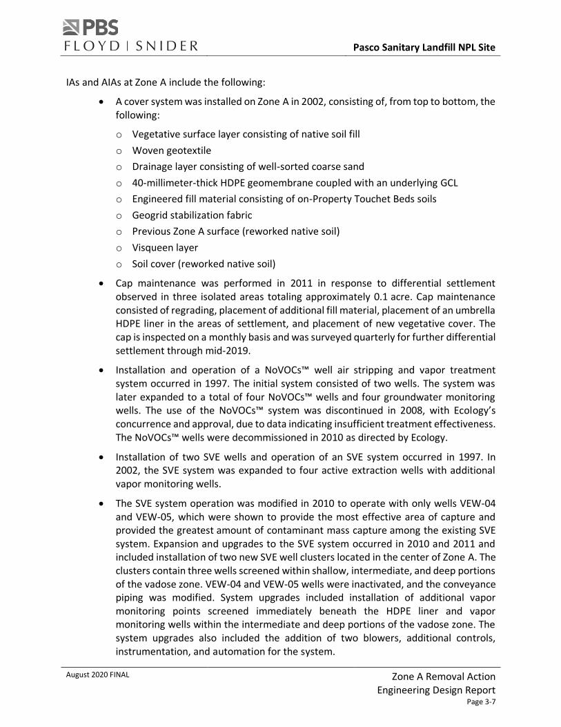
IAs and AIAs at Zone A include the following:
• A cover system was installed on Zone A in 2002, consisting of, from top to bottom, the following:
o Vegetative surface layer consisting of native soil fill
o Woven geotextile
o Drainage layer consisting of well-sorted coarse sand
o 40-millimeter-thick HDPE geomembrane coupled with an underlying GCL
o Engineered fill material consisting of on-Property Touchet Beds soils
o Geogrid stabilization fabric
o Previous Zone A surface (reworked native soil)
o Visqueen layer
o Soil cover (reworked native soil)
• Cap maintenance was performed in 2011 in response to differential settlement observed in three isolated areas totaling approximately 0.1 acre. Cap maintenance consisted of regrading, placement of additional fill material, placement of an umbrella HDPE liner in the areas of settlement, and placement of new vegetative cover. The cap is inspected on a monthly basis and was surveyed quarterly for further differential settlement through mid-2019.
• Installation and operation of a NoVOCs™ well air stripping and vapor treatment system occurred in 1997. The initial system consisted of two wells. The system was later expanded to a total of four NoVOCs™ wells and four groundwater monitoring wells. The use of the NoVOCs™ system was discontinued in 2008, with Ecology’s concurrence and approval, due to data indicating insufficient treatment effectiveness. The NoVOCs™ wells were decommissioned in 2010 as directed by Ecology.
• Installation of two SVE wells and operation of an SVE system occurred in 1997. In 2002, the SVE system was expanded to four active extraction wells with additional vapor monitoring wells.
• The SVE system operation was modified in 2010 to operate with only wells VEW-04 and VEW-05, which were shown to provide the most effective area of capture and provided the greatest amount of contaminant mass capture among the existing SVE system. Expansion and upgrades to the SVE system occurred in 2010 and 2011 and included installation of two new SVE well clusters located in the center of Zone A. The clusters contain three wells screened within shallow, intermediate, and deep portions of the vadose zone. VEW-04 and VEW-05 wells were inactivated, and the conveyance piping was modified. System upgrades included installation of additional vapor monitoring points screened immediately beneath the HDPE liner and vapor monitoring wells within the intermediate and deep portions of the vadose zone. The system upgrades also included the addition of two blowers, additional controls, instrumentation, and automation for the system.

Pasco Sanitary Landfill NPL Site
August 2020 FINAL Zone A Removal Action Engineering Design Report
Page 3-8
• Installation of a Gulf Coast Environmental Systems (GCE) RTO to treat extracted vapor (VOCs and SVOCs) from the SVE system occurred in September 2015 as a replacement for the MSW Landfill flare. The RTO operated from October 2015 through December 2016. The RTO was subject to the Ecology-issued Pasco Sanitary Landfill RTO Approval Order No. 14 AQ-E571 dated July 30, 2015 (Ecology 2015). However, the RTO did not operate as designed, and a Notice of Violation #13240 was issued by Ecology on April 4, 2016, to address permit exceedances.
• Installation of a rental thermal oxidizer (TO) occurred in December 2016 to replace the GCE RTO while a replacement RTO was designed. The rental TO system operated in accordance with Administrative Order Docket #13922, dated November 29, 2016, which outlined the specific operational parameters.
• A new RTO system designed by Anguil Environmental Systems, Inc. (Anguil; operating under Approval Order 16AQ-E031 dated May 2, 2017) was installed in June 2017. Associated with the new RTO, a higher capacity, intrinsically safe, regenerative blower and upgraded control system were installed.
• Reconfiguration of the SVE system below-grade moisture separators (BGMSs) and condensate conveyance piping occurred in August 2019 in response to a leak that was discovered in a piping coupling. The two BGMSs for the intermediate SVE vapor lines were removed, and upgrades were made to the existing BGMSs for the shallow and deep vapor lines. Secondary containment sumps with leak detection were installed at each BGMS, and primary condensate conveyance piping from each BGMS to the oil-water separator was replaced with continuous HDPE piping installed within secondary conveyance containment.
3.4 UPDATE TO CURRENT CONDITIONS
3.4.1 Current Status of Interim Action Operations
The currently active IAs at Zone A include O&M of the existing cap system, the expanded SVE system, the RTO treatment system, non-aqueous-phase liquid (NAPL)-sorbent sock collection, sitewide groundwater monitoring program, and ICs.
The current cap is fully intact and maintained as required. The cap covers the full extent of Zone A and minimizes precipitation from entering Zone A. As noted in Section 3.3.2, maintenance of the Zone A cap was conducted in 2011 to address subsidence and localized areas of closed depressions. Additional information on cap monitoring is available in the Operations and Maintenance Manual for Industrial Waste Area Caps – Zones A, C/D, and E (EPI 2013).
Although localized differential settlement has occurred on the cap that is outside of the original design specifications, there is no indication that the cap has failed with respect to inhibiting precipitation infiltration. In 2015, as part of the barrier wall excavation and installation, the Zone A geomembrane layer was uncovered. While the geomembrane was exposed, SCS Engineers performed an evaluation of the cover, which included collection of coupons for

Pasco Sanitary Landfill NPL Site
August 2020 FINAL Zone A Removal Action Engineering Design Report
Page 3-9
laboratory testing. The evaluation, which is summarized in the Updated Cover Settlement Evaluation (SCS 2017), indicated that the Zone A cap appeared to be performing as originally designed and that conditions were within its design and performance parameters.
In 2018, a Zone A Cover Investigation was performed at the request of Ecology to observe and document evidence of possible cover system damage, distress, or standing water at two closed depressions present in the surface of the Zone A cover and at four well seal boots (PBS 2018). During the investigation the soils, geotextile separator, and drainage layer were excavated to expose the geomembrane layer of the Zone A composite cover system and well seal boots. Close visual and tactile inspection of the exposed geomembranes and well seals showed no abrasions, tears, or other visible damage, including at several exposed seams. Following completion of inspection, the existing sumps were relocated to the apparent low spots, a new sump was installed, and the drainage layer materials were replaced in each excavation.
As summarized in Section 3.3.2, the SVE system at Zone A has been operating since 1997. In 2011, the SVE system was expanded to two clusters containing shallow, intermediate, and deep SVE wells and the perimeter SVE wells were deactivated. BGMSs were installed during this SVE system upgrade to capture and remove SVE vapor condensate generated in the SVE conveyance piping. Starting in 2011, SVE condensate was managed as a separate investigation-derived waste (IDW) involving offsite treatment. The reconfigured SVE system resulted in substantial increases in the VOCs mass removal rates compared to the original SVE well network. Approximately 440,000 pounds of VOCs were removed by the original SVE system over the 15-year period between 1997 and 2012. From 2012 to the present, the upgraded SVE system removed an additional 650,000 pounds of VOCs. Figure 3.3 presents the cumulative mass removed from October 2015 through November 2019.
Performance testing of the Anguil RTO has confirmed compliance with the Approval Order’s emission limits. The existing RTO unit continues to treat Zone A SVE vapors and gases during the current phase of IA cleanup.
3.4.2 Current Environmental Conditions
Zone A remains capped and within a signed, fenced, and restricted access enclosure. The cap is maintained and monitored. There are approximately 40 to 50 feet of vadose zone soils between the bottom of Zone A wastes and the water table. There is no physical access or exposure to contaminated soil by humans or terrestrial ecological receptors within Zone A. Groundwater is present at about 60 to 70 feet bgs at an elevation of about 355 feet above mean sea level. Groundwater migration is southwesterly in the area of Zone A. There is no direct exposure to human or ecological receptors to groundwater beneath Zone A.
Engineering controls in place to address potential vapor exposure at Zone A consist of a landfill cap with an HDPE membrane and the SVE system with a radius of capture that extends beyond the geomembrane. During operation of the SVE system, there are no potentially completed exposure pathways. In the event of an extended SVE shutdown, Zone A-related soil vapors could
Pasco Sanitary Landfill NPL Site
August 2020 FINAL Zone A Removal Action Engineering Design Report
Page 3-10
potentially migrate and create a possible exposure point at or near ground surface at the edge of the cap. One building, located at the BDI transfer station and recycling facility south of Zone A, is within 100 feet of the edge of the Zone A liner and could potentially be considered a point of exposure for vapor intrusion in the event of a long-term shutdown of the SVE system (Ecology 2009). The current ICs prohibit activities such as building new structures on the Property.
Current data indicate that certain volatile COCs within Zone A are migrating in the vapor phase through soil to groundwater. COCs enter groundwater through vapor-phase to aqueous-phase partitioning, as well as aqueous-phase transport.
Ongoing sitewide groundwater monitoring indicates that concentrations of VOCs in wells at the Site have continued to decrease overall since SVE system upgrades began operation in 2011. The COC concentrations observed in groundwater at the Site are generally below CULs and are near or below detection limits throughout the majority of the Site.
Localized LNAPL is present at the groundwater table surface within one well, MW-52S, located within the interior of Zone A. Since August 2018, an LNAPL-absorbent sock has been deployed in MW-52S, and replacement socks continue to absorb the LNAPL.

Pasco Sanitary Landfill NPL Site
August 2020 FINAL Zone A Removal Action Engineering Design Report
Page 4-1
4.0 Selection of Zone A Removal Action
4.1 GENERAL
The selected Cleanup Action for the Site is described in the CAP and associated SOW. The selected remedy for Zone A is a combination of FFS alternatives A-6 and A-9 with the additions and modifications outlined in the SOW. The Zone A Removal Action is one part of the selected Cleanup Action for Zone A. It will be followed by in situ thermal treatment of materials remaining within Zone A. Ecology selected the Zone A Removal Action, in combination with subsequent in situ thermal treatment, and remedial actions that cover other cleanup subareas, in order to be protective of human health and the environment and be consistent with the State of Washington’s preference for permanent solutions, as stated in RCW 70.105D.030(1)(b).
4.2 ZONE A REMOVAL ACTION
As stated previously, one of the goals of the Zone A Removal Action is to remove drums, drummed waste, pooled free liquids, and readily separable (by mechanical means) and potentially combustible material from Zone A for offsite treatment and/or disposal. Additional goals are to perform the work safely, protect groundwater, and prepare Zone A for future in situ thermal treatment. This EDR is designed to meet these goals by targeting the above-listed materials for excavation and offsite treatment and/or disposal and implementing additional remedial components.
The materials targeted by the Zone A Removal Action and the components of the removal action are summarized in the following sections.
4.2.1 Characteristics, Quantities, and Locations of Materials Targeted
Zone A wastes and soil are located within the boundary (lateral extent of excavation) presented on Sheet 8 in Appendix E. The materials subject to the Zone A Removal Action include the following:
• Approximately 35,000 buried drums, drum carcasses, and containers in various conditions ranging from intact to empty
• Wastes contained in or previously contained in drums and containers including potential pooled free liquids
• Mixed soil, non-drummed waste, and debris
In the event that drums, other containers, drummed waste, or pooled free liquids are encountered during excavation at the perimeter of the boundary presented on Sheet 8 in Appendix E, then the boundary of the excavation will be extended to remove these items. If potentially combustible materials (readily separable by mechanical means) are present along with drums, other containers, drummed waste, or pooled free liquids, outside the expected

Pasco Sanitary Landfill NPL Site
August 2020 FINAL Zone A Removal Action Engineering Design Report
Page 4-2
lateral extent of excavation presented on Sheet 8 in Appendix E, then the potentially combustible materials will also be removed. As described in Section 6.4.2, pre-excavation test trenching will be completed throughout approximately half of the perimeter of Zone A and will provide information that informs the sheet pile alignment and also the extent and composition of waste and potentially combustible material.
The SOW defines that the excavation in Zone A will proceed vertically for removal of drums (and other containers), drummed waste, and pooled free liquids. The actual depth of waste is expected to vary across the footprint of Zone A depending on actual field conditions and observed characteristics of the waste encountered. As shown in Sheets 9 through 12 in Appendix E, elevation 392 feet North American Vertical Datum of 1988 (NAVD 88) is planned for and identified as the anticipated maximum extent of excavation to remove drums and waste sourced from drums. This conservative elevation is a minimum of 2 feet below the anticipated bottom of drums and drum waste and is used in the design in order to ensure the necessary positioning of the temporary structure and excavation side slopes in the event excavation is necessary to this depth.
The approximate quantity of materials targeted including the drums and containers within the boundary presented on Sheet 8 in Appendix E is 50,000 cubic yards.
4.2.1.1 Drums, Containers, and Waste Contained in or Previously Contained in Drums or Containers
The first drums arrived at Zone A in April 1972. Initially, drums were placed in a low area east of Burn Trench BT-2 and Dietrich Road. Drums were placed randomly for a period of about 6 months. By late 1972, the randomly placed drums were consolidated and covered with soil and/or garbage on the west side of Zone A, and the Zone A stacked drums cell was created to the east. A soil berm is present to the east of the randomly placed drums. Sheet 8 in Appendix E shows the locations of the drum areas and the berm between them. Drums were stacked up to four high on the flat soil surface in Zone A. It was purported that the drums were generally heterogeneously distributed, did not appear to have been in “new” condition, and received a periodic cover of soil. Additional information regarding the filling of Zone A is presented in Section 3.3.1 and in the FFS and RI documents.
The drums (including the randomly placed drums) contained a variety of chemicals, including paint waste, metal cleaning and finishing waste, wood preserving waste, metal etching solutions, casting sands, pesticides, insecticides, debris, and various other types of miscellaneous industrial process waste.

Pasco Sanitary Landfill NPL Site
August 2020 FINAL Zone A Removal Action Engineering Design Report
Page 4-3
The characteristics of the waste contained in or previously contained in drums/containers is purported to include wastes in the following table:
Waste Approximate Percentage of
Drums/Containers
Drum/Container Count (1)
Inventory A Inventory B
Paint wastes 65 to 68 21,654 24,200
Metal casting waste (2) 21 to 25 6,894 8,774
Empty pesticide containers 3 1,045 863
Wood treatment wastes 3 1,100 --
Metal finishing waste 1 to 5 1,668 304
Acid waste 1.5 -- 544
Oily sludge/waste 1 433 433
Wood preservation wastes 1 238 --
Etching solution 0.5 160 --
Tar aromatic 0.5 248 160
Insecticide/pesticide 0.5 191 425
Cadmium waste <0.05 -- 11
Chemistry lab reagents/
Miscellaneous lab chemicals
<0.005 1/29 small containers
--
Notes: -- Not available. 1 Drum/Container Count as presented in the 1993 RI Report, which attributes the source of inventory A to Resource
Recovery, Inc., Monthly Reports to Ecology and October 19, 1973, and the source of Inventory B: Hand-Written Summary Sheets, Undated (Burlington 1993).
2 Metal casting waste was referred to as metal cleaning waste in Inventory A.
Based on PLP knowledge, it is estimated that approximately 9,000 drums contain zircon casting sands (ZCS; referred to in the table above as metal casting or finishing waste) potentially containing low levels of NORM were disposed of in Zone A.
4.2.1.2 Mixed Soil, Non-Drummed Waste, and Debris
The disposal and burning of refuse in the area of Zone A commenced in 1962. The Zone A drum disposal cell was placed on reworked native soils and the burned municipal waste. The mixed debris in the layer beneath Zone A is generally discontinuous both vertically and horizontally. Boring logs from the 2017 combustion evaluation range from no more than trace pieces of debris at four locations to approximately 9 feet of mixed debris greater than 50 percent of soil near the

Pasco Sanitary Landfill NPL Site
August 2020 FINAL Zone A Removal Action Engineering Design Report
Page 4-4
base of waste at GI-5. However, there are limited amounts of putrescible waste and no substantially intact layers of MSW in Zone A. Lidar monitoring of the Zone A cover system has documented areas of differential settlement indicating changes to the subsurface conditions of Zone A. The mixed debris present within Zone A will be identified during the removal action and potentially combustible material (separable by mechanical means) will be removed and disposed of offsite at appropriate waste disposal facilities.
In 1975 to 1979, baled waste was placed around the eastern and northern portions of Zone A, and mixed MSW and tires were placed immediately north of Zone A. The burned MSW from Burn Trench BT-2 (Figure 1.2) and inert and baled waste outside the extent of excavation shown on Figure 1.2 are not materials targeted for removal action but may be disturbed if drums are found at the edge of the removal boundary during the excavation. Backfilling in the area of the Burn Trench BT-2 after excavation may include provisions to isolate or separate some or all the Burn Trench BT-2 wastes from in situ thermal treatment impacts if supported by waste characterization activities, as described the SOW.
4.2.1.3 Materials Remaining After Excavation
In situ thermal treatment will be implemented for the contaminated media and mixed debris remaining within the footprint of Zone A following completion of excavation; removal of drums, other containers, drummed waste, readily separable potentially combustible debris, and pooled free liquids; and backfilling activities. The in situ thermal treatment of the remaining materials will be informed in large part by the post-excavation characterization sampling results. The design for this work will be documented in a separate Post-Excavation EDR as described in Task A.4 of the SOW.
4.2.2 Components
This Zone A Removal Action includes components to safely and efficiently excavate and manage drums, mixed debris, and contaminated media from Zone A above native soils.
The components of the Zone A Removal Action include the following:
• Installation of groundwater wells
• Reconfiguration of the existing SVE system
• Abandonment of existing wells, monitoring locations, and associated infrastructure within the excavation area
• Relocation of overhead power lines between Dietrich Road and Zone A
• Setup of support areas for the excavation activities
• Removal of the existing Zone A cover
• Setup of a stable working platform consisting of polyethylene sheeting overlain by geogrid and compacted gravel to prevent vapor emissions and aid in odor control

Pasco Sanitary Landfill NPL Site
August 2020 FINAL Zone A Removal Action Engineering Design Report
Page 4-5
• Setup of a temporary structure with air emissions controls over active excavation areas in Zone A to minimize potential emissions during drum removal activities
• Air monitoring within the temporary structure for worker health and safety and perimeter air monitoring during excavation activities
• Excavation and backfilling inside the temporary structure
• Waste handling and management inside the temporary structure
• Waste container management outside the temporary structure prior to offsite disposal
• Relocation of the temporary structure to other areas of Zone A requiring excavation
• Shoring of the excavation perimeter, as needed
• Excavation of areas not completed inside the temporary structure, if necessary
• Characterization of the contaminated media and mixed debris remaining within Zone A and subsurface native soils below Zone A extending to the water table
• Bench-scale treatability testing for future thermal treatment
• Grading and installation of a temporary cover over the excavation area to facilitate future in situ thermal treatment
These components are described in detail in Sections 6.0 and 7.0 of this EDR.
4.3 INFLUENCE OF FACILITY-SPECIFIC CHARACTERISTICS ON CLEANUP ACTION SELECTED
4.3.1 Existing Facility Operations
The removal action planned for Zone A will be coordinated with existing Zone A and other Site O&M activities, including the MSW areas overseen by the LFG. These activities include the sitewide groundwater monitoring program, O&M for Zone A SVE and RTO systems, O&M for the MSW Landfill gas control and treatment system, cover O&M for all waste disposal repository cover systems (MSW Landfill and Zones C/D and E), sitewide ICs for the same four waste disposal repositories and downgradient properties, and waste management related to general Site operations listed here.
Existing operations at the BDI transfer station and recycling center, which is located south of Zone A and the Balefill Area and Inert Waste Disposal Area, will continue during Zone A Removal Action construction.
Additional operations on the Property include a farming operation on the parcel west of Dietrich Road and commercial beekeeping north of the MSW Landfill flare.
The remedial action at Zone A will require coordination with field work associated with sitewide remedial actions overseen by the LFG including those at the Balefill Area, Inert Waste Disposal

Pasco Sanitary Landfill NPL Site
August 2020 FINAL Zone A Removal Action Engineering Design Report
Page 4-6
Area, and Burn Trenches. Removal action truck traffic for Zone A will need to be coordinated with traffic for BDI.
4.3.2 Regional Climate Information
The Site is located in an arid region of the Columbia Plateau that is surrounded on the west, north, and northeast by mountain ranges. The Cascade Mountains to the west shield the region from the moist and relatively mild air of the Pacific Ocean, and the northern stretches of the Rocky Mountains in Canada provide a barrier to the southward-moving arctic air. Annual precipitation in the Pasco Basin ranges from approximately 4 to 13 inches, with mean precipitation of approximately 7.5 inches. Winter snowfall averages about 14 inches annually.
The Pasco Tri-Cities Airport climate station (National Weather Service station ID KPSC) has been used for local, continuous weather data courtesy of the National Weather Service and is located approximately 1.5 miles from the Property. Based on long-term data from KPSC, the following weather conditions have been observed:
• Monthly precipitation ranges from 0.24 inches in August to 1.42 inches in December.
• High temperatures range from 40 °F in December to 92 °F in July.
• Low temperatures range from 28 °F in December to 58 °F in July.
• Average wind speed ranges from 5 miles per hour (mph) to 8 mph. Maximum wind speed ranges from 11 to 16 mph. Gusts of greater than 25 mph have been observed with large storm events.
• Winds are typically out of the northwest or southwest.
• Barometric pressure averages 30 inches of mercury and ranges from 29 to 31 inches of mercury. Barometric pressure changes are greatest in November and December, coinciding with large storm events.
According to the Stormwater Management Manual for Eastern Washington (Ecology 2004), the precipitation in Pasco during 24-hour rainfall events ranges from 0.95 inches for a 2-year mean recurrence interval to 2.28 inches for a 100-year mean recurrence interval and typically occur during thunderstorms between April and October. According to the nearest Washington State University agricultural weather station (CBC Pasco), the potential evapotranspiration ranges from 0.55 inches in December to 7.75 inches in July.
4.3.3 Soil and Groundwater Characteristics
4.3.3.1 Vadose Zone Soils and Geology
The general stratigraphic column beneath the Site is well understood and has been well documented. The affected soil units at the Site are the Eolian Loess, Touchet Beds, Upper Pasco Gravels, Lower Pasco Gravels, Middle Ringold Formation, and Lower Ringold Formation. The water table is located near the bottom of the Upper Pasco Gravels or the top of the Lower Pasco Gravels.

Pasco Sanitary Landfill NPL Site
August 2020 FINAL Zone A Removal Action Engineering Design Report
Page 4-7
The water table aquifer extends from the bottom of the Upper Pasco Gravels into the Lower Pasco Gravels and the Middle Ringold Formation, with the saturated layer at approximately 60 to 70 feet below the Zone A surface. The Lower Ringold formation may serve locally as an aquitard or perching layer for the water table aquifer that exists throughout the Site.
The 10 vertical and 4 horizontal borings completed through and beneath Zone A during the AIAs, more than 15 soil borings completed before installation of the protective barrier wall, 18 rotosonic and 6 bucket-auger vertical borings completed as part of the Zone A combustion investigation, and 4 cone penetration testing (CPT) borings made in 2017 provide an understanding of the soil conditions present in some of the excavation area. Vertical borings were drilled through Zone A using the rotosonic drilling method that provided a continuous core of the soil column. The north-south horizontal borings provided additional information at two relatively fixed depths beneath the length of Zone A. The geology beneath Zone A is consistent with the general stratigraphy described in the 1993 Phase I RI, with the exception of two units identified during Phase II AIA investigations: a mixed debris layer beneath Zone A and a transition layer between the Upper Pasco Gravels and the Touchet Beds.
The transition layer is likely present, but discontinuous, throughout the Site. It is identified visually in soil boring samples as very dense, tightly packed soils with silt or clay fractions at the contact between the Touchet Beds and the Upper Pasco Gravels (EPI 2012). The mixed debris layer, localized in the area of Zone A, Balefill Area, and mixed waste north of Zone A, is a remnant of MSW burning and disposal prior to industrial waste disposal at Zone A. The mixed debris is heterogeneous and discontinuous both vertically and horizontally.
4.3.3.2 Groundwater Occurrence, Flow, and Seasonal Water Level Changes
Groundwater occurs at the Site as an unconfined aquifer in the Pasco Gravels. The established and consistent direction of groundwater flow beneath the Property is southwesterly and becomes almost due south just south of the Property. The water table is typically first encountered within the Upper Pasco Gravels at an elevation of about 355 feet above mean sea level. The depth to groundwater beneath the Property varies primarily due to topography and the overall southwesterly groundwater gradient. The water table typically is encountered at depths ranging from approximately 30 feet bgs to 70 feet bgs. The seasonal variation in water level varies from less than 1 foot to more than 3.5 feet. Figure 3.2 presents shallow groundwater flow at the Site.

Pasco Sanitary Landfill NPL Site
August 2020 FINAL Zone A Removal Action Engineering Design Report
Page 5-1
5.0 Planning and Management for Zone A Removal Action
5.1 ENTITIES RESPONSIBLE FOR OWNING, OPERATING, AND MAINTAINING THE CLEANUP ACTION
As discussed in Section 3.1.4, the Property is owned by PSLI and Leonard and Glenda Dietrich. The IWAG is responsible for operating and maintaining the cleanup action associated with Zone A, in addition to Zones C/D and E. The IWAG includes a subset of the PLPs for the Site and is responsible for performing the work described in this EDR as required under the EO. The IWAG is seeking access agreements with the owners to access the Property and implement the Zone A cleanup action.
The IWAG, IWAG’s consultants, the selected GC and its subcontractors, and Ecology will be involved in the implementation of the project. The IWAG is the contracting party and is ultimately responsible for the performance of the work.
Various local entities also play an essential role. The IWAG will coordinate with local emergency response organizations and local businesses to keep them informed of cleanup activities and prepared to respond in case of an emergency. Key local entities include the Franklin County Fire District 3, Pasco Fire Department, Local Emergency Planning Committee, Benton Franklin Health District, City of Pasco School District, and BDI. (refer to Appendix B.2: Contingency Plan, Section 3.0).
5.2 ACCESS AGREEMENTS
As summarized in Section 3.1.4, the Property encompasses several parcels owned by PSLI and one parcel owned by Leonard and Glenda Dietrich. The IWAG is actively coordinating two access agreements for implementation of the Zone A Removal Action. Access agreements are required for the portions of the parcels that contain Zone A, as well as adjacent areas near Zone A where construction equipment and material laydown areas in support of the removal action will take place. Refer to additional details of construction equipment and materials staging activities in Section 6.3.
At parcel 113580037, access to the northern portion of the BDI facility is needed to accommodate access to the south end of Zone A and the planned temporary structure. It is anticipated that the access agreements will include provisions that require the GC to coordinate with BDI to ensure the normal daily operations of BDI, including access to Dietrich Road, are not impeded by construction activities.
5.3 PERMITS AND EXEMPT PERMITS
The Zone A Removal Action must comply with local, state, and federal laws, identified as applicable or relevant and appropriate requirements (ARARs) for this project in Tables 4.4-1 and 4.4-2 of the FFS and further evaluated as part of this EDR development. Updated tables from the FFS are included in Appendix A.

Pasco Sanitary Landfill NPL Site
August 2020 FINAL Zone A Removal Action Engineering Design Report
Page 5-2
The Pasco landfill is on the NPL. Under an interagency agreement between the U.S. Environmental Protection Agency (USEPA) and Ecology that governs cleanup responsibilities for state-lead NPL sites, USEPA retains its responsibility under the Comprehensive Environmental Response, Compensation, and Liability Act to ensure that the final cleanup action is appropriate, while transmitting the day-to-day cleanup oversight role to Ecology. Typically, the USEPA provides Ecology with documentation declaring its concurrence with the proposed cleanup activities being conducted in accordance with MTCA. Ecology is in coordination with USEPA for concurrence with cleanup action implementation.
Because this Zone A Removal Action is being conducted with Ecology oversight in accordance with MTCA, it is exempt from certain procedural and permitting requirements of select Washington laws and regulations and all local permits (WAC 173-340-710(9)(b)). However, implementation of the cleanup action must comply with the substantive requirements of any otherwise applicable permits. This remedial action will comply with the ARARs identified for this work and will meet the substantive requirements identified in Appendix A.
No separate federal approvals or permits are anticipated to be necessary for the implementation of the remedial actions at the Site.
This section identifies applicable permits for the Zone A Removal Action and identifies whether permits will be obtained or if requirements will be met through substantive equivalence.
The following state approval has already been received for this work:
• State Environmental Policy Act Determination of Non-Significance, issued by Ecology August 27, 2019
The following state approvals or permits will be obtained prior to initiating work:
• Ecology Notice of Intent to construct a Resource Protection Well
• Ecology approval of the EDR and CMP
• Ecology Air Quality Program concurrence on the notification of SVE system modifications under the existing RTO Air Quality Permit (Synthetic Minor Approval Order No. 16AQ-E031 issued to PBS on May 2, 2017); permit requires Ecology notification at least 60 days before modification
• Ecology Notice of Intent to Decommission a Well
• Ecology approval of Zone A waste Corrective Action Management Unit (CAMU) designation for offsite disposal
• Idaho Department of Environmental Quality CAMU approval for offsite disposal at the U.S. Ecology Grandview Idaho facility
• Oregon Department of Environmental Quality CAMU approval for offsite disposal at the Waste Management Arlington Oregon facility

Pasco Sanitary Landfill NPL Site
August 2020 FINAL Zone A Removal Action Engineering Design Report
Page 5-3
The following state approvals or permits are sought for approval as part of this EDR through substantive equivalence:
• Ecology concurrence on the compliance with the substantive equivalence with an Air Quality Permit for the Zone A temporary structure air treatment (received as approval of the Temporary Structure Air Treatment memorandum dated April 9, 2020; IWAG 2020)
• National Pollutant Discharge Elimination System Construction Stormwater General Permit
The following local approvals or permits will be obtained prior to initiating this work:
• Franklin County temporary structure, structural element, and inspection submittal (refer to Appendix A.2)
• City of Pasco right-of-way permit (provided in Appendix A.2)
5.4 UTILITIES
The following coordination with local utilities is anticipated prior to initiating this work:
• Washington State Department of Labor and Industries electrical inspection and approval: The existing overhead power line along Dietrich Road is located in the right of way. The power line will be disconnected and relocated out of the right of way (most likely on the west side of Dietrich Road). The relocation will be coordinated with the LFG because the line provides power to the MSW Landfill flare. A new power line will be installed to provide electrical service for the Zone A Removal Action temporary structure and as necessary to meet power demands for future phases of work (e.g., thermal treatment of remaining Zone A contaminated media and mixed debris). IWAG’s consultant and the GC will coordinate with utility companies to ensure that existing and relocated power lines are not damaged during construction or interfere with planned excavation activities.
• Cascade Natural Gas Corporation (CNG) coordination and notification of work: An 8-inch subsurface natural gas transmission line suppling Boise Cascade travels through the BDI facility at the southwest corner of Zone A and crosses under Dietrich Road at an approximate depth of 8 to 10 feet bgs. The gas transmission line is under high pressure (approximately 265 pounds per square inch) and cannot be turned off or rerouted. A CNG representative will need to be on site any time work is performed within 20 feet of the gas transmission line. The gas transmission line will need to be exposed or daylighted for CNG observation during such work. The GC may also need to employ excavation methods such as hand digging when working in the vicinity of the gas transmission line. Any modification to the extent of excavation near the gas transmission line will require notification to the IWAG and Ecology and their approval.

Pasco Sanitary Landfill NPL Site
August 2020 FINAL Zone A Removal Action Engineering Design Report
Page 5-4
• Water supply: It is anticipated that the GC will coordinate with the local water utility to obtain a fire hydrant meter for water needs during construction. The nearest fire hydrant is south of the BDI scale house. Water use is anticipated to be limited to dust suppression and decontamination. Potable water will be provided in bottles, and personal sanitation water needs will be supplied along with portable toilets.
5.5 ROLES AND RESPONSIBILITIES
Management and execution of the Zone A Removal Action will include Ecology, IWAG, IWAG’s consultants, and the GC. The roles and responsibilities of these entities are listed below.
Ecology
Ecology’s role and responsibilities:
• Regulatory oversight and support for the project including as the following:
o Regulatory oversight for the cleanup action plan implementation
o Review of the EDR and design
o Provision of written comments for reviewed documents
o Approval of the EDR
o Participation in project meetings
o Community relations including public notice and participation
IWAG
IWAG’s role and responsibilities:
• Overall responsibility for developing and implementing the technical strategy in conformance with the EO SOW and as approved by Ecology, including removal action performance and financial management
• Ensure that implementation of the EDR is in compliance with the CAP and SOW
• Managing the project including the following:
o Review of the EDR and design
o Retaining and managing consultants
o Retaining contractors
o Liaison with Ecology
o Liaison with PLPs
o Participation in project meetings
o Community relations

Pasco Sanitary Landfill NPL Site
August 2020 FINAL Zone A Removal Action Engineering Design Report
Page 5-5
IWAG’s Consultants
IWAG’s consultants’ roles and responsibilities on behalf of IWAG:
• Project management including performance assessments of IWAG contractors
• Liaison with Ecology
• Project administration and coordination
• Preparation and review of project documents
• Facilitate and participate in project meetings
• Review GC pre-construction submittals
• Ensure that implementation of the EDR is in compliance with the CAP and SOW
• Conduct quality assurance assessments of the work
• Emergency planning in coordination with Ecology
• Groundwater well and probe decommissioning and installation
• Reconfiguration of the SVE system
• Providing design and construction oversight, survey control, perimeter air monitoring, and project documentation by the Resident Engineer (RE)
• Documentation of the work including review of GC documentation (e.g., waste quantities, characterization, profiling, and tracking)
• Waste tracking and reporting (e.g., preparation of waste manifest and annual large quantity generator reports)
• O&M of existing systems and monitoring (e.g., SVE, RTO, groundwater, and ICs)
• Act as the Certified Erosion and Sediment Control Lead, ensuring appropriate implementation, function, and inspection of best management practices (BMPs)
• Ensuring compliance with ARARs and substantive requirements of permits
• Post-excavation characterization of the contaminated media and mixed debris remaining within Zone A
• Community relations in coordination with Ecology
General Contractor
The GC’s roles and responsibilities on behalf of IWAG:
• Pre-excavation activities including such work as pre-excavation test trenching, cover removal, and installation of the temporary structure and working platform
• Execution and management of the Zone A Removal Action including such work as excavation; drum removal; waste sampling, management, and disposal; temporary
Pasco Sanitary Landfill NPL Site
August 2020 FINAL Zone A Removal Action Engineering Design Report
Page 5-6
structure relocation and air handling and treatment system operation and maintenance; and backfilling
• Perform construction work in compliance with the EDR, CAP, and SOW
• Documentation of work
• Management of subcontractors
• Coordination with IWAG’s contractors
• Participate in project meetings
• Overall health and safety program management and implementation during the construction including air monitoring in the work zones
• Emergency planning
• Security of the construction site
• Install erosion and sediment control measures as required in the Zone A Removal Action Stormwater Runoff Management Plan (SWRMP; Appendix D.1), ensuring appropriate implementation, function, and inspection and repair of BMPs
• Compliance with substantive requirements of permits
Following approval of this EDR and retaining a RE and GC, the IWAG will develop an organization chart for the execution of the Zone A Removal Action that will be provided to Ecology. Additional discussion regarding the role of the RE and oversight of the Zone A Removal Action is provided in the following sections.
5.5.1 General Contractor Oversight
Contractor oversight will be performed by IWAG’s RE. The RE will consist of personnel familiar with the EDR and contract documents and include local individuals familiar with the Site. The designated personnel will be identified prior to the start of construction. Some of the activities that will be completed before construction (e.g., well installations, SVE system reconfiguration, and abandonments) will be overseen by local individuals that have filled similar roles at the Site in the past. This will ensure consistency with similar and previously performed work at the Site.
5.5.2 Oversight by Professional Engineer Registered in the State of Washington
All aspects of the Zone A Removal Action will be performed under the oversight of a professional engineer registered in the State of Washington or a qualified technician under the direct supervision of a professional engineer registered in the State of Washington. The RE will be identified prior to the start of construction.

Pasco Sanitary Landfill NPL Site
August 2020 FINAL Zone A Removal Action Engineering Design Report
Page 5-7
5.6 CONTACT INFORMATION DURING ACTIVITIES
The contact information for IWAG, Ecology, and IWAG’s consultant for the Zone A Removal Action is below.
IWAG IWAG Group III c/o Mr. Nick Garson Chair, Technical Committee (425) 269-7866
IWAG Group III c/o Ms. Carol Wiseman Assistant Chair, Technical Committee (360) 562-7733
Ecology Washington State Department of Ecology Mr. Chuck Gruenenfelder Ecology Project Manager (509) 329-3439
IWAG’s Consultant: Floyd|Snider Ms. Jessi Massingale, P.E. Project Manager/Coordinator (206) 292-2078
Additional contact information will be provided in the GC’s Health and Safety Plan (HASP) that will be completed prior to execution of the removal action. The information will include the GC’s main points of contact and stakeholders such as first responders and local authorities.
5.7 PUBLIC NOTICE AND PARTICIPATION
The CAP and SOW were issued for public comment, and a responsiveness summary was issued addressing the received comments. The draft CAP and SOW as presented for public comment became final on November 8, 2019, without further changes.
If in the future Ecology determines that plans prepared for the Zone A Removal Action represent a substantial change from the CAP, Ecology may provide public notice and opportunity for comment if deemed necessary in the public’s interest.
Documentation of the public notice and participation process is maintained by Ecology. In coordination with the IWAG, Ecology will keep the public informed regarding the progress toward completion of the Zone A Removal Action.

Pasco Sanitary Landfill NPL Site
August 2020 FINAL Zone A Removal Action Engineering Design Report
Page 5-8
5.8 PROJECT DOCUMENTATION
Documentation of the Zone A Removal Action will be completed by IWAG’s consultants, the RE, and the GC.
During construction, detailed records will be kept of the work performed and are expected to include the following:
• Site security and access control
• Health and safety meetings
• Health and safety monitoring data including air monitoring in the work zones
• Air monitoring within Zone A and perimeter air monitoring data
• Response actions and security breaches, if they occur
• Progress reports
• Progress meetings
• Quality assurance reporting
• Construction techniques and materials used
• Excavation depths and lateral extents
• Stockpiled soils
• Items decommissioned and installed (temporarily or permanently)
• HazCat and other sampling data
• Waste quantities, types, characterization, and profiles
• Waste management
• Waste disposal documentation
• Temporary Site restoration data (grading and temporary cover)
• Post-excavation characterization data for contaminated media and mixed debris remaining within Zone A and underlying soil units extending to the water table
Following completion of the work, a Zone A Excavation, Removal, and Offsite Disposal Construction Completion Technical Memorandum will be prepared as per Task A.4 of the SOW. As stated in Task A.4, this technical memorandum will include the following:
• Site mobilization, setup, and pre-construction assessment activities
• Overview of major construction phases:
o Pre-excavation test trenching and CPT borings along potential sheet pile alignments
o Cover system removal and installation of the working platform

Pasco Sanitary Landfill NPL Site
August 2020 FINAL Zone A Removal Action Engineering Design Report
Page 5-9
o Drum/waste/mixed debris excavation
o Material segregation, characterization, handling and off-site disposal
o Excavation backfilling and regrading
o Installation of temporary cover to support future thermal in situ treatment activities
• Description of SVE and RTO system modifications
• Waste materials encountered, quantities, types, and onsite waste management protocols
• Waste profiling, waste characterization, waste designation, and applied waste codes
• Site health and safety performance, engineering controls, and response actions
• Air monitoring results
• Waste/debris handling, temporary accumulation, loading, and off-site transport including waste packaging
• Offsite waste disposal facilities, treatment methods and permit documentation, disposal tickets, and waste manifest documentation
• Post-removal confirmation sampling results
• Results from in situ thermal treatability testing
A comprehensive Zone A Cleanup Action Completion Report will be prepared following completion of all phases of the Zone A Removal Action, will incorporate the information contained in the above-noted technical memorandum, and will be submitted to Ecology per the SOW schedule.
5.9 SITE SECURITY, ACCESS CONTROL, AND COMMUNICATION
Site security will be addressed in the GC’s HASP, which will include provisions for Site security, communication, and access control. Site security will include physical systems to control casual trespassing (fencing, gates, etc.) and will be maintained throughout the Zone A Removal Action. During working hours, sign in and sign out procedures will be in place to control access to the work areas. Emergency numbers will be posted in case local authorities are needed to address a security breach or emergency. Communication procedures will be established for the work and emergencies, if they occur. During non-working hours, a security service will be subcontracted by the GC to monitor the work area.
5.10 SCHEDULE
Upon approval of the EDR and contract execution with the GC, a detailed schedule for implementation of the Zone A Removal Action construction work will be developed by the GC that will show completion not longer than 24 months after EDR approval, consistent with the schedule presented in the SOW. The schedule will be updated as necessary during construction.

Pasco Sanitary Landfill NPL Site
August 2020 FINAL Zone A Removal Action Engineering Design Report
Page 5-10
Prior to mobilization of the GC, well installations, reconfiguration of the SVE system, and decommissioning of selected monitoring infrastructure will be completed. The schedule for these activities will be provided following approval of the EDR. With Ecology approval, well MW-56S, the new groundwater monitoring well located northeast of Zone A, was completed in January 2020, prior to Ecology approval of the final EDR. Early approval and installation was proposed and agreed to with Ecology in order to obtain baseline data prior to the construction phase and include sampling of this well during the earliest regularly scheduled sitewide groundwater quarterly sampling event.

Pasco Sanitary Landfill NPL Site
August 2020 FINAL Zone A Removal Action Engineering Design Report
Page 6-1
6.0 Zone A Removal Action Engineering Design
6.1 ENGINEERING JUSTIFICATION
WAC 173-340-400(4)(a)(viii) requires engineering justification for design and operation parameters, including the following:
(A) “Design criteria, assumptions and calculations for all components of the cleanup action;
(B) Expected treatment, destruction, immobilization, or containment efficiencies and documentation on how that degree of effectiveness is determined; and
(C) Demonstration that the cleanup action will achieve compliance with cleanup requirements by citing pilot or treatability test data, results from similar operations, or scientific evidence from the literature;”
The following sections discuss the engineering justification.
6.1.1 Design Criteria
This EDR establishes the design requirements for the Zone A Removal Action in accordance with WAC 173-340 and Task A of the SOW. The goal of this EDR is to provide sufficient detail to safely, efficiently, and effectively implement the Zone A Removal Action, while also making proper allowance for adaptive management and appropriate field-based decisions. This EDR uses a largely performance-based approach for some of the Zone A removal elements to accommodate the unique nature of the work and the potential unknowns associated with the buried drum waste and site conditions. In addition to the performance-based approach, specific prescriptive design details and engineering controls have been developed and incorporated into this EDR, with an overarching focus on safety.
The assumptions and calculations for most of the components that will be implemented by IWAG’s consultants, including reconfiguration of the SVE system, abandonment of existing wells and monitoring locations, installation of new wells, perimeter air monitoring, and characterization of contaminated media and mixed debris remaining within Zone A, are described in this EDR. The bench-scale treatability testing component details will be developed after the characterization data are available, because these data are necessary to inform the design of the bench-scale treatability testing.
6.1.2 Expected Efficiencies and Degree of Effectiveness
Design strategies have been developed as part of this EDR to ensure compliance with ARARs and other requirements consistent with MTCA. The performance-based approach of the engineering design, where appropriate, will permit the GC to use its base of knowledge to safely and effectively conduct the drum removal activities within Zone A. The approach will also permit the

Pasco Sanitary Landfill NPL Site
August 2020 FINAL Zone A Removal Action Engineering Design Report
Page 6-2
GC to find efficiencies during the work to increase the degree of effectiveness of the removal action.
The installation of new groundwater wells will provide a means to collect data along with the current well network to monitor groundwater quality and flow direction. The new wells will add to the effectiveness of the monitoring network.
The reconfiguration of the SVE system will have a high degree of effectiveness for protecting groundwater prior to, during, and after the Zone A excavation work, because the system is expected to perform as well as the current system.
Drums, drummed waste, pooled free liquids, and readily separable (by mechanical means) potentially combustible material will be removed to further reduce the potential for the ongoing risks of release and/or underground heating. These ongoing risks require the continued operation of the current SVE and groundwater monitoring systems installed in Zone A to protect groundwater. After reducing these risks to acceptable levels by implementing this EDR and a subsequent Post-Excavation EDR, site data and the results of in situ thermal treatment will be reviewed in coordination with Ecology to determine when operation of the SVE system is no longer needed.
6.1.3 Zone A Removal Action Compliance with Cleanup Requirements
The Zone A Removal Action activities shall comply with the CAP and SOW and achieve cleanup requirements. The excavation of drums, drummed waste, pooled free liquids, and readily separable (by mechanical means) potentially combustible material will remove risks of release and/or underground combustion and, along with the Post-Excavation EDR, will remove the need for operation of long-term systems installed at Zone A to protect groundwater. The contaminated media and mixed debris remaining within Zone A after excavation and underlying soils will be conducive to thermal treatment. The risk of impacting groundwater following successful in situ treatment will be mitigated. Design of in situ treatment following the excavation work will be informed by the Zone A Removal Action work and post-excavation characterization and documented in the Post-Excavation EDR. Following completion of in situ thermal treatment, a final engineered cover system will be installed over the Zone A footprint. The cover system will include long-term O&M monitoring, and groundwater compliance monitoring will also be conducted. The scope of post-remedial-action O&M and groundwater compliance monitoring will be determined in coordination with Ecology as documented in plans separate from this EDR. Any adjustments to long-term monitoring will require Ecology approval and may be associated with subsequent periodic reviews.
6.2 ADVANCE WORK ACTIVITIES
Certain activities that are part of the Zone A Removal Action will be completed prior to the start of the excavation work including installation of groundwater wells, reconfiguration of the SVE system, abandonment of selected existing wells and monitoring locations within and near

Pasco Sanitary Landfill NPL Site
August 2020 FINAL Zone A Removal Action Engineering Design Report
Page 6-3
Zone A, utility relocation, and support area preparation. Completing these activities before the construction phase is necessary to obtain baseline groundwater sampling analytical data, to facilitate continuous operation of the SVE system for protection of groundwater, and to provide unimpeded access to Zone A during the removal action.
As part of the advance work activities, IWAG will coordinate with Cascade Natural Gas to identify gas line locations via vacuum potholing to support the identification of the existing gas line elevation and depth below grade and inform appropriate offset distances associated with the SVE line installation and Zone A excavation.
The following sections describe the plans for these activities.
6.2.1 Installation of Groundwater Wells
The primary objective of groundwater well installations is to supplement the existing groundwater monitoring network that is designed to assess groundwater quality and flow direction near Zone A. This will be achieved by installing two additional groundwater monitoring wells as required by the SOW Task A.1 Subtask A.D and Task A.2 Subplan G. The locations are presented in the Zone A Removal Action Supplemental Groundwater Monitoring Plan (Zone A Supplemental GMP), which was submitted to Ecology on April 16, 2020, subsequently approved by Ecology, and is provided in Appendix B.6 of this EDR.
In January 2020, monitoring well MW-56S was installed near the northeast corner and hydraulically upgradient of Zone A. As stated in the SOW, the additional upgradient monitoring well (MW-56S) was installed to assess potential short-term changes in groundwater quality during the removal action and to assess possible changes that may occur during the subsequent in situ thermal treatment. Installation of this well was necessary as stated in the SOW to better assess groundwater quality hydraulically upgradient of Zone A and conditions from the Central Area outside the immediate influence of Zone A. The well location was coordinated with and approved by Ecology.
MW-56S was installed prior to the January 2020 quarterly groundwater monitoring event in order to document baseline conditions of groundwater upgradient of Zone A before any excavation or drum removal actions begin. MW-56S has been, and will be, sampled as part of the sitewide groundwater monitoring events, and will be sampled as part of the Zone A supplemental sampling program.
Two additional monitoring wells (MW-57S and MW-58S) will be installed adjacent to and hydraulically downgradient of Zone A, in locations outside the limits of the final Zone A cover system. Zone A Removal Action activities require the abandonment of two existing groundwater monitoring wells (MW-52S and MW-53S) located within the excavation footprint. MW-57S and MW-58S will replace these existing Zone A source wells. The replacement wells will be installed as part of the Site preparation activities, prior to the start of the removal action.

Pasco Sanitary Landfill NPL Site
August 2020 FINAL Zone A Removal Action Engineering Design Report
Page 6-4
Additional information on monitoring well installation and decommissioning is presented in the Zone A Decommissioning and Well Installation Plan, which was submitted on February 28, 2020, subsequently approved by Ecology, and is provided as Appendix B.8 of this EDR. The plan was developed to comply with the requirements outlined in WAC 173-340-410 and EO Section VII (Work to be Performed). Information included in the plan includes applicable background information, procedures, methods, contingencies, and implementation schedules, along with procedures for characterizing IDW from well installation.
A summary of the sampling and analysis requirements for Zone A wells during drum removal and other cleanup action activities is presented in Section 7.6 and detailed in the Zone A Supplemental GMP provided in Appendix B.6. Sampling and analysis and quality assurance requirements have been incorporated into the Zone A Supplemental GMP, which describes sampling procedures, analytical methods, and associated quality assurance and quality control requirements in accordance with WAC 173-340-410 and 173-340-820 requirements.
6.2.2 Reconfiguration of SVE System
Operation of the Zone A SVE system is required as part of the EO/CAP/SOW as well as ongoing IAs the Site (refer to Section 3.3.2). The SVE system is designed to provide ongoing groundwater protection through capture and treatment of vadose zone VOCs and SVOCs. The current configuration of the system involves vapor extraction from two deep wells, VEW-06D and VEW-07D. These wells and associated conveyance piping are located within the limits of excavation for the removal action and will be removed prior to the excavation work. The SOW requires that the SVE system operates throughout all phases of the Zone A drum/mixed debris/waste sorting and removal process and that the SVE well network reconfiguration will be necessary to support the Zone A Removal Action.
The objectives of the reconfigured SVE system, as included in the SOW are as follows: (1) design and operation that ensure the ongoing capture and treatment of VOCs and SVOCs extracted from the vadose zone beneath Zone A, (2) reduction of the potential for off-gassing from the open excavation area, and (3) providing ongoing groundwater protection during construction. The plan for SVE system reconfiguration is presented in Appendix B.9.
The objective related to preventing off-gassing was initially developed based on an assumption that the excavation would be completed in an open-air scenario. This EDR specifies use of a temporary structure with air management, treatment, and emission controls that will be constructed over areas subject to the drum removal activities. The temporary structure will be the primary emission control for potential off-gassing, achieving one of the objectives noted above. As a result of the use of a temporary structure, shallow SVE wells to control potential off-gassing of shallow soil vapor are not being proposed as part of the reconfigured SVE system. Additional engineering controls to be implemented inside and outside the temporary structure to help protect human health and the environment are discussed in Sections 6.15.1 and 7.1.

Pasco Sanitary Landfill NPL Site
August 2020 FINAL Zone A Removal Action Engineering Design Report
Page 6-5
The objective of protecting groundwater will be achieved by installing new SVE wells to replace the currently active wells VEW-06D and VEW-07D. The new wells will be installed using directional drilling methods to place new screens of the same length in the same approximate location as VEW-06D and VEW-07D. Drilling of the boreholes will start on the west side of Dietrich Road in order to reach the desired elevation. The new wells will be connected to the existing SVE infrastructure to convey condensate through the existing BGMSs to the oil-water separator and extracted vapors through the existing blowers to the RTO. Sheets 2 and 3 of the SVE Reconfiguration Plan in Appendix B.9 and Sheets 3 and 4 of the design drawings in Appendix E depict the approximate locations of the proposed new SVE wells. The installed locations may be revised based on field conditions encountered during drilling.
Wellhead completions and conveyance piping to the existing infrastructure will be constructed consistent with the design for the existing system. Refer to Sheet 4 of the SVE Reconfiguration Plan in Appendix B.9 for SVE well and header assembly construction details.
The target flow rates for the new horizontal wells will be similar to the current target flow rates of 250 standard cubic feet per minute (scfm) in VEW-06D and VEW-07D. Because the new SVE wells will be screened within the same geological formation as the existing wells, VOC concentrations in extracted vapors from the reconfigured system are expected to be similar to current composition and removal rates. Therefore, operation of the RTO will not change. Ecology has indicated that no changes to the existing RTO Approval Order, other than noting the horizontal rather than vertical orientation of the active deep extraction wells, will be necessary. Additional details of the well design are provided in Section 6.2.2.1.
The SVE reconfiguration will be completed as part of Site preparation activities before decommissioning the existing SVE wells and mobilization of the GC.
6.2.2.1 Reconfiguration of SVE System Well Design
As discussed in Section 6.2.2, the current system is performing as intended to protect groundwater; however, the active SVE wells will be decommissioned because they are located within the limits of excavation. Using directional drilling methods will permit installation of two deep wells (VEW-06H and VEW-07H) with screens located adjacent to the existing deep well screens of VEW-06D and VEW-07D. These wells will be capable of extracting soil vapor from Zone A during the removal action work because the supporting wellheads and conveyance piping will be outside the excavation and support areas. Approximate locations for the wellhead and screen locations are shown on Sheets 2 and 3 of the SVE Reconfiguration Plan in Appendix B.9 and Sheets 3 and 4 of the design drawings in Appendix E. The wellhead locations will be adjusted based on input from potential drilling companies and conditions observed in the field.
The design of the replacement wells includes use of 316 stainless steel casing, screens 15 feet in length and 4 inches in diameter, and 316 stainless steel 0.020-inch wire wound screen, consistent with the length and approximate location of the existing wells VEW-06D and VEW-07D. This
Pasco Sanitary Landfill NPL Site
August 2020 FINAL Zone A Removal Action Engineering Design Report
Page 6-6
includes the total design flow rate of 500 scfm or well flow rate of 250 scfm for each of the two wells.
The new horizontal wells will be installed with wellhead completions similar to the existing SVE wells, containing ports for parameter collection and vapor sampling as well as piping and valves to allow dilution air. The SVE Well and Header Assembly Construction Details figure from the SVE System O&M Manual (PBS 2017b) is provided as Sheet 4 of the SVE Reconfiguration Plan in Appendix B.9.
The wells will be connected to the existing system using a design similar to the existing conveyance piping. The planned routing for conveyance lines from the new wellheads to existing infrastructure is shown in Sheet 6 of the SVE Reconfiguration Plan in Appendix B.9.
6.2.2.2 SVE System Operation and Maintenance
O&M of the reconfigured SVE system will be virtually the same as current system operations. The two deep extraction wells (VEW-06H and VEW-07H) will replace the currently operating deep wells (VEW-06D and VEW-07D) to extract vapors for protection of groundwater and also help to reduce the potential for off-gassing and provide ongoing groundwater protection during construction. As described above, the new deep wells will be operated with flow rates similar to the current deep well operation at approximately 250 scfm for each well. Therefore, the total flow rate of the new deep wells is expected to be approximately 500 scfm. The total flow rate will not exceed the RTO Approval Order maximum flow rate of 1,000 scfm for extracted vapor.
Consistent with current operations, vapor extracted from VEH-06H and VEW-07H beneath Zone A will be conveyed to the SVE operations yard, where moisture will be knocked out with below-grade moisture separators. After the vapor stream leaves the below-grade separators, it enters the SVE building where additional condensate will be knocked out by a second set of moisture separators before entering the blowers. The vapor stream then exits the blowers and SVE building under negative pressure through piping connected to the permitted RTO for treatment. A simplified view of this process is shown in Sheet 7 of the SVE Reconfiguration Plan in Appendix B.9.
Consistent with current practice, all condensate generated below grade and within the SVE building will be pumped to the oil-water separator, then into accumulation tanks where it will be stored until a sufficient quantity is reached for shipment to an offsite treatment facility.
The facility’s Approval Order (RTO Synthetic Minor Approval Order No. 16AQ-E031) condition 8.e requires Ecology to be notified of project modifications at least 60 days in advance of making such modifications. Ecology’s air quality rules (WAC 173-400-030(51)) state that modifications are “any physical change in, or change in the method of operation of, a stationary source that increases the amount of any air contaminant emitted by such source or that results in the emissions of any air contaminant not previously emitted.”

Pasco Sanitary Landfill NPL Site
August 2020 FINAL Zone A Removal Action Engineering Design Report
Page 6-7
Because the new deep wells will be installed at approximately the same lateral location and depth below grade as the existing deep wells, vapor VOC concentrations and constituents are not expected to change from those originally provided in the current project’s Notice of Construction Application. As such, we believe that further air permitting notifications (i.e., formal Notice of Construction application) will not be required nor will the current Approval Order need to be amended.
The RTO will be operated in the same manner as the current operation and in compliance with approval conditions, emission limitations, monitoring and testing requirements, O&M Manual (PBS 2017b), reporting requirements, and general conditions as required by the existing Ecology-issued Approval Order.
Startup procedures are outlined in Section 6.2.2.3. After the reconfigured system components have been installed and tested, the system is functioning within blower specifications, SVE vapors analysis has been performed, and calculated emissions are within permit limits, the current SVE system O&M Manual (PBS 2017b) will be updated to reflect modifications of the equipment and any new operating, maintenance, or monitoring procedures. Due to well and conveyance piping modifications, an updated RTO system O&M Manual will be prepared as necessary in compliance with requirements of the air permit and WAC 173-340-400(4)(c).
Monitoring and operations of the SVE and RTO systems will continue similar to current operations and include monitoring of the same operational parameters at each new wellhead and at the SVE building, routine air sampling and assessment of estimated RTO unit emissions in accordance with the air permit, routine condensate sampling for waste characterization, routine inspections and as-needed maintenance, and reporting.
6.2.2.3 Startup Procedures and Criteria for Routine Operation
The following startup testing and optimization measures have been developed to support the associated removal actions. In order to minimize down time for the SVE system, upgrades will be made by first installing new wells and conveyance piping to the existing system. The system is expected to be down for a few to several days while connections to the below-grade moisture separators and blowers are made. When installation is complete and all new piping has been pressure or vacuum tested, the piping from existing wells will be disconnected from the below-grade sumps and the new wells will be connected.
Because the new horizontal well screens for the deep wells will be installed in the same geologic formation and location as the existing deep well screens, it is anticipated that operation of the two new deep wells will be very similar to operation of the two currently operating deep wells. The SVE system currently utilizes two regenerative blowers. The Rotron blower is capable of producing 500 scfm at 80 inches of water column and is currently being used to operate both deep extraction wells. The Airtech blower, which is intrinsically safe (Class I Division I), is capable of producing 500 scfm at the maximum vacuum. Operation of the vapor extraction wells has shown that the vacuum and flow responses of the deep wells are within the performance curve

Pasco Sanitary Landfill NPL Site
August 2020 FINAL Zone A Removal Action Engineering Design Report
Page 6-8
of the blowers. It is anticipated that operation of the horizontal SVE wells will be within the blower performance curves as well.
When installation is complete, the horizontal wells will be pre-tested one at a time in a stepwise fashion to ensure that each well and associated blower functions well. The flow rate will be increased in 50 scfm increments to establish a maximum flow no greater than 500 scfm. The system will be monitored to make sure operation is within the blower pressure curve and to verify that the lower explosive limit (LEL) is below 25 percent. Fresh air dilution will be added if necessary, to maintain an LEL of less than 25 percent. Once this phase is complete, startup testing will begin. To establish that the horizontal SVE wells and system are running with sufficient radius of influence, locations beneath the Zone A cap and around the perimeter of Zone A will be monitored for vacuum during startup. The locations beneath the Zone A cap include VMP-02, VMP-04, VMP-05, VMP-06, VMP-08, VMP-09, VMP-10, VMW-51I, VMW-51D, VEW-06S/I/D, and VEW-07S/I/D. Locations outside the protective barrier wall that will be monitored for vacuum are VMP-13S, VMP-13D, VMP-17, VMP-18, VMP-19, VMP-20, VMP-21, VEW-05, and VMW-50S. Additionally, VEW-04 will be monitored to the south of Zone A and VEW-01 and VMW-02D to the west of Zone A and Dietrich Road.
General flow, vacuum, and parameters will be collected at the new wellheads and the combined SVE system effluent piping (SV-BRTO) on days 1, 2, 4, 7, and 14. Flow rate adjustments may be made during testing to balance the flows or vacuum. Vapor samples will be collected from the new wellheads and SV-BRTO on days 2, 7, and 14. Pressure measurements will be collected from the vapor monitoring probes, VMW-50S, VMW-51I, and VMW-51D, VEW-01, VMW-02D, VEW-04, VEW-05, VEW-06S/I/D, and VEW-07S/I/D on days 1, 2, 7, and 14.
Table 3 from the SVE Reconfiguration Plan in Appendix B.9 summarizes the measurement and sampling schedule associated with startup testing. All measurements will be collected using the same methods that are currently used during routine SVE system monitoring. Analytical testing of the SVE vapor will be conducted via USEPA Method 8260 and performed as part of startup testing procedures, followed by weekly vapor sampling for 4 weeks consistent with procedures followed after a significant change in air flow, and then followed by biweekly sampling, consistent with condition 3.c of the existing RTO system Approval Order No. 16AQ-E031. The analysis and the emissions calculations required in conditions 3.c and 7.c include an evaluation of VOC and SVOC mass delivered to the RTO. These procedures along with those performed as part of the annual performance testing required in condition 4 of the permit, and other requirements of the permit will continue to be followed.
Baseline vacuum data will be collected from all monitoring locations on day 1 and/or prior to startup. Barometric pressure will be recorded from the field instrument each day measurements or samples are collected. LELs will be datalogged continuously with an LEL measurement recorded at the same approximate time of the parameter collection for each day listed. Air samples will be collected in Tedlar bags and analyzed using USEPA Method 8260 using the same methods currently used during routine SVE system monitoring.

Pasco Sanitary Landfill NPL Site
August 2020 FINAL Zone A Removal Action Engineering Design Report
Page 6-9
Data from startup testing will be evaluated to confirm effective operation of the horizontal wells.
Some monitoring locations will be retained after testing is complete and during the drum removal and thermal treatment phases including VEW-01, VEW-04, VEW-05, VMW-02D, and VMW-50S. Any additional monitoring locations to be retained will be determined based on data collected during system testing.
6.2.3 Abandonment of Existing Wells and Monitoring Locations
The objective of abandoning existing wells and monitoring locations within and around Zone A is to clear the excavation area of these items and their associated infrastructure to minimize potential impediments for cover removal and excavation work. This objective will be achieved by conducting this work as part of Site preparation activities prior to mobilization of the GC. The locations proposed for decommissioning and installation are provided in the Agency Review Draft of the Zone A Decommissioning and Well Installation Plan in Appendix B.8.
Zone A cover and waste removal activities will require the removal or in place decommissioning of groundwater wells, SVE wells, vapor monitoring probes, vapor monitoring wells, and thermocouple arrays. The shallowest thermocouples at each existing array will be removed as part of the cover removal activity. As described in Appendix B.8, the thermocouple arrays will be retained until the material surrounding each array is excavated. Reasonable efforts to protect thermocouples during cover removal will be taken; however, if they are inadvertently damaged, they will not be replaced. Once the GC enters an excavation grid with a thermocouple by direct excavation or sloping, the thermocouple will be decommissioned. Other monitoring locations and related infrastructure on Zone A, such as the SVE conveyance piping, cover vent system, and thermocouple solar panels, will also need to be decommissioned.
The groundwater monitoring wells to be abandoned within the extents of the Zone A excavation during Site preparation include MW-52S, MW-53S, and EE-3. Groundwater monitoring wells MW-48I, MW-48D, and EE-2 located at the south end of Zone A will be decommissioned, as discussed in Section 6.2.1. EE-3 was formerly abandoned in place with bentonite grout.
The removal action will also require abandonment of six SVE wells (VEW-06S, VEW-06I, VEW-06D, VEW-07S, VEW-07I, and VEW-07D) and associated aboveground and subsurface conveyance piping that extends south, just below the ground surface, to the south end of Zone A, then down the side slope, and west to where it crosses below Dietrich Road. As described in Section 6.2.2, the SVE wells are currently used to extract VOCs from beneath the Zone A cover system. While the shallow (S) and intermediate (I) depth extraction wells are not currently active, the deep (D) extraction wells produce negative pressure beneath the Zone A cover and are currently in use as part of the existing interim remedial actions. The discussion of the SVE system reconfiguration in Section 6.2.2 provides for replacement of the two active deep extraction wells.

Pasco Sanitary Landfill NPL Site
August 2020 FINAL Zone A Removal Action Engineering Design Report
Page 6-10
The following Zone A monitoring locations are located within the planned Zone A excavation area and will also be decommissioned:
• Seven vapor monitoring probes (VMP-02, VMP-04, VMP-05, VMP-06, VMP-08, VMP-09, and VMP-010) completed within the Zone A cover system
• Nine gas implant probe arrays (GI-1 through GI-9) through the Zone A cover system
• Nine thermocouple arrays (TC-1 through TC-9), to be retained until they are encountered in each temporary structure position and removed sequentially as excavation progresses
• Two associated thermocouple racks and associated wiring on the surface of Zone A
• Three sumps that extend down to the geomembrane in the subsidence depressions (north, north2 [middle], south)
• All remaining subsidence monitoring survey plates and benchmarks within Zone A surface or extending to the geomembrane layer
• The aboveground portion of the Zone A cover vent system (air admittance valves)
The following Zone A monitoring locations are located outside the existing limits of the Zone A cover and will be decommissioned to facilitate construction associated with the removal action:
• Three groundwater monitoring wells (EE-2, MW-48I, and MW-48D) at the south end of Zone A
• Nine vapor monitoring wells (PH-36, PH-37, PH-38, VEW-02, VMW-02S, VMW-03D, VMW-03S, VMW-51I, and VMW-51D), to be decommissioned after SVE system startup testing is complete
• Seven vapor monitoring probes (VMP-13S, VMP-13D, and VMP-17 through VMP-21) located north and east of Zone A, to be decommissioned after SVE system startup testing is complete
• Seven thermocouple arrays (VB-20 through VB-26) located to the northeast of Zone A
Some monitoring locations will be retained after testing is complete and during the drum removal and thermal in situ treatment including VEW-01, VEW-04, VEW-05, VMW-02D, and VMW-50S. Any additional monitoring locations to be retained will be determined based on data collected during system testing.
Appendix B.8 of this EDR contains the Agency Review Draft of the Zone A Decommissioning and Well Installation Plan, which will guide the removal or in place decommissioning of these monitoring locations at Zone A in accordance with WAC 173-160 requirements. The plan discusses management protocols and testing requirements for IDW generated during the decommissioning process.
The plan presents applicable background information, procedures, methods, contingencies, and implementation schedules. The intent of the plan is to comply with WAC 173-340-410 and

Pasco Sanitary Landfill NPL Site
August 2020 FINAL Zone A Removal Action Engineering Design Report
Page 6-11
EO Section VII (Work to be Performed). Sampling and analysis and quality assurance requirements incorporated in the plan meet WAC 173-340-410 and 173-340-820.
6.2.4 Utility Relocation and Support Areas
The GC will coordinate with the local power authority to relocate the overhead power line as well as provide the necessary electrical services to support the temporary facilities for the Zone A Removal Action. The objective of relocating the overhead power line along Dietrich Road is to prevent accidental contact between the temporary structure and the power lines at its current location. In addition, the GC will coordinate with the local power authority to establish power for Site use to support the excavation work, including power for operation of the temporary structure and associated air emissions controls.
6.3 CONSTRUCTION MOBILIZATION AND SITE PREPARATION
The GC will initiate mobilization to the site to begin Zone A Removal Action construction following receipt of all required project permits and approvals, including securing property owner access agreements, completion of the Site preparation activities described previously, and issuance of Notice to Proceed from IWAG. Site preparation and mobilization activities will include an engineering survey to establish baseline conditions, utility locates, setup of access/egress routes and temporary road construction, setup of an equipment staging area(s), decontamination pad construction, fencing modifications, installation of stormwater management controls, drum container management area construction, roll-off container management area construction, placement of office and lab trailers, equipment storage setup, preparation of stockpile area(s), installation of traffic controls, and installation of security and signage. Sheet 5 in Appendix E presents a preliminary Site layout, which may be updated prior to construction.
Site Prep and Mobilization Activities Responsible Party
Project permits and approvals IWAG consultant/GC
Property owner access agreements IWAG
Well and probe installation and decommissioning IWAG consultant
SVE system reconfiguration IWAG consultant
Utility relocation GC
Engineering survey to establish baseline conditions IWAG consultant
Utility locates GC
Access/egress routes setup GC
Temporary road construction GC
Equipment staging areas setup GC
Decontamination pad construction GC

Pasco Sanitary Landfill NPL Site
August 2020 FINAL Zone A Removal Action Engineering Design Report
Page 6-12
Site Prep and Mobilization Activities Responsible Party
Fencing modifications GC
Installation of stormwater management controls GC
Drum container management area construction GC
Roll-off container management area construction GC
Placement of office and lab trailers GC
Equipment storage setup GC
Preparation of stockpile area(s) GC
Traffic controls installation GC
Security and signage installation GC
6.4 REMOVAL OF EXISTING ZONE A COVER AND PRE-EXCAVATION TEST TRENCHING
6.4.1 Cover Removal and Working Platform
The removal of the existing Zone A cover system will provide access to the drums, mixed debris, and contaminated media targeted for excavation. This will be achieved by first excavating as much cover material as practical while preventing exposure to the drums, mixed debris, and contaminated media and then excavating the remaining cover over the drums, mixed debris, and contaminated media within the temporary structure. Following removal of the cover layers and Visqueen, and as shown in on Sheets 9 through 12 in Appendix E, the GC will establish a stable working platform at approximately elevation 408 feet NAVD 88. The working platform will consist of 8-milimeter polyethylene sheeting overlain by geogrid and 6 inches of compacted gravel to support temporary structure positions and drum removal activities as well as providing a vapor barrier to prevent vapor emissions and aid in odor control. During cover removal activities and during installation of the working platform and excavation, perimeter air monitoring will be performed in accordance with the Perimeter Air Monitoring Plan (PAMP) included in Appendix B.4. Additionally, the GC work area health and safety air monitoring conducted within the temporary structure will inform the vapor emissions released during excavation.
The removal of the existing cover as presented in the SOW includes the following:
• “Excavation, segregation, and on-site management (temporary staging and stockpiling) of Zone A vegetative cover and drainage layer soils
• Systematic removal of the existing geomembrane and geosynthetic clay liner
• Excavation, segregation, and on-site management (temporary staging and stockpiling) of granular fill material lying between the existing geomembrane and the underlying Visqueen layer/engineered soil fill above the drums”

Pasco Sanitary Landfill NPL Site
August 2020 FINAL Zone A Removal Action Engineering Design Report
Page 6-13
The systematic removal of the existing geomembrane and GCL will proceed slowly at first and with air monitoring to ensure that vapor emissions above Site-specific action levels for worker safety and perimeter air are not occurring.
The various cap and cover material layers initially removed will be stockpiled outside the excavation area in the area shown on Sheet 5 in Appendix E and covered with a soil cover amendment (e.g., Gorilla-Snot or Posi-Shell) for dust and odor control. A portion of the fill material that currently underlies the Visqueen and is located above the top of drums and drum waste will be removed to support the construction of a stable and level working platform to support the temporary structure. This portion of the fill material underlying the Visqueen will also be temporarily stockpiled outside of the excavation area in areas shown on Sheet 5 in Appendix E and covered with a soil cover amendment. If this fill material shows evidence of being impacted by waste, then such material will not be stockpiled and will instead be placed into a roll-off bin and undergo appropriate HazCat analysis and characterization for offsite waste disposal.
The intent of stockpiling is to make the materials available for reuse either as fill for grading and cover material in areas where excavation has been completed to suppress potential VOC and odor emissions, or installing a replacement cap after the excavation work is completed. Materials not used for the above purposes will be repurposed or otherwise managed on the Site or removed from the Site for reuse or disposal, as appropriate.
The lateral extent of excavation is shown on Sheet 8 in Appendix E. The GC will determine the amount of cover material beyond this lateral extent that will be removed to facilitate the excavation work.
6.4.2 Pre-Excavation Test Trenching and CPT Investigation
Following removal of the existing Zone A cover and construction of the working platform, the GC will conduct test trenching along approximately 550 feet of the 1,100-foot perimeter of Zone A. Test trenching will be conducted along tentatively identified sheet pile alignments: (1) in the north and northeast, inside of the existing SCB barrier wall; (2) in the northwest corner between the expected lateral extent of excavation and the potential further extent past the geomembrane; and (3) in the southwest perimeter of Zone A, inbound of the existing natural gas line, as shown on Sheet 8 in Appendix E. The test trenches will be approximately 2.5 feet wide, dug with an excavator bucket, and inform the need for sheet pile shoring as well as providing information on the extent of subsurface drums and drum waste in these areas. The test trench material, if soil, will be returned to the trenches.
In the north and northeast alignment, along the existing barrier wall, the target depth of test trenching will be 6 feet below the working platform elevation of 408 feet NAVD 88. Along the northwest and south west alignments, the target depth of test trenching will be to the inferred depth of the base of drums and drum waste, which is approximate elevation 394 feet NAVD 88, or approximately 14 feet below the working platform elevation. The target depth of test trenching along the northwest and southwest alignments is deeper than northeast to provide
Pasco Sanitary Landfill NPL Site
August 2020 FINAL Zone A Removal Action Engineering Design Report
Page 6-14
additional information about the extent of waste in these areas. The actual trenching depth will be dependent upon material encountered and stability.
As part of site preparation activities, a geotechnical investigation will be performed along the proposed test trench locations using CPT. The CPT will be performed for purposes of exploring the subsurface conditions along the proposed shoring alignment, such as the depth of each soil strata and variations in properties. CPT data will inform the design of the proposed shoring to be installed, provide insight as to the drivability of the sheeting, and will assist in determining the required pile driving equipment for the installations along the barrier wall in the northern portion of Zone A and along the natural gas line easement in the southwestern corner of Zone A.
CPTs will be spaced approximately 50 feet on center along the proposed shoring alignment. CPTs are typically advanced to a depth of at least 10 feet below the base of the shoring system. Data to be collected includes cone tip resistance, sleeve friction, pore pressure, pore water pressure, and temperature. Core logs will be prepared to illustrate data versus depth in each test location. The investigation will provide geotechnical data and no soil or water samples will be collected for laboratory chemical analysis.
Additional detail on the CPT investigation is presented in Appendix F.
6.5 TEMPORARY STRUCTURE
A temporary structure will be used over the active areas of the excavation in order to control air quality for the protection of Site workers, the general public, and the environment during the work. The temporary structure will provide a controlled environment for safe excavation and management of exposed drums, mixed debris, and contaminated media and controlling potential emissions.
The GC will be responsible for designing, establishing, moving, disassembling, and decontaminating reusable parts or disposing of nonreusable parts of the temporary structure. The City of Pasco and Franklin County have determined that a building permit is not necessary for the temporary structure (refer to Appendix A.2). However, an engineering submittal package, including structural design, inspections, decontamination, and other pertinent information, will be prepared by the GC’s licensed engineer in coordination with IWAG consultants and provided to the Franklin County Planning and Building Department prior to GC mobilization. Franklin County requires a submittal that lists any required structural elements that need to be inspected and shows that those structural elements have been inspected by the engineer. As the temporary structure is erected and moved into each position, a certification from the engineer showing that the structures have been erected as required by the design engineering, that any required environmental controls are in place and being property utilized, and that proper decontamination of the structure has been performed before the structure is moved will be required to be submitted to Franklin County.
The design of the temporary structure will include snow and wind loads in addition to a standalone electrical design, which will include all Site electrical requirements including the air

Pasco Sanitary Landfill NPL Site
August 2020 FINAL Zone A Removal Action Engineering Design Report
Page 6-15
handling and treatment systems. The design and submittal packages will be made available to Ecology for inclusion in the project administrative record.
The dimensions of the temporary structure will be sufficiently large (e.g., approximately 126 feet wide by 180 feet long) to accommodate drum excavation, placement, and temporary accumulation activities and to provide coverage of the entire footprint of the Zone A expected lateral excavation extent and the necessary excavation side slopes. The temporary structure size will enable an initial setup and five relocations, for a total of six different positions as shown on Sheets 7, 7A, 7B, and 7C in Appendix E. The final dimensions may slightly change as the design is completed. Configurations and relocations will be based on actual field conditions. The GC will use lift and construction plans that are consistent with the manufacturer’s recommendations, using suitable means and methods consistent with industry standards and accepted engineering practices and techniques while protecting the safety and health of workers. After setup, the structure will be anchored with ballast in accordance with the manufacturer’s design requirements. The anchoring and temporary structure design will account for seasonal loading for wind and precipitation.
The temporary structure is anticipated to have polyvinyl chloride-coated fabric with cargo doors and walk through doors for access of equipment and personnel. Viewing ports or windows will be included within the doors, and web-based cameras will be installed within the temporary structure to allow for exterior or remote viewing of excavation operations. The structure will also be equipped with a temporary air handling and treatment system to maintain negative pressure that can be connected and disconnected for ease of movement when the temporary structure is moved. After physical setup of the temporary structure and air handling and treatment system, electrical components will be installed and all systems will be inspected, activated, and operating prior to building entry.
6.5.1 Temporary Structure Air Handling and Treatment System
Instead of performing the drum removal operations in the open and excavations emissions passing directly to the atmosphere untreated, a temporary structure equipped with an air handling and treatment system designed by TIGG LLC (TIGG) will be used to treat the air prior to discharge to the atmosphere, which represents Best Available Control Technology (BACT) for the Site. The air handling and treatment system and an evaluation of potential emissions and treatment is provided in a technical memorandum that was submitted to Ecology’s Toxics Cleanup Program and Air Quality Program under separate cover to provide loading calculations for the temporary structure air handling and treatment system, along with operations and maintenance requirements for the structure and associated treatment system components, monitoring requirements for the air exchange and granular activated carbon (GAC) treatment unit, and operational procedures (IWAG 2020).
Because this Zone A Removal Action is being conducted with Ecology oversight in accordance with MTCA, it is exempt from certain procedural and permitting requirements of select Washington laws and regulations and all local permits (WAC 173-340-710(9)(b)). However,

Pasco Sanitary Landfill NPL Site
August 2020 FINAL Zone A Removal Action Engineering Design Report
Page 6-16
implementation of the cleanup action must comply with the substantive requirements of any otherwise applicable permits. Based on the potential to emit evaluation, the project is not a Title V major Hazardous Air Pollutant (HAP) source that exceeds the 10 tons per year threshold for an individual HAP or 25 tons per year of all HAPs combined. Therefore, the project is not subject to the air operating permit requirement that would be associated with being a major HAP source. The estimated pre-treatment VOC emission rate does exceed the 2 tons per year exemption threshold, and therefore, substantive compliance with preconstruction approval and new source review requirements as specified in WAC 173-400-110(2) are applicable.
The project is additionally subject to WAC Chapter 173-460 Controls for New Sources of Toxic Air Pollutants because some uncontrolled toxic air pollutant estimated emission rates exceed their de minimis values. Small quantity emission rates (SQERs) are established for specific pollutants post-treatment and represent a threshold less than which no adverse human health impacts are expected. The calculated emissions after treatment are less than the SQERs for all compounds, meaning that no adverse health impacts would be expected from this project.
The temporary structure and air handling and treatment system used to capture and treat emissions during excavation via a carbon adsorption treatment system and particulate filter represent the BACT for the Zone A Removal Action. The substantive requirements of a new source review, as would otherwise be required under Ecology air permitting rules, are met taken in conjunction with the operating, maintenance, and monitoring components described in the technical memorandum (IWAG 2020).
6.5.2 Relocation of Temporary Structure
Because covering the entire excavation limit with a temporary structure is not practical, the temporary structure will need to be relocated to five planned locations, following its initial setup to facilitate excavation within Zone A (Sheets 7, 7A, 7B, and 7C in Appendix E). The timing, sequencing, and configuration of each move and the number of moves of the temporary structure and associated equipment will be determined by the GC based on actual field conditions.
The GC will be responsible for safely moving the temporary structure and associated temporary air handling and treatment system. Prior to relocation, electrical components will be de-energized and disconnected. The temporary air handling and treatment system will also be disconnected, and the ballast will be removed for subsequent reuse. The temporary structure will be moved in two sections.
The GC will use lift plans that are consistent with the manufacturer’s recommendations, using suitable means and methods consistent with industry standards and accepted engineering practices and techniques while protecting the safety and health of workers.

Pasco Sanitary Landfill NPL Site
August 2020 FINAL Zone A Removal Action Engineering Design Report
Page 6-17
Once the lifts are complete, the sections will be reconnected, the structure will be anchored, and the electrical components and air treatment system will be reconnected. The air treatment system will be activated and operating prior to building entry.
6.6 TEMPORARY COVER OF EXCAVATED AREAS
After drum removal operations are completed within a particular grid, the grid will be backfilled with clean soil to maintain the grade of the working platform prior to relocating the temporary structure in order to prevent exposure to the remaining materials and control potential emissions while other areas are being excavated.
Both clean and potentially impacted soils will be returned to the excavation after the drum removal activities are complete. The potentially impacted soils (less any drums or material sourced from drums) will be placed at the bottom of the excavation followed by the clean cover material. Contaminated media and mixed debris placed within a grid area or areas will be compacted prior to placing stockpiled cover material and/or other approved offsite fill material. As determined by the GC, backfill will be placed and compacted to interim grades that do not impede excavation of adjacent areas or the moving of the temporary structure. Additional fill may be added as determined by the GC after the temporary structure is moved to facilitate setup of the temporary structure and/or movement around the outside of the temporary structure.
If control of emissions is not adequate to prevent exceedance in ambient air of HASP action levels and/or perimeter air monitoring action levels for VOCs, then the GC will take corrective action that may include adding additional fill, relining the work platform, or use of other suitable measures to reduce emissions. Upon completion of the first one or two temporary structure positions, possible concerns over passive emissions and associated air quality impacts from these backfilled excavation areas should become more evident based on direct work-zone and perimeter air monitoring. If emissions from the post-excavation areas are consistently detected, even at concentrations below HASP action levels, additional analysis may be required.
6.7 SHORING OF EXCAVATION PERIMETER
Shoring portions of the excavation perimeter may be required for the safety of workers, protection of equipment, and protection of the existing soil cement bentonite protection barrier (SCB barrier) located along the northeastern excavation limits as presented on Sheet 8 in Appendix E. Shoring may also be required near the existing natural gas transmission line to temporarily isolate it from the excavation work. Additional information regarding the gas transmission line is provided in Section 5.4. Shoring may also be required along the northwest excavation limits as presented on Sheet 8 in Appendix E.
If required, standard construction techniques for shoring excavations such as sheet pile, trench boxes, and/or layback sloping will be used, as determined by the GC responsible for implementing the work.

Pasco Sanitary Landfill NPL Site
August 2020 FINAL Zone A Removal Action Engineering Design Report
Page 6-18
The GC will be responsible for design and installation of the shoring consistent with industry standards and accepted engineering practices and techniques. The shoring will be designed to remain in place and function as intended until it is no longer required. Shoring that is installed will be outside areas with drums unless physically impossible at the time.
Preparation activities prior to shoring installation may include surveying and marking the alignments, removal of surficial objects, pre-trenching the drive line to remove obstructions prior to sheet pile installation (potentially drums, MSW/debris, or excess/blown out grout material from SCB barrier installation), and preparing a stable work platform to support the work. Material generated during installation of shoring will be managed in the same manner as other similar material.
6.8 EXCAVATION PROCEDURES FOR DRUMS AND MATERIALS INSIDE THE TEMPORARY STRUCTURE
IWAG and the GC have developed a plan for excavation of drums and materials inside the temporary structure using suitable means and methods consistent with industry standards and accepted engineering practices and techniques while protecting the safety and health of workers and the general public. This EDR has incorporated the minimum requirements into the excavation plan and added appropriate details, as prescribed in the SOW:
“All drums (and other containers), drummed waste, pooled free liquids, and/or readily-separable (by mechanical means), potentially combustible material will be excavated from within the lateral limit shown on Figure 1 [refer to Sheet 8 in Appendix E of this EDR] and removed. Where drums (and other containers), drummed waste, or pooled free liquids are encountered, the excavation will proceed laterally to remove these items. Sludge/solid material found immediately adjacent to a drum that clearly originated from the drum based on visual observations will also be removed. Alternatively, similar material that is possibly sourced from a drum but not visually definitive shall be verified by Hazard Categorization (HazCat) analysis. The excavation will proceed to the base of waste as determined in the field. The actual depth of waste is expected to vary. Any pooled free liquids found at the excavation base will be removed by pumping and/or absorbents. Underlying soil will remain in place.”
This EDR has incorporated the above minimum requirements into the excavation plan and added appropriate details. As per Task A.1 Subtask A: “The drum excavation and handling procedures in this Zone A Removal Action EDR subtask shall reflect well-established industry/regulatory guidance and protocols for safe and efficient management of potentially corrosive, reactive, toxic, and/or flammable hazardous substances (for example, see U.S. Environmental Protection Agency [EPA] document EPA/600/2-86/013 Drum Handling Practices at Hazardous Waste Sites).”
The objective of excavating drums, mixed debris, and contaminated media inside the temporary structure will be to conduct the waste handling, sampling, and preparation for disposal activities in a controlled environment to protect the general public and environment during the work. This objective will be achieved by containerizing (overpacks and bulk for compatible material) the

Pasco Sanitary Landfill NPL Site
August 2020 FINAL Zone A Removal Action Engineering Design Report
Page 6-19
materials designated for offsite treatment and/or disposal inside the temporary structure and preparing the containers for disposal before moving to them to container management areas outside the temporary structure.
Requirements for drum excavation include the following:
• Drums and containers used must meet minimum DOT transportation regulations.
• Drums and containers will be inspected to ensure their integrity prior to being moved.
• Drums or containers stored or stacked so that inspection is impossible will be moved to an accessible location within the temporary structure for inspection prior to further handling. Before moving or opening of drums and containers, atmospheric and area monitoring along with a visual inspection will be performed for indications that the materials inside may be radioactive, explosive, corrosive, toxic, or flammable.
• Unlabeled drums and containers will be assumed to contain hazardous substances and treated accordingly until contents are positively characterized.
• Site operations will be organized to minimize the amount of drum or container movement required.
• All employees exposed to transfer operations will be warned of potential hazards associated with contents of any drums or containers involved.
• DOT-specified salvage drums or containers and suitable sorbent materials shall be available in areas where spills may occur.
• Where major spills are possible, a spill containment program will be implemented. The spill containment program will allow for the containment and isolation of the entire volume being transferred.
• Drums and containers that cannot be moved without rupture or leakage will be transferred into a sound container (i.e., overpack or roll-off).
• Buried drums will be excavated carefully to prevent rupture.
• Suitable fire extinguishing equipment will be kept on hand and ready for use.
A drum excavation flow chart is presented in Appendix C. Drum assessment and sampling procedures, including atmospheric and visual assessment approaches, are detailed in Appendix C.
6.8.1 Activities Conducted Within the Temporary Structure
Excavation, material handling, material load out, and partial backfill activities in Zone A will be conducted within the temporary structure. Examples of activities that will be performed inside the temporary structure as part of the material handling include field screening, physical characterizing, sample collection for hazard classification, bulking, and overpacking (as necessary). Filled or partially filled drums or containers that are determined to be intact and can

Pasco Sanitary Landfill NPL Site
August 2020 FINAL Zone A Removal Action Engineering Design Report
Page 6-20
be lifted from the excavation without damage will be placed directly into drum overpacks or roll-offs. Drum remnants and empty drums will be placed into roll-offs. Stockpiles of potentially impacted materials not designated for removal offsite that will remain within Zone A for backfill will be managed within the structure near the open excavations.
Equipment will be cleaned and decontaminated prior to use on-site and prior to leaving the Site. Wheels/tracks and other ground-engaging tools on equipment in contact with potentially contaminated soil shall be decontaminated prior to leaving the exclusion zone. Equipment will be visually inspected and decontaminated with a high-pressure water spray or other suitable means until no visible contamination remains on the equipment. Site access roads will be improved to include geotextiles and 6 inches of aggregate. This allows for separation between existing soils. The access roads from Zone A, both to the south and to the Container Management Area will be removed, as well as 4 inches of underlying soil, following completion of the removal action. The Container Management Area will also be removed following project completion, as further described in Appendix C.
Decontamination pads (refer to Sheets 6 and 17 in Appendix E) were designed to manage wet decontamination methods (when used) and will be consist of a 40-millimeter HDPE geomembrane-lined gravel pad, containment berms or sidewalls, and drainage controls/grading to a HDPE-lined collection sump that will be located at a central collection point adjacent to the decontamination pad. Stormwater and wash water will be pumped from the sump to a holding tank and routed to the onsite water treatment plant for treatment (as needed) prior to offsite disposal or onsite reuse.
6.8.2 Pre-Excavation Planning
A pre-work area inspection will be conducted prior to the start of drum removal activities to identify health and safety protocol, inspect the drum area and adjacent areas that may be affected by excavation and drum handling activities, discuss drum transportation routes on site from the temporary structure to container management area, initiate positioning of the temporary structure, and determine logistics in supporting that operation and the proposed strategy for sequencing and conducting the work.
The GC will establish work areas within the temporary structure to delineate drum excavation, placement, and temporary accumulation in order to eliminate potential physical hazards associated with working in and around each drum. The following work areas are anticipated within the structure:
• Temporary drum laydown areas will be set up to allow for the evaluation, handling, and overpacking of the drums and subsequent HazCat sampling.
• Roll-offs will be transferred to the container management area to allow for proper management, accumulation, and relocation of roll-off containers throughout the waste management process.

Pasco Sanitary Landfill NPL Site
August 2020 FINAL Zone A Removal Action Engineering Design Report
Page 6-21
• A soil staging area will also be designated to accept soils from the excavation as it proceeds from grade to a defined bottom of excavation within the structure.
A drum excavation flow chart is presented in Appendix C.
6.8.3 Excavation Procedures
The GC will establish a grid, as shown in Sheets 7, 7A, 7B, and 7C in Appendix E, defining areas within the structure to sequence the excavation and control the size of open excavations. This will be beneficial for controlling emissions and material handling inside the building. Following completion of excavation activities within a grid area, the GC will compact the remaining materials that do not require removal for offsite treatment and/or disposal. Materials in temporary stockpiles will be moved to previously excavated grid areas and compacted. Material will be compacted with three passes of heavy earth-moving equipment to a non-yielding condition. Prior to placing additional lifts, backfilled material will pass a proof roll observation by the RE.
Further details regarding waste material handling and management are provided in the Waste Handling, Characterization, and Disposal Plan (Waste Plan), included as Appendix C.
6.8.4 Drum Removal
Drum removal activities will be performed using standard excavation equipment with specialized attachments such as a drum grapple rake bucket or bucket with an articulated thumb for removal of soil, drums, drum carcasses, debris, and other waste.
Depending on the position of the equipment in relation to the drums and the condition of the drums an attachment selection will be selected. For example, an excavator with a hydraulic thumb attachment may be used to remove drums and containers that appear to be intact and show limited signs of deterioration. The teeth of the excavator bucket will be covered with a solid steel cutting edge (butter bar) to reduce the potential for damaging excavated drums. Construction equipment such as telehandlers or all-terrain forklifts may be used for handling and transporting drums and will be regularly maintained to prevent the generation of sparks or backfiring. Safety apparel and equipment will be detailed in the GC’s HASP. The following major pieces of equipment may be used for drum removal activities within the temporary structure:
• Track-mounted excavator with bucket, skeleton/rake bucket, or grappler attachment
• Track-mounted excavator with a hydraulic thumb attachment
• Front-end loader
• Telehandler
• Articulated dump truck
• Bulldozer

Pasco Sanitary Landfill NPL Site
August 2020 FINAL Zone A Removal Action Engineering Design Report
Page 6-22
Custom equipment attachments will be coated or lined to prevent spark generation. Intrinsically safe portable pumps will be used. All handling and transport equipment will be equipped with Class ABC fire extinguishers. Equipment will be regularly maintained, particularly the ignition, manifold, and exhaust components, to prevent backfiring or generation of sparks within the exhaust gases.
Drums will be grounded prior to opening or sampling. Hand-operated, non-sparking tools will be used to penetrate intact drums, if the contents are known and acceptable for such activity. Intact drums with unknown contents that have badly rusted bungs or cover bolts will be entered using a non-sparking penetrating device operated remotely.
6.8.4.1 Drum Visual and Atmospheric Inspection
Prior to handling the containers, the GC will visually and atmospherically (via air monitoring) assess the containers for indications that the materials inside may be radioactive, explosive, corrosive, toxic, flammable, or lab packed. Detailed procedures for drum assessment and sampling are provided in Attachment C.2 of the Waste Plan (Appendix C).
Each drum will be assessed and documented prior to being opened (if intact and sealed) and prior to being removed. Photographs will be taken to document any legible drum labels, markings on intact drums that are overpacked, and general condition of each intact drum, or groupings of drums within the drum cache. Field instrument readings taken during the initial screening; a visual description of the drum and its contents; and a description of any labeling, logos, or warning information on the drum will be recorded. The location and condition of the drum as it appears in the excavation will also be recorded.
6.8.4.2 Removal and Segregation
Following preliminary inspection, drums will be removed using an excavator equipped with a grapple (multiple styles), bucket sling/strap, front end loader with bucket or forks, telescopic fork lift (if palletized), or drum carts (manual) and staged at either a drum or roll-off container management area or temporarily next to the excavation on a flat working area free of debris or objects that would interfere with safe handling of the drums. Many methods of attaching to and lifting drums exist. The best method for one drum or drum location may not work for another; the GC will determine the best method for drum handling based on drum conditions and past experience.
Drums found at excessive depths may have to be removed by equipment with extended-reach grapples. In the case of a severely leaking drum, it is reasonable to attempt to dig up the drum, surrounding soils, and released contents in one pass if an excavator of sufficient size is on hand and other drums would not be at risk to damage. Drums, soils, and drum contents removed in this manner will be placed in a roll-off while the drum is assessed, and free liquids will be collected. For small volumes of free liquids, an excavator will be used to remove the liquids and impacted soils and placed into a roll-off lined with absorbent materials for accumulation and further characterization. For larger volumes of free liquids, or liquids in partially disintegrated

Pasco Sanitary Landfill NPL Site
August 2020 FINAL Zone A Removal Action Engineering Design Report
Page 6-23
drums/containers, an air actuated diaphragm pump will be used to remove and transfer the liquids to a new or reconditioned 55-gallon drum.
In some situations, drums may be found compacted one on top of the other, requiring hand excavation to free each drum. Hand excavation may be required throughout the process as determined by the GC.
Careful consideration must be given to the depth and slope of the excavation as it progresses to maintain the ability of drum handling personnel to enter the excavation while maintaining compliance with OSHA and the GC’s HASP. Entry into the excavation by personnel is not anticipated on a routine basis. If individuals are to enter the excavation, access to the excavation will be determined by the GCs Site Safety Officer based on the potential for injury, such as cave in or atmospheric hazards. It is currently anticipated that access to the excavation will be achieved through ramps cut into the side slope or with the use of ladders. Upon removal and placement in an accumulation area within the temporary structure, drums will be re-inspected, sampled, and then segregated based on physical groupings such as empty/debris drums, drums suspected of containing liquids, intact drums containing solids, and drums containing ZCS. The identified drums will be tallied in the active daily total maintained for each of the groupings.
ZCS drums, once identified, will either be placed in a roll-off depending on the severity of drum degradation or overpacked. ZCS are known to contain NORM, and the radiation levels from the ZCS drums are expected to be low (i.e., approximately 90 to 110 picocuries per gram of NORM and thorium based on past operator knowledge, or less than 3 times background). Overpacks and roll-offs have shielding characteristics that will reduce the already low radiation levels.
If any excavated waste materials show evidence of radioactivity at levels exceeding those typically associated with NORM (i.e., if found to be greater than 5 times background), work will stop until the conditions can be properly assessed. If very low level radioactive materials are found outside the expected ZCS, they will be handled in the same manner as the ZCS and will be segregated until the contents are characterized and a disposal option is approved.
6.9 EXCAVATING AREAS OUTSIDE THE TEMPORARY STRUCTURE
The objective of potentially excavating areas outside the temporary structure is to safely remove drums, drummed waste, pooled free liquids, and readily separable (by mechanical means) potentially combustible material from Zone A that were not accessible from inside the temporary structure, if necessary. This objective will be achieved by developing a supplemental plan for this type of excavation prior to completing the work and executing the plan, if these types of areas exist following removal work inside the temporary structure.
For example, in the event drum wastes extend beyond the temporary structure in the northwest corner of Zone A beyond the limit of the geomembrane as represented by the dashed line in Sheet 8 in Appendix E, the GC will be allowed to remove drums, drummed waste, pooled free liquids, and readily separable (by mechanical means) potentially combustible material from Zone A for offsite treatment/disposal without the use of the temporary structure in accordance

Pasco Sanitary Landfill NPL Site
August 2020 FINAL Zone A Removal Action Engineering Design Report
Page 6-24
with the plan. The GC’s plan to conduct the work will include safety procedures, engineering controls, and air monitoring in the work zone. The GC’s plan will incorporate lessons learned during the excavation work conducted inside the temporary structure. The size of open excavations will be limited to minimize potential emissions. The GC plan for the additional excavation will be communicated to Ecology prior to implementation.
IWAG’s RE will conduct perimeter air monitoring during the work in accordance with the PAMP included as Appendix B.3.
6.10 WASTE HANDLING, CHARACTERIZATION, AND DISPOSAL
Waste designated for offsite removal along with excavation procedures are described in Section 6.8 of this EDR. A Waste Plan has been prepared to meet the requirements of SOW Task 1.A Subtask C for Waste Characterization, Handling, Staging, and Disposal and is provided in Appendix C.
During the October 2019 EDR work session, the IWAG presented to Ecology that the Zone A material is CAMU-eligible, and Ecology indicated support for this approach. Because the Zone A material is CAMU-eligible, disposal of the material can be determined by the rules and regulations for this classification. This is discussed in more details in the Waste Plan provided as Appendix C.
Details for air monitoring within the drum staging and handling areas will be provided in the GC’s HASP, as discussed in Section 7.1.
Additional details of what is currently planned for material handling and characterization are presented in the Waste Plan (Appendix C), which may be further refined during the course of work.
6.10.1 Waste Characterization
The objectives of waste characterization are to:
• Determine compatibility of the drummed materials, mixed debris, and contaminated media
• Determine the appropriate containers in which to temporarily accumulate the materials at the Site; to obtain disposal acceptance from appropriate receiving waste facilities
• Characterize the waste in accordance with the disposal facility requirements and applicable regulations
• Determine appropriate transportation methods to deliver materials to the facilities
These objectives will be achieved by inspecting the materials and performing robust sampling of the materials to determine material compatibility, transportation container requirements, and appropriate permitted receiving facilities in accordance with applicable transportation and disposal regulations.

Pasco Sanitary Landfill NPL Site
August 2020 FINAL Zone A Removal Action Engineering Design Report
Page 6-25
Waste characterization will be conducted prior to moving waste outside of the temporary structure. Waste sampling of drums/containers will be conducted by experienced personnel specifically trained for the task. The sampling will be conducted within the temporary structure. If different phases are present in the drum/container, each phase will be sampled separately for analysis. At a minimum, samples from each excavated drum or container (including samples of each phase if multiple phase are present in a drum) will be collected for HazCat analysis and/or offsite laboratory testing.
The GC will collect samples of waste as it is excavated in accordance with the Waste Plan to determine how to manage the waste. The waste characterization will include both on site (i.e., HazCat) and off site (i.e., at an accredited analytical laboratory) analyses of the materials.
Further details regarding excavation and waste management are provided in the Waste Plan (Appendix C).
6.10.2 Waste Management Outside Temporary Structure
All drums and containers removed from Zone A, which have been overpacked or repacked and sampled, will be transferred to the drum container or roll-off management area. The objective of managing waste outside the temporary structure is to store the material safely and securely pending waste disposal approval and transportation off site. This objective will be achieved by constructing container management areas outside of Zone A within the Site. As discussed in Section 6.3, the GC will construct a drum container management area and a roll-off container management area. The approximate locations are shown on Sheet 5 in Appendix E.
Further details regarding waste material handling and management, including requirements for the design of the drum and roll-off container management areas, are provided in the Waste Plan in Appendix C.
6.10.3 Waste Transportation and Offsite Disposal
The objective of waste transportation and offsite disposal is to safely relocate removed drums, drummed waste, pooled free liquids, and readily separable (by mechanical means) potentially combustible material from Zone A to appropriate waste disposal facility (or facilities) permitted to accept the waste. This includes treatment and/or disposal of the wastes, which are described in the Waste Plan, prepared in coordination with disposal facilities and regulatory agencies and provided in Appendix C.
As stated in the SOW, “All waste leaving the Site will be characterized to meet requirements for waste packaging, transportation, treatment, and/or disposal at a facility authorized to manage the waste.”

Pasco Sanitary Landfill NPL Site
August 2020 FINAL Zone A Removal Action Engineering Design Report
Page 6-26
6.10.3.1 Transportation
Specific transport routes and any intermediate loading or offloading facilities used to support the removal action work have been identified by IWAG and the GC and are included in the Waste Plan. The requirements of this plan are summarized in Section 6.10. Preliminary discussion with emergency response personnel (i.e., emergency management, fire, and hospital) conducted on October 10, 2019, included information with respect to potential transportation haul routes to potential disposal and treatment facilities and is included in Appendix C.
6.10.3.2 Offsite Disposal
All wastes will be disposed of at an offsite treatment, storage, and disposal facilities (TSDFs) and if treatment is necessary, treatment will occur at the TSDF and not at Zone A. The IWAG is requesting Ecology approval of a CAMU-eligible determination for Zone A wastes. CAMU-eligible means all solid and hazardous wastes, and all media (including groundwater, surface water, soils, and sediments) and debris that contain listed hazardous wastes or that exhibit hazardous characteristics, are managed for implementing cleanup. This request is being submitted in accordance with WAC 173-303-646920, “Disposal of CAMU-eligible wastes into permitted hazardous waste landfills located outside Washington,” and 40 CFR 264.555, “Disposal of CAMU-eligible wastes in permitted hazardous waste landfills.” TSDFs must be Resource Conservation and Recovery Act (RCRA)-permitted, not interim status, dangerous/hazardous waste landfills; meet the WAC 173-303-665 requirements for new landfills; and be authorized to accept CAMU-eligible wastes. Prior to offsite disposal, waste will be accumulated on site in accordance with the requirements of large quantity generators under WAC 173-303-200. CAMU approval requires a level of coordination between Ecology, disposal facilities, and state regulators where the disposal facility is located. Although all Zone A waste would be CAMU-eligible, it is anticipated that a portion of Zone A wastes will not meet offsite TSDF acceptance criteria and would, therefore, need to be profiled for disposal according to RCRA and WAC 173-303-070 procedures for a characteristic waste, listed waste, and/or state-only waste. For example, liquid wastes with the RCRA hazardous characteristics of Ignitability will not be disposed of under CAMU and will be profiled and disposed of as RCRA hazardous waste in accordance with land disposal regulation standards.
Details regarding disposal of Zone A CAMU-eligible waste, the expected waste streams, and initial waste profiles are included in the Waste Plan.
6.11 INSTALLATION OF INTERIM COVER FOR SUBSEQUENT THERMAL IN SITU TREATMENT
The objective of installing the interim cover for future in situ treatment is to provide a suitable working surface for constructing and operating the in situ treatment system that will act as an insulating barrier to aid in heat retention during treatment and prevent emission of vapors to air. This objective will be achieved by obtaining recommendations from potential in situ thermal treatment vendors of their requirements for system installation.

Pasco Sanitary Landfill NPL Site
August 2020 FINAL Zone A Removal Action Engineering Design Report
Page 6-27
Based on coordination with a thermal treatment vendor, the interim cover will consist of 4 inches of asphalt overlying 1 foot of cellular concrete and 3 feet of clean soil or fill material (refer to Sheets 15, 16, and 17 in Appendix E). This cover will be placed over the Zone A excavation footprint and on top of the fill material and contaminated media and mixed debris that will remain for in situ thermal treatment. The interim cover will prevent exposure to and emissions from the remaining materials prior to, during, and following the in situ thermal treatment. Prior to constructing the temporary cover, Zone A will be graded to facilitate the installation.
6.12 CHARACTERIZATION OF CONTAMINATED MEDIA AND MIXED DEBRIS REMAINING WITHIN ZONE A FOR THERMAL TREATMENT DESIGN
The objective of characterization of the contaminated media and mixed debris remaining within Zone A is to obtain data and collect samples for bench-scale treatability testing to inform the design and implementation of subsequent in situ thermal treatment as well as to determine the degree of treatment effectiveness and provide data to support the understanding of what residual contamination is remaining within Zone A.
In situ thermal treatment creates steam from the available soil moisture in the subsurface to help transport VOCs and SVOCs to vapor recovery screens. The thermal vendor defines this as vapor recovery. In contrast to SVE, steam-assisted vapor recovery does not require high vacuum that produces a large radius of influence. The vapor recovery system will be designed to create overlapping vacuum across the vapor recovery screen and throughout the target treatment area to ensure complete capture of contaminant vapors generated during treatment. The collected vapors will be conveyed to the surface for treatment.
The design of the future in situ thermal treatment will be part of a Post-Excavation EDR. This objective will be achieved by drilling boreholes spatially distributed over the excavation area and to the depth of the water table to facilitate collecting representative samples for analysis of selected parameters or for use in bench-scale treatability testing.
The SOW states: “Following completion of waste removal, waste segregation, and excavation backfilling, the material within the lateral limit of Zone A, including the underlying native soil down to the water table, will be characterized per an Ecology-approved Sampling and Analysis Plan (SAP) to inform the design and implementation of subsequent in-situ treatment.”
The post-excavation characterization sampling and analysis is intended to provide sufficient data to confirm the lateral and vertical extent of contamination to define the thermal treatment area. The proposed soil borings are located using a uniform grid within Zone A as informed by the thermal vendor’s treatment design needs and using perimeter boundary features (barrier wall, sheet pile wall, etc.) as the limits for soil characterization, because these features will effectively define the extent of thermal treatment. The post-excavation characterization sampling and analysis will include the following at a minimum:
• Continuous core drilling of 29 boreholes over the excavation area to the depth of the water table based on a maximum 50-foot by 50-foot grid, as shown on Figure 6.1

Pasco Sanitary Landfill NPL Site
August 2020 FINAL Zone A Removal Action Engineering Design Report
Page 6-28
• Advancing additional step-out soil borings as necessary based on field observations during drilling (e.g., observed NAPL or other field observations of contamination) to fully define the lateral limits of contamination and the thermal treatment area; need for additional borings to be determined in the field, and therefore, step-out locations not shown on Figure 6.1
• Field logging and field screening of contaminated media of every borehole (visual observation, photoionization detector [PID], and direct-detection field method for identifying NAPL, if visually observed or PID reading indicates presence of NAPL)
• Collecting one sample from each borehole from the remaining mixed debris, selected based on the highest PID measurement and/or the potential presence of contaminated media (as indicated by visual observation or direct-detection field method)
• Collecting two samples from each borehole from the Touchet Beds layer; the first selected near the base of the excavation (expected highest concentrations) and the second selected at least 5 to 10 feet below the first sample based on the highest PID measurement and/or the potential presence of contaminated media
• Collecting one to two samples from each borehole from the Upper Pasco Gravels; the first selected near the top of the unit and the second selected at least 5 to 10 feet below the first sample based depending on thickness and variability within the layer and based on the highest PID measurement and/or the potential presence of contaminated media
• Collecting soil samples from near the capillary fringe/water table from 10 soil borings in the vicinity of MW-52S as shown in yellow on Figure 6.1 and at additional locations if evidence of contamination is observed, such as elevated PID readings or the presence of NAPL near the capillary fringe/water table. Laboratory analysis of the samples for chemical (VOCs, SVOCs, including PAHs, and TPH) and physical soil properties (moisture and porosity)
• Laboratory analysis of the samples for chemical (VOCs, SVOCs, including PAHs, and TPH-G/Dx) and physical soil properties (moisture and porosity)
• Laboratory analysis of PCBs, RCRA 8 metals plus mercury, and pesticides from samples collected from the six locations shown in green on Figure 6.1 and up to an additional 10 samples where/if NAPL is observed
Figure 6.2 presents a vertical profile of the remaining contaminated media and mixed debris with potential sample locations. The actual sample locations will be determined in the field based on the screening described above. Additional samples may be collected if warranted based on variability of field observations to better inform thermal treatment design.
Additional details of the drilling, sampling, and analytical methods are discussed in Section 7.0 and Appendix B.7.

Pasco Sanitary Landfill NPL Site
August 2020 FINAL Zone A Removal Action Engineering Design Report
Page 6-29
6.13 BENCH-SCALE TREATABILITY TESTING
The objective of bench-scale treatability testing is primarily to evaluate how soil samples responds to thermal treatment for reducing VOCs, SVOCs, and TPH in the remaining materials to levels that will be protective of groundwater and determine estimated removal efficiencies of two applicable in situ thermal technologies: Electrical Resistance Heating (ERH) and Thermal Conductance Heating (TCH). This objective will be achieved by providing a potential vendor(s) the post-excavation characterization data (refer to Section 6.12) and samples of the remaining materials for bench-scale testing.
After all post-excavation characterization data are collected, soil samples will be evaluated by the vendor for selection of the most representative samples for testing, including soil data with the highest concentrations of VOCs, SVOCs, and/or TPH. A second mobilization will occur to collect the sample volumes necessary for bench testing from the locations selected by the thermal vendor. Once these data and the associated sample volumes are provided to the vendor, bench testing is expected to take approximately 1 month. Site-specific design of a thermal treatment system, including target temperature and required energy density, will be determined as part of the bench-scale treatability testing.
The complete bench-scale treatability testing report will be developed after the characterization data are provided to the vendor, which will be after excavation of Zone A. This report is expected to be issued approximately 1 month after completion of the bench test, and the results of the treatability test and associated analytical results will be included in the Post-Excavation EDR, as defined in the SOW Task A.4 and reviewed in coordination with Ecology. The treatability test plan is discussed in Section 7.5 and included as Appendix B.5.
6.14 SITE RESTORATION AND DEMOBILIZATION
Prior to demobilizing from Zone A and determining the final placement of excess staged non-impacted soil material, all MSW disposal areas adjacent to Zone A will be inspected to identify whether their covers were impacted by remedial activities. Suitable non-impacted soil material from the Zone A work area may be applied over these areas, as needed, to satisfy requirements of the cover systems in those areas. Additional appropriate fill, although not anticipated, may be imported to enhance the cover systems.
A portion of the Zone A existing cover material that will be stockpiled during the excavation and is not returned to Zone A to support backfilling will remain within the stockpile management area as shown on Sheet 5 in Appendix E and will be covered and stabilized for future use in the construction of the final Zone A cover.
6.15 CONTROL PLANS AND PROCEDURES
This section describes the various project controls and mitigation plans and procedures to support the Zone A Removal Action that have been prepared by IWAG and the GC. Project controls and procedures may be modified as needed by the GC to ensure compliance with

Pasco Sanitary Landfill NPL Site
August 2020 FINAL Zone A Removal Action Engineering Design Report
Page 6-30
cleanup requirements. Control plans and procedures for the Zone A Removal Action include the following:
• VOC, Odor, and Particulate Matter Control
• SWRMP
• Incidental Spill Response Plan
• Traffic Control Plan
• A summary of any required quality control testing (i.e., Construction Quality Assurance Project Plan)
6.15.1 VOC, Odor, and Particulate Matter Control
Air quality at the Site will be managed by work practices and control measures implemented by the GC during the Zone A Removal Action excavation work. Air quality at the Site will be monitored through the following programs:
• The primary control measure will be a temporary structure over the excavations with air emissions controls. The GC will monitor short-term changes in vapor and gas concentrations at the face of the excavation and the performance of the temporary structure’s air treatment system in accordance with the Temporary Structure Air Treatment memorandum (IWAG 2020). Field response actions will also be performed in accordance with the GC’s HASP and the PAMP as needed to minimize emissions.
• Work area air monitoring within Zone A will be conducted by the GC as part of its health and safety program to ensure worker safety, which will be presented in the GC’s HASP.
• The PAMP presents details for continuous ambient air monitoring for particulate and VOCs at the Site perimeter, along with Site-specific action levels and conditions that will warrant a corrective response to reduce emissions related to the Zone A Removal Action construction.
If an exceedance of a Site-specific action level occurs, additional control measures and/or changes in work practices (corrective response) will be implemented. Dust, vapor, and odor control measures for the Site are identified in the PAMP, included as Appendix B.3, and are summarized in the following sections.
6.15.1.1 Vapor and Odor Control
If levels approach a perimeter air or work zone action level, the following actions will be taken:
• Verify emission control measures.
• Identify the source of the emissions.
Pasco Sanitary Landfill NPL Site
August 2020 FINAL Zone A Removal Action Engineering Design Report
Page 6-31
• Initiate corrective measures, which may include non-toxic, biodegradable odor counteractants (e.g., Ecosorb); temporary liner covers; soil cover; Rusmar foam (or equivalent perfluoroalkyl and polyfluoroalkyl substance [PFAS/PFOA]-free and fluorine-free suppressant); and limiting earth work when certain meteorological conditions apply (e.g., high winds) to reduce emissions.
• Implement additional responses, as outlined in the PAMP, depending upon the source of emissions.
• Reduce emissions by modifying work activities or stopping specific activities causing the exceedance greater than background.
• Cease activities in immediate area and let VOC concentrations abate if engineering controls do not sufficiently mitigate the issue.
Air monitoring results will be downloaded and discussed during the daily and weekly onsite progress meetings including measurements (not attributable to background conditions that are greater than the action levels) that were recorded during the previous week and the corrective measures implemented. Data will be shared with Ecology in the monthly progress reports.
6.15.1.2 Particulate Matter Control
Particulate matter or dust control measures will be implemented during construction to limit their generation from Zone A work activities. Preventative measures for particulate matter control are anticipated to include the following:
• Stockpile management such as covering or other stabilization methods described in the SWRMP included as Appendix D.1
• Gravel road surface for Zone A work area access roads
• Water application on temporary road surfaces in the support areas
• Construction vehicle speed limits
• Track-out controls
• Work restrictions on high wind days
Perimeter air monitoring will be performed to evaluate dust generation during construction. If particulates not attributable to background conditions persist greater than action levels, field response actions will be taken to identify the source and additional control measure will be implemented.
6.15.2 Stormwater Runoff Management Plan
Appendix D.1 contains a draft SWRMP required under Task A.1 of the SOW. The plan will serve as a guide for the GC to manage stormwater runoff using BMPs and includes a description and requirements for the GC water treatment plant. Additional information regarding

Pasco Sanitary Landfill NPL Site
August 2020 FINAL Zone A Removal Action Engineering Design Report
Page 6-32
decontamination pads and procedures is also provided in Appendix D.1. The plan may be updated from time to time depending on Site conditions.
6.15.3 Incidental Spill Response Plan
An Incidental Spill Response Plan is provided as Attachment D.1.1 to the SWRMP, Appendix D.1. The Incidental Spill Response Plan details procedures, methods, equipment, and other measures that will collectively be used to prevent the discharge of oil, hazardous waste materials, and chemical substances on land and into water storage and conveyance systems. Additional spill response procedures for the handling and transport of drummed waste will be described in the GC’s HASP. All spill response equipment will be at the excavation site during the progress of the excavation.
6.15.4 Traffic Control Plan
The objective of a traffic plan is to provide direction to drivers to safely traverse the working area during construction. Appendix D.2 includes minimum requirements for a Traffic Control Plan. The GC will be responsible for developing an onsite Traffic Control Plan consistent with these requirements. Additionally, truck drivers who enter the Site will be given a Site orientation by the GC and will be monitored by the GC. The truck driver access will be limited to the support zone and will not be handling overpacks or roll-off boxes. When the truck drivers inspect truck loads, they will be required to be in Level D personal protective equipment (PPE), equivalent to the PPE level of GC workers in that area.
Offsite transportation will include transport of waste to approved disposal facilities. Offsite transportation is discussed in Section 6.10.3.1 and the Waste Plan (Appendix C), including potential haul routes depending on the disposal facilities used for the Zone A Removal Action.
6.15.5 Construction Quality Assurance Project Plan
A Construction Quality Assurance Project Plan (CQAPP) has been prepared to summarize the construction quality assurance (CQA) and construction quality control (CQC) procedures to be implemented during construction of remedial activities for the Site detailed within this EDR. The CQAPP:
• Outlines the project organization and responsibilities
• Presents the project meeting requirements
• Describes the submittals, inspections, and testing activities required to ensure that construction and materials comply with the project requirements
• Describes documentation requirements of CQA activities
In addition to CQA testing as identified in the CQAPP, CQC activities also will be implemented during Zone A Removal Action activities. CQC activities are procedures to be implemented by the selected GC to measure and control the characteristics of the materials and the construction

Pasco Sanitary Landfill NPL Site
August 2020 FINAL Zone A Removal Action Engineering Design Report
Page 6-33
methods during the remedial activities to demonstrate that the materials and construction meet the requirements of the EDR. CQC activities to be implemented by the GC during the remedial activities are identified in the EDR and Performance Monitoring Plan (PMP).

Pasco Sanitary Landfill NPL Site
August 2020 FINAL Zone A Removal Action Engineering Design Report
Page 7-1
7.0 Zone A Removal Action Compliance Monitoring Plan
The SOW requires a CMP to include the following subplans:
• HASP
• Contingency Plan
• PAMP (as part of the Contingency Plan)
• PMP
• Treatability Testing and Analysis Plan
• Zone A Supplemental GMP
• SAP
• Quality Assurance Project Plan (QAPP; as part of the SAP)
• Well and Probe Installation and Decommissioning Plan
The SOW states: “These plans will present applicable background information, procedures, methods, contingencies, and implementation schedules. Each plan will comply with WAC 173-340-410 and CD Section VI (Work to be Performed). The SAP and QAPP shall meet WAC 173-340-410 and -820 requirements.”
Additional requirements of these plans are described in the following sections.
7.1 HEALTH AND SAFETY PLAN REQUIREMENTS
A Site-specific HASP will be prepared by the GC to meet the minimum requirements as prescribed in the SOW. Appendix B.1 specifies the health and safety procedures and emergency response guidelines that, along with the above SOW requirements, must be expanded upon and included in the GC’s HASP.
IWAG’s consultants will follow the existing HASP(s) for the Site when conducting activities prior to mobilization of the GC or outside the Zone A Removal Action work area after mobilization. All persons accessing the GC’s work area will be required to follow the GC’s HASP.
7.1.1 Personal Protective Equipment
Inside the structure, workers will be protected by implementing safety procedures and practices that will be detailed in the GC’s HASP. For example, during the drum removal operations within the temporary structure, workers will be equipped and trained to use Level B PPE with respiratory protection. Workers will be equipped with Level C PPE in decontamination areas based on the contamination levels present and will be equipped with Level D PPE in the container management area unless air testing indicates otherwise or if an overpacked drum or roll-off needs to be opened for access. The PPE level in different areas of the Site will be described in the HASP.

Pasco Sanitary Landfill NPL Site
August 2020 FINAL Zone A Removal Action Engineering Design Report
Page 7-2
The HASP will address worker safety and potential site hazard analyses within and around the structure. Workers inside the temporary structure will be in Level B PPE because of the potential exposure to a variety of known and unknown organic and inorganic compounds due to the drum excavation activities, with the unknown contaminant being a key selection factor. Level B PPE respiratory protection in the form of a supplied air in positive pressure mode in combination with an auxiliary self-contained breathing apparatus operated in pressure-demand mode with a full facepiece as is to be used is the highest level of respiratory protection offered and will protect workers against a wider range and much higher concentration of contaminants than Level C PPE or forced air ventilation alone. Although it is difficult to estimate the concentrations of airborne contaminants that may be experienced while working in the temporary structure, it is a reasonable expectation that the assigned protection factor of 10,000, for Level B PPE as described above will protect workers from most exposure scenarios.
7.1.2 Air/Exposure Monitoring for Worker Protection
The GC HASP provided to Ecology as a pre-construction submittal will include work area and personnel air monitoring and action levels within and outside the temporary structure. Work area monitoring will be performed to establish the general conditions within the temporary structure (far-field) and at the working face (near-field) by providing real time data to the workers and remotely to operational staff. Additionally, handheld instruments, six-gas meters with PID and colorimetric tubes, will be available for use by personnel to properly assess worker exposure and potential for fugitive emissions and to investigate on site odors.
Work area monitoring will be performed inside the temporary structure as well as outside the structure during active work and at the following locations:
• Air handling system
• Container Management Area
• Decontamination areas
• Laboratory
• Stockpile
• Water treatment system
To better understand the potential hazards as the work progress within the excavation, the GC will use a number of analytical instruments to determine the presence of physical, chemical, and radiological airborne contaminants. The following constituents will be monitored:
• VOCs, including benzene and vinyl chloride1
• Nitrogen dioxide
1 A handheld meter will be available for periodic monitoring of hydrogen cyanide on an as needed basis, based on
results of routine analytical monitoring.

Pasco Sanitary Landfill NPL Site
August 2020 FINAL Zone A Removal Action Engineering Design Report
Page 7-3
• LEL
• Particulate
• Mercury
• Alpha, beta, gamma radiation
• Oxygen
• Carbon monoxide
• Hydrogen sulfide
These data will be collected on handheld instruments and will be downloaded at the end of each workday. Data will be made available to the RE within 24 hours.
During the work, a VOC work area monitoring station will be deployed between the excavation and the closest outlet of the air handling and treatment system. The position of the monitor will allow for mixing within the temporary structure as the air flow traverses over the excavation work area prior to entering the air handling and treatment system. The monitoring station will be similar to the perimeter air monitoring stations and will be equipped with a telemetry module to allow for data storage and transfer data to the RE. This monitoring station will be used to initiate action level notifications when VOC concentrations within the temporary structure exceed the action level concentrations.
The area monitor will be used to verify the loading assumptions for the temporary structure air handling and treatment system and to provide notification when temporary structure action levels established for health and safety have been exceeded. Samples for speciated laboratory analysis will also be collected periodically within the temporary structure, using SUMMA® canisters for sample collection. The area monitor and associated sampling program will be managed by the RE, the GC will support the sampling program within the structure, and all collected data will be shared between the various air monitoring programs. Additional information regarding the triggers for speciated laboratory analysis will be included in the GC HASP.
Worker air monitoring will also be performed in the work areas outside the structure. These outside work areas will have significantly lower action levels than inside the temporary structure based on absence of respiratory protection. The action levels and a full description of the worker safety air monitoring program will be described in the GC HASP and provided to Ecology.
7.2 CONTINGENCY PLAN
The Contingency Plan in Appendix B.2 was prepared to meet the minimum requirements as prescribed in the SOW. The plan references the GC’s HASP and includes examples of response actions that may be employed in the case of emergencies or exceedance of perimeter air monitoring action levels (refer to Section 7.4 and Appendix B.2). The RE and GC in coordination
Pasco Sanitary Landfill NPL Site
August 2020 FINAL Zone A Removal Action Engineering Design Report
Page 7-4
will be responsible for updating the Contingency Plan during the removal action, if necessary, in consultation with Ecology.
The Contingency Plan included as Appendix B.2 was informed by the recent local emergency response management and fire department coordination for the current Site Integrated Contingency Plan (PBS 2019) and a discussion of the Zone A Removal Action in October 2019. The Contingency Plan may be updated based on coordination with local stakeholders prior to the start of construction regarding coordination on the procedures and protocols in case of an accident or emergency occurring at the Site.
Discussions with emergency response personnel (i.e., emergency management, fire, and hospital) were conducted on October 10, 2019, with an email update on May 22, 2020, and included the following information:
• Overview of Discussion, HazMat Capabilities, and Emergency Response
o Project status, anticipated start of construction and anticipated duration, primary remedial action components, and security were discussed.
o Pasco Fire Chief indicated that they currently have Level A and Level B PPE HazMat capabilities, but in the future that may change and the Pasco area will rely on the City of Yakima for those capabilities. They are currently in the planning phases of a HazMat Engine and Decon Engine format.
o Local emergency response will be maintaining the ability to provide Level B PPE response with trained technicians on HazMat response engines so that in the event of an emergency they would have sufficient capabilities to conduct a rapid entry and extraction and area isolation wearing self-contained breathing apparatus and structural firefighting gear or by suiting up in Level B on scene using GC-supplied suits. Although trained with Level B PPE response, they do not have Level B PPE suits. The GC will make suits available on site. The Fire Chief indicated that they would be able to perform a rescue with Operations Level personnel under the new NFPA 1072 standard.
o Additional coordination and outreach are planned prior to construction, including potential presentation to the Local Emergency Planning Committee and potentially a Site “open house.”
o The Fire Chief of Franklin County Fire District 3 (the Site’s assigned station) communicated that they will likely want to conduct an in-service training exercise prior to excavation starting and will come on site.
o It was communicated that it would be most helpful to have access to a shareable link for web cameras and a website where the daily work plan would be posted so that, in the event of an emergency, emergency response personnel would be able to go to that work plan and know what activities were occurring that day in what area.
Pasco Sanitary Landfill NPL Site
August 2020 FINAL Zone A Removal Action Engineering Design Report
Page 7-5
7.3 PERFORMANCE MONITORING PLAN
A project PMP has been prepared to meet the requirements in the SOW under Task A.2 Subplan C Preparation of a Zone A Removal Action CMP, Performance Monitoring Plan and is provided as Appendix B.4. The PMP identifies the goals, objectives, and performance metrics of the following removal action components:
• O&M of a reconfigured SVE system and RTO for treating extracted vapor during Zone A drum removal activities
• Metrics used to verify that the excavation activity goals and objectives (removal of drums/containers, drummed waste, or pooled free liquids vertically to the base of the waste; refer to Sheet 8 in Appendix E) have been met, including documentation of the excavation and of any additional materials that are removed to achieve the overall remedial goals of the removal action work as well as the measurement and data collection methods used to establish these excavation performance objectives
• Air/exposure monitoring for worker protection at and around the active construction area/temporary structure
• Perimeter air monitoring at the property boundaries and between Zone A and the BDI waste transfer station south of Zone A
• Construction quality control measurements or monitoring
• Procedures for post-excavation characterization of Zone A materials for future in situ thermal treatment
• SAP, including appropriate QAPP, for characterizing material that will remain in Zone A and for air monitoring
• Bench-scale treatability testing described in a Treatability Testing and Analysis Plan
The GC will provide information and data to IWAG’s RE through the submittal process identified in the CQAPP. IWAG’s RE will review the GC’s information and data. The CQAPP in Appendix D.3 will be used by the RE to assess and document the GC’s performance and compliance with the EDR and, although a separate document, forms part of the PMP.
The GC air monitoring program will be used in and around the active construction area (e.g., excavation within the temporary structure) and will be included in the GC’s HASP. Although this will be a separate document, it will form part of the PMP. The GC will be responsible for providing the RE the data necessary to check compliance with their HASP and air monitoring program.
The procedures for sampling and characterizing material that will remain in the Zone A subsurface for subsequent in situ thermal treatment are presented in Section 6.12 and in the Post-Excavation Characterization SAP and QAPP contained in Appendix B.7. Although the Post-Excavation Characterization SAP and QAPP are separate documents, they form part of the

Pasco Sanitary Landfill NPL Site
August 2020 FINAL Zone A Removal Action Engineering Design Report
Page 7-6
PMP. The perimeter air monitoring program is discussed in Section 7.4 and will also form part of the PMP.
The GC will be responsible for operation, and maintenance of the temporary structure air handling and treatment system, in accordance with the requirements described in the Temporary Structure Air Treatment memorandum (IWAG 2020). This will include ensuring adequate airflow and negative pressure are maintained within the structure in accordance with USEPA Method 204 operational criteria and monitoring and reporting on GAC breakthrough.
7.4 PERIMETER AIR MONITORING PLAN
A separate project plan has been prepared to meet the requirements for perimeter air monitoring identified in the SOW under Task A.2 Preparation of a Zone A Removal Action CMP Subplan B Contingency Plan. The PAMP is described in general terms below. Additional detail and information are provided in the PAMP, included as Appendix B.3.
The PAMP will serve to monitor the effectiveness of the GC’s work practices and control measures within Zone A to maintain acceptable air quality at the Property boundary and between Zone A and BDI and to ensure that the neighboring properties and surrounding community are not impacted by activities conducted within the Zone A work area. Air monitoring and action levels used within work areas are covered by the GC HASP, which is summarized in Section 7.1 and will be provided to Ecology. The PAMP will include establishing baseline and background ambient air quality in order to establish ambient air concentrations from existing sources prior to the GC mobilizing to the Site to distinguish potential air emissions unrelated to the removal action from air emissions potentially resulting from Zone A drum removal work. Both the baseline and background data will be used to differentiate Zone A Removal Action impacts from existing and upwind ambient sources.
The IWAG’s RE will implement and maintain the PAMP over the duration of the Zone A Removal Action excavation work. The data from the PAMP and the work area air monitoring will be shared between the GC and IWAG’s RE on a regular basis to facilitate understanding of ambient air quality within and around Zone A and how construction activities may affect the concentrations of contaminants in ambient air within Zone A before issues arise. Data from the air monitoring program will be shared with Ecology as part of monthly progress reports.
The following are objectives of the PAMP:
• Establish perimeter action levels for VOCs and particulate matter that are protective of potential offsite receptors, including BDI.
• Establish monitoring methods and controls for VOCs and particulates generated by construction activities occurring outside the temporary structure.
• Establish procedures to evaluate ambient air quality at the perimeter to determine if corrective measures are warranted based on the evaluation of air quality data. This includes procedures for evaluating the effectiveness of the engineering control

Pasco Sanitary Landfill NPL Site
August 2020 FINAL Zone A Removal Action Engineering Design Report
Page 7-7
measures, as well as additional control measures and/or changes in work practices (corrective measures).
• Measure total VOCs, specific VOCs with low PELs, and particulate matter associated with Zone A Removal Action to confirm that they remain below Site-specific action levels at the perimeter.
The placement of the perimeter air monitoring stations were informed by historical wind direction data and established at the perimeter of the support areas. The location of each air monitoring station provides the ability to measure both onsite and offsite air quality as wind directions change; provides measurement and time to institute control measures when an action level is exceeded, to prevent deterioration of air quality at the perimeter and potential impact to offsite receptors including BDI to the south and residents and schools to the southwest; and provides background data from the upwind perimeter air monitoring stations.
The following air monitoring stations, as shown in Figure 7.1, will be used:
• Station P1, located between Zone A and BDI
• Station P2, located southwest of Zone A
• Station P3, located to the northwest of Zone A
• Station P4, located northeast of Zone A
• Station P5, located southeast of Zone A
• An onsite meteorological station
Each of the perimeter air monitoring stations will be equipped with a PID and particulate matter monitor. Real-time perimeter air monitoring will be performed on a continuous basis during drum removal and excavation.
Background ambient air quality conditions at the Site for VOCs and particulate matter will be determined by conducting baseline air monitoring and sampling for a minimum of 2 weeks prior to the removal of the cover system on top of Zone A (for VOCs) and prior to earth disturbing operations (for particulates). Wind direction will be monitored at the meteorological station.
7.4.1 Contaminants of Potential Concern
The Temporary Structure Air Treatment memorandum (IWAG 2020) included an evaluation of potential emissions from the Zone A excavation that included all constituents detected in soil within or beneath Zone A as contaminants of potential concern. Emissions estimates of VOCs, SVOCs, mercury, PCBs, pesticides, and herbicides from the Zone A excavation were calculated using methods described in USEPA-450/1-92-00: Estimation of Air Impacts for the Excavation of Contaminated Soil. Results of the analysis indicated that the estimated emissions for SVOCs, mercury, PCBs, herbicides, and pesticides would be less than the de minimis thresholds, which are defined in WAC 173-460-150 as “trivial levels of emissions that do not pose a threat to human
Pasco Sanitary Landfill NPL Site
August 2020 FINAL Zone A Removal Action Engineering Design Report
Page 7-8
health or the environment.” However, emissions estimates for 18 VOCs are at levels that exceed the de minimis thresholds. The memorandum concluded that all contaminants of potential concern would be less than the acceptable source impact levels following treatment, a threshold less than which no adverse human health impacts are expected as established under WAC 173-460.
The most representative data for VOCs that are likely to be encountered are the analytical results from the RTO influent testing. The RTO receives vapors from the SVE system that is a mixture of VOCs from Zone A, and it is expected that emissions during the excavation work will be a mixture of similar VOCs. Therefore, these VOCs represent compounds of interest (COIs) for the PAMP.
As part of RTO air permit (Approval Order No. 16AQ-E031) compliance requirements, existing RTO influent vapor was analyzed. Results of that analysis and a VOC hazard index is provided in the PAMP (Appendix B.3).
7.4.2 VOC Action Levels and Monitoring Methods
The development of the action levels for air monitoring at the perimeter of the Zone A Removal Action was informed by evaluation of an extensive dataset from Zone A soil, groundwater, and air sampling; the operation of the RTO at the Site; as well as the drum removal work performed in 2008 at the Ephrata Landfill. An action level of 5 parts per million total VOCs greater than background has been established for the work based on the following significant and overriding considerations:
1. The RTO currently operating on site is permitted to emit total VOCs less than 20 parts per million by volume (ppmv) as methane (condition 2.d of the Approval Order), which is equivalent to approximately 5 ppmv as isobutylene.2
2. An action level for total VOCs was established at the Ephrata Landfill for drum excavation, sampling, staging, and disposal work conducted in Ephrata, Washington.
3. Both the RTO permit limit and the Ephrata Landfill action level were established based on a mixture of VOCs, which is the type of potential emissions expected for the Zone A Removal Action.
PIDs will be located at each perimeter air monitoring station to monitor total VOCs at the perimeter of the site. PIDs will be equipped with a 10.6 electron volt (eV) lamp that will detect benzene and vinyl chloride, which have the lowest permissible exposure limits (PELs) and are significant COIs based their adjusted hazard ratios. An additional PID will be available on site and equipped with a 11.7 eV lamp that will detect COIs with higher ionization potentials (methylene chloride, 1,2-dichloroethane, and 1,1,1-trichloroethane). This 11.7 eV PID will be used for periodic monitoring of compounds with higher ionization potentials during the Zone A Removal Action and as part of the source investigation in the event PID readings persist at
2 Technical Note TN-158, Conversion of PID Readings to Methane Equivalent or Hexane Equivalent FID, RAE
Systems by Honeywell, 01/06/WH.

Pasco Sanitary Landfill NPL Site
August 2020 FINAL Zone A Removal Action Engineering Design Report
Page 7-9
concentrations greater than the established action level above background for more than 5 minutes.
Based on the action level for perimeter air monitoring, a VOC concentration of 5 ppmv or greater above background, sustained for 5 minutes, will constitute a need to determine the source of the emissions, and potentially instate corrective actions. Inspections will be made to confirm emissions controls for the SVE system and the temporary structure’s air handling and treatment systems are operational, confirm the presence of a negative pressure in the Temporary Structure, and perform chemical-specific field monitoring in those and other work areas that may have the potential to emit vapors. Speciated field monitoring will be conducted to qualitatively validate that the chemicals of greatest concern (i.e., VOCs with PELs less than 5 ppmv) are not significant contributors to the total VOC measurement.
Due to the potential for variability in air contaminant concentrations at the perimeter of the Zone A Removal Action work areas from existing data and from day to day as excavation proceeds from cell to cell, a flexible approach to perimeter air monitoring will be used. Periodically during the progress of work, data will be evaluated to determine the mix and distribution of VOCs at the perimeter of the activities that are associated with the Zone A Removal Action and to assess whether the action levels and COIs continue to be appropriate. Perimeter air samples will be collected for laboratory analysis. Required laboratory reporting limits and procedures for collecting air samples with are identified in the PAMP. Following receipt of laboratory results, the detected mass concentrations of VOCs will be used to calculate a hazard quotient to evaluate whether conditions are protective of human health or whether adjustments to the PAMP are needed. Although not anticipated, total VOC action levels may be reduced or the list of speciated compounds monitored may be adjusted if the compounds and/or concentrations within the temporary structure or at perimeter air monitoring stations pose a greater potential exposure risk from what is currently anticipated based on historical Zone A soil and soil vapor sampling.
The list of compounds for speciated monitoring at the perimeter of the Zone A Removal Action work areas may be revised based on results of analytical sampling performed as work progresses. This adaptive PAMP includes the following:
• Compounds will be removed from the list for speciated monitoring if they are not detected, are detected infrequently and/or at concentrations much less than their PEL, and if they have hazard ratios that are less than other compounds.
• Compounds will be added to the list for speciated monitoring if they are newly detected, detected frequently, make up a significant portion of the total VOCs reported in the air samples, have low PELs, and/or have hazard ratios that are greater than other compounds.
7.4.3 Particulate Action Level and Monitoring Method
Because the excavation areas will be within the temporary structure, which has an air handing and treatment system, particulate matter or dust that may be detected by perimeter air monitoring stations will be potentially generated by Zone A activities associated with clearing
Pasco Sanitary Landfill NPL Site
August 2020 FINAL Zone A Removal Action Engineering Design Report
Page 7-10
activities, Zone A cap removal, stockpile management activities, construction of the interim cover, traffic on Dietrich Road, traffic associated with the improved gravel roads, or other offsite sources. The work area is bordered on the south by BDI and is surrounded by agricultural land that can contribute significant particulate matter during certain farming operations; therefore, a perimeter action level of 1 milligram per cubic meter (mg/m3) of total particulates sustained for 5 minutes at concentrations greater than background levels has been established. Particulate matter will be measured with a particulate monitor (DustTrak™ from TSI Incorporated or equivalent). The action level is based in part on OSHA’s PEL for nuisance respirable particulates of 5 mg/m3 and a safety factor of 5. The total particulate concentration will include the respirable fraction as well as larger particles and will, therefore, overestimate the actual respirable dust concentration. The action level is also compliant with the National Ambient Air Quality Standard (NAAQS) of 150 µg/m3 (0.15 mg/m3) for particulate matter with aerodynamic diameter of 10 micrometers or less when averaged over a 24-hour period. Because the NAAQS value is based on a 24-hour average, the standard was scaled up to a 5-minute peak value to account for spikes from natural variability.
7.5 TREATABILITY TESTING PLAN
A Bench-Scale Treatability Testing Plan has been prepared to meet the requirements in the SOW under Task A.2 Preparation of a Zone A Removal Action CMP Subplan D Treatability Testing and Analysis Plan. Appendix B.5 contains the Bench-Scale Treatability Testing Plan for in situ thermal treatment.
As discussed in Section 6.13, bench-scale treatability testing will be completed following the excavation of Zone A. Bench-scale treatability testing will be informed by the data collected during characterization of the contaminated media and mixed debris remaining within Zone A and underlying native units to the water table (refer to Section 6.13).
7.6 ZONE A REMOVAL ACTION SUPPLEMENTAL GROUNDWATER MONITORING PLAN
A Zone A Supplemental GMP has been prepared to meet the minimum requirements as prescribed in the SOW. Appendix B.6 contains the Zone A Supplemental GMP, which includes sampling and analysis and quality assurance requirements specific to the supplemental groundwater monitoring. The Zone A Supplemental GMP presents a plan for groundwater monitoring at Zone A wells that supplements the existing sitewide groundwater monitoring program. The supplemental program for Zone A wells will be performed during the active phases of Zone A Removal Action, including excavation, drum removal, and in situ thermal treatment.
The supplemental groundwater monitoring program focuses on MW-56S, which is located immediately upgradient of Zone A, and wells immediately downgradient of Zone A, including two new wells that will be installed. The Zone A wells will be monitored in between the sitewide monitoring events with samples being analyzed for additional analytes. The supplemental program will be adaptive. Analyses may be added or removed from the schedule depending upon detections reported from the supplemental monitoring events. Any changes will be first

Pasco Sanitary Landfill NPL Site
August 2020 FINAL Zone A Removal Action Engineering Design Report
Page 7-11
coordinated with Ecology. Additionally, as described in the Zone A Supplemental GMP in Appendix B.6, at the completion of excavation activities and prior to the start of in situ thermal treatment, any changes to the Zone A Supplemental GMP will be re-evaluated with Ecology and documented in an addendum.
7.7 POST-EXCAVATION CHARACTERIZATION SAP AND QAPP
A Post-Excavation Characterization SAP and QAPP has been prepared to meet the minimum requirements for post-excavation characterization sampling, as prescribed in the SOW. Post-excavation characterization sampling of contaminated media and mixed debris remaining within Zone A after excavation activities are completed are described in the Post-Excavation Characterization SAP and QAPP in Appendix B.7.
7.8 ZONE A DECOMMISSIONING AND WELL INSTALLATION PLAN
The Zone A Decommissioning and Well Installation Plan has been prepared to meet the minimum requirements as prescribed in the SOW. Appendix B.8 contains the Zone A Decommissioning and Well Installation Plan, which provides specifics on the existing monitoring locations within the extent of excavation and within the excavation support areas that will be decommissioned as part of Site preparation for removal of the Zone A landfill cover and excavation and removal activities. The plan outlines decommissioning procedures including those for intermediate and deep wells within the excavation extents that will be over-drilled to remove the casing, and sealing the borehole to prevent downward migration of contaminants; wells outside the extent of excavation being sealed with the casing remaining in place; and additional procedures for monitoring infrastructure located at depths within or on top of the Zone A cover system.
The plan also includes procedures for installation of two additional wells to be installed downgradient of Zone A as required by the SOW. The plan includes procedures for IDW management generated during decommissioning and well installation activities and the associated sampling and analysis and quality assurance requirements.
Pasco Sanitary Landfill NPL Site
August 2020 FINAL Zone A Removal Action Engineering Design Report
Page 8-1
8.0 Additional Information
8.1 GREEN AND SUSTAINABLE REMEDIATION AND RESILIENCY
The current framework for the practice of green and sustainable remediation (GSR) and resiliency is rooted in policy and guidance documents published by the USEPA) and ASTM International, as well as other industries and groups involved in cleanup projects. GSR incorporates methods recommended as BMPs for greener remediation. Resilient cleanup remedies improve a project’s response to climate change impacts to help ensure that the remedy remains effective in the long-term. Green and sustainable cleanup considerations are increasingly being integrated into all phases of USEPA-administered cleanup programs, as well as cleanups administered by states, including under MTCA in Washington. Adaptation Strategies for Resilient Cleanup Remedies (Ecology 2017) is a Washington-specific resource to incorporate resiliency into the selected cleanup remedy.
In accordance with GSR principles, the five core elements of energy, air, water, land/ecosystems, and materials/waste should be considered to reduce the project’s net environmental footprint in ways that are consistent with applicable statutes and regulations. Common GSR elements that may be incorporated into this remedial design include the reduction of waste generation, optimization of material use or reuse, minimization of impacts to resources, minimization of air pollutants, and positive economic impact to the local community.
IWAG’s and Ecology’s EDR development coordination has already included a preliminary assessment of potential GSR options. Examples of such options that are included in the design or may be further explored include an idle reduction plan, use of air quality control measures, use of biodiesel, reuse of clean soil for cover material for Zone A, reuse of treated water, employment of local community members for some of the Zone A activities, and reuse of as much of the existing SVE system infrastructure as practical. The availability, implementability, and costs of potential GSR options will be further evaluated as design progresses and during remedial construction. Selection and implementation of GSR BMPs will depend on contractor methods, availability, and cost considerations. In later stages of the remedy design, resiliency-specific design considerations may influence decisions for components such as the final cap cover (e.g., resistance of extreme weather) and vegetation (species, location).
GSR BMPs will be tracked and documented throughout remedial construction and included as part of the Zone A Cleanup Action Completion Report. Where feasible and where data are readily available, quantitative evaluations will be performed. When quantitative analyses are not practical, qualitative evaluations will be performed or subjective metrics will be recorded. Documenting how GSR BMPs were integrated into remedial construction will help to highlight to project stakeholders and the public the benefits of GSR to human health and the environment, in addition to the benefits of the remedial action itself.

Pasco Sanitary Landfill NPL Site
August 2020 FINAL Zone A Removal Action Engineering Design Report
Page 8-2
8.2 FINANCIAL ASSURANCE AND INSTITUTIONAL CONTROLS
Financial assurance requirements for the Site including Zone A are incorporated into Section VII of the EO.
ICs limit or prohibit activities that may interfere with the integrity of a cleanup action or result in exposure to hazardous substances at the Site. Such measures assure the continued protection of human health and the environment and the integrity of the cleanup action whenever hazardous substances remain at the Site at concentrations exceeding CULs. ICs can include physical measures and legal and administrative mechanisms. WAC 173-340-440 covers ICs and the conditions under which they may be removed.
Current physical ICs for the Site including Zone A include 6-foot chain -link fencing around the Zone A landfill with barbed wire, locked gates, and signage. During the implementation of the Zone A Removal Action, portions of the existing fencing may be relocated to support construction access and Site use. Additional security measures to prevent trespass and non-authorized Site entry include repositioned fencing, a Site entry gate with guard house on Dietrich Road just north of the BDI facility, and security presence during non-working hours.
In the future, an environmental covenant (Uniform Environmental Covenants Act, Chapter 64.70 RCW) will be developed as part of the Zone A Cleanup Action Completion Report. The covenant will be executed by the property owners on the schedule described in the SOW. In addition, ICs will be identified and implemented as part of the area-specific O&M plans and documented in the Site-Wide Institutional Controls Report (Task G of the SOW).
The GPAs for the City of Pasco and Franklin County restrict domestic consumptive use of groundwater at and downgradient of the Site. The GPAs will remain in place after implementation of the final cleanup remedy and until post-remedy groundwater performance objectives for the Site have been met, including attainment of groundwater CULs.

Pasco Sanitary Landfill NPL Site
August 2020 FINAL Zone A Removal Action Engineering Design Report
Page 9-1
9.0 References
Anchor QEA, LLC, SCS Engineers, Environmental Partners Inc., 2012. Zone A Heating Evaluation, Pasco Sanitary Landfill Site. Submitted to the Washington State Department of Ecology. October 29, 2012
Anchor QEA, LLC, Environmental Partners, Inc., Amec Foster Wheeler Environment & Infrastructure, Inc., 2017. Draft Final Focused Feasibility Study Pasco Landfill National Priorities Listed Site. August 2017
Bauer, H.H., and J.J. Vaccaro, 1990. Estimates of Ground-water Recharge to the Columbia Plateau Regional Aquifer System, Washington, Oregon, and Idaho, for Predevelopment and Current Land-Use Conditions. U.S. Geological Survey, Water-Resources Investigations Report 88-4108
Burlington (Burlington Environmental Inc.), 1993. Final Draft Phase I Remedial Investigation, Pasco Landfill. Prepared for Pasco Landfill PLP Group. December 1993
Ecology (Washington State Department of Ecology), 2004. Stormwater Management Manual for Eastern Washington. September
Ecology, 2009. Draft Guidance for Evaluating Soil Vapor Intrusion in Washington State: Investigation and Remedial Action. October 2009
Ecology, 2015. Pasco Sanitary Landfill RTO Approval Order No. 14AQ-E571. From: Ecology. To: Thomas Morin, Environmental Partners, Inc. July 30, 2015
Ecology, 2017. Adaption Strategies for Resilient Cleanup Remedies. November 2017
Ecology, 2019a. Cleanup Action Plan – Pasco Landfill NPL Site. August 2019
Ecology, 2019b. Exhibit C Pasco Sanitary Landfill NPL Site Scope of Work and Schedule. August 2019
EPI, 2009. 2008 Annual Report Ground Water Monitoring and Phase I of Additional Interim Actions (Volumes 1 to 3). Prepared for IWAG Group II. May 20, 2009
EPI, 2012. Revised Phase II Additional Interim Actions: Sub-Zone A Investigation and Downgradient Well Installation Report. Pasco Landfill Site, Pasco, Washington. Prepared for IWAG Group III. May 21, 2012
EPI, 2013. Operations and Maintenance Manual for Industrial Waste Area Caps – Zones A, C/D, and E. November 21, 2013
Pasco Sanitary Landfill NPL Site
August 2020 FINAL Zone A Removal Action Engineering Design Report
Page 9-2
GSI and SCS (GSI and SCS Engineers), 2017. Zone A Combustion Evaluation Report. Prepared for: IWAG Group III. April 24, 2017
IWAG, 2020. Zone A Removal Action—Temporary Structure Air Treatment Summary to Support Compliance with Air Permitting Substantial Equivalency. Memorandum from Rob Harris and Pete Romzick, GHD; Emily Jackson, Floyd|Snider; John Browning, Bridgewater Group; and Mark Fleri, ENTACT, to Chuck Gruenenfelder, Jeremy Schmidt, and Robert Koster, Washington State Department of Ecology. April 9, 2020
PBS (PBS Engineering and Environmental, Inc.), 2017a. Site-Wide Groundwater Performance and Protection Monitoring Operations and Maintenance Manual. Submitted to the Washington State Department of Ecology. October 10, 2017
PBS, 2017b. Operations and Maintenance Manual Soil Vapor Extraction System and Regenerative Thermal Oxidizer. Prepared for IWAG Group III. December 13, 2017
PBS, 2018. Revised Zone A Cover Investigation Summary Report. Prepared for: IWAG Group III. April 9, 2018
PSC (Philip Environmental Services Company), 1998. Final Phase II Remedial Investigation Report, Pasco Landfill, Pasco, Washington. Prepared for Pasco Landfill PLP Group. Prepared by Philip Services Corporation. March 13, 1998
PSC, 1999. Final Draft Feasibility Study Report, Pasco Landfill, Pasco, Washington. Prepared for Pasco Landfill PLP Group. Prepared by Philip Services Corporation. April 28, 1999
SCS (SCS Engineers), 2017. Technical Memorandum: Updated Cover Settlement Evaluation Industrial Waste Area – Zone A, Pasco Sanitary Landfill Site. March 2017
U.S. Bureau of Reclamation, 1971. Columbia Basin Project, Deep Percolation as a Percentage of Water Allotment: WTL Code 493. Ephrata, Washington