zirat-10 special topics report - ant … · zirat-10 special topics report structural behavior of...
TRANSCRIPT

ZIRAT-10 SPECIAL TOPICS REPORT
Structural Behavior of Fuel and Fuel Channel Components
Prepared by
Brian Cox University of Toronto, Ontario, Canada
Friedrich Garzarolli Erlangen, Germany
Alfred Strasser, Aquarius Services Corp., Sleepy Hollow, NY, USA
Peter Rudling Advanced Nuclear Technology International Europe AB,
Surahammar, Sweden
September, 2005
Advanced Nuclear Technology International
Ekbacken 33
SE-735 35 SURAHAMMAR
Sweden

ZIRAT-10 Special Topic on Structural Behavior
Copyright © Advanced Nuclear Technology International Europe AB, ANT International, 2005. This information was compiled and produced by ANT International for the ZIRAT-10 membership. This report, its contents and conclusions are proprietary and confidential to ANT International to the members of ZIRAT-10 and are not to be provided to or reproduced for any third party, in whole or in part, without the prior written permission by ANT International in each instance.
II(X)
DISCLAIMER
The information presented in this report has been compiled and analysed by Advanced Nuclear Technology International Europe AB (ANT International)
and its subcontractors. ANT International has exercised due diligence in this work, but does not warrant the accuracy or completeness of the information. ANT International does not assume any responsibility for any consequences as a result of the use of the information for any party, except a warranty for
reasonable technical skill, which is limited to the amount paid for this assignment by each ZIRAT program member.
ZIRAT-10 Special Topic on Structural Behavior
Copyright © Advanced Nuclear Technology International Europe AB, ANT International, 2005. This information was compiled and produced by ANT International for the ZIRAT-10 membership. This report, its contents and conclusions are proprietary and confidential to ANT International to the members of ZIRAT-10 and are not to be provided to or reproduced for any third party, in whole or in part, without the prior written permission by ANT International in each instance.
III(X)
FOREWORD ANT International would like to acknowledge the following organisations that have provided company proprietary information included in this report:
• OKG
• Ringhals
• EDF
At the end of this report a conversion table appears providing conversion factors between SI and US units.
The personal viewpoints and conclusions presented in the report that are beyond those quoted from references, are those of the individual authors and may not represent the collective view of all authors.
Peter Rudling, Editor

ZIRAT-10 Special Topic on Structural Behavior
Copyright © Advanced Nuclear Technology International Europe AB, ANT International, 2005. This information was compiled and produced by ANT International for the ZIRAT-10 membership. This report, its contents and conclusions are proprietary and confidential to ANT International to the members of ZIRAT-10 and are not to be provided to or reproduced for any third party, in whole or in part, without the prior written permission by ANT International in each instance.
IV(X)
SUMMARY Structural behaviour such as fuel assembly/fuel outer channel bowing and dimensional changes of grids/spacers in LWRs may significantly impact safety margins e.g. by reducing the dnbr, CPR and LOCA thermal margins. There is also an example in the industry when excessive fuel outer channel bowing resulted in fuel failures. In addition CANDU pressure tube elongation, diametral creep and creep sag as well as delayed hydride cracking (DHC) may have severe consequences in CANDU reactors.
The objective of this Special Topics Report is to provide a better understanding of the mechanisms behind the dimensional changes of structural materials in LWRs and CANDUs. Such improved understanding may improve both fuel reliability and reactor safety. The other Special Topical Report entitled: “Impact of Irradiation on Material Performance” also furnished within the ZIRAT-10 Program is a complement to this report but the former focuses on irradiation damage and its in-pile consequences.
This report covers four main technical areas. Section 1 covers differences between PWR and BWR fuel designs as well as CANDU pressure tube design. Section 2 describes the fabrication of the structural components in LWRs and pressure tubes in CANDU reactors. Section 3 presents important parameters impacting the behaviour of structural components in LWRs and pressure tube components in CANDU reactors while Section 4 focuses on the in-pile performance of these structural components. Finally, Section 5 gives a summary of the whole report.
In both BWR and PWR assemblies the fuel rod are kept in position by the spacers, which in addition may affect coolant mixing and fuel rod cooling. Dimensional changes are quite differently governed in the BWR and PWR design.
In the BWR design bow, twist, and change of the exterior dimensions are mainly determined by the behavior of the exterior flow channel. Growth of the assembly result primarily from growth of the tie rods, which are fixed in the lower and upper tie plates, or in case of the Atrium 10 design of Framatome-ANP from growth of the inner channel, which acts here as load bearing support for the fuel assembly. In the BWR fuel assembly a different growth behavior of the standard fuel rods tie rods and channels have to be considered.
In PWR assemblies, which have to be hold down by hold down springs due to the high hydraulic forces from coolant flow, bow and growth is mostly governed by the behavior of guide tubes. The guide tubes, forming the load bearing support of PWR assemblies, change their length due to (1) irradiation creep under the compressive stresses due to the hold down springs, (2) irradiation growth and (3) oxide layer formation and hydriding. The width of the PWR fuel assembly can also increase during irradiation due to growth of the spacers. This growth results from hydriding, formation of a highly compressed oxide layer, irradiation growth, and irradiation creep.
The particular factors that may impact the in-reactor behavior depend on the component and will be discussed in this report.

ZIRAT-10 Special Topic on Structural Behavior
Copyright © Advanced Nuclear Technology International Europe AB, ANT International, 2005. This information was compiled and produced by ANT International for the ZIRAT-10 membership. This report, its contents and conclusions are proprietary and confidential to ANT International to the members of ZIRAT-10 and are not to be provided to or reproduced for any third party, in whole or in part, without the prior written permission by ANT International in each instance.
V(X)
The fuel assembly structure has to fulfill several design demands for normal operation such as keeping the fuel rods in a well-defined array enabling good cooling, guiding of the control rods, and enabling fuel handling and transport as well as for anticipated accidents. The demands that have to be considered for design are listed and discussed in this report.
During irradiation the fuel assemblies undergo small dimensional changes due to structural growth, creep, stress relaxation, corrosion and hydriding, such as growth, bow and degradation of the fuel rod support by the spacers.
A variety of measured data on in-reactor performance of fuel assembly structure and structural components as well as predictive models were analyzed to determine whether the different data are consistent, whether the main parameters affecting the behavior are known, and whether the in reactor behavior can be reasonably predicted.
The BWR fuel channel in- reactor performance is mainly influenced by bulging, bow, and corrosion as well as hydriding. Especially channel bow that occurs at high burnups depending especially on flux gradients can have consequences for operation and core design. The available database is quite large and should even allow statistical considerations. In any case prediction of all dimensional changes due to irradiation creep and growth should be very reliable. The only aspect that sometimes will lead to uncertainties is the contribution from corrosion and hydriding. Corrosion and hydriding of Zr alloys in BWR can differ quite significant from reactor to reactor without knowing the reasons. Furthermore, the models that can be applied today to estimate the contributions from corrosion and hydriding to growth are still very questionable. In the last years increasing occurrence of significant control blade friction events due to control blade induced shadow corrosion and channel bow have been observed. Although the principle mechanism is understood today, a lot of questions, such as the reason of the late hydrogen pickup under the shadow corrosion, the influence of material condition, water chemistry influences, are still not answered today. Sufficient know-how is available to predict channel bowing behavior from fabrication data and representative measurements after operation. Channel management services are provided by fuel suppliers, consulting companies and even utilities.
Corrosion of Zr alloys used for PWR structural components, such as guide tubes and spacers depends very much on temperature and material composition and condition. The temperature of spacers and guide tubes increases with increasing axial position, due to the rising coolant temperature. The available data base allows a quite reasonable prediction of corrosion and hydriding for the operating conditions of structural parts. The fact that unexpected corrosion related growth phenomena occurred, leads to the impression that analysis of corrosion and estimation of the potential consequences were not sufficiently performed when cores were upgraded or more demanding core loadings were introduced. Probably, more careful analyses should be performed for such changes.

ZIRAT-10 Special Topic on Structural Behavior
Copyright © Advanced Nuclear Technology International Europe AB, ANT International, 2005. This information was compiled and produced by ANT International for the ZIRAT-10 membership. This report, its contents and conclusions are proprietary and confidential to ANT International to the members of ZIRAT-10 and are not to be provided to or reproduced for any third party, in whole or in part, without the prior written permission by ANT International in each instance.
VI(X)
The behavior and the design of PWR guide tubes govern the Fuel Assembly, FA growth and bow behavior. Meanwhile many data on growth of FA with Zry-4 guide tubes have been reported. Evaluation of these data indicates (1st) a large scatter at low to moderate burnup, (2nd) an acceleration of the growth at high burnups, and (3rd) very large variations of the high burnup acceleration of growth. The scatter at low burnups is probably due to differences in the contribution from fuel rod length change resulting from relaxation of residual stresses from the tube manufacturing process, specifically from straightening process. The acceleration of growth at high burnup is due to an acceleration of irradiation growth and corrosion. The acceleration of growth at high neutron fluences depends on temperature and several material parameters. Today there are several indications how this parameters affect accelerated irradiation growth but reliable correlations are still missing. Growth contributions from oxide layer formation induced irradiation creep and volume change due to hydrogen pick up have been discussed on the basis of out-of-pile tests which my be misleading. Thus in-pile tests on these aspects would be desirable. However, it is probably very difficult to decide which tests should be done and what questions must be still answered due to the recent application of new more corrosion and growth resistant alloys, such as M5, HPA-4, ZIRLO, and Modified Zry-4.
PWR fuel assembly bow was an important issue in the last decade. In several reactors a large FA bow, often with an S-shape, and drastic reduction of the control rod drop times and even incomplete control rod (RCCA) insertions (IRIs) due to extreme fuel assembly bow have occurred with certain fuel designs (of Framatome and Westinghouse). The root cause analysis has shown that excessive bow was caused by too high hold down forces, large FA growth in cores becoming continuously hotter, and a too low FA stiffness. Fuel design was improved, by increasing the FA stiffness (thicker GT wall especially in the dashpot zone at the bottom), decreasing the hold-down force to a value optimized for the particular core, and introduction of more corrosion and growth resistant Zr alloys. Loading the new improved fuel assemblies has eliminated excessive bow, increased control rod drop times, and IRIs, although it took some years.
ZIRAT-10 Special Topic on Structural Behavior
Copyright © Advanced Nuclear Technology International Europe AB, ANT International, 2005. This information was compiled and produced by ANT International for the ZIRAT-10 membership. This report, its contents and conclusions are proprietary and confidential to ANT International to the members of ZIRAT-10 and are not to be provided to or reproduced for any third party, in whole or in part, without the prior written permission by ANT International in each instance.
VII(X)
The dimensional stability of Zr alloy spacer grids is normally mainly governed by corrosion and hydrogen pickup. The contribution of irradiation growth to the change of the lateral width of the spacers depends on the material condition and the orientation of the grid straps with respect to rolling direction Because the texture parameter in rolling direction is generally much lower (0.06-0.1) than in transverse direction (0.15-0.3) irradiation growth direction is much higher in rolling. Probably all modern spacer designs use a fully recrystallized Zr alloy condition but surprisingly there seem to be still some PWR spacer designs that have strap length direction in rolling direction and suffer as consequence of this from irradiation induced growth. The large effect of oxide thickness formation and H-pickup on growth was already discussed in the guide tube section. Due to the significant consequences of spacer growth several measurement results must be available, but not many data are published. The data available indicate a large scatter probably mostly due to different thermal hydraulic operation condition resulting in widely differing corrosion. The largest spacer growth values were reported from Wolf Creek and are likely due to high operation temperatures and a non-optimized spacer strap orientation in respect to the rolling direction. A crevice corrosion phenomenon was observed with one spacer type. Almost nothing is known on crevice corrosion under PWR condition. To avoid any future surprise it is recommended to evaluate this corrosion phenomenon.
Grid-to rod fretting has significantly contributed to PWR fuel defects. In difference to this no grid-to-rod fretting defects have been reported for US BWR fuel. Obviously, grid-to rod fretting is only a PWR problem. In BWR the only fretting defects are caused by debris, an issue not dealt in this report.
Plant experience has shown different types of grid-to-rod fretting phenomena:
• Bottom grid fretting defects at positions with loose grid cells incurred during fabrication or handling at the site. Often, these failures were due to a combination of unsteady flow and a weakness in the grid spacer. Such defects occurred especially in early days.
• Primarily cross-flow related bottom grid fretting defects after long exposure of grids with partially relaxed grid spring forces (e.g. 1993 in Westinghouse fuel and 2001-2004 in EDF 4 loop 14 foot core plants). Countermeasures were optimization of the spacer distance at the lower FA end and addition of a reinforcement grid at the bottom.
• Middle grid fretting defects due to baffle jetting (flow through a vertical seam in the baffle).
• Middle grid fretting failures due to unsteady cross flows in fuel assemblies with high pressure drop intermediate flow mixers (IFM) located adjacent to a high burnup spacer assembly with no IFMs.

ZIRAT-10 Special Topic on Structural Behavior
Copyright © Advanced Nuclear Technology International Europe AB, ANT International, 2005. This information was compiled and produced by ANT International for the ZIRAT-10 membership. This report, its contents and conclusions are proprietary and confidential to ANT International to the members of ZIRAT-10 and are not to be provided to or reproduced for any third party, in whole or in part, without the prior written permission by ANT International in each instance.
VIII(X)
• Middle grid fretting failures in fuel assemblies susceptible to self-excited fuel assembly vibration at specific flow conditions. The mechanism occurred only at plants with specific flow conditions. It was determined by testing that rotation of alternate LPD grids or optimization of the vane design eliminated the fuel assembly vibration.
• Bottom grid fretting defects in PWRs build by Siemens (which is outside the active zone) due to a spacer spring breakage by SCC in the mid 90ies. This problem was solved by use of proven Inconel spacers outside the active region.
The analysis and the understanding of the fretting damage have been improved significantly in the last years. New more fretting resistant spacer designs are available today. The number of grid-to-rod fretting defects in PWRs is consequently decreasing. Due to an increased knowledge of the grid-to-rod fretting phenomenon, these type of failures will probably not be an issue in the future.
Irradiation induced relaxation of spring forces (for spacer springs and hold-down springs), has been studied since the early days. Relaxation of spring stresses depends on material and neutron flux, but it reveals also that at high burnups the spring forces are almost fully relaxed independent on material and flux. Under such conditions grid-to-rod fretting may occur. The risk of fuel rod fretting in the spacers at zero spring forces depends on the design. Designs with long contact areas are more resistant towards grod-to-rod fretting failures.

ZIRAT-10 Special Topic on Structural Behavior
Copyright © Advanced Nuclear Technology International Europe AB, ANT International, 2005. This information was compiled and produced by ANT International for the ZIRAT-10 membership. This report, its contents and conclusions are proprietary and confidential to ANT International to the members of ZIRAT-10 and are not to be provided to or reproduced for any third party, in whole or in part, without the prior written permission by ANT International in each instance.
IX(X)
CONTENTS
1 DESIGN DIFFERENCES BETWEEN BWR, PWR AND CANDU REACTOR FUEL 1-11
1.1 BWR AND PWR 1-11 1.1.1 Introduction (Al Strasser and Peter Rudling) 1-11 1.1.2 PWR and BWR latest fuel design versions of various vendors (Peter Rudling) 1-16 1.1.2.1 Framatome ANP 1-16 1.1.2.1.1 PWR designs 1-17 1.1.2.1.1.1 AFA 3G 1-17 1.1.2.1.1.2 HTP 1-18 1.1.2.1.1.3 Mark BW and Mark B 1-19 1.1.2.1.2 BWR design (all former Siemens designs) 1-19 1.1.2.2 Westinghouse 1-21 1.1.2.2.1 CENP PWR Fuel 1-22 1.1.2.2.2 ASEA-Atom PWR Fuel 1-22 1.1.2.2.3 Westinghouse PWR Fuel 1-24 1.1.2.2.4 BWR 1-25 1.1.2.2.5 GNF 1-29 1.1.2.2.6 Mitsubishi and NFI 1-30 1.2 CANDU REACTOR PRESSURE TUBES (BRIAN COX) 1-31
2 FABRICATION OF STRUCTURAL COMPONENTS 2-1 2.1 FABRICATION OF LWR STRUCTURAL COMPONENTS (PETER RUDLING) 2-1 2.1.1 Tube Shell Production for Guide Tubes 2-3 2.1.2 Spacer strips, Channel sheet 2-8 2.2 SPACER GRID ASSEMBLY (AL STRASSER) 2-12 2.3 FUEL BUNDLE ASSEMBLY(AL STRASSER) 2-13 2.3.1 Introduction 2-13 2.3.2 BWRs 2-13 2.3.3 PWRs 2-14 2.4 BWR CHANNEL ASSEMBLY (AL STRASSER) 2-15 2.4.1 OUTER CHANNEL FABRICATION 2-16 2.4.1.1 Fabricators 2-16 2.4.1.2 Process 2-16 2.4.2 WATER CROSS CHANNEL FABRICATION 2-18 2.4.2.1 Fabricators 2-18 2.5 FABRICATION OF CANDU PRESSURE TUBES (BRIAN COX) 2-18
3 IMPORTANT FACTORS IMPACTING STRUCTURAL BEHAVIOR 3-1 3.1 BWR AND PWR (FRIEDRICH GARZAROLLI) 3-1 3.1.1 BWR flow channel 3-3 3.1.1.1 Phenomena affecting channel performance 3-4 3.1.1.2 Channel lifetime limits 3-14 3.1.2 PWR guide tubes and hold-down springs in the top nozzle 3-16 3.1.2.1 Phenomena affecting performance of PWR guide tubes and hold down springs 3-16 3.1.2.2 Design considerations for PWR guide tubes and hold down springs 3-19 3.1.3 Spacer grids 3-25 3.1.3.1 Phenomena affecting the performance of spacers 3-26 3.1.3.2 Design considerations for spacer grids 3-29 3.2 DIMENSIONAL INSTABILITY IN CANDU PRESSURE TUBES 3-29
ZIRAT-10 Special Topic on Structural Behavior
Copyright © Advanced Nuclear Technology International Europe AB, ANT International, 2005. This information was compiled and produced by ANT International for the ZIRAT-10 membership. This report, its contents and conclusions are proprietary and confidential to ANT International to the members of ZIRAT-10 and are not to be provided to or reproduced for any third party, in whole or in part, without the prior written permission by ANT International in each instance.
X(X)
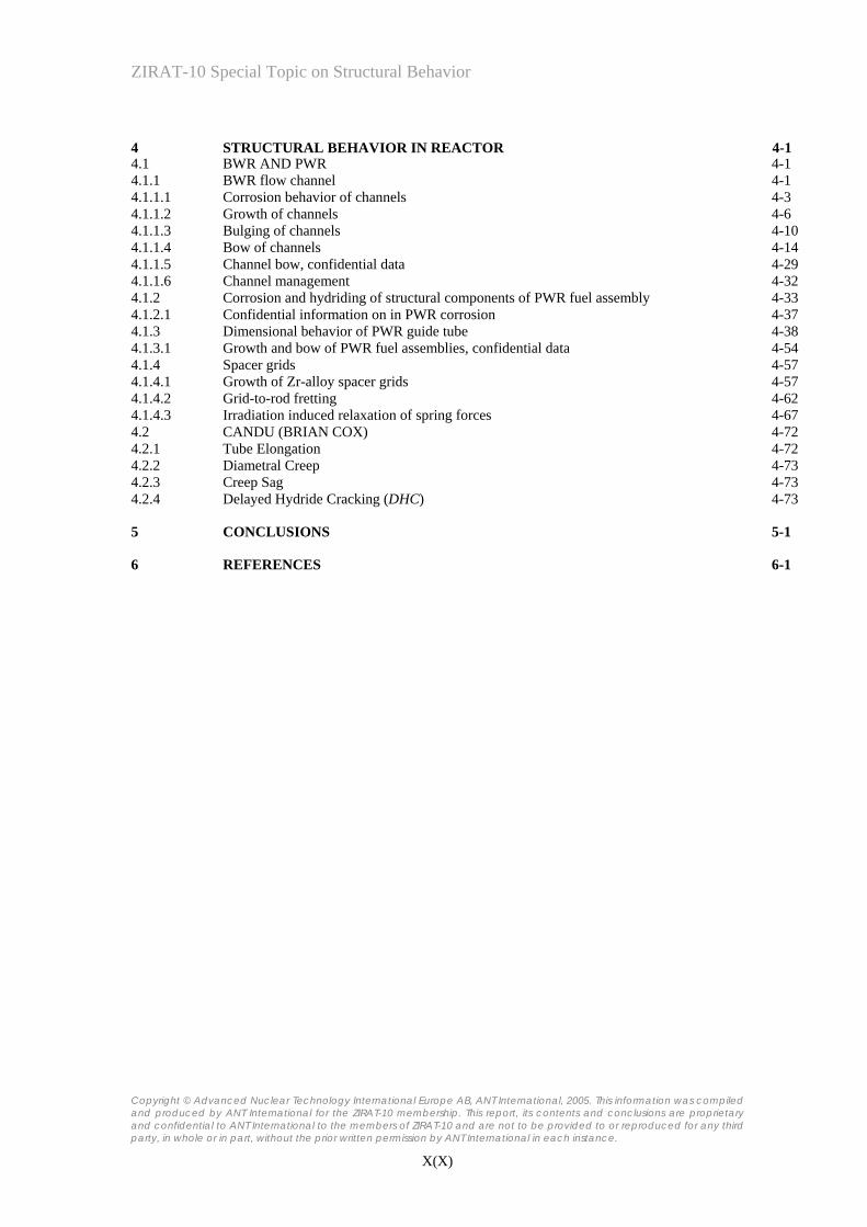
4 STRUCTURAL BEHAVIOR IN REACTOR 4-14.1 BWR AND PWR 4-1 4.1.1 BWR flow channel 4-1 4.1.1.1 Corrosion behavior of channels 4-3 4.1.1.2 Growth of channels 4-6 4.1.1.3 Bulging of channels 4-10 4.1.1.4 Bow of channels 4-14 4.1.1.5 Channel bow, confidential data 4-29 4.1.1.6 Channel management 4-32 4.1.2 Corrosion and hydriding of structural components of PWR fuel assembly 4-33 4.1.2.1 Confidential information on in PWR corrosion 4-37 4.1.3 Dimensional behavior of PWR guide tube 4-38 4.1.3.1 Growth and bow of PWR fuel assemblies, confidential data 4-54 4.1.4 Spacer grids 4-57 4.1.4.1 Growth of Zr-alloy spacer grids 4-57 4.1.4.2 Grid-to-rod fretting 4-62 4.1.4.3 Irradiation induced relaxation of spring forces 4-67 4.2 CANDU (BRIAN COX) 4-72 4.2.1 Tube Elongation 4-72 4.2.2 Diametral Creep 4-73 4.2.3 Creep Sag 4-73 4.2.4 Delayed Hydride Cracking (DHC) 4-73
5 CONCLUSIONS 5-1
6 REFERENCES 6-1

ZIRAT-10 Special Topic on Structural Behavior
Copyright © Advanced Nuclear Technology International Europe AB, ANT International, 2005. This information was compiled and produced by ANT International for the ZIRAT-10 membership. This report, its contents and conclusions are proprietary and confidential to ANT International to the members of ZIRAT-10 and are not to be provided to or reproduced for any third party, in whole or in part, without the prior written permission by ANT International in each instance.
1-11(1-34)
1 DESIGN DIFFERENCES BETWEEN BWR, PWR AND CANDU REACTOR FUEL
1.1 BWR AND PWR 1.1.1 Introduction (Al Strasser and Peter Rudling) There are a wide variety of different types of fuel assemblies for Light Water Reactors, LWRs. The fuel rod array for BWRs was initially 7x7 but there has been a trend over the years to increase the number of Fuel Assembly, FA, rods and today most FA designs are either of a 9x9 or 10x10 square configuration design. The driving force for this trend was to reduce the Linear Heat Generation Rate, LHGR, which resulted in a number of fuel performance benefits such as lower Fission Gas Release, FGR, and increased Pellet Cladding Interaction, PCI, margins. However, to increase utility competitiveness, the LHGRs of 9x9 and 10x10 FA have successively been increased, and peak LHGRs are today almost comparable to those of the 7x7 and 8x8 older designs. In all BWRs the assemblies are enclosed in “fuel channels” surrounding the assemblies and between which the blades of the control rods move.
Also for PWRs there has been a trend to greater subdivision of fuel rods, e.g. from Westinghouse 15x15 to 17x17 design, however to accomplish this one had to go to a new reactor design. This is because the PWRs do not have the same flexibility with core internals and control rods as is the case for BWRs. In most PWRs, the assemblies are positioned in the core by bottom and top fittings, and the lateral clearances are restricted by the assembly-to-assembly contacts at the spacer-grid levels. Furthermore, the control rods consist of rod cluster control assemblies, RCCAs, the poison part of which moves into guide thimbles (or guide tubes), that are an integral part of the assembly structure. For this reason the spacing and number of control rods for a 15x15 core differs from a 17x17 core and the upper internals of the reactor would need to be changed to switch from one fuel type to the other ---a very costly operation.
Irrespective of the many possible different shapes, sizes and configurations, the common FA design requirements are:
• maintain proper positioning of the fuel rods under normal operating conditions and in design basis accidents (e.g. seismic effects, LOCA, RIA)
• permit handling capability before and after irradiation.
Figure 1-1 and Figure 1-2 show a typical BWR and PWR FA, respectively. Also, the different fuel assembly components are shown and the material selections for these components are provided. The reason for the difference in structural material selection is that in general the most inexpensive material is chosen for a specific component that yields the lowest cost to produce the component while ensuring adequate performance during normal operation and accidents.

ZIRAT-10 Special Topic on Structural Behavior
Copyright © Advanced Nuclear Technology International Europe AB, ANT International, 2005. This information was compiled and produced by ANT International for the ZIRAT-10 membership. This report, its contents and conclusions are proprietary and confidential to ANT International to the members of ZIRAT-10 and are not to be provided to or reproduced for any third party, in whole or in part, without the prior written permission by ANT International in each instance.
1-12(1-34)
4.18
20.31
144
7.38
Active fuel zone
5.438
Fuel Assembly Handle304 L Stainless Steel
Spacer ButtonAssemblyIdentification Number
Upper Tie Plate304 L Stainless Steel
Fuel Cladding Zry-2
SpacersInconel X-750,
Inconel 718, Zry-2
Fuel Outer channelZry-4, Zry-2
Lower TiePlate, Debris Filter
304 L Stainless Steel
Identification Boss
Figure 1-1: Typical BWR FA dimensions in inches.

ZIRAT-10 Special Topic on Structural Behavior
Copyright © Advanced Nuclear Technology International Europe AB, ANT International, 2005. This information was compiled and produced by ANT International for the ZIRAT-10 membership. This report, its contents and conclusions are proprietary and confidential to ANT International to the members of ZIRAT-10 and are not to be provided to or reproduced for any third party, in whole or in part, without the prior written permission by ANT International in each instance.
1-13(1-34)
Top View
Rod Cluster Control
Top Nozzle304 L Stainless SteelSpringsInconel 718
Control Rod304 L Stainless SteelClad
Fuel CladdingZry-4/M5, ZIRLO,DUPLEX
SpacersZry-4/M5/ZIRLOInconel 625
Bottom Nozzle304 L Stainless SteelDebris Filter304 L Stainless Steel
Bottom View
Top SpacerZry-4/Inconel 625
Guide TubeInstrument TubeZry-4/M5/ZIRLO
Bottom SpacerZry-4/Inconel 625
Figure 1-2: Typical PWR FA.

ZIRAT-10 Special Topic on Structural Behavior
Copyright © Advanced Nuclear Technology International Europe AB, ANT International, 2005. This information was compiled and produced by ANT International for the ZIRAT-10 membership. This report, its contents and conclusions are proprietary and confidential to ANT International to the members of ZIRAT-10 and are not to be provided to or reproduced for any third party, in whole or in part, without the prior written permission by ANT International in each instance.
1-14(1-34)
The materials used for the FA components are Zr alloys, Inconel (precipitation hardened Inconel X-750, Inconel 718 and solution treated Inconel 625) and stainless steel (SS 304L). Spring materials need to be made of materials with low stress relaxation rates, such as e.g. Inconel X-750 or Inconel 718. These Ni base alloys are generally heat treated to reach an optimum precipitation hardening. To lower the parasitic neutron absorption by grids/spacers, the strips are made of Zry-2 and –4, while the spring itself is made of either Inconel X-750 or Inconel 718 to ensure adequate fuel rod support during its entire irradiation. In some fuel designs also the top and bottom PWR grid is entirely made of Inconel X-750 or Inconel 718. This is possible since the neutron flux is much lower at the top and bottom part of the core resulting in a very small loss of thermal neutrons due to parasitic material absorption. In newer BWR designs the spacers are made entirely of Inconel X-750, using the minimum thicknesses possible.
Table 1-1 presents an overview of stainless steel and nickel-base alloys used in LWR and their typical compositions. Table 1-2 provides data for different Zr alloys used by different fuel vendors.
Table 1-1: Chemical compositions of various stainless steels and Ni base alloys.
Material Fe (wt%)
Ni (wt%)
Cr (wt%)
Mn (wt%)
Si (wt%)
Mo (wt%)
Ti (wt%)
Nb (wt%)
Al (wt%)
AISI 304 Bal. 10 19 ≤2 ≤0.75
DIN 1.4541 Bal. 11 18 ≤2 ≤0.75 0.4
Inconel X-750 7 Bal. 15 ≤1 ≤1 2.6 1 0.7
Inconel 718 17 Bal. 19 0.5 0.75 3 0.7 5 0.6
Inconel 625 2.5 Bal. 22 0.3 0.1 8.8 0.3 3.91 0.2
1 (Nb+Ta) = 3.9 wt%

ZIRAT-10 Special Topic on Structural Behavior
Copyright © Advanced Nuclear Technology International Europe AB, ANT International, 2005. This information was compiled and produced by ANT International for the ZIRAT-10 membership. This report, its contents and conclusions are proprietary and confidential to ANT International to the members of ZIRAT-10 and are not to be provided to or reproduced for any third party, in whole or in part, without the prior written permission by ANT International in each instance.
1-15(1-34)
Table 1-2: Chemical composition of Zr alloys used in LWRs.
Alloy Sn %
Nb %
Fe %
Cr %
Ni %
O % Fuel Vendor.
BWRs
Zircaloy-2 1.2-1.7 - 0.07-0.2 0.05-0.15 0.03-0.08 0.1-0.14 All fuel vendors
Zr-Liner2
Sponge - - 0.015-0.06 - - 0.05-0.1 Only used in Japan
ZrSn 0.25 - 0.03-0.06 - - 0.05-0.1 Westinghouse
ZrFe - - 0.4 - - 0.05-0.1 Framatome ANP GmbH
ZrFe - - 0.10 - - 0.05-0.1 GNF
PWRs
Zircaloy-4 1.2-1.7 - 0.18-0.24 0.07-0.13 - 0.1-0.14 Only used in Japan
ZIRLO 1 1 0.1 - - Westinghouse3
M5 - 0.8-1.2 0.015-0.06 - - 0.09-0.12 Framatome ANP
HPA-4 0.6 - Fe+V - - Framatome ANP GmbH
Duplex4
ELS5 0.5/0.8 - 0.3/0.5 0.2 - 0.12 Framatome ANP GmbH
D4 0.5 - 0.7 - 0.12 Framatome ANP GmbH
3b6 <0.8 - <0.6 Westinghouse Sweden
3b+7 <1.0 - <0.6 Westinghouse Sweden
D48 <0.8 - <0.6 Westinghouse Sweden
WWER, RBMK
E-110 - 0.9-1.1 0.014 <0.003 0.0035 0.05-0.07 Fuel Cladding
Alloy E125 - 2.5 - - - 0.06 Pressure tube in RBMK
CANDU
Zircaloy-4 1.2-1.7 - 0.18-0.24 0.07-0.13 - 0.1-0.14 Fuel Cladding
Zr2.5Nb - 2.4-2.8 <0.15 - - 0.09-0.13 Pressure tube
2 In all BWR liner claddings, the liner being at the clad inner surface constitutes 10% of the cladding thickness while he remainingt 90 % of the thickness of the cladding tube consists of Zry-2. 3 An optimized ZIRLO with about 0.7 wt%Sn is being developed 4 All DUPLEX claddings consists of an outer corrosion resistant layer with a thickness < 100 microns and the rest of the thickness is Zry-4 to provide the mechanical strength. 5 All Framatome GmbH duplex claddings contains Zry-4 with 1.5 wt%Sn 6 Zry-4 with 1.3 wt %Sn 7 Zry-4 with 1.5 %Sn 8 Zry-4 with 1.5%Sn

ZIRAT-10 Special Topic on Structural Behavior
Copyright © Advanced Nuclear Technology International Europe AB, ANT International, 2005. This information was compiled and produced by ANT International for the ZIRAT-10 membership. This report, its contents and conclusions are proprietary and confidential to ANT International to the members of ZIRAT-10 and are not to be provided to or reproduced for any third party, in whole or in part, without the prior written permission by ANT International in each instance.
1-16(1-34)
In GE built plants, the gap between fuel channel and control rods may differ, see Figure 1-3. The D-lattice cores have a wide gap between the channels at sides facing the control rod blade (~19 mm, 760 mils ) and a narrow gap on opposite sides (~10 mm, 400 mils) while C lattice core have symmetric clearances between the channels. Typical initial clearance between the channel and control blade are between 2.4 mm (96 mils) and 3.3 mm (132 mils) depending on BWR design, channel wall thickness, and lattice type (D lattice with asymmetric clearances between blades and channels).
Plant Type
Lattice Type
Channel Thickness
mils
Channel-to ChannelGap mils
Blade Thickness
mils
Inserted Blade Clearance
Total mils
Difference Relative to
BWR/6 mils
BWR/6 S 120/75 572 328 244 0
BWR/5 C 100/65/50 120/75
592 572
260 260
332 312
88 68
BWR/4 C 100/65/50 592 260 332 88
BWR/4 D 100/65/50 700 312 388 144
BWR/2-3 D 100/65/50 700 312 388 144
Figure 1-3: S, C and D lattice geometry comparision.
1.1.2 PWR and BWR latest fuel design versions of various vendors (Peter Rudling)
1.1.2.1 Framatome ANP As a courtesy Framatome ANP has been provided valuable Framatome ANP proprietary information for the ZIRAT Program, which is presented in this section.
Framatome ANP, after the merger of the French Framatome with the German Siemens Nuclear Power, is operating in three regional units: Germany, the U.S. and France.

ZIRAT-10 Special Topic on Structural Behavior
Copyright © Advanced Nuclear Technology International Europe AB, ANT International, 2005. This information was compiled and produced by ANT International for the ZIRAT-10 membership. This report, its contents and conclusions are proprietary and confidential to ANT International to the members of ZIRAT-10 and are not to be provided to or reproduced for any third party, in whole or in part, without the prior written permission by ANT International in each instance.
1-17(1-34)
1.1.2.1.1 PWR designs Framatome ANP serves a wide spectrum of PWR fuel designs: Mark-B/BW for the U.S. market, AFA 3G in the European market and HTP worldwide. Framtome ANP’s first choice cladding material is M5™, a ternary alloy of zirconium, 1% niobium and 0.14% oxygen. M5™ is specially made for high duty demand regarding power and coolant temperature and stringent water chemistry conditions. Besides its use as cladding material, M5™ is also used as a structural material in guide tubes and spacers.
As an alternative cladding material to M5™, the DUPLEX concept has been proven very successful for many years. This type of cladding consists of a Zircaloy-4 tube with a corrosion resistant metallurgical bonded extra-low Sn (ELS) outer layer, about 100 µm thick. Since most of the cladding thickness consisted of Zry-4 it was possible for LOCA licensing purposes to argue that the fuel rods would behave as the Zry-4 rods, for which many large scale LOCA tests exist. This DUPLEX material as well as subsequent versions, are all characterized by an outer layer with low Sn content, ranging from 0.5-0.8 wt % and higher Fe+Cr contents compared to that of Zry-4. Also a through wall Zr0.6SnFeV (HPA-4) material was developed for structural parts.
In the following, some of the different FA designs provided by Framatome ANP are presented.
1.1.2.1.1.1 AFA 3G The AFA 3G design characteristics are:
1) M5 fuel rod cladding for improved corrosion resistance
2) Design features to reduce FA bowing (comparing to AFA2G)
3) Three Mid Span Mixing Grids (optional)
4) The TRAPPER bottom nozzle, consisting of a perforated plate welded to the top of a ribbed supporting structure.
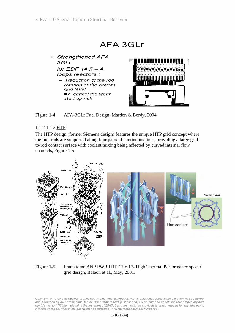
To increase the fuel rod support in 14 foot, 1300 MWe EDF plants, the AFA-3GL, design has been introduced and is currently being verified. This design has an additional bottom spacer, Figure 1-4.
ZIRAT-10 Special Topic on Structural Behavior
Copyright © Advanced Nuclear Technology International Europe AB, ANT International, 2005. This information was compiled and produced by ANT International for the ZIRAT-10 membership. This report, its contents and conclusions are proprietary and confidential to ANT International to the members of ZIRAT-10 and are not to be provided to or reproduced for any third party, in whole or in part, without the prior written permission by ANT International in each instance.
1-18(1-34)
Figure 1-4: AFA-3GLr Fuel Design, Mardon & Bordy, 2004.
1.1.2.1.1.2 HTP The HTP design (former Siemens design) features the unique HTP grid concept where the fuel rods are supported along four pairs of continuous lines, providing a large grid-to-rod contact surface with coolant mixing being affected by curved internal flow channels, Figure 1-5
Figure 1-5: Framatome ANP PWR HTP 17 x 17- High Thermal Performance spacer
grid design, Baleon et al., May, 2001.

ZIRAT-10 Special Topic on Structural Behavior
Copyright © Advanced Nuclear Technology International Europe AB, ANT International, 2005. This information was compiled and produced by ANT International for the ZIRAT-10 membership. This report, its contents and conclusions are proprietary and confidential to ANT International to the members of ZIRAT-10 and are not to be provided to or reproduced for any third party, in whole or in part, without the prior written permission by ANT International in each instance.
1-19(1-34)
1.1.2.1.1.3 Mark BW and Mark B The Mark BW, is a 17x17 replacement for Westinghouse designed PWRs while the Mark B fuel assembly, a 15x15 fuel assembly is designed for B&W reactors.
1.1.2.1.2 BWR design (all former Siemens designs) All ATRIUM type fuel assemblies are characterized by a square internal water channel which is the load bearing structure of the fuel assembly instead of using tie rods.
The ATRIUM 9 with a 9x9 rod lattice is mainly supplied as reload fuel in the Asian market. In the European and U.S. market the ATRIUM 10, having a 10x10 rod lattice, is the standard reload fuel design. The ATRIUM 10 A or B, Figure 1-6 has started operation in a German BWR in 1992 and has maintained since then its status as a reliable and economic fuel design.
The main features of the BWR ATRIUM FA design are:
1) the Zry-2 LTP, Low-Temperature Process, cladding material together with Fe-enhanced liner (Zr-sponge liner with 4000 wtppm Fe), or the LTP-2 Zry-2 material without liner.
2) ULTRAFLOW spacer
3) Part length fuel rods
4) Lower tie plates with debris filters available in two versions – either as a perforated plate (Small Hole Design) or as the FUELGUARD with its curved blade design.
5) Fuel channels made of Zry-2
The ATRIUM 10XP, Figure 1-7 provides an improved thermal hydraulic stability behavior and has been introduced in 2002.

ZIRAT-10 Special Topic on Structural Behavior
Copyright © Advanced Nuclear Technology International Europe AB, ANT International, 2005. This information was compiled and produced by ANT International for the ZIRAT-10 membership. This report, its contents and conclusions are proprietary and confidential to ANT International to the members of ZIRAT-10 and are not to be provided to or reproduced for any third party, in whole or in part, without the prior written permission by ANT International in each instance.
1-20(1-34)
Figure 1-6: The ATRIUM 10 fuel assembly, Urban et al., 2000 and Nuclear
Engineering International, September 2002.

ZIRAT-10 Special Topic on Structural Behavior
Copyright © Advanced Nuclear Technology International Europe AB, ANT International, 2005. This information was compiled and produced by ANT International for the ZIRAT-10 membership. This report, its contents and conclusions are proprietary and confidential to ANT International to the members of ZIRAT-10 and are not to be provided to or reproduced for any third party, in whole or in part, without the prior written permission by ANT International in each instance.
1-21(1-34)
Figure 1-7: ATRIUM XP, Bender et al, 2002.
1.1.2.2 Westinghouse As a courtesy Westinghouse has provided valuable Westinghouse proprietary information for the ZIRAT Program, which is presented in this section.
Westinghouse consists of mainly three different entities: 1) Westinghouse-US former old Westinghouse (USA), 2) Westinghouse CENP former Combustion Engineering (USA) and, 3) Westinghouse-Atom, former ABB Atom (Sweden). In the following the FA designs of the three different entities, now all part of Westinghouse, are presented.

ZIRAT-10 Special Topic on Structural Behavior
Copyright © Advanced Nuclear Technology International Europe AB, ANT International, 2005. This information was compiled and produced by ANT International for the ZIRAT-10 membership. This report, its contents and conclusions are proprietary and confidential to ANT International to the members of ZIRAT-10 and are not to be provided to or reproduced for any third party, in whole or in part, without the prior written permission by ANT International in each instance.
1-22(1-34)
1.1.2.2.1 CENP PWR Fuel The CENP fuel design is designed for Combustion Engineering built plants with 14x14, 15x15 and 16x16 lattice, Figure 1-8.
Axial Blankets
Advanced Alloy Cladding
Advanced Pellet Design
Erbium Burnable Absorber
GUARDIANTM Debris-Resistant Grid
Low Volume FuelRod Spring
Side-SupportedMixing Vane &I-Spring RodSupport
High-Strength Joints
Low Stress Coil Springs
Short SpanBetween Grids& AlternatingRod Supports
Lower Ends ofRods Protected
High-StrengthCasting
Figure 1-8: Westinghouse CENP Turbo PWR Fuel (latest 16x16 design), provided by
the courtesy of Westinghouse.
1.1.2.2.2 ASEA-Atom PWR Fuel Westinghouse Sweden manufactures and delivers designs originating in Columbia, as well as those developed by old ABB-Atom. Specific design features are all-Zircaloy mid grids and the GuardianTM debris catcher, which is integrated in the bottom Inconel grid. There exists, 16x16, 17x17, and 18x18 fuel designs
For 16x16 and 18x18 hot plants, the DUPLEX 3b+ (Zr with Sn <1.0 and (Fe+Ni+Cr)<0.6) material is provided, Figure 1-9a as cladding. Material for hold-down springs and the lower most grid is Inconel X750 and Alloy 625, respectively. The rest of the spacers are all-Zr-4. All Inconel materials are of ASTM standards with low Co-content.

ZIRAT-10 Special Topic on Structural Behavior
Copyright © Advanced Nuclear Technology International Europe AB, ANT International, 2005. This information was compiled and produced by ANT International for the ZIRAT-10 membership. This report, its contents and conclusions are proprietary and confidential to ANT International to the members of ZIRAT-10 and are not to be provided to or reproduced for any third party, in whole or in part, without the prior written permission by ANT International in each instance.
1-23(1-34)
In the 17x17 design, Figure 1-9b, Zry-4 is used as fuel claddings while the hold-down leaf springs as well as the lower most grid are made from Inconel 718. The rest of the spacers have Zry-4 straps with Inconel 718 springs.
Hold down springs
Guide tubes
Grids
Top nozzle
Bottom nozzle
Plenum spring
Fuel pellets
(a) (b)
Figure 1-9: (a) German PWRs (16x16, 18x18) and (b) 17x17 design, provided by the courtesy of Westinghouse.

ZIRAT-10 Special Topic on Structural Behavior
Copyright © Advanced Nuclear Technology International Europe AB, ANT International, 2005. This information was compiled and produced by ANT International for the ZIRAT-10 membership. This report, its contents and conclusions are proprietary and confidential to ANT International to the members of ZIRAT-10 and are not to be provided to or reproduced for any third party, in whole or in part, without the prior written permission by ANT International in each instance.
1-24(1-34)
1.1.2.2.3 Westinghouse PWR Fuel Westinghouse-US has 14x14, 15X15, 16x16, 17x17, and 17x17 XL fuel designs, Figure 1-10. The most recent Westinghouse FA design is the Robust Fuel Assembly, RFA, which is a modification of the 17X17 V5H/PERFORMANCE+ (V5HP+, similar to V5H except with intermediate flow mixers) design. The main features of the RFA design include:
• Debris Filter Bottom Nozzle, DFBN
• Modified structural middle grids, see below
• Intermediate flow mixing (IFM) grids
• Inconel protective bottom grid where the grid straps intersects the flow holes in DFBN
• Zirconia coating on the lower part of fuel rod to increase fretting resistance
• Thicker thimble tubes (compared to earlier designs)
• ZIRLOTM fuel cladding
• ZIRLOTM skeleton
• Integral Fuel Burnable Absorber, IFBA -- ZrB2 burnable absorber as a pellet coating
• Annular axial blankets
The middle structural grid has modifications to the grid strap design, the mixing vanes and the springs and dimples. The mixing vane geometry was modified to improve thermal margins. The vane and spring patterns were balanced to eliminate unbalanced lateral forces resulting from fluid flow exiting the grid. The spring stiffness was changed to improve the resistance to rod fretting. The grid was designed for a low-pressure drop.

ZIRAT-10 Special Topic on Structural Behavior
Copyright © Advanced Nuclear Technology International Europe AB, ANT International, 2005. This information was compiled and produced by ANT International for the ZIRAT-10 membership. This report, its contents and conclusions are proprietary and confidential to ANT International to the members of ZIRAT-10 and are not to be provided to or reproduced for any third party, in whole or in part, without the prior written permission by ANT International in each instance.
1-25(1-34)
Rod cluster control
Top nozzle
Control rod
Grid
Bulge joints
Grid spring
Bottom nozzle Thimble screw
Dimple
Dashpot region
Mixing vanes
Thimble tube
Fuel rod
Hold down springRod cluster control
Top nozzle
Control rod
Grid
Bulge joints
Grid spring
Bottom nozzle Thimble screw
Dimple
Dashpot region
Mixing vanes
Thimble tube
Fuel rod
Hold down springRod cluster control
Top nozzle
Control rod
Grid
Bulge joints
Grid spring
Bottom nozzle Thimble screw
Dimple
Dashpot region
Mixing vanes
Thimble tube
Fuel rod
Hold down spring
Figure 1-10: Westinghouse 17x17 fuel assembly design.
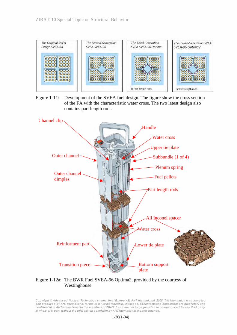
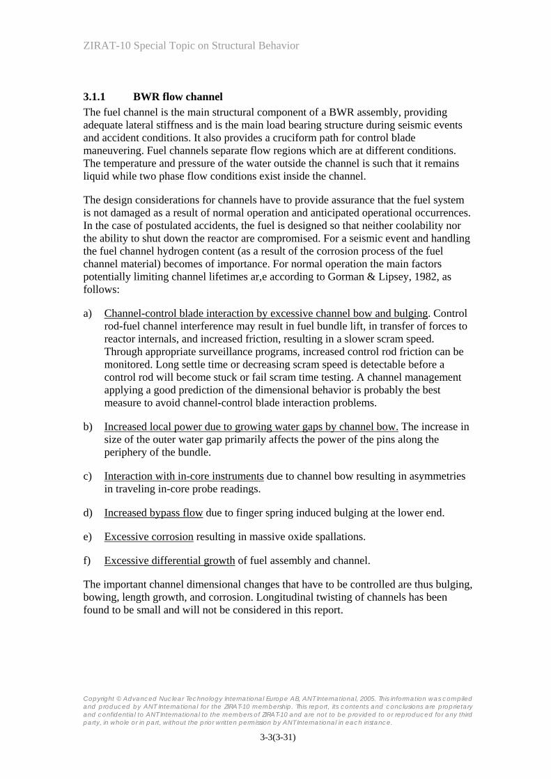
1.1.2.2.4 BWR Since 1981, ASEA-Atom has delivered SVEA fuel assemblies, Figure 1-11. The first design, SVEA-64 had 8x8 lattice while later version have 10x10 lattice, Figure 1-12. The part-length rods incorporated in the later designs provide increased shutdown margin and improved thermal-hydraulic stability in the core due to lower pressure drop in the upper part of the core.
ZIRAT-10 Special Topic on Structural Behavior
Copyright © Advanced Nuclear Technology International Europe AB, ANT International, 2005. This information was compiled and produced by ANT International for the ZIRAT-10 membership. This report, its contents and conclusions are proprietary and confidential to ANT International to the members of ZIRAT-10 and are not to be provided to or reproduced for any third party, in whole or in part, without the prior written permission by ANT International in each instance.
1-26(1-34)
Figure 1-11: Development of the SVEA fuel design. The figure show the cross section
of the FA with the characteristic water cross. The two latest design also contains part length rods.
Handle
Subbundle (1 of 4)
Upper tie plate
Plenum spring
Fuel pellets
Part length rods
All Inconel spacer
Water cross
Water cross
Lower tie plate
Outer channel
Outer channel dimples
Reinforment part
Transition piece Bottom support plate
Channel clip
Figure 1-12a: The BWR Fuel SVEA-96 Optima2, provided by the courtesy of
Westinghouse.

ZIRAT-10 Special Topic on Structural Behavior
Copyright © Advanced Nuclear Technology International Europe AB, ANT International, 2005. This information was compiled and produced by ANT International for the ZIRAT-10 membership. This report, its contents and conclusions are proprietary and confidential to ANT International to the members of ZIRAT-10 and are not to be provided to or reproduced for any third party, in whole or in part, without the prior written permission by ANT International in each instance.
1-27(1-34)
Figure 1-12b: The BWR SVEA Fuel channel, bottom support plate and transition piece,
provided by the courtesy of Westinghouse.

ZIRAT-10 Special Topic on Structural Behavior
Copyright © Advanced Nuclear Technology International Europe AB, ANT International, 2005. This information was compiled and produced by ANT International for the ZIRAT-10 membership. This report, its contents and conclusions are proprietary and confidential to ANT International to the members of ZIRAT-10 and are not to be provided to or reproduced for any third party, in whole or in part, without the prior written permission by ANT International in each instance.
1-28(1-34)
ASEA-Atom has over the years developed a series of BWR Zry-2 claddings, starting with the so-called LK0 cladding which was followed by LK 1 and 2 claddings. Both of the LK0 and 1 claddings were not subjected to a late beta-quench. The intermediate recrystallisation anneals were lowered from the LK0 to LK 1 material to improve nodular corrosion resistance. With the LK 2 material a beta –quenched before the two last pilgering steps was introduced to further reduce the tendency for nodular corrosion. LK3 is the latest version of clad material used, in which the late beta-quench was abandoned. The LK 2+ material still being delivered to some utilities is however, subjected to a late beta-quenching process. Both LK 2+ and LK 3 contains higher alloying additions of Fe, Ni and Cr, compared to earlier cladding variants. All of these cladding variants have a chemical composition within the range specified by ASTM for Zircaloy-2, Table 1-3.
Table 1-3: Target chemical composition of various ASEA-Atom Fuel Claddings.
Cladding Type Zr [wt%]
Sn [wt%]
Nb [wt%]
Fe+Cr+Ni [wt%]
LK0, LK1 & LK2 balance 1.5 - 0.18-0.38
LK2+ & LK3 balance 1.3 - 0.26-0.38
The initial Zr0.25Sn-liner with low iron content was provided in reload quantities from 1987. Today’s Zr0.25Sn-liner has a somewhat increased iron concentration within a range of 300 to 600 wtppm to improve secondary degradation resistance of failed fuel.
The spacer is of an all Inconel X-750 design heat treated to obtain required spring properties. The top and bottom tie plates are made of SS 304L material while the debris filter material is SS 316L.

ZIRAT-10 Special Topic on Structural Behavior
Copyright © Advanced Nuclear Technology International Europe AB, ANT International, 2005. This information was compiled and produced by ANT International for the ZIRAT-10 membership. This report, its contents and conclusions are proprietary and confidential to ANT International to the members of ZIRAT-10 and are not to be provided to or reproduced for any third party, in whole or in part, without the prior written permission by ANT International in each instance.
1-29(1-34)
1.1.2.2.5 GNF Global Nuclear Fuel, GNF, consists of two entities, the former General Electric Nuclear Energy (USA) and Hitachi/Toshiba (Japan).
The most recent GNF fuel designs are GE 11 (9x9 lattice), GE 12 (10x10 lattice), GE 13 (9x9 lattice) and GE 14 (10x10 lattice). All FA designs contain part length rods and 2 central water channels, Figure 1-13.
Figure 1-13: GE-14 design, Nuclear Engineering International, September 2002.

ZIRAT-10 Special Topic on Structural Behavior
Copyright © Advanced Nuclear Technology International Europe AB, ANT International, 2005. This information was compiled and produced by ANT International for the ZIRAT-10 membership. This report, its contents and conclusions are proprietary and confidential to ANT International to the members of ZIRAT-10 and are not to be provided to or reproduced for any third party, in whole or in part, without the prior written permission by ANT International in each instance.
1-30(1-34)
1.1.2.2.6 Mitsubishi and NFI The Japanese fuel vendors are Mitsubishi, a Westinghouse PWR licensee, GNF J and NFI (independent).
Ferrule-type spacers were introduced instead of the former eggcrate spacers to improve the thermal hydraulic characteristics of the NFI fuel design, Figure 1-14.
Low Pressure DropUpper Tie Plate
Ferrule Spacer
Large Diam. Water Rod
Lower Tie PlateLower Tie Plate
Water Rod
Grid Spacer
Step I Step II
Figure 1-14: Design Features of BWR Assembly, modified figure according to Sakurai et al., 2000.

ZIRAT-10 Special Topic on Structural Behavior
Copyright © Advanced Nuclear Technology International Europe AB, ANT International, 2005. This information was compiled and produced by ANT International for the ZIRAT-10 membership. This report, its contents and conclusions are proprietary and confidential to ANT International to the members of ZIRAT-10 and are not to be provided to or reproduced for any third party, in whole or in part, without the prior written permission by ANT International in each instance.
2-1(2-25)
2 FABRICATION OF STRUCTURAL COMPONENTS
2.1 FABRICATION OF LWR STRUCTURAL COMPONENTS (PETER RUDLING)
Figure 2-1 gives an overview of the manufacture of zirconium alloy strip and tube material that are used to manufacture guide tubes, GT, for PWRs, fuel outer channels for BWRs as well as strip material for BWR and PWR bimetallic spacers (grids).
Tubeshell
Guide TubesWater Rods
Clad
BundleAssembly
AssembleFuel Rod
Strip
Strip
Stamp
Sheet
Sheet
Form BWRChannel Boxes
Forge Flats
Roll Plate
AssembleSpacers
Tubeshell Bar stock
Bar stock
MachineEnd Plugs
Rounds
Extrude Hot Forge/Roll
Zircon Sand
Zirconium Sponge
Zircaloy Ingot
Fuel Vendors
Figure 2-1: Zircaloy Production Outline.

ZIRAT-10 Special Topic on Structural Behavior
Copyright © Advanced Nuclear Technology International Europe AB, ANT International, 2005. This information was compiled and produced by ANT International for the ZIRAT-10 membership. This report, its contents and conclusions are proprietary and confidential to ANT International to the members of ZIRAT-10 and are not to be provided to or reproduced for any third party, in whole or in part, without the prior written permission by ANT International in each instance.
2-2(2-25)
Figure 2-2: Final product manufacturing, Lemaignan & Motta, 1994.
The manufacturing process of different light water reactor, LWR, zirconium alloy products may be divided into three steps: 1) production of Zr raw material, 2) ingot manufacturing and, 3) final product (tube, strip/sheet, bar) fabrication. These are described in more detail in the following.
Nearly all the zirconium metal is extracted from zircon sand, Zr-Hf SiO4, occurring in beach sand all over the world. The zirconium to hafnium ratio in zircon is about 50/1 but since Hf has a very large thermal neutron cross section, it is crucial that as much Hf as possible is separated from zirconium during the manufacturing process.
The current dominant process to produce Zr metal is the Kroll process resulting in Zr sponge. The other two manufacturing processes are the Van Arkel process and the electrolytic process (used in Russia).
Zirconium sponge, recycle material from earlier manufacturing, and alloying elements are put together into an electrode. Normally, sponge-based briquettes and solid recycle material are assembled and welded either by electron beam in vacuum or plasma arc welding in argon atmosphere into an ingot typically between 50 to 80 cm in diameter weighing from 3 to 8 tons.
The ingot is remelted twice to increase the homogeneous distribution of the alloying elements.

ZIRAT-10 Special Topic on Structural Behavior
Copyright © Advanced Nuclear Technology International Europe AB, ANT International, 2005. This information was compiled and produced by ANT International for the ZIRAT-10 membership. This report, its contents and conclusions are proprietary and confidential to ANT International to the members of ZIRAT-10 and are not to be provided to or reproduced for any third party, in whole or in part, without the prior written permission by ANT International in each instance.
2-3(2-25)
2.1.1 Tube Shell Production for Guide Tubes During the later part of the manufacturing process, the workpiece is plastically deformed into its final desired shape. Plastic deformation also increases the microstructural homogeneity, e.g., the precipitate and grain size distribution in the workpiece. Processing is divided into hot and cold forming processes, where the temperature in the former is high enough to cause dynamic recrystallization while the latter process is done at such a low temperature that recrystallization will not occur during deformation. To restore the ductility after cold deformation an intermediate recrystallisation anneal is performed.
The first plastic deformation steps are accomplished by hot forging in the β phase, α + β phase and/or in the upper α phase9. The ingots are heated to about 1100°C and the forging is performed in a number of steps bringing down the thickness of the workpiece. Before each forging step, the workpiece needs to be reheated several times to increase plasticity of the workpiece. It is generally desirable to minimize deformation in the α + β region. At high temperature, the oxide layer that develops during forging is not protective and consequently elements such as O, N and H from the air can be absorbed by the bulk of the ingot if no precautions, such as limiting the time at high temperature in unprotected atmosphere, are taken.
The ingot is made into a round bar, named “log”, by hot press or rotary forging, the latter giving a more homogeneous plastic deformation.
The next step in the manufacturing process is the beta-quenching process. The objectives of the β-quenching of the log/billet are to homogenise the product by decreasing the microsegregation of the alloying elements and in some cases to establish the optimum size and distribution of second phase precipitates (SPPs) to improve the corrosion performance as well as the mechanical properties of the final product.
If a “log” was beta-quenched it is then cut up in smaller pieces, billets. If the solid billet itself was beta-quenched, the solid billet is then pierced to get a central hole (the pierced billet can also be beta-quenched resulting in faster cooling rate). Then the billet with a pierced hole is machined to remove the oxide scale and the surface beneath the oxide that may be contaminated from the manufacturing process.
Prior to extrusion the billet is heated and then put into the extrusion press and extruded to a hollow tube.
9 Zr metal has two crystallographic structures: 1) hexagonal close packed (h.c.p), α, that is the energetically most favourable structure at lower temperature and, 2) body centred cubic (b.c.c.), β, that is the high temperature modification.

ZIRAT-10 Special Topic on Structural Behavior
Copyright © Advanced Nuclear Technology International Europe AB, ANT International, 2005. This information was compiled and produced by ANT International for the ZIRAT-10 membership. This report, its contents and conclusions are proprietary and confidential to ANT International to the members of ZIRAT-10 and are not to be provided to or reproduced for any third party, in whole or in part, without the prior written permission by ANT International in each instance.
3-1(3-31)
3 IMPORTANT FACTORS IMPACTING STRUCTURAL BEHAVIOR
3.1 BWR AND PWR (FRIEDRICH GARZAROLLI) The fuel assembly structure has to fulfill several design demands for normal operation and anticipated accidents. Under normal operating conditions it must:
• keep the fuel rods in a well-defined array that enables good cooling
• guide the control rods and admit the core instrumentation
• enable fuel handling and transport
During accidents the fuel assembly structure must allow removal of decay heat. Furthermore it should:
• have a low neutron absorption,
• have a low resistance to coolant flow,
• improve the mixing of coolant,
• be compatible with other fuel assemblies, and
• and allow an exchange of fuel rods.
During irradiation fuel rods and assemblies undergo small dimensional changes mainly due to structural growth, creep and stress relaxation. The primary results are:
• fuel rod bow,
• fuel rod and Zircaloy grid growth,
• grid and hold-down spring force relaxation, and
• fuel assembly and flow channel growth, bow, twist, and bulging.
To get sufficient stiffness and dimensional stability under normal, anticipated operational occurrences, and design basis accidents the following demands are required:
• a low and homogeneous irradiation growth and irradiation creep,
• a low and radially uniform corrosion and hydrogen pickup; both can cause dimensional changes,
• a sufficiently thick component wall and weld thickness,

ZIRAT-10 Special Topic on Structural Behavior
Copyright © Advanced Nuclear Technology International Europe AB, ANT International, 2005. This information was compiled and produced by ANT International for the ZIRAT-10 membership. This report, its contents and conclusions are proprietary and confidential to ANT International to the members of ZIRAT-10 and are not to be provided to or reproduced for any third party, in whole or in part, without the prior written permission by ANT International in each instance.
3-2(3-31)
• a sufficient spacer/grid force supporting the fuel rods in spite of the irradiation induced relaxation of spacer/grid spring forces,
• sufficiently large, but not too large, hold-down spring forces of the PWR-fuel assembly to ensure that the fuel assembly lower tie-plate is not unseated from the fuel support structure by the hydraulic forces depending on coolant flow and pressure drop coefficient.
In both BWR and PWR assemblies the fuel rods are kept in position by the spacers grids, which in addition may affect coolant mixing and fuel rod cooling. However, dimensional changes are quite differently governed in the BWR and PWR designs.
In the BWR design bow, twist, and change of the exterior dimensions are mainly determined by the behavior of the exterior flow channel. Growth of the assembly results primarily from growth of the tie rods, which are fixed in the lower and upper tie plates or, in case of the Framatome Atrium 10 design, of Framatome from growth of the inner channel, which acts here as load bearing support for the fuel assembly, see Section 1. In the BWR fuel assembly a different growth behaviora of the standard fuel rods, tie rods and channels have to be considered. Standard BWR fuel rods show some scatter in growth and grow less than the tie rods and channels.
In PWR assemblies, which have to be held down by hold down springs due to the hydraulic forces from coolant flow, bow and growth is mostly governed by the behavior of guide tubes. The guide tubes, forming the load bearing support of PWR assemblies, change their length due to (1) irradiation creep under the compressive stresses due to the hold down springs, (2) irradiation growth and (3) hydriding. Vertical forces within the guide tubes are determined not only by FA weight, hold down forces, and coolant hydraulic flow forces, but also by differential thermal expansion and growth between fuel rods and guide tubes. The contribution from thermal expansion and growth differences depends primarily on the spacer spring forces. The differential growth of fuel rods and guide tubes is an important design aspect for PWR assemblies. The width of the PWR fuel assembly can also increase during irradiation due to growth of the spacers. This growth results from hydriding, formation of a highly stressed oxide layer, irradiation growth, and irradiation creep.
The interested reader is also referred to the ZIRAT-7 Special Topical Report on Dimensional Stability of Zr Alloys that treats the impact of hydriding, irradiation creep and growth mechanisms on dimensional stability.
The particular factors that may impact in-reactor behavior depend on the component, as will be discussed in the following sections.
ZIRAT-10 Special Topic on Structural Behavior
Copyright © Advanced Nuclear Technology International Europe AB, ANT International, 2005. This information was compiled and produced by ANT International for the ZIRAT-10 membership. This report, its contents and conclusions are proprietary and confidential to ANT International to the members of ZIRAT-10 and are not to be provided to or reproduced for any third party, in whole or in part, without the prior written permission by ANT International in each instance.
3-3(3-31)
3.1.1 BWR flow channel The fuel channel is the main structural component of a BWR assembly, providing adequate lateral stiffness and is the main load bearing structure during seismic events and accident conditions. It also provides a cruciform path for control blade maneuvering. Fuel channels separate flow regions which are at different conditions. The temperature and pressure of the water outside the channel is such that it remains liquid while two phase flow conditions exist inside the channel.
The design considerations for channels have to provide assurance that the fuel system is not damaged as a result of normal operation and anticipated operational occurrences. In the case of postulated accidents, the fuel is designed so that neither coolability nor the ability to shut down the reactor are compromised. For a seismic event and handling the fuel channel hydrogen content (as a result of the corrosion process of the fuel channel material) becomes of importance. For normal operation the main factors potentially limiting channel lifetimes ar,e according to Gorman & Lipsey, 1982, as follows:
a) Channel-control blade interaction by excessive channel bow and bulging. Control rod-fuel channel interference may result in fuel bundle lift, in transfer of forces to reactor internals, and increased friction, resulting in a slower scram speed. Through appropriate surveillance programs, increased control rod friction can be monitored. Long settle time or decreasing scram speed is detectable before a control rod will become stuck or fail scram time testing. A channel management applying a good prediction of the dimensional behavior is probably the best measure to avoid channel-control blade interaction problems.
b) Increased local power due to growing water gaps by channel bow. The increase in size of the outer water gap primarily affects the power of the pins along the periphery of the bundle.
c) Interaction with in-core instruments due to channel bow resulting in asymmetries in traveling in-core probe readings.
d) Increased bypass flow due to finger spring induced bulging at the lower end.
e) Excessive corrosion resulting in massive oxide spallations.
f) Excessive differential growth of fuel assembly and channel.
The important channel dimensional changes that have to be controlled are thus bulging, bowing, length growth, and corrosion. Longitudinal twisting of channels has been found to be small and will not be considered in this report.

ZIRAT-10 Special Topic on Structural Behavior
Copyright © Advanced Nuclear Technology International Europe AB, ANT International, 2005. This information was compiled and produced by ANT International for the ZIRAT-10 membership. This report, its contents and conclusions are proprietary and confidential to ANT International to the members of ZIRAT-10 and are not to be provided to or reproduced for any third party, in whole or in part, without the prior written permission by ANT International in each instance.
4-1(4-80)
4 STRUCTURAL BEHAVIOR IN REACTOR
4.1 BWR AND PWR A variety of measurement data on in-reactor performance of fuel assembly structure and structural components as well predictive models were analyzed. The main focus of these analyses was to determine whether the different data are consistent, whether the main parameters affecting the behavior are known, and whether the in reactor behavior can be reasonably predicted.
The particular parameters affecting the in-reactor behavior of fuel assembly structure and structural components, although in principle similar, are different in detail and will be discussed in the following sections.
4.1.1 BWR flow channel Fuel channel in-reactor performance is mainly influenced by the following effects:
• wall bulging,
• axial bow
• corrosion and hydriding.
Various pool site equipments have been developed by several companies to measure the dimensional behavior of the BWR flow channels as a function of exposure time in the mid 1970s. Figure 4-1 shows one measuring principle used. In this case each of the four channel sides is measured by three linear variable differential transducers (LVDT). With this device 12 axial traces are taken simultaneously over the circumference of the channel. From these bulging (also called displacement), bow, and twist are deduced over the total length of the channel.
A variety of dimensional BWR channel measurements have been reported over the years. In the following measurement data on in-reactor performance of BWR channels and their analysis, as well predictive models, are given and discussed for the different exposure induced changes, such as bulging, bow, and corrosion.

ZIRAT-10 Special Topic on Structural Behavior
Copyright © Advanced Nuclear Technology International Europe AB, ANT International, 2005. This information was compiled and produced by ANT International for the ZIRAT-10 membership. This report, its contents and conclusions are proprietary and confidential to ANT International to the members of ZIRAT-10 and are not to be provided to or reproduced for any third party, in whole or in part, without the prior written permission by ANT International in each instance.
4-2(4-80)
Trace 8Trace 2
1 mm
2
1
3123
987
456
121110
Important Information
1 Displacement at bottom nozzle
2 Maximum displacement in high-flux region
3 Maximum bow
Nominal channel width
FixtureBeam withconveyor slide
Slidecarriage
Calibration pieceDisplacement gauge
Array of measuring probes
Figure 4-1: Schematic view of the channel measurement device and typical
measurement results, modified figure according to Knaab & Knecht, 1978.

ZIRAT-10 Special Topic on Structural Behavior
Copyright © Advanced Nuclear Technology International Europe AB, ANT International, 2005. This information was compiled and produced by ANT International for the ZIRAT-10 membership. This report, its contents and conclusions are proprietary and confidential to ANT International to the members of ZIRAT-10 and are not to be provided to or reproduced for any third party, in whole or in part, without the prior written permission by ANT International in each instance.
4-3(4-80)
4.1.1.1 Corrosion behavior of channels Corrosion is usually not considered to be a life limiting mechanism for properly manufactured fuel channels. However, early channels, which were either fabricated from strips with a rather high A parameter (>1E-17 h), see Table 2-1, or fabricated from strips slow cooled from (α+β) temperatures, exhibited sometimes a rather high corrosion rate with oxide spallation. Oxide spallations usually start at oxide layer thickness values in excess of 150 µm. Figure 4-2 summarizes different data on corrosion of BWR channels. The materials used for these channels are probably all characterized by a relatively low A-parameter, except lot A irradiated in Onagawa-1, Fukuya et al., 1994. Nevertheless, all Zry-4 the materials in Figure 4-2 behave quite similarly, although the scatter is relatively large. The figure reveals in addition, that Zircaloy-2 channels corrode less than Zircaloy-4 channels and show less scatter. However it has to be mentioned that, up to now, the publication by Limbäck et al., 2001 is the only one that compares the corrosion behavior of the two materials, but it is in agreement with results from coupon irradiations in a German BWR, which also indicate a better corrosion behavior of Zircaloy-2 than that of Zircaloy-4 at higher burnups, Sell et al., 2004. Almost no data are available on hydriding of BWR channels during operation. It should depend on the corrosion behavior, wall thickness, and water chemistry aspects affecting the hydrogen pickup fraction. Hydriding might contribute to channel growth and channel bow, due to the fact that increasing hydrogen leads to an increasing linear expansion of 0.14-0.28% per 1000 ppm H2, according to out-of-pile measurements.
Figure 4-2: Oxide thickness versus burnup from different literature sources, Piascik
& Kasik, 1989, Kratzer et al., 1993, Fukuya et al., 1994, and Limbäck et al., 2001.

ZIRAT-10 Special Topic on Structural Behavior
Copyright © Advanced Nuclear Technology International Europe AB, ANT International, 2005. This information was compiled and produced by ANT International for the ZIRAT-10 membership. This report, its contents and conclusions are proprietary and confidential to ANT International to the members of ZIRAT-10 and are not to be provided to or reproduced for any third party, in whole or in part, without the prior written permission by ANT International in each instance.
5-1(5-5)
5 CONCLUSIONS
A variety of measured data on in-reactor performance of fuel assembly structures and structural components as well as predictive models were analyzed to determine whether the different data are consistent, whether the main parameters affecting the behavior are known, and whether the in reactor behavior can be reasonably predicted.
The BWR fuel channel in-reactor performance is mainly influenced by bulging, bow, and corrosion as well as hydriding. In particular, flux gradient dependant channel bow that occurs at high burnups can have consequences for operation and core design. The available database is quite large and should even allow statistical considerations. In any case prediction of all dimensional changes due to irradiation creep and growth should be very reliable.
The only aspect that sometimes will lead to uncertainties is the contribution from corrosion and hydriding. Corrosion and hydriding in BWR can differ quite significantly from reactor to reactor and the reasons for this are not understood. Thus work would be desirable to reduce this uncertainty. Furthermore, the models that can be applied today to estimate the contributions from corrosion and hydriding to growth are still questionable.
In recent years increasing occurrences of significant control blade friction events due to control blade induced shadow corrosion and channel bow have been observed. Although the principal mechanism is understood today, a lot of questions, such as the reason for the late hydrogen pickup under shadow corrosion, the influence of material condition and water chemistry influences, are still not answered today. Extended analyses and irradiation programs to determine the effect of material and water chemistry would be desirable.
Sufficient know-how is available to predict channel bowing behavior from fabrication data and representative measurements after operation. Channel management services are provided by fuel suppliers, consulting companies and even utilities.
An interesting development is the application of ß-quenched channels, which due to the almost isotropic texture of such channels should not suffer from irradiation induced growth and bow at high burnups. However, to fabricate such channels is not an easy job. Other material behavior parameters can easily be degraded due to such a treatment. The β-quenched channels reported by Dahlbäck et al., 2004, had probably a too low a quenching rate, that degraded corrosion resistance and in consequence the dimensional stability. An improvement of the fabrication process will be necessary.

ZIRAT-10 Special Topic on Structural Behavior
Copyright © Advanced Nuclear Technology International Europe AB, ANT International, 2005. This information was compiled and produced by ANT International for the ZIRAT-10 membership. This report, its contents and conclusions are proprietary and confidential to ANT International to the members of ZIRAT-10 and are not to be provided to or reproduced for any third party, in whole or in part, without the prior written permission by ANT International in each instance.
5-2(5-5)
Corrosion of Zr alloys used for PWR structural components, such as guide tubes and spacers depends very much on temperature and material composition and condition. The temperature of spacers and guide tubes increases with increasing axial position, due to the rising coolant temperature. The available database allows a quite reasonable prediction of corrosion and hydriding for the operating conditions of structural parts. The fact that unexpected corrosion related growth phenomena have occurred, leads to the impression that analysis of corrosion and estimation of the potential consequences are not performed adequately when cores are upgraded or more demanding core loadings are introduced. Probably, more careful analyses should be conducted for such changes.
The behavior and the design of PWR guide tubes govern the FA growth and bow behavior. Many data on growth of FA with Zry-4 guide tubes have been reported. Evaluation of these data indicates (1st) a large scatter at low to moderate burnup, (2nd) an acceleration of the growth at high burnups, and (3rd) very large variations of the high burnup acceleration of growth. The scatter at low burnups is probably due to contributions from the differential growth of fuel rods and spacers (different fuel rod spacer friction forces) and from relaxation of residual stresses from the tube manufacturing process, specifically from the straightening process. A more rigorous control of this process could be considered. The acceleration of growth at high burnup is due to an acceleration of irradiation growth and corrosion. The acceleration of growth at high neutron fluences depends on temperature and several material parameters. Today there are several indications of how these parameters affect accelerated irradiation growth but reliable correlations are still missing. Thus irradiation experiments to estimate these dependencies more accurately would be desirable.
Growth contributions from corrosion, such as oxide layer formation induced irradiation creep, and volume change due to hydrogen pick up can only be discussed on the basis of out-of-pile tests today, which may be misleading. Thus in-pile tests on these aspects would be desirable. However, it is probably very difficult to decide which tests should be done and which questions do not need to be answered any more due to the recent application of new more corrosion and growth resistant alloys, such as M5, HPA-4, ZIRLO, and Modified Zry-4.

ZIRAT-10 Special Topic on Structural Behavior
Copyright © Advanced Nuclear Technology International Europe AB, ANT International, 2005. This information was compiled and produced by ANT International for the ZIRAT-10 membership. This report, its contents and conclusions are proprietary and confidential to ANT International to the members of ZIRAT-10 and are not to be provided to or reproduced for any third party, in whole or in part, without the prior written permission by ANT International in each instance.
5-3(5-5)
PWR fuel assembly bow was an important issue in the last decade. In several reactors a large FA bow, often with an S-shape, and drastic reduction of the control rod drop times and even incomplete control rod (RCCA) insertions (IRIs) due to extreme fuel assembly bow have occurred with certain fuel designs (Framatome and Westinghouse). The root cause analysis has shown that excessive bow was caused by high hold-down forces, large FA growth in cores operating at higher temperatures, and insufficient FA stiffness. From the the literature information one gets the impression that the problem arose at least in some cases from fuel design standardization, resulting in too high hold-down forces in some plants with too low coolant flow. A careful plant analysis and a plant related optimization of several design parameters is probably a must. Fuel designs were improved, by increasing the FA stiffness (thicker GT wall especially in the dashpot zone at the bottom), decreasing the hold-down force to a value optimized for the particular core, and introduction of more corrosion and growth resistant Zr alloys. Loading the new improved fuel assemblies has eliminated excessive bow, and reduced control rod drop times, and IRIs, although it took several years. However, moderate bow does still occur and may result in reshuffling issues.
The dimensional stability of Zr alloy spacer grids is normally mainly governed by corrosion and hydrogen pickup. The contribution of irradiation growth to the change of the lateral width of the spacers depends on the material orientation of the grid straps with respect to rolling direction. Because the texture parameter in the rolling direction is generally much lower (0.06-0.1) than in transverse direction (0.15-0.3) irradiation growth is much higher in the rolling direction. Surprisingly there seem to be still some PWR spacer designs that have the strap length direction in the rolling direction and suffer as consequence from irradiation induced growth. A change of the grid strap should be considered. The other parameter influencing irradiation growth is the material condition. Probably all modern spacer designs use a fully recrystallized Zr alloy condition today. The large effect of oxide thickness formation and H-pickup on growth was already discussed in the guide tube section. Due to the significant consequences of spacer growth several measurement results must be available, but not many data are published. The data available indicate a large scatter probably mostly due to different thermal hydraulic operation conditions resulting in widely differing corrosion. The largest spacer growth values were reported from Wolf Creek and are likely due to high operation temperatures and a non-optimized spacer strap orientation with respect to the rolling direction.
A crevice corrosion phenomenon was observed with one spacer type. Almost nothing is known about crevice corrosion under PWR conditions. To avoid any future surprises an evaluation of this corrosion phenomenon is recommended.
Grid-to rod fretting has significantly contributed to PWR fuel defects. In contrast to this no grid-to-rod fretting defects have been reported for BWR fuel. apparently, grid-to rod fretting is only a PWR problem.

ZIRAT-10 Special Topic on Structural Behavior
Copyright © Advanced Nuclear Technology International Europe AB, ANT International, 2005. This information was compiled and produced by ANT International for the ZIRAT-10 membership. This report, its contents and conclusions are proprietary and confidential to ANT International to the members of ZIRAT-10 and are not to be provided to or reproduced for any third party, in whole or in part, without the prior written permission by ANT International in each instance.
6-1(6-7)
6 REFERENCES
Adamson R. B. et al, “High Temperature Irradiation Growth in Zircaloy”, ASTM STP 754, pp. 208-234, 1982.
Adamson R. B. et al., “Hot Cell Observations of Shadow Corrosion Phenomena”, KTG Fachtagung, Karlsruhe, 2000.
Adamson R. B. and Rudling P., “Dimensional Stability of Zirconium Alloys” ZIRAT-Spec.Top.Report 2002.
Andersson T., Thorvaldsson T., Wilson A. and Wardle A. M., “Influence of thermal processing and microstructure on the corrosion behavious of Zry-4 tubing”, Proc: IAEA Symposium on “Improvements in water reactor fuel technology and utilisation”, IAEA, Vienna, 1987.
Andersson T. et al., “A Decade of Assembly Bow Management at Ringhals”, ANS LWR Fuel Performance Conference, Orlando, 2004.
Aullo M and Rabenstein W. D. “European Fuel Group Experience on Control Rod Insertion and Grid to Rod Fretting”, IAEA TC Meeting on Fuel Assembly Structural Behaviour, Cadarache - November 2004.
Baleon J. P., Burtak F., Peyran J. C. and Urban P., “Framatome ANP Fuel Experience and Development”, ENS/TopFuel, Stockholm, 2001.
Baillon N., “Grid to Rod Fretting Wear in EDF PWR. From Operating Problems to New Design Qualification Methods”, IAEA TC Meeting on Fuel Assembly Structural Behaviour, Cadarache - November 2004.
Becker K. M. et.al., “Analysis of the Dryout Incident in The Oskarshamn 2 Boiling Water Reactor”, Paper presented at the European Two-Phase Flow Group Meeting, Paris, May 29-31, 1989.
Bender O., Opel S., Marx V., Meier W. and Faber W., “ATRIUM 10XP Fuel Assemblies in Gundremmingen”, Jahrestagung Kerntechnik, Stuttgart, 2002.
Billerey A. “Evolution of Fuel Rod Support Under Irradiation - Impact on the Mechanical Behaviour of Fuel Assemblies”, IAEA Fuel Assembly Structural Behavior, Caderach, Nov. 2004.
Bossis P. et al., “Comparison of High Burnup Corrosion on M5 and Low Sn Zry-4”, 14th Internat. Symposium on Zirconium in the Nuclear Industry, Stockholm, 2004.
Brown C. A. et al., “Fuel Rod Vibration and Fretting Impact on Reliability”, ANS LWR Fuel Performance Conference, Park City, 2000.

ZIRAT-10 Special Topic on Structural Behavior
Copyright © Advanced Nuclear Technology International Europe AB, ANT International, 2005. This information was compiled and produced by ANT International for the ZIRAT-10 membership. This report, its contents and conclusions are proprietary and confidential to ANT International to the members of ZIRAT-10 and are not to be provided to or reproduced for any third party, in whole or in part, without the prior written permission by ANT International in each instance.
6-2(6-7)
Causey A. R., “In-Reactor Stress Relaxation of Zr Alloys”, ASTM STP 551, pp. 263-272, 1974.
Causey A. R., Carpenter G. J. C. and MacEwen S. R., “In-Reactor Stress Relaxation of Selected Metals and Alloys at Low Temperatures”, J. Nucl. Mat. 90, pp. 216-223, 1980.
Causey A. R., Cheadle B. A., Coleman C. E. and Price E. G., “Improving the Sevice Life and Performance of CANDU Fuel Channels”, Presented at IAEA Tech. Comm. Meet. on Advances in Heavy Water Reactors, AECL 11543, Bombay, India, Jan. 29 - Feb 1, 1996.
Cheadle B. A., “The Physical Metallurgy of Zirconium Alloys”, AECL Report, CRNL-1208, pp. 163, 1974.
Cheadle B. A., Coleman C. E., Price E. G., Bajaj V. I. and Glendenings W. R. “Advances in Fuel Channel Technology for CANDU Reactors”, AECL Report, AECL-11059, 1994.
Choubey R., Aldridge S. A., Theaker J. R., Cann C. D. and Coleman C. E., “Effects of Extrusion-Billet Preheating on the Microstructure and Properties of Zr2.5Nb Pressure Tube Materials”, Proc. 11th Int. Symp. on Zr in the Nucl. Ind., (E. R. Bradley and G. P. Sabol, Eds) ASTM-STPP-1295, pp. 657-675., ASTM, 1996.
Dahlbäck M. et al., “The Effect of Beta-Quenching in Final Dimension on the Irradiation Growth of Tubes and Channels”, 14th Internat. Symposium on Zirconium in the Nuclear Industry, Stockholm, 2004.
Donaldson A. T., “Growth in Zircaloy-4 fuel clad arising from oxidation at temperatures in the rage of 623 to 723 K”, ASTM STP 1132, pp177-197, 1991.
Ferguson S. D. et al., “Post Irradiation Examination of the Lead Westinghouse Robust Fuel Assemblies after Three Cycles of Operation in the Wolf Creek Generating Station“, TopFuel-2003.
Fidleris V. et al., “An Overview on Microstructural and Experimental Factors that Affect the Irradiation Growth Behavior of Zr Alloys”, ASTM STP 939, pp. 49-85, 1987.
Forat C. and Florentine F., “The AFA 3G Fuel Assembly, a Proven Design for High Burnups”, Proc. TopFuel’99, pp. 73-82, 1999.
Francillon E., “Remedies to F.A. Bowing and Incomplete RCCA Insertion in PWRs”, TopFuel 1997.

ZIRAT-10 Special Topic on Structural Behavior
Copyright © Advanced Nuclear Technology International Europe AB, ANT International, 2005. This information was compiled and produced by ANT International for the ZIRAT-10 membership. This report, its contents and conclusions are proprietary and confidential to ANT International to the members of ZIRAT-10 and are not to be provided to or reproduced for any third party, in whole or in part, without the prior written permission by ANT International in each instance.
6-3(6-7)
Fukuya et al., “BWR Fuel Channel Performance and Localized Corrosion at High Burnups”, Proc. ANS LWR Fuel Performance Conference, Palm Beach, pp. 580-586, 1994.
Garner G. M. and Mardon J. P., “Performance of Alloy M5® Lead Assemblies After 3 Cycles in a High Duty U.S. Reactor”, Fontevraud-V, 2002.
Garzarolli F. et al., “Irradiation Growth and Strength of Zr Alloys”, IAEA Techn. Comm. Meeting on Properties of Materials for Water Reactor Fuel Elements, Vienna, Oct. 13-16. 1986.
Garzarolli F. et al., “Effects of High Neutron Fluences on Microstructure and Growth of Zircaloy-4”, ASTM STP 1023, pp. 641-657, 1989.
Garzarolli F., Stehle H. and Steinberg E., “Behavior and Properties of Zircaloys in Power Reactors: A Short Review of Pertinent Aspects in LWR Fuel”, ASTM STP 1295, pp. 12-32, 1996.
Garzarolli F. et al., “Irradiation Creep Behavior of High Purity Stainless Steels and Ni-Base Alloys”, Proc. 9th Int. Symp. Environmental Degradation of Materials in Nuclear Power Systems, pp. 1027-1034, 1999.
Garzarolli F., “Development of Cladding Materials for BWR and PWR Fuel”, 10th Environmental Degradation Conference, Lake Tahoe, 2001.
Garzarolli F. et al, “Shadow Corrosion or Crevice Corrosion”, J. Nucl. Mat. 289, pp. 338-341, 2001.
Garzarolli F. and Cox B., “Section 3.21 on Corrosion and Hydriding” in ZIRAT-8 Spec. Techn. Report on “High Burnup Fuel Issues”, 2003.
Garzarolli F., “Section 7.2 on In-Pile Corrosion and Hydriding” in ZIRAT-9 Annual Report, 2004.
Gautier B., “A General Overview of Nuclear Fuel in France“, Enlarged Halden Group Meeting, HPR-345/4, 1994.
Gilbon D. and Simonot C., “Effect of Irradiation on the Microstructure of Zircaloy-4”, ASTM STP 1245, pp. 521-548, 1994.
Gobillot G. and Vallory J., “Determination of Turbulent Excitation Spectra Superposition’s Rules in Various Cases of 2D Mixed Flow Redistribution in PWR Fuel Assemblies”, IAEA TC Meeting on Fuel Assembly Structural Behaviour, Cadarache - November 2004.
Gomolka K. et al., “Weiterentwicklung der Brennelementkasten-Einsatzplanung für das Kernkraftwerk Gundremmingen”, Jahrestagung Kerntechnik, Mannheim, 1996.
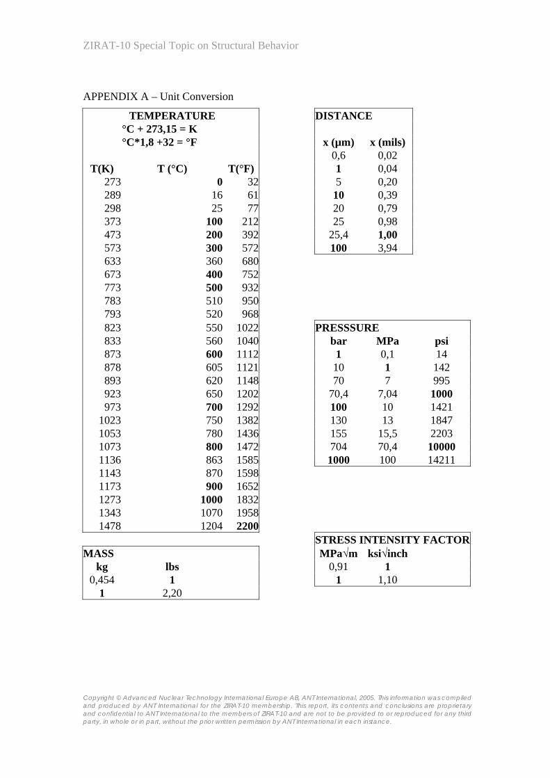
ZIRAT-10 Special Topic on Structural Behavior
Copyright © Advanced Nuclear Technology International Europe AB, ANT International, 2005. This information was compiled and produced by ANT International for the ZIRAT-10 membership. This report, its contents and conclusions are proprietary and confidential to ANT International to the members of ZIRAT-10 and are not to be provided to or reproduced for any third party, in whole or in part, without the prior written permission by ANT International in each instance.
APPENDIX A – Unit Conversion
TEMPERATURE DISTANCE °C + 273,15 = K °C*1,8 +32 = °F x (µm) x (mils) 0,6 0,02
T(K) T (°C) T(°F) 1 0,04 273 0 32 5 0,20 289 16 61 10 0,39 298 25 77 20 0,79 373 100 212 25 0,98 473 200 392 25,4 1,00 573 300 572 100 3,94 633 360 680 673 400 752 773 500 932 783 510 950 793 520 968 823 550 1022 PRESSSURE 833 560 1040 bar MPa psi 873 600 1112 1 0,1 14 878 605 1121 10 1 142 893 620 1148 70 7 995 923 650 1202 70,4 7,04 1000 973 700 1292 100 10 1421
1023 750 1382 130 13 1847 1053 780 1436 155 15,5 2203 1073 800 1472 704 70,4 10000 1136 863 1585 1000 100 14211 1143 870 1598 1173 900 1652 1273 1000 1832 1343 1070 1958 1478 1204 2200
STRESS INTENSITY FACTORMASS MPa√m ksi√inch
kg lbs 0,91 1 0,454 1 1 1,10
1 2,20