zinc oxide based photocatalysis: tailoring surface-bulk
TRANSCRIPT

RSC Advances
REVIEW
Publ
ishe
d on
06
Nov
embe
r 20
14. D
ownl
oade
d on
1/2
/202
2 11
:31:
21 A
M.
View Article OnlineView Journal | View Issue
Zinc oxide based
DKTPPpUrgDwPP
CdS thin lm heterojunction solar ceand photoluminescence properties oheterojunctions are his present inte
Department of Physics, Indian Institute of
India. E-mail: [email protected]; ksrkrao@
Cite this: RSC Adv., 2015, 5, 3306
Received 9th September 2014Accepted 6th November 2014
DOI: 10.1039/c4ra13299h
www.rsc.org/advances
3306 | RSC Adv., 2015, 5, 3306–3351
photocatalysis: tailoring surface-bulk structure and related interfacial charge carrierdynamics for better environmental applications
S. Girish Kumar and K. S. R. Koteswara Rao*
As an alternative to the gold standard TiO2 photocatalyst, the use of zinc oxide (ZnO) as a robust candidate
for wastewater treatment is widespread due to its similarity in charge carrier dynamics upon bandgap
excitation and the generation of reactive oxygen species in aqueous suspensions with TiO2. However,
the large bandgap of ZnO, the massive charge carrier recombination, and the photoinduced corrosion–
dissolution at extreme pH conditions, together with the formation of inert Zn(OH)2 during photocatalytic
reactions act as barriers for its extensive applicability. To this end, research has been intensified to
improve the performance of ZnO by tailoring its surface-bulk structure and by altering its
photogenerated charge transfer pathways with an intention to inhibit the surface-bulk charge carrier
recombination. For the first time, the several strategies, such as tailoring the intrinsic defects, surface
modification with organic compounds, doping with foreign ions, noble metal deposition,
heterostructuring with other semiconductors and modification with carbon nanostructures, which have
been successfully employed to improve the photoactivity and stability of ZnO are critically reviewed.
Such modifications enhance the charge separation and facilitate the generation of reactive oxygenated
free radicals, and also the interaction with the pollutant molecules. The synthetic route to obtain
hierarchical nanostructured morphologies and study their impact on the photocatalytic performance is
explained by considering the morphological influence and the defect-rich chemistry of ZnO. Finally, the
crystal facet engineering of polar and non-polar facets and their relevance in photocatalysis is outlined. It
is with this intention that the present review directs the further design, tailoring and tuning of the
physico-chemical and optoelectronic properties of ZnO for better applications, ranging from
photocatalysis to photovoltaics.
r S. Girish Kumar is a native ofarnataka (Kolar District, Maluraluk) and obtained his MSc inhysical Chemistry (2005) andhD (2012) degree in the area ofhotocatalysis from Bangaloreniversity, Bangalore. He is theecipient of India's most presti-ious Dr D. S. Kothari Postoctoral Fellowship (2012) andorks under the supervision ofrof. Rao at the Department ofhysics, IISc, Bangalore on CdTe/lls. The study of phase transitionf mixed phase titania and otherrests.
Dr K. S. R. Koteswara Rao isassociate professor at theDepartment of Physics, IndianInstitute of Science, Bangalore,India. He works in the eld ofsemiconductors. His researchinterests are understandingdefects in semiconductor mate-rials and their heterostructuresby optical (photoluminescence,optically induced conductivitymodulation, etc.) and electricalmethods. The growth and study
of III–V and II–VI based Binary, Ternary and Quaternarycompound semiconductor nano- and micro-structures and theirutility for device applications are his current research studies.
Science, Bangalore-560012, Karnataka,
physics.iisc.ernet.in
This journal is © The Royal Society of Chemistry 2015

Review RSC Advances
Publ
ishe
d on
06
Nov
embe
r 20
14. D
ownl
oade
d on
1/2
/202
2 11
:31:
21 A
M.
View Article Online
1. Introduction
Clean energy and pollutant-free water/air are the importanttasks that we currently face, with a common solution that lies inthe design and development of multifunctional nanomaterialsfor harvesting maximum light energy from solar light. Becauseenvironmental pollution has surpassed the threshold of naturalpurication, an advanced oxidation process seems to be themost effective wastewater treatment methods having high effi-ciency and low cost. In addition to the photo Fenton process,1–4
semiconductor photocatalysis, which is a ‘green approach’, is atthe forefront of fundamental research and consideration fortechnological applications due to its non-selectivity, lowtemperature and non-energy intensive approach for completemineralization of pollutants. The photoinduced charge carrierseparation upon the bandgap excitation of semiconductors isvital for redox reactions, followed by charge carrier transfer tosolution-phase redox couples, which is essential to accelerateoverall photocatalytic reaction rates. Thermodynamically, theredox potential of the VB-hole must be positive to generatehydroxyl radicals, and the CB-electron must be negative toinitiate dioxygen reduction.5 As an alternative to illustrioussemiconductors, such as TiO2, WO3, Bi2O3, Fe2O3, BiOX (X¼ Cl,Br and I) and (BiO)2CO3, recently, ZnO is in the spotlight ofmany research efforts, due to its stupendous benets, such aslow cost and high quantum efficiency, as well as a favourablebandgap and due to its photocatalytic mechanisms.6–15 Theadmirable attributes of ZnO, such as mechanical-thermalstability, high photosensitivity, low cost, high redox potential,large bandgap offering an excellent driving force to induceredox reactions, non-toxicity, versatility in synthesis with hier-archical morphology, the availability of different precursors(common inorganic salts) and their high solubility in varioussolvents, ease of crystallization, anisotropic growth, and naturalabundance, make it ideal for photocatalysis. The refractiveindex of ZnO (2.0) is lower than for TiO2 (2.5–2.7), and henceZnO scarcely scatters light, thereby making it colorless andboosting its transparency. Moreover, ZnO-photocatalyzed reac-tions perform best in neutral pH conditions, which is an addedmerit over its competitors. Furthermore, the emission proper-ties of ZnO have made it possible to set up an original catalyticsystem, which is able to ‘sense and shoot’ the environmentalcontaminants, thus motivating the further exploration of theproperties of ZnO.16
Due to the presence of intrinsic impurities, the electronmobility (200–300 cm2 V�1 s�1) and electron lifetime (>10 s) of ZnOare considerably higher compared to TiO2 (0.1–4.0 cm2 V�1 s�1),which reduces the electrical resistance and promotes the elec-tron transfer efficiency.17,18 Thus, a high concentration of pho-togenerated charge carriers transfer to the surface, contributingto efficient photocatalysis. In addition, the VB of ZnO is posi-tioned slightly below TiO2 VB, indicating that the hydroxylradical generated in the former (+3.06 V) has a higher oxidationpotential compared to the latter (+2.7 V); moreover, the electronderived from the ZnO CB is believed to be more negative thanTiO2 (at pH 0 vs. NHE), whereas the CB edges of both the
This journal is © The Royal Society of Chemistry 2015
semiconductors are almost the same at neutral pH conditions(�0.5 V vs. NHE).19,20 The ZnO absorbs a large fraction of UVspectrum and more light quanta, exhibiting a better perfor-mance compared to TiO2 for pollutant treatment under lightillumination.21–26 The surface band of ZnO is bent upward in air,indicating that the direction of its built-in electric eld is frominner to outer, and thus facilitates hole migration to the particlesurface, while electrons diffuse to the bulk of the particle.27
Defects like oxygen vacancies, zinc interstitials, oxygen inter-stitials, and the generation of hydrogen peroxide, superoxideand hydroxyl radicals on the ZnO surface are reported to beresponsible for the photocatalytic activity.28–33 Although,different radicals/defects mediate the degradation mechanismdepending on the surface-bulk modication of ZnO, it isunambiguously accepted that a low degree of charge carrierrecombination is vital to achieve a high photocatalyticefficiency.
ZnO commonly crystallizes in a wurtzite structure (spacegroup P63mc, a ¼ 3.25 A, c ¼ 5.20 A) with n-type conductivity(Zn1+sO, s > 0), with a direct bandgap of 3.37 eV and with a largeexcitonic binding energy (60 meV), which is even larger than thethermal energy at RT.28–33 The specic physicochemical, opto-electronic and magnetic properties of ZnO stimulates itspotential application in various elds, such as photocatalysis,light emitting diodes, solar cells, gas sensors, pyroelectricity,luminescent materials, pigments, UV shielding materials,surface acoustic wave lters, actuators, spin electronics, short-wavelength optoelectronic devices, varistors, antifungal, andpiezodielectric nanogenerators.34–39
Despite the versatility, ZnO-based photocatalysis suffersfrom the following draw backs: (i) ZnO does not absorb thevisible portion of the solar spectrum, instead it requires UVlight, which is expensive, for bandgap excitation; (ii) rapidrecombination of the charge carriers inevitably obstructs theoutward diffusion of the charge carriers, and consequentlyslows down the degradation reactions occurring at the semi-conductor–liquid interface; (iii) there are problems associatedwith the recovery of ZnO powder from the suspension byconventional ltration; (iv) the tendency to aggregate during thecatalytic reactions and the susceptibility to corrosion under UVlight. The photocorrosion reactions can be represented asfollows:40,41
ZnO + 2h+ + nH2O / Zn(OH)n(2�n)+ + 1/2O2 + nH+ (1)
where n depends on the pH of the solution. The photo-dissolution of ZnO initially involves hole trapping at thesurface, followed by a rapid formation of oxygen molecules anda fast expulsion of Zn2+ from the surface.
Osurface2� + h+ / Osurface
� (2)
Osurface� + 3O2� + 3h+ / 2(O–O2�) (3)
O–O2� + 2h+ / O2 (4)
2Zn2+ / 2Zn2+(aqueous) (5)
RSC Adv., 2015, 5, 3306–3351 | 3307

RSC Advances Review
Publ
ishe
d on
06
Nov
embe
r 20
14. D
ownl
oade
d on
1/2
/202
2 11
:31:
21 A
M.
View Article Online
The overall reaction can be represented as.
ZnO + 2h+ / Zn2+ + 1/2O2 (6)
In addition, the ZnO powder dissolves at strong acidic pH:
ZnO + 2H+ / Zn2+ + H2O (7)
Under strong alkaline medium, ZnO can undergodissolution:
ZnO + H2O + 2OH� / Zn(OH)42� (8)
ZnO passivates to form an inert Zn(OH)2 surface layer uponUV illumination;
2ZnO + 4H2O + 4h+ / 2Zn(OH)2 + O2 + 4H+ (9)
Thus, both strongly acidic and strongly alkaline pH may notfavour the photocatalytic process.
To overcome these aforementioned obstacles, research israpidly progressing to modify the surface-electronic structure ofZnO, largely by altering the ZnO defect chemistry to benetphotocatalysis under ambient conditions. Many insightfulreview articles are concentrated on the synthesis, properties,growth, defects, and other applications of ZnO.42–47 In contrast,a few seminal review articles associated with the photocatalysisdiscuss the effects of the initial reaction parameters, such ascatalyst dosage, concentration of the dye, solution pH and thepresence of electron acceptors, including a brief approach onhow to afford the visible light response of ZnO.48–51 Inspired bythe advances with interesting and exciting results, the authorshave taken up this review on the research progress of ZnO-basedphotocatalysis to pave the way for its practical application. Theinterfacial charge carrier transfer dynamics in each strategycorrelating to a high activity of modied ZnO are discussed withrespect to material properties, such as catalyst dosage, surfacecharge density, crystallinity, defects (intrinsic and extrinsic),properties of modiers, and charge carrier generation–separa-tion–recombination dynamics, together with the experimentalconditions appropriate for the pollutant structure, pH of thesolution, the presence of inorganic electrolytes, and the inten-sity and wavelength of the excitation source. For the rst time,the defect-facet-morphological dependence of ZnO on photo-catalytic activity is also highlighted.†
2. Fundamental aspects of ZnO-based photocatalysis
The underlying mechanism of the photocatalysis comprises thebandgap excitation of ZnO with energetic photons, therebygenerating an exciton pair with holes in the VB and electrons in
† (i) the excitation source for all those references/literature dealing with UV lightphotocatalysis is not mentioned in this review article, for clarity; (ii) the termUV/visible light indicates the photocatalytic activity dealt with both UV andvisible light illumination; (iii) UV-vis implies that the excitation source used hasan emission wavelength in both the UV and visible region.
3308 | RSC Adv., 2015, 5, 3306–3351
the CB. These charge carriers may recombine, which dissipatesthe input energy as heat. Moreover, they may undergo aninterfacial charge transfer process either by trapping at themetastable surface states or by interacting with pre-adsorbedelectron donors/acceptors on the catalyst surface or within thesurrounding electrical double layer of the chargedparticles.7,52,53
(a) Surface sensitization and complexation of ZnO
Microscale ZnO decomposes dyes like CV, MB, OG and MO at afaster rate compared to Degussa P25 under UV-visible light,indicating that the photosensitization of ZnO by dyes favoursthe visible light response with an enhanced charge carrierseparation.54 The excited dye molecule transfers electrons to theZnO CB, whereas the dye itself converts to a cationic radical.The injected electron reacts with dioxygen adsorbed on the ZnOsurface to generate a series of active oxygen species, which onsubsequent reaction with the dye molecules results indegradation.55,56
Dye + visible light / Dye* (10)
Dye* + ZnO / Dyec+ + ZnO(e�) (11)
ZnO(e�) + O2 / O2�c (12)
O2�c ������!Hþ
//HO2cþHOc (13)
Dyec+ + reactive oxygenated radicals / products (14)
In addition, an electricity conversion efficiency of 0.23% wasobtained for ZnO-based dye sensitized solar cells compared tothe Degussa P25 (0.0024%) counterpart. This is an importantreport to simultaneously realize both dye degradation and thegeneration of a renewable energy source. The ZnO-sensitizedheteroaggregate (CoTPPS + TAPPI) was efficient for the degra-dation of RhB under visible light compared to ZnO–CoTPPS,ZnO–TAPPI and ZnO.57 The heteroaggregates formed by theintermolecular electrostatic force of attraction between thepositively charged TAAPI {tetrakis(4-trimethylaminophyenyl)porphyrin} and the negatively charged CoTPPS {tetrakis(4-sulfonatophenyl) porphyrin cobalt(II)} extends the compositeabsorption to a wider spectral range compared to the porphyrinmonomer. The loading of water soluble porphyrin enhances thehydrophilic character of the ZnO microrods, thereby facilitatingtheir dispersion in the aqueous solution. In addition, the redoxpotentials of the heteroaggregates align with the energy level ofZnO to promote an electron injection from the excited state ofthe porphyrin into the ZnO CB and suppress the carrierrecombination.57 In the sensitization process, electron transferand recombination between the sensitizer and ZnO, togetherwith their redox potentials, govern the kinetics of the electroninjection.
Kamat et al.16 reported a ‘sense and shoot’ approach bymonitoring the quenching of the relative emission intensity ofZnO with organic compounds like 4-chlorocatechol, catecholand 4-CP. These phenolic compounds scavenge the
This journal is © The Royal Society of Chemistry 2015

Fig. 1 Illustration of the ‘sense and shoot’ approach in photocatalysis(reprinted with permission from ref. 16; Copyright 2002 @ AmericanChemical Society).
Review RSC Advances
Publ
ishe
d on
06
Nov
embe
r 20
14. D
ownl
oade
d on
1/2
/202
2 11
:31:
21 A
M.
View Article Online
photogenerated holes and compete with the charge carrierrecombination, which is responsible for the emission proper-ties (Fig. 1). Surprisingly, the original emission was restoredfollowing the exposure of the lm to deionized water, indicatingthat the interaction between ZnO and the phenolic compoundswas purely physisorption. The varying degree of emissionquenching for these compounds arises from the differences intheir adsorption and ability to scavenge holes on the ZnOsurface. The experimental illustration of the increased emissionduring photocatalysis conrms that the emission recovery waspurely associated with the degradation of the aromatic inter-mediates in an aqueous solution. In comparison to TiO2, thesurface complexation of 4-CP on the ZnO surface via –Zn–O–Ph–Cllinkages extended the photoresponse to the visible range andaccelerated the degradation rate of 4-CP.58 The PL studiesindicated a slight decrease in the visible emission, suggestingthat the surface complexes are mainly formed on the defect sites(oxygen vacancies), which improves the photostability of ZnO.This surface complex is formed via condensation reaction:
–Zn–OH– + OH–Ph–Cl / –Zn–O–Ph–Cl + H2O (15)
Unlike the conventional dye sensitization process, the visiblelight irradiation of the above surface complex directly excitesthe electron from the ground state of the adsorbate to ZnO CBthrough the ligand to a metal charge transfer process, providedthere exists a signicant electronic coupling between theadsorbate orbitals and the Zn ‘d’ orbitals. Similar complexationand degradation pathways for DCP and phenol were noticedunder visible light.58 The acetate-capped ZnO crystals (h-ZnO)promoted the degradation of MO and MR at pH 6, but weresusceptible to corrosion at extreme pH conditions.59 In contrast,HCA/TBPA-capped ZnO (nh-ZnO) showed a weaker pH depen-dence for degradation and a high resistance to photocorrosion,which was attributed to its hydrophobic nature. Phosphonicacid strongly bonds to the ZnO surface via a bi/tri-dentategeometry, as opposed to an acetate ligand, which anchors
This journal is © The Royal Society of Chemistry 2015
weakly via a unidentate fashion. Thus, the high density ofsurface sites is expected to be passivated by HCA or TBPA,resulting in a lower activity. In addition, the long alkyl chain canimpose a signicant barrier towards the adsorption of targetmolecules. The intermediates formed during the degradationwere retarded to a large extent on the nh-ZnO surface comparedto the h-ZnO.59 The activity of colloidal ZnO for MO degradationat various calcination temperatures followed an order: 150 > 300> 500 �C, in correlation with the monodentate-, bidentate-capped and the free acetate group, respectively. With anincrease in calcination temperature, the acetate group decom-poses, which leads to a larger particle size and a loss in pho-toactivity.60 The modication of ZnO with Co(II) acetate andtrimethylsilanolate inhibited the degradation of 4-NP. This wasattributed to the elimination of defect sites (oxygen vacancies)on the ZnO surface, which was crucial for photoactivity.61 Suchsurface modication with a suitable reagent could signicantlyimprove the stability of ZnO. The integration of organic andinorganic compounds into semiconductor NPs is drivingresearch into an adventurous new set of nanoscale functionalarchitectures suitable for an enormous range of applications.
(b) Effect of crystallite size
The efficiency of ZnO synthesized by the solvothermal route (80�C for 24 h, followed by calcination at 400 �C for 6 h) usingTEAOH and methanol showed a high activity for the degrada-tion of RhB under visible light compared to the samplesprepared with ethanol and propanol solvents (Fig. 2).62 Thecrystallite size of ZnO increased with the length of the carbonchain of the solvent, which can be interpreted by consideringthe dielectric constant of methanol (32), ethanol (25) andpropanol (21). In general, solvents with a low dielectric constantare likely to induce faster and uncontrolled precipitationkinetics, and also lead to the supersaturation of Zn2+ ions due tothe lower solubility of zinc salts. This offers the driving force fornucleation and the growth of ZnO NPs, with reduced nucleationtime and higher solid particle growth. The smaller crystallitesize obtained using the methanol solvent leads to a largersurface area and quantization in the bandgap, which facilitatesthe easy electron injection from the excited dye to ZnO CB.Upon replacing TMAOH in the synthetic route, the crystallinityappears to be the overriding factor rather than the surface areain governing the photocatalysis. The decolorization of MO for adistinct size of ZnO followed the following order: nanometer (50nm) > submicron (200 nm) > micron grade (1000 nm).63 Thistendency was attributed to the following reasons: (i) the amountof dispersed particles per volume in the reaction solutionincreases, consequently improving the photon absorptionability; (ii) the increased surface area promotes the adsorptionof the dye molecules on the catalyst surface; (iii) the coupling ofexciton pairs is suppressed. Surprisingly, ZnO with a particlediameter of 10 nm showed a lower activity compared to itssubmicron-sized counterpart. Dodd et al.64 also reported that anoptimal size of �33 nm resulted in an enhanced hydroxylradical generation, whereas reducing the particle size (�28 nm)lowered this tendency, as a result of the increased surface
RSC Adv., 2015, 5, 3306–3351 | 3309

Fig. 2 Degradation kinetics of RhB (left) and the rate constants (right) with ZnO synthesized with different solvents (reprinted with permissionfrom ref. 62; Copyright 2011 @ American Chemical Society).
RSC Advances Review
Publ
ishe
d on
06
Nov
embe
r 20
14. D
ownl
oade
d on
1/2
/202
2 11
:31:
21 A
M.
View Article Online
recombination.65 Casey et al.66 reported that the photoactivitysignicantly increased by a factor of 2 to 3 as the mean crys-tallite size was reduced from 100 to 20 nm. ZnO prepared by theprecipitation method from zinc acetate, zinc nitrate and zincsulfate showed a higher activity for the degradation of RhBcompared to the sample obtained through the citrate method.67
In the latter case, a two-step heat treatment at 300 �C (4 h) and500 �C (or 600 �C, 2 h) was necessary to remove the organicresidues and to induce the crystallization of ZnO, whereas theformer involved a single step involving calcination (500 �C, 2 h)for the nitrate or acetate precursor and 800 �C for the sulphateprecursor. The additional organic residues in the citratemethod originated from the formation of citrate complexes. Incontrast, the precipitation method produced a crystallinesurface devoid of contaminants, which was benecial for pho-tocatalysis. The activity of ZnO with respect to the precursorsobtained via the citrate method followed the followingsequence: zinc acetate > zinc nitrate > zinc sulphate, whereasthose prepared through the precipitation method showed analmost similar activity. Parameters, such as the surface area,agglomeration and sintering temperature, which varied withthe synthesis route and the counter anion of the zinc precursor,did not exhibit any inuence on the degradation kinetics.67
The photoactivity does not increase monotonically withdecrease in the particle size in all the cases, and the relationshipbetween size dependence and the catalytic efficiency is close-knit. A proper size is indispensable to balance the specicsurface area, crystallinity and the surface-bulk carrier recom-bination probability, in order to obtain a better performance.
(c) Inuence of reaction pH, electron acceptors anddegradation pathways
The photocatalytic activity for the degradation of Acid Brown 14dye under natural solar light with various catalysts had thefollowing order: ZnO > TiO2 > a-Fe2O3 > ZrO2 > CdS > WO3 >SnO2, which is mainly attributed to the absorption of more lightquanta and a large fraction of the solar spectrum by ZnO.68 Thephotocatalytic oxidation of NO with ZnO–TiO2�xNx producedNO2 gas and HNO3 as the major products, whereas HNO2
3310 | RSC Adv., 2015, 5, 3306–3351
produced as aminor compound with acids gets adsorbed on thecatalyst surface under UV/visible light.69 The NOx molecule mayreact with a superoxide radical to form the nitrate anion andnally HNO3, which deactivates the catalyst surface.
NO + 2OH / NO2 + H2O (16)
NO2 + HOc / NO3� + H+ (17)
NOx + O2�c / NO3
� (18)
The degradation of phenol was favoured in weakly acidic orneutral pH conditions and was effective under solar light ratherthan articial visible light illumination.70 The ZPC of ZnO NPs isin the range of 8–9, and the electrical property changes with thepH value of the dispersion.71 Hence, the surface charge densitywill be positive in an acidic or weak basic medium and negativeunder strong alkaline conditions. In a weak acidic solution, thephenol molecules remain undissociated to deliver a strongadsorption of phenol on the ZnO surface, resulting in an effi-cient degradation. In alkaline conditions, the phenolate inter-mediates experience an electrostatic repulsion from the ZnOsurface, resulting in a poor adsorption of pollutant, andconsequently a decline in the degradation rate. It is worthmentioning that commercial ZnO supplied from Merck chem-icals was less susceptible to photocorrosion and retained itsactivity even aer recycling for ve subsequent runs.70 Thedegradation and mineralization of SA via the Langmuir–Hin-shelwood mechanism was effective in neutral pH, which isattributed to the electrostatic force of attraction between thesalicylate anion and the positively charged ZnO. A signicantloss in activity was observed only aer the h run of therecycling test.72 The methyl parathion degradation followed arst-order kinetics on the ZnO and TiO2 surface, with the latterbeing more effective in complete mineralization.73 Theoptimum catalyst dosage was found to be 200 mg L�1 and 500mg L�1 for TiO2 and ZnO, respectively, with the differenceattributed to the difference in their characteristics, such ascrystal phase, specic surface area, grain size, density of defects,electron–hole recombination kinetics, charge carrier mobility
This journal is © The Royal Society of Chemistry 2015

Review RSC Advances
Publ
ishe
d on
06
Nov
embe
r 20
14. D
ownl
oade
d on
1/2
/202
2 11
:31:
21 A
M.
View Article Online
and the surface acid–base properties. At a lower catalyst dosage,the absorption of light controls the photocatalytic process dueto the limited catalyst surface, whereas the aggregation andscattering of light would be detrimental at high catalyst loading.The degradation was enhanced with peroxydisulfate as theelectron scavenger through the generation of sulfate radical,which is a strong oxidizing agent74
S2O82� + e� / SO4
2� + SO4�c (19)
SO4�c + e� / SO4
2� (20)
SO4�c + H2O / SO4
2� + HOc + H+ (21)
SO4�c + RH /./ SO4
2� + CO2 (22)
The toxicity of the treated solution was reduced with TiO2,while the release of Zn2+ ions as a result of the photodissolutionincreased the toxicity for ZnO. The mineralization studiesrevealed the absence of phosphate ions due to insolubleZn3(PO4)2 formation, which was otherwise present with thetitania dispersion, indicating the different degradation path-ways of these two metal oxides.73 The degradation of Acid Red14 was improved in the presence of H2O2 at neutral pH under aUV-C source (100–280 nm), while the addition of ethanol sup-pressed the reaction kinetics, thus conrming the participationof the hydroxyl radical in the degradation mechanism.20 H2O2
served as a better electron acceptor than the dioxygen fortrapping CB electrons at a faster rate or by direct photolysis toproduce hydroxyl radicals.7a
H2O2 + hv / 2OHc (23)
H2O2 + O2�c / OHc + OH� + O2 (24)
H2O2 + e� / OHc + OH� (25)
However, a higher dose of H2O2 served as a hydroxyl radicalscavenger or a hole scavenger, suppressing the degradationrate. The free radicals may also recombine to form neutralspecies.
H2O2 + h+ / O2Hc + H+ (26)
H2O2 + OHc / O2Hc + H2O (27)
O2Hc + OHc / H2O + O2 (28)
In contrast, the degradation of Acid Red 18 was suppressedwith H2O2, but accelerated with (NH4)2S2O8 and KBrO3. Thisunusual decrease was due to the low adsorption of H2O2 on theZnO surface.74c The degradation of HD proceeded through theformation of by-products such as thiodiglycol, hemisulfarmustard, divinyl sulde, 2-chloroethyl vinyl sulde at thesurface of ZnO NPs under dark and visible light irradiation.75
However, HD sulfoxide, HD sulfone, 1,3-dithiane, 2-chloro-ethanol and CH3CHO, along with hydrolysis and eliminationproducts, were formed under sunlight and UV-A light illumi-nation. In the former case, the degradation through elimination
This journal is © The Royal Society of Chemistry 2015
and surface complexation reactions played a dominant role,whereas in the latter case, photocatalytic reactions involvingC–S bond cleavage, an oxidation of carbon and sulphur atoms,were observed.75 The ZnO exhibited a superior visible lightactivity for the degradation of Basic Blue 11 compared to TiO2.76
The rapid degradation rate under alkaline conditions (pH 10)was attributed to the better adsorption of the dye on the ZnOsurface and the generation of more hydroxyl radicals in thereaction system. Interestingly, the degradation was consider-ably better at pH 3 compared to neutral conditions. The posi-tively charged ZnO surface promotes the migration of electronsfrom interior of nanocrystals to the surface and prevents carrierrecombination. The degradation mechanism was followed byboth N-dealkylation and oxidation pathways (pH 9). In anotherstudy, the degradation of EV followed oxidative degradation(cleavage of the chromophore) at acidic pH and through N-de-ethylation, which lead to an N-de-ethylated EV species, alongwith their N-hydroxyethylated intermediates under an alkalinemedium. The former proceeded via the formation of a carboncentred radical, whereas the latter was through the generationof a nitrogen centred radical.77
(d) Inuence of excitation source and radical scavenger
The photocatalytic degradation of metamitron herbicide undera mixed UV-A (315–400 nm) and UV-B (280–315 nm) light sourcewas efficient at acidic pH (2.1–4), but was inhibited with anionslike carbonate and sulphate, whereas chloride showed a weakinuence.78 The surface sites available at the ZnO–metamitroninterface for adsorption and electron transfer between thecatalyst and substrate were blocked by the anions, which arevery resistant towards oxidation. These deposited anions deac-tivate the catalyst surface towards the targeted pollutant andalso scavenge the hydroxyl radicals in the solution. The gener-ated carbonate or sulphate radicals, although they behave asoxidants, have lower oxidation potential compared to hydroxylradicals.74,78
OHc + CO32� / OH� + CO3
�c (29)
OHc + HCO3� / H2O + CO3
�c (30)
Cl� + h+ / Clc (31)
Clc + Cl� / Cl2�c (32)
OHc + Cl� / Clc + OH� (33)
SO42� + h+ / SO4
�c (34)
SO42� + OHc / SO4
�c + OH� (35)
The ZnO effectively oxidized the iodide ion under the inu-ence of the increased air ow-rate and decreased water contentin the reaction medium.79 The high water content promotes anindirect recombination via the trapping of the CB electrons bythe hydroxyl radical. The hole reacts with the adsorbed iodideion to form an iodine atom and further reacts with iodide ions
RSC Adv., 2015, 5, 3306–3351 | 3311

Fig. 3 Band structure and charge transfer pathways of ZnO nano-crystal with oxygen defects (reprinted with permission from ref. 81;Copyright 2009 @ American Chemical Society).
RSC Advances Review
Publ
ishe
d on
06
Nov
embe
r 20
14. D
ownl
oade
d on
1/2
/202
2 11
:31:
21 A
M.
View Article Online
to produce I2�, which then undergoes a disproportionate reac-
tion to form tri-iodide and iodide ions.
I� + h+ / I (36)
I + I� / I2� (37)
2I2� / I3
� + I� (38)
The coupling of the photo Electro Fenton process with theimmobilized ZnO was effective for decolorising Basic Yellow 28compared to the individual process at pH 3 using CNT-polytetrauoroethylene cathode and a Pt sheet anode in the pres-ence of Na2SO4 electrolyte.80 This is a consequence of theenhanced generation of hydroxyl radicals from both electro-catalysis and the photo Fenton process.
At anode: H2O / 1/2O2 + 2H+ + 2e� (39)
At cathode: O2 + 2H+ + 2e� / H2O2 (40)
Fe2+ + H2O2 / Fe3+ + HOc + H2O (41)
Fe3+ + e� / Fe2+ (42)
The excitation source UV-C was found to be more powerfulfor photoelectrochemical degradation compared to UV-B andUV-A, which is due to the production of hydroxyl radical, whicharises from the photolysis of H2O2. The initial step of themechanism of degradation involves the hydroxylation of thedye, leading to 1,2,3,3-tetramethyl indoline and 4-methoxybenzenamine, followed by a subsequent attack of hydroxylradical, which leads to the formation of simple aliphatic acids.80
(e) Defect-mediated photocatalysis
The use of nanoscopic ZnO embedded in Naon membranesresulted in a faster degradation of RhB compared to ZnOpowder.81 Initially, a blank Naon was soaked overnight in anaqueous zinc nitrate solution to facilitate Zn2+ ion exchange.Then, the Zn2+–Naon was soaked in C2H5OH (ZNE) or NaOH(ZNA) to introduce hydroxyl anions. The Zn(OH)2 formed isunstable in hydrophilic cavities (reverse micelles), which eitherdehydrolyzes it to give ZnO or it reacts with a hydroxyl anion toform the growth units of [Zn(OH)4]
2�, followed by its polymer-ization, resulting in a ZnO nuclei. ZNE showed a superioractivity and an excellent photostability compared to ZNA,although both the samples had comparable particle size, crystalstructure, morphology and surface area. The PL evidenced alarge concentration of oxygen defects, i.e. oxygen vacancy/interstitial oxygen with ZNE, as a result of the rapid crystalgrowth. Under UV excitation, the electrons are trapped byoxygen vacancies, whereas the holes are captured at interstitialoxygen, thereby restraining the recombination (Fig. 3). Ethanolswelled the membrane lm andmade the entrance of hydroxideions easy and uniform. This modied ZnO did not lose itsactivity even aer recycling ten times. The concentration of Zn2+
ions in the solution aer the photoreaction was�0.0148 mg L�1
for ZnO–Naon lm, whereas it was �0.2318 mg L�1 with the
3312 | RSC Adv., 2015, 5, 3306–3351
commercial ZnO.82 These Naon membranes form an excellentsupport for semiconductor nanocrystals because of theimproved chemical stability, exceptional mechanical strengthand high optical quality. The advantages of the Naon-templating approach to synthesize metal oxide NPs are asfollows: (i) it provides a stable matrix to prevent the agglomer-ation and corrosion of embedded NPs; (ii) NPs embedded areeasy to operate and can be recycled for catalytic purpose; (iii) theNaon membrane has a small absorbance in the UV-visibleregion and their hydrophilic cavities and the channels possessa strong polarity and excellent ion-exchange properties.83–85
These features enhance the adsorptive capacity of the materials,leading to the enrichment of pollutants on the catalyst surface.The hybrid effect between the 1.0%monomolecular-layers PANIdispersed on the ZnO surface inhibited photocorossion andalso improved the activity for MB degradation under UV/visiblelight.86 The degradation was quenched with EDTA (a holescavenger) for the ZnO system, and with EDTA or TBA (ahydroxyl radical scavenger) for the ZnO–PANI system. Thisindicates that the holes were the dominant oxidising agent inthe former case, whereas both holes and the hydroxyl radicalcontribute to photocatalysis in the latter under UV light. Incontrast, hydroxyl radicals predominately participated in thedegradation of MB for the composite under visible light. UnderUV light, VB holes transfer to the HOMO of PANI, and thenmigrate to the catalyst surface, thereby directly oxidizing thecontaminants. Under visible light, PANI absorbs the incidentphotons, and the excited electron is transferred from its LUMOto the ZnO CB.86 The coating of PANI via the cold-plasmatreatment technique intentionally Introduces defects (i.e.oxygen vacancies and interstitial zinc) and enhances the activityof PANI–ZnO for MO and 4-CP degradation.87 In addition, PANIeffectively stabilized these defects on the surface of ZnO evenaer prolonged UV illumination. The surface oxygen vacancytraps the electron from ZnO CB and the LUMO of PANI tosuppress the charge recombination process (Fig. 4). In addition,the increased donor density due to the presence of Zni (Znþ
i andZn0
i ) and Vo (Vþo and V0
o) improves the charge transport andshis the Fermi level towards the CB, which facilitates chargeseparation at the semiconductor–electrolyte interface and ulti-mately supplements the photocatalytic efficiency. The PANI
This journal is © The Royal Society of Chemistry 2015

Fig. 4 (a) Proposed photocatalytic mechanism; (b) atomic level illus-tration of ZnO–PANI hybrids (reprinted with permission from ref. 87;Copyright 2014 @ American Chemical Society).
Review RSC Advances
Publ
ishe
d on
06
Nov
embe
r 20
14. D
ownl
oade
d on
1/2
/202
2 11
:31:
21 A
M.
View Article Online
behaves like a p-type semiconductor, which is an excellent holetransporting material and has become a better choice forpreparing organic–inorganic hybrid photocatalysts. The oxygendecient ZnO obtained from the calcination of ZnO2 was foundto be efficient for the decomposition of DCP under visiblelight.88 The oxygen defects are introduced during the decom-position of O2
2� and were tailored by heat treatment at varioustemperatures. At high calcination temperatures (800 �C, 2 h),the pale yellow colour of oxygen-decient ZnO was transformedto a white color. However, annealing under an argon atmo-sphere preserves the visible light absorption edge, as the oxygenvacancies are retained under an oxygen free condition. Theimpurity states associated with these high oxygen vacanciesbecome more delocalized and overlap with the VB edge, andthis raises the position of VB, making the ZnOmore efficient forvisible light absorption. The photocatalytic activity of oxygen-decient ZnO gradually decreased with increases in the calci-nation temperature from 400 to 800 �C, which is in agreementwith the concentration of oxygen vacancies. However, very lowoxygen vacancies did not exert any impact on the optical prop-erties. In contrast, oxygen deciency was not observed for ZnOprepared by the calcination of Zn(OH)2.88 Thus, the electronicand optical properties of ZnO are strongly dependent on thenature and concentration of the defects generated during thecrystallization process. For ZnO-based photocatalysis, excita-tion at high energy wavelength (254 nm) triggers both photol-ysis and photocatalysis;89 however, low energy (340 nm) inducesonly photocatalysis, due to its close association with thebandgap absorption. This indicates an increase in the surface ornear surface reactions with the latter excitation source, and thatthe former operates by a MVK type mechanism, in which theoxygen from the crystal lattice is removed and used in theoxidation reaction. On the basis of a series of experiments, Aliet al.90 reported that a different degradation mechanism of MBoperated for different ZnO lms at different excitation wave-lengths, with competition between the two distinctive mecha-nisms: conventional redox radicals and lattice oxygen drivenoxidation. Surface photocatalyzed radical formation wasprominent for highly aligned and more crystalline morphol-ogies of ZnO with plentiful oxygen. However, the lattice oxygenmediated photodegradation was signicant for less aligned and
This journal is © The Royal Society of Chemistry 2015
more amorphous morphologies with more defects. The highenergy associated with 254 nm allows the activation energybarrier to overcome for lattice oxygen abstraction; furthermore,a high number of lattice defects lower the overall activationenergy. However, the MVK type mechanism deactivates thecatalyst surface, thereby inhibiting the redox reactions.90
Despite the debate concerning the exact role of defects inphotocatalysis, it is generally accepted that the surface defects(states) act as shallow trapping sites, whereas the localized bulkdefects promote the recombination process. The defects inmediated photocatalysis are vital for realizing the photo-catalysis pathways, as these defects not only modulate thephotoactivity, but are also inherent in pristine metal oxides.
On the basis of the above results, it can be surmised thatheterogeneous photocatalysis is a delicate function of catalystdosage, particle size, surface acid–base properties, defectdensity, surface anchored groups, photocatalyst stability,substrate concentration and their redox levels, pollutants'molecular structures, the presence of electron scavengers otherthan oxygen, the presence of inorganic electrolytes, the forma-tion of active free radicals, solution pH, the affinity of pollutantsand intermediates to react with free radicals, degradationpathways, intensity and the wavelength of the excitation source.
3. Morphological dependence of ZnOon the photocatalytic activity
Further improvements in the photoactivity of ZnO can be real-ized by providing a suitable geometric structure for effectivecarrier transfer pathways. ZnO has the richest morphologies,which are very complex and diversied and can be easilymanipulated with a desirable structure, as well as allow forrational tailoring of the surface to volume ratios. The capabilityto control the particle morphology and understanding thesurface signatures of ZnO governed by the particle size andshape may be vital for constructing nanoscale electronicdevices. The growth of metal oxides in an aqueous solution isinuenced by variable parameters such as temperature,precursor chemistry, chelating agents, solvents, precursorconcentration, mineralizers, inorganic electrolytes, templatesand the pH of the solution.91–94 Zn(II) exists as Zn2+, Zn(OH)2,Zn(OH)3
� and Zn(OH)42� in aqueous solution, with their
concentration ratio depending on the pH of the reactionmedium. In general, a relatively large quantity of Zn(OH)4
2�
under alkaline conditions will act as seeds for the nucleation ofZnO growth units.
The photocatalytic activity of ZnO towards resorcinoldegradation follows the order: spherical shape > rod-like > ake-like. The activity of the sperhical shape was due to the formationof a non-faceted morphology comprising a high surface area,small crystalline size distribution, and a high concentration ofelectron (oxygen vacancies) and hole traps (oxygen intersti-tials).95 The appreciable activity of the rod-like morphology wasattributed to the presence of a zinc-terminated {0001} and anoxygen terminated {0001�} polar face with a high surface energy.However, the formation of smooth {1101} and {1010} facets
RSC Adv., 2015, 5, 3306–3351 | 3313

RSC Advances Review
Publ
ishe
d on
06
Nov
embe
r 20
14. D
ownl
oade
d on
1/2
/202
2 11
:31:
21 A
M.
View Article Online
without a high surface energy for the ake-like morphologyresulted in poor activity. These morphologies could be tuned bychanging the capping agent, i.e. the Triton X-100 concentrationfrom PMC to CMC during the synthesis step (Fig. 5).96 In thecase of PMC (2.1 � 10�4 mol L�1), a high yield of ZnO nano-akes was obtained. During the particle formation, monomers(the capping agent) adsorb onto the preferred crystallographicplanes and alter the growth kinetics. Thus, growth along all thepreferred directions will be retarded to produce a nanoake-likemorphology during the nucleation stage. The nanoakes areaggregated due to their nanoscale forces. The spherical micellesare formed at their rst CMC (3.2 � 10�4 mol L�1), leading tothe formation of spherical NPs. Due to the smaller dimension ofthe spherical-shaped granular particles, the polar elds gener-ated in each particle are weaker.97 Consequently, a lowerpropensity of agglomeration between the single particles leadsto the formation of an unagglomerated assembly of NPs. Thesecond CMC (1.3 � 10�3 mol L�1) indicates the structuraltransition from a spherical micelle to rod-like ones to facilitatethe formation of the NRs. The collective behaviour of the vander Waals forces and the electrostatic interaction support theself-aggregation of the ZnO NRs.98
Flower-like ZnO thin lm (160 nm thick) deposited on theFTO substrate via spray pyrolysis (400 �C) was photo-electrochemically active for the degradation of organic pollut-ants, such as toluene, SA and 4-CP under natural solar light dueto the large content of surface oxygen vacancies and the highsurface area.99 Mesoporous ZnO prepared by a solutioncombustion route using oxalic acid as the fuel had higheractivity for the degradation of OG dye compared to ZnOprepared with other fuels such as citric acid, dextrose, glycine,oxalyl dihydrazide, and urea.100 The furnace temperature wasvaried between 350–450 �C depending on the number of carbonatoms in fuel and also on the nature of groups. The equivalenceratio (F), dened as the absolute value of the ratio of oxidizervalency to reducer valency, was <1 for citric acid and dextrose,and greater than unity for glycine, oxalic acid and urea, equalsto unity for oxalyl dihydrazide fuel. ZnO with a low crystallitesize and a high strain was obtained for F < 1, similarly due tothe smoldering combustion, which arises at a combustion
Fig. 5 Mechanism of formation of ZnO nanostructures with differentmorphologies (reprinted with permission from ref. 95; Copyright 2012@ American Chemical Society).
3314 | RSC Adv., 2015, 5, 3306–3351
temperature of <650 �C.101 This results in an improper crystalgrowth favouring the formation of small crystals. For F$ 1, themaximum amount of heat will be produced, helping to renderproper crystal growth. The morphology of ZnO was agglomer-ated, irregular, spherical, cylindrical, and ower-like for citricacid, dextrose, glycine, oxalyl dihydrazide, oxalic acid and urea,respectively. The surface area of the catalyst had no correlationwith its activity in this study.
The nanostar ZnO assembled from NRs obtained underhydrothermal conditions (160 �C, 2 h) with gelatin underaqueous ammonia was active for MO degradation. The surfaceand capacious interspaces of the nanostars provided moreopportunity for the diffusion and mass transportation of MOand hydroxyl radicals during the photocatalytic reactions.102
However, NSs, microrods, microsheets and hexagonal prismswere observed using NaOH, ethanediamine, urea and HMT,respectively. The optimum amount of gelatin to obtain nano-stars was found to be 0.02 g and high content (0.036 g) favoredthe formation of peanut-like structures. The carboxylic groupsof gelatin bind to metallic ions via coordination or electrostaticinteractions to form complexes such as gelatin–Zn(NH3)4
2+ andgelatin–Zn(OH)4
2�. The gelatin biomolecules are mainlydispersed as random coils in the solution and behave as sobiotemplates to tailor the shape of ZnO NPs under the reactionconditions. The ZnO nuclei generated from the abovecomplexes grow in free space and aggregate through theorientation and alignment to decrease the free energy, formingNRs in the initial stages. Then, the gelatin connes the growthof ZnO NRs and transforms them into star-like morphologiesvia the Ostwald ripening process.102 The ZnO NFs (78 nm) wereactive for the degradation of RhB, Amido Black 10B and AcidFuchsin compared to the ZnO NPs (30 nm) under visible light,although the latter had a smaller particle size.103 The porousstructure of the nanobrous mats improved the contactingsurface areas between the catalyst and the dye molecules,whereas an aggregation of NPs in solution lowered its efficiency.The ZnO TPs showed a high efficiency for MO, Acid Orange 7,MB and R6G degradation compared to the NPs, although alower concentration of hydroxyl radicals and a reactive oxygenradical were observed for the TPs structure.104 Due to the lowconcentration of non-radiative defects, PL decay was the longestfor the TPs, whereas a rapid decay of luminescence wasobserved for the small size NPs, attributed to the non-radiativequenching at the surface defects/impurities. In another study,the abundant surface states and the high surface-to-volumeratio of the ZnO TPs contributed to them exhibiting highactivity for RhB degradation.105 The EDS conrmed the oxygendeciencies in the TPs structure (atomic ratio of Zn and O is51.2 : 48.8), which then serve as reactive electron capturecentres. Both PL and photosensitivity measurements revealed ahigh density of surface states, which would be benecial forphotocatalytic and device fabrication.105 The photoactivity ofZnO TPs surpassed the irregular-shaped ZnO NPs towards MOdegradation, which is attributed to their 3D branchedmorphology, which resists aggregation during photocatalyticreactions.63 From a geometrical point of view, the TPs nano-structures, which assembled into the 3D networks may act as
This journal is © The Royal Society of Chemistry 2015

Review RSC Advances
Publ
ishe
d on
06
Nov
embe
r 20
14. D
ownl
oade
d on
1/2
/202
2 11
:31:
21 A
M.
View Article Online
ideal candidates for harvesting the maximum number ofphotons from a light source. In the reaction solution, the TPsprovide all the contactable surfaces, leading to a spatial steariceffect against the dense agglomeration, owing to their uniquestructure with four arms growing from one centre and multiplepathways for diffusion of the reactants and the products.
Highly oriented ZnO NRA synthesized on zinc foil exhibitedthe best activity for 4-CP degradation compared to a ZnO NRgrown on a titanium substrate. A cross-sectional SEM observa-tion revealed that the rods with typical lengths of about 500 nmwere well separated from each other but densely aligned, andthat a preferential growth occurs along the c-axis perpendicularto the substrate. In contrast, the hexagonal rods were packed ina disordered manner for ZnO grown on Ti-foil. In this study, thezinc foil was used both as a zinc ion source and as a substratefor the direct growth of NRA.106 The unique surface features ofwell-aligned NRs and an excess appearance of polar-{0001}facets in the NRA serve as the most active sites for photo-catalysis.107 In addition, the NRA exhibited remarkable activitywith little loss even aer a h run without any change inmorphology. Enhanced interfacial charge transfer can be ach-ieved in such a 1D material because the delocalization of thecarriers is increased owing to their free movement throughoutthe length of the crystal with minor resistance. Thus, theoccurrence of surface trapping states is reduced and a moreefficient charge separation is ensured.108
Porous ZnO nanopyramids with a greater density of basicsites exhibited a high rate of adsorption and degradation foracidic dyes, such as Fluorescein, Acid Green, Acid Blue and theAcid Black, compared to ZnO nanopyramids without pores andto ZnO mesoporous ellipsoids, but remained insensitive for theadsorption of basic dyes (RhB and Basic Red).109 Thus, theirintegration in adsorption and photocatalysis facilitates theporous nanopyramids to contact and react with more dyes perunit time. This ZnO had unique structural features, such ashigh specic surface area (127.7 m2 g�1), uniform nanopores(4.7 nm) and large pore volume, and was assembled from 4.7nm ZnO nanocrystal building blocks with an oriented attach-ment without any template assistance.109 Meso-macroporousZnO NSs prepared by the one-step polyol reuxing process(198 �C, 4 h) rapidly degraded MB compared to ZnO dense NSswithout any porous structure and/or ZnO nanospheres.110 TheEG (polyol) in the synthesis step played a crucial role in theformation of NSs; (i) it has a relatively high dielectric constantand most of the metal species are soluble, providing a suitablegrowth conditions for NSs; (ii) it lowers the hydrolysis rate of themetal oxides; (iii) it also serves as a reducing agent.111,112 Incontrast, the presence of nitrilotriacetic acid and PVP in thereaction system results in dense NSs and nanospheres,respectively.110 The photoactivity of ZnO hollow spheres for thedegradation of RhB under hydrothermal conditions (180 �C, 24h) of glucose–ZnCl2 mixtures increased with increase in themolar ratio of glucose to zinc ions up to 15, which is attributedto the combined effects of multiple factors, such as the porousstructure, enhancement in the carrier redox potential and theformation of a bimodal meso-macroporous structure.113 Theformation of hollow spheres proceeded through three steps: (i)
This journal is © The Royal Society of Chemistry 2015
dehydration of glucose with a subsequent carbonization,resulting in the formation of carbon spheres with hydrophilicfunctional groups such as –C]O and –OH; (ii) entrapment ofZn2+ ions into the hydrophilic shell via coordination/electrostatic interactions; (iii) removal of carbon spheres,densication and cross-linking of incorporating metal cationsin the layer via heat treatment, which leads to the hollow sphereformation. In addition, the hollow spheres were stable againstphotocorrosion at neutral pH, and could be easily separatedfrom the slurry system by simple ltration or sedimentation,due to their large weight, weak Brownian motion and goodmobility. These hollow spheres possess an unusual hierarchicalnanoporous structure, which allows more efficient transport forthe reactant molecules to reach the active sites on the frame-work walls by enhancing the photocatalytic efficiency. More-over, hollow spheres allow multiple reections of the UV-visiblelight within the interior cavity, which facilitates more efficientusage of a light source.114 This activity was reduced aergrinding the hollow spheres, suggesting that solvent entrap-ment and sequestration within the enclosed spheres werebenecial for the photocatalysis. The porous structure of theZnO plates (sintered at 700 �C, 1 h) was efficient for ReactiveOrange 16 and the degradation of Reactive Red 180 dye.115 TheZnO plates retained their photoactivity aer the recycling testswhen placed under darkness.116 The illuminated surfacebecame less negatively charged during the photocatalyticprocess, when positive holes are drawn to the illuminatedsurface by the layer of space charge. Conversely, the crystalattains a negative charge when the catalyst is placed underdarkness. In order to balance the charge, surface diffusion takeplace and restrains the hole trapping rate under UV illumina-tion, thus retaining the activity instead of deactivating it.Compared to the powder form, the plate structure signicantlyreduces the cost and time required for the catalyst removal fromthe suspension, thereby allowing better recycling and reuse ofthe plates.115 The rate constants for the degradation of MO were1.03, 1.73 and 1.96 h�1 for ZnO solid nanospheres, hollownanospheres and yolk–shell nanospheres, respectively, whichwere in exact (linear) correlation with the intensity of the visiblelight emission in the PL spectra.117 The evolution of morphologyfor the zinc citrate microspheres with aging time had thefollowing pathway: solid microspheres to hollow microspheresvia yolk–shell microspheres, according to the Ostwald ripeningmechanism associated with the progressive redistribution ofmatter from the cores to the shells of the microspheres, as thecores have a higher energy due to their larger curvaturescompared to the outer shells.118 Thus, the inner cores graduallydissolve into shells and are consumed and shrink with anincrease in aging time. Simultaneously, zinc citrate redepositson the outer shell, which increases the shell thickness, leadingto yolk–shell microspheres. Thus, the growth of the shell andshrinkage of the cores continues with aging time. The coreeventually disappears aer aging for 12 h, leaving behind aspherical hollow sphere (Fig. 6). This ripening process is aclassic phenomenon in particle growth, wherein the growth oflarger particles takes place at the expense of smaller particlesdue to the higher solubility of the latter.118 Novel ZnO composed
RSC Adv., 2015, 5, 3306–3351 | 3315

Fig. 6 Morphology evolution for zinc citrate microspheres with agingtime (reprinted with permission from ref. 117; Copyright 2012 @ RoyalSociety of Chemistry).
Fig. 7 Mechanism of formation for different ZnO nanostructuresunder the influence of hydroxyl anions (reprinted with permission fromref. 121; Copyright 2011 @ Elsevier).
RSC Advances Review
Publ
ishe
d on
06
Nov
embe
r 20
14. D
ownl
oade
d on
1/2
/202
2 11
:31:
21 A
M.
View Article Online
of a core (pyramid)–shell (nanosheet) composite with open andporous nanostructural surface layers exhibited excellent activityand durability for the degradation of MO against NPs, NSs andnanoneedles.119 Moreover, the higher redox potential of size-quantized NSs (�10 nm) standing on the micro-sized conical-shaped particles promotes electron transfer from the conduc-tion band of a nanosheet with a high electric potential to thoseof a core-part micropyramid with a low electric potential.120 Thevertical and net-like or grid-like arrangement of the NSs, as wellas the conical shape of the ZnO micro/nanostructures,successfully avoid aggregation and preserve its large specicsurface area. On the basis of the experimental observations, itwas proposed that the initial step involves the formation of ZnOhexagonal pyramid-like nanocrystals followed by the build-up ofa NSs network on the facets of pre-formed ZnO microcrystals.This two-step growth mode was favoured only for a certainrelease rate of Zn2+ ions (in this study, Zn foil was used as thezinc source and the ratio of Vdistilled water/Vehtylene diamine ¼ 3 : 37to 1 : 7) because a high growth rate leads to a single morphology(i.e. one-step growth) and a low growth rate results in quasi-equilibrium growth, leading to vertically arranged NRAs on aZn foil. In addition, replacing the Zn foil with zinc nitrateresults in irregular shaped particles.119 The high performance ofZnO NT arrays compared to ZnO NRA for NOx degradation wasattributed to the unique surface features of its well-alignedstructure. The NTs differ from NRs from the prospect ofhaving a hollow cavity structure.69 Noticeably, the NT arrayswith outer and inner surfaces have a relatively large surface area(�twice) compared to the NRA with the same length and thediameter. The peculiar tubular structure provides more inter-faces for NO decomposition, thereby increasing the activity ofthe NT arrays. In addition, incident light is preferably trappedin the NT arrays and reduplicatively gets absorbed, both insideand outside of the tubes, thus facilitating easy carriergeneration.69
The spherical particles of the ZnO increased its activity forthe degradation of MB compared to NRs and a mixedmorphology of particles and rods, which was attributed to thepresence of a large amount of oxygen vacancies, which trap CB
3316 | RSC Adv., 2015, 5, 3306–3351
electrons temporarily and reduce the surface recombination.121
Furthermore, the oxygen vacancies favour the adsorption ofoxygen to capture CB electrons, thereby simultaneouslyproducing oxygenated free radicals. These morphologies werene-tuned by varying the concentration of hydroxyl anion from50 to 400 mM NaOH through a so chemical approach (Fig. 7).At low concentration, spherical NPs (�8 nm) were formed dueto the uniform crystal growth as the concentration of hydroxylanions was very low to favour anisotropic growth. While athigher concentrations of hydroxyl anions, ZnO growth along the{0001} surface was blocked by the binding of [Zn(OH)4]
2�,which changed the surface free energy, thereby favouring thegrowth of a {000�1} surface to form NRs (length 30–40 nm).However, at an intermediate concentration of 200 mM, bothuniform, as well as anisotropic, crystal growth occurs, leading tothe formation of both NPs and NRs. The chemical reaction forZnO nanostructure formation is as follows;
Zn2+ + 2OH� / Zn(OH)2 (43)
Zn(OH)2 / ZnO + H2O (44)
Zn(OH)2 + 2OH� / [Zn(OH)4]2� (45)
[Zn(OH)4]2� / ZnO + H2O + OH� (46)
The Zn(OH)2 is unstable and directly hydrolyses to ZnOnuclei or reacts with a hydroxyl anion to form a growth unit of[Zn(OH)4]
2�, followed by polymerization to form a ZnO nucleus.The abundant concentration of hydroxyl anion favours theformation of a [Zn(OH)4]
2� intermediate, which is likely tocontrol the surface morphology of ZnO.121 Thin lms of ZnOmicrorods with an hexagonal shape of submicron-size diame-ters were active for the degradation of MB compared to ZnS,although the latter was more striking for MB adsorption.122 Themorphology of ZnO remained the same aer the photocatalyticreaction, whereas the surface of a ZnSmicrorod was occupied bydye molecules with partial damage in some areas. However,both ZnS and ZnO lost their activity aer three cycles insubsequent runs.
The high performance of sheet-like ZnO for the degradationof MO compared to ower-like and sphere-like ZnO wasattributed to a large quantization in the bandgap, as the mean
This journal is © The Royal Society of Chemistry 2015
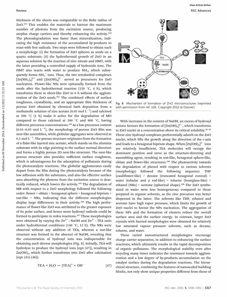
Fig. 8 Mechanism of formation of ZnO microstructures (reprintedwith permission from ref. 126; Copyright 2012 @ Elsevier).
Review RSC Advances
Publ
ishe
d on
06
Nov
embe
r 20
14. D
ownl
oade
d on
1/2
/202
2 11
:31:
21 A
M.
View Article Online
thickness of the sheets was comparable to the Bohr radius ofZnO.123 This enables the materials to harvest the maximumnumber of photons from the excitation source, producingsurplus charge carriers and thereby enhancing the activity.124
The photodegradation was faster than mineralization, indi-cating the high resistance of the accumulated by-products toreact with free radicals. Two steps were followed to obtain sucha morphology: (i) the formation of ZnO spheres as seeds on aquartz substrate; (ii) the hydrothermal growth of ZnO in anaqueous solution by the reaction of zinc nitrate and HMT, withthe latter providing a controlled supply of hydroxide ions. TheHMT also reacts with water to produce NH3, which subse-quently forms NH4
+ ions. Thus, the two tetrahedral complexes[Zn(NH3)4]
2+ and [Zn(OH)4]2� served as precursors for ZnO
nucleation. Flower-like NSs were epitaxially formed from theseeds aer the hydrothermal reaction (150 �C, 4 h), whichtransforms them to sheet-like ZnO in 6 h without the agglom-eration of the ZnO seeds.123 The combined effects of surfaceroughness, crystallinity, and an appropriate lm thickness ofporous ZnO obtained by chemical bath deposition from amethanolic solution of zinc acetate (0.05 mol L�1) and calcinedat 500 �C (1 h) make it active for the degradation of MOcompared to those calcined at 300 �C and 800 �C, havingdifferent precursor concentrations.125 At a low precursor content(0.01–0.05 mol L�1), the morphology of porous ZnO lm wasnest-like assemblies, while globular aggregates were observed at0.1 mol L�1. The porous structure originates from the formationof a ake-like layered zinc acetate, which stands on the aluminasubstrate with its edge pointing to the surface normal directionand forms a highly porous 2D nest-like structure. The nest-likeporous structure also provides sufficient surface roughness,which is advantageous for the adsorption of pollutants duringthe photocatalytic reactions. The globular agglomerates easilydepart from the lm during the photocatalysis because of thelow adhesion with the substrates, and also the effective surfacearea absorbing the photons from the excitation source is dras-tically reduced, which lowers the activity.125 The degradation ofMB with respect to a ZnO morphology followed the followingorder: ower > oblate > hexagonal sphere > hexagonal biprism >nut-like > NRs, indicating that the different morphologiesdisplay large differences in their activity.126 The high perfor-mance of ower-like ZnO was attributed to the greater exposureof its polar surface, and hence more hydroxyl radicals could beformed to participate in redox reactions.127 These morphologieswere obtained by varying the Zn2+ : NaOH and Zn2+ : TEA ratiounder hydrothermal conditions (140 �C, 12 h). The NRs wereobserved without any addition of TEA, whereas a nut-likestructure was formed in the absence of NaOH, revealing thatthe concentration of hydroxyl ions was indispensible forobtaining such diverse morphologies (Fig. 8). Initially, TEA willhydrolyze to produce the hydroxyl ions (eqn (47)), resulting inZn(OH)2, which further transforms into ZnO aer calcination(eqn (43)–(46)).
TEA + H2O 4 [TEA]+ + OH� (47)
This journal is © The Royal Society of Chemistry 2015
With increases in the content of NaOH, an excess of hydroxylanions favours the formation of [Zn(OH)4]
2�, which transformsto ZnO nuclei at a concentration above its critical solubility.91–93
These zinc hydroxyl complexes preferentially adsorb on the ZnOnuclei, which lis the growth along the direction of the c-axisand leads to a hexagonal biprism shape. When [Zn(OH)4]
2� ionsare relatively insufficient, TEA molecules will occupy thedominant position and serve as the structure-directing andassembling agent, resulting in nut-like, hexagonal sphere-like,oblate and ower-like structures.126 The photoactivity towardsthe degradation of phenol with respect to various solvents(morphology) followed the following sequence: THF(cauliower-like) > decane (truncated hexagonal conical) >water (tubular and a rod-like) > toluene (hourglass-like) >ethanol (NRs) > acetone (spherical shape).128 The ZnO synthe-sized in water were less homogeneous compared to thoseprepared in organic solvents, as the zinc precursor was betterdispersed in the latter. The solvents like THF, ethanol andacetone have high vapor pressure, which limits the growth ofZnO nuclei to favour the NPs nucleation. The aggregation ofthese NPs and the formation of clusters reduce the overallsurface area and the surface energy. In contrast, larger ZnOcrystals with faceted morphologies were obtained for relativelylow saturated vapour pressure solvents, such as decane,toluene, and water.
These varied nanostructured morphologies encouragecharge carrier separation, in addition to enhancing the surfacereactions, which ultimately results in the rapid decompositionof organic pollutants. The morphological stability even aerrecycling many times indicates the resistance towards agglom-eration and a low degree of by-products accumulation on thecatalyst surface during the degradation reactions. The hierar-chical structure, combining the features of nanoscaled buildingblocks, not only show unique properties different from those of
RSC Adv., 2015, 5, 3306–3351 | 3317

RSC Advances Review
Publ
ishe
d on
06
Nov
embe
r 20
14. D
ownl
oade
d on
1/2
/202
2 11
:31:
21 A
M.
View Article Online
the bulk, but also provide more opportunity for the surfacephotochemical reaction to realize the morphology dependentsurface reactivity.129 Therefore, it is desirable to develop a facileprotocol for the morphology controlled ZnO with low costprecursors and without special equipment, harsh experimentalconditions or toxic reagents. Despite having comprehensivestudies relating to the effects of the synthesis parameters on theformation of ZnO, the literature is not quite convincing inestablishing relationships among the synthesis parameters,morphological properties and the photocatalytic activity.Understanding such interdependences will provide an insightinto the origin of the chemistry behind the photocatalysis,which should advance our capability to utilize ZnOnanocrystals.
4. Photocatalytic activity of metalion-doped ZnO
The doping of metal oxides (TiO2 or ZnO) with foreign ions/impurities initially changes the coordination environment ofhost metal ions in the lattice and also modies the electronicband structure via introducing localized electronic energy levelswithin the bandgap states. The former alters the pristine defectstructure, and thus affects the mobility of charge carriers,whereas the latter enables a more efficient manipulation ofincident photons. The dopant impurity level situated eitherabove the VB or below the CB momentarily traps the photo-generated charge carriers, thus affecting their redoxpathways.130
(a) Doping with alkali metal ions
Li (10%)–ZnO was more active for the degradation of 4-NPunder visible light compared to Na–ZnO and K–ZnO, primarilydue to the electron trapping ability of Li+ ions, the small crys-tallite size and high surface roughness.131 The bandgapwidening and efficient charge carrier transfer process wereidentied as the factors responsible for the sunlight-drivenactivity of Mg (0.1%)–ZnO for the degradation of MB.132 Theincrease in optical bandgap energy by Mg2+ doping was attrib-uted to the Moss–Burstein effect, which was caused by electronsgenerated from the oxygen vacancies.133 The substitution ofZn2+ by Mg2+ intensies the oxygen vacancies and the electronconcentration due to the differences in electronegativity and theionic radius between the host (Zn) and the guest (Mg). Thisincrease in carrier density lis the Fermi level into the CB of adegenerate semiconductor, resulting in the bandgap widening.Cubic MgO crystallized at a higher Mg2+ doping (0.2%) served asthe recombination centres.132
(b) Doping with transition metal ions
The enhancement in the defect concentration of ZnO by Zr4+
(1.5 wt%) doping resulted in a faster degradation of resorcinol.95
The small crystallite size decreases the diffusion path length forthe movement of charge carriers from the bulk to the surface,and the size quantization of the bandgap enhances the redoxpotential of the charge carriers. However, a complete
3318 | RSC Adv., 2015, 5, 3306–3351
mineralization was observed only with a 365 nm excitationsource rather than at 254 nm. The UV light photolysis indicatedthat the intermediates formed during the course of degradationsignicantly absorb light energy at 254 nm, thus shuntingthe photons away from the ZnO surface. Because resorcinoldoes not absorb at 365 nm, the complete absorption of light byZr–ZnO facilitates the generation of reactive free radicals in thesolution, which accounts for the complete mineralization. Thedoping of Ta5+ into ZnO by a modied Pechini-type methodusing water soluble peroxo–citrato tantalum complexes as aTa5+ source was positive for the degradation of MB under visiblelight, which is attributed to a competitive trade-off between thecrystallinity, surface hydroxyl groups and the specic surfacearea.134 It was predicted that the crystallinity should dominateover the other two factors in enhancing the efficiency. Theactivity at different annealing temperatures of Ta (1 mol%)–ZnOhad the following order: 700 > 800 > 900 > 600 > 500 �C. As theannealing temperature increases, the crystallinity is improvedwith the loss of surface hydroxyl groups and surface area. Thedegradation rate increases by two fold with a change in the pHof the dye solution from 5 to 8 but declined at higher pH values.The high degree of hydroxylation combined with the efficientadsorption between cationic MB and the surface negativelycharged Ta–ZnO contributes to the overall efficiency at pH 8.Although the adsorption of MB was drastically improved at pH >8, the density of the hydroxyl groups decreased and the ruptureof hydroxylation on the catalyst surface suppressed the activity.The degradation rate with respect to the dopant content fol-lowed the following order: 1 > 1.5 > 0.5 > 2.0 > 3.0 mol%.135 Theparticle size increased, resulting in the loss of surface areawith increase in dopant concentration (>1 mol %) and anorthorhombic ZnTa2O6 was formed at a very high content ofTa5+ (4 mol%). The substitution of Ta5+ into the host Zn2+
resulted in the formation of defects, such as zinc and oxygenvacancies, which form an intermediate electronic level withinthe bandgap, enabling the visible light absorption and alsorestraining the carriers from recombination.
Null ¼ V00Zn þ Vcc
o (48)
Ta2O5 ������!ZnO2TacccZn þ 3V 00
Zn þ 5Oo (49)
Oo/Vcco þ 1=2O2 þ 2e� (50)
The oxygen vacancy forms a deep donor at�1.0 eV below thebottom of the CB, and the zinc vacancy defect is relativelyshallow at �0.4 eV above the top of the VB.136 The dopingchanged the morphology of ZnO from NRs to NPs with aspheroidal shape. The catalyst still retained its activity evenaer storage for 90 days in air, attesting to its excellent stabilitydue to its high crystallinity.
The defect-free Cr (�3 at.%)–ZnO obtained via the sol-vothermal treatment (120 �C, 12 h) in ethanolic solution underan alkaline medium showed visible light activity towards thedegradation of MO.137 The visible light response originatedfrom the ‘sp–d’ exchange interactions between the CB electrons
This journal is © The Royal Society of Chemistry 2015
Review RSC Advances
Publ
ishe
d on
06
Nov
embe
r 20
14. D
ownl
oade
d on
1/2
/202
2 11
:31:
21 A
M.
View Article Online
and localized ‘d’ electrons of the Cr3+ ions, which substitute forthe Zn2+ ions.138 The ‘s–d’ and ‘p–d’ exchange interactions leadto a negative and a positive correction to the CB and VB edges,respectively, resulting in a red shi in the bandgap absorp-tion.139 Mn (1%)–ZnO obtained by the wet chemical precipita-tion technique was detrimental to the degradation of MB underUV light, but was benecial under visible light.140 The contri-bution from the donor states (oxygen vacancies and interstitialzinc) and acceptor states (zinc vacancies and interstitial oxygen)enhanced the optical absorption in the visible region, and thusthe photoactivity.141 The Mn–ZnO creates electron–hole pairs atthe tail states of CB and VB, respectively, under visible light. Theexcited electron transfers to the adsorbed MB molecule on theparticle surface and disrupts its conjugated system, leading toits complete decomposition. The VB holes react with water orhydroxide ions to generate hydroxyl radicals, which furtherdegrade the pollutant molecules.140 In another study, both Mn(1%)–ZnO and ZnO obtained by a conventional method (i.e. aslow crystallization process) showed a low activity for thedegradation of MB under visible light against the defect rich (i.e.zinc interstitials and oxygen vacancies) ZnO, which was crys-tallized under microwave conditions.142 Heating of theprecursor solution occurs locally due to the molecular rotationof the medium, arising from their interaction with the electro-magnetic elds of incoming microwave radiation. This assistsin a quick energy supply for the reaction, thus resulting in afaster nucleation and growth of nanocrystallites.143 The rapidinclusion of zinc and oxygen atoms into the crystal latticecreates interstitial defects, which then induce the mid-gapstates, which serve as intermediate steps for the electrons andholes during the photoexcitation process. This means thatinstead of absorbing one UV-photon, an electron arrives at theCB by utilizing multiple photons from visible light. In the caseof a conventional heat treatment to induce crystallization, heatpasses by convection from the walls of a container towards thecentre and takes a long time before establishing thermal equi-librium between the precursor and its surroundings. Thus, thethermal decomposition of the precursor contents and thesubsequent formation/crystallization of ZnO or Mn–ZnO occurvery slowly, resulting in the formation of nearly defect-freenanocrystals. The doping of Mn2+ (2 mol%) was positive,while Co2+ (1–5 mol%) incorporation was detrimental for thegeneration of hydroxyl radicals, wherein, these doped catalystswere prepared by a three-stage process, consisting of a highenergy mechanical milling, heat treatment and washing.144 Itwas proposed that Co2+ doping served as recombinationcenters, while the presence of a secondary phase like Mn3O4
and Mn3�xZnxO4 favoured the charge separation in Mn–ZnO.Casey et al.66 and Barick et al.145 suggested that the dopants suchas Fe2+, Ni2+, Co2+, and Mn2+ were not benecial to enhance thephotoactivity of ZnO. Interestingly, Co–ZnO with bicrystallinewurtzite–zinc blende phases showed high activity for thedegradation of MB and phenol under visible light.146 The cobaltdoping induced a red shi in the visible light absorption andhomojunction between the mixed phases, together withincreased surface oxygen vacancies, thus promoting the chargecarrier generation–separation pathways. The undoped ZnO had
This journal is © The Royal Society of Chemistry 2015
a wurtzite structure and that doping of Co2+ led to the formationof CoO having a zinc blende crystal structure, and which servedas substrate for the growth of ZnO in the zinc blende phase.This is a very rare report on the activity of mixed phase ZnO andfurther research should focus on tuning the ratios of the mixedphases and understanding the charge carrier transfer pathways.
The doping of Ni2+ (1–15 wt%) into ZnO thin lm via acombined sol–gel and dip coating method was detrimental forthe degradation of MG under UV/visible light, despite Ni2+
doping reduced the crystallite size of the catalyst.147 The Ni2+
served as a p-type dopant in ZnO and acts as a recombinationcentre.148 The decrease in the effective charge carrier concen-tration lowers the band bending near the crystallite surface,thus suppressing the driving force for the charge carrier sepa-ration. However, the photostability of both the lms wereexcellent, as revealed by SEM images, in which the ganglia-likehills and wrinkles morphology of the lms were not changedeven aer recycling in three subsequent runs. In contrast, anincrease in the doping concentration of Ni from 0% to 5% intoZnO NRs increased the degradation of RhB, as the dopantinduced a distortion of the local electric eld and the chargecarriers were then trapped around the dopant. At a higherdopant concentration (�10%), the bandgap of a doped catalystdecreases, thus reducing the energy of excited electrons andthen the excess dopant promotes the recombination process.149
However, the doping of Pd2+ into ZnO decreased the surfacearea and improved the activity for the degradation of MO.150 ThePd2+ doping introduced a new electronic energy level within thebandgap states, which served as a shallow trap for chargecarriers. The charge carriers were efficiently separated with anincrease in the Pd2+ content from 2% to 3%, followed by asudden decrease at high concentration. At this optimum dopantconcentration, the surface barrier becomes higher and thespace charge region becomes narrower. The electron–hole pairswithin the region are efficiently separated by a large electriceld traversing the barrier, which promotes the charge carriergeneration–separation–transfer pathways. For higher dopantconcentrations, the space charge region becomes very narrow,and as the penetration depth of light into ZnO greatly exceedsthe space charge layer, this facilitates carrier recombination.151
The sequence in activity of Cu–ZnO with different dopantcontents for the degradation of MO was in correlation with theFS technique, namely, the lower the intensity, the higher theactivity.152 Because the FS emission arises from the recombi-nation of excited charge carriers, a lower FS intensity indicates areduced recombination. Thus, Cu–ZnO with 0.5 wt% of Cu2+
was benecial, while a higher dopant level was found to hinderthe activity. The doped Cu2+ traps the electron and detraps it toadsorbed oxygen to produce superoxide radicals, whereas thesurface hydroxyl groups trap the holes to form hydroxyl radicals.The optimum heat treatment for this catalyst was found to be350 �C (3 h).152 The Cu-doped Zn–ZnO composite modied by asurface carbon species exhibited visible light activity for thedegradation of Reactive Brilliant Blue KN-R dye.153 In thepreparation method, CO2 dissolved in solution was converted tocarbon, which then adhered onto the composite surface. Thedoping of copper promotes the crystal growth of ZnO, inhibits
RSC Adv., 2015, 5, 3306–3351 | 3319

RSC Advances Review
Publ
ishe
d on
06
Nov
embe
r 20
14. D
ownl
oade
d on
1/2
/202
2 11
:31:
21 A
M.
View Article Online
the phase transfer of metallic Zn to ZnO and enhancesabsorption in the visible region. The composite with a 2.0 at.%Cu loading under hydrothermal treatment (180 �C, 2 h) wasreported to have a high activity, which was attributed to: (i) thesubstituted Cu2+ serving as a deep acceptor along with theoxygen vacancy, which substantially improves the electrontransport properties;154 (ii) the metallic zinc clusters acting aselectron sinks, due to the Schottky barrier formation at Zn–ZnOinterface, in which the bulk Zn is surrounded by a ZnO shell;(iii) the surface carbonaceous species having a high propensityfor adsorbing the reactants, which facilitates the transfer ofreactants to the active sites, and thus improves the surfacechemical reactions.155 The formation of (Cu,Zn)7(SO4)2-(OH)10$3H2O impurity at a higher copper doping level (4–6at.%) did not inuenced the activity. The surface doping ofcopper (Cu1+dO) on ZnO enhanced the reaction rate for thedecomposition of OG and MB under UV/visible light. Theoptimum concentration of copper was found to be 1.5 and 0.5mol% for the catalysts prepared by the aqueous method and thesolid state reaction, respectively.156
Fig. 9 Charge transfer pathways in Ce–Ag–ZnO (reprinted withpermission from ref. 163; Copyright 2012 @ Royal Society ofChemistry).
(c) Doping with rare earth ions
Nd3+(1%)–ZnO nanoneedles synthesized via an ultrasonic-assisted method were active for MB degradation, as Nd3+
served as an electron scavenger to inhibit the recombination.157
The doping of Ln3+ (Nd3+-4 wt%, Sm3+-8 wt% and La3+-4 wt%)into the ZnO matrix by the polymer pyrolysis method waspromising for the 4-NP degradation, which is attributed to thechange in the structural properties, such as the surface area andthe crystallite size.158 A suitable loading of the dopant iscompulsory for producing a signicant potential differencebetween the surface and the centre of the particles to separatethe photoinduced electron–hole pairs, as an excess of Ln2O3
covering the ZnO surface may facilitate the carrier recombina-tion. The secondary phase of La2O3 nucleated at $3 mol%doping of La3+ into the ZnO matrix via the precipitation route,whereas it was observed at 10 mol% La3+ in the ball millingmethod, indicating a high degree of dopant solubility at roomtemperature in the latter.159 The doping of La3+ (1 mol%) intothe ZnO matrix was constructive in the former and detrimentalin the latter case for the degradation of MB, which is mainlyattributed to an increase or decrease in the oxygen vacanciesaer doping, respectively. The relative photonic efficiency of La(0.8 wt%)–ZnO for TCP and MCP degradation was relativelyhigher compared to ZnO under the excitation wavelengths of254 nm and 365 nm.160,161 This was attributed to the combinedfactors of large surface area, quantized bandgap and highdensity of oxygen vacancies, which collectively lead to an effi-cient adsorption of pollutants on the catalyst surface, a highredox potential for charge carriers and an enhanced productionof hydroxyl radicals, respectively. The charge carrier separationwas effective with the 254 nm excitation source, as it excites theelectron with high kinetic energy, and hence they escape fromthe recombination channels. The degradation rate reached amaximum at pH 10 for MCP, but declined thereaer. BecauseMCP is not protonated at pH > 10, the electrostatic repulsion
3320 | RSC Adv., 2015, 5, 3306–3351
between the surface charges on the adsorbent and adsorbateleads to an inefficient adsorption. The low reaction kinetics atacidic pH was due to the overcoverage of MCP on the ZnOsurface, which prevents the catalyst from photon absorption.161
The Ce4+ doping changed the morphology of ZnO from nano-plates to nanospheres and enhanced its activity for the degra-dation of MB (pH 5.4–9). In this study, a simple reuxingmethod (90 �C) was used to incorporate Ce4+ into the ZnOlattice. A Ce4+ content of 0.05 mol%, reuxing time of 9 h,catalyst dosage of 0.15 g and a calcination temperature of 400 �C(2 h) were found to be optimum conditions to achieve highperformance.162 The photoactivity of Ce–Ag–ZnO towards thedecomposition of Napthol Blue Black dye increased under solarlight up to pH 9, but declined thereaer, exactly correlating todye adsorption on the catalyst surface at different pH condi-tions.163 The synergistic effect between silver and Ce4+ (i.e. Lewisacid) to trap a CB electron with its subsequent transfer to theadsorbed oxygen was responsible for such a high activity(Fig. 9).
The doping of foreign ions into ZnO appears to be an alter-native approach to modify the physical (i.e. crystallite size andsurface area), electronic (i.e. bandgap energy and defectconcentration) and morphological features and make themsuitable for photocatalytic applications. However, the literaturereveals widespread disagreement related to the above-mentioned properties as follows: (i) a shi in bandgap towardsthe visible region is observed with transition metal ion doping,whereas quantization in the bandgap is noticed upon dopingwith alkali metal ion and rare earth ion doping; (ii) the changein crystallite size does not correlate with the bandgap energy;(iii) the morphological changes aer the doping are unclear, astheymay also originate from the counter-anion of the precursor;(iv) the change in the defect density distribution of defect-free ordefect-rich sites is almost impossible to predict owing to itsdependence on the experimental conditions; (v) the dopantscan either inhibit or promote the crystal growth; and (vi) the
This journal is © The Royal Society of Chemistry 2015
Review RSC Advances
Publ
ishe
d on
06
Nov
embe
r 20
14. D
ownl
oade
d on
1/2
/202
2 11
:31:
21 A
M.
View Article Online
precipitation of impure dopant oxides may change the chemicalcomposition of ZnO itself. The corrosion–dissolution of ZnO atextreme pH conditions leaches the substituted metal ion fromthe matrix, thus creating toxicity. These issues must be takeninto consideration for designing the doped ZnO nanostructurein near future.
5. Doping with nitrogen (N–ZnO orZnO1�xNx)
The cation doping usually produces additional defects orimpurities in ZnO, which may act as recombination centers. Incontrast, doping with non-metals with small radii are prom-ising candidates, because they easily substitute for latticeoxygen sites of ZnO or can occupy interstitial sites. Due to itslarger solubility in metal oxides and its comparable size withoxygen, nitrogen is widely used as a dopant to modify theelectronic structures of metal oxides, as only small formationenergy is required for the substitution process. In addition, thelow electronegativity and low ionization energy of nitrogencompared to oxygen reduces the electron density around thedoped nitrogen in the pristine oxide.164
(a) Photoactivity of N–ZnO
Highly crystalline N–ZnO obtained via a vacuum atmospheremethod (380 �C, 2 h) usingmelamine as the nitrogen source wasactive for the degradation of MO under simulated daylightillumination.165 The melamine transformed into isocyanic acidupon heating (120 �C), which then reacted with residual oxygenor water in the vacuum tube chamber to form ammonia, whichsubsequently mixed with ZnO to form N–ZnO.
NH3 4 NH2� + 2H+ (51)
xNH2� + ZnO 4 ZnO1�xNx + xH2O (52)
In addition, melamine combines with oxygen and a smallamount of N2 was also generated, further promoting thenitrogen doping into ZnO via diffusion of the nitrogen atoms.Interestingly, unreacted isocyanic acid was transformed tomelamine during the cooling process, which could then becollected for reuse.165 The surface doping of nitrogen on theZnO TPs showed visible light activity for the degradation of bis-phenol A.166 It was proposed that the nitrogen forms isolated N2p states above the VBM, which intensies the absorption in thevisible region. The electron–hole pairs generated between the N2p states and the CB of Zn 3d levels are separated throughtrapping from surface adsorbed oxygen and the hydroxylgroups, respectively. The N–ZnO prepared by the decompositionof zinc nitrate in air (350 �C, 3 h) showed a high performance forthe reduction of Cr(VI) and oxidation of MO under visiblelight.167 However, the activity of N–ZnO was lower for theoxidation of MO and better for the reduction of Cr(VI) comparedto pure ZnO under UV light. Based on rst principle calcula-tions, it was proposed that nitrogen doping into ZnO will causethe appearance of a redundant carrier, i.e. a hole near the top of
This journal is © The Royal Society of Chemistry 2015
VB. The mutual exclusion effect between the holes will enablethe carriers to form a narrow-deep acceptor level in the energygap and induce a conductivity conversion of N–ZnO from the n-type to the p-type, which was also supported by iodometrictitrations.168 Thus, photoformed holes move towards the inte-rior of the p-type semiconductor under illumination, whileelectrons migrate to the surface to favour the reduction process.In another study, N–ZnO obtained using zinc nitrate undersolvothermal conditions (260 �C, 20 min, followed by calcina-tion at 400 �C, 2 h), showed an appreciable performancetowards the degradation of RhB.169 The increased oxygendefects, improved absorption ability of the incident photonsand extended carrier lifetime were responsible for the highphotocatalytic activity. In the synthesis step, zinc nitrate coor-dinates to oleylamine and forms zinc–oleylamine complex(130 �C), followed by a pyrolysis to form N–ZnO at hightemperatures. The oleylamine serves as a structure directingagent, inuencing the nucleation and aggregation process ofthe NPs, which are ultimately assembled to microspheres with amesoporous structure. Liu and co-workers170 suggested thatsubstitutional nitrogen doping in semi-crystallized ZnO NPswas effective for the degradation of RhB under visible light. Incontrast, such successful doping failed in highly crystallizedZnO, during the calcination in gaseous ammonia atmosphere(400 �C, 30 min). The partially disordered structure and defectsin the surface layers of semicrystallized ZnO serve as reactivesites (i.e. energetic) for the substitution of nitrogen during theheating process. In contrast, the long-range ordered surfacestructure of crystallized ZnO requires a high energy for thesubstitution of nitrogen into oxygen and could not be accom-plished at 400 �C. The N–ZnO bundle-like NPs obtained fromthe ZnOHF precursor demonstrated exceptional visible lightinduced water oxidation without an applied bias, and theactivity was further enhanced by loading IrO2 co-catalyst.171 TheZnOHF decomposed to ZnO and HF during heat treatment in aNH3 gas ow (973 K). The ZnO intermediate was subsequentlydoped with nitrogen, while HF reacts with ammonia gas to forma NH4F ake-like by-product. However, this N–ZnO was lessactive for the degradation of MB under visible light. As themechanism for water oxidation and pollutant degradation areentirely different, it was suggested that the surface of N–ZnOpossesses energetic sites for oxygen evolution, but lacks reactivesites for pollutant degradation. The ZnO is partially reduced in ahighly reductive atmosphere and the resulting Zn is vaporizeddue to its low melting point at high calcination temperature(1073 K).171 The doping of nitrogen as No acceptor states isdetrimental for the degradation of MO degradation.172 The PLstudies indicate that N-related defects increase with theincrease in nitrogen content and are accompanied by a rapidrecombination process. The heavily doped (No) acceptor statesprovide a large number of internal holes, which may hinder theformation of photogenerated holes.
(b) Coupling of N–ZnO with other semiconductors
The glass–ZnO–ZnO1�xNx and glass–ZnO1�xNx–ZnO hetero-junction was positive for the degradation of humic acid,
RSC Adv., 2015, 5, 3306–3351 | 3321

RSC Advances Review
Publ
ishe
d on
06
Nov
embe
r 20
14. D
ownl
oade
d on
1/2
/202
2 11
:31:
21 A
M.
View Article Online
indicating a synergism between ZnO and ZnO1�xNx.173 However,the activity was found to depend on the mode of the light illu-minating the composite: (i) the former was active when lightwas illuminated from the lm to the glass side, as holes accu-mulate on the ZnO1�xNx layer to produce more hydroxyl radi-cals, which then react with pollutants. While few carriers will begenerated in the outer ZnO layer and then the inability of humicacid to diffuse into the ZnO1�xNx layer in the latter case resultsin a low efficiency; (ii) the glass–ZnO1�xNx–ZnO was benecialwhen light was illuminated from the glass to the lm side,which is attributed to the efficient absorption of visible light bythe ZnO1�xNx layer. In the case of glass–ZnO–ZnO1�xNx, most ofthe incident light will be lost via diffuse reection in the ZnOlayer, and also, the outer ZnO1�xNx may poorly absorb theincident photons.
The nitrogen doping into ZnO via spray pyrolysis at 600 �Cimproves the activity for the decomposition of CH3CHO undervisible light.174 The nitrogen atom exists in two chemical forms:one was site-N (i.e. nitrogen substituting the oxygen atoms ofZnO), while the second was residual nitrogen originatingfrom the precursors. A further improvement in the performanceof N–ZnO was achieved by coupling with WO3 (or V2O5) underUV/visible light, while the efficiency was hampered in the caseof Fe2O3.175–177 The nitrogen content in the catalyst increasedmonotonically with the increase in WO3 (or V2O5) added, whileit was insensitive to the addition of Fe2O3. The highest activitywas observed at 0.7 wt% Fe and 5.8 wt% for W series powders atthe spray pyrolysis temperatures of 800 �C and 1000 �C,respectively. Under visible light, the nitrogen dopant forms anenergy state above the VB of ZnO, serving as a “stepping stone”for electron transfer from VB to the impurity level and from theimpurity level to the ZnO CB. Then, the electron transfers toWO3 (or V2O5) CB, while the hole migrates in the oppositedirection. Tennakone et al.178 reported that W(VI) in WO3 couldeasily be reduced to W(V) by excited electrons and may bereoxidized to W(VI) by detrapping them to an adsorbed oxygen.In contrast, the CB and VB of Fe2O3 sandwiches between theZnO band edges, and thus both the electron and hole transfer inthe same direction, resulting in the recombination. The highactivity of V2O5–ZnO1�xNx compared to WO3–ZnO1�xNx isprobably due to the larger difference in the CB edge betweenV2O5 and ZnO, which facilitates a thermodynamically fasterelectron transfer process. A typical feature of sprayed catalysts isthe homogeneous distribution of ingredients throughout theparticle surface, as they are derived from a homogeneoussolution.174–177 The fabrication of hybrid SnO2 NFs decoratedwith surface bound N–ZnO showed a high performance for thedegradation of RhB under UV/visible light.179 According to theband energy diagram, photoelectrons generated in the CB ofSnO2 and the holes in ZnO VB can be separated at the hetero-junction by a favourable bias between the two sides. In addition,the lower resistance caused by the formation of oxygen vacan-cies upon nitrogen doping indicates an easy carrier transportand enhancement in the VB of ZnO.
Compared to the broad literature on N–TiO2, N–ZnO hasseldom been investigated, mostly due to the inconvenienceassociated with realizing the nitrogen doping process by the
3322 | RSC Adv., 2015, 5, 3306–3351
commonly developed synthesis routes. The undesired trans-formation of substituted nitrogen to molecular nitrogen atelevated temperature impairs the understanding of dopingprocess itself. However, low-temperature doping quite oenleads to poorly crystallized samples that cannot always guar-antee high activity. At the atomic level, the homogeneousdistribution of nitrogen dopant throughout the matrix isessential for narrowing the bandgap of the semiconductor,while surface doping oen leads to localized states, which maynot be very effective for a visible light response. The efficiency ofN–ZnO reported to date is not satisfactory, and thus leavesscope for further investigation.
6. Deposition with noble metals
Metal oxide–metal heterojunctions represent a novel class ofadvanced functional materials that have attracted tremendousinterest, owing to their promising applications in variouselds.180 The deposition of metal NPs on a semiconductorsurface is gainful, whereby the particle size could be indepen-dently controlled and a very narrow size distribution could beobtained. It is assumed that the metal NPs modify the reactivesites and the deposited noble metal itself serves as a catalyst todecompose the pollutants.181 The metal islands capture thephotoinduced charge carriers and intensify the light absorptionin semiconductor oxides, with both effects facilitating the redoxreactions and amplifying the photocatalytic efficiency.180 Thedouble layer charging around the metal NPs facilitates thestorage of electrons within them.182
6.1 Photocatalytic activity of Ag-deposited ZnO (Ag–ZnO)
The Ag (1.0 wt%)–ZnO obtained by the deposition–precipitationmethod showed a high activity for the degradation of MO due tothe maximum distribution of Ag and Ag–ZnO interface with alow concentration of surface oxygen defects. However, a sampleobtained by coprecipitation did not disperse well in dye solu-tion, resulting in a very low UV light utilization efficiency.183 TheAg NPs distributed along the hollow interior of the ZnO NRs,supported over Si (100) wafers, switch from superhydrophobicwith aWCA > 150� to superhydrophillic having aWCA < 10�, andalso have an inexion point at �110� under UV/visible light.184
The visible light was less effective in inducing super-hydrophilicity, as a WCA < 10� was reached aer an irradiationof 150 min, while it was otherwise attained in 8 min under UVillumination (Fig. 10). The surface recovered its super-hydrophobic character aer the samples were stored in thedark, with a full recovery aer ve days. It was proposed that theZnO close to the Ag NPs behaved as a superhydrophillic surfacebecause of the hydroxyl enrichment under the light illumi-nating conditions. The Ag NPs (1.66 wt%)–ZnO microrods withan interface between the {100} plane of ZnO (0.28 nm) and the{101} plane of Ag (0.235 nm) showed a strong performance forthe degradation of MB under UV/visible light, and furthermoretheir efficiency was maintained even aer ve consecutiveruns.185 The high crystallinities of ZnO (20 nm) and Ag (20–50nm) are responsible for the high performance, while a low
This journal is © The Royal Society of Chemistry 2015

Fig. 10 Switching the Ag–ZnO surface from superhydrophobic tosuperhydrophilic under UV (a) and visible light (b) illumination(reprinted with permission from ref. 184; Copyright 2012 @ RoyalSociety of Chemistry).
Review RSC Advances
Publ
ishe
d on
06
Nov
embe
r 20
14. D
ownl
oade
d on
1/2
/202
2 11
:31:
21 A
M.
View Article Online
concentration of surface defects in the micro/nano-conguredstructure improve the photostability. These structures possessan overall dimension in micrometer with nanosized units. Theassembled nanosized units are stabilized to ensure an improvedstructural stability, which reduces the aggregation. The Agislands on the ZnO surface act as electron wells to inhibit therecombination and the plasmatic effect of Ag NPs promote thephotocatalytic activity (Fig. 11). Dimer type Ag–ZnO NRs weresynthesized by the solvothermal method (160 �C, 24 h); wherein,Ag metals were embedded in the ZnO NR via Zn–O/Ag bondformation. The PL spectra revealed that the oxygen vacancydefect density increased to upto 5 at.% of Ag, but decreasedthereaer, exactly correlating to the observed efficiency ofAg–ZnO for the degradation of MO.186 The formation of oxygenvacancies was due to the intermolecular dehydrolysis of theprecursors to form a ZnO–Ag2O heterostructure, followed bytreatment with ethanol under solvothermal conditions.
ZnðOHÞ42� þ 2AgðOHÞ42�/ZnO�Ag2O �����������!ethanol-solvothermal
Ag� ZnOxð1� xÞV::
o (53)
Surprisingly, the concentration of ZnO aer Ag depositiondid not have any effect on the degradation rate. This composite
Fig. 11 Illustration of the process of the degradation of MB using Ag–ZnO microrods under UV and solar light irradiation (reprinted withpermission from ref. 185; Copyright 2012 @ American ChemicalSociety).
This journal is © The Royal Society of Chemistry 2015
had an excellent stability because of the surface-to-volume ratioof ZnO and the close contact between the Ag and ZnO.According to the proposed mechanism, an electron transferfrom ZnO to Ag or to the oxygen defects and nally to thesolution effectively suppress the recombination process.186
Highly ordered ZnO NRA fabricated via a wet chemical routeand photodeposited with Ag (0.05 M AgNO3) was shown to bepromising for the degradation of MB, and without a loss inactivity even aer ve consecutive runs.187 The ZnO micro-spheres modied with Ag NPs, prepared by a “one pot” strategyin an EG medium performed better for the degradation ofRhB.188 The EG served as a reaction medium for the formationof ZnO via a forced hydrolysis and also reduced Ag+ to Ag metal.The efficiency with respect to the Ag content had the followingsequence: 2.5 > 1.25 > 0.625 > 5.0 mol%. Thus, the deposition ofAg clusters with an appropriate amount on ZnO surfacecaptures and transfers the CB electrons to adsorbed species.The Ag NPs were found to aggregate and/or the size of the Agparticles increased at a high Ag content, thus promoting therecombination process. In addition, the large particle size of thecomposite was easily settled from the reaction system within 10min even without centrifugation.188 The deposition of 0.2 wt%Ag around the oxygen vacancy sites on the ZnO surface reducedthe defects, and improved the photostability and the efficiencyfor CV degradation without any change in the crystal structure,even aer recycling many times.189 The CB electrons trapped byAg react with chemisorbed/physisorbed/dissolved oxygen in thedye solution to form a reactive oxygen species. The suppressionof the degradation kinetics under the argon atmosphererevealed that the active oxygen formed by the reaction of the CBelectron and the oxygen chemisorbed on Ag was the potentialoxidant responsible for the dye degradation. This suggests thatthe metallic Ag promotes the reaction between chemisorbedoxygen and CB electrons to promote a charge separation, andhence the photostability. Although PL measurements revealedthe lowest intensity for 6.7% Ag–ZnO, the photoelectrochemicalmeasurements indicated a reduced photocurrent, as the holesget trapped by a large number of negatively charged Ag parti-cles, which is detrimental to photocatalytic reactions.190 Thisprocess of hole capture proceeds through a non-radiativepathway, which cannot be detected by PL measurements. Thehydrothermal synthesis (120 �C, 6 h) of Ag (6.2%)–ZnO in thepresence of HMT resulted in a faster degradation of RhB.191
During the composite preparation, HMT was transformed toNH3 and HCHO, which served as a precipitating agent for theformation of ZnO and as a reducing agent for Ag+ to metallicsilver. Pure ZnO exhibits a pillar and bundle-like morphology,while the addition of silver resulted in a rod-like structure. Incontrast, an increase in HMT concentration resulted in a pillar-like morphology, as it prevents the inuence of silver on theequilibrium between Zn2+ and NH3. The UV emission of ZnOwas enhanced aer depositing with Ag due to an increase in theconcentration of the excitons, as a result of the interfacebetween the Ag islands and ZnO.191
Ag (3 mol%)–ZnO prepared by a non-aqueous sol–gel processexhibited a higher activity compared to Degussa P25 andunmodied ZnO for the degradation of R6G under sunlight.192
RSC Adv., 2015, 5, 3306–3351 | 3323

RSC Advances Review
Publ
ishe
d on
06
Nov
embe
r 20
14. D
ownl
oade
d on
1/2
/202
2 11
:31:
21 A
M.
View Article Online
The segregation of Ag around the ZnO grain boundaries (whencalcined at 400 �C, 2 h) inhibits the grain growth and providesmore surface active sites, which enables the charge carriers toreact with the surface adsorbed molecules to form active freeradicals. The Ag modication was detrimental at high temper-ature (800–1000 �C), as Ag promoted the densication and graingrowth of ZnO by forming high surface energy silver islands,which reduces the surface active sites for pollutant adsorption,as well as for photon absorption. The degradation of R6G onAg–ZnO surface takes place by multiple charge transfer path-ways under visible light (Fig. 12). The high reduction potentialof R6G was found to be a vital factor that dominates the electrontransfer process and thereby denes the degradationpathway.192 The optimum Ag content towards hydrogen evolu-tion from a water–methanol mixture was found to be 1.6 and 8.3mol% under UV-vis and solar light, respectively.193 The betterdispersion of the Ag NPs and the large exposure of the ZnOsurface facilitate efficient light absorption in the former case,while the formation of a Ag2O–ZnO heterojunction additionallypromotes the activity in the latter case.194 The electron trans-ferred from ZnO CB to Ag NPs effectively reduces the H+ to H2 onits surface, while the holes oxidize the alcohol.
The worm-like Ag (2.8 at.%)–ZnO core–shell composite withthe single crystal Ag NWs serving as its core, on which a densecoating of ZnO particles grow as the shell, exhibits themaximum activity for RhB degradation.195 The synthesis routeinvolves the dispersion of single crystal Ag NWs into a mixedzinc acetate and TEA aqueous solution. The ZnO particle seedsare then partially deposited onto the surface of the Ag NWs toform nucleation sites for the subsequent growth. During theearly stages of ultrasonication, ZnO crystal nuclei are formedon the Ag lateral surface by the reduction reaction of zincacetate. The initial particle seeds so formed continuallyaggregate and crystallize over the course of the reaction time,leading to an increased diameter of ZnO shell. Finally, a dense
Fig. 12 Electron transfer events of the Ag–ZnO system in the pres-ence of R6G: (1) excitation of R6G from the ground singlet to anexcited singlet; (2) bandgap excitation of ZnO to generate an elec-tron–hole pair; (3) a sensitized electron transfer from the dye to ZnOCB; (4) sensitized electron migration from the dye or Ag islands; (5)electron transfer from the ZnO CB to Ag; (6) charge carrier recombi-nation; (7) shifting of the Fermi level of silver (reprinted with permissionfrom ref. 192; Copyright 2008 @ American Chemical Society).
3324 | RSC Adv., 2015, 5, 3306–3351
and complex worm-like heterostructure is formed.195 Guet al.196 reported a high activity of dendrite-like Ag (8 at.%)–ZnO, wherein the ZnO NRs were grown hetero-epitaxially onthe Ag NWs of the {111} and {100} lateral surfaces. This het-erostructure formation involved two steps: (i) single crystal AgNWs with a truncated-rhombic cross-section are dispersed inzinc nitrate and HMT solution. The Ag NWs have four {111}and {100} lateral surfaces, on which the ZnO NRs were grown;(ii) the nucleus of crystalline ZnO is formed on the Ag lateralsurfaces by the thermal decomposition of Zn2+ aminocomplex, followed by a preferential growth along the h0001idirection during the continuous chemical reaction. Thus, theZnO NRs grow perpendicular to the length direction of AgNWs, in order to minimize the interaction or competitionamong themselves. Finally, ultrathin ZNWs or NTs also growfrom ZnO NRs.196
6.2 Photocatalytic activity of M–ZnO (M ¼ Pd, Pt and Au)
The photocatalytic performance of ZnO for the degradation ofgas phase n-C7H16 and phenol in the liquid phase could beimproved aer depositing Pd (0.5 wt%) on the ZnO.27,197 Thelattice oxygen on the ZnO surface was reduced aer Pddeposition, accompanied by an enhancement in the adsorbedoxygen content as well as surface hydroxyl groups. The elec-tron transfer from CB of ZnO to the deposited metal and theadsorbed oxygen depends on the size and distribution ofmetal on the semiconductor surface. If the sizes of metal NPsare too large, its Fermi level will be lower than that of adsor-bed oxygen and the electrons cannot move uphill. In contrast,the Fermi level of very small size metal NPs lies above the CBof ZnO itself, due to the size quantized effect, thus disablingthe electron transfer from ZnO CB to metal NPs. Thus, anoptimal particle size is essential for the metal NPs, to ensurethat the Fermi energy level lies between ZnO CB and theadsorbed oxygen, to facilitate unidirectional electron transferfrom ZnO CB to the metal NPs, and then to the adsorbedoxygen.198
Pt–ZnO porous nanocages were fabricated through theincorporation of Pt into ZnO porous shells by an ultrasonicirradiation-assisted two-step etching of Zn–ZnO core–shell NPcolloids.199 The diameter of the Pt clusters was tuned from 2.5 to1.1 nm with a change in ultrasonic power from 160 to 400 W,and the size distribution became narrower. The rst step inH2PtCl6 etching induces core hollowing, and then Pt incorpo-rates through the diffusion–redox–deposition process. Thesecond step in C4H6O6 etching induces the nanoshell opening,due to the amphoteric nature of ZnO. These nanocages wereactive for the degradation of MO, which is attributed to theiroutstanding features: (i) abundant nanoscale Schottky barriers,formed because of their small size and high density ofembedded Pt clusters, which endow these nanocages with astrong interface to separate the charge carriers; (ii) a hollow andporous structure, which increases their specic surface area andthe active sites for redox reactions.199
Au–ZnO hybrid with a hexagonal pyramid-like morphologywas active for the degradation of RhB.200 These nanopyramids
This journal is © The Royal Society of Chemistry 2015

Review RSC Advances
Publ
ishe
d on
06
Nov
embe
r 20
14. D
ownl
oade
d on
1/2
/202
2 11
:31:
21 A
M.
View Article Online
possess a narrow size distribution, comprising Au NPs at the tipand hexagonal ZnO nanopyramids as the tail. In the presence ofoleylamine and dodecanol as the solvent and capping agent,respectively, ZnO nanopyramids epitaxially grow over the pre-synthesized Au seeds, in which Au decorates at the basal surfaceof hexagonal ZnO nanopyramids ({0001} polar plane) as a resultof the lower interfacial energy at the polar–metal interface.201 Inanother report, a multifunctional hybrid structure of Au NPsand a 3D hierarchical ower-like ZnO comprising a largespecic surface area and a small Au NPs was positive for thedegradation of RhB.202 The morphology of the Au–ZnO was verystable, and its efficiency was retained even aer three runs,underlining its extraordinary stability and reuse in photo-catalysis. The unique features of this composite are as follows:(i) interspaces in its ower-like nanostructures allow facilediffusion and the mass transportation of RhB molecules andhydroxyl radicals during the photochemical reactions; (ii) thestrong electronic interaction between the plasmonic Au NPsand ZnO result in an efficient charge transfer process; (iii) theAu NPs on the ZnO surface lower the work function203 and theadsorbed oxygen at the interface between Au and the ZnO,thereby facilitating an easy electron transfer to oxygen, whichproduces reactive oxygenated species to enhance the degrada-tion reaction. The Au (25.5%)–ZnO NRs had higher activity forthe degradation of RhB and 4-CP over ZnO NRs.204 In this study,gold was decorated on ZnO NRs via galvanic displacementreactions at room temperature with the aid of Cu foil and CoCl2solution. The dynamic force for a galvanic displacement reac-tion stems from the difference in the half-cell potentialsbetween the metal ions to be reduced and the substrate to beoxidized. For the deposition of metal NPs, the half-cell potentialof a reduced species must be higher than that of an oxidizedsubstrate. Consequently, Au NPs with a narrow size distributioncan be directly deposited onto a Cu foil without any additionalreducing or capping agents. CoCl2 improves the hindrancetowards homogeneous nucleation, while an autocatalyticgrowth of particles rapidly depletes the gold monomerconcentration in the solution, with both the effects collectivelyfavouring a heterogeneous nucleation. The mechanism of thedegradation of phenol involves the following steps; (i) scissionof the ring C–Cl bond to give a short-lived hydroxyphenylradical, which rapidly combines with a proton to form phenol,followed by o-hydroxylation, which results in catechol; (ii) the 4-chlorocatechol resulting from the hydroxylation of 4-CPundergoes p-dechlorination and subsequently reacts with the
Fig. 13 Photodegradation pathways of 4-CP (reprinted with permission
This journal is © The Royal Society of Chemistry 2015
protons in the presence of a CB electron to form catechol; (iii)oxidative hydroxylation of the catechol and phenol giveshydroxyhydroquinone and hydroquinone. Finally, the phenolicrings are opened to form aliphatic compounds, which oncontinuous oxidation lead to mineralization (Fig. 13).204 Thethiolate-protected Au NPs (2 wt%) decorated on ZnO exhibitedan enhanced activity without requiring any thermal activationfor both oxidative (R6G degradation) and reductive (thioninedegradation) pathways under visible light,205 which was incontrast to TiO2 with thiolate-protected gold NPs.206 Thepresence of ligands on the Au NPs imposed a large kineticsbarrier for an electron transfer from TiO2 to the gold NPs, andthus the catalytic activity was accelerated only aer removingthe ligand aer thermal treatment. In contrast, the thermaltreatment of Au–ZnO did not signicantly improve the activity,indicating that electron transfer through a linker ligand to theAu NPs occurs at a relatively short time-scale. The strongelectrostatic force of attraction between a negatively chargedcarboxylate anion of a glutathione molecule and a positivelycharged ZnO surface under neutral pH conditions resulted inAu–ZnO without the need of any additives. The mono-dispersed Au NPs surface avoids both direct- and trap-relatedcharge carrier recombination channels by extracting elec-trons from the photoexcited ZnO and supressing recombina-tion within the metal oxide.205 The photocatalytic activityincreased with an increase in gold size from 1.1 to 2.8 nm,which is in accordance with the electron transfer rate fromZnO to Au NPs, which followed the size-dependent capacitancemodel. Thus, both the photocatalytic and electron transferrates could be controlled by varying the size of the mediatinggold capacitors.207
The Au (3 wt%)–ZnO obtained by the ame spray pyrolysiswas effective for the degradation of MB, whereas Pt (1–3 wt%)–ZnO exhibited a poor efficiency, although PL measurementsrevealed the low degree of carrier recombination for both thecomposites.208 The deposition of Pt renders an ohmic contact,which neither induces the Fermi level shi towards morenegative potentials nor stores the photogenerated electrons, butrather it discharges them into the electrolyte.209,210 In contrast,the Schottky contact between the Au and ZnO facilitates effi-cient charge separation and induces a Fermi level equilibrationbetween the Au and ZnO. The metallic gold has an unusualcapacity to store electrons without facilitating their dischargeinto solution, and thus the photogenerated electrons getdistributed between the semiconductor and the metal layer.
from ref. 204; Copyright 2009 @ American Chemical Society).
RSC Adv., 2015, 5, 3306–3351 | 3325
RSC Advances Review
Publ
ishe
d on
06
Nov
embe
r 20
14. D
ownl
oade
d on
1/2
/202
2 11
:31:
21 A
M.
View Article Online
However, such an ohmic contact promotes the efficiency ofcertain photocatalytic reactions.211 The photoactivity of Au–ZnONRs for the degradation of MO was found to depend on thediameter and the densities of the Au NPs on the ZnO surface.For instance, Au deposited on ZnO NRs using 10�4 to 10�5 MHAuCl4 with photoirradiation for 30 min exhibited a higheractivity compared to other reaction conditions (10�3 or 10�4 MHAuCl4, 10 min).212 The maximum activity was observed for AuNPs < 15 nm, but then the activity declined for 30 nm. It wassuggested that the Au NPs with a smaller diameter and a highdensity on the surface of ZnO NRs induce a greater reductionin the built-in potential barrier, due to a large shi in theFermi level with CB.182,210 At higher metal loadings, theintensity of the incident light for the ZnO absorption will bereduced by the scattering, due to the larger Au NPs on the tips.In addition, the formation of a Schottky barrier at the junctionof ZnO NRs and Au NPs inhibits the electron injection fromthe semiconductor to metal.209,213 The charge distributionbetween UV-irradiated ZnO and gold NPs results in the Fermilevel equilibration. Additionally, the transfer of electrons tothe metal nanocore, followed by equilibration continues untilthe Fermi level reaches close to the CB edge of ZnO, and theneach injected electron within a gold NP shis the Fermi levelby 0.1 V, which obviously increases the photopotential of thenanocomposite electrode.210,214 The different optimum contentof metal NPs on the ZnO surface for maximising the photo-activity, as reported by several research groups, is due to thevaried morphologies of the composite, the crystallinity of themetal or ZnO, the charge density distribution and the densityof the interface contacts.
The multiple roles of the deposited metal, such as altering(i.e. increasing or decreasing) the surface defect concentration,increasing the chemisorbed oxygen and hydroxyl group density,and improving the charge carrier separation and visible lightresponse, together with changes in the morphology, make it anideal candidate for modifying the electronic properties of ZnO.The size of the deposited metal, the crystallinity of metal oxide,the segregation of the metal on the surface defective site of ZnOand the dispersivity of the metal–ZnO composite in the reactionsolution are the decisive factors dictating the photocatalysis.The disadvantage of metal aggregation to clusters and therelatively low coverage on the metal oxide surface at high andlow loadings, respectively, affect the photocatalytic properties ofthe composite materials.196,215 The decoration of noble metalsonto varied morphologies of ZnO under a wide variety ofpreparative methods attests to its structural stability, which isrequired for photocatalysis. More importantly, this compositeeasily settles down and retains its efficiency even aer manytimes of recycling and without an agglomeration of particulates.Rather than surface deposition, further research should focuson metal cores or metals embedded within metal oxides forpractical applications. However, the exact role of a depositedmetal in such an enhancement is yet to be realized in a nano-scale regime. The combination of well dened metal NPs withZnO opens the avenue to develop tunable nanoscale materials,and whose reactivity can be controlled by varying their intrinsicand extrinsic properties.
3326 | RSC Adv., 2015, 5, 3306–3351
7. Coupled semiconductors
The electronic-coupling of semiconductors with differentbandgaps to form heterojunctions has become a key focus ofresearch because of their unique properties that arise frominterfacial interactions at the nanoscale, which are notencountered in individual nanomaterials.216 A solid interfacialstructure is an underlying factor in establishing the chargetransfer behavior between different semiconductors in theirheterostructure, and thus their photocatalytic activities. It iswidely accepted that an extended carrier lifetime and anenhancement in the interfacial charge transfer to the targetedsubstrates can be attained by such heterostructures, i.e. throughthe formation of a heterojunction interface or an intrinsicallystaggered band offset.217 This improvement is related to theinterface electric eld built into junctions, originating from theband bending and the vectorial transfer of electrons and holesin the composite. Although pure ZnO has a defect-rich chem-istry, intense interest is devoted to hybridize it with othernanophase materials, as this is advantageous to overcome someintrinsic defects of ZnO and to impart it with new physico-chemical and optoelectronic properties, in order to extend itsapplications in various diverse elds.
7.1 Coupling of ZnO with metal oxides
(a) Photocatalytic activity of ZnO–TiO2. Photocurrentgeneration and the degradation of MB was enhanced for theZnO NRs–TiO2 composite (Zn/Ti molar ratio of 2 : 1) under UV-vis illumination, as the large surface area enabled maximumlight harvesting ability and improved the electron transportproperties.218 The deposition of titania NPs on the ZnO NRpassivates the surface recombination centers and act as a radialenergy barrier that can repel electrons from the surface of theZnO NRs. Alternatively, electron transport within a single crys-talline ZnO NR is considerably faster and the surface eldswithin each NR reinforces the charge separation because of thelonger diffusion length for the charge carriers.219 The preservedcrystallinity of TiO2 NPs and ZnO NRs permit an efficient elec-tron injection and transport within the composites. The Mott–Schottky plot revealed a large negative shi of CB and a highdonor density, which is attributed to the high concentration ofsurface states.218 The dispersion of titania on ZnO reduces thedefect density and inhibits photocorrosion.54 Anatase TiO2
immobilized on single crystalline TPs, such as ZnO, enhancethe degradation of phenol under a Hg lamp without a cut-offlter, although its activity is lower compared to Degussa P25under excitation wavelengths of >340 nm. The close matchbetween the {101} crystal plane of anatase with the ‘a’ and ‘b’values of hexagonal ZnO, facilitates an efficient heterojunctionvia an epitaxial growth mechanism.220 The highly crystallineZnO–TiO2 prepared by the direct mixing of sol and calcination(500 �C, 2 h) was active for the degradation of MO.221 The activityexhibited a linear tendency of rate constant against the value ofTi/(Ti + Zn), excluding at 75% because of the poor crystalliza-tion. This fact was conrmed by the increment in the
This journal is © The Royal Society of Chemistry 2015

Fig. 14 Energy band structure and electron–hole separation processof a tri-component SnO2–TiO2–ZnO system (reprinted with permis-sion from ref. 227; Copyright 2012 @ Elsevier).
Review RSC Advances
Publ
ishe
d on
06
Nov
embe
r 20
14. D
ownl
oade
d on
1/2
/202
2 11
:31:
21 A
M.
View Article Online
degradation rate with increases in the calcination time to 5–10h. The derived linear t followed the relation:
k ¼ 0:297þ 0:438
�Ti
Tiþ Zn
�(54)
Alternatively, treating the above composite with a 7–28%NH3 atmosphere (24 h, room temperature) and calcination at500–700 �C for 2 h also improved the crystallization andpromoted the anatase to rutile phase transition, consequentlyenhancing the photoactivity.222 The dominant hexagonalZnTiO3 was observed at 700 �C for the NH3-treated composite,while both the cubic and hexagonal ZnTiO3 phases were formedfor the untreated composite. However, a poorly crystallizedcomposite prepared by the in situ mixing of sol followed bycalcination showed very low activity.221
Macro-mesoporous thick lms of ZnO–TiO2 with homoge-neously distributed open porosity have shown promise for thedegradation of MO.223 The macroporous channels improve thelight harvesting capacity by enhancing the light transfer pathsfor photon energy distribution onto the mesoporous network.Such a structure-in-structure arrangement favours a moleculartransport control and prevents catalyst deactivation by the inertdeposits. Thus, the macro-/meso-porous structures offer readilyaccessible pore-walls for molecules and also diminish thepressure drop over a monolithic material.223 However, thecomposite activity was lower than for pure TiO2, indicating thatthe presence of ZnO was found to hamper the compositeactivity.224 It was proposed that the TiO2 particles were sur-rounded by ZnO lm, and an optical excitation results in elec-tron accumulation in the ZnO lm, while holes are conned tothe particles, which reduces the number of sites available fordegradation.223 The sulfated ZnO–TiO2 obtained via the modi-ed sol–gel route and calcination (550 �C, 4 h) using citric acidas a complex reagent with zinc sulfate showed a superiorperformance for the degradation of MO compared to thecomposite prepared with zinc chloride and zinc nitrateprecursors, indicating the role of the sulfate group in achievinga high activity.225 In addition, the sulfate group restrained theanatase phase even at a high calcination temperature in thecomposite. The sulfated ZnO–TiO2 showed a superacid behav-iour, which favours the transfer of CB electrons to the surface,resulting in an efficient charge carrier separation. The activitywas reduced aer washing with water due to the removal of thesulfate groups and also on calcination at 700 �C (4 h), because ofthe decomposition of the sulfate group, the increase in therutile content and the formation of impure ZnTiO3.225
The self-supporting ZnO–TiO2 fabricated by the tape castingand lamination process followed by calcination (600 �C, 3 h)exhibited a high activity for the degradation of Remazol Bril-liant Red F3B. At this temperature, the interdiffusion betweenZnO and TiO2 greatly prevents the formation of binarycompound and coarsening of the particles that favour an effi-cient photocatalysis.226 The formation of less active phases,such as Zn2TiO4 and Zn2Ti3O8, reduce the activity of thecomposite at high calcination temperatures (650–700 �C). Thetricomponent ZnO–TiO2–SnO2 prepared by the sol–gel method
This journal is © The Royal Society of Chemistry 2015
using a Sn(Zn)/Ti molar ratio of 0.05 and calcined at 500 �C (3 h)was more benecial for the degradation of MO compared to acomposite obtained by a solid state reaction under UV/visiblelight.227 The XPS revealed the formation of Ti3+ species, indi-cating the presence of many oxygen vacancies in the sol–gelcomposite. The TiO2 has a CB edge sandwiched between theZnO and SnO2, giving a “staggered” type-II heterojunction at thecomposite interface. Under light illumination, an electrontransfers from ZnO to TiO2 to SnO2, whereas a hole migrates inthe opposite direction to favour charge separation (Fig. 14). Theloss of crystallinity and rutile formation at high Sn(Zn)/Ti molarratios lower the activity. In another study, ZnO–TiO2–SnO2
(4 : 1 : 1) synthesized via a solid state reaction (calcined at500 �C, 2 h) was remarkably active for the degradation of MOcompared to TiO2 and SnO2, but had a lower activity comparedto ZnO.228 This situation was due to the presence of a highlyactive ZnO in association with a less active SnO2 in the tri-component system. The activity decreased with an increase inthe calcination temperature ($700 �C), due to the nucleation ofphotoinactive inverse spinel Zn2TiO4 and Zn2SnO4 polymorphs,and it was completely inert aer thermal treatment at 1300 �C(42 h) because all the oxides reacted to form solid solutionZn2Ti0.5Sn0.5O4.228 The photocatalytic activity of the ZnO NTarrays-TiO2�xNy and ZnO hollow sphere-TiO2 towards NOx
decomposition decreased with increase in the emission wave-length of the excitation source.69,229 The vectorial electrontransfer takes place from ZnO CB to TiO2�xNy (or TiO2) CB,whereas the hole transfers in the opposite direction to facilitatecharge separation. In addition, an additional energy levelcreated by Ti5O9 binds the excited electrons and also enablesthe formation of exciton by light with lower energy.229
The advantage of ZnO–TiO2 stems from the high absorbanceof ZnO and the better stability of TiO2. The three binarycompounds formed in this system are Zn2TiO4 (cubic), ZnTiO3
(cubic or hexagonal) and Zn2Ti3O8 (cubic),230 and any of thesesolid compound can nucleate via a solid state reaction,depending on the annealing environment, and the crystalstructure of ZnO and TiO2, together with their relative contents.As a consequence of the structural resemblance, Zn2Ti3O8 andZnTiO3 were formed with anatase and rutile, respectively. BothZnTiO3 and Zn2Ti3O8 are stable phases below 900 �C, whereasZn2TiO4 is most stable above this temperature.226 In fact,
RSC Adv., 2015, 5, 3306–3351 | 3327

RSC Advances Review
Publ
ishe
d on
06
Nov
embe
r 20
14. D
ownl
oade
d on
1/2
/202
2 11
:31:
21 A
M.
View Article Online
Zn2Ti3O8 is known to be a defect form of an inverse spinelstructure of Zn2TiO4 because of the missing Ti ions in thelattice.
(b) Photocatalytic activity of ZnO–SnO2. ZnO–SnO2 NFssynthesized by a combined sol–gel and electrospinning tech-nique have shown a high activity for the degradation of RhBcompared to the ZnO NFs and SnO2 NFs, due to their arrange-ment of a stable heterojunction and a large specic surfacearea.231 The average grain size of ZnO (42 nm) in the compositeis larger compared to pure ZnO (30 nm), whereas the averagegrain size of SnO2 (13 nm) in a coupled system is smaller thanpure SnO2 (31 nm). These electrospun–NF composites could bereclaimed easily by sedimentation without any loss of activity,due to their 1D nanostructural properties. A mesoporous-network-structured semicrystalline SnO2-high crystalline ZnOwas active for the degradation of MO.232 This was due to thepresence of more surface reaction sites, which favour theadsorption and transportation of the dye molecules. The TEMimage revealed a multipod framework for the composite andthat each NP is attached to several other NPs, indicating theformation of a stable heterojunction. In another study, thedegradation of MB using mesoporous ZnO–SnO2 collapsed inan acidic medium but improved in basic conditions, which wasrationalized on the basis of the surface charge density of SnO2
(PZC 4) and ZnO. The adsorption of cationic dye is favoured onnegatively charged metal oxide surfaces under an alkalinemedium.233 A high roughness of ZnO–SnO2 thin lms is bene-cial for the degradation of MB upon calcination (500 �C, 1 h)with a Zn : Sn atomic ratio of 80 : 20. In addition, thiscomposite lm was very resistant to acid etching with respect tophotostability.234 The maximum photocatalytic activity of ZnO–SnO2 prepared by a co-precipitation method for the degradationof MO was observed at 33.3 mol% of SnO2 at an annealingtemperature of 500 �C (10 h).235 The grain sizes of ZnO and SnO2
were smaller in the composite compared to their respective purephases, indicating the mutual interference of SnO2 and ZnO onthe particle growth dynamics. The activity was reduced at a hightemperature treatment ($700 �C), as ZnO reacts with SnO2 (4.8–95.2 mol%) to form a less photoactive Zn2SnO4, which wasotherwise observed at 1000 �C in a solid state reactionmethod.236 The uniform coating and tight decoration of SnO2
NPs on ZnO NRs resulted in a high performance for thedegradation of RhB. The PL investigation revealed a decreasedUV emission for the composite compared to the bare ZnO NRs,which reects the spatial charge separation from the type-IIband alignment.237 An extremely high adhesion of SnO2 NPson ZnO NRs was observed even aer ultrasonicating thecomposite in ethanolic medium. This composite was achievedby a two-step thermal evaporation approach: (i) ZnO NRs wereobtained through the thermal evaporation of zinc powder; (ii)SnO2 was coated on the pre-fabricated ZnO NRs from thethermal disproportionation of SnO powder.
ZnðsÞ þOðgÞ ������!600 �CZnOðsÞ (55)
SnOðsÞ ������!800 �CSnðgÞ þ SnO2ðsÞ (56)
3328 | RSC Adv., 2015, 5, 3306–3351
Hydrogen generation was observed from dye sensitized SnO2
(10–15 nm) attached to the large ZnO (�600 nm) particles undervisible light in the presence of a hole scavenger and a Pt co-catalyst.238 On the basis of the series of modications, it wasfound that the premixing of ZnO and SnO2 prior to dying andthe presence of a dye on SnO2 and Pt islands on ZnO favourhydrogen evolution. A photon absorbed by a dye molecule onthe surface of a SnO2, could inject an electron across a few SnO2
crystallites without losing energy to reach ZnO CB at a distanceof 120 nm from the ZnO surface, suggesting the involvement ofhot electrons with ballistic transport. Then, the electrons onZnO CB were captured by Pt islands to initiate water reduction.
2H2O + 2e� / 2OH� + H2 (57)
The bandgap, work function and electron affinity of ZnO are3.37 eV, 5.2 eV and 4.3 eV, whereas those of SnO2 are 3.5 eV, 4.9eV and 4.5 eV, respectively. The VB of ZnO is positioned betweenthe CB and VB of SnO2 and the CB of ZnO is positioned abovethe VB and CB of SnO2. Accordingly, a ZnO–SnO2 heterojunc-tion involves the vectorial transfer of an electron from ZnO toSnO2 and hole transfer in the reverse direction. Hence,this heterojunction not only serves as a source of carriersbut also acts as a sink for electrons and holes. The XPS revealedDEv ¼ 0.7 � 0.05 eV and DEc ¼ 0.2 � 0.05 eV for this hetero-junction.233 The surface acid–base properties, low-cost andcheap availability of SnO2 and ZnO, combined with thecompatibility of some specic crystallographic planes to form aheterojunction, would be very useful for the further design ofthis bicomponent system.239
(c) Photocatalytic activity of ZnO coupled with other metaloxides. ZnO–CuO prepared by the coordination–oxidation–homogeneous coprecipitation method exhibited a betteractivity for MO degradation under UV-vis light.240 Thecomposite was prepared by using a metallic copper as the Cu2+
source, NH3 as the coordination agent, air as the oxidizer andammonium bicarbonate as the precipitating agent, along withZnO. The change in the activity of the composite was in agree-ment with the analysis from particle growth dynamics. Theactivation energy for the growth dynamics in low (#450 �C) andhigh temperature ($450 �C) regions are 14.94 kJ mol�1 and59.84 kJ mol�1, respectively. At low temperatures, crystal parti-cles with a small size, an incomplete crystal lattice, and manyvacancies are obtained leading to a low crystal grain growthactivation energy, which contributes to the high photocatalyticactivity, while grain growth will be rapid, resulting in the loss ofsurface area and surface activity at high temperatures. Thus, thevacancies will be reduced, and hence the crystal grain growthactivation energy increases. In addition, ZnO–CuO was alsoeffective for the treatment of real textile waste water containingMO and MB dyes under visible light.241
ZnO–ZnO2 with small ZnO2 granules fused at the surface of aprismatic ZnO exhibited signicant activity for MO decompo-sition, due to the presence of either structural or energeticheterogeneity within the interfacial region of the composite.242
As-obtained ZnO2 from the aqueous reaction of zinc sulfate andH2O2 under an alkaline medium was less active, due to its poor
This journal is © The Royal Society of Chemistry 2015

Fig. 15 (a) Phase transformation from ZnO2 to ZnO; (b) rate constant (k) and normalized rate constant (k/x) vs. hydrothermal temperature (x is theZnO2-to-ZnO conversion) for the degradation of MO (reprinted with permission from ref. 242; Copyright 2005 @ Elsevier).
Review RSC Advances
Publ
ishe
d on
06
Nov
embe
r 20
14. D
ownl
oade
d on
1/2
/202
2 11
:31:
21 A
M.
View Article Online
crystalline nature. The hydrothermal treatment (120–180 �C,2 h) of ZnO2 gradually transformed it to ZnO, and a highphotoactivity was noticed in the range of 140–150 �C, while pureZnO obtained at 180 �C showed poor performance (Fig. 15). Thedifference in the electronic band structure between ZnO andZnO2 (4.12 eV) results in a potential gradient at the interface,and the interfacial structural defects serve as a trap site forexcitons, thereby suppressing recombination.242
The ball milling of n-ZnO in water doped with p-CaFe2O4
exhibited better activity for MB degradation, which was attrib-uted to the stable integrated micro p–n heterojunction.243 Theactivity increased with the increase in the content of p-CaFe2O4
by up to 1.0 wt% and decreased thereaer as the absorption oflight and the generation of electron–hole pairs were lowered,together with a decrease in the space charge region on theparticle surface. When the ball milling times were 3, 6, 12 and24 h, the degradation efficiencies were 50.8, 73.4, 78.7 and75.6%, respectively. With increases in the ball milling time, thespecic surface area and the number of active sites per unitweight of the catalyst increases, thus enhancing the activity.Beyond this optimum time, it is proposed that the fresh surfaceformed by the high energy ball milling possesses a robustsurface energy, which favours agglomeration, with a loss insurface area. In the process of ball milling, the crystal lattices ofCaFe2O4 and ZnO are vulnerable to severe plastic deformationthat induces stress and strain. This creates a crystal latticedistortion, and hence many defects are formed within theparticles, and which have a high surface energy. Under thissituation, the activation energy for the diffusion of elementsdecreases to a large extent, which allows the facile atomic orionic diffusion among the elements at room temperature. Whenthe activity of a powder system is sufficiently high, the collisionbetween the balls and the grains of powder produce a rise in theinterface temperature, which induces a coupling reactionbetween the semiconductors.243,244 ZnO–ZnFe2O4 was ineffectivefor MG degradation for all the contents of ZnFe2O4, both inthe thin lm and in the powder form.245 Interestingly, theZnO–ZnFe2O4 core–shell nanocable was active for RhB degra-dation under visible light. The nanocable arrays congurationare associated with a large surface-to-volume ratio, leading to anoptical path increase of incident light in the structure, which
This journal is © The Royal Society of Chemistry 2015
suppresses reection, thus enhancing the light absorption. Inthis composite, the unidirectional electron transfer takes placefrom the excited dye to ZnFe2O4 CB to ZnO CB, while holes arele in the VBM of ZnFe2O4. The degradation of RhB with acomposite involved both the de-ethylation and destruction ofthe chromophore, while only the latter mechanism wasobserved with methanol.246 ZnO–Ag3PO4 at an optimum contentof 3 wt% Ag3PO4 prepared by the ball milling was active for RhBdegradation under visible light.247 As evidenced by the XPSstudies, the DEv and DEc for this heterostructure were found tobe 0.3 eV and 1.05 eV � 0.05 eV, respectively. The reaction ratewas suppressed with isopropanol compared to benzoquinone,indicating that the hydroxyl radicals were the dominant oxida-tive species in the degradation mechanism. During the photo-catalytic process, the holes residing on ZnO VB induce oxidationreactions, while electrons accumulated on Ag3PO4 CB triggerhydrogen peroxide generation. It was proposed that the CB andVB levels of Ag3PO4 were positioned at 0.45 eV and 2.9 eV (vs.NHE), respectively.248 The bottom of CB was mainly composedof hybridized Ag 5s, 5p and a small quantity of P 3s orbitals,while the top of VB constituted hybridized Ag 4d and O 2porbitals.247
ZnO–AZO thin lm with a AZO thickness of 30 nm increasedthe degradation efficiency of RhB and MB, while it was loweredfor 80–200 nm.249 This was ascribed to IEF differences inducedby the dissimilarity in carrier concentration between AZO (1.5�1018 cm�3) and ZnO single crystals (8.8 � 1016 cm�3). Thedifference in the Fermi levels of AZO and ZnO single crystalsgave rise to a built-in potential of 0.07 eV, an IEF with amaximum intensity (Em) of 5.2 � 104 V cm�1 and a width of 27nm. When ZnO is excited by UV light, most of the chargecarriers are produced in a thin, effective absorption layer, whichis about a 100 nm below the surface.250 Thus, IEF lies completelywithin the light absorption layer and the charge carriers areefficiently separated by a 30 nm AZO lm thickness. When thethickness is further increased (80–100 nm), part of the IEF willbe located in the effective absorption layer and thus, the sepa-ration efficiency will be near the edge of light absorption layer.Under these circumstances, only a few electron–hole pairs willbe generated in the thickness zone of IEF, because of theexponential attenuation of UV light (Fig. 16). In fact, AZO thin
RSC Adv., 2015, 5, 3306–3351 | 3329

Fig. 16 The relationship between IEF and the effective UV-lightabsorption layer (about 100 nm, from the surface to the dotted line), inwhich the thickness of AZO TF is about (a) 30 nm, (b) 80 nm and (c) 100nm (reprinted with permission from ref. 249; Copyright 2011 @ RoyalSociety of Chemistry).
RSC Advances Review
Publ
ishe
d on
06
Nov
embe
r 20
14. D
ownl
oade
d on
1/2
/202
2 11
:31:
21 A
M.
View Article Online
lm with a higher thickness (200 nm) had a lower efficiencycompared to ZnO itself, as the charge carriers were completelygenerated in AZO, which had more recombination centres thanZnO single crystals.249 The incorporation of In2O3 to ZNWsresulted in a visible light response and glucose oxidation via aphotoelectrochemical approach at a potential bias of 0.8 V.251
Linear sweep voltammetry and EIS studies revealed the gener-ation of larger number of charge carriers with a charge transferrate constant of 3.23 s�1 and a very low charge transport resis-tance of 19 083 U for this composite compared to the pureZNWs (1.41 s�1 and 47 400 U). In2O3 had a bandgap of 2.8 eV,with both its VB and CB situated slightly above the corre-sponding energy levels of ZnO.252 Under visible light, electronsare excited from VB to CB of In2O3, and a transient photocurrentis generated, leaving the holes to participate in glucose oxida-tion. Due to the high electron mobility and geometry of verti-cally aligned ZNWs, the injected electrons are effectivelycollected as a result of the reduction in the electron transportresistance distance in the photoanode. However, a high loadingof In2O3 increases the shell thickness on ZNWs and creates alarge number of grain boundaries. Thus, electrons in In2O3 haveto travel a longer distance to reach the ZNWs, resulting in anincreased charge transfer resistance and lower separationefficiency.251
The small size and high surface-to-volume ratio of the mes-oporous spindle-like Fe2O3–ZnO core–shell contributed to afaster RhB degradation under UV/visible light.253 The electronsin the CB of the a-Fe2O3 core transfer to the ZnO CB shell, drivenby the decrease in the potential energy. Thus, the connedpotential of the excited electron–hole pair reduces their inter-action with traps on the surface and in the environment. Thisheterostructure was obtained by the seed mediated growth
Fig. 17 Stepwise formation of a Fe2O3@ZnO heterostructure; (i)adsorption of zinc species on hematite seeds; (ii) addition of ammoniato form Zn(OH)2; (iii) decomposition of the Zn(OH)2 to form a ZnOlayer (reprinted with permission from ref. 253; Copyright 2012 @American Chemical Society).
3330 | RSC Adv., 2015, 5, 3306–3351
route and the ZnO shell formation involved two steps: adsorp-tion on the surface of the monodispersed seeds and growthunder heat treatment (Fig. 17). The presence of spindle-likehematite seeds favours the growth of ZnO via heterogeneousnucleation, rather than forming separate nuclei by homoge-neous nucleation. The gaps in the single a-Fe2O3 seed aredistributed between both the grain boundaries, and thespindle-like particle is composed of small nanocrystals, whilethe overall particle surface is quite rough. This feature endowsa-Fe2O3 seeds with a high adsorption capacity for zinc ions. Theadsorbed zinc precursor reacts with NH3 to form Zn(OH)2,which then transforms to a layer ZnO shell during thermaltreatment (550 �C, 2 h).253 The ZnO–NiO (cubic) NFs exhibits ahigh activity for RhB degradation compared to the individualcomponents.254 Under UV light, an electron transfers from theCB of NiO to the ZnO CB, while a hole migrates in the oppositedirection. The p-NiO (Eg ¼ 3.5 eV) has a high hole mobility andlow lattice mismatch with ZnO, which benets the formation ofa stable p–n heterojunction.255 In addition, PL studies indicate ahigh concentration of oxygen vacancy defects for the composite,which improves the charge carrier separation.254
7.2 Photocatalytic activity of ZnO–Metal sulphide
The sensitization of ZnO via electronic coupling with a narrowbandgap photosensitizer is a viable approach to exploit theutilization of the solar spectrum. The conventional chargetransfer between narrow and wide bandgap semiconductors isbenecial for isolating the oxidation and reduction reaction, asthe electrons and holes dwell on different semiconductorsurfaces. For an efficient transfer of electrons between thesensitizer and ZnO, the CB energy level of ZnO must be lowerthan the excited state or the CB edge of the sensitizer. In thisperspective, CdS with wurtzite polymorph is more desirablebecause of its similar lattice structure with ZnO, thus estab-lishing a close interaction between these two semiconductors.
ZnO–CdS displayed an appreciable activity for the degrada-tion of RhB under the simulated sunlight, attributed to itsextended photoresponse and increased charge carrier separa-tion.256 The nanostructures were composed of 3D ower-likeZnO microstructures coated with cubic CdS NPs. Thecomposite preparation involved two stages: rst, ower-likeZnO was dispersed in an aqueous solution of CdCl2 by ultra-sonic agitation to facilitate the adsorption of Cd2+ ions on theZnO surface, followed by the addition of sodium sulphide,resulting in the uniform coating of CdS. Due to the rapidprecipitation and low reaction temperature, small size CdS NPswere formed. The coarse–surface structure enhanced the dyeadsorption and reduced the reection of incident light, thusbeneting the photocatalytic reactions.257 The ZnO–CdS systemhas a “staggered type” type-II band alignment, which meansthat ZnO CB is located between the CB and VB of CdS.258 Undervisible light, an electronmigrates from the CB of CdS to the ZnOCB, while holes do not transfer in the opposite direction, as theCdS VB is more cathodic than ZnO. The electrons accumulatedon ZnO initiate dioxygen reduction, whereas the holes in CdSreact with water adhering to its surface to generate hydroxyl
This journal is © The Royal Society of Chemistry 2015

Fig. 18 Mechanism of formation of ZnO–CdS core–shell nanorodarrays by the surface-functionalization method (reprinted withpermission from ref. 263; Copyright 2012 @ American Chemical
Review RSC Advances
Publ
ishe
d on
06
Nov
embe
r 20
14. D
ownl
oade
d on
1/2
/202
2 11
:31:
21 A
M.
View Article Online
radicals or they can also directly oxidize organic molecules. Theperformance was found to depend on the CdS loading; with CdSprepared by 2.5 g L�1 CdCl2 and 1.25 g L�1 of thiourea showinga high activity compared to other conditions.259 The reactionrate was drastically suppressed in the presence EDTA andslightly with dimethyl sulfoxide (electron quencher), indicatingthat the holes are the main active species in the degradationmechanism. For a higher CdS loading (5.0 g L�1 CdCl2 and 2.5 g L�1
of thiourea), the activity was reduced due to the formation ofZn1�xCdxS ternary compound, which hinders the sensitizationprocess by transporting the electrons from CdS to this transi-tion layer without being transported to ZnO due to the lowerposition of Zn1�xCdxS CB.260 In this study, the composite wasprepared with the aid of ultrasound irradiation. When a ZnOmicrosphere is added to the reaction system, the hydrogen andhydroxyl radicals are formed from the ultrasound induceddissociation of water molecules. The hydrogen radicals act as areducing species and trigger the decomposition of thiourea toform S2�, which reacts with Cd2+ to form the CdS NPs. Theultrasound induced cavitations provide a clean ZnO micro-sphere surface for the adhesion of S2� (or CdS), thereby facili-tating an intimate contact between the two semiconductors.
H2O / Hc + OHc (58)
2Hc + RS / H2S + Rc (RS ¼ H2NCSNH2) (59)
S2� + Cd2+ / CdS (60)
n(CdS) + ZnO / ZnO–CdS (61)
Kundu et al.260 also reported that a minimum CdS loading(4.1 wt%) resulted in faster degradation of MB, whereas a largebandgap of CdS and a decrease in the surface hydroxyl groups atthe ZnO surface at high loading (5.4–11.7 wt%) was detrimental.In the synthetic route, cadmium nitrate was rapidly evaporatedon ZnO NRs, followed by the addition of Na2S with variedconcentrations. The formation of the composite was controlledby two competing processes: the dissolution of the precursorphase in aqueous solution and their conversion to sulde. At alow concentration of Na2S, the rate of sulding is considerablyslower compared to the rate of dissolution, and therefore mostof the precursor lm dissolves before being converted to thesulde phase. Conversely, at high concentrations, most of thelm is converted to the sulde phase as the conversion rate isconsiderably faster compared to the dissolution rate, whereasne CdS NPs are formed on the substrate at an optimumconcentration of Na2S.260 The controlled heterogeneous nucle-ation of the CdS NPs on the ZnO TPs resulted in a stable het-erojunction that was active for the degradation of MB undervisible light.261 CdS formation on ZnO–TPs proceeded via anion-by-ion mechanism when DMF was used as the solvent forthe growth of CdS in the neutral environment. It is likely thatthe Cd2+ ions adsorbed on the ZnO surface act as “nucleationseeds” for CdS formation. The slow dissociation of thioureawith DMF enables the control of the S2� concentration throughtemperature setting and also avoids the bulk precipitation of
This journal is © The Royal Society of Chemistry 2015
CdS.262 This synthetic route is an alternative method to preservethe ZnO nanostructured morphology from the damagesinduced by the standard alkaline chemical bath depositionprocess and does not require the addition of any surfactants orpassivating agents. Thus, superior activity originates from a welldispersed and relatively suitable coverage of CdS NPs on theZnO surface.
The core–shell NRA of ZnO–CdS, with a shell thickness of 30nm, showed a high activity under simulated solar light for thedegradation of RhB.263 Study of the decay kinetics indicated thatthe average carrier lifetime of the core–shell NRA is longer thanthat of uncoated ZnO NRs, due to the charge separation, as theelectrons resides in the core and the holes accumulates in theshell. The time required for an electron transfer is about 18 ps,which is shorter than the electron lifetime in CdS.264 Once theelectron diffuse into the CB of ZnO, the probability of its decayis small because there are no free holes in the VB of ZnO undervisible light. This heterostructure was designed by the surfacefunctionalization of ZnO by citric acid, followed by the slowaddition of Cd2+ and S2�, because the normal CdS exchangeprocess is so fast that the ZnO core can be destroyed during thedeposition process. During the synthesis, citric acid adsorbs onthe surface of ZnO NRs via a carboxyl group with an outwardorientation of –OH functional groups. The negative charges onthe functionalized surfaces of ZnO attract Cd2+, and thinCd(OH)2 layers are formed. Aer the addition of sodiumsulphide, a CdS shell layer is formed on the surface of ZnO NRsvia the substitution of OH� by S2� ions. With an increase in theamount of citric acid, CdS shell layers gradually becomeuniform, along with an increase in the shell thickness (Fig. 18).The well-dened ZnO–CdS grown on the indium tin oxidesubstrate was active for 3,4-dihydroxy benzoic acid degradationunder visible light.265 In this study, the CdS layer was thinnerthan the room temperature diffusion length of electrons, whichfacilitated the ballistic process of the charge transfer pathways.Also, the CdS layer was discontinuous and too thin to supportthe interfacial depletion layer. Hence, a macroscopic potentialbarrier does not exist at the ZnO–CdS interface. The ZnO–CdSwas active for the degradation of Eriochrome Black T undervisible light, wherein ZnO NRAs were obtained by electro-chemical deposition on the FTO substrate and CdS was thencoated by the chemical bath deposition.266 The optimal loadingof CdS corresponds to a deposition time of 40 min, at which
Society).
RSC Adv., 2015, 5, 3306–3351 | 3331

RSC Advances Review
Publ
ishe
d on
06
Nov
embe
r 20
14. D
ownl
oade
d on
1/2
/202
2 11
:31:
21 A
M.
View Article Online
time ZnO–CdS showed a signicant visible light responsecompared to at a low deposition time (3 min) where the visiblelight response was not observed. Interestingly, a blue shi inCdS absorption was observed for a deposition time of 10–20min, indicating that the NPs were subjected to strain during thegrowth on ZnO. It was proposed that an initial voltage pulse andthe time are very important for obtaining a homogeneouslydistributed seed layer of ZnO for the subsequent growth of ZnONRs on the FTO substrate. In other words, ZnO NRs were grownin short clusters and were deposited on primary ZnO crystals inthe absence of a voltage pulse. A shorter time (0.5 h) leads to alow seed density, while a longer time (3 h) results in theformation of a continuous layer of ZnO on FTO with an initialvoltage pulse. Contrarily, ZnO NRs deposited for 1.5 h had ahigh density, long length, small diameter with narrow sizedistribution and a smooth surface. Unfortunately, thiscomposite was susceptible to photocorrosion aer 2 h ofdegradation reactions.
The ZnO–ZnS core–shell NRs (with a molar ratio of ZnS/ZnOof 0.6) synthesized by the water bath route (ZnO conversion toZnO–ZnS via surface suldation) showed a maximum hydrogenproduction under UV and solar light with quantum efficienciesof 22% and 13%, respectively, from a water–glycerol mixture.267
The CB of ZnS is more negative than ZnO, while the VB of ZnO ismore positive than ZnS, thereby facilitating electron and holetransfer in the opposite direction. The hole can be trapped bysurface hydrdoxyl groups, which later oxidizes glycerol to CO2,and the electron on the ZnO surface reduces protons tohydrogen. The small energy gap difference between the ZnS VBand O2/H2O energy levels, together with the high oxidativepower of the surface chemisorbed hydroxyl groups on ZnS,contributes to the overall efficiency. In addition, this compositewas found be thermally active (40–80 �C) under UV light.267 TheZnO–CuS obtained by decorating CuO on the ZnO NTs, followedby the addition of thioacetamide (80 �C, 1 h) was active fordecomposing MB at neutral pH conditions under visiblelight.268 The decline in degradation with silver nitrate and theincrease in the reaction with ammonium oxalate (i.e. a holescavenger) suggests that the electron-driven hydroxyl radicalswere found to be the major pathway in the photocatalysis. Thetype-II band alignment between p-CuS and n-ZnO leads to thetransfer of electrons from the CB of CuS to the ZnO CB, whileholes in the VB of CuS oxidize water to generate hydroxylradicals.
The heterostructuring of ZnO with lattice matched ordissimilar materials passivate the surface recombinationcenters and help it resist photocorrosion. The versatility of ZnOto be decorated by a variety of semiconductors with distinctivemorphologies under different experimental conditions high-lights its stable and suitable surface properties. In addition, theformation of impurity phases, interdiffusion among thecoupled components resulting in an alteration of the electronicenergy levels, and the change in its interfacial defect structureremain great challenges to overcome to fabricate impurity freeheterojunctions. The organization pattern, crystallographicstructures, electron affinity/work function, charge carriermobility, mechanical adhesion, band bending, the nature of the
3332 | RSC Adv., 2015, 5, 3306–3351
surface/interface/bulk defects, and the shape of each compo-nent in an integrated heterostructure determine their physical–chemical–electronic properties and performance.216c Theformation of heterostructure is limited by the band edge posi-tions and a poor interfacial structure of the composite. Whilethe former can be overcome by a suitable choice of material orby tuning the bandgap of the sensitizer, the latter still remains agreat challenge from the point of view of creating a favourableinterface structure. Because much literature discusses thegrowth of a secondary phase semiconductor on prenucleatedones, the one-pot synthesis involving the simultaneous nucle-ation of both the semiconductors with a modied surface/interface needs to be further investigated for developing cost-effective approaches.
8. Modification with carbonstructures8.1 Doping with carbon (C–ZnO)
Carbon doping is reported to be very active for visible lightinduced photocatalysis and promotes charge carrier separationby channelling the photoexcited electrons to nanosized carbonson the surface of catalyst.269 The heating of zinc chloride and EG(160 �C), followed by calcination (600 �C, 2 h) results in C–ZnO,which can mineralize HCHO under the irradiation of an indooruorescent lamp.270 Aer 60 min of irradiation, the CO2
concentration increased to 780 ppm for C–ZnO, whereas only595 ppm was achieved for N–TiO2. This difference was attrib-uted to the extended visible absorption edge (400–700 nm) forC–ZnO, while N–TiO2 showed weak absorption at �500 nm. Inaddition, PL studies revealed a lower intensity signal for C–ZnOcompared to N–TiO2, suggesting effective charge carrier sepa-ration in the former case. The ower-like C–ZnO obtained fromZn5(CO3)2(OH)6 was active towards the degradation of RhBunder visible light. This was attributed to the high oxidativepower of C–ZnO as a result of the downward shi in the energyband structure and to its organized morphological features,which enhance the light absorption due to multiple reection ofthe trapped incident light. The decline in the activity at higherthermal treatments (>500 �C) was due to the oxidation of thelattice carbon and the collapse of the mesoporous structure.271
The C–ZnO obtained from a solution of zinc nitrate, HMT andVitamin-C through heating (95 �C, 1 h) and calcination (500 �C,2 h) exhibited visible light activity for the degradation of OrangeII.272 A rod-like structure for ZnO was observed with HMT, whilethe aspect ratio of the rods decreased with the addition ofVitamin-C, indicating a suppressed growth along [001] direc-tion.273 The –COO� and –OH groups of Vitamin-C adsorb ontothe positively charged Zn2+ (0001) surface, thus blocking contactbetween the growth units and the (0001) crystal surface. Underthese conditions, growth along the six symmetric directions(non-polar plane) was enhanced. During calcination, ZnOcrystallizes and the combustion of carbon takes place, followedby the rearrangement of the host–guest atoms to render thesubstitution of carbide ions at lattice oxygen sites.272 The visiblelight performance of carbon doped strings of ZnO was
This journal is © The Royal Society of Chemistry 2015
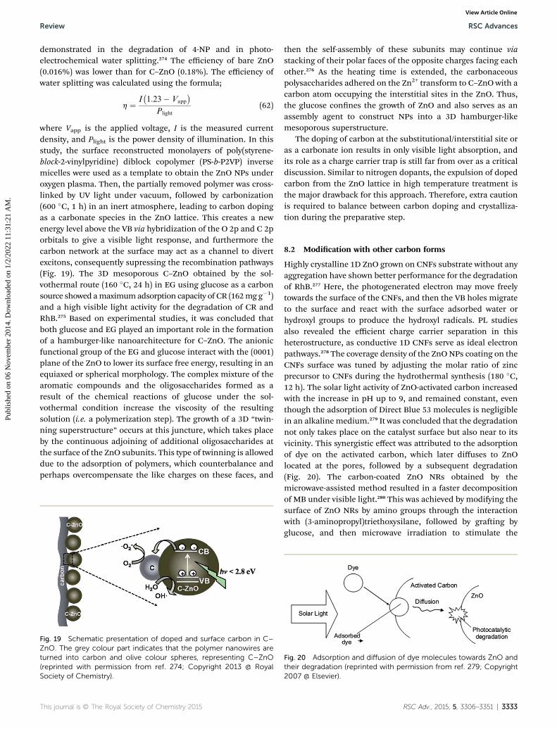
Review RSC Advances
Publ
ishe
d on
06
Nov
embe
r 20
14. D
ownl
oade
d on
1/2
/202
2 11
:31:
21 A
M.
View Article Online
demonstrated in the degradation of 4-NP and in photo-electrochemical water splitting.274 The efficiency of bare ZnO(0.016%) was lower than for C–ZnO (0.18%). The efficiency ofwater splitting was calculated using the formula;
h ¼ I�1:23� Vapp
�Plight
(62)
where Vapp is the applied voltage, I is the measured currentdensity, and Plight is the power density of illumination. In thisstudy, the surface reconstructed monolayers of poly(styrene-block-2-vinylpyridine) diblock copolymer (PS-b-P2VP) inversemicelles were used as a template to obtain the ZnO NPs underoxygen plasma. Then, the partially removed polymer was cross-linked by UV light under vacuum, followed by carbonization(600 �C, 1 h) in an inert atmosphere, leading to carbon dopingas a carbonate species in the ZnO lattice. This creates a newenergy level above the VB via hybridization of the O 2p and C 2porbitals to give a visible light response, and furthermore thecarbon network at the surface may act as a channel to divertexcitons, consequently supressing the recombination pathways(Fig. 19). The 3D mesoporous C–ZnO obtained by the sol-vothermal route (160 �C, 24 h) in EG using glucose as a carbonsource showed amaximumadsorption capacity of CR (162mg g�1)and a high visible light activity for the degradation of CR andRhB.275 Based on experimental studies, it was concluded thatboth glucose and EG played an important role in the formationof a hamburger-like nanoarchitecture for C–ZnO. The anionicfunctional group of the EG and glucose interact with the (0001)plane of the ZnO to lower its surface free energy, resulting in anequiaxed or spherical morphology. The complex mixture of thearomatic compounds and the oligosaccharides formed as aresult of the chemical reactions of glucose under the sol-vothermal condition increase the viscosity of the resultingsolution (i.e. a polymerization step). The growth of a 3D “twin-ning superstructure” occurs at this juncture, which takes placeby the continuous adjoining of additional oligosaccharides atthe surface of the ZnO subunits. This type of twinning is alloweddue to the adsorption of polymers, which counterbalance andperhaps overcompensate the like charges on these faces, and
Fig. 19 Schematic presentation of doped and surface carbon in C–ZnO. The grey colour part indicates that the polymer nanowires areturned into carbon and olive colour spheres, representing C–ZnO(reprinted with permission from ref. 274; Copyright 2013 @ RoyalSociety of Chemistry).
This journal is © The Royal Society of Chemistry 2015
then the self-assembly of these subunits may continue viastacking of their polar faces of the opposite charges facing eachother.276 As the heating time is extended, the carbonaceouspolysaccharides adhered on the Zn2+ transform to C–ZnO with acarbon atom occupying the interstitial sites in the ZnO. Thus,the glucose connes the growth of ZnO and also serves as anassembly agent to construct NPs into a 3D hamburger-likemesoporous superstructure.
The doping of carbon at the substitutional/interstitial site oras a carbonate ion results in only visible light absorption, andits role as a charge carrier trap is still far from over as a criticaldiscussion. Similar to nitrogen dopants, the expulsion of dopedcarbon from the ZnO lattice in high temperature treatment isthe major drawback for this approach. Therefore, extra cautionis required to balance between carbon doping and crystalliza-tion during the preparative step.
8.2 Modication with other carbon forms
Highly crystalline 1D ZnO grown on CNFs substrate without anyaggregation have shown better performance for the degradationof RhB.277 Here, the photogenerated electron may move freelytowards the surface of the CNFs, and then the VB holes migrateto the surface and react with the surface adsorbed water orhydroxyl groups to produce the hydroxyl radicals. PL studiesalso revealed the efficient charge carrier separation in thisheterostructure, as conductive 1D CNFs serve as ideal electronpathways.278 The coverage density of the ZnO NPs coating on theCNFs surface was tuned by adjusting the molar ratio of zincprecursor to CNFs during the hydrothermal synthesis (180 �C,12 h). The solar light activity of ZnO-activated carbon increasedwith the increase in pH up to 9, and remained constant, eventhough the adsorption of Direct Blue 53 molecules is negligiblein an alkaline medium.279 It was concluded that the degradationnot only takes place on the catalyst surface but also near to itsvicinity. This synergistic effect was attributed to the adsorptionof dye on the activated carbon, which later diffuses to ZnOlocated at the pores, followed by a subsequent degradation(Fig. 20). The carbon-coated ZnO NRs obtained by themicrowave-assisted method resulted in a faster decompositionof MB under visible light.280 This was achieved by modifying thesurface of ZnO NRs by amino groups through the interactionwith (3-aminopropyl)triethoxysilane, followed by graing byglucose, and then microwave irradiation to stimulate the
Fig. 20 Adsorption and diffusion of dye molecules towards ZnO andtheir degradation (reprinted with permission from ref. 279; Copyright2007 @ Elsevier).
RSC Adv., 2015, 5, 3306–3351 | 3333
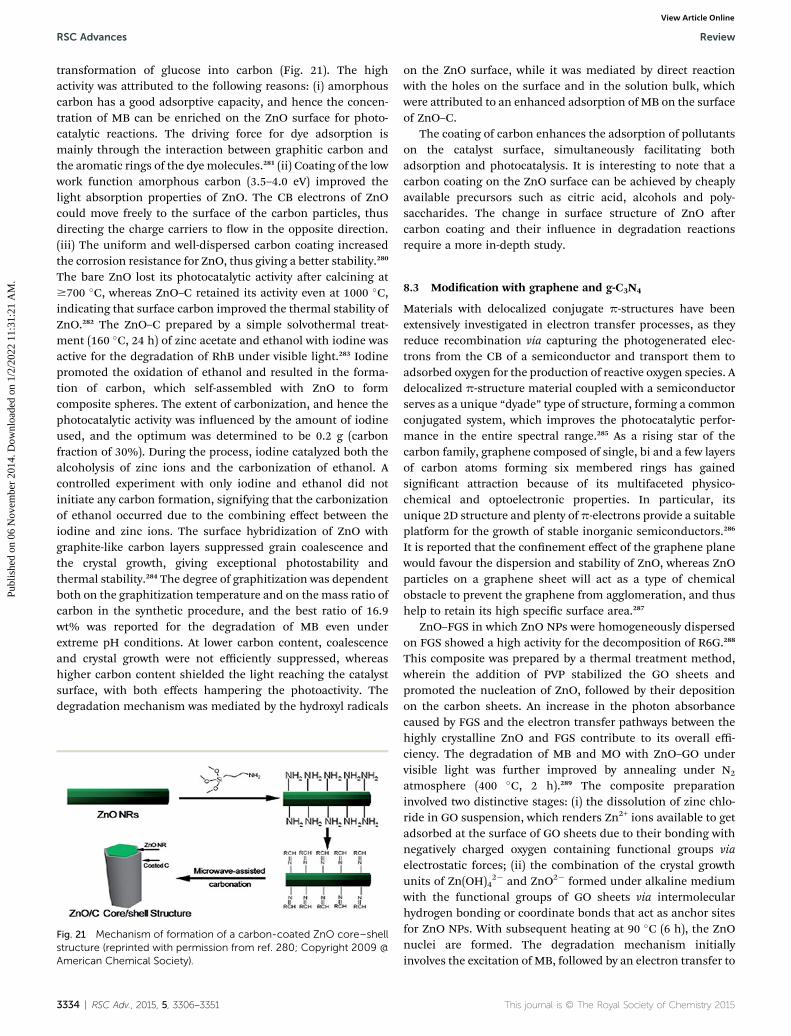
RSC Advances Review
Publ
ishe
d on
06
Nov
embe
r 20
14. D
ownl
oade
d on
1/2
/202
2 11
:31:
21 A
M.
View Article Online
transformation of glucose into carbon (Fig. 21). The highactivity was attributed to the following reasons: (i) amorphouscarbon has a good adsorptive capacity, and hence the concen-tration of MB can be enriched on the ZnO surface for photo-catalytic reactions. The driving force for dye adsorption ismainly through the interaction between graphitic carbon andthe aromatic rings of the dye molecules.281 (ii) Coating of the lowwork function amorphous carbon (3.5–4.0 eV) improved thelight absorption properties of ZnO. The CB electrons of ZnOcould move freely to the surface of the carbon particles, thusdirecting the charge carriers to ow in the opposite direction.(iii) The uniform and well-dispersed carbon coating increasedthe corrosion resistance for ZnO, thus giving a better stability.280
The bare ZnO lost its photocatalytic activity aer calcining at$700 �C, whereas ZnO–C retained its activity even at 1000 �C,indicating that surface carbon improved the thermal stability ofZnO.282 The ZnO–C prepared by a simple solvothermal treat-ment (160 �C, 24 h) of zinc acetate and ethanol with iodine wasactive for the degradation of RhB under visible light.283 Iodinepromoted the oxidation of ethanol and resulted in the forma-tion of carbon, which self-assembled with ZnO to formcomposite spheres. The extent of carbonization, and hence thephotocatalytic activity was inuenced by the amount of iodineused, and the optimum was determined to be 0.2 g (carbonfraction of 30%). During the process, iodine catalyzed both thealcoholysis of zinc ions and the carbonization of ethanol. Acontrolled experiment with only iodine and ethanol did notinitiate any carbon formation, signifying that the carbonizationof ethanol occurred due to the combining effect between theiodine and zinc ions. The surface hybridization of ZnO withgraphite-like carbon layers suppressed grain coalescence andthe crystal growth, giving exceptional photostability andthermal stability.284 The degree of graphitization was dependentboth on the graphitization temperature and on themass ratio ofcarbon in the synthetic procedure, and the best ratio of 16.9wt% was reported for the degradation of MB even underextreme pH conditions. At lower carbon content, coalescenceand crystal growth were not efficiently suppressed, whereashigher carbon content shielded the light reaching the catalystsurface, with both effects hampering the photoactivity. Thedegradation mechanism was mediated by the hydroxyl radicals
Fig. 21 Mechanism of formation of a carbon-coated ZnO core–shellstructure (reprinted with permission from ref. 280; Copyright 2009 @American Chemical Society).
3334 | RSC Adv., 2015, 5, 3306–3351
on the ZnO surface, while it was mediated by direct reactionwith the holes on the surface and in the solution bulk, whichwere attributed to an enhanced adsorption of MB on the surfaceof ZnO–C.
The coating of carbon enhances the adsorption of pollutantson the catalyst surface, simultaneously facilitating bothadsorption and photocatalysis. It is interesting to note that acarbon coating on the ZnO surface can be achieved by cheaplyavailable precursors such as citric acid, alcohols and poly-saccharides. The change in surface structure of ZnO aercarbon coating and their inuence in degradation reactionsrequire a more in-depth study.
8.3 Modication with graphene and g-C3N4
Materials with delocalized conjugate p-structures have beenextensively investigated in electron transfer processes, as theyreduce recombination via capturing the photogenerated elec-trons from the CB of a semiconductor and transport them toadsorbed oxygen for the production of reactive oxygen species. Adelocalized p-structure material coupled with a semiconductorserves as a unique “dyade” type of structure, forming a commonconjugated system, which improves the photocatalytic perfor-mance in the entire spectral range.285 As a rising star of thecarbon family, graphene composed of single, bi and a few layersof carbon atoms forming six membered rings has gainedsignicant attraction because of its multifaceted physico-chemical and optoelectronic properties. In particular, itsunique 2D structure and plenty of p-electrons provide a suitableplatform for the growth of stable inorganic semiconductors.286
It is reported that the connement effect of the graphene planewould favour the dispersion and stability of ZnO, whereas ZnOparticles on a graphene sheet will act as a type of chemicalobstacle to prevent the graphene from agglomeration, and thushelp to retain its high specic surface area.287
ZnO–FGS in which ZnO NPs were homogeneously dispersedon FGS showed a high activity for the decomposition of R6G.288
This composite was prepared by a thermal treatment method,wherein the addition of PVP stabilized the GO sheets andpromoted the nucleation of ZnO, followed by their depositionon the carbon sheets. An increase in the photon absorbancecaused by FGS and the electron transfer pathways between thehighly crystalline ZnO and FGS contribute to its overall effi-ciency. The degradation of MB and MO with ZnO–GO undervisible light was further improved by annealing under N2
atmosphere (400 �C, 2 h).289 The composite preparationinvolved two distinctive stages: (i) the dissolution of zinc chlo-ride in GO suspension, which renders Zn2+ ions available to getadsorbed at the surface of GO sheets due to their bonding withnegatively charged oxygen containing functional groups viaelectrostatic forces; (ii) the combination of the crystal growthunits of Zn(OH)4
2� and ZnO2� formed under alkaline mediumwith the functional groups of GO sheets via intermolecularhydrogen bonding or coordinate bonds that act as anchor sitesfor ZnO NPs. With subsequent heating at 90 �C (6 h), the ZnOnuclei are formed. The degradation mechanism initiallyinvolves the excitation of MB, followed by an electron transfer to
This journal is © The Royal Society of Chemistry 2015

Fig. 23 Charge transfermechanism for ZnO–graphene sensitized by adyemolecule (reprinted with permission from ref. 290; Copyright 2011@ Royal Society of Chemistry).
Review RSC Advances
Publ
ishe
d on
06
Nov
embe
r 20
14. D
ownl
oade
d on
1/2
/202
2 11
:31:
21 A
M.
View Article Online
ZnO CB via the GO sheets, which are later captured by adsorbedoxygen to produce reactive oxygen radicals. Finally, MB*+ isdegraded by itself or by the attack of reactive oxygen species(Fig. 22). Furthermore, the large surface area and hierarchicalporosity of ower-like ZnO anchored onto GO enhance theadsorption and mass transfer of dyes and oxygen species.289 Thefabrication of ZnO–graphene via the solvothermal reaction (150�C, 8 h) of Zn–EG–Ac complex and GO in ethanol solvent isbenecial for the decomposition of RhB.287 The reaction systempossessed the following characteristics: (i) the abundant func-tional groups in the Zn–EG–Ac complex interact with the func-tional groups (–COOH, –OH) of GO and hydrolyse in situ on GOto form well-dispersed ZnO NPs without the need for using anexternal alkali; (ii) Zn–EG–Ac has a relatively high stability inethanol, which promotes the growth of ZnO on graphene ratherthan homogeneous nucleation in the reaction medium; (iii)ethanol facilitates GO reduction and also slows down theliberation of Zn2+ to produce ne ZnO NPs tightly decorated ongraphene. In another study, ZnO–graphene composite preparedby the chemical deposition route was also active for the degra-dation of RhB under UV/visible light.290 The redox potentials ofRhB and RhB* are 0.95 V and �1.42 V (vs. NHE), while the workfunctions are �5.45 eV and �3.08 eV (vs. vacuum), respectively.Comparing the potential of the CB (�4.05 eV) and VB (�7.25 eV)of ZnO with the work function of graphene (�4.42 eV),291 directelectron transfer from RhB* to graphene seems to be thermo-dynamically more favorable (Fig. 23).292 In addition, thecomposite also served as a ltration membrane to remove thedye molecules from water. Graphene sheets densely decoratedby the ZnO NSs resulted in a good combination for the reduc-tion of Cr(VI),293 in which the photogenerated electron reducesCr(VI), while the hole oxidizes water molecules.
Cr2O72� + 14H+ + 6e� / 2Cr3+ + 7H2O (63)
2H2O + 4h+ / O2 + 4H+ (64)
The presence of graphene increases the light absorptionintensity, as a result of the increase in the surface electric chargeof the oxides in the composite, and modies the charge carrierdynamics during irradiation, thus promoting the activity. Theactivity decreases at a higher content of graphene (>1.0 wt%)due to following reasons: (i) graphene absorbs the UV light, andthus there exists a light harvesting competition between ZnO
Fig. 22 Photosensitized degradation of MB over ZnO–GO undervisible light (reprinted with permission from ref. 289; Copyright 2012 @Elsevier).
This journal is © The Royal Society of Chemistry 2015
and graphene; (ii) excess graphene acts as recombinationcentres.294 The ZnO–graphene obtained via the heat treatmentof the ZnO–GO (200 �C, 2 h) containing 2.5% graphene exhibi-ted higher visible light activity for the degradation of MBcompared to the ZnO–MWCNTs and retains 80% of the initialactivity, even aer recycling ve times.295 TEM images revealedthat both sides of the GO sheets are closely coated with ZnOparticles (average size of 5 nm) in relatively high density to forma sandwich-structure (ZnO/GO/ZnO), which favoured strongelectronic interactions. The PL studies revealed that the pres-ence of graphene eliminates the surface defects of ZnO parti-cles. However, the ZnO particles will peel off the graphenesheets and the graphene structure will be slowly destroyedduring the durability test. In addition, the impurity or inorganicanions occupy the active centers and hampers the photocatalystperformance.295
The ZnO–graphene hybrid containing 2 wt% of grapheneobtained via the reduction of GO with hydrazine was visiblelight active for the degradation of MB, accompanied by theparticipation of both the superoxide and hydroxyl radicals inthe solution, as well as in direct hole oxidation.296 By this in situreduction method, ZnO NPs could efficiently separate the gra-phene sheets and retard the restacking of graphene sheets. Thedefect sites on GO served as nucleation sites for ZnO, resultingin less agglomerated particles. For this method, Gayathriet al.297 reported that the optimum amount of ZnO (600 mg ofZn2+ ion precursor in the synthesis step) showed a higheractivity compared to a low (300 mg) or high (900 mg) amount,despite the other catalysts showing very low PL intensity. Theincrease in Zn2+ concentration makes the ZnO NPs stick to thesurface of the graphene sheets and prevent the graphene sheetsfrom combining as a result of weak van der Waals forcesbetween the graphene layers. However, graphene sheets stacktogether at a low concentration of Zn2+ and appear like ZnO onmultilayered graphene, due to the loss of the 2D planar struc-ture.297 The microwave assisted irradiation method to synthe-size ZnO–RGO in diethylene glycol medium was powerful forthe decolorization of self-photosensitized dyes (RhB and MB)under visible light, but was ineffective for the degradation ofbenzoic acid.298 This result indicated that the decolorization ofdyes is mainly due to the photosensitization process, ratherthan excitation of the ZnO–RGO nanohybrids. In this case,
RSC Adv., 2015, 5, 3306–3351 | 3335

RSC Advances Review
Publ
ishe
d on
06
Nov
embe
r 20
14. D
ownl
oade
d on
1/2
/202
2 11
:31:
21 A
M.
View Article Online
electron transfer takes place from the dye* to ZnO or throughRGO, which contributes to an effective charge carrier separa-tion. A high loading of ZnO was detrimental (0.0092–0.0115 Mzinc acetate in the preparation step), as it may reduce thequantity of photogenerated charges, due to an unfavourablemorphology and poor charge carrier transfer through the ZnOnanocrystals. The ZnO–RGO synthesized by the UV-assistedphotocatalytic reduction of graphite oxide by ZnO in ethanolwas efficient for the removal of Cr(VI) ion, due to the increasedlight absorption intensity and range, with reduced carrierrecombination.299 In addition, this composite also served as agood adsorbent for the removal of colour removal under darkconditions.300
The so material g-C3N4 (Eg 2.7 eV) as an analogue ofgraphite possesses a stacked 2D structure, with tri-s-triazinebuilding units connected with planar amino groups in eachlayer and weak van der Waals forces between the layers. It isexceptionally stable under light illumination in a wide pH range(0–14), thus making it a potential candidate for many greenenergy applications.301,302
The ZnO hybridized with g-C3N4 (ZnO:g-C3N4) via themonolayer dispersion method showed a high activity for thedegradation of MB under UV/visible light at a 3% loading of g-C3N4.303 This enhancement was mainly due to the p-stackingtype adsorption between MB and g-C3N4, which was similar tothe conjugation between graphene and aromatic molecule. TheMB can be adsorbed on the g-C3N4 surface with an offset face toface orientation via p–p conjugation until an adsorption–desorption equilibrium is reached. The superior adsorptioncapacity was a worthy complement for the high activity ofhybridized g-C3N4:ZnO. The suppression of the degradation ofdye with EDTA and TBA conrms the dominant involvement ofholes and hydroxyl radicals under UV and visible light photo-catalysis, respectively. Under UV light, the hole transfers fromZnO to the HOMO of g-C3N4, resulting in an efficient chargeseparation and it also suppresses the photocorrosion of ZnO.The g-C3N4 absorbs visible light to induce p–p* transition fromthe HOMO to LUMO. The LUMO potential of C3N4 is �1.12eV,304 which is more negative than the CB of ZnO (�0.5 eV), andthe excited electrons are directly injected to the CB of ZnO. Theg-C3N4
+ radical can accept electrons from the fragments of thedegradation of MB and return to the ground state.303 Theformation of a chemically bonded interface between g-C3N4 andZnO originates from the condensation reaction between thetriazine amino group and the surface hydroxyl groups of ZnO.The concentration of the Zn2+ ions aer the degradation of MOand 4-NP under visible light using this composite was found tobe considerably lower than for pure ZnO, attesting to its long-term stability in aqueous solution.305 The activity increasedwith an enhancement in the ZnO content upto 15.6 wt% andreduced at higher values (58.1 wt%), which was attributed to theunsuitable ratio between the coupled semiconductors and tothe poor visible light response of the composite. In anotherstudy, Shifu and co-workers reported that the optimumamounts of ZnO and g-C3N4 were 15 and 5 wt% for ZnO:g-C3N4
prepared from ball-milling and from the deposition–precipita-tion methods, respectively.306,307 This was attributed to the
3336 | RSC Adv., 2015, 5, 3306–3351
balanced introduction of the trap sites for the charge carriers,which prolongs the carrier lifetime. The reaction kinetics withdifferent radical scavengers declined in the order: benzoqui-none > isopropyl alcohol > ammonium oxalate, conrming thepivotal role of the superoxide radicals in the decompositionmechanism of RhB. However, the hydroxyl radical generation,as evidenced by PL spectroscopy, indicates that the superoxideradical, thus formed transforms to the hydroxyl radicals by aseries of reactions, and contributes to complete mineraliza-tion.306,307 The holes generated in g-C3N4 cannot oxidize OH
� orH2O to hydroxyl radicals, because the position of the VB of g-C3N4 (1.57 eV vs. NHE) is more negative compared to the stan-dard redox potential of E (OHc/OH�) ¼ 1.99 eV vs. NHE.
The ZnO–mesoporous g-C3N4 core–shell structure was alsoactive for the degradation of MB under UV/visible light.308 Theactivity was closely related to the thickness of the shell, het-erojunction interfaces and the core–shell structure induced bythe lattice match between the two components. The processesof formation for the core–shell structure takes place throughtwo steps: mesoporous g-C3N4 is exfoliated into sheet-likenanostructures via ultrasonication in methanol solvent, andlater these sheets are uniformly decorated on the ZnO surface tominimize the surface energy. The photoactivity increased withthe loading of g-C3N4 up to 4 wt% under UV light, whereas theactivity increased up to 20 wt% under visible light. The increasein shell thickness shields the UV light photons from reachingthe ZnO surface, while it improves the visible light absorption ofthe composite, beneting charge transfer at the heterojunctioninterfaces. The mesoporous structure easily permits the UVlight to reach ZnO, compared to bulk g-C3N4. The optimalamount of ZnO in ZnO: mesoporous g-C3N4 was found to be24.9 wt% under visible and solar light for the degradation ofMB.309 In this case, ZnO was allowed to nucleate and uniformlydisperse on the mesoporous g-C3N4 sheets under solvothermalconditions (160 �C, 24 h). The holes were found to be the majoroxidant responsible for the degradation of pollutant comparedto hydroxyl and superoxide radicals. Instead of bulk g-C3N4 witha big sheet of a lamellar structure, mesoporous g-C3N4 with anopen crystalline pore wall and large surface area will be morebenecial in photocatalysis.308,309 The C–ZnO:g-C3N4 showedhigh activity for the degradation of MB under visible light, at50.7 wt% g-C3N4, corresponding to the homogeneous hybrid-ization between ZnO and g-C3N4 (Fig. 24).310 This is the rstreport on simultaneous carbon doping and heterojunctionformation of ZnO with g-C3N4. In this work, high temperaturetreatment of zinc nitrate and dicyandiamide initiated theformation of g-C3N4 and ZnO, respectively, through the thermaldecomposition. Moreover, dicyandiamide adhering to thesurface of ZnO NPs undergoes combustion and subsequentatomic rearrangements (Zn, C and O), enabling the substitutionof carbon for oxygen in the bulk of the lattice.
The electronic coupling of ZnO with g-C3N4 may be an idealsystem to promote the charge carrier separation, due to theirwell-matched overlapping band structure. The activity seems tobe very sensitive to the content of both ZnO and g-C3N4 in thecomposite, and the preparative method used seems to be adecisive factor in governing the photocatalytic pathways. The
This journal is © The Royal Society of Chemistry 2015

Fig. 24 Illustration of the electron–hole separation, transport, andphotocatalytic progress of C–ZnO:g-C3N4 under visible light (reprin-ted with permission from ref. 310; Copyright 2014 @ AmericanChemical Society).
Fig. 25 Charge carrier separation and transportation in a CdS–ZNWs–MWCNTs heterojunction (reprinted with permission from ref. 311;Copyright 2011 @ Elsevier).
Review RSC Advances
Publ
ishe
d on
06
Nov
embe
r 20
14. D
ownl
oade
d on
1/2
/202
2 11
:31:
21 A
M.
View Article Online
relative tuning of the individual components and the decora-tion of g-C3N4 on various morphologies of ZnO still requiresfurther research.
Fig. 26 Ball and stick representative diagram of MWCNT–ZnOcomposite (reprinted with permission from ref. 313; Copyright 2010 @IOP Science).
8.4 Modication with CNTs, fullerenes and CQDs
The favourable bandgap energy level alignment in ZnO–MWCNTs–CdS resulted in its high photocurrent density (0.25mA cm�2) compared to ZNWs–MWCNTs (0.10 mA cm�2) andCdS–ZNWs (0.20 mA cm�2) under solar light.311 In this bandgapconguration, unidirectional electron transfer takes place fromCdS to ZNWs to MWCNTs to favour the separation and thephotocurrent collection. The CdS serves as an electron sensi-tizer or relay, while ZNWs and MWCNTs act as an electron sink(Fig. 25). The electrons from the ZnO CB are trapped byMWCNTs via an inductive effect that promotes the interfacialelectron transfer process. Such as the growth of ZNWs onMWCNTs improves the active surface area, thus enhancing thephoton absorption, while the NW conguration affordsconductive pathways to the charge carrier transfer process. TheMWCNTs possess more landing sites for the adhesive growth ofNWs and the space between each NT would be benecial for itsdispersion. The photocurrent of the ZNWs–MWCNTs washigher under UV light compared to solar light, as the extraexcitons photogenerated at the nanocomposite–electrolyteinterface intensies the electric eld produced in the depletionlayer, which further assists the electron transport processes.312
The ZnO (34%)–MWCNTs were effective in the removal ofcyanide under a 355 nm UV light generated by the thirdharmonic of Nd:YAG laser.313 The structural model proposedindicates that the zinc atom is aligned closer to the oxygen atomof the carbonyl group, whereas an oxygen atom of ZnO remains
This journal is © The Royal Society of Chemistry 2015
close to the hydrogen atom of the hydroxyl group on the func-tionalized MWCNTs (Fig. 26). The former is possible as theelectron density on oxygen atoms is shared with zinc, which hasan electron affinity, while the latter is favoured because of thehydrogen bond formation. In such types of hetero-interphaseinteractions, attractive van der Waals forces play a signicantrole. The rate of removal of cyanide was enhanced with the laserenergy (60 mJ to 200 mJ), but declined with an increase in thepH values (4–12). When the laser energy is increased, the inci-dent photon ux increases in the solution and facilitates thegeneration of more charge carriers. The PZC of functionalizedMWCNTs was 4.9, and hence an efficient adsorption-degradation was observed at acidic pH. With an increase inpH, both MWCNTs and ZnO become negatively charged and thecyanide experiences repulsion from the catalyst surface.313
The increased light absorption and high surface energy ofthe ZnO–TiO2–CNTs facilitated both the adsorption andreduction of the Cr(VI) ion.314 The CNTs served as wires con-necting different ZnO NSs and the TiO2 NPs, and also promotesthe electrons to freely ow throughout the structure without anyscattering from atoms or defects (ballistic transport).315 The IEFat the surface of the composite and the constructed stepwisestructure of the band edge levels leads to electron transfer fromZnO to TiO2 to the CNTs, whereas the hole traverses from TiO2
RSC Adv., 2015, 5, 3306–3351 | 3337

Fig. 27 Photocatalytic process of ZnO–CQDs under visible light(reprinted with permission from ref. 323; Copyright 2012 @ RoyalSociety of Chemistry).
RSC Advances Review
Publ
ishe
d on
06
Nov
embe
r 20
14. D
ownl
oade
d on
1/2
/202
2 11
:31:
21 A
M.
View Article Online
to ZnO. The increase in the loading of CNTs (4 wt%) competeswith photon absorption with TiO2 or ZnO and hampers thedispersion of the metal oxides on the CNTs surface, in additionto promoting the recombination process.316 The fabrication ofMWCNTs-doped ZnO (Zn–O–C bond) by a electrospinningmethod was positive for the degradation of MB under UV/visiblelight. Under UV light, electrons from the ZnO CB move freely tothe MWCNTs, while MWCNTs serve as a sensitizer by absorbingthe visible light and transferring the electrons to the ZnO CB.317
The positively charged MWCNTs remove an electron from theVB of ZnO leaving a hole. The oxidation of MWCNTs withconcentrated acid and the presence of surface alcohol, ketoneand the acid groups enhance the adsorption of dye on thecomposite surface, thus favouring an efficient photocatalysis.The ZnO:N–CNTs exhibit better activity compared to ZnO–CNTsfor the degradation of benzoic acid and RhB under visiblelight.318 The composite activity, with respect to the crystallitesize of ZnO, had the following sequence: 9.5 > 7.3 > 5.4 > 4.2 nm.The relative position in the CB of the N–CNTs allowed thetransfer of electrons to ZnO, and shows that defects introducedby nitrogen doping might have separated the charge carriers.Pd–ZnO : MWCNTs at an optimum ratio of 0.08 : 1.0 : 0.04 weresuccessful in reducing Hg(II), with excellent recyclability undervisible light.319 The introduction of CNT and Pd prevented theZnO NPs from agglomeration, showing that ZnO was stronglyattached to the surface of the CNTs network. The Pd doping andCNT incorporation induced a visible light response, while thelarge surface area of the composite provided more active sitesfor the reduction of Hg(II).
The hybridization of C60 at a loading of 1.5% on the ZnOsurface enhanced the activity for the degradation of MB and thephotocurrent generated remained constant even aer pro-longed UV illumination (20–35 h).320 The CB energy level of ZnO(�0.5 V vs. NHE at pH 7) thermodynamically favours the elec-tron transfer to the C60 molecules (E C60/C60
� is�0.2 V), and thedelocalized conjugated p-system of C60 promotes the facilemigration of electrons because of the minimal changes in thestructure and in the solvation associated with the process.321,322
The crystal structure of ZnO was changed to Zn5(OH)6(CO3)2aer prolonged illumination, whereas the pristine phase wasretained for the composite, suggesting that C60 inhibited thephotocorrosion of ZnO via deactivating the surface oxygenatoms. ZnO–CQDs were benecial for the degradation of toxicgases (i.e. benzene and methanol) under visible light.323 TheCQDs loaded on the ZnO surface form a “dyade” structure,providing access to the photoinduced charge transfer pathways.At the dyade structure, the photoinduced electrons are trans-ferred to joint charge transfer states located on the CQDs, whileholes accumulate electrically and structurally near ZnO. Theelectrons can be freely shuttled along the conducting network ofCQDs and combine with adsorbed oxygen to produce super-oxide and hydroxyl radicals in the solution. Moreover, the p-interaction between the conjugated structure of the CQDs andthe aromatic pollutant is benecial to enrich its concentrationon the composite surface.324 In addition, CQDs with upconver-sion PL properties convert the longer wavelength light to ashorter wavelength, resulting in a bandgap excitation of ZnO,
3338 | RSC Adv., 2015, 5, 3306–3351
and consequently facilitating the generation of more chargecarriers (Fig. 27).
The modication of ZnO with various carbon nano-structures, such as activated carbon, amorphous carbon,graphitic carbon, CNFs, graphene, RGO, g-C3N4, fullerenes,CNTs and CQDs, improves both the photoactivity and thestability of ZnO during photocatalytic reactions. In a few cases,these carbon nanostructures serve as a support for the growth ofZnO nanocrystallites or ZnO can act as substrate for the growthof these carbon forms. The excellent capacity of carbon nano-structures to enrich pollutant concentration on the catalystsurface and their robust capacity as electron conducting chan-nels allows more carriers to participate in degradation reac-tions. These semiconductor–carbon composite nanostructuresare expected to dominate in waste water purication in the nearfuture.
9. Reactivity of exposed polar andnon-polar facets
It is widely accepted that the photocatalytic reaction occurs atthe catalyst surface–pollutant interface. Thus, the morphologyof the catalyst affects the surface atomic rearrangements andcoordination, which thus modulates the crystal facets indifferent orientations and plays an important role in the pho-tocatalysis.325 The difference in the surface atomic congurationresults in a distinct capacity to adsorb oxygenated species andthe target molecules. Such speculation has given the impetus toexplore the relationship between the surface orientation of ZnOand their photocatalytic efficiency.
Compared with non-faceted ones, ZnO with a hexagonalfaceted prism (3–4 nm) showed a high performance for thedegradation of MB, which was attributed to the large surfacearea and the oxygen vacancy defects that promoted an efficient
This journal is © The Royal Society of Chemistry 2015

Review RSC Advances
Publ
ishe
d on
06
Nov
embe
r 20
14. D
ownl
oade
d on
1/2
/202
2 11
:31:
21 A
M.
View Article Online
charge transfer process.326 ZnO with a high degree of exposed{0001} facets embedded in a ower-like matrix was active for thedegradation of RhB compared to ZnO NRs (with fewer exposed{0001} facets) and platelets (with an equal number of Zn-{0001}and O-{0001�} facets) under visible light.327 The origin of thevisible light activity was attributed to the polar surface inducedoxygen defects such as oxygen vacancies or interstitial oxygen.31
Furthermore, the ower-like matrix possess a high degree ofdispersion and prevents the aggregation of ZnO NPs, therebyimproving the stability. The ower-like ZnO microarchitecturebuilt by the self-assembly of dense NSs with an ultrathinthickness of 5 nm and a large population of polar (0001) planesexhibit a high performance for the degradation of MOcompared to other morphologies such as NPs, NRs and NSs.328
These NSs were obtained by a citrate-mediated hydrothermaltreatment in the presence of zinc nitrate and HMT. The addi-tion of citric acid changes the orientation of ZnO from (0001) to(101�0), followed by amorphological transformation fromNRs toNSs and a change in the main exposed surface from non-polarto polar facets, attributed to its complexation on the (0001)surface. These size-quantized NSs promote dye adsorption,enhance the light harvesting capacity and efficiently channelizethe carriers from the bulk to the surface.329 The grid-like or net-like arrangement of NSs retain their structural integrity evenaer vigorous ultrasonication (50 min).
The inuence of the ZnO morphology for the degradation ofRhB followed the following order: cones > bullets > plates >rods, whereas the activity of the exposed crystal facet showedthe following trend: {10�11} [ {0001}, {10�10}.330 Themorphologies and crystal facets were controlled by varying thereaction temperature and the benzylamine/Zn2+ ratio, withbenzylamine serving as a reactant and capping agent to stabilizethe (10�11) planes. On the basis of a model, it was proposed thatthe {10�11} facets possess a ridge-and-valley topography withoxygen termination, whereas the surface oxygen atoms alternatebetween two-coordinated and three-coordinated in nature.Because low coordinated oxygen atoms are generally saturatedby hydrogen atoms via O/H–O–H hydrogen bond formation,they generate dense hydroxyl radicals in the solution. The ZnOnanoplatform with an exposed {0001} facet showed a higherphotocatalytic activity compared to a hamburger-likemorphology with a {10�10} facet.331 The former was obtainedby adding an aqueous solution of NaOH to zinc acetate, whereasadding sodium citrate resulted in the latter morphology underhydrothermal conditions (160 �C, 5 h). The concentration ofgrowth units involved in the nucleation and growth was reducedby the complexation of citrate ions with Zn2+ ions.332 In addi-tion, the longer organic molecular chain of citrate anions allowsthe ZnO growth units loosely spread in the reaction solution,leading to the formation of a bigger and looser hamburger-likemorphology. ZnO nanoplates with a higher proportion of polarto non-polar surfaces induce a rapid generation of H2O2 underUV irradiation, lasting for 730 min, compared to NRs, micro-rods and dumb-bell shaped, which is consistent with theirrespective area of polar faces.107 Recently, Bopella et al.333 alsoreported that the performance of ZnO for the degradation of MBincreased with the increase in the proportion of polar to non-
This journal is © The Royal Society of Chemistry 2015
polar facets. The ZnO NRs with a cone and small aspect ratioshowed a superior performance for the degradation of MOcompared to the short-and-fat microrods and NRs with a coneand large aspect ratio.334 Control over the shape was achieved byvarying the reaction temperature and time in the hydrothermalreaction of the zinc foil–zinc acetate–H2O system. The forma-tion of NRs with a cone originates from the change of V(0001) andV(011�0) during the growth. The crystalline nuclei grow into arod-like structure (120 �C, 2 h), as V(0001) is larger than V(011�0).The diffusion rate of zinc–hydroxyl complexes and zinc acetatein the solution will be slow and results in a concentrationgradient between the Zn-(0001) and O-(0001�) planes. As aconsequence, the concentration of zinc–hydroxyl complexesand zinc acetate will be maximum around the top of a NR andlower around the root. Thus, V(011�0) at the top of a NR is lowerthan that of its root, resulting in a cone-like structure. With anincrease in temperature (185 �C, 2 h), the diffusion rate betweenthe reactants increases and the concentration gradientdecreases, resulting in a NR with a cone and large aspect ratio.The formation of a short-and-fat microrod (120 �C, 6 h) origi-nates from the small difference between V{0001} and V(011�0).334
The prismatic aggregates of ZnO calcined at 800 �C (4 h) witha {10�10} facet demonstrated the highest activity for thedecomposition of CH3CHO.335 The SEM results revealed that thesurface exposed crystal faces or the ratios among the exposedcrystal faces were evidently different following self-assembly ofthe particles towards prismatic aggregates with an increase inthe calcination temperature. The driving force for the self-assembly originated from the solid state diffusion and migra-tion of the grain boundaries in the ZnO. In addition, theZnO single crystal with non-polar {10�10} or {11�20} facets havingO–Zn alternating atomic outermost layers performed bettercompared with a polar {000�1} or {0001} single crystal with anO–O or Zn–Zn monotonous atomic outermost layer.335,336 Thisprismatic morphology transformed to a sheet-shape aercoupling with VOx, which facilitated more exposure of {10�10}and consequently enhanced the activity. However, rod-like ZnOand no change in morphology was observed aer coupling withCeOx and WOx, respectively, which were not benecial tophotoactivity.337
The conical-like ZnO showed better photocatalytic activitycompared to hourglass-like ZnO, although these morphologiesexhibited similar crystal facets. This was attributed to thefollowing: (i) the conical-like ZnO exhibits large areas of (0001)planes because the two halves of the hourglass-shaped crystalsare attracted through the (0001) planes; (ii) the interior cavitiesin the conical-like ZnO allows multiple reections of UV light,which facilitates an efficient use of the incident light. The ZnOwith {�1101} and {10�10} facets showed the very least activity.128
The activity of ZnO with a hexagonal plate-like particle size was>5 fold for the degradation of MB compared to the rod-shapedparticles. The surface of c-axis aligned rods mostly consists ofnon-polar facets, whereas the dominant surfaces exposed on ahexagonal plate of the same diameter are the polar facets.127
The ZnO superstructures for the degradation of Orange-IIshowed the following order: structure-I > structure-IV >structure-III > structure-II (Fig. 28).338 The structure-II and
RSC Adv., 2015, 5, 3306–3351 | 3339

RSC Advances Review
Publ
ishe
d on
06
Nov
embe
r 20
14. D
ownl
oade
d on
1/2
/202
2 11
:31:
21 A
M.
View Article Online
structure-III had six symmetric side walls enclosed by {10�10}surfaces, whereas structure-IV was composed of cone-likebuilding blocks, of which the exposed crystal faces were{10�11}, {0001} and {10�10}. Because of the reduced arealproportion of low active {10�10} facets, structure-IV exhibited abetter performance compared to structure II and III. Interest-ingly, size quantized structure-I had a main exposed plane{21�10}, which has higher in surface energy than the {10�10}surface and close to the polar (0001) surface.339 These 3Dsuperstructures were tailored by varying the concentration ofzinc acetate and Na2O2, along with the reaction temperaturewithout an organic additive. Under the reaction conditions(0.03 M zinc acetate and 0.1 MNa2O2 at pH 12.9), the adsorptionof acetate anion and Zn(OH)3
� in the solution compete withZn(OH)4
2� for the occupation of the (0001) plane. Thus, thesurplus non-growth unit anions stabilized the surface charge
Fig. 28 The 3D ZnO superstructures with their building blocks and pho2010 @ American Chemical Society).
3340 | RSC Adv., 2015, 5, 3306–3351
and the structure of the (0001) surfaces to some extent, allowinga fast growth along h10�10i. Hence, the ZnO crystals grew alongh0001i and h10�10i directions (both are fast growth directions),resulting in ZnO NSs with an exposed {21�10} surface.
The ZnO nanodisks with a {0001} facet showed a high activityfor the degradation of dye compared to the ZNWs with {01�10}planes.340,341 Although NWs had a higher activity over nanodisksin the initial 4 h of illumination, the nal degradation aer 5 hwas slower than for nanodisks, which may be related to theformation of some long lived by-products covered at the surfaceof NWs, which are resistant to react with hydroxyl radicals.340
The heterostructure of the ZnO-disks with CdS improved thehydrogen evolution rate under visible light by a factor of 2.8times higher than the non-polar ZnO–CdS.342 Thus, it wasconcluded that the metallic features of polar surfaces promoteeasy charge transfer at the interface between ZnO and CdS,
tocatalytic activity (reprinted with permission from ref. 338; Copyright
This journal is © The Royal Society of Chemistry 2015

Fig. 30 Overall view of ZnO-based photocatalysis. The scheme at thefour corners shows the reactive facets (top left), intrinsic defects (topright), nanostructured morhopology (bottom left) and the generationof free radicals with electron acceptors (bottom right). The centre
Review RSC Advances
Publ
ishe
d on
06
Nov
embe
r 20
14. D
ownl
oade
d on
1/2
/202
2 11
:31:
21 A
M.
View Article Online
whereas non-polar (01�10) surfaces remain as semiconducting innature. In addition, the XPS VB spectra revealed that the VBM ofthe disk is lower compared to the rods, which reects the strongoxidative power of photogenerated holes on the disks. Surpris-ingly, there was only a marginal difference in the hydrogenevolution rates between ZnO rods and the disk samples. Thisresult was against the hypothesis that the polar surfacessignicantly promote the photodecomposition of organicpollutants.127,340 This contradiction was due to the followingreasons: (i) the polar function of the disk being restrained asthey adsorb ions in the solution (Na+, S2� or SO3
2); (ii) ZnO itselfnot being a good candidate for hydrogen evolution, as thebottom of its CB is little higher than the H+/H2 potential.343 TheZ-scheme transfer of photogenerated charge carriers betweenZnO and CdS mediated by Au NPs at the interface resulted insignicant hydrogen evolution (Fig. 29).344 Both Au and CdSwere selectively deposited at the oxygen-terminated {000�1}surface, based on the rationale that the Au3+- and Cd2+-basedcomplexes are electrostatically adsorbed on negatively chargedsurfaces. Thus, the CdS serves as a reductive site for hydrogenevolution, whereas ZnO serves as an oxidative site. In the Z-scheme, the recombination of photoexcited electrons from theZnO CB and holes from the CdS VB occur at the interface, andthus photoexcited electrons and holes with high CB and VBpotential, respectively, can be retained for redox reactions.Huang et al.345 suggested that Bi2WO6 crystal seeds can be usedto tune the polar facets of ZnO, and hence the photocatalyticactivity. The ZnO morphology gradually changed from NRs toNSs aer the addition of Bi2WO6, due to the electrostaticinteraction between these two semiconductors, consequentlychanging the ratio of the polar facets. Compared with previousreports that extensively used organic additives to tune the polarfacets, this method has outlined the heterogeneous nucleationof ZnO on Bi2WO6 with specic crystal planes with a minimallattice mismatch (2.5%). The (10�10) planes of ZnO stack parallelto the (200) planes of Bi2WO6, forming the heterojunction,indicating that ZnO NSs grow epitaxially along the normaldirection of the (200) plane. In addition, the polar surfaces ofZnO were also found to be catalytically active for the N-for-mylation of aniline and for the thermal decomposition ofammonium perchlorate.346,347
The internal electric eld between the polar faces of Zn-{0001} and O-{000�1} arising from the spontaneous polarizationdrives the electrons and holes to migrate towards the positive
Fig. 29 Schematic presentation of: (a) the direct Z-scheme charge-carrier transfer process in CdS–ZnO and (b) the vectorial Z-schemecharge-carrier transfer process in CdS–Au–ZnO (reprinted withpermission from ref. 344; Copyright 2013 @ Royal Society ofChemistry).
This journal is © The Royal Society of Chemistry 2015
and negative polar planes, facilitating the reduction andoxidation to operate at different sites, respectively.348 Theoreti-cally, the strong preference of zinc ions for a tetrahedral coor-dination geometry and the coordinatively unsaturatedenvironment of zinc ions on the (0001) plane facilitates moregeneration of H2O2, and adsorbs atmospheric oxygen throughchemical or physical adsorption and hydroxyl anions (i.e. viaelectrostatic attraction) to a larger extent on its surface. The Zn-{0001} facet holds the highest chemisorption ability and surfaceenergy, which enrich the dye adsorption at the surface and
image represents the charge transfer pathways in the surface-bulkmodification of zinc oxide that are reported to improve the photo-activity. Path 1-excitation fromVB to the dopant level (metal ions); Path2-bandgap excitation of ZnO; Path 3: excitation from the impurity level(nitrogen or carbon doping) to CB; Path 4: excitation of the sensitizer(for instance, CdS, CuS, g-C3N4, inorganic complexes); Path 5: transferof the excited electrons to the ZnO CB; Path 6: direct excitation of theelectron from the sensitizer to the CB of ZnO (as observed in thesurface complex formation between 4-CP and ZnO); Path 7 and 12:transfer of the electrons and holes in a bicomponent system (forinstance ZnO–SnO2); Path 8–10: electron trapping from graphene,MWCNTs and the metal islands on ZnO surface, respectively; Path 11:surface carbon enriches pollutant adsorption on the ZnO surface, thusfacilitating the direct attack of the hole or the hole oxidizes watermolecules to generate hydroxyl radicals.
RSC Adv., 2015, 5, 3306–3351 | 3341
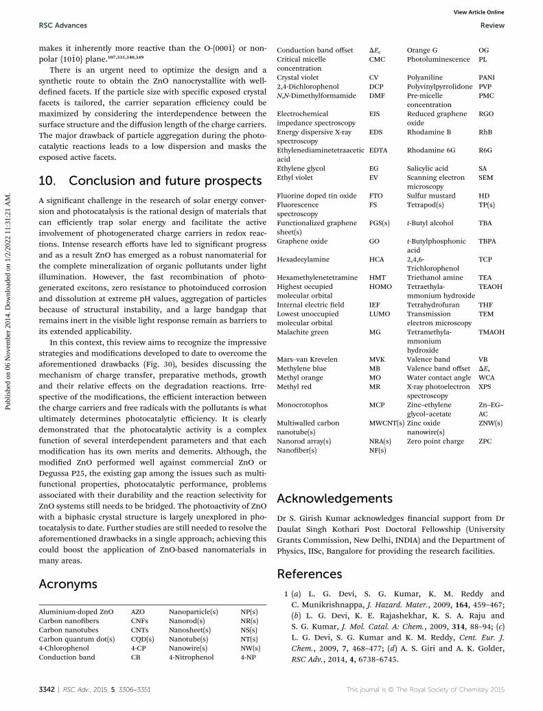
RSC Advances Review
Publ
ishe
d on
06
Nov
embe
r 20
14. D
ownl
oade
d on
1/2
/202
2 11
:31:
21 A
M.
View Article Online
makes it inherently more reactive than the O-{000�1} or non-polar {10�10} plane.107,331,340,349
There is an urgent need to optimize the design and asynthetic route to obtain the ZnO nanocrystallite with well-dened facets. If the particle size with specic exposed crystalfacets is tailored, the carrier separation efficiency could bemaximized by considering the interdependence between thesurface structure and the diffusion length of the charge carriers.The major drawback of particle aggregation during the photo-catalytic reactions leads to a low dispersion and masks theexposed active facets.
10. Conclusion and future prospects
A signicant challenge in the research of solar energy conver-sion and photocatalysis is the rational design of materials thatcan efficiently trap solar energy and facilitate the activeinvolvement of photogenerated charge carriers in redox reac-tions. Intense research efforts have led to signicant progressand as a result ZnO has emerged as a robust nanomaterial forthe complete mineralization of organic pollutants under lightillumination. However, the fast recombination of photo-generated excitons, zero resistance to photoinduced corrosionand dissolution at extreme pH values, aggregation of particlesbecause of structural instability, and a large bandgap thatremains inert in the visible light response remain as barriers toits extended applicability.
In this context, this review aims to recognize the impressivestrategies and modications developed to date to overcome theaforementioned drawbacks (Fig. 30), besides discussing themechanism of charge transfer, preparative methods, growthand their relative effects on the degradation reactions. Irre-spective of the modications, the efficient interaction betweenthe charge carriers and free radicals with the pollutants is whatultimately determines photocatalytic efficiency. It is clearlydemonstrated that the photocatalytic activity is a complexfunction of several interdependent parameters and that eachmodication has its own merits and demerits. Although, themodied ZnO performed well against commercial ZnO orDegussa P25, the existing gap among the issues such as multi-functional properties, photocatalytic performance, problemsassociated with their durability and the reaction selectivity forZnO systems still needs to be bridged. The photoactivity of ZnOwith a biphasic crystal structure is largely unexplored in pho-tocatalysis to date. Further studies are still needed to resolve theaforementioned drawbacks in a single approach; achieving thiscould boost the application of ZnO-based nanomaterials inmany areas.
Acronyms
Aluminium-doped ZnO A
3342 | RSC Adv., 2015, 5, 330
ZO
6–3351
Nanoparticle(s) N
P(s) Carbon nanobers C NFs Nanorod(s) N R(s) Carbon nanotubes C NTs Nanosheet(s) N S(s) Carbon quantum dot(s) C QD(s) Nanotube(s) N T(s) 4-Chlorophenol 4 -CP Nanowire(s) N W(s) Conduction band C B 4-Nitrophenol 4 -NPConduction band offset
This jou
DEc O
rnal is © The
range G
Royal Society of Chem
OG
Critical micelleconcentrationCMC P
hotoluminescence PLCrystal violet
CV P olyaniline PANI 2,4-Dichlorophenol DCP P olyvinylpyrrolidone PVP N,N-Dimethylformamide DMF P re-micelleconcentration
PMCElectrochemicalimpedance spectroscopy
EIS R
educed grapheneoxideRGO
Energy dispersive X-rayspectroscopy
EDS R
hodamine B RhBEthylenediaminetetraaceticacid
EDTA R
hodamine 6G R6GEthylene glycol
EG S alicylic acid SA Ethyl violet EV S canning electronmicroscopy
SEMFluorine doped tin oxide
FTO S ulfur mustard HD FluorescencespectroscopyFS T
etrapod(s) TP(s)Functionalized graphenesheet(s)
FGS(s) t
-Butyl alcohol TBAGraphene oxide
GO t -ButylphosphonicacidTBPA
Hexadecylamine
HCA 2 ,4,6-TrichlorophenolTCP
Hexamethylenetetramine
HMT T riethanol amine TEA Highest occupiedmolecular orbitalHOMO T
etraethyla-mmonium hydroxideTEAOH
Internal electric eld
IEF T etrahydrofuran THF Lowest unoccupiedmolecular orbitalLUMO T
ransmissionelectron microscopyTEM
Malachite green
MG T etramethyla-mmoniumhydroxideTMAOH
Mars–van Krevelen
MVK V alence band VB Methylene blue MB V alence band offset DEv Methyl orange MO W ater contact angle WCA Methyl red MR X -ray photoelectronspectroscopy
XPSMonocrotophos
MCP Z inc–ethyleneglycol–acetateZn–EG–AC
Multiwalled carbonnanotube(s)
MWCNT(s) Z
inc oxidenanowire(s)ZNW(s)
Nanorod array(s)
NRA(s) Z ero point charge ZPC Nanober(s) NF(s)Acknowledgements
Dr S. Girish Kumar acknowledges nancial support from DrDaulat Singh Kothari Post Doctoral Fellowship (UniversityGrants Commission, New Delhi, INDIA) and the Department ofPhysics, IISc, Bangalore for providing the research facilities.
References
1 (a) L. G. Devi, S. G. Kumar, K. M. Reddy andC. Munikrishnappa, J. Hazard. Mater., 2009, 164, 459–467;(b) L. G. Devi, K. E. Rajashekhar, K. S. A. Raju andS. G. Kumar, J. Mol. Catal. A: Chem., 2009, 314, 88–94; (c)L. G. Devi, S. G. Kumar and K. M. Reddy, Cent. Eur. J.Chem., 2009, 7, 468–477; (d) A. S. Giri and A. K. Golder,RSC Adv., 2014, 4, 6738–6745.
istry 2015

Review RSC Advances
Publ
ishe
d on
06
Nov
embe
r 20
14. D
ownl
oade
d on
1/2
/202
2 11
:31:
21 A
M.
View Article Online
2 (a) P. V. Nidheesh, R. Gandhimathi, S. Velmathi andN. S. Sanjini, RSC Adv., 2014, 4, 5698–5708; (b) T. Han,L. Qu, Z. Luo, X. Wu and D. Zhang, New J. Chem., 2014,38, 942–948; (c) L. G. Devi, K. S. A. Raju and S. G. Kumar,J. Environ. Monit., 2009, 11, 1397–1404; (d) I. Muthuveland M. Swaminathan, Catal. Commun., 2007, 8, 981–986.
3 (a) L. G. Devi, S. G. Kumar, K. S. A. Raju andK. E. Rajashekhar, Chem. Pap., 2010, 64, 378–385; (b)K. R. Naqvi, J. Marsh and V. Chechik, Dalton Trans., 2014,4745–4751; (c) L. Zhou, H. Zhang, L. Ji, Y. Shao and Y. Li,RSC Adv., 2014, 4, 24900–24908; (d) A. C. Pradhan,B. Nanda, K. M. Parida and M. Das, Dalton Trans., 2013,558–566.
4 (a) Z. Huang, P. Wu, H. Li, W. Li, Y. Zhu and N. Zhu, RSCAdv., 2014, 4, 6500–6507; (b) J. M. Sanchez, L. H. Reyes,J. L. G. Mar, J. M. P. Hernandez and A. H. Ramirez,Photochem. Photobiol. Sci., 2011, 10, 332–337; (c)P. V. Nidheesh and R. Gandhimathi, Desalination, 2012,299, 1–15; (d) A. M. de Freitas, C. Sirtori, C. A. Lenz andP. G. P. Zamora, Photochem. Photobiol. Sci., 2013, 12, 696–702.
5 R. Vinu and G. Madras, J. Indian Inst. Sci., 2010, 90, 189–230.6 (a) M. Wang, J. Ioccozia, L. Sun, C. Lin and Z. Lin, EnergyEnviron. Sci., 2014, 7, 2182–2202; (b) G. Zhang, G. Kim andW. Choi, Energy Environ. Sci., 2014, 7, 954–966; (c) K. Huo,B. Gao, J. Fu, L. Zhao and P. K. Chu, RSC Adv., 2014, 4,17300–17324; (d) J. B. Joo, M. Dahl, N. Li, F. Zaera andY. Yin, Energy Environ. Sci., 2013, 6, 2082–2092.
7 (a) S. G. Kumar and L. G. Devi, J. Phys. Chem. A, 2011, 115,13211–13241; (b) L. G. Devi and S. G. Kumar, Cent. Eur. J.Chem., 2011, 9, 959–961; (c) K. Bourikas, C. Kordulis andA. Lycourghiotis, Chem. Rev., 2014, 114, 9754–9823; (d)L. Sang, Y. Zhao and C. Burda, Chem. Rev., 2014, 114,9283–9318.
8 (a) K. Lv, B. Cheng, J. Yu and G. Liu, Phys. Chem. Chem.Phys., 2012, 14, 5349–5362; (b) C. Aprile, A. Corma andH. Garcia, Phys. Chem. Chem. Phys., 2008, 10, 769–783; (c)G. Liu, L. Wang, H. G. Yang, H. M. Cheng and G. Q. Lu, J.Mater. Chem., 2010, 20, 831–843.
9 (a) H. Zheng, J. Z. Ou, M. S. Strano, R. B. Kaner, A. Mitchelland K. K. Zadeh, Adv. Funct. Mater., 2011, 21, 2175–2196; (b)C. Janaky, K. Rajeshwar, N. R. de Tacconi, W. Chanmaneeand M. N. Huda, Catal. Today, 2013, 199, 53–64.
10 (a) L. Zhu, B. Wei, L. Xu, Z. Lu, H. Zhang, H. Gao and J. Che,CrystEngComm, 2012, 14, 5705–5709; (b) D. P. Dutta, M. Royand A. K. Tyagi, Dalton Trans., 2012, 10238–10248; (c)S. Balachandran and M. Swaminathan, J. Phys. Chem. C,2012, 116, 26306–26312.
11 (a) T. K. Townsend, E. M. Sabio, N. D. Browning andF. E. Osterloh, Energy Environ. Sci., 2011, 4, 4270–4275; (b)D. K. Bora, A. Braun and E. C. Constable, Energy EnvironSci., 2013, 6, 407–425; (c) J. Sun, K. L. Wu, X. Z. Li,C. Dong, X. W. Wei, X. W. Wang, B. Zhang, Z. X. Zhangand J. R. Huang, CrystEngComm, 2014, 16, 6873–6881; (d)K. Sivula, F. L. Formal and M. Gratzel, ChemSusChem,2011, 4, 432–449.
This journal is © The Royal Society of Chemistry 2015
12 (a) K. Pirkanniemi andM. Sillanpaa, Chemosphere, 2002, 48,1047–1060; (b) H. Zhang, G. Chen and D. W. Bahnemann, J.Mater. Chem., 2009, 19, 5089–5121.
13 (a) L. Ye, Y. Su, X. Jin, H. Xie and C. Zhang, Environ.Sci.:Nano, 2014, 1, 90–112; (b) J. Li, Y. Yu and L. Zhang,Nanoscale, 2014, 6, 8473–8488; (c) H. Cheng, B. Huangand Y. Dai, Nanoscale, 2014, 6, 2009–2026.
14 (a) F. Dong, Q. Li, Y. Zhou, Y. Sun, H. Zhang and Z. Wu,Dalton Trans., 2014, 9468–9480; (b) F. Dong, Y. Sun,W. K. Ho and Z. Wu, Dalton Trans., 2012, 8270–8284; (c)F. Dong, A. Zheng, Y. Sun, M. Fu, B. Jiang, W. K. Ho,S. C. Lee and Z. Wu, CrystEngComm, 2012, 14, 3534–3544.
15 (a) D. Zhang and F. Zeng, Res. Chem. Intermed., 2010, 36,1055–1063; (b) D. Zhang, Transition Met. Chem., 2010, 35,689–694; (c) D. Zhang and F. Zeng, J. Mater. Sci., 2012, 47,2155–2161; (d) D. Zhang, Russ. J. Phys. Chem. A, 2013, 87,137–144.
16 P. V. Kamat, R. Huehn and R. Nicolaescu, J. Phys. Chem. B,2002, 106, 788–794.
17 (a) D. C. Look, D. C. Reynolds, J. R. Sizelove, R. L. Jones,C. W. Litton, G. Cantwell and W. C. Harsch, Solid StateCommun., 1998, 105, 399–401; (b) A. K. Chandiran,M. A. Jalebi, M. K. Nazeeruddin and M. Gratzel, ACSNano, 2014, 8, 2261–2268.
18 (a) M. Quintana, T. Edvinsson, A. Hagfeldt and G. Boschloo,J. Phys. Chem. C, 2007, 111, 1035–1041; (b) J. A. Anta,E. Guillen and R. T. Zaera, J. Phys. Chem. C, 2012, 116,11413–11425; (c) S. Cho, J. W. Jang, S. H. Lim, H. J. Kang,S. W. Rhee, J. S. Lee and K. H. Lee, J. Mater. Chem., 2011,21, 17816–17822.
19 (a) G. Marci, V. Augugliaro, M. J. L. Munoz, C. Martin,L. Palmisano, V. Rives, M. Schiavello, R. J. D. Tilley andA. M. Venezia, J. Phys. Chem. B, 2001, 105, 1033–1040; (b)P. V. Kamat, I. Bedja and S. Hotchandani, J. Phys. Chem.,1994, 98, 9137–9142.
20 N. Daneshvar, D. Salari and A. R. Khataee, J. Photochem.Photobiol., A, 2004, 162, 317–322.
21 (a) A. A. Khodja, T. Sehili, J. F. Pilichowski and P. Boule, J.Photochem. Photobiol., A, 2001, 141, 231–239; (b) C. Tian,Q. Zhang, A. Wu, M. Jiang, Z. Liang, B. Jiang and H. Fu,Chem. Commun., 2012, 2858–2860.
22 (a) J. P. Percherancier, R. Chapelon and B. Pouyet, J.Photochem. Photobiol., A, 1995, 87, 261–266; (b)C. Hariharan, Appl. Catal., A, 2006, 304, 55–61.
23 (a) I. Poulios, M. Kositzi and A. Kouras, J. Photochem.Photobiol., A, 1998, 115, 175–183; (b) A. Akyol,H. C. Yatmaz and M. Bayramoglu, Appl. Catal., B, 2004,54, 19–24.
24 (a) P. R. Shukla, S. Wang, H. M. Ang and M. O. Tade, Sep.Purif. Technol., 2010, 70, 338–344; (b) G. Colon,M. C. Hidalgo, J. A. Navio, E. P. Melian, O. G. Diaz andJ. M. D. Rodriguez, Appl. Catal., B, 2008, 83, 30–38.
25 (a) C. Lizama, J. Freer, J. Baeza and H. D. Mansilla, Catal.Today, 2002, 76, 235–246; (b) J. Fenoll, P. Sabater,G. Navarro, G. P. Lucas and S. Navarro, J. Hazard. Mater.,2013, 244–245, 370–379.
RSC Adv., 2015, 5, 3306–3351 | 3343

RSC Advances Review
Publ
ishe
d on
06
Nov
embe
r 20
14. D
ownl
oade
d on
1/2
/202
2 11
:31:
21 A
M.
View Article Online
26 (a) V. Kandavelu, H. Kastien and K. R. Thampi, Appl. Catal.,B, 2004, 48, 101–111; (b) Y. Liao, C. Xie, Y. Liu andQ. Huang, J. Alloys Compd., 2013, 550, 190–197.
27 J. Liqiang, W. Dejun, W. Baiqi, L. Shudan, X. Baifu,F. Honggang and S. Jiazhong, J. Mol. Catal. A: Chem.,2006, 244, 193–200.
28 (a) S. S. Warule, N. S. Chaudhari, B. B. Kale and M. A. More,CrystEngComm, 2009, 11, 2776–2783; (b) E. Evgenidou,K. Fytianos and I. Poulios, Appl. Catal., B, 2005, 59, 81–89.
29 (a) S. Baruah, S. S. Sinha, B. Ghosh, S. K. Pal,A. K. Raychaudhuri and J. Dutta, J. Appl. Phys., 2009, 105,074308; (b) Y. Lv, C. Pan, X. Ma, R. Zong, X. Bai andY. Zhu, Appl. Catal., B, 2013, 138–139, 26–32.
30 (a) D. Chen, Z. Wang, T. Ren, H. Ding, W. Yao, R. Zong andY. Zhu, J. Phys. Chem. C, 2014, 118, 15300–15307; (b) Z. Pei,L. Ding, J. Hu, S. Weng, Z. Zheng, M. Huang and P. Liu,Appl. Catal., B, 2013, 142–143, 736–743.
31 (a) F. Kayaci, S. Vempati, I. Donmez, N. Biyikli and T. Uyar,Nanoscale, 2014, 6, 10224–10234; (b) Y. Lv, W. Yao, X. Ma,C. Pan, R. Zong and Y. Zhu, Catal. Sci. Technol., 2013, 3,3136–3146; (c) Y. Zheng, C. Chen, Y. Zhan, X. Lin,Q. Zheng, K. Wei, J. Zhu and Y. Zhu, Inorg. Chem., 2007,46, 6675–6682.
32 (a) H. W. Jeong, S. Y. Choi, S. H. Hong, S. K. Lim, D. S. Han,A. A. Wahab and H. Park, J. Phys. Chem. C, 2014, 118, 21331–21338; (b) X. Xu, X. Duan, Z. Yi, Z. Zhou, X. Fan andY. Wang, Catal. Commun., 2010, 12, 169–172; (c)M. Y. Guo, A. M. C. Ng, F. Liu, A. B. Djurisic andW. K. Chan, Appl. Catal., B, 2011, 107, 150–157.
33 (a) J. Han, Y. Liu, N. Singhal, L. Wang and W. Gao, Chem.Eng. J., 2012, 213, 150–162; (b) Y. Peng, Y. Wang,Q. G. Chen, Q. Zhu and A. W. Xu, CrystEngComm, 2014,16, 7906–7913.
34 (a) S. C. Pillai, J. M. Kelly, R. Ramesh and D. E. McCormack,J. Mater. Chem. C, 2013, 1, 3268–3281; (b) J. Li, Q. Sun, C. Jinand J. Li, Ceram. Int., 2015, 41, 921–929.
35 A. B. Djurisic, A. M. C. Ng and X. Y. Chen, Prog. QuantumElectron., 2010, 34, 191–259.
36 Y. Tu, L. Zhou, Y. Z. Jin, C. Gao, Z. Z. Ye, Y. F. Yang andQ. L. Wang, J. Mater. Chem., 2010, 20, 1594–1599.
37 (a) Z. L. Wang and J. Song, Science, 2006, 312, 242–246; (b)L. S. Mende and J. L. M. Driscoll, Mater. Today, 2007,10(5), 40–48.
38 (a) A. E. Lavat, C. C. Wagner and J. E. Tasca, Ceram. Int.,2008, 34, 2147–2153; (b) K. Ghule, A. V. Ghule, B. J. Chenand Y. C. Ling, Green Chem., 2006, 8, 1034–1041.
39 (a) G. Heiland and H. Ibach, Solid State Commun., 1966, 4,353–356; (b) H. Liu, F. Zeng, S. Gao, G. Wang, C. Songand F. Pan, Phys. Chem. Chem. Phys., 2013, 15, 13153–13161.
40 (a) P. Spathis and I. Poulios, Corros. Sci., 1995, 37, 673–680;(b) J. Han, W. Qiu and W. Gao, J. Hazard. Mater., 2010, 178,115–122.
41 A. L. Rudd and C. B. Breslin, Electrochim. Acta, 2000, 45,1571–1579.
42 (a) A. Moezzi, A. M. McDonagh and M. B. Cortie, Chem. Eng.J., 2012, 185–186, 1–22; (b) J. C. Fan, K. M. Sreekanth, Z. Xie,S. L. Chang and K. V. Rao, Prog. Mater. Sci., 2013, 58, 874–
3344 | RSC Adv., 2015, 5, 3306–3351
985; (c) J. L. Gomez and O. Tigli, J. Mater. Sci., 2013, 48,612–624.
43 (a) A. Janotti and C. G. V. de Walle, Rep. Prog. Phys., 2009,72, 126501; (b) Y. Kozuka, A. Tsukazaki and M. Kawasaki,Appl. Phys. Rev., 2014, 1, 011303; (c) J. J. Chen, X. R. Dengand H. Deng, J. Mater. Sci., 2013, 48, 532–542.
44 (a) M. D. McCluskey and S. J. Jokela, J. Appl. Phys., 2009, 106,071101; (b) B. Ludi and M. Niederberger, Dalton Trans.,2013, 12554–12568; (c) J. Li, S. Ma, X. Liu, Z. Zhou andC. Q. Sun, Chem. Rev., 2012, 112, 2833–2852.
45 (a) X. Wang, J. Song and Z. L. Wang, J. Mater. Chem., 2007,17, 711–720; (b) C. Klingshirn, J. Fallert, H. Zhou, J. Sartor,C. Thiele, F. M. Fliag, D. Schneider and H. Kalt, Phys. StatusSolidi B, 2010, 247, 1424–1447.
46 (a) U. Ozgur, Y. I. Alivov, C. Liu, A. Teke, M. A. Reshchikov,S. Dogan, V. Avrutin, S. J. Cho and H. Morkoc, J. Appl. Phys.,2005, 98, 041301; (b) B. Weintraub, Z. Zhou, Y. Li andY. Deng, Nanoscale, 2010, 2, 1573–1587.
47 (a) A. B. Djurisic, X. Chen, Y. H. Leung and A. M. C. Ng, J.Mater. Chem., 2012, 22, 6526–6535; (b) S. Dutta,S. Chattopadhyay, A. Sarkar, M. Chakrabarti, D. Sanyaland D. Jana, Prog. Mater. Sci., 2009, 54, 89–136.
48 (a) A. D. Paola, E. G. Lopez, G. Marci and L. Palmisano, J.Hazard. Mater., 2012, 211–212, 3–29; (b) I. Udom,M. K. Ram, E. K. Stefanakos, A. F. Hepp andD. Y. Goswami, Mater. Sci. Semicond. Process., 2013, 16,2070–2083; (c) Y. Zhang, M. K. Ram, E. K. Stefanakos andD. Y. Goswami, J. Nanomater., 2012, 624520.
49 (a) S. M. Lam, J. C. Sin, A. Z. Abdullah and A. R. Mohamed,Desalin. Water Treat., 2012, 41, 131–169; (b) S. H. S. Chan,T. Y. Wu, J. C. Juan and C. Y. Teh, J. Chem. Technol.Biotechnol., 2011, 86, 1130–1158; (c) R. Kumar, G. Kumarand A. Umar, Nanosci. Nanotechnol. Lett., 2014, 6, 631–650.
50 (a) M. D. H. Alonso, F. Fresno, S. Suarez and J. M. Coronado,Energy Environ. Sci., 2009, 2, 1231–1257; (b) M. Montazerand M. M. Amiri, J. Phys. Chem. B, 2014, 118, 1453–1470.
51 (a) S. Rehman, R. Ullah, A. M. Butt and N. D. Gohar, J.Hazard. Mater., 2009, 170, 560–569; (b) A. K. Radzimskaand T. Jesionowski, Materials, 2014, 7, 2833–2881.
52 (a) M. R. Hoffmann, S. T. Martin, W. Choi andD. W. Bahnemann, Chem. Rev., 1995, 95, 69–96; (b)A. Ajmal, I. Majeed, R. N. Malik, H. Idriss andM. A. Nadeem, RSC Adv., 2014, 4, 37003–37026.
53 (a) J. Schneider, M. Matsuoka, M. Takeuchi, J. Zhang,Y. Horiuchi, M. Anpo and D. Bahnemann, Chem. Rev.,2014, 114, 9919–9986; (b) D. Friedmann, C. Mendive andD. Bahnemann, Appl. Catal., B, 2010, 99, 398–406.
54 Y. Li, W. Xie, X. Hu, G. Shen, X. Zhou, Y. Xiang, X. Zhao andP. Fang, Langmuir, 2010, 26, 591–597.
55 (a) Z. Li, Y. Fang, X. Zhan and S. Xu, J. Alloys Compd., 2013,564, 138–142; (b) D. Chatterjee and S. Dasgupta, J.Photochem. Photobiol., C, 2005, 6, 186–205.
56 (a) R. Vinu, S. Polisetti and G. Madras, Chem. Eng. J., 2010,165, 784–797; (b) Y. C. Hsiao, T. F. Wu, Y. S. Wang, C. C. Huand C. Huang, Appl. Catal., B, 2014, 148–149, 250–257.
57 X. Li, Y. Cheng, S. Kang and J. Mu, Appl. Surf. Sci., 2010, 256,6705–6709.
This journal is © The Royal Society of Chemistry 2015

Review RSC Advances
Publ
ishe
d on
06
Nov
embe
r 20
14. D
ownl
oade
d on
1/2
/202
2 11
:31:
21 A
M.
View Article Online
58 Y. Li, X. Zhou, X. Hu, X. Zhao and P. Fang, J. Phys. Chem. C,2009, 113, 16188–16192.
59 R. Comparelli, E. Fanizza, M. L. Curri, P. D. Cozzoli,G. Mascolo and A. Agostiano, Appl. Catal., B, 2005, 60, 1–11.
60 H. Wang and C. Xie, J. Phys. Chem. Solids, 2008, 69, 2440–2444.
61 D. S. Bohle and C. J. Spina, J. Am. Chem. Soc., 2009, 131,4397–4404.
62 J. Becker, K. R. Raghupathi, J. St. Pierre, D. Zhao andR. T. Koodali, J. Phys. Chem. C, 2011, 115, 13844–13850.
63 H. Wang, C. Xie, W. Zhang, S. Cai, Z. Yang and Y. Gui, J.Hazard. Mater., 2007, 141, 645–652.
64 A. C. Dodd, A. J. McKinley, M. Saunders and T. Tsuzuki, J.Nanopart. Res., 2006, 8, 43–51.
65 (a) L. G. Devi and S. G. Kumar, Appl. Surf. Sci., 2012, 261,137–146; (b) L. G. Devi and S. G. Kumar, Appl. Surf. Sci.,2011, 257, 2779–2790; (c) L. G. Devi, N. Kottam andS. G. Kumar, J. Phys. Chem. C, 2009, 113, 15593–15601; (d)L. G. Devi, N. Kottam, B. N. Murthy and S. G. Kumar, J.Mol. Catal. A: Chem., 2010, 328, 44–52.
66 P. S. Casey, C. J. Rossouw, S. Boskovic, K. A. Lawrence andT. W. Turney, Superlattices Microstruct., 2006, 39, 97–106.
67 T. R. Giraldi, G. V. F. Santos, V. R. de Mendonca, C. Ribeiroand I. T. Weber, Mater. Chem. Phys., 2012, 136, 505–511.
68 S. Sakthivel, B. Neppolian, M. V. Shankar, B. Arabindoo,M. Palanichamy and V. Murugesan, Sol. Energy Mater. Sol.Cells, 2003, 77, 65–82.
69 Y. Huang, Y. Wei, J. Wu, C. Guo, M. Wang, S. Yin andT. Sato, Appl. Catal., B, 2012, 123–124, 9–17.
70 S. K. Pardeshi and A. B. Patil, Sol. Energy, 2008, 82, 700–705.71 (a) D. W. Bahnemann, C. K. Kormann and M. R. Hoffmann,
J. Phys. Chem., 1987, 91, 3789–3798; (b) G. A. Parks, Chem.Rev., 1965, 65, 177–198; (c) H. Yin and P. S. Casey, RSCAdv., 2014, 4, 26149–26157.
72 A. N. Rao, B. Sivasankar and V. Sadasivam, J. Hazard. Mater.,2009, 166, 1357–1361.
73 E. Evgenidou, I. Konstantinou, K. Fytianos, I. Poulios andT. Albanis, Catal. Today, 2007, 124, 156–162.
74 (a) L. G. Devi, K. S. A. Raju, S. G. Kumar andK. E. Rajashekhar, J. Taiwan Inst. Chem. Eng., 2011, 42,341–349; (b) X. Wang, L. Wang, J. Li, J. Qiu, C. Cai andH. Zhang, Sep. Purif. Technol., 2014, 122, 41–46; (c)N. Sobana and M. Swaminathan, Sep. Purif. Technol.,2007, 56, 101–107.
75 G. K. Prasad, P. V. R. K. Ramacharyulu, B. Singh, K. Batra,A. R. Srivastava, K. Ganesan and R. Vijayaraghavan, J. Mol.Catal. A: Chem., 2011, 349, 55–62.
76 C. Lu, Y. Wu, F. Mai, W. Chung, C. Wu, W. Lin and C. Chen,J. Mol. Catal. A: Chem., 2009, 310, 159–165.
77 C. Chen, J. Mol. Catal. A: Chem., 2007, 264, 82–92.78 D. Mijin, M. Savic, P. Snezana, A. Smiljanic, O. Glavaski,
M. Jovanovic and S. Petrovic, Desalination, 2009, 249, 286–292.
79 C. Karunakaran, S. Senthilvelan, S. Karuthapandain andK. Balaraman, Catal. Commun., 2004, 5, 283–290.
80 M. Iranifam, M. Zarei and A. R. Khataee, J. Electroanal.Chem., 2011, 659, 107–112.
This journal is © The Royal Society of Chemistry 2015
81 J. Wang, P. Liu, X. Fu, Z. Li, W. Han and X. Wang, Langmuir,2009, 25, 1218–1223.
82 J. Wang, P. Liu, S. Wang, W. Han, X. Wang and X. Fu, J. Mol.Catal. A: Chem., 2007, 273, 21–25.
83 P. Liu, J. Bandara, Y. Lin, D. Elgin, L. F. Allard and Y. P. Sun,Langmuir, 2002, 18, 10398–10401.
84 S. Wang, P. Liu, X. Wang and X. Fu, Langmuir, 2005, 21,11969–11973.
85 P. Pathak, M. J. Meziani, Y. Li, L. T. Cureton and Y. P. Sun,Chem. Commun., 2004, 1234–1235.
86 H. Zhang, R. Zong and Y. Zhu, J. Phys. Chem. C, 2009, 113,4605–4611.
87 Z. Pei, L. Ding, M. Lu, Z. Fan, S. Weng, J. Hu and P. Liu, J.Phys. Chem. C, 2014, 118, 9570–9577.
88 J. Wang, Z. Wang, B. Huang, Y. Ma, Y. Liu, X. Qin, X. Zhangand Y. Dai, ACS Appl. Mater. Interfaces, 2012, 4, 4024–4030.
89 R. W. Matthews and S. R. McEvoy, J. Photochem. Photobiol.,A, 1992, 66, 355–366.
90 A. M. Ali, E. A. C. Emanuelsson and D. A. Patterson, Appl.Catal., B, 2011, 106, 323–336.
91 R. A. Reichle, K. G. McCurdy and L. G. Hepler, Can. J. Chem.,1975, 53, 3841–3845.
92 A. Moezzi, M. Cortie and A. McDonagh, Dalton Trans., 2011,4871–4878.
93 (a) S. Yamabi and H. Imai, J. Mater. Chem., 2002, 12, 3773–3778; (b) A. Moezzi, M. B. Cortie and A. M. McDonagh,Dalton Trans., 2013, 14432–14437; (c) W. J. Li, E. W. Shi,W. Z. Zhong and Z. W. Yin, J. Cryst. Growth, 1999, 203,186–196.
94 S. G. Kumar and K. S. R. K. Rao, Nanoscale, 2014, 6, 11574–11632.
95 N. C. S. Selvam, J. J. Vijaya and L. J. Kennedy, Ind. Eng.Chem. Res., 2012, 51, 16333–16345.
96 (a) J. H. Qian, L. W. Zhu and R. Guo, J. Chin. Chem. Soc.,2005, 52, 1245–1252; (b) N. C. S. Selvam, J. J. Vijaya andL. J. Kennedy, J. Colloid Interface Sci., 2013, 407, 215–224.
97 J. Y. Dong, Y. J. Hsu, D. S. H. Wong and S. Y. Lu, J. Phys.Chem. C, 2010, 114, 8867–8872.
98 K. J. M. Bishop, C. E. Wilmer, S. Soh and B. A. Grzybowski,Small, 2009, 5, 1600–1630.
99 S. S. Shinde, P. S. Shinde, C. H. Bhosale and K. Y. Rajpure, J.Photochem. Photobiol., B, 2011, 104, 425–433.
100 P. R. Potti and V. C. Srivastava, Ind. Eng. Chem. Res., 2012,51, 7948–7956.
101 C. C. Hwang and T. Y. Wu, Mater. Sci. Eng., B, 2004, 111,197–206.
102 K. M. Fang, Z. Z. Wang, M. Zhang, A. J. Wang, Z. Y. Mengand J. J. Feng, J. Colloid Interface Sci., 2013, 402, 68–74.
103 H. Liu, J. Yang, J. Liang, Y. Huang and C. Tang, J. Am.Ceram. Soc., 2008, 91, 1287–1291.
104 M. Y. Guo, A. M. C. Ng, F. Liu, A. B. Djurisic, W. K. Chan,H. Su and K. S. Wong, J. Phys. Chem. C, 2011, 115, 11095–11101.
105 Q. Wan, T. H. Wang and J. C. Zhao, Appl. Phys. Lett., 2005,87, 083105.
106 Y.Wang, X. Li, G. Lu, X. Quan and G. Chen, J. Phys. Chem. C,2008, 112, 7332–7336.
RSC Adv., 2015, 5, 3306–3351 | 3345

RSC Advances Review
Publ
ishe
d on
06
Nov
embe
r 20
14. D
ownl
oade
d on
1/2
/202
2 11
:31:
21 A
M.
View Article Online
107 E. S. Jang, J. H. Won, S. J. Hwang and J. H. Choy, Adv.Mater., 2006, 18, 3309–3312.
108 (a) X. Zou, H. Fan, Y. Tian and S. Yan, CrystEngComm, 2014,16, 1149–1156; (b) P. D. Cozzoli, A. Kornowski andH. Weller, J. Am. Chem. Soc., 2003, 125, 14539–14548.
109 Y. Liu, J. Shi, Q. Peng and Y. Li, J. Mater. Chem., 2012, 22,6539–6541.
110 B. Liu, J. Xu, S. Ran, Z. Wang, D. Chen and G. Shen,CrystEngComm, 2012, 14, 4582–4588.
111 Z. Peng, Y. Jiang, Y. Song, C. Wang and H. Zhang, Chem.Mater., 2008, 20, 3153–3162.
112 (a) A. Subramania, G. V. Kumar, A. R. S. Priya andT. Vasudevan, Nanotechnology, 2007, 18, 225601; (b)L. H. Zhao and S. Q. Sun, CrystEngComm, 2011, 13, 1864–1869.
113 J. Yu and X. Yu, Environ. Sci. Technol., 2008, 42, 4902–4907.114 (a) H. Yu, J. Yu, S. Liu and S. Mann, Chem. Mater., 2007, 19,
4327–4334; (b) C. Zhu, B. Lu, Q. Su, E. Xie and W. Lan,Nanoscale, 2012, 4, 3060–3064; (c) J. Yu and J. Zhang,Dalton Trans., 2010, 5860–5867; (d) H. Li, Z. Bian, J. Zhu,D. Zhang, G. Li, Y. Huo, H. Li and Y. Lu, J. Am. Chem.Soc., 2007, 129, 8406–8407.
115 E. Yassitepe, H. C. Yatmaz, C. Ozturk, K. Ozturk andC. Duran, J. Photochem. Photobiol., A, 2008, 198, 1–6.
116 (a) A. V. Dijken, A. H. Janssen, M. H. P. Smitsmans,D. Vanmaekelbergh and A. Meijerink, Chem. Mater., 1998,10, 3513–3522; (b) R. I. Bickley and F. S. Stone, J. Catal.,1973, 31, 389–397.
117 Q. Xie, J. Li, Q. Tian and R. Shi, J. Mater. Chem., 2012, 22,13541–13547.
118 (a) H. C. Zeng, Curr. Nanosci., 2007, 3, 177–181; (b) X. Chen,X. Jing, J. Wang, J. Liu, D. Song and L. Liu, CrystEngComm,2013, 15, 7243–7249; (c) W. Ostwald, Z. Phys. Chem., 1897,22, 289–330; (d) W. Ostwald, Z. Phys. Chem., 1900, 34,495–503.
119 F. Lu, W. Cai and Y. Zhang, Adv. Funct. Mater., 2008, 18,1047–1056.
120 C. Ye, Y. Bando, G. Shen and D. Golberg, J. Phys. Chem. B,2006, 110, 15146–15151.
121 J. Gupta, K. C. Barick and D. Bahadur, J. Alloys Compd.,2011, 509, 6725–6730.
122 I. Altln, I. Polat, E. Bacakslz and M. Sokmen, Appl. Surf. Sci.,2012, 258, 4861–4865.
123 J. Xie, H. Wang, M. Duan and L. Zhang, Appl. Surf. Sci.,2011, 257, 6358–6363.
124 D. Chen, D. Yang, Q. Wang and Z. Jiang, Ind. Eng. Chem.Res., 2006, 45, 4110–4116.
125 H. Wang, S. Dong, Y. Chang, X. Zhou and X. Hu, Appl. Surf.Sci., 2012, 258, 4288–4293.
126 L. Sun, R. Shao, Z. Chen, L. Tang, Y. Dai and J. Ding, Appl.Surf. Sci., 2012, 258, 5455–5461.
127 A. Mclaren, T. V. Solis, G. Li and S. C. Tsang, J. Am. Chem.Soc., 2009, 131, 12540–12541.
128 L. Xu, Y. L. Hu, C. Pelligra, C. H. Chen, L. Jin, H. Huang,S. Sithambaram, M. Aindow, R. Joesten and S. L. Suib,Chem. Mater., 2009, 21, 2875–2885.
3346 | RSC Adv., 2015, 5, 3306–3351
129 (a) M. Wang, Y. Zhang, Y. Zhou, F. Yang, E. J. Kim,S. H. Hahn and S. G. Seong, CrystEngComm, 2013, 15,754–763; (b) S. Das and S. Ghosh, Dalton Trans., 2013, 42,1645–1656; (c) S. Das, K. Dutta and A. Pramanik,CrystEngComm, 2013, 15, 6349–6358; (d) M. Raula,M. Biswas and T. K. Mandal, RSC Adv., 2014, 4, 5055–5064.
130 (a) W. Choi, A. Termin and M. R. Hoffmann, J. Phys. Chem.,1994, 98, 13669–13679; (b) C. M. Teh and A. R. Mohamed, J.Alloys Compd., 2011, 509, 1648–1660; (c) L. G. Devi,N. Kottam, S. G. Kumar and K. S. A. Raju, Catal. Lett.,2009, 131, 612–617; (d) J. Choi, H. Park andM. R. Hoffmann, J. Phys. Chem. C, 2010, 114, 783–792.
131 H. Benhebal, M. Chaib, C. Malengreaux, S. D. Lambert,A. Leonard, M. Crine and B. Heinrichs, J. Taiwan Inst.Chem. Eng., 2014, 45, 249–253.
132 V. Etacheri, R. Roshan and V. Kumar, ACS Appl. Mater.Interfaces, 2012, 4, 2717–2725.
133 (a) B. E. Sernelius, K. F. Berggren, Z. C. Jin, I. Hamberg andC. G. Granqvist, Phys. Rev. B: Condens. Matter Mater. Phys.,1988, 37, 10244; (b) Z. Li, W. Shen, S. Xue and X. Zu, ColloidsSurf., A, 2008, 320, 156–160.
134 J. Z. Kong, A. D. Li, X. Y. Li, H. F. Zhai, W. Q. Zhang,Y. P. Gong, H. Li and D. Wu, J. Solid State Chem., 2010,183, 1359–1364.
135 J. Z. Kong, A. D. Li, H. F. Zhai, Y. P. Gong, H. Li and D.Wu, J.Solid State Chem., 2009, 182, 2061–2067.
136 (a) A. Janotti and C. G. V. de Walle, Appl. Phys. Lett., 2005,87, 122102; (b) A. Janotti and C. G. V. de Walle, J. Cryst.Growth, 2006, 287, 58–65.
137 C. Wu, L. Shen, Y. C. Zhang and Q. Huang, Mater. Lett.,2011, 65, 1794–1796.
138 C. Xu, L. Cao, G. Su, W. Liu, X. Qu and Y. Yu, J. AlloysCompd., 2010, 497, 373–376.
139 K. Jayanthi, S. Chawla, A. G. Joshi, Z. H. Khan andR. K. Kotnala, J. Phys. Chem. C, 2010, 114, 18429–18434.
140 R. Ullah and J. Dutta, J. Hazard. Mater., 2008, 156, 194–200.141 F. Tuomisto, K. Sarrinen, D. C. Look and G. C. Farlow, Phys.
Rev. B: Condens. Matter Mater. Phys., 2005, 72, 085206.142 M. A. Mahmood, S. Baruah and J. Dutta,Mater. Chem. Phys.,
2011, 130, 531–535.143 L. X. Zhang, P. Liu and Z. X. Su, Mater. Res. Bull., 2006, 41,
1631–1637.144 A. Dodd, A. McKinley, T. Tsuzuki and M. Saunders, Mater.
Chem. Phys., 2009, 114, 382–386.145 K. C. Barick, S. Singh, M. Aslam and D. Bahadur,
Microporous Mesoporous Mater., 2010, 134, 195–202.146 B. M. Rajbongshi and S. K. Samdarshi, Appl. Catal., B, 2014,
144, 435–441.147 N. V. Kaneva, D. T. Dimitrov and C. D. Dushkin, Appl. Surf.
Sci., 2011, 257, 8113–8120.148 K. Sato and H. K. Yoshida, Semicond. Sci. Technol., 2002, 17,
367–376.149 J. Zhao, L. Wang, X. Yan, Y. Yang, Y. Lei, J. Zhou, Y. Huang,
Y. Gu and Y. Zhang, Mater. Res. Bull., 2011, 46, 1207–1210.150 J. B. Zhong, J. Z. Li, X. Y. He, J. Zeng, Y. Lu, W. Hu and
K. Lin, Curr. Appl. Phys., 2012, 12, 998–1001.
This journal is © The Royal Society of Chemistry 2015

Review RSC Advances
Publ
ishe
d on
06
Nov
embe
r 20
14. D
ownl
oade
d on
1/2
/202
2 11
:31:
21 A
M.
View Article Online
151 (a) L. G. Devi, N. Kottam, S. G. Kumar andK. E. Rajashekhar, Cent. Eur. J. Chem., 2009, 8, 142–148;(b) K. E. Karakitsou and X. E. Verykios, J. Phys. Chem.,1993, 97, 1184–1189; (c) A. W. Xu, Y. Gao and H. Q. Liu, J.Catal., 2002, 207, 151–157.
152 M. Fu, Y. Li, S. Wu, P. Lu, J. Liu and F. Dong, Appl. Surf. Sci.,2011, 258, 1587–1591.
153 H. Ma, L. Yue, C. Yu, X. Dong, X. Zhang, M. Xue, X. Zhangand Y. Fu, J. Mater. Chem., 2012, 22, 23780–23788.
154 (a) B. Donkova, D. Dimitrov, M. Kostadinov, E. Mitkova andD. Mehandjiev, Mater. Chem. Phys., 2010, 123, 563–568; (b)Y. Kanai, Jpn. J. Appl. Phys., 1991, 30, 703–707.
155 (a) X. Zhang, M. Zhou and L. Lei, Carbon, 2005, 43, 1700–1708; (b) G. L. Puma, A. Bono, D. Krishnaiah andJ. G. Collin, J. Hazard. Mater., 2008, 157, 209–219; (c)A. E. Eliyas, L. Ljutzkanov, I. D. Stambolova,V. N. Blaskov, S. V. Vassilev, E. N. R. Velkova andD. R. Mehandjiev, Cent. Eur. J. Chem., 2013, 11, 464–470.
156 N. M. Jacob, G. Madras, N. Kottam and T. Thomas, Ind. Eng.Chem. Res., 2014, 53, 5895–5904.
157 O. Yayapao, T. Thongtem, A. Phuruangrat andS. Thongtem, Mater. Lett., 2013, 90, 83–86.
158 M. Khatamian, A. A. Khandar, B. Divband, M. Haghighi andS. Ebrahimiasl, J. Mol. Catal. A: Chem., 2012, 365, 120–127.
159 S. Suwanboon, P. Amornpitoksuk, A. Sukolrat andN. Muensit, Ceram. Int., 2013, 39, 2811–2819.
160 S. Anandan, A. Vinu, T. Mori, N. Gokulakrishnan,P. Srinivasu, V. Murugesan and K. Ariga, Catal. Commun.,2007, 8, 1377–1382.
161 S. Anandan, A. Vinu, K. L. P. S. Lovely, N. Gokulakrishnan,P. Srinivasu, T. Mori, V. Murugesan, V. Sivamurugan andK. Ariga, J. Mol. Catal. A: Chem., 2007, 266, 149–157.
162 M. Rezaei and A. H. Yangjeh, Appl. Surf. Sci., 2013, 265, 591–596.
163 B. Subash, B. Krishnakumar, R. Velmurugan,M. Swaminathan and M. Shanthi, Catal. Sci. Technol.,2012, 2, 2319–2326.
164 (a) M. V. Dozzi and E. Selli, J. Photochem. Photobiol., C, 2013,14, 13–28; (b) J. Zhang, Y. Wu, M. Xing, S. A. K. Leghari andS. Sajjad, Energy Environ. Sci., 2010, 3, 715–726; (c) L. G. Deviand R. Kavitha, Appl. Catal., B, 2013, 140–141, 559–587; (d)L. G. Devi and R. Kavitha, RSC Adv., 2014, 4, 28265–28299;(e) R. Asahi, T. Morikawa, H. Irie and T. Ohwaki, Chem. Rev.,2014, 114, 9824–9852.
165 S. Sun, X. Chang, X. Li and Z. Li, Ceram. Int., 2013, 39, 5197–5203.
166 Y. Qiu, M. Yang, H. Fan, Y. Xu, Y. Shao, X. Yang and S. Yang,Mater. Lett., 2013, 99, 105–107.
167 C. Shifu, Z. Wei, Z. Sujuan and L. Wei, Chem. Eng. J., 2009,148, 263–269.
168 (a) K. Chen, G. H. Fan, Y. Zhang and S. F. Ding, Acta Phys.-Chim. Sin., 2008, 24, 61–66; (b) J. Li, R. Kykyneshi, J. Tateand A. W. Sleight, Solid State Sci., 2007, 9, 613–618.
169 D. Zhang, J. Gong, J. Ma, G. Han and Z. Tong, Dalton Trans.,2013, 16556–16561.
170 Z. Yu, L. C. Yin, Y. Xie, G. Liu, X. Ma and H. M. Cheng, J.Colloid Interface Sci., 2013, 400, 18–23.
This journal is © The Royal Society of Chemistry 2015
171 X. Zong, C. Sun, H. Yu, Z. G. Chen, Z. Xing, D. Ye, G. Q. Lu,X. Li and L. Wang, J. Phys. Chem. C, 2013, 117, 4937–4942.
172 P. Gu, X. Wang, T. Li and H. Meng, Mater. Res. Bull., 2013,48, 4699–4703.
173 H. Qin, W. Li, Y. Xia and T. He, ACS Appl. Mater. Interfaces,2011, 3, 3152–3156.
174 D. Li and H. Haneda, J. Photochem. Photobiol., A, 2003, 155,171–178.
175 D. Li and H. Haneda, J. Photochem. Photobiol., A, 2003, 160,203–212.
176 D. Li, H. Haneda, N. Ohashi, S. Hishita and Y. Yoshikawa,Catal. Today, 2004, 93–95, 895–901.
177 D. Li and H. Haneda, Chemosphere, 2004, 54, 1099–1110.178 K. Tennakone, O. A. Iieperuma, J. M. S. Bandara and
W. C. B. Kiridena, Semicond. Sci. Technol., 1992, 7, 423–424.179 J. S. Lee, O. S. Kwon and J. Jang, J. Mater. Chem., 2012, 22,
14565–14572.180 (a) H. Yoo, C. Bae, Y. Yang, S. Lee, M. Kim, H. Kim, Y. Kim
and H. Shin, Nano Lett., 2014, 14, 4413–4417; (b) Y. Yang,M. Nogami, J. Shi, H. Chen, Y. Liu and S. Qian, J. Mater.Chem., 2003, 13, 3026–3032; (c) N. Zhang, S. Liu andY. J. Xu, Nanoscale, 2012, 4, 2227–2238; (d) A. Ayati,A. Ahmadpour, F. F. Bamoharram, B. Tanhaei,M. Manttari and M. Sillanpaa, Chemosphere, 2014, 107,163–174; (e) R. G. Chaudhuri and S. Paria, Chem. Rev.,2012, 112, 2373–2433; (f) A. Primo, A. Corma andH. Garcia, Phys. Chem. Chem. Phys., 2011, 13, 886–910; (g)A. Bumajdad and M. Madkour, Phys. Chem. Chem. Phys.,2014, 16, 7146–7158; (h) M. Jakob, H. Levanon andP. V. Kamat, Nano Lett., 2003, 3, 353–358; (i) H. Tada,T. Mitsui, T. Kiyonaga, T. Akita and K. Tanaka, Nat.Mater., 2006, 5, 782–786.
181 (a) H. Zhu, X. Chen, Z. Zheng, X. Ke, E. Jaatinen, J. Zhao,C. Guo, T. Xie and D. Wang, Chem. Commun., 2009, 7524–7526; (b) S. Sarina, E. R. Waclawik and H. Zhu, GreenChem., 2013, 15, 1814–1833; (c) S. Linic, P. Christopherand D. B. Ingram, Nat. Mater., 2011, 10, 911–921; (d)X. Zhou, G. Liu, J. Yu and W. Fan, J. Mater. Chem., 2012,22, 21337–21354.
182 V. Subramanian, E. E. Wolf and P. V. Kamat, J. Am. Chem.Soc., 2004, 126, 4943–4950.
183 Y. Zheng, C. Chen, Y. Zhan, X. Lin, Q. Zheng, K. Wei andJ. Zhu, J. Phys. Chem. C, 2008, 112, 10773–10777.
184 M. M. Montero, A. Borras, Z. Saghi, P. R. Gomez,J. R. S. Valencia, J. C. Gonzalez, A. Barranco, P. Midgley,J. Cotrino and A. R. G. Elipe, J. Mater. Chem., 2012, 22,1341–1346.
185 Q. Deng, X. Duan, D. H. L. Ng, H. Tang, Y. Yang, M. Kong,Z. Wu, W. Cai and G. Wang, ACS Appl. Mater. Interfaces,2012, 4, 6030–6037.
186 Y. Zheng, L. Zheng, Y. Zhan, X. Lin, Q. Zheng and K. Wei,Inorg. Chem., 2007, 46, 6980–6986.
187 C. Ren, B. Yang, M. Wu, J. Xu, Z. Fu, Y. Lv, T. Guo, Y. Zhaoand C. Zhu, J. Hazard. Mater., 2010, 182, 123–129.
188 C. Tian, W. Li, K. Pan, Q. Zhang, G. Tian, W. Zhou andH. Fu, J. Solid State Chem., 2010, 183, 2720–2725.
RSC Adv., 2015, 5, 3306–3351 | 3347

RSC Advances Review
Publ
ishe
d on
06
Nov
embe
r 20
14. D
ownl
oade
d on
1/2
/202
2 11
:31:
21 A
M.
View Article Online
189 W. Xie, Y. Li, W. Sun, J. Huang, H. Xie and X. Zhao, J.Photochem. Photobiol., A, 2010, 216, 149–155.
190 (a) A. Sclafani and J. M. Hermann, J. Photochem. Photobiol.,A, 1998, 113, 181–188; (b) C. Yu, K. Yang, Y. Xie, Q. Fan,J. C. Yu, Q. Shu and C. Wang, Nanoscale, 2013, 5, 2142–2151; (c) B. Chai, X. Wang, S. Cheng, H. Zhou andF. Zhang, Ceram. Int., 2014, 40, 429–435.
191 Y. Zhang and J. Mu, J. Colloid Interface Sci., 2007, 309, 478–484.
192 R. Georgekutty, M. K. Serry and S. C. Pillai, J. Phys. Chem. C,2008, 112, 13563–13570.
193 Q. Simon, D. Barreca, D. Bekermann, A. Gasparotto,C. Maccato, E. Comini, V. Gombac, P. Fornasiero,O. I. Lebedev, S. Turner, A. Devi, R. A. Fischer andG. V. Tendeloo, Int. J. Hydrogen Energy, 2011, 36, 15527–15537.
194 (a) K. Lalitha, J. K. Reddy, M. V. P. Sharma, V. D. Kumariand M. Subrahmanyam, Int. J. Hydrogen Energy, 2010, 35,3991–4001; (b) S. Ma, J. Xue, Y. Zhou and Z. Zhang, J.Mater. Chem. A, 2014, 2, 7272–7280; (c) S. M. Lam,J. C. Sin, A. Z. Abdullah and A. R. Mohamed, Chem. Pap.,2013, 67, 1277–1284; (d) M. Wu, J. Yan, M. Zhao andQ. Jiang, ChemPlusChem, 2012, 77, 931–935.
195 H. R. Liu, G. X. Shao, J. F. Zhao, Z. X. Zhang, Y. Zhang,J. Liang, X. G. Liu, H. S. Jia and B. S. Xu, J. Phys. Chem. C,2012, 116, 16182–16190.
196 C. Gu, C. Cheng, H. Huang, T. Wong, N. Wang andT. Y. Zhang, Cryst. Growth Des., 2009, 9, 3278–3285.
197 J. Liqiang, W. Baiqi, X. Baifu, L. Shudan, S. Keying,C. Weimin and F. Honggang, J. Solid State Chem., 2004,177, 4221–4227.
198 (a) B. Tian, J. Zhang, T. Tong and F. Chen, Appl. Catal., B,2008, 79, 394–401; (b) M. Sadeghi, W. Liu, T. G. Zhang,P. Stavropoulos and B. Levy, J. Phys. Chem., 1996, 100,19466–19474.
199 H. Zeng, P. Liu, W. Cai, S. Yang and X. Xu, J. Phys. Chem. C,2008, 112, 19620–19624.
200 P. Li, Z. Wei, T. Wu, Q. Peng and Y. Li, J. Am. Chem. Soc.,2011, 133, 5660–5663.
201 (a) Y. Chen, M. Kim, G. Lian, M. B. Johnson and X. Peng, J.Am. Chem. Soc., 2005, 127, 13331–13337; (b) F. Li, Y. Ding,P. Gao, X. Xin and Z. L. Wang, Angew. Chem., Int. Ed.,2004, 43, 5238–5242; (c) Z. L. Wang, X. Y. Kong andJ. M. Zuo, Phys. Rev. Lett., 2003, 91, 185502.
202 M. Ahmad, S. Yingying, A. Nisar, H. Sun, W. Shen, M. Weiand J. Zhu, J. Mater. Chem., 2011, 21, 7723–7729.
203 E. C. H. Sykes, F. J. Williams, M. S. Tikhov andR. M. Lambert, J. Phys. Chem. B, 2002, 106, 5390–5394.
204 Q. Wang, B. Geng and S. Wang, Environ. Sci. Technol., 2009,43, 8968–8973.
205 N. Udawatte, M. Lee, J. Kim and D. Lee, ACS Appl. Mater.Interfaces, 2011, 3, 4531–4538.
206 (a) M. Lee, P. Amaratunga, J. Kim and D. Lee, J. Phys. Chem.C, 2010, 114, 18366–18371; (b) P. Amaratunga, M. Lee,J. Kim and D. Lee, Can. J. Chem., 2011, 89, 1001–1009.
207 J. Lee, H. S. Shim, M. Lee, J. K. Song and D. Lee, J. Phys.Chem. Lett., 2011, 2, 2840–2845.
3348 | RSC Adv., 2015, 5, 3306–3351
208 P. Pawinrat, O. Mekasuwandumrong and J. Panpranot,Catal. Commun., 2009, 10, 1380–1385.
209 A. Wood, M. Giersig and P. Mulvaney, J. Phys. Chem. B,2001, 105, 8810–8815.
210 V. Subramanian, E. E. Wolf and P. V. Kamat, J. Phys. Chem.B, 2003, 107, 7479–7485.
211 (a) A. J. Bard and M. A. Fox, Acc. Chem. Res., 1995, 28, 141–145; (b) M. Ashokkumar, Int. J. Hydrogen Energy, 1998, 23,427–438.
212 J. J. Wu and C. H. Tseng, Appl. Catal., B, 2006, 66, 51–57.213 W. I. Park, G. C. Yi, J. W. Kim and S. M. Park, Appl. Phys.
Lett., 2003, 82, 4358–4360.214 S. Chen, R. S. Ingram, M. J. Hostetler, J. J. Pietron,
R. W. Murray, T. G. Schaaff, J. T. Khoury, M. M. Alvarezand R. L. Whetten, Science, 1998, 280, 2098–2101.
215 (a) B. Divband, M. Khatamian, G. R. K. Eslamian andM. Darbandi, Appl. Surf. Sci., 2013, 284, 80–86; (b) D. Lin,H. Wu, R. Zhang and W. Pan, Chem. Mater., 2009, 21,3479–3484; (c) Z. Zhang, H. Liu, H. Zhang, H. Dong,X. Liu, H. Jia and B. Xu, Superlattices Microstruct., 2014,65, 134–145; (d) C. Tian, Q. Zhang, B. Jiang, G. Tian andH. Fu, J. Alloys Compd., 2011, 509, 6935–6941.
216 (a) R. Marschall, Adv. Funct. Mater., 2014, 24, 2421–2440; (b)P. Zhou, J. Yu and M. Jaroniec, Adv. Mater., 2014, 26, 4920–4935; (c) S. G. Kumar and K. S. R. K. Rao, Energy Environ.Sci., 2014, 7, 45–102; (d) H. Wang, L. Zhang, Z. Chen,J. Hu, S. Li, Z. Wang, J. Liu and X. Wang, Chem. Soc. Rev.,2014, 43, 5234–5244.
217 (a) H. Ma, J. Han, Y. Fu, Y. Song, C. Yu and X. Dong, Appl.Catal., B, 2011, 102, 417–423; (b) H. G. Kim, P. H. Borse,W. Choi and J. S. Lee, Angew. Chem., Int. Ed., 2005, 44,4585–4589; (c) X. Wu, S. Yin, Q. Dong, B. Liu, Y. Wang,T. Sekino, S. W. Lee and T. Sato, Sci. Rep., 2013, 3, 2918;(d) Y. Chen, J. C. Crittenden, S. Hackney, L. Sutter andD. W. Hand, Environ. Sci. Technol., 2005, 39, 1201–1208;(e) S. Ida, A. Takashiba, S. Koga, H. Hagiwara andT. Ishihara, J. Am. Chem. Soc., 2014, 136, 1872–1878.
218 D. Chen, H. Zhang, S. Hu and J. Li, J. Phys. Chem. C, 2008,112, 117–122.
219 (a) M. Law, L. E. Greene, A. Radenovic, T. Kuykendall,J. Liphardt and P. Yang, J. Phys. Chem. B, 2006, 110,22652–22663; (b) J. Tian, Z. Zhao, A. Kumar,R. I. Boughton and H. Liu, Chem. Soc. Rev., 2014, 43,6920–6937; (c) B. Weng, S. Liu, Z. R. Tang and Y. J. Xu,RSC Adv., 2014, 4, 12685–12700.
220 Q. Zhang, W. Fan and L. Gao, Appl. Catal., B, 2007, 76, 168–173.
221 J. Tian, L. Chen, Y. Yin, X. Wang, J. Dai, Z. Zhu, X. Liu andP. Wu, Surf. Coat. Technol., 2009, 204, 205–214.
222 J. Tian, J. Wang, J. Dai, X. Wang and Y. Yin, Surf. Coat.Technol., 2009, 204, 723–730.
223 J. Mani, H. Sakeek, S. Habouti, M. Dietze and M. E. Souni,Catal. Sci. Technol., 2012, 2, 379–385.
224 (a) K. Mallick and M. S. Scurrell, Appl. Catal., A, 2003, 253,527–536; (b) C. H. Wu, Chemosphere, 2004, 57, 601–608.
225 S. Liao, H. Donggen, D. Yu, Y. Su and G. Yuan, J. Photochem.Photobiol., A, 2004, 168, 7–13.
This journal is © The Royal Society of Chemistry 2015
Review RSC Advances
Publ
ishe
d on
06
Nov
embe
r 20
14. D
ownl
oade
d on
1/2
/202
2 11
:31:
21 A
M.
View Article Online
226 M. Konyar, H. C. Yatmaz and K. Ozturk, Appl. Surf. Sci.,2012, 258, 7440–7447.
227 G. Yang, Z. Yan and T. Xiao, Appl. Surf. Sci., 2012, 258, 8704–8712.
228 C. Wang, B. Q. Xu, X. Wang and J. Zhao, J. Solid State Chem.,2005, 178, 3500–3506.
229 Y. Wei, Y. Huang, J. Wu, M. Wang, C. Guo, Q. Dong, S. Yinand T. Sato, J. Hazard. Mater., 2013, 248–249, 202–210.
230 (a) J. Yang and J. H. Swisher,Mater. Charact., 1996, 37, 153–159; (b) C. L. Wang, W. S. Hwang, H. L. Chu, C. S. Hsi,H. H. Ko, K. M. Chang, X. Zhao, M. C. Wang andW. L. Li, Ceram. Int., 2014, 40, 7407–7415; (c) Y. L. Chai,Y. S. Chang, G. J. Chen and Y. J. Hsiao, Mater. Res. Bull.,2008, 43, 1066–1073.
231 Z. Zhang, C. Shao, X. Li, L. Zhang, H. Xue, C. Wang andY. Liu, J. Phys. Chem. C, 2010, 114, 7920–7925.
232 L. Zheng, Y. Zheng, C. Chen, Y. Zhan, X. Lin, Q. Zheng,K. Wei and J. Zhu, Inorg. Chem., 2009, 48, 1819–1825.
233 M. T. Uddin, Y. Nicolas, C. Olivier, T. Toupance, L. Servant,M. M. Muller, H. J. Kleebe, J. Ziegler and W. Jaegermann,Inorg. Chem., 2012, 51, 7764–7773.
234 D. Y. T. Martinez, R. C. Perez, G. T. Delgado and O. Z. Angel,J. Photochem. Photobiol., A, 2012, 235, 49–55.
235 C. Wang, X. Wang, B. Q. Xu, J. Zhao, B. Mai, P. Peng,G. Sheng and J. Fu, J. Photochem. Photobiol., A, 2004, 168,47–52.
236 (a) T. Hashemi, H. M. Al-Allak, J. Illingsworth,A. W. Brinkman and J. Woods, J. Mater. Sci. Lett., 1990, 9,776–778; (b) F. Belliard, P. A. Connor and J. T. S. Irvine,Solid State Ionics, 2000, 135, 163–167; (c) J. Fang,A. Huang, P. Zhu, N. Xu, J. Xie, J. Chi, S. Feng, R. Xu andM. Wu, Mater. Res. Bull., 2001, 36, 1391–1397.
237 X. Huang, L. Shang, S. Chen, J. Xia, X. Qi, X. Wang, T. Zhangand X. M. Meng, Nanoscale, 2013, 5, 3828–3833.
238 K. Tennakone and J. Bandara, Appl. Catal., A, 2001, 208,335–341.
239 (a) Q. Kuang, Z. Y. Jiang, Z. X. Xie, S. C. Lin, Z. W. Lin,S. Y. Xie, R. B. Huang and L. S. Zheng, J. Am. Chem. Soc.,2005, 127, 11777–11784; (b) M. Davis, W. M. Hikal,C. Gumeci and L. J. H. Weeks, Catal. Sci. Technol., 2012,2, 922–924; (c) M. Li, Y. Hu, S. Xie, Y. Huang, Y. Tong andX. Lu, Chem. Commun., 2014, 4341–4343; (d)S. Balachandran, K. Selvam, B. Babu andM. Swaminathan, Dalton Trans., 2013, 16365–16374; (e)H. Wang, S. Baek, J. Lee and S. Lim, Chem. Eng. J., 2009,146, 355–361.
240 Z. L. Liu, J. C. Deng, J. J. Deng and F. F. Li, Mater. Sci. Eng.,B, 2008, 150, 99–104.
241 R. Saravanan, S. Karthikeyan, V. K. Gupta, G. Sekaran,V. Narayanan and A. Stephen, Mater. Sci. Eng., C, 2013,33, 91–98.
242 C. C. Hsu and N. L. Wu, J. Photochem. Photobiol., A, 2005,172, 269–274.
243 C. Shifu, Z. Wei, L. Wei, Z. Huaye and Y. Xiaoling, Chem.Eng. J., 2009, 155, 466–473.
244 (a) C. Shifu, C. Lei, G. Shen and C. Gengyu, Mater. Chem.Phys., 2006, 98, 116–120; (b) C. Shifu, Z. Wei, L. Wei,
This journal is © The Royal Society of Chemistry 2015
Z. Huaye, Y. Xiaoling and C. Yinghao, J. Hazard. Mater.,2009, 172, 1415–1423.
245 N. V. Kaneva and C. D. Dushkin, Colloids Surf., A, 2011, 382,211–218.
246 X. Guo, H. Zhu and Q. Li, Appl. Catal., B, 2014, 160–161,408–414.
247 W. Liu, M. Wang, C. Xu, S. Chen and X. Fu,Mater. Res. Bull.,2013, 48, 106–113.
248 (a) Z. Yi, J. Ye, N. Kikugawa, T. Kako, S. Ouyang,H. S. Williams, H. Yang, J. Cao, W. Luo, Z. Li, Y. Liu andR. L. Withers, Nat. Mater., 2010, 9, 559–564; (b) Y. Bi,S. Ouyang, J. Cao and J. Ye, Phys. Chem. Chem. Phys.,2011, 13, 10071–10075.
249 Z. Zhan, Y. Wang, Z. Lin, J. Zhang and F. Huang, Chem.Commun., 2011, 4517–4519.
250 J. M. Khoshman andM. E. Kordesch, Thin Solid Films, 2007,515, 7393–7399.
251 F. Zhou, X. Li, J. Shu and J. Wang, J. Photochem. Photobiol.,A, 2011, 219, 132–138.
252 (a) L. Gai, L. Ma, H. Jiang, Y. Ma, Y. Tian and H. Liu,CrystEngComm, 2012, 14, 7479–7486; (b) Z. Wang,B. Huang, Y. Dai, X. Qin, X. Zhang, P. Wang, H. Liu andJ. Yu, J. Phys. Chem. C, 2009, 113, 4612–4617.
253 W. Wu, S. Zhang, X. Xiao, J. Zhou, F. Ren, L. Sun andC. Jiang, ACS Appl. Mater. Interfaces, 2012, 4, 3602–3609.
254 Z. Zhang, C. Shao, X. Li, C. Wang, M. Zhang and Y. Liu, ACSAppl. Mater. Interfaces, 2010, 2, 2915–2923.
255 (a) H. Ohta, M. Hirano, K. Nakahara, H. Maruta, T. Tanabe,M. Kamiya, T. Kamiya and H. Hosono, Appl. Phys. Lett.,2003, 83, 1029–1031; (b) M. J. Ma, B. Lu, T. T. Zhou,Z. Z. Ye, J. G. Lu and X. H. Pan, J. Appl. Phys., 2013, 113,163704; (c) J. Wang, C. Lee, Y. Chen, C. Chen, Y. Chen,C. Lin and Y. Chen, Appl. Phys. Lett., 2009, 95, 131117.
256 B. Li and Y. Wang, J. Phys. Chem. Solids, 2011, 72, 1165–1169.
257 X. Cao, P. Chen and Y. Guo, J. Phys. Chem. C, 2008, 112,20560–20566.
258 (a) Y. Tak, S. J. Hong, J. S. Lee and K. Yong, J. Mater. Chem.,2009, 19, 5945–5951; (b) Y. Choi, M. Beak and K. Yong,Nanoscale, 2014, 6, 8914–8918.
259 F. Xu, Y. Yuan, H. Han, D. Wu, Z. Gao and K. Jiang,CrystEngComm, 2012, 14, 3615–3622.
260 P. Kundu, P. A. Deshpande, G. Madras and N. Ravishankar,J. Mater. Chem., 2011, 21, 4209–4216.
261 M. Villani, D. Calestani, L. Lazzarini, L. Zanotti, R. Moscaand A. Zappettini, J. Mater. Chem., 2012, 22, 5694–5699.
262 H. M. Pathan and C. D. Lokhande, Bull. Mater. Sci., 2004,27, 85–111.
263 S. Khanchandani, S. Kundu, A. Patra and A. K. Ganguli, J.Phys. Chem. C, 2012, 116, 23653–23662.
264 S. Hotchandani and P. V. Kamat, J. Phys. Chem., 1992, 96,6834–6839.
265 J. Nayak, S. N. Sahu, J. Kasuya and S. Nozaki, Appl. Surf. Sci.,2008, 254, 7215–7218.
266 C. Li, T. Ahmed, M. Ma, T. Edvinsson and J. Zhu, Appl.Catal., B, 2013, 138–139, 175–183.
RSC Adv., 2015, 5, 3306–3351 | 3349

RSC Advances Review
Publ
ishe
d on
06
Nov
embe
r 20
14. D
ownl
oade
d on
1/2
/202
2 11
:31:
21 A
M.
View Article Online
267 H. X. Sang, X. T. Wang, C. C. Fan and F. Wang, Int. J.Hydrogen Energy, 2012, 37, 1348–1355.
268 M. Basu, N. Garg and A. K. Ganguli, J. Mater. Chem. A, 2014,2, 7517–7525.
269 (a) P. Zhang, C. Shao, Z. Zhang, M. Zhang, J. Mu, Z. Guo andY. Liu, Nanoscale, 2011, 3, 2943–2949; (b) P. Zhang, C. Shao,Z. Zhang, M. Zhang, J. Mu, Z. Guo, Y. Sun and Y. Liu, J.Mater. Chem., 2011, 21, 17746–17753; (c) V. Kiran andS. Sampath, Nanoscale, 2013, 5, 10646–10652.
270 X. Zhou, Y. Li, T. Peng, W. Xie and X. Zhao, Mater. Lett.,2009, 63, 1747–1749.
271 S. Liu, C. Li, J. Yu and Q. Xiang, CrystEngComm, 2011, 13,2533–2541.
272 S. Cho, J. W. Jang, J. S. Lee and K. H. Lee, CrystEngComm,2010, 12, 3929–3935.
273 S. Cho, H. Jeong, D. H. Park, S. H. Jung, H. J. Kim andK. H. Lee, CrystEngComm, 2010, 12, 968–976.
274 S. T. Kochuveedu, Y. H. Jang, Y. J. Jang and D. H. Kim, J.Mater. Chem. A, 2013, 1, 898–905.
275 M. Zhou, X. Gao, Y. Hu, J. Chen and X. Hu, Appl. Catal., B,2013, 138–139, 1–8.
276 F. Waltz, G. Wißmann, J. Lippke, A. M. Schneider,H. C. Schwarz, A. Feldhoff, S. Eiden and P. Behrens,Cryst. Growth Des., 2012, 12, 3066–3075.
277 J. Mu, C. Shao, Z. Guo, Z. Zhang, M. Zhang, P. Zhang,B. Chen and Y. Liu, ACS Appl. Mater. Interfaces, 2011, 3,590–596.
278 (a) L. Zhang, D. Austin, V. I. Merkulov, A. Meleshko,K. L. Klein, M. A. Guillorn, D. H. Lowndes andM. L. Simpson, Appl. Phys. Lett., 2004, 84, 3972–3974; (b)H. E. Unalan, D. Wei, K. Suzuki, S. Dalal, P. Hiralal,H. Matsumoto, S. Imaizumi, M. Minagawa, A. Tanioka,A. J. Flewitt, W. I. Milne and G. A. Amaratunga, Appl.Phys. Lett., 2008, 93, 133116.
279 N. Sobana and M. Swamtinathan, Sol. Energy Mater. Sol.Cells, 2007, 91, 727–734.
280 Y. Guo, H. Wang, C. He, L. Qiu and X. Cao, Langmuir, 2009,25, 4678–4684.
281 S. Ma, J. Xue, Y. Zhou, Z. Zhang and X. Wu, CrystEngComm,2014, 16, 4478–4484.
282 H. F. Yu and H. Y. Chou, Powder Technol., 2013, 233, 201–207.
283 S. Lian, H. Huang, J. Zhang, Z. Kang and Y. Liu, Solid StateCommun., 2013, 155, 53–56.
284 L. Zhang, H. Cheng, R. Zong and Y. Zhu, J. Phys. Chem. C,2009, 113, 2368–2374.
285 (a) G. Yu, J. Gao, J. C. Hummelen, F. Wudl and A. J. Heeger,Science, 1995, 270, 1789–1791; (b) W. J. D. Beenken, Chem.Phys., 2009, 357, 144–150; (c) L. Zhao, X. Chen, X. Wang,Y. Zhang, W. Wei, Y. Sun, M. Antonietti andM. M. Titirici, Adv. Mater., 2010, 22, 3317–3321.
286 (a) S. Chowdhury and R. Balasubramanian, Appl. Catal., B,2014, 160–161, 307–324; (b) N. Zhang, Y. Zhang and Y. J. Xu,Nanoscale, 2012, 4, 5792–5813; (c) D. Chen, H. Zhang, Y. Liuand J. Li, Energy Environ. Sci., 2013, 6, 1362–1387; (d) X. Anand J. C. Yu, RSC Adv., 2011, 1, 1426–1434; (e) Q. Xiang, J. Yu
3350 | RSC Adv., 2015, 5, 3306–3351
and M. Jaroniec, Chem. Soc. Rev., 2012, 41, 782–796; (f)R. Leary and A. Westwood, Carbon, 2011, 49, 741–772.
287 Q. Zhang, C. Tian, A. Wu, T. Tan, L. Sun, L. Wang and H. Fu,J. Mater. Chem., 2012, 22, 11778–11784.
288 Y. Yang, L. Ren, C. Zhang, S. Huang and T. Liu, ACS Appl.Mater. Interfaces, 2011, 3, 2779–2785.
289 B. Li, T. Liu, Y. Wang and Z. Wang, J. Colloid Interface Sci.,2012, 377, 114–121.
290 B. Li and H. Cao, J. Mater. Chem., 2011, 21, 3346–3349.291 (a) Z. Xiong, L. L. Zhang, J. Ma and X. S. Zhao, Chem.
Commun., 2010, 6099–6101; (b) N. Yang, J. Zhai, D. Wang,Y. Chen and L. Jiang, ACS Nano, 2010, 4, 887–894; (c)T. Lv, L. Pan, X. Liu and Z. Sun, Catal. Sci. Technol., 2012,2, 2297–2301.
292 P. V. Kamat, Chem. Rev., 1993, 93, 267–300.293 X. Liu, L. Pan, T. Lv, T. Lu, G. Zhu, Z. Sun and C. Sun, Catal.
Sci. Technol., 2011, 1, 1189–1193.294 (a) Y. B. Tang, C. S. Lee, J. Xu, Z. T. Liu, Z. H. Chen, Z. He,
Y. L. Cao, G. Yuan, H. Song, L. Chen, L. Luo, H. M. Cheng,W. J. Zhang, I. Bello and S. T. Lee, ACS Nano, 2010, 4, 3482–3488; (b) Z. Chen, N. Zhang and Y. J. Xu, CrystEngComm,2013, 15, 3022–3030; (c) D. Fu, G. Han, F. Yang, T. Zhang,Y. Chang and F. Liu, Appl. Surf. Sci., 2013, 283, 654–659.
295 D. Fu, G. Han, Y. Chang and J. Dong, Mater. Chem. Phys.,2012, 132, 673–681.
296 T. Xu, L. Zhang, H. Cheng and Y. Zhu, Appl. Catal., B, 2011,101, 382–387.
297 S. Gayathri, P. Jayabal, M. Kottaisamy andV. Ramakrishnan, J. Appl. Phys., 2014, 115, 173504.
298 Y. Liu, Y. Hu, M. Zhou, H. Qian and X. Hu, Appl. Catal., B,2012, 125, 425–431.
299 X. Liu, L. Pan, Q. Zhao, T. Lv, G. Zhu, T. Chen, T. Lu, Z. Sunand C. Sun, Chem. Eng. J., 2012, 183, 238–243.
300 J. Wang, T. Tsuzuki, B. Tang, X. Hou, L. Sun and X. Wang,ACS Appl. Mater. Interfaces, 2012, 4, 3084–3090.
301 (a) S. Cao and J. Yu, J. Phys. Chem. Lett., 2014, 5, 2101–2107;(b) F. Dong, L. Wu, Y. Sun, M. Fu, Z. Wu and S. C. Lee, J.Mater. Chem., 2011, 21, 15171–15174; (c) F. Dong, Z. Zhao,T. Xiong, Z. Ni, W. Zhang, Y. Sun and W. K. Ho, ACS Appl.Mater. Interfaces, 2013, 5, 11392–11401; (d) Y. Cao,Z. Zhang, J. Long, J. Liang, H. Lin, H. Lin and X. Wang, J.Mater. Chem. A, 2014, 2, 17797–17807.
302 (a) F. Dong, Y. Sun, L. Wu, M. Fu and Z. Wu, Catal. Sci.Technol., 2012, 2, 1332–1335; (b) W. Zhang, Y. Sun,F. Dong, W. Zhang, S. Duan and Q. Zhang, Dalton Trans.,2014, 12026–12036; (c) Z. Zhao, Y. Sun and F. Dong,Nanoscale, 2015, DOI: 10.1039/c4nr03008g; (d) A. Thomas,A. Fischer, F. Goettmann, M. Antonietti, J. O. Muller,R. Schlogl and J. M. Carlsson, J. Mater. Chem., 2008, 18,4893–4908; (e) Y. Zheng, J. Liu, J. Liang, M. Jaroniec andS. Z. Qiao, Energy Environ. Sci., 2012, 5, 6717–6731.
303 Y. Wang, R. Shi, J. Lin and Y. Zhu, Energy Environ. Sci., 2011,4, 2922–2929.
304 S. C. Yan, S. B. Lv, Z. S. Li and Z. G. Zou, Dalton Trans., 2010,1488–1491.
305 J. X. Sun, Y. P. Yuan, L. G. Qiu, X. Jiang, A. J. Xie, Y. H. Shenand J. F. Zhu, Dalton Trans., 2012, 6756–6763.
This journal is © The Royal Society of Chemistry 2015

Review RSC Advances
Publ
ishe
d on
06
Nov
embe
r 20
14. D
ownl
oade
d on
1/2
/202
2 11
:31:
21 A
M.
View Article Online
306 W. Liu, M. Wang, C. Xu, S. Chen and X. Fu, J. Mol. Catal. A:Chem., 2013, 368–369, 9–15.
307 W. Liu, M. Wang, C. Xu and S. Chen, Chem. Eng. J., 2012,209, 386–393.
308 D. Chen, K. Wang, D. Xiang, R. Zong, W. Yao and Y. Zhu,Appl. Catal., B, 2014, 147, 554–561.
309 D. Chen, K. Wang, T. Ren, H. Ding and Y. Zhu, DaltonTrans., 2014, 13105–13114.
310 Y. P. Zhu, M. Li, Y. L. Liu, T. Z. Ren and Z. Y. Yuan, J. Phys.Chem. C, 2014, 118, 10963–10971.
311 L. Jiang, W. Zhang, Y. Yu and J. Wang, Electrochem.Commun., 2011, 13, 627–630.
312 W. Zhang, L. Jiang and J. Ye, J. Phys. Chem. C, 2009, 113,16247–16253.
313 T. A. Saleh, M. A. Gondal and Q. A. Drmosh,Nanotechnology, 2010, 21, 495705.
314 X. Liu, L. Pan, T. Lv, Z. Sun and C. Sun, J. Mol. Catal. A:Chem., 2012, 363–364, 417–422.
315 (a) K. Woan, G. Pyrgiotakis and W. Sigmund, Adv. Mater.,2009, 21, 2233–2239; (b) G. Zhu, L. Pan, T. Lu, T. Xu andZ. Sun, J. Mater. Chem., 2011, 21, 14869–14875; (c)H. Chu, L. Wei, R. Cui, J. Wang and Y. Li, Coord. Chem.Rev., 2010, 254, 1117–1134; (d) Y. Yu, J. C. Yu, J. Yu,Y. Kwok, Y. Che, J. Zhao, L. Ding, W. Ge and P. Wong,Appl. Catal., A, 2005, 289, 186–196.
316 (a) O. Akhavan, R. Azimirad, S. Safa and M. M. Larijani, J.Mater. Chem., 2010, 20, 7386–7392; (b) I. Shakir,J. H. Choi, M. Shahid, Z. Ali and D. J. Kang, J. Mater.Chem., 2012, 22, 20549–20553; (c) L. Tian, L. Ye, J. Liuand L. Zan, Catal. Commun., 2012, 17, 99–103.
317 M. Samadi, H. A. Shivaee, M. Zanetti, A. Pourjavadi andA. Moshfegh, J. Mol. Catal. A: Chem., 2012, 359, 42–48.
318 C. Yu, Y. Wang, Y. Liu, C. Guo and Y. Hu,Mater. Lett., 2013,100, 278–281.
319 R. M.Mohamed andM. A. Salam,Mater. Res. Bull., 2014, 50,85–90.
320 H. Fu, T. Xu, S. Zhu and Y. Zhu, Environ. Sci. Technol., 2008,42, 8064–8069.
321 P. V. Kamat, J. Am. Chem. Soc., 1991, 113, 9705–9707.322 T. Hasobe, S. Hattori, P. V. Kamat and S. Fukuzumi,
Tetrahedron, 2006, 62, 1937–1946.323 H. Yu, H. Zhang, H. Huang, Y. Liu, H. Li, H. Ming and
Z. Kang, New J. Chem., 2012, 36, 1031–1035.324 (a) H. Zhang, H. Ming, S. Lian, H. Huang, H. Li, L. Zhang,
Y. Liu, Z. Kang and S. T. Lee, Dalton Trans., 2011, 10822–10825; (b) H. Li, X. He, Z. Kang, H. Huang, Y. Liu, J. Liu,S. Lian, C. H. A. Tsang, X. Yang and S. T. Lee, Angew.Chem., Int. Ed., 2010, 49, 4430–4434; (c) X. Yu, J. Liu,Y. Yu, S. Zuo and B. Li, Carbon, 2014, 68, 718–724; (d)H. Wang, Z. Wei, H. Matsui and S. Zhou, J. Mater. Chem.A, 2014, 2, 15740–15745; (e) C. Han, M. Q. Yang, B. Wengand Y. J. Xu, Phys. Chem. Chem. Phys., 2014, 16, 16891–16903.
325 (a) W. J. Ong, L. L. Tan, S. P. Chai, S. T. Yong andA. R. Mohamed, Nanoscale, 2014, 6, 1946–2008; (b) G. Liu,H. G. Yang, J. Pan, Y. Q. Yang, G. Q. Lu and H. M. Cheng,Chem. Rev., 2014, 114, 9559–9612; (c) Y. Xia, Y. Xiong,
This journal is © The Royal Society of Chemistry 2015
B. Lim and S. E. Skrabalak, Angew. Chem., Int. Ed., 2008,48, 60–103; (d) W. J. Ong, L. L. Tan, S. P. Chai, S. T. Yongand A. R. Mohamed, ChemSusChem., 2014, 7, 690–719; (e)W. Q. Fang, X. Q. Gong and H. G Yang, J. Phys. Chem.Lett., 2011, 2, 725–734; (f) E. Grabowska, M. Diak,M. Marchelek and A. Zaleska, Appl. Catal., B, 2014, 156–157, 213–235.
326 L. Zhang, L. Yin, C. Wang, N. Lun and Y. Qi, ACS Appl.Mater. Interfaces, 2010, 2, 1769–1773.
327 S. He, S. Zhang, J. Lu, Y. Zhao, J. Ma, M. Wei, D. G. Evansand X. Duan, Chem. Commun., 2011, 10797–10799.
328 H. Lu, S. Wang, L. Zhao, J. Li, B. Dong and Z. Xu, J. Mater.Chem., 2011, 21, 4228–4234.
329 (a) X. Wang, J. C. Yu, C. Ho, Y. Hou and X. Fu, Langmuir,2005, 21, 2552–2559; (b) L. Zhang and J. C. Yu, Chem.Commun., 2003, 2078–2079.
330 J. Chang and E. R. Waclawik, CrystEngComm, 2012, 14,4041–4048.
331 J. Yang, J. Wang, X. Li, J. Lang, F. Liu, L. Yang, H. Zhai,M. Gao and X. Zhao, J. Alloys Compd., 2012, 528, 28–33.
332 L. Jia, W. Cai, H. Wang and H. Zeng, Cryst. Growth Des.,2008, 8, 4367–4371.
333 R. Boppella, K. Anjaneyulu, P. Basak and S. V. Manorama, J.Phys. Chem. C, 2013, 117, 4597–4605.
334 L. Zhang, H. Yang, J. Ma, L. Li, X. Wang, L. Zhang, S. Tianand X. Wang, Appl. Phys. A, 2010, 100, 1061–1067.
335 D. Li, V. Balek, N. Ohashi, T. Mitsuhashi, S. Hishita andH. Haneda, J. Colloid Interface Sci., 2005, 289, 472–478.
336 Y. Yamaguchi, M. Yamazaki, S. Yoshihara andT. Shirakashi, J. Electroanal. Chem., 1998, 442, 1–3.
337 D. Li, H. Haneda, N. Ohashi, N. Saito and S. Hishita, ThinSolid Films, 2005, 486, 20–23.
338 S. Cho, J. W. Jang, J. S. Lee and K. H. Lee, Langmuir, 2010,26, 14255–14262.
339 A. Wander and N. M. Harrison, Surf. Sci., 2000, 468, L851–L855.
340 J. H. Zeng, B. B. Jin and Y. F. Wang, Chem. Phys. Lett., 2009,472, 90–95.
341 M. Farbod and E. Jafarpoor, Mater. Lett., 2012, 85, 47–49.342 X. Wang, L. Yin, G. Liu, L. Wang, R. Saito, G. Q. Lu and
H. M. Cheng, Energy Environ. Sci., 2011, 4, 3976–3979.343 U. Rau and M. Schmidt, Thin Solid Films, 2001, 387, 141–
146.344 Z. B. Yu, Y. P. Xie, G. Liu, G. Q. Lu, X. L. Ma and
H. M. Cheng, J. Mater. Chem. A, 2013, 1, 2773–2776.345 M. Huang, Y. Yan, W. Feng, S. Weng, Z. Zheng, X. Fu and
P. Liu, Cryst. Growth Des., 2014, 14, 2179–2186.346 G. R. Li, T. Hu, G. L. Pan, T. Y. Yan, X. P. Gao and H. Y. Zhu,
J. Phys. Chem. C, 2008, 112, 11859–11864.347 G. Tang, S. Tian, Z. Zhou, Y. Wen, A. Pang, Y. Zhang,
D. Zeng, H. Li, B. Shan and C. Xie, J. Phys. Chem. C, 2014,118, 11833–11841.
348 Y. Chen, H. Zhao, B. Liu and H. Yang, Appl. Catal., B, 2015,163, 189–197.
349 X. G. Han, H. Z. He, Q. Kuang, X. Zhou, X. H. Zhang, T. Xu,Z. X. Xie and L. S. Zheng, J. Phys. Chem. C, 2009, 113, 584–589.
RSC Adv., 2015, 5, 3306–3351 | 3351