zigbee-based firmware updating algorithms in smart …repository.essex.ac.uk/20712/1/zigbee-based...
TRANSCRIPT

ZigBee-based Firmware Updating
Algorithms
in Smart Home Environment
Tuo Feng
Supervisor: Prof. Kun Yang
Department of Computer Science of Electronic Engineering
University of Essex
This dissertation is submitted for the degree of
Master by Dissertation
November 2017

Acknowledgements
I would like to express my greatest gratitude to my supervisor Prof. Kun Yang, for his
academic guidance. The Huffman Hamilton Decompression algorithm has been published
in IEEE CCNC 2017 conference which is named "A nimble decompression algorithm for
ZigBee firmware update in smart home environment".

Abstract
Smart home system is comprised of two parts: the home gateway and a number of
home appliances. ZigBee technology has great advantage (or IEEE 802.15.4) and is widely
used in this system. Therefore, updating the smart home ZigBee firmware is essential
in the practice. Since the ZigBee network contains massive nodes and many sensors are
battery powered,resource-efficiency, multi-node concurrent congestion and other ZigBee
nodes’ interference become challenges during the firmware updating. A lot of research has
been done regarding updating optimizations for a single updating mode, such as firmware
image compression algorithms and routing request strategies updating. Most optimizations
are implemented in either wire or wireless updating avenue. However, there is a limited
research on updating solution in combined wired and wireless methods. This dissertation
proposes an integrated ZigBee network firmware updating solution scheme that uses the
gateway to conduct the ZigBee network firmware updating by the wired method (Serial
bootloader (SBL)) and the wireless method (Over-the-air (OTA)). Considering the ZigBee
nodes’ resource limitation, this dissertation designs a nimble image decompression algorithm,
namely Huffman Hamilton-circuit decompression (HHD) to optimize the ZigBee SBL wired
updating. MATLAB simulations show that the decompression algorithm saves storage space
and time, when compared to the traditional Huffman image compression. For wireless
updating, a distributed priority page-request OTA (DPPOTA) algorithm is proposed which
will reduce the OTA network data redundancy and duration of updating. This dissertation
implements the DPPOTA, Optimization OTA (OOTA) and TI’s original OTA updating

iv
schemes on the NS2 simulator. The results show that the DPPOTA algorithm outperforms
the OOTA and TI’s OTA. Compared with the related OTA optimization work, DPPOTA has
a better performance on reducing network jitter and transmission delay. Under the different
application scenarios, this dissertation proposes the combined updating solution which can
exert the advantages of each single mode and outperforms any single mode.
Table of contents
List of figures viii
List of tables x
List of Symbols xi
1 Introduction 1
1.1 Background . . . . . . . . . . . . . . . . . . . . . . . . . . . . . . . . . . 1
1.2 Firmware Updating Technologies . . . . . . . . . . . . . . . . . . . . . . . 3
1.2.1 In-system Programming . . . . . . . . . . . . . . . . . . . . . . . 3
1.2.2 In-application Programming . . . . . . . . . . . . . . . . . . . . . 4
1.3 Dissertation Objectives and Contributions . . . . . . . . . . . . . . . . . . 5
2 Related Work 7
2.1 Smart Home Firmware Updating Technologies . . . . . . . . . . . . . . . 7
2.2 In-application Programming of ZigBee CC2530 Chip . . . . . . . . . . . . 10
2.3 Firmware Image Compression Processing . . . . . . . . . . . . . . . . . . 12
2.3.1 Firmware Image Compression: Huffman Coding . . . . . . . . . . 12
2.3.2 Huffman Compression Data Storage Structure . . . . . . . . . . . . 14
2.3.3 Traditional Huffman Decompression Algorithm . . . . . . . . . . . 18
2.4 OTA Updating Optimization Progress . . . . . . . . . . . . . . . . . . . . 20

TABLE OF CONTENTS vi
3 Preparing ZigBee Network for Firmware Updating 23
3.1 Updating Server: ZigBee Linux Gateway . . . . . . . . . . . . . . . . . . 24
3.2 Updating Client: ZigBee Network Applications . . . . . . . . . . . . . . . 28
4 Approaches to ZigBee Network Firmware Updating 31
4.1 Wired ZigBee Firmware Updating: Serial Bootloader . . . . . . . . . . . . 31
4.1.1 ZigBee SBL Server . . . . . . . . . . . . . . . . . . . . . . . . . . 32
4.1.2 ZigBee SBL Client . . . . . . . . . . . . . . . . . . . . . . . . . . 35
4.2 Wireless ZigBee Firmware Updating: Over-the-Air . . . . . . . . . . . . . 38
4.2.1 ZigBee OTA Server . . . . . . . . . . . . . . . . . . . . . . . . . . 40
4.2.2 ZigBee OTA Client . . . . . . . . . . . . . . . . . . . . . . . . . . 44
5 ZigBee Firmware Updating Optimization Algorithms 49
5.1 Wired SBL Optimization: HHD Algorithm . . . . . . . . . . . . . . . . . 50
5.1.1 HHD Algorithm’s Data Storage Structure . . . . . . . . . . . . . . 50
5.1.2 Huffman Tree Hamilton-circuit Path Algorithm . . . . . . . . . . . 53
5.1.3 HHD Algorithm Decompression Array . . . . . . . . . . . . . . . 57
5.2 Wireless OTA Optimization: DPPOTA Algorithm . . . . . . . . . . . . . . 59
5.2.1 DPPOTA Algorithm . . . . . . . . . . . . . . . . . . . . . . . . . 60
5.2.2 Implement DPPOTA Algorithm Based on Z-Stack . . . . . . . . . 66
6 Performance Evaluations 70
6.1 HHD Algorithm Evaluations . . . . . . . . . . . . . . . . . . . . . . . . . 70
6.2 DPPOTA Evaluation Models . . . . . . . . . . . . . . . . . . . . . . . . . 75
6.3 DPPOTA Updating NS2 Simulations . . . . . . . . . . . . . . . . . . . . 80
7 Conclusions 91
References 93

TABLE OF CONTENTS vii
Appendix A 96

List of figures
1.1 ZigBee Smart Home Environment . . . . . . . . . . . . . . . . . . . . . . 2
2.1 Complete Binary Tree Stored in the Order Schematic . . . . . . . . . . . . 15
2.2 General Binary Transformation Complete Binary Tree . . . . . . . . . . . 16
2.3 Single Binary Transformation Complete Binary Tree . . . . . . . . . . . . 16
2.4 Binary Tree Binary Schematic . . . . . . . . . . . . . . . . . . . . . . . . 17
2.5 Binary tree diagram showing the trigeminal list . . . . . . . . . . . . . . . 18
3.1 Smart Home Gateway ZPI Scheme . . . . . . . . . . . . . . . . . . . . . . 25
3.2 ZigBee Smart Home Gateway . . . . . . . . . . . . . . . . . . . . . . . . 26
3.3 ZigBee Mesh Network Topological Graph . . . . . . . . . . . . . . . . . . 30
4.1 SBL Programming Bank Address . . . . . . . . . . . . . . . . . . . . . . 38
4.2 A Simple ZigBee Firmware Upgrading Process . . . . . . . . . . . . . . . 39
4.3 OTA Process Communication Commands . . . . . . . . . . . . . . . . . . 40
4.4 OTA Server Wireless End . . . . . . . . . . . . . . . . . . . . . . . . . . . 41
4.5 OTA Server Serial Port End . . . . . . . . . . . . . . . . . . . . . . . . . 43
5.1 Mark Huffman’s Binary Tree Nodes . . . . . . . . . . . . . . . . . . . . . 51
5.2 Numbering Zero and One of Binary Tree . . . . . . . . . . . . . . . . . . . 52
5.3 Huffman Tree Hamilton Circuit Path Search . . . . . . . . . . . . . . . . . 53
5.4 Dynamic Page-request Distributed OTA Update Network . . . . . . . . . . 64
viii

LIST OF FIGURES ix
5.5 DPPOTA Z-stack Functions Codes . . . . . . . . . . . . . . . . . . . . . . 67
6.1 Sequence, Chain List and HHD Space Cost Comparison . . . . . . . . . . 71
6.2 Space Cost Comparison: Chain List vs HHD . . . . . . . . . . . . . . . . . 72
6.3 Sequence Storage Largest and Smallest Space Cost Comparison for Different
Coding Longest Length . . . . . . . . . . . . . . . . . . . . . . . . . . . . 73
6.4 Traversing and HHD Average Decompression Time Cost Comparison . . . 74
6.5 Original Scheme and DPPOTA Data Redundancy Comparison . . . . . . . 76
6.6 Original Scheme and DPPOTA Update Duration Comparison . . . . . . . . 77
6.7 TI’s Original Scheme and DPPOTA Updating Durations Comparison . . . . 79
6.8 Different Intervals of Page-request Mode Update Durations Comparison . . 80
6.9 ZigBee Network NS2 Simulation Graph . . . . . . . . . . . . . . . . . . . 81
6.10 One Node’s DPPOTA and OTA Jitter Comparison . . . . . . . . . . . . . . 85
6.11 Eight Node’s DPPOTA and OTA Jitter Comparison . . . . . . . . . . . . . 86
6.12 Four Node’s DPPOTA and OTA Jitter Comparison . . . . . . . . . . . . . 87
6.13 DPPOTA Updating Jitter . . . . . . . . . . . . . . . . . . . . . . . . . . . 88
6.14 Optimization OTA Updating Jitter . . . . . . . . . . . . . . . . . . . . . . 88
6.15 DPPOTA Updating Transmission Delay . . . . . . . . . . . . . . . . . . . 89
6.16 OOTA Updating Transmission Delay . . . . . . . . . . . . . . . . . . . . 90
List of tables
2.1 CHILDREN STRUCTURE . . . . . . . . . . . . . . . . . . . . . . . . . . 17
2.2 CHILDREN AND PARENT STRUCTURE . . . . . . . . . . . . . . . . . 17
4.1 SERVER BASIC COMMAND AND CLIENT BASIC COMMAND PATTERN 33
4.2 ERROR FLAGS . . . . . . . . . . . . . . . . . . . . . . . . . . . . . . . . 33
4.3 HANDSHAKE COMMAND PATTERN . . . . . . . . . . . . . . . . . . . 34
4.4 FLASH PROGRAMMING COMMAND PATTERN . . . . . . . . . . . . 34
4.5 READ BACK COMMAND PATTERN . . . . . . . . . . . . . . . . . . . 35
4.6 CRC RUN APPLICATION SYSTEM COMMAND PATTERN . . . . . . . 35
4.7 OTA UPGRADE CLUSTER COMPENENTS . . . . . . . . . . . . . . . 37
4.8 OTA UPGRADE CLUSTER COMPENENTS . . . . . . . . . . . . . . . . 46
4.9 OTA UPGRADE CLUSTER COMMANDS . . . . . . . . . . . . . . . . . 46
5.1 HHD ALGORITHM DECOMPRESSION ARRAY . . . . . . . . . . . . . 56
5.2 DPPOTA EVALUATION PARAMETERS . . . . . . . . . . . . . . . . . . 68
6.1 ZIGBEE NETWORK NS2 SIMULATION PARAMETERS . . . . . . . . 82
6.2 DPPOTA, OOTA AND OTA PKTLOSS RATE COMPARISON . . . . . . 90
x

List of Symbols
Acronyms / Abbreviations
AODV Ad hoc On-Demand Distance Vector Routing
APS Application Sub Layer
Cmd Command
CRC Cyclic Redundancy Check
DPPOTA Distributed priority page-request OTA
HHD Huffman Hamilton decompression
IAP In application programming
IDE Integrated Development Environment
ISP In system application
MAC Media Access Layer
NS2 Network Simulator version 2
NWK Network Layer
OAD Over the air download
xi

List of Symbols xii
OOTA Optimization over the air
OTA Over the air
PHY Physical Layer
pktloss packet loss rate
TI Texas Instruments
UART Universal Asynchronous Receiver/Transmitter
ZCL ZigBee Cluster Library
ZNP ZigBee Network Processor

Chapter 1
Introduction
1.1 Background
The modern smart technologies make individuals’ living environment more convenient,
comfortable, automatic and secure, which leads to the birth of smart home. Smart Home [1]
is defined as a home monitoring or control system that is simple to install and to operate
friendly. Few technologies, such as Bluetooth, WIFI, ZigBee, and 6LoWPAN, have already
been applied in smart home system. Featuring close range, low complexity, self-organization,
low power consumption and low data rate, ZigBee technology introduced in [2] is mainly
suitable for automatic control, remote control and being embedded in a variety of equipment.
Therefore, the ZigBee technology is majorly applied in the smart home environment. The
network structure is shown in Fig. 1.1.
1

CHAPTER 1. INTRODUCTION 2
Fig. 1.1 ZigBee Smart Home Environment
Smart home belongs to Internet of things technology applications. By connecting the
home devices with the internet, people can control the devices by phone or monitor them
through the wireless network. Google, Apple and other world-famous companies have already
published their relevant smart home products. Google Home for instance, is a hands-free
smart speaker powered by the Google Assistant. Consumers can control the home devices
by voice to release people’s hands and feet. Not only hardware has been overwhelmingly
concerned, the software of things is developed rapidly as well. Like OpenHub and home
assistant, many smart home frames are open source. IBM designs the MQTT protocol to
perform as an ISO standard of machines’ connection. Smart home is almost based on the
IEEE 802.15 communication protocols such as ZigBee, Bluetooth and WIFI that all work
in the 2.4GHz frequency range. There are many different firmware update technologies
when it refers to the practical updating applications. This article chooses the Microprocessor
Control Unit (MCU) update programming to conduct the case study and experiment. Through
analyzing the different MCU programming technologies, the author selects the In-Application
programming to actualize the ZigBee dongle and endpoints’ firmware update downloading.

CHAPTER 1. INTRODUCTION 3
1.2 Firmware Updating Technologies
The rapid development of semiconductor technology leads to the continuous upgrading
of various chip technologies. In terms of data storage, from the initial mask ROM to
the development of Flash technology, storage technology continues to improve and the
corresponding programming technology is also in constant development.
1.2.1 In-system Programming
To update the chip firmware without removing the core chip, an In-system programming
(ISP) technology was invented. [3] explains ISP is that the board level can be programmed
without dismantling chip down to write the entire program by the ISP interface. In-system
programming uses the serial port or other common generic communication interface to
program the chip. People can reserve a serial port on product. If firmware updating is needed,
people can simply plug the product into the computer and transfer the program through the
serial port into the chip, and the update operation will soon be completed. The achievement
of ISP technology depends on the chip’s bootloader program which is pre-programmed in the
factory. There are many different terminologies for bootloader such as ISP service program
(STC macro crystalline microcontroller 51 so called), bootstrap (MSP430 programming of
BSL so called) and so on, but the essence is the same. When chips are reset or powered,
the bootloader will make precedence run over the user’s own code. This code will firstly
check whether the specified pin of chip has the specific signal. If not, the code will jump into
the user program execution. According to the bootloader specific communication protocol,
bootloader sends handshake commands to the computer and the computer will eventually
trigger a new program through the common interface (such as serial port) to the chip. Then the
bootloader erases the user program area by software way as this paper [4] (hardware support
is certainly needed), then a new program is written to the specified location. In addition,
bootloader is written by their own various chip manufacturers, so it is not all-purpose for
CHAPTER 1. INTRODUCTION 4
different chips. Although they all use the serial port, the communication protocol is different
such as some STC microcontroller, communication protocols are even confidential. Thus,
the special ISP software usually requires manufacturers to provide flash loader in order to
program the chip.
1.2.2 In-application Programming
A technology that is more advanced than the ISP technology is called In Application Program-
ming (IAP). [5], [6], [7] introduce that the IAP is a method of updating firmware program of
the embedded products. It is now becoming more and more popular to update the firmware
of the embedded products via the network remotely. IAP technology allows users to modify
flash. In other words, the IAP technology allows users to customize one bootloader, or
there will be two bootloaders: a default bootloader and a user-defined one. Maybe someone
wonders whether the user customizing the bootloader program is just the user program . In
fact, the difference comparing with the ordinary user program is that bootloader will not be so
easily erased. The general idea is to use special software calling the cured bootloader to write
custom bootloader and then use custom bootloader which can read and write flash to write
a new program for the chip. A question is why we need a custom bootloader. The default
bootloader needs fixing pin through the serial port and a fixed transfer protocol program. If
we are dissatisfied with any point of the process, we can customize the bootloader ourselves.
The author [8] will brief on the Device Firmware Upgrade (DFU), which is usually reserved
for the USB device. Because many products are basically USB device and less serial port,
many MCUs have the built-in USB support. DFU is an abbreviation and the DFU mode is
used to support the USB bootloader. DFU Mode usually requires a specific driver since USB
interface chips typically operate in VCP (Virtual COM Port) mode and convert into a virtual
serial device after inserting into computer. The DFU mode is different at this point. Under
the VCP mode, PC client is a serial port driver, MCU is the user program. While in the DFU

CHAPTER 1. INTRODUCTION 5
mode, PC client is DFU driver and MCU side is bootloader. Bootloader of DFU mode is
typically user-defined through the curing bootloader brush into chip by the serial port.
Usually there are two ways to enter bootloader program. The first one is hardware reset
(or down) that pushes the reset button on the board. After reset it will first execute bootloader.
The second way is the software reset, which is typically sent by a series of specified instruction
through PC. The user program will detect and deal with these instructions by the interrupt
service routine. When the trigger condition occurs, the chip will perform a soft reset and
load the specified address into the PC register which jumps into the bootloader program by
the software.
1.3 Dissertation Objectives and Contributions
Over a serial time, people need to update the smart home devices’ firmware. But many
devices such as battery powered socket, switch and alarm are embedded on the wall, people
cannot take down them from wall to update them hand by hand. In addition, smart home
gateway device needs the more reliable and fast updating. To solve these problems, this
dissertation proposes a updating scheme combined wired and wireless firmware updating
methods. The remote battery powered end devices on the wall apply the wireless OTA
firmware updating and the core gateway device applies the SBL wired firmware updating.
Wireless method avoids the disassembly work and the wired method ensures reliability and
speed of the firmware updating. However, the wired and wireless methods’ performances
are not very well such as updating time, image decompression time cost and multi-nodes’
failed concurrent updating. According to these problems, this dissertation propose a nim-
ble decompression algorithm called HHD to decompress the firmware’s Huffman coding
compression image.The HHD algorithm can cost less storage space and decompression time.
Moreover, this dissertation also propose a DPPOTA algorithm for the OTA wireless updating
method in the ZigBee network. The DPPOTA algorithm can cut down the ZigBee network’s

CHAPTER 1. INTRODUCTION 6
data redundancy and congestion. This algorithm make the network more orderly so that
multi-nodes can update their firmware faster.
This dissertation is arranged as below: Chapter 2 introduces the smart home firmware
updating IAP technologies based on TI’s CC2530 Chip. It also analyzes the different
progresses on the firmware image compression algorithms and the OTA optimization methods.
Chapter 3 prepares the ZigBee updating scheme of smart home system such as the ZigBee
Linux gateway design and the ZigBee network applications configurations. Chapter 4
demonstrates the wired and wireless firmware update schemes (SBL and OTA) of the ZigBee-
based smart home. Chapter 5 proposes the optimization algorithms of the SBL and the OTA.
A nimble image decompression algorithm named Huffman Hamilton-circuit decompression
of the SBL is proposed and this dissertation proposes the DPPOTA algorithm to optimize the
OTA updating process. Chapter 6 presents the simulations of HHD and DPPOTA algorithms
and some experiments also evaluate their optimization performances. This dissertation uses
NS2 simulator to evaluate the network jitter and transmission delay of TI’s OTA, Optimizatin
OTA and DPPOTA. In addition, it also provides the comparison results.The last part of the
dissertation summarizes the optimization algorithms and point out that the updating scheme
combining wire and wireless performs much better than any single updating mode.

Chapter 2
Related Work
The major work is to carry out the smart home firmware updating that needs a gateway can
download the ZigBee firmware image to the local and track the remote nodes’ firmware
updating in the ZigBee network. According to the different ZigBee device types , the wired
and wireless in-application programming methods can perform well in their own work
environments. To optimize the firmware update, the image compression has been considered.
2.1 Smart Home Firmware Updating Technologies
Smart home system contains many technologies such as WIFI, Bluetooth and ZigBee.
These technologies have their own advantages in the different application conditions. When
consumers need the big data transmission applications such as watching movie and the
mobile entertainment, WIFI can meet these requirements. But many other applications such
as switch, lamp and reading temperature sensor are simpler to operate, sensitive to energy
consumption data and require less data transmission. In this scenario, the ZigBee technology
performs better than other technologies. The smart home system mainly contains applications
which need to work in a home mesh network, so this dissertation builds up the wireless
sensors network of smart home with these ZigBee devices.
7

CHAPTER 2. RELATED WORK 8
Tiny enough, the ZigBee-based smart home network refers to the network transmission
information commands grading data, such as a sensor’s switch. But when it processes the
updating services, the net transmission data will be a large data volume of updating image
so that the original ZigBee network cannot have relatively good performances. Thus, this
dissertation uses the Huffman lossless compression algorithm to compress the image data,
reduce the network congestion and upgrade transmission duration. For the entire firmware
update system, the compression work is done on the smart home gateway console, which
makes it possible to handle the resource restrictions. The decompression process is working
on the ZigBee endpoints as well. Because of memory storage endpoint chips and computing
power limitation, the dissertation designs a slight decompression algorithm to meet the needs
of the terminal nodes decompressing update data.
ZigBee is a wireless data transmission protocol by which devices use to connect to one
another. In fact, ZigBee can work in the home to improve individual’s comfort and make
home secure. It is convenient to extend the management with many advantages such as
reliability, interoperability and energy conservation. The ZigBee Wireless Networking [9]
introduces how to plan and develop applications and networks in detail. ZigBee sensors have
many applications including industrial automation, medical sensing, remote controls, and
security. Developers have a project at hand may benefit the most from the texts and examples.
All the ZigBee technology details are recorded in the ZigBee specification [10]. Smart
home energy management system [1] presents the design of a multi-sensing, heating and
actuation application, as well as the home users: a sensor network-based smart light control
system for smart home and energy control production. The z-stack developer’s guide [11]
explains some components of the Texas Instruments ZigBee stack and their functioning. It
also explains the configurable parameters in the ZigBee stack and how they adapt to the
application requirements. The author’s first task is to set up the smart home environment
through studying TI’s documents.

CHAPTER 2. RELATED WORK 9
TI provides the ZigBee hardware solutions CC2530 chips and z-stack protocol stack. The
smart home contains the z-stack logic node types: coordinator, router and endpoint. A smart
home ZigBee network has a coordinator that sets up the first network which later turns to be
a router. In the smart home simulation scene, the ZigBee dongle performs as a coordinator
and works on the ZigBee network gateway. The other endpoints transfer information and
commands through the dongle gateway to the internet.
According to the ZigBee network process (ZNP) cluster, developers can use the CC2531
as a ZNP dongle to manage the whole smart home network. The gateway is developed based
on the ZNP dongle and the MT layer APIS in the z-stack. Z-Stack 3.0 is TI’s ZigBee 3.0 com-
pliant protocol stack for the cc2530, cc2531, and cc2538 system-on-chip. It has the features
as below: Based on ZigBee pro 2015 and base device behavior specifications, with enhanced
security and new, application-agnostic device commissioning methods; Incorporated support
for the cc2592 and cc2590 RF front ends which support +22dBm and +14dBm transmit
power respectively, and provide improved receiver sensitivity; Z-Stack 3.0 combines multiple
previous ZigBee profiles into a single profile, and provides an interoperable ecosystem for
every device type. Then base device behavior defines a common set of mechanisms for
network commissioning to be used by all devices. In the ZigBee PRO 2015, it provides new
and improved security modes, including installing codes for out-of-band key exchange and
distributed security networks for coordinator-less network topology. The most important up-
date of the new version ZigBee is the Green Power Proxy support. Every ZigBee 3.0 routing
device (router and coordinator) will support green power which allows energy-harvesting and
ultra-low power devices to connect seamlessly. Z-Stack provides serial bootloader (SBL) for
the wired upgrading method through the serial port. In addition, it also supports Over-the-air
(OTA) firmware upgrade and allows future updates of deployed systems. If the smart home
gateway hosts an OTA server, it can update the ZigBee nodes’ firmware wirelessly. Both

CHAPTER 2. RELATED WORK 10
these two embedded firmware upgrading methods are the in-application-programming. Thus,
the following part will introduce the embedded programming technologies.
2.2 In-application Programming of ZigBee CC2530 Chip
In the smart home environment, this dissertation applies the IAP technology to update the
ZigBee nodes’ firmware. CC2530 is the 8051-core chip and the IAP method is a very
convenient and reliable update firmware technology. The chip itself (or through the periphery
of the chip) can write code through a series of operations. The microcontroller is divided
into three program areas: boot loader, the program working area and downloading area. Chip
receives the IAP commands and enters the guide area to run the bootstrap through the serial
ports. The program will download new code into the relevant area as the guidance of the
bootloader. When the downloading finishes and passes check, bootloader would copy the
download content into working area and run the reset program so that IAP will be completed.
It is now becoming more and more popular to update the firmware of the embedded products
via the network remotely. Q.Xu designed a new IAP method based on LwIP stack on the
platform of STM32F107, that is the IAP method based on HTTP through the Ethernet
interface of STM32F107 in paper [12]. After introducing the overview of the system model,
this dissertation shows how to port LwIP stack to STM32F107 and how to implement this
IAP program in details. At the end, the performance of the IAP method evaluation shows that
comparing to other on-line programming methods, this IAP method has a lot of advantages
and can be used for general embedded products. Upon the IAP theory and technology, a
new method of program remote online upgrading for the embedded device based on Real
View MDK compiler is introduced in [13]. Initially, the IAP theory for online upgrading is
analyzed. Then the difficult problems of the flash division, the program linking and location
and the old or new procedures jump are explained in the LPC2138 chips as an example.
At last, the advantage and disadvantage of the new method are described by comparing
CHAPTER 2. RELATED WORK 11
with the previous methods. With the IAP function, the new method realizes that the remote
upgrading through Ethernet is simple and convenient. It simplifies the cumbersome work of
the conventional upgrading method, such as removing chips. The efficiency and reliability
of updating program is improved greatly without additional hardware cost. From the point
of software’s or hardware’s code sign, this dissertation [14] describes the implement of
ISP/IAP system in the microcontroller without using Mask Rom. In the microcontroller, the
software is designed by assembly language and the hardware logic is designed by Verilog
HDL. This system combines with other modules, in the whole MCU system, building test
bench on which the ISP/ IAP system is tested entirely. Simulation, synthesis and verification
are successfully done. The design method of this system shows up the basic principle of
MCU’s function development. IAP technology can achieve wired update download that is
Serial Bootloader upgrading method in z-stack and Over the Air wireless update download
method. The smart home firmware update system supports these two IAP update methods.
Part of the this dissertation’s main research work is to implement the ZigBee-based
efficient firmware updating for smart home applications. After studying the methods of
firmware updating of the Z-stack CC2530-2.5.0-1.4.0, this dissertation applies the wired
update method: SBL and the wireless update: the OTA. The combined wire and wireless
solution is based on the IAP technology. ZigBee nodes can be updated by wired method
through the serial port on the chips. The OTA Upgrade Cluster provides a standard mechanism
for wirelessly upgrading the ZigBee device’s firmware. OTA upgrading sessions take place
between clients and a server. The OTA Client downloads an OTA Upgrade Image. The
images are hosted by the OTA server. Texas Instruments’ Z-Stack ZCL: ZigBee Cluster
Library provides the support for clients and server operation of the OTA Upgrade Cluster.
Thus, the section 4 is to study details of communication and protocol between the client and
the server. In addition, another part of the author’s work is to optimize the SBL and OTA
upgrading technologies. The SBL optimization is to use the HHD algorithm to compress the

CHAPTER 2. RELATED WORK 12
firmware size and nimbly decompress the image on the ZigBee endpoints. First of all, the
author introduces the traditional image compression processing.
2.3 Firmware Image Compression Processing
In the smart home network environment, the ZigBee embedded chips build network and
transmit commanding grading data information in a very small amount like switch on or
off for sensors. When ZigBee network multi-nodes concurrently update their firmware, the
network will transmit a large number of image data. The original ZigBee network cannot
have very good performances. Compression of the image data can reduce the network
congestion and upgrade transmission period that can have a better performance. This thesis
builds the smart home environment based on CC2530 chips and adopts Huffman lossless
compression algorithm to compress image data in the paper [15].
In the ZigBee smart home system, the firmware image compression work is conducted on
the gateway which has many resources such as big storage and electricity powered. Because
the decompression is working on the ZigBee remote endpoints and the ZigBee embedded
chips have the limited memory storage as well as the computing power, designing a slight
decompression algorithm is an important target. [16] first presents a new two-dimension
array data structure to represent the Huffman tree and confirms an efficient Huffman decoding
algorithm based on the designed data structure. When given a Huffman code, the search
time for finding the source symbol is T. This Huffman tree data structure could improve the
average T performance about twenty times in the section 6 simulations.
2.3.1 Firmware Image Compression: Huffman Coding
There are many algorithms are used in the firmware image compression. Because the Huffman
coding is the very traditional compression algorithm and very popular used in modern text
CHAPTER 2. RELATED WORK 13
compression. Our firmware is the coding text so the Huffman coding is very suitable for
this condition. LZ algorithm is proposed in [17] which is the better lossless compression
algorithm than the Huffman coding. But they have more complexity and computation. So
this dissertation choose the Huffman coding to compress the firmware image.
There are two main algorithms for data compression: loss compression and lossless
compression in the book [18]. Loss compression algorithm removes the need for fidelity
in the case of large amounts of data to store small details and the file is smaller. In the
loss compression process, removing some necessary data and restoring the original file
is impossible. Lossless compression also makes the file smaller, while the corresponding
decompression functions can accurately restore the original file without losing any data. The
basic principle of lossless data compression is widely used in the computer field. Lossless
compression algorithm is feasible: any non-random file contains duplicate data. Duplicating
these data can determine the occurrence probability of a character or phrase statistical
modeling techniques to compress.
Huffman coding [19] is a lossless compression coding which can perform well in the
text file compression process. Huffman (D.A. Huffman) proposed a coding method in
1952. Sometimes called the best coding, it is completely based on the character occurrence
probability to construct the shortest average length terminal. The idea of Huffman coding is
that shorter codes represent the bigger probability source symbols, and longer codes reflect a
smaller probability of source symbols to construct the shortest average length of words. The
header of each code is different.
Huffman coding is an optimal prefix code technology, but its shortcomings restrict its
direct application. Firstly, the decoding time is positive proportional to the average length
code word; Secondly and more importantly, the decoder needs to know the Huffman coding
tree structure which must be saved as an encoder or decoder transmission Huffman coding
tree. For a small amount of compressed data, this is a big overhead. Therefore, it is critical to

CHAPTER 2. RELATED WORK 14
figure out how to reduce storage space in Huffman coding Huffman coding tree. An adaptive
Huffman coding Huffman coding tree in which the storage space reduces to zero was
proposed in [20]. In the case of convention using, the decoder can dynamically reconstruct
the encoder synchronization and Kazakhstan Huffman coding tree without additional data,
which leads to increased time overhead. Another technique is to use an encoder and decoder
prior agreement of the code tree. This method can only apply to specific data which is
not versatility. Alternatively, and most common method is the paradigm Huffman coding.
Nowadays many popular compression methods use the paradigm Huffman coding techniques
such as PNG, GZIB, and JPEG.
2.3.2 Huffman Compression Data Storage Structure
There are many methods to record Huffman tree nodes information. Huffman trees discussed
above are all static. Huffman decoding needs Huffman tree or reconstruct Huffman tree by the
decoder through a certain algorithm. Therefore, Huffman tree is contained in the compression
file. The following part discusses two kinds of Huffman tree storage structure [21] sequential
storage and chain list storage.
Sequential Storage
Sequential storage binary tree is a set of contiguous memory locations to store the binary tree
nodes. Therefore, all binary tree nodes are arranged in proper sequence. The mutual position
of the nodes in this sequence can reflect their logical relationship. Start from the root with
numbering orderliness: from the upper to the lower layer, from left to right on all nodes. The
disadvantage is that it is likely to cause a great waste of storage space. In the worst case, a
depth of k and only k nodes right single branch tree requires 2k -1 nodes of storage space.
CHAPTER 2. RELATED WORK 15
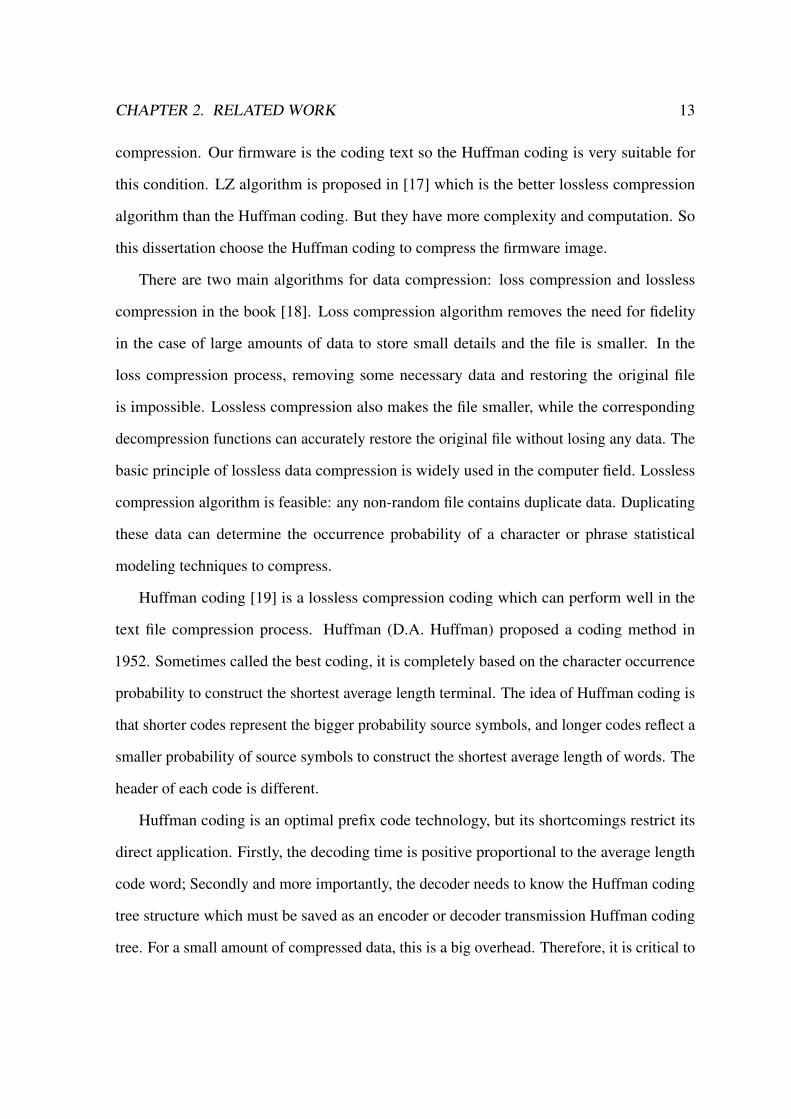
Fig. 2.1 Complete Binary Tree Stored in the Order Schematic
Based on binary nature, full binary tree and complete binary use sequential storage more
appropriately. Number of nodes in the tree can uniquely reflect the logical relationships
among nodes. In this way, it can use the index value of the array elements to determine the
nodes’ positions and their relationships. Fig. 2.1(a) is a complete binary tree. Its sequential
storage structure is presented as in Fig. 2.1(b).
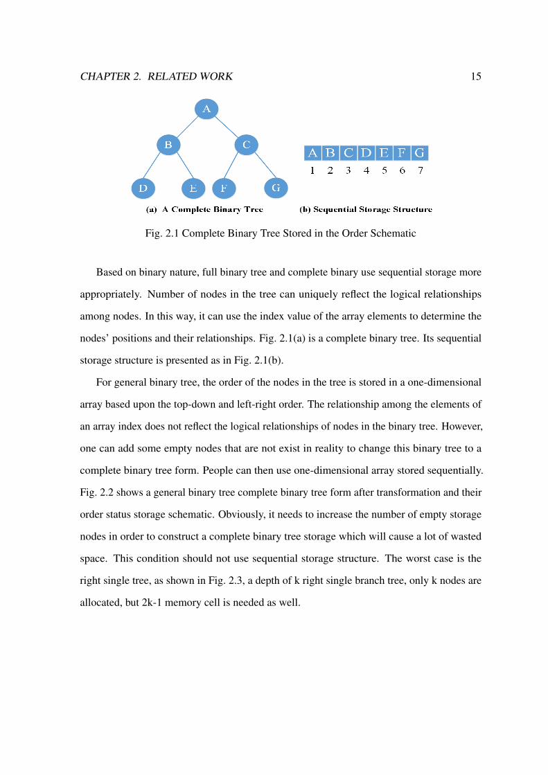
For general binary tree, the order of the nodes in the tree is stored in a one-dimensional
array based upon the top-down and left-right order. The relationship among the elements of
an array index does not reflect the logical relationships of nodes in the binary tree. However,
one can add some empty nodes that are not exist in reality to change this binary tree to a
complete binary tree form. People can then use one-dimensional array stored sequentially.
Fig. 2.2 shows a general binary tree complete binary tree form after transformation and their
order status storage schematic. Obviously, it needs to increase the number of empty storage
nodes in order to construct a complete binary tree storage which will cause a lot of wasted
space. This condition should not use sequential storage structure. The worst case is the
right single tree, as shown in Fig. 2.3, a depth of k right single branch tree, only k nodes are
allocated, but 2k-1 memory cell is needed as well.

CHAPTER 2. RELATED WORK 16
Fig. 2.2 General Binary Transformation Complete Binary Tree
Fig. 2.3 Single Binary Transformation Complete Binary Tree
Chain List Storage
Chain list storage binary tree structure is to represent a binary tree that used to indicate a
chain of logic elements. The usual pattern is to list each node consists of three domains,
domain and data about the target domain, were used to give the pointer around the left

CHAPTER 2. RELATED WORK 17
child node and the right child’s link points stored address. Its junction structure is shown as
Table 2.1.
Table 2.1 CHILDREN STRUCTURE
LCHILD DATAI RCHILD
In this structure, data field contains the value of a node; LCHILD and RCHILD are stored
pointing to the left child and right child pointers. When the left and right children do not
exist, the corresponding value is the null pointer domain (represented by the symbol ∧ or
NULL). Such binary tree node structure represents the chain storage structure as a binary list
as the example shown in Fig. 2.4. The right chain storage structure shows that the LCHILD
is the same as the RCHILD that points to the next left or right child data unit.
Fig. 2.4 Binary Tree Binary Schematic
In order to facilitate the process of accessing to a parent node, some researchers also add
a node to the linked list of parent field parent that directs to its parent node address. Each
node consists of four domains and the node structure changes as in Table 2.2:
Table 2.2 CHILDREN AND PARENT STRUCTURE
LCHILD DATAI RCHILD PARENT

CHAPTER 2. RELATED WORK 18
It is easy to find both child nodes and the parent node in this storage structure. But it
increases the space overhead regarding the binary list storage structure. Such binary tree
node structure that represents the chain storage structure is called the trigeminal list. Fig.6
shows a binary representation of the trigeminal list.
Fig. 2.5 Binary tree diagram showing the trigeminal list
2.3.3 Traditional Huffman Decompression Algorithm
The traditional Huffman decompression algorithm [22] is to rebuild the Huffman coding tree
and to decode the compression data. In a nutshell, the decompression of the Huffman code
tree is the conversion of the prefix Huffman code back to the symbol, usually by step-by-step
tracing of the received bits stream reduction. But in order to track the tree, the Huffman tree
must be built first. In some cases, if the weight of each symbol can be predicted in advance,
the Huffman tree can be pre-built and stored to reuse. Otherwise, sender end must pre-send
Hoffman tree related information to the receiver.
The simplest way is to count the weights of the symbols at first and then add them to
the compressed bit string. But the amount of computations in this method is considerable
and not suitable for practical applications. Canonical Huffman coding was first proposed by

CHAPTER 2. RELATED WORK 19
Schwartz which is a subset of the Huffman coding. Its central idea is that by using certain
mandatory convention, with only a few data, the Huffman coding tree will be able to be
reconstructed. One very important convention is the digital sequence attribute (numerical
sequence property), which requires the consecutive integers binary description with the code
word of same length. If the Canonical Huffman coding is used, it is possible to know the
exact amount of data reconstructed by the tree only for B∗2B bits (where B is the number of
bits per bit). If the bit of the received bit string is simply a bit, for example: ’0’ represents
the parent node and ’1’ represents the terminal node. If each reads 1, the next 8 bits will be
interpreted as the terminal node (assuming the data is 8-bit letters) and Huffman Tree can be
rebuilt. In this way, the amount of data may be the size of 2 ∼ 320 bytes. Although there are
many ways to rebuild the Huffman tree, as the compressed data string contains “trailing bits”,
do not restore them to the wrong value when the reduction decides when to stop, for example
in case the data is compressed with the length of the data Traditional algorithms operate by
bit, therefore it is inefficient. Fast decoding algorithm is developed to solve two kinds of
speed bottlenecks. The advantage of a small improvement of the algorithm is not bit by bit
operations, but to some extent, to enhance the decoding efficiency. For this algorithm, the
code length is determined in the code but improvements can also be made if the minimum
value develops into a binary tree, and code length can then be determined more quickly if
using the binary tree.
While these improvements are intended to ease the bottleneck of by-bit operation, the
code length is still needed to calculate. Therefore, this paper discusses the need to calculate
the code length lookup table algorithm. Assuming the length of the longest code word is the
maximum, each fixed decoding algorithms can read at least the max number. The read bit
string contains zero or more interpretable but uudecoded “surplus” sections of code words,
which are the prefix of next code word. Based on the interpretable code word, corresponding
symbols will be output, and by using the “surplus” partial index lookup table, the next bit

CHAPTER 2. RELATED WORK 20
string can be read. This method requires the number of the look-up table is equal to that of
different code word prefixes, i.e. the number of internal nodes of Huffman: N-1. Thus, each
lookup table has 2k records with k binary number string of corresponding length.
Huffman decoding needs to search the Huffman tree to decompress data. There are many
efficient Huffman decoding algorithms, but they are not very suitable for the embedded
environment. Due to the complexity of above decoding algorithms and poor function of
the space cost scenes in the smart home applications, this dissertation is originally inspired
by the literature and designs an efficient decoding algorithm. Both the compression and
decompression consider the data storage structure. A nimble and fewer space-cost storage
structure design has always been the goal to pursue. This dissertation proposes a flexible
Huffman tree storage structure to present the binary tree. It uses a recorded array of N-1
node information that contains each node’s logic and physical positions information. Then
the decompression algorithm can use the array to decode the bits string.
2.4 OTA Updating Optimization Progress
Texas Instruments provides an Over-air-download (OAD) firmware update method in the
z-stack [11] before ZigBee OTA firmware update specifications are formulated by ZigBee
Alliance [23]. Admittedly, the z-stack OTA is more standardized and mature in conforming
to the OTA specifications.
Many researchers and developers have made some optimizations about the ZigBee OTA
update technology based on different hardware platforms. In the z-stack [24], TI provides a
page requesting to reduce the image block commands as article [25]. But developers need to
implement it by themselves in the z-stack applications. Paper [26] presents a kind of image
data compression algorithm and voluntary nodes request method for the OTA upgrading. The
compression algorithm can make firmware image smaller so as to abbreviate the transmission
data and cut down the transmission duration. The voluntary nodes request method can assort

CHAPTER 2. RELATED WORK 21
the performance of backbone data circulation. But the firmware compression algorithm will
increase the complexity of OTA server workload computation and the OTA client needs to
decompress the image data, thus requiring more workload and power consumption. It is not
very suitable for ZigBee embedded chips’ strict requirements for low-power consumption.
Moreover, the nodes can voluntarily request method to close the pooling function and it is an
awful scheme that only OTA process can transmit data but the ZigBee’s natural functions
cannot work normally. In this paper [27], authors propose a multi-node concurrent upgrade
scheme which is to solve the efficiency problem with broadcast upgrade based on the tree-
type ZigBee network. It defines a new node’s logic type who has child nodes named the slave
server of the ZigBee OTA. When multi nodes of the ZigBee network concurrently update
the firmware, all nodes will send the request to the father slave server nodes other than the
OTA server and the slave server will decide whether to conduct the children nodes’ updating.
This method addresses the redundancy of firmware data and reduces the workload of the
OTA server. It allows the ZigBee OTA to update P2P scheme in an orderly manner other than
arbitrarily obstruct the OTA server’s backbone. However, as the self-healing function permits
the ZigBee network which is generally in the meshes to dynamically transform structure
so the father slave server in the tree may not be the befitting node. In addition, excessive
orderliness may not lead to the optimal efficiency. The nodes at the bottom of the tree network
will send vain polling commands if the slave server does not complete the firmware updating
and squander more energy when the multiple nodes are concurrently updating themselves.
All those leads to a complicity of the OTA update and make ZigBee OTA mesh network
need to cut the data redundancy and improve the update efficiency. Meanwhile, the OTA
update can work with the normal functions of ZigBee network [28] and features low power
consumption, self-healing and mesh network architecture. Therefore, this dissertation
proposes the dynamic page-request distributed OTA upgrade algorithm (DPPOTA) which
implements the image page request method in the z-stack to decrease the image block

CHAPTER 2. RELATED WORK 22
commands and modifies the ZigBee routers’ OTA applications to make the mesh network
dynamically process multi-node concurrent updating efficiently. In a way, this algorithm is
like a sort of the greedy algorithm: the OTA progress is based on the ZigBee mesh network’s
basic route choice and each thread is currently the best choice. In addition, the routers must
complete their own OTA process at first and then transmit other nodes’ OTA upgrading
commands. Therefore, each route path is dynamic and sequential and performs as an orderly
mesh network to cut down the massive data redundancy.
Chapter 3
Preparing ZigBee Network for Firmware
Updating
In this dissertation, ZigBee technology is used to build the smart home system which mainly
contains two parts: the ZigBee gateway and the ZigBee wireless mesh network nodes. ZigBee
gateway consists of a Linux host and a CC2531 as a ZigBee’s network coordinator. CC2531
chip performs as a ZNP device that can manage the ZigBee network such as building up the
ZigBee network, adding or moving devices, and setting the network security key. The Linux
host performs as an important role that parses the ZNP incoming information from bottom
layer and pushes the information to the upper different server applications for treatment
in progress. In addition, the gateway also needs to present a user interface or application
interface to be inserted into the internet. It is just like a bridge that connects the remote
ZigBee endpoints and people’s mobile devices through the internet. On the other side, the
ZigBee 3.0 came into consumers’ sight in June 2016. Comparing with the traditional ZigBee
standards, the ZigBee 3.0 has created a breakthrough technology named “Green Power”
which can make sensors consume less power and even some companies claimed that the
sensor can work in your life. ZigBee 3.0 evidently expands the power saving advantage of the
ZigBee technology than other 2.4GHz technologies. Smart home devices with ZigBee 3.0
23
CHAPTER 3. PREPARING ZIGBEE NETWORK FOR FIRMWARE UPDATING 24
can perform very well in the remote end-point environment. According to the implementation
of the technology, this dissertation selects TI open source solution – Z-Stack to build the
ZigBee 3.0 mesh network as the basic smart home devices network and builds the Z-Stack
Linux gateway as the smart home gateway.
3.1 Updating Server: ZigBee Linux Gateway
Z-Stack Linux gateway is TI’s ZigBee Home ZigBee Home gateway solution for Linux
systems. One of the main points of this gateway is to integrate ZigBee into the IP internet
world with simplified APIs over socket communication. The ZigBee middleware abstracts
a variety of smart home applications and conducts multiple automation application cases
such as lighting control, alarm, security, energy management, network management and
over-the-air firmware upgrade. It can be fast prototyped on Beagle Bone Black platform
which is powered by TI’s leading Sitara-Am335x Cortex-A8 processor and is able to run on
most Linux or Android platforms. This gateway solution can also support the green power
nodes of ZigBee 3.0.
The gateway’s upper level uses Google protocol buffers that are Google’s language-
neutral, platform-neutral and extensible mechanism for serializing structured data such as
XML, but it is smaller, faster, and simpler. Developers can define how they want to the data
to be structured, then they can use the special generated source code to easily write and read
your structured data to and from a variety of data streams and use a variety of languages such
java, C# and python. After that developers can use the protocol buffers to communicate with
other message queue servers such as Rabbit MQ broker for future development.
Home gateway can receive ZIGBEE nodes’ information and send commands to control
home devices. In addition, the gateway can serve as a bridge to support the ZIGBEE data
inserting into the internet. ZNP can perform as a home ZIGBEE devices dongle and an
application needs to be developed on the ZNP layer which is named ZIGBEE network
CHAPTER 3. PREPARING ZIGBEE NETWORK FOR FIRMWARE UPDATING 25
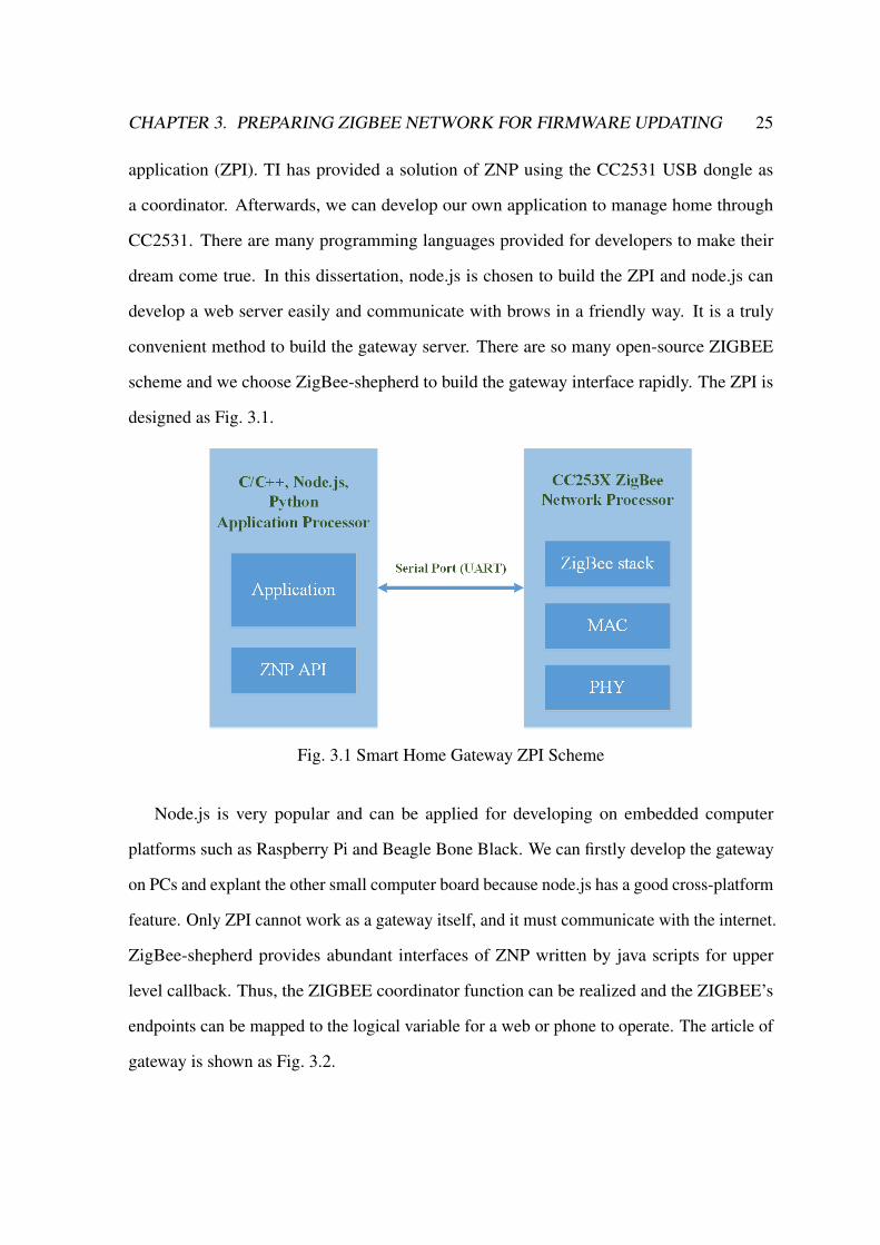
application (ZPI). TI has provided a solution of ZNP using the CC2531 USB dongle as
a coordinator. Afterwards, we can develop our own application to manage home through
CC2531. There are many programming languages provided for developers to make their
dream come true. In this dissertation, node.js is chosen to build the ZPI and node.js can
develop a web server easily and communicate with brows in a friendly way. It is a truly
convenient method to build the gateway server. There are so many open-source ZIGBEE
scheme and we choose ZigBee-shepherd to build the gateway interface rapidly. The ZPI is
designed as Fig. 3.1.
Fig. 3.1 Smart Home Gateway ZPI Scheme
Node.js is very popular and can be applied for developing on embedded computer
platforms such as Raspberry Pi and Beagle Bone Black. We can firstly develop the gateway
on PCs and explant the other small computer board because node.js has a good cross-platform
feature. Only ZPI cannot work as a gateway itself, and it must communicate with the internet.
ZigBee-shepherd provides abundant interfaces of ZNP written by java scripts for upper
level callback. Thus, the ZIGBEE coordinator function can be realized and the ZIGBEE’s
endpoints can be mapped to the logical variable for a web or phone to operate. The article of
gateway is shown as Fig. 3.2.
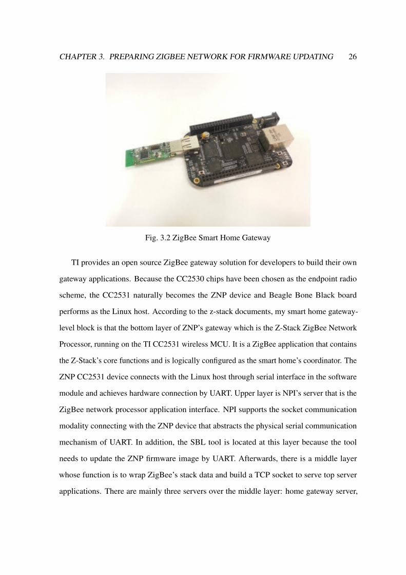
CHAPTER 3. PREPARING ZIGBEE NETWORK FOR FIRMWARE UPDATING 26
Fig. 3.2 ZigBee Smart Home Gateway
TI provides an open source ZigBee gateway solution for developers to build their own
gateway applications. Because the CC2530 chips have been chosen as the endpoint radio
scheme, the CC2531 naturally becomes the ZNP device and Beagle Bone Black board
performs as the Linux host. According to the z-stack documents, my smart home gateway-
level block is that the bottom layer of ZNP’s gateway which is the Z-Stack ZigBee Network
Processor, running on the TI CC2531 wireless MCU. It is a ZigBee application that contains
the Z-Stack’s core functions and is logically configured as the smart home’s coordinator. The
ZNP CC2531 device connects with the Linux host through serial interface in the software
module and achieves hardware connection by UART. Upper layer is NPI’s server that is the
ZigBee network processor application interface. NPI supports the socket communication
modality connecting with the ZNP device that abstracts the physical serial communication
mechanism of UART. In addition, the SBL tool is located at this layer because the tool
needs to update the ZNP firmware image by UART. Afterwards, there is a middle layer
whose function is to wrap ZigBee’s stack data and build a TCP socket to serve top server
applications. There are mainly three servers over the middle layer: home gateway server,
CHAPTER 3. PREPARING ZIGBEE NETWORK FOR FIRMWARE UPDATING 27
network manager server and over-the-air update server. The core of the firmware update
of the smart home is the OTA server which provides devices with firmware update service
listed in the gateway ZigBee network such as the lamp, the switch and other devices. The
network manager server uses ZigBee’s stack services to manage its facilities on the network
and creates a facility database that contains information such as IEEE address, device ID and
other parameters for all ZigBee’s facilities. The gateway server offers the primary function
of the gateway. It encapsulates the ZigBee’s endpoint registration, simple descriptor of
devices and the endpoints attribute table. For instance, if consumers want to read their home
temperature and control their home lamps, the gateway server will provide these services.
These three servers are the core of the smart home gateway and a user application layer
will be developed to combine these servers to serve individuals. C language is able to make
binary data coding and well communicate with GPU. So, C language is used in developing
many embedded systems to run application fast. When the upper layer application does not
much limit machine running speed demand, C language is not a very suited programming
language in web and mobile application development. However, if other developers want to
use another developing language, the problem will be how different programming languages
work together with each other.
In views of this situation, Google has designed a structured data encapsulation named
protocol buffers that are Google’s language-neutral, platform-neutral, extensible mechanism
for serializing structured data. To refer to the serializing data structure, there are many
popular technologies such as XML and JSON. The protocol buffer is smaller, faster and
simpler than them. People can define how they want the data to be structured and use the
special generated source code to easily write and read the structured data through the proto
file and using a variety of languages. The advantage of protocol buffer is that these three
servers socket interfaces can be encapsulated into three proto files and python and java can
be used to develop the web application communicating with servers. But the disadvantage

CHAPTER 3. PREPARING ZIGBEE NETWORK FOR FIRMWARE UPDATING 28
is that the proto file needs a compiler to produce the python class file and its readability is
poor. Recently the gateway user application can be developed to communicate with servers
by different languages using these three proto files.
Above all, the smart home has been built. User can send commands and receive attributes
of devices on the gateway application via the CC2531 ZNP layer. The next step is to establish
the endpoints’ ZigBee network applications.
3.2 Updating Client: ZigBee Network Applications
In 2016, ZigBee Alliance officially launched the ZigBee 3.0 protocol which was an open,
global standard for the Internet of Things based on the IEEE 802.15.4 standard and working
on the 2.4GHz frequency band. The difference compared with the precious ZigBee standard
is that ZigBee PRO network has the Green Power feature. The same protocol structure
as the previous ZigBee version is: the physical layer (PHY), media access layer (MAC),
network layer (NWK) and application layer (APL) from bottom to up. In the past fourteen
years, ZigBee Alliance has developed many APL applications such as home automation,
building automation and ZigBee light link, but the ZigBee 3.0 has integrated and simplified
these different applications as discussed in this paper [29]. Just as the ZigBee Alliance web
said, ZigBee is the only global, standards-based wireless solution that can conveniently and
affordably control the widest range of devices to improve comfort, security and convenience
for consumers. It is the choice of technology for world-leading service providers, installers
and retailers who bring the benefits of the Internet of Things into the Smart Home. It has
the following main features: frequently and agilely operating over sixteen channels in the
2.4GHz frequency, multiple star topology and inter-personal area network communication.
ZigBee 3.0 utilizes the industry standard AES-128 security scheme, incorporates power
saving mechanisms for device of all classes and provides support for battery-less devices.
Those features allow the energy harvest devices to securely join ZigBee’s pro networks. It is

CHAPTER 3. PREPARING ZIGBEE NETWORK FOR FIRMWARE UPDATING 29
the eco-friendliest way to power ZigBee products such as sensors, switches, flame and many
others. Devices can currently be powered by using widely available but frequently untapped
sources of energy: motion, light, click, vibration and temperature alternation, just to name
a few. The energy used to flip a typical switch via common energy harvesting techniques
is powerful enough to generate and send the ZigBee PRO commands. For instance, we can
use switch to turn on or off the lamp in the past circuit, but now we can use the battery-less
switch to control lamp with ZigBee battery-less radio chip instead.
In this dissertation, the TI z-stack 3.0 is chosen as the ZigBee protocol implement scheme.
TI ZigBee solution chips are CC2530 and CC2538. CC2530 is a true system-on-chip solution
for IEEE802.15.4 and RF4CE application. It combines the excellent performance of a
leading RF transceiver with an industry-standard enhanced 8041 MCU. CC2538 is more
powerful and contains an ARM Cortex-M3-based MCU. Considering the cost, CC2530 is
more suitable for the smart home devices’ radio module. To sum up, the CC2530 hardware
chips and z-stack software are used to build up the smart home environment.
Initially, the ZigBee network nodes have three logical types: coordinator, router and end
device. Coordinator is the first node to be started and is the only one node responsible for
forming the network by allowing other nodes to join the network through it. Coordinator
has all the functions of router. After it builds the network and the other ZigBee nodes have
joined the network, the coordinator only performs as a router. If the ZigBee network needs
to reset, the coordinator start the coordinator’s functions. As mentioned above, the gateway
application on the coordinator is set to be the smart home pivot. Router is another ZigBee
node’s logical type which has routing capability. It is also able to send and receive data as a
smart home device and allows other nodes to join the network. One ZigBee network contains
many routers that always wait to be on call. The last node type is an endpoint that is the most
common device type. It is only capable of sending and receiving data and cannot route other
commands. A mesh network is illustrated in the Fig. 3.3.

CHAPTER 3. PREPARING ZIGBEE NETWORK FOR FIRMWARE UPDATING 30
Fig. 3.3 ZigBee Mesh Network Topological Graph
The smart home contains many kinds of ZigBee nodes and they can be roughly divided
into three kinds: controller, sensor and binary sensor. To facilitate my study, this dissertation
uses just two devices as samples. If open the z-stack in IAR IDE, we can see that it does
not only contain the ZigBee protocol layers but also some other auxiliary layers as shown in
the Fig.3.3. To omit the developing progress, this dissertation abstracts two types’ devices:
switch and light. The switch can be turned on or off and bind with the light application in
a group. Both of them can be routers or endpoints. Then we can update their firmware by
upgrading the technologies of the ZigBee firmware in the next section.

Chapter 4
Approaches to ZigBee Network
Firmware Updating
This dissertation applies the TI CC2530 chips and z-stack platform to build the smart home
sensor network. When it comes to the smart home devices firmware update solutions, it needs
to upgrade the ZigBee firmware without removing core chips. If consumers need to update
devices’ firmware themselves by using the programmer to burn the image, the workload is
so massive and any consumer will not buy these products. The ZigBee IAP technology can
realize a convenient update and z-stack has provided two methods: Serial Bootloader wired
upgrading scheme and the Over-the-Air wireless upgrading scheme.
4.1 Wired ZigBee Firmware Updating: Serial Bootloader
Serial Bootloader (SBL) is provided as a value-enhancing sample solution that enables the
updating of code in devices without the cost of maintaining any download-related code in
the user’s application other than ensuring a compatible flash memory mapping of the final
output. SBL process is working as a managed client-server mechanism which requires a
serial master to drive the process and it has a generic feature that should deviate as little
31

CHAPTER 4. APPROACHES TO ZIGBEE NETWORK FIRMWARE UPDATING 32
as possible. Many implementations only support the idiosyncrasies of the specific medium
(e.g. USB) crucial to the level of service necessary to complete a code image download in a
reasonable amount of time. For the sake of example, the USB SBL specific references will
be made in this document, although merely changing the medium-specific verbiage and paths
should allow this document to sufficiently describe any Z-Stack SBL.
4.1.1 ZigBee SBL Server
TI has provided the SBL client application on CC2530 chips and a console tool as an .exe
server based on PC Windows. But developers cannot see SBL server’s operational principles.
If the smart home’s gateway wants to support the SBL service as a server end, it must make
the communication process clear. My contribution is providing the details of communication
between the server and the client through monitoring the serial communication. SBL updating
is a wired firmware updating method and it is generally used to upgrade the ZNP device.
I summarize the communication commands and implement a python SBL server on the
gateway to upgrade the CC2531 ZNP.
Firstly, when the consumer has a new version firmware of ZNP, the gateway can be
reliable and fast for transforming the firmware image to CC2531 ZNP device. The SBL
server communicates with the client in half-duplex operation. The gateway gives the SBL
server essential environment of port parameters such as baud rate, port number and so on.
Then the gateway sends a SBL request to ask ZNP to prepare for SBL updating. When
it receives a response command, the next step is to make handshake with ZNP. After the
handshake succeeds, ZNP client turns into a SBL client model and continues to receive
the firmware data. Then the gateway can write the hex or binary firmware data into ZNP
by UART. When the gateway receives the success response, it sends the next block data,
or resends the failing data frame. At last, the whole firmware image will be sent out and
the gateway sends a CRC command to make ZNP start the new firmware. Above all, it
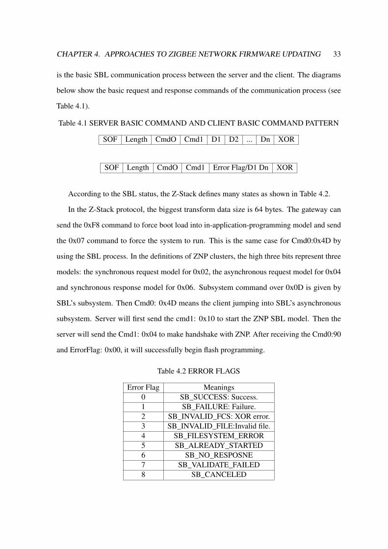
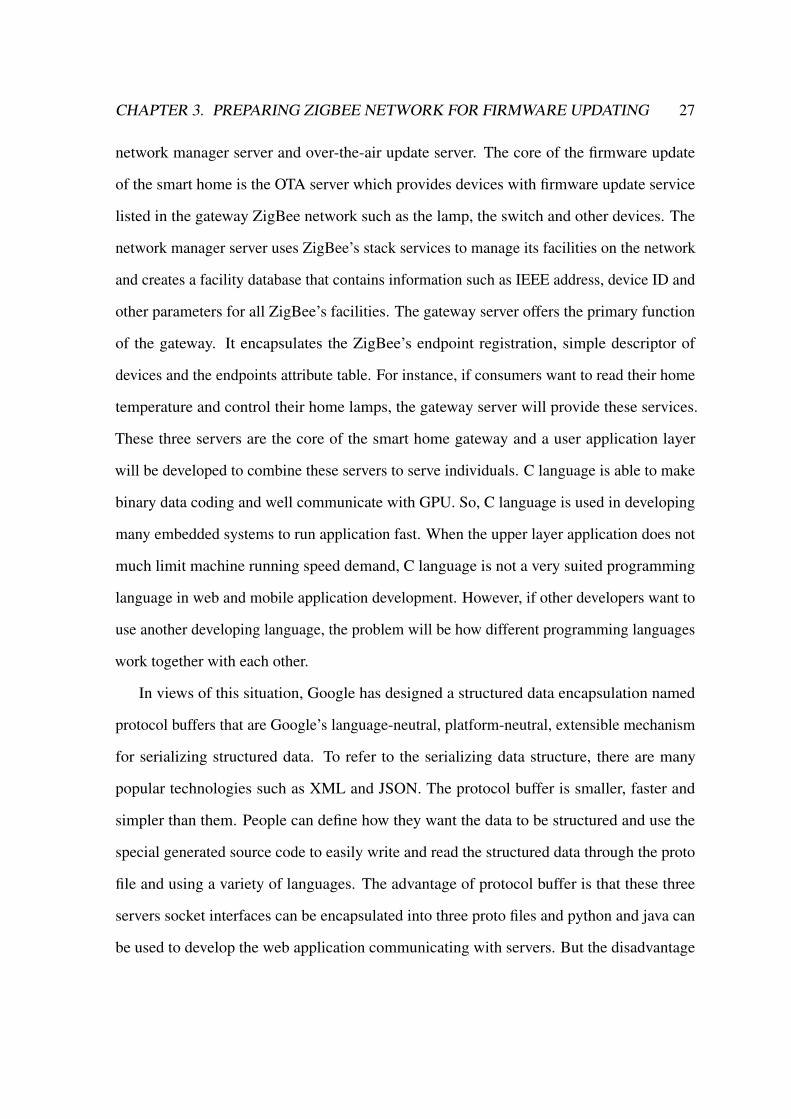
CHAPTER 4. APPROACHES TO ZIGBEE NETWORK FIRMWARE UPDATING 33
is the basic SBL communication process between the server and the client. The diagrams
below show the basic request and response commands of the communication process (see
Table 4.1).
Table 4.1 SERVER BASIC COMMAND AND CLIENT BASIC COMMAND PATTERN
SOF Length CmdO Cmd1 D1 D2 ... Dn XOR
SOF Length CmdO Cmd1 Error Flag/D1 Dn XOR
According to the SBL status, the Z-Stack defines many states as shown in Table 4.2.
In the Z-Stack protocol, the biggest transform data size is 64 bytes. The gateway can
send the 0xF8 command to force boot load into in-application-programming model and send
the 0x07 command to force the system to run. This is the same case for Cmd0:0x4D by
using the SBL process. In the definitions of ZNP clusters, the high three bits represent three
models: the synchronous request model for 0x02, the asynchronous request model for 0x04
and synchronous response model for 0x06. Subsystem command over 0x0D is given by
SBL’s subsystem. Then Cmd0: 0x4D means the client jumping into SBL’s asynchronous
subsystem. Server will first send the cmd1: 0x10 to start the ZNP SBL model. Then the
server will send the Cmd1: 0x04 to make handshake with ZNP. After receiving the Cmd0:90
and ErrorFlag: 0x00, it will successfully begin flash programming.
Table 4.2 ERROR FLAGS
Error Flag Meanings0 SB_SUCCESS: Success.1 SB_FAILURE: Failure.2 SB_INVALID_FCS: XOR error.3 SB_INVALID_FILE:Invalid file.4 SB_FILESYSTEM_ERROR5 SB_ALREADY_STARTED6 SB_NO_RESPOSNE7 SB_VALIDATE_FAILED8 SB_CANCELED

CHAPTER 4. APPROACHES TO ZIGBEE NETWORK FIRMWARE UPDATING 34
Table 4.3 HANDSHAKE COMMAND PATTERN
Server ClientName Content Name ContentSOF 0xFE SOF 0xFE
Length 0x01 Length 0x01Cmd0 0x4D Cmd0 0x4DCmd1 0x04 Cmd1 0x84Data 0x02 ErrorFlag 0x00 (Success)XOR 0x4A XOR 0xC8
Table 4.4 FLASH PROGRAMMING COMMAND PATTERN
Server ClientName Content Name ContentSOF 0xFE SOF 0xFE
Length 0x42 Length 0x01Cmd0 0x4D Cmd0 0x4DCmd1 0x01 Cmd1 0x81
FlgAddr 0x00 0x00Data Data ErrorFlag 0x00 (Success)XOR 0x38 XOR 0xCD
When SBL begins to flash the firmware, the server will send Cmd1:0x01 and flash start
address: 0x00 0x00. When the client receives the correct firmware image block, it will send
the 0x00 success response. Then the server begins to send 64-bit firmware image block
and the last block less than 64 bits are filled with 0xFF. After successfully flashing the last
firmware image block, the server will send the read command Cmd1:0x02 to read back the
data from address: 0x00 0x00 to check the firmware validity.
When the server reads back the whole firmware image correctly, the server will send
the CRC Cmd1:0x03 to make ZNP jump to run on the application system. When the server
writes the CRC command Cmd1:0x03, if the CRC’s result is incorrect, the Error Flag will
present SB_VALIDATE_FAILED or SB_SUCCESS. As the gateway design is based on the
TI CC2530 z-stack protocol, the commands will follow ZigBee’s cluster specification.

CHAPTER 4. APPROACHES TO ZIGBEE NETWORK FIRMWARE UPDATING 35
Table 4.5 READ BACK COMMAND PATTERN
Server ClientName Content Name ContentSOF 0xFE SOF 0xFELength 0x02 Length 0x43Cmd0 0x4D Cmd0 0x4DCmd1 0x02 Cmd1 0x82FlgAddr
0x00 0x00 Data. . . ErrorFlagData DataXOR 0x54 XOR 0xCD
Table 4.6 CRC RUN APPLICATION SYSTEM COMMAND PATTERN
Server ClientName Content Name ContentSOF 0xFE SOF 0xFELength 0x00 Length 0x01Cmd0 0x4D Cmd0 0x4DCmd1 0x03 Cmd1 0x83Data ErrorFlag 0x00 (Success)XOR 0x4E XOR 0xCF
Based on above all, the ZigBee SBL server can be implemented based on the special
protocol in different programming language. According to the upper application development
in the future, python is used to build the same function script as C programming SBL server
on the Beagle Bone Black which can be a widget for the gateway to abstract the SBL service.
4.1.2 ZigBee SBL Client
When developing the gateway application, the ZNP firmware needs to be updated frequently.
The SBL firmware update method can provide a reliable and convenient service. However,
SBL must possess wired communication by UART that is a big limit of application in the
wireless communication network. Thus, the CC2531 ZNP is a just perfect fit client device in
this condition.

CHAPTER 4. APPROACHES TO ZIGBEE NETWORK FIRMWARE UPDATING 36
The SBL solution requires the use of boot code to check the integrity of the active code
image before jumping to it. This check guards against an incomplete or incorrect program-
ming of the active image area. The SBL boot code provides the following functionality:
1. Boot Code will be the target of the reset vector (as well as any vector necessary for
communicating on the chosen serial bus), and therefore contains startup and ISR code; 2.
When the serial bus connection is detected and the master application commands it, Boot
Code will program the SBL image into the active image area and will thusly complete the
final step of the SBL process: code instantiation; 3. (Optional) Boot Code will guard against
interrupted, incomplete or incorrect programming of active image areas by checking the
validity of the active application code image via CRC. If the image is not valid then the boot
code will not allow it to run.
An SBL-compatible Z-Stack is implemented as a standard ZigBee application built with
the exception of the linker command file and some ancillary settings. The serial ports update
is completed in the sample application. By analyzing interaction of serial data frames, the
z-stack SBL update command is found between PC and CC2530. It can work with z-stack
boot loader application with fast speed. The frame and command are as Table 4.7
Each CC2530 chip runs as a ZigBee node radio chip that sends and receives wireless data
or commands for smart home devices. ZNP is an important device as a coordinator to build
and manage network or device. In this dissertation, CC2531 ZigBee Network Processer is
used as the solution to connect with Beagle Bone Black by UART as a home gateway. When
consumers want to update the ZNP firmware, SBL is a reliable and fast update method. Our
gateway has provided an SBL server to track the ZNP SBL update, and what ZNP needs to do
is to communicate with the server and make handshake. Then the ZNP client waits to receive
a block firmware data from the server and send a success response command to the server to
tell that it can send the next block image. After receiving the whole firmware data, the client
will receive a CRC to transform the new firmware to the memory bank. Counting several

CHAPTER 4. APPROACHES TO ZIGBEE NETWORK FIRMWARE UPDATING 37
Table 4.7 OTA UPGRADE CLUSTER COMPENENTS
| Data Header: SOF | Data Length: LEN | Command 1 | Command 2 | data | CRC: FCS|
For example:FE 01 4D 10 00 5C
In the SBL program has the following definition:// Bootloader Serial Interface Subsystem#define SB_RPC_SYS_BOOT 0x4D// Commands to Bootloader#define SB_WRITE_CMD 0x01#define SB_READ_CMD 0x02#define SB_ENABLE_CMD 0x03#define SB_HANDSHAKE_CMD 0x04
seconds, the ZNP will restart and run the new firmware. The logical interacting process is
shown in a figure and the communication commands are present in a table. However, if
ZNP wants to implement the SBL service, it needs to program the serial boot code into the
CC2531 in advance. The boot code is located from 0x0000 to 0x2000 in the memory bank.
Thus, the ZNP application code will start from bank: 0x2000 in the memory to keep the boot
code invariant. The CC2531 inner memory bank programming address allocation is showed
as Fig. 4.1.

CHAPTER 4. APPROACHES TO ZIGBEE NETWORK FIRMWARE UPDATING 38
Fig. 4.1 SBL Programming Bank Address
As the Serial Boot loader may run on the different platform, when developers use C/C++
in windows, they will write files to make it run on the Linux system because many embedded
computers are Linux system. For this cross-platform need, Python is a good programming
language choice. Therefore, a Serial Bootloader python script is developed to provide wired
firmware update service. It can work with the z-stack Linux gateway to update the ZNP
device’s firmware without any other servers running. This SBL server can work well with
the ZigBee network applications. The CC2531 dongle runs as not only a ZNP device on the
gateway but also a SBL client same as other ZigBee applications.
4.2 Wireless ZigBee Firmware Updating: Over-the-Air
This dissertation applies ZigBee technology to build a smart home In-Application program-
ming update environment as Fig.4.2. In this environment, the dongle is connecting the

CHAPTER 4. APPROACHES TO ZIGBEE NETWORK FIRMWARE UPDATING 39
computer through wired method. The ZigBee network nodes connect with each other by
wireless method. Then the dongle and other nodes should choose a different method to
update so that the whole network update is more efficient. After the z-stack data sheet is
studied, three methods can be used to update the ZigBee nodes firmware: Serial Bootloader
(SBL), Over the Air Download (OAD) and Over the Air (OTA). The OAD uses TI’s protocol
and the OTA use the ZigBee Alliance protocol. So, the OAD is the same as the OTA in
principle and it only chooses the OTA method to update. The above sections has introduced
the SBL technology, the OTA technology that is one of the In-Application programming
(IAP) technologies, same as the SBL, but the OTA is a wireless IAP.
Fig. 4.2 A Simple ZigBee Firmware Upgrading Process
The OTA (Over-the-Air) Upgrade Cluster provides a standard mechanism to wirelessly
upgrade a ZigBee device’s firmware. Over-the-air updating sessions take place between
a client and a server. The OTA Client downloads an OTA Updating Image from the OTA
Server that hosts new firmware images.

CHAPTER 4. APPROACHES TO ZIGBEE NETWORK FIRMWARE UPDATING 40
4.2.1 ZigBee OTA Server
ZigBee alliance formulates the Over-the-Air update standard that is providing a standard
mechanism for wirelessly upgrading a ZigBee device firmware in the ZigBee upgrade cluster.
Over-the-air update wireless sessions are processed between a client and a server. In addition,
the server needs to produce the firmware image data from the upper machine such as a
home gateway by wired method. Texas Instruments z-stack of ZigBee Cluster Library (ZCL)
provides the applications’ technical support for the client and the server operation in the OTA
Upgrade Cluster. It provides a simple description of how the OTA Upgrade Cluster is used
to renovate a device firmware. In simple terms, the OTA Upgrade Cluster communication
between a client and a server takes place using some message commands as shown in Fig.4.3.
Fig. 4.3 OTA Process Communication Commands

CHAPTER 4. APPROACHES TO ZIGBEE NETWORK FIRMWARE UPDATING 41
From the above diagram, it shows that the OTA updating is a kind of data request
and response dependable communication. If only considering the wireless communication
session, the ZigBee OTA Cluster commands are be presented as bellow. Basically, adding
OTA function can be sectioned into three parts: inserting OTA and related events, handling
OTA MSG, environment setup and updated image generation. The followings are steps to
change the Z-stack sample application, Simple Sensor EB, into an OTA-enabled application.
Increase in the data payload can speed up the update.
Fig. 4.4 OTA Server Wireless End
The server is a ZigBee device such as a CC2531 ZNP dongle that performs as an OTA
boot device by which the Image Notify message is sent broadcast or unicast to notify the OTA
clients that there are some new firmware images available. In the Fig.4.4, the server receives
the wireless data. If the wireless data is the command data then go left path to send commands

CHAPTER 4. APPROACHES TO ZIGBEE NETWORK FIRMWARE UPDATING 42
to PC console. If the data is the block image request then go right path to get the image
block from the PC console. This message command does not contain any information about
new images and it is just an OTA inspiration. Then the OTA clients determine whether they
need to update the new firmware image by sending the Query Next Image request command
and receiving the response messages. This request message contains the currently running
firmware version on the client device and the server decides whether an image should take
place and which image the client should update by checking this message. Then the server
sends the Query Next Image Response message to instruct the client to download the new
firmware or inform the firmware that it is not available. Afterwards, the download process
begins to run after the clients sending the Image Block Request message. The server sends
chunks of firmware image data in the Image Block Response message. The clients write the
received image blocks to a secondary storage location which can be in the on-chip or off-chip
flash memory. Depending on the CC2530 chips that only have 256k RAM, an external flash
is needed to communicate with the chip by SPI. Periodically, after a client requests the entire
firmware image data, the client sends the Upgrade End Request message to the server. The
Upgrade End Response message sent by the server contains information about what time
the client can switch to the new firmware, immediately or waiting a specified period. Above
all, it is the chief communication process of the OTA update. The detailed functions and
implementation of the OTA server and clients are presented in the following section.
The OTA server contains the upper machine that hosts firmware image and the OTA boot
loader. As the frontal home gateway design scheme, the ZigBee gateway hosts the OTA
update firmware image and provides the OTA update service. The ZNP CC2531 becomes
the OTA boot device like an assistant that produces the image data from the gateway and
sends the firmware data to the clients. The z-stack provides the OTA function solution but it
cannot work in the sample applications. Firstly, open the z-stack software file and find the
OTA dongle file. Because the ZNP device performs as a coordinator, the OTA dongle will be

CHAPTER 4. APPROACHES TO ZIGBEE NETWORK FIRMWARE UPDATING 43
programmed in the IAR IDE tool. Switch the C/C++ Compiler and Linker options in the
IAR and configure the parameters as shown in the figure. Then rebuild all endpoint codes of
the coordinator and download them into the ZNP dongle device. In the Fig.4.5, OTA server
serial port end can receive three types serial port data. One is the command from the PC
console which it the image notify. Second is the client’s commands from the PC console.
The last one is the client’s image block response.
Fig. 4.5 OTA Server Serial Port End
The gateway OTA server provides firmware upgrade services in the Gateway ZigBee net-
work and uses the ZigBee stack services provided by the Z-stack server. The server provides

CHAPTER 4. APPROACHES TO ZIGBEE NETWORK FIRMWARE UPDATING 44
some API interfaces to the user application over a TCP socket that allows maintenance of de-
vice in upgrading images and controls the air operations through the ZNP coordinator. In the
figure, there are three communication components: gateway application, the OTA subsystem
and ZNP device. Firstly, the gateway application sends the update registration request to the
OTA subsystem and the OTA enables request. When it receives the confirmation command,
the ZNP dongle produces the firmware data from the gateway database. Then the ZNP dongle
processes the OTA updating. After the update is finished, the OTA subsystem will inform the
gateway application that the remote device to finish the downloading of the firmware image.
Consumers can send the image-applying request to instruct the remote devices that they can
apply a previously downloaded image.
To sum up, the OTA upper server contains two components: the gateway application and
the ZNP dongle. Consumers can use the gateway application to update the remote ZigBee
devices firmware through the ZNP dongle assistant.
4.2.2 ZigBee OTA Client
The OTA clients are the ZigBee endpoint devices. Each ZigBee endpoint runs a z-stack
software on chip and the OTA updating is also based on the z-stack cluster. The advantage
is that the ZigBee endpoints can normally work and update OTA. If the devices want to
implement the OTA update function, they must start the booting application. To open the z-
stack OTA boot file, the CC2530 chips need to download the boot code firstly. The parameters
in the Linker option as shown in the figure are also needed to be checked. ZigBee endpoint
applications cannot work only by starting the boot application and it needs to add the boot
application to the SOAL system. Firstly, add the zcl_Init (taskID++) and zcl_event_loop
functions to the task of the sample application OSAL. Then add the OTA variables such as
program length, manufacturer ID, image’s type and image version to the global variables
declaration field. In the normal application profile, it does not have the zcl and zcl_ota files.

CHAPTER 4. APPROACHES TO ZIGBEE NETWORK FIRMWARE UPDATING 45
At last, it just needs adding an OTA callback function to the application function. The OTA
service is turned on at the endpoint chips. More operation and settings are provided in the
handbook [30]. If the programming compiles successfully, it can be downloaded into the
ZigBee endpoint device over the boot code. Currently, the ZigBee endpoint device can
perform the OTA update with the ZNP dongle.
The OTA process works as below: At the beginning of the OTA update, the server sends an
Image Notify message to one device or multiple devices by unicast or broadcast respectively.
It informs the devices that a new image is available. Then the server decides if or not to
update the client’s current firmware based on the information contained in the Query Next
Image Request message, which is sent by the client. After this, a Query Next Image Response
message is transmitted to inform the client that whether the firmware is available and whether
and when to follow the client manages and start the firmware’s downloading procedure.
During the downloading process, Image Block Request and Image Block Response, which
include the image block, are transmitted between the server and the client. The client writes
the image block to its secondary storage, which can be internal or external flash memory. In
the end, an Upgrade End Request is sent to the server when the client has received the entire
image. For response, the server sends back an Upgrade End Response message to inform the
client when to switch to the new firmware.
Basically, adding OTA function can be sectioned into three parts: inserting OTA and
related events, handling OTA MSG, environment setup and updated image generation. The
followings are steps to change the Z-stack sample application, Simple Sensor EB, into an
OTA-enabled application. Increase in the data payload can speed up the update. But there is
also a range. Texas Instruments’ Z-Stack ZCL, ZigBee Cluster Library, provides support for
client and server operation of the OTA Upgrade Cluster. The Texas Instruments’ Z-Stack
implementation of the OTA Upgrade Cluster consists of the following components (see
Table 4.8) .

CHAPTER 4. APPROACHES TO ZIGBEE NETWORK FIRMWARE UPDATING 46
Table 4.8 OTA UPGRADE CLUSTER COMPENENTS
1 OTA Console Application
2 OTA Image Converter Application
3 ZCL Implementation of the OTA Protocol
4 Boot loaders for the supported platforms
5 Sample OTA Application
This section provides a simple description of how the OTA Upgrade Cluster is used to
update a device’s firmware. For more detail, see the ZigBee Alliance Document 095264 [10],
ZigBee OTA Upgrade Cluster Specification. Communication via the OTA Upgrade Cluster
takes place using the following command messages in Table 4.9.
Table 4.9 OTA UPGRADE CLUSTER COMMANDS
1 Image Notify
2 Query Next Image Request
3 Query Next Image Response
4 Image Block Request
5 Image Block Response
6 Update End Request
7 Update End Response
The Image Notify message is sent unicast or is broadcast by an OTA Server to notify OTA
Clients that new images are available. The Image Notify does not contain information about
the new images. The Image Notify only indicates new available images. OTA Clients will
determine if these new images apply to them by using the Query Next Image request and
response messages.

CHAPTER 4. APPROACHES TO ZIGBEE NETWORK FIRMWARE UPDATING 47
Periodically, or after receipt of an Image Notify message, an OTA Client sends a Query
Next Image Request message to an OTA Server. The Query Next Image Request message
contains the version of the firmware which is currently running on the client. On receiving
the Query Next Image Request, the server decides if an image update should take place and
which image the client updates. The server responds to the query for next image request
with a Query Next Image Response message. This command may instruct the client to
download new firmware, or it may inform the client that no firmware is available. During
the downloading process, the client sends Image Block Request messages to the server and
receives Image Block Response messages from the server with chunks of the upgraded image.
The client writes the image blocks to a secondary storage location. In the Z-Stack’s sample
applications, this secondary storage can be in on-chip or off-chip flash memory, depending
on the hardware platform.
After the client has downloaded the entire upgrade image, the client sends the Upgrade
End Request message to the server. The server then responds with an Upgrade End Response
message. The Upgrade End Response message contains information about when the client
should switch to the new firmware. The client may switch to the new firmware immediately
or it may be instructed to wait for a specified period. In the z-stack’s sample applications,
when it is the time for a client to switch the new image, the client writes a nonvolatile (NV)
memory location indicating new firmware is available. Then the client reboots and a boot
loader on the client sees the new available image. The boot loader copies the new image
from secondary storage to the operational memory space and the new firmware is started on
the chips.
The existing OTA upgrade methods available are platform specific, not OTA interoperable
and do not provide a common framework for upgrading networks that support a mix of devices
from multiple 426 platforms and ZigBee Stack vendors. The intent of this document is to
provide an interoperable OTA upgrade of new image for devices deployed in the field. As
CHAPTER 4. APPROACHES TO ZIGBEE NETWORK FIRMWARE UPDATING 48
long as the device supports the OTA Upgrade cluster and it is certified by an approved
test house, its image shall be upgradeable by another device from the same or different
manufacturer that also implements and certifies the OTA Upgrade cluster. The OTA Upgrade
cluster will also require that in order to support OTA upgrade, the device will need to have
an application boot loader installed as well as sufficient memory (external or internal) to
store the newly loaded image. An application boot loader uses the running ZigBee stack
and application to retrieve and store a new image. Depending upon the manufacturer, the
image may consist of a boot loader image, a ZigBee stack image or only a patch to the
application image. Whatever comprises the OTA upgrade image being sent to the node does
not concern the ZigBee OTA cluster and it is outside the scope of this document. To use an
application boot loader, the device is required to have sufficient memory (internal or external)
to store the newly downloaded OTA upgrade image. By doing so, the current running image
is not overwritten until the new image has been successfully downloaded. It also allows the
possibility of a node saving an image in its memory and forwarding that image to another
node. Application boot loader provides flexibility of when the device decides to download
new OTA upgraded images as well as when the device decides to switch to running the new
image. Since the boot loader is done at the application level, it automatically makes use of
various features already offered by the ZigBee Network Layer and Application Sub Layer
(APS) including the ability to load a device that is multiple hops away, message retries to
increase reliability and security. It also allows the network to continue to operate normally
while the boot loader is in progress. In addition, it supports boot loader of sleeping (Rx on
When Idle=FALSE) devices. The application boot loader messages are built upon typical
ZigBee messages, with additional ZigBee Cluster Library (ZCL) header and payload and
ZigBee OTA cluster specific payload.

Chapter 5
ZigBee Firmware Updating
Optimization Algorithms
Apart from the functions mentioned above, SBL can even update the ZNP’s firmware out of
question through the serial port from the ZigBee gateway server. It can compress the firmware
image to reduce the update duration in the large firmware image condition. Correspondingly,
this dissertation designs a nimble image decompression algorithm to the ZigBee chips.
Over-the-Air technology can upgrade the ZigBee nodes’ firmware wirelessly. The original
OTA upgrade scheme is that, as a TI z-stack solution, the OTA clients communicate with OTA
server end-to-end. No matter ZigBee endpoints and routers send the OTA requests directly to
the OTA server that makes the OTA update serious congestion so that many nodes update
slowly and even failed. To solve this problem, this dissertation proposes the distributed
priority page-request (DPP) OTA algorithm to update firmware. The algorithm designs a
dynamic update priority orderliness to cut down the massive data redundancy by using the
page-request mode to ask for the firmware image. Then, this dissertation presents the data
redundancy mathematics model and the update duration mathematics model of the ZigBee
OTA network. Proved by the simulation results of the CC2530 experiments, the DPPOTA
algorithm has the advantages of lower data redundancy and shorter update duration. Last,
49

CHAPTER 5. ZIGBEE FIRMWARE UPDATING OPTIMIZATION ALGORITHMS 50
this dissertation concludes the DPPOTA features and provides the suggestions for future
optimization work.
5.1 Wired SBL Optimization: HHD Algorithm
Because the ZigBee end nodes have some limitations in memory storage, communication
bandwidth and processing capability, resource-efficiency firmware update becomes the top
challenge. A commonly used method presented in Section 2.3 is to compress the firmware
image before sending it to the ZigBee endpoints which need firmware update. The endpoints
could decompress the firmware image and use it to upgrade the current application in the
chips. The sender is typically a home gateway where resources are relatively abundant. In
Section 2.4, this dissertation designs a Hamilton Huffman decompression algorithm that
endpoints can easily decompress the firmware image data.
5.1.1 HHD Algorithm’s Data Storage Structure
The Section 2.1 and 2.2 present the traditional image compression technology, data storage
structure and the related decompression method. The sequential storage structure is more
suitable for embedded scenarios as it takes up less memory. In addition, it can read and
decode original data randomly so decoding is more efficient. Because the storage structure
is designed based on the Huffman tree that is stored in the sequence array one of the
disadvantages of sequence storage is that when the code is longer and the Huffman tree
structure is a special single branch, the sequential storage space will be significant huge.
The decoding process is traversing the Huffman binary tree and sequential storage structure
should traverse binary tree for each input bite to decode the code word. This method wastes
a lot of time on traversing and contrasting computation.

CHAPTER 5. ZIGBEE FIRMWARE UPDATING OPTIMIZATION ALGORITHMS 51
However, the chain list storage takes a lot of space to store the node pointer. Coding word
data can decompress directly by reading the bit stream. According to the advantages and
disadvantages of the above two kinds of Huffman tree data structures, this dissertation designs
a new Huffman tree data storage structure. Through contrasting with the new Huffman tree
storage array, it can easily decompress the coding word.
Fig. 5.1 Mark Huffman’s Binary Tree Nodes
The idea of designing the new Huffman tree storage structure is that the array can be
used to record the nodes properties such as left child node’s address, left child node value,
right child node’s address and right child node’s value. If we only record nodes instead
of leaf nodes, the total storage space will be O (N-1). Even though applying the sequence
storage structure can read decoding word quickly and easily, how the nodes’ logic position
projects its physical position will be a problem, which in Huffman binary tree is just a
Hamilton circuit problem. In the mathematical field of graph theory, a Hamiltonian path (or
traceable path) is a path of an undirected or directed graph that visits each vertex exactly
once. A Hamilton cycle (or Hamilton circuit) is a Hamiltonian path that is a cycle. It will
be determined whether such paths and cycles that exist in graphs are the Hamiltonian path
problem, which is NP-complete. If we can design a Hamilton circuit of all the Huffman tree

CHAPTER 5. ZIGBEE FIRMWARE UPDATING OPTIMIZATION ALGORITHMS 52
Fig. 5.2 Numbering Zero and One of Binary Tree
nodes, its logic position matches its position in the circuit. This paper takes the Huffman
coding tree in the Fig. 5.1 for an example to explain the generation algorithm. First, the
prerequisite is that we can confirm the Huffman tree and set the left child as 0 and the right
child as 1 to draw the Huffman tree as showed in 5.2. Our target is to build an ordered
configuration code table and demand its logic position to close. Whether it is closed or not
is the key to the success of the design. The problem can be solved by using the Hamilton
circuit: arranging the first root node number as 1, 2 as the left child and 3 as the right child.
The right child nodes are marked as end nodes. The left child nodes are marked as start nodes.
We set the lower layer’s start nodes with higher priority and the lower layer’s end nodes with
lower priority. Then the Huffman tree should be marked as Fig. 5.2 and the marking rules
for a unit binary tree are as below: the left child node is marked as the ending of binary
and the right child node is labeled as a starting point. When only one of the two children
nodes is a leaf node, the other node inherits its parent node’s quality mark; when the two
children nodes are both leaf nodes, its value will be marked. Starting nodes in higher layer
have higher priority and ending nodes in higher layer have lower priority. After marking
all the nodes, the Hamilton circuit will be built. As is shown in Fig 5.3, the seeking rules

CHAPTER 5. ZIGBEE FIRMWARE UPDATING OPTIMIZATION ALGORITHMS 53
of Hamilton circuit are: Branch searching direction of starting nodes is from top to bottom,
the ending nodes’ direction is from bottom to top; On the same branch, any starting node’s
priority is greater than any end node; The higher priority of node is the first number; and the
nodes sequentially will be numbered following the path search.
Fig. 5.3 Huffman Tree Hamilton Circuit Path Search
5.1.2 Huffman Tree Hamilton-circuit Path Algorithm
Based on the Huffman binary tree depicted in Fig. 5.3, a specified Hamilton Huffman
serial number algorithm has been proposed its pseudo code, as can be seen in Algorithm 1.
Essentially, this dissertation provides a common Hamilton-circuit path-finding strategy in the
Huffman tree.

CHAPTER 5. ZIGBEE FIRMWARE UPDATING OPTIMIZATION ALGORITHMS 54
Algorithm 1 Huffman Tree Hamilton-circuit Path Algorithm.Input: Huffman Binary Tree; Left is 0, right is 1;
Output: Hamilton numbering Huffman Tree ;
1: Node’s number is N;
2: Root N← 1;
3: Root left child N← 2; ;
4: Root right child N← 3
5: while mark unit tree process do
6: if le f tnode&rightnode = non− lea f then
7: Mark : rightnode← startingpoint
8: Mark : le f tnode← endingpoint
9: end if
10: if le f tnode||rightnode = lea f then
11: Mark : lea f node← value
12: end if
13: if (le f tnode= lea f &rightnode= non− lea f )∥(le f tnode= nonlea f &rightnode=
lea f ) then
14: Mark : non− lea f node← rootquality
15: end if
16: if node = higherlayer then
17: startingpoint priority← higher
18: endingpoint priority← lower
19: end if
20: end while
21: while number Huffman tree process do
22: path finding sequence: from starting to ending
23: path finding priority: from higher to lower
24: number nodes N as sequence, N>=3
25: end while

CHAPTER 5. ZIGBEE FIRMWARE UPDATING OPTIMIZATION ALGORITHMS 55
Specific steps to solve the time complexity of the algorithm are: Firstly, find the basic
algorithm in the statement. The sentence that has the most execution times in the algorithm
is the basic statement, usually the loop body of the innermost loop. Secondly, calculate the
order of magnitude of the number of basic sentences. Only the order of magnitude of basic
statement executions needs to be calculated, which means that all coefficients of the lower
and highest powers can be ignored as long as the highest power in the function that guarantees
the execution of the basic statements is correct. This simplifies algorithmic analysis and
focuses attention on the most important point: growth rate. Thirdly, symbol with a large
O that the algorithm’s time performance. Put the order of magnitude of basic statement
execution into the O mark. If the algorithm contains nested loops, the basic statements are
usually the innermost ones, and if the algorithm contains juxtaposed loops, the temporal
complexity of the juxtaposed loops is summed. Algorithm’s time complexity only concerned
about the worst case of running time that is the longest time algorithm.Focus only on the most
important level of growth.So in the Algorithm 1, the time complexity of the first While loop
is O(n) and the If loop’s time complexity in the first While is O(n2). The time complexity of
second While loop is O(n). So the total algorithm time complexity is O(n2 +n+n) = O(n2).
As the Hamilton circuit is closed, the calculation is completed. Then it is necessary to use
an array to record the nodes’ property. For instance, N[x][y] can indicate the array 0 < x < 5
and 0 < y < N.
The definition of this two-dimensional array is as follows. Node property can be recorded
by using a row: N[1][y] stores the left child node value; N[2][y] stores the right child node
value; N[3][y] stores the left child node number; N[4][y] stores the right child node number.
When the nodes are non-leaf, the value is null. Otherwise, the value is its decoding word,
and its number is zero, indicating this stream decoding has become an end. When it comes
to the end of a segment decoding, it starts decoding the new segment bit stream from N[1][y].
The sample N[x][y] for above Huffman tree is shown as TABLE 5.1.

CHAPTER 5. ZIGBEE FIRMWARE UPDATING OPTIMIZATION ALGORITHMS 56
Table 5.1 HHD ALGORITHM DECOMPRESSION ARRAY
Number lv rv ln rn
1 ∧ ∧ 2 3
2 ∧ ∧ 22 13
3 ∧ ∧ 12 4
4 ∧ ∧ 8 5
5 ∧ W 6 0
6 ∧ V 7 0
7 T U 0 0
8 R S 0 0
9 P Q 0 0
10 N O 0 0
11 ∧ ∧ 10 9
12 M ∧ 0 11
13 ∧ ∧ 17 14
14 ∧ L 15 0
15 I ∧ 0 16
16 J K 0 0
17 G H 0 0
18 D ∧ 0 19
19 E F 0 0
20 B C 0 0
21 A ∧ 0 20
22 ∧ ∧ 21 18

CHAPTER 5. ZIGBEE FIRMWARE UPDATING OPTIMIZATION ALGORITHMS 57
5.1.3 HHD Algorithm Decompression Array
According to the HHD array generating algorithm, the Huffman tree regenerates a decoding
array under the structure of sequential storage. Thus, the physical address is mapped with
the logical address, and the decompression clients can randomly decode data. The decoding
process contains the stream of binary bits and the Huffman tree, as presented in Table 5.1.
Also, Section 2 has discussed the reconstruction of the array. The process is as follows.
Set the left to the binary tree 0 and the right one 1. Input the binary bit stream, such as
10110101110000. . . . Search the array in Table5.1. When the first bit is 1, read N[4][1]
and y=N[4][1]. Then the bit is 0, read N[3][y] and y=N[3][y]. Until the bit is 0, y = 0,
Decoding =N[1][y] or the bit is 1, y = 0, Decoding =N[2][y]. Afterwards, read the next
bit and start from N[x][1] and do the cyclic operation until the decoding is completed. The
decompression algorithm can be seen in Algorithm 2. The “lv” is left child node’s value
and the “rv” is right child node’s value. The “ln” is left child node’s number and the “rn”
is right child node’s number. The pseudo code of the Hamilton Huffman decompression
algorithm is also shown in Algorithm 2. The time complexity of the first loop is O(n) and the
time complexity of second If loop is O(n2). The time complexity of the While loop in the
else sentence is O(n3). So the total algorithm time complexity is O(n3 +n2 +n) = O(n3).
Algorithm 1 has a better time complexity than the Algorithm 2.
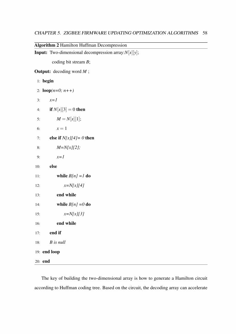
CHAPTER 5. ZIGBEE FIRMWARE UPDATING OPTIMIZATION ALGORITHMS 58
Algorithm 2 Hamilton Huffman Decompression
Input: Two-dimensional decompression array:N[x][y];
coding bit stream B;
Output: decoding word M ;
1: begin
2: loop(n=0; n++)
3: x=1
4: if N[x][3] = 0 then
5: M = N[x][1];
6: x = 1
7: else if N[x][4]= 0 then
8: M=N[x][2];
9: x=1
10: else
11: while B[n] =1 do
12: x=N[x][4]
13: end while
14: while B[n] =0 do
15: x=N[x][3]
16: end while
17: end if
18: B is null
19: end loop
20: end
The key of building the two-dimensional array is how to generate a Hamilton circuit
according to Huffman coding tree. Based on the circuit, the decoding array can accelerate

CHAPTER 5. ZIGBEE FIRMWARE UPDATING OPTIMIZATION ALGORITHMS 59
decompress data process. Since most of the computation cost is in the process of creating
decompression array, it is nimble to meet the contribution target.
To sum up, the HHD algorithm uses the structure of array storage to store the Huffman
binary tree and realize the logic address mapping the array index address. In other words,
it uses array to achieve the pointer function. In this way, ZigBee endpoints can nimbly
decompress the update firmware image.
5.2 Wireless OTA Optimization: DPPOTA Algorithm
Based on the IEEE 802.15.4 Protocol, ZigBee technology[31] defines the network layer
(NWK) and the application layer (APL). Over-the-Air is a wireless in-application program-
ming (IAP) [6] [32] technology in the ZigBee protocol framework. ZigBee Alliance [10]
proposes the Over-the-Air technical specifications for the ZigBee firmware upgrade on the
APL. Texas Instruments releases the semi-open source, namely, the z-stack protocol stack,
which implements the holonomic ZigBee protocol specifications and provides the OTA
solution cluster interfaces [33] in the ZigBee clusters library layer (ZCL). It can remotely
and wirelessly upgrade the TI ZigBee nodes’ firmware, thus fulfilling the OTA specifications.
However, the OTA is just a solution scheme in the z-stack where developers need to refer to
handbooks [34] in order to work it out.
As an added consideration, when a large number of devices simultaneously process the
OTA firmware update, even though the z-stack implements the basic one, its performance
is not stable. Initially, the OTA update rate is limited by the ZigBee technology which
is characterized as low data transmission rate. According to the general measurement
experiment, the z-stack OTA inefficiently takes fifteen minutes to upgrade 120k image data.
Subsequently, the OTA uses the P2P method [35] to update the remote devices: each ZigBee
OTA client device requests the image data from a unique OTA server. Both ZigBee routers
and endpoints are OTA clients, when the ZigBee network is organized in a deeper depth and
CHAPTER 5. ZIGBEE FIRMWARE UPDATING OPTIMIZATION ALGORITHMS 60
bigger scale, the backbone is congested. In addition, the undisciplined redundancy requests
not only disturb the backbone, but can lead to the OTA firmware update failure.
5.2.1 DPPOTA Algorithm
To solve the above problems, the distributed priority page-request OTA (DPPOTA) upgrade
algorithm adopts the page-request method firstly. In the z-stack, the OTA clients request
the image block data from the OTA server. As the augmented number of nodes upgrades
synchronously, the time of all the nodes fulfilling the OTA update will increase. Correspond-
ingly, the more nodes being updated, the bigger probability of wireless conflict. The ZigBee
data retransmission mechanism increases time cost in the client nodes OTA update. Even
worse, the OTA client nodes will reset the network parameters, and restart the OTA update
service under repeated void request. This situation wastes massive updating time and energy
as the redundancy data requests. In the reality application, the z-stack just can upgrade two
nodes at the same time because of the ZigBee network congestion.
Despite that the page image request method can reduce the image block request com-
mands, it cannot make a big difference in the redundancy data requests. The OTA priority
orderliness update scheme is a useful solution, but it is necessary to consider the excessive
orderliness problem as mentioned [27]. In the ZigBee mesh form network, all the nodes can
update in a dynamic suitable path to reduce the time and energy waste. Similarly, the priority
orderliness OTA update scheme reduces the network’s backbone transmission redundancy
data and solves the excessive orderliness problem with the same method.
The DPPOTA algorithm is designed as Algorithm 3 shows. One DPPOTA request
combines n numbers block image data requests as the page image request. This method
can reduce the total request command times of the OTA and cut down the OTA update
duration. Afterwards, when it comes to the router logic type nodes, it will process the
DPPOTA exceptional choice strategy. When the router completes the OTA update, it can
CHAPTER 5. ZIGBEE FIRMWARE UPDATING OPTIMIZATION ALGORITHMS 61
receive the child page image requests and send them to the upper router, until to the OTA
server. This algorithm follows the ZigBee normal data transmission principle and possesses
all the ZigBee mesh network functions and features.

CHAPTER 5. ZIGBEE FIRMWARE UPDATING OPTIMIZATION ALGORITHMS 62
Algorithm 3 Distributed Priority Page-request OTAInput: Firmware image request type: Img[t]; Image response:Imgblock[t].
Output: OTA_status: Success=1, Failure=0.
1: begin
2: Image[page]=Img[block]*n
3: if Logic[t]==router then
4: if OTA_status==1 then
5: while receive Img[page] from child do
6: send Img[page] to father
7: end while
8: while receive Imgblock[t] from father do
9: send Imgblock[block to child
10: end while
11: end if
12: if OTA_status==0 then
13: ignore Img[page]from child
14: send Img[page] to father
15: flash Imgblock[t]
16: end if
17: else if Loic[t]== endpoint then
18: if OTA_status==0 then
19: send Img[page] to father
20: receive Imgblock[t] from father && flash Imgblock[t]
21: end if
22: if OTA_status==1 then
23: return
24: end if
25: end
26: end if

CHAPTER 5. ZIGBEE FIRMWARE UPDATING OPTIMIZATION ALGORITHMS 63
When the multi-node concurrent updating command broadcast to the ZigBee mesh
network, the OTA will build a plethora of tree network paths to the OTA server, which is
similar to any remote ZigBee node request data from the coordinator on the AODV routing
path.Each node that needs to process the OTA updating sends the image data request to the
OTA server. However, OTA client does not consider the path choice, for example, which
father node should be chosen next and which request line is better. Since the ZigBee network
has solved the routing problem in the dynamic mesh network, there is need for OTA service
to follow the route path and keep it as the dynamic suitable scheme, but differentiated from
the OTA end-to-end scheme, every router cannot optionally retransmit the lower child request
commands. Each ZigBee node has its unique logic type, and the routers can process the OTA
updating shortly since the endpoints have the sleep function to save power while routers do
not. The DPPOTA algorithm makes the upper routers have the higher OTA update priorities
to update firmware preferentially, and when the upper routers complete the OTA update, it
turns to be an OTA router to unseal the lower nodes’ OTA update service. This OTA update
process can be seen in Fig.5.4: the coordinator is set to be the OTA server and the blue dots
are routers. When the ZigBee sleepy end device and routers concurrently process the OTA
update, each path to the server is filled with image data requests and other commands. Upper
routers that are closer to the coordinator have the higher priority, and the paths close to the
coordinator are more crowded and thick.
The DPPOTA algorithm can alleviate the OTA server backbone workload and reduce its
congestion degree. In Fig.18, it firstly upgrades the nearest three routers to the coordinator
who run an OTA thread on each line. When the updating is completed, these three paths turn
on to the next OTA update level. This network contains ten nodes and the OTA nodes take
up six. The three backbones averagely run two OTA threads as well. When these six nodes
finish the OTA update, the other seven nodes will begin to process the OTA update. In this
circumstance, the whole network contains seventeen nodes, but the three server backbone

CHAPTER 5. ZIGBEE FIRMWARE UPDATING OPTIMIZATION ALGORITHMS 64
Fig. 5.4 Dynamic Page-request Distributed OTA Update Network
paths only run seven threads. As the traditional OTA update end-to-end scheme, the server
backbone paths need to run sixteen OTA threads, but the DPPOTA algorithm only implements
two OTA threads in this example. The following sections will present two mathematical
parameters models to establish the DPPOTA algorithm’s attributes, namely, data redundancy
model and update duration model.
Data Redundancy Model
Data redundancy can reflect both the OTA updating path congestion and its energy efficiency
to a certain extent. Obviously, the OTA network with redundant data leads to frequent path
congestion and reduces the efficiency of OTA update. In the above OTA example, the data
redundancy is related to the ZigBee network range which contains two parameters: the
network depth and the path quantity. It uses dk to represent the network depth and the k
means the path quantity. In addition, the network depth dk equals to the nodes quantity of
each path. Set each node sending the data redundancy unit as du. Ideally, in one multi-nodes
concurrent OTA request process, each path’s total data redundancy D̃po of original OTA
update can be represented as in Equation (5.1). The data redundancy accumulation of growth

CHAPTER 5. ZIGBEE FIRMWARE UPDATING OPTIMIZATION ALGORITHMS 65
is as the depth increases: the next path’s data redundancy will add the previous one. For
instance, the number k path section runs dk OTA threads.
D̃po=du ∗
1+2+ · · ·+
dk
=(1+dk)∗dk
2∗du (5.1)
D̃pd=du ∗
1+1+ · · ·+1︸ ︷︷ ︸dk
= du ∗dk (5.2)
D(t) = de +do +∫ k
p=1D̃p (5.3)
When OTA update data redundancy of each path meets Equation (5.2), it becomes the
ideal DPPOTA algorithm. Because of the OTA router decision mechanism, each path section
only runs one OTA thread and the total data redundancy D̃po is supposed to meet Equation
(5.2). Expressions of each path’s data redundancy can be given to the OTA server and then
the OTA network total data redundancy mathematical model can be calculated, as can be seen
in Equation (5.3). The de parameter in Equation (5.3) is network error of the retransmission
data redundancy and do means that the OTA client nodes reset OTA network data redundancy.
Update Duration Model
The update duration can directly show the OTA update efficiency, in a common sense, and
frequent upgrading duration leads to lower efficiency. Meanwhile, all the OTA network
nodes that need more duration to complete updating will consume more energy. The update
duration model is also important to represent the OTA network update performances. Ideally,
one image block request duration unit has been set to be equal to the image block response
duration as tb, and the page-request image duration tr=tb. Next, set the total firmware image
size as block ∗ m and the page image data size page = block ∗ n. The original OTA scheme
update duration To is presented in Equation (5.4).

CHAPTER 5. ZIGBEE FIRMWARE UPDATING OPTIMIZATION ALGORITHMS 66
To =∫ k
p=1m ∗ trp +
∫ k
p=1m ∗ tbp + teo (5.4)
Td =∫ k
p=1
mn∗ trp +
∫ k
p=1
m1∗ tbp + ted (5.5)
The original OTA update needs m times request and response duration units. The DPPOTA
update cuts down the request duration times and receives the same times of block image as
the origin. Both two equations’ ends have the te variable that represents the network error of
retransmission image duration. The proportion to the path data redundancy is positive-related
which can follow the data redundancy model results, as shown in Equation (5.6).
teo = K ∗ 1+dk
2∗ ted ( K > 0, teo ∝ D̃po, ted ∝ D̃pd) (5.6)
Equation (5.6) shows that the original OTA scheme has more data redundancy to keep its
update duration longer. However, the DPPOTA can not only reduce the data redundancy, but
also curtail the update duration. Next, this dissertation will actualize the DPPOTA algorithm
based on the CC2530 z-stack platforms and illustrate the evaluations and simulations of these
two mathematical models.
5.2.2 Implement DPPOTA Algorithm Based on Z-Stack
TI has published the open source z-stack that provides the OTA service interface. But
developers need to call these OTA functions in the OSAL [33] on chip system and modify the
z-stack project application under the guidance of handbook [30]. This dissertation is based
on the TI CC2530 chip experiment [36] and z-stack 2.5.1a [37]. After turning on the OTA
service to the z-stack, it needs to modify the routers’ OTA transmission functions. Different
from the literature [27] in which all the OTA clients still send the request commands to
the OTA server, it has the natural advantage of the ZigBee network. Accordingly, a data
transmission judgement function has been added that the routers will not send the received

CHAPTER 5. ZIGBEE FIRMWARE UPDATING OPTIMIZATION ALGORITHMS 67
OTA type request commands until the routers’ own OTA update has been completed. Under
other circumstances, the nodes only send their own OTA updating commands to the upper,
then the OTA update process of the whole network will have the orderliness that cuts the data
redundancies and request conflicts.
On top of that, the page-request node also needs to modify the OTA client’s z-stack. In the
zcl_ota.c and zcl_ota.h, the image data block request function has been found and the page
request function has been added as the block request. Its difference from the block image
request is that the page request send number n image blocks’ request only once. Meanwhile,
it also needs to modify the OTA server application and add the manipulation page-request
function. The DPPOTA algorithm is similar to Go-Back-N algorithm, which is a dependable
communication based on the ZigBee network. The main DPPOTA z-stack functions are
presented as in Fig. 5.5.
Fig. 5.5 DPPOTA Z-stack Functions Codes
The page-request function defines how many image blocks are contained in a page image
request. In addition, the image blocks request interval in one page is an added consideration.
If the interval becomes too small, it may lead to failure of the update. On the other hand, the
interval cannot be too big to influence the efficiency of upgrading. According to the CC2530
chip serial port buffer, the block number n should not be relatively large. This dissertation
implements the dynamic page-request based on the CC2530 chips as shown in Fig.17 as well

CHAPTER 5. ZIGBEE FIRMWARE UPDATING OPTIMIZATION ALGORITHMS 68
Table 5.2 DPPOTA EVALUATION PARAMETERS
Symbol Description Conversion equationD̃po Original OTA data redundancy du ∗ (1+2+ · · ·+dk)
D̃pd DPPOTA data redundancy du ∗dk
D(t) Total network data redundancy de +do +∑kp=1 D̃p
To Original OTA upgrading duration ∑kp=1 m ∗ trp +∑
kp=1 m ∗ tbp + teo
Td DPPOTA upgrading redundancy ∑kp=1
mn ∗ trp +∑
kp=1
m1 ∗ tbp + ted
teo Original network-error retransmissionduration
K ∗ 1+dk2 ∗ ted
ted DPPOTA error retransmission dura-tion
teo÷ (K ∗ 1+dk2 )
Image Image total size 118253 bytesBlock Image block size 64 bytesPage Image page size 640 bytes, 320 bytes, 128 bytesn Each page contains block number 10, 5, 2K Positive proportional coefficient K > 0
as summarizes the OTA clients updating page-request function parameters and the DPPOTA
evaluations’ parameters as can be seen in Table 5.2. The normal ZigBee networks are the
mesh architecture ones, such as smart home and energy. As P2P model, when the original
OTA update starts, OTA clients communicate with the OTA server in all of the Zig Bee nodes.
In the physical structure, it keeps the mesh network architecture, but the clients logically
request and response data with the server in the endpoint-to-endpoint model.
Therefore, the DPPOTA changes the logical communication mode and designs the OTA
update priority orderliness, which makes all the router nodes judge the incoming data type.
The higher upper routers have the top priority to update, so the lower remote nodes need
to wait for their top routers completing the OTA updating. Moreover, the remote nodes
can choose the updated router to process their OTA update dynamic. If the used router is
power off or moves away, it can dynamically carry on another optimal suitable router. This
priority orderliness improves the OTA update network self-healing and overall optimization.

CHAPTER 5. ZIGBEE FIRMWARE UPDATING OPTIMIZATION ALGORITHMS 69
It can support the multi-node concurrent OTA update and save the global energy as much as
possible.

Chapter 6
Performance Evaluations
6.1 HHD Algorithm Evaluations
The evaluation process of the algorithm is as below. The first set prerequisites are that the
ZigBee firmware source file contains 256 elements and the image has been compressed
according to Huffman. The longest coding length is 11 and the average coding length is 6.
The unit data array space is 1byte and the pointer space occupies 2bytes.
Storage Space Cost
In order to avoid repeated affiliation from different authors, a template has been designed
for two affiliations which are supposed to be as succinct as possible (for example, do not
differentiate among departments of the same organization).
The sequence storage Huffman tree size depends on its longest coding length k. In this
dissertation, all the Huffman tree number sequence is from top to bottom and left to right. If
the longest coding length is the single left branch, its size is minimized:
(2k−1+2k−1+1
)∗1byte (6.1)
70

CHAPTER 6. PERFORMANCE EVALUATIONS 71
If the longest coding length is single right branch, its size is maximized:(2k+2k−1
)∗1byte (6.2)
Generally, the longest coding length would be more than 8. In the case of compressing the
ZigBee image file, k=11. So the minimum size is: (210 +210 +1)*1byte.= 2049bytes;
If the chain list storage only uses children pointers without parent pointer, the general
chain list storage structure space cost is:
y1=(2bytes+1bytes+2bytes)∗(N+N−1) (6.3)
Only when the children pointers without paint pointer data structure has been recorded
does the smaller space cost size of chain list apply: (2bytes+1byte+2bytes) ∗ (256+256-
1)=2555bytes; HHD algorithm records the non-leaf nodes information, and its items have
just N-1, each of which takes up 4bytes memory space. Therefore, the HHD Huffman tree
total space cost is:
y2 = (N−1)∗4bytes (6.4)
Accordingly, this decompression algorithm space cost size is: (256-1) × 4bytes=1020
bytes.
Fig. 6.1 Sequence, Chain List and HHD Space Cost Comparison

CHAPTER 6. PERFORMANCE EVALUATIONS 72
Fig. 6.1 compares three storage space sizes and the result is clear. In addition, Fig. 6.2
indicates the relationship between the space cost y and the element N, and Fig. 6.3 shows the
relationship between the longest coding length k and space cost y, in which y1 represents
chain list storage’s space cost and y2 represents HHD decompression algorithm’s space cost.
In Fig. 6.1 y1 bigger than y2. Since the sequence storage space cost is confined by the longest
coding length, HHD decompression algorithm costs smaller space than others.
Fig. 6.2 Space Cost Comparison: Chain List vs HHD

CHAPTER 6. PERFORMANCE EVALUATIONS 73
Fig. 6.3 Sequence Storage Largest and Smallest Space Cost Comparison for Different CodingLongest Length
Generally, the longest coding length is almost bigger than 8 and each file has different
longest coding length. Fig.22 shows its interval value with longest coding length k. If the
longest coding length is 11, the smallest space cost of sequence storage is 2049bytes, which
is still bigger than HHD 1020bytes.
Decompression Time Cost
The decompression algorithm realizes the pointer function in array by reading logic address
mapped with the index number. If the average coding length is 6 , it indicates that it takes
six steps to decode a coding word. Accordingly, the average time cost is 6∗ t. The result is
shown in Fig. as 6.4.

CHAPTER 6. PERFORMANCE EVALUATIONS 74
Fig. 6.4 Traversing and HHD Average Decompression Time Cost Comparison
In the experiment, the file has 256 elements and the searching unit time is set as t.
Traditional Huffman decoding is traversing the binary tree. According to the coding table, all
elements and their codes ought to be searched, and successfully traversing them to decode
coding word could not be better. In terms of the average probability, one word cost time of the
traditional coding table storage searching Huffman tree is (256/2)∗ t. If we use the sequence
to store and traverse the Huffman tree, the searching time will be bigger than (256/2) ∗ t.
The types of traversing binary tree are classified as pre-order traversal, in-order traversal and
post-order traversal, all of which take more steps to locate the decoded word. Under better
circumstance, the average coding length is 6 and it will take another six times to locate a
decoded word. However, since there are 256 elements to be traversed, the average decoding
time cost is (256/2)∗6t. In HHD algorithm, it just cost 6∗ t to decode a coding word. Due

CHAPTER 6. PERFORMANCE EVALUATIONS 75
to the traversing time cost of Huffman tree is bigger than coding table, Fig.7 compares the
traversing coding table time cost and the HHD algorithm time cost, from which HHD has
much better performance on average decompression time cost about twenty folds.
6.2 DPPOTA Evaluation Models
Section 2.4 has discussed that the data redundancy and update duration are two representative
mathematical models to evaluate the ZigBee OTA upgrade scheme’s performance. This
dissertation provides these two model simulations by using MATLAB. Initially, the evaluation
considers the data redundancy of the ZigBee OTA network. Equation 5.1, 5.2 and 5.3
represent the OTA network data redundancy simulation attributes. The original z-stack OTA
update scheme’s data redundancy simulation result is shown in Fig. 6.5 where the blue line
represents the original OTA update scheme and the red line is the DPPOTA simulation.
Data Redundancy Model
The ZigBee network’s range becomes larger as the depth dk of the network increases. Having
influence on the network range, the path number k is a co-efficient parameter of the network
dk. Fig. 6.5 has shown the increase of the DPPOTA’s data redundancies as the network
deepens. When it transforms the network depth to the linearity, the original OTA update
grows exponentially and the DPPOTA is in the linear growth. Ideally, when the depth in
the Fig. 6.5 becomes 2, where the blue line and the red line meet, their data redundancies
reach the same level. Then, the original update data redundancy will rise sharply over the
DPPOTA update with the depth increasing. In the experiment, the original OTA update can
only support two ZigBee nodes upgrading and their firmware at the same time. It does not
mean that the OTA cannot support the multi-nodes upgrading, instead, the OTA server cannot
synchronously support more than two nodes upgrading. If another ZigBee node needs to
process the upgrading, it must wait or break off other nodes upgrading frequently.
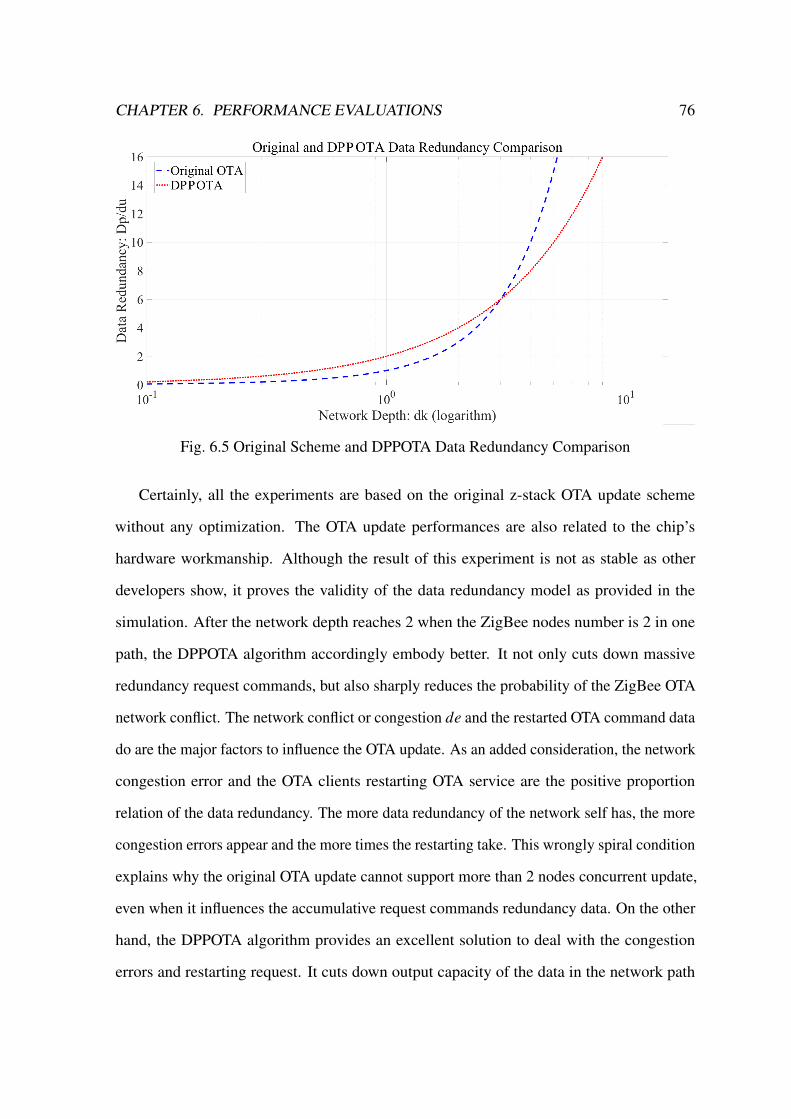
CHAPTER 6. PERFORMANCE EVALUATIONS 76
Fig. 6.5 Original Scheme and DPPOTA Data Redundancy Comparison
Certainly, all the experiments are based on the original z-stack OTA update scheme
without any optimization. The OTA update performances are also related to the chip’s
hardware workmanship. Although the result of this experiment is not as stable as other
developers show, it proves the validity of the data redundancy model as provided in the
simulation. After the network depth reaches 2 when the ZigBee nodes number is 2 in one
path, the DPPOTA algorithm accordingly embody better. It not only cuts down massive
redundancy request commands, but also sharply reduces the probability of the ZigBee OTA
network conflict. The network conflict or congestion de and the restarted OTA command data
do are the major factors to influence the OTA update. As an added consideration, the network
congestion error and the OTA clients restarting OTA service are the positive proportion
relation of the data redundancy. The more data redundancy of the network self has, the more
congestion errors appear and the more times the restarting take. This wrongly spiral condition
explains why the original OTA update cannot support more than 2 nodes concurrent update,
even when it influences the accumulative request commands redundancy data. On the other
hand, the DPPOTA algorithm provides an excellent solution to deal with the congestion
errors and restarting request. It cuts down output capacity of the data in the network path

CHAPTER 6. PERFORMANCE EVALUATIONS 77
and improves the efficiency of OTA update by formulating the OTA nodes’ update priority
orderliness.
Update Duration Model
The DPPOTA algorithm makes the remote endpoints wait for their turns. However, increasing
the OTA update duration as it may look like, it cuts down the chaotic congestion error and
reduces the update duration. When it comes to the update duration model, the DPPOTA
algorithm compared with the original z-stack OTA scheme simulation are shown in the
Fig. 6.6. Y-Axis presents the T/tb, tb is the unit updating duration which can be seen as 1ms.
To make the X-Axis only has one variabls dk, I just let the equation divide the tb. So Y-Axis
is T/tb which can directly reflect the updating duration. Firstly, the DPPOTA uses the image
page-request mode to request the firmware image and it reduces some redundancy request
duration from the origin. When there are more nodes in the network, the page-request mode
will reduce a larger number of request duration and it is impressive to save the accumulative
duration.
Fig. 6.6 Original Scheme and DPPOTA Update Duration Comparison

CHAPTER 6. PERFORMANCE EVALUATIONS 78
In addition, as the same problem as the data redundancy has, the congestion errors
duration and restart duration increase as redundancy of the network rises, which are also the
positive proportion relation. From the data redundancy model, it also can reflect the update
duration’s relationship with the redundancy data. But it needs to add other modulus variables
as shown in the Table 5.2, such as redundancy duration modulus K and the origin request
and response duration tr p. Then the duration model follows the data redundancy model and
is expressed as Equation 5.4 and 5.5. Fig. 6.6 shows that the original OTA update scheme
duration is over on DPPOTA. As the depth of network and number of nodes increase, the
redundancy duration overwhelmingly rises and the total update duration also increases fast.
When the number of nodes gets the threshold, the redundancy duration will be the main
influence. In the duration simulation, the DPPOTA duration threshold is bigger than the
original OTA update scheme, which reflects the DPPOTA algorithm interior interference
immunity. In the experiment, more noises improve the duration redundancy and the DPPOTA
can reduce the influence of noises to improve the network tolerance.
DPPOTA Simulations and Experiments
Above all, the two simulations prove that the DPPOTA algorithm has great advantages on
the data redundancy and update duration. When the network range has been extended, the
original OTA cannot work well, but the DPPOTA can still process multi-nodes concurrent
OTA update. Moreover, this DPPOTA algorithm is easy to realize complexity. As it shows in
the Fig. 6.7, compared to the original experiments, this dissertation illustrates the CC2530
chips’ DPPOTA upgrading. Due to the limit of the hardware nodes, it just evaluates two
DPPOTA nodes: server and client. Fig. 6.5 shows that the DPPOTA page-request mode has
about duple duration optimization over the original, and the more contained blocks (n) in one
page-request, the shorter update duration.

CHAPTER 6. PERFORMANCE EVALUATIONS 79
Fig. 6.7 TI’s Original Scheme and DPPOTA Updating Durations Comparison
The following Fig. 6.8 shows the different block request intervals’ OTA performances
under the different numbers of blocks contained in one page. When the interval is 10ms, the
less block request interval is, the less OTA update duration takes. But the bigger interval
may be better as n is bigger. The reason is that when the block requests increasingly grows,
more frequent requests may congest the serial port communication. In addition, when more
blocks are contained in one page-request, the duration is also shortened. When the interval
is uniform, the blocks’ number n is bigger, and the update duration is shorter. If one page
just contains all the blocks image requests, it will become the server propelling update.
The results of the CC2530 platforms from these two experiments suggest the advantages of
DPPOTA algorithm that it can shorten the data redundancy and update duration.

CHAPTER 6. PERFORMANCE EVALUATIONS 80
Fig. 6.8 Different Intervals of Page-request Mode Update Durations Comparison
6.3 DPPOTA Updating NS2 Simulations
ZigBee OTA NS2 Simulation [38] Parameters
1. Data Flow Parameters
Data type: The Constants Bit Rate (CBR) has been chosen as data flow. CBR has
one-way transmission, packet size and transmission interval, which is more conducive
to the analysis of network transmission performance.
Packet size: The Optimization OTA packet size is defined as 1000 bytes and DPPOTA
packet size is 2000 bytes, beacons and other flags not included.
Transmission direction: All the data information is unidirectional transmission from
node 3 to coordinator 0.
Channel selection: The simulation only uses the first three channels of the 2.4 GHz
band.
2. Node Parameters

CHAPTER 6. PERFORMANCE EVALUATIONS 81
Fig. 6.9 ZigBee Network NS2 Simulation Graph
Number of nodes: The simulation environment consists of 21 nodes, including one
coordination node, fourteen router nodes and seven endpoints , as shown in Fig. 6.9.
Node state: All nodes are stationary.
Node location: The distribution of all nodes is plane, as shown in Fig. 6.9. The central
node 0 is the ZigBee coordinator.
3. Physical parameters
Broadcast model: As the distribution of nodes in the simulation of a larger range, the
relationship between the equipment and the coordination position is more complicated,
hence the use of the Shadowing model.
Antenna type: Omni Antenna. It can use the same power to send the around data.
Path loss: The signal energy will produce attenuation by the distance, obstructions and
antenna height effects. But in the experiment where the attenuation is zero, the path
loss is 1.0 .

CHAPTER 6. PERFORMANCE EVALUATIONS 82
Table 6.1 ZIGBEE NETWORK NS2 SIMULATION PARAMETERS
Data flow: CBR Broadcast type: ShadowingCoordinator/Routers/Nodes: 1/14/21 Antenna type: Omni AntennaNode motion state: None Queue model: Drop TailNode distance: 10m Queue length: 50Packet size: 1000bytes Send gain: 1.0Band selection: 2.4GHz Receive gain: 1.0Channel numbers: 3 Path loss: 1.0Data transmission mod: Direct Routing protocol: AODV
Range: 50 x 50 m2. Neighbor Distance: 10 m. Tx Range: 12 m.
4. Routing layer parameters
Queue type: The simulation uses the tail drop algorithm (Drop Tail), which is to follow
the “first in first out” principle of queue management techniques: The packets that first
entered the queue will be processed firstly; when the packet number exceeds the upper
limit of the queue, the last packet into the queue will be discarded.
Queue length: The standard queue length used in the simulation is 50 packets, and
once this limit is exceeded, the excess will be discarded. As the performance of the
network only depends on the effective utilization of resources, increasing the queue
length for network performance has not a large impact.
Routing Protocol: The simulation uses the AODV routing protocol.
Performance Parameters
In order to measure the different algorithms’ OTA performance of ZigBee network, the
simulation defines a number of performance indicators, through which the running status and
reliability of the ZigBee network can be reflected. It should be noted that the performance
indicators mentioned here are mainly concerned with the transmission of data, while other
aspects are not an added consideration.
1. Transmission jitter rate

CHAPTER 6. PERFORMANCE EVALUATIONS 83
The transmission jitter rate is the Delay Variance of the transmission delay. As the
network traffic changes at any time, when the traffic is large, many packets must
be waiting in the queue, so each packet from the transmitter to the destination takes
different time. The difference is the so-called jitter rate which reflects the stability of
the network, and the greater the jitter rate, the worse the stability of the network. The
formula to calculate the jitter rate is as follow:
Jitter = ([receive(m)− sent (m)]− [receive(n)− sent (n)])÷ (m−n) (6.5)
The m and n are the packet numbers; receive (m) and receive (n) are the packet
reception time; sent (m) and sent (n) are the packet transmission time.
2. Transmission delay
Propagation Delay refers to the time it takes for a packet to be sent from one reception
to another. The transmission delay relates to each individual data packet, as long as the
packet transmission is successful, there will be different degrees of delay, where the
data packets are sent repeatedly. The average transmission delay for all packets can be
used to measure the overall transmission performance of the network. In addition, the
transmission delay can also reflect the capacity of the media access control sublayer.
The longer the delay, the smaller the capacity. The transmission delay and the average
transmission delay can be obtained based on the following formula:
Packet_delay = Time_receive−Time_transmit (6.6)
Average_delay = Sum_Packet_delay÷Sum_Packets_receive (6.7)
Packet_delay is the packet transmission delay while time_receive is the packet recep-
tion time; time_transmit means the packet transmission time and average_delay is the

CHAPTER 6. PERFORMANCE EVALUATIONS 84
average transmission delay; Sum_Packet_delay represents the sum of the transmission
delays for all packets whereas Sum_Packets_receive is the sum of the number of
packets received.
3. Packet loss rate
Packet loss rate refers to the amount of discarded packets in the simulation process
that the following can be sent: the packet ratio, usual packet loss rate, packet length
and packet transmission frequency. Packet loss is out of network transmission errors or
network congestion. For example, when the network within the forwarding device to
receive the wrong packet or CRC check, frame positioning error will occur when the
data packet is discarded. Similar to the transmission delay, as an added consideration,
the packet lost in the calculation will lead to the repeated transmission. When a data
packet waits for the next transmission, if the simulation process is successful, then the
packet before the discard is not calculated. Packet loss will also affect the real-time
performance of the network in terms of the transmission delay. In some connection-
oriented applications, packet loss will lead to data retransmission, thereby increasing
the transmission delay. The network equipment cannot work or the network load is too
large when the packet loss rate is considerably large, but it does not necessarily mean
that the network is faulty, because many businesses in the case of a small amount of
packet loss can continue. The packet loss rate is calculated as follow:
Packet_loss_rate = (Packet_drop)/(Packet_sent)∗100% (6.8)
The above performance indicators are calculated in the same Gawk program, each of
which is written to a different file, and then by Gnuplot it will be presented in the form
of a coordinate map.

CHAPTER 6. PERFORMANCE EVALUATIONS 85
Simulation Results
1. The comparison among DPPOTA, OOTA and OTA’s Jitter
Initially, the OTA, the Optimization OTA (OOTA) and DPPOTA have been imple-
mented. The NS2 simulator defines the network Jitter as Equation 6.5. Fig. 6.10 shows
that the DPPOTA updating grows from time 10.3s to 100s when the node number is
one. After 100s, the updating change to the TI’s original OTA. Y-Axis is the Jitter
which represents a rate. The unit of Y-Axis is a number such as 1. Meanwhile, the
DPPOTA algorithm’s jitter is thin and stable from the time 10.3s to 100s, but the TI’s
original OTA has a significant wide jitter.
Fig. 6.10 One Node’s DPPOTA and OTA Jitter Comparison

CHAPTER 6. PERFORMANCE EVALUATIONS 86
Fig. 6.11 Eight Node’s DPPOTA and OTA Jitter Comparison
Afterwards, I simulate the comparison under the 4 nodes concurrent OTA updating
and the 8 nodes concurrent OTA updating, as shown in Fig. 6.11 and Fig. 6.12, where
the 8 nodes’ DPPOTA jitter line is thicker than the one node’s. It indicates that the
more nodes in the DPPOTA, the more effect jitter of the ZigBee network. Fig 6.11 has
enlarged the jitter simulation to 100s, the interchange time of these two algorithms.
The OTA’s jitter shock density is bigger than the previous DPPOTA. Thus, no matter
how many nodes there are, DPPOTA’s network is always more stable than TI’s OTA.
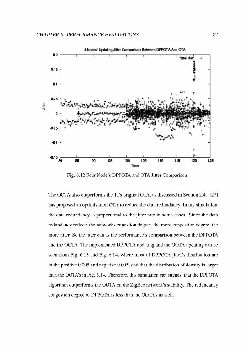
CHAPTER 6. PERFORMANCE EVALUATIONS 87
Fig. 6.12 Four Node’s DPPOTA and OTA Jitter Comparison
The OOTA also outperforms the TI’s original OTA, as discussed in Section 2.4. [27]
has proposed an optimization OTA to reduce the data redundancy. In my simulation,
the data redundancy is proportional to the jitter rate in some cases. Since the data
redundancy reflects the network congestion degree, the more congestion degree, the
more jitter. So the jitter can as the performance’s comparison between the DPPOTA
and the OOTA. The implemented DPPOTA updating and the OOTA updating can be
seen from Fig. 6.13 and Fig. 6.14, where most of DPPOTA jitter’s distribution are
in the positive 0.005 and negative 0.005, and that the distribution of density is larger
than the OOTA’s in Fig. 6.14. Therefore, this simulation can suggest that the DPPOTA
algorithm outperforms the OOTA on the ZigBee network’s stability. The redundancy
congestion degree of DPPOTA is less than the OOTA’s as well.

CHAPTER 6. PERFORMANCE EVALUATIONS 88
Fig. 6.13 DPPOTA Updating Jitter
Fig. 6.14 Optimization OTA Updating Jitter
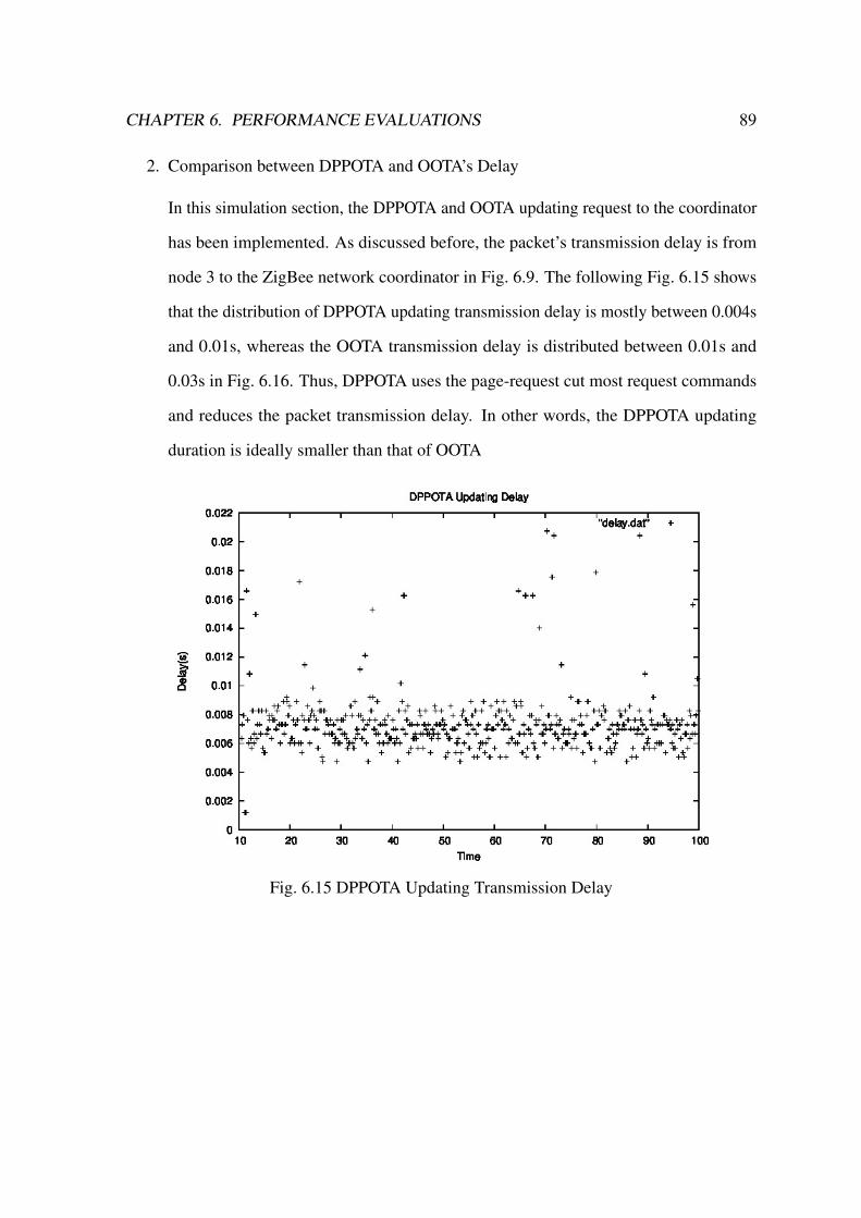
CHAPTER 6. PERFORMANCE EVALUATIONS 89
2. Comparison between DPPOTA and OOTA’s Delay
In this simulation section, the DPPOTA and OOTA updating request to the coordinator
has been implemented. As discussed before, the packet’s transmission delay is from
node 3 to the ZigBee network coordinator in Fig. 6.9. The following Fig. 6.15 shows
that the distribution of DPPOTA updating transmission delay is mostly between 0.004s
and 0.01s, whereas the OOTA transmission delay is distributed between 0.01s and
0.03s in Fig. 6.16. Thus, DPPOTA uses the page-request cut most request commands
and reduces the packet transmission delay. In other words, the DPPOTA updating
duration is ideally smaller than that of OOTA
Fig. 6.15 DPPOTA Updating Transmission Delay
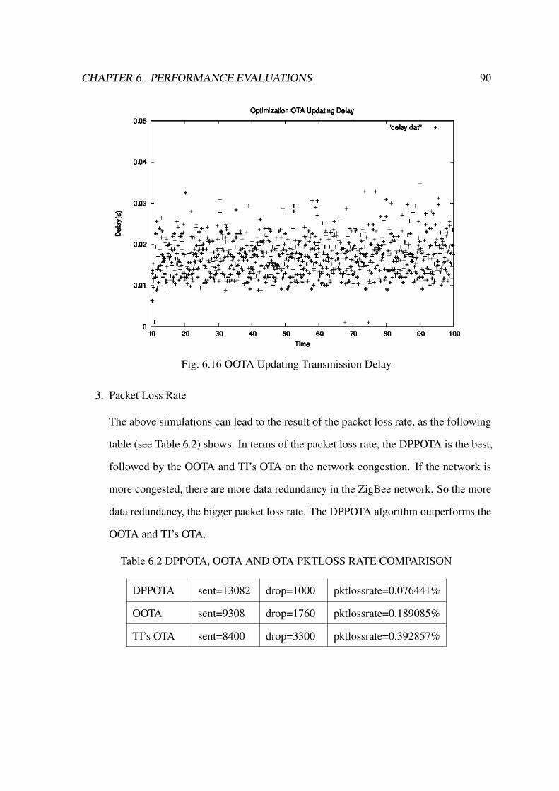
CHAPTER 6. PERFORMANCE EVALUATIONS 90
Fig. 6.16 OOTA Updating Transmission Delay
3. Packet Loss Rate
The above simulations can lead to the result of the packet loss rate, as the following
table (see Table 6.2) shows. In terms of the packet loss rate, the DPPOTA is the best,
followed by the OOTA and TI’s OTA on the network congestion. If the network is
more congested, there are more data redundancy in the ZigBee network. So the more
data redundancy, the bigger packet loss rate. The DPPOTA algorithm outperforms the
OOTA and TI’s OTA.
Table 6.2 DPPOTA, OOTA AND OTA PKTLOSS RATE COMPARISON
DPPOTA sent=13082 drop=1000 pktlossrate=0.076441%
OOTA sent=9308 drop=1760 pktlossrate=0.189085%
TI’s OTA sent=8400 drop=3300 pktlossrate=0.392857%

Chapter 7
Conclusions
The array constructed in this dissertation records the non-leaf nodes property as a data unit. It
shows that the HHD algorithm has two benefits. Firstly, the right leaf node does not require
heavy outside storage, which can further optimize. According to the experimental results,
the compressed average code length is about 6. So it takes average six steps to get to the
decoded values whose performance improves more than 20 times. By decreasing the amount
of calculation, the transmission time is shortened. Correspondingly, energy has also been
saved for the physical transmission layer. The other benefit is that the storage space with
arrays is smaller than storing the list and sequence array. Significantly, this algorithm saves
the Huffman decoding space cost. Since there are plenty of empty place for holder data, it
provides space for further optimization. The innovation of the paper is that the algorithm
decodes the Huffman tree into an array, which can directly decode data according to subscript
random read, decoding efficiency increases faster than the traditional method. However, the
cost of this design is that the compression increases the amount and complexity of client
computing and coding processes. In the upgrading process, the sensors’ nodes and the coding
process is done on the PC, which fits the application environment. However, the array is a big
challenge for decoding. According to the Huffman coding tree or table creation, using the
recursive algorithm can solve the problem. Since it is difficult to implement the algorithm and
91

CHAPTER 7. CONCLUSIONS 92
a certain amount of code is requested, the programming complexity also increases. Therefore,
the idea and design of this algorithm would be seen as an innovation.
As an added consideration, both the data redundancy and update duration mathematical
model simulation, along with the CC2530 platform experiments, present the advantage
of the DPPOTA algorithm: lower data redundancy and shorter update duration than the
original OTA. These two features can improve the OTA update efficiency, save the nodes’
power and increase the interference immunity and network tolerance. In addition, compared
with other paper’s solution, this dissertation designs the priority orderliness to update and
processes the dynamically distributed update in the ZigBee network. All the simulations and
experiments prove the DPPOTA algorithm’s advantages. Besides, the page-request parameter
configuration is a pending problem in the large-scale network. However, the optimal solution
of block numbers of page and the block request interval configuration is confined in the
reality application. The NS2 simulations present that DPPOTA algorithm has the better
performances on network Jitter and transmission delay over TI’s OTA and Optimization OTA.
Overall, the DPPOTA is a creative solution to ZigBee OTA firmware update optimization.
To sum up, this dissertation contributes to designing a creative nimble image decom-
pression algorithm HHD to run on the remote ZigBee smart home endpoints and proposes a
distributed priority page-request OTA (DPPOTA) updating algorithm for the whole ZigBee
network. These algorithms help the smart home firmware updating more efficient and stable.
Combining the wired and wireless updating method can exert each mode’s advantage. This
updating solution outperforms any single updating mode. The 2.4GHz interference is another
factor to improve the ZigBee OTA updating in the future work.
References
[1] D.-M. Han and J.-H. Lim, “Smart home energy management system using ieee 802.15.4 and zigbee,” IEEE Transactions on Consumer Electronics, vol. 56, no. 3, 2010.
[2] D. Gislason, ZigBee wireless networking. Newnes, 2008.
[3] G. R. Josephson, J. Shen, R. D. Darling, and C.-C. J. Cheng, “Structure and method formultiplexing pins for in-system programming,” Aug. 9 1994. US Patent 5,336,951.
[4] J. Henager, V. Clare, and X. Chen, “Device software update transport and download,”Apr. 3 2007. US Patent 7,200,390.
[5] L. Haijun, P. Yingzhi, Z. Yebo, Z. Jianbin, and X. Yu, “In application programmingof atmega88 with i2c bus [j],” Microcontrollers & Embedded Systems, vol. 11, p. 007,2012.
[6] M. Ananny, “Press-public collaboration as infrastructure: Tracing news organizationsand programming publics in application programming interfaces,” American BehavioralScientist, vol. 57, no. 5, pp. 623–642, 2013.
[7] W. Wenxiang, L. Xiaoli, and Z. Weifa, “The embedded remote iap in application ofmonitoring of power distribution terminal based on arm and gprs [j],” ElectrotechnicalApplication, vol. 9, p. 042, 2006.
[8] S.-K. Shin and J.-H. Lee, “Firmware upgrade method for wireless communicationsdevice, and method for supporting firmware upgrade by base station,” Mar. 6 2001. USPatent 6,198,946.
[9] P. Baronti, P. Pillai, V. W. Chook, S. Chessa, A. Gotta, and Y. F. Hu, “Wireless sensornetworks: A survey on the state of the art and the 802.15. 4 and zigbee standards,”Computer communications, vol. 30, no. 7, pp. 1655–1695, 2007.
[10] Z. Alliance, “Zigbee specification, 2008,” ZigBee Document 053474r17, 2008.
[11] T. Instruments, “Z-stack developer’s guide,” 2007.
[12] Q. Xu, “A design and implement of iap based on http,” in Computer Science and ServiceSystem (CSSS), 2011 International Conference on, pp. 1918–1922, IEEE, 2011.
[13] X. ZHANG and J. WANG, “Realization of remote online upgrading technology basedon realview mdk and iap function,” in International Conference on Mechanic Automa-tion and Control Engineering, Wuhan, pp. 6266–6269, 2010.
93
REFERENCES 94
[14] X. Ying-ying, Y. Rui-xiang, Z. Yu-hua, and W. Yu-xin, “The design of isp/iap system inmicrocontroller [j],” Electronics & Packaging, vol. 3, p. 008, 2006.
[15] C. Tharini and P. V. Ranjan, “Design of modified adaptive huffman data compressionalgorithm for wireless sensor network,” Journal of Computer Science, vol. 5, no. 6,p. 466, 2009.
[16] M. Aggarwal and A. Narayan, “Efficient huffman decoding,” in Image Processing,2000. Proceedings. 2000 International Conference on, vol. 1, pp. 936–939, IEEE, 2000.
[17] J. Ziv and A. Lempel, “A universal algorithm for sequential data compression,” IEEETransactions on information theory, vol. 23, no. 3, pp. 337–343, 1977.
[18] K. Sayood, Introduction to data compression. Newnes, 2012.
[19] D. A. Huffman, “A method for the construction of minimum-redundancy codes,” Pro-ceedings of the IRE, vol. 40, no. 9, pp. 1098–1101, 1952.
[20] N. Faller, “An adaptive system for data compression,” in Record of the 7-th AsilomarConference on Circuits, Systems and Computers, pp. 593–597, 1973.
[21] E. Horowitz, S. Sahni, and S. Anderson-Freed, “Fundamentals of data structures,” tech.rep., Pitman London, 1983.
[22] Y.-K. Lin, S.-C. Huang, and C.-H. Yang, “A fast algorithm for huffman decodingbased on a recursion huffman tree,” Journal of Systems and Software, vol. 85, no. 4,pp. 974–980, 2012.
[23] Z. Alliance, “Interest-zigbee ota upgrade cluster specification[z],” 2010.
[24] Y. Ren and T.-L. Guo, “Remote online firmware updating method used in led streetlamp energy-saving system based on zigbee [j],” Journal of Mechanical & ElectricalEngineering, vol. 1, p. 031, 2012.
[25] C. Yingjie and Z. Jinfeng, “Research and optimization design of zigbee over the airdownload technology,” Microcontrollers & Embedded Systems, vol. 11, p. 002, 2012.
[26] H. W. B. X. Lou Liangliang, Zhou Miao and G. Yuzhang, “Research on zigbee otatechnology and its improved method,” Modern Electronic Technology, vol. 37, no. 23,pp. 1–4, 2014.
[27] L. Shen, N. Li, and S. Wang, “Optimization on zigbee ota technique,” in Advanced Infor-mation Management, Communicates, Electronic and Automation Control Conference(IMCEC), 2016 IEEE, pp. 119–122, IEEE, 2016.
[28] D. Gascón, A. Bielsa, F. Genicio, and M. Yarza, “Over the air programming with802.15. 4 and zigbee-ota,” 2011.
[29] S. Lawson, “Zigbee 3.0 promises one smart home standard for many uses. pcworld,”2014.
[30] T. Instruments, “Z-stack ota upgrade user’s guide,” 2010.
REFERENCES 95
[31] M. Di Francesco, G. Anastasi, M. Conti, S. K. Das, and V. Neri, “Reliability andenergy-efficiency in ieee 802.15. 4/zigbee sensor networks: an adaptive and cross-layer approach,” IEEE Journal on selected areas in communications, vol. 29, no. 8,pp. 1508–1524, 2011.
[32] I. D. Kushnirskiy, “Scriptable plug-in application programming interface,” Sept. 112007. US Patent 7,269,833.
[33] T. Instruments, “Z-stack api[r],” 2009.
[34] L. A. Friedman, “Over-the-air download (oad) methods and apparatus for use in fa-cilitating application programming in wireless network devices of ad hoc wirelesscommunication networks,” May 26 2009. US Patent 7,539,488.
[35] X. Xu, “Research of p2p technology and its application,” in Electrical, InformationEngineering and Mechatronics 2011, pp. 583–588, Springer, 2012.
[36] J.-b. LI and Y.-z. HU, “Design of zigbee network based on cc2530 [j],” ElectronicDesign Engineering, vol. 16, p. 039, 2011.
[37] X. Xingmin, “Research of p2p technology and its application,” in J iaozuo: 2011International Conference on Electrical, Information Engineering and Meehatronics,pp. 583–588, 2011.
[38] P. Ran, M.-h. Sun, and Y.-m. Zou, “Zigbee routing selection strategy based on dataservices and energy-balanced zigbee routing,” in Services Computing, 2006. APSCC’06.IEEE Asia-Pacific Conference on, pp. 400–404, IEEE, 2006.

Appendix A
The Z-stack OTA Updating project files and NS2 simulation codes are attached in the
Appendix CD.
96