zfp instal and program manual dfu5000503 rev3!01!02 13
TRANSCRIPT

8/10/2019 Zfp Instal and Program Manual Dfu5000503 Rev3!01!02 13
http://slidepdf.com/reader/full/zfp-instal-and-program-manual-dfu5000503-rev30102-13 1/55
ZFPNetworkable
Analogue AddressableFire Alarm Control Panel
Standard 2 to 4 Loop PanelMedium 2 to 8 Loop PanelLarge 2 to 8 Loop Panel
Compact Controllers
Installation,Maintenance &Programming ManualApproved Document No. DFU5000503 Rev 3

8/10/2019 Zfp Instal and Program Manual Dfu5000503 Rev3!01!02 13
http://slidepdf.com/reader/full/zfp-instal-and-program-manual-dfu5000503-rev30102-13 2/55
ZFP Networkable Analogue Addressable Fire Alarm Panel
Installation and Programming Manual Approved Document No. DFU5000503 Rev 3 Page 2 of 55
Table of Contents
NOTE : A GLOSSARY OF TERMS USED IN THESE INSTRUCTIONS IS LISTED IN APPENDIX 7.
1 IMPORTANT NOTES ........................................................................................................ ....................... 5
1.1 ITEMS SUPPLIED ........................................................... ................................................................. ............ 5 1.2 NOTICES ............................................................ ................................................................. ....................... 5 1.3 SYSTEM DESIGN ........................................................... ................................................................. ............ 6 1.4 EQUIPMENT GUARANTEE .............................................................................................................. ............ 6
2 ZFP KEY FEATURES ............................................................................................. .................................. 7
2.1 NETWORKING (OPTIONAL ) ................................................................ ........................................................ 7
3 SYSTEM DESIGN ......................................................... ................................................................. ............ 8
3.1 4 LOOP ZFP PANEL BLOCK D IAGRAM ...................................................................................................... 8
4 CABLING REQUIREMENTS ........................................................................................... ....................... 9
4.1 MAINS W IRING ......................................................................................................................................... 9 4.2 FIELD W IRING .............................................................. ................................................................. ............ 9 4.3 TESTING OF FIELD W IRING ........................................................................................................................ 9
5 INSTALLATION ........................................................... ................................................................. .......... 10
5.1 E NCLOSURE DESCRIPTION ...................................................................................................................... 10 5.2 MOUNTING LOCATION ....................................................................................................... ..................... 11 5.3 R EMOVING THE LID, PCB CHASSIS AND PSU ......................................................................................... 11 5.4 PLANNING THE CABLE LAYOUT IN THE PANEL AND R EMOVING K NOCKOUTS ........................................ 11 5.5 WALL MOUNTING THE BACK BOX ................................................................ .......................................... 11 5.6 R EINSTALLING THE PSU, PCB CHASSIS AND LID ......................................................................... .......... 12
5.7 I NSERTING THE ‘SLIDE -IN’ LABELS ................................................................ .......................................... 12 5.8 FITTING THE 2-L OOP PCB (OPTIONAL ) ........................................................ ........................................... 12 5.9 COMPACT CONTROLLERS (OPTIONAL ) ......................................................... ........................................... 13
WARNING !
DO NOT connect or disconnect the panel’sinternal wiring/looms, or terminate fieldwiring at the PCBs, with the panel’s powerapplied (either Mains or battery).Failure to observe this will destroy thepanel’s electronic components and the warranty will be void.
8/10/2019 Zfp Instal and Program Manual Dfu5000503 Rev3!01!02 13
http://slidepdf.com/reader/full/zfp-instal-and-program-manual-dfu5000503-rev30102-13 3/55
ZFP Networkable Analogue Addressable Fire Alarm Panel
Installation and Programming Manual Approved Document No. DFU5000503 Rev 3 Page 3 of 55
5.10 A NALOGUE ADDRESSABLE LOOP OVERVIEW ................................................................ ..................... 14 5.11 A NALOGUE ADDRESSABLE LOOP (S) W IRING ..................................................................................... 15 5.12 CONVENTIONAL SOUNDER CIRCUIT (S) W IRING .................................................................... ............. 16 5.13 AUXILLARY I NPUT W IRING .............................................................................................................. .. 16 5.14 24V AUXILIARY POWER OUTPUT ............................................................ ........................................... 17 5.15 R ELAY OUTPUT W IRING ..................................................................................................................... 17 5.16 R EMOTE PC CONNECTION ............................................................. ..................................................... 17 5.17 PRINTER CONNECTION ....................................................................................................................... 17 5.18 CONNECTING MAINS .......................................................... ................................................................ 18 5.19 CONNECTING THE STANDBY BATTERIES ............................................................................................ 19
6 MULTIPATH & SINGLEPATH NETWORKING (OPTIONAL) ...................................................... 20
6.1 SUMMARY OF NETWORK FEATURES ....................................................................................................... 20 6.2 FITTING THE NETWORK I NTERFACE PCB ................................................................ ................................ 20 6.3 MULTIPATH NETWORK W IRING ............................................................................................................ .. 21 6.4 SINGLEPATH NETWORK W IRING ........................................................................................................... .. 22
6.5 ASSIGNING ID ADDRESSES AT ACCESS LEVEL 3 ..................................................................................... 23 7 A-BUS (OPTIONAL) ..................................................... ................................................................. .......... 24
7.1 SUMMARY OF A-B US FEATURES ........................................................ ..................................................... 24 7.2 FITTING AND W IRING A-B US PCB S ...................................................................................................... .. 26
8 TOUCHSCREEN, INDICATORS & CONTROLS .......................................................... ..................... 27
9 COMMISSIONING & PROGRAMMING ............................................................. ................................ 27
9.1 R ECOMMENDED SHORTFORM I NSTALLATION & COMMISSIONING PROCEDURE ...................................... 27 9.2 ACCESS LEVEL 3 MENU STRUCTURE ...................................................................................................... 29
9.3 HOW TO E NTER ACCESS LEVEL 3 (AL3) ................................................................. ................................ 29 9.4 E NGINEERING FUNCTIONS ................................................................. ...................................................... 30
9.4.1 Device Manager .................................................................................................................................... 30 9.4.2 Contamination Check ........................................................................................................................... 32 9.4.3 Show PSU Status ...................................................................................................................................... 33 9.4.4 Test Input Group...................................................................................................................................... 33 9.4.5 Test Output Group .................................................................................................................................. 33 9.4.6 Walk Test .................................................................................................................................................. 33 9.4.7 Clear All Tests .......................................................................................................................................... 33 9.4.8 Show Loop Status .................................................................................................................................... 33 9.4.9 Change Access Level 2 (AL2) Code ...................... ..................... ...................... ...................... .............. 34
9.4.10 Change Access Level 3 (AL3) Code ...................... ..................... ...................... ...................... .............. 34 9.4.11 Panel Notes ............................................................................................................................................. 34 9.4.12 Show System Details ............................................................................................................................... 35 9.4.13 Safe Mode ..................... ..................... ...................... ..................... ...................... ..................... ............... 35 9.4.14 Clean Start .............................................................................................................................................. 35 9.4.15 Backup System Devices ......................................................................................................................... 35 9.4.16 Restore System Devices .......................................................................................................................... 35 9.4.17 Diagnostics .............................................................................................................................................. 35
9.5 COMMISSIONING FUNCTIONS ..................................................................................................... ............. 36 9.5.1 Loop Learn .............................................................................................................................................. 36 9.5.2 Device Manager .................................................................................................................................... 37 9.5.3 Find New Devices ................................................................................................................................... 37 9.5.4 Add/Delete/Edit a Device ................... ...................... ...................... ...................... ..................... ........... 37 9.5.5 Edit Zone Name ...................................................................................................................................... 37 9.5.6 Edit Input Group Name .......................................................................................................................... 38

8/10/2019 Zfp Instal and Program Manual Dfu5000503 Rev3!01!02 13
http://slidepdf.com/reader/full/zfp-instal-and-program-manual-dfu5000503-rev30102-13 4/55
ZFP Networkable Analogue Addressable Fire Alarm Panel
Installation and Programming Manual Approved Document No. DFU5000503 Rev 3 Page 4 of 55
9.5.7 Edit Output Group Name ..................... ...................... ...................... ...................... ...................... .......... 38 9.5.8 Setup Panel Printer .................................................................................................................................. 38 9.5.9 Setup Networking ................................................................................................................................... 38 9.5.10 Select Language .................................................................................................................................... 38 9.5.11 Synchronise Network Data ..................................................................................................................... 38 9.5.12 LCD Auto-Dimming ................................................................................................................................. 39
9.5.13
Set Loops Fitted ....................................................................................................................................... 39
9.6 EVENT LOG FUNCTIONS .......................................................... ................................................................ 40 9.7 DISABLEMENT FUNCTIONS ................................................................ ...................................................... 41
9.7.1 Supervisory Disablements ....................................................................................................................... 41 9.7.2 Enable/Disable Zones ............................................................................................................................. 42 9.7.3 Enable/Disable Devices ......................................................................................................................... 42 9.7.4 Enable/Disable Sounders ....................................................................................................................... 42 9.7.5 Enable/Disable Input Groups ................... ...................... ...................... ...................... ..................... ....... 43 9.7.6 Enable/Disable Output Groups ............................................................................................................. 43 9.7.7 Enable/Disable Panel Printer.................................................................................................................. 43 9.7.8 Clear All Disablements ........................................................................................................................... 43
9.8 SET THE PANEL ’S TIME AND DATE .......................................................................................................... 44 9.9 SHOW SUPERVISORY EVENTS ................................................................................................................. 44
10 MAINTENANCE ........................................................... ................................................................. .......... 45
APPENDIX 1 – ENCLOSURE DIMENSIONS AND FIXING DETAILS......................................................... 46
APPENDIX 2 – BEZELS (FLUSH-MOUNT) ....................................................... ........................................... 48
APPENDIX 3 – CHASSIS.................................................................................................................................. 49
APPENDIX 4 – LIST OF MODULES ......................................................... ..................................................... 50
APPENDIX 5 – STANDBY BATTERY CALCULATION GUIDE ............................................................... 51
APPENDIX 6 – ZFP TECHNICAL SPECIFICATION ............................................................ ..................... 52
APPENDIX 7 – GLOSSARY OF TERMS ............................................................ ........................................... 54
Table of Figures
Figure 1 – 4 Loop ZFP Panel Block Diagram ........................................................................................................ 8 Figure 2 – Location of Standard 2/4 Loop Version Components ....................................................................... .. 10 Figure 3 – Typical Analogue Addressable Loop Overview ................................................. ................................ 14 Figure 4 – Analogue Addressable Loop Connections ..................................................................... ..................... 15 Figure 5 – Conventional Sounder Circuit Connections ................................................................... ..................... 16 Figure 6 – Auxiliary Input Connections .......................................................... ..................................................... 16 Figure 7 – 24V Auxiliary Output Connections .......................................................... ........................................... 17 Figure 8 – Relay Output Detail ............................................................. ................................................................ 17 Figure 9 – PC Connection..................................................................................................................................... 17 Figure 10 – 5A PSU Layout and Mains Connection Details (with protective cover removed) ............................ 18 Figure 11 – Battery Connection Details ............................................................................................................... 19 Figure 12 – Fitting the Network Interface PCB ......................................................... ........................................... 20 Figure 13 – Multipath Network Wiring ........................................................... ..................................................... 21 Figure 14 – Singlepath Network Wiring .......................................................... ..................................................... 22 Figure 15 – Access Level 3 Menu Structure ............................................................... .......................................... 28
8/10/2019 Zfp Instal and Program Manual Dfu5000503 Rev3!01!02 13
http://slidepdf.com/reader/full/zfp-instal-and-program-manual-dfu5000503-rev30102-13 5/55
ZFP Networkable Analogue Addressable Fire Alarm Panel
Installation and Programming Manual Approved Document No. DFU5000503 Rev 3 Page 5 of 55
1 IMPORTANT NOTES
READ THIS SECTION BEFORE INSTALLING /MAINTAINING THIS PRODUCT .
1.1 Items Supplied
ZFP Fire Alarm Control Panel, as ordered.
Installation, Maintenance & Programming manual (this manual) – Explains how to install, commissionand maintain the fire alarm control panel. This manual must not be left accessible to the user .
User Manual and Log Book (Document No. DFU5000501) – Gives detailed operational informationand details about the panel’s touchscreen, indicators and controls.
Quick start guides for users (Document No. DFU5000502) and engineers (Document No. DFU5000504) – Summarize key information provided in the main manuals.
Key for unfastening / securing the panel lid.
Electrical accessory pack, containing:
1 x 20mm 2ATH 250V HRC ceramic fuse (spare primary fuse)1 x 20mm 5A F glass fuse (spare battery fuse)1 x set of battery link wires and nylon cable ties4 x 6K8 0.25W EOL resistors for conventional sounder circuits (2) and auxiliary inputs (2)2 x 470R 0.25W trigger resistors for auxiliary input circuits.
1.2 Notices
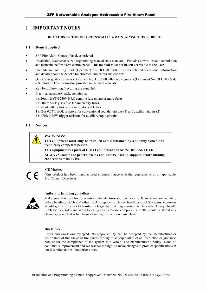
CE MarkedThis product has been manufactured in conformance with the requirements of all applicableEU Council Directives.
Anti-static handling guidelinesMake sure that handling precautions for electro-static devices (ESD) are taken immediately
before handling PCBs and other ESD components. Before handling any ESD items, engineersshould get rid of any electro-static charge by touching a sound safety earth. Always handlePCBs by their sides and avoid touching any electronic components. PCBs should be stored in aclean, dry place that is free from vibration, dust and excessive heat.
DisclaimerErrors and omissions excepted. No responsibility can be accepted by the manufacturer ordistributors of this range of fire panels for any misinterpretation of an instruction or guidancenote or for the compliance of the system as a whole. The manufacturer’s policy is one ofcontinuous improvement and we reserve the right to make changes to product specifications atour discretion and without prior notice.
WARNINGS!
This equipment must only be installed and maintained by a suitably skilled andtechnically competent person.
This equipment is a piece of Class 1 equipment and MUST BE EARTHED.ALWAYS isolate the panel’s Mains and battery backup supplies before ma kingconnections to its PCBs.

8/10/2019 Zfp Instal and Program Manual Dfu5000503 Rev3!01!02 13
http://slidepdf.com/reader/full/zfp-instal-and-program-manual-dfu5000503-rev30102-13 6/55
ZFP Networkable Analogue Addressable Fire Alarm Panel
Installation and Programming Manual Approved Document No. DFU5000503 Rev 3 Page 6 of 55
1.3 System Design
Fire alarm system design is beyond the scope of this document. A basic understanding of general fire alarmsystem components and their use is assumed.Contact the Fire Officer concerned with the property at an early stage in case he has any specialrequirements. We strongly recommend that a suitably qualified and competent person is consulted inconnection with the design of the fire alarm system.The equipment must be installed, operated and maintained in accordance with these instructions and theappropriate national, regional or local regulations. If in doubt please consult your supplier.We recommend you read BS 5839 Part 1 "Fire Detection and Alarm Systems for Buildings (Code of Practicefor System Design, Installation, Commissioning and Maintenance)" available at your local reference libraryor from the BSI. Other national standards of installation should be referenced where applicable.
1.4 Equipment Guarantee
This equipment is not guaranteed unless the complete installation is installed and commissioned inaccordance with the laid down national, regional or local standards (in the UK BS 5839 Part 1) by anapproved and competent person or organisation.

8/10/2019 Zfp Instal and Program Manual Dfu5000503 Rev3!01!02 13
http://slidepdf.com/reader/full/zfp-instal-and-program-manual-dfu5000503-rev30102-13 7/55
8/10/2019 Zfp Instal and Program Manual Dfu5000503 Rev3!01!02 13
http://slidepdf.com/reader/full/zfp-instal-and-program-manual-dfu5000503-rev30102-13 8/55
ZFP Networkable Analogue Addressable Fire Alarm Panel
Installation and Programming Manual Approved Document No. DFU5000503 Rev 3 Page 8 of 55
3 SYSTEM DESIGN
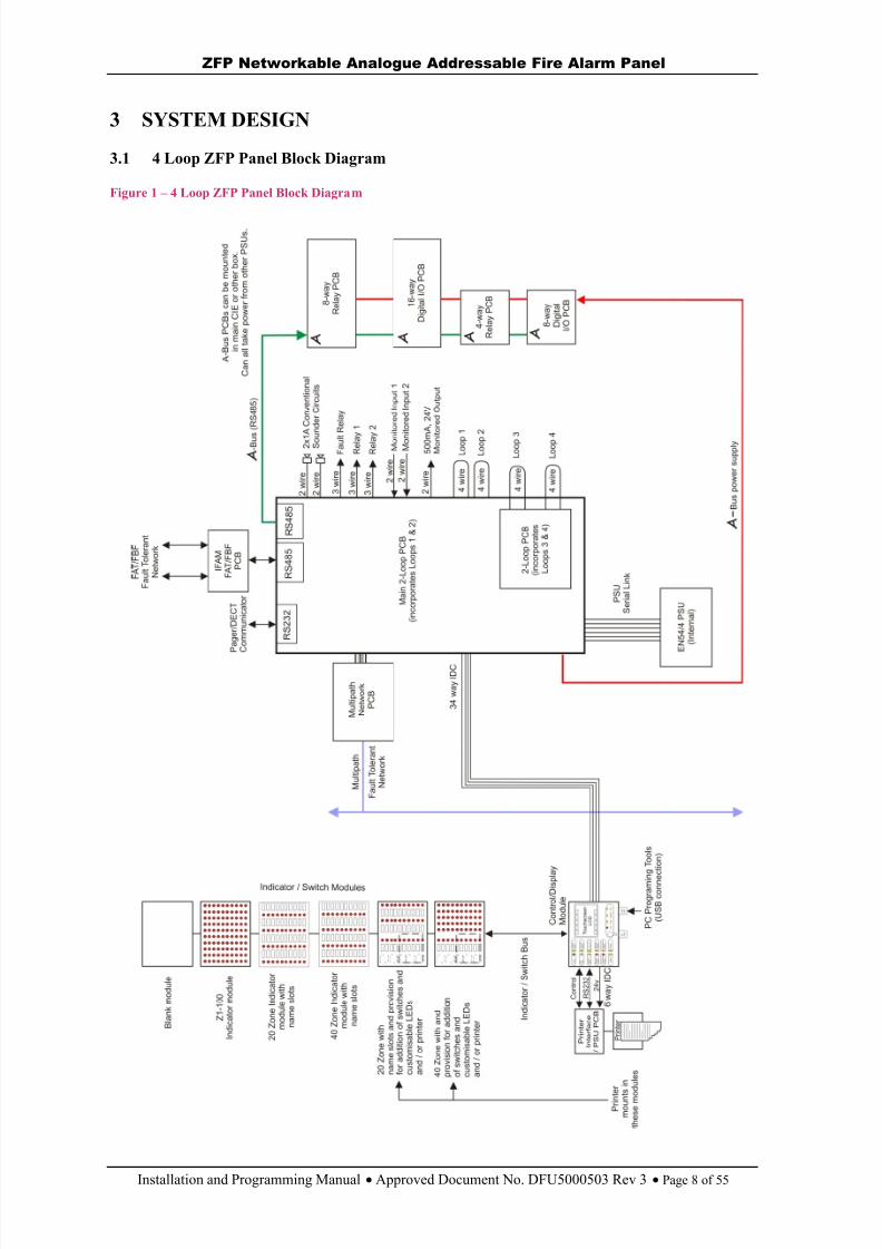
3.1 4 Loop ZFP Panel Block Diagram
Figure 1 – 4 Loop ZFP Panel Block Diagram
8/10/2019 Zfp Instal and Program Manual Dfu5000503 Rev3!01!02 13
http://slidepdf.com/reader/full/zfp-instal-and-program-manual-dfu5000503-rev30102-13 9/55
ZFP Networkable Analogue Addressable Fire Alarm Panel
Installation and Programming Manual Approved Document No. DFU5000503 Rev 3 Page 9 of 55
4 CABLING REQUIREMENTS
All installation wiring must be checked and tested before termination at the panel. Always isolate the panel’s Mains and battery backup supplies before cable termination at the panel.
4.1 Mains Wiring
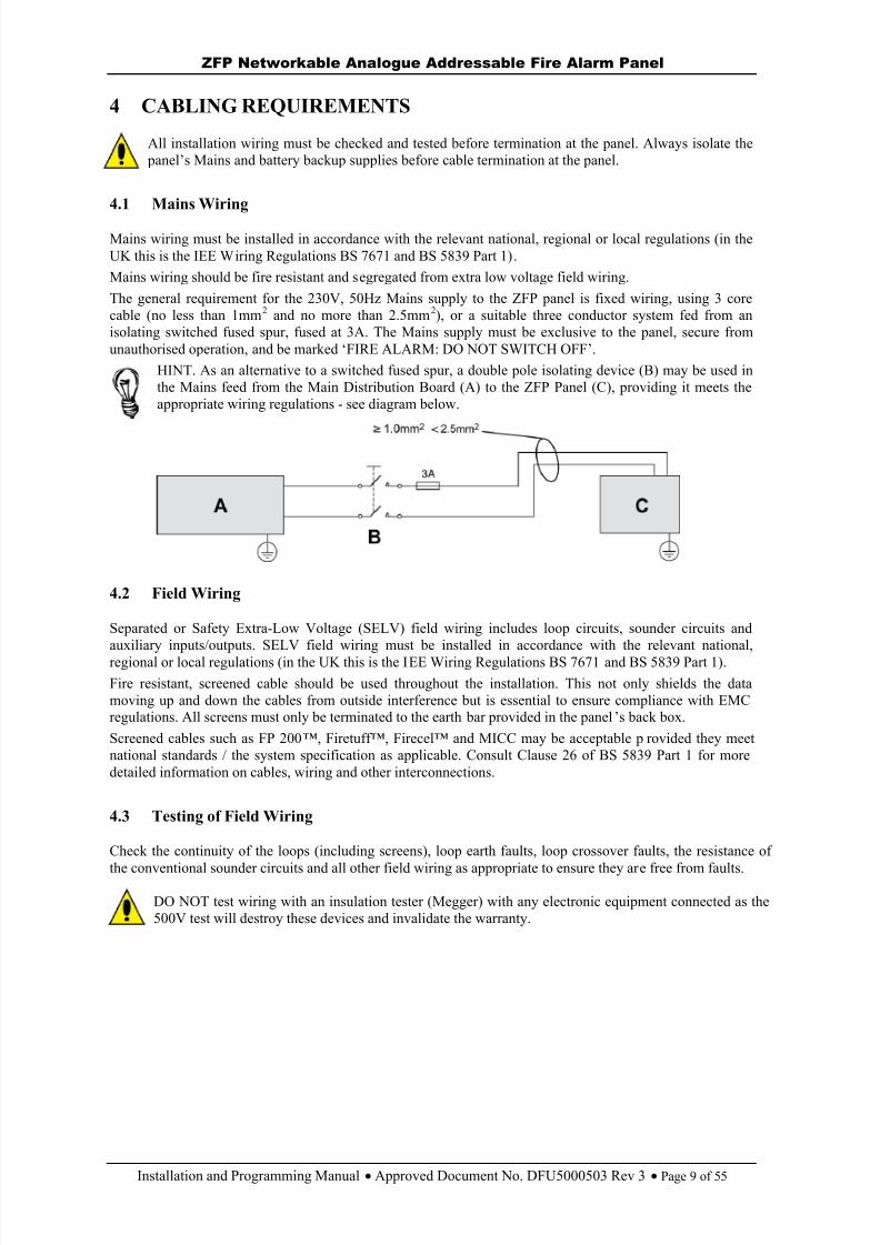
Mains wiring must be installed in accordance with the relevant national, regional or local regulations (in theUK this is the IEE Wiring Regulations BS 7671 and BS 5839 Part 1).Mains wiring should be fire resistant and segregated from extra low voltage field wiring.The general requirement for the 230V, 50Hz Mains supply to the ZFP panel is fixed wiring, using 3 corecable (no less than 1mm 2 and no more than 2.5mm 2), or a suitable three conductor system fed from anisolating switched fused spur, fused at 3A. The Mains supply must be exclusive to the panel, secure fromunauthorised operation, and be marked ‘FIRE ALARM: DO NOT SWITCH OFF’.
HINT. As an alternative to a switched fused spur, a double pole isolating device (B) may be used inthe Mains feed from the Main Distribution Board (A) to the ZFP Panel (C), providing it meets theappropriate wiring regulations - see diagram below.
4.2 Field Wiring
Separated or Safety Extra-Low Voltage (SELV) field wiring includes loop circuits, sounder circuits andauxiliary inputs/outputs. SELV field wiring must be installed in accordance with the relevant national,regional or local regulations (in the UK this is the IEE Wiring Regulations BS 7671 and BS 5839 Part 1).Fire resistant, screened cable should be used throughout the installation. This not only shields the datamoving up and down the cables from outside interference but is essential to ensure compliance with EMCregulations. All screens must only be terminated to the earth bar provided in the panel ’s back box .Screened cables such as FP 200 ™, Firetuff™, Firecel™ and MICC may be acceptable p rovided they meetnational standards / the system specification as applicable. Consult Clause 26 of BS 5839 Part 1 for moredetailed information on cables, wiring and other interconnections.
4.3 Testing of Field Wiring
Check the continuity of the loops (including screens), loop earth faults, loop crossover faults, the resistance of
the conventional sounder circuits and all other field wiring as appropriate to ensure they are free from faults.
DO NOT test wiring with an insulation tester (Megger) with any electronic equipment connected as the500V test will destroy these devices and invalidate the warranty.
8/10/2019 Zfp Instal and Program Manual Dfu5000503 Rev3!01!02 13
http://slidepdf.com/reader/full/zfp-instal-and-program-manual-dfu5000503-rev30102-13 10/55
ZFP Networkable Analogue Addressable Fire Alarm Panel
Installation and Programming Manual Approved Document No. DFU5000503 Rev 3 Page 10 of 55
5 INSTALLATION
Note : See section 9.1 for a recommended shortform installation procedure.
5.1 Enclosure Description
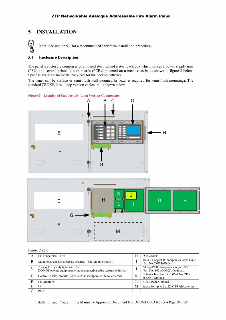
The panel ’s enclosure comprises of a hinged steel lid and a steel back box which houses a power supply unit(PSU) and several printed circuit boards (PCBs) mounted on a metal chassis, as shown in figure 2 below.Space is available inside the back box for the backup batteries.The panel can be surface or semi-flush wall mounted (a bezel is required for semi-flush mounting). Thestandard ZBOXS, 2 to 4 loop version enclosure, is shown below.
Figure 2 – Location of Standard 2/4 Loop Version Components
Figure 2 key:
A Lid Hinge Pins – 2 off H PCB Chassis
B Module (20 zone, 5 switches, 10 LEDs - Z45 Module shown) I Main 2-Loop PCB incorporates loops 1 & 2.(Part No. Z02MAIN/X).
C 20-way heavy duty brass earth bar.DO NOT operate equipment without connecting cable screens to this bar. J 2-Loop PCB incorporates loops 3 & 4.
(Part No. Z02LOOP/X). Optional.
D Control/Display Module (Part No. Z41) incorporates the touchscreen K Network Interface PCB (Part No. ZHNor ZSN). Optional.
E Lid Aperture L A-Bus PCB. Optional
F Lid M Space for up to 2 x 12 V 18 Ah batteriesG PSU

8/10/2019 Zfp Instal and Program Manual Dfu5000503 Rev3!01!02 13
http://slidepdf.com/reader/full/zfp-instal-and-program-manual-dfu5000503-rev30102-13 11/55
ZFP Networkable Analogue Addressable Fire Alarm Panel
Installation and Programming Manual Approved Document No. DFU5000503 Rev 3 Page 11 of 55
5.2 Mounting Location
Each panel must wall mounted, indoors and MUST NOT be subjected to conditions that are likely to affecttheir performance, e.g. damp, extreme temperatures, physical abuse, etc.They should be sited at an easily accessible height and in a prominent position within the building. The ambientlight and sound levels should allow the indicators and touchscreen to be clearly visible and the internal buzzerclearly heard. Typical locations for the panel are in the entrance foyer/hallway at ground floor level (the firstand most obvious point of contact for emergency services) or in a permanently manned security office.
5.3 Removing the Lid, PCB Chassis and PSU
To protect the panel’s electronic componen ts from damage and also to expose the back box mounting holes,the panel’s lid, PCB chassis and PSU should be removed prior to initial installation. When removed, all panelcomponents should be stored in a clean, dry place which is free from vibration, dust and excessive heat.
HINT. Retaining the components in a suitable cardboard box will also guard them againstmechanical damage.
To remove the lid:
Use the supplied key to unlock the lid. Open the lid 180° to the left (do not overbend the hinges), then disconnect the lid ’s earth strap.
By hand, or by using a screwdriver, push out the lid’s two plastic hinge pins (shownright) and lift off the lid.
To remove the PCB chassis and PSU:
See ‘Anti-static handling guidelines ’ in section 1.2
Disconnect the earth strap from the PCB chassis. Remove the four retaining screws that secure thePCB chassis in the back box and carefully remove the chassis to expose the PSU.
Pull the PSU ’s earth strap off the spade connector at the ba ck box ’s earth point. Remove the four retainingnuts and washers that secure the PSU in the back box and carefully remove the PSU.
5.4 Planning the Cable Layout in the Panel and Removing Knockouts
Mains wiring should be segregated from extra low voltage field wiring. Leave sufficienttails i nside the panel to ensure straightforward connection of wiring to the panel’s terminals. All cables should be fed into the panel through the knockouts provided in the back box.Knockouts should be removed with a sharp, light tap using a 6mm flat-bladed screwdriveras shown in the diagram (right). Ensure any swarf is removed from the enclosure.Always ensure if a knockout is removed, the hole is filled with a good quality 20mmcable gland. Any unused knockouts must be securely blanked off.
5.5 Wall Mounting the Back Box
Note : The panel can be surface or semi-flush mounted on a wall (note optional bezels are available for semi-flush mounting).
CAUTION: The enclosures are heavy! Therefore, use suitable screw fixings for wall mountingthe enclosures.
Securely fix the panel to a wall using the four ( ø4.7mm) mounting holes provided in the back box. Themounting holes are suitable for use with No.8 roundhead or countersunk screwsSee Appendix 1 for enclosure fixing details.Always assess the condition and construction of the wall and use suitable screw fixings. Any dust or swarfcreated during the fixing process must be removed from the inside of the back box.Ensure there is sufficient space to allow the lid to be fitted/removed when the panel is wall mounted.

8/10/2019 Zfp Instal and Program Manual Dfu5000503 Rev3!01!02 13
http://slidepdf.com/reader/full/zfp-instal-and-program-manual-dfu5000503-rev30102-13 12/55
ZFP Networkable Analogue Addressable Fire Alarm Panel
Installation and Programming Manual Approved Document No. DFU5000503 Rev 3 Page 12 of 55
5.6 Reinstalling the PSU, PCB Chassis and Lid
Refit the panel’s PSU, PCB chassis and lid by following the removal procedure (section 5.3) in reverse order. Note that the panel’s PSU will have to be refitted and con nections made to it before the chassis is refitted.See Connecting Mains – section 5.18 and Connecting the Standby Batteries – section 5.19.
5.7 Inserting the ‘slide -in’ labels
Insert the slide-in labels (supplied in the accessory pack) for the ancillarymodules), as shown right.
Note: The label inserted for the module’s control buttons depends on how theunit has been configured.
5.8 Fitting the 2-Loop PCB (Optional)
An optional 2-Loop PCB (Part No. Z02LOOP/X) provides two additional analogue loop connections (Loop3& Loop4) if required. With reference to the diagram below:
Take the 2-Loop PCB and carefully align its holes upwith the four mounting holes on the Main 2-LoopPCB.
Insert the four PCB ‘plug -on’ pillars (supplied withthe 2-Loop PCB) through the holes on the 2-LoopPCB and into the holes on the Main 2-Loop PCB.Push the pillars until they click and lock in position.
Refer to section 5.11, figure 4 for analogue loopconnections.

8/10/2019 Zfp Instal and Program Manual Dfu5000503 Rev3!01!02 13
http://slidepdf.com/reader/full/zfp-instal-and-program-manual-dfu5000503-rev30102-13 13/55
ZFP Networkable Analogue Addressable Fire Alarm Panel
Installation and Programming Manual Approved Document No. DFU5000503 Rev 3 Page 13 of 55
5.9 Compact Controllers (Optional)
The compact controller is an optional network node that can be used to operate the system with basicfunctionality. The controller is a loopless device and has the following flush and surface mounted versions:
Controller flush mount - Part No. ZREP1F (used with a multipath network), Part No. ZREP2F (usedwith a singlepath network).
Controller surface mount - Part No. ZREP1S (used with a multipath network), Part No. ZREP2S(used with a singlepath network).
Summary of Compact Controller Features
For controller dimensions and fixing details – see Appendix 1.
Silence, Reset and Mute buttons are available at the controller’s touchscreen.
Alarms, Faults, Disablements and Tests buttons are available at the controller’s touchscreen.
A controller comes with a network PCB fitted as standard, enabling it to communicate with othernodes (panels or controllers) over a ZFP network. See networking section 6 for details.
Each controller requires an EN 54-4/A2 boxed PSU (supplied separately). See networking section 6,figures 13 & 14 for PSU connection details.
A controller has a limited number of touchscreen menus available compared to a panel. These arelisted below. Refer to section 9 for menu details.
Access Level 1 menus Access Level 2 menus Access Level 3 menusAccess Level 2 Access Level 3 Set Time/DateAccess Level 3 ReSound Sounders Show System Details
Lamps Test Alarm Counter LCD Auto-DimmingView Alarm Counter Disablements Functions Setup Networking
Clean the Display Set Time/Date Select LanguageClean Start
Backup System DevicesRestore System Devices
Removing the Co mpact Controller’s Bezel
The compact c ontroller’s front bezel must be removed to access the unit’sinternal components and expose the back box mounting holes.Using a small flat bladed screwdriver, push in the two tabs to release the
bezel, as shown left.
8/10/2019 Zfp Instal and Program Manual Dfu5000503 Rev3!01!02 13
http://slidepdf.com/reader/full/zfp-instal-and-program-manual-dfu5000503-rev30102-13 14/55
ZFP Networkable Analogue Addressable Fire Alarm Panel
Installation and Programming Manual Approved Document No. DFU5000503 Rev 3 Page 14 of 55
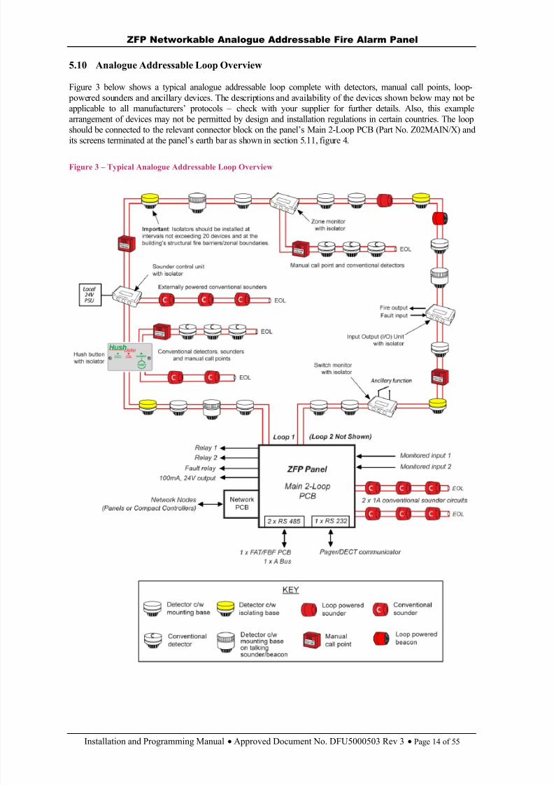
5.10 Analogue Addressable Loop Overview
Figure 3 below shows a typical analogue addressable loop complete with detectors, manual call points, loop- powered sounders and ancillary devices. The descriptions and availability of the devices shown below may not beapplicable to all manufacturers’ protocols – check with your supplier for further details. Also, this examplearrangement of devices may not be permitted by design and installation regulations in certain countries. The loopshould be connected to the relevant connector block on the panel’s Main 2-Loop PCB (Part No. Z02MAIN/X) andits screens terminated at the panel’s earth bar as shown in section 5.11, figure 4.
Figure 3 – Typical Analogue Addressable Loop Overview
8/10/2019 Zfp Instal and Program Manual Dfu5000503 Rev3!01!02 13
http://slidepdf.com/reader/full/zfp-instal-and-program-manual-dfu5000503-rev30102-13 15/55
ZFP Networkable Analogue Addressable Fire Alarm Panel
Installation and Programming Manual Approved Document No. DFU5000503 Rev 3 Page 15 of 55
Important Note : Remember to isolate the panel’s Mains and battery backup supplies before terminatingwiring at the panel.
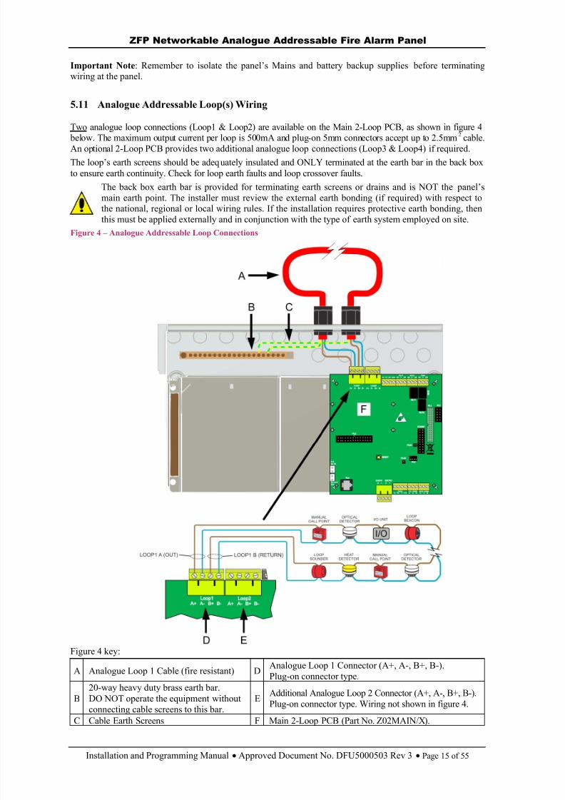
5.11 Analogue Addressable Loop(s) Wiring
Two analogue loop connections (Loop1 & Loop2) are available on the Main 2-Loop PCB, as shown in figure 4
below. The maximum output current per loop is 500mA and plug-on 5mm connectors accept up to 2.5mm2
cable.An optional 2-Loop PCB provides two additional analogue loop connections (Loop3 & Loop4) if required.The loop’s earth screens should be adeq uately insulated and ONLY terminated at the earth bar in the back boxto ensure earth continuity. Check for loop earth faults and loop crossover faults.
The back box earth bar is provided for terminating earth screens or drains and is NOT the panel’smain earth point. The installer must review the external earth bonding (if required) with respect tothe national, regional or local wiring rules. If the installation requires protective earth bonding, thenthis must be applied externally and in conjunction with the type of earth system employed on site.
Figure 4 – Analogue Addressable Loop Connections
Figure 4 key:
A Analogue Loop 1 Cable (fire resistant) D Analogue Loop 1 Connector (A+, A-, B+, B-).Plug-on connector type.
B
20-way heavy duty brass earth bar.
DO NOT operate the equipment withoutconnecting cable screens to this bar. EAdditional Analogue Loop 2 Connector (A+, A-, B+, B-).Plug-on connector type. Wiring not shown in figure 4.
C Cable Earth Screens F Main 2-Loop PCB (Part No. Z02MAIN/X).
8/10/2019 Zfp Instal and Program Manual Dfu5000503 Rev3!01!02 13
http://slidepdf.com/reader/full/zfp-instal-and-program-manual-dfu5000503-rev30102-13 16/55
ZFP Networkable Analogue Addressable Fire Alarm Panel
Installation and Programming Manual Approved Document No. DFU5000503 Rev 3 Page 16 of 55
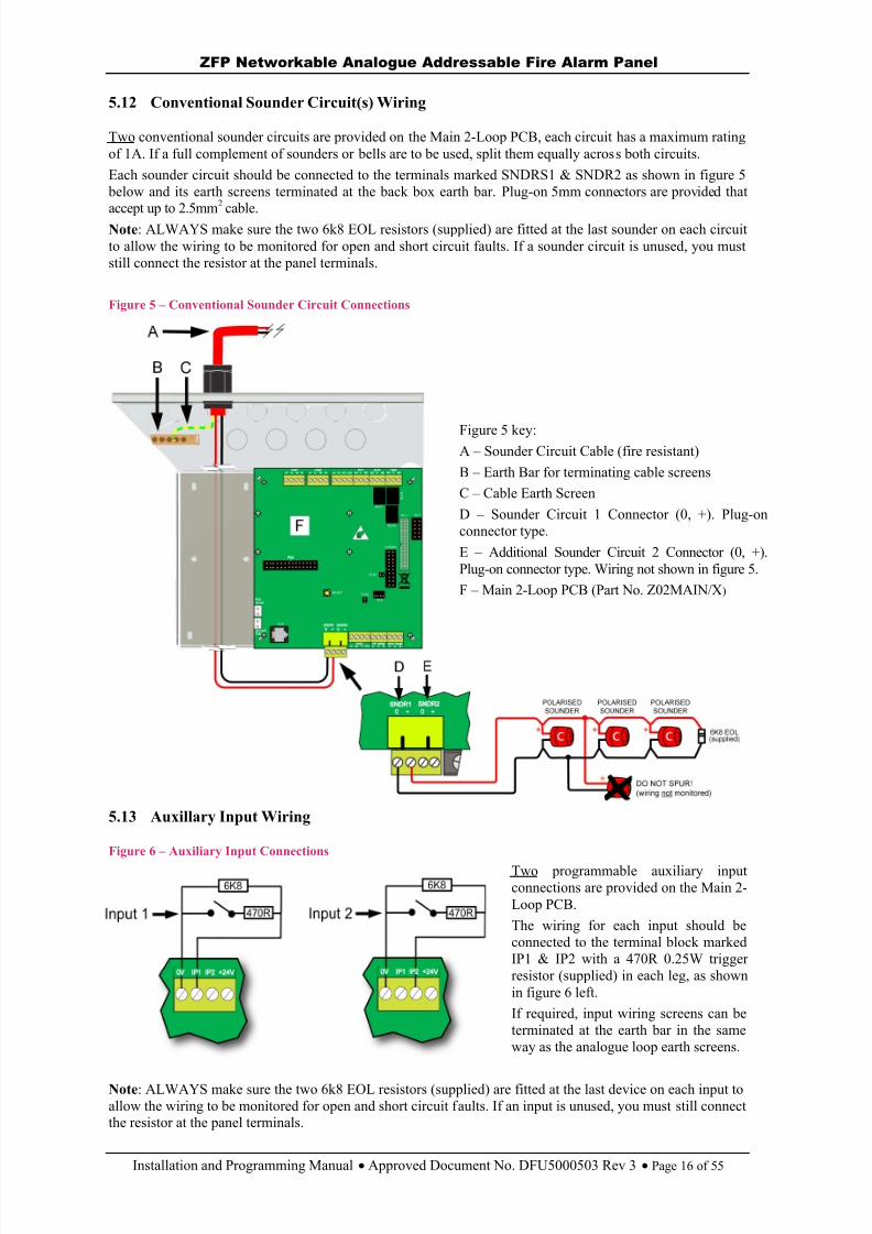
5.12 Conventional Sounder Circuit(s) Wiring
Two conventional sounder circuits are provided on the Main 2-Loop PCB, each circuit has a maximum ratingof 1A. If a full complement of sounders or bells are to be used, split them equally across both circuits.Each sounder circuit should be connected to the terminals marked SNDRS1 & SNDR2 as shown in figure 5
below and its earth screens terminated at the back box earth bar. Plug-on 5mm connectors are provided thataccept up to 2.5mm 2 cable.
Note : ALWAYS make sure the two 6k8 EOL resistors (supplied) are fitted at the last sounder on each circuitto allow the wiring to be monitored for open and short circuit faults. If a sounder circuit is unused, you muststill connect the resistor at the panel terminals.
Figure 5 – Conventional Sounder Circuit Connections
Figure 5 key:A – Sounder Circuit Cable (fire resistant)B – Earth Bar for terminating cable screensC – Cable Earth ScreenD – Sounder Circuit 1 Connector (0, +). Plug-onconnector type.E – Additional Sounder Circuit 2 Connector (0, +).Plug-on connector type. Wiring not shown in figure 5.F – Main 2-Loop PCB (Part No. Z02MAIN/X )
5.13 Auxillary Input Wiring
Figure 6 – Auxiliary Input Connections
Two programmable auxiliary inputconnections are provided on the Main 2-Loop PCB.The wiring for each input should beconnected to the terminal block markedIP1 & IP2 with a 470R 0.25W triggerresistor (supplied) in each leg, as shownin figure 6 left.If required, input wiring screens can beterminated at the earth bar in the sameway as the analogue loop earth screens.
Note : ALWAYS make sure the two 6k8 EOL resistors (supplied) are fitted at the last device on each input toallow the wiring to be monitored for open and short circuit faults. If an input is unused, you must still connectthe resistor at the panel terminals.
8/10/2019 Zfp Instal and Program Manual Dfu5000503 Rev3!01!02 13
http://slidepdf.com/reader/full/zfp-instal-and-program-manual-dfu5000503-rev30102-13 17/55
ZFP Networkable Analogue Addressable Fire Alarm Panel
Installation and Programming Manual Approved Document No. DFU5000503 Rev 3 Page 17 of 55
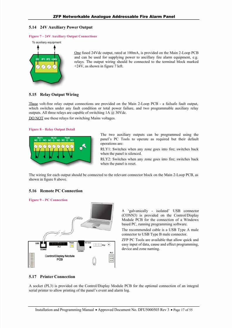
5.14 24V Auxiliary Power Output
Figure 7 – 24V Auxiliary Output Connections
One fused 24Vdc output, rated at 100mA, is provided on the Main 2-Loop PCB
and can be used for supplying power to ancillary fire alarm equipment, e.g.relays. The output wiring should be connected to the terminal block marked+24V, as shown in figure 7 left.
5.15 Relay Output Wiring
Three volt-free relay output connections are provided on the Main 2-Loop PCB - a failsafe fault output,which switches under any fault condition or total power failure, and two programmable auxiliary relayoutputs. All three relays are capable of switching 1A @ 30Vdc.DO NOT use these relays for switching Mains voltages.
Figure 8 – Relay Output Detail
The two auxiliary outputs can be programmed using the panel’s PC Tools to operate as required but their defaultoperations are:RLY1: Switches when any zone goes into fire; switches backwhen the panel is silenced.RLY2: Switches when any zone goes into fire; switches backwhen the panel is reset.
The wiring for each output should be connected to the relevant connector block on the Main 2-Loop PCB, asshown in figure 8 above.
5.16 Remote PC Connection
Figure 9 – PC Connection
A ‘galvanically - isolated’ USB connector(CONN3) is provided on the Control/DisplayModule PCB for the connection of a Windows
based PC, running programming software.
The recommended cable is a USB Type A maleconnector to USB Type B male connector.ZFP PC Tools are available that allow quick andeasy input of data, cause and effect programming,device and zone naming.
5.17 Printer Connection
A socket (PL3) is provided on the Control/Display Module PCB for the optional connection of an integralserial printer to allow printing of the panel’s event and alarm log.
8/10/2019 Zfp Instal and Program Manual Dfu5000503 Rev3!01!02 13
http://slidepdf.com/reader/full/zfp-instal-and-program-manual-dfu5000503-rev30102-13 18/55
ZFP Networkable Analogue Addressable Fire Alarm Panel
Installation and Programming Manual Approved Document No. DFU5000503 Rev 3 Page 18 of 55
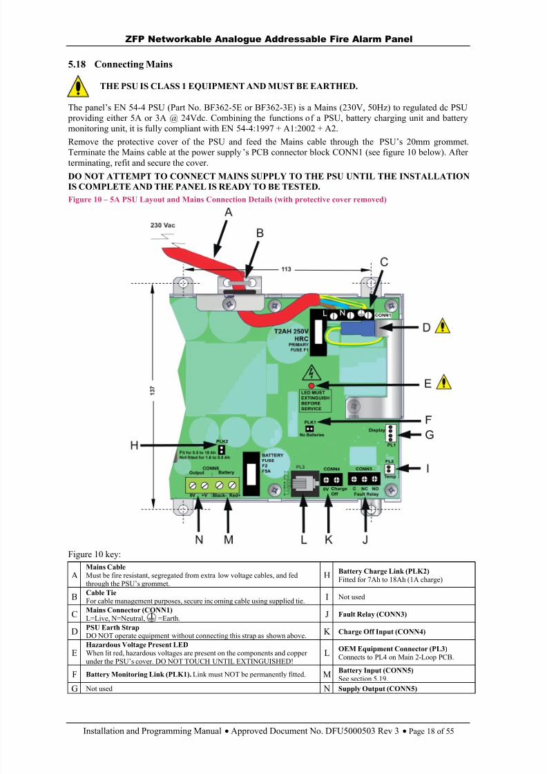
5.18 Connecting Mains
THE PSU IS CLASS 1 EQUIPMENT AND MUST BE EARTHED.
The panel’ s EN 54-4 PSU (Part No. BF362-5E or BF362-3E) is a Mains (230V, 50Hz) to regulated dc PSU providing either 5A or 3A @ 24Vdc. Combining the functions of a PSU, battery charging unit and batterymonitoring unit, it is fully compliant with EN 54-4:1997 + A1:2002 + A2.Remove the protective cover of the PSU and feed the Mains cable through the PSU’s 20mm grommet.Terminate the Mains cable at the power supply ’s PCB connector block CONN1 (see figure 10 below). Afterterminating, refit and secure the cover.
DO NOT ATTEMPT TO CONNECT MAINS SUPPLY TO THE PSU UNTIL THE INSTALLATION IS COMPLETE AND THE PANEL IS READY TO BE TESTED.Figure 10 – 5A PSU Layout and Mains Connection Details (with protective cover removed)
Figure 10 key:
AMains CableMust be fire resistant, segregated from extra low voltage cables, and fedthrough the PSU ’s grommet.
H Battery Charge Link (PLK2)Fitted for 7Ah to 18Ah (1A charge)
B Cable TieFor cable management purposes, secure incoming cable using supplied tie. I Not used
C Mains Connector (CONN1)L=Live, N=Neutral, =Earth. J Fault Relay (CONN3)
D PSU Earth StrapDO NOT operate equipment without connecting this strap as shown above. K Charge Off Input (CONN4)
EHazardous Voltage Present LEDWhen lit red, hazardous voltages are present on the components and copperunder the PSU’s cover. DO NOT TOUCH UNTIL EXTINGUISHED!
L OEM Equipment Connector (PL3)Connects to PL4 on Main 2-Loop PCB.
F Battery Monitoring Link (PLK1). Link must NOT be permanently fitted. MBattery Input (CONN5)See section 5.19.
G Not used N Supply Output (CONN5)
8/10/2019 Zfp Instal and Program Manual Dfu5000503 Rev3!01!02 13
http://slidepdf.com/reader/full/zfp-instal-and-program-manual-dfu5000503-rev30102-13 19/55
ZFP Networkable Analogue Addressable Fire Alarm Panel
Installation and Programming Manual Approved Document No. DFU5000503 Rev 3 Page 19 of 55
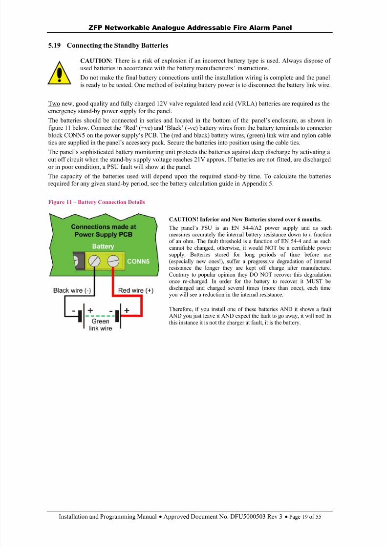
5.19 Connecting the Standby Batteries
CAUTION : There is a risk of explosion if an incorrect battery type is used. Always dispose ofused batteries in accordance with the battery manufacturers ’ instructions.Do not make the final battery connections until the installation wiring is complete and the panelis ready to be tested. One method of isolating battery power is to disconnect the battery link wire.
Two new, good quality and fully charged 12V valve regulated lead acid (VRLA) batteries are required as theemergency stand-by power supply for the panel.The batteries should be connected in series and located in the bottom of the panel’s enclosure , as shown infigure 11 below. Connect the ‘Red’ (+ve) and ‘Black’ ( -ve) battery wires from the battery terminals to connector
block CONN5 on the power supply ’s PCB. The (red and black) battery wires, (green) link wire and nylon cableties are supplied in the panel’s accessory pack. Secure the batteries into position using the cable ties.The panel’s sophisticated battery monitoring unit protects the batteries against deep discharge by activating acut off circuit when the stand-by supply voltage reaches 21V approx. If batteries are not fitted, are dischargedor in poor condition, a PSU fault will show at the panel.The capacity of the batteries used will depend upon the required stand-by time. To calculate the batteriesrequired for any given stand-by period, see the battery calculation guide in Appendix 5.
Figure 11 – Battery Connection Details
CAUTION! Inferior and New Batteries stored over 6 months.
The panel’s PSU is an EN 54-4/A2 power supply and as suchmeasures accurately the internal battery resistance down to a fractionof an ohm. The fault threshold is a function of EN 54-4 and as suchcannot be changed, otherwise, it would NOT be a certifiable powersupply. Batteries stored for long periods of time before use(especially new ones!), suffer a progressive degradation of internalresistance the longer they are kept off charge after manufacture.Contrary to popular opinion they DO NOT recover this degradationonce re-charged. In order for the battery to recover it MUST bedischarged and charged several times (more than once), each timeyou will see a reduction in the internal resistance.
Therefore, if you install one of these batteries AND it shows a faultAND you just leave it AND expect the fault to go away, it will not! Inthis instance it is not the charger at fault, it is the battery.

8/10/2019 Zfp Instal and Program Manual Dfu5000503 Rev3!01!02 13
http://slidepdf.com/reader/full/zfp-instal-and-program-manual-dfu5000503-rev30102-13 20/55
ZFP Networkable Analogue Addressable Fire Alarm Panel
Installation and Programming Manual Approved Document No. DFU5000503 Rev 3 Page 20 of 55
6 MULTIPATH & SINGLEPATH NETWORKING (Optional)
The Z FP’s network protocol allows the interconnection of up to 128 ZFP panels and compact controllers overa two-wire RS485 network. A ZFP network can either be a high integrity multipath network, or a standardsinglepath network.To communicate over a network, each network node (panel or compact controller) requires an RS485
network interface PCB. Compact controllers come with a network interface PCB fitted as standard.
6.1 Summary of Network Features
Feature Multipath network Singlepath network Network interface PCB Part No.(one required per panel)
ZHN ZSN
Maximum number of network nodes 128 (max. 64 x 8 loop panels) 8Maximum cable length between nodes 1km -Maximum cable length of network 128km 1km
Network protocol RS485 Network topology Ring configuration Daisy-chain configuration Network wiring 2 core screened cable, fire resistant (minimum size 1mm 2)Fault tolerant network (with a single wiring fault) Accept Events (Fires, Faults, Disablements,Tests) over the network
Accept Actions (Silence Sounders, ReSoundSounders, Reset Panel) over the network
Share Zones, Input Groups, Output Groups, etc.over the network
PC Tools available for programming Cause andEffects and site information over the network
6.2 Fitting the Network Interface PCB
A panel requires a network interface PCB fitting, whilst compact controllers include one fitted as standard.
Important Note: Before installing the PCB, isolate the Mains supply and disconnect the panel’s battery back-up supply.
Fit the network interface PCB as shown in figure 12 below. Items supplied with the PCB include 2x plastic mounting rails, 4 x retaining screws and a 10-way wiring loom (ZLOOM4).
Figure 12 – Fitting the Network Interface PCB
8/10/2019 Zfp Instal and Program Manual Dfu5000503 Rev3!01!02 13
http://slidepdf.com/reader/full/zfp-instal-and-program-manual-dfu5000503-rev30102-13 21/55
ZFP Networkable Analogue Addressable Fire Alarm Panel
Installation and Programming Manual Approved Document No. DFU5000503 Rev 3 Page 21 of 55
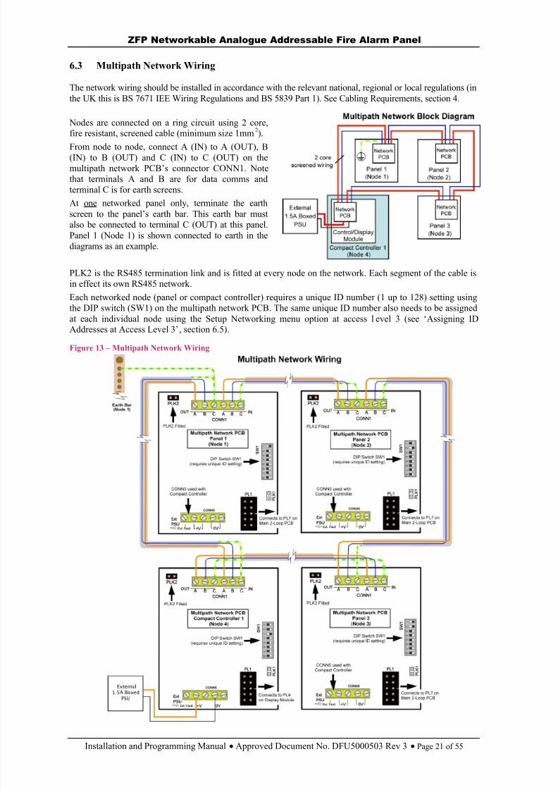
6.3 Multipath Network Wiring
The network wiring should be installed in accordance with the relevant national, regional or local regulations (inthe UK this is BS 7671 IEE Wiring Regulations and BS 5839 Part 1). See Cabling Requirements, section 4.
Nodes are connected on a ring circuit using 2 core,fire resistant, screened cable (minimum size 1mm 2).From node to node, connect A (IN) to A (OUT), B(IN) to B (OUT) and C (IN) to C (OUT) on themultipath network PCB’s connector CONN1. Notethat terminals A and B are for data comms andterminal C is for earth screens.At one networked panel only, terminate the earthscreen to the panel’s earth bar. This earth bar mustalso be connected to terminal C (OUT) at this panel.Panel 1 (Node 1) is shown connected to earth in thediagrams as an example.
PLK2 is the RS485 termination link and is fitted at every node on the network. Each segment of the cable isin effect its own RS485 network.Each networked node (panel or compact controller) requires a unique ID number (1 up to 128) setting usingthe DIP switch (SW1) on the multipath network PCB. The same unique ID number also needs to be assignedat each individual node using the Setup Networking menu option at access l evel 3 (see ‘Assigning IDAddresses at Access Level 3’ , section 6.5).
Figure 13 – Multipath Network Wiring
8/10/2019 Zfp Instal and Program Manual Dfu5000503 Rev3!01!02 13
http://slidepdf.com/reader/full/zfp-instal-and-program-manual-dfu5000503-rev30102-13 22/55
ZFP Networkable Analogue Addressable Fire Alarm Panel
Installation and Programming Manual Approved Document No. DFU5000503 Rev 3 Page 22 of 55
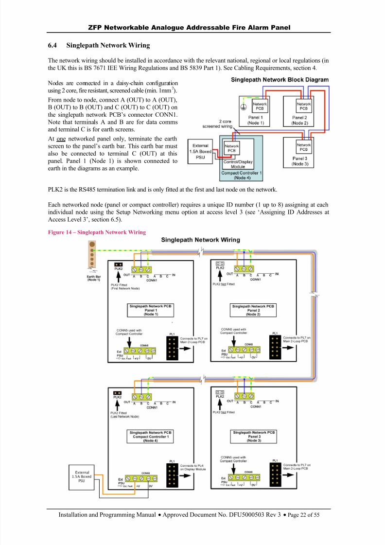
6.4 Singlepath Network Wiring
The network wiring should be installed in accordance with the relevant national, regional or local regulations (inthe UK this is BS 7671 IEE Wiring Regulations and BS 5839 Part 1). See Cabling Requirements, section 4.
Nodes are connected in a daisy-chain configurationusing 2 core, fire resistant, screened cable (min. 1mm 2).From node to node, connect A (OUT) to A (OUT),B (OUT) to B (OUT) and C (OUT) to C (OUT) onthe singlepath network PCB’s connector CONN1.
Note that terminals A and B are for data commsand terminal C is for earth screens.At one networked panel only, terminate the earthscree n to the panel’s earth bar. This earth bar mustalso be connected to terminal C (OUT) at this
panel. Panel 1 (Node 1) is shown connected toearth in the diagrams as an example.
PLK2 is the RS485 termination link and is only fitted at the first and last node on the network.
Each networked node (panel or compact controller) requires a unique ID number (1 up to 8) assigning at eachindividual node using the Setup Networking menu option at access level 3 (see ‘Assigning ID Addresses atAccess Level 3’ , section 6.5).
Figure 14 – Singlepath Network Wiring
8/10/2019 Zfp Instal and Program Manual Dfu5000503 Rev3!01!02 13
http://slidepdf.com/reader/full/zfp-instal-and-program-manual-dfu5000503-rev30102-13 23/55
ZFP Networkable Analogue Addressable Fire Alarm Panel
Installation and Programming Manual Approved Document No. DFU5000503 Rev 3 Page 23 of 55
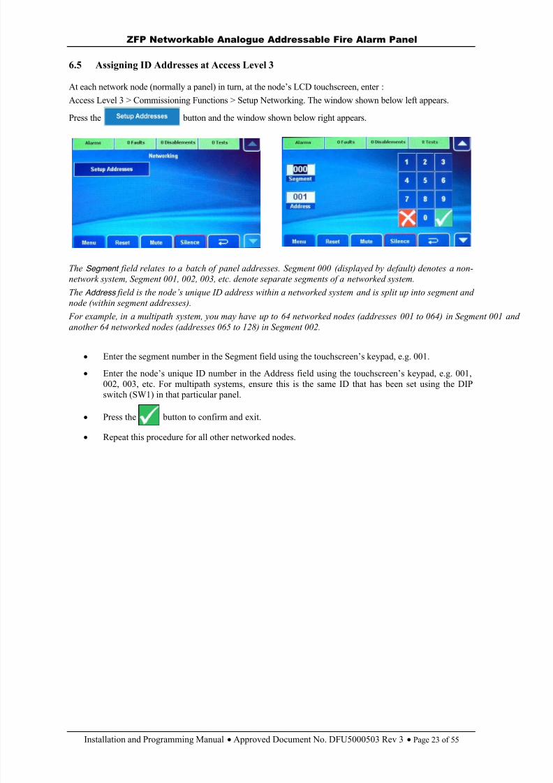
6.5 Assigning ID Addresses at Access Level 3
At each network node (normally a panel) in turn, at the node’s LCD touchscreen, enter :Access Level 3 > Commissioning Functions > Setup Networking. The window shown below left appears.
Press the button and the window shown below right appears.
The Segment field relates to a batch of panel addresses. Segment 000 (displayed by default) denotes a non-network system, Segment 001, 002, 003, etc. denote separate segments of a networked system.The Address field is the node’s unique ID address within a networked system and is split up into segment andnode (within segment addresses).
For example, in a multipath system, you may have up to 64 networked nodes (addresses 001 to 064) in Segment 001 andanother 64 networked nodes (addresses 065 to 128) in Segment 002.
Enter the segment number in the Segment field using the touchscreen’s keypad, e.g. 001.
Enter the node’s unique ID number in the Address field using the touchscreen’s keypad, e.g. 001,002, 003, etc. For multipath systems, ensure this is the same ID that has been set using the DIPswitch (SW1) in that particular panel.
Press the button to confirm and exit.
Repeat this procedure for all other networked nodes.
8/10/2019 Zfp Instal and Program Manual Dfu5000503 Rev3!01!02 13
http://slidepdf.com/reader/full/zfp-instal-and-program-manual-dfu5000503-rev30102-13 24/55
ZFP Networkable Analogue Addressable Fire Alarm Panel
Installation and Programming Manual Approved Document No. DFU5000503 Rev 3 Page 24 of 55
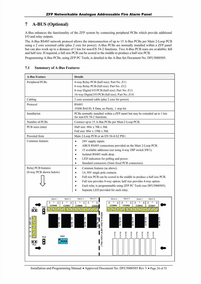
7 A-BUS (Optional)
A-Bus enhances the functionality of the ZFP system by connecting peripheral PCBs which provide additionalI/O and relay outputs.The A-Bus RS485 network protocol allows the interconnection of up to 15 A-Bus PCBs per Main 2-Loop PCBusing a 2 core screened cable (plus 2 core for power). A-Bus PCBs are normally installed within a ZFP panel
but can also work up to a distance of 1 km for non-EN 54-2 functions. Two A-Bus PCB sizes are available; fulland half size. If required, a full size PCB can be scored in the middle to produce a half size PCB.Programming A-Bus PCBs, using ZFP PC Tools, is detailed in the A-Bus Set Document No. DFU5000505.
7.1 Summary of A-Bus Features
A-Bus Feature Details
Peripheral PCBs 4-way Relay PCB (half size). Part No. Z11.8-way Relay PCB (full size). Part No. Z12.8-way Digital I/O PCB (half size). Part No. Z13.16-way Digital I/O PCB (full size). Part No. Z14.
Cabling 2 core screened cable (plus 2 core for power).Protocol RS485.
19200 BAUD, 8 Data, no Parity, 1 stop bit.
Installation PCBs normally installed within a ZFP panel but may be extended up to 1 kmfor non-EN 54-2 functions.
Number of PCBs Connect up to 15 A-Bus PCBs per Main 2-Loop PCB.
PCB sizes (mm) Half size: 80w x 70h x 30d.Full size: 80w x 150h x 30d.
Powered from Main 2-Loop PCB or an EN 54-4/A2 PSU.
Common features 24V supply inputs. ABUS RS485 connections provided on the Main 2-Loop PCB.
15 available addresses (set using 4-way DIP switch SW1). Isolated RS485 multi drop. LED indication for polling and power. Standard connectors (5mm fixed PCB connectors).
Relay PCB features(8-way PCB shown below)
Common features (as above). 1A 30V single pole contacts. Full size PCB can be scored in the middle to produce a half size PCB. Full size provides 8-way option; half size provides 4-way option. Each relay is programmable using ZFP PC Tools (see DFU5000505). Separate LED provided for each relay.
8/10/2019 Zfp Instal and Program Manual Dfu5000503 Rev3!01!02 13
http://slidepdf.com/reader/full/zfp-instal-and-program-manual-dfu5000503-rev30102-13 25/55
ZFP Networkable Analogue Addressable Fire Alarm Panel
Installation and Programming Manual Approved Document No. DFU5000503 Rev 3 Page 25 of 55
A-Bus Feature Details
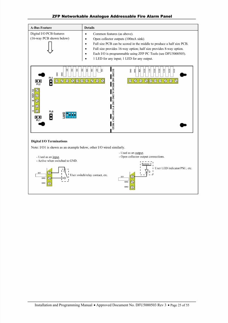
Digital I/O PCB features(16-way PCB shown below)
Common features (as above). Open collector outputs (100mA sink). Full size PCB can be scored in the middle to produce a half size PCB. Full size provides 16-way option; half size provides 8-way option. Each I/O is programmable using ZFP PC Tools (see DFU5000505). 1 LED for any input; 1 LED for any output.
Digital I/O Terminations
Note: I/O1 is shown as an example below, other I/O wired similarly.
8/10/2019 Zfp Instal and Program Manual Dfu5000503 Rev3!01!02 13
http://slidepdf.com/reader/full/zfp-instal-and-program-manual-dfu5000503-rev30102-13 26/55
ZFP Networkable Analogue Addressable Fire Alarm Panel
Installation and Programming Manual Approved Document No. DFU5000503 Rev 3 Page 26 of 55
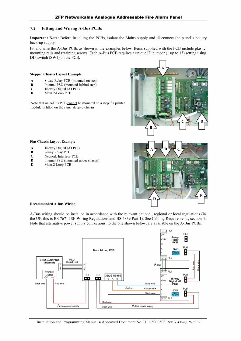
7.2 Fitting and Wiring A-Bus PCBs
Important Note: Before installing the PCBs, isolate the Mains supply and disconnect the p anel’s battery back-up supply.Fit and wire the A-Bus PCBs as shown in the examples below. Items supplied with the PCB include plasticmounting rails and retaining screws. Each A-Bus PCB requires a unique ID number (1 up to 15) setting usingDIP switch (SW1) on the PCB.
Stepped Chassis Layout Example
A 8-way Relay PCB (mounted on step)B Internal PSU (mounted behind step)C 16-way Digital I/O PCBD Main 2-Loop PCB
Note that an A-Bus PCB cannot be mounted on a step if a printermodule is fitted on the same stepped chassis.
Flat Chassis Layout Example
A 16-way Digital I/O PCBB 8-way Relay PCBC Network Interface PCBD Internal PSU (mounted under chassis)E Main 2-Loop PCB
Recommended A-Bus Wiring
A-Bus wiring should be installed in accordance with the relevant national, regional or local regulations (inthe UK this is BS 7671 IEE Wiring Regulations and BS 5839 Part 1). See Cabling Requirements, section 4.
Note that alternative power supply connections, to the one shown below, are available on the A-Bus PCBs.
B
C D
A
BA C
DE

8/10/2019 Zfp Instal and Program Manual Dfu5000503 Rev3!01!02 13
http://slidepdf.com/reader/full/zfp-instal-and-program-manual-dfu5000503-rev30102-13 27/55
ZFP Networkable Analogue Addressable Fire Alarm Panel
Installation and Programming Manual Approved Document No. DFU5000503 Rev 3 Page 27 of 55
8 TOUCHSCREEN, INDICATORS & CONTROLS
Note that information on the panel’s touchscreen, indicators and controls can be found in the separate UserManual (Document No. DFU5000501).
9 COMMISSIONING & PROGRAMMING
9.1 Recommended Shortform Installation & Commissioning Procedure
Note : DO NOT connect Mains or battery power to the panel until the installation is complete, i.e. panel PCBsare fitted and field wiring has been tested and connected to the panel.
Remove the panel’s lid, c hassis and PSU.
Fit the panel’s back box to a wall.
Gland field cables to the panel and terminate all screens to the earth bar in the back box. Test field cables and ensure they are fault-free, i.e. check continuity of cable runs (including screens).
Refit the panel’s P SU.
Connect external Mains cable to the panel (with Mains isolated) – see section 5.18.
Connect panel’s internal batteries (with battery supply isolated) – see section 5.19.
Refit the panel’s c hassis and lid.
Connect analogue loop(s) wiring to the panel – see section 5.11.
Connect conventional sounder circuit(s) to the panel – see section 5.12.
Connect additional field wiring to the panel – see sections 5.13 to 5.15.
Apply Mains and battery supply to power up the panel.
Investigate and rectify any messages reported as faults on the panel’s touchscreen.
The panel is now ready to be programmed.
Hint : ZFP PC Programming Tools (Part No. ZTOOLS) are available that allow quick and easy inputof data, cause and effect programming, device and zone naming, etc. Contact your supplier fordetails.
Carry out a loop learn, as detailed in section 9.5.1, and rectify any problems resulting from the loop learn.When all faults have been cleared, proceed to program the panel as appropriate.When you are satisfied the panel has been programmed and is working correctly, secure the panel lid andinstruct the client/customer in the operation of the system.Complete and hand over all necessary manuals and other documentation prior to leaving site.
8/10/2019 Zfp Instal and Program Manual Dfu5000503 Rev3!01!02 13
http://slidepdf.com/reader/full/zfp-instal-and-program-manual-dfu5000503-rev30102-13 28/55
ZFP Networkable Analogue Addressable Fire Alarm Panel
Installation and Programming Manual Approved Document No. DFU5000503 Rev 3 Page 28 of 55
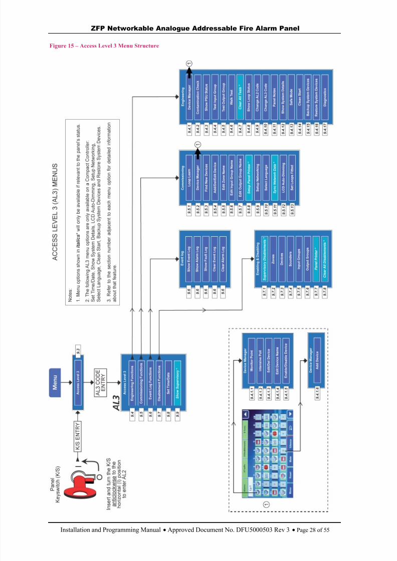
Figure 15 – Access Level 3 Menu Structure
8/10/2019 Zfp Instal and Program Manual Dfu5000503 Rev3!01!02 13
http://slidepdf.com/reader/full/zfp-instal-and-program-manual-dfu5000503-rev30102-13 29/55
ZFP Networkable Analogue Addressable Fire Alarm Panel
Installation and Programming Manual Approved Document No. DFU5000503 Rev 3 Page 29 of 55
9.2 Access Level 3 Menu Structure
Figure 15 shows the menu options available at access level 3.Three ‘ access levels’ are available at the panel; general user (access level 1), authorised user (access level 2)and authorised systems engineer (access level 3). This manual focuses on the programming functionsavailable at access level 3 only; access levels 1 & 2 are covered in the separate User Manual (DFU5000501),including information on how fire, fault, disablements and test conditions are reported and dealt with.
At access level 3, you can:
View any active fires, faults, disablements or test conditions that are displayed on the touchscreen. Gain entry to the panel’s access level 2 menu options. Gain access to a wide range of engineering functions including loop current, changing the entry codes
to access levels 2 and 3 from their factory default settings (see section 9.4). Gain access to a wide range of commissioning functions including auto loop learn, edit devices, set up
networking and Input/Output Group assignment (see section 9.5). Display, filter, print or reset the panel’s event and alarm history (see section 9.6). Enable or disable zones, sounders, Input Groups, Output Groups and loop devices (see section 9.7). Set the panel’s time and date (see section 9.8).
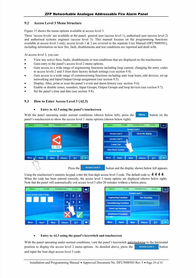
9.3 How to Enter Access Level 3 (AL3)
Entry to AL3 using the panel’s touchscreen
With the panel operating under normal conditions (shown below left), press the button on the panel’s touchscreen to show the access level 1 menu options (shown below right).
Press the button and the display shown below left appears.
Using the touchscreen’s numeric keypad, e nter the four-digit access level 3 code. The default code is: 4 4 4 4 .When the code has been entered correctly, the access level 3 menu options are displayed (shown below right).
Note that the panel will automatically exit access level 3 after 20 minutes without a button press.
Entry to AL3 u sing the panel’s keyswitch and touchscreen
With the panel operating under normal conditions, t urn the panel’s keyswitch anticlockwise to the horizontal position to display the access level 2 menu options. As detailed above, press the button
and input the four-digit access level 3 code.
8/10/2019 Zfp Instal and Program Manual Dfu5000503 Rev3!01!02 13
http://slidepdf.com/reader/full/zfp-instal-and-program-manual-dfu5000503-rev30102-13 30/55
ZFP Networkable Analogue Addressable Fire Alarm Panel
Installation and Programming Manual Approved Document No. DFU5000503 Rev 3 Page 30 of 55
9.4 Engineering Functions
The Engineering Functions menu is used to access the panel’s comprehensive test functions and displayimportant system status information.
At Access Level 3, press the button and the window shown below left appears.
Scroll down to view additional engineering menu options (shown below centre and right).
Engineering functions are listed in sections 9.4.1 to 9.4.17.
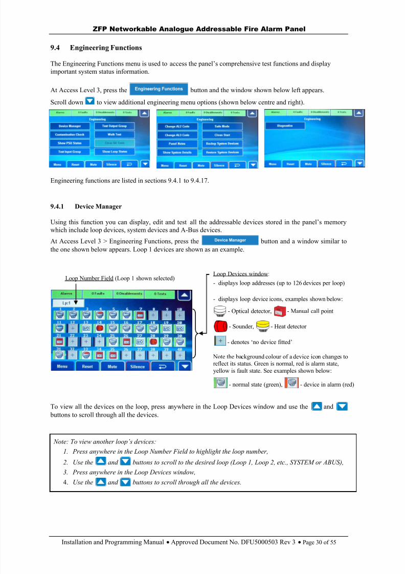
9.4.1 Device Manager
Using this function you can display, edit and test all the addressable devices stored in the panel’s memory which include loop devices, system devices and A-Bus devices.
At Access Level 3 > Engineering Functions, press the button and a window similar tothe one shown below appears. Loop 1 devices are shown as an example.
To view all the devices on the loop, press anywhere in the Loop Devices window and use the and buttons to scroll through all the devices.
Loop Number Field (Loop 1 shown selected)Loop Devices window:
- displays loop addresses (up to 126 devices per loop)
- displays loop device icons, examples shown below:- Optical detector, - Manual call point
- Sounder, - Heat detector
- denotes ‘no device fitted’
Note the background colour of a device icon changes toreflect its status. Green is normal, red is alarm state,yellow is fault state. See examples shown below:
- normal state (green), - device in alarm (red)
Note: To view another loop’s devices: 1. Press anywhere in the Loop Number Field to highlight the loop number,
2. Use the and buttons to scroll to the desired loop (Loop 1, Loop 2, etc., SYSTEM or ABUS),3. Press anywhere in the Loop Devices window,
4. Use the and buttons to scroll through all the devices.
8/10/2019 Zfp Instal and Program Manual Dfu5000503 Rev3!01!02 13
http://slidepdf.com/reader/full/zfp-instal-and-program-manual-dfu5000503-rev30102-13 31/55
ZFP Networkable Analogue Addressable Fire Alarm Panel
Installation and Programming Manual Approved Document No. DFU5000503 Rev 3 Page 31 of 55
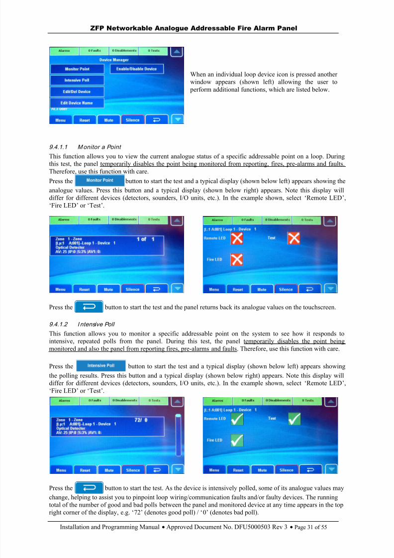
When an individual loop device icon is pressed anotherwindow appears (shown left) allowing the user to
perform additional functions, which are listed below.
9.4.1.1 M onitor a Point
This function allows you to view the current analogue status of a specific addressable point on a loop. Duringthis test, the panel temporarily disables the point being monitored from reporting, fires, pre-alarms and faults.Therefore, use this function with care.
Press the button to start the test and a typical display (shown below left) appears showing theanalogue values. Press this button and a typical display (shown below right) appears. Note this display willdiffer for different devices (detectors, sounders, I/O units, etc.). In the example shown, select ‘Remote LED ’,‘Fire LED ’ or ‘ Test ’.
Press the button to start the test and the panel returns back its analogue values on the touchscreen.
9.4.1.2 I ntensive Poll
This function allows you to monitor a specific addressable point on the system to see how it responds tointensive, repeated polls from the panel. During this test, the panel temporarily disables the point beingmonitored and also the panel from reporting fires, pre-alarms and faults. Therefore, use this function with care.
Press the button to start the test and a typical display (shown below left) appears showingthe polling results. Press this button and a typical display (shown below right) appears. Note this display willdiffer for different devices (detectors, sounders, I/O units, etc.). In the example shown, select ‘Remote LED ’,
‘Fire LED ’ or ‘ Test ’.
Press the button to start the test. As the device is intensively polled, some of its analogue values maychange, helping to assist you to pinpoint loop wiring/communication faults and/or faulty devices. The runningtotal of the number of good and bad polls between the panel and monitored device at any time appears in the topright corner of the display, e.g. ‘ 72’ (denotes good poll) / ‘ 0’ (denotes bad poll).
8/10/2019 Zfp Instal and Program Manual Dfu5000503 Rev3!01!02 13
http://slidepdf.com/reader/full/zfp-instal-and-program-manual-dfu5000503-rev30102-13 32/55
ZFP Networkable Analogue Addressable Fire Alarm Panel
Installation and Programming Manual Approved Document No. DFU5000503 Rev 3 Page 32 of 55
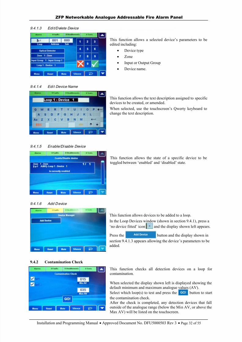
9.4.1.3 Edi t/Delete Device
This function allows a selected device’s parameters to beedited including:
Device type
Zone
Input or Output Group
Device name.
9.4.1.4 Edi t Device Name
This function allows the text description assigned to specificdevices to be created, or amended.When selected, use the touchscreen’s Qwerty keyboard tochange the text description.
9.4.1.5 Enable/Di sable Device
This function allows the state of a specific device to betoggled between ‘enabled’ and ‘disabled’ state.
9.4.1.6 Add D evice
This function allows devices to be added to a loop.In the Loop Devices window (shown in section 9.4.1), press a‘no device fitted ’ icon and the display shown left appears.
Press the button and the display shown in
section 9.4.1.3 appears allowing the device ’s parameters to beadded.
9.4.2 Contamination Check
This function checks all detection devices on a loop forcontamination.
When selected the display shown left is displayed showing thedefault minimum and maximum analogue values (AV).Select which loop(s) to test and press the button to start
the contamination check.After the check is completed, any detection devices that falloutside of the analogue range (below the Min AV, or above theMax AV) will be listed on the touchscreen.
8/10/2019 Zfp Instal and Program Manual Dfu5000503 Rev3!01!02 13
http://slidepdf.com/reader/full/zfp-instal-and-program-manual-dfu5000503-rev30102-13 33/55
ZFP Networkable Analogue Addressable Fire Alarm Panel
Installation and Programming Manual Approved Document No. DFU5000503 Rev 3 Page 33 of 55
9.4.3 Show PSU Status
This function allows you to view important information regarding the state of the panel’s PSU and its standby battery supply.
9.4.4 Test Input Group
This function allows you to perform tests on the panel’s Input Groups, e.g. simulate a manual call point inputto the panel to test the cause and effects.
At Access Level 3 > Engineering Functions, press the button and choose the Input Group to be tested from the list of available groups. In the next window choose the type of test to be performed on theInput Group including: NORM or TRIG test.
9.4.5 Test Output Group
This function allows you to perform tests on the panel’s Output Groups.
At Access Level 3 > Engineering Functions, press the button and choose the Output Group to be tested from the list of available groups. In the next window choose the type of test to be performed on theOutput Group including: OFF, ON and PULSED test.
9.4.6 Walk Test
This function allows you to put one or more of the system’s detection zones into walk test mode. When a zone isin walk test mode, any detector/manual call point triggered on that zone will turn on all of the sounders that aremapped to that zone for a brief period.At Access Level 3 > Engineering Functions, press the button and in the next window choose thetype of test to be performed, e.g. Sounders Enabled, Detectors Only, etc. After making a selection, press the
button and in the next window select the zone(s) you wish to put into walk test mode by pressing the zone button (s). This toggles the zone’s state between NORMAL operation and ON TEST.
After making a selection, press the button and confirm the changes by pressing the button.
Any zones in test can be viewed (and cancelled) by pressing yellow button on the top line of thetouchscreen. Any devices not tested will be listed on the touchscreen.
9.4.7 Clear All Tests
This function globally clears all active tests on the system. The button is greyed out when there are no tests onthe system.
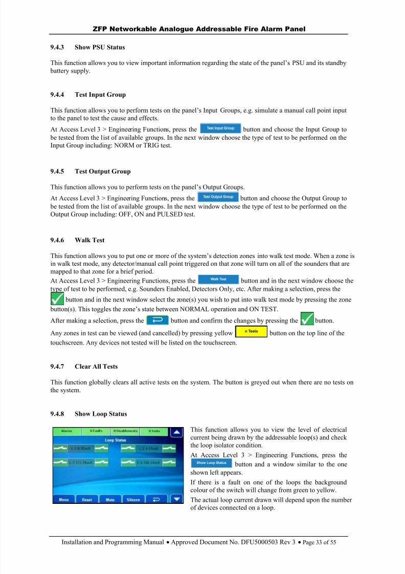
9.4.8 Show Loop Status
This function allows you to view the level of electricalcurrent being drawn by the addressable loop(s) and checkthe loop isolator condition.At Access Level 3 > Engineering Functions, press the
button and a window similar to the oneshown left appears.If there is a fault on one of the loops the backgroundcolour of the switch will change from green to yellow.
The actual loop current drawn will depend upon the numberof devices connected on a loop.
8/10/2019 Zfp Instal and Program Manual Dfu5000503 Rev3!01!02 13
http://slidepdf.com/reader/full/zfp-instal-and-program-manual-dfu5000503-rev30102-13 34/55
ZFP Networkable Analogue Addressable Fire Alarm Panel
Installation and Programming Manual Approved Document No. DFU5000503 Rev 3 Page 34 of 55
9.4.9 Change Access Level 2 (AL2) Code
This function is used to change the four- digit code needed to enter the panel’s access level 2 menu options.
At Access Level 3 > Engineering Functions, press the button and the window shown
below appears:Use the touchscreen’s numeric keypad buttons to enterthe new access level 2 code. After the fourth digit has
been entered, the panel will request you confirm thenew code by re-entering it.Enter the code again by pressing the buttons in the samesequence. If the two codes match, the panel will acceptthe code and you will be taken back to the engineeringmenus. If you type an incorrect confirmation code youwill be prompted to start the new code entry sequenceagain.
9.4.10 Change Access Level 3 (AL3) Code
This function is used to change the four- digit code needed to enter the panel’s acce ss level 3 menu options.
At Access Level 3 > Engineering Functions, press the button and the window shown below appears:
Use the touchscreen’s numeric keypad buttons to enterthe new access level 3 code. After the fourth digit has
been entered, the panel will request you confirm thenew code by re-entering it.Enter the code again by pressing the buttons in the samesequence. If the two codes match, the panel will accept
the code and you will be taken back to the engineeringmenus. If you type an incorrect confirmation code youwill be prompted to start the new code entry sequenceagain.
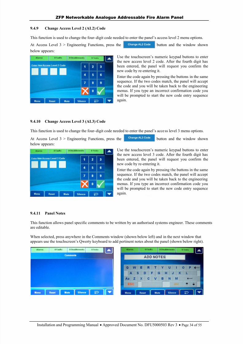
9.4.11 Panel Notes
This function allows panel specific comments to be written by an authorised systems engineer. These commentsare editable.
When selected, press anywhere in the Comments window (shown below left) and in the next window that
appears use the touchscreen’s Qwerty keyboard to add pertinent notes about the panel (shown below right).
8/10/2019 Zfp Instal and Program Manual Dfu5000503 Rev3!01!02 13
http://slidepdf.com/reader/full/zfp-instal-and-program-manual-dfu5000503-rev30102-13 35/55
ZFP Networkable Analogue Addressable Fire Alarm Panel
Installation and Programming Manual Approved Document No. DFU5000503 Rev 3 Page 35 of 55
9.4.12 Show System Details
This function lists system details including the panel’s firmware version number and internal SD memorycard information.
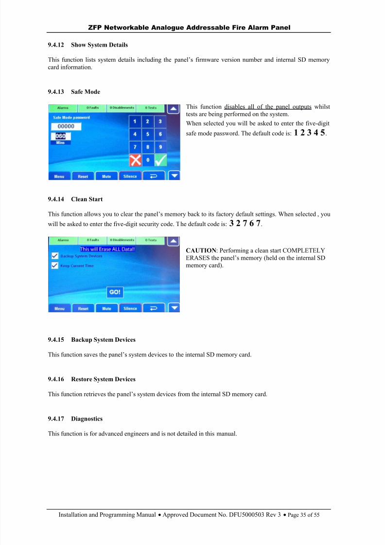
9.4.13 Safe Mode
This function disables all of the panel outputs whilsttests are being performed on the system.When selected you will be asked to enter the five-digit
safe mode password. The default code is: 1 2 3 4 5 .
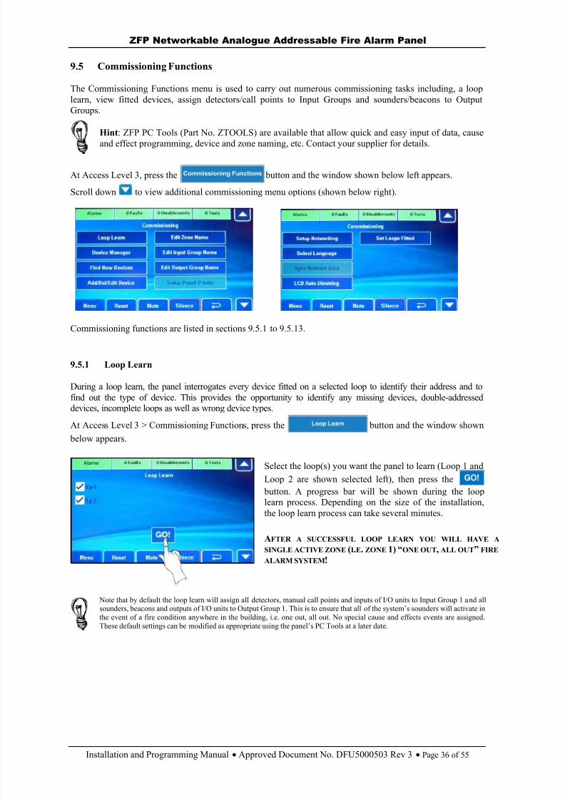
9.4.14 Clean Start
This function allows you to clear the panel’s memory back to its factory default settings. When selected , you
will be asked to enter the five-digit security code. The default code is: 3 2 7 6 7 .
CAUTION : Performing a clean start COMPLETELYERASES the panel’s memory (held on the internal SDmemory card).
9.4.15 Backup System Devices
This function saves the panel’s system devices to the internal SD memory card.
9.4.16 Restore System Devices
This function retrieves the p anel’s system devices from the internal SD memory card.
9.4.17 Diagnostics
This function is for advanced engineers and is not detailed in this manual.
8/10/2019 Zfp Instal and Program Manual Dfu5000503 Rev3!01!02 13
http://slidepdf.com/reader/full/zfp-instal-and-program-manual-dfu5000503-rev30102-13 36/55
ZFP Networkable Analogue Addressable Fire Alarm Panel
Installation and Programming Manual Approved Document No. DFU5000503 Rev 3 Page 36 of 55
9.5 Commissioning Functions
The Commissioning Functions menu is used to carry out numerous commissioning tasks including, a looplearn, view fitted devices, assign detectors/call points to Input Groups and sounders/beacons to OutputGroups.
Hint : ZFP PC Tools (Part No. ZTOOLS) are available that allow quick and easy input of data, causeand effect programming, device and zone naming, etc. Contact your supplier for details.
At Access Level 3, press the button and the window shown below left appears.
Scroll down to view additional commissioning menu options (shown below right).
Commissioning functions are listed in sections 9.5.1 to 9.5.13.
9.5.1 Loop Learn
During a loop learn, the panel interrogates every device fitted on a selected loop to identify their address and tofind out the type of device. This provides the opportunity to identify any missing devices, double-addresseddevices, incomplete loops as well as wrong device types.
At Access Level 3 > Commissioning Functions, press the button and the window shown below appears.
Select the loop(s) you want the panel to learn (Loop 1 andLoop 2 are shown selected left), then press the
button. A progress bar will be shown during the looplearn process. Depending on the size of the installation,the loop learn process can take several minutes.
AFTER A SUCCESSFUL LOOP LEARN YOU WILL HAVE ASINGLE ACTIVE ZONE (I.E . ZONE 1) “ ONE OUT , ALL OUT ” FIRE
ALARM SYSTEM !
Note that by default the loop learn will assign all detectors, manual call points and inputs of I/O units to Input Group 1 and allsounders, beacons and outputs of I/O units to Output Group 1. Th is is to ensure that all of the system’s sounders will activate inthe event of a fire condition anywhere in the building, i.e. one out, all out. No special cause and effects events are assigned.These default settings can be modified as appropriate using the panel’s PC Tools at a later date.
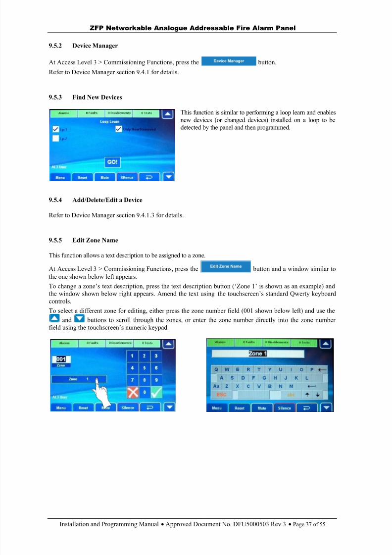
8/10/2019 Zfp Instal and Program Manual Dfu5000503 Rev3!01!02 13
http://slidepdf.com/reader/full/zfp-instal-and-program-manual-dfu5000503-rev30102-13 37/55
ZFP Networkable Analogue Addressable Fire Alarm Panel
Installation and Programming Manual Approved Document No. DFU5000503 Rev 3 Page 37 of 55
9.5.2 Device Manager
At Access Level 3 > Commissioning Functions, press the button.
Refer to Device Manager section 9.4.1 for details.
9.5.3 Find New Devices
This function is similar to performing a loop learn and enablesnew devices (or changed devices) installed on a loop to bedetected by the panel and then programmed.
9.5.4 Add/Delete/Edit a Device
Refer to Device Manager section 9.4.1.3 for details.
9.5.5 Edit Zone Name
This function allows a text description to be assigned to a zone.
At Access Level 3 > Commissioning Functions, press the button and a window similar tothe one shown below left appears.To change a zone’s text description, press the text description button (‘Zone 1’ is shown as an example) andthe window shown below right appears. Amend the text using the touchscreen’s standard Qwerty keyboardcontrols.To select a different zone for editing, either press the zone number field (001 shown below left) and use the
and buttons to scroll through the zones, or enter the zone number directly into the zone numberfield using the touchscreen’s numeric keypad.
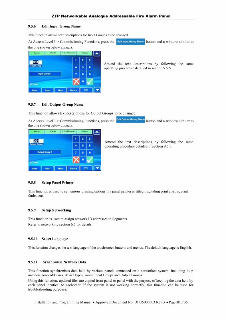
8/10/2019 Zfp Instal and Program Manual Dfu5000503 Rev3!01!02 13
http://slidepdf.com/reader/full/zfp-instal-and-program-manual-dfu5000503-rev30102-13 38/55
ZFP Networkable Analogue Addressable Fire Alarm Panel
Installation and Programming Manual Approved Document No. DFU5000503 Rev 3 Page 38 of 55
9.5.6 Edit Input Group Name
This function allows text descriptions for Input Groups to be changed.
At Access Level 3 > Commissioning Functions, press the button and a window similar to
the one shown below appears.
Amend the text descriptions by following the sameoperating procedure detailed in section 9.5.5.
9.5.7 Edit Output Group Name
This function allows text descriptions for Output Groups to be changed.
At Access Level 3 > Commissioning Functions, press the button and a window similar tothe one shown below appears.
Amend the text descriptions by following the sameoperating procedure detailed in section 9.5.5.
9.5.8 Setup Panel Printer
This function is used to set various printing options if a panel printer is fitted, including print alarms, printfaults, etc.
9.5.9 Setup Networking
This function is used to assign network ID addresses to Segments.
Refer to networking section 6.5 for details.
9.5.10 Select Language
This function changes the text language of the touchscreen buttons and menus. The default language is English.
9.5.11 Synchronise Network Data
This function synchronises data held by various panels connected on a networked system, including loopnumbers, loop addresses, device types, zones, Input Groups and Output Groups.
Using this function, updated files are copied from panel to panel with the purpose of keeping the data held byeach panel identical to eachother. If the system is not working correctly, this function can be used fortroubleshooting purposes.
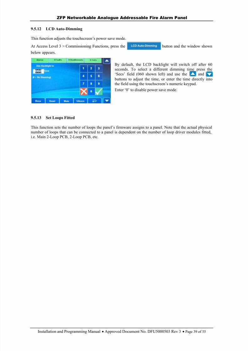
8/10/2019 Zfp Instal and Program Manual Dfu5000503 Rev3!01!02 13
http://slidepdf.com/reader/full/zfp-instal-and-program-manual-dfu5000503-rev30102-13 39/55
ZFP Networkable Analogue Addressable Fire Alarm Panel
Installation and Programming Manual Approved Document No. DFU5000503 Rev 3 Page 39 of 55
9.5.12 LCD Auto-Dimming
This function adjusts the touchscreen’s power save mode.
At Access Level 3 > Commissioning Functions, press the button and the window shown
below appears.
By default, the LCD backlight will switch off after 60seconds. To select a different dimming time press the‘Secs’ field (060 shown left) and use the and
buttons to adjust the time, or enter the time directly intothe field using the touchscreen’s numeric keypad.Enter ‘0’ to disable power save mode.
9.5.13 Set Loops Fitted
This function sets the number of loops the panel’s firmware assigns to a panel. Note that the actual physicalnumber of loops that can be connected to a panel is dependent on the number of loop driver modules fitted,i.e. Main 2-Loop PCB, 2-Loop PCB, etc.
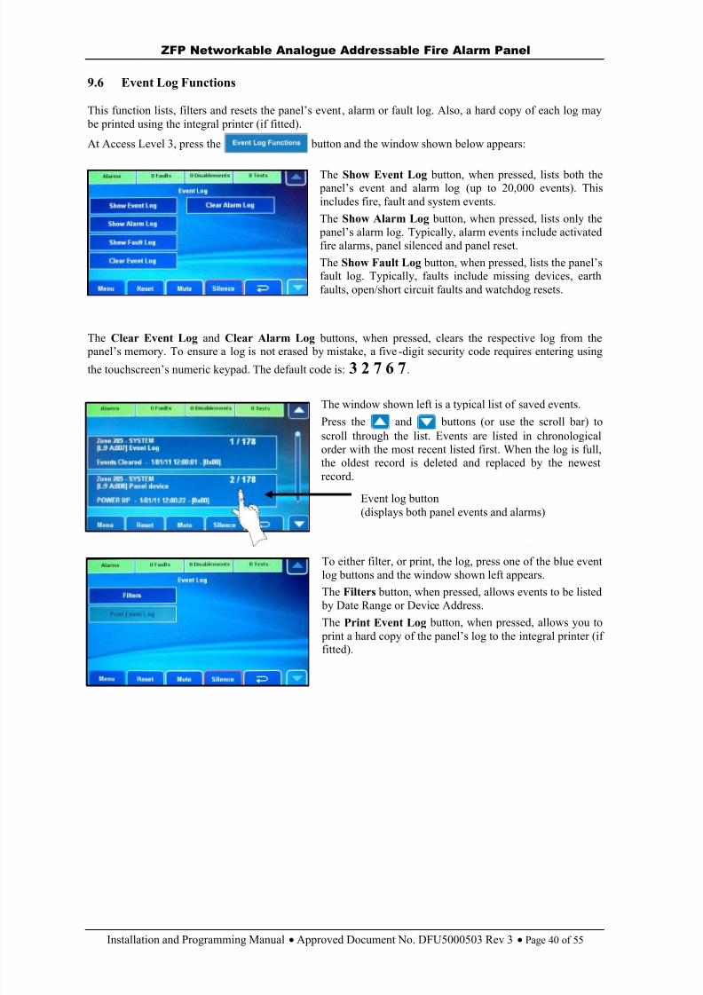
8/10/2019 Zfp Instal and Program Manual Dfu5000503 Rev3!01!02 13
http://slidepdf.com/reader/full/zfp-instal-and-program-manual-dfu5000503-rev30102-13 40/55
ZFP Networkable Analogue Addressable Fire Alarm Panel
Installation and Programming Manual Approved Document No. DFU5000503 Rev 3 Page 40 of 55
9.6 Event Log Functions
This function lists, filters and resets the panel’s event , alarm or fault log. Also, a hard copy of each log may be printed using the integral printer (if fitted).
At Access Level 3, press the button and the window shown below appears:
The Show Event Log button, when pressed, lists both the panel’s event and alarm log (up to 20,000 events). Thisincludes fire, fault and system events.The Show Alarm Log button, when pressed, lists only the
panel’s alarm log. Typically, alarm events include activatedfire alarms, panel silenced and panel reset.The Show Fault Log button, when pressed, lists the panel’sfault log. Typically, faults include missing devices, earthfaults, open/short circuit faults and watchdog resets.
The Clear Event Log and Clear Alarm Log buttons, when pressed, clears the respective log from the panel’s memory. To ensure a log is not erased by mistake, a five -digit security code requires entering usingthe to uchscreen’s numeric keypad. The default code is: 3 2 7 6 7 .
The window shown left is a typical list of saved events.
Press the and buttons (or use the scroll bar) toscroll through the list. Events are listed in chronologicalorder with the most recent listed first. When the log is full,the oldest record is deleted and replaced by the newestrecord.
To either filter, or print, the log, press one of the blue eventlog buttons and the window shown left appears.The Filters button, when pressed, allows events to be listed
by Date Range or Device Address.The Print Event Log button, when pressed, allows you to
print a hard copy of the panel’s log to the integral printer (iffitted).
Event log button(displays both panel events and alarms)
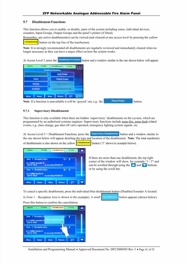
8/10/2019 Zfp Instal and Program Manual Dfu5000503 Rev3!01!02 13
http://slidepdf.com/reader/full/zfp-instal-and-program-manual-dfu5000503-rev30102-13 41/55
ZFP Networkable Analogue Addressable Fire Alarm Panel
Installation and Programming Manual Approved Document No. DFU5000503 Rev 3 Page 41 of 55
9.7 Disablement Functions
This function allows you to enable, or disable, parts of the system including zones, individual devices,sounders, Input Groups, Output Groups and the panel’s printer (if fitted). Remember, any active disablement(s) can be viewed (and cleared) at any access level by pressing the yellow
button on the top line of the touchscreen.
Note : It is strongly recommended all disablements are regularly reviewed and immediately cleared when nolonger necessary as they can have a major effect on how the system works.
At Access Level 3, press the button and a window similar to the one shown below will appear.
Note : If a function is unavailable it will be ‘greyed’ out, e.g. the button.
9.7.1 Supervisory Disablements
This function is only available when there are hidden ‘supervisory’ disablements on the sys tem, which are programmed by an authorised systems engineer. Supervisory functions include none-fire, none-fault relatedevents, e.g. class change, gas shut off valve operated, emergency lighting system signals, etc.
At Access Level 3 > Disablement Functions, press the button and a window similar to
the one shown below will appear detailing the type and location of the disablement. Note : The total number(n)of disablements is also shown on the yellow button (‘3’ shown in example below).
If there are more than one disablement, the top rightcorner of the window will show, for example “1 / 3” andcan be scrolled through using the and buttons,or by using the scroll bar.
To cancel a specific disablement, press the individual blue disablement button (Disabled Sounder A located
in Zone 1 – Reception Area is shown in the example). A small button appears (shown below).
Press this button to confirm the cancellation.
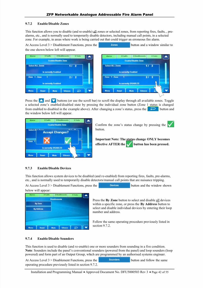
8/10/2019 Zfp Instal and Program Manual Dfu5000503 Rev3!01!02 13
http://slidepdf.com/reader/full/zfp-instal-and-program-manual-dfu5000503-rev30102-13 42/55
ZFP Networkable Analogue Addressable Fire Alarm Panel
Installation and Programming Manual Approved Document No. DFU5000503 Rev 3 Page 42 of 55
9.7.2 Enable/Disable Zones
This function allows you to disable (and re-enable) all zones or selected zones, from reporting fires, faults, , pre-alarms, etc., and is normally used to temporarily disable detectors, including manual call points, in a selectedzone. For example, in areas where work is being carried out that could trigger an erroneous fire alarm.
At Access Level 3 > Disablement Functions, press the button and a window similar to
the one shown below left will appear.
Press the and buttons (or use the scroll bar) to scroll the display through all available zones. Togglea selected zone’s enabled/disabled state by pressing the individual zone button (Zone 1 status is changedfrom enabled to disabled in the example above). After changing a zone’s status , press the button andthe window below left will appear.
Confirm the zone’s status change by pressing the button.
Important Note: The status change ONLY becomes
effective AFTER the button has been pressed.
9.7.3 Enable/Disable Devices
This function allows system devices to be disabled (and re-enabled) from reporting fires, faults, pre-alarms,etc., and is normally used to temporarily disable detectors/manual call points that are nuisance tripping.
At Access Level 3 > Disablement Functions, press the button and the window shown below will appear:
Press the By Zone button to select and disable all deviceswithin a specific zone, or press the By Address button toselect and disable individual devices by entering their loopnumber and address.
Follow the same operating procedure previously listed insection 9.7.2.
9.7.4 Enable/Disable Sounders
This function is used to disable (and re-enable) one or more sounders from sounding in a fire condition.Note : Sounders include the panel’s co nventional sounders (powered from the panel) and loop sounders (loop
powered) and form part of an Output Group, which are programmed by an authorised systems engineer.
At Access Level 3 > Disablement Functions, press the button and follow the sameoperating procedure previously listed in section 9.7.2.
8/10/2019 Zfp Instal and Program Manual Dfu5000503 Rev3!01!02 13
http://slidepdf.com/reader/full/zfp-instal-and-program-manual-dfu5000503-rev30102-13 43/55
ZFP Networkable Analogue Addressable Fire Alarm Panel
Installation and Programming Manual Approved Document No. DFU5000503 Rev 3 Page 43 of 55
9.7.5 Enable/Disable Input Groups
This function is used to disable (and re-enable) one or more Input Groups from activating. Note : InputGroups comprise of detectors, MCPs, inputs of I/O units, keyswitches and other input devices and are
programmed by an authorised systems engineer.
At Access Level 3 > Disablement Functions, press the button and follow the same
operating procedure previously listed in section 9.7.2.
9.7.6 Enable/Disable Output Groups
This function is used to disable (and re-enable) one or more Output Groups from activating. Note : OutputGroups comprise of loop and conventional panel sounders, beacons, outputs of I/O units, relays and otheroutput devices and are programmed by an authorised systems engineer. This function is typically used todisable, for example, auto-diallers and other ancillary equipment from activating during routine maintenance.
At Access Level 3 > Disablement Functions, press the button and follow the sameoperating procedure previously listed in section 9.7.2.
9.7.7 Enable/Disable Panel Printer
This function is used to disable (and re-enable) the panel printer (if fitted).
At Access Level 3 > Disablement Functions, press the button and follow the sameoperating procedure previously listed in section 9.7.2.
9.7.8 Clear All Disablements
This function is used to globally clear all current disablements on the system.
At Access Level 3 > Disablement Functions, press the button and follow the sameoperating procedure previously listed in section 9.7.2.
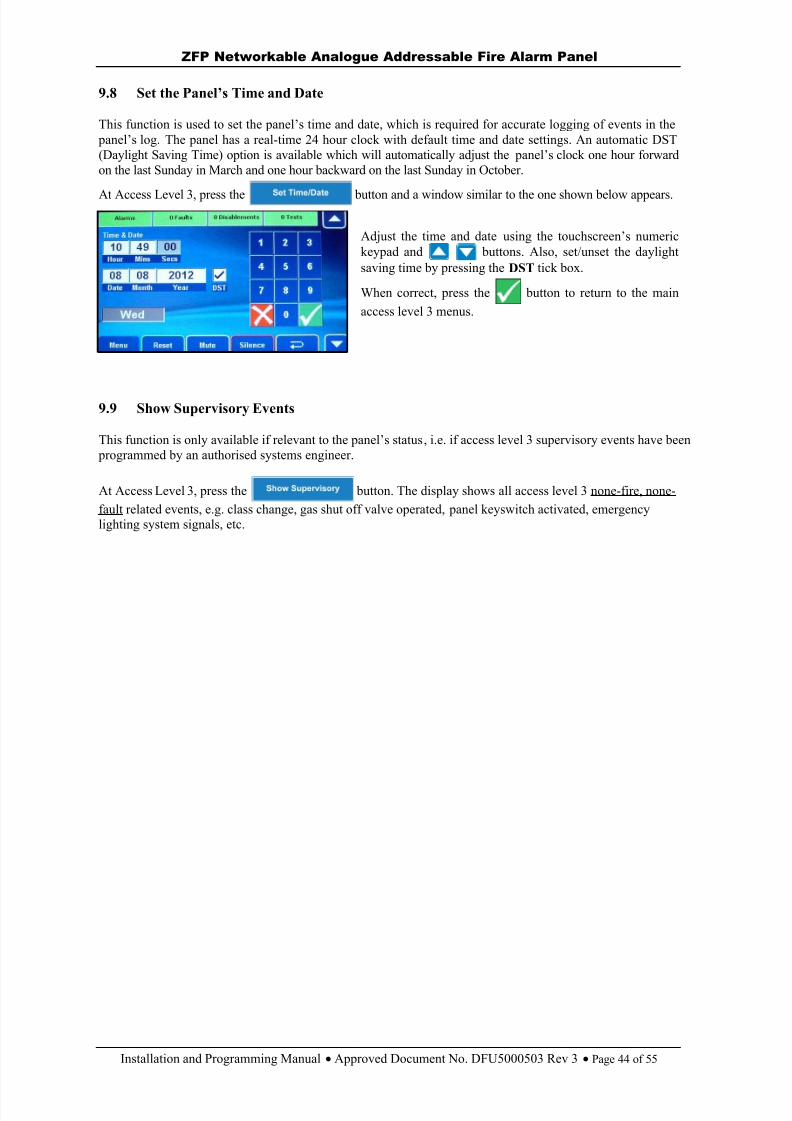
8/10/2019 Zfp Instal and Program Manual Dfu5000503 Rev3!01!02 13
http://slidepdf.com/reader/full/zfp-instal-and-program-manual-dfu5000503-rev30102-13 44/55
ZFP Networkable Analogue Addressable Fire Alarm Panel
Installation and Programming Manual Approved Document No. DFU5000503 Rev 3 Page 44 of 55
9.8 Set the Panel’s Time and Date
This function is used to set the panel’s time and date, which is required for accurate logging of events in the panel’s log. The panel has a real-time 24 hour clock with default time and date settings. An automatic DST(Daylight Saving Time) option is available which will automatically adjust the panel’s clock one hour forwardon the last Sunday in March and one hour backward on the last Sunday in October.
At Access Level 3, press the button and a window similar to the one shown below appears.
Adjust the time and date using the touchscreen’s numerickeypad and buttons. Also, set/unset the daylightsaving time by pressing the DST tick box.
When correct, press the button to return to the mainaccess level 3 menus.
9.9 Show Supervisory Events
This function is only available if relevant to the panel’s status, i.e. if access level 3 supervisory events have been programmed by an authorised systems engineer.
At Access Level 3, press the button. The display shows all access level 3 none-fire, none-fault related events, e.g. class change, gas shut off valve operated, panel keyswitch activated, emergencylighting system signals, etc.
8/10/2019 Zfp Instal and Program Manual Dfu5000503 Rev3!01!02 13
http://slidepdf.com/reader/full/zfp-instal-and-program-manual-dfu5000503-rev30102-13 45/55
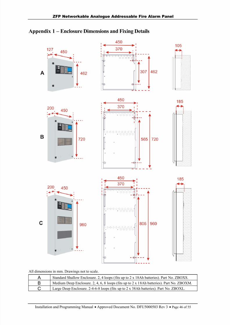
8/10/2019 Zfp Instal and Program Manual Dfu5000503 Rev3!01!02 13
http://slidepdf.com/reader/full/zfp-instal-and-program-manual-dfu5000503-rev30102-13 46/55
ZFP Networkable Analogue Addressable Fire Alarm Panel
Installation and Programming Manual Approved Document No. DFU5000503 Rev 3 Page 46 of 55
Appendix 1 – Enclosure Dimensions and Fixing Details
All dimensions in mm. Drawings not to scale.
A Standard Shallow Enclosure. 2, 4 loops (fits up to 2 x 18Ah batteries). Part No. ZBOXS.
B Medium Deep Enclosure. 2, 4, 6, 8 loops (fits up to 2 x 18Ah batteries). Part No. ZBOXM.C Large Deep Enclosure. 2-4-6-8 loops (fits up to 2 x 38Ah batteries). Part No. ZBOXL.
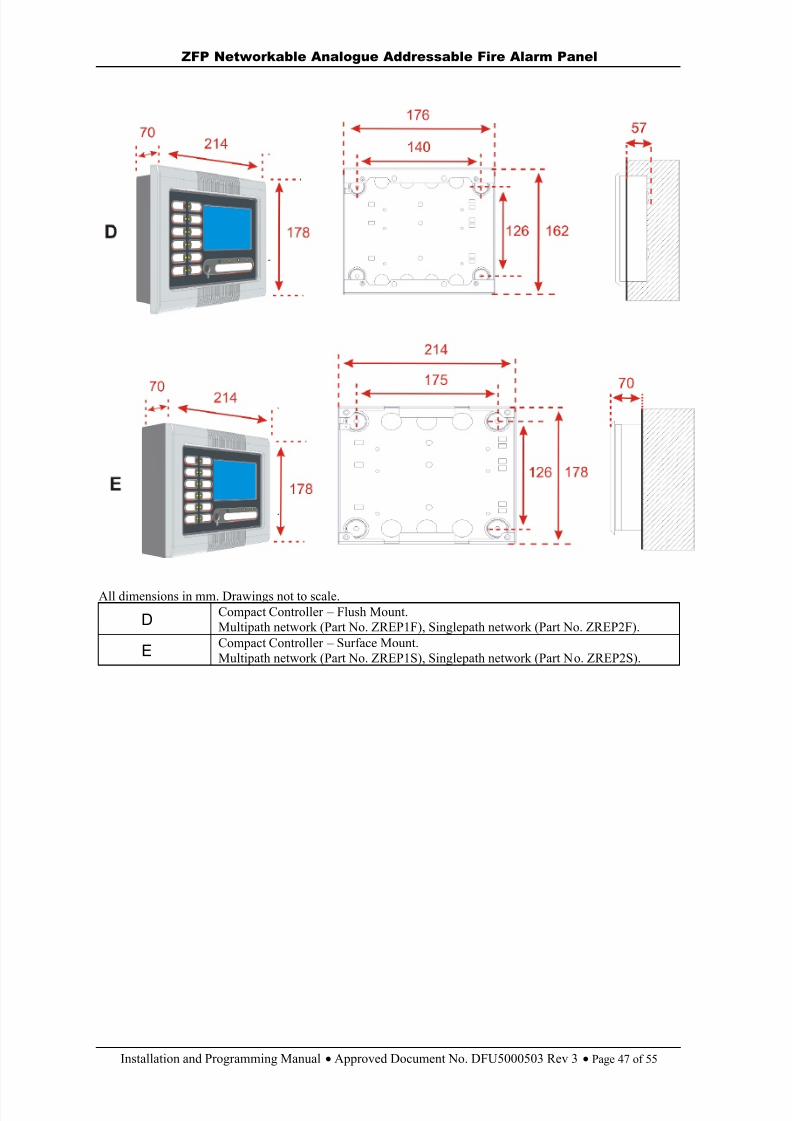
8/10/2019 Zfp Instal and Program Manual Dfu5000503 Rev3!01!02 13
http://slidepdf.com/reader/full/zfp-instal-and-program-manual-dfu5000503-rev30102-13 47/55
ZFP Networkable Analogue Addressable Fire Alarm Panel
Installation and Programming Manual Approved Document No. DFU5000503 Rev 3 Page 47 of 55
All dimensions in mm. Drawings not to scale.
D Compact Controller – Flush Mount.Multipath network (Part No. ZREP1F), Singlepath network (Part No. ZREP2F).
E Compact Controller – Surface Mount.Multipath network (Part No. ZREP1S), Singlepath network (Part No. ZREP2S).
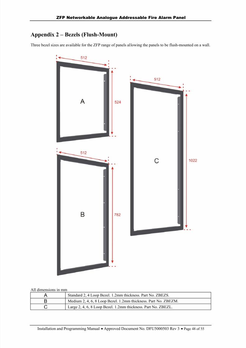
8/10/2019 Zfp Instal and Program Manual Dfu5000503 Rev3!01!02 13
http://slidepdf.com/reader/full/zfp-instal-and-program-manual-dfu5000503-rev30102-13 48/55
ZFP Networkable Analogue Addressable Fire Alarm Panel
Installation and Programming Manual Approved Document No. DFU5000503 Rev 3 Page 48 of 55
Appendix 2 – Bezels (Flush-Mount)
Three bezel sizes are available for the ZFP range of panels allowing the panels to be flush-mounted on a wall.
All dimensions in mm A Standard 2, 4 Loop Bezel. 1.2mm thickness. Part No. ZBEZS.
B Medium 2, 4, 6, 8 Loop Bezel. 1.2mm thickness. Part No. ZBEZM.
C Large 2, 4, 6, 8 Loop Bezel. 1.2mm thickness. Part No. ZBEZL.
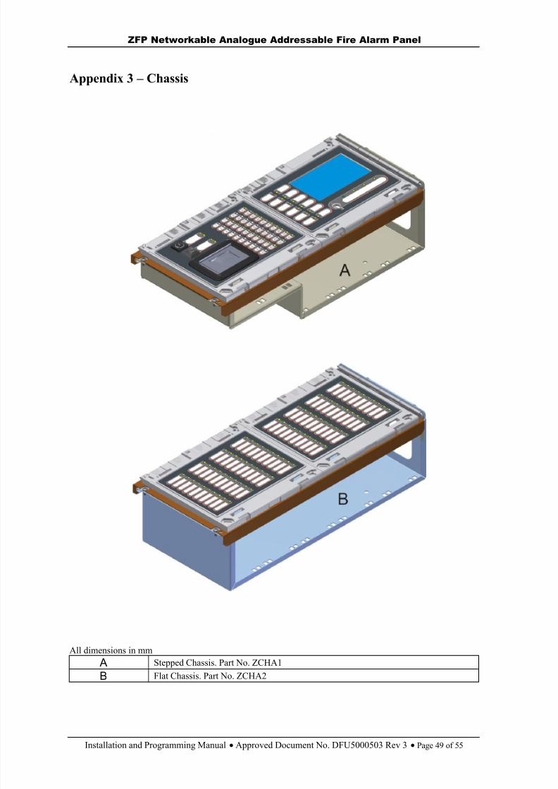
8/10/2019 Zfp Instal and Program Manual Dfu5000503 Rev3!01!02 13
http://slidepdf.com/reader/full/zfp-instal-and-program-manual-dfu5000503-rev30102-13 49/55
ZFP Networkable Analogue Addressable Fire Alarm Panel
Installation and Programming Manual Approved Document No. DFU5000503 Rev 3 Page 49 of 55
Appendix 3 – Chassis
All dimensions in mm A Stepped Chassis. Part No. ZCHA1
B Flat Chassis. Part No. ZCHA2

8/10/2019 Zfp Instal and Program Manual Dfu5000503 Rev3!01!02 13
http://slidepdf.com/reader/full/zfp-instal-and-program-manual-dfu5000503-rev30102-13 50/55
ZFP Networkable Analogue Addressable Fire Alarm Panel
Installation and Programming Manual Approved Document No. DFU5000503 Rev 3 Page 50 of 55
Appendix 4 – List of Modules
Control/Display modulec/w 4.3” touchscreen,keyswitch, 16 LEDs- Part No. Z41
20 zone indicatormodule c/w name slots- Part No. Z44
20 zone indicatormodule c/w name slots,5 switches, 10 bi-colourfunction LEDs- Part No. Z45
20 zone indicatormodule c/w name slots,
printer, 2 switches, 4 bi-colour function LEDs- Part No. Z46
40 zone indicatormodule c/w name slots- Part No. Z47
40 zone indicatormodule c/w 5 switches,10 bi-colour functionLEDs
- Part No. Z48
40 zone indicatormodule c/w printer, 2switches, 4 bi-colourfunction LEDs- Part No. Z49
100 zone indicatormodule (numbered 1-100)- Part No. Z50/1-100100 zone indicatormodule (numbered 101-200)- Part No. Z50/101-200
Printer module- Part No. Z51
Blank module- Part No. ZBLANK

8/10/2019 Zfp Instal and Program Manual Dfu5000503 Rev3!01!02 13
http://slidepdf.com/reader/full/zfp-instal-and-program-manual-dfu5000503-rev30102-13 51/55
ZFP Networkable Analogue Addressable Fire Alarm Panel
Installation and Programming Manual Approved Document No. DFU5000503 Rev 3 Page 51 of 55
Appendix 5 – Standby Battery Calculation Guide
The standby time of the fire alarm panel, after the Mains has failed, depends on the quiescent and alarmloading of the panel, and the capacity of the batteries. To determine the capacity of batteries required for anygiven stand-by period, the following formula should be used:
The multiplier 1.25 is present to account for lost capacity over the life of the batteries.
H = Number of hours standby required (e.g. 24Hrs).
P = The quiescent current of the panel. 4 loop panel = 120mA (0.12A); 8 loop panel = 190mA (0.19A). This value is with the Mains failed, beeper silenced and the Supply Present and General Fault indicators lit. Ifthere are other quiescent drains on the panel then these must be added in.
Z = The total quiescent current of all loop devicesAs a guideline, the total quiescent current of all addressable devices for a 4 loop panel and 8 loop panel, with80 devices per loop, is typically 204mA (0.204A) and 408mA (0.408A) respectively.To obtain accurate values consult the device manufacturers’ own specifications.
A = The total alarm current of panel sounders and activated relays. Conventional sounder load is 250mA(0.25A), a panel relay consumes 20mA (0.02A) when activated.
L = The total alarm current of loop devices per loop (sounders, beacons etc.) is typically 150mA (0.15A).
T = The amount of time in hours required for the alarm (e.g. half an hour, 0.5Hrs).
Example calculation for a 4 loop panel:The 4 loop panel has 80 devices per loop (320 in total) with a total quiescent current of 204mA (0.204A) forall loop devices. In alarm, the alarm current per loop is 0.15A (0.6A in total), 2 panel relays activated at(0.02A each), and a conventional sounder load of 0.25A. The required standby time is 24 hours, and therequired alarm time is 0.5 hours.-----------------------------------------------------------------------------------------------------------------------------------Calculate the alarm capacity: = T x (A + L x 1.5)
T = 0.5Hrs; A = 0.25 + 2 x 0.02 = 0.29A; L = 0.15 x 4 = 0.6A
Therefore, the alarm capacity is: = 0.5 x (0.29 + 0.6 x 1.5)= 0.668Ah
----------------------------------------------------------------------------------------------------------------------------- ------
Calculate the quiescent capacity: = H x (P + Z x 1.5)
H = 24Hrs; P = 0.12A; Z = 0.204A
Therefore, the quiescent capacity is: = 24 x (0.12 + 0.204 x 1.5)= 11.664Ah
----------------------------------------------------------------------------------------------------------------------------- ------Total Battery Capacity: = 1.25 x (0.668 + 11.664)
= 15.42Ah
Battery Capacity in Ah = 1.25 x [(T x (A + L x 1.5) + H x (P + Z x 1.5)]
Quiescent CapacityAlarm Capacity
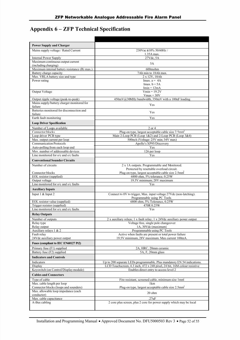
8/10/2019 Zfp Instal and Program Manual Dfu5000503 Rev3!01!02 13
http://slidepdf.com/reader/full/zfp-instal-and-program-manual-dfu5000503-rev30102-13 52/55
ZFP Networkable Analogue Addressable Fire Alarm Panel
Installation and Programming Manual Approved Document No. DFU5000503 Rev 3 Page 52 of 55
Appendix 6 – ZFP Technical Specification
STANDARD 2 / 4 LOOP VERSIONPower Supply and Charger
Mains supply voltage / Rated Current 230Vac ±10% 50/60Hz /1.35A max.
Internal Power Supply 27Vdc, 5AMaximum continuous output current(including charging) 5A
Maximum internal battery resistance (Ri max.) 600mohmBattery charge capacity 7Ah min to 18Ah max.Max. VRLA battery size and type 2 x 12V, 18AhPower rating Imax. a = 4A
Imax. b = 5AImin = 12mA
Output Voltage Vmin = 19.2VVmax = 30V
Output ripple voltage (peak-to-peak) 450mV@30MHz bandwidth, 350mV with a 100nF loadingMains supply/battery charger monitored forfailure Yes Batteries monitored for disconnection andfailure Yes
Earth fault monitoring Yes Loop Driver Specification
Number of Loops available 2 or 4Connector blocks Plug-on type, largest acceptable cable size 2.5mm 2 Loop driver PCB type Main 2-Loop PCB (Loop 1&2) and 2-Loop PCB (Loop 3&4)Max. output current per loop 500mA (Voltage: 25V min; 34V max) Communication Protocols Apollo ’s XP95/DiscoveryAuto-polling from each loop end Yes Max. number of addressable devices 126 per loop Line monitored for o/c and s/c faults Yes
Conventional Sounder Circuits
Number of circuits 2 x 1A outputs. Programmable and Monitored.Protected by resettable overload circuit.
Connector blocks Plug-on type, largest acceptable cable size 2.5mmEOL resistor (supplied) 6800 ohm, 5% tolerance, 0.25WOutput voltage 19.5V minimum; 28V maximumLine monitored for o/c and s/c faults Yes
Auxiliary Inputs
Input 1 & Input 2 Connect to 0V to trigger, Max. input voltage 27Vdc (non-latching).Programmable using PC Tools.
EOL resistor value (supplied) 6800 ohm, 5% Tolerance, 0.25WTrigger resistor (supplied) 470R 0.25WLine monitored for o/c and s/c faults Yes
Relay Outputs
Number of outputs 2 x auxiliary relays; 1 x fault relay; 1 x 24Vdc auxiliary power outputRelay type Voltage free, single pole changeoverRelay output 1A, 30Vdc (maximum)Auxiliary relays 1 & 2 Programmable using PC ToolsFault relay Active when faults are present or total power failure
24Vdc auxiliary power output 19.5V minimum, 28V maximum. Max current 100mA.Fuses (compliant to IEC EN60127 Pt2)
Primary fuse (F1) supplied 2A, HRC, 20mm ceramic Battery fuse (F2) supplied 5A, F, 20mm glass
Indicators and Controls
Indicators Up to 200 separate LEDs programmable. Plus mandatory EN 54 indications.Display LCD Touchscreen, 4.3 inch, 472 x 248 pixel, 24 bit, 16M colour resistiveKeyswitch (on Control/Display module) Enables direct entry to access level 2
Cables and Connectors
Type of cable Fire resistant, screened cable, minimum size 1mmMax. cable length per loop 1kmConnector blocks (loops and sounders) Plug-on type, largest acceptable cable size 2.5mm 2 Max. allowable loop impedance (eachconductor) 20 ohm
Max. cable capacitance .27uFA-Bus cabling 2 core plus screen, plus 2 core for power supply which may be local
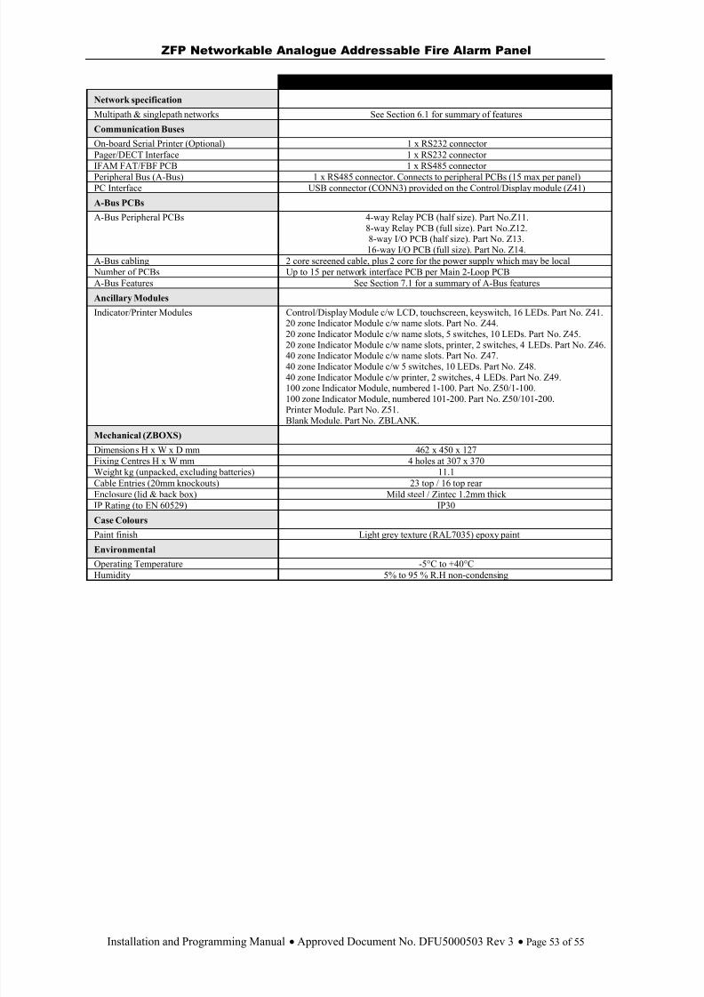
8/10/2019 Zfp Instal and Program Manual Dfu5000503 Rev3!01!02 13
http://slidepdf.com/reader/full/zfp-instal-and-program-manual-dfu5000503-rev30102-13 53/55
ZFP Networkable Analogue Addressable Fire Alarm Panel
Installation and Programming Manual Approved Document No. DFU5000503 Rev 3 Page 53 of 55
STANDARD 2 / 4 LOOP VERSIONNetwork specification
Multipath & singlepath networks See Section 6.1 for summary of features
Communication Buses
On-board Serial Printer (Optional) 1 x RS232 connectorPager/DECT Interface 1 x RS232 connectorIFAM FAT/FBF PCB 1 x RS485 connectorPeripheral Bus (A-Bus) 1 x RS485 connector. Connects to peripheral PCBs (15 max per panel)PC Interface USB connector (CONN3) provided on the Control/Display module (Z41)
A-Bus PCBs
A-Bus Peripheral PCBs 4-way Relay PCB (half size). Part No.Z11.8-way Relay PCB (full size). Part No.Z12.8-way I/O PCB (half size). Part No. Z13.16-way I/O PCB (full size). Part No. Z14.
A-Bus cabling 2 core screened cable, plus 2 core for the power supply which may be local Number of PCBs Up to 15 per network interface PCB per Main 2-Loop PCBA-Bus Features See Section 7.1 for a summary of A-Bus features
Ancillary Modules
Indicator/Printer Modules Control/Display Module c/w LCD, touchscreen, keyswitch, 16 LEDs. Part No. Z41.20 zone Indicator Module c/w name slots. Part No. Z44.20 zone Indicator Module c/w name slots, 5 switches, 10 LEDs. Part No. Z45.
20 zone Indicator Module c/w name slots, printer, 2 switches, 4 LEDs. Part No. Z46.40 zone Indicator Module c/w name slots. Part No. Z47.40 zone Indicator Module c/w 5 switches, 10 LEDs. Part No. Z48.40 zone Indicator Module c/w printer, 2 switches, 4 LEDs. Part No. Z49.100 zone Indicator Module, numbered 1-100. Part No. Z50/1-100.100 zone Indicator Module, numbered 101-200. Part No. Z50/101-200.Printer Module. Part No. Z51.Blank Module. Part No. ZBLANK.
Mechanical (ZBOXS)
Dimensions H x W x D mm 462 x 450 x 127 Fixing Centres H x W mm 4 holes at 307 x 370Weight kg (unpacked, excluding batteries) 11.1 Cable Entries (20mm knockouts) 23 top / 16 top rearEnclosure (lid & back box) Mild steel / Zintec 1.2mm thickIP Rating (to EN 60529) IP30
Case ColoursPaint finish Light grey texture (RAL7035) epoxy paint
Environmental
Operating Temperature -5°C to +40°C Humidity 5% to 95 % R.H non-condensing

8/10/2019 Zfp Instal and Program Manual Dfu5000503 Rev3!01!02 13
http://slidepdf.com/reader/full/zfp-instal-and-program-manual-dfu5000503-rev30102-13 54/55
ZFP Networkable Analogue Addressable Fire Alarm Panel
Installation and Programming Manual Approved Document No. DFU5000503 Rev 3 Page 54 of 55
Appendix 7 – Glossary of Terms
Addressable System : A fire alarm and detection system that contains addressable control devices.
AL1 : Access Level 1 (for general users).
AL2 : Access Level 2 (for authorised users).
AL3 : Access Level 3 (for authorised systems engineers).
BS EN 54-1 : Fire Detection and Fire Alarm Systems
BS EN 54-2 : Control and Indicating Equipment
BS EN 54-4 : Power Supply Equipment
Compact Controller : A fire alarm control panel with no field device loops connected that can be used tocontrol certain functions of the system. A Compact Controller is a node when connected as part of a network.
DST : Daylight Saving Time.
EOL : end-of-line resistor, value 6k8, ½ watt.
Input Device : Any device that can signal an event such as ‘fire’, ‘fault’, etc. to the fire alarm and detectionsystem, e.g. fire detectors, manual call points, I/O units.
Input Group : Comprise of grouped input devices and used in the C&E programming (max. 1000).
Input Supergroups : Comprise of selected Input Groups and used in the C&E programming (max. 32).
I/O : Input/Output (device) - device that is connected to a fire alarm and detection system and is used toreceive and/or transmit information within the system.
LCD : Liquid Crystal Display
Network : Either a Multipath network arranged as a loop so that a single fault does not prevent the systemfrom working, or a Singlepath network arranged as a daisy-chain where a fault prevents the system fromworking. Multipath maximum number of nodes is 128; Singlepath maximum number of nodes is 8.
N/C : Normally closed (relay contact).
N/O : Normally open (relay contact).
Node : Adding a network interface PCB to a panel allows it to become a network node. Compact Controllersinclude a network interface PCB fitted as standard.
Output Device : Any device that can act on a command from the fire alarm and detection system, e.g.sounder, beacon, relay, etc.
Output Group : Comprise of grouped output devices and used in C&E programming (max. 1000).
Output Supergroups : Comprise of selected Output Groups and used in C&E programming (max. 32).
Panel : A fire alarm control panel with 2, 4, 6 or 8 field device loops connected to it that can be used to
configure a fire alarm and detection system. A panel is a node when connected as part of a network.PCB : Printed Circuit Board
PSU : Power Supply Unit; that portion of the panel which supplies all voltages necessary for its operation.
SD : Secure Digital (memory card). A non-volatile micro memory card, fitted internally at CONN1 on theControl/Display Module PCB.
Supervisory : None-fire related action, e.g. Open a door, Start a fan, etc.
System Devices : Include panel sounder, panel relay, panel keyswitch, panel touchscreen, etc.
Zones : Geographical location of a device (max. 200 per panel).
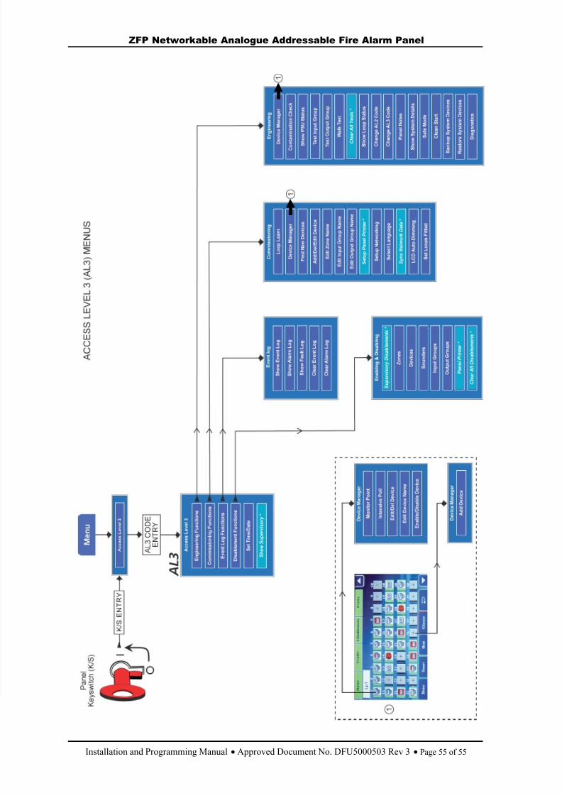
8/10/2019 Zfp Instal and Program Manual Dfu5000503 Rev3!01!02 13
http://slidepdf.com/reader/full/zfp-instal-and-program-manual-dfu5000503-rev30102-13 55/55
ZFP Networkable Analogue Addressable Fire Alarm Panel