zero owner's manual (s and ds) - zero...
TRANSCRIPT

ZERO S™
ZERO SR™
ZERO DS™
ZERO DSR™
ZE
RO
S / S
R / D
S / D
SR
TORCYCLES.COM
2016
2016 YCYY LES.COM
88-08461.04
OW
NE
R’S
MA
NU
AL
OWNER’S MANUAL
Zero Owner's Manual (S and DS).book Page 1 Thursday, March 15, 2018 4:13 PM

Zero Owner's Manual (S and DS).book Page 2 Thursday, March 15, 2018 4:13 PM
Table Of Contents
TOC.1
mation......................................... 2.1y Precautions ........................................ 2.1ety Precautions ...................................... 2.1perating Information ............................... 2.2portant Labels ..................................... 2.3
Important Labels..................................... 2.3
d Components ........................... 3.1Components.......................................... 3.1Controls .................................................. 3.2ew ........................................................... 3.4iew......................................................... 3.6iew.......................................................... 3.8icator Lights ......................................... 3.10gs.......................................................... 3.12 Application .......................................... 3.15Pairing .................................................. 3.15ontrols ................................................. 3.16
e Level Mode Button............................. 3.20 Lever Adjuster ..................................... 3.21.............................................................. 3.22 (if equipped) ........................................ 3.22k (if equipped) ...................................... 3.23
Zero Owner's Manual (S and DS).book Page 1 Thursday, March 15, 2018 4:13 PM
Introduction.................................................... 1.1Introduction.................................................................. 1.1
An Important Message From Zero Motorcycles........ 1.1About This Manual .................................................... 1.1Useful Information For Safe Riding........................... 1.2Unplug Your Z-Force® Power Pack™ ...................... 1.2California Proposition 65........................................... 1.2California Perchlorate Advisory................................. 1.2
Identification Numbers................................................ 1.3Owner Information .................................................... 1.3Power Pack Serial Number ....................................... 1.4Motor Serial Number................................................. 1.4Key Code Number .................................................... 1.4Vehicle Identification Number (VIN).......................... 1.4
General Information .................................................... 1.6Emissions Information............................................... 1.6Vehicle Range........................................................... 1.6Maximizing Your Range............................................ 1.7Transporting............................................................ 1.10
Safety InforGeneral Safet
General SafImportant O
Location of ImLocation of
Controls anControls and
Motorcycle Left Side ViRight Side VDash OvervWarning IndDash SettinSmartphoneBluetooth® Handlebar CPerformancFront BrakeTank Bag...Power TankCharge Tan

Table Of Contents
TO
SG
CP
MM
P
nce ................................................ 6.10....................................................... 6.10....................................................... 6.13s.................................................... 6.14
....................................................... 6.14
....................................................... 6.15ent................................................ 6.17
t Bulb Replacement ...................... 6.20Replacement.................................. 6.20ulb Replacement ........................... 6.21....................................................... 6.22g Term Storage............................. 6.23s Accessories ................................ 6.23....................................................... 6.23
g............................................ 7.1......................................................... 7.1cle Precautions................................ 7.1 Your Motorcycle ............................. 7.1 Indicator......................................... 7.2s ..................................................... 7.5
shooting .......................................... 7.8ment System.................................... 7.9eather Considerations ................... 7.15
..................................................... 7.16
Zero Owner's Manual (S and DS).book Page 2 Thursday, March 15, 2018 4:13 PM
C.2
tarting and Operating.................................. 4.1eneral Operation ........................................................4.1General Operation .....................................................4.1Key Switch/Steering Lock Positions...........................4.2Operating Your Motorcycle ........................................4.4ABS (Anti-lock Brake System) ...................................4.6Front Suspension Adjustment....................................4.9Rear Shock Adjustment ...........................................4.13
harging and Power Pack Information........ 5.1ower Pack and Charging ...........................................5.1
Power Pack................................................................5.1On-Board Power Pack Charger .................................5.2Charging the Power Pack ..........................................5.4Quick Charging (Off-Board Accessory Charger)........5.6Charge Tank (if equipped) .........................................5.9Public Charging Stations..........................................5.10Add On Electrical Equipment ...................................5.10
aintaining Your Motorcycle........................ 6.1aintaining Your Motorcycle ......................................6.1Owner’s Responsibilities............................................6.1Parts/Maintenance Items ...........................................6.2Service History...........................................................6.2Scheduled Maintenance ............................................6.2Component Fasteners ...............................................6.6
ower Pack ...................................................................6.9Power Pack................................................................6.9
General MaintenaBrakes..............Suspension ......Wheels And TireTire Inflation .....Drive Belt .........Headlight AlignmTurn Signal LighBrake/Tail LED Running Light BCleaning...........Parking and LonZero MotorcycleFuses ...............
TroubleshootinTroubleshooting .
Electric MotorcyTroubleshootingSystem WarningDash Error CodeGeneral TroubleBattery ManageCold and Hot WSafety Interlocks

Table Of Contents
TOC.3
e Record ................................... 10.1Record.................................................. 10.1ory ........................................................ 10.1
nder Information - High Voltage s Locations
Zero Owner's Manual (S and DS).book Page 3 Thursday, March 15, 2018 4:13 PM
Technical Specifications............................... 8.1Specifications .............................................................. 8.1
Zero S ....................................................................... 8.1Zero SR..................................................................... 8.3Zero DS..................................................................... 8.5Zero DSR .................................................................. 8.7
Warranty and Customer Information ........... 9.1Limited Warranty Information .................................... 9.1
Who Is The Warrantor?............................................. 9.1Who Does This Limited Warranty Cover?................. 9.1What Does This Limited Warranty Cover?................ 9.1What Is The Coverage Period Of This Limited Warranty? ................................................................. 9.2What Is Not Covered By This Limited Warranty?...... 9.3What Other Limitations Or Disclaimers Apply To This Limited Warranty ............................................... 9.5What Are Your Responsibilities As A Customer? ..... 9.6What Will Zero Motorcycles Do Under This Limited Warranty? ................................................................. 9.7How Does This Limited Warranty Relate To State Law? ......................................................................... 9.7How Do You Obtain Service Under This Limited Warranty? ................................................................. 9.8Transfer Of Ownership And Warranty....................... 9.9
Customer Information ............................................... 9.10Customer Assistance .............................................. 9.10Reporting Safety Defects ........................................ 9.11
MaintenancMaintenance
Service Hist
index
First RespoComponent

Zero Owner's Manual (S and DS).book Page 4 Thursday, March 15, 2018 4:13 PM

Introduction
1.1
Manualvers the following motorcycles (standard
quipment include Integrated Z-Force® d charger, belt drive, 17-inch wheels ise specified), and regenerative braking):etelssreet - Max Performanceelss
ual Sportels (19-inch diameter front)t TiresDual Sport - Max Performanceels (19-inch diameter front)t Tires
referencing informationo locate information about the motorcycle is the back of the manual.t” or “left” refer to the rider’s right or left the motorcycle.
Zero Owner's Manual (S and DS).book Page 1 Thursday, March 15, 2018 4:13 PM
IntroductionIntroductionAn Important Message From Zero MotorcyclesCongratulations and thank you for purchasing the 2016 Zero S, Zero SR, Zero DS, or Zero DSR electric motorcycle; we welcome you to the community of Zero Motorcycles riders. This manual is designed to provide you with a better understanding of the operation, inspection, and basic maintenance requirements of this motorcycle.Zero continually seeks advancements in product design and quality. Therefore, this manual contains the most current product information available at the time of printing. Because of this, your motorcycle may differ from the information supplied in this owner’s manual. No legal claims can be made on the basis of data in this manual. When it comes time to sell your Zero S/SR/DS/DSR, please ensure that this manual stays with the motorcycle; it is, by law, an important part of the vehicle. If you have any questions concerning the operation or maintenance of your motorcycle, please contact Zero at [email protected]. For 24 hour updates and additional information about your motorcycle, visit the Owner Resources section of the Zero Motorcycles website:http://www.zeromotorcycles.com/owner-resources/
About This This manual cofeatures and ePower Pack an(unless otherw• Zero S: Stre
• Cast Whe• Street Tire
• Zero SR: St• Cast Whe• Street Tire
• Zero DS: D• Cast Whe• Dual Spor
• Zero DSR: • Cast Whe• Dual Spor
Locating and A good place tin the index in The terms “righwhen sitting on

Introduction
1.
UThsothyo
WcoatadantealcaDth
TseHnow
Force® Power Pack™care of the motorcycle’s power pack is r motorcycle is charged, disconnect AC power. Leaving your motorcycle
imize long-term power pack health. See age 5-1 for other important information r pack.
osition 65 motorcycles contain or emit chemicals of California to cause cancer and birth roductive harm. In addition, certain
vehicles and certain products of ntain or emit chemicals known to the
o cause cancer and birth defects or harm.
hlorate Advisory components of this motorcycle such
may contain perchlorate material.ay apply for service or end of life .dtsc.ca.gov.
Zero Owner's Manual (S and DS).book Page 2 Thursday, March 15, 2018 4:13 PM
2
seful Information For Safe Ridingis manual contains the word WARNING to indicate mething that could hurt you or others. It also contains e word CAUTION to indicate things that could damage ur motorcycle.
ARNING! Please read this manual carefully and mpletely before operating this motorcycle. Do not tempt to operate this motorcycle until you have attained equate knowledge of its controls and operating features, d until you have been trained in safe and proper riding chniques. Regular inspections and proper maintenance, ong with good riding skills, help you safely enjoy the pabilities and the reliability of this motorcycle.
isregarding the aforementioned, however, may render e warranty invalid.
This symbol is located in various locations on the motorcycle to inform you that exposure to high voltage can cause shock, burns and even death.
he high voltage components on the motorcycle should be rviced only by technicians with special training.
igh voltage cable or wiring has an orange covering. Do t probe, tamper with, cut, or modify high voltage cable or
iring.
Unplug Your Z-CAUTION: Proper essential! Once youthe power pack fromunplugged will max“Power Pack”, on pregarding the powe
California PropWARNING: Certainknown to the State defects or other repfluids contained in component wear coState of California tother reproductive
California PercWARNING: Certainas lithium batteriesSpecial handling mdisposal. See www

Identification Numbers
1.3
dealer, you may need to provide this
Zero Owner's Manual (S and DS).book Page 3 Thursday, March 15, 2018 4:13 PM
Identification NumbersOwner InformationRecord information pertaining to your motorcycle here. When contacting your information.

Identification Numbers
1.
PTfro
MTof
KThketh
ation Number (VIN)it number stamped on the head tube of lter or remove this number as it is the our motorcycle.
all important labels on page 2.3.
ssis number information (A) is affixed
Zero Owner's Manual (S and DS).book Page 4 Thursday, March 15, 2018 4:13 PM
4
ower Pack Serial Numberhe Power Pack serial number is located on the upper
nt left of the power pack.
otor Serial Numberhe motor serial number is stamped on the right hand side the motor housing.
ey Code Numbere key code is a 5-digit number used to create duplicate ys. This number is located on a tag that accompanies e original keys.
Vehicle IdentificThe VIN is a 17-digthe frame. Do not alegal identifier for y
See the location of
Chassis NumberThe motorcycle chato the head tube.

Identification Numbers
1.5
of each digit or character in case you need
Zero Owner's Manual (S and DS).book Page 5 Thursday, March 15, 2018 4:13 PM
VIN BreakdownThe following breakdown of the VIN will help you understand the significance to reference it when contacting Zero Motorcycles or ordering parts.

General Information
1.
GenerETfreAEliqememelclgrVesose
Cacacanacw
ctric vehicle is defined as the distance on a single full charge of the power mileage estimates on an automobile, vary.” Your range results are a direct ing habits. The more conservative you e you can expect from your Zero
orcycle. which affect range include: speed, er of starts and stops, ambient air ll as changes in elevation. The e factors, as you travel from one point
your trip profile. In addition, tire ad are important considerations.u ride conservatively when you first get /DSR motorcycle, and get to know your r commute. Once you become familiar us performance of your motorcycle, t your riding characteristics if you so mainly to riders with trip profiles which he performance envelope.
Zero Owner's Manual (S and DS).book Page 6 Thursday, March 15, 2018 4:13 PM
6
al Informationmissions Informationhe Zero S/SR/DS/DSR electric motorcycle is a true
eway-capable zero-emissions vehicle under California ir Resources Board (CARB), U.S. Federal (EPA), and uropean Union standards. It uses no gasoline or other uid fuel. It has no tailpipe and therefore no tailpipe issions. It also has no exhaust or evaporative issions. Because the Zero S/SR/DS/DSR runs solely on
ectricity, it is the only kind of vehicle which actually gets eaner in terms of air pollution each year, as the electricity id gets cleaner and more renewable. Zero Emissions hicles (ZEV’s) offer greater efficiency, and can help lve the serious air pollution, global warming, and energy curity problems facing the country and the world.
AUTION: Please use only Zero approved parts and cessories for your Zero motorcycle. Parts and cessories for your Zero motorcycle have been checked d tested for safety and suitability. Zero is unable to cept any liability whatsoever for parts and accessories
hich have not been approved.
Vehicle RangeThe range of an elethe vehicle travels pack. Just like EPA“your mileage may reflection of your ridride, the better rangS/SR/DS/DSR motSome of the factorsacceleration, numbtemperature, as wecombination of thesto another, definespressure and payloWe suggest that yoyour Zero S/SR/DSmotorcycle and youwith the range versthen you can adjusdesire. This appliesare at the edge of t

General Information
1.7
Your Rangen electric motorcycles similarly to how it otorcycles. However, the big difference ic and gas is that energy consumption is a shorter distance on an electric ctric motorcycles are designed for
ly recharges versus less frequent and less s to the gas station. As a result, the same ycle often yields different ranges from one the next.
t the Rangeedict how an electric motorcycle’s range will u can use the four factors:
each of these factors, you can use uch as ‘city range’ as standards to estimate cycle’s real world range will be under your e case.
Zero Owner's Manual (S and DS).book Page 7 Thursday, March 15, 2018 4:13 PM
Reported motorcycle range values are measured using two different types of industry standard test procedures:1. “City”: This range test is specified to determine riding
during “stop-and-go” operation typically found in urban areas. This estimate is provided following the SAE J2982 Riding Range Test Procedure for On-Highway Electric Motorcycles to provide a reasonable and consistent basis for manufacturers to inform prospective owners of the riding range that can be expected under specified operating conditions. Actual range will vary based on riding conditions and habits.
2. “Highway”: This test procedure uses two separate constant speeds of 55 mph (89 km/h) and 70 mph (113 km/h) to simulate highway riding.
Both of these test procedures are run on a single charge, in order to report the associated measured range values.Range values labeled “Combined” are based on a calculation that assumes a duty cycle comprised of 50% City / 50% Highway.See technical specification charts on page 8.1 through page 8.7 for these ranges.
Maximizing Range varies ivaries in gas mbetween electraveraged overmotorcycle. Eleconvenient daiconvenient tripelectric motorcfull recharge to
How to PredicTo generally prbe affected, yo• route• rider• weather• motorcycle
By consideringspecifications swhat the motorparticular usag

General Information
1.
Zero Owner's Manual (S and DS).book Page 8 Thursday, March 15, 2018 4:13 PM
8

General Information
1.9
Zero Owner's Manual (S and DS).book Page 9 Thursday, March 15, 2018 4:13 PM

General Information
1.
TIt raramUtiemra
Zero Owner's Manual (S and DS).book Page 10 Thursday, March 15, 2018 4:13 PM
10
ransportingis recommended that the motorcycle be tied-down using tchet straps while it is being transported. Place the tchet straps around a frame contact point. Soft straps ust be used to prevent scratches or other damage.se two ratchet straps in the front and two in the rear. The down straps should be at a 45° angle from the otorcycle. Follow the manufacturer’s instructions for the tchet straps you are using.

General Safety Precautions
2.1
h use the rider must check everything in the column of the maintenance schedule on nd the charge level of the power pack as the dash display charge indicator.
depends in part on the good mechanical the motorcycle. Be sure to follow the e schedule and adjustment requirements this manual. Be sure you understand the
of checking all items thoroughly before
s to the motorcycle may render the vehicle may cause severe personal injury. Zero cannot be held liable for non-approved s.
eful when loading or adding accessories to ycle. Large, bulky, or heavy items may ffect the handling and performance of your
Zero Owner's Manual (S and DS).book Page 1 Thursday, March 15, 2018 4:13 PM
Safety InformationGeneral Safety PrecautionsGeneral Safety Precautions• This is a performance motorcycle and should be
treated with extreme caution.• Proper safety gear, including a regionally approved
helmet, eye protection, riding boots, gloves, and protective clothing should be worn while riding to reduce the risk of potential injury. We highly recommend the use of full height riding boots since the vast majority of motorcycle injuries are leg and foot injuries. It is not recommended to ride without the correct protective clothing; this applies to even short journeys and to every season of the year.
• Read all additional warnings and product instructions in this owner’s manual, as well as safety labels, before operating your electric motorcycle.
• Never permit a guest to ride your electric motorcycle without proper instruction.
• Never use alcohol or mind-altering drugs before operating your electric motorcycle.
• Persons unwilling or unable to take responsibility for their actions should not use this motorcycle. You assume all responsibility while operating your motorcycle. The seller assumes no liability for misuse or operator negligence.
• Prior to eac“every ride”page 6.2, aindicated on
• Your safetycondition ofmaintenanccontained inimportanceriding.
• Modificationunsafe andMotorcyclesmodification
• Be very caryour motorcadversely amotorcycle.

General Safety Precautions
2.
ImS•
•
•
•
•
arge the Zero power pack with the ard charger or the approved Zero
does not require nor benefit from deep get the most power pack life, recharge k immediately after each ride. Leaving a discharged state will cause damage. power pack storage and charging escribed in this Zero Motorcycles l may void the warranty of your Zero se guidelines have been rigorously maximum power pack efficiency and
Zero Owner's Manual (S and DS).book Page 2 Thursday, March 15, 2018 4:13 PM
2
portant Operating Informationeveral operating considerations are listed below:
Always turn the key switch and motor stop switch to the OFF position when not actively riding. It is very easy to forget that the motorcycle is powered up because it is silent. An accident can occur if the motorcycle is left powered up while getting on or off the motorcycle.Turn the motor stop switch OFF when backing up or pushing the motorcycle while dismounted.Use the rear brake when you are stopped on an incline. Do not hold the motorcycle using partial throttle or damage to the motor may occur.Plug your motorcycle into an AC power source to recharge it after each use. Once recharged, disconnect from the AC power source. Leaving your motorcycle unplugged between charges will maximize the long-term health of the power pack. You should also use the supplied cable as it is designed for use with your motorcycle’s electrical components.While unplugged with the key in the OFF position, the motorcycle’s electronics will consume a very small amount of power and the power pack will drain extremely slowly. If you don’t ride for an extended period of time (30 days or more), you may want to plug the motorcycle into an AC power source to charge it for a few hours prior to your next ride.
CAUTION: Only chmotorcycle’s on-boaccessory charger.• The power pack
discharging. To each power paca power pack in
• Failure to followinstructions as dOwner’s Manuamotorcycle. Thetested to ensureservice.

ocation of Important Labels
2.3
d European models:
orth America) - certification label shown
Zero Owner's Manual (S and DS).book Page 3 Thursday, March 15, 2018 4:13 PM
LLocation of Important LabelsLocation of Important LabelsThe vehicle could contain the following information for both North American an
A. VECI (Vehicle Emission Control Information) labelB. VIN label (European Union) - certification label
C. VIN label (N

Location of Important Labels
2.
H
Zero Owner's Manual (S and DS).book Page 4 Thursday, March 15, 2018 4:13 PM
4
igh Voltage Warning Label
Affixed to battery

Controls and Components
3.1
LANK
Zero Owner's Manual (S and DS).book Page 1 Thursday, March 15, 2018 4:13 PM
Controls and ComponentsControls and Components
THIS PAGE INTENTIONALLY LEFT B
Controls and Components
3.
M
Zero Owner's Manual (S and DS).book Page 2 Thursday, March 15, 2018 4:13 PM
2
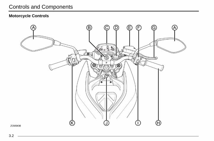
otorcycle Controls

Controls and Components
3.3
ke Leverption and operation, see “Handlebar on page 3-16.ontrolption and operation, see“Handlebar on page 3-16.p Switch ption and operation, see “Handlebar on page 3-16. Lockotorcycle tank bag, see “Tank Bag”, on .lebar Control ption and operation, see “Handlebar on page 3-16.
Zero Owner's Manual (S and DS).book Page 3 Thursday, March 15, 2018 4:13 PM
A. Mirrors This motorcycle is equipped with convex mirrors. A convex mirror has a curved surface. Convex mirrors offer a greater field of view than a similar flat mirror. However, the greater field of view makes objects seem further away than they really are. Care must be used when judging the distance of objects seen in these mirrors.
B. Key Switch/Steering LockFor description and operation, see “Key Switch/Steering Lock Positions”, on page 4-2.
C. DashFor description and operation, see “Dash Overview”, on page 3-8.
D. Cavity for Accessory 12 Volt SocketLocation for Zero dealer-installed 12 volt accessory socket.
E. Front Brake Fluid ReservoirFor description and operation, see “Brakes”, on page 6-10.
F. Right Handlebar ControlFor description and operation, see “Handlebar Controls”, on page 3-16.
G. Front BraFor descriControls”,
H. Throttle CFor descriControls”,
I. Motor StoFor descriControls”,
J. Tank BagLock for mpage 3-22
K. Left HandFor descriControls”,
Controls and Components
3.
L
Zero Owner's Manual (S and DS).book Page 4 Thursday, March 15, 2018 4:13 PM
4
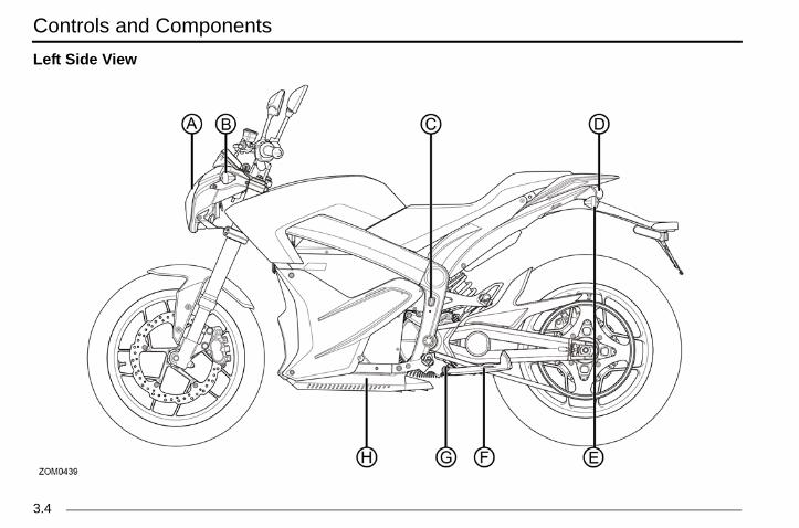
eft Side View

Controls and Components
3.5
and swings out from the side and supports ycle when parked. The key switch should FF position when parked. Switch
h is a safety feature that prevents motor when the kickstand is down. If the kickstand when riding it could contact the ground u to lose control of the motorcycle and
sonal injury.rk only on a flat firm surface, otherwise the ld fall over causing damage. Power Pack Charger
ption and operation, see “Power Pack”, on
Zero Owner's Manual (S and DS).book Page 5 Thursday, March 15, 2018 4:13 PM
A. Headlight
• For headlight operation, see “Handlebar Controls”, on page 3-16.
• For headlight bulb replacement, see “Headlight Bulb Replacement”, on page 6-18.
• For headlight alignment, see“Headlight Alignment”, on page 6-17.
B. Front Turn Signal• For turn signal operation, see “Handlebar Controls”,
on page 3-16.• For turn signal light bulb replacement, see “Turn
Signal Light Bulb Replacement”, on page 6-20.C. AC Charger Power Connection
For description and operation, see “Power Pack”, on page 5-1.
D. Brake/Tail LightFor brake/tail light bulb replacement, see “Brake/Tail LED Replacement”, on page 6-20.
E. Rear Turn Signal• For turn signal operation, see “Handlebar Controls”,
on page 3-16.• For turn signal light bulb replacement, see “Turn
Signal Light Bulb Replacement”, on page 6-20.
F. KickstandThe kickstthe motorcbe in the O
G. KickstandThis switcoperation were downcausing yocause per
CAUTION: Pamotorcycle couH. Integrated
For descripage 5-1.

Controls and Components
3.
R
Zero Owner's Manual (S and DS).book Page 6 Thursday, March 15, 2018 4:13 PM
6
ight Side View

Controls and Components
3.7
Zero Owner's Manual (S and DS).book Page 7 Thursday, March 15, 2018 4:13 PM
A. Rear Brake Fluid Reservoir See “Rear Brake Fluid Reservoir”, on page 6-11.
B. Auxiliary Power Pack Charging Connection For description and operation, see “Quick Charging (Off-Board Accessory Charger)”, on page 5-6. The auxiliary connector is located above the motor.
C. Power PackFor description and operation, see “Power Pack”, on page 5-1.
D. Rear Brake Pedal The rear brake pedal controls the rear brake when the pedal is pressed. When braking, the throttle should be in the closed position. The brake light illuminates when the rear brake pedal is applied.
E. Brushless Motor Controller Precisely “meters” the flow of electricity from the power pack to the motor according to the action of the throttle and surrounding conditions.
F. Drive Belt Tension Adjuster Located on left and right side. See “Checking Drive Belt Tension”, on page 6-15 for additional information.

Controls and Components
3.
D
Zero Owner's Manual (S and DS).book Page 8 Thursday, March 15, 2018 4:13 PM
8
ash Overview

Controls and Components
3.9
sing the performance level mode button the right handlebar control assembly. See nce Level Mode Button”, on page 3-20.eter UT meter indicates the amount of applied to the rear wheel and the POWER eing used while riding.tererative energy (REGEN) meter indicates t of TORQUE on the rear wheel and the
energy) feeding back into the battery of the during the regenerative braking process.
A&B &B can be customized to display functions de Trip odometers, Range, Errors, RPM,
ge, Lifetime Average, and Temperature. All ible by using the ADJ and SEL buttons. Settings”, on page 3-12.® Indicator tor displays when an active Bluetooth®
smartphone is paired with the motorcycle. instructions, see “Bluetooth® Pairing”, on
.
Zero Owner's Manual (S and DS).book Page 9 Thursday, March 15, 2018 4:13 PM
A. Adjust Button (ADJ)See “Dash Settings”, on page 3-12.
B. Select Button (SEL)See “Dash Settings”, on page 3-12.
C. Charge Indicator This indicator and readout displays the amount of energy remaining in the power pack, similar to the fuel gauge on a gasoline powered vehicle.
D. Remaining Charge Time Indicator This area displays the amount of time left for the power pack to reach full charge.
E. Clock The clock displays time in standard (AM/PM) or 24 hour mode. See “Setting the Clock”, on page 3-13.
F. Speedometer The speedometer is a digital display in either kilometers per hour (km/h) or miles per hour (mph). See “Unit Display - Speed”, on page 3-14.
G. Odometer The odometer displays the total distance the motorcycle has been ridden in kilometers or miles.
H. Performance Modes This area displays which performance riding mode (ECO, SPORT, and CUSTOM) has been selected by
the rider ulocated on“Performa
I. Output MThe OUTPTORQUE (energy) b
J. Regen MeThe regenthe amounPOWER (motorcycle
K. Displays Displays Awhich incluTrip Averaare accessSee “Dash
L. BluetoothThis indicaequipped For Pairingpage 3-15

Controls and Components
3.
W
Zero Owner's Manual (S and DS).book Page 10 Thursday, March 15, 2018 4:13 PM
10
arning Indicator Lights

Controls and Components
3.11
i-Lock Brake System) Indicator The indicator illuminates when the key is in the ON position. The light will extinguish when the motorcycle exceeds 3 mph nless there is a fault, the indicator will stay key is cycled off and back to the ON ain. See “ABS (Anti-lock Brake System)”,
-6 for more information. Indicator
Flashes slowly when the motorcycle is accepting a charge. The indicator flashes rapidly when a charging error is detected.
tor is solid green when the battery is charged. Indicator When the headlight high beam is on, this indicator illuminates blue, and remains on until the high beam is turned off.
n Signal Indicator An arrow on the lower dash flashes green in the same direction as selected by the turn signal switch. This remains flashing
rn signal request has been canceled.
Zero Owner's Manual (S and DS).book Page 11 Thursday, March 15, 2018 4:13 PM
A. Left Indicator Turn Signal An arrow on the lower dash flashes green in the same direction as selected by the turn signal switch. This arrow remains
flashing until the turn signal request has been canceled.
B. System Warning Indicator If a fault has been detected, count the number of times the red LED flashes. See the table on “System Warning Indicator”,
on page 7-2.C. Temperature Lamp
This flashes in the event that you exceed the motorcycle’s performance capabilities. The temperature warning lamp indicates
the temperature of the motor, controller temperature, or the battery over/under temperature. See “Temperature Indicator”, on page 4-5.
D. Armed Indicator Indicates the motorcycle is live or ready to move if the throttle is actuated. For troubleshooting, see “Troubleshooting
Your Motorcycle”, on page 7-1.
E. ABS (Ant
(5 km/h). Uoff until theposition agon page 4
F. Charging
The indicacompletely
G. High Beam
H. Right Tur
until the tu

Controls and Components
3.
D
Tpe(SA
B
N15da
with the dash in its normal operating press the SEL button once. Press the le through the following fields:r - Displays individual trip mileage and ing and holding the ADJ button for 2
set each time the battery is recharged
s remaining battery power based on tyle and usage. 2-digit error codes for dealer use. See es”, on page 7-5
motor RPM.
Zero Owner's Manual (S and DS).book Page 12 Thursday, March 15, 2018 4:13 PM
12
ash Settings
he displays on the dash can be customized to your rsonal preferences by using the ADJ (Adjust) and SEL elect) buttons.. Adjust Button (ADJ)
By momentarily pressing or holding the ADJ button you can reset fields and toggle through the trip menus and display options.
. Select Button (SEL)By momentarily pressing or holding the SEL button you can reset or select fields in Display A and Display B, change the time, and change the display units.
ote: Once a feature is selected, it will stop flashing after seconds if no further button press is detected, and the sh will return to its normal operating mode.
Displays A&B
Display ATo select Display Amode, momentarilyADJ button to togg• Trip 1 Odomete
is reset by pressseconds.Note: Trip 1 is reto 100%.
• Range - Displaylearned riding s
• Error - Displays“Dash Error Cod
• RPM - Displays

Controls and Components
3.13
ock
k with the dash in its normal operating d hold the SEL button for 5 seconds, then
ess the SEL button once more. The clock rt to flash.ss and release the ADJ button to increase tting.ress and release the SEL button once to inute display, then press and release the
to increase the minute setting. 24 Hour Mode - Press and release the SEL lect the time format, then press the ADJ lect P (am/pm mode) or 24:00 (24 hour
Zero Owner's Manual (S and DS).book Page 13 Thursday, March 15, 2018 4:13 PM
Display BTo select Display B with the dash in its normal operating mode, momentarily press the SEL button twice. Press the ADJ button to toggle through the following fields:• Trip 2 Odometer - Displays individual trip mileage and
is reset by pressing and holding the ADJ button for 2 seconds.
• Trip AV - Displays the average energy usage during duration of Trip 1 in watt hours (Wh), per mile (mi), or kilometer (km), depending on the currently selected display unit.Note: The Trip AV is reset each time the battery is recharged to 100%
• Temp - Displays the temperature of the motor in Fahrenheit (F) or Celsius (C).Note: The temperature may not read accurately during the first 5 miles of a ride while the application is calibrating itself.
• Life AV - Displays the average energy usage over the life of the motorcycle in watt hours (Wh), per mile (mi), or kilometer (km), depending on the currently selected display unit.
Setting the Cl
To set the clocmode, press anmomentarily prdisplay will sta• Hours - Pre
the hour se• Minutes - P
select the mADJ button
• Standard orbutton to sebutton to semode).

Controls and Components
3.
U
To1
2
3
perature
that the temperature display is shown: its normal operating mode press and tton for 5 seconds.ss the SEL button 4 times, the Temp r dash will start to flash.utton to toggle between °F or °C on the
ss the SEL button to return to normal .
Zero Owner's Manual (S and DS).book Page 14 Thursday, March 15, 2018 4:13 PM
14
nit Display - Speed
change the units that speed is shown in:. With the dash in its normal operating mode press and
hold the SEL button for 5 seconds. . Momentarily press the ADJ button to select English
(MPH) or metric (km/h).. Momentarily press the SEL button to return to normal
operating mode.
Unit Display - Tem
To change the units1. With the dash in
hold the SEL bu2. Momentarily pre
icon on the lowe3. Press the ADJ b
display.4. Momentarily pre
operating mode

Controls and Components
3.15
Pairingteps must be taken to properly pair a uipped smartphone with your motorcycle. the motorcycle is not Armed. The must be keyed ON, the kickstand must be in sition, and the run switch must be in the n.old the Mode button on the right handlebar
um of 5 seconds until the Bluetooth® he dash begins to blink, then you may Mode button.ycle will be discoverable with the
ID of ZeroMotorcyclesXXXXX (XXXXX last 5 digits of the motorcycle’s VIN).evices, go to the Settings application on tphone and locate the Bluetooth® menu ith your motorcycleid devices, go to the Settings tab in your oid application and choose the button with oth® symbol the Bluetooth® indicator on the dash lid, your motorcycle and smart phone are
Bluetooth®.
Zero Owner's Manual (S and DS).book Page 15 Thursday, March 15, 2018 4:13 PM
Smartphone ApplicationYou can download a smartphone application that lets you perform the following tasks related to your motorcycle:• Adjust the CUSTOM mode for performance gains• Collect and email logs to Zero support staff• Examine the precise State of Charge (SOC) of your
motorcycle• Examine real time power usage
The Smartphone application is available for free at both the Apple iTunes store and Google Play store. iTunes® is a registered trademark of Apple. Google Play® store is a registered trademark of Google.
Bluetooth® The following sBluetooth®-eq1. Ensure that
motorcycle the down poStop positio
2. Press and hfor a minimsymbol on trelease the
3. Your motorcBluetooth®refers to the• For iOS d
your smarand pair w
• For AndroZero Andrthe Blueto
Note: Whendisplay is sopaired over

Controls and Components
3.
H
Zero Owner's Manual (S and DS).book Page 16 Thursday, March 15, 2018 4:13 PM
16
andlebar Controls

Controls and Components
3.17
ontrol hrottle in a counter-clockwise rotation (A) to he motor and start the motorcycle in a rection. Release the throttle and it snaps closed position (B), de-energizing the regenerative braking begins.motorcycle is moving and the throttle n the fully closed position, the regenerative ature activates. Regenerative braking takes e energy from the moving motorcycle and
ck into electrical energy. This energy is then k into the power pack, contributing to energy efficiency. A slight drag is felt when rative braking is activated. If you want to
out the regenerative braking, hold the t off of the fully closed position.
Zero Owner's Manual (S and DS).book Page 17 Thursday, March 15, 2018 4:13 PM
A. Headlight High/Low Beam Switch When the switch is pushed, the headlight changes from low beam to high beam. It stays in the selected position until it is
switched back. When in high beam position, the high beam indicator on the lower dash illuminates.
B. Flash-to-Pass When the headlight is in the low beam position, push the flash-to-pass switch and the high beam illuminates and stays illuminated until the switch is released. When released, this switch defaults back to the low beam position. The high beam indicator also illuminates.
C. Front Brake Lever Adjuster Adjustment knob to set front brake lever position. Refer to “Front Brake Lever Adjuster”, on page 3-21.
D. Front Brake Lever The front brake lever controls the front brake when the lever is squeezed. When braking, the throttle should be in the closed position. The brake light also illuminates.
E. Throttle CTwist the tenergize tforward diback to themotor, andWhen the control is ibraking fesome of thturns it bastored bacincreased the regenecoast withthrottle jus

Controls and Components
3.
F
G
ng Flasher Switch f the switch is pressed, the turn signals ther drivers of situations, which include p or park under emergency conditions. m of the switch is pressed, the hazard
will turn off.witch en the turn signal switch is pushed in left or right position, the corresponding nt and rear turn signals flash. When the tch is ON, the corresponding turn signal e lower dash illuminates.your turns and other maneuvers as . Unlike an automobile, the turn signals
e canceled manually on the motorcycle. switch and it will return to the OFF r).
Zero Owner's Manual (S and DS).book Page 18 Thursday, March 15, 2018 4:13 PM
18
. Motor Stop Switch When the top of the switch (A) is pressed, it cuts off power to the run signal. The motor controller remains in this state until the bottom portion of the switch (B) is pressed. The switch does not turn off all electrical circuits, just the operation of the motor.
. Performance Level Mode Button See “Performance Level Mode Button”, on page 3-20.
H. Hazard WarniWhen the top oflash to warn oneeding to stoWhen the bottowarning circuit
I. Turn Signal SWhthefro
turn signal swiindicator on thAlways signal required by lawmust always bPush in on theposition (cente

Controls and Components
3.19
Zero Owner's Manual (S and DS).book Page 19 Thursday, March 15, 2018 4:13 PM
J. Horn ButtonWhen the key is in the ON position, the horn (A) sounds when the button is pressed. Electric vehicles run quietly; the horn can be used to warn pedestrians or other motorists of your presence.

Controls and Components
3.
P
ThEbewclThspwne
ion causes the motorcycle to accelerate ter rate. This position is recommended .ction has customizable performance e smartphone application (refer to
cation”, on page 3-15).vantage of the ECO position are likely ase in range and experience greater g.
Zero Owner's Manual (S and DS).book Page 20 Thursday, March 15, 2018 4:13 PM
20
erformance Level Mode Button
e performance level mode button (A) toggles between CO, SPORT, and CUSTOM modes. You can switch tween performance modes while riding, but the change
ill not be executed until the throttle is returned to the osed position.e ECO selection reduces the acceleration and top eed of the motorcycle. It is an ideal mode for when you
ant softer acceleration. This position is also good for wer riders and for extending range.
The SPORT selectat a significantly fasfor advanced ridersThe CUSTOM selesettings by using th“Smartphone AppliThose who take adto see a slight increregenerative brakin

Controls and Components
3.21
Zero Owner's Manual (S and DS).book Page 21 Thursday, March 15, 2018 4:13 PM
Front Brake Lever Adjuster
The position of the front brake lever can be adjusted by turning the adjustment knob (A) located on the master cylinder assembly. Turning the knob clockwise or counter-clockwise will adjust the distance between the lever and the throttle control.

Controls and Components
3.
TDeqre
Nbath
quipped)le may be equipped with a dealer-
quipment Power Tank in place of the er Tank’s power pack increases the the motorcycle, which increases the arge time.
Zero Owner's Manual (S and DS).book Page 22 Thursday, March 15, 2018 4:13 PM
22
ank Bagepending on specification, your Zero motorcycle may be uipped with a tank bag for additional storage. You can move the tank bag by pulling upwards on its sides.
ote: Before riding your Zero motorcycle, secure the tank g with the lock (in front of the tank bag). At high speeds e bag could eject if it is not secured.
Power Tank (if eYour Zero motorcycinstalled optional etank bag. The Powbattery capacity of riding range and ch

Controls and Components
3.23
Zero Owner's Manual (S and DS).book Page 23 Thursday, March 15, 2018 4:13 PM
Charge Tank (if equipped)Your Zero motorcycle may be equipped with a dealer- installed Charge Tank. This is optional equipment installed in place of the tank storage area. The Charge Tank has a J1772 charge connector, which is concealed by a hinged protective rubber cover. Compared to Level 1 charging, on-board charge times are effectively tripled with this Level 2 charge accessory. The battery can be charged at public charging stations using the popular J1772 standard. For use and more information, see “Charge Tank (if equipped)”, on page 5-9.

Notes
3.
Zero Owner's Manual (S and DS).book Page 24 Thursday, March 15, 2018 4:13 PM
24

General Operation
4.1
k both tires for condition and tread depth. tire pressure frequently. Check for damage nt. Maintain correct tire pressure as page 6.14. Replace the tires when the
t is 0.08 in (2 mm) or less.der-inflation is a common cause of tire result in severe tire cracking, tread wout,” or unexpected loss of motorcycle serious injury or death. Inspect tires ure proper inflation levels.ystem. Check for correct function of the rn signals, and the brake/tail lights.
Covers. Confirm protective covers for diagnostic connector, Quick Charge nd on-board charging connector are
rrectly.
Zero Owner's Manual (S and DS).book Page 1 Thursday, March 15, 2018 4:13 PM
Starting and OperatingGeneral OperationGeneral OperationThis section describes several items you should examine before operation.
Pre-Ride InspectionBefore operating your Zero motorcycle, check the following to make sure the motorcycle is secure and intact:• Power Pack. Make sure the charge indicator on the
lower dash is indicating a charged power pack. We suggest you recharge before use. Always keep the charger cord with the motorcycle.
• Drive Belt. Check the belt tension and condition. Adjust if necessary. See “Drive Belt”, on page 6.15.
• Brakes. Squeeze the brake lever and press the brake pedal individually while pushing the motorcycle to see if it rolls. You should be able to lock-up the wheels completely by applying the brakes.
• Throttle. With the key switch in the OFF position, apply the throttle and release to verify that the throttle is smooth and returns correctly.
• Tires. ChecCheck coldand alignmespecified ontread heigh
WARNING! Unfailure and mayseparation, “blocontrol causingregularly to ens• Electrical S
headlight, tu• Protective
power packconnector, ainstalled co

General Operation
4.
K
Thfro•••
Tpath
lock when parked prevents nd helps prevent theft.ring lock:bar all the way to the left.the OFF position, push the key down counter-clockwise..
ing lock:nd turn clockwise..
Zero Owner's Manual (S and DS).book Page 2 Thursday, March 15, 2018 4:13 PM
2
ey Switch/Steering Lock Positions
is is a three-position switch that is located on the fork in nt of the handlebar. The switch positions are as follows:Steering Lock (A)OFF (B)ON (C)
he key should be removed from the motorcycle when rked to prevent theft. The key can be removed in either e OFF or steering lock position.
Steering LockUsing the steering unauthorized use aTo operate the stee1. Turn the handle2. With the key in
and turn the key3. Remove the key
To unlock the steer1. Install the key a2. Remove the key

General Operation
4.3
Zero Owner's Manual (S and DS).book Page 3 Thursday, March 15, 2018 4:13 PM
OFF PositionThis position is used to turn the motorcycle OFF, disabling the electrical system.
ON PositionThis position is used for operating the motorcycle. In this position the following sequence occurs:• Lights turn ON• Dash display turns ON

General Operation
4.
OTm
S1234
BOTsqthbrW
Wenyosesh
wheels. Your Zero motorcycle is a light- product and therefore practice is
ded to perfect safe emergency stops.
torcyclecycle: in the closed position press the motor e OFF position. This switch can also be rgency to shut the motor off.itch to the OFF position and remove the theft, the key should be removed torcycle is left unattended.e the power pack after each ride.
Zero Owner's Manual (S and DS).book Page 4 Thursday, March 15, 2018 4:13 PM
4
perating Your Motorcyclehis section describes how to safely operate your otorcycle.
tarting. Turn the key switch to the ON position.. Verify that the charge indicator reads fully charged.. Press the motor stop switch to the ON position.. With the kickstand up, twist the throttle toward you
(counter-clockwise) to increase speed. When the throttle is twisted away from you (clockwise), the speed decreases.
rakingn the right handlebar is the hand operated brake lever. he brake lever controls the front brake when the lever is ueezed. On the right lower side, next to the foot peg, is e foot operated brake pedal. This pedal controls the rear ake. hen braking, the throttle should be in the closed position.
ARNING! If you apply the front or rear brake hard ough, it is possible to lock the wheels. This could cause u to lose control of the motorcycle and could lead to rious injury or death. Progressive use of the brakes ould bring the Zero motorcycle to a complete stop
without locking the weight performancestrongly recommen
Stopping Your MoTo stop your motor1. With the throttle
stop switch to thused in an eme
2. Turn the key swkey. To prevent anytime the mo
3. Be sure to charg

General Operation
4.5
ou can choose to slow down a bit until the ps flashing.
emperature continues to build, the indicator solid, letting you know that the thermal ow being applied and that your
s power will be reduced accordingly. If you he strategy while trying to maintain a high ed, the effect of the strategy will be that your will be gradually slowed down to the point speed of the bike is “sustainable,” from a dpoint. If you encounter the strategy due to ustained high power event, such as owering through a low traction surface, imply be reduced to ensure the continued ion of your powertrain.
at the lighting of this temperature indicator te that there’s anything malfunctioning with rcycle; it is simply letting you know that the y is working. If you do not moderate your he bike’s system will reduce your ntil your Zero can maintain its maximum al state; but no harm whatsoever will result this is exactly how the strategy is meant to
Zero Owner's Manual (S and DS).book Page 5 Thursday, March 15, 2018 4:13 PM
Temperature IndicatorZero Motorcycles has developed the most advanced passively air-cooled electric powertrain for your Zero motorcycle, delivering an unsurpassed level of simplicity, power/energy density, low weight and ease of maintenance. However, this passively air-cooled powertrain cannot be operated indefinitely at high power / high rpm without reaching its thermal limitations. Hence, your Zero motorcycle has a sophisticated thermal management strategy to ensure the long term performance and durability of its powertrain.
The red temperature indicator light (A) on your Zero motorcycle’s lower dash has two informational stages. • Stage 1, is presented by flashing this indicator and
advises you that the bike is about to enter its thermal strategy. To avoid encountering an enforced power
reduction, yindicator sto
• Stage 2, if tlight will go strategy is nmotorcycle’encounter tvehicle spemotorcycle that the topthermal stana different scontinued ppower will ssafe operat
Please note thdoes not indicayour Zero motothermal strategspeed/power, tspeed/power uallowable thermfrom this, sincefunction.

General Operation
4.
AWthsysualgoWWIf ADcoofth
le is stationary and the key is turned to is normal for the ABS warning indicator lluminate. The indicator will remain on tects the motorcycle’s speed exceeds er which will stay off until the key is sition and back to the ON position.
t can illuminate if there is a large speed between the front and rear , or loose gravel). If this happens, the inactive and can allow the wheels to reaking. To reactivate the ABS, bring complete stop, then turn the key to the for approximately 5 seconds, then turn sition. The ABS light should extinguish
each 3 mph (5 km/h) and be fully
Zero Owner's Manual (S and DS).book Page 6 Thursday, March 15, 2018 4:13 PM
6
BS (Anti-lock Brake System)ARNING! ABS prevents the wheels from locking, erefore maximizing the effectiveness of the braking stem in emergencies and when riding on slippery rfaces. The potentially shorter braking distances ABS
lows under certain conditions are not a substitute for od riding practices.ARNING! Always ride within the legal speed limit.ARNING! Carefully ride your motorcycle around corners. applying the motorcycle’s brakes while cornering, the BS cannot counteract the weight transfer and force. oing so, can create unsafe riding conditions. Some riding nditions and environments may reduce the effectiveness the ABS and require stopping distances equivalent to ose of a motorcycle without ABS.
When the motorcycthe ON position, it (A) on the dash to iuntil the system de3 mph (5 km/h), aftturned to the off po
Note: The ABS lighdifference in wheel(wheelies, burnoutsABS system will belock under heavy bthe motorcycle to aOFF position, wait it back to the ON poonce both wheels rfunctional.

General Operation
4.7
rmal operation.
Indicatorrcycle is stationary and the key turned to
n, it is normal for the ABS warning indicator illuminate. The indicator will remain on until ects the motorcycle’s speed exceeds 3 mph which it will stay off until the key is cycled off ON position.
front and rear wheel speed sensors must exceeding 3 mph (5 km/h) simultaneously in BS system and its indicator to operate
ning indicator is illuminated outside of its ng parameters:s been disabled by the rider. s a malfunction and requires attention
ice.he ABS indicator light remains illuminated rcycle exceeds 3 mph (5 km/h), ABS is not e is a fault with the ABS system. If an ABS ists, take your motorcycle to an authorized
earliest convenience to have the ABS d. If there are no dealers in you area, call les Customer Service. See “Customer page 9.10
Zero Owner's Manual (S and DS).book Page 7 Thursday, March 15, 2018 4:13 PM
Disabling the ABSWARNING! When the ABS is disabled, the motorcycle will operate as a non-ABS equipped motorcycle, potentially with increased stopping distance and unpredictable brake control.To disable the ABS (starting with the motorcycle at rest on a level and stable surface and the ignition key in OFF position): 1. Place kickstand in the down position.2. Put the Motor Stop Switch in the OFF position.3. Turn the ignition key to the ON position.4. Press and hold the ADJ button (on dash) and the
MODE button (on right handlebar) simultaneously. After 4 seconds, the ABS light will begin to flash slowly (approximately every 1.2 seconds). Release both buttons.Note: The ABS light will continue to flash (approximately every 1.2 seconds) until the key is cycled off and back to the ON position.
To reactivate the ABS (starting with the motorcycle at rest on a level and stable surface and the ignition key in OFF position): 1. Disconnect external charge cables.2. Wait for the dash display to turn off completely.3. Turn the ignition key to the ON position.
4. Resume no
ABS WarningWhen the motothe ON positioon the dash to the system det(5 km/h), after and back to the
Note: Both thedetect speeds order for the Aproperly.
If the ABS warnormal operati• The ABS ha• The ABS ha
and/or servWARNING! If tafter your motoactive and thersystem fault exdealer at your system repaireZero MotorcycAssistance”, on

General Operation
4.
WspththmWwAfuequnWspofANcofopow
Zero Owner's Manual (S and DS).book Page 8 Thursday, March 15, 2018 4:13 PM
8
ARNING! The ABS computer compares the relative eed of the front and rear wheels. Using tires other than ose specified by Zero Motorcycles can adversely affect e ABS functionality and stopping distance of your otorcycle.ARNING! If the ABS warning indicator is illuminated hen traveling at speeds exceeding 3 mph (5 km/h), the BS is not functioning. When the ABS system is not nctioning, your motorcycle will operate as a non-ABS uipped motorcycle with increased stopping distance and predictable brake control.ARNING! If the front and rear wheel speeds vary in eed significantly, such as during a burnout, wheelie, or f road riding, the ABS indicator will illuminate and disable BS.ote: To reactivate the ABS, bring the motorcycle to a mplete stop, then turn the key to the OFF position, wait r approximately 5 seconds, then turn it back to the ON sition. The ABS light should extinguish once both
heels reach 3 mph (5 km/h) and be fully functional.

General Operation
4.9
measurement (this is the measurement s M1).
motorcycle from the stand.ur normal riding apparel, sit on the
sistant hold the motorcycle upright, your feet n both pegs. suspension a couple of times.nd assistant take a measurement using the
ons as in step 2.
Zero Owner's Manual (S and DS).book Page 9 Thursday, March 15, 2018 4:13 PM
Front Suspension AdjustmentA shock has two main actions: compression when the shock gets loaded, and rebound when the shock returns back to full length. Compression damping is the adjustment that determines how fast or slow the fork compresses. Rebound damping is the adjustment that determines how fast or slow the fork rebounds.
Measuring PreloadObtaining the correct front suspension preload (sag) is critical for proper handling. The spring preload must be set to match the weight of the rider. The spring is preloaded for a 180 lbs (82 kg) rider. This puts the front tire 1/3 of the way through its vertical travel. Heavier riders require stiffer spring rates. A good approximation of your front springs requirements can be found by measuring the front suspension’s sag. This measurement quickly determines if your front springs are approximately correct for your weight. This adjustment is a recommended guideline; personal riding preference may vary from the specifications given.To Check the Sag Value:1. Support your motorcycle upright on a stand with the
front wheel off the ground.2. Measure vertically from the bottom of the fork tube to
the bottom of the tube’s dust seal.
3. Record thisreferred to a
4. Remove the5. Wearing yo
motorcycle.6. Have an as
should be o7. Bounce the8. Have a seco
same locati

General Operation
4.
9
10
7 in (45 mm). Refer to the chart below If the sag is not correct, the spring djusted.
Operator Value
4.13 in (105 mm)
- 2.36 in (60 mm)
= 1.77 in (45 mm)
SAG
1.77 in (45 mm)
2.32 in (59 mm)
Zero Owner's Manual (S and DS).book Page 10 Thursday, March 15, 2018 4:13 PM
10
. Record this measurement (this is the measurement referred to as M2).
.Subtract the second measurement (M2) from the first measurement (M1).
Example:
The total sag is 1.7for the correct sag.preload should be a
Measurement
M1
M2
Sag
MODEL
S & SR
DS & DSR

General Operation
4.11
rebound adjuster screw clockwise slows speed down making it better for larger
in or bumps. rebound adjuster screw counter-clockwise e rebound speed making it better for e frequent bumps. Adjust each fork leg
justers should never be forced completely ”; always leave one click of adjustment in .
Zero Owner's Manual (S and DS).book Page 11 Thursday, March 15, 2018 4:13 PM
Spring Preload AdjustmentThe spring preload is adjusted by turning the 19 mm anodized hex nut (B) located on top of the fork spring.
Note: When adjusting preload, always start from the minimum setting and adjust each fork leg evenly.• Turning the adjustment nut clockwise increases the
spring preload and reduces sag of the front suspension.
• Turning the adjustment nut counter-clockwise decreases the spring preload and increases sag of the front suspension.
Rebound DampingThe rebound damping is adjusted by turning the slotted adjuster screw (A) on the top of both fork legs. Next to the screw are the letters “H” meaning Hard (slower rebound) and “S” meaning Soft (faster rebound). The adjuster has 9 stages of adjustment. This determines how quick the fork returns to its extended position after being compressed.
• Turning thethe reboundrolling terra
• Turning theincreases thsmaller morevenly.
CAUTION: Ad“Soft” or “Hardeither direction

General Operation
4.
CTonlemst
•
•
Sfrogr
p (feel harsh over consecutive bumps), that is set too fast will cause the fork to If the fork is bottoming out, turn the t a time until the bottom-out stops. evenly. Replace the rubber dust cover t.
uld never be forced completely “Soft” ave one click of adjustment in either
Front Suspension Settingsation will allow you to adjust the front
the factory settings the motorcycle was ith.
SETTING
n 6 clicks out from fully closed
9 clicks out from fully closed
3 turns out from minimum
SETTING
n 5 clicks out from fully closed
9 clicks out from fully closed
3 turns out from minimum
Zero Owner's Manual (S and DS).book Page 12 Thursday, March 15, 2018 4:13 PM
12
ompression Dampinghe compression damping is adjusted by turning a screw the bottom of each fork leg. Next to the screw are the
tters “H” meaning Hard (slower compression) and “S” eaning Soft (faster compression). The adjuster has 12 ages of adjustment.
Turn the adjuster screw (A) clockwise for slower compression. To speed up compression, turn the adjuster screw counter-clockwise.
tart with a middle setting and fine tune the compression m there. Proper compression allows the tire to track the
ound over consecutive bumps. Compression that is set
too slow will pack-uwhile compression bottom out harshly.adjuster one click aAdjust each fork legafter the adjustmen
Note: Adjusters shoor “Hard”; always ledirection.
Factory Supplied The following informsuspension back tooriginally supplied wS & SR Models
DS & DSR Models
ADJUSTMENT
Front Fork Compressio
Front Fork Rebound
Front Fork Preload
ADJUSTMENT
Front Fork Compressio
Front Fork Rebound
Front Fork Preload

General Operation
4.13
motorcycle from the stand.ur normal riding apparel, sit on the
sistant hold the motorcycle up, your feet n both pegs. suspension a couple of times.nd assistant take a measurement using the
ons as in step 2. measurement (this is the measurement s M2).
Zero Owner's Manual (S and DS).book Page 13 Thursday, March 15, 2018 4:13 PM
Rear Shock AdjustmentMeasuring PreloadObtaining the correct rear spring preload (sag) is critical for proper handling. The spring preload must be set to match the weight of the rider. The spring is preloaded for a 180 lb (82 kg) rider. This puts the rear tire 1/3 of the way through its vertical travel. Heavier riders require stiffer spring rates. A good approximation of your rear spring requirements can be found by measuring the rear suspension’s sag. This measurement quickly determines if your rear spring is approximately correct for your weight. This adjustment is a recommended guideline; personal riding preference may vary from the specifications given.To Check the Sag value:1. Support your motorcycle on a stand with the rear wheel
off the ground.2. Measure vertically from the rear axle to the rear fender.
Mark this spot as it is used for other measurements.3. Record this measurement (this is the measurement
referred to as M1).
4. Remove the5. Wearing yo
motorcycle.6. Have an as
should be o7. Bounce the8. Have a seco
same locati9. Record this
referred to a

General Operation
4.
10
7 in (50 mm). Refer to the chart below If the sag is not correct, the spring djusted.
Operator Value
23.62 in (600 mm)
- 21.65 in (550 mm)
= 1.97 in (50 mm)
SAG
1.77 in (45 mm)
2.36 in (60 mm)
Zero Owner's Manual (S and DS).book Page 14 Thursday, March 15, 2018 4:13 PM
14
.Subtract the second measurement (M2) from the first measurement (M1).
Example:
The total sag is 1.9for the correct sag.preload should be a
Measurement
M1
M2
Sag
MODEL
S & SR
DS & DSR

General Operation
4.15
stmentdjuster knob (A) is at the bottom of the stages of adjustment. Printed on the knob is ard (slower rebound) and “S” meaning Soft ). The ride quality adjustment knob controls r softness the ride quality of your rning the knob clockwise, or H direction, is pacts.b counter-clockwise, or S direction, is good more frequent impacts.
should never be forced completely “Soft” ys leave one click of adjustment in either
Zero Owner's Manual (S and DS).book Page 15 Thursday, March 15, 2018 4:13 PM
Spring Preload Adjustment1. Clean any dirt or debris from the slots of the shock
adjusting collar (A).2. Using the adjusting wrench, turn the adjusting collar
(A).3. For measurements less than the specified value,
decrease the preload on the spring by turning the adjustment collar counter-clockwise on the shock. If more than the specified value, increase the preload on the spring by turning the adjustment collar clockwise on the shock.
Rebound AdjuThe rebound ashock. It has 8 “H” meaning H(faster reboundthe hardness omotorcycle. Tugood for big imTurning the knofor smaller and
Note: Adjustersor “Hard”; alwadirection.

General Operation
4.
CTshismclsocoththCovtoshun
Nordi
Zero Owner's Manual (S and DS).book Page 16 Thursday, March 15, 2018 4:13 PM
16
ompression Adjustmenthe compression adjustment knob is at the top of the ock. It has 28 stages of adjustment. Printed on the knob
“H” meaning Hard (slower compression) and “S” eaning Soft (faster compression). Turn the adjuster ockwise for a harder ride (slower compression). For a fter ride (faster compression), turn the adjuster unter-clockwise. Start with a middle setting and fine tune e compression from there. Proper compression allows e tire to track the ground over consecutive bumps. ompression that is set too hard will pack-up (feel harsh er consecutive bumps), while compression that is set o soft causes the shock to bottom out harshly. If the ock is bottoming out, turn the adjuster one click at a time til the bottom out stops.
ote: Adjusters should never be forced completely “Soft” “Hard”; always leave one click of adjustment in either rection.

General Operation
4.17
Zero Owner's Manual (S and DS).book Page 17 Thursday, March 15, 2018 4:13 PM
Factory Supplied Rear Suspension SettingsThe following information will allow you to adjust the rear suspension back to the factory settings the motorcycle was originally supplied with.S & SR Models
DS & DSR Models
ADJUSTMENT SETTING
Rear Shock Compression 12 clicks out from fully closed
Rear Shock Rebound 8 clicks out from fully closed
Rear Shock Spring Preload 2nd position
ADJUSTMENT SETTING
Rear Shock Compression 9 clicks out from fully closed
Rear Shock Rebound 12 clicks out from fully closed
Rear Shock Spring Preload 5th position

Notes
4.
Zero Owner's Manual (S and DS).book Page 18 Thursday, March 15, 2018 4:13 PM
18

Power Pack and Charging
5.1
Leaving your motorcycle unplugged es will maximize the long-term health of the
d with the key in the OFF position, the ectronics will consume a very small amount e power pack will drain extremely slowly. If
or an extended period of time (30 days or y want to plug the motorcycle into an AC o charge it for a few hours prior to your next
k must be charged within 24 hours if fully tored long-term, check the state of charge
y and charge it back up to 60% if it has 30%. See “Parking and Long Term ge 6-27 for more information.
Zero Owner's Manual (S and DS).book Page 1 Thursday, March 15, 2018 4:13 PM
Charging and Power Pack InformationPower Pack and ChargingPower PackThe battery is located within the power pack and requires no special break in period. The Zero S/SR/DS/DSR power pack leverages proven battery cell chemistry, configuration, and enhanced reliability. Not only does the Z-Force® technology enable you to go longer distances (range varies depending on riding type and conditions), it is also designed to last the life of the motorcycle. The integrated on-board charger minimizes charge time and can work in parallel with Zero’s quick charge accessories to cut charge times by as much as 75%. The charging time will remain the same if the on-board charger is connected to a 120 V AC or a 240 V AC supply.The normal recharging time of the power pack to a 100% charge is usually less than 7 hours for the ZF9.8 and 9 hours for the ZF13.0 in mild ambient temperatures. Out of the normal temperature range, charging and run-time times will vary. The power pack should not be used outside of the range of 23°F to 140°F (-5°C to 60°C); the Battery Management System (BMS) turns off the power controller outside of this range.
Note: The Battery will not charge if below 0°C or 32°F.
Plug your motorcycle into an AC power source to recharge it after each use. Once recharged, disconnect from the AC
power source. between chargpower pack.While unpluggemotorcycle’s elof power and thyou don’t ride fmore), you mapower source tride.The power pacdischarged. If sat least monthldropped belowStorage”, on pa

Power Pack and Charging
5.
BE(BoppepaTinopInTprthpapaTdodom
r Pack Chargerr pack to the charger after each use.
isconnect from the AC power source. cycle unplugged between charges will term health of the power pack. You plied cable as it is designed for use with lectrical components. The power pack ithin 24 hours if fully discharged. If you ended period of time (30 days or more), ug the motorcycle into an AC power for a few hours prior to your next ride.
arge the Zero power pack with the Zero ard charger is located under the power
motorcycle’s power pack, the charger n after the power pack is fully charged. r motorcycle after it is fully charged will power pack health. If left connected,
ible cases that can occur:d to the charger, the power pack will arge. Once fully charged, the charger en 90% and 100% state of charge. of charge gets close to 90%, the arge to 100% and repeat. When fully n light illuminates on the charger. ger not read that the power pack is full,
Zero Owner's Manual (S and DS).book Page 2 Thursday, March 15, 2018 4:13 PM
2
attery Management System (BMS)very power pack contains a Battery Management System MS) which monitors the condition of the cells, and timizes the charging process to provide the highest rformance, longest range, and longest life for the power ck.
he BMS safeguards the power pack by means of safety terlocks. These interlocks turn off or control certain erations that could damage the power pack. See “Safety terlocks”, on page 7-16 for more information.he BMS also monitors the power pack for a host of edefined conditions, and then takes actions according to ose conditions. See, “Battery Management System”, on ge 7-9 and “Cold and Hot Weather Considerations”, on ge 7-15 for further information.
he BMS is sealed inside the power pack. As a rider, you n’t need to think much about the BMS - it just silently es its job as you charge, ride, and store your
otorcycle.
On-Board PoweConnect your poweOnce recharged, dLeaving your motormaximize the long-should use the supyour motorcycle’s emust be charged wdon’t ride for an extyou may want to plsource to charge it
CAUTION: Only chcharger. The on-bopack.When charging thecan be left ON, eveBut unplugging youmaximize long-termthere are two poss• When connecte
receive a full chwill cycle betweWhen the state charger will rechcharged, a greeShould the char

Power Pack and Charging
5.3
the motorcycle, the LEDs flash from left to mber of LEDs (from 1 to 4) will illuminate to
arge level. For example, if 3 of the 4 LEDs , the battery is 3/4 charged. The LED nce will repeat once more. Refer to “Battery ystem”, on page 7-9 for more information.
member to install charge-level LED rubber ing motorcycle to prevent the ingress of dirt housing.
Zero Owner's Manual (S and DS).book Page 3 Thursday, March 15, 2018 4:13 PM
it continues to attempt to fully charge the power pack. In this event the green light may not illuminate; however, the power pack may be fully charged. To ensure that the power pack is charged, check the charge indicator on the dash display prior to riding.
• If the power pack terminates the charge before the charger reaches the state previously mentioned, then the charger continues to cycle and tops off the power pack until the power pack is removed from the charger, or the charger reaches the complete state previously noted.
The on-board charger status indicator is visible through the front of the battery housing by removing a black rubber plug (A). A circular lens with four LED’s displays the current charge level.
When chargingright. Then a nuindicate the chare illuminatedflashing sequeManagement S
CAUTION: Replug before ridinto the battery

Power Pack and Charging
5.
CWchIt
Nwchth
T12ov12haamIf yo(5mchchTlosh
Npa
standard on-board charging
d power cord (A) into the on-board tor. Always keep the power cord with
the charger to a GROUNDED outlet. xtension cord, avoid excessive voltage grounded, 3-wire, 12-AWG cord no
t (7.6 m). The charger can be used on 0 V AC current. The voltage does not unt of time that the motorcycle takes to
Zero Owner's Manual (S and DS).book Page 4 Thursday, March 15, 2018 4:13 PM
4
harging the Power PackARNING! Charge the Zero power pack with the Zero arger or approved Zero accessory chargers.is possible for lithium ion cells to overheat and fail.
ote: Charge the Zero power pack in a location that is ell-ventilated and away from combustible materials. If arging your Zero motorcycle outdoors, avoid charging in e rain.
he maximum power pack internal charging temperature is 2°F (50°C). If the power pack’s internal temperature is er that, it will not accept a charge until it is cooled below 2°F (50°C) Also, if the power pack has just been run rd, it may internally be above 122°F (50°C), even if the bient temperature is lower.
you experience a power pack that will not take a charge, u should ensure the internal temperature is below 122°F 0°C). If the power pack has recently been operating near aximum output and/or in hot conditions it may not take a arge, the power pack should cool off and begin taking a arge in around 30 minutes or less.
he maximum charging temperature cutoff is a power pack ngevity feature. Charging at higher temperatures can orten the life of the power pack.
ote: Frequent top off charging is good for the power ck’s life span, so do not hesitate to charge frequently.
To charge using theequipment:1. Plug the supplie
charger connecthe motorcycle.
2. Always connectWhen using an edrops by using alonger than 25 f120 V AC or 24change the amocharge.

Power Pack and Charging
5.5
Zero Owner's Manual (S and DS).book Page 5 Thursday, March 15, 2018 4:13 PM
Note: AVOID connecting the Zero charger and another device to a single 120 V AC 15A/20A circuit, as it may become overloaded. Zero chargers draw as much as 12 amps from the 120 V AC circuit when charging.
3. The charging icon (A) flashes as the battery is being charged. Once charging is complete, the icon stays illuminated.
4. For charging times, refer to the Technical Specifications section for charging times specific to the model and equipment level of your Zero motorcycle. See “Technical Specifications”, on page 8-1
Note: The charging icon is solid green when fully charged and plugged into the charger.

Power Pack and Charging
5.
QCTsuexmre
Nch
Tmch
dd Connectionhargerndicatorsmotorcycle)
Zero Owner's Manual (S and DS).book Page 6 Thursday, March 15, 2018 4:13 PM
6
uick Charging (Off-Board Accessory harger)he “scalable” quick charging feature allows up to four pplemental accessory chargers (in addition to the isting integrated charger) to be connected to the otorcycle. Use of supplemental accessory chargers can duce the charging time by up to 75%.
ote: The time for charging the motorcycle using quick arging will vary with the number of chargers used.
he accessory charging connector is located above the otor. For more information on how to connect additional argers, refer to the quick charger’s owner’s manual.
A. AC Power CorB. AC Power CorC. Power Pack CD. Charger LED IE. Connector (to

Power Pack and Charging
5.7
rent State of Charge (SOC) should display .AC Power Cord to an AC power outlet. nect the charger to a GROUNDED outlet. an extension cord, avoid excessive voltage ing a grounded, 3-wire, 12-AWG cord no 25 ft (7.6 m). The charger can be used on r 240 V AC current. The voltage does not amount of time that the motorcycle takes to
AC Power Cord to the AC Power Cord on the off-board accessory charger. See rging (Off-Board Accessory Charger)”, on
harge LED on the dash will begin blinking ndicate charge flow. If the key switch was e ON position, now turn it to the OFF
reen charge LED becomes solid or the SOC , the battery system is fully charged,
the charger. When the power pack is fully sconnect the charger(s) and reinstall the over in order to reduce water ingress, which dash warning lights.
Zero Owner's Manual (S and DS).book Page 7 Thursday, March 15, 2018 4:13 PM
Using the Quick Charger1. Ensure that the key switch is in the OFF position.2. Ensure that the Quick Charger is unplugged and
unpowered.3. Locate the accessory charging connector (A) and
remove the protective cover.4. Connect the power pack charger to the power pack
connector (A).
5. Either connect the on-board charger (see “Charging the Power Pack”, on page 5-4) or change the key switch to the ON position. You should hear the contactors close
and the curon the dash
6. Plug in the Always conWhen usingdrops by uslonger than120 V AC ochange thecharge.
7. Connect theConnection“Quick Chapage 5-6.
8. The green csteadily to iturned to thposition.
9. When the greads 100%disconnect charged, diprotective ccan trigger

Power Pack and Charging
5.
Q
A
B
nd BMS are balancing.tting off the charge because one or e reached maximum voltage.
rge LED is a green indicator. If it is on ing is complete and the charger will nce mode. If it is flashing, the se is complete and the charger is in
D is an amber indicator. If it is on solid, is good. If it is flashing, the AC voltage or proper voltage, and if an extension sed, verify that it is the correct length. th is 25 ft. (7.6 m) 12 AWG.
is a red indicator which indicates there ror. If it is flashing, reset the charger leshooting”, on page 7-1.
Zero Owner's Manual (S and DS).book Page 8 Thursday, March 15, 2018 4:13 PM
8
uick Charger LED Indicators
. AmmeterThe Ammeter LED is an amber indicator that indicates the amount of current output and should gradually ramp down from “IIIIII” to “I”.
. 80% ChargeThe 80% Charge LED is an amber indicator. If it is on solid, the bulk charge phase is complete, 80% charged. Charger is now in absorption phase. If the indicator is flashing, there are two issues that can cause this to occur:
• The charger a• The BMS is cu
more cells havC. 100% Charge
The 100% Chasolid, the chargenter maintenaabsorption phafinish phase.
D. AC ON The AC ON LEthe AC power is low. Check fcord is being uMaximum leng
E. Fault The Fault LEDis a charger erand see “Troub

Power Pack and Charging
5.9
772 charging connector into the Charge ng receptacle (B). Once connected, tomatically starts.g icon on the dash flashes as the battery is ed. Once charging is complete, the icon ated. See “Warning Indicator Lights”, on
ing has started, turn the key switch to the n and remove the key.e ready to ride, disconnect the charger and protective cover.
Zero Owner's Manual (S and DS).book Page 9 Thursday, March 15, 2018 4:13 PM
Charge Tank (if equipped)The Charge Tank is a dealer-installed quick charging accessory. It effectively triples charging speed (compared to the to the Level 1 existing integrated charger) and is designed to work with Level 2 public charging stations operating on the popular J1772 standard.The Charge Tank option can be installed by an authorized Zero dealer in place of the tank bag.
Using the Charge Tank1. Ensure that the key switch is in the ON position.
2. Open the charging connector protective cover (A).
3. Plug the J1Tank chargicharging au
4. The charginbeing chargstays illuminpage 3-10.
5. Once chargOFF positio
6. When you’rreinstall the

Power Pack and Charging
5.
PTevchsuwacarshgoreyo
N(Za Ndew
al Equipment add electrical components to your approved by an authorized Zero . Some add-on electrical components otorcycle, prevent other components y should, and/or dramatically reduce
e expectancy of the power pack.
Zero Owner's Manual (S and DS).book Page 10 Thursday, March 15, 2018 4:13 PM
10
ublic Charging Stationshere are more public charging stations coming online ery day and there may be some in your area. You can arge from a Level 1 public charging station with your pplied charge cord or from a Level 2 charging station
ith the optional J1772 Zero Motorcycles charging adapter cessory (Zero PN: 10-03267). These charging stations e often available at a variety of locations including opping centers, city parking lots, airports, hotels, vernment offices, and other businesses. We commend that you search the internet for locations in ur area. For example, search for “charging stations.”
ote: Use of a Level 2 charging adapter accessory cord ero PN: 10-03267) doesn’t improve charge times unless supplemental accessory charger is also used.ote: If your Zero motorcycle is equipped with a aler-installed Charge Tank, use of a Level 2 charger
ould greatly improve charge times.
Add On ElectricWARNING! Do notmotorcycle unless Motorcycles dealercan damage your mfrom working as thethe range and/or lif

aintaining Your Motorcycle
6.1
Zero Owner's Manual (S and DS).book Page 1 Thursday, March 15, 2018 4:13 PM
MMaintaining Your MotorcycleMaintaining Your MotorcycleOwner’s ResponsibilitiesListed below are the responsibilities afforded to the owner:• This owner’s manual should be considered a
permanent part of this motorcycle and should remain with it even if the motorcycle is subsequently sold.
• Perform routine care and maintenance of your electric motorcycle as detailed in this owner’s manual.
• Use only Zero approved parts and Zero Motorcycles accessories.
• The operator is responsible for learning and obeying all country, federal, state, and local laws governing the operations of an electric motorcycle.
• Always wear a regionally approved helmet, goggles, appropriate boots, and all other appropriate safety equipment when operating an electric motorcycle.

Maintaining Your Motorcycle
6.
PTar
SFoscinbo
tenanceenance schedule that follows, specifies ld have your Zero Motorcycle serviced d attention. It is essential to have your rviced as scheduled to maintain safe, ance.
ls in this maintenance schedule are riding conditions. Some items will need ice if you ride in unusually wet or dusty r dealer for recommendations ndividual needs and use. It is you have your Zero motorcycle
onths by a Zero Dealer regardless of .
duleintenance must be performed in is chart to keep the Zero motorcycle in n. The initial maintenance is vitally
t not be neglected. Where time and follow the interval that occurs first.
P
H
T
B
F
B
Zero Owner's Manual (S and DS).book Page 2 Thursday, March 15, 2018 4:13 PM
2
arts/Maintenance Itemshe proper replacement parts, fluids, and lubricants to use e listed in the table below.
ervice Historyllow the maintenance schedules on page 6.2. After each heduled service or routine is performed, record the formation in the Maintenance Record chapter of this ok.
Scheduled MainThe required mainthow often you shouand what items neeZero motorcycle sedependable performThe service intervabased on average more frequent servareas. Consult youapplicable to your irecommended thatserviced every 12 mthe distance ridden
Maintenance ScheThe scheduled maaccordance with thtop running conditioimportant and musmileage are listed,
ART NUMBER
eadlight Bulb H4 (55/60 watt)
urn Signal Light Bulb (amber) RY10W (10 watt)
rake/Tail Light Bulb LED (replace the entire unit)
ront Running Light Bulb W3W (3 watt)
rake Fluid DOT 4

aintaining Your Motorcycle
6.3
ODOMETER MILEAGE READING
8K mi (13K km)
or 12 months
12K mi (19K km)
or18 months
16K mi(25K km)
or24 months
20K mi (31K km)
or 30 months
√ √ √ √
√ √
√ √ √ √
√ √ √ √
√ √ √ √
√ √ √ √
√ √ √ √
Zero Owner's Manual (S and DS).book Page 3 Thursday, March 15, 2018 4:13 PM
M
# ITEM ROUTINE EVERYRIDE
INITIAL INITIAL
600 mi(1K km)
or 1 month
4K mi(7K km)
or6 months
1 Brake Fluid (front and rear)
Check brake fluid level. Add brake fluid as necessary. √ √ √
Replace brake fluid (every 12 months).
2 Front Brake Check operation, and for fluid leakage. Replace brake pads if necessary.
√ √ √
3 Rear Brake Check operation, and for fluid leakage. Replace brake pads if necessary.
√ √ √
4 Wheels Check run-out, and for damage. Replace if necessary. √
5 Tires - Check tread depth, and for damage. Replace if necessary. - Check air pressure. See page 6.14. Correct if necessary.
√ √
6 Wheel Bearings
Check bearings for smooth operation. Replace if necessary. √ √

Maintaining Your Motorcycle
6.
√ √ Repack √
√ √ √ √
√ √ √ √
√ √ √ √
√ √ √ √
√ √ √ √
ODOMETER MILEAGE READING
8K mi 3K km)
or months
12K mi (19K km)
or18 months
16K mi(25K km)
or24 months
20K mi (31K km)
or 30 months
Zero Owner's Manual (S and DS).book Page 4 Thursday, March 15, 2018 4:13 PM
4
7 Drive Belt -S/SR/DS
- Check belt tension.- Inspect belt for signs of damage or cracking.Replace belt:- DSR: every 16K mi (25K km).- S/SR/DS: every 24K mi (37K km).
√ √
8 Steering Bearings
- Check for looseness.- Repack with all-purpose grease. √ √
9 Chassis Fasteners
- Check all chassis fasteners and fittings.- Tighten and adjust as needed.
√
10 Front Brake Lever Pivot Shaft
- Apply silicon grease lightly.- Check operation.- Service/rebuild if necessary.
√ √
11 Front Fork - Check operation and for oil leakage. - Service/rebuild if necessary.
√ √
12 Rear Shock Absorber Assembly
- Check operation and for oil leakage. Replace if necessary √ √
13 Throttle Grip - Check operation and free play. √ √
# ITEM ROUTINE EVERYRIDE
INITIAL INITIAL
600 mi(1K km)
or 1 month
4K mi(7K km)
or6 months
(1
12

aintaining Your Motorcycle
6.5
rvals starting from 8,000 mi (13,000 km) or
√ √ √ √
√ √ √ √
√ √
ODOMETER MILEAGE READING
8K mi (13K km)
or 12 months
12K mi (19K km)
or18 months
16K mi(25K km)
or24 months
20K mi (31K km)
or 30 months
Zero Owner's Manual (S and DS).book Page 5 Thursday, March 15, 2018 4:13 PM
M
Note: From 24,000 mi (37,000 km) or 36 months, repeat the maintenance inte12 months.
14 Kickstand Pivots
- Check operation. - Apply silicon grease lightly. √
15 Kickstand Switch
Check operation and replace if necessary. √ √
16 Drive Motor Commissioning and timing. √
# ITEM ROUTINE EVERYRIDE
INITIAL INITIAL
600 mi(1K km)
or 1 month
4K mi(7K km)
or6 months

Maintaining Your Motorcycle
6.
CP
To
TITE® 242® (or equivalent)
TITE® 242® (or equivalent)
TITE® 242® (or equivalent)
TITE® 242® (or equivalent)
TITE® 242® (or equivalent)
TITE® 242® (or equivalent)
TITE® 242® (or equivalent)
TITE® 242® (or equivalent)
TITE® 242® (or equivalent)
TITE® anti-seize lubricant (or equivalent)
Zero Owner's Manual (S and DS).book Page 6 Thursday, March 15, 2018 4:13 PM
6
omponent Fastenerseriodically check and tighten the following fasteners on your motorcycle.
rque TableLOCATION ITEM TORQUE NOTES
A Headlight bolts 8 lb·ft (11 Nm) Use LOC
B Handlebar clamp mount bolts 19 lb·ft (26 Nm) -
C Rear shock mount bolts 40 lb·ft (54 Nm) -
D Seat retaining bolts 16 lb·ft (22 Nm) -
E Rear sprocket to wheel, 4 bolts 26 lb·ft (35 Nm) Use LOC
F Rear brake caliper mount bolts 34 lb·ft (46 Nm) Use LOC
G Controller heat sink to frame bolts (rear) 19 lb·ft (26 Nm) -
H Controller heat sink to frame (front) 19 lb·ft (26 Nm) -
I Main pivot bolt (swingarm) 75 lb·ft (102 Nm) -
J Upper/Lower triple clamps pinch bolts 15 lb·ft (20 Nm) - upper17 lb·ft (23 Nm) - lower
Use LOC
K Front axle pinch bolts 9 lb·ft (12 Nm) Use LOC
L Rear brake pedal pivot bolt 34 lb·ft (46 Nm) Use LOC
M Rear brake master cylinder to frame bolts 9 lb·ft (12 Nm) Use LOC
N Rear axle slider retaining bolts 19 lb·ft (26 Nm)
O Rear axle nut 75 lb·ft (102 Nm) Use LOC
P Motor mount bolts (rear) 20 lb·ft (27 Nm) -
Q Motor mount bolts (front) 20 lb·ft (27 Nm) -
R Front caliper mount bolts 19 lb·ft (26 Nm) Use LOC
S Front axle end bolts 19 lb·ft (26 Nm) Use LOC

aintaining Your Motorcycle
6.7
Zero Owner's Manual (S and DS).book Page 7 Thursday, March 15, 2018 4:13 PM
MLeft Side of Motorcycle
Refer to Torque table on page 6.6.

Maintaining Your Motorcycle
6.
R
Zero Owner's Manual (S and DS).book Page 8 Thursday, March 15, 2018 4:13 PM
8
ight Side of Motorcycle
Refer to Torque table on page 6.6.

Power Pack
6.9
Zero Owner's Manual (S and DS).book Page 9 Thursday, March 15, 2018 4:13 PM
Power PackPower PackCAUTION: You must leave your motorcycle on the charger if you expect it to sit in storage or unused for over 90 days.The power pack must be charged within 24 hours if fully discharged, and charged within 90 days if stored fully charged.Zero recommends you plug in your Zero motorcycle after 90 days, even if fully charged. Please leave your Zero motorcycle plugged in whenever possible.1. The power pack is a lithium ion power system. While it
does require charging, it does not require maintenance.2. The power pack should be kept away from excessive
heat. The lithium ion cells should not get above 160°F (71°C). Do not store in a hot trailer or leave the power pack in direct sunlight.
3. Only an authorized service agent is qualified to have access to the power pack’s interior.
4. Dispose of the power pack according to your state and local laws. It is encouraged that the power pack be recycled rather than disposed of in landfills.
5. Please contact Zero at [email protected] or locate a recycling center in your area.

General Maintenance
6.
GenerBTof(Abrbr
BYothCBm
BCfinpaAreLothanbr
ReservoirInspect the level of the front brake fluid, visible through the reservoir (C). If the fluid level is visibly below the MIN level mark (B), brake fluid must be added. Clean any dirt or debris from the cover (A) before opening the reservoir.
Note: The motorcycle should be in an upright position prior to checking fluid level.
fluid spills immediately. screws securing the cover onto the
brake fluid.r seal, ensuring that it is free of any and that it is positioned correctly.
voir cover screws. Torque - 0.7 ft lb
Zero Owner's Manual (S and DS).book Page 10 Thursday, March 15, 2018 4:13 PM
10
al Maintenancerakeshis section describes how to maintain the brake system your Zero S/SR/DS/DSR motorcycle. It covers the ABS nti-lock Brake System), brake pad examples (specific ake pads for front and rear are shown), and maintaining ake fluid levels and types for front and rear systems.
leeding the Brake Systemur motorcycle is equipped with ABS. You can only bleed
e brake system if fluid still remains in the HCU (Hydraulic ontrol Unit).leeding a dry HCU requires an evacuation and fluid fill achine.
rake Fluid Level InspectionAUTION: Do not spill brake fluid on painted surfaces; the ish could be damaged. Spilling brake fluid on the body nels will cause them to crack.
lways place a shop towel under the master cylinder servoir prior to removing cover/cap.w fluid levels may indicate worn brake pads or a leak in e hydraulic system. Inspect the brake pads for wear d/or the hydraulic system for leaks. Use only new DOT 4 ake fluid from a sealed container.
Front Brake Fluid
Clean off any brake1. Remove the two
reservoir.2. Add new DOT 43. Inspect the cove
wear or damage4. Install the reser
(0.9 Nm).

General Maintenance
6.11
r debris from the cap and reservoir opening ning the reservoir.
p and add new DOT 4 brake fluid. Inspect suring that it is free of any wear or damage e cap.
Zero Owner's Manual (S and DS).book Page 11 Thursday, March 15, 2018 4:13 PM
Rear Brake Fluid ReservoirThe reservoir is located inboard on the frame behind the heel guard.
Note: The motorcycle should be in an upright position prior to checking fluid level.
Inspect the level of the rear brake fluid through the reservoir housing. If the fluid level is visibly below the low minimum LOWER indicator (C), brake fluid must be added until level reaches the upper UPPER indicator (B). Do not overfill.
Clean any dirt o(A) before ope
Unscrew the cathe cap seal enthen reinstall th

General Maintenance
6.
BTmbrth
R(1bo
BThre
ementke pads and/or new brake discs is nsure proper brake performance and . Proper bedding improves brake reduces or eliminates brake squeal. es is a process of depositing an even
al on the surface of the brake disc.
Front brake pads
Zero Owner's Manual (S and DS).book Page 12 Thursday, March 15, 2018 4:13 PM
12
rake Pad Inspectionhe brake pads must be inspected when specified in the aintenance schedule, see page 6.2. Visually inspect the akes by looking at the remaining brake pad material rough the sides of the brake caliper.
eplace the brake pads if either pad’s thickness is 0.053 in .35 mm) or less. If the brake pads (A) are worn, replace th brake pads immediately.
rake Disc Inspectione thickness of the brake discs should be checked
gularly. The minimum thickness is 0.14 in (3.50 mm).
Brake Pad ReplacBedding in new brarecommended to emaximize brake lifepedal/lever feel andBedding in the braklayer of pad materi

General Maintenance
6.13
ance, see Maintenance Schedule on
e fork, see Suspension Adjustment on
e shock absorber assembly contains highly s.
pt to tamper with or open the cylinder or
ect the shock to high temperature or open
ing either of the above actions can cause shock to explode causing personal injury or
ce, see Maintenance Schedule on page 6.2.rk, see Suspension Adjustment on
Zero Owner's Manual (S and DS).book Page 13 Thursday, March 15, 2018 4:13 PM
Rear brake padsWARNING! With new brake systems or just new pads, the first few braking applications will result in very little braking power. Gently use the brakes a few times at low speeds (less than 25 mph [40 km/h]) to develop proper braking friction.
SuspensionFront• For mainten
page 6.2.• To adjust th
page 4.9.
RearWARNING! Thpressurized ga• Do not attem
shock.• Do not subj
flame.WARNING! Dothe cylinder or death.For maintenanTo adjust the fopage 4.9.

General Maintenance
6.
WIn••
In•
••
•
If ab
inflation is a common cause of tire ult in severe tire cracking, tread t,” or unexpected loss of motorcycle
rious injury or death.ld be checked and adjusted to the ls before each ride. Tire pressure
using an accurate gauge when the tires s that the tires have not been ridden on
. Always replace the valve stem cap sting tire pressures.
REAR
(32 PSI) 234 kPa (34 PSI)
a (32 PSI) 234 kPa (34 PSI)
Zero Owner's Manual (S and DS).book Page 14 Thursday, March 15, 2018 4:13 PM
14
heels And Tiresspect both wheels for the following:
Bent or cracked rimsImpact marks on the rims
spect both tires for the following:Cuts, cracks, splits, or missing tread lugs in the tread or sidewall areaBumps or bulges within the tire bodyUneven tire tread wear. Wear on one side of the tire tread or flat spots in the tire tread indicate a problem with the tire or motorcycle.Exposed tire thread or cords
either of the wheels or tires are found to have any of the ove conditions, replace the wheel and tire immediately.
Tire InflationWARNING! Under-failure and may resseparation, “blowoucontrol, causing seTire pressure shouproper inflation leveshould be checkedare cold. This meanfor at least 3 hourswhen finished adju
MODEL FRONT
S & SR 221 kPa
DS & DSR 221 kP

General Maintenance
6.15
e Belt Tensionsion is essential for optimum operation of m.sion can lead to “ratcheting.” The teeth of
ver the teeth of the rear sprocket. This leasant sound; the ratcheting can also to the carbon tensile cords. If ratcheting ou should replace the belt before the next
ion can increase the wear of your drive system can drag.
checked by using a Tension Tester.ster has a plastic measurement arm, t. Along this slot there is a measuring scale. tersection of the measurement arm and the le shows the tension of the belt. There is a pad) on the upper side of the Tension ou can secure your finger with a rubber spring is located underneath this clicking pressure is applied to the spring, it makes
d.
fender interferes with checking the belt he Tension Tester from the top side. Belt checked from under the motorcycle without
Zero Owner's Manual (S and DS).book Page 15 Thursday, March 15, 2018 4:13 PM
Drive BeltThe drive belt provides low maintenance and quiet operation with minimal stretch. Keep dirt, grease, oil, and debris off the belt and sprockets.The drive belt tension should be checked and adjusted at the intervals specified in the Maintenance Schedule. For maintenance information, see the Maintenance Schedule on page 6.2.Clean the belt with mild soap and water when washing your motorcycle. Towel dry and inspect for the following:• Cuts or unusual wear patterns.• Damage to the center of the belt.• Outside edge beveling. Some beveling is common but it
indicates that sprockets are misaligned.• Outside ribbed surface for signs of stone puncture.• Inside (tooth portion) of belt for exposed tensile cords
normally covered by nylon layer and polyethylene layer. This condition will result in belt failure and indicates worn sprocket teeth.
• Signs of puncture or cracking at the base of the belt teeth.
If any of the above conditions are found, the belt should be replaced.
Checking DrivProper belt tenthe drive systeLack of belt tenthe belt slide ocauses an unpcause damagehas occurred ytime you ride.Too much tenssystem and theThe tension is The Tension Telocated in a sloThe point of inmeasuring scabutton (clickingTester, where yband holder. Apad. If a certaina clicking soun
Note: The reartension using ttension can beinterference.

General Maintenance
6.
12
3
4
ent Procedureides (left and right) equally.m the key switch. axle nut (A). and right) 13 mm jam nuts (C). d right) 13 mm adjustment bolts (B) 1/4 til the belt adjustment is within
right jam nuts (C) to secure the belt. nut (A). torcycle. lt for proper adjustment after the test t, if necessary.
Zero Owner's Manual (S and DS).book Page 16 Thursday, March 15, 2018 4:13 PM
16
. Remove the key from the ignition switch.
. Press the Tension Tester steadily to the non-cogged side of the belt, half of the distance between the motor-driven sprocket and rear wheel drive sprocket. The “lip” of the tester will lead the tester on to the belt.
. Slowly increase the pressure on the tester, until you hear a clicking sound. Do not increase the pressure after the tester has clicked.
. Remove the tester carefully from the belt. Avoid rough movements of the tester, as this would change the results of the measurement. The measurement should be in the range of 20-30 kg.
Drive Belt AdjustmNote: Adjust both s1. Remove key fro2. Loosen the rear3. Loosen the (left4. Turn the (left an
turn at a time unspecification.
5. Tighten left and6. Tighten the axle7. Test ride the mo8. Recheck the be
ride and readjus

General Maintenance
6.17
Zero Owner's Manual (S and DS).book Page 17 Thursday, March 15, 2018 4:13 PM
Headlight AlignmentThe headlight should be checked for correct alignment periodically. It must be aligned any time the suspension sag is adjusted because this affects the headlight alignment. Before the headlight can be aligned, the suspension sag and tire pressure must be correctly adjusted. The headlight can be adjusted vertically. If the vertical adjustment is off, it causes the beam to point too close to or too far ahead of the motorcycle. With the headlight on the low beam position, the motorcycle perpendicular to the ground, and the operator sitting on the motorcycle, verify the beam alignment. The motorcycle is shipped with the headlight at a 0.5-2.5% dip.The adjustment screw (A) is located on the back upper right corner of the headlamp. To adjust the headlight, turn the screw until the correct beam alignment is achieved.

General Maintenance
6.
HWHflyTo•
•
•
•Cca
:hind the headlight, disconnect the
onnector (A) and rubber cover (B).
Zero Owner's Manual (S and DS).book Page 18 Thursday, March 15, 2018 4:13 PM
18
eadlight Bulb ReplacementARNING! Halogen bulbs contain gas under pressure. andling a bulb improperly could cause it to shatter into ing glass fragments, which could result in serious injury. help avoid injury:Turn the key switch OFF and allow the bulb to cool before changing the bulb.Leave the key switch OFF until the bulb change is complete.Always wear eye protection when changing a halogen bulb.Avoid touching the glass.
AUTION: Using higher wattage bulbs that specified n/will cause the headlight lens to melt.
To replace the bulb1. Working from be
headlight bulb c

General Maintenance
6.19
eadlight bulb into the lens.eadlight bulb retainer and turn it clockwise into position.eadlight bulb rubber cover. headlight bulb connector.
Zero Owner's Manual (S and DS).book Page 19 Thursday, March 15, 2018 4:13 PM
2. Remove the headlight bulb retainer (A) by turning it counter-clockwise.
3. Remove the headlight bulb by pulling it straight out.CAUTION: Do not touch the glass portion of the headlight bulb. Keep the headlight bulb free of contaminants. Oil from your fingers or contaminants will shorten the life of the bulb. Thoroughly clean any fingerprints or contaminants from the bulb using a clean cloth moistened with alcohol.
4. Install the h5. Install the h
until it locks6. Install the h7. Connect the

General Maintenance
6.
T1
2
3
4
Replacement (A) is not serviceable. Please contact le dealer for replacement.
Zero Owner's Manual (S and DS).book Page 20 Thursday, March 15, 2018 4:13 PM
20
urn Signal Light Bulb Replacement. Remove the turn signal lens screw (A) and remove the
lens.. Push in on the bulb, turn the bulb counterclockwise,
and then pull the bulb out.. Insert the new bulb into the socket, push in and turn
clockwise until it stops.. Install the lens and screw; tighten the screw. Do not
over-tighten the screw.
Brake/Tail LED The brake/tail LEDyour Zero Motorcyc

General Maintenance
6.21
Zero Owner's Manual (S and DS).book Page 21 Thursday, March 15, 2018 4:13 PM
Running Light Bulb Replacement1. Working from behind the headlight, remove the bulb
socket (A) from the headlight by squeezing the metal clip.
2. Pull the old bulb straight out from the socket.3. Push the new bulb into the socket, and push the socket
into the headlight.

General Maintenance
6.
CCconocacothcoTopemthIf cl
Wjo
WCplwprorNyoco
ur motorcycle with a sponge or a clean etergent, and plenty of water.cleaning the plastic parts (dash, e panels), which can scratch easier arts of your motorcycle.inse your motorcycle thoroughly with ater to remove any detergent residue.
ycle with a chamois or a soft, dry towel.nspect for damage, wear or leaks.
otorcycle, allow all of the electrical prior to operation. If the motorcycle is ashed, apply both brakes several
move any moisture from the brake
acidic wheel cleaners, especially on uch products are used on , do not leave the cleaner on the nger than instructed. Also thoroughly
ith water, immediately dry it, and then rotection spray.s such as tire dressings on tires as this tion.
Zero Owner's Manual (S and DS).book Page 22 Thursday, March 15, 2018 4:13 PM
22
leaningAUTION: Improper cleaning can damage electrical mponents, cowlings, panels, and other plastic parts. Do t use high pressure water or steam cleaners; they can use water intrusion of bearing, seals, and electrical mponents. Avoid spraying water of great force around e dash unit, quick charge connector, power pack, or ntroller. prolong the life of your motorcycle it should be washed riodically. Regular cleaning is an important factor in
aintaining the value of your motorcycle. It also ensures at safety related parts remain in full working order.tar, bugs, or other similar deposits have accumulated, ean them off as soon as possible.
ARNING! After cleaning and before starting your urney, always test the brakes.
ashingAUTION: Do not use any harsh chemical products on astic parts. Be sure to avoid using cloths or sponges hich have been in contact with strong abrasive cleaning oducts, solvent or thinner, fuel (gasoline), rust removers inhibitors, brake fluid, antifreeze, or electrolyte.ote: We recommend the use of a garden hose to wash ur motorcycle. High-pressure washers (like those at in-operated car washes) can damage certain parts.
1. Gently wash yosoft cloth, mild d
2. Use care when fenders, and sidthan the other p
3. After washing, rplenty of clean w
4. Dry your motorc5. After cleaning, i
After washing the mcomponents to dry ridden after being wtimes in order to repads.
Wheels and tiresAvoid using strong spoked wheels. If shard-to-remove dirtaffected area any lorinse the area off wapply a corrosion pDo not use productwill deteriorate trac

General Maintenance
6.23
ycles Accessoriesle accessories are designed to complement ith other systems on your motorcycle. Your essorize the motorcycle using genuine Zero
rts, accessories, and apparel can be found torcycles website.
e is an excessive amount of current flowing it the fusible element will melt and create an lete circuit. Fuses are a one-time protection st be replaced each time the circuit is place the fuse with one of equal current ing. If the fuse melts repeatedly, have the m inspected by your dealer.
Zero Owner's Manual (S and DS).book Page 23 Thursday, March 15, 2018 4:13 PM
Parking and Long Term Storage• For planned long-term storage (more than 30 days),
draining the power pack to a ~60% state of charge (SOC) and leaving the motorcycle unplugged is recommended.
• The power pack will drain extremely slowly over time. Check the SOC at least monthly and charge it back up to 60% if it has dropped below 30%. When you’re ready to take your motorcycle out of storage to ride it again, plug it in for at least 24 hours to ensure optimal cell balanced is restored.
• To prolong the life of your power pack you should store your motorcycle in a cool area. Storing your motorcycle in a hot area will cause your power pack’s life to be shortened.
For more information on the power pack and the electrical system, see page 5.1.
Note: Never store your motorcycle at a SOC of less than 30%. Leaving the power pack discharged below 30% for a prolonged period of time could damage the power pack and void its warranty.WARNING! Opening of the power pack is for trained Zero Motorcycles technicians. Please be aware that incorrect handling of a Zero power pack can be dangerous. DO NOT OPEN!
Zero MotorcZero motorcycand function wdealer can accaccessories.A full line of paon the Zero Mo
FusesWhenever therthrough a circuopen or incompdevice and muoverloaded. Reand voltage ratelectrical syste

General Maintenance
6.
12T
TmrethTo1
2
s (A) on the fuse center to remove the
e(s).
lues are listed below:
IRCUITS CONTROLLED
S-4 Key
S-9 Valve
eadlight
cessory
ash Lights, Turn Signals, Horn, Brake/Tail Light
ash, Running Lights
Zero Owner's Manual (S and DS).book Page 24 Thursday, March 15, 2018 4:13 PM
24
Volt Fuse Centerhe 12 volt fuse center is located underneath the seat.
he fuse center (see arrow) has a protective cover that ust first be removed to gain access to the fuses. To move the cover, squeeze the tabs together and pull off e cover. access the 12 volt fuse center:
. Remove two bolts securing the seat to the motorcycle frame. Refer to Component Fasteners, see page 6.6.
. Pull the seat rearward to gain access to the fuse center.
3. Squeeze the tabcover.
4. Replace the fus
The 12-volt fuse va
FUSE RATING C
1 5A AB
2 10A AB
3 10A H
4 10A Ac
5 10A Fl
6 5A D

General Maintenance
6.25
the tab (A) away from the red cap to release lder and pull upwards. fuse.
e value is listed below:
CIRCUITS CONTROLLED
ABS-18 Motor
Zero Owner's Manual (S and DS).book Page 25 Thursday, March 15, 2018 4:13 PM
ABS 12 Volt FuseThe ABS 12 volt fuse is located underneath the seat.
The ABS fuse holder (see arrow) is plugged into a protective red cap. To release the fuse holder from the red cap, gently pull the tab away from the cap and lift fuse holder. To access the 12 volt ABS fuse:1. Remove two bolts securing the seat to the motorcycle
frame. Refer to Component Fasteners, see page 6.6.2. Pull the seat rearward to gain access to the fuse.
3. Gently pull the fuse ho
4. Replace the
The 12-volt fus
FUSE RATING
0 25A

General Maintenance
6.
HTh
To1
23
45
se values are listed below:
fuse (4) needs replacement, contact les dealer.
CIRCUITS CONTROLLED
Low Power B+
Main Bike Board/Controller
DC/DC Converter
Charge Fuse (inline)
Zero Owner's Manual (S and DS).book Page 26 Thursday, March 15, 2018 4:13 PM
26
igh Voltage Fuse Centere high voltage fuses are located under the seat.
access the high voltage fuses:. Remove the two bolts securing the seat to the
motorcycle frame. . Pull the seat rearward to gain access to the fuses.. Pull back sheathing to access fuse holders (if
necessary).. Unscrew the fuse’s cover (1, 2, and 3).. Replace the fuse.
The high voltage fu
Note: If the chargeyour Zero Motorcyc
FUSE RATING
1 SPT3.15A
2 ABC4A
3 ABC4A
4 100A

Troubleshooting
7.1
e First Responder Information at the back of
ting Your Motorcyclercycles are carefully inspected before they
ven after the motorcycles are inspected, l issues can occur. The following information o help you to identify an issue, and if r it yourself. If you are unable to solve an Zero S/SR/DS/DSR electric motorcycle, thorized dealer at your convenience. If there your area call Zero Motorcycles Customer
Zero Owner's Manual (S and DS).book Page 1 Thursday, March 15, 2018 4:13 PM
TroubleshootingTroubleshootingElectric Motorcycle PrecautionsYour Zero motorcycle has high voltage components. The high voltage used by these components is dangerous and can cause personal injury, severe burns, electric shock and even fatal injury unless appropriate precautions are taken. Always observe and obey the instructions on labels attached to components on the vehicle - they are there for your safety.Do not touch, attempt to remove or replace any high voltage parts, wiring (identified by the orange outer sleeving) or connectors. If the motorcycle is involved in an accident do not touch any high voltage wiring connectors or the components connected to the wiring. If a motorcycle fire occurs, extinguish visible flame with a Class D power-type fire extinguisher. After flame has extinguished, douse with a water-based fire extinguisher.
WARNING! Your motorcycle uses high voltage. System components can be too hot to touch during and after starting and when the motorcycle is shut off. Be careful of both the high voltage and the high temperature. Obey all labels that are attached to the motorcycle. WARNING! The motorcycle’s high voltage system has no user serviceable parts. Disassembling, removing or replacing high voltage components, cables or connectors can cause severe burns or electric shock that may result in serious injury or death. High voltage cables are colored orange for easy
identification (sethis manual).
TroubleshooAll of the motoare delivered. Esome technicaoffers a guide tpossible, repaiissue with yourtake it to an auis no dealer in Service.

Troubleshooting
7.
SIf rere
Rca
Zero Owner's Manual (S and DS).book Page 2 Thursday, March 15, 2018 4:13 PM
2
ystem Warning Indicatora fault has been detected, count the number of times the d indicator light (A) flashes (flashing sequence does peat).
efer to the table starting on the next page for possible uses and solutions to the issue.

Troubleshooting
7.3
SOLUTION
Motor stop switch is in the OFF position. Press the motor stop switch ON button. Kickstand is down. Raise kickstand.
Contact Zero or your dealer.
Throttle is ON or throttle/connection is bad. Verify throttle action and/or check connection.
Could not pre-charge motor controller. Contact Zero or your dealer.
Charge Power Pack Before Riding.
Contact Zero or your dealer.
Contact Zero or your dealer.
Contact Zero or your dealer.
Contact Zero or your dealer.
Contact Zero or your dealer.
Motorcycle will run, but needs service. Contact your dealer.
Zero Owner's Manual (S and DS).book Page 3 Thursday, March 15, 2018 4:13 PM
NUMBER OF RED FLASHES CAUSE
1 Motor Stop Switch Disabled or KickstandSwitch Disabled
2 Self-Test Failed
3 High Throttle Disable
4 Precharge Fail
5 Low Power Pack Disable
6 Contactor Error
7 Charger Problem
8 Controller Area Network (CAN) Error
9Battery Management System (BMS)Throttle Disable
10 Module Variance Too High
11 Battery Temperature Sensor Fault

Troubleshooting
7.
1 ontact Zero or your dealer.
1 otorcycle needs service. Contact Zero or your ealer.
1 eeds second module, or blanking plug inserted.
1 eset BMS with button. If problem persists contact ero or your dealer.
1ycle Ignition Key OFF and then ON again, or reset MS with button. If problem persists contact Zero or ur dealer.
1ycle Ignition Key OFF and then ON again, or reset MS with button. If problem persists contact Zero or ur dealer.
1 ontact Zero or your dealer.
N OLUTION
Zero Owner's Manual (S and DS).book Page 4 Thursday, March 15, 2018 4:13 PM
4
2 Welded Contactor C
3 Motor Controller Error Md
4 Loopback Error N
5 Battery Management System (BMS) Startup Error
RZ
6 Battery Management System (BMS) Internal Disable
CByo
7 Battery Management System (BMS) Internal Fault
CByo
8 Miscellaneous Error C
UMBER OF RED FLASHES CAUSE S

Troubleshooting
7.5
Zero Owner's Manual (S and DS).book Page 5 Thursday, March 15, 2018 4:13 PM
Dash Error CodesIf an error code has been recorded, it can be retrieved from the dash Display A. To retrieve the error code, see Display A on the “Displays A&B”, on page 3.12
Refer to the table starting on the next page to identify the error associated with the Error Code number.

Troubleshooting
7.
r
ror
Open Warning
Welded Error
Error
tion Fault
tion Danger
Error
CAN Error
ariance Too High
Error Turn Off
rror Turn Off
Error
Error
V Error
Off
ut Of Range Disable
ttle En Wire Disable
ry Voltage Disable
ry Temperature Status Disable
ry Temperature Status Disable
Disable
Switch Disable
ESCRIPTION
Zero Owner's Manual (S and DS).book Page 6 Thursday, March 15, 2018 4:13 PM
6
CODE ERROR DESCRIPTION
0 No Error
1 High Throttle
2 Motor Temperature Warning Stage 1
3 Motor Temperature Warning Stage 2
4 Controller Temperature Warning Stage 1
5 Controller Temperature Warning Stage 2
6 BMS Throttle Enable Wire Error
7 Low Battery Voltage
8 High Battery Temperature Status
9 Low Battery Temperature Status
10 Battery Temperature Warning Stage 1
11 Battery Temperature Warning Stage 2
12 Reserve Partition Warning
13 Reserve Switch Warning
14 Safety Override Active
15 Charger Attached But Not Charging
16 CIB Contactor Compromised
17 Charger Error
18 Battery Temperature Sensor Fault
19 High Charge Current
20 BMS Low Isolation
21 Board Vpack Error
22 Board Temperature Error
23 Post Erro
24 Startup Er
25 Contactor
26 Contactor
27 Precharge
28 BMS Isola
29 BMS Isola
30 BMS Can
31 SEVCON
32 Module V
33 SEVCON
34 Charge E
35 Loopback
36 Board 5V
37 Board 3 3
38 Idle Turn
39 Throttle O
40 BMS Thro
41 Low Batte
42 High Batte
43 Low Batte
44 Kill Switch
45 Kickstand
CODE ERROR D

Troubleshooting
7.7
Zero Owner's Manual (S and DS).book Page 7 Thursday, March 15, 2018 4:13 PM
46 BMS Charger Connected Disable
47 MBB Charger Connected Disable
48 SEVCON Startup Disable
49 Contactor Open Disable
50 BMS Self-Test Error
51 BMS Self-Test Warning
52 Reserve Partition Disable
53 BMS Internal Disable
54 Internal Disable Error
55 Internal Fault Error
56 Monolith Not Connected
CODE ERROR DESCRIPTION

Troubleshooting
7.
G
S SOLUTION
M r Pack. Recheck key in ignition, turn OFF/ON the motor stop Switch ON button. See Charge art on page 7.10 or see Understanding BMS atterns starting on page 7.10.
C tlet for power, A/C source check fuse/voltage. ault Code chart on page 7.11 or see
g BMS Flash Code Patterns on page 7.11.
H ect tire pressure. See page 6.14.
nce front tire with the same tire supplied from the
nce tire with the same tire supplied from the
eadset for wear or damage, replace any worn or ts. Tighten the headset pre-load.
Zero Owner's Manual (S and DS).book Page 8 Thursday, March 15, 2018 4:13 PM
8
eneral Troubleshooting
YMPTOM POTENTIAL CAUSE POTENTIAL
otorcycle does not turn on Power Pack not charged. Key not properly engaged. Motor stop switch turned OFF. Fault code set.
Charge Poweagain. Press Fault Code chFlash Code P
harger not working A/C power missing. Fault code set Check A/C ouSee Charge FUnderstandin
andlebars wobbly (shimmy) Incorrect tire pressure Inflate to corr
Deformed front tire Replace/balafactory.
Bald tire (excess wear) Replace/balafactory.
Loose headset bearings Inspect the hdamaged par

Troubleshooting
7.9
Zero Owner's Manual (S and DS).book Page 9 Thursday, March 15, 2018 4:13 PM
Battery Management SystemThe Battery Management System (BMS) is located inside the power pack and is fitted with a window (A) to provide visual notification about the status of the power pack. There are four LED lamps that will flash: one red and three green lamps. The window is located on the front of the power pack (behind the front wheel). See the next page for the meanings of these patterns.

Troubleshooting
7.
UIn only monitoring the battery).
SOLUTION
BMS OK.
Contact Zero or the dealer.
Charge power pack.
Reset BMS with button. If problem persists contact Zero Motorcycles or your dealer.
Reset BMS with button. If problem persists contact Zero Motorcycles or your dealer.
sm
Zero Owner's Manual (S and DS).book Page 10 Thursday, March 15, 2018 4:13 PM
10
nderstanding BMS Flash Code Patterns (Idle Mode) this mode the key is OFF and the power pack is not being charged (the BMS is
1 RED 2 GREEN 3 GREEN 4 GREEN ON OFF MEANING
√ 50 ms 2 sec Healthy
√ √ 50 ms 2 sec Isolation Fault
√ 50 ms 60 sec Pack Low
√ 50 ms 2 sec BMS Internal Error
√ 50 ms 1 sec BMS Self-Test Failure
ec = secondss = milliseconds

Troubleshooting
7.11
the OFF position. During the Charging n the power pack’s state of charge.
SOLUTION
te Leave Charger Plugged in Until Ready to Ride
Continue Charging
Continue Charging
Continue Charging
Continue Charging
balanced Continue Charging
Let the Power Pack Cool Down
Zero Owner's Manual (S and DS).book Page 11 Thursday, March 15, 2018 4:13 PM
Understanding BMS Flash Code Patterns (Charge Mode)This mode is with the charging cord plugged into the AC power, and the key inprocess, first all lights will flash. Next, lights 1 through 4 will flash depending o
1 RED 2 GREEN 3 GREEN 4 GREEN ON OFF MEANING
√ √ √ √ 100 ms 5 sec Charge Comple
Charging
√ 2 sec 25%
√ √ 2 sec 50%
√ √ √ 2 sec 75%
√ √ √ √ 2 sec 100%
Balancing
√ 500 msPower Pack Un
√ √ 500 ms
Temperature Disable
√ √ 100 ms 500 ms Too Hot
sec = secondsms = milliseconds

Troubleshooting
7.
UIn
SOLUTION
ning Charge Soon
ning Charge Soon
ning Charge Soon
ining OK
sm
Zero Owner's Manual (S and DS).book Page 12 Thursday, March 15, 2018 4:13 PM
12
nderstanding BMS Flash Code Patterns (Run Mode) this mode, the key is in the ON position.
1 RED 2 GREEN 3 GREEN 4 GREEN ON OFF MEANING
√ 5 sec 1 sec 25% of Power Remai
√ √ 5 sec 1 sec 50% of Power Remai
√ √ √ 5 sec 1 sec 75% of Power Remai
√ √ √ √ 5 sec 1 sec 100% of Power Rema
ec = secondss = milliseconds

Troubleshooting
7.13
oo Hotk contains internal temperature sensors. If ures excessive internal temperatures, it r code and disables the throttle. You cannot ycle until the power pack cools down. Place in a cool, well-ventilated location and wait a fore riding again. If the “High Battery tatus Disable” (42) error code still flashes pack has had time to cool down, contact ur power pack may need to be repaired or
nbalancedk contains many individual cells. The BMS onitors the cells and tries to keep them all t the same level-of-charge). If any of the ly out-of-balance, the BMS flashes a Power ed error code and disables the throttle. You motorcycle until the problem is resolved. the problem is to plug in the charger and r pack to charge for 72 hours. This allows balance the cells in the power pack. If the balanced error code still flashes after the
s spent more than 72 hours charging, aler. Your power pack may need to be laced.
Zero Owner's Manual (S and DS).book Page 13 Thursday, March 15, 2018 4:13 PM
Power Pack EmptyIf the power pack is completely empty, the BMS disables the throttle. You cannot ride the motorcycle until you recharge the power pack. If the Power Pack does not have a partial charge after two hours of charging time, contact your dealer. Your power pack may need to be repaired or replaced.
Power Pack Full (High Power Pack-Voltage)If the BMS detects that the power pack is already full, it disables any further charging to prevent damage to the power pack.This is not an error-condition; it is the result of a successful charging cycle. There is no self-test flash code which reports this condition.During an ordinary charging cycle, when the cells are balanced, the charger (not the BMS) senses that the power pack is full and terminates the charging cycle with a “green light.” The BMS does have a redundant back-up mechanism to prevent overcharging of the power pack. If the charger fails to terminate a charging-cycle when the power pack is full, the BMS will terminate charging automatically to prevent damage.
Power Pack TThe power pacthe BMS measflashes an erroride the motorcthe motorcyclefew minutes beTemperature Safter the poweryour dealer. Yoreplaced.
Power Pack UThe power paccontinuously m“in balance” (acells are grossPack Unbalanccannot ride theThe solution toallow the powethe BMS to re-Power Pack Unpower pack hacontact your derepaired or rep

Troubleshooting
7.
OIf wPinre
Zero Owner's Manual (S and DS).book Page 14 Thursday, March 15, 2018 4:13 PM
14
ther Error-Flash Patternsthe BMS in your power pack produces an error code, hich is not described in Understanding BMS Flash Code atterns, then the power pack has encountered a serious ternal hardware problem and must be repaired or placed by a dealer.

Troubleshooting
7.15
motorcycle for the winter in a non-heated ptable, as long as:temperature in the garage does not fall (-35°C).
is drained to a ~60% state of charge prior to you check its state of charge at least charge it back up to 60% if it has dropped
is initially topped off at a temperature above
ratures below -31°F (-35°C) may result in rmanent decay of the battery performance, not recommended. Above this temperature he long-term storage guidelines (see ong Term Storage”, on page 6.27) will tery survives winter storage with no
age, even if the temperatures dip well for weeks at a time. Note that, while event battery damage, the BMS will prevent m charging the battery at a temperature C). Again, as long as the battery was
state of charge and kept above 30% state gh the winter at temperatures above -31°F ttery will be safe from damage.
Zero Owner's Manual (S and DS).book Page 15 Thursday, March 15, 2018 4:13 PM
Cold and Hot Weather ConsiderationsCold WeatherCold weather operation of the motorcycle has no permanent impact on its power pack/cells; however, the rider may see a reduction in range due to the effect cold temperature has on the amount of energy the pack/cells can release. The colder the weather, the greater the effect; so that, as compared to operation in 80°F (27°C) ambient, at 30°F (-1°C) ambient, the rider could experience a temporary reduction in range of up to 30%. In extreme cold weather the motorcycle may also experience a temporary reduction in power and, correspondingly, achieved top speed.It is not recommended that the motorcycle be ridden while its battery temperature is below 23°F (-5°C). If it is, its battery needs to be put on the charger at a temperature above 32°F (0°C) as soon as the ride is concluded. It is worth noting that the Battery Management System (BMS) will not allow the battery to be discharged below -22°F (-30°C), which is the absolute lowest discharge temperature prescribed by the cell manufacturer.
Storage of the garage is acce1. the coldest
below -31°F2. the battery
storage andmonthly andbelow 30%.
3. the battery 32°F (0°C).
Storage tempeaccelerated peand hence it isand following t“Parking and Lensure the batpermanent dambelow freezingcharging, to prthe charger frobelow 32°F (0°drained to ~60%of charge throu(-35°C), the ba

Troubleshooting
7.
HOrethasmInretimgr(5
Ninache
sa serious internal fault, it can take either ns to prevent damage to the power
e. The BMS disables the throttle if the mpty, or if the BMS detects certain problems. You cannot ride the the problem is resolved.le. The BMS prevents charging if it erious internal problems - even if the nnected to a charger and plugged in to
power pack cannot be charged until the lved.
Zero Owner's Manual (S and DS).book Page 16 Thursday, March 15, 2018 4:13 PM
16
ot Weather Operationperation of the motorcycle in hot temperatures should not sult in any noticeable performance changes. However, e BMS will not allow motorcycle operation and its sociated battery discharge above 140°F (60°C), as easured at the battery. hot temperatures greater than 110°F (43°C), the charger duces its charge current to the battery, increasing charge e accordingly; the hotter the ambient temperature, the
eater the effect. Above a battery temperature of 122°F 0°C), the BMS will no longer allow charging.
ote: Storing the motorcycle or its battery in direct sunlight ambient temperatures above 105°F (41°C) may result in celerated permanent decay of battery performance, and nce it is not recommended.
Safety InterlockIf the BMS detects or both of two actiopack:• Throttle Disabl
power pack is eserious internal motorcycle until
• Charger Disabdetects certain spower pack is coAC power. The problem is reso

Troubleshooting
7.17
le Interlockger is attached and plugged in to AC power, unicates with the charger. The BMS can
o the charger requesting that charging ediately. When the charger is disabled, the
on the charger displays that charging has
conditions that cause the BMS to disable
etects an internal power pack temperature F (50°C).
etects an internal power pack temperature (0°C).
Zero Owner's Manual (S and DS).book Page 17 Thursday, March 15, 2018 4:13 PM
Throttle Disable InterlockThe BMS communicates with the main motorcycle control module. The BMS can send a signal to the main motorcycle controller requesting that the throttle control on the motorcycle be disabled. When the throttle control is disabled, the motor will not deliver power to the rear wheel, and the motorcycle cannot be ridden.If the throttle is disabled while riding, the motorcycle will cease to provide power, and the operator must pull over to a safe location.All conditions which would cause the BMS to disable the throttle are also signaled by a flash code pattern at self-test. If you suspect that the BMS has disabled the throttle control on your motorcycle, turn the key switch OFF, wait 5 seconds, and back ON again to enter self-test mode. The flash code pattern from the BMS reports any of the error conditions which would cause the BMS to disable the throttle.Each of these conditions, the associated self-test flash code pattern, and the suggested remedies are discussed in Understanding BMS Flash Code Patterns on page 7.11.• Power Pack Empty• Too Hot• Power Pack Unbalanced
Charger-DisabWhen the charthe BMS commsend a signal tterminates immindicator lightsstopped.There are two charging: 1. Too hot
The BMS dabove 122°
2. Too coldThe BMS dbelow 32°F

Notes
7.
Zero Owner's Manual (S and DS).book Page 18 Thursday, March 15, 2018 4:13 PM
18

Specifications
8.1
arger e (with argers)
• ZF9.8: 2.0 hours (100% charged) / 1.5 hours (95% charged)
• ZF13.0: 2.6 hours (100% charged) / 2.1 hours (95% charged)
Universal 100 - 240 V AC
1.3 kW Integrated
Pack • ZF9.8: 272,000 miles (438,000 km)• ZF13.0: 362,000 miles (583,000 km)
• ZF9.8: 121 miles (195 km)• ZF13.0: 161 miles (259 km)
• ZF9.8: 74 miles (119 km)• ZF13.0: 98 miles (158 km)
• ZF9.8: 91 miles (146 km)• ZF13.0: 122 miles (196 km)
• ZF9.8: 61 miles (98 km) • ZF13.0: 81 miles (130 km)
+ • ZF9.8: 81 miles (130 km)• ZF13.0: 108 miles (174 km)
is referenced elsewhere in this manual for range, d highway speed as 70 mph (113 km/h).
Zero Owner's Manual (S and DS).book Page 1 Thursday, March 15, 2018 4:13 PM
Technical SpecificationsSpecificationsZero S
MOTOR
Type Z-Force® 75-7 passively air-cooled, high-efficiency magnet, brushless motor
Magnet Configuration • ZF9.8: Radial flux permanent• ZF13.0: Radial flux interior permanent
Controller High efficiency, 420 amp, 3-phase brushless controller with regenerative deceleration
Estimated Top Speed (max)
95 mph (153 km/h)
Estimated Top Speed (sustained)
• ZF9.8: 80 mph (129 km/h)• ZF13.0: 85 mph (137 km/h)
POWER SYSTEM
Type Z-Force® Li-Ion Intelligent Power Pack
Maximum Capacity • ZF9.8: 9.8 kWh• ZF13.0: 13.0 kWh
Nominal Capacity • ZF9.8: 8.6 kWh• ZF13.0: 11.4 kWh
Charge Time (standard) • ZF9.8: 6.8 hours (100% charged) / 6.3 hours (95% charged)
• ZF13.0: 8.9 hours (100% charged) / 8.4 hours (95% charged)
Supplemental Charger Quick Charge Time (with one accessory charger)
• ZF9.8: 4.0 hours (100% charged) / 3.5 hours (95% charged)
• ZF13.0: 5.2 hours (100% charged) / 4.7 hours (95% charged)
Supplemental ChQuick Charge Timmax accessory ch
Input
Charger Type
Estimated Power Life to 80% (city)
RANGE
City (EPA UDDS)
Highway, 55 mph(89 km/h)
>Combined (City + 55 mph)
Highway, 70 mph(113 km/h)*
>Combined (City 70 mph)
* When “highway”consider calculate

Specifications
8.
D
T
F
C
F
R
F
R
F
R
F
R
F
R
55.5 in (1,410 mm)
31.8 in (807 mm)
24.0 degrees
3.2 in (80 mm)
23 lb (10.4 kg)
• ZF9.8: 376 lb (171 kg)• ZF13.0: 408 lb (185 kg)
• ZF9.8: 399 lb (181 kg)• ZF13.0: 367 lb (166 kg)
ge • ZF9.8: $1.10/€2.01• ZF13.0: $1.46/€2.68
• ZF9.8: 475 MPGe (0.50 L/100 km) • ZF13.0: 475 MPGe (0.50 L/100 km)
• ZF9.8: 240 MPGe (.98 L/100 km)• ZF13.0: 240 MPGe (.98 L/100 km)
Zero Owner's Manual (S and DS).book Page 2 Thursday, March 15, 2018 4:13 PM
2
RIVETRAIN
ransmission Clutchless Direct Drive
inal Drive 130T/28T, Poly Chain® GT® Carbon™ belt
HASSIS/SUSPENSION/BRAKES
ront Suspension Travel 6.25 in (159 mm)
ear Suspension Travel 6.35 in (161 mm)
ront Brakes Bosch Gen 9 ABS, J-Juan asymmetric dual piston floating caliper, 320 mm OD x 5 mm thick disc
ear Brakes Bosch Gen 9 ABS, J-Juan single piston floating caliper, 240 mm OD x 4.5 mm thick disc
ront Tire Pirelli Sport Demon 110/70-17 54H
ear Tire Pirelli Sport Demon 140/70-17 66H
ront Wheel 3.00 x 17
ear Wheel 3.50 x 17
ront Suspension Showa 41 mm inverted cartridge forks, with adjustable spring preload, compression, and rebound damping
ear Suspension Showa 40 mm piston, piggy-back reservoir shock with adjustable spring preload, compression, and rebound damping
DIMENSION
Wheel Base
Seat Height
Rake
Trail
WEIGHT
Frame
Curb Weight
Carrying capacity
ECONOMY
Typical Cost to Rechar
Equivalent Fuel Economy, (city)
Equivalent Fuel Economy (highway)

Specifications
8.3
• 161 miles (259 km)
• 98 miles (158 km)
• 122 miles (196 km)
• 81 miles (130 km)
+ • 108 miles (174 km)
is referenced elsewhere in this manual for range, d highway speed as 70 mph (113 km/h).
Zero Owner's Manual (S and DS).book Page 3 Thursday, March 15, 2018 4:13 PM
Zero SR
MOTOR
Type Z-Force® 75-7R passively air-cooled, high-efficiency, radial flux, interior permanent hi-temp magnet, brushless motor
Controller High efficiency, 660 amp, 3-phase brushless controller with re-generative deceleration
Estimated Top Speed (max)
102 mph (164 km/h)
Estimated Top Speed (sustained)
95 mph (153 km/h)
POWER SYSTEM
Type Z-Force® Li-Ion Intelligent Power Pack
Maximum Capacity • 13.0 kWh
Nominal Capacity • 11.4 kWh
Charge Time (standard) • 8.9 hours (100% charged) / 8.4 hours (95% charged)
Supplemental Charger Quick Charge Time (with one accessory charger)
• 5.2 hours (100% charged) / 4.7 hours (95% charged)
Supplemental Charger Quick Charge Time (with max accessory chargers)
• 2.6 hours (100% charged) / 2.1 hours (95% charged)
Input Universal 100 - 240 V AC
Charger Type 1.3 kW Integrated
Estimated Power Pack Life to 80% (city)
• 362,000 miles (583,000 km)
RANGE
City (EPA UDDS)
Highway, 55 mph(89 km/h)
>Combined (City + 55 mph)
Highway, 70 mph(113 km/h)*
>Combined (City 70 mph)
* When “highway”consider calculate

Specifications
8.
D
T
F
C
F
R
F
R
F
R
F
R
F
R
55.5 in (1,410 mm)
31.8 in (807 mm)
24.0 degrees
3.2 in (80 mm)
23 lb (10.4 kg)
414 lb (188 kg)
361 lb (164 kg)
ge $1.46/€2.68
475 MPGe (0.50 L/100 km)
240 MPGe (.98 L/100 km)
Zero Owner's Manual (S and DS).book Page 4 Thursday, March 15, 2018 4:13 PM
4
RIVETRAIN
ransmission Clutchless Direct Drive
inal Drive 130T/30T, Poly Chain® GT® Carbon™ belt
HASSIS/SUSPENSION/BRAKES
ront Suspension Travel 6.25 in (159 mm)
ear Suspension Travel 6.35 in (161 mm)
ront Brakes Bosch Gen 9 ABS, J-Juan asymmetric dual piston floating caliper, 320 mm OD x 5 mm thick disc
ear Brakes Bosch Gen 9 ABS, J-Juan single piston floating caliper, 240 mm OD x 4.5 mm thick disc
ront Tire Pirelli Diablo Rosso II 110/70-R17 M/C 54H
ear Tire Pirelli Diablo Rosso II 140/70-R17 M/C 66H
ront Wheel 3.00 x17
ear Wheel 3.50 x17
ront Suspension Showa 41 mm inverted cartridge forks, with adjustable spring preload, compression, and rebound damping
ear Suspension Showa 40 mm piston, piggy-back reservoir shock with adjustable spring preload, compression, and rebound damping
DIMENSION
Wheel Base
Seat Height
Rake
Trail
WEIGHT
Frame
Curb Weight
Carrying capacity
ECONOMY
Typical Cost to Rechar
Equivalent Fuel Economy (city)
Equivalent Fuel Economy (highway)

Specifications
8.5
arger e (with argers)
• ZF9.8: 2.0 hours (100% charged) / 1.5 hours (95% charged)
• ZF13.0: 2.6 hours (100% charged) / 2.1 hours (95% charged)
Universal 100 - 240 V AC
1.3 kW Integrated
Pack • ZF9.8: 272,000 miles (438,000 km)• ZF13.0: 331,000 miles (533,000 km)
Z-Force® Li-Ion Intelligent Power Pack
• ZF9.8: 110 miles (177 km)• ZF13.0: 147 miles (237 km)
• ZF9.8: 66 miles (106 km)• ZF13.0: 88 miles (142 km)
• ZF9.8: 83 miles (134 km)• ZF13.0: 110 miles (177 km)
• ZF9.8: 53 miles (85 km) • ZF13.0: 70 miles (113 km)
+ • ZF9.8: 71 miles (114 km)• ZF13.0: 95 miles (153 km)
is referenced elsewhere in this manual for range, d highway speed as 70 mph (113 km/h).
Zero Owner's Manual (S and DS).book Page 5 Thursday, March 15, 2018 4:13 PM
Zero DS
MOTOR
Type Z-Force® 75-7 passively air-cooled, high-efficiency magnet, brushless motor
Magnet Configuration • ZF9.8: Radial flux permanent• ZF13.0: Radial flux interior permanent
Controller High efficiency, 420 amp, 3-phase brushless controller with regenerative deceleration
Estimated Top Speed (max)
98 mph (158 km/h)
Estimated Top Speed (sustained)
• ZF9.8: 80 mph (129 km/h)• ZF13.0: 85 mph (137 km/h)
POWER SYSTEM
Type Z-Force® Li-Ion Intelligent Power Pack
Maximum Capacity • ZF9.8: 9.8 kWh• ZF13.0: 13.0 kWh
Nominal Capacity • ZF9.8: 8.6 kWh• ZF13.0: 11.4 kWh
Charge Time (standard) • ZF9.8: 6.8 hours (100% charged) / 6.3 hours (95% charged)
• ZF13.0: 8.9 hours (100% charged) / 8.4 hours (95% charged)
Supplemental Charger Quick Charge Time (with one accessory charger)
• ZF9.8: 4.0 hours (100% charged) / 3.5 hours (95% charged)
• ZF13.0: 5.2 hours (100% charged) / 4.7 hours (95% charged)
Supplemental ChQuick Charge Timmax accessory ch
Input
Charger Type
Estimated Power Life to 80% (city)
Type
RANGE
City (EPA UDDS)
Highway, 55 mph(89 km/h)
>Combined (City + 55 mph)
Highway, 70 mph(113 km/h)*
>Combined (City 70 mph)
* When “highway”consider calculate

Specifications
8.
D
T
D
C
F
R
F
R
F
R
F
R
F
R
56.2 in (1,427 mm)
33.2 in (843 mm)
26.5 degrees
4.6 in (117 mm)
23 lbs (10.4 kg)
• ZF9.8: 381 lb (173 kg)• ZF13.0: 413 lb (187 kg)
• ZF9.8: 394 lb (179 kg)• ZF13.0: 362 lb (164 kg)
• ZF9.8: $1.10/€2.01• ZF13.0: $1.46/€2.68
• ZF9.8: 435 MPGe (.54 L/100 km)• ZF13.0: 435 MPGe (.54 L/100 km)
• ZF9.8: 210 MPGe (1.12 L/100 km)• ZF13.0: 210 MPGe (1.12 L/100 km)
Zero Owner's Manual (S and DS).book Page 6 Thursday, March 15, 2018 4:13 PM
6
RIVETRAIN
ransmission Clutchless Direct Drive
rive System (standard) 130T / 28T, Poly Chain® GT® Carbon™ belt
HASSIS/SUSPENSION/BRAKES
ront Suspension Travel 7.00 in (178 mm)
ear Suspension Travel 7.03 in (179 mm)
ront Brakes Bosch Gen 9 ABS, J-Juan asymmetric dual piston floating caliper, 320 mm OD x 5 mm thick disc
ear Brakes Bosch Gen 9 ABS, J-Juan single piston floating caliper, 240 mm OD x 4.5 mm thick disc
ront Tire Pirelli MT-60 100/90-19 57H
ear Tire Pirelli MT-60 130/80-17 65H
ront Wheel 2.50 x 19
ear Wheel 3.50 x 17
ront Suspension Showa 41 mm inverted cartridge forks, with adjustable spring preload, compression, and rebound damping
ear Suspension Showa 40 mm piston, piggy-back reservoir shock with adjustable spring preload, compression, and rebound damping
DIMENSION
Wheel Base
Seat Height
Rake
Trail
WEIGHT
Frame
Curb Weight
Carrying Capacity
ECONOMY
Typical Cost to Charge
Equivalent Fuel Economy, City (EPA UDDS)
Equivalent Fuel Economy (highway 70 mph)

Specifications
8.7
• 147 miles (237 km)
• 88 miles (142 km)
• 110 miles (177 km)
• 70 miles (113 km)
+ • 95 miles (153 km)
is referenced elsewhere in this manual for range, d highway speed as 70 mph (113 km/h).
Zero Owner's Manual (S and DS).book Page 7 Thursday, March 15, 2018 4:13 PM
Zero DSR
MOTOR
Type Z-Force® 75-7R passively air-cooled, high-efficiency, radial flux, interior permanent hi-temp magnet, brushless motor
Controller High efficiency, 660 amp, 3-phase brushless controller with re-generative deceleration
Estimated Top Speed (max)
98 mph (158 km/h)
Estimated Top Speed (sustained)
90 mph (145 km/h)
POWER SYSTEM
Type Z-Force® Li-Ion Intelligent Power Pack
Maximum Capacity • 13.0 kWh
Nominal Capacity • 11.4 kWh
Charge Time (standard) • 8.9 hours (100% charged) / 8.4 hours (95% charged)
Supplemental Charger Quick Charge Time (with one accessory charger)
• 5.2 hours (100% charged) / 4.7 hours (95% charged)
Supplemental Charger Quick Charge Time (with max accessory chargers)
• 2.6 hours (100% charged) / 2.1 hours (95% charged)
Input Universal 100 - 240 V AC
Charger Type 1.3 kW Integrated
Estimated Power Pack Life to 80% (city)
• 331,000 miles (533,000 km)
RANGE
City (EPA UDDS)
Highway, 55 mph(89 km/h)
>Combined (City + 55 mph)
Highway, 70 mph(113 km/h)*
>Combined (City 70 mph)
* When “highway”consider calculate

Specifications
8.
D
T
F
C
F
R
F
R
F
R
F
R
F
R
56.8 in (1,443 mm)
33.2 in (843 mm)
26.5 degrees
4.6 in (117 mm)
23 lb (10.4 kg)
419 lb (190 kg)
356 lb (161 kg)
ge $1.46/€2.68
435 MPGe (0.54 L/100 km)
210 MPGe (1.12 L/100 km)
Zero Owner's Manual (S and DS).book Page 8 Thursday, March 15, 2018 4:13 PM
8
RIVETRAIN
ransmission Clutchless Direct Drive
inal Drive 130T/28T, Poly Chain® GT® Carbon™ belt
HASSIS/SUSPENSION/BRAKES
ront Suspension Travel 7.00 in (178 mm)
ear Suspension Travel 7.03 in (179 mm)
ront Brakes Bosch Gen 9 ABS, J-Juan asymmetric dual piston floating caliper, 320 mm OD x 5 mm thick disc
ear Brakes Bosch Gen 9 ABS, J-Juan single piston floating caliper, 240 mm OD x 4.5 mm thick disc
ront Tire Pirelli MT-60 100/90-19 57H
ear Tire Pirelli MT-60 130/80-17 65H
ront Wheel 2.50 x 19
ear Wheel 3.50 x 17
ront Suspension Showa 41 mm inverted cartridge forks, with adjustable spring preload, compression, and rebound damping
ear Suspension Showa 40 mm piston, piggy-back reservoir shock with adjustable spring preload, compression, and rebound damping
DIMENSION
Wheel Base
Seat Height
Rake
Trail
WEIGHT
Frame
Curb Weight
Carrying capacity
ECONOMY
Typical Cost to Rechar
Equivalent Fuel Economy (city)
Equivalent Fuel Economy (highway)

imited Warranty Information
9.1
This Limited Warranty Cover?les Inc. ("Zero") warrants that all factory 016 Zero motorcycles are free from defects
workmanship during the period of this ty. arranty covers parts, including the motor, r, frame, swing arm, fork, rear shock, brake eels and electrical sub-assemblies, and
accessories installed at the time of authorized Zero dealer.arranty also covers the following items, rred to as “Power Packs”:
e® Power Tank accessory that may be a Zero S/SR/DS/DSR model motorcycle. Z-Force® Power Tank be purchased after service date” of the host Zero motorcycle, ® Power Tank’s warranty duration will emaining Power Pack warranty from the otorcycle.F13.0 Z-Force® Li-Ion Power Packs
the Zero S/SR/DS/DSR motorcycle.
arranty covers all components of the Power included as a part of the Z-Force® Power Tank, including the battery, integrated battery ystem, internal wiring, and internal structures.
Zero Owner's Manual (S and DS).book Page 1 Thursday, March 15, 2018 4:13 PM
LWarranty and Customer InformationLimited Warranty InformationWho Is The Warrantor?Zero Motorcycles Inc. ("Zero").
Who Does This Limited Warranty Cover?This Limited Warranty applies to all original owners who submit the warranty registration card within the required time period as printed on the registration card.This Limited Warranty is provided to the original and any subsequent owners of the covered 2016 Zero S, Zero SR, Zero DS, Zero DSR motorcycle(“2016 Zero Motorcycles”) at no additional cost during the applicable warranty coverage period. When a covered 2016 Zero motorcycle is sold, the original owner should submit a warranty transfer request either electronically or in writing. See “Transfer Of Ownership And Warranty”, on page 9-9.
What Does Zero Motorcycmanufactured 2in material andLimited WarranThis Limited Wmotor controlleassemblies, whapproved Zeropurchase by anThis Limited Wcollectively refe• The Z-Forc
mounted inShould the the initial “inthe Z-Forcematch the rhost Zero m
• ZF9.8 and Zinstalled on
This Limited WPacks that are Pack or Power management s

Limited Warranty Information
9.
WWTwnoDdrprhaNar
ANTh20of
Ndedeev“in
T(n
ars or 100,000 miles (160,000 km), rs first, from the “in service date” of the S/SR/DS/DSR motorcycle for the r Tank accessory. If purchased after the k warranty has expired, the Power Tank standard warranty of one (1) year from e.r 100,000 miles (160,000 km), rs first, from the “in service date” for the .0 Z-Force® Li-Ion Power Packs on the SR motorcycle.
outer case is not covered under the d Warranty duration terms above. Pack’s outer case is covered for a ars from its “in service date.”
erage Period for Demonstrators? Limited Warranty for demonstrator cles, not including the Power Packs, is years and 90 days from the original
t date” is the date that Zero ships the rcycle to the authorized dealer.
Limited Warranty for the Power Packs ower Pack's outer case) is:
Zero Owner's Manual (S and DS).book Page 2 Thursday, March 15, 2018 4:13 PM
2
hat Is The Coverage Period Of This Limited arranty?
he duration of this Limited Warranty depends upon hether your 2016 Zero motorcycle is a demonstrator or a n-demonstrator.
emonstrators are 2016 motorcycles that have been iven by or used by the dealership’s customers or ospective customers, staff, managers or executives, but ve never been registered within the state.
on-demonstrators are those 2016 Zero motorcycles that e not demonstrators.
. What is the Coverage Period for on-Demonstrators?e duration of this Limited Warranty for Non-Demonstrator 16 motorcycles, not including the Power Packs, is a period two (2) years from the original “in service date.”
ote: The “in service date” is the date that the authorized aler performs a pre-delivery inspection (“PDI”) and livers the motorcycle to the customer. In the event these ents occur on different dates, the later date shall be the service date.”
he duration of this Limited Warranty for the Power Packs ot including the Power Pack’s outer case) is:
• Up to five (5) yewhichever occuhost 2016 Zero Z-Force® Powehost Power Pacwill receive the date of purchas
• Five (5) years owhichever occuZF9.8 and ZF13Zero S/SR/DS/D
The Power Pack’s Power Pack LimiteInstead, the Powerperiod of two (2) ye
B. What is the CovThe duration of this2016 Zero motorcya period of two (2) “shipment date.”
Note: The “shipmenDemonstrator Moto
The duration of this(not including the P

imited Warranty Information
9.3
Covered By This Limited
ery chemistry, there is a normal, expected ge/capacity that Power Packs can yield sage. Depending on use and storage er Packs will degrade during the duration
Warranty period. Zero will only repair or nt to this Limited Warranty a Power Pack nominal storage capacity reduction of % of the published nominal capacity, as n authorized Zero dealer. To check the ower Pack, an authorized Zero dealer can ry management system log data extraction,
irm if a reduction is within expected norms.ited Warranty only covers 2016 Zero
Power Packs/Power Tanks that are ding to “proper use” and “under normal itions.” For purposes of this exclusion, the tions apply:erating conditions” require routine care and e of the 2016 Zero motorcycle and Power scribed in this Owner's Manual.” means only the use of a motorcycle in the nded for a rider and passenger on a 2016 ycle with proper safety equipment as
Zero Owner's Manual (S and DS).book Page 3 Thursday, March 15, 2018 4:13 PM
L• Up to five (5) years and 90 days or 100,000 miles
(160,000 km), whichever occurs first, from the “shipment date” of the host 2016 Zero S/SR/DS/DSR motorcycle for the Z-Force® Power Tank accessory. If purchased after the host Power Pack warranty has expired, the Power Tank will receive the standard warranty of one (1) year from date of purchase.
• Five (5) years and 90 days or 100,000 miles (160,000 km), whichever occurs first, from the “shipment date” for the ZF9.8 and ZF13.0 Z-Force® Li-Ion Power Packs on the Zero S/SR/DS/DSR motorcycle.
The Power Pack's outer case is not covered under the Power Pack Limited Warranty duration terms above. Instead, the Power Pack’s outer case is covered for a period of two (2) years and 90 days from its “shipment date.”
What Is NotWarranty?Due to the battreduction in ranover time and uconditions, Powof this Limited replace pursuathat exhibits a greater than 20measured by acapacity of a Pperform a battewhich will confFurther, this Limmotorcycles oroperated accoroperating condfollowing defini• “Normal op
maintenancPacks as de
• “Proper usemanner inteZero motorc

Limited Warranty Information
9.
•
In•
•
•
••
•
s and Power Packs used for racing or e events;s and Power Packs misused or ated; ctions, or performance problems
fications or alterations to 2016 Zero /or Power Packs - including
alterations performed by an authorized at cause the Zero motorcycle or Power
ctions, or performance problems market accessories installed on a 2016 or Power Pack after the “in service by aftermarket accessories installed er than an authorized Zero dealer;ctions, or performance problems proper repair of the motorcycle,
y parts or accessories not sold or ro, the installation and use of any sories that alter the motorcycle’s om those set by Zero, or the use of new t approved by Zero;ctions, or performance problems ollision, accident, or improper storage;ctions, or performance problems
nued operation of the motorcycle after a
Zero Owner's Manual (S and DS).book Page 4 Thursday, March 15, 2018 4:13 PM
4
described in this Owner's Manual, in accordance with local regulations.“Proper use” also means charging the Power Pack after each use and storing it in a fully charged state, or recharging it every 30 days, or keeping it on the charger when in storage or not in regular use.
addition, this Limited Warranty does not cover:The cost of parts and labor involved in any routine care and maintenance and/or the replacement of parts due to normal wear and tear, use, or deterioration, including but not limited to: tires, brake pads and rotors, belt drive, fork seals, grips, foot pegs, and the seat;This warranty does not cover the tires installed on the 2016 Zero motorcycle. The original equipment tires are warranted separately by the tire manufacturer.The replacement of fluids, unless their replacement is a necessary part of warranty service on a covered component;Wheels on off-road bikes once they have been ridden;Any cosmetic concerns that arise as a result of environmental conditions, owner abuse, misuse, lack of routine care and maintenance, and/or improper use;Parts or components damaged by use or operation under abnormal circumstances or contrary to the requirements described in this Owner's Manual.
• Zero motorcycleother competitiv
• Zero motorcycleimproperly oper
• Damage, malfuncaused by modimotorcycles andmodifications orZero dealer - thPack to fail;
• Damage, malfuncaused by afterZero motorcycledate,” or causedby someone oth
• Damage, malfuncaused by the iminstallation of anapproved by Zeparties or accesspecifications fror used parts no
• Damage, malfuncaused by fire, c
• Damage, malfuncaused by conti

imited Warranty Information
9.5
Limitations Or Disclaimers Apply ited Warrantydditional limitations and disclaimers apply Warranty: Warranty is the only express warranty nection with the sale of this Zero
model. Any implied warranty, including any merchantability or warranty of fitness for a urpose is limited in duration to the stated is written warranty. Some states do not ions on how long an implied warranty lasts, ation may not apply to you.ot assume – or authorize any person to ny other obligation or liability on its behalf. Warranty does not cover any incidental or ial damages, including loss of value of the lost profits or earnings, out-of-pocket r substitute transportation or lodging, ssociated with returning the covered n authorized service facility or dealer, or roadside assistance expenses, expenses with returning the covered product back to echanic's travel time or communication s or damage to personal property, loss or nvenience. Some states do not allow the
r limitation of incidental or consequential
Zero Owner's Manual (S and DS).book Page 5 Thursday, March 15, 2018 4:13 PM
Lwarning light, gauge reading, or other warning indicates a mechanical or operational problem;
• Motorcycles severely damaged or declared to be a total loss by an insurer, or motorcycles substantially reassembled from or repaired with parts obtained from another used motorcycle;
• Damage, malfunctions, or performance problems caused by the failure to follow recommended maintenance requirements as set forth in this Owner’s Manual; and,
• Damage, malfunctions, or performance problems caused by airborne industrial pollutants (e.g., acid rain), bird droppings, tree sap, stones, flood water, windstorms, or other similar occurrences;
Further, this Limited Warranty does not apply to Zero motorcycles or parts and accessories that are not imported or distributed by Zero.
What Other To This LimThe following ato this Limited • This Limited
made in conMotorcycle warranty ofparticular pperiod of thallow limitatso this limit
• Zero does nassume – a
• This Limitedconsequentmotorcycle,expenses foexpenses aproduct to atowing and/associated its owner, mcharges, lostime, or incoexclusion o

Limited Warranty Information
9.
•
•
•
Responsibilities As A
roduct covered by this Limited responsibility to read and understand l, this Limited Warranty, and all product erating your Zero motorcycle. Serious result from improper operation or failure s and safety instructions on any
ur responsibility to:mmended and necessary routine care e and engage in proper use of your and Power Pack as detailed in this l. all federal, state, and local laws perations of a motorcycle, generally,
otorcycle, specifically.n operating a Zero motorcycle wear uipment and clothing, including but not t, goggles, and appropriate boots.
Zero Owner's Manual (S and DS).book Page 6 Thursday, March 15, 2018 4:13 PM
6
damages, so this limitation or exclusion may not apply to you.Zero Motorcycles reserves the right to change or improve the design of any Zero motorcycle, Power Pack, or any other Zero parts (collectively, “Zero products”) at any time, without assuming any obligation to modify any Zero products previously manufactured or sold.The purchaser acknowledges that there is an inherent risk in the operation of motorcycles. This Limited Warranty does not cover - and Zero cannot assume responsibility for - any injury arising from the unsafe or improper operation of Zero products, or the user’s failure to comply with instructions, care and maintenance requirements, warnings, and safety precautionsThe original registered owner or subsequent registered transferee as documented on the Zero motorcycle warranty registration form is responsible for conveying the Owner’s Manual and all safety warnings, instructions, and Limited Warranty if the unit is sold, loaned, or otherwise transferred to another person.
What Are Your Customer?As the owner of a pWarranty, it is your the Owner's Manuawarnings before opinjury or death can to observe warningmotorcycle.Further, it is also yo• Perform all reco
and maintenancZero motorcycleOwner's Manua
• Learn and obeygoverning the oand an electric m
• At all times wheproper safety eqlimited to helme

imited Warranty Information
9.7
Zero Owner's Manual (S and DS).book Page 7 Thursday, March 15, 2018 4:13 PM
LWhat Will Zero Motorcycles Do Under This Limited Warranty?During the duration of this Limited Warranty, an authorized Zero dealer will repair or replace (at Zero’s discretion), without charge, any 2016 Zero motorcycle, Power Packs, or parts that are covered by this Limited Warranty and found by Zero or an authorized Zero dealer to be defective in factory materials or workmanship.
How Does This Limited Warranty Relate To State Law?This warranty gives you specific legal rights, and you may also have other rights, which vary from State to State.

Limited Warranty Information
9.
HLWlolofoInco+15pglsuInthprN
obal markets:s Europe
Holland 1812 RR
nal Patents and Trademarks Pending)
Zero Owner's Manual (S and DS).book Page 8 Thursday, March 15, 2018 4:13 PM
8
ow Do You Obtain Service Under This imited Warranty?arranty services may be obtained by contacting your cal Zero Motorcycles dealer. Please refer to the dealer cator on our website (www.zeromotorcycles.com/locator) r your nearest location. the event that a dealer is not in your state, province, or untry, you can contact Zero Motorcycles Inc. directly at (888) 786-9376 (North America, Monday-Friday, 8am to m Pacific Time) or +31 (0) 72 5112014 (UK,Europe, and
obal markets) or via e-mail at [email protected]. any written or telephonic communication, please state e specific nature of any circumstances leading to the oblem and include the VIN and odometer reading.orth America:Zero Motorcycles Inc.380 El Pueblo RoadScotts Valley, CA 95066USA
UK, Europe, and glZero MotorcycleFluorietweg 12DAlkmaar, Noord Netherlands
(U.S. and Internatio

imited Warranty Information
9.9
Zero Owner's Manual (S and DS).book Page 9 Thursday, March 15, 2018 4:13 PM
LTransfer Of Ownership And WarrantyWhen it comes time to sell your Zero Motorcycle, please visit the Zero Motorcycles website and access the owner resources section to fill out the transfer of ownership and warranty form. This must be performed to allow Zero Motorcycles the ability to contact the new owner in the unlikely event of a safety related issue. Use the email address below or feel free to contact the Zero Motorcycles Customer Service department for assistance.North America:Phone: +1 (888) 786-9376Monday-Friday 8am to 5pm (Pacific Time)E-mail: [email protected]
UK, Europe, and global markets:Phone: +31 (0) 72 5112014E-mail: [email protected]

Customer Information
9.
CustoCPMef•••••
Are
Z
PMEFomMw
Zero Owner's Manual (S and DS).book Page 10 Thursday, March 15, 2018 4:13 PM
10
mer Informationustomer Assistancelease have the following available when contacting Zero otorcycles Inc. as they are essential to effectively and ficiently answer your questions or resolve your concerns.
Owner’s name and addressOwner’s telephone numberVehicle identification number (VIN)Date of purchaseMotor serial number (if visible)
n owner information chart is provided on page 1-3 to cord this information.
ero Motorcycles Inc. can be contacted as follows: Zero Motorcycles Inc.380 El Pueblo Road Scotts Valley, CA 95066USA
hone: +1 (888) 786-9376onday-Friday 8am to 5pm (Pacific Time)-mail: [email protected] (24 hours)r 24 hour updates and additional information about your
otorcycle, visit the Owner Resources section of the Zero otorcycles website: ww.zeromotorcycles.com/owner-resources/

Customer Information
9.11
hat your vehicle has a defect which could or could cause injury or death, you should form Transport Canada, in addition to
otorcycles Inc.sport Canada, call their toll-free number:10
m, Europe, and Global Marketshat your vehicle has a defect which could or could cause injury or death, you should form your Zero Motorcycles authorized re unable to resolve the issue with your les authorized dealer you can contact Zero c. directly on +1-888-786-9376, or through
motorcycles.com
Zero Owner's Manual (S and DS).book Page 11 Thursday, March 15, 2018 4:13 PM
Reporting Safety Defects United StatesIf you believe that your vehicle has a defect which could cause a crash or could cause injury or death, you should immediately inform the National Highway Traffic Safety Administration (NHTSA) in addition to notifying Zero Motorcycles Inc.If NHTSA receives similar complaints, it may open an investigation, and if it finds that a safety defect exists in a group of vehicles, it may order a recall and remedy campaign. However, NHTSA cannot become involved in individual problems between you, your dealer, or Zero Motorcycles Inc.To contact NHTSA, you may call the Vehicle Safety Hotline toll-free at:1-888-327-4236 (TTY: 1-800-424-9153); go to http://www.safercar.gov; or write to:
AdministratorNational Highway Traffic Safety1200 New Jersey Avenue SEWashington, DC 20590
You can also obtain other information about motor vehicle safety from:http://www.safercar.gov
CanadaIf you believe tcause a crash immediately innotifying Zero MTo contact Tran+1-800-333-05
United KingdoIf you believe tcause a crash immediately indealer. If you aZero MotorcycMotorcycles Inour website at:http://www.zero

Notes
9.
Zero Owner's Manual (S and DS).book Page 12 Thursday, March 15, 2018 4:13 PM
12

Maintenance Record
10.1
000 km) or 12 months
g: Date:
,000 km) or 18 months
g: Date:
,000 km) or 24 months
g: Date:
Zero Owner's Manual (S and DS).book Page 1 Thursday, March 15, 2018 4:13 PM
Maintenance RecordMaintenance RecordService HistoryAfter you have had your Zero Motorcycle serviced, please make sure that the appropriate maintenance record has been completed. Use the space under “Notes” to record issues you want to remind yourself about or mention at the next service.
600 miles (1000 km) or 1 month
Odometer reading: Date:
Notes:
Performed by:
4,000 miles (7,000 km) or 6 months
Odometer reading: Date:
Notes:
Performed by:
8,000 miles (13,
Odometer readin
Notes:
Performed by:
12,000 miles (19
Odometer readin
Notes:
Performed by:
16,000 miles (25
Odometer readin
Notes:
Performed by:
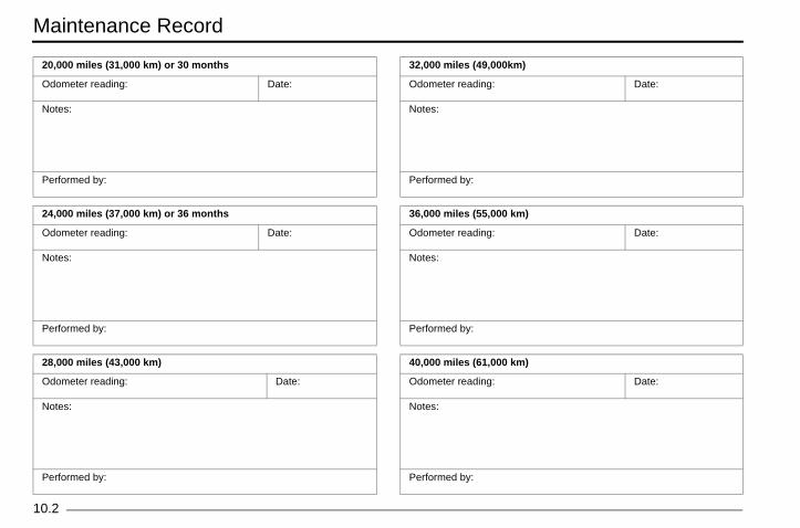
Maintenance Record
10
m)
Date:
km)
Date:
km)
Date:
Zero Owner's Manual (S and DS).book Page 2 Thursday, March 15, 2018 4:13 PM
.2
20,000 miles (31,000 km) or 30 months
Odometer reading: Date:
Notes:
Performed by:
24,000 miles (37,000 km) or 36 months
Odometer reading: Date:
Notes:
Performed by:
28,000 miles (43,000 km)
Odometer reading: Date:
Notes:
Performed by:
32,000 miles (49,000k
Odometer reading:
Notes:
Performed by:
36,000 miles (55,000
Odometer reading:
Notes:
Performed by:
40,000 miles (61,000
Odometer reading:
Notes:
Performed by:

Maintenance Record
10.3
,000 km)
g: Date:
,000 km)
g: Date:
,000 km)
g: Date:
Zero Owner's Manual (S and DS).book Page 3 Thursday, March 15, 2018 4:13 PM
44,000 miles (67,000 km)
Odometer reading: Date:
Notes:
Performed by:
48,000 miles (73,000 km)
Odometer reading: Date:
Notes:
Performed by:
52,000 miles (79,000 km)
Odometer reading: Date:
Notes:
Performed by:
56,000 miles (85
Odometer readin
Notes:
Performed by:
60,000 miles (91
Odometer readin
Notes:
Performed by:
64,000 miles (97
Odometer readin
Notes:
Performed by:

Maintenance Record
10
km)
Date:
km)
Date:
km)
Date:
Zero Owner's Manual (S and DS).book Page 4 Thursday, March 15, 2018 4:13 PM
.4
68,000 miles (103,000 km)
Odometer reading: Date:
Notes:
Performed by:
72,000 miles (109,000 km)
Odometer reading: Date:
Notes:
Performed by:
76,000 miles (115,000 km)
Odometer reading: Date:
Notes:
Performed by:
80,000 miles (121,000
Odometer reading:
Notes:
Performed by:
84,000 miles (127,000
Odometer reading:
Notes:
Performed by:
88,000 miles (133,000
Odometer reading:
Notes:
Performed by:
Index
INDEX.1
formation ...................................................1.6
.................................................................6.23se Center ................................................6.24ge Fuse Center .......................................6.26
ration .........................................................4.1h/Steering Lock Positions..........................4.2Inspection...................................................4.1ty Precautions...........................................2.1bleshooting ...............................................7.8
................................................................6.17acement...................................................6.18
erating Information....................................2.2
...................................................................4.1anel.................................................. 3.8, 3.10
Zero Owner's Manual (S and DS).book Page 1 Thursday, March 15, 2018 4:13 PM
AAccessories .................................................................6.23
BBrake/Tail Light Bulb Replacement .............................6.20Brakes .........................................................................6.10
Brake Fluid Level Inspection...................................6.10Brake Pad Inspection..............................................6.12Braking...............................................................4.4, 4.6DOT 4 brake fluid....................................................6.11Front Brake .............................................................6.10Rear Brake..............................................................6.11Squeal .....................................................................6.12
CCharge Tank..................................................................5.9Charging Stations ........................................................5.10Charging the Power Pack..............................................5.4Cleaning Your Motorcycle ...........................................6.22Contact information
NHTSA....................................................................9.11Zero Motorcycles ....................................................9.10
DDash Settings ..............................................................3.12Drive Belt .....................................................................6.15
Checking Drive Belt Tension...................................6.15
EEmissions In
FFuses ..........
12 Volt FuHigh Volta
GGeneral Ope
Key SwitcPre-Ride
General SafeGeneral Trou
HHeadlight
AlignmentBulb Repl
IImportant OpInspection
Pre-Ride .Instrument P

Index
IN
KK
LLoLo
MM
MMM
OO
OO
..........................................................6.23e Items...............................................6.2el Switch...........................................3.20..........................................................3.20on......................................................3.20............................................................6.9-Force Power Pack.............................1.2r ...........................................................1.4ion .......................................................4.1Stations .............................................5.10
............................................................5.6
defects..............................................9.11
mation .................................................1.2..........................................................7.16
............................................................1.4
............................................................1.4lication ..............................................3.15SOC) ................................................3.15
Zero Owner's Manual (S and DS).book Page 2 Thursday, March 15, 2018 4:13 PM
DEX.2
eysReplacement Code Number ..................................... 1.4
cation Of Important Labels ........................................ 2.3g book...................................................................... 10.1
aintenanceRecord .................................................................... 10.1
aintenance Schedule.................................................. 6.2aximizing Range......................................................... 1.7otor Serial Number ..................................................... 1.4
perating Your Motorcycle............................................ 4.4Braking...............................................................4.4, 4.6Stopping.................................................................... 4.4
wner Information Record ............................................ 1.3wner’s Responsibilities ............................................... 6.1
PParking ..............Parts/MaintenancPerformance Lev
ECO PositionSPORT Positi
Power Pack .......Plug in Your ZSerial Numbe
Pre-Ride InspectPublic Charging
QQuick Charging..
RReporting safety
SSafe Riding InforSafety InterlocksSerial Number
Motor.............Power Pack...
Smartphone AppState of Charge (

Index
INDEX.3
tification Number (VIN)...................................................................1.4ding Your VIN Number .............................1.5e ...............................................................1.6
ts..................................................... 3.8, 3.10
...................................................................9.1s .................................................................9.3f Ownership And Warranty.......................9.9
Tires ........................................................6.14
Zero Owner's Manual (S and DS).book Page 3 Thursday, March 15, 2018 4:13 PM
StorageLong Term...............................................................6.23
SuspensionFront........................................................................6.13Rear ........................................................................6.13
Suspension Adjustment.................................................4.9Front Fork Adjustment .....................................4.7, 4.12Rear Shock Adjustment ..........................................4.13
Suspension settingsFront (Factory) ........................................................4.12Rear (Factory) .........................................................4.17
TTechnical Specifications
Zero DS Technical Specifications .............................8.5Zero DSR Technical Specifications...........................8.7Zero S Technical Specifications................................8.1Zero SR Technical Specifications .............................8.3
Tire Inflation.................................................................6.14Transporting ................................................................1.10Troubleshooting
Battery Management System (BMS).........................7.9Charge Mode ..........................................................7.11Run Mode ...............................................................7.12
Turn Signal Light Bulb Replacement ...........................6.20
VVehicle Iden
Location..Understan
Vehicle Rang
WWarning LighWarranty
CoverageExclusionTransfer O
Wheels And

Notes
IN
Zero Owner's Manual (S and DS).book Page 4 Thursday, March 15, 2018 4:13 PM
DEX.4

First Responder Information - High Voltage Components LocationsFirst Responder Information - High Voltage Components Locations
Zero Owner's Manual (S and DS).book Page 1 Thursday, March 15, 2018 4:13 PM

TAKE CHARGE™
ZE
RO
S / S
R / D
S / D
SR
ZEROMOTORCYCLES.COM
2016
YCYY LES.COM88-08461.04
OW
NE
R’S
MA
NU
AL
Zero Owner's Manual (S and DS).book Page 1 Thursday, March 15, 2018 4:13 PM