zero-max servo class couplings - motionusa - your source
TRANSCRIPT
2 www.zero-max.com Phone 800.533.1731 763.546.4300 Fax 763.546.8260
®
� �
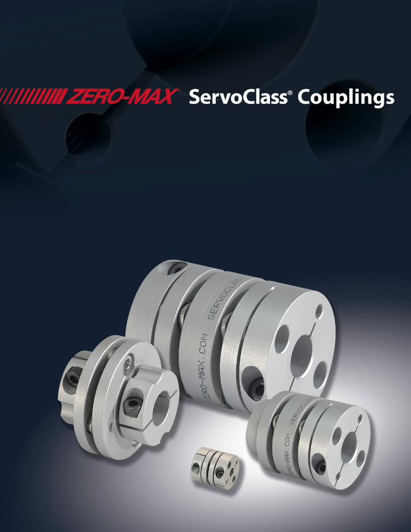
ZERO-MAX SERVOCLASS COUPLINGS
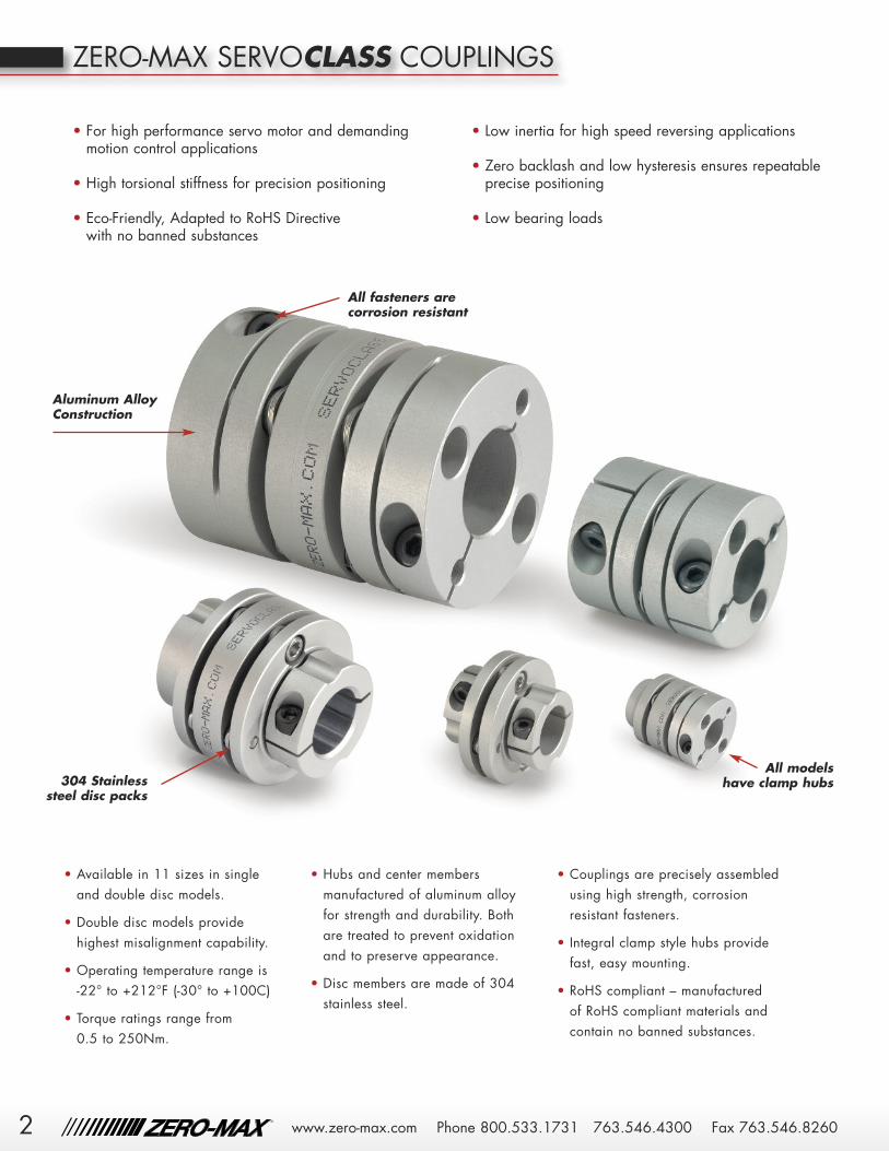
• For high performance servo motor and demandingmotion control applications
• High torsional stiffness for precision positioning
• Eco-Friendly, Adapted to RoHS Directive with no banned substances
• Low inertia for high speed reversing applications
• Zero backlash and low hysteresis ensures repeatableprecise positioning
• Low bearing loads
All fasteners are corrosion resistant
All models have clamp hubs
• Available in 11 sizes in single and double disc models.
• Double disc models providehighest misalignment capability.
• Operating temperature range is -22° to +212°F (-30° to +100C)
• Torque ratings range from 0.5 to 250Nm.
• Hubs and center membersmanufactured of aluminum alloyfor strength and durability. Bothare treated to prevent oxidationand to preserve appearance.
• Disc members are made of 304stainless steel.
• Couplings are precisely assembledusing high strength, corrosionresistant fasteners.
• Integral clamp style hubs providefast, easy mounting.
• RoHS compliant – manufactured of RoHS compliant materials andcontain no banned substances.
Aluminum AlloyConstruction
304 Stainlesssteel disc packs

3
SERVOCLASS COUPLINGS FOR EVERY SERVO SYSTEM REQUIREMENT
Today’s servo motorapplications are more demandingthan ever. The precision positioningrequirements and high reverse loadcharacteristics of AC and DCservomotor applications necessitate acoupling design that specificallyaddresses the needs of thesesophisticated systems.
Low Inertia is a critical feature ofa superior servo coupling. The inertiashould be low so as not to addsignificantly to overall inertia of theservo system. The lower the inertia,the less energy required by the motorto move the system and therefore,higher acceleration is possible.Because Zero-Max ServoClasscouplings are made from 7075-T6aluminum they have very low inertia.
High torsional stiffness is animportant quality of any highperformance coupling. Low torsionalstiffness couplings will reduce systemperformance and accuracy. Thetorsional stiffness characteristic of theZero-Max ServoClass couplingincreases the system resonantfrequency which exceeds the
resonant operating frequency of most equipment.
Zero Backlash is another keyrequirement of a high performance
servo coupling. A coupling may beconsidered zero backlash and still havea large amount of windup. Zerobacklash is the ability of the coupling tomaintain the same relative relationshipbetween the input and output shaftwithout lost motion. The Zero-MaxServoClass coupling is a zero backlashcoupling and it exhibits a very lowamount of windup.
Misalignment capability of acoupling is also important in a motioncontrol system. Usually, the alignment of
a well manufactured servo systemwill be very good. Over time andunder high load conditions, thisalignment may deteriorate. Anotherimportant benefit of a highmisalignment capability is the lowreaction loads on the bearings in thesystem. The Zero-Max ServoClasscoupling utilizes a design thatprovides flexibility but does notsacrifice any of the torque capabilityor the torsional stiffness capabilityand therefore minimizes the reactionloads to the servo motor bearings.

Style A Style B Style C
4 www.zero-max.com Phone 800.533.1731 763.546.4300 Fax 763.546.8260
®
� �
• Moment of Inertia and Weight are measured with the maximum bore diameters• Tolerance of mounted shaft should be h7
SERVOCLASS® SC SERIES
The shafts of the equipment (upto the maximum bore size of thecoupling) may be extended intothe interior of the couplingwithout any modification to theServoClass coupling. However,the ends of the shafts must nevertouch each other.
SC Series ServoClass Double Disc Specifications
Model OperatingTorque
Maximum RPM
TorsionalStiffness
Axial Stiffness
Misalignment Capacity Moment of Inertia
Weight Style
Parallel Angular Axial
in.lb.(Nm) r/min
in.lb./deg.(Nm/rad)
lb./in.(N/mm)
inch(mm) degree
± inch± (mm)
lb.in.2kgm2(x10-6)
Oz.(gm)
SC005R 4.4(0.5) 10,000 39
(250)400(70)
0.002(0.05) 0.5 0.004
(0.10)0.0012(0.36)
0.35(10) C
SC010R 7(0.8) 10,000 108
(700)400(70)
0.004(0.11) 1 0.008
(0.20)0.0027(0.79)
0.53(15) C
SC020R 13(1.5) 10,000 286
(1,850)183(32)
0.006(0.15) 1 0.013
(0.33)0.012(3.40)
1.3(36) C
SC030R 35(4.0) 10,000 618
(4,000)183(32)
0.007(0.18) 1 0.016
(0.4)
0.025(7.33)
1.9(53) A
0.032(9.39)
2.2(61) B
0.039(11.5)
2.4(69) C
SC035R 53(6.0) 10,000 1,390
(9,000)320(56)
0.009(0.24) 1 0.020
(0.5)0.092(26.8)
4.3(123) C
SC040R 89(10) 10,000 1,545
(10,000)228(40)
0.009(0.24) 1 0.024
(0.6)
0.101(29.5)
4.3(122) A
0.123(36.1)
4.8(136) B
0.146(42.6)
5.3(151) C
SC050R 221(25) 10,000 2,471
(16,000)137(24)
0.011(0.28) 1 0.031
(0.8)
0.331(96.9)
8.7(246) A
0.407(119)
9.7(275) B
0.483(141)
10.7(304) C
SC060R 531(60) 10,000 5,406
(35,000)218(38)
0.013(0.34) 1 0.035
(0.9)
0.862(252)
15.5(440) A
1.08(315)
17.6(498) B
1.29(377)
19.5(556) C
SC080R 885(100) 10,000 10,812
(70,000)366(64)
0.02(0.52) 1 0.04
(1.10)3.54(1,034)
37.0(1,051) C
SC090R 1,593(180) 10,000 7,723
(50,000)308(54)
0.02(0.52) 1 0.05
(1.30)6.08(1,776)
48.4(1,373) C
SC100R 2,213(250) 10,000 9,268
(60,000)317(55)
0.02(0.52) 1 0.06
(1.48)9.26(2,704)
60.2(1,707) C
• For high performance servo motor and demandingmotion control applications
• High torsional stiffness for precision positioning• Eco-Friendly, adapted to RoHS Directive with
no banned substances• Low inertia for high speed applications• Zero backlash and low hysteresis ensures
repeatable precise positioning

5
*SC010 with a bore of 8mm or 0.3125" will have a M2 clamp screw and a tightening torque of 3.5 in lbs. or 0.4Nm
SC Series ServoClass Double Disc DimensionsModel Bores Outside
Diameter OverallLength
HubLength
ReducedHub
Diameter
DistanceBetweenShaft Ends
Clamp Boltto Bore (onreduced hubs)
ClampBolt toBore
Clamp Boltto End ofHub
Clamp ScrewSize
TighteningTorque
Min Max D L LB N DBSE A1 A2 C M
Inch(mm)
Inch(mm)
Inch(mm)
Inch(mm)
Inch(mm)
Inch(mm)
Inch(mm)
Inch(mm)
Inch(mm)
Inch(mm) Size in. lb.
(Nm)
SC005R 0.157(4)
0.236(6)
0.63(16)
0.913(23.2)
0.309(7.85) – 0.295
(7.5) – 0.189(4.8)
0.098(2.5) M2.0 3.5
(0.4)
SC010R 0.157(4)
0.3125*(8)*
0.748(19)
1.02(25.9)
0.36(9.15) – 0.299
(7.6) – 0.228(5.8)
0.124(3.15) M 2.5* 9*
(1)*
SC020R 0.1875(5)
0.375(10)
1.024(26.0)
1.272(32.3)
0.423(10.75) – 0.425
(10.8) – 0.374(9.5)
0.130(3.3) M2.5 9
(1)
SC030R 0.1875**(5)**
0.5625(14)
1.339(34.0)
1.488(37.8)
0.488(12.4)
0.850(21.6)
0.511(13.0)
0.315(8)
0.492(12.5)
0.148(3.75) M3 13
(1.5)
SC035R 0.3125(8)
0.625(16)
1.535(39.0)
1.890(48)
0.610(15.5) – 0.669
(17.0) – 0.551(14)
0.177(4.5) M4 30
(3.4)
SC040R 0.3125**(8)**
0.750(19)
1.732(44.0)
1.890(48)
0.610(15.5)
1.165(29.6)
0.669(17.0)
0.433(11)
0.669(17)
0.177(4.5) M4 30
(3.4)
SC050R 0.375**(10)**
1.000(25)
2.205(56.0)
2.354(59.8)
0.807(20.5)
1.496(38)
0.739(18.8)
0.571(14.5)
0.866(22)
0.236(6) M5 62
(7)
SC060R 0.500**(12)**
1.1875(30)
2.677(68.0)
2.886(73.3)
0.992(25.2)
1.811(46)
0.902(22.9)
0.689(17.5)
1.043(26.5)
0.305(7.75) M6 124
(14)
SC080R 0.875(20)
1.375(35)
3.228(82.0)
3.858(98)
1.181(30) – 1.496
(38.0) – 1.102(28)
0.354(9) M8 266
(30)
SC090R 1.000(25)
1.5(40)
3.622(92.0)
3.882(98.6)
1.181(30) – 1.520
(38.6) – 1.339(34)
0.354(9) M8 266
(30)
SC100R 1.438(35)
1.75(45)
4.095(104.0)
4.000(101.6)
1.181(30) – 1.638
(41.6) – 1.535(39)
0.354(9) M8 266
(30)
** Reduced Hub DimensionsModel Min Max
Inch(mm)
Inch(mm)
SC030R 0.1875(5)
0.375(10)
SC040R 0.3125(8)
0.5625(15)
SC050R 0.375(10)
0.750(19)
SC060R 0.500(12)
0.9375(24)
LBDBSEC
L
øDøD
A2
øNA1
New Zero-MaxConfigurable 3D CADDownloads.www.zero-max.com
SERVOCLASS® SC SERIES
www.zero-max.com Phone 800.533.1731 763.546.4300 Fax 763.546.8260
®
� �

6 www.zero-max.com Phone 800.533.1731 763.546.4300 Fax 763.546.8260
®
� �
• Moment of Inertia and Weight are measured with the maximum bore diameters• Tolerance of mounted shaft should be h7
SERVOCLASS® SD SERIES
SD SeriesServoClass Single Disc Specifications
Model OperatingTorque
Maximum RPM
TorsionalStiffness
Axial Stiffness
Misalignment Capacity Moment of Inertia
Weight Style
Parallel Angular Axial
in.lb.(Nm) r/min
in.lb./deg.(Nm/rad)
lb./in.(N/mm)
inch(mm) degree
± inch± (mm)
lb.in.2kgm2(x10-6)
Oz.(gm)
SD005R 4.4(0.5) 10,000 77
(500)799(140)
0.001(0.02) 0.5 0.002
(0.05)0.0009(0.25)
0.25(7) C
SD010R 7(0.8) 10,000 216
(1,400)799(140)
0.001(0.02) 1 0.004
(0.10)0.0019(0.58)
0.39(11) C
SD020R 13(1.5) 10,000 572
(3,700)365(64)
0.001(0.02) 1 0.006
(0.15)0.008(2.36)
0.9(25) C
SD030R 35(4.0) 10,000 1,236
(8,000)365(64)
0.001(0.02) 1 0.008
(0.2)
0.014(4.00)
1.2(33) A
0.021(6.06)
1.4(41) B
0.028(8.12)
1.7(49) C
SD035R 53(6.0) 10,000 2,780
(18,000)640(112)
0.001(0.02) 1 0.010
(0.25)0.063(18.4)
3.0(84) C
SD040R 89(10) 10,000 3,089
(20,000)457(80)
0.001(0.02) 1 0.012
(0.3)
0.056(16.4)
2.7(76) A
0.078(23.0)
3.2(90) B
0.101(29.5)
3.7(105) C
SD050R 221(25) 10,000 4,943
(32,000)274(48)
0.001(0.02) 1 0.016
(0.4)
0.188(54.9)
5.5(156) A
0.263(77.1)
6.5(185) B
0.339(99.3)
7.5(214) C
SD060R 531(60) 10,000 10,812
(70,000)436(76.4)
0.001(0.02) 1 0.018
(0.45)
0.491(144)
9.8(279) A
0.704(206)
11.9(337) B
0.918(268)
14(396) C
SD080R 885(100) 10,000 21,625
(140,000)731(128)
0.001(0.02) 1 0.02
(0.55)2.43(709.3)
25.6(727) C
SD090R 1,593(180) 10,000 15,446
(100,000)616(108)
0.001(0.02) 1 0.03
(0.65)4.20(1,227)
33.8(959) C
SD100R 2,213(250) 10,000 18,535
(120,000)664(111)
0.001(0.02) 1 0.03
(0.74)6.36(1,858)
41.6(1,181) C
• For high performance servo motor and demandingmotion control applications
• High torsional stiffness for precision positioning• Eco-Friendly, adapted to RoHS Directive with
no banned substances• Low inertia for high speed applications• Zero backlash and low hysteresis ensures
repeatable precise positioning
Style A Style B Style C
The shafts of the equipment (upto the maximum bore size of thecoupling) may be extended intothe interior of the couplingwithout any modification to theServoClass coupling. However,the ends of the shafts must nevertouch each other.

7
*SD010 with a bore of 8mm or 0.3125" will have a M2 clamp screw and a tightening torque of 3.5 in lbs. or 0.4Nm
SD Series ServoClass Single Disc DimensionsModel Bores Outside
Diameter OverallLength
HubLength
ReducedHub
Diameter
DistanceBetweenShaft Ends
Clamp Boltto Bore (onreduced hubs)
ClampBolt toBore
Clamp Boltto End ofHub
Clamp ScrewSize
TighteningTorque
Min Max D L LB N DBSE A1 A2 C M
Inch(mm)
Inch(mm)
Inch(mm)
Inch(mm)
Inch(mm)
Inch(mm)
Inch(mm)
Inch(mm)
Inch(mm)
Inch(mm) Size in. lb.
(Nm)
SD005R 0.157(4)
0.236(6)
0.63(16)
0.657(16.7)
0.309(7.85) – 0.039
(1.0) – 0.189(4.8)
0.098(2.5) M2.0 3.5
(0.4)
SD010R 0.157(4)
0.3125*(8)*
0.748(19)
0.762 (19.35)
0.36(9.15) – 0.041
(1.05) – 0.228(5.8)
0.124(3.15) M 2.5* 9*
(1)*
SD020R 0.1875(5)
0.375(10)
1.024(26.0)
0.911(23.15)
0.423(10.75) – 0.065
(1.65) – 0.374(9.5)
0.130(3.3) M2.5 9
(1)
SD030R 0.1875**(5)**
0.5625(14)
1.339(34.0)
1.075(27.3)
0.488(12.4)
0.850(21.6)
0.098(2.5)
0.315(8)
0.492(12.5)
0.148(3.75) M3 13
(1.5)
SD035R 0.3125(8)
0.625(16)
1.535(39.0)
1.339(34)
0.610(15.5) – 0.118
(3.0) – 0.551(14)
0.177(4.5) M4 30
(3.4)
SD040R 0.3125**(8)**
0.750(19)
1.732(44.0)
1.339(34)
0.610(15.5)
1.165(29.6)
0.118(3.0)
0.433(11)
0.669(17)
0.177(4.5) M4 30
(3.4)
SD050R 0.375**(10)**
1.000(25)
2.205(56.0)
1.709(43.4)
0.807(20.5)
1.496(38)
0.094(2.4)
0.571(14.5)
0.866(22)
0.236(6) M5 62
(7)
SD060R 0.500**(12)**
1.1875(30)
2.677(68.0)
2.110(53.6)
0.992(25.2)
1.811(46)
0.126(3.2)
0.689(17.5)
1.043(26.5)
0.305(7.75) M6 124
(14)
SD080R 0.875(20)
1.375(35)
3.228(82.0)
2.677(68)
1.181(30) – 0.315
(8) – 1.102(28)
0.354(9) M8 266
(30)
SD090R 1.000(25)
1.5(40)
3.622(92.0)
2.689(68.3)
1.181(30) – 0.327
(8.3) – 1.339(34)
0.354(9) M8 266
(30)
SD100R 1.438(35)
1.75(45)
4.095(104.0)
2.748(69.8)
1.181(30) – 0.386
(9.8) – 1.535(39)
0.354(9) M8 266
(30)
** Reduced Hub DimensionsModel Min Max
Inch(mm)
Inch(mm)
SD030R 0.1875(5)
0.375(10)
SD040R 0.3125(8)
0.5625(15)
SD050R 0.375(10)
0.750(19)
SD060R 0.500(12)
0.9375(24)
øD
øNA1
LBDBSEC
L
øD
A2
New Zero-MaxConfigurable 3D CADDownloads.www.zero-max.com
SERVOCLASS® SD SERIES
www.zero-max.com Phone 800.533.1731 763.546.4300 Fax 763.546.8260
®
� �

8 www.zero-max.com Phone 800.533.1731 763.546.4300 Fax 763.546.8260
®
� �
SERVOCLASS®
High Torsional Stiffness• Increased system accuracy• Enables high-speed operation• Improved system stability
The right coupling can add performance and longevity to your system!
Precision designed clamp hub• Positive shaft hub connection• Zero Backlash• Trouble free assembly
Ultra low weight design• Low inertia• 7075-T6 High strength aluminum• Lower inertia than comparable
bellows designs
High Quality• High grade materials used
throughout the coupling• Machined and assembled
by highly skilled technicianswith certified tooling Low radial stiffness
• Improved bearing life• Reduce operating temperatures• Improved system accuracy

Phase
Torque
Phase
Torque
Torsional Windup
9
SERVOCLASS®
Typical “Zero Backlash” Jaw Type Coupling
Typical Hysteresis Curves
Zero-Max ServoClass Coupling
New Zero-Max Configurable 3D CAD Downloads.www.zero-max.com
www.zero-max.com Phone 800.533.1731 763.546.4300 Fax 763.546.8260
®
� �

How to evaluate the resonantfrequency of feed-screw system
10 www.zero-max.com Phone 800.533.1731 763.546.4300 Fax 763.546.8260
®
� �
1. Oscillation phenomena of servomotorsIf the resonant frequency of the entire feed-screwsystem is under 400~500Hz, oscillation may occurdepending on the gain adjustment of theservomotor. The problems can be avoided byraising the resonant frequency of the mechanicalsystem or adjusting the tuning function (filterfunction) of the servomotor.
Contact us for unclear points concerning oscillationphenomena of servomotors.
2. Resonance caused by stepping motorsResonance can occur within a certain speed rangedue to the pulsation frequency of the stepping motorand the natural frequency of the entire system.Resonance can be avoided by not operating nearresonant speed, or by reviewing the resonantfrequency in the design phase.
Contact us for unclear points concerning resonanceof stepping motors.
Feed Screw Systems
1. Select the coupling according to the normaloperating torque and maximum torque of theservomotor/stepping motor.
2. In the following feed-screw system, evaluate theentire resonant frequency: Nf from the torsionalspring constant: K of the coupling and feed screw,the moment of inertia: J1 of the driving side andthe moment of inertia: J2 of the driven side.
Nf: Eigenfrequency of the entire feed-screw system [Hz] K: Torsional spring constant of the coupling and feed
screw [N・m/rad] J1: Moment of inertia of the driving side J2: Moment of inertia of the driven side
12π
Nf =
SELECTING A SERVOCLASS® COUPLING
MotorFeed screw
Bearing
TableCoupling
J1 J2
√K +( )1J1
1J2
1. Calculate torque Ta applied to the coupling based on themotor output P and coupling operating rotation speed n.
Selection Procedure
2. Calculate corrected torque Td applied to the coupling afterdeciding the service factor K based on load conditions.Td = Ta x K
In servomotor drive, multiply the service factorK=1.2~1.5 by the maximum torque of servomotor Ts.Td = Ts × (1.2~1.5)
3. Select a coupling size with permissible torque Tn thatbecomes greater than the corrected torque Td.Tn ≥ Td
4. Depending on the bore diameters, the coupling permissibletorque may be limited. Refer to the "Specification" and"Standard bore diameter".
5. Confirm if the required shaft diameter does not exceed the maximum bore diameter of the selected size.
Ta[N•m] = 9550 x R [kW]n [min-1]
If our standard line of ServoClass coupling willnot exactly fit your system needs, contact us fora custom design.• Custom bores• Ultra high speeds• Special finishes• Special Lengths• Designed for operation in special environments

11
SERVOCLASS® HOW TO ORDER
Part Numbering Structure
TYPE R
SC Double FlexSD Single Flex
Code
Note: this isthe standard
design
RoHS Compliant
Code Description
Example: SC050R (20 mm x 1/2")• Double Flex design• Size 050• 20mm bore without keyway
x 1/2" bore without keyway
– SIZE
005 Size 005010 Size 010020 Size 020030 Size 030035 Size 035040 Size 040050 Size 050060 Size 060080 Size 080090 Size 090100 Size 100
Code Description
( Bore x Bore )
See Chart
ServoClass couplings arestandard without keyways.Keyways are availableupon request.
Note: The hub design of ServoClass couplings will provide the necessaryclamping force to hold the shaft in a dynamic application without the useof keyways. Keyways are available upon request. Please reference thebore size chart below for more details on bore sizes and torque.
ModelBore Coupling Operating Torque
Inch mm in-lbs Nm
SD/SC020R 0.1875 5 11 1.2
SD/SC030R0.1875 5 25 2.8
0.236 6 30 3.4
SD/SC040R 0.3125 8 80 9
SD/SC050R 0.375 10 195 22
SD/SC060R 0.500 12 451 51
●: Standard Bore Size – Full Rated Torque. ❍: Standard Bore, See the operating torque in the
Bore Size and Operating Torque table above right
Bore Size Bore Size and Operating TorqueBore size affects and limits the operating torque of the coupling
Bore Size D1 D2 mm
Inch mm
Model
SD/SC005R
SD/SC010R
SD/SC020R
SD/SC030R
SD/SC035R
SD/SC040R
SD/SC050R
SD/SC060R
SD/SC080R
SD/SC090R
SD/SC100R
0.157 4 ● ●
0.1875 5 ● ● ❍ ❍
0.236 6 ● ● ● ❍
0.250 6.35 ● ● ●
0.275 7 ● ● ●
0.3125 8 ● ● ● ● ❍
0.354 9 ● ● ● ●
0.375 9.525 ● ● ● ●
0.375 10 ● ● ● ●
0.433 11 ● ● ●
0.500 12 ● ● ● ❍
0.563 14 ● ● ● ●
0.563 15 ● ● ● ❍
0.625 16 ● ● ● ●
0.708 18 ● ● ●
0.750 19 ● ● ●
0.813 20 ● ● ●
0.875 22 ● ● ●
0.938 24 ● ● ●
1.00 25 ● ● ● ●
1.10 28 ● ● ● ●
1.188 30 ● ● ● ●
1.250 32 ● ● ●
1.375 35 ● ● ● ●
1.500 38 ● ●
1.563 40 ● ●
1.625 42 ●
1.750 45 ●
www.zero-max.com Phone 800.533.1731 763.546.4300 Fax 763.546.8260
®
� �

Warranty. Zero-Max, Inc. the manufacturer, warrants that for a period of 12 months from date of shipment it will repair, or at its option, replace any new apparatus which proves defective in material or workmanship, orwhich does not conform to applicable drawings and specifications approved by the manufacturer. All repairs and replacements shall be F.O.B. factory. All claims must be made in writing to the manufacturer. • In no eventand under no circumstances shall manufacturer be liable for (a) damages in shipment; (b) failures or damages due to misuse, abuse, improper installation or abnormal conditions of temperature, dirt, water or corrosives; (c)failures due to operation, intentional or otherwise, above rated capacities, and (d) non-authorized expenses for removal, inspection, transportation, repair or rework. Nor shall manufacturer ever be liable for consequentialand incidental damages, or in any amount greater than the purchase price of the apparatus. • Zero Max, Inc. reserves the right to discontinue models or to change specifications at any time without notice. No discontinuanceor change shall create any liability on the part of Zero-Max, Inc. in respect to its products in the hands of customers or products on order not incorporating such changes even though delivered after any such change. • Thiswarranty is in LIEU OF ALL OTHER WARRANTIES, EXPRESS OR IMPLIED, INCLUDING (BUT NOT LIMITED TO) ANY IMPLIED WARRANTIES OF MERCHANTABILITY OR FITNESS FOR A PARTICULAR PURPOSE. THE TERMS OF THISWARRANTY CONSTITUTE ALL BUYER’S OR USER’S SOLE AND EXCLUSIVE REMEDY, AND ARE IN LIEU OF ANY RIGHT TO RECOVER FOR NEGLIGENCE, BREACH OF WARRANTY, STRICT TORT LIABILITY OR UPON ANY OTHER THEORY.Any legal proceedings arising out of the sale or use of this apparatus must be commenced within 18 months of the date of purchase. • CAUTION: Rotating equipment must be guarded. Also refer to OSHA specifications andrecommendations. • Zero-Max®, CD®, ETP®, ServoClass®, Torq-Tender®, Control-Flex®, Posi-Lok®, Roh'Lix® and OHLA® are registered trademarks of Zero-Max, Inc. In U.S.A. © Zero-Max 2010 Printed in U.S.A.
13200 Sixth Avenue North, Plymouth, Minnesota 55441-5509
Phone: 800-533-1731 (763) 546-4300 Fax (763) 546-8260 www.zero-max.com
ServoClass® CouplingsDesigned for demandingservomotor applications. Zerobacklash, high torsional stiffnesscoupling. Features flexible metaldiscs and keyless clamp-typemounting hubs. Couplings areRoHS compliant.
Schmidt Offset Couplings®
Schmidt Offset Couplings® aredesigned to handle high amountsof parallel offset up to 17.00".Standard models with torquecapacities up to 459,000 in-lbs.
Torq-Tender® CouplingsTorq-Tender® Couplings providereliable overload protection in anymechanical power transmissionsystem. Torque ranges from 2 to3000 in-lbs.
ETP® Shaft Locking ConnectionsDesigned for quick, easy andaccurate assembly of mounted shaft components. Both inch andmetric bore connections are available from stock.
Adjustable Speed DriveEasy to install and maintenance free.Zero-Max Drives offer infinitelyvariable speeds from 0 rpm to 1/4 of input rpm. 5 models with torqueranges from 12 in-lbs to 200 in-lbs.
Crown Gear DrivesCrown Gear Drives® are available with1:1 and 2:1 ratios. High quality AGMAclass 10 spiral bevel gears. Stainlesssteel shafts and aluminum housings arestandard on all Crown Gear Drives®.
Roh’lix® Linear ActuatorsRoh’Lix® Linear Actuators convert rotary motion into precise linearmotion. Available in five models.Roh’Lix® actuators have thrust ratingsfrom 5 to 200 lbs. All models feature built in overload protection.
CD® CouplingsThese high performance couplingsout last bellows and steel discdesign couplings. The unique designof the composite disc enables theCD Couplings® to withstandpunishing applications and deliverhigh precision performance.
Control-Flex® CouplingsControl-Flex® Couplings are zerobacklash couplings designed forencoder and instrumentation type applications.
OHLA® Overhung Load AdaptersOHLA® Overhung Load Adapters aredesigned to eliminate radial and axialloads from a hydraulic pump or motor.11 models available for mounts fromSAE A to SAE F.