zafira, v.6 (rev ), en-gb - opel vehicle display screens may not support your ... r = reverse gear...
TRANSCRIPT

Introduction .................................... 2In brief ............................................ 6Keys, doors and windows ............ 27Seats, restraints ........................... 44Storage ........................................ 67Instruments and controls ............. 77Lighting ...................................... 108Infotainment system ................... 115Climate control ........................... 118Driving and operating ................. 126Vehicle care ............................... 153Service and maintenance .......... 191Technical data ........................... 205Customer information ................ 223Index .......................................... 224
Contents

2 Introduction
Introduction

Introduction 3
Vehicle specific dataPlease enter your vehicle’s data onthe previous page to keep it easilyaccessible. This information isavailable under the sections "Serviceand Maintenance" and "Technicaldata" as well as on the identificationplate.
IntroductionYour vehicle is a designedcombination of advanced technology,safety, environmental friendlinessand economy.This Owner’s Manual provides youwith all the necessary information toenable you to drive your vehiclesafely and efficiently.Make sure your passengers areaware of the possible risk of accidentand injury which may result fromimproper use of the vehicle.You must always comply with thespecific laws and regulations of thecountry that you are in. These lawsmay differ from the information in thisOwner’s Manual.
When this Owner’s Manual refers toa workshop visit, we recommend yourOpel Service Partner.All Opel Service Partners providefirst-class service at reasonableprices. Experienced mechanicstrained by Opel work according tospecific Opel instructions.The customer literature pack shouldalways be kept ready to hand in thevehicle glovebox.
Using this manual■ This manual describes all options
and features available for thismodel. Certain descriptions,including those for display andmenu functions, may not apply toyour vehicle due to model variant,country specifications, specialequipment or accessories.
■ The "In brief" section will give youan initial overview.
■ The table of contents at thebeginning of this manual and withineach chapter shows where theinformation is located.
■ The index will enable you to searchfor specific information.
■ Yellow arrows in the illustrationsserve as points of reference orindicate some action to beperformed.
■ Black arrows in the illustrationsindicate a reaction or a secondaction to be performed.
■ This Owner's Manual depicts left-hand drive vehicles. Operation issimilar for right-hand drive vehicles.
■ The Owner's Manual uses thefactory engine designations. Thecorresponding sales designationscan be found in the chapter"Technical data".
■ Directional data, e.g. left or right, orfront or back, always relate to thedirection of travel.
■ The vehicle display screens maynot support your specific language.
■ Display messages and interiorlabelling are written in bold letters.

4 Introduction
Danger, Warnings andCautions
9 Danger
Text marked 9 Danger providesinformation on risk of fatal injury.Disregarding this information mayendanger life.
9 Warning
Text marked 9 Warning providesinformation on risk of accident orinjury. Disregarding thisinformation may lead to injury.
Caution
Text marked Caution providesinformation on possible damage tothe vehicle. Disregarding thisinformation may lead to vehicledamage.
SymbolsPage references are indicated with3. 3 means "see page".We wish you many hours ofpleasurable driving.Adam Opel GmbH

Introduction 5

6 In brief
In brief
Initial drive information
Vehicle unlockingRadio remote control
Press button q to unlock and opendoor. To open the tailgate, press thebutton under the moulding.Radio remote control 3 28, Centrallocking system 3 32, Loadcompartment 3 35.
Electronic key
When in possession of the electronickey, simply pulling the door handlewill unlock the vehicle and open thedoor. To open the tailgate, press thebutton under the moulding.Open&Start system 3 29.

In brief 7
Seat adjustmentSeat positioning
Pull handle, slide seat, releasehandle.Seat adjustment 3 46, Seat position3 46.
Seat backrests
Turn handwheel. Do not lean on seatwhen adjusting.Seat adjustment 3 46, Seat position3 46, Folding front passenger seatbackrest 3 48.
Seat height
Lever pumping motionup = higherdown = lower
Seat adjustment 3 46, Seat position3 46.

8 In brief
Seat inclination
Pull lever, adjust inclination byshifting body weight. Release leverand audibly engage seat in position.Seat adjustment 3 46, Seat position3 46.
Head restraint adjustment
Press release button, adjust height,engage.Head restraints 3 44.
Seat belt
Pull out the seat belt and engage inbelt buckle. The seat belt must not betwisted and must fit close against thebody. The backrest must not be tiltedback too far (maximum approx. 25 °).To release belt, press red button onbelt buckle.Seat belts 3 54, Airbag system3 57, Seat position 3 46.

In brief 9
Mirror adjustmentInterior mirror adjustment
Swivel the lever on the underside toreduce dazzle.Interior mirror 3 40, Automatic anti-dazzle interior mirror 3 40.
Exterior mirrors adjustment
Select the relevant exterior mirror andadjust.Electric adjustment 3 38, Convexexterior mirrors 3 38, Foldingexterior mirrors 3 39, Heatedexterior mirrors 3 39.
Steering wheel adjustment
Unlock lever, adjust steering wheel,then engage lever and ensure it isfully locked. Do not adjust steeringwheel unless vehicle is stationary andsteering wheel lock has beenreleased.Airbag system 3 57, Ignitionpositions 3 127

10 In brief

In brief 11
Instrument panel overview1 Light switch ........................ 108
Instrument illumination ....... 113Rear fog light ....................... 112Front fog lights ................... 111Headlight rangeadjustment ......................... 109
2 Side air vents ...................... 1243 Turn and lane-change
signals, headlight flash,low beam and high beam ... 111Exit lighting .......................... 114Parking lights ...................... 112Cruise control ....................... 93
4 Steering wheel controls ......... 775 Horn ...................................... 78
Driver airbag ......................... 586 Instruments .......................... 837 Windscreen wiper,
windscreen washersystem, headlight washersystem .................................. 78
8 Centre air vents ................... 124
9 Left heated seat .................... 49Deflation detection system .. 175Tyre pressure monitoringsystem ................................. 175Ultrasonic parking sensors ... 89Hazard warning flashers ..... 111Central locking system .......... 32Sport mode ........................... 89Right heated seat .................. 49Fuel selector ........................ 84
10 Info-Display ........................... 93Trip computer ...................... 102Electronic climate controlsystem ................................. 121
11 Front passenger airbag ......... 5812 Glovebox .............................. 6713 Infotainment system ............ 11514 Climate control system ........ 11815 Selector lever, manual
transmission ....................... 135Manual transmissionautomated ........................... 135Automatic transmission ....... 130
16 Ashtray .................................. 8217 Start/Stop button .................. 2918 Accelerator pedal ................ 126
19 Ignition switch withsteering wheel lock ............. 127Sensor panel foremergency operation ofOpen&Start system ............... 29
20 Brake pedal ......................... 13921 Clutch pedal ........................ 12622 Steering wheel adjustment .... 7723 Bonnet release lever ........... 154

12 In brief

In brief 13
Exterior lighting
Turn light switch7 = Off8 = Side lights9 = HeadlightsAUTO = Automatic light control
Press light switch> = Front fog lightsr = Rear fog light
Lighting 3 108, Headlight warningdevice 3 100.
Headlight flash, high beam andlow beam
Headlight flash = Pull leverHigh beam = Push leverLow beam = Push or pull lever
High beam 3 109, Headlight flash3 109.
Turn and lane-change signals
To the right = Lever upTo the left = Lever down
Turn and lane-change signals3 111.

14 In brief
Hazard warning flashers
Operated with the ¨ button.Hazard warning flashers 3 111.
Horn
Press j.
Washer and wiper systemsWindscreen wiper
& = fast% = slow$ = timed interval wipe or
automatic wiping with rainsensor
§ = off
For a single swipe when thewindscreen wiper is off, press thelever down.Windscreen wiper 3 78, Wiperblade replacement 3 158.

In brief 15
Windscreen and headlightwasher systems
Pull lever.Windscreen and headlight washersystem 3 78, Washer fluid 3 157.
Rear window wiper and washersystems
Wipers on = push leverWipers off = push lever againWash = push lever and hold
Rear window wipers and washersystem 3 79, Wiper bladereplacement 3 158, Washer fluid3 157.
Climate controlHeated rear window, heatedexterior mirrors
Heating is operated by pressing theÜ button.Heated rear window 3 42.

16 In brief
Demisting and defrosting thewindows
Air distribution to l.Set temperature control to warmestlevel.Set fan speed to highest level or toA.Cooling n on.Press button V.Climate control system 3 118.
TransmissionManual transmission
Reverse: with the vehicle stationary,wait 3 seconds after depressingclutch pedal and then pull up thebutton on the selector lever andengage the gear.If the gear does not engage, set thelever in neutral, release the clutchpedal and depress again; then repeatgear selection.Manual transmission 3 135.
Manual transmission automated
N = neutralo = drive+ = higher gear- = lower gearA = switch between Automatic and
Manual modeR = reverse gear (with selector
lever lock)
Manual transmission automated3 135.

In brief 17
Automatic transmission
P = parkR = reverseN = neutralD = drive
The selector lever can only be movedout of P or N when the ignition is onand the foot brake is depressed(Selector lever lock). To engage P orR, push button on selector lever.The automatic transmission isavailable in two versions 3 130.
Starting offCheck before starting off■ Tyre pressure and condition
3 174, 3 218.■ Engine oil level and fluid levels
3 155.■ All windows, mirrors, exterior
lighting and number plates are freefrom dirt, snow and ice and areoperational.
■ Proper position of seats, seat beltsand mirrors 3 46, 3 55, 3 38.
■ Brake function at low speed,particularly if the brakes are wet.
Starting engine with ignitionswitch
Turn key to position 1. Move thesteering wheel slightly to release thesteering wheel lock. Operate clutchand brake, automatic transmission inP or N, do not accelerate; for dieselengines, turn the key to position 2 forpreheating and wait until controlindicator ! goes out; turn key to3 and release key when engine isrunning.

18 In brief
Starting engine with Start/Stopbutton
The electronic key must be inside thevehicle. Operate clutch and brake,automatic transmission in P or N, donot accelerate, for diesel engine,press the button briefly to startpreheating, move the steering wheelslightly to release the steering wheellock, wait until control indicator !goes out and then press button for1 second and release when theengine is running.Open&Start system 3 29.
Parking■ Always apply the parking brake
without pressing the release button.Apply as firmly as possible ona downhill slope or uphill slope.Depress the foot brake at the sametime to reduce operating force.
■ Switch off the engine. Turn theignition key to 0 and remove it or,with the vehicle stationary, pressthe Start/Stop button and open thedriver's door. Turn the steeringwheel until the steering wheel lockis felt to engage.For vehicles with automatictransmission, the key can only beremoved when the selector lever isin the P position. If P is not engagedor the parking brake is not applied,"P" flashes for a few seconds in thetransmission display.
■ If the vehicle is on a level surface oruphill slope, engage first gear or setthe selector lever to P beforeswitching off the ignition. On anuphill slope, turn the front wheelsaway from the kerb.
If the vehicle is on a downhill slope,engage reverse gear or set theselector lever to P before switchingoff the ignition. Turn the frontwheels towards the kerb.
■ Lock the vehicle with button p onthe radio remote control or with thesensor in a front door handle.To activate the anti-theft lockingsystem and the anti-theft alarmsystem, press button p twice ortouch the sensor in a front doorhandle twice.
■ Do not park the vehicle on an easilyignitable surface. The hightemperature of the exhaust systemcould ignite the surface.
■ On vehicles with manualtransmission automated, controlindicator R flashes for a fewseconds after the ignition isswitched off if the parking brake hasnot been applied 3 100.
■ Close windows.■ The engine cooling fans may run
after the engine has been switchedoff 3 154.

In brief 19
■ After running at high engine speedsor with high engine loads, operatethe engine briefly at a low load orrun in neutral for approx. 30seconds, before switching off inorder to protect the turbocharger.
Keys, locking 3 27, Laying thevehicle up for a long period of time3 153.

20 In brief
Notable features Seats in second row
9 Warning
When the row of seats or thebackrests are being adjusted,keep hands away from the hingearea.
Moving seatsPush the release lever forward andslide the seat row. Release the leverand audibly engage the seats.
Adjust backrests of outboardseats
Push the release lever down, adjustinclination, release the lever andengage the backrest.
9 Warning
Occupants may only travel ona seat if its backrest is properlyengaged in the upright position.

In brief 21
Seats in third row
9 Warning
When the seats are being movedupright or folded in, keep handsaway from hinge area.
Setting up seatsRemove floor covering 3 70 andload compartment cover 3 69.Push the lever forward and slide thesecond row of seats forward to themark.
Guide the seat belts through the beltholders and insert the latch plates inthe holders.
9 Warning
On version with side rails in loadcompartment, follow thedescriptions 3 71.
From the luggage compartment, pullup the seat by the handle.

22 In brief
Swivel the seat rearward until it isupright and audibly engages. Supportthe top of the backrest with your hand.Preparing belt buckles for use3 55, Load compartment cover3 69.
9 Warning
The belt must not be routedthrough the belt holder when theseat belt is in use.
Slide the second row of seats to therequired position and engage.
Storing seatsRemove the load compartment cover3 69.Push the lever forward and slide thesecond row of seats forward to themark.Press the catch to release and slidethe head restraints of the third row allthe way down.Guide the seat belts through the beltholders and insert the latch plates inthe holders.
From the luggage compartment,press the button on the top of thebackrest and lower the backrest.Using the handle on the seat, pullrearwards and upwards and thenswing the seat forwards until it islowered into the vehicle floor. Holdthe seat by the handle during theentire procedure.Retract belt buckle 3 55 and installfloor covering 3 70 and loadcompartment cover 3 69.Slide the second row of seats to therequired position and engage.

In brief 23
Active head restraints on frontseats
In the event of a rear-end impact, theactive head restraints tilt forwardsslightly. The head is more effectivelysupported by the head restraint andthe risk of whiplash injury is reduced.Active head restraints can berecognised by the word ACTIVE.Head restraints 3 44.
Trip computer
Functions:■ Range■ Instantaneous consumption■ Distance■ Average speed■ Absolute consumption■ Average consumption■ Stop watch■ Tyre pressureTrip computer 3 102, 3 104.
Check control
The check control monitors:■ Fluid levels■ Tyre pressure■ Radio remote control battery■ Anti-theft alarm system■ Important exterior lighting bulbs,
including cables and fuses.Display messages 3 100.

24 In brief
Rear seat audio system
Twin Audio allows occupants in thesecond row the choice between theaudio source played on theinfotainment system or a separateaudio source.Rear seat audio system 3 116.
Sport mode
Activate by pressing the SPORTbutton.The Sport mode is used to makesuspension and steering more direct.The engine is more responsive tothrottle application. With manualtransmission automated andautomatic transmission, gearchanging is altered.Sport mode 3 142.
FlexOrganizer
The side walls contain retainingstrips, where various componentscan be attached to divide the loadcompartment or fasten loads.The system consists of■ adapters■ variable partition net■ mesh pockets for the side walls■ hooks in the load compartmentFlexOrganizer 3 71.

In brief 25
Tyre deflation detectionsystem
If a tyre loses pressure, it becomessmaller. It then rotates at a differentspeed than the other tyres. If thesystem detects a difference in speed,control indicator w illuminates red.Deflation Detection System 3 175.
Tyre pressure monitoringsystem
A pressure sensor is integrated ineach wheel to monitor tyre pressure.Whilst driving, the current tyrepressures appear in the Boardcomputer menu.Deviating tyre pressure is displayedin the form of a message in theInfo-Display.Tyre pressure monitoring system3 175.
Adaptive Forward Lighting
The system improves lighting ofcurves and increases the headlightrange.The beam pivots based on steeringwheel position and vehicle speed.At higher speeds and continuousstraight ahead travel, the beamautomatically raises slightly, therebyincreasing headlight range.Adaptive Forward Lighting 3 110.

26 In brief
Natural gas operation
This specially developed engine isdesigned for the use of natural gasand petrol.The Y button is used to switchbetween petrol and natural gasoperation.The status of the LED indicates thetype of fuel in use.Natural gasoperation
= LED off.
Petrol operation = LED illuminates.
Natural gas 3 84, 3 146.
Diesel particle filterThe diesel particle filter system filtersharmful soot particles out of theexhaust gases. The system includesa self-cleaning function that runsautomatically during driving. The filteris cleaned by burning off the sootparticles at high temperature. Thisprocess takes place automaticallyunder set driving conditions and maytake up to 25 minutes. Fuelconsumption may be higher duringthis period. The emission of smellsand smoke during this process isnormal.
Under certain driving conditions, e.g.short distances, the system cannotclean itself automatically.If the filter requires cleaning andprevious driving conditions did notenable automatic cleaning, controlindicator ! flashes.Further instructions 3 128.

Keys, doors and windows 27
Keys, doors andwindows
Keys, locks ................................... 27Doors ........................................... 35Vehicle security ............................ 36Exterior mirrors ............................ 38Interior mirrors ............................. 40Windows ...................................... 40Roof ............................................. 43
Keys, locksKeysReplacement keysThe key number is specified in theCar Pass or on a detachable tag.The key number must be quotedwhen ordering replacement keys as itis a component of the immobilisersystem.When electronic keys of theOpen&Start system are beingreplaced, all keys requiringprogramming must be handed over tothe dealer.Locks 3 188, Open&Start system,electronic keys 3 29.
Key with foldaway key section
Press button to extend. To fold thekey, first press the button.
Car PassThe Car Pass contains securityrelated vehicle data and shouldtherefore be kept in a safe place.When the car is taken to a workshop,this vehicle data is needed in order toperform certain operations.

28 Keys, doors and windows
Radio remote control
Used to operate:■ Central locking system,■ Anti-theft locking system,■ Anti-theft alarm system,■ Power windows.The radio remote control has a rangeof approx. 5 metres. This range canbe affected by outside influences.The hazard warning flashers confirmoperation.Handle with care, protect frommoisture and high temperatures andavoid unnecessary operation.
FaultIf the central locking system cannotbe operated with the radio remotecontrol, it may be due to the following:■ Range exceeded,■ Battery voltage too low,■ Frequent, repeated operation of the
radio remote control while not inrange, which will require re-synchronisation,
■ Overload of the central lockingsystem by operating at frequentintervals, the power supply isinterrupted for a short time,
■ Interference from higher-powerradio waves from other sources.
Unlocking 3 32.
Radio remote control batteryreplacementReplace the battery as soon as therange reduces.Batteries do not belong in householdwaste. They must be disposed of atan appropriate recycling collectionpoint.
Key with foldaway key section
Extend the key and open the unit.Replace the battery (battery typeCR 2032), paying attention to theinstallation position. Close the unitand synchronise.
Key with fixed key sectionHave the battery replaced bya workshop.

Keys, doors and windows 29
Radio remote controlsynchronisationAfter replacing the battery, unlock thedoor with the key in the driver's doorlock. The radio remote control will besynchronised when you switch on theignition.
Memorised settingsWhenever the vehicle is locked thelast settings are automatically savedspecifically for the used key:■ Electronic climate control,■ Info-Display,■ Infotainment system,■ Instrument panel illumination.The saved settings are automaticallyused next time that key is used forunlocking.
Open&Start system
Makes operation of the followingpossible without the use of themechanical key■ Central locking system,■ Anti-theft locking system,■ Anti-theft alarm system,■ Power windows,■ Ignition and starter.The electronic key simply needs to bein the driver's possession.
Press the Start/Stop button. Theignition is switched on. The electronicimmobiliser and steering wheel lockare deactivated.To start the engine press and hold theStart/Stop button whilst applying boththe brake and clutch pedals.Automatic transmission: the enginecan only be started with the selectorlever in P or N.The engine and the ignition areswitched off by pressing the Start/Stop button again. The vehicle mustbe stationary. The immobiliser isactivated at the same time.

30 Keys, doors and windows
If the ignition has been switched offand the vehicle is stationary, thesteering wheel lock activatesautomatically when the driver’s dooris opened or closed.Control indicator 0 3 92.NoteDo not put the electronic key in theload compartment or in front of theInfo-Display.The sensor fields in the door handlesmust be kept clean to ensureunrestricted functionality.If the battery is discharged, thevehicle must not be towed, tow-started or jump-started as thesteering wheel lock cannot bedisengaged.
Radio remote control
The electronic key likewise hasa radio remote control feature.
Emergency operation
If the radio remote control also fails,the driver's door can be locked orunlocked with the emergency keycontained in the electronic key: presslocking mechanism and remove thecap by applying light pressure. Pushemergency key towards the outsideover the detent and remove.

Keys, doors and windows 31
The emergency key can only lock orunlock the driver's door. Unlockingthe entire vehicle 3 32. On vehicleswith anti-theft alarm system, thealarm may be triggered when thevehicle is unlocked. Deactivate thealarm by switching on the ignition.
Hold the electronic key at the markedposition and press the Start/Stopbutton.To switch off the engine, press theStart/Stop button for at least2 seconds.Lock the driver's door with theemergency key. Locking the entirevehicle 3 32.This option is intended foremergencies only. Seek theassistance of a workshop.
Replacing battery in electronickey
Replace the battery as soon as thesystem no longer operates properlyor the range is reduced. The need forbattery replacement is indicated byInSP3 in the service display or bya check control message in theInfo-Display 3 100.Batteries do not belong in householdwaste. They must be disposed of atan appropriate recycling collectionpoint.

32 Keys, doors and windows
To replace the battery, press thelocking mechanism and remove thecap by applying light pressure. Pressthe cap on the other side outward.Replace the battery (battery typeCR 20 32), noting the installationposition. Engage caps.
Radio remote controlsynchronisationThe radio remote controlsynchronises itself automaticallyduring every starting procedure.
FaultIf the central locking cannot beoperated or the engine cannot bestarted, the cause may be one of thefollowing:■ Fault in remote control 3 28,■ electronic key out of reception
range.To rectify the cause of the fault,change the position of the electronickey.
Central locking systemUnlocks and locks doors, loadcompartment and fuel filler flap.A pull on an interior door handleunlocks the entire vehicle and opensthe door.NoteIn the event of an accident ofa certain severity, the vehicleunlocks automatically.
UnlockingRadio remote control
Press button q.

Keys, doors and windows 33
Electronic key
Pull a door handle or press the buttonunder the tailgate moulding.The electronic key must be outsidethe vehicle, within a range ofapproximately one metre.
LockingClose doors, load compartment andfuel filler flap. If the driver's door is notclosed properly, the central lockingsystem will not work.
Radio remote control
Press button p.
Electronic key
Touch the sensor field in the doorhandle of one of the front doors.The electronic key must be outsidethe vehicle, within a range ofapproximately one metre. The otherelectronic key must not be inside thevehicle.2 seconds must pass before thevehicle can be unlocked. Within thistime, it is possible to check that thevehicle is locked.NoteThe vehicle is not automaticallylocked.
Central locking button

34 Keys, doors and windows
Press the m button: the doors arelocked or unlocked.The LED in the button m illuminatesfor approx. 2 minutes after lockingwith the radio remote control.If the doors are locked from the insidewhilst driving, the LED remains lit.If the key is in the ignition switch,locking is only possible if all doors areclosed.
Fault in remote control orOpen&Start systemUnlocking
Turn key or emergency key 3 29 inthe driver's door lock as far as it willgo. The entire vehicle is unlockedwhen the driver's door is opened.
LockingClose the driver's door, open thepassenger door, press central lockingbutton m. The vehicle is locked.Close the passenger door.
Fault in central locking systemUnlockingTurn key or emergency key 3 29 inthe driver's door lock as far as it willgo. The other doors can be opened byusing the interior handle (not possibleif the anti-theft locking system isactive). The load compartment andfuel filler flap remain locked. Todeactivate the anti-theft lockingsystem, switch on the ignition 3 36.
Locking
Insert key or emergency key 3 29 intoopening above lock on inside of doorand operate lock by pressing until itclicks. Then close the door. Theprocedure must be carried out foreach door. The driver's door can alsobe locked from the outside with thekey. The fuel filler flap and tailgatecannot be locked.

Keys, doors and windows 35
Child locks
9 Warning
Use the child locks wheneverchildren are occupying the rearseats.
Using a key or suitable screwdriver,turn button on rear door lock to thehorizontal position: door cannot beopened from inside.
DoorsLoad compartmentOpening
Press the button underneath themoulding.
9 Warning
Do not drive with the tailgate openor ajar, e.g. when transportingbulky objects, since toxic exhaustgases could enter the vehicle.
NoteThe installation of certain heavyaccessories onto the tailgate mayaffect its ability to remain open.
Closing
Use the interior handle.Do not press the button under themoulding while closing as this willunlock it again.

36 Keys, doors and windows
Vehicle securityAnti-theft locking system
9 Warning
Do not use the system if there arepeople in the vehicle! The doorscannot be unlocked from theinside.
The system deadlocks all the doors.All doors must be closed or thesystem cannot be activated.If the ignition was on, the driver's doormust be opened and closed once sothat the vehicle can be secured.Unlocking the vehicle disables themechanical anti-theft locking system.This is not possible with the centrallocking button.
Activating with the radio remotecontrol
Press p twice within 15 seconds.
Activating with the electronic key
Touch the sensor field in the frontdoor handle twice within 15 seconds.The electronic key must be outsidethe vehicle, within a range ofapproximately one metre.
Anti-theft alarm systemThe anti-theft alarm systemincorporates and is operated inconjunction with the anti-theft lockingsystem.

Keys, doors and windows 37
It monitors:■ Doors, load compartment, bonnet,■ Passenger compartment,■ Vehicle inclination, e.g. if it is
raised,■ Ignition.Unlocking the vehicle deactivatesboth systems simultaneously.NoteChanges to the vehicle interior, suchas the use of seat covers, couldimpair the function of passengercompartment monitoring.
Activation without monitoring ofpassenger compartment andvehicle inclination
Switch off the monitoring ofpassenger compartment and vehicleinclination, when people or animalsare being left in the vehicle, becauseof high volume ultrasonic signals,movements triggering the alarm andwhen the vehicle is on a ferry or train.1. Close load compartment and
bonnet.2. Press button b. The LED in buttonm flashes for maximum 10seconds
3. Close doors.4. Activate the anti-theft alarm
system. The LED illuminates.After approx. 10 seconds, thesystem is armed. The LED flashesuntil the system is deactivated.
Light-emitting diode (LED)
During the first 10 seconds of anti-theft alarm system activation:LEDilluminates
= Test, ignition delay,
LEDflashesquickly
= Door, loadcompartment orbonnet open, orsystem fault.

38 Keys, doors and windows
After the first 10 seconds of anti-theftalarm system activation:LED flashesslowly
= System active,
LED comeson for approx.1 second
= Switch off function.
Seek the assistance of a workshop inthe event of faults.
AlarmWhen triggered, the alarm gives offan acoustic signal (horn) and a visualsignal (hazard warning flashers). Thenumber and duration of which arestipulated by legislation.The alarm siren can be silenced bypressing a button of the radio remotecontrol or by switching on the ignition.The anti-theft alarm system isdeactivated at the same time.
ImmobiliserThe system checks whether thevehicle is allowed to start with the keybeing used. If the transponder in thekey is recognised, the engine can bestarted.
The electronic immobiliser activatesitself automatically after the key hasbeen removed from the ignitionswitch or when the engine is switchedoff by pressing the Start/Stop button.Control indicator A 3 88.NoteThe immobiliser does not lock thedoors. You should always lock thevehicle after leaving it and switch onthe anti-theft alarm system 3 32,3 36.
Exterior mirrorsConvex shapeThe convex exterior mirror reducesblind spots. The shape of the mirrormakes objects appear smaller, whichwill affect the abilty to estimatedistances.
Electric adjustment
First select the relevant exterior mirrorthen swivel the control to adjust.

Keys, doors and windows 39
Folding
For pedestrian safety, the exteriormirrors will swing out of their normalmounting position if they are struckwith sufficient force. Reposition themirror by applying slight pressure tothe mirror housing.
Manual foldingThe exterior mirrors can be folded inby pressing gently on the outer edgeof the housing.
Electric folding
Press the n button and both exteriormirrors will fold.Press button n again - both exteriormirrors return to their original position.If an electrically folded mirror ismanually extended, pressing the nbutton will only electrically extend theother mirror.
Heated
Operated by pressing the Ü button.Heating functions with the enginerunning and is switched offautomatically after a short time.

40 Keys, doors and windows
Interior mirrorsManual anti-dazzle
To reduce dazzle, adjust the lever onthe underside of the mirror housing.
Automatic anti-dazzle
Dazzle from following vehicles atnight is automatically reduced.
WindowsManual windowsThe door windows can be opened orclosed with the window winders.
Power windows
9 Warning
Take care when operating thepower windows. Risk of injury,particularly to children.If there are children on the rearseats, switch on the child safetysystem for the electric windows.Keep a close watch on thewindows when closing them.Ensure that nothing becomestrapped in them as they move.
Power windows can be operated■ with ignition on,■ within 5 minutes of switching
ignition off,■ within 5 minutes of switching
ignition key to position 1.

Keys, doors and windows 41
After switching off the ignition, thestandby feature ceases when thedriver's door is opened.
Operate the control to open or closethe window.For vehicles with automatic featurepull or press the switch again to stopwindow movement.
Safety functionIf the window glass encountersresistance above the middle of thewindow during automatic closing, it isimmediately stopped and the windowopened again.
In the event of closing difficulties dueto frost or the like, operate the switchseveral times to close the window instages.
Child safety system for rearwindows
Switch z can be used to activate ordeactivate the switches in the reardoors.
Operating windows from outsideThe windows can be operatedremotely from outside the vehicle.
Radio remote control
Press q or p until all windows haveopened or closed.

42 Keys, doors and windows
Open&Start system
To close, touch the sensor field in thedoor handle until all windows arecompletely closed.The electronic key must be outsidethe vehicle, within a range ofapproximately one metre.
OverloadIf the windows are repeatedlyoperated within short intervals, thewindow operation is disabled forsome time.
FaultIf the windows cannot be opened orclosed automatically, activate thewindow electronics as follows:1. Close doors.2. Switch on ignition.3. Close the window completely and
operate the button for a further5 seconds.
4. Open the window completely andoperate the button for a further1 second.
5. Repeat for each window.
Heated rear window
Operated by pressing the Ü button.Heating functions with the enginerunning and is switched offautomatically after a short time.Depending on the engine type, theheated rear window comes onautomatically when the diesel particlefilter is being cleaned.
Sun visorsThe sun visors can be folded down orswivelled to the side to preventdazzling.If the sun visors have integral mirrors,the mirror covers should be closedwhen driving.

Keys, doors and windows 43
RoofMoonroofDo not affix any stickers to the middlepart of the roof. Do not cover thevehicle using a tarpaulin.
SunblindThe sunblind is electrically operated.
Press button G to open and H toclose. Press and hold the button toclose completely.
44 Seats, restraints
Seats, restraints
Head restraints ............................ 44Front seats ................................... 46Rear seats ................................... 49Seat belts ..................................... 54Airbag system .............................. 57Child restraints ............................. 62
Head restraints
Position
9 Warning
Only drive with the head restraintset to the proper position.
The middle of the head restraintshould be at eye level. If this is notpossible for extremely tall people, setto highest position, and set to lowestposition for small people.
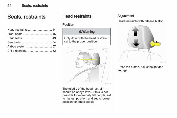
AdjustmentHead restraints with release button
Press the button, adjust height andengage.

Seats, restraints 45
Head restraints without releasebutton
Pull the head restraint upwards orpress the catch to release and pushthe head restraint downwards.
Active head restraints
In the event of a rear-end impact, theactive head restraints tilt slightlyforwards. The head is moreeffectively supported so the risk ofwhiplash injury is reduced.Active head restraints are identifiedby the lettering ACTIVE on the headrestraint guide sleeves.NoteApproved accessories may only beattached to the front passenger seathead restraint if the seat is not in use.
Removing
Press the catches and pull up thehead restraint.

46 Seats, restraints
Front seatsSeat position
9 Warning
Only drive with the seat correctlyadjusted.
■ Sit with buttocks as far back againstthe backrest as possible. Adjust thedistance between the seat and thepedals so that legs are slightlyangled when pressing the pedals.Slide the front passenger seat asfar back as possible.
■ Sit with shoulders as far backagainst the backrest as possible.Set the backrest rake so that it ispossible to easily reach thesteering wheel with arms slightlybent. Maintain contact betweenshoulders and the backrest whenturning the steering wheel. Do notangle the backrest too far back. Werecommend a maximum rake ofapprox. 25°.
■ Adjust the steering wheel 3 77.■ Set seat height high enough to
have a clear field of vision on allsides and of all display instruments.There should be at least one handof clearance between head and theroof frame. Thighs should restlightly on the seat without pressinginto it.
■ Adjust the head restraint 3 44.■ Adjust the height of the seat belt
3 55.■ Adjust the thigh support so that
there is a space approx. two fingerswide between the edge of the seatand the hollow of the knee.
■ Adjust the lumbar support so that itsupports the natural shape of thespine.
Seat adjustment
9 Warning
Never adjust seats while driving asthey could move uncontrollably.
Seat positioning
Pull handle, slide seat, releasehandle.

Seats, restraints 47
Seat backrests
Turn handwheel. Do not lean onbackrest when adjusting.
Seat height
Lever pumping motionup = higherdown = lower
Seat inclination
Pull lever, adjust inclination byshifting body weight. Release leverand audibly engage seat in position.

48 Seats, restraints
Lumbar support
Turn handwheel. Do not lean onbackrest when adjusting.
Adjustable thigh support
Press the button and slide the thighsupport.
Seat folding
Push the head restraint down.Slide the seat backwards.Raise release lever, fold backrestforward and engage.To restore the seat to the uprightposition, raise release lever andaudibly engage backrest.

Seats, restraints 49
Armrest
Push raised armrest backwardagainst resistance and fold down.The armrest can be moved todifferent positions in stages by liftingit.
Heating
Adjust heating to the desired settingby pressing the ß button for the seatone or more times with the ignition on.The control indicator in the buttonindicates the setting.Prolonged use of the highest settingfor people with sensitive skin is notrecommended.Seat heating is operational when theengine is running.
Rear seatsSecond row seats
9 Warning
When the row of seats or thebackrests are being adjusted,keep hands away from the hingearea.
Moving seat row
Push the release lever forwards andslide the row of seats. Release thelever and audibly engage the seats.

50 Seats, restraints
Lowering seat row and slidingforwardsRemove the luggage compartmentcover as required 3 69.Slide head restraints down 3 44.
Place seat belt buckles in seatpockets.
Press release lever 1 down andswivel the seat cushion upwards untilit engages.Press down release lever 2 on bothsides, bring the backrest into theupright position and engage.Pull handle on back of centrebackrest, bring the backrest into theupright position and engage.Press release lever 3, slide the benchto the frontmost position and engage.To restore, press release lever 3 andslide the bench to the requiredposition. Adjust the backrest and use
release lever 1 to swivel the seatcushion downwards. All positionsmust audibly engage.
Adjust backrests of outboardseats
Press the release lever down, selectone of the two inclinations, releasethe lever and engage the backrest.
9 Warning
Occupants may only travel ona seat if its backrest is properlyengaged in the rearward inclinedposition.

Seats, restraints 51
Folding down outboard backrests
Remove the luggage compartmentcover as required 3 69.Slide head restraints down 3 44.Place seat belt buckles in seatcushion pockets.Press the release lever down, set thebackrest to a vertical position orangled forward or fold it to the seatcushion and engage.To move upright, push release leverdown and latch backrest in requiredposition.
Folding down middle backrest
Slide the head restraint all the waydown 3 44.Place seat belt buckles in seatcushion pockets.Pull the handle on the back, set thebackrest to a vertical position or foldto the seat cushion and engage.To restore, pull the handle, straightenand engage in required position.
The centre seat backrest can be usedas an armrest when folded down, andcontains drink holders and stowagecompartments.
Third row seats
9 Warning
When the seats are being set upor folded, keep hands away fromhinge area.

52 Seats, restraints
Setting up seats
Remove the floor covering and loadcompartment cover 3 70.Push the lever forward and slide thesecond seat row forward to the mark.
Guide the seat belts through the beltholders and insert the latch plates inthe holders.
9 Warning
Before setting up, all componentsmust be removed from the siderails and the seat belts hooked inthe seat belt eyes in the floor of thevehicle without twisting.
From the luggage compartment, pullup the seat by the handle.

Seats, restraints 53
Slide the seat rearwards until it isupright and audibly engages. Supportthe top of the backrest with your hand.Slide the second seat row to therequired position and engage.Seat belts 3 55.Stow the load compartment cover byinstalling it behind the third row ofseats 3 69.
Stowing seatsRemove the load compartment cover3 69.Push the lever forwards and slide thesecond seat row forwards to themark.Press the catch to release and slidethe head restraints of the third seatrow all the way down.
Guide the seat belts through the beltholders and insert the latch plates inthe holders.
From the load compartment, pressthe button on the top of the backrestand lower the backrest. Using thehandle on the seat, pull rearwardsand upwards and then swing the seatforwards until it is lowered into thevehicle floor. Hold the seat by thehandle during the entire procedure.
Push belt buckles into recess in floorand close cover.Install the rear floor storage cover andload compartment cover 3 70,3 69.Slide the second row of seats to therequired position and engage.

54 Seats, restraints
Seat belts
The belts are locked during heavyacceleration or deceleration of thevehicle for the safety of theoccupants.
9 Warning
Fasten seat belt before each trip.In the event of an accident, peoplenot wearing seat belts endangertheir fellow occupants andthemselves.
Seat belts are only designed for useby one person at a time. They are notsuitable for people younger than 12years of age or smaller than 150 cm(59 inches).Periodically check all parts of the beltsystem for damage and properfunctionality.Have damaged componentsreplaced. After an accident, have thebelts and triggered belt tensionersreplaced by a workshop.NoteMake sure that the belts are notdamaged by shoes or sharp-edgedobjects or trapped. Prevent dirt fromgetting into the belt retractors.
Seat belt control indicator X 3 87.
Belt force limitersIn the front seats, stress on the bodyis reduced by gradual release of thebelt during a collision.
Belt tensioners
In the event of a head-on or rear-endcollision of a certain severity, the frontseat belt buckles are pulled down totighten the belts.
9 Warning
Incorrect handling (e.g. removal orfitting of belts) can trigger the belttensioners.
Deployment of the belt tensioners isindicated by illumination of controlindicator v 3 87.

Seats, restraints 55
Triggered belt tensioners must bereplaced by a workshop. Belttensioners can only be triggeredonce.NoteDo not affix or install accessories orother objects that may interfere withthe operation of the belt tensioners.Do not make any modifications tobelt tensioner components as thiswill invalidate the vehicle typeapproval.
Three-point seat beltFitting
Withdraw belt from retractor, guide ituntwisted across the body and insertthe latch plate in the buckle. Tensionthe lap belt regularly whilst driving bytugging the shoulder belt.
Loose or bulky clothing prevents thebelt from fitting snugly. Do not placeobjects such as handbags or mobilephones between the belt and yourbody.
9 Warning
The belt must not rest against hardor fragile objects in the pockets ofyour clothing.
Height adjustment
1. Pull belt out slightly.2. Press button.3. Adjust height and engage.
Adjust the height so that the belt liesacross the shoulder. It must not lieacross the throat or upper arm.Do not adjust while driving.

56 Seats, restraints
Removing
To release belt, press red button onbelt buckle.
Seat belts in the second rowThe seat belt for the middle seat canonly be withdrawn from the retractor ifthe backrest is latched in the rearmostposition
Seat belts in the third row
Open the cover in the floor betweenthe seats and pull up the belt buckles.Remove latch plate and belt fromfixture.
9 Warning
The belt must not be routedthrough the belt holder when theseat belt is being applied.
When not in use, guide the seat beltthrough the belt holder and insert thelatch plate in the holder.
Unhookable seat belts in the third rowDetachable seat belts are identifiedby a label on the belt.To use the side rails, the seat beltscan be removed from the seat belteyes in the vehicle floor.

Seats, restraints 57
Press the spring catch and releasethe hook from the belt eye in thevehicle floor.
Reel the belt in and fasten the hook tothe magnetic holder.To hinge the seat belt, remove hookfrom magnetic holder, push spring-loaded tab of hook and attach to seatbelt eye in floor of vehicle. The seatbelt must not be twisted. The hookmust be properly engaged in the seatbelt eye with the spring-loaded tabclosed again.NoteThe hook must only be attached tothe eyes placed on the vehicle floor.The eyes and the seat belts may notbe used for lashing loads.
Using the seat belt while pregnant
9 Warning
The lap belt must be positioned aslow as possible across the pelvisto prevent pressure on theabdomen.
Airbag systemThe airbag system consists ofa number of individual systems.When triggered the airbag inflateswithin milliseconds. They also deflateso quickly that it is often unnoticeableduring the collision.
9 Warning
If handled improperly the airbagsystems can be triggered in anexplosive manner.

58 Seats, restraints
NoteThe airbag systems and belttensioner control electronics arelocated in the centre console area.Do not put any magnetic objects inthis area.Do not stick anything on the airbagcovers and do not cover them withother materials.Each airbag is triggered only once.Have deployed airbags replaced bya workshop.Do not make any modifications tothe airbag system as this willinvalidate the vehicle type approval.In the event of airbag deploymenthave the steering wheel, theinstrument panel, all panelling parts,the door seals, the handles and theseats removed by a workshop.
Control indicator v for airbag systems3 87.
Front airbag system
The front airbag system consists ofone airbag in the steering wheel andone in the instrument panel. Thesecan be identified by the wordAIRBAG.
There is also a warning label on theside of the instrument panel, visiblewhen the front passenger door isopen.

Seats, restraints 59
The front airbag system is triggered inthe event of an accident of a certainseverity in the depicted area. Theignition must be on.Seat occupancy recognition 3 61.Child restraint system withtransponders 3 65.
The forward movement of the frontseat occupants is decelerated,thereby considerably reducing therisk of injury to the upper body andhead.
9 Warning
Optimum protection is onlyprovided when the seat is in theproper position 3 46.Keep the area in which the airbaginflates clear of obstructions.Fit the seat belt correctly andengage securely. Only then theairbag is able to protect.
Side airbag system
The side airbag system consists of anairbag in each front seat backrest.This can be identified by the wordAIRBAG.
The side airbag system is triggered inthe event of an accident of a certainseverity in the depicted area. Theignition must be on.Seat occupancy recognition 3 61.Child restraint system withtransponders 3 65.

60 Seats, restraints
The risk of injury to the upper bodyand pelvis in the event of a side-oncollision is considerably reduced.
9 Warning
Keep the area in which the airbaginflates clear of obstructions.
NoteOnly use protective seat covers thathave been approved for the vehicle.Be careful not to cover the airbags.
Curtain airbag system
The curtain airbag system consists ofan airbag in the roof frame on eachside. This can be identified by theword AIRBAG on the roof pillar.
The curtain airbag system is triggeredin the event of an accident of a certainseverity in the depicted area. Theignition must be on.

Seats, restraints 61
The risk of injury to the head in theevent of a side impact is considerablyreduced.The curtain airbag system does notprotect the third row of seats.
9 Warning
Keep the area in which the airbaginflates clear of obstructions.The hooks on the handles in theroof frame are only suitable forhanging up light articles ofclothing, without coat hangers. Donot keep any items in theseclothes.
Seat occupancy recognition
Identified by a label on the lowerpanel of the front passenger seat andby control indicator y, whichilluminates for approx. 4 secondswhen the ignition is switched on.The seat occupancy recognitionsystem deactivates the passengerfront and side airbag if the frontpassenger seat is not occupied or isfitted with an Opel child restraintsystem with transponders. Thecurtain airbag system remainsactivated.
9 Danger
Only Opel child restraint systemswith transponders should be fittedon the front passenger seats. Useof systems without transpondersposes a risk of fatal injury.
Control indicator 3 87.NoteAnyone weighing less than 35 kgshould only travel on the rear seats.Do not place any heavy objects onthe front passenger seat. Otherwisethe seat will register as occupied andthe airbag system for the frontpassenger seat will not bedeactivated.Do not use protective covers or seatcushions on the front passengerseat.

62 Seats, restraints
Child restraintsChild restraint systemsWhen a child restraint system is beingused, pay attention to the followingusage and installation instructionsand also those supplied with the childrestraint system.Always comply with local or nationalregulations. In some countries, theuse of child restraint systems isforbidden on certain seats.
Selecting the right systemChildren should travel facingbackwards in the vehicle, until as oldas possible. It is appropriate tochange the system when the child’shead can no longer be properlysupported at eye height. The child’scervical vertebrae are still very weakand in an accident they suffer lessstress in the semi-prone rearwardposition than when sitting upright.Children under 12 years or under 150cm (59 inches) tall should only travelin an appropriate child restraintsystem.
Never hold a child whilst travelling inthe vehicle. The child will become tooheavy to be held in the event ofa collision.When transporting children, use thechild restraint systems suitable for thechild's weight.Ensure that the child restraint systemto be installed is compatible with thevehicle type.Ensure that the mounting location ofthe child restraint system within thevehicle is correct.Only allow children to enter and exitthe vehicle at the side facing awayfrom the traffic.When the child restraint system is notin use, secure the seat with a seat beltor remove it from the vehicle.NoteDo not stick anything on the childrestraint systems and do not coverthem with any other materials.A child restraint system which hasbeen subjected to stress in anaccident must be replaced.

Seats, restraints 63
Child restraint installation locationsPermissible options for fitting a child restraint system
Weight and age class1)
On front passengerseat
On outboardseats in thesecond row
On centre seatin the secondrow
On the seatsin the thirdrow
Group 0: up to 10 kg or approx. 10 monthsGroup 0+: up to 13 kg or approx. 2 years
B1, + U, + U X
Group I: 9 to 18 kg or approx. 8 months to 4 years B2, + U, +, ++ U UF
Group II: 15 to 25 kg or approx. 3 to 7 yearsGroup III: 22 to 36 kg or approx. 6 to 12 years
X U U UF
B1 = Limited, only with seat occupancy recognition and Opel child restraint system with transponders.If the child restraint system is being secured using a three-point seat belt, move seat height adjustment to uppermostposition. Move front passenger seat as far back as possible and move front passenger seat belt anchorage point tolowest position.
B2 = Limited, only with seat occupancy recognition and Opel child restraint system with transponders.If the child restraint system is being secured using a three-point seat belt, move seat height adjustment to uppermostposition. Move front passenger seat as far back as possible so that vehicle safety belt runs from anchorage pointtowards the front.
U = Universal suitability in conjunction with three-point seat belt.UF = Can be used universally for forward-facing child restraint systems in combination with a three-point seat belt.+ = Vehicle seat available with ISOFIX attachments. When attaching using ISOFIX, only the ISOFIX child restraint
systems permitted for the vehicle may be used.
1) We recommend the use of each system until the child reaches the upper weight limit.

64 Seats, restraints
++ = Vehicle seat available with ISOFIX attachments. When attaching using ISOFIX and Top-tether, universally permittedISOFIX child restraint systems may be used.
X = No child restraint system permitted in this weight class.

Seats, restraints 65
Isofix child restraint systems
Fasten vehicle-approved ISOFIXchild restraint systems to themounting brackets.
Top-tether child restraintsystems
Fasten Top-tether child restraintsystems to the fastening eyes of thesecond row of seats. The strap mustrun between the two guide rods of thehead restraint.When using ISOFIX and Top-tetherfor seat mounting, universallypermitted child restraint systems forISOFIX may be used.
Child restraints withtransponders
A label on the child restraint systemindicates that it is fitted withtransponders.Opel child restraint systems withtransponders are automaticallydetected if correctly installed to thefront passenger seat with seatoccupancy recognition.

66 Seats, restraints
NoteThere must be no objects (e.g.plastic sheet or heating mats)between the seat and the childrestraint system.
Seat occupancy recognition 3 61.

Storage 67
Storage
Storage compartments ................ 67Load compartment ....................... 69Roof rack system ......................... 74Loading information ..................... 75
Storage compartmentsGlovebox
The glovebox features a pen holder.The glovebox should be closed whilstdriving.
Cupholders
Cupholders are located in the centreconsole, in the doors and the rear sidepanelling.

68 Storage
Additional cupholders are located inthe centre seat backrest when it isfolded down.
Sunglasses storage
Fold down and open.Do not use for storing heavy objects.
Underseat storage
Lift at recessed edge and pull out.Maximum load: 1.5 kg. To close, pushin and engage.
Roof panelling
Press marked locations to open.The maximum permitted load of thetwo front compartments is 1 kg, andthe maximum permitted load of thethree rear compartments is 2 kg.The compartments must be closedwhilst driving.

Storage 69
Load compartment
Stowage in the load compartment
To open the cover, lift the carpeting.Raise, rotate and lift the ring. Thestowage compartment contains thevehicle tools 3 172 and the couplingball bar.The fuse box is on the left side behindthe cover in the load compartmentside panelling 3 170.The tyre repair kit is on the right sidebehind the cover 3 177.
Load compartment coverDo not place any heavy or sharp-edged objects on the loadcompartment cover.Before operating the loadcompartment cover, the rear seatbelts must be fed through the side beltholders.
Opening
Remove load compartment coverfrom side brackets. It rolls upautomatically.
ClosingPull the cover towards the rear usingthe handle and engage it in theretainers at the sides.
Removing
Open the load compartment cover.Pull the release lever up and hold. Liftcover on right side and remove fromretainers.

70 Storage
InstallationInsert the left side of the loadcompartment cover in the recess, pullthe release lever up and hold, insertthe right side of the load compartmentcover and engage.
Stowing behind the third row ofseats
Insert the left side of the loadcompartment cover in the recess, pullthe release lever up and hold, insertthe right side of the load compartmentcover and engage.
Rear floor storage coverUse the rear floor storage cover whenthe third seat row is stowed.
Load rails and hooks
Install the hooks in the desiredposition in the rails: insert the hook inthe upper groove on the rail and pressin the lower groove.When the rails are being used (withthe exception of the partition net infront of the tailgate), the third seat rowmust be stowed 3 51 and the seat
belts unhooked from the vehicle floor.Secure released seat belt hooks tobelt holder magnets 3 55.
Lashing eyes
The lashing eyes are designed tosecure items against slippage, e.g.using lashing straps, luggage net orsafety net.The eyes for securing the removableseat belts must not be used as lashingeyes.The seat belts in the third seat rowmust never be used for securingloads.

Storage 71
Cargo management systemThe FlexOrganizer is a flexiblesystem for dividing the loadcompartment or securing loads.
The system consists of■ adapters,■ variable partition net,■ mesh pockets,■ hooks.The components are fitted in two railsin the side panels using adapters andhooks. The partitioning net can alsobe fitted directly in front of the tailgate.
Variable partition net
Insert an adapter into each rail: foldopen the handle plate, insert adapterinto upper and lower groove of railand move to required position. Turnhandle plate upwards to lock theadapter. The rods of the net must beextended before inserting into theadapters: pull out all of the end piecesand lock by rotating clockwise.To install, push rods together a littleand insert into the relevant openingsin the adapters. The longer rod mustbe inserted into the upper adapter.
To remove, press the net rod togetherand remove from the adapters. Foldopen the adapter handle plate,disengage from lower groove andthen from upper groove.
Hooks and net pocket
Net pocket can be suspended fromthe luggage hooks.

72 Storage
Partitioning net in front of tailgate
The partitioning net can be installeddirectly in front of the tailgate,preventing the load from falling outwhen the tailgate is opened.The four end pieces of the net rodmust be pushed in before installationby rotating each end pieceanticlockwise and pushing in.To install, push the net rods togethera little and insert into the openings.The longer rod must be inserted at thetop.To remove, push the net rodstogether and remove.
For easier loading with the third seatrow upright, first insert the rod, placethe load in the load compartment andthen insert the upper rod.
Safety netThe safety net can be installed behindthe second seat row or the front seats.Passengers must not be transportedbehind the safety net.
Installation
There are two installation openings inthe roof frame: suspend and engagerod of net at one side, compress rodand suspend and engage at otherside.
Behind the second seat row
Suspend hooks of net tensioningbelts in lashing eyes in floor andtension.

Storage 73
Behind front seats
Suspend hooks of net tensioningbelts in slots and tension.
RemovalTilt length adjuster of the nettensioning belt upwards and detachthe belt. Disengage the upper rod onone side, compress, disengage otherside and remove from the openings.
Stowage
Place tensioning straps as shown infigure and align to net.
Roll the upper net rod down toapproximately over the middle.Place the upper net rod over thetensioning straps next to the lower netrod. The hooks on the upper net rodmust point away from the lower netrod.
Fasten Velcro tape tightly about thenet next to the length adjusters. Thelength adjusters and net rods must lieflat next to each other.

74 Storage
Raise the seat cushion of the secondseat row 3 49. Slide safety net into theretainers, fold the seat cushion downand engage.
Folding trayLocated in the front seat backrests.Open by pulling upward until itengages.Fold away by pressing down past theresistance point.Do not place any heavy objects.
Warning triangleStow the warning triangle in the spacein the tailgate and fasten with the rightand left straps.
First aid kit
Stow the first aid kit in the space in thetailgate and fasten with the strap.
Roof rack systemRoof rackFor safety reasons and to avoiddamage to the roof, the vehicleapproved roof rack system isrecommended.Follow the installation instructionsand remove the roof rack when not inuse.
Version without roof railing
Lift the covers from the fittingopenings.

Storage 75
Fasten the roof rack at the fasteningpoints.
Version with roof railing
To fasten the roof rack, insert themounting bolts in the holes indicatedin the figure.
Loading information
■ Heavy objects in the loadcompartment should be placedagainst the seat backrests. Ensurethe backrests are securelyengaged. If objects can be stacked,the heavier objects should beplaced at the bottom.
■ Secure objects with lashing strapsattached to lashing eyes 3 70.
■ Secure loose objects in loadcompartment to prevent sliding.
■ When transporting objects in theload compartment, the backrests ofthe second row must not be angledforward.
■ Do not allow the load to protrudeabove the upper edge of thebackrests.
■ Do not place any objects on theload compartment cover or theinstrument panel.
■ The load must not obstruct theoperation of the pedals, parkingbrake and gear selector, or hinderthe freedom of movement of thedriver. Do not place any unsecuredobjects in the interior.
■ Do not drive with an open loadcompartment.

76 Storage
■ The payload is the differencebetween the permitted grossvehicle weight (see identificationplate 3 206) and the EC kerbweight.To calculate the EC kerb weight,enter the data for your vehicle in theWeights table on page 3 3.The EC kerb weight includesweights for the driver (68 kg),luggage (7 kg) and all fluids (tank90 % full).Optional equipment andaccessories increase the kerbweight.
■ Driving with a roof load increasesthe sensitivity of the vehicle tocross-winds and has a detrimentaleffect on vehicle handling due tothe vehicle’s higher centre ofgravity. Distribute the load evenlyand secure it properly with retainingstraps. Adjust the tyre pressure andvehicle speed according to the loadconditions. Check and retighten thestraps frequently.
The permissible roof load is 75 kgand 100 kg for vehicles with roofrailing. The roof load is thecombined weight of the roof rackand the load.

Instruments and controls 77
Instruments andcontrols
Controls ....................................... 77Warning lights, gauges andindicators ..................................... 83Information displays ..................... 93Vehicle messages ...................... 100Trip computer ............................. 102
ControlsSteering wheel adjustment
Unlock lever, adjust steering wheel,then engage lever and ensure it isfully locked.Do not adjust steering wheel unlessvehicle is stationary and steeringwheel lock has been released.
Steering wheel controls
The Infotainment system and theInfo-Display can be operated via thecontrols on the steering wheel.Further information is available in theInfotainment system manual.

78 Instruments and controls
Horn
Press j.
Windscreen wiper/washerWindscreen wiper
The lever always springs back to itsoriginal position.& = fast% = slow$ = adjustable timed interval wipe§ = Off
For a single wipe when thewindscreen wiper is off, press thelever down.
Run through the windscreen wiperstages by pushing the lever past theresistance point and holding. Anacoustic signal sounds at §.Do not use if the windscreen is frozen.Switch off in car washes.
Adjustable wiper interval
To set the wiper interval to a valuebetween 2 and 15 seconds: Switch onignition, move lever down fromposition §, wait desired time intervaland raise lever to $.After turning on the ignition andsetting the lever to $, the interval isset to 6 seconds.

Instruments and controls 79
Automatic wiping with rain sensor
$ = Automatic wiping with rainsensor
The rain sensor detects the amount ofwater on the windscreen andautomatically regulates the frequencyof the windscreen wipers.
Keep the sensor free from dust, dirtand ice.
Windscreen washer
Pull lever. Washer fluid is sprayed onthe windscreen and the wiper wipesfor a few strokes.If the lights are on, washer fluid is alsosprayed on the headlights. Theheadlight washer system is theninoperable for 2 minutes.
Rear window wiper/washer
Push lever forwards. The rear windowwiper wipes in interval mode. Switchoff by pushing lever forwards again.If the lever is held forwards, washerfluid is sprayed on the rear window.

80 Instruments and controls
The rear screen wiper comes onautomatically when the windscreenwiper is switched on and reverse gearis engaged.
Outside temperature
A drop in temperature is indicatedimmediately and a rise in temperatureafter a time delay.If outside temperatures drop to 3 °C,the symbol : illuminates in theTriple-Info-Display or theBoard-Info-Display as a warning for
icy road conditions. : remainsilluminated until temperatures reachat least 5 °C.
In vehicles with Graphic-Info-Displayor Color-Info-Display, a warningmessage appears in the display asa warning for icy road conditions.There is no message below -5 °C.
9 Warning
The road surface may already beicy even though the displayindicates a few degrees above0 °C.
ClockDate and time are shown in theInfo-Display.Board-Info-Display 3 93,Graphic-Info-Display,Color-Info-Display 3 96.
Set date and time inTriple-Info-Display
The Infotainment system must be off.Activate setting mode by holding theÖ button depressed for about2 seconds. The flashing value is

Instruments and controls 81
adjusted using the ; button. The Öbutton is used to switch to the nextmode and to exit setting mode.
Automatic time synchronisationThe RDS signal of most VHFtransmitters automatically sets thetime, identified by } in the display.Some transmitters do not senda correct time signal. In such cases,we recommend to switch offautomatic time synchronisation.Activate setting mode and set it toyear setting. Hold the Ö buttondepressed about 3 seconds until }flashes in the display and “RDSTIME" appears. The function isactivated (RDS TIME 1) ordeactivated (RDS TIME 0) withthe ; button. Exit setting mode usingthe Ö button.
Power outletsPower outlets are located in thecentre console and in the luggagecompartment.
Do not damage the power outlets byusing unsuitable plugs. Connectingelectrical accessories while theengine is off will discharge thebattery. Do not exceed the maximum
power consumption of 120 Watts. Donot connect any current-deliveringaccessories, e.g. electrical chargingdevices or batteries.Electrical accessories that areconnected must comply with theelectromagnetic compatibilityrequirements laid down in DIN VDE40 839.
Cigarette lighter
The cigarette lighter is located in thecentre console.

82 Instruments and controls
Press in cigarette lighter. Switches offautomatically once the element isglowing. Pull out lighter.
Ashtrays
Caution
To be used only for ash and not forcombustible rubbish.
Ashtray, front
Open ashtray at recess.
To empty the ashtray, press thespring, open ashtray all the way andremove.
Portable ashtray
The portable ashtray can be placed inthe cupholders.

Instruments and controls 83
Warning lights, gaugesand indicatorsInstrument clusterIn some versions, the needles of theinstruments briefly rotate to the endposition when the ignition is switchedon.
Speedometer
Indicates vehicle speed.
Odometer
The bottom line displays the recordeddistance.
Trip odometerThe top line displays the countedkilometres since the last reset.To reset, hold the reset knobdepressed for a few seconds with theignition on.
Tachometer
Displays the engine speed.Drive in a low engine speed range foreach gear as much as possible.
Caution
If the needle is in the red warningzone, the maximum permittedengine speed is exceeded. Engineat risk.

84 Instruments and controls
Fuel gauge
Displays the fuel level or gas pressurein the tank depending on theoperation mode.Control indicator Y illuminates if thelevel in the tank is low. Refuelimmediately if it flashes. Duringnatural gas operation, the switchautomatically switches over to petroloperation 3 84.
When operating with natural gas, themessage LoFuEL is displayed if thelevel in the petrol tank is low.Acknowledge the message bypressing the reset button 3 83.Never run the tank dry.Because of the fuel remaining in thetank, the top-up quantity may be lessthan the specified tank capacity.
Fuel selector
Pressing button Y switches betweenpetrol and natural gas operation.Switching is not possible at high loads(e.g. strong acceleration, running atfull throttle). The LED status showsthe current operating mode.Natural gasoperation
= LED off.
Petrol operation = LED illuminates.
As soon as the natural gas tanks areempty, petrol operation isautomatically engaged until theignition is switched off.

Instruments and controls 85
If the natural gas tanks are notrefuelled, the system must bemanually switched to petrol operationbefore the engine is started up again.This will prevent damage to thecatalytic converter (overheatingcaused by irregular fuel supply).If the selector switch is operatedseveral times within a short timea switchover block is activated. Theengine remains in the currentoperating mode. The block remainsactive until the ignition is switched off.A slight loss of power and torque canbe expected in petrol operation. Youmust therefore adapt your drivingstyle (e.g. during overtakingmanoeuvres) and vehicle loads (e.g.towing loads) accordingly.Every six months run the petrol tankdown until control indicator Yilluminates and refuel. This isnecessary to maintain fuel quality aswell as system function necessary forpetrol operation.Fill the tank completely at regularintervals to prevent corrosion in thetank.
Service display
The message InSP appears when itis time for servicing. Furtherinformation 3 191.
Control indicatorsThe control indicators described arenot present in all vehicles. Thedescription applies to all instrumentversions. When the ignition isswitched on, most control indicatorswill illuminate briefly as a functionalitytest.
The control indicator colours mean:Red = Danger, important
reminder,Yellow = Warning, information,
fault,Green = Confirmation of activation,Blue = Confirmation of activation.

86 Instruments and controls

Instruments and controls 87
Turn signalO illuminates or flashes green.
IlluminatesThe control indicator illuminatesbriefly when the parking lights areswitched on.
FlashesThe control indicator flashes if a turnsignal or the hazard warning flashersare activated.Rapid flashing: failure of a directionindicator lamp or associated fuse,failure of direction indicator lamp ontrailer.Bulb replacement 3 159. Fuses3 166.Turn signals 3 111.
Seat belt reminderX illuminates or flashes red.
IlluminatesAfter the ignition is switched on untilthe seat belt is fastened.
FlashesAfter starting off until the seat belt isfastened.Fastening the seat belt 3 55.
Airbag and belt tensionersv illuminates red.When the ignition is switched on, thecontrol indicator illuminates forapprox. 4 seconds. If it does notilluminate, does not go out after4 seconds or illuminates whilstdriving, there is a fault in the belttensioner, the airbags or the seatoccupancy recognition system. Thesystems may fail to trigger in theevent of an accident.Deployment of the belt tensioners orairbags is indicated by continuousillumination of v.
9 Warning
Have the cause of the faultremedied immediately bya workshop.
Airbag system, belt tensioners 3 57,3 54.
Seat occupancy recognitiony illuminates or flashes yellow.
IlluminatedIf the vehicle is equipped with seatoccupancy recognition, y illuminatesfor approx. 4 seconds after theignition is switched on.If a child restraint system withtransponders is detected, y remainsilluminated. Only then a child restraintsystem with transponders may beused on the front passenger seat asthe front passenger airbag systemsare deactivated 3 61.
9 Danger
If a child restraint system is fittedand the control indicator is notilluminated while driving, the frontand side airbag for the frontpassenger seat are notdeactivated.

88 Instruments and controls
FlashesFault in system or child restraintsystem with transponders defectiveor improperly fitted 3 61.
9 Danger
Flashing of the control indicatorwhile driving indicates a fault.Have the cause of the faultremedied by a workshopimmediately.
Child restraint system withtransponders 3 65.
Charging systemp illuminates red.Illuminates when the ignition isswitched on and goes out shortly afterthe engine starts.
Illuminates when the engine isrunningStop, switch off engine. Battery is notcharging. Engine cooling may beinterrupted. In diesel engines, powerto the brake servo unit may be cut.Seek the assistance of a workshop.
Malfunction indicator lightZ illuminates or flashes yellow.Illuminates when the ignition isswitched on and goes out shortly afterthe engine starts.
Illuminates when the engine isrunningFault in the emission control system.The permitted emission limits may beexceeded. Immediately seek theassistance of a workshop.
Flashes when the engine isrunningFault that could lead to catalyticconverter damage. Ease up on theaccelerator until the flashing stops.Seek the immediate assistance ofa workshop.
Service vehicle soonA illuminates or flashes yellow.
Illuminates when the engine isrunningFault in engine or transmissionelectronics 3 134, 3 138. Theelectronics switch to an emergencyrunning programme. Fuelconsumption may be increased andthe vehicle handling may be impaired.If the fault persists after restarting thevehicle, consult a workshop.
Illuminates together with InSP4 inthe service displaySeek the assistance of a workshop fordraining the diesel fuel filter 3 101.
Flashes with switched on ignitionFault in the electronic immobilisersystem. The engine cannot be started3 38.Switch off the ignition and repeat thestart attempt.

Instruments and controls 89
If the control indicator continuesflashing, attempt to start the engineusing the spare key and seek theassistance of a workshop.
Brake and clutch systemR illuminates or flashes red.
IlluminatedIlluminates when the parking brake isreleased if the brake and clutch fluidlevel is too low 3 157.
9 Warning
Stop. Do not continue yourjourney. Consult a workshop.
Illuminates after the ignition isswitched on if the parking brake isapplied 3 140.
FlashesOn vehicle with automated manualtransmission, flashes for a fewseconds when the ignition is switchedoff if the parking brake is not applied.
On vehicles with automated manualtransmission, flashes when thedriver's door is opened if no gear isengaged and the parking brake is notapplied.
Antilock brake system (ABS)u illuminates red.Illuminates for a few seconds after theignition is turned on. The system isready for operation when the controlindicator goes out.If the control indicator does not go outafter a few seconds, or if it illuminateswhile driving, there is a fault in theABS. The brake system remainsoperational but without ABSregulation.Anti-lock Braking System 3 139.
Sport mode1 illuminates yellow.The symbol is illuminated when Sportmode is on 3 133, 3 137.
Winter modeT illuminates yellow.The symbol is illuminated whenWinter mode is on 3 133, 3 137.
Ultrasonic parking assistr illuminates or flashes yellow.
IlluminatesFault in system. Have the cause of thefault remedied by a workshop.
FlashesFault due to sensors that are dirty orcovered by ice or snow.orInterference due to external sourcesof ultrasound. Once the source ofinterference is removed, the systemwill operate normally.Ultrasonic parking sensors 3 144.
Electronic Stability Programv flashes or illuminates yellow.Illuminates for a few seconds whenthe ignition is switched on.

90 Instruments and controls
Flashes whilst drivingThe system is actively engaged.Engine output may be reduced andthe vehicle may be brakedautomatically to a small degree3 141.
Illuminates whilst drivingThe system is switched off or a faultis present. Continued driving ispossible. Driving stability, however,may deteriorate depending on roadsurface conditions.Have the cause of the fault remediedby a workshop.ESP®Plus 3 141.
Engine coolant temperatureW illuminates red.
Illuminates when the engine isrunningStop, switch off engine.
Caution
Coolant temperature too high.
Check coolant level immediately3 156.If there is sufficient coolant, consulta workshop.
Preheating and diesel particlefilter! illuminates or flashes yellow.
IlluminatesPreheating activated. Only activateswhen outside temperature is low.
Flashesin vehicles fitted with a diesel particlefilter.Control indicator ! flashes if the filterrequires cleaning and previousdriving conditions did not permitautomatic cleaning. Continue drivingand if possible do not allow enginespeed to drop below 2000 rpm.The control indicator ! goes off assoon as the self-cleaning operation iscomplete.Diesel particle filter 3 128.
Deflation detection systemand tyre pressure monitoringsystemw illuminates or flashes red or yellow.
Control indicator illuminates redTyre pressure loss. Stop immediatelyand check tyre pressure. A maximumspeed of 80 km/h is permitted for run-flat tyres 3 173.
Control indicator illuminatesyellowFault in system or tyre withoutpressure sensor mounted (e.g. sparewheel). Consult a workshop.
FlashesFlashes three times to indicatesystem initialisation.Deflation detection system 3 175,tyre pressure monitoring system3 175.

Instruments and controls 91
Interactive driving system,continuous damping control,sport modeIDS+ illuminates yellow.Illuminates for approximately 10seconds after the driver's door isopened. Illumination whilst drivingindicates a fault in the system. Thesystem switches to the harder chassissetting for reasons of safety. Have thecause of the fault remedied bya workshop.IDSPlus 3 142, CDC 3 142, Sportmode 3 142.
Engine oil pressureI illuminates red.Illuminates when the ignition isswitched on and goes out shortly afterthe engine starts.
Illuminates when the engine isrunning
Caution
Engine lubrication may beinterrupted. This may result indamage to the engine and/orlocking of the drive wheels.
1. Depress clutch.2. Select neutral gear, set selector
lever to N.3. Move out of the flow of traffic as
quickly as possible withoutimpeding other vehicles.
4. Switch off ignition.
9 Warning
When the engine is off,considerably more force is neededto brake and steer.Do not remove key until vehicle isstationary, otherwise the steeringwheel lock could engageunexpectedly.
Seek the assistance of a workshop.
Low engine oil levelS illuminates yellow.Engine oil level is checkedautomatically.
Illuminates when the engine isrunningLow engine oil level. Check engine oillevel and top up as necessary3 155.
Low fuelY illuminates or flashes yellow.
IlluminatesLevel in fuel tank too low.
FlashesFuel used up. Refuel immediately.Never run the tank dry.Catalytic converter 3 129.Bleeding the diesel fuel system3 158.

92 Instruments and controls
When operating with natural gas, thesystem automatically switches over topetrol operation 3 84.
Open&Start system0 illuminates or flashes yellow.
FlashesThe electronic key is no more withinthe reception range of the vehicleinterior. The engine cannot bestarted. Hold the Start/Stop buttondepressed a bit longer to switch offthe ignition.orFailure of the electronic key.Operation is yet only possible viaemergency operation.
IlluminatesFault in system. Try to operate withthe spare key, the remote control orthrough emergency operation. Holdthe Start/Stop button depressed a bitlonger to switch off the ignition. Seekthe assistance of a workshop.or
The steering wheel lock is stillengaged. Move the steering wheelslightly and press the Start/Stopbutton.Open&Start System 3 29.
Apply footbrakej illuminates yellow.The engine with manual transmissionautomated can only be started if thefoot brake is depressed. If the footbrake is not depressed, the controlindicator illuminates 3 136.
Exterior light8 illuminates green.Illuminates when the exterior lightsare on 3 108.
High beamC illuminates blue.Illuminates when high beam is on andduring headlamp flash 3 109.
Adaptive forward lightingB illuminates or flashes yellow.
IlluminatesFault in system.If the swivelling device for curvelighting fails, the corresponding lowbeam lamp is deactivated and the foglamp is switched on.Seek the assistance of a workshop.
FlashesSystem switched to symmetrical lowbeam.Control indicator B flashes forapprox. 4 seconds after the ignition isswitched on as a reminder that thesystem has been switched 3 109.Adaptive Forward Lighting AFL3 110.
Fog light> illuminates green.Illuminates when the fog lights are on3 111.

Instruments and controls 93
Rear fog lightr illuminates yellow.Illuminates when the rear fog light ison 3 112.
Cruise controlm illuminates green.Illuminates when the system is on3 143.
Door openQ illuminates red.Illuminates when a door or the tailgateis open.
Information displaysTriple-Info-Display
Displays time, outside temperatureand date or Infotainment systemwhen it is on.When the ignition is off, time, date andoutside temperature can be displayedby briefly pressing one of the twobuttons below the display.
Board-Info-Display
Displays time, outside temperatureand date or Infotainment systeminformation.
Selecting functionsFunctions and settings of theInfotainment system can be accessedvia the board information display.This is done using the menus andbuttons of the Infotainment system.If nothing is operated within5 seconds, the menus areautomatically exited.

94 Instruments and controls
Select using the Infotainment systembuttons
In the Settings menu, use the OKbutton to call up the required function.Use the arrow buttons to changesettings.In the BC menu, use the OK button tocall up the required function. Use theOK button to operate the stop watchor restart measurement andcalculation.
Select using the left adjuster wheel onthe steering wheel:
Press the adjuster wheel to open theBC menu. In the BC menu press tooperate the stop watch or restartmeasurement and calculation.Turn the adjuster wheel to call up therequired function.
System settings
Press the Settings button of theInfotainment system. Menu itemAudio then opens.Call up System with the left arrowbutton and select with the OK button.

Instruments and controls 95
Automatic time synchronisation
The RDS signal of most VHFtransmitters automatically sets thetime. This can be identified by } in thedisplay.Some transmitters do not senda correct time signal. In such cases,we recommend to switch offautomatic time synchronisation.Deactivate (Clock Sync.Off) oractivate (Clock Sync.on) automatictime synchronisation with the arrowbuttons.
Setting date and time
The value ready for modification ismarked with arrows. Use the arrowbuttons to make the required setting.
Ignition logicSee Infotainment system manual.
Language selection
The display language for somefunctions can be selected.Select the required language with thearrow buttons.

96 Instruments and controls
Setting units of measure
Select the required unit ofmeasurement with the arrow buttons.
Graphic-Info-Display, Colour-Info-Display
Displays time, outside temperature,date or Infotainment system (when itis on) and electronic climate controlsystem.The Color-Info-Display displays theinformation in colour.The type of information and how it isdisplayed depend on the equipmentof the vehicle and the settings made.
Selecting functionsFunctions and settings of theInfotainment system and electronicclimate control system are accessedvia the display.Selections are made via the menusand buttons, the multifunction controlof the Infotainment system or the leftadjuster wheel of the steering wheel.
Selecting with the Infotainmentsystem buttons

Instruments and controls 97
Select menu items via the menus andusing the Infotainment systembuttons. The OK button is used toselect the highlighted item or confirma command.To exit a menu, press the right or leftarrow button until Return or Mainappear and select.
Selecting with the multifunctioncontrol
Turn the multifunction control tohighlight menu items or commandsand to select function areas.
Press the multifunction control toselect the highlighted item or confirma command.To exit a menu, turn the multifunctioncontrol until Return or Main appearand select.
Selecting with the left adjuster wheelon the steering wheel
Turn to select a menu item.Press the adjuster wheel to select thehighlighted item or confirma command.
Function areas
For each function area there is a mainpage (Main), which is selected at thetop edge of the display (not withInfotainment system CD 30 or theMobile Phone Portal):■ Audio,■ Navigation,■ Telephone,■ Trip computer.

98 Instruments and controls
System settings
Press the Main button of theInfotainment system.Press the Settings button on theInfotainment system. ForInfotainment system CD 30, no menumay be selected.
Setting date and time
Select menu item Time, Date from theSettings menu.Select the required menu items andmake settings.
Automatic time synchronisationThe RDS signal of most VHFtransmitters automatically sets thetime.Some transmitters do not senda correct time signal. In such cases,we recommend to switch offautomatic time synchronisation.
On Infotainment systems withnavigation, time and date are alsoharmonised upon receipt of a GPSsatellite signal.The function is activated by ticking thefield in front of Synchron. clockautomatical. in the Time, Date menu.
Language selection
The display language for somefunctions can be selected.Select menu item Language from theSettings menu.Select the desired language.

Instruments and controls 99
Selection is indicated by a 6 in frontof the menu item.In systems with voice output, whenthe language setting of the display ischanged the system will ask whetherthe announcement language shouldalso be changed - see Infotainmentsystem manual.
Setting units of measure
Select menu item Units from theSettings menu.Select the desired unit.Selections are indicated by a o infront of the menu item.
Adjusting contrast(Graphic-Info-Display)
Select menu item Contrast from theSettings menu.Confirm the required setting.
Setting display modeDisplay brightness is dependent ofvehicle lighting. Additional settingscan be made as follows:Select menu item Day/Night from theSettings menu.Automatic: The colours are adaptedto the exterior lights.

100 Instruments and controls
Always day design: black or colouredtext on light background.Always night design: white orcoloured text on dark background.Selection is indicated by a o in frontof the menu item.
Ignition logicSee Infotainment system manual.
Vehicle messagesMessages are given via theinstrument panel display or aswarning and signal buzzers. Checkcontrol messages appear on theInfo-Display. Some appear in anabbreviated form. Confirm warningmessages with the multifunctionknob3 93, 3 96.
Warning chimesWhen starting the engine or whilstdriving■ If the electronic key is not present
or is not recognised.■ If seat belt is not fastened.■ If a door or the tailgate is not fully
closed when starting off.■ If a certain speed is exceeded with
the parking brake applied.■ If the speed programmed at the
factory is exceeded.
■ If the vehicle has automatedmanual transmission and thedriver's door is opened when theengine is running, a gear isengaged and the foot brake is notdepressed.
When the vehicle is parked andthe driver's door is opened■ When the key is in the ignition
switch.■ With exterior lights on.■ With Open&Start system and
automatic transmission, if theselector lever is not in P.
■ For automated manualtransmission, if the parking brake isnot applied and no gear is engagedwhen the engine is switched off.
Battery voltageLow battery voltage in radio remotecontrol or electronic key. On vehicleswithout check control, the messageInSP3 appears in the instrumentpanel display. Replace the battery3 28, 3 29.

Instruments and controls 101
Brake light switchBrake light does not come on duringbraking. Have the cause of the faultremedied immediately bya workshop.
Engine cooling level
Low fluid level in engine coolingsystem. Check coolant immediately3 156.
Drain diesel fuel filterIf there is water in the diesel fuel filter,the message InSP4 appears in theinstrument panel. Consulta workshop.
LightingImportant exterior lights, includingcables and fuses, are monitored. Intrailer mode, trailer lighting is alsomonitored. Trailers with LED lightingmust have an adapter that enableslight monitoring as with conventionalbulbs.
The failed lighting will be indicated inthe information display or themessage InSP2 will appear in theinstrument panel display.
Anti-theft alarm systemSystem fault in anti-theft alarmsystem. Have the cause of the faultremedied by a workshop.
Tyre pressure
On vehicles with tyre pressuremonitoring system, if there is low tyrepressure, information which tyre tocheck appears on the display.

102 Instruments and controls
Reduce speed and check tyrepressure at the next opportunity. Tyrepressure monitoring system 3 175.Check tyre pressure 3 174, 3 218.
If there is a considerable loss ofpressure, a corresponding messageappears indicating the tyre.Steer out of flow of traffic as quicklyas possible without endangeringother vehicles. Stop and check thetyres. Mount the spare wheel 3 180.If run-flat tyres are fitted, maximumspeed is 80 km/h. Information3 173. Tyre pressure monitoringsystem 3 175.
Washer fluid levelLow washer fluid level. Top upwasher fluid 3 157.
Trip computerTrip computer in Board-Info-DisplayAccess the data by pressing the BCbutton on the Infotainment system orthe left adjuster wheel on the steeringwheel.Some information appears in thedisplay in an abbreviated form.Once an audio function has beenselected, the lower row of the tripcomputer function is displayedfurthermore.
Instantaneous consumption

Instruments and controls 103
Displays the instantaneousconsumption. At low speeds,consumption per hour is displayed.
Average consumptionDisplays average consumption. Themeasurement can be reset at anytime.
Absolute consumptionDisplays fuel consumed. Themeasurement can be reset at anytime.
Average speedDisplays average speed. Themeasurement can be reset at anytime.Stoppages in the journey with theignition off are not included in thecalculations.
DistanceDisplays distance travelled. Themeasurement can be reset at anytime.
Range
Range is calculated from current fueltank content and currentconsumption. The display showsaverage values.After refuelling, the range updatesautomatically after a brief delay.When the fuel level in the tank is low,the message Range appears in thedisplay.When the fuel tank is nearly empty,the message Please refuel! appearsin the display.
Stop watch
Select the function. Press the OKbutton or the left adjuster wheel on thesteering wheel to start or stop the stopwatch.
Restart trip computerThe measurement or calculation ofthe following trip computerinformation can be restarted:■ Average consumption,■ Absolute consumption,■ Average speed,■ Distance,■ Stop watch.

104 Instruments and controls
Select the desired trip computerinformation 3 93. To restart, press theOK button or the left adjuster wheelon the steering wheel for approx.2 seconds.
Trip computer in Graphic-Info-Display or Colour-Info-DisplayThe main page of the trip computerprovides information on range,current consumption and averageconsumption of BC 1.To display other trip computer data,press the BC button on theinfotainment system, select the tripcomputer menu from the display orpress the left adjuster wheel on thesteering wheel.Select BC 1 or BC 2 from the tripcomputer menu.
Range
Range is calculated from current fueltank content and currentconsumption. The display showsaverage values.After refuelling, the range is updatedautomatically after a brief delay.
When the fuel level in the tank is low,the message Range appears in thedisplay.When the fuel tank is nearly empty,the message Please refuel! appearsin the display.The navigation system will supportyou in finding the nearest gas station.See Infotainment manual for furtherinformation.
Instantaneous consumptionDisplay of the instantaneousconsumption. At low speeds,consumption per hour is displayed.

Instruments and controls 105
DistanceDisplays distance travelled. Themeasurement can be reset at anytime.
Average speedDisplays average speed. Themeasurement can be reset at anytime.Stoppages in the journey with theignition off are not included in thecalculations.
Absolute consumptionDisplays fuel consumed. Themeasurement can be reset at anytime.
Average consumptionDisplays average consumption. Themeasurement can be reset at anytime.
Restart trip computerThe measurement or calculation ofthe following trip computerinformation can be restarted:■ Distance,■ Average speed,■ Absolute consumption,■ Average consumption.Select BC 1 or BC 2 from the Boardcomputer menu.
The information of the two tripcomputers can be reset separately,making it possible to evaluate datafrom different time periods.Select the required trip computerinformation and confirm.

106 Instruments and controls
To reset all information of a tripcomputer, select menu item Allvalues.
Stop watch
Select menu item Timer from theBoard Computer menu.To start, select menu item Start. Tostop, select menu item Stop.To reset, select menu item Reset.The relevant stop watch display canbe selected in the Options menu:
Driving Time excl. StopsThe time the vehicle is in motion isrecorded. Stationary time is notincluded.
Driving Time incl. StopsThe time the vehicle is in motion isrecorded. The time the vehicle isstationary with the ignition switchedon is included.
Travel TimeMeasurement of the time frommanual activation via Start to manualdeactivation via Reset.
Tyre pressures
Select menu Tyres from the BoardComputer menu.

Instruments and controls 107
The current pressure of each tyre isdisplayed.Further information 3 175.

108 Lighting
Lighting
Exterior lighting .......................... 108Interior lighting ........................... 113Lighting features ........................ 114
Exterior lightingLight switch
Turn light switch:7 = Off8 = Side lights9 = Headlights
Control indicator 8 3 92.If the ignition is switched off with theheadlights on, only the side lightsremain illuminated.
Automatic light control
Light switch set to AUTO: When theengine is running, headlights areswitched on when external lightconditions are poor.For reasons of safety, the light switchshould always remain in the AUTOposition.Move light switch to 9 if visibility ispoor because of fog or mist.

Lighting 109
High beam
To switch from low to high beam,push lever.To switch to low beam, push leveragain or pull.
Headlight flashTo activate the headlight flash, pulllever.
Headlight range adjustmentManual headlight rangeadjustment
To adapt headlight range to thevehicle load to prevent dazzling:Press knob to disengage and turn torequired position.
Vehicles without automatic levelcontrol system0 = front seats occupied1 = all seats occupied2 = all seats occupied and luggage
compartment laden3 = driver's seat occupied and
luggage compartment laden
Vehicles with automatic level controlsystem0 = front seats occupied1 = all seats occupied1 = all seats occupied and luggage
compartment laden2 = driver's seat occupied and
luggage compartment laden
Automatic headlight rangeadjustmentHeadlight range is automaticallyadjusted based on vehicle load.
Headlights when drivingabroadThe assymetrical headlight beamextends visibility at the edge of theroad at the passenger side.However, when driving in countrieswhere traffic drives on the oppositeside of the road, adjust the headlightsto prevent dazzling of oncomingtraffic.

110 Lighting
Vehicles with halogen headlightsystemHave the headlights adjusted bya workshop.
Vehicles with adaptive forwardlighting
Adapting the aim of the headlightbeam:1. Pull lever and hold.2. Switch on ignition.3. An acoustic signal sounds after
approx. 3 seconds.Control indicator B 3 92.
Daytime running lightsWith the ignition on and the lightswitch set to 7 or AUTO, the sidelights are switched on. When theengine is running, headlightsilluminate.On vehicle without automatic lightcontrol, 9 must be switched on whenit gets dark for illumination of theinstrument panel.The daytime running lights switch offwhen the ignition is switched off.
Adaptive forward lightingAdaptive forward lighting with Bi-Xenon headlights improves lighting incurves and increases headlightrange.
Curve lighting
The light beam pivots based onsteering wheel position and speed.
Motorway lightingAt higher speeds and continuousstraight ahead travel, the beamautomatically raises slightly, therebyincreasing headlight range.Control indicator B 3 92.

Lighting 111
Hazard warning flashers
Operated with the ¨ button.The hazard warning flashers activateautomatically if the airbags deploy.
Turn and lane-change signals
Lever up = right turn signalLever down = left turn signal
The lever always springs back to itsoriginal position.If the lever is moved past theresistance point, the turn signal isswitched on constantly. When thesteering wheel moves back, the turnsignal is automatically deactivated.For three flashes, e.g. when changinglanes, press the lever until resistanceis felt and then release.Move the lever to the resistance pointand hold for longer indication.
Switch the turn signal off manually bymoving the lever slightly.
Front fog lights
The front fog lights can only beswitched on when both the ignitionand headlights or side lights are on.Operated with the > button.

112 Lighting
Rear fog lights
The rear fog light can only beswitched on when both the ignitionand headlights or side lights (withfront fog lights) are on.Operated with the r button.The vehicle rear fog light isdeactivated when towing.
Parking lights
When parked, the parking light on oneside can be activated:1. Set light switch to 7 or AUTO.2. Ignition off.3. Move turn signal lever all the way
up (right parking light) or down(left parking light).
Confirmed by a signal and thecorresponding turn signal controlindicator.To switch it off, switch on the ignitionor move the turn signal lever in theopposite direction.
Reversing lightsThe reversing lights come on whenthe ignition is on and reverse gear isselected.
Misted light coversThe inside of the light covers may mistup briefly in poor, wet and coldweather conditions, in heavy rain orafter washing. The mist disappearsquickly by itself; to help, switch on theheadlights.

Lighting 113
Interior lightingInstrument panel illuminationcontrol
Brightness can be adjusted when theexterior lights are on: Press knob k todisengage and then turn it and holduntil the desired brightness isobtained.
Interior lightsDuring entry and exit of the vehicle,the front and centre courtesy lightsautomatically come on and thenswitch off after a delay.
Front courtesy light
Operated with the c button.
Centre and rear courtesy lightsThere are two versions.
Operated with switch (I = on, 0 = off,centre = automatic).
Deactivated with the c button.

114 Lighting
Reading lights
Operated with a buttons or switch (I= on, 0 = off, centre = automatic)
Sunvisor lightsThe lighting switches on when thecover is opened.
Lighting featuresCentre console lightingSpotlight in interior mirror housing.Daylight-dependent, automaticallyregulated centre console lighting.
Entry lightingAfter unlocking the vehicle, theinstrument panel lighting and thenumber plate lights come on for a fewseconds.
Exit lighting
Headlights and reversing lights comeon for approx. 30 seconds after thesystem is activated and the driver'sdoor is closed.
Activating1. Switch off ignition.2. Remove ignition key.3. Open driver's door.4. Pull turn signal lever.5. Close driver's door.
If the driver's door is not closed thelights switch off after two minutes.The lighting is switched offimmediately if the turn signal lever ispulled while the driver's door is open.
Battery discharge protectionTo prevent the battery from becomingdischarged, all the interior lighting isswitched off automatically after 10minutes, when the ignition is switchedoff.

Infotainment system 115
Infotainment system
Introduction ................................ 115Radio ......................................... 115Audio players ............................. 116Rear seat infotainment .............. 116Phone ........................................ 116
IntroductionOperationThe Infotainment system is operatedas described in the Infotainmentsystem manual.
RadioRadio receptionRadio reception may be disrupted bystatic, noise, distortion or loss ofreception due to■ Changes in distance from the
transmitter,■ multi-path reception due to
reflection,■ shadowing.

116 Infotainment system
Audio playersAuxiliary devices
An external audio source such asa portable CD player can beconnected using a 3.5 mm jack plugvia the AUX input.Always keep the AUX input clean anddry.
Rear seat infotainmentRear seat audio system
Twin Audio allows the choicebetween the audio source played onthe Infotainment system or anotheraudio source. Only an audio sourcethat is not currently active on theInfotainment system can becontrolled.Two headphone connections areavailable, with separate volumecontrols.
PhoneMobile phones and CB radioequipmentInstallation instructions andoperating guidelinesThe vehicle specific installationinstructions and the operatingguidelines of the mobile phone andhandsfree manufacturer must beobserved when installing andoperating a mobile telephone. Failureto do so could invalidate the vehicletype approval (EU directive 95/54/EC).Recommendations for fault-freeoperation:■ Professionally installed exterior
antenna to obtain the maximumrange possible,
■ Maximum transmission power 10Watts,
■ Installation of the phone ina suitable spot, consider relevantNote 3 57.

Infotainment system 117
Seek advice on predeterminedinstallation points for the externalantenna or equipment holder andways of using devices witha transmission power exceeding 10Watts.Use of a handsfree attachmentwithout external antenna with mobiletelephone standards GSM900/1800/1900 and UMTS is onlypermitted if the maximumtransmission power of the mobiletelephone is 2 Watts for GSM 900 or1 Watt for the other types.For reasons of safety, do not use thephone while driving. Even use ofa handsfree set can be a distractionwhile driving.
9 Warning
Operation of radio equipment andmobile telephones which fail tomeet above mentioned mobiletelephone standards is onlypermitted using an antennalocated outside of the vehicle.
Caution
Mobile telephones and radioequipment may lead tomalfunctions in the vehicleelectronics when operated insidethe vehicle with no exteriorantenna, unless the abovementioned regulations areobserved.

118 Climate control
Climate control
Climate control systems ............. 118Air vents ..................................... 124Maintenance .............................. 125
Climate control systemsHeating and ventilation system
Controls for:■ Air distribution■ Temperature■ Fan speedHeated rear window Ü 3 42.
Air distributionL = to head area and foot wellM = to head areal = to windscreen and front door
windows
J = to windscreen, front doorwindows and foot well
K = to foot well
Intermediate settings are possible.
Temperaturered = warmblue = cold
Heating will not be fully effective untilengine has reached normal operatingtemperature.
Fan speedAdjust the air flow by switching the fanto the desired speed.
Demisting and defrosting thewindows■ Set air distribution control to l.■ Set temperature control to warmest
level.■ Set fan speed to highest level.■ Switch on heated rear window Ü.

Climate control 119
■ Open side air vents as required anddirect them towards door windows.
■ For simultaneous warming of thefoot well, set air distribution controlto J.
Air conditioning system
Additional to the heating andventilation system, the airconditioning system has:n = Cooling4 = Air recirculation
Cooling nOperated with the n button and isfunctional only when the engine andfan are running.The air conditioning system cools anddehumidifies (dries) when outsidetemperature is above a specific level.Therefore condensation may formand drip from under the vehicle.If no cooling or drying is required,switch the cooling system off to savefuel.
Air recirculation system 4Operated with the 4 button.
9 Warning
The exchange of fresh air isreduced in air recirculation mode.In operation without cooling the airhumidity increases, so thewindows may mist up. The qualityof the passenger compartment airdeteriorates, which may cause thevehicle occupants to feel drowsy.
Air distribution to l: Air recirculationis deactivated.
Maximum coolingBriefly open the windows so that hotair can disperse quickly.■ Cooling n on.■ Air circulation system 4 on,■ Set air distribution control to M.■ Set temperature control to coldest
level.■ Set fan speed to highest level.■ Open all vents.
Demisting and defrosting thewindows■ Cooling n on.■ Set air distribution control to l.■ Set temperature control to warmest
level.■ Set fan speed to highest level.■ Switch on heated rear window Ü.

120 Climate control
■ Open side air vents as required anddirect them towards door windows.
■ For simultaneous warming of thefoot well, set air distribution controlto J.
Automatic climate controlsystem
Controls for:■ Air distribution■ Temperature■ Fan speed
n = Cooling4 = Air recirculationV = Demisting and defrosting
Heated rear window Ü 3 42.The preselected temperature isautomatically regulated. In theautomatic mode the fan speedautomatically regulates the air flow.
Automatic modeBasic setting for maximum comfort:■ Set fan control to A.■ Set the air distribution control to the
desired setting.■ Preset temperature to the desired
level.■ Cooling n on.■ Open all of the air vents.
Air distributionL = to head area and foot wellM = to head areal = to windscreen and front door
windowsJ = to windscreen, front door
windows and foot wellK = to foot well
Intermediate settings are possible.
Temperature preselectionSet the temperature control to therequired position. Intermediatesettings are possible.For reasons of comfort, changetemperature only in small increments.At the end positions, there is notemperature regulation. The airconditioning system works withmaximum cooling or heating.Heating will not be fully effective untilengine has reached normal operatingtemperature.
Fan speedIn the automatic mode A the fanspeed automatically regulates the airflow. If required the air flow can bemanually adjusted.
Cooling nOperated with the n button and isfunctional only when the engine andfan are running.

Climate control 121
The air conditioning system cools anddehumidifies (dries) when outsidetemperature is above a specific level.Therefore condensation may formand drip from under the vehicle.If no cooling or drying is required,switch the cooling system off to savefuel.
Air recirculation system 4The air recirculation mode is operatedwith the 4 button.
9 Warning
The exchange of fresh air isreduced in air recirculation mode.In operation without cooling the airhumidity increases, so thewindows may mist up. The qualityof the passenger compartment airdeteriorates, which may cause thevehicle occupants to feel drowsy.
Maximum coolingBriefly open the windows so that theheated air can disappear quickly.
■ Cooling n on.■ Set air distribution control to M.■ Set temperature control to required
temperature value.■ Set fan control to A.■ Open all vents.The automatic climate controlautomatically cools to the specifiedvalue with the maximum coolingpower.With the temperature control turnedto its minimum setting, the systemcontinually runs at maximum cooling.The system is automatically set to airrecirculation when the air conditioningis on.
Demisting and defrosting thewindows■ Cooling n on.■ Press button V: in position A, fan
automatically switches to maximumspeed, the air distribution isdirected towards the windscreen.
■ Set temperature control to warmestlevel.
■ Switch on heated rear window Ü.
Electronic climate controlsystem
Controls for:■ Temperature■ Air distribution and menu selection■ Fan speedAUTO = Automatic mode4 = air recirculationV = demisting and defrosting
Heated rear window Ü 3 42.

122 Climate control
The preselected temperature isautomatically regulated. In theautomatic mode the fan speed and airdistribution automatically regulate theair flow.The system can be manually adaptedby use of air distribution and air flowcontrols.
Data is shown on the Info-Display.Setting modifications are brieflyshown in the Info-Display,superimposing over the currentlydisplayed menu.
The electronic climate control systemis only fully operational when theengine is running.Do not cover the sensor on theinstrument panel for correctoperation.
Automatic modeBasic setting for maximum comfort:■ Press AUTO button.■ Open all air vents.■ Air conditioning on.■ Set desired temperature.
Temperature preselectionTemperatures can be set to thedisired value.For reasons of comfort, changetemperature only in small increments.If the minimum temperature is set,Lo appears in the display and theelectronic climate control system runsat maximum cooling.If the maximum temperature is set,Hi appears in the display and theelectronic climate control system runsat maximum heating.
Fan speedThe selected fan speed is indicatedwith x and a number in the display.If the fan is switched off the airconditioning is also deactivated.To return to automatic mode: PressAUTO button.
Demisting and defrosting thewindowsPress the V button. V appears inthe display.Temperature and air distribution areset automatically and the fan runs ata high speed.To return to automatic mode: pressbutton V or AUTO.Switch on heated rear window Ü.
Manual settings in climate menuClimate control system settings canbe changed via the centre control, thebuttons and the menus shown on thedisplay.To view the menu, press the centrecontrol. The Climate menu appears inthe display.

Climate control 123
Individual menu items are marked byturning the centre control andselected by pressing it.To exit a menu, turn the centre controluntil Return or Main appear andselect.
Air distributionTurn the centre control. The Airdistribut. menu is activated, showingthe possible air distribution settings:Top = to windscreen and front
door windows.Centre = to vehicle occupants.Bottom = to foot well.
The Air distribut. menu can also becalled up via the Climate menu.Return to automatic air distribution:Deactivate corresponding setting orpress button AUTO.
Cooling
In the Climate menu, select menuitem AC and activate or deactivatecooling.The air conditioning system cools anddehumidifies (dries) when outsidetemperature is above a specific level.Therefore condensation may formand drip from under the vehicle.If no cooling or drying is required,switch the cooling system off to savefuel, Eco appears in the display.
Fan regulation in automatic modeFan regulation in automatic mode canbe adapted.
Select menu item Automatic blowerfrom the Climate menu and select thedesired fan regulation.
Manual air recirculation modeThe manual air recirculation mode isoperated with the 4 button.
9 Warning
The exchange of fresh air isreduced in air recirculation mode.In operation without cooling the airhumidity increases, so thewindows may mist up. The qualityof the passenger compartment airdeteriorates, which may cause thevehicle occupants to feel drowsy.
Air conditioning with the enginenot runningWhen ignition is off, the residual heator cooling in the system can be usedfor climate control in passengercompartment.Press the AUTO button with theignition off. Residual air conditioningon will appear briefly in the display.

124 Climate control
Residual climate control can onlyoperate for a limited period of time. Tocancel, press the AUTO button.
Auxiliary heaterAir heaterQuickheat is an electric auxiliary airheater which warms up thepassenger compartment morequickly.
Coolant heaterDiesel-engined vehicles have a fuel-powered auxiliary coolant heaterwhich warms up the engine coolantwhen the engine is running.
Air ventsAdjustable air ventsAt least one air vent must be openwhile cooling is on in order to preventthe evaporator from icing up due tolack of air movement.
Air vents with adjuster wheel
To open or close the vent, turn theadjuster wheel.
Direct the flow of air by tilting andswivelling the slats.
Air vents without adjuster wheel

Climate control 125
Open slats and adjust direction of airflow.To close the vents, direct slatsdownwards.
9 Warning
Do not attach any objects to theslats of the air vents. Risk ofdamage and injury in case of anaccident.
Fixed air ventsAdditional air vents are locatedbeneath the windscreen and doorwindows and in the foot wells.
MaintenanceAir intake
The air intakes in front of thewindscreen in the enginecompartment must be kept clear toallow air intake. Remove any leaves,dirt or snow.
Pollen filterThe pollen filter cleans dust, soot,pollen and spores from the airentering the vehicle through the airintake.
Air conditioning regularoperationIn order to ensure continuouslyefficient performance, cooling mustbe operated for a few minutes oncea month, irrespective of the weatherand time of year. Operation withcooling is not possible when outsidetemperature is too low.
ServiceFor optimal cooling performance, it isrecommended that the climate controlsystem be checked annually, startingthree years after initial vehicleregistration, including:■ Functionality and pressure test■ Heating functionality■ Leakage check■ Check of drive belts■ Cleaning of condenser and
evaporator drainage■ Performance check

126 Driving and operating
Driving andoperating
Driving hints ............................... 126Starting and operating ............... 126Engine exhaust .......................... 128Automatic transmission .............. 130Manual transmission .................. 135Manual transmissionautomated .................................. 135Brakes ........................................ 139Ride control systems ................. 141Cruise control ............................. 143Object detection systems ........... 144Fuel ............................................ 145Towing ....................................... 148
Driving hintsControl of the vehicleNever coast with engine notrunningMany systems will not function in thissituation (e.g. brake servo unit, powersteering). Driving in this manner isa danger to yourself and others.
PedalsTo ensure the pedal travel isuninhibited, there must be no mats inthe area of the pedals.
Starting and operatingNew vehicle running-inDo not brake unnecessarily hard forthe first few journeys.During the first drive, smoke mayoccur because of wax and oilevaporating off the exhaust system.Park the vehicle in the open fora while after the first drive and avoidinhaling the fumes.Fuel and engine oil consumption maybe higher during the running-inperiod.

Driving and operating 127
Ignition switch positions
0 = Ignition off1 = Steering wheel lock released,
ignition off2 = Ignition on, for diesel engine:
preheating3 = Starting
Starting the engineStarting engine with ignitionswitch
Operate clutch and brake, automatictransmission in P or N, do notaccelerate; for diesel engines, turnthe key to position 2 for preheatinguntil control indicator ! goes out;turn key briefly to position 3 andrelease key when engine is running.Before restarting or to switch off theengine, turn key back to 0.
Starting engine with theStart/Stop button
The electronic key must be inside thevehicle. Operate clutch and brake,automatic transmission in P or N, donot accelerate, for diesel engines,press the button briefly to startpreheating, move the steering wheelslightly to release the steering wheellock, wait until control indicator !goes out and then press button for1 second and release when theengine is running.To repeat the starting procedure or toswitch off the engine, press the buttonagain.

128 Driving and operating
Overrun cut-offThe fuel supply is automatically cut offduring overrun, i.e. when the vehicleis driven with a gear engaged butaccelerator is released.
Parking■ Do not park the vehicle on an easily
ignitable surface. The hightemperature of the exhaust systemcould ignite the surface.
■ Always apply parking brake withoutpressing release button. Apply asfirmly as possible on downhill oruphill slopes. Depress the footbrake at same time to reduceoperating force.
■ Switch off the engine and ignition.Turn the steering wheel until thesteering wheel lock engages.
■ If the vehicle is on a level surface oruphill slope, engage first gear or setthe selector lever to P beforeswitching off the ignition. On anuphill slope, turn the front wheelsaway from the kerb.
If the vehicle is on a downhill slope,engage reverse gear or set theselector lever to P before switchingoff the ignition. Turn the frontwheels towards the kerb.
■ Lock the vehicle and activate theanti-theft locking system and theanti-theft alarm system.
Engine exhaust
9 Danger
Engine exhaust gases containpoisonous carbon monoxide,which is colourless and odourlessand could be fatal if inhaled.If exhaust gases enter the interiorof the vehicle, open the windows.Have the cause of the faultrectified by a workshop.Avoid driving with an open loadcompartment, otherwise exhaustgases could enter the vehicle.
Diesel particle filterThe diesel particle filter system filtersharmful soot particles out of theexhaust gases. The system includesa self-cleaning function that runsautomatically during driving. The filteris cleaned by burning off the sootparticles at high temperature. Thisprocess takes place automaticallyunder set driving conditions and maytake up to 25 minutes. Fuel

Driving and operating 129
consumption may be higher duringthis period. The emission of smellsand smoke during this process isnormal.
Under certain driving conditions, e.g.short distances, the system cannotclean itself automatically.If the filter requires cleaning andprevious driving conditions did notenable automatic cleaning, controlindicator ! flashes. Continue driving,keeping engine speed above 2000revolutions per minute. Shift down ifnecessary. Diesel particle filtercleaning is then started.
Stopping the journey or switching offthe engine during cleaning is notrecommended.
Caution
If the cleaning process isinterrupted more than once, thereis a great risk of provoking severeengine damage.
Cleaning takes place quickest at highengine speeds and loads.
The control indicator ! extinguishesas soon as the self-cleaningoperation is complete.
Catalytic converterThe catalytic converter reduces theamount of harmful substances in theexhaust gases.

130 Driving and operating
Caution
Fuel grades other than those listedon pages 3 145, 3 207 coulddamage the catalytic converter orelectronic components.Unburnt petrol will overheat anddamage the catalytic converter.Therefore avoid excessive use ofthe starter, running the fuel tankdry and starting the engine bypushing or towing.
In the event of misfiring, unevenengine running, a reduction in engineperformance or other unusualproblems, have the cause of the faultrectified by a workshop as soon aspossible. In an emergency, drivingcan be continued for a short period,keeping vehicle speed and enginespeed low.
Automatic transmissionThe automatic transmission makesautomatic shifting possible(automatic mode) and the versionwith ActiveSelect also makes manualshifting possible (manual mode).
Transmission display
The mode or selected gear is shownin the transmission display.
On vehicles with the Open&Startsystem, P flashes in the transmissiondisplay when the ignition is switchedoff if P is not engaged or the parkingbrake is not applied.If Sport mode is activated, 1 isilluminated.If the Winter programme is activated,T is illuminated.

Driving and operating 131
Selector lever
P = park position, fFront wheelslocked, engage only when thevehicle is stationary and theparking brake is applied
R = reverse gear. engage onlywhen vehicle is stationary
N = neutralD = automatic mode with all gears
The selector lever can only be movedout of P or N when the ignition is onand the foot brake is depressed(Selector lever lock).When the selector lever is in N, theselector lever lock is activated aftera delay and only if the vehicle isstationary.
When the selector lever is in the P orN position, control indicator j in thegear indicator strip illuminates redwhen the selector lever is locked. Ifthe selector lever is not in the Pposition when the ignition is switchedoff, control indicator j and P in thegear indicator strip flash.To engage P or R, push button onselector lever.When position N is selected, pressfoot brake or engage parking brakebefore starting.

132 Driving and operating
Do not accelerate while engaginga gear. Never depress the acceleratorpedal and brake pedal at the sametime.When a gear is engaged, the vehicleslowly begins to creep when thebrake is released.
Gears 3, 2, 1
3, 2, 1 = Transmission does notshift above the selectedgear.
Press button on selector lever toengage 3 or 1.
Only select 3, 2 or 1 to preventautomatic upshifting or as an aid inengine braking.
Engine brakingTo utilise the engine braking effect,select a lower gear in good time whendriving downhill.
Rocking the vehicleRocking the vehicle is onlypermissible if the vehicle is stuck insand, mud or snow. Move the selectorlever between D and R in a repeatpattern. Do not race the engine andavoid sudden acceleration.
ParkingApply the parking brake and engageP.The ignition key can only be removedwhen the selector lever is in positionP.
Manual mode
Move selector lever out of position Dtowards the left and then forwards orbackwards.+ = Shift to a higher gear.
- = Shift to a lower gear.
If a higher gear is selected whenvehicle speed is too low, or a lowergear when vehicle speed is too high,the shift is not executed.If engine speed is too low, thetransmission automatically shifts toa lower gear above a specific vehiclespeed.

Driving and operating 133
No automatic shifting to a higher geartakes place at a high engine speed.For reasons of safety, kickdown isalso available in manual mode.
Electronic driving programmes■ Following a cold start, the operating
temperature programme increasesengine speed to quickly bring thecatalytic converter to the requiredtemperature.
■ The automatic neutral shift functionautomatically shifts to idling whenthe vehicle is stopped witha forward gear engaged.
■ When Sport mode is engaged, thevehicle shifts at higher enginespeeds (unless cruise control ison). Sport mode 3 142.
Winter programme T
Activate the Winter programme toassist starting off on a slippery roadsurface.
Activation on vehicles without manualmodePress the T button with P, R, N, D or3 engaged. The vehicle starts off in3rd gear.
Activation on vehicles with manualmodeIn automatic mode, press the Tbutton. Depending on roadconditions, the vehicles starts off in2nd or 3rd gear.
DeactivationThe Winter programme is switched offby:■ pressing the T button again,■ manually selecting 2 or 1,■ changing to manual mode,■ turning off the ignition,■ or if the transmission oil
temperature is too high.
Kickdown
If the accelerator pedal is pressedpast the pressure point, thetransmission shifts to a lower geardepending on engine speed.

134 Driving and operating
FaultIn the event of a fault, A illuminates.The transmission no longer shiftsautomatically. Continued travel ispossible with manual shifting.Have the cause of the fault remediedby a workshop.
Version without manual mode2nd gear is not available. Manualshifting:1 = 1st gear2 = 3rd gear3, D = 4th gear
Version with manual modeOnly the highest gear is available.Depending on the fault, 2nd gear mayalso be available in manual mode.
Interruption of power supplyIn the event of an interruption ofpower supply, the selector levercannot be moved out of the P or Nposition.If the battery is discharged, start thevehicle using jump leads 3 184.
If the battery is not the cause of thefault, release selector lever:1. Apply parking brake.
2. Remove ashtray insert 3 82.Slacken the screw on the metalcover and remove the two pieces.Vehicle tools 3 172.
3. Unclip ashtray holder or cover:reach into the opening at the topedge, unclip the ashtray holder orcover and remove.
4. Pull the loop and move theselector lever out of P or N. If P orN is engaged again, the selectorlever will be locked in positionagain. Have the cause of thepower supply interruptionremedied by a workshop.
5. Put on ashtray holder or cover andengage.
6. Fasten the metal cover with thescrew. Fit the ashtray insert 3 82.

Driving and operating 135
Manual transmission
To engage reverse, with the vehiclestationary wait 3 seconds afterdeclutching and then pull up thebutton on the selector lever andengage the gear.If the gear does not engage, set thelever in neutral, release the clutchpedal and depress again; then repeatgear selection.Do not grind the clutch unnecessarily.When operating, depress the clutchpedal completely. Do not use thepedal as a foot rest.
Caution
It is inadvisable to drive with handresting on the selector lever.
Manual transmissionautomatedThe Easytronic transmission permitsmanual (manual mode) or automaticgear shifting (automatic mode), bothwith automatic clutch control.
Transmission display
Shows the mode and current gear.The display flashes for a few secondswhen A, M or R is selected with theengine running and the foot brake notactivated.

136 Driving and operating
If the Winter programme is activated,T is illuminated.
Starting the engineDepress the foot brake when startingthe engine. If the foot brake is notdepressed, j illuminates in theinstrument, "N" flashes in thetransmission display and the enginecannot be started.Starting is not possible if all brakelights fail.When the foot brake is depressed, thetransmission automatically shifts toN upon start. There may be a slightdelay.
Selector lever
Always move the selector lever in theappropriate direction as far as it willgo. Upon release, it automaticallyreturns to the centre position.N = Neutral.A = Switch between automatic and
manual mode. Thetransmission display shows Aor M.
R = Reverse gear. Engage onlywhen vehicle is stationary.
+ = Shift to a higher gear.- = Shift to a lower gear.
Starting offDepress the foot brake and move theselector lever to A, + or -. Thetransmission is in automatic modeand first gear is engaged. If R isselected, reverse gear is engaged.The vehicle starts to move when thebrake is released.To start off without depressing thefoot brake, accelerate immediatelyafter engaging a gear.If neither the accelerator nor thebrake pedal are depressed, no gearis engaged and A or R flashes fora brief time in the display.
Stopping the vehicleIn A, first gear is engaged and theclutch is released when the vehicle isstopped. In R, reverse gear remainsengaged.
Engine brakingAutomatic modeWhen driving downhill, the manualtransmission automated does notshift into higher gears until a fairly

Driving and operating 137
high engine speed has been reached.It shifts down in good time whenbraking.
Manual modeTo utilise the engine braking effect,select a lower gear in good time whendriving downhill.
Rocking the vehicleRocking the vehicle is onlypermissible if the vehicle is stuck insand, mud or snow. Move the selectorlever between R and A in a repeatpattern. Do not race the engine andavoid sudden acceleration.
ParkingApply the parking brake. The mostrecently engaged gear (seetransmission display) remainsengaged. With N, no gear is engaged.When the ignition is switched off thetransmission no longer responds tomovement of the selector lever.
Manual modeIf a higher gear is selected when theengine speed is too low, or a lowergear when the speed is too high, theshift is not executed. This preventsthe engine from running at too low ortoo high an engine speed.If engine speed is too low, thetransmission automatically shifts toa lower gear.If engine speed is too high, thetransmission only switches to a highergear via kickdown.When + or - is selected in automaticmode, the transmission switches tomanual mode and shifts accordingly.
Electronic driving programmes■ Following a cold start, the operating
temperature programme increasesengine speed to quickly bring thecatalytic converter to the requiredtemperature.
■ The adaptive programme tailorsgearshifting to the drivingconditions, e.g. greater load orgradients.
■ When Sport mode is engaged, shifttimes are reduced and thetransmission shifts at higher enginespeeds (unless cruise control ison). Sport mode 3 142.

138 Driving and operating
Winter programme T
Activate the Winter programme if youhave problems starting off ona slippery road surface.
ActivationPress the T button. The transmissionswitches to automatic mode. Thevehicle starts off in 2nd gear. Sportmode is deactivated.
DeactivationThe Winter programme is switched offby:■ pressing the T button again■ turning off the ignition,
■ switching to manual mode (whenswitched back to automatic mode,the Winter programme is againactive)
■ when clutch temperature is too high
Kickdown
If the accelerator pedal is pressedpast the pressure point, thetransmission shifts to a lower geardepending on engine speed.
FaultTo prevent damage to the manualtransmission automated, the clutch isengaged automatically at high clutchtemperatures.A illuminates in the event of a fault.Continued driving is possible. Manualmode cannot be used for shifting.If F appears in the transmissiondisplay, continued driving is notpossible.Have the cause of the fault remediedby a workshop.
Interruption of power supplyThe clutch is not disengaged if thereis an interruption of the power supplywhen a gear is engaged. The vehiclecannot move.If the battery is discharged, start thevehicle using jump leads 3 184.If the cause of the fault is nota discharged battery, seek theassistance of a workshop.

Driving and operating 139
If the vehicle must be moved out ofthe flow of traffic, disengage theclutch as follows:1. Apply parking brake and switch off
ignition.2. Open the bonnet 3 154.3. Clean the transmission around
the cap so that no dirt can get intothe opening when the cap isremoved.
4. Rotate cap to slacken and removeby lifting upwards.
5. Using a flat-head screwdriver,turn the adjusting screw under thecap clockwise until clearresistance can be felt. The clutchhas now been disengaged.
6. Refit cleaned cap. The cap mustbe in full contact with the housing.
Caution
Do not turn beyond the resistancesince this could damage thetransmission.
Caution
Towing the vehicle and startingthe engine is not permitted whenthe clutch has been disengaged inthis way, although the vehicle canbe moved a short distance.
Seek the immediate assistance ofa workshop.
BrakesThe brake system comprises twoindependent brake circuits.If a brake circuit fails, the vehicle canstill be braked using the other brakecircuit. However, braking effect isachieved only when you depress thebrake pedal firmly. You need to useconsiderably more force for this. Thebraking distance is extended. Seekthe assistance of a workshop beforecontinuing your journey.When the engine is not running, thesupport of the brake servo unitdisappears once the brake pedal hasbeen depressed once or twice.Braking effect is not reduced, butbraking requires significantly greaterforce. It is especially important to bearthis in mind when being towed.Control indicator R 3 89.
Antilock brake systemAntilock brake system (ABS)prevents the wheels from locking.

140 Driving and operating
ABS starts to regulate brake pressureas soon as a wheel shows a tendencyto lock. The vehicle remainssteerable, even during hard braking.ABS control is made apparent thougha pulse in the brake pedal and thenoise of the regulation process.For optimum braking, keep the brakepedal fully depressed throughout thebraking process, despite the fact thatthe pedal is pulsating. Do not reducethe pressure on the pedal.Control indicator u 3 89.
Adaptive brake lampDuring full braking, all three brakelamps flash for the duration of ABScontrol.
Fault
9 Warning
If there is a fault in the ABS, thewheels may be liable to lock dueto braking that is heavier thannormal. The advantages of ABSare no longer available. Duringhard braking, the vehicle can nolonger be steered and mayswerve.
Have the cause of the fault remediedby a workshop.
Parking brake
Always apply parking brake firmlywithout operating the release button,and apply as firmly as possible ona downhill or uphill slope.To release the parking brake, pull thelever up slightly, press the releasebutton and fully lower the lever.To reduce the operating forces of theparking brake, depress the foot brakeat the same time.Control indicator R 3 89.

Driving and operating 141
Brake assistIf the brake pedal is depressedquickly and forcefully, maximumbrake force is automatically applied(full braking).Maintain steady pressure on thebrake pedal for as long as full brakingis required. Maximum brake force isautomatically reduced when thebrake pedal is released.
Hill start assistThe system helps pull away oninclines by holding the vehicle. Afterthe parking brake is disengaged andthe foot brake pedal is released, thebrakes are released after a 2 seconddelay.
Ride control systemsElectronic stability programElectronic stability program(ESP®Plus) improves driving stabilitywhen necessary, regardless of thetype of road surface or tyre grip. It alsoprevents the drive wheels fromspinning.As soon as the vehicle starts toswerve (understeer/oversteer),engine output is reduced and thewheels are braked individually. Thisconsiderably improves the drivingstability of the vehicle on slippery roadsurfaces.ESP®Plus is operational as soon ascontrol indicator v extinguishes.When ESP®Plus comes into action vflashes.
9 Warning
Do not let this special safetyfeature tempt you into taking riskswhen driving.Adapt speed to the roadconditions.
Control indicator v 3 89.
Deactivation
ESP®Plus can be deactivated whenSport mode is engaged for high-performance driving:

142 Driving and operating
Hold the SPORT button depressedfor about 4 seconds. Control indicatorv illuminates. ESPoff also appears inthe service display.
9 Warning
Do not deactivate ESP®Plus ifa run-flat tyre has lost pressure.
ESP®Plus is reactivated by pressingthe SPORT button. ESPon appears inthe service display. ESP®Plus is alsoreactivated the next time the ignitionis switched on.Sport mode 3 142.
Interactive driving systemInteractive driving system (IDSPlus)combines the electronic stabilityprogram (ESP®Plus) with the antilockbrake system (ABS) and continuousdamping control (CDC) to improvedriving dynamics and vehicle safety.
Sport modeSuspension and steering becomemore direct and provide bettercontact with the road surface. Theengine reacts more quickly toaccelerator pedal movements.Automatic gear changing is also moreresponsive.Control indicator IDSPlus 3 91.
Activation
Press SPORT button.Control indicator 1 3 89.Winter programme activation notpossible.
DeactivationBriefly press the SPORT button.Sport mode is deactivated the nexttime the ignition is switched on or ifthe Winter programme is activated.
Continuous damping controlContinuous damping control (CDC)changes suspension with dampingadaptation of each shock absorber tothe current driving situation and roadconditions.When Sport mode is engaged, thedamping control is adapted toa sportier driving style.Control indicator IDS+ 3 91.

Driving and operating 143
Automatic level control
The rear level of the vehicle isautomatically adjusted to the loadconditions while driving. Suspensionand ground clearance are increased,which improves driving conditions.The automatic level control isactivated after the vehicle has beendriven for some distance, dependingon the vehicle loading and the roadconditions.Do not use full payload in the event ofa fault. Have the cause of the faultremedied by a workshop.
Cruise controlThe cruise control can store andmaintain speeds of approx. 30 to 200km/h. Deviations from the storedspeeds may occur when driving uphillor downhill.For safety reasons the cruise controlcannot be activated until the footbrake has been operated once.
Do not use the cruise control if it is notadvisable to maintain a constantspeed.
With automatic transmission ormanual transmission automated, onlyactivate cruise control in automaticmode.Control indicator m 3 93.
ActivationBriefly press the m button: the currentspeed is stored and maintained.Vehicle speed can be increased bydepressing the accelerator pedal.When the accelerator pedal isreleased, the previously stored speedis resumed.The speed is saved until the ignitionis switched off.To resume the saved speed, brieflypress the g button at a speed above30 km/h.
Increase speedWith cruise control active, hold downbutton m or briefly press it repeatedly:speed is increased continuously or insmall increments.When button m is released thecurrent speed is stored andmaintained.

144 Driving and operating
Reduce speedWith cruise control active, hold downbutton g or briefly press it repeatedly:speed is reduced continuously or insmall increments.When button g is released the currentspeed is stored and maintained.
DeactivationBriefly press the § button: cruisecontrol is deactivated.Automatic deactivation:■ Vehicle speed below approx. 30
km/h■ The brake pedal is depressed■ The clutch pedal is depressed■ Selector lever in N.
Object detection systemsParking assist
The parking assist makes parkingeasier by measuring the distancebetween the vehicle and obstacles. Itis the driver, however, who bears fullresponsibility for parking.The system consists of four ultrasonicparking sensors in each of the frontand rear bumpers.Control indicator r 3 89.NoteAttached parts in the detection areacause system malfunction.
Activation

Driving and operating 145
When reverse gear is engaged, thesystem switches itself onautomatically.The system can also be activated atlow speed by pressing the r button.An obstacle is indicated by buzzers.The interval between the buzzersbecomes shorter as the vehicle getscloser to the obstacle. When thedistance is less than 30 cm (1 ft), thebuzzer is continuous.
9 Warning
Under certain circumstances,various reflective surfaces onobjects or clothing as well asexternal noise sources may causethe system to fail to detectobstacles.
DeactivationDeactivate the system by pressingthe r button.The system automatically switchesitself off when the vehicle is drivenabove a certain speed.
Towing equipmentThe system automatically detectsfactory-fitted towing equipment.The rear parking sensors aredeactivated when towing.
FuelFuel for petrol enginesOnly use unleaded fuel that complieswith DIN EN 228.Equivalent standardised fuels with anethanol content of max. 10% byvolume may be used. In this case onlyuse fuel that complies withDIN 51625.Use fuel with the recommendedoctane rating 3 207. Use of fuel withtoo low an octane rating can reduceengine power and torque and slightlyincreases fuel consumption.
Caution
Use of fuel with too low an octanerating could lead to uncontrolledcombustion and engine damage.
Fuel for diesel enginesOnly use diesel fuel that complieswith DIN EN 590. The fuel must havelow sulphur content (max. 50 ppm).Equivalent standardised fuels with

146 Driving and operating
a biodiesel (= FAME according toEN14214) content of max. 7% byvolume (like DIN 51628 or equivalentstandards) may be used.Do not use marine diesel oils, heatingoils or entirely or partially plant-baseddiesel fuels, such as rape seed oil orbio diesel, Aquazole and similardiesel-water emulsions. Diesel fuelsmust not be diluted with fuels forpetrol engines.The flow and filterability of diesel fuelare temperature-dependent. Whentemperatures are low, refuel withdiesel fuel with guaranteed winterproperties.
Fuel for natural gas operationUse natural gas with a methanecontent of approx. 78 - 99 %. L-gas(low) has approx. 78 - 87 % and H-gas(high) has approx. 87 - 99 %. Biogaswith the same methane content canalso be used if it has been chemicallyprepared and desulphurised.Only use natural gas or biogas thatcomplies with DIN 51624.
Liquid gas or LPG must not be used.
Refuelling
9 Danger
Before refuelling, switch off engineand any external heaters withcombustion chambers (identifiedby sticker on fuel filler flap). Switchoff any mobile phones.Follow the operating and safetyinstructions of the filling stationwhen refuelling.
9 Danger
Fuel is flammable and explosive.No smoking. No naked flames orsparks.If you can smell fuel in yourvehicle, have the cause of thisremedied immediately bya workshop.
Fuel filler flap is located at right rearside of vehicle.The fuel filler flap can only be openedif the vehicle is unlocked.

Driving and operating 147
The fuel filler cap can be retained inthe bracket on the fuel filler flap.
Caution
Wipe off any overflowing fuelimmediately.
Natural gas refuelling
When filling with natural gas, removethe protective cap from the filler neck.
9 Warning
Refuel only with a maximumoutput pressure of 250 bar. Useonly temperature compensatedfilling stations.
The refuelling procedure must becompleted, i.e. the filler neck must bevented. Refit the protective cap.The capacity of the natural gas tankdepends on outside temperature,filling pressure and type of refuellingsystem.Terms for "natural gas vehicles"abroad:
German Erdgasfahrzeuge
English NGVs = Natural GasVehicles
French Véhicules au gaz naturel –or – Véhicules GNV
Italian Metano auto
Terms for "natural gas" abroad:
German Erdgas
English CNG = CompressedNatural Gas
French GNV = Gaz Naturel (pour)Véhicules - or -CGN = carburantgaznaturel
Italian Metano (per auto)
Fuel filler capOnly a genuine fuel filler cap providesfull functionality. Diesel-enginedvehicles have special fuel filler caps.
Fuel consumption - CO2-EmissionsThe determination of fuelconsumption is regulated byEuropean directive 80/1268/EEC(latest edition 2004/3/EC).The directive is oriented to actualdriving practices: Urban driving israted at approx. 1/3 and extra urban

148 Driving and operating
driving with approx. 2/3. Cold startsand acceleration phases are alsotaken into consideration.The specification of CO2 emission isalso a constituent of the directive.The figures given must not be takenas a guarantee for the actual fuelconsumption of a particular vehicle.Furthermore, fuel consumption isdependent on personal driving styleas well as road and traffic conditions.All values are based on the EU basemodel with standard equipment.The calculation of fuel consumptiontakes into account the vehicle's kerbweight, ascertained in accordancewith the regulations. Optionalequipment may result in slightlyhigher fuel consumption and CO2emission levels and a lower maximumspeed.Fuel consumption, CO2 emissions3 211.
Natural gasThe fuel consumption informationwas obtained using reference fuelG20 (methane proportion 99 - 100mol%) under prescribed drivingconditions. When using natural gaswith a lower proportion of methane,the fuel consumption can differ fromthe specified values.
TowingGeneral informationOnly use towing equipment that hasbeen approved for your vehicle.Entrust retrofitting of towingequipment to a workshop. It may benecessary to make changes thataffect the cooling system, heatshields or other equipment.Fitting of towing equipment couldcover the opening of the towing eye.If this is the case use the coupling ballbar for towing. Always keep thecoupling ball bar in the vehicle.Installation dimensions of factory-fitted towing equipment 3 222.
Driving characteristics andtowing tipsBefore attaching a trailer, lubricatethe coupling ball. However, do not doso if a stabiliser, which acts on thecoupling ball, is being used to reducesnaking movements.

Driving and operating 149
For trailers with low driving stabilityand trailers with a permitted grossvehicle weight of more than 1300 kga speed of 80 km/h must not beexceeded; the use of a stabiliser isrecommended.If the trailer starts snaking, drive moreslowly, do not attempt to correct thesteering and brake sharply ifnecessary.When driving downhill, drive in thesame gear as if driving uphill anddrive at a similar speed.Adjust tyre pressure to the valuespecified for full load 3 218.
Trailer towingTrailer loadsThe permissible trailer loads arevehicle and engine-dependentmaximum values which must not beexceeded. The actual trailer load isthe difference between the actualgross weight of the trailer and theactual coupling socket load with thetrailer coupled.
The permissible trailer loads arespecified in the vehicle documents. Ingeneral, they are valid for gradientsup to max. 12 %The permitted trailer load applies upto the specified incline and up to analtitude of 1000 metres above sealevel. Since engine power decreasesas altitude increases due to the airbecoming thinner, therefore reducingclimbing ability, the permissible grosstrain weight also decreases by 10 %for every 1000 metres of additionalaltitude. The gross train weight doesnot have to be reduced when drivingon roads with slight inclines (less than8 %, e. g. motorways).The permissible gross train weightmust not be exceeded. This weight isspecified on the identification plate3 206.
Vertical coupling loadThe vertical coupling load is the loadexerted by the trailer on the couplingball. It can be varied by changing theweight distribution when loading thetrailer.
The maximum permissible verticalcoupling load (75 kg) is specified onthe towing equipment identificationplate and in the vehicle documents.Always aim for the maximum load,especially in the case of heavytrailers. The vertical coupling loadshould never fall below 25 kg.
Rear axle loadWhen the trailer is coupled and thetowing vehicle fully loaded, thepermissible rear axle load (seeidentification plate or vehicledocuments) may be exceeded by 90kg and the gross vehicle weight ratingby 75 kg. If the permissible rear axleload is exceeded, a maximum speedof 100 km/h applies.
Towing equipment
Caution
When operating without a trailer,remove the coupling ball bar.

150 Driving and operating
Stowage of coupling ball bar
To open the cover, lift the carpeting.Raise, rotate and lift the ring.
The pouch with the coupling ball baris held in place with a rubber strap.When inserting, ensure that the rotaryhandle of the coupling ball bar isfacing upwards.
Fitting the coupling ball barFrom underneath at the recesses,pull the cover in the bumperrearwards at a slight angle.
Disengage and fold down the socket.Remove the sealing plug from theopening for the coupling ball bar andstow it.
Checking the tensioning of thecoupling ball bar
■ Red marking on rotary knob mustpoint towards white marking oncoupling ball bar.
■ The gap between the rotary knoband the coupling ball bar must beapprox. 6 millimetres.
■ Key must be at position c (1).Otherwise, the coupling ball bar mustbe tensioned before being inserted:■ Unlock coupling ball bar by turning
key to position c (1)

Driving and operating 151
■ Pull out rotary knob and turnclockwise as far as it will go.
Inserting the coupling ball bar
Insert the tensioned coupling ball barin the opening and push firmlyupwards until it audibly engages.The rotary handle snaps back into itsoriginal position resting against thecoupling ball bar without a gap.
9 Warning
Do not touch rotary handle duringinsertion.
Lock the coupling ball bar by turningthe key to position e (2). Remove thekey and close the protective flap.
Eye for break-away stopping cableAttach breakaway stopping cable toeye.
Check that the coupling ball bar iscorrectly installed■ Green marking on rotary knob must
point towards white marking oncoupling ball bar.
■ There must be no gap between therotary handle and the coupling ballbar.
■ The coupling ball bar must be firmlyengaged in the opening.
■ The coupling ball bar must belocked and the key removed.
9 Warning
Towing a trailer is permitted onlywhen a coupling ball bar is fittedcorrectly. If the coupling ball bardoes not engage correctly, seekthe assistance of a workshop.

152 Driving and operating
Dismounting the coupling ball bar
Open the protective flap and turn thekey to position c (1) to unlock thecoupling ball bar.Pull out rotary handle and turnclockwise as far as it will go. Pull outcoupling ball bar downwards.Insert sealing plug in opening. Foldaway socket.Insert cover in bumper: Insert guidesof cover into bumper, first in the frontand then in the rear and engage.Compress cover in a slightly bentposition while doing so.
Trailer stability assistIf the system detects snakingmovements, engine power is reducedand the vehicle/trailer combination isselectively braked until the snakingceases.Trailer stability assistant (TSA) isa function of the Electronic StabilityProgram (ESP®Plus) 3 141.

Vehicle care 153
Vehicle care
General Information ................... 153Vehicle checks ........................... 154Bulb replacement ....................... 159Electrical system ........................ 166Vehicle tools .............................. 172Wheels and tyres ....................... 173Jump starting ............................. 184Towing ....................................... 186Appearance care ....................... 188
General InformationAccessories and vehiclemodificationsWe recommend using genuine partsand accessories and factoryapproved parts specific for yourvehicle type. We cannot assess orguarantee reliability of other products- even if they have a regulatory orotherwise granted approval.Do not make any modifications to theelectrical system, e.g. changes ofelectronic control units (chip tuning).
Vehicle storageStorage for a long period of timeFollowing must be done if the vehicleshould be stored for several months:■ Wash and wax the vehicle.■ Have the wax in the engine
compartment and underbodychecked.
■ Clean and preserve rubber seals.■ Change engine oil.
■ Drain washer fluid reservoir.■ Check coolant antifreeze.■ Adjust tyre pressure to the value
specified for full load.■ Park vehicle in dry, well ventilated
place. Engage first or reverse gearor set selector lever to P. Preventthe vehicle from rolling.
■ Do not apply parking brake.■ Open bonnet, close all doors and
lock the vehicle.■ Disconnect the clamp from the
negative terminal of the vehiclebattery. Beware that all systems arenot functional, e.g. anti-theft alarmsystem.
Putting back into operationFollowing must be done if the vehicleis putting back into operation:■ Connect the clamp to the negative
terminal of the vehicle battery.Activate the electronics of thepower windows.
■ Check tyre pressure.■ Fill up the washer fluid reservoir.

154 Vehicle care
■ Check the engine oil level.■ Check the coolant level.■ Fit the number plate if necessary.
End-of-life vehicle recoveryInformation on end-of-life vehiclerecovery centres and the recycling ofend-of-life vehicles is available on ourwebsite. Only entrust this work to anauthorised recycling centre.
Vehicle checksPerforming work
9 Warning
Only perform engine compartmentchecks when the ignition is off.The cooling fan may startoperating even if the ignition is off.
9 Danger
The ignition system and Xenonheadlights use extremely highvoltage. Do not touch.
The caps for topping up the engine oil,the coolant, the washing fluid and theoil dipstick handle are yellow for easeof identification.
BonnetOpening
Pull the release lever and return it toits original position.

Vehicle care 155
Lift the safety catch upwards andopen the bonnet.Air intake 3 125.
Secure the bonnet support.
ClosingBefore closing the bonnet, press thesupport into the holder.Lower the bonnet and allow it to dropinto the catch. Check that the bonnetis engaged.
Engine oilEngine oil level is checkedautomatically, Vehicle messages3 91. However, check the engine oillevel manually on a regular basis toprevent damage to the engine.Check with the vehicle on a levelsurface. The engine must be atoperating temperature and switchedoff for at least 5 minutes.Pull out the dipstick, wipe it clean,insert it to the stop on the handle, pullout and read the engine oil level.Insert dipstick to the stop on thehandle and make half a turn.
Different dipsticks are useddepending on engine variant.

156 Vehicle care
When the engine oil level hasdropped to the MIN mark, top upengine oil.
We recommend to use the sameengine oil that is filled in.The engine oil level must not exceedthe MAX mark on the dipstick.
Caution
Overfilled engine oil must bedrained or suctioned out.
Capacities 3 217.Fit the cap on straight and tighten it.
Engine coolantThe coolant provides freezeprotection down to approx. -28 °C.
Caution
Only use approved antifreeze.
Coolant level
Caution
Too low a coolant level can causeengine damage.
If the cooling system is cold, thecoolant level should be just above theKALT/COLD mark. Top up if the levelis low.
9 Warning
Allow the engine to cool beforeopening the cap. Carefully openthe cap, relieving the pressureslowly.
Top up with antifreeze. If noantifreeze is available, use clean tapwater or distilled water. Install the captightly. Have the antifreezeconcentration checked and have thecause of the coolant loss remedied bya workshop.

Vehicle care 157
Washer fluid
Fill with clean water mixed witha suitable quantity of windscreenwasher fluid which containsantifreeze.
BrakesA squealing noise indicates that thebrake lining is at its minimumthickness. Continued driving ispossible but have the brake liningreplaced as soon as possible.Once new brake linings are installed,do not brake unnecessarily hard forthe first few journeys.
Brake fluid
9 Warning
Brake fluid is poisonous andcorrosive. Avoid contact with eyes,skin, fabrics and painted surfaces.
The brake fluid level must be betweenthe MIN and the MAX marks.When topping up, ensure maximumcleanliness as contamination of thebrake fluid can lead to brake systemmalfunctions. Have the cause of theloss of brake fluid remedied bya workshop.
Only use high-performance brakefluid approved for the vehicle, Brakeand clutch fluid 3 157.
BatteryThe vehicle battery is maintenance-free.Batteries do not belong in householdwaste. They must be disposed of atan appropriate recycling collectionpoint.Laying up the vehicle for more than4 weeks can lead to batterydischarge. Disconnect the clamp fromthe negative terminal of the vehiclebattery.Ensure the ignition is switched offbefore connecting or disconnectingthe vehicle battery.The anti-theft alarm siren must bedeactivated as follows: switch theignition on then off, disconnect thevehicle's battery within 15 seconds.

158 Vehicle care
Diesel fuel system bleedingIf the tank has been run dry, the dieselfuel system must be bled. Switch onthe ignition three times for 15 secondsat a time. Then crank the engine fora maximum of 40 seconds. Repeatthis process after no less than5 seconds. If the engine fails to start,seek the assistance of a workshop.
Wiper blade replacementService setting for frontwindscreen wipers
Switch off the ignition but do notremove ignition key or open driver'sdoor.Within 4 seconds, push the wiperlever down and release as soon asthe wipers are vertical.
Wiper blades on the windscreen
Lift the wiper arm, press the twocatches on the arm, disengage thewiper blade and remove.
Wiper blade on the rear window
Lift wiper arm. Disengage wiper bladeas shown in illustration and remove.

Vehicle care 159
Bulb replacementSwitch off the ignition and switch offthe relevant switch or close the doors.Only hold a new bulb at the base! Donot touch the bulb glass with barehands.Use only the same bulb type forreplacement.
The bulbs of the front outer lights arereplaced through openings in thefront wheel housing: turn wheels ina way that allows access, releasecatch and remove cover.
To replace bulbs on the right side ofthe engine compartment, detach theair hose from the air filter. On the leftside, detach the plug to the fuse box.
Halogen headlights
Headlights have separate systems forhigh beam 1 (inner bulbs) and lowbeam 2 (outer bulbs).
Low beam1. Replace bulbs through the
opening in the wheel housing.
2. Remove protective cover 2.
3. Rotate bulb holder anti-clockwiseto disengage. Withdraw the bulbholder from the reflector.

160 Vehicle care
4. Detach bulb from bulb holder andrenew the bulb.
5. Insert the bulb holder, engagingthe two lugs into the reflector androtate clockwise to secure.
6. Rotate bulb carrier to right as faras it will go.
7. Install protective cover.8. Close the opening in the wheel
housing with the cover.
High beam1. Access to the bulbs is through the
engine compartment.
2. Remove protective cover 1.3. Detach wiring plug from bulb.
4. Disengage spring clip fromretainer by pressing forward andthen swing downwards.
5. Withdraw bulb from reflectorhousing.
6. When installing the new bulb,insert lugs in the reflectorrecesses and engage the springclip.
7. Install the wiring plug onto bulb.8. Install protective cover.
Side lights1. Access to the bulbs is through the
engine compartment.

Vehicle care 161
2. Remove protective cover 1.
3. Withdraw parking light bulb holderfrom reflector.
4. Remove bulb from socket andrenew bulb.
5. Insert holder in reflector. Installthe headlamp protective cover.
Front turn signal1. Replace bulbs through the
opening in the wheel housing.
2. Remove protective cover.
3. Rotate bulb holder anti-clockwiseto disengage.
4. Push bulb into socket slightly,rotate anti-clockwise, remove andrenew bulb.
5. Insert bulb holder in reflector,rotate clockwise to engage.
6. Install protective cover.7. Close the opening in the wheel
housing with the cover.

162 Vehicle care
Xenon headlights
9 Danger
Xenon headlights work underextremely high electrical voltage.Do not touch. Except for the turnsignal bulbs, bulbs should bereplaced by a workshop.
Front turn signal1. Access to the bulbs is through the
engine compartment.
2. Rotate bulb holder anti-clockwiseto disengage.
3. Push bulb into socket slightly,rotate anti-clockwise, remove andrenew bulb.
4. Insert bulb holder in reflector,rotate clockwise to engage.
Fog lightsHave bulbs replaced by a workshop.
Tail lights
To change the bulbs on the right side,open the side cover: push lockingtabs forwards and remove cover.Remove insert with tyre repair kit.

Vehicle care 163
To change the bulbs on the left side,take off the retainer of the loadcompartment cover and open the sidecover: push locking tabs forwards andremove cover.
1. Compress wiring plug and pullfrom bulb holder.
2. Unscrew two plastic securing nutsfrom the inside by hand.
3. Remove tail light assembly.
4. Disengage locking tabs andremove bulb holder.

164 Vehicle care
5. Push bulb into socket slightly,rotate anti-clockwise, remove andrenew bulb.Tail light/brake light (1)Turn signal light (2)Rear fog light, may be only on oneside (3)Reverse light (4)
6. Engage bulb holder into the taillight assembly. Connect wiringplug. Install tail light assembly inbody and tighten securing nuts.On the right side, fit the insert withtyre repair kit. Engage side cover.On the left side engage retainer ofthe load compartment cover.
7. After bulb replacement, check thetail lights for proper functionality:switch on the ignition, operate thebrake, switch on the side lights.
Side turn signal lightsHave bulbs replaced by a workshop.
Number plate light
1. Insert screwdriver in bulbhousing, press to the side andrelease spring.
2. Remove bulb housingdownwards, taking care not to pullon the cable.
3. Lift flap and disconnect wiringplug from bulb holder.
4. Rotate bulb holder anti-clockwiseto disengage.
5. Remove bulb from holder andrenew bulb.
6. Insert bulb holder in bulb housingand rotate clockwise.
7. Connect wiring plug to bulbholder.
8. Insert and engage bulb housing.

Vehicle care 165
Interior lightsFront courtesy light, reading lights
1. Disengage lens, press itdownward slightly and remove ata downward angle.
2. Remove bulb and renew.3. Engage lens.
Rear courtesy light and readinglightsHave bulbs replaced by a workshop.
Glovebox light, foot well light
1. Prise the lamp out witha screwdriver.
2. Press bulb slightly towards springclip and remove.
3. Insert new bulb.4. Install lamp.
Instrument panel illuminationHave bulbs replaced by a workshop.

166 Vehicle care
Electrical systemFusesData on the replacement fuse mustmatch the data on the defective fuse.The vehicle has two fuse boxes: onebehind a cover on the left side of theload compartment and one in the frontleft of the engine compartment.
Store spare fuses in the loadcompartment fuse box version B.Open the cover 3 170.Before replacing a fuse, turn off therespective switch and the ignition.
A blown fuse can be recognised by itsmelted wire. Do not replace the fuseuntil the cause of the fault has beenremedied.Some functions are protected byseveral fuses.Fuses may also be inserted withoutexistence of a function.
Fuse extractorA fuse extractor may be located in thefuse box in the load compartment.

Vehicle care 167
Place the fuse extractor on thevarious types of fuse from the top orside, and withdraw fuse.
Engine compartment fuse box
Insert a screwdriver into the openingas far as it will go and tilt it sideways.Open the cover upwards and remove.The fuse box has two different fuseassignments depending on the loadcompartment fuse box variant,3 170.

168 Vehicle care
Fuse assignments in conjunctionwith load compartment fuse boxversion ANo. Circuit
1 ABS
2 ABS
3 Interior fan electronic climatecontrol
4 Interior fan heating and airconditioning system
5 Radiator fan
6 Radiator fan
7 Central locking system
8 Windscreen washer, rearwindow washer
9 Heated rear window, heatedexterior mirror
10 Diagnostics plug
11 Instruments
No. Circuit
12 Mobile telephone, Infotainmentsystem, display
13 Courtesy light
14 Windscreen wiper
15 Windscreen wiper
16 Horn, ABS, brake light switch,air conditioning system
17 Diesel fuel filter or airconditioning system
18 Starter
19 –
20 Horn
21 Engine electronics
22 Engine electronics
23 Headlight range adjustment
24 Fuel pump
25 –
26 Engine electronics
No. Circuit
27 Heating, air conditioningsystem, air quality sensor
28 –
29 Power steering
30 Engine electronics
31 Rear window wiper
32 Brake light switch
33 Headlight range adjustment,light switch, clutch switch,instrument, driver's doormodule
34 Steering column control unit
35 Infotainment system
36 Cigarette lighter, front poweroutlet

Vehicle care 169
Fuse assignments in conjunctionwith load compartment fuse boxversion BNo. Circuit
1 ABS
2 ABS
3 Interior fan electronic climatecontrol
4 Interior fan heating and airconditioning system
5 Radiator fan
6 Radiator fan
7 Windscreen washer system
8 Horn
9 Headlight washer system
10 Emergency unlocking of centrallocking system
11 –
12 –
13 Fog light
No. Circuit
14 Windscreen wiper
15 Windscreen wiper
16 Control module electronics,Open&Start system, ABS,brake light switch
17 Diesel fuel filter heating
18 Starter
19 Transmission electronics
20 Air conditioning system
21 Engine electronics
22 Engine electronics
23 Adaptive forward lighting,headlight range adjustment
24 Fuel pump
25 Transmission electronics
26 Engine electronics
27 Power steering
28 Transmission electronics
No. Circuit
29 Transmission electronics
30 Engine electronics
31 Adaptive forward fighting,headlight range adjustment
32 Brake system, air conditioningsystem, clutch switch
33 Adaptive forward lighting,headlight range adjustment,light switch
34 Steering column control unit
35 Infotainment system
36 Mobile telephone, Infotainmentsystem, display

170 Vehicle care
Load compartment fuse box
The fuse box is behind a cover. Pressthe locking tabs forward and removethe cover.Do not store any objects behind thecover.Depending on the equipment, thereare two different fuse boxes.
Fuse box version ATo replace a fuse, remove therelevant protective cap.
No. Circuit
1 Fog light
2 Rear power outlet
3 Load compartment power outlet
4 Reversing lights
5 Rear power windows
6 Air conditioning system
7 Front power windows
8 Heated exterior mirrors
Fuse box version B

Vehicle care 171
No. Circuit
1 Front power windows
2 -
3 Instruments
4 Heating, air conditioningsystem, electronic climatecontrol
5 Airbags
6 –
7 –
8 –
9 –
10 –
11 Heated rear window
12 Rear window wiper
13 Parking assist
14 Heating, air conditioning system
15 –
No. Circuit
16 Seat occupancy recognition,Open&Start system
17 Rain sensor, air quality sensor,tyre pressure monitoringsystem, interior mirror
18 Instruments, switches
19 –
20 CDC
21 Heated exterior mirrors
22 –
23 Rear power windows
24 Diagnostics plug
25 –
26 Electrical foldable exteriormirrors
27 Ultrasonic sensor, anti-theftalarm system
28 –
No. Circuit
29 Cigarette lighter, front poweroutlet
30 Rear power outlet
31 –
32 –
33 Open&Start system
34 –
35 Rear power outlet
36 Socket for towing equipment
37 –
38 Central locking system, terminal30
39 Left seat heating
40 Right seat heating
41 –
42 –

172 Vehicle care
No. Circuit
43 –
44 –
Vehicle toolsTools
To open the cover, lift the carpeting.Raise, rotate and lift the ring.
The jack and the vehicle tools are ina pouch, secured to the stowagecompartment in the floor of the loadcompartment with a rubber strap.To close the lid, insert the lugs on itsfront rim into the recesses and lockinto place.

Vehicle care 173
Wheels and tyres
Tyre condition, wheel conditionDrive over edges slowly and at rightangles if possible. Driving over sharpedges can cause tyre and wheeldamage. Do not trap tyres on the kerbwhen parking.Regularly check the wheels fordamage. Seek the assistance ofa workshop in the event of damage orunusual wear.
TyresTyres of size 225/45 R 17 are onlypermitted if the vehicle is equippedwith electronic stability program.
Winter tyresWinter tyres improve driving safety attemperatures below 7 °C and shouldtherefore be fitted on all wheels.Tyres of size 225/40 R 18, 225/40 ZR18 and 235/35 R 19 must not be usedas winter tyres.
Winter tyres may only be used on theZafira OPC on special alloy wheelsapproved by Opel.Run-flat winter tyres may only beused on factory approved alloywheels.In accordance with country-specificregulations, affix the speed sticker inthe driver's field of view.
Run-flat tyresRun-flat tyres have reinforced, self-supporting sidewalls, which ensurethat the tyres always have a certainamount of driveability, even whenthere is no pressure.Run-flat tyres are only permitted onvehicles with electronic stabilityprogram and tyre pressure monitoringsystem or deflation detection system.
Caution
Check tyre pressures regularlyeven if run-flat tyres are fitted.
Depending on tyre manufacturer, run-flat tyres can be identified froma marking on the tyre wall. E.g.ROF = RunonFlat for Goodyear or
SSR = Self Supporting Runflat Tyrefor Continental.
Use of run-flat tyres is only permittedin combination with factory approvedalloy wheels.Do not use a tyre repair kit.The ECO tyre pressure must not beused.Run-flat tyres must not be combinedwith standard tyres.If converting to standard tyres, notethat the vehicle is not equipped witha spare wheel or tyre repair kit.
Driving with a damaged tyreA loss in tyre pressure is indicated bythe tyre pressure monitoring systemor the deflation detection system.If a tyre has no pressure, continueddriving is possible■ at a speed of max. 80 km/h■ up to a distance of 80 km

174 Vehicle care
9 Warning
The vehicle will be more difficult tosteer and handle. Brakingdistance will be longer.Adapt driving style and speed tothe changed conditions.
Tyre designationsE.g. 195/65 R 15 91 H195 = Tyre width, mm65 = Cross-section ratio (tyre
height to tyre width), %R = Belt type: RadialRF = Type: RunFlat15 = Wheel diameter, inches91 = Load index e.g. 91 is
equivalent to 618 kgH = Speed code letter
Speed code letter:Q = up to 160 km/hS = up to 180 km/hT = up to 190 km/hH = up to 210 km/hV = up to 240 km/hW = up to 270 km/h
Tyre pressureCheck the pressure of cold tyres atleast every 14 days and before anylong journey. Do not forget the sparewheel. This also applies to vehicleswith tyre pressure monitoring.
Remove the valve cap key from thefuel filler flap and use it to unscrew thevalve cap.
On vehicles with tyre pressuremonitoring system, screw the adapterto the valve.Tyre pressure 3 218 and on the labelon the inside of the fuel filler flap.The tyre pressure data refer to coldtyres. It applies to summer and wintertyres.Always inflate the spare wheel to thepressure specified for full load.The ECO tyre pressure serves toachieve the smallest amount of fuelconsumption possible. It must not beused with run-flat tyres.

Vehicle care 175
Incorrect tyre pressures will impairsafety, vehicle handling, comfort andfuel economy and will increase tyrewear.
9 Warning
If the pressure is too low, this canresult in considerable tyre warm-up and internal damage, leading totread separation and even to tyreblow-out at high speeds.
Tyre pressure monitoringsystemThe tyre pressure monitoring systemcontinually checks the pressure of allfour wheels when vehicle speedexceeds a certain limit.All wheels must be equipped withpressure sensors and the tyres musthave the prescribed pressure.Otherwise, the tyre pressure will bemonitored by the deflation detectionsystem 3 175.The current tyre pressures can beshown in the Info-Display 3 106.
Vehicle messages, tyre pressure3 101.Control indicator w 3 90.If a complete set of wheels withoutsensors is mounted (e.g. four wintertyres), no error message will bedisplayed. The tyre pressuremonitoring system is not operational.Retrofitting of sensors is possible.The use of commercially availableliquid tyre repair kits can impair thefunction of the system. Factoryapproved systems can be used.External high-power radio equipmentcould disrupt the tyre pressuremonitoring system.
System initialisation
After a wheel change, the systemmust be initialised: inflate the tyres tothe prescribed pressure, switch onthe ignition, press and hold the DDSbutton for approx. 4 seconds, controlindicator w flashes three times.
Tyre deflation detectionsystemThe tyre deflation detection systemcontinually checks the rotation speedof all four tyres.

176 Vehicle care
If a tyre loses pressure the controlindicator w illuminates red. Stopimmediately and check tyre pressure.Control indicator w 3 90.
System initialisation
After tyre pressure correction orwheel change, the system must beinitialised: Switch on the ignition,press and hold the DDS button forapprox. 4 seconds, control indicatorw flashes three times.
Tread depthCheck tread depth at regularintervals.
Tyres should be replaced for safetyreasons at a tread depth of 2-3 mm (4mm for winter tyres).
The legally permissible minimumtread depth (1.6 mm) has beenreached when the tread has worndown as far as one of the tread wearindicators (TWI). Their position isindicated by markings on thesidewall.If there is more wear at the front thanthe rear, swap round front wheels andrear wheels.Tyres age, even if they are not used.We recommend tyre replacementevery 6 years.
Changing tyre and wheel sizeIf tyres of a different size than thosefitted at the factory are used, it may benecessary to reprogram thespeedometer and make other vehiclemodifications.After converting to a different tyresize, have the label with tyrepressures replaced.
9 Warning
Use of unsuitable tyres or wheelsmay lead to accidents and willinvalidate the vehicle typeapproval.
Wheel coversWheel covers and tyres that arefactory approved for the respectivevehicle and comply with all of therelevant wheel and tyre combinationrequirements must be used.If the wheel covers and tyres used arenot factory approved, the tyres mustnot have a rim protection ridge.

Vehicle care 177
Wheel covers must not impair brakecooling.Remove the wheel covers if tyrechains are to be installed.
9 Warning
Use of unsuitable tyres or wheelcovers could lead to suddenpressure loss and therebyaccidents.
Tyre chains
Tyre chains are only permitted on thefront wheels.
Always use fine mesh chains that addno more than 10 mm to the tyre treadand the inboard sides (including chainlock).
9 Warning
Damage may lead to tyre blowout.
Tyre chains are not permitted on tyresof size 225/40 R 18, 225/40 ZR 18and 235/35 R 19.The use of tyre chains is not permittedon the temporary spare wheel.
Tyre repair kitMinor damage to the tyre tread orsidewall can be repaired with the tyrerepair kit.Do not remove foreign bodies fromthe tyres.Tyre damage exceeding 4 mm or thatis near the rim cannot be repaired withthe tyre repair kit.
9 Warning
Do not drive faster than 80 km/h .Do not use for a lengthy period.Steering and handling may beaffected.
If you have a flat tyre:Apply parking brake and engage firstgear, reverse gear or P.
The tyre repair kit is in the stowagecompartment in the loadcompartment.

178 Vehicle care
Push the locking tabs forward andremove the cover.1. Take the sealant bottle and
bracket with air hose from theinsert.
2. Detach air hose from bracket andscrew onto sealant bottleconnection.
3. Position the sealant bottle on thebracket. Make sure that the bottledoes not fall.
4. Unscrew valve cap from defectivetyre.
5. Screw tyre inflation hose to valve.
6. Screw air hose onto compressorconnection.
7. Open cover of electricalconnection from the left and pullout the plug.

Vehicle care 179
8. Open the rear power outlet andinsert plug of tyre repair kit.To avoid discharging the battery,we recommend running theengine.
9. Switch on the compressor bypressing the < button. The tyre isfilled with sealant.
10. The compressor pressure gaugebriefly indicates up to 6 bar whilstthe sealant bottle is emptying(approx. 30 seconds). Then thepressure starts to drop.
11. All of the sealant is pumped intothe tyre. Then the tyre is inflated.
12. The prescribed tyre pressureshould be obtained within 10minutes. Tyre pressure 3 218.When the correct pressure isobtained, switch off thecompressor by pressing the <button again.If the prescribed tyre pressure isnot obtained within 10 minutes,remove the tyre repair kit. Movethe vehicle one tyre rotation.Reattach the tyre repair kit andcontinue the filling procedure for10 minutes. If the prescribed tyrepressure is still not obtained, thetyre is too badly damaged. Seekthe assistance of a workshop.
Release excess tyre pressureusing the ] button.Do not run the compressor longerthan 10 minutes.
13. Disconnect plug from poweroutlet, place in plug compartmentand remove tyre repair kit. Pushcatch on bracket to removesealant bottle from bracket. Screwtyre inflation hose to freeconnection of sealant bottle. Thisprevents sealant from escaping.Stow tyre repair kit in loadcompartment.
14. Remove any excess sealantusing a cloth.
15. Take the label indicatingmaximum permitted speed fromthe sealant bottle and affix in thedriver's field of view.
16. Continue driving immediately sothat sealant is evenly distributedin the tyre. After driving approx. 10km (but no more than 10 minutes),stop and check tyre pressure.

180 Vehicle care
Screw compressor air hosedirectly onto tyre valve andcompressor when doing this.If tyre pressure is more than 1.3bar, set it to the correct value.Repeat the procedure until thereis no more loss of pressure.If the tyre pressure has fallenbelow 1.3 bar, the vehicle mustnot be used. Seek the assistanceof a workshop.
17. Stow away tyre repair kit in loadcompartment.
NoteThe driving characteristics of therepaired tyre is severely affected,therefore have this tyre replaced.If unusual noise is heard or thecompressor becomes hot, turncompressor off for at least 30minutes.The built-in safety valve opens ata pressure of 7 bar.Note the expiry date of the kit. Afterthis date its sealing capability is nolonger guaranteed. Pay attention tostorage information on sealantbottle.Replace the used sealant bottle.Dispose of the bottle as prescribedby applicable laws.The compressor and sealant can beused from approx. -30 °C.The adapters supplied can be usedto pump up other items e.g.footballs, air mattresses, inflatabledinghies etc. They are located on theunderside of the compressor. Toremove, screw on compressor airhose and withdraw adapter.
Wheel changingSome vehicles are equipped witha tyre repair kit instead of a sparewheel 3 177.Make the following preparations andobserve the following information:■ Park the vehicle on a level, firm and
non-skid surface. The front wheelsmust be in the straight-aheadposition.
■ Apply the parking brake andengage first gear, reverse gear orP.
■ Remove the spare wheel 3 182.■ Never change more than one wheel
at once.■ Use the jack only to change wheels.■ If the ground on which the vehicle
is standing is soft, a solid board(max. 1 cm /0.4 inches thick) shouldbe placed under the jack.
■ No people or animals may be in thevehicle when it is jacked-up.
■ Never crawl under a jacked-upvehicle.

Vehicle care 181
■ Do not start the vehicle when it israised on the jack.
■ Before screwing in the wheel bolts,clean them and lightly coat thetaper of each wheel bolt withcommercially available grease.
1. Pull off the wheel cover with thehook. Vehicle tools 3 172.For wheel covers with visiblewheel bolts: The cover can remainon the wheel. Do not remove theretaining rings on the wheel bolts.
Alloy wheels: Disengage wheelbolt caps with a screwdriver andremove. To protect the wheel,place a soft cloth between thescrewdriver and the alloy wheel.
2. Install the wheel wrench ensuringthat it locates securely andslacken each bolt by half a turn.
3. Ensure the jack is positionedcorrectly with the vehicle jackingpoints.

182 Vehicle care
4. Set the jack to the necessaryheight before positioning it directlybelow the jacking point ina manner that prevents it fromslipping.
Attach jack handle and with thejack correctly aligned rotatehandle until wheel is clear of theground.
5. Unscrew the wheel bolts.6. Change the wheel.7. Screw in the wheel bolts.8. Lower vehicle.
9. Install the wheel wrench ensuringthat it locates securely and tighteneach bolt in a crosswisesequence. Tightening torque is110 Nm.
10. Align the valve hole in the wheelcover with the tyre valve beforeinstalling.Install wheel bolt caps.
11. Stow the replaced wheel 3 177and the vehicle tools 3 172.
12. Check the tyre pressure of theinstalled tyre and also the wheelbolt torque as soon as possible.
Have the defective tyre renewed orrepaired.
Spare wheelThe spare wheel can be classified asa temporary spare wheel dependingon the size compared to the othermounted wheels and countryregulations.The spare wheel has a steel rim.
Use of a spare wheel that is smallerthan the other wheels or together withwinter tyres could affect driveability.Have the defective tyre replaced assoon as possible.
The spare wheel is kept beneath thevehicle.1. Open the stowage in the load
compartment 3 172.2. Fully release the hexagon bolt in
the stowage compartment usingthe wheel wrench.
3. Lift the spare wheel holder.4. Unhook the catch and lower the
spare wheel.

Vehicle care 183
5. Detach the safety cable.6. Lower holder all the way and
remove spare wheel.7. Change the wheel.8. Place replaced wheel in spare
wheel holder with outside of wheelfacing upwards. Wheels only up to16 inches can be placed.
9. Lift the spare wheel holder, insertthe safety cable.
10. Lift the spare wheel holder andengage in the catch. The openside of the catch must point in thedirection of travel.
11. Turn the hexagon bolt clockwisein the stowage compartmentusing the wheel wrench.
12. Close and lock stowagecompartment cover.
Temporary spare wheelUse of the temporary spare wheelcould affect driveability. Have thedefective tyre renewed or repaired assoon as possible.Only mount one temporary sparewheel. Do not drive faster than 80 km/h. Take curves slowly. Do not use fora long period of time.Tyre chains 3 177.

184 Vehicle care
Directional tyresFit directional tyres such that they rollin the direction of travel. The rollingdirection is indicated by a symbol(e.g. an arrow) on the sidewall.The following applies to tyres fittedopposing the rolling direction:■ Driveability may be affected. Have
the defective tyre renewed orrepaired as soon as possible.
■ Do not drive faster than 80 km/h.■ Drive particularly carefully on wet
and snow-covered road surfaces.
Jump startingDo not start with quick charger.A vehicle with a discharged batterycan be started using jump leads andthe battery of another vehicle.
9 Warning
Be extremely careful when startingwith jump leads. Any deviationfrom the following instructions canlead to injuries or damage causedby battery explosion or damage tothe electrical systems of bothvehicles.
9 Warning
Avoid contact with eyes, skin,fabrics, and painted surfaces. Thefluid contains sulphuric acid whichcan cause injuries and damage inthe event of direct contact.
■ Never expose the battery to nakedflames or sparks.
■ A discharged battery can alreadyfreeze at temperatures of 0 °C.Defrost the frozen battery beforeconnecting jump leads.
■ Wear eye protection and protectiveclothing when handling a battery.
■ Use a booster battery with thesame voltage (12 Volts). Itscapacity (Ah) must not be muchless than that of the dischargedbattery.
■ Use jump leads with insulatedterminals and a cross section of atleast 16 mm2 (25 mm2 for dieselengines).
■ Do not disconnect the dischargedbattery from the vehicle.
■ Switch off all unnecessary electricalconsumers.
■ Do not lean over the battery duringjump starting.
■ Do not allow the terminals of onelead to touch those of the otherlead.

Vehicle care 185
■ The vehicles must not come intocontact with each other during thejump starting process.
■ Apply the handbrake, transmissionin neutral, automatic transmissionin P.
Lead connection order:1. Connect the red lead to the
positive terminal of the boosterbattery.
2. Connect the other end of the redlead to the positive terminal of thedischarged battery.
3. Connect the black lead to thenegative terminal of the boosterbattery.
4. Connect the other end of the blacklead to a vehicle grounding point,such as the engine block or anengine mounting bolt. Connect asfar away from the dischargedbattery as possible, however atleast 60 cm.
Route the leads so that they cannotcatch on rotating parts in the enginecompartment.To start the engine:1. Start the engine of the vehicle
providing the jump.2. After 5 minutes, start the other
engine. Start attempts should bemade for no longer than 15seconds at an interval of 1 minute.
3. Allow both engines to idle forapprox. 3 minutes with the leadsconnected.
4. Switch on electrical consumers(e.g. headlights, heated rearwindow) of the vehicle receivingthe jump start.
5. Reverse above sequence exactlywhen removing leads.

186 Vehicle care
TowingTowing the vehicle
Version with cover strip: Disengagestrip at bottom, slide to side andremove.Version with cover cap: Disengagecap at bottom and removedownwards.The towing eye is stowed with thevehicle tools 3 172.
Screw in the towing eye as far as it willgo until it stops in a horizontalposition.Attach a tow rope – or better still a towrod – to the towing eye.The towing eye must only be used fortowing and not recovering the vehicle.Switch on ignition to release steeringwheel lock and to permit operation ofbrake lamps, horn and windscreenwiper.Open&Start system 3 29.Transmission in neutral.
Caution
Drive slowly. Do not drive jerkily.Excessive tractive force candamage the vehicle.
When the engine is not running,considerably more force is needed tobrake and steer.To prevent the entry of exhaust gasesfrom the towing vehicle, switch on theair recirculation and close thewindows.Vehicles with automatic transmissionmust be towed facing forwards, notfaster than 80 km/h nor further than100 km. In all other cases and whenthe transmission is defective, the frontaxle must be raised off the ground.Seek the assistance of a workshop.Manual transmission automated3 135.After towing, unscrew the towing eyeand refit the cover.

Vehicle care 187
Towing another vehicle
Disengage cap at bottom and removedownwards.The towing eye is stowed with thevehicle tools 3 172.
Screw in the towing eye as far as it willgo until it stops in a horizontalposition.The lashing eye at the rearunderneath the vehicle must never beused as a towing eye.Attach a tow rope – or better still a towrod – to the towing eye.The towing eye must only be used fortowing and not recovering a vehicle.
Caution
Drive slowly. Do not drive jerkily.Excessive tractive force candamage the vehicle.
After towing, unscrew the towing eyeand refit the cover.

188 Vehicle care
Appearance careExterior careLocksThe locks are lubricated at the factoryusing a high quality lock cylindergrease. Use de-icing agent only whenabsolutely necessary, as this hasa degreasing effect and impairs lockfunction. After using de-icing agent,have the locks regreased bya workshop.
WashingThe paintwork of your vehicle isexposed to environmental influences.Wash and wax your vehicle regularly.When using automatic car washes,select a programme that includeswaxing.Bird droppings, dead insects, resin,pollen and the like should be cleanedoff immediately, as they containaggressive constituents which cancause paint damage.If using a car wash, comply with thecar wash manufacturer's instructions.The windscreen wipers and rear
window wiper must be switched off.Remove antenna and externalaccessories such as roof racks etc.If you wash your vehicle by hand,make sure that the insides of thewheel housings are also thoroughlyrinsed out.Clean edges and folds on openeddoors and the bonnet as well as theareas they cover.Have the door hinges of all doorsgreased by a workshop.Do not clean the engine compartmentwith a steam-jet or high-pressure jetcleaner.Thoroughly rinse and leather-off thevehicle. Rinse leather frequently. Useseparate leathers for painted andglass surfaces: remnants of wax onthe windows will impair vision.Do not use hard objects to removespots of tar. Use tar removal spray onpainted surfaces.
Exterior lightsHeadlight and other light covers aremade of plastic. Do not use anyabrasive or caustic agents, do not usean ice scraper, and do not clean themdry.
Polishing and waxingWax the vehicle regularly (at thelatest when water no longer beads).Otherwise, the paintwork will dry out.Polishing is necessary only if the painthas become dull or if solid depositshave become attached to it.Paintwork polish with silicone formsa protective film, making waxingunnecessary.Plastic body parts must not be treatedwith wax or polishing agents.
Windows and windscreen wiperbladesUse a soft lint-free cloth or chamoisleather together with window cleanerand insect remover.When cleaning the rear window,make sure the heating element insideis not damaged.

Vehicle care 189
For mechanical removal of ice, usea sharp-edged ice scraper. Press thescraper firmly against the glass sothat no dirt can get under it andscratch the glass.Clean smearing wiper blades witha soft cloth and window cleaner.
MoonroofNever clean with solvents or abrasiveagents, fuels, aggressive media (e.g.paint cleaner, acetone-containingsolutions etc.), acidic or highlyalkaline media or abrasive pads. Donot apply wax or polishing agents tothe middle part of the moonroof.
Wheels and tyresDo not use high-pressure jetcleaners.Clean rims with a pH-neutral wheelcleaner.Rims are painted and can be treatedwith the same agents as the body.
Paintwork damageRectify minor paintwork damage witha touch-up pen before rust forms.Have more extensive damage or rustareas repaired by a workshop.
UnderbodySome areas of the vehicle underbodyhave a PVC undercoating while othercritical areas have a durableprotective wax coating.After the underbody is washed, checkthe underbody and have it waxed ifnecessary.Bitumen/rubber materials coulddamage the PVC coating. Haveunderbody work carried out bya workshop.Before and after winter, wash theunderbody and have the protectivewax coating checked.
Engine compartmentAreas of the engine compartment thatare painted in the same colour as thevehicle must be looked after like anyother painted surface.
It is advisable to wash the enginecompartment before and after winterand preserve it with wax. Protect thealternator and brake fluid reservoirwith plastic sheets before washingthe engine.When washing the engine witha steam-jet cleaner, do not direct thesteam jet towards components of theantilock brake system, airconditioning system or the belt driveand its components.After an engine wash, have all engineroom components preservedthoroughly by a workshop usingprotective wax.Do not use high-pressure jetcleaners.
Natural gas systemDo not direct the steam jet or high-pressure jet towards natural gassystem components. It is particularlyimportant to protect the natural gastank and the pressure valves on thevehicle underbody and the bulkheadin the engine compartment.

190 Vehicle care
These components must not betreated using chemical cleaners orpreservatives.Have components of the natural gassystem cleaned by a workshopauthorised to carry out maintenanceof natural gas vehicles.
Towing equipmentDo not clean the coupling ball bar witha steam-jet or high-pressure jetcleaner.
Interior careInterior and upholsteryOnly clean the vehicle interior,including the instrument panel fasciaand panelling, with a dry cloth orinterior cleaner.The instrument panel should only becleaned using a soft damp cloth.Clean fabric upholstery witha vacuum cleaner and brush.Remove stains with an upholsterycleaner.Clean seat belts with lukewarm wateror interior cleaner.
Caution
Close Velcro fasteners as openVelcro fasteners on clothing coulddamage seat upholstery.
Plastic and rubber partsPlastic and rubber parts can becleaned with the same cleaner asused to clean the body. Use interiorcleaner if necessary. Do not use anyother agent. Avoid solvents and petrolin particular. Do not use high-pressure jet cleaners.

Service and maintenance 191
Service andmaintenance
General information ................... 191Scheduled maintenance ............ 193Recommended fluids, lubricantsand parts .................................... 202
General informationService informationIn order to ensure economical andsafe vehicle operation and tomaintain the value of your vehicle, itis of vital importance that allmaintenance work is carried out at theproper intervals as specified.
European service intervalsDue every 30.000 km or 1 year,whichever occurs first.
International service intervalsDue every 15.000 km or 1 year,whichever occurs first.
ConfirmationsConfirmation of service is recorded inthe Service and Warranty Booklet.The date and mileage is completedwith the stamp and signature of theservicing workshop.Make sure that the Service andWarranty Booklet is completedcorrectly as continuous proof ofservice is essential if any warranty or
goodwill claims are to be met, and isalso a benefit when selling thevehicle.
Fixed service intervalWhen service is due, InSP appears inthe service display for approx. 10seconds when the ignition is switchedon. Have the next service performedby a workshop within one week or 500km (whichever occurs first).
Flexible service intervalThe service interval is based onseveral parameters depending onusage and is calculated using theseparameters.If the remaining distance is less than1500 km, InSP is displayed witha remaining distance of 1000 kmwhen the ignition is switched on andoff. If less than 1000 km remain,InSP is displayed for severalseconds. Have the next serviceperformed by a workshop within oneweek or 500 km (whichever occursfirst).

192 Service and maintenance
Display of remaining distance:1. Switch off ignition.2. Briefly press the trip odometer
reset button. The odometerreading is shown.
3. Press and hold the reset button forabout 2 seconds. InSP and theremaining distance are displayed.

Service and maintenance 193
Scheduled maintenanceService schedulesEuropean service scheduleThe European schedule is valid for the following countries:Andorra, Austria, Belgium, Cyprus, Czech Republic, Denmark, Estonia, Finland, France, Germany, Greece, Greenland,Hungary, Iceland, Ireland, Italy, Latvia, Lithuania, Luxembourg, Malta, Netherlands, Norway, Poland, Portugal, Slovakia,Slovenia, Spain, Sweden, Switzerland, United KingdomFor all other countries the international schedule is valid.
Service operationsby year1)
km (x 1000)130
260
390
4120
5150
Check visually control unit, lighting unit and signalling equipment as well as airbag,check steering wheel lock and ignition switch
X X X X X
Replace batteries for radio remote control (Do not forget the second key) Every 2 years
Check and correct windscreen wipers, windscreen washer system, and headlightwasher system
X X X X X
Check coolant level, antifreeze (pale orange)2), correctNote freeze protection temperature in the Service and Warranty Booklet (confirmationfields)
X X X X X
Check for leaks and correct seating of the coolant hoses X X X X X
1) Whichever occurs first.2) In case of too high consumption / leakage / wear, perform additional work with customer's agreement.

194 Service and maintenance
Service operationsby year1)
km (x 1000)130
260
390
4120
5150
Check brake fluid level, correct X X X
Check battery terminals are firmly located X X X X X
Vehicle system check with TECH2 X X X X X
Replace pollen filter or activated carbon filter X X
o If air is badly polluted, has a high dust or sand content, or pollen, smell of the airconditioning
Agreement with customer
Replace air cleaner insert Every 4 years / 60,000 km
+ Replace spark plugs
Z 16 XE1, Z 16 XER, Z 18 XER, Z 20 LEH, Z 20 LER, Z 16 XNT Every 4 years / 60,000 km
Z 16 YNG Every 2 years / 30,000 km
Z 22 YH Every 8 years / 120,000 km
Visually inspect ribbed V-belt X X
Replace ribbed V-belt Every 10 years / 150,000 km
+ Check valve clearance, adjustZ 16 XE1, Z 16 XER, Z 18 XER, Z 17 DTJ, A 17 DTJ, A 17 DTR
Every 150,000 km
Z 19 DT, Z 19 DTL Every 60,000 km

Service and maintenance 195
Service operationsby year1)
km (x 1000)130
260
390
4120
5150
+ Replace toothed belt and tension roller,Z 20 LER, Z 20 LEH
Every 8 years / 120,000 km
Z 16 YNG, Z 16 XNT Every 6 years / 90,000 km
Z 16 XE1, Z 16 XER, Z 16 XNT, Z 18 XER, A 17 DTJ, A 17 DTR, Z 17 DTJ, Z 19 DT,Z 19 DTH, Z 19 DTL
Every 10 years / 150,000 km
Inspect power steering for leaks, check / correct fluid level X X X X X
Check electro-hydraulic power steering (EHPS) oil level (cap with dipstick) X X X X X
Change engine oil and filter X X X X X
+o Drain water from fuel filter, diesel (with high humidity and / or lower grade fuel) X X X X X
Drain CNG oil-separator Every 4 years / 60,000 km
Replace and drain fuel filter, diesel (grade EN 590) X X
Replace fuel filter, external, petrol and CNG (grade EN 228) Every 4 years / 60,000 km
Check and adjust parking brake (no weight on wheels); visually inspect wheel mountingand suspension springs front and rear, brake lines, brake pressure hoses, fuel lines,gas lines of CNG vehicles, level control and exhaust system
X X
Check exterior of body/underbody corrosion protection and note any damage in theService Booklet
X X X X X

196 Service and maintenance
Service operationsby year1)
km (x 1000)130
260
390
4120
5150
+o Visually inspect front and rear wheel brakes , if a tyre pressure monitoring system isfitted, do not swap wheels over
X X X X X
Engine, transmission (AT, MT), inspect air-conditioning compressor for leaks X X X X X
Visually inspect folding covers on steering, tie rods and axle drive X X X X X
Tie rod and supporting joint checking X X X X X
+ Change brake and clutch fluid automated manual transmission (MTA) Every 2 years
Undo wheel fastening (take care if tyre pressure monitoring system is present) andtighten to torque: 110 Nm.The wheel bolt taper should be greased or oiled lightly during assembly.Check tyre condition. Check/correct tyre pressure (including spare wheel)With tyre repair kit - check completeness and expiry date of kit. Replace sealant bottleevery 4 years.
X X
Visually inspect first-aid kit, (presence in designated stowage compartment,completeness and expiry date), lashing eyes, warning triangle and high visibility vest
Every 2 years
Check/correct headlight adjustment (including auxiliary headlights) X X

Service and maintenance 197
Service operationsby year1)
km (x 1000)130
260
390
4120
5150
Grease door hinges, door stop, lock cylinder, striker plate, bonnet lock, tailgate hinges,wipe door stop check strap clean before greasing
X X
Test drive, final inspection (check steering wheel lock and ignition switch, instrumentsand indicator lights, entire brake system, steering, air conditioning, engine, body andrunning gear), reset service interval display with TECH 2)
X X X X X
+: Additional operations.o: Under extreme operating conditions and if required by country-specific conditions, the intervals are reduced.
International service scheduleThe international service schedule is valid for the countries which are not listed at the European service schedule.
Service operationsby yearkm (x 1000)
115
230
345
460
575
Check visually control unit, lighting unit and signalling equipment as well as airbag,check steering wheel lock and ignition switch
X X X X X
Replace batteries for radio remote control (Do not forget the second key) Every 2 years
Check and correct windscreen wipers, windscreen washer system, and headlightwasher system
X X X X X

198 Service and maintenance
Service operationsby yearkm (x 1000)
115
230
345
460
575
Check coolant level, antifreeze (pale orange), correctNote freeze protection temperature in the Service and Warranty Booklet (confirmationfields)
X X X X X
Check for leaks and correct seating of the coolant hoses X X X X X
Check brake fluid level, correct X X X
Check battery terminals are firmly located X X X X X
Vehicle system check with TECH2 X X X X X
Replace pollen filter or activated carbon filter X X
o If air is badly polluted, has a high dust or sand content, or pollen, smell of the airconditioning
Agreement with customer
Replace air cleaner insert Every 4 years / 60,000 km
+ Replace spark plugs
Z 16 XE1, Z 16 XER, Z 18 XER, Z 20 LEH, Z 20 LER, Z 16 XNT Every 4 years / 60,000 km
Z 16 YNG Every 2 years / 30,000 km
Z 22 YH Every 8 years / 120,000 km

Service and maintenance 199
Service operationsby yearkm (x 1000)
115
230
345
460
575
Visually inspect ribbed V-belt X X
Replace ribbed V-belt Every 10 years / 150,000 km
+ Check valve clearance, adjustZ 16 XE1, Z 16 XER, Z 18 XER, Z 17 DTJ, A 17 DTJ, A 17 DTR
Every 150,000 km
Z 19 DT, Z 19 DTL Every 60,000 km
+ Replace toothed belt and tension roller,Z 20 LER, Z 20 LEH
Every 8 years / 120,000 km
Z 16 YNG, Z 16 XNT Every 6 years / 90,000 km
Z 16 XE1, Z 16 XER, Z 16 XNT, Z 18 XER, A 17 DTJ, A 17 DTR, Z 17 DTJ, Z 19 DT,Z 19 DTH, Z 19 DTL
Every 10 years / 150,000 km
Inspect power steering for leaks, check / correct fluid level X X X X X
Check electro-hydraulic power steering (EHPS) oil level (cap with dipstick) X X X X X
Change engine oil and filter X X X X X
+o Drain water from fuel filter, diesel (with high humidity and / or lower grade fuel) X X X X X
Drain CNG oil-separator Every 4 years / 60,000 km

200 Service and maintenance
Service operationsby yearkm (x 1000)
115
230
345
460
575
Replace and drain fuel filter, diesel (grade EN 590) X X
Replace fuel filter, external, petrol and CNG (grade EN 228) Every 4 years / 60,000 km
Check and adjust parking brake (no weight on wheels); visually inspect wheel mountingand suspension springs front and rear, brake lines, brake pressure hoses, fuel lines,gas lines of CNG vehicles, level control and exhaust system
X X
Check exterior of body/underbody corrosion protection and note any damage in theService Booklet
X X X X X
+o Visually inspect front and rear wheel brakes , if a tyre pressure monitoring system isfitted, do not swap wheels over
X X X X X
Engine, transmission (AT, MT), inspect air-conditioning compressor for leaks X X X X X
Visually inspect folding covers on steering, tie rods and axle drive X X X X X
Tie rod and supporting joint checking X X X X X
+ Change brake and clutch fluid automated manual transmission (MTA) Every 2 years

Service and maintenance 201
Service operationsby yearkm (x 1000)
115
230
345
460
575
Undo wheel fastening (take care if tyre pressure monitoring system is present) andtighten to torque: 110 Nm.The wheel bolt taper should be greased or oiled lightly during assembly.Check tyre condition. Check/correct tyre pressure (including spare wheel)With tyre repair kit - check completeness and expiry date of kit. Replace sealant bottleevery 4 years.
X X
Visually inspect first-aid kit, (presence in designated stowage compartment,completeness and expiry date), lashing eyes, warning triangle and high visibility vest
Every 2 years
Check/correct headlight adjustment (including auxiliary headlights) X X
Grease door hinges, door stop, lock cylinder, striker plate, bonnet lock, tailgate hinges,wipe door stop check strap clean before greasing
X X
Test drive, final inspection (check steering wheel lock and ignition switch, instrumentsand indicator lights, entire brake system, steering, air conditioning, engine, body andrunning gear), reset service interval display with TECH 2)
X X X X X
+: Additional operations.o: Under extreme operating conditions and if required by country-specific conditions, the intervals are reduced.

202 Service and maintenance
Additional servicingAdditional operations +Additional operations are not requiredevery service but can be performed inconjunction with a regular service.Time allowances for such work arenot included in the scope of regularservices and will be charged foradditionally. It is more economic ifthese operations are performed aspart of a scheduled service thanhaving them performed separately.
Extreme operating conditions oExtreme operating conditions aregiven when at least one of thefollowing occurs frequently:■ cold starts,■ stop and go,■ trailer towing,■ gradients and/or high altitudes,■ poor road surfaces,■ sand and dust,■ extreme temperature fluctuations.
Police vehicles, taxis and drivingschool vehicles are also classified asoperating under extreme conditions.Under extreme operating conditions,it may be necessary to have certainscheduled service work done morefrequently than the scheduledintervals.Seek technical advice on theservicing requirements dependent onthe specific operating conditions.
Recommended fluids,lubricants and partsRecommended fluids andlubricantsOnly use products that have beentested and approved. Damageresulting from the use of non-approved materials will not becovered by the warranty.
9 Warning
Operating materials arehazardous and could bepoisonous. Handle with care. Payattention to information given onthe containers.
Engine oilEngine oil is identified by its qualityand also its viscosity. Quality is moreimportant than viscosity whenselecting which engine oil to use.

Service and maintenance 203
The new engine oil GM-Dexos 2 is ofthe highest quality available at themoment. If it is unavailable, engineoils of other listed qualities have to beused.
Engine oil quality for Europeanservice schedulesGM-Dexos2
= Petrol and dieselengines
GM-LL-A-025
= Petrol engines
GM-LL-B-025
= Diesel engines
Engine oil quality for internationalservice schedulesGM-Dexos2
= Petrol and dieselengines
GM-LL-A-025
= Petrol engines
GM-LL-B-025
= Diesel engines
ACEA-A3 = Petrol enginesACEA-B4 = Diesel engines
without Diesel ParticleFilter (DPF)
ACEA-C3 = Diesel engines withDPF
Topping up engine oilEngine oils of different manufacturersand brands can be mixed as long asthey comply with the required engineoil (quality and viscosity).If engine oil of the required quality isnot available, a maximum of 1 litre ofACEA A3/B4 or A3/B3 grade may beused (only once between each oilchange). The viscosity should be ofthe correct rating.Use of ACEA A1/B1 and A5/B5engine oil is expressly forbidden,since they can cause long-termengine damage under certainoperating conditions.
Engine oil additivesThe use of engine oil additives couldcause damage and invalidate thewarranty.
Engine oil viscosityUse only engine oil viscosities SAE0W-30, 0W-40, 5W-30 or 5W-40.The SAE viscosity rating defines theability of an oil to flow. When cold, oilis more viscous than when hot.
Multigrade oil is indicated by twofigures. The first figure, followed bya W, indicates low temperatureviscosity and the second figure thehigh temperature viscosity.
Coolant and antifreezeUse only silicate-free long life coolant(LLC) antifreeze.The system is factory filled withcoolant designed for frost protectiondown to approx. -28 °C. Maintaina sufficient concentration ofantifreeze.Coolant additives intended to giveadditional corrosion protection or sealagainst minor leaks can causefunction problems. Liability forconsequences resulting from the useof coolant additives will be rejected.
Brake and clutch fluidOnly use DOT4 brake fluid.Over time, brake fluid absorbsmoisture which will reduce brakingeffectiveness. The brake fluid shouldtherefore be replaced at the specifiedinterval.

204 Service and maintenance
Brake fluid should be stored ina sealed container to avoid waterabsorption.Ensure brake fluid does not becomecontaminated.

Technical data 205
Technical data
Vehicle identification .................. 205Vehicle data ............................... 207
Vehicle identificationVehicle Identification Number
The Vehicle Identification Number isstamped on the identification plateand on the floor pan, under the floorcovering, visible under a cover.
The Vehicle Identification Numbermay be embossed on the instrumentpanel visible through the windscreen.

206 Technical data
Identification plate
The identification plate is located onthe front right door frame.
Information on identification plate:1 = Manufacturer2 = Type approval number3 = Vehicle Identification Number4 = Permissible gross vehicle
weight rating5 = Permissible gross train weight6 = Maximum permissible front axle
load7 = Maximum permissible rear axle
load8 = Vehicle-specific or
countryspecific data
The combined total of front and rearaxle loads must not exceed thepermissible gross vehicle weight. Forexample, if the front axle is bearing itsmaximum permissible load, the rearaxle can only bear a load that is equalto the gross vehicle weight minus thefront axle load.The technical data is determined inaccordance with EuropeanCommunity standards. We reservethe right to make modifications.Specifications in the vehicledocuments always have priority overthose given in this manual.

Technical data 207
Vehicle dataEngine dataSales designation 1.6 1.6 1.6 CNG 1.6 CNGEngine identifier code Z 16 XER Z 16 XE1 Z 16 XNT Z 16 YNG
Number of cylinders 4 4 4 4
Piston displacement [cm3] 1598 1598 1598 1598
Engine power [kW] 85 77 110 69
at rpm 6000 6000 5000 6200
Torque [Nm] 155 150 210 133
at rpm 4000 3900 2300 - 5000 4200
Fuel type Petrol Petrol Natural gas/petrol Natural gas/petrol
Octane rating RON
recommended 95 95 95 95
possible 98 98 98 98
possible 91 91 – –
Oil consumption [l/1000 km] 0.6 0.6 0.6 0.6

208 Technical data
Sales designation 1.8 2.0 Turbo 2.0 Turbo 2.2Engine identifier code Z 18 XER Z 20 LER Z 20 LEH Z 22 YH
Number of cylinders 4 4 4 4
Piston displacement [cm3] 1796 1998 1998 2198
Engine power [kW] 103 147 177 110
at rpm 6300 5400 5600 5600
Torque [Nm] 175 262 320 215
at rpm 3800 4200 2400-5000 4000
Fuel type Petrol Petrol Petrol Petrol
Octane rating RON
recommended 95 95 98 95
possible 98 98 95 98
possible 91 91 911) –
Oil consumption [l/1000 km] 0.6 0.6 0.6 0.6
1) Possible only if high engine load, full load or driving in mountainous terrain with a caravan/trailer or high payload isavoided.

Technical data 209
Sales designation 1.7 1.7 1.7 1.9 CDTI 1.9 CDTI 1.9 CDTIEngine identifier code A 17 DTJ A 17 DTR Z 17 DTJ Z 19 DTL Z 19 DT Z 19 DTH
Number of cylinders 4 4 4 4 4 4
Piston displacement [cm3] 1686 1686 1686 1910 1910 1910
Engine power [kW] 81 92 81 74 88 110
at rpm 3800 4000 3800 3500 3500 4000
Torque [Nm] 260 280 260 260 280 320
at rpm 2300 2300 2300 1700-2500 2000-2750 2000-2750
Fuel type Diesel Diesel Diesel Diesel Diesel Diesel
Oil consumption [l/1000 km] 0.6 0.6 0.6 0.6 0.6 0.6
PerformanceEngine Z16XER Z16XE1 Z16XNT Z16YNG
Maximum speed2) [km/h]
Manual transmission 185 177 200 165
Manual transmission automated – – – –
Automatic transmission – – – –
2) The maximum speed indicated is achievable at kerb weight (without driver) plus 200 kg payload. Optional equipmentcould reduce the specified maximum speed of the vehicle.

210 Technical data
Engine Z18XER Z20LER Z20LEH Z22YH
Maximum speed [km/h]
Manual transmission 197 225 231 200
Manual transmission automated 197 – – –
Automatic transmission – – – 190
Engine A17DTJ A17DTR Z17DTJ Z19DTL Z19DT Z19DTH
Maximum speed [km/h]
Manual transmission 179 189 180 174 186 202 / 2043)
Manual transmission automated – – – – – –
Automatic transmission – – – – 182 198
3) Version with reduced exhaust emission.

Technical data 211
Fuel consumption - CO2-emissionsTyre width up to 195 mm with manual transmission / manual transmission automated / automatic transmission.
Engine Z16XER Z16XE1 Z18XER Z20LER Z20LEH Z22YH
urban [l/100 km] 9.2/–/– 9.3/–/– 9.8/9.6/– – – 11.3/–/11.6
extra-urban [l/100 km] 5.7/–/– 5.8/–/– 5.9/5.7/– – – 6.4/–/6.7
total [l/100 km] 7.0/–/– 7.1/–/– 7.3/7.1/– – – 8.2/–/8.5
CO2 [g/km] 167/–/– 169/–/– 174/169/– – – 197/–/204
Engine A17DTJ A17DTR Z17DTJ Z19DTL Z19DT Z19DTH
urban [l/100 km] 7.0/–/– 7.0/–/– 6.4/–/– 7.5/–/– 7.5/–/9.55) 7.6 (7.5)4)/–/9.75)
extra-urban [l/100 km] 4.8/–/– 4.8/–/– 4.5/–/– 5.0/–/– 5.0/–/5.45) 5.1 (5.0)4)/–/5.65)
total [l/100 km] 5.6/–/– 5.6/–/– 5.2/–/– 5.9/–/– 5.9/–/6.95) 6.0 (5.9)4)/–/7.15)
CO2 [g/km] 149/–/– 149/–/– 138/–/– 156/–/– 156/–/1835) 160 (156)4)/–/188 5)
Tyre width up to 225 mm with manual transmission / manual transmission automated / automatic transmission.
5) Country-specific weight-reduced version.4) Version with reduced exhaust emission.

212 Technical data
Engine Z16XER Z16XE1 Z18XER Z20LER Z20LEH Z22YH
urban [l/100 km] 9.3/–/– 9.4/–/– 9.9/9.7/– 13.3/–/– 13.4/–/– 11.3/–/11.6
extra-urban [l/100 km] 5.8/–/– 5.9/–/– 6.0/5.8/– 7.3/–/– 7.4/–/– 6.4/–/6.7
total [l/100 km] 7.1/–/– 7.2/–/– 7.4/7.2/– 9.5/–/– 9.6/–/– 8.2/–/8.5
CO2 [g/km] 169/–/– 172/–/– 177/172/– 228/–/– 230/–/– 197/–/204
Engine A17DTJ A17DTR Z17DTJ Z19DTL Z19DT Z19DTH
urban [l/100 km] 7.1/–/– 7.1/–/– 6.5/–/– 7.6/–/– 7.6/–/9.65) 7.7 (7.6)4)/–/9.85)
extra-urban [l/100 km] 4.9/–/– 4.9/–/– 4.6/–/– 5.1/–/– 5.1/–/5.55) 5.2 (5.1)4)/–/5.75)
total [l/100 km] 5.7/–/– 5.7/–/– 5.3/–/– 6.0/–/– 6.0/–/7.05) 6.1 (6.0)4)/–/7.25)
CO2 [g/km] 152/–/– 152/–/– 139/–/– 159/–/– 159/–/1865) 165 (159)4)/–/191 5)
Tyre width up to 225 mm with manual transmission.
5) Country-specific weight-reduced version.4) Version with reduced exhaust emission.

Technical data 213
Engine Z16XNT Z16YNG
urban [m3/100km]/[kg/100km] 10.8/7.1 10.1/6.6
extra-urban [m3/100km]/[kg/100km] 6.0/3.9 6.4/4.2
total [m3/100km]/[kg/100km] 7.8/5.1 7.7/5.0
CO2 [g/km] 139 138

214 Technical data
Vehicle weightKerb weight, basic modelZafira Engine Manual transmission Manual transmission
automatedAutomatic transmission
without/with air conditioning[kg]
Z16XER, Z16XE1 1505/1520 –/– –/–
Z16XNT –/1735 –/– –/–
Z16YNG 1665/1680 –/– –/–
Z18XER 1503/1518 1503/1518 –/–
Z20LER –/1610 –/– –/–
Z20LEH –/1665 –/– –/–
Z22YH 1570/1585 –/– 1595/1610
A17DTJ, A17DTR 1600/1615 –/– –/–
Z17DTJ 1600/1615 –/– –/–
Z19DTL, Z19DT 1613/1628 –/– –/–
Z19DT6) –/– –/– 1613/–
Z19DTH 1613/1628 –/– –/–
Z19DTH6) –/– –/– 1613/–
6) Country-specific weight-reduced version

Technical data 215
Additional weightEngine Z16XER Z16XE1 Z16XNT Z16YNG Z18XER Z20LER Z20LEH
Edition/Enjoy [kg] 10 10 10 10 10 5 –
Cosmo [kg] 23 23 23 23 23 16 –
Sport [kg] 20 20 – – 20 13 –
Engine Z22YH A17DTJ A17DTR Z17DTJ Z19DTL Z19DT Z19DTH
Edition/Enjoy [kg] 5 5 5 5 5 5 5
Cosmo [kg] 16 16 16 16 16 16 16
Sport [kg] 13 13 13 13 13 13 13
Heavy accessoriesAccessories Moon roof Towing equipment Headlight washer system Adaptive forward lighting
Weight [kg] 35 17 3 4

216 Technical data
Vehicle dimensionsZafira Zafira OPC
Length [mm] 4467 4503
Width without exterior mirrors [mm] 1801 1801
Width with two exterior mirrors [mm] 2025 2025
Height (without antenna) [mm] 1635 1635
Height with panorama roof (without antenna) [mm] 1670 1670
Length of load compartment floor [mm] 1088 1088
Load compartment width [mm] 1071 1071
Height of load compartment opening [mm] 895 895
Wheelbase [mm] 2703 2703
Turning circle diameter [m] 11.50 11.85

Technical data 217
CapacitiesEngine oilEngine Z16XE1 Z16XNT Z16YNG Z20LER Z20LEH A17DTJ Z17DTJ Z 19 DTL,
Z16XER Z22YH A17DTR Z19DTZ18XER Z19DTH
including Filter [l] 4.5 4.5 3.5 4.25 5.0 5.4 5.4 4.3
between MIN and MAX [l] 1.0 1.0 1.0 1.0 1.0 1.0 1.0 1.0
Fuel tankPetrol/diesel, nominal capacity [l] 58
Natural gas, nominal capacity [kg] or [l] 21 or 122
Petrol, nominal capacity [l] 14

218 Technical data
Tyre pressuresComfort with up to3 people ECO with up to 3 people
With full load
Engine Tyres front rear front rear front rear[kPa/bar](psi)
[kPa/bar](psi)
[kPa/bar](psi)
[kPa/bar](psi)
[kPa/bar](psi)
[kPa/bar](psi)
Z16XER, 195/65 R 15, 200/2.0 (29) 200/2.0 (29) 250/2.5 (36) 250/2.5 (36) 210/2.1 (30) 260/2.6 (38)
Z16XE1 205/55 R 16,
225/45 R 17
Z18XER 195/65 R 15, 200/2.0 (29) 200/2.0 (29) 250/2.5 (36) 250/2.5 (36) 210/2.1 (30) 260/2.6 (38)
205/55 R 16,
225/45 R 17
225/40 R 18 220/2.2 (32) 220/2.2 (32) – – 230/2.3 (33) 280/2.8 (41)
Z16XNTZ16YNG
205/55 R 16, 230/2.3 (33) 270/2.7 (39) – – 240/2.4 (35) 310/3.1 (45)
225/45 R 177)
205/55 R 16 210/2.1 (30) 250/2.5 (36) 260/2.6 (38) 260/2.6 (38) 230/2.3 (33) 310/3.1 (45)
7) Only for Z16XNT.

Technical data 219
Comfort with up to3 people ECO with up to 3 people
With full load
Engine Tyres front rear front rear front rear[kPa/bar](psi)
[kPa/bar](psi)
[kPa/bar](psi)
[kPa/bar](psi)
[kPa/bar](psi)
[kPa/bar](psi)
Z22YH 205/55 R 16, 220/2.2 (32) 200/2.0 (29) 260/2.6 (38) 260/2.6 (38) 240/2.4 (35) 290/2.9 (42)
225/45 R 17
225/40 R 18 240/2.4 (35) 220/2.2 (32) – – 250/2.5 (36) 300/3.0
Z20LER 205/55 R 16, 250/2.5 (36) 230/2.3 (33) – – 260/2.6 (38) 310/3.1 (45)
225/45 R 17
225/40 R 18 260/2.6 (38) 240/2.4 (35) – – 280/2.8 (41) 320/3.2 (46)
Z20LEH 205/50 R 178) 250/2.5 (36) 230/2.3 (33) – – 270/2.7 (39) 320/3.2 (46)
225/45 R 178) 9),
225/40 ZR 18,
235/35 ZR 19
225/40 R 1810) 260/2.6 (38) 240/2.4 (35) – – 280/2.8 (41) 320/3.2 (46)
8) Only permitted as winter tyres.9) For a correct speed display reprogramme the speedometer.10) For Russia only.

220 Technical data
Comfort with up to3 people ECO with up to 3 people
With full load
Engine Tyres front rear front rear front rear[kPa/bar](psi)
[kPa/bar](psi)
[kPa/bar](psi)
[kPa/bar](psi)
[kPa/bar](psi)
[kPa/bar](psi)
A17DTJ, A17DTR 195/60 R 16 260/2.6 (38) 240/2.4 (35) – – 280/2.8 (41) 320/3.2 (46)
205/55 R 16, 240/2.4 (35) 220/2.2 (32) – – 260/2.6 (38) 310/3.1 (45)
225/45 R 17
225/40 R 18 250/2.5 (36) 230/2.3 (33) – – 270/2.7 (39) 310/3.1 (45)
Z17DTJ 195/60 R 16 260/2.6 (38) 240/2.4 (35) – – 280/2.8 (41) 320/3.2 (46)

Technical data 221
Comfort with up to3 people ECO with up to 3 people
With full load
Engine Tyres front rear front rear front rear[kPa/bar](psi)
[kPa/bar](psi)
[kPa/bar](psi)
[kPa/bar](psi)
[kPa/bar](psi)
[kPa/bar](psi)
Z19DTL,Z19DT,Z19DTH
195/60 R16 260/2.6 (38) 240/2.4 (35) – – 280/2.8 (41) 320/3.2 (46)
205/55 R 16, 240/2.4 (35) 220/2.2 (32) – – 260/2.6 (38) 310/3.1 (45)
225/45 R 17
205/55 R 1611), 250/2.5 (36) 230/2.3 (33) – – 260/2.6 (38) 310/3.1 (45)
225/45 R 179)
225/40 R 1812) 250/2.5 (36) 230/2.3 (33) – – 270/2.7 (39) 310/3.1 (45)
all Temporary sparewheel
420/4.2 (61) 420/4.2 (61) – – 420/4.2 (61) 420/4.2 (61)
11) Z19DTH with automatic transmission and moon roof.9) For a correct speed display reprogramme the speedometer.12) Not for Z19DTL.

222 Technical data
Towing hitch installation dimensions

Customer information 223
Customerinformation
Vehicle data recording andprivacy ....................................... 223
Vehicle data recordingand privacyEvent data recordersThe vehicle has a number ofsophisticated systems that monitorand control several vehicle data.Some data may be stored duringregular operation to facilitate repair ofdetected malfunctions, other data isstored only in a crash or near crashevent by systems commonly calledevent data recorders (EDR).The systems may record data aboutthe condition of the vehicle and how itwas operated (e.g. engine speed,brake application, seat belt usage).To read this data special equipmentand access to the vehicle is required.This will take place when the vehicleis serviced in a workshop. Some datais electronically fed into GM globaldiagnostic systems. Themanufacturer will not accessinformation about a crash event orshare it with others except
■ with the consent of the vehicleowner or, if the vehicle is leased,with the consent of the lessee,
■ in response to an official request ofpolice or similar government office,
■ as part of the manufacturer’sdefense in case of legalproceedings,
■ as required by law.In addition, the manufacturer may usethe collected or received data■ for the manufacturer's research
needs,■ to make it available for research
needs where appropriateconfidentiality is maintained andneed is shown,
■ to share summary data which is nottied to a specific vehicle with otherorganisations for researchpurposes.

224
Index AAccessories and vehicle
modifications .......................... 153Active head restraints on front
seats ......................................... 23Adaptive Forward Lighting ........
.................................... 25, 92, 110Additional servicing .................... 202Adjustable air vents ................... 124Airbag and belt tensioners ........... 87Airbag system .............................. 57Air conditioning regular
operation ................................ 125Air conditioning system .............. 119Air intake .................................... 125Antilock brake system ................ 139Antilock brake system (ABS) ....... 89Anti-theft alarm system ........ 36, 101Anti-theft locking system .............. 36Apply footbrake ............................ 92Armrest ........................................ 49Ashtrays ....................................... 82Automatic anti-dazzle .................. 40Automatic climate control
system .................................... 120Automatic level control .............. 143Automatic light control ............... 108Automatic transmission ............. 130
Auxiliary devices ........................ 116Auxiliary heater........................... 124
BBattery ....................................... 157Battery discharge protection ...... 114Battery voltage ........................... 100Board-Info-Display ....................... 93Bonnet ....................................... 154Brake and clutch system ............. 89Brake assist ............................... 141Brake fluid .................................. 157Brake light switch ....................... 101Brakes ............................... 139, 157Bulb replacement ....................... 159
CCapacities .................................. 217Cargo management system ........ 71Car Pass ...................................... 27Catalytic converter ..................... 129Central locking system ................ 32Centre console lighting .............. 114Changing tyre and wheel size . . . 176Charging system .......................... 88Check control ............................... 23Child locks ................................... 35Child restraint installation
locations ................................... 63

225
Child restraints withtransponders ............................ 65
Child restraint systems ................ 62Cigarette lighter ........................... 81Climate control ............................. 15Clock ............................................ 80Continuous damping control ...... 142Control indicators.......................... 85Control of the vehicle ................. 126Convex shape .............................. 38Cruise control ...................... 93, 143Cupholders .................................. 67Curtain airbag system .................. 60
DDanger, Warnings and Cautions . . . 4Daytime running lights ............... 110Deflation detection system and
tyre pressure monitoringsystem....................................... 90
Diesel fuel system bleeding ....... 158Diesel particle filter .............. 26, 128Door open .................................... 93Drain diesel fuel filter ................. 101Driving characteristics and
towing tips .............................. 148
EEasytronic................................... 135Electric adjustment ...................... 38
Electronic climate controlsystem .................................... 121
Electronic driving programmes ......................................... 133, 137
Electronic Stability Program 89, 141End-of-life vehicle recovery ....... 154Engine compartment fuse box ... 167Engine coolant ........................... 156Engine coolant temperature ........ 90Engine cooling level .................. 101Engine data ............................... 207Engine exhaust .......................... 128Engine oil ................................... 155Engine oil pressure ...................... 91Entry lighting .............................. 114Event data recorders.................. 223Exit lighting ................................ 114Exterior care .............................. 188Exterior light ................................. 92Exterior lighting ............................ 13
FFault ................................... 134, 138First aid kit ................................... 74Fixed air vents ........................... 125FlexOrganizer .............................. 24Fog light ....................................... 92Fog lights ................................... 162Folding ......................................... 39Folding tray .................................. 74
Front airbag system ..................... 58Front fog lights ........................... 111Fuel consumption - CO2-
Emissions ....................... 147, 211Fuel for diesel engines .............. 145Fuel for natural gas operation . . . 146Fuel for petrol engines ............... 145Fuel gauge ................................... 84Fuel selector ................................ 84Fuses ......................................... 166
GGeneral information ................... 148Glovebox ..................................... 67Graphic-Info-Display, Colour-
Info-Display .............................. 96
HHalogen headlights .................... 159Hand brake................................. 140Hazard warning flashers ............ 111Headlight flash ........................... 109Headlight range adjustment ...... 109Headlights when driving abroad 109Head restraint adjustment ............. 8Head restraints ............................ 44Heated ......................................... 39Heated rear window ..................... 42Heating ........................................ 49Heating and ventilation system . 118

226
High beam ........................... 92, 109Hill start assist ........................... 141Horn ....................................... 14, 78
IIdentification plate ..................... 206Ignition switch positions ............. 127Immobiliser .................................. 38Instrument cluster ........................ 83Instrument panel illumination ..... 165Instrument panel illumination
control .................................... 113Instrument panel overview ........... 11Interactive driving system........... 142Interactive driving system,
continuous damping control,sport mode................................ 91
Interior care ............................... 190Interior lights ...................... 113, 165Interruption of power supply .....
........................................ 134, 138Introduction .................................... 3Isofix child restraint systems ........ 65
JJump starting ............................. 184
KKeys ............................................. 27
LLashing eyes ............................... 70Lighting ...................................... 101Light switch ................................ 108Load compartment ................ 35, 69Load compartment cover ............. 69Load compartment fuse box ...... 170Loading information ..................... 75Load rails and hooks ................... 70Low engine oil level ..................... 91Low fuel ....................................... 91
MMalfunction indicator light ............ 88Manual anti-dazzle ...................... 40Manual mode ..................... 132, 137Manual transmission .................. 135Manual transmission automated 135Manual windows .......................... 40Memorised settings...................... 29Mirror adjustment ........................... 9Misted light covers ..................... 112Mobile phones and CB radio
equipment .............................. 116Moonroof ..................................... 43
NNatural gas operation .................. 26New vehicle running-in .............. 126Number plate light ..................... 164
OOdometer ..................................... 83Open&Start system ............... 29, 92Operation ................................... 115Outside temperature .................... 80Overrun cut-off ........................... 128
PParking ................................ 18, 128Parking assist ............................ 144Parking brake ............................ 140Parking lights ............................. 112Performance .............................. 209Performing work ........................ 154Pollen filter ................................. 125Power outlets ............................... 81Power windows ............................ 40Preheating and diesel particle
filter .......................................... 90
QQuickheat................................... 124
RRadio reception ......................... 115Radio remote control ................... 28Reading lights ............................ 114Rear floor storage cover .............. 70Rear fog light ............................... 93Rear fog lights ........................... 112

227
Rear seat audio system ....... 24, 116Rear window wiper/washer .......... 79Recommended fluids and
lubricants ................................ 202Refuelling ................................... 146Reversing lights ......................... 112Roof panelling .............................. 68Roof rack ..................................... 74Run-flat tyres ............................. 173
SSafety net .................................... 72Seat adjustment ....................... 7, 46Seat belt ........................................ 8Seat belt reminder ....................... 87Seat belts ..................................... 54Seat folding .................................. 48Seat occupancy recognition . . 61, 87Seat position ................................ 46Seats in second row .................... 20Seats in third row ......................... 21Second row seats ........................ 49Selector lever ..................... 131, 136Service ............................... 125, 191Service display ............................ 85Service information .................... 191Service schedules...................... 193Service vehicle soon .................... 88Side airbag system ...................... 59Side lights................................... 108
Side turn signal lights ................ 164Spare wheel ............................... 182Speedometer ............................... 83Sport mode .................... 24, 89, 142Starting off ................................... 17Starting the engine ............ 127, 136Steering wheel adjustment ...... 9, 77Steering wheel controls ............... 77Stop watch ................................. 106Sunglasses storage ..................... 68Sunvisor lights ........................... 114Sun visors .................................... 42Symbols ......................................... 4
TTachometer ................................. 83Tail lights ................................... 162Third row seats ............................ 51Three-point seat belt .................... 55Tools .......................................... 172Top-tether child restraint
systems .................................... 65Towing another vehicle ............. 187Towing equipment ..................... 149Towing hitch installation
dimensions ............................. 222Towing the vehicle ..................... 186Trailer stability assist ................. 152Trailer towing ............................. 149Transmission ............................... 16
Transmission display ......... 130, 135Tread depth ............................... 176Trip computer .............................. 23Trip computer in Board-Info-
Display ................................... 102Trip computer in Graphic-Info-
Display or Colour-Info-Display ................................... 104
Triple-Info-Display ....................... 93Trip odometer .............................. 83Turn and lane-change signals ... 111Turn signal ................................... 87Tyre chains ................................ 177Tyre deflation detection system.
.......................................... 25, 175Tyre designations ...................... 174Tyre pressure .................... 101, 174Tyre pressure monitoring
system .............................. 25, 175Tyre pressures ................... 106, 218Tyre repair kit ............................. 177Tyres .......................................... 173
UUltrasonic parking assist .............. 89Underseat storage ....................... 68Using this manual .......................... 3

228
VVehicle dimensions .................... 216Vehicle Identification Number .... 205Vehicle messages ..................... 100Vehicle specific data ...................... 3Vehicle storage........................... 153Vehicle unlocking ........................... 6Vehicle weight ........................... 214Ventilation................................... 118
WWarning chimes ......................... 100Warning triangle .......................... 74Washer and wiper systems ......... 14Washer fluid ............................... 157Washer fluid level ...................... 102Wheel changing ......................... 180Wheel covers ............................. 176Wheels and tyres ....................... 173Windscreen wiper/washer ........... 78Winter mode ................................ 89Winter tyres ............................... 173Wiper blade replacement .......... 158
XXenon headlights ....................... 162