z-source inverter - technische universität münchen · z-source inverter … the name „z-source...
TRANSCRIPT

LecturePower Electronics
„Z-Source Inverter“
Prof. Dr.‐Ing. Ralph Kennel([email protected])
Technische Universität MünchenElectrical Drive Systems and Power Electronics
Arcisstraße 2180333 München
Germany

Z-Source Inverter
… the name „Z-Source Inverter“ does not refer to the topology(in that case the name would be „X-Inverter“)
but to the fact, that the DC link can be describedneither by a DC link voltage
nor by a DC link current
but by a DC link impedance (Z)

Quelle : Prof. B. Piepenbreier, Prof. I. Hahn, Universität Erlangen, ALM-Symposium vom 21. 12. 2009
… the current iL increases and the inductances LDC store energy… after switching off the transistors the energy will be transferred from to the capacitances CDC
voltage uC is going to increase
it is possible to achieve inverter output voltagesequal to the voltage on motor side and/or line side
Z-Source Inverter with Regeneration Capabilityoperational principle :
besides the normal performance of the motor side inverter there is an additional feature – which usually is strongly forbidden – the so-called „shoot-through“.… during „shoot-through“ all transistors are switched on in a phase
it is possible to increase motor efficiency by 10 %the motor side inverter can always operate in linear range

Z Source Inverter
operation under low DC link voltage :
all power semiconductors in the output inverterare switched on simultaneously for a short time
there is a short-cut in the DC link the inductances in the DC link are charged
to increase the DC link voltage afterwards
Z Source Inverter
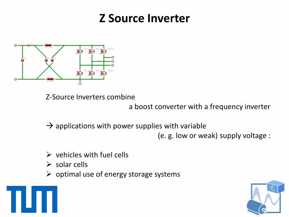
Z-Source Inverters combinea boost converter with a frequency inverter
applications with power supplies with variable(e. g. low or weak) supply voltage :
vehicles with fuel cells solar cells optimal use of energy storage systems

Z Source Inverter
Z-Source Inverters combinea boost converter with a frequency inverter
applications with power supplies with variable(e. g. low or weak) supply voltage :
vehicles with fuel cells solar cells optimal use of energy storage systems
D
D
T
TT
T
Bo
o
31
1
31
1
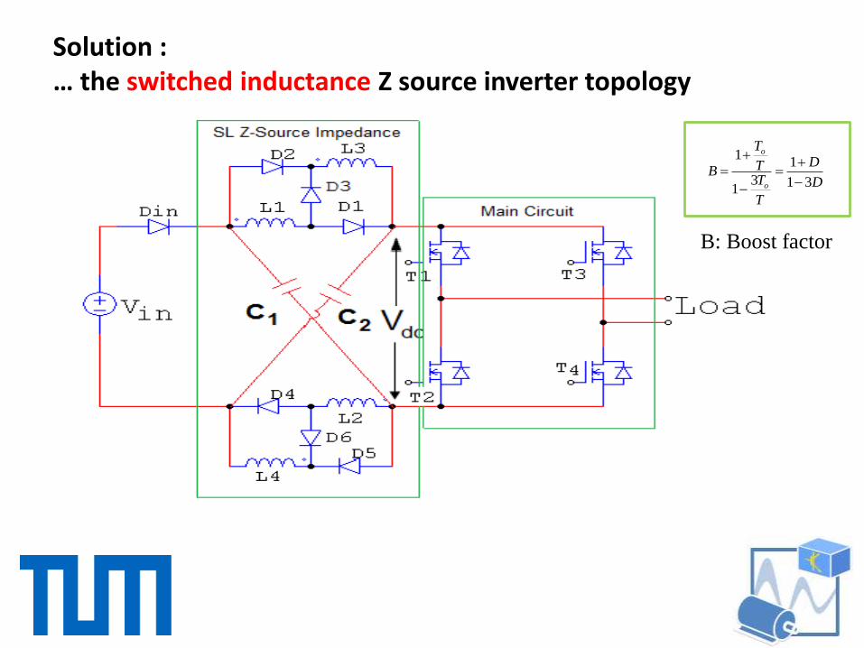
B: Boost factor
Solution :… the switched inductance Z source inverter topology

D
D
T
TT
T
Bo
o
31
1
31
1
B: Boost factor
Solution :… the switched inductance Z source inverter topology

Improved
Switched Inductor (SL) Z-source Inverter
Voltage Stress
Inrush current

0 0.05 0.1 0.15 0.2 0.25 0.30
2
4
6
8
10
D
Vc/
Vin
SL Z-source
Improved SL Z-source
Stress analysis
inCV
D
DV
31
1
inCV
D
DV
31
2
SL Z-Source
Improved SL Z-Source

Modeling of non-ideal Improved Switched Inductor
(SL) Z-source Inverter
b)Non-shoot-through statea) Shoot-Through State

Simulation Results
0.4 0.6 0.8 1 1.2 1.4 1.6 1.8 20
50
100
150
200
250
300
Capacitor voltage
under load change
0.6 0.65 0.7 0.75 0.8 0.85 0.9 0.95 1-400
-300
-200
-100
0
100
200
300
400Load VoltageLoad Current*100
Output voltage and current
under load change
Vin= 35 V, L1=L2=L3=L4= 1mHC1=C2= 0.8 mFCf= 100 µF, Lf= 2 mH, Rl= 311 Ω

Experimental Results(Open loop, single phase Z-source inverter)
13
Using simple boost control Method, where M=1- D
M: Modulation index
D: Shoot-through duty cycle
R=680 Ω
Vin=0-10 V
mHLFCFCCuHLLff
1,50,100,2202121

14
Vin= 5 V, D= 0.1, M=0.9Switching frquency= 20 KHz
Vdc=7 V
Vout= 6.3 V

15
Vin= 5 V, D= 0.3, M=0.7Switching frquency= 20 KHz
Vdc=12.5 V
Vout=11 V