z master z597 diesel series
TRANSCRIPT

Z Master Z597Diesel SeriesService Manual
LCE Products

This service manual was written expressly for Toro service technicians. The Toro Company has made every effort to make the information in this manual complete and correct.
Basic shop safety knowledge and mechanical/electrical skills are assumed. The Table of Contents lists the systems and the related topics covered in this manual.
The following service materials are available in addition to this service manual:
Hydrostatic Pumps: Hydro-Gear BDP-10A/16A/21L - Service and Repair ManualForm #492-4789
Wheel Motors: Parker/Ross Wheel Motor Service ManualForm #492-4753
Diesel Engine: Briggs & Stratton Daihatsu 3 Cylinder Liquid-Cooled Engine Repair ManualForm #492-0670
Hydraulic Troubleshooting: Interactive hydraulic troubleshooting and failure analysis on compact diskForm #492-4777
Electrical Troubleshooting: Interactive electrical troubleshooting and wiring diagrams on compact diskForm # 492-9143
The Z Master 597 model years 2004 and 2005 are covered in this manual. The manual may also be specified for use on later model products.
The hydrostatic drive system is precision machinery. Maintain strict cleanliness control during all stages of service and repair. Cover or cap all hose ends and fittings whenever they are exposed. Even a small amount of dirt or other contamination can severely damage the system.
We are hopeful that you will find this manual a valuable addition to your service shop. If you have any questions or comments regarding this manual, please contact us at the following address:
The Toro Company LCE Service Training Department 8111 Lyndale Avenue South Bloomington, MN 55420
The Toro Company reserves the right to change product specifications or this manual without notice.
ABOUT THIS MANUAL
Copyright© All Rights Reserved©2005 The Toro Company

THIS PAGE INTENTIONALLY LEFT BLANK.
iZ Master Z597 Diesel Service Manual
TABLE OF CONTENTSSafety Information General Information . . . . . . . . . . . . . . . . . . . . . . . . . . . . . . . . . . Think Safety First . . . . . . . . . . . . . . . . . . . . . . . . . . . . . . . . . . .
Specifications Machine Profile Photos . . . . . . . . . . . . . . . . . . . . . . . . . . . . . . . . Specifications . . . . . . . . . . . . . . . . . . . . . . . . . . . . . . . . . . . . Specifications . . . . . . . . . . . . . . . . . . . . . . . . . . . . . . . . . . . . General Specifications . . . . . . . . . . . . . . . . . . . . . . . . . . . . . . . . . Available Service Manuals / Service Aids . . . . . . . . . . . . . . . . . . . . . . . . . Torque Specifications . . . . . . . . . . . . . . . . . . . . . . . . . . . . . . . . . Standard Torque for Dry, Zinc Plated, and Steel Fasteners (Inch Series) . . . . . . . . . . . . . Standard Torque for Dry, Zinc, and Steel Fasteners (Metric Fasteners) . . . . . . . . . . . . . . Other Torque Specifications . . . . . . . . . . . . . . . . . . . . . . . . . . . . . . . Equivalents and Conversions . . . . . . . . . . . . . . . . . . . . . . . . . . . . . . U.S. to Metric Conversions . . . . . . . . . . . . . . . . . . . . . . . . . . . . . . .
Chassis Caster Fork Assembly Removal . . . . . . . . . . . . . . . . . . . . . . . . . . . . . Replacing the Caster Bearings . . . . . . . . . . . . . . . . . . . . . . . . . . . . . Caster Fork Assembly . . . . . . . . . . . . . . . . . . . . . . . . . . . . . . . . . Front Wheel Removal and Bearing Replacement . . . . . . . . . . . . . . . . . . . . . . Fuel Tank Removal . . . . . . . . . . . . . . . . . . . . . . . . . . . . . . . . . . Right Side Fuel Tank Removal . . . . . . . . . . . . . . . . . . . . . . . . . . . . Right Side Fuel Tank Installation . . . . . . . . . . . . . . . . . . . . . . . . . . . Left Side Fuel Tank Removal . . . . . . . . . . . . . . . . . . . . . . . . . . . . Left Side Fuel Tank Installation . . . . . . . . . . . . . . . . . . . . . . . . . . . . Hood Assembly Removal . . . . . . . . . . . . . . . . . . . . . . . . . . . . . . . . Hood Assembly Installation . . . . . . . . . . . . . . . . . . . . . . . . . . . . . . . Throttle Control Replacement . . . . . . . . . . . . . . . . . . . . . . . . . . . . . . Installation . . . . . . . . . . . . . . . . . . . . . . . . . . . . . . . . . . . . Brake Lever Removal . . . . . . . . . . . . . . . . . . . . . . . . . . . . . . . . . Brake Lever Installation . . . . . . . . . . . . . . . . . . . . . . . . . . . . . . . . Brake Band Removal . . . . . . . . . . . . . . . . . . . . . . . . . . . . . . . . . Brake Band Installation . . . . . . . . . . . . . . . . . . . . . . . . . . . . . . . . Brake Cross Shaft Removal . . . . . . . . . . . . . . . . . . . . . . . . . . . . . . Brake Shaft Installation . . . . . . . . . . . . . . . . . . . . . . . . . . . . . . . . Adjusting the Parking Brake . . . . . . . . . . . . . . . . . . . . . . . . . . . . . . Deck Lift Lever Removal . . . . . . . . . . . . . . . . . . . . . . . . . . . . . . . . Deck Lift Lever Installation . . . . . . . . . . . . . . . . . . . . . . . . . . . . . . . Motion Control Assembly Removal . . . . . . . . . . . . . . . . . . . . . . . . . . . . Motion Control Assembly Installation . . . . . . . . . . . . . . . . . . . . . . . . . . .
Hydraulic System Hydrostatic Pump Removal . . . . . . . . . . . . . . . . . . . . . . . . . . . . . . . Hydrostatic Pump Installation . . . . . . . . . . . . . . . . . . . . . . . . . . . . . . Wheel Motor Removal . . . . . . . . . . . . . . . . . . . . . . . . . . . . . . . . . Wheel Motor Installation . . . . . . . . . . . . . . . . . . . . . . . . . . . . . . . . Purging the Hydraulic System . . . . . . . . . . . . . . . . . . . . . . . . . . . . . . Hydraulic Fan Pump Removal . . . . . . . . . . . . . . . . . . . . . . . . . . . . . . Hydraulic Fan Pump Installation . . . . . . . . . . . . . . . . . . . . . . . . . . . . . Hydraulic Fan Motor Removal . . . . . . . . . . . . . . . . . . . . . . . . . . . . . . Hydraulic Fan Motor Installation . . . . . . . . . . . . . . . . . . . . . . . . . . . . .
1-21-2
2-22-32-42-52-62-72-82-92-102-112-12
3-23-33-43-53-63-63-83-83-113-113-123-123-133-163-173-173-183-183-203-223-233-263-293-32
4-24-54-84-104-134-144-164-174-20
ii Z Master Z597 Diesel Service Manual
TABLE OF CONTENTSHydraulic System continued Setting the Hydrostatic Pump Neutral . . . . . . . . . . . . . . . . . . . . . . . . . . . Adjusting the Handle Neutral . . . . . . . . . . . . . . . . . . . . . . . . . . . . . . Setting the LH Hydrostatic Pump Neutral . . . . . . . . . . . . . . . . . . . . . . . . . Setting the RH Hydrostatic Pump Neutral . . . . . . . . . . . . . . . . . . . . . . . . . Adjusting the Tracking . . . . . . . . . . . . . . . . . . . . . . . . . . . . . . . . . Hydraulic Flow Testing Procedure . . . . . . . . . . . . . . . . . . . . . . . . . . . . Cooling Fan Pump Flow Testing Procedure . . . . . . . . . . . . . . . . . . . . . . . . Replacing the Traction Pump Drive Belt . . . . . . . . . . . . . . . . . . . . . . . . . . Pushing the Machine by Hand . . . . . . . . . . . . . . . . . . . . . . . . . . . . . . Changing to Machine Operation . . . . . . . . . . . . . . . . . . . . . . . . . . . . . Hydraulic Schematic . . . . . . . . . . . . . . . . . . . . . . . . . . . . . . . . .
Engine Engine Removal . . . . . . . . . . . . . . . . . . . . . . . . . . . . . . . . . . . Engine Installation . . . . . . . . . . . . . . . . . . . . . . . . . . . . . . . . . . Cooling System . . . . . . . . . . . . . . . . . . . . . . . . . . . . . . . . . . . Removing the Radiator . . . . . . . . . . . . . . . . . . . . . . . . . . . . . . . Radiator Installation . . . . . . . . . . . . . . . . . . . . . . . . . . . . . . . . Checking the Radiator Coolant . . . . . . . . . . . . . . . . . . . . . . . . . . . . Replacing the Fan Pump Drive Belt . . . . . . . . . . . . . . . . . . . . . . . . . . . . Replacing and Tensioning the Alternator Belt . . . . . . . . . . . . . . . . . . . . . . . . Replacing the Alternator Belt . . . . . . . . . . . . . . . . . . . . . . . . . . . . . Tensioning the Alternator Belt . . . . . . . . . . . . . . . . . . . . . . . . . . . . Servicing the Fuel Filter . . . . . . . . . . . . . . . . . . . . . . . . . . . . . . . . Draining Water from the Fuel Filter . . . . . . . . . . . . . . . . . . . . . . . . . . Changing the Fuel Filter . . . . . . . . . . . . . . . . . . . . . . . . . . . . . . Priming the Fuel System . . . . . . . . . . . . . . . . . . . . . . . . . . . . . . . .
Electrical Electrical System . . . . . . . . . . . . . . . . . . . . . . . . . . . . . . . . . . . General . . . . . . . . . . . . . . . . . . . . . . . . . . . . . . . . . . . . . Relays . . . . . . . . . . . . . . . . . . . . . . . . . . . . . . . . . . . . . . . PTO Switch . . . . . . . . . . . . . . . . . . . . . . . . . . . . . . . . . . . . . Ignition Switch . . . . . . . . . . . . . . . . . . . . . . . . . . . . . . . . . . . . Neutral Safety Switch . . . . . . . . . . . . . . . . . . . . . . . . . . . . . . . . . Park Brake Switch . . . . . . . . . . . . . . . . . . . . . . . . . . . . . . . . . . Seat Switch . . . . . . . . . . . . . . . . . . . . . . . . . . . . . . . . . . . . . Delay Module . . . . . . . . . . . . . . . . . . . . . . . . . . . . . . . . . . . . Dual-Tone Alarm . . . . . . . . . . . . . . . . . . . . . . . . . . . . . . . . . . . Glow Plug Controller . . . . . . . . . . . . . . . . . . . . . . . . . . . . . . . . . Temperature Sender . . . . . . . . . . . . . . . . . . . . . . . . . . . . . . . . . Oil Pressure Switch . . . . . . . . . . . . . . . . . . . . . . . . . . . . . . . . . . Water Temperature Gauge . . . . . . . . . . . . . . . . . . . . . . . . . . . . . . . Hour Meter . . . . . . . . . . . . . . . . . . . . . . . . . . . . . . . . . . . . . Volt Meter Gauge . . . . . . . . . . . . . . . . . . . . . . . . . . . . . . . . . . . Electric PTO Clutch . . . . . . . . . . . . . . . . . . . . . . . . . . . . . . . . . . Coil Resistance Measurement . . . . . . . . . . . . . . . . . . . . . . . . . . . . Measuring Clutch Current Draw . . . . . . . . . . . . . . . . . . . . . . . . . . . Fuel Filter Sensor . . . . . . . . . . . . . . . . . . . . . . . . . . . . . . . . . . Electrical Schematic . . . . . . . . . . . . . . . . . . . . . . . . . . . . . . . . .
4-234-244-254-264-274-284-304-314-324-334-34
5-25-115-215-215-255-285-295-295-305-315-325-325-335-34
6-26-26-26-46-56-66-76-96-106-116-136-156-166-176-186-196-206-206-216-226-24, 25

iiiZ Master Z597 Diesel Service Manual
TABLE OF CONTENTSMower Decks Electric PTO Clutch Removal . . . . . . . . . . . . . . . . . . . . . . . . . . . . . . PTO Clutch Installation . . . . . . . . . . . . . . . . . . . . . . . . . . . . . . . . Mower Deck Removal . . . . . . . . . . . . . . . . . . . . . . . . . . . . . . . . . Mower Deck Installation . . . . . . . . . . . . . . . . . . . . . . . . . . . . . . . . Mower Spindle Removal . . . . . . . . . . . . . . . . . . . . . . . . . . . . . . . . Mower Spindle Disassembly . . . . . . . . . . . . . . . . . . . . . . . . . . . . . . Mower Spindle Assembly . . . . . . . . . . . . . . . . . . . . . . . . . . . . . . . . Mower Jackshaft Assembly Removal . . . . . . . . . . . . . . . . . . . . . . . . . . . Mower Jackshaft Installation . . . . . . . . . . . . . . . . . . . . . . . . . . . . . . Mower Jackshaft and Pulley Assembly . . . . . . . . . . . . . . . . . . . . . . . . . . Right Hand Mower Idler Assembly Removal . . . . . . . . . . . . . . . . . . . . . . . . Right Hand Mower Idler Assembly Installation . . . . . . . . . . . . . . . . . . . . . . . Left Hand Mower Idler Assembly Removal . . . . . . . . . . . . . . . . . . . . . . . . . Left Hand Mower Idler Assembly Installation . . . . . . . . . . . . . . . . . . . . . . . . Replacing the Mower Spindle Belt . . . . . . . . . . . . . . . . . . . . . . . . . . . . Replacing Mower Drive Belts . . . . . . . . . . . . . . . . . . . . . . . . . . . . . . Leveling the Mower . . . . . . . . . . . . . . . . . . . . . . . . . . . . . . . . . . Setting up the Machine . . . . . . . . . . . . . . . . . . . . . . . . . . . . . . . Leveling the Mower Side-to-Side . . . . . . . . . . . . . . . . . . . . . . . . . . . . . Adjusting the Front-to-Rear Mower Pitch . . . . . . . . . . . . . . . . . . . . . . . . . . Adjusting the Compression Spring . . . . . . . . . . . . . . . . . . . . . . . . . . . .
7-27-57-87-137-187-207-247-297-317-327-327-347-367-387-397-417-467-467-477-487-50

iv Z Master Z597 Diesel Service Manual
THIS PAGE INTENTIONALLY LEFT BLANK.
TABLE OF CONTENTS
1-1Z Master Z597 Diesel Service Manual
Safety Information . . . . . . . . .
Specifications . . . . . . . . . . .
Chassis . . . . . . . . . . . . . .
Hydraulic System . . . . . . . . .
Engine . . . . . . . . . . . . . . .
Electrical . . . . . . . . . . . . . .
Mower Decks . . . . . . . . . . .
2
3
4
5
6
7
1
SAFETY INFORMATION

1-2 Z Master Z597 Diesel Service Manual
1
SAFETY INFORMATIONSAFETY INFORMATION
General InformationThis symbol means WARNING or PERSONAL SAFETY INSTRUCTION - read the instruction because it has to do with your safety. Failure to comply with the instruction may result in personal injury or even death.
This manual is intended as a service and repair manual only. The safety instructions provided herein are for troubleshooting, service, and repair of the Z Master Z597 Zero-turn Riding Mower
The riding mower and attachment operator's manualcontain safety information and operating tips for safeoperating practices. Operator's manuals are availablethrough your Toro parts source or:
The Toro Company Publications Department8111 Lyndale Avenue SouthBloomington, MN 55420
Think Safety First
Avoid unexpected starting of engine...
Always turn off the engine and disconnect the spark plug wire(s) before cleaning, adjusting, or repair.
Avoid lacerations and amputations...
Stay clear of all moving parts whenever the engine is running. Treat all normally moving parts as if they were moving whenever the engine is running or has the potential to start.
Avoid burns...
Do not touch the engine, muffler, or other components which may increase in temperature during operation, while the unit is running or shortly after it has been running.
Avoid fires and explosions...
Avoid spilling fuel and never smoke while working with any type of fuel or lubricant. Wipe up any spilled fuel or oil immediately. Never remove the fuel cap or add fuel when the engine is running. Always use approved, labeled containers for storing or transporting fuel and lubricants.
Avoid asphyxiation...
Never operate an engine in a confined area without proper ventilation.
Avoid injury from batteries...
Battery acid is poisonous and can cause burns. Avoid contact with skin, eyes, and clothing. Battery gases can explode. Keep cigarettes, sparks, and flames away from the battery.
Avoid injury due to inferior parts...
Use only original equipment parts to ensure that important safety criteria are met.
Avoid injury to bystanders...
Always clear the area of bystanders before starting or testing powered equipment.
Avoid injury due to projectiles...
Always clear the area of sticks, rocks, or any other debris that could be picked up and thrown by the powered equipment.
Avoid modifications...
Never alter or modify any part unless it is a factory approved procedure.
Avoid unsafe operation...
Always test the safety interlock system after making adjustments or repairs on the machine. Refer to the Electrical section in this manual for more information.
SAFETY INFORMATION
General InformationThis symbol means WARNING or PERSONAL SAFETY INSTRUCTION - read the instruction because it has to do with your safety. Failure to comply with the instruction may result in personal injury or even death.
This manual is intended as a service and repair manual only. The safety instructions provided herein are for troubleshooting, service, and repair of the Z Master Z597 Zero-turn Riding Mower
The riding mower and attachment operator's manualcontain safety information and operating tips for safeoperating practices. Operator's manuals are availablethrough your Toro parts source or:
The Toro Company Publications Department8111 Lyndale Avenue SouthBloomington, MN 55420
Think Safety First
Avoid unexpected starting of engine...
Always turn off the engine and disconnect the spark plug wire(s) before cleaning, adjusting, or repair.
Avoid lacerations and amputations...
Stay clear of all moving parts whenever the engine is running. Treat all normally moving parts as if they were moving whenever the engine is running or has the potential to start.
Avoid burns...
Do not touch the engine, muffler, or other components which may increase in temperature during operation, while the unit is running or shortly after it has been running.
Avoid fires and explosions...
Avoid spilling fuel and never smoke while working with any type of fuel or lubricant. Wipe up any spilled fuel or oil immediately. Never remove the fuel cap or add fuel when the engine is running. Always use approved, labeled containers for storing or transporting fuel and lubricants.
Avoid asphyxiation...
Never operate an engine in a confined area without proper ventilation.
Avoid injury from batteries...
Battery acid is poisonous and can cause burns. Avoid contact with skin, eyes, and clothing. Battery gases can explode. Keep cigarettes, sparks, and flames away from the battery.
Avoid injury due to inferior parts...
Use only original equipment parts to ensure that important safety criteria are met.
Avoid injury to bystanders...
Always clear the area of bystanders before starting or testing powered equipment.
Avoid injury due to projectiles...
Always clear the area of sticks, rocks, or any other debris that could be picked up and thrown by the powered equipment.
Avoid modifications...
Never alter or modify any part unless it is a factory approved procedure.
Avoid unsafe operation...
Always test the safety interlock system after making adjustments or repairs on the machine. Refer to the Electrical section in this manual for more information.

2-1Z Master Z597 Diesel Service Manual
3
4
5
6
7
1
SPECIFICATIONS
1
2
Safety Information . . . . . . . . .
Specifications . . . . . . . . . . .
Chassis . . . . . . . . . . . . . .
Hydraulic System . . . . . . . . .
Engine . . . . . . . . . . . . . . .
Electrical . . . . . . . . . . . . . .
Mower Decks . . . . . . . . . . .
2-2 Z Master Z597 Diesel Service Manual
2
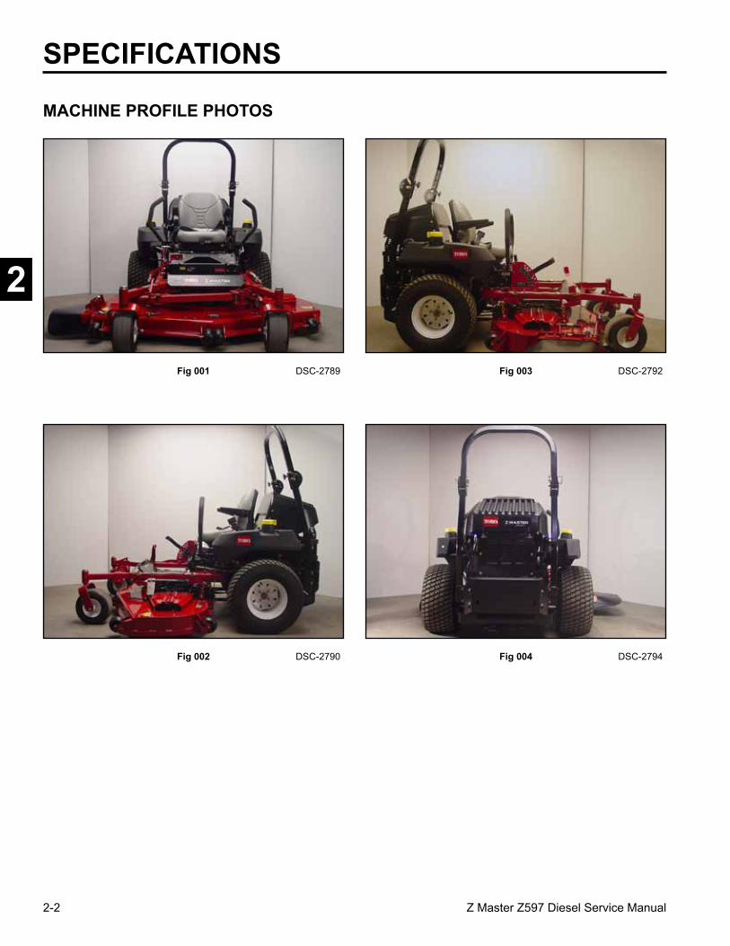
SPECIFICATIONS
MACHINE PROFILE PHOTOS
Fig 001 DSC-2789
Fig 002 DSC-2790 Fig 004 DSC-2794
Fig 003 DSC-2792

2-3Z Master Z597 Diesel Service Manual
2
SPECIFICATIONS
Item SpecificationEngine Briggs & Stratton® Vanguard™ Daihatsu® 27 Horsepower Diesel Engine
RPM setting High RPM Setting (no load) 3850 + 50 (International: 3450 + 50)Low RPM Setting 1750
Fuel Capacity 12 gallons (45.4 liters) Diesel Fuel
Length Z597 – 60” (152.4cm) TF Deck - 81.5” (207cm)Z597 – 72” (182.9cm) TF Deck - 84.5” (214.6cm)
Width Z597 – 60” (152.4cm) TF Deck - 61.7” (156.7cm) - Deflector 76” (193cm)Z597 – 72” (182.9cm) TF Deck - 73.6” (186.9cm) - Deflector 88” (223.5cm)
Height 74” (188cm) ROPS Height Upright55” (140cm) ROPS Folded
Weight Z597 – 60” (152.4cm) TF Deck - 1630 lbs. (739.36kg)Z597 – 72” (182.9cm) TF Deck - 1695 lbs. (768.84kg)
Traction System (2) Hydro-Gear BDP-21A, 21cc/rev with system check relief (Pump)(2) Parker/Ross MB18, 17.1 cir 1 ¼“ Tapered Shaft (Wheel Motor)
Ground Speed Forward: Infinite 0 – 12 mphReverse: Infinite 0 – 8 mph
Tires Rear: 26” x 12” – 12Front: 13” x 6.5” – 6
Tire Pressure Rear: 13 psi (90kPa)Front: 13 psi (90kPa)
Attachment Drive 200 ft-lb. electromagnetic clutch (271.16 Nm)
Battery BCI Group Size: 26540 cold cranking amps.

2-4 Z Master Z597 Diesel Service Manual
2
SPECIFICATIONS
Item SpecificationMower Deck TURBO FORCE
Deck Construction Fabricated, High Strength 7-gauge Steel/with Bull-nose Bumper
Deck Depth 5 ½” (13.97cm)
Mower Baffles Adjustable Discharge Baffle
Spindle Housing 9 3/8” (23.8cm) Diameter Cast Iron
Spindle Shaft/Bearings 1” (2.54cm) Shaft / Tapered Roller
Blade Tip Speed 18,500+ ft/min (5,638+ m/min)
Blades ¼” (.635cm) Heat Treated Steel
Discharge Chute 5/16” (.79cm) Rubber
Cutting Height 1-1/2” – 5” (3.81 - 12.7cm)
Carrier Frame Construction 2” x 2” x 3/16” (5.08 x 5.08 x .476cm) Steel
Anti-scalp Rollers 6
Certification ANSI, CARB, EPA, OSHA

2-5Z Master Z597 Diesel Service Manual
2
SPECIFICATIONS
Greasing and Lubrication:
Grease: No. 2 general purpose lithium base or molybdenum grease.
Where to Add Grease: See Check Service Reference Aid decal below.
General Specifications
Fig 006 fig. 55 m-5615
Hydraulic System Oil Capacity: 4 quarts (3.8 l)
Fluid Type: Mobil 1 15W – 50 synthetic motor oil or equivalent synthetic oil
Fluid Level: Check the fluid level while the fluid is warm. The fluid should be between cold and hot.
Note: The fluid level should be to the top of the hot level of the baffle, when the fluid is hot (Fig. 006 above).
Fig 005 fig. 50 decal
1. Cap 3. Cold fluid level - full2. Baffle 4. Hot fluid level - full

2-6 Z Master Z597 Diesel Service Manual
2
Fig 007 DSC-2351
Model and Serial Number Location
The unit model and serial number plate is located on the right hand side of the unit, below the right side motion control lever (Fig. 007).
Engine Model and Serial Number Identification:
Consult the appropriate engine manufacture’s service literature for the location and translation of the engine model and serial number information.
Hydrostatic Pumps Model and Serial Number:
The label above (Fig. 008), can be located on the pump housing. It identifies the model and configuration of the BDP pump.
Available Service Manuals / Service Aids
Hydrostatic Pumps: Hydro-Gear BDP-10A/16A/21L – Service and Repair ManualForm # 492-4789
Wheel Motors: Parker/Ross Wheel Motor Service ManualForm # 492-4753
Diesel Engine: Briggs & Stratton Daihatsu 3 Cylinder Liquid-Cooled Engine Repair Manual Form # 492-0670
Hydraulic Troubleshooting: Interactive hydraulic troubleshooting and failure analysis on compact diskForm #492-4777
Electrical Troubleshooting: Interactive electrical troubleshooting and wiring diagrams on compact diskForm #492-9143
Fig 008 configuration
SPECIFICATIONS

2-7Z Master Z597 Diesel Service Manual
2
2
Torque Specifications
Recommended fastener torque values are listed in the following tables. For critical applications, as determined by Toro, either the recommended torque or a torque that is unique to the application is clearly identified and specified in the service manual.
These torque specifications for the installation and tightening of fasteners shall apply to all fasteners which do not have a specific requirement identified in the service manual. The following factors shall be considered when applying torque: cleanliness of the fastener, use of a thread sealant (Loctite), degree of lubrication on the fastener, presence of a prevailing torque feature, hardness of the surface underneath of the fastener’s head, or similar condition which affects the installation.
As noted in the following tables, torque values should be reduced by 25% for lubricated fasteners to achieve the similar stress as a dry fastener. Torque values may also have to be reduced when the fastener is threaded into aluminum or brass. The specific torque value should be determined based on the aluminum or brass material strength, fastener size, length of thread engagement, etc.
The standard method of verifying torque shall be performed by marking a line on the fastener (head or nut) and mating part, then back off fastener 1/4 of a turn. Measure the torque required to tighten the fastener until the lines match up.
Fastener Identification
Figure A
Figure B
Inch Series Bolts and Screws
(A) Grade 1(B) Grade 5
(C) Grade 8
Metric Bolts and Screws
(A) Class 8.8 (B) Class 10.9
SPECIFICATIONS

2-8 Z Master Z597 Diesel Service Manual
2
SPECIFICATIONS
Standard Torque for Dry, Zinc Plated, and Steel Fasteners (Inch Series)
Note: Reduce torque values listed in the table above by 25% for lubricated fasteners. Lubricated fasteners are defined as threads coated with a lubricant such as oil, graphite, or thread sealant such as Loctite.
Note: Torque values may have to be reduced when installing fasteners into threaded aluminum or brass. The specific torque value should be determined based on the fastener size, the aluminum or base material strength, length of thread engagement, etc.
Note: The nominal torque values listed above for Grade 5 and 8 fasteners are based on 75% of the minimum proof load specified in SAE J429. The tolerance is approximately ± 10% of the nominal torque value. Thin height nuts include jam nuts.
Thread Size
Grade 1, 5, & 8 with Thin Height Nuts
SAE Grade 1 Bolts, Screws, Studs, & Sems with Regular
Height Nuts (SAE J995 Grade 2 or Stronger Nuts)
SAE Grade 5 Bolts, Screws, Studs, & Sems with Regular
Height Nuts (SAE J995 Grade 2 or Stronger Nuts)
SAE Grade 8 Bolts, Screws, Studs, & Sems with Regular
Height Nuts (SAE J995 Grade 2 or Stronger Nuts)
In-lb In-lb N-cm In-lb N-cm In-lb N-cm
# 6 - 32 UNC10 ± 2 13 ± 2 147 ± 23
15 ± 2 170 ± 20 23 ± 2 260 ± 20# 6 - 40 UNF 17 ± 2 190 ± 20 25 ± 2 280 ± 20# 8 - 32 UNC
13 ± 2 25 ± 5 282 ± 3029 ± 3 330 ± 30 41 ± 4 460 ± 45
# 8 - 36 UNF 31 ± 3 350 ± 30 43 ± 4 31 ± 3# 10 - 24 UNC
18 ± 2 30 ± 5 339 ± 5642 ± 4 475 ± 45 60 ± 6 674 ± 70
#10 - 32 UNF 48 ± 4 540 ± 45 68 ± 6 765 ± 701/4 - 20 UNC 48 ± 7 53 ± 7 599 ± 79 100 ± 10 1125 ± 100 140 ± 15 1580 ± 1701/4 - 28 UNF 53 ± 7 65 ± 10 734 ± 113 115 ± 10 1300 ± 100 160 ± 15 1800 ± 1705/16 - 18 UNC 115 ± 15 105 ± 17 1186 ± 169 200 ± 25 2250 ± 280 300 ± 30 3390 ± 3405/16 - 24 UNF 138 ± 17 128 ± 17 1446 ± 192 225 ± 25 2540 ± 280 325 ± 30 3670 ± 340
ft-lb ft-lb N-m ft-lb N-m ft-lb N-m3/8 - 16 UNC 16 ± 2 16 ± 2 22 ± 3 30 ± 3 41 ± 4 43 ± 4 58 ± 53/8 - 24 UNF 17 ± 2 18 ± 2 24 ± 3 35 ± 3 47 ± 4 50 ± 4 68 ± 57/16 - 14 UNC 27 ± 3 27 ± 3 37 ± 4 50 ± 5 68 ± 7 70 ± 7 68 ± 97/16 - 20 UNF 29 ± 3 29 ± 3 39 ± 4 55 ± 5 75 ± 7 77 ± 7 104 ± 91/2 - 13 UNC 30 ± 3 48 ± 7 65 ± 9 75 ± 8 102 ± 11 105 ± 10 142 ± 141/2 - 20 UNF 32 ± 3 53 ± 7 72 ± 9 85 ± 8 115 ± 11 120 ± 10 163 ± 145/8 - 11 UNC 65 ± 10 88 ± 12 119 ± 16 150 ± 15 203 ± 20 210 ± 20 285 ± 275/8 - 18 UNF 75 ± 10 95 ± 15 129 ± 20 170 ± 15 230 ± 20 240 ± 20 325 ± 273/4 - 10 UNC 93 ± 12 140 ± 20 190 ± 27 265 ± 25 359 ± 34 374 ± 35 508 ± 473/4 - 16 UNF 115 ± 15 165 ± 25 224 ± 34 300 ± 25 407 ± 34 420 ± 35 569 ± 477/8 - 9 UNC 140 ± 20 225 ± 25 305 ± 34 430 ± 45 583 ± 61 600 ± 60 813 ± 817/8 - 14 UNF 155 ± 25 260 ± 30 353 ± 41 475 ± 45 644 ± 61 660 ± 60 895 ± 81
2

2-9Z Master Z597 Diesel Service Manual
2
SPECIFICATIONS
Standard Torque for Dry, Zinc, and Steel Fasteners (Metric Fasteners)
Note: Reduce torque values listed in the table above by 25% for lubricated fasteners. Lubricated fasteners are defined as threads coated with a lubricant such as oil, graphite, or thread sealant such as Loctite.
Note: Torque values may have to be reduced when installing fasteners into threaded aluminum or brass. The specific torque value should be determined based on the fastener size, the aluminum or base material strength, length of thread engagement, etc.
Note: The nominal torque values listed above are based on 75% of the minimum proof load specified in SAE J1199. The tolerance is approximately ± 10% of the nominal torque value. Thin height nuts include jam nuts.
Thread SizeClass 8.8 Bolts, Screws, and Studs with
Regular Height Nuts (Class 8 or Strong Nuts)
Class 10.9 Bolts, Screws, and Studs with Regular Height Nuts (
Class 10 or Strong Nuts)M5 X 0.8 57 ± 5 in-lb 640 ± 60 N-cm 78 ± 7 in-lb 885 ± 80 N-cmM6 X 1.0 96 ± 9 in-lb 1018 ± 100 N-cm 133 ± 13 in-lb 1500 ± 150 N-cm
M8 X 1.25 19 ± 2 ft-lb 26 ± 3 N-m 27 ± 2 ft-lb 36 ± 3 N-mM10 X 1.5 38 ± 4 ft-lb 52 ± 5 N-m 53 ± 5 ft-lb 72 ± 7 N-mM12 X 1.75 66 ± 7 ft-lb 90 ± 10 N-m 92 ± 9 ft-lb 125 ± 12 N-mM16 X 2.0 166 ± 15 ft-lb 225 ± 20 N-m 229 ± 22 ft-lb 310 ± 30 N-mM20 X 2.5 325 ± 33 ft-lb 440 ± 45 N-m 450 ± 37 ft-lb 610 ± 50 N-m

2-10 Z Master Z597 Diesel Service Manual
2
SPECIFICATIONS
Other Torque Specifications
SAE Grade 8 Steel Set Screws
Thread Cutting Screws(Zinc Plated Steel)
Conversion Factors
in-lb X 11.2985 - N-cmft-lb X 1.3558 = N-m
Wheel Bolts and Lug Nuts
** For steel wheels and non-lubricated fasteners.
Thread Cutting Screws(Zinc Plated Steel)
* Hole size, material strength, material thickness and finish must be considered when determining specific torque values. All torque values are based on non-lubricated fasteners.
N-cm X - 0.08851 = in-lbN-cm X 0.73776 - ft-lb
Thread SizeRecommended Torque
Square Head Hex Socket
1/4 - 20 UNC 140 ± 20 in-lb 73 ± 12 in-lb
5/16 - 18 UNC 215 ± 35 in-lb 145 ± 20 in-lb
3/8 - 16 UNC 35 ± 10 ft-lb 18 ± 3 ft-lb
1/2 - 13 UNC 75 ± 15 ft-lb 50 ± 10 ft-lb
Type 1, Type 23, or Type F
Thread Size Baseline Torque*
No. 6 - 32 UNC 20 ± 5 in-lb
No. 8 - 32 UNC 30 ± 5 in-lb
No.10 - 24 UNC 38 ± 7 in-lb
1/4 - 20 UNC 85 ± 15 in-lb
5/16 - 18 UNC 110 ± 20 in-lb
3/8 - 16 UNC 200 ± 100 in-lb
Thread Size Recommended Torque**
7/16 - 20 UNFGrade 5 65 ± 10 ft-lb 88 ± 14 N-m
1/2 - 20 UNFGrade 5 80 ± 10 ft-lb 108 ± 14 N-m
M12 X 1.25Class 8.8 80 ± 10 ft-lb 108 ± 14 N-m
M12 X 1.5Class 8.8 80 ± 10 ft-lb 108 ± 14 N-m
Thread Size
Threads per InchBaseline Torque*
Type A Type B
No. 6 18 20 20 ± 5 in-lb
No. 8 15 18 30 ± 5 in-lb
No. 10 12 16 38 ± 7 in-lb
No. 12 11 14 85 ± 15 in-lb

2-11Z Master Z597 Diesel Service Manual
2
SPECIFICATIONS
Equivalents and ConversionsDecimal and Millimeter Equivalents
Fractions Decimals mm Fractions Decimals mm1/64 0.015625 0.397 33/64 0.515625 13.097
1/32 0.03125 0.794 16/32 0.53125 13.4843/64 0.046875 1.191 35/64 0.546875 13.891
1/16 0.0625 1.588 9/16 0.5625 14.2885/64 0.078125 1.984 37/64 0.578125 14.684
3/32 0.9375 2.381 19/32 0.59375 15.0811/8 0.1250 3.175 5/8 0.6250 15.875
9/64 0.140625 3.572 41/64 0.640625 16.2725/32 0.15625 3.969 21/32 0.65625 16.669
11/64 0.171875 4.366 43/64 0.671875 17.0663/16 0.1875 4.762 11/16 0.6875 17.462
13/64 0.203125 5.159 45/64 0.703125 17.8597/32 0.21875 5.556 23/32 0.71875 18.256
15/64 0.234375 5.953 47/64 0.734375 18.6531/4 0.2500 6.350 3/4 0.7500 19.050
17/64 0.265625 6.747 49/64 0.765625 19.4479/32 0.28125 7.144 25/32 0.78125 19.844
19/64 0.296875 7.541 51/64 0.796875 20.2415/16 0.3125 7.541 13/16 0.8125 20.638
21/64 0.328125 8.334 53/64 0.828125 21.03411/32 0.34375 8.731 27/32 0.84375 21.431
23/64 0.359375 9.128 55/64 0.859375 21.8283/8 0.3750 9.525 7/8 0.8750 22.225
25/64 0.390625 9.922 57/64 0.890625 22.62213/32 0.40625 10.319 29/32 0.90625 23.019
27/64 0.421875 10.716 59/64 0.921875 23.4167/16 0.4375 11.112 15/16 0.9375 23.812
29/64 0.453125 11.509 61/64 0.953125 24.20915/32 0.46875 11.906 31/32 0.96875 24.606
31/64 0.484375 12.303 63/64 0.984375 25.0031/2 0.5000 12.700 1 1.000 25.400
1 mm = 0.03937 in. 0.001 in. = 0.0254 mm
2-12 Z Master Z597 Diesel Service Manual
2
SPECIFICATIONS
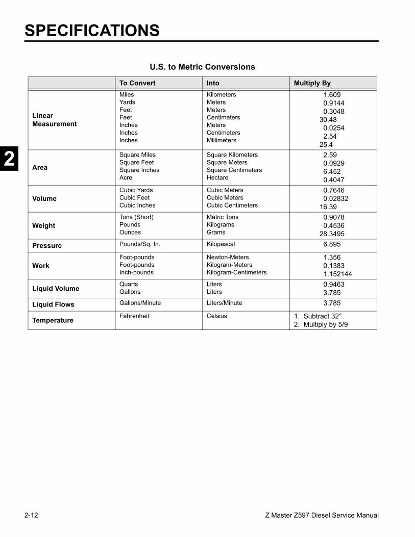
U.S. to Metric Conversions
To Convert Into Multiply By
LinearMeasurement
MilesYardsFeetFeetInchesInchesInches
KilometersMetersMetersCentimetersMetersCentimetersMillimeters
1.6090.91440.3048
30.480.02542.54
25.4
Area
Square MilesSquare FeetSquare InchesAcre
Square KilometersSquare MetersSquare CentimetersHectare
2.590.09296.4520.4047
VolumeCubic YardsCubic FeetCubic Inches
Cubic MetersCubic MetersCubic Centimeters
0.76460.02832
16.39
WeightTons (Short)PoundsOunces
Metric TonsKilogramsGrams
0.90780.4536
28.3495
Pressure Pounds/Sq. In. Kilopascal 6.895
WorkFoot-poundsFoot-poundsInch-pounds
Newton-MetersKilogram-MetersKilogram-Centimeters
1.3560.13831.152144
Liquid Volume QuartsGallons
LitersLiters
0.94633.785
Liquid Flows Gallons/Minute Liters/Minute 3.785
Temperature Fahrenheit Celsius 1. Subtract 32°2. Multiply by 5/9

3-1Z Master Z597 Diesel Service Manual
2
4
5
6
7
1
CHASSIS
Safety Information . . . . . . . . .
Specifications . . . . . . . . . . .
Chassis . . . . . . . . . . . . . .
Hydraulic System . . . . . . . . .
Engine . . . . . . . . . . . . . . .
Electrical . . . . . . . . . . . . . .
Mower Decks . . . . . . . . . . .
1
3

3-2 Z Master Z597 Diesel Service Manual
3
CHASSIS
Caster Fork Assembly Removal
1. Raise the front of the unit off the ground, allowing enough clearance to remove the castor fork from the bottom of the hub.
2. With a hammer and chisel, remove the top grease cap (Fig. 009).
Fig 009 mvc-1531
Fig 011 DSC-1533
4. Remove the Belleville washers, caster fork and wheel assembly (Fig. 011).
Fig 010 DSC-1532
3. Remove the locknut (Fig. 010).
3-3Z Master Z597 Diesel Service Manual
3
Fig 013 DSC-1535
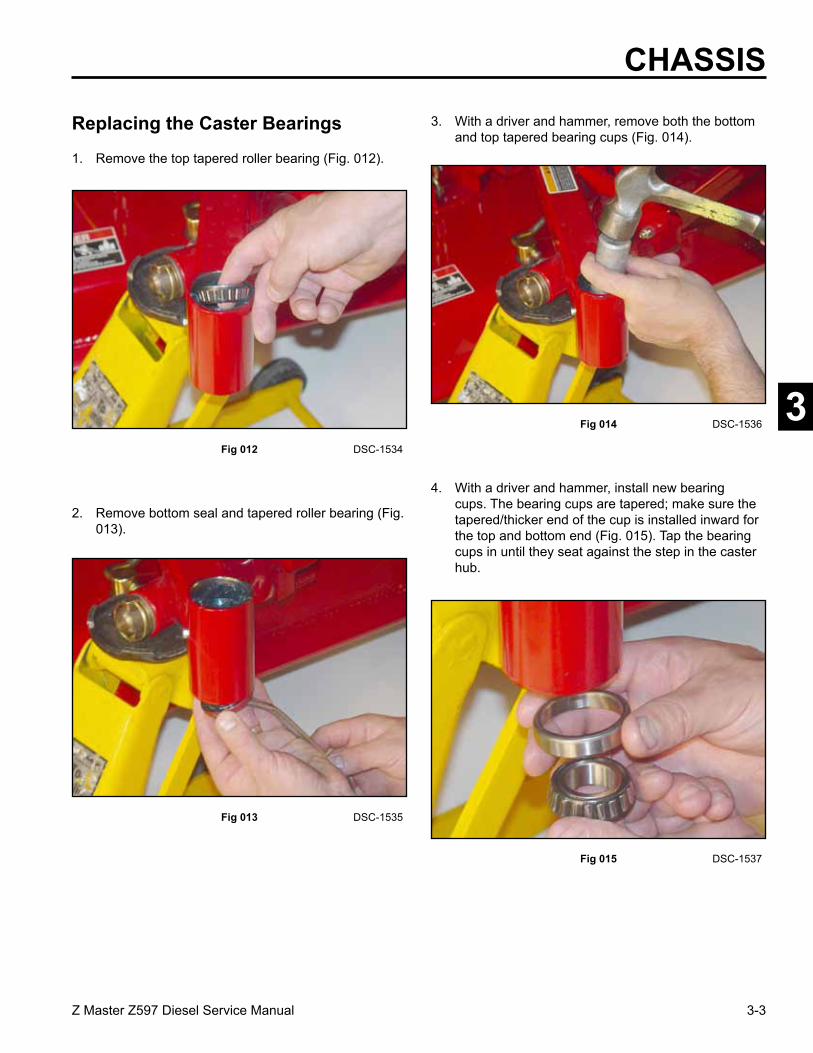
2. Remove bottom seal and tapered roller bearing (Fig. 013).
Fig 012 DSC-1534
1. Remove the top tapered roller bearing (Fig. 012).
Fig 015 DSC-1537
4. With a driver and hammer, install new bearing cups. The bearing cups are tapered; make sure the tapered/thicker end of the cup is installed inward for the top and bottom end (Fig. 015). Tap the bearing cups in until they seat against the step in the caster hub.
Fig 014 DSC-1536
3. With a driver and hammer, remove both the bottom and top tapered bearing cups (Fig. 014).
Replacing the Caster Bearings
CHASSIS

3-4 Z Master Z597 Diesel Service Manual
3
5. Pack the upper and lower tapered bearings prior to installation (Fig. 016).
Castor Fork Assembly
Fig 016 DSC-1539
2. Install the upper bearing.
3. Install the Belleville (spring) washers as shown in (Fig. 019).
A. Dust Cap B. Locknut C. Spring Washers
Fig 018 DSC-1533
Fig 019 washers line art
1. Install the castor fork into the frame (Fig. 018).
6. Install the lower bearing and seal, with the open end of the seal facing up (Fig. 017).
Fig 017 DSC-1538
CHASSIS
A
B
C

3-5Z Master Z597 Diesel Service Manual
3
CHASSIS4. Install the locknut and tighten until the spring
washers are flat, then back off 1/4 turn to properly set the preload on the bearings (Fig. 020).
Fig 020 DSC-1532
5. Remove the plug located on the side of the hub on the frame for the castor fork. Install a grease fitting. Pump grease into the housing until grease is passing through the upper bearing (Fig. 021).
Fig 021 DSC-1540
Fig 022 DSC-1541
6. Remove the grease fitting and install the grease plug.
7. Install the dust cap on the caster hub (Fig. 022).
1. Raise the front of the unit off the ground.
2. Remove the wheel bolt from the fork (Fig. 023).
Fig 023 DSC-1543
Front Wheel Removal and Bearing Replacement

3-6 Z Master Z597 Diesel Service Manual
3
Fig 024 DSC-1546
3. Remove bearing spacers and the front caster spacer. Remove the seals located on each side of the wheel and both the tapered bearings (Fig. 024).
A. Bearing Spacer D. Caster Spacer B. Bearing Seal E. Retaining wheel nut C. Taper Bearing F. Retaining wheel bolt
Fuel Tank Removal
AA B BC C
D
E F
4. Pack both tapered wheel bearings. Reassemble per Fig. 024. Pump grease into the wheel bearings through the grease fitting located on the rim (Fig. 025).
Fig 026 DSC-1548
1. Disconnect the negative battery cable. Empty the fuel tank.
2. Remove the fuel hose at the bottom of the fuel tank (Fig. 026).
Fig 025 DSC-1547
Right Side Fuel Tank Removal
3. Remove the fuel return line located on the inside of the fuel tank (Fig. 027).
Fig 027 DSC-1549
CHASSIS
3-7Z Master Z597 Diesel Service Manual
3
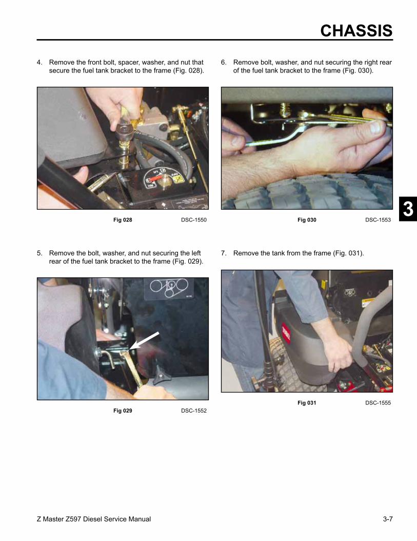
4. Remove the front bolt, spacer, washer, and nut that secure the fuel tank bracket to the frame (Fig. 028).
Fig 028 DSC-1550
5. Remove the bolt, washer, and nut securing the left rear of the fuel tank bracket to the frame (Fig. 029).
Fig 029 DSC-1552
6. Remove bolt, washer, and nut securing the right rear of the fuel tank bracket to the frame (Fig. 030).
Fig 030 DSC-1553
CHASSIS
7. Remove the tank from the frame (Fig. 031).
Fig 031 DSC-1555

3-8 Z Master Z597 Diesel Service Manual
3
CHASSIS8. Remove the fuel tank bracket by removing 3
locknuts and springs and 1 bolt (Fig. 032).
Fig 032 DSC-1556
Right Side Fuel Tank Installation
Reverse the order of removal.
Note: When tightening the nuts and springs on the fuel tank bracket, Do Not over-tighten the nuts. Tighten the nuts until there are three threads showing on the threaded stud (Fig. 033).
1. Disconnect the negative battery cable. Empty the fuel tank.
Left Side Fuel Tank Removal
Fig 033 3 thread above nut
A
A. Tank Stud D. NutB. Compression Spring E. 3 ThreadsC. Tank mounting Plate
C
B
D
E

3-9Z Master Z597 Diesel Service Manual
3
3. Carefully remove the control panel and control panel shield by lifting the panel and sliding it to the middle of the unit.
NOTE: It is not necessary to disconnect any cables or wiring.
4. Unplug the 3 connectors that plug into the delay module (Fig. 035).
Fig 035 DSC-1578
5. Remove the return fuel line, located on the inside of the fuel tank (Fig. 036).
Fig 036 DSC-1565
6. Remove the fuel line, located under the front of the fuel tank (Fig. 037).
Fig 037 DSC-1566
CHASSIS2. Remove the 4 screws retaining the control panel and
control panel shield to the tank (Fig. 034).
Fig 034 DSC-1563

3-10 Z Master Z597 Diesel Service Manual
3
8. Remove the bolt, washer, and nut that retain the fuel tank bracket to the frame. They are located under the right rear of the fuel tank (Fig. 039).
CHASSIS
Fig 039 DSC-1571
9. Remove the bolt, washer, and nut that retain the fuel tank bracket to the frame. They are located under the left rear of the fuel tank (Fig. 040).
Fig 040 DSC-1573
10. Remove the fuel tank from the frame (Fig. 041).
Fig 041 DSC-1575
7. Remove the front bolt, spacer, washer, and nut that secure the fuel tank bracket to the frame (Fig. 038).
Fig 038 DSC-1568
3-11Z Master Z597 Diesel Service Manual
3
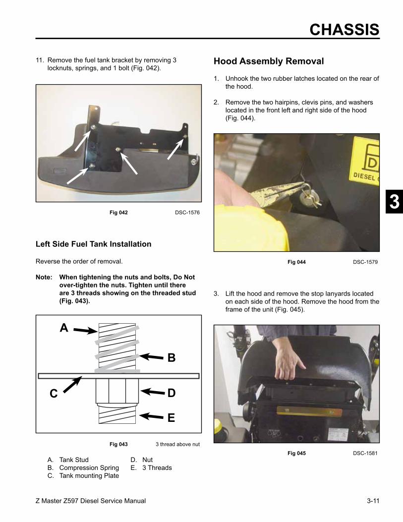
CHASSIS11. Remove the fuel tank bracket by removing 3
locknuts, springs, and 1 bolt (Fig. 042).
Fig 042 DSC-1576
Left Side Fuel Tank Installation
Reverse the order of removal.
Note: When tightening the nuts and bolts, Do Not over-tighten the nuts. Tighten until there are 3 threads showing on the threaded stud (Fig. 043).
Hood Assembly Removal
3. Lift the hood and remove the stop lanyards located on each side of the hood. Remove the hood from the frame of the unit (Fig. 045).
Fig 045 DSC-1581
Fig 043 3 thread above nut
1. Unhook the two rubber latches located on the rear of the hood.
2. Remove the two hairpins, clevis pins, and washers located in the front left and right side of the hood (Fig. 044).
Fig 044 DSC-1579
A. Tank Stud D. NutB. Compression Spring E. 3 ThreadsC. Tank mounting Plate
A
C
B
D
E
3-12 Z Master Z597 Diesel Service Manual
3
1. Disconnect the negative battery cable.
2. Remove the 4 screws retaining the control panel to the fuel tank (Fig. 046).
Throttle Control Replacement
Fig 046 DSC-1584
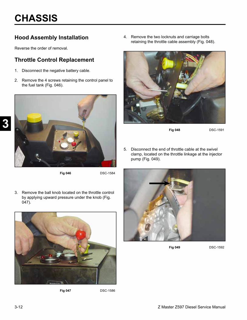
4. Remove the two locknuts and carriage bolts retaining the throttle cable assembly (Fig. 048).
Fig 048 DSC-1591
3. Remove the ball knob located on the throttle control by applying upward pressure under the knob (Fig. 047).
5. Disconnect the end of throttle cable at the swivel clamp, located on the throttle linkage at the injector pump (Fig. 049).
Fig 047 DSC-1586
Fig 049 DSC-1592
CHASSIS
Hood Assembly Installation
Reverse the order of removal.

3-13Z Master Z597 Diesel Service Manual
3
Installation
CHASSIS6. Loosen the screw on the throttle casing clamp and
remove the throttle cable (Fig. 050).1. Install the throttle control in the control plate. Install
the two carriage bolts and nuts and tighten (Fig. 052).
Fig 052 DSC-1596
Fig 050 DSC-1593
7. Keeping the tie straps in place, slide the throttle cable through the two tie straps to remove it from the machine. One tie strap is located at the radiator fan motor mount, Ref. A, and the other is at the engine removal bracket, Ref. B (Fig. 051).
NOTE: DO NOT cut or remove the tie straps.
2. Feed the throttle cable through the tie strap on the radiator fan motor mount (Fig. 053).
Fig 051 DSC-1594
Fig 053 DSC-1597
A
B
3-14 Z Master Z597 Diesel Service Manual
3
3. Route the throttle cable through the tie strap located on the engine lifting bracket (Fig. 054).
Fig 056 DSC-1605
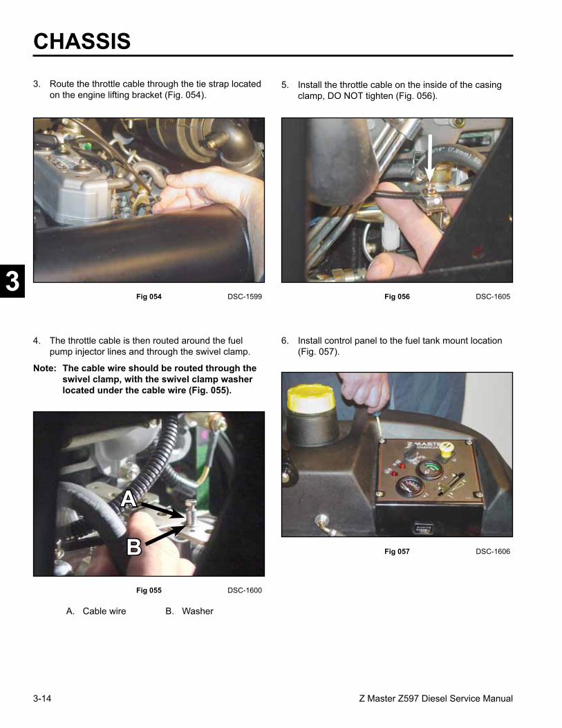
4. The throttle cable is then routed around the fuel pump injector lines and through the swivel clamp.
Note: The cable wire should be routed through the swivel clamp, with the swivel clamp washer located under the cable wire (Fig. 055).
6. Install control panel to the fuel tank mount location (Fig. 057).
Fig 055 DSC-1600
Fig 057 DSC-1606
Fig 054 DSC-1599
5. Install the throttle cable on the inside of the casing clamp, DO NOT tighten (Fig. 056).
CHASSIS
A
B
A. Cable wire B. Washer

3-15Z Master Z597 Diesel Service Manual
3
7. Install throttle control knob and position throttle control lever to the idle position (Fig. 058).
Fig 058 DSC-1608 Fig 060 DSC-1616
9. Tighten the cable housing clamp (Fig. 060).
8. Position the throttle cable swivel clamp until 1/4” (6.35mm) of the throttle cable wire protrudes through the opposite end of the clamp. Carefully tighten the swivel clamp screw (Fig. 059).
10. Move the throttle control lever to the Full speed position. Verify injector pump arm contacts the high speed stop screw (Fig. 061).
Fig 059 DSC-1614
Fig 061 DSC-1617
CHASSIS
3-16 Z Master Z597 Diesel Service Manual
3
CHASSIS
1. Release the parking brake (forward position).
2. Remove the cotter pin and clevis pin from the brake rod yoke (Fig. 062).
Brake Lever Removal
Fig 062 DSC-1618
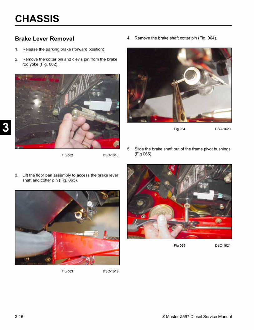
3. Lift the floor pan assembly to access the brake lever shaft and cotter pin (Fig. 063).
5. Slide the brake shaft out of the frame pivot bushings (Fig 065).
Fig 064 DSC-1620
4. Remove the brake shaft cotter pin (Fig. 064).
Fig 065 DSC-1621
Fig 063 DSC-1619

3-17Z Master Z597 Diesel Service Manual
3
Brake Lever Installation6. Using a hammer and punch, drive both brake lever control bearings from the brake pivot (Fig. 066).
Fig 066 DSC-1622
7. Inspect the brake shaft and bushings for excessive wear. Replace any worn or broken components (Fig. 067).
Fig 067 DSC-1623
Fig 068 DSC-1624
1. Raise the left rear tire off the ground (Fig. 068).
Reverse the order of removal
Brake Band Removal
2. Remove the four wheel lug bolts.
CHASSIS
A
A. Brake Lever C. Cotter PinB. Bushings
B C

3-18 Z Master Z597 Diesel Service Manual
3
3. Remove bolts, brake band retainer, spacers, and brake band (Fig. 069).
A. 3 Bolts B. Brake Band Retainer C. 3 Spacers D. Brake Band
CHASSIS
Fig 069 DSC-1626
Fig 071 DSC-1631
2. Install the 3 bolts, brake band retainer, brake band, and spacers and tighten (Fig. 071).
A B
C
D
1. Install the brake band around the wheel hub (Fig. 070).
Brake Band Installation
Fig 070 DSC-1629
3. Install tire assembly and the 4 wheel bolts.
Brake Cross Shaft Removal
1. Raise the rear end of the unit and remove the right and left rear tires.
Note: To prevent the unit from rolling, block the two front tires.

3-19Z Master Z597 Diesel Service Manual
3
5. On the right side, remove the two bolts and nuts holding the flange bearing (Fig. 075).
CHASSIS
Fig 072 DSC-1632
3. Remove the cotter pin and clevis pin from the left side lower brake linkage assembly (Fig. 073).
Fig 073 DSC-1633
4. On the right side, remove the cotter pin and clevis pin from the lower brake linkage assembly (Fig. 074).
Fig 075 DSC-1635
Fig 074 DSC-1634
2. Remove the clevis spring pin from the brake rod and remove the rod (Fig. 072).

3-20 Z Master Z597 Diesel Service Manual
3
CHASSIS
Brake Shaft Installation
7. Remove the brake shaft from the frame (Fig. 077).
Fig 077 DSC-1637
8. Inspect brake shaft and flange bushings for excessive wear (Fig. 078).
Fig 079 DSC-1640
1. Install the flange bearing on the right side of the shaft. From the outside of the frame, align the flange bearing holes with the frame mounting holes. Install mounting hardware and tighten (Fig. 079).
Fig 078 DSC-1638
A
6. On the left side, remove the two bolts, spacers, and nuts holding the flange bearing (Fig. 076).
Fig 076 DSC-1636
A. RH Mounting Bolts D. Flange BearingB. Brake Shaft E. SpacersC. LH Mounting Bolts
BC
DE
D
3-21Z Master Z597 Diesel Service Manual
3
CHASSIS2. Install the flange bearing over the left side of the
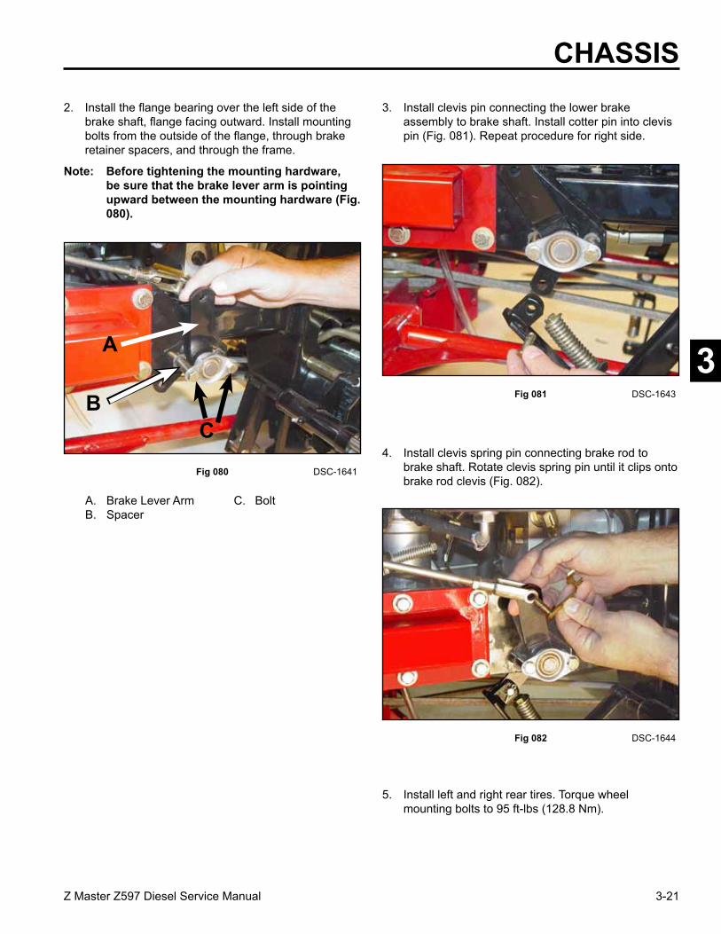
brake shaft, flange facing outward. Install mounting bolts from the outside of the flange, through brake retainer spacers, and through the frame.
Note: Before tightening the mounting hardware, be sure that the brake lever arm is pointing upward between the mounting hardware (Fig. 080).
Fig 080 DSC-1641
Fig 082 DSC-1644
4. Install clevis spring pin connecting brake rod to brake shaft. Rotate clevis spring pin until it clips onto brake rod clevis (Fig. 082).
Fig 081 DSC-1643
5. Install left and right rear tires. Torque wheel mounting bolts to 95 ft-lbs (128.8 Nm).
3. Install clevis pin connecting the lower brake assembly to brake shaft. Install cotter pin into clevis pin (Fig. 081). Repeat procedure for right side.
A. Brake Lever Arm C. BoltB. Spacer
A
BC

3-22 Z Master Z597 Diesel Service Manual
3
Adjusting the Parking Brake
Check the parking brake for proper adjustment.
1. Disengage the brake lever (lever down).
2. Measure the length of the spring. The measurement should be 2-3/4” (70mm) between the washers (Fig. 083).
Fig 083 m-7417
3. If an adjustment is necessary, loosen the jam nut below the spring and tighten the nut directly below the yoke (Fig. 083). Turn the nut until the correct measurement is obtained. Tighten the two nuts together and repeat on the opposite side of the unit.
4. Turn the nuts clockwise to shorten the spring length and counterclockwise to lengthen the spring.
5. Engage the parking brake (lever up).
6. Measure the distance between the spring bracket and the adjusting nut under spring bracket. The measurement should be 1/4 - 5/16” (5 - 8mm) (Fig. 083).
7. If adjustment is necessary, loosen the jam nut directly above the trunion roller. Turn the lock nut below the trunion roller until the correct measurement is obtained (Fig. 083).
8. Tighten the jam nut directly above the trunion roller (Fig. 083).
Note: If the 1/4 - 5/16” (5 - 8mm) can not be achieved, remove a pin from either yoke at the ends of the brake rod. Adjust the length of the rod so 1/4 - 5/16” (5 - 8mm) can be achieved and install the brake rod.
CHASSIS
1. Brake lever - engaged 7. 1/4 - 5/16” (5 - 8mm)2. Brake lever - disengaged 8. Spring bracket3. Spring, 2-3/4” (70mm) 9. Lock nut below trunion4. Jam nut above trunion roller roller5. Nut below spring bracket 10. Brake rod6. Trunion roller 11. Yoke
11 11
10

3-23Z Master Z597 Diesel Service Manual
3
CHASSIS4. Loosen jam nuts on LH and RH deck lift rods until
deck support springs are fully extended (Fig. 086).
Fig 086 DSC-1649
5. Remove hex nut from RH rear deck lift assembly. Repeat procedure for LH rear deck lift assembly (Fig. 087).
Fig 087 DSC-1650
Fig 085 DSC-1648
1. Park the machine on a level surface, disengage the blade control (PTO), and turn the ignition key to OFF to stop the engine. Remove the ignition key.
2. Remove the lower stop bolt from the deck lift plate (Fig. 084).
Fig 084 DSC-1647
Deck Lift Lever Removal
3. With the mower deck in the transport position, place a 4”x 4” block under each corner of the deck. Lower the mower deck onto the support blocks to remove the weight from the support chains (Fig. 085).

3-24 Z Master Z597 Diesel Service Manual
3
6. Lower lift lever to its lowest position. Rear deck swivel mounts should clear deck lift rods on both sides. The mower deck lift linkage should now be fully unloaded (Fig. 088).
Fig 088 DSC-1651
7. Remove hex bolt, nut, and lift lever bushing from the lower deck lift plate mounting location (Fig. 089).
Fig 089 DSC-1652
A
A. Lift Lever at lowest position
8. Loosen the top hex head flange nut at the deck lift plate mounting location. Pivot the INNER deck lift plate up and back toward the RH motion control lever (Fig. 090).
Fig 090 DSC-1653
9. Lift the floor pan assembly to its fully opened position (Fig. 091).
Fig 091 DSC-1654
CHASSIS

3-25Z Master Z597 Diesel Service Manual
3
CHASSIS12. When removing the lift lever you may experience
interference with the RH floor pan hinge or the front edge of the RH motion control plate, or both (Fig. 094).
Fig 094 DSC-1657
13. If the lift lever contacts the RH floor pan hinge, loosen the RH floor pan hinge mounting hardware. Push the RH hinge upward. Re-tighten the RH floor pan hinge mounting hardware (Fig. 095).
Fig 095 DSC-1661
Fig 093 DSC-1656
11. Remove retainer clip from lift lever (Fig. 093).
Fig 092 DSC-1655
10. Remove hex bolt, bushing, and nylock nut connecting the deck lift arm plates to the mower deck rear cross-shaft lift assembly (Fig. 092).
A B
A. RH Floor pan hinge B. RH Motion control plate
A. RH Floor pan hinge
A
3-26 Z Master Z597 Diesel Service Manual
3
CHASSIS14. If the lift lever contacts the RH motion control plate,
tilt and hold the floor pan assembly slightly forward. Move the RH motion control lever out of the neutral lock position and push it in the full forward position. Using a tie strap or wire, tie the floor pan assembly to the motion control arm to hold the floor pan assembly in place (Fig. 096).
Fig 096 DSC-1665
15. Carefully slide the lift lever assembly out of its carrier frame pivot (Fig. 097).
Fig 097 DSC-1667
Deck Lift Lever Installation
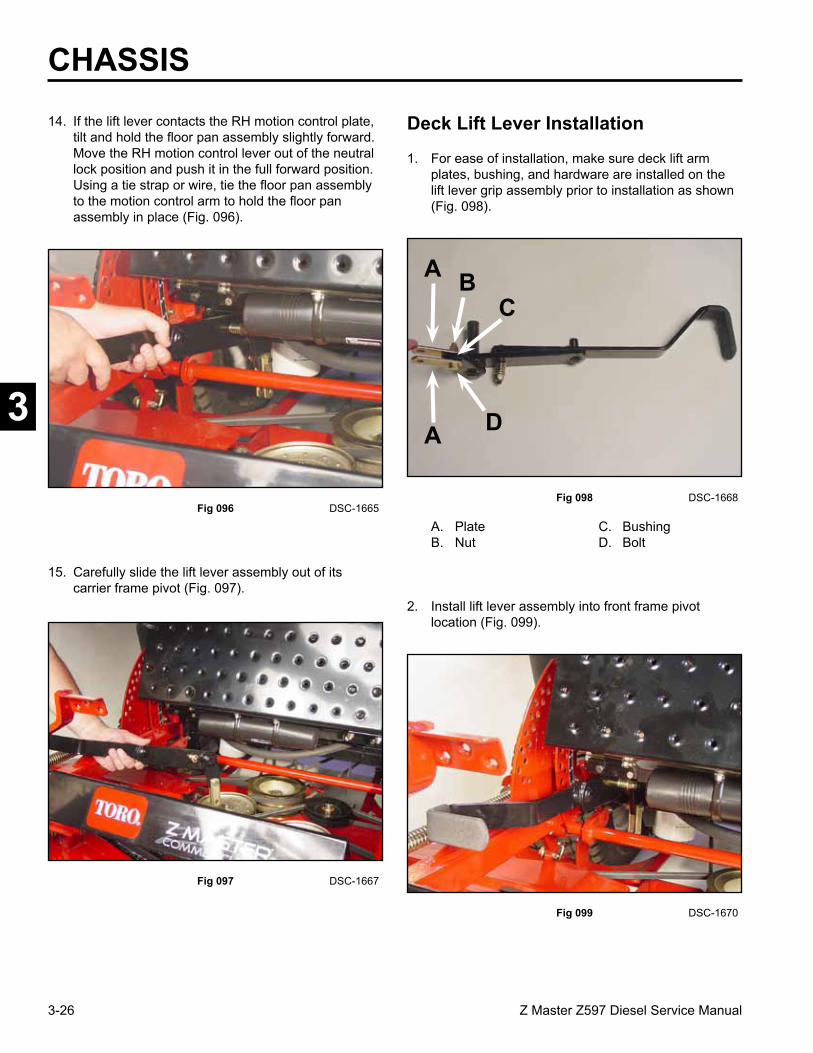
1. For ease of installation, make sure deck lift arm plates, bushing, and hardware are installed on the lift lever grip assembly prior to installation as shown (Fig. 098).
Fig 098 DSC-1668
2. Install lift lever assembly into front frame pivot location (Fig. 099).
Fig 099 DSC-1670
A. Plate C. BushingB. Nut D. Bolt
A
A
BC
D

3-27Z Master Z597 Diesel Service Manual
3
CHASSIS5. Install hex bolt through deck lift plates and rear
lift arm cross shaft bushing. Install nylock nut and tighten (Fig. 102).
Fig 102 DSC-1675
6. Rotate deck lift plate (inner) downward until lower mounting holes line up with hole in carrier frame and deck lift plate (outer). From the outside of the frame, install hex bolt, spacer, and flanged lock nut as shown. Tighten bolt (Fig. 103).
Fig 103 DSC-1677
Fig 101 DSC-1674
4. Install bushing into rear lift arm cross shaft (Fig. 101).
Fig 100 DSC-1672
3. Install retainer clip to lift lever shaft (Fig. 100).
A
A. Bushing
AA
B
A. Rear Lift Arm Plates B. Hex Bolt
A B C
A. Hex Bolt C. Flanged Lock NutB. Spacer

3-28 Z Master Z597 Diesel Service Manual
3
CHASSIS
Fig 104 DSC-1680
8. Raise lift lever until deck mount swivels rest against deck rod jam nuts. Install HOC pin into deck lift plate height of cut holes to hold lift lever in this position (Fig. 105).
Fig 105 DSC-1681
7. Align rear deck mount swivels with ends of deck lift rod (Fig. 104).
9. Install lower “stop” bolt through inner and outer deck lift plates. Install nylock nut and tighten until hex nut and bolt are seated firmly against the deck lift plates. DO NOT over-tighten or deck lift plates will deform inward causing height of cut hitch pin assembly to bind (Fig. 106).
Fig 106 DSC-1682
10. Install hex nut on end of deck lift rod. Tighten against deck mount swivel. Repeat procedure for opposite side deck lift rod (Fig. 107).
Fig 107 DSC-1683
A
A. HOC Pin

3-29Z Master Z597 Diesel Service Manual
3
CHASSIS
1. Remove both floor pan assembly hinge bolts (Fig. 109).
Motion Control Assembly Removal
Fig 109 DSC-1686
2. Remove floor pan assembly (Fig. 110).
Fig 110 DSC-1689
Fig 108 DSC-1685
11. Raise mower deck to the transport position. Remove support blocks. Check deck level adjustment (refer to the Leveling the Mower procedure, pg 7-46). Readjust compression spring length by turning front nut. Spring should be compressed to a length of 11-1/2” (29.2cm) between washers. Lock the front nut into position by tightening the spring jam nut (Fig. 108).
12. Untie the floor pan assembly and lower. Return motion control lever to its neutral locked position.

3-30 Z Master Z597 Diesel Service Manual
3
3. Remove (4) pocket mounting bolts (Fig. 111).
Fig 111 DSC-1690 Fig 113 DSC-2062
5. Remove the two bolts retaining the lever assembly to the control arm shaft (Fig. 113).
4. Remove pocket (Fig. 112).6. Disconnect motion control dampener from motion
control assembly (Fig. 114).
Fig 114 DSC-1695
Fig 112 DSC-1691
CHASSIS

3-31Z Master Z597 Diesel Service Manual
3
CHASSIS9. Remove the cotter pin and clevis pin through the
adjustable yoke for the neutral return bolt (Fig. 117).
10. Remove the two bolts and nuts that retain the flange bearing on the inside of the motion control (Fig. 118).
Fig 117 DSC-2064
Fig 118 DSC-2066
7. Disconnect neutral switch wire harness from neutral switch (Fig. 115).
8. Remove bolt, spacer, and nut that retains the ball joint to the motion control (Fig. 116).
Fig 116 DSC-2063
Fig 115 DSC-1693

3-32 Z Master Z597 Diesel Service Manual
3
11. Remove the two bolts and nuts that retain the flange bearing on the outside of the motion control (Fig. 119).
12. Remove the motion control from the frame (Fig. 120).
Fig 119 DSC-2067
Fig 120 DSC-2068
Reverse the order of removal
Motion Control Assembly Installation
CHASSIS

4-1Z Master Z597 Diesel Service Manual
2
3
5
6
7
1
HYDRAULIC SYSTEM
Safety Information . . . . . . . . .
Specifications . . . . . . . . . . .
Chassis . . . . . . . . . . . . . .
Hydraulic System . . . . . . . . .
Engine . . . . . . . . . . . . . . .
Electrical . . . . . . . . . . . . . .
Mower Decks . . . . . . . . . . .
4
1

4-2 Z Master Z597 Diesel Service Manual
4
HYDRAULIC SYSTEM
Hydrostatic Pump Removal
Note: Cleanliness is a key factor in a successful repair of any hydrostatic system. Thoroughly clean all exposed surfaces prior to any type of maintenance. Cleaning all parts by using a solvent wash and air drying is usually adequate. As with any precision equipment, all parts must be kept free of foreign material and chemicals. Protect all exposed sealing areas and open cavities from damage and foreign material.
Upon removal, all seals, O-rings, and gaskets should be replaced. Lightly lubricate all seals, O-Rings and gaskets with clean petroleum jelly prior to installation.
This procedure is showing the LH Hydrostatic Pump being removed. Use these same procedures to remove the RH Hydrostatic Pump.
1. Disconnect the negative and positive battery cables. Remove the battery from the unit.
2. Using compressed air, clean the area around the hydrostatic pump. Perform additional cleaning as needed to make sure it is free from any dirt and debris.
3. Remove the two knobs located on the engine access panel assembly. Remove both engine belt shield and the engine access panel (Fig. 121).
Fig 121 DSC-2071
4. Using a 3/8” drive ratchet, insert the drive end into the square hole in the pump belt tensioner arm. Relieve the tension on the hydrostatic pump v-belt and remove the belt (Fig. 122).
Fig 122 DSC-2073
5 Remove the bolt and nut retaining the hydro pump control linkage to the hydro control arm (Fig. 123).
Fig 123 DSC-2081

4-3Z Master Z597 Diesel Service Manual
4
HYDRAULIC SYSTEM6. Remove the case drain hydraulic hose, located on
the left hand side of the hydrostatic pump (Fig. 124).
Note: When removing hydraulic hoses from the pump, cap the hose and the fitting on the hydrostatic pump. This is to make sure dirt and debris does not enter these areas.
Fig 124 DSC-2083
Note: Before removing the hydraulic lines from the hydrostatic pump, mark or tag one of the hoses to make sure they are reconnected correctly.
Fig 126 DSC-2088
8. Remove the hydraulic suction line from the top of the hydrostatic pump (Fig. 126). Install caps on the hydraulic line and on the fittting.
Fig 125 DSC-2087
7. Remove the two hydraulic hoses on the bottom of the hydrostatic pump that go to the hydraulic motor (Fig. 125). Install caps on the hydraulic hoses and fittings.

4-4 Z Master Z597 Diesel Service Manual
4
HYDRAULIC SYSTEM9. Using a 12-point 3/8” socket, loosen the two set
screws located on the hydro pump hub Slide the hydrostatic pump hub and pulley off the hydrostatic pump shaft. Remove the key on the hydrostatic pump shaft (Fig. 127).
Fig 127 DSC-2089
10. Loosen and remove the two bolts and nuts retaining the hydrostatic pump to the frame (Fig. 128).
Fig 128 DSC-2091
Fig 130 DSC-2094
12. Remove the hydrostatic pump from the frame (Fig. 130).
Fig 129 DSC-2092
11. Cut the two cable ties that hold the fuel line and the wiring harness (Fig. 129).
13. For service work on the hydrostatic pump refer to the Hydro-Gear Service Manual, Form 492-4789.

4-5Z Master Z597 Diesel Service Manual
4
HYDRAULIC SYSTEM
Hydrostatic Pump Installation
Note: Prior to connecting the hydraulic lines, replace the O-Rings with new ones and lightly lubricate with petroleum jelly.
1. Install the hydrostatic pump to the frame. Install and tighten the two bolts and nuts (Fig. 131).
Fig 131 DSC-2091
2. Install the key on the hydrostatic pump shaft; make sure the key is facing up on the shaft (Fig. 132).
Fig 132 DSC-2095 Fig 134 DSC-2089
4. Tighten the two sets screws on the pulley using a 12-point 3/8” (9.5mm) socket (Fig. 134).
Fig 133 DSC-2097
Note: Before installing the pulley, replace the set screws. The end of the set screws have a knurled cup point for retention and must not be re-used.
3. Install pulley and hydro pump hub on the hydrostatic pump shaft and key. Align the center of the hydrostatic pump pulley with the center of the idler pulley (Fig. 133).
A. Pump pulley B. Idler Pulley
A
B

4-6 Z Master Z597 Diesel Service Manual
4
HYDRAULIC SYSTEM5. Install the hydraulic suction line on the top of the
hydrostatic pump (Fig. 135).
Fig 135 DSC-2088
6. Install the two hydraulic hoses that run from the hydraulic wheel motor to the bottom of the hydrostatic pump (Fig. 136).
Fig 136 DSC-2098 Fig 138 DSC-2081
8. Install and tighten the bolt and nut retaining the hydro pump control linkage to the hydro control arm (Fig. 138).
Fig 137 DSC-2099
7. Install the case drain hydraulic line, located on the left hand side of the pump (Fig. 137).
Remember to install the hydraulic hoses to the correct port on the hydrostatic pump. If the lines are reversed, the hydrostatic wheel motor will turn in the direction opposite of motion control position.
Note: It may be easier to remove the rear tire assembly for installation of the bottom and side hydraulic hoses.

4-7Z Master Z597 Diesel Service Manual
4
HYDRAULIC SYSTEM9. Using a 3/8” drive ratchet, insert the wrench into
the square hole in the pump belt tensioner arm and relieve the tension to install the hydrostatic pump v-belt (Fig. 139).
Fig 139 DSC-2073
10. Install two cable ties for the fuel line and the wiring harness (Fig. 140).
Fig 140 DSC-2101
Fig 141 DSC-2071
11. Install the battery in the unit and connect the positive and negative battery cables.
12. Check the hydraulic fluid in the reservoir tank. Add oil if necessary, refer to Figure 006, page 2-5. Air will need to be purged in the system. Follow the procedures on Purging the Hydraulic System, page 4-13.
13. Check the neutral adjustment. Follow procedures for Adjusting the Handle Neutral, page 4-24.
14. Install the engine belt shield and the engine access panel. Install the two knobs (Fig. 141).
4-8 Z Master Z597 Diesel Service Manual
4
HYDRAULIC SYSTEM
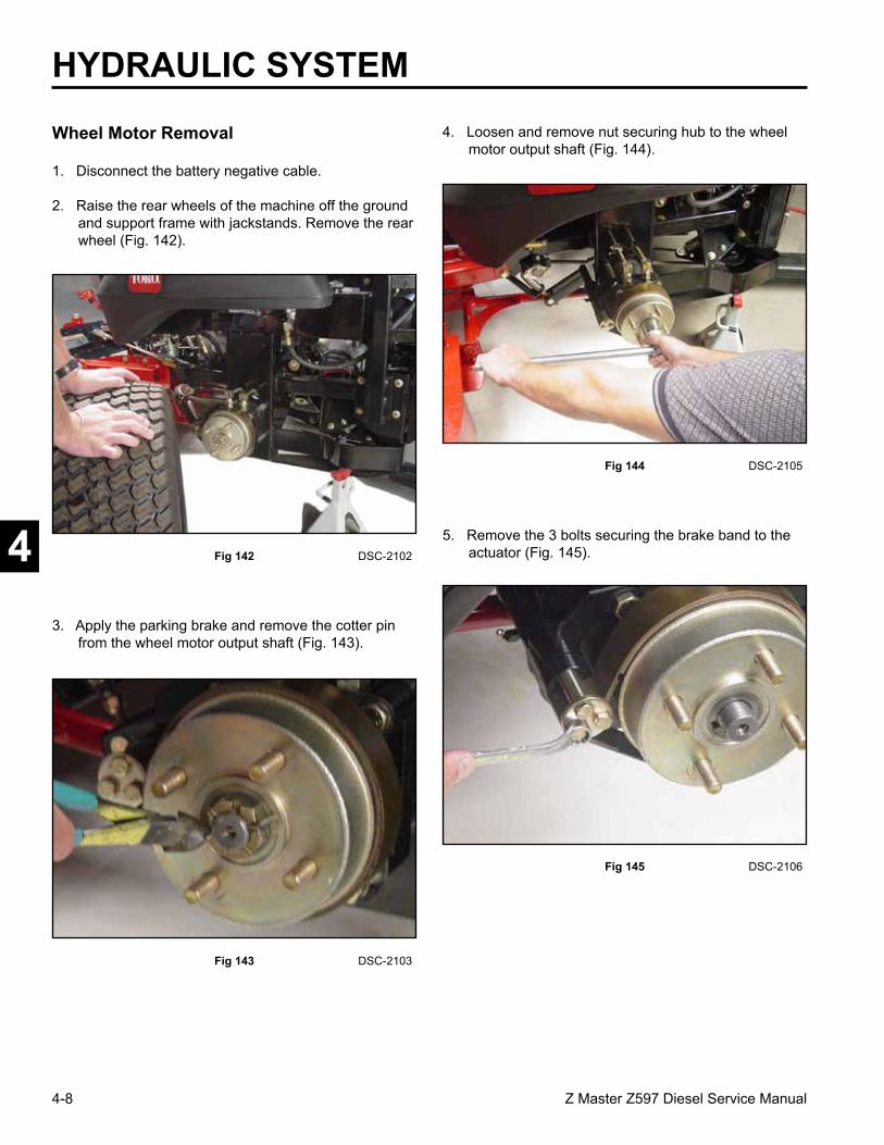
1. Disconnect the battery negative cable.
2. Raise the rear wheels of the machine off the ground and support frame with jackstands. Remove the rear wheel (Fig. 142).
Fig 142 DSC-2102
Fig 144 DSC-2105
4. Loosen and remove nut securing hub to the wheel motor output shaft (Fig. 144).
Fig 143 DSC-2103
3. Apply the parking brake and remove the cotter pin from the wheel motor output shaft (Fig. 143).
Wheel Motor Removal
5. Remove the 3 bolts securing the brake band to the actuator (Fig. 145).
Fig 145 DSC-2106
4-9Z Master Z597 Diesel Service Manual
4
HYDRAULIC SYSTEM6. Remove the brake band from the hub (Fig. 146).
Fig 146 DSC-2107
Fig 148 DSC-2110
8. Clean any dirt or debris away from the hydraulic line fittings. Remove the hydraulic lines.
Note: Cap the fittings and hoses to prevent dirt from entering the hydraulic system (Fig. 148).
Fig 147 DSC-2108
7. Install a wheel puller on to the hub and remove the hub from the motor output shaft (Fig. 147).
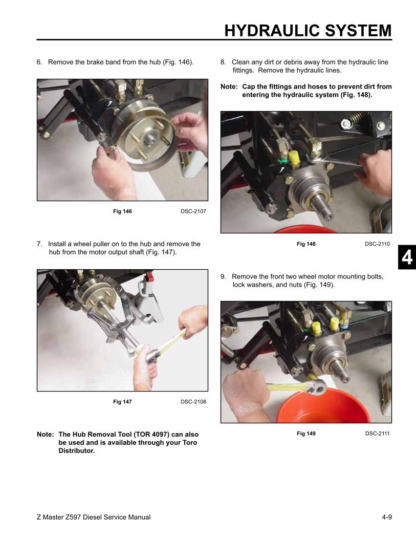
9. Remove the front two wheel motor mounting bolts, lock washers, and nuts (Fig. 149).
Fig 149 DSC-2111Note: The Hub Removal Tool (TOR 4097) can also be used and is available through your Toro Distributor.

4-10 Z Master Z597 Diesel Service Manual
4
HYDRAULIC SYSTEM10. Swing the brake linkage forward out of the way of
the wheel motor. It may be necessary to loosen the back two bolts to remove the spacers (Fig. 150).
Fig 150 DSC-2113
12. For service work on the wheel motor refer to the Parker/Ross Service Manual, Form #492-4753.
Fig 151 DSC-2114
11. Remove the back two bolts, lock washers, spacers, and nuts and remove the wheel motor from the frame (Fig. 151).
Wheel Motor Installation
Note: As a reminder, prior to connecting the hydraulic lines, the O-Rings should be replaced with new ones and lightly lubricated with petroleum jelly.
Note: There are two different spacers used on the wheel motors (Fig. 152). The short spacers are used in the front of the wheel motor (with the brake linkage) and the long spacers are used to retain the back of the wheel motor.
Fig 152 DSC-2117
A B
A. Short Spacer B. Long Spacer

4-11Z Master Z597 Diesel Service Manual
4
HYDRAULIC SYSTEM
Fig 154 DSC-2119
2. Align the brake linkage up with the two front bolt holes (Fig. 154).
Fig 153 DSC-2116
1. Install wheel motor in the frame. Loosely install the back two bolts, long spacers, lock washers and nuts (Fig. 153).
3. Install the two front bolts, short spacers, lock washers, and nuts through the wheel motor, brake linkage and frame (Fig. 155).
Fig 155 DSC-2120
4. Install the two rear bolts and long spacers through the wheel motor and frame.
5. Torque the bolts to 80 to 90 ft-lbs. (108 to 122 Nm) (Fig. 156).
Fig 156 DSC-2122

4-12 Z Master Z597 Diesel Service Manual
4
HYDRAULIC SYSTEM
Fig 158 DSC-2125
7. Install wheel hub assembly, making sure the woodruff key is in place (Fig. 158).
Fig 157 DSC-2123
6. Install and tighten the hydraulic lines (Fig. 157).
Fig 160 DSC-2106
9. Install spacers, brake band retainer, and brake band around the wheel hub and tighten all three retainer bolts (Fig. 160).
Fig 159 DSC-2126
8. Install the nut on the wheel motor shaft, DO NOT tighten (Fig. 159).
4-13Z Master Z597 Diesel Service Manual
4
HYDRAULIC SYSTEM10. Install rear wheel and wheel lug nuts and tighten.
11. Engage parking brake, torque the wheel hub nut to 125 ft-lbs. (169 Nm) (Fig. 161). Install cotter key through the nut and motor wheel shaft.
Note: Re-torque nut at 100 hours, and every 500 hours thereafter. Washer 1-523157 can be added under nut to keep cotter pin engaged with nut castellation.
Fig 161 DSC-2128
12. Check the park brake and adjust park brake if necessary. Refer to Adjusting the Parking Brake, page 3-22.
13. Reconnect the battery negative cable.
14. Check the hydraulic fluid in the reservoir tank. Add oil if necessary. Air will need to be purged in the system. Follow the procedures on Purging the Hydraulic System, page 4-13.
Purging the Hydraulic System
The hydraulic system is self bleeding; however, it may be necessary to bleed the system if fluid is changed or after work is performed on the system.
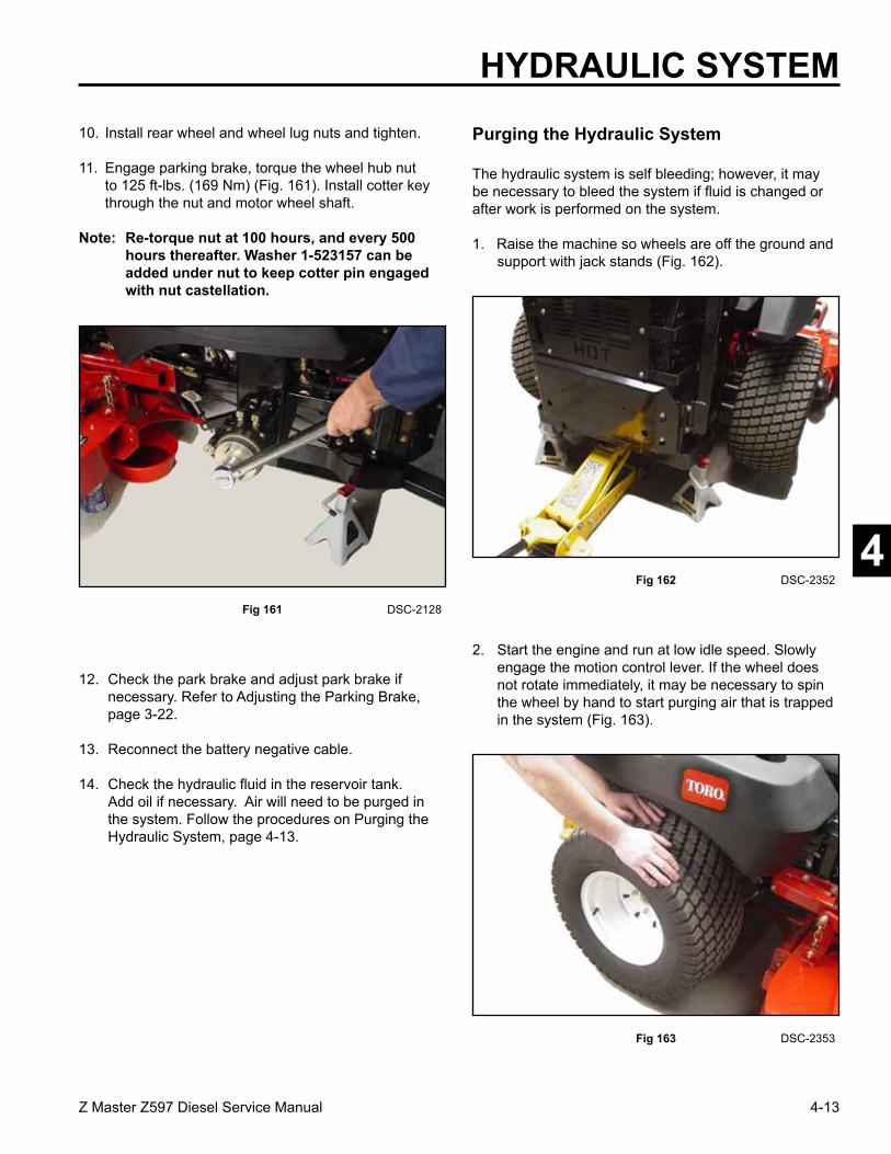
1. Raise the machine so wheels are off the ground and support with jack stands (Fig. 162).
Fig 162 DSC-2352
2. Start the engine and run at low idle speed. Slowly engage the motion control lever. If the wheel does not rotate immediately, it may be necessary to spin the wheel by hand to start purging air that is trapped in the system (Fig. 163).
Fig 163 DSC-2353

4-14 Z Master Z597 Diesel Service Manual
4
HYDRAULIC SYSTEM3. When the wheel begins to spin on its own, keep it
engaged until the wheel drives smoothly. (Minimum 2 minutes)
4. Check the hydraulic fluid level and add fluid as required to maintain proper level.
5. Repeat this procedure on the opposite wheel.
Hydraulic Fan Pump Removal
Note: Cleanliness is a key factor in a successful repair of any hydraulic system. Thoroughly clean all exposed surfaces prior to any type of maintenance. Cleaning all parts by using a solvent wash and air drying is usually adequate. As with any precision equipment, all parts must be kept free of foreign material and chemicals. Protect all exposed sealing areas and open cavities from damage and foreign material.
Upon removal, all seals, O-rings, and gaskets should be replaced. Lightly lubricate all seals, O-rings and gaskets with clean petroleum jelly prior to installation.
1. Loosen the 4 bolts on the rear bumper assembly and remove.
Note: DO NOT remove the bolts (Fig. 164).
Fig 164 DSC-2359
Fig 166 DSC-2361
3. Loosen two hex set screws located on the hydraulic pump pulley (Fig. 166).
Fig 165 DSC-2360
2. Push down on the pump belt tensioner and remove the drive belt from the pulley on the PTO clutch. Remove the other end of the pump drive belt from the hydraulic pump pulley (Fig. 165).

4-15Z Master Z597 Diesel Service Manual
4
HYDRAULIC SYSTEM4. Remove the hydraulic pump pulley.
Note: It may be necessary to use a puller to remove the pulley (Fig. 167).
Fig 167 DSC-2362
Note: Cut a piece of cardboard approximately 8” x 18” (20.3 x 45.7cm) to be used as a deflector to channel oil away from the mower drive belt and pulleys located under the hydraulic pump fan (Fig. 168).
Fig 168 DSC-2363
Fig 170 DSC-2367
6. Remove the four bolts and nuts retaining the hydraulic fan pump to the fan pump mounting plate (Fig. 170).
Fig 169 DSC-2366
5. Disconnect the three hydraulic lines connected to the hydraulic fan pump (Fig. 169).

4-16 Z Master Z597 Diesel Service Manual
4
7. Remove the hydraulic fan pump from the unit (Fig. 171).
Fig 171 DSC-2368
Fig 172 DSC-2367
Note: Prior to connecting the hydraulic lines, replace the O-rings with new ones and lightly lubricate with petroleum jelly.
1. Install the hydraulic fan pump with four bolts and nuts to the fan pump mounting plate (Fig. 172).
HYDRAULIC SYSTEM
Hydraulic Fan Pump Installation
Fig 173 DSC-2366
2. Install the three hydraulic lines to the hydraulic fan pump and tighten (Fig. 173).
3. Install the square key in the hydraulic fan pump shaft. Install the fan pump pulley on the shaft. Before installing the set screws into the pulley, install a thread locking compound on the set screws and tighten (Fig. 174).
Note: Always use new set screws when installing the pump drive pulley.
Fig 174 DSC-2361

4-17Z Master Z597 Diesel Service Manual
4
HYDRAULIC SYSTEM4. Install pump drive belt around the hydraulic pump
pulley. Push down the pump belt tensioner and install the belt around the PTO clutch pulley (Fig. 175).
Fig 175 DSC-2360
6. Check the hydraulic fluid in the reservoir tank. Add oil of necessary. Air may need to be purged in the system. Follow the procedures on Purging the Hydraulic System, page 4-13.
Fig 176 DSC-2369
5. Install the rear bumper assembly and tighten the four bolts (Fig. 176).
Hydraulic Fan Motor Removal
Note: Cleanliness is a key factor in a successful repair of any hydraulic system. Thoroughly clean all exposed surfaces prior to any type of maintenance. Cleaning all parts by using a solvent wash and air drying is usually adequate. As with any precision equipment, all parts must be kept free of foreign material and chemicals. Protect all exposed sealing areas and open cavities from damage and foreign material.
Upon removal all seals, O-rings, and gaskets should be replaced. Lightly lubricate all seals, O-rings, and gaskets with clean petroleum jelly prior to installation.
1. Unlatch and open the engine hood. Loosen and remove the rear heat shield from the frame (Fig. 177).
Fig 177 DSC-2370

4-18 Z Master Z597 Diesel Service Manual
4
HYDRAULIC SYSTEM
Fig 179 DSC-2071
3. Remove the two knobs located on the engine access panel assembly. Remove the engine belt shield and the engine access panel (Fig. 179).
Fig 178 DSC-2371
2. There are 6 bolts and nuts, 3 on each side, retaining the radiator and fan mounting plate assembly to the right and left upper frame assembly. Loosen, DO NOT remove, the two bolts and nuts at the front right and left side; this will allow you to pivot the assembly upward. Remove the rear 4 bolts and nuts (Fig. 178).
A. Remove B. Loosen
B
A A
4. Loosen and remove the clamp on the hydraulic return line located on the left side of the unit (Fig. 180).
Fig 180 DSC-2372
Fig 181 DSC-2374
5. Remove the tie strap holding the throttle control cable. Remove the clamps holding the inlet cooling hose and the overflow hose to the radiator (Fig. 181).

4-19Z Master Z597 Diesel Service Manual
4
HYDRAULIC SYSTEM6. Tilt the fan mounting plate assembly and the
radiator up approximately 5” (12.7cm) to get enough clearance to remove the hydraulic motor fan.
Caution: Do not raise too far, as damage could occur to some of the hydraulic lines and cooling hoses.
Use a nylon tie down strap between the fan mounting plate and the center section of the ROPS Bar to hold in place (Fig. 182).
Fig 182 DSC-2377
7. Place a small oil drain pan on top of the engine. Loosen and remove the hydraulic lines to the hydraulic fan motor (Fig. 183).
Fig 183 DSC-2378
8. Loosen and remove the 4 bolts and nuts holding the fan motor mount (Fig. 184).
Fig 184 DSC-2379
9. Remove the fan motor mount from the fan mounting plate (Fig. 185).
Fig 185 DSC-2380

4-20 Z Master Z597 Diesel Service Manual
4
HYDRAULIC SYSTEM
Fig 187 DSC-2383
11. Loosen and remove the 4 bolts and nuts retaining the hydraulic fan motor to the fan motor mount.
Fig 186 DSC-2382
10. With a hex wrench loosen the two set screws on the fan hub and remove the fan (Fig. 186).
1. Note the orientation of the hydraulic fittings on the fan motor. The case drain fitting should be facing the mounting tab on the fan motor mount (Fig. 187).
Hydraulic Fan Motor Installation
Note: As a reminder, prior to connecting the hydraulic lines, the O-rings should be replaced with new ones and lightly lubricate with petroleum jelly.
2. Note the location of the hydraulic fittings and install the hydraulic fan motor to the fan motor mount tighten the 4 bolts and nuts (Fig. 188).
Fig 188 DSC-2384
Fig 189 DSC-2391
3. Slide the fan assembly over the motor shaft, making sure the hub of the fan is facing toward the motor and the square key is on the shaft. The fan assembly should be installed so the motor shaft is recessed approximately 1/2” (12.7mm) from the outside of the fan hub (Fig. 189).
1/2 inch(12.7mm)
A B
A. Mounting tab B. Case drain fitting
4-21Z Master Z597 Diesel Service Manual
4
HYDRAULIC SYSTEM
Fig 190 DSC-2396
4. Apply a thread locking compound to the hex set screws and tighten both screws (Fig. 190).
5. Install the fan motor mount to the fan mounting plate (Fig. 191).
Fig 191 DSC-2380
6. Install the 4 bolts and nuts that retain the fan motor mount to the fan mounting plate.
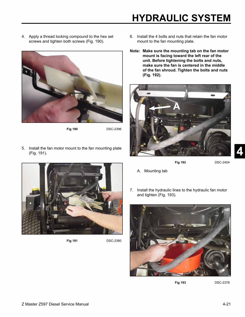
Note: Make sure the mounting tab on the fan motor mount is facing toward the left rear of the unit. Before tightening the bolts and nuts, make sure the fan is centered in the middle of the fan shroud. Tighten the bolts and nuts (Fig. 192).
Fig 192 DSC-2404
A
A. Mounting tab
Fig 193 DSC-2378
7. Install the hydraulic lines to the hydraulic fan motor and tighten (Fig. 193).

4-22 Z Master Z597 Diesel Service Manual
4 Fig 194 DSC-2371
8. Remove the nylon tie strap to lower the fan mounting plate and radiator assembly. Reinstall the 4 bolts and nuts that retain the fan mounting plate to the right and left upper frame and tighten the bolts, including the front two nuts and bolts (Fig. 194).
HYDRAULIC SYSTEM
9. Install the two hose clamps; the large clamp retaining the inlet cooling hose and the small clamp for the overflow hose to the radiator. Secure the throttle cable to the clamp with a tie strap (Fig. 195).
Fig 195 DSC-2405
10. Install clamp, located on the left side of the unit, that retains the hydraulic return line. Tighten the bolt and nut (Fig. 196).
Fig 196 DSC-2372
Fig 197 DSC-2071
11. Install the engine access panel and the engine belt shield with the two knobs (Fig. 197).

4-23Z Master Z597 Diesel Service Manual
4
HYDRAULIC SYSTEM
Fig 198 DSC-2370
12. Install the rear heat shield and tighten the bolts (Fig. 198).
13. Close the engine hood and latch. Start unit up and operate for approximately 5 minutes and check the oil level in the reservoir.
Note: Adjust handle neutral before setting pump neutral. See Adjusting the Handle Neutral, page 4-24.
This adjustment must be made with drive wheels turning.
Fig 199 DSC-2352
Fig 200 DSC-2357
2. Slide the seat fully forward, unlatch the seat and tilt the seat forward (Fig. 200).
Setting the Hydrostatic Pump Neutral
1. Raise the frame and support the machine so drive wheels can rotate freely (Fig. 199).

4-24 Z Master Z597 Diesel Service Manual
4
HYDRAULIC SYSTEM
Fig 201 DSC-2355
3. Disconnect the electrical connector from the seat safety switch. Temporarily install a jumper wire across terminals in the wiring harness connector (Fig. 201).
Adjusting the Handle Neutral
If motion control levers do not align, or move easily into the console notch, adjustment is required. Adjust each lever, spring and rod separately.
Note: Motion control levers must be installed correctly. See Installing the Motion Control Levers in the Set Up instructions.
1. Disengage the PTO, move the motion control levers to the neutral locked position and set the parking brake.
2. Stop the engine, remove the key, and wait for all moving parts to stop before leaving the operating position.
Fig 202 m-7510
6. Pull lever back until the clevis pin (on arm below pivot shaft) contacts the end of the slot (just beginning to put pressure on the spring) (Fig. 202).
1. Clevis pin in slot 7. Spring2. Nut against yoke 8. Pivot shaft3. Adjustment bolt 9. Yoke4. Pump rod 10. Locknut5. Double nuts 11. Ball joint6. Jam nut 12. Tracking knob
3. Unlatch the seat and tilt the seat up.
4. Begin with either the left or right motion control lever.
5. Move lever to the neutral position but not locked (Fig. 202).

4-25Z Master Z597 Diesel Service Manual
4
Setting the LH Hydrostatic Pump Neutral1. Start the engine, open throttle half way and release
parking brake.
Note: Motion control lever must be in neutral while making any adjustments.
2. Adjust pump rod length by rotating the knob, in the appropriate direction, until the wheel is still or slightly creeping in reverse (Fig. 204).
Fig 204 DSC-2568
3. Move motion control lever forward and reverse, then back to neutral. Wheel must stop turning or creep only slightly in reverse.
4. Open engine throttle to Fast. Make sure wheel remains stopped or slightly creeps in reverse; adjust if necessary.
HYDRAULIC SYSTEM
8. If adjustment is needed, loosen the nut and jam nut against the yoke (Fig. 202).
9. Apply slight rearward pressure on the motion control lever, turn the head of the adjustment bolt in the appropriate direction until the control lever is centered in neutral lock position (Fig. 203).
Note: Keeping rearward pressure on the lever will keep the pin at the end of the slot and allow the adjustment bolt to move the lever to the appropriate position.
10. Tighten the nut and jam nut (Fig. 202).
11. Repeat on the opposite side of the machine.
Fig 203 m-6282
1. Neutral locked position 3. Neutral position2. Control lever
7. Check where the control lever is relative to notch in console (Fig. 203). It should be centered allowing lever to pivot outward to the neutral lock position.
A. Adjustment knob
A

4-26 Z Master Z597 Diesel Service Manual
4
2. Start the engine, open the engine throttle half way and release the parking brake.
Note: Motion control lever must be in neutral while making any adjustments.
Fig 205 DSC-2569
1. Loosen the locknuts at the ball joints on pump control rod (Fig. 205).
Note: The front nut on the pump rod has left-hand threads.
Setting the RH Hydrostatic Pump Neutral
3. Adjust pump rod length by rotating double nuts on rod, in the appropriate direction, until wheel is still or slightly creeps in reverse (Fig. 206).
Fig 206 DSC-2570
4. Move motion control lever forward and reverse, then back to neutral. Wheel must stop turning or slightly creep in reverse.
5. Open engine throttle to fast. Make sure wheel remains stopped or slightly creeps in reverse, readjust if necessary.
6. Tighten the locknuts at the ball joints (Fig. 207).
Fig 207 DSC-2569
HYDRAULIC SYSTEM

4-27Z Master Z597 Diesel Service Manual
4
HYDRAULIC SYSTEM7. After both pump neutrals are set, shut off the
machine.
8. Remove jumper wire from the harness connector and plug the connector into the seat switch.
9. Lower the seat into position.
10. Remove the jack stands.
Adjusting the Tracking
The left-hand pump has a knob for adjusting the tracking (Fig. 208).
Fig 208 DSC-2568
Adjust the handle neutral and hydraulic pump neutral before adjusting the tracking. Refer to Adjusting the Handle Neutral on page 4-24 and Setting the Hydrostatic Pump Neutral on page 4-23.
1. Push both control levers forward the same distance (Fig. 209). Test operate the machine in an open, flat area.
Fig 209 DSC-2571
2. Check to see if the machine pulls to one side. If it does, stop the machine and set the parking brake.
3. Unlatch the seat and tilt the seat forward to access the tracking knob.
Note: Determine the left and right sides of the machine from normal operating position.
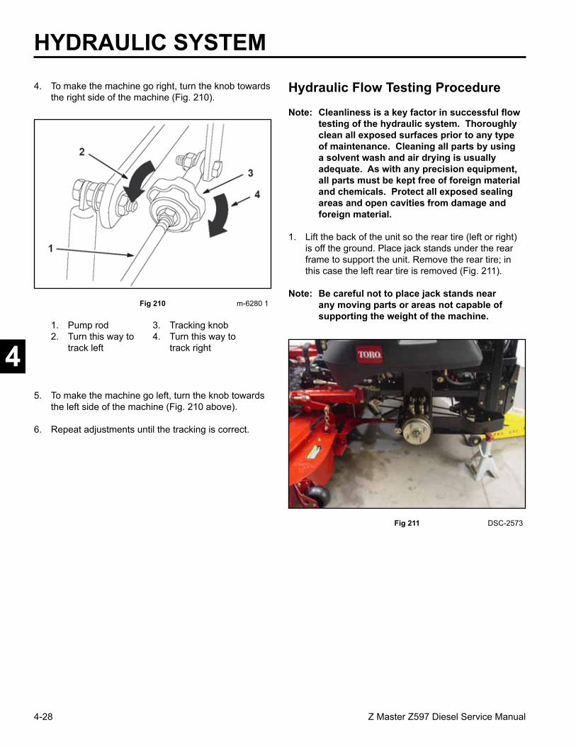
4-28 Z Master Z597 Diesel Service Manual
4
HYDRAULIC SYSTEM
Fig 210 m-6280 1
4. To make the machine go right, turn the knob towards the right side of the machine (Fig. 210).
5. To make the machine go left, turn the knob towards the left side of the machine (Fig. 210 above).
6. Repeat adjustments until the tracking is correct.
1. Pump rod 3. Tracking knob2. Turn this way to 4. Turn this way to track left track right
Note: Cleanliness is a key factor in successful flow testing of the hydraulic system. Thoroughly clean all exposed surfaces prior to any type of maintenance. Cleaning all parts by using a solvent wash and air drying is usually adequate. As with any precision equipment, all parts must be kept free of foreign material and chemicals. Protect all exposed sealing areas and open cavities from damage and foreign material.
1. Lift the back of the unit so the rear tire (left or right) is off the ground. Place jack stands under the rear frame to support the unit. Remove the rear tire; in this case the left rear tire is removed (Fig. 211).
Note: Be careful not to place jack stands near any moving parts or areas not capable of supporting the weight of the machine.
Hydraulic Flow Testing Procedure
Fig 211 DSC-2573

4-29Z Master Z597 Diesel Service Manual
4
HYDRAULIC SYSTEM2. Clean any dirt or debris away from the hydraulic line
fittings. Remove the hydraulic lines.
Note: Cap the fittings to prevent dirt from entering the hydraulic system (Fig. 212).
Fig 212 DSC-2110
3. Connect the hydraulic hose fittings to the hydraulic flow tester and tighten the fittings (Fig. 213). The flow tester shown is bidirectional so it does not matter in which order the hoses are connected to the flow tester. If using a directional flow tester, be sure to correctly connect hoses.
Fig 213 DSC-2576
4. Check the hydraulic reservoir and fill as needed with Mobil 1, 15w-50 oil.
5. Disconnect the electric PTO clutch from the wiring harness to prevent accidental engagement of the mower deck (Fig. 214).
6. Disconnect the seat switch. Temporarily install a jumper wire across the harness (Fig. 215).
Fig 214 DSC-2601
Fig 215 DSC-2355

4-30 Z Master Z597 Diesel Service Manual
4
HYDRAULIC SYSTEM7. Verify the restrictor valve on the hydraulic flow tester
is in the fully “Opened” position.
8. Start the machine. Run the unit for approximately 5 minutes to warm the oil in the hydrostatic system.
9. Release the parking brake and bring both levers to the inside neutral position. Set the engine throttle to full RPM.
10. Stroke the left hand hydrostatic lever fully forward. Very slowly, rotate the “T” handle of the adjustable flow tester restrictor valve until the pressure gauge reaches 500 PSI (3447 kPa). The measured flow should be between 13 to 15 gpm (49 to 56.8 lpm).
11. With the unit at full engine throttle speed, slowly rotate the “T” handle of the flow tester restrictor valve clockwise until the pressure gauge reads approximately 1000 to 1200 PSI (6895 to 8274 kPa).
Caution: DO NOT operate the machine for an extended period of time at the 1200 PSI rate.
12. Record the difference or “flow droop” of the pump. For the Hydro-Gear BDP 21 pump, maximum allowable “flow droop” is 2.0 gpm (7.5 lpm). Any droop greater than 2.0 gpm (7.5 lpm) is considered unacceptable and the pump should be repaired/replaced barring any other potential causes.
13. Return the motion control lever to neutral position and return both levers to the neutral locked position. Engage the parking brake. Slow the engine speed to idle and turn the ignition switch to the OFF position.
14. Disconnect the hydraulic flow tester from the hydraulic lines.
15. Re-connect the hydraulic lines to the wheel motor. Tighten the hydraulic lines to the wheel motor.
16. Check the hydraulic reservoir and fill as necessary to the “Hot” level mark; refer to Figure 006, page 2-5.
17. Reinstall the left rear tire and lower the unit to the ground. Remove the temporary jumper cable and reconnect the seat switch. Reconnect the electric PTO clutch.
3. Unlatch and open the hood.
4. Slide a low profile oil catch pan or absorbent cloth pad under the fan motor and on top of the engine.
Fig 216 DSC-2579
1. Raise the seat and disconnect the seat switch plug from the harness. Temporary install a jumper lead into the harness.
2. Remove the muffler guard (Fig. 216).
Cooling Fan Pump Flow Testing Procedure

4-31Z Master Z597 Diesel Service Manual
4
HYDRAULIC SYSTEM
6. Before starting the engine make sure the hydraulic lines are held away from moving parts and the muffler. The pump used in this system is designed to run at 1.6 to 1.7 gpm (6 to 6.4 lpm) at 3000 PSI (20684 kPa) continuous pressure. Under little or no restriction, you should measure 3 to 4 gpm (11 to 15 lpm) at full engine speed.
7. Make sure the restrictor valve is in the full “OPEN” position. Start the engine. Allow at least 5 minutes for the hydraulic system to reach operating temperature. Run the machine at full speed. The gauge should read approximately 3 to 4 gpm (11 to 15 lpm) under no restriction. Record the flow reading.
Fig 217 fan motor test
FANMOTOR
CA
SE D
RA
INTO
CO
OLE
R
RET
UR
N T
O P
UM
P
RES
UM
E LI
NE
FRO
M P
UM
P
FLOW TESTER
5. Remove the hydraulic pressure and return lines at the fan hydraulic motor. Connect the flow meter as shown (Fig. 217).
Note: If using a directional flow tester, be sure to correctly connect hoses.
8. With the engine running at full rpm, carefully close the restrictor valve until 1500 PSI (10342 kPa) is reached. There should be approximately 1 gpm flow loss under pressure.
If flow drops more than 1 gpm (3.8 lpm), replace the pump. If the pump falls within spec, replace the motor or inspect the cooling system for other component failure.
Caution: DO NOT operate the machine for an extended period of time at 1500 psi (10342 kPa) system pressure. Hydraulic temperatures can rise quickly under pressure. Open the flow tester restrictor valve, bring the engine to idle, and shut the machine off.
9. Remove the flow tester from the machine. Reconnect the hydraulic lines to the fan motor.
10. Re-install the rear heat shield.
11. Close the hood.
12. Reconnect the seat switch and lower the seat.
Check the pump drive belt for wear after every 50 hours of operation.
1. Tilt the seat forward and remove the front engine panel.
Replacing the Traction Pump Drive Belt

4-32 Z Master Z597 Diesel Service Manual
4
HYDRAULIC SYSTEM
Fig 218 DSC-2594
2. Using a 3/8” drive ratchet, pull the spring loaded idler toward the right side of the unit and remove the traction belt from the engine and hydro pump pulleys (Fig. 218).
3. Install the belt around the engine and hydro pump (Fig. 219).
Fig 219 DSC-000
1. Spring loaded idler pulley2. Pump drive belt
4. Install the 3/8” drive ratchet, pull the spring loaded idler toward the right side of the unit and release the pressure on the spring.
5. Install the front engine panels.
Pushing the Machine by Hand
Important: Always push the machine by hand. Never tow the machine because hydraulic system damage may occur.
1. Disengage the power take off (PTO) and turn the ignition key to OFF. Move the levers to the neutral position and apply the parking brake.
2. Rotate the by-pass valves counterclockwise 1 turn to push. This allows hydraulic fluid to by-pass the pump enabling the wheels to turn (Fig. 220).
Fig 220 DSC-2795
Important: Do not rotate the by-pass valves more than 1 turn to prevent the valves from coming out of the body and causing fluid to run out.
3. Disengage the parking brake before pushing.
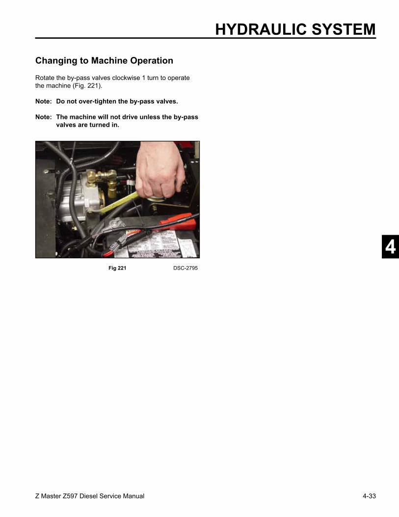
4-33Z Master Z597 Diesel Service Manual
4
HYDRAULIC SYSTEM
Rotate the by-pass valves clockwise 1 turn to operate the machine (Fig. 221). Note: Do not over-tighten the by-pass valves.
Note: The machine will not drive unless the by-pass valves are turned in.
Changing to Machine Operation
Fig 221 DSC-2795

4-34 Z Master Z597 Diesel Service Manual
4
HYDRAULIC SYSTEMH
YDR
AU
LIC D
IAG
RA
M

5-1Z Master Z597 Diesel Service Manual
2
3
4
6
7
1
ENGINE
Safety Information . . . . . . . . .
Specifications . . . . . . . . . . .
Chassis . . . . . . . . . . . . . .
Hydraulic System . . . . . . . . .
Engine . . . . . . . . . . . . . . .
Electrical . . . . . . . . . . . . . .
Mower Decks . . . . . . . . . . .
1
5

5-2 Z Master Z597 Diesel Service Manual
5
ENGINE
Engine Removal1. Disconnect the negative, then the positive battery
cable and remove the battery from the unit.
2. Unlatch and open the engine hood. Loosen and remove the rear heat shield from the frame (Fig. 222).
Fig 222 DSC-2370
3. Remove the two knobs located on the engine access panel. Remove the engine belt shield and the engine access panel (Fig. 223).
Fig 223 DSC-2071
Fig 225 DSC-2411
5. Remove the left and right hair pins, the clevis pins and remove the hood (Fig. 225)
Fig 224 DSC-2410
4. Remove the hood lanyard from the right and left radiator support bolts (Fig. 224)

5-3Z Master Z597 Diesel Service Manual
5
ENGINEDANGER! Discharge of hot pressurized coolant or
touching hot radiator and surrounding parts can cause severe burns.
• Do not remove radiator cap or open drain petcock when the engine is hot. Always allow the engine to cool at least 15 minutes or until the radiator cap is cool enough to touch without burning your hand before removing the radiator cap or opening drain petcock.
• Do not touch radiator and surrounding parts that are hot.
6. With a drain funnel and pan, open the radiator petcock, located at the lower right hand corner of the radiator, and drain the coolant out of the radiator (Fig. 226).
Fig 226 DSC-2413
7. At the left rear of machine, remove the tie strap and the clamp holding the engine inlet cooling hose and the overflow hose to the radiator (Fig. 227).
Fig 227 DSC-2374
Fig 228 DSC-2425
8. At the right rear of machine, loosen and remove the hose clamp on the engine inlet cooling hose at the radiator (Fig. 228). Lower the hose and drain any coolant that is left in the hose.

5-4 Z Master Z597 Diesel Service Manual
5
ENGINE
10. Place a small drain pan on top of the engine. Loosen and remove the hydraulic lines to the hydraulic fan motor (Fig. 230). Cap the fittings to protect from any dirt or debris.
Fig 230 DSC-2378
11. Remove the case drain hydraulic line at the tee fitting, located at the left front corner of the radiator (Fig. 231). A drain pan will be needed to catch any oil from the hydraulic line. Cap the fittings to prevent contamination.
Fig 231 DSC-2429
Fig 232 DSC-2433
12. Loosen and remove the tank return hydraulic hose from the radiator. This line is located at the left rear corner of the radiator (Fig. 232). Cap the fittings to prevent contamination.
Fig 229 DSC-2428
9. Located on the right side of the fan mounting plate assembly is an access hole to remove the hose clamp for the engine outlet hose, located at the radiator (Fig. 229). Remove the clamp and lower the hose to drain any coolant that is left in the hose.
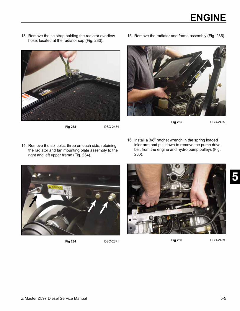
5-5Z Master Z597 Diesel Service Manual
5
ENGINE
Fig 233 DSC-2434
13. Remove the tie strap holding the radiator overflow hose, located at the radiator cap (Fig. 233).
14. Remove the six bolts, three on each side, retaining the radiator and fan mounting plate assembly to the right and left upper frame (Fig. 234).
Fig 234 DSC-2371
15. Remove the radiator and frame assembly (Fig. 235).
Fig 235 DSC-2435
Fig 236 DSC-2439
16. Install a 3/8” ratchet wrench in the spring loaded idler arm and pull down to remove the pump drive belt from the engine and hydro pump pulleys (Fig. 236).

5-6 Z Master Z597 Diesel Service Manual
5
ENGINE
18. Loosen the outer clamp on the short hose between the intake hood and the air filter. Remove the two bolts and nuts on the air cleaner mount (Fig. 238).
Fig 238 DSC-2441
19. Remove the air cleaner assembly (Fig. 239).
Fig 239 DSC-2442
Fig 240 DSC-2443
20. Make sure the fuel valve is in the OFF position. Tag or mark the OUT or return fuel line. Loosen the clamps and remove the fuel lines from the engine (Fig. 240).
OUT
Fig 237 DSC-2440
17. Loosen the hose clamp on the air intake hose and remove the hose from the air filter (Fig. 237).

5-7Z Master Z597 Diesel Service Manual
5
Fig 241 DSC-2444
21. Remove the throttle cable clamp and the throttle casing clamp from the fuel pump injector linkage (Fig. 241).
22. Remove the following wires from the engine: • Pink/Black wire to the glow plug strap (A) • Yellow/Red wire to the temperature sender (B) • Black/Green wire to the temperature switch (C) (Fig. 242).
Fig 242 DSC-2445
23. Remove the following wires from the engine: • Dark Blue wire to the oil pressure sending unit (E) • Dark Green wire to the fuel solenoid (F) (Fig. 243).
Fig 243 DSC-2446
Fig 244 DSC-2447
24. Remove the bolt that holds the wire clamp located on top of the alternator (Fig. 244).
ENGINE
A. Throttle Casing ClampB. Throttle Cable Clamp
A
BF
E
A
BC

5-8 Z Master Z597 Diesel Service Manual
5
ENGINE
26. Remove the bolt located at the adjusting strap and remove the alternator belt. Remove the bolt located at the bottom of the alternator and remove the alternator (Fig. 246).
Fig 246 DSC-2448
27. Remove the Orange/Black wire and the Red wire to the starter motor.
29. Unplug the jack and plug to the electric PTO clutch.
30. Located below the starter motor are two ground wires bolted to a bracket attached to the engine block. Remove the bolt and nut (Fig. 247).
Fig 247 DSC-2451
Fig 248 DSC-2452
31. Loosen the 4 bolts to the rear bumper assembly and remove (Fig. 248).
Fig 245 DSC-2546
25. Disconnect the red wire located on top of the alternator and unplug the wiring harness located at the back of the alternator (Fig. 245).
AB
A. Red lead to alternatorB. Alternator harness

5-9Z Master Z597 Diesel Service Manual
5
ENGINE
33. Remove the bolt and nut holding the clutch/brake strap and rotate the strap up and out of the way (Fig. 250).
Fig 250 DSC-2455
34. Remove both mower drive belts; refer to Replacing Mower Drive Belts, page 7-41.
35. Located on the left rear side of the engine is a ball joint assembly, between the frame and the engine flywheel cover. Remove the nut holding the assembly to the frame (Fig. 251).
Fig 251 DSC-2457
Fig 252 DSC-2458
36. Remove the bolt holding the ball joint link to the flywheel cover (Fig. 252).
Fig 249 DSC-2453
32. Pull the spring loaded idler down and remove the fan drive belt (Fig. 249).

5-10 Z Master Z597 Diesel Service Manual
5
ENGINE
38. On the left side of the engine, remove the bolt, nut and washers from the left hand engine mount (Fig. 254).
Fig 254 DSC-2468
39. Repeat the procedure on the right hand engine mount.
Note: Before removing the rear engine mount, install engine hoist to the lifting brackets located on top of the engine (Fig. 255). Raise until there is NO slack in the lift chain.
Fig 255 DSC-2469
Fig 256 DSC-2470
40. Remove the bolt, washer and nut on the engine rear mount (Fig. 256).
Fig 253 DSC-2460
37. Remove the bolt holding the ball joint link to the left front engine bracket (Fig. 253).

5-11Z Master Z597 Diesel Service Manual
5
ENGINE
Engine Installation
1. Before installing the engine, make sure the large washer is located on top of the rear engine mount isolator (Fig. 258).
Fig 258 DSC-2481
2. Carefully lower the engine into the frame of the unit. The engine will have to be turned slightly so the muffler clears the right rear radiator support bracket and to clear the engine drive pulley, pump idler pulley and the RH pump pulley.
3. Install the bolt and nut on the engine rear mount, do not tighten (Fig. 259).
Fig 259 DSC-2482
Fig 257 DSC-2480
41. Carefully lift the engine with the hoist. As the engine is being lifted out, turn it slightly to gain clearance between the engine drive pulley, pump idler pulley, and the RH pump pulley. Also, you may have to turn the engine so the muffler clears the right rear radiator support bracket (Fig. 257).

5-12 Z Master Z597 Diesel Service Manual
5
ENGINE
Fig 261 DSC-2483
6. Before tightening the bolts and nuts on the engine mounts, check the alignment of the engine drive pulley to the right side pump pulley (Fig. 261). The right and left engine mount brackets are slotted to permit adjustment.
7. Tighten all three engine mount bolts and nuts once alignment has been achieved.
Fig 260 engine mount assembly c
4. Install the right hand engine mount bolt. Note the sequence of the washers from the bottom up: bolt, large washer, and then the small thick washer through the isolator; then a small washer and nut (Fig. 260). Do not tighten the bolt and nut.
BA
C D
E F
A. Bolt D. IsolatorB. Large washer E. Small washerC. Small thick washer F. Nut
5. Install the left hand engine mount bolt following the same pattern as the right hand engine mount bolt. Do not tighten the bolt and nut.

5-13Z Master Z597 Diesel Service Manual
5
8. Install the front ball joint link assembly between the frame and the engine bracket (Fig. 262). Follow the hardware sequence in the diagram (Fig. 263).
Fig 262 DSC-2484
Fig 263 front Fig 265 rear
Fig 264 DSC-2457
9. Install the rear ball joint assembly between the flywheel cover and the frame (Fig. 264). Follow the hardware sequence in the diagram (Fig. 265).
ENGINE
A. Washer E. Link - ball jointB. Screw HH F. Washer, largeC. Ball joint assembly G. IsolatorD. Nut - jam H. Nut - lock
A C
A
B
DE
F
H
G
F
A. Washer E. Link - ball jointB. Screw HH F. Washer, largeC. Ball joint assembly G. IsolatorD. Nut - jam H. Nut - lock
A C
A
B
DE
F
H
G
F
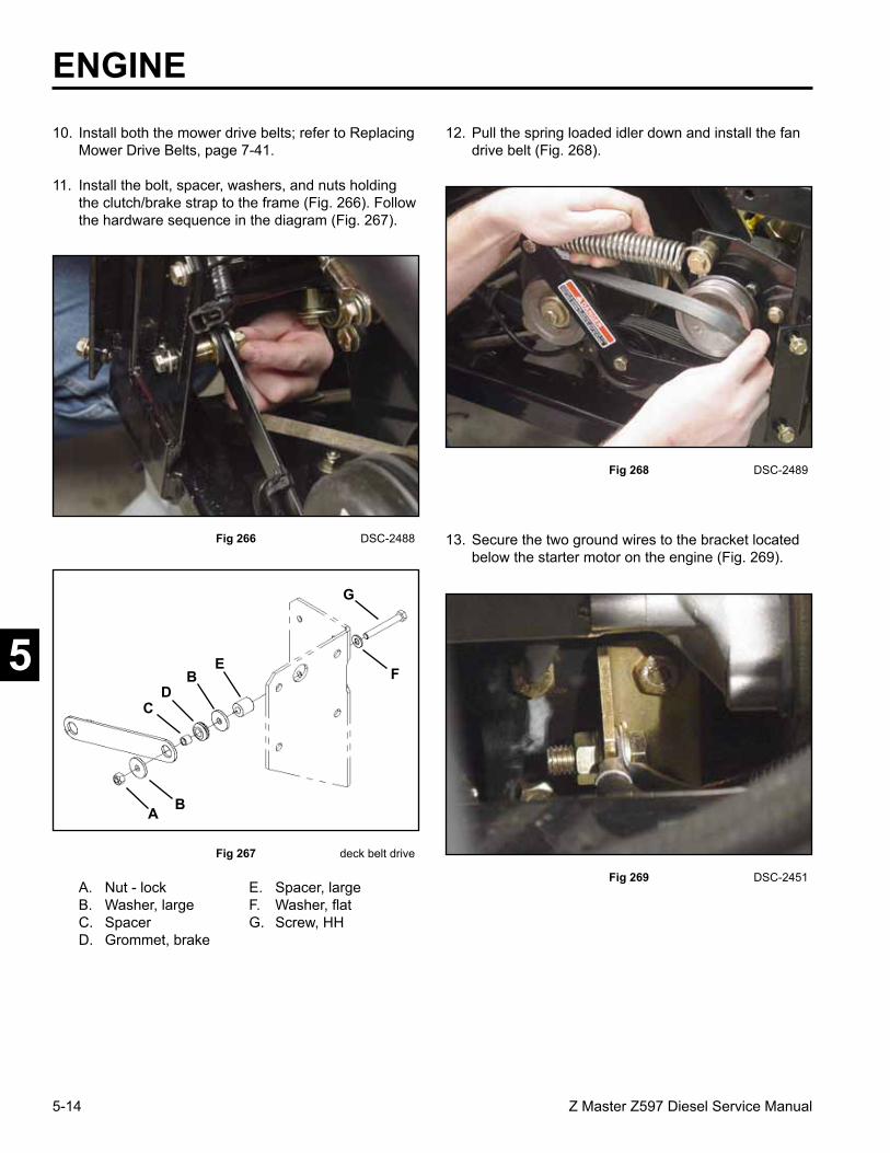
5-14 Z Master Z597 Diesel Service Manual
5
ENGINE
Fig 269 DSC-2451
13. Secure the two ground wires to the bracket located below the starter motor on the engine (Fig. 269).
Fig 268 DSC-2489
12. Pull the spring loaded idler down and install the fan drive belt (Fig. 268).
10. Install both the mower drive belts; refer to Replacing Mower Drive Belts, page 7-41.
11. Install the bolt, spacer, washers, and nuts holding the clutch/brake strap to the frame (Fig. 266). Follow the hardware sequence in the diagram (Fig. 267).
Fig 266 DSC-2488
Fig 267 deck belt drive
A B
CD
EF
G
B
A. Nut - lock E. Spacer, largeB. Washer, large F. Washer, flatC. Spacer G. Screw, HHD. Grommet, brake

5-15Z Master Z597 Diesel Service Manual
5
14. Connect the electric PTO clutch (Fig. 270).
Fig 270 DSC-2490
15. Install the Orange/Black wire to the starter motor (Fig. 271).
Fig 271 DSC-2492
Fig 273 DSC-2447
17. Install the alternator belt and follow the instructions for Tensioning the Alternator Belt, page 5-31.
18. Connect the Red wire to the top of the alternator and plug the wiring harness into the back of the alternator.
19. Install the bolt through the wiring clamp that holds the wiring harness to the top of the alternator (Fig. 273).
Fig 272 DSC-2495
16. Install the bolt holding the bottom of the alternator to the bracket. Install the bolt through the adjusting strap to the alternator (Fig. 272).
ENGINE

5-16 Z Master Z597 Diesel Service Manual
5
ENGINE
Fig 277 DSC-2442
24. Install the air cleaner assembly (Fig. 277).
Fig 276 DSC-2443
22. Install the throttle cable; follow instructions under Throttle Control Installation page 3-13.
23. Install the two fuel lines to the injector pump. Make sure you install the tagged or marked fuel line to the Out or return connector (Fig. 276).
20. Install the following wires to the engine: • Dark Blue to the oil pressure sending unit (E) • Dark Green to the fuel solenoid (F) (Fig. 274).
Fig 274 DSC-2446
21. Install the following wires: • Pink/Black to the glow plug strap (A) • Yellow/Red to the temperature sender (B) • Black/Green to the temperature switch (C) (Fig. 275).
Fig 275 DSC-2445
F
E
A
BC
OUT

5-17Z Master Z597 Diesel Service Manual
5
25. Tighten the hose clamps and the two bolts and nuts on the air cleaner mount (Fig. 278).
Fig 278 DSC-2441
26. Install the air intake hose between the engine and air filter. Tighten the hose clamps (Fig. 279).
Fig 279 DSC-2440
Fig 281 DSC-2435
28. Install the radiator and frame assembly to the right and left upper frame (Fig. 281).
Fig 280 DSC-2439
27. Insert a 3/8” ratchet wrench into the spring loaded idler arm. Pull down to install the pump drive belt from the engine to the hydro pump pulleys (Fig. 280).
ENGINE

5-18 Z Master Z597 Diesel Service Manual
5
ENGINE
Fig 285 DSC-2429
32. Install the case drain hydraulic line at the tee fitting, located at the left front corner of the radiator assembly (Fig. 285).
Fig 284 DSC-2433
31. Install the tank return hydraulic hose to the radiator. The line is located at the left rear corner of the radiator (Fig. 284).
29. Install the six bolts, three located on each side, retaining the radiator and fan mounting plate assembly to the right and left upper frame (Fig. 282).
Fig 282 DSC-2371
30. Install the radiator overflow hose, located at the radiator cap. Install a tie strap to hold it in place (Fig. 283).
Fig 283 DSC-2496

5-19Z Master Z597 Diesel Service Manual
5
33. Install the three hydraulic lines to the hydraulic fan motor (Fig. 286).
Fig 286 DSC-2500
35. Install the engine inlet hose to the radiator and tighten the hose clamp (Fig. 288)
Fig 288 DSC-2425
34. On the right side of the radiator, install the hose for the engine outlet to the radiator. Install the clamp and tighten the clamp through the access hole in the fan mounting plate (Fig. 287).
36. Install the two clamps holding the engine inlet cooling hose and the overflow hose to the fan mounting plate (Fig. 289).
Fig 287 DSC-2428 Fig 289 DSC-2374
ENGINE

5-20 Z Master Z597 Diesel Service Manual
5
ENGINE
43. Install the rear bumper assembly and tighten the 4 bolts (Fig. 293).
Fig 293 DSC-2452
Fig 292 DSC-2504
40. Prime the fuel system; refer to Priming the Fuel System, page 5-34. Start the unit up and run for approximately 5 minutes.
41. Check for any leaks in the hydraulic fluid lines, fuel lines, and the coolant lines. The hydraulic system may need air purged from the hydraulic system, refer to Purging the Hydraulic System, page 4-13. Top up coolant and hydraulic fluid as needed.
42. Install the engine access panel with two knobs (Fig. 292).
37. Install coolant in the radiator (Fig. 290), and the overflow bottle (Fig. 291). Fill to the line indicator of the overflow bottle. Refer to Checking the Radiator Coolant, page 5-28.
Fig 290 DSC-2502
Fig 291 DSC-2503
38. Check the hydraulic fluid in the reservoir; refer to Figure 006, page 2-5.
39. Install the battery in the unit and connect the positive and negative battery cables.

5-21Z Master Z597 Diesel Service Manual
5
44. Install the rear heat shield (Fig. 294).
Fig 294 DSC-2370
Fig 295 DSC-2505
45. Install the engine hood assembly with clevis pins, washers and hairpins (Fig. 295).
ENGINE
DANGER! Discharge of hot pressurized coolant or touching hot radiator and surrounding parts can cause severe burns.
• Do not remove radiator cap or open drain petcock when the engine is hot. Always allow the engine to cool at least 15 minutes or until the radiator cap is cool enough to touch without burning your hand before removing the radiator cap or opening drain petcock.
• Do not touch radiator and surrounding parts that are hot.
1. Disconnect the battery negative cable.
Slip the hood lanyards on the radiator support bolts (Fig. 296).
Fig 296 DSC-2410
Removing the Radiator
Cooling System

5-22 Z Master Z597 Diesel Service Manual
5
ENGINE
5. Remove the right and left hair pins off the clevis pins and remove the hood assembly (Fig. 300).
Fig 300 DSC-2411
Fig 297 DSC-2370 Fig 299 DSC-2410
4. Slide the hood lanyard off the right and left radiator support bolts (Fig. 299).
Fig 298 DSC-2071
3. Remove the two knobs located on the engine access panel. Remove the engine belt shield and the engine access panel (Fig. 298).
2. Unlatch and open the engine hood. Loosen and remove the rear heat shield from the frame (Fig. 297).

5-23Z Master Z597 Diesel Service Manual
5
6. With a drain funnel and pan, open the radiator petcock, located at the lower right hand corner of the radiator, and drain the coolant out of the radiator (Fig. 301).
Fig 301 DSC-2413 Fig 303 DSC-2428
8. Located on the right side of the fan mounting plate is an access hole to remove the hose clamp for the engine outlet hose, located at the radiator (Fig. 303). Remove the clamp and lower the hose to drain any coolant that is left in the hose.
Fig 302 DSC-2425
7. Loosen and remove the hose clamp on the engine inlet cooling hose at the radiator (Fig. 302). Lower the hose and drain any coolant that is left in the hose.
9. Remove the tie strap holding the radiator overflow hose, located at the radiator cap (Fig. 304).
Fig 304 DSC-2434
ENGINE
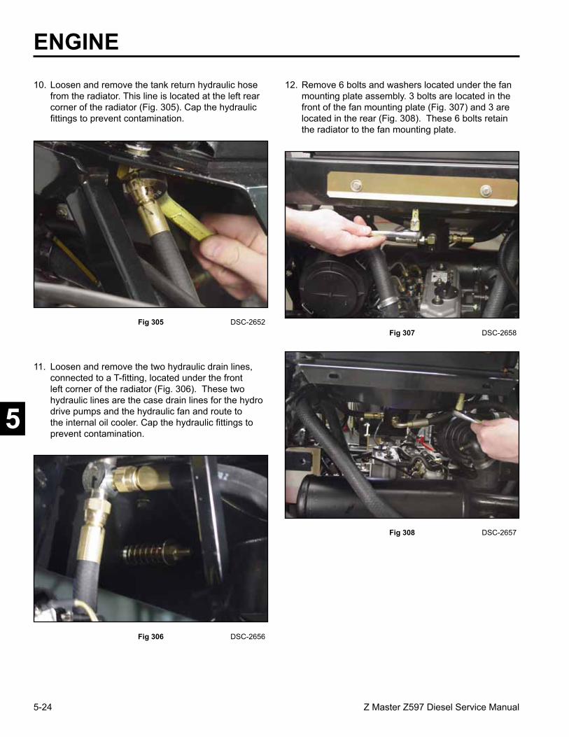
5-24 Z Master Z597 Diesel Service Manual
5
ENGINE12. Remove 6 bolts and washers located under the fan
mounting plate assembly. 3 bolts are located in the front of the fan mounting plate (Fig. 307) and 3 are located in the rear (Fig. 308). These 6 bolts retain the radiator to the fan mounting plate.
Fig 307 DSC-2658
Fig 308 DSC-2657
10. Loosen and remove the tank return hydraulic hose from the radiator. This line is located at the left rear corner of the radiator (Fig. 305). Cap the hydraulic fittings to prevent contamination.
Fig 305 DSC-2652
Fig 306 DSC-2656
11. Loosen and remove the two hydraulic drain lines, connected to a T-fitting, located under the front left corner of the radiator (Fig. 306). These two hydraulic lines are the case drain lines for the hydro drive pumps and the hydraulic fan and route to the internal oil cooler. Cap the hydraulic fittings to prevent contamination.

5-25Z Master Z597 Diesel Service Manual
5
ENGINE
Fig 309 DSC-2659
13. Remove the radiator from the fan mounting plate (Fig. 309).
1. Install the radiator to the fan mounting plate assembly (Fig. 310).
Radiator Installation
Fig 310 DSC-2659
2. Install the 3 bolts and washers located under the fan mounting plate assembly in the front (Fig. 311). DO NOT TIGHTEN.
Fig 311 DSC-2658
Fig 312 DSC-2657
Install the 3 bolts and washers under the fan mounting plate assembly and in the rear (Fig. 312) DO NOT TIGHTEN.
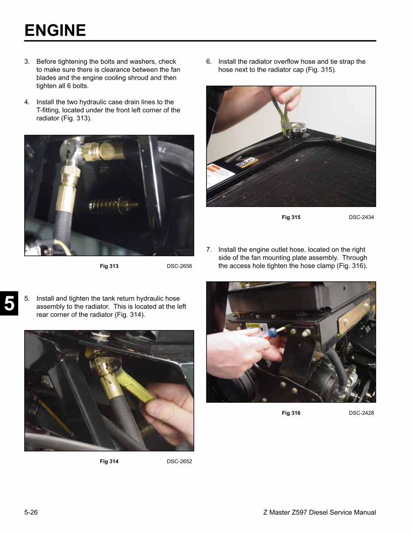
5-26 Z Master Z597 Diesel Service Manual
5
ENGINE
5. Install and tighten the tank return hydraulic hose assembly to the radiator. This is located at the left rear corner of the radiator (Fig. 314).
Fig 314 DSC-2652
6. Install the radiator overflow hose and tie strap the hose next to the radiator cap (Fig. 315).
Fig 315 DSC-2434
Fig 313 DSC-2656
3. Before tightening the bolts and washers, check to make sure there is clearance between the fan blades and the engine cooling shroud and then tighten all 6 bolts.
4. Install the two hydraulic case drain lines to the T-fitting, located under the front left corner of the radiator (Fig. 313).
7. Install the engine outlet hose, located on the right side of the fan mounting plate assembly. Through the access hole tighten the hose clamp (Fig. 316).
Fig 316 DSC-2428

5-27Z Master Z597 Diesel Service Manual
5
8. Install the engine inlet house and tighten the clamp (Fig. 317).
Fig 317 DSC-2425
9. Close the radiator petcock.
10. Fill the radiator with 50/50 mix of extended life antifreeze/Dex-Cool and water.
Check the antifreeze overflow bottle and make sure
it is up to indicator line. Cooling system capacity: 128 ounces (3.8l) 11. Check the hydraulic reservoir tank to make sure the
fluid level is at the cold level mark.
12. Connect the negative battery cable. Start the unit up and operate for about 5 minutes. Observe all the cooling and hydraulic lines for any leaks.
13. Recheck the hydraulic reservoir tank at the hot level mark; add oil if necessary. Also, recheck the coolant level in the overflow bottle.
14. Install the right and left hair pins to the clevis pins that hold the engine hood assembly (Fig. 318).
Fig 318 DSC-2411
15. Slide the right and left hood lanyards on the radiator support bolts (Fig. 319).
Fig 319 DSC-2410
ENGINE

5-28 Z Master Z597 Diesel Service Manual
5
ENGINE
Checking the Radiator Coolant
Check the cooling system level daily.
Fluid Type: 50/50 mix of extended life antifreeze/Dex-Cool and water.
Cooling system capacity: 128 ounces (3.8l)
Note: Do not open the radiator cap. Doing this may induce air into the cooling system.
1. Position the machine on a level surface, stop the engine, and set the parking brake.
2. With the engine cool, check the overflow bottle level. The fluid needs to be up to the raised indicator line on the outside of overflow bottle (Fig. 322).
Fig 322 fig 47 m-7402
3, If the coolant level is low, add a 50/50 mix of extended life antifreeze/Dex-Cool and water to the overflow bottle to the indicator line on the bottle.
1. Coolant overflow bottle2. Indicator line on side of overflow bottle
Fig 321 DSC-2370
17. Install the rear heat shield to the frame (Fig. 321).
Fig 320 DSC-2071
16. Install the engine belt shield and the engine access panel assembly with two knobs (Fig. 320).

5-29Z Master Z597 Diesel Service Manual
5
Fig 324 DSC-2581
2. Pull the spring loaded idler down and remove the fan pump drive belt from the engine and pump pulley (Fig. 324).
Fig 323 DSC-2580
Check the fan pump drive belt for wear after every 50 hours of operation.
1. Loosen the bolts and remove the rear engine panel (Fig. 323).
3. Install the new belt around the engine and hydro pump pulley.
4. Pull the spring loaded idler down and align the belt. Release the pressure on the spring loaded idler (Fig. 325).
Fig 325 DSC-2583
Check the alternator belt for wear after every 50 hours of operation.
ENGINE
Replacing the Fan Pump Drive Belt
Replacing and Tensioning the Alternator Belt
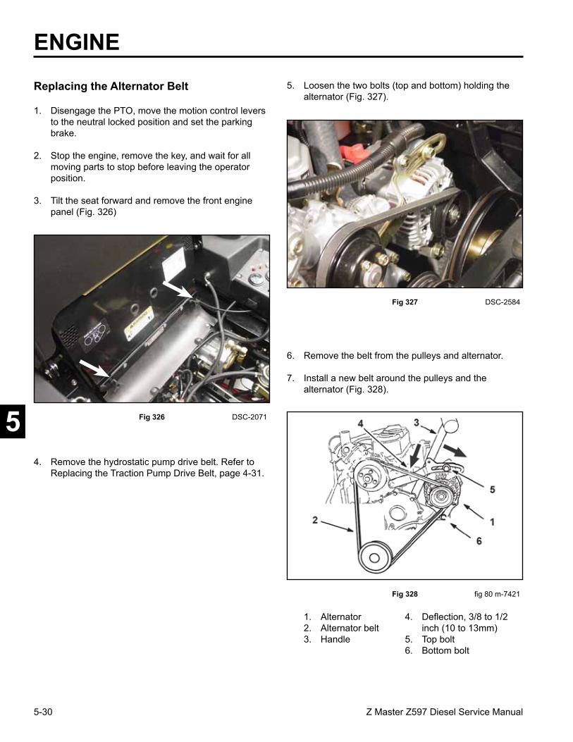
5-30 Z Master Z597 Diesel Service Manual
5
ENGINE5. Loosen the two bolts (top and bottom) holding the
alternator (Fig. 327).
Fig 327 DSC-2584
1. Disengage the PTO, move the motion control levers to the neutral locked position and set the parking brake.
2. Stop the engine, remove the key, and wait for all moving parts to stop before leaving the operator position.
3. Tilt the seat forward and remove the front engine panel (Fig. 326)
Replacing the Alternator Belt
Fig 326 DSC-2071
4. Remove the hydrostatic pump drive belt. Refer to Replacing the Traction Pump Drive Belt, page 4-31.
6. Remove the belt from the pulleys and alternator.
7. Install a new belt around the pulleys and the alternator (Fig. 328).
Fig 328 fig 80 m-7421
1. Alternator 4. Deflection, 3/8 to 1/22. Alternator belt inch (10 to 13mm)3. Handle 5. Top bolt 6. Bottom bolt

5-31Z Master Z597 Diesel Service Manual
5
Tensioning the Alternator Belt
1. Place a wood tool handle between the alternator and cylinder block to use as a lever (Fig. 329).
Fig 329 DSC-2585
2. Adjust the alternator to the outside until there is 3/8 to 1/2 inch (10 to 13mm) deflection in the belt between the engine and the alternator (Fig. 328).
3. Tighten the alternator bolts.
4. Check the deflection in the belt again and adjust the belt if needed (Fig. 330).
Fig 331 DSC-2587
5. If the deflection is correct, torque the upper bolt to 170 in-lbs. (19 Nm) and the bottom bolt to 40 ft-lbs. (54 Nm) (Fig. 331).
Fig 330 DSC-2586
ENGINE
6. Install the pump drive belt; refer to Replacing the Traction Pump Drive Belt, page 4-31.
7. Install the front engine panel (Fig. 332).
Fig 332 DSC-2071

5-32 Z Master Z597 Diesel Service Manual
5
ENGINE
Servicing the Fuel Filter
Draining Water from the Fuel Filter
Fig 333 fig 48 m-7409
If the Water in Fuel Light comes on stop the engine and drain the water from the fuel filter.
1. Disengage the PTO, move the motion control levers to the neutral locked postion and set the parking brake.
2. Stop the engine, remove the key, and wait for all moving parts to stop before leaving the operating position.
3. Disconnect the negative battery cable.
4. Allow the machine to cool down.
5. Place a drain pan under the fuel filter and loosen the drain plug 1 turn (Fig. 333).
6. Let the water drain. If necessary, operate the priming pump to drain water, but only until fuel flows from the filter (Fig. 334).
Fig 334 DSC-2588
7. Tighten the drain plug when fuel begins to flow.
8. Bleed the air from the fuel line by priming the fuel system. Refer to Priming the Fuel System, page
5-34.
1. Fuel filter 4. O-ring2. Sensor wire 5. Metal Primer button3. Drain plug

5-33Z Master Z597 Diesel Service Manual
5
Fig 335 DSC-2589
Replace the fuel filter after every 800 operating hours or yearly, whichever occurs first.
Never reinstall a dirty filter once it is removed.
1. Allow the machine to cool down.
2. Disengage the PTO, move the motion control levers to the neutral locked position and set the parking brake.
3. Stop the engine, remove the key, and wait for all moving parts to stop before leaving the operator position.
4. Close the fuel shut-off valve (Fig. 335).
ENGINE
Changing the Fuel Filter 5. Disconnect the sensor wire (Fig. 336).
Fig 336 DSC-2590
6. Remove the drain plug and discard the O-ring (Fig. 337).
Fig 337 fig 48 m-7409
1. Fuel filter 4. O-ring2. Sensor wire 5. Metal Primer button3. Drain plug

5-34 Z Master Z597 Diesel Service Manual
5
ENGINE
Fig 338 DSC-2591
7. Remove the filter.
8. Install a new filter by hand until the gasket contacts the housing, then tighten an extra 1/3 of a turn.
9. Install the drain plug with new O-ring and connect the sensor wire.
10. Bleed the air from the fuel line by priming the fuel system. Refer to Priming the Fuel System, page 5-34.
11. Open the fuel shut-off valve (Fig. 338).
Priming the Fuel System
The primer pump is the gold metal button on top of the fuel filter (Fig. 339).
Fig 339 DSC-2593
To bleed air from the fuel system, push down on the primer pump until resistance becomes firm. This should take about 10 – 15 pushes on the primer button (Fig. 340).
Fig 340 DSC-2588
12. Start the engine and check for leaks.

6-1Z Master 597 Diesel Series Service Manual
7
5
4
3
2
ELECTRICAL
Safety Information . . . . . . . . .
Specifications . . . . . . . . . . .
Chassis . . . . . . . . . . . . . .
Hydraulic System . . . . . . . . .
Engine . . . . . . . . . . . . . . .
Electrical . . . . . . . . . . . . . .
Mower Decks . . . . . . . . . . .
6
1

6-2 Z Master 597 Diesel Series Service Manual
6
Note: Interactive Electrical Troubleshooting CD, Form 492-9143 is also available.
When turning the ignition switch clockwise to the RUN position, the glow plug indicator light will come on. After the glow plug indicator light goes out, turn the key to the START position and start the mower. The “Low Oil Pressure” alarm will sound a “pulse tone”. Once the engine starts and the oil pressure in the engine builds the alarm will stop; this is normal.
Current flows from the ignition switch to the start relay and on to the engine starter. At the same time, current flows to the PTO switch, park brake switch, through the two neutral motion control switches, then on to the fuel solenoid and energizes the start relay and glow plug relay.
ELECTRICAL SYSTEM
There are 4 relays.1. Start Relay2. Glow Plug Relay3. Oil Pressure Relay4. Alternator Relay.
1. Start Relay: Once the safety connections are met, the relay will activate completing the circuit to the starter solenoid.
2. Glow Plug Relay: Once the safety connections are met, the relay will activate and provide current to the glow plugs and Oil Pressure Relay.
3. Oil Pressure Relay: During the time the glow plug relay is activated the oil pressure relay opens the warning buzzer ground circuit.
4. Alternator Relay: The alternator relay completes the audible alarm ground circuit if the alternator is not charging. Fig 342 DSC-2516
The glow plug and the start relay are located under the seat area, behind the battery (Fig. 342).
Fig 341 DSC-2515
The alternator and the oil pressure relays are located behind the engine access panel on the left side (Fig. 341).
ELECTRICAL
RELAYS
Purpose
Location
A B
A. Oil Pressure Relay B. Alternator Relay
C. Start Relay D. Glow Plug Relay
C D
General
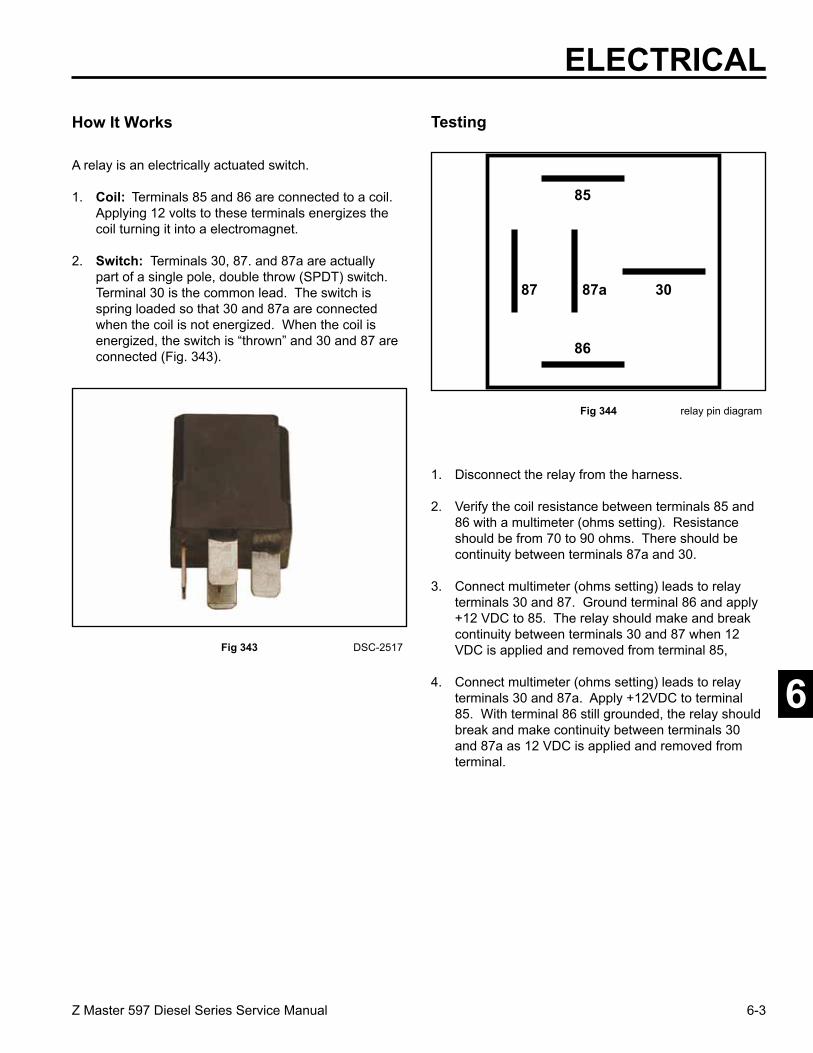
6-3Z Master 597 Diesel Series Service Manual
6
How It Works
A relay is an electrically actuated switch.
1. Coil: Terminals 85 and 86 are connected to a coil. Applying 12 volts to these terminals energizes the coil turning it into a electromagnet.
2. Switch: Terminals 30, 87. and 87a are actually part of a single pole, double throw (SPDT) switch. Terminal 30 is the common lead. The switch is spring loaded so that 30 and 87a are connected when the coil is not energized. When the coil is energized, the switch is “thrown” and 30 and 87 are connected (Fig. 343).
Fig 343 DSC-2517
1. Disconnect the relay from the harness.
2. Verify the coil resistance between terminals 85 and 86 with a multimeter (ohms setting). Resistance should be from 70 to 90 ohms. There should be continuity between terminals 87a and 30.
3. Connect multimeter (ohms setting) leads to relay terminals 30 and 87. Ground terminal 86 and apply +12 VDC to 85. The relay should make and break continuity between terminals 30 and 87 when 12 VDC is applied and removed from terminal 85,
4. Connect multimeter (ohms setting) leads to relay terminals 30 and 87a. Apply +12VDC to terminal 85. With terminal 86 still grounded, the relay should break and make continuity between terminals 30 and 87a as 12 VDC is applied and removed from terminal.
Fig 344 relay pin diagram
87 87a
86
85
30
Testing
ELECTRICAL
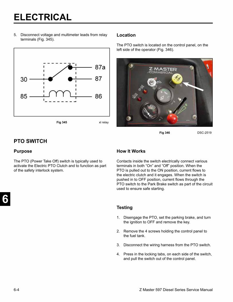
6-4 Z Master 597 Diesel Series Service Manual
6
ELECTRICAL5. Disconnect voltage and multimeter leads from relay
terminals (Fig. 345).
Fig 345 xl relay
The PTO (Power Take Off) switch is typically used to activate the Electric PTO Clutch and to function as part of the safety interlock system.
Contacts inside the switch electrically connect various terminals in both “On” and “Off” position. When the PTO is pulled out to the ON position, current flows to the electric clutch and it engages. When the switch is pushed in to OFF position, current flows through the PTO switch to the Park Brake switch as part of the circuit used to ensure safe starting.
Fig 346 DSC-2519
The PTO switch is located on the control panel, on the left side of the operator (Fig. 346).
Location
Purpose
PTO SWITCH
How It Works
Testing
1. Disengage the PTO, set the parking brake, and turn the ignition to OFF and remove the key.
2. Remove the 4 screws holding the control panel to the fuel tank.
3. Disconnect the wiring harness from the PTO switch.
4. Press in the locking tabs, on each side of the switch, and pull the switch out of the control panel.

6-5Z Master 597 Diesel Series Service Manual
6
ELECTRICAL5. Verify that there is continuity between the
appropriate terminals in the ON and OFF positions (Fig. 347).
Cont.
OFF (IN) ON (OUT)
not used
Cont.
Open
Open
Cont.
Cont.
Open
Opennot used
Y
Y
Y
Y
N
N
N
N
Fig 347 PTO switch test
6. Replace the switch if your test results do not correspond with those given in Fig. 347.
7. Mount the PTO switch back into the control panel and reinstall the wiring harness (Fig. 348).
Violet
Orange
GrayGray Gray
Orange
Orange
Fig 348 PTO clutch switch
Fig 349 DSC-2519
The ignition switch is located on the control panel, to the left side of the operator (Fig. 349).
The ignition switch provides the proper switching for the starter, accessories, and safety circuits.
Purpose
IGNITION SWITCH
Location
Continuity?Y = YesN = No

6-6 Z Master 597 Diesel Series Service Manual
6
ELECTRICAL
How It Works
Detents inside the switch give it 3 positions: OFF, RUN, and START. The START position is spring loaded so the cylinder automatically returns to RUN once the key is released (Fig. 350).
Fig 350 MVC-166
Ignition Switch Wiring ConnectionsB = Battery voltage “in”S = Starting CircuitI = Safety Circuit, Gauges, and Start CircuitA = Alternator/Charge CircuitY = Safety and Start CircuitX = Safety/Start/Delay Module
Fig 351 DSC-2524
To gain access to the neutral safety switches, remove the front pocket. There are 2 neutral switches. One for the right motion control handle and one for the left motion control handle (Fig. 351).
Used to ensure the motion control handles are in neutral to start the unit. It is activated by moving the motion control handles to the neutral position (handles outward).
Purpose
NEUTRAL SAFETY SWITCH
Testing
1. Disconnect the switch from the wiring harness
2. Verify that continuity exists between the terminals listed for the switch position. Verify that there is NO continuity between terminals not listed for the switch position.
OFF No continuity between terminalsRUN Continuity – B I A XY
START Continuity – B I S
Location
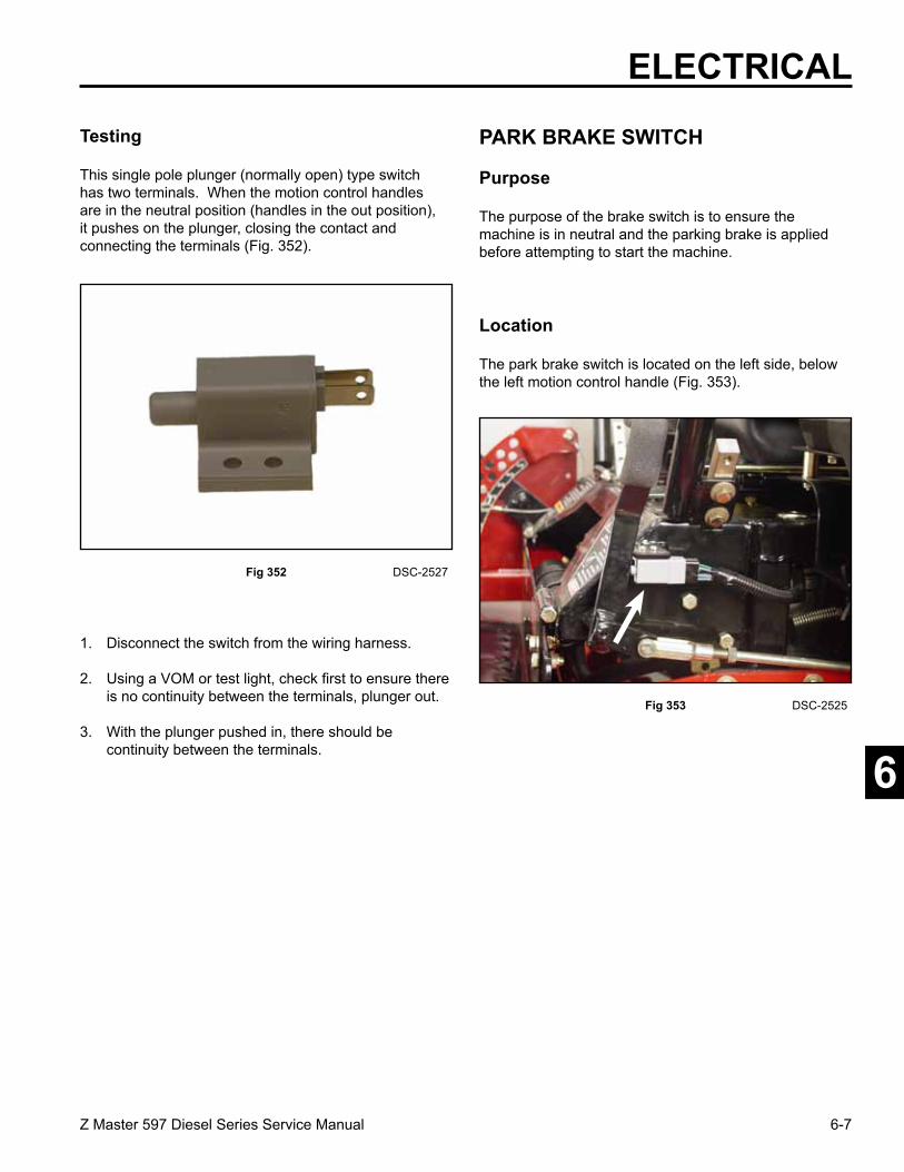
6-7Z Master 597 Diesel Series Service Manual
6
Testing
This single pole plunger (normally open) type switch has two terminals. When the motion control handles are in the neutral position (handles in the out position), it pushes on the plunger, closing the contact and connecting the terminals (Fig. 352).
Fig 352 DSC-2527
1. Disconnect the switch from the wiring harness.
2. Using a VOM or test light, check first to ensure there is no continuity between the terminals, plunger out.
3. With the plunger pushed in, there should be continuity between the terminals.
Fig 353 DSC-2525
The park brake switch is located on the left side, below the left motion control handle (Fig. 353).
The purpose of the brake switch is to ensure the machine is in neutral and the parking brake is applied before attempting to start the machine.
Purpose
PARK BRAKE SWITCH
ELECTRICAL
Location

6-8 Z Master 597 Diesel Series Service Manual
6
Plunger Not Depressed Plunger Depressed
A/B Terminals – ClosedCircuit – Continuity
A/B Terminals – OpenCircuit – No Continuity
C/D Terminals – OpenCircuit – No Continuity
C/D Terminals – ClosedCircuit – Continuity
Fig 355 brake switch
2. Using a multimeter, follow the procedures listed below (Fig. 355).
How It Works
In the start position it is used to ensure the park brake is in the ON position. At the same time it allows current to flow through for safety circuit. When the park brake is released in the OFF position it bypasses both neutral switches, as long as the operator is in the seat to maintain current for the safety circuit (Fig. 354).
Fig 354 DSC-2528
1. Disconnect the switch from the wiring harness.
The park brake is a double pole switch. When the park brake is in the On position, a pair of closed terminals is part of the starting safety interlock circuit. When the brake is released after starting, the other pair of terminals closes, bypassing the neutral switches and applying power to the seat switch circuit.
ELECTRICAL
Testing
AB
CD

6-9Z Master 597 Diesel Series Service Manual
6
ELECTRICAL
Fig 356 DSC-2555
The switch is in the safety circuit. If the engine is running and the operator vacates the seat with either the PTO engaged or the parking brake disengaged, the engine will shut down.
Note: There is a delay module in the system; there will be a slight delay before the engine shuts down after the operator vacates the seat.
Purpose
SEAT SWITCH How It Works
When the seat is vacated, the switch is open and there should be NO continuity between the two terminals. When the seat is occupied, the switch closes and there should be continuity between the two terminals (Fig. 357).
Fig 357 DSC-2556
1. Disconnect the switch from the wiring harness.
2. Using a VOM or test light, check first to ensure there is no continuity between either terminal, plunger out.
3. With the plunger pushed in, there should be continuity between the terminals
The seat switch is fastened to the bottom of seat base (Fig. 356).
Location
Testing

6-10 Z Master 597 Diesel Series Service Manual
6
ELECTRICAL
DELAY MODULE
Purpose
When operating the unit on rough terrain and the operator comes off the seat, the seat delay module will temporarily delay the engine shutting down, preventing erratic engine operation.
The seat delay module is located under the control panel on the LH fuel tank. (Fig. 358).
Fig 358 DSC-2534
Fig 359 DSC-2532
The seat delay module circuit board is made up of several different electrical components, such as a transient voltage suppressor, capacitor, transistors, carbon film resistors, diodes and a relay. These all work together to supply seat switch temporary voltage to the circuit to keep the engine running in case of short term voltage interruption (Fig. 359).
Testing
Location
Fig 360 DSC-2537
1. Raise the seat and disconnect the seat switch. Install a jumper wire in place of the seat switch (Fig. 360).
How It Works

6-11Z Master 597 Diesel Series Service Manual
6
ELECTRICAL2. Remove the 4 bolts to the control panel and raise
the panel.
3. Connect a VOM positive lead to the blue wire on the module (Fig. 361). Connect the negative lead to the battery negative terminal.
Fig 361 DSC-2536
Fig 362 DSC-2535
The audible alarm is located behind the engine access panel on the left side of the unit above the two relays (Fig. 362).
The dual-tone alarm is an audible alarm system to alert the operator of the following:
PULSE TONE - Either the engine is low on oil pressure or the alternator is not charging. Note: On start-up of the engine it is normal for the alarm to pulse tone after the glow plugs have timed out until the engine is running and the oil pressure is up on the engine.
CONTINUOUS TONE - The engine is overheating.
In either case, when the alarm sounds while operating the unit, it should be shut down immediately.
Purpose
DUAL-TONE ALARM
4, Follow the procedure below to test the delay module function.1. Disengage the parking brake.2. Pull the right and left motion control levers out of
the neutral position.3. Turn the ignition key to the RUN position.4. The meter should read approximately 12 volts
DC. 5. Disconnect one of the jumper wire leads. The
meter should hold around 12 volts and then read 0 volts DC after approximately 1 to 3 seconds. This test shows the delay module is working.
6. If you do not get 12 volts DC at the light blue wire when turning the ignition switch to the RUN position, verify the following:1. 12VDC at the Tan wire terminal.2. 12VDC at the Brown wire terminal.3. 0 VDC at the Gray wire terminal.4. If all these conditions are met, replace the seat delay module.
Location

6-12 Z Master 597 Diesel Series Service Manual
6
ELECTRICAL
Fig 363 DSC-2538
12 VDC is applied to the audible alarm when the ignition key is on. For pulse and continuous tone a ground is needed to activate the audible alarm.
For pulse tone (alternator not charging) the alternator senses battery voltage dropping and grounds the alternator relay. The alternator relay activates and grounds the audible alarm to pulse tone.
For pulse tone (low oil pressure) the oil pressure switch is closed when the engine is not running. Oil pressure opens the switch contacts taking the wire to the switch off of ground. When the oil pressure drops, the contacts in the switch close and grounds the audible alarm to pulse tone.
For continuous tone the engine temperature switch connects to ground when the engine reaches a certain temperature. The audible alarm has a continuous tone (Fig. 363).
How It Works Testing
Connect a positive leadfrom a 12 volt battery to the + terminal on the back of the audible alarm. Connect the negative lead to the S terminal on the back of the audible alarm. You should have a continuous tone. Move the negative lead to the P terminal of the audible alarm and you should get a pulse tone (Fig. 364).
Fig 364 DSC-2539
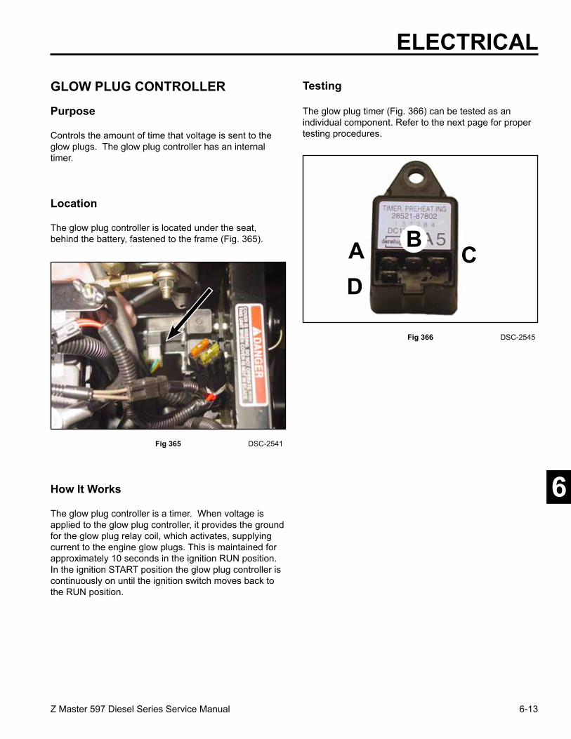
6-13Z Master 597 Diesel Series Service Manual
6
Fig 366 DSC-2545
The glow plug controller is a timer. When voltage is applied to the glow plug controller, it provides the ground for the glow plug relay coil, which activates, supplying current to the engine glow plugs. This is maintained for approximately 10 seconds in the ignition RUN position. In the ignition START position the glow plug controller is continuously on until the ignition switch moves back to the RUN position.
Fig 365 DSC-2541
The glow plug controller is located under the seat, behind the battery, fastened to the frame (Fig. 365).
Location
Testing
The glow plug timer (Fig. 366) can be tested as an individual component. Refer to the next page for proper testing procedures.
How It Works
ELECTRICAL
Controls the amount of time that voltage is sent to the glow plugs. The glow plug controller has an internal timer.
Purpose
GLOW PLUG CONTROLLER
A CD
B

6-14 Z Master 597 Diesel Series Service Manual
6
ELECTRICALStep 1 Testing the “timed” output in the “run”
position (Fig. 367).
A. Set VOM to read K ohms.B. Connect the red lead to terminal “A” of
the glow plug timer.C. Connect the black lead to the negative
terminal of the battery.D. Connect a jumper lead from terminal “D”
of the timer to the negative terminal of the battery.
E. Connect a jumper lead from terminal “B” of the timer to the positive terminal of the battery. The meter should hold at a constant continuity reading. The timer is reactivated in a continuous mode as the machine is being started.
A. Set VOM to read continuity in K ohms. B. Connect the red lead to referenced
terminal “A” of the glow plug timer.C. Connect the negative lead to the
negative terminal of the battery. D. Connect a jumper lead from terminal “D”
of the timer to the negative terminal of the battery.
E. Connect terminal “C” of the timer to the positive terminal of the battery and watch the meter. The meter should read continuity then increasing resistance until it reads “open”. The timeframe should be approximately 10 seconds from reading continuity to reading “open”.
Step 2 Testing continuous output in the “START” position (Fig. 368).
set for K
BLACK
RED
Fig 367 glow plug timer test 2
set for K
BLACK
RED
Fig 368 glow plug timer test 3

6-15Z Master 597 Diesel Series Service Manual
6
ELECTRICAL
TEMPERATURE SENDER
Purpose
The temperature sender is a temperature-dependent variable resistor. As the coolant temperature increases the internal resistance decreases. This causes a change in voltage applied to the water temperature gauge, which indicates a higher temperature.
The temperature sender is located on the right side of the engine water pump (Fig. 369).
Fig 369 DSC-2547
It is not practical to test the sender in a shop environ-ment. If the gauge is not reading at all, temporarily ground the lead at the sender. If the meter reads full scale, the ground wire and gauge are OK and the sender is bad. If the gauge does not respond, check for 12 VDC at gauge and continuity of the ground lead. If OK, the gauge is bad. Erratic readings can be either the gauge or sender. Replace the sender first, when diagnosing.
Fig 370 DSC-2548
When the water temperature increases the internal resistance decreases which will cause the water temperature gauge to increase (Fig. 370).
How It Works
Location
Testing

6-16 Z Master 597 Diesel Series Service Manual
6
ELECTRICAL
OIL PRESSURE SWITCH
Purpose
When the oil pressure drops, the switch activates an audible alarm which alerts the operator to shut the engine down immediately.
Located on the right hand side of the engine block, above the oil dipstick tube (Fig. 371).
Fig 371 DSC-2558 If the audible alarm operates continuously (pulse mode) when the engine is running, disconnect the switch lead. If the alarm stops, the pressure switch is bad. The switch can also be tested with an ohmmeter. There should be continuity between the wire terminal and ground with the engine not running, and no continuity when the engine is running.
Fig 372 DSC-2557
The oil pressure switch is a normally closed switch. When the engine is running, oil pressure builds and opens the contact in the switch. If the engine oil pressure drops, the contacts in the switch close, grounding the audible alarm, which alerts the operator to shut the unit down immediately (Fig. 372).
How It Works
Location
Testing

6-17Z Master 597 Diesel Series Service Manual
6
ELECTRICAL
WATER TEMPERATURE GAUGE
Purpose
The purpose of the water temperature gauge is to monitor the engine coolant temperature.
The water temperature gauge is located on the left side of the operator on the control panel (Fig. 373).
Fig 373 DSC-2550
Time-efficient shop testing is not possible. See information under Temperature Sender Testing, page6-15.
Fig 374 DSC-2549
When the engine water temperature increases the water sending unit resistance decreases, which cause the needle on the water temperature gauge readings will increase (Fig. 374).
How It Works
Location
Testing

6-18 Z Master 597 Diesel Series Service Manual
6
ELECTRICALBack side of the Temperature Gauge with terminal and wire locations (Fig. 375).
S Terminal - Yellow/Red Wire (to Temperature Sender)
G Terminal - Black Wire (Ground) I Terminal - Orange Wire (I Terminal of the Ignition
Switch)
Fig 375 DSC-2551
The hour meter keeps track of the actual unit running hours or the time that the ignition key switch is in the RUN position.
Fig 377 DSC-2560
Since a normal clock might be affected by variations in voltage and current, the hour meter is made up of an electric “winder” and a mechanical clock movement. When power is applied, a coil is energized to wind the movement. The movement unwinds in about 2 seconds. As it finishes its rotation, it re-energizes the coil so that the cycle can start over (Fig. 377).
Fig 376 DSC-2559
Raise the seat, the hour meter is located on the left side of the operator on the lower portion of the control panel (Fig. 376).
Location
S
G
I
Purpose
HOUR METER
How It Works

6-19Z Master 597 Diesel Series Service Manual
6
ELECTRICAL
Fig 378 DSC-2563
This gauge indicates the voltage across the battery.
Verify that 12 volts DC is present across the two terminals when the ignition key is in the RUN position. If so, and the meter is not running, replace the meter. If 12 volts is not present, check the connections. The meter is a permanently sealed unit and is not repairable.
Testing How It Works
The meter movement is proportional to the voltage level across the two terminals of the battery. This is accomplished by placing a resistor in parallel with the meter movement.
1. Remove the control panel from the tank by removing 4 screws.
2. With a Volt-ohm meter, place the negative probe on the battery negative terminal. Turn the ignition key to the RUN position.
3. Place the positive probe of the meter to the I (orange wire) terminal. You should read 12 volts DC on the meter.
4. Move the positive probe of the meter to the G (black wire) terminal. You should get 0 volts DC on the meter.
5. If you DO NOT get the above readings, replace the voltmeter.
VOLT METER GAUGE
Purpose
The voltmeter is located to the left side of the operator, on the control panel (Fig. 378).
Location
Testing
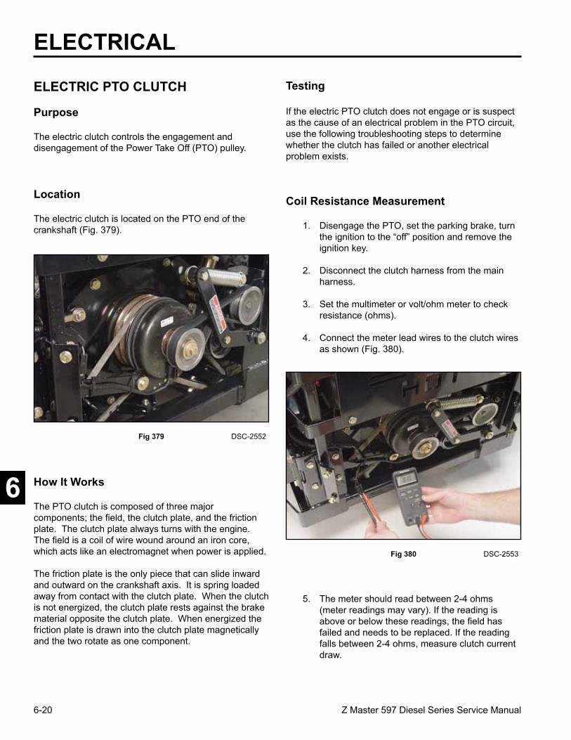
6-20 Z Master 597 Diesel Series Service Manual
6
ELECTRICAL
Testing
If the electric PTO clutch does not engage or is suspect as the cause of an electrical problem in the PTO circuit, use the following troubleshooting steps to determine whether the clutch has failed or another electrical problem exists.
1. Disengage the PTO, set the parking brake, turn the ignition to the “off” position and remove the ignition key.
2. Disconnect the clutch harness from the main harness.
3. Set the multimeter or volt/ohm meter to check resistance (ohms).
4. Connect the meter lead wires to the clutch wires as shown (Fig. 380).
Fig 380 DSC-2553
Fig 379 DSC-2552
The electric clutch is located on the PTO end of the crankshaft (Fig. 379).
The electric clutch controls the engagement and disengagement of the Power Take Off (PTO) pulley.
Purpose
ELECTRIC PTO CLUTCH
Location
The PTO clutch is composed of three major components; the field, the clutch plate, and the friction plate. The clutch plate always turns with the engine. The field is a coil of wire wound around an iron core, which acts like an electromagnet when power is applied.
The friction plate is the only piece that can slide inward and outward on the crankshaft axis. It is spring loaded away from contact with the clutch plate. When the clutch is not energized, the clutch plate rests against the brake material opposite the clutch plate. When energized the friction plate is drawn into the clutch plate magnetically and the two rotate as one component.
How It Works
Coil Resistance Measurement
5. The meter should read between 2-4 ohms (meter readings may vary). If the reading is above or below these readings, the field has failed and needs to be replaced. If the reading falls between 2-4 ohms, measure clutch current draw.

6-21Z Master 597 Diesel Series Service Manual
6
ELECTRICAL
1. Disengage the PTO, set the parking brake, turn the ignition key to OFF, and remove the key.
2. Loosen 4 bolts and remove the rear bumper plate.
3. Disconnect the PTO clutch harness from the main harness.
4. Set the multimeter to check amps (10 amp scale).
5. Connect the positive meter lead to terminal (1) of the main harness (Fig. 381).
Measuring Clutch Current Draw
Fig 381 diag 3-7
6. Connect the negative meter lead to the clutch harness terminal (3), Fig. 381.
8. Turn the ignition switch to the “RUN” position. Turn the PTO switch to the “ON” position.
9. If the meter reading is 3.5 amps or above, the system is functioning properly. If the meter reading is below 3.5 amps, check the electrical system for problems (i.e., the battery, ignition switch. PTO switch, or wiring harness). Make sure the negative side of the wiring has a good connection to chassis ground.
Fig 382 diag 3-7
7. Connect a short jumper lead from terminal (2) to terminal (4) (Fig. 382).

6-22 Z Master 597 Diesel Series Service Manual
6
ELECTRICAL
The fuel filter water sensor activates when too much water has accumulated in the water separator fuel filter. A warning light on the control panel indicates the need for fuel filter service.
FUEL FILTER SENSOR
Purpose
Fig 383 DSC-2565
The fuel filter, with the fuel filter sensor, is located under the seat, on the left side of the unit. The fuel filter sensor is located under the fuel filter (Fig. 383).
How It Works
Fig 384 DSC-2566
The fuel filter sensor is a float type switch. Water is heavier than fuel and when water accumulates in the base of the sensor, a float raises and closes off a set of contacts. This completes the ground to the indicator light located on the control panel (Fig. 384).
1. There are two wires located at the bottom of the fuel filter sensor.
Location
Testing

6-23Z Master 597 Diesel Series Service Manual
6
Meter reads “CLOSED” (continuity)Float in raised position
3. With the meter probes still on the wires of the sensor, raise the float upwards, you should have continuity (Fig. 386).
Fig 386 fuel filter sensor raised
ELECTRICAL
Fig 385 fuel filter sensor down
Meter reads “OPEN”Float in “down” position
2. Set the multimeter to read continuity. Place the meter probes on each wire. With the float at the bottom of the sensor you should have NO Continuity (Fig. 385).

6-24 Z Master 597 Diesel Series Service Manual
6
ELECTRICAL

6-25Z Master 597 Diesel Series Service Manual
6
ELECTRICAL
+
+
_
+
_

6-26 Z Master 597 Diesel Series Service Manual
6
THIS PAGE INTENTIONALLY LEFT BLANK.
ELECTRICAL

7-1Z Master 597 Diesel Series Service Manual
6
5
4
3
2
MOWER DECKS
Safety Information . . . . . . . . .
Specifications . . . . . . . . . . .
Chassis . . . . . . . . . . . . . .
Hydraulic System . . . . . . . . .
Engine . . . . . . . . . . . . . . .
Electrical . . . . . . . . . . . . . .
Mower Decks . . . . . . . . . . . 7
1

7-2 Z Master 597 Diesel Series Service Manual
7
MOWER DECKS
Electric PTO Clutch Removal
1. Loosen the 4 bolts holding the rear bumper assem-bly and remove from the unit (Fig. 387).
Fig 387 DSC-2595
2. Pull the spring loaded idler down and remove the fan drive belt (Fig. 388).
Fig 388 DSC-2596
Fig 390 DSC-2598
4. Remove the bolt, spacer, washer, and nut retaining the extension spring to the top of the fan pump tension assembly (Fig. 390).
Fig 389 DSC-2597
3. Remove the bolt and nut retaining the idler pulley to the fan pump tension assembly (Fig. 389).

7-3Z Master 597 Diesel Series Service Manual
7
5. Disconnect the electric clutch harness from the wiring harness (Fig. 391).
Fig 391 DSC-2601
6. Remove the bolt, spacer, washers and nut retaining the clutch brake strap to the frame (Fig. 392).
Fig 392 DSC-2604
Fig 394 DSC-2651
8. Insert a 12” long 3/8” drive extension into the square hole of the idler bracket. Use a 3/8” drive ratchet on the extension and pull back to relieve spring tension on the idler bracket. Remove the mower drive belt from the spring loaded idler pulley and outer PTO clutch sheave (Fig. 394).
Fig 393 DSC-2650
7. On the left side of the unit is the spring loaded idler pulley for the mower drive belt. Note the square cut hole in the idler bracket (Fig. 393).
MOWER DECKS
Note: Rear tire removed for clarity.

7-4 Z Master 597 Diesel Series Service Manual
7
9. On the right side of the unit is the spring loaded idler pulley for the second mower drive belt. Insert a 3/8” drive ratchet with a 6” extension into the square cut hole in the idler bracket. Pull back on the ratchet to relieve tension on the belt. Slip the belt off the idler pulley and the PTO clutch (Fig. 395).
Fig 395 DSC-2607
10. Using an air impact wrench, loosen the center bolt retaining the pulley and the PTO clutch (Fig. 396).
Fig 396 DSC-2613
Fig 398 DSC-2615
12. Remove the electric PTO clutch from the crankshaft (Fig. 398).
Fig 397 DSC-2614
11. Use a wheel puller to remove the fan pump drive pulley from the PTO clutch (Fig. 397).
MOWER DECKS

7-5Z Master 597 Diesel Series Service Manual
7
PTO Clutch Installation
1. Apply anti-seize compound to the crankshaft (Fig. 399).
Fig 399 DSC-2616
2. Install the PTO clutch on the crankshaft (Fig. 400).
Fig 400 DSC-2617
Fig 402 DSC-2619
4. Install drive pulley; make sure the square key is in the pulley (Fig. 402).
Fig 401 DSC-2618
3. Slide the spacer on the crankshaft (Fig. 401).
MOWER DECKS

7-6 Z Master 597 Diesel Series Service Manual
7
MOWER DECKS5. The retention hardware for the electric clutch is: a
bolt, 2 spring washers, and a large washer (Fig. 403).
Fig 403 DSC-2620
6. Apply a thread locking compound to the bolt. Install bolt and hardware to the crankshaft. Torque the bolt 65 ft. lbs (88.13 Nm) (Fig. 404).
Fig 404 DSC-2621 Fig 406 DSC-2650
8. On the left side, insert a 3/8” drive ratchet with a 12” extension in the square hole in the idler bracket (Fig. 406). Pull back to relieve the tension on the idler arm.
Fig 405 DSC-2607
7. Install the right side mower drive belt. Insert a 3/8” drive ratchet with a 6” extension into the square hole in the idler bracket. Pull back to relieve the tension on the idler arm and slip the belt on the inner sheave of the electric clutch drive pulley (Fig. 405).
A. Bolt B. 2 Spring WashersC. Large Washer
A B C
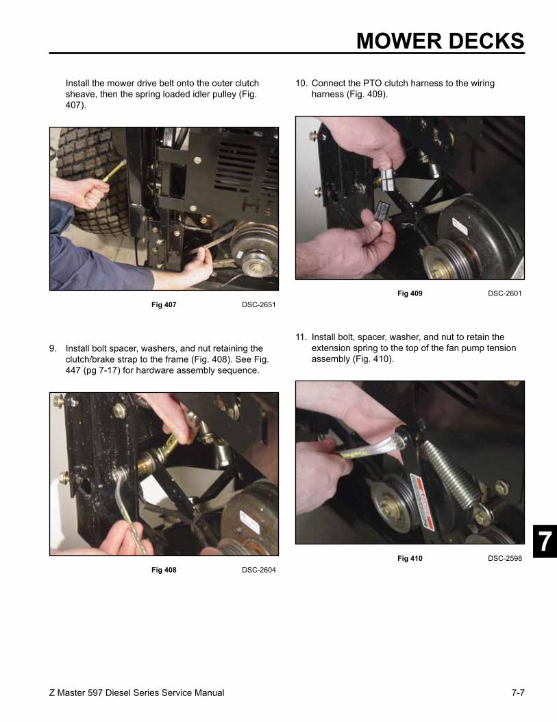
7-7Z Master 597 Diesel Series Service Manual
7
MOWER DECKS Install the mower drive belt onto the outer clutch
sheave, then the spring loaded idler pulley (Fig. 407).
Fig 407 DSC-2651
9. Install bolt spacer, washers, and nut retaining the clutch/brake strap to the frame (Fig. 408). See Fig. 447 (pg 7-17) for hardware assembly sequence.
Fig 408 DSC-2604 Fig 410 DSC-2598
11. Install bolt, spacer, washer, and nut to retain the extension spring to the top of the fan pump tension assembly (Fig. 410).
Fig 409 DSC-2601
10. Connect the PTO clutch harness to the wiring harness (Fig. 409).
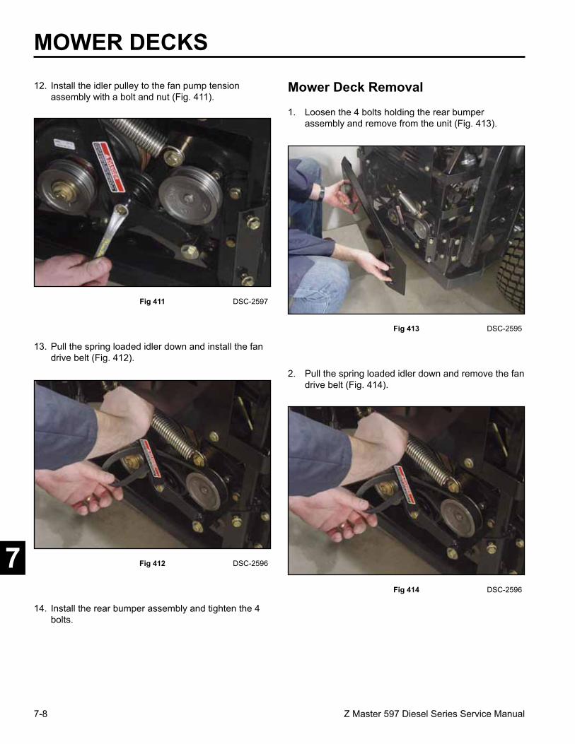
7-8 Z Master 597 Diesel Series Service Manual
7
MOWER DECKS12. Install the idler pulley to the fan pump tension
assembly with a bolt and nut (Fig. 411).
Fig 411 DSC-2597
13. Pull the spring loaded idler down and install the fan drive belt (Fig. 412).
Fig 412 DSC-2596
Fig 414 DSC-2596
2. Pull the spring loaded idler down and remove the fan drive belt (Fig. 414).
Fig 413 DSC-2595
1. Loosen the 4 bolts holding the rear bumper assembly and remove from the unit (Fig. 413).
14. Install the rear bumper assembly and tighten the 4 bolts.
Mower Deck Removal
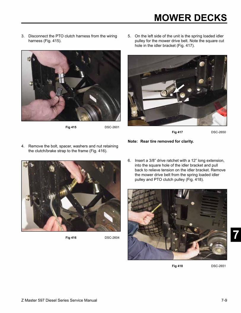
7-9Z Master 597 Diesel Series Service Manual
7
3. Disconnect the PTO clutch harness from the wiring harness (Fig. 415).
Fig 415 DSC-2601
4. Remove the bolt, spacer, washers and nut retaining the clutch/brake strap to the frame (Fig. 416).
Fig 416 DSC-2604
Fig 418 DSC-2651
6. Insert a 3/8” drive ratchet with a 12” long extension, into the square hole of the idler bracket and pull back to relieve tension on the idler bracket. Remove the mower drive belt from the spring loaded idler pulley and PTO clutch pulley (Fig. 418).
Fig 417 DSC-2650
5. On the left side of the unit is the spring loaded idler pulley for the mower drive belt. Note the square cut hole in the idler bracket (Fig. 417).
MOWER DECKS
Note: Rear tire removed for clarity.

7-10 Z Master 597 Diesel Series Service Manual
7
7. On the right side of the unit is the spring loaded idler pulley for the inner mower drive belt. Insert a 3/8” ratchet drive with a 6” extension into the square hole in the idler bracket. Pull back on the ratchet to relieve tension on the belt. Slip the belt off the idler pulley and the PTO clutch pulley (Fig. 419).
Fig 419 DSC-2607
8. Lift the floor pan (Fig. 420).
Fig 420 DSC-2625
Fig 422 DSC-2628
10. Remove the tension spring on the idler arm (Fig. 422).
Fig 421 DSC-2626
9. Remove the right side belt cover (Fig. 421).
MOWER DECKS

7-11Z Master 597 Diesel Series Service Manual
7
11. Remove the mower spindle belt from the top groove of the jackshaft sheave pulley (Fig. 423).
Fig 423 DSC-2629
12. Remove both the left and right mower drive belts from the jackshaft sheave (Fig. 424).
Fig 424 DSC-2630
Fig 426 DSC-2631
14. Remove the front and rear lift chains from the right side of the mower deck (Fig. 426).
Fig 425 DSC-2623
13. Raise the mower deck to the transport position. Install a 4 x 4 wood block under the right side of the mower deck. Lower the deck to relieve tension on the lift chains on the right side (Fig. 425).
MOWER DECKS

7-12 Z Master 597 Diesel Series Service Manual
7
MOWER DECKS15. Remove the bolt and nut holding the right rear strut
pin from the strut assembly (Fig. 427).
Fig 427 DSC-2632
16. Remove the strut pin from the strut assembly and remove the assembly from the mower deck (Fig. 428).
Fig 428 DSC-2633
Fig 430 DSC-2636
18. Push the lift handle to the lowest HOC position to overcome the tension of the lift assist springs. Use the hitch pin above the lift handle to lock the handle in the down position (Fig. 430).
Fig 429 DSC-2635
17. Raise the deck to transport position. Install a 4 x 4 wood block under the left side of the mower deck. Lower the mower deck until it rests on the block of wood to relieve tension on the lift chains (Fig. 429).
Tie strap the strut assembly up so it will be out of the way of the mower deck when sliding it out under the frame. Remove the 4 x 4 block of wood from the right side of the deck and allow the deck to sit on the floor.

7-13Z Master 597 Diesel Series Service Manual
7
MOWER DECKS19. Follow steps 8 through 10 on the left side of the
mower deck.
20. Remove the 4 x 4 wood block from under the left side of the mower deck and lower the deck to the floor.
21. Turn the right front wheel so the caster fork is angled forward. This will allow more clearance to slide the mower deck from under the frame (Fig. 431).
Fig 431 DSC-2637
22. Slide the mower deck out the right side of the unit (Fig. 432).
Fig 434 DSC-2639
3. Install the strut pin through the strut assembly and install the bolt and nut (Fig. 434).
Fig 433 DSC-2635
1. Slide the mower deck under the unit.
2. Install a 4 x 4 wood block under the left side of the mower deck (Fig. 433).
Fig 432 DSC-2638
Mower Deck Installation

7-14 Z Master 597 Diesel Series Service Manual
7
MOWER DECKS4. Install the rear and front lift chains to the mower
deck (Fig. 435).
Fig 435 DSC-2640
5. Remove the hitch pin on the lift handle and raise the mower in the transport position.
6. Install a 4 x 4 wood block under the right side of the mower deck.
7. Lower the mower deck down on the wood block.
8. Install the strut pin in the strut assembly. Install and tighten the bolt and nut.
9. Install the rear and front lift chains to the mower deck.
10. Raise the mower deck and remove the wood block from under the mower.
Fig 437 DSC-2642
12 Install the left mower drive belt on the middle sheave of the jackshaft pulley (Fig. 437).
Fig 436 DSC-2641
11. Install the right mower drive belt on the bottom sheave of the jackshaft pulley (Fig. 436).

7-15Z Master 597 Diesel Series Service Manual
7
13. Install the mower spindle belt around the idler pulleys and the top sheave of the jackshaft pulley (Fig. 438).
Fig 438 DSC-2643
14. Install the tension spring on the idler arm (Fig. 439).
Fig 439 DSC-2645
Fig 441 DSC-2646
Fig 440 fig. 74 m-7404
15. Install the right side belt cover (Fig. 440).
MOWER DECKS
16. Install the RH drive belt over the PTO clutch and around the inner drive sheave of the clutch (Fig. 441).
1. Drive belt 4. Adjustable idler pulley2. Clutch 5. Three stacked pulleys3. Spring loaded idler 6. Mower belt pulley

7-16 Z Master 597 Diesel Series Service Manual
7
MOWER DECKS17. Install the RH drive belt around the fixed idler
sheave. Insert a 3/8” drive ratchet with 6” extension into the 3/8” square hole in the idler arm. Pull toward the back of the machine to overcome the idler spring tension. Slip the RH drive belt over idler pulley and slowly release the idler arm (Fig. 442).
Note: Be sure the belt orientation is correct per Fig. 443.
Fig 442 DSC-2648
Fig 445 DSC-2651
21. Pull back to relieve idler spring tension. Install the mower drive belt on the spring loaded idler pulley and the outer sheave of PTO pulley. Release the idler arm slowly (Fig. 445).
Fig 444 DSC-2650
18. Install the LH drive belt over the electric PTO clutch and around the outer drive pulley.
19. Install the LH drive belt around the fixed idler pulley only.
20. On the left, insert a 3/8” drive ratchet with a 12”
extension into the square hole in the idler bracket (Fig. 444).
Fig 443 fig. 74 m-7404
1. Belt drive 4. Adjustable idler pulley2. Clutch 5. Three stacked pulleys3. Spring loader idler 6. Mower belt pulley

7-17Z Master 597 Diesel Series Service Manual
7
23. Connect the PTO clutch harness to the wiring harness plug (Fig. 448).
22. Install the bolt, spacer, washers, and nut holding the clutch/brake strap to the frame (Fig. 446).
Fig 446 DSC-2488
Follow the hardware sequence in the diagram (Fig. 447).
Fig 447 deck belt drive a Fig 449 DSC-2596
24. Pull the spring loaded idler down and install the fan drive belt (Fig. 449).
Fig 448 DSC-2601
MOWER DECKS
A B
CD
EF
G
B
A. Nut - lock E. Spacer, largeB. Washer, large F. Washer, flatC. Spacer G. Screw, HHD. Grommet, brake

7-18 Z Master 597 Diesel Series Service Manual
7
25. Install the rear bumper assembly and tighten the 4 bolts (Fig. 450).
MOWER DECKS
Mower Spindle Removal
Fig 450 DSC-2595
Fig 451 DSC-2625
This applies to removing any of the three mower spindles. This procedure shows removing the right side spindle.
1. Use a hoist or the Z Stand to raise the front of the mower deck.
2. Chock or block the drive wheels.
3. Disconnect the battery negative cable.
4. Lower the mower deck to the lowest position.
5. Lift the floor pan (Fig. 451).

7-19Z Master 597 Diesel Series Service Manual
7
6. Remove the right side belt cover (Fig. 452).
Fig 452 DSC-2626
7. Remove the tension spring on the idler arm (Fig. 453).
Fig 453 DSC-2628 Fig 455 DSC-2662
9. Remove three bolts retaining the pulley to the pulley hub (Fig. 455).
Fig 454 DSC-2661
8. Remove the mower spindle drive belt (Fig. 454).
MOWER DECKS

7-20 Z Master 597 Diesel Series Service Manual
7
Mower Spindle Disassembly
1. Remove the nut and washer (Fig. 457).
Fig 457 DSC-2669
2. Remove the pulley hub and square key (Fig. 458).
Fig 458 DSC-2670
MOWER DECKS10. Raise the mower deck to the transport position.
11. Remove the mower blade from the spindle assembly.
12. Remove the 6 bolts and nuts from the spindle assembly. Remove the spindle assembly (Fig. 456).
Note: Early production units did not have nuts on the bolts holding the spindle to the mower deck, It is recommended to install flange nuts to all of the bolts retaining the spindles to the mower deck.
Fig 456 DSC-2666
Reverse the order of mower spindle removal.
Mower Spindle Installation

7-21Z Master 597 Diesel Series Service Manual
7 Fig 460 DSC-2672
4. Remove the spindle housing from the spindle shaft assembly (Fig. 460).
Fig 459 DSC-2671
3. Remove the bearing shield (Fig. 459).
MOWER DECKS5. Remove the seal spacer from the top of the spindle
housing (Fig. 461).
Fig 461 DSC-2673
6. Remove the seal spacer from the bottom of the spindle housing (Fig. 462).
Fig 462 DSC-2674

7-22 Z Master 597 Diesel Series Service Manual
7
9. Remove the spacer (Fig. 465).
Fig 465 DSC-2677
10. Remove the split ring (Fig. 466).
Fig 466 DSC-2678
MOWER DECKS
Fig 464 DSC-2676
8. Remove the tapered roller bearing from the top of the spindle housing (Fig. 464).
Fig 463 DSC-2675
7. Remove the top oil seal from the spindle housing (Fig. 463).

7-23Z Master 597 Diesel Series Service Manual
7 Fig 468 DSC-2680
12. Remove the tapered roller bearing from the bottom of the spindle (Fig. 468).
Fig 467 DSC-2679
11. Turn the spindle housing over and remove the oil seal from the bottom of the spindle housing (Fig. 467). Note the orientation of the lower oil seal. The open end of the seal faces outwards to help relieve pressure from over-greasing the spindle assembly.
MOWER DECKS13. Using a hammer and a driver with a square edge,
drive both the top and bottom bearing races out of the spindle housing (Fig. 469).
Fig 469 DSC-2681
14. Remove the large spacer in the spindle housing (Fig. 470).
Fig 470 DSC-2682

7-24 Z Master 597 Diesel Series Service Manual
7
Mower Spindle Assembly
1. Install the spacer through the top of the spindle housing (Fig. 472).
Fig 472 DSC-2688
2. Using a press, install the upper bearing race into the spindle housing (Fig. 473).
Note: The wider inside diameter of the bearing race should be facing up to accept the tapered bearing.
Fig 473 DSC-2689
MOWER DECKS
A. Bearing Race B. Spacer
Fig 471 DSC-2684
15. This view shows the 2 bearing races and the large spacer in the spindle housing (Fig. 471). Note the internal snap ring in the housing; it is not necessary to remove it when installing new bearing races and the spacer.
AB
A

7-25Z Master 597 Diesel Series Service Manual
7
MOWER DECKS
Fig 476 DSC-2692
5. Install the lower seal (Fig. 476).
Note: The open lip of the seal should be facing outward.
Fig 474 DSC-2690
3. Turn the spindle housing over and install the lower bearing race into the spindle housing (Fig. 474).
Note: The wider inside diameter of the bearing race should be facing up to accept the tapered bearing.
Fig 475 DSC-2691
4. Pack the tapered bearing with #2 grease and install the tapered bearing (Fig. 475).
6. Using a seal driver, drive or press the seal on the lower end of the spindle housing until the seal is flush with the outer edge of the housing (Fig. 477).
Fig 477 DSC-2693

7-26 Z Master 597 Diesel Series Service Manual
7
10. Install the seal. Press it flush with the top of the housing (Fig. 481).
Note: The open lip of the seal faces inward.
Fig 481 DSC-2696
MOWER DECKS7. Turn the spindle assembly over and install the split
ring spacer (Fig. 478).
Fig 478 DSC-2699 Fig 480 DSC-2694
9. Pack the tapered bearing with #2 grease and install the tapered bearing (Fig. 480).
Fig 479 DSC-2700
8. Install the inner spacer to the spindle assembly (Fig. 479).

7-27Z Master 597 Diesel Series Service Manual
7
11. Install the bearing shield and the seal spacer onto the spindle shaft (Fig. 482).
Fig 482 DSC-2702 Fig 484 DSC-2704
13. Install the seal spacer on the top of the spindle housing (Fig. 484).
Fig 483 DSC-2703
12. Lower the spindle housing over the spindle shaft (Fig. 483).
MOWER DECKS
14. Install bearing shield (Fig. 485).
Fig 485 DSC-2705

7-28 Z Master 597 Diesel Series Service Manual
7
18. Torque the top nut to 100 to 120 ft-lbs. (135.58 to 162.7 Nm) (Fig. 489).
Fig 489 DSC-2709
Fig 487 DSC-2707
16. Install the pulley hub on the spindle shaft (Fig. 487).
15. Install the square key onto the spindle shaft (Fig. 486).
Fig 486 DSC-2706
Fig 488 DSC-2708
17. Install the heavy washer and nut on the top of the spindle shaft (Fig. 488).
Note: The cup side of the washer should be facing down toward the pulley hub.
MOWER DECKS
19. Grease the spindle assembly using a grease gun with #2 grease.

7-29Z Master 597 Diesel Series Service Manual
7
Mower Jackshaft Assembly Removal
Fig 491 DSC-2626
4. Remove the right side belt cover (Fig. 491).
Fig 490 DSC-2625
1. Raise the rear of the machine and chock or block the front wheels.
2. Disconnect the battery negative cable.
3. Raise the floor pan (Fig. 490).
MOWER DECKS5. Remove the tension spring on the idler arm (Fig.
492).
Fig 492 DSC-2628
6. Remove the mower spindle belt from the top sheave of the jackshaft pulley (Fig. 493).
Fig 493 DSC-2629

7-30 Z Master 597 Diesel Series Service Manual
7
9. Insert a 3/8” drive ratchet with a 12” long extension into the square hole of the idler bracket. Pull back on the idler arm to relieve tension on the belt. Remove the mower drive belt from the spring loaded idler pulley (Fig. 496).
Fig 496 DSC-2651
10. On the right side of the unit is the spring loaded idler pulley for the inner mower drive belt. Insert a 3/8” drive ratchet with a 6” long extension into the square hole in the idler bracket. Pull back on the idler arm to relieve tension on the belt and slip the belt off the idler pulley (Fig. 497).
Fig 497 DSC-2607
MOWER DECKS
Fig 495 DSC-2650
8. On the left side of the unit is the spring loaded idler pulley for the mower drive belt. Note the square cut hole in the idler bracket (Fig. 495).
Fig 494 DSC-2595
7. Loosen the 4 bolts holding the rear bumper assembly and remove from the unit (Fig. 494).
Note: Rear tire removed for clarity.

7-31Z Master 597 Diesel Series Service Manual
7
MOWER DECKS
Fig 499 DSC-2712
14. Remove the remaining two bolts and washers retaining the jackshaft assembly to the rear deck bracket (Fig. 499).
Fig 498 DSC-2711
11. Lower the mower deck to the lowest cutting position.
12. Remove the right and left mower drive belts from the jackshaft pulley.
13. Remove the two bolts and washers retaining the jackshaft belt guide and the jackshaft assembly to the rear mower bracket (Fig. 498).
Mower Jackshaft Installation
15. Remove the jackshaft assembly from the mower deck (Fig. 500).
Fig 500 DSC-2713
Reverse the order of removal.
Note: The four washers holding the jackshaft assembly are Belleville washers. Make sure the cup side of the washers are facing the mower bracket before tightening.

7-32 Z Master 597 Diesel Series Service Manual
7
Mower Jackshaft and Pulley AssemblyThe jackshaft housing and bearings are not available as separate components. Listed below is a view of the components of the jackshaft and pulley assembly (Fig. 501).
Fig 501 DSC-2714
A. Retaining Nut D. Jackshaft AssemblyB. Spring Washer E. Jackshaft PulleyC. Bottom Spacer F. Jackshaft Guard
Fig 503 DSC-2607
2. Remove the right side mower drive belt by inserting a 3/8” drive ratchet with a 6” long extension into the square cut hole in the idler bracket. Pull back to relieve the tension on the belt. Slip the belt off the idler pulley (Fig. 503).
Fig 502 DSC-2595
1. Loosen the 4 bolts holding the rear bumper assembly and remove from the unit (Fig. 502).
Note: Item C., Bottom Spacer Guard is recessed. Make sure the recessed portion of the guard is facing the jackshaft bearing.
A B C DE
F
Right Hand Mower Idler Assembly Removal
MOWER DECKS
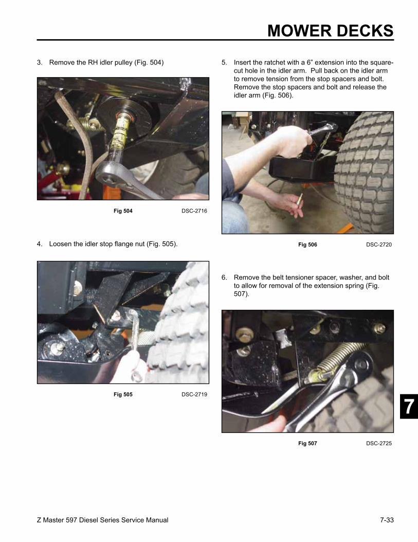
7-33Z Master 597 Diesel Series Service Manual
7
MOWER DECKS3. Remove the RH idler pulley (Fig. 504)
Fig 504 DSC-2716
4. Loosen the idler stop flange nut (Fig. 505).
Fig 505 DSC-2719
Fig 507 DSC-2725
6. Remove the belt tensioner spacer, washer, and bolt to allow for removal of the extension spring (Fig. 507).
Fig 506 DSC-2720
5. Insert the ratchet with a 6” extension into the square-cut hole in the idler arm. Pull back on the idler arm to remove tension from the stop spacers and bolt. Remove the stop spacers and bolt and release the idler arm (Fig. 506).

7-34 Z Master 597 Diesel Series Service Manual
7
7. Remove the RH idler bolt (Fig. 508).
Fig 508 DSC-2727
8. Remove the RH idler assembly (Fig. 509).
Fig 509 DSC-2730
Fig 510 DSC-2731
9. Inspect the sleeve bearing and bushing for any wear (Fig. 510).
MOWER DECKS
Right Hand Mower Idler Assembly Installation1. Install the right hand idler assembly (Fig. 511).
Fig 511 DSC-2727
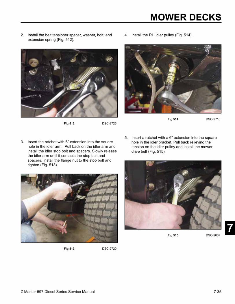
7-35Z Master 597 Diesel Series Service Manual
7
MOWER DECKS2. Install the belt tensioner spacer, washer, bolt, and
extension spring (Fig. 512).
Fig 512 DSC-2725 Fig 514 DSC-2716
4. Install the RH idler pulley (Fig. 514).
Fig 513 DSC-2720
3. Insert the ratchet with 6” extension into the square hole in the idler arm. Pull back on the idler arm and install the idler stop bolt and spacers. Slowly release the idler arm until it contacts the stop bolt and spacers. Install the flange nut to the stop bolt and tighten (Fig. 513).
Fig 515 DSC-2607
5. Insert a ratchet with a 6” extension into the square hole in the idler bracket. Pull back relieving the tension on the idler pulley and install the mower drive belt (Fig. 515).

7-36 Z Master 597 Diesel Series Service Manual
7
1. Loosen the 4 bolts holding the rear bumper assembly and remove from the unit (Fig. 517).
Fig 517 DSC-2595
2. On the left side of the unit is the spring loaded idler pulley for the mower drive belt; note the square hole in the idler bracket (Fig. 518).
Fig 518 DSC-2650 Fig 516 DSC-2595
6. Install the rear bumper assembly and tighten the 4 bolts (Fig. 516).
Left Hand Mower Idler Assembly Removal
Note: Rear tire removed for clarity.
MOWER DECKS
3. Insert a 3/8” drive ratchet with a 12” extension into the square hole in the idler bracket. Pull back to relieve tension on the idler bracket. Remove the mower drive belt from the idler pulley (Fig. 519).
Fig 519 DSC-2651

7-37Z Master 597 Diesel Series Service Manual
7
MOWER DECKS4. Relieve spring tension with the 3/8” ratchet drive to
allow for removal of the stop bolt, spacer, and nut (Fig. 520).
Fig 520 DSC-2735 Fig 522 DSC-2741
6. Remove the bolt and nut retaining the idler bracket to the frame (Fig. 522).
Fig 521 DSC-2737
5. Remove the bolt, spacer, 2 washers and nut on the stationary end of the tension spring toward the rear of the machine (Fig. 521).
7. Remove the left hand idler bracket (Fig. 523).
Fig 523 DSC-2742
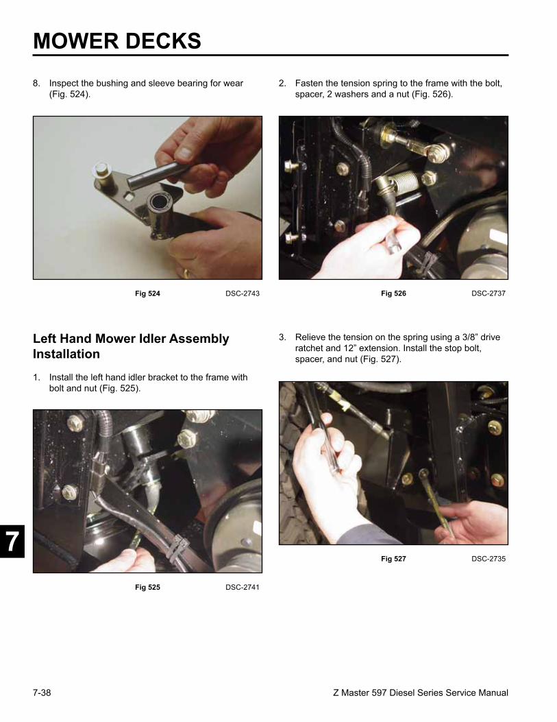
7-38 Z Master 597 Diesel Series Service Manual
7
Left Hand Mower Idler Assembly Installation
8. Inspect the bushing and sleeve bearing for wear (Fig. 524).
Fig 524 DSC-2743 Fig 526 DSC-2737
2. Fasten the tension spring to the frame with the bolt, spacer, 2 washers and a nut (Fig. 526).
Fig 525 DSC-2741
1. Install the left hand idler bracket to the frame with bolt and nut (Fig. 525).
MOWER DECKS
3. Relieve the tension on the spring using a 3/8” drive ratchet and 12” extension. Install the stop bolt, spacer, and nut (Fig. 527).
Fig 527 DSC-2735
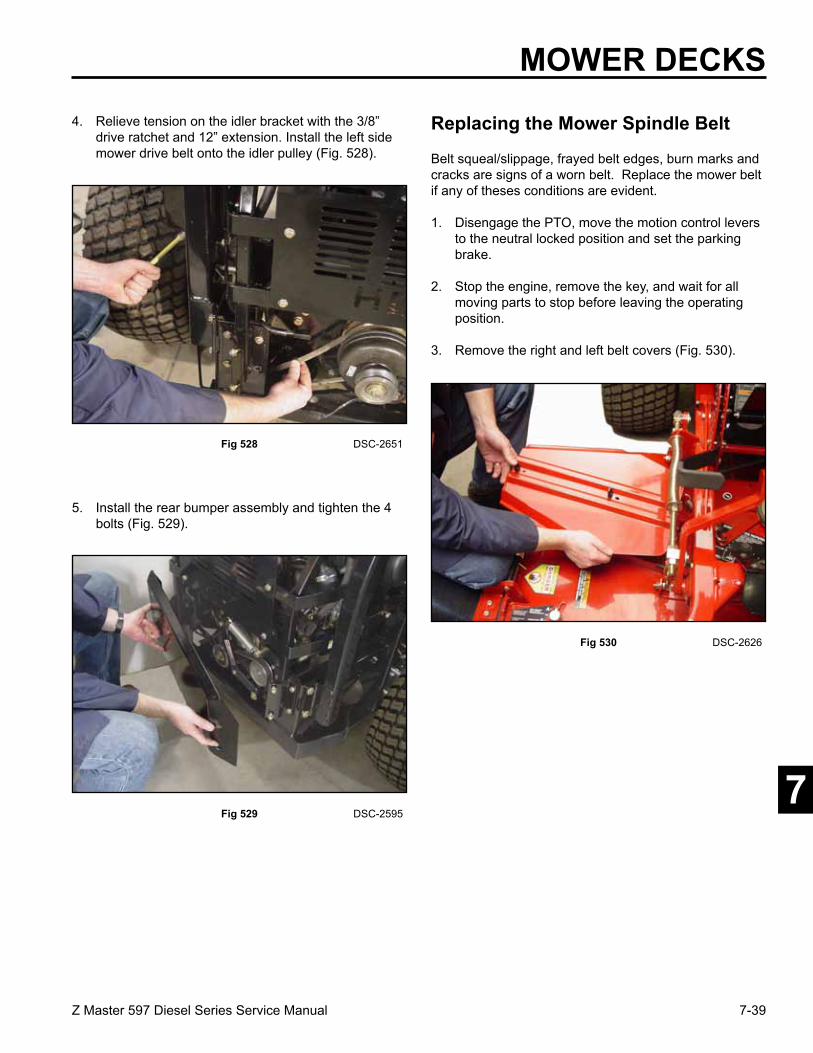
7-39Z Master 597 Diesel Series Service Manual
7
MOWER DECKS4. Relieve tension on the idler bracket with the 3/8”
drive ratchet and 12” extension. Install the left side mower drive belt onto the idler pulley (Fig. 528).
Fig 528 DSC-2651
Fig 529 DSC-2595
5. Install the rear bumper assembly and tighten the 4 bolts (Fig. 529).
Replacing the Mower Spindle Belt
Belt squeal/slippage, frayed belt edges, burn marks and cracks are signs of a worn belt. Replace the mower belt if any of theses conditions are evident.
1. Disengage the PTO, move the motion control levers to the neutral locked position and set the parking brake.
2. Stop the engine, remove the key, and wait for all moving parts to stop before leaving the operating position.
3. Remove the right and left belt covers (Fig. 530).
Fig 530 DSC-2626

7-40 Z Master 597 Diesel Series Service Manual
7 Fig 532 DSC-2628
5. Remove the tension spring on the idler arm (Fig. 532).
Fig 531 DSC-2625
4. Raise the floor pan (Fig. 531).
MOWER DECKS6. Remove the mower belt from the mower pulleys,
idler pulleys and the top groove of the triple sheave jackshaft pulley (Fig. 533).
Fig 533 fig. 71 m-7419
7. Install the new belt around the mower pulleys, idler pulleys and the top groove of the triple sheave jackshaft pulley (Fig. 534).
Fig 534 fig. 71 m-7419
1. Triple sheave pulley 3. Mower spindle pulley2. Mower belt 4. Mower idler pulleys
4
4

7-41Z Master 597 Diesel Series Service Manual
7
MOWER DECKS
Fig 536 fig. 72 m-7422
9. Install the belt covers and close the latches (Fig. 536).
Fig 535 DSC-2628
8. Install the tension spring on the idler arm (Fig. 535).
1. Belt cover 2. Latch
Replacing Mower Drive Belts
Note: Remove the mower spindle belt first. If any of the primary drive belts need to be replaced, see Replacing the Mower Spindle Belt, page 7-39.
1. Disengage the PTO, move the motion control levers to the neutral locked position and set the parking brake.
2. Stop the engine, remove the key, and wait for all moving parts to stop before leaving the operating position.
3. Loosen the 4 bolts holding the rear bumper assembly and remove from the unit (Fig. 537).
Fig 537 DSC-2595

7-42 Z Master 597 Diesel Series Service Manual
7 Fig 539 DSC-2601
5. Disconnect the PTO clutch harness from the wiring harness (Fig. 539).
Fig 538 DSC-2596
4. Pull the spring loaded idler down and remove the fan drive belt (Fig. 538).
MOWER DECKS6. Remove the bolt, spacer, washers, and nut retaining
the clutch/brake strap to the frame (Fig. 540).
Fig 540 DSC-2604
7. There is a 3/8” square hole in the idler arm on the LH side of the machine (Fig. 541).
Fig 541 DSC-2650
Note: Rear tire removed for clarity.

7-43Z Master 597 Diesel Series Service Manual
7
MOWER DECKS
Fig 543 DSC-2607
9. Insert a 3/8” drive ratchet with a 6” extension into the square hole in the RH idler bracket. Pull back on the idler arm to relieve tension on the belt. Slip the belt off the idler pulleys and the PTO clutch (Fig. 543).
Fig 542 DSC-2651
8. Insert a 3/8” drive ratchet with a 12” extension into the square hole of the idler bracket and pull back to relieve tension on the idler bracket. Remove the mower drive belt from the spring loaded idler pulley, fixed idler pulley, and the PTO clutch (Fig. 542).
10. Raise the floor pan (Fig. 544).
Fig 544 DSC-2625
11. Remove the right side belt cover (Fig. 545).
Fig 545 DSC-2626

7-44 Z Master 597 Diesel Series Service Manual
7
14. Remove the drive belts from the jackshaft sheave pulley on the mower deck (Fig. 548).
Fig 548 DSC-2630
15. Install the new right mower drive belt on the bottom sheave of the jackshaft pulley, the adjustable idler pulley, and around the inner sheave of the PTO clutch pulley (Fig. 549).
Fig 549 fig. 74 m-7404
MOWER DECKS
1. Belt drive 4. Fixed idler pulley2. Clutch 5. Three stacked pulleys3. Spring loaded idler 6. Mower belt pulley
Fig 547 DSC-2629
13. Remove the mower spindle belt from the top groove of the jackshaft pulley (Fig. 547).
Fig 546 DSC-2628
12. Remove the tension spring (Fig. 546).

7-45Z Master 597 Diesel Series Service Manual
7 Fig 551 fig. 74 m-7404
17. Install the new left mower drive belt on the middle sheave of the jackshaft pulley, the adjustable idler pulley, and around the outer sheave of the PTO clutch pulley (Fig. 551).
Fig 550 DSC-2607
16. Insert a 3/8” drive ratchet with a 6” extension into the square hole in the RH idler bracket. Pull back to relieve tension on the idler bracket. Install the belt onto the idler pulley (Fig. 550)
MOWER DECKS
1. Belt drive 4. Fixed idler pulley2. Clutch 5. Three stacked pulleys3. Spring loaded idler 6. Mower belt pulley
18. Insert a 3/8” drive ratchet with a 12” extension into the square hole in the LH idler bracket. Pull back to relieve tension on the idler bracket. Install the new belt onto the idler pulley (Fig. 552).
Fig 552 DSC-2651
19. Install the bolt, spacer, washers, and nut retaining the clutch/brake strap to the frame (Fig. 553).
Fig 553 DSC-2604

7-46 Z Master 597 Diesel Series Service Manual
7
1. Position mower on a flat surface.
2. Disengage the PTO, move the motion control levers to the neutral locked position and set the parking brake.
3. Stop the engine, remove the key, and wait for all moving parts to stop before leaving the operating position.
4. Check the tire pressure of all four tires. If needed, adjust to 13 psi (90 kPa).
Leveling the Mower
22. Install the mower spindle belt; refer to Mower Spindle Belt, page 7-39.
23. Install the rear bumper and tighten the 4 bolts (Fig. 556).
Fig 556 DSC-2595
Setting up the Machine
MOWER DECKS20. Connect the electric PTO clutch harness to the
wiring harness (Fig. 554).
Fig 554 DSC-2601
21. Pull the spring loaded idler bracket down and install the fan pump drive belt (Fig. 555)
Fig 555 DSC-2596
7-47Z Master 597 Diesel Series Service Manual
7
MOWER DECKS5. Lower the mower to the 3 inch (76mm) height-of-cut
position.
6. Inspect the four chains. The chains need to have tension.
• If one rear chain is loose, lower (loosen) the front support arm on the same side. Refer to Adjusting the Front-to-Rear Mower Pitch on page 7-48.
• If one front chain is loose, raise (tighten) the front support arm for that chain. Refer to Front-to-Rear Mower Pitch on page 7-48.
Leveling the Mower Side-to-Side
1. Position the right blade side-to-side (Fig. 557).
Fig 557 fig. 65 m-1078
2. Measure the right blade at the B location (Fig. 557), from a level surface to the cutting edge of the blade tip (Fig. 558).
Fig 558 fig. 66 m-2539
3. Record this measurement. This measurement needs to be 3-1/8 to 3-1/4 inches (7.9 to 8.3cm).
4. Position the left blade side-to-side (Fig. 557).
5. Measure the left blade at the C location (Fig. 557) from level surface to cutting edge of the blade tips
(Fig. 558).
6. Record this measurement. The measurement needs to be 3-1/8 to 3-1/4 inches (7.9 to 8.3cm).
7-48 Z Master 597 Diesel Series Service Manual
7
MOWER DECKS7. If the measurement at positions B or C are not
correct, loosen the bolt attaching the rear chain support arm (Fig. 559).
8. Loosen the jam nut under the rear support arm and use the adjustment bolt to get a measurement of
3-1/8 to 3-1/4 inches (7.9 to 8.3cm).
Note: Ideally both sides of the mower are set to the same distance.
9. Tighten the jam nut under the rear support arm and tighten the bolt securing the chain to the rear support arm.
Fig 559 fig. 67 m-6830
1. Rear chain 5. Adjustment bolt2. Rear support arm 6. Front swivel3. Bolt 7. Front support arm4. Jam nut
Adjusting the Front-to-Rear Mower Pitch
1. Position the right blade front-to-rear (Fig. 560).
Fig 560 fig. 68 m-1078
2. Measure the right blade at the A location (Fig. 560), from a level surface to the cutting edge of the blade tip (Fig. 561).
Fig 561 fig. 69 m-2539
MEASURE FROM CUTTINGEDGE TO A LEVEL SURFACE

7-49Z Master 597 Diesel Series Service Manual
7
MOWER DECKS
Fig 562 fig. 70 m-6831a
3. Record the measurement.
4. Measure the right blade at the B location (Fig. 560) from a level surface to the cutting edge of the blade tip (Fig. 561).
5. Record this measurement.
6. The mower blade should be 1/4 to 3/8 inch (6 to 10mm) lower at position A than at position B (Fig. 560). If it is not correct, proceed to the following steps.
Note: Both of the front swivels need to be adjusted the same amount to maintain equal chain tension.
7. Loosen the front swivel jam nuts, at the front of the right and left swivels, approximately 1/2 inch (13mm) (Fig. 562 and Fig. 563).
4. Front swivel 6. Lift nut5. Swivel jam nut 7. Front support arm
Fig 563 fig. 70 m-6831 rev
8. Adjust the lift nuts on both the left and the right side of the machine (Fig. 562 and Fig. 563) to achieve 1/4 to 3/8 inch (6 to 10mm) lower in front A than in the rear at B (Fig. 560).
4. Front swivel 6. Lift nut5. Swivel jam nut 7. Front support arm
9. Tighten both swivel jam nuts against the front swivel to lock the height.
10. Check to make sure there is equal tension on chains and adjust again if needed.

7-50 Z Master 597 Diesel Series Service Manual
7
MOWER DECKS
1. Raise the mower lift lever to the transport position.
2. Check the distance between the two large washers, it needs to be 11-1/2 inches (29.2cm) (Fig. 564).
3. Adjust this distance, by loosening the spring jam nut and turning the nut in front of each spring (Fig. 564). Turning the nut clockwise will shorten the spring; counter-clockwise will lengthen the spring.
4. Lock the nut into position by tightening the spring jam nut (Fig. 564).
Adjusting the Compression Spring
Fig 564 fig. 70 m-6831
1. 11-1/2” (29.2cm) 4. Front swivel between the large 5. Swivel jam nut washers 6. Lift nut2. Front nut 7. Front support arm3. Spring jam nut 8. Large washer

Z Master Z597Diesel Series
Service Manual
Form No. 492-9150