yy jz 300/500v · yy – jz 300/500v vde-registeredoil-resistantpvccontrolcable...
TRANSCRIPT

05
.11
.20
20
/ W
e re
serv
e th
e rig
ht to
mak
e te
chni
cal c
hang
es; t
he im
prin
t in
the
imag
e is
pur
ely
exem
plar
y
TECHNICAL DATAPVC control and connection cable in alignment with DIN VDE 0285-525-2-51 / DIN EN 50525-2-51
Temperature range flexible -15°C to +80°C fixed -40°C to +80°C
Nominal voltage AC Uo/U 300/500 VTest voltage core/core 4000 VBreakdown voltage 8000 VMinimum bending radius flexible 7,5x Outer-Ø
fixed 4x Outer-Ø
n CABLE STRUCTURE• Copper wire bare, finely stranded acc. to DIN VDE 0295 class 5 /
IEC 60228 class 5• Core insulation: PVC, compound type Z 7225• Core identification acc. to DIN VDE 0293-334, black cores with
consecutive labeling in white digits• Protective conductor: starting with 3 cores,
G = with protective conductor GN-YE, in the outer layer, x = without protective conductor (OZ)
• Cores stranded in layers with optimal lay lengths• Outer sheath: PVC acc. to DIN VDE 0207-363-4-1 /
DIN EN 50363-4-1 (compound type TM2)• Sheath colour: grey (RAL 7001)• Length marking: in metres• Largely resistant to: oil, for details, see "Technical Information"• Conditionally suitable for drag chains• Conditionally torsional• The materials used during manufacturing are cadmium-free, con-
tain no silicone and are free from substances harmful to the wetting properties of lacquers
Part no. No. cores x cross-sec. mm²
AWG, approx.
Outer Ø mm,
approx.
Cu-weight kg/km
Weight kg/km,
approx.
10001 2 x 0.5 20 4.8 9.6 40.0
10002 3 G 0.5 20 5.1 14.4 46.0
10003 3 x 0.5 20 5.1 14.4 46.0
10004 4 G 0.5 20 5.5 19.0 56.0
10005 4 x 0.5 20 5.5 19.0 56.0
10006 5 G 0.5 20 6.2 24.0 65.0
10007 5 x 0.5 20 6.2 24.0 65.0
10008 6 G 0.5 20 6.7 29.0 75.0
10009 7 G 0.5 20 6.7 33.6 80.0
10010 7 x 0.5 20 6.7 33.6 80.0
10011 8 G 0.5 20 7.4 38.0 97.0
10172 8 x 0.5 20 7.4 38.0 97.0
10012 10 G 0.5 20 8.6 48.0 116.0
10013 12 G 0.5 20 9.1 58.0 135.0
10014 12 x 0.5 20 9.1 58.0 135.0
10015 14 G 0.5 20 9.5 67.0 150.0
10183 16 G 0.5 20 10.0 76.0 175.0
10016 18 G 0.5 20 10.7 86.0 196.0
10017 20 G 0.5 20 11.3 96.0 215.0
10018 21 G 0.5 20 11.3 101.0 240.0
10019 25 G 0.5 20 12.6 120.0 270.0
10020 30 G 0.5 20 13.5 144.0 310.0
10021 32 G 0.5 20 14.0 154.0 323.0
10022 34 G 0.5 20 14.7 163.0 362.0
Part no. No. cores x cross-sec. mm²
AWG, approx.
Outer Ø mm,
approx.
Cu-weight kg/km
Weight kg/km,
approx.
10023 40 G 0.5 20 15.3 192.0 434.0
10024 42 G 0.5 20 15.8 202.0 449.0
10025 50 G 0.5 20 17.3 240.0 513.0
10169 52 G 0.5 20 17.3 252.0 534.0
10026 61 G 0.5 20 18.5 293.0 625.0
10027 65 G 0.5 20 19.2 312.0 682.0
10028 80 G 0.5 20 21.3 384.0 780.0
10029 100 G 0.5 20 23.8 480.0 980.0
10030 2 x 0.75 19 5.3 14.4 46.0
10031 3 G 0.75 19 5.6 21.6 54.0
10032 3 x 0.75 19 5.6 21.6 54.0
10033 4 G 0.75 19 6.3 28.8 66.0
10034 4 x 0.75 19 6.3 28.8 66.0
10035 5 G 0.75 19 6.9 36.0 80.0
10036 5 x 0.75 19 6.9 36.0 80.0
10037 6 G 0.75 19 7.7 43.0 99.0
10177 6 x 0.75 19 7.7 43.0 99.0
10038 7 G 0.75 19 7.7 50.0 110.0
10039 7 x 0.75 19 7.7 50.0 110.0
10040 8 G 0.75 19 8.3 58.0 130.0
10173 8 x 0.75 19 8.3 58.0 130.0
10041 9 G 0.75 19 9.1 65.0 153.0
10042 10 G 0.75 19 9.8 72.0 162.0
10043 12 G 0.75 19 10.1 86.0 179.0
Continued on next page
YY – JZ 300/500V VDE-registered oil-resistant PVC control cable
n APPLICATIONUsed for flexible applications involving medium mechanical stress with free movement, without tensile stress and without forced motion control in dry, damp and wet rooms, however, not suitable for outdoor use. Used as a connection and control cable in machine tools, assembly lines and conveyor belts, production lines, in plant construction, air-conditioning technology, in smelters and steel mills. Select PVC compounds guarantee good flexibility, efficient and quick installation.
n NOTES• the conductor is metrically (mm²) constructed, AWG numbers are
approximated, and are for reference only• please note "cleanroom qualification" in your order• VDE-Reg.-No. 7032
n REGULATORY COMPLIANCE
[email protected] tel +44 (0)24 76543 291 fax +44 (0) 843 5240132

05
.11
.20
20
/ W
e re
serv
e th
e rig
ht to
mak
e te
chni
cal c
hang
es; t
he im
prin
t in
the
imag
e is
pur
ely
exem
plar
y
Part no. No. cores x cross-sec. mm²
AWG, approx.
Outer Ø mm,
approx.
Cu-weight kg/km
Weight kg/km,
approx.
10044 12 x 0.75 19 10.1 86.0 179.0
10045 14 G 0.75 19 10.8 101.0 214.0
10046 15 G 0.75 19 11.4 108.0 218.0
10047 18 G 0.75 19 12.2 130.0 257.0
10533 19 G 0.75 19 12.2 137.0 264.0
10048 20 G 0.75 19 12.8 144.0 286.0
10049 21 G 0.75 19 12.8 151.0 320.0
10050 25 G 0.75 19 14.3 180.0 365.0
10534 27 G 0.75 19 14.5 195.0 382.0
10051 32 G 0.75 19 15.9 230.0 455.0
10052 34 G 0.75 19 16.7 245.0 510.0
10182 37 G 0.75 19 16.7 266.0 537.0
10053 40 G 0.75 19 17.3 288.0 595.0
10054 41 G 0.75 19 18.1 296.0 607.0
10055 42 G 0.75 19 18.1 302.0 612.0
10056 50 G 0.75 19 19.8 360.0 735.0
10057 61 G 0.75 19 21.2 439.0 845.0
10178 65 G 0.75 19 22.0 468.0 895.0
10058 80 G 0.75 19 24.3 576.0 1070.0
10059 100 G 0.75 19 27.1 720.0 1322.0
10060 2 x 1 18 5.6 19.2 60.0
10061 3 G 1 18 6.1 29.0 72.0
10062 3 x 1 18 6.1 29.0 72.0
10063 4 G 1 18 6.6 38.0 86.0
10064 4 x 1 18 6.6 38.0 86.0
10065 5 G 1 18 7.5 48.0 104.0
10066 5 x 1 18 7.5 48.0 104.0
10067 6 G 1 18 8.1 58.0 125.0
10068 7 G 1 18 8.1 67.0 141.0
10069 7 x 1 18 8.1 67.0 141.0
10070 8 G 1 18 9.0 77.0 175.0
10071 9 G 1 18 9.8 86.0 200.0
10180 10 G 1 18 10.6 96.0 217.0
10170 10 x 1 18 10.6 96.0 217.0
10072 12 G 1 18 10.9 115.0 230.0
10073 12 x 1 18 10.9 115.0 230.0
10074 14 G 1 18 11.5 134.0 271.0
10075 16 G 1 18 12.3 154.0 300.0
10076 18 G 1 18 12.9 173.0 343.0
10174 18 x 1 18 12.9 173.0 343.0
10197 19 G 1 18 12.9 182.0 355.0
10077 20 G 1 18 13.8 192.0 375.0
10184 20 x 1 18 13.8 192.0 375.0
10179 21 G 1 18 13.8 205.0 420.0
10175 24 G 1 18 15.4 230.0 440.0
10078 25 G 1 18 15.4 240.0 485.0
10176 25 x 1 18 15.4 240.0 485.0
10196 26 G 1 18 15.4 252.0 500.0
10198 27 G 1 18 15.4 259.0 534.0
10168 30 x 1 18 16.5 288.0 550.0
10079 34 G 1 18 17.9 326.0 650.0
10080 36 G 1 18 17.9 346.0 668.0
10199 37 G 1 18 17.9 355.0 701.0
10081 40 G 1 18 18.6 384.0 755.0
10167 40 x 1 18 18.6 384.0 755.0
10082 41 G 1 18 19.4 394.0 770.0
10083 42 G 1 18 19.4 403.0 810.0
10084 50 G 1 18 21.3 480.0 936.0
10085 56 G 1 18 22.1 538.0 920.0
10086 61 G 1 18 22.7 586.0 1100.0
10087 65 G 1 18 23.6 628.0 1180.0
10088 80 G 1 18 26.3 768.0 1294.0
10089 100 G 1 18 29.3 960.0 1644.0
10090 2 x 1.5 16 6.4 29.0 70.0
10091 3 G 1.5 16 6.8 43.0 90.0
10092 3 x 1.5 16 6.8 43.0 90.0
Part no. No. cores x cross-sec. mm²
AWG, approx.
Outer Ø mm,
approx.
Cu-weight kg/km
Weight kg/km,
approx.
10093 4 G 1.5 16 7.6 58.0 109.0
10094 4 x 1.5 16 7.6 58.0 109.0
10095 5 G 1.5 16 8.3 72.0 131.0
10096 5 x 1.5 16 8.3 72.0 131.0
10097 6 G 1.5 16 9.2 86.0 157.0
10098 7 G 1.5 16 9.2 101.0 184.0
10099 7 x 1.5 16 9.2 101.0 184.0
10100 8 G 1.5 16 10.1 115.0 216.0
11007735 8 x 1.5 16 10.1 115.0 216.0
10101 9 G 1.5 16 11.1 129.0 259.0
10181 10 G 1.5 16 12.0 144.0 275.0
10102 11 G 1.5 16 12.0 158.0 300.0
10103 12 G 1.5 16 12.4 173.0 309.0
10104 12 x 1.5 16 12.4 173.0 309.0
10105 14 G 1.5 16 13.0 202.0 345.0
10106 16 G 1.5 16 13.9 230.0 386.0
10107 18 G 1.5 16 14.8 259.0 440.0
10185 19 G 1.5 16 14.8 279.0 445.0
10108 20 G 1.5 16 15.6 288.0 490.0
10109 21 G 1.5 16 15.6 302.0 555.0
10110 25 G 1.5 16 17.6 360.0 620.0
10535 27 G 1.5 16 17.6 389.0 670.0
10111 32 G 1.5 16 19.5 461.0 790.0
10112 34 G 1.5 16 20.2 490.0 830.0
10536 37 G 1.5 16 20.2 533.0 892.0
10113 41 G 1.5 16 22.1 591.0 996.0
10114 42 G 1.5 16 22.1 605.0 1007.0
10115 50 G 1.5 16 24.2 720.0 1250.0
10116 56 G 1.5 16 25.1 806.0 1332.0
10117 61 G 1.5 16 25.8 878.0 1440.0
10187 65 G 1.5 16 26.9 936.0 1602.0
10118 80 G 1.5 16 29.8 1152.0 1871.0
10119 100 G 1.5 16 33.2 1440.0 2353.0
10120 2 x 2.5 14 7.8 48.0 112.0
10121 3 G 2.5 14 8.3 72.0 148.0
10122 3 x 2.5 14 8.3 72.0 148.0
10123 4 G 2.5 14 9.2 96.0 178.0
10124 4 x 2.5 14 9.2 96.0 178.0
10125 5 G 2.5 14 10.1 120.0 221.0
10126 5 x 2.5 14 10.1 120.0 221.0
10127 7 G 2.5 14 11.2 168.0 306.0
10128 7 x 2.5 14 11.2 168.0 306.0
10129 8 G 2.5 14 12.3 192.0 363.0
11007736 8 x 2.5 14 12.3 192.0 363.0
10548 10 G 2.5 14 14.8 240.0 429.0
10130 12 G 2.5 14 15.3 288.0 498.0
10131 14 G 2.5 14 16.2 336.0 569.0
10132 18 G 2.5 14 18.2 432.0 764.0
10133 21 G 2.5 14 19.4 504.0 914.0
10134 25 G 2.5 14 21.6 600.0 1044.0
10135 34 G 2.5 14 25.2 816.0 1470.0
10136 42 G 2.5 14 27.3 1008.0 1790.0
10137 50 G 2.5 14 30.0 1200.0 2095.0
10138 61 G 2.5 14 32.2 1464.0 2750.0
10139 100 G 2.5 14 41.4 2400.0 4450.0
10140 2 x 4 12 9.2 77.0 195.0
10141 3 G 4 12 9.7 115.0 230.0
10142 4 G 4 12 10.8 154.0 295.0
10143 5 G 4 12 12.1 192.0 361.0
10144 7 G 4 12 13.4 269.0 458.0
10145 8 G 4 12 14.7 307.0 590.0
10549 10 G 4 12 17.6 384.0 687.0
10146 12 G 4 12 18.2 461.0 790.0
10147 3 G 6 10 11.9 173.0 355.0
10148 4 G 6 10 13.2 230.0 424.0
10149 5 G 6 10 14.7 288.0 525.0
Continued on next page
[email protected] tel +44 (0)24 76543 291 fax +44 (0) 843 5240132
YY – JZ 300/500V VDE-registered oil-resistant PVC control cable

05
.11
.20
20
/ W
e re
serv
e th
e rig
ht to
mak
e te
chni
cal c
hang
es; t
he im
prin
t in
the
imag
e is
pur
ely
exem
plar
y
Part no. No. cores x cross-sec. mm²
AWG, approx.
Outer Ø mm,
approx.
Cu-weight kg/km
Weight kg/km,
approx.
10150 7 G 6 10 16.2 403.0 625.0
10151 3 G 10 8 14.8 288.0 540.0
10152 4 G 10 8 16.4 384.0 701.0
10153 5 G 10 8 18.3 480.0 858.0
10154 7 G 10 8 20.2 672.0 1106.0
10190 3 G 16 6 18.4 461.0 827.0
10155 4 G 16 6 20.4 614.0 1035.0
10156 5 G 16 6 22.8 768.0 1259.0
10157 7 G 16 6 25.2 1075.0 1780.0
10191 3 G 25 4 22.4 720.0 1186.0
10158 4 G 25 4 25.1 960.0 1582.0
10159 5 G 25 4 27.9 1200.0 1999.0
10160 7 G 25 4 30.8 1680.0 2825.0
10192 3 G 35 2 25.2 1008.0 1585.0
Part no. No. cores x cross-sec. mm²
AWG, approx.
Outer Ø mm,
approx.
Cu-weight kg/km
Weight kg/km,
approx.
10161 4 G 35 2 27.9 1344.0 2105.0
10162 5 G 35 2 31.0 1680.0 2633.0
10193 3 G 50 1 29.9 1440.0 2550.0
10163 4 G 50 1 33.0 1920.0 2940.0
10188 5 G 50 1 37.0 2400.0 2936.0
10194 3 G 70 2/0 34.1 2016.0 3180.0
10164 4 G 70 2/0 37.9 2688.0 4090.0
10189 5 G 70 2/0 42.4 3360.0 5443.0
10195 3 G 95 3/0 39.6 2736.0 4680.0
10165 4 G 95 3/0 43.9 3648.0 5540.0
10333 5 G 95 3/0 49.0 4560.0 6931.0
10166 4 G 120 4/0 48.8 4608.0 7000.0
13139 4 G 150 300 kcmil 54.4 5760.0 8340.0
13140 4 G 185 350 kcmil 62.3 7104.0 9904.0
[email protected] tel +44 (0)24 76543 291 fax +44 (0) 843 5240132
YY – JZ 300/500V VDE-registered oil-resistant PVC control cable
ELECTRICAL CHARACTERISTICS Current Ratings – Table 1A - Current Carrying Capacity at 30°C
NOMINAL CROSS SECTIONAL AREA mm²
CURRENT RATING Amps
0.25 4 0.34 6 0.5 9
0.75 12 1.0 15 1.5 18 2.5 2.5
4 34 6 44
10 61 16 82 25 108 35 135 50 168 70 207 95 250
120 292 150 335 185 382 240 453 300 523
The above table is a guide extracted from DIN VDE 0298 Part 4 and DIN 0100 Part 430 (2003-08 Table 11 Column 5)

YY – JZ 300/500V VDE-registered oil-resistant PVC control cable
Nominal cross-
section in mm2
Conductor resistances at 20 °C for 1 km in Ω (max. value) Made of wires with metal sheath Made of bare wires
Class 2 Class 5 + 6 Class 2 Class 5 + 6
0.14 142.0 138.0 0.25 82.0 79.0 0.34 59.0 57.0 0.38 52.8 48.5 0.5 36.7 40.1 36.0 39.0 0.75 24.8 26.7 24.5 26.0 1 18.2 20.0 18.1 19.5 1.5 12.2 13.7 12.1 13.3 2.5 7.56 8.21 7.41 7.98 4 4.70 5.09 4.61 4.95 6 3.11 3.39 3.08 3.30 10 1.84 1.95 1.83 1.91 16 1.16 1.24 1.15 1.21 25 0.734 0.795 0.727 0.780 35 0.529 0.565 0.524 0.554 50 0.391 0.393 0.387 0.386 70 0.270 0.277 0.268 0.272 95 0.195 0.210 0.193 0.206 120 0.154 0.164 0.153 0.161 150 0.126 0.132 0.124 0.129 185 0.100 0.108 0.0991 0.106 240 0.0762 0.0817 0.0754 0.0801
The above table is in accordance with BS EN 60228 (previously BS 6360)
Table 1B – Conductor Resistances
Table 1C – Correction Factors For Multi core cables with conductor cross-sections up to 10mm²
Number of cores under load Conversion factor for installation in the open air
Conversion factor for installation underground
5 0.75 0.70
7 0.65 0.60
10 0.55 0.50
14 0.50 0.45
19 0.45 0.40
24 0.40 0.35
40 0.35 0.30
61 0.30 0.25
The above table is a guide extracted from DIN VDE 0298 Part 4 (2003-08 Table 26)
[email protected] tel +44 (0)24 76543 291 fax +44 (0) 843 5240132
BYSl)n YY – JZ 300/500V VDE-registered oil-resistant PVC control cable
[email protected] tel +44 (0)24 76543 291 fax +44 (0) 843 5240132
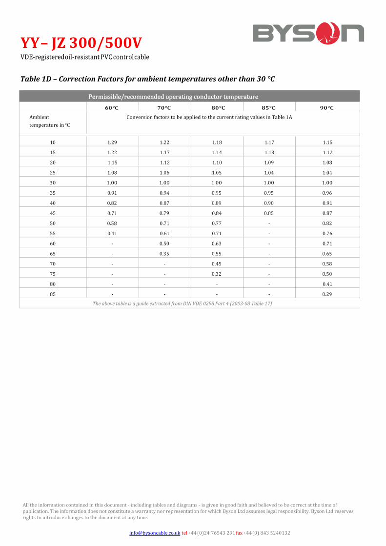
Permissible/recommended operating conductor temperature
60 °C 70 °C 80 °C 85 °C 90 °C
Ambient temperature in °C
Conversion factors to be applied to the current rating values in Table 1A
10 1.29 1.22 1.18 1.17 1.15
15 1.22 1.17 1.14 1.13 1.12
20 1.15 1.12 1.10 1.09 1.08
25 1.08 1.06 1.05 1.04 1.04
30 1.00 1.00 1.00 1.00 1.00
35 0.91 0.94 0.95 0.95 0.96
40 0.82 0.87 0.89 0.90 0.91
45 0.71 0.79 0.84 0.85 0.87
50 0.58 0.71 0.77 - 0.82
55 0.41 0.61 0.71 - 0.76
60 - 0.50 0.63 - 0.71
65 - 0.35 0.55 - 0.65
70 - - 0.45 - 0.58
75 - - 0.32 - 0.50
80 - - - - 0.41
85 - - - - 0.29
The above table is a guide extracted from DIN VDE 0298 Part 4 (2003-08 Table 17)
Table 1D – Correction Factors for ambient temperatures other than 30 °C
All the information contained in this document - including tables and diagrams - is given in good faith and believed to be correct at the time of publication. The information does not constitute a warranty nor representation for which Byson Ltd assumes legal responsibility. Byson Ltd reserves rights to introduce changes to the document at any time.