your contact tab connectors & screw connector...
TRANSCRIPT

WECO - making contacts
WECO Contact GmbH
Connectors for electronic and electrical application
PO Box 2342
63413 Hanau
Donaustrasse 15
63452 Hanau
Germany
Phone +49 6181 / 105 -145
Fax +49 6181 / 105 -720
eMail [email protected]
www.wecogroup.com
CANADA / USAWECO Electrical Connectors Inc.18 050 Trans-Canada HighwayKirkland, QC Canada H9J 4A1Phone: +1 514 694-9136Fax: +1 514 [email protected]
CHINAWECO Electrical (Shenzhen) Ltd.Room 1719, Dynamic World,Zhonghang Road No. 9Futian District,Shenzhen, P.R. China, 518031Phone: +86 755 8280 7673Fax: +86 755 8280 7674www.weco-cn.com
MEXICOWECO de México SA CVCarretera a Morelia 3583-BTlajomulco de ZuñigaGuadalajara, JaliscoFraccionamiento Los GavilanesCodigo Postal: 45645Phone: +52 33 3684 9066Fax: +52 33 3684 9066www.wecoconnectors.com
HONG KONGWECO Electrical Connectors Ltd.Room 1105, New Commerce Centre19 On Sum Street, ShatinNew Territory, Hong KongPhone: +852 2636 6252Fax: +852 2559 3161www.weco-hk.com
BRAZILWECO do Brasil LTDA.Rod. BR-116, 12.757 - Vila FannyCuritiba, PR CEP-81690-200Phone: +55 41-3278-9720Phone: +55 41-3278-9721Phone: +55 41-3278-9717Fax: +55 [email protected]
Your Contact
8
ElectricalCatalogue 8Art.-No.: 64 955 102
© by WECO 01/2015
Tab
conn
ecto
rs &
Scr
ew c
onne
ctor
blo
cks
Tab connectors &Screw connector blocks

1
Content
Overview . . . . . . . . . . . . . . . . . . . . . . . . . . . .The WECO Group . . . . . . . . . . . . . . . . . . . . .Household Appliance Standard DIN EN/IEC 60335-1 . . . . . . . . . . . . . . . . .RoHS . . . . . . . . . . . . . . . . . . . . . . . . . . . . . .
Tab-, screw and solder connector blocks . . .Flat plug guides and housings . . . . . . . . . . . .Accessories . . . . . . . . . . . . . . . . . . . . . . . . . .
Coding systems . . . . . . . . . . . . . . . . . . . . . . .Marking . . . . . . . . . . . . . . . . . . . . . . . . . . . . .Packaging . . . . . . . . . . . . . . . . . . . . . . . . . . .Moulding colours / Screws . . . . . . . . . . . . . .Customer Designed Solutions . . . . . . . . . . . .Our Publications . . . . . . . . . . . . . . . . . . . . . .Soldering processes . . . . . . . . . . . . . . . . . . .Technical Information . . . . . . . . . . . . . . . . . . .Index . . . . . . . . . . . . . . . . . . . . . . . . . . . . . . .
23
45
77177
929394959698
100101104
We reserve the right to make technical as well as changes to measurements, colours and formats after print. Only the values given in our written confirmationswill be binding for us . Please take notice that it is not allowed to use our photos, drawings or catalogue pages for your own applications without having our written agreement .
pottable
Through its geometry, this product is specially suitable for potting .
„no fl ame“ after glow-wire testaccording to
household appliance stan-dard DIN EN/IEC 60335-1
The housing materials used are VDE-tested and approved according to the glow-wire tests specifi ed in DIN EN/IEC 60335-1 . They meet the requirements of the household appliance standard .
RoHS compliant
These articles comply with the RoHS regulations .
These symbols can be found on our data sheets on the right side of the product image .
Symbols on data sheets
407-PA
3070-PCM
411-S / 411-B

2
Overview
Connectors for printed circuit boardsWECO PCB connectors always offer a
good solution for almost any connec-
tion problem by its big variety of types .
The screw connections are available
in socket terminal style, in elevator
clamping style or as head contact
terminals . The plug connectors are
especially designed for the connection
of components or peripheral devices .
Tab connectors and screwless types
complete the product program .
Ceramic terminal blocksThis group covers mantle terminals,
ceramic terminal strips and terminals
for explosion and fi redamp-hazard
areas. Various sizes and designs
permit them to be used for wire cross
sections up to 120 mm² and including
applications in furnace construction
and ship building, for engines and
intrinsically safe electrical equipment .
The terminal blocks with ceramic
insulator can be used at increased
temperatures .
Tab connectorsThese connectors are equipped with
receptacles in different sizes and sty-
les . Mixed arrangements per terminal
block as well as per pole (Multi-Point
Tab Connectors) are possible . Com-
binations of tab / solder connectors,
fl at plug couplers and space saving
tier versions increase the density of
connections . The tab connectors offer
a wide spectrum of possible combi-
nations, whereby many connection
problems can be solved .
Terminal stripsThis group contains socket terminals,
plug-in connectors, screwless types
and additionally the combination of
screw and solder tag for the wire-to-
wire connection . All types are available
for different cross sections, with and
without wire protectors . The used
Polyamide plastic material pass the
ball pressure test with 125°C accor-
ding to VDE 0470, which is demanded
in many IEC and VDE regulations for
insulants .
SMD & THR“SMarTconn” covers terminals and
plug connectors for surface mount
and refl ow soldering technique. Apart
from the proven Through-Hole-Tech-
nology (THR) we focus on genuine
SMD - Surface Mount Devices – in this
product serie . With their reliable adhe-
sive forces and their good refl ow sol-
dering capabilities, we offer products,
which are a worthy replacement for
the conventional soldering technique .
All products of this series are packed
in tape-on-reel or tube magazines for
the automatic assembling with a pick
& place machine .
Plug-In connector systemsThe series of conecta are plug-in
connector systems consisting of plug
connectors with screw and their corre-
sponding pin strips .
Due to four different pitch sizes, lateral
fl ange executions, tier versions and
different plug directions, this product
serie suit almost every application on
the PCB . All connectors offer coding
possibilities to avoid incorrect
plugging .

3
The WECO Group
We, WECO Contact GmbH, are
a German manufacturer of high
reputation for connectors in the
fi eld of electronics and electrical
engineering . Our headquarter is
located in Hanau and has own
assembly and sales companies in
Canada, Brazil, China, Hong Kong,
Mexico, Tunisia and Czech Republic.
With over 450 employees and a
worldwide distribution network in 56
countries, we speak the language of
our customers .
Our wide product range includes
nearly 17,000 different articles .
We are well known for innovation
which is particularly evident in the
patented SMD series for the genuine
surface mounting technology . Hereby,
the user experiences real cost
savings in the manufacturing process,
especially if the terminal is the last
component of the customer to be
soldered on the board .
Another strength are the customer-
specifi c developments and a fast and
fl exible project implementation with
which we respond to the increasing
engineering demands of the middle
class customers .
The entire WECO Group is a reliable
partner for our customers, and the
customers’ satisfaction is one of our
main goals to achieve .
w w w . w e c o g r o u p . c o m
CANADAWECO Electrical Connectors Inc .
MEXICOWECO de México SA CV
TUNISIAConecta Tunisie S .A .R .L .
CZECH REPUBLICconnectra manufacturing s .r .o .
CHINAWECO Electrical (Shenzhen) Ltd.
HONG KONGWECO Electrical Connectors Ltd .
GERMANYWECO Contact GmbHHeadquarter
BRAZILWECO do Brasil LTDA .

4
Household Appliance Standard DIN EN/IEC 60335-1
What is the household appliance standard all about? The household appliance standard
DIN EN/IEC 60335-1:2012-10
standardizes the safety features of
electrical appliances for household and
commercial use whose rated voltages
do not exceed 250 V for single-
phase appliances and 480 V for other
appliances .
Which aspects of the household appliance standard are particularly important for WECO products?Chapter 30: Heat- and fl ame-
resistance. Components made of
non-metallic materials holding active
components (e .g . connection elements)
in position must be resistant against
ignition and fi re propagation.
Electrical appliances are divided into
several classes . Depending on their
application, they are tested according to
different methods .
Most WECO products meet the
requirements for unattended
appliances with currents > 0 .2 A . These
requirements stipulate the glow-wire
resistance test for non-metallic materials
and refer to other glow-wire tests .
These fl ame-resistance requirements
shall prevent self-ignition of unattended
appliances . On the market, they are
designated as “no fl ame”.
Who is affected by this household appliance standard? The standard is applicable for
manufacturers of electric and electronic
components in household appliances,
such as terminals and switches, e .g . in:
• Dishwashers, washing machines,
refrigerators
• Kitchen stoves, microwaves
• Small household appliances, such
as mixers, coffee machines
Also affected is unattended equipment
used in small and medium-sized
enterprises, particularly:
• Pump components
• Illuminant components
• Industrial and commercial cleaning
equipment
• Hair salon equipment etc .
WECO products are compliant with the glow-wire test of the household appliance standard! For the white goods market segment,
WECO Contact GmbH offers an
extensive range of PC board terminals
and PC board plug connectors which
meet the fl ame-resistance requirements
of the Household Appliance Standard
DIN EN/IEC 60335-1 .
Molding materials used by WECO are
tested and VDE-approved according to
the glow-wire test requirements specifi ed
in DIN EN/IEC 60335-1 . This applies for
all standard WECO colors!
WECO products made of these molding
materials are:
• All products with PC board connection
technology, except for versions with
higher number of poles such as series
95 . ., 96 . . and 97…,
• terminal strips (catalogue 7), if
purchased made of V-0 molding
material (for unprinted versions, the
part number ends with “EN6”),
• other products . Feasibility must be
checked individually .
WECO “no fl ame” products are
designated with a small symbol on our
label:
Our customer serviceWECO takes technical support and
after-sale service for our customers very
seriously .
For your information, we have therefore
compiled a list of all manufacturer
products affected by the household
appliance standard on our website . At
a glance, you can gather information on
whether your appliances are affected or
not .
The list is also a valuable tool for both
our sales staff and our fi eld reps, helping
them to resolve unclear issues in project
meetings, and enabling them to optimally
support the customer .
33822021EN6323-FU-18,5-HDS/03-V0KLEMMLEISTE
300V/B,D;30A;22-10AWG; 0,51Nm
300V/B,C,D,E;25A;26-10AWG;0,51Nm
750V;2,5 mm²;24A
1.000
323-FU-18,5-HDS/03-V0
33822021EN6 112345078318

5
RoHS - Restriction of Hazardous Substances
The directive 2002/95/EC (RoHS 1)
on the restriction of the use of certain
hazardous substances in electrical and
electronic equipment controls since 1st
July 2006 the use of hazardous subs-
tances in devices and components . The
directive is generally named with the
short term RoHS (Restriction of Hazar-
dous Substances) . It affects manufac-
turers, sellers, distributors and recyclers
of electrical and electronic equipment
containing mercury, cadmium, lead,
chromium VI, polybrominated biphenyls
(PBB) and polybrominated diphenyl
ethers (PBDE) .
This directive has been replaced on 3rd
January 2013 by the revised version
2011/65/EU (RoHS 2) . Thus, the ranges
of validity of the RoHS have been
extended . Earlier given exceptions are
reduced step by step .
WECO Contact is a responsible ma-
nufacturer of components for electri-
cal connection technology and thus
provides products in RoHS - compliant
versions since the implementation of
the EU Directive 2002/95/EC in 2006 .
All products are now RoHS compliant
since the recast 2011/65/EU .
Which technical solutions does
WECO provide?
• Matt pure tin as a surface for sol-
der elements,
• Thick layer passivated screws,
• Temperature-resistant housing
What should be considered for the
use of the products?
Particular attention should be paid
to the storage life of the solder pins .
For this, WECO offers a comfortable
delivery-on-demand procedure by
means of our supply agreements . The
customer just sends a preview call for
our production planning and always
receives „fresh“ products.
Declaration
Labeling of our products
Frequently Asked Questions
Customers can clearly see the RoHS Compliance of
the product on the right bottom of our product labels,
marked with a little icon:
Products, which have been produced before 14th Oc-
tober 2013, do not have this icon, but even here RoHS
Compliance is guaranteed and marked - albeit some-
what hidden. These products bear the letters „GP“ at the
end of the line with the product type name .

6

7
Tab-, screw and solder connector blocks
Tab connectors are equipped with tab
terminals of various sizes and can be used
combined as assemblies on one strip but
also on only one contact .
These lead distributors and space-saving
feature multi-tier designs thus increasing
connection density .
Thanks to the countless possible combina-
tions, also with screw or solder terminals,
our tab connectors provide immediate
solutions for most connection problems
Tab- and solder connector blocks are used
mainly as connectors, lead distributors or
as an electrical interface in equipment and
motor vehicles .
Depending on your application, these
connector blocks are available with B 2 .8,
4.8 or 6.3 tab connectors in various sizes,
pole numbers and designs . We deliver tab
connector blocks with two-sided push-on
termination, as solder tab connectors and
as tab connector guide .

8
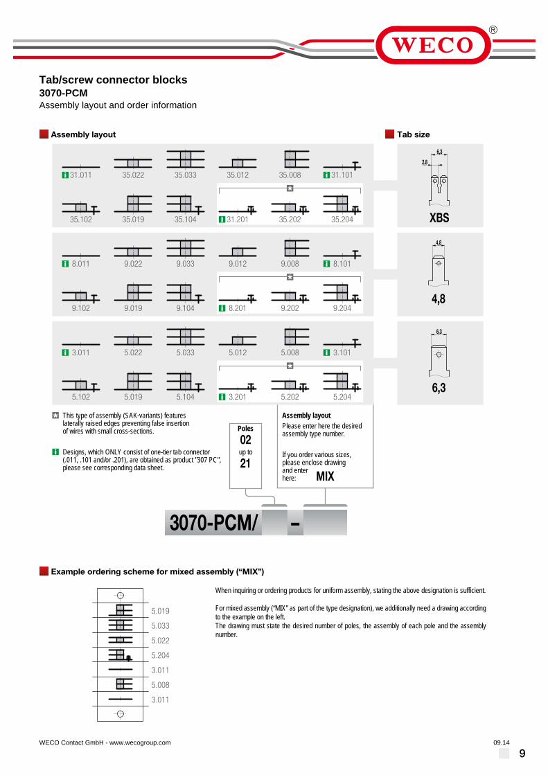
Tab/screw connector blocks3070-PCMParallel arrangement of the tabs
06.14WECO Contact GmbH - www.wecogroup.com
L = (Number of poles x Pitch) + 8A = (Number of poles + 1) x PitchShown type of tab connector package: 5.033
Series 3070-PCM connectors are a combination of straight tab and straight screwconnectors and used for mains connection of electrical equipment and many otherapplications. Depending on the respective specifications, they are available indifferent pole number and variants.Type 307-PC is designed only with one-tier tabs.Tab connectors are suitable for tab receptacles according to DIN 46247. They arejoined with a metal rivet to a package with multiple connections (max. 6 connectionper pole), thus resulting in low contact resistances.Due to the numerous and variable assembly combinations at the pole, highconnection densities can be achieved.Mounting holes are located at each end.Flexible wires require the use of ferrules and cable lugs.
For mixed assemblies, we kindly ask for a scheme according to the example on thenext page. For asymmetrical assemblies, it must contain the componentorientation.Due to the large variety of different types, article numbers cannot be listed.
General InformationPitch 11 mmNo. of poles 2 - 21
Technical DataClamping Range solid / flexible / AWG
0,75-4 mm² / 0,75-2,5 mm² / 18-12 AWG [1]0,5-1,5 mm² / 0,5-1,5 mm² / 20-16 AWG [2]
Rated Cross Section 4 mm² [1] / 1,5 mm² [2]Wire Stripping Length 8 mmOvervoltage Category IIIPollution Severity Level 3Rated Voltage 250 VRated Impulse Voltage 4 kVRated Insulation Voltage 450 V acc. to EN 60998-1Rated Current 6 A with receptacle 2,8; wire 1 mm² (16 AWG)
16 A with receptacle 4,8; wire 2,5 mm² (14 AWG)25 A with receptacle 6,3; wire 6 mm² (10 AWG)Screw connection depends on tab connectordesign
Torque 1,2 NmOther specifications Screw terminals are generally suitable for wires
with identical wire type / cross-section.
MaterialMoulding PC, grey, V-0Comparative Tracking Index CTI 250Insulating Group IIIaTemperature Range -40°C up to 125°CTab Nickel plated brassScrew M4; zinc plated steel, blue passivatedTubular rivet Tin plated copper
ApprovalsCurrent Voltage Group AWG Nm
25156
300300300
BBB
max. 10max. 14max. 16
[3][6][7][4][6][7][5][6][7]
2515
300300
BB
max. 10max. 10
[3][4]
Options / Accessories• Marking strips BST-307• Jumpers 307-V, 307-VS; Cover 3070-B• Special packages upon request (e.g. 6,3 tab connector with solder connection)
[1] Screw connection[2] SAK version[3] For use with insulation receptacles 6,3[4] For use with insulation receptacles 4,8[5] For use with insulation receptacles 2,8[6] for factory wiring only[7] Group C: 150 V
909.14WECO Contact GmbH - www.wecogroup.com
Example ordering scheme for mixed assembly (“MIX”)
Assembly layout Tab size
When inquiring or ordering products for uniform assembly, stating the above designation is sufficient.
For mixed assembly (“MIX” as part of the type designation), we additionally need a drawing according to the example on the left.The drawing must state the desired number of poles, the assembly of each pole and the assembly number.
6,3
6,3
02
21
4,8
4,8
2,8
6,3
XBS
3070-PCM/ –
MIX
Assembly layoutThis type of assembly (SAK-variants) featureslaterally raised edges preventing false insertionof wires with small cross-sections.
Please enter here the desiredassembly type number.
Poles
up to If you order various sizes,please enclose drawingand enterhere:
Designs, which ONLY consist of one-tier tab connector(.011, .101 and/or .201), are obtained as product "307 PC",please see corresponding data sheet.
3.011 5.022 5.033 5.012 5.008 3.101
5.102 5.019 5.104 3.201
5.033
5.022
5.204
3.011
5.008
3.011
5.019
5.202 5.204
8.011 9.022 9.033 9.012 9.008 8.101
9.102 9.019 9.104 8.201 9.202 9.204
31.011 35.022 35.033 35.012 35.008 31.101
35.102 35.019 35.104 31.201 35.202 35.204
Tab/screw connector blocks3070-PCMAssembly layout and order information

10
Tab/screw connector blocks307-PC/-PCMStar-shaped tab arrangement
08.14WECO Contact GmbH - www.wecogroup.com
L = (number of poles x pitch) + 8A = (number of poles + 1) x pitchTypes of connection shown with package 5.033
A combination of straight and angular tabs and straight screw connections, theseconnector blocks are particularly suitable for the mains connection of electricalequipment. They are available in various sizes, pole numbers and types forindividual applications. Depending on the application requirements, they areavailable in different number of poles and variants.The tabs are suitable for receptacles to DIN 46247 and assembled in packetscontaining multiple ports (maximum of 6 ports per pole) with a metal rivet whichresults in low contact resistance.Due to the variable and extensive assembly combinations of the poles, a highpacking density is achieved.At the end of the connectors a fixing hole is provided. Flexible conductors may onlybe used with core cable ends and cable lugs.
At a mixed assembly, we ask for a sketch according to order illustration (pleasesee next page), especially for the orientation of asymmetric packets.Due to the variety of designs, a total list of part numbers is not possible.
Note concerning the variants:..-PC: single level..-PCM: multi level
General InformationPitch 11 mmNo. of poles 2 - 21
Technical DataClamping Range solid / flexible / AWG
0,75-4 mm² / 0,75-2,5 mm² / 18-12 AWG [1]0,5-1,5 mm² / 0,5-1,5 mm² / 20-16 AWG [2]
Rated Cross Section 4 mm² [1] / 1,5 mm² [2]Wire Stripping Length 8 mm ± 0,5 mmOvervoltage Category III III IIPollution Severity Level 3 2 2Rated Voltage 200 V 320 V 500 VRated Impulse Voltage 4 kV 4 kV 4 kVRated Insulation Voltage 250 V acc. to EN 60998-1 [1]Rated Current 6 A with receptacle 2,8; wire 1 mm² (16 AWG)
16 A with receptacle 4,8; wire 2,5 mm² (14 AWG)25 A with receptacle 6,3; wire 6 mm² (10 AWG)Screw connection: depending on tab versions
Torque 1,2 NmOther specifications Screw terminals are generally suitable for wires
with identical wire type / cross-section.
MaterialMoulding PC, black, V-0Comparative Tracking Index CTI 250Insulating Group IIIaTemperature Range -40°C up to 125°CTab Nickel plated brassScrew M4; zinc plated steel, blue passivatedTubular rivet Tin plated copper
ApprovalsCurrent Voltage Group AWG Nm
25156
300300300
BBB
max. 10max. 14max. 16
[4][7][8][5][7][8][6][7][8]
2515
300300
BB
max. 10max. 10
[4][5]
Options / Accessories• Marking strips BST-307• Jumpers 307-V, 307-VS
[1] Screw connection[2] SAK version[3] For use with insulation receptacles 450 V[4] For use with insulation receptacles 6,3[5] For use with insulation receptacles 4,8[6] For use with insulation receptacles 2,8[7] for factory wiring only[8] Group C: 150 V

1105.14WECO Contact GmbH - www.wecogroup.com
Example ordering scheme for mixed assembly (“MIX”)
Assembly layout Tab size
When inquiring or ordering products for uniform assembly, stating the above designation is sufficient.
For mixed assembly (“MIX” as part of the type designation), we additionally need a drawing according to the example on the left. The drawing must state the desired number of poles, the assembly of each pole and the assembly number.
MIX
02
21
6,3
6,3
4,8
4,8
2,8
6,3
XBS
Assembly layoutThis type of assembly (SAK-variants) featureslaterally raised edges preventing false insertionof wires with small cross-sections.
one-tier tab connector (.011, .077, .066, .101, .201) only as „-PC“
Please enter here the desiredassembly type number.
Poles
up to If you order various sizes,please enclose drawingand enterhere:
307-PCM/ –
3.066
8.077
8.112
3.011
31.033
3.011
31.019
31.011 31.077 31.066 31.019 31.022 31.033
31.101 31.103 31.112 31.201 31.203 31.212
8.011 8.077 8.066 8.019 8.022 8.033
8.101 8.103 8.112 8.201 8.203 8.212
3.011 3.077 3.066 1.019 1.022 1.033
3.101 1.103 1.112 3.201 1.203 1.212
Tab/screw connector blocks307-PC/-PCMAssembly layout and order information

12
Multi-point screw connector307-PCFwith grooved flat terminals
08.14WECO Contact GmbH - www.wecogroup.com
9,5
22
11
L
36
4,5ø
The multi-point screw connector 307-PCF in 11 mm pitch is available in 2- to21-pole design.They are equipped with grooved flat terminals and are particularly suitable for themains connection of electrical equipment. They are available in various sizes, polenumbers and types to suit individual applications.The grooves serve as wire guide and prevent lateral wire offset when fastening thescrew connection.Each one mounting hole is provided on the end of the connector block.The connector block features a polycarbonate housing with riveted flat tabsaccording to DIN 41000/12.66
Part NumbersNo. ofpoles
307-PCF Length A * PU
2 50.880.602 41,00 33,00 1123 50.880.603 52,00 44,00 844 50.880.604 63,00 55,00 645 50.880.605 74,00 66,00 566 50.880.606 85,00 77,00 487 50.880.607 96,00 88,00 408 50.880.608 107,00 99,00 369 50.880.609 118,00 110,00 3210 50.880.610 129,00 121,00 3211 50.880.611 140,00 132,00 2812 50.880.612 151,00 143,00 2013 50.880.613 162,00 154,00 2414 50.880.614 173,00 165,00 4215 50.880.615 184,00 176,00 4216 50.880.616 195,00 187,00 2117 50.880.617 206,00 198,00 2118 50.880.618 217,00 209,00 6319 50.880.619 228,00 220,00 1620 50.880.620 239,00 231,00 7021 50.880.621 250,00 242,00 16
* = Distance of the two outermost mounting holes
General InformationPitch 11 mmNo. of poles 2 - 21Usable with Cover 3070-B; securing pins BEF-3070
Technical DataClamping Range solid / flexible / AWG
0,5 - 4 mm² / 0,5 - 4 mm² / 20 - 14 AWG [1] [2] [3]Rated Cross Section 4 mm²Wire Stripping Length 12,5 mm ± 0,5 mmOvervoltage Category III III IIPollution Severity Level 3 2 2Rated Voltage 400 V 630 V 630 VRated Impulse Voltage 6 kV 6 kV 6 kV
Rated Insulation Voltage 750 V acc. to EN 60998-1Rated Current 32 ATorque 1,2 NmOther specifications Screw terminals are generally suitable for wires
with identical wire type / cross-section.
MaterialMoulding PC, black, V-0Comparative Tracking Index CTI 250Insulating Group IIIaTemperature Range -40°C up to 125°CScrew terminal Nickel plated brassScrew M4; zinc plated steel, blue passivatedTubular rivet Tin plated copperWasher Zinc plated steel, blue passivated
ApprovalsCurrent Voltage Group AWG Nm
2020
300150
BC
max. 14max. 14
1,21,2
2020
300150
BC
18 - 1418 - 14
1,21,2
Options / Accessories• Consecutive numbering• Special marking according to drawing• Marking strips BST-307• Jumper 307-VS• Cover 3070-B• Securing pin BEF-3070
[1] with cabel lug 6 mm²[2] Ferrules are required when using flexible or fine-wire conductors.[3] for 4 mm² flexible wires, only one conductor per clamping unit is possible

13
Tab/screw connector322-A-2,8(-DS)with tab A 2,8
09.13WECO Contact GmbH - www.wecogroup.com
The tab connector block 322-A-2,8 in 10 mm pitch is available with 1 to 12 poles.These connector strips are a combination of screw and tab connectors. The can beused to connect equipment to the grid and are well suited for many otherapplications.
After slipping on the tab receptacles, their ends protrude approx. 12,5 mm from themoulding. The screws are ready to be wired, secured against self-loosening andcaptive.
This tab connector block can be combined with our plug-in terminal strip 322-SV -the plugs are simply inserted in the sockets and subsequently screwed tight.
The wire protector of the “DS”-version reliably prevents damage to multi-wireflexible conductors by the turning screw.These terminals strips can be screw-mounted on a substrate.
Part NumbersNo. ofpoles
322-A-2,8 322-A-2,8-DS Length PU
1 11.821.014 31.821.014 8,00 20002 12.821.014 32.821.014 18,00 20003 13.821.014 33.821.014 28,00 10004 14.821.014 34.821.014 38,00 8005 15.821.014 35.821.014 48,00 5006 16.821.014 36.821.014 58,00 1007 17.821.014 37.821.014 68,00 708 18.821.014 38.821.014 78,00 709 19.821.014 39.821.014 88,00 6010 20.821.014 40.821.014 98,00 5011 21.821.014 41.821.014 108,00 5012 22.821.014 42.821.014 117,00 50
General InformationPitch 10 mmNo. of poles 1 - 12Accessories 322-SV
Technical DataClamping Range solid / flexible / AWG
without wire protector 0,5 - 4 mm² / 0,5 - 2,5 mm² / 20 - 12 AWGwith wire protector 0,34 - 2,5 mm² / 0,34 - 2,5 mm² / 22 - 14 AWG
Rated Cross Section [1] 2,5 mm²; [2] 1 mm²Overvoltage Category III III IIPollution Severity Level 3 2 2Rated Voltage 400 V 630 V 1000 VRated Impulse Voltage 6 kV 6 kV 6 KV
Rated Insulation Voltage 450 V acc. to EN 60998-1Rated Current 6 A compare DIN 46 249Torque 0,5 Nm
MaterialMoulding PA, natural, V-2Comparative Tracking Index CTI ≥ 600Insulating Group ITemperature Range -40°C up to 100°CTerminal Body Nickel plated brassScrew M3; zinc plated steel, blue passivatedWire protector Tin plated tin bronze
ApprovalsCurrent Voltage Group AWG Nm
6 300 B,D,E 22 - 10 0,51
Options / Accessories• Marking options on the screw guides• Marking strips BST-322• Cover caps A-323 und base plate B-323 for additional contact protection
[1] Screw side[2] Plug-in side

14
Tab/solder connector block401-LFPA-4,8/-6,3
06.14WECO Contact GmbH - www.wecogroup.com
1,5 12 2,8
3
208,5
4,86,3
8
10
ø 3,2
L
4,5 7
6,3 4,8
The combined tab/solder connector blocks are used primarily as connectors, cablesplitter or as a base in electrical appliances and in automotive.In the -LF version of the Type 401 a solder connection is located on the oppositeside of the flat plug. The solder tags protrude approximately 8,5 mm from thehousing. On the solder tag a flat plug sleeve B 2.8 x 0.8 can be inserted.Depending on the application, this type is available with flat connectors 4,8 mm or6,3 mm width in 1 to 12 pole design.The insulation on the plug side can be done with our insulating ISO 187 on the tab4,8 mm and ISO 110 with the solder joints. The tab connectors are suitable for flatplugs according to DIN 46247.
Part NumbersNo. ofpoles
401-LFPA-4,8 401-LFPA-6,3 Length A * PU
1 11.833.002 31.833.010 11,00 25002 12.833.002 32.833.010 23,00 15003 13.833.002 33.833.010 35,00 12,00 10004 14.833.002 34.833.010 47,00 24,00 8005 15.833.002 35.833.010 59,00 36,00 2006 16.833.002 36.833.010 71,00 48,00 2507 17.833.002 37.833.010 83,00 60,50 2508 18.833.002 38.833.010 95,00 72,50 2509 19.833.002 39.833.010 107,00 84,50 20010 20.833.002 40.833.010 119,00 96,50 15011 21.833.002 41.833.010 131,00 108,50 15012 22.833.002 42.833.010 143,00 120,50 150
* = Distance of the two outermost mounting holes
General InformationPitch 12 mmNo. of poles 1 - 12
Technical DataOvervoltage Category III III IIPollution Severity Level 3 2 2Rated Voltage 400 V 630 V 1000VRated Impulse Voltage 6 kV 6 kV 6 kV
Rated Insulation Voltage 450 V acc. to EN 60998-1Rated Current 16 A: with receptacle 4,8; wire 2,5 mm² (14 AWG)
25 A: with receptacle 6,3; wire 6,0 mm² (10 AWG)Other specifications Rated values apply to use in combination with
insulated substrates.
MaterialMoulding PA, natural, V-2Comparative Tracking Index CTI ≥ 600Insulating Group ITemperature Range -40°C up to 100°CTab Tin plated brass
ApprovalsCurrent Voltage Group AWG Nm
15 300 B max. 10 [1][2]
151510
300150300
BC
D,E
max. 10max. 10max. 10
[1][1][1]
[1] max. 14 AWG for solder side[2] max. 16 AWG for solder side
Options / Accessories• Consecutive numbering• Special marking according to drawing• Insulating sleeves ISO-110 for solder points and ISO-187 for receptacles• Other tab connector variants available upon request, e.g. for the transition from
4.8 to 6.3

15
Tab connector block401-PA-4,8/-6,3 /-XBS
06.14WECO Contact GmbH - www.wecogroup.com
Tab connector blocks 401-PA are used mainly as connectors, lead distributors oras electrical interface in equipment and motor vehicles. Depending on theapplication, these connector blocks are available with B 2,8 (-XBS); 4,8 or 6,3 tabconnectors in 1- to 12-pole design.
Upon request, crimping points for 4,8 tabs can be insulated with our ISO insulatingsleeves. Tab connectors are suitable for tab receptacles according to DIN 46247.
Part NumbersNo. ofpoles
401-PA-4,8 401-PA-6,3 401-PA-XBS Length A * PU
1 11.830.039 31.830.039 71.830.039 12,00 25002 12.830.039 32.830.039 72.830.039 24,00 15003 13.830.039 33.830.039 73.830.039 36,00 12,00 10004 14.830.039 34.830.039 74.830.039 48,00 24,00 10005 15.830.039 35.830.039 75.830.039 59,00 36,00 2006 16.830.039 36.830.039 76.830.039 71,00 48,00 2007 17.830.039 37.830.039 77.830.039 83,00 60,00 508 18.830.039 38.830.039 78.830.039 95,00 72,00 509 19.830.039 39.830.039 79.830.039 107,00 84,00 2510 20.830.039 40.830.039 80.830.039 119,00 96,00 10011 21.830.039 41.830.039 81.830.039 131,00 108,00 10012 22.830.039 42.830.039 82.830.039 142,00 120,00 100
* = Distance of the two outermost mounting holes
General InformationPitch 12 mmNo. of poles 1 - 12Additonal Information After pushing on the tab receptacles, their ends
protrude 7 mm from the housing.
Technical DataOvervoltage Category III III IIPollution Severity Level 3 2 2Rated Voltage 500 V 630 V 1000 VRated Impulse Voltage 6 kV 6 kV 6 kVRated Insulation Voltage 750 V acc. to EN 60998-1Rated Current 6 A: with receptacle 2,8; wire 1 mm² (16 AWG)
16 A: with receptacle 4,8; wire 2,5 mm² (14 AWG)25 A: with receptacle 6,3; wire 6,0 mm² (10 AWG)
Other specifications Rated values apply to use in combination withinsulated substrates.
MaterialMoulding PA, natural, V-2Comparative Tracking Index CTI ≥ 600Insulating Group ITemperature Range -40°C up to 100°CTab Nickel plated brass
ApprovalsCurrent Voltage Group AWG Nm
25 [2]6 [3]15 [4]
300300300
BBB
max. 10max. 16max. 14
25 [1] [2]25 [1] [2]
10
300150300
BC
D,E
max. 10max. 10max. 10
[1] 15 A is applicable for 401-PA-4.8 in group B,C[2] applies only for receptacle for tabs 6,3[3] applies for receptacle for tabs 2,8[4] applies for receptacle for tabs 4,8
Options / Accessories• Consecutive numbering• Special marking according to drawing• Insulating sleeves ISO-187 for receptacles• Other tab connector variants available upon request, e.g. for the transition from
4.8 to 6.3

16
Tab connector block401-PVC-6,3Material: PVC
06.14WECO Contact GmbH - www.wecogroup.com
28
3,2ø
128
2,8
6,3
2,8
4,86,3
L
5 7
0,8
6,3 4,8 YBS
[*] = optionally available tab connector types
The standard version of tab connector block 401-PVC comes with tab width 6,3mm and is available in 1- to 12-pole design. It is used mainly as connector, leaddistributor or as electrical interface in equipment and motor vehicles.
Optionally, they are available in tab width 4,8 mm and as “–YBS”-version, i.e. withone single connection on the one side and a double connection 2 x 2,8 mm or 1 x6,3 mm on the opposite side.Crimped points can be insulated with our ISO insulation sleeves.These tab connectors are suitable for tab receptacles according to DIN 46247.
Part NumbersNo. ofpoles
401-PVC-6,3 Length A * PU
1 31.830.002 12,00 25002 32.830.002 24,00 15003 33.830.002 36,00 12,00 10004 34.830.002 48,00 24,00 10005 35.830.002 59,00 36,00 2006 36.830.002 71,00 48,00 2007 37.830.002 83,00 60,00 508 38.830.002 95,00 72,00 509 39.830.002 107,00 84,00 2510 40.830.002 119,00 96,00 10011 41.830.002 131,00 108,00 10012 42.830.002 142,00 120,00 100
* = Distance of the two outermost mounting holes
General InformationPitch 12 mmNo. of poles 1 - 12Additonal Information After pushing on the tab receptacles, their ends
protrude 7 mm from the housing.
Technical DataOvervoltage Category III III IIPollution Severity Level 3 2 2Rated Voltage 500 V 630 V 1000 VRated Impulse Voltage 6 kV 6 kV 6 kVRated Insulation Voltage 750 V acc. to EN 60998-1Rated Current 6 A: with receptacle 2,8; wire 1 mm² (16 AWG)
16 A: with receptacle 4,8; wire 2,5 mm² (14 AWG)25 A: with receptacle 6,3; wire 6,0 mm² (10 AWG)
Other specifications Rated values apply to use in combination withinsulated substrates.
MaterialMoulding Soft PVC, transparent, V-2Comparative Tracking Index CTI 400Insulating Group IITemperature Range -10°C up to 70°CTab Nickel plated brass
ApprovalsCurrent Voltage Group AWG Nm
25 300 B max. 10
Options / Accessories• Consecutive numbering• Special marking according to drawing• Flat connector type -4,8• Flat connector type -YBS• Other tab connector variants available upon request, e.g. for the transition from
4.8 to 6.3

17
Tab connector block404-6,3
06.14WECO Contact GmbH - www.wecogroup.com
0,8
4 6
L
48
8,112,1
ø3,2
6,3A
2,8
YBS4,86,3
[*] = optionally available tab connector types
The tab connector 404 with the pitch of 12,1 mm is mainly used as connector,terminal or as a electrical distribution in electrical equipment and motor vehicleconstruction.In the standard version, these tab connector is available with 6,3 mm tabs and withtwo-sided push-on termination. The tabs are suitable for receptacle for tabsaccording to DIN 46 247.
Deferred receptacles are fully covered by the wide housing insulation. This allowsstacking the connector without the need for an intermediate insulating layer. Theconnector is similar to DIN 72 586-C50.
Part NumbersNo. ofpoles
404-6,3 Length A * PU
1 31.830.008 12,00 15002 32.830.008 24,00 10003 33.830.008 36,00 12,10 2504 34.830.008 48,00 24,20 2005 35.830.008 60,00 36,30 2006 36.830.008 72,00 48,40 1507 37.830.008 84,00 60,50 1008 38.830.008 96,00 72,60 1009 39.830.008 108,00 84,70 10010 40.830.008 120,00 96,80 10011 41.830.008 132,00 108,90 7012 42.830.008 144,00 121,00 70
* = Distance of the two outermost mounting holes
General InformationPitch 12,1 mmNo. of poles 1 - 12
Technical DataOvervoltage Category IIIPollution Severity Level 3Rated Voltage 320 VRated Impulse Voltage 4 kV
Rated Insulation Voltage 450 V acc. to EN 60998-1Rated Current 6 A: with receptacle 2,8; wire 1 mm² (16 AWG)
16 A: with receptacle 4,8; wire 2,5 mm² (14 AWG)25 A: with receptacle 6,3; wire 6,0 mm² (10 AWG)
Other specifications Rated values apply to use without insulatedsubstrates.
MaterialMoulding Soft PVC, transparent, V-2Comparative Tracking Index CTI 400Insulating Group IITemperature Range -10°C up to 70°CTab Nickel plated brass
Options / Accessories• Consecutive numbering• Special marking according to drawing• Flat connector types -4,8• Flat connector types -YBS

18
Tab connector406Lead distributor
06.14WECO Contact GmbH - www.wecogroup.com
Tab connector 406 is only available as 1-pole variant. It features one singleconnection 6,3 mm on one side and a double connection 2x6,3 mm on theopposite side.Pushed on tab receptacles 6,3 are completely covered by the housing.
Part NumbersNo. ofpoles
406 Length PU
1 10.836.008 54 250
General InformationNo. of poles 1
Technical DataOvervoltage Category IIIPollution Severity Level 3Rated Voltage 630 VRated Impulse Voltage 6 kV
Rated Insulation Voltage 750 V acc. to EN 60998-1Rated Current 25 A: with receptacle 6,3; wire 6,0 mm² (10 AWG)Other specifications Rated values apply to use without insulated
substrates.
MaterialMoulding Soft PVC, transparent, V-2Comparative Tracking Index CTI 400Insulating Group IITemperature Range -10°C up to 70°CTab Nickel plated brass
Options / Accessories• Special marking according to drawing

19
Tab connector407-PA/-PVC
06.14WECO Contact GmbH - www.wecogroup.com''no flame'' after glow-wire test according toHousehold Appliance DIN EN/IEC 60335-1
20
527
17,8
6,3
407-PA
20
517
17,8
6,3
407-PVC
Tab connector 407 is only available as 1-pole variant. It features doubleconnections with 6,3 mm tabs.Pushed on tab receptacles 6,3 are completely covered by the housing.
Part NumbersNo. ofpoles
407-PA 407-PVC PU
1 20.830.040 20.830.030 400
Part numbers: "no flame" acc. to glow-wire testNo. ofpoles
407-PA 407-PVC PU
1 20.830.036.EN6 400
General InformationNo. of poles 1
Technical DataOvervoltage Category IIIPollution Severity Level 3Rated Voltage 500 VRated Impulse Voltage 6 kV
Rated Insulation Voltage 750 V acc. to EN 60998-1Rated Current 25 A: with receptacle 6,3; wire 6,0 mm² (10 AWG)Other specifications Rated values apply to use without insulated
substrates.
MaterialMoulding PA, natural, V-2 (PA, white, V-0)
Details in parentheses for "no flame" productsSoft PVC, transparent, V-2
Comparative Tracking Index PA: CTI ≥ 600; PVC: CTI 400Insulating Group PA: I; PVC: IITemperature Range PA: -40°C up to 100°C; PVC: -10°C up to 70°CTab Nickel plated brass
Options / Accessories• Special marking according to drawing

20
Tab connector block408-46-4,8/-6,3 /-XBSHousing width 46 mm
06.14WECO Contact GmbH - www.wecogroup.com
Tab connector blocks 408-46 with double connectors on both sides are usedmainly as connectors, lead distributors or as electrical interface in equipment andmotor vehicles. Depending on the application, these connector blocks with ahousing width of 46 mm are available for 4,8; 6,3 or XBS-tabs in 1- to 12-poledesign.
These tab connectors are suitable for tab receptacles according to DIN 46247. Thehousing variant requires 2,8 tab receptacles for the insulation of crimp points.
Part NumbersNo. ofpoles
408-46-4,8 408-46-6,3 408-46-XBS Length A * PU
1 40.830.221 30.830.221 20.830.221 10,00 20002 40.830.222 30.830.222 20.830.222 22,50 10003 40.830.223 30.830.223 20.830.223 35,00 12,50 7004 40.830.224 30.830.224 20.830.224 47,50 25,00 2005 40.830.225 30.830.225 20.830.225 60,00 37,50 1006 40.830.226 30.830.226 20.830.226 72,50 50,00 1007 40.830.227 30.830.227 20.830.227 85,00 62,50 1008 40.830.228 30.830.228 20.830.228 97,50 75,00 1009 40.830.229 30.830.229 20.830.229 110,00 87,50 7010 40.830.230 30.830.230 20.830.230 122,50 100,00 7011 40.830.231 30.830.231 20.830.231 135,00 112,50 7012 40.830.232 30.830.232 20.830.232 147,50 125,00 60
* = Distance of the two outermost mounting holes
General InformationPitch 12,5 mmNo. of poles 1 - 12
Technical DataOvervoltage Category III III IIPollution Severity Level 3 2 2Rated Voltage 320 V 320 V 630 VRated Impulse Voltage 4 kV 4 kV 4 kV
Rated Insulation Voltage 450 V acc. to EN 60998-1Rated Current 6 A: with receptacle 2,8; wire 1 mm² (16 AWG)
16 A: with receptacle 4,8; wire 2,5 mm² (14 AWG)25 A: with receptacle 6,3; wire 6,0 mm² (10 AWG)
Other specifications Rated values apply to use without insulatedsubstrates.
MaterialMoulding PA, natural, V-2Comparative Tracking Index CTI ≥ 600Insulating Group ITemperature Range -40°C up to 100°CTab Nickel plated brass
ApprovalsCurrent Voltage Group AWG Nm
25156
600600600
B,CB,CB,C
max. 10max. 14max. 16
[1][2][3]
25 600 B,C max. 10 [1]
[1] only applicable when used with 6,3 tab receptacles[2] only applicable when used with 4,8 tab receptacles[3] only applicable when used with 2,8 tab receptacles
Options / Accessories• Consecutive numbering• Special marking according to drawing

21
Tab connector block408-50-4,8/-6,3 /-XBSHousing width 50 mm
06.14WECO Contact GmbH - www.wecogroup.com
Tab connector blocks 408-50 with double connectors on both sides are usedmainly as connectors, lead distributors or as electrical interface in equipment andmotor vehicles. Depending on the application, these connector blocks with ahousing width of 50 mm are available for 4,8; 6,3 or XBS-tabs in 1- to 12-poledesign.Except for pitch and total length this variant is compliant with DIN 72586-C50.
These tab connectors are suitable for tab receptacles according to DIN 46247. Thecrimp points of tab receptacles are completely insulated.
Part NumbersNo. ofpoles
408-50-4,8 408-50-6,3 408-50-XBS Length A * PU
1 40.830.201 30.830.201 20.830.201 10,00 20002 40.830.202 30.830.202 20.830.202 22,50 10003 40.830.203 30.830.203 20.830.203 35,00 12,50 7004 40.830.204 30.830.204 20.830.204 47,50 25,00 6005 40.830.205 30.830.205 20.830.205 60,00 37,50 1006 40.830.206 30.830.206 20.830.206 72,50 50,00 1007 40.830.207 30.830.207 20.830.207 85,00 62,50 1008 40.830.208 30.830.208 20.830.208 97,50 75,00 1009 40.830.209 30.830.209 20.830.209 110,00 87,50 7010 40.830.210 30.830.210 20.830.210 122,50 100,00 7011 40.830.211 30.830.211 20.830.211 135,00 112,50 7012 40.830.212 30.830.212 20.830.212 147,50 125,00 50
* = Distance of the two outermost mounting holes
General InformationPitch 12,5 mmNo. of poles 1 - 12
Technical DataOvervoltage Category III III IIPollution Severity Level 3 2 2Rated Voltage 500 V 630 V 1000 VRated Impulse Voltage 6 kV 6 kV 6 kV
Rated Insulation Voltage 750 V acc. to EN 60998-1Rated Current 6 A: with receptacle 2,8; wire 1 mm² (16 AWG)
16 A: with receptacle 4,8; wire 2,5 mm² (14 AWG)25 A: with receptacle 6,3; wire 6,0 mm² (10 AWG)
Other specifications Rated values apply to use without insulatedsubstrates.
MaterialMoulding PA, natural, V-2Comparative Tracking Index CTI ≥ 600Insulating Group ITemperature Range -40°C up to 100°CTab Nickel plated brass
ApprovalsCurrent Voltage Group AWG Nm
25156
600600600
B,CB,CB,C
max. 10max. 14max. 16
[1][2][3]
25 600 B,C max. 10 [1]
[1] only applicable when used with 6,3 tab receptacles[2] only applicable when used with 4,8 tab receptacles[3] only applicable when used with 2,8 tab receptacles
Options / Accessories• Consecutive numbering• Special marking according to drawing

22
Tab connector block408-54-4,8/-6,3 /-XBSHousing width 54 mm
07.14WECO Contact GmbH - www.wecogroup.com''no flame'' after glow-wire test according toHousehold Appliance DIN EN/IEC 60335-1
Tab connector blocks 408-54 with double connectors on both sides are usedmainly as connectors, lead distributors or as electrical interface in equipment andmotor vehicles. Depending on the application, these connector blocks with ahousing width of 54 mm are available for 4,8; 6,3 or XBS-tabs in 1- to 12-poledesign.These tab connectors are suitable for tab receptacles according to DIN 46247. Thecrimp points of tab receptacles are completely insulated.
Part NumbersNo. ofpoles
408-54-4,8 408-54-6,3 408-54-XBS Length A * PU
1 40.830.241 30.830.241 20.830.241 10,00 20002 40.830.242 30.830.242 20.830.242 22,50 10003 40.830.243 30.830.243 20.830.243 35,00 12,50 8004 40.830.244 30.830.244 20.830.244 47,50 25,00 5005 40.830.245 30.830.245 20.830.245 60,00 37,50 1006 40.830.246 30.830.246 20.830.246 72,50 50,00 1007 40.830.247 30.830.247 20.830.247 85,00 62,50 808 40.830.248 30.830.248 20.830.248 97,50 75,00 809 40.830.249 30.830.249 20.830.249 110,00 87,50 8010 40.830.250 30.830.250 20.830.250 122,50 100,00 5011 40.830.251 30.830.251 20.830.251 135,00 112,50 5012 40.830.252 30.830.252 20.830.252 147,50 125,00 50
* = Distance of the two outermost mounting holes
Part numbers: "no flame" acc. to glow-wire testNo. ofpoles
408-54-4,8 408-54-6,3 408-54-XBS Length A * PU
1 40.830.261.EN6 30.830.261.EN6 20.830.261.EN6 10,00 20003 30.830.263.EN6 35,00 12,50 8004 30.830.264.EN6 47,50 25,00 50012 30.830.272.EN6 147,50 125,00 50
General InformationPitch 12,5 mmNo. of poles 1 - 12
Technical DataOvervoltage Category III III IIPollution Severity Level 3 2 2Rated Voltage 630 V 630 V 1000 VRated Impulse Voltage 6 kV 6 kV 6 kV
Rated Insulation Voltage 750 V acc. to EN 60998-1Rated Current 6 A: with receptacle 2,8; wire 1 mm² (16 AWG)
16 A: with receptacle 4,8; wire 2,5 mm² (14 AWG)25 A: with receptacle 6,3; wire 6,0 mm² (10 AWG)
Other specifications Rated values apply to use without insulatedsubstrates.
MaterialMoulding PA, natural, V-2 (PA, white, V-0)
Details in parentheses for "no flame" productsComparative Tracking Index CTI ≥ 600Insulating Group ITemperature Range -40°C up to 100°CTab Nickel plated brass
ApprovalsCurrent Voltage Group AWG Nm
25156
600600600
B,CB,CB,C
max. 10max. 14max. 16
[1][2][3]
25 600 B,C max. 10 [1]
[1] only applicable when used with 6,3 tab receptacles[2] only applicable when used with 4,8 tab receptacles[3] only applicable when used with 2,8 tab receptacles
Options / Accessories• Consecutive numbering• Special marking according to drawing

23
Tab/screw connector block42..-CL(-DS)Tabs 6,3 mm
06.14WECO Contact GmbH - www.wecogroup.com''no flame'' after glow-wire test according toHousehold Appliance DIN EN/IEC 60335-1
13
14
5,76,3
5
19
0,83,4
4,2ø
L
19
14
* = Outer hole for 2 and 6 poles: ø 3,6 mm
Tab/screw connector block 42..-CL in 14 mm pitch is a combination of socketterminals and tab connectors. On the tab connector side, it features two 6,3 mmtabs and is available in 2- to 4- and 6-pole design.The individual poles are continuously numbered according to the number of poles.The wire protector of the “DS”-version reliably prevents damage to multi-wireflexible conductors by the turning screw.
Ordering note:For the variable placeholder („..“) in the type designation, please enter thecorresponding number of poles. Example: 423-CL for a 3-pole variant.
Part NumbersNo. ofpoles
42..-CL 42..-CL-DS Length PU
2 50.830.414 60.830.414 21,00 2003 50.830.415 60.830.415 35,00 1504 50.830.417 60.830.417 49,00 1006 50.830.411 60.830.411 77,00 100
General InformationPitch 14 mmNo. of poles 2, 3, 4, 6Areas of application Mains connection of electrical equipmentAdditonal Information These components cannot be mounted
side-by-side. Multiple connectors can only bemounted side-by-side in 14 mm pitch to ensureclearance and creepage distances are observed.
Technical DataClamping Range solid / flexible / AWG
without wire protector 4 mm² / - / 12 AWG [1]with wire protector 1,5 - 4 mm² / 1,5 - 2,5 mm² / 16 - 12 AWG
Rated Cross Section 2,5 mm² [2]Wire Stripping Length 6 mm ± 0,5 mmOvervoltage Category III III IIPollution Severity Level 3 2 2Rated Voltage 400 V 630 V 1000 VRated Impulse Voltage 6 kV 6 kV 6 kVRated Insulation Voltage 450 V acc. to EN 60998-1Rated Current 25 A: with receptacle 6,3; wire 6,0 mm² (10 AWG)
24 A: screw sideTorque 0,5 Nm
MaterialMoulding PA, grey, V-0Comparative Tracking Index CTI ≥ 600Insulating Group ITemperature Range -40°C up to 100°CTerminal Body Nickel plated brassTab Nickel plated brassScrew M3; zinc plated steel, blue passivatedWire protector Tin plated tin bronze
ApprovalsCurrent Voltage Group AWG Nm
2020
300150
BC
14 - 1214 - 12
0,51 [3][4]0,51 [3][4]
2010
300300
BD,E
20 - 1220 - 12
0,51 [3][5]0,51 [3][5]
Options / Accessories• Marking strips BST-422 to -426• Extended screw guide• Insulation receptacles ISO
[1] use only solid wires. Small and flexible wires are not possible.[2] Screw side[3] quick connector max. 10 AWG[4] 18 - 12 AWG is applicable for 42...-CL-DS[5] 22 - 12 AWG is applicable for 42...-CL-DS

24
Tab/screw connector block42..-CZ(-DS)Tabs 6,3, with peg
06.14WECO Contact GmbH - www.wecogroup.com''no flame'' after glow-wire test according toHousehold Appliance DIN EN/IEC 60335-1
13
14
5,76,3
5
2
0,8 3,4
4,2ø
L
19
14
4ø
19
Tab/screw connector block 42..-CZ in 14 mm pitch with projecting peg is acombination of socket terminals and tab connectors. On the tab connector side, itfeatures two 6,3 mm tabs and is available in 3- and 4-pole design.The individual poles are continuously numbered according to the number of poles.
In place of the mounting hole, a projecting peg at the base is located on the leftside facing the tabs, enabling to mount the connector to the substrate with only onescrew.The wire protector of the “DS”-version reliably prevents damage to multi-wireflexible conductors by the turning screw.
Ordering note:For the variable placeholder („..“) in the type designation, please enter thecorresponding number of poles. Example: 423-CZ for a 3-pole variant.
Part NumbersNo. ofpoles
42..-CZ 42..-CZ-DS Length PU
3 50.830.416 60.830.416 35,00 1504 50.830.418 60.830.418 49,00 100
General InformationPitch 14 mmNo. of poles 3 + 4Areas of application Mains connection of electrical equipmentAdditonal Information These components cannot be mounted
side-by-side. Multiple connectors can only bemounted side-by-side in 14 mm pitch to ensureclearance and creepage distances are observed.
Technical DataClamping Range solid / flexible / AWG
without wire protector 4 mm² / - / 12 AWG [1]with wire protector 1,5 - 4 mm² / 1,5 - 2,5 mm² / 16 - 12 AWG
Rated Cross Section 2,5 mm² [2]Wire Stripping Length 6 mm ± 0,5 mmOvervoltage Category III III IIPollution Severity Level 3 2 2Rated Voltage 400 V 630 V 1000 VRated Impulse Voltage 6 kV 6 kV 6 kVRated Insulation Voltage 450 V acc. to EN 60998-1Rated Current 25 A: with receptacle 6,3; wire 6,0 mm² (10 AWG)
24 A: screw sideTorque 0,5 Nm
MaterialMoulding PA, grey, V-0Comparative Tracking Index CTI ≥ 600Insulating Group ITemperature Range -40°C up to 100°CTerminal Body Nickel plated brassTab Nickel plated brassScrew M3; zinc plated steel, blue passivatedWire protector Tin plated tin bronze
ApprovalsCurrent Voltage Group AWG Nm
2020
300150
BC
14 - 1214 - 12
0,51 [3][4]0,51 [3][4]
2010
300300
BD,E
20 - 1220 - 12
0,51 [3][5]0,51 [3][5]
Options / Accessories• Marking strips BST-422 to -426• Extended screw guide• Insulation receptacles ISO
[1] use only solid wires. Small and flexible wires are not possible[2] Screw side[3] quick connector max. 10 AWG[4] 18 - 12 AWG is applicable for 42...-CZ-DS[5] 22 - 12 AWG is applicable for 42...-CZ-DS

25
Tab/screw connector block42..-DL(-DS)single-sided tab 6,3 mm
06.14WECO Contact GmbH - www.wecogroup.com''no flame'' after glow-wire test according toHousehold Appliance DIN EN/IEC 60335-1
13
14
5,76,3
5
0,8
4,2ø
L
19
14
19
* = Outer hole for 2 and 6 poles: ø 3,6 mm
Tab/screw connector block 42..-DL in 14 mm pitch is a combination of socketterminals and tab connectors. On the tab connector side, it features two 6,3 mmtabs and is available in 2- to 4- and 6-pole design.The individual poles are continuously numbered according to the number of poles.The wire protector of the “DS”-version reliably prevents damage to multi-wireflexible conductors by the turning screw.
Ordering note:For the variable placeholder („..“) in the type designation, please enter thecorresponding number of poles. Example: 423-DL for a 3-pole variant.
Part NumbersNo. ofpoles
42..-DL 42..-DL-DS Length PU
2 11.830.414 71.830.414 21,00 2003 11.830.415 71.830.415 35,00 1504 11.830.417 71.830.417 49,00 1006 11.830.411 71.830.411 77,00 100
General InformationPitch 14 mmNo. of poles 2, 3, 4, 6Areas of application Mains connection of electrical equipmentAdditonal Information These components cannot be mounted
side-by-side. Multiple connectors can only bemounted side-by-side in 14 mm pitch to ensureclearance and creepage distances are observed.
Technical DataClamping Range solid / flexible / AWG
without wire protector 4 mm² / - / 12 AWG [1]with wire protector 1,5 - 4 mm² / 1,5 - 2,5 mm² / 16 - 12 AWG
Rated Cross Section 2,5 mm² [2]Wire Stripping Length 6 mm ± 0,5 mmOvervoltage Category III III IIPollution Severity Level 3 2 2Rated Voltage 400 V 630 V 1000 VRated Impulse Voltage 6 kV 6 kV 6 kVRated Insulation Voltage 450 V acc. to EN 60998-1Rated Current 25 A: with receptacle 6,3; wire 6,0 mm² (10 AWG)
24 A: screw sideTorque 0,5 Nm
MaterialMoulding PA, grey, V-0Comparative Tracking Index CTI ≥ 600Insulating Group ITemperature Range -40°C up to 100°CTerminal Body Nickel plated brassTab Nickel plated brassScrew M3; zinc plated steel, blue passivatedWire protector Tin plated tin bronze
ApprovalsCurrent Voltage Group AWG Nm
2020
300150
BC
14 - 1214 - 12
0,51 [3][4]0,51 [3][4]
2010
300300
BD,E
20 - 1220 - 12
0,51 [3][5]0,51 [3][5]
Options / Accessories• Marking strips BST-422 to -426• Extended screw guide• Insulation receptacles ISO
[1] use only solid wires. Small and flexible wires are not possible[2] Screw side[3] quick connector max. 10 AWG[4] 18 - 12 AWG is applicable for 42...-DL-DS[5] 22 - 12 AWG is applicable for 42...-DL-DS

26
Tab/screw connector block42..-DZ(-DS)single-sided tab 6,3 mm, with peg
06.14WECO Contact GmbH - www.wecogroup.com''no flame'' after glow-wire test according toHousehold Appliance DIN EN/IEC 60335-1
Tab/screw connector block 42..-DZ in 14 mm pitch with projecting peg is acombination of socket terminals and tab connectors. On the tab connector side, itfeatures one 6,3 mm tab per pole and is available in 3- and 4-pole design.The individual poles are continuously numbered according to the number of poles.
In place of the mounting hole, a projecting peg at the base is located on the leftside facing the tabs, enabling to mount the connector to the substrate with only onescrew.The wire protector of the “DS”-version reliably prevents damage to multi-wireflexible conductors by the turning screw.
Ordering note:For the variable placeholder („..“) in the type designation, please enter thecorresponding number of poles. Example: 423-DZ for a 3-pole variant.
Part NumbersNo. ofpoles
42..-DZ 42..-DZ-DS Length PU
3 11.830.416 71.830.416 35,00 1504 11.830.418 71.830.418 49,00 100
General InformationPitch 14 mmNo. of poles 3 + 4Areas of application Mains connection of electrical equipmentAdditonal Information These components cannot be mounted
side-by-side. Multiple connectors can only bemounted side-by-side in 14 mm pitch to ensureclearance and creepage distances are observed.
Technical DataClamping Range solid / flexible / AWG
without wire protector 4 mm² / - / 12 AWG [1]with wire protector 1,5 - 4 mm² / 1,5 - 2,5 mm² / 16 - 12 AWG
Rated Cross Section 2,5 mm² [2]Wire Stripping Length 6 mm ± 0,5 mmOvervoltage Category III III IIPollution Severity Level 3 2 2Rated Voltage 400 V 630 V 1000 VRated Impulse Voltage 6 kV 6 kV 6 kVRated Insulation Voltage 450 V acc. to EN 60998-1Rated Current 25 A: with receptacle 6,3; wire 6,0 mm² (10 AWG)
24 A: screw sideTorque 0,5 Nm
MaterialMoulding PA, grey, V-0Comparative Tracking Index CTI ≥ 600Insulating Group ITemperature Range -40°C up to 100°CTerminal Body Nickel plated brassTab Nickel plated brassScrew M3; zinc plated steel, blue passivatedWire protector Tin plated tin bronze
ApprovalsCurrent Voltage Group AWG Nm
2020
300150
BC
14 - 1214 - 12
0,51 [3][4]0,51 [3][4]
2010
300300
BD,E
20 - 1220 - 12
0,51 [3][5]0,51 [3][5]
Options / Accessories• Marking strips BST-422 to -426• Extended screw guide• Insulation receptacles ISO
[1] use only solid wires. Small and flexible wires are not possible[2] Screw side[3] quick connector max. 10 AWG[4] 18 - 12 AWG is applicable for 42...-DZ-DS[5] 22 - 12 AWG is applicable for 42...-DZ-DS

27
Tab/screw connector block42..-EL(-DS)Tab 2x2,8 / 1x6,3
06.14WECO Contact GmbH - www.wecogroup.com''no flame'' after glow-wire test according toHousehold Appliance DIN EN/IEC 60335-1
14 ø 6
L
5
13,5
19
3,4
6,45,7
0,814 14
ø 4,2
12
19
* = Outer hole for 2 and 6 poles: ø 3,6 mm
Tab/screw connector block 42..-EL in 14 mm pitch is a combination of socketterminals and tab connectors. On the tab connector side, it features two B 2,8 mmtabs per pole and is available in 2- to 4- and 6-pole design.The individual poles are continuously numbered according to the number of poles.The wire protector of the “DS”-version reliably prevents damage to multi-wireflexible conductors by the turning screw.
Ordering note:For the variable placeholder („..“) in the type designation, please enter thecorresponding number of poles. Example: 423-EL for a 3-pole variant.
Part NumbersNo. ofpoles
42..-EL 42..-EL-DS Length PU
2 80.830.414 81.830.414 21,00 2003 80.830.415 81.830.415 35,00 1504 80.830.417 81.830.417 49,00 1006 80.830.411 81.830.411 77,00 100
General InformationPitch 14 mmNo. of poles 2, 3, 4, 6Areas of application Mains connection of electrical equipmentAdditonal Information These components cannot be mounted
side-by-side. Multiple connectors can only bemounted side-by-side in 14 mm pitch to ensureclearance and creepage distances are observed.
Technical DataClamping Range solid / flexible / AWG
without wire protector 4 mm² / - / 12 AWG [1]with wire protector 1,5 - 4 mm² / 1,5 - 2,5 mm² / 16 - 12 AWG
Rated Cross Section 2,5 mm² [2]Wire Stripping Length 6 mm ± 0,5 mmOvervoltage Category III III IIPollution Severity Level 3 2 2Rated Voltage 400 V 630 V 1000 VRated Impulse Voltage 6 kV 6 kV 6 kVRated Insulation Voltage 450 V acc. to EN 60998-1Rated Current 6 A: with receptacle 2,8; wire 1,0 mm² (16 AWG)
25 A: with receptacle 6,3; wire 6,0 mm² (10 AWG)24 A: screw side
Torque 0,5 Nm
MaterialMoulding PA, grey, V-0Comparative Tracking Index CTI ≥ 600Insulating Group ITemperature Range -40°C up to 100°CTerminal Body Nickel plated brassTab Nickel plated brassScrew M3; zinc plated steel, blue passivatedWire protector Tin plated tin bronze
ApprovalsCurrent Voltage Group AWG Nm
2020
300150
BC
14 - 1214 - 12
0,51 [3][4]0,51 [3][4]
2010
300300
BD,E
20 - 1220 - 12
0,51 [3][5]0,51 [3][5]
Options / Accessories• Marking strips BST-422 to -426• Extended screw guide• Insulation receptacles ISO
[1] use only solid wires. Small and flexible wires are not possible[2] Screw side[3] quick connector max. 10 AWG[4] 18 - 12 AWG is applicable for 42...-EL-DS[5] 22 - 12 AWG is applicable for 42...-EL-DS

28
Tab/screw connector block42..-EZ(-DS)Tab 2x2,8 / 1x6,3, with peg
06.14WECO Contact GmbH - www.wecogroup.com''no flame'' after glow-wire test according toHousehold Appliance DIN EN/IEC 60335-1
14 ø 6
L
52
ø 4
13,5
19
3,4
6,45,7
0,814 14
ø 4,2
12
19
Tab/screw connector block 42..-EZ in 14 mm pitch with projecting peg is acombination of socket terminals and tab connectors. On the tab connector side, itfeatures two 6,3 mm tabs and is available in 3- and 4-pole design.The individual poles are continuously numbered according to the number of poles.
In place of the mounting hole, a projecting peg at the base is located on the leftside facing the tabs, enabling to mount the connector to the substrate with only onescrew.The wire protector of the “DS”-version reliably prevents damage to multi-wireflexible conductors by the turning screw.
Ordering note:For the variable placeholder („..“) in the type designation, please enter thecorresponding number of poles. Example: 423-EZ for a 3-pole variant.
Part NumbersNo. ofpoles
42..-EZ 42..-EZ-DS Length PU
3 80.830.416 81.830.416 35,00 1504 80.830.418 81.830.418 49,00 100
General InformationPitch 14 mmNo. of poles 3 + 4Areas of application Mains connection of electrical equipmentAdditonal Information These components cannot be mounted
side-by-side. Multiple connectors can only bemounted side-by-side in 14 mm pitch to ensureclearance and creepage distances are observed.
Technical DataClamping Range solid / flexible / AWG
without wire protector 4 mm² / - / 12 AWG [1]with wire protector 1,5 - 4 mm² / 1,5 - 2,5 mm² / 16 - 12 AWG
Rated Cross Section 2,5 mm² [2]Wire Stripping Length 6 mm ± 0,5 mmOvervoltage Category III III IIPollution Severity Level 3 2 2Rated Voltage 400 V 630 V 1000 VRated Impulse Voltage 6 kV 6 kV 6 kVRated Insulation Voltage 450 V acc. to EN 60998-1Rated Current 6 A: with receptacle 2,8; wire 1,0 mm² (16 AWG)
25 A: with receptacle 6,3; wire 6,0 mm² (10 AWG)24 A: screw side
Torque 0,5 Nm
MaterialMoulding PA, grey, V-0Comparative Tracking Index CTI ≥ 600Insulating Group 1Temperature Range -40°C up to 100°CTerminal Body Nickel plated brassTab Nickel plated brassScrew M3; zinc plated steel, blue passivatedWire protector Tin plated tin bronze
ApprovalsCurrent Voltage Group AWG Nm
2020
300150
BC
14 - 1214 - 12
0,51 [3][4]0,51 [3][4]
2010
300300
BD,E
20 - 1220 - 12
0,51 [3][5]0,51 [3][5]
Options / Accessories• Marking strips BST-422 to -426• Extended screw guide• Insulation receptacles ISO
[1] use only solid wires. Small and flexible wires are not possible[2] Screw side[3] quick connector max. 10 AWG[4] 18 - 12 AWG is applicable for 42...-EZ-DS[5] 22 - 12 AWG is applicable for 42...-EZ-DS
29
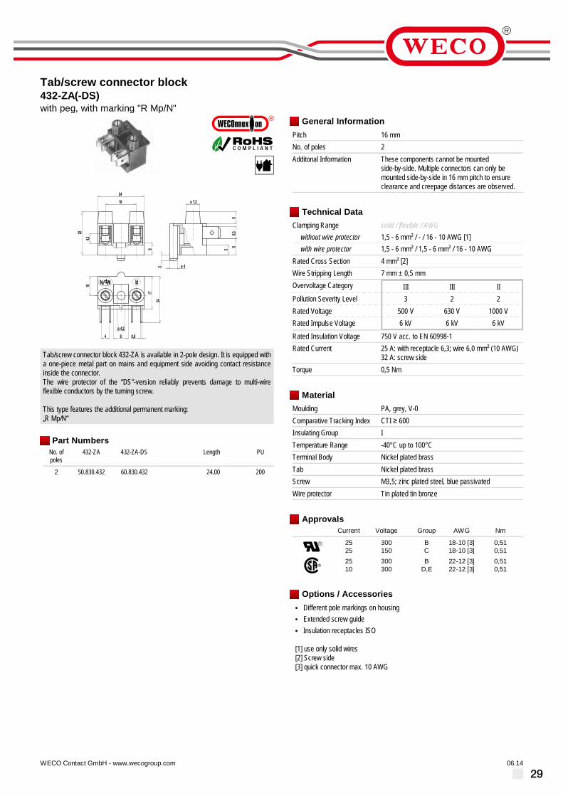
Tab/screw connector block432-ZA(-DS)with peg, with marking "R Mp/N"
06.14WECO Contact GmbH - www.wecogroup.com''no flame'' after glow-wire test according toHousehold Appliance DIN EN/IEC 60335-1
ø 4,2
0,84
24
17
24
10
8
ø 7,2
66,3
856
ø 4
4,5
16
22
3
RMp/N
Tab/screw connector block 432-ZA is available in 2-pole design. It is equipped witha one-piece metal part on mains and equipment side avoiding contact resistanceinside the connector.The wire protector of the “DS”-version reliably prevents damage to multi-wireflexible conductors by the turning screw.
This type features the additional permanent marking:„R Mp/N“
Part NumbersNo. ofpoles
432-ZA 432-ZA-DS Length PU
2 50.830.432 60.830.432 24,00 200
General InformationPitch 16 mmNo. of poles 2Additonal Information These components cannot be mounted
side-by-side. Multiple connectors can only bemounted side-by-side in 16 mm pitch to ensureclearance and creepage distances are observed.
Technical DataClamping Range solid / flexible / AWG
without wire protector 1,5 - 6 mm² / - / 16 - 10 AWG [1]with wire protector 1,5 - 6 mm² / 1,5 - 6 mm² / 16 - 10 AWG
Rated Cross Section 4 mm² [2]Wire Stripping Length 7 mm ± 0,5 mmOvervoltage Category III III IIPollution Severity Level 3 2 2Rated Voltage 500 V 630 V 1000 VRated Impulse Voltage 6 kV 6 kV 6 kV
Rated Insulation Voltage 750 V acc. to EN 60998-1Rated Current 25 A: with receptacle 6,3; wire 6,0 mm² (10 AWG)
32 A: screw sideTorque 0,5 Nm
MaterialMoulding PA, grey, V-0Comparative Tracking Index CTI ≥ 600Insulating Group ITemperature Range -40°C up to 100°CTerminal Body Nickel plated brassTab Nickel plated brassScrew M3,5; zinc plated steel, blue passivatedWire protector Tin plated tin bronze
ApprovalsCurrent Voltage Group AWG Nm
2525
300150
BC
18-10 [3]18-10 [3]
0,510,51
2510
300300
BD,E
22-12 [3]22-12 [3]
0,510,51
Options / Accessories• Different pole markings on housing• Extended screw guide• Insulation receptacles ISO
[1] use only solid wires[2] Screw side[3] quick connector max. 10 AWG

30
Tab/screw connector block432-ZB(-DS)with peg, with marking "L Mp/N"
06.14WECO Contact GmbH - www.wecogroup.com''no flame'' after glow-wire test according toHousehold Appliance DIN EN/IEC 60335-1
ø 4,2
0,84
17
24
10
8
ø 7,2
66,3
85
ø 43
24
6
4,5
16
22
LMp/N
Tab/screw connector block 432-ZB is available in 2-pole design. It is equipped witha one-piece metal part on mains and equipment side avoiding contact resistanceinside the connector.The wire protector of the “DS”-version reliably prevents damage to multi-wireflexible conductors by the turning screw.
This type features the additional permanent marking: „L Mp/N“
Part NumbersNo. ofpoles
432-ZB 432-ZB-DS Length PU
2 50.830.442 60.830.442 24,00 200
General InformationPitch 16 mmNo. of poles 2Additonal Information These components cannot be mounted
side-by-side. Multiple connectors can only bemounted side-by-side in 16 mm pitch to ensureclearance and creepage distances are observed.
Technical DataClamping Range solid / flexible / AWG
without wire protector 1,5 - 6 mm² / - / 16 - 10 AWG [1]with wire protector 1,5 - 6 mm² / 1,5 - 6 mm² / 16 - 10 AWG
Rated Cross Section 4 mm² [2]Wire Stripping Length 7 mm ± 0,5 mmOvervoltage Category III III IIPollution Severity Level 3 2 2Rated Voltage 500 V 630 V 1000 VRated Impulse Voltage 6 kV 6 kV 6 kV
Rated Insulation Voltage 750 V acc. to EN 60998-1Rated Current 25 A: with receptacle for tabs 6,3; wire 6,0 mm²
(10 AWG)32 A: screw side
Torque 0,5 Nm
MaterialMoulding PA, grey, V-0Comparative Tracking Index CTI ≥ 600Insulating Group ITemperature Range -40°C up to 100°CTerminal Body Nickel plated brassTab Nickel plated brassScrew M3,5; zinc plated steel, blue passivatedWire protector Tin plated tin bronze
ApprovalsCurrent Voltage Group AWG Nm
2525
300150
BC
18-10 [3]18-10 [3]
0,510,51
2510
300300
BD,E
22-12 [3]22-12 [3]
0,510,51
Options / Accessories• Different pole markings on housing• Extended screw guide• Insulation receptacles ISO
[1] use only solid wires[2] Screw side[3] quick connector max. 10 AWG

31
Tab/screw connector block433-LA(-DS)Tab 6,3 mm, with marking "R S N"
06.14WECO Contact GmbH - www.wecogroup.com''no flame'' after glow-wire test according toHousehold Appliance DIN EN/IEC 60335-1
ø 7,2
66,3
85
4 16 0,8
17
24
ø 4,28
40
16 16
4,5
22
6
N S R
Tab/screw connector block 433-LA is available in 3-pole design. It is equipped witha one-piece metal part on mains and equipment side avoiding contact resistanceinside the connector.Thanks to mounting holes between the poles and with a only one screw, thisconnector can be mounted twist-proof on an appropriately prepared substrate.The wire protector of the “DS”-version reliably prevents damage to multi-wireflexible conductors by the turning screw.
This type features the additional permanent marking:„R S N“
Part NumbersNo. ofpoles
433-LA 433-LA-DS Length PU
3 50.830.431 60.830.431 40,00 150
General InformationPitch 16 mmNo. of poles 3Additonal Information These components cannot be mounted
side-by-side. Multiple connectors can only bemounted side-by-side in 16 mm pitch to ensureclearance and creepage distances are observed.
Technical DataClamping Range solid / flexible / AWG
without wire protector 1,5 - 6 mm² / - / 16 - 10 AWG [1]with wire protector 1,5 - 6 mm² / 1,5 - 6 mm² / 16 - 10 AWG
Rated Cross Section 4 mm² [2]Wire Stripping Length 7 mm ± 0,5 mmOvervoltage Category III III IIPollution Severity Level 3 2 2Rated Voltage 500 V 630 V 1000 VRated Impulse Voltage 6 kV 6 kV 6 kV
Rated Insulation Voltage 750 V acc. to EN 60998-1Rated Current 25 A: with receptacle for tabs 6,3; wire 6,0 mm²
(10 AWG)32 A: screw side
Torque 0,5 Nm
MaterialMoulding PA, grey, V-0Comparative Tracking Index CTI ≥ 600Insulating Group ITemperature Range -40°C up to 100°CTerminal Body Nickel plated brassTab Nickel plated brassScrew M3,5; zinc plated steel, blue passivatedWire protector Tin plated tin bronze
ApprovalsCurrent Voltage Group AWG Nm
2525
300150
BC
18-10 [3]18-10 [3]
0,510,51
2510
300300
BD,E
22-12 [3]22-12 [3]
0,510,51
Options / Accessories• Different pole markings on housing• Extended screw guide• Insulation receptacles ISO
[1] use only solid wires[2] Screw side[3] quick connector max. 10 AWG

32
Tab/screw connector block433-LB(-DS)Tab 6,3 mm, with marking "L N [Earth]"
06.14WECO Contact GmbH - www.wecogroup.com''no flame'' after glow-wire test according toHousehold Appliance DIN EN/IEC 60335-1
ø 7,2
66,3
85
4 16 0,8
40
17
24
ø 4,28
16 16
4,5
22
6
N L
Tab/screw connector block 433-LA is available in 3-pole design. It is equipped witha one-piece metal part on mains and equipment side avoiding contact resistanceinside the connector.Thanks to mounting holes between the poles and with a only one screw, thisconnector can be mounted twist-proof on an appropriately prepared substrate.The wire protector of the “DS”-version reliably prevents damage to multi-wireflexible conductors by the turning screw.
This type features the additional permanent marking:„L N [Earth]“
Part NumbersNo. ofpoles
433-LB 433-LB-DS Length PU
3 50.830.406 60.830.406 40,00 150
General InformationPitch 16 mmNo. of poles 3Additonal Information These components cannot be mounted
side-by-side. Multiple connectors can only bemounted side-by-side in 16 mm pitch to ensureclearance and creepage distances are observed.
Technical DataClamping Range solid / flexible / AWG
without wire protector 1,5 - 6 mm² / - / 16 - 10 AWG [1]with wire protector 1,5 - 6 mm² / 1,5 - 6 mm² / 16 - 10 AWG
Rated Cross Section 4 mm² [2]Wire Stripping Length 7 mm ± 0,5 mmOvervoltage Category III III IIPollution Severity Level 3 2 2Rated Voltage 500 V 630 V 1000 VRated Impulse Voltage 6 kV 6 kV 6 kV
Rated Insulation Voltage 750 V acc. to EN 60998-1Rated Current 25 A: with receptacle for tabs 6,3; wire 6,0 mm²
(10 AWG)32 A: screw side
Torque 0,5 Nm
MaterialMoulding PA, grey, V-0Comparative Tracking Index CTI ≥ 600Insulating Group ITemperature Range -40°C up to 100°CTerminal Body Nickel plated brassTab Nickel plated brassScrew M3,5; zinc plated steel, blue passivatedWire protector Tin plated tin bronze
ApprovalsCurrent Voltage Group AWG Nm
2525
300150
BC
18-10 [3]18-10 [3]
0,510,51
2510
300300
BD,E
22-12 [3]22-12 [3]
0,510,51
Options / Accessories• Different pole markings on housing• Extended screw guide• Insulation receptacles ISO
[1] use only solid wires[2] Screw side[3] quick connector max. 10 AWG

33
Tab/screw connector block433-ZA(-DS)Tab 6,3 mm, with peg, with marking "R S N"
06.14WECO Contact GmbH - www.wecogroup.com''no flame'' after glow-wire test according toHousehold Appliance DIN EN/IEC 60335-1
ø 7,2
66,3
85
4 16 0,8
17
24
ø 4,28
6
ø 4
3
40
16 16
4,5
22
6
N S R
Tab/screw connector block 433-ZA is available in 3-pole design. It is equipped witha one-piece metal part on mains and equipment side avoiding contact resistanceinside the connector.Thanks to mounting holes between the poles and a protecting peg, this connectorcan be mounted twist-proof with a only one screw on an appropriately preparedsubstrate.The wire protector of the “DS”-version reliably prevents damage to multi-wireflexible conductors by the turning screw.
This type features the additional permanent marking:„R S N“
Part NumbersNo. ofpoles
433-ZA 433-ZA-DS Length PU
3 50.830.433 60.830.433 40,00 150
General InformationPitch 16 mmNo. of poles 3Additonal Information These components cannot be mounted
side-by-side. Multiple connectors can only bemounted side-by-side in 16 mm pitch to ensureclearance and creepage distances are observed.
Technical DataClamping Range solid / flexible / AWG
without wire protector 1,5 - 6 mm² / - / 16 - 10 AWG [1]with wire protector 1,5 - 6 mm² / 1,5 - 6 mm² / 16 - 10 AWG
Rated Cross Section 4 mm² [2]Wire Stripping Length 7 mm ± 0,5 mmOvervoltage Category III III IIPollution Severity Level 3 2 2Rated Voltage 500 V 630 V 1000 VRated Impulse Voltage 6 kV 6 kV 6 kV
Rated Insulation Voltage 750 V acc. to EN 60998-1Rated Current 25 A: with receptacle for tabs 6,3; wire 6,0 mm²
(10 AWG)32 A: screw side
Torque 0,5 Nm
MaterialMoulding PA, grey, V-0Comparative Tracking Index CTI ≥ 600Insulating Group ITemperature Range -40°C up to 100°CTerminal Body Nickel plated brassTab Nickel plated brassScrew M3,5; zinc plated steel, blue passivatedWire protector Tin plated tin bronze
ApprovalsCurrent Voltage Group AWG Nm
2525
300150
BC
18-10 [3]18-10 [3]
0,510,51
2510
300300
BD,E
22-12 [3]22-12 [3]
0,510,51
Options / Accessories• Different pole markings on housing• Extended screw guide• Insulation receptacles ISO
[1] use only solid wires[2] Screw side[3] quick connector max. 10 AWG

34
Tab/screw connector block433-ZB(-DS)Tab 6,3 mm, with peg, with marking "L N [Earth]"
06.14WECO Contact GmbH - www.wecogroup.com''no flame'' after glow-wire test according toHousehold Appliance DIN EN/IEC 60335-1
ø 7,2
66,3
85
4 16 0,8
17
24
ø 4,28
3
6
ø 4
40
16 16
4,5
22
6
N L
Tab/screw connector block 433-ZB is available in 3-pole design. It is equipped witha one-piece metal part on mains and equipment side avoiding contact resistanceinside the connector.Thanks to mounting holes between the poles and a protecting peg, this connectorcan be mounted twist-proof with a only one screw on an appropriately preparedsubstrate.The wire protector of the “DS”-version reliably prevents damage to multi-wireflexible conductors by the turning screw.
This type features the additional permanent marking:„L N [Earth]“
Part NumbersNo. ofpoles
433-ZB 433-ZB-DS Length PU
3 50.830.404 60.830.404 40,00 150
General InformationPitch 16 mmNo. of poles 3Additonal Information These components cannot be mounted
side-by-side. Multiple connectors can only bemounted side-by-side in 16 mm pitch to ensureclearance and creepage distances are observed.
Technical DataClamping Range solid / flexible / AWG
without wire protector 1,5 - 6 mm² / - / 16 - 10 AWG [1]with wire protector 1,5 - 6 mm² / 1,5 - 6 mm² / 16 - 10 AWG
Rated Cross Section 4 mm² [2]Wire Stripping Length 7 mm ± 0,5 mmOvervoltage Category III III IIPollution Severity Level 3 2 2Rated Voltage 500 V 630 V 1000 VRated Impulse Voltage 6 kV 6 kV 6 kV
Rated Insulation Voltage 750 V acc. to EN 60998-1Rated Current 25 A: with receptacle for tabs 6,3; wire 6,0 mm²
(10 AWG)32 A: screw side
Torque 0,5 Nm
MaterialMoulding PA, grey, V-0Comparative Tracking Index CTI ≥ 600Insulating Group ITemperature Range -40°C up to 100°CTerminal Body Nickel plated brassTab Nickel plated brassScrew M3,5; zinc plated steel, blue passivatedWire protector Tin plated tin bronze
ApprovalsCurrent Voltage Group AWG Nm
2525
300150
BC
18-10 [3]18-10 [3]
0,510,51
2510
300300
BD,E
22-12 [3]22-12 [3]
0,510,51
Options / Accessories• Different pole markings on housing• Extended screw guide• Insulation receptacles ISO
[1] use only solid wires[2] Screw side[3] quick connector max. 10 AWG

35
Tab connector block444-Bwith tabs 2,8
06.14WECO Contact GmbH - www.wecogroup.com
7,5 2,8
ø2,8
35
4,2
3,4 5,5
L
5,8 4,2
Tab connectors 444-B in 7,5 mm pitch are used as connectors, lead distributors oras electrical interface in equipment. They are available with 2,8 tabs in 1- to12-pole design.
Tab connectors are suitable for tab receptacles according to DIN 46247.For this variant, pushed on tab receptacles are completely covered, allowing tostack 2-pole or more tab connector blocks on top of each other.
Part NumbersNo. ofpoles
444-B Length A * PU
1 31.835.001 7,50 8002 32.835.001 15,00 4003 33.835.001 22,50 7,50 2504 34.835.001 30,00 15,00 5005 35.835.001 37,50 22,50 5006 36.835.001 45,00 30,00 2007 37.835.001 52,50 37,50 1008 38.835.001 60,00 45,00 1009 39.835.001 67,50 52,50 10010 40.835.001 75,00 60,00 5011 41.835.001 82,50 67,50 5012 42.835.001 88,00 75,50 100
* = Distance of the two outermost mounting holes
General InformationPitch 7,5 mmNo. of poles 1 - 12
Technical DataOvervoltage Category III III IIPollution Severity Level 3 2 2Rated Voltage 250 V 320 V 500 VRated Impulse Voltage 4 kV 4 kV 4 kV
Rated Insulation Voltage 450 V acc. to EN 60998-1Rated Current 6 A: with receptacle 2,8; wire 1 mm² (16 AWG)Other specifications Rated values apply to use in combination with
insulated substrates.
MaterialMoulding Soft PVC, transparent, V-2Comparative Tracking Index CTI 400Insulating Group IITemperature Range -10°C up to 70°CTab Tin plated brass
Options / Accessories• Consecutive numbering• Special marking according to drawing

36
Tab/solder connector block444-BLFwith solder connection
06.14WECO Contact GmbH - www.wecogroup.com
7,5 2,8
21
7,4
3,4 5,5
L
ø 2,8 4,2
5,8
Tab/solder connector blocks 444-BLF in 7,5 mm pitch are used as connectors, leaddistributors or as electrical interface in equipment.
This type features one solder connection on one side and is available in 1- to12-pole design. The soldering tags protrude about 7,4 mm from the housing. Thediameter of the soldering lug is ø 1,4 mm. A 2,8 x 0,8 tab receptacle can also bepushed on the soldering tag.
Part NumbersNo. ofpoles
444-BLF Length A * PU
1 31.835.002 7,50 20002 32.835.002 15,00 10003 33.835.002 22,50 7,50 10004 34.835.002 30,00 15,00 5005 35.835.002 37,50 22,50 5006 36.835.002 45,00 30,00 2007 37.835.002 52,50 37,50 1008 38.835.002 60,00 45,00 1009 39.835.002 67,50 52,50 10010 40.835.002 75,00 60,00 10011 41.835.002 82,50 67,50 10012 42.835.002 88,00 75,00 100
* = Distance of the two outermost mounting holes
General InformationPitch 7,5 mmNo. of poles 1 - 12
Technical DataOvervoltage Category III III IIPollution Severity Level 3 2 2Rated Voltage 320 V 320 V 630 VRated Impulse Voltage 4 kV 4 kV 4 kV
Rated Insulation Voltage 450 V acc. to EN 60998-1Rated Current 6 A: with receptacle 2,8; wire 1 mm² (16 AWG)Other specifications Rated values apply to use in combination with
insulated substrates.
MaterialMoulding Soft PVC, transparent, V-2Comparative Tracking Index CTI 400Insulating Group IITemperature Range -10°C up to 70°CTab Tin plated brass
Options / Accessories• Consecutive numbering• Special marking according to drawing• Insulating sleeves ISO-187 for receptacles

37
Tab connector900-F-S-5Tab 2x 2,8 mm / 1x 6,3 mm, with pegs
09.13WECO Contact GmbH - www.wecogroup.com
pottable''no flame'' after glow-wire test according toHousehold Appliance DIN EN/IEC 60335-1
The tab connector 900-F-S-5 with a pitch of 5 mm is a raised 900-S-5 version anddesigned for tab receptacles of 1x 2.8 mm or 1x 6.3 mm.
The tab connector housing of series 900-F was raised for this special variant. Theenormous variety of different tab connector designs and their mixed mountingincrease the versatility of this series. When potting the tab connector moulding, thecasting resin can penetrate between the raised feet from below without affectingthe blade connection area.
Depending on the respective application, the series 900-F allows to plug in bare,partially or fully insulated tab receptacles according to DIN 46247. Alsonon-insulated 2.8 mm or 6.3 mm tab receptacles can be plugged on these tabconnectors. Insulation receptacles ISO-25 (see also ISO product data sheet) canbe used to insulate 2.8 mm or 6.3 mm tab receptacles.Insulation sockets are available for 6.3 mm tab connectors with double-springcontacts (see also ISO-900 product data sheet).
Part NumbersNo. ofpoles
900-F-S-5 Length PU
5 50.870.710 23,50 100further number of poles on request
General InformationPitch 5 mmNo. of poles 2 - 25
Technical DataOvervoltage Category III III IIPollution Severity Level 3 2 2Rated Voltage 320 V 320 V 630 VRated Impulse Voltage 4 kV 4 kV 4 kVRated Insulation Voltage 450 V acc. to EN 60998-1Rated Current 6 A: with receptacles 2,8; wire 1 mm² (16 AWG)
16 A: with receptacles 6,3; wire 2,5 mm² (14 AWG)Hole in PCB ø 1,6 mmOther specifications Indicated rated voltages refer to applications with
insulation receptacles
MaterialMoulding PA, grey, V-0Comparative Tracking Index CTI ≥ 600Insulating Group ITemperature Range -40°C up to 100°CSolder pin 1,0 x 0,8 mm; tin plated brassTab 2,8 x 0,8 mm; 6,3 x 0,8 mm; tin plated brass
ApprovalsCurrent Voltage Group AWG Nm
15 125 B
Options / Accessories• Consecutive numbering• Special marking according to drawing• Self-adhesive marking strip BST-5,00• Insulation receptacles ISO• Insulation sockets ISO-900• Change of pitch• Component mix of tab connector versions• Tab connectors are also individually available (see single tabs GST-900)

38
Tab connector900-F-S-7,5Tab 2x 2,8 mm / 1x 6,3 mm, with pegs
09.13WECO Contact GmbH - www.wecogroup.com
pottable''no flame'' after glow-wire test according toHousehold Appliance DIN EN/IEC 60335-1
The tab connector 900-F-S-7,5 with a pitch of 7,5 mm is a raised 900-S-7,5 versionand designed for tab receptacles of 1x 2,8 mm or 1x 6,3 mm.
The tab connector housing of series 900-F was raised for this special variant. Theenormous variety of different tab connector designs and their mixed mountingincrease the versatility of this series. When potting the tab connector moulding, thecasting resin can penetrate between the raised feet from below without affectingthe blade connection area.
Depending on the respective application, the series 900-F allows to plug in bare,partially or fully insulated tab receptacles according to DIN 46247. Alsonon-insulated 2,8 mm or 6,3 mm tab receptacles can be plugged on these tabconnectors. Insulation receptacles ISO-25 (see also ISO product data sheet) canbe used to insulate 2,8 mm or 6,3 mm tab receptacles.Insulation sockets are available for 6,3 mm tab connectors with double-springcontacts (see also ISO-900 product data sheet).
Part NumbersNo. ofpoles
900-F-S-7,5 Length PU
3 75.870.704 18,50 2005 75.870.707 33,50 1006 75.870.709 41,00 1009 75.870.713 63,50 10010 75.870.715 71,00 100
further number of poles on request
General InformationPitch 7,5 mmNo. of poles 2 - 17
Technical DataOvervoltage Category III III IIPollution Severity Level 3 2 2Rated Voltage 500 V 630 V 1000 VRated Impulse Voltage 6 kV 6 kV 6 kVRated Insulation Voltage 750 V acc. to EN 60998-1Rated Current 6 A: with receptacles 2,8; wire 1 mm² (16 AWG)
16 A: with receptacles 6,3; wire 2,5 mm² (14 AWG)Hole in PCB ø 1,6 mmOther specifications Indicated rated voltages refer to applications with
insulation receptacles
MaterialMoulding PA, grey, V-0Comparative Tracking Index CTI ≥ 600Insulating Group ITemperature Range -40°C up to 100°CSolder pin 1,0 x 0,8 mm; tin plated brassTab 2,8 x 0,8 mm; 6,3 x 0,8 mm; tin plated brass
ApprovalsCurrent Voltage Group AWG Nm
15 300 B
Options / Accessories• Consecutive numbering• Special marking according to drawing• Self-adhesive marking strip BST-7,50• Insulation receptacles ISO• Insulation sockets ISO-900• Change of pitch• Component mix of tab connector versions• Tab connectors are also individually available (see single tabs GST-900)

39
Tab connector900-S-5Tab 2x 2,8 mm / 1x 6,3 mm
09.13WECO Contact GmbH - www.wecogroup.com''no flame'' after glow-wire test according toHousehold Appliance DIN EN/IEC 60335-1
The tab connector 900-S-5 with double solder termination and a pitch of 5 mm isdesigned for 1x 2,8 mm or 1x 6,3 mm tab connector receptacles.
Depending on the respective application, the tab connectors of series 900 allow toplug in bare, partially or fully insulated tab receptacles according to DIN 46247.Also non-insulated 2,8 mm or 6,3 mm tab receptacles can be plugged on these tabconnectors. Insulation receptacles ISO-25 (see also ISO product data sheet) canbe used to insulate 2,8 mm or 6,3 mm tab receptacles.Insulation sockets are available for 6,3 mm tab connectors with double-springcontacts (see also ISO-900 product data sheet).
Part NumbersNo. ofpoles
900-S-5 Length PU
2 50.870.902 8,50 2503 50.870.903 13,50 2504 50.870.904 18,50 2005 50.870.905 23,50 1006 50.870.906 28,50 1007 50.870.907 33,50 1008 50.870.908 38,50 1009 50.870.909 43,50 10010 50.870.910 48,50 10011 50.870.911 53,50 10012 50.870.912 58,50 10013 50.870.913 63,50 10014 50.870.914 68,50 10015 50.870.915 73,50 10016 50.870.916 78,50 10017 50.870.917 83,50 10018 50.870.918 88,50 10019 50.870.919 93,50 10020 50.870.920 98,50 10021 50.870.921 103,50 10022 50.870.922 108,50 10023 50.870.923 113,50 10024 50.870.924 118,50 5025 50.870.925 123,50 50
further number of poles on request
General InformationPitch 5 mmNo. of poles 2 - 25
Technical DataOvervoltage Category III III IIPollution Severity Level 3 2 2Rated Voltage 320 V 320 V 630 VRated Impulse Voltage 4 kV 4 kV 4 kVRated Insulation Voltage 450 V acc. to EN 60998-1Rated Current 6 A: with receptacles 2,8; wire 1 mm² (16 AWG)
16 A: with receptacles 6,3; wire 2,5 mm² (14 AWG)Hole in PCB ø 1,6 mmOther specifications Indicated rated voltages refer to applications with
insulation receptacles
MaterialMoulding PA, red, V-0Comparative Tracking Index CTI ≥ 600Insulating Group ITemperature Range -40°C up to 100°CSolder pin 1,0 x 0,8 mm; tin plated brassTab 2,8 x 0,8 mm; 6,3 x 0,8 mm; tin plated brass
ApprovalsCurrent Voltage Group AWG Nm
15 125 B
1510
300300
BD, E
Options / Accessories• Consecutive numbering• Special marking according to drawing• Self-adhesive marking strip BST-5,00• Insulation receptacles ISO• Insulation sockets ISO-900• Change of pitch• Component mix of tab connector versions• Tab connectors are also individually available (see single tabs GST-900)

40
Tab connector900-S-7,5Tab 2x 2,8 mm / 1x 6,3 mm
09.13WECO Contact GmbH - www.wecogroup.com''no flame'' after glow-wire test according toHousehold Appliance DIN EN/IEC 60335-1
The tab connector 900-S-7,5 with double solder termination and a pitch of 7,5 mmis designed for 1x 2,8 mm or 1x 6,3 mm tab connector receptacles.
Depending on the respective application, the tab connectors of series 900 allow toplug in bare, partially or fully insulated tab receptacles according to DIN 46247.Also non-insulated 2,8 mm or 6,3 mm tab receptacles can be plugged on these tabconnectors. Insulation receptacles ISO-25 (see also ISO product data sheet) canbe used to insulate 2,8 mm or 6,3 mm tab receptacles.Insulation sockets are available for 6,3 mm tab connectors with double-springcontacts (see also ISO-900 product data sheet).
Part NumbersNo. ofpoles
900-S-7,5 Length PU
2 75.870.903 11,00 2503 75.870.904 18,50 2004 75.870.906 26,00 1005 75.870.907 33,50 1006 75.870.909 41,00 1007 75.870.910 48,50 1008 75.870.912 56,00 1009 75.870.913 63,50 10010 75.870.915 71,00 10011 75.870.916 78,50 10012 75.870.918 86,00 10013 75.870.919 93,50 10014 75.870.921 101,00 10015 75.870.922 108,50 10016 75.870.924 116,00 5017 75.870.925 123,50 50
General InformationPitch 7,5 mmNo. of poles 2 - 17
Technical DataOvervoltage Category III III IIPollution Severity Level 3 2 2Rated Voltage 500 V 630 V 1000 VRated Impulse Voltage 6 kV 6 kV 6 kVRated Insulation Voltage 750 V acc. to EN 60998-1Rated Current 6 A: with receptacles 2,8; wire 1 mm² (16 AWG)
16 A: with receptacles 6,3; wire 2,5 mm² (14 AWG)Hole in PCB ø 1,6 mmOther specifications Indicated rated voltages refer to applications with
insulation receptacles
MaterialMoulding PA, red, V-0Comparative Tracking Index CTI ≥ 600Insulating Group ITemperature Range -40°C up to 100°CSolder pin 1,0 x 0,8 mm; tin plated brassTab 2,8 x 0,8 mm; 6,3 x 0,8 mm; tin plated brass
ApprovalsCurrent Voltage Group AWG Nm
1515
300150
BC
1510
300300
BD, E
Options / Accessories• Consecutive numbering• Special marking according to drawing• Self-adhesive marking strip BST-7,50• Insulation receptacles ISO• Insulation sockets ISO-900• Change of pitch• Component mix of tab connector versions• Tab connectors are also individually available (see single tabs GST-900)

41
Tab connector900-S-10Tab 2x 2,8 mm / 1x 6,3 mm
09.13WECO Contact GmbH - www.wecogroup.com''no flame'' after glow-wire test according toHousehold Appliance DIN EN/IEC 60335-1
The tab connector 900-S-10 with double solder termination and a pitch of 10 mm isdesigned for 1x 2,8 mm or 1x 6,3 mm tab connector receptacles.
Depending on the respective application, the tab connectors of series 900 allow toplug in bare, partially or fully insulated tab receptacles according to DIN 46247.Also non-insulated 2,8 mm or 6,3 mm tab receptacles can be plugged on these tabconnectors. Insulation receptacles ISO-25 (see also ISO product data sheet) canbe used to insulate 2,8 mm or 6,3 mm tab receptacles.Insulation sockets are available for 6,3 mm tab connectors with double-springcontacts (see also ISO-900 product data sheet).
Part NumbersNo. ofpoles
900-S-10 Length PU
2 80.870.903 13,50 2503 80.870.905 23,50 1004 80.870.907 33,50 1005 80.870.909 43,50 1006 80.870.911 53,50 1007 80.870.913 63,50 1008 80.870.915 73,50 1009 80.870.917 83,50 10010 80.870.919 93,50 10011 80.870.921 103,50 10012 80.870.923 113,50 10013 80.870.925 123,50 50
further number of poles on request
General InformationPitch 10 mmNo. of poles 2 - 13
Technical DataOvervoltage Category III III IIPollution Severity Level 3 2 2Rated Voltage 630 V 630 V 1000 VRated Impulse Voltage 6 kV 6 kV 6 kVRated Insulation Voltage 750 V acc. to EN 60998-1Rated Current 6 A: with receptacles 2,8; wire 1 mm² (16 AWG)
16 A: with receptacles 6,3; wire 2,5 mm² (14 AWG)Hole in PCB ø 1,6 mmOther specifications Indicated rated voltages refer to applications with
insulation receptacles
MaterialMoulding PA, red, V-0Comparative Tracking Index CTI ≥ 600Insulating Group ITemperature Range -40°C up to 100°CSolder pin 1,0 x 0,8 mm; tin plated brassTab 2,8 x 0,8 mm; 6,3 x 0,8 mm; tin plated brass
ApprovalsCurrent Voltage Group AWG Nm
1515
300150
BC
1510
300300
BD, E
Options / Accessories• Consecutive numbering• Special marking according to drawing• Self-adhesive marking strip BST-10,00• Insulation receptacles ISO• Insulation sockets ISO-900• Change of pitch• Component mix of tab connector versions• Tab connectors are also individually available (see single tabs GST-900)

42
Tab connector900-SH-5Tab 2x 2,8 mm
09.14WECO Contact GmbH - www.wecogroup.com''no flame'' after glow-wire test according toHousehold Appliance DIN EN/IEC 60335-1
The tab connector 900-SH-5 with double solder termination and a pitch of 5 mm isdesigned for 2x 2,8 mm tab connector receptacles.
Depending on the respective application, the tab connectors of series 900 allow toplug in bare, partially or fully insulated tab receptacles according to DIN 46247. Ontab connectors of this series, two non-insulated 2,8 mm tab receptacles can beplugged in parallel. Insulation receptacles ISO-110 (see also ISO product datasheet) can be used to insulate 2,8 mm tab receptacles.
Part NumbersNo. ofpoles
900-SH-5 Length PU
2 35.870.902 8,50 2503 35.870.903 13,50 2504 35.870.904 18,50 2005 35.870.905 23,50 1006 35.870.906 28,50 1007 35.870.907 33,50 1008 35.870.908 38,50 1009 35.870.909 43,50 10010 35.870.910 48,50 10011 35.870.911 53,50 10012 35.870.912 58,50 10013 35.870.913 63,50 10014 35.870.914 68,50 10015 35.870.915 73,50 10016 35.870.916 78,50 10017 35.870.917 83,50 10018 35.870.918 88,50 10019 35.870.919 93,50 10020 35.870.920 98,50 10021 35.870.921 103,50 10022 35.870.922 108,50 10023 35.870.923 113,50 10024 35.870.924 118,50 5025 35.870.925 123,50 50
further number of poles on request
General InformationPitch 5 mmNo. of poles 2 - 25
Technical DataOvervoltage Category III III IIPollution Severity Level 3 2 2Rated Voltage 320 V 320 V 630 VRated Impulse Voltage 4 kV 4 kV 4 kVRated Insulation Voltage 450 V acc. to EN 60998-1Rated Current 6 A: with receptacles 2,8; wire 1 mm² (16 AWG)Hole in PCB ø 1,6 mmOther specifications Indicated rated voltages refer to applications with
insulation receptacles
MaterialMoulding PA, red, V-0Comparative Tracking Index CTI ≥ 600Insulating Group ITemperature Range -40°C up to 100°CSolder pin 1,0 x 0,8 mm; tin plated brassTab 2,8 x 0,8 mm; tin plated brass
ApprovalsCurrent Voltage Group AWG Nm
15 125 B
1510
300300
BD, E
Options / Accessories• Consecutive numbering• Special marking according to drawing• Self-adhesive marking strip BST-5,00• Insulation receptacles ISO• Change of pitch• Component mix of tab connector versions• Tab connectors are also individually available (see single tabs GST-900)

43
Tab connector900-SH-7,5Tab 2x 2,8 mm
09.13WECO Contact GmbH - www.wecogroup.com''no flame'' after glow-wire test according toHousehold Appliance DIN EN/IEC 60335-1
The tab connector 900-SH-7,5 with double solder termination and a pitch of 7,5mm is designed for 2x 2,8 mm tab connector receptacles.
Depending on the respective application, the tab connectors of series 900 allow toplug in bare, partially or fully insulated tab receptacles according to DIN 46247. Ontab connectors of this series, two non-insulated 2,8 mm tab receptacles can beplugged in parallel. Insulation receptacles ISO-110 (see also ISO product datasheet) can be used to insulate 2,8 mm tab receptacles.
Part NumbersNo. ofpoles
900-SH-7,5 Length PU
2 37.870.903 11,00 2503 37.870.904 18,50 2004 37.870.906 26,00 1005 37.870.907 33,50 1006 37.870.909 41,00 1007 37.870.910 48,50 1008 37.870.912 56,00 1009 37.870.913 63,50 10010 37.870.915 71,00 10011 37.870.916 78,50 10012 37.870.918 86,00 10013 37.870.919 93,50 10014 37.870.921 101,00 10015 37.870.922 108,50 10016 37.870.924 116,00 5017 37.870.925 123,50 50
General InformationPitch 7,5 mmNo. of poles 2 - 17
Technical DataOvervoltage Category III III IIPollution Severity Level 3 2 2Rated Voltage 500 V 630 V 1000 VRated Impulse Voltage 6 kV 6 kV 6 kVRated Insulation Voltage 750 V acc. to EN 60998-1Rated Current 6 A: with receptacles 2,8; wire 1 mm² (16 AWG)Hole in PCB ø 1,6 mmOther specifications Indicated rated voltages refer to applications with
insulation receptacles
MaterialMoulding PA, red, V-0Comparative Tracking Index CTI ≥ 600Insulating Group ITemperature Range -40°C up to 100°CSolder pin 1,0 x 0,8 mm; tin plated brassTab 2,8 x 0,8 mm; tin plated brass
ApprovalsCurrent Voltage Group AWG Nm
1515
300150
BC
1510
300300
BD, E
Options / Accessories• Consecutive numbering• Special marking according to drawing• Self-adhesive marking strip BST-7,50• Insulation receptacles ISO• Change of pitch• Component mix of tab connector versions• Tab connectors are also individually available (see single tabs GST-900)

44
Tab connector900-SH-10Tab 2x 2,8 mm
09.13WECO Contact GmbH - www.wecogroup.com''no flame'' after glow-wire test according toHousehold Appliance DIN EN/IEC 60335-1
The tab connector 900-SH-10 with double solder termination and a pitch of 10 mmis designed for 2x 2,8 mm tab connector receptacles.
Depending on the respective application, the tab connectors of series 900 allow toplug in bare, partially or fully insulated tab receptacles according to DIN 46247. Ontab connectors of this series, two non-insulated 2,8 mm tab receptacles can beplugged in parallel. Insulation receptacles ISO-110 (see also ISO product datasheet) can be used to insulate 2,8 mm tab receptacles.
Part NumbersNo. ofpoles
900-SH-10 Length PU
2 39.870.903 13,50 2503 39.870.905 23,50 1004 39.870.907 33,50 1005 39.870.909 43,50 1006 39.870.911 53,50 1007 39.870.913 63,50 1008 39.870.915 73,50 1009 39.870.917 83,50 10010 39.870.919 93,50 10011 39.870.921 103,50 10012 39.870.923 113,50 10013 39.870.925 123,50 50
further number of poles on request
General InformationPitch 10 mmNo. of poles 2 - 13
Technical DataOvervoltage Category III III IIPollution Severity Level 3 2 2Rated Voltage 630 V 630 V 1000 VRated Impulse Voltage 6 kV 6 kV 6 kVRated Insulation Voltage 750 V acc. to EN 60998-1Rated Current 6 A: with receptacles 2,8; wire 1 mm² (16 AWG)Hole in PCB ø 1,6 mmOther specifications Indicated rated voltages refer to applications with
insulation receptacles
MaterialMoulding PA, red, V-0Comparative Tracking Index CTI ≥ 600Insulating Group ITemperature Range -40°C up to 100°CSolder pin 1,0 x 0,8 mm; tin plated brassTab 2,8 x 0,8 mm; tin plated brass
ApprovalsCurrent Voltage Group AWG Nm
1515
300150
BC
1510
300300
BD, E
Options / Accessories• Consecutive numbering• Special marking according to drawing• Self-adhesive marking strip BST-10,00• Insulation receptacles ISO• Change of pitch• Component mix of tab connector versions• Tab connectors are also individually available (see single tabs GST-900)

45
Tab connector900-SUB-5Tab 2,8 mm
09.13WECO Contact GmbH - www.wecogroup.com''no flame'' after glow-wire test according toHousehold Appliance DIN EN/IEC 60335-1
The tab connector 900-SUB-5 with double solder termination and a pitch of 5 mmis designed for 2,8 mm tab connector receptacles.
Depending on the respective application, the tab connectors of series 900 allow toplug in bare, partially or fully insulated tab receptacles according to DIN 46247.Insulation receptacles ISO-110 (see also ISO product data sheet) can be used toinsulate 2,8 mm tab receptacles.Insulation sockets are available for 6,3 mm tab connectors with double-springcontacts (see also ISO-900 product data sheet).
Part NumbersNo. ofpoles
900-SUB-5 Length PU
2 11.870.902 8,50 2503 11.870.903 13,50 2504 11.870.904 18,50 2005 11.870.905 23,50 1006 11.870.906 28,50 1007 11.870.907 33,50 1008 11.870.908 38,50 1009 11.870.909 43,50 10010 11.870.910 48,50 10011 11.870.911 53,50 10012 11.870.912 58,50 10013 11.870.913 63,50 10014 11.870.914 68,50 10015 11.870.915 73,50 10016 11.870.916 78,50 10017 11.870.917 83,50 10018 11.870.918 88,50 10019 11.870.919 93,50 10020 11.870.920 98,50 10021 11.870.921 103,50 10022 11.870.922 108,50 10023 11.870.923 113,50 10024 11.870.924 118,50 5025 11.870.925 123,50 50
further number of poles on request
General InformationPitch 5 mmNo. of poles 2 - 25
Technical DataOvervoltage Category III III IIPollution Severity Level 3 2 2Rated Voltage 320 V 320 V 630 VRated Impulse Voltage 4 kV 4 kV 4 kVRated Insulation Voltage 450 V acc. to EN 60998-1Rated Current 6 A: with receptacles 2,8; wire 1 mm² (16 AWG)Hole in PCB ø 1,6 mmOther specifications Indicated rated voltages refer to applications with
insulation receptacles
MaterialMoulding PA, red, V-0Comparative Tracking Index CTI ≥ 600Insulating Group ITemperature Range -40°C up to 100°CSolder pin 1,0 x 0,8 mm; tin plated brassTab 2,8 x 0,8 mm; tin plated brass
ApprovalsCurrent Voltage Group AWG Nm
15 125 B
6 300 B, D, E
Options / Accessories• Consecutive numbering• Special marking according to drawing• Self-adhesive marking strip BST-5,00• Insulation receptacles ISO• Insulation sockets ISO-900• Change of pitch• Component mix of tab connector versions• Tab connectors are also individually available (see single tabs GST-900)

46
Tab connector900-SUB-7,5Tab 2,8 mm
09.13WECO Contact GmbH - www.wecogroup.com''no flame'' after glow-wire test according toHousehold Appliance DIN EN/IEC 60335-1
The tab connector 900-SUB-7,5 with double solder termination and a pitch of 7,5mm is designed for 2,8 mm tab connector receptacles.
Depending on the respective application, the tab connectors of series 900 allow toplug in bare, partially or fully insulated tab receptacles according to DIN 46247.Insulation receptacles ISO-110 (see also ISO product data sheet) can be used toinsulate 2,8 mm tab receptacles.Insulation sockets are available for 6,3 mm tab connectors with double-springcontacts (see also ISO-900 product data sheet).
Part NumbersNo. ofpoles
900-SUB-7,5 Length PU
2 12.870.903 11,00 2503 12.870.904 18,50 2004 12.870.906 26,00 1005 12.870.907 33,50 1006 12.870.909 41,00 1007 12.870.910 48,50 1008 12.870.912 56,00 1009 12.870.913 63,50 10010 12.870.915 71,00 10011 12.870.916 78,50 10012 12.870.918 86,00 10013 12.870.919 93,50 10014 12.870.921 101,00 10015 12.870.922 108,50 10016 12.870.924 116,00 5017 12.870.925 123,50 50
General InformationPitch 7,5 mmNo. of poles 2 - 17
Technical DataOvervoltage Category III III IIPollution Severity Level 3 2 2Rated Voltage 500 V 630 V 1000 VRated Impulse Voltage 6 kV 6 kV 6 kVRated Insulation Voltage 750 V acc. to EN 60998-1Rated Current 6 A: with receptacles 2,8; wire 1 mm² (16 AWG)Hole in PCB ø 1,6 mmOther specifications Indicated rated voltages refer to applications with
insulation receptacles
MaterialMoulding PA, red, V-0Comparative Tracking Index CTI ≥ 600Insulating Group ITemperature Range -40°C up to 100°CSolder pin 1,0 x 0,8 mm; tin plated brassTab 2,8 x 0,8 mm; tin plated brass
ApprovalsCurrent Voltage Group AWG Nm
1515
300150
BC
6 300 B, D, E
Options / Accessories• Consecutive numbering• Special marking according to drawing• Self-adhesive marking strip BST-7,50• Insulation receptacles ISO• Insulation sockets ISO-900• Change of pitch• Component mix of tab connector versions• Tab connectors are also individually available (see single tabs GST-900)

47
Tab connector900-SUB-10Tab 2,8 mm
09.13WECO Contact GmbH - www.wecogroup.com''no flame'' after glow-wire test according toHousehold Appliance DIN EN/IEC 60335-1
The tab connector 900-SUB-10 with double solder termination and a pitch of 10mm is designed for 2,8 mm tab connector receptacles.
Depending on the respective application, the tab connectors of series 900 allow toplug in bare, partially or fully insulated tab receptacles according to DIN 46247.Insulation receptacles ISO-110 (see also ISO product data sheet) can be used toinsulate 2,8 mm tab receptacles.Insulation sockets are available for 6,3 mm tab connectors with double-springcontacts (see also ISO-900 product data sheet).
Part NumbersNo. ofpoles
900-SUB-10 Length PU
2 13.870.903 13,50 2503 13.870.905 23,50 2504 13.870.907 33,50 2505 13.870.909 43,50 2506 13.870.911 53,50 2507 13.870.913 63,50 1008 13.870.915 73,50 1009 13.870.917 83,50 10010 13.870.919 93,50 10011 13.870.921 103,50 10012 13.870.923 113,50 10013 13.870.925 123,50 50
further number of poles on request
General InformationPitch 10 mmNo. of poles 2 - 13
Technical DataOvervoltage Category III III IIPollution Severity Level 3 2 2Rated Voltage 630 V 630 V 1000 VRated Impulse Voltage 6 kV 6 kV 6 kVRated Insulation Voltage 750 V acc. to EN 60998-1Rated Current 6 A: with receptacles 2,8; wire 1 mm² (16 AWG)Hole in PCB ø 1,6 mmOther specifications Indicated rated voltages refer to applications with
insulation receptacles
MaterialMoulding PA, red, V-0Comparative Tracking Index CTI ≥ 600Insulating Group ITemperature Range -40°C up to 100°CSolder pin 1,0 x 0,8 mm; tin plated brassTab 2,8 x 0,8 mm; tin plated brass
ApprovalsCurrent Voltage Group AWG Nm
1515
300150
BC
6 300 B, D, E
Options / Accessories• Consecutive numbering• Special marking according to drawing• Self-adhesive marking strip BST-10,00• Insulation receptacles ISO• Insulation sockets ISO-900• Change of pitch• Component mix of tab connector versions• Tab connectors are also individually available (see single tabs GST-900)

48
Tab connector900-SUC-5Tab 4,8 mm
09.13WECO Contact GmbH - www.wecogroup.com''no flame'' after glow-wire test according toHousehold Appliance DIN EN/IEC 60335-1
The tab connector 900-SUC-5 with double solder termination and a pitch of 5 mmis designed for 4,8 mm tab connector receptacles.
Depending on the respective application, the tab connectors of series 900 allow toplug in bare, partially or fully insulated tab receptacles according to DIN 46247.Insulation receptacles ISO-187 (see also ISO product data sheet) can be used toinsulate 4,8 mm tab receptacles.Insulation sockets are available for 6,3 mm tab connectors with double-springcontacts (see also ISO-900 product data sheet).
Part NumbersNo. ofpoles
900-SUC-5 Length PU
2 15.870.902 8,50 2503 15.870.903 13,50 2504 15.870.904 18,50 2005 15.870.905 23,50 1006 15.870.906 28,50 1007 15.870.907 33,50 1008 15.870.908 38,50 1009 15.870.909 43,50 10010 15.870.910 48,50 10011 15.870.911 53,50 10012 15.870.912 58,50 10013 15.870.913 63,50 10014 15.870.914 68,50 10015 15.870.915 73,50 10016 15.870.916 78,50 10017 15.870.917 83,50 10018 15.870.918 88,50 10019 15.870.919 93,50 10020 15.870.920 98,50 10021 15.870.921 103,50 10022 15.870.922 108,50 10023 15.870.923 113,50 10024 15.870.924 118,50 5025 15.870.925 123,50 50
further number of poles on request
General InformationPitch 5 mmNo. of poles 2 - 25
Technical DataOvervoltage Category III III IIPollution Severity Level 3 2 2Rated Voltage 320 V 320 V 630 VRated Impulse Voltage 4 kV 4 kV 4 kVRated Insulation Voltage 450 V acc. to EN 60998-1Rated Current 16 A: with receptacles 4,8; wire 2,5 mm² (14 AWG)Hole in PCB ø 1,6 mmOther specifications Indicated rated voltages refer to applications with
insulation receptacles
MaterialMoulding PA, red, V-0Comparative Tracking Index CTI ≥ 600Insulating Group ITemperature Range -40°C up to 100°CSolder pin 1,0 x 0,8 mm; tin plated brassTab 4,8 x 0,8 mm; tin plated brass
ApprovalsCurrent Voltage Group AWG Nm
15 125 B
1510
300300
BD, E
Options / Accessories• Consecutive numbering• Special marking according to drawing• Self-adhesive marking strip BST-5,00• Insulation receptacles ISO• Insulation sockets IS0-900• Change of pitch• Component mix of tab connector versions• Tab connectors are also individually available (see single tabs GST-900)

49
Tab connector900-SUC-7,5Tab 4,8 mm
09.13WECO Contact GmbH - www.wecogroup.com''no flame'' after glow-wire test according toHousehold Appliance DIN EN/IEC 60335-1
The tab connector 900-SUC-7,5 with double solder termination and a pitch of 7,5mm is designed for 4,8 mm tab connector receptacles.
Depending on the respective application, the tab connectors of series 900 allow toplug in bare, partially or fully insulated tab receptacles according to DIN 46247.Insulation receptacles ISO-187 (see also ISO product data sheet) can be used toinsulate 4,8 mm tab receptacles.Insulation sockets are available for 6,3 mm tab connectors with double-springcontacts (see also ISO-900 product data sheet).
Part NumbersNo. ofpoles
900-SUC-7,5 Length PU
2 17.870.903 11,00 2503 17.870.904 18,50 2004 17.870.906 26,00 1005 17.870.907 33,50 1006 17.870.909 41,00 1007 17.870.910 48,50 1008 17.870.912 56,00 1009 17.870.913 63,50 10010 17.870.915 71,00 10011 17.870.916 78,50 10012 17.870.918 86,00 10013 17.870.919 93,50 10014 17.870.921 101,00 10015 17.870.922 108,50 10016 17.870.924 116,00 5017 17.870.925 123,50 50
General InformationPitch 7,5 mmNo. of poles 2 - 17
Technical DataOvervoltage Category III III IIPollution Severity Level 3 2 2Rated Voltage 500 V 630 V 1000 VRated Impulse Voltage 6 kV 6 kV 6 kVRated Insulation Voltage 750 V acc. to EN 60998-1Rated Current 16 A: with receptacles 4,8; wire 2,5 mm² (14 AWG)Hole in PCB ø 1,6 mmOther specifications Indicated rated voltages refer to applications with
insulation receptacles
MaterialMoulding PA, red, V-0Comparative Tracking Index CTI ≥ 600Insulating Group ITemperature Range -40°C up to 100°CSolder pin 1,0 x 0,8 mm; tin plated brassTab 4,8 x 0,8 mm; tin plated brass
ApprovalsCurrent Voltage Group AWG Nm
1515
300150
BC
1510
300300
BD, E
Options / Accessories• Consecutive numbering• Special marking according to drawing• Self-adhesive marking strip BST-7,50• Insulation receptacles ISO• Insulation sockets IS0-900• Change of pitch• Component mix of tab connector versions• Tab connectors are also individually available (see single tabs GST-900)

50
Tab connector900-SUC-10Tab 4,8 mm
09.13WECO Contact GmbH - www.wecogroup.com''no flame'' after glow-wire test according toHousehold Appliance DIN EN/IEC 60335-1
The tab connector 900-SUC-10 with double solder termination and a pitch of 10mm is designed for 4,8 mm tab connector receptacles.
Depending on the respective application, the tab connectors of series 900 allow toplug in bare, partially or fully insulated tab receptacles according to DIN 46247.Insulation receptacles ISO-187 (see also ISO product data sheet) can be used toinsulate 4,8 mm tab receptacles.Insulation sockets are available for 6,3 mm tab connectors with double-springcontacts (see also ISO-900 product data sheet).
Part NumbersNo. ofpoles
900-SUC-10 Length PU
2 19.870.903 13,50 2503 19.870.905 23,50 1004 19.870.907 33,50 1005 19.870.909 43,50 1006 19.870.911 53,50 1007 19.870.913 63,50 1008 19.870.915 73,50 1009 19.870.917 83,50 10010 19.870.919 93,50 10011 19.870.921 103,50 10012 19.870.923 113,50 10013 19.870.925 123,50 50
further number of poles on request
General InformationPitch 10 mmNo. of poles 2 - 13
Technical DataOvervoltage Category III III IIPollution Severity Level 3 2 2Rated Voltage 630 V 630 V 1000 VRated Impulse Voltage 6 kV 6 kV 6 kVRated Insulation Voltage 750 V acc. to EN 60998-1Rated Current 16 A: with receptacles 4,8; wire 2,5 mm² (14 AWG)Hole in PCB ø 1,6 mmOther specifications Indicated rated voltages refer to applications with
insulation receptacles
MaterialMoulding PA, red, V-0Comparative Tracking Index CTI ≥ 600Insulating Group ITemperature Range -40°C up to 100°CSolder pin 1,0 x 0,8 mm; tin plated brassTab 4,8 x 0,8 mm; tin plated brass
ApprovalsCurrent Voltage Group AWG Nm
1515
300150
BC
1510
300300
BD, E
Options / Accessories• Consecutive numbering• Special marking according to drawing• Self-adhesive marking strip BST-10,00• Insulation receptacles ISO• Insulation sockets ISO-900• Change of pitch• Component mix of tab connector versions• Tab connectors are also individually available (see single tabs GST-900)

51
Tab connector900-SUN-5Tab 6,3 mm
09.13WECO Contact GmbH - www.wecogroup.com''no flame'' after glow-wire test according toHousehold Appliance DIN EN/IEC 60335-1
The tab connector 900-SUN-5 with double solder termination and a pitch of 5 mmis designed for 6,3 mm tab connector receptacles.
Depending on the respective application, the tab connectors of series 900 allow toplug in bare, partially or fully insulated tab receptacles according to DIN 46247.Insulation receptacles ISO-25 and ISO-250 (see also ISO product data sheet) canbe used to insulate 6,3 mm tab receptacles.Insulation sockets are available for 6,3 mm tab connectors with double-springcontacts (see also ISO-900 product data sheet).
Part NumbersNo. ofpoles
900-SUN-5 Length PU
2 45.870.902 8,50 2503 45.870.903 13,50 2504 45.870.904 18,50 2005 45.870.905 23,50 1006 45.870.906 28,50 1007 45.870.907 33,50 1008 45.870.908 38,50 1009 45.870.909 43,50 10010 45.870.910 48,50 10011 45.870.911 53,50 10012 45.870.912 58,50 10013 45.870.913 63,50 10014 45.870.914 68,50 10015 45.870.915 73,50 10016 45.870.916 78,50 10017 45.870.917 83,50 10018 45.870.918 88,50 10019 45.870.919 93,50 10020 45.870.920 98,50 10021 45.870.921 103,50 10022 45.870.922 108,50 10023 45.870.923 113,50 10024 45.870.924 118,50 5025 45.870.925 123,50 50
further number of poles on request
General InformationPitch 5 mmNo. of poles 2 - 25
Technical DataOvervoltage Category III III IIPollution Severity Level 3 2 2Rated Voltage 320 V 320 V 630 VRated Impulse Voltage 4 kV 4 kV 4 kVRated Insulation Voltage 450 V acc. to EN 60998-1Rated Current 16 A: with receptacles 6,3; wire 2,5 mm² (14 AWG)Hole in PCB ø 1,6 mmOther specifications Indicated rated voltages refer to applications with
insulation receptacles
MaterialMoulding PA, red, V-0Comparative Tracking Index CTI ≥ 600Insulating Group ITemperature Range -40°C up to 100°CSolder pin 1,0 x 0,8 mm; tin plated brassTab 6,3 x 0,8 mm; tin plated brass
ApprovalsCurrent Voltage Group AWG Nm
15 125 B
1510
300300
BD, E
Options / Accessories• Consecutive numbering• Special marking according to drawing• Self-adhesive marking strip BST-5,00• Insulation receptacles ISO• Insulation sockets IS0-900• Change of pitch• Component mix of tab connector versions• Tab connectors are also individually available (see single tabs GST-900)
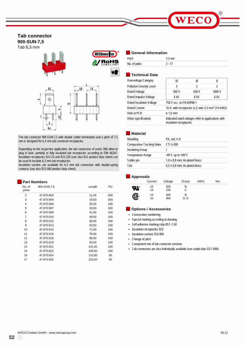
52
Tab connector900-SUN-7,5Tab 6,3 mm
09.13WECO Contact GmbH - www.wecogroup.com''no flame'' after glow-wire test according toHousehold Appliance DIN EN/IEC 60335-1
The tab connector 900-SUN-7,5 with double solder termination and a pitch of 7,5mm is designed for 6,3 mm tab connector receptacles.
Depending on the respective application, the tab connectors of series 900 allow toplug in bare, partially or fully insulated tab receptacles according to DIN 46247.Insulation receptacles ISO-25 and ISO-250 (see also ISO product data sheet) canbe used to insulate 6,3 mm tab receptacles.Insulation sockets are available for 6,3 mm tab connectors with double-springcontacts (see also ISO-900 product data sheet).
Part NumbersNo. ofpoles
900-SUN-7,5 Length PU
2 47.870.903 11,00 2503 47.870.904 18,50 2004 47.870.906 26,00 1005 47.870.907 33,50 1006 47.870.909 41,00 1007 47.870.910 48,50 1008 47.870.912 56,00 1009 47.870.913 63,50 10010 47.870.915 71,00 10011 47.870.916 78,50 10012 47.870.918 86,00 10013 47.870.919 93,50 10014 47.870.921 101,00 10015 47.870.922 108,50 10016 47.870.924 116,00 5017 47.870.925 123,50 50
General InformationPitch 7,5 mmNo. of poles 2 - 17
Technical DataOvervoltage Category III III IIPollution Severity Level 3 2 2Rated Voltage 500 V 630 V 1000 VRated Impulse Voltage 6 kV 6 kV 6 kVRated Insulation Voltage 750 V acc. to EN 60998-1Rated Current 16 A: with receptacles 6,3; wire 2,5 mm² (14 AWG)Hole in PCB ø 1,6 mmOther specifications Indicated rated voltages refer to applications with
insulation receptacles
MaterialMoulding PA, red, V-0Comparative Tracking Index CTI ≥ 600Insulating Group ITemperature Range -40°C up to 100°CSolder pin 1,0 x 0,8 mm; tin plated brassTab 6,3 x 0,8 mm; tin plated brass
ApprovalsCurrent Voltage Group AWG Nm
1515
300150
BC
1510
300300
BD, E
Options / Accessories• Consecutive numbering• Special marking according to drawing• Self-adhesive marking strip BST-7,50• Insulation receptacles ISO• Insulation sockets IS0-900• Change of pitch• Component mix of tab connector versions• Tab connectors are also individually available (see single tabs GST-900)

53
Tab connector900-SUN-10Tab 6,3 mm
09.13WECO Contact GmbH - www.wecogroup.com''no flame'' after glow-wire test according toHousehold Appliance DIN EN/IEC 60335-1
The tab connector 900-SUN-10 with double solder termination and a pitch of 10mm is designed for 6,3 mm tab connector receptacles.
Depending on the respective application, the tab connectors of series 900 allow toplug in bare, partially or fully insulated tab receptacles according to DIN 46247.Insulation receptacles ISO-25 and ISO-250 (see also ISO product data sheet) canbe used to insulate 6,3 mm tab receptacles.Insulation sockets are available for 6,3 mm tab connectors with double-springcontacts (see also ISO-900 product data sheet).
Part NumbersNo. ofpoles
900-SUN-10 Length PU
2 49.870.903 13,50 2503 49.870.905 23,50 1004 49.870.907 33,50 1005 49.870.909 43,50 1006 49.870.911 53,50 1007 49.870.913 63,50 1008 49.870.915 73,50 1009 49.870.917 83,50 10010 49.870.919 93,50 10011 49.870.921 103,50 10012 49.870.923 113,50 10013 49.870.925 123,50 50
further number of poles on request
General InformationPitch 10 mmNo. of poles 2 - 13
Technical DataOvervoltage Category III III IIPollution Severity Level 3 2 2Rated Voltage 630 V 630 V 1000 VRated Impulse Voltage 6 kV 6 kV 6 kVRated Insulation Voltage 750 V acc. to EN 60998-1Rated Current 16 A: with receptacles 6,3; wire 2,5 mm² (14 AWG)Hole in PCB ø 1,6 mmOther specifications Indicated rated voltages refer to applications with
insulation receptacles
MaterialMoulding PA, red, V-0Comparative Tracking Index CTI ≥ 600Insulating Group ITemperature Range -40°C up to 100°CSolder pin 1,0 x 0,8 mm; tin plated brassTab 6,3 x 0,8 mm; tin plated brass
ApprovalsCurrent Voltage Group AWG Nm
1515
300150
BC
1510
300300
BD, E
Options / Accessories• Consecutive numbering• Special marking according to drawing• Self-adhesive marking strip BST-10,00• Insulation receptacles ISO• Insulation sockets ISO-900• Change of pitch• Component mix of tab connector versions• Tab connectors are also individually available (see single tabs GST-900)

54
Tab connector900-W-5Tabs with 90° angle
09.13WECO Contact GmbH - www.wecogroup.com''no flame'' after glow-wire test according toHousehold Appliance DIN EN/IEC 60335-1
The tab connector 900-W-5 with double solder termination and a pitch of 5 mm isdesigned for 1x 2,8 mm and 1x 2,8 mm/1x 6,3 mm tab connector receptacles.
Depending on the respective application, the tab connectors of series 900 allow toplug in bare, partially or fully insulated tab receptacles according to DIN 46247. Anon-insulated 2,8 mm or a 6,3 mm (optionally also insulated) tab connectorreceptacle can be plugged in the angled plug-in area of the tab connector. To thevertical tab connector, a non-insulated 2,8 mm tab connector receptacle can bealso be connected. Insulation receptacles ISO-25 and ISO-250 (see also ISOproduct data sheet) can be used to insulate 6,3 mm tab receptacles.
Part NumbersNo. ofpoles
900-W-5 Length PU
2 25.870.902 8,50 2503 25.870.903 13,50 2504 25.870.904 18,50 2005 25.870.905 23,50 1006 25.870.906 28,50 1007 25.870.907 33,50 1008 25.870.908 38,50 1009 25.870.909 43,50 10010 25.870.910 48,50 10011 25.870.911 53,50 10012 25.870.912 58,50 10013 25.870.913 63,50 10014 25.870.914 68,50 5015 25.870.915 73,50 5016 25.870.916 78,50 5017 25.870.917 83,50 5018 25.870.918 88,50 5019 25.870.919 93,50 5020 25.870.920 98,50 5021 25.870.921 103,50 5022 25.870.922 108,50 5023 25.870.923 113,50 5024 25.870.924 118,50 5025 25.870.925 123,50 50
further number of poles on request
General InformationPitch 5 mmNo. of poles 2 - 25
Technical DataOvervoltage Category III III IIPollution Severity Level 3 2 2Rated Voltage 320 V 320 V 630 VRated Impulse Voltage 4 kV 4 kV 4 kVRated Insulation Voltage 450 V acc. to EN 60998-1Rated Current 6 A: with receptacles 2,8; wire 1 mm² (16 AWG)
16 A: with receptacles 6,3; wire 2,5 mm² (14 AWG)Hole in PCB ø 1,6 mmOther specifications Indicated rated voltages refer to applications with
insulation receptacles
MaterialMoulding PA, red, V-0Comparative Tracking Index CTI ≥ 600Insulating Group ITemperature Range -40°C up to 100°CSolder pin 1,0 x 0,8 mm; tin plated brassTab 2,8 x 0,8 mm; 6,3 x 0,8 mm; tin plated brass
ApprovalsCurrent Voltage Group AWG Nm
15 125 B
1510
300300
BD, E
Options / Accessories• Consecutive numbering• Special marking according to drawing• Self-adhesive marking strip BST-5,00• Insulation receptacles ISO• Change of pitch• Component mix of tab connector versions• Tab connectors are also individually available (see single tabs GST-900)

55
Tab connector900-W-7,5Tabs with 90° angle
09.13WECO Contact GmbH - www.wecogroup.com''no flame'' after glow-wire test according toHousehold Appliance DIN EN/IEC 60335-1
The tab connector 900-W-7,5 with double solder termination and a pitch of 7,5 mmis designed for 1x 2,8 mm and 1x 2,8 mm / 1x 6,3 mm tab connector receptacles.
Depending on the respective application, the tab connectors of series 900 allow toplug in bare, partially or fully insulated tab receptacles according to DIN 46247. Anon-insulated 2,8 mm or a 6,3 mm (optionally also insulated) tab connectorreceptacle can be plugged in the angled plug-in area of the tab connector. To thevertical tab connector, a non-insulated 2,8 mm tab connector receptacle can bealso be connected. Insulation receptacles ISO-25 and ISO-250 (see also ISOproduct data sheet) can be used to insulate 6,3 mm tab receptacles.
Part NumbersNo. ofpoles
900-W-7,5 Length PU
2 27.870.903 11,00 2503 27.870.904 18,50 2004 27.870.906 26,00 1005 27.870.907 33,50 1006 27.870.909 41,00 1007 27.870.910 48,50 1008 27.870.912 56,00 1009 27.870.913 63,50 10010 27.870.915 71,00 5011 27.870.916 78,50 5012 27.870.918 86,00 5013 27.870.919 93,50 5014 27.870.921 101,00 5015 27.870.922 108,50 5016 27.870.923 116,00 5017 27.870.924 123,50 50
General InformationPitch 7,5 mmNo. of poles 2 - 17
Technical DataOvervoltage Category III III IIPollution Severity Level 3 2 2Rated Voltage 500 V 630 V 1000 VRated Impulse Voltage 6 kV 6 kV 6 kVRated Insulation Voltage 750 V acc. to EN 60998-1Rated Current 6 A: with receptacles 2,8; wire 1 mm² (16 AWG)
16 A: with receptacles 6,3; wire 2,5 mm² (14 AWG)Hole in PCB ø 1,6 mmOther specifications Indicated rated voltages refer to applications with
insulation receptacles
MaterialMoulding PA, red, V-0Comparative Tracking Index CTI ≥ 600Insulating Group ITemperature Range -40°C up to 100°CSolder pin 1,0 x 0,8 mm; tin plated brassTab 2,8 x 0,8 mm; 6,3 x 0,8 mm; tin plated brass
ApprovalsCurrent Voltage Group AWG Nm
1515
300150
BC
1510
300300
BD, E
Options / Accessories• Consecutive numbering• Special marking according to drawing• Self-adhesive marking strip BST-7,50• Insulation receptacles ISO• Change of pitch• Component mix of tab connector versions• Tab connectors are also individually available (see single tabs GST-900)

56
Tab connector900-W-10Tabs with 90° angle
09.13WECO Contact GmbH - www.wecogroup.com''no flame'' after glow-wire test according toHousehold Appliance DIN EN/IEC 60335-1
The tab connector 900-W-10 with double solder termination and a pitch of 10 mmis designed for 1x 2,8 mm and 1x 2,8 mm / 1x 6,3 mm tab connector receptacles.
Depending on the respective application, the tab connectors of series 900 allow toplug in bare, partially or fully insulated tab receptacles according to DIN 46247. Anon-insulated 2,8 mm or a 6,3 mm (optionally also insulated) tab connectorreceptacle can be plugged in the angled plug-in area of the tab connector. To thevertical tab connector, a non-insulated 2,8 mm tab connector receptacle can bealso be connected. Insulation receptacles ISO-25 and ISO-250 (see also ISOproduct data sheet) can be used to insulate 6,3 mm tab receptacles.
Part NumbersNo. ofpoles
900-W-10 Length PU
2 30.870.903 13,50 2503 30.870.905 23,50 1004 30.870.907 33,50 1005 30.870.909 43,50 1006 30.870.911 53,50 1007 30.870.913 63,50 1008 30.870.915 73,50 509 30.870.917 83,50 5010 30.870.919 93,50 5011 30.870.921 103,50 5012 30.870.923 113,50 5013 30.870.925 123,50 50
further number of poles on request
General InformationPitch 10 mmNo. of poles 2 - 13
Technical DataOvervoltage Category III III IIPollution Severity Level 3 2 2Rated Voltage 630 V 630 V 1000 VRated Impulse Voltage 6 kV 6 kV 6 kVRated Insulation Voltage 750 V acc. to EN 60998-1Rated Current 6 A: with receptacles 2,8; wire 1 mm² (16 AWG)
16 A: with receptacles 6,3; wire 2,5 mm² (14 AWG)Hole in PCB ø 1,6 mmOther specifications Indicated rated voltages refer to applications with
insulation receptacles
MaterialMoulding PA, red, V-0Comparative Tracking Index CTI ≥ 600Insulating Group ITemperature Range -40°C up to 100°CSolder pin 1,0 x 0,8 mm; tin plated brassTab 2,8 x 0,8 mm; 6,3 x 0,8 mm; tin plated brass
ApprovalsCurrent Voltage Group AWG Nm
1515
300150
BC
1510
300300
BD, E
Options / Accessories• Consecutive numbering• Special marking according to drawing• Self-adhesive marking strip BST-10,00• Insulation receptacles ISO• Change of pitch• Component mix of tab connector versions• Tab connectors are also individually available (see single tabs GST-900)

57
Tab connector931-FST
02.11WECO Contact GmbH - www.wecogroup.com
The tab connector 931-FST with tabs 2,8 x 0,8 mm can be used both with plugconnector 930-FL or 938-FLDS and to connect individual wires with tabreceptacles B 2.8-DIN 46 247 whose crimped points must be insulated. The tabconnector is inserted in the plug connector 930-FL in direction of the wire entrance,which minimizes the space requirements on the PC board compared to thecombination with pin strip 931-SLS or 931-SLR.The receptacles are not parts of our production program.
Part NumbersNo. ofpoles
931-FST Length Pcs
2 12.893.705 7,00 10003 13.893.705 10,50 10004 14.893.705 14,00 5005 15.893.705 17,50 5006 16.893.705 21,00 5007 17.893.705 24,50 5008 18.893.705 28,00 2509 19.893.705 31,50 20010 20.893.705 35,00 20011 21.893.705 38,50 20012 22.893.705 42,00 25013 23.893.705 45,50 20014 24.893.705 49,00 20015 25.893.705 52,50 20016 26.893.705 56,00 200
General InformationPitch 3,5 mmNo. of poles 2 - 16Usable with plug connector 930-FL; 938-FLDS; receptacle B 2,8
Technical DataOvervoltage Category III III IIPollution Severity Level 3 2 2Rated Voltage 160 V 160 V 250 VRated Impulse Voltage 2,5 kV 2,5 kV 2,5 kVRated Insulation Voltage 130 V acc. to EN 60998-1Rated Current 6 A: with receptacles 2,8; wire 1 mm² (16 AWG)Hole in PCB ø 1,8 mmOther specifications Rated voltage with insulated receptacles
MaterialMoulding PA, grey, V-0Comparative Tracking Index CTI 250Insulating Group IIIaTemperature Range -40°C up to 100°CSolder pin 1,4 x 0,8 mm; tin plated brassTab 2,8 x 0,8 mm; tin plated brass
ApprovalsCurrent Voltage Group AWG Nm
6 300 B
6 300 B
Options / Accessories• Pitch of 7 mm for larger clearance and creepage distances

58
Tab/screw connector block970-B-2,8(-DS)screw connection, with tabs 2,8
06.14WECO Contact GmbH - www.wecogroup.com''no flame'' after glow-wire test according toHousehold Appliance DIN EN/IEC 60335-1
1,5
13
5
0,8
5
5
L
ø 2,6ø 4
4,2
2,8
99
3,1
L - 10
Tab/screw connector block 970-B-2,8 in 5 mm pitch is a combination of tabconnector block and screw connector. They are available in 2- to 8-pole design.They are mostly used for the mains connections of electrical equipment but arealso suitable for other applications.
Due to the 5 mm pitch, the tab/screw connector block 970-B-2,8 has only smallspace requirements and is particularly suitable as lead-out terminal for plasticwalls.The housing features two lateral mounting flanges.Interior connections are designed as A 2,8 mm x 0,8 mm tab connectors.The wire protector of the “DS”-version reliably prevents damage to multi-wireflexible conductors by the turning screw.
Installation note:Tab connectors are provided for connections inside electrical equipment. Theyoffer easy and low-cost mounting solutions. Screw connections are available formains connections.
Part NumbersNo. ofpoles
970-B-2,8 970-B-2,8-DS Length PU
2 13.872.702 23.872.702 20,00 2003 13.872.703 23.872.703 25,00 2004 13.872.704 23.872.704 30,00 1005 13.872.705 23.872.705 35,00 1006 13.872.706 23.872.706 40,00 1007 13.872.707 23.872.707 45,00 1008 13.872.708 23.872.708 50,00 100
General InformationPitch 5 mmNo. of poles 2 - 8
Technical DataClamping Range solid / flexible / AWG
without wire protector 1 - 6 mm² / 1 - 2,5 mm² / 16 - 12 AWGwith wire protector 0,75 - 4 mm² / 0,75 - 2,5 mm² / 18 - 12 AWG
Rated Cross Section 2,5 mm² [1]; 1 mm² [2]Wire Stripping Length 6,5 mmOvervoltage Category IIIPollution Severity Level 3Rated Voltage 250 VRated Impulse Voltage 4 kV
Rated Insulation Voltage 250 V acc. to EN 60998-1Rated Current 6 A: with receptacle 2,8; wire 1 mm² (16 AWG)Torque 0,5 NmOther specifications Indicated rated voltages refer to applications with
insulation receptacles.
MaterialMoulding PA, grey, V-0Comparative Tracking Index CTI ≥ 600Insulating Group ITemperature Range -40°C up to 100°CTerminal Body Nickel plated brassTab Nickel plated brassScrew M3; zinc plated steel, blue passivatedWire protector Tin plated tin bronze
ApprovalsCurrent Voltage Group AWG Nm
6 300 B,D 22 - 12 0,51 [3]
6 300 B,D,E 22 - 10 0,51
Options / Accessories• Consecutive numbering• Special marking according to drawing• Self-adhesive marking strip BST-5,00• Version with higher number of poles• Version without fastening flanges• Version with extended wire entrance• Double wire protector as bridge
[1] Screw side[2] Plug-in side[3] No. 26 AWG min for factory-wiring only

59
Tab/screw connector blocks982-Fwith tabs 4,8 or screw connection
06.14WECO Contact GmbH - www.wecogroup.com''no flame'' after glow-wire test according toHousehold Appliance DIN EN/IEC 60335-1
Tab/screw connector block 982-F in 9,52 mm pitch is based on our proven 98..series (see Catalogue 4 “Pitch 7,5 mm”).It features a 4.8 mm tab connector in star-shaped arrangement and is available in2- to 24-pole design for a maximum of six tab connectors or alternatively one screwconnector per pole.The compartments on both extremities of the block can serve either for mountingon a substrate or for fastening our 982-A/983-A cover caps. Upon request, othercompartments can remain empty for mounting purposes.
Installation note:Since the bottom is not closed, the connector should be mounted on an isolatingsubstrate/surface. Alternatively, our marking strip BST-983-F can be used for thispurpose.
Due to the large variety of different types, listing numbers and prices of the variousarticles is not possible. When inquiring or ordering products with uniform assembly,stating the number of poles and the assembly number is sufficient. For mixedassemblies, we require an exemplary scheme including the orientation ofasymmetrical assemblies, stating the number of desired poles and the assembly ofeach pole with assembly number.
General InformationPitch 9,52 mmNo. of poles 2 - 24
Technical DataClamping Range solid / flexible / AWG
0,75 - 2,5 mm² / 0,75 - 2,5 mm² / 18 - 12 AWGRated Cross Section 2,5 mm² [1]Wire Stripping Length 8,5 mmOvervoltage Category IIIPollution Severity Level 3Rated Voltage 320 VRated Impulse Voltage 4 kVRated Insulation Voltage 450 V acc. to EN 60998-1Rated Current 16 A: with receptacle 4,8; wire 2,5 mm² (14 AWG)Torque 0,8 NmOther specifications For screw connectors, two leads of identical
cross-section can be connected per pole.
MaterialMoulding PA, grey, V-0Comparative Tracking Index CTI ≥ 600Insulating Group ITemperature Range -40°C up to 100°CTerminal Body Nickel plated brassTab Nickel plated brassScrew M3,5; zinc plated steel, blue passivatedTubular rivet Tin plated copper
ApprovalsCurrent Voltage Group AWG Nm
20 300 B 20 - 12 0,79
1510
300300
BD,E
20 - 1220 - 12
0,790,79
Options / Accessories• Consecutive numbering• Version for printed circuits (with solder connection), see type 983-FS/-FD• Cover cap for use with assembly type 8.011 and screw connections• Crosshead screws• Fastening pole position can be freely selected
[1] Screw side

6005.14WECO Contact GmbH - www.wecogroup.com
Example ordering scheme for mixed assembly (“MIX”)
Assembly layout Tab size
When inquiring or ordering products for uniform assembly, stating the above designation is sufficient.
For mixed assembly (“MIX” as part of the type designation), we additionally need a drawing according to the example on the left.The drawing must state the desired number of poles, the assembly of each pole and the assembly number.
MIX
02
24
4,8
4,8
Assembly layoutPlease enter here the desiredassembly type number.
No. ofpoles
toIf you order various sizes,please enclose drawingand enterhere:
–
Tab size
(not applicable, if screwconnection 8.190 only)
4,8Standard crosshead screw design,crosshead screws upon request
8.011 8.077 8.066 8.019 8.022 8.033
8.190
8.011
8.022
8.033
8.066
8.190
8.019
982-F-4,8/
982-FTab/screw connector blocks
Assembly layout and order information

61
Tab/screw connector block982-MF-2,8/-4,8with tabs
06.14WECO Contact GmbH - www.wecogroup.com''no flame'' after glow-wire test according toHousehold Appliance DIN EN/IEC 60335-1
16
3,3ø
0,8
L16
,511
,5
9,52 2,8 (4,8)
6ø
Tab/screw connector blocks 982-MF-2,8 and 982-MF-4,8 in 9,52 mm pitch areavailable in 2- to 12-pole design and can be mounted side-by-side in nominal pitch.These connectors are based on our series 982 terminal strips.
The lead connection is designed as head contact terminal with M3,5 screws.Screws and square washers are movably connected. The square washers aremounted in a non-twist arrangement. For an easier connection of the lead, thewasher automatically moves up when the screw is loosened.
One tab connection per pole with widths of 2,8 or 4,8 mm is located on thesolder/tab side. That way, current transmission to other components is possiblewithout using printed circuits.
Part NumbersNo. ofpoles
982-MF-2,8 982-MF-4,8 Length PU
2 40.873.704 42.873.704 38,08 1003 40.873.705 42.873.705 47,60 1004 40.873.706 42.873.706 57,12 1005 40.873.707 42.873.707 66,64 1006 40.873.708 42.873.708 76,16 1007 40.873.709 42.873.709 85,68 508 40.873.710 42.873.710 95,20 509 40.873.711 42.873.711 104,72 5010 40.873.712 42.873.712 114,24 5011 40.873.713 42.873.713 123,76 5012 40.873.714 42.873.714 133,28 50
further number of poles on request
General InformationPitch 9,52 mmNo. of poles 2 - 12Areas of application Wall bushings
Technical DataClamping Range solid / flexible / AWG
0,5 - 2,5 mm² / 0,5 - 2,5 mm² / 20 - 12 AWGRated Cross Section 2,5 mm² [1]Wire Stripping Length 8,5 mmOvervoltage Category IIIPollution Severity Level 3Rated Voltage 320 VRated Impulse Voltage 4 kV
Rated Insulation Voltage 450 V acc. to EN 60998-1Rated Current 6 A: with receptacle 2,8; wire 1 mm² (16 AWG)
16 A: with receptacle 4,8; wire 2,5 mm² (14 AWG)Torque 0,8 NmOther specifications Per pole two wires of identical cross-section can
be connected. Indicated rated voltages refer toapplications with insulation receptacles.
MaterialMoulding PA, grey, V-0Comparative Tracking Index CTI ≥ 600Insulating Group ITemperature Range -40°C up to 100°CTerminal Body Nickel plated brassTab Nickel plated brassScrew M3,5; zinc plated steel, blue passivatedTubular rivet Tin plated copper
ApprovalsCurrent Voltage Group AWG Nm
15 300 B 20 - 12 0,79 [2]
1510
300300
BD,E
20 - 1220 - 12
0,79 [3]0,79 [3]
Options / Accessories• Consecutive numbering• Insulation receptacles ISO• Cover caps• Crosshead screws on request• Tab versions available instead of screw connections• Bushing and mounting bases are available upon request
[1] Screw side[2] For type 982-MF-2,8 is applicable: 300 V / B / 6 A / 0,79 Nm[3] For type 982-MF-2,8 is applicable: 300 V / B,D,E / 6 A / 0,79 Nm

62
Screw/solder connector block982-ML-2,8with soldering tags
06.14WECO Contact GmbH - www.wecogroup.com''no flame'' after glow-wire test according toHousehold Appliance DIN EN/IEC 60335-1
Screw/solder connector block 982-ML-2,8 in 9,52 mm pitch is available in 2- to12-pole design and can be mounted side-by-side in nominal pitch. This connectoris based on our series 982 terminal strip.
The lead connection is designed as head contact terminal with M3,5 screws.Screws and square washers are movably connected. The square washers aremounted in a non-twist arrangement. For an easier connection of the lead, thewasher automatically moves up when the screw is loosened.
One solder tag (width 2,8 mm) per pole is located on the soldering side.
Part NumbersNo. ofpoles
982-ML-2,8 Length PU
2 46.873.704 38,08 1003 46.873.705 47,60 1004 46.873.706 57,12 1005 46.873.707 66,64 1006 46.873.708 76,16 1007 46.873.709 85,68 508 46.873.710 95,20 509 46.873.711 104,72 5010 46.873.712 114,24 5011 46.873.713 123,76 5012 46.873.714 133,28 50
General InformationPitch 9,52 mmNo. of poles 2 - 12Accessories Marking strips 983-FAreas of application Wall bushings
Technical DataClamping Range solid / flexible / AWG
0,75 - 2,5 mm² / 0,75 - 2,5 mm² / 18 - 12 AWGRated Cross Section 2,5 mm² [1]Wire Stripping Length 8,5 mmOvervoltage Category IIIPollution Severity Level 3Rated Voltage 320 VRated Impulse Voltage 4 kVRated Insulation Voltage 450 V acc. to EN 60998-1Rated Current 17,5 A (wire 1,5 mm² at soldering tag)Torque 0,8 NmOther specifications Per pole two wires of identical cross-section can
be connected.
MaterialMoulding PA, grey, V-0Comparative Tracking Index CTI ≥ 600Insulating Group ITemperature Range -40°C up to 100°CTerminal Body Tin plated brassScrew M3,5; zinc plated steel, blue passivatedTubular rivet Tin plated copper
ApprovalsCurrent Voltage Group AWG Nm
20 300 B 20 - 12 0,79
2010
300300
BD,E
20 - 1220 - 12
0,790,79
Options / Accessories• Consecutive numbering• Version for printed circuits (with solder connection), see type 983-FS/-FD• Insulation receptacles ISO• Cover caps• Crosshead screws on request• Tab versions available instead of screw connections• Bushing and mounting bases are available upon request
[1] Screw side

63
PCB connector982-SMF-2,8/-4,8Screw connection, with solder pin and tab
09.11WECO Contact GmbH - www.wecogroup.com''no flame'' after glow-wire test according toHousehold Appliance DIN EN/IEC 60335-1
982-SMF-2,8
982-SMF-4,8
The PCB connectors 982-SMF-2,8 and 982-SMF-4,8 with a pitch of 9.52 mm areavailable in 1- to 12-pole design and can be mounted side-by-side in the nominalpitch.They are based on our series 982 terminal strips.
The conductor terminal is of head contact design with Screws M3.5, whereby thescrews and square washers are movably connected.For easier connection, the non-rotably mounted square washers are automaticallylifted when the screw is loosened.
On the solder side and the plug-in side they feature one solder pin and one tabconnection of 2.8 mm or 4.8 mm width per pole.This allows current to flow to other components without having to use additionalconductor paths.
Part NumbersNo. ofpoles
982-SMF-2,8 982-SMF-4,8 Length PU
1 91.873.703 92.873.703 28,56 2002 91.873.704 92.873.704 38,08 2003 91.873.705 92.873.705 47,60 2004 91.873.706 92.873.706 57,12 1005 91.873.707 92.873.707 66,64 506 91.873.708 92.873.708 76,16 507 91.873.709 92.873.709 85,68 508 91.873.710 92.873.710 95,20 509 91.873.711 92.873.711 104,72 5010 91.873.712 92.873.712 114,24 5011 91.873.713 92.873.713 123,76 5012 91.873.714 92.873.714 133,28 50
further number of poles on request
General InformationPitch 9,52 mmNo. of poles 1 - 12
Technical DataClamping Range solid / flexible / AWG
0,75 - 2,5 mm² / 0,75 - 2,5 mm² / 18 - 12 AWGRated Cross Section 2,5 mm²Wire Stripping Length 8,5 mmOvervoltage Category IIIPollution Severity Level 3Rated Voltage 320 VRated Impulse Voltage 4 kV
Rated Insulation Voltage 450 V acc. to EN 60998-1Rated Current 6 A: with receptacles 2,8; wire 1 mm² (16 AWG)
16 A: with receptacles 4,8; wire 2,5 mm² (14 AWG)Hole in PCB ø 1,6 mmTorque 0,8 NmOther specifications Screw-fixing holes ø 3,2 mm. Per pole two wires of
identical cross-section can be connected. Indicatedrated voltage applies to applications with insulationreceptacles.
MaterialMoulding PA, grey, V-0Comparative Tracking Index CTI ≥ 600Insulating Group ITemperature Range -40°C up to 100°CPressure clamp Tin plated brassScrew M3,5; zinc plated steel, blue passivatedSolder pin 0,8 x 1,0 mm; tin plated brass
ApprovalsCurrent Voltage Group AWG Nm
20 300 B 20 - 12 0,79
61510
300300300
B, D, EB
D, E
20 - 1220 - 1220 - 12
0,79 [1]0,79 [2]0,79 [2]
[1] for 982-SMF-2,8[2] for 982-SMF-4,8
Options / Accessories• Consecutive numbering• Special marking according to drawing• Crosshead screws• Cover cap 982-A• Securing pins BEF-983• Fastening pole position can be freely selected• Various versions of tabs instead of screw connections

64
Tab/screw connector blocks983-Fwith tabs 4,8 or screw connection
06.14WECO Contact GmbH - www.wecogroup.com''no flame'' after glow-wire test according toHousehold Appliance DIN EN/IEC 60335-1
10
L
17,2
4,8
16
ø 6,2
ø 3,8
Tab/screw connector block 983-F in 10 mm pitch is based on our proven 98..series (see Catalogue 5 “Pitch >10 mm”).It features a 4.8 mm tab connector in star-shaped arrangement and is available in2- to 24-pole design for a maximum of six tab connectors or alternatively one screwconnector per pole.The compartments on both extremities of the block can serve either for mountingon a substrate or for fastening our 982-A/983-A cover caps. Upon request, othercompartments can remain empty for mounting purposes.
Installation note:Since the bottom is not closed, the connector should be mounted on an isolatingsubstrate/surface. Alternatively, our marking strip BST-983-F can be used for thispurpose.
Due to the large variety of different types, listing numbers and prices of the variousarticles is not possible. When inquiring or ordering products with uniform assembly,stating the number of poles and the assembly number is sufficient. For mixedassemblies, we require an exemplary scheme including the orientation ofasymmetrical assemblies, stating the number of desired poles and the assembly ofeach pole with assembly number.
General InformationPitch 10 mmNo. of poles 2 - 24
Technical DataClamping Range solid / flexible / AWG
0,5 - 2,5 mm² / 0,5 - 2,5 mm² / 20 - 12 AWGRated Cross Section 2,5 mm² [1]Wire Stripping Length 8,5 mmOvervoltage Category IIIPollution Severity Level 3Rated Voltage 320 VRated Impulse Voltage 4 kVRated Insulation Voltage 450 V acc. to EN 60998-1Rated Current 16 A: with receptacle 4,8; wire 2,5 mm² (14 AWG)Torque 1,2 NmOther specifications For screw connectors, two leads of identical
cross-section can be connected per pole.
MaterialMoulding PA, grey, V-0Comparative Tracking Index CTI ≥ 600Insulating Group ITemperature Range -40°C up to 100°CTerminal Body Nickel plated brassTab Nickel plated brassScrew M4; zinc plated steel, blue passivatedTubular rivet Tin plated brass
ApprovalsCurrent Voltage Group AWG Nm
15 [2] 300 B 20 - 12 1,13
15 [2]10
300300
BD,E
20 - 1220 - 12
1,131,13
Options / Accessories• Consecutive numbering• Special marking according to drawing• Self-adhesive marking strip BST-10,00• Design for printed circuits (with solder connection), please see 983-FS/-FD• Cover caps• Crosshead for screw connection upon request• Fastening pole position can be freely selected
[1] Screw side[2] Version with screw connections only: 20 A max.

6505.14WECO Contact GmbH - www.wecogroup.com
Example ordering scheme for mixed assembly (“MIX”)
Assembly layout Tab size
When inquiring or ordering products for uniform assembly, stating the above designation is sufficient.
For mixed assembly (“MIX” as part of the type designation), we additionally need a drawing according to the example on the left.The drawing must state the desired number of poles, the assembly of each pole and the assembly number.
MIX
02
24
4,8
4,8
Assembly layoutPlease enter here the desiredassembly type number.
No. ofpoles
toIf you order various sizes,please enclose drawingand enterhere:
–
Tab size
(not applicable, if screwconnection 8.190 only)
4,8Standard crosshead screw design,crosshead screws upon request
8.011 8.077 8.066 8.019 8.022 8.033
8.190
8.011
8.022
8.033
8.066
8.190
8.019
983-F-4,8/
983-FTab/screw connector blocks
Assembly layout and order information

66
Tab connector983-FDTab/screw connection, 2 solder pins per pole
09.13WECO Contact GmbH - www.wecogroup.com''no flame'' after glow-wire test according toHousehold Appliance DIN EN/IEC 60335-1
L = Number of poles x pitchA: Terminal design with tab connector package 8.066B: Terminal design with tab connector package 8.022
Terminal designs / Example of mixed assembly
* = Screw connection
On the input side, each pole of the tab connector 983-FD in 10 mm pitch can beconnected to up to 6 tab connections or one screw connection.For a uniform assembly, version, assembly type (4-digit number) and number ofpoles must be specified. Both technical drawings (A and B) show an example foruniform assembly. Mixed assembly requires either specifications of the terminaldesign for each pole or a drawing.
Due to the multitude of assembly combinations there is no designated order code.For uniform assembly with screw connections (8.190) see tab connector strip983-D.
General InformationPitch 10 mmNo. of poles 2 - 26Usable with receptacles for tabs acc. to DIN 46247
Technical DataClamping Range solid / flexible / AWG
0,5 - 2,5 mm² / 0,5 - 2,5 mm² / 20 - 12 AWGRated Cross Section 2,5 mm²Wire Stripping Length 8,5 mmOvervoltage Category IIIPollution Severity Level 3Rated Voltage 320 VRated Impulse Voltage 4 kVRated Insulation Voltage 450 V acc. to EN 60998-1Rated Current 16 A: with receptacles 4,8; wire 2,5 mm² (14 AWG)Hole in PCB ø 1,6 mmTorque 1,2 NmOther specifications For screw connections, 2 wires of the same
cross-section can be connected per pole. Thespecified rated voltage applies to applications withinsulating receptacles.
MaterialMoulding PA, grey, V-0Comparative Tracking Index CTI ≥ 600Insulating Group ITemperature Range -40°C up to 100°CPressure clamp Tin plated brassScrew M4; zinc plated steel, blue passivatedSolder pin 0,8 x 1,0 mm; tin plated brassTab Nickel plated brassTubular rivet Tin plated copper
ApprovalsCurrent Voltage Group AWG Nm
15 300 B 20 - 12
1510
300300
BD, E
20 - 1220 - 12
Options / Accessories• Consecutive numbering• Special marking according to drawing• Self-adhesive marking strip BST-10,00• Cover cap 983-A (two unassigned poles required); not suitable for every
assembly type• Crosshead screws• 10 mm pin length• Version without solder pin
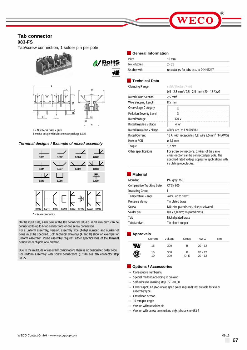
67
Tab connector983-FSTab/screw connection, 1 solder pin per pole
09.13WECO Contact GmbH - www.wecogroup.com''no flame'' after glow-wire test according toHousehold Appliance DIN EN/IEC 60335-1
L = Number of poles x pitchTerminal design with tab connector package 8.022
Terminal designs / Example of mixed assembly
* = Screw connection
On the input side, each pole of the tab connector 983-FS in 10 mm pitch can beconnected to up to 6 tab connections or one screw connection.For a uniform assembly, version, assembly type (4-digit number) and number ofpoles must be specified. Both technical drawings (A and B) show an example foruniform assembly. Mixed assembly requires either specifications of the terminaldesign for each pole or a drawing.
Due to the multitude of assembly combinations there is no designated order code.For uniform assembly with screw connections (8.190) see tab connector strip983-S.
General InformationPitch 10 mmNo. of poles 2 - 26Usable with receptacles for tabs acc. to DIN 46247
Technical DataClamping Range solid / flexible / AWG
0,5 - 2,5 mm² / 0,5 - 2,5 mm² / 20 - 12 AWGRated Cross Section 2,5 mm²Wire Stripping Length 8,5 mmOvervoltage Category IIIPollution Severity Level 3Rated Voltage 320 VRated Impulse Voltage 4 kVRated Insulation Voltage 450 V acc. to EN 60998-1Rated Current 16 A: with receptacles 4,8; wire 2,5 mm² (14 AWG)Hole in PCB ø 1,6 mmTorque 1,2 NmOther specifications For screw connections, 2 wires of the same
cross-section can be connected per pole. Thespecified rated voltage applies to applications withinsulating receptacles.
MaterialMoulding PA, grey, V-0Comparative Tracking Index CTI ≥ 600Insulating Group ITemperature Range -40°C up to 100°CPressure clamp Tin plated brassScrew M4; zinc plated steel, blue passivatedSolder pin 0,8 x 1,0 mm; tin plated brassTab Nickel plated brassTubular rivet Tin plated copper
ApprovalsCurrent Voltage Group AWG Nm
15 300 B 20 - 12
1510
300300
BD, E
20 - 1220 - 12
Options / Accessories• Consecutive numbering• Special marking according to drawing• Self-adhesive marking strip BST-10,00• Cover cap 983-A (two unassigned poles required); not suitable for every
assembly type• Crosshead screws• 10 mm pin length• Version without solder pin• Version with screw connections only, please see 983-S

68
Tab/screw connector blocks983-MF-2,8/-4,8with tabs
06.14WECO Contact GmbH - www.wecogroup.com''no flame'' after glow-wire test according toHousehold Appliance DIN EN/IEC 60335-1
16
6,2ø
3,8ø
0,8
L
10
17,2
11,5
2,8 (4,8)
Tab/screw connector blocks 983-MF-2,8 and 983-MF-4,8 in 10 mm pitch areavailable in 2- to 12-pole design and can be mounted side-by-side in nominal pitch.These connectors are based on our series 983 terminal strips.
The lead connection is designed as head contact terminal with M3,5 screws.Screws and square washers are movably connected. The square washers aremounted in a non-twist arrangement. For an easier connection of the lead, thewasher automatically moves up when the screw is loosened.
One tab connection per pole with widths of 2,8 or 4,8 mm is located on thesolder/tab side. That way, current transmission to other components is possiblewithout using printed circuits.
Part NumbersNo. ofpoles
983-MF-2,8 983-MF-4,8 Length PU
2 40.873.804 42.873.804 40,00 1003 40.873.805 42.873.805 50,00 1004 40.873.806 42.873.806 60,00 1005 40.873.807 42.873.807 70,00 1006 40.873.808 42.873.808 80,00 1007 40.873.809 42.873.809 90,00 508 40.873.810 42.873.810 100,00 509 40.873.811 42.873.811 110,00 5010 40.873.812 42.873.812 120,00 5011 40.873.813 42.873.813 130,00 5012 40.873.814 42.873.814 140,00 50
further number of poles on request
General InformationPitch 10 mmNo. of poles 2 - 12Areas of application Wall bushings
Technical DataClamping Range solid / flexible / AWG
0,5 - 2,5 mm² / 0,5 - 2,5 mm² / 20 - 12 AWGRated Cross Section 2,5 mm² [1]Wire Stripping Length 8,5 mmOvervoltage Category IIIPollution Severity Level 3Rated Voltage 320 VRated Impulse Voltage 4 kV
Rated Insulation Voltage 450 V acc. to EN 60998-1Rated Current 6 A: with receptacle 2,8; wire 1,0 mm² (16 AWG)
16 A: with receptacle 4,8; wire 2,5 mm² (14 AWG)Torque 1,2 NmOther specifications Per pole two wires of identical cross-section can
be connected. Indicated rated voltages refer toapplications with insulation receptacles.
MaterialMoulding PA, grey, V-0Comparative Tracking Index CTI ≥ 600Insulating Group ITemperature Range -40°C up to 100°CTerminal Body Nickel plated brassTab Nickel plated brassScrew M4; zinc plated steel, blue passivated
ApprovalsCurrent Voltage Group AWG Nm
15 300 B 20 - 12 1,13 [2]
1510
300300
BD,E
20 - 1220 - 12
1,13 [3]1,13 [3]
Options / Accessories• Consecutive numbering• Special marking according to drawing• Self-adhesive marking strip BST-10,00• Insulation receptacles ISO• Cover caps• Crosshead screws on request• Tab versions available instead of screw connections• Bushing and mounting bases or backwalls are available upon request
[1] Screw side[2] For type 983-MF-2,8 is applicable: 300 V / B / 7 A / 1,13 Nm[3] For type 983-MF-2,8 is applicable: 300 V / B,D,E / 6 A / 1,13 Nm

69
Screw/solder connector block983-ML-2,8with soldering tags
06.14WECO Contact GmbH - www.wecogroup.com''no flame'' after glow-wire test according toHousehold Appliance DIN EN/IEC 60335-1
Screw/solder connector block 983-ML-2,8 in 10 mm pitch is available in 2- to12-pole design and can be mounted side-by-side in nominal pitch. This connectoris based on our series 983 terminal strip.
The lead connection is designed as head contact terminal with M4 screws. Screwsand square washers are movably connected. The square washers are mounted ina non-twist arrangement. For an easier connection of the lead, the washerautomatically moves up when the screw is loosened.
One solder tag (width 2,8 mm) per pole is located on the soldering side.
Part NumbersNo. ofpoles
983-ML-2,8 Length PU
2 46.873.804 40,00 1003 46.873.805 50,00 1004 46.873.806 60,00 1005 46.873.807 70,00 1006 46.873.808 80,00 1007 46.873.809 90,00 508 46.873.810 100,00 509 46.873.811 110,00 5010 46.873.812 120,00 5011 46.873.813 130,00 5012 46.873.814 140,00 50
further number of poles on request
General InformationPitch 10 mmNo. of poles 2 - 12Areas of application Wall bushings
Technical DataClamping Range solid / flexible / AWG
0,5 - 2,5 mm² / 0,5 - 2,5 mm² / 20 - 12 AWGRated Cross Section 2,5 mm² [1]Wire Stripping Length 8,5 mmOvervoltage Category IIIPollution Severity Level 3Rated Voltage 320 VRated Impulse Voltage 4 kV
Rated Insulation Voltage 450 V acc. to EN 60998-1Rated Current 17,5 A (wire 1,5 mm² at soldering tag)Torque 1,2 NmOther specifications Per pole two wires of identical cross-section can
be connected.
MaterialMoulding PA, grey, V-0Comparative Tracking Index CTI > 600Insulating Group ITemperature Range -40°C up to 100°CTerminal Body Tin plated brassScrew M4; zinc plated steel, blue passivated
ApprovalsCurrent Voltage Group AWG Nm
20 300 B 20 - 12 1,13
2010
300300
BD,E
20 - 1220 - 12
1,131,13
Options / Accessories• Consecutive numbering• Special marking according to drawing• Self-adhesive marking strip BST-10,00• Version for printed circuits (with solder connection), see type 983-FS/-FD• Cover caps• Crosshead screws on request• Tab versions available instead of screw connections• Bushing and mounting bases are available upon request• Housings with backwalls
[1] Screw side

70
PCB connector983-SMF-2,8/-4,8Screw connection, with solder pin and tab
10.11WECO Contact GmbH - www.wecogroup.com''no flame'' after glow-wire test according toHousehold Appliance DIN EN/IEC 60335-1
983-SMF-2,8
983-SMF-4,8
The PCB connectors 983-SMF-2,8 and 983-SMF-4,8 with a pitch of 10 mm areavailable in 1- to 12-pole design and can be mounted side-by-side in the nominalpitch.They are based on our series 983 terminal strips.
The conductor terminal is of head contact design with Screws M4, whereby thescrews and square washers are movably connected.For easier connection, the non-rotably mounted square washers are automaticallylifted when the screw is loosened.
On the solder side and the plug-in side they feature one solder pin and one tabconnection of 2.8 mm or 4.8 mm width per pole.This allows current to flow to other components without having to use additionalconductor paths.
Part NumbersNo. ofpoles
983-SMF-2,8 983-SMF-4,8 Length PU
1 91.873.803 92.873.803 30,00 1002 91.873.804 92.873.804 40,00 1003 91.873.805 92.873.805 50,00 1004 91.873.806 92.873.806 60,00 1005 91.873.807 92.873.807 70,00 1006 91.873.808 92.873.808 80,00 1007 91.873.809 92.873.809 90,00 508 91.873.810 92.873.810 100,00 509 91.873.811 92.873.811 110,00 5010 91.873.812 92.873.812 120,00 5011 91.873.813 92.873.813 130,00 5012 91.873.814 92.873.814 140,00 50
General InformationPitch 10 mmNo. of poles 1 - 12
Technical DataClamping Range solid / flexible / AWG
0,5 - 2,5 mm² / 0,5 - 2,5 mm² / 20 - 12 AWGRated Cross Section 2,5 mm²Wire Stripping Length 8,5 mmOvervoltage Category IIIPollution Severity Level 3Rated Voltage 320 VRated Impulse Voltage 4 kV
Rated Insulation Voltage 450 V acc. to EN 60998-1Rated Current 6 A: with receptacles 2,8; wire 1 mm² (16 AWG)
16 A: with receptacles 4,8; wire 2,5 mm² (14 AWG)Hole in PCB ø 1,6 mmTorque 1,2 NmOther specifications Screw-fixing holes ø 3,2 mm. Per pole two wires of
identical cross-section can be connected. Indicatedrated voltage applies to applications with insulationreceptacles.
MaterialMoulding PA, grey, V-0Comparative Tracking Index CTI ≥ 600Insulating Group ITemperature Range -40°C up to 100°CPressure clamp Tin plated brassScrew M4; zinc plated steel, blue passivatedSolder pin 0,8 x 1,0 mm; tin plated brass
ApprovalsCurrent Voltage Group AWG Nm
20 300 B 20 - 12 1,13
61510
300300300
B, D, EB
D, E
20 - 1220 - 1220 - 12
1,13 [1]1,33 [2]1,33 [2]
[1] for 982-SMF-2,8[2] for 982-SMF-4,8
Options / Accessories• Consecutive numbering• Special marking according to drawing• Self-adhesive marking strip BST-10,00• Cover cap 983-A• Securing pins BEF-983, fastening pole position can be freely selected• Crosshead screws• Various versions of tabs instead of screw connections

71
This section contains flat plug guides and
housings .
Tab receptacles and housings of series
411 are suitable for all applications in elec-
trical machines, vehicles, equipment and
switchgear .
Tab connector or tab receptacle are con-
nected with the terminal lead and inserted
into the housing where they latch automa-
tically .
The flat plug guide 440 is used for the
insulation of tab connectors with nominal
size 6.3.
Flat plug guides and housings

72
Plug receptacle411-Bfor tabs 6,3 mm
06.14WECO Contact GmbH - www.wecogroup.com''no flame'' after glow-wire test according toHousehold Appliance DIN EN/IEC 60335-1
Series 411 flat plug couplings are suited for electrical machines, vehicles,appliances and switch gear systems.After crimping the leads, the flat plugs are plugged into the 411-B plug receptaclesaccording to DIN 46340. Index lobes on the metal part lock them into place in thehousing.Subsequently, the housing/plug receptacles combination can now be connectedwith the 411-S housing equipped with flat plugs resulting in a flat plug couplingsuitable in for switch gear applications.
The housing shape prevents false plugging. Pole identifiers are located on the plugopenings of the metal parts.
Please note:Suitable plug receptacles are not included in our product range.
Part NumbersNo. ofpoles
411-B PU
2 10.837.004 10004 10.837.006 10006 10.837.002 5008 10.837.008 500
Part numbers: "no flame" acc. to glow-wire testNo. ofpoles
411-B PU
6 10.837.002.EN6 500further number of poles on request
General InformationNo. of poles 2, 4, 6, 8Usable with Flat plug housing 411-SAreas of application for electrical machines, vehicles, appliances and
switch gear systems
Technical DataRated Cross Section 6,0 mm² / 10 AWGOvervoltage Category IIPollution Severity Level 2Rated Voltage 400 VRated Impulse Voltage 4 kV
Rated Current 25 A: with receptacle 6,3; wire 6,0 mm² (10 AWG)
MaterialMoulding PA, natural, V-2 (PA, white, V-0)
details in parentheses for "no flame" productsComparative Tracking Index CTI ≥ 600Insulating Group ITemperature Range -40°C up to 100°C

73
Plug receptacle411-BMLwith fastening flanges, for receptacle for tabs 6,3
06.14WECO Contact GmbH - www.wecogroup.com
Series 411 flat plug couplings are suited for electrical machines, vehicles,appliances and switch gear systems.After crimping the leads, the flat plugs are plugged into the 411-BML plugreceptacles according to DIN 46340.Index lobes on the metal part lock them into place in the housing.Subsequently, the housing/plug receptacles combination can now be connectedwith the 411-S housing equipped with flat plugs resulting in a flat plug couplingsuitable in for switch gear applications.
The housing shape prevents false plugging.Pole identifiers are located on the plug openings of the metal parts.The housing side is equipped with an additional mounting lug.
Please note:Suitable plug receptacles are not included in our product range.
Part NumbersNo. ofpoles
411-BML PU
2 10.837.011 1000
General InformationNo. of poles 2Usable with Flat plug housing 411-SAreas of application for electrical machines, vehicles, appliances and
switch gear systems
Technical DataRated Cross Section 6,0 mm² / 10 AWGOvervoltage Category IIPollution Severity Level 2Rated Voltage 400 VRated Impulse Voltage 4 kV
Rated Current 25 A: with receptacle 6,3; wire 6,0 mm² (10 AWG)
MaterialMoulding PA, natural, V-2Comparative Tracking Index CTI ≥ 600Insulating Group ITemperature Range -40°C up to 100°C

74
Flat plug housing411-Sfor tabs 6,3 mm
06.14WECO Contact GmbH - www.wecogroup.com''no flame'' after glow-wire test according toHousehold Appliance DIN EN/IEC 60335-1
Series 411 flat plug couplings are suited for electrical machines, vehicles,appliances and switch gear systems.After crimping the leads, the flat plugs are plugged into the 411-S flat plug housing.Index lobes on the metal part lock them into place in the housing.Subsequently, the housing/flat plug combination can now be connected with 411-Bor 411-BML housing equipped with plug receptacles resulting in a flat plug couplingsuitable in for switch gear applications.
The housing shape prevents false plugging. Pole identifiers are located on the plugopenings of the metal parts.
Please note:Suitable flat plugs are not included in our product range.
Part NumbersNo. ofpoles
411-S PU
2 10.837.003 10004 10.837.005 10006 10.837.001 5008 10.837.007 500
Part numbers: "no flame" acc. to glow-wire testNo. ofpoles
411-S PU
6 10.837.001.EN6 500further number of poles on request
General InformationNo. of poles 2, 4, 6, 8Usable with Plug receptacles 411-B, 411-BMLAreas of application for electrical machines, vehicles, appliances and
switch gear systems
Technical DataRated Cross Section 6,0 mm² / 10 AWGOvervoltage Category IIPollution Severity Level 2Rated Voltage 400 VRated Impulse Voltage 4 kV
Rated Current 25 A: with receptacle 6,3; wire 6,0 mm² (10 AWG)
MaterialMoulding PA, natural, V-2 (PA, white, V-0)
details in parentheses for "no flame" productsComparative Tracking Index CTI ≥ 600Insulating Group ITemperature Range -40°C up to 100°C

75
Flat plug guide440-PAfor tab connections 6,3 mm
06.14WECO Contact GmbH - www.wecogroup.com
108
12
49
7,5
L
ø3,2
Flat plug guides 440-PA are used for insulating flat plug connections of nominalsize 6,3.During assembly, a latch locks the flat plug into place in the housing. The tabreceptacle can then be plugged onto the plug.All along the plug guide, the plug contact is completely insulated.
Part NumbersNo. ofpoles
440-PA Length A * PU
1 20.830.011 10,00 15 0002 20.830.012 22,00 10003 20.830.013 34,00 12,00 5004 20.830.014 46,00 24,00 5005 20.830.015 58,00 36,00 1006 20.830.016 70,00 48,00 1007 20.830.017 82,00 60,00 1008 20.830.018 94,00 72,00 1009 20.830.019 106,00 84,00 10010 20.830.020 118,00 96,00 7011 20.830.021 130,00 108,00 6012 20.830.022 142,00 120,00 60
* = Distance of the two outermost mounting holes
General InformationPitch 12 mmNo. of poles 1 - 12
Technical DataClamping Range solid / flexible / AWG
6,0 mm² / 10 AWGOvervoltage Category IIIPollution Severity Level 2Rated Voltage 630 VRated Impulse Voltage 6 kVRated Current 25 A: with receptacle 6,3; wire 6,0 mm² (10 AWG)
MaterialMoulding PA, natural, V-2Comparative Tracking Index CTI ≥ 600Insulating Group ITemperature Range -40°C up to 100°C

76
Notes

77
Accessories
In this section you will find our accessories
to the previous products .
In addition to marking strips for series
307/3070, series 422 to 426 and series
982/983, see this section for our range of
individual tabs, washers, cover caps and
jumpers for our Series 307/3070.
The marking strips are fastened together
with the terminal blocks on or under the
housing .
By default the designation strips are
supplied unmarked .
Upon request we provide a label to
according to your specifications. A later
inscription can, for example, done with felt-
tip pen, ink or stamp paint before or after
assembly of the terminal strip .

78
Cover cap3070-B1/-B2Accessories
05.14WECO Contact GmbH - www.wecogroup.com
6
11
7,5
L
39,5
ø4
Caps 3070-B.. cover series 307/3070 connector blocks.The tab receptacle crimping points protrude the housing by approx. 6 mm. Whenusing our insulation sleeves, the cover caps completely insulate the connectors.Depending on the number of poles, one or two BEF-3070 securing pins arerequired. After wiring, the pins are inserted through the mounting holes into thetubular rivets of the package. By pulling out the pins with a tool, the cap can beremoved.
ORDERING NOTE:..-B1 = 1 mounting holes..-B2 = 2 mounting holes
Part NumbersNo. ofpoles
3070-B1 3070-B2 Length PU
2 10.891.028 10.891.017 24,00 8003 10.891.018 10.891.031 35,00 6004 10.891.019 46,00 4005 10.891.020 57,50 1126 10.891.021 68,50 1007 10.891.022 79,50 808 10.891.023 90,50 729 10.891.024 101,50 6410 10.891.025 113,00 6411 10.891.026 124,00 2012 10.891.027 135,00 20
further number of poles on request
General InformationPitch 11 mmNo. of poles 2 - 12Usable with connector blocks 307-PCF; 3070-PCMAdditonal Information For one-tier poles, securing pins BEF-3070-21 are
available, for multi-tier poles securing pinsBEF-3070-18 are provided.
MaterialMoulding PA, natural, V-2Temperature Range -40°C up to 100°C
Options / Accessories• Securing pin BEF-3070

79
Jumpers307-V/-VSAccessories
06.14WECO Contact GmbH - www.wecogroup.com
Jumper 307-V is designed for the tab/screw connectors of series 307-PCF and3070-PCM. By pushing them into to the tubular rivets from the top, it connects twoadjacent poles to an impeccable electrical contact. This jumper cannot be used incombination with the cover caps.
Jumper 307-VS also connects two adjacent screw connections from the side (notSAK-types). Jumpers are made of nickel-plated brass and are supplied loose.
Part NumbersNo. ofpoles
307-V 307-VS PU
1 10.451.007 10.454.001 10 000
General InformationUsable with Tab/screw connector blocks 307-PCF; 3070-PCM
MaterialJumpers Nickel plated brass

80
Cover cap982-AAccessories
05.14WECO Contact GmbH - www.wecogroup.com
1) Cover cap2) PCB connector3) Securing pin
The 982-A cover cap is used as shock protection for series 982 PCB connectors.All cover caps have two ø 3 mm fastening holes.They are fastened after wiring the strips with two securing pins BEF-983, which arepressed into the first and the last empty pole compartment of the PCB connector.
When ordering series 982 PCB connectors, the two empty pole compartments onthe far left and the far right must be specified because terminal pole numbers areonly allocated to connected pole compartments.
The number of poles and the cover cap sizes stated herein are already configuredaccording to the number of empty pole compartments, i.e. a 3-pole cover cap issuitable for a 3-pole PCB connector equipped with two additional empty polecompartments.
Part NumbersNo. ofpoles
982-A Length PU
1 13.891.202 28,50 2002 14.891.202 38,00 1003 15.891.202 47,60 1004 16.891.202 51,10 1005 17.891.202 66,60 1006 18.891.202 76,10 1007 19.891.202 85,70 1008 20.891.202 95,20 1009 21.891.202 104,70 10010 22.891.202 114,30 10011 23.891.202 123,80 10012 24.891.202 133,30 10013 25.891.202 142,80 10014 26.891.202 152,40 10015 27.891.202 161,90 10016 28.891.202 171,40 10018 30.891.202 190,50 10020 32.891.202 209,50 10022 34.891.202 228,60 10024 36.891.202 247,60 100
further number of poles on request
General InformationNo. of poles 1 - 24Usable with PCB connectors series 982
MaterialMoulding ABS, transparentTemperature Range -30°C up to 80°C
Options / Accessories• Fastening holes in different position• Securing pins BEF-983

81
Cover cap983-AAccessories
10.11WECO Contact GmbH - www.wecogroup.com
1) Cover cap2) PCB connector3) Securing pin
The 983-A cover cap is used as shock protection for series 983 PCB connectors.All cover caps have two ø 3 mm fastening holes.They are fastened after wiring the strips with two securing pins BEF-983, which arepressed into the first and the last empty pole compartment of the PCB connector.
When ordering PCB connectors of series 983, the two empty pole compartmentson the far left and the far right must be specified because terminal pole numbersare only allocated to connected pole compartments.
The number of poles and the cover cap sizes stated herein are already configuredaccording to the number of empty pole compartments, i.e. a 3-pole cover cap issuitable for a 3-pole PCB connector equipped with two additional empty polecompartments.
Part NumbersNo. ofpoles
983-A Length PU
1 13.891.203 30,00 2002 14.891.203 40,00 2003 15.891.203 50,00 2004 16.891.203 60,00 1005 17.891.203 70,00 1006 18.891.203 80,00 1007 19.891.203 90,00 1008 20.891.203 100,00 1009 21.891.203 110,00 10010 22.891.203 120,00 10011 23.891.203 130,00 10012 24.891.203 140,00 10014 26.891.203 160,00 10016 28.891.203 180,00 10018 30.891.203 200,00 10020 32.891.203 220,00 10022 34.891.203 240,00 10024 36.891.203 260,00 100
further number of poles on request
General InformationNo. of poles 1 - 24Usable with PCB connectors series 983
MaterialMoulding ABS, transparentTemperature Range -30°C up to 80°C
Options / Accessories• Fastening holes in different position• Securing pins BEF-983

82
Securing pinBEF-983Accessories
02.14WECO Contact GmbH - www.wecogroup.com
1) Cover cap2) PCB connector3) Securing pin
The securing pins BEF-983 are used to attach the cover caps onto series 982 and983 PCB connectors.Both pins are pressed into the far end empty pole compartments of the series 982and 983 PCB connectors.
Part NumbersNo. ofpoles
BEF-983 Length PU
1 10.476.008 1000
General InformationUsable with PCB connectors series 982 and 983, cover caps
982-A and 983-A
MaterialMoulding PA, grey, V-0Temperature Range -40°C up to 100°C

83
Securing pinsBEF-3070-18/-21Accessories
06.14WECO Contact GmbH - www.wecogroup.com
Securing pins BEF-3070 fasten cover cap 3070-B on tab/screw connector blocks ofseries 307-PCF und 3070-PCM.Depending on the number of poles, one or two securing pins BEF-3070 arerequired. After the wiring, the pins are inserted through the mounting holes intotubular rivets of the package. By pulling out the pins with a tool, the cap can beremoved.
For one-tier poles, securing pins BEF-3070-21 are available, for multi-tier polessecuring pins BEF-3070-18 are provided.
Part NumbersNo. ofpoles
BEF-3070-18 BEF-3070-21 Length PU
1 10.476.002 10.476.006 18,00 /21,00
10 000
General InformationUsable with Tab/screw connector blocks 307-PCA/-PCF and
3070-PCM
MaterialMoulding PA, natural, V-2Temperature Range -40°C up to 100°C

84
Marking stripBST-307Accessories
06.14WECO Contact GmbH - www.wecogroup.com
L
ø5
39
14
A
t = 0,6
Marking strip BST-307 is available for our tab/screw connector blocks 307 and3070 in 2- to 12-pole design.They are made of matt white, hard PVC with a thickness of 0,6 mm.Marking strips are attached on the housing bottom of the connector, where holesare provided in the respective locations.The marking strip protrudes the connector by approx. 7 mm and therefore offerslarge marking space.
As standard, the marking strip is delivered without markings. Prior to or after theassembly of the connector, the strips can be marked with e.g. felt markers, inkpens or stamps. Special marking strips with customer-specific marking (letter sizeapprox. 4 mm) are available upon request.
Part NumbersNo. ofpoles
BST-307 Length A * PU
2 10.495.032 42,00 33,00 5003 10.495.033 53,00 44,00 5004 10.495.034 64,00 55,00 5005 10.495.035 75,00 66,00 5006 10.495.036 86,00 77,00 5007 10.495.037 97,00 88,00 2508 10.495.038 108,00 99,00 2509 10.495.039 119,00 110,00 25010 10.495.040 130,00 121,00 25011 10.495.041 141,00 132,00 25012 10.495.042 152,00 143,00 200
* = Distance of the two outermost mounting holes
General InformationNo. of poles 2 - 12Usable with Tab/screw connector blocks 307, 3070
MaterialMoulding Hard PVC, white, matTemperature Range up to 80°C
Options / Accessories• Consecutive numbering• Special marking according to drawing

85
Marking stripsBST-42..Accessories
06.14WECO Contact GmbH - www.wecogroup.com
L
25
ø4,5
9
14 14
t = 0,6
Marking strips BST-422 to BST-426 for tab/screw connector blocks 422, 423, 424and 426 are available in 2-, 4- and 6-pole design.They are made of matt white, hard PVC with a thickness of 0,6 mm.Marking strips are attached on the housing bottom of the connector, where holesare provided in the respective locations.Der Bezeichnungsstreifen steht unter der Leiste um etwa 7 mm vor und bietet soeine große Beschriftungsfläche.
Standardmäßig wird er unbeschriftet geliefert. Die Beschriftung erfolgt z.B. mitFilzschreiber, Tusche oder Stempelfarbe vor oder nach der Montage derKlemmleiste. Als Sonderausführung sind auch kundenspezifische Beschriftungenmöglich (Schrifthöhe ca. 4 mm).
Ordering note:For the variable placeholder („..“) in the type designation, please enter thecorresponding number of poles. Example: BST-423 for a 3-pole variant.
Part NumbersNo. ofpoles
BST-42.. Length PU
2 10.495.026 20,00 5003 10.495.027 34,00 5004 10.495.028 48,00 10006 10.495.030 76,00 1000
General InformationPitch 14 mmNo. of poles 2 - 4, 6Usable with Tab/screw connector block series 422-426
MaterialMoulding Hard PVC, white, matTemperature Range up to 80°C
Options / Accessories• Consecutive numbering• Special marking according to drawing

86
Marking stripBST-983-FAccessories
06.14WECO Contact GmbH - www.wecogroup.com
A
L
33 ø5
16,5
t = 0,6
Marking strip BST-983-F is available for our tab/screw connector blocks 982-F and983-F in 2- to 24-pole design.They are made of matt white, hard PVC with a thickness of 0,6 mm.Marking strips are attached on the housing bottom of the connector, where holesare provided in the respective locations.The marking strip protrudes the connector by approx. 11 mm and therefore offerslarge marking space.
As standard, the marking strip is delivered without markings. Prior to or after theassembly of the connector, the strips can be marked with e.g. felt markers, inkpens or stamps. Special marking strips with customer-specific marking (letter sizeapprox. 4 mm) are available upon request.
Part NumbersNo. ofpoles
BST-983-F Length A * PU
2 12.495.111 40,00 30,00 10003 13.495.111 50,00 40,00 10004 14.495.111 60,00 50,00 10005 15.495.111 70,00 60,00 10006 16.495.111 80,00 70,00 10007 17.495.111 90,00 80,00 5008 18.495.111 100,00 90,00 5009 19.495.111 110,00 100,00 50010 20.495.111 120,00 110,00 50011 21.495.111 130,00 120,00 50012 22.495.111 140,00 130,00 50013 23.495.111 150,00 140,00 25014 24.495.111 160,00 150,00 25015 25.495.111 170,00 160,00 25016 26.495.111 180,00 170,00 25017 27.495.111 190,00 180,00 25018 28.495.111 200,00 190,00 25019 29.495.111 210,00 200,00 25020 30.495.111 220,00 210,00 25021 31.495.111 230,00 220,00 25022 32.495.111 240,00 230,00 25023 33.495.111 250,00 240,00 25024 34.495.111 260,00 250,00 250
* = Distance of the two outermost mounting holes
General InformationNo. of poles 2 - 24Usable with Tab/screw connector blocks 982-F, 983-F
MaterialMoulding Hard PVC, white, matTemperature Range up to 80°C
Options / Accessories• Consecutive numbering• Special marking according to drawing

87
Versions
Tab1x 6,3 mm / 2x 2,8 mm
For a non-insulated2,8 mm or an 6,3 mmreceptacle for tabs
GST-900-S2,8
16,7
2,8
6,3
6,32,8
2,8
5
7,8
1
5
2,8
6,3
4,8
1
5
5,5
19,5
5,5
19,5
1
5
5,5
19,5
1
5
5,5
19,5
1
5
5,5
19,5
1
5
5,5
19,5
2,8
16,7
2,8
6,3
6,32,8
2,8
5
7,8
1
5
2,8
6,3
4,8
1
5
5,5
19,5
5,5
19,5
1
5
5,5
19,5
1
5
5,5
19,5
1
5
5,5
19,5
1
5
5,5
19,5
2,8
16,7
2,8
6,3
6,32,8
2,8
5
7,8
1
5
2,8
6,3
4,8
1
5
5,5
19,5
5,5
19,5
1
5
5,5
19,5
1
5
5,5
19,5
1
5
5,5
19,5
1
5
5,5
19,5
2,8
16,72,8
6,3
6,32,8
2,8
5
7,8
1
5
2,8
6,3
4,8
1
5
5,5
19,5
5,5
19,5
1
5
5,5
19,5
1
5
5,5
19,5
1
5
5,5
19,5
1
5
5,5
19,5
2,8
16,7
2,8
6,3
6,32,8
2,8
5
7,8
1
5
2,8
6,3
4,8
1
5
5,5
19,5
5,5
19,5
1
5
5,5
19,5
1
5
5,5
19,5
1
5
5,5
19,5
1
5
5,5
19,5
2,8
16,7
2,8
6,3
6,32,8
2,8
5
7,8
1
5
2,8
6,3
4,8
1
5
5,5
19,5
5,5
19,5
1
5
5,5
19,5
1
5
5,5
19,5
1
5
5,5
19,5
1
5
5,5
19,5
Tab 2,8 mmGST-900-SUB
Tab 1x 2,8 mm1x 6,3 mm / 2x 2,8 mm
For a non-insulated2,8 mm or an 6,3 mmreceptacle for tabs
GST-900-W
Tab 6,3 mmGST-900-SUN
Tab 2x 2,8 mm
2 non-insulated2,8 mm receptacles for tabs fit next to each other
GST-900-SH
Tab 4,8 mmGST-900-SUC-4,8

88
Tabs for equipmentGSTfor plugged-in receptacles 2x 2,8/6,3; 4,8 and 6,3 DIN 46247
06.14WECO Contact GmbH - www.wecogroup.com
These tab connectors are directly mounted onto the equipment, e.g. as groundconnection.They are suitable for tab receptacles according to DIN 46247, with nominal widths2,8; 4,8; 6,3 x 0,8.
The packaging unit for all tab connectors is 1.000 pieces.
Technical DataRated Current 6 A: with receptacle 2,8; wire 1,0 mm² (16 AWG)
16 A: with receptacle 4,8; wire 2,5 mm² (14 AWG)25 A: with receptacle 6,3; wire 6,0 mm² (10 AWG)
MaterialTab Nickel plated brass
Options / Accessories• Also available as tab connector mounted on series 307/3070 and 983-F
8
4
ø 4,218
710
2,86,3
8
4 10
4,8
ø 4,218
6,38
4 10
ø 4,218
710
2,86,3
28ø 4,2
8
28ø 4,2
8 4,8
10
10
6,3
28ø 4,2
8
0,8
4
7,5
90°
1111
0,8
7,5
4
90°
0,8
4
7,5
11
90°
11
70,8
90°
0,8 7
11
90°
11
0,8 7
90°
4 4,5
0,8 16
45°
4 4,5
0,8 16
45°
4 4,5
0,8 16
45°
8,5
260,88
45°
26
8,580,8
45°
26
8,5 45°
0,88
GST-0-2,8/6,311.351.118
GST-0011.361.106
GST-011.351.101
GST-45-2,8/6,311.351.218
GST-04511.361.105
GST-4511.351.201
GST-90-2,8/6,311.351.318
GST-09011.361.107
GST-9011.351.301
GST-0-0-2,8/6,311.352.118
GST-00-0011.362.304
GST-0-011.352.102
GST-45-45-2,8/6,311.352.218
GST-045-04511.362.305
GST-45-4511.352.201
GST-90-90-2,8/6,311.352.318
GST-090-09011.362.303
GST-90-9011.352.301
for plugged-in receptacles 2,8/6,3
for plugged-in receptacles 4,8
for plugged-in receptacles 6,3
Versions

89
Tabs for equipmentGST-Sfor plugged-in receptacles 2x 2,8/6,3; 4,8 and 6,3 DIN 46247, with screw connection
06.14WECO Contact GmbH - www.wecogroup.com
These tab connectors are directly mounted onto the equipment, e.g. as groundconnection.They are suitable for tab receptacles according to DIN 46247, with nominal widths2,8; 4,8; 6,3 x 0,8.
Contrary to standard tab connectors, this equipment tab connector have anadditional screw connection with oneM4x6 screw according to EN ISO 1580. “-SAK” types feature a laterally raisededge preventing incorrect wire insertion. For screw connections without SAK, thewires must be protected from wire offset when fastening the screw.
The packaging unit for all tab connectors is 1.000 pieces.
ADDITIONAL INFORMATION:Flexible and stranded wires require the use of ferrules and/or cable lugs.
Technical DataRated Cross Section 4 mm² (1,5 mm² SAK-Version)Rated Current 6 A: with receptacle 2,8; wire 1,0 mm² (16 AWG)
16 A: with receptacle 4,8; wire 2,5 mm² (14 AWG)25 A: with receptacle 6,3; wire 6,0 mm² (10 AWG)
Torque 1,2 Nm
MaterialTab Nickel plated brassScrew M4x6; Zinc plated steel, blue passivated
Options / Accessories• Tab connectors also available with spring lock washer, washer and M4x8
screw• Also available as tab connector mounted on series 307/3070 (including type
983-F)
9,3 14
8
ø 4,2 27,5
10
6,32,8
8
27,5ø 4,2
10
4,8
9,3 14
6,3
10
27,5ø 4,2
9,3 14
8
6,4
9,3 14
ø 4,2 27,5
10
6,32,8
8,5
8,5
4,86,4
9,3 14
ø 4,2 27,5
10
6,3
8,5
6,4
9,3 14
ø 4,2 27,5
10
0,8
9,3
10,35
18,454,95
90°
0,8
9,3
10,35
18,454,95
90°
0,8
9,3
10,35
18,454,95
90°
5,3
0,8 90°8,59,3
10,35
18,454,95
5,3
0,8 90°8,59,3
10,35
18,454,95
5,3
0,8 90°8,59,3
10,35
18,454,95
25
45°
0,8
4,19,3
25
45°
0,8
4,19,3
25
45°
0,8
4,19,3
25
0,8
45°
5,3
8,59,3 4,1
25
0,8
45°
5,3
8,59,3 4,1
25
0,8
45°
5,3
8,59,3 4,1
GST-S-0-2,8/6,321.351.401
GST-S-0021.362.401
GST-S-021.352.401
GST-S-45-2,8/6,321.351.402
GST-S-04521.362.402
GST-S-4521.352.402
GST-S-90-2,8/6,321.351.403
GST-S-09021.362.403
GST-S-9021.352.413
GST-SAK-0-2,8/6,321.352.423
GST-SAK-0021.362.404
GST-SAK-021.352.403
GST-SAK-45-2,8/6,321.352.424
GST-SAK-04521.362.405
GST-SAK-4521.352.407
GST-SAK-90-2,8/6,321.352.425
GST-SAK-09021.362.406
GST-SAK-9021.352.414
for plugged-in receptacles 2,8/6,3
for plugged-in receptacles 4,8
for plugged-in receptacles 6,3
Versions

90
Insulation receptaclesISOAccessories
07.14WECO Contact GmbH - www.wecogroup.com
Mounting example
The insulation receptacles, made of polyethylene, are available in various sizes.Receptacles for tabs according to DIN 46 247 are fully insulated (including thecrimped point) with insulation receptacles. Prior to crimping, they are pushed ontothe wire end and are therefore captive. They can also be used to insulate crimpedplug-in receptacles and cable sockets.
General InformationAdditonal Information By means of using both ISO-23 (tab connector
side) and ISO-25 insulation receptacles, a 6,3 mmcross-section cable connection can be completelyinsulated (see figure).
MaterialMoulding PE, naturalTemperature Range approx. up to 50°C
Options / Accessories• Insulation receptacles in other colours on request
* Since cable diameters vary, cross-sections are only reference values.
Part numbers Type Colour Nom. Size Cross-section* Length x width x height Pcs
10.838.001 ISO-110-PEN natural 2,8 up to 1 mm² (16 AWG) 19,5 x 5,5 x 3,5 mm 10 000
10.838.011 ISO-187-PEN natural 4,8 up to 1,5 mm² (16 AWG) 21 x 8 x 4,5 mm 10 000
10.838.006 ISO-23-PEN natural 6,3 up to 2,5 mm² (14 AWG) 23 x 12,5 x 8,5 mm 10 000
10.838.013 ISO-25-PEN natural 6,3 up to 2,5 mm² (14 AWG) 25 x 9,5 x 5 mm 10 000
10.838.009 ISO-250-PEN natural 6,3 up to 4 mm² (12 AWG) 25 x 9,5 x 6 mm 10 000
Part numbers
ISO-110ISO-187ISO-25ISO-250
ISO-23ISO-25
PlugReceptacle
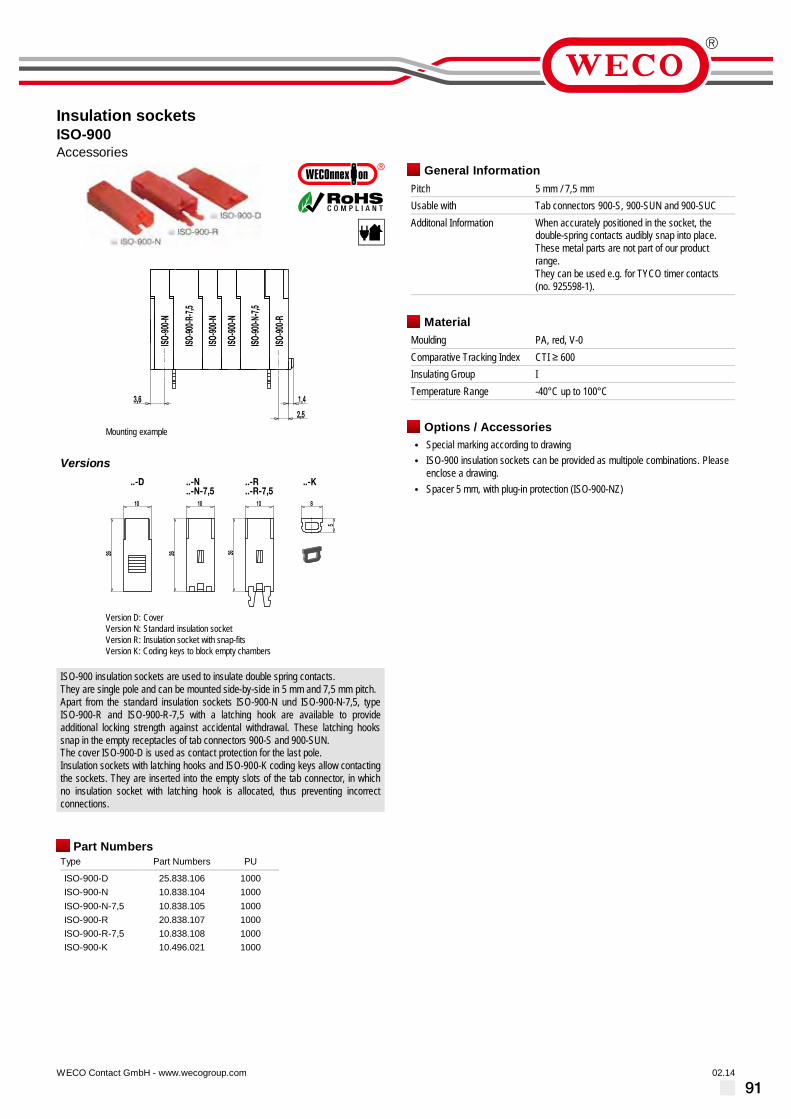
91
Insulation socketsISO-900Accessories
02.14WECO Contact GmbH - www.wecogroup.com''no flame'' after glow-wire test according toHousehold Appliance DIN EN/IEC 60335-1
Mounting example
Versions
Version D: CoverVersion N: Standard insulation socketVersion R: Insulation socket with snap-fitsVersion K: Coding keys to block empty chambers
ISO-900 insulation sockets are used to insulate double spring contacts.They are single pole and can be mounted side-by-side in 5 mm and 7,5 mm pitch.Apart from the standard insulation sockets ISO-900-N und ISO-900-N-7,5, typeISO-900-R and ISO-900-R-7,5 with a latching hook are available to provideadditional locking strength against accidental withdrawal. These latching hookssnap in the empty receptacles of tab connectors 900-S and 900-SUN.The cover ISO-900-D is used as contact protection for the last pole.Insulation sockets with latching hooks and ISO-900-K coding keys allow contactingthe sockets. They are inserted into the empty slots of the tab connector, in whichno insulation socket with latching hook is allocated, thus preventing incorrectconnections.
Part NumbersType Part Numbers PU
ISO-900-D 25.838.106 1000ISO-900-N 10.838.104 1000ISO-900-N-7,5 10.838.105 1000ISO-900-R 20.838.107 1000ISO-900-R-7,5 10.838.108 1000ISO-900-K 10.496.021 1000
General InformationPitch 5 mm / 7,5 mmUsable with Tab connectors 900-S, 900-SUN and 900-SUCAdditonal Information When accurately positioned in the socket, the
double-spring contacts audibly snap into place.These metal parts are not part of our productrange.They can be used e.g. for TYCO timer contacts(no. 925598-1).
MaterialMoulding PA, red, V-0Comparative Tracking Index CTI ≥ 600Insulating Group ITemperature Range -40°C up to 100°C
Options / Accessories• Special marking according to drawing• ISO-900 insulation sockets can be provided as multipole combinations. Please
enclose a drawing.• Spacer 5 mm, with plug-in protection (ISO-900-NZ)

92
Coding systems
Usable with:
Tab connector: Series 900
Insulation sockets: ISO-900
Coding examples
Tab connector 900-SUN-MIX2/06-KOD
Part number Type Colour PU10 .496 .021 ISO-900-K KODIERPLAETTCHEN grey 100
Coding keys ISO-900-K are used for
the coding of our tab connectors 900
series .
Depending on the pitch, tab connector
strips feature minimum one empty pole
cavity between each corresponding
tab connector . This cavity can house
coding key ISO-900-K, thus allowing
for coding in insulating sockets with
latching hooks .
Coding keys ISO-900-K
Tab connector 900-SUN-MIX2/06-KOD
Gerade Seite, LINKS

93
Marking
WECO offers marking of individual connections for nearly all terminals and products .
Marking strips
Self-adhesive marking strips consist
of polyester with black print on silver
background . They are scratch-proof
and surface-sealed with Mylar .
The numbering begins with 1 . The last
digit represents the indicated number
of poles .
The marking strips withstand PC board
cleaning processes using water and
soap, Freon, fl uorinated or chlorinated
cleaning agents . However, they are not
refl ow-capable and should therefore
only be mounted after the refl ow
soldering process .
Marking strips are delivered in ten strips
per sheet .
Part number Type Marking Pitch Length (L) Width (a) PU24 .499 .013 BST-3,50/24 1 2 3 . . . 24 3,50 mm 84 mm 3 mm 10024 .499 .009 BST-5,00/12 1 2 3 . . . 12 5,00 mm 60 mm 3,5 mm 10024 .499 .010 BST-5,00/32 1 2 3 . . . 32 5,00 mm 160 mm 3,5 mm 10024 .499 .006 BST-5,08/12 1 2 3 . . . 12 5,08 mm 61 mm 3,5 mm 10024 .499 .007 BST-5,08/32 1 2 3 . . . 32 5,08 mm 162 mm 3,5 mm 10024 .499 .012 BST-7,50/19 1 2 3 . . . 19 7,50 mm 141 mm 3,5 mm 10024 .499 .011 BST-10,00/16 1 2 3 . . . 16 10,00 mm 155 mm 3,5 mm 10024 .499 .008 BST-10,16/16 1 2 3 . . . 16 10,16 mm 157 mm 3,5 mm 100
InkJet printing
As an alternative to self-adhesive
marking strips, we also offer markings
according to your specifi c requirements.
Our products are marked by means of
inkjet printers. Micro-sized ink droplets
are shot accurately to the point and
guided by an electric fi eld thus creating
the high-precision print – very much
like a printed pattern generated by a
common matrix printer . This process is
fast, easy-to-use and reprogrammable .
However, this printing process
comprises of the contour precision of
the print .
In addition to numbers and letters,
special characters can also be printed .
The inkjet print features tried and tested
scratch- and wipe-resistance .
Standard marking for PCB connectors
comes in either black or white -
depending on the housing colour . The
marking is printed on given surfaces .
Markings for our connectors featured in
catalogue 7 are printed in black .
Markings may be printed in two
locations: either on or between the
screw guides (for series 302 only on the
screw guides) .
Alternatively, WECO offers pad printed
markings (also in special colours) .
Pad-printed markings excel with high-
precision contours of the print, but are
higher-priced due to the more elaborate
printing process .
InkJet printing(graphic illustration)
Tampon printing(graphic illustration)
Ungerade Seite, RECHTS

94
Packaging
As standard, we deliver our products
packaged in eco-friendly folding boxes
made of cardboard or corrugated
board .
In order to ensure effi cient automated assembly and subsequent
soldering of our components, WECO offers various component
packaging systems, such as
When assembling components from tape-on-reels or trays, the placement head
vacuum-picks the component from the tape or the tray, verifi es the position by
means of a camera system, calculates angle and position offset to the nominal
position and places the component onto the PC board . After all components
have been placed, a conveyor system transports the assembled PC board
downstream .
All three component packaging types use anti-static materials to avoid problems with electrostatic discharges (ESD) .
Tape-on-Reel Bar magazinesTrays
These carrier tapes on reels are
suitable for most SMD and THR
components . They feature blisters
and are sealed with a cover fi lm.
WECO offer reels in different widths
of 24 mm, 32 mm, 44 mm, 56 mm,
72 mm or 88 mm .
Our 550 mm bar magazines have
various geometries which are
tailored to the individual component
size and shape. Both magazine
ends are closed with a plug that is
easy to remove .
Delivered in cardboard folding
boxes, bar magazines are easy to
unpack .
WECO also offers trays as another
option for automated component
assembly. The fl at trays feature
component pockets, they are
stackable and ensure suffi ciently
large component supply .
Gerade Seite, LINKS

95
Other options
Moulding colours
WECO offers a multitude of various
moulding colours .
In addition to our standard colours
charcoal grey, black, vermilion and natural
other moulding colours are also possible .
Please contact us for further information,
we look forward to assisting you .
Standard colours Special colours
Charcoal grey(similar to RAL U706)
Red orange(similar to RAL 2001)
Yellow green(similar to RAL 6018)
Black(similar to RAL 9011)
Heather violet(similar to RAL 4003)
Light grey(similar to RAL 7035)
Vermilion(similar to RAL 2002)
Zinc yellow(similar to RAL 1018)
White(similar to RAL 9010)
NaturalBrilliant blue(similar to RAL 5007)
Screws
We use standard slotted-head screws for
our products .
Upon inquiry and specifi c customer
request, we also offer screws with Phillips/
Pozidriv or +/- screw heads.
Other materials:
Our products are predominantly equipped
with steel screws . Upon request, screws
made of alternative materials, such as
brass, are also available .
Ungerade Seite, RECHTS

Looking for a Customer Designed Solution?
„Top“
Version of a terminal our series 970 in 5 mm pitch.In order to achieve a distance of 100 mm from the PCB, a housing was constructed, which not only does protect the pins but also positions them in a special arrange-ment. In the terminal area are also placed elongated ribs.
„Sealed“
With a pitch of 3.5 mm, this insert with four tabs 2.8 x 0.8 mm was designed to seal the contacts to fulfi ll the application according to protection class IP54.
„Well Contacted“
This plug connector with the pitch of 5 mm is designed with outer gold-plated contact surfaces. Additionally, the side walls provide ribs for receiving a corresponding locking hook.
Our Product Information Centre will assist you with every technical inquiry.
• Please, call us under +49 6181 105-151.
• Contact us via e-mail at [email protected].
• You want us to pay you a visit? We are pleased to arrange an appointment.
• You would prefer a visit in Hanau?
Of course, you are welcomed anytime.
We are looking forward to your call.
„Long-ribbed“
A plug connector with a pitch of 3.5 mm, with a anti-twist peg and two extra-long guiding ribs.In the plug connection area, tabs and round plug pins could be contacted.
„Stable bridged“
Terminal connector in 5 mm pitch with one potential but two screw connections and a plug connector at the back. This allows a connection to other terminals.For the customer the housing was made with zinc yellow material (similar to RAL 1018).
„Solar“
Draft for a photovoltaic-module connection.
96

„Long-ribbed“
A plug connector with a pitch of 3.5 mm, with a anti-twist peg and two extra-long guiding ribs.In the plug connection area, tabs and round plug pins could be contacted.
„Stable bridged“
Terminal connector in 5 mm pitch with one potential but two screw connections and a plug connector at the back. This allows a connection to other terminals.For the customer the housing was made with zinc yellow material (similar to RAL 1018).
„Solar“
Draft for a photovoltaic-module connection.
97

98
Our Publications
Your Contact
CANADAWECO Electrical Connectors Inc.19 900 Clark GrahamBaie d’Urfé, QC. H9X 3R8Phone: +1 514 694-9136Fax: +1 514 [email protected]
USAWECO Electrical Connectors Inc.2330 State Route 11Mooers NY12958Phone: +1 518 298-4810Fax: +1 518 298-5938
BRASILWECO do Brasil LTDA.Rod. BR-116, 12.757 - Vila FannyCuritiba, PR CEP-81690-200Phone: +55 41-3278-9720Phone: +55 41-3278-9721Phone: +55 41-3278-9717Fax: +55 [email protected]
MEXICOWECO de Mexiko SA CVCarretera a Morelia 3583-BTlajomulco de ZuñigaGuadalajara, JaliscoFraccionamiento Los GavilanesCodigo Postal: 45645Phone: +52 33 3684 9066Fax: +52 33 3684 9066www.weco.com.mx
FRANCEWECO-Connexion S.A.R.L.8 B, Rue des IndustriesF-67140 EichhoffenPhone: +33 (0) 3 88.08.97.29Fax: +33 (0) 3 88.08.97.49
HONG KONGWECO Electrical Connectors Ltd.Room 1105, New Commerce Centre19 On Sum Street, ShatinNew Territory, Hong KongPhone: +852 2636 6252Fax: +852 2559 3161www.weco-hk.com
CHINAWECO Electrical (Shenzhen) Ltd.Room 1719, Dynamic World,Zhonghang Road No. 9Futian District,Shenzhen, P.R. China, 518031Phone: +86 755 8280 7673Fax: +86 755 8280 7674www.weco-cn.com
Connection Technology forPrinted Circuit BoardsPitch 3.5 mm
WECO - making contact
Catalogue 1 ElectronicArt.-No.: 43 955 102
© by WECO 06/2011
WECO Contact GmbH
Connectors for electronic and electrical application
PO Box 2342
63413 Hanau
Donaustrasse 15
63452 Hanau
Germany
Phone +49 6181 / 105 -156
Fax +49 6181 / 105 -720
eMail [email protected]
Internet www.wecogroup.com
WECO - making contact
Electronic
Your Contact
CANADAWECO Electrical Connectors Inc.19 900 Clark GrahamBaie d’Urfé, QC. H9X 3R8Phone: +1 514 694-9136Fax: +1 514 [email protected]
USAWECO Electrical Connectors Inc.2330 State Route 11Mooers NY12958Phone: +1 518 298-4810Fax: +1 518 298-5938
BRASILWECO do Brasil LTDA.Rod. BR-116, 12.757 - Vila FannyCuritiba, PR CEP-81690-200Phone: +55 41-3278-9720Phone: +55 41-3278-9721Phone: +55 41-3278-9717Fax: +55 [email protected]
MEXICOWECO de México SA CVCarretera a Morelia 3583-BTlajomulco de ZuñigaGuadalajara, JaliscoFraccionamiento Los GavilanesCodigo Postal: 45645Phone: +52 33 3684 9066Fax: +52 33 3684 9066www.weco.com.mx
FRANCEWECO-Connexion S.A.R.L.8B, Rue des Industries67140 EichhoffenPhone: +33 (0) 3 88.08.97.29Fax: +33 (0) 3 88.08.97.49
HONG KONGWECO Electrical Connectors Ltd.Room 1105, New Commerce Centre19 On Sum Street, ShatinNew Territory, Hong KongPhone: +852 2636 6252Fax: +852 2559 3161www.weco-hk.com
CHINAWECO Electrical (Shenzhen) Ltd.Room 1719, Dynamic World,Zhonghang Road No. 9Futian District,Shenzhen, P.R. China, 518031Phone: +86 755 8280 7673Fax: +86 755 8280 7674www.weco-cn.com
WECO Contact GmbH
Connectors for electronic and electrical application
PO Box 2342
63413 Hanau
Donaustrasse 15
63452 Hanau
Germany
Phone +49 6181 / 105 -156
Fax +49 6181 / 105 -720
eMail [email protected]
Internet www.wecogroup.com
Catalogue 4
Connection Technology forPrinted Circuit BoardsPitch 7.5 mm
Art.-No.: 46 955 102
© by WECO 10/2011
WECO Contact GmbH
Connectors for electronic and electrical application
PO Box 2342
63413 Hanau
Donaustrasse 15
63452 Hanau
Germany
Phone +49 6181 / 105 -156
Fax +49 6181 / 105 -720
eMail [email protected]
Internet www.wecogroup.com
Europe type connectors
WECO - making contacts
Catalogue 7 Electrical
Your Contact
CANADAWECO Electrical Connectors Inc.18 050 Trans-Canada HighwayKirkland, QC Canada H9J 4A1Phone: +1 514 694-9136Fax: +1 514 [email protected]
USAWECO Electrical Connectors Inc.2330 State Route 11Mooers NY12958Phone: +1 518 298-4810Fax: +1 518 298-5938
BRASILWECO do Brasil LTDA.Rod. BR-116, 12.757 - Vila FannyCuritiba, PR CEP-81690-200Phone: +55 41-3278-9720Phone: +55 41-3278-9721Phone: +55 41-3278-9717Fax: +55 [email protected]
MEXICOWECO de México SA CVCarretera a Morelia 3583-BTlajomulco de ZuñigaGuadalajara, JaliscoFraccionamiento Los GavilanesCodigo Postal: 45645Phone: +52 33 3684 9066Fax: +52 33 3684 9066www.weco.com.mx
FRANCEWECO-Connexion S.A.R.L.8B, Rue des Industries67140 EichhoffenPhone: +33 (0) 3 88.08.97.29Fax: +33 (0) 3 88.08.97.49
HONG KONGWECO Electrical Connectors Ltd.Room 1105, New Commerce Centre19 On Sum Street, ShatinNew Territory, Hong KongPhone: +852 2636 6252Fax: +852 2559 3161www.weco-hk.com
CHINAWECO Electrical (Shenzhen) Ltd.Room 1719, Dynamic World,Zhonghang Road No. 9Futian District,Shenzhen, P.R. China, 518031Phone: +86 755 8280 7673Fax: +86 755 8280 7674www.weco-cn.com
WECO Contact GmbH
Connectors for electronic and electrical application
PO Box 2342
63413 Hanau
Donaustrasse 15
63452 Hanau
Germany
Phone +49 6181 / 105 -145
Fax +49 6181 / 105 -720
eMail [email protected]
Internet www.wecogroup.com
Art.-No.: 52 955 102
© by WECO 09/2012
Eur
ope
type
con
nect
ors
WECO - making contact
Electronic
Your Contact
CANADAWECO Electrical Connectors Inc.19 900 Clark GrahamBaie d’Urfé, QC. H9X 3R8Phone: +1 514 694-9136Fax: +1 514 [email protected]
USAWECO Electrical Connectors Inc.2330 State Route 11Mooers NY12958Phone: +1 518 298-4810Fax: +1 518 298-5938
BRASILWECO do Brasil LTDA.Rod. BR-116, 12.757 - Vila FannyCuritiba, PR CEP-81690-200Phone: +55 41-3278-9720Phone: +55 41-3278-9721Phone: +55 41-3278-9717Fax: +55 [email protected]
MEXICOWECO de Mexiko SA CVCarretera a Morelia 3583-BTlajomulco de ZuñigaGuadalajara, JaliscoFraccionamiento Los GavilanesCodigo Postal: 45645Phone: +52 33 3684 9066Fax: +52 33 3684 9066www.weco.com.mx
FRANCEWECO-Connexion S.A.R.L.8 B, Rue des IndustriesF-67140 EichhoffenPhone: +33 (0) 3 88.08.97.29Fax: +33 (0) 3 88.08.97.49
HONG KONGWECO Electrical Connectors Ltd.Room 1105, New Commerce Centre19 On Sum Street, ShatinNew Territory, Hong KongPhone: +852 2636 6252Fax: +852 2559 3161www.weco-hk.com
CHINAWECO Electrical (Shenzhen) Ltd.Room 1719, Dynamic World,Zhonghang Road No. 9Futian District,Shenzhen, P.R. China, 518031Phone: +86 755 8280 7673Fax: +86 755 8280 7674www.weco-cn.com
Catalogue 3
Connection Technology forPrinted Circuit BoardsPitch 5,08 mm
Art.-No.: 45 955 102
© by WECO 08/2011
WECO Contact GmbH
Connectors for electronic and electrical application
PO Box 2342
63413 Hanau
Donaustrasse 15
63452 Hanau
Germany
Phone +49 6181 / 105 -156
Fax +49 6181 / 105 -720
eMail [email protected]
Internet www.wecogroup.com
Your Contact
CANADAWECO Electrical Connectors Inc.19 900 Clark GrahamBaie d’Urfé, QC. H9X 3R8Phone: +1 514 694-9136Fax: +1 514 [email protected]
USAWECO Electrical Connectors Inc.2330 State Route 11Mooers NY12958Phone: +1 518 298-4810Fax: +1 518 298-5938
BRASILWECO do Brasil LTDA.Rod. BR-116, 12.757 - Vila FannyCuritiba, PR CEP-81690-200Phone: +55 41-3278-9720Phone: +55 41-3278-9721Phone: +55 41-3278-9717Fax: +55 [email protected]
MEXICOWECO de México SA CVCarretera a Morelia 3583-BTlajomulco de ZuñigaGuadalajara, JaliscoFraccionamiento Los GavilanesCodigo Postal: 45645Phone: +52 33 3684 9066Fax: +52 33 3684 9066www.weco.com.mx
FRANCEWECO-Connexion S.A.R.L.8B, Rue des Industries67140 EichhoffenPhone: +33 (0) 3 88.08.97.29Fax: +33 (0) 3 88.08.97.49
HONG KONGWECO Electrical Connectors Ltd.Room 1105, New Commerce Centre19 On Sum Street, ShatinNew Territory, Hong KongPhone: +852 2636 6252Fax: +852 2559 3161www.weco-hk.com
CHINAWECO Electrical (Shenzhen) Ltd.Room 1719, Dynamic World,Zhonghang Road No. 9Futian District,Shenzhen, P.R. China, 518031Phone: +86 755 8280 7673Fax: +86 755 8280 7674www.weco-cn.com
WECO Contact GmbH
Connectors for electronic and electrical application
PO Box 2342
63413 Hanau
Donaustrasse 15
63452 Hanau
Germany
Phone +49 6181 / 105 -145
Fax +49 6181 / 105 -720
eMail [email protected]
Internet www.wecogroup.com
WECO - making contacts
ElectronicCatalogue 6
Connection Technology onPrinted Circuit BoardsSMD & THR
Art.-No.: 48 955 102
© by WECO 09/2012
WECO - making contact
Electronic
Con
nect
ion
Tech
nolo
gy fo
r P
rinte
d C
ircui
t Boa
rds
Pitc
h 5
mm
Catalogue 2
Connection Technology forPrinted Circuit BoardsPitch 5 mm
Art.-No.: 44 955 102
© by WECO 06/2011
WECO - making contact
Electronic
Your Contact
CANADAWECO Electrical Connectors Inc.19 900 Clark GrahamBaie d’Urfé, QC. H9X 3R8Phone: +1 514 694-9136Fax: +1 514 [email protected]
USAWECO Electrical Connectors Inc.2330 State Route 11Mooers NY12958Phone: +1 518 298-4810Fax: +1 518 298-5938
BRASILWECO do Brasil LTDA.Rod. BR-116, 12.757 - Vila FannyCuritiba, PR CEP-81690-200Phone: +55 41-3278-9720Phone: +55 41-3278-9721Phone: +55 41-3278-9717Fax: +55 [email protected]
MEXICOWECO de México SA CVCarretera a Morelia 3583-BTlajomulco de ZuñigaGuadalajara, JaliscoFraccionamiento Los GavilanesCodigo Postal: 45645Phone: +52 33 3684 9066Fax: +52 33 3684 9066www.weco.com.mx
FRANCEWECO-Connexion S.A.R.L.8B, Rue des Industries67140 EichhoffenPhone: +33 (0) 3 88.08.97.29Fax: +33 (0) 3 88.08.97.49
HONG KONGWECO Electrical Connectors Ltd.Room 1105, New Commerce Centre19 On Sum Street, ShatinNew Territory, Hong KongPhone: +852 2636 6252Fax: +852 2559 3161www.weco-hk.com
CHINAWECO Electrical (Shenzhen) Ltd.Room 1719, Dynamic World,Zhonghang Road No. 9Futian District,Shenzhen, P.R. China, 518031Phone: +86 755 8280 7673Fax: +86 755 8280 7674www.weco-cn.com
WECO Contact GmbH
Connectors for electronic and electrical application
PO Box 2342
63413 Hanau
Donaustrasse 15
63452 Hanau
Germany
Phone +49 6181 / 105 -156
Fax +49 6181 / 105 -720
eMail [email protected]
Internet www.wecogroup.com
Catalogue 5
Connection Technology forPrinted Circuit Boardsup from pitch 10 mm
Art.-No.: 47 955 102
© by WECO 10/2011
WECO Contact GmbH
Connectors for electronic and electrical application
PO Box 2342
63413 Hanau
Donaustrasse 15
63452 Hanau
Germany
Phone +49 6181 / 105 -156
Fax +49 6181 / 105 -720
eMail [email protected]
Internet www.wecogroup.com
WECO - making contacts
WECO Contact GmbH
Connectors for electronic and electrical application
PO Box 2342
63413 Hanau
Donaustrasse 15
63452 Hanau
Germany
Phone +49 6181 / 105 -145
Fax +49 6181 / 105 -720
eMail [email protected]
Internet www.wecogroup.com
CANADA / USAWECO Electrical Connectors Inc.18 050 Trans-Canada HighwayKirkland, QC Canada H9J 4A1Phone: +1 514 694-9136Fax: +1 514 [email protected]
CHINAWECO Electrical (Shenzhen) Ltd.Room 1719, Dynamic World,Zhonghang Road No. 9Futian District,Shenzhen, P.R. China, 518031Phone: +86 755 8280 7673Fax: +86 755 8280 7674www.weco-cn.com
MEXICOWECO de México SA CVCarretera a Morelia 3583-BTlajomulco de ZuñigaGuadalajara, JaliscoFraccionamiento Los GavilanesCodigo Postal: 45645Phone: +52 33 3684 9066Fax: +52 33 3684 9066www.wecoconnectors.com
HONG KONGWECO Electrical Connectors Ltd.Room 1105, New Commerce Centre19 On Sum Street, ShatinNew Territory, Hong KongPhone: +852 2636 6252Fax: +852 2559 3161www.weco-hk.com
BRAZILWECO do Brasil LTDA.Rod. BR-116, 12.757 - Vila FannyCuritiba, PR CEP-81690-200Phone: +55 41-3278-9720Phone: +55 41-3278-9721Phone: +55 41-3278-9717Fax: +55 [email protected]
Your Contact
ElectricalCatalogue 8Art.-No.: 64 955 102
© by WECO 06/2014
Tab
conn
ecto
rs &
Scr
ew c
onne
ctor
blo
cks
Tab connectors &Screw connector blocks
Catalogue 1Connection technology for PCBPitch 3,5 mmPart No . 36 .955 .102
Catalogue 4Connection technology for PCBPitch 7,5 mmPart No . 39 .955 .102
Catalogue 7Europe type connectors„WECONNECT“Part No . 51 .955 .102
Catalogue 3Connection technology for PCBPitch 5,08 mmPart No . 38 .955 .102
Catalogue 6Connection technology for PCBSMD & THRPart No . 41 .955 .102
Catalogue 2Connection technology for PCBPitch 5 mmPart No . 37 .955 .102
Catalogue 5Connection technology for PCBup from pitch 10 mmPart No . 40 .955 .102
Catalogue 8Tab connectors &Screw connector blocks„WECOnnexion“Part No . 64 .955 .102
Ele
ctr
on
icE
lec
tric
al

99
Our Publications
Extract of connection technology on PCBsPitch 3,5 mm 5 mm 7,5 mm5,08 mm 10 mm 10,16 / 12,7 mm
110-A-111 210-A-111 930 931-SLR-THR 120-A-111 971 960140-A-111 971-SLR-SMD-1,3 122-A-111950 121-A-111 977950-FL-DS 141-A-111 910970 940 158-A-111
110-M-211 210-A-121 930-THR 931-SLT-SMD-1,3 120-D-121 971-LH 961140-A-126-SMD 971-SLR-THR 122-D-111
950-THR
121-C-111 977-OPSG950-RFL-DS 141-A-121 910-Y970-EN 940-T 158-A-211
110-M-221-THR 210-A-126-SMD 931 931-SLR-THR-1,1 120-M-151 971-THM 964-T140-B-111 971-SLS 122-M-111
951-LH
121-M-121 977-T958-FLDS 141-C-111970-LH 941
110-P-215 210-A-SMD 934-THR-DS 931-SLR-THR-1,3 120-M-191 974-D-SMD 968140-C-111 971-SLT-SMD 122-M-121
951-THG
121-M-161950-SLS 970-THR 941-T 159-A-111
110-V-215 938-FLDS 931-FST 120-M-221-SMD 971-SLW115-F-111 970-TX.. 159-A-211
Series 110 Series 210 Series 93 Series 93 Series 120 Series 97 Series 96Series 140 Series 97 Series 122Series 95 Series 121 Series 97Series 95 /Series 115 Series 141 Series 91Series 97 Series 94 Series 158/159
1,5 mm² 1 mm² 1 mm² - - - 2,5 mm² 2,5 mm² 2,5 mm²1,5 mm² - - - 2,5 mm²1,5 mm² 2,5 mm² 2,5 mm²1,5 mm² 1,5 mm² 4 mm²2,5 mm² 1,5 mm² 10 mm²
2-24 poles 2-24 poles 2-24 poles 2-16 poles 2-24 poles 2-32 poles 2-32 poles2-24 poles 2-12 poles 2-12 poles2-32 poles 2-24 poles 2-8 poles2-24 poles 2+3 poles 2-12 poles2-32 poles 2-32 poles 2-12 poles
2-24 poles 2-24 poles 2-12 poles 2-16 poles 2-24 poles 2-12 poles 2-32 poles2-12 poles 2-12 poles 2-12 poles
2-12 poles
2-24 poles 2-19 poles2-12 poles 2+3 poles 2-12 poles4-24 poles 2+3 poles 2-12 poles
2-12 poles 2-12 poles 2-24 poles 2-16 poles 4-48 poles 2+3 poles 2+3 poles2+3 poles 2-24 poles 2-12 poles
2-12 poles
2-24 poles 2+3 poles2-8 poles 2+3 poles2-12 poles 2-32 poles
4-44 poles 2-12 poles 2-24 poles 2-16 poles 2-24 poles 2-12 poles 2-32 poles2-24 poles 2-12 poles 2-12 poles
2+3 poles
4-48 poles2-24 poles 2-12 poles 2+3 poles 2-12 poles
2-22 poles 2-16 poles6 A/28-20 AWG
18-12 AWG
poles 2-12 poles 2-24 poles2-12 poles 1 poles 2-12 poles
300 V/8 A/30-16 AWG 1)
300 V/8 A/30-16 AWG 1)
300 V/10 A/30-16 AWG
300 V/10 A/30-16 AWG
300 V/10 A/26-16 AWG
300 V/10 A/26-16 AWG
150 V/6 A
150 V/6 A
300 V/15 A/26-12 AWG 1)
300 V/15 A/26-12 AWG 1)
300 V/20 A/22-12 AWG
300 V/20 A/26-12 AWG
300 V/20 A/22-12 AWG
300 V/20 A/26-12 AWG
300 V/10 A/30-14 AWG
300 V/15 A/30-14 AWG
300 V/10 A
300 V/10 A
300 V/15 A/26-12 AWG
300 V/15 A/26-12 AWG
300 V/15 A/26-14 AWG
300 V/15 A/26-14 AWG
300 V/15 A/26-12 AWG 1)
300 V/15 A/26-12 AWG 1)
300 V/15 A/22-12 AWG
300 V/20 A/26-12 AWG
300 V/10 A/26-14 AWG 1)
300 V/10 A/26-14 AWG 1)
300 V/10 A/30-14 AWG
300 V/15 A/30-14 AWG
300 V/25 A/18-10 AWG
300 V/25 A/22-10 AWG
300 V/20 A/22-12 AWG 2)
300 V/20 A/26-12 AWG 2)
300 V/15 A/26-14 AWG
300 V/15 A/26-14 AWG 300 V/60 A/20-6 AWG
600 V/60 A/20-6 AWG
Series
Rated cross section
Approvals
Type of product
CataloguesPitch 3,5 mmPitch 5 mmPitch 5,08 mmPitch 7,5 mmPitch >10 mmSMD & THR
1) AWG information not valid for pin strips2) AWG information not valid for socket terminals (..-FB)
Technical modification reserved.For detailed information please see our data sheet onwww.wecogroup.com
950-D-SMD-DS
2-12 poles
Your Contact
CANADAWECO Electrical Connectors Inc.19 900 Clark GrahamBaie d’Urfé, QC. H9X 3R8Phone: +1 514 694-9136Fax: +1 514 [email protected]
USAWECO Electrical Connectors Inc.2330 State Route 11Mooers NY12958Phone: +1 518 298-4810Fax: +1 518 298-5938
BRASILWECO do Brasil LTDA.Rod. BR-116, 12.757 - Vila FannyCuritiba, PR CEP-81690-200Phone: +55 41-3278-9720Phone: +55 41-3278-9721Phone: +55 41-3278-9717Fax: +55 [email protected]
MEXICOWECO de México SA CVCarretera a Morelia 3583-BTlajomulco de ZuñigaGuadalajara, JaliscoFraccionamiento Los GavilanesCodigo Postal: 45645Phone: +52 33 3684 9066Fax: +52 33 3684 9066www.weco.com.mx
FRANCEWECO-Connexion S.A.R.L.8B, Rue des Industries67140 EichhoffenPhone: +33 (0) 3 88.08.97.29Fax: +33 (0) 3 88.08.97.49
HONG KONGWECO Electrical Connectors Ltd.Room 1105, New Commerce Centre19 On Sum Street, ShatinNew Territory, Hong KongPhone: +852 2636 6252Fax: +852 2559 3161www.weco-hk.com
CHINAWECO Electrical (Shenzhen) Ltd.Room 1719, Dynamic World,Zhonghang Road No. 9Futian District,Shenzhen, P.R. China, 518031Phone: +86 755 8280 7673Fax: +86 755 8280 7674www.weco-cn.com
WECO Contact GmbH
Connectors for electronic and electrical application
PO Box 2342
63413 Hanau
Donaustrasse 15
63452 Hanau
Germany
Phone +49 6181 / 105 -156
Fax +49 6181 / 105 -720
eMail [email protected]
Internet www.wecogroup.com
for catalogues 1 – 6 Electronic
OverviewConnection Technology on Printed Circuit Boards
Art. no. 49 955 102
© by WECO 11/2011
„SMD“ is the abbreviation for Sur-
face Mounted Devices and reunite all
surface-assembled components on
one circuit board. Often certain ma-
nufacturers of electronic and electrical
components also use the term “SMD”
for THR (Through Hole Reflow) compo-
nents, but unlike thru hole devices that
require drilling holes through which the
pins go through the board and are sol-
dered underneath, SMD components
are positioned on the PCB surface and
soldered afterwards. No more need for
holes in the printed circuit board.
History of the SMD The beginnings of surface mount tech-
nology go back to the 1960s, but only
became widely used in the 1980s. Mid
1980s, the production of conventional
leaded devices soldered directly on the
circuit path became a standard.
Surface mounted devices (SMD) made
it possible to increase the number of
components and therefore contributed
to many more connections per com-
ponent. Furthermore, SMD compo-
nents can be placed on both sides of
a printed circuit board. Components
are usually secured temporarily with
adhesive on the lower side of the PCB,
and as soon as the adhesive is harde-
ned, the printed circuit board can be
turned upwards to populate the other
side. This is followed by the soldering
process.
WECO SMD terminals and plug connectorsTo fully take advantage of a pure SMD
production, the customer needs a wide
product range of SMD components.
This should include terminals and plug
connectors. SMD terminal blocks and
plug connectors are undoubtedly a
good deal more difficult to achieve than
components which are not exposed
to a mechanical load, as for example
resistors and condensers.
The most important criterion is good
and durable soldering at the printed
circuit board level. A terminal block or
a plug connector has a substantially
larger volume than conventional „chip
components“ and offers a much larger
attack region in order to lever the com-
ponent off the PCB surface. Therefore
soldering connections only at the pins
would not be sufficient, and additional
reinforcement would be required. Often
the problem is resolved by providing
additional support with lugs or with
separate screw fixation. From our point
of view, this is not an ideal solution
because using pure SMD technolo-
gy drillings in a printed circuit board
should be avoided. WECO’s range of
SMD terminal blocks and plug connec-
tors (pinstrips) are equipped with lateral
soldering cylinders, which are placed
off-center in order to create a counter
anchoring to the pins. Thus, the pins
do not have to carry the entire depar-
ture load. In addition, these soldering
cylinders create a larger soldering
surface and achieve a reliable adhesive
force on the printed circuit board.
A further challenge in SMD technology
for terminal blocks and plug connec-
tors starting at sizes of 3.5 mm pitch
and larger, is to ensure an accurate
soldering connection of the pins over
the entire length of the component.
Deviations of the components, within
given tolerances, linear extensions
under thermal load during the soldering
process and unevenness of the PCB
surface, all contribute to factors of
mismatch.
To correct this problem, WECO develo-
ped the patented principle of movable
soldering elements. WECO’s line of
SMD terminals and plug connector
are equipped with soldering pins and
anchor elements, called “floating
anchors”. This ensures a freedom of
movement in both lateral and vertical
directions, which in turn ensures excel-
lent co-planarity performance.
What is SMD?
Through hole technology became po-
pular in the 1950s with the resurgence
of the second generation computer
and continued its popularity until sur-
face mount technology was develo-
ped. Surface mount technology then
gained popularity over the through hole
technology and became a standard
thereafter.
In the beginning, every printed circuit
board was assembled using Through
Hole Technology. All components were
inserted through holes drilled in the
circuit boards and soldered either by
hand or on the wave.
Over the years, the process was
automated and the reflow soldering
method with automated assembling
(Pick & Place) became widely accepted
especially with the enforcement of lead
free soldering (RoHS).
Nowadays many electronic compo-
nents are already surface mounted. A
much higher density of components
and many more connections per com-
ponent are possible on a printed circuit
board without holes.
Some components, such as terminal
blocks, plug connectors, switches or
electrolytic capacitors, still had to be
soldered on the wave or by hand on
the printed circuit board, because they
were not suitable for the high mechani-
cal and thermal load.
Due to a mixture of through hole and
surface mount components, the solde-
ring process could not be automated
completely and therefore incurred
greater production costs. To rectify the
problem, the components, which were
not suitable for this kind of processing,
had to be made compatible for the
reflow soldering method.
This gave rise to the SMarTconn family
of products through which WECO was
able to identify and subsequently invent
technical solutions to successfully
resolve these problems:
1. The through hole reflow technology
(THR) was steadily developed and
addressed the through-hole reflow
applications.
2. The patented product program
in genuine SMD technology was
invented. Terminal blocks and plug
connectors from a size of 3.5 mm
pitch and larger could now be
surface-mounted.
The Through Hole Reflow Process ...The through hole reflow process ena-
bles the automated assembling and
the reflow soldering technique normally
used on surface mount components to
be applied to THR components as well.
... or the “Pin-in-Paste”-MethodThe basis for the integration of THR
components in the reflow soldering
process is the pin in paste procedure.
Precondition for the use of THR com-
ponents is a printed circuit board with
drillings and a correctly cut out and
positioned template. Soldering paste is
laid via a screen printing system in or-
der to receive an appropriate borehole
filling. The arising amount of pushed
through solder paste is intended. The
components are then placed on the
PCB. The pins of the components dip
into the holes and push the solder pas-
te through the holes to the other side
of the PCB. The action of pushing the
solder paste through the holes forms
a characteristic match head around
each pin. This is followed by the reflow
soldering process. The solder joints
created are mechanically and electri-
cally comparable to the classical wave
soldering process.
ConclusionWith THR devices, the integration of
electrical components into the reflow
soldering process enables the produc-
tion of a single soldering process. This
approach is beneficial in substantially
reducing production cost and results in
process optimisation. In addition, the
THR device high-temperature-resistant
thermoplastic body is configured for
RoHS-compliant production, resulting
in the possibility of variant reductions.
What is THR ?
Extract of Europe type connectorsSeries
Series
Socket terminal strips
Screw/solder terminal strips
Plug-in terminal strips
Screw/plugterminal strips
Tab and screwconnector blocks Plug connectors
302
931-A-LFDS
302-N 323 323-FU-16,5 324 302-NFB 321-B326 302-FLW-DS 322-FBG327 302-FBG 323-FB327-FU 302-STB 323-PHFBW302-FB 302-NSTB 324-STFB
302-G 323-FU-18,5 324-FU 321-S302-NFLW-DS 322-STFS 323-STFB302-STS 302-NSTS 324-STFS
302-NFLP-DS 322-SV
322-A-2,8
323-FBW302-SV 302-NSV
951-A-LFDS 302-LF-DS 321-LFS 322-LFS 820 322-SVG951-B-SV 302-NSLP
971-FBS
8 mm
3,5 mm
8 mm
5 mm
10 mm
8 mm
10 mm
10 mm
11,5 mm
10 mm
8 mm 10 mm14,5 mm
10 mm
8 mm 10 mm14,5 mm
10 mm
8 mm 10 mm14,5 mm
5 mm
8 mm 10 mm8 mm 8 mm 11,5 mm
1,5 mm²
1 mm²
1,5 mm²
1,5 mm²
2,5 mm²
1,5 mm²
2,5 mm²
2,5 mm²
4 mm²
2,5 mm²
1,5 mm² 2,5 mm²10 mm²
1,5 mm² 1)/2,5 mm² 2)
1,5 mm² 2,5 mm²16 mm²
2,5 mm² 1)/1 mm² 2)
1,5 mm² 2,5 mm²16 mm²
1,5 mm²
1,5 mm² 2,5 mm²1,5 mm² 1,5 mm² 4 mm²
1-12 poles 1-12 poles 1-12 poles 1-12 poles 1-12 poles 2-12 poles 2-12 poles1-12 poles 2-12 poles 2-12 poles1-12 poles 2-12 poles 2-12 poles1-12 poles 2-12 poles 2-12 poles2-12 poles 2-12 poles 2-12 poles
2-12 poles 1-12 poles 1-12 poles 2-12 poles2-12 poles 2-12 poles 2-12 poles2-12 poles 2-12 poles 2-12 poles
2-12 poles 2-12 poles
1-12 poles
2-12 poles2-12 poles 2-12 poles
2-12 poles 2-12 poles 1-12 poles 1-12 poles 1-12 poles 1-12 poles 2-12 poles2-12 poles 2-12 poles
2-24 poles
20 A/300 V/20-12 AWG
20 A/300 V/20-12 AWG
17,5 A/450 V/1,5 mm²
10 A/300 V/26-16 AWG
10 A/300 V/26-16 AWG
10 A/300 V/20-12 AWG
20 A/300 V/26-12 AWG
17,5 A/250 V/1,5 mm²
15 A/300 V/26-14 AWG
15 A/300 V/26-14 AWG
30 A/300 V/22-10 AWG
25 A/300 V/26-10 AWG
24 A/450 V/2,5 mm²
6 A/300 V/20-14 AWG
10 A/300 V/26-14 AWG
30 A/300 V/22-10 AWG
25 A/300 V/26-10 AWG
24 A/750 V/2,5 mm²
- - -
20 A/300 V/26-10 AWG
35 A/300 V/22-8 AWG
40 A/300 V/22-10 AWG
32 A/450 V/4 mm²
10 A/300 V/20-12 AWG
20 A/300 V/22-10 AWG
10 A/300 V/22-14AWG
6 A/300 V/26-12 AWG
- - -
20 A/300 V/18-12 AWG
15 A/300 V/26-10 AWG
- - -
50 A/300 V/14-8 AWG
55 A/300 V/14-8 AWG
57 A/750 V/10 mm²
10 A/300 V/16-10 AWG
10 A/300 V/20-10 AWG
10 A/300 V/22-14 AWG
10 A/300 V/26-14 AWG
- - -
20 A/300 V/18-12 AWG
15 A/300 V/26-10 AWG
- - -
80 A/300 V/14-4 AWG
80 A/300 V/14-6 AWG
76 A/750 V/16 mm²
- - -
6 A/300 V/22-10 AWG
7 A/300 V/20-14 AWG
10 A/300 V/26-12 AWG
- - -
20 A/300 V/18-12 AWG
15 A/300 V/26-10 AWG
- - -
65 A/600 V/14-6 AWG
80 A/600 V/14-6 AWG
76 A/750 V/16 mm²
7 A/300 V/26-14 AWG
7 A/300 V/26-14 AWG
6 A/300 V/20-14 AWG
10 A/300 V/26-12 AWG
- - -
20 A/300 V/18-12 AWG
20 A/300 V/26-10 AWG
- - -
6 A/300 V/20-14 AWG
6 A/300 V/26-12 AWG
- - -
10 A/300 V/22-14 AWG
10 A/300 V/26-12 AWG
- - -
25 A/150 V/18-10 AWG
20 A/300 V/26-10 AWG
- - -
Pitch
Pitch
Rated Cross Section
Rated Cross Section
Approvals
Approvals
Type of product
Type of product
CataloguesPitch 3,5 mmPitch 5 mmPitch 5,08 mmPitch 7,5 mmPitch >10 mmSMD & THREurope type connectors
1) Screw connection2) Plug connection
Technical modification reserved.For detailed information please see our data sheet on www.wecogroup.com
302-SVG
2-12 poles
302-NSLW
2-12 poles
322-SVW
2-12 poles
302-NLF-DS
1-12 poles
UR/VDE: withoutCSA: 15 A / 26-14 AWG
UR: 14-8 AWGVDE: 750 V
UR: 20 A/300 V/22-12AWGCSA: 20 A/300 V/26-12AWGUR: without
UR: without
UR: without
UR: without
Your Contact
CANADAWECO Electrical Connectors Inc.18 050 Trans-Canada HighwayKirkland, QC Canada H9J 4A1Phone: +1 514 694-9136Fax: +1 514 [email protected]
USAWECO Electrical Connectors Inc.2330 State Route 11Mooers NY12958Phone: +1 518 298-4810Fax: +1 518 298-5938
BRASILWECO do Brasil LTDA.Rod. BR-116, 12.757 - Vila FannyCuritiba, PR CEP-81690-200Phone: +55 41-3278-9720Phone: +55 41-3278-9721Phone: +55 41-3278-9717Fax: +55 [email protected]
MEXICOWECO de México SA CVCarretera a Morelia 3583-BTlajomulco de ZuñigaGuadalajara, JaliscoFraccionamiento Los GavilanesCodigo Postal: 45645Phone: +52 33 3684 9066Fax: +52 33 3684 9066www.weco.com.mx
FRANCEWECO-Connexion S.A.R.L.8B, Rue des Industries67140 EichhoffenPhone: +33 (0) 3 88.08.97.29Fax: +33 (0) 3 88.08.97.49
HONG KONGWECO Electrical Connectors Ltd.Room 1105, New Commerce Centre19 On Sum Street, ShatinNew Territory, Hong KongPhone: +852 2636 6252Fax: +852 2559 3161www.weco-hk.com
CHINAWECO Electrical (Shenzhen) Ltd.Room 1719, Dynamic World,Zhonghang Road No. 9Futian District,Shenzhen, P.R. China, 518031Phone: +86 755 8280 7673Fax: +86 755 8280 7674www.weco-cn.com
WECO Contact GmbH
Connectors for electronic and electrical application
PO Box 2342
63413 Hanau
Donaustrasse 15
63452 Hanau
Germany
Phone +49 6181 / 105 -145
Fax +49 6181 / 105 -720
eMail [email protected]
Internet www.wecogroup.com
for catalogue 7 Electrical
OverviewEurope type connectors
Art.-Nr.: 54 955 102
© by WECO 09/2012
Jumper302-J, 323-J, 324-J, 327-J
Marking
Marking signsBEZ
Jumpers for the electrical connection of adjacent poles. Applicable for terminal strips of the series 302 to 327.
We mark the lead connections of our terminal strips according to your specifications upon request. Two lettering options are available: At the screw guidance or in between the screw guidances (does not apply for series 302).
A tampon printing process provides a clear and crisp typeface. In addition to standard letters and numbers, special printing plates allow for printing specific characters.Our standard terminal strips are lettered in black. Special lettering colours are available upon request.
Marking signs in 1-pole design for our terminal strips 302, 322, 323 and 324
Cover cap which provides in combination with the base plate B-323 a safe-to-touch protection of the series 322 and 323.
WECO offers a wide range of housing colours.Besides our standard housing colours, you can choose between many other colours.Please contact us for further information.
Marking strips for our terminal strips of the series 302, 322, 323, 324, 326 and 327 to identify the individual pole connections.
Base plate which provides in combination with the cover cap A-323 a safe-to-touch protection of the series 322 and 323.
Our standard products are fitted with slotted screws.On enquiry and customer‘s request, we also offer screws with Philips/Pozidrive or +/- screw heads.
Further materials: Standard screws are made of steel; also screws out of various materials, e.g. brass, are available on request.
Insulation receptacles in various colours and sizes for isolating receptacles.
Cover capA-323
Colours
Marking stripsBST
Base plateB-323
Screws
Insulation receptaclesISO
Accessories
Options
Household Appliance StandardDIN EN/IEC 60335-1
What is the household ap-pliance standard all about? The Household Appliance Standard
DIN EN/IEC 60335-1:2007-02 standar-
dizes the safety features of electrical
appliances for household use and
similar purposes.
The standard requires testing of glow
wire resistance for non-metallic mate-
rials used in appliances operated with
>0,2 A and applies for non-metallic
materials which hold active compo-
nents in position.
These fi re protection requirements
shall prevent self-ignition of unattended
appliances thus signifi cantly increasing
fi re safety.
For which appliances does this standard apply?The standard is applicable for electric
and electronic components in unatten-
ded household appliances with rated
currents of >0,2 A, such as
terminals and switches, e.g. in:
• Dishwashers, washing machines,
refrigerators
• Kitchen stoves, microwaves
• Small household appliances, such as
mixers, coffee machines
Unattended equipment used in small
and medium-sized enterprises is also
affected, namely:
• Pump components
• Illuminant components
• Industrial and commercial cleaning
equipment
• Hair salon equipment etc.
WECO products are com-pliant with the glow-wire tests according to the household appliance stan-dard!For the white goods market segment,
WECO Contact GmbH offers an exten-
sive range of products meeting the re-
quirements of the Household Appliance
Standard DIN EN/IEC 60335-1. Even
before the transition period expired
in July 2007, many WECO products
had already been compliant with the
tightened household appliance stan-
dard, providing WECO Contact with
an enormous edge over competitors,
particularly over those in Asia.
The materials used for enclosures are
VDE-tested and approved according
to the glow-wire tests specifi ed in DIN
EN/IEC 60335-1. This applies for all
standard WECO colours!
PRODUCTS:
• All products of the connections for
printed circuit boards with the excep-
tion of large-pole articles of the series
95.., 96.. and 97.. as well as SMD
and THR products.
• Series 326 and 327
• Other products: Producibility must
verifi ed for each product
We designate products compliant with
this tightened household appliance
standard, if a specifi c variant compatib-
le to the household appliance standard
is available:
• PART NUMBER:
The existing 8-digit article number
will be continued and supplemen-
ted by „EN6“.
• DESIGNATION:
The existing designation will be
continued. A „6“ will be placed
before „GP“ resulting in „6GP“.
Are you affected?Even today, long after the tightened
Household Appliance Standard DIN
EN/IEC 60335-1 entered into force,
many questions still arise and need
clarifi cation.
Even equipment manufacturers
affected by this household appliance
standard often are unaware of the
standard’s requirements and only fi nd
out that they ARE AFFECTED, when
they submit their products at VDE and
are denied approval because pro-
ducts do not meet the currently valid
standards.
We at WECO Contact take technical
support and service for our customers
seriously. Therefore, we have compiled
on our website a list of all manufacturer
products affected by the household
appliance standard. At a glance, our
customers can now gather information
on whether their appliances are affec-
ted or not.
The list is also a valuable tool for both
sales staff and fi eld reps, helping them
to resolve possible unclear issues in
project meetings, and enabling them to
optimally support the customer.
WECO Contact GmbH
Connectors for electronic and electrical application
PO Box 2342
63413 Hanau
Donaustrasse 15
63452 Hanau
Germany
Phone +49 6181 / 105 -145
Fax +49 6181 / 105 -720
eMail [email protected]
Internet www.wecogroup.com
CANADAWECO Electrical Connectors Inc.18 050 Trans-Canada HighwayKirkland, QC Canada H9J 4A1Phone: +1 514 694-9136Fax: +1 514 [email protected]
MEXICOWECO de México SA CVCarretera a Morelia 3583-BTlajomulco de ZuñigaGuadalajara, JaliscoFraccionamiento Los GavilanesCodigo Postal: 45645Phone: +52 33 3684 9066Fax: +52 33 3684 9066www.weco.com.mx
USAWECO Electrical Connectors Inc.2330 State Route 11Mooers NY12958Phone: +1 518 298-4810Fax: +1 518 298-5938
BRASILWECO do Brasil LTDA.Rod. BR-116, 12.757 - Vila FannyCuritiba, PR CEP-81690-200Phone: +55 41-3278-9720Phone: +55 41-3278-9721Phone: +55 41-3278-9717Fax: +55 [email protected]
HONG KONGWECO Electrical Connectors Ltd.Room 1105, New Commerce Centre19 On Sum Street, ShatinNew Territory, Hong KongPhone: +852 2636 6252Fax: +852 2559 3161www.weco-hk.com
CHINAWECO Electrical (Shenzhen) Ltd.Room 1719, Dynamic World,Zhonghang Road No. 9Futian District,Shenzhen, P.R. China, 518031Phone: +86 755 8280 7673Fax: +86 755 8280 7674www.weco-cn.com
Your Contact WECO products for
White Goods
Art.-No.: 59 955 102
© by WECO 01/2013
WECO Contact GmbH
Connectors for electronic and electrical application
PO Box 2342
63413 Hanau
Donaustrasse 15
63452 Hanau
Germany
Phone +49 6181 / 105 -145
Fax +49 6181 / 105 -720
eMail [email protected]
Internet www.wecogroup.com
CANADAWECO Electrical Connectors Inc.18 050 Trans-Canada HighwayKirkland, QC Canada H9J 4A1Phone: +1 514 694-9136Fax: +1 514 [email protected]
MEXICOWECO de México SA CVCarretera a Morelia 3583-BTlajomulco de ZuñigaGuadalajara, JaliscoFraccionamiento Los GavilanesCodigo Postal: 45645Phone: +52 33 3684 9066Fax: +52 33 3684 9066www.weco.com.mx
USAWECO Electrical Connectors Inc.2330 State Route 11Mooers NY12958Phone: +1 518 298-4810Fax: +1 518 298-5938
BRASILWECO do Brasil LTDA.Rod. BR-116, 12.757 - Vila FannyCuritiba, PR CEP-81690-200Phone: +55 41-3278-9720Phone: +55 41-3278-9721Phone: +55 41-3278-9717Fax: +55 [email protected]
HONG KONGWECO Electrical Connectors Ltd.Room 1105, New Commerce Centre19 On Sum Street, ShatinNew Territory, Hong KongPhone: +852 2636 6252Fax: +852 2559 3161www.weco-hk.com
CHINAWECO Electrical (Shenzhen) Ltd.Room 1719, Dynamic World,Zhonghang Road No. 9Futian District,Shenzhen, P.R. China, 518031Phone: +86 755 8280 7673Fax: +86 755 8280 7674www.weco-cn.com
Your Contact WECO products for
SecurityTechnology
Art.-No.: 60 955 102
© by WECO 01/2013
WECO Contact GmbH
Connectors for electronic and electrical application
PO Box 2342
63413 Hanau
Donaustrasse 15
63452 Hanau
Germany
Phone +49 6181 / 105 -145
Fax +49 6181 / 105 -720
eMail [email protected]
www.wecogroup.com
CANADA / USAWECO Electrical Connectors Inc.18 050 Trans-Canada HighwayKirkland, QC Canada H9J 4A1Phone: +1 514 694-9136Fax: +1 514 [email protected]
CHINAWECO Electrical (Shenzhen) Ltd.Room 1719, Dynamic World,Zhonghang Road No. 9Futian District,Shenzhen, P.R. China, 518031Phone: +86 755 8280 7673Fax: +86 755 8280 7674www.weco-cn.com
MEXICOWECO de México SA CVCarretera a Morelia 3583-BTlajomulco de ZuñigaGuadalajara, JaliscoFraccionamiento Los GavilanesCodigo Postal: 45645Phone: +52 33 3684 9066Fax: +52 33 3684 9066www.wecoconnectors.com
HONG KONGWECO Electrical Connectors Ltd.Room 1105, New Commerce Centre19 On Sum Street, ShatinNew Territory, Hong KongPhone: +852 2636 6252Fax: +852 2559 3161www.weco-hk.com
BRAZILWECO do Brasil LTDA.Rod. BR-116, 12.757 - Vila FannyCuritiba, PR CEP-81690-200Phone: +55 41-3278-9720Phone: +55 41-3278-9721Phone: +55 41-3278-9717Fax: +55 [email protected]
Your Contact
Art.-No.: 66 955 102
© by WECO 10/2014
Application Examples forWECO products in
lighting technology
WECO Contact GmbH
Connectors for electronic and electrical application
PO Box 2342
63413 Hanau
Donaustrasse 15
63452 Hanau
Germany
Phone +49 6181 / 105 -145
Fax +49 6181 / 105 -720
eMail [email protected]
Internet www.wecogroup.com
CANADAWECO Electrical Connectors Inc.18 050 Trans-Canada HighwayKirkland, QC Canada H9J 4A1Phone: +1 514 694-9136Fax: +1 514 [email protected]
MEXICOWECO de México SA CVCarretera a Morelia 3583-BTlajomulco de ZuñigaGuadalajara, JaliscoFraccionamiento Los GavilanesCodigo Postal: 45645Phone: +52 33 3684 9066Fax: +52 33 3684 9066www.weco.com.mx
USAWECO Electrical Connectors Inc.2330 State Route 11Mooers NY12958Phone: +1 518 298-4810Fax: +1 518 298-5938
BRASILWECO do Brasil LTDA.Rod. BR-116, 12.757 - Vila FannyCuritiba, PR CEP-81690-200Phone: +55 41-3278-9720Phone: +55 41-3278-9721Phone: +55 41-3278-9717Fax: +55 [email protected]
HONG KONGWECO Electrical Connectors Ltd.Room 1105, New Commerce Centre19 On Sum Street, ShatinNew Territory, Hong KongPhone: +852 2636 6252Fax: +852 2559 3161www.weco-hk.com
CHINAWECO Electrical (Shenzhen) Ltd.Room 1719, Dynamic World,Zhonghang Road No. 9Futian District,Shenzhen, P.R. China, 518031Phone: +86 755 8280 7673Fax: +86 755 8280 7674www.weco-cn.com
Your Contact
Art.-No.: 62 955 102
© by WECO 01/2013
WECO products for
HeatingTechnology
Flyer„White Goods“Extract from our product rangePart No . 55 .955 .102
Flyer„Security Technology“Extract from our product rangePart No . 56 .955 .102
OverviewConnection technology for PCB
for Catalogue 1-6Part No . 42 .955 .102
OverviewEurope type connectors
for Catalogue 7Part No . 53 .955 .102
Flyer„Application Examples forWECO products in lighting technology“Part No . 66 .955 .102
Flyer„Heating Technology“Extract from our product rangePart No . 58 .955 .102

100
Soldering processes
During the refl ow soldering process, printed circuit
boards assembled with SMD and THR components,
are passed at a constant speed through various heating
zones of a furnace (preheating, refl ow soldering and
furnace cooling) .
In contrast to wave soldering, components and their
plastic packages are exposed to the same temperatures
as the metallic contacts to be soldered .
Electrical components, printed circuit boards and solder
joints are heated either by infrared, convection or a vapor
phase processes . In order to avoid oxidation of the
solder pads on the printed circuit, this process can also
be conducted under inert atmosphere .
Wave soldering processes are suitable for soldering
conventional components .
A conveyor system moves the PCB through the
soldering system at a constant speed . Upstream in the
wave soldering system, the PCB and its components
pass through the fl uxer. Downstream in the preheating
zone, the solvents contained in the fl uxer are vaporized
thus activating the fl ux.
Liquid solder is continuously pumped fl owing over
edges, through holes or into gaps, forming a wave of
solder . This solder wave conveys and wets the underside
of the printed circuit . Capillary forces raise the solder
through the space between hole and component lead
(solder pin) forming the characteristic solder meniscus .
300
250
200
150
100
50
0360300 60 90 120 150 180 210 240 270 300 330
Heating rate < 3 K/s
Cooling rate < 6 K/s
approx. 45 ... 90 s > 220°C
180°C
220°C
150°C
Preheating
Tem
per
atur
e [°
C]
Time [s]
Typical
SnAgCureflow soldering
235°C245°C 250°C
300
250
200
150
100
50
0240200 40 60 80 100 120 140 160 180 200 220
Second wave
max. 10 s, maximum contact time is 5 s per wave
Cooling
First wave
ΔT < 150 K
Preheating
Typisch
130°C
approx. 3,5 K/s is typical
approx. 2 K/s
approx. 5 K/s
SnPb: 235°C-260°CSnAgCu: 250°C-260°C
120°C
100°C
Tem
per
atur
e [°
C]
Time [s]
As a principle, soldering electrically
and mechanically connects electronic
components to printed circuits forming a
subassembly .
The solder contributes essentially to the
operational reliability of an assembly .
Among the various soldering methods,
such as refl ow soldering and wave
soldering, Surface-Mount-Technology
(SMT) using refl ow soldering is the most
common and cost-effi cient process.
Refl ow soldering
Wave soldering
The shown tables represents two solder temperature profi les compliant with EN 61760-1. Due to the various customer-
specifi c parameters (e.g. soldering system, solder paste, component arrangement and orientation) the profi les are only
recommendations and should be used accordingly .

101
Technical Information
The rating of clearance and creepage distances depends
on the expected electrical surge, the characteristic values
of the electronic protection measures as well as the
contamination at the place of installation .
Clearance distances are dimensioned in accordance with
the rated impulse voltage (see table F .1), which results out
of the overvoltage category and phase-to-earth voltage .
The minimum clearance in air is stated at altitudes of
less than 2000 m above sea level and ascertained in
accordance with the impulse voltage and the contamination
level, see table F .2 .
Creepage distances are measured by the operating voltage,
the characteristic of the insulants (CTI value), the expected
contamination level as well as the preventive measures
against contamination .
Basis of the creepage distance is the rated voltage derived
from the operating and / or system voltage .
The minimum creepage distance (depending on the
respective degree of contamination) are assigned to the
rated voltage, see table F .4 .
Overvoltage categoriesOvervoltage category IV
Electrical equipments for the use at the connection point
of the installation e .g . electricity meter and primary over-
current protection devices .
Overvoltage category III
Electrical equipment in fi rm installations and for such cases
in which special demands are made against the reliability
and the availability of the electrical equipment, e .g . switches
in fi rm installations and devices for industrial use with
continuing connection to the fi rm installation.
Overvoltage category II
Energy using electrical equipment, which is energised by a
fi rm installation e.g. household appliances, portable tools
and other domestic appliances as well as similar devices .
Overvoltage category I
Electrical equipment for the connection to electric circuits,
in which measures are taken for the delimitation of the
transient overvoltages to a suitable low value, e .g . devices
with electronic circuits and appropriate protection level .
Rating of clearance and creepage distances according to DIN EN 60664-1 (VDE 0110-1)
F.4 DIN EN 60664-1 (VDE 0110-1), table F.4 (extract)Creepage distance for the avoidance of the failure bytracking
F.1 DIN EN 60664-1 (VDE 0110-1), table F.1 (extract)Rated impulse voltages for electrical equipments, which are energised directly by a low-voltage system

102
Technical Information
Degree of contaminationThe micro environment determines the infl uence of the conta-
mination on the isolation .
However the macro environment must be considered with the
view of the micro environment .
Resources to achieve a reduction of the contamination on the
regarded isolation can be planned by the effective employment
of casings (housings), encapsulations or hermetic sealings .
The infl uence of the contamination is considered with the cal-
culation of air and creepage distances by degrees of pollution .
Four degrees of contamination levels are defi ned for the micro
environment:
Contamination level 1
No contamination or only dry, non-conductive contamination
occurs. The contamination has no infl uence;
Contamination level 2
Only non-conductive contamination occurs . However, occa-
sional temporary conductivity must be expected as a result of
moisture condensation;
Contamination level 3
Conductive contamina-
tion occurs; dry, non-
conductive contamination
which becomes conducti-
ve as a result of moisture
condensation may also
occur;
Contamination level 4
Impurities in the form of
conductive dust, rain or
humidity result in perma-
nent conductivity .
InsulantDIN EN 60664-1 (VDE 0110-1) divides the insulants according
to their CTI values in four groups . These are:
Insulant I: 600 ≤ CTI
Insulant II: 400 ≤ CTI < 600
Insulant IIIa: 175 ≤ CTI < 400
Insulant IIIb: 100 ≤ CTI < 175
The check numbers of the tracking must be determined accor-
ding to IEC 60112 at an examination body using test solution
A . The check number of the tracking is used as a proof of the
creepage characteristics of insulants .
F.2 DIN EN 60664-1 (VDE 0110-1),table F.2 (extract)Clearance for transientovervoltages

103
Technical Information
The current carrying capacity depends not only on the
terminal design, but also on the application of the terminals .
The appropriate specifi cations for the devices, e.g. DIN EN
60335-1 (VDE 0700-1), should be taken into account .
According to DIN EN 60999-1 / VDE 0609 part 1, the
current cross section and respectively the rated connection
ability of a connection referres to the wire cross section in-
dicated by the manufacturer, to which determined thermal,
mechanical and electrical requirements apply to .
The relationship between rated connection abilities and
diameters of the wires is represented in table 1 .
If nothing else is specifi ed in the product standard, each
connection point must be able to take up not only its rated
cross section (rated connection ability) but also the next
two lower cross sections .
Connecting points must be able to take up unprepared
wires .
Regarded as unprepared wires are all cables stripped at
their ends, whose form is adjusted before insertion or who-
se wires are twisted for the purpose of the solidifi cation.
In the USA and Canada an identifi cation is used by leader
sizes (AWG) instead of the cross section indicated in mm².
Technical data state a maximum rated current at which no
thermal damage or malfunctions occur, if a certain ambient
temperature and rated cross-section is provided . The rated
current is a current which the terminal or connector can
carry simultaneously at all contacts without exceeding the
maximum permissible temperature limit .
Appropriate test currents are applied to the rated cross
sections (see table T2) . Depending on the connection type,
the maximum permissible heating of the clamping unit is
limited to 45 K (acc. to DIN 60998-1, Temperature Rise Test
for PCB Connectors) and to 30 K (acc. to DIN 60512-5-1,
Temperature Rise Test for Plug Connectors)
Based on the results of the temperature rise test acc . to
DIN EN 60512-5-2 and the rated cross-section, a current
carrying curve (base curve) is generated under consi-
deration of the upper temperature limit for the insulating
material and depending on the ambient temperature .
This base curve is used to determine the current carrying
capacity of PCB connectors . For plug connectors, the
base curve is corrected by factor 0 .8 (derating curve) . The
permissible current carrying capacity not only depends
on the terminal design but also the fi nal application of the
terminal. The corresponding equipment specifi cations, e.g.
DIN EN 60335-1 (VDE 0700-1) must be observed .
mm²
0,2
0,34
0,5
0,75
1
1,5
2,5
4
6
10
16
25
35
4
5
6
9
13,5
17,5
24
32
41
57
76
101
125
A
Rated Cross-section Load capacity
T2 DIN EN 60998-1, table 2 (extract)Relation between rated connection abilities and testing current
T1 DIN EN 60999-1, table 1 (extract)Relation between rated connection abilities and wires
Current carrying-capacityRated cross section

104
Index
307-PC/-PCM 10/11
307-PCF 12
307-V/-VS 79
322-A-2,8 13
401-LFPA-4,8/-6,3 14
401-PA-4,8/-6,3/-XBS 15
401-PVC-6,3 16
404-6,3 17
406 18
407-PA 19
408-46-4,8/-6,3/-XBS 20
408-50-4,8/-6,3/-XBS 21
408-54-4,8/-6,3/-XBS 22
411-B 72
411-BML 73
411-S 74
42 . .-CL 23
42 . .-CZ 24
42 . .-DL 25
42 . .-DZ 26
42 . .-EL 27
42 . .-EZ 28
432-ZA 29
432-ZB 30
433-LA 31
433-LB 32
433-ZA 33
433-ZB 34
440-PA 75
444-B 35
444-BLF 36
900-F-S-5 37
900-F-S-7,5 38
900-S-10 41
900-S-5 39
900-S-7,5 40
900-SH-10 44
900-SH-5 42
900-SH-7,5 43
900-SUB-10 47
900-SUB-5 45
900-SUB-7,5 46
900-SUC-10 50
900-SUC-5 48
900-SUC-7,5 49
900-SUN-10 53
900-SUN-5 51
900-SUN-7,5 52
900-W-10 56
900-W-5 54
900-W-7,5 55
931-FST 57
970-B-2,8 58
982-A 80
982-F 59/60
982-MF-2,8/-4,8 61
982-ML-2,8 62
982-SMF-2,8/-4,8 63
983-A 81
983-F 64/65
983-FD 66
983-FS 67
983-MF-2,8/-4,8 68
983-ML-2,8 69
983-SMF-2,8/-4,8 70
3070-B1/-B2 78
3070-PCM 8/9
BEF-3070-18/-21 83
BEF-983 82
BST-307 84
BST-422 85
BST-423 85
BST-424 85
BST-426 85
BST-983-F 86
GST (Tabs) 88
GST-900 (Tabs) 87
GST-S (Tabs) 89
ISO (Insulation receptacles) 90
ISO-900 91
ISO-900-K 91,92
Product Page Product Page Product Page
Catalogue overview
Electronic
# 1: Pitch 3,5 mm
# 2: Pitch 5 mm
# 3: Pitch 5,08 mm
# 4: Pitch 7,5 mm
# 5: Pitch >10 mm
# 6: SMD & THR
Electrical
# 7: Europe type connectors
# 8: Tab connectors &
Screw connector blocks

WECO - making contacts
WECO Contact GmbH
Connectors for electronic and electrical application
PO Box 2342
63413 Hanau
Donaustrasse 15
63452 Hanau
Germany
Phone +49 6181 / 105 -145
Fax +49 6181 / 105 -720
eMail [email protected]
www.wecogroup.com
CANADA / USAWECO Electrical Connectors Inc.18 050 Trans-Canada HighwayKirkland, QC Canada H9J 4A1Phone: +1 514 694-9136Fax: +1 514 [email protected]
CHINAWECO Electrical (Shenzhen) Ltd.Room 1719, Dynamic World,Zhonghang Road No. 9Futian District,Shenzhen, P.R. China, 518031Phone: +86 755 8280 7673Fax: +86 755 8280 7674www.weco-cn.com
MEXICOWECO de México SA CVCarretera a Morelia 3583-BTlajomulco de ZuñigaGuadalajara, JaliscoFraccionamiento Los GavilanesCodigo Postal: 45645Phone: +52 33 3684 9066Fax: +52 33 3684 9066www.wecoconnectors.com
HONG KONGWECO Electrical Connectors Ltd.Room 1105, New Commerce Centre19 On Sum Street, ShatinNew Territory, Hong KongPhone: +852 2636 6252Fax: +852 2559 3161www.weco-hk.com
BRAZILWECO do Brasil LTDA.Rod. BR-116, 12.757 - Vila FannyCuritiba, PR CEP-81690-200Phone: +55 41-3278-9720Phone: +55 41-3278-9721Phone: +55 41-3278-9717Fax: +55 [email protected]
Your Contact
8
ElectricalCatalogue 8Art.-No.: 64 955 102
© by WECO 01/2015
Tab
conn
ecto
rs &
Scr
ew c
onne
ctor
blo
cks
Tab connectors &Screw connector blocks