you won’t err with air
TRANSCRIPT

Section K 1
YOU WON’T ERR WITH AIR It is perfectly natural that machinists should have an affinity for mechanical gages. To a machinist, the working of a mechanical gage is both straightforward and pleasing. Air gages, on the other hand, rely on the action of a fluid material, the dynamics of which are hard to (shall we say?) grasp. But air gaging has many advantages over mechanical gages and should be seriously considered as an option for many applications. Air gages are capable of measuring to tighter tolerances than mechanical gages. The decision break-point generally falls around 0.0005 inch; if your tolerances are tighter than that, air gaging provides the higher resolution you will need. At their very best, mechanical gages are capable of measuring down to 50 millionths, but that requires extreme care. Air gages handle 50 millionths with ease, and some will measure to a resolution of 5 millionths. But let’s say your tolerances are around 0.0001 inch and mechanical gaging would suffice. Air still provides several advantages. The high-pressure jet of air automatically cleans the surface of the workpiece of most coolants, chips, and grit, aiding in accuracy and saving the operator the trouble of cleaning the part. The air jet also provides self-cleaning action for the gage plug itself. However, the mechanical plug-type gages can become clogged with cutting oil or coolant and may require occasional disassembly for cleaning. The contacts and the internal workings of mechanical plug gages are subject to wear. There’s nothing to wear on an air plug except the plug itself, and that has such a large surface area that wear occurs very, very slowly. Air gages consequently require less frequent mastering and, in abrasive applications, less frequent repair or replacement.
On some highly polished or lapped workpieces, mechanical gage contacts can leave visible marks. Air gaging, as a non-contact operation, won’t mark fine surfaces. For the same reason, air gaging can be more appropriate for use on workpieces that are extremely thin-walled, made of soft materials, or otherwise delicate. Continuous processes, as in the production of any kind of sheet stock, rolled or extruded shapes, also benefit from non-contact gaging. Air equipment can save time in almost any gaging task that is not entirely straight-forward. Air plugs with separate circuits can take several measurements simultaneously on a single workpiece, for example, to measure diameters at the top and bottom of a bore for absolute dimensions, or to check for taper. Jets can be placed very close together for measurements of closely spaced features. Air plugs are available (or can be readily engineered as “specials”) to measure a
Section K 2
wide range of shapes that would be difficult with mechanical tools. Examples include: spherical surfaces, interrupted bores, tapered bores, and slots with rectangular or other profile shapes. It would be possible to design a fixture gage with a number of dial indicators to measure several dimensions in a single setup, such as diameters of all the bearing journals on a crankshaft. But a fixture gage using air gaging will almost inevitably be simpler in design and fabrication, easier to use, less expensive and more accurate. Because of the relative simplicity of fixture design, air gaging is especially suited to relational, as opposed to dimensional, measurements, such as squareness (see illustration), taper, twist, parallelism, and concentricity. Air gaging isn’t perfect, though. Its high level of resolution makes air gaging impractical for use on workpieces with surface finish rougher than 50 microinches Ra because the readings would average the highs and lows of the rough surface. Most important, air gaging has relatively high initial cost, so it is usually reserved for large production runs. Clean, compressed air is also expensive to generate and must be figured into the equation. In general, however, air gaging is the fast, economic choice for measuring large production runs and/or tight tolerances.
FLEXIBILITY OF AIR GAGING In a previous columns, I touched on several applications where air gaging is particularly practical. These include relational, as opposed to dimensional, measurements, such as distance between centers, taper and concentricity. Along with high resolution and magnification, speed and repeatability, air gaging exhibits great flexibility.
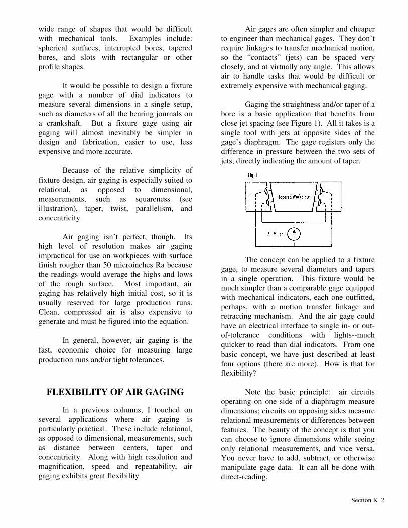
Air gages are often simpler and cheaper to engineer than mechanical gages. They don’t require linkages to transfer mechanical motion, so the “contacts” (jets) can be spaced very closely, and at virtually any angle. This allows air to handle tasks that would be difficult or extremely expensive with mechanical gaging. Gaging the straightness and/or taper of a bore is a basic application that benefits from close jet spacing (see Figure 1). All it takes is a single tool with jets at opposite sides of the gage’s diaphragm. The gage registers only the difference in pressure between the two sets of jets, directly indicating the amount of taper.
The concept can be applied to a fixture gage, to measure several diameters and tapers in a single operation. This fixture would be much simpler than a comparable gage equipped with mechanical indicators, each one outfitted, perhaps, with a motion transfer linkage and retracting mechanism. And the air gage could have an electrical interface to single in- or out-of-tolerance conditions with lights--much quicker to read than dial indicators. From one basic concept, we have just described at least four options (there are more). How is that for flexibility? Note the basic principle: air circuits operating on one side of a diaphragm measure dimensions; circuits on opposing sides measure relational measurements or differences between features. The beauty of the concept is that you can choose to ignore dimensions while seeing only relational measurements, and vice versa. You never have to add, subtract, or otherwise manipulate gage data. It can all be done with direct-reading.
Section K 3
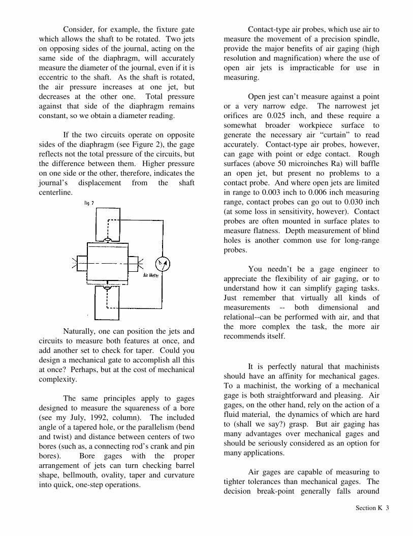
Consider, for example, the fixture gate which allows the shaft to be rotated. Two jets on opposing sides of the journal, acting on the same side of the diaphragm, will accurately measure the diameter of the journal, even if it is eccentric to the shaft. As the shaft is rotated, the air pressure increases at one jet, but decreases at the other one. Total pressure against that side of the diaphragm remains constant, so we obtain a diameter reading. If the two circuits operate on opposite sides of the diaphragm (see Figure 2), the gage reflects not the total pressure of the circuits, but the difference between them. Higher pressure on one side or the other, therefore, indicates the journal’s displacement from the shaft centerline.
Naturally, one can position the jets and circuits to measure both features at once, and add another set to check for taper. Could you design a mechanical gate to accomplish all this at once? Perhaps, but at the cost of mechanical complexity. The same principles apply to gages designed to measure the squareness of a bore (see my July, 1992, column). The included angle of a tapered hole, or the parallelism (bend and twist) and distance between centers of two bores (such as, a connecting rod’s crank and pin bores). Bore gages with the proper arrangement of jets can turn checking barrel shape, bellmouth, ovality, taper and curvature into quick, one-step operations.
Contact-type air probes, which use air to measure the movement of a precision spindle, provide the major benefits of air gaging (high resolution and magnification) where the use of open air jets is impracticable for use in measuring. Open jest can’t measure against a point or a very narrow edge. The narrowest jet orifices are 0.025 inch, and these require a somewhat broader workpiece surface to generate the necessary air “curtain” to read accurately. Contact-type air probes, however, can gage with point or edge contact. Rough surfaces (above 50 microinches Ra) will baffle an open jet, but present no problems to a contact probe. And where open jets are limited in range to 0.003 inch to 0.006 inch measuring range, contact probes can go out to 0.030 inch (at some loss in sensitivity, however). Contact probes are often mounted in surface plates to measure flatness. Depth measurement of blind holes is another common use for long-range probes. You needn’t be a gage engineer to appreciate the flexibility of air gaging, or to understand how it can simplify gaging tasks. Just remember that virtually all kinds of measurements -- both dimensional and relational--can be performed with air, and that the more complex the task, the more air recommends itself.
It is perfectly natural that machinists should have an affinity for mechanical gages. To a machinist, the working of a mechanical gage is both straightforward and pleasing. Air gages, on the other hand, rely on the action of a fluid material, the dynamics of which are hard to (shall we say?) grasp. But air gaging has many advantages over mechanical gages and should be seriously considered as an option for many applications. Air gages are capable of measuring to tighter tolerances than mechanical gages. The decision break-point generally falls around
Section K 4
0.0005 inch; if your tolerances are tighter than that, air gaging provides the higher resolution you will need. At their very best, mechanical gages are capable of measuring down to 50 millionths, but that requires extreme care. Air gages handle 50 millionths with ease, and some will measure to a resolution of 5 millionths. But let’s say your tolerances are around 0.0001 inch and mechanical gaging would suffice. Air still provides several advantages. The high-pressure jet of air automatically cleans the surface of the workpiece of most coolants, chips, and grit, aiding in accuracy and saving the operator the trouble of cleaning the part. The air jet also provides self-cleaning action for the gage plug itself. However, the mechanical plug-type gages can become clogged with cutting oil or coolant and may require occasional disassembly for cleaning. The contacts and the internal workings of mechanical plug gages are subject to wear. There’s nothing to wear on an air plug except the plug itself, and that has such a large surface area that wear occurs very, very slowly. Air gages consequently require less frequent mastering and, in abrasive applications, less frequent repair or replacement.
AIR IS FREE, BUT NOT CARE-FREE
Last month, we concluded that air gaging represents the method of choice for most high-resolution measurements on large production runs. While quite durable and reliable compared to mechanical gages, air gaging is not care-free. Accurate air gaging requires proper maintenance of the tooling, and vigilance over the air supply. Although the factory air supply may not be under the gage user’s control--compressors and air lines may be shared by dozens of other users--the gage user must ensure that the air reaching his gage is clean,
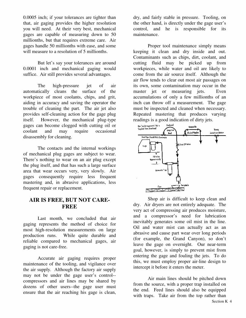
dry, and fairly stable in pressure. Tooling, on the other hand, is directly under the gage user’s control, and he is responsible for its maintenance. Proper tool maintenance simply means keeping it clean and dry inside and out. Contaminants such as chips, dirt, coolant, and cutting fluid may be picked up from workpieces, while water and oil are likely to come from the air source itself. Although the air flow tends to clear out most air passages on its own, some contamination may occur in the master jet or measuring jets. Even accumulations of only a few millionths of an inch can throw off a measurement. The gage must be inspected and cleaned when necessary. Repeated mastering that produces varying readings is a good indication of dirty jets.
Shop air is difficult to keep clean and dry. Air dryers are not entirely adequate. The very act of compressing air produces moisture, and a compressor’s need for lubrication inevitably generates some oil mist in the line. Oil and water mist can actually act as an abrasive and cause part wear over long periods (for example, the Grand Canyon), so don’t leave the gage on overnight. Our near-term goal, however, is simply to prevent mist from entering the gage and fouling the jets. To do this, we must employ proper air-line design to intercept it before it enters the meter. Air main lines should be pitched down from the source, with a proper trap installed on the end. Feed lines should also be equipped with traps. Take air from the top rather than

Section K 5
the bottom of the mains, so that moisture doesn’t drain into the fee. Long, gentle bends on feeds are preferable to hard angles and close ells. Bleed air lines before connecting gages to them. Gages must always have a filter in place when operating, and this should be changed when it becomes saturated. So, enough about moisture and that oil. Let’s talk about air. Air leaks are another common cause of air gage inaccuracy. To test, cover the measuring jets tightly with your fingers and observe the indicator needle. If it’s not stationary, check all fittings, tubes and connectors for leaks. Simple.
Most factory air lines run at about 100 psi, but depending upon the demands of other air users, this can fluctuate widely. Properly designed air gages operate reliably over a wide range--some as wide as 40-150 psi--so a certain amount of fluctuation is acceptable. Other gages are more sensitive and must be isolated from fluctuations by using a dedicated or semi-dedicated air line. To check the sensitivity, simply leave a master in place on the tool and observe the indicator for movement as other air-line users perform their normal tasks. If large pneumatic equipment is being used on the same air line, surges over 400 psi
might be generated that could blow out the built-in regulator and damage the gage itself. Again, isolation of the line is the solution. Tight, clean and dry: the requirements of air gaging aren’t very different from mechanical gaging after all.
On some highly polished or lapped workpieces, mechanical gage contacts can leave visible marks. Air gaging, as a non-contact operation, won’t mark fine surfaces. For the same reason, air gaging can be more appropriate for use on workpieces that are extremely thin-walled, made of soft materials, or otherwise delicate. Continuous processes, as in the production of any kind of sheet stock, rolled or extruded shapes, also benefit from non-contact gaging. Air equipment can save time in almost any gaging task that is not entirely straight-forward. Air plugs with separate circuits can take several measurements simultaneously on a
Section K 6
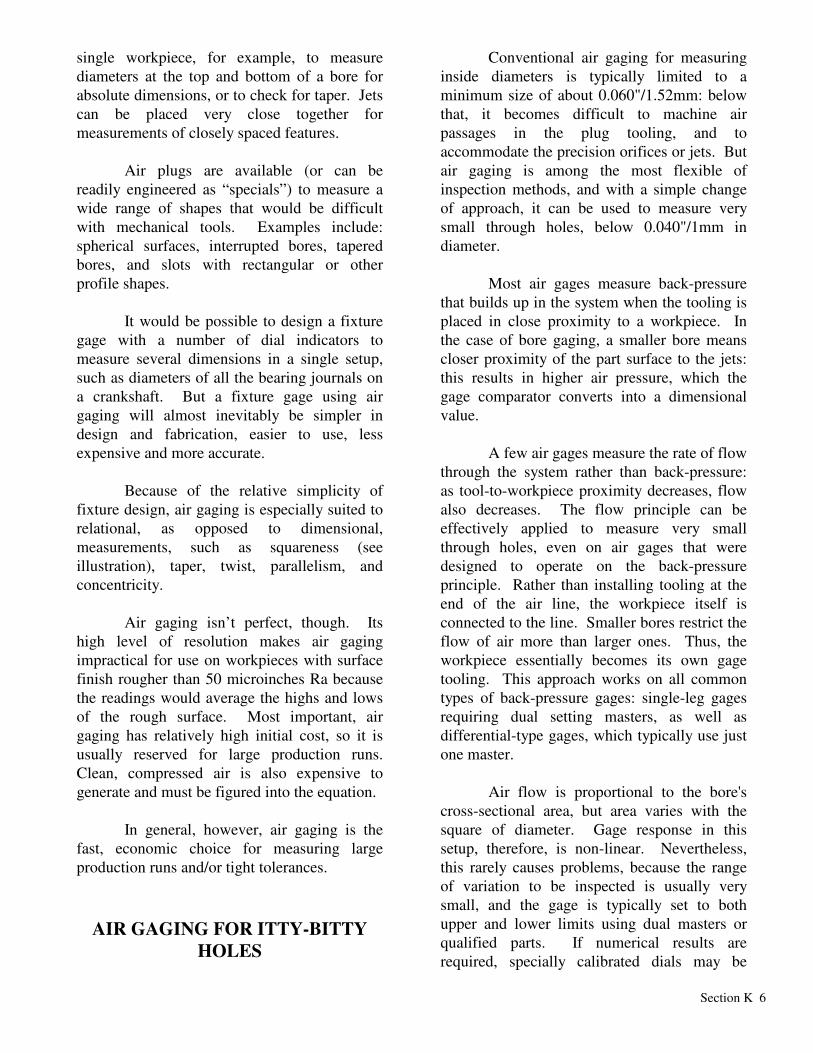
single workpiece, for example, to measure diameters at the top and bottom of a bore for absolute dimensions, or to check for taper. Jets can be placed very close together for measurements of closely spaced features. Air plugs are available (or can be readily engineered as “specials”) to measure a wide range of shapes that would be difficult with mechanical tools. Examples include: spherical surfaces, interrupted bores, tapered bores, and slots with rectangular or other profile shapes. It would be possible to design a fixture gage with a number of dial indicators to measure several dimensions in a single setup, such as diameters of all the bearing journals on a crankshaft. But a fixture gage using air gaging will almost inevitably be simpler in design and fabrication, easier to use, less expensive and more accurate. Because of the relative simplicity of fixture design, air gaging is especially suited to relational, as opposed to dimensional, measurements, such as squareness (see illustration), taper, twist, parallelism, and concentricity. Air gaging isn’t perfect, though. Its high level of resolution makes air gaging impractical for use on workpieces with surface finish rougher than 50 microinches Ra because the readings would average the highs and lows of the rough surface. Most important, air gaging has relatively high initial cost, so it is usually reserved for large production runs. Clean, compressed air is also expensive to generate and must be figured into the equation. In general, however, air gaging is the fast, economic choice for measuring large production runs and/or tight tolerances.
AIR GAGING FOR ITTY-BITTY
HOLES
Conventional air gaging for measuring inside diameters is typically limited to a minimum size of about 0.060"/1.52mm: below that, it becomes difficult to machine air passages in the plug tooling, and to accommodate the precision orifices or jets. But air gaging is among the most flexible of inspection methods, and with a simple change of approach, it can be used to measure very small through holes, below 0.040"/1mm in diameter. Most air gages measure back-pressure that builds up in the system when the tooling is placed in close proximity to a workpiece. In the case of bore gaging, a smaller bore means closer proximity of the part surface to the jets: this results in higher air pressure, which the gage comparator converts into a dimensional value. A few air gages measure the rate of flow through the system rather than back-pressure: as tool-to-workpiece proximity decreases, flow also decreases. The flow principle can be effectively applied to measure very small through holes, even on air gages that were designed to operate on the back-pressure principle. Rather than installing tooling at the end of the air line, the workpiece itself is connected to the line. Smaller bores restrict the flow of air more than larger ones. Thus, the workpiece essentially becomes its own gage tooling. This approach works on all common types of back-pressure gages: single-leg gages requiring dual setting masters, as well as differential-type gages, which typically use just one master. Air flow is proportional to the bore's cross-sectional area, but area varies with the square of diameter. Gage response in this setup, therefore, is non-linear. Nevertheless, this rarely causes problems, because the range of variation to be inspected is usually very small, and the gage is typically set to both upper and lower limits using dual masters or qualified parts. If numerical results are required, specially calibrated dials may be
Section K 7
installed on analog comparators, while some digital comparators allow software correction. Back-pressure air gages operating as flow gages for small holes have been used in a number of specialty applications, ranging from fuel injection components to hypodermic needles. Often, all that is required is a special holder that allows the part to be attached quickly and easily, with a good air seal. Air pressure and flow stabilize quickly, making this method efficient for high-volume inspection. Like other forms of air gaging, flow-type measuring of small through holes is extremely adaptable. It has been used to measure IDs as small as 12 microinches/0.3 micrometers, and as large as 0.050"/1.27mm. Range of measurement can be as long as 0.006"/0.15mm, and discrimination as fine as 5 microinches/0.125 micrometers. In some cases, where the hole is so small that air flow is negligible, bleeds may be engineered into the system to boost total flow to a measurable level. On the other hand, excessive flow through large bores may be brought down into a measurable range by engineering restrictors into the system. Some parts, including some fuel injection components, have two holes sharing a common air passage, and require that the holes be measured twice: once simultaneously, and once independently. To accommodate this requirement, special two-station air gages have been designed, where the first station connects the air flow through both holes, while the second station only connects the air circuit to one of the holes, and blocks the other. Many other methods exist to inspect small holes. Some applications are served well by microscopes and optical comparators, although neither is well suited to high-volume production applications, and both are limited in the part configurations they can accept. Go/no-go gaging with precision wires is also practical only for very low volume tasks. The air gaging method described here often requires a modest level of application engineering, and
occasionally a custom dial face or gaging fixture, but it lends itself well to high-throughput inspection of very tight tolerances. Some users have experienced up to 300 percent increases in efficiency compared to other methods. In discussing air gaging in past columns, we've often emphasized its flexibility. With it, one can measure a wide range of dimensional characteristics, including inside and outside diameters, feature location, thickness, height, and clearance/interference. Air can also be used to measure geometry characteristics such as roundness, squareness, flatness, parallelism, twist, and concentricity. And we've seen how air gages can measure very deep bores, blind holes, and counterbores. The use of air gaging to inspect very small through holes is yet another example of the tremendous adaptability of this relatively simple, but very cost-effective technology.
CHOOSING THE RIGHT AIR GAGE
Air gaging has many advantages as an inspection method. It is quick and easy to use, requiring little skill on the part of the operator. It is highly adaptable to measuring special features for both dimensional and geometric tolerances, ranging from simple IDs and ODs to taper, flatness, and runout. With different tooling readily installed on the gage display unit, it can be highly economical. And as a non-contact form of measurement (in the sense that there are no hard contacts), air gaging is useful for measuring delicate or flexible surfaces, and for monitoring the stability of continuous processes such as drawing and extruding. Once the decision has been made to use air, the user can choose between three basic types of gages, each operating on a different principle. These are: the flow system; the differential pressure or balanced system; and the back-pressure system.
Section K 8
In older flow-type gages, air flows upward through a graduated glass column containing a float. Exiting the column, it flows through a tube to the tooling, where it exits through precision orifices or jets. Flow increases with clearance between the jets and the workpiece. When clearance is large, air flows freely through the column and the float rises. When clearance is small, air flow decreases and the float descends. Flow systems are not very popular in production environments, because they do not readily provide high magnification, and tend to be sensitive to clogging. The other types of air gages measure pressure, not flow. As clearance between the jets and the workpiece increases, pressure decreases. In the back-pressure system, both the pressure meter itself and the bleed (i.e., zeroing circuit) are "Tee'd" off of a single air line—at the end of which is the tooling. Back-pressure systems are often called "dual master" systems: with a relatively short range of linearity, two masters are required to set the upper and lower tolerance limits. In the differential system, the line is split into two legs. The bleed is at the end of one leg; the tooling is at the end of the other; and the bellows-type meter is located between the two legs. When pressure in both legs is equal, the meter is centered at zero. When a change in distance between the tooling and the workpiece causes pressure in the measuring leg to increase or decrease, the bellows reacts accordingly, and this is reflected on the meter. Differential systems offer linear response over a relatively long range: a single master is therefore sufficient to establish the zero point and still assure excellent accuracy on both the plus and minus sides. Both differential and back-pressure systems are very well suited to production gaging applications, for different reasons. Differential systems are capable of higher magnification and discrimination; are easier to use because of greater tool-to-part clearance
and the requirement for only one master; and are more stable. Back-pressure systems offer lower cost, adjustable magnification, and greater interchangeability of tooling between manufacturers. See the table for a summary of benefits associated with these gages.
BACK-PRESSURE VS. DIFFERENTIAL AIR GAGING
Back Pressure (Dual Master) Gages • Adjustable magnification; tooling
flexibility. • Less costly tooling. • Higher air pressure: cleans part surface
more • effectively. • Two masters provide greater traceability. • More manufacturers; wide compatibility. Differential (Single Master) Gages • Higher magnification, discrimination;
longer range. • Greater tool-to-part clearance reduces wear,
speeds usage. • Better stability, dependability; no drift.
Better for automatic control applications, and data collection for SPC.
• Single master makes gage easier, quicker to set.
CHECKING FOR CENTRALIZATION AND BALANCE ERRORS
Air gaging is often referred to as a non-contact form of measurement. This is accurate, to the extent that there's no metal-to-metal contact between a sensitive gage component and the workpiece. Nevertheless, air gage tooling—including air plugs for inside diameter measurements—does generally come in contact with the workpiece, and may show wear after several thousand measurements or years of use. (The comments here are equally applicable to electronic plug gages.) When, due to wear, the clearance between the gage and the workpiece exceeds
Section K 9
the design clearance, centralization error results. The air jets then measure a chord rather than the true diameter of the part. As the distance between the chord and the bore centerline increases, we begin to see measurement inaccuracy. Another form of error occurs when the jet centerline is not on the plug centerline. In this case, the plug will always measure a chord of the part. How much centralization error is allowable depends upon both the diameter of the workpiece and the dimensional tolerance specification. Obviously, looser tolerances can "tolerate" more measurement error. But equal amounts of misalignment will cause greater centralization error in a small bore than in a large one. (For details on calculating the misalignment tolerance based on allowable centralization error, refer to this department in MMS 7/98.) For a gage to function properly, all the jets in an air plug (or ring) must have a common recess depth and orifice diameter. But recesses and orifices may become clogged with contaminants, damaged through accident, or worn unevenly through very heavy usage. This causes another form of measurement error, called "balance error." It is easy to inspect for these various forms of error. Certain types of gage usage will demonstrate characteristic wear patterns. In hand-held gaging applications, wear usually occurs fairly evenly around the circumference of the plug. If, however, the plug is horizontally mounted on the front of an air gage display, then the top surface will probably experience the most wear.
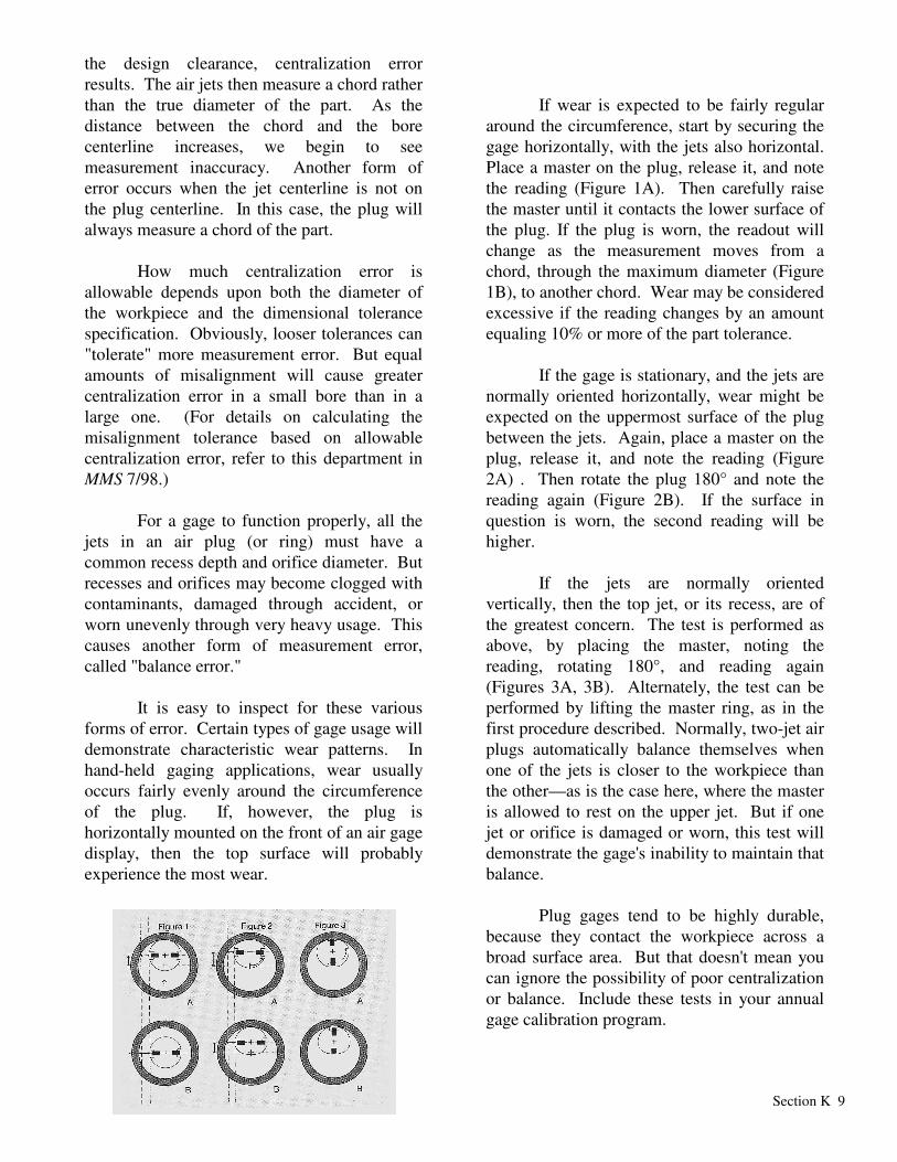
If wear is expected to be fairly regular around the circumference, start by securing the gage horizontally, with the jets also horizontal. Place a master on the plug, release it, and note the reading (Figure 1A). Then carefully raise the master until it contacts the lower surface of the plug. If the plug is worn, the readout will change as the measurement moves from a chord, through the maximum diameter (Figure 1B), to another chord. Wear may be considered excessive if the reading changes by an amount equaling 10% or more of the part tolerance. If the gage is stationary, and the jets are normally oriented horizontally, wear might be expected on the uppermost surface of the plug between the jets. Again, place a master on the plug, release it, and note the reading (Figure 2A) . Then rotate the plug 180° and note the reading again (Figure 2B). If the surface in question is worn, the second reading will be higher. If the jets are normally oriented vertically, then the top jet, or its recess, are of the greatest concern. The test is performed as above, by placing the master, noting the reading, rotating 180°, and reading again (Figures 3A, 3B). Alternately, the test can be performed by lifting the master ring, as in the first procedure described. Normally, two-jet air plugs automatically balance themselves when one of the jets is closer to the workpiece than the other—as is the case here, where the master is allowed to rest on the upper jet. But if one jet or orifice is damaged or worn, this test will demonstrate the gage's inability to maintain that balance. Plug gages tend to be highly durable, because they contact the workpiece across a broad surface area. But that doesn't mean you can ignore the possibility of poor centralization or balance. Include these tests in your annual gage calibration program.

Section K 10
THE 3 D'S OF STRAIGHTNESS PLUGS
We have touched on the many different applications of air gaging in a number of articles: size, match gaging, and form applications such as taper. In this column we'll spend some time with air straightness plugs and how they work.
The typical out-of-straightness condition is
seen as a "bow" form within the bore, one that was introduced as part of the manufacturing process. The air straightness plug attempts to measure the depth of its curve. Usually this out-of-straightness condition is all within one orientation along the axis of the hole.
Design
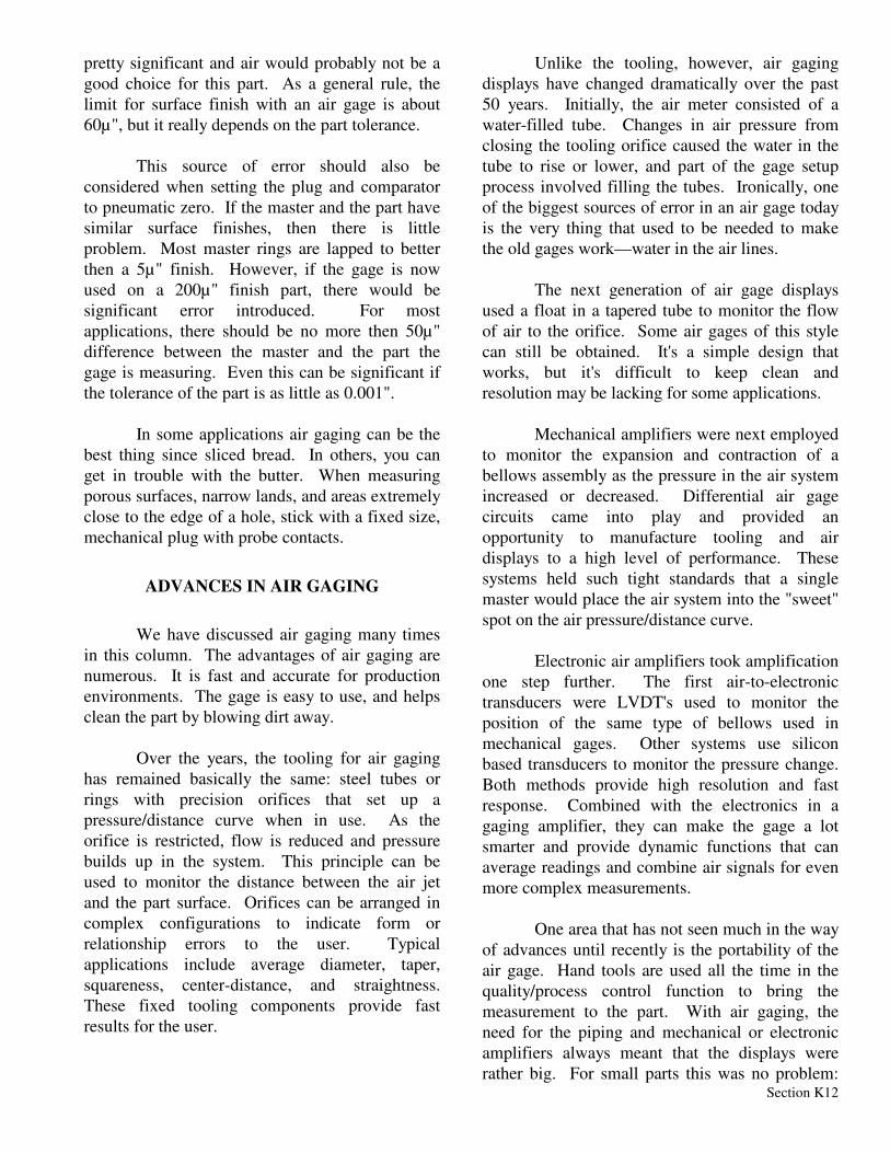
A typical air plug has four measuring jets
in two opposing sets—two near the middle and two near the ends, as seen in Figure 1. This design allows the plug to look at both extremes of the bow condition.
There are no rules for the exact positioning
of the jets relative to each other—as is sometimes the case with taper or squareness checks. Nor are there any ratios involved. The air jets at the extreme of the plug are positioned to inspect for the out-of-straightness condition which is usually specified over the total length of the bore. But, in order to understand how a straightness plug works, we have to take a quick look at the various combinations of jets typical in air tooling.
Differential Measurement
A two-jet plug is a differential measuring
system. Imagine a two-jet air plug inside a master ring with the indicator reading zero. Now move the plug so that one jet is pressed against the side of the ring. This increases the back pressure on one jet, and decreases it on the other. But the indicator reading does not change, because the combined pressure of the two jets remains the same. However, when you insert the plug into a smaller or larger test part, the pressure does change, and the gage reads the differential.
An extension of the two-jet air plug is a four-jet system. Here, four jets are added together and if the plug is moved in any direction, again an average (differential) reading is made. The four jets see four pressure changes and add them all together. If there is a change in any of the measured dimensions, the total—and the reading on the indicator dial—changes.
The four jets are normally at the same level
or plane on the plug. In theory, the four jets could be moved anywhere along the length of the plug independently, and if they are positioned at 90 degrees to each other, they will measure an average diameter of the bore. But if we move the jets so that two are on the same side at the extremes of the plug, and the other two are moved to the center on the other side of the plug, we have the straightness plug described above. If the part being measured is perfectly straight, and the plug is moved up and down, it acts like a two-jet piece of tooling. The two jets on the top are offset by the two jets on the bottom, and the result is no change on the display. But if the bore is not perfectly straight, the combined pressure changes, and the differential is shown on the instrument.Dynamic Measurement.
But don't go thinking you've got it down so
fast. If the straightness plug is simply inserted into the bore, the display shows a number. What that number means is the real question. Straightness needs to be made as a dynamic measurement, very similar to a squareness check. With both of these form errors, the out-of-form condition is at its maximum along the axis at two positions, 180 degrees opposite each other.
Again, looking at Fig. 1, we can
understand what the inner and outer jets are looking at. When the jets are in line with the bow (jets up and down) the jets are seeing either their max or min reading depending on the orientation. When moved 180 degrees, the inner and outer jets reverse roles and the same value is seen, and the plug is working in its differential mode.
But as the plug is rotated through 180
degrees exploring the bore, the pairs of jets will experience a maximum clearance and then find the

Section K 11
minimum clearance, usually at right angles to each other. This difference between the maximum and minimum value is the out-of-straightness condition as seen over the total length of the plug measurement length.
You can also think of it this way. If you
looked at the bore from the end, and drew a line around the extremes of its path, you would end up with an ellipse, Fig. 2. If you had an ellipse in a hole, a two-jet air plug would be capable of measuring the variation in size by rotating it in the part. Think of the straightness plug as a stretched out air plug with four jets doing the same thing. With this in mind you have a pretty good understanding of what the straightness plug is doing.
The air straightness plug, though it is a
little more complicated then a standard air plug, still maintains the same advantages of a standard air plug—easy to set up, easy to use, and high precision results.
SLICED BREAD AND THE LIMITS OF AIR
GAGING
"Air gaging is the greatest thing since sliced bread," a friend once told me. And he was right — air gaging is good. It's fast, high resolution, non-contact, self-cleaning and easy to use. For use in a high-volume shop, it's hard to beat. But that begs the question, "If air gaging is so good, why would you ever consider going back to contact type gaging?"
The answer is that while air gaging does
provide all of the benefits listed above, it and
everything else that obeys the laws of physics, has some limitations. There are, in short, some trade-offs and for every advantage you gain in the measuring process with air, you will have to pay the price and sacrifice something else. The real question is, "What are those limitations and how can you best work with them?"
Air gaging gives you a fast measurement
device that provides superior reliability in the dirtiest shop environment. But you give up things like measurement range and a clear delineation of surface. Air gaging has about 10 - 20% of the range of a typical electronic transducer with similar resolution.
The response of air to surface finish,
however, is more complicated. Think of an air jet. The measurement 'point' is really the average area of the surface the jet is covering. Now consider the finish, or roughness, of that surface. The measurement point of the air jet is actually the average of the peaks and valleys the jet is exposed to. This is not the same measured point you would have if a contact type probe is used. This difference is a source of real gaging error, and one which is most often apparent when two different inspection processes are used.
For example, let's say we have a surface
finish of 100µ" on a part, and we're measuring with an air gage comparator and two-jet air plug that has a range typically used to measure a 0.003" tolerance. The typical gaging rule says you should have no sources of error greater then 10% of the tolerance. In this example, that's 0.0003". If we used this plug on the 100µ" surface, the average measuring line is really 50µ" below the peak line. Double this error with two jets and you get 0.0001" or 30% of the allowable error. That's
Fig 1. Location of jets on straightness plug.
Fig 2. Jets actually “see” the max of the middle and extreme diameters.
Section K 12
pretty significant and air would probably not be a good choice for this part. As a general rule, the limit for surface finish with an air gage is about 60µ", but it really depends on the part tolerance.
This source of error should also be
considered when setting the plug and comparator to pneumatic zero. If the master and the part have similar surface finishes, then there is little problem. Most master rings are lapped to better then a 5µ" finish. However, if the gage is now used on a 200µ" finish part, there would be significant error introduced. For most applications, there should be no more then 50µ" difference between the master and the part the gage is measuring. Even this can be significant if the tolerance of the part is as little as 0.001".
In some applications air gaging can be the
best thing since sliced bread. In others, you can get in trouble with the butter. When measuring porous surfaces, narrow lands, and areas extremely close to the edge of a hole, stick with a fixed size, mechanical plug with probe contacts.
ADVANCES IN AIR GAGING
We have discussed air gaging many times in this column. The advantages of air gaging are numerous. It is fast and accurate for production environments. The gage is easy to use, and helps clean the part by blowing dirt away.
Over the years, the tooling for air gaging
has remained basically the same: steel tubes or rings with precision orifices that set up a pressure/distance curve when in use. As the orifice is restricted, flow is reduced and pressure builds up in the system. This principle can be used to monitor the distance between the air jet and the part surface. Orifices can be arranged in complex configurations to indicate form or relationship errors to the user. Typical applications include average diameter, taper, squareness, center-distance, and straightness. These fixed tooling components provide fast results for the user.
Unlike the tooling, however, air gaging displays have changed dramatically over the past 50 years. Initially, the air meter consisted of a water-filled tube. Changes in air pressure from closing the tooling orifice caused the water in the tube to rise or lower, and part of the gage setup process involved filling the tubes. Ironically, one of the biggest sources of error in an air gage today is the very thing that used to be needed to make the old gages work—water in the air lines.
The next generation of air gage displays
used a float in a tapered tube to monitor the flow of air to the orifice. Some air gages of this style can still be obtained. It's a simple design that works, but it's difficult to keep clean and resolution may be lacking for some applications.
Mechanical amplifiers were next employed
to monitor the expansion and contraction of a bellows assembly as the pressure in the air system increased or decreased. Differential air gage circuits came into play and provided an opportunity to manufacture tooling and air displays to a high level of performance. These systems held such tight standards that a single master would place the air system into the "sweet" spot on the air pressure/distance curve.
Electronic air amplifiers took amplification
one step further. The first air-to-electronic transducers were LVDT's used to monitor the position of the same type of bellows used in mechanical gages. Other systems use silicon based transducers to monitor the pressure change. Both methods provide high resolution and fast response. Combined with the electronics in a gaging amplifier, they can make the gage a lot smarter and provide dynamic functions that can average readings and combine air signals for even more complex measurements.
One area that has not seen much in the way
of advances until recently is the portability of the air gage. Hand tools are used all the time in the quality/process control function to bring the measurement to the part. With air gaging, the need for the piping and mechanical or electronic amplifiers always meant that the displays were rather big. For small parts this was no problem:
Section K 13
the parts could easily be brought to the gage. For larger parts, the tooling could be attached to a hose and brought to the part, but there was a potential problem in that the operator had to watch the tooling as he placed the plug in the part, then turn around to search for the air display in order to interpret the value.
In recent years, electronics have allowed
even air displays to become smaller. There are now air gages on the market that make the display portable, as part of the air tooling itself. With this configuration, the air display is right in front of the operator, ready to be read, and there is no searching for the old air meter. Like the amplifier version, these portable air gages combine electronic transducers with today's digital indicators, to provide selectable resolutions, tolerances and data collection capabilities.
Air gaging was thought to have reached its
peak many years ago. But in reality, there is an increasing demand for its application. As tolerances have gotten tighter on the shop floor, air gaging is often the only way to make the check fast and easy for the operator. With portable air gaging, that check can now be made right at the part.