you can’t do that with autodesk...
TRANSCRIPT

November 30 – December 3, 2004 ◊ Las Vegas, Nevada
You Can’t Do That with Autodesk Revit!
James Vandezande, AIA – Skidmore, Owings & Merrill
BD23-2 An informative look at what many thought impossible to accomplish with Autodesk Revit. Learn what it takes to manage change within a large organization and how to use Revit to maximum advantage on large projects with large teams.
About the Speaker: James is an associate with Skidmore, Owings and Merrill in New York and has 10 years experience as an architect and CAD manager. He is in charge of BIM evaluation, implementation, and training for SOM worldwide. James received a Bachelor of Architecture cum laude from the New York Institute of Technology in Old Westbury, NY.

You Can’t Do That with Autodesk Revit!
2
Introduction Since Revit’s conception from the loins of Charles River Software, questions from practicing industry professionals have arisen concerning its ability to perform under rigorous demands. We hear time and time again, “You can’t do that with Autodesk Revit!” This course will explore some of the things many said could not be accomplished in this underrated platform.
Most of the presented content is focused on intermediate to advanced concepts in Autodesk Revit and assumes some basic knowledge of fundamental concepts. To learn more about basic functions, refer to the Revit tutorials or Autodesk’s Distance Learning Seminars.
Case Study One lesson I learned from other professional training events was the inclusion of actual projects using advanced technologies. While learning about some of Revit’s advanced capabilities, I will share some of the progress being made on the Freedom Tower project – one of Skidmore, Owings & Merrill’s building information modeling pilots.
All included images copyrighted by Skidmore, Owings, Merrill LLP – 2004.
You Can’t Do That with Autodesk Revit!
3
Organizing a Large Dataset How can you work in a project with hundreds or even thousands of views?
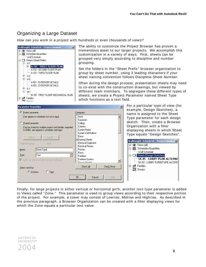
The ability to customize the Project Browser has proven a tremendous asset to our larger projects. We accomplish this customization in a variety of ways. First, sheets can be grouped very simply according to discipline and number grouping.
Set the folders in the “Sheet Prefix” browser organization to group by sheet number, using 3 leading characters if your sheet naming convention follows Discipline-Sheet Number.
Often during the design process, presentation sheets may need to co-exist with the construction drawings, but viewed by different team members. To segregate these different types of sheets, we create a Project Parameter named Sheet Type which functions as a text field.
For a particular type of view (for example, Design Sketches), a name is assigned to the Sheet Type parameter for each design sketch. Then, create a Browser Organization with a filter displaying sheets in which Sheet Type equals “Design Sketches”.
Finally, for large projects in either vertical or horizontal girth, another text-type parameter is added to Views called “Zone.” This parameter is used to group views according to their respective portion of the project. For example, a tower may consist of Lowrise, Midrise and Highrise. As described in the previous paragraph, a Browser Organization can be created with a filter displaying views for which the Zone equals a particular text value.

You Can’t Do That with Autodesk Revit!
4
Worksets Can a large project be organized to allow efficient workflow of a large team?
Early problems in Revit implementation usually stem from improper team structure. Because Revit utilizes a model-based approach to design and documentation, the traditional drawing-based roles become obsolete. Project teams must focus on assemblies of building components rather than plans, sections, elevations…
To this end, Revit allows a project of any size to be organized according to the structure of the team. Following are some examples of worksets used on large scale projects:
Large Vertical Building Large Campus-Type Project
• Exterior Enclosure
• Core
• Interior Walls 1, Interior Walls 2, …
• Furniture 1, Furniture 2, …
• Telecom 1, Telecom 2, …
• Structure-Foundation
• Structure-Podium
• Structure-Tower
• Datum-Grids
• Datum-Levels
• Floors-Vertical Openings
• Site
• Existing Structure
• Existing Partitions
• Structure-Part A, Structure-Part B, …
• Enclosure-Part A, Enclosure-Part B, …
• Core-Part A, Core-Part B, …
• Partitions-A1, Partitions-A2, …
• Partitions-B1, Partitions-B2, …
• Datum-Grids
• Datum-Levels
• Site
With this type of workset structure, team members have the ability to open discrete portions of the virtual building. Using File-Open, you are presented with the option to specify which worksets you would like to open, thus limiting the amount of data loaded into memory.

You Can’t Do That with Autodesk Revit!
5
Managing Complex Designs with Building Maker Can Revit work with designs other than boxes?
Before the “Building Maker” in Revit 7.0, complex geometry was possible albeit somewhat cumbersome to manage. Generating forms such as hyperbolic paraboloids were simple with Revit’s Blend tool, but updating floor plates was more involved. For posterity, let’s briefly review how this was accomplished in Revit 6.1.
First, the levels were established and an overall floor template shape was created. Reference planes were added to layout the basic rules for the geometry:
Next, an in-place family was created with voids to ‘slice’ through all of the floor plates based on the geometric layout of the reference planes:

You Can’t Do That with Autodesk Revit!
6
Finally, the floors are cut using the in-place voids using the Cut Geometry tool. Any additional modifications to the overall geometry had to be accomplished by reshaping the voids and re-cutting the floors. This was quite cumbersome as voids ‘inherited’ the geometry of each solid object it was cutting, thus quadrupling the amount of calculation for each floor instance.
With the release of 7.0, this process is greatly simplified. The slicing voids are no longer required to shape the floors. Using Revit 7.0’s new Floor Faces tools, the gross floor area of the original solid form can be analyzed before any actual building elements, such as floors, are added. Once the schematic analysis is complete, building elements are associated with the massing elements.
Because the building elements are associated with the massing elements, any global change to the massing can be propagated to the building elements using the “Remake” function.

You Can’t Do That with Autodesk Revit!
7
Family Geometry Generating structural-based architectural content is challenging in any platform. Representations of support members for architectural documentation may or may not be directly usable in analysis software, but that is a different discussion.
The immediate need is to create intelligent and flexible geometric content for development of a complex design concept. To this end, we utilize a number of non-conventional modeling techniques including some examples below.
To create a complex truss-like form, we commonly use a void shape as a parametric jig to guide other dependent solid geometry. In the first example, we create a 5-sided blend void. Solid sweeps are created using the ‘Pick Path’ option and selecting the edges of the void. Once all edges are complete, all members can be adjusted with the geometry of the single void.
For easier control of the sweep geometry, use a loaded profile which contains a type parameter, such as the radius of a tube. Using the example, one can quickly modify all the geometric members by navigating the Project Browser of the family down to Profiles, find the loaded profile and examine its properties and modify the value. This will update all sweeps with the associated profile type.
You Can’t Do That with Autodesk Revit!
8
Vertical Openings How can we manage extensive vertical penetrations?
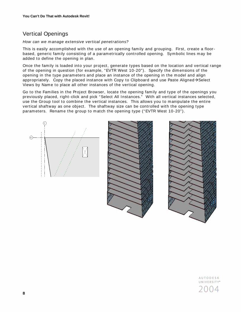
This is easily accomplished with the use of an opening family and grouping. First, create a floor-based, generic family consisting of a parametrically controlled opening. Symbolic lines may be added to define the opening in plan.
Once the family is loaded into your project, generate types based on the location and vertical range of the opening in question (for example, “EVTR West 10-20”). Specify the dimensions of the opening in the type parameters and place an instance of the opening in the model and align appropriately. Copy the placed instance with Copy to Clipboard and use Paste Aligned Select Views by Name to place all other instances of the vertical opening.
Go to the Families in the Project Browser, locate the opening family and type of the openings you previously placed, right-click and pick “Select All Instances.” With all vertical instances selected, use the Group tool to combine the vertical instances. This allows you to manipulate the entire vertical shaftway as one object. The shaftway size can be controlled with the opening type parameters. Rename the group to match the opening type (“EVTR West 10-20”).

You Can’t Do That with Autodesk Revit!
9
Geometry Verification Can you qualify the design data in the model?
Yes. A good example of this ability in action is a method to verify that walls included in the project do not exceed their limiting heights. This is accomplished through the use of project parameters added to wall types and customized wall schedules. In this example we create a project parameter called “Limiting Ht” to assign the maximum height of a particular wall type.
We then add values to template wall types according to their structure via Type Properties.
For example, the limiting height on a wall using 16 gauge 4” metal studs is
Querying the maximum height of a wall instance is the real trick in the current release of Revit. The average height of a wall segment can be calculated by dividing the area of the segment by the length, but this is affected by openings and edited profiles.
Begin a new Wall Schedule and add the fields: Type, Length, Area and
the custom parameter Limiting Ht. Create a calculated value named Height, which is a function of Area / Length. Create another calculated value named Height Check, which is a function of Height – Limiting Ht.
Finally, set the filter for the Wall Schedule to values where Height Check is greater than 0’-0”. The resulting wall segments in the schedule are the ones that exceed the limiting height in the type parameters. From this ‘checking schedule’ you can select a row indicating a wall that exceeds its limiting height and click Show to open a view with that wall highlighted.

You Can’t Do That with Autodesk Revit!
10
Energy Analysis Can energy analysis be used during the design process with Revit?
Normally, design firms will delegate this task to specialists after a certain completion point of the project; however, this workflow does not lend itself to the iterative design process. Autodesk Revit facilitates the inclusion of such advanced data into the project from the earliest stages of design.
To begin the energy analysis process a minimum amount of information must be assembled. This includes the Project Information, bounding walls and Room Tag assignments. Once these have been placed in the model, use File-Export-gbXML to generate an XML file. The gbXML file is a textual representation of your project which can be translated into an energy program such as the Green Building Studio, developed by Geopraxis (www.geopraxis.com).
Registration with the Green Building Studio is free. Once you log into the Geopraxis website at www.greenbuildingstudio.com, create a new project based on its actual location. The zip code is important to determine the geographic energy performance used in the analysis. Once a project is created, launch the Green Building Studio Client from your computer, login, and click Refresh List if you don’t see the name of your project in the list.
Pick the ‘Select gbXML File’ button and find the XML file you previously exported then click on ‘Get Results for Above File.’

You Can’t Do That with Autodesk Revit!
11
With this data, one can quickly modify the arrangement of interior spaces, building orientation, fenestration material or other design parameters earlier in the design process and help inform your clients.
View of VRML (Virtual Reality Modeling Language) file in a web browser.