you can find us everywhere. - westek electronics · you can find us everywhere. there must be a...
TRANSCRIPT

You can find us everywhere.There must be a reason.
Main catalogue 2010
Energie-Messtechnik
Power Quality MonitoringEnergie-Management
Power ManagementSoftware & Zubehör
Software & AccessoriesNetzqualitäts-Lösungen
Power Quality Solutions

▼ UMG 604 power analyser � Reduce electricity costs� Stabilise production processes� Reliable supply with energy� Reduce maintenance costs
“Quality is never an accident; it is always the result of intelligent effort.”
John Russkin

Company profile 3
3P-strategy 5
An overview of application options 6
Software 145
GridVis, OPC Server, MS Excel analysis tools 148
Accessories 161
Current transformer, mechanical accessories, field bus
components, data server, touch panels, ... 164
Appendix 205
PFC cable diameters, fuses, cos-phi selection table,
project descriptions 206
Energy Measurement Technology Power Quality Monitoring 7
An overview of UMG families 9
UMG 103 – universal measuring instrument for DIN rails 12
UMG 104 – power analyser for DIN rails 18
UMG 604 – power analyser for DIN rails 24
UMG 605 – power quality analyser for DIN rails 32
UMG 96L/UMG96 – universal measuring instrument 96x96mm 38
UMG 96S – universal measuring instrument with M-Bus, Modbus
and Profibus/harmonics display 44
UMG 503 – 144 x 144mm power analyser 52
UMG 505 – power analyser with LON and analogue IOs 60
UMG 507 – power analyser with continuous measurements,
Ethernet and short term interruption detection 68
UMG 508 – multifunctional power analyser 76
UMG 511 – class A power quality analyser in accordance with
IEC61000-4-30 and PQ reports for EN50160/61000-2-4 82
Power Management 89
Electronic impulse-energy meter 92
Peak demand management, UMG 507Emax 100
Data logger, ProData® 106
Power Quality Solutions 111
Power factor controller, Prophi® 114
Power capacitors for power factor correction 120
Conventional PFC without reactors (PFC), 124
Detuned power factor correction (PFC),
harmonic filters 130
Dynamic power factor correction (DPFC) 138
Chapter 01
Chapter 02
Chapter 03
Chapter 04
Chapter 05
Chapter 06
Chapter 07

Janitza electronics®
▼
The story
Janitza® electronics GmbH was founded by Mr. Eugen Janitza andMr. Markus Janitza in Lahnau in the year 1986. After EugenJanitza, one of the co-founders, retired from the company, hisson, Markus Janitza, took over as general manager.
As a medium-sized family company, Janitza electronics® GmbHis an important employer in the region with a significantupwards tendency. The management is dedicated to the site inGermany which is testified by the continual, active apprentice -ship schemes for young talents. The complete chain of valuecreation including product development, production and sales isbased in Lahnau and the major expansion of production area atthe beginning of 2007 shows that this will continue to be thecase in the future. Traditional values such as continuity and relia-bility are of great interest to our customers along with innovati-ve technology and products together with a rapid, professionalservice.
Chapter 1
3
▼

Reflow soldering machine in the PQM device production
The customers
The focus
Janitza electronics® GmbH is a leading global manufacturer inthe field of digital integrated measuring equipment for energydistributors, energy optimisation systems and power qualitysolutions. The products made by Janitza electronics® are gene-rally used to reduce energy, maintenance and products costs.
Awareness of power quality has gained significance in allcompanies in the past years. Excessive power quality distortionlead to increased wear and tear in all electrical supply equip-ment and any connected electrical and electronic loads andcan lead even up to production stoppages. Our measuringinstruments therefore provide essential information aboutinsufficient power quality and hence enable customers to takemeasures for the improvement of power quality problems.This leads to a longer lifespan for equipment and improvedsustainability of the respective investments.
The possibility of allocating energy costs to certain products isbecoming more and more important to industrial companies.Janitza electronics® also has customised solutions for cost centreanalysis.
The reduction of expensive peak demand loads and the com-pensation of reactive power can immediately cut down the electricity bill.
Janitza electronics® GmbH products are generally of interest to allprofessional consumers of electrical energy. The products fromJanitza electronics® are already used by 17 companies which arelisted in the German Shares Index (DAX). The most importantcustomers are in the automobile industry, the banking and insu-rance sector or local councils. The products are used in industry,commercial buildings, by energy suppliers, in airports, supermar-
kets, universities and in hospitals. However, the use of our produc-ts is also lucrative for smaller companies.
Janitza electronics® GmbH has an export ratio of approximately50% and markets its products in more than 60 countries through-out the world.
4

Power Quality Monitoring - Power Management - Power Quality Solutions
The products, systems and services of Janitza electronics® range from measurement (collection of data) through energymanagement to solutions for the improvement of power quality. Janitza electronics® does not solely limit itself to the collec-tion of data but, based on the measurement data, offers customised solutions in the fields of power quality and power mana-gement. This one-stop offer supports the best possible efficiency and power reliability.
Janitza’s® 3P-Strategy
▼
Power Quality Monitoring� Measurement� Monitoring� Automatic alarm management� Detection of PQ problems
Janitza’s® 3P-Strategy
Power Management� Peak demand management� Collection of data� Cost centre management� Energy efficiency
Power Quality Solutions
� Power factor correction (PFC)� Harmonic filters� Dynamic PFC
Chapter 1
5
▼

Switch:Communication usingTCP/IP, internet
Computer environment:- Programming and assessment software- Cost centre data collection- Power quality- Analysis tools- Database management- Etc.
Janitza® UMG 511:EN50160 StandardMonitoring of power qualityClass A Power Quality Monitoring
Janitza® UMG 508:Monitoring the reliability of voltage suppliesMonitoring short-term interruption
Janitza® Prophi®:Reactive power controller
Janitza® UMG 604, UMG 503 - 507:Cost centre analysis, consumer data collection, ...
Janitza® UMG 103 / UMG 96S:Monitoring important energy and electrical data; replacement for analogue measuring equipment
Janitza® UMG 507 EMax:Peak demand management
Janitza® ProData®:Data logger
Janitza® Power Quality Solutions
Fixed & automatic power factor
correction
Dynamicpower factor
correction
De-tunedcapacitor banksharmonic filters
An overview of application options
6
7
Power Quality Monitoring
▼▼
Chapter 2
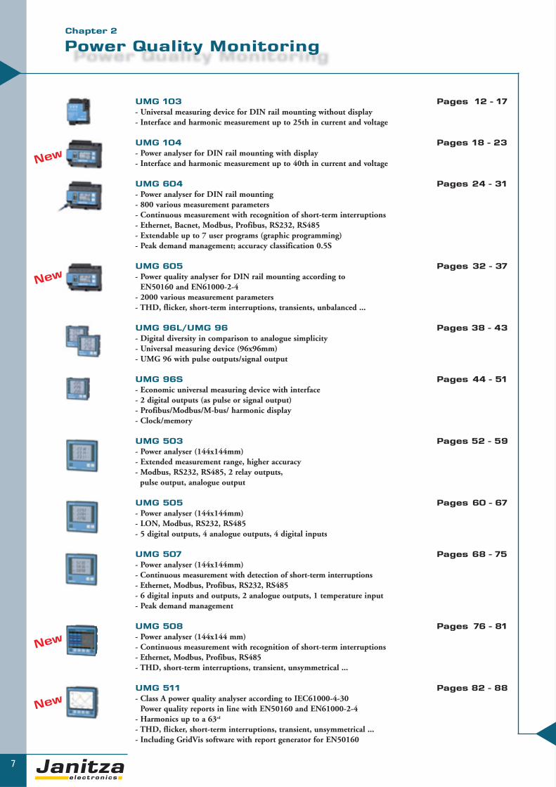
UMG 103 Pages 12 - 17- Universal measuring device for DIN rail mounting without display- Interface and harmonic measurement up to 25th in current and voltage
UMG 104 Pages 18 - 23- Power analyser for DIN rail mounting with display - Interface and harmonic measurement up to 40th in current and voltage
UMG 604 Pages 24 - 31- Power analyser for DIN rail mounting- 800 various measurement parameters- Continuous measurement with recognition of short-term interruptions- Ethernet, Bacnet, Modbus, Profibus, RS232, RS485- Extendable up to 7 user programs (graphic programming)- Peak demand management; accuracy classification 0.5S
UMG 605 Pages 32 - 37- Power quality analyser for DIN rail mounting according to
EN50160 and EN61000-2-4- 2000 various measurement parameters- THD, flicker, short-term interruptions, transients, unbalanced ...
UMG 96L/UMG 96 Pages 38 - 43- Digital diversity in comparison to analogue simplicity- Universal measuring device (96x96mm)- UMG 96 with pulse outputs/signal output
UMG 96S Pages 44 - 51- Economic universal measuring device with interface- 2 digital outputs (as pulse or signal output)- Profibus/Modbus/M-bus/ harmonic display- Clock/memory
UMG 503 Pages 52 - 59- Power analyser (144x144mm)- Extended measurement range, higher accuracy- Modbus, RS232, RS485, 2 relay outputs,
pulse output, analogue output
UMG 505 Pages 60 - 67- Power analyser (144x144mm)- LON, Modbus, RS232, RS485- 5 digital outputs, 4 analogue outputs, 4 digital inputs
UMG 507 Pages 68 - 75- Power analyser (144x144mm)- Continuous measurement with detection of short-term interruptions- Ethernet, Modbus, Profibus, RS232, RS485- 6 digital inputs and outputs, 2 analogue outputs, 1 temperature input- Peak demand management
UMG 508 Pages 76 - 81- Power analyser (144x144 mm)- Continuous measurement with recognition of short-term interruptions- Ethernet, Modbus, Profibus, RS485- THD, short-term interruptions, transient, unsymmetrical ...
UMG 511 Pages 82 - 88- Class A power quality analyser according to IEC61000-4-30
Power quality reports in line with EN50160 and EN61000-2-4- Harmonics up to a 63rd
- THD, flicker, short-term interruptions, transient, unsymmetrical ...- Including GridVis software with report generator for EN50160
New
New
New
New

▼
PQ
M -
Po
we
r Q
ua
lity
Mo
nit
ori
ng
8
PQM - Power Quality MonitoringEnergy measurement technology
The first step towards saving energy and improving operational processes is the measurement of the
most important parameters of your electrical energy supply while monitoring the peak loads.
Janitza electronics® offers you a complete range of power
monitoring units with the corresponding accessories.
The UMG measuring equipment and power analysers
help you to gain a comprehensive overview of your
energy supplies and introduce the correct measures.
The power quality is also monitored according to the
general valid standards (e.g. EN50160). The
GridVis software packages in connection with
the measurement equipment and power
analysers from Janitza electronics® offer
you energy and power monitoring
with real-time diagnosis from the
provider through to all levels of your
enterprise.

9
Overview of universal measuring instruments
▼▼
*1 Other voltages are available as options (2) Combination options for inputs and outputs: a) 2 digital outputs, b) 2 digital inputs
c) 2 analogue outputs, d) 1 digital output and 1 analogue output, e) 1 digital output and 1 digital input
Chapter 2
Type
Item number
Measurement range L-N, AC
Measurement range L-L, AC
Over voltage category
Operating voltage L-N, AC
Auxiliary voltage
Three phase/four phase
Quadrants
Scan frequency 50/60Hz Measurement points per sec.
Continuous measurement
Measurements per second
Effective value from periods50/60Hz
Harmonics V/A
Distortion factor THD-U in %
Distortion factor THD-I in %
Unbalance
Positive/negative/zero system
Current flicker strength
Short/long-term flicker
Transients
Short-term interruptions
Accuracy V, A
Effective energy classification
Operating hour meter
Weekly time switch
Auxiliary input
Digital inputs
Digital/pulse output
Relay outputs
Analogue inputs
Analogue outputs
Temperature input
Integrated logic
Min/max value memory
Memory size
Number of storage values
Clock
Bi-metallic function A/kW
Fault recording function
Peak demand management
Software
Interfaces
RS 232
RS 485
Profibus DP
M-Bus
LON
Ethernet
Web server / e-mail
Protocols
Modbus RTU
ISDN router
Modbus gateway
Profibus DP V0
LonTalkModbus TCP/IP, Modbus over TCPBACnet IP/MSTP
Catalogue page
UMG 103
52.18.001
50 - 300V
85 - 520V
300V CAT III
115-240V-
-/•4
5,4kHz5,400
•5
10/12
1.3 ... 25
••••-
-
-
-
+-0.2%
0.5S
•-
-
-
-
-
-
-
-
-
•
-
-
-
•-
-
GridVis
-
•-
-
-
-
-
•-
-
-
-
-
-
12
UMG 96L
52.14.001(52.14.005)
50 - 255V, (16 - 80V)*1
86 - 442V, (28 - 139V)*1
300V CAT III
196 - 255V, (45 - 80V)*1
-
-/•4 *4
2.5/3kHz50
-
1
1/1
-
-
-
-
-
-
-
-
-
+-1%
2
•-
-
-
-
-
-
-
-
-
•
-
-
-
•-
-
-
-
-
-
-
-
-
-
-
-
-
-
-
-
-
38
UMG 604L E P EP
52.1
6.00
3
52.1
6.00
2
52.1
6.00
4
52.1
6.00
1
10 - 600Vrms
18 - 1000Vrms
300V CAT III-
95 - 240V AC; 135 - 340V DC*1
•/•4
20kHz20,000
•5
10/12
1 - 40
••••-
-
50μs
•+-0.2%
0.5S
•• Jasic®
-
2
2
-
-
-
1
Jasic® (7 Prg.)
•
128 MB Flash
5,000k
••••
GridVis
• • • •• • • •- - • •- - - -
- - - -
- • - •- •/• - •/•
• • • •- • - •- • - •- - • •- - - -
- • - •-/• •/• -/• •/•*3
24
UMG 605
52.16.027
10 - 600Vrms
18 - 1000Vrms
300V CAT III-
95 - 240V AC; 135 - 340V DC*1
•/•4
20kHz20,000
•5
10/12
1 - 63
••••••
50μs
•+-0.2%
0.5S
•• Jasic®
-
2
2
-
-
-
1
Jasic® (7 Prg.)
•
128 MB Flash
5,000k
••••
GridVis
•••-
-
••/•
••••-
•
•/•*3
32
UMG 104P
52.2
0.00
1
52.2
0.00
2
10 - 600Vrms
18 - 1000Vrms
300V CAT III
-
95 - 240V AC; 135 - 340V DC*1
•/•4
20kHz20,000
•5
10/12
1 - 40
••••-
-
-
-
+-0.2%
0.5S
•-
-
2
2
-
-
-
1
-
•
4 MB Flash
156k
•••-
GridVis
• •• •- •- -
- -
- -
- -
• •- -
- -
- •- -
- -
- -
18

10- : Not included: Included*3 Option *4 Not for effective and reactive power
Type
Item number
Measurement range L-N, AC
Measurement range L-L, AC
Over voltage category
Operating voltage L-N, AC
Auxiliary voltage
Three phase/four phase
Quadrants
Scan frequency 50/60Hz Measurement points per sec.
Continuous measurement
Measurements per second
Effective value from periods50/60Hz
Harmonics V/A
Distortion factor THD-U in %
Distortion factor THD-I in %
Unbalance
Positive/negative/zero system
Current flicker strength
Short/long-term flicker
Transients
Short-term interruptions
Accuracy V, A
Effective energy classification
Operating hour meter
Weekly time switch
Auxiliary input
Digital inputs
Digital/pulse output
Relay outputs
Analogue inputs
Analogue outputs
Temperature input
Integrated logic
Min/max value memory
Memory size
Number of storage values
Clock
Bi-metallic function A/kW
Fault recording function
Peak demand management
Software
Interfaces
RS 232
RS 485
Profibus DP
M-Bus
LON
Ethernet
Web server / e-mail
Protocols
Modbus RTU
ISDN router
Modbus gateway
Profibus DP V0
LonTalkModbus TCP/IP, Modbus over TCPBACnet IP/MSTP
Catalogue page
UMG 96S
52.1
3.00
1
52.1
3.00
5
52.1
3.00
9
52.1
3.01
7
52.1
3.01
3
52.1
3.02
1
52.1
3.02
5
52.1
3.04
0
52.1
3.02
9
50 - 300V ( 25 - 150V)*1
87 - 520V
300V CAT III
85-300V(5213025/35; 140 -300V) -
nur 52.13.029; 18 - 70V DC, 18 - 33V AC-/•4
1.5kHz180
-
1
6/6
1.3 ... 15
••-
-
-
-
-
-
+-0.5%
1
•-
-
- - - - - (2) (2) (2) (2)
2 2 2 2 2 (2) (2) (2) (2)
-
-
- - - (2) (2) - - - -
-
Comparator
•
- -
512k
512k - - - - -
- -
160k
160k - - - - -
- - • • - - - - -
•-
-
GridVis
- •• -
- • - •- - • -
-
-
-
•-
-
- - - - - - • - •-
-
-
44
UMG 96
52.09.001(52.09.002)
50 - 275V, (49 - 76V)*1
86 - 476V, (85 - 132V)*1
300V CAT III
196 - 275V, (49 - 76V)*1
-
-/•4 *4
2.5/3kHz50
-
1
1/1
-
-
-
-
-
-
-
-
-
+-1%
2
•-
-
-
•-
-
-
-
Comparator
•
-
-
-
•-
-
-
-
-
-
-
-
-
-
-
-
-
-
-
-
-
38
UMG 508
52.21.001
10 - 600V
18 - 1000V
600V CAT III
-
95 - 240V AC; 135 - 340V DC
•/•4
20kHz20,000
•5
10/12
1 - 40
••••-
-
50μs
•+-0.1%
0.2S
••-
8
5
-
-
-
-
• Jasic®
•
256MB
10,000k
••••
GridVis
-
••-
-
••/•
••••-
•
•/•*3
76
UMG 511
52.19.001
10 - 600V
18 - 1000V
600V CAT III-
95 - 240V AC; 135 - 340V DC
•/•4
20kHz20,000
•5
10/12
1 - 63
••••••
50μs
•+-0.1%
0.2S
••-
8
5
-
-
-
-
• Jasic®
•
256MB
10,000k
••••
GridVis
-
••-
-
••/•
••••-
•
•/•*3
82

11
▼▼
Overview of universal measuring instrumentsChapter 2
*1 Other voltages are available as options
(2) Combination options for inputs and outputs: a) 2 digital outputs, b) 2 digital inputs c) 2 analogue outputs, d) 1 digital output and
1 analogue output, e) 1 digital output and
1 digital input*4 not for effective and reactive
power
- : Not included: Included
Type
Item number
Measurement range L-N, AC
Measurement range L-L, AC
Over voltage category
Operating voltage L-N, AC
Auxiliary voltage
Three phase/four phase
Quadrants
Scan frequency 50/60Hz Measurement points per sec.
Continuous measurement
Measurements per second
Effective value from periods50/60Hz
Harmonics V/A
Distortion factor THD-U in %
Distortion factor THD-I in %
Unbalance
Positive/negative/zero system
Current flicker strength
Short/long-term flicker
Transients
Short-term interruptions
Accuracy V, A
Effective energy classification
Operating hour meter
Weekly time switch
Auxiliary input
Digital inputs
Digital/pulse output
Relay outputs
Analogue inputs
Analogue outputs
Temperature input
Integrated logic
Min/max value memory
Memory size
Number of storage values
Clock
Bi-metallic function A/kW
Fault recording function
Peak demand management
Software
Interfaces
RS 232
RS 485
Profibus DP
M-Bus
LON
Ethernet
Web server / e-mail
Protocols
Modbus RTU
ISDN router
Modbus gateway
Profibus DP V0
LonTalkModbus TCP/IP, Modbus over TCPBACnet IP/MSTP
Catalogue page
UMG 503L LG LS S OV V
52.0
7.01
7
52.0
7.02
7
52.0
7.02
8
52.0
7.00
8
52.0
7.00
6
52.0
7.00
1
50 - 500V
80 - 870V
600V CAT III
-
85 - 265V AC; 80 - 370V DC*1
•/•4
6.4/7.68kHz256
-
2
2/2
1 - 20
••-
-
-
-
-
-
+-0.2%
1
-
-
- - - - 1*3 1
- - - - - -
- - - - 1*3 •- - - - 2*3 2
- - - - - -
- - - - 1*3 1
-
Comparator
•
128k
512k
128k
128k
512k
512k
80k
320k
80k
80k
320k
320k
••-
-
GridVis
• • - - • •- - • • • •- - - - - -
-
-
-
-
• • • • • •- - - - - -
- - - - - -
- - - - - -
- - - - - -
- - - - - -
- - - - - -
52
UMG 505MOD MOD LON LON
52.1
0.00
4
52.1
0.00
7
52.1
0.00
1
52.1
0.01
3
50 - 500V
80 - 870V
600V CAT III
-
85 - 265V AC; 80 - 370V DC*1
•/•4
6.4/7.68kHz256
-
2
2/2
1 - 20
••-
-
-
-
-
-
+-0.2%
1
-
•-
4
5
-
-
4
-
Comparator
•
512k
320,000
••-
-
GridVis
• - • -
- • - •- - - -
- - - -
- - • •- - - -
-/- -/- -/- -/-
• • • •- - - -
- - - -
- - - -
- - • •- - - -
- - - -
60
UMG 507L EL AD P E EP
52.1
5.00
4
52.1
5.02
1
52.1
5.00
3
52.1
5.00
2
52.1
5.00
1
52.1
5.00
5
50 - 500V
80 - 870V
600V CAT III
-
85 - 265V AC; 80 - 370V DC*1
•/•4
1.65/1.98kHz1,650/1,980
•5
10/10
1.3 - 15
••••-
-
-
•+-0.2%
1
••-
6 - 6 6 6 6
6 - 6 6 6 6
- - - - - -
- - 1 1 1 1
- - 2 2 2 2
- - 1 1 1 1
••
256k
16M
B
256k
256k
16M
B
16M
B
18k
1.00
0k
18k
18k
1,00
0k
1,00
0k
••••
GridVis
• • • • • •• - • • • •- - - • - •- - - - - -
- - - - - -
- • - - • •- •/• -/- -/- •/• •/•
• • • • • •- • - - • •- - - - • •- - - • - •- - - - - -
- • - - • •- - - - - -
68

PQ
M -
Po
we
r Q
ua
lity
Mo
nit
ori
ng
12
Universal measuring equipment for DIN rail mounting
Universal measuring devices of the UMG 103 product family are mainly designed for use in low vol-tage distribution systems.
The UMG 103 is a measuring instrument with an effective energy class of 0.5S.
In addition to a large quantity of electrical measurement values, the UMG 103 offers a multitude ofadditional functions such as the measurement of harmonics, the storage of minimum and maximumvalues, operating hour meter, bi-metallic strip function and password protection. The interface andfield bus capabilities (Modbus) enable the communication of measurement data and incorporationinto a comprehensive energy management system.
Areas of application� For measuring and checking electrical parameters in energy distribution systems� Cost centre management solutions for data collection� Limit value monitoring, measurement value generator for building management systems or PLC� Monitoring harmonics
UMG 103
▼
13
Universal measuring instrument
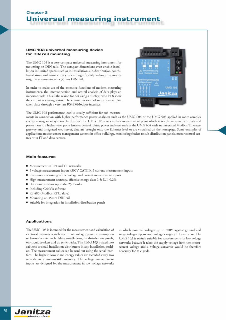
UMG 103 universal measuring devicefor DIN rail mounting
The UMG 103 is a very compact universal measuring instrument formounting on DIN rails. The compact dimensions even enable instal-lation in limited spaces such as in installation sub-distribution boards.Installation and connection costs are significantly reduced by moun-ting the instrument on a 35mm DIN rail.
In order to make use of the extensive functions of modern measuringinstruments, the interconnection and central analysis of data plays animportant role. This is the reason for not using a display; two LEDs showthe current operating status. The communication of measurement datatakes place through a very fast RS485/Modbus interface.
The UMG 103 performance level is usually sufficient for sub-measure-ments in connection with higher performance power analysers such as the UMG 604 or the UMG 508 applied in more complexenergy management systems. In this case, the UMG 103 serves as data measurement point which takes the measurement data andpasses it on to a higher-level point (master device). Using power analysers such as the UMG 604 with an integrated Modbus/Ethernet-gateway and integrated web server, data are brought onto the Ethernet level or are visualised on the homepage. Some examples ofapplications are cost centre management systems in office buildings, monitoring feeders to sub-distribution panels, motor control cen-tres or in IT and data centres.
Applications
The UMG 103 is intended for the measurement and calculation ofelectrical parameters such as current, voltage, power, consumptionor harmonics etc. in building installations, on distribution panels,on circuit breakers and on server racks. The UMG 103 is fixed intocabinets or small installation distributors in any installation positi-on. The measurement values can be read out using the serial inter-face. The highest, lowest and energy values are recorded every twoseconds in a non-volatile memory. The voltage measurementinputs are designed for the measurement in low voltage networks
▼▼
in which nominal voltages up to 300V against ground andsurge voltages up to over voltage category III can occur. TheUMG 103 is mainly suitable for measurements in low voltagenetworks because it takes the supply voltage from the measu-rement voltage and a voltage converter would be thereforenecessary for HV grids.
Main features
� Measurement in TN and TT networks� 3 voltage measurement inputs (300V CATIII), 3 current measurement inputs� Continuous scanning of the voltage and current measurement inputs� High measurement accuracy, effective energy class 0.5; U/I, 0.2%� Harmonic analysis up to the 25th order� Including GridVis software� RS 485 (Modbus RTU, slave)� Mounting on 35mm DIN rail� Suitable for integration in installation distribution panels
Chapter 2
14
▼
UMG 103
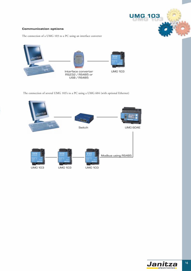
Communication options
The connection of a UMG 103 to a PC using an interface converter
Interface converterRS232 / RS485 or
USB / RS485
UMG 103
Switch UMG 604E
UMG 103 UMG 103 UMG 103
The connection of several UMG 103’s to a PC using a UMG 604 (with optional Ethernet)
Modbus using RS485

15
Functions and technical data
▼
Measurement range
Voltage L-N 50-300 V-AC
Voltage L-L 85-520 V-AC
Current (CTs: x/1 and x/5A) 0.001...7.5A
Frequency, mains 45...65 Hz
Overview of product variants
Description Type Operating voltage Item number
Universal measuring device 50/60Hz; Current transformer: ../1/5A
UMG 103 L-N: 115 ... 240 VAC 52.18.001
General technical dataOperating voltage CAT III 110 ...240 V-AC
Scanning rate 5.4 kHz per channel
Quadrants 4
Weight 150g
Dimensions B=71.5 mm, H=90 mm, T=46 mm
Mounting 35 mm DIN rail
Working temperature -10…+55 °C
Storage temperature -20…+70 °C
Protection class According to EN 60529 IP20
Connectable conductors (U/I)Single wire, multi-wire, fine-wirePin cable lugs, ferrule
0.08-2.5 mm2
1.5 mm2
Measurement valuesVoltage L1, L2, L3, L1-L2, L2-L3, L1-L3 0.2% rdg + 0.02% rng
Current L1, L2, L3, N calculated 0.2% rdg + 0.02% rng
Effective, reactive and apparent power L1, L2, L3, sum Accuracy ±(0.4% rdg + 0.10% rng)
Cos-phi, power factor L1, L2, L3, sum
Effective/reactive energy Consumed/inductive Class 0.5S(kWh)
Frequency L1, L2, L3 Accuracy ±0.1% rdg
Average value Yes
Minimum/maximum value Yes
Operating hour meter Yes
Power qualityHarmonics 1-25th harmonic order,uneven Current, voltage, L1, L2, L3 Accuracy: 0.5% rdg + 0.05% rng
Distortion factor THD-U in % L1, L2, L3 Accuracy: 0.5% rdg + 0.05% rng
Distortion factor THD-I in % L1, L2, L3 Accuracy: 0.5% rdg + 0.05% rng
CommunicationInterfaces
RS 485 Up to 115.2 kbps Yes
Protocols
Modbus RTU/slave Yes
Chapter 2

16
▼
Typical connection options
UMG 103
Illustration: connection example for a voltagemeasurement using a voltage transformer (VT)
Illustration: current measurement using a sum currenttransformer (CT)
Illustration: connection option UMG 103
UMG 103

17
UMG 103
▼▼
Support rail
Mounting illustration
Dimensional drawings
Illustration: front view Illustration: side view
Chapter 2

▼
18
PQ
M -
Po
we
r Q
ua
lity
Mo
nit
ori
ng
UMG 104
More than just a Multimeter
The UMG 104 equipped with a 500 MHz DSP (digital signal processor) is a very fast and powerfulpower analyser.
The continuous scanning of the 8 channels with 20 kHz per channel allows the recording of all elec-trical parameters (more than 800 values), minimum - and maximum - values, and the main powerquality values such as harmonics (up to the 40th, each phase with the detection of direction). Based on these data loss of production can be avoided, concepts can be developed, such as the elec-tricity cost reduction programs, and measures introduced. And finally the improvements can bemonitored and recorded with the UMG 104 as well.
Using modern communication architectures, the acquired data are fed to a central location, in power-ful databases, stored centrally and made available for further processing in an open architecture. Theeasy integration into an existing building control system or PLC environment extends the capabili-ties of the UMG 104.
Applications:� Replacement of analogue and digital instrumentation� Consumption data collection and analysis (load profiles) � Continuous power quality monitoring � Cost center management, i.e. breakdown of energy costs, e.g. allocation per product � Remote control and monitoring of equipment and processes � Protection of networks � “Sensor” for building management systems or PLC
19
Power analyser
▼Chapter 2
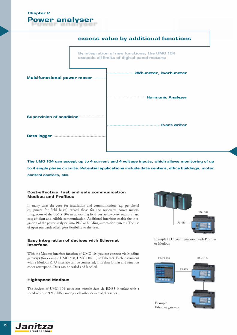
By integration of new functions, the UMG 104 exceeds all limits of digital panel meters:
Multifunctional power meterkWh-meter, kvarh-meter
Harmonic Analyzer
Event writer
Supervision of condition
excess value by additional functions
▼
Data logger
Cost-effective, fast and safe communication Modbus and Profibus
In many cases the costs for installation and communication (e.g. peripheralequipment for field buses) exceed those for the respective power meters.Integration of the UMG 104 in an existing field bus architecture means a fast,cost-efficient and reliable communication. Additional interfaces enable the inte-gration of the power analysers into PLC or building automation systems. The useof open standards offers great flexibility to the user.
Easy integration of devices with Ethernet interface
With the Modbus interface function of UMG 104 you can connect via Modbusgateways (for example UMG 508, UMG 604, ...) to Ethernet. Each instrumentwith a Modbus RTU interface can be connected, if its data format and functioncodes correspond. Data can be scaled and labelled.
Highspeed Modbus
The devices of UMG 104 series can transfer data via RS485 interface with aspeed of up to 921.6 kB/s among each other device of this series.
The UMG 104 can accept up to 4 current and 4 voltage inputs, which allows monitoring of up
to 4 single phase circuits. Potential applications include data centers, office buildings, motor
control centers, etc.
Example PLC communication with Profibus or Modbus
ExampleEthernet gateway
RS 485
RS 485
UMG 104
UMG 508 UMG 104
20
▼
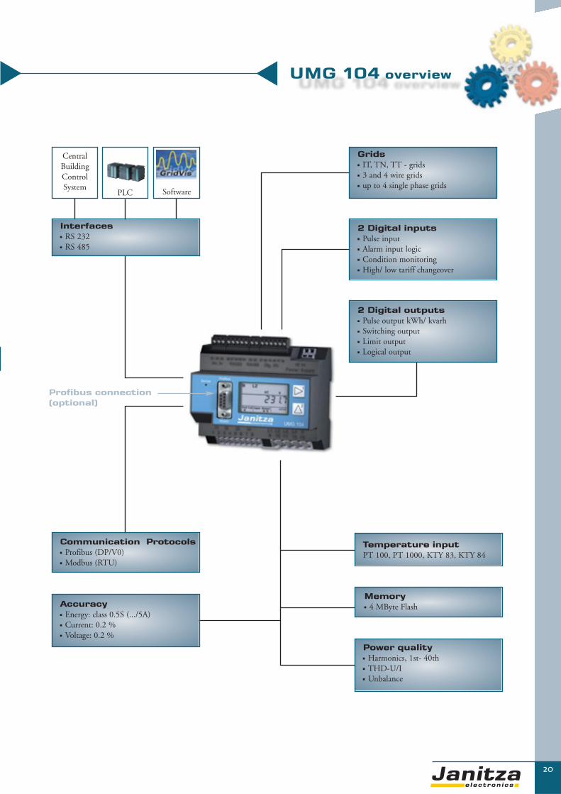
UMG 104 overview▼
▼
Interfaces� RS 232� RS 485
CentralBuildingControlSystem
PLC Software
Communication Protocols� Profibus (DP/V0)� Modbus (RTU)
Accuracy� Energy: class 0.5S (.../5A)� Current: 0.2 % � Voltage: 0.2 %
Profibus connection(optional)
2 Digital outputs� Pulse output kWh/ kvarh� Switching output� Limit output� Logical output
2 Digital inputs� Pulse input� Alarm input logic � Condition monitoring� High/ low tariff changeover
Grids� IT, TN, TT - grids� 3 and 4 wire grids� up to 4 single phase grids
Temperature inputPT 100, PT 1000, KTY 83, KTY 84
Memory� 4 MByte Flash
Power quality� Harmonics, 1st- 40th� THD-U/I� Unbalance

21
Functions and technical data
▼Chapter 2
95...
240
V A
C,
135.
..340
V D
C±1
0% o
f no
min
al r
ange
50...
110V
AC
±10%
of
nom
inal
ran
ge
20...
55V
AC
20...
77V
DC
4 V
olta
ge a
nd
4 C
urre
nt in
puts
2 D
igit
al in
puts
2 D
igit
al o
utpu
ts
1 Te
mpe
ratu
re in
put
RS
232
RS
485
Prof
ibus
DP
V0
Type
Item
no.
� � � � � � � - UMG 104 52.20.001
� � � � � � � - UMG 104 52.20.003
� � � � � � � - UMG 104 52.20.005
� � � � � � � � UMG 104 P 52.20.002
� � � � � � � � UMG 104 P 52.20.004
� � � � � � � � UMG 104 P 52.20.006
InterfacesSupply Voltage
- = not possible � = included
Overview of product variantsThree/four phase power analysers; 50/ 60Hz; current transformer ../1/5A; including GridVis programming and analysis software.
CommunicationInterfaces
RS 232 9.6, 19.2, 38.4, 115.2 kbps yes
RS 485 9.6, 19.2, 38.4, 76.8, 115.2, 921.6 kbps yes
Profibus DP Sub D9-pole up to 12 Mbps yes, variant P
Protocols
Modbus RTU yes
Profibus DP V0 yes, variant P
FeaturesMemory Measurement data 4 MB
Clock +/- 1 min per month
Operating hours counter yes
Tarifs 4 x real energy / 4 x reactive energy
PeripheralsDigital inputs as status or pulse input 2
Digital outputs as switching or pulse output 2
Temperature input PT100, PT1000, KTY83, KTY84 1
Password protection yes
Software GridVis yes

22
▼
UMG 104
Technical dataVoltage measurement 3-phase 4-wire grid (L-N, L-L) 277/480 V AC
3-phase 3-wire grid (L-L) 480 V AC
Overvoltage class 300 V CATIII
Quadrants 4
Continuous Measurement yes
Sampling rate, 8 channels per channel 20 kHz
Weight 350 g
Dimensions W=107.5 mm x D=90 mm x H=82 mm
Mounting according to IEC EN60999-1/ DIN EN 50022 35 mm DIN rail
Working temperature -10…55 °C
Connectable wires (U/I) one wire, more wires, fine stranded wires 0.08 - 2.5 mm²
cable end sleeve 1.5 mm²
Protection class according to EN60529 IP 20
Measuring rangeVoltage L-N, AC (without PT) 10…300 V AC
Voltage L-L, AC (without PT) 17…520 V AC
Current (Transformer: x/1 und x/5 A) 0.005...7.5 A
Frequency of fundamental 45 ..65 Hz
Grids IT, TN, TT
Measurement in grids1ph, 2ph, 3 ph, 4 phup to 4 times 1ph
Measured valuesVoltage L1, L2, L3, L4, L1-L2, L2-L3, L1-L3 accuracy ±0.2%
Current L1, L2, L3, L4, Sum L1-L3, Sum L1-L4 accuracy ±0.2%
K-factor L1, L2, L3, L4 yes
Rotating current components Positive/ Negative/ Zero Phase Sequence yes
Real, apparent, reactive power L1, L2, L3, L4, Sum L1-L3, Sum L1-L4 accuracy ±0.4% (EN61557-12)
Cos-phi / power factor L1, L2, L3, L4, Sum L1-L3, Sum L1-L4 yes
Phase angle L1, L2, L3, L4 yes
Real energy (kWh)L1, L2, L3, L4, Sum L1-L3, Sum L1-L4:- Consumed real energy (rate 1, rate 2)- Supplied real energy (rate 1, rate 2)
Class 0.5S (…/5 A), Class 1 (…/1 A)
Reactive energy (Karh)L1, L2, L3, L4, Sum L1-L3, Sum L1-L4:- Inductive energy (rate 1, rate 2) - Capacitive reactive energy
Class 2
Reactive energy (kVAh) L1, L2, L3, L4, Sum L1-L3, Sum L1-L4 yes
Wave form voltage L1, L2, L3, L4 yes
Frequency of mains accuracy ±0.01 Hz
Temperature input accuracy ±1.5% rng
Average values yes
Minimum and maximum values yes
Power quality
Harmonics, 1st- 40thCurrent, voltage, real/reactive power (±)L1, L2, L3, L4
accuracy V, I Class 1 (EN61000-4-7)
Distortion factor THD-U in % L1, L2, L3, L4 yes
Distortion factor THD-I in % L1, L2, L3, L4 yes
Unbalance yes
Positive/ Negative/ Zero Phase Sequence yes
Inrush-currents 10 ms no
Malfunction writer no
Short-term interruptions no

23
UMG 104
▼▼
Chapter 2
Connection diagram UMG 104
Dimensional drawing
front view side view
90 m
m
107,5 mm76 mm
82 mm
90 m
m
50 mm

24
High performance power analysers for DIN rails
High performance power analysers from the UMG 604 product family are suitable for use at all net-work levels. The high scanning rate enables a continuous measurement by gathering more than 800measurement parameters. Due to the very high performance level of the digital signal processor, allimportant power quality parameters are recorded e.g. short-term interruptions with fault recorderfunction, transients, harmonics up to a 40th and starting current etc. Extensive communication opti-ons e.g. Ethernet (TCP/IP), BACnet, Modbus, Profibus, RS232, RS485, HTTP, FTP, SMTP, SNTP,SNMP or DNS… allow affordable and quick integration in the existing communication architectu-re. Worldwide access to the embedded web server can be gained through a web browser e.g. for ener-gy consumption analysis. Programs specific to the user can be created with implemented graphic pro-gramming. It is possible to run 7 user programs simultaneously.
Areas of application� For measuring, monitoring and checking electrical parameters in energy distribution units� Consumption data collection and analysis (cost centre data collection)� For monitoring the power quality (harmonics, short term interruptions, transients,
initial current…)� Measurement value generator for building management systems or PLC� Control tasks e.g. depending upon the achieved measurement values or limit values� Peak demand management (avoidance of costly and dangerous peak loads)� Ethernet gateway for subordinate measurement points� Remote monitoring
PQ
M -
Po
we
r Q
ua
lity
Mo
nit
ori
ng
UMG 604
▼

25
Power analyser
UMG 604: the extra compact power analyser
Added value through additional functions
Through the integration of various functions, the UMG 604power analyser goes far beyond the limits of digital multifunctionalmeasuring equipment and, therefore, offers the respective addedvalue. The UMG 604 and the use of state-of-the-art processorsallow to offer a very fast and extremely compact power analyser atan affordable price. The UMG 604 contains the following func-tions:
� Power analyser for electrical energy distribution(over 800 parameters)
� Energy consumption and cost centre data collection� Monitoring of power quality� Peak demand management (optional)� PLC function (up to 7 simultaneous freely programmable
programs, graphic programming)� Transient recorder� Event recorder� Data logger� Modbus/Ethernet gateway
Main features
� Continuous measurement� Collection of all relevant power quality parameters (harmonics, short-term interruptions, unbalance ...) � Ethernet and embedded web server� Jasic® interpreter� Up to 7 user defined programs� GridVis software - full version included in the delivery
Applications
Major increases of energy costs make electrical energy a driving forcein costing. With the UMG 604, you can make the first step towardsbetter cost efficiency. The precise collection of all energy data andelectrical parameters ensures the necessary amount of transparency inyour energy supplies. Concepts can be developed on the basis of thedata e.g. electricity cost reductions and the introduction of measures.These targeted improvements can also be monitored and recordedwith the UMG 604.
The UMG 604, equipped with a 500 MHz DSP (digital signalprocessor), is a fast and high performing power analyser. Thecontinuous scanning of eight channels with 20 KHz per channelenables the collection of all relevant electrical parameters (morethan 800 values), minimum and maximum values, the basic
▼▼
power quality values such as harmonics (up to the 40th, eachphase with direction recognition) and short-term interruptions.Even fast transients (> 50μs) can be safely identified. Usingmodern communication processes, the collected data is con-ducted to a central location, stored centrally in a high-perfor-mance database and provided for further processing in an opensystem. Simple integration in an existing building managementsystem control or PLC environment expands the areas of appli-cation of the UMG 604.
Chapter 2

High-speed Modbus
The devices of the UMG 604 series can transfer data between the units using the RS485 interface at a speed of up to 921.5 kB/s.
26
▼
DIN rail mounting (6 units): reduction ofinstallation costs
Measurement equipment is usually installed in the low voltagemain distribution as an integral measurement instrument for theswitchgear cabinet door. Installation and connection costs aresignificantly reduced by the installation of the UMG 604 on a35mm DIN rail. This means that the panel cut-out and wiring tothe cabinet door is no longer necessary. In order to make use of theextensive functions of modern measuring equipment, the inter-connection and central analysis of the data plays an importantrole. This means that the on-site display generally serves the pur-pose of the initialisation and service only.The decidedly compact UMG 604 is suitable for installation inlow voltage main distribution panels and machines as well as ininstallation distribution boards which is particularly of interest forapplications in building services engineering, information techno-logy and data centres.
Modern communication processesthrough the Ethernet: affordable, rapidand safe communication
The costs for installation and communication (e.g. periphery for fieldbuses) often surpass the costs of the equipment.By connecting the equipment to an existing Ethernet system, a fast,optimally priced and reliable communication system can be develo-ped. Additional interfaces allow the integration of power analysers inPLC systems or in central building management systems. The use ofclear standards offers the user a high amount of flexibility.
Modbus gateway: the affordable connection of units without an Ethernet interface
With the Modbus gateway function, simple Modbus RTU-units canbe connected to the Ethernet using the UMG 604. For example, theUMG 604 can be used simultaneously as a gateway for subordinatemeasurement points or older units which already exist in the installa-tion. Each unit with a Modbus RTU interface, where the data formatand function codes match up, can be connected. Data can be markedand scaled.
The e-mail and homepage inform you wherever you are…
Who hasn’t experienced it before? You are hardly through the doorand the telephone is already ringing. There are problems in produc-tion, computers are crashing and the energy supplies are lost.You have direct access to the extremely high performance homepageof the UMG 604 with a web browser and an IP address. Extensiveinformation is already available to you on the homepage. Online dataare available together with historical data and graphs recording events.The homepage can be used to directly convert the rates into costs andbe exported as a csv file or printed. As an alternative, you can let your-self be informed by e-mail anywhere in the world if your energy sup-ply becomes overloaded, if short-term interruptions to the voltagesupplies bring your production processes to a standstill or unauthori -zed harmonics reduce the lifespan of equipment. The application pos-sibilities are endless.
UMG 604

27
Power analyser
▼
Power visualisation software
The data gained from various measurement points must be collected, saved, visualised and made available. The GridVis software con-tained in the UMG 604 package allows
� Parameterisation and programming of UMG measurement equipment
� Visualisation of the measurement values with topological view
� Automatic download of the measurement data
� Data storage
� Online analysis tools
� Analysis tools for historic data
Visualisation, topological view
GridVis allows an individually adaptable visualisation of online data. The topological view provides a rapid overview of energy distributionwith the possibility of localising power faults by comparing the individual measurement points and by offering the possibility to check thedefined tolerances at a glance.
Customer specific solutions can be quickly and simply implemented through uploading of graphic documents (standard formats such asJPG) with circuit diagrams, production lines or construction plans and incorporating the respective measurement units by drag and dropinto their actual locations. Limit value excesses (e.g. THD-U is too high) and the status of inputs and outputs can also be displayed.
Online values and analysis of historic data
With the graphic line writer function, GridVis enablesrapid online presentation of the selected measurementvalues. In this function, the graph is continuously expan-ded with new measurement values. For example, load pro-files can be presented through the analysis of historic datain order to produce exact consumption analysis for opti-mised electricity supply contracts. Fault analysis throughthe comparison of various parameters can also be achievedwith a few mouse clicks.
Graphic programming
The graphic programming option for user programs is com-pletely new in the field of digital power analysers. Programsspecific to the application can be created with this methodsuch as the free programming of inputs and outputs, moni-toring of processes or the issue of reports when defined limitvalues are achieved. In addition to the operator-friendly gra-phic programming, the user is also free to program the Jasic®
code directly.
programming language
The Jasic® programming language offers brand newopportunities. The user is no longer tied to the functionswhich are fixed integrations in the unit; the unit can beexpanded to include more functions. Up to seven of thesefreely definable user programs can be processed simulta-neously in the unit.
Chapter 2
28
▼
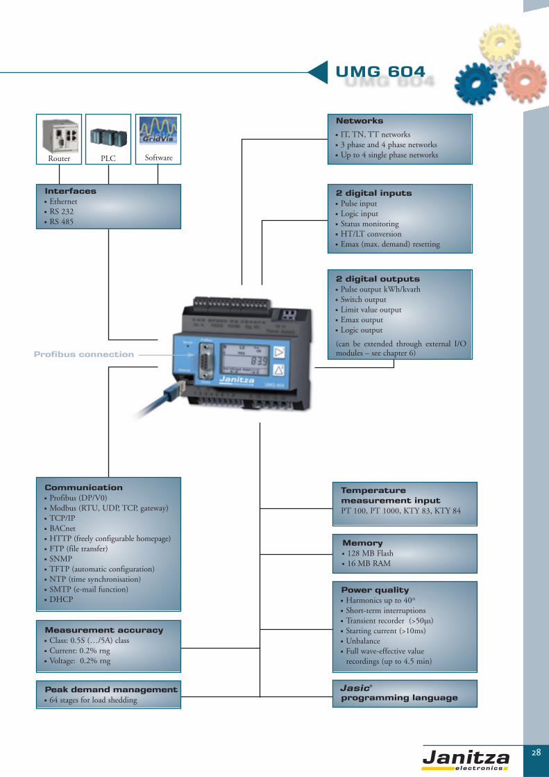
Interfaces� Ethernet� RS 232� RS 485
Router PLC Software
Communication� Profibus (DP/V0)� Modbus (RTU, UDP, TCP, gateway)� TCP/IP� BACnet� HTTP (freely configurable homepage)� FTP (file transfer)� SNMP� TFTP (automatic configuration)� NTP (time synchronisation) � SMTP (e-mail function)� DHCP
Measurement accuracy� Class: 0.5S (…/5A) class� Current: 0.2% rng� Voltage: 0.2% rng
Peak demand management� 64 stages for load shedding
Profibus connection
2 digital outputs� Pulse output kWh/kvarh� Switch output � Limit value output� Emax output� Logic output
(can be extended through external I/Omodules – see chapter 6)
2 digital inputs� Pulse input� Logic input� Status monitoring� HT/LT conversion� Emax (max. demand) resetting
Temperature measurement inputPT 100, PT 1000, KTY 83, KTY 84
Memory� 128 MB Flash� 16 MB RAM
Power quality� Harmonics up to 40th
� Short-term interruptions� Transient recorder (>50μs)� Starting current (>10ms)� Unbalance� Full wave-effective value
recordings (up to 4.5 min)
programming language
UMG 604
Networks� IT, TN, TT networks� 3 phase and 4 phase networks� Up to 4 single phase networks

29
Product variants and technical data
▼
General technical dataVoltage measurement 3-phase 4-wire grid (L-N, L-L) 277/480 V AC
3-phase 3-wire grid (L-L) 480 V AC
Overvoltage category 300V CATIII
Quadrants 4
Continuous measurement Yes
8 channel scanning rate Per channel 20 kHz
Weight 350g
Dimensions L=107.5mm * W=90mm * H=62 mm
Mounting According to IEC EN60999-1/DIN EN50022 35mm DIN rail
Working temperature range -10…55 °C
Connectable conductor (U/I) Single wire, multi-wire, fine-wire 0.08 - 2.5 mm²
pin cable lugs, ferrule 1.5 mm²
Protection class According to EN 60529 IP 20
Measurement rangeL-N voltage, AC (without voltage transformer) Free voltage transformer settings 50…300 VAC
L-L voltage, AC (without voltage transformer) Free voltage transformer settings 87…520 VAC
Current (transformer: x/1 and x/5A) 0.001...7.5 A
Frequency of mains 45...65 Hz
Networks IT, TN, TT
Measurement in single/multi-phase networks1 ph, 2 ph, 3 ph, 4 phand up to 4 x 1 ph
PeripheryDigital inputs Status, logic or pulse input 2
Digital outputs Switch logic output or pulse output 2
Temperature measurement input PT100, PT1000, KTY83, KTY84 1
Password protection Multilevel Yes
Peak demand management Optional 64 channels Yes
Software GridVis Yes
- = not possible � = contained Not suitable for use in residential areas.
Overview of product variantsThree/four phase power analysers; 50/60Hz; current transformer .../1/5a; including GridVis programming and analysis software
95...
240V
AC
,13
5...3
40V
DC
±10%
of n
omin
al r
ange
50...
110V
AC
,50
...15
5V D
C±1
0% o
f nom
inal
ran
ge
20...
55V
AC
,20
...77
V D
C±1
0% o
f nom
inal
ran
ge
4 vo
ltage
and
4
curr
ent
inpu
ts
Mem
ory
128
MB
Fla
sh
2 di
gita
l inp
uts
2 di
gita
l out
puts
1 te
mpe
ratu
re in
put
RS
232
RS
485
Eth
erne
t 10
0bas
eT
Prof
ibus
DP
V0
7 fr
eely
pro
gram
mab
le
appl
icat
ion
prog
ram
s
Type
Item
num
ber
� � � � � � � � � - � UMG 604 E 52.16.002
� � � � � � � � � � � UMG 604 EP 52.16.001
� � � � � � � � � - � UMG 604 E 52.16.012
� � � � � � � � � � � UMG 604 EP 52.16.011
� � � � � � � � � - � UMG 604 E 52.16.022
� � � � � � � � � � � UMG 604 EP 52.16.021
Options (for all versions)Emax function application program (peak demand management) Emax 52.16.080
BACnet communication BACnet 52.16.081
Supply voltage Interfaces
Chapter 2

30
▼
UMG 604
Measurement valuesVoltage L1, L2, L3, L4, L1-L2, L2-L3, L1-L3 Accuracy ±(0.2% rdg + 0.02% rng)
Current L1, L2, L3, L4, Sum L1-L3, Sum L1-L4 Accuracy ±(0.2% rdg + 0.05% rng)
K-factor L1, L2, L3, L4 Yes
Three-phase current components Positive/negative/zero phase sequence Yes
Effective, reactive and apparent power L1, L2, L3, L4, Sum L1-L3, Sum L1-L4 Accuracy ±(0.4% rdg + 0.10% rng)
Cos-phi, power factor L1, L2, L3, L4, Sum L1-L3, Sum L1-L4 Yes
Phase angle L1, L2, L3, L4 Yes
Effective energy (kWh)L1, L2, L3, L4, Sum L1-L3, Sum L1-L4:- Purchased effective energy (tariff 1, tariff 2)- Supplied effective energy (tariff 1, tariff 2)
Class 0.5S (…/5A), Class 1 (…/1A)
Reactive energy (kvarh)L1, L2, L3, L4, Sum L1-L3, Sum L1-L4:- Inductive reactive energy (tariff 1, tariff 2)- Capacitive reactive energy
Class 2
Apparent energy (kVAh) L1, L2, L3, L4, Sum L1-L3, Sum L1-L4 Yes
Current/voltage wave form L1, L2, L3, L4 Yes
Frequency of mains Accuracy ±0.1% rdg
Temperature measurement Accuracy ±1.5% rng
Average value Yes
Minimum and maximum values Yes
Power quality
Harmonics, 1-40 harmonicCurrent, voltage reactive/effective power (±)L1, L2, L3, L4
Accuracy ±(0.5% rdg + 0.05 rng)
Distortion factor THD-U in % L1, L2, L3, L4 Yes
Distortion factor THD-I in % L1, L2, L3, L4 Yes
Unbalance Yes
Positive/negative/zero system Yes
Transients 50 μs Yes
Start-up processes 10 ms Yes
Fault recorder function Yes
Short-term interruptions Yes
CommunicationInterfaces
RS 232 9.6, 19.2, 38.4, 115.2 kbps Yes
RS 485 9.6, 19.2, 38.4, 76.8, 115.2, 921.6 kbps Yes
Profibus DP Plug, sub D 9-pole up to 12Mbps Yes, EP version
Ethernet 10/100 Base- TX RJ-45 sockets Yes
Protocols
Modbus RTU Yes
Profibus DP V0 Yes, EP version
Modbus TCP Yes
Modbus over TCP Yes
Modbus Gateway Yes
HTTP Homepage (configurable) Yes
SMTP E-mail Yes
SNMP Yes
SNTP Time synchronisation Yes
TFTP Automatic configuration Yes
FTP File transfer Yes
DHCP Yes
BACnet / IP or MSTP Yes, option
FeaturesMemory 128 MB
Clock +/- 1 min per month
Integrated logic Programming language Jasic®
Operating hour meter Yes
Weekly time switch Jasic®

31
UMG 604
▼▼
Front view Side view
Dimensional drawing
90 m
m
107.5 mm
62 mm
90 m
m
36 mm
Connection illustration
Chapter 2

PQ
M -
Po
we
r Q
ua
lity
Mo
nit
ori
ng
32
UMG 605
▼
High performance power quality analyserfor DIN railsaccording to EN 50160
The UMG 605 power quality analyser is particularly suitable for monitoring power quality accordingto standards such as the EN 50160. All power quality parameters are collected and analysed e.g.flicker, short-term interruptions with fault recorder function, transients, harmonics up to 63rd andinrush currents etc. Extensive communication possibilities e.g. RS 485 Modbus, Profibus, Ethernet(TCP/IP), BACnet, HTTP, FTP, SMTP, SNTP, SNMP, DNS .... allow cost effective and rapid inte-gration in existing communication networks. Worldwide access to the embedded web server can begained through a web browser. The GridVis software included in the content of delivery allows exten-sive analysis just with the click of a button.
Areas of application
� Continuous monitoring of the power quality e.g. EN 50160� Ethernet gateway for subordinate measurement points� Analysis of electrical faults for network problems� Monitoring of the internal distribution network according to EN 61000-4-7, 4-15, 4-30� Report generator for EN 50160 analysis� Control tasks, e.g. depending on achieved measured values or limits� Transducer for building automation or PLC systems

33
Power quality analyser
▼▼
Chapter 2
UMG 605: the extra compact power quality analyser
Added value through additional functions
Thanks to state-of-the-art digital signal processor, it is possible to offer thepower quality analyser UMG 605 at a very reasonable price. The high sam-pling rate enables a continuous measurement of more than 2000 measuredvalues per measurement cycle (200ms). The UMG 605 power quality ana-lyser serves the purpose of continuous monitoring of the power quality e.g.in accordance with EN 50160. This serves the purpose of monitoring thesupply power quality from the energy supply side. The UMG 605 can alsobe used in applications for failure analysis on the consumer side and is alsoused as a preventative measure for network perturbations.
Main Features
� Measurement of power quality according to DIN EN 61000-4-30� Measurement method class A� Fourier analysis 1st to 63rd harmonics for U-LN, U-LL, I, P (consumption/supply) and Q (ind./cap.) � Measurement of harmonics and interharmonics (U-LN, U-LL, I) � Analysis and evaluation according to DIN EN 50160 with the contained programming and analysis software GridVis� Flicker measurement according to DIN EN 61000-4-15� Measurement in IT and TT grids (300V CATIII)� 4 voltage measuring inputs, 4 current measuring inputs� Continuous sampling of the voltage and current measuring inputs with 20kHz� Recording of more than 2000 different measurement parameters per measuring cycle (200ms)� Detection of transients >50μs and storage with up to 16.000 samples� Data logger / event memory (128MB Flashdisk)� 2 digital inputs and 2 digital outputs� Profibus DP/V0 alternatively RS 485 (Modbus RTU, Modbus-Master, optional BACnet)� Ethernet (Web-Server, E-Mail, optional BACnet)� Programming of customer specific applications in Jasic
Applications
The power quality analyser which is equipped with 4 current and voltage inputs collects and digitalises the effective values (TrueRMS) from currents and voltages in 40-70Hz (15-440Hz) networks. The integrated microprocessor calculates the electrical para-meters from the sampling values. The relevant voltage can be defined as a phase-neutral or a phase-phase voltage for measurementin a three-phase system. The voltage serves the UMG 605 as a reference voltage for harmonic measurement, transient and eventrecording and for the flicker meter. A nominal current can be set using this for the measurement of electrical current events. The4th current and voltage input represents a separate measurement system. However, it is generally used for measuring the currentin the neutral or PE conductor or used for measuring a voltage difference between N and PE.

34
▼
UMG 605
Interfaces� Ethernet� RS 232� RS 485
Router PLC Software
Communication� Profibus (DP/V0)� Modbus (RTU, UDP, TCP, gateway)� TCP/IP� BACnet� HTTP (freely configurable homepage)� FTP (file transfer)� SNMP� TFTP (automatic configuration)� NTP (time synchronisation) � SMTP (e-mail function)� DHCP� SNMP
Measurement accuracy� Class: 0.5S (…/5A) class� Current: 0.2% rng� Voltage: 0.2% rng
Peak demand management� 64 stages for load shedding
Profibus connection
2 digital outputs� Pulse output kWh/kvarh� Switch output � Limit value output� Emax output� Logic output
(can be extended through external I/O modules)
2 digital inputs� Pulse input� Logic input� Status monitoring� HT/LT switch over� Emax (max. demand) resetting
Temperature measurement inputPT 100, PT 1000, KTY 83, KTY 84
Memory� 128 MB Flash� 16 MB RAM
Power quality� Harmonics up to 63rd
� Short-term interruptions� Transient recorder (>50μs)� Starting current (>10ms)� Unbalance� Half wave-effective value
recordings (up to 4.5 min)� Flicker
programming language
Networks
� IT, TN, TT networks� 3 phase and 4 phase networks� Up to 4 single phase networks

35
General technical dataVoltage measurement 3-phase 4-wire grid (L-N, L-L) 277/480 V AC
3-phase 3-wire grid (L-L) 480 V AC
Overvoltage category 300V CATIII
Quadrants 4
Continuous measurement yes
8 channel scanning rate Per channel 20 kHz
Weight 350g
Dimensions L=107.5mm * W=90mm * H=76/82mm
Mounting According to IEC EN 60999-1/DIN EN 50022 35mm DIN rail
Working temperature range -10…55 °C
Connectable conductor (U/I) Single wire, multi-wire, fine-wire 0.08 - 2.5 mm²
pin cable lugs, ferrule 1.5 mm²
Protection class According to EN 60529 IP 20
- = not possible � = contained
Overview Three/four phase power quality analysers; current transformer .../1/5a; including GridVis programming and analysis software
95...
240V
AC
,13
5...3
40V
DC
±10%
of n
omin
al r
ange
50...
110V
AC
,50
...15
5V D
C±1
0% o
f nom
inal
ran
ge
20...
55V
AC
,20
...77
V D
C±1
0% o
f nom
inal
ran
ge
4 vo
ltage
and
4
curr
ent
inpu
ts
Mem
ory
128/
256
MB
Fla
sh
digi
tal i
nput
s
digi
tal o
utpu
ts
1 te
mpe
ratu
re in
put
RS
232
RS
485
Eth
erne
t 10
0bas
eT
Prof
ibus
DP
V0
Type
Item
num
ber
� � � 2 2 � � � � � UMG 605 52.16.027
� � � 2 2 � � � � � UMG 605 52.16.028
� � � 2 2 � � � � � UMG 605 52.16.029
Options (for all versions)Emax function application program (peak demand management) Emax 52.16.084
BACnet communication BACnet 52.16.083
Supply voltage Interfaces
Measurement rangeL-N voltage, AC (without voltage transformer) Free voltage transformer settings 50 ... 300 VAC
L-L voltage, AC (without voltage transformer) Free voltage transformer settings 87...520 VAC
Current (transformer: x/1 and x/5A) 0.005..6 A
Frequency of mains 40 ..70 Hz
Networks IT, TN, TT
Measurement in single/multi-phase networks 1 ph, 2 ph, 3 ph, 4 ph and up to 4 x 1 ph
PeripheryDigital inputs Status, logic or pulse input 2
Digital outputs Switch logic output or pulse output 2
Temperature measurement input PT100, PT1000, KTY83, KTY84 1
Password protection Multilevel yes
Demand management Optional 64 channels yes
Software GridVis yes
FeaturesMemory 128 MB
Clock +/- 1 min per month
Integrated logic Programming language Jasic®
Operating hour meter yes
Weekly time switch Jasic®
Scope of operation and types of variants
▼Chapter 2

36
▼
UMG 605
Measurement valuesVoltage L1, L2, L3, L4, L1-L2, L2-L3, L1-L3 Accuracy ±(0.2% rdg + 0.02% rng)
Current L1, L2, L3, L4 ±(0.2% rdg + 0.05% rng)
Calculated sum current ±(0.6% rdg + 0.05% rng)
K-factor L1, L2, L3, L4 yes
Three-phase current components Positive/ Negative/ Zero Phase Sequence yes
Cos-phi, power factor L1, L2, L3, L4, Sum L1-L3, Sum L1-L4 yes
Phase angle L1, L2, L3, L4 yes
Effective energy (kWh) L1, L2, L3, L4, Sum L1-L3, Sum L1-L4:- Purchased effective energy (tariff 1, tariff 2)- Supplied effective energy (tariff 1, tariff 2)
Class 0.5S (…/5A)Class 1 (…/1A)
Reactive energy (kvarh) L1, L2, L3, L4, Sum L1-L3, Sum L1-L4:- Inductive reactive power (tariff 1, tariff 2)- Capacitive reactive power
Class2
Apparent energy (kVAh) L1, L2, L3, L4, Sum L1-L3, Sum L1-L4 yes
Current/voltage wave form L1, L2, L3, L4 yes
Frequency of mains Accuracy ±0.1% rdg
Temperature measurement Accuracy ±1.5% rng
Average value yes
Minimum and maximum values yes
Power qualityHarmonics order, 1.- 63rd
Harmonics, even/oddVoltage L1, L2, L3, L4 Measure value > 3% of measuring rangeMeasure value < 3% of measuring range
Accuracy ± 5% rdgAccuracy ± 0.05 rng)
Interharmonics Current, voltage L1, L2, L3, L4 yes
Distortion factor THD-U in % L1, L2, L3, L4 yes
Distortion factor THD-I in % L1, L2, L3, L4 yes
Positive/negative/zero system yes
Actual flicker value L1, L2, L3, L4 yes
Short term flicker value L1, L2, L3, L4 yes
Long term flicker value L1, L2, L3, L4 yes
Transients 50 μs yes
Trigger events 10 ms yes
Inrush currents 10 ms yes
Event recorder yes
Communication
Interfaces
RS 232 9.6, 19.2, 38.4, 115.2 kbps yes
RS 485 9.6, 19.2, 38.4, 76.8, 115.2, 921.6 kbps yes
Profibus DP Plug, sub D 9-pole up to 12Mbps yes
Ethernet 10/100 Base- TX RJ-45 sockets yes
Protocols
Modbus RTU yes
Profibus DP V0 yes
Modbus TCP yes
Modbus over TCP yes
Modbus gateway yes
HTTP Homepage (configurable) yes
SMTP E-Mail yes
SNMP yes
SNTP Time synchronisation yes
TFTP Automatic configuration yes
FTP File Transfer yes
DHCP yes
BACnet / IP or MSTP yes, option

37
UMG 605
▼▼
Chapter 2
Dimensional drawing
90 m
m
107.5 mm
76 mm
82 mm
90 m
m
36 mm
Connection illustration
Front view Side view

PQ
M -
Po
we
r Q
ua
lity
Mo
nit
ori
ng
38
Universal measuring instrumentsDigital diversity versus analogue simplicity
Universal measuring instruments of UMG 96L and UMG 96 product families are mainly designedfor use in low and medium voltage distribution systems. Due to the large number of available mea-surement values in an extremely compact measuring unit, a number of analogue measurement instru-ments can be replaced and, therefore, installation costs can be reduced. Additional functions such asthe recording of minimum and maximum values, the operating hour meter, the bi-metallic strip fun-ction, password protection and many more offer a significant amount of added value. The high mea-surement accuracy and a large LCD-display means universal application possibilities and offer fun-damental advantages in comparison to analogue measuring instruments.
Areas of application� Replacement of analogue measurement instruments� Display and control of electrical parameters in energy distribution systems� Cost centre data collection� Measurement value generator for building management systems or PLC� Limit value monitoring
UMG 96L / UMG 96
▼

39
Universal measuring instruments
UMG 96L/UMG 96 universal measuring instruments 96 x 96mm front panel mounting
The use of energy measurement technology in energy distributionhas moved dynamically towards digital universal measuring instru-ments in the past few years. The advantages are obvious: lowerequipment costs for more information and functionality. In addition,digital measuring technology is more accurate, even all along theentire lifespan.
Clear cost advantages also result from the construction of theswitchgear which results in lower installation costs and less wiringefforts in comparison to analogue measuring technology. Universalmeasuring instruments of the UMG 96L and UMG 96 productfamilies are mainly designed for use in low and medium voltagedistribution systems.
In addition to the large quantity of electrical measurement values,this series also offers a number of additional functions such as therecording of minimum and maximum values, the operating hourmeter, the bi-metallic strip function, password protection andmany more.
Applications
The UMG 96L and UMG 96 measurement instruments are digitalfront panel mounted measuring instruments which are suitablefor measuring and recording electrical parameters (True-RMS) in50/60 Hz networks. The measurement is configured for three-phase systems with a neutral conductor (TN and TT networks).At the network frequency of 50 Hz or 60 Hz, the scanning fre-quency of the random measurements which take place once persecond is 2.5 kHz or 3.0 kHz. The supply voltage and scanningfrequency for operating the UMG 96L is taken from the L1-Nmeasurement voltage. The effective values and the minimum andmaximum values are recorded every 15 minutes and the pro-gramming data is immediately stored in a non-volatile memory(EEPROM). The main characteristic of the measurement instru-ment is the compact construction (96x96 mm) and the high levelof stability.
▼▼
In order to achieve the functional diversity of the universal mea-surement instrument, you would need 13 analogue units such asan ampere meter, volt meter, volt meter switch, power meter(kW, kVA, kvar, cos ϕ), an effective and reactive energy meter(kWh/kvarh) and a frequency meter. This means that the plan-ning, installation, wiring and storage costs are significantly re -duced in comparison to the use of analogue measuring instru-ments. Another advantage is the higher precision and better legi-bility.
Main features
� Compact housing dimensions (96x96 mm), minimal installation depth� User-friendly and reliable terminals� Large LCD with outstanding legibility� The large quantity of electrical measurement values, replaces 13 analogue measurement units and more� Excellent reliability and long life span
Chapter 2

k varhMin. limitvalue
30V DC
+
-
Max. limitvalue
k Wh
40
▼
L-L voltage cos (phi) Effective power Effective energy
Digital output for cost centre data collection Digital output for limit value monitoring
UMG 96L / UMG 96
Measurement value displays
The extremely legible LCD display in connection with the function keys informs the user about the selected measurement values (actual, low, high and average values). Three measurement values can be simultaneously displayed in the LCD data field. The contrast of the LCD display can be adjusted by the user.
Display selection and automatic display rotation
All measurements values can be called up in the initial delivery status. Measurement values which are not required can be hidden and dis-played again when necessary. A cycle between 1 and 250 seconds can be set for the automatic display rotation. The display rotationfunction can also be deactivated.
Display examples
Bi-metallic function (average value generation)
A common average time for achieving measurement values in L1, L2, L3 and N and an average time for the power measurement valuesof effective power, apparent power and reactive power can be programmed. These values can be integrated at selectable time of 5, 10, 30,60, 300, 480 and 900 seconds and stored as a highest average value.
Operating hour meter
The operating hour meter is immediately activated when the unit is switched on and can not be reset. The time is recorded at a 15 minuteresolution and is displayed in hours.
Digital outputs for effective or reactive energy consumption or limit values
Digital outputs can be used as pulse outputs for the effective or reactive energy consumption or as switch outputs. The digital outputs canbe programmed in order to monitor the measurement data. The transistor output can also be linked with the measurement value of the limitvalue by programming which is activated if the value is not achieved or is exceeded. The transistor output is suitable for controllingelectrical devices with a DC operating voltage or units with NPN inputs e.g. PLC.
Password
The user can protect programming and configurations against unauthorised changes with a 3-digit password.
Cost centre data collection and monitoring limit values (UMG 96)

41
Product variants and technical data
▼
Measurement rangeVoltage L-N Refer to order details
Voltage L-L Refer to order details
Current .../1A or .../5A 0.02...6 A
Frequency, mains 45 ...65 Hz
Overview of product variants
Description Type Operating voltage Item number
Four-phase universal measuring instrument 50/60Hz; Current transformer: ../1/5AMeasurement range: L - N: 50 ... 255V-AC; L - L: 86 ... 442V- AC
UMG 96L L-N: 196 ... 255V- AC 52.14.001
As above but measurement range:L - N: 16 ... 80V- AC; L - L: 28 … 139V-AC
UMG 96L L-N: 45 ... 80V- AC 52.14.005
As above but measurement range:L - N: 25 ... 160V- AC; L - L: 45 … 277V-AC
UMG 96L L-N: 90 ... 160V- AC 52.14.007
Four-phase universal measuring instrument 50/60Hz; Current transformer: ../1/5A, 2 digital /pulse outputsMeasurement range: L - N: 50 ... 275V-AC; L - L: 87 ... 476V- AC
UMG 96 L-N: 196 ... 275V- AC 52.09.001
As above but measurement range:L - N: 20 ... 76V- AC; L - L: 35 … 132V-AC
UMG 96 L-N: 49 ... 76V- AC 52.09.002
As above but measurement range:L - N: 30 ... 140V- AC; L - L: 52 … 242V-AC
UMG 96 L-N: 98 ... 140V- AC 52.09.005
General technical dataOperating voltage Refer to order details above
Scanning rate 2.5 / 3 kHz
Weight 250g
Dimensions W= 96mm x H 96mm x D= 42mm
Mounting Front panel installation
Working temperature -10…+55 °C
Storage temperature -20…+70 °C
Protection class (reverse/front) According to EN60529 IP 20/50
Connectable conductors Single wire, multi-wire, fine-wire,
pin cable lugs, ferrule
0.08 - 2.5mm2
1.5mm2
Periphery2 digital outputs As switch output or pulse output UMG 96 only
Measurement values
Current 1/5A L1-L3 0.00 .. 9.99 kA 0.02 .. 6 A +-1 % rng
Current calculated in N 0.00 .. 9.99 kA 0.06 .. 18 A +-3 % rng
Voltage L-N 0.0 .. 34 kV 50 .. 255 V AC*2 +-1 % rng
Voltage L-L 0.0 .. 60 kV 86 .. 442 V AC*2 +-2% rng
Frequency (U) 45.0 .. 65.0 Hz +-1.5 % rdg
Effective power, sum ,+/- 0.00 W .. 150 MW 1.8 W .. 2.4 kW +-1.5 % rng
Apparent power, sum 0.00 VA .. 150 MVA 1.8 VA .. 2.4 kVA +-1.5 % rng
Reactive power, sum 0.00 var .. 150 MVar 1.8 var .. 2.4 kvar Ind.+-1.5 % rng
Cos phi 0.00 ind. .. 1.00 .. 0.00 kap. 0.00 kap. .. 1.00 .. 0.00 ind. +-3 % rng*4
Effective energy, consumed 0 .. 999.999.999 kWh Class 2
Reactive energy, inductive 0 .. 999.999.999 kvarh Class 2
Operating hour meter 0 .. 999.999.999 h +-2 min per day
Measurement parameter
Display range Measurementaccuracy
SumL1 L2 L3Measurement rangeat scaling factor 1
Lowestvalue Average
value
Averagevalue *1
rng: of measurement range, rdg: of measurement value*1 - integration over time: 5, 10, 30, 60, 300, 480, 600 and 900 seconds.*2 - also available: measurement range: L-N 16 .. 80V, AC, L-L 28 .. 139V, AC, operating voltage: L-N 45 .. 80V, AC and measurement range: L-N 25 .. 160V, AC, L-L 45 .. 277V, AC,
Operating voltage: L-N 90 .. 160V, AC (the operating voltage is taken from the measurement voltage)*3 - accuracy class according to DIN EN61036:2001-01, VDE0418 part 7, IEC61036:1996 + A1:2000*4 - the measured apparent power must be in a range between 1 and 100%.
*3
Measure-ment value
Max
*3
Chapter 2

42
▼
UMG 96L / UMG 96
Typical connection options
UMG 96L
UMG 96

43
UMG 96L / UMG 96
▼▼
UMG 96L - reverse side of unit UMG 96 - reverse side of unit
Connection illustrations
Side view Reverse side, panel cut-out dimensions: 92+0,8 x 92+0,8 mm
All dimensions stated in this drawing are in mm.
Chapter 2
Dimensional drawings

▼
44
The little field bus giant
Universal flush-mounting measuring instruments of the UMG 96S product family are mainly designed for use in low and medium voltage distribution systems. Due to the large number of available measurement values in an extremely compact measuring unit, a number of analogue measurement instruments can be replaced. Additional functions such as the measurement of harmonics, the recording of minimum and maximum values, digital and analogue I/Os, the operating hour meter, the bi-metallic strip function, password protection and many more offer aneffective tool for fault analysis and for monitoring power quality. The interface and field bus features (Modbus, Profibus, M-bus) enable communication of the measurement data and incor-poration into extensive energy management systems.
Areas of application� Display and control of electrical parameters in energy distribution systems� Cost centre data collection� Limit value monitoring (e. g. over voltage, energy consumption)� Monitoring of harmonics� Measurement value generator for central building control systems or PLC
PQ
M -
Po
we
r Q
ua
lity
Mo
nit
ori
ng
UMG 96S

45
Universal measurement instruments
UMG 96S with interface and field bus
Entry level in intelligentenergy management systems
The use of energy measurement technology in energy distributionhas moved dynamically towards digital universal measuring instru-ments in the past few years. The advantages are obvious: lower equip-ment costs for more information and functionality.
In addition, digital measuring technology is more accurate even allalong the entire lifespan. Clear cost advantages also result from theconstruction of the cabinet which results in lower installation costsand less wiring efforts in comparison to analogue measuring techno-logy.
Applications
The UMG 96S is a measurement instrument which is suitable formeasuring, recording and monitoring electrical parameters (True-RMS) in low and medium voltage networks.
The measurement is suitable for 1 and 3-phase systems with aneutral conductor in low and medium voltage networks. One ofthe characteristics of this measurement instrument is the compactconstruction (96x96 mm) and the measurement of harmonic cur-rents and voltages in each conductor.
▼▼
Main features
� RS232, RS485 interface� Field buses: Modbus, Profibus, M-bus� Harmonics display� Digital I/O and analogue outputs� Integrated logic for alarm signals� High reliability and long lifespan
In order to achieve functional diversity of the universal mea-surement instrument, you would need around 15 analogueunits such as an ampere meter, volt meter, volt meter switch,power meter (kW, kVA, kvar, cos ϕ), an effective and reac-tive energy meter (kWh/kvarh), a harmonic analyser and ameasurement converter. This means that the planning,installation, wiring and storage costs are significantly re -duced for the UMG 96S in comparison to analogue measu-ring instruments.
Universal measuring instruments of the UMG 96S product family are mainly designed for use in low and medium voltage distri-bution systems. In addition to the large quantity of electrical measurement values, this series also offers a number of additional func-tions such as the recording of minimum and maximum values, the operating hour meter, the bi-metallic strip function, passwordprotection and lots more. The possibility for communication through various field buses enables incorporation in more complexenergy management systems as well as the connection to PLC controls or central building control systems. Integrated harmonicsanalysis becomes more significant with increasing network pollution (increasing THD-U values).
Chapter 2

Data storage / memory
Up to 160,000 measurement values or events can be stored in the onboard memory (option). Four predefined profiles can be used forthe storage of measurement values and events. Each of these profiles can be selected individually or together with other profiles. The basic UMG 96S without memory and clock only stores the consumption (overall) and minimum/maximum values (without timestamp).
Measurement value displays and automatic display rotation
The measurement values are calculated once per second and can be called up in the measurement value displays. Two methods areavailable for calling up the measurement values:
• An automatically changing presentation of selected measurement value displays with a settable change over time of 0...60 seconds• The selection of the measurement value display using the keys for a preselected display profile.
There are four display profiles available and each profile can be configured using the PC, specific to the customer needs, and be trans-ferred to the unit.
Anzeigenbeispiele
LCD contrast
The contrast of the LCD display can be adapted by the user. In order to achieve the optimum contrast throughout the full operatingtemperature range, an automatic contrast setting takes place using the measured inside temperature.
Operating hour meter
The operating hour meter measures the time (6 minute intervals) after the unit is ready for operation and cannot be reset. In addition, 6overall runtimes can be programmed using the 6 comparator systems and the overall runtime is recorded using the comparator system result.The measurement values, limits and operands (>=<) are available as parameters. The overall runtimes can also be individually reset.
46
▼
Rotary field display THD L3 highest value Programming
Current transformer
Real energy
HarmonicsModbus / Profibus
Memory Analogue outputs Digital I/O
UMG 96S

Industrial data communications – interface and field bus
In order to process and analyse the large quantities of generated data, the data are transferred using corresponding communicationmeans and are centrally collected. The incorporation of the UMG 96S in more complex management systems and the connection toPLC controls or central building control systems is also possible. The UMG 96S thereby provides various interfaces (RS232, RS485, M-bus) and protocols for the configuration of the most common field buses (Modbus, Profibus, M-bus). The UMG 96S is characterisedby its reliable communication and very high transfer rate.
Analogue outputs
The product variants with analogue outputs can either be configured as analogue outputs, pulse outputs or switch outputs. The followingparameters are available to each analogue output: measurement value, scale start value (4mA) and the scale end value (20mA).
Digital inputs/outputs
The digital outputs can be used as pulse outputs (max. 10 Hz) for the effective and reactive energy consumption or as switch out-puts. The digital outputs can be programmed in order to monitor the measurement data. Up to 3 comparators (A, B, C) can be allocatedto each digital output and the result is conducted to the digital output. The comparator result can also be written from externally throughthe RTU Modbus. The switch outputs can also be set through the Profibus remote.
Integrated logic
47
Universal measurement instruments
▼
Limit value monitoring
Comparator A Comparator B Comparator C
Link of results of comparators A, B and C
Chapter 2

48
▼
UMG 96S
Interfaces� RS 232� RS 485� M-bus
Communication� Modbus RTU � Profibus DPVO � M-bus
Measurement accuracy� Class 1� Current: 0.5%� Voltage: 0.5%
2 digital IOs� Pulse outputs� Signal input logic� Status monitoring� Alarm report� HT/LT changeover� Switch output� Limit value output
Networks� TN and TT networks� 1- and 4-phase networks
Memory (optional)� 512 kByte � 160 000 measurement values
Power quality� THD-I� THD-U� Harmonics 1...15
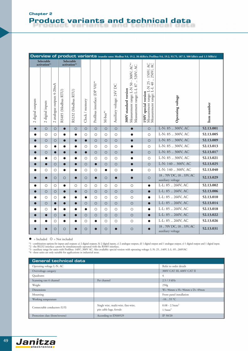
49
Overview of product variants (transfer rates: Modbus 9.6, 19.2, 38.4kBit/s; Profibus 9.6, 19.2, 93.75, 187.5, 500 kBit/s and 1.5 MBit/s)
2 di
gita
l out
puts
2 di
gita
l inp
uts
2 an
alog
ue o
utpu
ts 4
-20m
A
RS4
85 (
Mod
bus
RT
U)
RS2
32 (
Mod
bus
RT
U)
Clo
ck /
mem
ory
Prof
ibus
inte
rfac
e (D
P V
0)*4
M-b
us*4
Aux
iliar
y vo
ltage
: 24V
DC
300V
sta
ndar
d ve
rsio
nM
easu
rem
ent r
ange
: L-N
50
- 30
0V; A
C*3
Mea
sure
men
t ran
ge:L
-L 8
7 ..
520V
; AC
150V
spe
cial
ver
sion
Mea
sure
men
t ra
nge:
L-N
25
- 15
0V; A
CM
easu
rem
ent
rang
e: L
-L 4
0 ..
250V
; AC
Ope
rati
ng v
olta
ge
Item
num
ber
� � � � � � � � � � � L-N: 85 .. 300V, AC 52.13.001
� � � � � � � � � � � L-N: 85 .. 300V, AC 52.13.005
� � � � � � � � � � � L-N: 85 .. 300V, AC 52.13.009
� � � � � � � � � � � L-N: 85 .. 300V, AC 52.13.013
� � � � � � � � � � � L-N: 85 .. 300V, AC 52.13.017
� � � � � � � � � � � L-N: 85 .. 300V, AC 52.13.021
� � � � � � � � � � � L-N: 140 .. 300V, AC 52.13.025
� � � � � � � � � � � L-N: 140 .. 300V, AC 52.13.040
� � � � � � � � � � �18 .. 70V DC, 18 .. 33V, ACauxiliary voltage
52.13.029
� � � � � � � � � � � L-L: 85 .. 260V, AC 52.13.002
� � � � � � � � � � � L-L: 85 .. 260V, AC 52.13.006
� � � � � � � � � � � L-L: 85 .. 260V, AC 52.13.010
� � � � � � � � � � � L-L: 85 .. 260V, AC 52.13.014
� � � � � � � � � � � L-L: 85 .. 260V, AC 52.13.018
� � � � � � � � � � � L-L: 85 .. 260V, AC 52.13.022
� � � � � � � � � � � L-L: 85 .. 260V, AC 52.13.026
� � � � � � � � � � �18 .. 70V DC, 18 .. 33V, ACauxiliary voltage
52.13.031
Selectableactivation*1
� = Included � = Not included
Selectableactivation*2
General technical dataOperating voltage L-N, AC Refer to order details
Overvoltage category 300V CAT III, 600V CAT II
Quadrants 4
Scanning rate 6 channel Per channel 2.5 / 3 kHz
Weight 250g
Dimensions W= 96mm x H= 96mm x D= 49mm
Mounting Front panel installation
Working temperature -10…55 °C
Connectable conductors (U/I)Single wire, multi-wire, fine-wire,
pin cable lugs, ferrule
0.08 - 2.5mm2
1.5mm2
Protection class (front/reverse) According to EN60529 IP 50/20
Product variants and technical data
▼
*1 - combination options for inputs and outputs: a) 2 digital outputs, b) 2 digital inputs, c) 2 analogue outputs, d) 1 digital output and 1 analogue output, e) 1 digital output and 1 digital input.*2 - the RS232 interface cannot be simultaneously operated with the RS485 interface.*3 - auxiliary range for units with Profibus: 140V...300V AC. Also available: special version with operating voltage: L-N: 25...140V, L-L: 85...260VAC*4 - these units are only suitable for applications in industrial areas.
Chapter 2

50
Power qualityHarmonics, 1st to 15th harmonics, uneven Current, voltage L1, L2, L3 Accuracy: ± 2% rng
Distortion factor THD-U in % L1, L2, L3 Accuracy: ± 2% rng
Distortion factor THD-I in % L1, L2, L3 Accuracy: ± 2% rng
Recorder for threshold events Yes, for units with memory
Measurement accuracyAccuracy V, A ± 0.5 % rng
Reactive energy (karh) Class 1 (5A) 2 (1A)
Effective energy (kWh) Class 1 (5A) 2 (1A)
PeripheryDigital inputs As a status input or pulse input 2, refer to order details
Digital outputs As a switch output or pulse output 2
Analogue outputs 4...20mA 2, refer to order details
Password protection Yes
Software GridVis Refer to chapter 5 Yes
CommunicationInterfaces
RS 232 9.6, 19.2, 38.4 kbps; RJ11 Refer to order details
RS 485 9.6, 19.2, 38.4 kbps; terminal strip Refer to order details
M-bus Plug, sub D 9-pole Refer to order details
Protocols
Modbus RTU 9.6, 19.2, 38.4 kbps Yes
Profibus DP V0 9.6, 19.2, 45.45, 93.75, 187.5, 500, 1500 kbps Refer to order details
M-bus 0.3, 2.4, 9.6 kbps Refer to order details
Measurement rangeVoltage L-N, AC (without voltage transformer) Refer to order details
Voltage L-L, AC (without voltage transformer) Refer to order details
Current ( transformer: x/1 and x/5A) 0.01...6A
Frequency of mains 45...65Hz
Grid types TN,TT
Measurement in single phase/multiphase networks 1ph, 2ph, 3ph and up to 3 x 1ph
▼
UMG 96S
Measurement values
Current 0.01 .. 60.0 kA 0.01 .. 6 A +-0.5 % rng
Current calculated in N 0.01 .. 180.0 kA 0.01 .. 18 A +-1.5 % rng
Voltage L-N 0.0 .. 34 kV 50 .. 300 V +-0.5 % rng
Voltage L-L 0.0 .. 60 kV 87 .. 520 V +-1.0 % rng
Frequency (U) 45.00 .. 65.00 Hz 45.00 .. 65.00 Hz +-0.1 % rdg
Effective power per phase 0.1 W .. 99.9 MW 0.1 W .. 1.8 kW +-1.0 % rng
Apparent power per phase 0.1 VA .. 99.9 MVA 0.1 VA .. 1.8 kVA +-1.0 % rng
Reactive power per phase 0.1 var .. 99.9 Mvar 0.1 var .. 1.8 kvar ind. +-1.0 % rng
Effective power, sum 1.0 W .. 99.9 MW 1.0 W .. 5.4 kW +-1.0 % rng
Apparent power, sum 1.0 VA .. 99.9 MVA 1.0 VA .. 5.4 kVA +-1.0 % rng
Reactive power, sum 1.0 var .. 99.9 Mvar 1.0 var .. 5.4 kvar ind. +-1.0 % rng
Cos phi 0.00 kap. .. 1.00 .. 0.00 ind. 0.00 kap. .. 1.00 .. 0.00 ind. +-1.0 degree
Effective energy, consumed 0 .. 999.999.999 kWh Class 1(5A) 2 (1A)
Reactive energy, inductive 0 .. 999.999.999 kvarh Class 1(5A) 2 (1A)
Operating hour meter 0 .. 999.999.999 h +-2 min per day
Measurement parameter
Display range Measurementaccuracy
SumL1 L2 L3Measurement rangeat scaling factor 1
Lowestvalue
Maximumvalue
Averagevalue *1
rng: of measurement range, rdg: of measurement value*1 integration over time: 5, 10, 30, 60, 300, 480, 600 and 900 seconds
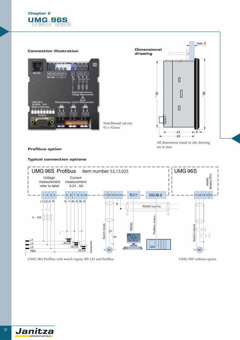
max. 6
90
96
49
DS
UB
-9
42 6
51
UMG 96S
Typical connection options
Profibus option
Dimensional drawing
▼▼
UMG 96S Profibus with switch inputs, RS 232 and Profibus UMG 96S without option
Switchboard cut-out92 x 92mm
Connection illustration
Chapter 2
All dimensions stated in this drawingare in mm.

▼
52
Digital measurement in perfection
Power analysers of the UMG 503 product family are mainly designed for use in low and mediumvoltage distribution systems. The large display in 144 x 144mm housing, the higher accuracy leveland the extended measurement range allows universal applications. Additional functions such asthe measurement of harmonics, the recording of minimum and maximum values, the relay outputs,pulse and analogue outputs, the bi-metallic strip function, password protection and many more offeran effective tool for fault analysis and for monitoring power quality.
The interface and field bus features (Modbus) enable communication of the measurement data andincorporation in extensive energy management systems. The integrated logic enables the analysisof measurement data and the introduction of concrete measures.
Areas of application� Measurement, monitoring and controlling of electrical parameters in energy distribution systems� Recording of load profiles for energy management systems� Collection of energy consumption data for cost centre analysis� Measurement value generator for building management systems or PLC (Modbus)� Monitoring of harmonics, limit value monitoring
PQ
M -
Po
we
r Q
ua
lity
Mo
nit
ori
ng
UMG 503
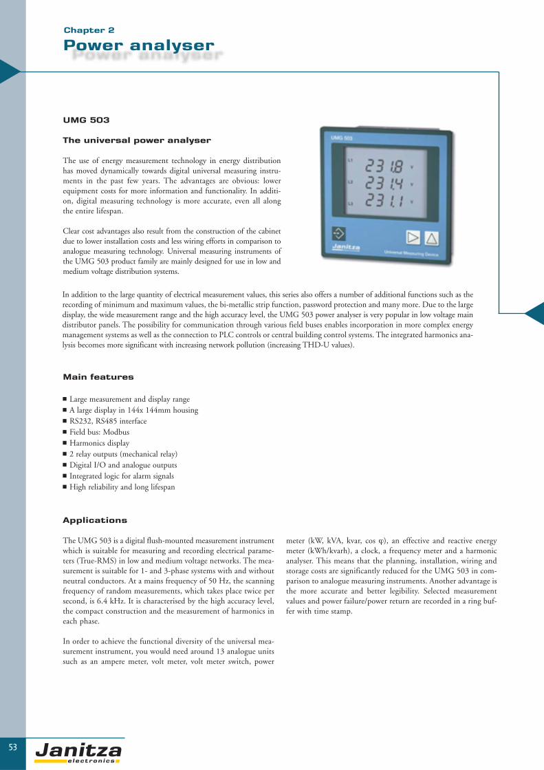
53
Power analyser
UMG 503
The universal power analyser
The use of energy measurement technology in energy distributionhas moved dynamically towards digital universal measuring instru-ments in the past few years. The advantages are obvious: lowerequipment costs for more information and functionality. In additi-on, digital measuring technology is more accurate, even all alongthe entire lifespan.
Clear cost advantages also result from the construction of the cabinetdue to lower installation costs and less wiring efforts in comparison toanalogue measuring technology. Universal measuring instruments ofthe UMG 503 product family are mainly designed for use in low andmedium voltage distribution systems.
Applications
The UMG 503 is a digital flush-mounted measurement instrumentwhich is suitable for measuring and recording electrical parame-ters (True-RMS) in low and medium voltage networks. The mea-surement is suitable for 1- and 3-phase systems with and withoutneutral conductors. At a mains frequency of 50 Hz, the scanningfrequency of random measurements, which takes place twice persecond, is 6.4 kHz. It is characterised by the high accuracy level,the compact construction and the measurement of harmonics ineach phase.
In order to achieve the functional diversity of the universal mea-surement instrument, you would need around 13 analogue unitssuch as an ampere meter, volt meter, volt meter switch, power
▼▼
meter (kW, kVA, kvar, cos ϕ), an effective and reactive energymeter (kWh/kvarh), a clock, a frequency meter and a harmonicanalyser. This means that the planning, installation, wiring andstorage costs are significantly reduced for the UMG 503 in com-parison to analogue measuring instruments. Another advantage isthe more accurate and better legibility. Selected measurementvalues and power failure/power return are recorded in a ring buf-fer with time stamp.
Main features
� Large measurement and display range� A large display in 144x 144mm housing� RS232, RS485 interface� Field bus: Modbus� Harmonics display� 2 relay outputs (mechanical relay)� Digital I/O and analogue outputs� Integrated logic for alarm signals� High reliability and long lifespan
In addition to the large quantity of electrical measurement values, this series also offers a number of additional functions such as therecording of minimum and maximum values, the bi-metallic strip function, password protection and many more. Due to the largedisplay, the wide measurement range and the high accuracy level, the UMG 503 power analyser is very popular in low voltage maindistributor panels. The possibility for communication through various field buses enables incorporation in more complex energymanagement systems as well as the connection to PLC controls or central building control systems. The integrated harmonics ana-lysis becomes more significant with increasing network pollution (increasing THD-U values).
Chapter 2

Data memory
A ring buffer for 80,000 or 320,000 measurement values (depending on the variant) is available for storing the selected average values.With the factory settings, average values of U1, U2, U3, I1, I2, I3, P1, P2 and P3 are stored using an average time of 15 minutes forapproximately 1 year for variants with 512 k RAM (approximately 3 months for types with 128k RAM).
A total of six limit value windows for storing measurement values can be programmed. The upper and lower limit values can be freelyselected. The recording can take place within or outside of the range.
Measurement value displays and automatic display rotation
The extremely legible LCD data field in connection with the function keys informs the user about the selected measurement values(current, low, high and average values). With the UMG 503, three measurement values can be simultaneously displayed in the LCDdata field and up to 140 data fields can be individually designed with the GridVis software. A cycle between 1 and 9999 seconds canbe set and a selection of measurement values can be made.
Bi-metallic strip function
The bi-metallic strip function is recreated for the three external conductor currents. These values can be integrated in the stated times andbe recorded as highest average values.
Summer/winter time switch
The following options can be selected:
a) No switchoverb) Own switchover pointc) EU listed switching
54
UMG 503
▼
Event memory
The following events can be registered in the event memory:
� Deletion of the event memory� Relay outputs on/off� Failure and return of the auxiliary voltage� Failure and return of the measurement voltage
Interfaces
The communication interfaces of the UMG 503 which are configured in accordance with the EIA RS485 standard (half duplex) supportthe Modbus RTU in integer format. The communication protocol can be selected by using the menu.
In the Modbus RTU mode, baud rates from 9.6 kBit/s to 115 kBit/s are supported (depending on the design version). The registeraddresses are available to the PLC user in integer format.
Power values and cos ϕ Currents THD-U Voltage transformer

Interfaces- RS232 - RS485
Auxiliary input *4
The auxiliary input can be programmed for the following functions:
OFF = auxiliary input is not used1 = reset of the 15 minutes
power average value3 = synchronisation of the internal clock
55
Scope of operation and types of variants
▼
2 relay outputsFor limit value monitoring I, U, P, THD-U etc.
1 pulse outputFor the effective or reactive energy
1 analogue output- 0/4 .. 20 mA
128 memory/512 kByte- For 80,000/320,000 measurement values
1 auxiliary input for- Resetting the 15 minute power
average value- Tariff switchover- Synchronisation of the internal clock
Modem PLC Software
*4: refer to product variant
Pulse output *4
The pulse output delivers the effective or reactiveenergy in current pulses. The minimum pulse length is 50ms.
Relay outputs *4
The relay outputs K1 and K2 can be used for moni-toring limit values. Each relay output can be linkedwith a measurement value and (recorded with dateand time) can be stored if the value is not achieved oris exceeded. A minimum initialisation time can beprogrammed for each relay output to avoid excessivelyfrequent switching.
Communication- Modbus RTU (integer format)
Chapter 2

56
▼
UMG 503
GridVis software
The UMG 503 power analysers contains the GridVis software upon delivery. On one hand, this software enables simple and completeparameterisation of the respective measurement instruments and on the other hand, it can download the measurement value memory inthe unit where available. In GridVis, the data is stored in a database and can be processed in MS Excel for example. More informationis available in chapter 5 – “software”.
Options for the units (release code) UMG 503..
Relay outputs (min/max) OV 52.07.051
Pulse output for effective or reactive energy OV 52.07.052
Analogue output 0(4) – 20mA OV 52.07.053
Auxiliary input OV 52.07.056
Three-phase measurement L/LG/LS/S/OV 52.07.058
� = Included - = Not possible � = Option which can be supplied with the unit (each option is only possible once)
85 ..
250
V A
C,
80 ..
370
V D
C
40 ..
115
V A
C,
55 ..
165
V D
C
15 ..
55V
AC
, 20
.. 8
0V D
C
128k
RA
M
mem
ory
512k
RA
M
mem
ory
Rel
ay o
utpu
t
Puls
e ou
tput
Ana
logu
e ou
tput
0(
4) -
20m
A
RS
232
RS
485
Aux
iliar
y in
put
3-ph
ase
mea
sure
men
t
Type
Item
num
ber
� - - � - - - - � - - � UMG 503 L 52.07.017
- � - � - - - - � - - � UMG 503 L 52.07.019
- - � � - - - - � - - � UMG 503 L 52.07.022
� - - - � - - - � - - � UMG 503 LG 52.07.027
- � - - � - - - � - - � UMG 503 LG 52.07.033
- - � - � - - - � - - � UMG 503 LG 52.07.068
� - - � - - - - - � - � UMG 503 LS 52.07.028
- � - � - - - - - � - � UMG 503 LS 52.07.074
- - � � - - - - - � - � UMG 503 LS 52.07.037
� - - � - - - - - � - � UMG 503 S 52.07.008
- � - � - - - - - � - � UMG 503 S 52.07.015
- - � � - - - - - � - � UMG 503 S 52.07.009
� - - - � � � � � � � � UMG 503 V 52.07.001
- � - - � � � � � � � � UMG 503 V 52.07.014
- - � - � � � � � � � � UMG 503 V 52.07.005
� - - - � � � � � � � � UMG 503 OV 52.07.006
- � - - � � � � � � � � UMG 503 OV 52.07.016
- - � - � � � � � � � � UMG 503 OV 52.07.007
InterfacesAuxiliary voltage
Overview of product variantsThree/four-phase universal measurement instruments 50/60Hz; current transformer...1/5A; including GridVis programming and analysis software

57
Scope of operation and technical data
▼
General technical dataOperating voltage L-N, AC Refer to order details
Overvoltage category 600V CAT III
Quadrants 4
Scanning rate 6 channel Per channel 6.4 / 7.68 kHz
Weight 1kg
Dimensions W=144mm x H=144mm x D=66.5mm
Mounting Front panel installation
Working temperature -10…55 °C
Connectable conductors (U/I)Single wire, multi-wire, fine-wire,
pin cable lugs, ferrule
0.08 - 2.5mm2
1.5mm2
Protection class (front/reverse) According to EN60529 IP 50/20
Power qualityHarmonics, 1st to 20th harmonics, even/uneven Current, voltage L1, L2, L3 Accuracy: ± 0.5% rng
Distortion factor THD-U in % L1, L2, L3 Accuracy: ± 0.5% rng
Distortion factor THD-I in % L1, L2, L3 Accuracy: ± 0.5% rng
Recorder for limit value events Yes
Measurement values
Measurement accuracyReactive energy kvarh Class 1
Effective energy kWh Class 1
Measurement rangeVoltage L-N, AC (without voltage transformer) 50…500VAC
Voltage L-L, AC (without voltage transformer) 80…870VAC
Current (transformer: x/1 and x/5 A) 0.005...6A
Frequency of mains 45...65Hz
Grid types TN, TT, (IT)
Measurement in single and multi-phase networks 1ph, 2ph, 3ph and up to 3x1ph
Current .. /5A 0.000 .. 9999 A 0.005 .. 6 A +-0.2 % rng
Current .. /1A 0.000 .. 9999 A 0.005 .. 1 A +-0.2 % rng
Current, neutral wire 0.000 .. 9999 A 0.060 .. 15 A +-0.6 % rng
Voltage L-N 0.0 .. 999.9 MV 50 .. 500 V +-0.2 % rng
Voltage L-L 0.0 .. 999.9 MV 80 .. 870 V +-0.2 % rng
Frequency (U) 45.00 .. 65.00 Hz 45.00 .. 65.00 Hz +-0.2 % rdg
Effective power +/- 0.00 W .. 9999 MW 0.05 W .. 2.5 kW +-0.5 % rng
Apparent power 0.00 VA .. 9999 MVA 0.05 VA .. 2.5 kVA +-0.5 % rng
Reactive power 0.00 kvar .. 999 Mvar 0.05 var .. 2.5 kvar kap. ind. +-0.5 % rng
Power factor 0.00 kap. .. 1.00 .. 0.00 ind. 0.00 kap. .. 1.00 .. 0.00 ind. kap. ind. +-0.5 % rng
Effective energy + 0.0 Wh .. 9999 GWh 0.05 Wh .. 9999 GWh*2 t1/t2 *3
Effective energy - -0.0 Wh .. -9999 GWh -0.05 Wh .. -9999 GWh*2
Reactive energy +/- 0.0 .. 9999 Gvarh 0.05vars .. 9999 Mvarh*2 t1/t2 *3
Measurement parameter
Display range Measurementaccuracy
SumL1 L2 L3Measurement rangeat scaling factor 1
Lowestvalue
Maximumvalue
Averagevalue *1
Date/time
Rng: from measurement range, rdg: from measurement value, t1: start time, t2: runtime, + purchase, - supply, *1 - integration over time: 5, 10, 15, 30 seconds, 1, 5, 10, 15, 30, 60 minutes, *2 memory period 60 minutes, *3 accuracy class according to EN61036:1996, VDE0418 part 7:May 1997, IEC1036:1996, with current transformer ../5A : class 1, with current transformer ../1A : class 2
Chapter 2
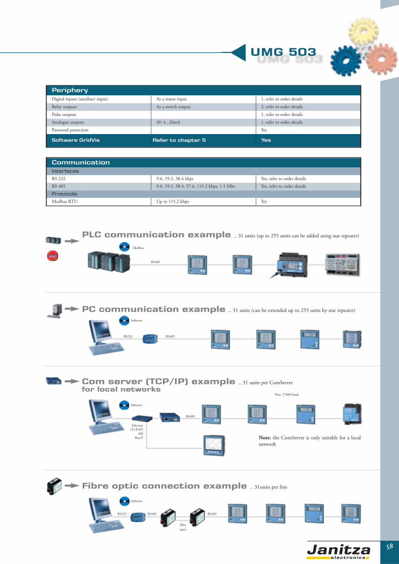
58
▼
UMG 503
PeripheryDigital inputs (auxiliary input) As a status input 1, refer to order details
Relay outputs As a switch output 2, refer to order details
Pulse outputs 1, refer to order details
Analogue outputs (0) 4...20mA 1, refer to order details
Password protection Yes
Software GridVis Refer to chapter 5 Yes
CommunicationInterfaces
RS 232 9.6, 19.2, 38.4 kbps Yes, refer to order details
RS 485 9.6, 19.2, 38.4, 57.6, 115.2 kbps, 1.5 Mbs Yes, refer to order details
Protocols
Modbus RTU Up to 115.2 kbps Yes
PLC communication example .. 31 units (up to 255 units can be added using star repeater)
Modbus
RS485
PC communication example .. 31 units (can be extended up to 255 units by star repeater)
Software
RS485RS232
Note: the ComServer is only suitable for a localnetwork
Com server (TCP/IP) example .. 31 units per ComServerfor local networks
Software
RS485
Max. 57600 baud
Fibre optic connection example .. 31units per line
Software
fibre optic
RS485RS232 RS485
Ethernet(TCP/IP)
100BaseT

59
UMG 503
▼▼
Typical connection option
Dimensionaldrawing
Switchboard cut-out139 x 139mm
(Item number 52.07.001)
Connection illustration
Chapter 2
All dimensions stated in thisdrawing are in mm.

▼
60
Power analysis, LON and I/O diversity
Power analysers of the UMG505 product family are mainly designed for use in low and mediumvoltage distribution systems. Due to the additional communication options using LON, this poweranalyser is often used in building management. The large number of digital and analogue inputs andoutputs (4 DI, 5DO, 4AO) enables the incorporation in monitoring systems, control tasks, infor-mation reports, the communication of measurement data (e.g. energy consumption) at a controlpoint and incorporation in an extensive energy management system. Additional functions such as themeasurement of harmonics, the recording of minimum and maximum values, the relay output, pulseand analogue outputs, the bi-metallic strip function, password protection and many more offers aneffective tool for fault analysis and for monitoring power quality.
Areas of application� Measurement, monitoring and control of electrical parameters in energy distribution systems� Recording of load profiles for energy management systems (cost centre data collection)� Data logging (water, gas, cooling, electrical ...)� Measurement value generator for central building control systems or PLC� Monitoring of harmonics, limit value monitoring� Control tasks e.g. depending upon achieved measurement values or limit values
PQ
M -
Po
we
r Q
ua
lity
Mo
nit
ori
ng
UMG 505

61
Power analyser
UMG 505 power analyser
LON for building services, analogue I/Osfor control tasks
The use of energy measurement technology in energy distributionhas moved dynamically towards digital universal measuringinstruments in the past few years. The advantages are obvious:lower equipment costs for more information and functionality. Inaddition, digital measuring technology is more accurate, even allalong the entire lifespan.
Clear cost advantages also result from the construction of the cabinetwhich results in lower installation costs and less wiring efforts incomparison to analogue measuring technology. Universal measu-ring instruments of the UMG505 product family are mainly desi-gned for use in low and medium voltage distribution systems.
Main features
� LON bus, Modbus RTU� Harmonics display� 4 analogue outputs � 4 digital inputs, 5 digital outputs� Integrated logic for control tasks and alarm signals� Weekly time switch with 100 channels
Applications
The UMG 505 is a digital flush-mounted measurement instrumentwhich is suitable for measuring and recording electrical parameters(True-RMS) in low and medium voltage networks. The measure-ment device is suitable for 1- and 3-phase systems with and with-out neutral conductors. At a mains frequency of 50 Hz, the scan-ning frequency of random measurements, which takes place twiceper second, is 6.4 kHz. It is characterised by the high accuracylevel, the compact construction and the measurement of harmonicsin each phase.
In order to achieve functional variety of the UMG 505, you wouldneed around 13 analogue units such as an ampere meter, voltmeter, volt meter switch, power meter (kW, kVA, kvar, cos ϕ), an
▼▼
effective and reactive energy meter (kWh/kvarh), a clock, a fre-quency meter and a harmonic analyser. This means that the plan-ning, installation, wiring and storage costs are significantly reducedwith the UMG 505 in comparison to analogue measuring instru-ments. Another advantage is the more accurate and better legibili-ty. Selected measurement values and power failure/power returnare recorded in a ring buffer with time stamp.
In addition to the large quantity of electrical measurement values, this series also offers a number of additional functions such as therecording of minimum and maximum values, the bi-metallic strip function, password protection and many more. Due to the LONfield bus, the UMG 505 is starting to find more applications in building services. The large number of digital and analogue inputsand outputs offers a variety of communication possibilities and allow connection to PLC controls and independent control tasks. Theintegrated harmonics analysis becomes more significant with increasing network pollution (increasing THD-U values).
Chapter 2

Measurement value displays and automatic display rotation
The extremely legible LCD display in connection with the function keys informs the user about the selected measurement values(actual, low, high and average values). With the UMG 505, three measurement values can be simultaneously displayed in the LCDdata field and up to 140 data fields can be individually designed with the GridVis software. A cycle between 1 and 9999 secondscan be set for measurement value rotation and a selection of measurement values can be made.
Memory
The memory of the UMG 505 is split into three areas: the event memory, the lowest and highest memory and the ring buffer.
Event memory
The following events can be stored in the event memory with time and date:
� Deletion of the event memory� Changes to the digital input� Failure and return of the auxiliary voltage� Failure and return of the measurement voltage
Up to a maximum of 9999 events can be stored. The data can only be read out with the PC and the GridVis software.
Ring buffer
The following can be selected for storage in the ring buffer:
� Average of measurement values� The fixed energy meters
When storing the average values of U1, U2, U3, I1, I2, I3, P1, P2 and P3 using an average time of 15 minutes, the memory issufficient for a period of 1 year. A total of six limit value windows for storing measurement values can be programmed. The upperand lower limit values can be freely selected. The recording can take place within or outside of the range.
Summer/winter time switch
The following options can be selected:� No switchover� Own switchover point� EU listed switching
Weekly time switch
The time switch in the UMG 505 has 100 time channels. Each time switch channel specifies a period of time. The period oftime is specified by the start-up point and the switch off point. The start and stop points are defined by weekdays, hour andminutes. Each time switch channel can simultaneously control a time switch output and select a consumption meter. A timeswitch output can be allocated to a “digital output” when programming the digital outputs.
62
▼
UMG 505

Pulse input
Digital input 4 can also be used as a pulse meter input for theeffective energy measurement (max 20Hz).
Digital inputs
The 4 optical coupler inputs are illustrated on the internal inputs1 to 4. The UMG 505 has a total of 20 internal inputs. The eightinputs from the LON bus interface (option) are illustrated on theinternal inputs 5 to 12 and eight inputs from the MODBUSinterface (option) are illustrated on the internal inputs 13 to 20.The status of the digital inputs 1-4 can be called up using theserial interface.
Each input channel can simultaneously switch a energy counterand synchronise the internal clock.
Two of each of the digital inputs can be linked with each otherusing AND. The results can be allocated to an input channel.Each digital input 1 to 4 is allocated to an event counter (1-3max. 1Hz). If one of the digital inputs (1 to 4) is allocated a fun-ction, with the exception of pulse value, all changes are recordedwith the date and time stamp in the event memory.
Digital output
The UMG 505 has five digital transistor outputs. These outputsare marked on the display with out1 to out5. Each of these out-puts can be allocated to a different data source. There are up to 5 different data sources which can be selected:
� Limit value outputs� Times switch outputs� LON bus (option)� MODBUS (option)� Energy meter
Each data source can only be allocated to one output. If an outputis allocated to a consumption meter, the output works as a pulsegenerator. The signals from all data sources (except the consumption meter)can also be generated as inverted signals.
63
Scope of operation
▼
Pulse outputs
The five digital outputs in the UMG 505 can be assigned as pulseoutputs. The minimum pulse length is 50ms and the maximum frequency is 10Hz.
Analogue outputs
The UMG 505 has 4 analogue outputs. The analogue outputshave common ground and are galvanically isolated from the otherinputs and outputs in the UMG 505. An external auxiliary volta-ge of 20V to 30V DC is required to operate the analogue outputs.The sources for analogue outputs are:
� Measurement values� Values which are sent to the
UMG 505 through Modbus.
Interfaces
Depending upon the product variant, the UMG 505 is equippedwith an RS485 LON and/or an RS232 interface. The RS232interface serves as a peer-to-peer connection e.g. as a connectionbetween the UMG 505 and a laptop. The protocol Modbus RTUis available through the RS485 which is used to network theUMG 505. The LON interface is frequently used in central buil-ding control systems in order to incorporate the UMG 505 inbuilding automation.
Limit value monitoring
Five limit value outputs can be programmed to monitor themeasurement values. Each limit value output can be allocated toup to 3 comparators (A, B, C). The following can be programmedfor each comparator:
� 2 limit values and 2 measurement values or� 2 limit values and 1 measurement value or� 1 limit value and the minimum start-up time
Any limit value violations established by a limit value output isregistered in the event memory with a record of the time and canalso be issued on a “digital output”.
Chapter 2

Software
64
▼
UMG 505
Interfaces- RS232
- RS485
- LON
Protocols- LONTalk
- Modbus RTU ( RS232 or RS485)
4 digital inputs- Pulse input
- HT/LT switchover
- Clock synchronisation
5 digital outputs- Limit value output for I, U, P etc
- Remote using Modbus/LON
- Pulse output effective/reactive energy
- Time switch output
4 analogue outputs- 0 .. 20 mA or 4 .. 20 mA can be set
- Almost all measurement values
- Values from the Modbus
512k byte memory- For 320,000 measurement values
- Event memory
- Lowest and highest values
- Ring buffer
Weekly time switch - 100 channels
- Digital output
- Nominal value switchover HT / LT
- Energy meter, 4 tariffs
Modem PLC
Limit value programming with 3 comparators- Minimum start up time if the value is exceeded
- Minimum start up time if the value is not achieved
- Hysteresis if the value is exceeded
- Hysteresis if the value is not achieved
- Within range
- Outside of range
- Both limit values exceeded
- Both limit values not achieved

65
Product variants and technical data
▼
General technical dataOperating voltage L-N, AC Refer to order details
Overvoltage category 600V CAT III
Quadrants 4
Scanning rate 6 channels Per channel 6.4 kHz / 7.68 kHz
Weight 1kg
Dimensions W= 144mm x H=144mm x D=66.5mm
Mounting Front panel installation
Working temperature range -10…55 °C
Connectable conductors (U/I)Single wire, multi-wire, fine-wire, pin cable lugs, ferrule
0.08 - 2.5 mm2
1.5 mm2
Protection class (front/reverse) According to EN60529 IP 50/20
Measurement rangeVoltage L-N, AC (without voltage transformer) 50…500VAC
Voltage L-L, AC (without voltage transformer) 80…870VAC
Current (transformer: x/1 and x/5 A) 0.005...6 A
Frequency of mains 45...65 Hz
Grid types TN, TT, (IT)
Measurement in single and multi-phase networks1ph, 2ph, 3ph and up to 3x1ph
Overview of product variants
85 ..
265
V A
C,
80 ..
370
V D
C
40 ..
115
V A
C,
55 ..
165
V D
C
15 ..
55V
AC
,20
.. 8
0V D
C
512k
RA
M m
emor
y
4 di
gita
l inp
uts
5 di
gita
l out
puts
4 pa
ssiv
e an
alog
ue
outp
uts
0(4)
– 2
0mA
LON
RS
232
RS
485
3-ph
ase
mea
sure
men
t
Type
Item
num
ber
� - - � � � � - � - � UMG 505 MOD 52.10.004
- � - � � � � - � - � UMG 505 MOD 52.10.005
- - � � � � � - � - � UMG 505 MOD 52.10.006
� - - � � � � - - � � UMG 505 MOD 52.10.007
- � - � � � � - - � � UMG 505 MOD 52.10.008
- - � � � � � - - � � UMG 505 MOD 52.10.009
� - - � � � � � � - � UMG 505 LON 52.10.001
- � - � � � � � � - � UMG 505 LON 52.10.002
- - � � � � � � � - � UMG 505 LON 52.10.003
� - - � � � � � - � � UMG 505 LON 52.10.013
- � - � � � � � - � � UMG 505 LON 52.10.015
- - � � � � � � - � � UMG 505 LON 52.10.016
Auxiliary voltage Interfaces
� = Option - = Not possible � = Included
Chapter 2

Current .. /5A 0.000 .. 9999 A 0.005 .. 6 A +-0.2 % rng
Current .. /1A 0.000 .. 9999 A 0.005 .. 1 A +-0.2 % rng
Current, calculated in neutral 0.000 .. 9999 A 0.060 ..1 5 A +-0.6 % rng
Voltage L-N 0.0 .. 999.9 MV 50 .. 500 V +-0.2 % rng
Voltage L-L 0.0 .. 999.9 MV 80 .. 870 V +-0.2 % rng
Frequency (U) 45.00 .. 65.00 Hz 45.00 .. 65.00 Hz +-0.2 % rdg
Effective power +/- 0.00 W .. 9999 MW 0.05 W .. 2.5 kW +-0.5 % rng
Apparent power 0.00 VA .. 9999 MVA 0.05 VA .. 2.5 kVA +-0.5 % rng
Reactive power 0.00 kvar .. 999 Mvar 0.05 var .. 2.5 kvar cap ind. +-0.5 % rng
Power factor 0.00 kap. .. 1.00 .. 0.00 ind. 0.00 kap. .. 1.00 .. 0.00 ind. cap. ind. +-0.5 % rng
Effective energy + 0.0 Wh .. 9999 GWh 0.05 Wh .. 9999 GWh*2 t1/t2 *3
Effective energy - -0.0 Wh .. -9999 GWh -0.05 Wh .. -9999 GWh*2
Reactive energy +/- 0.0 .. 9999 Gvarh 0.05vars .. 9999 Mvarh*2 t1/t2 *3
Harmonic rate THD U,I 0.0 .. 100 % 0.0 .. 100 % +-0.5 % rng
Partial harmonic I, 2nd to 20th 0.000 A .. 9999 A 0.005 A .. 5A (1 A) +-0.5 % rng
Partial harmonic U, 2nd to 20th 0.0 V .. 99.99 kV 0.000 V .. 9999 V +-0.5 % rng
66
▼
UMG 505
CommunicationInterfaces
RS 232 9.6, 19.2, 38.4 kbps Yes, refer to order details
RS 485 9.6, 19.2, 38.4, 57.6, 115.2 kbps Yes, refer to order details
LON Yes, refer to order details
Protocols
Modbus RTU Yes
LonTalk Yes, refer to order details
PeripheryDigital inputs As a status input or pulse input 4
Digital outputs As a switch output or pulse output 5
Analogue outputs 0(4)…20mA 4
Password protection Yes
Software GridVis Refer to chapter 5 Yes
FeaturesMemory size 512kB
Clock ± 3 minutes per month
Weekly time switch Yes, 100 channels
Power qualityHarmonics, 1st to 20th harmonics,even/uneven
Current, voltage L1, L2, L3 Accuracy: ± 0.5% rng
Distortion factor THD-U in % L1, L2, L3 Accuracy: ± 0.5% rng
Distortion factor THD-I in % L1, L2, L3 Accuracy: ± 0.5% rng
Recorder for limit value events Yes
Rng: of measurement range, rdg: of measurement value, t1: start time, t2: runtime, + purchase, - supply*1 - integration over time: 5, 10, 15, 30 seconds, 1, 5, 10, 15, 30 and 60 minutes*2 - memory period – 60 minutes *3 - accuracy class according to EN61036:1996, VDE0418 part 7: May 1997, IEC1036:1996 with current transformer ../5A: class 1 with current transformer ../1A: class 2
Measurement values
Measurement parameter
Display range Measurementaccuracy
SumL1 L2 L3Measurement rangeat scaling factor 1
Lowestvalue
Maximumvalue
Averagevalue *1
Date/time

67
UMG 505
▼▼
Typical connection options
Dimensionaldrawing
Switch board cut-out:139x139 mm
Connection illustration
Illustration: option with LON
Chapter 2
Consumers
All dimensions stated in thisdrawing are in mm.

▼
68
Continuous measurements and the Ethernet
Power analysers of the UMG 507 product family are suitable for use at all network levels. The con-tinuous measurement enables the collection of various measurement parameters, the identification ofshort-term interruptions, a fault recorder function and harmonic analysis. Extensive communicationoptions e.g. Ethernet (TCP/IP), Modbus, Profibus, RS232, RS485, HTTP, SMTP, UTP or DNSallow affordable and quick integration in existing communication networks. Worldwide access to theembedded web server can be gained through a web browser. This means that the extensive opportu-nities offered by the UMG 507 are available without any additional software. The large number ofdigital and analogue inputs and outputs enable incorporation in monitoring systems, control tasks,information reports, the communication of measurement data (e.g. energy consumption) to a centralcontrol point and incorporation in extensive energy management systems. Extensive logic functionsallow the analysis of measurement data and the introduction of concrete measures.
Areas of application� For measuring, monitoring and control of electrical parameters in energy distribution systems� For recording load profiles (energy consumption) for energy management systems
(cost centre data collection)� For monitoring power quality (harmonics, short term interruptions, inrush currents…)� Control tasks e.g. depending upon the achieved measurement values or limit values� Data logging (electricity, gas, water, cooling ...)� Peak demand management (avoidance of costly and dangerous peak loads)� Remote monitoring via onboard homepage
PQ
M -
Po
we
r Q
ua
lity
Mo
nit
ori
ng
UMG 507
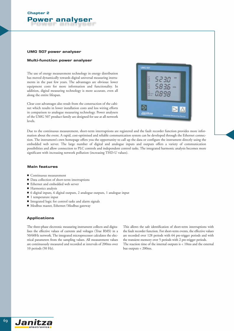
69
Power analyser
UMG 507 power analyser
Multi-function power analyser
The use of energy measurement technology in energy distributionhas moved dynamically towards digital universal measuring instru-ments in the past few years. The advantages are obvious: lowerequipment costs for more information and functionality. In addition, digital measuring technology is more accurate, even allalong the entire lifespan.
Clear cost advantages also result from the construction of the cabi-net which results in lower installation costs and less wiring effortsin comparison to analogue measuring technology. Power analysersof the UMG 507 product family are designed for use at all networklevels.
Applications
The three-phase electronic measuring instrument collects and digita-lises the effective values of currents and voltages (True RMS) in a50/60Hz network. The integrated microprocessor calculates the elec-trical parameters from the sampling values. All measurement valuesare continuously measured and recorded at intervals of 200ms over10 periods (50 Hz).
▼▼
Main features
� Continuous measurement� Data collection of short-term interruptions� Ethernet and embedded web server� Harmonics analysis� 6 digital inputs, 6 digital outputs, 2 analogue outputs, 1 analogue input� 1 temperature input� Integrated logic for control tasks and alarm signals� Modbus master, Ethernet /Modbus gateway
This allows the safe identification of short-term interruptions withthe fault recorder function. For short-term events, the effective valuesare recorded over 128 periods with 64 pre-trigger periods and withthe transient memory over 5 periods with 2 pre-trigger periods.The reaction time of the internal outputs is < 10ms and the externalbus outputs < 200ms.
Due to the continuous measurement, short-term interruptions are registered and the fault recorder function provides more infor-mation about the event. A rapid, cost-optimised and reliable communication system can be developed through the Ethernet connec-tion. The instrument’s own homepage offers you the opportunity to call up the data or configure the instrument directly using theembedded web server. The large number of digital and analogue inputs and outputs offers a variety of communication possibilities and allow connection to PLC controls and independent control tasks. The integrated harmonic analysis becomes moresignificant with increasing network pollution (increasing THD-U values).
Chapter 2

GridVis software
The UMG 507 power analysers already contain the GridVis software upon delivery. On one hand, this software enables simple and com-plete parameterisation of the respective measurement instruments and on the other hand, can analyse the measurement value memory inthe unit. In GridVis, the data is stored in a database and can be processed in MS Excel for example. GridVis also allows online presenta-tion of the measurement values. More information is available in chapter 5 – “software”.
Peak demand management (Emax)
The release of the Emax function for peak demand management is available as an option. More information can be found in chapter 3 –energy management.
Embedded web server / e-mail
Worldwide access to the UMG 507 can be gained through a web browser. In order to provide access, the web address and access autho-risations must be set up. The complete parameterisation software is filed as an HTML page on the flash memory. The open architectureof the UMG 507 allows the user to apply own ideas to design Java-Applets and Active X-components and file them on the UMG507. Iflimit value violations or events occur, they can be automatically sent to the set up e-mail address. Data from the memory storage can besent by e-mail (attachment) at preset times and processed with the GridVis software. Protocols: HTTP, SMT, UTP, DNS, NTP, MOD TCP, Modbus over TCP, DHCP/BootP.
Connection to an ISDN router / DSL router
The unit can be connected to the internet using an external router (e.g. ISDN router or DSL router).
The SMTP authentication enables you to store mails on the internet provider’s mailbox using the Plain/Login/Cram-MDS (newestencryption methods).
Data collection and recording
The UMG 507 has an internal memory of 256KB RAM and, depending on the version, an addi-tional memory of 16 MB flash is available for con-tinuous recording of the measured data. This mea-surement value memory can be freely configuredwith reference to the measurement values whichare to be saved and the recording intervals. Inaddition, the highest and lowest actual values (200ms average time) can also be saved within theseintervals. The recording of events is prompted bytriggers. Events such as excess currents, under vol-tage or overvoltage can be safely collected from ahalf period duration. Events are recorded over 128periods as effective value recorders.
70
▼
UMG 507
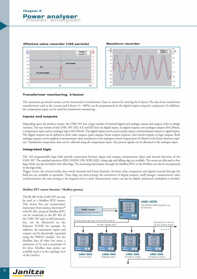
Transformer monitoring, k-factor
The maximum permitted current can be monitored in transformers, fuses or motors by entering the k-factor. The data from transformermanufacturers such as the current and k-factor (1= 100%) can be programmed on the digital output using the comparator. In addition,the temperature input can be used for transformer monitoring.
Inputs and outputs
Depending upon the product variant, the UMG 507 has a large number of internal digital and analogue inputs and outputs (refer to design versions). The top versions of the UMG 507 (AD, P, E and EP) have six digital inputs, six digital outputs, two analogue outputs (0/4-20mA),a temperature input and an analogue input (0/4-20mA). The digital inputs can be used as pulse inputs, synchronisation inputs or signal inputs.The digital outputs can be defined as limit value outputs, pulse outputs, Emax outputs (option), time switch outputs or logic outputs. Bothanalogue outputs can be applied as measurement value transducers or for analogue control of generators (0-20mA) in the Emax function (opti-on). Transformer temperature data can be collected using the temperature input. Any process signals can be allocated to the analogue input.
Integrated logic
The 128 programmable logic links provide connections between inputs and outputs, measurement values and internal functions of the UMG 507. The standard operators AND, NAND, OR, XOR, EQU, rising edge and falling edge are available. The events are allocated to freeflags which can also be linked with other flags. The incoming information through the Modbus RTU or the Profibus can also be incorporatedin the logic links.Trigger events, the virtual weekly time switch channels and Emax channels, the limit value comparator and signals received through thefield bus are available as operands. These flags can then prompt the switchover of digital outputs, tariff changes, measurement valuesynchronisation, the time setting or the despatch of an e-mail. Measurement values can also be added, subtracted, multiplied or divided.
Modbus RTU master function / Modbus gateway
The RS 485 of the UMG 507 can alsobe used as a Modbus RTU master.This means that any measurementinstrument from Janitza electronics®
with RS 485, protocol Modbus RTUcan be connected to the RS 485 ofthe UMG 507 and, in full functiona-lity, can be illustrated on theEthernet TCP/IP for example. Inaddition, the instrument inputs andoutputs can be decentrally expandedusing the WAGO module. For theModbus data of other bus users, aminimum of 32 and a maximum of64 three Modbus data points areavailable such as in the topology viewof the GridVis.
71
Power analyser
▼
Effective value recorder (128 periods) Waveform recorder
ISDN router (Internet) or switch (intranet)
Ethernet/TCP/IP
Recommended cable type: Li 2YCY(TP) 2x2x0.22
RS 485 / Modbus RTUMaximum of 31 units on one line without repeater
UMG 507EThe Modbus field bus gateway on the Ethernet
UMG 96S UMG 96S UMG 96S UMG 96S
• • • •
(Freezer output) (Lighting output) (Ventilation output) (Compressor output)
Chapter 2

72
▼
UMG 507
6 digital inputs- Pulse input- HT/LT switchover- Clock synchronisation- Signal input logic- Emax resetting
1 temperature input- PT 100 / PT 1000 / KTY 83 or 84
6 digital outputs- Limit value output for I, U, P etc.- Remote using Modbus / Profibus- Pulse output effective energy / reactive
energy- Signal output short term interruption
reaction time <=10ms- Logic output- Emax output
2 analogue outputs- Settings: 0...20mA or 4...20mA - Emax analogue output- Emax generator control
16Mbyte memory - For 1000k events and measurement values
256kByte RAM memory- For 18k events and measurement values
Weekly time switch- 24 channels- Digital output- Nominal value switchover HT / LT- Send e-mail
Interfaces- Ethernet- RS232- RS485
Highlights- The despatch of e-mails including ring buffer contents- Web server
- JAVA Applets- Active X components- Macromedia FLASH in MX
- Modbus master function- Supports WAGO I/O using the RS 485 and
Modbus TCP/IP*- Capturing short term interruption >=10ms for U and I- Measurement value recorder
(1 measurement value every 200 ms)- Connection to DSL/ISDN router
Modem PLC Software
Protocols- Profibus DP V0- Modbus RTU- Modbus TCP/IP (port 502)- UTP- Modbus over TCP/IP (port 8000)- SMTP- HTTP- DNS- NTP
Limit value programming with 16 comparators- Within window- Within window with hysteresis - Outside of window- Outside of window with hysteresis- Over limit value- Over limit value with hysteresis- Under limit value- Under limit value with hysteresis,
setting: lead/follow-up time
* Special software is necessary on the WAGO coupler - available from us.
Peak demand management- 6 on-board outputs- Up to 32 steps for load shedding (external) Ethernet / Modbus gateway
- Simple connection of Modbus devices

73
Product variants and technical data
▼
Measurement rangeVoltage L-N, AC (without voltage transformer) 50…500VAC
Voltage L-L, AC (without voltage transformer) 80…870VAC
Current (transformer: x/1 and x/5 A) 0.005...6A
Frequency of mains 45...65Hz
Grid types TN, TT, (IT)
Measurement in single and multi-phase networks 1ph, 2ph, 3ph and up to 3x1ph
General technical dataOperating voltage L-N, AC Refer to order details
Overvoltage category 600V CAT III
Quadrants 4
Measurement Per channel Continuous
Weight 1kg
Dimensions W= 144mm x H= 144mm x D=66.5mm
Mounting Front panel installation
Working temperature range -10…55 °C
Connectable conductors (U/I)Single wire, multi-wire, fine-wire,
pin cable lugs, ferrule
0.08 - 2.5mm2
1.5mm2
Protection class (front/reverse) According to EN60529 IP 50/20
Overview of product variantsThree/four-phase universal measurement instruments 50/60Hz; current transformer...1/5A; including GridVis programming and analysis software
85 ..
250
V A
C,
80 ..
370
V D
C
40 ..
115
V A
C,
55 ..
165
V D
C
15 ..
50V
AC
, 20
.. 7
0V D
C
256k
RA
M m
emor
y
Add
itio
nal 1
6MB
fla
sh m
emor
y
6 di
gita
l inp
uts
6 di
gita
l out
puts
1 te
mpe
ratu
re in
put
1 an
alog
ue in
put
2 pa
ssiv
e an
alog
ue o
utpu
ts
RS
232
RS
485
Eth
erne
t 10
base
T
Prof
ibus
DP
V0
Inte
grat
ed w
eekl
y
tim
e sw
itch
clo
ck
Type
Item
num
ber
� - - � - � � - - - � � - - � UMG 507 L 52.15.004
- � - � - � � - - - � � - - � UMG 507 L 52.15.009
� - - � � - - - - - � - � - - UMG 507 EL 52.15.021
- � - � � - - - - - � - � - - UMG 507 EL 52.15.022
� - - � - � � � � � � � - - � UMG 507 AD 52.15.003
- � - � - � � � � � � � - - � UMG 507 AD 52.15.008
� - - � - � � � � � � � - � � UMG 507 P 52.15.002
- � - � - � � � � � � � - � � UMG 507 P 52.15.007
� - - � � � � � � � � � � - � UMG 507 E 52.15.001
- � - � � � � � � � � � � - � UMG 507 E 52.15.006
- - � � � � � � � � � � � - � UMG 507 E 52.15.011
� - - � � � � � � � � � � � � UMG 507 EP 52.15.005
- � - � � � � � � � � � � � � UMG 507 EP 52.15.010
- - � � � � � � � � � � � � � UMG 507 EP 52.15.015
Unit options
Emax function (maximum demand controller) Emax 52.15.080
Auxiliary voltage Interfaces
- = Not possible � = Included
Chapter 2

74
▼
Power qualityHarmonics, 1st to 20th harmonics, uneven Current, voltage L1, L2, L3 Accuracy: ± 0.5% rng
Distortion factor THD-U in % L1, L2, L3 Accuracy: ± 0.5% rng
Distortion factor THD-I in % L1, L2, L3 Accuracy: ± 0.5% rng
Voltage positive/negative/zero system Accuracy: ± 0.5% rng
Short-term interruptions 10ms yes
Initial current 10ms yes
Recorder for limit value events yes
FeaturesMemory size 256kB/16MB – refer to order details
Clock ± 2 minutes per month
Integrated logic 128 links, 16 comparators Yes
Weekly time switch 24 channels Yes
PeripheryDigital inputs As a status input or pulse input 6 – refer to order details
Digital outputs As a switch output or pulse output 6 – refer to order details
Analogue outputs 0(4)…20mA 2 – refer to order details
Temperature measurement input Pt100, Pt1000, KTY83, KTY84 1 – refer to order details
Analogue input 0(4)…20mA 1 – refer to order details
Password protection Yes
Software GridVis Refer to chapter 5 Yes
UMG 507
rng: of measurement range, rdg: of measurement value, t1: start time, t2: runtime, + purchase, - supply, *1- integration over time: 5, 10, 15, 30 seconds, 1, 5, 10, 15, 30 and 60 minutes,
*2 - memory period – 60 minutes *3 - accuracy class according to DIN EN61036: 2001-01, VDE0418 part 7, IEC1036:1996 + A1: 2000
Measurement values
Measurement parameter
Display range Measurementaccuracy
SumL1 L2 L3Measurement rangeat scaling factor 1
Lowestvalue
Maximumvalue
Averagevalue *1
Date/time
Maximumaveragevalue
Current .. /(1)5A 0.000 .. 9999 A 0.005 .. /(1)6A +-0.2 % rng
Current, N 0.000 .. 9999 A 0.060 .. 15 A +-0.6 % rng
Voltage L-N 0.0 .. 999.9 MV 50 .. 500 V +-0.2 % rng
Voltage L-L 0.0 .. 999.9 MV 90 .. 870 V +-0.2 % rng
Pos./neg./zero sequence 0.0 .. 999.9 MV 50 .. 500 V +-0.5 % rng
Frequency (U) 45.00 .. 65.00 Hz 45.00 .. 65.00 Hz +-0.2 % rdg
Effective power +/- 0.00 W .. 9999 MW 0.05 W .. 2.5 kW +-0.5 % rng
Apparent power 0.00 VA .. 9999 MVA 0.05 VA .. 2.5 kVA +-0.5 % rng
Reactive power 0.00 kvar .. 999 Mvar 0.05 var .. 2.5 kvar ind. +-0.5 % rng
Power factor 0.00 kap. .. 1.00 .. 0.00 ind. 0.00 kap. .. 1.00 .. 0.00 ind. ind. +-0.5 % rng
Effective energy + 0.0 Wh .. 9999 GWh 0.05 Wh .. 9999 GWh*2 t1/t2 Class *3
Effective energy - -0.0 Wh .. -9999 GWh -0.05 Wh .. -9999 GWh*2 1 (5A), 2 (1A)
Reactive energy +/- 0.0 .. 9999 Gvarh 0.05vars .. 9999 Mvarh*2 t1/t2 Class *3
1 (5A), 2 (1A)
Measurement accuracyAccuracy VA ± 0.2%
Reactive energy kvarh Class 1 (5A), 2 (1A)
Effective energy kWh Class 1 (5A), 2 (1A)

75
UMG 507
▼▼
CommunicationInterfaces
RS 232 38.4 kbps Yes
RS 485 (Modbus/Profibus) 9.6, 38.4, 115.2 kbps up to 1.5 Mbps (Sub D 9 pole) Yes, refer to order details
Ethernet 10 Base-T RJ45 Yes, refer to order details
Protocols
Modbus RTU Yes, refer to order details
Profibus DP V0 Yes, refer to order details
Modbus gateway Yes, refer to order details
Embedded web server Configurable homepage Yes, refer to order details
TCP/IP Yes, refer to order details
SMTP E-Mail Yes, refer to order details
DHCP Yes, refer to order details
Modbus TCP Yes, refer to order details
Modbus over Ethernet Yes, refer to order details
BootP Yes, refer to order details
NTP Yes, refer to order details
Dimensionaldrawing
Switchboard cut-out: 139x139 mm
Connection illustration
Typical connection options (e. g. UMG 507EP)
Chapter 2
All dimensions stated inthis drawing are in mm.

▼
76
UMG 508
PQ
M -
Po
we
r Q
ua
lity
Mo
nit
ori
ng
Multifunctional Power Analyser with Ethernet and BACnet
The Power Analyser UMG 508 is an all-rounder for the front door panel mounting. The device isequipped with a colourful graphic display with intuitive user interface. The extensive measuring func- tions, such as monitoring of short term interruptions, inrush currents, transients, harmonics up tothe 40th order …) are unique in this price range.
Extensive communication options, such as RS485 (Modbus RTU, Profibus), Ethernet TCP / IP,BACnet, HTTP, FTP, SNMP, SMTP, SNTP, or DNS allow a cost effective and rapid integration intoexisting communication structures.
The measurement is made on 4 separate current inputs, either for three phase systems with additio-nal measurements in N or PE or the measurement of 4 individual single-phase loads. The UMG 508has per each current input a separate energy counter. The very large data memory of 256 MB per-mits the logging of all readings for months even without intermediate reading.
Areas of application� Monitoring of a wide range of electrical and energy parameters� Continuous monitoring of the power quality parameters� Ethernet-Gateway for subordinate measurement devices� Analysis of electrical faults and root cause analysis in case of power failures� Cost centre management� Remote monitoring for real estate management� Usage in test facilities (e.g. in Universities)

77
Main features and customer's benefit
▼▼
Chapter 2
User-friendly graphical color display with intuitiveuser interface
The high-resolution graphic display provides informative presentations of line graphs,FFT harmonic as bar diagram, clear display of the kWh-month values, alarm manage-ment / event viewer with dates and time stamp, and many other features.
In addition to the information content the redesign of the UMG displays focused verymuch on a user-friendly, self-explanatory and intuitive operation of the UMG 508.
Modern communication architecture via Ethernet:Cost-effective, fast and safe communication
In many cases the costs for installation and communication (e.g. peripheral equip-ment for field buses) exceed those for the respective power meters. Integration of theUMG 508 in an existing Ethernet architecture means a fast, cost- efficient and relia-ble communication. Additional interfaces enable the integration of the power analy-sers into PLC or building automation systems. The use of open standards offers greatflexibility to the user.
Modbus Gateway: Easy integration of devices without Ethernet interface
With the Modbus Gateway function of UMG 508 you can connect less sophisticated Modbus RTU meters to Ethernet. The UMG 508 can be used simulta-neously as a gateway for sub-meters or prior instruments existing within the installa-tion. Each instrument with a Modbus RTU interface can be connected, if its data for-mat and function codes correspond. Data can be scaled and labelled.
Highspeed Modbus
The UMG 508 series can transfer data via RS485 interface with a speed of up to921.6 kB/s among each other device of this series.
Alarm management: E-mail and homepage inform you, wherever you are...
Who would not agree? Just leaving the building the first call arrives about certain pro-blems in production, computer failure, energy breakdown...
By using a webbrowser and IP address you have direct access to the extremely power-ful homepage of your UMG 508. You get detailed information about the actual con-dition of your powergrid from the homepage. Online data as well as historical data andgraphs of events are available. Via homepage you can directly calculate the costs ofyour energy consumption and export it into a CSV-file or print it out.
Alternatively, an e-mail informs you, if overload occurs, short-term interruptions dis-rupt your production process, harmonics reduce the life expectancy of your technicalequipment... The applications are ceaseless.

78
▼
UMG 508
Interfaces� Ethernet� Profibus / RS485(D-Sub9)
Router PLC Software
Communication� Protocols: Profibus (DP/V0)� Modbus (RTU, UDP, TCP, Gateway)� TCP/IP� BACnet � HTTP: freely programmable homepage� FTP (file transfer)� SNMP� TFTP (automatic configuration)� NTP ( time synchronisation)� SMTP (e-mail function)� DHCP
Accuracy� Energy: class 0.2S (.../5A)� Current: 0.2 % � Voltage: 0.1 %
Maximum demand control� 64 outputs
5 Digital outputs� Pulse output kWh/ kvarh� Switching output� Limit output� Emax output� Logical output
8 Digital inputs� Pulse input� Alarm input logic � Condition monitoring� High/ low tariff changeover� Emax reset
Grids� TN, TT - grids� 3 and 4 wire grids� up to 4 single phase grids
Memory� 256 MByte Flash� 16 Mbyte RAM
Power quality� Harmonics, 1st- 40th
� Short-term interruptions� Transients (>50 μs)� Inrush currents (> 10 ms)� Unbalance� Full period RMS
recording (< 4.5 min.)
Programming language

79
Power analyser
▼Kapitel 2
95...
240V
AC
,80
...34
0V D
C±1
0% o
f no
min
al r
ange
44...
130V
AC
48...
180V
DC
±10%
of
nom
inal
ran
ge
20...
50V
AC
20...
70V
DC
±10%
of
nom
inal
ran
ge
4 vo
ltage
and
4
curr
ent
inpu
ts
Add
itio
nal m
emor
y25
6 M
B F
lash
8 di
gita
l inp
uts
5 di
gita
l out
puts
RS
485*
Eth
erne
t 10
0bas
eT
Prof
ibus
DP
V0*
7 fr
eely
pro
gram
mab
le
appl
icat
ion
prog
ram
mes
Type
Item
num
ber
� � � � � � � � � UMG 508 52.21.001
� � � � � � � � � UMG 508 52.21.002
� � � � � � � � � UMG 508 52.21.003
optionally available
Application programme EMax function EMAX 52.21.080
BACnet communication BACnet 52.21.081
InterfacesSupply voltage
- = not possible � = contained *1 DSUB-9 connector
Overview of product variants UMG 508
CommunicationInterfaces
RS 485* 9.6, 19.2, 38.4, 76.8, 115.2, 921.6 kbps yes
Profibus DP* Sub D9-pole up to 12 Mbps yes
Ethernet 10/100 Base- TX RJ-45 connector yes
Protocols
Modbus RTU yes
Profibus DP V0 yes
Modbus TCP yes
Modbus over TCP yes
Modbus gateway yes
HTTP homepage (configurable) yes
SMTP e-mail yes
SNTP time synchronization yes
TFTP automatic configuration yes
FTP file transfer yes
SNMP yes
DHCP yes
TCP/IP yes
BACnet yes
FeaturesMemory 256 MB
Clock +/- 1 min per month
Integrated logic Programming language Jasic®
Operating hours counter yes
Weekly switching clock Jasic®
PeripheralsDigital inputs as status or pulse input 8
Digital outputs as switching or pulse output 5
Password protection yes
Maximum demand control optional 64 channels yes
Software GridVis yes
*1 DSUB-9 connector

80
▼
UMG 508
Technical dataVoltage measurement 3-phase 4-wire grid (L-N, L-L) 417/720 V AC
3-phase 3-wire grid (L-L) 480 V AC
Overvoltage class 600 V CATIII
Quadrants 4
Continuous Measurement yes
Sampling rate, 8 channels per channel 20 kHz
Weight 1 kg
Dimensions H=144 mm x W=144 mm x D=81 mm
Mounting according to IEC EN60999-1/ DIN EN50022 Frontpanel mounting
Working temperature -10…55 °C
Connectable wires (U/I) one wire, more wires, fine stranded wires 0,08 - 2,5 mm²
cable end sleeve 1,5 mm²
Protection class according to EN60529 IP 20
Measuring rangeVoltage L-N, AC (without VT) 50…500 V AC
Voltage L-L , AC (without VT) 8…870 V AC
Current (Transformer: x/1 und x/5 A) 0.005...6 A
Frequency of fundamental 40...70 Hz
Grids TN, TT
Measurement in grids1ph, 2ph, 3ph, 4phup to 4 times 1ph
Measured valuesVoltage L1, L2, L3, L4, L1-L2, L2-L3, L1-L3 accuracy ±0.1 %
Current L1, L2, L3, L4, Sum L1-L3, Sum L1-L4 accuracy ±0.2 %
K-factor L1, L2, L3, L4 yes
Rotating current components Positive/ Negative/ Zero Phase Sequence yes
Real, apparent, reactive power L1, L2, L3, L4, Sum L1-L3, Sum L1-L4 accuracy ±0.4 %
Cos-phi / phase angle L1, L2, L3, L4, Sum L1-L3, Sum L1-L4 yes
Phase angle L1, L2, L3, L4 yes
Real energy (kWh)L1, L2, L3, L4, Sum L1-L3, Sum L1-L4:- Consumed real energy (rate 1, rate 2)- Supplied real energy (rate 1, rate 2)
Class 0.2S (…/5 A), Class 1 (…/1 A)
Reactive energy (Karh)L1, L2, L3, L4, Sum L1-L3, Sum L1-L4:- Inductive energy (rate 1, rate 2) - Capacitive reactive energy
Class 2
Reactive energy (kVAh) L1, L2, L3, L4, Sum L1-L3, Sum L1-L4 yes
Wave form voltage L1, L2, L3, L4 yes
Frequency of mains accuracy ±0.1% rdg
Average values yes
Minimum and maximum values yes
Power quality
Harmonics, 1st- 40thCurrent, voltage, real/reactive power (±)L1, L2, L3, L4
accuracy ±(0.5% rdg + 0.05 rng)
Distortion factor THD-U in % L1, L2, L3, L4 yes
Distortion factor THD-I in % L1, L2, L3, L4 yes
Unbalance yes
Positive/ Negative/ Zero Phase Sequence yes
Transients 50 μs yes
Inrush-currents 10 ms yes
Malfunction writer yes
Short-term interruptions yes

81
UMG 508
▼▼
Chapter 2
Dimensional drawing Connection illustration
Typical connection
Side view
View from below. All measurement data in mm.
Ethernet connection

▼
82
UMG 511
Class A power quality analyser according to IEC61000-4-30
The UMG 511 power quality analyser is particularly suitable for monitoring power quality accordingto standards such as the EN 50160. All power quality parameters are collected and analysed e.g.flicker, short term interruptions with fault recorder function, transients, harmonics up to the 63rd
and inrush currents etc. Extensive communication possibilities e.g. RS 485 Modbus, Profibus,Ethernet (TCP/IP), BACnet, HTTP, FTP, SMTP, SNTP, DNS ... allow cost effective and rapid inte-gration in existing communication networks. Worldwide access to the embedded web server can begained through a web browser. The GridVis software included in the content of delivery allows exten-sive analysis just by the click of a button.
Areas of application
� Continuous monitoring of the power quality e.g. EN 50160� Ethernet gateway for subordinate measurement points� Analysis of electrical faults for network problems� Monitoring of the internal distribution network according to EN 61000-4-7, 4-15, 4-30� Report generator for EN 50160 analysis� Remote control
PQ
M -
Po
we
r Q
ua
lity
Mo
nit
ori
ng

83
Power quality analyser
UMG 511 power quality analyser
Added value with additional functions
The UMG 511 power quality analyser serves for the purpose ofcontinuous monitoring of the power quality e.g. in accordancewith EN 50160. This serves for the purpose of monitoring the sup-ply power quality from the energy supply side. The UMG 511 canalso be used in applications for failure analysis on the consumerside and is also used as a preventative measure for network pertur-bations. A rapid, cost-optimised and reliable communicationsystem can be developed through the Ethernet connection. Theinstrument’s own homepage offers you the opportunity to call upthe data or configure the instrument directly using the embeddedweb server.
Applications
The power quality analyser which is equipped with 4 current andvoltage inputs collects and digitalises the effective values (TrueRMS) from currents and voltages in 40-70Hz (15-440Hz) net-works. The integrated microprocessor calculates the electrical para-meters from the sampling values. The relevant voltage can be defi-ned as a phase-neutral or a phase-phase voltage for measurement ina three-phase system. The voltage serves the UMG 511 as a refe-
▼▼
Main features
� Measurement of power quality according to DIN EN 61000-4-30, Class A� Fourier analysis 1st to 63rd harmonic for U-LN, U-LL, I, P (consumption/supply) and Q (ind./cap.) � Measurement of harmonics and interharmonics (U-LN, U-LL, I) according to DIN EN 61000-4-7� Analysis and evaluation according to DIN EN 50160 with the contained programming and analysis
software GridVis� Flicker measurement according to DIN EN 61000-4-15� Measurement in TN and TT grids (600V CATIII)� 4 voltage measuring inputs, 4 current measuring inputs� Continuous sampling of voltage and current inputs with 20kHz� Recording of more than 2000 different measurement parameter per measuring cycle (200ms)� Detection of transients >50μs and storage with up to 16.000 samples� Data logger / Event memory (256MB Flashdisk)� 8 digital inputs and 5 digital outputs� Profibus DP/V0 alternatively RS 485 (Modbus RTU, Modbus-Master, optional BACnet)� Ethernet (Web-Server, E-Mail, optional BACnet)� Programming of customer specific applications in Jasic®
rence voltage for harmonic measurement, transient and eventrecording and for the flicker meter. A nominal current can be setusing this for the measurement of electrical current events. The 4thcurrent and voltage input represents a separate measurementsystem. However, it is generally used for measuring the current inthe neutral or PE conductor or used for measuring a voltage diffe-rence between N and PE.
The large number of digital and analogue inputs and outputs offer a variety of communication systems possibilities and allowsconnection to PLC systems and independent control tasks. The GridVis analysis software represents a fundamental part of the stan-dard delivery. The GridVis can be used to practically trigger analysis in accordance with EN 50160 with the click of a button. Thepresentation of online data and the analysis of historical data is also a benefit for finding the root cause of network problems.
Chapter 2

Display examples
The backlighted active matrix display (5,7“) of the UMG 511 enables the presentation of measurement values in numerical form,as a bar chart or as a line graph. Selected displays can automatically be displayed in alternation (automatic display rotation). Theinstrument is programmed using userfriendly clear text menus or the GridVis software.
84
▼
UMG 511
Example of a UMG 511 connection illustration
Measurement in a four-phase network with main measurement and auxiliary measurement
Main measurement
The UMG 511 has 4 measurement channelsfor current and voltage. The first three channels(main measurement) are intended for use in athree-phase system.
Auxiliary measurement
The auxiliary measurement can be used formeasurement in a single-phase or symmetricalthree-phase system. Alternatively, the currentinput can be allocated to the three-phasesystem of the main measurement for measuringthe neutral-conductor current. For example,the voltage input could then be used for recor-ding the voltage between the neutral conductorand PE. The auxiliary measurement providesall measurement parameters like in the mainmeasurement (current, voltage, power, harmo-nics, transients, events and flicker).

85
Scope of operation
▼Chapter 2
Interfaces� Ethernet� RS 485
Router PLC Software
Communication� Profibus (DP/V0)� Modbus (RTU, UDP, TCP, gateway)� TCP/IP� BACnet� HTTP (freely configurable homepage)� FTP (file transfer)� TFTP (automatic configuration)� NTP (time synchronisation) � SMTP (e-mail function)� DHCP� SNMP
Measurement accuracy� Class: 0.5S (…/5A) class� Current: 0.2% rng� Voltage: 0.2% rng
Peak demand management� 64 stages for load shedding
5 digital outputs� Pulse output kWh/kvarh� Switch output � Limit value output� Emax output� Logic output
(can be extended through external I/Omodules)
8 digital inputs� Pulse input� Logic input� Status monitoring� HT/LT switch over� Emax (max. demand) resetting
Memory� 256 MB Flash� 16 MB RAM
Power quality� Harmonics up to 63rd
� Short-term interruptions� Transient recorder (>50μs)� Starting current (>10ms)� Unbalance� Half wave-effective value
recordings (up to 4.5 min)� Flicker
programming language
Networks
� IT, TN, TT networks� 3 phase and 4 phase networks

86
▼
UMG 511
Dimensional drawing Connection illustration
Typical connection
Side view
View from below. All measurement data in mm.
Ethernet connection

87
Product variants and technical data
▼Chapter 2
- = not possible � = contained
General technical dataVoltage measurement 3-phase 4-wire grid (L-N, L-L) 417/720 V AC
3-phase 3-wire grid (L-L) 480 V AC
Overvoltage category 600V CATIII
Quadrants 4
Continuous measurement yes
8 channel scanning rate Per channel 20 kHz
Weight 1kg
Dimensions L=144mm x W=144mm x H=81 mm
Mounting According to IEC EN 60999-1/DIN EN 50022 Front panel mounting
Working temperature range -10…50 °C
Connectable conductor (U/I) Single wire, multi-wire, fine-wire 0,08 - 2,5 mm²
pin cable lugs, ferrule 1,5 mm²
Protection class According to EN 60529 IP 50 front /IP 20 rear
Measurement rangeL-N voltage, AC (without voltage transformer) Free voltage transformer settings 5 …500 VAC
L-L voltage, AC (without voltage transformer) Free voltage transformer settings 8…870 VAC
Current (transformer: x/1 and x/5A) 0,005..6 A
Frequency of mains 40 ..70 Hz
Networks TN, TT
Measurement in single/multi-phase networks 1 ph, 2 ph, 3 ph, 4 ph
PeripheryDigital inputs Status, logic or pulse input 8
Digital outputs Switch logic output or pulse output 5
Password protection Multilevel yes
Peak load management Optional 64 channels ja
Software GridVis ja
FeaturesMemory 256 MB
Clock +/- 1 min per month
Integrated logic Programming language Jasic®
Operating hour meter yes
Weekly time switch Jasic®
95...
240V
AC
,80
...34
0V D
C±1
0% o
f no
min
al r
ange
44...
130V
AC
48...
180V
DC
±10%
of
nom
inal
ran
ge
20...
50V
AC
20...
70V
DC
±10%
of
nom
inal
ran
ge
4 vo
ltage
and
4
curr
ent
inpu
ts
Mem
ory
256
MB
Fla
sh
digi
tal i
nput
s
digi
tal o
utpu
ts
RS
485
Eth
erne
t 10
0bas
eT
Prof
ibus
DP
V0
Type
Item
num
ber
� � � 8 5 � � � UMG 511 52.19.001
� � � 8 5 � � � UMG 511 52.19.002
� � � 8 5 � � � UMG 511 52.19.003
Options (for all versions)
Emax function application program (peak demand management) Emax 52.19.080
BACnet communication BACnet 52.19.081
InterfacesSupply voltage
Overview of product variants UMG 511Three/four phase power quality analysers; current transformer .../1/5a; including GridVis programming and analysis software
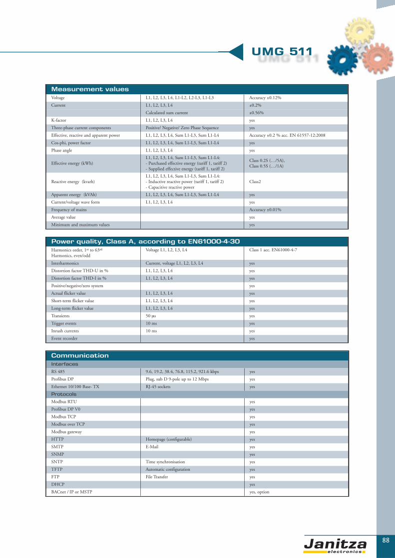
88
▼
UMG 511
Measurement valuesVoltage L1, L2, L3, L4, L1-L2, L2-L3, L1-L3 Accuracy ±0.12%
Current L1, L2, L3, L4 ±0.2%
Calculated sum current ±0.56%
K-factor L1, L2, L3, L4 yes
Three-phase current components Positive/ Negative/ Zero Phase Sequence yes
Effective, reactive and apparent power L1, L2, L3, L4, Sum L1-L3, Sum L1-L4 Accuracy ±0.2 % acc. EN 61557-12:2008
Cos-phi, power factor L1, L2, L3, L4, Sum L1-L3, Sum L1-L4 yes
Phase angle L1, L2, L3, L4 yes
Effective energy (kWh)L1, L2, L3, L4, Sum L1-L3, Sum L1-L4:- Purchased effective energy (tariff 1, tariff 2)- Supplied effective energy (tariff 1, tariff 2)
Class 0.2S (…/5A), Class 0.5S (…/1A)
Reactive energy (kvarh)L1, L2, L3, L4, Sum L1-L3, Sum L1-L4:- Inductive reactive power (tariff 1, tariff 2)- Capacitive reactive power
Class2
Apparent energy (kVAh) L1, L2, L3, L4, Sum L1-L3, Sum L1-L4 yes
Current/voltage wave form L1, L2, L3, L4 yes
Frequency of mains Accuracy ±0.01%
Average value yes
Minimum and maximum values yes
Power quality, Class A, according to EN61000-4-30Harmonics order, 1st to 63rd
Harmonics, even/oddVoltage L1, L2, L3, L4 Class 1 acc. EN61000-4-7
Interharmonics Current, voltage L1, L2, L3, L4 yes
Distortion factor THD-U in % L1, L2, L3, L4 yes
Distortion factor THD-I in % L1, L2, L3, L4 yes
Positive/negative/zero system yes
Actual flicker value L1, L2, L3, L4 yes
Short-term flicker value L1, L2, L3, L4 yes
Long-term flicker value L1, L2, L3, L4 yes
Transients 50 μs yes
Trigger events 10 ms yes
Inrush currents 10 ms yes
Event recorder yes
CommunicationInterfaces
RS 485 9.6, 19.2, 38.4, 76.8, 115.2, 921.6 kbps yes
Profibus DP Plug, sub D 9-pole up to 12 Mbps yes
Ethernet 10/100 Base- TX RJ-45 sockets yes
Protocols
Modbus RTU yes
Profibus DP V0 yes
Modbus TCP yes
Modbus over TCP yes
Modbus gateway yes
HTTP Homepage (configurable) yes
SMTP E-Mail yes
SNMP yes
SNTP Time synchronisation yes
TFTP Automatic configuration yes
FTP File Transfer yes
DHCP yes
BACnet / IP or MSTP yes, option

89
Power Management
An overview of DIN rail kWh-meters
▼
Electronic pulse output – energy meter, EM-series
- Modbus, M-Bus, EIB-KNX - communication module- 2 tariffs- 4 quadrant measurement- With and without MID (Measuring Instruments Directive)- Up to 125A direct measurement
Peak demand management systems UMG 507Emax
- For limiting peak loads- Up to 32 load shedding stages- Including UMG 507 power analyser with continuous measurement- RS232, RS485, Modbus, Ethernet (optional Profibus)
Data logger ProData®
- Collection and storage of counter values, operational statuses and process data
- 16 digital inputs- 64 bit counter- 128 programmable comparators- RS232, RS485, modem, LON, Modbus, Modbus-master
▼
Page 93
Page 97
Page 100
Page 106
Page 91
Electronic pulse output – energy meter, H-series
- Direct measurement or with current transformer- SO interface pulse output- Mounting on 35mm DIN rail- 7 digit LCD display- Calibrated/non-calibrated
Chapter 3

▼
PM
- P
ow
er
Ma
na
ge
me
nt
90
PM - Power Management
Professional energy management considers aspects such as peak demand management, energy data
collection and cost centre management. With the UMG 507Emax and ProData® product groups
and state-of-the-art pulse output energy meters, the energy supply for your company can be actively
controlled with regard to power peaks and energy consumption.
The electricity consumption and electricity costs can,
therefore, be sustainably reduced. The ProData®
series enables you to have a transparent invoicing
system within the company and monitor the
individual cost centres with separate invoicing.
This improvement to cost transparency enables
the respective allocation to cost centres. This is
especially important for accurate determination
of the costs for your products and services
and for transferring electricity costs to
your end consumers.

91
An overview of energy meters
▼▼
Internet
UMG 604
UMG 103 EM1-80 EM3-5 EM3-125
Ethernet TCP/IP
Mo
db
us
RTU
UMG 507 Emax
Central building control system
BACnet LON
Mo
db
us
RTU
Mo
db
us
M-B
us
EIB
-KN
X
PCISDN router
P i
n kW
Load course during the dayPower savings Target value
ProData®
WH6165 DVH3113 MDVH3106
Chapter 3

92
Electronic energy meter with pulse output
Electronic energy meters are measuring instruments which are used to determine energy consumption
of electrical loads. The meters can either be used for direct connection or for current transformer
measurements. Typical areas of application are in the field of energy management for cost centre
analysis, as a measurement value generator for PLC controls or in central building control systems.
Electronic meters should be calibrated and sealed for invoicing purposes in order to guarantee conti -
n uous accuracy and to protect the meter from misuse or unintended reprogramming.
PM
- P
ow
er
Ma
na
ge
me
nt
Electronic energy meters

93
The EM series energy meter
Areas of application
Electronic energy meters are mainly used for collecting data ofeffective and reactive energy consumption. Their standard area ofapplication is in the field of energy management for cost centreanalysis. There are various communication possibilities available inorder to avoid time-consuming manual readings at site. The effec-tive pulses can be connected via two impulse outputs e.g. DDC,PLC, SCADA systems or the data logger ProData®. In the area ofcentral building control systems the protocols M-Bus, EIB-KNXand Modbus RTU are available through additional communica -tion modules which read the actual meters using an optical inter-face and which provide the respective value on the field busthrough the interface. The selection of additional values such asvoltage, current, power, power factor and frequency together witheffective and reactive energy are available on the bus cable throughthe communication modules. For consumption data collection, theEM meters can also be used as instruments for sub-metering for theUMG604 through Modbus RTU.
Applications
The electronic energy meters of the EM series are suitable for themeasurement of effective- and reactive-energy consumption.Measurement is laid out for a 1- and 3- phase system with a voltageof L-N 184-276VAC. The current inputs are designed for directconnection or for measurement through current transformers.Installation is undertaken on DIN-rails, whereby the extremely
▼▼
compact construction is of particular value. There are two versionsavailable: a non-calibrated version and a calibrated version (MID).All meters in the EM series can be sealed. The effective and reactiveenergy is available in two tariffs and in four quadrants. The accu-racy of the meters is class 1 for effective energy and class 2 for reac-tive energy.
Main features
� Communication modules: Modbus, M-Bus, EIB-KNX� Direct measurement up to 125A or through current transformer� 2 tariffs� With and without MID calibration� Sealed clamp covers
� Four quadrants measurement� Measurement values: effective energy,
reactive energy, effective power, reactive power� Class 1
Data collection and recording
All meters store the counter values in non-volatile memories. The meter reading cannot be reset in the calibrated version. In the non-calibrated version the readings can be reset. The current transformer ratio is fixed (5:5) for calibrated meters.
Chapter 3

94
▼
Measurement rangeVoltage L-N 184…276VAC 184…276VAC 184…276VAC 184…276VAC
Voltage L-L - 319…478VAC 319…478VAC 319…478VAC
Current 0.025…80A 0.025…80A 0.12…125A 0.05…6A (…/5A)
Frequency, mains 50Hz 50Hz 50Hz 50Hz
Measurement 1-phase 3-phase 3-phase 3-phase
Measurement mode Direct Direct Direct CTs
General technical dataOperating voltage 184…276VAC 184…276VAC 184…276VAC 184…276VAC
Dimensions [mm] W= 36x H= 90x D=70 W= 72 x H= 90 x D= 70 W= 108 x H= 90 x D= 70 W= 72 x H= 90 x D= 70
Width in units 2 4 6 4
Working temperature -10…+55°C -10…+55°C -10…+55°C -10…+55°C
Storage temperature -25…+70°C -25…+70°C -25…+70°C -25…+70°C
Protection class (front/clamps) IP 51/20 IP 51/20 IP51/20 IP51/20
Max connectable conductorsCurrent 35mm2
Voltage 2.5mm2Current 35mm2
Voltage 2.5mm2Current 50mm2
Voltage 2.5mm2Current 6mm2
Voltage 2.5mm2
Measurement valueEffective energy Class 1 Class 1 Class 1 Class 1
Reactive energy Class 2 Class 2 Class 2 Class 2
4 quadrants Yes Yes Yes Yes
2 tariffs Yes Yes Yes Yes
Effective-, reactive-power display
Yes Yes Yes Yes
PeripheryPulse outputs 2 2 2 2
Pulse value 10 Imp/kWh 10 Imp/kWh 10 Imp/kWh 1/10/100 Imp/kWh
Pulse length 100 ± 5ms 100 ± 5ms 100 ± 5ms 100 ± 5ms
Digital input 1 1 1 1
Optional communication modulesModbus RTU / ASCII Baud rate: up to 115kBaud
Types:
Modbus RTU / ASCII (Basic) Applicable parameters: Wh, kvarh Item number: 14.01.400
Modbus RTU / ASCII (Full) Applicable parameters: Wh, kvarh, V, A, Hz, cosphi, kW, kvar Item number: 14.01.410
M-Bus Baud rate: 300…9600Baud
Types:
M-Bus (Basic) Applicable parameters: Wh, kvarh Item number: 14.01.401
M-Bus (Full) Applicable parameters: Wh, kvarh, V, A, Hz, cosphi, kW, kvar Item number: 14.01.411
EIB-KNX Baud rate: 9600Baud
Types:
EIB-KNX (Basic) Applicable parameters: Wh, kvarh Item number: 14.01.402
Overview of product variants
Types EM1-80 EM3-80 EM3-125 EM3-5without MID EM1-80 (without MID) EM3-80 (without MID) EM3-125 (without MID) EM3-5 (without MID)
Item number 14.01.301 14.01.320 14.01.330 14.01.310
with MID EM1-80 (MID) EM3-80 (MID) EM3-125 (MID) EM3-5 (MID)
Item number 14.01.302 14.01.321 14.01.331 14.01.311
Product variants and
technical data
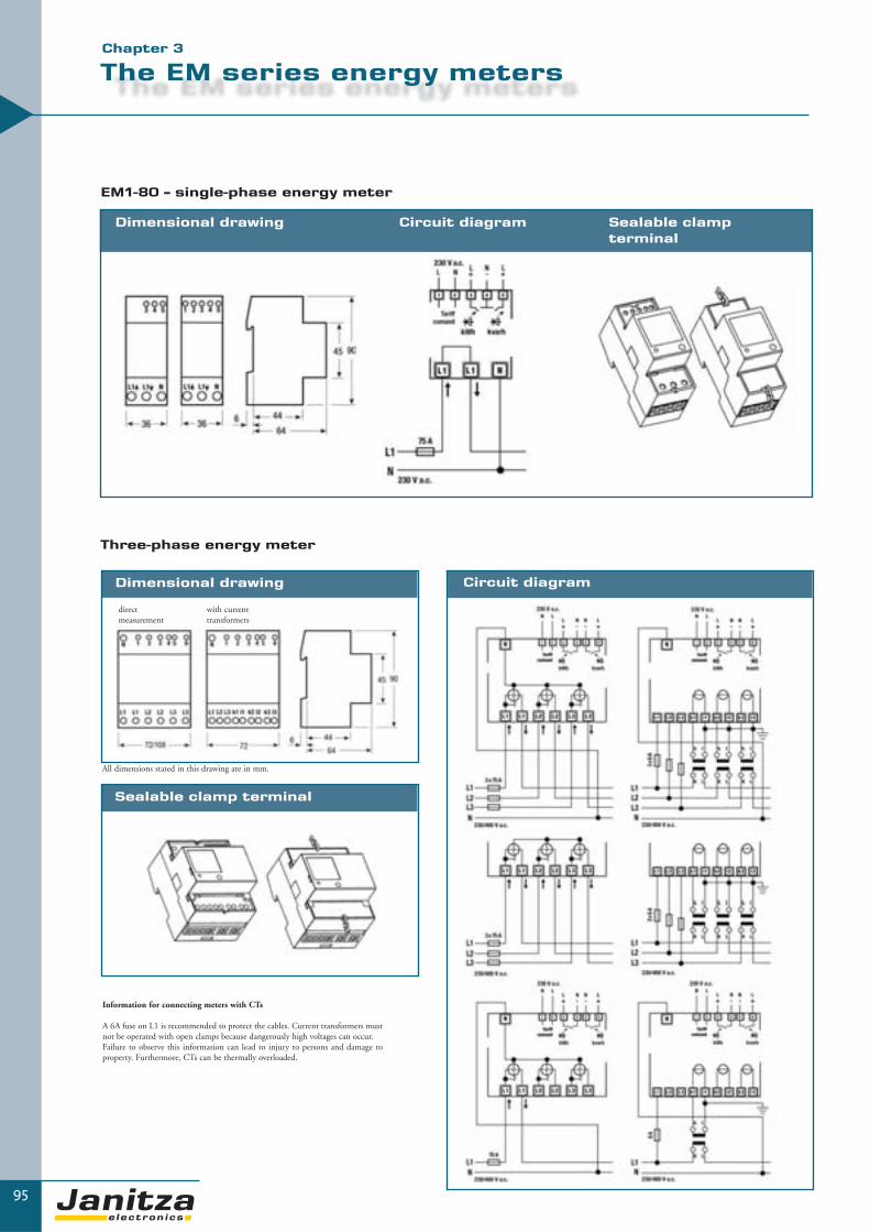
Sealable clamp terminal
95
The EM series energy meters
▼
EM1-80 – single-phase energy meter
Three-phase energy meter
Dimensional drawing
Circuit diagram
Circuit diagram Sealable clamp terminal
Dimensional drawing
Information for connecting meters with CTs
A 6A fuse on L1 is recommended to protect the cables. Current transformers mustnot be operated with open clamps because dangerously high voltages can occur.Failure to observe this information can lead to injury to persons and damage toproperty. Furthermore, CTs can be thermally overloaded.
All dimensions stated in this drawing are in mm.
direct measurement
with current transformers
Chapter 3
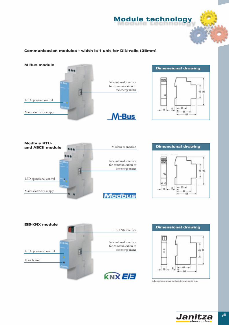
96
Communication modules – width is 1 unit for DIN-rails (35mm)
LED operation control
Mains electricity supply
Side infrared interface for communication to
the energy meter
LED operational control
Mains electricity supply
Side infrared interface for communication to
the energy meter
Modbus connection
M-Bus module
Modbus RTU- and ASCII module
Reset button
LED operational control
Side infrared interface for communication to
the energy meter
EIB-KNX interface
Dimensional drawing
Dimensional drawing
Dimensional drawingEIB-KNX module
Module technology
All dimensions stated in these drawings are in mm.

97
The H series electronic energy meters
Areas of application
Electrical energy meters are used to collect effective energy data.Their standard area of application is in the field of energy manage-ment for cost centre analysis. A pulse output is available in order toavoid time-consuming manual readings on site. The effective pulses can be connected via pulse output to e.g.DDC, PLC, SCADA systems or the data collection instrumentProData®.
Applications
The electronic energy meters of the H series are suitable for the measurement of effective energy. Measurement is laid out for a 1-and 3-phase system with a voltage of L-N 207-253VAC. The cur-rent inputs are designed for direct connection or for measurementthrough a current transformer. The meter is installed on a DIN-rail. The accuracy level of the meter is class 1.
Main features
� Direct measurement up to 65A or through a current transformer� Class 1� S0 interface pulse output� Installation on 35mm DIN rail� 7 digit LCD display
▼▼
Data collection and display
All meters store the energy values in non-volatile memories.
The diagram on the right side shows the call-up possibilities for thevarious data.
“In operation” mode
Display test – all segments activated
Current transformerratio (only for CTmeters)
Current energy value
= Briefly flashes on and offwith an external light
Chapter 3

98
▼
General technical data
WH6165 DVH3113 MDVH3106Operating voltage 207…253VAC 207…253VAC 207…253VAC
Dimensions [mm] W= 36 x H= 106 x D= 61,1 W= 125 x H= 96 x D= 66 W= 125 x H= 96 x D= 66
Width in units 2 7 7
Working temperature -20…+55°C -20…+55°C -20…+55°C
Storage temperature -25…+70°C -25…+70°C -25…+70°C
Protection class (front/clamps) IP51/20 IP51/20 IP51/20
Weight 140g 500g 500g
Max connectable conductors Current: 16 mm2, voltage: 2.5mm2 Current: 25 mm2, voltage: 2.5mm2 Current: 10 mm2, voltage: 2.5mm2
Certification Option Option Option
Measurement value
WH6165 DVH3113 MDVH3106Effective energy Class 1 Class 1 Class 1
Overview of product variants
WH6165 DVH3113 MDVH3106Item number (non-calibrated instrument)
14.01.020 14.01.021 14.01.022
Item number (calibrated instrument)
14.01.023 14.01.024 14.01.025
Periphery
WH6165 DVH3113 MDVH3106Pulse output 1 1 1
Pulse value 1000 pulses/kWh 500 pulses/kWh 5000 pulses/kWh
Pulse length Min. 30ms Min. 30ms Min. 30ms
Measurement range
WH6165 DVH3113 MDVH3106Voltage L-N 207…253VAC 207…253VAC 207…253VAC
Voltage L-L - 358…438VAC 358…438VAC
Current 0…65A 0…65A 0…5A
Frequency, mains 50/60Hz 50/60Hz 50/60Hz
Measurement 1-phase 3-phase 3-phase
Measurement mode Direct Direct CTs
Product variants and
technical data
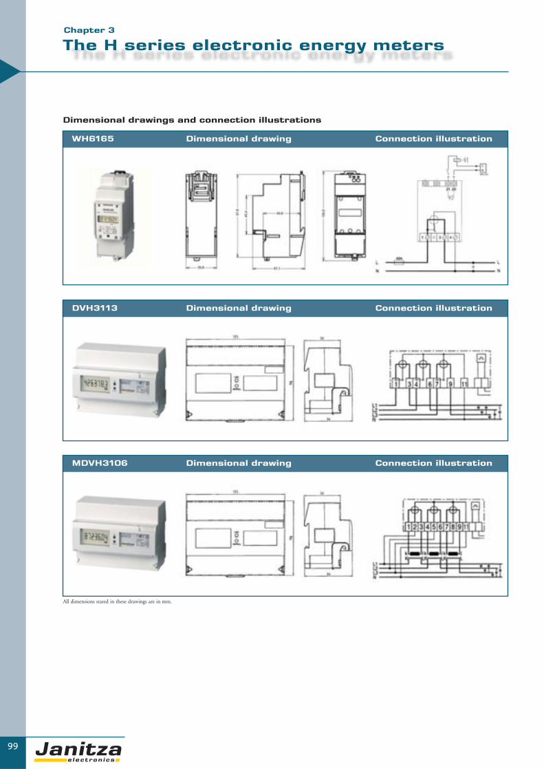
99
The H series electronic energy meters
Dimensional drawings and connection illustrations
WH6165 Dimensional drawing Connection illustration
DVH3113 Dimensional drawing Connection illustration
MDVH3106 Dimensional drawing Connection illustration
▼Chapter 3
All dimensions stated in these drawings are in mm.

UMG 507Emaxpeak demand management systems
Energy consumption varies significantly over a 24 hour cycle period. This leads to massive strains onproduction and distribution systems and also causes expensive peak load coverage e.g. pumped storage power plants. In order to balance out these effective power peaks, the energy suppliers haveintroduced corresponding demand price tariffs. According to the tariffs offered by power companies,the highest measured power peak value within a period of 15 minutes is used to establish the monthlyelectricity costs. Using this peak value, the network allocation costs and the monthly energy price arethen calculated. If this peak value is reduced the electricity costs will also be reduced. Due to per-manently increasing electricity costs in current times, it is necessary to guarantee the optimum adap-tation of load distribution profile to the supply conditions offered by the energy suppliers. The UMG 507Emax peak demand management systems are the solution. The UMG 507Emax reducesthe power of certain loads or switches them off according to customer defined settings.
Areas of application
� Reduction of effective power peaks and, therefore, significant reduction of electricity costs� Avoidance of short-term overloads in energy distribution systems
(e.g. triggers power switches)� Stabilisation of energy supply and production processes� Hotels, canteen kitchens, hospitals, industry, compressors, thermal processes ...
100
PM
- P
ow
er
Ma
na
ge
me
nt
UMG 507Emax

101
The intelligent reduction of power peaks
UMG 507Emax - peak demand management systems
The intelligent reduction of effective power peaks
The UMG 507Emax peak demand management systems continuously collect data of all electrical parameters. The UMG 507Emax is equipped with intelligent algorithms which calculate the effective power trends and compare them with theagreed target for effective power.
Due to the trend calculations, the UMG 507Emax can precisely interact with the operational process and can quickly disconnectany non-critical loads according to information provided by the user. This means that some very expensive power peaks can be safely avoided and significant cost savings can be achieved. Any random power peaks are avoided. And the processes itself are notnegatively influenced.
Main features
� Optimum limitation of effective power peaks� Up to 32 load shedding stages� Includes UMG 507E power analyser with continuous
measurement (also available with other UMG 507) � RS232, RS485, Modbus, Ethernet� Including GridVis software
� Capturing short-term interruptions� Harmonics display, monitoring of short-term
interruptions� With Ethernet and embedded web server� UMG 507Emax6 optional with Profibus
Applications
The UMG 507Emax is a multifunctional instrument which is essential as basic equipment in low voltage main distributionsystems. The maximum effective power is reduced with the peak load manager UMG 507Emax through the short period shutdownof loads. Furthermore, the system also enables time- or event-related switching of loads with the integrated weekly time switch.
The UMG 507E is available as a basic instrument with additional components integrated in compact steel cabinet or as individualcomponent. As a measuring instrument, the UMG 507Emax monitors the loads upon the electrical supply systems in order toavoid overload. The UMG 507E is also designed to measure and store almost all electrical parameters including average currentand power values (refer to catalogue page 68 et seq).
▼
UMG 507Emax peak demand management system- Assembled in a steel housing for wall mounting- Wired ready for connection on terminals- Includes GridVis software and standard programming- Auxiliary voltage: 230 V; 50/60 Hz- Dimensions:
W= 600mm x H= 380mm x D= 210mm - Colour: RAL 7035
Chapter 3

102
Functional principle
The UMG 507Emax determines the necessary parameters for compliance with up to 5 stipulated nominal values in kW based on theeffective power pulses entering the digital input or the overall effective power calculated by the instrument. The instrument continuouslycalculates the average value, actual value, trend value and correction power within the set time period.
If the instrument identifies that the maximum effective power may be exceeded, it checks whether the consumers have to be switchedoff using the preset consumer parameters. The aim of this method is to insignificantly impair the operational process with as few swit-ching processes as possible while still complying with the given nominal demand value.
Depending upon the product variant, there are up to 32 shutdown stages available (change over contact is potential free) for the loadsand two optional analogue Emax channels for the control of generators.
Peak demand management up to 32 load shedding stages / 5 nominal values
Measurement period length:In order to be synchronised with the measurement of the power utility, resetting is undertaken through a digital input of the UMG 507Emax or through an interface. If the instrument is not reset within the programmed measurement period, it is reset automati-cally by the internal clock. When the measurement period is reset, the Emax effective power is deleted and a new measurement periodis started. The last measured maximum effective power is used for storing the minimum and maximum values and, if programmed, isrecorded in the UMG 507Emax memory.
Off-time:This starts at the beginning of the measurement period and avoids brief power peaks at the beginning of the measurement period leading to shut down.
Pause time:This is the time between two switching actions. Because switching actions do not have an immediate effect on the network, the delayedreaction can be regarded with the pause time.
P i
n kW
Load profile over a time period of 24 hours
Power savingsTarget value
Involved loads:Involved loads are given priority for shutdown. Only involved loads are included in the trend value calculation. This means that theEmax program tries to comply with the maximum demand by only using the “involved loads” under consideration of the switchingtimes and load power. If this is not possible, other defined loads are also used for shutdown.
UMG 507Emax

103
The intelligent reduction of power peaks
▼▼
Priority
Each shutdown level can be given priority between 0 and 32. Emax outputs with a priority of 0 are not included inthe trend value calculation undertaken by the Emax program. Emax outputs with a low priority (e.g. 1) are shutdown first and are last to be switched on again.
Connection load
In order to be able to determine the time of shut down more accurately, the nominal load power of the connectedload must be programmed for each Emax output. The switching times allocated to each Emax output are compliedwith on priority.
Minimum connection time
This determines how long a load must remain switched on between two switching actions.
Minimum disconnection time
This determines how long a load must remain switched off after shutdown.
Maximum disconnection time
This determines how long a load may remain switched off after shutdown.
Availability
The availability of a load can be set as a percentage value.
Illustration: Emax programming using GridVis software
Chapter 3

104
UMG 507Emax
▼
UMG 507Emax product variants
256k
RA
M m
emor
y
16M
B f
lash
add
itio
nal m
emor
y
6 di
gita
l inp
uts
Shut
dow
n st
ages
Con
tact
typ
e, 1
A c
hang
e ov
er
1 te
mpe
ratu
re in
put
1 an
alog
ue in
put
2 pa
ssiv
e an
alog
ue o
utpu
ts
RS
232
RS
485
Eth
erne
t 10
base
T
Prof
ibus
DP
V0
Inte
grat
ed w
eekl
y ti
me
swit
ch
Type
Item
num
ber
� � � 6 � � � � � � � � � UMG 507MAX6 52.15.217
� � � 16 � � � � � � � - � UMG 507MAX16 52.15.222
� � � 32 � � � � � � � - � UMG 507MAX32 52.15.232
Interfaces
� = Option � = Included
More functions and technical data – refer to UMG 507 in the energy measurement technology chapter.The UMG 507E is integrated in the above variants as a basic control unit.
Typical connection

105
Technical data
▼
Measurement rangeVoltage L-N, AC (without voltage transformer) 50…500VAC
Voltage L-L, AC (without voltage transformer) 80…870VAC
Current (transformer: x/1 and x/5 A) 0.02...6A
Frequency, mains 45…65Hz
Grid types TN, TT, (IT)
Measurement in 1-phase / multiphase networks 1ph, 2ph, 3 ph
General technical dataSupply voltage L-N, AC 230V, 50/60Hz
Overvoltage category 600V CAT III
Operational voltage 400V, 50/60Hz
Weight (6/12/32 stages) 18/19/20kg
Dimensions W= 600mm x H=380mm x D=210mm
Mounting Wall mounting
Working temperature range -10…55 °C
Protection class IP 43
Colour RAL 7035
Software GridVis
Shutdown stages 6/16/32
CommunicationInterfaces
RS 232 38.4 kbps Yes, refer to order details
RS 485 9.6, 38.4, 115.2 kbps Yes, refer to order details
Profibus DP 9.6kbps up to 1.5Mbps, SUB D 9-pole Optional for UMG 507MAX6
Ethernet 10 Base-T RJ45 Yes
Protocols
Modbus RTU Yes
Profibus DP V0 Option
TCP/IP Yes
Measurement values
VoltageL1, L2, L3L1-L2, L2-L3, L1-L3
Accuracy: ± 0,2% rngAccuracy: ± 0,2% rng
CurrentL1, L2, L3N (calculated)
Accuracy: ± 0,2% rngAccuracy: ± 0,6% rng
Effective, apparent or reactive power L1, L2, L3, Sum L1-L3 Accuracy: ± 0,5% rng
cosphi L1, L2, L3, Sum L1-L3 Accuracy: ± 0,5% rng
Effective energy (kWh) purchase/supply Sum L1-L3 Class 1 (.../5A), Class 2 (.../1A)
Reactive energy (karh), inductive/capacitive Sum L1-L3 Class 2
Apparent energy (kVAh) Class 2
Mains frequency Accuracy: ± 0,2% rdg
K-factor L1, L2, L3 Yes
Average value Yes
Minimum and maximum values Yes
Power qualityHarmonics, 1st to 15th harmonics, odd Current, voltage L1, L2, L3 Accuracy: ± 0,5% rng
Distortion factor THD-U in % L1, L2, L3 Accuracy: ± 0,5% rng
Distortion factor THD-I in % L1, L2, L3 Accuracy: ± 0,5% rng
Voltage pos./neg./zero system Accuracy: ± 0,5% rng
Short-term interruptions 10ms Yes
Initialisation current 10ms Yes
Limit value event recorder Yes
Chapter 3

ProData® data loggerData collection and recording
ProData® data loggers are used for the collection of any physical measurement data (temperature,pressure, operating period...) or any consumption values (electricity, water, gas, coolant...). ProData®
data loggers consist of a programmable microprocessor, storage media, several interfaces and 16 chan-nels for connecting sensors or pulse generators. External sensors are used to collect the measurementdata and convert it with analogue-digital converters into “memory-safe” data in order to be able tobe stored by the ProData® storage media. The collected data is read out through an interface and isanalysed with suitable software. The ProData® can also be configured for the application throughone of these interfaces (e.g. start and stop time for measurement, measurement intervals etc). Dataloggers are indispensable for energy management systems e.g. for cost centre management. ProData®
data loggers are also indispensable in the field of status monitoring e.g. number of switching cyclesof circuit breakers or operating times for equipment which requires intensive maintenance.
Areas of application
� Data collection and recording of meter values and operational conditions� Electricity cost data collection and cost centre management� Analysis of process data� Remote monitoring� Condition monitoring� Alarm signal when a meter reading or condition is reached
106
ProData®
PM
- P
ow
er
Ma
na
ge
me
nt

107
Data collection instrument
ProData® data logger
The ProData® data logger is suitable for collecting data and recor-ding meter values, operating conditions and process data. The datacan be used for analysing energy consumption, operating hours orfor monitoring switch conditions and faults in buildings and companies etc. The alarm for faults or limit value violations takesplace through the relay outputs, the analogue modem or field bus.
Main features
� The collection and recording of meter values, operating conditions and process data
� 16 digital inputs� 64 bit counter� 128 programmable comparators� RS232, RS485, modem, LON, Modbus or Modbus-master� 1 analogue input� 1 temperature input� 2 relay outputs� Including GridVis software
Data recording
The analogue measurement values can be recorded in set time intervals (1 sec ...12h) as minimum, average and maximum values. In theset time intervals (1 sec ...12h), the difference between the overall meter readings and the meter reading at the last recording time is shown.Condition changes to the inputs can be provided with a time stamp (1 sec resolution) and collected. Various internal events (e.g. failure andreturn of the electricity supply) are registered. Condition changes to the programmable limit values/alarm triggers can be recorded as anevent with a time stamp. All recorded values and events are recorded in a ring buffer. This consists of 430KB and is sufficient for 3 monthsif the digital counters are recorded every 15 minutes.
UMG 96 UMG 96
PT100
UMG 96 UMG 96
S0-Output
LiYcY 4x0,5Maximal 100m
PSTN
S0-Output
Solar intensity measurement
S0-Output S0-Output
▼▼
Application example –photovoltaic
Chapter 3

Analogue inputs
� 1 analogue input 0 (4) – 20mA, -20/20mA programmable� 1 input for temperature sensor: PT100, PT200, PT500, PT1000, NTC10k or KTY83
The measurement values can be read through Modbus. The temperature measurement value and the scaled 20mA measurement values areavailable through LON.
Relay outputs
� 2 internal relay outputs (change over contact)� 31 decentralised relay outputs (optional)
The relay outputs can be used as: Threshold monitoring, alarm contact and annual time switch. The ProData® can handle inModbus-master operation up to 31 de-centralized outputs.
Digital inputs
16 digital inputs can be used as:� An overall pulse counter at each input – maximum frequency 50Hz, 64 bit counter� Pulse meter with automatic resetting in set time intervals between 1 sec and 12 hours or
external synchronisation with automatically saved meter reading at the last reset� Collection of all switch-on and shutdown times for each input e.g. operating hour
meter/service intervals. Resolution: 1 sec, maximum time >100 years� Monitoring function for switch-on and shutdown times� Frequency measurement on each input for monitoring flow quantities, power etc.
The stated measurement values can be read through the Modbus. The overall meter readings are available as 32 bit values throughLON. The digital inputs (4x4) can be set as pulse (S0 interface) or as signal inputs using jumpers.
Threshold comparator
The ProData® has 128 programmable comparators. These compare the input value with the upper and lower thresholds (with hysteresis)and check whether the value is within or beyond of the two threshold levels. The result can be linked to another comparator resultusing a logical link (AND, OR, NOT). Various actions can be taken depending upon the result. Switch-on and shutdown delays canbe programmed separately.
Every internal available measurement value or register contents can be used as an input value for a comparator. In the Modbus-masteroperation, a measurement value or register of a slave unit can be read and used as an input value.
The following actions are possible:� Switch on or switch off relay output or LED � Switch on relay output or LED for a programmable time� Set internal status marker � Write the comparator result in a register of a Modbus slave� Record event in the ring buffer � Alarm through an analogue modem, text message through a GSM modem
The internal status flags (4 pcs) can be read out through LON. The relays and LEDs can be switched through LON as well.
108
ProData®
▼

109
Application options
▼
Typical application
Dimensional drawing
Modbus
LON
GSMmodemRS232
Relay outputs
Process signal 0 (4) - 20mAPT 100/200/500/1000Temperature monitoring
Gas consumption
Effective/reactive energy consumption
Effective energyconsumption
Water consumption
Compressedair/steam
Modbus-master
The RS485 interface can be switched in the mastermode. In this mode, the ProData® registers fromother Modbus units can be read (e.g. additionalProData® or UMG 503). The ProData® can alsowrite the results of the programmable comparatorsin the registers of other units.For example, this means that the number of relayoutputs can be increased by connecting a correspon-ding module to the Modbus as a slave. In theModbus-master mode, Modbus telegrams whichenter the RS232 interface and are not intended forthe ProData® are transferred to the connected slaveson the RS485 bus.
Chapter 3

110
▼
Measurement rangeEffective energy (kWh) purchase/supply Through the pulse input Yes
Reactive energy (Karh), inductive/capacitive Through the pulse input Yes
Apparent energy Through the pulse input Yes
Temperature measurement input -150…400°C Accuracy: ± 1°C
Analogue input -20…20mA Accuracy: ± 0.3mA
PeripheryDigital inputs As status or pulse input 16 (max. 50Hz, 64 bit counter)
Relay outputs As switch output, change over 2 (2A, 250VAC)
Temperature measurement input Pt100, Pt200, Pt500, Pt1000, NTC10k, KTY83 1
Analogue input -20…20mA, scaleable 1
Software GridVis Yes
CommunicationInterfaces
RS 232 9.6, 19.2, 38.4, 115.2 kbps Yes
RS 485 9.6, 19.2, 38.4, 115.2 kbps Yes
LON FTT-10A Yes
Protocols
Modbus RTU Yes
LonTalk Yes
FeaturesConsumption data collection
Memory size 430kB
Clock ± 1 minute per month
Integrated logic 128 programmable comparators Yes
Event recording Yes
General technical dataSupply voltage External power supply is necessary 24VDC (+15/-35%)
Overvoltage category CAT II
Weight 660g
Dimensions W=174mm x H=110mm x D=57mm
Mounting DIN rail
Working temperature -10…55 °C
Storage temperature -20…60°C
Protection class According EN60529 IP 20
Overview of product variants
Description Type Item number
Data logger ProData® 52.11.001
External power supply 24VDC 16.05.002
ProData®

111
Power Quality Solutions
Prophi ® power factor controller
- Power factor controller for use in conventional and dynamic (fast switching) PFC systems
- Hybrid switching (conventional and dynamic PFC are mixed)- Protocols: Profibus DP V0 + Modbus (RTU) slave
▼
PFC-Power capacitors
- Can-type capacitors in aluminium housing- Square capacitors in steel housing- De-tuned power capacitors in steel cabinet
Power factor correction (without reactors)
For power factor correction (PFC) in low voltage networkswith a low amount of non-linear loads, i.e. low harmonicdistortion.
De-tuned power factor correction, passive harmonic filters
- Passive harmonic filters (de-tuned reactive power compensation, tuned filters)
Dynamic (fast switching) power factor correction
Switching times of approx. 20-30 milliseconds can be achieved with dynamicreactive power compensation systems. Reactive power compensation can beachieved in real time together with the highly dynamic power factor control-ler Prophi®-T
- Drawer modules for integration in existing switch boards- Dynamic power factor correction (without reactors)- De-tuned dynamic power factor correction (dynamic harmonic filter)
▼
Page 120
Page 124
Page 130
Page 138
Page 114
Chapter 4

▼
PQ
S -
Po
we
r Q
ua
lity
So
luti
on
s
112
PQS - Power Quality SolutionsPower quality
Power quality and supply reliability are extremely important in the modern world of business. Highly
sensitive equipment and working processes are heavily dependant upon precisely defined power qua-
lity. On the other hand, the number of electrical and
electronic consumers with system perturbations is
increasing which means that the networks are
becoming more polluted. Janitza electronics®
offers systems for the improvement of power
quality and the necessary expertise for implemen-
tation. You, therefore, improve your power quality,
save electricity, stabilise your processes, avoid
production interruptions and reduce
maintenance costs.
� Electricity cost savings� Reduction of reactive power
consumption� Saving of CO2 emissions� Reduction of voltage drops� Avoidance of transients� Compensation of rapidly changing loads� Filtering of harmonics

113
Introduction and customer benefits from PFC
▼▼
What is reactive power?
Reactive power is necessary for the generation of electromagnetic fields. Because these fields continuously develop and reduce,the reactive power fluctuates between producers and users. In contrast to active power, reactive power cannot be used i.e. can-not be converted into another form of energy and strain the electricity supply network and the production equipment (gene-rators and transformers). Furthermore, all energy distribution systems must be constructed larger for the allocation of reactivecurrents.
It is, therefore, necessary to reduce the same amount of occurring inductive reactive power near to the consumer with a capaci-tive reactive power. This process is called compensation. During compensation, the ratio of reactive power in the network redu-ces by the reactive power of the power capacitor or the PFC system. The energy generation systems and the energy transmissionsystems are, therefore, discharged from reactive currents.
What can be done to combat reactive power?
Energy supply companies invoice the reactive consumption whereby significantly increased costs usually occur. Reactive powercompensation systems reduce the high costs for extra reactive consumption and offer the following additional advantages:
� Reduced electricity invoices through lower reactive power costs
� Reduced I2R losses which means lower kWh consumption
� Discharge of transformers, cables and supply systems
� Increased lifespan of electrical distribution systems
� Active environment protection through the reduction of CO2 emissions
� Improved utilization of networks i.e. additional loads (kWh) can be connected
� Voltage stabilisation (reduced apparent current reduces the voltage drops)
In power factor correction systemsthe reactive current and the corres -ponding reactive power drawn byloads will be compensated by themeans of PFC capacitors.
Chapter 4

▼
Optimised control for long PFC system lifespan
The Prophi® power factor controller has an optimised control mode. The implemented controlalgorithms reduces the number of switching cycles as well as the operating time per capacitor stage.
The aim is to have the same number of switching cycles and, if possible, the same operating timeper capacitor stage. In addition, the number of switching cycles is reduced by up to 80%.
The lifespan of the entire system can be significantly increased through even loading of all stages withan automatically regulated PFC system. This means that invested capital earns money for a longertime period and that new investments can be avoided.
The hybrid switching (i.e. the combination of capacitor contactors and dynamic thyristor modulesfor contact-free rapid switching of capacitors) combines the advantages of rapid switching withoutnetwork perturbation with the cost advantages of common PFC systems.
114
PQ
S -
Po
we
r Q
ua
lity
So
luti
on
s
Prophi®
power factor controller

115
Prophi® power factor controller
Applications
PFC systems are used to discharge unnecessarily overloaded supp-ly systems through inductive reactive power and to save reactiveconsumption costs. The reactive power controller is the main partof a PFC system and automatically switches capacitors steps on oroff. The Prophi® power factor controller is suitable for use in con-ventional and dynamic PFC systems. A mixed operation (hybridswitching) is possible as well.
Functional principle
The single-phase electronic measuring system collects the reactive and effective current ratios of the network through the current and voltage measurement. Using the current from one phase and the voltage from the other two phases, the reactive power controller calculates the necessary reactive power to achieve the set target power factor. The capacitor steps are switched on or off if any differencesoccur and the reactive power controller differentiates between the switching of capacitors through contactors or thyristors. The controlthrough capacitor contactors is optimised; this means that the reactive power factor controller achieves the cos-phi target with a minimumof switching actions. The transistor outputs control the semiconductor switches for almost immediate compensation of any differences.
▼▼
Illustration: Reverse of Prophi® 12RS
Features
� Automatic configuration� Display of U, I, f, Q, P, S, cos-phi, uneven current
and voltage harmonics, 1-19th� Display of capacitor currents� Display of switching cycles per capacitor step� Display of capacitor step connection time� Zero voltage release within 15ms� Detuning degree in % is programmable for each
step from 0-20%� Setting of discharging time for all capacitor steps
from 0-1200 secs� Capacitor power can be individually programmed� Temperature sensor for ventilator control� Excess temperature shutdown can be programmed� Control of external semiconductors
(max. 50 switch actions per second)� Current transformer input for ../1A and ../5A� Automatic or manual configuration� Password protection� External target cos-phi changeover
Alarm output is programmable for:
� Under-voltage recognition� Over voltage recognition� Under-compensation � Measurement current exceeding� Harmonic limit value� Supply of effective power� Excess temperature
Chapter 4

Excess temperature shutdown
Connected capacitor steps can be disconnected with the excess temperature shutdown func-tion in order to reduce the temperature inside the PFC-system cabinet and to protect thecapacitors. The upper/lower limit temperature and pause time can be set by the user.
Upper limit temperature
LCD display
The Prophi® power factor controller has a high-quality LCD display with high contrast. Extensive measurement parameters (approx.100 measurement values) can be displayed via LCD.
116
▼
Interface
The Prophi® power factor controller is equipped with a RS485 interface depending upon the product variant. The Modbus RTU orProfibus DPV0 protocols are available through the RS485 in order to interconnect the Prophi® or connect it to PLC systems.
Communication speed: Modbus: 9.6, 19.2, 38.4, 57.6, 115.2 kBit/s Profibus: up to 1.5 MBit/s
Ventilator control
Simple ventilator controls can be developed with the temperature sensor which is built into the Prophi® and a ventilator. A relay outputor the alarm relay is used for controlling the ventilators. The upper/lower temperature limit can be programmed for this feature.
Automatic configuration
The “LEARN” function offers the opportunity to learn the connection configuration of the power factor controller and save it.
Display examples: voltage reactive power harmonics
Illustration: RS485 interface terminal configuration
Prophi®
power factor controller
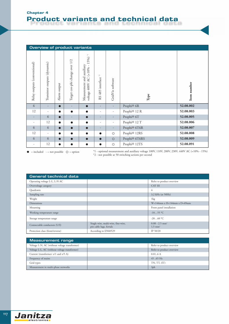
Measurement rangeVoltage L-N, AC (without voltage transformer) Refer to product overview
Voltage L-L, AC (without voltage transformer) Refer to product overview
Current (transformer: x/1 and x/5 A) 0.01..6 A
Frequency of mains 45 ..65 Hz
Grid types TN, TT, (IT)
Measurement in multi-phase networks 3ph
General technical dataOperating voltage L-L, L-N AC Refer to product overview
Overvoltage category CAT III
Quadrants 4
Sampling rate 3,2 kHz (at 50Hz)
Weight 1kg
Dimensions W=144mm x H=144mm x D=49mm
Mounting Front panel installation
Working temperature range -10…55 °C
Storage temperature range -20…60 °C
Connectable conductors (U/I)Single wire, multi-wire, fine-wire, pin cable lugs, ferrule
0.08 - 2.5 mm2
1,5 mm2
Protection class (front/reverse) According to EN60529 IP 50/20
117
Overview of product variants
Rel
ay o
utpu
ts (
conv
enti
onal
)
Tran
sist
or o
utpu
ts (
dyna
mic
)
Ala
rm o
utpu
t
Targ
et c
os-p
hi c
hang
e ov
er 1
/2
Mea
sure
men
t an
d au
xilia
ry
volta
ge 4
00V
AC
(+1
0% -
15%
) *1
RS
485
inte
rfac
e *2
Gri
dVis
sof
twar
e
Type
Item
num
ber
6 - � - � - - Prophi® 6R 52.08.002
12 - � � � - - Prophi® 12 R 52.08.003
- 6 � - � - - Prophi® 6T 52.08.005
- 12 � � � - - Prophi® 12 T 52.08.006
6 6 � � � - - Prophi® 6T6R 52.08.007
12 - � � � � � Prophi® 12RS 52.08.008
6 6 � � � � � Prophi® 6T6RS 52.08.009
- 12 � � � � � Prophi® 12TS 52.08.091
� = included - = not possible � = option *1 - optional measurement and auxiliary voltage 100V, 110V, 200V, 230V, 440V AC (+10% - 15%)*2 - not possible at 50 switching actions per second
Product variants and technical data
▼
▼
Chapter 4

Power qualityHarmonics 1st to 19th, uneven Current, voltage 1-phase Accuracy: ± 2% rdg
Distortion factor THD-U in % 1-phase Yes
Distortion factor THD-I in % 1-phase Yes
118
Measurement valuesVoltage 1 phase L-N or L-L Accuracy: ± 0.5% rdg
Current 1 phase Accuracy: ± 0.5% rdg
Effective, apparent and reactive power Sum L1-L3 Accuracy: ± 1% rdg
cosphi Sum L1-L3 Accuracy: ± 1% rdg
Frequency of mains Accuracy: ± 0.5% rdg
Minimum and maximum values Yes
PeripheryRelay outputs As switch output 6 or 12, refer to product overview
Transistor outputs As switch output 6 or 12, refer to product overview
Alarm output As status output 1
Digital input For tariff change over 1, refer to product overview
Temperature sensor Internal 1
Software GridVis Yes
CommunicationInterfaces
RS 485 9.6, 19.2, 38.4, 57.6, 115.2 kbps Yes, refer to product overview
Profibus DP V0 9.6kbps to 1.5Mbps Yes, refer to product overview
Protocols
Modbus RTU Yes, refer to product overview
Profibus DP V0 Yes, refer to product overview
FeaturesCapacitor current Yes
Capacitor opertion time Yes
No. of switching per step Yes
Zero voltage release Yes
Automatic configuration Yes
Password protection Yes
Prophi®
power factor controller

119
Amount of functions and technical data
▼
▼
Dimensional drawing (all dimensions in mm)
Typical connection
Illustration: connection example - Prophi® power factor controller 12 RS (item no. 52.08.008) with L2-L3 voltagemeasurement, 12 relay outputs, target cos-phi changeover, alarm output and RS485 interface.
Illustration: Prophi® 12 RS– reverse side
Connection illustration
Chapter 4

120
Highest safety and long lifespan with dry technology
PFC-Power capacitors for power factor correction allow the configuration of fixed capacitors, automa-
tic PFC systems and harmonic filters for all requirements.
Our capacitors are designed with dry technology due to safety reasons. All capacitors are designed accor-
ding to the international valid standards EN60831-1 and -2 and production is are monitored in
accordance with our quality management system.
PQ
S -
Po
we
r Q
ua
lity
So
luti
on
s
Power capacitors
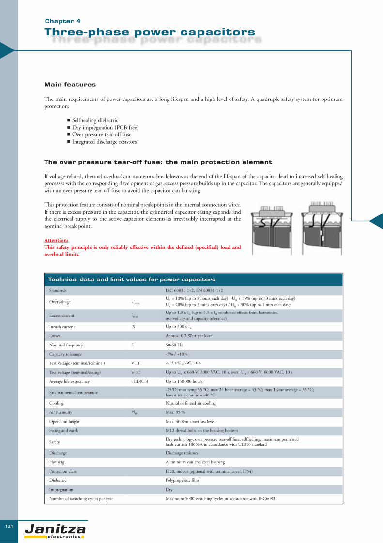
121
Three-phase power capacitors
The over pressure tear-off fuse: the main protection element
If voltage-related, thermal overloads or numerous breakdowns at the end of the lifespan of the capacitor lead to increased self-healingprocesses with the corresponding development of gas, excess pressure builds up in the capacitor. The capacitors are generally equippedwith an over pressure tear-off fuse to avoid the capacitor can bursting.
This protection feature consists of nominal break points in the internal connection wires.If there is excess pressure in the capacitor, the cylindrical capacitor casing expands andthe electrical supply to the active capacitor elements is irreversibly interrupted at thenominal break point.
Attention:This safety principle is only reliably effective within the defined (specified) load andoverload limits.
Main features
The main requirements of power capacitors are a long lifespan and a high level of safety. A quadruple safety system for optimumprotection:
� Selfhealing dielectric� Dry impregnation (PCB free)� Over pressure tear-off fuse� Integrated discharge resistors
▼▼
Technical data and limit values for power capacitors
Standards IEC 60831-1+2, EN 60831-1+2
Overvoltage UmaxUn + 10% (up to 8 hours each day) / Un + 15% (up to 30 mins each day)Un + 20% (up to 5 mins each day) / Un + 30% (up to 1 min each day)
Excess current ImaxUp to 1,3 x In (up to 1,5 x In combined effects from harmonics, overvoltage and capacity tolerance)
Inrush current IS Up to 300 x In
Losses Approx. 0.2 Watt per kvar
Nominal frequency f 50/60 Hz
Capacity tolerance -5% / +10%
Test voltage (terminal/terminal) VTT 2.15 x Un, AC, 10 s
Test voltage (terminal/casing) VTC Up to Un ≤ 660 V: 3000 VAC, 10 s, over Un = 660 V: 6000 VAC, 10 s
Average life expectancy t LD(Co) Up to 150 000 hours
Environmental temperature-25/D; max temp 55 °C; max 24 hour average = 45 °C; max 1 year average = 35 °C;lowest temperature = -40 °C
Cooling Natural or forced air cooling
Air humidity Hrel Max. 95 %
Operation height Max. 4000m above sea level
Fixing and earth M12 thread bolts on the housing bottom
SafetyDry technology, over pressure tear-off fuse, selfhealing, maximum permitted fault current 10000A in accordance with UL810 standard
Discharge Discharge resistors
Housing Aluminium can and steel housing
Protection class IP20, indoor (optional with terminal cover, IP54)
Dielectric Polypropylene film
Impregnation Dry
Number of switching cycles per year Maximum 5000 switching cycles in accordance with IEC60831
Chapter 4

122
▼
LK-440V power capacitors
Nominal powerin kvar Type Item
number Dimensions kg
2,5 JF440/2,5H/LK 50.61.000 H341 x W355 x D132 mm 5
5 JF440/5H/LK 50.61.050 H341 x W355 x D132 mm 5
10 JF440/10H/LK 50.61.150 H341 x W355 x D132 mm 8
12,5 JF440/12,5H/LK 50.61.200 H341 x W355 x D132 mm 8
15 JF440/15H/LK 50.61.250 H341 x W355 x D132 mm 9
20 JF440/20H/LK 50.61.350 H341 x W355 x D132 mm 10
25 JF440/25H/LK 50.61.400 H341 x W355 x D132 mm 10
30 JF440/30H/LK 50.61.450 H341 x W355 x D132 mm 15
40 JF440/40H/LK 50.61.650 H341 x W355 x D132 mm 19
50 JF440/50H/LK 50.61.700 H341 x W355 x D132 mm 19
60 JF440/60I/LK 50.61.750 H500 x W645 x D165 mm 20
70 JF440/70I/LK 50.61.780 H500 x W645 x D165 mm 20
75 JF440/75I/LK 50.61.820 H500 x W645 x D165 mm 20
80 JF440/80I/LK 50.61.860 H500 x W645 x D165 mm 21
90 JF440/90I/LK 50.61.900 H500 x W645 x D165 mm 21
100 JF440/100I/LK 50.61.945 H500 x W645 x D165 mm 21
Delta connected with discharge resistors – protection class: IP00 – frequency: 50Hz
Dimensions (mm) 2.5 kvar – 50 kvarH=341, W=355, D=132, A1= only from 50 kvarA2=300, A3=345, A4=15, A5=230, A6=132
Dimensions (mm) from 60 kvarH=500, W=645, D=165, A1=120, A2=630, A3=680, A4=20, A5=395, A6=160
Nominal power in kvar at a nominal voltage of: Type Item
numberCapacity in μF +10% -5%
Dimensions kg
400V 415V 440V 480V 525V
2.4 2.6 2.9 3.5 4.17 LKT5,6-610-D52 19.02.575 3x16 D= 60mm x H= 225mm 0.7
2.5 2.7 3.0 3.6 4.3 LKT4,3-525-D52 19.02.505 3x16.6 D= 60mm x H= 150mm 0.5
3.5 3.77 4.17 5 5.9 LKT8,0-610-D52 19.02.570 3x22 D= 60mm x H= 225mm 0.8
4.8 5.2 5.8 7 8.33 LKT11,2-610-D52 19.02.549 3x32 D= 70mm x H= 225mm 0.9
5 5.4 6 7.2 8.6 LKT8,6-525-D52 19.02.510 3x33.2 D= 60mm x H= 225mm 0.8
5.8 6.3 7 8.33 10 LKT10-525-D52 19.02.550 3x38.5 D= 70mm x H= 225mm 0.8
6.25 6.8 7.6 9.0 - LKT9,0-480-D52 19.02.511 3x41.7 D= 60mm x H= 225mm 0.7
7.2 7.8 8.7 10.5 12.5 LKT12,5-525-D52 19.02.580 3x47.9 D= 70mm x H= 225mm 1.1
8.7 9.4 10.5 12.5 15 LKT15,0-525-D52 19.02.503 3x57.7 D= 70mm x H= 265mm 1.2
7.5 8.1 9.1 10.8 - LKT10,8-480-D52 19.02.515 3x49.9 D= 60mm x H= 225mm 0.7
10 10.8 12.1 14.4 - LKT14,4-480-D52 19.02.517 3x66.3 D= 70mm x H= 225mm 1.1
10.8 11.6 13.1 15.5 - LKT15,5-480-D52 19.02.516 3x71.4 D= 70mm x H= 225mm 1.1
9.3 10 11.2 - - LKT11,2-440-D52 19.02.519 3x61.4 D= 70mm x H= 225mm 1.1
10 10.8 12.1 - - LKT12,1-440-D52 19.02.520 3x66.3 D= 70mm x H= 225mm 1.1
11.7 12.5 14.1 - - LKT14,1-440-D52 19.02.521 3x77.3 D= 70mm x H= 225mm 1.1
12.5 13.4 15.1 - - LKT15,1-440-D52 19.02.525 3x82.9 D= 70mm x H= 225mm 1.1
20 - 24.2 - - LKT24,2-440-D52 19.02.528 3x132.6 D= 85mm x H= 285mm 2.4
23.3 25.1 28.2 - - LKT28,2-440-D52 19.02.526 3x154.6 D= 85mm x H= 355mm 2.5
25 26.9 30.2 - - LKT30,2-440-D52 19.02.527 3x165.5 D= 85mm x H= 355mm 2.6
Protection cap with cable glandconstruction height + 77mm
SK60 19.02.620 For power capacitors with a diameter of 60mm
Protection cap with cable glandconstruction height + 75mm
SK70 19.02.621 For power capacitors with a diameter of 70mm
Connection cap for D60/70mm with spring force clamp 2x6qmm
ASS 1 19.02.610 Height = 28mm
Connection cap for D85mm with spring force clamp 16qmm
ASS 2 19.02.612 Height = 30.5mm
Can-type capacitor in aluminium housing
Square capacitor in steel housingApplication: mainly for fixed PFC, freestanding and for high mechanical protectionWith discharge resistors – IP53 – network: 400V/50Hz – nominal capacitor voltage: 440V

123
De-tuned power capacitors in steel cabinets
Application
For fixed PFC in networks with a high proportion of non-linearloads or for filtering of harmonics.
Nominal voltage: 400V, 3-phase, 50 HzProtection class: IP32Cooling: Natural cooling – from 25 kvar
with ventilators in the switchboard cabinet door
Filter frequency: 7 % = 189 Hz, 14 % = 134 Hz
▼▼
LK-FK7 power capacitors
Nominal powerin kvar Type Item
number Dimensions kg
5 JF440/5LK-KB4-FK7 50.24.050 H600 x W400 x D210 mm 23
10 JF440/10LK-KB4-FK7 50.24.100 H600 x W400 x D210 mm 28
12.5 JF440/12,5LK-KB4-FK7 50.24.130 H600 x W400 x D210 mm 29
20 JF440/20LK-KB4-FK7 50.24.170 H600 x W400 x D210 mm 36
25 JF440/25LK-KB8-FK7 50.24.220 H800 x W600 x D250 mm 38
30 JF440/30LK-KB8-FK7 50.24.280 H800 x W600 x D250 mm 40
40 JF440/40LK-KB8-FK7 50.24.350 H800 x W600 x D250 mm 49
50 JF440/50LK-KB8-FK7 50.24.450 H800 x W600 x D250 mm 82
7% De-tuning (with reactors)
Isolator or capacitor contactors available upon request.Other network voltages, powers, detuning and designs are available upon request.
14% De-tuning (with reactors)
LK-FK14 power capacitors
Nominal powerin kvar Type Item
number Dimensions kg
5 JF525/5LK-KB4-FK14 50.25.050 H600 x W400 x D210 mm 24
10 JF525/10LK-KB4-FK14 50.25.100 H600 x W400 x D210 mm 29
12.5 JF525/12,5LK-KB4-FK14 50.25.130 H600 x W400 x D210 mm 30
20 JF525/20LK-KB8-FK14 50.25.170 H800 x W600 x D250 mm 37
25 JF525/25LK-KB8-FK14 50.25.220 H800 x W600 x D250 mm 39
30 JF525/30LK-KB8-FK14 50.25.280 H800 x W600 x D250 mm 51
40 JF525/40LK-KB8-FK14 50.25.350 H800 x W600 x D250 mm 63
50 JF525/50LK-KB8-FK14 50.25.450 H800 x W600 x D250 mm 83
Cooling determines the lifespan of the capacitor
KB4: H=600, W=400, D=210, A1=23, A2=430, A3=535KB8: H=800, W=600, D=250, A1=23, A2=630, A3=735
Chapter 4
All measurements in mm.

▼
Quality components for a long lifespan.
Automatic PFC-systems for central compensation in low voltage distribution boards or group com-pensation of system parts. Due to exclusive use of quality components from leading manufacturers,the Prophi® power factor controller, as a central control unit, guarantees the best safety and a longlifespan thanks to the years of experience in the field of PFC- systems.
PFC-systems without reactors are considered for use in applications with a low proportion of non-linear loads i.e. low harmonic loads. There are four different designs customised to suit your indivi-dual application.
124
PQ
S -
Po
we
r Q
ua
lity
So
luti
on
s
Automatic PFC-Systems
(without reactors)
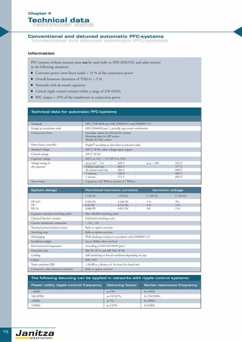
125
Technical data
Conventional and detuned automatic PFC-systems
Information
PFC-systems without reactors must not be used (refer to DIN EN61921 and other norms) in the following situations:
� Converter power (non-linear loads) > 15 % of the connection power
� Overall harmonic distortion of THD-U > 3 %
� Networks with de-tuned capacitors
� Critical ripple control systems within a range of 270-425Hz
� PFC output > 35% of the transformer or connection power
▼▼
Technical data for automatic PFC-systems
Standards DIN, VDE 0660 part 500, EN60439-1 and EN60831-1/2
Design in accordance with: DIN EN60439 part 1, partially type tested combination
Construction form Steel plate cabinet for KB and ES versions Mounting plate for MP version Module for MO version
Power factor controller Prophi® according to data sheet or selection table
Nominal voltage 400 V, 50 Hz; other voltages upon request
Control voltage 230 V, 50 Hz
Capacitor voltage 440 V at 5.67 - 7 %, 525 V at 14%
Voltage rating of the capacitor
At p=5.67 - 7 % 440 V at p = 14% 525 V8 hours each day 484 V 577 V30 minutes each day 506 V 604 V5 minutes 528 V 630 V1 minute 572 V 682 V
Power losses Capacitors <0.3 W/kvar, systems 4-7 W/kvar
System design Permitted harmonic currents harmonic voltage
I 250 Hz I 350 Hz U 250 Hz U 350 Hz
FK 5,67FK 7FK 14
0.565 IN 0.186 IN 5 % 5%0.31 IN 0.134 IN 5 % 5 %0.086 IN 0.051 IN 5% 5 %
Capacitor contactor switching cycles Max 100,000 switching cycles
Optional thyristor actuator Unlimited switching cycles
Current transformer connection .. /1A, ../5A
Nominal power/nominal current Refer to option overview
Switching ratio Refer to option overview
Discharging With discharge resistors in accordance with EN60831-1/2
Installation height Up to 2000m above sea level
Environmental temperature According to DIN EN 60439 part 1
Protection class KB, ES: IP 32 and MP, MO: IP 00
Cooling Self-ventilating or forced ventilation depending on type
Colour RAL 7035
Noise emissions (FK) < 60 dB at a distance of 1m from the closed unit
Connection cable diameters and fuses Refer to option overview
The following detuning can be applied in networks with ripple control systems:
Power utility ripple control frequency Detuning factor Series resonance frequency
<168Hz p=14% fr=134Hz
168-183Hz p=14/5.67% fr=134/210Hz
>228Hz p=7% fr=189Hz
>350Hz p=5.67% fr=210Hz
Chapter 4

126
Other nominal voltages, frequencies, powers, mechanical designs or versions with circuit breaker are available upon request.
Extension units, units in ISO housing and audio frequency blocking circuits are available upon request.
Automatic PFC in compact design (without reactors)
Applications
This is a space-saving design for smaller nominal power levels and wall mounting, for grids with low harmonic content.
Nominal voltage 400 V, 3-phase, 50 HzProtection class IP32Cooling Natural – pay attention to sufficient convectionController Prophi® 6R with AUTO configurationReactor No reactor
Compact design
KB4: H=600, W=400, D=210, A1=23, A2=421, A3=560KB8: H=800, W=600, D=250, A1=23, A2=620, A3=756
All measurements in mm
Compact design
Nominalpower kvar
Step power kvar
Switchingratio Type Item
number kg Version
7.5 2.5/5 1:2 JF440/7.5ER3KB4 50.39.005 25 KB4
10 2.5/2.5/5 1:1:2 JF440/10ER4KB4 50.39.015 25 KB4
12.5 2.5/5/5 1:2:2 JF440/12.5ER5KB4 50.39.030 25 KB4
15 5/10 1:2 JF440/15ER3KB4 50.39.045 26 KB4
17.5 2.5/5/10 1:2:4 JF440/17.5/ER7KB4 50.39.060 26 KB4
20 5/5/10 1:1:2 JF440/20ER4KB4 50.39.075 29 KB4
25 5/10/10 1:2:2 JF440/25ER5KB4 50.39.095 27 KB4
31 6.2/12.5/12.5 1:2:2 JF440/31ER5KB4 50.39.145 35 KB4
35 5/10/20 1:2:4 JF440/35ER7KB4 50.39.175 35 KB4
40 10/10/20 1:1:2 JF440/40ER4KB4 50.39.195 36 KB4
50 10/20/20 1:2:2 JF440/50ER5KB4 50.39.235 38 KB4
55 5/10/20/20 1:2:4:4 JF440/55ER11KB8 50.39.270 77 KB8
60 10/20/30 1:2:3 JF440/60ER6KB8 50.39.295 78 KB8
75 12/12/25/25 1:1:2:2 JF440/75ER6KB8 50.39.345 70 KB8
80 20/20/40 1:1:2 JF440/80ER4KB8 50.39.370 92 KB8
100 12/12/25/50 1:1:2:4 JF440/100ER8KB8 50.39.420 95 KB8
100 20/40/40 1:2:2 JF440/100ER5KB8 50.39.430 95 KB8
110 10/20/40/40 1:2:4:4 JF440/110ER11KB8 50.39.440 96 KB8
120 20/20/40/40 1:1:2:2 JF440/120ER6KB8 50.39.450 97 KB8
Dimensionaldrawing

127
Modular design ES8184 (W= see below x H= 1820mm x D= 400mm)
Nominal power kvar
Steppower kvar
Switchingratio Type Item
number kg Width
150 25/25/50/50 1:1:2:2 JF440/150ER6ES8184** 50.81.400 208 800mm
150 12/12/25/50/50 1:1:2:4:4 JF440/150ER12ES8184** 50.81.415 208 800mm
150 25/25/25... 1:1:1:1:1:1 JF440/150ER6ES8184** 50.81.425 208 800mm
160 20/20/40... 1:1:2:2:2 JF440/160ER8ES8184** 50.81.450 209 800mm
175 25/50/50/50 1:2:2:2 JF440/175ER7ES8184** 50.81.475 210 800mm
175 12/12/25/25/50... 1:1:2:2:4:4 JF440/175ER14ES8184*** 50.81.490 210 800mm
180 20/40/40... 1:2:2:2:2 JF440/180ER9ES8184** 50.81.515 211 800mm
200 50/50... 1:1:1:1 JF440/200ER4ES8184** 50.81.540 212 800mm
200 25/25/50... 1:1:2:2:2 JF440/200ER8ES8184** 50.81.550 212 800mm
200 12/12/25/50... 1:1:2:4:4... JF440/200/ER16ES8184** 50.81.560 212 800mm
200 20/20/40... 1:1:2:2:2:2 JF440/200ER10ES8184** 50.81.570 212 800mm
240 20/20/40... 1:1:2:2... JF440/240ER12ES8184*** 50.81.600 232 800mm
250 50... 1:1:1:1:1 JF440/250ER5ES8184** 50.81.625 233 800mm
250 25/25/50... 1:1:2:2... JF440/250ER10ES8184** 50.81.635 233 800mm
250 12/12/25/50... 1:1.2:4:4... JF440/250ER20ES8184*** 50.81.645 233 800mm
300 50/50... 1:1:1:1:1:1 JF440/300ER6ES8184** 50.81.670 236 800mm
300 25/25/50... 1:1:2:2... JF440/300ER12ES8184*** 50.81.680 236 800mm
300 12/12/25/50... 1:1:2:4:4... JF440/300ER24ES8184*** 50.81.690 236 800mm
400 50/50/50... 1:1... JF440/400ER8ES8184*** 50.81.693 475 2 x 800mm
500 50/50/50... 1:1... JF440/500ER10ES8184*** 50.81.696 500 2 x 800mm
600 50/50/50... 1:1... JF440/600ER12ES8484*** 50.81.701 525 2 x 800mm
Accessories
Socket100mm high
SO 100/800/400 29.03.317 5
Socket200mm high
SO 200/800/400 29.03.322 10
** With Prophi® 6R *** With Prophi® 12R
Applications
These are automatically regulated PFC systems in steel cabinets in modular design. The output can be easily expanded inside the cabinet or with additional cabinets. For grids with low harmonic content.
Nominal voltage 400 V, 3-phase, 50 HzProtection class IP32Cooling Natural cooling – pay attention to sufficient convectionController Prophi® with AUTO configurationReactor No reactor
Other nominal voltages, frequencies, powers, mechanical designs or versions with circuit breakersare available upon request.Extension units, units in ISO housing and audio frequency blocks are available upon request.
Dimensional drawing
ES8184:H=1820, W=800, D=400, A1=374, A2=25, A3=700, A4=100, A5=1480
All measurements in mm
Power factor correction systems
in modular design (without reactors)▼▼Chapter 4

Audio frequency blocking circuits, other nominal voltages, frequencies, outputs, mechanical designs or versions with circuit breakers are available uponrequest.
128
MP4, MP8 mounting plate
Nominalpower kvar
Steppower kvar
Switchingratio Type Item
number kg Version
7.5 2.5/5 1:2 JF440/7.5ER3MP4 50.33.005 10 MP4
10 2.5/2.5/5 1:1:2 JF440/10ER4MP4 50.33.015 10 MP4
12.5 2.5/5/5 1:2:2 JF440/12.5ER5MP4 50.33.030 10 MP4
15 5/10 1:2 JF440/15ER3MP4 50.33.045 11 MP4
17.5 2.5/5/10 1:2:4 JF440/17.5/ER7MP4 50.33.060 11 MP4
20 5/5/10 1:1:2 JF440/20ER4MP4 50.33.075 14 MP4
25 5/10/10 1:2:2 JF440/25ER5MP4 50.33.095 14 MP4
31 6.2/12.5/12.5 1:2:2 JF440/31ER5MP4 50.33.145 26 MP4
35 5/10/20 1:2:4 JF440/35ER7MP4 50.33.175 26 MP4
40 10/10/20 1:1:2 JF440/40ER4MP4 50.33.195 28 MP4
50 10/20/20 1:2:2 JF440/50ER5MP4 50.33.245 29 MP4
55 5/10/20/20 1:2:4:4 JF440/55ER11MP8 50.33.270 29 MP8
60 10/20/30 1:2:3 JF440/60ER6MP8 50.33.295 30 MP8
75 12/12/25/25 1:1:2:2 JF440/75ER6MP8 50.33.345 32 MP8
80 20/20/40 1:1:2 JF440/80ER4MP8 50.33.370 35 MP8
100 12/12/25/50 1:1:2:4 JF440/100ER8MP8 50.33.420 38 MP8
100 20/40/40 1:2:2 JF440/100ER5MP8 50.33.430 38 MP8
110 10/20/40/40 1:2:4:4 JF440/110ER11MP8 50.33.440 39 MP8
120 20/20/40/40 1:1:2:2 JF440/120ER6MP8 50.33.450 40 MP8
Slot 9 x 17
MP4: H=555, W=350, D=210, A1=295, A2=555MP8: H=750, W=550, D=250, A1=510, A2=745
Dimensional drawing
Mounting plate
Automatic PFC system on mounting plate (without reactors)
Applications
This is the compact design of a PFC system on mounting plate for installation in existing switchboard cabinets or distribution boards. For grids with low harmonic content.
Nominal voltage 400 V, 3-phase, 50 HzProtection class IP00Cooling Natural cooling – pay attention to sufficient convectionController Prophi® 6R with AUTO configurationReactor No reactor
All measurements in mm

129
Extractable modules
PFC Module M084
Nominalpower kvar
Step power kvar
Switchingratio Type Item
number kg
50 50 JF440/50EK1MO84 50.80.700 22
50 25/25 1:1 JF440/50/2EK2MO84 50.80.740 22
50 10/20/20 1:2:2 JF440/50/3EK5MO84 50.80.770 22
50 12/12/25 1:1:2 JF440/50/3/EK4MO84 50.80.774 22
60 20/40 1:2 JF440/60/2EK3MO84 50.80.775 23
60 10/10/20/20 1:1:2:2 JF440/60/4EK6MO84 50.80.776 23
75 25/50 1:2 JF440/75/2EK3MO84 50.80.800 24
75 25/25/25 1:1:1 JF440/75/3EK3MO84 50.80.810 24
75 12/12/25/25 1:1:2:2 JF440/75/4EK6MO84 50.80.811 24
80 40/40 1:1 JF440/80/2EK2MO84 50.80.835 24
80 20/20/40 1:1:2 JF440/80/3EK4MO84 50.80.837 24
100 50/50 1:1 JF440/100/2EK2MO84 50.80.875 25
100 25/25/50 1:1:2 JF440/100/3EK4MO84 50.80.880 25
100 25/25/25/25 1:1:1:1 JF440/100/4EK4MO84 50.80.900 25
100 20/40/40 1:2:2 JF440/100/3EK5MO84 50.80.902 25
100 12/12/25/50 1:1:2:4 JF440/100/4EK8MO84 50.80.903 25
Control module with Prophi® 6R controller,Fuse separation switch, current transformer clamp and 2m connection cable (mounted on the capacitor module)
50.80.003
Control module with Prophi® 12R controller,Fuse separation switch, current transformer clamp and 2m connection cable (mounted on the capacitor module)
50.80.004
AccessoriesModule fixing rail for Rittal cabinet on the leftModule fixing rail for Rittal cabinet on the right
29.12.43529.12.436
MO84: H=330, W=703, D=333, A1=290, A2=14, A3=26.5
Other nominal voltages, frequencies, powers, mechanical designs or versions with circuit breakers are available upon request.
Power factor correction system on extractable module – M084 (without reactor)
Application
This is a ready to install extractable PFC module for installation in existing switchboard cabinets or low voltage distribution boards.The module includes capacitors, contactors, 630A bus bar system, HRC fuses and fuse sockets, discharge resistors...
Nominal voltage 400 V, 3-phase, 50 HzProtection class IP00Cooling Natural cooling – pay attention to sufficient convectionController NoneReactor No reactor
Dimensional drawing
▼▼
All measurements in mm
Chapter 4

Harmonic filters for improved power quality.
In electrical power networks, ranging from the industrial electricity network through to office buil-dings, system perturbation occur when operating electrical and electronic loads. We refer to networkperturbation when the original “clean” sine wave of the voltage or current changes.
Network perturbation cause additional costs and should be limited. Janitza® offers various approachesto solutions which limit harmonic currents and therefore improve power quality. The solutions rangefrom passive harmonic filters e.g. de-tuned PFC systems through to customized tuned harmonic filters.Investments in harmonic filters generally pay off within 6-24 months. This means that kWh lossesare reduced, reactive power costs are decreased, the lifespan of electrical instruments is lengthenedand production processes are stabilised.
130
PQ
S -
Po
we
r Q
ua
lity
So
luti
on
s
▼
De-tuned power factor
correction (with reactors)
Harmonic filters

131
Harmonic filters
Improvement of power quality, energy savings and stabilisation of the power supply
The permanently increasing number of non-linear loads in our electricity networks causerising “network impurities”. We talk about network perturbations in a similar way to theway we talk about the environment with its water and air pollution. In an ideal situation,the generators in a power plant produce a pure sinusoidal-shaped current at the outputterminals. This sinusoidal-shaped voltage form is regarded as the ideal form of alternatingcurrent and any deviation from this form is described as a network perturbation. More andmore consumers take a non-sinusoidal-shaped current from the network. The FFT fast-fourier transformation of these polluted currents results in a wide range of harmonic fre-quencies which are usually referred to as harmonics.
Harmonics are causing negative effects to electrical networks and can sometimes be danger-ous. Connected loads can suffer in a way which is similar to the unhealthy effect impurewater has on the human body. This results in overload, reduced lifespan and under somecircumstances can even lead to premature failure of electrical and electronic components.Harmonics overloads are the main cause of invisible power quality problems with enor-mous maintenance costs and investments for the replacement of defective equipment.Excessive network perturbations and the resulting poor power quality can also lead to pro-blems in production processes and can even result in production stoppages.
What can you do to improve your power quality?
There are different solutions for the restriction of harmonic currents which are caused by non-linear consumers which can therefore con-tribute to the improvement of power quality.
De-tuned PFC systems (passive, de-tuned filter)
Passive filters and de-tuned PFC systems are some of the traditional measures. In de-tuned PFC systems, power capacitors are switchedto the network individually or in groups and are regulated according to the power factor. Low-pass filters with a de-tuning factor, whichis more or less dependent upon a broadband filter effect (towards high frequencies), is generated through the filter circuit reactors whichare connected to the capacitor in series. This means that the occurrence of resonance is avoided and some harmonics are reduced fromthe network.
Advantages
Network optimisation with de-tuned PFC systems (harmonic filters) from Janitza® result in the following advantages:
� Reduction of electricity bills through the elimination of reactive power� Reduction of electricity bills through reduced kWh losses (I2R losses)� Avoidance of resonance problems and significant safety risks� Improvement of the general power quality (reduction of THD-U)� Saving of maintenance costs� Delay or avoidance of new investments through improved utilization of energy distribution systems and equipment� Stabilisation of production processes� Stabilisation of supply voltage
▼Chapter 4
Illustration: network perturbationthrough a frequency converter (above: voltage; below: current)

132
De-tuned, automatically regulated power factor correction
Passive harmonic filters
De-tuned automatically regulated PFC (passive harmonic filters) for central compensation in lowvoltage distribution boards or group compensation. The exclusive use of quality components fromleading manufacturers and the Prophi® power factor controller, as a central control unit, guaranteesthe best safety and a long lifespan also thanks to the years of experience in the field of PFC systems.Reactors with high linearity and low power losses reduce electricity costs.
De-tuned PFC systems are suitable for use in applications with non-linear loads i.e. harmonic loads(refer to data sheet for maximum harmonic loads).
There are four different product families customised to suit your individual application.
De-tuned power factor
correction (with reactors)
Passive harmonic filters

KB6825: W=600, H=800, D=250, A1=410
KB6123: W=600, H=1200, D=300, A1=655
KB6825: W=600, H=800, D=250, A1=410
KB6123: W=600, H=1200, D=300, A1=655
133
De-tuned power factor correction (with reactors)
▼
Other nominal voltages, frequencies, outputs, reactors, mechanical designs or versions with circuit breakers are available uponrequest. Refer to page 137 for accessories.
Compact design
Nominalpower kvar
Level power kvar
Standardratio Type Item
number kg Version
15 5/10 1:2 JF440/15ER3KB6825FK7 50.52.020 112 KB6825
20 5/5/10 1:1:2 JF440/20ER4KB6825FK7 50.52.040 113 KB6825
25 5/10/10 1:2:2 JF440/25ER5KB6825FK7 50.52.080 116 KB6825
31 6.25/12.5/12.5 1:2:2 JF440/31/ER5KB6825FK7 50.52.110 118 KB6825
35 5/10/20 1:2:4 JF440/35ER7KB6825FK7 50.52.150 122 KB6825
43.75 6.25/12.5/25 1:2:4 JF440/43.75ER7KB6825FK7 50.52.180 138 KB6825
50 10/20/20 1:2:2 JF440/50ER5KB6825FK7 50.52.210 142 KB6825
60 10/20/30 1:2:3 JF440/60ER6KB6123FK7 50.52.225 158 KB6123
75 12.5/25/37.5 1:2:3 JF440/75ER6KB6123FK7 50.52.240 167 KB6123
7% De-tuning with a filter frequency of 189Hz
14% De-tuning with a filter frequency of 134Hz
Compact design
Nominalpower kvar
Level power kvar
Standardratio Type Item
number kg Version
15 5/10 1:2 JF525/15ER3KB6825FK14 50.52.520 123 KB6825
20 5/5/10 1:1:2 JF525/20ER4KB6825FK14 50.52.540 124 KB6825
25 5/10/10 1:2:2 JF525/25ER5KB6825FK14 50.52.580 128 KB6825
31 6.25/12.5/12.5 1:2:2 JF525/31/ER5KB6825FK14 50.52.610 130 KB6825
35 5/10/20 1:2:4 JF525/35ER7KB6825FK14 50.52.650 134 KB6825
43.75 6.25/12.5/25 1:2:4 JF525/43.75ER7KB6825FK14 50.52.680 152 KB6825
50 10/20/20 1:2:2 JF525/50ER5KB6825FK14 50.52.710 173 KB6825
60 10/20/30 1:2:3 JF525/60ER6KB6123FK14 50.52.725 184 KB6123
75 12.5/25/37.5 1:2:3 JF525/75ER6KB6123FK14 50.52.729 195 KB6123
De-tuned power factor correction(harmonic filters) in compact design
Applications
Small sized automatically regulated PFC systems for grids with harmonics.
Nominal voltage 400 V, 3-phase, 50 HzProtection class IP32Cooling With ventilator in cabinet door from 31 kvar and aboveController Prophi® 6R with AUTO configurationReactor 5…14 %
Compact design
All measurements in mm
All measurements in mm
Chapter 4

134
▼
ES8206:H=2020, W=800 or 1600, D=600, A1=537A2=63, A3=737, A4=62, A5=1480
Other nominal voltages, frequencies, outputs, reactors, mechanical designs or versions with circuit breakers are available upon request. Refer topage 137 for accessories.
** with Prophi® 6R, ***with Prophi® 12R
Extractable modular design ES8206 FK7
Nominalpower kvar
Steppower kvar
Switching ratio Type Item
number kg Width
60 10/20/30 1:2:3... JF440/60ER6ES8206FK7 ** 50.89.040 278 800mm
75 12/12/25... 1:1:2... JF440/75ER6ES8206FK7 ** 50.89.080 278 800mm
100 25/25/50 1:1:2 JF440/100ER4ES8206FK7 ** 50.89.120 288 800mm
100 12/12/25/50 1:1:2:4 JF440/100ER8ES8206FK7 ** 50.89.200 288 800mm
100 10/20/30/40 1:2:3:4 JF440/100ER10ES8206FK7 ** 50.89.250 288 800mm
120 20/20/40/40 1:1:2:2 JF440/120ER6ES8206FK7 ** 50.89.320 340 800mm
150 25/25/50/50 1:1:2:2 JF440/150ER6ES8206FK7 ** 50.89.400 344 800mm
175 25/50/50/50 1:2:2:2 JF440/175ER7ES8206FK7 ** 50.89.440 367 800mm
200 50... 1:1:1... JF440/200ER4ES8206FK7 ** 50.89.480 314 800mm
200 25/25/50... 1:1:2... JF440/200ER8ES8206FK7 ** 50.89.520 314 800mm
200 12/12/25/50... 1:1:2:4.. JF440/200ER16ES8206FK7 ** 50.89.560 314 800mm
250 50... 1:1:1... JF440/250/ER5ES8206FK7 ** 50.89.600 437 800mm
250 25/25/50... 1:1:2... JF440/250ER10ES8206FK7 ** 50.89.640 437 800mm
300 50... 1:1:1... JF440/300ER6ES8206FK7 ** 50.89.685 487 800mm
300 25/25/50... 1:1:2... JF440/300ER12ES8206FK7 *** 50.89.687 498 800mm
350 50... 1:1:1... JF440/350ER7ES8206FK7-1S *** 50.89.720 520 800mm
350 50... 1:1:1... JF440/350ER7ES8206FK7 *** 50.89.722 352/347 1600mm
400 50... 1:1:1... JF440/400ER8ES8206FK7-1S *** 50.89.744 570 800mm
400 50... 1:1.1... JF440/400ER8ES8206FK7 *** 50.89.740 2x370 1600mm
450 50... 1:1:1... JF440/450ER9ES8206FK7 *** 50.89.770 437/347 1600mm
500 50... 1:1:1... JF440/500ER10ES8206FK7 *** 50.89.800 479/359 1600mm
550 50... 1:1:1... JF440/550ER11ES8206FK7 *** 50.89.805 2x431 1600mm
600 50... 1:1:1... JF440/600ER12ES8206FK7 *** 50.89.820 2x481 1600mm
Extractable modular design
7% De-tuned PFC(harmonic filters) in extractable design
Application
These are automatically regulated PFC systems in steel cabinets constructed in extractable modular design. The output inthe systems can be expanded as required. For grids with harmonics distortions.
Nominal voltage 400 V, 3-phase, 50 HzProtection class IP32Cooling Ventilator in cabinet doorController Prophi® with AUTO configurationReactor 7 % (189Hz filter)
All measurements in mm

135
De-tuned power factor correction (with reactors)
▼
Other nominal voltages, frequencies, outputs, reactors, mechanical designs or versions with circuit breakers are available upon request. Refer to page137 for accessories.
** with Prophi® 6R, ***with Prophi® 12R
Extractable modular design ES8206 FK14
Nominal power kvar
Steppower kvar
Switchingratio Type Item
number kg Width
60 10/20/30 1:2:3 JF525/60ER6ES8206FK14** 50.93.040 317 800mm
75 12/12/25/25 1:1:2:2 JF525/75ER6ES8206FK14** 50.93.080 318 800mm
100 25/25/50 1:1:2 JF525/100ER4ES8206FK14** 50.93.120 368 800mm
100 12/12/25/50 1:1:2:4 JF525/100ER8ES8206FK14** 50.93.200 380 800mm
100 10/20/30/40 1:2:3:4 JF525/100ER10ES8206FK14** 50.93.250 387 800mm
120 20/20/40/40 1:1:2:2 JF525/120ER6ES8206FK14** 50.93.320 379 800mm
150 25/25/50/50 1:1:2:2 JF525/150ER6ES8206FK14** 50.93.400 375 800mm
175 25/50/50/50 1:2:2:2 JF525/175ER7ES8206FK14** 50.93.440 407 800mm
200 50 1:1:1:1 JF525/200ER4ES8206FK14** 50.93.480 420 800mm
200 25/25/50... 1:1:2... JF525/200ER8ES8206FK14** 50.93.520 421 800mm
200 12/12/25/50... 1:1:2:4... JF525/200ER16ES8206FK14** 50.93.560 371 800mm
250 50 1:1:1... JF525/250/ER5ES8206FK14** 50.93.600 478 800mm
250 25/25/50... 1:1:2... JF525/250ER10ES8206FK14** 50.93.640 490 800mm
300 50 1:1:1... JF525/300ER6ES8206FK14** 50.93.685 500 800mm
300 25/25/50... 1:1:2... JF525/300ER12ES8206FK14*** 50.93.690 500 800mm
350 50... 1:1:1... JF525/350ER7ES8206FK14-1S*** 50.93.720 550 800mm
350 50... 1:1:1... JF525/350ER7ES8206FK14*** 50.93.722 424/365 1600mm
400 50... 1:1:1... JF525/400ER8ES8206FK14-S*** 50.93.740 600 800mm
400 50... 1:1:1... JF525/400ER8ES8206FK14*** 50.93.742 2x424 1600mm
450 50... 1:1:1... JF525/450ER9ES8206FK14*** 50.93.770 2x478 1600mm
500 50... 1:1:1... JF525/500ER10ES8206FK14*** 50.93.800 500/420 1600mm
550 50... 1:1:1... JF525/550ER11ES8206FK14*** 50.93.805 500/478 1600mm
600 50... 1:1:1... JF525/600ER12ES8206FK14*** 50.93.920 500/500 1600mm
14% De-tuned PFC(harmonic filters) in extractable design
Application
These are automatically regulated PFC systems in steel cabinets constructed in extractable modular design. The output inthe systems can be expanded as required. For grids with harmonics distortions.
Nominal voltage 400 V, 3-phase, 50 HzProtection class IP32Cooling Ventilator in cabinet doorController Prophi® with AUTO configurationReactor 14% (134Hz filter)
ES8206:H=2020, W=800 or 1600, D=600, A1=537, A2=63, A3=737, A4=62, A5=1480
All measurements in mm
Chapter 4

136
▼
7% De-tuned capacitor module (189Hz)
H=330, W=703, D=533, A1=290, A2=14, A3=26.5
Capacitor module M086FK7 (width 800mm, depth 600mm)
Nominal power kvar
Steppower kvar
Switchingratio Type Item
number kg
10 10 JF440/10EK1MO86FK7 50.88.650 24
12,5 12,5 JF440/12,5EK1MO86FK7 50.88.680 26
20 20 JF440/20EK1MO86FK7 50.88.710 33
25 25 JF440/25/EK1MO86FK7 50.88.740 33
40 40 JF440/40EK1MO86FK7 50.88.770 43
50 50 JF440/50EK1MO86FK7 50.88.800 45
20/2 10 1:1 JF440/20/2EK2MO86FK7 50.88.801 36
25/2 12,5 1:1 JF440/25/2EK2MO86FK7 50.88.830 38
30/2 10/20 1:2 JF440/30/2EK2MO86FK7 50.88.860 42
40/2 20 1:1 JF440/40/2EK2MO86FK7 50.88.890 55
40/3 10/10/20 1:1:2 JF440/40/3EK2MO86FK7 50.88.891 55
50/2 25 1:1 JF440/50/2EK2MO86FK7 50.88.930 56
75/2 25/50 1:2 JF440/75/2EK2MO86FK7 50.88.932 72
80/2 40 1:1 JF440/80/2EK2MO86FK7 50.88.933 72
100/2 50 1:1 JF440/100/2EK2MO86FK7 50.88.931 86
For cabinet depth 600mm
Capacitor module M086FK14 (construction width 800mm, depth 600mm)
Nominal power kvar
Steppower kvar
Switchingratio Type Item
number kg
10 10 JF525/10EK1MO86FK14 50.92.650 34
12,5 12,5 JF525/12,5EK1MO86FK14 50.92.680 35
20 20 JF525/20EK1MO86FK14 50.92.710 40
25 25 JF525/25EK1MO86FK14 50.92.740 40
40 40 JF525/40EK1MO86FK14 50.92.770 52
50 50 JF525/50EK1MO86FK14 50.92.800 54
20/2 10 1:1 JF525/20/2EK2MO86FK14 50.92.803 53
25/2 12,5 1:1 JF525/25/2EK2MO86FK14 50.92.804 60
30/2 10/20 1:2 JF525/30/2EK2MO86FK14 50.92.849 45
40/2 20 1:1 JF525/40/2EK2MO86FK14 50.92.850 67
40/3 10/10/20 1:1:2 JF525/40/3EK3MO86FK14 50.92.851 72
50/2 25 1:1 JF525/50/2EK2MO86FK14 50.92.890 69
75/2 25/50 1:2 JF525/75/2EK2MO86FK14 50.92.893 78
80/2 40 1:1 JF525/80/2EK2MO86FK14 50.92.896 78
100/2 50 1:1 JF525/100/2EK2MO86FK14 50.92.892 92
14% De-tuned capacitor module (134Hz)
Other nominal voltages, frequencies, outputs, reactors, mechanical designs (e.g. 500mm cabinet depth) or versionswith circuit breakers are available upon request. Refer to page 137 for accessories.
Extractable modular design
De-tuned capacitor modules (harmonic filters)
Application
These are automatically regulated PFC modules for installation in existing cabinets or low voltage distribution boards constructed in extractable modular design. The output can be expanded to 300 kvar (in series). Supply complete with set of copper bus bar links for connecting multiple modules.
Nominal voltage 400 V, 3-phase, , 50 HzProtection class IP00Cooling Natural – pay attention to sufficient ventilationController NoneReactor 7 % and 14 %
All measurements in mm
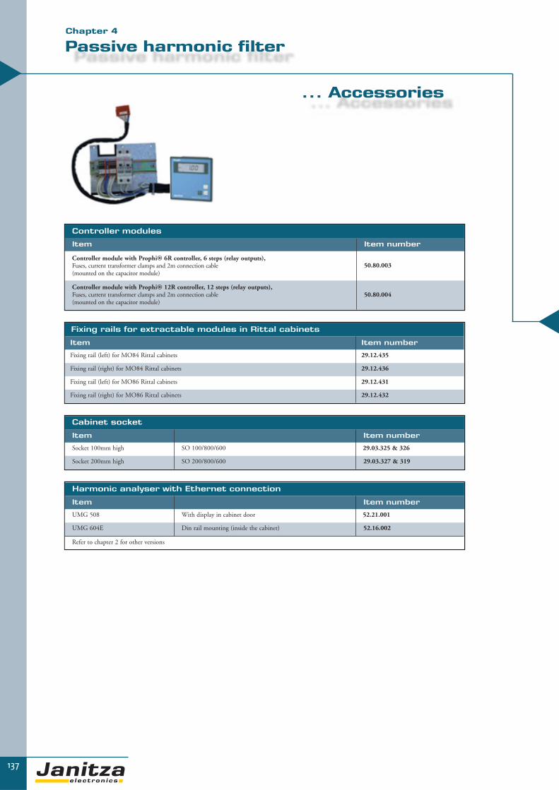
137
Passive harmonic filter
... Accessories▼▼
Cabinet socket
Item Item number
Socket 100mm high SO 100/800/600 29.03.325 & 326
Socket 200mm high SO 200/800/600 29.03.327 & 319
Harmonic analyser with Ethernet connection
Item Item number
UMG 508 With display in cabinet door 52.21.001
UMG 604E Din rail mounting (inside the cabinet) 52.16.002
Refer to chapter 2 for other versions
Controller modules
Item Item number
Controller module with Prophi® 6R controller, 6 steps (relay outputs), Fuses, current transformer clamps and 2m connection cable (mounted on the capacitor module)
50.80.003
Controller module with Prophi® 12R controller, 12 steps (relay outputs), Fuses, current transformer clamps and 2m connection cable (mounted on the capacitor module)
50.80.004
Fixing rails for extractable modules in Rittal cabinets
Item Item number
Fixing rail (left) for MO84 Rittal cabinets 29.12.435
Fixing rail (right) for MO84 Rittal cabinets 29.12.436
Fixing rail (left) for MO86 Rittal cabinets 29.12.431
Fixing rail (right) for MO86 Rittal cabinets 29.12.432
Chapter 4

▼
For use with rapid and high load changes
Dynamic PFC systems are particularly used in applications with rapid and high load changes. Theseare automatically regulated systems for central compensation in low voltage distribution boards or forgroup compensation of sub-systems.
De-tuned PFC systems for use in applications with non-linear loads i.e. harmonic loads.
There are various designs customised to suit your individual application.
138
Dynamic (fast switching)
power factor correction

139
Dynamic power factor correction
▼
Applications
Dynamic PFC systems are particularly used in applications withrapid and high load changes. In such cases, conventional PFCsystems are not fast enough to follow the load changes whichmeans that these systems are either undercompensated or over-compensated.
Electromechanical contactors are not suitable for these types offrequent switching cycles. If contactors or capacitor contactorsare still used in such applications, the contactors are worn outvery quickly and this can lead to significant safety risks for thewhole system. Dynamic PFC systems avoid this problem withthe help of semiconductors. Semiconductors gently connect thecapacitors to the network i.e. without network perturbationsand capacitor stresses.
This results in the following advantages:
� Improved power quality i.e. high inrush currents from power capacitors are avoided� The lifespan of PFC systems is increased� The safety of the full system is significantly increased (i.e. damages due to defective contactors
and as a result of exploding capacitors are avoided)� Extremely rapid regulation of the power factor and therefore consequential reduction of
reactive power costs and kWh losses� Voltage stabilisation (e.g. network support during the start-up phase for large motors)� Improved utilization for energy distribution (transformers, cable, switch gear etc.) through
the elimination of power peaks� Process times can be shortened (e.g. welding)
Typical applications
� Automobile industry (welding machines, presses...)� Elevator systems and cranes� Start-up compensation for larger motors� Drilling rigs in oil production� Wind power plants� Welding� Steel production� Plastic injection moulding units � Trawlers
Controller signal
Network current withoutdynamic PFC
With dynamic PFC
Vol
tage
Cur
rent
Without dynamic PFC
With dynamic PFC
With dynamic PFC
Without dynamic PFC
Illustration: comparison of current and voltage with andwithout dynamic PFC when starting up a large motor.
Illustration: current reduction through dynamic PFC
I in A
in sec
↑
↑
ON
Chapter 4

140
▼
7 % Reactor
H=330, W=703, D=550, A1=290, A2=14, A3=26,5
Capacitor module M086FK7Th (width 800mm, depth 600mm)
Nominalpower kvar
Step power kvar
Switching ratio Type Item
number kg
10 10 JF440/10EK1MO86FK7Th 50.18.650 26
12.5 12.5 JF440/12.5EK1MO86FK7Th 50.18.680 28
20 20 JF440/20EK1MO86FK7Th 50.18.710 35
25 25 JF440/25/EK1MO86FK7Th 50.18.740 35
40 40 JF440/40EK1MO86FK7Th 50.18.770 45
50 50 JF440/50EK1MO86FK7Th 50.18.800 47
20 10 1:1 JF440/20/2EK2MO86FK7Th 50.18.801 40
25 12.5 1:1 JF440/25/2EK2MO86FK7Th 50.18.830 42
30 15 1:1 JF440/30/2EK2MO86FK7Th 50.18.860 46
40 20 1:1 JF440/40/2EK2MO86FK7Th 50.18.890 57
50 25 1:1 JF440/50/2EK2MO86FK7Th 50.18.930 58
75 25/50 1:2 JF440/75/2EK2MO86FK7Th 50.18.932 76
80 40/40 1:1 JF440/80/2EK2MO86FK7Th 50.18.933 77
100 50/50 1:1 JF440/100/2EK2MO86FK7Th 50.18.931 90
De-tuned dynamic capacitor module in extractable modular design
Application
Automatically regulated dynamic PFC modules in extractable design for applications with rapid and high load changes.This is an extractable module for use in existing cabinets or low-voltage main distribution systems.
Nominal voltage 400 V, 3-phase, 50 HzProtection class IP00Reactor 5 ... 14%
Capacitor module M086FK14Th (width 800mm, depth 600mm)
Nominalpower kvar
Steppower kvar
Switching ratio Type Item
number kg
10 10 JF525/10EK1MO86FK14Th 50.12.650 36
12.5 12.5 JF525/12.5EK1MO86FK14Th 50.12.680 37
20 20 JF525/20EK1MO86FK14Th 50.12.710 42
25 25 JF525/25EK1MO86FK14Th 50.12.740 43
40 40 JF525/40EK1MO86FK14Th 50.12.770 54
50 50 JF525/50EK1MO86FK14Th 50.12.800 56
20 10 1:1 JF525/20/2EK2MO86FK14Th 50.12.803 57
25 12.5 1:1 JF525/25/2EK2MO86FK14Th 50.12.804 64
30 15 1:1 JF525/30/2EK2MO86FK14Th 50.12.849 69
40 20 1:1 JF525/40/2EK2MO86FK14Th 50.12.850 71
50 25 1:1 JF525/50/2EK2MO86FK14Th 50.12.890 73
75 25/50 1:2 JF525/75/2EK2MO86FK14Th 50.12.893 82
80 40/40 1:1 JF525/80/2EK2MO86FK14Th 50.12.896 84
100 50/50 1:1 JF525/100/2EK2MO86FK14Th 50.12.892 96
14 % Reactor
Other nominal voltages, frequencies, outputs, reactors, mechanical designs or versions with circuit breakers are availableupon request. Refer to page 144 for accessories.
Extractable modular design
All measurements in mm

ES8184:H=1800, W=800, D=400, A1=537,A2=63, A3=737, A4=62, A5=1480
141
Dynamic power factor correction
▼
Extractable module design ES8184Th W=see below x H=1800mm x D=400mm
Nominalpower kvar
Steppower kvar
Switchingratio Type Item
number kg Width
100 12.5/12.5/25/50 1:1:2:4 JF440/100ER8ES8184Th** 50.81.920 190 800mm
125 12.5/25/37.5/50 1:2:3:4 JF440/125ER10ES8184Th** 50.81.921 195 800mm
150 12.5/12.5/25/50/50 1:1:2:4:4 JF440/150ER12ES8184Th** 50.81.922 208 800mm
150 25/25/50/50 1:1:2:2 JF440/150ER6ES8184Th** 50.81.923 208 800mm
175 12,5/25/37.5/50/50 1:2:3:4:4 JF440/175ER14ES8184Th** 50.81.924 210 800mm
180 20/40/40/40/40 1:2:2:2:2 JF440/180ER9ES8184Th** 50.81.925 211 800mm
200 50/50/50/50 1:1:1:1 JF440/200ER4ES8184Th** 50.81.926 212 800mm
200 25/25/50/50/50 1:1:2:2:2 JF440/200ER8ES8184Th** 50.81.927 212 800mm
200 12.5/12,5/25/50... 1:1:2:4... JF440/200ER16ES8184Th** 50.81.928 212 800mm
250 50/50/50/50/50 1:1:1:1:1 JF440/250ER5ES8184Th** 50.81.929 233 800mm
250 25/25/50/50/50/50 1:1:2:2:2:2 JF440/250ER10ES8184Th** 50.81.930 233 800mm
250 12.5/12.5/25/50... 1:1:2:4... JF440/250ER20ES8184Th*** 50.81.931 233 800mm
300 50/50... 1:1... JF440/300ER6ES8184Th** 50.81.932 236 800mm
300 25/25/50... 1:1:2... JF440/300ER12ES8184Th*** 50.81.933 236 800mm
400 50/50... 1:1... JF440/400ER8ES8184Th*** 50.81.934 380 1600mm
500 50/50... 1:1... JF440/500ER10ES8184Th*** 50.81.935 460 1600mm
600 50/50... 1:1... JF440/600ER12ES8184Th*** 50.81.936 540 1600mm
Dynamic PFC in extractable module design
Application
Automatically regulated PFC systems in extractable module design for applications with rapid and high load changes. The modulesare built into steel cabinets constructed in extractable module design in which the output can be expanded as required.
Nominal voltage 400 V, 3-phase, 50 HzProtection class IP32Cooling Ventilator in cabinet doorController Prophi® with AUTO configurationReactor None
Other nominal voltages, frequencies, outputs, mechanical designs or versions with circuit breakers are available upon request. Refer to page 144 for accessories.
** With Prophi® 6T *** With Prophi® 12T
All measurements in mm
Chapter 4

ES8206:H=2020, W=800, D=600, A1=537,A2=63, A3=737, A4=62, A5=1480
Extractable module design ES8206 FK7Th W=see below x H=2020mm x D=600mm
Nominalpower kvar
Steppower kvar
Switchingratio Type Item
number kg Width
60 10/20/30 1:2:3 JF440/60ER6ES8206FK7Th** 50.19.040 290 800mm
75 12.5/12.5/25/25 1:1:2:2 JF440/75ER6ES8206FK7 Th** 50.19.080 290 800mm
100 25/25/50 1:1:2 JF440/100ER4ES8206FK7Th** 50.19.120 306 800mm
100 20/40/40 1:2:2 JF440/100/ER5ES8206FK7Th** 50.19.160 306 800mm
100 12.5/12.5/25/50 1:1:2:4 JF440/100ER8ES8206FK7Th** 50.19.200 306 800mm
120 20/20/40/40 1:1:2:2 JF440/120ER6ES8206FK7Th** 50.19.320 362 800mm
150 25/25/50/50 1:1:2:2 JF440/150ER6ES8206FK7Th** 50.19.400 366 800mm
175 25/50/50/50 1:2:2:2 JF440/175ER7ES8206FK7Th** 50.19.440 379 800mm
200 50 1:1 JF440/200ER4ES8206FK7Th** 50.19.480 381 800mm
200 25/25/50/50/50 1:1:2:2:2 JF440/200ER8ES8206FK7Th** 50.19.520 381 800mm
200 12.5/12.5/25/50 1:1:2:4:4:4 JF440/200ER16ES8206FK7Th** 50.19.560 385 800mm
250 50... 1:1... JF440/250/ER5ES8206FK7Th** 50.19.600 454 800mm
250 25/25/50... 1:1:2:2... JF440/250ER10ES8206FK7Th*** 50.19.640 456 800mm
300 50... 1:1... JF440/300ER6ES8206FK7Th** 50.19.685 492 800mm
300 25/25/50... 1:1:2:2... JF440/300ER12ES8206FK7Th*** 50.19.687 496 800mm
350 50... 1:1... JF440/350ER7ES8206FK7Th*** 50.19.722 362/359 1600mm
400 50... 1:1... JF440/400ER8ES8206FK7Th*** 50.19.740 2x376 1600mm
450 50... 1:1... JF440/450ER9ES8206FK7Th*** 50.19.770 459/376 1600mm
500 50... 1:1... JF440/500ER10ES8206FK7Th*** 50.19.800 492/372 1600mm
550 50... 1:1... JF440/550ER11ES8206FK7Th*** 50.19.805 2x456 1600mm
600 50... 1:1... JF440/600ER12ES8206FK7Th*** 50.19.820 2x496 1600mm
142
7% De-tuned dynamic PFC in extractable module design
Application
Automatically regulated PFC systems in extractable module design for applications with rapid and high load changes. Themodules are built into steel cabinets constructed in extractable module design in which the power can be expanded as required.7% reactors for networks with predominantly 3-phase non-linear loads i.e. a lower proportion of 3rd harmonics.
Nominal voltage 400 V, 3-phase, 50 HzProtection class IP32Cooling Ventilator in cabinet doorController Prophi® with AUTO configurationReactor 7% (189Hz filter)
Other nominal voltages, frequencies, outputs, reactors, mechanical designs or versions with circuit breakers are available upon request. Refer to page 144 foraccessories.
** With Prophi® 6T *** With Prophi® 12T
All measurements in mm
▼
Extractable modular design

Dynamic power factor correction
▼
143
ES8206:H=2020, W=800, D=600, A1=537,A2=63, A3=737, A4=62, A5=1480
14% De-tuned dynamic PFC in extractable module design
Application
Automatically regulated PFC systems in extractable module design for applications with rapid and high load changes. The modu-les are built into steel cabinets constructed in extractable module design in which the power can be expanded as required. 14%reactors for networks with a high proportion of 1-phase non-linear loads i.e. a high proportion of 3rd harmonics.
Nominal voltage 400 V, 3-phase, 50 HzProtection class IP32Cooling Ventilator in cabinet doorController Prophi® with AUTO configurationReactor 14% (134Hz filter)
Other nominal voltages, frequencies, outputs, reactors, mechanical designs or versions with circuit breakers are available upon request. Refer to page 144for accessories.
** With Prophi® 6R *** With Prophi® 12R
Extractable module design ES8206 Th W=see below x H=2020mm x D=600mm
Nominalpower kvar
Step power kvar
Switchingratio Type Item
number kg Width
100 12.5/12.5/25/50 1:1:2:4 JF525/100ER8ES8206FK14Th** 50.98.200 380 800mm
125 12.5/25/37.5/50 1:2:3:4 JF525/125ER10ES8206FK14Th** 50.98.325 390 800mm
150 12.5/12.5/25/50... 1:1:2:4... JF525/150ER12ES8206FK14Th** 50.98.330 410 800mm
150 25/25/50/50 1:1:2:2 JF525/150ER6ES8206FK14Th** 50.98.400 410 800mm
175 12.5/25/37.5/50... 1:2:3:4... JF525/175ER14ES8206FK14Th** 50.98.440 420 800mm
200 50/50/50/50 1:1:1:1 JF525/200ER4ES8206FK14Th** 50.98.480 430 800mm
200 25/25/50... 1:1:2... JF525/200ER8ES8206FK14Th** 50.98.520 430 800mm
200 12.5/12.5/25/50... 1:1:2:4... JF525/200ER16ES8206FK14Th** 50.98.560 435 800mm
250 50/50... 1:1... JF525/250ER5ES8206FK14Th** 50.98.600 478 800mm
250 25/25/50... 1:1:2... JF525/250ER10ES8206FK14Th** 50.98.640 490 800mm
250 12.5/12.5/25/50... 1:1:2:4... JF525/250ER20ES8206FK14Th*** 50.98.645 495 800mm
300 50/50... 1:1... JF525/300ER6ES8206FK14Th** 50.98.685 500 800mm
300 25/25/50... 1:1:2... JF525/300ER12ES8206FK14Th*** 50.98.690 500 800mm
400 50/50... 1:1... JF525/400ER8ES8206FK14Th*** 50.98.742 2 x 421 1600mm
500 50/50... 1:1... JF525/500ER10ES8206FK14Th*** 50.98.800 500/421 1600mm
600 50/50... 1:1... JF525/600ER12ES8206FK14Th*** 50.98.920 2 x 500 1600mm
All measurements in mm
Chapter 4

controller module
▼
144
MO84:H=330, W=703, D=345, A1=290,A2=14, A3=26,5
Dynamic capacitor modules without reactors (thyristor switches)
Nominal voltage 400 V, 50 HzCapacitor voltage 440 V, 50 HzProtection class IP00Reactor None
Accessories
Capacitor modules and accessories
Capacitor module MO84Th (width 800mm, depth 400mm)
Nominalpower kvar
Steppower kvar
Switchingratio Type kg Item
number
50 50 JF440/50EK1MO84Th 24 50.81.700
50 25 1:1 JF440/50/2EK2MO84Th 28 50.81.740
60 20/40 1:2 JF440/60/2EK3MO84Th 28 50.80.775
75 25/50 1:2 JF440/75/2EK3MO84Th 30 50.80.800
80 40 1:1 JF440/80/2EK2MO84Th 32 50.80.835
100 50 1:1 JF440/100/2EK2MO84Th 34 50.80.875
Dynamic PFC accessories
Item Type kg Item number
100mm high socket SO 100/800/600 8 29.03.325 & 326
200mm high socket SO 200/800/600 15 29.03.327 & 319
PFC controller module
Item Item number
Controller module with Prophi® 6T controller,Fuse separation switch, current transformer clamp and 2m connection cable (mounted on the capacitor module)
50.10.003
Controller module with Prophi® 12T controller,Fuse separation switch, current transformer clamp and 2m connection cable (mounted on the capacitor module)
50.10.004
Fixing rails
Fixing rail (left) for MO84 Rittal cabinets 29.12.435
Fixing rail (right) for MO84 Rittal cabinets 29.12.436
Fixing rail (left) for MO86 Rittal cabinets 29.12.431
Fixing rail (right) for MO86 Rittal cabinets 29.12.432
All measurements in mm

145
Software for Energy Management
and Power Quality▼▼
Chapter 5
GridVis grid visualisation software
- Standard supply for all devices of the UMG series, Prodata® and Prophi®
- Parameterisation, visualisation, data management and analysis
OPC server
- Standardised interface to other systems- Integration in central building control system or automation systems
Page 148
Page 154
MS Excel analysis tools
- Customer specific data analysis such as cost centre analysis
Page 156
Programming language Jasic®
- Graphic programming of user programs
Page 153

▼
So
ftw
are
146
Software solutions – especially adapted to suit you
In the field of energy management, the processing and analysis of energy data and measurement datafor electrical power quality is the main focus. All important measurement data should be able to bedocumented without any interruptions in order to be able to find reasons for production breakdowns,manufacturing problems or quality defects. For example, the chronological arrangement of voltagefluctuations, harmonics or network failures can prove whether these are the causes of the occurringproblems. If insufficient power quality is identified within time, increased wear and tear or the ruinof electrical supply systems and equipment can be avoided and the danger of fire can be significant-ly reduced. Load profiles and consumption can be analysed to introduce measures for the improve-ment of energy efficiency.
The GridVis software systems of Janitza electronics® GmbH, is suitable for programming and con-figuring power quality analysers, power analysers, universal measurement instruments, data loggersand reactive power controllers as well as for the administration and visualisation of all measured data.The electrical data from companies can be monitored at a glance in the topology overviews. The mea-sured values are written in the data memories of the units or directly online in databases and can thenbe presented as line graphs, bar charts or histograms.
Power quality reports can be created from the database for measuring instruments according toactual regulations (e.g. EN 50160). Furthermore, a library of MS Excel macros is available for further processing and analysis of the gained measurement data.
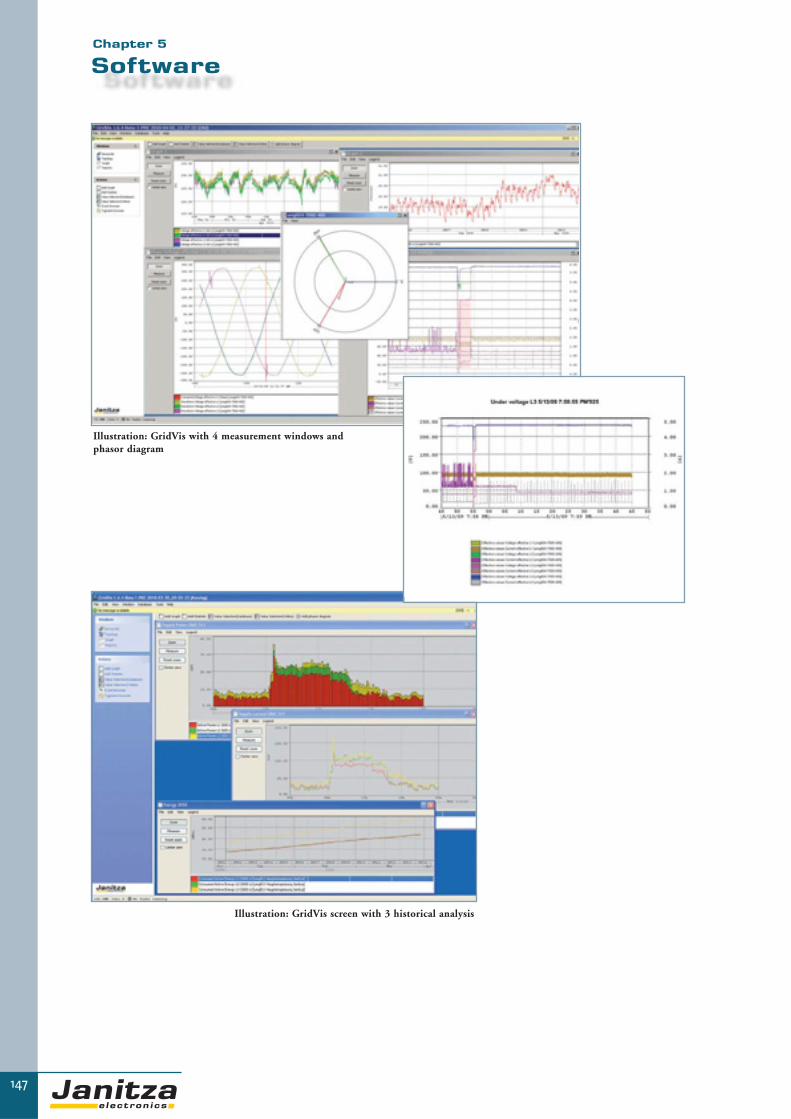
147
SoftwareChapter 5
Illustration: GridVis screen with 3 historical analysis
Illustration: GridVis with 4 measurement windows and phasor diagram

So
ftw
are
148
GridVis
Grid visualisation for more transparency in the network
The GridVis software is part of the standard package supplied with the power quality analysers,power analysers, universal measuring devices, data logger and power factor controller.
This software can be used to present the measurement values as actual values online and a graphicpresentation of the values read from the measurement value memory is possible.
The topology overview guarantees a quick overview of the complete electrical network. The GridVissoftware also serves the purpose of parameterisation of the measurement instruments. Furthermore,the creation of customer-specific programs is possible using our own developed programming language, Jasic®, or the user-friendly graphic programming periphery.

149
Software
Applications
The GridVis software has a multitude of applications:
� The development of extensive energy management systems� Visualisation of energy supplies with the help of a topology view� Documentation of power quality for freely definable periods of time� Analysis of the root causes of faults� Cost centre management i.e. simple and precise electricity cost calculation� Stabilisation of energy supply through the alarm function when limit values are exceeded e.g. overvoltage or short-term interruption� Improvement of power quality e.g. harmonic analysis for fault detection� Load profile analysis e.g. consumption prognosis for electricity contract negotiations
▼▼
Main features
The GridVis grid visualisation software enables the following:� Visualisation of measurement values� Automatic ring buffer readout from the connected measurement instruments� Storage of the data in a database� Graphical presentation of online measurement values� Configurable topology overview with freely selectable register levels� Configuration of the measuring instruments� Graphical programming of user programs or programming with Jasic® source code� Parameterisation, visualisation, data management and analysis� Measurement data analysis
GridVis
Software for grid visualisation
The GridVis software for programming and grid visua-lisation, which is part of the standard delivery package ofall power meters, enables a simple and complete para-meterisation of the power analysers. Customer specificvisualisation of the energy supply is possible with thetopology view. The individual measurement instrumentcan also be operated online using the mouse, if the cor-responding device supports this feature. Measurementdata can be directly recorded on the PC in online graphs.Furthermore, GridVis offers convenient opportunitiesfor presentation and analysis of historical data from thedatabase. The automatic ring buffer download and inte-grated data management has a particular positive effectin medium and large sized projects as data can be storedin various database formats. With the graphical pro-gramming, user specific programs can be created for themeasurement instruments families UMG 604, UMG605, UMG 508 and UMG 511.
Chapter 5

150
▼
GridVis
Programming and configuration
Using the software GridVis all power analysers are completely confi -gurable. Any name can be given to the instruments and connectionmode and PTs and CTs ratio values can be set. Trigger values for themeasurement of events and transients, as well as the measurementvalues which are to be stored and their recording intervals are determi-ned. Limit values for the monitoring function of the digital outputs areprogrammed using the comparator or the pulse value for the digitalinputs or outputs is established. The external temperature sensor can beselected. The time server for time synchronisation is also determined. Ifit is necessary to carry out an update on the measuring instruments, thiscan con veniently be done by the software without the instrumenthaving to be dismantled or returned to Janitza. The most recent upda-tes for software and instrument firmware are available free of charge atwww.janitza.de.
Illustration: GridVis indication of various online data
Illustration: Configuration of power analyser UMG 604
Online data
The software GridVis allows an individual collection, reading out and visualisation of online data. The received data of mul-tiple measuring points are collected, saved, processed, visualised and provided for further use. All measured values are availa-ble in the mode of online measurement either as a line graph or bar graph. The line graphs are permanently actualised andthe most obsolete data are cancelled. Two scales can be created for two different units per graph. Any number of measure-ment data from each unit, including from several measurement instruments, can be observed in the same graph. In the graphs,the indication of transients and events is displayed. The colour of the graphs can be adjusted as required.

151
Software
▼Chapter 5
▼
Topology View (Graphical User Interface)
A device view of any instrument in the network can be called up.Beside watching the actual display, you may also remotely control thecomplete instrument same as if you were on site. All measured datacan be displayed simultaneously. The topology gives a quick overviewof the energy distributions and the possibility to locate power failuresby comparing measuring points and checking the defined tolerances ata glance.Depositing some graphical files (common formats such as .jpg) withcircuit diagrams, flow processes or building plans and binding of thecorresponding instruments by drag and drop to their real position, youcan establish customer specific solutions quickly and simply. Limitviolations e.g. high THD-V as well as conditions of inputs or outputscan be indicated as well.
Event and transient browser
With the two functions EVENT- and TRANSIENT-browser, freelydefinable time periods can be checked regarding occurred events andtransients. These functions (e.g. illustration: transient browser) areespecially essential for failure analysis.
Data memory
Most measuring instruments have a memory. Reading out thememory, the data are saved within a database. e.g. Derby, SQL andMySQL are available. The most preferable databases are MySQL orMicrosoft SQL server databases, as they are much faster then the derbydatabase, which is of importance especially in large projects. MySQLcan be downloaded free of charge at www.MySQL.org.
Offline data
Data stored in the GridVis database can be displayed as line graphs,bar graphs or histogram. Also parameters such as year month andday are stored. Therefore, the data can be easily selected.Particularly interesting periods of time can be enlarged with thezoom feature. The graphs can be provided with titles and com-ments and be printed out. The display of transients and events alsotakes place here within the transient and event browser. The flagbrowser can be used to examine whether measurement data aremissing at certain periods of time or whether the data are not reli -able. With the anaysis of historical data you can build load profi-les, for exact demand analysis for optimised supply contracts. Alsofailure analysis by comparing various parameters can be carriedout by a few mouse clicks.
Illustration: Transient browser
Illustration: Freely configurable data saving and average times

▼
GridVis
Reporting and statistical functions
With the integrated reporting and statistical functions the following reports and information can be created, printed on paperor exported via HTML, Excel, images, or as PDF files.
� EN50160 Power Quality Report� EN61000-2-4 Report� Statistical functions� Cost Centre Report
152

153
Programming language Jasic® and Licences
Unlimited Programming Options
The programming language Jasic® opens up completely new possibili-ties. You are no longer limited to the device's built-in functions, but thedevice can be extended with your own functions and applications. Thegraphical programming is used to create and configure logical operationsor mathematical functions. You can activate your own digital outputsdepending on pre-defined thresholds for example, and digital inputs areevaluated. In addition, it is possible to analyze or write registers of exter-nal Modbus devices. With the tool "graphical programming" it ispossible to customize your own applications according specificrequirements and extend by far the functionality of the measure-ment devices of the UMG device series UMG 604, UMG 605, UMG508 and UMG 511. Even limit violations, timer functions or recordings of special values are user configurable with the graphical pro-gramming. The self-made programs can be stored on the computer as a file, or directly transmitted to the UMG measurement device.For the storage of your customized programs there are 7 memory locations, each with 128 kByte memory space available. The graphi-cal programming feature of customized programs is a real novelty in the field of digital power analyzers. Besides the user-friendly gra-phical programming the user is free to go directly for the source code programming, which opens even more advanced options.
Threshold monitoring (comparator)
In the example threshold moni-toring, we see two versions of themonitoring of a measurementvalue. The first example shows themonitoring of the current L1,with fixed constants the upperand lower threshold values aredefined. In case one of the pre-defined limit values is exceeded, adigital "1" signal is fed to thedigital output 1, means the digi-tal output is activated.
The second example is monito-ring the voltage L1, but only thelower threshold limit, means thedigital output 2 is activated incase of under voltage below180V.
LicensesOptional the following extension modules are available for GridVis
▼
GridVis licence 1, item number 51.00.117Graphic programming module – write/read ModbusThis allows the graphic programming of the UMG604 as aModbus master for reading/writing Modbus units using the graphic programming.
GridVis licence 2, item number 51.00.118Database driver for the Microsoft SQL serverThis enables the data exchange between the GridVis and a MS-SQL server. Without this driver, the GridVis software uses theintegrated Derby database.
GridVis licence 3, item number 51.00.119Database driver for the MySQL serverThis enables the data exchange between the GridVis and aMySQL server. Without this driver, the GridVis software uses the integratedDerby database.
GridVis licence 4, item number 51.00.120Devices driver for generic Modbus devicesIn addition to devices of the Janitza-UMG-families non-Janitza devices with Modbus protocol can be integrated.Any profiles for reading out of such devices can be created.
Chapter 5
▼

So
ftw
are
154
OPC server – the big, wide world of automation
Once a while it is required to incorporate measurement values from power analysers into non-Janitzavisualisation systems but the existing visualisation system does not support the protocol which is con-tained in the measuring instrument. OPC servers serve as an interface between the measuring instru-ment and the central building control system or PLC in these cases.
OPC drivers, therefore, offer a standardised interface for easy data exchange without exact knowledgeabout the communication options in the counterpart system.
The OPC can be used to link the measurement data with the data from other trades and archive itin the database structures for process control techniques. OPC drivers for process control techniquesare used by almost all renowned manufacturers of building automation systems.
OPC server
Modbus TCP/IPOPC variables
Intranet
GLT
OPC server
▼

155
OPC server
Modbus Suite TOP Server
Janitza electronics® GmbH has been recommending the proven and cost-effective OPC Top server with Modbus suite fromSoftware Toolbox (www.softwaretoolbox.com) for years. Support is also provided in connection with UMG measuring instrumentsand power analysers.
Functions of the OPC server
The OPC server is a software driver and must be installed on a PC in the network. If the existing automation software is alreadyrunning on a computer with sufficient power reserves and if the operating system is compatible with the OPC server, installation ispossible on this computer. If sufficient power reserves are available, the OPC server also runs on systems in which GridVis is alreadyinstalled. The software driver contains a Modbus TCP/IP or a Modbus over TCP/IP Master and an OPC server. The data (e.g. mea-surement values) is read out using the Ethernet interface (port 502 or port 8000) and is passed on to the OPC server. The OPC serverthen passes on the data to the OPC client of the external program. Access can be simultaneously gained to up to 6 software applica -tions on port 502 of the UMG 507E/EP and UMG 604E/EP. Another two applications can be simultaneously accessed on down streammeasuring instruments using the RS485 (Ethernet encapsulation). This means that measurement data can be simultaneously read withGridVis and the OPC server.
Configuration of the OPC server
The OPC server is configured using aconvenient operating area but does requi-re some basic knowledge of the data types(Word, float etc) and bus technology.Communication settings can be individu-ally adapted for each channel.
Following data typesare supported:
Char, Byte, Long, Float, Word andDouble as big-endian and little-endian.The OPC server also contains an OPCQuick Client for quick online control ofthe data. This means that the data isautomatically taken from the configuration table and displayed. The statistics functionassists fault detection.
The meaning of OPC
OPC is an abbreviation for “OLE for pro-cess control” and is a standardised interfa-ce in the field of automation technology.This term is frequently used in the field ofbuilding automation. OPC was created toprovide industrial bus systems and proto-cols with a universal communication possi-bility. An OPC driver can be integratedinto any size control and monitoringsystem without any major adaptationefforts.
▼▼
Illustration: Determining OPC variables
Illustration: OPC Quick Client
Illustration: Communication settings
Chapter 5
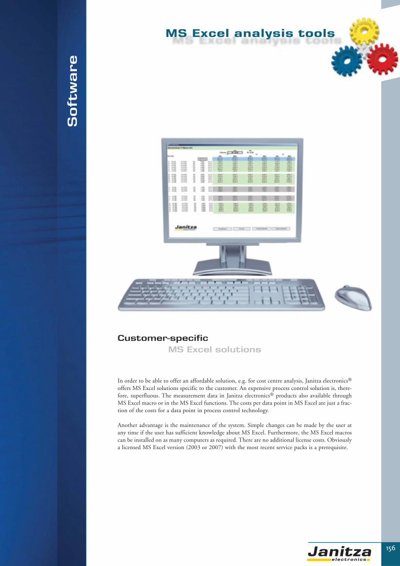
▼
So
ftw
are
156
Customer-specific MS Excel solutions
In order to be able to offer an affordable solution, e.g. for cost centre analysis, Janitza electronics®
offers MS Excel solutions specific to the customer. An expensive pro cess control solution is, there-fore, superfluous. The measurement data in Janitza electronics® products also available throughMS Excel macro or in the MS Excel functions. The costs per data point in MS Excel are just a frac-tion of the costs for a data point in process control technology.
Another advantage is the maintenance of the system. Simple changes can be made by the user atany time if the user has sufficient knowledge about MS Excel. Furthermore, the MS Excel macroscan be installed on as many computers as required. There are no additional license costs. Obviouslya licensed MS Excel version (2003 or 2007) with the most recent service packs is a prerequisite.
MS Excel analysis tools

157
Software
MS Excel analysis
The analysis of measurement data can be carried out using the software for the instruments or additionally by using the MS Excelmacros which are available as an option. The macros produce MS Excel functions similar to the familiar MS Excel function = sum ().The macros can be incorporated in MS Excel as an add-in. The macros use an ODBC driver to directly access the measuring instru-ment’s database. Complex analysis can be created even if the user only has moderate knowledge of MS Excel.
The customer specific MS Excel solutions, which are directly created by Janitza electronics®, can program progress charts and userinterfaces which are specially produced for the application. For example, it is possible to create a complete cost analysis as a PDFdocument with the push of a button. The integration of the building plan or the entering of a password is also possible.
You will not recognise the standard MS Excel at all. The MS Excel solutions developed by us come very close to visualisation systembut only cost a fraction of the price and do not have any complicated, expensive license management. You only require a licensedversion of MS Excel on the computer on which the analysis is to be carried out. The actual macros theirselves can be used as required.
▼▼
Main features
� Affordable, just a fraction of the cost per data point in comparison to process control visualization solutions� View changes can be undertaken by the end customer at any time if the customer has sufficient MS Excel knowledge� The complete functional diversity of MS Excel is available� Many users can access the database via MS Exel at the same time� Many programs can directly access MS Excel� The MS Excel macros are consistently adapted to the database models of Janitza electronics®.
This means that a rapid data flow rate is achieved.� The standard MS Excel terms are used for all Janitza® MS Excel functions such as sum = (..,...)� A standard file with the most important analysis is available free of charge� The software supports MS Excel 2003 and MS Excel 2007 with ribbon UI� A user interface in the look&feel function in Office 2007 (ribbon UI) can be created
Software GridVis
Database ODBC
MS Excel
Janitza electronics® Analysis
ODBC driver
Chapter 5

158
▼
Applications
The MS Excel functions which are especially programmed for the database model offer a wide range of selection options. For example, itis possible to let the software carry out a targeted search for peak values. It is even possible to create an average value over any period oftime and to create the maximum value of a measurement parameter. The loading of a transformer can also be identified at an early stage.Here is a small selection of the possible functions:
� AverageValue: provides the average value of a measurement parameter in a month� AverageDates: provides the average value of a measurement parameter within the time range� Maximum: provides the maximum value of a measurement parameter in a month� MaximumDates: provides the maximum value of a measurement parameter within the time range� MaximumDate_time_month: provides the date and time of the maximum value� Minimum: provides the minimum value of a measurement parameter in a month� MinimumDates: provides the minimum value of a measurement parameter within the time range� MinimumDate_time_month: provides the date and time of the minimum value� ConsumedRealEnergy: provides the effective energy drawn in a month� ConsumedRealEnergyDates: provides the effective energy drawn within the time range� Get_AvgValues_oneMonth: this function produces a list with measurement values for a month.
A total of more than 50 functions are available
Example of an application implemented with macros
MS Excel analysis tools

159
Software
▼▼
MS Excel VBA
VBA (Visual Basic for applications) is an independent, object-orientated programming language for MS Office applications. It serves thepurpose of expanding the extent of functions of MS office products. Through the use of these programs (macros), MS Excel becomes evenmore powerful because MS Excel tables can be automated for example.
Who can benefit from the MS Excel analysis tools?
Analysis tools are applied when functions of the GridVis softwaresystems are not sufficient. They, therefore, make sense for complex costcentre analysis, large-scale applications and when measurement data hasto be compared with certain specifications. The MS Excel analysis toolscan be an affordable introduction to the world of process control tech-nology for medium-sized companies which do not have their own buil-ding automation and visualisation. But MS Excel analysis tools can alsooffer an option to make necessary data accessible to all members of staffin large companies in which all employees may not have access to buil-ding automation. This means that consumption levels and power peakscan easily be passed on to controlling in customer specific form or invoi-ces can be issued directly from MS Excel if the MS Excel sheet alreadyhas an invoice template.
Function
The macros take the respective measurement data from the database created by GridVis and enter it in an MS Excel document. The timeperiods, for example, are now simply entered and the respective measurement values, consumptions, costs or other values calculated by MSExcel are issued as a graph or table. All MS Excel instruments are available for creating the MS Excel documents. The MS Excel macro isincorporated in MS Excel as an add-in. This can be used to create graphics of the building complex or systems. Set function keys can beused to zoom in on individual buildings or building parts in order to be able to monitor the incurred costs, consumptions or any othermeasurement data.
Illustration: graphic presentation of energy consumption per cost centre
Illustration: configuration of costs centres
Chapter 5
Total
Facilities
Hall 2
Hall 1
Hall B

▼
160
Advantages
The data are made available as measured in the databases of the various software systems of Janitza electronics® GmbH. However, in theMS Excel analysis tools any computing processes can be undertaken which are provided by MS Excel. The measurement data from themacros can be reprocessed in formulas. This means that the facility manager has almost unrestricted options for analysis e.g. for thecomparison with reference data, for percentage distributions, for comparisons of various properties or any graphs etc. This means that thecustomer is no longer tied to the rigid functions of ready to use software and can either create MS Excel sheets himself, whereby Janitzaelectronics® GmbH provides the macros, or he can allow Janitza electronics® GmbH to undertake programming of complete solutions(service against payment at very reasonable charges).
Procedures
In order to be able to create MS Excel solutions specific to the customer, Janitza electronics® needs a specification in which the functionsof the MS Excel analysis tools are described. The costs are exclusively based on the time needed for programming. These costs can be keptlow with active cooperation e.g. the customer provides prepared tables or building plans in MS Excel. Our sales team is pleased to sup-port you and work together with you on a suitable and affordable solution.
Illustration: actual comparison of energy consumption
MS Excel analysis tools
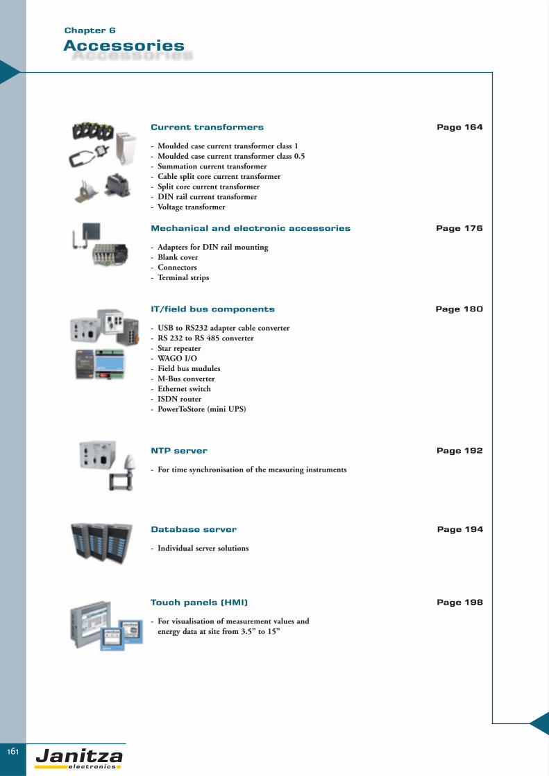
161
Accessories
Current transformers
- Moulded case current transformer class 1- Moulded case current transformer class 0.5- Summation current transformer- Cable split core current transformer- Split core current transformer- DIN rail current transformer- Voltage transformer
▼
Mechanical and electronic accessories
- Adapters for DIN rail mounting- Blank cover- Connectors- Terminal strips
IT/field bus components
- USB to RS232 adapter cable converter- RS 232 to RS 485 converter- Star repeater- WAGO I/O- Field bus mudules- M-Bus converter- Ethernet switch- ISDN router- PowerToStore (mini UPS)
NTP server
- For time synchronisation of the measuring instruments
Database server
- Individual server solutions
▼
Page 176
Page 180
Page 192
Page 194
Page 164
Touch panels (HMI)
- For visualisation of measurement values and energy data at site from 3.5” to 15”
Page 198
Chapter 6

▼
Ac
ce
ss
ori
es
162
Accessories
The respective communication systems are necessary
for the development of extensive energy
management systems.
Janitza electronics® offers a wide range of
field bus components such as converters
and repeaters etc.
In order to be able to manage the large
quantities of data and maintain availability
over the years, we offer high
speed servers with the
necessary reliability.
Touch panels are used
for simple visualisation,
including in industrial
environments.

163
Accessories
Remote maintenance ISDNDatabase server
Ethernetswitch
M-Bus / RS232converter
JPC 150
UMG 508
UMG 604
JPC 35
GPS antenna for NTP server NTP server
UMG 96S
UMG 96SUMG 103Modbus slave digital outputs
Modbus slave relay outputs
Eth
erne
t TC
P/IP
Eth
erne
t TC
P/IP
Eth
erne
t TC
P/IP
M-B
us®
RS485
RS2
32
RS2
32
RS485
E-maxPFC
UMG 96S UMG 96S
PST
Chapter 6

Ac
ce
ss
ori
es
164
Current transformers – the link between power currents and digital technology
Obviously currents of several hundreds to thousands of Ampere cannot be directly digitally measured.Current transformers convert almost any amount of primary current into “bite-sized” secondary currents. The secondary output is .../1 or .../5A.
Janitza electronics® GmbH has a wide range of various current transformers whether these are moul-ded case type current transformer, summation current transformer or cable split core type transfor-mer.
It is recommended to select the accuracy classification of the current transformer to match the accuracyclassification of the connected measuring instruments.
Areas of application:
� Conversion of high primary currents into standardized secondary currents .../1A or .../5A� Transformer classes 0.5 or 1 depending on the instrument� Transformers are available for various bus bars and cables� Moulded case type transformers for cable or bus bars� Cable split core type transformers for cables when the electricity path cannot be opened� Summation current transformers
Current transformers

165
Moulded case current transformers
Applications
Current transformers are used when currents cannot be directlymeasured. They are a special form of transformers which transformthe primary current into a (mostly) smaller secondary current andgalvanically separate the primary and secondary circuits from eachother. Due to the physically determined saturation aspect of thecore material, additional protection against high currents in thesecondary circuit is achieved.
▼▼
General mechanical properties
� Sturdy plastic housing made of polycarbonate� Flame resistant in accordance with UL94VO
and self extinguishing� Nickel secondary clamps with positive-negative
screws (2Nm)� Integrated secondary clamp plates
All dimensions stated in these drawings are in mm.
Dimensional drawing 6A315.3 Dimensional drawing IPA40
Dimensional drawing IPA40.5
Dimensional drawing 7A412.3 Dimensional drawing 8A512
Chapter 6

166
▼
Technical data
� Nominal frequency 50 Hz to 60 Hz� Insulation class E (other classifications upon request)� Thermal short-term current Ith = 60 x IN/1s� Surge current Idyn = 2.5 x Ith, minimum
100kA for all bushing type current transformers� Highest voltage for materials Um = 0.72kV� Calculation of insulation level (test voltage) 3kV/1 min (in accordance with EN6044-1)� Overvoltage limit factor FS5 or FS10� Harmonic currents up to the 50th harmonic
Secondary current transformers .../1A upon request.
Dimensional drawings – refer to page 165.
Overview of current transformers class 1
Des
crip
tion
Type
(di
men
sion
al
draw
ing
pg 1
65)
Pri
mar
y cu
rren
t in
A
Seco
ndar
y cu
rren
t in
A
Pow
er i
n V
A
Cla
ss
Pri
mar
y co
nduc
tor
Cir
cula
r co
nduc
tor
Con
stru
ctio
n w
idth
Item
num
ber
Current transformer 50/5 -1
IPA 40 50 5 2.5 1 40x10mm, 30x15mm, 25x20mm 30mm 70mm 09.05.110
Current transformer 75/5 -1
IPA 40 75 5 2.5 1 40x10mm, 30x15mm, 25x20mm 30mm 70mm 09.05.112
Current transformer 100/5 -1
6A315.3 100 5 2.5 1 30x15mm, 20x20mm 28mm 60mm 09.00.404
Current transformer 150/5 -1
6A315.3 150 5 5 1 30x15mm, 20x20mm 28mm 60mm 09.00.452
Current transformer 200/5 -1
6A315.3 200 5 5 1 30x15mm, 20x20mm 28mm 60mm 09.00.424
Current transformer 250/5 -1
6A315.3 250 5 5 1 30x15mm, 20x20mm 28mm 60mm 09.00.425
Current transformer 300/5 -1
6A315.3 300 5 5 1 30x15mm, 20x20mm 28mm 60mm 09.00.426
Current transformer 400/5 -1
6A315.3 400 5 5 1 30x15mm, 20x20mm 28mm 60mm 09.00.427
Current transformer 500/5 -1
6A315.3 500 5 5 1 30x15mm, 20x20mm 28mm 60mm 09.00.428
Current transformer 600/5 -1
6A315.3 600 5 5 1 30x15mm, 20x20mm 28mm 60mm 09.00.429
Current transformer 800/5 -1
7A412.3 800 5 5 1 40x12mm, 2x30x10mm 33mm 70mm 09.00.981
Current transformer 1000/5 -1
7A412.3 1000 5 5 1 40x12mm, 2x30x10mm 33mm 70mm 09.00.982
Current transformer 1250/5 -1
8A512.3 1250 5 5 1 50x12mm, 2x40x10mm 42mm 85mm 09.01.412
Current transformer 1500/5 -1
8A512.3 1500 5 5 1 50x12mm, 2x40x10mm 42mm 85mm 09.01.413
Accessories
Snap fixing For EN50022-35 DIN rails, suitable for IPA 30 and IPA 40 versions 09.09.000
Snap fixing For EN50022-35 DIN rails, suitable for 6A315.3, 7A412.3 and 8A512.3 versions 09.09.001
Moulded case current transformer
class 1

167
Moulded case current transformer class 0.5
▼▼
Technical data
� Nominal frequency 50 Hz to 60 Hz� Insulation class E (other classifications upon request)� Thermal short-term current Ith = 60 x IN/1s� Surge current Idyn = 2.5 x Ith, minimum
100kA for all bushing type current transformers� Highest voltage for materials Um = 0.72kV� Calculation of insulation level (test voltage) 3kV/1 min (in accordance with EN6044-1)� Overvoltage limit factor FS5 or FS10� Harmonic currents up to the 50th harmonic
Overwiev of current transformers class 0,5
Des
crip
tion
Type
Pri
mar
y cu
rren
t in
A
Seco
ndar
y cu
rren
t in
A
Pow
er i
n V
A
Cla
ss
Pri
mar
y co
nduc
tor
Cir
cula
r co
nduc
tor
Con
stru
ctio
n w
idth
Item
num
ber
Current transformer 50/5 -0,5
IPA 40.5 50 5 2,5 0.5 40x10mm, 30x15mm, 25x20mm 30mm 70mm 09.05.250
Current transformer 75/5 -0,5
IPA 40.5 75 5 2,5 0.5 40x10mm, 30x15mm, 25x20mm 30mm 70mm 09.05.252
Current transformer 100/5 -0,5
IPA 40.5 100 5 5 0.5 40x10mm, 30x15mm, 25x20mm 30mm 70mm 09.05.234
Current transformer 150/5 -0,5
IPA 40.5 150 5 10 0.5 40x10mm, 30x15mm, 25x20mm 30mm 70mm 09.05.236
Current transformer 200/5 -0,5
6A315.3 200 5 3,75 0.5 30x15mm, 20x20mm 28mm 60mm 09.00.360
Current transformer 250/5 -0,5
6A315.3 250 5 5 0.5 30x15mm, 20x20mm 28mm 60mm 09.00.361
Current transformer 300/5 -0,5
6A315.3 300 5 5 0.5 30x15mm, 20x20mm 28mm 60mm 09.00.362
Current transformer 400/5 -0,5
6A315.3 400 5 5 0.5 30x15mm, 20x20mm 28mm 60mm 09.00.363
Current transformer 500/5 -0,5
6A315.3 500 5 5 0.5 30x15mm, 20x20mm 28mm 60mm 09.00.364
Current transformer 600/5 -0,5
6A315.3 600 5 5 0.5 30x15mm, 20x20mm 28mm 60mm 09.00.365
Current transformer 800/5 -0,5
7A412.3 800 5 5 0.5 40x12mm, 2x30x10mm 33mm 70mm 09.00.887
Current transformer 1000/5 -0,5
7A412.3 1000 5 5 0.5 40x12mm, 2x30x10mm 33mm 70mm 09.00.888
Current transformer 1250/5 -0,5
8A512.3 1250 5 5 0.5 50x12mm, 2x40x10mm 42mm 85mm 09.01.339
Current transformer 1500/5 -0,5
8A512.3 1500 5 5 0.5 50x12mm, 2x40x10mm 42mm 85mm 09.01.340
Secondary current transformers .../1A upon request.
Dimensional drawings – refer to page 165.
Chapter 6

▼
168
Summation current transformers (CTs)
Applications
Summation current transformers have the task of adding up the secondary currents from various main, CTs and, therefore, making the measurement of an instrument accessible. Summation current transformers redeliver a norm signal at theoutput. This means that not only an addition of the input currents takes place but also the sum is divided through the amo-unt of summands (number of inputs). We differentiate between summation current transformers for even and uneven maintransformers.
General mechanical properties
� Sturdy plastic housing made of ABS, IP40� Flame resistant in accordance with UL94VO and self extinguishing� Nickel clamps with positive-negative screws � Integrated contact protection, IP10� Nominal frequency 50 Hz to 60 Hz� Insulation class E (other classifications upon request)� Thermal short-term current Ith= 60 x IN/1s
� Surge current Idyn=2.5 x IN� Maximum operating voltage Um = 0.72kV
(other voltages upon request)� Calculation of insulation level (test voltage)
3kV/1min (other voltages upon request)� Overvoltage limit factor FS5 or FS10
Note: the conversion ratio of the main CTs must be provided when placing an order.The ratio of the largest to smallest primary current should not be greater than 10:1 for uneven main transformers.
Overview of current transformers class 1
Des
crip
tion
Type
Pri
mar
y cu
rren
t in
A
Seco
ndar
y cu
rren
t in
A
Pow
er i
n V
A
Cla
ss
Item
num
ber
SCT 5+5 -1 IPS20 5+5 5 15 1 15.02.510
SCT 5+5+5 -1 IPS30 5+5+5 5 15 1 15.02.515
SCT 5+5+5+5 -1 IPS40 5+5+5+5 5 15 1 15.02.520
Overview of current transformers class 0.5
Des
crip
tion
Type
Pri
mar
y cu
rren
t in
A
Seco
ndar
y cu
rren
t in
A
Pow
er i
n V
A
Cla
ss
Item
num
ber
SCT 5+5 -0.5 IPS20 5+5 5 15 0.5 15.02.511
SCT 5+5+5 -0.5 IPS30 5+5+5 5 15 0.5 15.02.516
SCT 5+5+5+5 -0.5 IPS40 5+5+5+5 5 15 0.5 15.02.519
All dimensions stated in these drawings are in mm.

169
Cable split core CTs
▼Chapter 6
▼Application
The cable split core CTs of the types KUW1, 2 and 4, due to their very compact design and easy mounting, are well suitable for in limi-ted space or places difficult to reach. Cable split core CTs are especially used in cases, when the electricity path may not be interrupted.
Type KUW 1The cable split core CT, type KUW1 is a very compact current transformer and especially suitable for digital panel meters. The designof the CT provides correct mounting arround the cable and is closed with a clearly audible „click“. The two delivered cable binders ofUV-resistant material protect the CT additionally.
Types KUW 2 and KUW4The special rubber coating around the PVC housing keeps the parts of the current transformers togerther and additionally protectsagainst external influence. The UV-resistant cable binders enable a quick and convenient installation on the insulated primary cable.
The specified data below about burden and accuracy class refer to the ends of the multi-coloured coded, 5 meter long secondary leadswhich are supplied.
...for 18 mm cable diameter ...for 27 mm cable diameter
KUW1 KUW2
Technical dataApplication Indoor/only for insulated cables
Capacity Ith 60*In/1s
Overload capability 120 % duty cycle
Insulation material class E
Ambient temperature -5 to +40°C
Frequency 50/60Hz
Primary conductor Cable with max. 27mm diameter
Length of secondary conductor 5m, multicolour coded
Diameter 0.5mm2
Version PVC

170
Cable split core CTs
Overview of product variants
Type
Pri
mar
y cu
rren
t in
A
Seco
ndar
y cu
rren
t in
A
Bur
den
in V
A
afte
r 5m
Acc
urac
y cl
ass
afte
r 5m
Dia
met
er o
f
prim
ary
in m
m
Item
num
ber
Type KUW1 for insulated cables, max. 18mm diameter
KUW1-60 60 1 0.2 3 18 15.03.310
KUW1-75 75 1 0.2 3 18 15.03.311
KUW1-100 100 1 0.2 3 18 15.03.312
KUW1-125 125 1 0.2 3 18 15.03.313
KUW1-150 150 1 0.2 3 18 15.03.314
KUW1-200 200 1 0.2 3 18 15.03.315
Type KUW2 for insulated cables, max. 27mm diameter
KUW2-60 60 1 0.6 3 27 15.03.350
KUW2-75 75 1 1 3 27 15.03.351
KUW2-100 100 1 2 3 27 15.03.352
KUW2-125 125 1 2.5 3 27 15.03.353
KUW2-150 150 1 3.75 3 27 15.03.354
KUW2-200 200 1 3.75 3 27 15.03.355
KUW2-250 250 1 3.75 3 27 15.03.356
KUW2-300 300 1 0.5 - 3.75 1 - 3 27 15.03.357
KUW2-400 400 1 2.5 1 27 15.03.358
KUW2-500 500 1 5 1 27 15.03.359
Type KUW4 for insulated cables, max. 42mm diameter
KUW4-250 250 1 0.25 - 0.5 1 42 15.03.360
KUW4-300 300 1 0.25 - 0.5 1 42 15.03.361
KUW4-400 400 1 0.25 - 1.5 1 42 15.03.362
KUW4-500 500 1 0.25 - 2.5 1 42 15.03.363
KUW4-600 600 1 0.25 - 5 1 42 15.03.364
KUW4-750 750 1 0.25 - 5 1 42 15.03.365
KUW4-800 800 1 0.25 - 5 1 42 15.03.366
KUW4-1000 1000 1 0.25 - 5 1 42 15.03.367
KUW1 for primary diameter 18 mm
KUW2 for primary diameter 27 mm
KUW4 for primary diameter 42 mm
Dimensional drawing
All dimensions stated in these drawings are in mm.

171
Split core current transformers
Split core current transformer
For bus bars: 2 x 60 x 10mm60 x 10(35)mm
For cables: Max diameter 35mm
Split core current transformer
For bus bars: 2 x 80 x 10mm80 x 10(32)mm
For cables: Max diameter 32mm
Overview of product variants
Type
Pri
mar
y cu
rren
t in
A
Seco
ndar
y cu
rren
t in
A
Pow
er i
n V
A
Cla
ss
Item
num
ber
Split-100 100 5 3 3 15.02.800
Split-150 150 5 4 3 15.02.801
Split-200 200 5 5 3 15.02.802
Split-250 250 5 5 3 15.02.803
Split-300 300 5 7.5 3 15.02.804
Split-400 400 5 5 1 15.02.805
Split-500 500 5 7.5 1 15.02.806
Split-600 600 5 7.5 1 15.02.807
Split-750 750 5 10 1 15.02.808
Split-800 800 5 10 1 15.02.809
Overview of product variants
Type
Pri
mar
y cu
rren
t in
A
Seco
ndar
y cu
rren
t in
A
Pow
er i
n V
A
Cla
ss
Item
num
ber
Split-1000 1000 5 10 0.5 15.02.810
Split-1200 1200 5 10 0.5 15.02.811
Split-1250 1250 5 10 0.5 15.02.812
Split-1500 1500 5 15 0.5 15.02.813
Split-1600 1600 5 15 0.5 15.02.814
Split-2000 2000 5 15 0.5 15.02.815
▼Chapter 6
Dimensional drawing
Dimensionaldrawing
All dimensions stated in these drawings are in mm.

172
DIN-rail current transformer
▼
DIN-rail current transformer CT 35/1A and 64/1Awith voltage tap
While measuring in substations, there are often problems regarding the space, as vol-tage and current are necessary for each phase. Those problems can be solved by usingthe DIN-rail CTs, which combine three functions in one device. The DIN-rail CTconsists of series terminal, current transformer and voltage tap with fuse. The fuse isdirectly mounted on the primary and therefore the non protected part of the measu-ring cable is very short, which ensures a high intrinsic safety.
The DIN-rail CTs lead to simple wiring, low mounting costs and high reliability dueto less connections, retrenchment of space and rare connection errors.
Technical data Generals
Maximum voltage 690V
Insulation voltage 1890V / 50Hz 1min.
Rated current 67A
Maximum current (16 mm2) 76A
Protection class E
Protection IP 20
Ambient temperature -5 .. +40°C
Housing PA, 30% glas
Screw terminal Cross recess DIN 7962-H2
Series terminal Standard IEC60947-7-1
Connection diameter 1,5 bis 16 mm2
Voltage tap
Short-circuit strength 70kA at 400V; 50Hz
Connection diameter max. 4 mm2
Fuse5x25mm with indicating pin;
max. 2A SIBA DIN 41576-2
Current transformer Standard IEC60044-1
Capacity 60xIn/1s
CT variantsCT ratio Class Power Item number
35/1A 1 0.2VA 15.03.002
64/1A 0,5 0.2VA 15.03.003
Dimensional drawing
Connection diagram
32
72
92 96
All dimensions stated inthese drawings are in mm.

173
Current transformers
▼Chapter 6
DINCT64/1/1 – DIN rail current transformers
“Deeper” measurements (sub-distributions or loads/individual output) are more andmore common in electrical installations. The nominal currents are, therefore, relativelylow (64, 32 or 16A), the space is restricted and the accuracy of the current transformermust be sufficient for the power measurement (minimum class 1). These characteristicsare often difficult to combine.
The DINCT64/1/1 combines these characteristics in a single product. Due to the uni-que construction, no solder, crimp or clamp connections are required. The secondaryleads are 1 meter long.
Technical data
Transmission ratio: 64/1A (32/1A & 16/1A)
Accuracy: Class 1
Power: 0.5VA
Icth; continuous limit current: 120%
Ith; thermal limit current: 60xIn/1s
Frequency: 50Hz
Secondary lead diameter: 0.5mm2
Ambient temperature: 45°C max.
Standard: IEC6000-44-1
Material: PA6.6
Item number: 15.02.849
Applications
Primary lead Primary lead
Primary lead
Transmission ratio 64/1A1 x loopNominal measurement current 64AMax measurement current 76A
Transmission ratio 32/1A2 x loopNominal measurement current 32AMax measurement current 38A
Transmission ratio 16/1A4 x loopNominal measurement current 16AMax measurement current 19A
All dimensions stated inthis drawing are in mm.
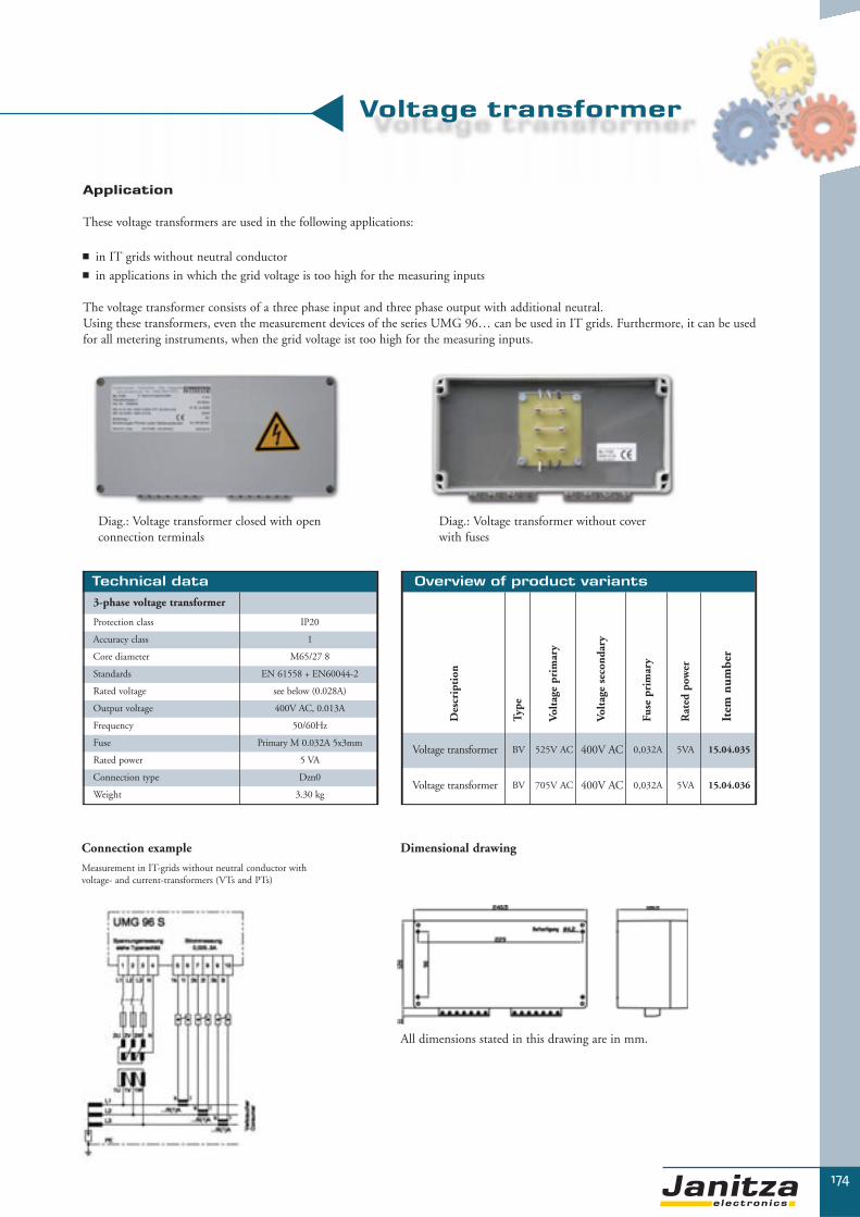
174
Voltage transformer
▼
Application
These voltage transformers are used in the following applications:
� in IT grids without neutral conductor� in applications in which the grid voltage is too high for the measuring inputs
The voltage transformer consists of a three phase input and three phase output with additional neutral.Using these transformers, even the measurement devices of the series UMG 96… can be used in IT grids. Furthermore, it can be usedfor all metering instruments, when the grid voltage ist too high for the measuring inputs.
Diag.: Voltage transformer closed with openconnection terminals
Diag.: Voltage transformer without cover with fuses
Technical data
3-phase voltage transformer
Protection class IP20
Accuracy class 1
Core diameter M65/27 8
Standards EN 61558 + EN60044-2
Rated voltage see below (0.028A)
Output voltage 400V AC, 0.013A
Frequency 50/60Hz
Fuse Primary M 0.032A 5x3mm
Rated power 5 VA
Connection type Dzn0
Weight 3.30 kg
Overview of product variants
Des
crip
tion
Type
Volt
age
prim
ary
Volt
age
seco
ndar
y
Fuse
pri
mar
y
Rat
ed p
ower
Item
num
ber
Voltage transformer BV 525V AC 400V AC 0,032A 5VA 15.04.035
Voltage transformer BV 705V AC 400V AC 0,032A 5VA 15.04.036
Dimensional drawingConnection example
Measurement in IT-grids without neutral conductor with voltage- and current-transformers (VTs and PTs)
All dimensions stated in this drawing are in mm.

175
Current transformer accessories
▼▼
Voltage taps
A fast voltage tap is often required for measurement tasks. With the ZK4S and ZK4B voltage taps, the tap can take place directlyfrom a copper rail.
ZK4S
Colour: black
Connection measurement cable = 4mm2
Fuse: 250V 6,3A
For bus bars 4 - 15mm
Item number: 10.11.525
ZK4B
Colour: blue
For bus bars 4 - 15mm
Item number: 10.11.526
ZK4B
Chapter 6
Technical specification
Max operating voltage 690V
Test voltage/pulse 3kV/50Hz 6kV
In max 10A
Insulation material class E (max 120°)
Fuse type5x25mm (with alarm)10A SIBA DIN41576-2
Short-circuit resistance 10kA@400V/50Hz
Protection class IP20
Environmental temperature -5...+40°C 1)
Temperature increase on rails Max 75K 1)
Primary connection M8 interior Allen screw
Interior Allen wrench Number 6
Maximum rail thickness 15mm / 4mm
Housing Polyamide (PA6.6)
Clamp material Nickel plated brass
1 set of voltage taps
Consisting of 3 x voltage taps ZK4S (item number 10.11.525) and
1 x voltage tape ZK4B (item number 10.11.526)
Item number: 10.11.527
ZK4B
Dimensional drawings All dimensions stated in these drawings are in mm.
ZK4S
ZK4R
Isolated Tool for fixing the taps
1000V EN/IEC60900:2004
Item number: 10.11.528
ZK4S
1) Max temperature of primary rail 120°C (sum of environmental temperature and temperature increase of the rail)

Ac
ce
ss
ori
es
176
Mechanical and electronic accessories– assembly and installation assistance
Instruments often have to be mounted on DIN rails, cut-outs in doors which are no longer neededmust be closed, digital outputs have to be made potential-free and so on and so forth. Janitza elec-tronics® GmbH supplies little helpers which make mounting work easier for the customer.
Areas of application:
� DIN rail mounting of front panel mounting devices� Covering or reducing the size of cut-outs� Connection of RS485 bus interfaces� Potential separation of outputs� Power filters for the protection of the UMG series against heavy network interference
▼
Mechanical accessories

Mechanical accessories for UMG devices
Description Type Item number
Calibration protocol UMG (available for all UMG except UMG 96L)
33.03.300
Adapter for DIN rail mounting UMG 96L / UMG 96 / UMG 96SDimensions: W x H x D = 85 x 113 x 90 mm
AH96 52.09.201
Adapter for DIN rail mounting UMG 96S with ProfibusDimensions: W x H x D = 85 x 113 x 90 mm
AH96P 52.09.202
Adapter for DIN rail mounting UMG 505 / 503 / 507, Prophi®
Dimensions W x H x D = 160 x 80 x 80 mmAH144 52.07.666
Sealing (front protection class to IP65) for UMG 96-96S
Sealing (front protection class to IP65) for UMG 503-511,
and Prophi®
D96
D144
29.01.907
29.01.903
Blank cover in black plastic 96 x 96 mm BA96 29.12.001
Blank cover in black plastic 144x144 mm BA144 29.12.002
Adapter plate 144 mm to 96 mm RAL 7032
Adapter plate 144 mm to 96 mm RAL 7035
AB144/1
AB144/2
29.12.912
29.12.913
177
Mechanical accessories
▼▼
Chapter 6

▼
178
Mechanical accessories
Accessories for universal measuring instruments
Description Type Item number
Profibus connector 9 pole, SUBCON-PLUS-ProfiB/AX/SC AX/SC 13.10.539
Accessories for universal measuring instruments
Description Type Item number
Ethernet front feed-through with extension frame and RJ45 socket type VS-08-BU-RJ45/BU
EFD 13.080.16
Protective cover; flat design for covering the RJ45 contact insert in the extension frame
EFDD 13.080.17
Grid filter for the UMG 96 NF96 52.09.200
Some instruments with Profibus connections require a Profibus connector. The incoming bus cable is connected to the1A/1B terminal and the continuing bus conductor is connected to the 2A/2B terminal. The slide switch is used to activa-te the terminal resistance at the beginning and end of the bus system. The terminal clamps (2A/2B) are simultaneouslyswitched off for the continuing bus conductor.
Note:For the UMG 507, the Profibus connector is alsoused for the Modbus.

Accessories for universal measuring instruments
Description Type Item number
Function module mounted on DIN rails for the UMG 507,
digital outputs on coupler relay (potential free converter)
with power supply and 2m cable (ready to use)
KMK6 52.15.200
Extra: KMK6-UMG 507
� Function module mounted on a DIN rail for the UMG 507� Digital outputs on coupler relay (potential free converter) with
24V DC power supply and 2m cable (ready to use)� Power supply input voltage: 115 ... 230V AC� Nominal power per relay: 8A / 250V AC� Application: maximum demand monitoring of UMG 507 for 6 loads;
a WAGO module is required for more than 6 loads
Extra: circuit diagram
179
Mechanical accessories
▼▼
Chapter 6
UMG 507
KMK6
2m

Ac
ce
ss
ori
es
180
IT and field bus components
In addition to simple data collection with power analysers, industrial data communication, i.e. the
transfer, central storage and processing of the data, also plays an important role in energy management.
Janitza electronics® offers frequently used and proven IT and field bus components supported by
Janitza®. Interface converters are included together with IO modules, repeaters, industrial Ethernet
switches, ISDN modems, signal converters and a mini UPS for problem-free operation of your
system.▼
IT and field bus components

181
Field bus components
▼Chapter 6
De-centralized fieldbus IO-modules series FBM10
The FBM10 series is a cheap alternative to the WAGO I / O system. All FBM10 modules have an interface RS485 with Modbus RTUprotocol and can be used as slaves to the devices of the UMG 604, UMG 605, UMG 508 and UMG 511 series. The UMG 104 andUMG 507 series cannot be used as a master for the FBM10 modules.
All FBM10 modules are configured and programmed accordingly by Janitza electronics® for each device.
Distance
The I/O modules of the FBM-series can be connected up to 1000m distance to the RS485 Modbus master. Cable type should be usedeither a Profibus cable or type Li2YCY (TP cable) 2x2x0.22.
Application of I/O Fieldbuses
The fieldbus module has no own intelligence, but it takes up the various input and output signals in order to distribute to the partici-pant. To use the fieldbus modules, a connection to each Modbus master device such as the UMG 604, UMG 605, UMG 508 or UMG511 is necessary.
With the inclusion of the remote I/O modules are to two different versions available. The user can basically integrate all data points inhis Janitza® system. In this case the Janitza® system is no longer limited only on electrical parameters. In principle, other values suchas process data, status, alarms, limits, alarm outputs or the like can be recorded. This values can be captured with the software GridVisfor live and historical data.
Example of using the outputs• E-Max-Outputs (max. 64)• Limit outputs for values
Example of use of inputs• E-Max blocking or release• Tariff change• Set point E-Max• Synchronization of measuring period • Alarms• Status messages
FBM10 I
FBM10 R

182
▼
Application
Technische Daten Auxilary voltage 24V DC ±20%
Load current 20mA
Bus protocol RS485, Modbus-RTU
Transmission rate 9600 bis 38.400Bit/s
Digital Input 24V DC, 5mA
Relay outputs 250V AC/6A-AC1 / 2A-AC3 potential free
Ambient temperature -10...+50°C
EMC according to EN 61326
Terminals Plug-in terminals up to 1.5 mm²
Case 45mm DIN rail mounted system H x W x D 90 x 88 x 58 mm
Mounting DIN rail
Humidity <95° r.H. noncondensing
Protection IP20
Standards CE conformity
Overview I/O fieldbus series FBM10Type Relais-Ausgänge Digital-Eingänge Artikel-Nr.
FBM10R 10 - 15.06.075
FBM10I - 10 15.06.076
RS-485, Modbus-RTU

Standard WAGO components
Description Item No.
Field bus coupler, Modbus RTU, RS485for digital and analogue signals, 9.6, 19.2, 38.4, 115.2 kBaud, supply voltage 24VDC
15.06.202
Field bus coupler, Ethernet TCP/IPfor digital signals, supply voltage 24VDC
15.06.204
Digital output terminal 2-channel relay, 230 VAC, 2 change-over 1A
15.06.250
Digital input terminal, 230VAC2 channel
15.06.271
Analogue output terminal 2-channel, 0...20mA 15.06.261
Analogue input terminal PT100/PT10003 conducter connection
15.06.273
End terminal 15.06.251
Interface cable UMG bus coupler RS485, 5m length 08.02.424
183
Field bus components
▼Chapter 6
De-centralized WAGO/I system for UMG 507, UMG 604, UMG 605, UMG 508 and UMG 511
Assembly
The decentralised field bus couplers of the WAGO I/O system are controlled usingthe RS485 Modbus RTU or using the Ethernet TCP/IP. Communication takes placebetween the UMG and one or more bus couplers into which the respective inputs andoutputs are plugged-in. The WAGO I/O system is fixed to a DIN rail. If the RS485is used, a Profibus cable or a suitable cable e.g. Li2YCY (TP) 2x2x0.22 should be usedwhereby the maximum distance between the master and slave must not exceed 1000 m.
WAGO standard components
The WAGO field bus couplers can generally be used with all plug-in terminals fromWAGO. However, only the most common ones are shown here:
The Ethernet field bus coupler 15.06.204 is used if RS485 cab-ling is not desired or not possible. The coupler reads the UMG507E/604/605/508 and UMG 511 marker status using theEthernet and switches the output terminals 15.06.250 accor-dingly. The allocation of the marker to the WAGO output takesplace through the web interface of the WAGO coupler.
Janitza electronics® takes over full configuration:
A program relating to the necessary outputs is loaded on to thecoupler before delivery. The following data is required for thedelivery: future IP adress of the UMG 507/604/605/508/511and WAGO coupler, gateway and SubNetMask and the num-ber of required outputs. Delivery can only take place once thisdata is provided.Application: diverse control tasks e.g. shutdown of consumers for
maximum demand management or fault indication.
Illustration: WAGO coupler with RS485connection (15.06.202) with outputs(15.06.250) and end terminal (15.06.251).

▼
184
Field bus components
Accessories for universal measuring instruments
Description Type Item number
RS232 <-> RS485 converter with galvanic separation and 3000 volt insulation;
variable baud rate 300...9600...baud 115 kBaud; incl. power supply 230V/sec.
12VDC, 300mA; max transfer length 1000m;
operating systems: Windows 2000/XP; software: PSW basic/professional; GridVis.
Products: UMG 96S, UMG 103, UMG 104, UMG 503, UMG 505, UMG 507,
UMG 604, UMG 605, ProData® and Prophi®
K-2075 15.06.015
RS485 repeater – 1 x RS485 input and output for extension of a RS485 network
with 31 further measuring instruments or a further 1000m transfer length; max. 7
repeaters possible in a RS485 network; with 3000V galvanic separation.
variable baud rate 300...9600...baud 115 kBaud (note: repeater is not suitable for
Profibus);
Products: UMG 96S, UMG 103, UMG 104, UMG 503, UMG 505, UMG 507,
UMG 604, UMG 605, ProData® and Prophi®
Power supply “connectpower” is required.
K-1075 15.06.024
RS485 HUB 1 x RS485 input and 3 x RS485 outputs for construction of a
star-shaped RS485 network with galvanic separation and 3000 volt insulation;
variable baud rate 300...9600...baud 115kBaud.
Products: UMG 96S, UMG 103, UMG 104, UMG 503, UMG 505, UMG 507,
UMG 604, UMG 605, ProData® and Prophi®
Power supply “connectpower” is required.
K-1375 15.06.035
RS485 <-> USB with galvanic separation and 3000 volt insulation; variable
baud rate 75...115kBaud; compatible with USB v1.1 standard; USB type-A
connector; incl. driver disc; max transfer length 1000m; operating systems:
Windows 2000/XP; software: PSW basic/professional; GridVis.
Products: UMG 96S, UMG 103, UMG 104, UMG 503, UMG 505, UMG 507,
UMG 604, UMG 605, ProData® and Prophi®
K-6175 15.06.025
RS485 star repeater IP65 1 x RS485 input and 5 x RS485 outputs for
construction of a star-shaped RS485 network for wall mounting in a IP65
industrial-housing (260 x 160 x 95mm) with 230V AC
power supply. Baud rate 9600 baud...153kBaud;
Note: the star repeater is also suitable for Profibus.
K-6585 15.06.017
RS232 <-> RS485 star repeater IP65 1 x RS232 input and 5 x RS485 outputs
for construction of a star-shaped RS485 network with RS232 PC connection
for wall mounting in a IP65 housing (260 x 160 x 95mm) with 230V AC
power supply.
K-6532 15.06.018
USB converter to RS232 adapter cable – converts USB-A output into a RS232
output, USB-A plug on to 9 pole sub plug, 1.8m, compatible with USB 1.1,
compatible with Windows 2000/XP; software: PSW basic/professional, GridVis.
Products: UMG 96S, UMG 103, UMG 104, UMG 503, UMG 505, UMG 507,
UMG 604, UMG 605 and ProData®
AD-232 15.06.032

185
Field bus components
Accessories for universal measuring instruments
Description Type Item number
Power supply for DIN rail mounting
prim. 115-230V 50/60 Hz
sec. 24VDC; 1A
Connectpower 16.05.002
DB-9 connection plug (with screw clamps) DB-9 plug 13.10.520
S0 converter – interface to M-Bus, baud rate M-Bus 2400, 9600 baud;
single S0 interface in accordance with DIN EN 43864 or potential-free pulse;
in support rail housing W26 x L75 x H111mm; IP40;
(products: UMG 96, UMG 96S, UMG 104, UMG 503, UMG 505, UMG 507,
UMG 508, UMG 511, UMG 604 and UMG 605)
PadPuls M1C 15.06.028
▼▼
Chapter 6

186
Field bus components
▼
Applications
The economic NS-208 Ethernet switch is suitable for connecting the Ethernet units in the switch board. The 8-fold switch whichsupports 10/100 base-T can be used anywhere where several Ethernet units must be connected with each other. It possesses all of thenecessary properties which can be expected from a non-configurable, industrial switch. With its robust plastic housing and the largetemperature range from -30°C to +75°C, it is ideal for industrial applications.
Industrial DIN rail Ethernet switch NS-208 Item number: 15.06.041
Hager switch, 5 ports TN025 Item number: 15.06.039
Technical data
� Switch: 8 x RJ45, 10/100MBit/s� Band width: 2.0 Gbps� ESD protection: 8kV direct contact
15kV discharge gap� Network cable: 10/100 Base-T
(Cat 5 UTP cable; 100m max)� Supply voltage: 10 to 30V DC
(separate power supply required)� Consumption: app. 0.12A at 24VDC; ± 5%� Cable connection
electricity supply: Removable screw clamps
� Dimensions (WxLxH): 64x110x97.5mm� Mounting: Mounting on DIN rail� Housing: Robust plastic housing� Operating temperature: -30 .. +75 °C� Storage temperature: -40 .. +85 °C� Humidity: 10 .. 90% (non-condensing)
General features
� 8 x 10/100 Mbps Ethernet-ports� Shielded RJ-45 connections� Automatic setting of the transfer rate� Compatible with IEEE 802.3, 802.3u and 802.3x
General features
� 5 ports switch for DIN rail mounting� 10/100 Mbit/s transfer rate� For 5 power analysers� RJ45 plug sockets with protective caps for plug sockets which are not in use� Integrated power supply (230V) (+/- 10%) 50 Hz� Protection class II, protection type IP20� Dimensions: 6 units
Application:
for mounting in installation boards e.g. next to a UMG 508, UMG 511,
UMG 604 and UMG 605.

187
Remote maintenance solution by ISDN
The option of remote maintenance by ISDN offers a more cost effective alternativeto an on-site visit. No matter whether you want to read the memory of the measuringinstrument or if you are interested in the parameterisation of the peak demand mana-gement system. With the JaTeNe router, it is almost like being personally on-site. Youcan freely and flexibly organise online times. But the router can manage even more.In the case of a fault, e.g. short-term interruptions, you are automatically informedby e-mail.
Areas of application
� Reading-out the memory of the measuring instruments� Configuration changes for peak demand management� Changes to memory configurations� Support when creating and changing parameters� Automatic e-mail despatch if faults occur
(UMG 507E, UMG 604E, UMG 605, UMG 508 and UMG 511)
Application:
The Janitza® Telephone Network router => JaTeNe router of Janitza electronics® combines an IDSN modem, a router and a 4-portswitch. The dial-in and dial-out function allows remote maintenance and remote control of instruments which are found within theEthernet network. The JaTeNe router is equipped with an integrated ISDN-TA. The integrated four port switch allows direct connectionof up to 4 measuring instruments. The JaTeNe router can be easily and quickly configured using the web interface. The router has thefollowing functions:
� Integrated communication module (ISDN TA)� Dial in� Dial out (dial on demand)� 4 port switch with 10/100 MBit/s� DHCP server and client� Integrated configuration area with auxiliary function� Authentication for up to 10 users (dial in)
� Selection filter for dial out� Authentication using PAP, CHAP, MSCHAP, MS-CHAP 2� Simple configuration� Local or remote configuration� Firmware update (local and remote)� Buffered RTC (real-time clock)
PST
GridVis on client computerwith ISDN card
UMG 511 UMG 96S UMG 96S
... up to 31 participants without repeater
Internet provider with SMTP server
The router requires anS0 (ISDN) connectionwith own MSN
Ethernetinterface
RS485 RS485
E-m
ail
Direct read / write
Field bus components
▼Chapter 6
JaTeNe Router-Modem-Switch

Prerequisites:
� On-site:� ISDN connection with its own MSN� 24 V DC supply to the router
� Computer:� ISDN card or USB ISDN modem (e.g. AVM)� ISDN connection
188
Direct despatch of e-mails is also possible. The UMG 507E or UMG 604E can generate an e-mail when faults are reported (e.g. short-term interruptions). The e-mail is sent to the router which automatically registers itself with an Internetprovider and sends the e-mail to the SMTP server. The configuration of the internet provider (dial out) and the e-mail SMTPconfiguration also take place using the convenient web-server of the router.
▼
Field bus components
Technical data
� ISDN: Euro ISDN up to 64kBits/s� Switch: 4 x RJ45, 10/100MBit/s� Supply voltage: 10..60VDC� Power consumption: ca. 3W� Cable connections: Screw clamps� Dimensions (WxLxD): 70x110x75mm� Mounting: Fixing on DIN rail� Housing: Plastic housing� Operating temperature: 0..+55 °C� Humidity: 0..95% (non-condensing)� Degree of protection: Housing IP40, screw clamps IP20� Weight: 300g� Item number: 15.06.040

189
Field bus components
▼▼
M-Bus signal converter PW60
M-Bus installations are characterised by their simple cabling. Janitza electronics® has madeaccommodations for this and has developed the UMG 96S with M-Bus interface. Using the signal process-controlled M-Bus level converter PW60, up to 60 x UMG 96S M-Buscan be connected to one PC (master). M-Bus software which is available on the market or theGridVis software can be used to analyse the data.
Features:
� Integrated RS232 interface (PC as master)� Galvanic separation between M-Bus and PC� Baud rates: 300 to 9600 baud� Bit recovery� Protection against excess currents and short-circuits in the M-Bus� Echo reduction and collision recognition with break signals� Operational display, data transactions, maximum bus current and excess current� External 24V DC or AC power supply is required� Housing for DIN-C rails or wall mounting� Dimensions (WxLxD) = 78 x 70 x 118mm� Protection class: IP20� Maximum network dimension for JYSTY Nx2x0.8 = 1km (9600 baud) 4km (2400 baud)� Maximum distance to slave for JYSTY Nx2x0.8 => 1200m� Power consumption: 15W� Operating voltage range: 20...45V DC or 20...30 V AC� Operating temperature range: 0...+55°C� Storage temperature: -20...60°C� Item number: 15.06.048
In GridVis, the following measurement parameters are available online with M-Bus:
Effective energy, effective energy purchase (purchase or high tariff ), effective energy (supply or low tariff ), reactive energy, reactive ener-gy (capacitive or high tariff ), reactive energy (inductive or low tariff ), apparent energy, comparator runtimes 1a to 2c, operating hoursmeter, current in N, effective power sum, reactive power sum, apparent power sum, UL1, UL2, UL3, IL1, IL2, IL3, PL1, PL2, PL3.
Note: it is not possible to read the UMG 96S memory with the M-Bus. However, online recording can be activated in GridVis. Pleasenote that due to the low M-Bus baud rates in case many measuring instruments are used longer delays can occur.
Application:
UMG 96SM-Bus
UMG 96SM-Bus
UMG 96SM-Bus
GridVis
M-BusM-Bus M-Bus
Level converter M-Bus to RS232
Simple installationin GridVis
Chapter 6

190
Field bus components
▼
PowerToStore 10F – mini UPS for UMG 604E
Capturing short-term interruptions is one of the strengths of the UMG 604/605/508/511. Due to the small constructionand the large memory, the instrument is ideally suitable for monitoring transformer stations. The UMG 604’s auxiliaryvoltage supply is provided through a switch mode power supply which has been developed for both DC and AC operation.Voltage interruptions of approximately 80ms are safely bridged. Voltage interruptions which are longer than 80 ms causethe UMG 640E to shut down. In order to capture longer short-term interruptions, the auxiliary voltage supply of the UMG604 must be backed up with a UPS. If a UPS is not available, the PowerToStore will be used. Usually batteries are used inUPS units. However, the disadvantage of batteries is the regular maintenance. The PowerToStore 10F is an energy bufferbased on capacitors. Therefore it does not require batteries and is maintenance free. The capacity level has been designedso that 3 x UMG 604E can be supplied with energy for approximately 3.5 minutes. The maximum number of UMG 604swhich can be connected is limited to 3 instruments.
Technical data
� Potential separation: yes� Input voltage: max. 240V AC (DC)� Output voltage: ca. 220V DC� Output current: max. 90mA� Storage capacity: 10 farad� Dimensions (WxHxL): 220 x 105 x 80 mm � Cable connections: screw/plug clamps� Mounting: fixing on din rail� Housing: aluminium mould housing� Operating temperature: -25° … +55°C� Lifespan: ca. 15 to 20 years at 40°C� Degree of protection: IP54� Weight: 1.5 kg� Item number: 15.06.400
Application
UMG 604 UMG 604 UMG 604

191
Field bus components
▼▼
Chapter 6
20.0A 5.00ms 500V 5.00ms2 1�� � �
Power quality
Kostenstellenerfassung
Januar
Verwaltung Küche Büro...
275,99 kWh 38,79 kWh 529,32 kWh
Februar 375,89 kWh 57,44 kWh 254,22 kWh
März 422,59 kWh 24,53 kWh 458,33 kWh
April 312,77 kWh 85,45 kWh 754,65 kWh
Mai... 775,29 kWh... 61,23 kWh... 451,32 kWh...
Drucken Gebäudeplan Aktuellen Monat aktualisieren
Peak demand management
P i
n kW
Load during the day Power savings Nominal value
Cost centre data collection
January
Administration Kitchen Office...
275,99 kWh 38,79 kWh 529,32 kWh
February 375,89 kWh 57,44 kWh 254,22 kWh
March 422,59 kWh 24,53 kWh 458,33 kWh
April 312,77 kWh 85,45 kWh 754,65 kWh
May... 775,29 kWh... 61,23 kWh... 451,32 kWh...
Print Building plan Update current month
UMG 604● Power analyser (over 800 power parameters)
for electricity supply● Energy consumption and cost centre data
collection● Power quality monitoring● Peak demand controller● PLC function (7 free user programs)● Transient recorder● Event recorder and data logger
The UMG 604 offers internet access andautomatic e-mail despatch for defined events. Visit the power analyser “LIVE” onthe homepage
www.umg604.janitza.de

▼
Ac
ce
ss
ori
es
192
NTP Time Server LANTIME
There is often the need to provide synchronised time information for various power analysers. This
is especially important in the field of power analysers because you want to compare voltage events
and transients for various measuring points with each other. The measuring instruments must have
the same clock setting if the events are to be clearly allocated. This means that any inaccuracies in the
internal instrument clocks must be balanced out. This is where so-called time or NTP servers are
used. They always provide precise time information thanks to the GPS antenna and wireless controls
and can supply this informations to the complete LAN network. LANTIME synchronises all systems
which are either NTP or SNTP compatible. This means that the UMG 507 (E/EP), UMG 508,
UMG 511, UMG 604 and UMG 605 of Janitza electronics® GmbH can be set to maintain a com-
mon time.
NTP server

193
NTP server
General technical data
Supply voltage 110…240VAC / 18…72VDC
Power frequency 50/60Hz
Mounting DIN rail
Working temperature range LANTIME 0…50 °C
Working temperature range GPSANT -40…65°C
Protection class In accordance with EN60529 IP 20
Item number Type: LANTIME 15.06.051
Communication
Interfaces
Ethernet TCP/IP 10/100 MBit with RJ45 Yes
USB For update / back up configuration Yes
RS232 For update / back up configuration Yes
Protocols
NTP, SNTP
IPv4, IPv6, DAYTIME, DHCP, HTTP, HTTPS, FTP, SAMBA, SFTP, SSH, SCP, SYSLOG, SNMP, TIME, TELNET, W32TIME
Yes
TCP, UDP Network protocol Yes
Installation
The corresponding GPSANT antenna and various accessories are partof the standard delivery. It can be installed 300m away from the LAN-TIME and in a position from which the most amount of unrestrictedsky is available (e.g. roof of a house).
Periphery
Receiver type 6 channel GPS C7A code 1
LED Fail (red), lock (green) 1 of each
Antenna type GPSANT Remote fed GPS antennae Included in delivery
Converter unit Included in delivery
Plastic pipe, mast holder Included in delivery
Distance 300m with RG58 standard cable 20m included in delivery
▼▼
Chapter 6

▼
Ac
ce
ss
ori
es
194
Database server
Extensive power quality monitoring and energy management applications require high-performance
server solutions. Janitza electronics® can support you with the selection of a suitable system.
Furthermore, we can offer you a high-performance server as a complete solution. Janitza electronics®
guarantees problem-free and immediate use.
Your system administrator only needs to integrate the server which we configure into your own net-
work. We supply a fully installed database server with GridVis software. You can choose between an
MSSQL or MySQL database.
Janitza electronics® uses high-performance towers or rack servers from Dell. Dell Power Edge- Servers
offer a high quality and reliability with maximum extension options. A high level of data security is
offered by the use of RAID 5 systems with HotPlug hard drives.
Server

195
We leave you also after the purchase not in the lurch...
With Janitza electronics® maintenance remote diagnosis, the service technician can remotely access your database server (only with yourpermission!) and can, therefore, diagnose and correct the problem within a few minutes. We use common remote maintenance solutionswith triple level coding according to industry standards.
We currently recommend the following server configuration for larger projects:
� Processor (dual core) AMD operton 2218
(Internal speed 2.6 GHz)
(External speed 1067 MHz)� L2 cache (full speed) 2MB� Memory (667 MHz SDRAM) 2GB ECC� HDD controller SATA or SAS� HDD - 3 x 146GB (HOT SWAP)� Video - SVGA� ServeRAID 8k� RAID 5 over 3 x 146GB, 1 x 146GB Hot-Spare� Ethernet controller 10/100/1000 Mbps� DVD - CDRW (IDE)� Power Supply with redundant power� Auto restart� System: XPprofessional or
SMALL business server 2003� MySQL or MSSQL
Quotes are available upon request
Areas of application
Recommended for larger projects with a high number of measuring instruments and everywhere where high data security and maximumperformance is required. Systems can be individually configured for small and large sized companies.
Server
▼
Application
The GridVis software works with an additional program as a service on the server. The user does not have to be logged on. For measure-ment value analysis, the client computers access the server directly through the network.
Chapter 6

196
▼
Server
Intranet
GridVis on theclient computer
GridVis on theclient computer
GridVis software: collection of measurement data on the database server
UMG 508 UMG 96S UMG 96S
... up to 31 participants without repeater
Ethernetinterface
RS485 RS485
UMG 511 UMG 96S
RS485 HUBK1375
UMG 96S
... up to 31 participants without repeater
... up to 31 UMGs
... up to 31 UMGs
(if branch lines are necessary)
Ethernetinterface
RS485 RS485 RS485
RS485RS485
RS485RS485
Application:
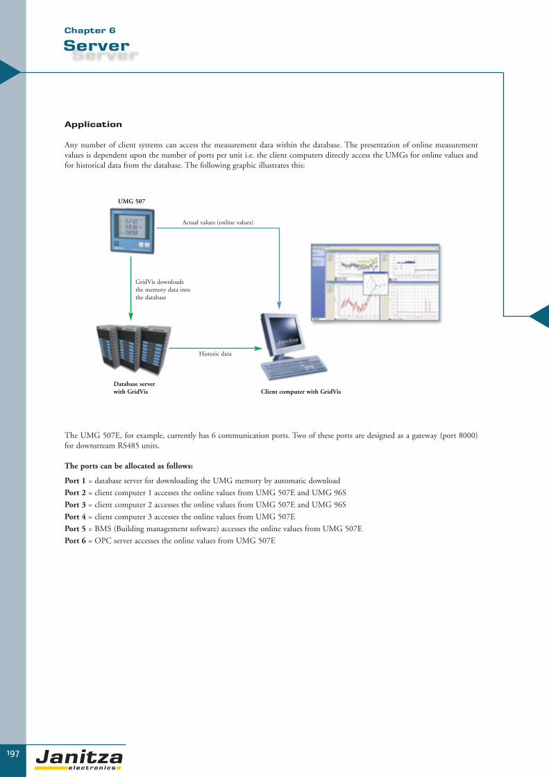
197
Server
Application
Any number of client systems can access the measurement data within the database. The presentation of online measurementvalues is dependent upon the number of ports per unit i.e. the client computers directly access the UMGs for online values andfor historical data from the database. The following graphic illustrates this:
The UMG 507E, for example, currently has 6 communication ports. Two of these ports are designed as a gateway (port 8000)for downstream RS485 units.
The ports can be allocated as follows:
Port 1 = database server for downloading the UMG memory by automatic download
Port 2 = client computer 1 accesses the online values from UMG 507E and UMG 96S
Port 3 = client computer 2 accesses the online values from UMG 507E and UMG 96S
Port 4 = client computer 3 accesses the online values from UMG 507E
Port 5 = BMS (Building management software) accesses the online values from UMG 507E
Port 6 = OPC server accesses the online values from UMG 507E
▼▼
UMG 507
Database serverwith GridVis Client computer with GridVis
Actual values (online values)
Historic data
GridVis downloads the memory data intothe database
Chapter 6

▼
Ac
ce
ss
ori
es
198
Touch panels
For user-friendly visualisation of measurement parameters without PC directly at site, touch panels
are a perfect solution. The simple installation, which is almost enabled with plug & play, guarantees
the rapid display of measurement values in the switch board door.
Numerous measuring instruments can be compiled on to one display. Just one cut-out is now suffi-
cient instead of several switchboard door cut-outs which were formerly required. This saves space and
costs and ensures that a better overview is achieved. Standard applications can be supplied for all
touch panels. Touch panels JPC104, JPC121 and JPC150, based on a web browser, can provide
customer-specific solutions upon request with a display of a circuit plan or the display of service
telephone numbers etc.
Touch panels
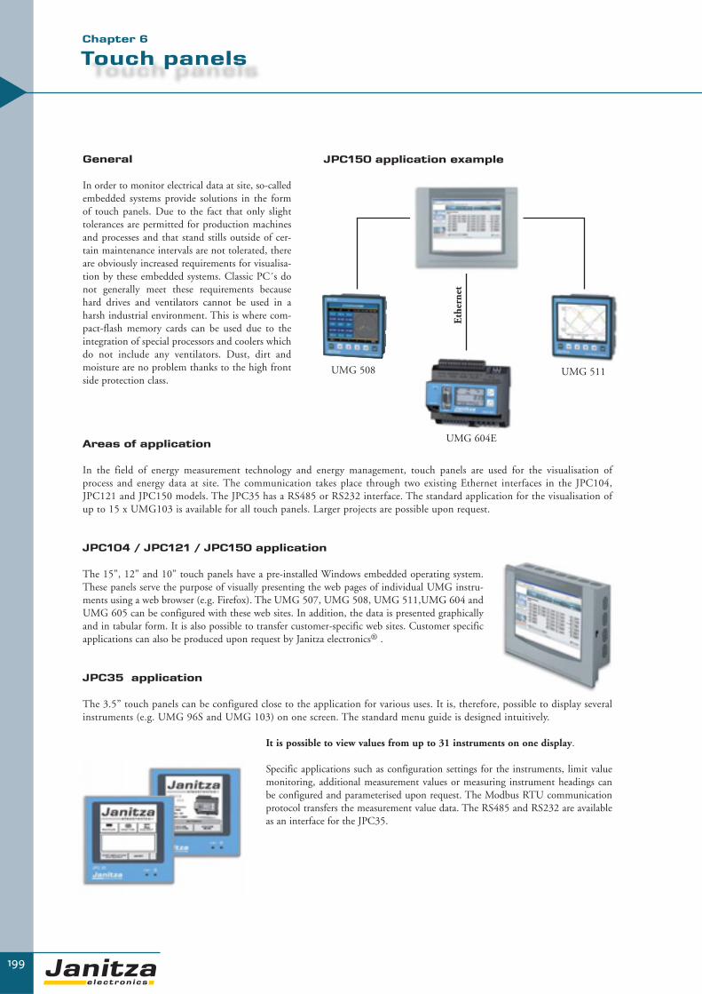
199
Touch panels
General
In order to monitor electrical data at site, so-calledembedded systems provide solutions in the formof touch panels. Due to the fact that only slighttolerances are permitted for production machinesand processes and that stand stills outside of cer-tain maintenance intervals are not tolerated, thereare obviously increased requirements for visualisa-tion by these embedded systems. Classic PC´s donot generally meet these requirements becausehard drives and ventilators cannot be used in aharsh industrial environment. This is where com-pact-flash memory cards can be used due to theintegration of special processors and coolers whichdo not include any ventilators. Dust, dirt and moisture are no problem thanks to the high frontside protection class.
JPC150 application example
Areas of application
In the field of energy measurement technology and energy management, touch panels are used for the visualisation of process and energy data at site. The communication takes place through two existing Ethernet interfaces in the JPC104,JPC121 and JPC150 models. The JPC35 has a RS485 or RS232 interface. The standard application for the visualisation ofup to 15 x UMG103 is available for all touch panels. Larger projects are possible upon request.
JPC104 / JPC121 / JPC150 application
The 15”, 12” and 10” touch panels have a pre-installed Windows embedded operating system.These panels serve the purpose of visually presenting the web pages of individual UMG instru-ments using a web browser (e.g. Firefox). The UMG 507, UMG 508, UMG 511,UMG 604 andUMG 605 can be configured with these web sites. In addition, the data is presented graphicallyand in tabular form. It is also possible to transfer customer-specific web sites. Customer specificapplications can also be produced upon request by Janitza electronics® .
JPC35 application
The 3.5” touch panels can be configured close to the application for various uses. It is, therefore, possible to display severalinstruments (e.g. UMG 96S and UMG 103) on one screen. The standard menu guide is designed intuitively.
It is possible to view values from up to 31 instruments on one display.
Specific applications such as configuration settings for the instruments, limit valuemonitoring, additional measurement values or measuring instrument headings canbe configured and parameterised upon request. The Modbus RTU communicationprotocol transfers the measurement value data. The RS485 and RS232 are availableas an interface for the JPC35.
▼
UMG 508
UMG 604E
Eth
erne
t
UMG 511
Chapter 6

200
Touch panels
JPC35 display
▼
There are standard visualisations and menu guides (refer to table) for up to 31 slave instruments for the JPC35.Specific applications and options are available upon request.
Standard Version
Measurement values Display range
Voltage: L1, L2, L3 / L1-L2 ,L2-L3,L1-L3 0…999999.9V
Current: L1, L2, L3, current in N 0…999999.9A
Effective power: L1, L2, L3, sum 0…999999.9 kW
Apparent power: Sum 0…999999.9 kVA
Reactive power: Sum 0…999999.9 kvar
Cosphi: L1, L2, L3, sum 0,00 kap - 0,00 ind
THD: UL1, UL2, UL3 0 - 100%
Frequency 45 - 65 Hz
Rotating field left / right
Average current 0…999999.9A with over line
Effective energy sum 0…99999999 kWh
Reactive energy ind. sum 0…99999999 kvarh
Special variants
Specific features on request - additional measurement values
Item no. 15.06.307 - Limit values
- special headlines
- customised menue

201
Touch panels
▼▼
Chapter 6
Application with JPC35, Item no. 15.06.308
Application with JPC35, Item no. 15.06.309
UMG 604
UMG 96S UMG 103 UMG 96S UMG 103 UMG 103
RS 232
RS 232
RS 485
UMG 604
Prerequisite components:
• JPC35, Item no. 15.06.308• 1 UMG604• 1 up to 31 UMG103 or UMG96S
Topology:
The JPC35 is connected via RS232 interface to the UMG 604.All slave-devices like UMG103 and UMG96S are connected via RS485. For the different displays, an EGG (program extension)hast o be installed or pre installed.
Features:
• Display of real values: UL1, UL2, UL3, ULL1, ULL2, ULL3, I1, I2, I3, ISUM, P1, P2, P3, PSUM, SSUM, QSUM, CosPhi1, CosPhi2, CosPhi3, CosPhiSum, THDU1, THDU2, THDU3, HZ, rotating field , AVG_I1, AVG_I2, AVG_I3, KWH, kvarh
• automatic monitoring of communication• delete kWh / kVArh / kVAh (UMG604)• Monitoring of limiting values
(UL1, UL2, UL3, I1, I2, I3,P1, P2, P3, CosPhi1-3)• Language selection (German, English, Spanish)• Configuration assistent
Prerequisite components:
• JPC35, Item no. 15.06.309• 1 UMG604
Topology:
For this application the standard values of the UMG 604 are displayed. The communication is via interface RS232. For this application is no EGG (program extension) required.
Features:
• Display of real values: UL1, UL2, UL3, ULL1, ULL2, ULL3, I1, I2, I3, ISUM, P1, P2, P3, PSUM, SSUM, QSUM, CosPhi1, CosPhi2, CosPhi3, CosPhiSum, THDU1, THDU2, THDU3, HZ, rotating field , AVG_I1, AVG_I2, AVG_I3, KWH, kvarh
• automatic monitoring of communication• delete kWh / kVArh / kVAh (UMG604)• Monitoring of limiting values
(UL1, UL2, UL3, I1, I2, I3,P1, P2, P3, CosPhi1-3)• Language selection (German, English, Spanish)• Configuration assistent

▼
202
Touch panels
Application with JPC35, Item no. 15.06.311
Application with JPC35, Artikel-Nr. 15.06.312
UMG 605
UMG 96S UMG 103 UMG 96S UMG 103 UMG 103
RS 232
RS 232
RS 485
UMG 605
Prerequisite components:
• JPC35, Item no. 15.06.311• 1 UMG605• 1 up to 31 UMG103 or UMG96S
Topology:
The JPC35 is connected via RS232 interface to the UMG 605. All slave-devices like UMG103 and UMG96S are connected via RS485. For the different displays, an EGG (program extension)hast o be installed or pre installed .
Features:
• Display of real values: UL1, UL2, UL3, ULL1, ULL2, ULL3, I1, I2, I3, ISUM, P1, P2, P3, PSUM, SSUM, QSUM, CosPhi1, CosPhi2, CosPhi3, CosPhiSum, THDU1,THDU2, THDU3, HZ, rotating field , AVG_I1, AVG_I2, AVG_I3, KWH, kvarh
• automatic monitoring of communication• delete kWh / kVArh / kVAh (UMG604)• Monitoring of limiting values
(UL1, UL2, UL3, I1, I2, I3,P1, P2, P3, CosPhi1-3)• Language selection (German, English, Spanish)• Configuration assistent
Prerequisite components:
• JPC35, Item no. 15.06.312• 1 UMG605
Topology:
For this application the standard values of the UMG 605 are displayed. The communication is via interface RS232. For thisapplication is no EGG (program extension) required .
Features:
• Display of real values: UL1, UL2, UL3, ULL1, ULL2, ULL3, I1, I2, I3, ISUM, P1, P2, P3, PSUM, SSUM, QSUM, CosPhi1, CosPhi2, CosPhi3, CosPhiSum, THDU1, THDU2, THDU3, HZ, rotating field , AVG_I1, AVG_I2, AVG_I3, KWH, kvarh
• automatic monitoring of communication• delete kWh / kVArh / kVAh (UMG604)• Monitoring of limiting values
(UL1, UL2, UL3, I1, I2, I3,P1, P2, P3, CosPhi1-3)• Language selection (German, English, Spanish)• Configuration assistent

203
Touch panels (HMI)
▼Chapter 6
Touch panels
Standard programming with 31 x UMG 96S / 103 is available for the larger touch panels. The UMG 604 E/EP or UMG 605 isused as a master. The application is fully created in FLASH and uses the web server of the UMG 604E/EP. FLASH adapts auto-matically to the various screen resolutions. Another major advantage is that the application can be called up within the networkwith any browser with FLASH plug-in. The view can be adapted to suit the specific customer requirements.
The “station selection” standard application contains 15 instruments but can be expanded customer request.
Illustration: Error report
Illustration: Communication error
Illustration: UMG 604 main distribution
Illustration: Station selection

204
Touch panels (HMI)
▼
Functions and technical data
Overview of product variants
Type JPC35 JPC104 JPC121 JPC150
Item number see application 15.06.300 15.06.301 15.06.302
Front panelResolution [Pixel] 240 x 240 800 x 600 800 x 600 1024 x 768
Brightness [cd/m2] 110 230 250 300
Number of colours 16 levels of grey 65,000 colours 65,000 colours 65,000 colours
Input Resistive touch Resistive touch Resistive touch Resistive touch
Screen diagonal 3,5’’ 10,4’’ 12,1’’ 15’’
General technical dataVoltage supply (external)
24 VDC ± 15% 24 VDC ± 20% 24 VDC ± 20% 24 VDC ± 20%
Weight [kg] 0,21 2,8 3,0 5,0
Operating temperature [°C]
0...50 0...50 0...50 0...50
Storage temperature [°C]
-10...60 -20...60 -20...60 -20...60
External measurements [mm]
96 x 96 x 40,6 318 x 244 x 81 364 x 296 x 74 452 x 357 x 86
Installation measurements [mm]
89,3 x 89,3 303 x 229 344 x 276 429 x 334
Front protection class IP65 IP65 IP65 IP65
CPUProzessor [MHz] 32 Bit RISC 300 300 300
CommunicationInterfaces
Ethernet, RJ45 No 2 2 2
RS485 Yes Option Option Option
RS232 Yes Yes Yes Yes
USB No 2 2 2
VGA No Yes Yes Yes
Keyboard/mouse No PS/2 PS/2 PS/2
Protocols
Modbus RTU Yes No No No
Ethernet TCP/IP No Yes Yes Yes
Operating systemXP embedded No Yes Yes Yes
Windows CE 4.1 No Yes Yes Yes
Windows 2000 No Yes Yes Yes
Applications (optional)Standard visualisation for 1-15 instruments (UMG 103 or UMG 96S)
Yes Yes Yes Yes
Customer-specific applications
Yes Yes Yes Yes
Web server No Yes Yes Yes
Please provide type and number of instruments to be visualized while placing your order.

205
Appendix
▼▼
Application at an energy supply company in Eastern Europe
In this project, an energy supply company wanted to link the measurements from its 110kV transformer station and 35kV sub-station with each other. The transformer stations are linked with the central control centre of the energy supply company byusing fibre optics. Communication is achieved with Ethernet - TCP/IP. Across various voltage levels depending upon the information required from the measuring point and the communication requirements various power analysers and measuring instruments where used. The aim was to read out the fundamental electrical values from all stations automaticallytogether with power quality measurement values and collect, store and analyse them centrally.
UMG 511
UMG 507E
UMG507ETR1• Short-term
interruption• THD-V• Transients• Peak loadPCC power quality
monitoring• EN50160• Short-term
interruptions• Transients• Gateway
• Power quality• Comparison of
energy efficiency
• IT environment• Server• Database• Analysis software• Clients• Analysis tools
Ethernet/TCP/IP via fibre optic conductor
110 kV Grid
35kV Grid
10kV Feeders
UMG 507E UMG 507E UMG 507E
UMG 96S UMG 96S UMG 96S UMG 96S UMG 96S UMG 96S
Chapter 7

▼
Ap
pe
nd
ix
206
Janitza electronics® GmbH...
…provides information in the appendix regarding the subjects of energy measurement technology,
power management, power quality solutions and logistics. Case studies and reference projects are also
shown. This information is intended to quickly provide our customers, distributors and representa-
tives worldwide with basic information.
More information and a collection of application reports can be found on our homepage at:
www.janitza.com
Important note
Some parts of the appendix chapter contain statements about the application, use or availability in
certain areas of use or applications. These statements are based on our experiences, typical applications
and typical requirements in connection with specific applications. It is the responsibility of the
customer to check whether a product of Janitza electronics® can be used with the res pective
specifications and specific standards for the application and whether the following information can
be applied to the specific application. The following information can be changed by us without pro-
viding information about the changes and can be updated if required. Our products are specified in
detail in our catalogues and operating manuals.

207
Cable diameters & fuse sizing
for power factor correction
We provide general non-binding information about common practices in this table. Connection diameters and the fuse rating aredependent upon the nominal power of the PFC system, the national regulations, the cable material used and the environmentalconditions. The recommendation for fuse amperage is only for short-circuit protection, HRC fuses are not suitable to protectPFC capacitors against overloading. The system manufacturer or the planning office is responsible for calculating and selectingcable diameters and fuses for each individual case.
PFC systems with a power level of more than 300 kvar have 2 separate bus bar systems and require 2 separate feeders. The tableapplies to conventional or de-tuned PFC systems. The actual valid regulations (e.g. DIN VDE 0298) must always be observed.
Important note: the bus bar separation must be allocated before extending any existing systems.
▼▼
Chapter 7
PFC cable diameters, fuses (for 400V/50Hz) networks
Power inkvar
Nominal current in A
Cable diameter NYY-J mm2
HRC fuse A
5 7 4 x 2,5 16
7,5 10 4 x 4 20
10 14 4 x 4 25
12,5 18 4 x 6 35
15 22 4 x 6 35
17,5 25 4 x 10 50
20 29 4 x 10 50
25 36 4 x 16 63
30 43 4 x 16 80
37,5 54 4 x 25 100
50 72 3 x 35/16 125
55 - 65 79 - 94 3 x 35/16 160
70 - 85 101 - 123 3 x 70/35 200
86 - 100 124 - 145 3 x 95/50 250
101 - 125 146 - 181 3 x 120/70 250
126 - 160 182 - 231 2’’ 3 x 70/35 315
161 - 180 233 - 260 2’’ 3 x 95/50 400
181 - 200 261 - 289 2’’ 3 x 120/70 400
201 - 250 290 - 361 2’’ 3 x 150/70 500
251 - 300 362 - 434 2’’ 3 x 185/95 630
Connection diameters are only valid for the given capacitor power levels
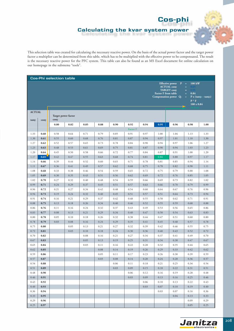
Cos-Phi selection table
Effective power P = 100 kWACTUAL cosϕ = 0.65TARGET cosϕ = 0.95
Factor F from table = 0.84Compensation power QC = P x (tanϕ1 - tanϕ2)
P * F100 x 0.8484 kvar
ACTUALTarget power factorcosϕtanϕ cosϕ
0.80 0.82 0.85 0.88 0.90 0.92 0.94 0.95 0.96 0.98 1.00
Factor F
1.33 0.60 0.58 0.64 0.71 0.79 0.85 0.91 0.97 1.00 1.04 1.13 1.33
1.30 0.61 0.55 0.60 0.68 0.76 0.81 0.87 0.94 0.97 1.01 1.10 1.30
1.27 0.62 0.52 0.57 0.65 0.73 0.78 0.84 0.90 0.94 0.97 1.06 1.27
1.23 0.63 0.48 0.53 0.61 0.69 0.75 0.81 0.87 0.90 0.94 1.03 1.23
1.20 0.64 0.45 0.50 0.58 0.66 0.72 0.77 0.84 0.87 0.91 1.00 1.20
1.17 0.65 0.42 0.47 0.55 0.63 0.68 0.74 0.81 0.84 0.88 0.97 1.17
1.14 0.66 0.39 0.44 0.52 0.60 0.65 0.71 0.78 0.81 0.85 0.94 1.14
1.11 0.67 0.36 0.41 0.49 0.57 0.62 0.68 0.75 0.78 0.82 0.90 1.11
1.08 0.68 0.33 0.38 0.46 0.54 0.59 0.65 0.72 0.75 0.79 0.88 1.08
1.05 0.69 0.30 0.35 0.43 0.51 0.56 0.62 0.69 0.72 0.76 0.85 1.05
1.02 0.70 0.27 0.32 0.40 0.48 0.54 0.59 0.66 0.69 0.73 0.82 1.02
0.99 0.71 0.24 0.29 0.37 0.45 0.51 0.57 0.63 0.66 0.70 0.79 0.99
0.96 0.72 0.21 0.27 0.34 0.42 0.48 0.54 0.60 0.64 0.67 0.76 0.96
0.94 0.73 0.19 0.24 0.32 0.40 0.45 0.51 0.57 0.51 0.64 0.73 0.94
0.91 0.74 0.16 0.21 0.29 0.37 0.42 0.48 0.55 0.58 0.62 0.71 0.91
0.88 0.75 0.13 0.18 0.26 0.34 0.40 0.46 0.52 0.55 0.59 0.68 0.88
0.86 0.76 0.11 0.16 0.24 0.32 0.37 0.43 0.49 0.53 0.56 0.65 0.86
0.83 0.77 0.08 0.13 0.21 0.29 0.34 0.40 0.47 0.50 0.54 0.63 0.83
0.80 0.78 0.05 0.10 0.18 0.26 0.32 0.38 0.44 0.47 0.51 0.60 0.80
0.78 0.79 0.03 0.08 0.16 0.24 0.29 0.35 0.41 0.45 0.48 0.57 0.78
0.75 0.80 0.05 0.13 0.21 0.27 0.32 0.39 0.42 0.46 0.55 0.75
0.72 0.81 0.03 0.10 0.18 0.24 0.30 0.36 0.40 0.43 0.52 0.72
0.70 0.82 0.08 0.16 0.21 0.27 0.34 0.37 0.41 0.49 0.70
0.67 0.83 0.05 0.13 0.19 0.25 0.31 0.34 0.38 0.47 0.67
0.65 0.84 0.03 0.11 0.16 0.22 0.28 0.32 0.35 0.44 0.65
0.62 0.85 0.08 0.14 0.19 0.26 0.29 0.33 0.42 0.62
0.59 0.86 0.05 0.11 0.17 0.23 0.26 0.30 0.39 0.59
0.57 0.87 0.03 0.08 0.14 0.20 0.24 0.28 0.36 0.57
0.54 0.88 0.06 0.11 0.18 0.21 0.25 0.34 0.54
0.51 0.89 0.03 0.09 0.15 0.18 0.22 0.31 0.51
0.48 0.90 0.06 0.12 0.16 0.19 0.28 0.48
0.46 0.91 0.03 0.09 0.13 0.16 0.25 0.46
0.43 0.92 0.06 0.10 0.13 0.22 0.43
0.40 0.93 0.03 0.07 0.10 0.19 0.40
0.36 0.94 0.03 0.07 0.16 0.36
0.33 0.95 0.04 0.13 0.33
0.29 0.96 0.09 0.29
0.25 0.97 0.05 0.25
208
Cos-phi
▼
This selection table was created for calculating the necessary reactive power. On the basis of the actual power factor and the target powerfactor a multiplier can be determined from this table, which has to be multiplied with the effective power to be compensated. The resultis the necessary reactive power for the PFC system. This table can also be found as an MS Excel document for online calculation onour homepage in the submenu “tools”.
Calculating the kvar system power

Selection table for fixed compensation of transformers
Transformer nominal power in kVA
Capacitornominal power in kvar
100 5
160 6.25
200 7.5
250 10
315 12.5
400 15
500 20
630 25
800 30
1000 40
1250 50
1600 60
2000 80
209
Fixed compensation
Note: • Values are guide values
only• The capacitor power
should be approx 90% of the idle motor power
• Over-compensation must be avoided to prevent overexcitation
Note: • Values are guide values only• Regional regulations of energy supply companies
must be observed• Pay attention to the respective back-up fuses
and short-circuit proof cables
▼▼
Chapter 7
Selection table – fixed compensation of motors
Motor power in kW
Capacitor power in kvar(dependent upon speed/minute)
1500 1000 750
1 - 1,9 0,5 0,6 0,7
2 - 2,9 1 1,2 1,3
3 - 3,9 1,5 1,7 2
4 - 4,9 2 2,3 2,5
5 - 5,9 2,5 2,8 3
6 - 7,9 3 3,5 4
8 - 10,9 4 4,5 5
11 - 13,9 5 6 7
14 - 17,9 6 7 8
18 - 21,9 7,5 8,5 10
22 - 29,9 10 11,5 12,5
30 - 39,9 ca. 40% ca. 43% ca. 50%
> 40 ca. 35% ca. 38% ca. 55%
Guideline values for fixed motor compensation (PFC) according VDEW

Direct connection via RS232 interfacePossible with:UMG 104 • UMG 503L, LG, OV, V • UMG 505 • UMG 507L, AD, P, E, EP • UMG 96S • Prodata®
UMG 604 • UMG 605
Connection with RS485 interfacePossible with: UMG 96S • UMG 103 • UMG 104 • UMG 503 • UMG 505 • UMG 507 • UMG 508 • UMG 511 • UMG 604 • UMG 605 ProData® • Prophi®
Neutral modem cable Item number• For UMG 503 08.02.405• For UMG 505 08.02.425• For UMG 96S 08.01.501
Item Item numberRS485 converter K2075 15.06.015RS485 repeater K1075 15.06.024RS485 hub K1375 15.06.035
210
Communication
▼
Overview of the available field buses and interfaces with the variousUMG families:
Neutral modem cable
RS232 RS232
Direct connection via EthernetPossible with: UMG 507E, EP • UMG 508 • UMG 511 • UMG 604E, EP • UMG 605
Item Item numberCross-Patch-Kabel 08.01.506
Cross patch cable
RS232
RS485 (without repeater max. 1000m)
Field buses & interfaces in the UMG family
Protocol UMG 103
UMG 104
UMG 96S
UMG503
UMG505
UMG507
UMG508
UMG511
UMG604
UMG605 Interface
ModbusRTU
XWithout RS232
X X X X XDSub9
XWithout RS232
XWithout RS232
X X RS232 RS485
ModbusTCP/IP
- - - - - X X X X X Ethernet RJ45
ModbusUDP
- - - - - X X X X X Ethernet RJ45
ProfibusDPV0
- X X - - X X X X X DSub9
MBus - - X - - - - - - - DSub9
LONBus - - - - X - - - - - Lon Interface
BacNet - - - - - - X X X XRS485Ethernet RJ45

Connection via Ethernet (intranet)Possible with: UMG 507E, EP • UMG 508 • UMG 511 • UMG 604E, EP • UMG 605
211
Communication
Item Item numberPatch cable 08.01.504
▼
Ethernet Ethernet
Connection via ISDNPossible with: UMG 507E, EP • UMG 508 • UMG 511 • UMG 604E, EP • UMG 605
Item Item numberISDN router 15.06.040
Post network
Computer withISDN card
Modbus gateway (intranet)Possible with master instrument types: UMG 507E, EP • UMG 508 • UMG 511 • UMG 604E, EP • UMG 605Slave: UMG 503LS, S, OV, V • UMG 507L, AD, P, E, EP • UMG 505 • UMG 96S • ProData® • Prophi®
UMG 103 • UMG 104
Item Item numberPatch-Kabel 08.01.504
IntranetEthernet Ethernet
RS485
MasterSlave instruments
RS485RS485 RS485
Ethernet
ISDN router
Connection via modemPossible with: UMG 503L, LG, OV, V • UMG 96S • UMG 505 • ProData®
Modem Modem
▼Chapter 7

212
Request for information
Request form for documents
Janitza electronics GmbHVor dem Polstück 135633 Lahnau / GermanyE-mail: [email protected]
FAX: 0049 6441 964230
Sender:
Company:
Name:
Street:
ZIP code / City:
Country:
Telephone:
Fax:
Mobile:
� Main catalogue
� Image brochure
� Price list
� UMG flyer
� CD Rom software
� AN1001 application report – PQM in power utilities
� Application report ...
� ISO9001 certificate
� Miscellaneous:
pcs
pcs
pcs
pcs
pcs
pcs
pcs
pcs
pcs
Please send me the following information:
Please copy this page, fill out the form and fax it to: 0049 6441 964230
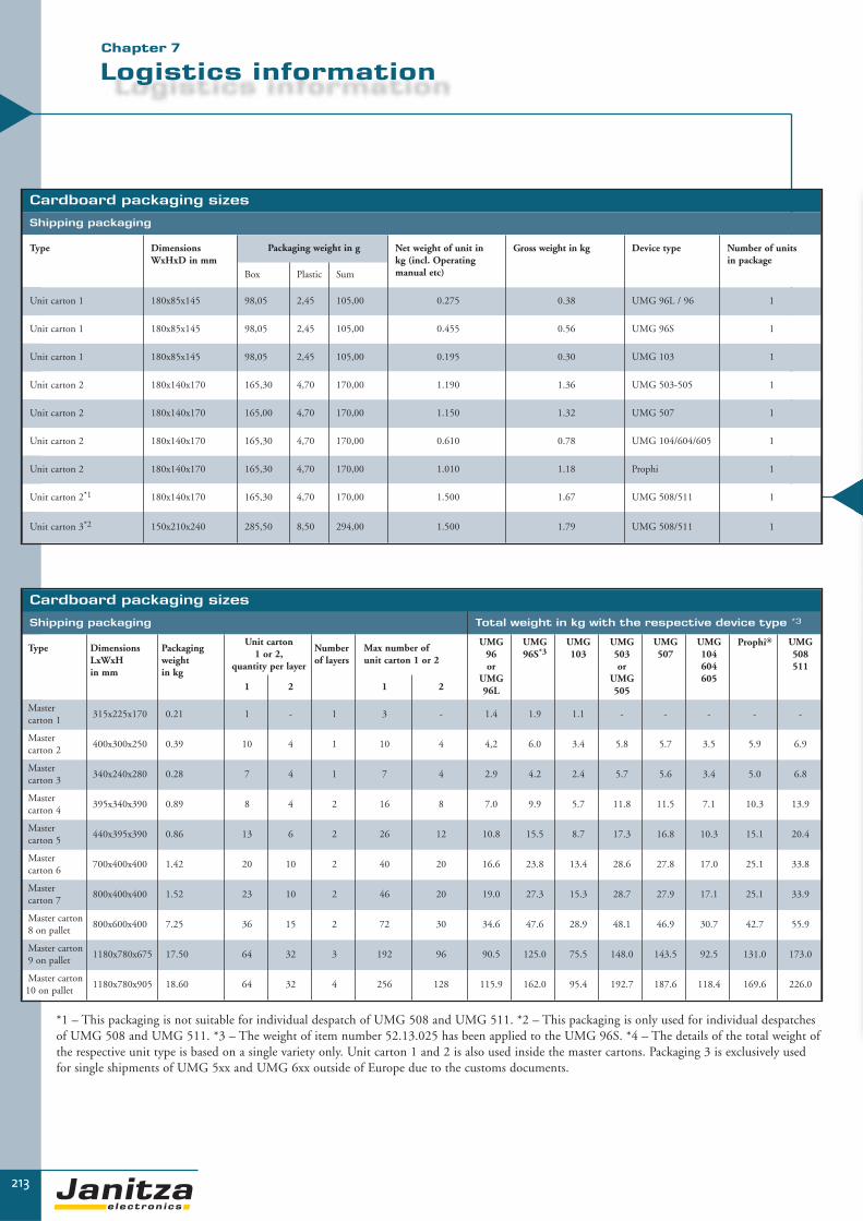
213
Logistics information
▼▼
Cardboard packaging sizes
Shipping packaging
Type DimensionsWxHxD in mm
Packaging weight in g Net weight of unit in kg (incl. Operating manual etc)
Gross weight in kg Device type Number of units in package
Box Plastic Sum
Unit carton 1 180x85x145 98,05 2,45 105,00 0.275 0.38 UMG 96L / 96 1
Unit carton 1 180x85x145 98,05 2,45 105,00 0.455 0.56 UMG 96S 1
Unit carton 1 180x85x145 98,05 2,45 105,00 0.195 0.30 UMG 103 1
Unit carton 2 180x140x170 165,30 4,70 170,00 1.190 1.36 UMG 503-505 1
Unit carton 2 180x140x170 165,00 4,70 170,00 1.150 1.32 UMG 507 1
Unit carton 2 180x140x170 165,30 4,70 170,00 0.610 0.78 UMG 104/604/605 1
Unit carton 2 180x140x170 165,30 4,70 170,00 1.010 1.18 Prophi 1
Unit carton 2*1 180x140x170 165,30 4,70 170,00 1.500 1.67 UMG 508/511 1
Unit carton 3*2 150x210x240 285,50 8,50 294,00 1.500 1.79 UMG 508/511 1
Chapter 7
Cardboard packaging sizes
Shipping packaging Total weight in kg with the respective device type *3
Type Dimensions LxWxH in mm
Packagingweight in kg
Unit carton1 or 2,
quantity per layer
Numberof layers
Max number of unit carton 1 or 2
UMG 96or
UMG 96L
UMG 96S*3
UMG 103
UMG 503or
UMG 505
UMG 507
UMG 104604605
Prophi® UMG 508511
1 2 1 2
Master carton 1
315x225x170 0.21 1 - 1 3 - 1.4 1.9 1.1 - - - - -
Master carton 2
400x300x250 0.39 10 4 1 10 4 4,2 6.0 3.4 5.8 5.7 3.5 5.9 6.9
Master carton 3
340x240x280 0.28 7 4 1 7 4 2.9 4.2 2.4 5.7 5.6 3.4 5.0 6.8
Master carton 4
395x340x390 0.89 8 4 2 16 8 7.0 9.9 5.7 11.8 11.5 7.1 10.3 13.9
Master carton 5
440x395x390 0.86 13 6 2 26 12 10.8 15.5 8.7 17.3 16.8 10.3 15.1 20.4
Master carton 6
700x400x400 1.42 20 10 2 40 20 16.6 23.8 13.4 28.6 27.8 17.0 25.1 33.8
Master carton 7
800x400x400 1.52 23 10 2 46 20 19.0 27.3 15.3 28.7 27.9 17.1 25.1 33.9
Master carton 8 on pallet
800x600x400 7.25 36 15 2 72 30 34.6 47.6 28.9 48.1 46.9 30.7 42.7 55.9
Master carton9 on pallet
1180x780x675 17.50 64 32 3 192 96 90.5 125.0 75.5 148.0 143.5 92.5 131.0 173.0
Master carton10 on pallet
1180x780x905 18.60 64 32 4 256 128 115.9 162.0 95.4 192.7 187.6 118.4 169.6 226.0
*1 – This packaging is not suitable for individual despatch of UMG 508 and UMG 511. *2 – This packaging is only used for individual despatchesof UMG 508 and UMG 511. *3 – The weight of item number 52.13.025 has been applied to the UMG 96S. *4 – The details of the total weight ofthe respective unit type is based on a single variety only. Unit carton 1 and 2 is also used inside the master cartons. Packaging 3 is exclusively usedfor single shipments of UMG 5xx and UMG 6xx outside of Europe due to the customs documents.

214
▼
The problem:
Transparency regarding energy costs and power quality is continuously becoming moreand more important in industrial companies. Energy consumption must be allocated tothe production stages and the final products in order to simplify pricing policies.
Due to the use of non linear consumers such as frequency converters, problems oftenarise with electronic equipment and controls. Reactive power compensation systems areusually subject to particularly high loads and, therefore, require skilled engineering.
Expensive peak loads can be avoided with intelligent peak demand management.
The task:
A supplier to the automobile industry decided to relocate its complete production facilities and construct the buildings in a “green belt” area. The company wanted tocollect consumption data for all welding robots together with compressed air consump-tion and heating supplies and provide the data to the controlling department.
The power quality from the four main feeds needed to be monitored and the four respective PFC systems needed to be integrated in the energy management system.
Peak demand management had to be anticipated in order to reduce high electricity costsdue to high loadpeaks, shutdowns of compressors and air conditioning units etc. for ashort period will be the solution. Intranet was available as a communication medium.
The solution:
The UMG 96 of Janitza electronics®, which passes on the effective pulses to theProData® data logger, was used as a meter for electrical en er gy consumption. Otherpulse meters for compressed air and heating were also connected to the ProData®
using the pulse outputs.
Four UMG 508´s were deployed in the four main feeders in order to determine thepower quality. Four Prophi® 12TS reactive power controllers were also visualisedusing the RS485 in GridVis software. Distinctive feature:
The four PFC systems work as a so-called mixed operation, which means that the baseload is compensated using the conventional contactors. The rapidly changing loadproportions, as caused by welding systems, are switched using thyristor modules.
This means that dynamic PFC can be created for almost the same price as the con-ventional compensation system. A globally unique feature of the Prophi®
controller. The UMG 511 works as peak demand management and as a master fordownstream WAGO modules as well as a gateway for the RS485 bus cable toEthernet/TCP/IP.
Project description – industry

215
Application example
▼▼
Chapter 7
PFC using the Prophi reactive power
controller
PFC using the Prophi reactive power
controller
PFC using theProphi reactive power
controller
PFC using the Prophi reactive power
controller
Consumer Consumer Consumer Consumer
power utilties 15min reset 230V
power utilties effec-tive pulse S0 inaccordance with
EN 62053-31
1 to 16 units
1 to 16 units
Load shedding of consumers for peak demand management through the UMG 508 using the decentralised function modules.
Effective energy consumption through the UMG96 orcollection of flow rate quantities, heating quantities orpulse generators
*1 Recommended power type: Li2YCY(TP) 2x2x0.22. Maximum cable length: 1000 m
*3 Recommended power type: Li2YCY(TP) 2x2x0.22. Maximum cable length: 100m
*2 Wiring is undertaken progressively in the bus structure. A stub may not be illustrated. Recommended power type: Li2YCY(TP) 2x2x0.22Maximum cable length: 1000m

216
▼
The problem:
Despite very similar buildings and consumer structures, the consumption and loads insupermarket stores can be very different. The reason for this can be the various manufacturers of deep freezers, lighting and ventilation systems which often have verydifferent levels of energy efficiency but it can also be due to the various sites with different weather conditions (snow, hours of sunlight etc), the number of customers eachday or the environmental awareness of the employees. Furthermore, non-linear consumersfrequently lead to serious problems with regard to power quality.
Therefore, it makes sense to measure consumption levels and loads together with the general power data in the stores, collect the data and benchmark the stores with eachother.
The task:
A supermarket chain wanted to measure the loads, consumption data and power qualityin the main feeders and several outputs in the respective stores and then collect the datain one main PC. With the help of concrete measurement data, stores with high con-sumption levels were intended to be identified in order to find reasons for the particu-larly high consumption and peak loads. The supermarket chain then wanted to reducepeak loads using peak demand management and monitor the power quality in the indi-vidual outputs with regard to harmonics, as produced by deep freezers for example. Inaddition, the consumption of gas and water was also to be measured and the data was tobe provided to the facility management. The communication media was an ISDNconnection.
The solution:
Stores:A UMG 507E was deployed in the main feeder which enabled direct access through anISDN router. On one hand, the device monitors power quality in the complete networkand on the other hand, allows peak demand management for six sheddable loads usingthe Emax function. The unit can be extended by up to 32 Emax channels using an external WAGO module. Additional superfluous consumptions can be avoided using atime switch program e.g. automatic switch-off for lighting when the store closes. Voltagebreaks and other events can be sent by e-mail with a document attachment upon request.The sub measurements are connected to the UMG 507E using an RS485 which alsofunctions as a gateway. Data from four outputs (freezers, ventilation, lighting and com-pressors) are collected using four UMG 96S´s with the clock and memory. The consumption of gas and water is measured using pulse meters and the pulse is passed onto the integral ProData®.
Headquarters:The data is compiled on a main data server. The measurement value memory in theinstruments is conveniently read-out using the PSW professional analysis software in theindividual stores. Due to the number of stores, the instruments are only read once permonth. The measurement data can easily be processed for the required time period com-parison in MS Excel sheets. These are integrated using MS Excel macros which read thedata produced by PSW professional into the database.
Project description – supermarket

217
Application example
▼▼
ISDN router(internet) or switch (intranet)
Ethernet/TCP/IP
Recommended power type: Li 2YCY(TP) 2x2x0.22
RS485/Modbus RTUMaximum 31 units in a
row without repeater
Pulse generator meterFor gas and water with S0 interface,
Max. 16 inputs per ProData®
UMG 507E
UMG 96S(Freezer feeder)
UMG 96S(Lighting feeder)
UMG 96S(Ventilation feeder)
UMG 96S(Compressor feeder)
• • • •
• • • •
Chapter 7

218
Project description – Bank
▼
The problem:
In banks, insurance companies and other commercial buildings, increasing power problems with reference to harmonics, flickers, voltage peaks and similar effects haveoccurred in the past years. Network perturbations are often transported into the buil-ding from the medium voltage network.
The reason for internal power problems is the large number of PCs and switched modepower supply units which are used. Due to the widely branched 5-conductor networks,so-called “stray” currents can occur in ground wires. These are caused by incorrect gro-unding. These particularly lead to problems in data networks because they proceed incables.
Flickering can lead to discomfort, headaches and tiredness among the members of staff.These disturbances are certainly not welcome because working in these types of buildings is made more difficult and may even become impossible without safe communication options. European norms have existed for several years for the assessment of network perturbations.
EN50160 regulates the power quality which must be provided by the energy supplier.The EN61000-2-4 provides the opportunity to measure the power quality within abuilding.
The task:
The power quality must be checked in a large bank at the feeders in accordance withEN50160 and at the sub-distributions in accordance with EN61000-2-4. Furthermore,the reasons for frequent problems in the data cables had also to be identified. Theemployees in building services should have access to the data at all times. Intranet wasprovided as the communication medium.
The solution:
A total of 39 x UMG 511 were installed in the feeders and all important distributionsfor communication, such as in the server rooms etc. An important feature is the fourth current and voltage input on the instrument. Due to the installation of the fourth current transformer in the protective earth conductor, stray currents could be trackeddown. Potential differences due to incorrect grounding were identified using a separatemeasurement with the bridge between N and PE.
The existing grounding errors could, therefore, be corrected. Obviously all of the datawith reference to the power quality and all current related data were stored in the 256MB memory of the UMG 511. The GridVis software could be used to read the data atany time. An Ethernet TCP/IP interface was available for this purpose.
The reasons for the frequent loss of communication in the data network were found andimportant knowledge about the power quality was gained. The producers of harmonicscould, therefore, be tracked down. Materials such as electronic controls or server supplyunits, which were previously destroyed due to network perturbations, could be protec-ted with suitable power filters.
Furthermore, the monitoring of the power quality from the energy supplier was madepossible in accordance with EN50160. A pleasing side-effect is the control of energypurchases or the power utility meter.

219
Application example
▼▼
Measurement in the distributionnetwork with main measurementand auxiliary measurement of pro-tective earth.
• •
••
• •
UMG 511
Ethernet switch
Client
UMG 511
UMG 511
GridVissoftware
Intranet
Chapter 7
UMG 511

▼
220
Notes

Janitza electronics®
221
▼

222
Notes

Janitza electronics®
223
▼

224
Notes

Janitza electronics®
225
▼

226
Notes

Janitza electronics GmbHVor dem Polstück 1D-35633 LahnauGermanyTel.: 0049 6441 9642-0Fax: 0049 6441 [email protected]
Sales partner
Item no.: 33.03.629 • Edition 07/2010 • All rights to technical changes are reserved.