you can do digital filtering with an mcu!
TRANSCRIPT

Renesas Electronics America Inc. © 2012 Renesas Electronics America Inc. All rights reserved.
You CAN Do Digital Filtering with an MCU!

© 2012 Renesas Electronics America Inc. All rights reserved. 2
Renesas Technology & Solution Portfolio

© 2012 Renesas Electronics America Inc. All rights reserved. 3
Microcontroller and Microprocessor Line-up
Wide Format LCDs Industrial & Automotive, 130nm
350µA/MHz, 1µA standby
44 DMIPS, True Low Power
Embedded Security, ASSP
165 DMIPS, FPU, DSC
1200 DMIPS, Performance 1200 DMIPS, Superscalar
500 DMIPS, Low Power
165 DMIPS, FPU, DSC
25 DMIPS, Low Power
10 DMIPS, Capacitive Touch
Industrial & Automotive, 150nm
190µA/MHz, 0.3µA standby
Industrial, 90nm
200µA/MHz, 1.6µA deep standby
Automotive & Industrial, 90nm
600µA/MHz, 1.5µA standby
Automotive & Industrial, 65nm
600µA/MHz, 1.5µA standby Automotive, 40nm
500µA/MHz, 35µA deep standby
Industrial, 40nm
200µA/MHz, 0.3µA deep standby
Industrial, 90nm
1mA/MHz, 100µA standby
Industrial & Automotive, 130nm
144µA/MHz, 0.2µA standby
2010 2012
32
-bit
8
/1
6-b
it

© 2012 Renesas Electronics America Inc. All rights reserved. 4
Challenge: “More and More Sensors are required by our “Smart” devices and reliable filtering is required to separate the signal from the noise.”
Solution:
“This lecture will introduce you to some of the basic concepts of Digital Filtering, low-cost Filter tools and help you avoid some of the more common pitfalls when implementing filters on the Renesas processor of their choice.”
‘Enabling The Smart Society’
Wireless
Module
Doctor, your
patient is in
distress Inphase Filter Frequency Response
Frequency in kHz
Mag
nit
ud
e in
dB
0.0 2.5 5.0 7.5 10.0 12.5 15.0 17.5 20.0 22.5-100
-80
-60
-40
-20
0
20

© 2012 Renesas Electronics America Inc. All rights reserved. 5
Agenda
System Block Diagram – analog filter
FIR vs IIR
Sampling theorem
Anti-aliasing
Oversampling
Triggering skew
ADC interrupt overhead
Decimation
Fixed point and floating point principles
Fixed point vs. floating point benchmark
Summary

© 2012 Renesas Electronics America Inc. All rights reserved. 6
Example Filter Applications
Sensor60 Hz
Filter
MCU
ADC
Instrument Board
Cabling
4 kHz
LowPass
MCU
ADC
Voice Recorder
Microphone

© 2012 Renesas Electronics America Inc. All rights reserved. 7
Filter Applications – The Boxcar Filter
Very common to perform a “running” average
Sum n samples, scale the output (usually divide by n)
Recalculate each time one new sample comes in
Very simple FIR called boxcar
All coefficients equal to 1
Example of 8 kHz sampling rate, 8 tap FIR

© 2012 Renesas Electronics America Inc. All rights reserved. 8
Filter Types - FIR
X[n] Z-1
b0
+
b1
Z-1
+
b2
Z-1
+
b3
Z-1
+
bM
X[n-N]
X[n-1] X[n-2]
Y[n]
nD Y”[n]
Typically the gain = 1
Does not always have Decimation
Decimation can be on front or back end
X[n] – Input samples
nD – Decimation Factor
Y”[n] – Decimated Output
B[n] – Coefficients (multiplies)
Z-1 – Delay elements (storage array)

© 2012 Renesas Electronics America Inc. All rights reserved. 9
Filter Types - IIR
In addition to a forward path there is a feedback path
Z-1
Z-1
+X[n]
bk1 b
k2
bk0 + + Y
k[n]
Z-1
-ak2
+
Z-1
-ak1
X[n] – Input samples
Yk[n] – Output
bk[n] – Feed forward Coefficients (multiplies)
-ak[n] – Feedback Coefficients (multiplies)
Z-1 – Delay elements (storage array)
© 2012 Renesas Electronics America Inc. All rights reserved. 10
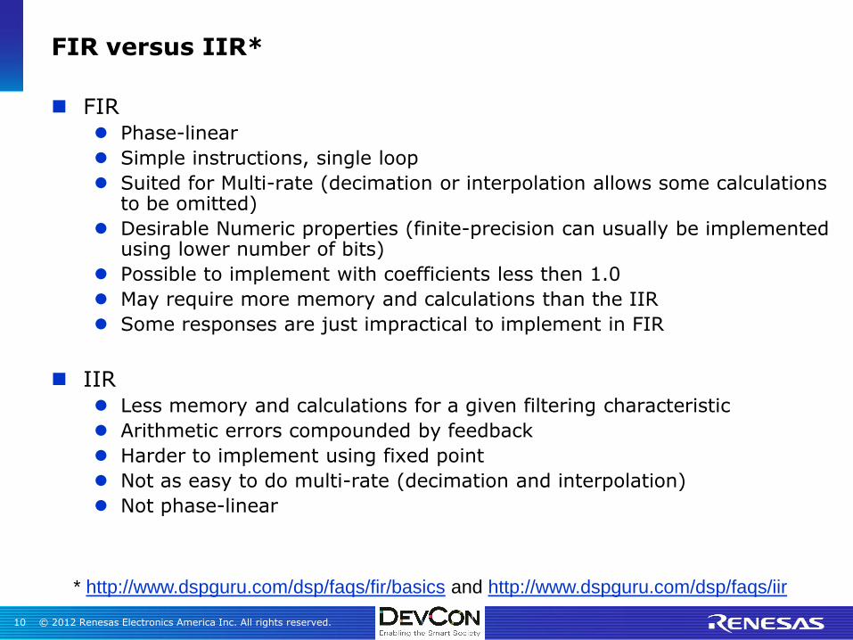
FIR versus IIR*
FIR Phase-linear
Simple instructions, single loop
Suited for Multi-rate (decimation or interpolation allows some calculations to be omitted)
Desirable Numeric properties (finite-precision can usually be implemented using lower number of bits)
Possible to implement with coefficients less then 1.0
May require more memory and calculations than the IIR
Some responses are just impractical to implement in FIR
IIR Less memory and calculations for a given filtering characteristic
Arithmetic errors compounded by feedback
Harder to implement using fixed point
Not as easy to do multi-rate (decimation and interpolation)
Not phase-linear
* http://www.dspguru.com/dsp/faqs/fir/basics and http://www.dspguru.com/dsp/faqs/iir

© 2012 Renesas Electronics America Inc. All rights reserved. 11
Designing the Filter
Programs like ScopeFIR, ScopeIIR or WinFilter simplify the task of designing a filter

© 2012 Renesas Electronics America Inc. All rights reserved. 12
Identifying the Noise
Programs like ScopeDSP allows inputting ADC data and running FFT

© 2012 Renesas Electronics America Inc. All rights reserved. 13
Identifying the Noise
The FFT clearly identifies a 1k,2K,4K and 8K component

© 2012 Renesas Electronics America Inc. All rights reserved. 14
Sampling Theorem
Nyquist-Shannon Sampling Theorem
“If a function x(t) contains no frequencies higher than B hertz, it is
completely determined by giving its ordinates at a series of points
spaced 1/(2B) seconds apart.”1
Sometimes this is incorrectly stated:
To not lose information you must sample at twice the highest frequency you
are concerned with in a signal
Simply stated:
A signal can only be properly sampled if it contains no frequencies greater
than one-half the sampling frequency

© 2012 Renesas Electronics America Inc. All rights reserved. 15
Aliasing Problem
Record voice data and store
Limit voice bandwidth to 4 kHz
Sample at 8 kHz
Problem - Audio contains energy above 4 kHz
Anti-aliasing filter
Adjust corner for 4 kHz

© 2012 Renesas Electronics America Inc. All rights reserved. 16
Anti-aliasing filter
-
+
8 nF
4 nF
7K 7K
Frequency (kHz)
Ou
tpu
t (d
B)
0 1 102 4 86
0
-12
- 12 dB is only an attenuation of 1/4

© 2012 Renesas Electronics America Inc. All rights reserved. 17
Anti-aliasing filter
Frequency / Hertz
1k 2k 3k 4k 5k 6k 7k 8k 9k 10k
dbV
@ R
1-P
/ d
B
-10
-8
-6
-4
-2
Actual Response of 2nd
Order 4 kHz Filter
Frequency (kHz)
Ou
tpu
t (d
B)
0
-2
-4
-6
-8
-10
-12
1 2 3 4 5 6 7 8

© 2012 Renesas Electronics America Inc. All rights reserved. 18
Frequency Response of 8 Tap 4 kHz Filter
-12dB line
20 dB attenuation at 8 kHz compared to 12 for analog filter

© 2012 Renesas Electronics America Inc. All rights reserved. 19
Improved 4 kHz Filter
By using 14 taps notice the improved attenuation at 6 kHz

© 2012 Renesas Electronics America Inc. All rights reserved. 20
Oversampling and digital filtering
Sample at 32 kHz instead of 8 kHz
Only signals 16 kHz or greater will alias
Could use simple RC or no anti-aliasing filter
© 2012 Renesas Electronics America Inc. All rights reserved. 21
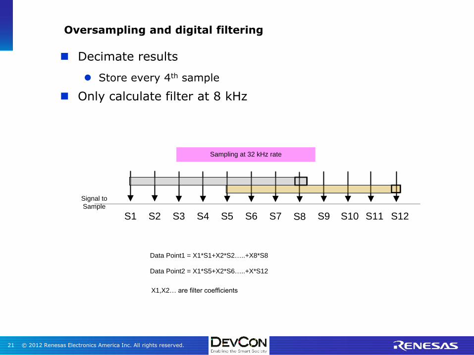
Oversampling and digital filtering
Decimate results
Store every 4th sample
Only calculate filter at 8 kHz
S1 S2 S3 S4 S5 S6 S7 S8 S9 S10 S11
Signal to
Sample
Sampling at 32 kHz rate
Data Point1 = X1*S1+X2*S2…..+X8*S8
Data Point2 = X1*S5+X2*S6…..+X*S12
S12
X1,X2… are filter coefficients

© 2012 Renesas Electronics America Inc. All rights reserved. 22
ADC Considerations - Skew
Problems:
Interrupt Skew
– 32 kHz requires sampling every 31.25 uS
Software start ADC possibility of sample skew
Other interrupts in the system
Long instructions required to complete
Solutions:
Possible - Make the start interrupt highest system priority
Preferred - Use ADC system that can be triggered by timer
– Some devices may have to loop a timer to ADC trigger

© 2012 Renesas Electronics America Inc. All rights reserved. 23
ADC Considerations - Overhead
Problem:
Interrupt Overhead Storing ADC Data
– Assume ADC ISR takes 40 cycles
• context save + data save and pointer adjust + context restore
Sampling at 32 kHz BW to store data = 1.28 million cycles
Solutions:
Use a DMA controller
4-5 cycles or less per transfer
CPU BW to store data <200 thousand cycles

© 2012 Renesas Electronics America Inc. All rights reserved. 24
ADC Considerations - Benchmark Example
RX allows triggering ADC from GPT/MTU2/MTU3 (timer)
DMAC transfers data to buffer
HW assist to acquire/transfer data to buffer saves*
~3% at 200kHz rate / 5K samples
~13% at 400kHz rate / 5K samples
~26% at 500kHz rate / 5K samples
* DevCon RX Performance lab
MTU2
Channel 0
ADC0
AD Trigger (160kHz)
DMAC
Channel
Memory
PING/PONG
BufferAN7
AD Complete
Complete Intr
(PING/PONG Rdy)*
Data to
Filter Task

© 2012 Renesas Electronics America Inc. All rights reserved. 25
Calculating the Filter
Design 4 kHz, 8 tap , lowpass filter Sampling rate 32 kHz
Passband 4 kHz
Stopband 8 kHz
Stopband attenuation 12 dB – actual 20 dB
Passband ripple = 2 dB - actual 0.76
Coefficients: -0.074778857796693535
0.020358522095065112
0.200149797853876850
0.366925297165379800
0.366925297165379800
0.200149797853876850
0.020358522095065112
-0.074778857796693535

© 2012 Renesas Electronics America Inc. All rights reserved. 26
Implementing the Filter
Could calculate the filter as:
result=0;
for (index = 0; index < taps; index++)
{
result += data[index] * coeff[index];
}
The problem is the coefficients are all fractional values

© 2012 Renesas Electronics America Inc. All rights reserved. 27
Options to Calculate the Filter
Use an MCU with an FPU
RH850 – 32 Bit RISC High Performance RISC
RX600 – High Performance CISC
SH2A like SH7269 – High Performance RISC
Use Floating Point Libraries
Can be very slow
Use Fixed Point Math
A little more complicated than floating point

© 2012 Renesas Electronics America Inc. All rights reserved. 28
Floating Point Numbers
Floating point value =
(-1)sb + (1+Fraction) x 2 (exponent – bias)
The exponent is expressed in biased form:
e = E + bias
Precision is function of fraction bits
Floating supports a very large dynamic range
Parameter Single Precision
Double Precision
Total bit Width
32bits 64bits
Sign bit 1bit 1bit
Exponent field
8bits 11bits
Significand 23bits 52bits
Precision 24bits 53bits
Bias +127 +1023
Emax +127 +1023
Emin -126 +1024
0 31 30 22
Significand part 23 bits (implied 1) Exponent 8 bits S
-28 27 26 25 24 23 22 21 20 2-1 2-2 2-3 2-4 2-5 2-6 2-7 2-8 2-9 2-10 2-11 2-12 2-13 2-14 2-15 2-16 2-17 2-18 2-19 2-20
Radix point
2-21 2-22 2-23
23

© 2012 Renesas Electronics America Inc. All rights reserved. 29
Floating Point Hardware
Single Precision
Min Value = 5.88 x 10e-39, Max value = 3.4 x 10e+38
Double Precision
Min Value = ~2.0 x 10e-308, Max value = ~2.0 x 10e+307
0 31 30 22
Significand part 23 bits (implied 1) Exponent 8 bits S
-28 27 26 25 24 23 22 21 20 2-1 2-2 2-3 2-4 2-5 2-6 2-7 2-8 2-9 2-10 2-11 2-12 2-13 2-14 2-15 2-16 2-17 2-18 2-19 2-20
Radix point
2-21 2-22 2-23
23
0 31
Significand part 32/52 bits (implied 1)
23 22 21 20
32 63 62 51
Significand part 20/52 bits (implied 1) Exponent 11 bits S
-212 211 210 29 28 27 26 25 24 2-1 2-2 2-3 2-4 2-5 2-6 2-7 2-8 2-9 2-10 2-11 2-12 2-13 2-14 2-15 2-16 2-17 2-18 2-19
Radix point
52
2-32 2-33 2-34 2-35 2-36 2-37 2-38 2-39 2-40 2-41 2-42 2-43 2-44 2-45 2-46 2-47 2-48 2-49 2-50 2-51 2-28 2-29 2-30 2-31 2-24 2-25 2-26 2-27 2-20 2-21 2-22 2-23

© 2012 Renesas Electronics America Inc. All rights reserved. 30
Fixed Point Fraction value is shifted (multiplied) by a value to make an integer
Example – Represent 19. 78 using 16 bit fixed point
– 1 bit for the sign – 19 requires 5 bits in binary – 10 bits left to represent fraction – Multiply the value by 1024 (shift left 10) – Could allocate more bits for integer and less for fraction
Example :
Calculate a 4 tap box filter using fixed point Assume ADC samples are
– 0x100 (256), 0x200 (512) , 0x120(288), 0x150(336) Coefficients are all 0.25
Solution
– Scale coefficients to be integers by multiplying by 4 (shift left 2)
– Multiply coefficients time ADC values • 1*0x100 + 1 *0x200 + 1*0x120 + 1 *0x150 = 0x570 (1392)
– Restore proper scaling (shift right 2) = 0x15C (348)
S 24 23 22 21 20 2-1 2-2 2-3 2-4 2-5 2-6 2-7 2-8 2-9 2-10

© 2012 Renesas Electronics America Inc. All rights reserved. 31
Precision Requirements
How many bits of coefficient are required?
Do not want round-off error to cause an LSB error
For 10 bit ADC need 10 bits coefficient
Each tap could accumulate error
– Additional bits depends on number taps
– 8 taps – add 3 LSB
– 16 taps – add 4 LSB
– Etc…

© 2012 Renesas Electronics America Inc. All rights reserved. 32
Pop Quiz:
Assuming: 12 bit ADC, 7 tap FIR filter
QUESTION: Is 16 bit Fixed Point enough resolution?
8 taps – add 3 LSB, for a total of 15 bits
Don’t forget the sign bit!
16 bit total

© 2012 Renesas Electronics America Inc. All rights reserved. 33
Some Benchmark Results
Using RL78/G14 (16 bit, 32 MHz MCU )
8 Tap Filter – 216 cycles (27 cycles per tap)
22 Tap Filer – 594 cycles (27 cycles per tap)
8 taps at 8 kHz = ~1.73 million cycles
(approximately 5.4% BW @ 32 MHz)
Each tap calculation requires
Multiply
Sum
Two Pointer Increments

© 2012 Renesas Electronics America Inc. All rights reserved. 34
A MAC Really Helps
Really need a MAC
RX has RMPA (software MAC), RL78 has MACH Unit
– RL78 200 samples/64 Tap Filter – 354,000 cycles
– RX 200 samples/64 Tap Filter – 33,000 cycles
RX average 2.6 cycles per tap*
RL78 average 27.6 cycles per tap*
*From DSP and DSCL library test results

© 2012 Renesas Electronics America Inc. All rights reserved. 35
Circular Buffer Bottleneck
Most DSPs can handle circular buffers, MCUs typically do not
Inefficient to put pointer check in loop
X0 X1 X2 X3
C0 C1 C2 C3
X1 X2 X3 X4
C0 C1 C2 C3
New Data
Circular Buffer Implementation
X4
Classical Implementation

© 2012 Renesas Electronics America Inc. All rights reserved. 36
Double Coefficient Loops
X0 X1 X2 X3
C0 C1 C2 C3
C0 C1 C2 C3
X4 X1 X2 X3
C0 C1 C2 C3
Loop1
C0 C1 C2 C3
X4 X5 X2 X3
C0 C1 C2 C3
Loop2
Loop3
C0 C1 C2 C3

© 2012 Renesas Electronics America Inc. All rights reserved. 37
IIR Filters

© 2012 Renesas Electronics America Inc. All rights reserved. 38
IIR
Z-1
Z-1
+X[n]
bk1 b
k2
bk0 + + Y
k[n]
Z-1
-ak2
+
Z-1
-ak1
Xk[n] – Input Samples, Y
k[n] Output Samples, b
k[n]/a
k[n] Filter Coefficients, Z
-1 – Delay Line
Since round-off error in output feeds back IIR requires greater precision
16 bit precision typically sufficient for FIR
IIR requires 32 bit precision1
Floating point simplifies math

© 2012 Renesas Electronics America Inc. All rights reserved. 39
Why use IIR
Design 5 kHz bandpass
Sampling rate 44 kHz
Center Frequency - 5 kHz
Passband - 1 kHz
Stopband attenuation 40 dB
Passband ripple = 2 dB
FIR filter requires 59 taps:
IIR filter only requires 17 taps (13 non-zero)
Forward coefficients
– 1,0,-4,0,6,0,-4,0,1
Feedback coefficients
-0.9027953874, 5.5279871696 , -16.3895992764
29.9415524963, -36.6655508659 , 30.7172057969
-17.2497536574. 5.9688037639
Inphase Filter Frequency Response
Frequency in kHz
Mag
nit
ud
e in
dB
0.0 2.5 5.0 7.5 10.0 12.5 15.0 17.5 20.0 22.5-100
-80
-60
-40
-20
0
20

© 2012 Renesas Electronics America Inc. All rights reserved. 40
Some Benchmark Results
Calculating the previous filter
Using RX 59 tap FIR
– 645 Cycles (6.45 uS @ 100 MHz)
– 28% BW if run @ 44 kHz
RX 17 tap IIR
– 353 cycles (3.53 uSec @ 100 MHz)
– 15% BW if run @ 44 kHz
Tools like the RX DSP Library and RL78 DSC Library help simplify the calculations / implementation.

© 2012 Renesas Electronics America Inc. All rights reserved. 41
Summary
System Block Diagram – analog filter
FIR vs IIR
Sampling theorem
Anti-aliasing
Oversampling
Triggering skew
ADC interrupt overhead
Decimation
Fixed point and floating point principles
Fixed point vs. floating point benchmark

© 2012 Renesas Electronics America Inc. All rights reserved. 42
Questions?

© 2012 Renesas Electronics America Inc. All rights reserved. 43
Challenge: “More and More Sensors are required by our “Smart” devices and reliable filtering is required to separate the signal from the noise.”
“This lecture will introduce them to some of the basic concepts of Digital Filtering, low-cost Filter tools and help you avoid some of the more common pitfalls when implementing on the Renesas processor of their choice.”
Do you agree that we accomplished the above statement?
‘Enabling The Smart Society’ in Review…

© 2012 Renesas Electronics America Inc. All rights reserved. 44
Appendix: Additional Information

© 2012 Renesas Electronics America Inc. All rights reserved. 45
Resources
ScopeFir and ScopeDSP
http://www.iowegian.com/
http://www.dspguru.com/
The Scientist and Engineer's Guide to Digital Signal Processing, copyright ©1997-1998 by Steven W. Smith. For more information visit the book's website at: www.DSPguide.com
C. E. Shannon, "Communication in the presence of noise", Proc. Institute of Radio Engineers, vol. 37, no. 1, pp. 10–21, Jan. 1949. Reprint as classic paper in: Proc. IEEE, vol. 86, no. 2, (Feb. 1998)
http://www.winfilter.20m.com
Signal Processing tfor Communications (http://www.sp4comm.org/ )

© 2012 Renesas Electronics America Inc. All rights reserved. 46
A visual look at Aliasing
x(t) = cos(2π * 8400t) solid line
Fs = 8000Hz
400 Hz (dots) not distinguishable from 8000Hz

Renesas Electronics America Inc.
© 2012 Renesas Electronics America Inc. All rights reserved.