york rooftop 40.pdf
DESCRIPTION
HVACTRANSCRIPT

036-21716-001-C-0306
FOR DISTRIBUTION USE ONLY - NOT TO BE USED AT POINT OF RETAIL SALE
TECHNICAL GUIDE
MILLENNIUM®
SINGLE PACKAGE ROOFTOP UNITS
Z22, Z23 & Z24 (R-410A)
25, 30, & 40 TON
25, 30 & 40 TON (10 EER)
��
30 TON UNIT SHOWN
TOMORROW’S UNIT TODAY
GENERAL
Introducing the YORK Millennium 25, 30, & 40 ton rooftopline - units designed to provide peak performance and valueboth today and for years to come. Millennium units are manu-factured at an ISO 9001 registered facility, and each rooftopis completely computer-run tested prior to shipment.
The Millennium is designed to be flexible enough to meetyour needs today and in the future. The true value of YORK’sMillennium is that it can be designed to fit any need, fromcooling only, constant volume applications to variable air vol-ume systems with variable frequency drive.
FEATURING:
• Cooling Only Units• Cooling/Gas Heating Units (Natural Gas or Propane)• Cooling/Electric Heating Units• Cooling/Hot Water Heating Units• Cooling/Steam Heating Units• Industry Leading Efficiency• Double Wall Construction• Stainless Steel Drain Pan• Multiple Scroll Compressors• Multiple Refrigeration Circuits• Upgradable Motor Efficiency• Enhanced Filtration• Vibration Isolated Supply Fan/Motor• Technicoated Condenser Coils• High Capacity Evaporator Coils• Single Power Point Connection• Easy Access Hinged Doors• Variable Air Volume• Constant Air Volume• Factory Installed Economizers/Disconnect/Convenience
Outlet/Control Options• Low Profile
MILLENNIUM SIMPLICITY® ELITE™ FEATURES:
• Single Button Programming and LED Display• Designed to operate on both constant and variable air
volume units• 365-Day real time clock with automatic Daylight Savings
time adjustment• Occupancy Schedule allowing two schedules per day• 20 Holiday schedules with programmable schedules that
can start at any time, day or night• Patented Comfort Ventilation operation for economical
and comfortable economizer operation• Demand Ventilation option to assure proper IAQ condi-
tions based on available space or return air CO2 levels• Temperature/Humidity programming algorithm allows
programmable limits to help control humidity in the space• Smoke Purge automatically ventilates the space when
smoke is detected• Monitors dirty filters and proves airflow before starting
heating or cooling• Intelligent recovery to bring the space temperature up to
occupied setting quicker and more economically

036-21716-001-C-0306
2 Unitary Products Group
TABLE OF CONTENTS
GENERAL . . . . . . . . . . . . . . . . . . . . . . . . . . . . . . . . . 1FEATURING: . . . . . . . . . . . . . . . . . . . . . . . . . . . . . . . . . . 1MILLENNIUM SIMPLICITY® ELITE™ FEATURES: . . . . 1
OVERVIEW . . . . . . . . . . . . . . . . . . . . . . . . . . . . . . . . 5FEATURES AND BENEFITS . . . . . . . . . . . . . . . . . . 5
INSTALLATION FEATURES . . . . . . . . . . . . . . . . . . . . . . 6CONSTRUCTION FEATURES . . . . . . . . . . . . . . . . . . . . 7LIST OF FEATURES AND BENEFITS . . . . . . . . . . . . . . . 8
STANDARD FEATURES . . . . . . . . . . . . . . . . . . . . . . . . . . 8FACTORY INSTALLED OPTIONS . . . . . . . . . . . . . . . . . . 8FIELD INSTALLED ACCESSORIES . . . . . . . . . . . . . . . . . 8
SELECTION PROCEDURE . . . . . . . . . . . . . . . . . . 11SELECT UNIT: . . . . . . . . . . . . . . . . . . . . . . . . . . . . . . . . 11SELECT FAN SPEED AND HORSEPOWER REQUIREMENTS OF SUPPLY AIR FAN . . . . . . . . . . . 11SIZE OVERCURRENT PROTECTION DEVICE AND DETERMINE CIRCUIT AMPACITY . . . . . . . . . . . . . . . . 12
HOT WATER HEATING . . . . . . . . . . . . . . . . . . . . . 12PHYSICAL DATA HOT WATER COIL - 1 ROW . . . . . . 12PIPING CONNECTIONS . . . . . . . . . . . . . . . . . . . . . . . . 13PHYSICAL DATA HOT WATER COIL - 2 ROW . . . . . . 18
STEAM HEATING . . . . . . . . . . . . . . . . . . . . . . . . . . 23PHYSICAL DATA STEAM COIL - 1 ROW . . . . . . . . . . . 23PIPING CONNECTIONS . . . . . . . . . . . . . . . . . . . . . . . . 23
SUPPLY AIR DRIVE ADJUSTMENT . . . . . . . . . . . 26CFM, STATIC PRESSURE, AND POWER - ALTITUDE AND TEMPERATURE CORRECTIONS . . . . . . . . . . . . 32
GUIDE SPECIFICATIONS - YORK MILLENNIUM 25, 30, & 40 TON UNITS . . . . . . . . . 70
GENERAL . . . . . . . . . . . . . . . . . . . . . . . . . . . . . . . . . . . 70DESCRIPTION . . . . . . . . . . . . . . . . . . . . . . . . . . . . . . . . 70CONSTRUCTION . . . . . . . . . . . . . . . . . . . . . . . . . . . . . . 70
BASE . . . . . . . . . . . . . . . . . . . . . . . . . . . . . . . . . . . . . . . . 70CASING . . . . . . . . . . . . . . . . . . . . . . . . . . . . . . . . . . . . . . 70
SUPPLY AIR SYSTEM . . . . . . . . . . . . . . . . . . . . . . . . . . 70SUPPLY AIR FAN . . . . . . . . . . . . . . . . . . . . . . . . . . . . . . 70OPTIONAL . . . . . . . . . . . . . . . . . . . . . . . . . . . . . . . . . . . . 70
BEARINGS AND DRIVES . . . . . . . . . . . . . . . . . . . . . . . 70AIR FILTERING SYSTEM . . . . . . . . . . . . . . . . . . . . . . . 71
OPTIONAL . . . . . . . . . . . . . . . . . . . . . . . . . . . . . . . . . . . . 71AIR INLET SYSTEM . . . . . . . . . . . . . . . . . . . . . . . . . . . . 71
GENERAL . . . . . . . . . . . . . . . . . . . . . . . . . . . . . . . . . . . . 71ECONOMIZER (OPTIONAL) . . . . . . . . . . . . . . . . . . . . . . 71RELIEF SYSTEM (OPTIONAL) . . . . . . . . . . . . . . . . . . . . 71BAROMETRIC RELIEF (OPTIONAL) . . . . . . . . . . . . . . . 71EXHAUST AIR FANS (OPTIONAL) . . . . . . . . . . . . . . . . 71
ENERGY RECOVERY VENTILATION (FIELDINSTALLED OPTION) . . . . . . . . . . . . . . . . . . . . . . . . . . 71
GENERAL . . . . . . . . . . . . . . . . . . . . . . . . . . . . . . . . . . . . 71HEATING SYSTEM . . . . . . . . . . . . . . . . . . . . . . . . . . . . 71
GAS-FIRED HEATING SECTION (OPTIONAL) . . . . . . . 71ELECTRIC HEATING SECTION . . . . . . . . . . . . . . . . . . . 72HOT WATER HEATING COIL . . . . . . . . . . . . . . . . . . . . . 72STEAM HEATING COIL . . . . . . . . . . . . . . . . . . . . . . . . . 72
REFRIGERATION SYSTEM . . . . . . . . . . . . . . . . . . . . . 72EVAPORATOR COILS . . . . . . . . . . . . . . . . . . . . . . . . . . 72COMPRESSORS . . . . . . . . . . . . . . . . . . . . . . . . . . . . . . 73CONDENSER COILS . . . . . . . . . . . . . . . . . . . . . . . . . . . 73CONDENSER FANS AND MOTORS . . . . . . . . . . . . . . . 73REFRIGERANT PIPING . . . . . . . . . . . . . . . . . . . . . . . . . 73HOT GAS BYPASS (OPTIONAL ON CV; STANDARD ON VAV) . . . . . . . . . . . . . . . . . . . . . . . . . . . . . . . . . . . . . . . . 73
CONTROLS . . . . . . . . . . . . . . . . . . . . . . . . . . . . . . . . . . 73GENERAL DESCRIPTION . . . . . . . . . . . . . . . . . . . . . . . 73COMPRESSOR CONTROL . . . . . . . . . . . . . . . . . . . . . . 73FAN CONTROL . . . . . . . . . . . . . . . . . . . . . . . . . . . . . . . . 73EQUIPMENT CONTROL FEATURES . . . . . . . . . . . . . . 74
COMFORT CONTROL FEATURES . . . . . . . . . . . . . . . 74OPTIONAL MODLINC TRANSLATOR . . . . . . . . . . . . . 75
OVERVIEW . . . . . . . . . . . . . . . . . . . . . . . . . . . . . . . . . . . 75AVAILABLE ACCESSORIES . . . . . . . . . . . . . . . . . . . . . 76
FULL PERIMETER AND PARTIAL PERIMETER ROOF CURBS . . . . . . . . . . . . . . . . . . . . . . . . . . . . . . . . . . . . . . 76BURGLAR BARS . . . . . . . . . . . . . . . . . . . . . . . . . . . . . . 76FIELD INSTALLED BAROMETRIC RELIEF . . . . . . . . . . 76PROGRAMMABLE THERMOSTAT, WITH OR WITHOUT REMOTE SENSOR (REQUIRED FOR CONSTANT VOLUME UNITS) . . . . . . . . . . . . . . . . . . . . . . . . . . . . . . 76REMOTE WALL MOUNTED TEMPERATURESENSORS . . . . . . . . . . . . . . . . . . . . . . . . . . . . . . . . . . . . 76DIRTY FILTER SWITCH . . . . . . . . . . . . . . . . . . . . . . . . . 76NATURAL GAS AND PROPANE CONVERSION KITS . 76HIGH ALTITUDE CONVERSION KITS . . . . . . . . . . . . . . 76ENERGY RECOVERY VENTILATORS . . . . . . . . . . . . . 76

036-21716-001-C-0306
Unitary Products Group 3
LIST OF FIGURESFig.# Pg.#
1 HOT WATER PIPING CROSS-SECTION . . . . . . . . . 13
2 HOT WATER COIL - 25 & 30 TON, 1 ROW, AT 10 GPM . . . . . . . . . . . . . . . . . . . . . . . . . . . . . . . . . 14
3 HOT WATER COIL - 25 & 30 TON, 1 ROW, AT 20 GPM . . . . . . . . . . . . . . . . . . . . . . . . . . . . . . . . . 14
4 HOT WATER COIL - 25 & 30 TON, 1 ROW, AT 30 GPM . . . . . . . . . . . . . . . . . . . . . . . . . . . . . . . . . 15
5 HOT WATER COIL - 25 & 30 TON, 1 ROW, AT 40 GPM . . . . . . . . . . . . . . . . . . . . . . . . . . . . . . . . . 15
6 HOT WATER COIL - 40 TON, 1 ROW, AT 10 GPM . . 16
7 HOT WATER COIL - 40 TON, 1 ROW, AT 20 GPM . . 16
8 HOT WATER COIL - 40 TON, 1 ROW, AT 30 GPM . . 17
9 HOT WATER COIL - 40 TON, 1 ROW, AT 40 GPM . . 17
10 HOT WATER COIL - 25 & 30 TON, 2 ROW, AT 20 GPM . . . . . . . . . . . . . . . . . . . . . . . . . . . . . . . . . 19
11 HOT WATER COIL - 25 & 30 TON, 2 ROW, AT 40 GPM . . . . . . . . . . . . . . . . . . . . . . . . . . . . . . . . . 19
12 HOT WATER COIL - 25 & 30 TON, 2 ROW, AT 60 GPM . . . . . . . . . . . . . . . . . . . . . . . . . . . . . . . . . 20
13 HOT WATER COIL - 25 & 30 TON, 2 ROW, AT 80 GPM . . . . . . . . . . . . . . . . . . . . . . . . . . . . . . . . . 20
14 HOT WATER COIL - 40 TON, 2 ROW, AT 20 GPM . . 21
15 HOT WATER COIL - 40 TON, 2 ROW, AT 40 GPM . . 21
16 HOT WATER COIL - 40 TON, 2 ROW, AT 60 GPM . . 22
17 HOT WATER COIL - 40 TON, 2 ROW, AT 80 GPM . . 22
18 STEAM PIPING CROSS SECTION . . . . . . . . . . . . . . 23
19 STEAM COIL - 25 & 30 TON, 1 ROW . . . . . . . . . . . . 24
Fig.# Pg.#
20 STEAM COIL - 40 TON, 1 ROW . . . . . . . . . . . . . . . . 24
21 ALTITUDE/TEMPERATURE CONVERSIONFACTOR . . . . . . . . . . . . . . . . . . . . . . . . . . . . . . . . . . 33
22 FAN PERFORMANCE - 25 TON . . . . . . . . . . . . . . . . 35
23 FAN PERFORMANCE - 30 TON . . . . . . . . . . . . . . . . 37
24 FAN PERFORMANCE - 40 TON . . . . . . . . . . . . . . . . 39
25 POWER EXHAUST - ONE FORWARD CURVEFAN - 25 TONS . . . . . . . . . . . . . . . . . . . . . . . . . . . . . 42
26 POWER EXHAUST - TWO FORWARD CURVEDFANS - 30 & 40 TONS . . . . . . . . . . . . . . . . . . . . . . . . 44
27 CENTER OF GRAVITY . . . . . . . . . . . . . . . . . . . . . . . 59
28 COMPONENT LOCATION . . . . . . . . . . . . . . . . . . . . 61
29 END RETURN, BOTTOM SUPPLY . . . . . . . . . . . . . . 62
30 BOTTOM SUPPLY AND RETURN . . . . . . . . . . . . . . 63
31 BOTTOM RETURN, FRONT & REAR SUPPLY . . . . 64
32 END RETURN, FRONT & REAR SUPPLY . . . . . . . . 65
33 MILLENNIUM OVERHEAD VIEW . . . . . . . . . . . . . . . 66
34 MILLENNIUM MAJOR COMPONENT LAYOUT . . . . 66
35 40 TON SIDE & CONDENSER END VIEW . . . . . . . . 66
36 CLEARANCES - HOOD/ECONOMIZER & MOTOR DRIVE - SIDE . . . . . . . . . . . . . . . . . . . . . . . . . . . . . . 67
37 CLEARANCES - HOOD/ECONOMIZER & MOTOR DRIVE - FRONT & END . . . . . . . . . . . . . . . . . . . . . . 67
38 PARTIAL ROOF CURB MODEL 1RC0455P . . . . . . . 68
39 FULL ROOF CURB MODEL 1RC0455F . . . . . . . . . . 69

036-21716-001-C-0306
4 Unitary Products Group
LIST OF TABLES
Tbl.# Pg.#
1 GENERAL PHYSICAL DATA . . . . . . . . . . . . . . . . . . . 102 REFRIGERANT FACTORY CHARGE R-410A . . . . . 113 GAS HEATING CAPACITIES . . . . . . . . . . . . . . . . . . . 124 ELECTRIC HEATING CAPACITIES . . . . . . . . . . . . . . 125 STATIC RESISTANCE HOT WATER COIL (25 & 30
TON) . . . . . . . . . . . . . . . . . . . . . . . . . . . . . . . . . . . . . . 136 HOT WATER COIL (1 ROW, 25 & 30 TON) . . . . . . . . 137 WATER PRESSURE DROP (1 ROW, 25 &
30 TON) . . . . . . . . . . . . . . . . . . . . . . . . . . . . . . . . . . . 138 STATIC RESISTANCE HOT WATER COIL
(1 ROW, 40 TON) . . . . . . . . . . . . . . . . . . . . . . . . . . . . 139 HOT WATER COIL (1 ROW 40 TON) . . . . . . . . . . . . 1310 WATER PRESSURE DROP (2 ROW, 25 &
30 TON) . . . . . . . . . . . . . . . . . . . . . . . . . . . . . . . . . . . 1811 STATIC RESISTANCE HOT WATER COIL (25 &
30 TON) . . . . . . . . . . . . . . . . . . . . . . . . . . . . . . . . . . . 1812 HOT WATER COIL (2 ROW, 25 & 30 TON) . . . . . . . . 1813 HOT WATER COIL (2 ROWS, 40 TON) . . . . . . . . . . . 1814 STATIC RESISTANCE HOT WATER COIL
(40 TON) . . . . . . . . . . . . . . . . . . . . . . . . . . . . . . . . . . . 1815 WATER PRESSURE DROP (2 ROW, 40 TON) . . . . . 1816 STEAM COIL (1 ROW, 25 & 30 TON) . . . . . . . . . . . . 2317 STATIC RESISTANCE STEAM COIL
(1 ROW, 25 & 30 TON) . . . . . . . . . . . . . . . . . . . . . . . . 2318 STEAM COIL (1 ROW, 40 TON) . . . . . . . . . . . . . . . . 2319 STATIC RESISTANCE STEAM COIL
(1 ROW, 40 TON) . . . . . . . . . . . . . . . . . . . . . . . . . . . . 2320 EXHAUST FAN DRIVE DATA . . . . . . . . . . . . . . . . . . 2521 SUPPLY FAN MOTOR AND DRIVE DATA . . . . . . . . 2522 25 TON DRIVE ADJUSTMENT . . . . . . . . . . . . . . . . . 2723 30 TON DRIVE ADJUSTMENT . . . . . . . . . . . . . . . . . 2724 40 TON DRIVE ADJUSTMENT . . . . . . . . . . . . . . . . . 2725 DRIVE ADJUSTMENT FOR POWER EXHAUST -
25 TON . . . . . . . . . . . . . . . . . . . . . . . . . . . . . . . . . . . . 2826 DRIVE ADJUSTMENT FOR POWER EXHAUST -
30 & 40 TON . . . . . . . . . . . . . . . . . . . . . . . . . . . . . . . . 2827 COOLING PERFORMANCE - 25 TON R-410A . . . . . 2928 COOLING PERFORMANCE - 30 TON R-410A . . . . . 3029 COOLING PERFORMANCE - 40 TON R-410A . . . . . 31
Tbl.# Pg.#
30 ALTITUDE CORRECTION FACTORS . . . . . . . . . . . . 3231 FAN PERFORMANCE - 25 TON . . . . . . . . . . . . . . . . 3432 FAN PERFORMANCE - 30 TON . . . . . . . . . . . . . . . . 3633 FAN PERFORMANCE - 40 TON . . . . . . . . . . . . . . . . 3834 COMPONENT STATIC RESISTANCE . . . . . . . . . . . . 4035 POWER EXHAUST - ONE FORWARD CURVED
FAN 25 TON . . . . . . . . . . . . . . . . . . . . . . . . . . . . . . . . 4136 POWER EXHAUST - TWO FORWARD CURVED
FANS - 30 & 40 TON . . . . . . . . . . . . . . . . . . . . . . . . . 4337 ELECTRICAL DATA 25 TON BASIC UNIT R-410A . . 4538 ELECTRICAL DATA 30 TON BASIC UNIT R-410A . . 4539 ELECTRICAL DATA 40 TON BASIC UNIT R-410A . . 4540 ELECTRICAL DATA 25 TON w/ELECTRIC HEAT
R-410A . . . . . . . . . . . . . . . . . . . . . . . . . . . . . . . . . . . . 4641 ELECTRICAL DATA 30 TON w/ELECTRIC HEAT
R-410A . . . . . . . . . . . . . . . . . . . . . . . . . . . . . . . . . . . . 4742 ELECTRICAL DATA 40 TON w/ELECTRIC HEAT
R-410A . . . . . . . . . . . . . . . . . . . . . . . . . . . . . . . . . . . . 4843 ELECTRICAL DATA 25 TON w/POWER EXHAUST
R-410A . . . . . . . . . . . . . . . . . . . . . . . . . . . . . . . . . . . . 4944 ELECTRICAL DATA 30 TON w/POWER EXHAUST
R-410A . . . . . . . . . . . . . . . . . . . . . . . . . . . . . . . . . . . . 5045 ELECTRICAL DATA 40 TON w/POWER EXHAUST
R-410A . . . . . . . . . . . . . . . . . . . . . . . . . . . . . . . . . . . . 5146 ELECTRICAL DATA 25 TON w/ELECTRIC HEAT and
POWER EXHAUST R-410A . . . . . . . . . . . . . . . . . . . . 5247 ELECTRICAL DATA 30 TON w/ELECTRIC HEAT and
POWER EXHAUST R-410A . . . . . . . . . . . . . . . . . . . . 5548 ELECTRICAL DATA 40 TON w/ELECTRIC HEAT and
POWER EXHAUST R-410A . . . . . . . . . . . . . . . . . . . . 5749 UNIT WEIGHTS . . . . . . . . . . . . . . . . . . . . . . . . . . . . . 5950 SUPPLY FAN MOTOR VFD WEIGHTS . . . . . . . . . . . 5951 EXHAUST FAN MOTOR VFD WEIGHTS . . . . . . . . . 5952 UNIT CENTER OF GRAVITY . . . . . . . . . . . . . . . . . . 5953 UNIT CORNERWEIGHT . . . . . . . . . . . . . . . . . . . . . . 6054 INDOOR SOUND POWER RATING . . . . . . . . . . . . . 6055 ATTENUATION FACTORS . . . . . . . . . . . . . . . . . . . . 6056 OUTDOOR SOUND POWER RATING . . . . . . . . . . . 61

036-21716-001-C-0306
Unitary Products Group 5
YORK Millennium®
OVERVIEW
Introducing the YORK Millennium 25, 30, & 40 ton rooftopline - units designed to provide peak performance and valueboth today and for years to come. When we asked our cus-tomers what they wanted in a new rooftop line, we were care-ful to listen to both the needs of today and tomorrow. So,you'll find that Millennium units not only help you solvetoday's problems, but can handle tomorrow's difficulties aswell:
Industry Leading Efficiency - The Millennium's (10 EER) rat-ing makes it the most frugal energy consumer in its class.When it comes to lower operating costs, Millennium simplyoutperforms the competition.
Double Wall Construction - Millennium units come doublewalled as standard. The galvanized sheet metal liner pro-vides the best protection against microbial growth, helpingboth the unit and the indoor air stay fresh and clean. And, therigid sheet metal inner liner keeps the insulation completelyout of the air stream, eliminating concerns about fiberglassparticles.
Drain Pan Whisks Away Condensate - Condensate is fre-quently the source of microbial contamination. Competitivedrain pans often are insufficiently sloped to properly drain allof the condensate, causing drain pan corrosion and bacterialgrowth to begin almost immediately. The YORK design isstainless steel, for long life. And, it is sloped at the 1/4” perfoot recommended by the new ASHRAE ventilation draftstandard, with an extra large drain connection capable ofremoving up to three gallons of condensate per minute. Bestof all, the drain pan is easily removed from the unit so that itcan be cleaned at regular intervals.
Efficient, Durable Scroll Compressors - The Millenniumdesign uses industrial grade hermetic scroll compressors forpeak efficiency and low noise operation. The compressordesign is so durable that it can actually hold more liquidcharge without slugging than is present in each refrigerantcircuit at shipment, dramatically reducing the chances of everslugging a compressor with liquid charge.
Multiple Refrigeration Circuits for Greater Turndown - TheYORK Millennium unit has intertwined circuits giving the bestunloading capability in the industry. With more and moredesigns requiring higher outside air quantities, the lowercapacity capability is an outstanding way to neutralize outsideair without over-conditioning the space on off-peak days.And, Millennium's high quality balance-port thermal expan-sion valves are more effective at metering refrigerant flow inpart-load conditions, making Millennium a peak-performeracross a wide capacity range.
FEATURES AND BENEFITS
When it comes to flexibility, Millennium really shines. Our cus-tomers were clear about one thing - not all installations arethe same. Some have very simple needs, others are moreinvolved. The YORK Millennium serves both markets - and allof those in between - extremely well. YORK engineers crafteda design which is both uniquely flexible and competitive, giv-ing you the best of both worlds. In addition to a competitivebase product, Millennium offers unparalleled flexibility.Optional features include:
Variable Air Volume - YORK gives you the ability to vary airvolume by inlet guide vanes or variable frequency drive - thechoice is yours. All Millennium VAV units come standard withhot gas bypass to give extended operation range.

036-21716-001-C-0306
6 Unitary Products Group
Optional Head Pressure Control - For those applicationswhere mechanical cooling is required below 40°F, optionallow ambient operation allows compressor operation down to0°F.
Easily Upgrade Motor Efficiency to Meet Tighter Codes -Optional high efficiency motors help you make simpleupgrades to meet more demanding building and energycodes.
Enhanced Filtration Options - Millennium gives designers theflexibility to meet various IAQ requirements with a full rangeof rigid and throwaway filters at different efficiency levels.
Vibration Isolation - The Millennium's 1” isolator springs aretypically sufficient for most applications, but when sound andvibration transmission are a major concern, YORK offers 2”isolation springs for even greater protection from supply airfan noise and vibration.
Optional TechniCoated Coated Condenser Coils - Manyindustrial and seacoast applications require enhanced pro-tection from corrosive environments. The special dipped phe-nolic coating process provides a high level of protection forthe exposed condenser coil.
High Capacity Evaporator Coils - For those applicationswhich require slightly more capacity than offered by the stan-dard Millennium product, YORK offers the option of highercapacity evaporator coils, boosting cooling output withoutincreasing unit size.
Variety of Exhaust Air Options - YORK Millennium offers awide variety of exhaust air options, including barometricrelief, non-modulating power exhaust, and modulating powerexhaust. And, because Millennium units use forward-curvedblowers for power exhaust fans, they can exhaust up to 100%of the nominal supply air at much greater static pressureloads than competitive units. Not available on end return.
Optional Factory Installed Economizers - Millennium unitsoffer an optional factory installed economizer with low leakdampers. Comparative enthalpy, single enthalpy and dry bulbcontrol are available.
Optional Factory Installed Disconnect - A convenientlylocated actuator handle in the front of the unit can disconnectline power to the entire unit, eliminating the need for a fieldprovided disconnect. The handle may also be locked in eitherposition through the use of a standard padlock. Millennium'ssingle point power connection makes this option particularlyappealing. If desired, the disconnect may be ordered with a115 volt, GFCI protected convenience outlet, including a fac-tory wired transformer to power the outlet from the singlepoint power connection; the convenience outlet remainsoperational when the disconnect is open.
Heating Done Your Way - Millennium offers the choice of nat-ural gas or propane, electric resistance heat, hot water heat,steam, or no heat at all. Very simply, the choice is yours.
INSTALLATION FEATURES
With YORK Millennium, high performance doesn't mean highcomplexity. YORK listened carefully to make sure that Millen-nium was as simple as possible, and service conveniencecomes standard with each unit. From a single curb size to theeasy service access, you'll find that Millennium was designedto be easy from start to finish.
Full Range of Air Flows and Static Pressures - The Millen-nium design gives a complete offering of supply air flows andstatic pressure combinations to meet most every applicationrequirement.
Single Power Point Connection - Millennium units have a sin-gle gas and electric connection, minimizing time at the jobsite. For further installation flexibility, power and gas connec-tions may be brought up from the curb or through the side ofthe unit.
Simple Controls - Millennium's controls system is easy tounderstand and apply, and it doesn't lock you into proprietarydevices. A choice for YORK Millennium today does not limityour choices tomorrow.
Rain Hoods Rotate Into Place - No bulky, field--installed rainhoods here. Millennium rain hoods ship rotated inside theunit. Once on the job, installer merely rotates the hoodupward and puts in a few screws - an easy one-person job.
Excellent Access for Service - Service access on Millenniumis a snap. Hinged and latched doors give access on bothsides of the unit to all major components. All doors have pos-itive action slide latches for even greater ease of access. Allservice fittings are conveniently located to minimize time andeffort.

036-21716-001-C-0306
Unitary Products Group 7
CONSTRUCTION FEATURES
YORK's Millennium rooftop line is built for the long haul, withhigh end features and construction offered at a competitiveprice. Millennium units are manufactured at an ISO 9001 reg-istered facility, and each rooftop is completely computer-runtested prior to shipment. Some of the valuable constructionfeatures of the Millennium which are not found on competitiveunits include:
Double Wall Construction - Each unit has both an exteriorand an interior wall, which make for a more rigid design withpanels and doors that are solid, not flimsy. The unit features afully framed construction for even greater stability.
Powder Paint - Industry leading 1000 salt spray hour paintkeeps the unit in great condition for years to come.
Low Profile - Millennium units stand only 64” above theircurb, minimizing potential aesthetic conflicts.
Extended flue connection - Each gas unit ships with a fieldmounted external flue. The flue lifts all products of furnacecombustion far above the unit - eliminating the possibility ofcorrosion in the furnace heat exchanger from recirculatingflue gases.
Protective Covering - Special polyurethane sleeves whichcover the distributor tubing keep distributor tubes from con-tacting each other and wearing out.
Built-in Hail Guard - Condenser coils angled at 30 degreesfrom the vertical are inherently protected from damage due toshipment, hail, etc.
Induced Draft Furnace - This design provides a positiveexhaust of all combustion products.
� � � � � � � � � �
� � � � � � � � � � � � � � � � � � � � � � � � � � � � � � � � � � � � � � � � � � �
� � � � � � � � � � � � � �
� � � � � � � � � � �
� � � � � � � � � � � � � � � � � � � � � �
� � � � � � � � � � � � � � � � � � � �
036-21716-001-C-0306
8 Unitary Products Group
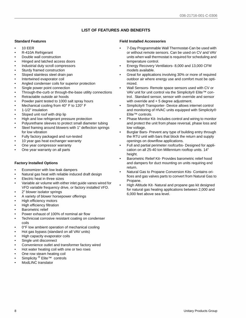
LIST OF FEATURES AND BENEFITS
Standard Features
• 10 EER• R-410A Refrigerant• Double wall construction• Hinged and latched access doors• Industrial duty scroll compressors• Sturdy framed construction• Sloped stainless steel drain pan• Intertwined evaporator coil• Angled condenser coils for superior protection• Single power point connection• Through-the-curb or through-the-base utility connections• Retractable outside air hoods• Powder paint tested to 1000 salt spray hours• Mechanical cooling from 40° F to 120° F• 1-1/2” insulation• Sloped unit roof with drip lip• High and low refrigerant pressure protection• Polyurethane sleeves to protect small diameter tubing• Steel framing around blowers with 1” deflection springs
for low vibration• Fully factory packaged and run-tested• 10 year gas heat exchanger warranty• One year compressor warranty• One year warranty on all parts
Factory Installed Options
• Economizer with low leak dampers• Natural gas heat with reliable induced draft design• Electric heat in three sizes• Variable air volume with either inlet guide vanes wired for
VFD variable frequency drive, or factory installed VFD.• 2” blower isolator springs• A variety of blower horsepower offerings• High efficiency motors• High efficiency filtration • Barometric relief• Power exhaust of 100% of nominal air flow• Technicoat corrosive resistant coating on condenser
coils• 0°F low ambient operation of mechanical cooling• Hot gas bypass (standard on all VAV units)• High capacity evaporator coils• Single unit disconnect• Convenience outlet and transformer factory wired• Hot water heating coil with one or two rows• One row steam heating coil• Simplicity ® Elite™ controls• ModLINC translator
Field Installed Accessories
• 7-Day Programmable Wall Thermostat-Can be used with or without remote sensors. Can be used on CV and VAV units when wall thermostat is required for scheduling and temperature control.
• Energy Recovery Ventilators- 8,000 and 13,000 CFM models available.
• Great for applications involving 30% or more of required outdoor air where energy use and comfort must be opti-mized.
• Wall Sensors- Remote space sensors used with CV or VAV unit for unit control via the Simplicity® Elite™ con-trol. Standard sensor, sensor with override and sensor with override and + 5 degree adjustment.
• Simplicity® Transporter- Device allows internet control and monitoring of HVAC units equipped with Simplicity® Elite™ controls.
• Phase Monitor Kit- Includes control and wiring to monitor and protect the unit from phase reversal, phase loss and low voltage.
• Burglar Bars- Prevent any type of building entry through the RTU unit with bars that block the return and supply openings on downflow applications.
• Full and partial perimeter roofcurbs- Designed for appli-cation on all 25-40 ton Millennium rooftop units. 14" height.
• Barometric Relief Kit- Provides barometric relief hood and dampers for duct mounting on units requiring end return.
• Natural Gas to Propane Conversion Kits- Contains ori-fices and gas valves parts to convert from Natural Gas to Propane.
• High Altitude Kit- Natural and propane gas kit designed for natural gas heating applications between 2,000 and 6,000 feet above sea level.

036-21716-001-C-0306
Unitary Products Group 9
NOMENCLATURE

036-21716-001-C-0306
10 Unitary Products Group
TABLE 1: GENERAL PHYSICAL DATAUNIT SIZE 25 TON 30 TON 40 TON
UNIT EER / IPLV(STANDARD CAPACITY EVAPORATOR) 10.5 / 12.3 10.1 / 11.0 10.2 / 11.2
COMPRESSOR DATA
NUMBER/SIZE 4 x 5.7Ton 4 x 7 Ton 4 x 8.6 TonTYPE Scroll Scroll Scroll
UNIT CAPACITY STEPS 25%, 50%, 75%, 100% 25%, 50%, 75%, 100% 25%, 50%, 75%, 100%INDOOR FAN AND DRIVE
NUMBER / TYPE 1 / FC 1 / FC 1 / FCDIAMETER X WIDTH (INCHES) 22 x20 22 x 20 25 x 22
HP RANGE 7.5 - 20 10 - 25 10 - 25CFM RANGE (FULL LOAD) 6,000 - 12,500 6,000 - 15,000 8,000 - 18,000
ESP RANGE 0.2” - 4.0” 0.2" - 4.0” 0.2" - 4.0"EXHAUST FAN
NUMBER/SIZE/TYPE 1/FC 2/FC 2/FCHP RANGE (SINGLE MOTOR) 5 - 10 7.5 - 15 7.5 - 15
CFM 3,000 - 9,000 4,000 - 15,000 4,000 - 18,000STANDARD EVAPORATOR COIL
SIZE (SQ. FT.) 26.0 26.0 30.4ROWS/FPI 3 / 16 4 / 16 4 / 16
CONDENSER COIL
SIZE (SQ. FT.) 65 78 104ROWS/FPI 2/16 2 /16 2 /16
CONDENSER FANS
QUANTITY / DIAMETER (INCHES) 4 / 24 4 / 24 4 / 30NOMINAL CFM 6,800 7,200 9,600
MOTOR HP 1.0 1.5 1.5ELECTRIC HEAT
KW RANGE 40 - 108 40 - 108 40 - 10840 KW CAPACITY STEPS 1 1 1
80 AND 108 KW CAPACITY STEPS (CV/VAV) 2 / 1 2 / 1 2 / 1NATURAL GAS HEAT
UNIT SIZE 25 TON 30 TON 40 TON233 MBH CAPACITY STEPS (CV/VAV) 1 / 1 1 / 1 1 / 1466 MBH CAPACITY STEPS (CV/VAV) 2 / 1 2 / 1 2 / 1699 MBH CAPACITY STEPS (CV/VAV) - - 3 / 1
HOT WATER COIL
SIZE (INCHES) 22.5” x 65” 22.5" X 65” 22.5" X 65”CAPACITY 25 Ton 30 Ton 40 Ton
STEAM COIL
SIZE (INCHES) 21" X 65"TYPE Steam Coil
FILTERS 2" HI. EFF. TA NUMBER / SIZE 4 / 16 x 25 & 6 / 20 x 25 4 / 16 x 25 & 6 / 20 x 25 4 / 16 x 25 & 6 / 20 x 25
FACE AREA (SQ. FT.) 30.4 30.4 30.4FILTERS 2" PLEATED, 65%
NUMBER / SIZE 4 / 16 x 25 & 6 / 20 x 25 4 / 16 x 25 & 6 / 20 x 25 4 / 16 x 25 & 6 / 20 x 25FACE AREA (SQ. FT.) 30.4 30.4 30.4
FILTERS 65% RIGID W/ 2” TA PREFILTERS
NUMBER / SIZE 4 / 16 x 25 & 6 / 20 x 25 4 /16 x 25 & 6 / 20 x 25 4 / 16 x 25 & 6 / 20 x 25FACE AREA (SQ. FT.) 30.4 30.4 30.4
FILTERS 95% RIGID W/ 2” TA PREFILTERS
NUMBER / SIZE 4 ea. 16 x 25 / 6 ea. 20 x 25 4 ea. 16 x 25 / 6 ea. 20 x 25 4 ea. 16 x 25 / 6 ea. 20 x 25FACE AREA (SQ. FT.) 30.4 30.4 30.4

036-21716-001-C-0306
Unitary Products Group 11
SELECTION PROCEDURE
GIVEN:
Required Cooling Capacity 460,000 Btuh
Required Sensible Cooling 390,000 Btuh
Required Heating (Gas) 320,000 Btuh
Entering Air on Evaporator 83° F DB/ 67° F WB
Outside Design Temperature 95° F
Supply Fan CFM 13,000 CFM
External Static Pressure 1.25 IWG
Electrical Supply Voltage 460-3-60
Economizer Required
2” Throw Away Filters
Constant Volume
SELECT UNIT:
1. Determine nominal tons:
460,000 / 12,000 = 38.33 Tons
Thus, a nominal 40 ton unit is selected.
2. Reference Cooling Capacity Table for a 40 ton unit with standard evaporator coil.
a. Locate the table for a standard evaporator coil with95° F air on the condenser.
b. Enter table at 13,000 CFM and 67°F WB air onevaporator
c. Trace to 83° F Entering Dry Bulb column.
d. Read 493 MBH total capacity and 403 MBH sensi-ble capacity.
The 40 ton unit will meet the cooling requirements. From the nomenclature, the unit will be a Z14. Choose the appropriate configuration for the next digit. Assuming bottom return and supply, the fourth digit would be an “A,” making the model Z14A.
3. Find Gas Heating Capacity Table.
a. Trace down Output column.
b. Find output which exceeds 320,000 Btuh require-ment. The N4 option gives 373 MBH output.
c. Ensure that it is offered in the Z14 unit. Read optionmodel as N4.
From the basic nomenclature, the model now becomes Z14AN4. Add voltage code of “4” for 460-3-60. Nomen-clature becomes Z14AN44.
SELECT FAN SPEED AND HORSEPOWER REQUIREMENTS OF SUPPLY AIR FAN
1. Find Supply Air Performance Tables for the 40 ton unit.
a. Check footnotes and make necessary additions ordeductions to static resistance of ductwork:
Ductwork static resistance 1.25 IWG
Economizer static resistance addition (interpolate) =.25 IWG + Gas Heat (High) = 0.5 IWG
Total Static Resistance 2.0 IWG
b. Enter Fan Performance Table at 13,000 CFM and2.0 IWG static pressure:
RPM = 690
BHP = 10.2
c. Correct BHP for drive losses (using 1.05 correctionfactor). 10.2 BHP x 1.05 = 10.7 BHP. Enter the FanMotor Drive Tables. Selecting a 15 hp motor allows(service factor of 1.5) for a maximum operating BHPgreater than the 10.7 BHP requirement.
TABLE 2: REFRIGERANT FACTORY CHARGE R-410A
UNIT (TONS) MODEL CHARGESYSTEM #1 SYSTEM #2 SYSTEM #3 SYSTEM #4
25 wo/HGBP 12lb 0oz 12lb 0oz 11lb 0oz 11lb 0oz25 w/HGBP 12lb 8oz 12lb 0oz 11lb 0oz 11lb 0oz30 wo/HGBP 16lb 3oz 16lb 9oz 14lb 1oz 18lb 4oz30 w/HGBP 16lb 10oz 16lb 9oz 14lb 1oz 18lb 4oz40 wo/HGBP 17lb 10oz 17lb 10oz 19lb 13oz 19lb 13oz40 w/HGBP 18lb 1oz 17lb 10oz 19lb 13oz 19lb 13oz

036-21716-001-C-0306
12 Unitary Products Group
SIZE OVERCURRENT PROTECTION DEVICE AND DETERMINE CIRCUIT AMPACITY
1. Find electrical tables for the basic 40 ton unit.
a. Enter table for 460-3-60 voltage.
b. Find 15 hp in the Supply Air Fan column.
c. Trace to Minimum Circuit Ampacity column - read109.
d. Trace to M.O.P.D. column - read 125.
e. Size wire and overprotection device accordingly.
f. Check all footnotes.
HOT WATER HEATING1
The YORK Millennium Rooftop units (30 - 40 Ton sizes) canbe furnished with a YORK hot water coil as the source ofheat (Bottom Supply Only). A one or two row coil will be fac-tory installed in the heating section downstream of the supplyair fan and just above the supply air opening in the bottom ofthe unit.
The hot water control valve will not be provided. The installerwill need to field supply a water valve. The installer must alsoconnect the hot water piping, and valve wiring at the job sitefor the hot water heat section to be operational.
For all hot water coils the entering water temperature shouldnot exceed 200°F.
PHYSICAL DATA HOT WATER COIL - 1 ROW
Coil Casing . . . . . . . . . . . . . . . . . . . . Galvanized SteelCoil Construction . . . . . . . . . . . . . . . Al Fin / Cu. TubeRows Deep . . . . . . . . . . . . . . . . . . . . . . . . . . . . . . . . .1Fin Thickness . . . . . . . . . . . . . . . . . . . . . . . . . . . ..006”Tube Wall . . . . . . . . . . . . . . . . . . . . . . . . . . . . . . ..016”Tubes / Circuit. . . . . . . . . . . . . . . . . . . . . . . . . . . . . . .2Fins Per Inch . . . . . . . . . . . . . . . . . . . . . . . . . . . . . . .8Tubes High . . . . . . . . . . . . . . . . . . . . . . . . . . . . .22.50”Tube Length . . . . . . . . . . . . . . . . . . . . . . . . . . . . . . 65”Face Area . . . . . . . . . . . . . . . . . . . . . . . . . . . . 10.16ft.2
Weight . . . . . . . . . . . . . . . . . . . . . . . . . . . . . . . . 71lbs.Operating Weight . . . . . . . . . . . . . . . . . . . . . . . . 83lbs.
TABLE 3: GAS HEATING CAPACITIES
GAS HEAT OPTION
AVAILABLE ON MODELS
INPUT CAPACITY (MBH)1 OUTPUT CAPACITY (MBH)2
GAS RATE, CU. FT./HR.3 TEMP. RISE °F AT FULL RATE1ST STAGE TOTAL 1ST STAGE TOTAL
N2 Z22/Z23/Z24 233 233 186 217 217 5 - 35N4 Z22/Z23/Z24 233 466 373 217 434 15 - 45
N74 Z24 ONLY 466 699 560 434 650 20 - 50
1. Heating capacity is only staged on CV models. VAV models use only one stage at full capacity.2. Blower motor heat not included.3. based on a heat content of 1075 Btu/Ft.3
4. Minimum heating CFM for N7 700 MBH heat is 11,700 CFM.
TABLE 4: ELECTRIC HEATING CAPACITIES
ELECTRIC HEAT OPTION
AVAILABLE ON MODELS
RATED VOLTAGE
NOMINAL KWNOMINAL
MBH1
MBH AND KW PER STAGE2
STAGE 1 STAGE 2KW MBH KW MBH
E4 Z22, Z23, Z24 2403/4804/575
40 137 40 137 0 0
E8 Z22, Z23, Z24 2402/4803/575
80 273 40 137 40 136
E1Z22, Z23,Z24 (460 & 575 volt only)
4803/575 108 369 72 246 36 123
1. Supply air fan motor heat not included.2. Heating capacity is only staged on CV models. VAV models use only one stage at full capacity.3. For 208 volts, multiply kW and MBH values by .751. For 203 volts, multiply kW and MBH values by .9184. For 460 volts, multiply kW and MBH values by .918.
1. Hot water, steam or electric heat is not available for front or rear supply.

036-21716-001-C-0306
Unitary Products Group 13
NOTE: Water pressure drop numbers are based on 60°Fentering air temperature, 2.00” maximum air pres-sure drop across the hot water coil(s). ARI certifiedratings at other conditions are available uponrequest. Hot water coils are approved for use withglycol (rates available upon request).
PIPING CONNECTIONS
The hot water piping must enter the unit through the floor ofthe heat section compartment. The access doors to the com-partment are gasketed so the compartment can be sealed.However, as added protection for water leakage into thespace, the piping access holes should be sealed with a heatresistant mastic (see the following illustration for approximatelocation of the compartment and piping connections.
FIGURE 1 - HOT WATER PIPING CROSS-SEC-TION
TABLE 5: WATER PRESSURE DROP (1 ROW, 25 & 30 TON)
GPM 10 20 30 40WATER PRESSURE DROP 0.9 3.0 6.0 10.0
TABLE 6: STATIC RESISTANCE HOT WATER COIL (25 & 30 TON)CFM 6000 8000 10000 15000
AIR PRESSURE DROP 1 ROW 0.07 0.11 0.16 0.32AIR PRESSURE DROP 2 ROW 0.14 0.23 0.33 0.65
DO NOT use tin based solder. Brazing with tinbased solder could cause equipment damage orpossible injury to OCCUPANTS of the structurethat is being conditioned.
TABLE 7: HOT WATER COIL (1 ROW, 25 & 30 TON)1
1. Based on 60°F entering air temperature, 2.00” maxi-mum pressure drop across the hot water coil.
GPM CFMCAPACITY (MBH) AT ENTERING WATER
TEMPERATURE
140 °F 160 °F 180 °F 200 °F
10
6000 91.4 115.3 139.3 163.68000 102 128.8 155.8 182.910000 110.4 139.5 168.8 198.412000 117.3 148.4 179.6 211.215000 125.9 159.2 192.9 226.9
20
6000 103 129.4 156 182.78000 116.8 147 177.2 207.710000 128.2 161.3 194.7 228.212000 137.8 173.6 209.5 245.615000 150 189 228.2 267.8
30
6000 107.6 135 162.5 190.18000 122.8 154.3 185.8 217.510000 135.5 170.3 205.1 240.212000 146.4 184 221.8 259.715000 160.3 201.6 243 284.8
40
6000 110.1 138 166 194.18000 126.1 158.2 190.5 222.810000 139.6 175.2 210.9 246.812000 151.2 189.8 228.5 267.515000 166.1 208.6 251.3 294.1
TABLE 8: STATIC RESISTANCE HOT WATER COIL (1 ROW, 40 TON)CFM 8000 11000 14000 20000
AIR PRESSURE DROP 1 ROW 0.11 0.19 0.29 0.52AIR PRESSURE DROP 2 ROW 0.23 0.39 0.58 1.06
TABLE 9: HOT WATER COIL (1 ROW 40 TON)1
1. Based on 60°F entering air temperature, 2.00” maxi-mum pressure drop across the hot water coil.
GPM CFMCAPACITY (MBH) AT ENTERING WATER
TEMPERATURE
140 °F 160 °F 180 °F 200 °F
10
8000 102 128.8 155.8 182.911000 114 144.1 174.4 205.114000 123.2 155.9 188.8 222.117000 130.6 165.4 200.4 235.820000 136.8 173.3 210.1 247.3
20
8000 116.8 147 177.2 207.711000 133.2 167.7 202.3 237.214000 146.2 184.2 222.4 260.817000 157 197.9 239 280.520000 166.2 209.6 253.2 297.3
30
8000 122.8 154.3 185.8 217.511000 141.2 177.4 213.8 250.314000 155.9 196.1 236.4 276.917000 168.3 211.8 255.4 299.320000 179.1 225.3 271.8 318.6
40
8000 126.1 158.2 190.5 222.811000 145.6 182.7 220 257.514000 161.4 202.6 244.1 285.817000 174.7 219.5 264.5 309.720000 186.3 234.2 282.3 330.6
HOT WATERCOIL
CONDENSINGSECTION
INLET (2")OUTLET (2")
CL
2.55"
8.38"
2.25"
11.88"
26"
15.8"
88.75"
HEAT SECTIONCOMPARTMENT
(1 OR 2 ROW)
OUTSIDE OFBASE RAIL

036-21716-001-C-0306
14 Unitary Products Group
FIGURE 2 - HOT WATER COIL - 25 & 30 TON, 1 ROW, AT 10 GPM
FIGURE 3 - HOT WATER COIL - 25 & 30 TON, 1 ROW, AT 20 GPM
8 0 .0
9 0 .0
1 0 0 .0
1 1 0 .0
1 2 0 .0
1 3 0 .0
1 4 0 .0
1 5 0 .0
1 6 0 .0
1 7 0 .0
1 8 0 .0
1 9 0 .0
2 0 0 .0
2 1 0 .0
2 2 0 .0
2 3 0 .0
6 0 0 0 7 0 0 0 8 0 0 0 9 0 0 0 1 0 0 0 0 1 1 0 0 0 1 2 0 0 0 1 3 0 0 0 1 4 0 0 0 1 5 0 0 0
F L O W R A T E (C F M )
CA
PAC
ITY
(MB
H)
1 4 0 °F1 6 0 °F1 8 0 °F2 0 0 °F
90.0
100.0
110.0
120.0
130.0
140.0
150.0
160.0
170.0
180.0
190.0
200.0
210.0
220.0
230.0
240.0
250.0
260.0
270.0
6000 7000 8000 9000 10000 11000 12000 13000 14000 15000
FLO W R AT E (C FM )
CA
PAC
ITY
(MB
H)
140 °F160 °F180 °F200 °F

036-21716-001-C-0306
Unitary Products Group 15
FIGURE 4 - HOT WATER COIL - 25 & 30 TON, 1 ROW, AT 30 GPM
FIGURE 5 - HOT WATER COIL - 25 & 30 TON, 1 ROW, AT 40 GPM
1 0 0 .0
1 1 0 .0
1 2 0 .0
1 3 0 .0
1 4 0 .0
1 5 0 .0
1 6 0 .0
1 7 0 .0
1 8 0 .0
1 9 0 .0
2 0 0 .0
2 1 0 .0
2 2 0 .0
2 3 0 .0
2 4 0 .0
2 5 0 .0
2 6 0 .0
2 7 0 .0
2 8 0 .0
2 9 0 .0
6 0 0 0 7 0 0 0 8 0 0 0 9 0 0 0 1 0 0 0 0 1 1 0 0 0 1 2 0 0 0 1 3 0 0 0 1 4 0 0 0 1 5 0 0 0
F L O W R A T E (C F M )
CA
PAC
ITY
(MB
H)
1 4 0 °F1 6 0 °F1 8 0 °F2 0 0 °F
1 0 0 .0
1 1 0 .0
1 2 0 .0
1 3 0 .0
1 4 0 .0
1 5 0 .0
1 6 0 .0
1 7 0 .0
1 8 0 .0
1 9 0 .0
2 0 0 .0
2 1 0 .0
2 2 0 .0
2 3 0 .0
2 4 0 .0
2 5 0 .0
2 6 0 .0
2 7 0 .0
2 8 0 .0
2 9 0 .0
3 0 0 .0
6 0 0 0 7 0 0 0 8 0 0 0 9 0 0 0 1 0 0 0 0 1 1 0 0 0 1 2 0 0 0 1 3 0 0 0 1 4 0 0 0 1 5 0 0 0
F L O W R A T E (C F M )
CA
PAC
ITY
(MB
H)
1 4 0 °F1 6 0 °F1 8 0 °F2 0 0 °F

036-21716-001-C-0306
16 Unitary Products Group
FIGURE 6 - HOT WATER COIL - 40 TON, 1 ROW, AT 10 GPM
FIGURE 7 - HOT WATER COIL - 40 TON, 1 ROW, AT 20 GPM
90 .0
1 00 .0
1 10 .0
1 20 .0
1 30 .0
1 40 .0
1 50 .0
1 60 .0
1 70 .0
1 80 .0
1 90 .0
2 00 .0
2 10 .0
2 20 .0
2 30 .0
2 40 .0
2 50 .0
80 0 0 9 0 00 10 0 0 0 1 1 0 00 1 20 0 0 13 0 00 1 4 0 00 1 5 00 0 1 60 0 0 17 0 0 0 1 80 0 0 19 0 0 0 2 0 0 00
F L O W R A T E (C F M )
CA
PAC
ITY
(MB
H)
14 0 °F16 0 °F18 0 °F20 0 °F
100.0
110.0
120.0
130.0
140.0
150.0
160.0
170.0
180.0
190.0
200.0
210.0
220.0
230.0
240.0
250.0
260.0
270.0
280.0
290.0
300.0
8000 9000 10000 11000 12000 13000 14000 15000 16000 17000 18000 19000 20000
F LO W R AT E (C FM )
CA
PAC
ITY
(MB
H)
140 °F160 °F180 °F200 °F
036-21716-001-C-0306
Unitary Products Group 17
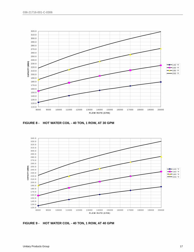
FIGURE 8 - HOT WATER COIL - 40 TON, 1 ROW, AT 30 GPM
FIGURE 9 - HOT WATER COIL - 40 TON, 1 ROW, AT 40 GPM
110.0
120.0
130.0
140.0
150.0
160.0
170.0
180.0
190.0
200.0
210.0
220.0
230.0
240.0
250.0
260.0
270.0
280.0
290.0
300.0
310.0
320.0
8000 9000 10000 11000 12000 13000 14000 15000 16000 17000 18000 19000 20000
FLO W R AT E (C FM )
CA
PAC
ITY
(MB
H)
140 °F160 °F180 °F200 °F
1 2 0 .0
1 3 0 .0
1 4 0 .0
1 5 0 .0
1 6 0 .0
1 7 0 .0
1 8 0 .0
1 9 0 .0
2 0 0 .0
2 1 0 .0
2 2 0 .0
2 3 0 .0
2 4 0 .0
2 5 0 .0
2 6 0 .0
2 7 0 .0
2 8 0 .0
2 9 0 .0
3 0 0 .0
3 1 0 .0
3 2 0 .0
3 3 0 .0
3 4 0 .0
8 0 0 0 9 0 0 0 1 0 0 0 0 1 1 0 0 0 1 2 0 0 0 1 3 0 0 0 1 4 0 0 0 1 5 0 0 0 1 6 0 0 0 1 7 0 0 0 1 8 0 0 0 1 9 0 0 0 2 0 0 0 0
F L O W R A T E (C F M )
CA
PAC
ITY
(MB
H)
1 4 0 °F1 6 0 °F1 8 0 °F2 0 0 °F

036-21716-001-C-0306
18 Unitary Products Group
PHYSICAL DATA HOT WATER COIL - 2 ROW
Coil Casing . . . . . . . . . . . . . . . . . . . . Galvanized Steel
Coil Construction. . . . . . . . . . . . . . . . Al Fin / Cu. Tube
Rows Deep . . . . . . . . . . . . . . . . . . . . . . . . . . . . . . . . 2
Fin Thickness . . . . . . . . . . . . . . . . . . . . . . . . . . . .006”
Tube Wall . . . . . . . . . . . . . . . . . . . . . . . . . . . . . . .016”
Tubes / Circuit . . . . . . . . . . . . . . . . . . . . . . . . . . . . . 2
Fins Per Inch. . . . . . . . . . . . . . . . . . . . . . . . . . . . . . . 8
Tubes High . . . . . . . . . . . . . . . . . . . . . . . . . . . . 22.50”
Tube Length . . . . . . . . . . . . . . . . . . . . . . . . . . . . . . 65”
Face Area . . . . . . . . . . . . . . . . . . . . . . . . . . . 10.16 ft.2
Weight . . . . . . . . . . . . . . . . . . . . . . . . . . . . . . . . .90 lbs
Operating Weight . . . . . . . . . . . . . . . . . . . . . . . 110 lbs
NOTE: Water pressure drop numbers are based on 60°Fentering air temperature, 2.00” maximum air pres-sure drop across the hot water coil(s). ARI certifiedratings at other conditions are available uponrequest. Hot water coils are approved for use withglycol (rates available upon request.)
1. Based on 60°F entering air temperature, 2.00” maxi-mum pressure drop across the hot water coil
TABLE 10: WATER PRESSURE DROP (2 ROW, 25 & 30 TON)
GPM 20 40 60 80WATER
PRESSURE DROP
0.9 3.0 6.0 10.0
TABLE 11: STATIC RESISTANCE HOT WATER COIL (25 & 30 TON)
CFM 6000 8000 10000 15000AIR PRESSURE DROP
1 ROW0.07 0.11 0.16 0.32
AIR PRESSURE DROP 2 ROW
0.14 0.23 0.33 0.65
TABLE 12: HOT WATER COIL (2 ROW, 25 & 30 TON)1
GPM CFMCAPACITY (MBH) AT ENTERING WATER TEMPERATURE
140 °F 160 °F 180 °F 200 °F
20
6000 177.5 223.8 270.4 317.38000 203.8 257.2 311.1 365.5
10000 224.8 284.1 343.9 404.212000 242.2 306.4 371.1 436.415000 263.6 333.8 404.6 476.1
40
6000 198.1 248.9 300.0 351.38000 232.2 292.0 352.2 412.7
10000 260.7 328.1 395.9 464.112000 285.0 359.0 433.4 508.315000 316.0 398.4 481.3 564.8
60
6000 206.1 258.7 311.4 364.28000 243.6 305.9 368.4 431.1
10000 275.3 345.9 416.8 488.012000 302.9 380.7 458.9 537.615000 338.4 425.7 513.4 601.7
80
6000 210.5 263.9 317.4 371.18000 249.8 313.3 377.1 441.1
10000 283.3 355.6 428.2 501.012000 312.7 392.7 473.0 553.615000 351.0 440.9 531.3 622.1
TABLE 13: HOT WATER COIL (2 ROWS, 40 TON)1
1. Based on 60°F entering air temperature, 2.00” maxi-mum air pressure drop across the hot water coil.ARI certified ratings at other conditions available upon request.Hot water coils are approved for use with glycol (ratings available upon request.)
GPM CFMCAPACITY (MBH) AT ENTERING WATER
TEMPERATURE
140 °F 160 °F 180 °F 200 °F
20
8000 203.8 257.2 311.1 365.511000 233.9 295.7 358.1 421.014000 257.0 325.3 394.2 463.817000 275.5 349.0 423.3 498.320000 290.9 368.7 447.4 526.9
40
8000 232.2 292.0 352.2 412.711000 273.3 344.1 415.3 487.014000 306.3 386.0 466.3 547.117000 333.9 421.1 508.9 597.320000 357.5 451.1 545.4 640.5
60
8000 243.6 305.9 368.4 431.111000 289.5 363.9 438.5 513.614000 327.2 411.5 496.3 581.517000 359.2 452.0 545.3 639.220000 386.9 487.1 587.9 689.4
80
8000 249.8 313.3 377.1 441.111000 298.5 374.7 451.2 528.114000 338.9 425.7 512.8 600.517000 373.4 469.3 565.6 662.520000 403.6 507.5 611.8 716.8
TABLE 14: STATIC RESISTANCE HOT WATER COIL (40 TON)CFM 8000 11000 14000 20000
AIR PRESSURE DROP 1 ROW 0.11 0.19 0.29 0.52AIR PRESSURE DROP 2 ROW 0.23 0.39 0.58 1.06
TABLE 15: WATER PRESSURE DROP (2 ROW, 40 TON)
GPM 20 40 60 80WATER PRESSURE DROP 0.9 3.0 6.0 10.0
TABLE 12: HOT WATER COIL (2 ROW, 25 & 30 TON)1
GPM CFMCAPACITY (MBH) AT ENTERING WATER TEMPERATURE
140 °F 160 °F 180 °F 200 °F

036-21716-001-C-0306
Unitary Products Group 19
FIGURE 10 - HOT WATER COIL - 25 & 30 TON, 2 ROW, AT 20 GPM
FIGURE 11 - HOT WATER COIL - 25 & 30 TON, 2 ROW, AT 40 GPM
1 6 0 .0
1 8 0 .0
2 0 0 .0
2 2 0 .0
2 4 0 .0
2 6 0 .0
2 8 0 .0
3 0 0 .0
3 2 0 .0
3 4 0 .0
3 6 0 .0
3 8 0 .0
4 0 0 .0
4 2 0 .0
4 4 0 .0
4 6 0 .0
4 8 0 .0
6 0 0 0 7 0 0 0 8 0 0 0 9 0 0 0 1 0 0 0 0 1 1 0 0 0 1 2 0 0 0 1 3 0 0 0 1 4 0 0 0 1 5 0 0 0
F L O W R A T E (C F M )
CA
PAC
ITY
(MB
H)
1 4 0 °F1 6 0 °F1 8 0 °F2 0 0 °F
1 8 0 .0
2 0 0 .0
2 2 0 .0
2 4 0 .0
2 6 0 .0
2 8 0 .0
3 0 0 .0
3 2 0 .0
3 4 0 .0
3 6 0 .0
3 8 0 .0
4 0 0 .0
4 2 0 .0
4 4 0 .0
4 6 0 .0
4 8 0 .0
5 0 0 .0
5 2 0 .0
5 4 0 .0
5 6 0 .0
5 8 0 .0
6 0 0 0 7 0 0 0 8 0 0 0 9 0 0 0 1 0 0 0 0 1 1 0 0 0 1 2 0 0 0 1 3 0 0 0 1 4 0 0 0 1 5 0 0 0
F L O W R A T E (C F M )
CA
PAC
ITY
(MB
H)
1 4 0 °F1 6 0 °F1 8 0 °F2 0 0 °F

036-21716-001-C-0306
20 Unitary Products Group
FIGURE 12 - HOT WATER COIL - 25 & 30 TON, 2 ROW, AT 60 GPM
FIGURE 13 - HOT WATER COIL - 25 & 30 TON, 2 ROW, AT 80 GPM
190.0
210.0
230.0
250.0
270.0
290.0
310.0
330.0
350.0
370.0
390.0
410.0
430.0
450.0
470.0
490.0
510.0
530.0
550.0
570.0
590.0
610.0
6000 7000 8000 9000 10000 11000 12000 13000 14000 15000
FLO W R AT E (C F M )
CA
PAC
ITY
(MB
H)
140 °F160 °F180 °F200 °F
200 .0
220 .0
240 .0
260 .0
280 .0
300 .0
320 .0
340 .0
360 .0
380 .0
400 .0
420 .0
440 .0
460 .0
480 .0
500 .0
520 .0
540 .0
560 .0
580 .0
600 .0
620 .0
640 .0
6000 7000 8000 9000 10000 11000 12000 13000 14000 15000
F L O W R AT E (C F M )
CA
PAC
ITY
(MB
H)
140 °F160 °F180 °F200 °F
036-21716-001-C-0306
Unitary Products Group 21
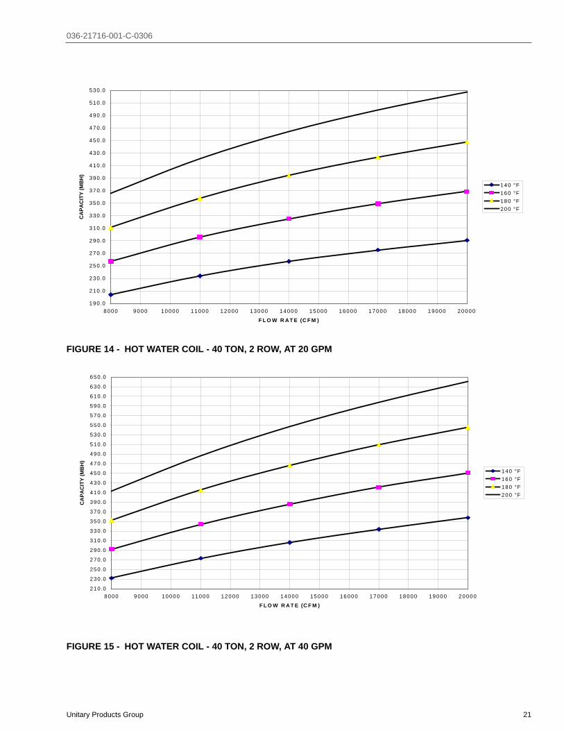
FIGURE 14 - HOT WATER COIL - 40 TON, 2 ROW, AT 20 GPM
FIGURE 15 - HOT WATER COIL - 40 TON, 2 ROW, AT 40 GPM
190 .0
210 .0
230 .0
250 .0
270 .0
290 .0
310 .0
330 .0
350 .0
370 .0
390 .0
410 .0
430 .0
450 .0
470 .0
490 .0
510 .0
530 .0
8000 9000 10000 11000 12000 13000 14000 15000 16000 17000 18000 19000 20000
F L O W R AT E (C F M )
CA
PAC
ITY
(MB
H)
140 °F160 °F180 °F200 °F
2 1 0 .0
2 3 0 .0
2 5 0 .0
2 7 0 .0
2 9 0 .0
3 1 0 .0
3 3 0 .0
3 5 0 .0
3 7 0 .0
3 9 0 .0
4 1 0 .0
4 3 0 .0
4 5 0 .0
4 7 0 .0
4 9 0 .0
5 1 0 .0
5 3 0 .0
5 5 0 .0
5 7 0 .0
5 9 0 .0
6 1 0 .0
6 3 0 .0
6 5 0 .0
8 0 0 0 9 0 0 0 1 0 0 0 0 1 1 0 0 0 1 2 0 0 0 1 3 0 0 0 1 4 0 0 0 1 5 0 0 0 1 6 0 0 0 1 7 0 0 0 1 8 0 0 0 1 9 0 0 0 2 0 0 0 0
F L O W R A T E (C F M )
CA
PAC
ITY
(MB
H)
1 4 0 °F1 6 0 °F1 8 0 °F2 0 0 °F

036-21716-001-C-0306
22 Unitary Products Group
FIGURE 16 - HOT WATER COIL - 40 TON, 2 ROW, AT 60 GPM
FIGURE 17 - HOT WATER COIL - 40 TON, 2 ROW, AT 80 GPM
220 .0240 .0260 .0280 .0300 .0320 .0340 .0360 .0380 .0400 .0420 .0440 .0460 .0480 .0500 .0520 .0540 .0560 .0580 .0600 .0620 .0640 .0660 .0680 .0700 .0
8000 9000 10000 11000 12000 13000 14000 15000 16000 17000 18000 19000 20000
F L O W R AT E (C F M )
CA
PAC
ITY
(MB
H)
140 °F160 °F180 °F200 °F
2 3 0 .02 5 0 .02 7 0 .02 9 0 .03 1 0 .03 3 0 .03 5 0 .03 7 0 .03 9 0 .04 1 0 .04 3 0 .04 5 0 .04 7 0 .04 9 0 .05 1 0 .05 3 0 .05 5 0 .05 7 0 .05 9 0 .06 1 0 .06 3 0 .06 5 0 .06 7 0 .06 9 0 .07 1 0 .07 3 0 .0
8 0 0 0 9 0 0 0 1 0 0 0 0 1 1 0 0 0 1 2 0 0 0 1 3 0 0 0 1 4 0 0 0 1 5 0 0 0 1 6 0 0 0 1 7 0 0 0 1 8 0 0 0 1 9 0 0 0 2 0 0 0 0
F L O W R A T E (C F M )
CA
PAC
ITY
(MB
H)
1 4 0 °F1 6 0 °F1 8 0 °F2 0 0 °F

036-21716-001-C-0306
Unitary Products Group 23
STEAM HEATINGThe YORK Millennium units (25, 30, and 40 ton sizes) can bemanufactured with a steam heat coil (Bottom Supply only).YORK's one row steam coil is installed in the heating sectionjust downstream of the supply air fan and just above the sup-ply air opening in the bottom of the unit.
The steam control valve will not be provided. The installerwill need to field supply a steam control valve. Connect thesteam piping and valve power wiring at the job site for thesteam heat section to be operational.
There are no provisions in the coil or control sequence to pre-vent freezing of condensate. The control valve, piping andfield installed wiring connections are particularly vulnerablebecause they are installed in the vestibule outside of the con-ditioned air stream.
All piping, control valves, and wiring that is field installed mustconform to all local and national codes
Condensate can freeze on the control valve and piping if theyare not properly insulated.
PHYSICAL DATA STEAM COIL - 1 ROW
Coil Casing . . . . . . . . . . . . . . . . . . . . Galvanized SteelCoil Construction . . . . . . . . . . . . . . . Al Fin / Cu. TubeRows Deep . . . . . . . . . . . . . . . . . . . . . . . . . . . . . . . . .1Fin Thickness . . . . . . . . . . . . . . . . . . . . . . . . . . . ..010”Tube Wall . . . . . . . . . . . . . . . . . . . . . . . . . . . . . . ..035”Tubes / Circuit. . . . . . . . . . . . . . . . . . . . . . . . . . . . . . .2Fins Per Inch . . . . . . . . . . . . . . . . . . . . . . . . . . . . . . .6Tubes High . . . . . . . . . . . . . . . . . . . . . . . . . . . . . . . 21”Tube Length . . . . . . . . . . . . . . . . . . . . . . . . . . . . . . 65”Face Area . . . . . . . . . . . . . . . . . . . . . . . . . . . . 9.48 ft.2
Weight. . . . . . . . . . . . . . . . . . . . . . . . . . . . . . . . 92 lbs.
*Hot water, steam coil or electric heat not available for front or rear supply.
PIPING CONNECTIONS
The steam piping must enter the unit through the floor of theheat section compartment. The access doors to the compart-ment are gasketed to the compartment can be sealed. How-ever, as added protection for condensate leakage into thespace, the piping access holes should be sealed with a heatresistant mastic. The following figure illustrates the approxi-mate location of the compartment and piping connections.
FIGURE 18 - STEAM PIPING CROSS SECTION
TABLE 16: STEAM COIL (1 ROW, 25 & 30 TON)1
1. Based on 60°F entering air temperature, 2.00” maxi-mum air pressure drop across the coil.
CFMCAPACITY (MBH) AT STEAM PRESSURE (PSI)
2 6 10 156000 194.1 207.9 219.8 232.68000 221.1 236.9 250.4 265.0
10000 243.2 260.5 275.4 291.412000 261.9 280.6 296.6 313.915000 285.6 306.0 323.5 342.4
TABLE 17: STATIC RESISTANCE STEAM COIL(1 ROW, 25 & 30 TON)
CFM 6000 8000 10000 12000 15000AIR PRESSURE DROP 0.11 0.18 0.26 0.36 0.54
TABLE 18: STEAM COIL (1 ROW, 40 TON)1
CFMCAPACITY (MBH) AT STEAM PRESSURE (PSI)
2 6 10 158000 221.1 236.9 250.4 265.011000 252.9 271.0 286.4 303.114000 278.2 298.0 315.0 333.417000 299.4 320.7 339.0 358.820000 317.6 340.2 359.6 380.6
1. Based on 60°F entering air temperature, 2.00” maxi-mum air pressure drop across the coil.
TABLE 19: STATIC RESISTANCE STEAM COIL(1 ROW, 40 TON)
CFM 8000 11000 14000 17000 20000AIR PRESSURE DROP 0.18 0.31 0.48 0.67 0.88
DO NOT use tin based solder. Brazing with tinbased solder could cause equipment damage orpossible injury to OCCUPANTS of the structure thatis being conditioned.
� � � �� � � �
� � � � � � � � � �� � � � � � �
� � � � � � � � � � � � �
� �
� � � � �
� ! �
� " �
� � � �� � � � � � � � �
�
# �
� � � � � � � � � �� � � � � � � � �
� $ � �
� � � � � � �
� � � � � � � � �� � � � �

036-21716-001-C-0306
24 Unitary Products Group
FIGURE 19 - STEAM COIL - 25 & 30 TON, 1 ROW
FIGURE 20 - STEAM COIL - 40 TON, 1 ROW
180
190
200
210
220
230
240
250
260
270
280
290
300
310
320
330
340
350
6000 7000 8000 9000 10000 11000 12000 13000 14000 15000
F L O W R AT E (C F M )
CA
PAC
ITY
(MB
H)
2 ps i6 ps i10 ps i15 ps i
210
220
230
240
250
260
270
280
290
300
310
320
330
340
350
360
370
380
390
8000 9000 10000 11000 12000 13000 14000 15000 16000 17000 18000 19000 20000
FLO W R AT E (C FM )
CA
PAC
ITY
(MB
H)
2 ps i6 ps i10 psi15 psi

036-21716-001-C-0306
Unitary Products Group 25
TABLE 20: EXHAUST FAN DRIVE DATA
MODELBLOWER
RPM RANGE
MOTOR MOTOR PULLEY BLOWER PULLEY BELTS
HPFRAME SIZE
MOTOR EFF (STD.
MOTOR)
MOTOR EFF (HI
EFF OPT)PITCH DIA (INCHES)
BORE (INCHES)
PITCH DIA (INCHES)
BORE (INCHES) DESIGNATION QTY
25 TON
732 5 213T 87.5 89.5 4.9 1-3/8 11.3 2-3/16 BX63 2827 7.5 215T 88.5 91.7 5.5 1-3/8 11.3 2-3/16 BX63 2955 10 215T 89.5 91 6.3 1-5/8 11.3 2-3/16 BX63 2
30 TON
852 7.5 213T 84 86.5 5.5 1-3/8 11.3 1-11/16 B65 2976 10 215T 86.5 89.5 6.3 1-3/8 11.3 1-11/16 B65 2
1069 15 254T 85.7 89.5 6.9 1-3/8 11.3 1-11/16 B65 2
40 TON
852 7.5 184T 84 86.5 5.5 1-3/8 11.3 1-11/16 B65 2976 10 215T 86.5 89.5 6.3 1-3/8 11.3 1-11/16 B65 2
1069 15 254T 85.7 89.5 6.5 1-3/8 11.3 1-11/16 B65 2
TABLE 21: SUPPLY FAN MOTOR AND DRIVE DATA1
MODELBLOWER
RPM RANGE
MOTOR MOTOR PULLEY BLOWER PULLEY BELTS
HP FRAME SIZE
MOTOR EFFICIENCY
(STD. MOTOR)
MOTOR EFFICIENCY (ULTRA HI EFF OPT)
PITCH DIA (INCHES)
BORE (INCHES)
PITCH DIA (INCHES)
BORE (INCHES)
DESIGNATION
QTY
25 Ton
567 7.5 213T 88.5 91.7 4.5 1-3/8 13.9 2-3/16 BX56 2692 10 215T 89.5 91 5.5 1-3/8 13.9 2-3/16 BX56 2793 15 254T 91 91.7 6.3 1-5/8 13.9 2-3/16 BX56 2894 20 256T 91 93 7.1 1-5/8 13.9 2-3/16 BX56 2
30 Ton
617 10 215T 89.5 91 4.9 1-3/8 13.9 2-3/16 BX56 2743 15 254T 91 91.7 5.9 1-5/8 13.9 2-3/16 BX56 2844 20 256T 91 93 6.7 1-5/8 13.7 2-3/16 5VX610 2919 25 284T 91.7 93.6 7.1 1-7/8 13.7 2-3/16 5VX610 2
40 Ton
567 10 215T 89.5 91 4.5 1-3/8 13.9 2-7/16 BX67 2642 15 254T 91 91.7 5.1 1-5/8 13.7 2-7/16 5VX710 2717 20 256T 91 93 5.7 1-5/8 13.7 2-7/16 5VX710 2768 25 284T 91.7 93.6 6.1 1-7/8 13.7 2-7/16 5VX710 2
1. kW = (BHP X 0.746) / Motor Eff.MBH = kW X 3.414MBH = (BHP X 2.546) / Motor Eff.

036-21716-001-C-0306
26 Unitary Products Group
SUPPLY AIR DRIVE ADJUSTMENT
At unit start-up, the measured CFM may be higher or lowerthan the specified CFM shown in Figures 22, 23, and 24. Toachieve the specified CFM, the speed of the drive may haveto be decreased or increased by changing the pitch diameter(PD) of the motor sheave as outlined below:
Example:
A 30-ton unit was selected to deliver 12,000 CFM with a 20HP motor and a 966 RPM drive, but the unit is only delivering11,000 CFM per Figures 22, 23, and 24.
Use the equation to determine the required PD for the newmotor sheave (12,000 CFM / 11,000 CFM) x 6.9” = 7.53”
Use the 30-ton table to select a Browning 2B5V74 which willincrease the speed of the unit's drive and its supply air CFM108.7%.
New drive speed = 1.087 x 966 = 1,050 RPM
New supply air = 1.087 x 11,000 = 11,957 CFM
Re-use the existing belts and blower sheave.
New motor BHP = (speed increase)3 x estimated motorBHP at original start-up with 11,000 CFM and 966 RPM =(1.087)3 x 13.5 BHP = 1.284 x 13.5 BHP = 17.3 BHPNew motor amps = (speed increase)3 x measured motoramps at original start-up with 11,000 CFM and 966 RPM.
Failure to properly adjust the total system air quan-tity can result in extensive blower damage.
Before making any blower speed changes reviewthe installation for any installation errors, leaks orundesirable systems effects that can result in lossof air flow.
Even small changes in blower speed can result insubstantial changes in static pressure and bhp.Bhp or amp draw of the blower motor will increase(see table) by the cube ratio of the blower speed.Static pressure will increase by the square ratio ofthe blower speed. Tables 22, 23 and 24 are forreference only. All blower speed changes must bemade by qualified personnel with strict adherenceto the fan laws.

036-21716-001-C-0306
Unitary Products Group 27
TABLE 22: 25 TON DRIVE ADJUSTMENT
7.5 HP MOTOR & 567 RPM DRIVE 10 HP MOTOR & 692 RPM DRIVE 15 HP MOTOR & 793 RPM DRIVE 20 HP MOTOR & 894 RPM DRIVE
%RPM& CFM
REQ’D PD
BROWNING 2B5V_ _
%RPM& CFM
REQ’D PD
BROWNING 2B5V_ _
%RPM& CFM
REQ’D PD
BROWNING 2B5V_ _
%RPM & CFM
REQ’D PD
BROWNING 2B5V_ _
- - - 82 4.5 42 84 5.3 50 86 6.1 58
- - - 86 4.7 44 87 5.5 52 89 6.3 60
100 (Std.)4.5 42 89 4.9 46 90 5.7 54 91 6.5 62
104 4.7 44 93 5.1 48 94 5.9 56 94 6.7 64
109 4.9 46 96 5.3 50 97 6.1 58 97 6.9 66
113 5.1 48 100 (Std.)5.5 52 100 (Std)6.3 60 100 (Std.)7.1 68
118 5.3 50 104 5.7 54 103 6.5 62 103 7.3 70
122 5.5 52 107 5.9 56 106 6.7 64 108 7.7 74
126 5.7 54 111 6.1 58 110 6.9 66 117 8.3 80
- - - 115 6.3 60 113 7.1 68 125 8.9 86
- - - 118 6.5 62 116 7.3 70 - - -
- - - 122 6.7 64 122 7.7 74 - - -
TABLE 23: 30 TON DRIVE ADJUSTMENT10 HP MOTOR & 617 RPM DRIVE 15 HP MOTOR & 743 RPM DRIVE 20 HP MOTOR & 856 RPM DRIVE “25 HP MOTOR & 933 RPM DRIVE”
%RPM& CFM
REQ’D PD
BROWNING2B5V_ _
%RPM& CFM
REQ’D PD
BROWNING2B5V_ _
%RPM& CFM
REQ’D PD
BROWNING2B5V_ _
%RPM & CFM
REQ’D PD
BROWNING2B5V_ _
91.8 4.5 42 86.4 5.1 48 82.1 5.5 54 86.3 6.1 6095.9 4.7 44 89.8 5.3 50 85.1 5.7 56 89.0 6.3 62
100.0 (Std.)4.9 46 93.2 5.5 52 88.1 5.9 58 91.8 6.5 64
104.1 5.1 48 96.6 5.7 54 91.0 6.1 60 94.5 6.7 66
108.2 5.3 50 100.0 (Std.)5.9 56 94.0 6.3 62 97.3 6.9 68
112.2 5.5 52 103.4 6.1 58 97.0 6.5 64 100.0 (Std.) 7.1 70
116.3 5.7 54 106.8 6.3 60 100.0 (Std.) 6.7 66 105.5 7.5 74
120.4 5.9 56 110.2 6.5 62 103.0 6.9 68 113.7 8.1 80124.5 6.1 58 113.6 6.7 64 106.0 7.1 70 121.9 8.7 86
- - - 116.9 6.9 66 109.0 7.5 74 - - -- - - 120.3 7.1 68 114.9 8.1 80 - - -- - - 123.7 7.3 70 123.9 8.7 86 - - -
TABLE 24: 40 TON DRIVE ADJUSTMENT10 HP MOTOR & 667 RPM DRIVE 15 HP MOTOR & 768 RPM DRIVE 20 HP MOTOR & 830 RPM DRIVE 25 HP MOTOR & 881 RPM DRIVE
%RPM & CFM
REQ’D PD
BROWNING2B5V_ _
% RPM & CFM
REQ’D PD
BROWNING2B5V_ _
%RPM & CFM
REQ’D PD
BROWNING 2B5V_ _
%RPM & CFM
REQ’D PD
BROWNING2B5V_ _
100.0 4.5 42 88.2 4.5 44 82.5 4.7 46 83.7 5.1 50104.4 4.7 44 92.1 4.7 46 86.0 4.9 48 86.9 5.3 52
108.9 (Std.) 4.9 46 96.0 4.9 48 89.5 5.1 50 90.2 5.5 54
113.3 5.1 48 100.0 (Std.)5.1 50 93.0 5.3 52 93.4 5.7 56
117.8 5.3 50 103.9 5.3 52 96.5 5.5 54 96.7 5.9 58
122.2 5.5 52 107.8 5.5 54 100.0 5.7 56 100.0 (Std.)6.1 60
126.7 5.7 54 111.7 5.7 56 103.5 5.9 58 103.3 6.3 62- - - 115.6 5.9 58 107.0 6.1 60 106.6 6.5 64- - - 119.5 6.1 60 110.5 6.3 62 109.8 6.7 66- - - 123.4 6.3 62 114.0 6.5 64 113.1 6.9 68- - - 127.4 6.5 64 117.5 6.7 66 116.4 7.1 70- - - - - 66 121.1 6.9 68 119.7 7.5 74

036-21716-001-C-0306
28 Unitary Products Group
TABLE 25: DRIVE ADJUSTMENT FOR POWER EXHAUST - 25 TON5 HP MOTOR & 732 RPM DRIVE 7.5 HP MOTOR & 827 RPM DRIVE 10 HP MOTOR & 955 RPM DRIVE
%RPM& CFM
REQ’DPD
BROWNING 2B5V_ _
%RPM& CFM
REQ’DPD
BROWNING 2B5V_ _
%RPM& CFM REQ’D PD BROWNING
2B5V_ _100 4.9 46 92 5.1 48 93 5.9 56104 5.1 48 96 5.3 50 97 6.1 58109 5.3 50 100 5.5 52 100 6.3 60113 5.5 52 104 5.7 54 103 6.5 62117 5.7 54 108 5.9 56 107 6.7 64122 5.9 56 112 6.1 58 110 6.9 66
TABLE 26: DRIVE ADJUSTMENT FOR POWER EXHAUST - 30 & 40 TON7.5 HP MOTOR & 852 RPM DRIVE 10 HP MOTOR & 976 RPM DRIVE 15 HP MOTOR & 1069 RPM DRIVE
% RPM& CFM
REQ’DPD (IN)
BROWNING2B5V_ _
% RPM& CFM
REQ’DPD (IN)
BROWNING2B5V_ _
% RPM& CFM
REQ’DPD (IN)
BROWNING2B5V_ _
96.4 5.3 52 93.7 5.9 58 94.2 6.5 64100.0 (Std.) 5.5 54 96.8 6.1 60 97.1 6.7 66103.6 5.7 56 100.0 (Std.) 6.3 62 100.0 (Std.) 6.9 68107.3 5.9 58 103.2 6.5 64 102.9 7.1 70110.9 6.1 60 106.3 6.7 66 108.7 7.5 74114.5 6.3 62 109.5 6.9 68 117.4 8.1 80

036-21716-001-C-0306
Unitary Products Group 29
TABLE 27: COOLING PERFORMANCE - 25 TON R-410A
Air on EvaporatorCoil
Temperature of Air on Condenser Coil75°F 85°F
CFM WB(°F)
TotalCap.1(MBH)
Total2Input(kW)
Sensible Capacity (MBH)*Return Dry Bulb (°F)
TotalCap.1
(MBH)
Total2
Input(kW)
Sensible Capacity (MBH)*Return Dry Bulb (°F)
86 83 80 77 74 71 68 86 83 80 77 74 71 68
7500
72 365.8 21.0 202.1 183.9 165.7 147.5 129.3 - - 352.2 23.2 192.9 174.9 156.9 138.9 120.9 - -67 342.4 20.5 248.8 230.6 212.4 194.2 176.1 157.9 139.7 325.5 22.9 239.4 221.5 203.5 185.5 167.5 149.5 131.562 311.7 20.4 302.2 284.0 265.8 247.6 229.4 211.2 193.0 299.6 22.4 286.0 268.0 250.0 232.0 214.0 196.0 178.057 300.0 19.7 300.0 299.5 281.3 263.1 244.9 226.7 208.6 289.8 22.0 289.8 284.4 266.5 248.5 230.5 212.5 194.5
8750
72 376.3 21.2 214.5 193.8 173.1 152.4 131.7 - - 357.7 23.5 205.1 184.6 164.2 143.7 123.2 - -67 352.0 20.7 263.3 242.6 221.9 201.2 180.5 159.8 139.1 330.6 23.2 253.8 233.3 212.8 192.4 171.9 151.5 131.062 320.6 20.6 315.9 298.4 277.7 257.0 236.3 215.6 194.9 304.3 22.6 297.5 282.0 261.6 241.1 220.6 200.2 179.757 308.6 19.9 308.6 308.4 293.9 273.2 252.5 231.8 211.1 294.3 22.2 294.3 291.6 278.8 258.3 237.8 217.4 196.9
10000
72 386.7 21.4 226.9 203.7 180.5 157.3 134.1 - - 363.2 23.7 217.3 194.3 171.4 148.5 125.6 - -67 361.7 20.9 277.8 254.6 231.4 208.2 185.0 161.8 138.6 335.7 23.4 268.1 245.2 222.2 199.3 176.4 153.4 130.562 329.5 20.8 329.5 312.8 289.6 266.4 243.2 220.0 196.8 309.0 22.9 309.0 296.0 273.1 250.2 227.3 204.3 181.457 317.2 20.1 317.2 317.2 306.4 283.2 260.0 236.8 213.6 298.8 22.5 298.8 298.8 291.1 268.1 245.2 222.3 199.3
11250
72 400.1 21.5 248.4 223.6 198.7 173.9 149.1 - - 377.0 23.7 237.8 213.3 188.8 164.3 139.8 - -67 374.2 21.0 304.4 279.6 254.8 229.9 205.1 180.3 155.5 348.5 23.4 293.8 269.3 244.8 220.3 195.8 171.3 146.862 340.9 20.9 340.9 332.5 318.8 294.0 269.2 244.4 219.5 320.7 22.9 320.7 314.2 300.8 276.3 251.8 227.3 202.857 328.2 20.2 328.2 328.2 322.8 298.0 273.1 248.3 223.5 310.2 22.5 310.2 310.2 306.3 281.8 257.3 232.8 208.3
12500
72 413.5 21.6 269.8 243.4 217.0 190.5 164.1 - - 390.8 23.7 258.3 232.2 206.2 180.1 154.0 - -67 386.8 21.1 331.0 304.6 278.1 251.7 225.3 198.8 172.4 361.2 23.4 319.4 293.4 267.3 241.2 215.2 189.1 163.062 352.3 21.0 352.3 352.3 348.1 321.6 295.2 268.8 242.3 332.4 22.8 332.4 332.4 328.5 302.4 276.4 250.3 224.257 339.1 20.3 339.1 339.1 339.1 312.7 286.2 259.8 233.4 321.5 22.5 321.5 321.5 321.5 295.5 269.4 243.3 217.3
95°F 105°F
7500
72 338.5 25.4 183.8 166.0 148.2 130.3 112.5 - - 310.7 28.6 171.7 154.3 136.8 119.3 101.9 - -67 308.7 25.4 230.1 212.3 194.5 176.7 158.9 141.1 123.2 286.0 28.3 219.1 201.6 184.1 166.7 149.2 131.7 114.362 287.4 24.4 269.9 252.1 234.2 216.4 198.6 180.8 163.0 266.3 27.5 257.5 241.5 224.0 206.6 189.1 171.6 154.257 279.5 24.3 279.5 269.4 251.6 233.8 216.0 198.2 180.4 264.1 27.5 264.1 252.8 235.3 217.8 200.4 182.9 165.4
8750
72 339.0 25.7 195.7 175.5 155.2 135.0 114.8 - - 310.9 28.7 184.1 164.1 144.1 124.0 104.0 - -67 309.2 25.7 244.2 224.0 203.8 183.5 163.3 143.1 122.9 286.1 28.5 234.0 214.0 193.9 173.9 153.9 133.8 113.862 287.9 24.7 279.1 265.7 245.5 225.2 205.0 184.8 164.5 266.4 27.7 262.0 251.7 236.0 215.9 195.9 175.9 155.857 280.0 24.6 280.0 274.9 263.6 243.4 223.2 202.9 182.7 264.2 27.6 264.2 258.5 247.8 227.8 207.7 187.7 167.7
10000
72 339.6 26.1 207.7 185.0 162.3 139.7 117.0 - - 311.0 28.9 196.5 173.9 151.3 128.7 106.1 - -67 309.7 26.0 258.4 235.7 213.1 190.4 167.8 145.1 122.5 286.2 28.6 248.9 226.3 203.8 181.2 158.6 136.0 113.462 288.4 25.0 288.4 279.3 256.7 234.0 211.3 188.7 166.0 266.5 27.8 266.5 261.9 247.9 225.3 202.7 180.1 157.557 280.4 24.9 280.4 280.4 275.7 253.0 230.4 207.7 185.0 264.3 27.8 264.3 264.3 260.3 237.7 215.1 192.5 169.9
11250
72 353.9 25.9 227.2 203.0 178.9 154.7 130.5 - - 324.0 28.9 214.9 190.8 166.8 142.7 118.6 - -67 322.7 25.8 283.1 259.0 234.8 210.6 186.4 162.2 138.1 298.2 28.7 272.6 248.6 224.5 200.5 176.4 152.3 128.362 300.5 24.8 300.5 295.9 282.8 258.6 234.4 210.3 186.1 277.6 27.9 277.6 275.4 267.4 243.4 219.3 195.3 171.257 292.2 24.8 292.2 292.2 289.8 265.6 241.5 217.3 193.1 275.4 27.8 275.4 275.4 273.4 249.3 225.3 201.2 177.2
12500
72 368.1 25.8 246.8 221.1 195.4 169.7 144.0 - - 337.1 29.0 233.2 207.7 182.2 156.7 131.1 - -67 335.7 25.7 307.9 282.2 256.5 230.8 205.1 179.4 153.7 310.2 28.7 296.3 270.8 245.3 219.7 194.2 168.7 143.262 312.6 24.7 312.6 312.6 308.9 283.2 257.5 231.8 206.1 288.8 27.9 288.8 288.8 287.0 261.5 235.9 210.4 184.957 304.0 24.6 304.0 304.0 304.0 278.3 252.6 226.9 201.2 286.5 27.9 286.5 286.5 286.5 261.0 235.5 209.9 184.4
115°F 125°F
7500
72 283.0 31.7 159.7 142.6 125.5 108.3 91.2 - - 255.3 34.9 147.7 130.9 114.1 97.3 80.5 - -67 263.3 31.3 208.0 190.9 173.8 156.7 139.5 122.4 105.3 240.6 34.2 197.0 180.2 163.5 146.7 129.9 113.1 96.362 245.1 30.7 245.1 230.9 213.8 196.7 179.5 162.4 145.3 223.9 33.8 223.9 220.4 203.6 186.8 170.0 153.2 136.457 248.8 30.6 248.8 236.1 219.0 201.9 184.7 167.6 150.5 233.4 33.8 233.4 219.5 202.7 185.9 169.1 152.3 135.6
8750
72 282.7 31.8 172.6 152.7 132.9 113.1 93.2 - - 254.5 34.8 161.0 141.3 121.7 102.1 82.5 - -67 263.0 31.3 223.8 203.9 184.1 164.3 144.4 124.6 104.8 239.9 34.1 213.5 193.9 174.3 154.6 135.0 115.4 95.762 244.8 30.7 244.8 237.7 226.5 206.6 186.8 167.0 147.2 223.3 33.7 223.3 223.3 217.0 197.4 177.7 158.1 138.557 248.5 30.7 248.5 242.2 232.0 212.2 192.3 172.5 152.7 232.8 33.7 232.8 225.8 216.2 196.5 176.9 157.3 137.6
10000
72 282.4 31.8 185.4 162.9 140.3 117.8 95.3 - - 253.7 34.6 174.3 151.8 129.3 106.9 84.4 - -67 262.7 31.3 239.5 217.0 194.4 171.9 149.3 126.8 104.3 239.2 34.0 230.0 207.6 185.1 162.6 140.1 117.6 95.262 244.5 30.7 244.5 244.5 239.2 216.6 194.1 171.5 149.0 222.6 33.6 222.6 222.6 222.6 207.9 185.5 163.0 140.557 248.2 30.7 248.2 248.2 245.0 222.4 199.9 177.4 154.8 232.1 33.5 232.1 232.1 229.6 207.2 184.7 162.2 139.7
11250
72 294.2 32.0 202.5 178.6 154.6 130.7 106.8 - - 264.4 35.0 190.2 166.4 142.5 118.7 94.9 - -67 273.7 31.5 262.1 238.2 214.2 190.3 166.4 142.4 118.5 249.2 34.3 249.2 227.8 204.0 180.2 156.3 132.5 108.762 254.8 30.9 254.8 254.8 252.1 228.2 204.2 180.3 156.4 232.0 33.9 232.0 232.0 232.0 212.9 189.1 165.3 141.557 258.6 30.9 258.6 258.6 257.0 233.1 209.1 185.2 161.3 241.8 33.9 241.8 241.8 240.6 216.8 193.0 169.1 145.3
12500
72 306.0 32.2 219.6 194.3 169.0 143.6 118.3 - - 275.0 35.4 206.1 180.9 155.7 130.6 105.4 - -67 284.8 31.7 284.7 259.4 234.1 208.7 183.4 158.1 132.7 259.3 34.7 259.3 248.0 222.9 197.7 172.6 147.4 122.262 265.0 31.1 265.0 265.0 265.0 239.7 214.4 189.0 163.7 241.3 34.3 241.3 241.3 241.3 218.0 192.8 167.6 142.557 269.0 31.1 269.0 269.0 269.0 243.7 218.3 193.0 167.7 251.6 34.3 251.6 251.6 251.6 226.4 201.2 176.1 150.9
1. These capacities are gross ratings. For net capacity, deduct the supply air blower motor heat (MBH = 3.415 x kW). Refer to the appropriate Blower Performance Table for the kW of the supply air blower motor.
2. These ratings include the condenser fan motors and the compressor motors but not the supply air blower motor.

036-21716-001-C-0306
30 Unitary Products Group
TABLE 28: COOLING PERFORMANCE - 30 TON R-410A
Air on EvaporatorCoil
Temperature of Air on Condenser Coil75°F 85°F
CFM WB(°F)
TotalCap.1(MBH)
Total2Input(kW)
Sensible Capacity (MBH)*Return Dry Bulb (°F)
TotalCap.1
(MBH)
Total2
Input(kW)
Sensible Capacity (MBH)*Return Dry Bulb (°F)
86 83 80 77 74 71 68 86 83 80 77 74 71 68
9000
72 438.1 25.5 255.0 231.9 208.9 185.8 162.8 - - 417.5 27.8 247.3 224.4 201.6 178.7 155.8 - -67 411.1 25.1 316.7 293.6 270.6 247.5 224.5 201.4 178.4 391.4 27.4 307.6 284.7 261.9 239.0 216.1 193.3 170.462 383.5 24.6 383.5 357.8 334.8 311.7 288.7 265.6 242.6 366.6 27.0 366.6 347.4 324.6 301.7 278.8 255.9 233.157 381.2 24.6 381.2 372.6 349.6 326.5 303.5 280.4 257.3 365.6 26.9 365.6 356.5 333.7 310.8 287.9 265.0 242.2
10500
72 449.0 25.7 276.2 250.1 224.0 197.9 171.8 - - 427.7 27.9 268.2 242.4 216.6 190.8 165.0 - -67 421.4 25.3 342.4 316.3 290.2 264.1 238.0 211.9 185.8 401.0 27.5 333.0 307.2 281.4 255.6 229.9 204.1 178.362 393.2 24.8 393.2 380.3 359.1 333.0 306.9 280.8 254.7 375.6 27.1 375.6 366.0 348.8 323.0 297.2 271.4 245.757 390.8 24.7 390.8 386.5 374.9 348.8 322.7 296.6 270.5 374.5 27.1 374.5 370.0 358.6 332.8 307.0 281.2 255.4
12000
72 460.0 25.8 297.5 268.3 239.2 210.0 180.9 - - 437.9 28.1 289.0 260.3 231.7 203.0 174.3 - -67 431.7 25.5 368.1 339.0 309.8 280.7 251.5 222.4 193.3 410.6 27.6 358.3 329.7 301.0 272.3 243.6 214.9 186.262 402.8 25.0 402.8 402.8 383.3 354.2 325.1 295.9 266.8 384.5 27.3 384.5 384.5 373.0 344.3 315.6 286.9 258.257 400.3 24.9 400.3 400.3 400.3 371.2 342.0 312.9 283.7 383.5 27.2 383.5 383.5 383.5 354.8 326.1 297.4 268.7
13500
72 466.7 25.9 316.2 284.7 253.1 221.6 190.0 - - 444.3 28.1 308.7 277.3 245.9 214.6 183.2 - -67 438.0 25.5 391.0 359.4 327.9 296.3 264.8 233.2 201.6 416.6 27.7 382.3 350.9 319.5 288.1 256.8 225.4 194.062 408.7 25.0 408.7 408.7 399.0 367.4 335.9 304.3 272.8 390.2 27.3 390.2 390.2 384.4 353.0 321.6 290.3 258.957 406.2 25.0 406.2 406.2 406.2 374.6 343.1 311.5 280.0 389.1 27.3 389.1 389.1 389.1 357.7 326.3 294.9 263.6
15000
72 473.5 26.0 335.0 301.0 267.0 233.1 199.1 - - 450.7 28.2 328.4 294.3 260.2 226.2 192.1 - -67 444.4 25.6 413.8 379.9 345.9 311.9 278.0 244.0 210.0 422.6 27.8 406.2 372.2 338.1 304.0 270.0 235.9 201.862 414.6 25.1 414.6 414.6 414.6 380.6 346.7 312.7 278.7 395.8 27.4 395.8 395.8 395.8 361.7 327.7 293.6 259.557 412.1 25.1 412.1 412.1 412.1 378.1 344.1 310.2 276.2 394.7 27.4 394.7 394.7 394.7 360.6 326.6 292.5 258.4
95°F 105°F
9000
72 396.9 30.0 239.6 216.9 194.3 171.6 148.9 - - 375.8 32.9 231.0 208.5 186.1 163.6 141.2 - -67 371.8 29.6 298.5 275.9 253.2 230.5 207.8 185.1 162.4 352.1 32.5 289.7 267.2 244.7 222.3 199.8 177.4 154.962 349.7 29.3 349.7 337.0 314.3 291.6 268.9 246.2 223.6 333.9 32.2 333.9 322.6 300.2 277.7 255.3 232.8 210.357 350.0 29.3 350.0 340.4 317.8 295.1 272.4 249.7 227.0 334.1 32.2 334.1 324.3 301.9 279.4 257.0 234.5 212.1
10500
72 406.4 30.1 260.1 234.7 209.2 183.7 158.3 - - 384.5 33.0 251.4 226.1 200.8 175.4 150.1 - -67 380.6 29.7 323.6 298.1 272.6 247.2 221.7 196.2 170.8 360.2 32.6 314.7 289.4 264.1 238.8 213.5 188.1 162.862 358.0 29.4 358.0 351.7 338.5 313.0 287.6 262.1 236.6 341.7 32.3 341.7 336.0 323.9 298.5 273.2 247.9 222.657 358.3 29.4 358.3 353.5 342.2 316.7 291.3 265.8 240.3 341.8 32.3 341.8 336.9 325.7 300.4 275.1 249.8 224.5
12000
72 415.8 30.3 280.6 252.4 224.1 195.9 167.7 - - 393.2 33.2 271.8 243.6 215.5 187.3 159.1 - -67 389.5 29.8 348.6 320.3 292.1 263.9 235.6 207.4 179.1 368.4 32.7 339.8 311.6 283.4 255.2 227.1 198.9 170.762 366.3 29.5 366.3 366.3 362.7 334.4 306.2 277.9 249.7 349.4 32.5 349.4 349.4 347.6 319.4 291.2 263.0 234.957 366.6 29.5 366.6 366.6 366.6 338.4 310.2 281.9 253.7 349.5 32.5 349.5 349.5 349.5 321.4 293.2 265.0 236.9
13500
72 421.9 30.4 301.2 270.0 238.8 207.6 176.4 - - 398.7 33.2 291.7 260.7 229.7 198.7 167.7 - -67 395.2 29.9 373.6 342.4 311.2 280.0 248.8 217.6 186.4 373.6 32.8 358.7 333.2 302.2 271.2 240.2 209.2 178.262 371.7 29.6 371.7 371.7 369.8 338.6 307.4 276.2 245.0 354.3 32.5 354.3 354.3 353.4 322.4 291.4 260.4 229.357 372.0 29.6 372.0 372.0 372.0 340.8 309.6 278.4 247.1 354.4 32.5 354.4 354.4 354.4 323.4 292.4 261.4 230.4
15000
72 428.0 30.4 321.8 287.6 253.4 219.3 185.1 - - 404.2 33.3 311.7 277.8 244.0 210.2 176.3 - -67 400.9 30.0 398.7 364.5 330.3 296.1 261.9 227.7 193.6 378.7 32.9 377.6 354.8 321.0 287.1 253.3 219.5 185.662 377.0 29.7 377.0 377.0 377.0 342.8 308.7 274.5 240.3 359.2 32.6 359.2 359.2 359.2 325.3 291.5 257.7 223.857 377.4 29.7 377.4 377.4 377.4 343.2 309.0 274.8 240.6 359.3 32.6 359.3 359.3 359.3 325.5 291.7 257.8 224.0
115°F 125°F
9000
72 396.9 30.0 239.6 216.9 194.3 171.6 148.9 - - 375.8 32.9 231.0 208.5 186.1 163.6 141.2 - -67 371.8 29.6 298.5 275.9 253.2 230.5 207.8 185.1 162.4 352.1 32.5 289.7 267.2 244.7 222.3 199.8 177.4 154.962 349.7 29.3 349.7 337.0 314.3 291.6 268.9 246.2 223.6 333.9 32.2 333.9 322.6 300.2 277.7 255.3 232.8 210.357 350.0 29.3 350.0 340.4 317.8 295.1 272.4 249.7 227.0 334.1 32.2 334.1 324.3 301.9 279.4 257.0 234.5 212.1
10500
72 406.4 30.1 260.1 234.7 209.2 183.7 158.3 - - 384.5 33.0 251.4 226.1 200.8 175.4 150.1 - -67 380.6 29.7 323.6 298.1 272.6 247.2 221.7 196.2 170.8 360.2 32.6 314.7 289.4 264.1 238.8 213.5 188.1 162.862 358.0 29.4 358.0 351.7 338.5 313.0 287.6 262.1 236.6 341.7 32.3 341.7 336.0 323.9 298.5 273.2 247.9 222.657 358.3 29.4 358.3 353.5 342.2 316.7 291.3 265.8 240.3 341.8 32.3 341.8 336.9 325.7 300.4 275.1 249.8 224.5
12000
72 415.8 30.3 280.6 252.4 224.1 195.9 167.7 - - 393.2 33.2 271.8 243.6 215.5 187.3 159.1 - -67 389.5 29.8 348.6 320.3 292.1 263.9 235.6 207.4 179.1 368.4 32.7 339.8 311.6 283.4 255.2 227.1 198.9 170.762 366.3 29.5 366.3 366.3 362.7 334.4 306.2 277.9 249.7 349.4 32.5 349.4 349.4 347.6 319.4 291.2 263.0 234.957 366.6 29.5 366.6 366.6 366.6 338.4 310.2 281.9 253.7 349.5 32.5 349.5 349.5 349.5 321.4 293.2 265.0 236.9
13500
72 421.9 30.4 301.2 270.0 238.8 207.6 176.4 - - 398.7 33.2 291.7 260.7 229.7 198.7 167.7 - -67 395.2 29.9 373.6 342.4 311.2 280.0 248.8 217.6 186.4 373.6 32.8 358.7 333.2 302.2 271.2 240.2 209.2 178.262 371.7 29.6 371.7 371.7 369.8 338.6 307.4 276.2 245.0 354.3 32.5 354.3 354.3 353.4 322.4 291.4 260.4 229.357 372.0 29.6 372.0 372.0 372.0 340.8 309.6 278.4 247.1 354.4 32.5 354.4 354.4 354.4 323.4 292.4 261.4 230.4
15000
72 428.0 30.4 321.8 287.6 253.4 219.3 185.1 - - 404.2 33.3 311.7 277.8 244.0 210.2 176.3 - -67 400.9 30.0 398.7 364.5 330.3 296.1 261.9 227.7 193.6 378.7 32.9 377.6 354.8 321.0 287.1 253.3 219.5 185.662 377.0 29.7 377.0 377.0 377.0 342.8 308.7 274.5 240.3 359.2 32.6 359.2 359.2 359.2 325.3 291.5 257.7 223.857 377.4 29.7 377.4 377.4 377.4 343.2 309.0 274.8 240.6 359.3 32.6 359.3 359.3 359.3 325.5 291.7 257.8 224.0
1. These capacities are gross ratings. For net capacity, deduct the supply air blower motor heat (MBH = 3.415 x kW). Refer to the appropriate Blower Performance Table for the kW of the supply air blower motor.
2. These ratings include the condenser fan motors and the compressor motors but not the supply air blower motor.

036-21716-001-C-0306
Unitary Products Group 31
TABLE 29: COOLING PERFORMANCE - 40 TON R-410A
Air on EvaporatorCoil
Temperature of Air on Condenser Coil75°F 85°F
CFM WB(°F)
TotalCap.1(MBH)
Total2Input(kW)
Sensible Capacity (MBH)*Return Dry Bulb (°F)
TotalCap.1
(MBH)
Total2
Input(kW)
Sensible Capacity (MBH)*Return Dry Bulb (°F)
86 83 80 77 74 71 68 86 83 80 77 74 71 68
12000
72 570.6 32.2 340.7 309.3 277.8 246.4 215.0 - - 542.3 35.4 330.1 298.7 267.4 236.0 204.7 - -67 532.3 31.6 420.3 388.9 357.4 326.0 294.5 263.1 231.7 506.1 34.9 409.3 378.0 346.6 315.3 283.9 252.6 221.262 495.7 31.1 495.7 474.7 443.3 411.8 380.4 348.9 317.5 475.2 34.4 475.2 458.9 427.5 396.2 364.8 333.5 302.157 495.9 31.1 495.9 484.4 453.0 421.5 390.1 358.6 327.2 475.3 34.4 475.3 463.7 432.4 401.0 369.7 338.3 307.0
14000
72 584.8 32.4 369.1 333.8 298.5 263.2 227.9 - - 555.3 35.6 358.0 322.9 287.7 252.6 217.4 - -67 545.5 31.8 454.7 419.4 384.1 348.8 313.5 278.2 242.9 518.2 35.0 443.3 408.2 373.0 337.8 302.7 267.5 232.462 508.0 31.3 508.0 497.5 476.3 441.0 405.7 370.4 335.1 486.6 34.6 486.6 478.5 460.0 424.9 389.7 354.6 319.457 508.2 31.3 508.2 502.5 486.7 451.4 416.1 380.8 345.5 486.7 34.6 486.7 480.9 465.3 430.1 394.9 359.8 324.6
16000
72 598.9 32.6 397.6 358.4 319.3 280.1 240.9 - - 568.3 35.8 386.0 347.0 308.0 269.1 230.1 - -67 558.7 32.0 489.0 449.8 410.7 371.5 332.4 293.2 254.1 530.4 35.2 477.3 438.3 399.4 360.4 321.4 282.5 243.562 520.3 31.5 520.3 520.3 509.3 470.2 431.0 391.9 352.7 498.0 34.7 498.0 498.0 492.6 453.6 414.6 375.6 336.757 520.5 31.5 520.5 520.5 520.5 481.4 442.2 403.0 363.9 498.1 34.7 498.1 498.1 498.1 459.2 420.2 381.2 342.3
18000
72 608.2 32.7 422.8 380.6 338.4 296.3 254.1 - - 576.8 35.9 411.0 369.1 327.1 285.2 243.3 - -67 567.4 32.2 525.1 477.5 435.4 393.2 351.0 308.9 266.7 538.2 35.4 508.0 466.1 424.1 382.2 340.3 298.3 256.462 528.3 31.6 528.3 528.3 522.8 480.7 438.5 396.3 354.2 505.4 34.9 505.4 505.4 502.7 460.7 418.8 376.9 334.957 528.6 31.6 528.6 528.6 528.6 486.4 444.2 402.0 359.9 505.5 34.9 505.5 505.5 505.5 463.6 421.6 379.7 337.8
20000
72 617.4 32.9 448.0 402.8 357.6 312.5 267.3 - - 585.2 36.1 436.0 391.1 346.2 301.3 256.4 - -67 576.0 32.3 561.2 505.2 460.0 414.9 369.7 324.5 279.3 546.1 35.5 538.7 493.8 448.9 404.0 359.1 314.2 269.362 536.4 31.7 536.4 536.4 536.4 491.2 446.0 400.8 355.6 512.8 35.0 512.8 512.8 512.8 467.9 423.0 378.1 333.257 536.6 31.7 536.6 536.6 536.6 491.4 446.2 401.0 355.9 512.9 35.0 512.9 512.9 512.9 468.0 423.1 378.2 333.3
95°F 105°F
12000
72 514.0 38.7 319.4 288.2 256.9 225.7 194.4 - - 485.9 42.7 308.8 277.7 246.7 215.7 184.6 - -67 479.8 38.1 398.4 367.1 335.9 304.6 273.3 242.1 210.8 453.8 42.1 387.0 356.0 325.0 293.9 262.9 231.9 200.862 454.7 37.7 454.7 443.1 411.8 380.5 349.3 318.0 286.8 433.8 41.7 433.8 421.7 390.7 359.6 328.6 297.6 266.557 454.7 37.7 454.7 443.0 411.8 380.5 349.3 318.0 286.8 433.8 41.7 433.8 421.7 390.7 359.6 328.6 297.6 266.5
14000
72 525.9 38.9 346.9 311.9 276.9 241.9 206.8 - - 496.8 42.8 336.1 301.2 266.4 231.6 196.8 - -67 490.9 38.3 432.0 397.0 361.9 326.9 291.9 256.9 221.9 463.9 42.3 420.6 385.8 350.9 316.1 281.3 246.5 211.762 465.3 37.9 465.3 459.4 443.8 408.8 373.7 338.7 303.7 443.4 41.9 443.4 437.4 421.9 387.1 352.2 317.4 282.657 465.2 37.9 465.2 459.4 443.8 408.7 373.7 338.7 303.7 443.4 41.9 443.4 437.4 421.9 387.0 352.2 317.4 282.6
16000
72 537.8 39.0 374.4 335.6 296.8 258.1 219.3 - - 507.6 43.0 363.4 324.8 286.1 247.5 208.9 - -67 502.0 38.4 465.6 426.8 388.0 349.3 310.5 271.7 232.9 474.0 42.4 454.1 415.5 376.9 338.3 299.7 261.1 222.562 475.8 38.0 475.8 475.8 475.8 437.0 398.2 359.4 320.6 453.1 42.0 453.1 453.1 453.1 414.5 375.9 337.3 298.757 475.8 38.0 475.8 475.8 475.8 437.0 398.2 359.4 320.6 453.1 42.0 453.1 453.1 453.1 414.5 375.9 337.2 298.6
18000
72 545.4 39.2 399.2 357.5 315.8 274.1 232.4 - - 514.8 43.1 388.0 346.4 304.9 263.3 221.7 - -67 509.1 38.6 490.9 454.6 412.9 371.2 329.5 287.8 246.1 480.8 42.5 470.8 443.1 401.6 360.0 318.5 276.9 235.362 482.5 38.1 482.5 482.5 482.5 440.8 399.1 357.4 315.7 459.5 42.2 459.5 459.5 459.5 418.0 376.4 334.8 293.357 482.5 38.1 482.5 482.5 482.5 440.8 399.1 357.4 315.7 459.5 42.2 459.5 459.5 459.5 417.9 376.4 334.8 293.2
20000
72 552.9 39.3 424.1 379.5 334.8 290.2 245.6 - - 522.0 43.2 412.6 368.1 323.6 279.1 234.6 - -67 516.2 38.7 516.2 482.3 437.7 393.1 348.5 303.9 259.3 487.5 42.7 487.5 470.6 426.3 381.7 337.2 292.7 248.262 489.2 38.3 489.2 489.2 489.2 444.6 400.0 355.4 310.8 466.0 42.3 466.0 466.0 466.0 421.5 376.9 332.4 287.957 489.2 38.3 489.2 489.2 489.2 444.6 400.0 355.4 310.7 466.0 42.3 466.0 466.0 466.0 421.4 376.9 332.4 287.9
115°F 125°F
12000
72 457.9 46.7 298.1 267.3 236.5 205.7 174.9 - - 429.9 50.6 287.5 256.9 226.3 195.7 165.1 - -67 427.9 46.2 375.7 344.9 314.1 283.3 252.5 221.7 190.8 402.0 50.2 364.4 333.8 303.2 272.6 242.0 211.4 180.962 412.8 45.8 412.8 400.4 369.5 338.7 307.9 277.1 246.3 391.9 49.8 391.9 379.0 348.4 317.8 287.3 256.7 226.157 412.8 45.8 412.8 400.3 369.5 338.7 307.9 277.1 246.3 391.9 49.8 391.9 379.0 348.4 317.8 287.2 256.7 226.1
14000
72 467.6 46.8 325.2 290.6 256.0 221.4 186.7 - - 438.5 50.8 314.4 279.9 245.5 211.1 176.7 - -67 437.0 46.3 409.2 374.6 339.9 305.3 270.7 236.1 201.5 410.1 50.3 397.8 363.4 328.9 294.5 260.1 225.7 191.362 421.6 45.9 421.6 415.4 400.0 365.4 330.7 296.1 261.5 399.8 50.0 399.8 393.4 378.1 343.7 309.2 274.8 240.457 421.6 45.9 421.6 415.4 400.0 365.3 330.7 296.1 261.5 399.8 50.0 399.8 393.3 378.1 343.6 309.2 274.8 240.4
16000
72 477.4 46.9 352.3 313.9 275.4 237.0 198.6 - - 447.2 50.9 341.3 303.0 264.8 226.5 188.2 - -67 446.1 46.4 442.7 404.2 365.8 327.4 288.9 250.5 212.1 418.2 50.4 418.2 393.0 354.7 316.4 278.2 239.9 201.762 430.4 46.1 430.4 430.4 430.4 392.0 353.5 315.1 276.7 407.7 50.1 407.7 407.7 407.7 369.5 331.2 293.0 254.757 430.4 46.1 430.4 430.4 430.4 392.0 353.5 315.1 276.6 407.7 50.1 407.7 407.7 407.7 369.4 331.2 292.9 254.7
18000
72 484.2 47.0 376.8 335.3 293.9 252.5 211.0 - - 453.6 51.0 365.5 324.2 282.9 241.6 200.3 - -67 452.5 46.5 450.8 431.6 390.3 348.9 307.4 266.0 224.6 424.2 50.5 424.2 420.1 379.0 337.7 296.4 255.1 213.862 436.6 46.2 436.6 436.6 436.6 395.1 353.7 312.3 270.8 413.6 50.2 413.6 413.6 413.6 372.3 331.0 289.7 248.457 436.6 46.2 436.6 436.6 436.6 395.1 353.7 312.2 270.8 413.6 50.2 413.6 413.6 413.6 372.3 331.0 289.7 248.4
20000
72 491.0 47.1 401.2 356.8 312.4 267.9 223.5 - - 460.1 51.1 389.8 345.5 301.1 256.8 212.4 - -67 458.9 46.6 458.9 458.9 414.8 370.4 326.0 281.5 237.1 430.2 50.6 430.2 430.2 403.4 359.0 314.7 270.3 226.062 442.7 46.3 442.7 442.7 442.7 398.3 353.9 309.4 265.0 419.5 50.3 419.5 419.5 419.5 375.2 330.8 286.5 242.157 442.7 46.3 442.7 442.7 442.7 398.3 353.8 309.4 265.0 419.5 50.3 419.5 419.5 419.5 375.1 330.8 286.4 242.1
1. These capacities are gross ratings. For net capacity, deduct the supply air blower motor heat (MBH = 3.415 x kW). Refer to the appropriate Blower Performance Table for the kW of the supply air blower motor.
2. These ratings include the condenser fan motors and the compressor motors but not the supply air blower motor.

036-21716-001-C-0306
32 Unitary Products Group
CFM, STATIC PRESSURE, AND POWER - ALTI-TUDE AND TEMPERATURE CORRECTIONS
The information below should be used to assist in applicationof product when being applied at altitudes at or exceeding1000 feet above sea level.
The air flow rates listed in the standard blower performancetables are based on standard air at sea level. As the altitudeor temperature increases, the density of air decreases. In
order to use the indoor blower tables for high altitude applica-tions, certain corrections are necessary.
A centrifugal fan is a "constant volume" device. This meansthat, if the rpm remains constant, the CFM delivered is thesame regardless of the density of the air. However, since theair at high altitude is less dense, less static pressure will begenerated and less power will be required than a similarapplication at sea level. Air density correction factors areshown in Table 30 and Figure 21.
The examples below will assist in determining the airflow per-formance of the product at altitude.
Example 1: What are the corrected CFM, static pressure,and BHP at an elevation of 5,000 ft. if the blower performancedata is 6,000 CFM, 1.5 IWC and 4.0 BHP?
Solution: At an elevation of 5,000 ft the indoor blower will stilldeliver 6,000 CFM if the rpm is unchanged. However, Table30 must be used to determine the static pressure and BHP.Since no temperature data is given, we will assume an airtemperature of 70°F. Table 30 shows the correction factor tobe 0.832.
Corrected static pressure = 1.5 x 0.832 = 1.248 IWC
Corrected BHP = 4.0 x 0.832 = 3.328
Example 2: A system, located at 5,000 feet of elevation, is todeliver 6,000 CFM at a static pressure of 1.5". Use the unit
blower tables to select the blower speed and the BHPrequirement.
Solution: As in the example above, no temperature informa-tion is given so 70°F is assumed.
The 1.5" static pressure given is at an elevation of 5,000 ft.The first step is to convert this static pressure to equivalentsea level conditions.
Sea level static pressure = 1.5 / .832 = 1.80"
Enter the blower table at 6000 sCFM and static pressure of1.8". The rpm listed will be the same rpm needed at 5,000 ft.
Suppose that the corresponding BHP listed in the table is 3.2.This value must be corrected for elevation.
BHP at 5,000 ft = 3.2 x .832 = 2.66
TABLE 30: ALTITUDE CORRECTION FACTORS
AIR TEMP ALTITUDE (FEET)
0 1000 2000 3000 4000 5000 6000 7000 8000 9000 1000040 1.060 1.022 0.986 0.950 0.916 0.882 0.849 0.818 0.788 0.758 0.72950 1.039 1.002 0.966 0.931 0.898 0.864 0.832 0.802 0.772 0.743 0.71560 1.019 0.982 0.948 0.913 0.880 0.848 0.816 0.787 0.757 0.729 0.70170 1.000 0.964 0.930 0.896 0.864 0.832 0.801 0.772 0.743 0.715 0.68880 0.982 0.947 0.913 0.880 0.848 0.817 0.787 0.758 0.730 0.702 0.67690 0.964 0.929 0.897 0.864 0.833 0.802 0.772 0.744 0.716 0.689 0.663100 0.946 0.912 0.880 0.848 0.817 0.787 0.758 0.730 0.703 0.676 0.651

036-21716-001-C-0306
Unitary Products Group 33
FIGURE 21 - ALTITUDE/TEMPERATURE CONVERSION FACTOR
������������� ���� ���������� � ����
�����
�����
�����
�����
�����
�����
�� � �� �� �� �� ���
��������� ����
�������� �����
�� �����
���� ��
����
����
���
����
����
����
����
������
����

036-21716-001-C-0306
34 Unitary Products Group
TABLE 31: FAN PERFORMANCE - 25 TON1, 2
AIRFLOW CFMAVAILABLE EXTERNAL STATIC PRESSURE (IWG)
0.2 0.4 0.6 0.8 1.0RPM BHP3 RPM BHP3 RPM BHP3 RPM BHP3 RPM BHP3
4000 302 0.5 365 0.7 422 0.9 475 1.2 523 1.55000 341 0.8 396 1.1 447 1.3 495 1.6 540 1.96000 380 1.1 427 1.4 473 1.7 516 2.0 557 2.47000 416 1.7 459 2.0 500 2.3 540 2.7 578 3.18000 452 2.2 491 2.6 528 3.0 565 3.4 600 3.89000 492 3.1 527 3.5 561 3.8 594 4.2 626 4.710000 532 4.0 563 4.3 594 4.7 624 5.1 653 5.611000 578 5.2 605 5.6 632 6.0 659 6.4 686 6.912000 623 6.4 647 6.9 671 7.3 695 7.7 719 8.212500 639 7.0 664 7.5 688 8.0 712 8.5 736 9.0
AIRFLOW CFMAVAILABLE EXTERNAL STATIC PRESSURE (IWG)
1.2 1.4 1.6 1.8 2.0RPM BHP3 RPM BHP3 RPM BHP3 RPM BHP3 RPM BHP3
4000 568 1.8 609 2.0 646 2.4 681 2.7 713 3.05000 582 2.2 621 2.6 657 2.9 692 3.3 724 3.76000 596 2.7 633 3.1 669 3.5 702 3.9 735 4.37000 615 3.4 650 3.8 683 4.3 716 4.7 747 5.18000 633 4.2 666 4.6 698 5.0 729 5.4 759 5.99000 658 5.1 688 5.5 718 6.0 747 6.5 776 6.910000 682 6.0 710 6.5 738 7.0 766 7.5 793 8.011000 713 7.3 739 7.8 765 8.3 791 8.9 816 9.412000 743 8.7 767 9.2 791 9.7 815 10.3 839 10.812500 760 9.5 784 10.1 807 10.6 830 11.2 853 11.8
AIRFLOW CFMAVAILABLE EXTERNAL STATIC PRESSURE (IWG)
2.2 2.4 2.6 2.8 3.0RPM BHP3 RPM BHP3 RPM BHP3 RPM BHP3 RPM BHP3
4000 743 3.4 770 3.7 796 4.1 821 4.4 844 4.85000 754 4.1 783 4.4 810 4.8 836 5.2 861 5.66000 766 4.8 795 5.2 824 5.6 851 6.1 878 6.57000 777 5.5 806 6.0 834 6.5 861 6.9 888 7.48000 788 6.3 817 6.8 844 7.3 871 7.8 898 8.39000 804 7.4 831 7.9 857 8.5 883 9.0 909 9.610000 819 8.5 845 9.1 870 9.6 896 10.2 920 10.811000 841 10.0 866 10.5 890 11.1 914 11.7 938 12.312000 863 11.4 887 12.0 910 12.6 933 13.2 956 13.812500 876 12.3 899 12.9 921 13.5 943 14.1 965 14.8
AIRFLOW CFMAVAILABLE EXTERNAL STATIC PRESSURE (IWG)
3.2 3.4 3.6 3.8 4.0RPM BHP3 RPM BHP3 RPM BHP3 RPM BHP3 RPM BHP3
4000 867 5.1 890 5.5 912 5.9 935 6.2 958 6.65000 885 6.0 909 6.5 932 6.9 956 7.3 979 7.66000 903 7.0 928 7.4 953 7.8 976 8.3 1000 8.77000 914 7.9 939 8.4 963 8.9 988 9.5 1012 10.08000 924 8.9 949 9.5 974 10.0 999 10.6 1023 11.39000 934 10.1 959 10.7 983 11.3 1007 11.9 1030 12.510000 944 11.4 968 12.0 992 12.6 1015 13.2 1037 13.811000 961 12.9 984 13.5 1007 14.2 1029 14.8 1051 15.512000 978 14.5 1000 15.1 1022 15.8 1043 16.5 1064 17.113000 986 15.4 1008 16.0 1029 16.7 1050 17.4 1070 18.1
1. Fan performance is based on wet evaporator coils, clean 2” throwaway filters and system/cabinet effects at standard air density and 0’ elevation.
2. Refer to Tables 6, 11, 17 and 34 for component additions and deductions to fan performance tables.3. BHP does not include drive losses. Multiply BHP by 1.05 to account for drive losses.

036-21716-001-C-0306
Unitary Products Group 35
FIGURE 22 - FAN PERFORMANCE - 25 TON
0 1 2 3 4 5 6 7 8 9 10 11 12 13
CFM (x1000)
0.0
0.5
1.0
1.5
2.0
2.5
3.0
3.5
4.0
4.5
5.0
5.5
6.0
6.5
7.0
7.5
8.0
To
tal
Sta
tic
Pre
ssu
re (
IWG
)
1100R
PM
900
800
700
600
500
1000
A
25 Ton Forward Curve
10
15 BHP
20
A - Standard Unit
Note: Standard Unit includes wet evaporator coil, clean 2" throwaway filters, system
and cabinet effects at standard air density and 0' elevation.
7.5

036-21716-001-C-0306
36 Unitary Products Group
TABLE 32: FAN PERFORMANCE - 30 TON 1, 2
AIRFLOW (CFM)AVAILABLE EXTERNAL STATIC PRESSURE (IWG)
0.2 0.4 0.6 0.8 1.0RPM BHP3 RPM BHP3 RPM BHP3 RPM BHP3 RPM BHP3
6000 405 1.3 450 1.6 494 1.9 535 2.2 575 2.67000 444 1.9 485 2.2 524 2.5 562 2.9 599 3.38000 483 2.4 519 2.8 555 3.2 589 3.6 623 4.09000 520 3.3 554 3.7 586 4.1 618 4.5 649 4.910000 558 4.2 588 4.6 618 5.0 647 5.4 676 5.911000 603 5.5 629 5.9 656 6.3 683 6.8 709 7.312000 647 6.7 671 7.2 695 7.7 718 8.2 742 8.713000 687 8.4 709 8.9 731 9.4 753 9.9 776 10.414000 728 10.2 748 10.6 768 11.1 789 11.6 809 12.115000 767 12.0 786 12.6 805 13.1 825 13.7 845 14.3
AIRFLOW (CFM)AVAILABLE EXTERNAL STATIC PRESSURE (IWG)
1.2 1.4 1.6 1.8 2.0RPM BHP3 RPM BHP3 RPM BHP3 RPM BHP3 RPM BHP3
6000 612 2.9 649 3.3 683 3.7 717 4.1 748 4.57000 634 3.7 668 4.1 701 4.5 733 4.9 763 5.38000 655 4.4 687 4.8 719 5.3 749 5.7 779 6.29000 680 5.4 710 5.8 739 6.3 768 6.8 796 7.310000 704 6.3 732 6.8 760 7.4 787 7.9 813 8.411000 735 7.8 761 8.3 787 8.8 812 9.4 837 9.912000 766 9.2 790 9.8 814 10.3 837 10.8 861 11.413000 798 11.0 820 11.5 843 12.1 865 12.7 887 13.314000 830 12.7 851 13.3 872 13.9 893 14.5 914 15.115000 864 14.9 884 15.5 904 16.1 923 16.7 943 17.4
AIRFLOW (CFM)AVAILABLE EXTERNAL STATIC PRESSURE (IWG)
2.2 2.4 2.6 2.8 3.0RPM BHP3 RPM BHP3 RPM BHP3 RPM BHP3 RPM BHP3
6000 779 4.9 808 5.3 837 5.7 864 6.1 890 6.67000 793 5.8 822 6.2 850 6.7 877 7.2 903 7.78000 807 6.7 836 7.2 863 7.7 890 8.2 916 8.89000 823 7.9 850 8.4 877 8.9 902 9.5 928 10.110000 839 9.0 865 9.6 890 10.2 915 10.8 940 11.411000 862 10.5 886 11.1 910 11.6 934 12.2 957 12.912000 884 12.0 907 12.5 930 13.1 953 13.7 975 14.313000 909 13.9 931 14.5 953 15.1 975 15.8 996 16.414000 935 15.8 956 16.4 976 17.1 997 17.8 1017 18.515000 963 18.0 982 18.7 1002 19.4 1021 20.1 1040 20.8
AIRFLOW (CFM)AVAILABLE EXTERNAL STATIC PRESSURE (IWG)
3.2 3.4 3.6 3.8 4.0RPM BHP3 RPM BHP3 RPM BHP3 RPM BHP3 RPM BHP3
6000 916 7.0 940 7.5 964 7.9 988 8.4 1011 8.97000 928 8.2 953 8.7 977 9.2 1000 9.7 1023 10.28000 941 9.3 965 9.8 989 10.4 1013 10.9 1035 11.59000 952 10.6 976 11.2 1000 11.8 1023 12.4 1045 12.910000 964 12.0 987 12.6 1010 13.2 1033 13.8 1055 14.411000 981 13.5 1003 14.1 1025 14.7 1047 15.4 1069 16.012000 997 15.0 1019 15.6 1040 16.3 1061 16.9 1082 17.713000 1017 17.1 1038 17.7 1058 18.4 1078 19.1 1097 19.814000 1037 19.2 1056 19.9 1076 20.6 1094 21.3 1113 22.015000 1059 21.5 1078 22.2 1097 22.9 1115 23.7 1134 24.4
1. Fan performance is based on wet evaporator coils, clean 2” throwaway filters and system/cabinet effects at standard air density and 0’ elevation.
2. Refer to Tables 6, 11, 17 and 34 for component additions and deductions to fan performance tables.3. BHP does not include drive losses. Multiply BHP by 1.05 to account for drive losses.

036-21716-001-C-0306
Unitary Products Group 37
FIGURE 23 - FAN PERFORMANCE - 30 TON
0 1 2 3 4 5 6 7 8 9 10 11 12 13 14 15
CFM (x1000)
0.0
0.5
1.0
1.5
2.0
2.5
3.0
3.5
4.0
4.5
5.0
5.5
6.0
6.5
7.0
7.5
8.0T
ota
l S
tati
c P
ress
ure
(IW
G)
1100R
PM
900800
700
600
500
1000A
30 Ton Forward Curve
10
15
20BH
P
A - Standard Unit
Note: Standard Unit includes wet evaporator coil, clean 2" throwaway filters, system
and cabinet effects at standard air density and 0' elevation.

036-21716-001-C-0306
38 Unitary Products Group
TABLE 33: FAN PERFORMANCE - 40 TON1,2
AIRFLOW (CFM)AVAILABLE EXTERNAL STATIC PRESSURE (IWG)
0.2 0.4 0.6 0.8 1.0RPM BHP3 RPM BHP3 RPM BHP3 RPM BHP3 RPM BHP3
8000 367 1.8 409 2.2 448 2.7 485 3.1 519 3.69000 396 2.4 433 2.8 469 3.3 504 3.8 536 4.210000 424 3.0 458 3.4 491 3.9 523 4.4 553 4.911000 454 3.8 486 4.3 516 4.8 546 5.4 574 5.912000 484 4.7 513 5.2 542 5.8 569 6.3 596 6.913000 507 5.7 535 6.2 562 6.8 589 7.4 614 8.014000 530 6.6 557 7.2 583 7.8 608 8.5 633 9.115000 560 8.0 584 8.6 609 9.3 632 9.9 655 10.616000 589 9.4 612 10.0 634 10.7 656 11.4 678 12.117000 613 11.1 635 11.8 657 12.5 678 13.2 699 13.918000 638 12.9 659 13.6 680 14.3 700 15.0 721 15.7
AIRFLOW (CFM)AVAILABLE EXTERNAL STATIC PRESSURE (IWG)
1.2 1.4 1.6 1.8 2.0RPM BHP3 RPM BHP3 RPM BHP3 RPM BHP3 RPM BHP3
8000 552 4.0 583 4.5 612 4.9 639 5.4 665 5.99000 567 4.7 596 5.2 624 5.7 651 6.2 677 6.810000 582 5.4 610 6.0 637 6.5 663 7.1 688 7.711000 602 6.5 628 7.0 654 7.6 679 8.2 703 8.812000 621 7.5 647 8.1 671 8.7 695 9.3 718 9.913000 639 8.6 664 9.3 687 9.9 710 10.6 733 11.314000 657 9.8 681 10.5 704 11.2 726 11.9 748 12.615000 678 11.3 700 12.0 722 12.7 744 13.4 765 14.216000 699 12.8 720 13.5 741 14.3 761 15.0 781 15.717000 720 14.6 740 15.4 760 16.1 780 16.9 799 17.718000 740 16.4 760 17.2 780 18.0 799 18.8 818 19.6
AIRFLOW (CFM)AVAILABLE EXTERNAL STATIC PRESSURE (IWG)
2.2 2.4 2.6 2.8 3.0RPM BHP3 RPM BHP3 RPM BHP3 RPM BHP3 RPM BHP3
8000 690 6.3 713 6.8 736 7.3 758 7.8 779 8.49000 701 7.3 725 7.8 747 8.4 769 9.0 790 9.510000 712 8.3 736 8.9 759 9.5 781 10.1 802 10.711000 726 9.4 749 10.0 771 10.7 793 11.3 814 12.012000 740 10.6 762 11.2 784 11.9 805 12.6 826 13.313000 755 11.9 776 12.6 797 13.3 818 14.0 838 14.814000 769 13.3 790 14.0 811 14.8 831 15.5 851 16.315000 785 14.9 805 15.6 825 16.4 845 17.2 864 18.016000 801 16.5 820 17.3 839 18.1 858 18.8 877 19.717000 819 18.5 837 19.3 856 20.1 874 20.9 892 21.818000 836 20.5 855 21.3 873 22.2 890 23.0 908 23.9
AIRFLOW (CFM)AVAILABLE EXTERNAL STATIC PRESSURE (IWG)
3.2 3.4 3.6 3.8 4.0RPM BHP3 RPM BHP3 RPM BHP3 RPM BHP3 RPM BHP3
8000 799 8.9 819 9.5 839 10.1 859 10.7 879 11.39000 811 10.1 831 10.7 851 11.3 871 12.0 891 12.610000 823 11.3 843 12.0 863 12.6 883 13.3 902 13.911000 834 12.6 855 13.3 874 14.0 894 14.6 913 15.312000 846 13.9 866 14.6 885 15.3 905 16.0 924 16.713000 858 15.5 877 16.2 896 16.9 915 17.7 934 18.414000 870 17.0 889 17.8 908 18.6 926 19.4 944 20.115000 882 18.7 901 19.6 919 20.4 937 21.2 955 22.016000 895 20.5 913 21.3 931 22.2 948 23.0 966 23.917000 910 22.6 928 23.5 945 24.3 962 25.2 979 26.118000 925 24.8 942 25.6 959 26.5 975 27.4 991 28.3
1. Fan performance is based on wet evaporator coils, clean 2” throwaway filters and system/cabinet effects at standard air density and 0° elevation.
2. Refer to Tables 8, 14, 19 and 34 for component additions and deductions to fan performance tables.3. BHP does not include drive losses. Multiply BHP by 1.05 to account for drive losses.

036-21716-001-C-0306
Unitary Products Group 39
FIGURE 24 - FAN PERFORMANCE - 40 TON
40 Ton Forward Curve
A - Standard Unit
Note: Standard Unit includes wet evaporator coil, clean 2" throwaway filters, system
and cabinet effects at standard air density and 0' elevation.
0 2 4 6 8 10 12 14 16 18 20
CFM (x1000)
0.0
0.5
1.0
1.5
2.0
2.5
3.0
3.5
4.0
4.5
5.0
5.5
6.0
6.5
7.0
Tota
l S
tati
c P
ress
ure
(IW
G)
900RPM
800
700
600
500
400
300
10
15
20
25B
HP
A

036-21716-001-C-0306
40 Unitary Products Group
TABLE 34: COMPONENT STATIC RESISTANCE1, 2
COMPONENT COIL LOSSES
CFM4,000 6,000 8,000 10,000 12,000 14,000 16,000 18,000
COIL LOSSES 25T3 Row, 16 FPI, dry -0.14 -0.18 -0.24 -0.34 -0.45 - - -
3 Row, 16 FPI, wet Baseline Baseline Baseline Baseline Baseline - - -
COIL LOSSES 30T4 Row, 16 FPI, dry -0.18 -0.22 -0.32 -0.45 -0.60 -0.76 - -
4 Row, 16 FPI, wet Baseline Baseline Baseline Baseline Baseline Baseline - -
COIL LOSSES 40T4 Row, 16 FPI, dry -0.15 -0.22 -0.26 -0.31 -0.42 -0.53 -.0.65 -0.79
4 Row, 16 FPI, wet Baseline Baseline Baseline Baseline Baseline Baseline Baseline Baseline
FILTER LOSSES2” TA or HI EFF. Baseline Baseline Baseline Baseline Baseline Baseline Baseline Baseline
Rigid 6”, 65% 0.06 0.12 0.19 0.27 0.36 0.46 0.58 0.70
Rigid 6”, 95% 0.13 0.26 0.41 0.60 0.81 1.04 1.29 1.57
IGV LOSSES25 & 30 Ton F.C. 0.02 0.05 0.08 0.13 0.19 0.26 0.34 0.43
40 Ton F.C. 0.01 0.03 0.05 0.08 0.11 0.15 0.19 0.25
GAS HEAT266 MBH Heat 0.07 0.11 0.14 0.18 0.21 0.25 0.28 0.32
466 MBH Heat 0.14 0.21 0.28 0.35 0.42 0.49 0.57 0.64
700 MBH Heat 0.21 0.32 0.42 0.53 0.64 0.74 0.85 0.95
ELECTRIC HEAT40KW 0.01 0.02 0.04 0.06 0.10 0.20 0.31 0.40
80KW 0.01 0.04 0.08 0.13 0.20 0.31 0.44 0.56
108KW 0.02 0.05 0.10 0.15 0.31 0.43 0.53 0.68
ECONOMIZER 0.03 0.06 0.10 0.15 0.21 0.28 0.35 0.43
POWER EXHAUST 0.02 0.05 0.08 0.13 0.18 0.25 0.32 0.41
1. Baseline losses based on system/cabinet effects, wet standard coil and 2” throwaway filters at 70°F, 0° elevation with standard air.2. See Tables 6, 8, 11, 14 and 17 for hot water and steam water coil static resistance.

036-21716-001-C-0306
Unitary Products Group 41
TABLE 35: POWER EXHAUST - ONE FORWARD CURVED FAN 25 TON1
AIRFLOW CFM AVAILABLE EXTERNAL STATIC PRESSURE (IWG)
0.2 0.4 0.6 0.8 1.0RPM BHP2 RPM BHP2 RPM BHP2 RPM BHP2 RPM BHP2
2000 --- --- --- --- 524 0.32 609 0.42 685 0.543000 --- --- 450 0.41 531 0.51 605 0.64 672 0.774000 442 0.63 496 0.74 562 0.87 626 1.00 687 1.165000 524 1.15 566 1.29 609 1.43 663 1.58 717 1.746000 612 1.84 646 2.08 679 2.25 717 2.43 762 2.607000 703 2.86 731 3.16 759 3.37 787 3.57 820 3.788000 791 3.63 821 4.09 844 4.54 868 4.99 892 5.239000 877 5.53 911 5.88 932 6.22 953 6.57 974 6.92
10000 967 8.02 1004 8.34 1022 8.66 1041 8.98 1059 9.30
AIRFLOW CFMAVAILABLE EXTERNAL STATIC PRESSURE (IWG)
1.2 1.4 1.6 1.8 2.0RPM BHP2 RPM BHP2 RPM BHP2 RPM BHP2 RPM BHP2
2000 754 0.66 819 0.78 878 0.90 933 1.03 986 1.163000 736 0.92 797 1.08 854 1.24 909 1.41 961 1.584000 743 1.32 799 1.47 850 1.66 900 1.84 948 2.045000 768 1.90 818 2.08 865 2.28 911 2.48 955 2.686000 806 2.78 850 2.95 895 3.17 937 3.40 978 3.627000 857 3.98 895 4.19 933 4.39 972 4.60 1010 4.808000 921 5.47 953 5.71 985 5.95 1018 6.19 1052 6.439000 995 7.27 1020 7.59 1048 7.86 1075 8.13 1103 8.39
10000 1077 9.62 1096 9.94 1119 10.25 1143 10.55 1167 10.86
1. Fan performance is based on system/cabinet effects and back draft damper effects at standard air density and 0° elevation.2. BHP does not include drive losses. Multiply BHP by 1.05 to account for drive losses.

036-21716-001-C-0306
42 Unitary Products Group
FIGURE 25 - POWER EXHAUST - ONE FORWARD CURVE FAN - 25 TONS
Power Exhaust 25 Ton
0.0
0.5
1.0
1.5
2.0
2.5
3.0
3.5
4.0
4.5
5.0
5.5
6.0
6.5
7.0
7.5
8.0
0.0 2.0 4.0 6.0 8.0 10.0 12.0 14.0 16.0 18.0
CFM (x1000)
Tot
al S
tatic
Pre
ssur
e (I
WG
)
300400
500
600
700800
900
1000
1100
1200
1300
1400
1500
1600
5 BHP
7.5 BHP
10 BHP

036-21716-001-C-0306
Unitary Products Group 43
TABLE 36: POWER EXHAUST - TWO FORWARD CURVED FANS - 30 & 40 TON1
AIRFLOW CFMAVAILABLE EXTERNAL STATIC PRESSURE (IWG)
0.2 0.4 .06 0.8 1.0RPM BHP2 3 RPM BHP2 3 RPM BHP2 3 RPM BHP2 3 RPM BHP2 3
4000 363 0.3 468 0.5 560 0.7 641 0.9 716 1.15000 402 0.5 494 0.7 576 1.0 652 1.2 722 1.46000 445 0.8 527 1.0 602 1.3 670 1.6 735 1.97000 494 1.2 565 1.5 633 1.7 697 2.0 757 2.48000 544 1.7 609 2.0 670 2.3 729 2.6 784 3.09000 597 2.3 654 2.7 711 3.0 765 3.3 817 3.710000 651 3.1 703 3.5 754 3.8 805 4.2 853 4.611000 705 4.1 753 4.5 801 4.9 847 5.3 893 5.712000 761 5.2 805 5.6 849 6.0 893 6.5 934 6.913000 817 6.6 858 7.0 899 7.4 939 7.9 979 8.414000 874 8.1 912 8.6 950 9.1 988 9.5 1025 10.015000 932 9.9 967 10.4 1002 11.0 1037 11.5 1072 12.016000 989 12.0 1022 12.6 1055 13.1 1088 13.6
AIRFLOW CFMAVAILABLE EXTERNAL STATIC PRESSURE (IWG)
1.2 1.4 1.6 1.8 2RPM BHP2 3 RPM BHP2 3 RPM BHP2 3 RPM BHP2 3 RPM BHP2 3
4000 783 1.4 844 1.6 903 1.8 956 2.1 1008 2.35000 788 1.7 848 2.0 906 2.3 959 2.5 1011 2.86000 798 2.1 855 2.5 911 2.8 963 3.1 1014 3.47000 814 2.7 869 3.0 922 3.3 972 3.7 1021 4.08000 837 3.3 889 3.7 938 4.0 987 4.4 1033 4.89000 866 4.1 915 4.5 961 4.9 1007 5.3 1050 5.710000 900 5.0 945 5.4 989 5.9 1032 6.3 1073 6.811000 936 6.1 979 6.6 1020 7.0 1061 7.5 1101 7.912000 976 7.4 1016 7.9 1055 8.3 1094 8.8 1131 9.313000 1018 8.9 1055 9.4 1093 9.9 1129 10.4 1165 11.014000 1061 10.6 1098 11.1 1133 11.7 1167 12.3 1202 12.815000 1107 12.6 1141 13.1 1175 13.7 1208 14.2 1240 14.8
1. Fan performance is based on system/cabinet effects and back draft damper effects at standard air density and 0° elevation.2. BHP includes the sum of both exhaust fan blowers3. BHP does not include drive losses. Multiply BHP by 1.05 to account for drive losses.

036-21716-001-C-0306
44 Unitary Products Group
FIGURE 26 - POWER EXHAUST - TWO FORWARD CURVED FANS - 30 & 40 TONS

036-21716-001-C-0306
Unitary Products Group 45
TABLE 37: ELECTRICAL DATA 25 TON BASIC UNIT R-410A
VoltageCompressors (each) OD Fan Motors Supply Blower
Motor MCA(Amps)
Max Fuse/Breaker
Size(Amps)Qty RLA LRA Qty FLA HP FLA
208-3-60 4 23.0 160 4 4.5
7.5 24.2 140.3 15010 30.8 148.5 17515 46.2 167.8 20020 59.4 184.3 225
230-3-60 4 23.0 160 4 4.3
7.5 22.0 137.8 15010 28.0 145.0 15015 42.0 162.5 20020 54.0 177.5 225
460-3-60 4 12.2 87 4 2.2
7.5 11.0 71.5 8010 14.0 74.9 8015 21.0 83.7 10020 27.0 91.2 110
575-3-60 4 9.6 65 4 1.7
7.5 9 56.6 6010 11 59.0 6015 17 66.5 8020 22 72.7 90
TABLE 38: ELECTRICAL DATA 30 TON BASIC UNIT R-410A
VoltageCompressors (each) OD Fan Motors Supply Blower
Motor MCA(Amps)
Max Fuse/Breaker
Size(Amps)Qty RLA LRA Qty FLA HP FLA
208-3-60 4 27.9 164 4 5.8
10 30.8 161.7 17515 46.2 181.0 22520 59.4 197.5 25025 74.8 216.7 250
230-3-60 4 27.9 164 4 5.2
10 28.0 158.2 17515 42.0 175.7 20020 54.0 190.7 22525 68.0 208.2 250
460-3-60 4 13.6 100 4 2.6
10 14.0 77.9 9015 21.0 86.7 10020 27.0 94.2 11025 34.0 102.9 125
575-3-60 4 10.0 78 4 2.2
10 11 58.6 6015 17 66.1 8020 22 72.3 9025 27 78.6 100
TABLE 39: ELECTRICAL DATA 40 TON BASIC UNIT R-410A
VoltageCompressors (each) OD Fan Motors Supply Blower
Motor MCA(Amps)
Max Fuse/Breaker
Size(Amps)Qty RLA LRA Qty FLA HP FLA
208-3-60 4 33.6 225 4 5.8
10 30.8 182.1 20015 46.2 201.4 22520 59.4 217.9 25025 74.8 237.1 300
230-3-60 4 33.6 225 4 5.2
10 28.0 179.1 20015 42.0 196.1 22520 54.0 211.1 25025 68.0 228.6 250
460-3-60 4 18.6 114 4 2.6
10 14.0 96.2 11015 21.0 104.3 12520 27.0 111.8 12525 34.0 120.5 150
575-3-60 4 13.6 80 4 2.2
10 11 71.7 8015 17 78.9 9020 22 85.1 10025 27 91.4 110
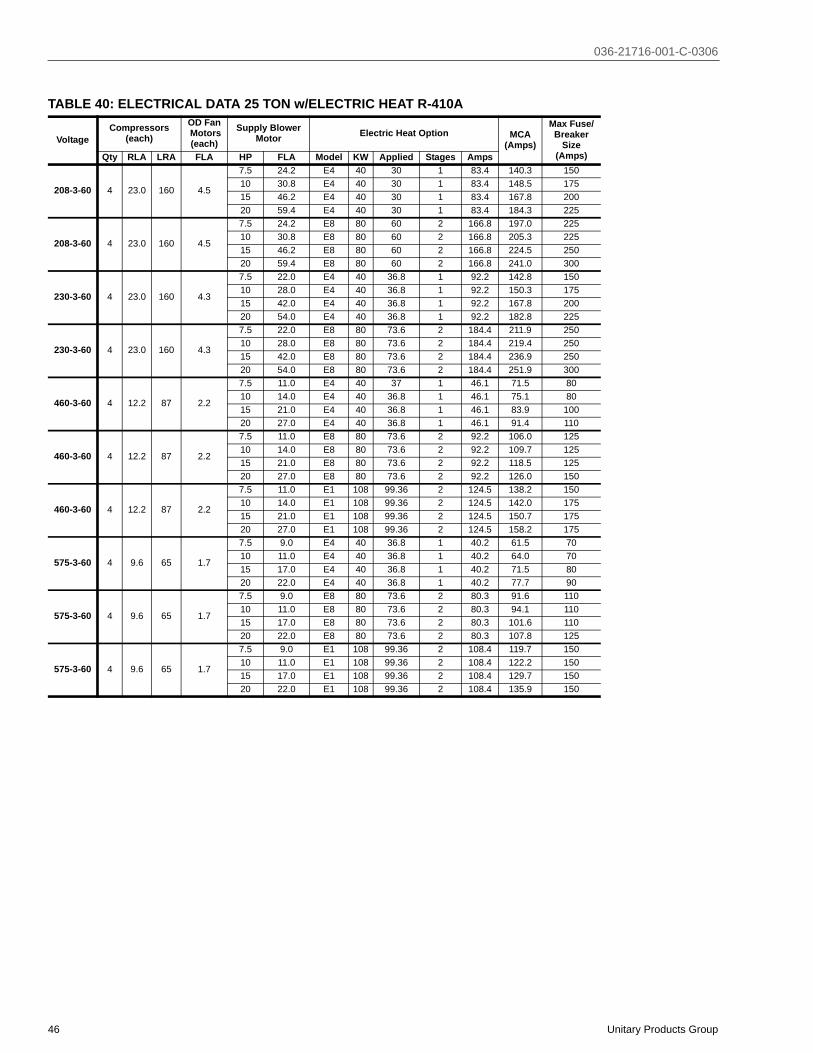
036-21716-001-C-0306
46 Unitary Products Group
TABLE 40: ELECTRICAL DATA 25 TON w/ELECTRIC HEAT R-410A
VoltageCompressors
(each)OD Fan Motors(each)
Supply BlowerMotor Electric Heat Option MCA
(Amps)
Max Fuse/Breaker
Size(Amps)Qty RLA LRA FLA HP FLA Model KW Applied Stages Amps
208-3-60 4 23.0 160 4.5
7.5 24.2 E4 40 30 1 83.4 140.3 15010 30.8 E4 40 30 1 83.4 148.5 17515 46.2 E4 40 30 1 83.4 167.8 20020 59.4 E4 40 30 1 83.4 184.3 225
208-3-60 4 23.0 160 4.5
7.5 24.2 E8 80 60 2 166.8 197.0 22510 30.8 E8 80 60 2 166.8 205.3 22515 46.2 E8 80 60 2 166.8 224.5 25020 59.4 E8 80 60 2 166.8 241.0 300
230-3-60 4 23.0 160 4.3
7.5 22.0 E4 40 36.8 1 92.2 142.8 15010 28.0 E4 40 36.8 1 92.2 150.3 17515 42.0 E4 40 36.8 1 92.2 167.8 20020 54.0 E4 40 36.8 1 92.2 182.8 225
230-3-60 4 23.0 160 4.3
7.5 22.0 E8 80 73.6 2 184.4 211.9 25010 28.0 E8 80 73.6 2 184.4 219.4 25015 42.0 E8 80 73.6 2 184.4 236.9 25020 54.0 E8 80 73.6 2 184.4 251.9 300
460-3-60 4 12.2 87 2.2
7.5 11.0 E4 40 37 1 46.1 71.5 8010 14.0 E4 40 36.8 1 46.1 75.1 8015 21.0 E4 40 36.8 1 46.1 83.9 10020 27.0 E4 40 36.8 1 46.1 91.4 110
460-3-60 4 12.2 87 2.2
7.5 11.0 E8 80 73.6 2 92.2 106.0 12510 14.0 E8 80 73.6 2 92.2 109.7 12515 21.0 E8 80 73.6 2 92.2 118.5 12520 27.0 E8 80 73.6 2 92.2 126.0 150
460-3-60 4 12.2 87 2.2
7.5 11.0 E1 108 99.36 2 124.5 138.2 15010 14.0 E1 108 99.36 2 124.5 142.0 17515 21.0 E1 108 99.36 2 124.5 150.7 17520 27.0 E1 108 99.36 2 124.5 158.2 175
575-3-60 4 9.6 65 1.7
7.5 9.0 E4 40 36.8 1 40.2 61.5 7010 11.0 E4 40 36.8 1 40.2 64.0 7015 17.0 E4 40 36.8 1 40.2 71.5 8020 22.0 E4 40 36.8 1 40.2 77.7 90
575-3-60 4 9.6 65 1.7
7.5 9.0 E8 80 73.6 2 80.3 91.6 11010 11.0 E8 80 73.6 2 80.3 94.1 11015 17.0 E8 80 73.6 2 80.3 101.6 11020 22.0 E8 80 73.6 2 80.3 107.8 125
575-3-60 4 9.6 65 1.7
7.5 9.0 E1 108 99.36 2 108.4 119.7 15010 11.0 E1 108 99.36 2 108.4 122.2 15015 17.0 E1 108 99.36 2 108.4 129.7 15020 22.0 E1 108 99.36 2 108.4 135.9 150

036-21716-001-C-0306
Unitary Products Group 47
TABLE 41: ELECTRICAL DATA 30 TON w/ELECTRIC HEAT R-410A
VoltageCompressors
(each)OD Fan Motors(each)
Supply BlowerMotor Electric Heat Option MCA
(Amps)
Max Fuse/Breaker
Size(Amps)Qty RLA LRA FLA HP FLA Model KW Applied Stages Amps
208-3-60 4 27.9 164 5.8
10 30.8 E4 40 30 1 83.4 161.7 17515 46.2 E4 40 30 1 83.4 181.0 22520 59.4 E4 40 30 1 83.4 197.5 25025 74.8 E4 40 30 1 83.4 216.7 250
208-3-60 4 27.9 164 5.8
10 30.8 E8 80 60 2 166.8 205.3 22515 46.2 E8 80 60 2 166.8 224.5 25020 59.4 E8 80 60 2 166.8 241.0 30025 74.8 E8 80 60 2 166.8 260.3 300
230-3-60 4 27.9 164 5.2
10 28.0 E4 40 36.8 1 92.2 158.2 17515 42.0 E4 40 36.8 1 92.2 175.7 20020 54.0 E4 40 36.8 1 92.2 190.7 22525 68.0 E4 40 36.8 1 92.2 208.2 250
230-3-60 4 27.9 164 5.2
10 28.0 E8 80 73.6 2 184.4 219.4 25015 42.0 E8 80 73.6 2 184.4 236.9 25020 54.0 E8 80 73.6 2 184.4 251.9 30025 68.0 E8 80 73.6 2 184.4 269.4 300
460-3-60 4 13.6 100 2.6
10 14.0 E4 40 37 1 46.1 77.9 9015 21.0 E4 40 36.8 1 46.1 86.7 10020 27.0 E4 40 36.8 1 46.1 94.2 11025 34.0 E4 40 36.8 1 46.1 102.9 125
460-3-60 4 13.6 100 2.6
10 14.0 E8 80 73.6 2 92.2 109.7 12515 21.0 E8 80 73.6 2 92.2 118.5 12520 27.0 E8 80 73.6 2 92.2 126.0 15025 34.0 E8 80 73.6 2 92.2 134.7 150
460-3-60 4 13.6 100 2.6
10 14.0 E1 108 99.36 2 124.5 142.0 17515 21.0 E1 108 99.36 2 124.5 150.7 17520 27.0 E1 108 99.36 2 124.5 158.2 17525 34.0 E1 108 99.36 2 124.5 167.0 200
575-3-60 4 10.0 78 2.2
10 11.0 E4 40 36.8 1 40.2 64.0 7015 17.0 E4 40 36.8 1 40.2 71.5 8020 22.0 E4 40 36.8 1 40.2 77.7 9025 27.0 E4 40 36.8 1 40.2 84.0 100
575-3-60 4 10.0 78 2.2
10 11.0 E8 80 73.6 2 80.3 94.1 11015 17.0 E8 80 73.6 2 80.3 101.6 11020 22.0 E8 80 73.6 2 80.3 107.8 12525 27.0 E8 80 73.6 2 80.3 114.1 125
575-3-60 4 10.0 78 2.2
10 11.0 E1 108 99.36 2 108.4 122.2 15015 17.0 E1 108 99.36 2 108.4 129.7 15020 22.0 E1 108 99.36 2 108.4 135.9 15025 27.0 E1 108 99.36 2 108.4 142.2 150
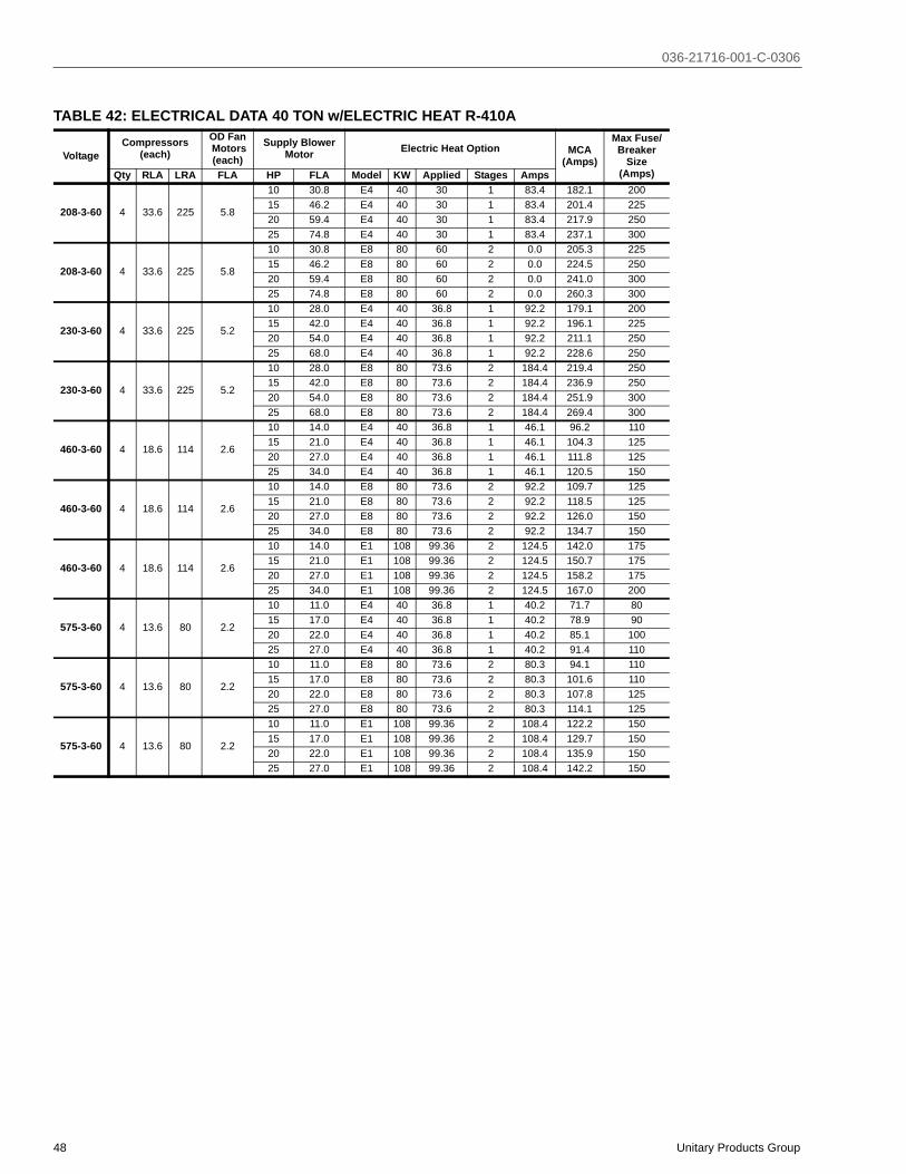
036-21716-001-C-0306
48 Unitary Products Group
TABLE 42: ELECTRICAL DATA 40 TON w/ELECTRIC HEAT R-410A
VoltageCompressors
(each)OD Fan Motors(each)
Supply BlowerMotor Electric Heat Option MCA
(Amps)
Max Fuse/Breaker
Size(Amps)Qty RLA LRA FLA HP FLA Model KW Applied Stages Amps
208-3-60 4 33.6 225 5.8
10 30.8 E4 40 30 1 83.4 182.1 20015 46.2 E4 40 30 1 83.4 201.4 22520 59.4 E4 40 30 1 83.4 217.9 25025 74.8 E4 40 30 1 83.4 237.1 300
208-3-60 4 33.6 225 5.8
10 30.8 E8 80 60 2 0.0 205.3 22515 46.2 E8 80 60 2 0.0 224.5 25020 59.4 E8 80 60 2 0.0 241.0 30025 74.8 E8 80 60 2 0.0 260.3 300
230-3-60 4 33.6 225 5.2
10 28.0 E4 40 36.8 1 92.2 179.1 20015 42.0 E4 40 36.8 1 92.2 196.1 22520 54.0 E4 40 36.8 1 92.2 211.1 25025 68.0 E4 40 36.8 1 92.2 228.6 250
230-3-60 4 33.6 225 5.2
10 28.0 E8 80 73.6 2 184.4 219.4 25015 42.0 E8 80 73.6 2 184.4 236.9 25020 54.0 E8 80 73.6 2 184.4 251.9 30025 68.0 E8 80 73.6 2 184.4 269.4 300
460-3-60 4 18.6 114 2.6
10 14.0 E4 40 36.8 1 46.1 96.2 11015 21.0 E4 40 36.8 1 46.1 104.3 12520 27.0 E4 40 36.8 1 46.1 111.8 12525 34.0 E4 40 36.8 1 46.1 120.5 150
460-3-60 4 18.6 114 2.6
10 14.0 E8 80 73.6 2 92.2 109.7 12515 21.0 E8 80 73.6 2 92.2 118.5 12520 27.0 E8 80 73.6 2 92.2 126.0 15025 34.0 E8 80 73.6 2 92.2 134.7 150
460-3-60 4 18.6 114 2.6
10 14.0 E1 108 99.36 2 124.5 142.0 17515 21.0 E1 108 99.36 2 124.5 150.7 17520 27.0 E1 108 99.36 2 124.5 158.2 17525 34.0 E1 108 99.36 2 124.5 167.0 200
575-3-60 4 13.6 80 2.2
10 11.0 E4 40 36.8 1 40.2 71.7 8015 17.0 E4 40 36.8 1 40.2 78.9 9020 22.0 E4 40 36.8 1 40.2 85.1 10025 27.0 E4 40 36.8 1 40.2 91.4 110
575-3-60 4 13.6 80 2.2
10 11.0 E8 80 73.6 2 80.3 94.1 11015 17.0 E8 80 73.6 2 80.3 101.6 11020 22.0 E8 80 73.6 2 80.3 107.8 12525 27.0 E8 80 73.6 2 80.3 114.1 125
575-3-60 4 13.6 80 2.2
10 11.0 E1 108 99.36 2 108.4 122.2 15015 17.0 E1 108 99.36 2 108.4 129.7 15020 22.0 E1 108 99.36 2 108.4 135.9 15025 27.0 E1 108 99.36 2 108.4 142.2 150

036-21716-001-C-0306
Unitary Products Group 49
TABLE 43: ELECTRICAL DATA 25 TON w/POWER EXHAUST R-410A
VoltageCompressors
(each)OD Fan Motors(each)
Supply BlowerMotor Pwr Exh Motor MCA
(Amps)
Max Fuse/Breaker
Size(Amps)Qty RLA LRA FLA HP FLA HP FLA
208-3-60 4 23.0 160 4.5
7.5 24.2 5 16.7 157.0 1757.5 24.2 7.5 24.2 164.5 1757.5 24.2 10 30.8 172.7 2007.5 24.2 15 46.2 192.0 225
208-3-60 4 23.0 160 4.5
10 30.8 5 16.7 165.2 17510 30.8 7.5 24.2 172.7 20010 30.8 10 30.8 179.3 20010 30.8 15 46.2 198.6 225
208-3-60 4 23.0 160 4.5
15 46.2 5 16.7 184.5 22515 46.2 7.5 24.2 192.0 22515 46.2 10 30.8 198.6 22515 46.2 15 46.2 214.0 250
208-3-60 4 23.0 160 4.5
20 59.4 5 16.7 201.0 25020 59.4 7.5 24.2 208.5 25020 59.4 10 30.8 215.1 25020 59.4 15 46.2 230.5 250
230-3-60 4 23.0 160 4.3
7.5 22.0 5 15.2 153.0 1757.5 22.0 7.5 22.0 160.0 1757.5 22.0 10 28.0 167.0 1757.5 22.0 15 42.0 185.0 225
230-3-60 4 23.0 160 4.3
10 28.0 5 15.2 160.0 17510 28.0 7.5 22.0 167.0 17510 28.0 10 28.0 173.0 20010 28.0 15 42.0 191.0 225
230-3-60 4 23.0 160 4.3
15 42.0 5 15.2 178.0 20015 42.0 7.5 22.0 185.0 22515 42.0 10 28.0 191.0 22515 42.0 15 42.0 205.0 225
230-3-60 4 23.0 160 4.3
20 54.0 5 15.2 193.0 22520 54.0 7.5 22.0 200.0 25020 54.0 10 28.0 206.0 25020 54.0 15 42.0 220.0 250
460-3-60 4 12.2 87 2.2
7.5 11.0 5 7.6 80.9 907.5 11.0 7.5 11.0 85.1 907.5 11.0 10 14.0 88.9 907.5 11.0 15 21.0 97.6 110
460-3-60 4 12.2 87 2.2
10 14.0 5 7.6 84.6 9010 14.0 7.5 11.0 88.9 9010 14.0 10 14.0 92.6 10010 14.0 15 21.0 101.4 110
460-3-60 4 12.2 87 2.2
15 21.0 5 7.6 93.4 11015 21.0 7.5 11.0 97.6 11015 21.0 10 14.0 101.4 11015 21.0 15 21.0 110.1 125
460-3-60 4 12.2 87 2.2
20 27.0 5 7.6 100.9 12520 27.0 7.5 11.0 105.1 12520 27.0 10 14.0 108.9 12520 27.0 15 21.0 117.6 125
575-3-60 4 9.6 65 1.7
7.5 9.0 5 6.1 69.1 707.5 9.0 7.5 9.0 72.7 807.5 9.0 10 11.0 75.2 807.5 9.0 15 17.0 82.7 90
575-3-60 4 9.6 65 1.7
10 11.0 5 6.1 71.6 8010 11.0 7.5 9.0 75.2 8010 11.0 10 11.0 77.7 8010 11.0 15 17.0 85.2 90
575-3-60 4 9.6 65 1.7
15 17.0 5 6.1 79.1 8015 17.0 7.5 9.0 82.7 9015 17.0 10 11.0 85.2 9015 17.0 15 17.0 92.7 100
575-3-60 4 9.6 65 1.7
20 22.0 5 6.1 85.3 10020 22.0 7.5 9.0 89.0 10020 22.0 10 11.0 91.5 10020 22.0 15 17.0 99.0 110

036-21716-001-C-0306
50 Unitary Products Group
TABLE 44: ELECTRICAL DATA 30 TON w/POWER EXHAUST R-410A
VoltageCompressors
(each)OD Fan Motors
(each)Supply Blower
Motor Pwr Exh Motor MCA(Amps)
Max Fuse/Breaker
Size(Amps)Qty RLA LRA Qty FLA HP FLA HP FLA
208-3-60 4 27.9 164 4 5.810 30.8 7.5 24.2 185.9 20010 30.8 10 30.8 192.5 20010 30.8 15 46.2 211.8 250
208-3-60 4 27.9 164 4 5.815 46.2 7.5 24.2 205.2 25015 46.2 10 30.8 211.8 25015 46.2 15 46.2 227.2 250
208-3-60 4 27.9 164 4 5.820 59.4 7.5 24.2 221.7 25020 59.4 10 30.8 228.3 25020 59.4 15 46.2 243.7 300
208-3-60 4 27.9 164 4 5.825 74.8 7.5 24.2 240.9 30025 74.8 10 30.8 247.5 30025 74.8 15 46.2 262.9 300
230-3-60 4 27.9 164 4 5.210 28.0 7.5 22 180.2 20010 28.0 10 28 186.2 20010 28.0 15 42 203.7 225
230-3-60 4 27.9 164 4 5.215 42.0 7.5 22 197.7 22515 42.0 10 28 203.7 22515 42.0 15 42 217.7 250
230-3-60 4 27.9 164 4 5.220 54.0 7.5 22 212.7 25020 54.0 10 28 218.7 25020 54.0 15 42 232.7 250
230-3-60 4 27.9 164 4 5.225 68.0 7.5 22 230.2 25025 68.0 10 28 236.2 30025 68.0 15 42 250.2 300
460-3-60 4 13.6 100 4 2.610 14.0 7.5 11.0 88.9 10010 14.0 10 14.0 92.6 10010 14.0 15 21.0 101.4 110
460-3-60 4 13.6 100 4 2.615 21.0 7.5 11.0 97.7 11015 21.0 10 14.0 101.4 11015 21.0 15 21.0 110.1 125
460-3-60 4 13.6 100 4 2.620 27.0 7.5 11.0 105.2 12520 27.0 10 14.0 108.9 12520 27.0 15 21.0 117.6 125
460-3-60 4 13.6 100 4 2.625 34.0 7.5 11.0 113.9 12525 34.0 10 14.0 117.6 15025 34.0 15 21.0 126.4 150
575-3-60 4 10.0 78 4 2.210 11.0 7.5 9.0 67.6 7010 11.0 10 11.0 69.6 8010 11.0 15 17.0 77.1 90
575-3-60 4 10.0 78 4 2.215 17.0 7.5 9.0 75.1 9015 17.0 10 11.0 77.1 9015 17.0 15 17.0 83.1 100
575-3-60 4 10.0 78 4 2.220 22.0 7.5 9.0 81.3 10020 22.0 10 11.0 83.3 10020 22.0 15 17.0 89.3 110
575-3-60 4 10.0 78 4 2.225 27.0 7.5 9.0 87.6 11025 27.0 10 11.0 89.6 11025 27.0 15 17.0 95.6 110

036-21716-001-C-0306
Unitary Products Group 51
TABLE 45: ELECTRICAL DATA 40 TON w/POWER EXHAUST R-410A
VoltageCompressors
(each)OD Fan Motors
(each)Supply Blower
Motor Pwr Exh Motor MCA(Amps)
Max Fuse/Breaker
Size(Amps)Qty RLA LRA Qty FLA HP FLA HP FLA
208-3-60 4 33.6 225 4 5.810 30.8 7.5 24.2 206.3 22510 30.8 10 30.8 212.9 22510 30.8 15 46.2 232.2 250
208-3-60 4 33.6 225 4 5.815 46.2 7.5 24.2 225.6 25015 46.2 10 30.8 232.2 25015 46.2 15 46.2 247.6 250
208-3-60 4 33.6 225 4 5.820 59.4 7.5 24.2 242.1 30020 59.4 10 30.8 248.7 30020 59.4 15 46.2 264.1 300
208-3-60 4 33.6 225 4 5.825 74.8 7.5 24.2 261.3 30025 74.8 10 30.8 267.9 30025 74.8 15 46.2 283.3 350
230-3-60 4 33.6 225 4 5.210 28.0 7.5 22.0 201.1 22510 28.0 10 28.0 207.1 22510 28.0 15 42.0 224.1 250
230-3-60 4 33.6 225 4 5.215 42.0 7.5 22.0 218.1 25015 42.0 10 28.0 224.1 25015 42.0 15 42.0 238.1 250
230-3-60 4 33.6 225 4 5.220 54.0 7.5 22.0 233.1 25020 54.0 10 28.0 239.1 25020 54.0 15 42.0 253.1 300
230-3-60 4 33.6 225 4 5.225 68.0 7.5 22.0 250.6 30025 68.0 10 28.0 256.6 30025 68.0 15 42.0 270.6 300
460-3-60 4 18.6 114 4 2.610 14.0 7.5 11.0 107.2 11010 14.0 10 14.0 110.2 12510 14.0 15 21.0 118.3 125
460-3-60 4 18.6 114 4 2.615 21.0 7.5 11.0 115.3 12515 21.0 10 14.0 118.3 12515 21.0 15 21.0 125.3 150
460-3-60 4 18.6 114 4 2.620 27.0 7.5 11.0 122.8 12520 27.0 10 14.0 125.8 15020 27.0 15 21.0 132.8 150
460-3-60 4 18.6 114 4 2.625 34.0 7.5 11.0 131.5 15025 34.0 10 14.0 134.5 15025 34.0 15 21.0 141.5 175
575-3-60 4 13.6 80 4 2.210 11.0 7.5 9.0 80.7 9010 11.0 10 11.0 82.7 9010 11.0 15 17.0 89.9 100
575-3-60 4 13.6 80 4 2.215 17.0 7.5 9.0 87.9 10015 17.0 10 11.0 89.9 10015 17.0 15 17.0 95.9 110
575-3-60 4 13.6 80 4 2.220 22.0 7.5 9.0 94.1 11020 22.0 10 11.0 96.1 11020 22.0 15 17.0 102.1 110
575-3-60 4 13.6 80 4 2.225 27.0 7.5 9.0 100.4 12525 27.0 10 11.0 102.4 12525 27.0 15 17.0 108.4 125

036-21716-001-C-0306
52 Unitary Products Group
TABLE 46: ELECTRICAL DATA 25 TON w/ELECTRIC HEAT and POWER EXHAUST R-410A
VoltageElectric Heat Option Compressors
(each)OD Fan Motors(each)
Supply BlowerMotor Pwr Exh Motor MCA
(Amps)
Max Fuse/Breaker
Size(Amps)Model KW Stages Amps Qty RLA LRA Qty FLA HP FLA HP FLA
208-3-60 E4 40 1 83.4
4 23.0 160 36.0 4.5
7.5 24.2 5 16.7 155.4 1757.5 24.2 7.5 24.2 164.7 1757.5 24.2 10 30.8 173.0 2007.5 24.2 15 46.2 192.2 225
4 23.0 160 36.0 4.5
10 30.8 5 16.7 165.2 17510 30.8 7.5 24.2 173.0 20010 30.8 10 30.8 181.2 20010 30.8 15 46.2 200.5 225
4 23.0 160 36.0 4.5
15 46.2 5 16.7 184.5 22515 46.2 7.5 24.2 192.2 22515 46.2 10 30.8 200.5 22515 46.2 15 46.2 219.7 250
4 23.0 160 36.0 4.5
20 59.4 5 16.7 201.0 25020 59.4 7.5 24.2 208.7 25020 59.4 10 30.8 217.0 25020 59.4 15 46.2 236.2 250
208-3-60 E8 80 2 166.8
4 23.0 160 36.0 4.5
7.5 24.2 5 16.7 217.9 2257.5 24.2 7.5 24.2 227.3 2507.5 24.2 10 30.8 235.5 2507.5 24.2 15 46.2 254.8 300
4 23.0 160 36.0 4.5
10 30.8 5 16.7 226.2 25010 30.8 7.5 24.2 235.5 25010 30.8 10 30.8 243.8 25010 30.8 15 46.2 263.0 300
4 23.0 160 36.0 4.5
15 46.2 5 16.7 245.4 25015 46.2 7.5 24.2 254.8 30015 46.2 10 30.8 263.0 30015 46.2 15 46.2 282.3 300
4 23.0 160 36.0 4.5
20 59.4 5 16.7 261.9 30020 59.4 7.5 24.2 271.3 30020 59.4 10 30.8 279.5 30020 59.4 15 46.2 298.8 300
230-3-60 E4 40 1 92.2
4 23.0 160 36.0 4.3
7.5 22.0 5 15.2 161.8 1757.5 22.0 7.5 22.0 170.3 1757.5 22.0 10 28.0 177.8 2007.5 22.0 15 42.0 195.3 225
4 23.0 160 36.0 4.3
10 28.0 5 15.2 169.3 17510 28.0 7.5 22.0 177.8 20010 28.0 10 28.0 185.3 20010 28.0 15 42.0 202.8 225
4 23.0 160 36.0 4.3
15 42.0 5 15.2 186.8 20015 42.0 7.5 22.0 195.3 22515 42.0 10 28.0 202.8 22515 42.0 15 42.0 220.3 225
4 23.0 160 36.0 4.3
20 54.0 5 15.2 201.8 22520 54.0 7.5 22.0 210.3 25020 54.0 10 28.0 217.8 25020 54.0 15 42.0 235.3 250
230-3-60 E8 80 2 184.4
4 23.0 160 36.0 4.3
7.5 22.0 5 15.2 230.9 2507.5 22.0 7.5 22.0 239.4 2507.5 22.0 10 28.0 246.9 2507.5 22.0 15 42.0 264.4 300
4 23.0 160 36.0 4.3
10 28.0 5 15.2 238.4 25010 28.0 7.5 22.0 246.9 25010 28.0 10 28.0 254.4 30010 28.0 15 42.0 271.9 300
4 23.0 160 36.0 4.3
15 42.0 5 15.2 255.9 30015 42.0 7.5 22.0 264.4 30015 42.0 10 28.0 271.9 30015 42.0 15 42.0 289.4 300
4 23.0 160 36.0 4.3
20 54.0 5 15.2 270.9 30020 54.0 7.5 22.0 279.4 30020 54.0 10 28.0 286.9 30020 54.0 15 42.0 304.4 350

036-21716-001-C-0306
Unitary Products Group 53
VoltageElectric Heat Option Compressors
(each)OD Fan Motors(each)
Supply BlowerMotor Pwr Exh Motor MCA
(Amps)
Max Fuse/Breaker
Size(Amps)Model KW Stages Amps Qty RLA LRA Qty FLA HP FLA HP FLA
460-3-60 E4 40 1 46.1
4 12.2 87 4 2.2
7.5 11.0 5 7.6 80.9 907.5 11.0 7.5 11.0 85.1 907.5 11.0 10 14.0 88.9 907.5 11.0 15 21.0 97.6 110
4 12.2 87 4 2.2
10 14.0 5 7.6 84.6 9010 14.0 7.5 11.0 88.9 9010 14.0 10 14.0 92.6 10010 14.0 15 21.0 101.4 110
4 12.2 87 4 2.2
15 21.0 5 7.6 93.4 11015 21.0 7.5 11.0 97.6 11015 21.0 10 14.0 101.4 11015 21.0 15 21.0 110.1 125
4 12.2 87 4 2.2
20 27.0 5 7.6 100.9 12520 27.0 7.5 11.0 105.1 12520 27.0 10 14.0 108.9 12520 27.0 15 21.0 117.6 125
460-3-60 E8 80 2 92.2
4 12.2 87 4 2.2
7.5 11.0 5 7.6 115.5 1257.5 11.0 7.5 11.0 119.7 1257.5 11.0 10 14.0 123.5 1257.5 11.0 15 21.0 132.2 150
4 12.2 87 4 2.2
10 14.0 5 7.6 119.2 12510 14.0 7.5 11.0 123.5 12510 14.0 10 14.0 127.2 15010 14.0 15 21.0 136.0 150
4 12.2 87 4 2.2
15 21.0 5 7.6 128.0 15015 21.0 7.5 11.0 132.2 15015 21.0 10 14.0 136.0 15015 21.0 15 21.0 144.7 150
4 12.2 87 4 2.2
20 27.0 5 7.6 135.5 15020 27.0 7.5 11.0 139.7 15020 27.0 10 14.0 143.5 15020 27.0 15 21.0 152.2 175
460-3-60 E1 108 2 124.5
4 12.2 87 4 2.2
7.5 11.0 5 7.6 147.7 1757.5 11.0 7.5 11.0 152.0 1757.5 11.0 10 14.0 155.7 1757.5 11.0 15 21.0 164.5 175
4 12.2 87 4 2.2
10 14.0 5 7.6 151.5 17510 14.0 7.5 11.0 155.7 17510 14.0 10 14.0 159.5 17510 14.0 15 21.0 168.2 175
4 12.2 87 4 2.2
15 21.0 5 7.6 160.2 17515 21.0 7.5 11.0 164.5 17515 21.0 10 14.0 168.2 17515 21.0 15 21.0 177.0 200
4 12.2 87 4 2.2
20 27.0 5 7.6 167.7 17520 27.0 7.5 11.0 172.0 17520 27.0 10 14.0 175.7 20020 27.0 15 21.0 184.5 200
575-3-60 E4 40 1 40.2
4 9.6 65 4 1.7
7.5 9.0 5 6.1 69.1 707.5 9.0 7.5 9.0 72.7 807.5 9.0 10 11.0 75.2 807.5 9.0 15 17.0 82.7 90
4 9.6 65 4 1.7
10 11.0 5 6.1 71.6 8010 11.0 7.5 9.0 75.2 8010 11.0 10 11.0 77.7 8010 11.0 15 17.0 85.2 90
4 9.6 65 4 1.7
15 17.0 5 6.1 79.1 8015 17.0 7.5 9.0 82.7 9015 17.0 10 11.0 85.2 9015 17.0 15 17.0 92.7 100
4 9.6 65 4 1.7
20 22.0 5 6.1 85.3 10020 22.0 7.5 9.0 89.0 10020 22.0 10 11.0 91.5 10020 22.0 15 17.0 99.0 110
TABLE 46: ELECTRICAL DATA 25 TON w/ELECTRIC HEAT and POWER EXHAUST R-410A (CONT.)

036-21716-001-C-0306
54 Unitary Products Group
VoltageElectric Heat Option Compressors
(each)OD Fan Motors(each)
Supply BlowerMotor Pwr Exh Motor MCA
(Amps)
Max Fuse/Breaker
Size(Amps)Model KW Stages Amps Qty RLA LRA Qty FLA HP FLA HP FLA
575-3-60 E8 80 2 80.3
4 9.6 65 4 1.7
7.5 9.0 5 6.1 99.2 1107.5 9.0 7.5 9.0 102.8 1107.5 9.0 10 11.0 105.3 1107.5 9.0 15 17.0 112.8 125
4 9.6 65 4 1.7
10 11.0 5 6.1 101.7 11010 11.0 7.5 9.0 105.3 11010 11.0 10 11.0 107.8 11010 11.0 15 17.0 115.3 125
4 9.6 65 4 1.7
15 17.0 5 6.1 109.2 11015 17.0 7.5 9.0 112.8 12515 17.0 10 11.0 115.3 12515 17.0 15 17.0 122.8 125
4 9.6 65 4 1.7
20 22.0 5 6.1 115.5 12520 22.0 7.5 9.0 119.1 12520 22.0 10 11.0 121.6 12520 22.0 15 17.0 129.1 150
575-3-60 E1 108 2 108.4
4 9.6 65 4 1.7
7.5 9.0 5 6.1 127.3 1507.5 9.0 7.5 9.0 130.9 1507.5 9.0 10 11.0 133.4 1507.5 9.0 15 17.0 140.9 150
4 9.6 65 4 1.7
10 11.0 5 6.1 129.8 15010 11.0 7.5 9.0 133.4 15010 11.0 10 11.0 135.9 15010 11.0 15 17.0 143.4 150
4 9.6 65 4 1.7
15 17.0 5 6.1 137.3 15015 17.0 7.5 9.0 140.9 15015 17.0 10 11.0 143.4 15015 17.0 15 17.0 150.9 175
4 9.6 65 4 1.7
20 22.0 5 6.1 143.6 15020 22.0 7.5 9.0 147.2 15020 22.0 10 11.0 149.7 15020 22.0 15 17.0 157.2 175
TABLE 46: ELECTRICAL DATA 25 TON w/ELECTRIC HEAT and POWER EXHAUST R-410A (CONT.)

036-21716-001-C-0306
Unitary Products Group 55
TABLE 47: ELECTRICAL DATA 30 TON w/ELECTRIC HEAT and POWER EXHAUST R-410A
VoltageElectric Heat Option Compressors
(each)OD Fan Motors(each)
Supply BlowerMotor Pwr Exh Motor MCA
(Amps)
Max Fuse/Breaker
Size(Amps)Model KW Stages Amps Qty RLA LRA Qty FLA HP FLA HP FLA
208-3-60 E4 40 1 83.4
4 27.9 164 4 5.810 30.8 7.5 24.2 185.9 20010 30.8 10 30.8 192.5 20010 30.8 15 46.2 211.8 250
4 27.9 164 4 5.815 46.2 7.5 24.2 205.2 25015 46.2 10 30.8 211.8 25015 46.2 15 46.2 227.2 250
4 27.9 164 4 5.820 59.4 7.5 24.2 221.7 25020 59.4 10 30.8 228.3 25020 59.4 15 46.2 243.7 300
4 27.9 164 4 5.825 74.8 7.5 24.2 240.9 30025 74.8 10 30.8 247.5 30025 74.8 15 46.2 262.9 300
208-3-60 E8 80 2 166.8
4 27.9 164 4 5.810 30.8 7.5 24.2 235.5 25010 30.8 10 30.8 243.8 25010 30.8 15 46.2 263.0 300
4 27.9 164 4 5.815 46.2 7.5 24.2 254.8 30015 46.2 10 30.8 263.0 30015 46.2 15 46.2 282.3 300
4 27.9 164 4 5.820 59.4 7.5 24.2 271.3 30020 59.4 10 30.8 279.5 30020 59.4 15 46.2 298.8 300
4 27.9 164 4 5.825 74.8 7.5 24.2 290.5 35025 74.8 10 30.8 298.8 35025 74.8 15 46.2 318.0 350
230-3-60 E4 40 1 92.2
4 27.9 164 4 5.210 28.0 7.5 22.0 180.2 20010 28.0 10 28.0 186.2 20010 28.0 15 42.0 203.7 225
4 27.9 164 4 5.215 42.0 7.5 22.0 197.7 22515 42.0 10 28.0 203.7 22515 42.0 15 42.0 220.3 250
4 27.9 164 4 5.220 54.0 7.5 22.0 212.7 25020 54.0 10 28.0 218.7 25020 54.0 15 42.0 235.3 250
4 27.9 164 4 5.225 68.0 7.5 22.0 230.2 25025 68.0 10 28.0 236.2 30025 68.0 15 42.0 252.8 300
230-3-60 E8 80 2 184.4
4 27.9 164 4 5.210 28.0 7.5 22.0 246.9 25010 28.0 10 28.0 254.4 30010 28.0 15 42.0 271.9 300
4 27.9 164 4 5.215 42.0 7.5 22.0 264.4 30015 42.0 10 28.0 271.9 30015 42.0 15 42.0 289.4 300
4 27.9 164 4 5.220 54.0 7.5 22.0 279.4 30020 54.0 10 28.0 286.9 30020 54.0 15 42.0 304.4 350
4 27.9 164 4 5.225 68.0 7.5 22.0 296.9 35025 68.0 10 28.0 304.4 35025 68.0 15 42.0 321.9 350
460-3-60 E4 40 1 46.1
4 13.6 100 4 2.610 14.0 7.5 11.0 88.9 10010 14.0 10 14.0 92.6 10010 14.0 15 21.0 101.4 110
4 13.6 100 4 2.615 21.0 7.5 11.0 97.7 11015 21.0 10 14.0 101.4 11015 21.0 15 21.0 110.1 125
4 13.6 100 4 2.620 27.0 7.5 11.0 105.2 12520 27.0 10 14.0 108.9 12520 27.0 15 21.0 117.6 125
4 13.6 100 4 2.625 34.0 7.5 11.0 113.9 12525 34.0 10 14.0 117.6 15025 34.0 15 21.0 126.4 150

036-21716-001-C-0306
56 Unitary Products Group
VoltageElectric Heat Option Compressors
(each)OD Fan Motors(each)
Supply BlowerMotor Pwr Exh Motor MCA
(Amps)
Max Fuse/Breaker
Size(Amps)Model KW Stages Amps Qty RLA LRA Qty FLA HP FLA HP FLA
460-3-60 E8 80 2 92.2
4 13.6 100 4 2.610 14.0 7.5 11.0 155.7 17510 14.0 10 14.0 159.5 17510 14.0 15 21.0 168.2 175
4 13.6 100 4 2.615 21.0 7.5 11.0 164.5 17515 21.0 10 14.0 168.2 17515 21.0 15 21.0 177.0 200
4 13.6 100 4 2.620 27.0 7.5 11.0 172.0 17520 27.0 10 14.0 175.7 20020 27.0 15 21.0 184.5 200
4 13.6 100 4 2.625 34.0 7.5 11.0 180.7 20025 34.0 10 14.0 184.5 20025 34.0 15 21.0 193.2 200
460-3-60 E1 108 2 124.5
4 13.6 100 4 2.610 14.0 7.5 11.0 155.7 17510 14.0 10 14.0 159.5 17510 14.0 15 21.0 168.2 175
4 13.6 100 4 2.615 21.0 7.5 11.0 164.5 17515 21.0 10 14.0 168.2 17515 21.0 15 21.0 177.0 200
4 13.6 100 4 2.620 27.0 7.5 11.0 172.0 17520 27.0 10 14.0 175.7 20020 27.0 15 21.0 184.5 200
4 13.6 100 4 2.625 34.0 7.5 11.0 180.7 20025 34.0 10 14.0 184.5 20025 34.0 15 21.0 193.2 200
575-3-60 E4 40 1 40.2
4 10 78 4 2.210 11.0 7.5 9.0 75.2 8010 11.0 10 11.0 77.7 8010 11.0 15 17.0 85.2 90
4 10 78 4 2.215 17.0 7.5 9.0 82.7 9015 17.0 10 11.0 85.2 9015 17.0 15 17.0 92.7 100
4 10 78 4 2.220 22.0 7.5 9.0 89.0 10020 22.0 10 11.0 91.5 10020 22.0 15 17.0 99.0 110
4 10 78 4 2.225 27.0 7.5 9.0 95.2 11025 27.0 10 11.0 97.7 11025 27.0 15 17.0 105.2 110
575-3-60 E8 80 2 80.3
4 10 78 4 2.210 11.0 7.5 9.0 105.3 11010 11.0 10 11.0 107.8 11010 11.0 15 17.0 115.3 125
4 10 78 4 2.215 17.0 7.5 9.0 112.8 12515 17.0 10 11.0 115.3 12515 17.0 15 17.0 122.8 125
4 10 78 4 2.220 22.0 7.5 9.0 119.1 12520 22.0 10 11.0 121.6 12520 22.0 15 17.0 129.1 150
4 10 78 4 2.225 27.0 7.5 9.0 125.3 15025 27.0 10 11.0 127.8 15025 27.0 15 17.0 135.3 150
575-3-60 E1 108 2 108.4
4 10 78 4 2.210 11.0 7.5 9.0 133.4 15010 11.0 10 11.0 135.9 15010 11.0 15 17.0 143.4 150
4 10 78 4 2.215 17.0 7.5 9.0 140.9 15015 17.0 10 11.0 143.4 15015 17.0 15 17.0 150.9 175
4 10 78 4 2.220 22.0 7.5 9.0 147.2 15020 22.0 10 11.0 149.7 15020 22.0 15 17.0 157.2 175
4 10 78 4 2.225 27.0 7.5 9.0 153.4 17525 27.0 10 11.0 155.9 17525 27.0 15 17.0 163.4 175
TABLE 47: ELECTRICAL DATA 30 TON w/ELECTRIC HEAT and POWER EXHAUST R-410A (CONT.)

036-21716-001-C-0306
Unitary Products Group 57
TABLE 48: ELECTRICAL DATA 40 TON w/ELECTRIC HEAT and POWER EXHAUST R-410A
VoltageElectric Heat Option Compressors
(each)OD Fan Motors(each)
Supply BlowerMotor Pwr Exh Motor MCA
(Amps)
Max Fuse/Breaker
Size(Amps)Model KW Stages Amps Qty RLA LRA Qty FLA HP FLA HP FLA
208-3-60 E4 40 1 83.4
4 33.6 225 4 5.810 30.8 7.5 24.2 206.3 22510 30.8 10 30.8 212.9 22510 30.8 15 46.2 232.2 250
4 33.6 225 4 5.815 46.2 7.5 24.2 225.6 25015 46.2 10 30.8 232.2 25015 46.2 15 46.2 247.6 250
4 33.6 225 4 5.820 59.4 7.5 24.2 242.1 30020 59.4 10 30.8 248.7 30020 59.4 15 46.2 264.1 300
4 33.6 225 4 5.825 74.8 7.5 24.2 261.3 30025 74.8 10 30.8 267.9 30025 74.8 15 46.2 283.3 350
208-3-60 E8 80 2 166.8
4 33.6 225 4 5.810 30.8 7.5 24.2 235.5 25010 30.8 10 30.8 243.8 25010 30.8 15 46.2 263.0 300
4 33.6 225 4 5.815 46.2 7.5 24.2 254.8 30015 46.2 10 30.8 263.0 30015 46.2 15 46.2 282.3 300
4 33.6 225 4 5.820 59.4 7.5 24.2 271.3 30020 59.4 10 30.8 279.5 30020 59.4 15 46.2 298.8 300
4 33.6 225 4 5.825 74.8 7.5 24.2 290.5 35025 74.8 10 30.8 298.8 35025 74.8 15 46.2 318.0 350
230-3-60 E4 40 1 92.2
4 33.6 225 4 5.810 28.0 7.5 22.0 201.1 22510 28.0 10 28.0 207.1 22510 28.0 15 42.0 224.1 250
4 33.6 225 4 5.815 42.0 7.5 22.0 218.1 25015 42.0 10 28.0 224.1 25015 42.0 15 42.0 238.1 250
4 33.6 225 4 5.820 54.0 7.5 22.0 233.1 25020 54.0 10 28.0 239.1 25020 54.0 15 42.0 253.1 300
4 33.6 225 4 5.825 68.0 7.5 22.0 250.6 30025 68.0 10 28.0 256.6 30025 68.0 15 42.0 270.6 300
230-3-60 E8 80 2 184.4
4 33.6 225 4 5.810 28.0 7.5 22.0 246.9 25010 28.0 10 28.0 254.4 30010 28.0 15 42.0 271.9 300
4 33.6 225 4 5.815 42.0 7.5 22.0 264.4 30015 42.0 10 28.0 271.9 30015 42.0 15 42.0 289.4 300
4 33.6 225 4 5.820 54.0 7.5 22.0 279.4 30020 54.0 10 28.0 286.9 30020 54.0 15 42.0 304.4 350
4 33.6 225 4 5.825 68.0 7.5 22.0 296.9 35025 68.0 10 28.0 304.4 35025 68.0 15 42.0 321.9 350
460-3-60 E4 40 1 46.1
4 18.6 114 4 2.610 14.0 7.5 11.0 107.2 11010 14.0 10 14.0 110.2 12510 14.0 15 21.0 118.3 125
4 18.6 114 4 2.615 21.0 7.5 11.0 115.3 12515 21.0 10 14.0 118.3 12515 21.0 15 21.0 125.3 150
4 18.6 114 4 2.620 27.0 7.5 11.0 122.8 12520 27.0 10 14.0 125.8 15020 27.0 15 21.0 132.8 150
4 18.6 114 4 2.625 34.0 7.5 11.0 131.5 15025 34.0 10 14.0 134.5 15025 34.0 15 21.0 141.5 175

036-21716-001-C-0306
58 Unitary Products Group
VoltageElectric Heat Option Compressors
(each)OD Fan Motors(each)
Supply BlowerMotor Pwr Exh Motor MCA
(Amps)
Max Fuse/Breaker
Size(Amps)Model KW Stages Amps Qty RLA LRA Qty FLA HP FLA HP FLA
460-3-60 E8 80 2 92.2
4 18.6 114 4 2.610 14.0 7.5 11.0 123.5 12510 14.0 10 14.0 127.2 15010 14.0 15 21.0 136.0 150
4 18.6 114 4 2.615 21.0 7.5 11.0 132.2 15015 21.0 10 14.0 136.0 15015 21.0 15 21.0 144.7 150
4 18.6 114 4 2.620 27.0 7.5 11.0 139.7 15020 27.0 10 14.0 143.5 15020 27.0 15 21.0 152.2 175
4 18.6 114 4 2.625 34.0 7.5 11.0 148.5 17525 34.0 10 14.0 152.2 17525 34.0 15 21.0 161.0 175
460-3-60 E1 108 2 124.5
4 18.6 114 4 2.610 14.0 7.5 11.0 155.7 17510 14.0 10 14.0 159.5 17510 14.0 15 21.0 168.2 175
4 18.6 114 4 2.615 21.0 7.5 11.0 164.5 17515 21.0 10 14.0 168.2 17515 21.0 15 21.0 177.0 200
4 18.6 114 4 2.620 27.0 7.5 11.0 172.0 17520 27.0 10 14.0 175.7 20020 27.0 15 21.0 184.5 200
4 18.6 114 4 2.625 34.0 7.5 11.0 180.7 20025 34.0 10 14.0 184.5 20025 34.0 15 21.0 193.2 200
575-3-60 E4 40 1 40.2
4 13.6 80 4 2.210 11.0 7.5 9.0 80.7 9010 11.0 10 11.0 82.7 9010 11.0 15 17.0 89.9 100
4 13.6 80 4 2.215 17.0 7.5 9.0 87.9 10015 17.0 10 11.0 89.9 10015 17.0 15 17.0 95.9 110
4 13.6 80 4 2.220 22.0 7.5 9.0 94.1 11020 22.0 10 11.0 96.1 11020 22.0 15 17.0 102.1 110
4 13.6 80 4 2.225 27.0 7.5 9.0 100.4 12525 27.0 10 11.0 102.4 12525 27.0 15 17.0 108.4 125
575-3-60 E8 80 2 80.3
4 13.6 80 4 2.210 11.0 7.5 9.0 105.3 11010 11.0 10 11.0 107.8 11010 11.0 15 17.0 115.3 125
4 13.6 80 4 2.215 17.0 7.5 9.0 112.8 12515 17.0 10 11.0 115.3 12515 17.0 15 17.0 122.8 125
4 13.6 80 4 2.220 22.0 7.5 9.0 119.1 12520 22.0 10 11.0 121.6 12520 22.0 15 17.0 129.1 150
4 13.6 80 4 2.225 27.0 7.5 9.0 125.3 15025 27.0 10 11.0 127.8 15025 27.0 15 17.0 135.3 150
575-3-60 E1 108 2 108.4
4 13.6 80 4 2.210 11.0 7.5 9.0 133.4 15010 11.0 10 11.0 135.9 15010 11.0 15 17.0 143.4 150
4 13.6 80 4 2.215 17.0 7.5 9.0 140.9 15015 17.0 10 11.0 143.4 15015 17.0 15 17.0 150.9 175
4 13.6 80 4 2.220 22.0 7.5 9.0 147.2 15020 22.0 10 11.0 149.7 15020 22.0 15 17.0 157.2 175
4 13.6 80 4 2.225 27.0 7.5 9.0 153.4 17525 27.0 10 11.0 155.9 17525 27.0 15 17.0 163.4 175
TABLE 48: ELECTRICAL DATA 40 TON w/ELECTRIC HEAT and POWER EXHAUST R-410A (CONT.)

036-21716-001-C-0306
Unitary Products Group 59
NOTE: If the Millennium is VAV with ERV, add the weight of an exhaust VFD - it will be in the unit.
TABLE 49: UNIT WEIGHTSCOMPONENT 25 TON 30 TON 40 TON
Basic Unit 4410 4565 4845Gas Heat
233 MBH 180 180 180466 MBH 320 320 320700 MBH - - 450
Electric Heat40KW 40 40 4080KW 105 105 105
108KW 110 110 110Hot Water Heat
1 Row Coil 70 70 702 Row Coil 85 85 85
Steam Heat1 Row Coil 85 85 85
BlowerForward Curve Fan (Std Fan) 0 0 0
FC IGV 155 155 175Air Foil Fan 135 135 155
AF IGV 155 155 180Motor - Supply Fan
7.5hp 110 - -10hp 145 145 14515hp 200 200 20020hp 240 240 24025hp - 300 300
Supply Fan Motor VFD See Table 50Refrigeration
T-Coat Evap. 32 30 40T-Coat cond. 32 30 40
Hot Gas Bypass 10 10 10Low Ambient Head Pressure Control
208-230/380/460 5 5 5575 25 25 25
Filters6" Rigid 70 70 70
Exhaust1
1. If ERV and Supply Fan VAV are selected, add the weight of an Exhaust VFD, Table 50.
Exhaust TypeBarometric 45 65 65Modulated 140 275 275
Exhaust Motor5hp 80 80 80
7.5hp 110 110 11010hp 145 145 14515hp 200 200 200
Exhaust Motor VFD See Table 51Economizer
Std. Econ. 235 235 235Econ. w/ERV 50 50 50
ControlDisconnect 15 15 15110V outlet 55 55 55Optilogic 20 20 20
Roof CurbPartial Curb 415 415 415
Full Curb 615 615 615
TABLE 50: SUPPLY FAN MOTOR VFD WEIGHTS
Supply Fan Motor VFD 230V 460V 575V
W/O Bypass
7.5hp 60 25 30
10hp 60 25 30
15hp 75 50 60
20hp 75 50 60
25hp 115 50 60
W/Bypass
7.5hp 155 90 120
10hp 155 90 120
15hp 185 140 155
20hp 185 140 155
25hp 255 140 155
TABLE 51: EXHAUST FAN MOTOR VFD WEIGHTS
Exhaust Fan Motor 230V 460V 575V
W/O Bypass
5hp 15 10 20
7.5hp 50 15 20
10hp 50 15 20
15hp 65 40 50
FIGURE 27 - CENTER OF GRAVITY
TABLE 52: UNIT CENTER OF GRAVITYMODEL
25 TON 30 TON 40 TON
X* Y X* Y X* YBASIC UNIT 99” 48” 100” 47” 96” 46"
BASIC UNIT /W ECON. 110” 48” 110” 47” 100” 46"
BASIC UNIT /W ECON. & GAS OR
ELECT. HEAT, STEAM OR HOT WATER HEAT
104” 48” 104” 46” 99” 45"
BASIC UNIT /W ECON. & GAS OR ELECT. HEAT, & POWER EXHAUST
118” 47” 114” 46” 111” 45"
BACK
CENTER OF
GRAVITY
CONDENSER
COIL END
FRONT
X
Y
"
240"
A
B
C
D
92

036-21716-001-C-0306
60 Unitary Products Group
NOTES: Basic Unit = cooling only, 10hp FC fan.+ Econ = +235lb+ Heat = single stage gas, 180 lb+ Power Exhaust = modulating 7.5hp
Sound Power Ratings for Supply Air Blowers in our MilleniumUnits with High Gas Heat, Economizer, 2: T/A Filters and WetDX Sound power calculations complements of Lau’s revised“Whirlwind” application selection software for air moving com-ponents.
The sound ratings above occur at the blower wheel. To deter-mine the sound rating at a unit’s supply and return air ductconnection, subtract the attenuation factors listed below.
TABLE 53: UNIT CORNERWEIGHTUNIT
DESCRIPTION25 TON 30 TON 40 TON
A B C D A B C D A B C D
BASIC UNIT 870 949 1352 1239 930 972 1360 130 969 969 1454 1454
BASIC UNIT WITH ECONOMIZER
1018 1111 1313 1203 1076 1124 1328 1272 1058 1058 1482 1482
BASIC UNIT WITH ECONOMIZER AND GAS OR ELECTRIC
HEAT
994 1084 1418 1300 1073 1073 1403 1403 1102 1055 1503 1570
BASIC UNIT WITH ECONOMIZER AND GAS OR ELECTRIC HEAT AND POWER
EXHAUST
1220 1275 1318 1262 1275 1275 1410 1410 1335 1278 1485 1551
TABLE 54: INDOOR SOUND POWER RATING
MODEL NUMBER CFMESP BLOWER SOUND POWER (DB 10-12 WATTS)
OCTAVE BAND CENTERLINE FREQUENCY (Hz)dba
IWG RPM BHP 63 125 250 500 1000 2000 4000 8000Z22 10,000 1.5 750 7.5 90 88 85 85 80 78 74 68 87Z23 12750 1.5 840 12.8 93 91 88 88 83 81 77 71 90Z24 17500 1.3 800 20 95 92 89 89 84 83 78 72 91
TABLE 55: ATTENUATION FACTORS
LOCATION
OCTAVE BAND CENTERLINE FREQUENCY (HZ)63 125 250 500 1000 2000 4000 8000
SOUND ATTENUATION (DB12 WATTS)SUPPLY AIR 11 13 18 10 21 21 23 23RETURN AIR 13 15 22 23 25 25 29 29

036-21716-001-C-0306
Unitary Products Group 61
NOTE: These values have been accessed using a model ofsound propagation from a point source into thehemispheric free field (AMCA 303-79). The dBA val-ues provided are to be used for reference only. Cal-culation of dBA values cover matters of sysemdesign, and the fan manufacturer has no way of
knowing the details of each system. This consitutesan exception to any specification or guaranteerequiring a dBA value or sound data in any otherform than sound power level ratings.
TABLE 56: OUTDOOR SOUND POWER RATING
MODEL
Octave Band Centerline Frequency (Hertz)db(A)65 125 250 500 1000 2000 4000 8000
Sound Power Level, db (10)-12 WattsZ22 88 91 89 86 82 79 76 72 88Z23 87 90 88 86 82 80 77 73 88Z24 88 91 89 86 82 80 77 73 88
FIGURE 28 - COMPONENT LOCATION

036-21716-001-C-0306
62 Unitary Products Group
FIGURE 29 - END RETURN, BOTTOM SUPPLY

036-21716-001-C-0306
Unitary Products Group 63
FIGURE 30 - BOTTOM SUPPLY AND RETURN

036-21716-001-C-0306
64 Unitary Products Group
FIGURE 31 - BOTTOM RETURN, FRONT & REAR SUPPLY

036-21716-001-C-0306
Unitary Products Group 65
FIGURE 32 - END RETURN, FRONT & REAR SUPPLY

036-21716-001-C-0306
66 Unitary Products Group
FIGURE 33 - MILLENNIUM OVERHEAD VIEW
259.68
35.42
39.31
93.43
241.22
FIGURE 34 - MILLENNIUM MAJOR COMPONENT LAYOUT
FIGURE 35 - 40 TON SIDE & CONDENSER END VIEW

036-21716-001-C-0306
Unitary Products Group 67
FIGURE 36 - CLEARANCES - HOOD/ECONOMIZER & MOTOR DRIVE - SIDE
FIGURE 37 - CLEARANCES - HOOD/ECONOMIZER & MOTOR DRIVE - FRONT & END
RAIN HOOD FORFIXED OUTSIDE AIROR ECONOMIZER
RAIN HOOD FOROPTIONAL POWER EXHAUSTOR BAROMETRIC RELIEF(NOT AVAILABLE WITHEND RETURN OR WITHFIXED OUTSIDE AIR)
HOOD FOROPTIONAL
EXHAUST AIR(NOT AVAILABLE WITHEND RETURN OR WITHFIXED OUTSIDE AIR)
33.90
15.93 79.0 15.93
19.620.12
29.36
7.94
33.90
59.52
���� ������� ����

036-21716-001-C-0306
68 Unitary Products Group
FIGURE 38 - PARTIAL ROOF CURB MODEL 1RC0455P
� � � � �
� � � � �
� � � � � � � � � � � � �
� � � � �
� � � �
� � �
� � � � �
� � � �
� � � � �
� � � � �� � �
� � � � � � �
� � � � � �� � �
� � � � � � �
� � � � � � � �� � � � � � � � � � �
� � � � � � � � � �
� ! � � � � � � � �
� � � � � � � � � � " � � � � �� � � # � � � � �
� � � � � � � � $ �
� � � � � � �
�
�
� � � � � � � � � � � � � �
� � � � � � � � � � � � $ � � � � � �
� � � � �
� � � � �
� � � � �
� � � � �
� � � � �
� � �
� � � � � � � � � � � � �� � � � � � � � �
� � � � � � � � � � � � � � � � � � � � � �
� � � ! � � " � � � � !! " � �
�
� � � � � � � " � � � � � � � � � � � � � � !# � � � � � � " � � � � � � � $ � � ! % � � � � � � !
� � � & � � � � � � � � � � � � � � � � � � ' � � � � � � � � � � � � ( � � � � � � � � ) � � � � � ' � � � � � � � � � � � � � � � � � � � � � * � � � � � � � � �� � � � � ' � � + ,
� * ) � � � � � � � � � � � � �
� % � � � � � ! " � � � � � � � � � � � �

036-21716-001-C-0306
Unitary Products Group 69
FIGURE 39 - FULL ROOF CURB MODEL 1RC0455F
� � � � � � � �� � � � � � � � � � �
� � � � � � � � � �
� ! � � � � � � � �
� � � � � � � � � � " � � � � �� � � # � � � � �
� � � � � � � � $ �
� � � � � � �
� � � � �
� � � � �
� � � � �
� � �
� � � � �
� � �
� � � �
� � � � �
� � � � �� � �
� � � � � � �
� � � � � �� � �
� � � � � � �
� � � � �
� � � � �
� � � � � � � � � � �� � � �
� � �
� � � � �� � � � � �
� � �
�
�
� � � � � � � � � � � � $ � � � � � �
� � � � �
� � � � �
� � � � �
� � � � �
� � � � �
� � �

036-21716-001-C-0306
70 Unitary Products Group
GUIDE SPECIFICATIONS - YORK MILLENNIUM 25, 30, & 40 TON UNITS
GENERAL
Units shall be manufactured by York International UnitaryProducts Group in an ISO 9001 certified facility. Introducingthe YORK Millennium 25, 30, & 40 ton rooftop line - unitsdesigned to provide peak performance and value both todayand for years to come. Millennium units are manufactured atan ISO 9001 registered facility, and each rooftop is com-pletely computer-run tested prior to shipment. The Millenniumis designed to be flexible enough to meet your needs todayand in the future. The true value of York's Millennium is that itcan be designed to fit any need, from cooling only, constantvolume applications to variable air volume systems with vari-able frequency drive.
DESCRIPTION
Supply York Millennium packaged rooftop system in accor-dance with the capacities in the plans. Units shall be rated bythe manufacturer at a minimum 10 EER according to ARI360. Units shall be shipped in a single package, fully chargedwith R-410A refrigerant. The manufacturing facility shall beregistered under ISO 9001 Quality Standards for Manufactur-ing. Units shall carry both ETL and CGA safety approval rat-ings. Tags and decals to aid in the service or indicate cautionareas shall be provided. Installation and maintenance manu-als shall be supplied with each unit. Units shall be capable ofproviding mechanical cooling down to 40°F (0°F with lowambient kit). Unit shall be capable of starting and running at120°F. Unit electric and gas connections shall be eitherthrough the curb or the side of the unit.
CONSTRUCTION
Base
The base rail shall be constructed of 12 gauge galvanizedsteel, extending the full perimeter of the unit. All componentsshall be supported from the base, and the base shall includeintegral lifting lugs. The unit base rail shall overhang the roofcurb for water runoff and shall have a fabricated recess with acontinuous flat surface to seat on the roof curb gasket, pro-viding a positive, weather tight seal between the unit and thecurb.
Casing
The unit cabinet shall be double wall construction to provideboth maximum resistance to bacterial growth in the air streamand superior structural integrity. All sheet metal shall be G90mill galvanized sheet metal, formed and reinforced to providea rigid assembly. Sheet metal shall be cleaned in an alkalineand zinc phosphate bath, and the exterior surfaces shall becoated with a 1.5 mil powder paint, capable of withstanding1000 salt spray hours in accordance with ASTM B-117. Theunit shall be insulated with 1-1/2," 1 pound fiberglass insula-tion between the two sheet metal skins. Insulation shall meetNFPA-90A regulations for smoke and flame spread ratings.
The cabinet corner post and the intermediate side supportsshall be 16 gauge steel. All access doors shall be 18 gaugeon the exterior surfaces, and 20 gauge on the interior. Floorshall be 18 gauge, and 24 gauge. All serviceable sectionsshall have hinged access doors with latches on both sides ofthe unit. All access doors shall be constructed of 20 gaugesteel on the outside, with 24 gauge on the inside. Each doorshall seal against a rubber gasket to prevent air and waterleakage. The roof shall be double wall, with 18 gauge on theexternal surface and 24 gauge on the interior. The roof shallbe formed with a 45 degree drip lip overhanging the sidewallsto prevent precipitation drainage from streaming down theside of the unit. Roof sections shall be connected together viaintegral channels fastened with screws and sealed with rub-ber gasketing. Each fastened seam shall be further protectedby a sheet metal channel covering the full length of the gas-ket surface, making a completely water tight seal.
SUPPLY AIR SYSTEM
SUPPLY AIR FAN
Fans shall be centrifugal type, statically and dynamically bal-anced in the factory. Fan wheels shall be designed for contin-uous operation at the maximum rate of fan speed and motorHP. The fan and motor assembly shall be mounted on a com-mon base to allow consistent belt tension with no relativemotion between the fan and motor shafts. The entire assem-bly shall be isolated from the unit base with 1" (or 2" optional)deflection springs. The fan discharge shall be connected tothe cabinet through a reinforced neoprene flexible connectionto eliminate vibration transmission from the fan to the unitcasing. Fans shall be double-width, double-inlet with forwardcurved blades. Fan wheels shall be a minimum of Class IIconstruction.
OPTIONAL
On variable air volume units without variable frequencydrives, fans shall be provided with heavy gauge, corrosionresistant blades, with zinc-plated steel inter-locking operatingmechanism. Both inlet vanes must operate from a singleshaft and be synchronized for precise control.
Units equipped with variable frequency drive on supply fanmust be controlled by a duct static transducer providing a 2-10 VDC signal to the drive. Supply fan variable frequencydrives shall have factory option of being equipped with amanual drive bypass.
BEARINGS AND DRIVES
Bearings shall be self-aligning pillow-block re-greasable ballbearings with an average life expectancy of 200,000 hours.Grease fittings shall be accessible through access doors. Fanmotors shall be NEMA designed, Standard efficiency (option,Hi-efficiency) ball bearing type with electrical characteristicsand horsepower as specified. Motors shall be 1750 RPM,open drip proof type. The motor shall be located within theunit on an adjustable, heavy steel base. All fan motor drives

036-21716-001-C-0306
Unitary Products Group 71
shall be selected for a minimum service factor of 1.2 andhave fixed pitched sheaves.
AIR FILTERING SYSTEM
All filter holding frames shall be of heavy duty constructiondesigned for industrial applications. All filters shall be eitherside accessible or front loading with access doors providedon both sides of the filter section. All filter media shall beClass II listed under UL Standard 900. Filter efficiencies shallbe rated in accordance with ASHRAE Standard 52-76 2"Throwaway Filters with fiberglass media multiple shall bestandard
OPTIONAL
Two inch pleated, throwaway filters with 30% efficiency. Rigidfilters shall be high performance, expanded area, disposabletype filters. Rigid filter sections shall be preceded by a 2throwaway prefilter assembly. Filter efficiency shall be 95%(Option: 65%) based on ASHRAE Standard 52-76.
AIR INLET SYSTEM
General
Outside Air inlet openings shall be covered by a factoryinstalled rain hood permanently attached to the cabinet toprevent windblown precipitation from entering the unit. Therain hoods on the front and back of the unit shall be rotatedinto the cabinet and secured for shipment so that upon instal-lation they need only be rotated upwards and screwed intoplace. The outside air hood shall contain a removable andcleanable filter with an efficiency rating of 50% based onASHRAE 52- 76. All damper assemblies shall be of low leakdesign. Damper blades shall be fabricated from a minimum of16 gauge galvanized steel. Blade ends and edges shall becovered with vinyl seals. Damper shafts shall be fabricatedfrom solid steel and mounted in the frame with bronze bear-ings. On all units not equipped with an economizer, an optionshall be available for a manually adjustable outside airdamper shall be capable of admitting 0-25% outside air.
Economizer (Optional)
An economizer shall have outdoor air and return air dampersthat are interlocked and positioned by fully modulating, solidstate damper actuators. The actuators shall be spring loadedso that the outside air damper will close when power to theunit is interrupted. The operation of the economizer shall befully integrated into the cooling control system. The econo-mizer shall be available for control via a dry bulb sensor(Optional: single or dual enthalpy sensors).
RELIEF SYSTEM (Optional)
All units with relief must have an economizer.
Barometric Relief (Optional)
Building air exhaust shall be accomplished through baromet-ric relief dampers installed in the return air plenum. The
dampers will open relative to the building pressure. Theopening pressure shall be adjustable.
Exhaust Air Fans (Optional)
General - forward curved centrifugal fan(s) shall be installedin the return air plenum for positive power exhaust. Fans shallbe on a common shaft, driven by a single motor. The fans,motors and drives shall be of the same quality and design asspecified for the Supply Air Fan, except the fans shall beClass I. Fans shall be capable of exhausting up to 100% ofthe nominal CFM of the unit. Non-modulating Exhaust - Unitswith non-modulating power exhaust shall have a barometricrelief damper to prevent outside air from entering in the offcycle. The fans shall cycle on and off with building pressure.Modulating Operation - The fans shall be capable of modulat-ing the amount of air from 0% to 100% of nominal CFM. Mod-ulation shall be through discharge dampers or variablefrequency motor speed modulation. Dampers or VFD shall becontrolled by static pressure in the conditioned space orreturn air duct.
ENERGY RECOVERY VENTILATION (FIELD INSTALLED OPTION)
General
The packaged rooftop unit shall have attached at the jobsite apowered exhaust combined with an air intake through a rotat-ing energy receovery wheel, which captures sensible andlatent heat from the exhaust air stream and returns it to theincoming air stream. The energy recovery module will be con-tained in a separate enclosure designed to attach to the endof the Millennium packaged rooftop unit equipped with Sim-plicity® Elite™ control.
The Energy Recovery Ventilation module will be capable ofexhausting up to 8,000 (13,000) CFM.
Control parameters for the ERV will be preset in the unit con-trol.
HEATING SYSTEM
Gas-fired Heating Section (Optional)
One or more gas-fired heating modules shall be installed toprovide the heating requirements per the schedule shown onthe plans. The heat exchanger shall be of tubular design.Tubes shall be 2 1/4 OD and constructed of minimum 20gauge, G160 aluminized steel (1.6 mil aluminum siliconealloy) for corrosion resistance (Optional: 409 Stainless Steel).Flue baffles shall be made of 430 stainless steel. Each gas-fired heat module shall have an induced draft combustion fanwith energy efficient intermittent pilot spark ignition andredundant main gas valves with pressure regulator. Units withstanding spark ignition shall not be acceptable. An induceddraft fan shall be provided to maintain a positive flow of airthrough each tube, to expel the flue gas and to maintain anegative pressure within the heat exchanger relative to theconditioned space. Induced draft fans shall be direct-drive.One (1) high limit controller per heating module, with auto-

036-21716-001-C-0306
72 Unitary Products Group
matic reset to prevent the heat exchanger from operating atan excessive temperature will be installed. A centrifugalswitch on the induced draft fan motor shaft must be providedto prevent ignition until sufficient air flow is establishedthrough the heat exchanger. Secondary airflow safety shallbe provided by rollout switch protection. The rollout switchshall discontinue furnace operation if the flue becomesrestricted. Units shall ship with an external flue to be shippedin the unit and mounted on the job site. The flue shall dis-charge products of combustion above the unit, preventingrecycling of corrosive combustion gases back through theheat exchanger. Gas heating sections shall be both ETL andCGA approved to both US and Canadian safety standards.
Electric Heating Section
An electric slip-in heater shall be installed within the rooftopunit to provide the heating requirements per the scheduleshown on the plans. The electric heater shall be wired in sucha manner as to provide two equal steps of capacity (80 and108 kW) or a single step of capacity (40 kW). The furnaceshall be an industrial grade design using an open coil(s)made of the highest grade resistance wire containing 80%nickel and 20% chromium. The resistance coil(s) shall beadequately supported in the air stream using ceramic bush-ings in the supporting framework. Terminals of the coil(s)shall be stainless steel with high temperature ceramic bush-ings. The primary high temperature protection shall be anautomatic reset type thermal cut out. Secondary protectionshall be an automatic reset type thermal cut out. Secondaryprotection shall be a replaceable thermal link. The operationof the electric heater shall be an integral part of the roof topcontrol system. Power connection to the strip heater shall bethrough the single power point connection for the entire unit.Electric heat shall be ETL certified to both US and Canadiansafety standards.
Hot Water Heating Coil
The manufacturer shall furnish and factory install a hot watercoil in the rooftop units, as described in the following specifi-cations. Water coil capacities and pressure drops shall becertified in accordance with ARI Standard 410. The hot watercoil shall have eight fins per inch, 2 tubes per circuit, and and2" inlet and outlet connection. Primary surface shall be 1/2"OD copper tube, staggered in direction of airflow. Tubes shallbe mandrel expanded to form fin bond and provide bur-nished, work-hardened interior surface. Return bends shallbe die formed and silver-brazed to tubes. Headers shall be ofheavy seamless copper tubing, silver-brazed to tubes. Con-nections shall be of red brass, with male pipe threads, silverbrazed to headers. Connections also have 1/4" FPT drainplug on each connection. Extended surface shall consist ofdie-formed, continuous, aluminum fins with formed channels,and surface treatment to minimize moisture carry-over. Finsshall have fully drawn collars to accurately space fins, and toform a protective sheath for the primary surface. A structuralgalvanized steel casing shall protect the coil. Tube sheets oneach end shall have drawn collars to support tubes. An inter-mediate coil support shall be provided. The coil shall be cir-cuited to provide free draining and venting, through one ventand drain. Completed coil, including headers, connections
and return bends shall be tested with 325 pounds com-pressed air under water. Coils shall be designed for operationat 250 psig design working pressure.
Steam Heating Coil
The manufacturer shall furnish and factory install a steamheating coil in the rooftop units, as described in the followingspecifications. Steam coil capacities and pressure drops shallbe certified in accordance with ARI standard 410. The steamcoil shall be constructed in the non-freeze style. The steamcoil shall have six fins per inch, and 2" inlet, and 1 1/2" outletconnection. Tubes shall be 1" OD seamless copper tubingwith a minimum wall thickness of 0.035" and expanded intothe fin collars for maximum fin-tube bond. Inner distributingtubes shall be 5/8" OD seamless copper tubing with a mini-mum wall thickness of 1/4". The copper to copper joints shallbe joined with high temperature, silver solder. Corrugated finswith integral spacing collars shall cover the entire tube sur-face. Headers shall be constructed of seamless copper. Theheader tube holes shall be extruded providing better tube toheader contact for a stronger braze connection. All headerconnections shall be of red brass or steel, with male pipethreads and silver braze to headers. Casing shall be 16gauge galvanized steel. Chafing shall be prevented byextruding and flaring the holes in the tube sheet and interme-diate tube sheet. The core shall be pitched in the direction ofthe condensate connection for proper drainage. The com-pleted coil (including headers and connections) shall betested underwater with 325 lbs. compressed air to ensure aleak free coil.
REFRIGERATION SYSTEM
Units shall have four independent refrigerant circuits for max-imum load-matching capability. Each refrigerant circuit shallbe controlled with a balance-port thermal expansion valve formaximum control at low load conditions.
Evaporator Coils
Evaporator coils shall be direct expansion type with inter-twined circuiting to assure complete coil face activity duringpart load operation. Coil tubes shall be 3/8 OD copper, inter-nally enhanced tubes. Fins shall be enhanced aluminummechanically expanded to bond with the copper tubes. Coilcasing shall be fabricated from heavy gauge galvanizedsteel. All coils shall be pressure tested at a minimum of 450PSIG. A stainless steel drain pan shall be provided under theentire length and width of the evaporator coil, including allreturn bends. The main drain pan shall be sloped a total of 1/4 per foot towards the drainage point. Main drain pan shall beeasily cleanable in the field. The condensate drain openingshall be flush with the bottom of the drain pan to allow com-plete drainage. Coils in excess of 48 high shall have an inter-mediate drain pan, also fabricated of stainless steelextending the entire finned length of the coil to provide betterwater drainage. Drainage from the intermediate drain panshall be to the primary drain pan. OPTIONAL: Evaporatorcoils shall be protected by the Technicoat 10-1 four coat pro-cess. Coils shall be dipped in a phenolic coating, which pro-
036-21716-001-C-0306
Unitary Products Group 73
vides substantial resistance to corrosion of aluminum andcopper.
Compressors
Units shall have four industrial duty hermetic scroll compres-sors, independently piped and charged. Compressors shallhave an enlarged liquid carrying capacity to withstand ruggedoperating conditions. Compressor frame shall be cast iron,with cast iron fixed and orbiting scrolls. Each compressorshall feature a solid state protection module, designed to pro-tect the compressor from over temperature and overcurrentconditions. Each compressor shall include the followingsafety and convenience devices: replaceable suction screen,discharge line check valve, and oil sight glass. Compressorsshall be vibration isolated from the unit, and installed in aneasily accessible area of the unit.
Condenser Coils
Condenser coils shall have 3/8 seamless copper tubes,arranged in staggered rows, mechanically expanded into alu-minum fins. Coils shall be protected from hail damage with aV configuration, with individual flat coils rotated 30 from thevertical plane for each condensing circuit. Condensing coilsshall have an integral subcooler for more efficient, stableoperation. OPTIONAL: Condenser coils shall be protected bythe Technicoat 10-1 four coat process. Coils shall be dippedin a phenolic coating, which provides substantial resistanceto corrosion of aluminum and copper.
Condenser Fans and Motors
Condenser fans shall be direct drive, propeller type, discharg-ing vertically. Condenser fan motors shall be 3 phase, totallyenclosed air over (TEAO) type, with built in thermal overloadprotection.
Refrigerant Piping
All interconnecting piping between refrigeration componentsshall be copper tubing with brazed joints. Each refrigerant cir-cuit shall be equipped with liquid line filter drier, and moistureindicating sight glass. Each circuit shall also have both highand low pressure switches installed on either side of the com-pressor and include shrader depressors for replacement ofthe pressure switches without removing charge. All smalldiameter distributor tubing to the evaporator coil shall be pro-tected by polyurethane sleeves over the length of the tubingto prevent the tubes from copper-to-copper contact duringshipment or operation.
Hot Gas Bypass (Optional on CV; standard on VAV)
Unit shall have hot gas bypass factory installed on the leadcompressor.
CONTROLS
GENERAL DESCRIPTION
Equipment with Simplicity® as standard shall be factory run-tested through the control, after the test is complete; there will
be no wires to re-connect. All control wiring points shall betested and verified through communication.
The control shall be UL or CSA recognized. The control shallbe manufactured in a manufacturing facility that is certified toISO 9001.
COMPRESSOR CONTROL
The control shall have a five-minute Anti-Short Cycle Delay toprevent excessive compressor cycling. The control shallhave a three-minute minimum run time to insure that oil getsreturned to the compressor each time it starts. The minimumruntime shall be programmable up to 10 minutes.
The control shall monitor the High Pressure switch, the LowPressure switch, and the Compressor Overloads separatelyfor each refrigeration circuit. The control shall have a 30 sec-ond Low Pressure Switch bypass when it starts any compres-sor.
A hard compressor lockout shall occur if the control detectsthe same switch trip three times in a two-hour window, whichstarts when the first trip occurs. On the first and second trips,the control will turn the compressor off and wait five-minutesafter the switch re-closes, before restarting the compressor.
The control shall be capable of operating both compressorsand the economizer when there is a call for both stages ofcooling.
The control shall have a means of locking out mechanicalcompression below a programmable low ambient trip point.This must be done without adding extra components to theunit.
The control shall have a means of locking out the mechanicalcompression when the economizer is operating in free cool-ing mode without additional components
The control shall have a means of starting the compressorbefore the indoor Fan comes on when operating with a Ther-mostat in the AUTO FAN mode.
FAN CONTROL
The control shall have fully adjustable Fan ON and Fan OFFdelays for both Heating and Cooling settable at the control orvia communication.
The control's default Fan OFF delay for Cooling shall be 30seconds to take advantage of the remaining capacity in thecoil after the compressor has been turned off.
The control shall lock on the Fan if the high temperature limittrips three times in one hour of operation.
The control will have a software programmable Fan ModeSwitch for Auto operation or Continuous operation.

036-21716-001-C-0306
74 Unitary Products Group
When the Fan is in the Continuous mode, it will run continu-ously during the occupied schedule and in the Auto modewhen in an unoccupied schedule.
The control shall be capable of operating the fan without a Gor fan signal from the thermostat.
EQUIPMENT CONTROL FEATURES
The control shall be capable of communicating on the Stan-dard Open protocol, Modbus® RTU.
The register data for the Modbus® must be publicly availableand open.
Monitoring Software shall be provided at no cost. The moni-toring software shall have a flashing icon when any unit wiredto the computer has an alarm. Clicking the flashing icon shalldisplay the fault code and the details of the fault.
The networking setup shall be completed by connecting athree-wire daisy chain cable to each unit, then powering allthe units up and pushing a button on each control. Thereshall not be any dipswitches to configure the networkaddress.
The control shall use a communication driver that is capableof having 64 nodes on the bus before a repeater is needed.
The control shall use non-volatile memory to store the lastfive alarms. There shall be a single button to push to recallthese last five alarms. The alarms shall be stored first in lastout. The first flash code shall be the last alarm that occurred.There shall be a button press sequence to clear the alarms innon-volatile memory.
The control shall have a button to reset compressor lockoutswithout powering the unit down.
The control shall have a button to clear compressor Anti-Short Cycle Delays. When this button is pressed it will onlyclear the Anti-Short Cycle Delays for one cycle only and notpermanently.
The control will be compatible with any BAS (Building Auto-mation System). Any BAS shall be able to control the equip-ment when wired to the control's Thermostat Terminal Strip.
The control shall have loading of at least 25 milliamps on allthermostat inputs for controllers and thermostats that use out-put TRIACs.
The control shall have a Smoke Detector Shutdown input onthe board. The control shall be powered through this input,so when the Smoke Detector trips, the control will shut downthe unit immediately.
The control will have low voltage protection for the contactorsand will not energize a contactor if the voltage is below 19.2VAC, to insure contactor pull-in. If the control has a compres-sor contactor energized when the voltage drops, it shall not
de-energize the contactor until the voltage drops below 16VAC, which is the drop out voltage for most contactors.
The control shall have a means of low ambient control with-out adding any additional components. The control shallhave a means of cycling the compressor on for 10 minutesand off for 5 minutes to defrost the indoor coil when the outside ambient is below a low ambient switch point without add-ing additional components.
The control shall have a means of storing compressor runtime. This data shall be available through communication.The control shall have the ability to clear this data when acompressor is replaced.
The control shall have the ability to store a name of at least26 characters in length. The control will leave the factory withthe serial number of the equipment it is in, stored in non-vola-tile memory in the Name location.
The control shall have the ability to store the model numberof the equipment of at least 26 characters in length. The con-trol will leave the factory with the model number of the equip-ment it is in, stored in non-volatile memory.
The control shall have the ability to store the serial number ofthe equipment of at least 26 characters in length. The controlwill leave the factory with the serial number of the equipmentit is in, stored in non-volatile memory.
The control shall not power the contactors through the ther-mostat wiring. Dropping voltage over the thermostat wiringcauses chattering contactors when the contactors are pow-ered in this manner.
The control will operate and monitor up to 3 stages of heatindependently.
The control shall monitor the Gas Heat operation in the heat-ing mode. It shall monitor the gas valve when there is a callfor heating. The control shall alarm when there is a call forheat and no gas valve voltage after 5 minutes.
There will only be one control board for this series of units, forboth CV and VAV operation.
COMFORT CONTROL FEATURES
The control will be installed and tested at the factory wherethe equipment is assembled.
The control will use a Wall Senor that has a means of overrid-ing the unoccupied mode for a programmable amount oftime.
The Unoccupied Override time will be programmed in min-utes up to 4 hours.
The control will use a Wall Sensor that has a warmer/coolerdial so the occupants can offset the programmed setpoint bya programmed amount between 1 and 5 degrees.

036-21716-001-C-0306
Unitary Products Group 75
The control will have a Supply Air Sensor as standard.
The control will have a Return Air Sensor as standard.
The control will have an Outside Air Sensor as standard.
The control will use the Return Air Sensor in place of theSpace Sensor if the Space Sensor fails for any reason, thecontrol will have a 365 day Real Time Clock.
The Real Time Clock will be able to do automatic DaylightSavings Time adjustment.
The control will have an Occupancy Schedule that allows twodifferent Occupied schedules per day for each of the sevendays of the week individually.
The control will have 20 Holiday Schedules, each capable of99 days.
The control's Holiday Schedules will have a start time associ-ated with each schedule.
The control will control the Economizer directly.
The control will be capable of operating the Economizer usingDry Bulb, Outside Enthalpy, or Differential Enthalpy.
When the control is using Enthalpy to control the Economizer,it will also have an Outside Air Temperature enable Setpoint.
The control will use two setpoints for Supply Air Temperaturefor the Economizer operation. One will be for a small spacecooling demand and one for a large space cooling demand.
The control will have the ability to do Demand Ventilationusing one CO2 sensor.
The control will have a programmable maximum Outside AirDamper Position for IAQ operation.
The control will have the ability to temper the ventilation airduring times when heating or cooling is not required.
The control will have the ability to offset the operating set-point based on high Humidity in the Space.
The control will have programmable limits when offsetting theOperating Setpoint to control Humidity.
The control must be able to lockout Cooling below a program-mable Outside Air Temperature Setpoint.
The control will be able to lockout Heating above a program-mable Outside Air Temperature Setpoint.
The control will have a Space Temperature Alarm.
The control will have a Supply Air Temperature Alarm forHeating and Cooling. The Alarm temperature will be pro-grammable
The Control will be able to do a Pre-Occupancy Purge at aProgrammable Time.
The control will have a hardware Smoke-Purge input.
The control will have the ability to read a dirty filter switch
The control will have the capability of reading a Fan provingswitch.
The control will have an intelligent recovery function that willbring the space to the Occupied Setpoint just before or at thebeginning of the first Occupied schedule each day. The con-trol will learn and apply the minimum run time required to heator cool the space to setpoint for the first Occupied period of aday.
The control will have Software controllable Mode Switches(Heat, Cool, and Fan).
The control will meter and track Unoccupied Override Timefor billing purposes.
OPTIONAL ModLINC TRANSLATOR
Overview
The ModLINC translator operates as a Modbus® Client pro-viding an interface between a BACnet® control system anddevices that communicate using the Modbus® RTU protocol.The ModLINC is preconfigured to provide an interface toYORK UPG products equipped with an Intelli-Comfort or Sim-plicity-Elite controller and allows monitoring and control by anISN ConneXsys or third-party BACnet® Building AutomationSystem (BAS).
The ModLINC communicates using the Modbus® RTU proto-col on one port and BACnet® MS/TP, which is the protocolused by ISN ConneXsys devices, on the other port. By pro-viding different communication protocols on the two ports,data can be retrieved from and provided to two different sys-tems.
The ModLINC mounts inside the control panel of the UPGunit and utilizes 24 VAC power from the unit's control trans-former. One port is connected to the UPG controller. Theother port must be connected to the ISN ConneXsys/BAC-net® network.
The ModLINC translator is preconfigured to obtain opera-tional data points from the controller and expose them on anISN ConneXsys/BACnet® network. The data can be trans-ferred to any network device, including an ISN ConneXsysOWS.
"The ModLINC device is primary a control offered and config-ured by York's ESG (Engineering Systems Group). Thedevice is designed to tie into and function with the ISN Con-neXsys system. The device can be used with other BACnet®MS/TP systems, but a qualified controls contractor must beinvolved. UPG cannot support the ModLINC device beyond

Subject to change without notice. Printed in U.S.A. 036-21716-001-C-0306Copyright © by Unitary Products Group 2006. All rights reserved. Supersedes: 036-21726-001-B-0306
Unitary 5005 NormanProducts York OKGroup Drive 73069
its hardware functionality and cannot guarantee functionalitywith the ISN or other third party BAS device."
Please refer to the ModLINC Installation/Application manualPart Number 126367-UIM-A-0305.
AVAILABLE ACCESSORIES
The following accessories shall be available:
Full perimeter and partial perimeter roof curbs
14" high roof curb with wood nailer. Roof curb covers theentire perimeter of the unit (full curb) or that portion of theunit, which has airflow (partial curb).
Burglar Bars
This accessory mounts in the supply and return opening ofeither the full or partial perimeter curb to prevent entry intothe building through the ductwork.
Field Installed Barometric Relief
This accessory is a set of barometric relief dampers and hoodused for the millennium barometric relief option that is fullyassembled for mounting to return ductwork. This accessory isintended for use on horizontal return applications.
Programmable thermostat, with or without remote sen-sor (required for constant volume units)
Provides 2 Heat/4 Cool control and 7 day programming.
Remote Wall Mounted Temperature Sensors
Attractive wall mounted temperature sensors are available toprecisely control multiple or individual zone temperature.Sensors are available without adjustment, with override andoverride with programmable setpoint adjustment.
Dirty Filter Switch
A Dirty Filter pressure switch kit is available for field installa-tion. Switches will monitor pressure drop across the units airfilters and provide an alarm when filters become dirty.
Natural gas and propane conversion kits
Contains the necessary orifices and gas valve parts to con-vert from natural gas to propane and from propane to naturalgas.
High altitude conversion kits
These kits are required for natural gas or propane applica-tions between 2,000 and 6,000 feet.
Energy Recovery Ventilators
8,000 and 13,000 CFM models availalbe. Great applicationsinvolving 30% or more of required outdoor air where energyuse and comfort must be optimized.