ymc 2 operations and maintenance
TRANSCRIPT

R-134a
YMC2 MODEL B WITH OPTIVIEW™ CONTROL CENTER
CENTRIFUGAL LIQUID CHILLERS
OPERATIONS AND MAINTENANCE Supersedes: 160.84-OM1 (214) Form 160.84-OM1 (914)
Issue Date: September 15, 2014
LD17500

JOHNSON CONTROLS2
FORM 160.84-OM1 ISSUE DATE: 9/15/2014
This equipment is a relatively complicated apparatus. During installation, operation maintenance or service, individuals may be exposed to certain components or conditions including, but not limited to: refrigerants, materials under pressure, rotating components, and both high and low voltage. Each of these items has the potential, if misused or handled improperly, to cause bodily injury or death. It is the obligation and respon-sibility of operating/service personnel to identify and recognize these inherent hazards, protect themselves, and proceed safely in completing their tasks. Failure to comply with any of these requirements could result in serious damage to the equipment and the property in
IMPORTANT!READ BEFORE PROCEEDING!
GENERAL SAFETY GUIDELINES
which it is situated, as well as severe personal injury or death to themselves and people at the site.
This document is intended for use by owner-authorized operating/service personnel. It is expected that these individuals possess independent training that will en-able them to perform their assigned tasks properly and safely. It is essential that, prior to performing any task on this equipment, this individual shall have read and understood this document and any referenced mate-rials. This individual shall also be familiar with and comply with all applicable governmental standards and regulations pertaining to the task in question.
SAFETY SYMBOLSThe following symbols are used in this document to alert the reader to specific situations:
Indicates a possible hazardous situation which will result in death or serious injury if proper care is not taken.
Indicates a potentially hazardous situa-tion which will result in possible injuries or damage to equipment if proper care is not taken.
Identifies a hazard which could lead to damage to the machine, damage to other equipment and/or environmental pollu-tion if proper care is not taken or instruc-tions and are not followed.
Highlights additional information useful to the technician in completing the work being performed properly.
External wiring, unless specified as an optional connection in the manufacturer’s product line, is not to be connected inside the OptiView cabinet. Devices such as relays, switches, transducers and controls and any external wiring must not be installed inside the micro panel. All wiring must be in accordance with Johnson Controls’ published specifications and must be performed only by a qualified electrician. Johnson Controls will NOT be responsible for damage/problems resulting from improper connections to the controls or application of improper control signals. Failure to follow this warn-ing will void the manufacturer’s warranty and cause serious damage to property or personal injury.
Ensure power is removed from the input side of the VSD at all times when the chiller is under vacuum (less than atmospheric pressure). The VSD maintains voltage to ground on the motor when the chiller is off while voltage is available to the VSD. Insulating properties in the motor are reduced in vacuum and may not insulate this voltage sufficiently.

JOHNSON CONTROLS 3
FORM 160.84-OM1 ISSUE DATE: 9/15/2014
CHANGEABILITY OF THIS DOCUMENT
In complying with Johnson Controls’ policy for contin-uous product improvement, the information contained in this document is subject to change without notice. Johnson Controls makes no commitment to update or provide current information automatically to the man-ual owner. Updated manuals, if applicable, can be ob-tained by contacting the nearest Johnson Controls Ser-vice office or accessing the Johnson Controls QuickLIT website at http://cgproducts.johnsoncontrols.com.
Operating/service personnel maintain responsibility for the applicability of these documents to the equipment. If there is any question regarding the applicability of
these documents, the technician should verify whether the equipment has been modified and if current litera-ture is available from the owner of the equipment prior to performing any work on the chiller.
CHANGE BARSRevisions made to this document are indicated with a line along the left or right hand column in the area the revision was made. These revisions are to technical in-formation and any other changes in spelling, grammar or formatting are not included.
ASSOCIATED LITERATURE
MANUAL DESCRIPTION FORM NUMBERInstallation and Reassembly 160.84-N1
Unit Installation Checklist and Request for Startup 160.84-CL1
Unit Startup Checklist 160.84-CL2
Field Connections Diagram 160.84-PW1
Field Control, Wiring and MBC Diagrams 160.84-PW2
Unit Replacement Parts 160.84-RP1
VSD Replacement Parts 160.84-RP3
Centrifugal Chiller Long Term Storage 50.20-NM5
All Products - Replacement Parts Electrical Connectors 50.20-RP1
All Products - Replacement Parts Fittings 50.20-RP2

JOHNSON CONTROLS4
FORM 160.84-OM1 ISSUE DATE: 9/15/2014
VESSEL NOMENCLATURE
Inlet from Front ViewR = RightL = Left
Waterbox TypeC = CompactM = Marine
Water Side Pressure Code1 = 150 psi3 = 300 psi
Water Connection TypeF = FlangesG = Grooved StandardA = Victaulic AGS
Number of Passes
Vessel E = Evaporator C = Condenser
Vessel Refrigerant Pressure Code R = Code 180 S = Code 235 T = Code 300 U = Code 350 V = Code 400
Tube Code B = 3/4" Code 1 C = 3/4" Code 2 D = 3/4" Code 3 E = 3/4" Code 4 2 = 1" Code 1 3 = 1" Code 2 4 = 1" Code 3 5 = 1" Code 4
Heat Exchanger Mod LevelNominal Inside Diameter (Inches)Nominal Length (Feet)Marketing Tube Number
E A 25 14 271 B R 1 1 F C R
COMPRESSOR NOMENCLATURE
Gas Path Revision LevelImpeller Design Revision Level
MotorMotor Design LevelImpeller Tip Diameter (mm)Rotation F = Forward R = Reverse
M2 B - 197 F A A
SYSTEM NOMENCLATURE
YORK
Centrifugal Chiller
Magnetic Bearing
Mod Level
S = Single StageT = Two Stage
Capacity in KW
Refrigerant R-134a
Y M C 2 - S 0756 A B
Liquid DWP15 = 150 psi30 = 300 psi
40 = 380V 60Hz 50 = 400V 50Hz46 = 460V 60Hz68 = 415V 50Hz
D = Disconnect SwitchB = Circuit Breaker
X = Factory Mount R = Retrofit Model
VARIABLE SPEED DRIVE NOMENCLATURE
Hyper
H = YMC2 Chiller
Amps
HYP 0774 X H 15 D - 40
JOHNSON CONTROLS 5
FORM 160.84-OM1 ISSUE DATE: 9/15/2014
TABLE OF CONTENTS
SECTION 1 - SYSTEM FUNDAMENTALS ...............................................................................................................9System Components ........................................................................................................................................9System Operation Description ........................................................................................................................13
SECTION 2 - SYSTEM OPERATING PROCEDURES ...........................................................................................17Pre-Starting ....................................................................................................................................................17Condenser Water Temperature Control ..........................................................................................................17Start-Up ..........................................................................................................................................................17Chiller Operation ............................................................................................................................................18Chilled Liquid Control Settings .......................................................................................................................18Operator Setpoints Quick Reference .............................................................................................................19Stopping The System .....................................................................................................................................19Safety Stop .....................................................................................................................................................20Operating Logs ...............................................................................................................................................20Need For Maintenance Or Service .................................................................................................................20Fault Shutdowns .............................................................................................................................................21Prolonged Shutdown ......................................................................................................................................21Restart After Prolonged Shutdown .................................................................................................................21
SECTION 3 - OPTIVIEW™ CONTROL CENTER FUNCTIONS AND NAVIGATION .............................................23Interface Conventions ....................................................................................................................................23Analog Input Ranges ......................................................................................................................................25
Home Screen ........................................................................................................................................26System Screen ......................................................................................................................................28Evaporator Screen ................................................................................................................................30Condenser Screen ................................................................................................................................32Compressor Screen ..............................................................................................................................34Magnetic Bearing Controller Screen .....................................................................................................36Magnetic Bearing Controller Details Screen .........................................................................................38Surge Screen ........................................................................................................................................40Variable Geometry Diffuser Screen .......................................................................................................42Power Panel Screen ..............................................................................................................................43Capacity Control Screen .......................................................................................................................45Variable Speed Drive Screen ................................................................................................................47Variable Speed Drive (VSD) Details Screen .........................................................................................49Motor Details Screen .............................................................................................................................51Setpoints Screen ...................................................................................................................................53Setup Screen .........................................................................................................................................55Schedule Screen ...................................................................................................................................57User Screen ..........................................................................................................................................59COMMS Screen ....................................................................................................................................60Printer Screen .......................................................................................................................................61Sales Order Screen ...............................................................................................................................62Operations Screen ................................................................................................................................64History Screen .......................................................................................................................................65History Details Screen ...........................................................................................................................67Custom Screen ......................................................................................................................................68Custom Setup Screen ...........................................................................................................................69

JOHNSON CONTROLS6
FORM 160.84-OM1 ISSUE DATE: 9/15/2014
Trend Screen .........................................................................................................................................70Trend Setup Screen ..............................................................................................................................72Advanced Trend Setup Screen .............................................................................................................74Common Slots Screen ..........................................................................................................................76
Master Slot Numbers List For Use With Trend Feature .................................................................................77Display Messages ..........................................................................................................................................80
SECTION 4 - VSD OPERATION ...........................................................................................................................103Optispeed Compressor Drive Overview ......................................................................................................103Optispeed Compressor Drive Features .......................................................................................................103Optispeed Compressor Drive Details (490 and 774 amp drives) .................................................................104Optispeed Compressor Drive Details (612 amp drive) .................................................................................105Optispeed Compressor Drive And Chiller Operation (490 and 774 amp models) ........................................ 110Optispeed Compressor Drive And Chiller Operation (612 amp model) ....................................................... 110
SECTION 5 - MAINTENANCE .............................................................................................................................. 111Preventative Maintenance ............................................................................................................................ 111Renewal Parts .............................................................................................................................................. 112Operating Inspections .................................................................................................................................. 112Checking System For Leaks ........................................................................................................................ 112Conduct Pressure Test ................................................................................................................................. 112System Evacuation ....................................................................................................................................... 113Vacuum Dehydration .................................................................................................................................... 113Conduct R-134a Pressure Test .................................................................................................................... 115Refrigerant Charging .................................................................................................................................... 116Checking The Refrigerant Charge ................................................................................................................ 116Handling Refrigerant For Dismantling And Repairs ...................................................................................... 116Compressor And Motor ................................................................................................................................ 116Condensers And Evaporators ...................................................................................................................... 117Electrical Controls ........................................................................................................................................ 119Automatic Battery Health Test – During Shutdown....................................................................................... 119
SECTION 6 - TROUBLESHOOTING ....................................................................................................................121
SECTION 7 - PRINTING .......................................................................................................................................123Printing Overview .........................................................................................................................................123Acceptable Printers ......................................................................................................................................123Printer Connections ......................................................................................................................................124Printer Setup ................................................................................................................................................124Printer Connections ......................................................................................................................................125Control Center Setup ....................................................................................................................................125Downloading System Prints to a Laptop ..........................................................................................................................................................126Temperature .................................................................................................................................................135
TABLE OF CONTENTS (CONT'D)
JOHNSON CONTROLS 7
FORM 160.84-OM1 ISSUE DATE: 9/15/2014
LIST OF FIGURES
FIGURE 1 - YMC2 Chiller Components .....................................................................................................................9FIGURE 2 - Optiview™ Control Center ................................................................................................................... 11FIGURE 3 - Refrigerant Flow-Thru Chiller...............................................................................................................16FIGURE 4 - Liquid Chiller Log Sheets .....................................................................................................................20FIGURE 5 - Home Screen .......................................................................................................................................26FIGURE 6 - System Screen ....................................................................................................................................28FIGURE 7 - Evaporator Screen ...............................................................................................................................30FIGURE 8 - Condenser Screen ...............................................................................................................................32FIGURE 9 - Compressor Screen ............................................................................................................................34FIGURE 10 - Magnetic Bearing Controller Screen ..................................................................................................36FIGURE 11 - Magnetic Bearing Controller Details Screen ......................................................................................38FIGURE 12 - Surge Screen .....................................................................................................................................40FIGURE 13 - Variable Geometry Diffuser Screen ..................................................................................................42FIGURE 14 - Power Panel Screen ..........................................................................................................................43FIGURE 15 - Capacity Controls Screen ..................................................................................................................45FIGURE 16 - Variable Speed Drive Screen .............................................................................................................47FIGURE 17 - Variable Speed Drive (VSD) Details Screen ......................................................................................49FIGURE 18 - Motor Details Screen ........................................................................................................................51FIGURE 19 - Setpoints Screen ...............................................................................................................................53FIGURE 20 - Setup Screen .....................................................................................................................................55FIGURE 21 - Schedule Screen ...............................................................................................................................57FIGURE 22 - User Screen .......................................................................................................................................59FIGURE 23 - COMMS Screen.................................................................................................................................60FIGURE 24 - Printer Screen ....................................................................................................................................61FIGURE 25 - Sales Order Screen ...........................................................................................................................62FIGURE 26 - Operations Screen .............................................................................................................................64FIGURE 27 - History Screen ...................................................................................................................................65FIGURE 28 - History Details Screen .......................................................................................................................67FIGURE 29 - Custom Screen ..................................................................................................................................68FIGURE 30 - Custom Setup Screen........................................................................................................................69FIGURE 31 - Trend Screen .....................................................................................................................................70FIGURE 32 - Trend Setup Screen ...........................................................................................................................72FIGURE 33 - Advanced Trend Setup Screen ..........................................................................................................74FIGURE 34 - Common Slots Screen .......................................................................................................................76FIGURE 35 - Left Side Of Drive Cabinet (Typical For All Model Drives) ...............................................................106FIGURE 36 - Right Side Of Drive Cabinet HYP0490 ............................................................................................107FIGURE 37 - Right Side Of Drive Cabinet HYP0612 ............................................................................................107FIGURE 38 - Right Side Of Drive Cabinet HYP0774 ............................................................................................108FIGURE 39 - Drive Logic Board ............................................................................................................................108FIGURE 40 - Rectifier Side Of The Power Unit HYP0490 and HYP0612 .............................................................109FIGURE 41 - Rectifier Side Of The Power Unit HYP0774 ....................................................................................109FIGURE 42 - Evacuation of Chiller ........................................................................................................................ 114FIGURE 43 - Saturation Curve .............................................................................................................................. 115FIGURE 44 - OKIPOS Printer ...............................................................................................................................124FIGURE 45 - Breckman Printer .............................................................................................................................125FIGURE 46 - Communications Block Diagram......................................................................................................127FIGURE 47 - OptiView Panel to PC Serial Cable ..................................................................................................127FIGURE 48 - Sample Printout (Status or History) .................................................................................................128FIGURE 49 - Sample Printout (Setpoints) .............................................................................................................130FIGURE 50 - Sample Printout (Schedule) .............................................................................................................132FIGURE 51 - Sample Printout (Sales Order).........................................................................................................132FIGURE 52 - Sample Printout (Security Log Report) ............................................................................................134FIGURE 53 - Sample Printout (Trend Data New or Existing Points) .....................................................................134FIGURE 54 - Sample Printout (Custom Screen Report) .......................................................................................134

JOHNSON CONTROLS8
FORM 160.84-OM1 ISSUE DATE: 9/15/2014
LIST OF TABLES
TABLE 1 - Input Current Limit Threshold ................................................................................................................18
TABLE 2 - Temperature Setpoint ............................................................................................................................18
TABLE 3 - Water Flow Rate Limits In GPM (L/S) – Based Upon Standard Tubes @ Design Full Load Conditions 21
TABLE 4 - Analog Input Ranges .............................................................................................................................25
TABLE 5 - Status Messages ...................................................................................................................................80
TABLE 6 - Run Messages .......................................................................................................................................81
TABLE 7 - MBC Startup Messages .........................................................................................................................81
TABLE 8 - Start Inhibit Messages ...........................................................................................................................81
TABLE 9 - Warning Messages ................................................................................................................................82
TABLE 10 - Routine Shutdown Messages ..............................................................................................................84
TABLE 11 - Cycling Shutdown Messages ...............................................................................................................85
TABLE 12 - Safety Shutdown Messages ................................................................................................................92
TABLE 13 - Maintenance Requirements ............................................................................................................... 111
TABLE 14 - System Pressures ............................................................................................................................. 114
TABLE 15 - Approximate Refrigerant and Water Weight ...................................................................................... 117
TABLE 16 - Operation Analysis Chart ...................................................................................................................121
TABLE 17 - OKIDATA OKIPOS 441 ......................................................................................................................124
TABLE 18 - Brecknell CP130 ................................................................................................................................125
TABLE 19 - SI Metric Conversion .........................................................................................................................135

JOHNSON CONTROLS 9
FORM 160.84-OM1 ISSUE DATE: 9/15/2014
1SECTION 1 - SYSTEM FUNDAMENTALS
SYSTEM COMPONENTSThe YORK Model YMC2 Centrifugal Liquid Chiller is completely factory-packaged including evapora-tor, condenser, compressor, motor, Variable Speed Drive, Battery Power Panel, OptiViewTM Control Center, and all interconnecting unit piping and wir-ing (see Figure 1).
CompressorThe compressor is a single-stage centrifugal type pow-ered by a hermetic electric motor, on a common shaft with a cast aluminum, fully shrouded impeller. The compressor has fixed inlet vanes and variable geometry diffuser.
MotorThe compressor motor is a hermetic permanent magnet high speed design with magnetic bearings. The com-pressor impeller is overhung from the end of the motor shaft and has no bearings of it's own.
The motor includes angular contact ball bearings only engaged with the rotor shaft during shutdown after rotation is stopped or during shutdown due to loss of power to the magnetic bearings.
The bearing control center maintains proper shaft posi-tion in the magnetic bearings.
Heat ExchangersEvaporator and condenser shells are fabricated from rolled carbon steel plates with fusion welded seams. Heat exchanger tubes are internally enhanced type.
EvaporatorThe evaporator is a shell and tube, hybrid falling film, and flooded type heat exchanger. A distributor trough provides uniform distribution of refrigerant over tubes in the falling film section. Residual refrigerant floods the tubes in the lower section. Suction baffles are locat-ed above the tube bundle to prevent liquid refrigerant carryover into the compressor. A 2" liquid level sight
1
FIGURE 1 - YMC2 CHILLER COMPONENTS
LD14022b
COMPRESSORTRANSFORMERSOPTIVIEWCONTROL
PANEL
CONDENSEREVAPORATOR
VSDCOOLING
PIPING
COMPACTWATERBOXES
VARIABLESPEED DRIVE
DIRECT-DRIVEMOTOR
MAGNETICBEARING
CONTROLLER
LIFTINGOPENINGS
POWER PANEL

JOHNSON CONTROLS10
FORM 160.84-OM1 ISSUE DATE: 9/15/2014SECTION 1 - SYSTEM FUNDAMENTALS
glass is located on the side of the shell. The evapora-tor shell contains dual refrigerant relief valves unless condenser isolation is installed.
CondenserThe condenser is a shell and tube type, with a discharge gas baffle to prevent direct high velocity impingement on the tubes. A separate subcooler is located in the con-denser to enhance performance. Dual refrigerant relief valves are located on condenser shells and optional re-frigerant isolation valves are available.
Water BoxesThe removable compact water boxes are fabricated of steel. The design working pressure is 150 PSIG (1034 kPa) and the boxes are tested at 225 PSIG (1551 kPa). Integral steel water baffles provide the required pass arrangements. Stub-out water nozzle connections with Victaulic grooves are welded to the water boxes. These nozzle connections are suitable for Victaulic couplings, welding or flanges, and are capped for shipment. Plugged 3/4" drain and vent connections are provided in each water box. Optional marine waterboxes and higher pressure ratings are available.
Refrigerant Flow ControlRefrigerant flow to the evaporator is controlled by the liquid level control valve.
A level sensor senses the refrigerant level in the con-denser and outputs an analog voltage to the control panel that represents this level (0% = empty; 100% = full). Under program control, the control panel modu-lates the liquid level control valve to control the con-denser refrigerant level to a programmed setpoint. Oth-er setpoints affect the control sensitivity and response. Only a qualified service technician may modify these settings. The level setpoint must be entered at chiller commissioning by a qualified service technician.
While the chiller is shut down, the level control valve will be pre positioned to anticipate run. When the chiller is started, if actual level is less than the level setpoint, a linearly increasing ramp is applied to the level setpoint. This ramp causes the setpoint to go from the initial refrigerant level to the programmed setpoint over a programmable period of time. If the actual level is greater than the setpoint upon run, it immediately begins to control to the programmed setpoint.
While the chiller is running, the refrigerant level is nor-mally controlled to the level setpoint.
Variable Speed DriveA Variable Speed Drive will be factory packaged with the chiller. It is designed to vary the compressor motor speed by controlling the frequency and voltage of the electrical power to the motor. The control logic auto-matically adjusts motor speed as required to suit lift and capacity requirements.
Power PanelThe power panel includes the uninterrupted power supply and power storage battery. These feed essential loads while the chiller shuts down upon loss of main chiller power.
Optional Service Isolation ValvesIf your chiller is equipped with optional service iso-lation valves on the discharge and liquid line, these valves must remain open during operation. These valves are used for isolating the refrigerant charge in either the evaporator or condenser to allow service ac-cess to the system. A refrigerant pump-out unit will be required to isolate the refrigerant.
Isolation of the refrigerant in this system must be performed by a qualified service technician.
Optional Hot Gas BypassHot gas bypass is optional and is used to provide great-er turndown than otherwise available for load and head conditions. The OptiViewTM Control Center will auto-matically modulate the hot gas valve open and closed as required. Adjustment of the hot gas control valve must only be performed by a qualified service techni-cian.

JOHNSON CONTROLS 11
SECTION 1 - SYSTEM FUNDAMENTALSFORM 160.84-OM1 ISSUE DATE: 9/15/2014
1
OptiViewTM Control CenterThe YORK OptiView™ control center LCD Graphic Display and keypad is the interface for starting, stop-ping, configuring, monitoring, and commanding the chiller controls. The control center is a microprocessor based system for R134a centrifugal chillers. It controls the leaving chilled liquid temperature and maintains safe operation. It is factory-mounted, wired and tested.
The graphic display allows the presentation of operat-ing parameters in logical groups on screens and can trend data to present a graphical representation of pres-ent or historical operation of the chiller. The locations of various chiller parameters are clearly and intuitively marked. Instructions for specific operations are provid-ed on many of the screens. The screens and navigation are shown in the Optiview™ Control Center Functions and Navigation section of this manual.
Eight buttons are available on the right side of the panel, and are primarily used for navigation between the system screens. At the base of the display are 5 ad-ditional buttons. The button functions are redefined based on the currently displayed screen. The area to the right of the keypad is used for data entry with a standard numeric keypad provided for entry of system setpoints and limits.
The Decimal key provides accurate entry of setpoint values.
± A +/- key has also been provided to allow entry of negative values and AM/PM selection dur-ing time entry.
In order to accept changes made to the chiller setpoints, the Check key is provided as a uni-versal ‘Enter’ key or ‘Accept’’ symbol.
In order to reject entry of a setpoint or dismiss an entry form, the ‘X’ key is provided as a uni-versal ‘Cancel’ symbol.
Cursor Arrow keys are provid-ed to allow movement on screens which contain a large amount of entry data. In addi-tion, these keys can be used to scroll through history and event logs.
The graphic display also allows numerical information to be represented in both English (temperatures in °F and pressures in PSIG) and Metric (temperatures in °C and pressures in kPa) mode. It also has the ability to display many languages.
1
FIGURE 2 - OPTIVIEW™ CONTROL CENTER
LD18050
OPTIVIEW CONTROL CENTER321654987±0.
JOHNSON CONTROLS12
FORM 160.84-OM1 ISSUE DATE: 9/15/2014SECTION 1 - SYSTEM FUNDAMENTALS
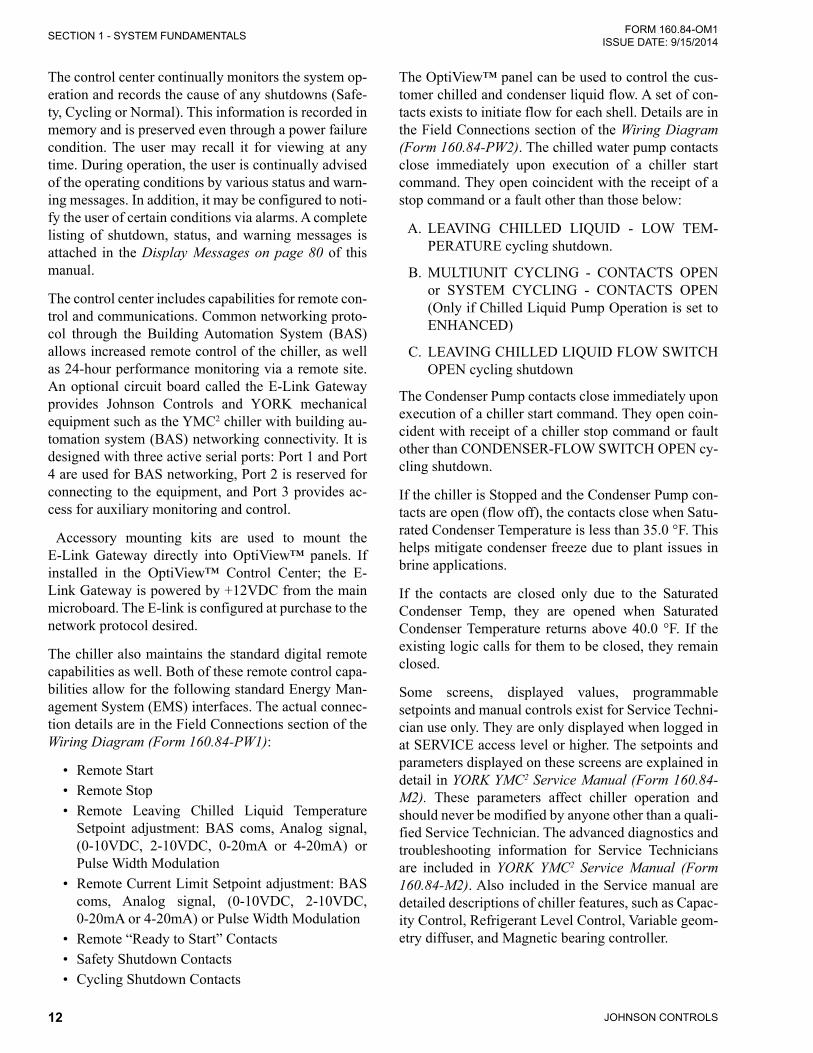
The control center continually monitors the system op-eration and records the cause of any shutdowns (Safe-ty, Cycling or Normal). This information is recorded in memory and is preserved even through a power failure condition. The user may recall it for viewing at any time. During operation, the user is continually advised of the operating conditions by various status and warn-ing messages. In addition, it may be configured to noti-fy the user of certain conditions via alarms. A complete listing of shutdown, status, and warning messages is attached in the Display Messages on page 80 of this manual.
The control center includes capabilities for remote con-trol and communications. Common networking proto-col through the Building Automation System (BAS) allows increased remote control of the chiller, as well as 24-hour performance monitoring via a remote site. An optional circuit board called the E-Link Gateway provides Johnson Controls and YORK mechanical equipment such as the YMC2 chiller with building au-tomation system (BAS) networking connectivity. It is designed with three active serial ports: Port 1 and Port 4 are used for BAS networking, Port 2 is reserved for connecting to the equipment, and Port 3 provides ac-cess for auxiliary monitoring and control.
Accessory mounting kits are used to mount the E-Link Gateway directly into OptiView™ panels. If installed in the OptiView™ Control Center; the E-Link Gateway is powered by +12VDC from the main microboard. The E-link is configured at purchase to the network protocol desired.
The chiller also maintains the standard digital remote capabilities as well. Both of these remote control capa-bilities allow for the following standard Energy Man-agement System (EMS) interfaces. The actual connec-tion details are in the Field Connections section of the Wiring Diagram (Form 160.84-PW1):
• Remote Start• Remote Stop• Remote Leaving Chilled Liquid Temperature
Setpoint adjustment: BAS coms, Analog signal, (0-10VDC, 2-10VDC, 0-20mA or 4-20mA) or Pulse Width Modulation
• Remote Current Limit Setpoint adjustment: BAS coms, Analog signal, (0-10VDC, 2-10VDC, 0-20mA or 4-20mA) or Pulse Width Modulation
• Remote “Ready to Start” Contacts• Safety Shutdown Contacts• Cycling Shutdown Contacts
The OptiView™ panel can be used to control the cus-tomer chilled and condenser liquid flow. A set of con-tacts exists to initiate flow for each shell. Details are in the Field Connections section of the Wiring Diagram (Form 160.84-PW2). The chilled water pump contacts close immediately upon execution of a chiller start command. They open coincident with the receipt of a stop command or a fault other than those below:
A. LEAVING CHILLED LIQUID - LOW TEM-PERATURE cycling shutdown.
B. MULTIUNIT CYCLING - CONTACTS OPEN or SYSTEM CYCLING - CONTACTS OPEN (Only if Chilled Liquid Pump Operation is set to ENHANCED)
C. LEAVING CHILLED LIQUID FLOW SWITCH OPEN cycling shutdown
The Condenser Pump contacts close immediately upon execution of a chiller start command. They open coin-cident with receipt of a chiller stop command or fault other than CONDENSER-FLOW SWITCH OPEN cy-cling shutdown.
If the chiller is Stopped and the Condenser Pump con-tacts are open (flow off), the contacts close when Satu-rated Condenser Temperature is less than 35.0 °F. This helps mitigate condenser freeze due to plant issues in brine applications.
If the contacts are closed only due to the Saturated Condenser Temp, they are opened when Saturated Condenser Temperature returns above 40.0 °F. If the existing logic calls for them to be closed, they remain closed.
Some screens, displayed values, programmable setpoints and manual controls exist for Service Techni-cian use only. They are only displayed when logged in at SERVICE access level or higher. The setpoints and parameters displayed on these screens are explained in detail in YORK YMC2 Service Manual (Form 160.84-M2). These parameters affect chiller operation and should never be modified by anyone other than a quali-fied Service Technician. The advanced diagnostics and troubleshooting information for Service Technicians are included in YORK YMC2 Service Manual (Form 160.84-M2). Also included in the Service manual are detailed descriptions of chiller features, such as Capac-ity Control, Refrigerant Level Control, Variable geom-etry diffuser, and Magnetic bearing controller.
JOHNSON CONTROLS 13
SECTION 1 - SYSTEM FUNDAMENTALSFORM 160.84-OM1 ISSUE DATE: 9/15/2014
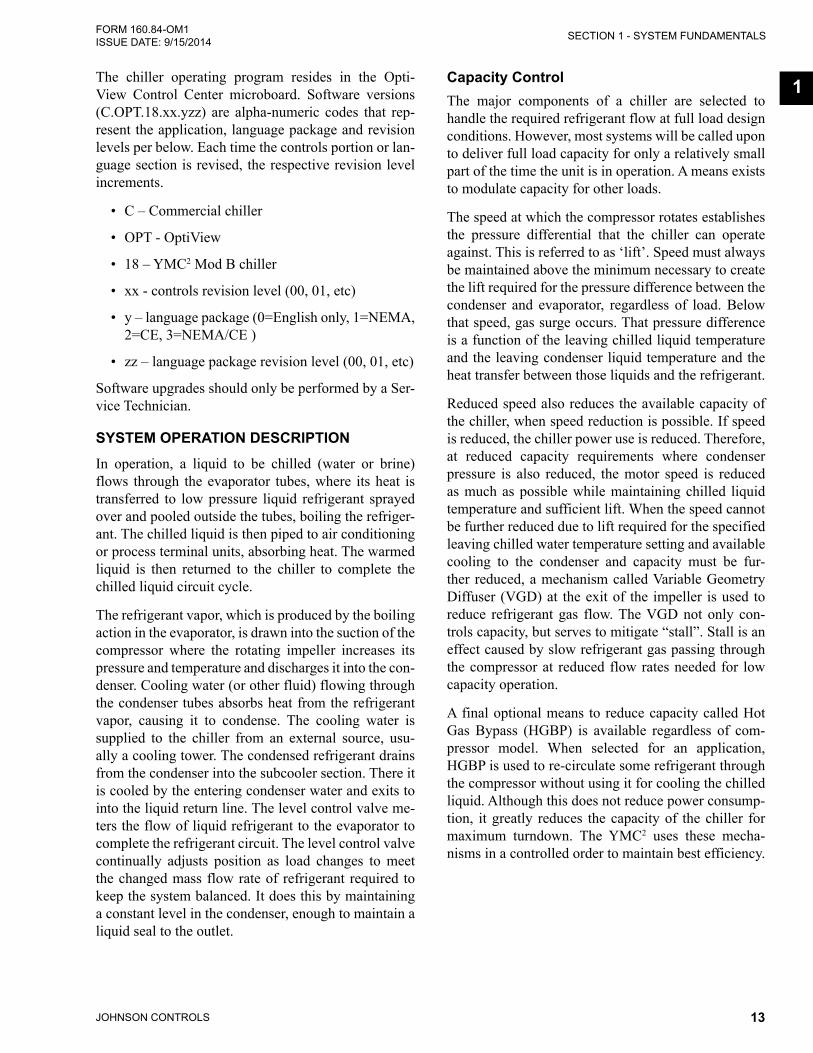
1The chiller operating program resides in the Opti-View Control Center microboard. Software versions (C.OPT.18.xx.yzz) are alpha-numeric codes that rep-resent the application, language package and revision levels per below. Each time the controls portion or lan-guage section is revised, the respective revision level increments.
• C – Commercial chiller
• OPT - OptiView
• 18 – YMC2 Mod B chiller
• xx - controls revision level (00, 01, etc)
• y – language package (0=English only, 1=NEMA, 2=CE, 3=NEMA/CE )
• zz – language package revision level (00, 01, etc)
Software upgrades should only be performed by a Ser-vice Technician.
SYSTEM OPERATION DESCRIPTIONIn operation, a liquid to be chilled (water or brine) flows through the evaporator tubes, where its heat is transferred to low pressure liquid refrigerant sprayed over and pooled outside the tubes, boiling the refriger-ant. The chilled liquid is then piped to air conditioning or process terminal units, absorbing heat. The warmed liquid is then returned to the chiller to complete the chilled liquid circuit cycle.
The refrigerant vapor, which is produced by the boiling action in the evaporator, is drawn into the suction of the compressor where the rotating impeller increases its pressure and temperature and discharges it into the con-denser. Cooling water (or other fluid) flowing through the condenser tubes absorbs heat from the refrigerant vapor, causing it to condense. The cooling water is supplied to the chiller from an external source, usu-ally a cooling tower. The condensed refrigerant drains from the condenser into the subcooler section. There it is cooled by the entering condenser water and exits to into the liquid return line. The level control valve me-ters the flow of liquid refrigerant to the evaporator to complete the refrigerant circuit. The level control valve continually adjusts position as load changes to meet the changed mass flow rate of refrigerant required to keep the system balanced. It does this by maintaining a constant level in the condenser, enough to maintain a liquid seal to the outlet.
Capacity ControlThe major components of a chiller are selected to handle the required refrigerant flow at full load design conditions. However, most systems will be called upon to deliver full load capacity for only a relatively small part of the time the unit is in operation. A means exists to modulate capacity for other loads.
The speed at which the compressor rotates establishes the pressure differential that the chiller can operate against. This is referred to as ‘lift’. Speed must always be maintained above the minimum necessary to create the lift required for the pressure difference between the condenser and evaporator, regardless of load. Below that speed, gas surge occurs. That pressure difference is a function of the leaving chilled liquid temperature and the leaving condenser liquid temperature and the heat transfer between those liquids and the refrigerant.
Reduced speed also reduces the available capacity of the chiller, when speed reduction is possible. If speed is reduced, the chiller power use is reduced. Therefore, at reduced capacity requirements where condenser pressure is also reduced, the motor speed is reduced as much as possible while maintaining chilled liquid temperature and sufficient lift. When the speed cannot be further reduced due to lift required for the specified leaving chilled water temperature setting and available cooling to the condenser and capacity must be fur-ther reduced, a mechanism called Variable Geometry Diffuser (VGD) at the exit of the impeller is used to reduce refrigerant gas flow. The VGD not only con-trols capacity, but serves to mitigate “stall”. Stall is an effect caused by slow refrigerant gas passing through the compressor at reduced flow rates needed for low capacity operation.
A final optional means to reduce capacity called Hot Gas Bypass (HGBP) is available regardless of com-pressor model. When selected for an application, HGBP is used to re-circulate some refrigerant through the compressor without using it for cooling the chilled liquid. Although this does not reduce power consump-tion, it greatly reduces the capacity of the chiller for maximum turndown. The YMC2 uses these mecha-nisms in a controlled order to maintain best efficiency.

JOHNSON CONTROLS14
FORM 160.84-OM1 ISSUE DATE: 9/15/2014SECTION 1 - SYSTEM FUNDAMENTALS
The YMC2 Chiller controls capacity by adjusting the compressor VGD position, the compressor motor Vari-able Speed Drive (VSD), and optional Hot Gas Bypass valve (HGBP) position (if equipped) in a specific se-quence depending on whether loading or unloading is required to keep Leaving Chilled Liquid Temperature at setpoint. Motor speed is additionally and simulta-neously adjusted as necessary to maintain the mini-mum compressor lift required to prevent surge. The sequence for operation of the control devices is as fol-lows to achieve the best chiller efficiency:
• Conditions require capacity increase: HGBP (if present) is driven toward closed. Then when the HGBP is full closed, VGD is driven toward open. Then when the VGD is full open, VSD speed is increased.
• Conditions require capacity decrease: VSD speed is decreased. Then when VSD speed is at the min-imum limit to avoid surge for the lift, the VGD is driven toward closed. Then when the VGD reach-es closed, the HGBP (if present) is driven toward open.
Also, High Condenser Pressure, Low Evaporator Pres-sure, High Motor Current, and High Input Current lim-its and overrides limit or reduce the output to the ap-propriate devices (HGBP, VGD, or VSD) to mitigate the condition to keep the chiller online. As any of these physical thresholds are approached, the control will proportionally limit the amount of capacity increase permitted and if exceeded will issue unloading into the capacity control command.
Anti-Surge Minimum FrequencyIn order to maintain sufficient compressor lift to over-come condenser pressure and prevent surge through-out operation, the control maintains and continuously updates a minimum limit for VSD speed. This limit is the Active Anti-Surge Minimum Frequency. It is calcu-lated and applied to the speed each cycle of the capac-ity control routine.
Smart FreezeThe Smart Freeze feature prevents nuisance chiller shutdowns due to brief periods of chilled liquid flow fluctuations or other brief operating conditions that would normally cause Low Evaporator Pressure Safe-ty shutdowns. With this feature enabled and activated, the chiller is permitted to ride through these tempo-
rary conditions. Also, this feature allows the Leaving Chilled Liquid Temperature Setpoint to be set as low as 36.0ºF (2.2ºC). Smart Freeze protection can be enabled or disabled at the Keypad, by a Service Technician. It cannot be used in Brine cooling mode.
Smart Freeze protection uses the Evaporator Refriger-ant Temperature as one of the variables to determine when freezing is imminent. The basis of this feature is that the chilled liquid contains an amount of heat, which cannot be eliminated immediately. Therefore, it requires a certain amount of time for the liquid to change to a solid. During this period of time, those pa-rameters that determine when solidification will occur are evaluated and the shutdown is based on accumu-lated time below the freeze temperature.
Surge ProtectionThe surge protection feature detects surge events. It provides a running count of the surges detected over the lifetime of the chiller. It allows the user to define how many surges are excessive and how the control will react to an excess surge condition. When exces-sive surging is detected, this feature can shutdown the chiller.
Surge events are detected by monitoring the relation-ship between the Condenser pressure and Evaporator pressure while the chiller is running. An excess surge condition is detected by comparing the number of surge events that occur in a selectable time period to a selectable threshold.
If the number of surge events (Surge Window Count) detected in the time period programmed as the COUNT WINDOW setpoint (1 to 5 minutes; default 5) exceed the threshold programmed as the COUNT LIMIT setpoint (4 to 20; default 4) an excess surge condition has been detected.
Unless the SHUTDOWN features have been enabled, as explained below, the chiller will continue to run under the same conditions displaying WARNING – EXCESS SURGE DETECTED. This message will be displayed until manually reset with the Warning Re-set key in Operator access level. If the SHUTDOWN setpoint is Enabled, when an excess surge condition has been detected a safety shutdown will be performed and SURGE PROTECTION - EXCESS SURGE is displayed.

JOHNSON CONTROLS 15
SECTION 1 - SYSTEM FUNDAMENTALSFORM 160.84-OM1 ISSUE DATE: 9/15/2014
1Head Pressure ControlThe Head Pressure Control feature enables chiller control of a field-mounted facility condenser water temperature control means, if one is necessary for pro-longed cold water startup as described in SECTION 2 - SYSTEM OPERATING PROCEDURES of this man-ual. YMC2 chillers are capable of operation within a wide range of condenser water temperatures. However, a low minimum condenser water temperature, as spec-ified in the YMC2 Engineering Guide (Form 160.84-EG1), is required to maintain sufficient pressure dif-ferential (head) between the condenser and evaporator for proper refrigerant management in the chiller. The head pressure control function provides an analog out-put control signal from the OptiView™ Control Center that responds to the programmed Head Pressure (con-denser pressure minus evaporator pressure) Setpoint. The 0-10VDC or 4-20mA output is configurable from the Head Pressure Control screen when the feature is Enabled. Output wiring is described in the Field Con-nections section of the Wiring Diagram (Form 160.84-PW2):

JOHNSON CONTROLS16
FORM 160.84-OM1 ISSUE DATE: 9/15/2014SECTION 1 - SYSTEM FUNDAMENTALS
FIGURE 3 - REFRIGERANT FLOW-THRU CHILLER
COMPRESSOROPTIONAL HOT
GAS BYPASS VALVE
LD16542
SUCTIONLINE
POWERPANEL
CONTROL PANEL
DISCHARGELINE
VARIABLESPEEDDRIVE
ISOLATIONVALVE
CONDENSER
REFRIGERANT STATES
YMC2
YORK® MAGNETICCENTRIFUGAL CHILLER
029-26550-000 REV-
SYSTEM DATAPLATE
High Pressure Vapor
High Pressure Liquid Refrigerant
Low Pressure Liquid Refrigerant
Low Pressure Vapor
SUB-COOLER
SUCTIONBAFFLE
EVAPORATOR
LIQUID LINE

JOHNSON CONTROLS 17
FORM 160.84-OM1 ISSUE DATE: 9/15/2014
2
SECTION 2 - SYSTEM OPERATING PROCEDURES
PRE-STARTINGPrior to starting the chiller, make sure the display reads "SYSTEM READY TO START".
The Panel can only boot up when line power is avail-able to the VSD transformers and the UPS battery in the power panel is present and connected with its dis-connect closed.
After periods of waterside maintenance or prolonged shutdown, vent any air from the chiller water boxes prior to starting the water pumps. Failure to do so can result in pass baffle damage.
CONDENSER WATER TEMPERATURE CONTROLThe YORK YMC2 chiller is designed to use less power by taking advantage of lower than design temperatures that are naturally produced by cooling towers through-out the operating year. Exact control of condenser wa-ter such as a cooling tower bypass, is not necessary for most installations. The minimum entering condenser water temperature for full and part load conditions is specified in the chiller engineering guide.
Where:
ECWT = Entering Condensing Water Temperature LCWT = Leaving Chilled Water Temperature C Range = Condensing water temperature range at the given load condition.
Min. ECWT = LCWT – C RANGE + 5ºF + 12 ( )
Min. ECWT = LCWT – C RANGE + 2.8ºC + 6.6 ( )
% Load100
% Load100
At start-up, the entering condenser water temperature may be as much as 25°F (14°C) colder than the standby return chilled water temperature. Cooling tower fan cy-cling will normally provide adequate control of the en-tering condenser water temperature on most installations.
START-UPIf the chilled water and/or condenser water pumps are manually operated, start the pump. The Control Cen-ter will not allow the chiller to start unless chilled liq-uid flow is established through the unit. If the liquid pumps are wired to the Microcomputer Control Center pump run contacts, the pump will automatically start, therefore, this step is not necessary.
The coolant temperature inside any JCI-supplied liquid-cooled motor starter must be maintained above the dewpoint temperature in the equipment room to prevent condens-ing water vapor inside the starter cabinet. Therefore, an additional temperature-controlled throttle valve is needed in the flow path for the starter heat exchanger to regu-late cooling above the equipment room dew-point for applications using cooling sources other than evaporative air-exchange meth-ods, such as wells, bodies of water, and chilled water. The temperature control valve should be the type to open on increasing drive coolant temperature, fail-closed, and set for a temperature above dewpoint. It can be requested as factory-supplied on a chiller order by special quotation.
The Start/Stop control depends whether the chiller Control Source is set to Local or one of the Remote types from the chiller Setup - Operations screen. Start is operated:• Only the keypad when the chiller is set to local
mode,• remotely through digital inputs in digital or ana-
log remote mode but local keypad start must be pressed initially to enable the run permissive, or
• by the E-Link Gateway in BAS (ISN) remote mode but local keypad start must be pressed ini-tially to enable the run permissive.
To start the chiller press the START key on the Home Screen on the display panel. In LOCAL control source, the chiller then starts. In remote ISN, ANALOG, DIGI-TAL, or MODEM a remote start command must also be provided to the proper input connection.When the control is changed to local mode from any other source, it will remain in RUN if already running or remain in STOP if already stopped. A hardware Safe-ty Stop button is also located on the side of the panel.The chiller will start if the following conditions are met:• Leaving Chilled Liquid Temperature is above the
setpoint• Chilledliquidflowisestablished• Condenserliquidflowisestablished• No un-cleared faults or start inhibits exist
2

JOHNSON CONTROLS18
FORM 160.84-OM1 ISSUE DATE: 9/15/2014SECTION 2 - SYSTEM OPERATING PROCEDURES
CHILLER OPERATIONUpon start request, the following occur in sequence:
1. Chiller's system pump run contacts close.2. VSD pre-charges (~12 seconds)3. VSD pre-regulates (~3 seconds)4. Motor runs
The chiller will vary capacity to maintain the leaving chilled liquid temperature setpoint by a specific se-quencing of optional hot gas bypass, variable geometry diffuser, and compressor speed.Throughout capacity control, the compressor speed is maintained above the minimum required for the prevail-ing head condition, to avoid surge. Otherwise, the device maintaining capacity is controlled by a proportional-in-tegral-derivative control based on leaving chiller liquid temperature. Pressure and motor current overrides also apply as necessary to maintain operating limits.The Input Current limit threshold value is determined from several settings, depending on the chiller control source selected according to the Table 1.
TABLE 1 - INPUT CURRENT LIMIT THRESHOLDCONTROL SOURCE
ACTIVE INPUT CURRENT LIMIT THRESHOLD
LocalLowest of: Local Input Current Limit Setpoint (% Input Job FLA) Pulldown Input Current Limit (when active)
ISN Remote Input Current Limit Setpoint (comms)
Analog Remote
Lowest of: Local Input Current Limit Setpoint (% Input Job FLA) Analog Remote Input Current Limit Setpoint Pulldown Input Current Limit (when active)
Digital Remote
Lowest of: Local Input Current Limit Setpoint (% Input Job FLA) Digital Remote Input Current Limit Setpoint Pulldown Input Current Limit (when active)
CHILLED LIQUID CONTROL SETTINGS
Temperature Control SetpointThe temperature to which the chiller will control the chilled fluid leaving the evaporator must be set by the Operator. The way it is selected depends whether the Operator wants this value set locally or modulated by a remote input.
TABLE 2 - TEMPERATURE SETPOINTCONTROL SOURCE
LEAVING CHILLED LIQUID TEMPERATURE SETPOINT
Local Local Leaving Chilled Liquid Temperature Setpoint, entered from the panel. It is programmable over the range of 38.0°F to 70.0°F (water) or 10.0°F to 70.0°F (brine). If Smart Freeze (see previous) is enabled, the range is 36.0°F to 70.0°F (water). The default is 45 °F.
ISN (BAS) Remote Leaving Chilled Liquid Temperature Setpoint value sent over communications. The setpoint entered from the panel is ignored. If nothing is written to the address, the default is 45 °F.
Analog Remote Local Leaving Chilled Liquid Temperature Setpoint, entered from the panel plus the temperature offset defined by the remote analog input signal. A remote device can provide an analog signal (0-20mA, 4-20mA, 0-10VDC or 2-10VDC) that creates the temperature offset in Analog Remote mode. The span of the offset may be defined as 10, 20, 30, or 40ºF using the Local Leaving Chilled Liquid Temperature Range setting from the panel. For example, if this Range Setpoint is programmed for 10°F and the Local Leaving Chilled Liquid Temperature Setpoint is 45°F, then the remote device can set the Leav-ing Chilled Liquid Temperature setpoint over the range 45.0 to 55.0°F as its voltage or current changes from minimum to maximum.
Digital Remote Local Leaving Chilled Liquid Temperature Setpoint, entered from the panel plus the temperature offset defined by the remote pulse width signal. A remote device can provide a Pulse Width Modulation (PWM) signal in Digital Remote mode that creates the temperature offset in Digital Remote mode. The span of the offset may be defined as 10, 20, 30, or 40ºF using the Local Leaving Chilled Liquid Tem-perature Range setting from the panel. For example, if this Range Setpoint is programmed for 10°F and the Local Leaving Chilled Liquid Temperature Setpoint is 45°F, then the remote device can set the Leaving Chilled Liquid Temperature setpoint over the range 45.0 to 55.0°F as its pulse duration chang-es from minimum to maximum. The PWM input is in the form of a 1 to 11 second relay contact closure that applies 115VAC to the I/O Board TB4-19 for 1 to 11 seconds. A contact closure time (pulse width) of 1 second produces a 0°F offset. An 11 second closure produces the maximum offset. The relay contacts should close for 1 to 11 seconds at least once every 30 minutes to maintain the setpoint to the desired value. If a 1 to 11 second closure is not received within 30 minutes of the last closure, the offset is defaulted to zero. A closure is only accepted at rates not to exceed once every 70 seconds. Offset (°F) = (pulse width in seconds – 1)( Local Leaving Chilled Liquid Temperature Range) divided by 10.

JOHNSON CONTROLS 19
SECTION 2 - SYSTEM OPERATING PROCEDURESFORM 160.84-OM1 ISSUE DATE: 9/15/2014
2
Regardless of which method is used to select the de-sired Leaving Chilled Liquid Temperature (LCHLT), the chiller controls to its own Active LCHLT Setpoint. The Active Setpoint is a target to the programmed setpoint. When the chiller is not running, the Active Setpoint is set to Entering Chilled Liquid Temperature minus a programmable offset (default 5°F), but not ad-justed to less than the programmed LCHLT setpoint. When the compressor motor starts, the Active LCHLT Setpoint is ramped from this value to the programmed LCHLT Setpoint at the programmable LCHLT Setpoint Ramp Rate (default 0.1°F/second). This keeps the chiller from undershooting setpoint excessively dur-ing pulldown. Any time the programmed setpoint is changed during operation, the active setpoint is ramped to the new value at this rate.
Automatic Temperature ShutdownThe temperature below the LCHLT setpoint at which the chiller is desired to automatically cycle off when load is less than the chiller minimum capability is programmed from the panel as Leaving Chilled Liq-uid Temperature Cycling Offset; Shutdown. This set-ting defines the temperature offset below the LCHLT setpoint where shutdown is expected. It is program-mable over a range of 1°F to 64°F. However the actual shutdown temperature will never be calculated to low-er than 36°F (water), 34°F (water with Smart Freeze enabled) or 6°F (brine). Anytime the LCHLT setpoint is decreased, the shutdown threshold decreases to the new LCHLT active setpoint minus offset at a rate equal to the programmed LCHLT Setpoint Ramp Rate. Any-time the Leaving Chilled Liquid Temperature setpoint is increased, the shutdown threshold increases to the new LCHLT active setpoint minus offset at a rate = 1/2 the programmed LCHLT Setpoint Ramp Rate. This al-lows time for the chiller to change temperature without shutting down first.
Automatic Temperature Restart:The temperature above the LCHLT setpoint at which the chiller is desired to automatically restart after a low LCHLT shutdown per above is programmed from the panel as Leaving Chilled Liquid Temperature Cycling Offset; Restart. This setting defines the temperature offset above the LCHLT setpoint where automatic re-start is expected. It is programmable over a range of 0°F to 70°F. However, the restart temperature will nev-er be calculated above 80°F. This setpoint can be used to reduce chiller cycling by delaying the chiller restart until the cooling load has increased sufficiently.
OPERATOR SETPOINTS QUICk REFERENCEThe most common Operator level setpoints can be found on the Setpoints screen or the following screens:
Leaving Chilled Liquid Temperaure: Evaporator Screen
Shutdown Temperature Offset: Evaporator Screen
Restart Temperature Offset: Evaporator Screen
Local Input Current Limit: VSD Screen
Pulldown Demand Limit: VSD Screen
Pulldown Demand Time: VSD Screen
Control Source: Setpoints - Setup - Operations Screen
Head Pressure Setpoint Condenser - Head (When The Feature Is Enabled) Pressure Control Screen
STOPPING THE SYSTEMTo stop the chiller, proceed as follows:
1. Push the Soft Stop key on the home screen of the OptiViewTM panel if in LOCAL control or send a stop command through the remote system if in RE-MOTE or BAS control. If the chiller is in a remote control source and the local Soft Stop key is used to stop the chiller, the Start key must be pressed be-fore the chiller will again permit starts through the remote source. In the event of an unusual circum-stance requiring immediate stoppage, a safety stop switch is located on the side of the control panel. Normal stop eases the driveline to stop and should always be used instead of the safety stop during regular operation.
2. Stop the chilled water and/or condenser water pumps if not wired into the Microcomputer Con-trol Center, (in which case it will shut off auto-matically. The actual water pump contact timing operation is dependent upon the selection on the SETUP screen.)
3. Open the switch to the cooling tower fan motors, if used.
The OptiView™ Control Center can be programmed to start and stop automatically (maximum - once each day) whenever desired.
Refer to Schedule Screen on page 57 in the SEC-TION 3 - OPTIVIEW™ CONTROL CENTER FUNC-TIONS AND NAVIGATION of this manual.
2

JOHNSON CONTROLS20
FORM 160.84-OM1 ISSUE DATE: 9/15/2014SECTION 2 - SYSTEM OPERATING PROCEDURES
LD16236a
FIGURE 4 - LIQUID CHILLER LOG SHEETS
DATETIMEHour Meter ReadingO.A. Temperature Dry Bulb / Wet Bulb / / / / / / / / /
Compressor Discharge Temperature
Motor
Input Power% Input FLA% Motor FLADC Bus Voltage
Magnetic Bearing Controller
Motor Housing TemperatureRotor Elongation
Evap
orat
or
RefrigerantEvaporator PressureCorrsponding TemperatureSmall Temperature Difference
Liquid
Supply TemperatureSupply PressureReturn TemperatureReturn PressureFlow Rate - GPM (If equipped)
Con
dens
er
Refrigerant
Condenser PressureCorresponding TemperatureDrop Leg TemperatureSmall Temperature DifferenceRefrigerant Level
Liquid
Supply TemperatureSupply PressureReturn TemperatureReturn PressureFlow Rate - GPM (If equipped)
Capacity Control
VSD CommandVGD CommandHGBP Command (If equipped)
Remarks: 160.84-MR1 (813)New Release
Issue Date: August 30, 2013
CENTRIFUGALLIQUID CHILLER LOG SHEET
Chiller Location System No.
ry Bulb / Wet Bulb / / / / / / / /Discharge TemperatureTTInput Power% Input FLA% Motor FLADC Bus VoltageVVMotor Housing TemperatureTTRotor ElongationEvaporator PressureCorrsponding TemperatureTTSmall Temperature DifferenceTTSupply TemperatureTTSupply PressureReturn TemperatureTTReturn PressureFlow Rate - GPM (If equipped)Condenser PressureCorresponding TemperatureTTDrop Leg TemperatureTTSmall Temperature DifferenceTTRefrigerant LevelSupply TemperatureTTSupply PressureReturn TemperatureTTReturn PressureFlow Rate - GPM (If equipped)VSD CommandVGD Command
CENTRIFUGALLIQUID CHILLER LOG SHEET
Chiller LocationSystem No.
YMC2
Form 160.84-MR1 (813) New Release
Issue Date:August 30, 2013
...an Energy-Savingapproach to your Service needs...
YMC2 MOD B CENTRIFUGAL
* NOTE: A pad of 50 log sheets can be ordered from your local Johnson Controls branch by requesting Form 160.84-MR1.
SAFETY STOPWhen depressed, the chiller will not run under any condition. For safety reasons, this position is required for many maintenance tasks to be completed. The safe-ty stop button must be rotated clockwise to release the stop condition. The safety stop is not intended for nor-mal shutdown of the chiller. If used an immediate stop occurs, which by passes the programmed controlled shutdown.
OPERATING LOGSA permanent daily record of system operating condi-tions (temperatures and pressures) recorded at regular intervals throughout each 24-hour operating period should be kept. Automatic data logging is possible by connecting the optional printer and programming the DATA LOGGER function. An optional status printer is available for this purpose. Figure 4 on page 20 shows an example log sheet used by Johnson Controls Personnel for recording test data on chiller systems. Log sheets are available in pads of 50 sheets and may be obtained through the nearest Johnson Controls of-fice.
An accurate record of readings serves as a valuable reference for operating the system. Readings taken when a system is newly installed will establish normal conditions with which to compare later readings.
For example, an increase in condenser approach tem-perature (condenser temperature minus leaving con-denser water temperature) may be an indication of dirty condenser tubes.
NEED FOR MAINTENANCE OR SERVICEIf the system is malfunctioning in any manner or the unit is stopped by one of the safety controls, refer to the Operation Analysis Chart shown on Table 16 on page 121 (SECTION 6 - TROUBLESHOOTING). After consulting this chart, if you are unable to make the proper repairs or adjustments to start the compres-sor or the particular trouble continues to hinder the performance of the unit, please call the nearest John-son Controls District Office. Failure to report constant troubles could damage the unit and increase the cost of repairs.
Ensure power is removed from the input side of the VSD at all times when the chiller is under vacuum (less than atmo-spheric pressure). The VSD maintains voltage to ground on the motor when the chiller is off while voltage is available to the VSD. Insulating properties in the mo-tor are reduced in vacuum and may not insulate this voltage sufficiently.

JOHNSON CONTROLS 21
SECTION 2 - SYSTEM OPERATING PROCEDURESFORM 160.84-OM1 ISSUE DATE: 9/15/2014
2
FAULT SHUTDOWNSThe chiller is programmed to shut down on two kinds of fault conditions. A Cycling fault will allow the chill-er to automatically restart when the condition clears. A Safety fault requires the cause for the condition be determined and resolved before restarting. Safety faults require the Clear Faults key on the panel Home screen be pressed to allow restart. When the condition is cleared and that key pressed, the chiller will restart unless the local stop key was pressed or the remote run command ceased.
PROLONGED SHUTDOWNIf the chiller is to be shut down for an extended period of time (for example, over the winter season), the fol-lowing procedure should be followed.
1. Test all system joints for refrigerant leaks with a leak detector. If any leaks are found, they should be repaired before allowing the system to stand for a long period of time.
During long idle periods, the tightness of the sys-tem should be checked periodically.
2. If freezing temperatures are encountered while the system is idle, carefully drain the cooling wa-ter from the cooling tower, condenser, condenser pump, and the chilled water system-chilled water pump and coils.
Open the drains on the evaporator and condenser liquid heads to assure complete drainage. Drain the Variable Speed Drive cooling system.
3. On the SETUP Screen, disable the clock. This conserves the battery.
4. Open the main disconnect switches to the VSD, condenser water pump and the chilled water pump. Open the disconnect on the side of the Power Panel to disconnect the storage battery. Ensure the control center is powered off.
RESTART AFTER PROLONGED SHUTDOWNThe chiller has a start inhibit limit for storage battery minimum voltage below 12.8 VDC when charging. Ensure the chiller has line power and battery discon-nect restored at least eight hours prior to first planned startup to charge the battery.
TABLE 3 - WATER FLOW RATE LIMITS IN GPM (L/S) – BASED UPON STANDARD TUBES @ DESIGN FULL LOAD CONDITIONS
M2 MOTOR
EVAPORATOR MODEL
EVAPORATOR M2 MOTOR
CONDENSER MODEL
CONDENSER1 PASS 2 PASS 3 PASS 1 PASS 2 PASS 3 PASS
MIN MAX MIN MAX MIN MAX MIN MAX MIN MAX MIN MAX
EB2910-B 950 (60)
3790 (239)
470 (30)
1820 (115)
320 (20)
950 (60) CB2914-B 1160
(73)4170 (263)
580 (37)
1920 (121)
390 (25)
1290 (81)
EB2910-C 1040 (66)
4170 (263)
520 (33)
2000 (126)
350 (22)
1050 (66) CB2914-C 1380
(87)4980 (314)
690 (44)
2270 (143)
460 (29)
1530 (97)
EB2910-2 740 (47)
2950 (186)
370 (23)
1470 (93)
250 (16)
980 (62) CB2914-D 1620
(102)5840 (368)
810 (51)
2630 (166)
540 (34)
1790 (113)
EB2910-3 1000 (63)
3990 (252)
500 (32)
1990 (126)
330 (21)
1300 (82) CB2914-E 1760
(111)6330 (399)
880 (56)
2830 (179)
590 (37)
1930 (122)
EB2914-B 950 (60)
3790 (239)
470 (30)
1900 (120)
320 (20)
1010 (64) CB2914-F 1950
(123)7030 (444)
980 (62)
3100 (196)
650 (41)
2140 (135)
EB2914-C 1040 (66)
4170 (263)
520 (33)
2090 (132)
350 (22)
1110 (70) CB2914-2 1420
(90)5120 (323)
710 (45)
2560 (162)
470 (30)
1710 (108)
EB2914-2 740 (47)
2950 (186)
370 (23)
1470 (93)
250 (16)
980 (62) CB2914-3 1740
(110)6290 (397)
870 (55)
3140 (198)
580 (37)
2100 (132)
EB2914-3 1000 (63)
3990 (252)
500 (32)
1990 (126)
330 (21)
1330 (84) CB2510-B 780
(49)2810 (177)
390 (25)
1400 (88)
260 (16)
940 (59)
EB3310-B 1170 (74)
4690 (296)
590 (37)
2350 (148)
390 (25)
1280 (81) CB2510-C 900
(57)3230 (204)
450 (28)
1610 (102)
300 (19)
1080 (68)
EB3310-C 1500 (95)
6010 (379)
750 (47)
3010 (190)
500 (32)
1640 (103) CB2510-D 1120
(71)4030 (254)
560 (35)
2020 (127)
370 (23)
1340 (85)
EB3310-2 790 (50)
3140 (198)
390 (25)
1570 (99)
260 (16)
1050 (66) CB2510-E 1400
(88)5030 (317)
700 (44)
2520 (159)
470 (30)
1680 (106)

JOHNSON CONTROLS22
FORM 160.84-OM1 ISSUE DATE: 9/15/2014SECTION 2 - SYSTEM OPERATING PROCEDURES
M2 MOTOR
EVAPORATOR MODEL
EVAPORATOR M2 MOTOR
CONDENSER MODEL
CONDENSER1 PASS 2 PASS 3 PASS 1 PASS 2 PASS 3 PASS
MIN MAX MIN MAX MIN MAX MIN MAX MIN MAX MIN MAX
EB3310-3 1400 (88)
5610 (354)
700 (44)
2800 (177)
470 (30)
1870 (118) CB2510-2 910
(57)3290 (208)
460 (29)
1640 (103)
300 (19)
1100 (69)
EB3314-B 1170 (74)
4690 (296)
590 (37)
2350 (148)
390 (25)
1340 (85) CB2510-3 1320
(83)4760 (300)
660 (42)
2380 (150)
440 (28)
1590 (100)
EB3314-C 1500 (95)
6010 (379)
750 (47)
3010 (190)
500 (32)
1710 (108) CB2910-B 1160
(73)4170 (263)
580 (37)
2090 (132)
390 (25)
1390 (88)
EB3314-2 790 (50)
3140 (198)
390 (25)
1570 (99)
260 (16)
1050 (66) CB2910-C 1380
(87)4980 (314)
690 (44)
2490 (157)
460 (29)
1660 (105)
EB3314-3 1400 (88)
5610 (354)
700 (44)
2800 (177)
470 (30)
1870 (118) CB2910-D 1620
(102)5840 (368)
810 (51)
2920 (184)
540 (34)
1950 (123)
CB2910-E 1760 (111)
6330 (399)
880 (56)
3170 (200)
590 (37)
2110 (133)
CB2910-F 1950 (123)
7030 (444)
980 (62)
3520 (222)
650 (41)
2340 (148)
CB2910-2 1420 (90)
5120 (323)
710 (45)
2560 (162)
470 (30)
1710 (108)
CB2910-3 1740 (110)
6290 (397)
870 (55)
3140 (198)
580 (37)
2100 (132)
CB3310-B 1590 (100)
5720 (361)
790 (50)
2860 (180)
530 (33)
1910 (121)
CB3310-C 1900 (120)
6830 (431)
950 (60)
3420 (216)
630 (40)
2280 (144)
CB3310-D 2480 (156)
8940 (564)
1240 (78)
4370 (276)
830 (52)
2980 (188)
CB3310-E 2760 (174)
9940 (627)
1380 (87)
4720 (298)
920 (58)
3310 (209)
CB3310-2 1620 (102)
5840 (368)
810 (51)
2920 (184)
540 (34)
1950 (123)
CB3310-3 1930 (122)
6960 (439)
970 (61)
3480 (220)
640 (40)
2320 (146)
CB3310-4 2590 (163)
9320 (588)
1290 (81)
4660 (294)
860 (54)
3110 (196)
CB3314-B 1590 (100)
5720 (361)
790 (50)
2580 (163)
530 (33)
1750 (110)
CB3314-C 1900 (120)
6830 (431)
950 (60)
3020 (191)
630 (40)
2080 (131)
CB3314-D 2480 (156)
8940 (564)
1240 (78)
3790 (239)
830 (52)
2690 (170)
CB3314-E 2760 (174)
9940 (627)
1380 (87)
4120 (260)
920 (58)
2960 (187)
CB3314-2 1620 (102)
5840 (368)
810 (51)
2920 (184)
540 (34)
1950 (123)
CB3314-3 1930 (122)
6960 (439)
970 (61)
3480 (220)
640 (40)
2320 (146)
CB3314-4 2590 (163)
9320 (588)
1290 (81)
4660 (294)
860 (54)
3110 (196)
TABLE 3 - WATER FLOW RATE LIMITS IN GPM (L/S) – BASED UPON STANDARD TUBES @ DESIGN FULL LOAD CONDITIONS

JOHNSON CONTROLS 23
FORM 160.84-OM1 ISSUE DATE: 9/15/2014
3
SECTION 3 - OPTIVIEW™ CONTROL CENTER FUNCTIONS AND NAVIGATION
INTERFACE CONVENTIONSEach screen description in this document will begin with a section entitled Overview which will describe the graphical elements on the screen and give a short summary of the functions available. Each element on the screen will then be categorized into three distinct groups: Display Only, Programmable, and Navigation. Below is a short description of what types of informa-tion are included in these groups.
The Programmable values and Navigation commands are also subject to access level restrictions as described below. For each of these elements, an indication is given to show the minimum access level required to program the value or navigate to the subscreen.
DISPLAY ONLYValues in this group are read-only parameters of in-formation about the chiller operation. This type of in-formation may be represented by a numerical value, a text string, or an LED image. For numerical values, if the monitored parameter is above the normal operat-ing range, the high limit value will be displayed along with the ‘>’ symbol; if it is below the normal operating range, the low limit value will be displayed along with the ‘<’ symbol. In some cases, the value may be ren-dered invalid by other conditions and the display will use X’s to indicate this.
PROGRAMMABLEValues in this group are available for change by the user. In order to program any setpoints on the system, the user must first be logged in with the appropriate access level. Each of the programmable values requires a specific Ac-cess Level which will be indicated beside the specified value. All of the programmable controls in the system fall into one of the categories described below:
Access LevelThe OptiView™ Panel restricts certain operations based on password entry by the operator. Three dif-ferent access levels are provided as follows: VIEW: The panel defaults to the lowest access level which is termed VIEW. In this mode, the chiller operating values and setpoints can be observed, but no changes can be made. OPERATOR: The second access level is termed OPERATOR and will allow the customer
to change all of the setpoints required to operate the chiller system. In order to gain standard OPERATOR level access, the Home Screen Login Password would be entered as 9 6 7 5, using the numeric keypad. SER‑VICE: In the event that advanced diagnostics are nec-essary, a SERVICE access level has been provided. Only qualified service personnel utilize this access lev-el. This level provides advanced control over many of the chiller functions and allows calibration of many of the chiller controls. The access levels are listed above in hierarchical order beginning with the lowest level and proceeding to the highest level. Users logged in under higher access levels may perform any actions permitted by lower access levels.
The OPERATOR access level is accompanied by a 10-minute timeout. After ten (10) successive minutes without a keypress, the panel will revert to the VIEW access level. This prevents unauthorized changes to the chiller if a user was logged in at a higher access level and failed to logout. Proper procedure requires that after making necessary setpoint adjustments the user return to the Home Screen and logout.
Change SetpointsOn screens containing setpoints programmable at the OPERATOR access level, a key with this label will be visible if the present access level is VIEW. This key brings up the Access Level prompt described above. It allows the user to login at a higher Access Level with-out returning to the Home Screen. After login, the user may then modify setpoints on that screen.
SetpointsThe control center uses the setpoint values to control the chiller and other devices connected to the chiller system. Setpoints can fall into several categories. They could be numeric values (such as 45.0°F for the Leav-ing Chilled Liquid Temperature), or they could Enable or Disable a feature or function.
Regardless of which setpoint is being programmed, the following procedure applies:
1. Press the desired setpoint key. A dialog box ap-pears displaying the present value, the upper and lower limits of the programmable range, and the default value.

JOHNSON CONTROLS24
FORM 160.84-OM1 ISSUE DATE: 9/15/2014SECTION 3 - OPTIVIEW™ CONTROL CENTER FUNCTIONS AND NAVIGATION
2. If the dialog box begins with the word “ENTER”, use the numeric keys to enter the desired value. Leading zeroes are not necessary. If a decimal pointisnecessary,pressthe‘•’key(i.e.45.0).
Pressingthe▲key,setstheentryvaluetothede-faultforthatsetpoint.Pressingthe▼key,clearsthepresententry.The◄keyisabackspacekeyand causes the entry point to move back one space.
If the dialog box begins with “SELECT”, use the ◄and►keystoselectthedesiredvalue.
If the previously defined setpoint is desired, press the "X" (Cancel) key to dismiss the dialog box.
3. Press the "" (Enter) key.
If the value is within range, it is accepted and the dialog box disappears. The chiller will begin to operate based on the new programmed value. If out of range, the value will not be accepted and the user is prompted to try again.
Manual ControlsSome keys are used to perform manual control func-tions. These may involve manual control of items such as the compressor speed or valve actuators. These are typically restricted to qualified technicians in Service access. Other keys in this category are used to initiate/terminate processes such as calibrations or reports.
Free CursorOn screens containing many setpoints, a specific “soft” key may not be assigned to each setpoint value. A soft key will be assigned to enable the cursor arrow keys below the numeric keypad which are used to “high-light” the desired setpoint field. At this point, the ‘’ key is pressed to bring up a dialog prompting the user to enter a new setpoint value. The ‘X’ key cancels cur-sor mode. (See the Schedule Screen for an example.)
NAVIGATIONIn order to maximize the amount of values which the panel can display to the user, and in order to place those values in context, multiple screens have been designed to describe the chiller operation. In order to move from one screen to the next, navigation keys have been de-fined. These keys allow the user to either move “for-ward” to a subscreen of the present screen, or move “backward” to the previous screen. Except for the Home Screen display, the upper-right “soft” key will always return the user to the Home Screen. Navigating with “soft” keys is as simple as pressing the key next to the label containing the name of the desired screen.
The system will immediately refresh the display with the graphics for that screen. Following is a layout of all the screens and how they are connected.
Home Screen (Page 26)
System Screen (Page 28)
Evaporator Screen (Page 30)
Condenser Screen (Page 32)
Compressor Screen (Page 34)
Magnetic Bearing Controller Screen (Page 36)
MBC Details Screen (Page 38)
Surge Screen (Page 40)
Variable Geometry Diffuser Screen (Page 42)
Power Panel Screen (Page 43)
Capacity Controls Screen (Page 45)
VSD Screen (Page 47)
VSD Details Screen (Page 49)
Motor Details Screen (Page 51)
Setpoints Screen (Page 53)
Setup Screen (Page 55)
Schedule Screen (Page 57)
User Screen (Page 59)
COMMS Screen (Page 60)
Printer Screen (Page 61)
Sales Order Screen (Page 62)
Operations Screen (Page 64)
History Screen (Page 65)
History Details Screen (Page 67)
Custom Screen (Page 68)
Custom Setup Screen (Page 69)
Trend Screen (Page 70)
Trend Setup Screen (Page 72)
Advanced Trend Setup Screen (Page 74)
Common Slots Screen (Page 76)

JOHNSON CONTROLS 25
SECTION 3 - OPTIVIEW™ CONTROL CENTER FUNCTIONS AND NAVIGATIONFORM 160.84-OM1 ISSUE DATE: 9/15/2014
3
ANALOG INPUT RANGES
The following table indicates the valid display range for each of the analog input values. In the event that the input sensor is reading a value outside of these ranges,
LANGUAGESThe screens can be displayed in various languages. Language selection is done on the USER Screen. The desired language is selected from those available. Not all languages are available. English is the default lan-
guage. If a language other than English is being dis-played, an English speaking person should navigate to the USER Screen (using the preceding Navigation chart) and select English.
TABLE 4 - ANALOG INPUT RANGES
ANALOG INPUTENGLISH RANGE METRIC RANGE
LOW HIGH UNITS LOW HIGH UNITS
Leaving Chilled Liquid Temperature 0.0 82.0 °F -17.7 27.7 °C
Return Chilled Liquid Temperature 0.0 94.1 °F -17.7 34.5 °C
Leaving Condenser Liquid Temperature 8.0 133.5 °F -13.3 56.3 °C
Return Condenser Liquid Temperature 8.0 133.5 °F -13.3 56.3 °C
Evaporator Refrigerant Temperature (Optional) 0.0 126.1 °F -17.7 52.3 °C
Discharge Temperature 31.8 226.3 °F -0.1 107.9 °C
Condenser Pressure (R134a) 0.0 300.0 PSIG 0.0 2069 KPAG
Condenser Temperature (R134a)* -98.7 160.1 °F -72.6 71.7 °C
Evaporator Pressure (R134a) 0.0 125.0 PSIG 0 862 KPAG
Evaporator Temperature (R134a)* -44.9 64.7 °F -42.7 18.1 °C
Refrigerant Level 0.0 100.0 % 0.0 100.0 %
Drop Leg Refrigerant Temperature 0.0 121.7 °F -17.7 49.8 °C
Motor Housing Temperature 31.8 226.3 °F -0.1 107.9 °C
*Saturation temperatures are calculated values. They will display XXX if the pressure used for the calculation is out of range.
the < or > symbols will be displayed beside the mini-mum or maximum value, respectively.

JOHNSON CONTROLS26
FORM 160.84-OM1 ISSUE DATE: 9/15/2014SECTION 3 - OPTIVIEW™ CONTROL CENTER FUNCTIONS AND NAVIGATION
HOME SCREEN
OVERVIEWWhen the chiller system is powered on, the above de-fault display appears. The Home Screen display depicts a visual representation of the chiller itself. Animation indicates chilled liquid flow and/or condenser cooling liquid flow when the flow switch inputs are satisfied.
DISPLAY ONLY
Chilled Liquid Temperature - LeavingDisplays the temperature of the liquid as it leaves the evaporator.
Chilled Liquid Temperature - EnteringDisplays the temperature of the liquid as it enters the evaporator.
Condenser Liquid Temperature - LeavingDisplays the temperature of the liquid as it leaves the condenser.
Condenser Liquid Temperature - EnteringDisplays the temperature of the liquid as it enters the condenser.
Input % Full Load AmpsThis displays the percentage of full load amps utilized by the system.
Input Power (kW)This displays the total input power used by the system.
Operating HoursDisplays the cumulative operating hours of the chiller.
Motor Run (LED)Is ON when the digital output that gives the VSD a mo-tor run command is on.
PROGRAMMABLE
LoginAccess Level Required: VIEWThis key allows the user to change Access Level when the proper password is entered at the prompt.
LogoutAccess Level Required: OPERATORThis key is displayed when a user is logged in at any level other than VIEW. Pressing it will return the ac-cess level to VIEW.
LD17916a
FIGURE 5 - HOME SCREEN

JOHNSON CONTROLS 27
SECTION 3 - OPTIVIEW™ CONTROL CENTER FUNCTIONS AND NAVIGATIONFORM 160.84-OM1 ISSUE DATE: 9/15/2014
3
PrintAccess Level Required: VIEWUse this key to generate a hard-copy report of the present system status. This provides a snapshot of the primary operating conditions at the time the key is pressed. The History page provides enhanced report-ing capability. (See HISTORY Screen.) This option will not be present if the chiller is presently configured to print History, New Data, which continuously logs.
Clear FaultAccess Level Required: VIEWWhen safety conditions have been detected, the chiller is shutdown, and the main status display of the chill-er will display a message indicating the cause of the shutdown. Using this key, the fault and message can be cleared once the condition has been removed. The key only shows when the condition can be cleared. If the chiller has a standing Local or Remote run command, it will start when the key is pressed.
Warning ResetAccess Level Required: OPERATORUse of this key acknowledges a warning condition and resets the message display associated with it.
Start Access Level Required: OPERATORThis key is only available when the chiller does not have a local run request. Pressing this key allows selec-tion of enter to run or cancel to abort to stopped. Enter causes the chiller to start if control source is LOCAL, or permits run if control source is any remote.
Soft Stop Access Level Required: OPERATORThis key is only available when the chiller is in local mode and has a local run request. It shows in place of the start key. Pressing this key allows selection of enter to stop or cancel to remain running. Enter causes the chiller to perform a soft shutdown and disables the remote run permissive.
NAVIGATION
SystemUsed to provide additional system information.
EvaporatorA detailed view of all evaporator parameters, including the programmable Leaving Chilled Liquid Setpoints.
CondenserA detailed view of all condenser parameters, including control of the liquid level functions.
CompressorA detailed view of all the compressor parameters. This includes surge protection, Magnetic Bearing Control, Variable Geometry Diffuser, and calibration.
Capacity ControlA detailed view of all the parameters associated with capacity control.
VSDA detailed view of the motor and VSD parameters. This allows programming of the Current Limit and the Pulldown Demand Limit values.
SetpointsThis screen provides a single location to program the most common system setpoints. It is also the gateway to many of the general system setup parameters such as Date/Time, Display Units, Scheduling, Printer Setup, etc.
HistoryThis screen provides access to a snapshot of system data at each of the last 10 shutdown conditions, and provides for trending operating parameters.

JOHNSON CONTROLS28
FORM 160.84-OM1 ISSUE DATE: 9/15/2014SECTION 3 - OPTIVIEW™ CONTROL CENTER FUNCTIONS AND NAVIGATION
OVERVIEWThis screen gives a general overview of common chill-er parameters for both shells.
DISPLAY ONLY
Discharge Temperature Displays the temperature of the refrigerant in its gas-eous state at discharge of the compressor as it travels to the condenser.
Input % Full Load AmpsThis displays the percentage of full load amps utilized by the system.
Input Current Limit SetpointDisplays the current limit value in use. This value is percent of Input Full Load Amps.
Condenser Liquid Temperature - LeavingDisplays the temperature of the liquid as it leaves the condenser.
Condenser Liquid Temperature - EnteringDisplays the temperature of the liquid as it enters the condenser.
Chilled Liquid Temperature - LeavingDisplays the temperature of the liquid as it leaves the evaporator.
Chilled Liquid Temperature - EnteringDisplays the temperature of the liquid as it enters the evaporator.
Chilled Liquid Temperature - SetpointDisplays the programmed temperature setpoint for leaving chilled liquid. It is the local value or remote reset value depending on control source.
Condenser Pressure Displays the refrigerant pressure in the condenser.
Condenser Saturation Temperature Displays the saturation temperature in the condenser calculated from condenser pressure.
SYSTEM SCREEN
LD17917a
FIGURE 6 - SYSTEM SCREEN

JOHNSON CONTROLS 29
SECTION 3 - OPTIVIEW™ CONTROL CENTER FUNCTIONS AND NAVIGATIONFORM 160.84-OM1 ISSUE DATE: 9/15/2014
3
Evaporator Pressure Displays the present refrigerant pressure in the evapo-rator.
Evaporator Saturation Temperature Displays the present saturation temperature in the evaporator calculated from evaporator pressure.
Head PressureDisplays the pressure difference between the condens-er and evaporator (condenser minus evaporator). Only appears when Head Pressure Control is enabled.
Head Pressure SetpointDisplays the active Head Pressure Setpoint to which the head pressure is being controlled. Only appears when Head Pressure Control is enabled.
Isolation Valves (LEDs)Only show when optional brine isolation valve feature exists and enabled.
Closing - The control is commanding the valve close output on.
Closed Limit Switch - Feedback from the valve lim-it switch at the full closed position shows the switch made, indicating closed valve.
Opening - The control is commanding the valve open output on.
Opened Limit Switch - Feedback from the valve limit switch at the full open position shows the switch made, indicating open valve.
PROGRAMMABLEThere are no programmable fields on this screen.
NAVIGATION
HomeCauses an instant return to the Home Screen.
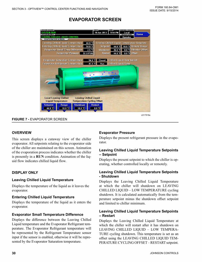
JOHNSON CONTROLS30
FORM 160.84-OM1 ISSUE DATE: 9/15/2014SECTION 3 - OPTIVIEW™ CONTROL CENTER FUNCTIONS AND NAVIGATION
OVERVIEWThis screen displays a cutaway view of the chiller evaporator. All setpoints relating to the evaporator side of the chiller are maintained on this screen. Animation of the evaporation process indicates whether the chiller is presently in a RUN condition. Animation of the liq-uid flow indicates chilled liquid flow.
DISPLAY ONLY
Leaving Chilled Liquid Temperature Displays the temperature of the liquid as it leaves the evaporator.
Entering Chilled Liquid Temperature Displays the temperature of the liquid as it enters the evaporator.
Evaporator Small Temperature DifferenceDisplays the difference between the Leaving Chilled Liquid temperature and the Evaporator Refrigerant tem-perature. The Evaporator Refrigerant temperature will be represented by the Refrigerant Temperature sensor input if the sensor is enabled, otherwise it will be repre-sented by the Evaporator Saturation temperature.
Evaporator Pressure Displays the present refrigerant pressure in the evapo-rator.
Leaving Chilled Liquid Temperature Setpoints – Setpoint Displays the present setpoint to which the chiller is op-erating, whether controlled locally or remotely.
Leaving Chilled Liquid Temperature Setpoints - ShutdownDisplays the Leaving Chilled Liquid Temperature at which the chiller will shutdown on LEAVING CHILLED LIQUID – LOW TEMPERATURE cycling shutdown. It is calculated automatically from the tem-perature setpoint minus the shutdown offset setpoint and limited to chiller minimum.
Leaving Chilled Liquid Temperature Setpoints – RestartDisplays the Leaving Chilled Liquid Temperature at which the chiller will restart after it has shutdown on LEAVING CHILLED LIQUID – LOW TEMPERA-TURE cycling shutdown. This temperature is set as an offset using the LEAVING CHILLED LIQUID TEM-PERATURE CYCLING OFFSET – RESTART setpoint.
EVAPORATOR SCREEN
LD17918a
FIGURE 7 - EVAPORATOR SCREEN

JOHNSON CONTROLS 31
SECTION 3 - OPTIVIEW™ CONTROL CENTER FUNCTIONS AND NAVIGATIONFORM 160.84-OM1 ISSUE DATE: 9/15/2014
3
Leaving Chilled Liquid Temperature Setpoints – Remote RangeDisplays the temperature range proportional to a re-mote analog input used to reset the Leaving Chilled Liquid temperature upward by this amount remotely.
Leaving Chilled Liquid Temperature Setpoints (Shutdown) – Effective OffsetDisplays the present value of the leaving chilled liquid temperature shutdown offset in effect limited by the chiller minimum temperature.
Leaving Chilled Liquid Temperature Setpoints (Restart) – OffsetDisplays the value set for leaving chilled liquid tem-perature restart offset.
Evaporator Saturation Temperature Displays the present saturation temperature in the evaporator, determined from evaporator pressure.
Chilled Liquid Flow Switch (Open/Closed)Displays whether the liquid flow switch input indicates flow is present in the evaporator.
Chilled Liquid PumpDisplays the command presently sent by the control center to the Chilled Liquid Pump run contacts (RUN or STOP).
Evaporator Refrigerant Temperature Displays the temperature of the refrigerant in the evap-orator.
PROGRAMMABLE
Local Leaving Chilled Liquid Temperature - Setpoint Access Level Required: OPERATOR
This value allows the user to define the Leaving Chilled Liquid Temperature that is to be maintained by the chiller. It is programmable over the range of 38.0°F to 70.0°F (water) or 10.0°F to 70.0°F (brine). If Smart Freeze (see below) is enabled, the range is 36.0°F to 70.0°F (water).
When the chiller is running, performing capacity control, any change to the LCHLT setpoint results in a ramp from the old value to the new value at the programmed LCHLT setpoint ramp rate.
Local Leaving Chilled Liquid Temperature - Range Access Level Required: OPERATORThis is the range over which an analog or a digital sig-nal (PWM) can reset the Leaving Chilled Liquid Tem-perature setpoint above the operator programmed Base Setpoint.
Leaving Chilled Liquid Temperature Cycling Offset - ShutdownAccess Level Required: OPERATORThis value allows the user to specify the Leaving Chilled Liquid Temperature at which the chiller will shut down on a LEAVING CHILLED LIQUID – LOW TEMPERATURE cycling shutdown. This is done by defining an offset below the Leaving Chilled Liquid Temperature setpoint. It is programmable over a range of 1°F to 64°F.
Leaving Chilled Liquid Temperature Cycling Offset - RestartAccess Level Required: OPERATORThis value allows the user to specify the Leaving Chilled Liquid Temperature at which the chiller will restart after a shutdown on a LEAVING CHILLED LIQUID – LOW TEMPERATURE cycling shutdown. This is done by defining an offset above the Leaving Chilled Liquid Temperature setpoint. It is program-mable over a range of 0°F to 70°F.
NAVIGATIONHomeCauses an instant return to the Home Screen.

JOHNSON CONTROLS32
FORM 160.84-OM1 ISSUE DATE: 9/15/2014SECTION 3 - OPTIVIEW™ CONTROL CENTER FUNCTIONS AND NAVIGATION
OVERVIEWThis screen displays a cutaway view of the chiller con-denser. All setpoints relating to the condenser side of the chiller are maintained on this screen. Animation in-dicates condenser liquid flow. This screen also serves as a gateway to controlling the Refrigerant Level.
DISPLAY ONLY
Entering Condenser Liquid Temperature Displays the water temperature as it enters the con-denser.
Leaving Condenser Liquid Temperature Displays the water temperature as it leaves the con-denser.
Condenser Saturation Temperature Displays the saturation temperature in the condenser.
Condenser Small Temperature DifferenceDisplays the difference between the Condenser Refrig-erant temperature and the Leaving Condenser Liquid temperature. The Condenser Refrigerant temperature will be represented by the Condenser Saturation tem-perature.
Condenser Pressure Displays the refrigerant pressure in the condenser.
Drop Leg Refrigerant Temperature Displays the temperature of the refrigerant in the drop leg between the condenser and evaporator shells.
Subcooling TemperatureDisplays the difference between the Condenser Refrig-erant temperature and the Drop Leg Refrigerant tem-perature. The Condenser Refrigerant temperature will be represented by the Condenser Saturation tempera-ture.
High Pressure Switch (Open/Closed)Displays the present position of the high pressure switch. This will indicate open when a High Pressure fault is present.
CONDENSER SCREEN
LD17919a
FIGURE 8 - CONDENSER SCREEN

JOHNSON CONTROLS 33
SECTION 3 - OPTIVIEW™ CONTROL CENTER FUNCTIONS AND NAVIGATIONFORM 160.84-OM1 ISSUE DATE: 9/15/2014
3
Condenser Liquid Flow Switch Indicates whether flow is present in the condenser.
Condenser Liquid Pump (Run/Stop)Displays the command presently sent by the control center to the Condenser Liquid Pump run contacts.
Refrigerant LevelDisplays the present position of the refrigerant level.
Active Level Setpoint Displays the setpoint to which the refrigerant level is being controlled.
Level Control Valve CommandDisplays the position command to the level control valve in percent of travel with 0% full closed to 100% full open.
NAVIGATION
HomeCauses an instant return to the Home Screen.

JOHNSON CONTROLS34
FORM 160.84-OM1 ISSUE DATE: 9/15/2014SECTION 3 - OPTIVIEW™ CONTROL CENTER FUNCTIONS AND NAVIGATION
OVERVIEWThis screen displays a cutaway view of the chiller com-pressor, revealing the impeller, and shows all condi-tions associated with the compressor. Animation of the compressor impeller indicates whether the chiller is presently in a RUN condition. This screen also serves as a gateway to subscreens for jumping to capacity con-trol and displaying MBC, Surge and VGD and Power Panel detail.
DISPLAY ONLY
Discharge Temperature Displays the temperature of the refrigerant in its gas-eous state at discharge of the compressor as it travels to the condenser.
Discharge SuperheatDisplays the Discharge superheat, calculated as (Dis-charge Temperature – Condenser Saturation tempera-ture).
Motor Run (LED)Indicates ON when the digital output run command to the VSD is on.
Input % Full Load Amps Displays the chiller current as a percentage of the job input Full Load Amps (FLA) value.
Motor % Full Load AmpsDisplays the current to the motor as a percentage of the motor maximum current.
VSD Output FrequencyDisplays the VSD frequency.
PROGRAMMABLEThere are no programmable fields on this screen.
NAVIGATION
HomeCauses an instant return to the Home Screen.
Capacity ControlCauses an instant transfer to the Capacity Control Screen.
COMPRESSOR SCREEN
LD17922a
FIGURE 9 - COMPRESSOR SCREEN

JOHNSON CONTROLS 35
SECTION 3 - OPTIVIEW™ CONTROL CENTER FUNCTIONS AND NAVIGATIONFORM 160.84-OM1 ISSUE DATE: 9/15/2014
3
MBCMoves to the subscreen allowing view of the Magnetic Bearing Controller parameters and event log.
SurgeMoves to the subscreen that allows viewing and pro-gramming of the Surge Protection feature.
VGDMoves to the subscreen that allows viewing and cali-brating the Variable Geometry Diffuser feature. Pro-gramming requires an access level of SERVICE.
Motor DetailsMoves to the screen showing motor operating details.
Power PanelMoves to the subscreen that allows viewing power panel status and parameters

JOHNSON CONTROLS36
FORM 160.84-OM1 ISSUE DATE: 9/15/2014SECTION 3 - OPTIVIEW™ CONTROL CENTER FUNCTIONS AND NAVIGATION
OVERVIEWThis screen displays the orientation of the magnetic bearing axes relative to the compressor driveline. Per-tinent parameters transmitted to the control panel from the Magnetic Bearing Controller (MBC) are displayed on this screen. Many parameters are shown in the dia-gram in the locations they represent. The left end of the motor shaft graphic represents the low stage (single stage) Impeller End Bearing. The right end of the mo-tor shaft graphic represents the Opposite End Bearing.
DISPLAY ONLY
V13 Position Displays the shaft position in micrometers from center along the radial axis designated “V” for the Impeller End Bearing.
W13 PositionDisplays the shaft position in micrometers from center along the radial axis designated “W” for the Impeller End Bearing.
W1 (Current) Displays the magnetizing current to the upper bearing on the radial axis designated “W” for the Impeller End.
W3 (Current) Displays the magnetizing current to the lower bearing on the radial axis designated “W” for the Impeller End.
V1 (Current)Displays the magnetizing current to the upper bearing on the radial axis designated “V” for the Impeller End.
V3 (Current) Displays the magnetizing current to the lower bearing on the radial axis designated “V” for the Impeller End.
Z1 (Current)Displays the magnetizing current to the axial bearing at the Impeller End.
Z12 PositionDisplays the shaft position in micrometers from center along the axial axis.
V24 PositionDisplays the shaft position in micrometers from center along the radial axis designated “V” for the Opposite Impeller End Bearing.
MAGNETIC BEARING CONTROLLER SCREEN
LD17923a
FIGURE 10 - MAGNETIC BEARING CONTROLLER SCREEN

JOHNSON CONTROLS 37
SECTION 3 - OPTIVIEW™ CONTROL CENTER FUNCTIONS AND NAVIGATIONFORM 160.84-OM1 ISSUE DATE: 9/15/2014
3
W24 PositionDisplays the shaft position in micrometers from center along the radial axis designated “W” for the Opposite Impeller End Bearing.
W2 (Current)Displays the magnetizing current to the upper bearing on the radial axis designated “W” for the Opposite Im-peller End.
W4 (Current)Displays the magnetizing current to the lower bearing on the radial axis designated “W” for the Opposite Im-peller End.
V2 (Current)Displays the magnetizing current to the upper bearing on the radial axis designated “V” for the Opposite Im-peller End.
V4 (Current)Displays the magnetizing current to the lower bearing on the radial axis designated “V” for the Opposite Im-peller End.
Z2 (Current)Displays the magnetizing current to the axial bearing at the Opposite Impeller End.
MBC Control ModeDisplays whether the MBC is in Manual or Automatic Control.
CommandDisplays the OptiView state command to the MBC
[MBC Status] Levitation Mode (LED) Indicates the MBC is reporting itself in Levitated status via Modbus Data.
[MBC Status] Rotation Mode (LED) Indicates the MBC is reporting itself in Rotation mode via Modbus Data.
[MBC Status] MBC Alarm (LED) Indicates the MBC is reporting a shutdown fault via Modbus Data.
[MBC Outputs] MBC Alive (LED) Indicates the MBC alive allowed contacts are closed by the control Digital Input.
[MBC Outputs] Rotation Allowed (LED) Indicates the MBC rotation allowed contacts are closed by the control Digital Input.
[MBC Outputs] MBC Fault (LED) Indicates the MBC fault contacts are opened, indicat-ing a fault, by the control Digital Input.
Motor SpeedIndicates the compressor motor rotational speed.
MBC Input VoltageIndicates voltage supply to the MBC.
Rotor ElongationIndicates the thermal growth of the motor shaft as de-termined by the difference in the low stage impeller end position sensor and the opposite end position sen-sor.
Motor Housing TemperatureIndicates the motor housing temperature measured from a thermistor inserted in the motor housing.
NAVIGATIONHomeCauses immediate return to the Home Screen.
CompressorCauses immediate transfer to the Compressor Screen.
MBC DetailsMoves to the subscreen showing additional detailed MBC parameters.
MBC Event LogMoves to the subscreen showing the MBC collection of event history logs.

JOHNSON CONTROLS38
FORM 160.84-OM1 ISSUE DATE: 9/15/2014SECTION 3 - OPTIVIEW™ CONTROL CENTER FUNCTIONS AND NAVIGATION
OVERVIEWThis screen displays the orientation of the magnetic bearing axes relative to the compressor driveline simi-lar to the MBC Screen. Additional pertinent param-eters transmitted to the control panel from the Mag-netic Bearing Controller (MBC) are displayed on this screen. Many parameters are shown in the diagram in the locations they represent. The left end of the mo-tor shaft graphic represents the low stage (single stage) Impeller End Bearing. The right end of the motor shaft graphic represents the Opposite End Bearing.
DISPLAY ONLY
Z1 Temperature Displays the temperature measured at the impeller end bearing assembly.
A13 Unbalance / B13 UnbalanceMagnitude of motion at 1x rotation in each of two vec-tors at the 1-stage impeller end.
A24Unbalance / B24 UnbalanceMagnitude of motion at 1x rotation in each of two vec-tors at the opposite 1-stage impeller end.
Z2 TemperatureDisplays the temperature measured at the opposite im-peller end bearing assembly.
Z12 VibrationDisplays the vibration amplitude for specific frequen-cies measured axially by the position sensors.
Magnetic bearing currents as described for the MBC Screen are repeated on this screen:
• W1 (Current)
• V1 (Current)
• Z1 (Current)
• V3 (Current)
• W3 (Current)
• W2 (Current)
• V2 (Current)
• Z2 (Current)
• V4 (Current)
• W4 (Current)
MAGNETIC BEARING CONTROLLER DETAILS SCREEN
LD17924a
FIGURE 11 - MAGNETIC BEARING CONTROLLER DETAILS SCREEN

JOHNSON CONTROLS 39
SECTION 3 - OPTIVIEW™ CONTROL CENTER FUNCTIONS AND NAVIGATIONFORM 160.84-OM1 ISSUE DATE: 9/15/2014
3
[MBC Status] AVR (LED)Indicates the MBC is reporting its automatic vibration reduction feature is active via Modbus Data.
[MBC Status] ABS (LED)Indicates the MBC is reporting its automatic balancing system feature is active via Modbus Data.
Motor SpeedIndicates the compressor motor rotational speed.
DC Bus VoltageIndicates the voltage of the DC Bus, which supplies the MBC.
MBC Operation TimeIndicates the cumulative time of operation of the MBC since initial power up.
MBC Amplifier TempDisplays the temperature measured at the MBC bear-ing current amplifier board.
Active Parameter SetDisplays a code number for the bearing stiffness parameter set the MBC is using, as commanded by OptiView on power up. This is based on the compres-sor model number on the Sales Order Screen.
AZ Vibration / BZ VibrationMagnitude of runout motion in each of two vectors.
Landing CountersDisplay the number of time the MBC counted a dis-placement beyond 80% of the nominal bearing gap when running in each of the indicated directions or planes. Hard or Soft relates to dwell time.
Power Fail Landing CounterIndicates the number of times OptiView has deter-mined upon power up that the last power down oc-curred while speed was still indicated from the MBC.
PROGRAMMABLEThere are no programmable fields on this screen.
NAVIGATION
HomeCauses immediate return to the Home Screen.
CompressorCauses immediate transfer to the Compressor Screen.
MBCCauses immediate return to the MBC Screen.

JOHNSON CONTROLS40
FORM 160.84-OM1 ISSUE DATE: 9/15/2014SECTION 3 - OPTIVIEW™ CONTROL CENTER FUNCTIONS AND NAVIGATION
OVERVIEWThis screen displays the chiller compressor and all pa-rameters relating to the Surge Protection feature. All setpoints relating to this screen are maintained on this screen.
The Surge Protection feature allows the user to define how many surges are excessive and how the control will react to an excess surge condition. When excess surging is detected, it can be configured to shutdown the chiller. The sensitivity of this surge detection is set by the Sensitivity Setpoint on this screen.
DISPLAY ONLY
Delta P/PA parameter that represents the system differential or HEAD PRESSURE. It is calculated as (condenser pressure – evaporator pressure) / evaporator pressure.
Surge Window TimeWhen the chiller enters run mode, this value counts up to the time programmed as the COUNT WINDOW setpoint. When it reaches the COUNT WINDOW min-utes, the number of surge events in the oldest minute is
discarded and the number of surge events in the most recent minute is added, thus providing a rolling count of the total surge events that have occurred in the last COUNT WINDOW minutes. This value is reset when the chiller shuts down.
Surge Window CountDisplays the number of surge events that have oc-curred in the last 1 to 5 minutes as programmed with the COUNT WINDOW setpoint. If the chiller has been running for less than the COUNT WINDOW minutes, it is the number of surge events that have occurred within the last number of minutes displayed as the SURGE WINDOW TIME. The count is cleared when the chiller shuts down.
Surge Detected (LED)Illuminates momentarily when a surge is detected by the Surge Protection feature.
Surge CountThis is the total number of surges accumulated by the Surge Protection feature.
SURGE SCREEN
LD17927a
FIGURE 12 - SURGE SCREEN

JOHNSON CONTROLS 41
SECTION 3 - OPTIVIEW™ CONTROL CENTER FUNCTIONS AND NAVIGATIONFORM 160.84-OM1 ISSUE DATE: 9/15/2014
3
PROGRAMMABLE
Shutdown (Enabled/Disabled)Access Level Required: OPERATORAllows the user to select whether the chiller will shut-down or continue to run when an Excess Surge situa-tion has been detected.
Count WindowAccess Level Required: OPERATORAllows the user to define the period of time (1 to 5 minutes; default 5; default 3 in which the number of surge events (SURGE WINDOW COUNT) are com-pared to the maximum allowed (COUNT LIMIT), for the purpose of detecting an excess surge situation.
Count LimitAccess Level Required: OPERATORAllows the user to define the maximum number of surge events (4 to 20; default 4; default 15 that can oc-cur within a defined period of time before an Excess Surge situation is detected. If the SURGE WINDOW COUNT exceeds the COUNT LIMIT, an Excess Surge situation has occurred.
When an Excess Surge situation is detected, and the SHUTDOWN setpoint is Enabled, the chiller will perform a safety shutdown and display SURGE PRO-TECTION – EXCESS SURGE.
NAVIGATION
HomeCauses an instant return to the Home Screen.
CompressorCauses an instant return to the Compressor Screen.

JOHNSON CONTROLS42
FORM 160.84-OM1 ISSUE DATE: 9/15/2014SECTION 3 - OPTIVIEW™ CONTROL CENTER FUNCTIONS AND NAVIGATION
OVERVIEWThis screen displays information pertinent to the VGD operation.
DISPLAY ONLY
Active Stall VoltageDisplays the Stall Detector output voltage (x.xxVdc), as received by the Microboard, from the stall board.
Active Stall Voltage TypeDisplays STANDARD or ENHANCED to indicate whether the Active Stall Voltage has enhanced filtering applied when necessary to normalize flow noise.
Mach NumberDisplays the compressor calculated mach number, based on drive speed and suction conditions.
VGD PositionDisplays the position of the VGD over the range of 0% (fully closed) to 100% (fully open). Displayed as XXX until calibration procedure is performed by a qualified Service technician.
VGD CommandDisplays the position command from the control to the VGD.
Surge Detected (LED)Illuminates for 5 seconds each time a surge is detected.
Discharge PressureDisplays the compressor discharge pressure as sensed by the transducer used for the stall signal determina-tion.
Condenser PressureDisplays the condenser pressure sensed by the con-denser shell transducer.
Head PressureDisplays the resultant of the Condenser Pressure minus the evaporator pressure.
NAVIGATION
HomeCauses an instant return to the Home Screen.
CompressorCauses an instant return to the Compressor Screen.
VARIABLE GEOMETRY DIFFUSER SCREEN
LD17928a
FIGURE 13 - VARIABLE GEOMETRY DIFFUSER SCREEN

JOHNSON CONTROLS 43
SECTION 3 - OPTIVIEW™ CONTROL CENTER FUNCTIONS AND NAVIGATIONFORM 160.84-OM1 ISSUE DATE: 9/15/2014
3
OVERVIEWThis screen displays information pertaining to the power panel, which includes the uninterruptable power supply (UPS) and storage battery for essential loads necessary for shutdown during a line power loss.
DISPLAY ONLY
Control Voltage (LED)Indicates the OptiView control voltage digital input voltage is present, indicating line power is available.
Power Loss TimeIndicates the time in seconds while the OptiView con-trol voltage digital input is low, indicating time without line power for the present outage.
Motor SpeedIndicates the motor speed as reported from the MBC.
UPS Line / Charging (LED)Indicates the UPS is in charging mode, using line power to supply loads and any necessary current to the power storage battery.
UPS Inverter (LED)Indicates the UPS is providing power from the storage battery.
UPS Fault (LED)Indicates the UPS has faulted.
UPS Battery V+ (LED) Indicates the UPS senses battery present
UPS Battery VoltageIndicates the UPS battery voltage from available to the UPS input.
UPS Inverter Enable (LED)Indicates the presence of the signal from OptiView to the UPS permitting the UPS to supply power from the battery as needed upon loss of line power.
Power Panel TemperatureIndicates the ambient temperature inside the power panel.
POWER PANEL SCREEN
LD17930a
FIGURE 14 - POWER PANEL SCREEN

JOHNSON CONTROLS44
FORM 160.84-OM1 ISSUE DATE: 9/15/2014SECTION 3 - OPTIVIEW™ CONTROL CENTER FUNCTIONS AND NAVIGATION
Power Panel Cooling System Run (LED)Indicates the power panel coolant pump and coil fan are commanded to run.
Line Low Battery Voltage Offset, Inverter Low Battery Voltage Threshold, Line Low Battery Voltage ThresholdThese are control setpoints for battery health fault logic.
PROGRAMMABLE
Start Battery Test Access Level Required: Operator Initiates a battery load test. Only applies when chiller is shutdown and manual operation of power supply to the chiller can be peformed according to the pro-cess outlines in YORK YMC2 Service Manual (Form 160.84-M2).
NAVIGATION
HomeCauses an instant return to the Home Screen.
CompessorCauses an instant return to the Compressor Screen.
VSDCauses an instant return to the Variable Speed Drive Screen.

JOHNSON CONTROLS 45
SECTION 3 - OPTIVIEW™ CONTROL CENTER FUNCTIONS AND NAVIGATIONFORM 160.84-OM1 ISSUE DATE: 9/15/2014
3
OVERVIEWThis screen displays the pertinent parameters associat-ed with capacity control in relation to Leaving Chilled Liquid temperature, current and pressure overrides, and anti-surge control. This screen also provides a means for a Service Technician to control VGD, Speed, and Optional Hot Gas Bypass Valve manually for mainte-nance or service.
DISPLAY ONLY
Evaporator PressureDisplays the pressure in the evaporator.
[Evaporator Pressure] Override ThresholdDisplays the evaporator pressure setpoint below which the low evaporator pressure capacity control override takes effect.
Condenser PressureDisplays the pressure in the condenser.
[Condenser Pressure] Override ThresholdDisplays the condenser pressure setpoint above which the high condenser pressure capacity control override takes effect.
Input Current % FLADisplays the percent of useful job full load current presently supplied to the chiller, determined from the highest of the three phase Input Currents/(Input Job FLA setting/0.9).
[Input Current % FLA] Override ThresholdDisplays the active input current percent limit, which is the minimum of Local Input Current Limit, Remote Input Current Limit, and Pulldown Current Limit or BAS (ISN) current limit.
Motor Current % FLADisplays the percentage of maximum motor current delivered to the motor, determined from the highest of the three phase Motor Currents/Maximum Motor Cur-rent Limit.
[Motor Current % FLA] Override ThresholdDisplays the active motor current percent limit, which is a percentage of the minimum of VSD and motor maximum current limits.
Entering Chilled LiquidDisplays the temperature of the chilled liquid as it en-ters the evaporator.
CAPACITY CONTROL SCREEN
LD17931a
FIGURE 15 - CAPACITY CONTROLS SCREEN

JOHNSON CONTROLS46
FORM 160.84-OM1 ISSUE DATE: 9/15/2014SECTION 3 - OPTIVIEW™ CONTROL CENTER FUNCTIONS AND NAVIGATION
Leaving Chilled LiquidDisplays the temperature of the chilled liquid as it leaves the evaporator.
Active LCHLT SetpointDisplays the active temperature setpoint to which the chiller is set to control liquid leaving the evaporator. The Active Setpoint is a target to the Local, Remote or BAS (ISN) LCHLT programmed setpoint, depending on the control source selected. When the chiller is not running, the Active Setpoint is set to Entering Chilled Liquid Temperature - LCHLT Setpoint Start Offset When the VSD starts, the Active LCHLT Setpoint is ramped to the programmed LCHLT Setpoint at the programmable LCHLT Setpoint Ramp Rate. When the chiller is running, performing capacity control, any change to the programmed LCHLT setpoint results in a ramp from the old Active Setpoint value to the new LCHLT setpoint value at the programmed LCHLT Setpoint Ramp Rate.
Delta TDisplays the difference between the temperature of the chilled liquid leaving the evaporator and the Leaving Chilled Liquid Active Setpoint.
Control StateDisplays the present source controlling the command to the capacity control devices, based on conditions as follows:
• Inactive- Capacity Control is not active
• Temperature Control – Capacity Control is active with no overrides acting
• Input Current- Input Current Override is in control
• Motor Current- Motor Current Override is in con-trol
• Condenser Pressure – Condenser Pressure Over-ride is in control
• Evaporator Pressure- Evaporator Pressure Over-ride is in control
• Low LCHLT- LCHLT low temperature Override is in control
Load LimitDisplays if any load limiting control is acting on the temperature control output to the capacity control de-vices. The field indicates the following:
• Inactive - Capacity Control is not active
• None – No limit is in effect
• Input Current
• Motor Current
• Condenser Pressure
• Evaporator Pressure
Head PressureDisplays the difference between condenser refrigerant pressure and evaporator refrigerant pressure.
Entering Condenser Liquid TemperatureDisplays the temperature of the condenser liquid enter-ing the condenser.
Capacity Control Output DevicesDisplays the following for each of the devices that is available: VSD (Variable Speed Drive), VGD (Variable Geometry Diffuser) or HGBP (Hot Gas Bypass Valve)
• Active Output (LED): Indicates which device is currently selected by the control for manipulation.
• Command: Displays the output command from the control to the device in Hertz to the VSD or in percent of full open to the VGD or HGBP valve.
• Feedback: Displays the present speed feedback from the VSD or present position feedback from the VGD.
• Control Mode: Displays whether the device is un-der Automatic or Manual control.
• Active Min: Displays the prevailing minimum value to which the control to the device is limited, based upon surge controls or operating limits.
NAVIGATION
HomeCauses and instant return to the Home Screen.
CompressorCauses an instant navigation to the Compressor Screen.
VSDCauses an instant navigation to the VSD Screen.

JOHNSON CONTROLS 47
SECTION 3 - OPTIVIEW™ CONTROL CENTER FUNCTIONS AND NAVIGATIONFORM 160.84-OM1 ISSUE DATE: 9/15/2014
3
OVERVIEWThis screen displays information pertaining to the Vari-able Speed Drive (VSD).
DISPLAY ONLY
Motor Run (LED)Indicates whether the digital output from the controls is commanding the motor to RUN.
VSD Fault (LED)Indicates the VSD is reporting a fault over the commu-nications link or by logic low at the hardwired digital input.
Input % Full Load AmpsDisplays the input current as a percentage of the job Full Load Amps (FLA) value, based on the highest phase.
Input Current Limit SetpointDisplays the input current limit value in use. This value could come from a 0-20mA, 4-20 mA, 0-10VDC or 2-10VDC input in Analog Remote mode, PWM signal
in Digital Remote mode, E-Link Gateway interface in BAS (ISN) mode, or a locally programmed value.
Pulldown Demand Time LeftDisplays the time remaining in the programmed pulldown period if the value is nonzero.
VSD Output VoltageDisplays the output voltage measured to the motor.
VSD Output FrequencyDisplays the present output frequency to the motor.
Max Chiller FrequencyDisplays the maximum value that the Output frequen-cy is limited to for the chiller, based on configuration.
Input PowerDisplays the total input Kilowatts measured by the VSD.
Input kW HoursDisplays the cumulative amount of kilowatts used over time as the VSD motor controller operates.
VARIABLE SPEED DRIVE SCREEN
LD17932a
FIGURE 16 - VARIABLE SPEED DRIVE SCREEN

JOHNSON CONTROLS48
FORM 160.84-OM1 ISSUE DATE: 9/15/2014SECTION 3 - OPTIVIEW™ CONTROL CENTER FUNCTIONS AND NAVIGATION
Output Current (RMS) - Phase A, B, C Displays the RMS current measured to the motor, per phase.
VGD PositionDisplays the variable geometry diffuser position as a value between 0 and 100%.
Input kVA Displays the supply kVA measured by the VSD.
Input Power FactorDisplays the relationship between the Input Power and the Supply kVA.
Rated Motor VoltageDisplays the motor voltage rating, based on configura-tion.
Maximum Motor CurrentDisplays the maximum motor current, based on con-figuration.
Motor % Full Load AmpsDisplays the percentage of maximum motor current presently delivered, based on highest phase.
Voltage Total Harmonic Distortion - (L1, L2, L3)Displays the Total Harmonic Distortion (THD) for each of the voltage lines as calculated by the VSD.
Input Current Total Demand Distortion - (L1, L2, L3)Displays the Total Dynamic Distortion (TDD) for each of the supply current lines as calculated by the VSD.
Input Job Full Load AmpsShows the job input full load amp limit within a range limited from 10% to 100% of the VSD nominal input current at nominal line voltage.
PROGRAMMABLE
Local Input Current LimitAccess Level Required: OPERATORAllows the user to specify the maximum allowed input current (as a percentage of job FLA). When the input current reaches this value, the input current override takes effect.
Pulldown Demand LimitAccess Level Required: OPERATORAllows the user to specify the current limit value (as a percentage of FLA) to which the chiller will be limited during the specified pulldown limit time. This value will override the input Current Limit value during this time period. This function is used to provide energy savings following chiller start-up. Pulldown demand limit is ignored in BAS (ISN) control source because the BAS system is expected to use its algorithms to reset current limit as required in that operating mode.
Pulldown Demand TimeAccess Level Required: OPERATORAllows the user to set a period of time for which the pulldown demand limit will be in effect after the chiller starts.
NAVIGATION
HomeCauses an instant return to the Home Screen.
VSD DetailsMoves to the subscreen which provides more informa-tion about the Variable Speed Drive.
Capacity ControlMoves to the Capacity Control Screen.
Motor DetailsAccess Level Required: SERVICEMoves to a subscreen that provides information and setpoints pertinent to the Motor Monitoring feature.
Power PanelMoves to the power Panel Screen.

JOHNSON CONTROLS 49
SECTION 3 - OPTIVIEW™ CONTROL CENTER FUNCTIONS AND NAVIGATIONFORM 160.84-OM1 ISSUE DATE: 9/15/2014
3
OVERVIEWThis screen displays more detailed parameters associ-ated with the Variable Speed Drive. This screen also provides a means for a Service Technician to access setpoints or control the DC Bus manually for mainte-nance or service.
DISPLAY ONLY
VSD CommandThe command from OptiView™ control to the VSD. Commands are as follows:
• 0 = Off• 1 = Pre-Regulate• 2 = Run• 3 = Manual Precharge• 4 = Manual Pre-Regulate• 5 = Soft Shutdown
VSD Control StateDisplays the control state of the VSD. States are as fol-lows:
• 0 = Idle
• 1 = Precharge• 2 = Pre-Regulate• 3 = Waiting for Run• 4 = Run• 5 = Stop• 6 = Unit trip• 7 = Water Pump• 8 = Test Mode• 9 = Manual Precharge• 10 = Man Pre-Regulate• 11 = Soft Shutdown• 12 = Precharge Re-init• 13 = Check DCCT
VSD Inverter State• 0 = Stop• 1 = Dwell• 2 = Run• 3 = Run Voltage Control• 4 = Test Mode• 5 = Faulted• 6 = Check DCCT
VARIABLE SPEED DRIVE (VSD) DETAILS SCREEN
LD17933a
FIGURE 17 - VARIABLE SPEED DRIVE (VSD) DETAILS SCREEN
JOHNSON CONTROLS50
FORM 160.84-OM1 ISSUE DATE: 9/15/2014SECTION 3 - OPTIVIEW™ CONTROL CENTER FUNCTIONS AND NAVIGATION
VSD Output FrequencyDisplays the present output frequency to the motor.
Phase RotationDisplays the phase rotation sequencing
Output Current RatingIndicates VSD size reported from VSD.
Motor Run (LED)Indicates the digital output from the controls is com-manding the motor to RUN.
DC Bus Regulating (LED)Indicates the VSD is regulating the DC bus.
Precharge Complete (LED)Indicates the VSD DC bus has been pre-charged.
Input Current Limit (LED)Indicates the chiller input current is at the Job FLA limit.
Cooling System (LED)Indicates the relay controlling the VSD water pump output is energized.
Precharge Active (LED)Indicates the VSD is pre-charging the DC bus.
DC Bus VoltageDisplays the DC Bus voltage.
Total Supply kVADisplays the total kilovolt-Amps measured by the VSD.
Input Voltage Peak (L1, L2, L3)Displays the three-phase input peak voltages measured by the VSD (Neutral to Line).
Input Voltage RMS (L1, L2, L3)Displays the three-phase input RMS voltages across each line.
Input Current RMS (L1, L2, L3)Displays the three-phase input current values measured by the VSD.
Output Voltage RMS (Phase A, B, C)Displays the three-phase output RMS voltages across each line.
Output Current RMS (Phase A, B, C)Displays the three-phase output current values mea-sured by the VSD.
Rectifier Baseplate Temperature (L1, L2, L3)Displays the VSD input rectifier baseplate tempera-tures at each phase.
Inverter Baseplate Temperature (Phase A, B, C)Displays the VSD output inverter baseplate tempera-tures at each phase.
Internal Ambient TemperatureDisplays the ambient temperature inside the VSD cabi-net from two sensors as reported by the VSD.
NAVIGATION
HomeCauses an instant return to the Home screen.
VSDCauses an instant return to the VSD screen.

JOHNSON CONTROLS 51
SECTION 3 - OPTIVIEW™ CONTROL CENTER FUNCTIONS AND NAVIGATIONFORM 160.84-OM1 ISSUE DATE: 9/15/2014
3
OVERVIEWThis screen displays information pertinent to the Motor Temperature Monitoring feature. The feature consists of motor winding temperature and motor housing tem-perature. Also, individual winding temperature sensors can be disabled on this screen.
DISPLAY ONLY
Motor Run (LED)Illuminates when the OptiView™ control center is commanding the motor to run.
%Input Full Load AmpsDisplays the input current as a percentage of chiller full load amps.
Output FrequencyDisplays the frequency at which the VSD is operating the motor. This value is returned from the VSD Logic Board.
VGD Position Displays the present variable geometry diffuser posi-tion as a value between 0% (closed) and 100% (full open).
Motor TemperaturesDisplays the enabled motor winding temperatures for phase A, B and C. Individual temperatures can be dis-abled using the TEMPERATURE DISABLE Setpoint. The software prevents more than 2 of the 3 sensors at either end of the motor to be disabled. When an in-dividual temperature is disabled, the temperature data box does not appear. Any input that registers as open is considered invalid and displays as XXX.X.
Average Winding Temperature This value is calculated as the average of all enabled and valid motor winding temperatures. Any winding temperature that registers as open, out of range or dis-abled is not used in the calculation. A maximum of 6 temperatures is used to calculate the average.
MOTOR DETAILS SCREEN
LD17934a
FIGURE 18 - MOTOR DETAILS SCREEN

JOHNSON CONTROLS52
FORM 160.84-OM1 ISSUE DATE: 9/15/2014SECTION 3 - OPTIVIEW™ CONTROL CENTER FUNCTIONS AND NAVIGATION
Rotor ElongationDisplays the calculated change in distance from the two axial position sensors for the rotor shaft versus the shutdown baseline set at the factory. This indicates thermal growth and torque effect.
Estimated Rotor TemperatureDisplays the temperature derived from physical param-eters, elongation, and housing temperature.
Motor Housing TemperatureDisplay the temperature of the motor housing sensed at the thermistor on the motor externally.
Motor Housing Temperature SetpointDisplays the target temperature for the motor cooling control. It is equal to entering condenser water tem-perature plus the programmable setpoint offset.
Ambient Dew Point TemperatureWhen the optional Ambient Dew Point Temperature sensor is Enabled, its reading is indicated here.
Motor Cooling Valve CommandOutput to the motor cooling valve in percent from 0% (closed) to 100% Opened)
Motor Cooling Control StateDisplays whether the motor cooling valve is in Auto or Manual control.
NAVIGATION
HomeCauses an instant return to the Home Screen.
VSDReturns to the VSD Screen.

JOHNSON CONTROLS 53
SECTION 3 - OPTIVIEW™ CONTROL CENTER FUNCTIONS AND NAVIGATIONFORM 160.84-OM1 ISSUE DATE: 9/15/2014
3
OVERVIEWThis screen provides a convenient location for pro-gramming the most common setpoints involved in the chiller control. This screen also serves as a gateway to a subscreen for defining the setup of general system parameters.
DISPLAY ONLY
Leaving Chilled Liquid Temperature - SetpointDisplays the present Active setpoint to which the chill-er is operating whether controlled remotely or locally.
Leaving Chilled Liquid Temperature Cycling - ShutdownDisplays the Leaving Chilled Liquid Temperature at which the chiller will shut down to avoid over-cooling LCHLT below setpoint in low load situations.
Leaving Chilled Liquid Temperature Cycling – RestartDisplays the Leaving Chilled Liquid Temperature at which the chiller will restart after it has shut down due to over-cooling temperature.
Input Current Limit SetpointDisplays the active Input Current Limit setpoint. This is the minimum of the locally or remote (received via 0-10VDC, 2-10VDC, 0-20mA or 4-20mA input or PWM) programmed Current Limit setpoint or pulldown limit. In BAS (ISN) remote mode, the remote setpoint is received from the E-Link Gateway interface.
PROGRAMMABLE
Local Leaving Chilled Liquid Temperature - RangeAccess Level Required: OPERATORThis is the range over which an analog signal or a digi-tal signal (PWM) can reset the Leaving Chilled Liquid Temperature setpoint above the operator programmed Base Setpoint. Programmable as either 10°F, 20°F, 30°F or 40°F, with a default of 10°F, it is added to the BASE value to create a range over which the remote device can reset the setpoint.
SETPOINTS SCREEN
LD17935a
FIGURE 19 - SETPOINTS SCREEN

JOHNSON CONTROLS54
FORM 160.84-OM1 ISSUE DATE: 9/15/2014SECTION 3 - OPTIVIEW™ CONTROL CENTER FUNCTIONS AND NAVIGATION
Local Leaving Chilled Liquid Temperature - SetpointAccess Level Required: OPERATORThis value allows the user to define the Leaving Chilled Liquid Temperature that is to be maintained by the chiller. It is programmable over the range of 38.0°F to 70.0°F (water) or 10.0°F to 70.0°F (brine). If Smart Freeze is enabled, the range is 36.0°F to 70.0°F (wa-ter).
Leaving Chilled Liquid Temperature Cycling Offset - ShutdownAccess Level Required: OPERATORThis value allows the user to specify the Leaving Chilled Liquid Temperature at which the chiller will shut down on a LEAVING CHILLED LIQUID – LOW TEMPERATURE cycling shutdown. This is done by defining an offset below the Leaving Chilled Liquid Temperature setpoint. It is programmable over a range of 1°F to 64°F.
Leaving Chilled Liquid Temperature Cycling Offset - RestartAccess Level Required: OPERATORThis value allows the user to specify the Leaving Chilled Liquid Temperature at which the chiller will restart after a shutdown on a LEAVING CHILLED LIQUID – LOW TEMPERATURE cycling shut-down. This is done by defining an offset above the Leaving Chilled Liquid Temperature setpoint. It is pro-grammable over a range of 0°F to 70°F.
Remote Analog Input RangeAccess Level Required: OPERATORThis setpoint defines, for the control center, the re-mote signal range applied for remote reset of the Leav-ing Chilled Liquid temperature Setpoint and Current Limit Setpoint in ANALOG remote mode. If the re-mote signal is 0-10VDC or 0-20mA, this setpoint must be programmed for 0-10VDC. If the remote signal is 2-10VDC or 4-20mA, this setpoint must be pro-grammed for 2-10VDC.
Local Input Current LimitAccess Level Required: OPERATORAllows the user to specify the maximum allowed chill-er input current (as a percentage of FLA). When the chiller input current reaches this value, the input cur-rent override takes effect.
Pulldown Demand LimitAccess Level Required: OPERATORAllows the user to specify the current limit value (as a percentage of Full Load Amps) to which the chiller will be limited during the specified pulldown limit time. This value will override the Input Current Limit value during this time period. This function is used to provide energy savings following chiller start-up. Pulldown demand limit is ignored in BAS (ISN) con-trol source because the BAS system is expected to use its algorithms to reset current limit as required in that operating mode.
Pulldown Demand TimeAccess Level Required: OPERATORAllows the user to set a period of time for which the pulldown demand limit will be in effect after the chiller starts.
PrintGenerates Setpoints print report.
NAVIGATION
HomeCauses an instant return to the Home Screen.
SetupMoves to the subscreen allowing setup of general sys-tem parameters.

JOHNSON CONTROLS 55
SECTION 3 - OPTIVIEW™ CONTROL CENTER FUNCTIONS AND NAVIGATIONFORM 160.84-OM1 ISSUE DATE: 9/15/2014
3
OVERVIEWThis screen is the top level of the general configura-tion parameters. It allows programming of the time and date, along with specifications as to how the time will be displayed (12 or 24 hour format). In addition, the chiller configuration, as determined by the state of the Microboard Program Jumpers and Program Switches is displayed. A qualified Service Technician, follow-ing instructions in YORK YMC2 Service Manual (Form 160.84-M2), establishes this configuration per the de-sired operation. This screen also serves as a gateway to more subscreens for defining general system param-eters.
DISPLAY ONLY
Liquid TypeDisplays Water or Brine
Refrigerant SelectionShows R134a selected at factory level.
PROGRAMMABLE
Present DateAccess Level Required: OPERATORAllows the user to specify the present date. This value is critical to logging system shutdowns accurately and for utilizing the scheduling capabilities. When prompt-ed to enter a date value, the user must enter the day, month, and four-digit year (using leading zeroes as necessary). If within range, the value will be accepted. If out of range, the user is prompted for the information again. At this point the user may retry the date entry, or cancel the programming attempt.
Present TimeAccess Level Required: OPERATORAllows the user to specify the present time. This value is critical to logging system shutdowns accurately and for utilizing the scheduling capabilities. When prompt-ed to enter a time value, the user must enter the hour and minute desired (using leading zeroes as necessary). If the chiller is presently set to 24-hour mode, the time must be entered in the 24-hour format. Otherwise, the user must also select AM or PM for the entered time. If out of range, the user is prompted for the information again. At this point the user may retry the time entry, or cancel the programming attempt.
SETUP SCREEN
LD17936a
FIGURE 20 - SETUP SCREEN

JOHNSON CONTROLS56
FORM 160.84-OM1 ISSUE DATE: 9/15/2014SECTION 3 - OPTIVIEW™ CONTROL CENTER FUNCTIONS AND NAVIGATION
Clock (Enabled / Disabled)Access Level Required: OPERATORAllows the user to enable or disable the real-time clock in order to conserve battery life. The clock will be dis-abled during manufacturing and must be enabled at system commissioning. In addition, when preparing for prolonged shutdown the clock should once again be disabled.
12/24 Hr Access Level Required: OPERATORAllows the user to specify the format in which the time will be presented. This setpoint affects the display of the time on the chiller panel and on all reports gener-ated. The 12-Hour time format will include the AM and PM modifiers and show the range of time between 1:00 and 12:59, while the 24-Hour time format will show the range of time between 0:00 and 23:59.
Change SettingsAccess Level Required: OPERATOR or higher Used to enter the following setpoints. Pressing this key places a green selection box around the first changeable setpoint. The access level determines which setpoints canbechanged.Usethe▲and▼keystoplacetheselection box around the desired setpoint. With the setpoint selected, press the ENTER " " key. A dialog box appears with the range of settings.
Chilled Liquid Pump OperationAccess Level Required: SERVICE Allows a Service Technician to select chilled liquid pump control contacts (I/O Board TB2-44/45) opera-tion as either Standard or Enhanced. Service Techni-cians refer to YORK YMC2 Service Manual (Form 160.84-M2).
Line VoltageAccess level Required: SERVICEAllows a Service Technician to program the applicable supply line voltage
Line FrequencyAccess level Required: SERVICEAllows as Service technician to program the line fre-quency to 50 or 60hZ.
Power Failure Restart Access Level Required: OPERATORAllows the user to select Manual or Automatic restart after power failure.
Head Pressure ControlAccess Level Required: SERVICEAllows the Service Technician to enable or disable the Head Pressure Control feature. Service Technicians re-fer to YORK YMC2 Service Manual (Form 160.84-M2).
Hot Gas Control (Enabled/Disabled)Access level required: SERVICEEnables and disables the optional Hot gas Bypass Con-trol feature.
Flow SwitchAccess Level Required: SERVICE Used to enter the applicable Flow Switch type. YMC2
chillers could be equipped with either Paddle-type or Thermal-Type Flow sensors. The actual type installed must be entered to allow the program to read the cor-rect input.
NAVIGATION
HomeCauses an instant return to the Home Screen.
ScheduleMoves to the subscreen allowing definition of the chiller operation schedule.
UserMoves to the subscreen allowing configuration of user preferences.
CommsMoves to the subscreen allowing configuration of sys-tem communications.
Printer Moves to the subscreen allowing configuration and control of printer functions.
Sales OrderMoves to the subscreen displaying the Sales Order in-formation for the chiller system.
OperationsMoves to the subscreen displaying operating param-eters of the chiller system.
DiagnosticsAccess Level Required: SERVICEMoves to the subscreen allowing limited diagnostic ca-pability while operating.

JOHNSON CONTROLS 57
SECTION 3 - OPTIVIEW™ CONTROL CENTER FUNCTIONS AND NAVIGATIONFORM 160.84-OM1 ISSUE DATE: 9/15/2014
3
OVERVIEWThe schedule screen contains more programmable val-ues than a normal display screen. As such, each pro-grammable value is not linked to a specific button. In-stead the Select key is used to enable the cursor arrows which are used to highlight the day and the start or stop time the user wishes to modify. At this point the user may press the " " (Check) key to program the Start / Stop times for that day.
In order for the Start / Stop combination to be uti-lized, each Start time must have a corresponding Stop time which occurs later in the day. The presently pro-grammed schedule for a given day can be cancelled by setting both the Start time and Stop time to 12:00 AM. If the Start time equals the Stop time (with any time other than 12:00 AM), the chiller is OFF for that day. If the user desires the chiller to operate continuously through several days, the Stop time of Day 1 can be set to 11:59 PM and the Start time of Day 2 can be set to 12:00 AM. The chiller will not stop but continue to operate until the stop of Day 2.
The user has the ability to define a standard set of Start / Stop times which are utilized every week. The user may then specify exception Start / Stop combinations for any day of the week up to 6 weeks in advance. At the end of each week the schedule for the next week is created by combining the standard week definition and the next defined exception week. The schedule is then updated as each of the exception weeks “shifts down”, leaving a new, blank exception week in the 6th week slot.
DISPLAY ONLYThis screen displays the chiller schedule. There are no other display options.
PROGRAMMABLE
Standard Week Start/Stop TimesAccess Level Required: OPERATORFor each day of the week, the user may specify a time for the chiller to start and a time for the chiller to stop. The times specified in this entry week will be used as the default for every week of chiller operation.
SCHEDULE SCREEN
LD17937a
FIGURE 21 - SCHEDULE SCREEN

JOHNSON CONTROLS58
FORM 160.84-OM1 ISSUE DATE: 9/15/2014SECTION 3 - OPTIVIEW™ CONTROL CENTER FUNCTIONS AND NAVIGATION
Exception Start/Stop TimesAccess Level Required: OPERATORFor each day of the week, the user may specify a time for the chiller to start and a time for the chiller to stop. These Start / Stop combinations may be scheduled up to five (5) weeks in advance and also for the present week. As each week goes by, the new schedule will be created for the present week using the Exception specification in combination with the Standard week definition, as described above.
Schedule (Enabled / Disabled)Access Level Required: OPERATORAllows the user to enable or disable the monitoring function which enforces the scheduled starting and stopping of the chiller.
Repeat Sunday ScheduleAccess Level Required: OPERATORDuplicates the schedule defined for Sunday for the re-mainder of the standard weekdays.
Reset All Exception DaysAccess Level Required: OPERATORDeletes all programming for exception days within the next 6 weeks.
SelectAccess Level Required: OPERATORPlaces a selection box around a start time for a given day.Use◄,►,▲or▼cursorarrowstoplacethebox around the desired start or stop time for a given day.
PrintGenerates a Schedule print report.
NAVIGATION
HomeCauses an instant return to the Home Screen.
SetupReturn to the previous Setup Screen.

JOHNSON CONTROLS 59
SECTION 3 - OPTIVIEW™ CONTROL CENTER FUNCTIONS AND NAVIGATIONFORM 160.84-OM1 ISSUE DATE: 9/15/2014
3
OVERVIEWThis screen allows definition of custom User ID’s and matching passwords. This allows the building admin-istrator to assign custom passwords to those who are authorized to maintain the chiller.
Each Custom User value is not linked to a specific button. Instead, the Change button is pressed which enables the cursor arrows which are used to highlight the Custom User parameter the user wishes to modify. At this point the "" (ENTER) key is pressed and the value may be entered.
DISPLAY ONLYThis screen displays attributes assigned to User IDs. There are no other display options.
PROGRAMMABLE
System LanguageAccess Level Required: OPERATORAllows the user to define the language for all Screens. The desired language is selected by scrolling through
the list of those available. English is the Default lan-guageandisselectedbypressingthe▲keywhenthedialog box appears during the selection process. The selected language will not be displayed until after the user navigates from the USER Screen to another Screen. The selections are: English, French, German, Hungarian, Italian, Japanese, Portuguese, Simplified Chinese, Spanish, and Traditional Chinese.
English / Metric UnitsAccess Level Required: OPERATORDefine the unit system (English or Metric) used by the chiller display.
NAVIGATION
HomeCauses an instant return to the Home Screen.
SetupReturn to the Setup Screen.
USER SCREEN
LD17938a
FIGURE 22 - USER SCREEN

JOHNSON CONTROLS60
FORM 160.84-OM1 ISSUE DATE: 9/15/2014SECTION 3 - OPTIVIEW™ CONTROL CENTER FUNCTIONS AND NAVIGATION
OVERVIEWThis screen allows definition of the necessary commu-nications parameters. Refer to SECTION 7 - PRINTING of this manual for details on the Printer connections and setup. Presently, there are no COM 2 communica-tions features available.
DISPLAY ONLYThis screen displays attributes assigned to COMMS IDs. There are no other display options.
PROGRAMMABLE
Chiller IDAccess Level Required: OPERATORDefine the numeric chiller ID when used within an BAS network of chillers. This ID number is also print-ed at the top of reports obtained with a local printer.
Printer SetupAccess Level Required: OPERATORPressing either key places a green selection box around thefirstchangeableparameter.Usethe▲and▼keysto place the selection box around the desired parameter
to be changed. With the selection box around the de-sired parameter, press the ENTER "" key. A dialog box is displayed permitting data entry.
Printer Baud RateDefine the baud rate at which the panel shall commu-nicate to the printer.
Printer Data Bit(s)Define the number of data bits with which the panel shall communicate to the printer.
Printer Parity Bit(s)Define the number of parity bits with which the panel shall communicate to the printer.
Printer Stop Bit(s)Define the number of stop bits with which the panel shall communicate to the printer.
NAVIGATION
Home Causes an instant return to the Home Screen.
Setup Return to the Setup Screen.
COMMS SCREEN
LD17939a
FIGURE 23 - COMMS SCREEN

JOHNSON CONTROLS 61
SECTION 3 - OPTIVIEW™ CONTROL CENTER FUNCTIONS AND NAVIGATIONFORM 160.84-OM1 ISSUE DATE: 9/15/2014
3
OVERVIEWThis screen allows definition of the necessary commu-nications parameters for the printer. Refer to SECTION 7 - PRINTING of this manual for details on Printer connections and setup.
DISPLAY ONLY
Time Remaining Until Next PrintDisplays the time until the next print log will occur, if the function is enabled.
PROGRAMMABLE
Log Start TimeAccess Level Required: OPERATORSet the time at which scheduled print logs will begin.
Output IntervalAccess Level Required: OPERATORDefine the interval at which log printing will occur.
Automatic Printer Logging (Enabled/Disabled)Access Level Required: OPERATOREnable the printer to begin printing status reports be-ginning at the programmed start time and recurring at the interval defined above.
Printer TypeAccess Level Required: OPERATORDefine the printer type connected to the chiller system.
Print ReportAccess Level Required: OPERATORSelect the report type to print when the Print Report key is selected. This can vary from Status report (present system parameters), Setpoints report (present value of the system setpoints), Schedule report (present value of the system schedule times), or a Sales Order Data re-port (information provided on the Sales Order screen). A print report is generated upon completion of selection.
Print All HistoriesAccess Level Required: OPERATORGenerate a report of the system data at the time of all stored shutdowns.
NAVIGATION
HomeCauses an instant return to the Home Screen.
SetupReturn to the Setup Screen.
PRINTER SCREEN
LD17940a
FIGURE 24 - PRINTER SCREEN

JOHNSON CONTROLS62
FORM 160.84-OM1 ISSUE DATE: 9/15/2014SECTION 3 - OPTIVIEW™ CONTROL CENTER FUNCTIONS AND NAVIGATION
OVERVIEWThis screen allows definition of the sales order parame-ters. The Commissioning date is entered by the YORK/Johnson Controls Service Technician at the time of chiller commissioning. These values should never be changed or entered by anyone other than a qualified Service Technician. Entry instructions are included in the YORK YMC2 Service Manual (Form 160.84-M2). The remainder of the values are entered at the YORK Factory during the manufacturing of the chiller.
DISPLAY ONLY
Model NumberFactory defined model number of the chiller system.
YORk Order NumberFactory defined order number under which the chiller was sold.
Chiller Serial NumberFactory defined serial number for the chiller system.
Compressor ModelFactory defined model number of the Compressor. Critical entry for proper Chiller Operation. Technicians see YORK YMC2 Service Manual (Form 160.84-M2).
Evaporator ModelFactory defined model number of the Evaporator.
Condenser ModelFactory defined model number of the Condenser.
VSD ModelFactory defined model number of the VSD.
Condenser and Evaporator Design Load InformationFactory defined description of the condenser and evap-orator parameters according to the original rating.
Nameplate InformationFactory defined information about the chiller configu-ration.
SALES ORDER SCREEN
LD17941a
FIGURE 25 - SALES ORDER SCREEN

JOHNSON CONTROLS 63
SECTION 3 - OPTIVIEW™ CONTROL CENTER FUNCTIONS AND NAVIGATIONFORM 160.84-OM1 ISSUE DATE: 9/15/2014
3
Commissioning DateDefine the date at which the chiller was commissioned.
Job Name and LocationFactory defined job name and location the chiller is destined for.
PROGRAMMABLE
PrintThis generates a listing of the Sales Order data.
NAVIGATION
HomeCauses an instant return to the Home Screen.
SetupReturn to the Setup Screen.
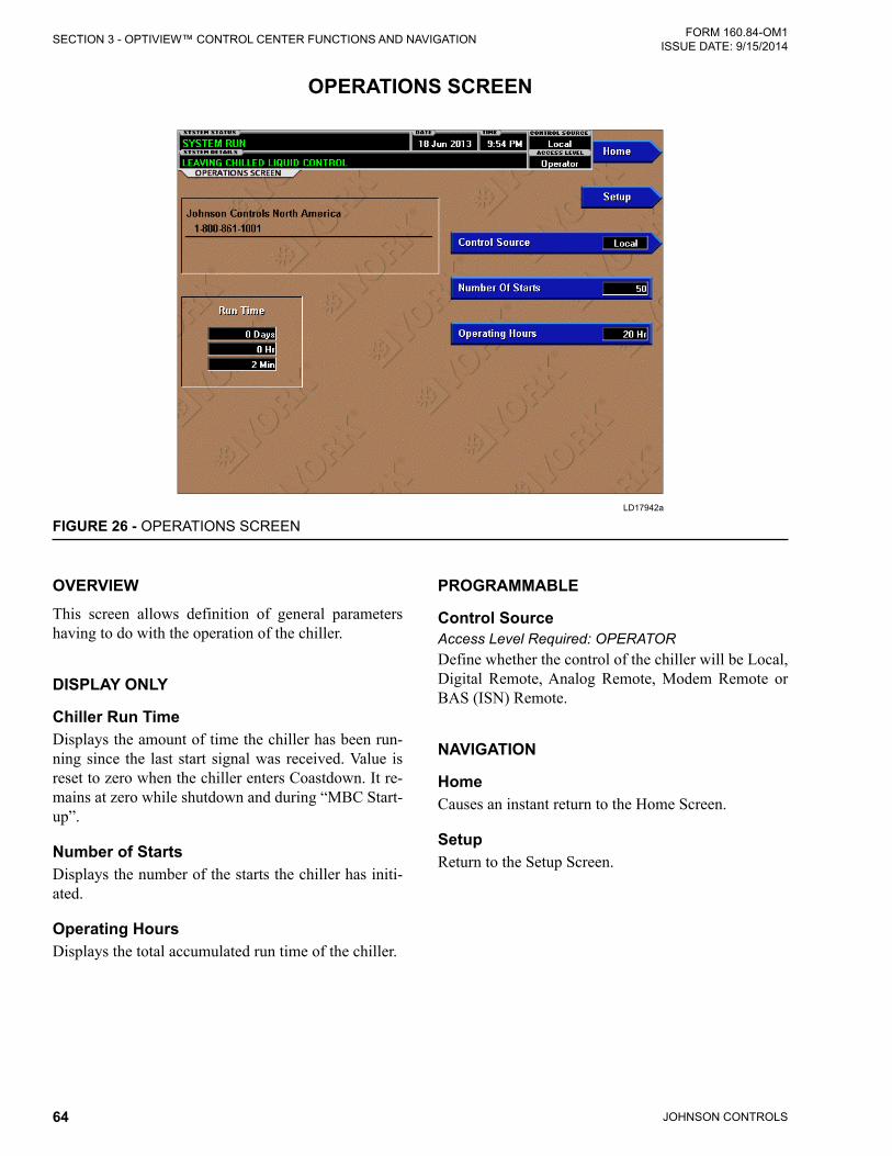
JOHNSON CONTROLS64
FORM 160.84-OM1 ISSUE DATE: 9/15/2014SECTION 3 - OPTIVIEW™ CONTROL CENTER FUNCTIONS AND NAVIGATION
OVERVIEWThis screen allows definition of general parameters having to do with the operation of the chiller.
DISPLAY ONLY
Chiller Run TimeDisplays the amount of time the chiller has been run-ning since the last start signal was received. Value is reset to zero when the chiller enters Coastdown. It re-mains at zero while shutdown and during “MBC Start-up”.
Number of StartsDisplays the number of the starts the chiller has initi-ated.
Operating HoursDisplays the total accumulated run time of the chiller.
PROGRAMMABLE
Control SourceAccess Level Required: OPERATORDefine whether the control of the chiller will be Local, Digital Remote, Analog Remote, Modem Remote or BAS (ISN) Remote.
NAVIGATION
HomeCauses an instant return to the Home Screen.
SetupReturn to the Setup Screen.
OPERATIONS SCREEN
LD17942a
FIGURE 26 - OPERATIONS SCREEN

JOHNSON CONTROLS 65
SECTION 3 - OPTIVIEW™ CONTROL CENTER FUNCTIONS AND NAVIGATIONFORM 160.84-OM1 ISSUE DATE: 9/15/2014
3
OVERVIEWThis screen allows the user to browse through the faults. In order to get a more thorough reporting of the system conditions at the time of the recorded shutdown, move to the History Details subscreen.
The user may use the Select Fault button to select the history to view. At this point the View Details button is used to jump to a subscreen containing stored chiller parameters values at the time of the shutdown. Addi-tionally, the Print History button can be used to gen-erate a hard-copy report of the parameter values at the time of the shutdown.
DISPLAY ONLY
Last Normal ShutdownThis window displays the date and time and the de-scription of the last normal shutdown. A normal shut-down is defined as:
• Local (Panel rocker switch)
• Remote (Digital, Analog or BAS (ISN))
Last Fault While RunningThis window displays the date and time and the de-scription of the last safety or cycling shutdown while the system was running.
Last Ten FaultsThis window displays a chronological listing (most recent first) of the date and time and the description of the last ten safety or cycling shutdowns that occur while the system is running or stopped.
PROGRAMMABLE
Print HistoryThis generates a report listing the status of the chiller parameters at the time of the selected shutdown.
Print All HistoriesThis generates a report listing the status of the chiller parameters at the time of each of the stored shutdowns.
HISTORY SCREEN
LD17943a
FIGURE 27 - HISTORY SCREEN

JOHNSON CONTROLS66
FORM 160.84-OM1 ISSUE DATE: 9/15/2014SECTION 3 - OPTIVIEW™ CONTROL CENTER FUNCTIONS AND NAVIGATION
NAVIGATION
HomeCauses an instant return to the Home Screen.
View DetailsCauses a move to a subscreen containing the value of select chiller parameters at the time of the associated shutdown.
TrendingCauses a move to a subscreen allowing the user to view trending data on selected chiller parameters.
Custom View Causes a move to a subscreen allowing the user to view the Custom Setup Screen.
Security LogAccess Level Required: SERVICECauses a move to a subscreen allowing the user to view a record of the last 75 setpoint changes.

JOHNSON CONTROLS 67
SECTION 3 - OPTIVIEW™ CONTROL CENTER FUNCTIONS AND NAVIGATIONFORM 160.84-OM1 ISSUE DATE: 9/15/2014
3
OVERVIEWThis screen allows the user to see an on-screen printout of all the system parameters at the time of the selected shutdown. Not all screens are shown above. The num-ber of screens required to display all of the data varies according to type of motor starter and options applied.
DISPLAY ONLY
History PrintoutThis is the on-screen printout of the system parameters.
PROGRAMMABLE
Page Up / Page DownScroll up in the displayed data (if applicable).
Print HistoryThis generates a report listing the status of the chiller parameters at the time of the selected shutdown.
NAVIGATION
HomeCauses an instant return to the Home Screen.
HistoryCauses a return to the History Screen.
HISTORY DETAILS SCREEN
LD17944a
FIGURE 28 - HISTORY DETAILS SCREEN

JOHNSON CONTROLS68
FORM 160.84-OM1 ISSUE DATE: 9/15/2014SECTION 3 - OPTIVIEW™ CONTROL CENTER FUNCTIONS AND NAVIGATION
OVERVIEW This screen allows up to 10 Service Technician select-ed parameters to be displayed. These parameters are selected from a list on the Custom View Setup Screen. This allows the Service Technician to display param-eters pertinent to a particular problem during trouble-shooting. At completion of the service call, the display can be cleared or the parameters can be left there for monitoring by operations personnel.
DISPLAY ONLYThis screen display attributes assigned to Custom screen. There are no other display options.
PROGRAMMABLE
PrintThis generates a listing of the parameters displayed on this screen.
NAVIGATION
HomeCauses an instant return to the Home Screen.
HistoryCauses an instant return to the History Screen.
SetupAccess Level Required: OPERATORCauses a jump to the subscreen that allows selection of the parameters to be displayed.
CUSTOM SCREEN
LD17947a
FIGURE 29 - CUSTOM SCREEN

JOHNSON CONTROLS 69
SECTION 3 - OPTIVIEW™ CONTROL CENTER FUNCTIONS AND NAVIGATIONFORM 160.84-OM1 ISSUE DATE: 9/15/2014
3
OVERVIEWThis screen allows the Service technician to select up to 10 parameters for display on the Custom View Screen.
DISPLAY ONLY
Slot NumbersLists the available parameters that can be displayed. The desired parameters for display are selected from this list.
PROGRAMMABLE
Page UpScroll up through list of available parameters.
Page DownScroll down through list of available parameters.
SelectFirst use the Page Up and Page Down keys to scroll through the Slot Numbers list and note the number of the parameter(s) to be displayed. Pressing the Select key places a green colored selection box around Cus-
tom Slot 1. If it is desired to change an already entered parameter, use the 5 and 6 keys to place the selection box around the slot number to be changed. With the selection box around the slot number to be changed or entered, press the ENTER () key. A dialog box is dis-played permitting data entry. Using the numeric key-pad keys, enter the desired slot number and press the ENTER () key.
Custom Slot (1-10) Use the Select key and numeric keypad keys as de-scribed above and enter the slot number from Slot Numbers list. Setting the Slot number to zero clears the display of this slot number.
NAVIGATION
HomeCauses a return to the Home Screen.
Custom ViewAccess Level Required: SERVICECauses a return to the Custom View Screen.
CUSTOM SETUP SCREEN
LD17948a
FIGURE 30 - CUSTOM SETUP SCREEN

JOHNSON CONTROLS70
FORM 160.84-OM1 ISSUE DATE: 9/15/2014SECTION 3 - OPTIVIEW™ CONTROL CENTER FUNCTIONS AND NAVIGATION
OVERVIEWAs many as six Operator selected parameters (data points) can be plotted in an X/Y graph format. The X-axis is scaled per the selected Data Collection Interval and displayed in a time of day or elapsed time format, as selected with the X-axis toggle key. The Y-axis is scaled for each parameter per the selected minimum and maximum value for each parameter. Analog pa-rameters are scaled in pressure, temperature, volts, amps, hertz or time. Digital on/off parameters are scaled as zero (off) and one (on). Only one Y-axis la-bel is displayed at a time. The Y-axis Toggle Key is used to toggle the Y-axis labels through the different parameters. The Y-axis label that is being displayed is identified at the top of the graph. For identification, each plotted parameter and associated Y-axis labeling is color coordinated.
The DATA SELECT key is used to display all trended data points simultaneously or select a single data point for display.
The parameters are sampled at the selected Data Col-lection Interval and plotted using 450 data points across the X-axis. If the actual value of the sampled parameter is less than the Y-axis label minimum for that param-
eter, the value will be plotted at the minimum value. Similarly, if the actual value is greater than the Y-axis label maximum for that parameter, the value will be plotted at the maximum value.
There are three types of charts that can be created:
• ONE SCREEN, • CONTINUOUS • TRIGGERED
When plotting reaches the end of the X-axis, and ONE SCREEN is selected, trending stops and data is fro-zen. If CONTINUOUS is selected, the oldest data is dropped from the left-hand side of the graph at the next collection interval. Thereafter, the oldest data is dropped from the left hand-side of the graph at each data collection interval. If TRIGGERED is selected, data collection can be set to start or stop based upon the selected TRIGGER ACTION (START or STOP). If START is selected, data collection will not begin until the Triggers have been satisfied and any selected TRIGGER DELAY has elapsed. Data collection will stop at the completion of one screen of data similar to the ONE SCREEN. If STOP is selected, data collection will not stop until the Triggers have been satisfied and any selected TRIGGER DELAY has elapsed.
TREND SCREEN
LD17949a
FIGURE 31 - TREND SCREEN

JOHNSON CONTROLS 71
SECTION 3 - OPTIVIEW™ CONTROL CENTER FUNCTIONS AND NAVIGATIONFORM 160.84-OM1 ISSUE DATE: 9/15/2014
3
If a power failure occurs while the trending is running, the trending is stopped. Upon restoration of power, the last screen of data that was collected will be dis-played on the trending screen. The START key must be pressed to initiate a new trend screen.
DISPLAY ONLYThis screen allows the user to view the graphical trend-ing of the selected parameters and is also a gateway to the graph setup screens.
A red screen with the words TREND MAX MUST BE > TREND MIN will appear if the Y-Axis minimum has been pro-grammed to a value that is greater than the Y-Axis maximum for any parameter. If this appears, proceed to the Trend Setup Screen to change the values.
PROGRAMMABLE
StartAccess Level Required: OPERATOR Pressing this key clears the graph, starts a new graph, sets the time of day to the present clock time and be-gins the trending. This key is only available if trending is stopped. If the selected Chart Type is TRIGGERED and TRIGGER ACTION is set to START, data collec-tion will not begin until the Triggers have been satis-fied and any selected TRIGGER DELAY has elapsed. Otherwise, data collection will begin immediately.
StopAccess Level Required: OPERATORPressing this key stops the trending. The trend data is frozen on the display until another graph is started with the START key. The STOP key is only available if trending is running.
PrintAllows the data on the trend screen to be printed in tabular format. If set to EXISTING, a snapshot of the data presently on the screen is sent to the printer. If set to NEW, all data collected after pressing this key will be sent to the printer as it is collected. If set to DISABLED, no data is sent to the printer. Refer to SECTION 7 - PRINTING of this manual for printout examples.
Data SelectAllows the user to display all trended data points si-multaneously or select a single trended data point for display, hiding the other data points. Selections are ALL DATA or DATA POINT X (1-6).
Y-Axis This key toggles the Y-Axis labels of the graph. Each key press changes the label to another of the selected parameters.
X-AxisThis key toggles the X-Axis labels of the graph. Each key press alternates the scaling between time of day and elapsed time. The Time of Day scaling is in 24-hour format. The Elapsed Time scaling is the time elapsed since the START key was pressed, starting the trending.
NAVIGATION
HomeCauses a return to the Home Screen.
HistoryCauses a return to the History Screen.
Trend SetupAccess Level Required: OPERATOROnly displayed if the trending is stopped. Causes a jump to a subscreen for configuring the trending dis-play.

JOHNSON CONTROLS72
FORM 160.84-OM1 ISSUE DATE: 9/15/2014SECTION 3 - OPTIVIEW™ CONTROL CENTER FUNCTIONS AND NAVIGATION
OVERVIEWThis screen is used to configure the trending screen. The parameters to be trended are selected from the Common Slots Screen or Common Slots Master list and entered as Slot Numbers for Data Points 1 through 6. The Y-Axis minimum and maximum values for each parameter are entered as Data Point Min and Data Point Max for Data Points 1 through 6. The interval at which all the parameters are sampled is selected as the Data Collection Interval.
DISPLAY ONLYThis screen displays chiller trend setup fields. There are no display only field.
PROGRAMMABLE
Chart TypeAccess Level Required: OPERATORSelects CONTINUOUS, ONE SCREEN or TRIG-GERED.
Collection IntervalAccess Level Required: OPERATORSelects the interval at which the parameters are sam-pled. There are 450 data points displayed across the X-Axis of the graph. Each point represents the instan-taneous value of the parameter. The user selects the time interval between these points. This is called the DATA COLLECTION INTERVAL, or the interval at which the parameter is sampled. This interval is pro-grammable over the range of 1 second to 3600 sec-onds (1 hour), in one second increments. The selected interval not only determines the sample interval, but also the full screen time display. The full screen time display is a result of the selected interval in seconds, multiplied by the 450 data points. For example, if the Data Collection Interval is programmed for 900 sec-onds, the parameter would be sampled every 900 sec-onds, with the last 112.5 hours (4.7 days) of data view-able on the screen. Therefore, the selected interval is a compromise between resolution and full screen time display. Select the desired Data Collection Interval as follows:
TREND SETUP SCREEN
LD17950a
FIGURE 32 - TREND SETUP SCREEN
JOHNSON CONTROLS 73
SECTION 3 - OPTIVIEW™ CONTROL CENTER FUNCTIONS AND NAVIGATIONFORM 160.84-OM1 ISSUE DATE: 9/15/2014
3
4. Determine the desired time interval (in seconds), between data samples.
5. Calculate the full screen time display as follows:
• 450 x Data Collection Interval = full screen seconds
• full screen seconds / 60 = full screen minutes
• full screen minutes / 60 = full screen hours
• full screen hours / 24 = full screen days
6. Decide if the resultant sample interval and full screen display meet the requirements. If not, se-lect a different sample interval.
SelectAccess Level Required: OPERATORThis key is used to enter the slot numbers and the mini-mum and maximum Y-Axis values of each parameter to be trended. Pressing this key places a yellow box aroundDataPoint1SlotNumber.Usethe▲and▼navigation keys to place the box around the value of Data Points 1 through 6 to be changed. With the de-sired value selected, press the "" ENTER key. A dia-log box is displayed permitting data entry.
Data Point Slot # (1-6)Access Level Required: OPERATOR Use the SELECT key as described above and enter the slot number from the Common Slots Screen or Master Slot Number List of the desired parameter to be trended. The selected parameter description will be displayed for the Data Point. Setting this slot number to zero will disable trending for that particular Data Point. Any or all points can be disabled.
Data Point Min (1-6)Access Level Required: OPERATOROnly displayed if the Associated Slot Number is not Zero. This is the minimum value displayed for the Y-Axis. Selecting a parameter for a Data Point sets this to the default value, which is the lowest value allowed for that parameter. It can be changed to a value that provides a more appropriate resolution for the param-eter being monitored. To change, use the SELECT key as described above and enter the desired value. The value must always be set to a value less than the Data Point Max. Otherwise, a red graph is displayed on the Trend Screen with the words TREND MAX MUST BE > TREND MIN. If the parameter selected for this data point is a digital type (on/off), this value must be set to zero (0). Zero indicates the OFF state.
Data Point Max (1-6)Access Level Required: OPERATOROnly displayed if the associated slot number is not zero. This is the maximum value displayed for the Y-Axis. Selecting a parameter for a Data Point sets this to the default value, which is the highest value allowed for that parameter. It can be changed to a value that provides a more appropriate resolution for the param-eter being monitored. To change, use the SELECT key as described above and enter the desired value. The value must always be set to a value greater than the Data Point Min. Otherwise, a red graph is displayed on the Trend Screen with the words TREND MAX MUST BE > TREND MIN. There are 20 Y-Axis divisions. If a MIN-MAX span is selected that is not evenly divided by 20, the Program will automatically select the next higher MAX value that makes the span evenly divided by 20. For example, if 0.0 is selected as the MIN and 69.0 is selected as the MAX, the Program will insert 70.0 as the MAX value. If the parameter selected for this data point is a digital type (on/off), this value must be set to one (1). One indicates the on state.
NAVIGATION
HomeCauses a return to the Home Screen.
TrendingCauses a return to the Trending Screen.
Slot NumbersCauses a jump to a subscreen that lists the slot num-bers of the most commonly monitored parameters. The desired parameters to be plotted are selected from this screen.
TriggersCauses a jump to the Advanced Trend Setup Screen, where the start/stop Triggers can be setup. Only dis-played if TRIGGERED has been selected as Chart Type.

JOHNSON CONTROLS74
FORM 160.84-OM1 ISSUE DATE: 9/15/2014SECTION 3 - OPTIVIEW™ CONTROL CENTER FUNCTIONS AND NAVIGATION
OVERVIEWThe desired data collection start/stop triggers are setup on this screen. The trend data collection can be set to start or stop based upon the status of up to two selected Triggers.
The Triggers can consist of digital events or analog pa-rameters compared to thresholds. The Triggers can be used individually or in combination. The digital and analog parameters are selected from the Common Slots Screen (or Master Slot Numbers List in this manual).
The parameter selected as the Primary Trigger is com-pared to a value selected as the Primary Test, using the Primary Operator as a comparator. If it is evaluated as true, then the data collection is started or stopped (af-ter any selected Trigger delay) per the selected Trigger Action.
A Secondary Trigger can be evaluated with the Prima-ry Trigger to start/stop data collection. The Primary to Secondary Operator is used to define the Trigger com-binations required to be true to start/stop data collec-tion. The Secondary Trigger is setup and evaluated the same as the Primary Trigger.
Entry fields are as follows:
If Primary Trigger Is Primary Operator Primary Test
Primary to Secondary Operator
Secondary Trigger Is Secondary Operator Secondary Test
Then Trigger Action the Data Collection With a delay of Trigger Delay
After the desired Triggers are set, the START key on the TREND Screen must be manually pressed be-fore the triggers will be evaluated. While waiting for the triggers to start or stop data collection, a status message is displayed in the upper right corner of the TREND Screen describing the pending action.
DISPLAY ONLYThis screen displays trending start/stop fields. There are no display only fields on this screen.
ADVANCED TREND SETUP SCREEN
00474VIP
FIGURE 33 - ADVANCED TREND SETUP SCREEN

JOHNSON CONTROLS 75
SECTION 3 - OPTIVIEW™ CONTROL CENTER FUNCTIONS AND NAVIGATIONFORM 160.84-OM1 ISSUE DATE: 9/15/2014
3
PROGRAMMABLE
Primary TriggerAccess Level Required: OPERATOR Selects the first parameter to be evaluated. Selection is made from the Slot Numbers listing on the Trend Com-mon Slots Screen or the Master Slot Numbers List in this manual. Setting this slot number to zero disables the Primary Trigger.
Primary OperatorAccess Level Required: OPERATOR Selects the comparator for the Primary Trigger’s rela-tionship to the Primary Test. If the Primary Trigger is an analog value, selections are: <, <=, =, =>, >. If the Primary Trigger is a digital event, selections are: Equal To, Not Equal To.
Primary TestAccess Level Required: OPERATORSelects the value or condition that the Primary Trig-ger is compared to. Selection ranges from the Primary Trigger minimum value to the Primary Trigger maxi-mum value.
Trigger ActionAccess Level Required: OPERATORSelects whether the trend data collection will Start or Stop when the Trigger comparisons are true. If set to Start, data collection will stop after one screen of data is collected.
Trigger DelayAccess Level Required: OPERATORAllows the data collection start or stop to be delayed after the Triggers evaluate as true. The delay is select-able from 1 to 864000 seconds (10 days). Display is in days, hours, minutes and seconds. The delay timer begins when the triggers evaluate as true. If the Trigger Action is set to Start, data collection will begin after the triggers evaluate as true and the delay timer has elapsed. If the Trigger Action is set to Stop, data col-lection will stop after the Triggers evaluate as true and the delay timer has elapsed.
Primary to Secondary OperatorAccess Level Required: OPERATORSelects whether the Primary Trigger, Secondary Trig-ger or both have to be true in order to start or stop data collection. Selections are AND, OR, XOR and None. If NONE is selected, the Secondary Trigger is disabled.
Data collection will start/stop (as selected with Trigger Action):
• If AND selected: Both Primary AND Secondary are true
• If OR selected: Either Primary OR Secondary (or both) are true
• If XOR selected: Either Primary OR Secondary (but not both) are true
Secondary TriggerAccess Level Required: OPERATORSelects the second parameter to be evaluated. Selection is made from the Slot Numbers listing on the Trend Common Slots Screen or the Master Slot Numbers List in this manual. Setting this slot number to zero disables the Secondary Trigger.
Secondary OperatorAccess Level Required: OPERATORSelects the comparator for the Secondary Trigger’s re-lationship to the Secondary Test. If the Secondary trig-ger is an Analog value, selections are: <, <=, =, =>, >. If the Secondary Trigger is a digital event, selections are: Equal To, Not Equal To.
Secondary TestAccess Level Required: OPERATORSelects the value or condition that the Secondary Trig-ger is compared to. Selection ranges from the Second-ary Trigger minimum to the Secondary Trigger maxi-mum.
NAVIGATION
HomeCauses an instant return to the Home Screen.
Trend SetupCauses an instant return to the Trend Setup Screen.

JOHNSON CONTROLS76
FORM 160.84-OM1 ISSUE DATE: 9/15/2014SECTION 3 - OPTIVIEW™ CONTROL CENTER FUNCTIONS AND NAVIGATION
OVERVIEWThis screen displays the slot numbers of the commonly monitored parameters. The slot numbers for the re-mainder of the available parameters are listed on the Master Slot Numbers List that follows.
From these lists, select up to six parameters to be trend-ed. Return to the Trend Setup Screen and enter the pa-rameters Slot Numbers into Data Points 1 through 6.
DISPLAY ONLY
Slot NumbersThese are the slot numbers of the most commonly used parameters.
PROGRAMMABLE
Page DownAccess Level Required: OPERATORScroll down in the displayed data.
Page UpAccess Level Required: OPERATORScroll up in the displayed data.
PrintAccess Level Required: OPERATOR Generates a list of the slot numbers of the available parameters.
NAVIGATION
HomeCauses an instant return to the Home Screen.
Trend SetupCauses a return to the Trend Setup Screen.
COMMON SLOTS SCREEN
LD14869
FIGURE 34 - COMMON SLOTS SCREEN
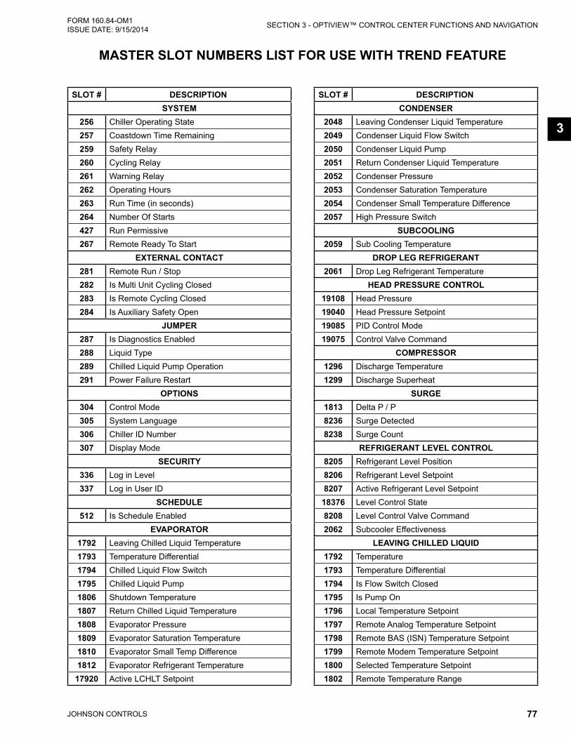
JOHNSON CONTROLS 77
SECTION 3 - OPTIVIEW™ CONTROL CENTER FUNCTIONS AND NAVIGATIONFORM 160.84-OM1 ISSUE DATE: 9/15/2014
3
MASTER SLOT NUMBERS LIST FOR USE WITH TREND FEATURE
SLOT # DESCRIPTIONSYSTEM
256 Chiller Operating State257 Coastdown Time Remaining259 Safety Relay260 Cycling Relay261 Warning Relay262 Operating Hours263 Run Time (in seconds)264 Number Of Starts427 Run Permissive267 Remote Ready To Start
EXTERNAL CONTACT281 Remote Run / Stop282 Is Multi Unit Cycling Closed283 Is Remote Cycling Closed284 Is Auxiliary Safety Open
JUMPER287 Is Diagnostics Enabled288 Liquid Type289 Chilled Liquid Pump Operation291 Power Failure Restart
OPTIONS304 Control Mode305 System Language306 Chiller ID Number307 Display Mode
SECURITY336 Log in Level337 Log in User ID
SCHEDULE512 Is Schedule Enabled
EVAPORATOR1792 Leaving Chilled Liquid Temperature1793 Temperature Differential1794 Chilled Liquid Flow Switch1795 Chilled Liquid Pump1806 Shutdown Temperature1807 Return Chilled Liquid Temperature1808 Evaporator Pressure1809 Evaporator Saturation Temperature1810 Evaporator Small Temp Difference1812 Evaporator Refrigerant Temperature17920 Active LCHLT Setpoint
SLOT # DESCRIPTIONCONDENSER
2048 Leaving Condenser Liquid Temperature2049 Condenser Liquid Flow Switch2050 Condenser Liquid Pump2051 Return Condenser Liquid Temperature2052 Condenser Pressure2053 Condenser Saturation Temperature2054 Condenser Small Temperature Difference2057 High Pressure Switch
SUBCOOLING2059 Sub Cooling Temperature
DROP LEG REFRIGERANT2061 Drop Leg Refrigerant Temperature
HEAD PRESSURE CONTROL19108 Head Pressure19040 Head Pressure Setpoint19085 PID Control Mode19075 Control Valve Command
COMPRESSOR1296 Discharge Temperature1299 Discharge Superheat
SURGE1813 Delta P / P8236 Surge Detected8238 Surge Count
REFRIGERANT LEVEL CONTROL8205 Refrigerant Level Position8206 Refrigerant Level Setpoint8207 Active Refrigerant Level Setpoint
18376 Level Control State8208 Level Control Valve Command2062 Subcooler Effectiveness
LEAVING CHILLED LIQUID1792 Temperature1793 Temperature Differential1794 Is Flow Switch Closed1795 Is Pump On1796 Local Temperature Setpoint1797 Remote Analog Temperature Setpoint1798 Remote BAS (ISN) Temperature Setpoint1799 Remote Modem Temperature Setpoint1800 Selected Temperature Setpoint1802 Remote Temperature Range

JOHNSON CONTROLS78
FORM 160.84-OM1 ISSUE DATE: 9/15/2014SECTION 3 - OPTIVIEW™ CONTROL CENTER FUNCTIONS AND NAVIGATION
SLOT # DESCRIPTION1803 Restart Temperature Offset1804 Restart Temperature Offset1805 Shutdown Temperature Offset1806 Shutdown Temperature Setpoint1818 Remote Digital Temperature Setpoint
SMART FREEZE PROTECTION1815 Is Control Enabled
VARIABLE GEOMETRY DIFFUSER8280 Active Stall Voltage
18305 Active Stall Voltage Type18135 Mach Number18137 Active High Limit18138 Active Low Limit8337 Stroke Calibration Complete8338 VGD Stroke Calibration Command8352 VGD Fault Code8353 VGD Actuator Fault8354 VGD Shutdown Command17408 Discharge Pressure
VARIABLE SPEED DRIVE2305 Motor Run2306 Motor % FLA3047 VSD Fault18085 Input % Full Load Amps2823 VSD Output Voltage2822 VSD Output Frequency20788 Max Chiller Frequency2818 Input Power2819 Input kW Hours2878 L1 Voltage Total Harmonic Distortion2879 L2 Voltage Total Harmonic Distortion2880 L3 Voltage Total Harmonic Distortion3014 L1 Input Current Total Demand Distortion3015 L2 Input Current Total Demand Distortion3016 L3 Input Current Total Demand Distortion3017 Input kVA2869 Input Power Factor2306 Motor % Full Load Amps20784 VSD Command3051 VSD Control State3050 VSD Inverter State3058 Precharge Active3044 Precharge Complete3057 DC Bus Regulating3027 DC Bus Voltage2829 Cooling System
SLOT # DESCRIPTION3053 L1 Input Voltage (Peak)3054 L2 Input Voltage (Peak)3055 L3 Input Voltage (Peak)2872 L1 Input Voltage (RMS)2873 L2 Input Voltage (RMS)2874 L3 Input Voltage (RMS)3008 L1 Input Current (RMS)3009 L2 Input Current (RMS)3010 L3 Input Current (RMS)3018 Phase A Output Voltage (RMS)3019 Phase B Output Voltage (RMS)3020 Phase C Output Voltage (RMS)3021 Phase A Output Current (RMS)3022 Phase B Output Current (RMS)3023 Phase C Output Current (RMS)3031 Phase A Rectifier Baseplate Temperature3032 Phase B Rectifier Baseplate Temperature3033 Phase C Rectifier Baseplate Temperature3034 Phase A Inverter Baseplate Temperature3035 Phase B Inverter Baseplate Temperature3036 Phase C Inverter Baseplate Temperature3029 Internal Ambient Temperature 13030 Internal Ambient Temperature 2
MOTOR MONITORING3059 Motor Temperature 13060 Motor Temperature 23061 Motor Temperature 33062 Motor Temperature 43063 Motor Temperature 53064 Motor Temperature 6
19148 Average Winding Temperature2362 Motor Housing Temperature
18361 Motor Housing Temperature Setpoint 18371 Motor Winding Temperature Setpoint18362 Motor Cooling Valve Command 18396 Motor Cooling Control State18397 Estimated Rotor Temperature
CAPACITY CONTROL2822 VSD Output Frequency
18023 HGBP Command18041 Condenser Pressure Override Threshold18042 Evaporator Pressure Override Threshold18058 Head Pressure18093 Active Anti-Surge Minimum Frequency18122 VSD Frequency Command18143 Input Current Override Threshold

JOHNSON CONTROLS 79
SECTION 3 - OPTIVIEW™ CONTROL CENTER FUNCTIONS AND NAVIGATIONFORM 160.84-OM1 ISSUE DATE: 9/15/2014
3
SLOT # DESCRIPTION18251 Motor Current Override Threshold18273 Control State18274 Active Load Limit18288 Speed of Sound18289 Isentropic Head18290 Omega18291 Surge Mach18292 Surge Frequency18293 Anti-Surge Minimum Frequency18295 Leaving Chilled Liquid Temperature (Filtered)18296 Condenser Pressure (Filtered)18297 Evaporator Pressure (Filtered)18300 VGD Command18332 Anti-Surge Transient Offset18342 VGD Position
MAGNETIC BEARING CONTROLLER20992 Axial Clearance Check20996 Axial Cenetring20998 Levitation Mode20999 Rotation Mode21001 MBC Alarm21002 Position V1321003 Position W1321004 Position V2421005 Position W2421006 Position Z1221010 Current V121011 Current V221012 Current V321013 Current V421014 Current W121015 Current W221016 Current W321017 Current W421018 Current Z1A21019 Current Z2A21020 Z1 Temperature21021 Z2 Temperature21022 MBC Amplifier Temp21024 Rotor Elongation21025 Motor Speed21041 MBC Fault21042 First Alarm Code21043 Rotation Allowed21045 Control Mode
SLOT # DESCRIPTION21072 VW13 Soft Landing Counter21073 VW24 Soft Landing Counter21074 Z12 Soft Landing Counter21075 VW13 Hard Landing Counter21076 VW24 Hard Landing Counter21077 Z12 Hard Landing Counter 21049 A13 Unbalance 21050 B13 Unbalance21051 A24 Unbalance21052 B24 Unbalance21053 Az Vibration21054 Bz Vibration21078 SDR Counter21079 MBC Input Voltage21154 MBC Max Alarm Level21055 MBC Alive21152 MBC Levitation Command21153 MBC Rotation Command
POWER PANEL17940 Control Voltage17938 Power Loss Time17941 UPS Line / Charging17942 UPS Inverter17943 UPS Fault17950 UPS Battery Voltage17948 UPS Inverter Enable17937 Power Panel Cooling Threshold17939 Power Panel Temperature17947 Power Panel Cooling System Run

JOHNSON CONTROLS80
FORM 160.84-OM1 ISSUE DATE: 9/15/2014SECTION 3 - OPTIVIEW™ CONTROL CENTER FUNCTIONS AND NAVIGATION
DISPLAY MESSAGESThe Status Bar of the Display contains a Status Line and, beneath it a Details Line. The Status Line contains a message describing the operating state of the chill-er; whether it is stopped, running, starting or shutting down. The Details Line displays Warning, Cycling, Safety, Start Inhibit and other messages that provide further details of the Status Bar messages. The Status Messages listed below are displayed on the Status Line. All other messages are displayed on the Details Line. For convenience they are listed in alphabetical order.
To aid in the meaning of the message, messages are displayed in different colors as follows:• Normal Operation messages - Green• Warning messages - Yellow• Cycling Shutdown messages - Orange• Safety Shutdown messages - Red
Warning messages will scroll between all those stand-ing. Shutdowns will show first occurrence.
TABLE 5 - STATUS MESSAGESMESSAGE DESCRIPTION
CYCLING SHUTDOWN – AUTO RESTART
The chiller is shut down on a CYCLING shutdown. The cause of the shutdown is still in effect and is displayed on the Details line of the Status Bar. The chiller will automatically restart when the CYCLING condition clears.
MBC STARTUPA chiller start has been initiated. The MBC conditions are verified and transitioned to levitate the driveline rotor (MBC Levitation Mode). The progress of the MBC startup is described in the Details Line of the Status Bar.
SAFETY SHUTDOWN – MANUAL RESTART
The chiller is shut down on a SAFETY shutdown. The cause of the shutdown is still in effect and is displayed on the Details line of the Status Bar. The chiller can be started after the Safety con-dition clears and the Operator presses the CLEAR FAULT key.
SOFT SHUTDOWN
The chiller is performing a Soft Shutdown. Simultaneously, the Hot Gas Bypass Valve is com-manded to 100% open (if Hot Gas Bypass is Enabled), the compressor VGD commanded to close rapidly. The motor drive speed is slowed from its initial speed to the minimum required to prevent surge. Then the motor drive speed is ramped to 0 Hz. The chiller then transitions to coastdown. Soft Shutdown in initiated by the following: • Leaving Chilled Liquid – Low Temperature • Local Panel Stop Key • Remote Stop • Any MBC Fault occurs • Multi-Unit Cycling – Contacts Open • System Cycling – Contacts Open • Control Panel – Schedule • "Condenser – Flow Switch Open" fault active • "Chilled Liquid – Flow Switch Open" fault active • "Expansion I/O – Serial Communications" fault activeIf the local panel safety stop switch is pressed or any chiller shutdown faults other than those listed above occur, Soft Shutdown is immediately terminated and a System Coastdown will occur.
START INHIBIT The chiller is prevented from being started due to the reason displayed on the Details Line of the Status bar.
SYSTEM COASTDOWN
The chiller has shut down and removed the run signal from the motor variable speed drive (VSD). The system is waiting for confirmation that the driveline has stopped rotating. When the MBC and VSD report drive frequency of 0Hz for 5 seconds, coastdown is considered completed. Then, after 60 seconds delay the VSD Precharge command is released.
SYSTEM READY TO START
The chiller is shut down but will initiate start upon receipt of a Local or Remote start signal. The Magnetic Bearing Controller (MBC) does not have the driveline rotor levitated. The Hot Gas Bypass Valve position (if present) is set to the programmed Hot Gas Startup Position. The Level Control Valve position is set to the programmed Condenser Level Control Valve Startup Position. The VGD driven to the programmed VGD Startup Position.
SYSTEM RUN The chiller is running under the condition described in the Details Line of the Status Bar. SYSTEM STOPPED The chiller is shutdown with a prevailing stop command.

JOHNSON CONTROLS 81
SECTION 3 - OPTIVIEW™ CONTROL CENTER FUNCTIONS AND NAVIGATIONFORM 160.84-OM1 ISSUE DATE: 9/15/2014
3
TABLE 6 - RUN MESSAGESMESSAGE DESCRIPTION
LEAVING CHILLED LIQUID CONTROL
The chiller is running, controlling the Leaving Chilled Liquid to the Leaving Chilled Liquid Temperature Setpoint. No system conditions is inhibiting this operation.
WARNING – VSD DC BUS ACTIVE
This non-annunciating message alerts that the DC Bus is precharged or pre-regulated for a state outside of chiller run. It is set when the VSD indicates a precharge or pre-regulated state or DC Bus voltage >50v in the stopped state. A countdown timer shows with this message to indicate the time remaining in a precharge or pre-regulate com-mand while stopped.
VSD – HIGH INPUT CURRENT LIMIT
The Chiller Input current is greater than or equal to the Active Current Limit Setpoint. The Current Limit Setpoint is programmed over a range of 30 to 100% of the Chiller Full Load Amps (FLA). The Active limit is the minimum of the Local, pulldown (if active), and Remote Current Limit Setpoints in Remote mode or the remote value in BAS (ISN) mode. While this condition is in effect, chiller capacity control is in override to reduce current. Normal LCHLT capacity control operation is resumed and this message auto-matically clears when the input current decreases below this limit.The highest of the three phase input currents divided by the programmed Job Input FLA is compared to the limit for this override.
VSD – INPUT PULLDOWN LIMIT The chiller input current will be limited by the pulldown demand limit setpoint. The mes-sage clears when the pulldown demand time expires.
TABLE 7 - MBC STARTUP MESSAGES
MESSAGE DESCRIPTION
WAITING FOR FLOWThe chilled liquid or condenser flow switch input is not reading voltage indicating no presence of flow from the flow switch. Indication of flow is required during the MBC Startup state to allow transition to chiller run.
WAITING FOR MBC LEVITATION
The OptiView™ has issued a MBC Levitate command to the MBC and is waiting for confirmation from the MBC that De-levitated mode is OFF, Levitated mode is ON, and the input from the digital Rotation Allowed contacts on the MBC is high at OptiView™ I/O board terminal TB3-30. This message precedes “Waiting for Chilled Liquid Flow”.
WAITING FOR VSD PREREGULATION
The OptiView™ has issued a VSD Pre-Charge/Pre-Regulate command to the VSD and is waiting for confirmation from the VSD that it has achieved regulated DC bus voltage and is awaiting a run command. This message precedes “Waiting for MBC Levitation”.
TABLE 8 - START INHIBIT MESSAGESMESSAGE DESCRIPTION
LINE FREQUENCY NOT SET This start inhibit is set when the Line Frequency setpoint is “INVALID”. Line Frequency is set invalid on a new or cleared BRAM until programmed.
LINE VOLTAGE NOT SET This start inhibit is set when the Line Voltage setpoint is “INVALID”. Line Voltage is set invalid on a new or cleared BRAM until programmed.
VGD STROkE NOT CALIBRATED
The Variable Geometry Diffuser stroke calibration procedure has NOT yet been per-formed.
VGD FEEDBACk NOT CALIBRATED
The Variable Geometry Diffuser feedback calibration has not yet been performed since last stroke calibration.
MBC - INITIALIZATION FAILURE
OptiView was unable to read a valid validation key code over serial communications from the MBC after prompted by voltage present on the MBC Alive contacts (I/O board TB3-71).

JOHNSON CONTROLS82
FORM 160.84-OM1 ISSUE DATE: 9/15/2014SECTION 3 - OPTIVIEW™ CONTROL CENTER FUNCTIONS AND NAVIGATION
TABLE 9 - WARNING MESSAGESMESSAGE DESCRIPTION
WARNING - CONDENSER FREEZE THREAT FROM LOW PRESSURE
While the chiller state is Stopped, the Saturated Condenser Temperature decreased below 35.0 °F. The condenser pump run contacts close. The message is automatically reset and pump contacts return to prior state when either the chiller is not in stopped state or the Saturated Condenser Temperature > 40.0 °F.
WARNING – CONDENSER – HIGH PRESSURE LIMIT
The Condenser Pressure exceeds the High Pressure Warning Setpoint threshold, programmed by a Service technician logged in at SERVICE access level. While this condition is in effect, the chiller capacity is in override to reduce pressure. This message automatically clears and normal LCHLT capacity control restored when the Condenser pressure decreases to below the Setpoint.
WARNING – CONDENSER OR EVAPORATOR XDCR ERROR
The Evaporator pressure Transducer is indicating a higher pressure than the Condenser pressure Transducer after the chiller has been running for 10 minutes. This is indicative of a Condenser or Evaporator Transducer failure. This message will be displayed until the condition clears and the WARNING RESET Keypad key is pressed in OPERATOR (or higher) access mode. Condition not checked in Brine mode.
WARNING – CONDENSER OR VGD SENSOR FAILURE
The difference between the Discharge Pressure Transducer output and the Condenser Pressure Transducer output has exceeded 21 PSID for 3 continuous minutes while the chiller was running. This feature verifies the operation of the transducers. Since both transducers are measuring essentially the same pressure, both outputs should be within the specified tolerance. This message must be manually cleared. It will be displayed un-til the transducer outputs are within the acceptable range of each other and the WARN-ING RESET key in SERVICE access level.
WARNING – EVAPORATOR – LOW PRESSURE LIMIT
The Evaporator pressure has decreased to the Warning threshold. This threshold is fixed in Water cooling applications. In Brine cooling applications, the threshold is a fixed amount above the programmable safety shutdown threshold. The Safety threshold in Brine applications is determined by the Brine solution and is determined by the YORK Factory. While this condition is in effect, the chiller capacity control is in override to in-crease suction pressure. This message automatically clears and normal LCHLT capacity control restored when the Evaporator pressure increases to the reset value.
EVAPORATOR PRESSURE THRESHOLDSWarning Threshold (PSIG) Reset Threshold (PSIG)
Water Brine Water BrineR134a 27.0 +2.0>Safety Setpoint 28.0 +3.0>Safety Setpoint
WARNING – EXCESS SURGE DETECTED
(Applies only if Surge Protection SHUTDOWN feature is Disabled) The Surge Window Count has exceeded the Count Limit. Message can be manually cleared after the Surge Window Count is less than or equal to the Count Limit, or the SHUTDOWN feature is Enabled or the chiller is stopped. To clear message press WARNING RESET key on HOME Screen when logged in at OPERATOR (or higher) access level.
WARNING - LIQUID LEVEL SETPOINT NOT ACHIEVED
The chiller is running and Refrigerant Level > (Refrigerant Level setpoint +15%) OR Refrigerant Level < (Refrigerant Level setpoint -15%) for 10 continuous minutes. The Warning is bypassed for the first 30 minutes of run to allow stabile operation to estab-lish. It is released when the chiller is not running or Refrigerant Level is within setpoint +- 15%. The message clears automatically.
WARNING - LOSS OF SUBCOOLER LIQUID SEAL
The chiller is running greater than 30 minutes and the Subcooler Effectiveness value decreased less than 0.400 (ADMIN programmable) at any drop leg refrigerant tempera-ture or increased greater than 1.50 (ADMIN programmable) when the drop leg refriger-ant temperature is at least 0.5 °F below or any amount above the Entering Condenser Liquid Temperature. The subcooler effectiveness is (Condenser Sat Temp - Drop leg refrigerant temp)/(Cond Sat Temp - Entering Condenser Liquid Temp). To clear mes-sage press WARNING RESET key on HOME Screen when logged in at OPERATOR (or higher) access level.
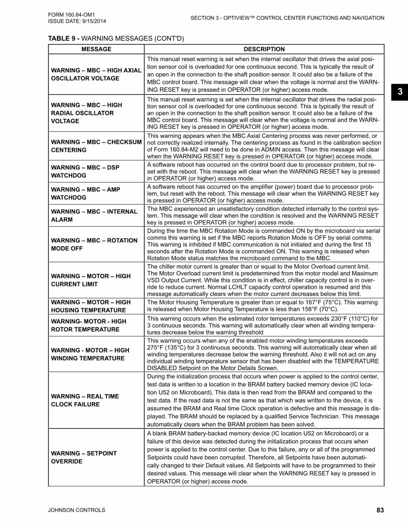
JOHNSON CONTROLS 83
SECTION 3 - OPTIVIEW™ CONTROL CENTER FUNCTIONS AND NAVIGATIONFORM 160.84-OM1 ISSUE DATE: 9/15/2014
3
MESSAGE DESCRIPTION
WARNING – MBC – HIGH AXIAL OSCILLATOR VOLTAGE
This manual reset warning is set when the internal oscillator that drives the axial posi-tion sensor coil is overloaded for one continuous second. This is typically the result of an open in the connection to the shaft position sensor. It could also be a failure of the MBC control board. This message will clear when the voltage is normal and the WARN-ING RESET key is pressed in OPERATOR (or higher) access mode.
WARNING – MBC – HIGH RADIAL OSCILLATOR VOLTAGE
This manual reset warning is set when the internal oscillator that drives the radial posi-tion sensor coil is overloaded for one continuous second. This is typically the result of an open in the connection to the shaft position sensor. It could also be a failure of the MBC control board. This message will clear when the voltage is normal and the WARN-ING RESET key is pressed in OPERATOR (or higher) access mode.
WARNING – MBC – CHECkSUM CENTERING
This warning appears when the MBC Axial Centering process was never performed, or not correctly realized internally. The centering process as found in the calibration section of Form 160.84-M2 will need to be done in ADMIN access. Then this message will clear when the WARNING RESET key is pressed in OPERATOR (or higher) access mode.
WARNING – MBC – DSP WATCHDOG
A software reboot has occurred on the control board due to processor problem, but re-set with the reboot. This message will clear when the WARNING RESET key is pressed in OPERATOR (or higher) access mode.
WARNING – MBC – AMP WATCHDOG
A software reboot has occurred on the amplifier (power) board due to processor prob-lem, but reset with the reboot. This message will clear when the WARNING RESET key is pressed in OPERATOR (or higher) access mode.
WARNING – MBC – INTERNAL ALARM
The MBC experienced an unsatisfactory condition detected internally to the control sys-tem. This message will clear when the condition is resolved and the WARNING RESET key is pressed in OPERATOR (or higher) access mode.
WARNING – MBC – ROTATION MODE OFF
During the time the MBC Rotation Mode is commanded ON by the microboard via serial comms this warning is set if the MBC reports Rotation Mode is OFF by serial comms. This warning is inhibited if MBC communication is not initiated and during the first 15 seconds after the Rotation Mode is commanded ON. This warning is released when Rotation Mode status matches the microboard command to the MBC.
WARNING – MOTOR – HIGH CURRENT LIMIT
The chiller motor current is greater than or equal to the Motor Overload current limit. The Motor Overload current limit is predetermined from the motor model and Maximum VSD Output Current. While this condition is in effect, chiller capacity control is in over-ride to reduce current. Normal LCHLT capacity control operation is resumed and this message automatically clears when the motor current decreases below this limit.
WARNING – MOTOR – HIGH HOUSING TEMPERATURE
The Motor Housing Temperature is greater than or equal to 167°F (75°C). This warning is released when Motor Housing Temperature is less than 158°F (70°C).
WARNING- MOTOR - HIGH ROTOR TEMPERATURE
This warning occurs when the estimated rotor temperatures exceeds 230°F (110°C) for 3 continuous seconds. This warning will automatically clear when all winding tempera-tures decrease below the warning threshold
WARNING - MOTOR – HIGH WINDING TEMPERATURE
This warning occurs when any of the enabled motor winding temperatures exceeds 275°F (135°C) for 3 continuous seconds. This warning will automatically clear when all winding temperatures decrease below the warning threshold. Also it will not act on any individual winding temperature sensor that has been disabled with the TEMPERATURE DISABLED Setpoint on the Motor Details Screen.
WARNING – REAL TIME CLOCk FAILURE
During the initialization process that occurs when power is applied to the control center, test data is written to a location in the BRAM battery backed memory device (IC loca-tion U52 on Microboard). This data is then read from the BRAM and compared to the test data. If the read data is not the same as that which was written to the device, it is assumed the BRAM and Real time Clock operation is defective and this message is dis-played. The BRAM should be replaced by a qualified Service Technician. This message automatically clears when the BRAM problem has been solved.
WARNING – SETPOINT OVERRIDE
A blank BRAM battery-backed memory device (IC location U52 on Microboard) or a failure of this device was detected during the initialization process that occurs when power is applied to the control center. Due to this failure, any or all of the programmed Setpoints could have been corrupted. Therefore, all Setpoints have been automati-cally changed to their Default values. All Setpoints will have to be programmed to their desired values. This message will clear when the WARNING RESET key is pressed in OPERATOR (or higher) access mode.
TABLE 9 - WARNING MESSAGES (CONT'D)

JOHNSON CONTROLS84
FORM 160.84-OM1 ISSUE DATE: 9/15/2014SECTION 3 - OPTIVIEW™ CONTROL CENTER FUNCTIONS AND NAVIGATION
MESSAGE DESCRIPTION
WARNING – UPS – BATTERY NOT CONNECTED
This is an auto reset warning. The minimum and maximum Battery Voltage that occurs within each 10 second window is stored. At the end of each 10 second window, if the difference between the min and max battery voltage is greater than 0.5 V, a counter is increased. If the difference between them is less than 0.5 V, the counter is reset to 0. This warning is set when the Battery Disconnected Counter >= 4 (The intent is for 4 consecutive 10 second windows to see battery voltage fluctuations to set this fault)It is released when the Battery Disconnected Counter is 0 for 60 continuous seconds.
WARNING – UPS – CHECk BATTERY CONNECTION
This manual reset warning is set when Battery Voltage > 16.0 V. (Indicates only the UPS output is connected to the battery leads). It is released when Battery Voltage < 16.0 V.
WARNING – UPS – LINE LOW BATTERY VOLTAGE
This auto reset warning is set when all of the following are true: • Control Voltage digital input is high (indicates line power is available) • Battery Voltage < Line Low Battery Voltage Threshold It releases when Battery Voltage > Line Low Battery Voltage Threshold + 0.1 V
WARNING – UPS – NOT CHARGING
This auto reset warning is set when all of the following are true for 5 continuous sec-onds: • Control Voltage digital input is high (indicates line power is available) • UPS Line / Charging digital input is low (indicates UPS not reporting in charge mode)It releases when any of the following are true: • Control Voltage digital input is low (indicates line power is lost) • UPS Line / Charging digital input is high (UPS is reporting in charge mode)
WARNING – VSD – INPUT VOLTAGE IMBALANCE
Line voltage imbalance shall be calculated, for every VSD communications cycle, as:
Vimb% =max (|Vab-Vavg|,|Vbc-Vavg|,|Va-Vavg|)
x 100%Vavg
where Vab, Vbc and Vca are line-to-line total rms voltages received from the drive, max is the function which selects the largest of its arguments, and:
Vavg =|Vab|+|Vbc|+|Vca|
3
If Vimb% exceeds 5% continuously for 45 seconds, the warning will be displayed. The 45 second timer shall reset and the warning shall clear if three consecutive imbalance readings fall below the 5% threshold.
TABLE 10 - ROUTINE SHUTDOWN MESSAGESMESSAGE DESCRIPTION
LOCAL STOP A local shutdown command has been received by pressing the Keypad Stop key.
REMOTE STOP
A shutdown command has been received from a remote device. Remote Stop com-mands can be received in Digital Remote mode via I/O Board TB4-7/8 or in BAS (ISN) (Integrated Systems Network) Remote mode via the E-Link Gateway serial communica-tions. If the chiller is running when this occurs, the chiller performs a soft shutdown.
TABLE 9 - WARNING MESSAGES (CONT'D)

JOHNSON CONTROLS 85
SECTION 3 - OPTIVIEW™ CONTROL CENTER FUNCTIONS AND NAVIGATIONFORM 160.84-OM1 ISSUE DATE: 9/15/2014
3
MESSAGE DESCRIPTION
CHILLED LIQUID – FLOW SWITCH OPEN
The Chilled Liquid Flow Switch has remained open for 5 continuous seconds while the chiller was running, in soft shutdown, or at least 45 seconds after MBC startup is initi-ated. The chiller will automatically restart when the flow switch closes or the fault will clear if the chiller is run command is ceased.
CONDENSER – FLOW SWITCH OPEN
The Condenser water flow switch has remained open for 5 continuous seconds while the chiller was running, in soft shutdown, or at least 45 seconds after MBC startup is initiated. The chiller will automatically restart when the flow switch closes or the fault will clear if the chiller is run command is ceased.
CONDENSER -FREEZE THREAT-FLOW SWITCH OPEN
This fault is set when all of the following are true: • Chiller State is Stopped • Saturated Condenser Temperature < 35.0 °F • Condenser Flow Switch is Open for 1 minute or longer
It is released when any of the following are true: • Chiller State is not Stopped • Saturated Condenser Temperature > 40.0 °F • Condenser Flow Switch is Closed
CONTROL PANEL – LOSS OF CONTROL VOLTAGE
The line power input signal at I/O board TB3-81 was low for 1 second continuous. This signal is used to determine when the digital inputs are affected by a line power loss versus an actual condition for their devices. This fault is not expected on an actual loss of microboard power from the critical load bus, because the processor will be off before the fault delay. This message can indicate a Cycling (auto-restart after power failure) or Safety (manual restart after power failure) shutdown, depending upon control center configuration.
CONTROL PANEL – POWER FAILURE
A Control Power failure has occurred. If the power failure occurred while the chiller was running, it will automatically restart when power is restored. This message can indicate a Cycling (auto-restart after power failure) or Safety (manual restart after power failure) shutdown, depending upon control center configuration. It indicates a cycling shutdown when displayed in orange characters; Safety shutdown when displayed in red char-acters. The control center is configured for auto-restart or manual restart after power failure by a qualified Service Technician following instructions in YORK YMC2 Service Manual (Form 160.84-M2).
CONTROL PANEL – SCHEDULEThe programmed Daily Schedule Setpoint has shutdown the chiller. If this occurs while the chiller is running, a Soft Shutdown is performed. The chiller will automatically restart at the next scheduled start time.
EVAPORATOR – LOW PRESSURE
The evaporator pressure, as sensed by the Evaporator Transducer, has decreased to the shutdown threshold. For water cooling applications, the shutdown threshold is a fixed value. For Brine cooling applications, the shutdown threshold varies according to the concentration of the Brine solution. The Brine shutdown threshold is programmed at the YORK Factory. It should not be changed by anyone other than a qualified Service Technician following instructions in YORK YMC2 Service Manual (Form 160.84-M2). The chiller will restart after the evaporator pressure increases to the restart threshold. If this shutdown occurs 3 times in a 90 minute period, an EVAPORATOR-LOW PRESSURE safety shutdown is initiated.
SHUTDOWNSHUTDOWN
(PSIG)RESTART
(PSIG)Water Cooling
-R134a25.0 25.1
Brine Cooling -R134a
6.0 to 25.0 as programmed
+0.1> Shutdown threshold
TABLE 11 - CYCLING SHUTDOWN MESSAGESThe chiller will automatically restart when the cycling condition clears.

JOHNSON CONTROLS86
FORM 160.84-OM1 ISSUE DATE: 9/15/2014SECTION 3 - OPTIVIEW™ CONTROL CENTER FUNCTIONS AND NAVIGATION
MESSAGE DESCRIPTION
EXPANSION I/O – SERIAL COMMUNICATIONS
Valid communication between the microboard and the LTC I/O Board have been disrupted for 3 consecutive attempts. The chiller will automatically restart when valid communication is received.
ISOLATION VALVES - NOT CLOSED
The optional brine freeze protection motorized isolation valves Close output is energized > 40 seconds but the feedback from the valve limit switch does not indicate it closed for 3 continuous seconds. This cycling fault is released when the isolation valves closed input is energized
LEAVING CHILLED LIQUID – LOW TEMPERATURE
The Leaving Chilled Liquid Temperature has decreased to the programmed Shutdown Temperature Setpoint. If the chiller is running when this occurs, a Soft Shutdown is performed. The chiller will automatically restart when the temperature increases to the programmed Restart Temperature Setpoint.
MBC – FAULT CONTACTS OPEN
Refer to “MBC Shutdown – Requesting Fault Data” message above. If the control cen-ter’s microboard does not receive the cause of the MBC fault over the serial link within 10 seconds after the fault contacts open is recognized, it is assumed it is not forthcom-ing and that message is replaced with this message.
MBC - LOW INPUT VOLTAGE Main DC supply voltage to the MBC decreased below 135VDC (150-10%)
MBC – SERIAL COMMUNICATIONS
This Cycling Shutdown is set when an invalid or no response is received from the MBC to a Modbus command from the panel for 3 consecutive attempts with a 2 second timeout between attempts. It shall be triggered by the Modbus communications task when its fault conditions are met (thresholds of consecutive timeouts, ID mismatches, checksum failures, or error packets). It is released when a valid response is received.
MBC SHUTDOWN – REQUESTING FAULT DATA
The MBC has shutdown the chiller and the control center has not yet received the cause of the fault from the MBC via the serial communications link. The MBC shuts down the chiller by opening the MBC Fault contacts (located on the MBC control board and con-nected to TB3-70 in the control center). The microboard in the control center then sends a request for the cause of the fault to the MBC control board over the serial link. Since serial communications are initiated every 2 seconds, this message is typically displayed for a few seconds and then replaced with one of the other MBC fault messages in this section.
MBC – SPEED SIGNAL FAULT
This Cycling Shutdown is set when the MBC looses the speed signal that is expected from the VSD or speed signal is less than 10 Hz. While the MBC is commanded in Rota-tion Mode. The MBC Fault contacts open. The MBC remains in Levitation mode with the motor shaft levitated until commanded to de-levitate over serial comms. This shutdown is released when the MBC is out of Rotation mode or speed greater than 10 Hz is trans-mitted. A 10 second bypass exists when the initial command to Rotation Mode occurs.
MBC – STARTUP FAILURE
This Shutdown is set when the chiller fails to exit the MBC startup state within 60 seconds, during a chiller start. Refer to the Basic Operation section of this manual for conditions necessary to complete MBC startup successfully. Check fault history details to determine which specific conditions were not met.
MBC – V13 LOW FREQUENCY DISPLACEMENT
The MBC has measured shaft displacement is greater than 90 µm from center in the orthogonal radial axis designated V at the impeller end radial magnetic bearing during Levitation or Rotation mode over a 7 second window (approximately 2/3 of the air gap space to the touchdown bearing). The MBC Fault contacts open. The MBC remains in Levitation mode with the motor shaft levitated until commanded to de-levitate over serial comms. This shutdown is released when displacement is less than 90 µm.
MBC - UNkNOWN PARAMATER FILE
This Cycling shutdown is set when the bearing setup parameter file received from Opti-View is not an expected file format. The fault is released when the error is corrected. This fault could be corrupted data transfer between OptiView and the MBC.
MBC – V13 POSITION
The MBC has measured shaft displacement is greater than 100 µm from center in the orthogonal radial axis designated V at the impeller end radial magnetic bearing during Levitation or Rotation mode (approximately 2/3 of the air gap space to the touchdown bearing). The MBC Fault contacts open. The MBC remains in Levitation mode with the motor shaft levitated until commanded to de-levitate over serial comms. This shutdown is released when displacement is less than 100 µm.
TABLE 11 - CYCLING SHUTDOWN MESSAGES (CONT'D)

JOHNSON CONTROLS 87
SECTION 3 - OPTIVIEW™ CONTROL CENTER FUNCTIONS AND NAVIGATIONFORM 160.84-OM1 ISSUE DATE: 9/15/2014
3
MESSAGE DESCRIPTION
MBC – V24 LOW FREQUENCY DISPLACEMENT
The MBC has measured shaft displacement is greater than 90 µm from center in the orthogonal radial axis designated V at the opposite-impeller end radial magnetic bearing during Levitation or Rotation mode over a 7 second window (approximately 2/3 of the air gap space to the touchdown bearing). The MBC Fault contacts open. The MBC remains in Levitation mode with the motor shaft levitated until commanded to de-levitate over serial comms. This warning is released when displacement is less than 90 µm.
MBC – V24 POSITION
The MBC has measured shaft displacement is greater than 100 µm from center in the orthogonal radial axis designated V at the opposite-impeller end radial magnetic bearing during Levitation or Rotation mode (approximately 2/3 of the air gap space to the touchdown bearing). The MBC Fault contacts open. The MBC remains in Levitation mode with the motor shaft levitated until commanded to de-levitate over serial comms. This shutdown is released when displacement is less than 100 µm.
MBC – W13 LOW FREQUENCY DISPLACEMENT
The MBC has measured shaft displacement is greater than 90 µm from center in the orthogonal radial axis designated W at the impeller end radial magnetic bearing during Levitation or Rotation mode over a 7 second window (approximately 2/3 of the air gap space to the touchdown bearing). The MBC Fault contacts open. The MBC remains in Levitation mode with the motor shaft levitated until commanded to de-levitate over serial comms. This warning is released when displacement is less than 90 µm.
MBC – W13 POSITION
The MBC has measured shaft displacement is greater than 100 µm from center in the orthogonal radial axis designated W at the impeller end radial magnetic bearing during Levitation or Rotation mode (approximately 2/3 of the air gap space to the touchdown bearing). The MBC Fault contacts open. The MBC remains in Levitation mode with the motor shaft levitated until commanded to de-levitate over serial comms. This shutdown is released when displacement is less than 100 µm.
MBC – W24 LOW FREQUENCY DISPLACEMENT
The MBC has measured shaft displacement is greater than 90 µm from center in the or-thogonal radial axis designated W at the opposite-impeller end radial magnetic bearing during Levitation or Rotation mode over a 7 second window (approximately 2/3 of the air gap space to the touchdown bearing). The MBC Fault contacts open. The MBC remains in Levitation mode with the motor shaft levitated until commanded to de-levitate over serial comms. This warning is released when displacement is less than 90 µm.
MBC – W24 POSITION
The MBC has measured shaft displacement is greater than 100 µm from center in the orthogonal radial axis designated W at the opposite-impeller end radial magnetic bearing during Levitation or Rotation mode (approximately 2/3 of the air gap space to the touchdown bearing). The MBC Fault contacts open. The MBC remains in Levitation mode with the motor shaft levitated until commanded to de-levitate over serial comms. This shutdown is released when displacement is less than 100 µm.
MBC – VW13 VIBRATION
The MBC has measured synchronous speed (first harmonic) shaft vibration at the impeller end radial magnetic bearing is greater than 45 µm peak amplitude in Rotation mode. This condition is monitored only when the AVR and ABS filter is on, which occurs for speed above 70 Hz. The MBC Fault contacts open. The MBC remains in Levitation mode with the motor shaft levitated until commanded to de-levitate over serial comms. This fault is released when vibration is less than 45 µm.
MBC – VW24 VIBRATION
The MBC has measured synchronous speed (first harmonic) shaft vibration at the opposite-impeller end radial magnetic bearing is greater than 45 µm peak amplitude in Rotation mode. This condition is monitored only when the AVR and ABS filter is on, which occurs for speed above 70 Hz. The MBC Fault contacts open. The MBC remains in Levitation mode with the motor shaft levitated until commanded to de-levitate over serial comms. This fault is released when vibration is less than 60 µm.
MBC – Z12 LOW FREQUENCY DISPLACEMENT
The MBC has measured shaft displacement is greater than 100 µm axially from the design running position over a 7 second window (approximately 1/3 of the air gap space to the touchdown bearing axially). The MBC Fault contacts open. The MBC remains in Levitation mode with the motor shaft levitated until commanded to de-levitate over serial comms. This fault is released when displacement is less than 100 µm.
TABLE 11 - CYCLING SHUTDOWN MESSAGES (CONT'D)

JOHNSON CONTROLS88
FORM 160.84-OM1 ISSUE DATE: 9/15/2014SECTION 3 - OPTIVIEW™ CONTROL CENTER FUNCTIONS AND NAVIGATION
MESSAGE DESCRIPTION
MBC – Z12 POSITION
The MBC has measured shaft displacement is greater than 100 µm axially from the design running position (approximately 1/2 of the air gap space to the touchdown bearing axially). The MBC Fault contacts open. The MBC remains in Levitation mode with the motor shaft levitated until commanded to de-levitate over serial comms. This shutdown is released when displacement is less than 100 µm.
MBC - Z12 VIBRATION
The MBC has measured a vibration in axial position at one times the rotating frequency whose amplitude exceeds 60 um. This frequency axially can be the image of the rotor axial run-out. This fault is available when AVR or ABS are activated. The MBC fault contacts open. The MBC remains in Levitation mode with the motor shaft levitated until commanded to de-levitate over serial comms. This fault is released when this displacement is less than 60 um.
MULTIUNIT CYCLING – CONTACTS OPEN
The Multiunit Cycling contacts connected to I/O Board TB4-9, have opened to initiate a cycling shutdown. If the chiller is running when this occurs, the Pre-rotation Vanes are driven fully closed prior to shutting down the chiller. The chiller will automatically restart when the contacts close.
SYSTEM CYCLING – CONTACTS OPEN
The System Cycling contacts connected to I/O Board TB4-13, have opened to initiate a cycling shutdown. If the chiller is running when this occurs, the Pre-rotation Vanes are driven fully closed prior to shutting down the chiller. The chiller will automatically restart when the contacts close.
UPS – LINE LOW BATTERY VOLTAGE
This cycling fault initiates a soft shutdown if it is set while the chiller state is Running. It is set during chiller state Running or Soft Shutdown when all of the following are true: • Battery Voltage Faults setting is “Enabled” • “Warning – UPS – Line Low Battery Voltage” warning has been set for 60 continuous
minutesThis fault is also set during chiller state Stopped when all of the following are true: • Battery Voltage Faults setting is “Enabled” • Control Voltage digital input is high (indicates line power is available) • Battery Voltage < Line Low Battery Voltage ThresholdIt is released when any of the following are true: • Battery Voltage Faults is Disabled • Battery Voltage > Line Low Battery Voltage Threshold + 0.1 V.
VSD – DC BUS PRE-REGULATION
The DC bus voltage has not increased to a value of +/- 50 volts of the DC bus voltage setpoint of 785 VDC within 2 seconds after entering the pre-regulation state. If this con-dition does not pass, then this shutdown is generated. The VSD will attempt another pre-charge and pre-regulation cycle after a delay of 10 seconds. If this shutdown occurs three consecutive times, then the chiller will lock out on a “VSD – DC BUS PRE-REGULATION LOCKOUT”.
VSD – HIGH DC BUS VOLTAGE
If the DC bus voltage exceeds the value for the given model of drive, then this shutdown will occur. Typically, this shutdown will occur when there is a sudden change in the input voltage due to storms, utility power problems, or site power problems
DRIVE MODEL HIGH DC BUS VOLTAGE SHUTDOWN VALUE0490 878 VDC
0612 and 0774 985 VDC
TABLE 11 - CYCLING SHUTDOWN MESSAGES (CONT'D)

JOHNSON CONTROLS 89
SECTION 3 - OPTIVIEW™ CONTROL CENTER FUNCTIONS AND NAVIGATIONFORM 160.84-OM1 ISSUE DATE: 9/15/2014
3
MESSAGE DESCRIPTION
VSD – HIGH INTERNAL AMBIENT TEMPERATURE
The variable speed drive contains two temperature sensors, which monitor the unit’s internal ambient temperature. This shutdown is generated when the higher of the two ambient temperatures exceeds a high limit of 158°F (70°C). The unit’s fan(s) and water pump(s) remain energized until the internal temperature drops below 148°F (64°C), after which they shall be de-energized and the fault can be cleared. Some potential causes for this shutdown are internal VSD fan failure, VSD coolant pump failure, enter-ing condenser water temperature higher than design, condenser water flow lower than required, fouled VSD heat exchanger, or restriction of condenser water to the VSD.
VSD – HIGH PHASE A INPUT CURRENT
If the A phase input current exceeds the value for the given model of drive, then a cycling shutdown will occur. If three high input current cycling shutdown faults occur on any phase within 90 minutes, the third fault in the 90 minute period will cause a Safety Shutdown. If the safety shutdown occurs, the chiller can be restarted after the CLEAR FAULTS key is pressed.
DRIVE MODEL INPUT CURRENT FAULT VALUE 0490 886 Amps0612 1418 Amps0774 1446 Amps
VSD – HIGH PHASE B INPUT CURRENT
See “VSD – HIGH PHASE A INPUT CURRENT” message preceeding.
VSD – HIGH PHASE C INPUT CURRENT
See “VSD – HIGH PHASE A INPUT CURRENT” message preceeding.
VSD – HIGH PHASE A MOTOR CURRENT
If the A phase motor current exceeds the value for the given model of drive, then a cycling shutdown will occur. If three high motor current cycling shutdown faults occur on any phase within 90 minutes, the third fault in the 90 minute period will cause a Safety Shutdown. If the safety shutdown occurs, the chiller can be restarted after the CLEAR FAULTS key is pressed.
DRIVE MODEL MOTOR CURRENT FAULT VALUE 0490 776 Amps0612 1094 Amps0774 1317 Amps
VSD – HIGH PHASE B MOTOR CURRENT
See “VSD – HIGH PHASE A MOTOR CURRENT” message preceeding.
VSD – HIGH PHASE C MOTOR CURRENT
See “VSD – HIGH PHASE A MOTOR CURRENT” message preceeding.
VSD INITIALIZATION FAILED
Upon application of power, all boards go through the initialization process. At this time, memory locations are cleared, program jumper positions are checked and serial communications links are established. There are several causes for an unsuccessful initialization as follows: • Serial data communications must be established. Refer to VSD – Serial Communi-
cations fault. If communications between the VSD Logic Board, and control center Microboard does not take place during initialization, this message will be generated. The Serial communications can be verified by selecting the VSD DETAILS screen from the MOTOR screen and observing the Full Load amps value. A zero displayed for this and other VSD parameters, indicates a serial communications link problem.
VSD – INVALID SETPOINTS
The VSD Logic Board is able to determine which model of drive can run which model of motor. If the Control Center provides a model of motor that is not compatible with this model of VSD, then this shutdown is generated. When this condition clears, the chiller can be started after the CLEAR FAULTS key is pressed.
VSD – LOGIC BOARD POWER SUPPLY
This shutdown is generated by the VSD logic board and it indicates that the low voltage power supplies for the logic boards have dropped below their allowable operating limits. This message usually means the power to the VSD has been removed.
TABLE 11 - CYCLING SHUTDOWN MESSAGES (CONT'D)

JOHNSON CONTROLS90
FORM 160.84-OM1 ISSUE DATE: 9/15/2014SECTION 3 - OPTIVIEW™ CONTROL CENTER FUNCTIONS AND NAVIGATION
MESSAGE DESCRIPTIONVSD – LOGIC BOARD PROCESSOR
This shutdown is generated if a communications problem occurs between the two mi-croprocessors on the VSD Logic Board.
VSD – LOW DC BUS VOLTAGE
Following a successful pre-charge and pre-regulation of the bus capacitor(s), if the DC bus voltage drops below 755 VDC, then this shutdown is generated. Typically, this shut-down will occur when there is a sudden change in the input voltage due to storms, utility power problems, or site power problems.
VSD – LOW PHASE A INPUT BASEPLATE TEMPERATURE
The temperature of the input baseplate phase A has decreased below the low limit of 37°F (2.7°C). All phase temperatures have to increase above the fault-reset threshold of 42°F (5.5°C), for this fault to be cleared. The cooling fans and pumps will turn on while this shutdown is present. They will turn off when the temperature rises above the fault-reset threshold.
VSD – LOW PHASE B INPUT BASEPLATE TEMPERATURE
See “VSD – LOW PHASE A INPUT BASEPLATE TEMPERATURE” message preceed-ing.
VSD – LOW PHASE C INPUT BASEPLATE TEMPERATURE
See “VSD – LOW PHASE A INPUT BASEPLATE TEMPERATURE” message preceed-ing.
VSD – LOW PHASE A MOTOR BASEPLATE TEMPERATURE
The temperature of the motor baseplate phase A has decreased below the low limit of 37°F. All phase temperatures have to increase above the fault-reset threshold of 42°F, for this fault to be cleared. The cooling fans and pumps will turn on while this shutdown is present. They will turn off when the temperature rises above the fault-reset threshold.
VSD – LOW PHASE B MOTOR BASEPLATE TEMPERATURE
See “VSD – LOW PHASE A MOTOR BASEPLATE TEMPERATURE” message preceed-ing.
VSD – LOW PHASE C MOTOR BASEPLATE TEMPERATURE
See “VSD – LOW PHASE A MOTOR BASEPLATE TEMPERATURE” message preceed-ing.
VSD – NOT RUNNINGThe VSD has not reported run state via serial communications for 8 seconds while the microboard issues a VSD run command. The fault is released when the microboard command is “Stopped State”.
VSD – PHASE A INPUT DCCT OFFSET
When the VSD begins precharge, the output of the input current Direct Current Cur-rent Transformers (DCCT) are evaluated to ensure that they are reading zero current when no current is flowing through the DCCT. If the zero current output value is above a threshold, then this shutdown is generated.
VSD – PHASE B INPUT DCCT OFFSET
See “VSD – PHASE A INPUT DCCT OFFSET” message preceeding.
VSD – PHASE C INPUT DCCT OFFSET
See “VSD – PHASE A INPUT DCCT OFFSET” message preceeding.
VSD – PHASE A INPUT GATE DRIVER
The gate driver board for the input rectifier monitors the power supplies within the gate driver circuit, and verifies that the input rectifier can be properly controlled. If the gate driver monitor determines that the input rectifier cannot be properly controlled, then the drive will shutdown and display this message.
VSD – PHASE B INPUT GATE DRIVER
See “VSD – PHASE A INPUT GATE DRIVER” message preceeding.
VSD – PHASE C INPUT GATE DRIVER
See “VSD – PHASE A INPUT GATE DRIVER” message preceeding.
VSD – PHASE A MOTOR GATE DRIVER
The gate driver board for the motor inverter monitors the power supplies within the gate driver circuit, and verifies that the input rectifier can be properly controlled. If the gate driver monitor determines that the input rectifier cannot be properly controlled, then the drive will shutdown and display this message.
VSD – PHASE B MOTOR GATE DRIVER
See “VSD – PHASE A MOTOR GATE DRIVER” message preceeding.
VSD – PHASE C MOTOR GATE DRIVER
See “VSD – PHASE A MOTOR GATE DRIVER” message preceeding.
TABLE 11 - CYCLING SHUTDOWN MESSAGES (CONT'D)

JOHNSON CONTROLS 91
SECTION 3 - OPTIVIEW™ CONTROL CENTER FUNCTIONS AND NAVIGATIONFORM 160.84-OM1 ISSUE DATE: 9/15/2014
3
MESSAGE DESCRIPTION
VSD – PRECHARGE – LOW DC BUS VOLTAGE 1
During Pre-charge, the DC bus voltage must exceed the minimum threshold which is determined by Line Voltage Setpoint (see the table below) within 4 seconds after the pre-charge signal has been commanded. If this condition is not met, this shutdown is generated. The VSD logic board shall wait 10 seconds before clearing the fault and allowing another pre-charge to start. The VFD’s fan(s) and water pump(s) shall remain energized during this time. The VSD logic board shall allow up to three consecutive pre-charge-related faults to occur. After the third consecutive pre-charge-related fault, Safety Shutdown message “VSD – PRECHARGE LOCKOUT” is generated.
LINE VOLTAGE MINIMUM THRESHOLD (VOLTS)380/415 41
460 50
VSD – PRECHARGE – LOW DC BUS VOLTAGE 2
During Pre-charge, the DC bus voltage must exceed the minimum threshold which is determined by Line Voltage Setpoint (see the table below) within 12 seconds after the pre-charge signal has been commanded. If this condition is not met, this shutdown is generated. The VSD logic board shall wait 10 seconds before clearing the fault and allowing another pre-charge to start. The VFD’s fan(s) and water pump(s) shall remain energized during this time. The VSD logic board shall allow up to three consecutive pre-charge-related faults to occur. After the third consecutive pre-charge-related fault, Safety Shutdown message “VSD – PRECHARGE LOCKOUT” is generated.
LINE VOLTAGE MINIMUM THRESHOLD (VOLTS)380/415 414
460 500
VSD – RUN SIGNAL
Redundant RUN signals are generated by the control center; one via TB6-24 and the second via the Serial Communications link. Upon receipt of either of the two RUN com-mands by the VSD, a 5 second timer shall commence timing. If both run commands are not received by the VSD Logic Board within 5 seconds, a shutdown is performed and this message is displayed. This is generally indicative of a wiring problem between the control center and the VSD.
VSD – SERIAL RECEIVE This shutdown is generated when the VSD logic board has not received a valid commu-nications packet from the control center for 10 consecutive seconds.
VSD SHUTDOWN – REQUESTING FAULT DATA
The VSD has shutdown the chiller and the control center has not yet received the cause of the fault from the VSD, via the serial communications link. The VSD shuts down the chiller by opening the Motor Controller VSD Stop Contacts. The control center then sends a request for the cause of the fault to the VSD over the serial link. Since serial communications are initiated every 2 seconds, this message is typically displayed for a few seconds and then replaced with one of the other VSD fault messages.
VSD – SINGLE PHASE INPUT POWER
The VSD monitors the input voltage of all three phases. If the input voltage of any one phase drops below the threshold value for the given input voltage range below, then this shutdown will occur.
INPUT VOLTAGE RANGE
INPUT VOLTAGE SINGLE PHASE SHUTDOWN VALUE
380/415 264 Volts 460 295 Volts
VSD – STOP (FAULT) CONTACTS OPEN
Refer to “VSD Shutdown – Requesting Fault Data” message above. If the control center’s does not receive the cause of the Fault over the Serial Link within 20 seconds, it is assumed it is not forthcoming and that message is replaced with “VSD – STOP CONTACTS OPEN” message.
TABLE 11 - CYCLING SHUTDOWN MESSAGES (CONT'D)

JOHNSON CONTROLS92
FORM 160.84-OM1 ISSUE DATE: 9/15/2014SECTION 3 - OPTIVIEW™ CONTROL CENTER FUNCTIONS AND NAVIGATION
MESSAGE DESCRIPTION
AUXILIARY SAFETY – CONTACTS CLOSED
The Auxiliary Safety shutdown input, connected to I/O Board TB4-31 senses 115 VAC, initiat-ing a safety shutdown. This input is a general-purpose, user defined safety shutdown input. The chiller can be started after the contacts open and the CLEAR FAULT key is pressed.
CONDENSER – HIGH PRESSURE
The condenser pressure, as sensed by the Condenser Transducer, has increased to is greater than 200 PSIG for shells with 235 PSIG DWP and 295 PSIG for shells with 350 PSIG DWP. The control determines the shell DWP by the condenser model number on the Sales Order Screen. The chiller can be started after the pressure decreases to is less than 140 PSIG for shells with 235 PSIG DWP and 235 PSIG for shells with 350 PSIG DWP and the CLEAR FAULT key is pressed.
CONDENSER – HIGH PRESSURE CONTACTS OPEN
The contacts of the electro-mechanical high pressure safety device, located on the condenser shell, have opened because this device has detected a pressure greater than 204±7 PSIG for shells with 235 PSIG DWP and 308±7 PSIG for shells with 350 PSIG DWP. The contacts will automatically close when the condenser pressure decreases to is less than 160±10 PSIG for the 235 DWP shells and 230±10 PSIG for the 350 DWP shells. The chiller can be started after the contacts close and the CLEAR FAULT key is pressed.
CONDENSER – HIGH PRESSURE – STOPPED
The condenser pressure exceeded 170 PSIG for shells with 235 PSIG DWP and 264 PSIG for shells with 350 PSIG DWP while the chiller was stopped. The control determines the shell DWP by the condenser model number on the Sales Order Screen. High temperature condenser water flowing through the condenser while the chiller is shutdown can cause a condenser high pressure condition resulting in loss of refrigerant. This safety fault anticipates this problem by annunciating the condenser high pressure condition. The chiller can be restarted after a Service Technician performs a special reset preset procedure.
CONDENSER – PRESSURE TRANSDUCER OUT OF RANGE
The Condenser Pressure Transducer is indicating a pressure that is is less than 6.8 PSIG or greater than 300.0 PSIG. This is outside the normal operating range of the transducer. This is generally indicates a defective transducer. The chiller can be started after the transducer is indi-cating a pressure that is within range and the CLEAR FAULT key is pressed.
CONTROL PANEL - INVALID BRAM
On bootup, the panel shall determine whether a 512K BRAM module is installed by a sequence of tests where data is written and read from address above and below 128K. IF the BRAM is not 512K, this shutdown is generated.
CONTROL PANEL – LOSS OF CONTROL VOLTAGE
The line power input signal at I/O board TB3-81 was low for 1 second continuous. This signal is used to determine when the digital inputs are affected by a line power loss versus an actual condition for their devices. This fault is not expected on an actual loss of microboard power from the critical load bus, because the processor will be off before the fault delay. This message can indicate a Cycling (auto-restart after power failure) or Safety (manual restart after power failure) shutdown, depending upon control center configuration.
CONTROL PANEL – POWER FAILURE
A Control Power failure has occurred. If the power failure occurred while the chiller was running, it will automatically restart when power is restored. This message can indicate a Cycling (auto-restart after power failure) or Safety (manual restart after power failure) shutdown, depending upon control center configuration. It indicates a cycling shutdown when displayed in orange characters; Safety shutdown when displayed in red characters. The control center is configured for auto-restart or manual restart after power failure by a qualified Service Technician following instructions in YORK YMC2 Service Manual (Form 160.84-M2).
DISCHARGE – HIGH TEMPERATURE
The discharge temperature, as sensed by the Discharge Temperature Thermistor, has increased to greater than 220.0°F (104°C). The chiller can be started after the temperature decreases to less than 220.0°F (104°C) and the CLEAR FAULT key is pressed.
DISCHARGE – LOW TEMPERATURE
The discharge temperature, as sensed by the Discharge Temperature Thermistor, has de-creased to less than 30.0°F (-1.1°C). The chiller can be started after the temperature increases to greater than 30.0°F (-1.1°C) and the CLEAR FAULT key is pressed.
TABLE 12 - SAFETY SHUTDOWN MESSAGESThe chiller can be started after manual resets are per-formed as detailed below. Service and troubleshooting information is contained in the YORK YMC2 Service
Manual (Form 160.84-M2) and Chiller service (Form 160.84-M1).
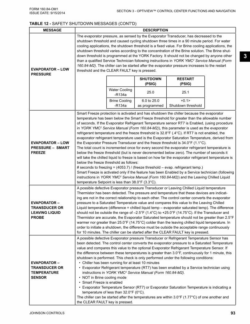
JOHNSON CONTROLS 93
SECTION 3 - OPTIVIEW™ CONTROL CENTER FUNCTIONS AND NAVIGATIONFORM 160.84-OM1 ISSUE DATE: 9/15/2014
3
MESSAGE DESCRIPTION
EVAPORATOR – LOW PRESSURE
The evaporator pressure, as sensed by the Evaporator Transducer, has decreased to the shutdown threshold and caused cycling shutdown three times in a 90 minute period. For water cooling applications, the shutdown threshold is a fixed value. For Brine cooling applications, the shutdown threshold varies according to the concentration of the Brine solution. The Brine shut-down threshold is programmed at the YORK Factory. It should not be changed by anyone other than a qualified Service Technician following instructions in YORK YMC2 Service Manual (Form 160.84-M2). The chiller can be started after the evaporator pressure increases to the restart threshold and the CLEAR FAULT key is pressed.
SHUTDOWN (PSIG)
RESTART (PSIG)
Water Cooling -R134a
25.0 25.1
Brine Cooling -R134a
6.0 to 25.0 as programmed
+0.1> Shutdown threshold
EVAPORATOR – LOW PRESSURE – SMART FREEZE
Smart Freeze protection is activated and has shutdown the chiller because the evaporator temperature has been below the Smart Freeze threshold for greater than the allowable number of seconds. If the Evaporator Refrigerant Temperature sensor RT7 is Enabled, (using procedure in YORK YMC2 Service Manual (Form 160.84-M2)), this parameter is used as the evaporator refrigerant temperature and the freeze threshold is 32.8°F (.4°C). If RT7 is not enabled, the evaporator refrigerant temperature used is the Evaporator Saturation Temperature, derived from the Evaporator Pressure Transducer and the freeze threshold is 34.0°F (1.1°C). The total count is incremented once for every second the evaporator refrigerant temperature is below the freeze threshold (but is never decremented below zero). The number of seconds it will take the chilled liquid to freeze is based on how far the evaporator refrigerant temperature is below the freeze threshold as follows: # seconds to freezing = (4053.7) / (freeze threshold – evap. refrigerant temp.)Smart Freeze is activated only if the feature has been Enabled by a Service technician (following instructions in YORK YMC2 Service Manual (Form 160.84-M2)) and the Leaving Chilled Liquid temperature Setpoint is less than 38.0°F (3.3°C).
EVAPORATOR – TRANSDUCER OR LEAVING LIQUID PROBE
A possible defective Evaporator pressure Transducer or Leaving Chilled Liquid temperature Thermistor has been detected. The pressure and temperature that these devices are indicat-ing are not in the correct relationship to each other. The control center converts the evaporator pressure to a Saturated Temperature value and compares this value to the Leaving Chilled Liquid temperature (difference = chilled liquid temp – evaporator saturated temp). The difference should not be outside the range of –2.5°F (1.4°C) to +25.0°F (14.75°C). If the Transducer and Thermistor are accurate, the Evaporator Saturated temperature should not be greater than 2.5°F warmer nor greater than 25.0°F (14.75°C) colder than the leaving chilled liquid temperature. In order to initiate a shutdown, the difference must be outside the acceptable range continuously for 10 minutes. The chiller can be started after the CLEAR FAULT key is pressed.
EVAPORATOR – TRANSDUCER OR TEMPERATURE SENSOR
A possible defective Evaporator pressure Transducer or Refrigerant Temperature Sensor has been detected. The control center converts the evaporator pressure to a Saturated Temperature value and compares this value to the optional Evaporator Refrigerant Temperature Sensor. If the difference between these temperatures is greater than 3.0°F, continuously for 1 minute, this shutdown is performed. This check is only performed under the following conditions: • Chiller has been running for at least 10 minutes • Evaporator Refrigerant temperature (RT7) has been enabled by a Service technician using
instructions in YORK YMC2 Service Manual (Form 160.84-M2). • NOT in Brine cooling mode • Smart Freeze is enabled • Evaporator Temperature Sensor (RT7) or Evaporator Saturation Temperature is indicating a
temperature of less than 32.0°F (0°C).The chiller can be started after the temperatures are within 3.0°F (1.77°C) of one another and the CLEAR FAULT key is pressed.
TABLE 12 - SAFETY SHUTDOWN MESSAGES (CONT'D)

JOHNSON CONTROLS94
FORM 160.84-OM1 ISSUE DATE: 9/15/2014SECTION 3 - OPTIVIEW™ CONTROL CENTER FUNCTIONS AND NAVIGATION
MESSAGE DESCRIPTIONINTERNAL ERROR – INVALID BRAM
BRAM is detected to be a size other than 512K. Clears when proper size BRAM is detected upon boot up.
ISOLATION VALVES – NOT OPENED
The optional brine freeze protection motorized isolation valves Open output is energized > 40 seconds but the feedback from the valve limit switch does not indicate it opened for 3 continu-ous seconds. This cycling fault is released when the chiller is stopped with the run command removed. The chiller can be started when the condition is released and the OptiView™ panel CLEAR FAULTS key is pressed.
MBC – CUSTOMER SERIAL LINk DISABLED
This Safety Shutdown is set when the MBC Local/Remote Modbus command is not reported from the MBC as set for panel control. This would be caused if the MBC were accessed via a computer using diagnostic software and the serial communication setting then changed in the Remote Command tab from Customer Serial Link to another choice. The chiller can be started when the MBC setting is restored and the OptiView™ panel CLEAR FAULTS key is pressed.
MBC – DSP COMMUNICATION
This Safety Shutdown is set when the MBC control board detects a communication error within the control board of the MBC. The MBC Fault contacts open. The MBC remains in Levitation mode with the motor shaft levitated until commanded to de-levitate over serial comms. This shutdown is released when the board-level communication failure is resolved. The chiller can be started when the condition is released and the OptiView™ panel CLEAR FAULTS key is pressed.
MBC – AMP COMMUNICATION
This Safety Shutdown is set when the MBC control board detects a communication error between the control and amplifier boards of the MBC. The MBC Fault contacts open. The MBC remains in Levitation mode with the motor shaft levitated until commanded to de-levitate over serial comms. This shutdown is released when the board-level communication failure is resolved. The chiller can be started when the condition is released and the OptiView™ panel CLEAR FAULTS key is pressed.
MBC – AMP WATCHDOG
This Safety Shutdown is set when the MBC determines a lapse in internal microprocessor activity on the Amplifier Board through its Watchdog device. The MBC Fault contacts open. The MBC will not react to a levitation mode change command via serial comms. The MBC remains in the levitation mode it was in when the fault occurred until power is removed. Power must be removed from the UPS to the MBC. The chiller can be started when the condition is released and the OptiView™ panel CLEAR FAULTS key is pressed.
MBC – DSP WATCHDOG
This Safety Shutdown is set when the MBC determines a lapse in internal microprocessor activity on the Control Board through its Watchdog device. The MBC Fault contacts open. The MBC will not react to a levitation mode change command via serial comms. The MBC remains in the levitation mode it was in when the fault occurred until power is removed. Power must be removed from the UPS to the MBC. The chiller can be started when the condition is released and the OptiView™ panel CLEAR FAULTS key is pressed.
MBC – EXCESSIVE SHUTDOWNS
This Safety Shutdown is set if 3 MBC Cycling Shutdowns occur in a 15 minute window. It is released when the chiller is stopped. The 15 minute window begins with the first MBC fault. The chiller can be started when the condition is released and the OptiView™ panel CLEAR FAULTS key is pressed.
MBC – HIGH AMPLIFIER TEMPERATURE
This Safety Shutdown is set when the MBC amplifier temperature exceeds 158 F (70 C) for 1 seconds continuous. The MBC Fault contacts open. The MBC remains in Levitation mode with the motor shaft levitated until the VSD rotation signal indicates less than 10 Hz. Then the MBC de-levitates the rotor. The shutdown is released when amplifier temperature drops below the trip value. Check the connection of the board to the heatsink and the response of the temperature sensor on the board. The chiller can be started when the condition is released and the OptiV-iew™ panel CLEAR FAULTS key is pressed.
MBC – HIGH BEARING Z1 TEMPERATURE
This Safety Shutdown is set when the MBC detects a temperature is greater than 266ºF (130ºC) on the impeller end axial magnetic bearing. The MBC Fault contacts open. The MBC remains in Levitation mode with the motor shaft levitated until the VSD rotation signal indicates is less than 10 Hz. This shutdown is released when temperature is less than 266ºF (130ºC). The chiller can be started when the condition is released and the OptiView™ panel CLEAR FAULTS key is pressed.
TABLE 12 - SAFETY SHUTDOWN MESSAGES (CONT'D)

JOHNSON CONTROLS 95
SECTION 3 - OPTIVIEW™ CONTROL CENTER FUNCTIONS AND NAVIGATIONFORM 160.84-OM1 ISSUE DATE: 9/15/2014
3
MESSAGE DESCRIPTION
MBC – HIGH BEARING Z2 TEMPERATURE
This Safety Shutdown is set when the MBC detects a temperature is greater than 266ºF (130ºC) on the opposite-impeller end axial magnetic bearing. The MBC Fault contacts open. The MBC remains in Levitation mode with the motor shaft levitated until the VSD rotation signal indicates is less than 10 Hz. This shutdown is released when temperature is less than 266ºF (130ºC). The chiller can be started when the condition is released and the OptiView™ panel CLEAR FAULTS key is pressed.
MBC – HIGH INPUT VOLTAGE Main DC supply voltage to the MBC exceeded 165VDC (150+ 10%)
MBC – NO LEVITATION
This Safety Shutdown is set when OptiView™ software is commanding MBC Levitation Mode ON but the MBC is not reporting Levitated within 15 seconds. This fault is prohibited when the MBC Alive input is not high, indicating the MBC unavailable. This fault is released when the chiller is stopped. The chiller can be started when the condition is released and the OptiView™ panel CLEAR FAULTS key is pressed.
WARNING – MBC – HIGH RADIAL OSCILLATOR VOLTAGE
This Safety Shutdown is set when the internal oscillator that drives the radial position sensor coil is overloaded for one continuous second. This is typically the result of an open in the connection to the shaft position sensor. It could also be a failure of the MBC control board. The MBC Fault contacts open. The shutdown is released when the Oscillator voltage drop is normal. The chiller can be started when the condition is released and the OptiView panel CLEAR FAULTS key is pressed.
MBC – LOW RADIAL OSCILLATOR VOLTAGE
This Safety Shutdown is set when the internal oscillator that drives the radial position sensor coil is low for one continuous second. This is typically the result of a short in the connection to the shaft position sensor. It could also be a failure of the MBC control board. The MBC Fault contacts open. The shutdown is released when the Oscillator voltage drop is normal. The chiller can be started when the condition is released and the OptiView panel CLEAR FAULTS key is pressed.
MBC – HIGH AXIAL OSCILLATOR VOLTAGE
This Safety Shutdown is set when the internal oscillator that drives the axial position sensor coil is overloaded for one continuous second. This is typically the result of an open in the connection to the shaft position sensor. It could also be a failure of the MBC control board. The MBC Fault contacts open. The shutdown is released when the Oscillator voltage drop is normal. The chiller can be started when the condition is released and the OptiView panel CLEAR FAULTS key is pressed.
MBC – LOW AXIAL OSCILLATOR VOLTAGE
This Safety Shutdown is set when the internal oscillator that drives the axial position sensor coil is low for one continuous second. This is typically the result of a short in the connection to the shaft position sensor. It could also be a failure of the MBC control board. The MBC Fault contacts open. The shutdown is released when the Oscillator voltage drop is normal. The chiller can be started when the condition is released and the OptiView panel CLEAR FAULTS key is pressed.
MBC – OVERSPEED FAULT
This Safety Shutdown is set when the MBC determines the rotor speed exceeds the pro-grammed setpoint of 360 Hz for 0.1 seconds continuous. Rotor speed is transmitted to the MBC from the VSD. The MBC Fault contacts open. The MBC remains in Levitation mode with the mo-tor shaft levitated until commanded to de-levitate over serial comms. This shutdown is released when the speed signal no longer exceeds the setpoint, which should occur when the chiller is stopped. The chiller can be started when the condition is released and the OptiView™ panel CLEAR FAULTS key is pressed.
MBC – POWER FAIL LANDING
This Safety Shutdown is set when the panel boots up after a power loss has occurred and the buffer data prior to the shutdown showed motor speed > 0, indicating the motor was rotating when the UPS power was lost. If the Power Fail Landing Counter on the MBC Details Screen is < 5, the chiller can be restarted after the cause of a loss of UPS power is determined and remedied and the OptiView™ panel CLEAR FAULTS key is pressed. IF the Power Fail Land-ing Counter is => 5, lockout occurs and must be reset by a Service Technician according to the procedure in the Calibration and Troubleshooting Section of Form 160.84-M2.
TABLE 12 - SAFETY SHUTDOWN MESSAGES (CONT'D)

JOHNSON CONTROLS96
FORM 160.84-OM1 ISSUE DATE: 9/15/2014SECTION 3 - OPTIVIEW™ CONTROL CENTER FUNCTIONS AND NAVIGATION
MESSAGE DESCRIPTION
MBC – ROTOR CONTRACTION
This Safety Shutdown is set when the MBC has calculated the algebraic difference between the displacement at shaft impeller end axial position sensor and he shaft opposite-impeller end axial position sensor is less than -100 um. The MBC fault contacts open. The MBC remains in Levita-tion mode with the motor shaft levitated until commanded to de-levitate over serial comms. This shutdown is released when the difference in displacements is over -100 um. The chiller can be started when the condition is released and the OptiView panel CLEAR FAULTS key is pressed.
MBC – ROTOR ELONGATION
This Safety Shutdown is set when the MBC has calculated the algebraic difference between the displacement at shaft impeller end axial position sensor and the shaft opposite-impeller end axial position sensor is greater than 700 um. The MBC Fault contacts open. The MBC remains in Levitation mode with the motor shaft levitated until commanded to de-levitate over serial comms. This shutdown is released when the difference in displacements no longer exceeds 700 um. The chiller can be started when the condition is released and the OptiView™ panel CLEAR FAULTS key is pressed.
MBC – SPEED SIGNAL FAULT
This Safety Shutdown is set when the MBC has the speed signal cycling fault three times in a 90-minute window. The window is started when not currently in a window and a MBC Speed Signal cycling fault is received. The MBC Fault contacts open. The MBC remains in Levitation mode with the motor shaft levitated until commanded to de-levitate over serial comms. This shutdown is released when a valid speed signal over 10 Hz is presented or the MBC is not in Rotation mode. The chiller can be started when the condition is released and the OptiView™ panel CLEAR FAULTS key is pressed.
SAFETY STOP
This is set when the panel safety stop hardware pushbutton is depressed, removing input from the I/O Board terminal TB3-28 for > 500msec. continuous. It also sets the local command to STOP. The chiller can be started when the pushbutton is released and the OptiView™ panel CLEAR FAULTS key is pressed.
MBC – STARTUP FAILURE
This Safety Shutdown is set when the chiller initiates three MBC-STARTUP FAILURE Cycling Shutdown in a 90 minute period. Refer to YORK YMC2 Service Manual (Form 160.84-M2) for conditions necessary to complete MBC startup successfully. Check fault history details to deter-mine which specific conditions were not met.
MBC – SPV UNAUTHORIZED ROTATION
This Safety Shutdown is set when the MBC is commanded to Rotation mode while it is not indi-cating acceptable to rotate. The MBC Fault contacts open. The MBC remains in Levitation mode with the motor shaft levitated until commanded to de-levitate over serial comms. This shutdown is the rotation mode command is coincident with MBC levitated and rotation allowed contacts closed. The chiller can be started when the condition is released and the OptiView™ panel CLEAR FAULTS key is pressed.
MBC – DSP UNAUTHORIZED ROTATION
This Safety Shutdown is set when the MBC detects a rotor speed signal from the VSD while the Levitation Mode is not activated. The MBC Fault contacts open. The MBC remains in Levita-tion mode with the motor shaft levitated until commanded to de-levitate over serial comms. This shutdown is released when the MBC Levitation or Rotation mode is activated or the VSD speed signal indicates no shaft rotation. The chiller can be started when the condition is released and the OptiView™ panel CLEAR FAULTS key is pressed.
MOTOR – HIGH WINDING TEMPERATURE
This safety shutdown occurs when any of the enabled motor winding temperatures exceeded the programmed High Winding Temperature Shutdown Threshold of 302˚F (150˚C) for 3 continu-ous seconds.The chiller can be started after all winding temperatures decreased to at least 18˚F (10˚C) below the shutdown threshold and the COMPRESSOR is stopped. The safety shutdown will not act on any individual winding temperature sensor that has been disabled with the TEMPERATURE DISABLE Setpoint on the Motor Details Screen.
MOTOR – HIGH ROTOR TEMPERATURE
This safety shutdown occurs when the estimated rotor temperature exceeds 250.0 F for 3 con-tinuous seconds. The fault si released and the chiller can be restarted when the estimated rotor temperature is below 230 F and the OptiView panel CLEAR FAULTS key is pressed.
MOTOR – HIGH HOUSING TEMPERATURE
This Safety Shutdown is set when Motor Housing Temperature is greater than or equal to 185 °F (85 °C). This fault is released when Motor Housing Temperature is less than 158 °F (70 °C). The chiller can be started when the condition is released and the OptiView™ panel CLEAR FAULTS key is pressed.
TABLE 12 - SAFETY SHUTDOWN MESSAGES (CONT'D)

JOHNSON CONTROLS 97
SECTION 3 - OPTIVIEW™ CONTROL CENTER FUNCTIONS AND NAVIGATIONFORM 160.84-OM1 ISSUE DATE: 9/15/2014
3
MESSAGE DESCRIPTION
SALES ORDER - INVALID COMPRESSOR MODEL
This safety shutdown is set when the Compressor Model field entered on the Setpoints – Setup –Sales Order screen does not conform to the format expected. The format is defined below and the data can be found on the compressor nameplate if it ever needs re-entry in the control:
MO
TOR
MO
TOR
REV
SS/L
S IM
P D
IAM
SS/L
S R
OTA
TIO
NSS
/LS
IMP
REV
SS/L
S FL
OW
REV
HS
IMP
DIA
M
HS
RO
TATI
ON
HS
IMP
REV
HS
FLO
W R
EV
:CODE
1,2 3 - 4 5 6 7 8 9 - 10 11 12 13 14 15 :Position
The “Sales Order - Invalid Compressor Model” safety shutdown is set when any of the following are true:
• MOTOR is anything other than M2 or M6• MOTOR REV is anything other than ‘C’• Character other than ‘-‘ between position 3 and 4• SS/LS IMP DIAM is anything other than 164, 174, 186, 197, 205, 218, 233, 246, 275,
295 or 331• SS/LS ROTATION is anything other than ‘F’• SS/LS IMP REV is anything other than the character ‘A’• SS/LS FLOW REV is anything other than the character ‘C’• Motor Model is Invalid• Invalid impeller / motor combination
The following table shows all valid impeller / motor combinations.
COMPRESSOR MOTOR
SIN
GLE
STA
GE
197FA M1 M2205FA M1 M2218FA M1 M2233FA M2 M4246FA M2 M4 M6275FA M4 M6295FA M4 M6331FA M6
TWO
S
TAG
E 233FA / 205RA M1 M2275FA / 241RA M2 M4 M6331FA / 291RA M4 M6
The fault is released when the values have been corrected. The chiller can be restarted after the CLEAR FAULTS key is pressed.
SURGE PROTECTION – EXCESS SURGE
(Applies only if Surge Protection SHUTDOWN feature is Enabled)The Surge Window Count surge events exceeded the Count Limit setpoint. The chiller shuts down as soon as the count exceeds the limit. The chiller can be started after the CLEAR FAULT key is pressed.
WATCHDOG – SOFTWARE REBOOT
The Microboard’s software Watchdog initiated a Microprocessor reset because it detected that a portion of the chiller operating Program was not being executed. The result of this reset is a Safety shutdown and re-initialization of the Program. This is generally indicative of a severe electrical power disturbance or impending Microboard Failure. The chiller can be started after the COMPRESSOR switch is placed in the Stop-Reset (O) position.
TABLE 12 - SAFETY SHUTDOWN MESSAGES (CONT'D)

JOHNSON CONTROLS98
FORM 160.84-OM1 ISSUE DATE: 9/15/2014SECTION 3 - OPTIVIEW™ CONTROL CENTER FUNCTIONS AND NAVIGATION
MESSAGE DESCRIPTION
UPS – BATTERY NOT CONNECTED
This safety fault initiates a soft shutdown if it is set while the chiller state is Running. It is set during chiller state Running or Soft Shutdown when all of the following are true: • Battery Voltage Faults is Enabled • “Warning - UPS - Battery Not Connected” warning has been set for 10 continuous minutesThis fault is also set during chiller state Stopped when all of the following are true: • Battery Voltage Faults is Enabled • Battery Disconnected Counter >= 4It is released when any of the following are true: • Battery Voltage Faults is Disabled • Battery Disconnected Counter is 0.
UPS – INVERTER LOW BATTERY VOLTAGE
This safety fault is set when all of the following are true for 5 continuous seconds: • Battery Voltage Faults is Enabled • Control Voltage digital input is low (indicates line power is lost) • Battery Voltage < Inverter Low Battery Voltage ThresholdIt is released when any of the following are true: • Battery Voltage Faults is Disabled • Battery Voltage > Line Low Battery Voltage Threshold + 0.1 V. (Note the thresholds for set
and release are intended to be different)
VGD ACTUATOR FAULT
The VGD actuator fault digital input has lost voltage either by wiring issue or fault indicated at the actuator. The chiller begins a starndard soft shutdown. The fault clears when the digital input sees voltage. When the condition clears, the chiller can be started after the CLEAR FAULTS key is pressed.
VGD POSITIONING FAULT
The VGD Position feedback indicates greater or less than the VGD command by 5% for 1 min-ute continuous. The fault clears when the position is within the command + 5 % over 1 minute. When the condition clears, the chiller can be started after the CLEAR FAULTS key is pressed.
VGD FEEDBACk FAULTThe VGD Feedback voltage is below 0.4 VDC or above 4.6 VDC. It is released when voltage is within the range. When the condition clears, the chiller can be started after the CLEAR FAULTS key is pressed.
VSD – DC BUS LOCkOUT – DO NOT CYCLE POWER
When the unit is stopped in a mode where no command exists to energize the DC bus, the DC bus voltage is monitored and checked against a threshold level of 100 VDC every five minutes. If the DC bus voltage is higher than the threshold value, this shutdown is generated. When the condition clears and VSD input modules tested and determined acceptable the chiller can be started after the CLEAR FAULTS key is pressed.
VSD – DC BUS PRE-REGULATION LOCkOUT
If the unit fails to complete pre-regulation (due to VSD – DC BUS PRE-REGULATION fault), it shall have to repeat pre-charge in order to attempt another pre-regulation. The VSD shall wait 10 seconds before clearing the DC bus voltage pre-regulation fault and allowing another pre-charge to start. The unit’s fan(s) and water pump(s) shall remain energized during this wait time. The VSD shall allow up to three consecutive pre-regulation-related faults (i.e. VSD-DC BUS REGULATION) to occur. After the third consecutive fault, this shutdown is generated. When the condition clears, the chiller can be started after the CLEAR FAULTS key is pressed.
VSD – GROUND FAULT
This message is generated when the sum of the 3 phases of instantaneous input current values are greater than the shutdown value for a period of 1 second for the given model of drive listed below. When the condition clears, the chiller can be started after the CLEAR FAULTS key is pressed.
DRIVE MODEL GROUND CURRENT SHUTDOWN VALUE0490 40 amps0612 80 Amps0774 120 amps
TABLE 12 - SAFETY SHUTDOWN MESSAGES (CONT'D)

JOHNSON CONTROLS 99
SECTION 3 - OPTIVIEW™ CONTROL CENTER FUNCTIONS AND NAVIGATIONFORM 160.84-OM1 ISSUE DATE: 9/15/2014
3
MESSAGE DESCRIPTION
VSD – HIGH PHASE A INPUT BASEPLATE TEMPERATURE
This shutdown occurred because the Input Baseplate Temperature exceeded the shutdown value for the given model of drive listed below. After the unit trips, the VSD fan(s) and water pump(s) shall remain energized until the temperatures of all three rectifier’s phases drop below the fault-reset threshold of 165°F (73.8°C). When this happens, the unit’s fan(s) and water pumps shall be de-energized. When the condition clears, the chiller can be started after the CLEAR FAULTS key is pressed.
DRIVE MODEL HIGH PHASE A INPUT BASEPLATE TEMPERATURE SHUTDOWN VALUE
0490 and 0612 190°F (87.8°C)0774 170°F (76.6°C)
VSD – HIGH PHASE B INPUT BASEPLATE TEMPERATURE
See “VSD – HIGH PHASE A INPUT BASEPLATE TEMPERATURE” message preceeding.
VSD – HIGH PHASE C INPUT BASEPLATE TEMPERATURE
See “VSD – HIGH PHASE A INPUT BASEPLATE TEMPERATURE” message preceeding.
VSD – HIGH PHASE A MOTOR BASEPLATE TEMPERATURE
The chiller has shutdown because the motor baseplate temperature exceeded the high limit of 190°F (87.7°C). After the unit trips, the VSD fan(s) and water pump(s) shall remain energized until the motor baseplate temperatures of all phases drop below the fault-reset threshold of 165°F (73.8°C). When this happens, the unit’s fan(s) and water pump(s) shall be de-energized. When the condition clears, the chiller can be started after the CLEAR FAULTS key is pressed.
VSD – HIGH PHASE B MOTOR BASEPLATE TEMPERATURE
See “VSD – HIGH PHASE A MOTOR BASEPLATE TEMPERATURE” message preceeding.
VSD – HIGH PHASE C MOTOR BASEPLATE TEMPERATURE
See “VSD – HIGH PHASE A MOTOR BASEPLATE TEMPERATURE” message preceeding.
VSD – HIGH TOTAL DEMAND DISTORTION
This shutdown indicates the input current to the VSD is not sinusoidal. This shutdown will occur if the Total Demand Distortion (TDD) exceeds 25% continuously for 45 seconds. The displayed TDD is the sum of the harmonic currents up to the 50th harmonic supplied by the main power to the VSD divided by the VSD rated Full Load Amps. The chiller can be started after the CLEAR FAULT key is pressed.
VSD – INPUT CURRENT OVERLOAD
The input current overload value is variable based on the Input Job Full Load Amps value pro-grammed at the Control Panel. The input current overload value is 1.16 times the Input Job Full Load Amps value, but not to exceed the value for the given model of drive listed below. This cal-culation takes into account installations where the input line voltage could be up to 10% below the nominal value. An additional 5% of current is added to reduce nuisance shutdowns due to power fluctuations. To provide addition time for the chiller too unload, the input current overload value must be greater than the shutdown value for 10 continuous seconds for this shutdown to occur. When the condition clears, the chiller can be started after the CLEAR FAULTS key is pressed.
DRIVE MODEL
INPUT CURRENT OVERLOAD MAXIMUM SHUTDOWN VALUE
0490 425 Amps0612 690 Amps0774 1020 Amps
VSD – INPUT DCCT OFFSET LOCkOUT
If three consecutive VSD – Phase A, B or C Input DCCT Offset cycling faults occur, this safety shutdown is generated to require investigation and manual reset. When the condition clears the chiller can be started after the CLEAR FAULTS key is pressed.
TABLE 12 - SAFETY SHUTDOWN MESSAGES (CONT'D)

JOHNSON CONTROLS100
FORM 160.84-OM1 ISSUE DATE: 9/15/2014SECTION 3 - OPTIVIEW™ CONTROL CENTER FUNCTIONS AND NAVIGATION
MESSAGE DESCRIPTION
VSD – INVERTER PROGRAM FAULT
The VSD software contains a verification process to ensure that the correct set of software is installed in the VSD logic board for the application. When this condition clears, the chiller can be started after the CLEAR FAULTS key is pressed.
VSD – LINE VOLTAGE PHASE ROTATION
The input voltage to the VSD is not phase rotation sensitive, but the VSD must be able to deter-mine the correct input phase rotation. If the VSD logic board cannot determine the correct phase rotation, then this shutdown is generated. When this condition clears, the chiller can be started after the CLEAR FAULTS key is pressed.
VSD – LOGIC BOARD HARDWARE
After power is applied to the chiller, the VSD logic board performs several internal tests to en-sure proper operation of the input power device. If the tests fail, then this shutdown is generated. When this condition clears, the chiller can be started after the CLEAR FAULTS key is pressed.
VSD – LOGIC BOARD PLUG
A jumper is located in the rectifier and inverter current transformers connectors that indicate the connector is properly installed. If either connector is not installed, then this shutdown is gener-ated. When the condition clears, the chiller can be started after the CLEAR FAULTS key is pressed.
VSD – MOTOR CURRENT IMBALANCE
Each phase of motor current is compared against the average of the three phases of motor current to determine the current imbalance value. If the current imbalance value is greater than 32 amps for a period of 45 seconds, then this shutdown is generated. For example: The three motor current RMS values are 200, 225, and 240 amps. This would calculated to an average current of (200 + 260 + 240)/3 = 233 amps. Subtract the real current value from the average value. 200 – 233 = 33, 260 – 233 = 33, 240 – 233 = 7. If this condition or worse were maintained for 45 seconds, then this shutdown is generated, because the motor current imbalance is 33 amps. The chiller can be started after the CLEAR FAULTS key is pressed.
VSD – 105% MOTOR CURRENT OVERLOAD
The 105% motor current overload value is based on the highest output current compared to the programmed Motor Current value displayed on the Control panel. The 105% motor current over-load value is 1.05 times the programmed Motor Current value displayed on the Control panel. The motor current overload value must be greater than the shutdown value for 40 continuous seconds for this shutdown to occur.
DRIVE MODEL
MAXIMUM MOTOR CURRENT OVERLOAD SHUTDOWN VALUE
0490 490 Amps0612 612 Amps0774 774 Amps
When the condition clears, the chiller can be started after the CLEAR FAULTS key is pressed.
VSD – MOTOR CURRENT THD FAULT
This shutdown provides protection to the compressor motor. High levels of current total harmon-ic distortion (THD) can cause the motor to overheat. Verify that all wiring is properly connected between the inverter and the output harmonic filter. When the condition clears, the chiller can be started after the CLEAR FAULTS key is pressed.
VSD – PHASE A INPUT DCCT
The input current in each phase to the VSD is measured during the precharge time. If the input current does not exceed the shutdown value for the given model of drive listed below, then this shutdown is generated. (Fill in the rest of the text from the PDF file here, then insert the table.)
DRIVE MODEL MINIMUM INPUT CURRENT SHUTDOWN VALUE
0490 and 0612 5.0 amps0774 15.0 amps
When the condition clears, the chiller can be started after the CLEAR FAULTS key is pressed. VSD – PHASE B INPUT DCCT See “VSD –PHASE A INPUT DCCT” message preceeding.
VSD – PHASE C INPUT DCCT See “VSD – PHASE A INPUT DCCT” message preceeding.
TABLE 12 - SAFETY SHUTDOWN MESSAGES (CONT'D)

JOHNSON CONTROLS 101
SECTION 3 - OPTIVIEW™ CONTROL CENTER FUNCTIONS AND NAVIGATIONFORM 160.84-OM1 ISSUE DATE: 9/15/2014
3
MESSAGE DESCRIPTION
VSD – PHASE A MOTOR DCCT
The motor current in each phase of the VSD is measured at the beginning of the run command. The motor current at this time should measure very low. This low value will be used as the zero current value for the rest of this run time. The motor current is then monitored for the next 1.5 seconds to ensure that a minimum amount of current is flowing to the motor. If at the end of the 1.5 second time a minimum of 25 amps peak is not detected, then this shutdown is generated. Problem with the VSD Init fault message. Requesting additional information from engineering. When the condition clears, the chiller can be started after the CLEAR FAULTS key is pressed.
VSD – PHASE B MOTOR DCCT See “VSD –PHASE A MOTOR DCCT” message preceeding.
VSD – PHASE C MOTOR DCCT See “VSD – PHASE A MOTOR DCCT” message preceeding.
VSD – PHASE LOCkED LOOP
The VSD must be able to determine the input voltage frequency from the input voltage measure-ment. If the input voltage frequency is not stable enough for the VSD to make this determination, then this shutdown is generated. When this condition clears, the chiller can be started after the CLEAR FAULTS key is pressed.
VSD – PRECHARGE LOCkOUT
If the unit fails to complete pre-charge (due to VSD – PRECHARGE – LOW DC BUS VOLTAGE or VSD – PRECHARGE – HIGH DC BUS VOLTAGE), the VSD shall time 10 seconds before clearing the fault and allowing another pre-charge to start. The unit’s fan(s) and water pump(s) shall remain energized during this time. The VSD shall allow up to three consecutive pre-charge-related faults to occur. After the third consecutive pre-charge-related fault, this shutdown is generated. When the condition clears, the chiller can be started after the CLEAR FAULTS key is pressed.
VSD – RECTIFIER PROGRAM FAULT
The VSD software contains a verification process to ensure that the correct set of software is installed in the VSD logic board for the application. When this condition clears, the chiller can be started after the CLEAR FAULTS key is pressed.
VSD SHUTDOWN – REQUESTING FAULT DATA
The VSD has shut down the chiller and the control center has not yet received the cause of the fault from the VSD, via the serial communications link. The VSD shuts down the chiller by open-ing the Motor Controller “VSD Stop Contacts” (located on the VSD Logic Board and connected between TB6-16 and TB6-53 in the control center). The Microboard in the control center then sends a request for the cause of the fault to the VSD Logic Board over the serial link. Since se-rial communications are initiated every 2 seconds, this message is typically displayed for a few seconds and then replaced with one of the other VSD fault messages.
TABLE 12 - SAFETY SHUTDOWN MESSAGES (CONT'D)

JOHNSON CONTROLS102
FORM 160.84-OM1 ISSUE DATE: 9/15/2014SECTION 3 - OPTIVIEW™ CONTROL CENTER FUNCTIONS AND NAVIGATION
THIS PAGE INTENTIONALLY LEFT BLANK

JOHNSON CONTROLS 103
FORM 160.84-OM1 ISSUE DATE: 9/15/2014
4
SECTION 4 - VSD OPERATION
OPTISPEED COMPRESSOR DRIVE OVERVIEW The new YORK OptiSpeed Compressor Drive (OSCD) is specifically designed for the application of driving a permanent magnet high speed motor with magnetic bearings used on the YORK Model YMC2 Centrifugal Liquid Chiller. This type of design allows the chiller to be design as a complete system, and take full advantage of the strengths of each major component within the system. This method of design is a superior approach to using general purpose components off the shelf that may not work well together.
This new OSCD design builds on the successes of pre-vious designs of being chiller mounted, provide for high levels of energy savings, great integration with the chiller control center, liquid cooled, shell and tube heat exchanger, use of fast switching power modules, high reliability, and ease of service.
New features include:• The option of a circuit breaker or disconnect
switch.• Ground fault detection even when a disconnect
switch is selected.• Direct liquid cooling of power modules.• A more accessible cooling system.• Variable voltage input.• High speed direct drive motor.• Theharmonicfilterisstandardonallmodels.• Modular lighter weight power units that can be re-pairedinthefieldwithoutcompletereplacement.
• Ease of maintenance and setup.
OPTISPEED COMPRESSOR DRIVE FEATURES The new drive design is current available in a 490, 612 and 774 output current ratings. The operation of each drive is identical except for the precharge of the 612 amp drive. Each drive model has a dedicated drive log-ic board. The drive logic board cannot be switched be-tween the drive models. There are basically 2 different power assemblies used between the 3 drive designs. The 490 and the 612 amp drives use a single power as-sembly that contains all of the power devices required for the 3 phases of input and output. The 774 amp drive has three power assemblies. Each power assembly con-tains all of the power devices required for one phase of input and output.
For the first time, the OSCD is offered with a discon-nect switch without giving up the ability to detect a ground fault. The OSCD contains 3 input current sen-sors that will provide the information for the drive log-ic board to detect a ground fault condition.
Direct liquid cooling is much more efficient way of removing heat from the OSCD. This method also re-duces the cooling load on the internal cooling coil. In the past, YORK developed direct liquid cooling for the inverter power modules, but today York is direct liquid cooling the rectifier, inverter, input inductor, and the output filter inductor. The cooling system for the OSCD is greatly modified to improve serviceability of the power electronics. Re-pair of the power electronics no longer requires access to the back of the drive except to drain the cooling sys-tem. Also the use of a shell and tube heat exchanger is standard on all models. The OSCD can now be configured for many different input voltage levels. Lower input voltages may de-rate the input power rating of the OSCD, but the OSCD will produce the same output voltage and will use the same motor. The harmonic filter is no longer an option, and the function of the harmonic filter is included in a new rec-tifier module. This type of arrangement for the recti-fier no longer requires a separate power unit for the harmonic filter. Also this rectifier is part of the power unit for the inverter, thus reducing the number of parts required and increasing reliability. The new OSCD control system allows for high speed operation of the compressor motor. This improvement eliminates the need for a gear system between the com-pressor motor and the compressor. Without a gear sys-tem reliability and efficiency are improved. The new power unit consists of a newly designed bus capacitor, new light weight plastic cooling blocks, new power module gate driver design, new rectifier mod-ule, and the cooling system is connected to the front of the power unit for reduce down time and service cost. The new bus capacitor is the core of the power unit. The new capacitor is made of a material that is much more robust and has a longer lifetime than bus capaci-tors commonly used in the past. Also, this capacitor contains all of the hardware required to mount all of the other parts of the power unit.
JOHNSON CONTROLS104
FORM 160.84-OM1 ISSUE DATE: 9/15/2014SECTION 4 - VSD OPERATION
The harmonic filter operation is now part of the input to the OSCD. This feature is no longer an option when this OSCD is used with the YMC2 chiller.New special plastic cooling blocks were designed for this OSCD. These plastic cooling blocks provide a light weight solution by replacing heavy copper or alumi-num cooling blocks, while providing direct liquid cool-ing for the rectifier and inverter power modules. They also provide a method for mounting the power module assemblies to the bus capacitor within the power unit.
The power unit contains all of the items needed for the output of the OSCD in a highly integrated, but modu-lar design. On top of the bus capacitor is the laminat-ed bus structure and the gate driver board on the 774 amp design. The 490 and 612 amp drives also have the laminated bus structure on top of the bus capacitor or capacitors, but the gate driver boards are mounted di-rectly above the power module. A power supply board is located on the laminated bus structure on the 490 and 612 amp power assemblies. The rectifier and inverter assemblies are attached to each side of the bus capaci-tor. The rectifier or inverter assemblies can be replaced in the field.
Ease of maintenance is provided by using the commu-nications link between the OptiView™ panel and the OSCD. The cooling pumps and fans can be turned on from the OptiView™ panel. This provides for a safer annual coolant change. The programmed chiller full load amps is now programmed from the OptiView panel.
OPTISPEED COMPRESSOR DRIVE DETAILS (490 AND 774 AMP DRIVES)An electronic circuit breaker or disconnect switch con-nects the three phase input power to input fuses and then onto the AC line inductor, and input filter. See Figure 35 on page 106. Three phase power continues onto the rectifier power modules to the bus capacitor to the inverter, then onto the output filter and the com-pressor motor.
The AC line inductor provides isolation between the 3 phase power source and the input to the drive. The AC line inductor improves the input current waveform so that it appears more like a sine wave. The input filter reduces the effects of the high frequency switching of the rectifier and provides the inductance for boosting the bus voltage above the peak of the line voltage.
The higher bus voltage is required for harmonic current correction at the input of the OSCD, and to provide the correct output voltage for high speed operation of the
compressor motor.
The AC to DC rectifier uses several power devices. Each phase has one or more modules arranged in a par-allel connection depending on the amount of input cur-rent required. Each rectifier module contains 3 power devices that are called the Upper, Lower, and Aux. de-vice. All three devices are required to rectify and boost the 3 phase input AC voltage into DC voltage in a mod-ified new three-phase bridge configuration. The use of the modified new three-phase bridge configuration in the rectifier permits pre-charge of the DC bus filter capacitors when the chiller enters the start mode, and provides a fast disconnect from the AC line when the chiller enters the stopped mode. This new bridge con-figuration also provides the harmonic filtering without the need of separate power unit, precharge circuit, and control board. Figure 36 on page 107 and Figure 38 on page 108.The DC to AC inverter also uses several power devic-es. Each phase has one or more modules arranged in a parallel connection depending on the amount of output current required. Each inverter module contains an Up-per and Lower device. The Aux. device is not need in the inverter.
The permanent magnet motor used on the YMC2 chiller requires a near sine wave of voltage. Typically, drives provide a pulse of voltage at the amplitude of the bus voltage for a varying period of time. This waveform is typically known as a square wave. This OSCD con-tains a direct water cooled output filter.
A new drive logic board was designed to provide all of the logic required to turn on and turn off all of the power devices, turn on and off the cooling fans and pumps, evaluate data from the input and output current sensors, evaluate data about the input and output volt-age, and communicated to the OptiView™ panel.
Other sensors and boards are used to convey informa-tion back to the OSCD Logic board (See Figure 39 on page 108), and provide safe operation of the OSCD. Each power module contains a temperature sensor that provides temperature information back to the OSCD logic board. Two ambient temperature sensors ensure that the internal temperature of the OSCD does not ex-ceed a safe operation level. Three Current Transform-ers monitor the output current from the OSCD power unit and are used to protect the drive and motor from overcurrent conditions. Another 3 Current Transform-ers monitor the input current to the OSCD to provide current limit, ground fault detection, and information for the harmonic current filtering.

JOHNSON CONTROLS 105
SECTION 4 - VSD OPERATIONFORM 160.84-OM1 ISSUE DATE: 9/15/2014
4
OPTISPEED COMPRESSOR DRIVE DETAILS (612 AMP DRIVE)The 612 amp drive has the same basic function as the 490 and 774 amp drives, but the precharge of the drive is different.
The precharge is now completed through a precharge and supply contactor, which are control by the drive logic board. During the precharge period the drive log-ic board will command the precharge contactor to close for 12 seconds. During this time, the voltage will in-crease across the bus capacitors, and the current will be limited by the precharge resistors. This 12 second pe-riod is called the precharge time. After 12 seconds has passed, a small relay will close, and cause the supply contactor to close. Shortly, after this time the precharge contactor will open. The drive is now precharged and ready to run. All of the precharge faults will remain the same as when the Aux. power device is used to pre-charge the drive.
The drive contains only one power assembly. It is very similar to the assembly used on the 490 amp drive. The power assembly contains 2 bus capacitors, with 6 power devices attached to both of the outer faces of the bus capacitor. A pair of power devices share a gate driver board. A power supply board mounted on top of the power assembly provides power to the gate driver boards.
Harmonic Filter BenefitsThe OptiSpeed Compressor Drive (OSCD) system now includes an input harmonic filter and high fre-quency filter trap designed to meet the IEEE Std 519, “IEEE Recommended Practices and Requirements for Harmonic Control in Electrical Power Systems”. The harmonic filter provides a means to improve the input current waveform drawn by the OSCD from the AC line, thus reducing the possibility of causing electrical interference with other sensitive electronic equipment connected to the same power source, and reduce power loss in the customer’s switch gear and source trans-former.
In addition, the power factor of the system with this harmonic filter corrects the OSCD’s input power factor to nearly unity.
Harmonic Filter General InformationThe Harmonic Filter is no longer an option for this style of OSCD. The function of the Harmonic Filter is now integrated into the input of the OSCD. The input rectifier has fast switching transistors instead of SCR’s and diodes. The OSCD can now control the input cur-rent waveform to a near sine wave shape by controlling how the rectifiers are turned on and off. The Harmonic Filter of the past injected harmonic current into the in-put of the OSCD to correct the current waveform.
Since the Harmonic Filter is basically the input to the OSCD there is no need for the additional, pre-charge, power unit, Harmonic Filter logic board, and contactors for the harmonic filter of yesterday. The Harmonic Filter does not require its own pre-charge time, thus allowing the chiller to start or restart sooner. This is an important benefit to many customers. The reductions in parts counts will improve the reliability of the OSCD, and ease of repair. See Figure 40 on page 109 and Figure 41 on page 109.
A line inductor is still needed to limit the rate of change in the input current. Without the line inductor the input current cannot be properly controlled and harmonic currents would be generated.

JOHNSON CONTROLS106
FORM 160.84-OM1 ISSUE DATE: 9/15/2014SECTION 4 - VSD OPERATION
Note: Variable Speed Drive Model HYP0774 Shown.
FIGURE 35 - LEFT SIDE OF DRIVE CABINET (TYPICAL FOR ALL MODEL DRIVES)
Input Power Fuses
Voltage Transient Board
Cooling Fans
Line Voltage Isolation Board
Circuit Breaker or Disconnect Switch
LD16294

JOHNSON CONTROLS 107
SECTION 4 - VSD OPERATIONFORM 160.84-OM1 ISSUE DATE: 9/15/2014
4
FIGURE 36 - RIGHT SIDE OF DRIVE CABINET HYP0490LD18052
Power Unit Includes 3 Phases for the Rectifier and Inverter
Drive Logic Board
Output Inductor
Input Filter
FIGURE 37 - RIGHT SIDE OF DRIVE CABINET HYP0612LD18743
Power Unit Includes 3 Phases for the Rectifier and Inverter
Drive Logic Board
Output Inductor

JOHNSON CONTROLS108
FORM 160.84-OM1 ISSUE DATE: 9/15/2014SECTION 4 - VSD OPERATION
FIGURE 38 - RIGHT SIDE OF DRIVE CABINET HYP0774
Phase A Power Unit
Input Line Inductor
Phase B Power Unit
Phase C Power Unit
Drive Logic Board
Output Inductor
LD18053
FIGURE 39 - DRIVE LOGIC BOARDLD16293

JOHNSON CONTROLS 109
SECTION 4 - VSD OPERATIONFORM 160.84-OM1 ISSUE DATE: 9/15/2014
4
FIGURE 40 - RECTIFIER SIDE OF THE POWER UNIT HYP0490 AND HYP0612
LD18051
FIGURE 41 - RECTIFIER SIDE OF THE POWER UNIT HYP0774
LD16292

JOHNSON CONTROLS110
FORM 160.84-OM1 ISSUE DATE: 9/15/2014SECTION 4 - VSD OPERATION
OPTISPEED COMPRESSOR DRIVE AND CHILLER OPERATION (0490 AND 0774 AMP MODELS)When the chiller enters a start command, the OSCD is commanded to pre-charge, the Aux. power devices are gradually turned on to slowly charge the DC bus capacitors. This is called the pre-charge period, which will last for 12-seconds. After the 12-second time pe-riod has expired, the AUX. power devices are gated fully on. After precharge is complete the AUX. power device will remain turned on for the duration of the run cycle. The OSCD logic board provides the turn on, and turn off commands for the AUX. power devices.
During normal chiller run conditions the control panel provides a speed command to the OSCD. The speed command must take into account minimum speed command from the anti-surge control, and the speed required by the leaving chilled liquid temperature con-trol. The OSCD logic board will determine the proper turn-on and turn-off commanded to the inverter to pro-vide the correct RPM to the compressor motor.
When the chiller enters a normal stop command the OSCD will continue to follow the speed command from the control panel. The control panel begins to unload the chiller. As the load and pressure across the compressor starts to decrease, the output speed of the OSCD will slow down. When the capacity control devices (PRV or VGD and sometimes hot gas bypass valve) reaches minimum load position, the OSCD will start to decelerate the motor to 50 Hz. When 50 Hz is reached all rectifier and inverter power devices will be turned off except for the AUX. The OSCD will remain in a precharge state for 60 seconds, and then the AUX. is turned off. The DC link capacitors will start to dis-charge through the bleeder resistors.
OPTISPEED COMPRESSOR DRIVE AND CHILLER OPERATION (0612 AMP MODEL) When the chiller enters a start command, the OSCD is commanded to pre-charge, the pre-charge contactor will close and slowly charge the DC bus capacitors through the pre-charge resistors. This is called the pre-charge period, which will last for 12-seconds. Af-ter the 12-second time period has expired, the supply contactor will close and the pre-charge contactor will open. The supply and pre-charge contactors will re-main in this state for the duration of the run cycle. The OSCD logic board provides the commands for the sup-ply and pre-charge contactors.

JOHNSON CONTROLS 111
FORM 160.84-OM1 ISSUE DATE: 9/15/2014
5
SECTION 5 - MAINTENANCE
PREVENTATIVE MAINTENANCEIt is the responsibility of the owner to provide the nec-essary daily, monthly and yearly maintenance require-ments of the system.In any operating system it is most important to pro-vide a planned maintenance and inspection of its func-tioning parts to keep it operating at its peak efficiency. Therefore, the following maintenance should be per-formed when prescribed.
IMPORTANT – If a unit failure occurs due to improper maintenance during the warranty period; Johnson Controls will not be liable for costs incurred to return the system to satisfactory operation.
Electrical Isolation1. Isolate electrical power supply to the chiller from
the facility
2. Isolate the Power Panel battery from the Uninter-rupted Power Supply by opening the Power Panel disconnect switch.
3. Isolateplantfluidflowtothechilleratappropriatevalves or have refrigerant isolated to prevent free-wheeling the driveline and generating electrical energy from the permanent magnet rotor.
TABLE 13 - MAINTENANCE REQUIREMENTS
Procedure Daily Weekly Monthly Yearly Other
Record operating conditions (on applicable Log Form) XCheck operating parameters for indication of tube fouling or refrigerant loss
X
Check three-phase voltage and current balance XCheck programmable operating setpoints and safety cut-outs. Make sure they are correct for the application
X
Verify condenser and evaporator water flows X
Leak check and repair leaks as needed 1 X
Check and tighten all electrical connections X
Clean or backflush VSD heat exchanger X
Replace VSD starter coolant X
Measure motor winding and insulation resistance X
Perform refrigerant analysis 1 XReview operating data for trends which indicate increasing vibration or power consumption. The MBC data includes 1 x rotational speed vibration in displacement.
X
Clean tubes X2
Perform Eddy current testing and inspect tubes 2-5 YearsFor operating and maintenance requirements listed above, refer to appropriate service literature, or contact your local Johnson Controls Service Office.1 This procedure must be performed at the specified time interval by an Industry Certified Technician who has been trained and qualified
to work on this type of YORK equipment. A record of this procedure being successfully carried out must be maintained on file by the equipment owner should proof of adequate maintenance be required at a later date for warranty validation purposes.
2 More frequent service may be required depending on local operating conditions.
MAINTENANCE REQUIREMENTS FOR YMC2 CHILLERS
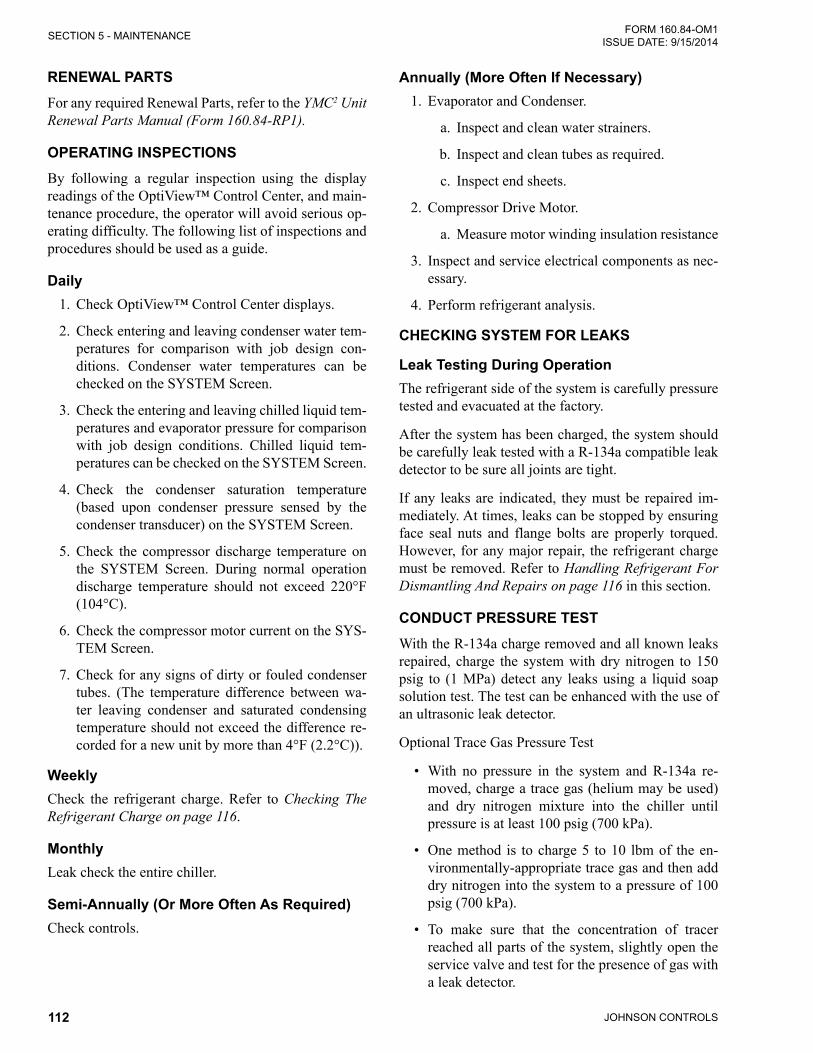
JOHNSON CONTROLS112
FORM 160.84-OM1 ISSUE DATE: 9/15/2014SECTION 5 - MAINTENANCE
RENEWAL PARTSFor any required Renewal Parts, refer to the YMC2 Unit Renewal Parts Manual (Form 160.84-RP1).
OPERATING INSPECTIONSBy following a regular inspection using the display readings of the OptiView™ Control Center, and main-tenance procedure, the operator will avoid serious op-erating difficulty. The following list of inspections and procedures should be used as a guide.
Daily1. Check OptiView™ Control Center displays.
2. Check entering and leaving condenser water tem-peratures for comparison with job design con-ditions. Condenser water temperatures can be checked on the SYSTEM Screen.
3. Check the entering and leaving chilled liquid tem-peratures and evaporator pressure for comparison with job design conditions. Chilled liquid tem-peratures can be checked on the SYSTEM Screen.
4. Check the condenser saturation temperature (based upon condenser pressure sensed by the condenser transducer) on the SYSTEM Screen.
5. Check the compressor discharge temperature on the SYSTEM Screen. During normal operation discharge temperature should not exceed 220°F (104°C).
6. Check the compressor motor current on the SYS-TEM Screen.
7. Check for any signs of dirty or fouled condenser tubes. (The temperature difference between wa-ter leaving condenser and saturated condensing temperature should not exceed the difference re-corded for a new unit by more than 4°F (2.2°C)).
WeeklyCheck the refrigerant charge. Refer to Checking The Refrigerant Charge on page 116.
MonthlyLeak check the entire chiller.
Semi-Annually (Or More Often As Required)Check controls.
Annually (More Often If Necessary)1. Evaporator and Condenser.
a. Inspect and clean water strainers.
b. Inspect and clean tubes as required.
c. Inspect end sheets.
2. Compressor Drive Motor.
a. Measure motor winding insulation resistance
3. Inspect and service electrical components as nec-essary.
4. Perform refrigerant analysis.
CHECkING SYSTEM FOR LEAkS
Leak Testing During OperationThe refrigerant side of the system is carefully pressure tested and evacuated at the factory.
After the system has been charged, the system should be carefully leak tested with a R-134a compatible leak detector to be sure all joints are tight.
If any leaks are indicated, they must be repaired im-mediately. At times, leaks can be stopped by ensuring face seal nuts and flange bolts are properly torqued. However, for any major repair, the refrigerant charge must be removed. Refer to Handling Refrigerant For Dismantling And Repairs on page 116 in this section.
CONDUCT PRESSURE TESTWith the R-134a charge removed and all known leaks repaired, charge the system with dry nitrogen to 150 psig to (1 MPa) detect any leaks using a liquid soap solution test. The test can be enhanced with the use of an ultrasonic leak detector.
Optional Trace Gas Pressure Test
• With no pressure in the system and R-134a re-moved, charge a trace gas (helium may be used) and dry nitrogen mixture into the chiller until pressure is at least 100 psig (700 kPa).
• One method is to charge 5 to 10 lbm of the en-vironmentally-appropriate trace gas and then add dry nitrogen into the system to a pressure of 100 psig (700 kPa).
• To make sure that the concentration of tracer reached all parts of the system, slightly open the service valve and test for the presence of gas with a leak detector.

JOHNSON CONTROLS 113
SECTION 5 - MAINTENANCEFORM 160.84-OM1 ISSUE DATE: 9/15/2014
5
• Test around each joint and factory weld carefully and thoroughly.
• To check for tube or tube joint leaks,
1. Isolate and drain the condenser and evapora-tor waterboxes
2. Purge the waterboxes and tubes with dry ni-trogen through the vents or drains until the detector does not indicate
3. Close the vents and drains and wait an hour
4. Open a vent or drain and insert the leak de-tector. If a leak is detected, the heads must be removed and the source of the leak de-termined as outlined in the Condensers And Evaporators on page 117 in this section.
• Recover the test gas as applicable, make neces-sary repairs, repeat leak tests, evacuate the chiller and perform time hold test. Always consider the effect of temperature change when performing any time-based hold test. For an ideal gas, at time 1, pressure over temperature (absolute unit sys-tem) = the ratio at time 2.
SYSTEM EVACUATIONEnsure power is removed from the input side of the VSD at all times when the chiller is under vacuum (less than atmo-spheric pressure). The VSD maintains voltage to ground on the motor when the chiller is off while voltage is available to the VSD. Insulating properties in the mo-tor are reduced in vacuum and may not insulate this voltage sufficiently.
After the pressure test has been completed, the vacuum test should be conducted as follows:
1. Connect a high capacity vacuum pump, with in-dicator, to the system charging valve as shown in Figure 42 on page 114 and start the pump. Refer to Vacuum Dehydration on page 113 in this sec-tion.
2. Open wide all system valves. Be sure all valves to theatmosphereareclosedandflarecapsinstalledon outlets.
3. Operate the vacuum pump in accordance with Vacuum Dehydration on page 113 in this section until a wet bulb temperature of +32°F (0°C) or a pressure of 5 mm Hg is reached. Refer to Table 14 on page 114 for corresponding pressure values.
4. To improve evacuation circulate hot water, not to exceed 125°F (51.7ºC) through the evaporator and condenser tubes to thoroughly dehydrate the shells. If a source of hot water is not readily avail-able, a portable water heater should be employed. DO NOT USE STEAM. A suggested method is to connect a hose between the source of hot water under pressure and the evaporator head drain con-nection, out the evaporator vent connection, into the condenser head drain and out the condenser vent. To avoid the possibility of causing leaks, the temperature should be brought up slowly so that the tubes and shell are heated evenly.
5. Close the system charging valve and the stop valve between the vacuum indicator and the vac-uum pump. Then disconnect the vacuum pump leaving the vacuum indicator in place.
6. Hold the vacuum obtained in Step 3 above in the system for 8 hours; the slightest rise in pressure indicates a leak or the presence of moisture, or both. It is important to check for pressure change with the chiller at the same temperature. Pressure will change proportional to temperature and affect results. If after 24 hours the wet bulb temperature in the vacuum indicator has not risen above 40°F (4.4°C) or a pressure of 6.3 mm Hg, the system may be considered tight.
Be sure the vacuum indicator is valved off while holding the system vacuum and be sure to open the valve between the vacuum indicator and the system when checking the vacuum after the 8 hour period.
7. If the vacuum does not hold for 8 hours within the limitsspecifiedinStep 6 above, the leak must be found and repaired.
VACUUM DEHYDRATIONTo obtain a sufficiently dry system, the following in-structions have been assembled to provide an effective method for evacuating and dehydrating a system in the field. Although there are several methods of dehydrating a system, we are recommending the following, as it pro-duces one of the best results, and affords a means of ob-taining accurate readings as to the extent of dehydration.
The equipment required to follow this method of dehy-dration consists of a wet bulb indicator or vacuum gauge, a chart showing the relation between dew point tempera-ture and pressure in inches of mercury (vacuum), (refer to Table 14 on page 114) and a vacuum pump capable of pumping a suitable vacuum on the system.
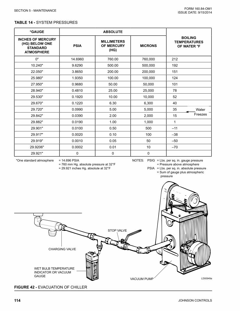
JOHNSON CONTROLS114
FORM 160.84-OM1 ISSUE DATE: 9/15/2014SECTION 5 - MAINTENANCE
TABLE 14 - SYSTEM PRESSURES
*GAUGE ABSOLUTEBOILING
TEMPERATURES OF WATER °F
INCHES OF MERCURY (HG) BELOW ONE
STANDARD ATMOSPHERE
PSIAMILLIMETERS OF MERCURY
(HG)MICRONS
0" 14.6960 760.00 760,000 212
10.240" 9.6290 500.00 500,000 192
22.050" 3.8650 200.00 200,000 151
25.980" 1.9350 100.00 100,000 124
27.950" 0.9680 50.00 50,000 101
28.940" 0.4810 25.00 25,000 78
29.530" 0.1920 10.00 10,000 52
29.670" 0.1220 6.30 6,300 40
29.720" 0.0990 5.00 5,000 35
29.842" 0.0390 2.00 2,000 15
29.882" 0.0190 1.00 1,000 1
29.901" 0.0100 0.50 500 –11
29.917" 0.0020 0.10 100 –38
29.919" 0.0010 0.05 50 –50
29.9206" 0.0002 0.01 10 –70
29.921" 0 0 0
*One standard atmosphere = 14.696 PSIA = 760 mm Hg. absolute pressure at 32°F = 29.921 inches Hg. absolute at 32°F
NOTES: PSIG = Lbs. per sq. in. gauge pressure = Pressure above atmosphere PSIA = Lbs. per sq. in. absolute pressure = Sum of gauge plus atmospheric pressure
Water Freezes
WET BULB TEMPERATUREINDICATOR OR VACUUM GAUGE
STOP VALVE
VACUUM PUMP
CHARGING VALVE
FIGURE 42 - EVACUATION OF CHILLER
LD00949a

JOHNSON CONTROLS 115
SECTION 5 - MAINTENANCEFORM 160.84-OM1 ISSUE DATE: 9/15/2014
5
OperationDehydration of a refrigerant system can be obtained by this method because the water present in the system reacts much as a refrigerant would. By pulling down the pressure in the system to a point where its satu-ration temperature is considerably below that of room temperature, heat will flow from the room through the walls of the system and vaporize the water, allowing a large percentage of it to be removed by the vacuum pump. The length of time necessary for the dehydra-tion of a system is dependent on the size or volume of the system, the capacity and efficiency of the vacuum pump, the room temperature and the quantity of water present in the system. By the use of the vacuum indi-cator as suggested, the test tube will be evacuated to the same pressure as the system, and the distilled water will be maintained at the same saturation temperature as any free water in the system, and this temperature can be observed on the thermometer.
If the system has been pressure tested and found to be tight prior to evacuation, then the saturation tempera-ture recordings should follow a curve similar to the typical saturation curve shown as Figure 43 on page 115.
The temperature of the water in the test tube will drop as the pressure decreases, until the boiling point is reached, at which point the temperature will level off and remain at this level until all of the water in the shell is vaporized. When this final vaporization has taken place the pressure and temperature will continue to drop until eventually a temperature of 35°F (1.6°C) or a pressure of 5 mm Hg. is reached.
LD00474
FIGURE 43 - SATURATION CURVE
When this point is reached, practically all of the air has been evacuated from the system, but there is still a small amount of moisture left. In order to provide a medium for carrying this residual moisture to the vacuum pump, nitrogen should be introduced into the system to bring it to atmospheric pressure and the indi-cator temperature will return to approximately ambient temperature. Close off the system again, and start the second evacuation.
The relatively small amount of moisture left will be carried out through the vacuum pump and the tem-perature or pressure shown by the indicator should drop uniformly until it reaches a temperature of 35°F (1.6°C) or a pressure of 5 mm Hg.
When the vacuum indicator registers this tempera-ture or pressure, it is a positive sign that the system is evacuated and dehydrated to the recommended limit. If this level cannot be reached, it is evident that there is a leak somewhere in the system. Any leaks must be cor-rected before the indicator can be pulled down to 35°F (1.6°C) or 5 mm Hg. in the primary evacuation.
During the primary pulldown, keep a careful watch on the wet bulb indicator temperature, and do not let it fall below 35°F (1.6°C). If the temperature is allowed to fall to 32°F (0°C), the water in the test tube will freeze, and the result will be a faulty temperature reading.
CONDUCT R-134A PRESSURE TESTIf a pressure test indicates all joints are not leaking, proceed to test with R-134a as follows:
• With no pressure in the system, charge R-134a vapor into the chiller until pressure is at least 29 psig (200 kPa) so pressure is above the saturation temperature for water to freeze.
• Add refrigerant until the saturation pressure for the prevailing ambient temperature of the chiller is achieved, leak checking repaired joints with a refrigerant leak detector as pressure is increased.
• Test around each joint and factory weld carefully and thoroughly.
• To check for tube or tube joint leaks,1. Isolate and drain the condenser and evapora-
tor waterboxes
2. Purge the waterboxes and tubes with dry ni-trogen through the vents or drains until the detector does not indicate
3. Close the vents and drains and wait an hour

JOHNSON CONTROLS116
FORM 160.84-OM1 ISSUE DATE: 9/15/2014SECTION 5 - MAINTENANCE
4. Open a vent or drain and insert the leak de-tector. If a leak is detected, the heads must be removed and the source of the leak de-termined as outlined in the Condensers And Evaporators on page 117 in this section.
REFRIGERANT CHARGINGTo avoid the possibility of freezing liquid within the evaporator tubes when charging an evacuated system, only refrigerant vapor from the top of the drum or cyl-inder must be admitted to the system until the system pressure is raised above the point corresponding to the freezing point of the evaporator liquid. For water, the pressure corresponding to the freezing point is 29 PSIG (200 kPa) for R-134a (at sea level).
While charging, every precaution must be taken to pre-vent moisture laden air from entering the system. Make up a suitable charging connection from new copper tubing to fit between the system charging valve and the fitting on the charging drum. This connection should be as short as possible but long enough to permit suf-ficient flexibility for changing drums. The charging connection should be purged each time a full container of refrigerant is connected and changing containers should be done as quickly as possible to minimize the loss of refrigerant.
Refrigerant may be furnished in cylinders containing either 30, 50, 125, 1,025 or 1750 lbs. (13.6, 22.6, 56.6, 464 or 794 kg) of refrigerant.
CHECkING THE REFRIGERANT CHARGEThe refrigerant charge is specified for each chiller model in Table 15 on page 117. Charge the correct amount of refrigerant.
Charge the refrigerant in accordance with the method shown in this section. The weight of the refrigerant charged should be recorded after initial charging.
During operation, the refrigerant charge level is cor-rect when the condenser level is about 1 inch above the subcooler, and the measured Evaporator Approach and Discharge Refrigerant Gas Superheat are at the de-sign values for the condition. Design values would be provided upon request from the chillers sales engineer from the chiller rating program. These depend on tube selection, chilled fluid type, operating head, and op-erating condition. The equations (below) define these parameters. Condenser level is detected by the liquid level sensor and controlled to the programmed setpoint by the chiller control logic.
Equations• Evaporator Approach = (LELT) - (SET)
• Discharge Superheat = (CDGT) - (SCT)
Definitions:• SET = Saturated Evaporator Temperature
• LELT = Leaving Evaporator Liquid Temperature
• CDGT = Compressor Discharge Gas Temperature
• SCT = Saturated Condensing Temperature
The parameters can be viewed on the control center. The chiller must be at design operating conditions and full load operation before the correct refrigerant charge level can be properly determined when oper-ating. When proper condenser level is set, evaporator approach can be trended at constant operating points to monitor potential loss of charge.
Liquid refrigerant will be visible in the evaporator sight glass, but the refrigerant charge amount cannot be properly determined by viewing the liquid refrigerant level in the evaporator sight glass. The level changes due to suction conditions and load. If exact conditions are repeated, level should repeat in the glass from a known baseline.
HANDLING REFRIGERANT FOR DISMANTLING AND REPAIRSIf it becomes necessary to open any part of the refriger-ant system for repairs, it will be necessary to remove the charge before opening any part of the unit. If the chiller is equipped with optional valves, the refrigerant can be isolated in either the condenser or evaporator / compressor while making any necessary repairs.
COMPRESSOR AND MOTOR1. Check mounting screws and piping joint nuts fre-
quently to insure tightness.
2. Test motor windings annually to check for dete-rioration of windings.
Electrical test of motor winding resistance should be performed by a qualified service technician according to Service Instructions Manual (Form 160.84-M1) be-cause it involves determination of power leads between the motor and the VSD. Results from these winding in-sulation resistance tests should be trended each interval to determine degradation in motor windings.

JOHNSON CONTROLS 117
SECTION 5 - MAINTENANCEFORM 160.84-OM1 ISSUE DATE: 9/15/2014
5
CONDENSERS AND EVAPORATORS
GeneralMaintenance of condenser and evaporator shells is im-portant to provide trouble free operation of the chiller. The water side of the tubes in the shell must be kept clean and free from scale.
The major portion of maintenance on the condenser and evaporator will deal with the maintaining the water side of the condenser and evaporator in a clean condi-tion.
The use of untreated water in cooling towers, closed water systems, etc. frequently results in one or more of the following:
1. Scale Formation.
2. Corrosion or Rusting.
3. Slime and Algae Formation.
It is therefore to the benefit of the user to provide for proper water treatment to provide for a longer and more economical life of the equipment. The following recommendation should be followed in determining the condition of the water side of the condenser and evaporator tubes.
1. The condenser tubes should be cleaned annually or earlier if conditions warrant. If the temperature difference between the water off the condenser and the condenser liquid temperature is more than 4°F (2°C) greater than the difference recorded on
a new unit, it is a good indication that the con-denser tubes require cleaning. Refer to Cleaning Evaporator and Condenser Tubes on page 118 in this section for condenser tube cleaning instruc-tions.
2. The evaporator tubes under normal circumstances will not require cleaning. If the temperature dif-ference between the refrigerant and the chilled water increases slowly over the operating season, it is an indication that the evaporator tubes may be fouling or that there may be a water bypass in the water box requiring gasket replacement or refrig-erant may have leaked from the chiller.
Chemical Water TreatmentSince the mineral content of the water circulated through evaporators and condensers varies with almost every source of supply, it is possible that the water be-ing used may corrode the tubes or deposit heat resistant scale in them. Reliable water treatment companies are available in most larger cities to supply a water treat-ing process which will greatly reduce the corrosive and scale forming properties of almost any type of water.
As a preventive measure against scale and corrosion and to prolong the life of evaporator and condenser tubes, a chemical analysis of the water should be made preferably before the system is installed. A reliable wa-ter treatment company can be consulted to determine whether water treatment is necessary, and if so, to fur-nish the proper treatment for the particular water con-dition.
TABLE 15 - APPROXIMATE REFRIGERANT AND WATER WEIGHT
EVAPORATOR CONDENSER REFRIGERANT WEIGHT LBS (kG)*
WATER WEIGHT LBS (kG)**
EB2510CB2110 540 (250) 980 (450)CB2510 600 (270) 1310 (600)
EB2514 CB2514 840 (380) 1680 (770)
EB2910CB2510 640 (290) 1510 (690)CB2910 860 (390) 1760 (800)
EB2914CB2514 900 (410) 1940 (880)CB2914 1210 (550) 2240 (1020)
EB3310CB2910 920 (420) 2070 (940)CB3310 980 (450) 2580 (1170)
EB3314CB2914 1290 (590) 2640 (1200)CB3314 1380 (630) 3310 (1510)
*Refrigerant Weight based on maximum tube bundle. ** Water Weight is the total water in both shells and for 150PSI, 2-pass, compact water boxes.

JOHNSON CONTROLS118
FORM 160.84-OM1 ISSUE DATE: 9/15/2014SECTION 5 - MAINTENANCE
Cleaning Evaporator and Condenser Tubes
EvaporatorIt is difficult to determine by any particular test wheth-er possible lack of performance of the evaporator is due to fouled tubes alone or due to a combination of troubles. Trouble which may be due to fouled tubes is indicated when, over a period of time, the cooling ca-pacity decreases and the split (temperature difference between water leaving the evaporator and the refriger-ant temperature in the evaporator) increases. A gradual drop-off in cooling capacity can also be caused by a gradual leak of refrigerant from the system or by a combination of fouled tubes and shortage of refriger-ant charge.
CondenserIn a condenser, trouble due to fouled tubes is usually indicated by a steady rise in head pressure, over a pe-riod of time, accompanied by a steady rise in condens-ing temperature.
Tube FoulingFouling of the tubes can be due to deposits of two types as follows:
1. Rustorsludge–whichfindsitswayintothetubesand accumulates there. This material usually does not build up on the inner tube surfaces as scale, but does interfere with the heat transfer. Rust or sludge can generally be removed from the tubes by a thorough brushing process.
2. Scale – due to mineral deposits. These deposits, even though very thin and scarcely detectable upon physical inspection, are highly resistant to heat transfer. They can be removed most effec-tively by circulating an acid solution through the tubes using skilled experts as described below.
Tube Cleaning Procedures
Brush Cleaning of TubesIf the tube consists of dirt and sludge, it can usually be removed by means of the brushing process. Drain the water sides of the circuit to be cleaned (cooling wa-ter or chilled water) remove the heads and thoroughly clean each tube with a soft bristle nylon brush. DO NOT USE A STEEL BRISTLE BRUSH. A steel brush may damage the tubes.
Improved results can be obtained by admitting water into the tube during the cleaning process. This can be done by mounting the brush on a suitable length of 1/8" pipe with a few small holes at the brush end and con-necting the other end by means of a hose to the water supply.
The tubes should always be brush cleaned before acid cleaning.
Acid Cleaning of TubesIf the tubes are fouled with a hard scale deposit, they may require acid cleaning. It is important that before acid cleaning, the tubes be cleaned by the brushing process described above. If the relatively loose foreign material is removed before the acid cleaning, the acid solution will have less material to dissolve and flush from the tubes with the result that a more satisfactory cleaning job will be accomplished with a probable sav-ing of time.
Acid cleaning should only be performed by an expert. Please consult your local water treatment representative for as-sistance in removing scale buildup and preventative maintenance programs to eliminate future problems.
Commercial Acid CleaningIn many major cities, commercial organizations now offer a specialized service of acid cleaning evaporators and condensers. If acid cleaning is required, Johnson Controls recommends the use of this type of organiza-tion. The Dow Industries Service Division of the Dow Chemical Company, Tulsa, Oklahoma, with branches in principal cities is one of the most reliable of these companies.
Testing for Evaporator and Condenser Tube LeaksEvaporator and condenser tube leaks in R-134a sys-tems may result in refrigerant leaking into the water circuit, or water leaking into the shell depending on the pressure levels. If refrigerant is leaking into the water, it can be detected at the liquid head vents after a period of shutdown. If water is leaking into the refrigerant, system capacity and efficiency will drop off sharply. If a tube is leaking and water has entered the system, the evaporator and condenser should be valved off from the rest of the water circuit and drained immediately to

JOHNSON CONTROLS 119
SECTION 5 - MAINTENANCEFORM 160.84-OM1 ISSUE DATE: 9/15/2014
5
prevent severe rusting and corrosion. The refrigerant system should then be drained and purged with dry ni-trogen to prevent severe rusting and corrosion. If a tube leak is indicated, the exact location of the leak may be determined as follows:
1. Remove the heads and listen at each section of tubes for a hissing sound that would indicate gas leakage. This will assist in locating the section of tubes to be further investigated. If the probable location of the leaky tubes has been determined, treat that section in the following manner (if the locationisnotdefinite,all thetubeswillrequireinvestigations).
2. Wash off both tube heads and the ends of all tubes with water.
3. With nitrogen or dry air, blow out the tubes to clear them of traces of refrigerant laden moisture from the circulation water. As soon as the tubes are clear, a cork should be driven into each end of the tube. Pressurize the dry system with 50 to 100 PSIG (345 to 690 kPa) of nitrogen. Repeat this with all of the other tubes in the suspected section or, if necessary, with all the tubes in the evaporator or condenser. Allow the evaporator or condenser to remain corked up to 12 to 24 hours before proceeding. Depending upon the amount of leakage, the corks may blow from the end of a tube, indicating the location of the leakage. If not, if will be necessary to make a very thorough test with the leak detector.
4. After the tubes have been corked for 12 to 24 hours, it is recommended that two men working at both ends of the evaporator carefully test each tube – one man removing corks at one end and the other at the opposite end to remove corks and handle the leak detector. Start with the top row of tubes in the section being investigated. Remove the corks at the ends of one tube simultaneously and insert the exploring tube for 5 seconds – this should be long enough to draw into the detector any refrigerant gas that might have leaked through the tube walls. A fan placed at the end of the evap-orator opposite the detector will assure that any leakage will travel through the tube to the detec-tor.
5. Markanyleakingtubesforlateridentification.
6. If any of the tube sheet joints are leaking, the leak should be indicated by the detector. If a tube sheet leak is suspected, its exact location may be found by using a soap solution. A continuous buildup of bubbles around a tube indicates a tube sheet leak.
ELECTRICAL CONTROLSEnsure electrical connections are tight and connectors are secure annually.
It is important that the factory settings of controls (op-eration and safety) not be changed. If the settings are changed without Johnson Controls approval, the war-ranty will be jeopardized.
AUTOMATIC BATTERY HEALTH TEST – DURING SHUTDOWNFor periodic maintenance or to diagnose battery faults or warnings, a battery health test can be performed. This test is initiated from the Power Panel screen of the Optiview panel to monitor battery voltage while under a known load. This will ensure that the battery has enough capacity left to withstand a power failure event. The test is available though operator access lev-el or higher.
At the keypad, log in at Operator access level using access level code 9 6 7 5 or a higher level.
Navigate to Compressor – Power Panel screen.
On the Power Panel screen, the “Start Battery Test” button is shown and the function available when all of the following are true:
• Access Level is Operator or higher
• Chiller State is Stopped
• Safety Stop pushbutton is depressed
• The Local Run/Stop is set to Stop
When the “Start Battery Test” button is pressed the Bat-tery Health Test is initiated. When the Battery Health Test is in progress, this button changes to a “Cancel Battery Test” button to cancel the active Battery Health Test in progress if needed. The test proceeds as fol-lows:

JOHNSON CONTROLS120
FORM 160.84-OM1 ISSUE DATE: 9/15/2014SECTION 5 - MAINTENANCE
The panel instructs “UPS Battery Test - Disconnect 3-phase line power to the chiller now”. At that time, re-move three-phase power to the chiller. Once the power is removed, the UPS becomes available for a limit of 10 minutes for performance of the test.
When the panel detects control voltage is low and UPS is in Inverter mode due to loss of the line power, the panel displays “UPS Battery Test - Evaluating Bat-tery”. The MBC is then commanded to Levitation. Af-ter the MBC reports to Optiview that it is in Levitation mode, the battery voltage is monitored for the next 60 seconds.
The following constitute a fail result:
• If Battery Voltage drops to less than the Inverter Low Battery Voltage Threshold (Default 11.0 V) (UPS – Inverter Low Battery Voltage fault thresh-old) the test fails and ends.
• If the test takes longer than 75 seconds the test fails and ends.
• If the UPS shuts down (OptiView will lose power) due to voltage, fuses, disconnect, or any other rea-son the test fails and the Optiview displays a fault on next power up stating that the battery health test has failed. This fault can be cleared by run-ning a successful battery health test.
If the “UPS – Inverter Low Battery Voltage” fault is not set by the end of the 60 second test (Battery Volt-age stays above the threshold), the battery evaluation is considered good.
Next, the control ceases MBC levitation. If this step takes longer than 15 seconds, the test fails and ends.
Then the panel instructs “Reconnect 3-phase line power to the chiller now”. At that time, reapply three-phase power to the chiller. The full test successfully ends when Optiview detects the control voltage has returned.
If the 10 minute power loss holdup timer runs out (Op-tiView power will be lost due to turning off UPS In-verter) before the test completes and power is restored the test is considered failed.
“UPS Battery Health Test Successful” is displayed for 10 seconds when the test passes
“UPS Battery Health Test Failed – Step X” (Where X is the step that failed) is displayed when the test fails. It remains while the “Warning – UPS – Battery Test Failed” warning is active. It and the warning will be cleared when a Battery Health Test completes success-fully.
For a fail, the following steps may be indicated as the fail point
• Step 2 is when the Optiview is waiting to sense line power removed – typically the user has taken too long and exceeded 10 minute test time.
• Step 3 is during the 60 second battery voltage monitoring under Levitation load – typically would be bad battery
• Step 4 is after completion of the 60 second moni-toring and waiting for successful automatic de-levitation – would indicate some unplanned fail-ure of the control or communication
• Step 5 is waiting to sense line power restored – typically the user has taken too long and exceeded 10 minute test time

JOHNSON CONTROLS 121
FORM 160.84-OM1 ISSUE DATE: 9/15/2014
6
SECTION 6 - TROUBLESHOOTING
TABLE 16 - OPERATION ANALYSIS CHART
RESULTS POSSIBLE CAUSE REMEDY
1. SYMPTOM: ABNORMALLY HIGH DISCHARGE PRESSURE
Temperature difference between condens-ing temperature and water off condenser higher than normal.
Condenser tubes dirty or scaled.
Clean condenser tubes. Check water conditioning.
High condenser water temperature.Cooling tower or cooling source malfunction
Reduce condenser water inlet temperature. (Check cooling tower and water circulation.)
Temperature difference between con-denser water on and water off higher than normal, with normal evaporator pressure.
Insufficient condensing water flow.
Increase the quantity of water through the condenser to proper value.
2. SYMPTOM: ABNORMALLY LOW SUCTION PRESSURE
Temperature difference between leaving chilled water and refrigerant in the evapo-rator greater than normal with possible slight increase in discharge temperature.
Insufficient charge of refrigerant.
Check for leaks and charge refrigerant into system.
Liquid level control valve or sensor problem
Ensure actuator is functioning and check wiring.Ensure level sensor is indicating level reasonably
Temperature difference between leaving chilled water and refrigerant in the evapo-rator greater than normal with normal discharge temperature.
Evaporator tubes dirty or restricted.
Clean evaporator tubes.
Temperature of chilled water too low with low motor amperes.
Insufficient load for system capacity.
Check capacity control operation and setting of low water temperature shutdown setpoint.
3. SYMPTOM: HIGH EVAPORATOR PRESSURE
High chilled water temperature.
Capacity control failed to load.
Check the VGD and Hot Gas Bypass (if applicable) positioning circuits.
System overload.Be sure the capacity control devices and speed increased as much as possible (without overloading the motor) until the load decreases.

JOHNSON CONTROLS122
FORM 160.84-OM1 ISSUE DATE: 9/15/2014SECTION 6 - TROUBLESHOOTING
4. SYMPTOM: LOW DISCHARGE TEMPERATURE
Temperature difference between dis-charge and condenser saturation lower than normal for the prevailing condenser temperature and leaving chilled liquid temperature.
Chiller overcharged Trim charge to correct amount
Condenser level control setpoint too low or level control actuator or sen-sor fail
Check operation of level sensor, actuator, and ensure setpoint keeps refrigerant over the subcooler top
TABLE 16 - OPERATION ANALYSIS CHART (CONT'D)

JOHNSON CONTROLS 123
FORM 160.84-OM1 ISSUE DATE: 9/15/2014
7
SECTION 7 - PRINTING
PRINTING OVERVIEWA printer can be connected to the Control Center’s Microboard to print the following reports. The screen from which each report can be generated is listed in parenthesis.
• Status ‑ Present system parameters (Printer, Home)
• Setpoints ‑ Present programmed values of all set-points (Printer, Setpoints)
• Schedule ‑ Present value of programmed daily schedule (Printer, Schedule)
• Sales Order ‑ Information about SALES ORDER Screen (Printer, Sales Order)
• History ‑ System parameters at the time of the last normal stop, last fault while running and last 10 faults, whether running or not (Printer, History)
• Cycling or Safety Shutdown Initiated Print ‑ Snapshot of all system parameters at instant of shutdown. Automatically occurs if printer is con-nected at time of shutdown.
• Adaptive Capacity Control (ACC) Surge Map ‑ System conditions at instant all surge points were mapped. (Compressor Motor Variable Speed Drive applications; requires SERVICE access lev-el) (Printer, ACC)
• Trend ‑ Prints a snapshot of the existing TREND Screen data or prints new data collected after the TREND PRINT key is pressed.
The printer can be permanently connected to the Con-trol Center or connected as required to produce a report. If permanently connected, a DATA LOGGING feature can produce a status report automatically, beginning at an Operator selected start time and occurring at an Op-erator selected interval thereafter.
The following figures are examples of the different print reports. Solid State Starter application print re-ports shown. Electro-Mechanical Starter and Variable Speed Drive reports are similar but print parameters applicable to those devices.
• Status or History - Figure 48 on page 128
• Setpoints - Figure 49 on page 130
• Schedule - Figure 50 on page 132
• Sales Order - Figure 51 on page 132
• Security Log - Figure 52 on page 134
• Trend - Figure 53 on page 134
• CUSTOM Screen - Figure 54 on page 134
ACCEPTABLE PRINTERSThe following printers can be used. Printers must be equipped with an RS-232 Serial interface.
• Okidata OKIPOS 441
• Brecknell CP130
The Control Center provides the required formatting control codes for the printers above when the printer is selected on the PRINTER Screen. These codes are transmitted through the serial interface to the printer to provide a proper print format.
Different printers require different formatting control codes. Other printers might provide proper operation when connected to the Control Center. However, the print format may not be correct or as desired.
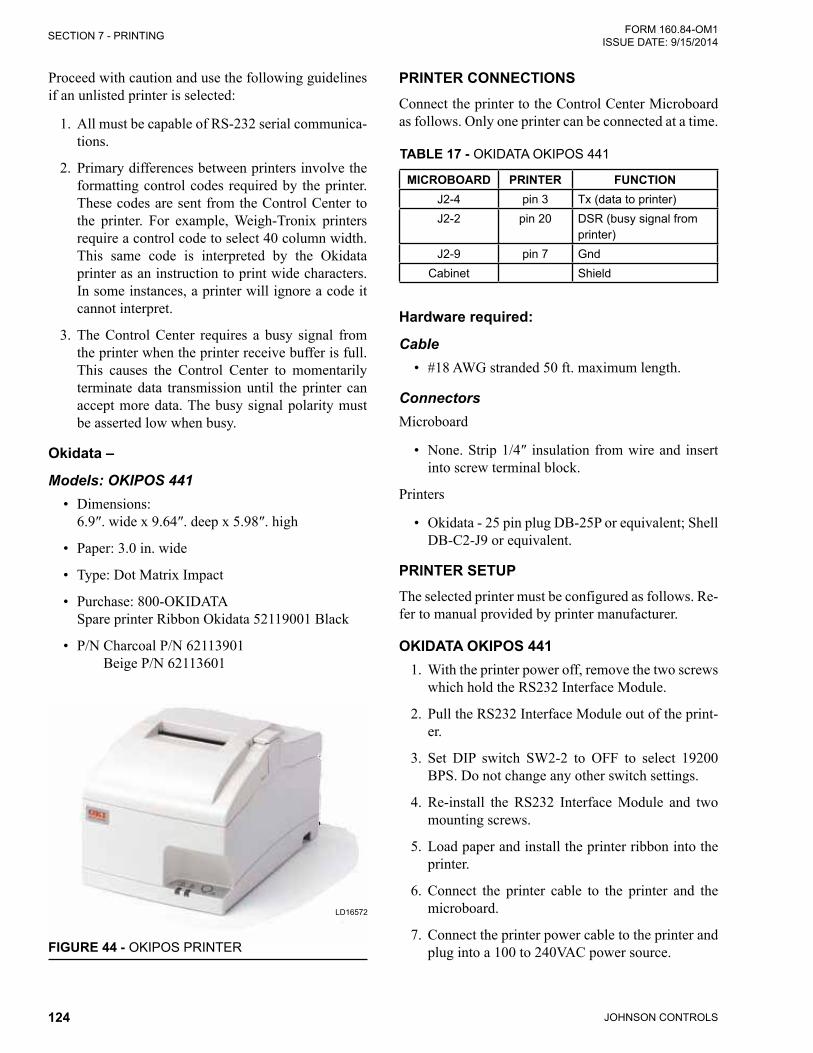
JOHNSON CONTROLS124
FORM 160.84-OM1 ISSUE DATE: 9/15/2014SECTION 7 - PRINTING
Proceed with caution and use the following guidelines if an unlisted printer is selected:
1. All must be capable of RS-232 serial communica-tions.
2. Primary differences between printers involve the formatting control codes required by the printer. These codes are sent from the Control Center to the printer. For example, Weigh -Tronix printers require a control code to select 40 column width. This same code is interpreted by the Okidata printer as an instruction to print wide characters. In some instances, a printer will ignore a code it cannot interpret.
3. The Control Center requires a busy signal from the printer when the printer receive buffer is full. This causes the Control Center to momentarily terminate data transmission until the printer can accept more data. The busy signal polarity must be asserted low when busy.
Okidata –
Models: OKIPOS 441• Dimensions: 6.9″.widex9.64″.deepx5.98″.high
• Paper: 3.0 in. wide
• Type: Dot Matrix Impact
• Purchase: 800-OKIDATA Spare printer Ribbon Okidata 52119001 Black
• P/N Charcoal P/N 62113901 Beige P/N 62113601
FIGURE 44 - OKIPOS PRINTER
LD16572
PRINTER CONNECTIONSConnect the printer to the Control Center Microboard as follows. Only one printer can be connected at a time.
TABLE 17 - OKIDATA OKIPOS 441
MICROBOARD PRINTER FUNCTIONJ2-4 pin 3 Tx (data to printer)J2-2 pin 20 DSR (busy signal from
printer)J2-9 pin 7 Gnd
Cabinet Shield
Hardware required:
Cable• #18 AWG stranded 50 ft. maximum length.
ConnectorsMicroboard
• None.Strip1/4″ insulationfromwireand insertinto screw terminal block.
Printers
• Okidata - 25 pin plug DB-25P or equivalent; Shell DB-C2-J9 or equivalent.
PRINTER SETUPThe selected printer must be configured as follows. Re-fer to manual provided by printer manufacturer.
OkIDATA OkIPOS 4411. With the printer power off, remove the two screws
which hold the RS232 Interface Module.
2. Pull the RS232 Interface Module out of the print-er.
3. Set DIP switch SW2-2 to OFF to select 19200 BPS. Do not change any other switch settings.
4. Re-install the RS232 Interface Module and two mounting screws.
5. Load paper and install the printer ribbon into the printer.
6. Connect the printer cable to the printer and the microboard.
7. Connect the printer power cable to the printer and plug into a 100 to 240VAC power source.

JOHNSON CONTROLS 125
SECTION 7 - PRINTINGFORM 160.84-OM1 ISSUE DATE: 9/15/2014
7
Brecknell –
Models: Brecknell CP130• Dimensions: 5.25″Longx3.75″Widex2.5″High
• Paper: Thermal 57mm (2.25”)
• Type: Dot Matrix
• Purchase: 800-637-0529 (North America) +44 (0) 845-246-6717 (Europe & ME)
• P/N AWT 05-505788 (printer, cable, 1 roll of paper)
• P/N AWT 05-505594 (power supply)
• P/N AWT 05-505671 (case, 20 rolls of paper)
PRINTER CONNECTIONSConnect the printer to the Control Center Microboard as follows. Only one printer can be connected at a time.
TABLE 18 - BRECKNELL CP130
Modify the cable and connect as shown below.MICROBOARD PRINTER FUNCTION
J2-4 Pin 3 TX Data to the printerJ2-2 Pin 5 Busy signal from the printerJ2-9 Pin 6 Signal Common
LD17609
FIGURE 45 - BRECKMAN PRINTER
CONTROL CENTER SETUP
Chiller ID
Access Level Required: OPERATORUsing the COMMS Screen, assign an identification number to the chiller. This number will appear at the top of each report.
Printer SetupAccess Level Required: OPERATOR Using the COMMS Screen, the Control Center must be configured to transmit data in the same format as the printer is configured to receive the data. The following values must be entered.
• Baud Rate - Set to 9600 for Brecknell 19200 for OKIPOS
• Data Bits - 8• Parity - None • Stop Bits - 1
Printer TypeAccess Level Required: OPERATORUsing the PRINTER Screen, set the printer type to Weigh-Tronix.
Automatic Data LoggingAccess Level Required: OPERATORIf automatic data logging is desired, a status report can be automatically printed at a specified interval begin-ning at a specified time, using the PRINTER Screen. The interval is programmable over the range of 1 min-ute to 1440 minutes in 1 minute increments. The first print will occur at the programmed START time and occur at the programmed Output Interval thereafter. The time remaining until the next print is displayed on the PRINTER Screen.
• Automatic Printer Logging - Enables and disables automatic data logging.
• LogStartTime‑Enter the timethefirstprint isdesired.
• Output Interval - Enter the desired interval be-tween prints.

JOHNSON CONTROLS126
FORM 160.84-OM1 ISSUE DATE: 9/15/2014SECTION 7 - PRINTING
DOWNLOADING SYSTEM PRINTS TO A LAPTOPDownloading system histories to a file is another use-ful method to capture system operating conditions. The following instructions are used to establish communi-cation between the OptiView™ Control Panel and a laptop computer.
1. Connect the laptop computer to the OptiView™ as described below.
Laptop(RS-232 Serial Port)
OptiView(Com 1)
PIN DESC Connector Terminal2 RX to J2 4 (TXD1)4 DTR to J2 2 (DSR1)5 GND to J2 9 GND
2. On OptiView™ Printer Screen, select “PC”. This will allow faster data download than the printer selections. On Setpoints - Setup - Comms screen, ensure the printer settings match “h. Port settings” see below.
3. Setup HyperTerminal
a. Go to START menub. Select All Programsc. Select Accessoriesd. Select Communicationse. Select HyperTerminalf. In the box displayed, it requires a name and
icon for the connection. Select a name that is descriptive and select an icon. Select OK.
g. In the box labeled Connect using the select com port that will connect to the YK unit. This port is usually labelled Com 1. Select OK.
h. Port settingsBits per second 57600Data bits 8Parity NoneStop Bits 1Flow control None
4. SetHyperTerminaltocaptureafile.
a. Select Transfer from toolbarb. Select Capture Text from the drop down
menu.c. A Capture Text Filebox will be displayed.
Verify location and file name.d. Select Start.
5. Press the Print Screen key on the appropriate screen to be captured. The HyperTerminal will display the printed information and the informa-tionwillberecordedasa.txtfile.
When the print file has been recorded, select Transfer from the toolbar and capture from the drop down menu and select Stop. This will stop the transfer and allow access to the capture file.
The following additional RS232 connections, are used to wire up serial devices for desktop and laptop com-puters.
RS-232 PIN ASSIGNMENTS (DB25 PC SIGNAL SET)
(OLDER DESkTOPS ONLY)Pin 1 Protective GroundPin 2 Transmit DataPin 3 Recieved DataPin 4 Request To SendPin 5 Clear To SendPin 6 Data Set ReadyPin 7 Signal Ground
Pin 8Recieved line Signal Detector
(Data Carrier Detect)Pin 20 Data Terminal ReadyPin 22 Ring Indicator
The connector on the PC has Male pins, therefore the mating cable needs to terminate in a DB25/F (Female pin) connector.
RS-232 PIN ASSIGNMENTS (DB9 PC SIGNAL SET)
(MOST LAPTOPS)
Pin 1Recieved line Signal Detector
(Data Carrier Detect)Pin 2 Recieved DataPin 3 Transmit DataPin 4 Data Terminal ReadyPin 5 Signal GroundPin 6 Data Set ReadyPin 7 Request To SendPin 8 Clear To SendPin 9 Ring Indicator

JOHNSON CONTROLS 127
SECTION 7 - PRINTINGFORM 160.84-OM1 ISSUE DATE: 9/15/2014
7
The connector on the PC has male pins; therefore, the mating cable needs to terminate DB9/F (female pin) connector.
MICRO
OPTIVIEW
RTX1
GRX1
PC HYPERTERMINAL
E-LINK
COM 1
RS-232
TX
DB9
25
4
Port 2BRXTX
COM
GND
DSR
GTXGRXCOM 4B
J2942
J276
FIGURE 46 - COMMUNICATIONS BLOCK DIAGRAM
LD14492
A serial cable to go from the OptiView Control Pan-el to the serial port is available from the parts center (P/N 075-90490-230).
LD17607VIEW A-A
BLACK
RED
WHITE
GREEN
DRAIN
FIGURE 47 - OPTIVIEW PANEL TO PC SERIAL CABLE

JOHNSON CONTROLS128
FORM 160.84-OM1 ISSUE DATE: 9/15/2014SECTION 7 - PRINTING
YORK UpdateStatus or HistoryYORK History 1 (line only displayed for History Report)YORK Live Data (line only displayed for Status Report)¬Sales Order Job Name hereSales Order Model Number hereSales Order Serial Number hereSales Order Compressor Model hereSales Order Evaporator Model hereSales Order Condenser Model hereSales Order VSD Model hereYMC2 Chiller ID 1(c) 2010 Johnson ControlsSun 05 Dec 2010 8:04:27 AM
SAFETY SHUTDOWN - MANUAL RESTART MBC - SPEED SIGNAL FAULT VSD - DC BUS ACTIVE
Controls C.OPT.18.00.213Run Time 0 Days 1 Hr 14 Min 6 Sec
Operating Hours = 83 HrNumber Of Starts = 41 Control Source = DigitalRun Permissive = True
Evaporator------------------------------------------------------Chilled Liquid Pump = RunChilled Liquid Flow Switch = ClosedActive LCHLT Setpoint = 44.0 ~FShutdown Temperature = 40.0 ~FLeaving Chilled Liquid Temperature = 44.8 ~FEntering Chilled Liquid Temperature = 50.3 ~FEvaporator Pressure = 46.4 PSIG Evaporator Saturation Temperature = 50.9 ~FEvaporator Refrigerant Temperature = 50.9 ~F (when sensor is Enabled)Evaporator Small Temp Difference = -6.1 ~F
Condenser------------------------------------------------------Condenser Liquid Pump = StopCondenser Liquid Flow Switch = ClosedLeaving Condenser Liquid Temperature = 70.6 ~F Entering Condenser Liquid Temperature = 67.9 ~FCondenser Pressure = 68.3 PSIG Condenser Saturation Temperature = 68.1 ~FCondenser Small Temp Difference = -2.5 ~FDrop Leg Refrigerant Temp = 68.5 ~FSubcooling Temperature = -0.4 ~FHead Pressure = 2.7 PSID (when HPC is Enabled)Head Pressure Setpoint = 23.0 PSID (when HPC is Enabled)PID Control Mode = Inactive (when HPC is Enabled)Control Valve Command = 0.0 % (when HPC is Enabled)Isolation Valves Opening = On (when Iso Vlv is Enabled) Isolation Valves Opened Limit Switch = On (when Iso Vlv is Enabled)Isolation Valves Closing = Off (when Iso Vlv is Enabled) Isolation Valves Closed Limit Switch = Off (when Iso Vlv is Enabled)
Compressor-----------------------------------------------------Discharge Temperature = 79.0 ~FDischarge Superheat = 14.0 ~F
Surge-----------------------------------------------------Surge Count = 0 Delta P / P = 1.23 Surge Window Time = 0 MinSurge Window Count = 0
FIGURE 48 - SAMPLE PRINTOUT (STATUS OR HISTORY)
Condenser Refrigerant Level Control-----------------------------------------------------Condenser Refrigerant Level = 7.3 %Condenser Active Level Setpoint = 7.3 %Condenser Level Control State = InactiveCondenser Level Control Valve Command = 25.0 %Subcooler Effectiveness = 0.100 Subcooler Effectiveness High Threshold = 1.500 Subcooler Effectiveness Low Threshold = 0.400
Variable Geometry Diffuser------------------------------------------------------Active Stall Voltage = 0.22 V Active Stall Voltage Type = Standard Mach Number = 1.25Sec Discharge Pressure = 46.3 PSIGVGD Feedback Counts = 23456VGD Fault Code = 0000 0000 0000 0000
Variable Speed Drive------------------------------------------------------VSD Inverter = C.H035.04.01.02VSD Rectifier = C.H035.03.01.02Motor Run = OffVSD Fault = OffInput % Full Load Amps = 0.0 %Input Job Full Load Amps = 200 A VSD Output Voltage = 0 VVSD Output Frequency = 0.00 HzMax Chiller Frequency = 345.00 HzInput Power = 0 kWInput kW Hours = 5543 kWhL1 Voltage Total Harmonic Distorti = 8.0 %L2 Voltage Total Harmonic Distortion = 8.0 %L3 Voltage Total Harmonic Distortion = 3.0 %L1 Input Current Total Demand Distortion = 0.0 %L2 Input Current Total Demand Distortion = 0.0 %L3 Input Current Total Demand Distortio = 0.0 %Input KVA = 1 kVAInput Power Factor = 0.00 Motor % Full Load Amps = 0.0 %VSD Command = RunVSD Control State = RunVSD Inverter State = RunPhase Rotation = ABC Precharge Active = On Precharge Complete = False DC Bus Regulating = Off DC Bus Voltage = 696 VInput Current Limit = OffCooling System = OnL1 Input Voltage (peak) = 698 VL2 Input Voltage (Peak) = 707 VL3 Input Voltage (Peak) = 696 VL1 Input Voltage (RMS) = 698 VL2 Input Voltage (RMS) = 707 VL3 Input Voltage (RMS) = 696 VL1 Input Current (RMS) = 1 AL2 Input Current (RMS) = 1 AL3 Input Current (RMS) = 0 APhase A Output Voltage (RMS) = 0 VPhase B Output Voltage (RMS) = 0 VPhase C Output Voltage (RMS) = 0 VPhase A Output Current (RMS) = 0 APhase B Output Current (RMS) = 0 APhase C Output Current (RMS) = 0 APhase A Rectifier Baseplate Temperature = 81 ~FPhase B Rectifier Baseplate Temperature = 80 ~FPhase C Rectifier Baseplate Temperature = 77 ~FPhase A Inverter Baseplate Temperature = 87 ~FPhase B Inverter Baseplate Temperature = 82 ~FPhase C Inverter Baseplate Temperature = 80 ~FInternal Ambient Temperature 1 = 77 ~FInternal Ambient Temperature 2 = 77 ~FTest Mode = DisabledManual DC Bus = DisabledManual VSD Cooling = DisabledID Faults = 0Checksum Errors = 0Error Packets = 0Timeout Faults = 0VSD Fault Waveform Available = Yes

JOHNSON CONTROLS 129
SECTION 7 - PRINTINGFORM 160.84-OM1 ISSUE DATE: 9/15/2014
7
FIGURE 47 - SAMPLE PRINTOUT (STATUS OR HISTORY) (CONT'D)
Variable Speed Drive – Fault Snapshot------------------------------------------------------VSD Output Voltage = 0 VVSD Output Frequency = 0.00 HzInput Power = 0 kWL1 Voltage Total Harmonic Distortion = 8.0 %L2 Voltage Total Harmonic Distortion = 8.0 %L3 Voltage Total Harmonic Distortion = 3.0 %L1 Input Current Total Demand Distortion = 0.0 %L2 Input Current Total Demand Distortion = 0.0 %L3 Input Current Total Demand Distortion = 0.0 %Input KVA = 1 kVAVSD Control State = RunVSD Inverter State = RunPhase Rotation = ABC Precharge Active = On Precharge Complete = False DC Bus Regulating = Off DC Bus Voltage = 696 VInput Current Limit = OffCooling System = OnL1 Input Voltage (peak) = 698 VL2 Input Voltage (Peak) = 707 VL3 Input Voltage (Peak) = 696 VL1 Input Voltage (RMS) = 698 VL2 Input Voltage (RMS) = 707 VL3 Input Voltage (RMS) = 696 VL1 Input Current (Peak) = 1 AL2 Input Current (Peak) = 1 AL3 Input Current (Peak) = 0 AL1 Input Current (RMS) = 1 AL2 Input Current (RMS) = 1 AL3 Input Current (RMS) = 0 APhase A Output Voltage (RMS) = 0 VPhase B Output Voltage (RMS) = 0 VPhase C Output Voltage (RMS) = 0 VPhase A Output Current (Peak) = 0 APhase B Output Current (Peak) = 0 APhase C Output Current (Peak) = 0 APhase A Output Current (RMS) = 0 APhase B Output Current (RMS) = 0 APhase C Output Current (RMS) = 0 APhase A Rectifier Baseplate Temperature = 81 ~FPhase B Rectifier Baseplate Temperature = 80 ~FPhase C Rectifier Baseplate Temperature = 77 ~FPhase A Inverter Baseplate Temperature = 87 ~FPhase B Inverter Baseplate Temperature = 82 ~FPhase C Inverter Baseplate Temperature = 80 ~FInternal Ambient Temperature 1 = 77 ~FInternal Ambient Temperature 2 = 77 ~FTest Mode = Disabled
Motor Monitoring-----------------------------------------------------Motor Winding Phase A Temp Z1 End = 71 ~FMotor Winding Phase B Temp Z1 End = 71 ~FMotor Winding Phase C Temp Z1 End = 71 ~FMotor Winding Phase A Temp Z2 End = 71 ~FMotor Winding Phase B Temp Z2 End = 71 ~FMotor Winding Phase C Temp Z2 End = 71 ~FAverage Winding Temperature = 71.0 ~FEstimated Rotor Temperature = 123.4 ~FMotor Housing Temperature = 71 ~FMotor Housing Temperature Setpoint = 71 ~FMotor Winding Temperature Setpoint = 121 ~FAmbient Dew Point Temperature = 71 ~F (when Dew Point Enabled)Motor Cooling Valve Command = 25.0 %Motor Cooling Control State = Inactive
Capacity Control-----------------------------------------------------Control State = InactiveLoad Limit = InactiveVSD Frequency Command = 0.00 HzVSD Output Frequency = 0.00 HzVSD Control Mode = AutoActive Anti-Surge Minimum Frequency = 0.00 HzAnti-Surge Minimum Frequency = 0.00 HzAnti-Surge Transient Offset = 0.00 HzVGD Command = 25.00 %
VGD Position = 25.00 %VGD Control Mode = Auto HGBP Command = 25.0 % (when HGBP enabled)HGBP Control Mode = Auto (when HGBP enabled)Head Pressure = 0.0 PSIDEvaporator Pressure = 46.40 PSIG Condenser Pressure = 68.30 PSIG Leaving Chilled Liquid Temperature = 44.80 ~F Magnetic Bearing Controller-----------------------------------------------------MBC Control Mode = AutoMBC Levitation Command = OnMBC Rotation Command = OnLevitation Mode = OnRotation Mode = OnMBC Alarm = OnMBC Alive = OnRotation Allowed = OnMBC Fault = OnMotor Speed = 44 HzMBC Input Voltage = 150 VV13 Position = 14 ~mW13 Position = 13 ~mV24 Position = 13 ~mW24 Position = 12 ~mZ12 Position = 2 ~mV1 Current = 1.803 AV2 Current = 1.772 AV3 Current = 0.878 AV4 Current = 0.972 AW1 Current = 1.992 AW2 Current = 1.788 AW3 Current = 0.721 AW4 Current = 0.894 AZ1 Current = 1.082 AZ2 Current = 1.443 ARotor Elongation = 102 ~mVW13 Soft Landing Counter = 0 VW24 Soft Landing Counter = 0Z12 Soft Landing Counter = 0VW13 Hard Landing Counter = 0VW24 Hard Landing Counter = 0Z12 Hard Landing Counter = 0Power Fail Landing Counter = 0A13 Unbalance = 0 ~mB13 Unbalance = 0 ~mA24 Unbalance = 0 ~mB24 Unbalance = 0 ~mAz Vibration = 0 ~mBz Vibration = 0 ~mZ1 Temperature = 91 ~FZ2 Temperature = 77 ~FMBC Amplifier Temp = 88 ~FMBC Operation Time = 3 DaysSDR Counter = 1First Alarm Code = 16Active Parameter Set = 0ID Faults = 0Checksum Errors = 0Error Packets = 0Timeout Faults = 0
Power Panel-----------------------------------------------------Control Voltage = OnPower Loss Time = 15 Sec UPS Line / Charging = OnUPS Inverter = OffUPS Fault = OffUPS Battery V+ = OnUPS Battery Voltage = 12.0 VUPS Inverter Enable = OnPower Panel Temperature = 79.0 ~FPower Panel Cooling System Run = OnManual Power Panel Cooling = DisabledLine Low Battery Voltage Offset = 0.0 V Inverter Low Battery Voltage Threshold = 11.0 V Battery Voltage Faults = Enabled

JOHNSON CONTROLS130
FORM 160.84-OM1 ISSUE DATE: 9/15/2014SECTION 7 - PRINTING
FIGURE 49 - SAMPLE PRINTOUT (SETPOINTS)
YORK Setpoints¬Sales Order Job Name here
Sales Order Model Number here
Sales Order Serial Number here
Sales Order Compressor Model here
Sales Order Evaporator Model here
Sales Order Condenser Model here
Sales Order VSD Model here
YMC2 ¬Chiller ID 1
(c) 2010 Johnson Controls
Mon 01 Nov 2010 9:25:18 AM
Software Versions
------------------------------------------------------
Controls = C.OPT.18.01.213
CC = 3.09
BIOS = C.OPT.00.02
Kernel = 1.20
GP = 1.09
GUI = 0.43
SIO = 1.25
GPIC = 0.14
Ext I/O = C.EXP.01.00
VSD Inverter = C.H035.04.01.02
VSD Rectifier = C.H035.03.01.02
VSD Modbus = 05.01
System Information
------------------------------------------------------
Data Display Mode = English
System Language = English
Date Format = DD MMM YYYY
Control Source = Local
Remote Analog Input Range = 0-10 Volts
Line Voltage = 460V
Line Frequency = 60Hz
Chilled Liquid Pump Operation = Standard
Head Pressure Control = Disabled
Hot Gas Bypass = Enabled
Flow Switch Input = J14
Power Failure Restart = Auto
Clock = Enabled
Jumper Settings
------------------------------------------------------
Liquid Type = Water
Refrigerant Selection = R134a
Printer Setup
------------------------------------------------------
Automatic Printer Logging = Disabled
Log Start Time = 12:00 AM
Output Interval = 60 Min
Printer Type = Okidata
Baud = 9600 Baud
Data Bits = 8 Bits
Parity = None
Stop Bits = 1 Bit
COM 2 Setup
------------------------------------------------------
Baud = 38400 Baud
Data Bits = 8 Bits
Parity = None
Stop Bits = 2 Bits
Evaporator
------------------------------------------------------
Leaving Chilled Local Setpoint = 42.0 ~F
Leaving Chilled ISN Setpoint = 45.0 ~F
Leaving Chilled Modem Setpoint = 45.0 ~F
Leaving Chilled Analog Setpoint = 42.0 ~F
Leaving Chilled Digital Setpoint = 42.0 ~F
Remote Range = 10.0 ~F
Restart Offset = 4.0 ~F
Restart Temperature = 46.0 ~F
Shutdown Offset = 6.0 ~F
Shutdown Temperature = 36.0 ~F
Brine Low Evaporator Cutout = 25.0 PSIG
Smart Freeze = Off
Refrigerant = Disabled
Condenser
------------------------------------------------------
High Pressure Warning Threshold = 162.5
PSIGHead Pressure Control = Enabled
Head Pressure Setpoint = 23.0 PSID
(when HPC is Enabled)
Type = 0-10V
(when HPC is Enabled)
PID Output = Direct
(when HPC is Enabled)
Minimum PID Output = 0.0 %
(when HPC is Enabled)
Shutdown Position = 0.0 %
(when HPC is Enabled)
Head Pressure Control P = 2.00
(when HPC is Enabled)
Head Pressure Control I = 2.00
(when HPC is Enabled)
Head Pressure Control D = 0.00
(when HPC is Enabled)
Isolation Valves = Enabled
Surge
------------------------------------------------------
Surge Sensitivity = 0.3
Shutdown = Enabled
Count Limit = 15
Count Window = 3 Min
Condenser Refrigerant Level Control
------------------------------------------------------
Condenser Level Setpoint = 50.0 %
Condenser Level Control Startup Position = 25.0 %
Condenser Level Control Startup Delay = 15 Sec
Condenser Level Control Ramp Time = 1 Min
Condenser Level Control Kp = 0.50
Condenser Level Control Ti = 100.0
Condenser Level Control Td = 0.00

JOHNSON CONTROLS 131
SECTION 7 - PRINTINGFORM 160.84-OM1 ISSUE DATE: 9/15/2014
7
Variable Geometry Diffuser
------------------------------------------------------
100% VGD Counts = 2000
0% VGD Counts = 28493
VGD Feedback Calibrated = True
Variable Speed Drive
------------------------------------------------------
Local Input Current Limit = 100 %
Remote ISN Input Current Limit = 100 %
Remote Analog Input Current Limit = 100 %
Remote Digital Input Current Limit = 100 %
Remote Modem Input Current Limit = 100 %
Pulldown Demand Limit = 70 %
Pulldown Demand Time = 5 Min
Input Job Full Load Amps = 181 A
Rated Motor Voltage = 507V
Maximum Motor Current = 505 A
Output Current Rating = 525 A
DC Bus Voltage Setpoint = 750 V
Operation Mode = Voltage
Soft Shutdown Frequency = 0.00 Hz
SW Fault Mask 1
SW Fault Mask 2
SW Fault Mask 3
Motor Monitoring
------------------------------------------------------
Ambient Dew Point Temperature Enable = Enabled
Motor Winding Phase A Temp Z1 End Enable = Enabled
Motor Winding Phase B Temp Z1 End Enable = Enabled
Motor Winding Phase C Temp Z1 End Enable = Enabled
Motor Winding Phase A Temp Z2 End Enable = Enabled
Motor Winding Phase B Temp Z2 End Enable = Enabled
Motor Winding Phase C Temp Z2 End Enable = Enabled
Motor Cooling Setpoint Offset = 4.0 ~F
Min Housing Temp = 46.0 ~F
Max Winding Temp = 46.0 ~F
Motor Cooling Primary Kp = 5.0
Motor Cooling Primary Ti = 25.0
Motor Cooling Primary Td = 0.0
Motor Cooling Secondary Kp = 5.0
Motor Cooling Secondary Ti = 25.0
Motor Cooling Secondary Td = 0.0
Motor Cooling Valve Start Position = 0.0 %
Capacity Control
------------------------------------------------------
Unit Control Mode = Cooling
VSD Start Frequency = 250.00 Hz
VSD Soft Shutdown Ramp Rate = 20 Hz/Sec
VGD Start Position = 10.0 %
Minimum VGD Position = 10.0 %
HGBP Start Position = 0.0 %
LCHLT Setpoint Ramp Rate = 0.1 ~F/S
LCHLT Setpoint Start Offset = 10.0 ~F
Temperature Control Kp = 5.0
Temperature Control Ti = 25.0
Temperature Control Td = 0.0
FIGURE 48 - SAMPLE PRINTOUT (SETPOINTS) (CONT'D)
Temperature Control Max Loading Delta = 1.0
Temperature Control Max Unloading Delta = 1.0
VSD Output Gain = 0.5
VGD Output Gain = 1.0
HGBP Output Gain = 1.0
Max Frequency Multiplier = 1.000
Min Frequency Multiplier = 1.000
Min Frequency Offset = 0.0
Min Frequency Rate Maximum = 10.00 Hz/Sec
Min Frequency Rate Minimum = 0.10 Hz/Sec
Min Frequency Admin Multiplier = 1.000
Min Frequency Mid Position = 40.0 %
Min Frequency Coefficient a1 = 1.440
Min Frequency Coefficient a2 = 1.315
Min Frequency Coefficient a3 = 1.305
Min Frequency Coefficient b1 = 0.525
Min Frequency Coefficient b2 = 0.497
Min Frequency Coefficient b3 = 0.495
Transient Time Delay = 2.5
Transient Deadband = 0.010
Transient Max Change = 0.25
Evaporator Pressure Load Limit Threshold = 20.0 PSID
Evaporator Pressure Load Limit Delta = 0.10
Evaporator Pressure Max Override Threshold = 2.0 PSID
Evaporator Pressure Max Override Delta = -0.20
Condenser Pressure Load Limit Threshold = 10.0 PSID
Condenser Pressure Load Limit Delta = 0.10
Condenser Pressure Max Override Threshold = 10.0 PSID
Condenser Pressure Max Override Delta = -0.10
Input Current Load Limit Threshold = 20.0 %
Input Current Load Limit Delta = 0.10
Input Current Max Override Threshold = 5.0 %
Input Current Max Override Delta = -0.10
Motor Current Load Limit Threshold = 20.0 %
Motor Current Load Limit Delta = 0.10
Motor Current Override Threshold = 100.0 %
Motor Current Max Override Threshold = 5.0 %
Motor Current Max Override Delta = -0.10
LCHLT Max Override Delta = -0.10
Magnetic Bearing Controller
-----------------------------------------------------
Z1 Clearance Stored = 14 ~m
Z2 Clearance Stored = 14 ~m
Z1 Clearance Last = 14 ~m
Z2 Clearance Last = 14 ~m
Z1 Centering Offset = 14 ~m
Z2 Centering Offset = 14 ~m
Date Axial Centering Stored = 01 Nov 2012
Date of Last Clearance Check = 01 Nov 2012
Power Panel
------------------------------------------------------
Minimum Power Loss Holdup Time = 15 Sec
Power Panel Cooling Threshold = 100.0 ~F
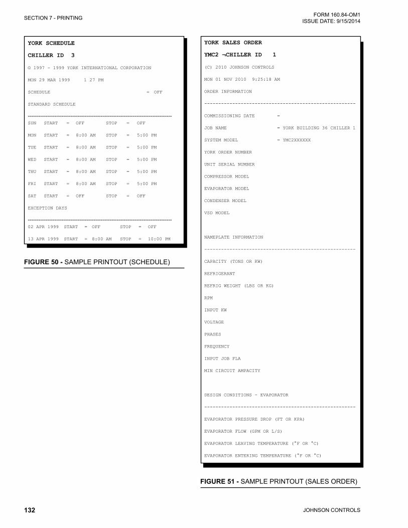
JOHNSON CONTROLS132
FORM 160.84-OM1 ISSUE DATE: 9/15/2014SECTION 7 - PRINTING
FIGURE 50 - SAMPLE PRINTOUT (SCHEDULE)
YORK SchedUle
chilleR id 3
© 1997 - 1999 YORK INTERNATIONAL CORPORATION
MON 29 MAR 1999 1 27 PM
SCHEDULE = OFF
STANDARD SCHEDULE
---------------------------------------------------------------------------------SUN START = OFF STOP = OFF
MON START = 8:00 AM STOP = 5:00 PM
TUE START = 8:00 AM STOP = 5:00 PM
WED START = 8:00 AM STOP = 5:00 PM
THU START = 8:00 AM STOP = 5:00 PM
FRI START = 8:00 AM STOP = 5:00 PM
SAT START = OFF STOP = OFF
EXCEPTION DAYS
---------------------------------------------------------------------------------02 APR 1999 START = OFF STOP = OFF
13 APR 1999 START = 8:00 AM STOP = 10:00 PM
FIGURE 51 - SAMPLE PRINTOUT (SALES ORDER)
YORK SaleS ORdeR
YMc2 ¬chilleR id 1
(C) 2010 JOHNSON CONTROLS
MON 01 NOV 2010 9:25:18 AM
ORDER INFORMATION
------------------------------------------------------
COMMISSIONING DATE =
JOB NAME = YORK BUILDING 36 CHILLER 1
SYSTEM MODEL = YMC2XXXXXX
YORK ORDER NUMBER
UNIT SERIAL NUMBER
COMPRESSOR MODEL
EVAPORATOR MODEL
CONDENSER MODEL
VSD MODEL
NAMEPLATE INFORMATION
------------------------------------------------------
CAPACITY (TONS OR KW)
REFRIGERANT
REFRIG WEIGHT (LBS OR KG)
RPM
INPUT KW
VOLTAGE
PHASES
FREqUENCY
INPUT JOB FLA
MIN CIRCUIT AMPACITY
DESIGN CONDITIONS - EVAPORATOR
------------------------------------------------------
EVAPORATOR PRESSURE DROP (FT OR KPA)
EVAPORATOR FLOW (GPM OR L/S)
EVAPORATOR LEAVING TEMPERATURE (°F OR °C)
EVAPORATOR ENTERING TEMPERATURE (°F OR °C)

JOHNSON CONTROLS 133
SECTION 7 - PRINTINGFORM 160.84-OM1 ISSUE DATE: 9/15/2014
7
EVAPORATOR FOULING FACTOR (HR-FT-°F/BTU OR M^2-°C/KW)
EVAPORATOR LIqUID TYPE
EVAPORATOR BRINE PERCENT
DESIGN CONDITIONS - CONDENSER
----------------------------------------------------
CONDENSER PRESSURE DROP (FT OR KPA)
CONDENSER FLOW (GPM OR L/S)
CONDENSER LEAVING TEMPERATURE (°F OR °C)
CONDENSER ENTERING TEMPERATURE (°F OR °C)
CONDENSER FOULING FACTOR (HR-FT-°F/BTU OR M^2-°C/KW)
CONDENSER LIqUID TYPE
CONDENSER BRINE PERCENT
SALES ORDER SETUP
---------------------------------------------------
FINISH PANEL SETUP = NO
FIGURE 50 - SAMPLE PRINTOUT (SALES ORDER) (CONT'D)
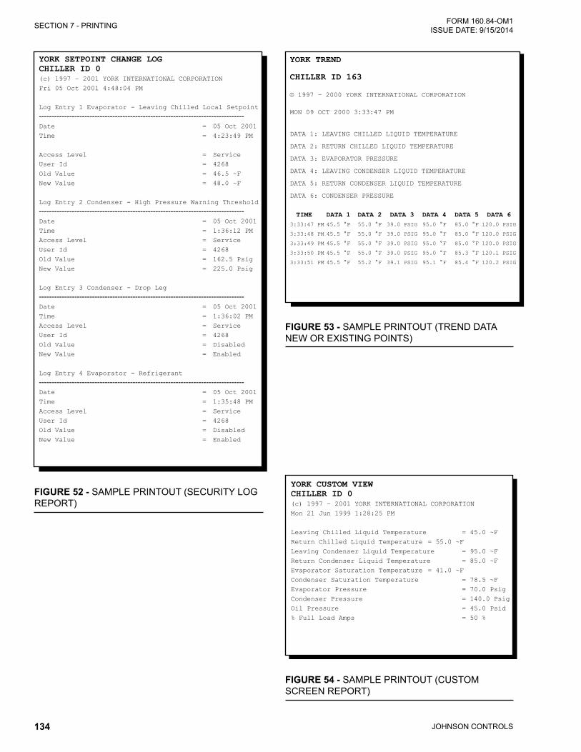
JOHNSON CONTROLS134
FORM 160.84-OM1 ISSUE DATE: 9/15/2014SECTION 7 - PRINTING
YORK tRend
chilleR id 163
© 1997 – 2000 YORK INTERNATIONAL CORPORATION
MON 09 OCT 2000 3:33:47 PM
DATA 1: LEAVING CHILLED LIqUID TEMPERATURE
DATA 2: RETURN CHILLED LIqUID TEMPERATURE
DATA 3: EVAPORATOR PRESSURE
DATA 4: LEAVING CONDENSER LIqUID TEMPERATURE
DATA 5: RETURN CONDENSER LIqUID TEMPERATURE
DATA 6: CONDENSER PRESSURE
tiMe data 1 data 2 data 3 data 4 data 5 data 6 3:33:47 PM 45.5 °F 55.0 °F 39.0 PSIG 95.0 °F 85.0 °F 120.0 PSIG
3:33:48 PM 45.5 °F 55.0 °F 39.0 PSIG 95.0 °F 85.0 °F 120.0 PSIG
3:33:49 PM 45.5 °F 55.0 °F 39.0 PSIG 95.0 °F 85.0 °F 120.0 PSIG
3:33:50 PM 45.5 °F 55.0 °F 39.0 PSIG 95.0 °F 85.3 °F 120.1 PSIG
3:33:51 PM 45.5 °F 55.2 °F 39.1 PSIG 95.1 °F 85.4 °F 120.2 PSIG
FIGURE 53 - SAMPLE PRINTOUT (TREND DATA NEW OR EXISTING POINTS)
FIGURE 52 - SAMPLE PRINTOUT (SECURITY LOG REPORT)
YORK SetpOint change lOgchilleR id 0(c) 1997 – 2001 YORK INTERNATIONAL CORPORATION
Fri 05 Oct 2001 4:48:04 PM
Log Entry 1 Evaporator - Leaving Chilled Local Setpoint
---------------------------------------------------------------------------------Date = 05 Oct 2001
Time = 4:23:49 PM
Access Level = Service
User Id = 4268
Old Value = 46.5 ~F
New Value = 48.0 ~F
Log Entry 2 Condenser - High Pressure Warning Threshold---------------------------------------------------------------------------------Date = 05 Oct 2001
Time = 1:36:12 PM
Access Level = Service
User Id = 4268
Old Value = 162.5 Psig
New Value = 225.0 Psig
Log Entry 3 Condenser - Drop Leg---------------------------------------------------------------------------------Date = 05 Oct 2001
Time = 1:36:02 PM
Access Level = Service
User Id = 4268
Old Value = Disabled
New Value = Enabled
Log Entry 4 Evaporator - Refrigerant---------------------------------------------------------------------------------Date = 05 Oct 2001
Time = 1:35:48 PM
Access Level = Service
User Id = 4268
Old Value = Disabled
New Value = Enabled
FIGURE 54 - SAMPLE PRINTOUT (CUSTOM SCREEN REPORT)
YORK cUStOM ViewchilleR id 0(c) 1997 – 2001 YORK INTERNATIONAL CORPORATION
Mon 21 Jun 1999 1:28:25 PM
Leaving Chilled Liquid Temperature = 45.0 ~F
Return Chilled Liquid Temperature = 55.0 ~F
Leaving Condenser Liquid Temperature = 95.0 ~F
Return Condenser Liquid Temperature = 85.0 ~F
Evaporator Saturation Temperature = 41.0 ~F
Condenser Saturation Temperature = 78.5 ~F
Evaporator Pressure = 70.0 Psig
Condenser Pressure = 140.0 Psig
Oil Pressure = 45.0 Psid
% Full Load Amps = 50 %

JOHNSON CONTROLS 135
FORM 160.84-OM1 ISSUE DATE: 9/15/2014
The following factors can be used to convert from English to the most common SI Metric values.
TEMPERATURETo convert degrees Fahrenheit (°F) to degrees Celsius (°C), subtract 32° and multiply by 5/9 or 0.5556.
Example: (45.0°F - 32°) x 0.5556 = 27.2°C
To convert a temperature range (i.e., a range of 10°F) from Fahrenheit to Celsius, multiply by 5/9 or 0.5556.
Example: 10.0°F range x 0.5556 = 5.6 °C range
TABLE 19 - SI METRIC CONVERSION
MEASUREMENT MULTIPLY ENGLISH UNIT BY FACTOR TO OBTAIN METRIC UNIT
Capacity Tons Refrigerant Effect (ton) 3.516 Kilowatts (kW)
Power Horsepower 0.7457 Kilowatts (kW)
Flow Rate Gallons / Minute (gpm) 0.0631 Liters / Second (l/s)
LengthFeet (ft) 0.3048 Meters (m)
Inches (in) 25.4 Millimeters (mm)
Weight Pounds (lbs) 0.4538 Kilograms (kg)
Velocity Feet / Second (fps) 0.3048 Meters / Second (m/s)
Pressure DropFeet of Water (ft) 2.989 Kilopascals (kPa)
Pounds / Square Inch (psi) 6.895 Kilopascals (kPa)

P.O. Box 1592, York, Pennsylvania USA 17405-1592 800-861-1001 Subject to change without notice. Printed in USACopyright © by Johnson Controls 2014 www.johnsoncontrols.com ALL RIGHTS RESERVEDForm 160.84-OM1 (914)Issue Date: September 15, 2014 Supersedes: February 14, 2014