ygg brookfield place for pdf...icd brookfield place project details icd brookfield place will be...
TRANSCRIPT

ICD Brookfield PlaceStrategy for Basement Excavation
Andrew Smith
Coffey Geotechnics Ltd.
CONTENTS
1. Project description and site history
2. Ground Conditions
3. Assessment of constraints to construction
4. Development of strategy for design and construction of perimeter wall
5. Some details of design and construction
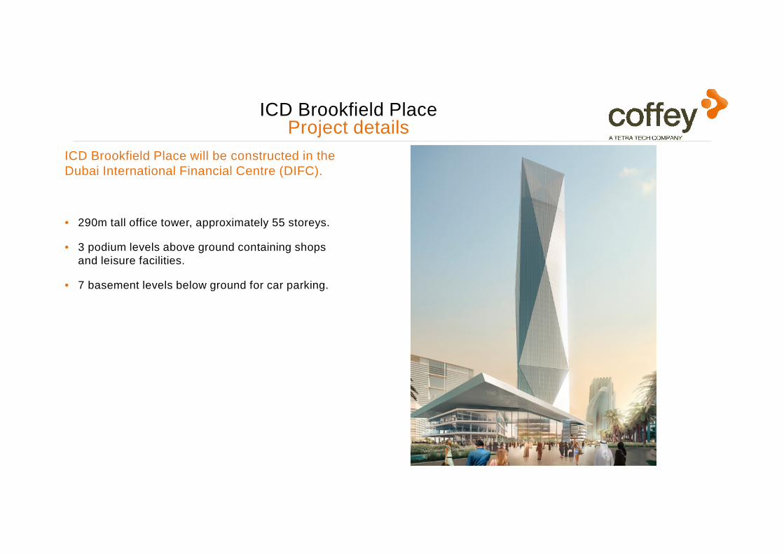
ICD Brookfield PlaceProject details
ICD Brookfield Place will be constructed in the Dubai International Financial Centre (DIFC).
• 290m tall office tower, approximately 55 storeys.
• 3 podium levels above ground containing shops and leisure facilities.
• 7 basement levels below ground for car parking.

ICD Brookfield PlaceSite plan and nearby development
Plot GB03(previously developed
in 2007-09)
Plot GB04
Al Fattan Currency House
N
Existing Diaphragm WallsWest
South
North
East
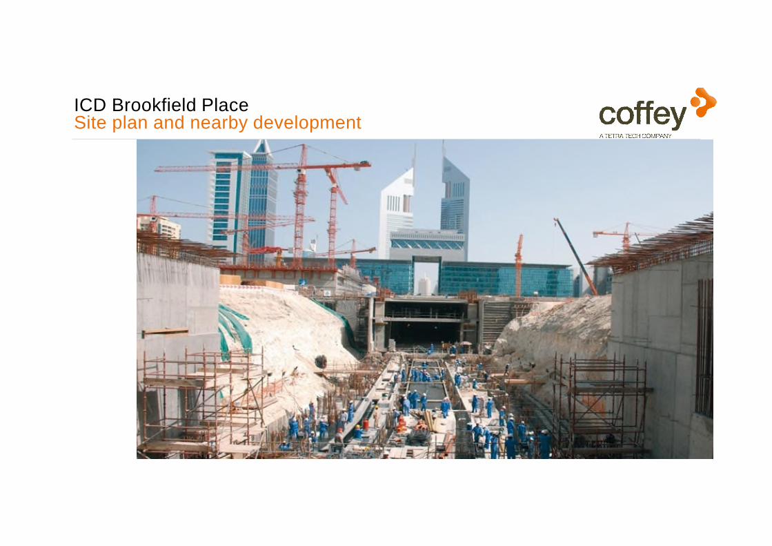
ICD Brookfield PlaceSite plan and nearby development

Construction began in 2007 on Plot GB03:
• Excavation to -16.55 mDMD (GL ~ 2 mDMD)for five levels of basement parking
• 24 m deep diaphragm walls (600 mm to 640 mm thick) on three sides
• Temporary anchors to support the shoring walls.
• Excavation to -18.65 mDMDfor two linked towers
• Construction of 890 piles in excavation base
– 750 mm 16 m long tension piles in podium
– 900 mm 31 m long compression piles and
– 1500 mm 47 m long piles for towers
• Internal and external dewatering. NB water table then was at -12 mDMDdue to extensive construction in the area)
In 2009 construction was stoppedand the excavation was backfilled with sand,leaving the shoring walls and piles in-situ.
North
South
East
West
Previous development of Plot GB03Lighthouse Tower

2017
2016
2015
2014
2013
2012
2011
2010
2009
2008
2007 Lighthouse Tower starts
Basement backfilled
Options StudyTenders
Construction starts
Tower foundation cast
Previous development of Plot GB03 (2009)

Requirements for ICD Brookfield Place
• Seven level basement – founding level -26.75 mDMD(10 m deeper than previously)(second deepest basement in Dubai)
• Single tower in different location from previous proposed Lighthouse TowersFounding level -28.75 mDMD
• Extension into Plot GB04
• Basement space for car parking had to be maximised

Requirements for ICD Brookfield Place
• Key Constraints
• Anchors in existing temporary wall are life-expired
• New excavation level will be below toe of existing wall
• Water table has recovered since 2008 – long term design level 0 mDMD
• A new temporary perimeter wall will be needed for stability and water control
• New wall and foundations will be constrained by existing wall and piles

Ground Conditions
-80
-70
-60
-50
-40
-30
-20
-10
0
0 2 4 6 8 10
Weak Sandstone
Made Ground(Sand Fill)
Sand
Weak Conglomorate
Level (m
DM
D)
New Excavation Levels
GB04GB03
Very weakSandstone / Calcaranite
Extremely weak Sandstone Design UCS profile
UCS (MPa)

Ground Conditions
-80
-70
-60
-50
-40
-30
-20
-10
0
0 2 4 6 8 10
Weak Sandstone
Made Ground(Sand Fill)
Sand
Weak Conglomorate
Level (m
DM
D)
New Excavation Levels
GB04GB03
Very weakSandstone / Calcaranite
Extremely weak Sandstone Design UCS profile
UCS (MPa)

Ground Conditions
-80
-70
-60
-50
-40
-30
-20
-10
0
0 2 4 6 8 10
Weak Sandstone
Made Ground(Sand Fill)
Sand
Weak Conglomorate
Level (m
DM
D)
New Excavation Levels
GB04GB03
Very weakSandstone / Calcaranite
Extremely weak Sandstone Design UCS profile
UCS (MPa)

Ground Conditions
-80
-70
-60
-50
-40
-30
-20
-10
0
0 2 4 6 8 10
Weak Sandstone
Made Ground(Sand Fill)
Sand
Weak Conglomorate
Level (m
DM
D)
New Excavation Levels
GB04GB03
Very weakSandstone / Calcaranite
Extremely weak Sandstone Design UCS profile
UCS (MPa)

• Options Report
• Presentations to:
– Project managers;
– Structural engineers;
– Architects;
– ECI Contractors
• Concept drawings for shoring wall tender documents;
• Tender review
Simplified Contractual Setup
Client - ICD Brookfield
Robert Bird GroupLead Consultant
Permanent Works Structural Designers
Foster & PartnersArchitects
Brewer Smith Brewer GroupLocal Architects for Design
Submissions
AecomProject Management
Brookfield MultiplexEarly Contractor Involvement
2017
2016
2015
2014
ICD Brookfield Place Options Study
Tenders
Construction starts
Tower foundation cast
CoffeyBasement Temporary Support -
Concept DesignGeotechnical Interpretative Report
Piled Foundation Settlement Assessment

Simplified Contractual Setup
Client - ICD Brookfield
Brookfield Multiplex Ssangyong JVMain Contractor
Robert Bird GroupLead Consultant
Permanent Works Structural Designers
Swissboring Overseas PilingBasement Temporary Support
D & B Subcontractor
Foster & PartnersArchitects
Brewer Smith Brewer GroupLocal Architects for Design
Submissions
AecomProject Management
Brookfield MultiplexEarly Contractor Involvement
CoffeyBasement Temporary Support
Category III Check
WJ DewateringDewatering D & B
EirengStructural Check
2017
2016
2015
2014
ICD Brookfield Place Options Study
Tenders
Construction starts
Tower foundation cast
CoffeyBasement Temporary Support -
Concept DesignGeotechnical Interpretative Report
Piled Foundation Settlement Assessment

Existing Conditions
• Ground level at 1.5 to 2.5mDMD• Groundwater at 0mDMD• Existing wall
o 600-660mm thicko Varies in height
• Existing piles 600-1200mm from wall• P1 750 mm dia 16 m long
(tension piles for podium)• P2 900 mm dia 31 m long
(compression piles for towers)• P3 1500 mm dia 47 m long
(compression piles for towers)• Anchors past 2 year design life
East Wall (Al Sa’ada Street)

2017
2016
2015
2014
2013
2012
2011
2010
2009
2008
2007 Lighthouse Tower starts
Basement backfilled
Options StudyTenders
Construction starts
Tower foundation cast
Previous development of Plot GB03Close up of East Wall (2009)

2017
2016
2015
2014
2013
2012
2011
2010
2009
2008
2007 Lighthouse Tower starts
Basement backfilled
Options StudyTenders
Construction starts
Tower foundation cast
Previous development of Plot GB03Piling (2009)

Features to be Defined
Design Decisions Required
• Working level• Dewatering level
• Wall construction• Basement / pile construction
• New retaining wallo Type (secant or D-wall)o Thicknesso Toe level
Controlled by both stability and groundwater criteria
o Cut-down levelMay be controlled by water control criteria
• Construction clearance• Existing piles
o Feasibility of extractiono Extraction level
• New anchor levelso Protrusion of anchors
+ waling beams

Option Tree
Dewatering
External Internal
X Pile Extraction
Possible Not Possible
New Wall LocationDetermined by Existing Wall
Determined by Existing Piles and Wall
Working level determined by:
– Extent of reuse of existing wall
– Groundwater controlFor original construction ground water was lowered over a large area – not now possible
Southern Boundary – dealt with separately
Effects on neighbouring properties

Interactions Between Constraints
Construction Level Dewatering Level
Control over wall verticality
Better Control
Reuse of Existing D-wall
High (+2.5mDMD)
Low(-16.55mDMD)
Ease of construction
Increasing Difficulty with water pressures and flows
Risk of hitting buried piles
Reducing Risk
Wall watertightnessfor secant piles
Increasing Risk of Leaks
Risk of Unintended External Dewatering
Increasing Risk

Location of New Wall
Determined by:
– Location of existing wall
– Existing walings and anchor heads – vary according to location
– New walings and anchor heads – have to be related to existing
– Construction tolerances – e.g wall verticality and machine clearance
– Existing piles if we can’t extract them
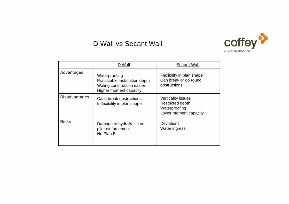
D Wall vs Secant Wall
D Wall Secant Wall
Advantages
Disadvantages
Risks
WaterproofingPracticable Installation depthWaling construction easierHigher moment capacity
Flexibility in plan shapeCan break or go round obstructions
Can’t break obstructionsInflexibility in plan shape
Verticality issuesRestricted depthWaterproofingLower moment capacity
DeviationsWater ingress
Damage to hydrofraise on pile reinforcementNo Plan B
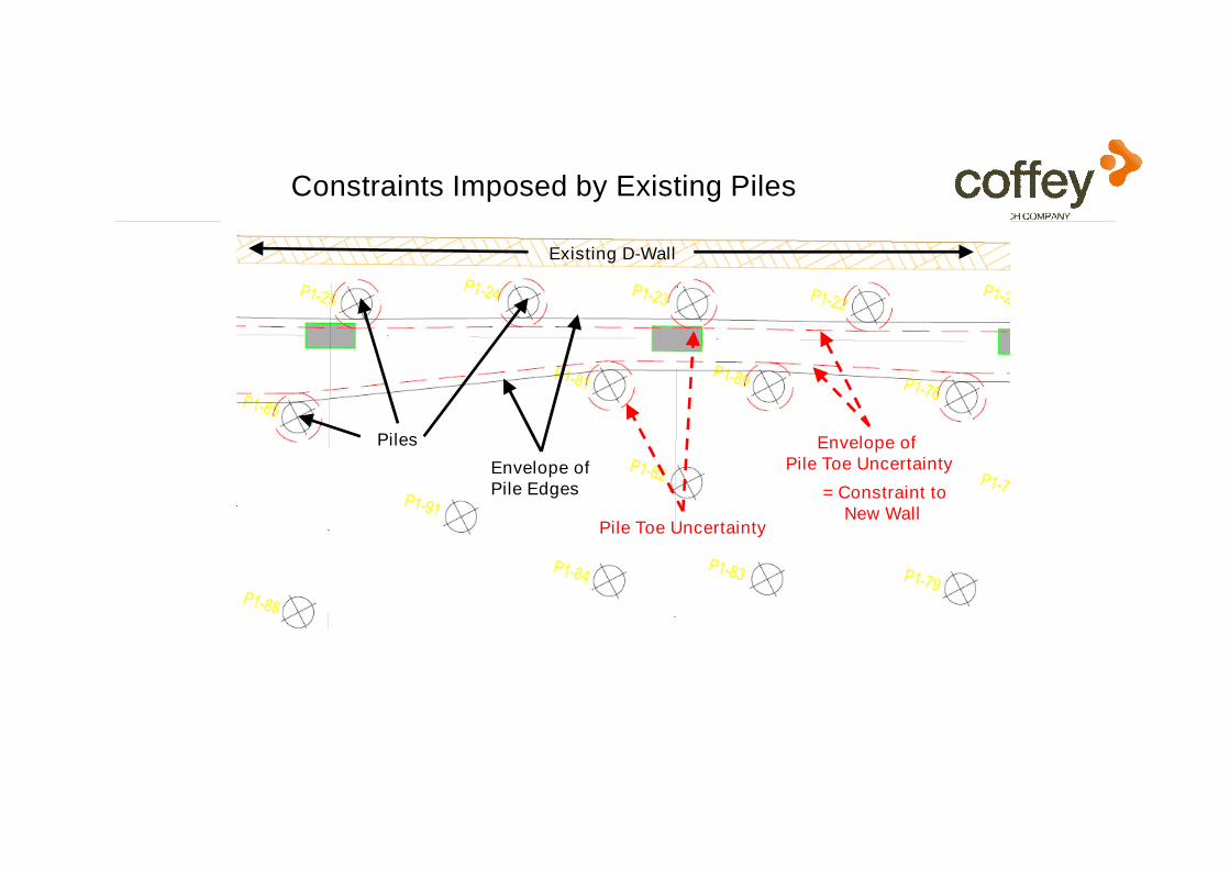
Constraints Imposed by Existing Piles
Existing D-Wall
Piles Envelope of Pile Toe Uncertainty
Pile Toe Uncertainty
= Constraint toNew Wall
Envelope ofPile Edges

5
4
3
2
1
00 20 40 60 80 100 120
Distance along Wall from North (m)
Off
set
fro
m E
xis
tin
g D
Wall (
m)
Edge of Pile TopsPotential Edge of Pile ToesNew 800 mm D-Wall Top at EGLPotential D-Wall at Pile Toe Level
Effect of Verticality Tolerances – East Side
• Nominal Pile gap 2400 mm
• Very Complex at South End
• Piles 1:75 verticality
• 800 mm D Wall
• Installed from EGL
• D Wall 1:100
• These graphs indicated that a D wall should be feasiblefor substantial lengths
And that there was little to be gainedfrom extracting piles

Dewatering for Installation of Wall
Risks
Unintended external
dewatering
High flows though faults
Advantages
Enables construction from a
lower level, hence:
– Easier to locate existing piles
– Easier to remove existing piles
– Shorter new wall
– - And less to remove later
Disadvantages
Need to dispose of water flow
Harder to install piles and D
wall against upward water
flow
Need to deal with
groundwater pressure and
flow from extracted pile voids
Need to anchor / prop existing
D wall

East Wall
Geometric Constraints
– Existing road adjacent
– Top of existing D Wall +2.5 mDMD
– Excavation level –16.55 mDMD (short length at -18.65 mDMD)
– Three or four rows of anchors
– Walings believed to be built in based on site photos
– Protruding anchor heads and strands
– Tension piles ~1200 mm gap to D Wall
– (7 No 900 mm 31 m long pilesand 3 No 1500 mm 47 m long piles in same row)

2.5 mDMD
-18.6 mDMD
-26.75 mDMD
-16.55 mDMD
-36.0 mDMD
East Wall
Design Decisions
– Construct new wall from former excavation level (-16.55 mDMD)
– Cut down wall to -18.6 mDMD
– No pile extraction
– Internal dewatering in two stages
– New anchors in old walls

East Wall
Design Decisions
– Construct new wall from former excavation level (-16.55 mDMD)
– Cut down wall to -18.6 mDMD
– No pile extraction
– Internal dewatering
– New anchors in old walls
– Diaphragm wall except secant wall in one location
– All former tension piles abandoned
– A few 900 mm and 1500mm piles could be reused
– North end used for access and North wall constructed last
– Non-structural cut-off wall installed across middle of site

Previous development of Plot GB03Close up of East Wall (2009)
2017
2016
2015
2014
2013
2012
2011
2010
2009
2008
2007 Lighthouse Tower starts
Basement backfilled
Options StudyTenders
Construction starts
Tower foundation cast

New development of Plot GB03East Wall (2017)
2017
2016
2015
2014
2013
2012
2011
2010
2009
2008
2007 Lighthouse Tower starts
Basement backfilled
Options StudyTenders
Construction starts
Tower foundation cast

Previous development of Plot GB03Close up of East Wall (2017)
2017
2016
2015
2014
2013
2012
2011
2010
2009
2008
2007 Lighthouse Tower starts
Basement backfilled
Options StudyTenders
Construction starts
Tower foundation cast
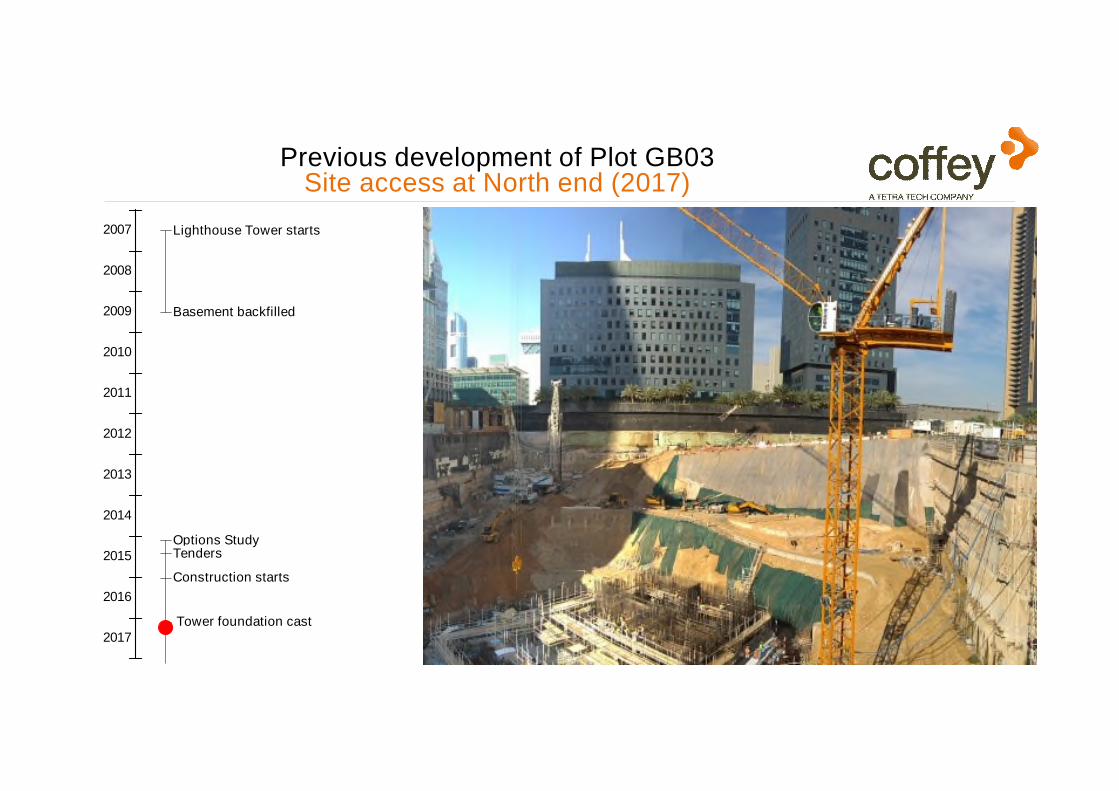
Previous development of Plot GB03Site access at North end (2017)
2017
2016
2015
2014
2013
2012
2011
2010
2009
2008
2007 Lighthouse Tower starts
Basement backfilled
Options StudyTenders
Construction starts
Tower foundation cast


Strategies for constrained lengths of East side
Northern end – cut the corner
5
4
3
2
1
00 20 40 60 80 100 120
Distance along Wall from North (m)
Off
set
fro
m E
xis
tin
g D
Wall (
m)
Edge of Pile TopsPotential Edge of Pile ToesNew 800 mm D-Wall Top at EGLPotential D-Wall at Pile Toe Level

Strategies for constrained lengths of East side
Towards south - original design was for secant wall to avoid existing piles
- after existing piles exposed, design was changed to have a thinner wall (600 mm) with an extra row of anchors
5
4
3
2
1
00 20 40 60 80 100 120
Distance along Wall from North (m)
Off
set
fro
m E
xis
tin
g D
Wall (
m)
Edge of Pile TopsPotential Edge of Pile ToesNew 800 mm D-Wall Top at EGLPotential D-Wall at Pile Toe Level

West Wall
Geometric Constraints
– Truck Tunnel immediately adjacent
– Top of existing D Wall -8.5 mDMD – nature of connection to Truck Tunnel not known
– Excavation level –16.55 mDMD
– Two rows of anchors throughout – threaded between Truck Tunnel piles?
– Nature of waling not known – see note
– Tension piles ~600 mm gap to D Wall – then ~1500 mm to next row

West WallWest Side (Truck Tunnel)
– New anchors in old wall(Three rows instead of twoin same vertical plane)
– New wall top at -18.6mDMD
– Space between walls grouted with pressure relief wells
Truck Tunnel
-8.5 mDMD
-18.6 mDMD
-26.75 mDMD
-28.75 mDMD
-20.5 mDMD
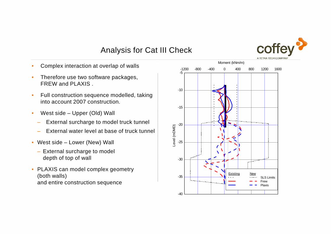
Analysis for Cat III Check
• Complex interaction at overlap of walls
• Therefore use two software packages, FREW and PLAXIS .
• Full construction sequence modelled, taking into account 2007 construction.
• West side – Upper (Old) Wall
– External surcharge to model truck tunnel
– External water level at base of truck tunnel
• West side – Lower (New) Wall
– External surcharge to model depth of top of wall
• PLAXIS can model complex geometry (both walls)and entire construction sequence
-8.5 mDMD
-18.6 mDMD
-18.6 mDMD
-26.75 mDMD
ShearMomentDisplacement
-40
-35
-30
-25
-20
-15
-10
-5-1200 -800 -400 0 400 800 1200 1600
Existing NewSLS LimitsFrewPlaxis
Level (m
DM
D)
Moment (kNm/m)

CoffeyBasement Temporary Support -
Concept DesignGeotechnical Interpretative Report
Piled Foundation Settlement Assessment
Simplified Contractual Setup
Client - ICD Brookfield
Brookfield Multiplex Ssangyong JVMain Contractor
Robert Bird GroupLead Consultant
Permanent Works Structural Designers
Swissboring Overseas PilingBasement Temporary Support
D & B Subcontractor
Foster & PartnersArchitects
Brewer Smith Brewer GroupLocal Architects for Design
Submissions
AecomProject Management
Brookfield MultiplexEarly Contractor Involvement
CoffeyBasement Temporary Support
Category III Check
WJ DewateringDewatering D & B
EirengStructural Check
2017
2016
2015
2014
ICD Brookfield Place Options Study
Tenders
Construction starts
Tower foundation cast

~18m
2017
2016
2015
2014
2013
2012
2011
2010
2009
2008
2007 Lighthouse Tower starts
Basement backfilled
Options StudyTenders
Construction starts
Tower foundation cast
Existing diaphragm wall (GB03)• 600mm thick• 3 rows of new anchors, new walers• New wall to be installed in front of existing wall
(-18.6mDMD to -36mDMD)

~18m
December 2016New diaphragm wall (GB04)• 800mm thick• 5-7 rows of anchors• 38.5m deep (GL to -36mDMD)
2017
2016
2015
2014
2013
2012
2011
2010
2009
2008
2007 Lighthouse Tower starts
Basement backfilled
Options StudyTenders
Construction starts
Tower foundation cast

New diaphragm wall (GB03)• 800mm thick• 2 rows of new anchors, new walers• Installed in front of existing wall
(-18.6 mDMD to -36 mDMD)


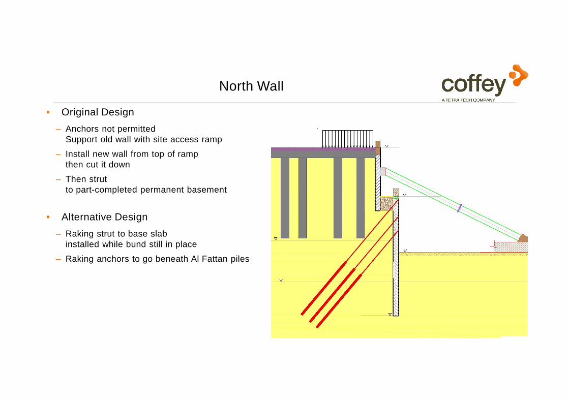
North Wall
Geometric Constraints
– Al Fattan Tower immediately adjacent
– Top of existing D Wall -11.5 mDMD– nature of connection to Al Fattan Tower not known
– Variable previous excavation level –18.65 mDMD in centre and -16.55 mDMD elsewhere
– Cantilever at ends – two rows of anchors in centre– threaded between Al Fattan piles?
– Tension piles ~600 mm gap to D Wall
– (also 7 No 900 mm 31 m long piles)
– Anchors not permittedbetween Al Fattan piles

North Wall
• Original Design
– Anchors not permittedSupport old wall with site access ramp
– Install new wall from top of rampthen cut it down
– Then strut to part-completed permanent basement
-11.5 mDMD
-16.0 mDMD
-18.6 mDMD
-26.75 mDMD
North Wall
• Original Design
– Anchors not permittedSupport old wall with site access ramp
– Install new wall from top of rampthen cut it down
– Then strut to part-completed permanent basement
• Alternative Design
– Raking strut to base slabinstalled while bund still in place
– Raking anchors to go beneath Al Fattan piles
-11.5 mDMD
-16.0 mDMD
-18.6 mDMD
-26.75 mDMD

Some Conclusions
• The existing structure posed serious constraints to new construction
• Many of these constraints interacted with each other
• Initial assessment of the constraints and their interactionenabled a coherent construction strategy to be developed
• The problem was dominated by geometry
• Continuity of involvement was crucial to coherent design

Some Conclusions

Some Conclusions