yg-221m spec v1 - d3s5r33r268y59.cloudfront.net · schematic diagram 8. testing block diagram fig 1...
TRANSCRIPT

Issue Date :2013-10-21 1
Product Specification
CLASS Ⅱ
DRAWN BY :
MODEL :
CHECKED BY :
DESCRIPTION :
CSR8670(16M Flash )Module
APPD. BY:
REV : 1.2
SJR-BTM870 MODULE
SJR-BTM870

Issue Date :2013-10-21 2
Contents
1. Product Photo 2. Feature 3. Summary of Benefit 4. Device Terminal Function 5. Block Diagram 6. Electrical Specification:
7. Schematic Diagram 8. Testing Block Diagram Fig 1 Programming and Freq. Alignment Test Procedure Fig 2 RF Parameter Test procedure Fig 3 Assemble/Alignment/Testing Flow Chart


Issue Date :2013-10-21 4
2.Feature
■ Bluetooth® v3.0 specification fully qualified software
■ Bluetooth v4.0 specification compliant hardware
■ Radio includes integrated balun and RF performance of 10dBm transmit power and -90dBm receive sensitivity
■80MHz RISC MCU and 80MIPS Kalimba DSP
■ 16Mb internal flash memory (64-bit wide, 45ns);
optional support for 64Mb of external SPI flash
■ Stereo codec with 2 channels of ADC and up to 6 microphone inputs
(includes bias generators and digital microphone support)
■ Support for CSR's latest CVC technology for narrow-band and wideband
voice connections including wind noise reduction
■ Audio interfaces: I²S, PCM and SPDIF
■ Serial interfaces: UART, USB 2.0 full-speed,master and slave
bit-serialiser (I²C and SPI)
■ Integrated dual switch-mode regulators, linear regulators and battery
charger
■ 3 hardware LED controllers (for RGB) and ability to drive LCD segment
display directly
■ Support for up to 6 capacitive touch sensor inputs
■ Green (RoHS compliant and no antimony or halogenated flame
retardants)

Issue Date :2013-10-21 5
3.Summary of Benefit
■The Module consumer audio platform for wired and wireless
applications integrates an ultra-low-power DSP and application processor with embedded flash memory, a high-performance stereo codec, a power management subsystem, LED and LCD drivers and capacitive touch sensor inputs in a SOC IC. The dual-core architecture with flash memory enables manufacturers to easily differentiate their products with new features without extending development cycles.
■The enhanced Kalimba DSP coprocessor with 80MIPS supports enhanced
audio and DSP applications.
■Smallest footprint, 13.7mmX21.3mm
■Class 1, Class 2 and Class 3 support without the need for an external
power amplifier or TX/RX switch
■Low-power Solution for DSP Intensive Audio Applications
Applications:
Home Entertainment Ecosystem: ■ TVs ■ Smart remote controllers ■ Wired or wireless soundbars ■ Wired or wireless speakers and headphones Tablets / PCs / Mobile Connectivity: ■ Wearable audio (on-the-go) Wearable audio with sensors (health and well wellbeing applications) ■ Wired or wireless stereo headphones for music/gaming/multimedia
content ■ Wired or wireless speakers
Issue Date :2013-10-21 6
■ Wired or wireless speakerphones ■ Mono headsets for voice Software Support CSR bluetooth stack Design for Client
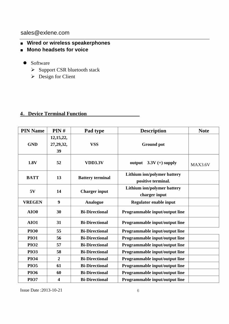
4.Device Terminal Function
PIN Name PIN # Pad type Description Note
GND
12,15,22,
27,29,32,
39
VSS Ground pot
1.8V 52 VDD3.3V output 3.3V (+) supply
MAX3.6V
BATT 13 Battery terminal Lithium ion/polymer battery
positive terminal.
5V 14 Charger input Lithium ion/polymer battery
charger input
VREGEN 9 Analogue Regulator enable input
AIO0 30 Bi-Directional Programmable input/output line
AIO1 31 Bi-Directional Programmable input/output line
PIO0 55 Bi-Directional Programmable input/output line
PIO1 56 Bi-Directional Programmable input/output line
PIO2 57 Bi-Directional Programmable input/output line
PIO3 58 Bi-Directional Programmable input/output line
PIO4 2 Bi-Directional Programmable input/output line
PIO5 61 Bi-Directional Programmable input/output line
PIO6 60 Bi-Directional Programmable input/output line
PIO7 4 Bi-Directional Programmable input/output line

Issue Date :2013-10-21 7
PIO8 63 Bi-Directional Programmable input/output line
PIO9 3 Bi-Directional Programmable input/output line
PIO10 64 Bi-Directional Programmable input/output line
PIO11 65 Bi-Directional Programmable input/output line
PIO12 6 Bi-Directional Programmable input/output line
PIO13 5 Bi-Directional Programmable input/output line
PIO14 62 Bi-Directional Programmable input/output line
PIO15 59 Bi-Directional Programmable input/output line
RST 45
CMOS Input with
weak intemal
pull-down
RESET
RX 49
CMOS input with
weak internal
pull-down
UART Data input
TX 50
CMOS output,
Tri-stable with weak
internal pull-up
UART Data output
SPI-MOSI 46
CMOS input with
weak internal
pull-down
Serial peripheral interface data
input
SPI-CS# 47 CMOS input with
weak internal pull-up
Chip select for serial peripheral
interface, active low
SPI-CLK 40
CMOS input with
weak internal
pull-down
Serial peripheral interface clock
SPI-MISO 48
CMOS input with
weak internal
pull-down
Serial peripheral interface data
Output
USB-N 1 Bi-Directional USB D-
USB-P 66 Bi-Directional USB D+
MIC-RP 20 Analogue input Microphone input R positive
Microphone
Right
Positive
MIC-RN 19 Analogue input Microphone input R negative Microphone

Issue Date :2013-10-21 8
Right
Negative
MIC_LP 17 Analogue input Microphone input L positive Microphone
Left Positive
MIC_LN 16 Analogue input Microphone input L negative Microphone
Left Negative
MIC-BAIS-
A 18 Analogue Microphone bias L
MIC-BAIS-
B 21 Analogue Microphone bias R
SPKLP 26 Analogue
output Speaker output L positive Left Positive
SPKLN 25 Analogue output Speaker output L negative Left Negative
SPKRP 23 Analogue output Speaker output R positive Right
Positive
SPKRN 24 Analogue output Speaker output R negative Right
Negative
PCM_IN 41 Synchronous PCM data input
PCM_SYNC 43 Synchronous PCM data sync
PCM_CLK 42 Synchronous PCM data clock
PCM_OUT 44 Synchronous PCM data output
ANT 28 Analogue RF In/Out
LED0 51 Open drain output LED driver
LED1 53 Open drain output LED driver
LED2 54 Open drain output LED driver
VBAT-SEN
SE 7 Battery charger sense input
CHGEXT 8 External battery charger control
SPISDRAM
-CS# 10
Bidirectional with
strong
SPI RAM chip select. Alternative
function PIO[24]
SPISDARM 11 Bidirectional with SPI RAM clock. Alternative

Issue Date :2013-10-21 9
-CLK strong pull-down function PIO[22]
CAP-SENS
EN0 33 Analogue input Capacitive touch sensor input
CAP-SENS
EN1 34 Analogue input Capacitive touch sensor input
CAP-SENS
EN2 36 Analogue input Capacitive touch sensor input
CAP-SENS
EN3 35 Analogue input Capacitive touch sensor input
CAP-SENS
EN4 37 Analogue input Capacitive touch sensor input
CAP-SENS
EN5 38 Analogue input Capacitive touch sensor input
5. Block Diagram

Issue Date :2013-10-21 10
6. Electrical Specification: Absolute Maximum Ratings
Recommended Operating Conditions


Issue Date :2013-10-21 13
8. Testing Block Diagram
Fig 1 Programming and Freq. Alignment Test Procedure
Fig 2 RF Parameter Test procedure
