yfm7rz yfm7rsez - yamaha · yfm7rz/yfm7rsez owner ’s manual ... crossing through shallow water...
TRANSCRIPT

1AS-28199-10LIT-11626-23-09
This ATV should not be ridden by anyone under 16 years of age.WARNING
YFM7RZYFM7RSEZ
OWNER’S MANUAL
READ THIS MANUAL CAREFULLY!It contains important safety information.
DIC183

EBU17092
Read this manual carefully before operating this vehicle. This manual should stay with this ve-hicle if it is sold.
U1AS10E0.book Page 1 Tuesday, February 10, 2009 9:33 AM

EBU17170
INTRODUCTIONEBU17302
Congratulations on your purchase of the Yamaha YFM7RZ/YFM7RSEZ. This ATV represents the result ofmany years of Yamaha experience in the production of fine sporting, touring, and pacesetting racing ma-chines. With the purchase of this Yamaha, you can now appreciate the high degree of craftsmanship andreliability that have made Yamaha a leader in these fields.This manual will provide you with a good basic understanding of the features and operation of this ATV.This manual includes important safety information. It provides information about special tech-niques and skills necessary to ride the ATV. It also includes basic maintenance and inspection proce-dures. If you have any questions regarding the operation or maintenance of your ATV, please consult aYamaha dealer.
AN IMPORTANT SAFETY MESSAGE:� Read this manual together with TIPS FOR THE ATV RIDER carefully and completely before operating
your ATV. Make sure you understand all instructions.� Pay close attention to the warning and notice labels on the ATV.� Never operate an ATV without proper training or instruction. Free training is available to anyone who buys
a new ATV. Call 1-800-887-2887 for more information.� This ATV should not be ridden by anyone under 16 years of age.� This ATV is a high-performance ATV for off-road use only, for sport-type recreational and competitive use
by experienced operators.
U1AS10E0.book Page 1 Tuesday, February 10, 2009 9:33 AM

EBU17330
IMPORTANT MANUAL INFORMATIONEBU17342
FAILURE TO FOLLOW THE WARNINGS CONTAINED IN THIS MANUAL CAN RESULT IN SERIOUS IN-JURY OR DEATH.Particularly important information is distinguished in this manual by the following notations:
* Product and specifications are subject to change without notice.
This is the safety alert symbol. It is used to alert you to potential per-sonal injury hazards. Obey all safety messages that follow this sym-bol to avoid possible injury or death.
A WARNING indicates a hazardous situation which, if not avoided, could result in death or serious injury.
A NOTICE indicates special precautions that must be taken to avoid damage to the vehicle or other property.
A TIP provides key information to make procedures easier or clearer.
WARNING
NOTICE
TIP
U1AS10E0.book Page 1 Tuesday, February 10, 2009 9:33 AM

EBU17350
IMPORTANT NOTICEEBU17362
This ATV is designed and manufactured for off-road use only. It is illegal and unsafe to operate this ATV onany public street, road or highway.This ATV complies with all applicable off-road noise level and spark arrester laws and regulations in effectat the time of manufacture.Please check your local riding laws and regulations before operating this ATV.
EBU17382
YFM7RZ/YFM7RSEZOWNER’S MANUAL
©2009 by Yamaha Motor Corporation, U.S.A.1st edition, February 2009
All rights reserved.Any reprinting or unauthorized use without the written permission of Yamaha Motor Corporation, U.S.A.
is expressly prohibited.Printed in Japan.
P/N LIT-11626-23-09
U1AS10E0.book Page 1 Tuesday, February 10, 2009 9:33 AM

WARNINGEWB00011
Indicates a hazardous situation which, if notavoided, could result in death or serious injury.
EBU17420
TABLE OF CONTENTS
LOCATION OF THE WARNING AND SPECIFICATION LABELS ............................ 1-1
SAFETY INFORMATION .............................. 2-1
DESCRIPTION .............................................. 3-1Left view ...................................................... 3-1Right view.................................................... 3-1Controls and instruments ............................ 3-2
INSTRUMENT AND CONTROL FUNCTIONS .................................................. 4-1
Main switch ................................................ 4-1Indicator lights and warning lights .............. 4-2Multi-function display .................................. 4-3Handlebar switches .................................... 4-5Throttle lever .............................................. 4-6
Speed limiter ...............................................4-7Clutch lever .................................................4-7Brake lever ..................................................4-8Brake pedal .................................................4-8Parking brake lever .....................................4-9Shift pedal .................................................4-10Reverse knob “REV” .................................4-10Fuel tank cap ............................................4-11Fuel ...........................................................4-11Seat ..........................................................4-13Adjusting the front shock absorber
assemblies ..............................................4-14Adjusting the rear shock absorber
assembly .................................................4-19
PRE-OPERATION CHECKS ..........................5-1Fuel .............................................................5-3Engine oil ....................................................5-3Coolant .......................................................5-3Front and rear brakes .................................5-3Throttle lever ...............................................5-4Drive chain ..................................................5-4Tires ............................................................5-4Chassis fasteners .......................................5-6Instruments, lights and switches .................5-6
U1AS10E0.book Page 1 Tuesday, February 10, 2009 9:33 AM

OPERATION .................................................. 6-1Starting the engine ..................................... 6-1Operating the reverse knob and driving in
reverse ..................................................... 6-2Shifting ....................................................... 6-3Engine break-in .......................................... 6-5Parking ....................................................... 6-5Parking on a slope ..................................... 6-6Accessories and loading ............................ 6-7
RIDING YOUR ATV ...................................... 7-1GETTING TO KNOW YOUR ATV............... 7-2RIDE WITH CARE AND GOOD
JUDGMENT .............................................. 7-2BE CAREFUL WHERE YOU RIDE............. 7-9TURNING YOUR ATV .............................. 7-12CLIMBING UPHILL ................................... 7-14RIDING DOWNHILL.................................. 7-16CROSSING A SLOPE............................... 7-18CROSSING THROUGH SHALLOW
WATER ................................................... 7-19RIDING OVER ROUGH TERRAIN ........... 7-20SLIDING AND SKIDDING......................... 7-21WHAT TO DO IF... .................................... 7-22WHAT TO DO... ........................................ 7-22
PERIODIC MAINTENANCE AND ADJUSTMENT................................................8-1
Owner’s manual and tool kit .......................8-1Periodic maintenance chart for the
emission control system ...........................8-3General maintenance and lubrication
chart ..........................................................8-5Removing and installing the panel ..............8-9Checking the spark plug .............................8-9Engine oil and oil filter element .................8-12Coolant .....................................................8-17Cleaning the air filter element ...................8-20Cleaning the spark arrester ......................8-24Adjusting the engine idling speed .............8-26Adjusting the throttle cable free play .........8-27Valve clearance ........................................8-27Brakes .......................................................8-28Checking the front and rear brake pads ...8-28Checking the brake fluid level ...................8-29Changing the brake fluid ...........................8-31Checking the front brake lever free play ...8-31Checking the brake pedal position ............8-32Adjusting the parking brake free play .......8-32Brake light switches ..................................8-33Adjusting the clutch lever free play ...........8-34Drive chain slack .......................................8-35Lubricating the drive chain ........................8-37
U1AS10E0.book Page 2 Tuesday, February 10, 2009 9:33 AM

Checking and lubricating the cables ........ 8-38Checking and lubricating the brake and
clutch levers ........................................... 8-38Checking the shift pedal ........................... 8-38Checking and lubricating the brake
pedal ...................................................... 8-39Checking the wheel hub bearings ............ 8-39Lubricating the swingarm pivots ............... 8-39Lubricating the rear suspension relay arm
and connecting arm pivoting points ........ 8-39Lubricating the upper and lower arm
pivots ...................................................... 8-40Battery ...................................................... 8-41Replacing a fuse ...................................... 8-44Replacing a headlight bulb ....................... 8-46Adjusting a headlight beam ...................... 8-47Tail/brake light .......................................... 8-48Removing a wheel .................................... 8-48Installing a wheel ...................................... 8-48Troubleshooting ....................................... 8-49Troubleshooting charts ............................. 8-50
CLEANING AND STORAGE.......................... 9-1Cleaning ..................................................... 9-1Storage ....................................................... 9-2
SPECIFICATIONS .......................................10-1
CONSUMER INFORMATION.......................11-1Identification numbers ...............................11-1Noise regulation ........................................11-4Maintenance record ..................................11-5YAMAHA MOTOR CORPORATION,
U.S.A. ATV LIMITED WARRANTY .........11-6YAMAHA EXTENDED SERVICE
(Y.E.S.) ...................................................11-8
U1AS10E0.book Page 3 Tuesday, February 10, 2009 9:33 AM
1-1
1
EBU17660
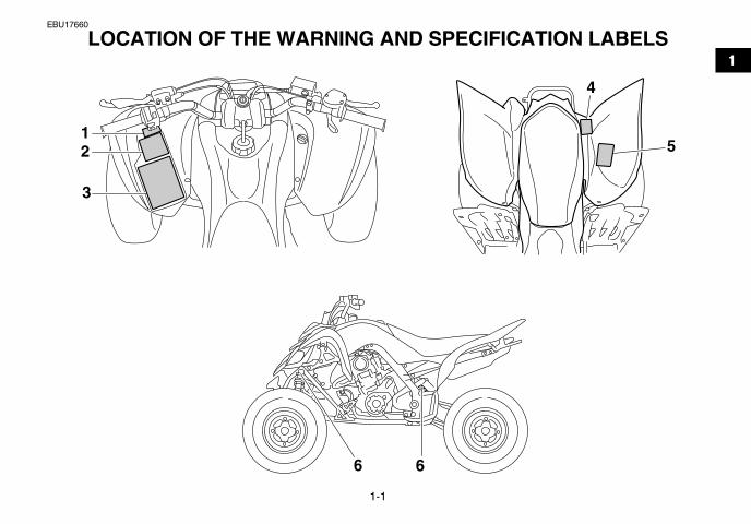
LOCATION OF THE WARNING AND SPECIFICATION LABELS
66
21
3
4
5
U1AS10E0.book Page 1 Tuesday, February 10, 2009 9:33 AM

1-2
1
EBU17670
Read and understand all of the labels on your ATV. These labels contain important information for safe andproper operation.Never remove any labels from your ATV. If a label becomes difficult to read or comes off, request a replace-ment label from your Yamaha dealer.
U1AS10E0.book Page 2 Tuesday, February 10, 2009 9:33 AM

1-3
1
43P-2817J-00
This ATV complies with applicable provisions ofANSI/SVIA 1-2007 and is subject to an approvedATV action plan submitted by YAMAHA and is on filewith the U.S. Consumer Product safety Commission.
Certification of Compliance
YAMAHA MOTOR CORPORATION U.S.A.6555 Katella Avenue, Cypress, California 90630-5101, U.S.A.
1 3
2
U1AS10E0.book Page 3 Tuesday, February 10, 2009 9:33 AM
1-4
1
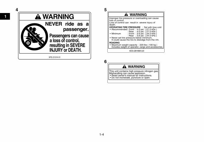
WARNINGThis unit contains high pressure nitrogen gas.Mishandling can cause explosion. • Read owner’s manual for instructions. • Do not incinerate, puncture or open.
WARNINGImproper tire pressure or overloading can causeloss of control.Loss of control can result in severe injury ofdeath.OPERATING TIRE PRESSURE : Set with tires cold• Recommended : Front : 4.0 psi ( 27.5 kPa )
: Rear : 4.0 psi ( 27.5 kPa )• Minimum : Front : 3.6 psi ( 24.5 kPa )
: Rear : 3.6 psi ( 24.5 kPa )• Never set tire pressure below minimum.
It could cause the tire to dislodge from the rim.ROADING• Maximum weight capacity : 220 lbs ( 100 kg )
Includes walght of operator, cargo and accessories.
4D3-2816M-U0
WARNINGNEVER ride as a
passenger.Passengers can causea loss of control,resulting in SEVEREINJURY or DEATH.
5FE-2151H-01
4 5
6
U1AS10E0.book Page 4 Tuesday, February 10, 2009 9:33 AM

2-1
2
EBU17431
SAFETY INFORMATION
EBU26663
AN ATV IS NOT A TOY AND CAN BE HAZARD-OUS TO OPERATE.An ATV handles differently from other vehicles, in-cluding motorcycles and cars. A collision or roll-over can occur quickly, even during routinemaneuvers such as turning and riding on hills orover obstacles, if you fail to take proper precau-tions.SEVERE INJURY OR DEATH can result if you donot follow these instructions:� Read this manual and all labels carefully and fol-
low the operating procedures described.� Never operate an ATV without proper training or
instruction. Take a Training Course. Beginnersshould receive training from a certified instruc-tor. Contact an authorized ATV dealer or call 1-800-887-2887 to find out about the trainingcourses nearest you.
� Always follow the age recommendation:– A child under 16 years old should never oper-ate an ATV with engine size greater than 90 cc.
� Never allow a child under age 16 to operate anATV without adult supervision, and never allowcontinued use of an ATV by a child if he or shedoes not have the abilities to operate it safely.
� Never carry a passenger on an ATV.� Always avoid operating an ATV on any paved
surfaces, including sidewalks, driveways, park-ing lots and streets.
� Never operate an ATV on any public street, roador highway, even a dirt or gravel one.
� Never operate an ATV without wearing an ap-proved motorcycle helmet that fits properly. Youshould also wear eye protection (goggles or faceshield), gloves, boots, a long-sleeved shirt or ajacket, and long pants.
� Never consume alcohol or drugs before or whileoperating this ATV.
U1AS10E0.book Page 1 Tuesday, February 10, 2009 9:33 AM

2-2
2
� Never operate at speeds too fast for your skillsor the riding conditions. Always go at a speedthat is proper for the terrain, visibility, operatingconditions, and your experience.
� Never attempt wheelies, jumps, or other stunts.� Always inspect your ATV each time you use it to
make sure it is in safe operating condition. Al-ways follow the inspection and maintenanceprocedures and schedules described in thismanual.
� Always keep both hands on the handlebars andboth feet on the footboards of the ATV duringoperation.
� Always go slowly and be extra careful when op-erating on unfamiliar terrain. Always be alert tochanging terrain conditions when operating theATV.
� Never operate on excessively rough, slippery orloose terrain until you have learned and prac-ticed the skills necessary to control the ATV onsuch terrain. Always be especially cautious onthese kinds of terrain.
� Always follow proper procedures for turning asdescribed in this manual. Practice turning at lowspeeds before attempting to turn at fasterspeeds and never turn at excessive speeds.
� Never operate the ATV on hills too steep for theATV or for your abilities. Practice on smaller hillsbefore attempting larger hills.
� Always follow proper procedures for climbinghills as described in this manual. Check the ter-rain carefully before you start up any hill. Neverclimb hills with excessively slippery or loose sur-faces. Shift your weight forward. Never open thethrottle suddenly or make sudden gear changes.Never go over the top of a hill at high speed.
� Always follow proper procedures for going downhills and for braking on hills as described in thismanual. Check the terrain carefully before youstart down any hill. Shift your weight backward.Never go down a hill at high speed. Avoid goingdown a hill at an angle that would cause the ve-hicle to lean sharply to one side. Go straightdown the hill where possible.
� Always follow proper procedures for crossingthe side of a hill as described in this manual.Avoid hills with excessively slippery or loose sur-faces. Shift your weight to the uphill side of theATV. Never attempt to turn the ATV around onany hill until you have mastered the turning tech-nique described in this manual on level ground.Avoid crossing the side of a steep hill if possible.
U1AS10E0.book Page 2 Tuesday, February 10, 2009 9:33 AM

2-3
2
� Always use proper procedures if you stall or rollbackwards when climbing a hill. To avoid stall-ing, use the proper gear and maintain a steadyspeed when climbing a hill. If you stall or rollbackwards, follow the special procedure forbraking described in this manual. Dismount onthe uphill side or to a side if pointed straight up-hill. Turn the ATV around and remount, followingthe procedure described in this manual.
� Always check for obstacles before operating in anew area.
� Never attempt to operate over large obstacles,such as large rocks or fallen trees. Always followproper procedures when operating over obsta-cles as described in this manual.
� Always be careful when skidding or sliding.Learn to safely control skidding or sliding bypracticing at low speeds and on level, smoothterrain. On extremely slippery surfaces, such asice, go slowly and be very cautious in order to re-duce the chance of skidding or sliding out of con-trol.
� Never operate an ATV in fast flowing water or inwater deeper than that recommended in thismanual. Remember that wet brakes may have
reduced stopping ability. Test your brakes afterleaving water. If necessary, apply them severaltimes to let friction dry out the linings.
� Always be sure there are no obstacles or peoplebehind you when you operate in reverse. Whenit is safe to proceed in reverse, go slowly.
� Always use the size and type of tires specified inthis manual.
� Always maintain proper tire pressure as de-scribed in this manual.
� Never modify an ATV through improper installa-tion or use of accessories.
� Never exceed the stated load capacity for anATV. Cargo should be properly distributed andsecurely attached. Reduce speed and follow in-structions in this manual for carrying cargo orpulling a trailer. Allow greater distance for brak-ing.
U1AS10E0.book Page 3 Tuesday, February 10, 2009 9:33 AM

2-4
2
WARNINGEWB00071
Avoid Carbon Monoxide PoisoningAll engine exhaust contains carbon monoxide,a deadly gas. Breathing carbon monoxide cancause headaches, dizziness, drowsiness, nau-sea, confusion, and eventually death.Carbon Monoxide is a colorless, odorless,tasteless gas which may be present even if youdo not see or smell any engine exhaust. Deadlylevels of carbon monoxide can collect rapidlyand you can quickly be overcome and unableto save yourself. Also, deadly levels of carbonmonoxide can linger for hours or days in en-closed or poorly ventilated areas. If you experi-ence any symptoms of carbon monoxidepoisoning, leave the area immediately, getfresh air, and SEEK MEDICAL TREATMENT.� Do not run engine indoors. Even if you try to
ventilate engine exhaust with fans or openwindows and doors, carbon monoxide canrapidly reach dangerous levels.
� Do not run engine in poorly ventilated or par-tially enclosed areas such as barns, garages,or carports.
� Do not run engine outdoors where engineexhaust can be drawn into a buildingthrough openings such as windows anddoors.
FOR MORE INFORMATION ABOUT ATV SAFE-TY, call the Consumer Products Safety Commis-sion at 1-800-638-2772, or the ATV Distributor’sSafety Hotline at 1-800-852-5344.
U1AS10E0.book Page 4 Tuesday, February 10, 2009 9:33 AM

3-1
3
EBU17680
DESCRIPTION EBU17690
Left viewEBU17700
Right view
1. Engine oil tank2. Coolant reservoir3. Idle adjusting screw4. Tail/brake light5. Shift pedal
1 2 3 4
51. Spark arrester2. Seat3. Headlight4. Brake pedal
1 2 3
4
U1AS10E0.book Page 1 Tuesday, February 10, 2009 9:33 AM

3-2
3
EBU17712
Controls and instruments TIPThe ATV you have purchased may differ slightlyfrom the figures shown in this manual.
1. Clutch lever2. Parking brake lever3. Main switch4. Brake lever5. Throttle lever6. Reverse knob7. Fuel tank cap8. Handlebar switches
1 2 3 4
5678
U1AS10E0.book Page 2 Tuesday, February 10, 2009 9:33 AM

4-1
4
EBU17725
INSTRUMENT AND CONTROL FUNCTIONS
WARNINGEWB00011
Indicates a hazardous situation which, if notavoided, could result in death or serious injury.
EBU17760
Main switch The positions of the main switch are as follows:
ONAll electrical systems are supplied with power. Theheadlights and taillight come on when the lightswitch is on, and the engine can be started. Thekey cannot be removed.
OFFAll electrical systems are off. The key can be re-moved.
1. Main switch
OFF ON
1
U1AS10E0.book Page 1 Tuesday, February 10, 2009 9:33 AM

4-2
4
EBU26693
Indicator lights and warning lights
EBU17830
Reverse indicator light “ ” This indicator light comes on when the transmis-sion is in the reverse position.
EBU17860
Neutral indicator light “ ” This indicator light comes on when the transmis-sion is in the neutral position.
EBU26702
Coolant temperature warning light “ ” This warning light comes on when the engine over-heats. When this occurs during operation, stop theengine as soon as it is safe to do so and allow it tocool down for about 10 minutes.The electrical circuit of the warning light can bechecked by turning the key to “ON”. The warninglight should come on for a few seconds, and thengo off.If the warning light does not come on initially whenthe key is turned to “ON”, or if the warning light re-mains on, have a Yamaha dealer check the electri-cal circuit.
NOTICEECB00010
� The engine may overheat if the ATV is over-loaded. In this case, reduce the load to spec-ification.
� Start the engine after making sure that thewarning light is out. Continuous use whilethe warning light is on may cause damage tothe engine.
1. Neutral indicator light “N”2. Reverse indicator light “R”3. Coolant temperature warning light “ ”4. Engine trouble warning light “ ”5. Fuel level warning light “ ”
54
1 2
3
U1AS10E0.book Page 2 Tuesday, February 10, 2009 9:33 AM
4-3
4
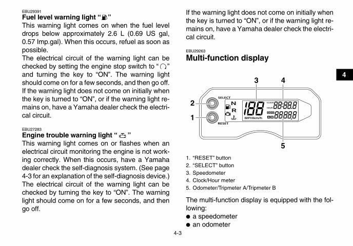
EBU29391
Fuel level warning light “ ” This warning light comes on when the fuel leveldrops below approximately 2.6 L (0.69 US gal,0.57 Imp.gal). When this occurs, refuel as soon aspossible.The electrical circuit of the warning light can bechecked by setting the engine stop switch to “ ”and turning the key to “ON”. The warning lightshould come on for a few seconds, and then go off.If the warning light does not come on initially whenthe key is turned to “ON”, or if the warning light re-mains on, have a Yamaha dealer check the electri-cal circuit.
EBU27283
Engine trouble warning light “ ” This warning light comes on or flashes when anelectrical circuit monitoring the engine is not work-ing correctly. When this occurs, have a Yamahadealer check the self-diagnosis system. (See page4-3 for an explanation of the self-diagnosis device.)The electrical circuit of the warning light can bechecked by turning the key to “ON”. The warninglight should come on for a few seconds, and thengo off.
If the warning light does not come on initially whenthe key is turned to “ON”, or if the warning light re-mains on, have a Yamaha dealer check the electri-cal circuit.
EBU29263
Multi-function display
The multi-function display is equipped with the fol-lowing:� a speedometer� an odometer
1. “RESET” button2. “SELECT” button3. Speedometer4. Clock/Hour meter5. Odometer/Tripmeter A/Tripmeter B
2
1
3 4
5
U1AS10E0.book Page 3 Tuesday, February 10, 2009 9:33 AM

4-4
4
� two tripmeters (which show the distance trav-eled since they were last set to zero)
� a clock� an hour meter (which shows the total time the
engine has been running)� a self-diagnosis device
Odometer and tripmeter modesPushing the “SELECT” button switches the displaybetween the odometer mode “ODO” and the trip-meter modes “A” and “B” in the following order:ODO → A → B → ODOTo reset a tripmeter, select it by pushing the “SE-LECT” button, and then push the “RESET” buttonfor at least three seconds. The tripmeters can beused to estimate the distance that can be traveledwith a full tank of fuel. This information will enableyou to plan future fuel stops.
TIPPushing and holding in the “SELECT” button, andturning the key to “ON” while the button is pushed,switches the display between “mph” and “km/h”.
Clock modePush and hold “SELECT” button for at least threeseconds to switch the display between the clockmode “CLOCK” and the hour meter mode “HOUR”in the following order:CLOCK → HOUR → CLOCK
To set the clock1. Set the display to the clock mode.2. Push the “SELECT” button and “RESET” but-
ton together for at least three seconds.3. When the hour digits start flashing, push the
“RESET” button to set the hours.4. Push the “SELECT” button, and the minute
digits will start flashing.5. Push the “RESET” button to set the minutes.6. Push the “SELECT” button and then release it
to start the clock.
U1AS10E0.book Page 4 Tuesday, February 10, 2009 9:33 AM

4-5
4
Self-diagnosis device
This model is equipped with a self-diagnosis de-vice for various electrical circuits.If a problem is detected in any of those circuits, themulti-function display will indicate an error code.If the multi-function display indicates an error code,note the code number, and then have a Yamahadealer check the vehicle.
NOTICEECB00811
If the multi-function display indicates an errorcode, the vehicle should be checked as soonas possible in order to avoid engine damage.
EBU18061
Handlebar switches
EBU18080
Engine stop switch “ / ” Set this switch to “ ” before starting the engine.The engine stop switch controls the ignition andstops the engine when it is running. Use this switchto stop the engine in an emergency situation. Theengine will not start or run when this switch is setto “ ”.
1. Error code display
1
1. Light switch “ / /OFF”2. Engine stop switch “ / ”3. Start switch “ ”
1
2 3
U1AS10E0.book Page 5 Tuesday, February 10, 2009 9:33 AM

4-6
4
EBU18101
Start switch “ ” Push this switch to crank the engine with the start-er. See the starting instructions on page 6-1 priorto starting the engine.
EBU18152
Light switch “ / /OFF” Set this switch to “ ” to turn on the low beamsand the taillight. Set the switch to “ ” to turn onthe high beams and the taillight. Set the switch to“OFF” to turn off all the lights.
NOTICEECB00041
Do not use the headlights with the engineturned off for an extended period of time, oth-erwise the battery may discharge to the pointthat the starter motor will not operate properly.If this should happen, remove the battery andrecharge it. See page 8-41 for battery charginginformation.
EBU18281
Throttle lever Once the engine is running, movement of the throt-tle lever will increase the engine speed.
Regulate the speed of the ATV by varying thethrottle position. Because the throttle is spring-loaded, the ATV will decelerate, and the engine willreturn to an idle any time the hand is removed fromthe throttle lever.
Before starting the engine, check the throttle to besure it is operating smoothly. Make sure it returnsto the idle position as soon as the lever is released.
1. Throttle lever
1
U1AS10E0.book Page 6 Tuesday, February 10, 2009 9:33 AM

4-7
4
EBU18322
Speed limiter Your ATV was delivered with an adjustable speedlimiter. The speed limiter keeps the throttle fromfully opening, even when the throttle lever ispushed to the maximum.
1. Loosen the locknut.2. To increase the maximum engine power avail-
able and the maximum speed of the ATV, turnthe adjusting screw in direction (a). To de-crease the maximum engine power availableand the maximum speed of the ATV, turn theadjusting screw in direction (b). Do not turnthe adjusting screw out more than 12 mm(0.47 in) or the throttle cable could be dam-aged. Always make sure the throttle lever freeplay is adjusted to 2.0–4.0 mm (0.08–0.16 in).(See page 8-27.) WARNING! Improper ad-justment of the speed limiter and throttlecould cause throttle cable damage or im-proper throttle operation. You could losecontrol, resulting in an accident. [EWB00241]
3. Tighten the locknut.
EBU18382
Clutch lever The clutch lever is located on the left handlebarand the ignition circuit cut-off system is incorporat-ed in the clutch lever holder. To disengage theclutch, pull the clutch lever toward the handlebargrip. To engage the clutch, release the clutch lever.The clutch lever should be pulled rapidly and re-
1. Locknut2. Adjusting screw3. No more than 12 mm (0.47 in)
3 1 2
(a)
(b)
U1AS10E0.book Page 7 Tuesday, February 10, 2009 9:33 AM

4-8
4
leased slowly for smooth clutch operation. (Seepage 6-1 for a description of the ignition circuit cut-off system.)
EBU18421
Brake lever The brake lever is located on the right handlebar.To apply the front brake, pull the brake lever to-ward the handlebar grip.The brake lever is equipped with a position adjust-ing bolt. To adjust the distance between the brakelever and the handlebar grip, hold the brake leveraway from the handlebar so it does not contact theadjusting bolt, loosen the locknut, turn the adjust-ing bolt, and then tighten the locknut.
EBU18432
Brake pedal The brake pedal is located on the right side of theATV. To apply the rear brake, push down on thebrake pedal.
1. Clutch lever
1. Brake lever2. Locknut3. Brake lever position adjusting bolt4. Distance between brake lever and handlebar grip
U1AS10E0.book Page 8 Tuesday, February 10, 2009 9:33 AM

4-9
4
EBU18520
Parking brake lever Use the parking brake before starting the engine orparking the ATV, especially on a slope. To applythe parking brake, move the parking brake lever indirection (a). To release the parking brake, movethe parking brake lever in direction (b).
1. Brake pedal
11. Parking brake lever (locked position)
1. Parking brake lever (unlocked position)
U1AS10E0.book Page 9 Tuesday, February 10, 2009 9:33 AM
4-10
4
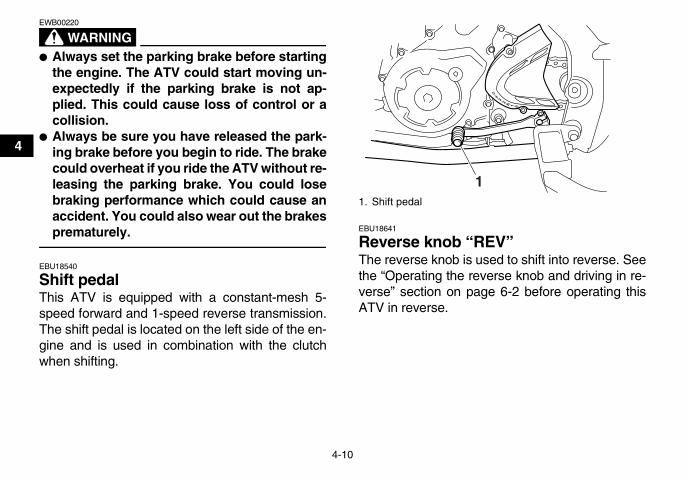
WARNINGEWB00220
� Always set the parking brake before startingthe engine. The ATV could start moving un-expectedly if the parking brake is not ap-plied. This could cause loss of control or acollision.
� Always be sure you have released the park-ing brake before you begin to ride. The brakecould overheat if you ride the ATV without re-leasing the parking brake. You could losebraking performance which could cause anaccident. You could also wear out the brakesprematurely.
EBU18540
Shift pedal This ATV is equipped with a constant-mesh 5-speed forward and 1-speed reverse transmission.The shift pedal is located on the left side of the en-gine and is used in combination with the clutchwhen shifting.
EBU18641
Reverse knob “REV” The reverse knob is used to shift into reverse. Seethe “Operating the reverse knob and driving in re-verse” section on page 6-2 before operating thisATV in reverse.
1. Shift pedal
1
U1AS10E0.book Page 10 Tuesday, February 10, 2009 9:33 AM

4-11
4
EBU18720
Fuel tank cap Remove the fuel tank cap by turning it counter-clockwise.
EBU18731
Fuel Make sure there is sufficient gasoline in the tank.
WARNINGEWB02521
Gasoline and gasoline vapors are extremelyflammable. To avoid fires and explosions andto reduce the risk of injury when refueling, fol-low these instructions.
1. Before refueling, turn off the engine and besure that no one is sitting on the vehicle. Nev-er refuel while smoking, or while in the vicinity
1. Reverse knob “REV”
1
1. Fuel tank cap
1
U1AS10E0.book Page 11 Tuesday, February 10, 2009 9:33 AM

4-12
4
of sparks, open flames, or other sources of ig-nition such as the pilot lights of water heatersand clothes dryers.
2. Do not overfill the fuel tank. When refueling,be sure to insert the pump nozzle into the fueltank filler hole. Stop filling when the fuel reach-es the bottom of the filler tube. Because fuelexpands when it heats up, heat from the en-gine or the sun can cause fuel to spill out ofthe fuel tank.
3. Wipe up any spilled fuel immediately.NOTICE: Immediately wipe off spilled fuelwith a clean, dry, soft cloth, since fuel maydeteriorate painted surfaces or plasticparts. [ECB00981]
4. Turn the fuel tank cap fully clockwise to makesure it is securely closed.
WARNINGEWB02531
Gasoline is poisonous and can cause injury ordeath. Handle gasoline with care. Never siphongasoline by mouth. If you should swallowsome gasoline or inhale a lot of gasoline vapor,or get some gasoline in your eyes, see yourdoctor immediately. If gasoline spills on yourskin, wash with soap and water. If gasolinespills on your clothing, change your clothes.
1. Filler tube2. Fuel level
1 2
Recommended fuel:UNLEADED GASOLINE ONLY
Fuel tank capacity:11.0 L (2.91 US gal, 2.42 Imp.gal)
Fuel reserve amount:2.6 L (0.69 US gal, 0.57 Imp.gal)
U1AS10E0.book Page 12 Tuesday, February 10, 2009 9:33 AM

4-13
4
NOTICEECB00070
Use only unleaded gasoline. The use of leadedgasoline will cause severe damage to internalengine parts, such as the valves and pistonrings, as well as to the exhaust system.
Your Yamaha engine has been designed to useregular unleaded gasoline with a pump octanenumber [(R+M)/2] of 86 or higher, or a research oc-tane number of 91 or higher. If knocking (or ping-ing) occurs, use a gasoline of a different brand.Use of unleaded fuel will extend spark plug life andreduce maintenance costs.
GasoholThere are two types of gasohol: gasohol contain-ing ethanol and that containing methanol. Gasoholcontaining ethanol can be used if the ethanol con-tent does not exceed 10% (E10). Gasohol contain-ing methanol is not recommended by Yamahabecause it can cause damage to the fuel system orvehicle performance problems.
EBU18891
Seat
To remove the seatInsert your hand between the rear of the seat andthe rear fender, pull the seat lock lever upward andpull up the seat at the rear.
To install the seatInsert the projections on the front of the seat intothe seat holders and push down on the seat at therear. Make sure that the seat is securely fitted.
1. Seat lock lever
1
U1AS10E0.book Page 13 Tuesday, February 10, 2009 9:33 AM

4-14
4
EBU27907
Adjusting the front shock absorber as-semblies These shock absorber assemblies are equippedwith a spring preload adjusting nut, a rebounddamping force adjusting screw, with a compres-sion damping force adjusting bolt (for fast com-pression damping), and a compression dampingforce adjusting screw (for slow compression damp-ing).
WARNINGEWB02601
� Suspension components become hot duringoperation. Never touch the compressiondamping force adjusting screw, the rebounddamping force adjusting screw or the oil res-ervoir with your bare hand or skin until sus-pension components have cooled.
� Always adjust the shock absorber assem-blies on the left and right side to the samesetting. Uneven adjustment can cause poorhandling and loss of stability, which couldlead to an accident.
NOTICEECB00090
Never turn an adjusting mechanism beyondthe minimum and maximum settings.
Spring preload1. Loosen the locknut.2. Turn the spring preload adjusting nut in direc-
tion (a) to increase the spring preload andthereby harden the suspension, and in direc-tion (b) to decrease the spring preload andthereby soften the suspension.
1. Projection2. Seat holder
1
2
U1AS10E0.book Page 14 Tuesday, February 10, 2009 9:33 AM

4-15
4
TIP� A special wrench can be obtained at a Yamaha
dealer to make this adjustment.� The spring preload setting is determined by
measuring distance A, shown in the illustration.The shorter distance A is, the higher the springpreload; the longer distance A is, the lower thespring preload. With each complete turn of theadjusting nut, distance A is changed by 1.5 mm(0.06 in).
3. Tighten the locknut to the specified torque.NOTICE: Always tighten the locknutagainst the adjusting nut, and then tightenit to the specified torque. [ECB00081]
1. Spring preload adjusting nut2. Locknut3. Special wrench
2
1
3
(a)
(b)
Spring preload setting:Minimum (soft):
Distance A = 263.0 mm (10.35 in)Standard:
Distance A = 260.0 mm (10.24 in)Maximum (hard):
Distance A = 251.0 mm (9.88 in)
1. Distance A
1
U1AS10E0.book Page 15 Tuesday, February 10, 2009 9:33 AM

4-16
4
Rebound damping forceTurn the rebound damping force adjusting screw indirection (a) to increase the rebound dampingforce and thereby harden the damping, and in di-rection (b) to decrease the rebound damping forceand thereby soften the damping.
TIPMake sure that the position indicator marks arealigned when the shock absorber assembly is setto the standard setting.
Compression damping force
Compression damping force (for fast compressiondamping)To increase the compression damping force andthereby harden the compression damping, turn thecompression damping force adjusting bolt in direc-tion (a). To decrease the compression dampingforce and thereby soften the compression damp-ing, turn the adjusting bolt in direction (b).
Tightening torque:Locknut:
42 Nm (4.2 m·kgf, 30 ft·lbf)
1. Rebound damping force adjusting screw2. Position indicator marks
1
(a)
(b)2
Rebound damping setting:Minimum (soft):
20 click(s) in direction (b)*Standard:
12 click(s) in direction (b)*Maximum (hard):
3 click(s) in direction (b)** With the adjusting screw fully turned in direc-
tion (a)
U1AS10E0.book Page 16 Tuesday, February 10, 2009 9:33 AM

4-17
4
TIPMake sure that the position indicator marks arealigned when the shock absorber assembly is setto the standard setting.
Compression damping force (for slow compres-sion damping)To increase the compression damping force andthereby harden the compression damping, turn thecompression damping force adjusting screw in di-rection (a). To decrease the compression dampingforce and thereby soften the compression damp-ing, turn the adjusting screw in direction (b).
1. Compression damping force adjusting bolt (for fast compression damping)
2. Position indicator marks
Compression damping setting (for fast com-pression damping):
Minimum (soft):4 turn(s) out from the fully turned in posi-tion
Standard:2 turn(s) out from the fully turned in posi-tion
Maximum (hard):Fully turned in
1
(a)
(b)
1
2
U1AS10E0.book Page 17 Tuesday, February 10, 2009 9:33 AM

4-18
4
TIPAlthough the total number of clicks of a dampingforce adjusting mechanism may not exactly matchthe above specifications due to small differences inproduction, the actual number of clicks always rep-resents the entire adjusting range. To obtain a pre-cise adjustment, it would be advisable to check thenumber of clicks of each damping force adjustingmechanism and to modify the specifications asnecessary.
WARNINGEWB00410
These shock absorber assemblies containhighly pressurized nitrogen gas. Read and un-derstand the following information before han-dling the shock absorber assemblies.� Do not tamper with or attempt to open the
cylinder assemblies.� Do not subject the shock absorber assem-
blies to an open flame or other high heatsource. This may cause the unit to explodedue to excessive gas pressure.
� Do not deform or damage the cylinders inany way. Cylinder damage will result in poordamping performance.
1. Compression damping force adjusting screw (for slow compression damping)
Compression damping setting (for slow com-pression damping):
Minimum (soft):16 click(s) in direction (b)*
Standard:10 click(s) in direction (b)*
Maximum (hard):1 click(s) in direction (b)*
* With the adjusting screw fully turned in direc-tion (a)
1
(a)
(b)
U1AS10E0.book Page 18 Tuesday, February 10, 2009 9:33 AM

4-19
4
� Do not dispose of a damaged or worn outshock absorber assembly yourself. Take theshock absorber assembly to a Yamaha deal-er for any service.
EBU27963
Adjusting the rear shock absorber as-sembly This shock absorber assembly is equipped with aspring preload adjusting nut, a rebound dampingforce adjusting screw, with a compression damp-ing force adjusting bolt (for fast compressiondamping), and a compression damping force ad-justing screw (for slow compression damping).
WARNINGEWB00440
Suspension components become hot duringoperation. Never touch the compressiondamping force adjusting screw, the rebounddamping force adjusting screw or the oil reser-voir with your bare hand or skin until suspen-sion components have cooled.
NOTICEECB00090
Never turn an adjusting mechanism beyondthe minimum and maximum settings.
Spring preload1. Loosen the locknut.2. Turn the spring preload adjusting nut in direc-
tion (a) to increase the spring preload andthereby harden the suspension, and in direc-tion (b) to decrease the spring preload andthereby soften the suspension.
1. Spring preload adjusting nut2. Locknut3. Special wrench
1
(b)
(a)
2
3
U1AS10E0.book Page 19 Tuesday, February 10, 2009 9:33 AM

4-20
4
TIP� A special wrench can be obtained at a Yamaha
dealer to make this adjustment.� The spring preload setting is determined by
measuring distance A, shown in the illustration.The shorter distance A is, the higher the springpreload; the longer distance A is, the lower thespring preload. With each complete turn of theadjusting nut, distance A is changed by 1.5 mm(0.06 in).
3. Tighten the locknut to the specified torque.NOTICE: Always tighten the locknutagainst the adjusting nut, and then tightenit to the specified torque. [ECB00081]
Spring preload setting:Minimum (soft):
Distance A = 243.0 mm (9.57 in)Standard:
Distance A = 233.0 mm (9.17 in)Maximum (hard):
Distance A = 228.0 mm (8.98 in)
1. Distance A
Tightening torque:Locknut:
42 Nm (4.2 m·kgf, 30 ft·lbf)
1
U1AS10E0.book Page 20 Tuesday, February 10, 2009 9:33 AM

4-21
4
Rebound damping forceTurn the rebound damping force adjusting screw indirection (a) to increase the rebound dampingforce and thereby harden the damping, and in di-rection (b) to decrease the rebound damping forceand thereby soften the damping.
TIPMake sure that the position indicator marks arealigned when the shock absorber assembly is setto the standard setting.
Compression damping force
Compression damping force (for fast compressiondamping)To increase the compression damping force andthereby harden the compression damping, turn thecompression damping force adjusting bolt in direc-tion (a). To decrease the compression dampingforce and thereby soften the compression damp-ing, turn the adjusting bolt in direction (b).
1. Rebound damping force adjusting screw2. Position indicator marks
1
(b) (a)
2
Rebound damping setting:Minimum (soft):
20 click(s) in direction (b)*Standard:
13 click(s) in direction (b)*Maximum (hard):
3 click(s) in direction (b)** With the adjusting screw fully turned in direc-
tion (a)
U1AS10E0.book Page 21 Tuesday, February 10, 2009 9:33 AM

4-22
4
TIPMake sure that the position indicator marks arealigned when the shock absorber assembly is setto the standard setting.
Compression damping force (for slow compres-sion damping)To increase the compression damping force andthereby harden the compression damping, turn thecompression damping force adjusting screw in di-rection (a). To decrease the compression dampingforce and thereby soften the compression damp-ing, turn the adjusting screw in direction (b).
1. Compression damping force adjusting bolt (for fast compression damping)
2. Position indicator marks
Compression damping setting (for fast com-pression damping):
Minimum (soft):Adjusting bolt 4 turn(s) out from the fully turned in position
Standard:Adjusting bolt 2 turn(s) out from the fully turned in position
Maximum (hard):Adjusting bolt fully turned in
1
(b) (a)
1
2
1. Compression damping force adjusting screw (for slow compression damping)
1(b) (a)
U1AS10E0.book Page 22 Tuesday, February 10, 2009 9:33 AM
4-23
4
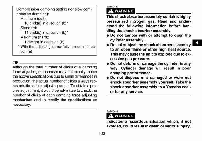
TIPAlthough the total number of clicks of a dampingforce adjusting mechanism may not exactly matchthe above specifications due to small differences inproduction, the actual number of clicks always rep-resents the entire adjusting range. To obtain a pre-cise adjustment, it would be advisable to check thenumber of clicks of each damping force adjustingmechanism and to modify the specifications asnecessary.
WARNINGEWB00430
This shock absorber assembly contains highlypressurized nitrogen gas. Read and under-stand the following information before han-dling the shock absorber assembly.� Do not tamper with or attempt to open the
cylinder assembly.� Do not subject the shock absorber assembly
to an open flame or other high heat source.This may cause the unit to explode due to ex-cessive gas pressure.
� Do not deform or damage the cylinder in anyway. Cylinder damage will result in poordamping performance.
� Do not dispose of a damaged or worn outshock absorber assembly yourself. Take theshock absorber assembly to a Yamaha deal-er for any service.
WARNINGEWB00011
Indicates a hazardous situation which, if notavoided, could result in death or serious injury.
Compression damping setting (for slow com-pression damping):
Minimum (soft):16 click(s) in direction (b)*
Standard:11 click(s) in direction (b)*
Maximum (hard):1 click(s) in direction (b)*
* With the adjusting screw fully turned in direc-tion (a)
U1AS10E0.book Page 23 Tuesday, February 10, 2009 9:33 AM

5-1
5
EBU19201
PRE-OPERATION CHECKSEBU19224
Inspect your vehicle each time you use it to make sure the vehicle is in safe operating condition. Alwaysfollow the inspection and maintenance procedures and schedules described in the Owner’s Manual.
WARNINGEWB00481
Failure to inspect or maintain the vehicle properly increases the possibility of an accident or equip-ment damage. Do not operate the vehicle if you find any problem. If a problem cannot be correctedby the procedures provided in this manual, have the vehicle inspected by a Yamaha dealer.
Before using this vehicle, check the following points:
ITEM ROUTINE PAGE
Fuel• Check fuel level in fuel tank, and add recommended fuel if neces-
sary.• Check fuel line for leakage. Correct if necessary.
4-11, 5-3
Engine oil• Check oil level in engine, and add recommended oil to specified lev-
el if necessary.• Check ATV for oil leakage. Correct if necessary.
5-3, 8-12
Coolant• Check coolant level in reservoir, and add recommended coolant to
specified level if necessary.• Check cooling system for leakage. Correct if necessary.
5-3, 8-17
Front brake
• Check operation. If soft or spongy, have Yamaha dealer bleed hy-draulic system.
• Check brake pads for wear, and replace if necessary.• Check brake fluid level in reservoir, and add recommended brake
fluid to specified level if necessary.• Check hydraulic system for leakage. Correct if necessary.
5-3, 8-28, 8-29, 8-31
U1AS10E0.book Page 1 Tuesday, February 10, 2009 9:33 AM

5-2
5
Rear brake
• Check operation. If soft or spongy, have Yamaha dealer bleed hy-draulic system.
• Check brake pads for wear, and replace if necessary.• Check brake fluid level in reservoir, and add recommended brake
fluid to specified level if necessary.• Check hydraulic system for leakage. Correct if necessary.
5-3, 8-28, 8-29, 8-32
Clutch• Check operation, and correct if necessary.• Lubricate cable if necessary.• Check lever free play, and adjust if necessary.
8-34
Throttle lever• Make sure that operation is smooth. Lubricate cable and lever hous-
ing if necessary.• Check cable free play, and adjust if necessary.
5-4, 8-27
Control cables • Make sure that operation is smooth. Lubricate if necessary. 8-38
Drive chain • Check chain slack, and adjust if necessary.• Check chain condition. Lubricate if necessary. 5-4, 8-35, 8-37
Wheels and tires• Check wheel condition, and replace if damaged.• Check tire condition and tread depth. Replace if necessary.• Check air pressure. Correct if necessary.
5-4
Shift pedal • Make sure that operation is smooth.• Correct if necessary. 8-38
Brake pedal • Make sure that operation is smooth. Lubricate pedal pivoting point if necessary. 8-39
Brake and clutch levers • Make sure that operation is smooth. Lubricate lever pivoting points if necessary. 8-38
Chassis fasteners • Make sure that all nuts, bolts and screws are properly tightened. 5-6Instruments, lights and switches • Check operation, and correct if necessary. 5-6
ITEM ROUTINE PAGE
U1AS10E0.book Page 2 Tuesday, February 10, 2009 9:33 AM

5-3
5
EBU19541
Fuel Make sure that there is sufficient fuel in the tank.(See page 4-11.)
EBU19560
Engine oil Make sure that the engine oil is at the specified lev-el. Add oil as necessary. (See page 8-12.)
EBU19631
Coolant Make sure that the coolant is at the specified level.Add coolant as necessary. (See page 8-17.)
TIPThe coolant level must be checked on a cold en-gine since the level varies with engine tempera-ture.
EBU19711
Front and rear brakes
Brake lever and brake pedal� Check that there is no free play in the brake le-
ver. If there is free play, have a Yamaha dealercheck the brake system.
� Check for correct brake pedal height. (See page8-32.) If the pedal height is incorrect, have aYamaha dealer adjust it.
� Check the operation of the lever and pedal. Theyshould move smoothly and there should be afirm feeling when the brakes are applied. If not,have a Yamaha dealer check the brake system.
Brake fluid levelCheck the brake fluid level. Add fluid if necessary.(See page 8-29.)
Brake fluid leakageCheck to see if any brake fluid is leaking out of thepipe joints or brake fluid reservoirs. Apply thebrakes firmly for one minute. If there is any leak-age, have a Yamaha dealer check the brake sys-tem.
Brake operationTest the brakes at slow speed after starting out tomake sure they are working properly. If the brakesdo not provide proper braking performance, checkthe brake pads for wear. (See page 8-28.)
Recommended brake fluid:DOT 4
U1AS10E0.book Page 3 Tuesday, February 10, 2009 9:33 AM

5-4
5
EBU19761
Throttle lever Check the operation of the throttle lever. It mustopen smoothly and spring back to the idle positionwhen released. Have a Yamaha dealer correct ifnecessary.
EBU19770
Drive chain Check the condition of the drive chain and checkthe drive chain slack. Lubricate and adjust thedrive chain as necessary. (See page 8-35.)
EBU19794
Tires Check tire pressure regularly to make sure it is atthe recommended specifications. Also check forwear and damage.
Tire pressureUse the low-pressure tire gauge to check and ad-just tire pressures when the tires are cold. Tirepressures must be equal on both sides.WARNING! Operation of this vehicle with im-proper tire pressure may cause severe injuryor death from loss of control or rollover. Tirepressure below the minimum specified could
also cause the tire to dislodge from the rim un-der severe riding conditions. [EWB02541] Set tirepressures to the following specifications:
The low-pressure tire gauge is included as stan-dard equipment. Make two measurements of thetire pressure and use the second reading. Dust ordirt in the gauge could cause the first reading to beincorrect.
Recommended tire pressure:Front
27.5 kPa (0.275 kgf/cm², 4.0 psi)Rear
27.5 kPa (0.275 kgf/cm², 4.0 psi)Minimum tire pressure:
Front24.5 kPa (0.245 kgf/cm², 3.6 psi)
Rear24.5 kPa (0.245 kgf/cm², 3.6 psi)
Maximum tire seating pressure:Front
250 kPa (2.5 kgf/cm², 36 psi)Rear
250 kPa (2.5 kgf/cm², 36 psi)
U1AS10E0.book Page 4 Tuesday, February 10, 2009 9:33 AM

5-5
5
Tire wear limitWhen the tire groove decreases to 3 mm (0.12 in)due to wear, replace the tire.
Tire informationThis ATV is equipped with tubeless tires withvalves.
WARNINGEWB02551
Use of improper tires on this ATV may causeloss of control, increasing your risk of an acci-dent.
After extensive tests, only the tires listed belowhave been approved for this model by YamahaMotor Co., Ltd.
1. Low-pressure tire gauge 1. Tire wear limit
U1AS10E0.book Page 5 Tuesday, February 10, 2009 9:33 AM

5-6
5
Aftermarket tires and rimsThe tires and rims that came with your ATV weredesigned to match the performance capabilitiesand to provide the best combination of handling,braking, and comfort. Other tires, rims, sizes, andcombinations may not be appropriate.
EBU19840
Chassis fasteners Make sure that all nuts, bolts and screws are prop-erly tightened.
EBU19850
Instruments, lights and switches Check that all instruments, lights and switches areworking properly. Correct if necessary.
Front:Manufacturer/model:
DUNLOP/KT341 RadialSize:
AT21 x 7R10Type:
TubelessRear:
Manufacturer/model:DUNLOP/KT345 Radial
Size:AT20 x 10R9
Type:Tubeless
U1AS10E0.book Page 6 Tuesday, February 10, 2009 9:33 AM

6-1
6
EBU19872
OPERATION
WARNINGEWB00011
Indicates a hazardous situation which, if notavoided, could result in death or serious injury.
EBU19901
Read the Owner’s Manual carefully before ridingthe ATV. If there is a control or function you do notunderstand, ask your Yamaha dealer.
WARNINGEWB00631
Read the Owner’s Manual carefully to becomefamiliar with all controls in order to help pre-vent any loss of control, which could cause anaccident or injury.
EBU29483
Starting the engine
NOTICEECB00150
See the “Engine break-in” section on page 6-5prior to operating the engine for the first time.
1. Set the parking brake.2. Turn the key to “ON” and the engine stop
switch to “ ”.The following warning lights should come onfor a few seconds, then go off.� Coolant temperature warning light� Fuel level warning light� Engine trouble warning light
NOTICEECB00824
If a warning light does not go off, see page 4-2for the corresponding warning light circuitcheck. To avoid possible damage, do not oper-ate the ATV if a warning light stays on.
3. Shift the transmission into neutral. The neutralindicator light should come on, if it does notcome on, have a Yamaha dealer check theelectrical circuit.
TIPThis model is equipped with an ignition circuit cut-off system. The engine can be started under thefollowing conditions.� The transmission is in neutral.
U1AS10E0.book Page 1 Tuesday, February 10, 2009 9:33 AM
6-2
6
� The clutch is disengaged with the transmissionin gear. However, it is recommended to shift intoneutral before starting the engine.
4. Completely close the throttle lever and startthe engine by pushing the start switch.NOTICE: For maximum engine life, neveraccelerate hard when the engine is cold![ECB00162]
TIPIf the engine fails to start, release the start switch,then push it again. Pause a few seconds beforethe next attempt. Each cranking should be as shortas possible to preserve battery energy. Do notcrank the engine more than 10 seconds on eachattempt.
EBU20501
Operating the reverse knob and driving in reverse
WARNINGEWB00720
Improper operation in reverse could make youhit an obstacle or even a person behind you,resulting in serious injury. When you shift into
reverse, make sure there are no people or ob-stacles behind you. When it is safe to proceed,go slowly.
NOTICEECB00170
Before shifting, stop the ATV, otherwise thetransmission may be damaged.
1. Bring the ATV to a complete stop, apply theclutch lever, and then shift the transmissioninto first gear.
2. While applying the brake pedal, turn the re-verse knob clockwise with your right hand.
3. Apply the clutch lever and shift the transmis-sion into reverse by pressing down on the shiftpedal, and then release the reverse knob.
U1AS10E0.book Page 2 Tuesday, February 10, 2009 9:33 AM

6-3
6
TIPWhen in reverse, the reverse indicator light shouldcome on. If the indicator light does not come on,have a Yamaha dealer check the electrical circuit.
4. Check behind you for people or obstacles,and then release the brake pedal.
5. Open the throttle lever gradually and releasethe clutch lever slowly. Continue to watch tothe rear while backing.
EBU20531
Shifting This ATV has a 5-speed forward and 1-speed re-verse transmission. The transmission allows youto control the amount of power you have availableat a given speed or for starting, accelerating, climb-ing hills, etc.To shift into neutral, return the throttle lever to theclosed position, apply the clutch, and then repeat-edly depress the shift pedal until it stops.When it stops, it will be in first gear. Raise the pedalslightly to reach the neutral position.
1. Reverse knob “REV”2. Shift pedal
2
1
1. Shift pedal2. Neutral position3. Reverse position
2345
N1R
1
2
3
U1AS10E0.book Page 3 Tuesday, February 10, 2009 9:33 AM

6-4
6
EBU20571
To start out and accelerate1. Release the throttle lever.
NOTICEECB00200
Always close the throttle before shifting gears,otherwise damage to the engine and drive trainmay result.
2. Pull the clutch lever to disengage the clutch.3. Shift into first gear.4. Open the throttle gradually and at the same
time, release the clutch lever slowly.WARNING! Opening the throttle abruptlyor releasing the clutch lever too quicklycould make the ATV wheelie, which wouldincrease the chance of an accident, includ-ing an overturn. [EWB00731]
5. Once the ATV has attained adequate speed,release the throttle, and at the same time,quickly pull in the clutch lever.
6. Shift the transmission into second gear.(Make sure not to shift the transmission intoneutral.)
7. Open the throttle part way and gradually re-lease the clutch lever.
8. Follow the same procedure when shifting tothe next higher gear.
EBU20650
To decelerateWhen slowing down or stopping, release the throt-tle and apply the brakes smoothly and evenly. Asyou slow down, shift to a lower gear. Be sure thatthe engine has sufficiently slowed before engaginga lower gear. Improper use of the brakes or shiftingcan cause the tires to lose traction, reducing con-trol and increasing the possibility of an accident.
WARNINGEWB00710
Make sure the engine has sufficiently slowedbefore shifting to a lower gear. Engaging a low-er gear when the engine speed is too highcould make the wheels stop rotating and losetraction. This could cause loss of control, anaccident and injury. It could also cause engineor drive train damage.
NOTICEECB00180
� Even with the transmission in the neutral po-sition, do not coast for long periods of timewith the engine off, and do not tow the ATV
U1AS10E0.book Page 4 Tuesday, February 10, 2009 9:33 AM

6-5
6
for long distances. The transmission is prop-erly lubricated only when the engine is run-ning. Inadequate lubrication may damagethe transmission.
� Always use the clutch when changing gears.The engine, transmission and drive train arenot designed to withstand the shock offorced shifting and can be damaged by shift-ing without using the clutch.
EBU20672
Engine break-in
TIP� For ATVs equipped with an odometer or an hour
meter, follow the figures given in km (mi) or thefigures given in hours.
� For ATVs not equipped with an odometer orhour meter, follow the figures given in hours.
There is never a more important period in the life ofyour engine than the first 320 km (200 mi) or 20hours of riding. For this reason, you should readthe following material carefully.Since the engine is brand new, do not put an ex-cessive load on it for the first 320 km (200 mi) or 20hours. The various parts in the engine wear and
polish themselves to the correct operating clear-ances. During this period, prolonged full-throttleoperation or any condition that might result in en-gine overheating must be avoided.
0–160 km (0–100 mi) or 0–10 hoursAvoid prolonged operation above 1/2 throttle. Varythe speed of the ATV regularly. Do not operate it atone set throttle position.
160–320 km (100–200 mi) or 10–20 hoursAvoid prolonged operation above 3/4 throttle. Revthe engine through the gears freely, but do not usefull throttle at any time.
320 km (200 mi) or 20 hours and beyondThe ATV can now be operated normally.
NOTICEECB00220
If any engine trouble should occur during theengine break-in period, immediately have aYamaha dealer check the ATV.
EBU26760
Parking When parking the ATV, stop the engine, shift intofirst gear, and then apply the parking brake.
U1AS10E0.book Page 5 Tuesday, February 10, 2009 9:33 AM

6-6
6EBU20900
Parking on a slope
WARNINGEWB00870
Avoid parking on hills or other inclines. Park-ing on a hill or other incline could cause theATV to roll out of control, increasing thechance of an accident. If you must park on anincline, place the ATV transversely across theincline, apply the parking brake, stop the en-gine, shift into first gear, and then block thefront and rear wheels with rocks or other ob-jects.
Do not park the ATV at all on hills that are sosteep you could not walk up them easily.
1. Bring the ATV to a stop by applying the frontbrake.
2. With the front and rear brake applied, pull theclutch lever, shift into the neutral position, re-lease the clutch lever, and then apply theparking brake.
3. Stop the engine by setting the engine stopswitch to “ ”.
4. With the front and rear brakes applied, pull theclutch lever, shift into first gear, and then re-lease the clutch lever, brake lever and brakepedal.
TIPMake sure that the neutral indicator light goes off.
5. Turn the key to “OFF”.
1. Locked position
U1AS10E0.book Page 6 Tuesday, February 10, 2009 9:33 AM

6-7
6 EBU20910
Accessories and loading
EBU20921
Genuine Yamaha AccessoriesChoosing accessories for your ATV is an importantdecision. Genuine Yamaha Accessories, whichare available only from a Yamaha dealer, havebeen designed, tested, and approved by Yamahafor use on your ATV. Many companies with no con-nection to Yamaha manufacture parts and acces-sories or offer other modifications for Yamahavehicles. Yamaha is not in a position to test theproducts that these aftermarket companies pro-duce. Therefore, Yamaha can neither endorse norrecommend the use of accessories not sold by
Yamaha or modifications not specifically recom-mended by Yamaha, even if sold and installed bya Yamaha dealer.
Aftermarket parts, accessories, and modifica-tionsWhile you may find aftermarket products similar indesign and quality to genuine Yamaha Accesso-ries, recognize that some aftermarket accessoriesor modifications are not suitable because of poten-tial safety hazards to you or others. Installing after-market products or having other modificationsperformed to your ATV that change any of the ve-hicle’s design or operation characteristics can putyou and others at greater risk of serious injury ordeath. You are responsible for injuries related tochanges in the vehicle.Keep the following in mind when considering anaccessory or operating an ATV which has acces-sories.� Accessories should be rigidly and securely
mounted. An accessory which can shift positionor come off while you are riding could affect yourability to control the ATV.
� Do not mount an accessory where it could inter-fere with your ability to control the ATV. Exam-ples include (but are not limited to) a heavy or
U1AS10E0.book Page 7 Tuesday, February 10, 2009 9:33 AM

6-8
6
bulky object attached to the handlebars whichcould make steering difficult, an accessory thatlimits your ability to move around on the seat, orone that limits your view.
� Use extra caution when riding an ATV with ac-cessories. The ATV may handle differently thanit does without accessories.
EBU20941
Loading
WARNINGEWB00820
Never exceed the stated load capacity for thisATV. Overloading this ATV or carrying or tow-ing cargo improperly could cause changes inATV handling which could lead to an accident.Cargo should be properly distributed and se-curely attached. Reduce speed when carryingcargo or pulling a trailer. Allow greater dis-tance for braking.
As originally equipped, this ATV is not designed tocarry cargo or tow a trailer. If you choose to add ac-cessories so that you can carry cargo or tow a trail-er, you must use common sense and good
judgment as the stability and handling of an ATVcan be changed. When adding accessories, keepthe following points in mind:� Never exceed the weight limits shown. An over-
loaded ATV can be unstable.
� If you are carrying cargo and towing a trailer, in-clude the tongue weight in the maximum ATVload limit.
� Load cargo on the carriers as close to the centerof the ATV as possible. Put cargo at the rear ofthe front carrier, at the front of the rear carrier,and center it.
� Tie down cargo securely to the carriers. Makesure cargo in the trailer cannot move around. Ashifting load can cause an accident.
� Make sure the load does not interfere with con-trols or your ability to see where you are going.
� Ride more slowly than you would without a load.The more weight you carry, the slower youshould go. Although conditions vary, it is good
MAXIMUM LOADING LIMITATV loading limit (total weight of rider, cargo, accessories, and tongue):
100.0 kg (220 lb)
U1AS10E0.book Page 8 Tuesday, February 10, 2009 9:33 AM
6-9
6
practice not to exceed 2nd gear whenever youare carrying heavier loads or when towing a trail-er.
� Allow more braking distance. A heavier ATVtakes longer to stop.
� Avoid making sharp turns unless at very slowspeeds.
� Avoid hills and rough terrain. Choose terraincarefully. Added weight affects the stability andhandling of the ATV.
WARNINGEWB00011
Indicates a hazardous situation which, if notavoided, could result in death or serious injury.
U1AS10E0.book Page 9 Tuesday, February 10, 2009 9:33 AM

7-1
7
EBU21132
RIDING YOUR ATV
U1AS10E0.book Page 1 Tuesday, February 10, 2009 9:33 AM

7-2
7
WARNINGEWB00011
Indicates a hazardous situation which, if notavoided, could result in death or serious injury.
EBU21595
GETTING TO KNOW YOUR ATVThis ATV is intended for recreational use by expe-rienced operators only. This section, Riding yourATV, provides general ATV riding instructions forrecreational riding. The skills and techniques de-scribed in this section, however, are appropriatefor all types of riding. Riding your ATV requiresspecial skills acquired through practice over a pe-riod of time. Take the time to learn the basic tech-niques well before attempting more difficultmaneuvers.Riding your new ATV can be a very enjoyable ac-tivity, providing you with hours of pleasure. But it isessential to familiarize yourself with the operationof the ATV to achieve the skill necessary to enjoyriding safely. Before you begin to ride, be sure youhave read this Owner’s Manual completely and un-derstand the operation of the controls. Pay partic-
ular attention to the safety information on pages2-1–2-4. Also read all warning and notice labels onyour ATV.
RIDE WITH CARE AND GOOD JUDGMENT
Get training if you are inexperienced.
WARNINGEWB01381
� Do not operate this ATV or allow anyone elseto operate it without proper instruction. Therisk of an accident is greatly increased if theoperator does not know how to operate theATV properly in different situations and ondifferent types of terrain.
� Do not operate this ATV at speeds too fastfor your skills or the conditions, as this in-creases your chances of losing control ofthe ATV and an accident. Always go at aspeed that is proper for the terrain, visibilityand operating conditions, and your experi-ence.
Beginning and inexperienced operators shouldcomplete the certified training course offered byYamaha. They should then regularly practice theskills learned in the course and the operating tech-
U1AS10E0.book Page 2 Tuesday, February 10, 2009 9:33 AM
7-3
7
niques described in this Owner’s Manual. For moreinformation about the training course, contact anauthorized ATV dealer or call 1-800-887-2887.
Riding your ATV requires skills acquiredthrough practice over a period of time.Do not attempt to operate at maximum perfor-mance until you are totally familiar with the ATV’shandling and performance characteristics. Takethe time to learn the basic techniques well beforeattempting more difficult maneuvers. Become fa-miliar with this ATV at slow speeds first, even if youare an experienced operator.
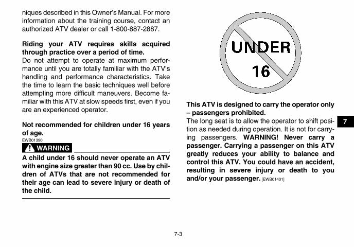
Not recommended for children under 16 yearsof age.
WARNINGEWB01390
A child under 16 should never operate an ATVwith engine size greater than 90 cc. Use by chil-dren of ATVs that are not recommended fortheir age can lead to severe injury or death ofthe child.
This ATV is designed to carry the operator only– passengers prohibited.The long seat is to allow the operator to shift posi-tion as needed during operation. It is not for carry-ing passengers. WARNING! Never carry apassenger. Carrying a passenger on this ATVgreatly reduces your ability to balance andcontrol this ATV. You could have an accident,resulting in severe injury or death to youand/or your passenger. [EWB01401]
U1AS10E0.book Page 3 Tuesday, February 10, 2009 9:33 AM

7-4
7 ApparelAlways wear the following to reduce risk of injury inan accident:� Approved motorcycle helmet that fits properly� Eye protection (goggles, helmet face shield, or
protective eyewear)� Over-the-ankle boots, gloves, long-sleeved shirt
or jacket, and long pantsAn approved helmet and other personal protectiveequipment can reduce the severity of injuries in anaccident. WARNING! Operating without an ap-
proved motorcycle helmet increases yourchances of a severe head injury or death in theevent of an accident. [EWB01411]
Wear eye protection when operating your ATV toreduce the risk of a serious accident or injury. Eyeprotection, such as a face shield or goggles, mayreduce the risk of foreign material getting in youreyes and help prevent loss of vision. WARNING!Operating without eye protection can result inan accident and increases your chances of asevere injury in the event of an accident.[EWB02611]
U1AS10E0.book Page 4 Tuesday, February 10, 2009 9:33 AM

7-5
7
Do not operate after or while consuming alco-hol or drugs.The operator’s performance capability is reducedby the influence of alcohol or drugs. Consuming al-cohol or drugs could seriously affect your judg-ment, cause you to react more slowly, and affectyour balance and perception. WARNING! Neverconsume alcohol or drugs before or while driv-ing this ATV. You increase your chance of anaccident. [EWB01421]
Pre-operation checksAlways inspect your ATV each time you use it tomake sure the ATV is in safe operating condition.Perform the pre-operation checks listed on page5-1. Always follow the inspection and maintenanceprocedures and schedules described in the Own-er’s Manual. WARNING! Failure to inspect theATV before operating it and to maintain it prop-erly increases the possibility of an accident orequipment damage. [EWB01431]
Speed limiterFor riders less experienced with this model, thethrottle lever housing is equipped with a speed lim-iter. The speed limiter keeps the throttle from fully
1. Protective clothing2. Goggles3. Gloves4. Boots5. Helmet
U1AS10E0.book Page 5 Tuesday, February 10, 2009 9:33 AM
7-6
7
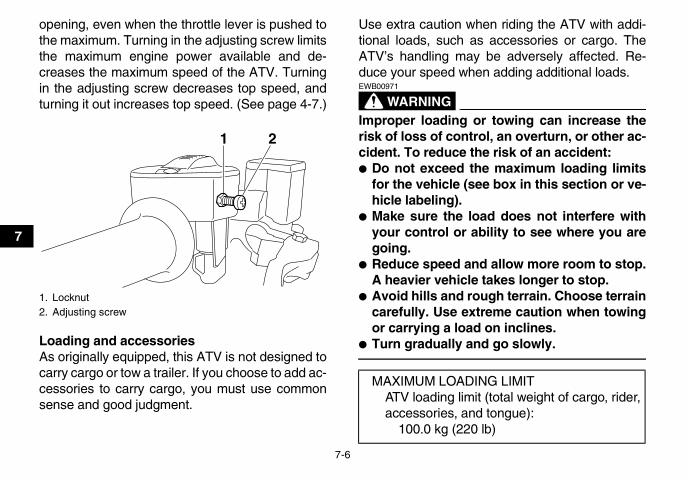
opening, even when the throttle lever is pushed tothe maximum. Turning in the adjusting screw limitsthe maximum engine power available and de-creases the maximum speed of the ATV. Turningin the adjusting screw decreases top speed, andturning it out increases top speed. (See page 4-7.)
Loading and accessoriesAs originally equipped, this ATV is not designed tocarry cargo or tow a trailer. If you choose to add ac-cessories to carry cargo, you must use commonsense and good judgment.
Use extra caution when riding the ATV with addi-tional loads, such as accessories or cargo. TheATV’s handling may be adversely affected. Re-duce your speed when adding additional loads.
WARNINGEWB00971
Improper loading or towing can increase therisk of loss of control, an overturn, or other ac-cident. To reduce the risk of an accident:� Do not exceed the maximum loading limits
for the vehicle (see box in this section or ve-hicle labeling).
� Make sure the load does not interfere withyour control or ability to see where you aregoing.
� Reduce speed and allow more room to stop.A heavier vehicle takes longer to stop.
� Avoid hills and rough terrain. Choose terraincarefully. Use extreme caution when towingor carrying a load on inclines.
� Turn gradually and go slowly.
1. Locknut2. Adjusting screw
1 2
MAXIMUM LOADING LIMITATV loading limit (total weight of cargo, rider, accessories, and tongue):
100.0 kg (220 lb)
U1AS10E0.book Page 6 Tuesday, February 10, 2009 9:33 AM

7-7
7
During operationAlways keep your feet on the footboards during op-eration; otherwise, they may contact the rearwheels. WARNING! Removing even one handor foot can reduce your ability to control theATV or could cause you to lose your balanceand fall off of the ATV. If you remove a footfrom a footboard, your foot or leg may comeinto contact with the rear wheels, which couldinjure you or cause an accident. [EWB01471]
Avoid wheelies and jumping. WARNING! At-tempting wheelies, jumps, and other stunts in-creases the chance of an accident, includingan overturn. Never attempt stunts, such aswheelies or jumps. Don’t try to show off.[EWB01481]
Modifications and accessoriesNever modify this ATV through improper installa-tion or use of accessories or other modification. Allparts and accessories added to this ATV should begenuine Yamaha or equivalent components de-signed for use on this ATV and should be installedand used according to instructions. If you havequestions, consult an authorized ATV dealer.
U1AS10E0.book Page 7 Tuesday, February 10, 2009 9:33 AM

7-8
7
WARNING! Operating this ATV with impropermodifications may cause changes in handlingwhich in some situations could lead to an acci-dent. [EWB01491]
Exhaust system
WARNINGEWB01501
� Dry grass or brush or other combustible ma-terial accumulated around the engine areacould catch fire. Do not operate, idle, or parkthe ATV in dry grass or other dry ground cov-er. Keep the engine area free of dry grass,brush, or other combustible material.
� Someone touching the exhaust system dur-ing or after operation could be burned. Donot touch the hot exhaust system. Do notpark the ATV in a place where others mightbe likely to touch it.
The muffler and other engine parts become ex-tremely hot during operation and remain hot afterthe engine has stopped. To reduce the risk of fireduring operation or after leaving the ATV, do not letbrush, grass and other materials collect under thevehicle, near the muffler or exhaust pipe, or next toother hot parts. Check under the vehicle after op-
erating in areas where combustible materials mayhave collected. Do not idle or park the vehicle inlong dry grass or other dry ground cover.To prevent burns, avoid touching the exhaust sys-tem. Park the ATV in a place where pedestrians orchildren are not likely to touch it.
U1AS10E0.book Page 8 Tuesday, February 10, 2009 9:33 AM

7-9
7
BE CAREFUL WHERE YOU RIDEThis ATV is designed for off-road use only.WARNING! Paved surfaces may seriously af-fect handling and control of the ATV, and maycause the ATV to go out of control. Alwaysavoid paved surfaces, including sidewalks,driveways, parking lots and streets. [EWB01511]
Do not ride on any public road, street, or highway.Riding on public roads can result in collisions withother vehicles. In many states it is illegal to operateATVs on public streets, roads and highways.WARNING! Never operate this ATV on any pub-lic street, road or highway, even a dirt or gravelone. You could collide with another vehicle.[EWB01031]
U1AS10E0.book Page 9 Tuesday, February 10, 2009 9:33 AM

7-10
7
Know the terrain where you ride. Ride cautiously inunfamiliar areas. Stay alert for holes, rocks, orroots in the terrain, and other hidden hazardswhich may cause the ATV to upset. WARNING!The ATV could go out of control if you do nothave enough time to react to hidden rocks,bumps, or holes. Go slowly and be extra care-ful when operating on unfamiliar terrain. Al-ways be alert to changing terrain conditionswhen operating the ATV. [EWB01531]
Do not operate on rough, slippery, or loose terrainuntil you have learned and practiced the skills nec-essary to control the ATV on such terrain. Alwaysbe especially cautious on these kinds of terrain.WARNING! Failure to use extra care when op-erating on excessively rough, slippery, orloose terrain could cause loss of traction orATV control, which could result in an accident,including an overturn. [EWB01541]
U1AS10E0.book Page 10 Tuesday, February 10, 2009 9:33 AM

7-11
7
When riding in an area where you might not easilybe seen, such as desert terrain, mount a cautionflag on the ATV. DO NOT use the flag pole bracketas a trailer hitch. WARNING! You could collidewith another vehicle if operating in off-road ar-eas where you cannot easily be seen. Mount acaution flag on the ATV to make you more vis-ible. Watch carefully for other vehicles. [EWB01061]
Do not ride in areas posted “no trespassing”.Do not ride on private property without getting per-mission.
Select a large, flat area off-road to become familiarwith your ATV. Make sure that this area is free ofobstacles and other riders. You should practicecontrol of the throttle, brakes, shifting procedures,and turning techniques in this area before tryingmore difficult terrain.
U1AS10E0.book Page 11 Tuesday, February 10, 2009 9:33 AM

7-12
7
Set the parking brake and follow the instruction onpage 6-1 to start the engine. Once it has warmedup you are ready to begin riding your ATV. As youget on the ATV, be sure not to accidentally movethe shift pedal. With the engine idling, pull theclutch lever to disengage the clutch and shift into1st gear, and then release the parking brake. Openthe throttle gradually, and at the same time, re-lease the clutch lever slowly. Once the ATV has at-tained adequate speed, release the throttle leverand at the same time, quickly pull in the clutch le-ver and shift into 2nd gear. Open the throttle partway and gradually release the clutch. WARNING!If the throttle is applied too abruptly or if thethrottle is not released during shifting, or if theshift pedal is not released before applying thethrottle, the front wheels may lift off theground, resulting in a loss of directional con-trol. [EWB02631] NOTICE: Do not shift gears withoutreleasing the throttle. Damage to the engine ordrive train may occur. [ECB01071]
Use this same procedure as you move into thehigher gears. Be sure to coordinate the use of thethrottle and shift pedal properly.Avoid higher speeds until you are thoroughly famil-iar with the operation of your ATV.
When slowing down or stopping, release the throt-tle and apply the brakes smoothly and evenly. Asyou slow down, shift to a lower gear. Be sure thatthe engine has sufficiently slowed before engaginga lower gear. Improper use of the brakes or shiftingcan cause the tires to lose traction, reducing con-trol and increasing the possibility of an accident.
TURNING YOUR ATV
WARNINGEWB01771
Always follow proper procedures for turningas described in this Owner’s Manual. Practiceturning at low speeds before attempting to turnat faster speeds. Do not turn at speeds too fastfor your skills or the conditions. ATV could goout of control, causing a collision or overturn.
To achieve maximum traction while riding off-road,the two rear wheels turn together at the samespeed. Therefore, unless the wheel on the insideof the turn is allowed to slip or lose some traction,the ATV will resist turning. A special turning tech-nique must be used to allow the ATV to make turnsquickly and easily. It is essential that this skill belearned first at low speed.
U1AS10E0.book Page 12 Tuesday, February 10, 2009 9:33 AM

7-13
7
As you approach a curve, slow down and begin toturn the handlebars in the desired direction. As youdo so, put your weight on the footboard to the out-side of the turn (opposite your desired direction)and lean your upper body into the turn. Use thethrottle to maintain an even speed through the turn.This maneuver will let the wheel on the inside ofthe turn slip slightly, allowing the ATV to make theturn properly.
This procedure should be practiced at slow speedmany times in a large off-road area with no obsta-cles. If an incorrect technique is used, your ATVmay continue to go straight. If the ATV doesn’tturn, come to a stop and then practice the proce-dure again. If the riding surface is slippery or loose,it may help to position more of your weight over thefront wheels by moving forward on the seat.Once you have learned this technique, you shouldbe able to perform it at higher speeds or in tightercurves.Improper riding procedures such as abrupt throttlechanges, excessive braking, incorrect body move-ments, or too much speed for the sharpness of theturn may cause the ATV to tip. If the ATV begins totip over to the outside while negotiating a turn, leanmore to the inside. It may also be necessary togradually let off on the throttle and steer to the out-side of the turn to avoid tipping over.Remember: Avoid higher speeds until you arethoroughly familiar with the operation of your ATV.
1. Lean towards inside of turn.2. Support your weight on the outer footrest.
U1AS10E0.book Page 13 Tuesday, February 10, 2009 9:33 AM

7-14
7
CLIMBING UPHILL
WARNINGEWB01591
Climbing hills improperly can cause overturnsor loss of control. Use proper riding tech-niques described in this Owner’s Manual.� Never operate the ATV on hills too steep for
the ATV or for your abilities. The ATV canoverturn more easily on extremely steep hillsthan on level surfaces or small hills.
� Always check the terrain carefully beforeyou start up any hill. Never climb hills withexcessively slippery or loose surfaces.
� Shift your weight forward.� Never open the throttle suddenly or make
sudden gear changes. The ATV could flipover backwards.
� Never go over the top of any hill at highspeed. An obstacle, a sharp drop, or anothervehicle or person could be on the other sideof the hill.
� Never attempt to turn the ATV around on anyhill until you have mastered the turning tech-nique as described in the Owner’s Manual onlevel ground. Be very careful when turningon any hill.
� Avoid crossing the side of a steep hill if pos-sible. When crossing the side of a hill, shiftyour weight to the uphill side of the ATV.
U1AS10E0.book Page 14 Tuesday, February 10, 2009 9:33 AM

7-15
7
Do not attempt to climb hills until you have mas-tered basic maneuvers on flat ground. Alwayscheck the terrain carefully before attempting anyhill. In all cases avoid inclines with slippery or loosesurfaces, or obstacles that might cause you to losecontrol.To climb a hill, you need traction, momentum, andsteady throttle. Travel fast enough to maintain mo-mentum, but not so fast that you cannot react tochanges in the terrain as you climb.
It is important when climbing a hill to make surethat your weight is transferred forward on the ATV.This can be accomplished by leaning forward and,on steeper inclines, standing on the footboardsand leaning forward over the handlebars. Whenev-er possible, ride straight up hills.Slow down when you reach the crest of the hill ifyou cannot see clearly what is on the other side –there could be another person, an obstacle, or asharp drop-off. Use common sense and rememberthat some hills are too steep for you to climb or de-scend.If you are climbing a hill and you find that you havenot properly judged your ability to make it to thetop, you should turn the ATV around while you stillhave forward motion (provided you have the roomto do so) and go down the hill.If your ATV has stalled or stopped and you believeyou can continue up the hill, restart carefully tomake sure you do not lift the front wheels whichcould cause you to lose control. If you are unableto continue up the hill, dismount the ATV on the up-hill side. Physically turn the ATV around and thendescend the hill.
U1AS10E0.book Page 15 Tuesday, February 10, 2009 9:33 AM

7-16
7
If you start to roll backwards, DO NOT apply therear brake, and apply the front brake gradually.The ATV could easily tip over backwards. Whenfully stopped, apply the rear brake as well, andthen lock the parking brake. Dismount the ATV im-mediately on the uphill side or to a side if pointedstraight uphill. Turn the ATV around and remount,following the procedure described in the Owner’sManual. WARNING! Stalling, rolling backwardsor improperly dismounting while climbing a hillcould result in ATV overturning. If you cannotcontrol the ATV, dismount immediately on theuphill side. [EWB01802]
RIDING DOWNHILL
WARNINGEWB01131
Going down a hill improperly could causeoverturns or loss of control. Always followproper procedures for going down hills as de-scribed in this Owner’s Manual.� Always check the terrain carefully before
you start down any hill.
U1AS10E0.book Page 16 Tuesday, February 10, 2009 9:33 AM

7-17
7
� Never operate the ATV on hills too steep forthe ATV or for your abilities. The ATV canoverturn more easily on extremely steep hillsthan on level surfaces or small hills.
� Shift your weight backward and to the upside of the hill.
� Never go down a hill at high speed.� Avoid going down a hill at an angle that
would cause the ATV to lean sharply to oneside. Go straight down the hill where possi-ble.
� Improper braking can cause the wheels onthe uphill side to come off the ground orcause loss of traction. Gradually apply onlythe rear brake when going downhill.
When riding your ATV downhill, shift your weightas far to the rear and uphill side of the ATV as pos-sible. Move back on the seat and sit with your armsstraight. Choose a low gear which will allow the en-gine compression to do most of the braking for you.Use caution while descending a hill with loose orslippery surfaces. Braking ability and traction maybe adversely affected by these surfaces. Improperbraking may also cause a loss of traction. Gradual-ly apply only the rear brake.
Whenever possible, ride your ATV straight down-hill. Avoid sharp angles which could allow the ATVto tip or roll over. Carefully choose your path andride no faster than you will be able to react to ob-stacles which may appear.
U1AS10E0.book Page 17 Tuesday, February 10, 2009 9:33 AM

7-18
7
CROSSING A SLOPE
WARNINGEWB01632
Improperly crossing hills or turning on hillscould cause loss of control or cause the ATV tooverturn.� Always follow proper procedures as de-
scribed in the Owner’s Manual.� Avoid hills with excessively slippery or loose
surfaces.� Avoid crossing the side of a steep hill.� Shift your weight to the uphill side of the
ATV.� Never attempt to turn the ATV around on any
hill until you have mastered the turning tech-nique as described in the Owner’s Manual onlevel ground. Be very careful when turningon any hill.
Traversing a sloping surface on your ATV requiresyou to properly position your weight to maintainproper balance. Be sure that you have learned thebasic riding skills on flat ground before attemptingto cross a sloping surface. Avoid slopes with slip-pery surfaces or rough terrain that may upset yourbalance.
As you travel across a slope, lean your body in theuphill direction. It may be necessary to correct thesteering when riding on loose surfaces by pointingthe front wheels slightly uphill. When riding onslopes, be sure not to make sharp turns either upor down hill.If your ATV does begin to tip over, gradually steerin the downhill direction if there are no obstacles inyour path. As you regain proper balance, graduallysteer again in the direction you wish to travel.
U1AS10E0.book Page 18 Tuesday, February 10, 2009 9:33 AM

7-19
7
CROSSING THROUGH SHALLOW WATER
WARNINGEWB01641
Operating this vehicle through deep or fast-flowing water can lead to loss of control or anoverturn. To reduce your risk of drowning orother injuries, use care when crossing throughwater. Never operate this ATV water deeperthan the depth specified in your Owner’s Man-ual, as tires may float, increasing the risk of anoverturn.
The ATV can be used to cross slow moving, shal-low water of up to a maximum of 35 cm (14 in) indepth. Before entering the water, choose your pathcarefully. Enter where there is no sharp drop off,and avoid rocks or other obstacles which may beslippery or upset the ATV. Drive slowly and care-fully.
Test your brakes after leaving the water. If neces-sary, apply them several times to let friction dry outthe linings. Do not continue to ride your ATV with-out verifying that you have regained proper brakingability. WARNING! Wet brakes may have re-duced stopping ability, which could cause lossof control. [EWB02621]
U1AS10E0.book Page 19 Tuesday, February 10, 2009 9:33 AM

7-20
7
After riding your ATV in water, be sure to drain thetrapped water by removing the check hose at thebottom of the air filter case. NOTICE: Undrainedwater can cause damage or improper opera-tion. [ECB00841]
Wash the ATV in fresh water if it has been operat-ed in salt water or muddy conditions.
RIDING OVER ROUGH TERRAIN
WARNINGEWB01651
Riding improperly over obstacles could causeloss of control or a collision. Before operatingin a new area, check for obstacles. Never at-tempt to ride over large obstacles, such aslarge rocks or fallen trees. When you go overobstacles, always follow proper procedures asdescribed in the Owner’s Manual.
Riding over rough terrain should be done with cau-tion. Look out for obstacles which could causedamage to the ATV or could lead to an upset or ac-
1. Air filter case check hose
1
U1AS10E0.book Page 20 Tuesday, February 10, 2009 9:33 AM

7-21
7
cident. Be sure to keep your feet firmly mounted onthe footboards at all times. Avoid jumping the ATVas loss of control and damage to the ATV may re-sult.
SLIDING AND SKIDDING
WARNINGEWB01662
Skidding or sliding improperly may cause youto lose control of this ATV. You may also re-gain traction unexpectedly, which may causethe ATV to overturn.� Learn to safely control skidding or sliding by
practicing at low speeds and on level,smooth terrain.
� On extremely slippery surfaces, such as ice,go slowly and be very cautious in order to re-duce the chance of skidding or sliding out ofcontrol.
Care should be used when riding on loose or slip-pery surfaces since the ATV may slide. If unex-pected and uncorrected, sliding could lead to anaccident.To reduce the tendency for the front wheels to slidein loose or slippery conditions, positioning yourweight over the front wheels will sometimes help.
If the rear wheels of your ATV start to slide side-ways, control can usually be regained (if there isroom to do so) by steering in the direction of theslide. Applying the brakes or accelerating is notrecommended until you have corrected the slide.
U1AS10E0.book Page 21 Tuesday, February 10, 2009 9:33 AM

7-22
7
With practice, over a period of time, skill at con-trolled sliding can be developed. The terrainshould be chosen carefully before attempting suchmaneuvers, since both stability and control are re-duced. Bear in mind that sliding maneuvers shouldalways be avoided on extremely slippery surfacessuch as ice, since all control may be lost.
WHAT TO DO IF...This section is designed to be a reference guideonly. Be sure to read each section on riding tech-niques completely.
WHAT TO DO...� If your ATV doesn’t turn when you want it to:
Bring the ATV to a stop and practice the turningmaneuvers again. Be sure you are putting yourweight on the footboard to the outside of theturn. Position your weight over the front wheelsfor better control. (See page 7-12.)
� If your ATV begins to tip while turning:Lean more into the turn to regain balance. If nec-essary, gradually let off the throttle and/or steerto the outside of the turn. (See page 7-12.)
� If your ATV starts to slide sideways:Steer in the direction of the slide if you have theroom. Applying the brakes or accelerating is notrecommended until you have corrected theslide. (See page 7-21.)
� If your ATV can’t make it up a hill you are tryingto climb:Turn the ATV around if you still have forwardspeed. If not, stop, dismount on the uphill side ofthe ATV and physically turn the ATV around. Ifthe ATV starts to slip backwards, DO NOT USETHE REAR BRAKE – the ATV may tip over ontop of you. Dismount the ATV on the uphill side.(See page 7-14.)
U1AS10E0.book Page 22 Tuesday, February 10, 2009 9:33 AM
7-23
7
� If your ATV is traversing a sloping surface:Be sure to ride with your weight positioned to-wards the uphill side of the ATV to maintainproper balance. If the ATV starts to tip, steerdown the hill (if there are no obstacles in yourway) to regain balance. If you discover that theATV is going to tip over, dismount on the uphillside. (See page 7-18.)
� If your ATV encounters shallow water:Ride slowly and carefully through slow movingwater, watching for obstacles. Be sure to let wa-ter drain from the ATV and CHECK YOURBRAKES FOR PROPER OPERATION whenyou come out of the water. Do not continue toride your ATV until you have regained adequatebraking ability. (See page 7-19.)
WARNINGEWB00011
Indicates a hazardous situation which, if notavoided, could result in death or serious injury.
U1AS10E0.book Page 23 Tuesday, February 10, 2009 9:33 AM
8-1
8
EBU2164A
PERIODIC MAINTENANCE AND ADJUSTMENTEBU21671
Periodic inspection, adjustment, and lubricationwill keep your vehicle in the safest and most effi-cient condition possible. Safety is an obligation ofthe vehicle owner/operator. The most importantpoints of vehicle inspection, adjustment, and lubri-cation are explained on the following pages.
WARNINGEWB01841
Failure to properly maintain the vehicle or per-forming maintenance activities incorrectly mayincrease your risk of injury or death during ser-vice or while using the vehicle. If you are not fa-miliar with vehicle service, have a Yamahadealer perform the service.
WARNINGEWB02561
Turn off the engine when performing mainte-nance unless otherwise specified.� A running engine has moving parts that can
catch on body parts or clothing and electri-cal parts that can cause shocks or fires.
� Running the engine while servicing can leadto eye injury, burns, fire, or carbon monoxidepoisoning - possibly leading to death. Seepage 2-1 for more information about carbonmonoxide.
The intervals given in the periodic maintenanceand lubrication chart should be considered as ageneral guide under normal riding conditions.However, DEPENDING ON THE WEATHER,TERRAIN, GEOGRAPHICAL LOCATION, ANDINDIVIDUAL USE, THE MAINTENANCE INTER-VALS MAY NEED TO BE SHORTENED.
EBU27111
Owner’s manual and tool kit Be sure to put this owner’s manual in the plasticbag and to always carry it as well as the owner’stool kit and the low-pressure tire gauge in their re-spective compartments under the seat.
U1AS10E0.book Page 1 Tuesday, February 10, 2009 9:33 AM

8-2
8The service information included in this manualand the tools provided in the owner’s tool kit are in-tended to assist you in the performance of preven-tive maintenance and minor repairs. However,additional tools such as a torque wrench may benecessary to perform certain maintenance workcorrectly.
TIPIf you do not have the tools or experience requiredfor a particular job, have a Yamaha dealer performit for you.
1. Owner’s manual2. Owner’s tool kit3. Low-pressure tire gauge
1
2
1
2
3
U1AS10E0.book Page 2 Tuesday, February 10, 2009 9:33 AM
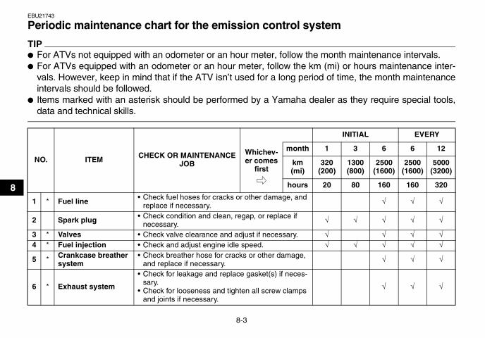
8-3
8
EBU21743
Periodic maintenance chart for the emission control system
TIP� For ATVs not equipped with an odometer or an hour meter, follow the month maintenance intervals.� For ATVs equipped with an odometer or an hour meter, follow the km (mi) or hours maintenance inter-
vals. However, keep in mind that if the ATV isn’t used for a long period of time, the month maintenanceintervals should be followed.
� Items marked with an asterisk should be performed by a Yamaha dealer as they require special tools,data and technical skills.
NO. ITEM CHECK OR MAINTENANCE JOB
INITIAL EVERY
Whichev-er comes
first
month 1 3 6 6 12
km (mi)
320 (200)
1300 (800)
2500 (1600)
2500 (1600)
5000 (3200)
hours 20 80 160 160 320
1 * Fuel line • Check fuel hoses for cracks or other damage, and replace if necessary. √ √ √
2 Spark plug • Check condition and clean, regap, or replace if necessary. √ √ √ √ √
3 * Valves • Check valve clearance and adjust if necessary. √ √ √ √4 * Fuel injection • Check and adjust engine idle speed. √ √ √ √ √
5 * Crankcase breather system
• Check breather hose for cracks or other damage, and replace if necessary. √ √ √
6 * Exhaust system
• Check for leakage and replace gasket(s) if neces-sary.
• Check for looseness and tighten all screw clamps and joints if necessary.
√ √ √
U1AS10E0.book Page 3 Tuesday, February 10, 2009 9:33 AM

8-4
8
7 Spark arrester • Clean. √ √ √
NO. ITEM CHECK OR MAINTENANCE JOB
INITIAL EVERY
Whichev-er comes
first
month 1 3 6 6 12
km (mi)
320 (200)
1300 (800)
2500 (1600)
2500 (1600)
5000 (3200)
hours 20 80 160 160 320
U1AS10E0.book Page 4 Tuesday, February 10, 2009 9:33 AM

8-5
8
EBU21864
General maintenance and lubrication chart
NO. ITEM CHECK OR MAINTENANCE JOB
INITIAL EVERY
Whichev-er comes
first
month 1 3 6 6 12
km (mi)
320 (200)
1300 (800)
2500 (1600)
2500 (1600)
5000 (3200)
hours 20 80 160 160 320
1 Air filter element • Clean and replace if necessary. Every 20–40 hours (more often in wet or dusty areas)
2 * Clutch • Check operation and adjust if necessary. √ √ √ √
3 * Front brake
• Check operation and correct if necessary.• Check fluid level and ATV for fluid leakage, and
correct if necessary.√ √ √ √ √
• Replace brake pads. Whenever worn to the limit
4 * Rear brake
• Check operation and correct if necessary.• Check fluid level and ATV for fluid leakage, and
correct if necessary.√ √ √ √ √
• Replace brake pads. Whenever worn to the limit
5 * Brake hoses• Check for cracks or other damage, and replace if
necessary. √ √ √ √
• Replace. Every 4 years6 * Parking brake • Check operation and adjust if necessary. √ √ √ √ √
7 * Wheels • Check runout and for damage, and replace if nec-essary. √ √ √ √
8 * Tires
• Check tread depth and for damage, and replace if necessary.
• Check air pressure and balance, and correct if necessary.
√ √ √ √
U1AS10E0.book Page 5 Tuesday, February 10, 2009 9:33 AM

8-6
8
9 * Wheel hub bearings • Check for looseness or damage, and replace if necessary. √ √ √ √
10 * Swingarm pivots• Check operation and for excessive play, and re-
place bearings if necessary.• Lubricate with lithium-soap-based grease.
√ √ √
11 * Upper and lower arm pivots • Lubricate with lithium-soap-based grease. √ √ √
12 Drive chain
• Check chain slack and adjust if necessary.• Check rear wheel alignment and correct if neces-
sary.• Clean and lubricate.
√ √ √ √ √
13 * Chassis fasteners • Make sure that all nuts, bolts, and screws are properly tightened. √ √ √ √ √
14 * Shock absorber as-semblies
• Check operation and correct if necessary.• Check for oil leakage and replace if necessary. √ √ √
15 *
Rear suspension re-lay arm and con-necting arm pivoting points
• Check operation and correct if necessary.• Lubricate with lithium-soap-based grease. √ √ √ √
16 * Steering shaft • Lubricate with lithium-soap-based grease. √ √ √
17 * Steering system • Check operation and repair or replace if damaged.• Check toe-in and adjust if necessary. √ √ √ √ √
18 Engine oil• Change.• Check ATV for oil leakage, and correct if neces-
sary.√ √ √ √
NO. ITEM CHECK OR MAINTENANCE JOB
INITIAL EVERY
Whichev-er comes
first
month 1 3 6 6 12
km (mi)
320 (200)
1300 (800)
2500 (1600)
2500 (1600)
5000 (3200)
hours 20 80 160 160 320
U1AS10E0.book Page 6 Tuesday, February 10, 2009 9:33 AM

8-7
8
EBU23071
TIP� Some maintenance items need more frequent service if you are riding in unusually wet, dusty, sandy or
muddy areas, or at full-throttle.� Hydraulic brake service
• Regularly check and, if necessary, correct the brake fluid level.
19 Engine oil filter ele-ment • Replace. √ √ √
20 Cooling system• Check coolant level and ATV for coolant leakage,
and correct if necessary. √ √ √ √ √
• Replace coolant. Every 2 years
21 * Moving parts and cables • Lubricate. √ √ √ √
22 * Throttle lever hous-ing and cable
• Check operation and correct if necessary.• Check throttle cable free play and adjust if neces-
sary.• Lubricate throttle lever housing and cable.
√ √ √ √ √
23 * Front and rear brake switches • Check operation and correct if necessary. √ √ √ √ √
24 * Lights and switches • Check operation and correct if necessary.• Adjust headlight beams. √ √ √ √ √
NO. ITEM CHECK OR MAINTENANCE JOB
INITIAL EVERY
Whichev-er comes
first
month 1 3 6 6 12
km (mi)
320 (200)
1300 (800)
2500 (1600)
2500 (1600)
5000 (3200)
hours 20 80 160 160 320
U1AS10E0.book Page 7 Tuesday, February 10, 2009 9:33 AM
8-8
8
• Every two years replace the internal components of the brake master cylinders and calipers, andchange the brake fluid.
• Replace the brake hoses every four years and if cracked or damaged.
U1AS10E0.book Page 8 Tuesday, February 10, 2009 9:33 AM

8-9
8
WARNINGEWB00011
Indicates a hazardous situation which, if notavoided, could result in death or serious injury.
EBU23080
Removing and installing the panel The panel shown needs to be removed to performsome of the maintenance jobs described in thischapter. Refer to this section each time the panelneeds to be removed and installed.
EBU23101
Panel A
To remove the panelRemove the bolts, and then take the panel off.
To install the panelPlace the panel in the original position and installthe bolts.
EBU23211
Checking the spark plug The spark plug is an important engine component,which is easy to check. Since heat and depositswill cause any spark plug to slowly erode, the spark
1. Panel A
1
1. Panel A2. Bolt
2 2
1
U1AS10E0.book Page 9 Tuesday, February 10, 2009 9:33 AM

8-10
8
plug should be removed and checked in accor-dance with the periodic maintenance and lubrica-tion chart. In addition, the condition of the sparkplug can reveal the condition of the engine.
To remove the spark plug1. Remove the spark plug cap.
2. Remove the spark plug as shown, with thespark plug wrench included in the owner’s toolkit.
To check the spark plug1. Check that the porcelain insulator around the
center electrode of the spark plug is a medi-um-to-light tan (the ideal color when the ATVis ridden normally).
TIPIf the spark plug shows a distinctly different color,the engine could be operating improperly. Do notattempt to diagnose such problems yourself. In-stead, have a Yamaha dealer check the ATV.
1. Spark plug cap
1
1. Spark plug wrench
1
U1AS10E0.book Page 10 Tuesday, February 10, 2009 9:33 AM

8-11
8
2. Check the spark plug for electrode erosionand excessive carbon or other deposits, andreplace it if necessary.
To install the spark plug1. Measure the spark plug gap with a wire thick-
ness gauge and, if necessary, adjust the gapto specification.
2. Clean the surface of the spark plug gasketand its mating surface, and then wipe off anygrime from the spark plug threads.
3. Install the spark plug with the spark plugwrench, and then tighten it to the specifiedtorque.
Specified spark plug:NGK/CR8E
Spark plug gap:0.7–0.8 mm (0.028–0.031 in)
1. Spark plug gap
Tightening torque:Spark plug:
12.5 Nm (1.25 m·kgf, 9.0 ft·lbf)
U1AS10E0.book Page 11 Tuesday, February 10, 2009 9:33 AM
8-12
8
TIPIf a torque wrench is not available when installinga spark plug, a good estimate of the correct torqueis 1/4–1/2 turn past finger tight. However, the sparkplug should be tightened to the specified torque assoon as possible.
4. Install the spark plug cap.
EBU26785
Engine oil and oil filter element The engine oil level should be checked beforeeach ride. In addition, the oil must be changed andthe oil filter element replaced at the intervals spec-ified in the periodic maintenance and lubricationchart.
To check the engine oil level1. Place the ATV on a level surface.2. Start the engine, warm it up until the engine oil
has reached a normal temperature of 60 °C(140 °F), let it continue to idle for ten secondsor more, and then turn the engine off.
TIPTo achieve the proper engine oil temperature foran accurate oil level reading, the engine must havefirst completely cooled down, and then warmed upagain for several minutes to normal operating tem-perature.
3. Remove the engine oil tank filler cap, and thenwipe the engine oil dipstick off with a cleanrag.
4. Insert the dipstick in the filler hole (withoutscrewing it in), and then remove it again tocheck the oil level.
U1AS10E0.book Page 12 Tuesday, February 10, 2009 9:33 AM

8-13
8
TIPThe engine oil should be between the minimumand maximum level marks.
5. If the engine oil is at or below the minimumlevel mark, add sufficient oil of the recom-mended type through the engine oil tank fillerhole to raise it to the correct level. NOTICE:
Be sure the engine oil is at the correct lev-el, otherwise engine damage may result.[ECB00851]
TIPWhen adding oil, be careful not to overfill the en-gine oil tank; the oil level rises faster starting fromthe half-level-portion on the dipstick.
6. Insert the dipstick into the engine oil tank fillerhole, and then tighten the engine oil tank fillercap. NOTICE: Make sure that the engine oiltank filler cap is securely tightened; other-wise, oil may seep out when the engine isrunning. [ECB00362]
To change the engine oil (with or without oil fil-ter element replacement)
1. Place the ATV on a level surface.2. Start the engine, warm it up for several min-
utes, and then turn it off.3. Place an oil pan under the engine to collect
the used oil.4. Remove the crankcase engine oil filler cap
and the crankcase engine oil drain bolt.
1. Engine oil tank2. Engine oil filler cap3. Engine oil dipstick4. Maximum level mark5. Minimum level mark
2
3
4
51
2
U1AS10E0.book Page 13 Tuesday, February 10, 2009 9:33 AM

8-14
8
5. Remove the engine oil tank filler cap and theengine oil tank drain bolt.
6. Check the washers for damage, and replace ifnecessary.
TIPSkip steps 7–10 if the oil filter element is not beingreplaced.
7. Remove the oil filter element cover by remov-ing the bolts, and then remove the oil filter el-ement.
1. Crankcase engine oil filler cap
1. Crankcase engine oil drain bolt
1
1
1. Engine oil tank drain bolt
1
U1AS10E0.book Page 14 Tuesday, February 10, 2009 9:33 AM

8-15
8
8. Check the O-rings for damage, and replacethem if necessary.
9. Install a new oil filter element and the O-rings.
TIPMake sure that the O-rings are properly seated.
10. Install the oil filter element cover by installingthe bolts, and then tighten them to the speci-fied torque.
1. Oil filter element cover2. Bolt
2
1
1. Oil filter element2. O-ring
Tightening torque:Oil filter element cover bolt:
10 Nm (1.0 m·kgf, 7.2 ft·lbf)
1
2
2
U1AS10E0.book Page 15 Tuesday, February 10, 2009 9:33 AM

8-16
8
11. Install the crankcase engine oil drain bolt andthe engine oil tank drain bolt, and then tightenthem to the specified torques.
12. Install the crankcase engine oil filler cap, andthen tighten it to the specified torque.
13. Pour only 1.3 L (1.37 US qt, 1.14 Imp.qt) ofthe specified amount of the recommended en-gine oil through the engine oil tank filler hole,and then install and tighten the oil tank fillercap.
14. Start the engine, rev it several times, and thenturn it off.
15. Remove the engine oil tank filler cap, and thengradually fill the oil tank with the remaining oilquantity while regularly checking the oil levelon the dipstick.
16. Install and tighten the engine oil tank filler cap.
TIPBe sure to wipe off spilled oil on any parts after theengine and exhaust system have cooled down.
NOTICEECB00300
� In order to prevent clutch slippage (since theengine oil also lubricates the clutch), do notmix any chemical additives. Do not use oilswith a diesel specification of “CD” or oils of
Tightening torques:Crankcase engine oil drain bolt:
23 Nm (2.3 m·kgf, 17 ft·lbf)Engine oil tank drain bolt:
19 Nm (1.9 m·kgf, 13 ft·lbf)
Tightening torque:Crankcase engine oil filler cap:
12 Nm (1.2 m·kgf, 8.7 ft·lbf)
Recommended oil:See page 10-1.
Oil quantity:Without oil filter element replacement:
1.75 L (1.85 US qt, 1.54 Imp.qt)With oil filter element replacement:
1.85 L (1.96 US qt, 1.63 Imp.qt)
U1AS10E0.book Page 16 Tuesday, February 10, 2009 9:33 AM

8-17
8
a higher quality than specified. In addition,do not use oils labeled “ENERGY CONSERV-ING II” or higher.
� Make sure that no foreign material enters thecrankcase.
17. Start the engine, and then let it idle for severalminutes while checking it for oil leakage. If oilis leaking, immediately turn the engine off andcheck for the cause.
18. Turn the engine off, and then check the oil lev-el and correct it if necessary.
EBU23470
Coolant The coolant level should be checked before eachride. In addition, the coolant must be changed atthe intervals specified in the periodic maintenanceand lubrication chart.
EBU27941
To check the coolant level1. Place the ATV on a level surface.
TIPThe coolant level must be checked on a cold en-gine since the level varies with engine tempera-ture.
2. Check the coolant level in the coolant reser-voir.
TIPThe coolant should be between the minimum andmaximum level marks.
1. Maximum level mark2. Minimum level mark
1
2
U1AS10E0.book Page 17 Tuesday, February 10, 2009 9:33 AM
8-18
8
3. If the coolant is at or below the minimum levelmark, remove the coolant reservoir cap, addcoolant or distilled water to the maximum levelmark, and then install the reservoir cap.NOTICE: If coolant is not available, usedistilled water or soft tap water instead. Donot use hard water or salt water since theyare harmful to the engine. If water hasbeen used instead of coolant, replace itwith coolant as soon as possible, other-wise the cooling system will not be pro-tected against frost and corrosion. If waterhas been added to the coolant, have aYamaha dealer check the antifreeze con-tent of the coolant as soon as possible,otherwise the effectiveness of the coolantwill be reduced. [ECB01011]
TIP� The radiator fan is automatically switched on or
off according to the coolant temperature in theradiator.
� If the engine overheats, see page 8-50 for fur-ther instructions.
EBU23542
To change the coolant
WARNINGEWB01890
Wait for the engine and radiator to cool beforeremoving the radiator cap. You could beburned by hot fluid and steam blown out underpressure. Always place a thick rag over the capwhen opening. Allow any remaining pressureto escape before completely removing the cap.
1. Place the ATV on a level surface.2. Remove panel A. (See page 8-9.)3. Place a container under the engine, and then
remove the coolant drain bolt.
Coolant reservoir capacity (up to the maximum level mark):
0.25 L (0.26 US qt, 0.22 Imp.qt)
U1AS10E0.book Page 18 Tuesday, February 10, 2009 9:33 AM

8-19
8
4. Remove the radiator cap.
5. Remove the coolant reservoir cap.6. Disconnect the hose on the coolant reservoir
side, and then drain the coolant from the cool-ant reservoir.
7. After draining the coolant, thoroughly flush thecooling system with clean tap water.
8. Replace the coolant drain bolt washer if it isdamaged, and then tighten the coolant drainbolt to the specified torque.
1. Coolant drain bolt
1. Radiator cap
1
11. Coolant reservoir cap2. Hose
Tightening torque:Coolant drain bolt:
11 Nm (1.1 m·kgf, 8.0 ft·lbf)
1
2
U1AS10E0.book Page 19 Tuesday, February 10, 2009 9:33 AM

8-20
8
9. Connect the coolant reservoir hose.10. Pour the recommended coolant into the reser-
voir to the maximum level mark, and then in-stall the reservoir cap. NOTICE: Mixantifreeze with distilled water only. Howev-er, if distilled water is not available, softwater may be used for refilling. Do not usehard water or salt water since they areharmful to the engine. [ECB00991]
11. Pour the recommended coolant into the radia-tor until it is full.
12. Install the radiator cap, start the engine, let itidle for several minutes, and then turn it off.
13. Remove the radiator cap to check the coolantlevel in the radiator. If it is low, add sufficientcoolant until it reaches the top of the radiator,and then install the radiator cap.
14. Start the engine, and then check for coolantleakage.
TIPIf any leakage is found, have a Yamaha dealercheck the cooling system.
15. Install the panel.
EBU26803
Cleaning the air filter element The air filter element should be cleaned at the in-tervals specified in the periodic maintenance andlubrication chart. Clean or, if necessary, replacethe air filter element more frequently if you areriding in unusually wet or dusty areas.
TIPThere is a check hose at the bottom of the air filtercase. If dust or water collects in this hose, emptythe hose and clean the air filter element and air fil-ter case.
Antifreeze/water mixture ratio:1:1
Recommended antifreeze:High-quality ethylene glycol antifreeze con-taining corrosion inhibitors for aluminum en-gines
Coolant quantity:Radiator capacity (including all routes):
1.61 L (1.70 US qt, 1.42 Imp.qt)Coolant reservoir capacity (up to the maxi-mum level mark):
0.25 L (0.26 US qt, 0.22 Imp.qt)
U1AS10E0.book Page 20 Tuesday, February 10, 2009 9:33 AM

8-21
8
1. Place the ATV on a level surface.2. Remove the seat. (See page 4-13.)3. Remove the air filter case cover by unhooking
the holders.
4. Loosen the wing bolt.5. Remove the air filter element together with the
wing bolt and washer.
1. Air filter case check hose
1
1. Air filter case cover2. Air filter case cover holder
2 1
2
U1AS10E0.book Page 21 Tuesday, February 10, 2009 9:33 AM

8-22
8
6. Remove the wing bolt and washer from the airfilter element.
7. Remove the sponge material from the air filterelement frame.
8. Wash the sponge material gently but thor-oughly in solvent. WARNING! Always useparts cleaning solvent to clean the spongematerial. Never use low-flash-point sol-vents or gasoline to clean the sponge ma-terial because the engine could catch fireor explode. [EWB01941]
9. Squeeze the excess solvent out of the spongematerial and let it dry. NOTICE: Do not twistthe sponge material when squeezing it.[ECB00441]
1. Wing bolt2. Air filter element
12
1. Sponge material2. Air filter element frame
2
1
U1AS10E0.book Page 22 Tuesday, February 10, 2009 9:33 AM

8-23
8
10. Check the sponge material and replace it ifdamaged.
11. Apply Yamaha foam air filter oil or other qual-ity foam air filter oil to the sponge material.
TIPThe sponge material should be wet but not drip-ping.
12. Pull the sponge material over the air filter ele-ment frame.
13. Install the washer onto the air filter elementframe, and then insert the wing bolt into thehole in the air filter element frame. NOTICE:Be sure to install the washer with the bentedge facing outward as shown. [ECB00452]
14. Insert the air filter element into the air filtercase, and then tighten the wing bolt. NOTICE:Make sure that the air filter element isproperly seated in the air filter case. Neveroperate the engine with the air filter ele-ment removed. This will allow unfiltered airto enter the engine, causing rapid enginewear and possible engine damage. Addi-tionally, operation without the air filter ele-ment will affect the fuel injection systemwith subsequent poor performance andpossible engine overheating. [ECB00761]
15. Install the air filter case cover by hooking theholders onto the air filter case.
1. Washer
1
U1AS10E0.book Page 23 Tuesday, February 10, 2009 9:33 AM

8-24
8
16. Install the seat.
TIPThe air filter element should be cleaned every 20–40 hours. It should be cleaned and lubricated moreoften if the ATV is operated in extremely dusty ar-eas. Each time the air filter element maintenanceis performed, check the air inlet of the air filter casefor obstructions. Check the air filter case rubberjoint to the throttle body and the rubber joint mani-fold fittings for an air-tight seal. Tighten all fittingssecurely to avoid the possibility of unfiltered air en-tering the engine.
EBU27701
Cleaning the spark arrester Select a well-ventilated area free of combustiblematerials and make sure the exhaust and mufflerare cool.
1. Remove the bolt.
2. Remove the tailpipe by pulling it out of themuffler.
3. Tap the tailpipe lightly, and then use a wirebrush to remove any carbon deposits from thespark arrester portion of the tailpipe and insideof the tailpipe housing.
1. Bolt
1
U1AS10E0.book Page 24 Tuesday, February 10, 2009 9:33 AM

8-25
8
4. Insert the tailpipe into the muffler and align thebolt holes.
5. Install the bolt and tighten it to the specifiedtorque.
6. Remove the purging bolt.
7. Start the engine and rev it up approximatelytwenty times while momentarily creating ex-haust system back pressure by blocking theend of the muffler with a shop towel.
8. Stop the engine and allow the exhaust pipe tocool.
9. Install the purging bolt and tighten it to thespecified torque.
1. Tailpipe2. Spark arrester
Tightening torque:Tailpipe bolt:
8 Nm (0.8 m·kgf, 5.8 ft·lbf)
1
2
1. Purging bolt
Tightening torque:Purging bolt:
27 Nm (2.7 m·kgf, 19 ft·lbf)
1
U1AS10E0.book Page 25 Tuesday, February 10, 2009 9:33 AM

8-26
8
WARNINGEWB02380
Never run the engine in an enclosed area whenpurging the spark arrester, otherwise it couldcause injury to the eyes, burns, carbon monox-ide poisoning, possibly leading to death, andstart a fire.� Always let the exhaust system cool prior to
touching exhaust components.� Always wear eye protection, and make sure
no one is behind the ATV.� Make sure there are no combustible materi-
als in the area.
EBU26811
Adjusting the engine idling speed The engine idling speed must be checked and, ifnecessary, adjusted as follows at the intervalsspecified in the periodic maintenance and lubrica-tion chart.
TIPA diagnostic tachometer is needed to make thisadjustment.
1. Start the engine and warm it up.2. Attach the tachometer to the spark plug lead.
3. Check the engine idling speed and, if neces-sary, adjust it to specification by turning theidle adjusting screw. To increase the engineidling speed, turn the idle adjusting screw indirection (a), and to decrease it, turn the screwin direction (b).
1. Idle adjusting screw
Engine idling speed:1500–1700 r/min
1(a)
(b)
U1AS10E0.book Page 26 Tuesday, February 10, 2009 9:33 AM
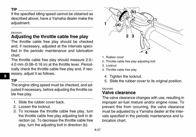
8-27
8
TIPIf the specified idling speed cannot be obtained asdescribed above, have a Yamaha dealer make theadjustment.
EBU24045
Adjusting the throttle cable free play The throttle cable free play should be checkedand, if necessary, adjusted at the intervals speci-fied in the periodic maintenance and lubricationchart.The throttle cable free play should measure 2.0–4.0 mm (0.08–0.16 in) at the throttle lever. Period-ically check the throttle cable free play and, if nec-essary, adjust it as follows.
TIPThe engine idling speed must be checked, and ad-justed if necessary, before adjusting the throttle ca-ble free play.
1. Slide the rubber cover back.2. Loosen the locknut.3. To increase the throttle cable free play, turn
the throttle cable free play adjusting bolt in di-rection (a). To decrease the throttle cable freeplay, turn the adjusting bolt in direction (b).
4. Tighten the locknut.5. Slide the rubber cover to its original position.
EBU24060
Valve clearance The valve clearance changes with use, resulting inimproper air-fuel mixture and/or engine noise. Toprevent this from occurring, the valve clearancemust be adjusted by a Yamaha dealer at the inter-vals specified in the periodic maintenance and lu-brication chart.
1. Rubber cover2. Throttle cable free play adjusting bolt3. Locknut4. Throttle cable free play
32
4
(a)
(b)
1
U1AS10E0.book Page 27 Tuesday, February 10, 2009 9:33 AM

8-28
8
EBU29601
Brakes Replacement of brake components requires pro-fessional knowledge. Brake service should be per-formed by a Yamaha dealer.
WARNINGEWB02571
Operating with improperly serviced or adjust-ed brakes could lead to a loss in braking abilityand an accident.
EBU24110
Checking the front and rear brake pads The front and rear brake pads must be checked forwear at the intervals specified in the periodic main-tenance and lubrication chart. Each brake pad isprovided with wear indicator grooves, which allowyou to check the brake pad wear without having todisassemble the brake. If a brake pad has worn tothe point that the wear indicator grooves have al-most disappeared, have a Yamaha dealer replacethe brake pads as a set.
1. Wear indicator groove
1. Wear indicator groove
1
1
U1AS10E0.book Page 28 Tuesday, February 10, 2009 9:33 AM

8-29
8
EBU26822
Checking the brake fluid level Insufficient brake fluid may allow air to enter thebrake system, possibly causing it to become inef-fective.Before riding, check that the brake fluid is abovethe minimum level mark and replenish if neces-sary. A low brake fluid level may indicate wornbrake pads and/or brake system leakage. If thebrake fluid level is low, be sure to check the brakepads for wear and the brake system for leakage.
Front brake
Rear brake
TIPTo check the rear brake fluid level, remove theseat. (See page 4-13.)
If the rear brake fluid level is low, replenish as fol-lows.
1. Remove the cowling bolt and quick fastenerscrew.
1. Minimum level mark
1
1. Minimum level mark
1
U1AS10E0.book Page 29 Tuesday, February 10, 2009 9:33 AM

8-30
8
2. Pull the cowling slightly outward as shown. 3. Remove the brake fluid reservoir cap, andthen refill with brake fluid.
4. Install the brake fluid reservoir cap.5. Place the cowling in the original position, and
then install the bolt and quick fastener screw.Observe these precautions:� When checking the fluid level, make sure that
the top of the brake fluid reservoir is level.� Use only the recommended quality brake fluid,
otherwise the rubber seals may deteriorate,causing leakage and poor braking performance.
1. Quick fastener screw2. Bolt
1
2
1. Cowling2. Brake fluid reservoir cap
1
2
U1AS10E0.book Page 30 Tuesday, February 10, 2009 9:33 AM

8-31
8
� Refill with the same type of brake fluid. Mixingfluids may result in a harmful chemical reactionand lead to poor braking performance.
� Be careful that water does not enter the brakefluid reservoir when refilling. Water will signifi-cantly lower the boiling point of the fluid and mayresult in vapor lock.
� Brake fluid may deteriorate painted surfaces orplastic parts. Always clean up spilled fluid imme-diately.
� As the brake pads wear, it is normal for the brakefluid level to gradually go down. However, if thebrake fluid level goes down suddenly, have aYamaha dealer check the cause.
EBU24291
Changing the brake fluid Have a Yamaha dealer change the brake fluid atthe intervals specified in the TIP after the periodicmaintenance and lubrication chart. In addition,have the oil seals of the master cylinders and cali-pers as well as the brake hoses replaced at the in-tervals listed below or whenever they are damagedor leaking.
� Oil seals: Replace every two years.� Brake hoses: Replace every four years.
EBU24394
Checking the front brake lever free play The brake lever free play must be checked at theintervals specified in the periodic maintenance andlubrication chart. The brake lever should have nofree play as shown. If there is free play, have aYamaha dealer check the brake system.
Recommended brake fluid:DOT 4
1. No free play
U1AS10E0.book Page 31 Tuesday, February 10, 2009 9:33 AM

8-32
8
EBU24612
Checking the brake pedal position The brake pedal position must be checked and, ifnecessary, adjusted at the intervals specified in theperiodic maintenance and lubrication chart.The top of the brake pedal should be positioned15.3 mm (0.60 in) below the top of the footrest asshown. If the brake pedal is not positioned as spec-ified, have a Yamaha dealer adjust it.
EBU26850
Adjusting the parking brake free play The parking brake free play must be checked and,if necessary, adjusted at the intervals specified inthe periodic maintenance and lubrication chart.
Cable length “A” should measure 56–58 mm(2.20–2.28 in). Adjust the parking brake free playas follows.
1. Release the parking brake by moving theparking brake lever to the right.
2. Loosen the locknut on the brake cable.3. Turn the adjusting nut on the brake cable in di-
rection (a) to increase the cable length, and indirection (b) to decrease it.
1. Brake pedal position
11. Cable length “A”
1
U1AS10E0.book Page 32 Tuesday, February 10, 2009 9:33 AM

8-33
8TIPIf the cable length cannot be adjusted to specifica-tion, consult a Yamaha dealer.
4. Tighten the locknut on the brake cable.
WARNINGEWB02090
Operating with improperly serviced or adjust-ed brakes could cause the brakes to malfunc-tion, resulting in reduced brakingperformance. This could increase the chanceof a collision or accident. After adjusting theparking brake free play, block the rear of the
ATV off the ground and spin the rear wheels.Check to make sure there is no brake drag. Ifbrake drag is noticed, perform the adjustmentagain.
EBU24740
Brake light switches The operation of the brake light switches must bechecked and, if necessary, adjusted at the inter-vals specified in the periodic maintenance and lu-brication chart.The brake light switch for the brake pedal can beadjusted as follows, but the other brake lightswitches should be adjusted by a Yamaha dealer.
TIPThe brake light switch is properly adjusted whenthe brake light comes on just before braking takeseffect.
Turn the adjusting nut while holding the brake lightswitch in place. To make the brake light come onearlier, turn the adjusting nut in direction (a). Tomake the brake light come on later, turn the adjust-ing nut in direction (b).
1. Locknut2. Brake lever free play adjusting nut
12
(a)
(b)
U1AS10E0.book Page 33 Tuesday, February 10, 2009 9:33 AM

8-34
8
EBU24820
Adjusting the clutch lever free play The clutch lever free play must be checked and, ifnecessary, adjusted at the intervals specified in theperiodic maintenance and lubrication chart.The clutch lever free play should measure 5.0–10.0 mm (0.20–0.39 in) as shown. If the free playis incorrect, adjust it as follows.
1. Loosen the locknut at the clutch lever.2. To increase the clutch lever free play, turn the
adjusting bolt at the clutch lever in direction(a), and to decrease it, turn the bolt in direction(b).
3. Tighten the locknut at the clutch lever.If the specified free play cannot be obtained,proceed with the following steps.
4. Loosen the locknut at the clutch lever.5. Fully turn the adjusting bolt at the clutch lever
in direction (a) to loosen the clutch cable.6. Loosen the locknut at the crankcase.7. To increase the clutch lever free play, turn the
adjusting nut at the crankcase in direction (a),and to decrease it, turn the nut in direction (b).
1. Brake light switch2. Brake light switch adjusting nut
1
2
(a) (b)
1. Locknut2. Clutch lever free play adjusting bolt3. Clutch lever free play
12(a)
(b)
3
U1AS10E0.book Page 34 Tuesday, February 10, 2009 9:33 AM
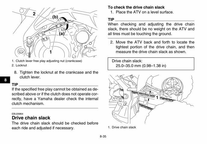
8-35
8
8. Tighten the locknut at the crankcase and theclutch lever.
TIPIf the specified free play cannot be obtained as de-scribed above or if the clutch does not operate cor-rectly, have a Yamaha dealer check the internalclutch mechanism.
EBU26864
Drive chain slack The drive chain slack should be checked beforeeach ride and adjusted if necessary.
To check the drive chain slack1. Place the ATV on a level surface.
TIPWhen checking and adjusting the drive chainslack, there should be no weight on the ATV andall tires must be touching the ground.
2. Move the ATV back and forth to locate thetightest portion of the drive chain, and thenmeasure the drive chain slack as shown.
1. Clutch lever free play adjusting nut (crankcase)2. Locknut
1
2
(a)
(b)
Drive chain slack:25.0–35.0 mm (0.98–1.38 in)
1. Drive chain slack
1
U1AS10E0.book Page 35 Tuesday, February 10, 2009 9:33 AM

8-36
8
3. If the drive chain slack is incorrect, adjust it asfollows.
To adjust the drive chain slack1. Place the ATV on a level surface.2. Loosen the rear wheel axle pinch bolts.3. Insert a rod of a diameter of 8 mm (0.3 in) and
a length of 10 cm (4 in) into one of the holes inthe drive chain tensioner as shown.
TIPA rod can be obtained at a Yamaha dealer to makethis adjustment.
4. Shift the transmission into neutral.5. To tighten the drive chain, push the ATV back-
ward. To loosen the drive chain, push the ATVforward. NOTICE: Improper drive chainslack will overload the engine as well asother vital parts of the ATV and can lead todrive chain slippage or breakage. To pre-vent this from occurring, keep the drivechain slack within the specified limits.[ECB00542]
6. Pull the rod out, and then tighten the rear axlepinch bolts to the specified torque in the ordershown.
1. Rear wheel axle pinch bolt2. Rod3. Drive chain tensioner4. Hole
4
2 1 1
3
U1AS10E0.book Page 36 Tuesday, February 10, 2009 9:33 AM

8-37
8EBU24881
Lubricating the drive chain The drive chain must be cleaned and lubricated atthe intervals specified in the periodic maintenanceand lubrication chart, otherwise it will quickly wearout, especially when riding in dusty or wet areas.Service the drive chain as follows.
NOTICEECB00560
The drive chain must be lubricated after wash-ing the ATV or riding in the rain.
1. Clean the drive chain with kerosene and asmall soft brush. NOTICE: To prevent dam-aging the O-rings, do not clean the drivechain with steam cleaners, high-pressurewashers or inappropriate solvents. [ECB00571]
2. Wipe the drive chain dry.3. Thoroughly lubricate the drive chain with a
special O-ring chain lubricant. NOTICE: Donot use engine oil or any other lubricants
Tightening torque:Rear axle pinch bolt:
21 Nm (2.1 m·kgf, 15 ft·lbf)
3 12
4
1. O-ring
1
U1AS10E0.book Page 37 Tuesday, February 10, 2009 9:33 AM

8-38
8
for the drive chain, as they may containsubstances that could damage the O-rings. [ECB00581]
EBU24901
Checking and lubricating the cables The operation and the condition of all control ca-bles should be checked before each ride, and thecables and cable ends should be lubricated if nec-essary. If a cable is damaged or does not movesmoothly, have a Yamaha dealer check or replaceit.
WARNINGEWB02581
� Inspect cables frequently and replace if dam-aged. Corrosion can result when the cablesheaths become damaged, and cables canalso become frayed or kinked, which couldrestrict the operation of controls and lead toan accident or injury.
� Always make sure all control cables worksmoothly before you begin riding in coldweather. If the control cables are frozen or do
not work smoothly, you could be unable tocontrol the ATV, which could lead to an acci-dent or collision.
EBU24922
Checking and lubricating the brake and clutch levers The operation of the brake and clutch leversshould be checked before each ride, and the leverpivots should be lubricated if necessary.
EBUM0170
Checking the shift pedal The operation of the shift pedal should be checkedbefore each ride. If operation is not smooth, havea Yamaha dealer check the vehicle.
Recommended lubricant:Engine oil
Recommended lubricants:Brake lever:
Silicone greaseClutch lever:
Lithium-soap-based grease
U1AS10E0.book Page 38 Tuesday, February 10, 2009 9:33 AM
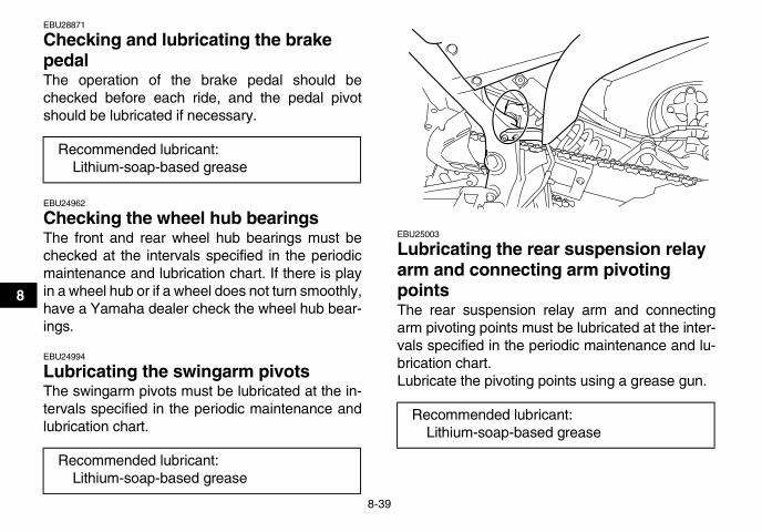
8-39
8
EBU28871
Checking and lubricating the brake pedal The operation of the brake pedal should bechecked before each ride, and the pedal pivotshould be lubricated if necessary.
EBU24962
Checking the wheel hub bearings The front and rear wheel hub bearings must bechecked at the intervals specified in the periodicmaintenance and lubrication chart. If there is playin a wheel hub or if a wheel does not turn smoothly,have a Yamaha dealer check the wheel hub bear-ings.
EBU24994
Lubricating the swingarm pivots The swingarm pivots must be lubricated at the in-tervals specified in the periodic maintenance andlubrication chart.
EBU25003
Lubricating the rear suspension relay arm and connecting arm pivoting points The rear suspension relay arm and connectingarm pivoting points must be lubricated at the inter-vals specified in the periodic maintenance and lu-brication chart.Lubricate the pivoting points using a grease gun.
Recommended lubricant:Lithium-soap-based grease
Recommended lubricant:Lithium-soap-based grease
Recommended lubricant:Lithium-soap-based grease
U1AS10E0.book Page 39 Tuesday, February 10, 2009 9:33 AM

8-40
8
EBU25032
Lubricating the upper and lower arm pivots The upper and lower arm pivots must be lubricatedat the intervals specified in the periodic mainte-nance and lubrication chart.Lubricate the pivoting points using a grease gun.
1. Grease nipple
1. Grease nipple
1
1
1. Grease nipple
Recommended lubricant:Lithium-soap-based grease
1
U1AS10E0.book Page 40 Tuesday, February 10, 2009 9:33 AM
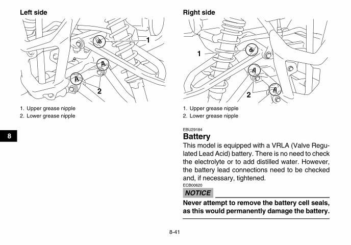
8-41
8
Left side Right side
EBU29184
Battery This model is equipped with a VRLA (Valve Regu-lated Lead Acid) battery. There is no need to checkthe electrolyte or to add distilled water. However,the battery lead connections need to be checkedand, if necessary, tightened.
NOTICEECB00620
Never attempt to remove the battery cell seals,as this would permanently damage the battery.
1. Upper grease nipple2. Lower grease nipple
1
2
1. Upper grease nipple2. Lower grease nipple
1
2
U1AS10E0.book Page 41 Tuesday, February 10, 2009 9:33 AM

8-42
8
WARNINGEWB02160
Battery electrolyte is poisonous and danger-ous, as it contains sulfuric acid, which cancause severe burns. Avoid contact with skin,eyes or clothing. Always shield your eyeswhen working near batteries.Antidote:EXTERNAL: Flush with water.INTERNAL: Drink large quantities of water ormilk. Follow with milk of magnesia, beaten eggor vegetable oil. Call a physician immediately.EYES: Flush with water for 15 minutes and getprompt medical attention.Batteries produce explosive gases. Keepsparks, flame, cigarettes or other sources of ig-nition away. Ventilate when charging or usingin an enclosed space.KEEP OUT OF REACH OF CHILDREN.
To remove the battery1. Remove the seat. (See page 4-13.)2. Remove the battery holding plate by removing
the bolts.
3. Disconnect the negative battery lead first,then the positive battery lead by removingtheir bolt. NOTICE: When removing the bat-tery, the main switch must be off, and thenegative lead must be disconnected be-fore the positive lead. [ECB01001]
4. Pull the battery out of its compartment.
1. Negative battery lead (black)2. Positive battery lead (red)
21
U1AS10E0.book Page 42 Tuesday, February 10, 2009 9:33 AM

8-43
8
To charge the batteryHave a Yamaha dealer charge the battery as soonas possible if it seems to have discharged. Keep inmind that the battery tends to discharge morequickly if the ATV is equipped with optional electri-cal accessories.
NOTICEECB00930
To charge a VRLA (Valve Regulated Lead Acid)battery, a special (constant-voltage) batterycharger is required. Using a conventional bat-tery charger will damage the battery. If you donot have access to a constant-voltage batterycharger, have a Yamaha dealer charge yourbattery.
To store the battery� If the ATV will not be used for more than one
month, remove the battery, fully charge it, andthen place it in a cool, dry place.
� If the battery will be stored for more than twomonths, check it at least once a month and fullycharge it if necessary.
NOTICEECB00940
Always keep the battery charged. Storing a dis-charged battery can cause permanent batterydamage.
To install the battery
TIPBe sure the battery is fully charged.
1. Place the battery in its compartment.2. Connect the positive battery lead first, then
connect the negative battery lead by installingtheir bolt.
U1AS10E0.book Page 43 Tuesday, February 10, 2009 9:33 AM

8-44
8
3. Install the battery holding plate by installingthe bolts.
4. Install the seat. (See page 4-13.)
EBU25326
Replacing a fuse The main fuse and the fuse box are located underthe seat. (See page 4-13.)
1. Positive battery lead (red)2. Negative battery lead (black)
21
1. Main fuse2. Spare main fuse
1
2
U1AS10E0.book Page 44 Tuesday, February 10, 2009 9:33 AM

8-45
8If a fuse is blown, replace it as follows.
1. Turn the key to “OFF” and turn off all electricalcircuits.
NOTICEECB00640
To prevent accidental short-circuiting, turn offthe main switch when checking or replacing afuse.
2. Remove the blown fuse, and then install anew fuse of the specified amperage.WARNING! Always use a fuse of the spec-ified rating, and never use a substitute ob-ject in place of the proper fuse. Animproper fuse or a substitute object cancause damage to the electrical system,which could lead to a fire. [EWB02172]
3. Turn the key to “ON” and turn on the electricalcircuits to check if the devices operate.
4. If the fuse immediately blows again, have aYamaha dealer check the electrical system.
1. Signaling system fuse2. Headlight fuse3. Ignition fuse4. Fuel injection system fuse5. Spare fuse
1234
5
Specified fuses:Main fuse:
20.0 AHeadlight fuse:
15.0 AIgnition fuse:
10.0 ASignaling system fuse:
10.0 AFuel injection system fuse:
10.0 A
U1AS10E0.book Page 45 Tuesday, February 10, 2009 9:33 AM

8-46
8
EBU25442
Replacing a headlight bulb If a headlight bulb burns out, replace it as follows.
1. Remove the headlight unit by removing thebolt.
2. Disconnect the headlight coupler.3. Remove the headlight bulb holder cover.
4. Remove the headlight bulb holder by pushingit in and turning it counterclockwise, and thenremove the burnt-out bulb.
1. Headlight unit2. Bolt
1
2
1. Headlight bulb holder cover2. Headlight coupler
1
2
U1AS10E0.book Page 46 Tuesday, February 10, 2009 9:33 AM

8-47
8
5. Place a new headlight bulb into position.NOTICE: Do not touch the glass part of theheadlight bulb to keep it free from oil, oth-erwise the transparency of the glass, theluminosity of the bulb, and the bulb life willbe adversely affected. Thoroughly cleanoff any dirt and fingerprints on the head-light bulb using a cloth moistened with al-cohol or thinner. [ECB00651]
6. Install the headlight bulb holder by pushing itin and turning it clockwise.
7. Install the headlight bulb holder cover.8. Connect the headlight coupler.9. Install the headlight unit by installing the bolts.
10. Adjust the headlight beam if necessary.
EBU25560
Adjusting a headlight beam
NOTICEECB00690
It is advisable to have a Yamaha dealer makethis adjustment.
1. Headlight bulb holder
1
1. Do not touch the glass part of the bulb.
U1AS10E0.book Page 47 Tuesday, February 10, 2009 9:33 AM

8-48
8
To raise a headlight beam, turn the adjusting boltin direction (a).To lower a headlight beam, turn the adjusting boltin direction (b).
EBU26920
Tail/brake light This model is equipped with an LED type oftail/brake light.If the tail/brake light does not come on, have aYamaha dealer check it.
EBU25651
Removing a wheel 1. Place the ATV on a level surface.
2. Loosen the wheel nuts.
3. Elevate the ATV and place a suitable standunder the frame.
4. Remove the nuts from the wheel.5. Remove the wheel.
EBU27481
Installing a wheel 1. Place the ATV on a level surface.2. Install the wheel and the nuts.
1. Headlight beam adjusting bolt
1
(a)
(b)
1. Nut
U1AS10E0.book Page 48 Tuesday, February 10, 2009 9:33 AM

8-49
8
TIPWhen installing the wheel, make sure its arrowmark points toward the rotating direction of thewheel.
3. Lower the ATV to the ground.4. Tighten the wheel nuts to the specified
torques.
EBU25740
Troubleshooting Although Yamaha ATVs receive a thorough in-spection before shipment from the factory, troublemay occur during operation. Any problem in the fu-el, compression, or ignition systems, for example,can cause poor starting and loss of power.The following troubleshooting charts representquick and easy procedures for checking these vitalsystems yourself. However, should your ATV re-quire any repair, take it to a Yamaha dealer, whoseskilled technicians have the necessary tools, expe-rience, and know-how to service the ATV properly.Use only genuine Yamaha replacement parts. Im-itation parts may look like Yamaha parts, but theyare often inferior, have a shorter service life andcan lead to expensive repair bills.
WARNINGEWB02280
Do not smoke when checking the fuel system.Fuel can ignite or explode, causing severe inju-ry or property damage. Make sure there are noopen flames or sparks in the area, including pi-lot lights from water heaters or furnaces.
1. Arrow mark
Tightening torques:Front wheel nut:
45 Nm (4.5 m·kgf, 32 ft·lbf)Rear wheel nut:
45 Nm (4.5 m·kgf, 32 ft·lbf)
U1AS10E0.book Page 49 Tuesday, February 10, 2009 9:33 AM

8-50
8
EBU27691
Troubleshooting charts
Starting problems or poor engine performance
Check the fuel level inthe fuel tank.
1. FuelThere is enough fuel.
There is no fuel.
Check the compression.
Supply fuel. The engine does not start. Check the compression.
Operate the electric starter.
2. CompressionThere is compression.
There is no compression.
Check the ignition.
Have a Yamaha dealercheck the ATV.
Remove the spark plugand check the electrodes.
3. Ignition Wipe off with a dry cloth and correct thespark plug gap, or replace the spark plug.
Have a Yamaha dealer check the ATV.
The engine does not start.Have a Yamaha dealercheck the ATV.
The engine does not start.Check the battery.
Operate the electric starter.
4. BatteryThe engine turns over quickly.
The engine turns over slowly.
The battery is good.
Check the battery lead connections,and charge the battery if necessary.
Dry
Wet Operate the electric starter.
U1AS10E0.book Page 50 Tuesday, February 10, 2009 9:33 AM
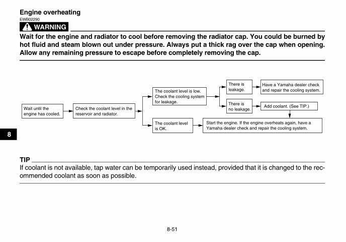
8-51
8
Engine overheating
WARNINGEWB02290
Wait for the engine and radiator to cool before removing the radiator cap. You could be burned byhot fluid and steam blown out under pressure. Always put a thick rag over the cap when opening.Allow any remaining pressure to escape before completely removing the cap.
TIPIf coolant is not available, tap water can be temporarily used instead, provided that it is changed to the rec-ommended coolant as soon as possible.
Wait until the engine has cooled.
Check the coolant level in the reservoir and radiator.
The coolant level is OK.
The coolant level is low.Check the cooling systemfor leakage.
Have a Yamaha dealer checkand repair the cooling system.
Add coolant. (See TIP.)
Start the engine. If the engine overheats again, have a Yamaha dealer check and repair the cooling system.
There isleakage.
There is no leakage.
U1AS10E0.book Page 51 Tuesday, February 10, 2009 9:33 AM
9-1
9
EBU25860
CLEANING AND STORAGEEBU25901
Cleaning Frequent, thorough cleaning of your ATV will notonly enhance its appearance but will improve itsgeneral performance and extend the useful life ofmany components.
1. Before cleaning the ATV:a. Block off the end of the exhaust pipe to
prevent water entry. A plastic bag andstrong rubber band may be used.
b. Make sure the spark plug and all filler capsare properly installed.
2. If the engine case is excessively greasy, applydegreaser with a paint brush. Do not apply de-greaser to the chain, sprockets or wheel ax-les.
3. Rinse the dirt and degreaser off with a gardenhose. Use only enough pressure to do thejob.WARNING! Wet brakes may have re-duced stopping ability, increasing thechance of an accident. Test the brakes af-ter washing. Apply the brakes severaltimes at slow speeds to let friction dry outthe linings. [EWB02311] NOTICE: Excessive wa-
ter pressure may cause water seepage anddeterioration of wheel bearings, brakes,transmission seals and electrical devices.Many expensive repair bills have resultedfrom improper high-pressure detergentapplications such as those available incoin-operated car washers. [ECB00711]
4. Once most of the dirt has been hosed off,wash all surfaces with warm water and mild,detergent-type soap. An old toothbrush or bot-tle brush is handy for hard-to-reach places.
5. Rinse the ATV off immediately with clean wa-ter and dry all surfaces with a chamois, cleantowel or soft absorbing cloth.
6. Dry the chain and lubricate it to prevent it fromrusting.
7. Clean the seat with a vinyl upholstery cleanerto keep the cover pliable and glossy.
8. Automotive type wax may be applied to allpainted and chrome plated surfaces. Avoidcombination cleaner-waxes. Many containabrasives which may mar the paint or protec-tive finish. When finished cleaning, start theengine and let it idle for several minutes.
U1AS10E0.book Page 1 Tuesday, February 10, 2009 9:33 AM

9-2
9
EBU27261
Storage
Short-termAlways store your ATV in a cool, dry place and, ifnecessary, protect it against dust with a porouscover. NOTICE: Storing the ATV in a poorly ven-tilated room or covering it with a tarp while it isstill wet, will allow water and humidity to seepin and cause rust. To prevent corrosion, avoiddamp cellars, stables (because of the presenceof ammonia) and areas where strong chemi-cals are stored. [ECB00721]
Long-termBefore storing your ATV for several months:
1. Follow all the instructions in the “Cleaning”section of this chapter.
2. Fill up the fuel tank and add fuel stabilizer (ifavailable) to prevent the fuel from deteriorat-ing.
3. Perform the following steps to protect the cyl-inder, piston rings, etc. from corrosion.a. Remove the spark plug cap and spark
plug.b. Pour a teaspoonful of engine oil into the
spark plug bore.c. Install the spark plug cap onto the spark
plug, and then place the spark plug on thecylinder head so that the electrodes aregrounded. (This will limit sparking duringthe next step.)
d. Turn the engine over several times with thestarter. (This will coat the cylinder wall withoil.)
e. Remove the spark plug cap from the sparkplug, and then install the spark plug andthe spark plug cap.
4. Lubricate all control cables and the pivotingpoints of all levers and pedals.
5. Check and, if necessary, correct the tire airpressure, and then block up the ATV so thatall of its wheels are off the ground. Alternative-ly, turn the wheels a little every month in orderto prevent the tires from becoming degradedin one spot.
Specified amount:7.5 ml of stabilizer to each liter of fuel (or 1 oz of stabilizer to each gallon of fuel)
U1AS10E0.book Page 2 Tuesday, February 10, 2009 9:33 AM

9-3
9
6. Cover the muffler outlet with a plastic bag toprevent moisture from entering it.
7. Remove the battery and fully charge it. Storeit in a cool, dry place and charge it once amonth. Do not store the battery in an exces-sively cold or warm place [less than 0 °C (30°F) or more than 30 °C (90 °F)]. For more in-formation on storing the battery, see page8-41.
TIPMake any necessary repairs before storing theATV.
U1AS10E0.book Page 3 Tuesday, February 10, 2009 9:33 AM

10-1
10
EBU25960
SPECIFICATIONS Dimensions:
Overall length:1845 mm (72.6 in)
Overall width:1170 mm (46.1 in)
Overall height:1130 mm (44.5 in)
Seat height:815 mm (32.1 in)
Wheelbase:1280 mm (50.4 in)
Ground clearance:240 mm (9.4 in)
Minimum turning radius:3500 mm (138 in)
Weight:With oil and fuel:
192.0 kg (423 lb)Engine:
Engine type:Liquid cooled 4-stroke, SOHC
Cylinder arrangement:Forward-inclined single cylinder
Displacement:686 cm³
Bore × stroke:102.0 × 84.0 mm (4.02 × 3.31 in)
Compression ratio:9.20 :1
Starting system:Electric starter
Lubrication system:Dry sump
Engine oil:Recommended brand:
YAMALUBEType:
SAE 5W-30 or SAE 10W-40 or SAE 20W-50
Recommended engine oil grade:API service SG type or higher, JASO standard MA
0 10 30 50 70 90 110 130 ̊ F
-20 -10 0 10 20 30 40 50 ̊ C
SAE 5W-30
SAE 10W-40
SAE 20W-50
U1AS10E0.book Page 1 Tuesday, February 10, 2009 9:33 AM

10-2
10
Engine oil quantity:Without oil filter element replacement:
1.75 L (1.85 US qt, 1.54 Imp.qt)With oil filter element replacement:
1.85 L (1.96 US qt, 1.63 Imp.qt)Cooling system:
Coolant reservoir capacity (up to the maximum level mark):0.25 L (0.26 US qt, 0.22 Imp.qt)
Radiator capacity (including all routes):1.61 L (1.70 US qt, 1.42 Imp.qt)
Air filter:Air filter element:
Wet elementFuel:
Recommended fuel:Unleaded gasoline only
Fuel tank capacity:11.0 L (2.91 US gal, 2.42 Imp.gal)
Fuel reserve amount:2.6 L (0.69 US gal, 0.57 Imp.gal)
Fuel injection:Throttle body:
Type/quantity:44EHS/1
Spark plug (s):Manufacturer/model:
NGK/CR8ESpark plug gap:
0.7–0.8 mm (0.028–0.031 in)
Clutch:Clutch type:
Wet, multiple-discTransmission:
Primary reduction system:Spur gear
Primary reduction ratio:77/34 (2.265)
Secondary reduction system:Chain drive
Secondary reduction ratio:38/14 (2.714)
Transmission type:Constant mesh 5-speed.forward, 1-speed.reverse
Operation:Left foot operation
Gear ratio:1st:
38/13 (2.923)2nd:
28/14 (2.000)3rd:
25/17 (1.471)4th:
25/22 (1.136)5th:
22/24 (0.917)Reverse gear:
24/13 × 29/12 (4.462)Chassis:
Frame type:Aluminum die-cast and steel tube frame
U1AS10E0.book Page 2 Tuesday, February 10, 2009 9:33 AM

10-3
10
Caster angle:5.0 °
Trail:21.0 mm (0.83 in)
Front tire:Type:
TubelessSize:
AT21 x 7R10Manufacturer/model:
DUNLOP/KT341 RadialRear tire:
Type:Tubeless
Size:AT20 x 10R9
Manufacturer/model:DUNLOP/KT345 Radial
Loading:Maximum loading limit:
100.0 kg (220 lb)(Total weight of rider, cargo, accessories, and tongue)
Tire air pressure (measured on cold tires):Recommended:
Front:27.5 kPa (0.275 kgf/cm², 4.0 psi)
Rear:27.5 kPa (0.275 kgf/cm², 4.0 psi)
Minimum:Front:
24.5 kPa (0.245 kgf/cm², 3.6 psi)
Rear:24.5 kPa (0.245 kgf/cm², 3.6 psi)
Front wheel:Wheel type:
Panel wheelRim size:
10 x 5.5ATRear wheel:
Wheel type:Panel wheel
Rim size:9 x 8.5AT
Front brake:Type:
Dual disc brakeOperation:
Right hand operationRecommended fluid:
DOT 4Rear brake:
Type:Single disc brake
Operation:Right foot operation
Recommended fluid:DOT 4
Front suspension:Type:
Double wishboneSpring/shock absorber type:
Coil spring/gas-oil damper
U1AS10E0.book Page 3 Tuesday, February 10, 2009 9:33 AM

10-4
10
Wheel travel:230 mm (9.1 in)
Rear suspension:Type:
Swingarm (link suspension)Spring/shock absorber type:
Coil spring/gas-oil damperWheel travel:
256 mm (10.1 in)Electrical system:
Ignition system:TCI (digital)
Charging system:AC magneto
Battery:Model:
GT9B-4Voltage, capacity:
12 V, 8.0 AhHeadlight:
Bulb type:Krypton bulb
Bulb voltage, wattage × quantity:Headlight:
12 V, 30/30 W × 2Tail/brake light:
LEDMeter lighting:
ELNeutral indicator light:
LED
Fuel level warning light:LED
Reverse indicator light:LED
Coolant temperature warning light:LED
Engine trouble warning light:LED
Fuses:Main fuse:
20.0 AFuel injection system fuse:
10.0 AHeadlight fuse:
15.0 ASignaling system fuse:
10.0 AIgnition fuse:
10.0 A
U1AS10E0.book Page 4 Tuesday, February 10, 2009 9:33 AM

11-1
11
EBU25981
CONSUMER INFORMATIONEBU26012
Identification numbers Record the key identification number, vehicle iden-tification number and model label information inthe spaces provided below for assistance when or-dering spare parts from a Yamaha dealer or for ref-erence in case the ATV is stolen.KEY IDENTIFICATION NUMBER:
VEHICLE IDENTIFICATION NUMBER:
MODEL LABEL INFORMATION:
EBU26020
Key identification number The key identification number is stamped into thekey. Record this number in the space provided anduse it for reference when ordering a new key.
EBU26030
Vehicle identification number The vehicle identification number is stamped intothe frame.
1. Key identification number
U1AS10E0.book Page 1 Tuesday, February 10, 2009 9:33 AM
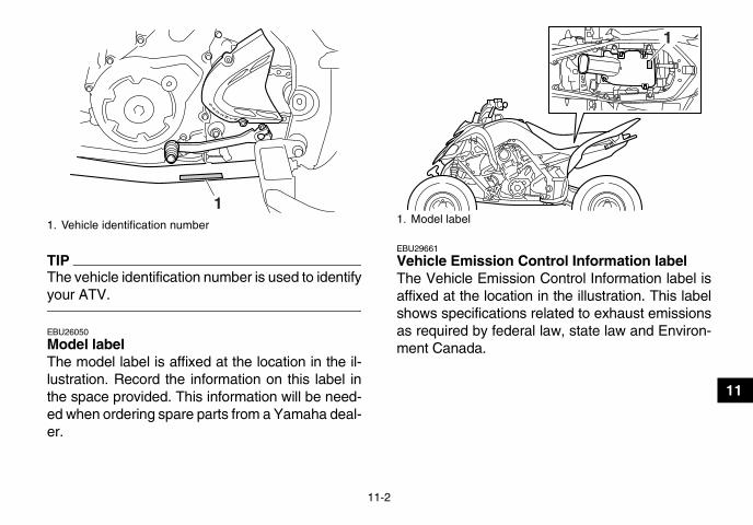
11-2
11
TIPThe vehicle identification number is used to identifyyour ATV.
EBU26050
Model label The model label is affixed at the location in the il-lustration. Record the information on this label inthe space provided. This information will be need-ed when ordering spare parts from a Yamaha deal-er.
EBU29661
Vehicle Emission Control Information label The Vehicle Emission Control Information label isaffixed at the location in the illustration. This labelshows specifications related to exhaust emissionsas required by federal law, state law and Environ-ment Canada.
1. Vehicle identification number
11. Model label
1
U1AS10E0.book Page 2 Tuesday, February 10, 2009 9:33 AM

11-3
11
1. Vehicle Emission Control Information label
1
U1AS10E0.book Page 3 Tuesday, February 10, 2009 9:33 AM

11-4
11
EBU26060
Noise regulation TAMPERING WITH NOISE CONTROL SYSTEM PROHIBITED:Federal law prohibits the following acts or the causing thereof: (1) The removal or rendering inoperative byany person other than for purposes of maintenance, repair, or replacement of any device or element of de-sign incorporated into any new vehicle for the purpose of noise control prior to its sale or delivery to the ul-timate purchaser or while it is in use or (2) the use of the vehicle after such device or element of design hasbeen removed or rendered inoperative by any person.“AMONG THOSE ACTS PRESUMED TO CONSTITUTE TAMPERING ARE THE ACTS LISTED BELOW”.These acts include tampering with the following systems; i.e., modification, removal, etc.
Exhaust system• Muffler• Exhaust pipe• Silencer
Intake system• Air cleaner case• Air cleaner element• Intake duct
U1AS10E0.book Page 4 Tuesday, February 10, 2009 9:33 AM

11-5
11
EBU26080
Maintenance record Copies of work orders and/or receipts for parts you purchase and install will be required to document main-tenance done in accordance with the warranty. The chart below is printed only as a reminder to you that themaintenance work is required. It is not acceptable proof of maintenance work.
MAINTENANCE INTERVAL DATE OF SERVICE MILEAGE SERVICING DEALER
NAME AND ADDRESS REMARKSmonth km (mi) hours
1 320 (200) 203 1300 (800) 806 2500 (1600) 160
12 5000 (3200) 32018 7500 (4800) 48024 10000 (6400) 64030 12500 (8000) 80036 15000 (9600) 96042 17500 (11200) 112048 20000 (12800) 128054 22500 (14400) 144060 25000 (16000) 1600
U1AS10E0.book Page 5 Tuesday, February 10, 2009 9:33 AM

11-6
11
EBU26501
YAMAHA MOTOR CORPORATION, U.S.A. ATV LIMITED WARRANTY
Yamaha Motor Corporation, U.S.A. hereby warrants that new Yamaha ATVs purchased from an authorized Yamaha ATV dealer in the continental United States will be free from defects in material and workmanship for the period of time stated herein, sub-ject to certain stated limitations.
THE PERIOD OF WARRANTY for Yamaha ATVs shall be six (6) months from the date of purchase.
DURING THE PERIOD OF WARRANTY any authorized Yamaha ATV dealer will, free of charge, repair or replace any part adjudged defective by Yamaha due to faulty workmanship or material from the factory. Parts used in warranty repairs will be warranted for the balance of the product’s warranty period. All parts replaced under warranty become property of Yamaha Motor Corp. U.S.A.
GENERAL EXCLUSIONS from this warranty shall include any failures caused by:a. Competition or racing use.b. Installation of parts or accessories that are not
qualitatively equivalent to genuine Yamaha parts.c. Abnormal strain, neglect, or abuse.d. Lack of proper maintenance.e. Accident or collision damage. f. Modification to original parts.g. Damage due to improper transportation.
SPECIFIC EXCLUSIONS from this warranty shall include parts replaced due to normal wear or routine maintenance, such as spark plugs, oil, oil filter, air filter, and brake shoes.
THE CUSTOMER’S RESPONSIBILITY under this war-ranty shall be to:1. Operate and maintain the ATV as specified in the
appropriate owner’s manual;2. Give notice to an authorized Yamaha ATV dealer
of any and all apparent defects within ten (10) days after discovery, and make the machine available at that time for inspection and repairs at such dealer’s place of business.
WARRANTY TRANSFER: To transfer the warranty from the original purchaser to any subsequent pur-chaser(s), it is imperative that the machine be inspected and registered for warranty by an autho-rized Yamaha ATV dealer. In order for this warranty to remain in effect, this inspection and registration must take place within ten (10) days after transfer. An inspection and registration fee will be charged for this service.
EMISSION CONTROL SYSTEM WARRANTYYamaha Motor Corporation, USA also warrants to the ultimate purchaser and each subsequent pur-chaser of each 2006 and later model Yamaha ATV covered by this warranty that the vehicle is designed, built, and equipped so as to conform at the time of sale with all U.S. emissions standards applicable at the time of manufacture and that it is free from defects in materials and workmanship which would cause it not to meet these standards
within the period listed immediately below. Failures other than those resulting from defects in material or workmanship which arise solely as a result of owner abuse and/or lack of proper maintenance are not covered by this warranty.
All ModelsThirty (30) months from the original purchase date
YAMAHA MOTOR CORPORATION, U.S.A. MAKES NO OTHER WARRANTY OF ANY KIND, EXPRESSED OR IMPLIED. ALL IMPLIED WARRANTIES OF MERCHANTABILITY AND FITNESS FOR A PARTICULAR PURPOSE WHICH EXCEED THE OBLIGATIONS AND TIME LIMITS STATED IN THIS WARRANTY ARE HEREBY DISCLAIMED BY YAMAHA MOTOR CORPORATION, U.S.A. AND EXCLUDED FROM THIS WARRANTY.
SOME STATES DO NOT ALLOW LIMITATIONS ON HOW LONG AN IMPLIED WARRANTY LASTS, SO THE ABOVE LIMITATION MAY NOT APPLY TO YOU. ALSO EXCLUDED FROM THIS WARRANTY ARE ANY INCIDENTAL OR CONSEQUENTIAL DAMAGES INCLUDING LOSS OF USE. SOME STATES DO NOT ALLOW THE EXCLUSION OR LIMITATION OF INCIDENTAL OR CONSEQUENTIAL DAMAGES, SO THE ABOVE EXCLUSION MAY NOT APPLY TO YOU.
THIS WARRANTY GIVES YOU SPECIFIC LEGAL RIGHTS, AND YOU MAY ALSO HAVE OTHER RIGHTS WHICH VARY FROM STATE TO STATE.
YAMAHA MOTOR CORPORATION, U.S.A.P.O. Box 6555
Cypress, California 90630
U1AS10E0.book Page 6 Tuesday, February 10, 2009 9:33 AM

11-7
11
WARRANTY QUESTIONS AND ANSWERS
Q. What costs are my responsibility during the warranty period?A. The customer’s responsibility includes all costs of normal maintenance services,
non-warranty repairs, accident and collision damages, and oil, oil filters, air filters, spark plugs, and brake shoes.
Q. What are some examples of “abnormal” strain, neglect, or abuse?A. These terms are general and overlap each other in areas. Specific examples include:
Running the machine out of oil, sustained high rpm, full-throttle, operating the machine with a broken or damaged part which causes another part to fail, damage or failure due to improper or careless transportation and or tie-down. If you have any specific questions on operation or maintenance, please contact your dealer for advice.
Q. Does the warranty cover incidental costs such as towing or transportation due to a failure?
A. No. The warranty is limited to repair of the machine itself.
Q. May I perform any or all of the recommended maintenance shown in the Owner’s Manual instead of having the dealer do them?
A. Yes, if you are a qualified mechanic and follow the procedures specified in the Owner’s and Service Manual. We do recommend, however, that items requiring special tools or equipment be done by a Yamaha ATV dealer.
Q. Will the warranty be void or cancelled if I do not operate or maintain my new ATV exactly as specified in the Owner’s Manual?
A. No. The warranty on a new ATV cannot be “voided” or “cancelled.” However, if a particular failure is caused by operation or maintenance other than as described in the Owner’s Manual, that failure may not be covered under warranty.
Q. What responsibility does my dealer have under this warranty?A. Each Yamaha ATV dealer is expected to:
1. Completely set up every new machine before sale.2. Explain the operation, maintenance, and warranty requirements to your satis-
faction at the time of sale, and upon your request at any later date.3. Each Yamaha ATV dealer is held responsible for his setup, service and war-
ranty repair work.
Q. Is the warranty transferable to second owners?A. Yes. The remainder of the existing warranty can be transferred upon request. The
unit has to be inspected and re-registered by an authorized Yamaha ATV dealer for the policy to remain effective.
CUSTOMER SERVICE
If your machine requires warranty service, you must take it to any authorized Yamaha ATV dealer within the continental United States. Be sure to bring your warranty registration card or other valid proof of the original date of purchase. If a question or problem arises regarding warranty, first contact the owner of the dealership. Since all warranty matters are handled at the dealer level, this person is in the best position to help you. If you are still not satisfied and require additional assistance, please write:
YAMAHA MOTOR CORPORATION U.S.A.CUSTOMER RELATIONS DEPARTMENT
P.O. Box 6555Cypress, California 90630
When contacting Yamaha Motor Corporation, U.S.A. don’t forget to include any important information such as names, addresses, model, V.I.N. (frame number), dates, and receipts.
CHANGE OF ADDRESS
The federal government requires each manufacturer of a motor vehicle to maintain a complete, up-to-date list of all first purchasers against the possibility of a safety-related defect and recall. This list is compiled from the purchase registrations sent to Yamaha Motor Corporation, U.S.A. by the selling dealer at the time of your purchase.
If you should move after you have purchased your new ATV, please advise us of your new address by sending a postcard listing your ATV model name, V.I.N. (frame number), dealer number (or dealer’s name) as it is shown on your warranty card, your name and new mailing address. Mail to:
YAMAHA MOTOR CORPORATION, U.S.A.P.O. Box 6555
Cypress, California 90630Attention: Warranty Department
This will ensure that Yamaha Motor Corporation, U.S.A. has an up-to-date registration record in accordance with federal law.
U1AS10E0.book Page 7 Tuesday, February 10, 2009 9:33 AM

11-8
11
EBU26123
YAMAHA EXTENDED SERVICE (Y.E.S.)
Keep your Yamaha protected even after your warranty expires with genuine Yamaha Extended Service (Y.E.S.).
Y.E.S. is designed and administered by Yamaha Motor Corporation to provide maximum owner satisfaction. You get uninterrupted factory-backed coverage for extra peace of mind.
Y. E. S. is flexible. You choose the plan that’s right for you: 12 months, 24 months, or 36 months beyond your warranty period.
Y.E.S. is designed and administered by the same Yamaha people who handle your warranty – and i t shows in the comprehensive coverage benefits. There are no mileage l imitat ions. Coverage isn ’ t l imited to “moving par ts” or the “drive train” l ike many other plans. And Y.E.S. covers manufacturing defects just l ike the warranty. See the sample contract at your Yamaha dealer to see how comfor t ing uninterrupted factory-backed protection can be.
You don ’ t have to pay anything for covered repairs. There ’s no deduc t ib le to pay, and repa i rs a ren ’ t “pro-rated.” You don ’t have any “out-of-pocket” expenses for covered repairs.
In addition, Travel and Recreation Interruption Protection (TRIP) is included at no extra cost. TRIP gives you up to $150 reimbursement per occurrence for any reasonable expenses you incur because your Yamaha needs covered service: replacement vehicle rental, emergency towing, phone calls, even food and lodging when you are away from home. This superb coverage goes into effect when you purchase Y.E.S., so it applies to any warranty repairs as well as covered repairs during your entire Y.E.S. plan period.
Y.E.S. coverage is honored at any authorized Yamaha dealer nationwide.
Y.E.S. coverage is transferable to a new owner if you sell or trade in your ATV. That can make your Yamaha much more valuable!
This excellent Y.E.S. plan coverage is only available to Yamaha owners like you, and only while your Yamaha is still within the Yamaha Limited Warranty period. So visit your authorized Yamaha dealer to get all the facts. He can show you how easy it is to protect your investment with Yamaha Extended Service.
U1AS10E0.book Page 8 Tuesday, February 10, 2009 9:33 AM

11-9
11
We urge you to act now. You’ll get the excellent benefits of TRIP coverage r ight away, and you ’ l l rest easy knowing you ’ l l have strong factory-backed protection even after your Yamaha Limited Warranty expires. You can also save money: Y.E.S. costs less within the first 90 days after you buy your Yamaha. See your dealer today!
A special note:If visiting your dealer isn’t convenient, contact Yamaha with your Pr imary ID number (your frame number). We ’ l l be happy to help you get the Y.E.S. coverage you need.
Yamaha Service MarketingP.O. Box 6555Cypress, CA 90630
Indicates a hazardous situation which, if not avoided, could result in death or serious injury.
WARNING
U1AS10E0.book Page 9 Tuesday, February 10, 2009 9:33 AM

11-10
11
EBU26132
U1AS10E0.book Page 10 Tuesday, February 10, 2009 9:33 AM

INDEX
AAccessories and loading ................................................ 6-7Air filter element, cleaning ............................................ 8-20
BBattery .......................................................................... 8-41Brake and clutch levers, checking and lubricating ....... 8-38Brake fluid, changing .................................................... 8-31Brake fluid level, checking ............................................ 8-29Brake lever ..................................................................... 4-8Brake lever free play, checking the front ...................... 8-31Brake light switches ..................................................... 8-33Brake pads, checking the front and rear ...................... 8-28Brake pedal .................................................................... 4-8Brake pedal, checking and lubricating ......................... 8-39Brake pedal position, checking .................................... 8-32Brakes .......................................................................... 8-28Brakes, front and rear .................................................... 5-3
CCables, checking and lubricating ................................. 8-38Chassis fasteners ........................................................... 5-6Cleaning ......................................................................... 9-1Clutch lever .................................................................... 4-7Clutch lever free play, adjusting ................................... 8-34Coolant ..................................................................5-3, 8-17Coolant temperature warning light ................................. 4-2
DDrive chain ..................................................................... 5-4Drive chain, lubricating ................................................. 8-37
Drive chain slack .......................................................... 8-35E
Engine break-in .............................................................. 6-5Engine idling speed ...................................................... 8-26Engine oil ....................................................................... 5-3Engine oil and oil filter element .................................... 8-12Engine, start ................................................................... 6-1Engine stop switch ......................................................... 4-5Engine trouble warning light ........................................... 4-3
FFuel .......................................................................4-11, 5-3Fuel level warning light ................................................... 4-3Fuel tank cap ................................................................ 4-11Fuses, replacing ........................................................... 8-44
HHandlebar switches ........................................................ 4-5Headlight beam, adjusting ............................................ 8-47Headlight bulb, replacing .............................................. 8-46
IIdentification numbers .................................................. 11-1Indicator lights and warning lights .................................. 4-2Instruments, lights and switches .................................... 5-6
KKey identification number ............................................. 11-1
LLabel locations ............................................................... 1-1Light switch .................................................................... 4-6
U1AS10E0.book Page 1 Tuesday, February 10, 2009 9:33 AM

MMain switch .................................................................... 4-1Maintenance and lubrication chart ................................. 8-5Maintenance chart, emission control system ................. 8-3Maintenance record ..................................................... 11-5Model label ................................................................... 11-2Multi-function display ..................................................... 4-3
NNeutral indicator light ..................................................... 4-2Noise regulation ........................................................... 11-4
OOwner’s manual and tool kit ........................................... 8-1
PPanel, removing and installing ....................................... 8-9Parking ........................................................................... 6-5Parking brake free play, adjusting ................................ 8-32Parking brake lever ........................................................ 4-9Parking on a slope ......................................................... 6-6Part locations ................................................................. 3-1
RReverse indicator light ................................................... 4-2Reverse knob ............................................................... 4-10Reverse knob and driving in reverse ............................. 6-2Riding your ATV ............................................................. 7-1
SSafety information .......................................................... 2-1Seat .............................................................................. 4-13Shifting ........................................................................... 6-3Shift pedal .................................................................... 4-10Shift pedal, checking .................................................... 8-38Shock absorber assemblies, adjusting the front .......... 4-14Shock absorber assembly, adjusting the rear .............. 4-19
Spark arrester, cleaning ............................................... 8-24Spark plug, checking ..................................................... 8-9Specifications ............................................................... 10-1Speed limiter .................................................................. 4-7Start switch .................................................................... 4-6Storage .......................................................................... 9-2Suspension, lubricating the upper and lower arm
pivots ......................................................................... 8-40Suspension relay arm and connecting arm pivoting
points, lubricating the rear ......................................... 8-39Swingarm pivots, lubricating ........................................ 8-39
TTail/brake light ............................................................. 8-48Throttle cable free play, adjusting ................................ 8-27Throttle lever ........................................................... 4-6, 5-4Tires ............................................................................... 5-4Troubleshooting ........................................................... 8-49Troubleshooting charts ................................................ 8-50
VValve clearance ........................................................... 8-27Vehicle Emission Control Information label ................. 11-2Vehicle identification number ....................................... 11-1
WWarranty, extended ..................................................... 11-8Warranty, limited .......................................................... 11-6Wheel hub bearings, checking ..................................... 8-39Wheel, installing ........................................................... 8-48Wheel, removing .......................................................... 8-48
U1AS10E0.book Page 2 Tuesday, February 10, 2009 9:33 AM

B6-yoko.fm Page 1 Wednesday, March 8, 2006 10:46 AM

B6-yoko.fm Page 1 Wednesday, March 8, 2006 10:46 AM

PRINTED IN JAPAN2009.02-0.3×1 CR
(E)
PRINTED ON RECYCLED PAPERYAMAHA MOTOR CO., LTD.
EBU26141
LOCATE AND READ OWNER’S MANUAL. FOLLOW ALL INSTRUCTIONS AND WARNINGS.(For replacement manual, call 1-800-532-1558)
WARNING
ALWAYS: use proper riding techniques to avoid vehicle overturns on hills and rough terrain and in turns. avoid paved surfaces-pavement may seriously affect handling and control.
Improper ATV use can result in SEVERE INJURY or DEATH.
NEVER operate: without proper training or instruction. at speeds too fast for your skills or the conditions. on public roads-a collision can occur with another vehicle. with a passenger-passengers affect balance and steering and increase risk of losing control.
ALWAYS USE AN APPROVED HELMET AND
PROTECTIVE GEAR
NEVER USE ON PUBLIC
ROADS
NEVER CARRY PASSENGERS
NEVER USE WITH DRUGS OR ALCOHOL
B EE R
B EE R
DIC183

