yamaha motif xs rack
TRANSCRIPT

7/14/2019 Yamaha Motif XS Rack
http://slidepdf.com/reader/full/yamaha-motif-xs-rack 1/118
EN
TONE GENERATOR
OWNER’S MANUAL

7/14/2019 Yamaha Motif XS Rack
http://slidepdf.com/reader/full/yamaha-motif-xs-rack 2/118
MOTIF-RACK XS Owner’s Manual2 MOTIF-RACK XS Owner’s Manual2
PLEASE KEEP THIS MANUAL
This product utilizes batteries or an external power supply (adapter). DONOT connect this product to any power supply or adapter other than onedescribed in the manual, on the name plate, or specifically recom-mended by Yamaha.
WARNING: Do not place this product in a position where anyone couldwalk on, trip over, or roll anything over power or connecting cords of anykind. The use of an extension cord is not recommended! If you must usean extension cord, the minimum wire size for a 25’ cord (or less) is 18AWG. NOTE: The smaller the AWG number, the larger the current han-dling capacity. For longer extension cords, consult a local electrician.
This product should be used only with the components supplied or; acart, rack, or stand that is recommended by Yamaha. If a cart, etc., isused, please observe all safety markings and instructions that accom-pany the accessory product.
SPECIFICATIONS SUBJECT TO CHANGE:The information contained in this manual is believed to be correct at thetime of printing. However, Yamaha reserves the right to change or modifyany of the specifications without notice or obligation to update existingunits.
This product, either alone or in combination with an amplifier and head-phones or speaker/s, may be capable of producing sound levels that
could cause permanent hearing loss. DO NOT operate for long periodsof time at a high volume level or at a level that is uncomfortable. If youexperience any hearing loss or ringing in the ears, you should consult anaudiologist.IMPORTANT: The louder the sound, the shorter the time period beforedamage occurs.
Some Yamaha products may have benches and / or accessory mountingfixtures that are either supplied with the product or as optional accesso-ries. Some of these items are designed to be dealer assembled orinstalled. Please make sure that benches are stable and any optional fix-tures (where applicable) are well secured BEFORE using.Benches supplied by Yamaha are designed for seating only. No otheruses are recommended.
NOTICE:Service charges incurred due to a lack of knowledge relating to how afunction or effect works (when the unit is operating as designed) are not
covered by the manufacturer’s warranty, and are therefore the ownersresponsibility. Please study this manual carefully and consult your dealerbefore requesting service.
ENVIRONMENTAL ISSUES:Yamaha strives to produce products that are both user safe and environ-mentally friendly. We sincerely believe that our products and the produc-tion methods used to produce them, meet these goals. In keeping withboth the letter and the spirit of the law, we want you to be aware of thefollowing:
Battery Notice:This product MAY contain a small non-rechargeable battery which (ifapplicable) is soldered in place. The average life span of this type of bat-tery is approximately five years. When replacement becomes necessary,contact a qualified service representative to perform the replacement.
This product may also use “household” type batteries. Some of thesemay be rechargeable. Make sure that the battery being charged is arechargeable type and that the charger is intended for the battery beingcharged.
When installing batteries, do not mix batteries with new, or with batteriesof a different type. Batteries MUST be installed correctly. Mismatches orincorrect installation may result in overheating and battery case rupture.
Warning:Do not attempt to disassemble, or incinerate any battery. Keep all batter-ies away from children. Dispose of used batteries promptly and as regu-lated by the laws in your area. Note: Check with any retailer ofhousehold type batteries in your area for battery disposal information.
Disposal Notice:Should this product become damaged beyond repair, or for some reasonits useful life is considered to be at an end, please observe all local,
state, and federal regulations that relate to the disposal of products thatcontain lead, batteries, plastics, etc. If your dealer is unable to assistyou, please contact Yamaha directly.
NAME PLATE LOCATION:The name plate is located on the top panel of the product. The nameplate lists the product’s model number, power requirements, and otherinformation. The serial number is located on the rear panel. Pleaserecord the model number, serial number, and date of purchase in thespaces provided below, and keep this manual as a permanent record ofyour purchase.
Model
Serial No.
Purchase Date
SPECIAL MESSAGE SECTION
92-BP (others)

7/14/2019 Yamaha Motif XS Rack
http://slidepdf.com/reader/full/yamaha-motif-xs-rack 3/118
MOTIF-RACK XS Owner’s Manual 3
IMPORTANT NOTICE FOR THE UNITED KINGDOM
Connecting the Plug and Cord
IMPORTANT. The wires in this mains lead are coloured in accordancewith the following code:
BLUE : NEUTRALBROWN : LIVE
As the colours of the wires in the mains lead of this apparatus may notcorrespond with the coloured makings identifying the terminals in yourplug proceed as follows:
The wire which is coloured BLUE must be connected to the terminalwhich is marked with the letter N or coloured BLACK.
The wire which is coloured BROWN must be connected to the termi-
nal which is marked with the letter L or coloured RED.Making sure that neither core is connected to the earth terminal of thethree pin plug.
• This applies only to products distributed by Yamaha Music U.K. Ltd. (2 wires)
OBSERVERA!Apparaten kopplas inte ur växelströmskällan (nätet) så länge som denar ansluten till vägguttaget, även om själva apparaten har stängts av.
ADVARSEL: Netspæendingen til dette apparat er IKKE afbrudt,sålæenge netledningen siddr i en stikkontakt, som er t endt — også
selvom der or slukket på apparatets afbryder.
VAROITUS: Laitteen toisiopiiriin kytketty käyttökytkin ei irroita kokolaitetta verkosta.
(standby)
1. IMPORTANT NOTICE: DO NOT MODIFY THIS UNIT!This product, when installed as indicated in the instructions con-tained in this manual, meets FCC requirements. Modifications notexpressly approved by Yamaha may void your authority, granted bythe FCC, to use the product.
2. IMPORTANT: When connecting this product to accessories and/
or another product use only high quality shielded cables. Cable/ssupplied with this product MUST be used. Follow all installationinstructions. Failure to follow instructions could void your FCCauthorization to use this product in the USA.
3. NOTE: This product has been tested and found to comply with therequirements listed in FCC Regulations, Part 15 for Class “B” digitaldevices. Compliance with these requirements provides a reason-able level of assurance that your use of this product in a residentialenvironment will not result in harmful interference with other elec-tronic devices. This equipment generates/uses radio frequenciesand, if not installed and used according to the instructions found inthe users manual, may cause interference harmful to the operationof other electronic devices. Compliance with FCC regulations does
* This applies only to products distributed by YAMAHA CORPORATION OF AMERICA. (class B)
not guarantee that interference will not occur in all installations. Ifthis product is found to be the source of interference, which can bedetermined by turning the unit “OFF” and “ON”, please try to elimi-nate the problem by using one of the following measures:
Relocate either this product or the device that is being affected bythe interference.
Utilize power outlets that are on different branch (circuit breaker orfuse) circuits or install AC line filter/s.
In the case of radio or TV interference, relocate/reorient theantenna. If the antenna lead-in is 300 ohm ribbon lead, change thelead-in to co-axial type cable.
If these corrective measures do not produce satisfactory results,please contact the local retailer authorized to distribute this type ofproduct. If you can not locate the appropriate retailer, please con-tact Yamaha Corporation of America, Electronic Service Division,6600 Orangethorpe Ave, Buena Park, CA90620
The above statements apply ONLY to those products distributed byYamaha Corporation of America or its subsidiaries.
FCC INFORMATION (U.S.A.)
* This applies only to products distributed byYAMAHA CORPORATION OF AMERICA.
COMPLIANCE INFORMATION STATEMENT(DECLARATION OF CONFORMITY PROCEDURE)
Responsible Party : Yamaha Corporation of America
Address : 6600 Orangethorpe Ave., Buena Park, Calif. 90620
Telephone : 714-522-9011
Type of Equipment : TONE GENERATOR
Model Name : MOTIF-RACK XS
This device complies with Part 15 of the FCC Rules.
Operation is subject to the following two conditions:
1) this device may not cause harmful interference, and
2) this device must accept any interference received including interference
that may cause undesired operation.See user manual instructions if interference to radio reception is sus-pected.
(FCC DoC)

7/14/2019 Yamaha Motif XS Rack
http://slidepdf.com/reader/full/yamaha-motif-xs-rack 4/118
MOTIF-RACK XS Owner’s Manual4
PRECAUTIONSPLEASE READ CAREFULLY BEFORE PROCEEDING
* Please keep this manual in a safe place for future reference.
WARNING
Always follow the basic precautions listed below to avoid the possibility of serious injury or even death from electricalshock, short-circuiting, damages, fire or other hazards. These precautions include, but are not limited to, the following:
• Only use the voltage specified as correct for the instrument. The required
voltage is printed on the name plate of the instrument.
• Use the specified adaptor (PA-301, PA-300B, or an equivalent recommended by
Yamaha) only. Using the wrong adaptor can result in damage to the instrument
or overheating.
• Check the electric plug periodically and remove any dirt or dust which may have
accumulated on it.
• Do not place the AC adaptor cord near heat sources such as heaters or radiators,and do not excessively bend or otherwise damage the cord, place heavy objects
on it, or place i t in a position where anyone could walk on, trip over, or roll
anything over it.
• Do not open the instrument or attempt to disassemble the internal parts or
modify them in any way. The instrument contains no user-serviceable parts. If it
should appear to be malfunctioning, discontinue use immediately and have it
inspected by qualified Yamaha service personnel.
• Do not expose the instrument to rain, use it near water or in damp or wet
conditions, or place containers on it containing liquids which might spill into
any openings. If any liquid such as water seeps into the instrument, turn off the
power immediately and unplug the power cord from the AC outlet. Then have
the instrument inspected by qualified Yamaha service personnel.
• Never insert or remove an electric plug with wet hands.
• Do not put burning items, such as candles, on the unit.
A burning item may fall over and cause a fire.
• If the AC adaptor cord or plug becomes frayed or damaged, or if there is a
sudden loss of sound during use of the instrument, or if any unusual smells or
smoke should appear to be caused by it, immediately turn off the power switch,
disconnect the adaptor plug from the outlet, and have the instrument inspected
by qualified Yamaha service personnel.
CAUTION
Always follow the basic precautions listed below to avoid the possibility of physical injury to you or others, or damageto the instrument or other property. These precautions include, but are not limited to, the following:
• When removing the electric plug from the instrument or an outlet, always hold
the plug itself and not the cord.
• Unplug the AC power adaptor when not using the instrument, or during
electrical storms.
• Do not connect the instrument to an electrical outlet using a multiple-connector.
Doing so can result in lower sound quality, or possibly cause overheating in the
outlet.
• Do not expose the instrument to excessive dust or vibrations, or extreme cold or
heat (such as in direct sunlight, near a heater, or in a car during the day) to
prevent the possibility of panel disfiguration or damage to the internal
components.
• Do not use the instrument in the vicinity of a TV, radio, stereo equipment,
mobile phone, or other electric devices. Otherwise, the instrument, TV, or radio
may generate noise.
• Do not place the instrument in an unstable position where it might accidentally
fall over.
• Before moving the instrument, remove all connected adaptor and other cables.
• When setting up the product, make sure that the AC outlet you are using is
easily accessible. If some trouble or malfunction occurs, immediately turn off
the power switch and disconnect the plug from the outlet. Even when the power
switch is turned off, electricity is still flowing to the product at the minimum
level. When you are not using the product for a long time, make sure to unplug
the power cord from the wall AC outlet.
• Use only the rack specified for the instrument. When attaching the stand or rack,
use the provided screws only. Failure to do so could cause damage to the
internal components or result in the instrument falling over.
Power supply/AC power adaptor
Do not open
Water warning
Fire warning
If you notice any abnormality
Power supply/AC power adaptor
Location
(3)-11 1/2

7/14/2019 Yamaha Motif XS Rack
http://slidepdf.com/reader/full/yamaha-motif-xs-rack 5/118
MOTIF-RACK XS Owner’s Manual 5
• Before connecting the instrument to other electronic components, turn off the
power for all components. Before turning the power on or off for all
components, set all volume levels to minimum. Also, be sure to set the volumes
of all components at their minimum levels and gradually raise the volume
controls while playing the instrument to set the desired listening level.
• When cleaning the instrument, use a soft, dry cloth. Do not use paint thinners,
solvents, cleaning fluids, or chemical-impregnated wiping cloths.
• Do not insert a finger or hand in any gaps on the instrument.
• Never insert or drop paper, metallic, or other objects into the gaps on the panel.
If this happens, turn off the power immediately and unplug the power cord from
the AC outlet. Then have the instrument inspected by qualified Yamaha service
personnel.
• Do not place vinyl, plastic or rubber objects on the instrument, since this might
discolor the panel or keyboard.
• Do not rest your weight on, or place heavy objects on the instrument, and do not
use excessive force on the buttons, switches or connectors.• Do not use the instrument/device or headphones for a long period of time at a
high or uncomfortable volume level, since this can cause permanent hearing
loss. If you experience any hearing loss or ringing in the ears, consult a
physician.
Saving and backing up your data
For instruments with DRAM (RAM that does not retain data)
• DRAM data (see page 48) is lost when you turn off the power to the instrument.
Save the data to the flash ROM (see page 48)/ external device such as a
computer.
Saved data to the flash ROM may be lost due to malfunction or incorrect
operation. Save important data to external device such as a computer.
• Never attempt to turn off the power while data is being written to Flash ROM
(while an “Executing...” or “Please keep power on” message is shown). Turning
the power off in this state results in loss of all user data and may cause the
system to freeze (due to corruption of data in the Flash ROM). This means that
this tone generator may not be able to start up properly, even when turning the
power on next time.
Backing up the external media
• To protect against data loss through media damage, we recommend that you
save your important data onto two external media.
Yamaha cannot be held responsible for damage caused by improper use or modifications to the instrument, or data that is lost or destroyed.
Always turn the power off when the instrument is not in use.
Even when the power switch is in the “STANDBY” position, electricity is still flowing to the instrument at the minimum level. When you are not using the instrument for a long
time, make sure you unplug the AC power adaptor from the wall AC outlet.
About the latest Firmware Version
Yamaha may from time to time update firmware of the product and the other associated software without notice for improvement. We recommend that you check
our web site for later releases and upgrade your firmware of the MOTIF-RACK XS or the associated software.
http://www.yamahasynth.com/
Note that the explanations in this Owner’s Manual apply to the version of firmware when this Owner’s Manual was produced. For details about the additional
functions due to later releases, refer to the above website.
Connections
Maintenance
Handling caution
Saving data
(3)-11 2/2

7/14/2019 Yamaha Motif XS Rack
http://slidepdf.com/reader/full/yamaha-motif-xs-rack 6/118
MOTIF-RACK XS Owner’s Manual6
Thank you for purchasing the Yamaha MOTIF-RACK XS Tone Generator.In order to get the best use out of your new MOTIF-RACK XS and fully take advantage of its manysophisticated features and functions, we urge you to read the manual carefully, and keep it in a safe, readilyaccessible location for future reference.
■ AC Power Adaptor (PA-301, PA-300B or an equivalent)*
■ Owner's manual (this book)
■ Data List
■ Disk x 1 (containing DAW software)
* May not be included in your area. Please check with your Yamaha dealer.
SPECIAL NOTICE
• The software included in the accessory disk and the copyrights thereof are under exclusive ownership bySteinberg Media Technologies GmbH.
• Use of the software and this manual is governed by the license agreement which the purchaser fully agrees to uponbreaking the seal of the software packaging. (Please read carefully the Software Licensing Agreement at the end ofthis manual before installing the application.)
• Copying of the software or reproduction of this manual in whole or in part by any means is expressly forbidden
without the written consent of the manufacturer.• Yamaha makes no representations or warranties with regard to the use of the software and documentation andcannot be held responsible for the results of the use of this manual and the software.
• This disk is NOT for audio/visual purpose. Do not attempt to play the disk on an audio/visual CD/DVD player. Doingso may result in irreparable damage to your player.
• Note that Yamaha does not offer technical support for the DAW software in the accessory disk.
About the DAW software in the accessory disk
The accessory disk contains DAW software both for Windows and Macintosh.
n • Make sure to install DAW software under the “Administrator” account.
• In order to have continuous use of the DAW software in the accessory disk, including support and other benefits, you will need to register thesoftware and activate your software license by starting it while the computer is connected to the Internet. Click the “Register Now” buttonshown when the software is started, then fill in all required fields for registration. If you do not register the software, you will be unable to use itafter a limited period of time expires.
• If you are using a Macintosh computer, double-click the “***.pkg” file to start installation.
For information about the minimum system requirements and latest information on the software in the disk,check the web site below.<http://www.yamahasynth.com/>
About software support
Support for the DAW software in the accessory disk is provided by Steinberg on its website at the followingaddress.
http://www.steinberg.net
You can visit the Steinberg site also via the Help menu of the included DAW software. (The Help menu alsoincludes the PDF manual and other information on the software.)
Introduction
Accessories
About the Accessory Disk

7/14/2019 Yamaha Motif XS Rack
http://slidepdf.com/reader/full/yamaha-motif-xs-rack 7/118
MOTIF-RACK XS Owner’s Manual 7
■Wide range of dynamic and authentic Voices—in a 1U rack-mounted tone generator
• Wide range of dynamic and authentic Voices of the original top-of-the-line Yamaha MOTIF XS Synthesizer—togive you whatever sound you need, for any musical style.
• Comprehensive effect processing, including Insertion Effects for up to eight Parts, independent three-band PartEqualizers for each Part, high-quality Reverb Effects and VCM Effects, provides pro-level sound enhancementfor your music creation and performance.
■ Simple, intuitive panel layout
A detailed 160x64 dot graphic display provides comprehensive and easy-to-understand control over virtually alloperations. Use the various buttons and the Encoder Knob to quickly and easily edit any of the parameters.
■ Large selection of versatile, instantly selectable multiple Voice setups—Multi Mode (page 35)
The MOTIF-RACK XS also features 128 different Multis, each specially programmed with its own effect, equalizerand other settings, and each designed particularly for a specific style of music or application—letting youquickly and easily call up the settings you need.
■ Powerful Arpeggio feature with four different types (page 40)
Arpeggio automatically plays a variety of sequenced phrases in response to the keys you play. This function isespecially powerful with Drum Voices—letting you easily call up various rhythm patterns at the touch of a key,and providing instant inspiration for your performance. With Normal Voices, Arpeggio changes harmonicallyaccording to the chords you play, helping you as you compose or perform. Up to four Arpeggios can be runningsimultaneously, and of course, in perfect sync. Accent feature and Random SFX feature give you even greaterexpressive, realtime control over Arpeggio playback.
■ Five Knobs (page 29)
Comprehensive control with five knobs lets you adjust parameter values in real time, including the Effect settingsapplied to the Voice and Multi, allowing you to change the sound dynamically as you per form or record.
■Wide variety of input/output terminals (page 12)
Equipped with an extensive set of terminals, including ASSIGNABLE OUTPUT jacks, DIGITAL OUT terminal,
MIDI terminals, mLAN terminals (when the optional mLAN16E2 is installed) and USB terminals.
■ Quick Setup for using a computer (page 101)
This function lets you instantly reconfigure the MOTIF-RACK XS for different computer/sequencer relatedapplications by calling up specially programmed presets.
■ Editor software for the MOTIF-RACK XS (page 23)
The instrument is also compatible with the MOTIF-RACK XS Editor—a comprehensive, easy-to-use editingsoftware program that lets you edit (via USB connection) the Voices of the MOTIF-RACK XS, including theElement/Key parameters, Multis used for sequencer playback and Quick Setup parameters for use with acomputer. The MOTIF-RACK XS Editor is free and can be downloaded from the Yamaha website.
■ Integration with Cubase (page 24)
The MOTIF-RACK XS is specially designed to work seamlessly with Cubase, Steinberg’s full-featured DAWsoftware—giving you a comprehensive, all-in-one music production system, in which hardware and software arefully integrated.
Main Features

7/14/2019 Yamaha Motif XS Rack
http://slidepdf.com/reader/full/yamaha-motif-xs-rack 8/118
MOTIF-RACK XS Owner’s Manual8
The documentation for MOTIF-RACK XS consists of the following booklets.
■ Owner’s Manual (this book)
The Controls & Connectors (page 10)This section lists and explains the panel controls (such as LCD and buttons) and the connectors of the rearpanel.
Setting Up (page 13)This section covers how to set up this instrument before turning the power on.
Listening to the Sound (page 15)This section shows you how to play the Demo Songs and Audition Phrases. We recommend you take time andlisten to these, to hear the high-quality sounds of the MOTIF-RACK XS and its enormous capabilities.
Connections (page 17)This section shows how to connect the MOTIF-RACK XS to various external devices.
Using a Computer (page 22)This section shows you how to use the instrument with software programs such as Cubase and the MOTIF-RACKXS Editor.
Quick Guide (page 25)This section explains the basic functions of the MOTIF-RACK XS and shows you how to get star ted using it asquickly as possible.
Basic Structure (page 49)This section provides a detailed overview of all of the main functions and features of this instrument, and showshow they fit together.
Reference (page 64)This section explains the parameters in the various modes of the MOTIF-RACK XS and MOTIF-RACK XS Editor.
Appendix (page 104)This section contains detailed information about this instrument, including Display Messages, instructions forInstalling the optional mLAN16E2, Troubleshooting, and Specifications.
■ Data List (separate booklet)
This contains various important lists such as the Voice List, Waveform List, Multi List, MIDI Data Format, etc.
■ Arpeggio Type List (separate online documentation)
This contains the Arpeggio Type List. This special online documentation can be downloaded from the ManualLibrary site. For details about how to use this List, see page 54.
http://www.yamaha.co.jp/manual/
SPECIAL NOTICE• The contents of this Owner’s Manual and the copyrights thereof are under exclusive ownership by Yamaha Corporation.• The illustrations and LCD screens as shown in this owner’s manual are for instructional purposes only, and may appear somewhat different from those
on your instrument.• This product incorporates and bundles computer programs and contents in which Yamaha owns copyrights or with respect to which it has license to
use others' copyrights. Such copyrighted materials include, without limitation, all computer software, style files, MIDI files, WAVE data, musical scoresand sound recordings. Any unauthorized use of such programs and contents outside of personal use is not permitted under relevant laws. Anyviolation of copyright has legal consequences. DON'T MAKE, DISTRIBUTE OR USE ILLEGAL COPIES.
• This device is capable of using various types/formats of music data by optimizing them to the proper format music data for use with the device inadvance. As a result, this device may not play them back precisely as their producers or composers originally intended.
• Copying of the commercially available musical data including but not limited to MIDI data and/or audio data is strictly prohibited except you’re yourpersonal use.
• Windows is the registered trademark of Microsoft® Corporation.• Apple and Macintosh are trademarks of Apple Inc., registered in the U.S. and other countries.
• Steinberg and Cubase are the registered trademarks of Steinberg Media Technologies GmbH.• The company names and product names in this Owner’s Manual are the trademarks or registered trademarks of their respective companies.
How to Use the Manual
Various pages and menus appear on the LCD of this instrument depending the selected mode or function. Throughoutthis manual, arrows are used in the instructions, indicating in shorthand the process of calling up certain displays andfunctions. For example, the instructions below indicate to: 1) press the [VOICE] button, 2) select a Normal Voice,3) press the [EDIT] button, 4) Select “Name” in the Voice Edit Select display, 5) press the [ENTER] button.
[VOICE]→ select Normal Voice → [EDIT]→ select “Name” in the Voice Edit Select display → [ENTER]
n When a confirmation message (page 104) is shown in the display, press the [EXIT] button to exit from that condition, then execute theinstructions as in the above example.

7/14/2019 Yamaha Motif XS Rack
http://slidepdf.com/reader/full/yamaha-motif-xs-rack 9/118
MOTIF-RACK XS Owner’s Manual 9
B a s i c S t r u c t u r e
V o i c e
M u l t i
U t i l i t y
R e f e r e n c e
T h e C o n t r o l s &
C o n n e c t o r s
S e t t i n g U
p
L i s t e n i n g t o
t h e S o u n d
C o n
n e c t i o n s
U s i n g a C o m p u t e r
Q u i c k G u i d e
A p p e n d i x
Introduction ................................................................6
Accessories ................................................................6
About the Accessory Disk.........................................6
Main Features.............................................................7
How to Use the Manual..............................................8
The Control & Connectors 10
Front Panel ...............................................................10
Rear Panel.................................................................12
Setting Up 13
Power Supply ...........................................................13
Cable Clip..................................................................13
Using Headphones or Speakers .............................13Power-on Procedure................................................14
Turning the Power On/Off .......................................14
Listening to the Sound 15
Demo Playback ........................................................15
Audition Phrase Playback.......................................16
Connections 17
Connecting to a Computer and MIDI Device .........17
Connecting to External MIDI Equipment................21
Using a Computer 22
Creating a Song by Using a Computer ..................22Song playback from a computer using the MOTIF-RACK XS
sounds ...................................................................................... 22
Using another synthesizer together with the MOTIF-RACK XS22
Using the MOTIF-RACK XS Editor ........................................... 23
Integration Between the MOTIF-RACK XS andCubase ......................................................................24
What you can do by using Cubase 4/ Cubase AI 4 together with
the MOTIF-RACK XS................................................................ 24
Studio Connections...................................................................24
Quick Guide 25
Modes of MOTIF-RACK XS and Basic Operation..25Voice Mode ...............................................................................25
Multi Mode ................................................................................25
The modes of the MOTIF-RACK XS......................................... 26
How to leave the current display...............................................26
Voice Mode ...............................................................27Playing the Voices ....................................................................27
Using Knobs 1 – 5 to change the sound................................... 29
Voice Editing.............................................................................31
Using Voice Effects...................................................................33
Multi Mode ................................................................35
Playing a Multi...........................................................................35Editing the Multi ........................................................................36
Effect settings in the Multi mode............................................... 38
Playing four Parts in a layer with a single MIDI keyboard......... 40
Using the Arpeggio Function................................. 40What is the Arpeggio function? .................................................40
Arpeggio playback.....................................................................41
Controlling from an External MIDI Keyboard........ 44External controllers supported by the MOTIF-RACK XS...........44
Assigning Control numbers .......................................................45
Storing the Edited Voice, Multi and Utility Settings.................................................................................. 46
Storing the edited Voice, Multi and Utility settings in the internal
Flash ROM................................................................................46
Saving data to an external device (Bulk Dump) ........................47
Resetting the User Memory to the Initial FactorySettings .................................................................... 48
Basic Structure 49
The Five Functional Blocks.................................... 49Tone Generator Block............................................. 50
Tone Generator block in the Voice mode..................................50
Tone Generator block in the Multi mode ...................................52
Audio Input Block.................................................... 53
Arpeggio Block........................................................ 53Arpeggio Category ....................................................................53
Arpeggio Sub Category .............................................................53
Arpeggio Type Name ................................................................54
How to use the Arpeggio Type List ...........................................54
Arpeggio related settings...........................................................54
Arpeggio playback types ...........................................................55
Controller Block ...................................................... 57
Effect Block ............................................................. 57Effect structure ..........................................................................57
Effect connection in each mode ................................................58
Effect Types divided into Effect Categories...............................59
Effect Parameters......................................................................61
Reference 64
Voice Mode .............................................................. 64Normal Voice Edit......................................................................64
Element Edit .............................................................................73
Drum Voice Edit ........................................................................83
Supplementary information .......................................................87
Multi Mode................................................................ 91Multi Edit....................................................................................91
Utility ........................................................................ 98
Appendix 104
Display Messages ................................................. 104
About MIDI ............................................................. 105
Installing the Optional mLAN16E2....................... 108
Troubleshooting.................................................... 109
Specifications........................................................ 112
SOFTWARE LICENSE AGREEMENT ................... 113
Index....................................................................... 114
Contents

7/14/2019 Yamaha Motif XS Rack
http://slidepdf.com/reader/full/yamaha-motif-xs-rack 10/118
MOTIF-RACK XS Owner’s Manual10
R ef er en c e
T h
C
t
l
&
L it
i
t
The Control & Connectors
1 VOLUME knobThis knob has two functions. It switches the power on and off
(STANDBY), and has a click detent to provide tactile
indication of turning the power on/off. When the power is
turned on, the knob also enables you to adjust the overall
volume of the instrument. Turning this knob right raises the
volume or level output from the OUTPUT L/R jack and
PHONE jack.
2 PHONES jack (page 13)This standard stereo phones jack is for connection to a set of
stereo headphones.
3 LCD (Liquid Crystal Display)The MOTIF-RACK XS’s backlit LCD displays the parameters
and values related to the currently selected operation or
mode.
4 Encoder knobFor editing (changing the value of) the currently selected
parameter. To increase the value, turn the dial right
(clockwise); to decrease the value, turn the dial left (counter-
clockwise). If a parameter with a wide value range is
selected, you can change the value in broader strokes by
quickly turning this knob. Turning the knob can move the
cursor leftward, rightward, upward and downward only when
the selection menu (each of which is surrounded by the box)is shown on the display for each mode.
Note that this knob can be pressed as well as turned. On the
Voice select display and Multi select display, the Category
Search dialogue can be called up by pressing this knob. For
other displays, pressing this knob is equivalent to pressing
the [ENTER] button.
5 Cursor [L]/[M]/[<]/[>] buttonsThe cursor buttons move the “cursor” around the LCD
screen, highlighting and selecting the various parameters.
On the Voice select display and Multi select display, pressing
the Cursor [L]/[M] button increases or decreases the Voice
number or Multi number by 1 while pressing the Cursor [<]/
[>] button calls up the adjacent Voice Bank or Multi Part.
n On the Voice Play display and Multi Play display, holding down theCursor [L] button then pressing the Cursor [M] button increases theprogram number by 10, while down the Cursor [M] button then
pressing the Cursor [L] button decreases the program number by 10.On the Voice Edit display and Multi Edit display, holding down theCursor [L] button then pressing the Cursor [M] button moves thecursor to the parameter at the top of the previous page, while holdingthe Cursor [M] button then pressing the Cursor [L] button moves thecursor to the parameter at the top of the next page.
6 [AUDITION] buttonPressing this button lets you hear the sound of the Voice
selected in the Voice mode or assigned to the current Part in
the Multi mode.
When the “Audition Button” parameter (page 99) is set to
“audition sw” on the General display of the Utility mode,
pressing this button starts/stops the pre-programmed phrase
(referred to as “Audition Phrase”). When the “Audition Button”
parameter (page 99) is set to “arpeggio sw,” pressing this
button determines whether the Arpeggio assigned to the
current Voice or Multi Part is turned on or off.
n When the “Audition Button” parameter (page 99) is set to “audition sw”on the General display of the Utility mode, holding the [AUDITION]button for two seconds or more in the Voice mode calls up the Auditionsetup page of the Play Mode display (page 65). When the “AuditionButton” parameter (page 99) is set to “arpeggio sw” on the Generaldisplay of the Utility mode, holding the [AUDITION] button for twoseconds or more in the Voice mode or Multi mode calls up Arp Selectdisplay of the Voice Common Edit or Multi Part Edit.
7 [STORE] buttonPressing this button stores the edited Voice, Multi and Utility
settings to internal memory (page 46).
8 [ENTER] buttonUse this button to actually enter a number when selecting a
Memory or Bank for Voice or Multi. Also use this button to
execute a Store operation or play the demo songs.
9 [EXIT] buttonThe menus and displays are organized according to a
hierarchical structure. Press this button to exit from the
current display and return to the previous level in the
hierarchy.
Front Panel
6
3
1 4
2 ^
5
%
$
#
@
!
)
8
9
7

7/14/2019 Yamaha Motif XS Rack
http://slidepdf.com/reader/full/yamaha-motif-xs-rack 11/118
Front Panel
MOTIF-RACK XS Owner’s Manual 11
B a s i c S t r u c t u r e
V o i c e
M u l t i
U t i l i t y
R e f e r e n c e
T h e C o n t r o l s &
C o n n e c t o r s
S e t t i n g U
p
L i s t e n i n g t o
t h e S o u n d
C o n
n e c t i o n s
U s i n g a C o m p u t e r
Q u i c k G u i d e
A p p e n d i x
) [VOICE] buttonUse this button to enter the Voice mode (pages 27 and 64).
Pressing this button calls up the Voice Play display (page
27); this enters the Voice mode and turns the lamp on. In the
Voice mode, this button’s lamp flashes when MIDI messages
are received from an external MIDI device or computer.
! [EFFECT] button
Pressing this button calls up the Effect dialog (page 34).Holding this button for two seconds or more calls up the
Effect display in the current mode.
n When you select the Voice/Multi that is set the Insertion Effect, SystemEffect (Reverb, Chorus), and Master Effect to on, this button’s lamp willlight.
@ [EDIT] buttonPressing this button calls up the Edit Select display in the
Voice mode/Multi mode.
# [MULTI] buttonUse this button to enter the Multi mode (pages 35 and 91).
Pressing this button calls up the Multi Play display (page 35);
this enters the Multi mode and turns the lamp on. In the Multi
mode, this button’s lamp flashes when MIDI messages are
received from an external MIDI device or computer.
$ [SELECT] buttonPressing this button changes the functions assigned to the
five knobs. The lamp next to the currently active parameters
will light (page 30). When the “Knob Sel Disp Sw” parameter
(page 99) is set to “on” in the General display of the Utility
mode, pressing this button calls up the Knob Select pop-up
window (page 29).
% [UTILITY] buttonUse this button to call up the Utility parameters. Pressing this
button calls up the Utility Select window (page 98) for the
relevant Utility parameters of the currently selected mode.
^ Knobs 1 – 5 (page 29)These five highly versatile knobs let you adjust various
parameters such as Voice or Multi settings and Arpeggio
tempo. Pressing or turning any of the knobs calls up the
Knob pop-up window (page 29), according to the setting of
the “Knob Disp Time” parameter (page 99) in the General
window of the Utility mode.
Functions performed by operating two controllers
[EDIT] and [UTILITY]
Pressing the [EDIT] and [UTILITY] buttons simultaneously entersthe Demo mode (page 15).
[VOICE] and [STORE]
In the Voice mode, pressing the [STORE] button while holdingthe [VOICE] button transmits the bulk data of the current Voice tothe external MIDI device.
[MULTI] and [STORE]
In the Multi mode, pressing the [STORE] button while holding the[MULTI] button transmits the bulk data of the current Multisettings to the external MIDI device.
[MULTI] and [ENTER]
In the Multi mode, pressing the [ENTER] button while holding the[MULTI] button initializes all settings for the selected Multi.
[UTILITY] and Encoder knob
Turning the Encoder knob while holding the [UTILITY] adjusts the
LCD for optimum legibility (page 99).

7/14/2019 Yamaha Motif XS Rack
http://slidepdf.com/reader/full/yamaha-motif-xs-rack 12/118
Rear Panel
MOTIF-RACK XS Owner’s Manual12
R ef er en c e
T h
C
t
l
&
L it
i
t
1 mLAN expansion board (mLAN16E2) cover (page108)The optional mLAN16E2 can be installed by removing this
cover. By installing a mLAN16E2 board, you can upgrade
your MOTIF-RACK XS for convenient and easy connection to
an IEEE1394-compatible computer.
2 USB TO HOST terminal (page 17)The USB TO HOST terminal is used to connect this
instrument to the computer via the USB cable and allows you
to transfer MIDI data between the devices.
3 MIDI IN/OUT terminalMIDI IN is for receiving control or performance data from
another MIDI device, such as an external sequencer, letting
you control the MOTIF-RACK XS from the connected
separate MIDI device. MIDI OUT is for transmitting all control
(via knobs and buttons) and playback data from the MOTIF-
RACK XS to another MIDI device, such as an external
sequencer.
When the “MIDI Soft Thru” parameter (page 100) is set to
“on” in the MIDI display of the Utility mode, MIDI messages
received via MIDI IN are forwarded through MIDI OUT.
4 DIGITAL OUTPUT terminalUse this terminal to output digital signals via a coaxial (RCA-
pin) cable. The digital signal format is CD/DAT (S/P DIF). This
terminal outputs a digital signal of 44.1 kHz/24 bit. By using
this jack, you can record the keyboard performance or Song/
Pattern playback of this synthesizer to external media (e.g., a
CD recorder) with exceptionally high-quality sound—thanks
to the direct digital connection.
5 ASSIGNABLE OUTPUT L and R jacksLine level audio signals are output from this instrument via
these phone jacks (1/4" mono phone plug). These outputs are
independent of the main output (at the L/MONO and R jacksbelow), and can be freely assigned to any of the Drum Voice
keys or the Parts. This lets you route specific Voices or sounds
for processing with a favorite outboard effect unit. The Parts
which can be assigned to these jacks are as follows:
• Audio Parts in the Voice mode (page 102)
• Drum Voice keys to which drum/percussion instruments
have been assigned (page 85)
• Any Part of a Multi* (pages 92 and pages 95)
*Includes the Audio Input Part (mLAN IN Part)
6 OUTPUT L/MONO and R jacks (page 13)Line level audio signals are output via these phone jacks. For
monophonic output, use just the L/MONO jack.
7 DC IN terminal (page 13)Connect an AC power adaptor to this jack.
Use only the included power adaptor (or an equivalent
recommended by Yamaha). Use of a different adaptor may
result in equipment damage, overheating, or fire. Doing so
will also immediately void the product warranty, even if the
effective warranty period has not expired.
8 Cable Clip (page 13)Wrap the DC output cable of the adaptor around this cable
clip to prevent accidental unplugging of the cable during
operation.
Rear Panel
7 81 2 6543
■When the optional mLAN16E2 has been installed:
1 mLAN (IEEE1394) terminal 1, 2For connecting mLAN devices or IEEE1394-compatible(FireWire) devices via standard IEEE1394 (6-pin) cables.
n Yamaha recommends that you use an IEEE1394 cable with a length of4.5 meters or less.
About mLAN“mLAN” is a digital network designed for musical applications. It
uses and extends the industry standard IEEE1394 highperformance serial bus. By connecting the MOTIF-RACK XS to acomputer in a peer-to-peer connection via an IEEE1394 cable,you can transfer audio data for all channels and MIDI data for allports simultaneously between the MOTIF-RACK XS and thecomputer. This kind of connection, its capabilities and uses arereferred to as “mLAN” in this Owner’s Manual and the MOTIF-RACK XS instrument.
For details and the latest information on mLAN, refer to thefollowing URL:http://www.yamahasynth.com/
*The name “mLAN” and its logo (above) are trademarks of Yamaha Corporation.
USBUSB is an abbreviation for Universal Serial Bus. It is a serialinterface for connecting a computer with peripheral devices, andenables much faster data transfer compared to conventionalserial port connections.
1
WARNING

7/14/2019 Yamaha Motif XS Rack
http://slidepdf.com/reader/full/yamaha-motif-xs-rack 13/118
MOTIF-RACK XS Owner’s Manual 13
B a s i c S t r u c t u r e
V o i c e
M u l t i
U t i l i t y
R e f e r e n c e
T h e C o n t r o l s &
C o n n e c t o r s
S e t t i n g U p
L i s t e n i n g t o
t h e S o u n d
C o n n e c t i o n s
U s i n g a C o m p u t e r
Q u i c k G u i d e
A p p e n d i x
Setting Up
Connect the supplied AC power adapter in the following order.
Before you connect the power adaptor, make sure that the
[VOLUME] knob is set to STANDBY (Off).
1. Connect one end of the AC cable to the power
adaptor.
2. Connect the plug of the power adaptor to the DC
IN terminal on the rear panel of the MOTIF-RACK
XS.
3. Plug in the AC cable to an appropriate AC outlet.
n Follow this procedure in reverse order when disconnecting the poweradaptor.
Use the specified adaptor (or an equivalent recommended by
Yamaha). Using the wrong adaptor can result in damage to the
instrument or overheating.
Make sure your MOTIF-RACK XS is rated for the AC voltage
supplied in the area in which it is to be used (as listed on the
rear panel). Connecting the unit to the wrong AC supply can
cause serious damage to the internal circuitry and may even
pose a shock hazard!
Even when the [VOLUME] knob is in the “STANDBY” position,
electricity is still flowing to the instrument at the minimum level.
When not using the MOTIF-RACK XS for an extended period of
time, be sure to unplug the AC power adaptor from the wall AC
outlet.
Wrap the DC output cable of the adaptor around the cable clip
(as shown above) to prevent accidental unplugging of the cable
during operation. Avoid tightening the cord more than
necessary or pulling on the cord strongly while it is wrapped
around the cable clip to prevent wear on the cord or possible
breakage of the clip.
Since the MOTIF-RACK XS has no built-in speakers, you’ll need
an external audio system or a set of stereo headphones to
properly monitor it. Connect a set of headphones, powered
speakers, or other playback equipment as illustrated below.When making connections, be sure that your cables have the
appropriate ratings.
A pair of powered speakers can accurately produce the
instrument’s rich sounds with their own pan and effect settings.
Connect your powered speakers to the OUTPUT L/MONO and R
jacks on the rear panel.
n When using just one powered speaker, connect it to the OUTPUT L/MONOjack on the rear panel.
Power Supply
1
2Power adaptor
Rear Panel
DC IN
To electrical outlet
AC cable
WARNING
CAUTION
CAUTION
Cable Clip
Using Headphones orSpeakers
MOTIF-RACK XS
PHONES
OUTPUT L/MONO OUTPUT R
Powered speaker(Left)
Headphones
Powered speaker(Right)

7/14/2019 Yamaha Motif XS Rack
http://slidepdf.com/reader/full/yamaha-motif-xs-rack 14/118
Power-on Procedure
MOTIF-RACK XS Owner’s Manual14
R ef er en c e
T h
C
t
l
&
L it
i
t
Once you’ve made all the necessary connections (pages 13 and
21) between your MOTIF-RACK XS and any other devices, make
sure that all volume settings are turned down all the way to zero,
then turn on each device in order: first, MIDI masters (senders),
MIDI slaves (receivers), then audio equipment (mixers,amplifiers, speakers, etc.). This ensures smooth signal flow from
the first device to the last (first MIDI, then audio).
n To turn off the power to the devices, first lower the volume of the audioequipment, then turn off the power in the reverse sequence.
To protect your speakers, before you turn the power to the
MOTIF-RACK XS on or off, lower the volume setting on the
MOTIF-RACK XS and connected audio equipment.
1. Turn the [VOLUME] knob from the STANDBY
position to the ON position to turn the power on.
The opening message appears in the LCD. After a while,the default display appears.
n You can set the default display in the “Power On Mode” parameter([UTILITY] → General window). For details, see page 98.
n If the LCD is difficult to read, you may need to adjust the displaycontrast. To do this, simultaneously hold down the [UTILITY] buttonand turn the Encoder knob.
2. Raise the sound system volume to a reasonable
level.
3. Turn the [VOLUME] knob clockwise to set an
appropriate volume level.
4. When you want to turn the MOTIF-RACK XS off,
first turn down the volume of all the connected
audio equipment then turn the power to each
device off.
Power-on Procedure
1 2 3 4 5 6 7 8 9 1 0 1 1 1 2 1 3 1 4 1 5 1 6 L R
POWERON!!
MIDI master (transmitting device)
MOTIF-RACK XS as MIDI slave(MIDI receiving device)
Audio equipment(mixer first, then amplifier)
Turning the Power On/Off
CAUTION

7/14/2019 Yamaha Motif XS Rack
http://slidepdf.com/reader/full/yamaha-motif-xs-rack 15/118
MOTIF-RACK XS Owner’s Manual 15
B a s i c S t r u c t u r e
V o i c e
M u l t i
U t i l i t y
R e f e r e n c e
T h e C o n t r o l s &
C o n n e c t o r s
S e t t i n g U
p
L i s t e n i n g t o
t h e S o u n d
C o n
n e c t i o n s
U s i n g a C o m p u t e r
Q u i c k G u i d e
A p p e n d i x
Listening to the Sound
The MOTIF-RACK XS features a variety of demo songs, showcasing its dynamic sound and sophisticated functions. Here's how to playthem back.
n Make sure the MOTIF-RACK XS is ready for playback. Details are given in the section “Setting Up” on page 13.
1. Simultaneously hold the [EDIT] button and press the [UTILITY] button.
2. From the Demo Song Play display, select the desired Song by using the Encoder knob, orCursor [L] and [M] buttons.
3. Press the [ENTER] button or Encoder knob to start the selected Demo Song.
Pressing the [ENTER] button or Encoder knob during playback stops playback at the current point in the Song
then pressing this again starts playback from that point.
4. To stop playback, press the [EXIT] button.
5. To close the Demo Song display, press any of the [EXIT], [VOICE] and [MULTI] buttons.
Demo Playback

7/14/2019 Yamaha Motif XS Rack
http://slidepdf.com/reader/full/yamaha-motif-xs-rack 16/118
Audition Phrase Playback
MOTIF-RACK XS Owner’s Manual16
R ef er en c e
T h
C
t
l
&
L it
i
t
Audition Phrases let you quickly and easily check the sound of the Voice you’ve selected. This is convenient when going through the
wide variety of Voices available and trying to select the most suitable one for your song or performance.
Listening to the Audition Phrase of
the desired Voice
1. Press the [VOICE] button.
The [VOICE] lamp lights and the Voice Play display of the
Voice mode appears.
2. Select the desired Voice by using the Cursor
buttons and Encoder knob.
3. Press the [AUDITION] button.
The [AUDITION] lamp flashes and the Audition Phrase of
the selected Voice will play back.
When another Voice is selected during playback, the
Audition Phrase of the new Voice automatically starts.
nIf pressing the [AUDITION] button produces no sound, follow theinstructions titled “When pressing the [AUDITION] button producesno Audition Phrase” below.
4. Press the [AUDITION] button again to stop the
Audition Phrase playback.
The Audition Phrase is available also in the Voice Edit
mode (page 31) and Multi mode (page 35). In the Multi
mode, you can hear the Audition Phrase of the Voice
assigned to the current Part.
When pressing the [AUDITION]
button produces no Audition Phrase:
If pressing the [AUDITION] button produces no sound, make
sure the setting is appropriate by following the instructions
below.
1. Press the [UTILITY] button.
The Utility Select window appears.
2. Select “General” by using the Encoder knob and
Cursor buttons, then press the [ENTER] button.
3. Press the Cursor [L]/[M] to call up the third pageof the Utility General window, then select
“Audition Button.”
4.Set the “Audition Button” parameter to “audition
sw” by turning the Encoder knob.
This setting enables the [AUDITION] button for playback of
the Audition Phrase.
Audition Phrase Playback
Playback variation of the Audition PhraseThe type and pitch of the Audition Phrase assigned to the eachVoice can be changed as desired by setting the followingparameters in the Play Mode display (page 66) of Voice CommonEdit.
• Audition No. (Audition Phrase number)
Determines the type of the Audition Phrase.
• Audition Note Shift
Shifts the playback notes of the Audition Phrase in semitones.
• Audition Vel Shift (Audition Phrase Velocity Shift)
Increases or decreases the velocities for the playback notes ofthe Audition Phrase.
n Some Audition Phrases include Control Change messages whichcontrol the tonal characteristics of the Voice.
n When the “Audition Button” parameter is set to “audition sw,” holdingthe [AUDITION] button for two seconds or more calls up the Play Modedisplay (page 65) containing the above parameters.
n Even within the same Audition Phrase type, the playback sound willdiffer depending on the Arpeggio setting of the each Voice or Part inthe Multi.
(This display can be called up from the Voice mode.)

7/14/2019 Yamaha Motif XS Rack
http://slidepdf.com/reader/full/yamaha-motif-xs-rack 17/118
MOTIF-RACK XS Owner’s Manual 17
B a s i c S t r u c t u r e
V o i c e
M u l t i
U t i l i t y
R e f e r e n c e
T h e C o n t r o l s &
C o n n e c t o r s
S e t t i n g U
p
L i s t e n i n g t o
t h e S o u n d
C o n
n e c t i o n s
U s i n g a C o m p u t e r
Q u i c k G u i d e
A p p e n d i x
Connections
Connecting this instrument to a computer via MIDI opens up a whole world of musical possibilities—such as using DAW software to
record and play back compositions with the MOTIF-RACK XS sounds or using the Voice Editor software (free for downloading from theYamaha web site) to create and edit your own custom Voices. By connecting a MIDI keyboard to your MOTIF-RACK XS/computer
setup, you can use the MOTIF-RACK XS to play back both song data on the DAW and your keyboard performance.
n When using an external keyboard to play the MOTIF-RACK XS sounds while connecting the MOTIF-RACK XS to a computer, you’ll need to use the MIDI Thru functionof the DAW software on the computer to re-transmit received MIDI data to the MOTIF-RACK XS (Port 1). If not using the DAW software, use the MIDI Thru function of theStudio Manager version 2.3.0 or later.
n For details about connection between the computer and the external keyboard or between the computer and the synthesizer, refer to the owner's manual of theparticular devices.
* In connection example 2, the received MIDI data from an external keyboard is transmitted through the MOTIF-RACK XS to the connected computer. If MIDI Thru isenabled in the client application, MIDI data is re-transmitted to the MOTIF-RACK XS. For details, refer to the “Using the Thru Port” (page 18).
Connection between the MOTIF-RACK XS and a computer
This section shows you how to connect the MOTIF-RACK XS to a
computer via a USB cable. Note that the MIDI data can be
transmitted through a USB cable.
n Since the MOTIF-RACK XS has no built-in speakers, you’ll need an externalaudio system or a set of stereo headphones to properly monitor it. Fordetails, refer to “Setting Up” on page 13.
1. Download the USB-MIDI driver from our website:
http://www.global.yamaha.com/download/usb_midi/
n Information on system requirements is also available at the aboveweb site.
n The USB-MIDI driver may be revised and updated without priornotice. Make sure to check and download the latest version from theabove site.
2. Install the downloaded USB-MIDI driver to thecomputer.
For instructions on installing, refer to the online Installation
Guide included in the downloaded file package. When
connecting the MOTIF-RACK XS to a computer in the
Installation procedure, connect the USB cable to the USB
TO HOST of the MOTIF-RACK XS and the USB terminal ofthe computer as shown below.
Connecting to a Computer and MIDI Device
USB/IEEE1394 cable, etc. USB cable, etc.
External MIDI keyboard or synthesizer (example: MOTIF XS)
MOTIF-RACK XS
USB/IEEE1394 cable, etc.
MIDI IN terminal
MOTIF-RACK XS
DAW software (MIDI Thru active)
MIDI IN terminal
MIDI OUTterminal
MIDI OUT terminal
External MIDI keyboard or synthesizer (example: MOTIF XS)
Connection example 1:
Connection example 2*:
DAW software(MIDI Thru active)
Using a USB TO HOST terminal
USB terminal
USB TO HOST terminal
USB cable
Rear panel of theMOTIF-RACK XS

7/14/2019 Yamaha Motif XS Rack
http://slidepdf.com/reader/full/yamaha-motif-xs-rack 18/118
Connecting to a Computer and MIDI Device
MOTIF-RACK XS Owner’s Manual18
R ef er en c e
T h
C
t
l
&
L it
i
t
3. Make sure that the USB TO HOST terminal of theMOTIF-RACK XS is enabled.
Press the [UTILITY] button to call up the Utility Select
window, then select “MIDI” in the window. Then, press the
[ENTER] button or Encoder knob to call up the MIDI
window (page 99) and set the “MIDI In/Out” parameter to
“USB.”
4. Press the [STORE] button to store this setting.
Use a MIDI interface to connect the MIDI terminal of the MOTIF-
RACK XS to a computer.
n When connecting the MOTIF-RACK XS to a computer via the MIDI terminalof the MOTIF-RACK XS, the MOTIF-RACK XS and MOTIF-RACK XS Editorcannot communicate with each other.
This section shows you how to connect the MOTIF-RACK XS to acomputer via an IEEE1394 (FireWire) cable. Note that the audio
data as well as MIDI data can be transmitted through an
IEEE1394 cable.
n The MOTIF-RACK XS can be connected to a computer equipped with theIEEE1394 terminal only when an optional mLAN16E2 has been installed tothe MOTIF-RACK XS. For instructions on installing the mLAN16E2, seepage 108.
n When equipped with mLAN, the MOTIF-RACK XS provides greater input/ output versatility, with 3 Stereo Inputs, 14 Mono Outputs + 1 Stereo Output(or 8 Stereo Outputs) audio channels and 2 MIDI In/2 MIDI Out channels.
1. Download the proper AI Driver from our website:
http://www.yamahasynth.com/download/
n Information on system requirements is also available at the aboveweb site.
n The AI Driver may be revised and updated without prior notice. Makesure to check and download the latest version from the above site.
Precautions when using the [USB TO HOST]When connecting the computer to the [USB TO HOST]
terminal, make sure to observe the following points. Failing to
do so risks freezing the computer and corrupting or losing
the data. If the computer or the instrument freezes, restart the
application software or the computer OS, or turn the power to
the instrument off then on again.
• Use an AB type USB cable of less than about 3 meters.
• Before connecting the computer to the [USB TO HOST] terminal,exit from any power-saving mode of the computer (such assuspended, sleep, standby).
• Before turning on the power to the instrument, connect thecomputer to the [USB TO HOST] terminal.
• Execute the following before turning the power to the instrumenton/off or plugging/unplugging the USB cable to/from the [USB TOHOST] terminal.- Quit any open application software on the computer.- Make sure that data is not being transmitted from the instrument.- (Data is transmitted on the MOTIF-RACK XS by using Knobs 1 – 5.)
• While the computer is connected to the instrument, you should waitfor six seconds or more between these operations: (1) when turningthe power of the instrument off then on again, or (2) whenalternately connecting/disconnecting the USB cable.
MIDI channels and MIDI portsMIDI song data can be sent independently over sixteen separate
channels, and this instrument is capable of simultaneously playing
sixteen separate parts via these channels. While a single MIDI cable
is equipped to handle data over up to sixteen channels
simultaneously, a USB connection or an IEEE1394 connection is
capable of handling far more—thanks to the use of MIDI ports. Each
MIDI port can handle sixteen channels, and the USB connection or
IEEE1394 connection allows up to eight ports, letting you use up to
128 channels (8 ports x 16 channels) on your computer. When
connecting the MOTIF-RACK XS to a computer using a USB cable or
an IEEE1394 cable, the MIDI ports are defined as follows:
• Port 1
The tone generator block in the MOTIF-RACK XS can recognize and
use only this port.
When playing the MOTIF-RACK XS sounds from an external MIDI
instrument or computer, you should set the MIDI Port to 1 on the
connected MIDI device or computer.
• Port 3
This port is used as the MIDI Thru Port. The MIDI data received over
Port 3 via the USB TO HOST or mLAN terminal will be re-transmitted
to an external MIDI device or computer via the MIDI OUT terminal.
The MIDI data received over Port 3 via the MIDI IN terminal will be
retransmitted to an external device (computer, etc.) via the USB TO
HOST or mLAN terminal.
n Port 2 is not used. Port 4 is used to synchronize with the MOTIF-RACKXS Editor on the computer when connecting the MOTIF-RACK XS tothe computer via the USB TO HOST terminal. We recommend that youavoid using Port 4 for synchronizing with software other than theMOTIF-RACK XS Editor.
When using a USB connection or IEEE1394 connection between theMOTIF-RACK XS and the computer, make sure to match the MIDI
transmit port and the MIDI receive port (as well as the MIDI transmit
channel and the MIDI receive channel) as described above.
CAUTION
Using the Thru PortMIDI ports can be used to divide playback among multiple
synthesizers, as well as expand the MIDI channel capacity beyond
sixteen. In the example below, a separate synthesizer connected to
the MOTIF-RACK XS is played by MIDI data via Port 3. Also, the
MOTIF-RACK XS can be used as a MIDI Interface by re-transmitting
the MIDI data received from an external MIDI device to Port 3 of the
USB TO HOST terminal. In the example below, set the MOTIF-RACK
XS with the following operation.
When playing the MOTIF-RACK XS sounds by received MIDI data
from DAW software on the computer, set the MIDI output port of the
tracks (for playing the MOTIF-RACK XS) to Port 1 of USB or mLAN.
Using a MIDI terminal
Using an mLAN terminal
External MIDI tone generator or synthesizer
MIDI INterminal
MIDI OUTterminal
USB/IEEE1394 cable
DAW software
USB/mLAN terminal
MIDI INterminal
MIDI OUTterminal
Only MIDI data overport 3 will be
transmitted throughthe MOTIF-RACK
XS to the above tonegenerator
Only MIDI data over ports 1 are received to the MOTIF-RACK XS.Only MIDI data over ports 3 are re-transmitted to the computer or theexternal MIDI tone generator through the MOTIF-RACK XS.
[UTILITY]→ select “MIDI” in the Utility Select window→ [ENTER]→
“MIDI In/Out” = “USB”/”mLAN”

7/14/2019 Yamaha Motif XS Rack
http://slidepdf.com/reader/full/yamaha-motif-xs-rack 19/118
Connecting to a Computer and MIDI Device
MOTIF-RACK XS Owner’s Manual 19
B a s i c S t r u c t u r e
V o i c e
M u l t i
U t i l i t y
R e f e r e n c e
T h e C o n t r o l s &
C o n n e c t o r s
S e t t i n g U
p
L i s t e n i n g t o
t h e S o u n d
C o n
n e c t i o n s
U s i n g a C o m p u t e r
Q u i c k G u i d e
A p p e n d i x
2. Install the downloaded AI Driver to the computer.
For instructions on installing, refer to the online Installation
Guide included in the downloaded file package. When
connecting the MOTIF-RACK XS to a computer in the
Installation procedure, connect the IEEE1394 cable to the
mLAN terminal of the MOTIF-RACK XS and the IEEE1394
terminal of the computer as shown below.
Be sure to connect the IEEE1394 (mLAN) cable plug to themLAN jack with the correct orientation.
n For optimum results, use an IEEE1394 cable shorter than 4.5 meters.
3. Make sure that the mLAN terminal of the MOTIF-RACK XS is enabled for MIDI communication.
Press the [UTILITY] button to call up the Utility Select
window, then select “MIDI” in the display. Then, press the
[ENTER] button or the Encoder knob to call up the MIDI
display (page 99) and set the “MIDI In/Out” parameter to
“mLAN.”
4. Make sure that the mLAN terminal of the MOTIF-RACK XS is enabled for audio communication.
When transmitting audio signals via the mLAN terminal, set
the Output Select parameter of the MOTIF-RACK XS.
When receiving audio signals via the mLAN terminal, set
the mLAN audio input part parameters of the MOTIF-RACK
XS. For details, see “Audio signal transmission/reception”
in the section “Signal flow of audio and MIDI data via an
IEEE1394 cable” on page 20.
5. Press the [STORE] button to store this setting.
What you can do with the IEEE1394 connection
You can integrate the MOTIF-RACK XS with DAW software on a
computer by connecting the mLAN equipped MOTIF-RACK XS
(which the optional mLAN16E2 is installed) to a computer in a
peer-to-peer arrangement. For details, see below.
• Transfer data of multiple audio channels between the MOTIF-
RACK XS and the computer (up to 16 channels from the MOTIF-
RACK XS to the computer and up to 6 channels from the computer
to the MOTIF-RACK XS).
• While playing back sequence software, you can simultaneously
record the sounds of the MOTIF-RACK XS back to the sequence
software as audio data.
• Monitor via the MOTIF-RACK XS the audio output from the
computer and the audio output from the MOTIF-RACK XS.
• Use Cubase 4/ Cubase AI 4 together with the MOTIF-RACK XS
with a variety of convenient functions. For details, refer to the
section “Integration Between the MOTIF-RACK XS and Cubase”
(page 24).
n The capabilities and uses of connecting the MOTIF-RACK XS to acomputer via an IEEE1394 cable in a peer-to-peer arrangement is referredto as “mLAN” in this Owner’s Manual and the MOTIF-RACK XS instrument.For details and the latest information on mLAN, refer to the following URL:
http://www.yamahasynth.com/
IEEE1394 terminal
mLANterminal
IEEE1394 cable
Rear panel of theMOTIF-RACK XS
CAUTION
Plug in the jack with the correct orientation.

7/14/2019 Yamaha Motif XS Rack
http://slidepdf.com/reader/full/yamaha-motif-xs-rack 20/118
Connecting to a Computer and MIDI Device
MOTIF-RACK XS Owner’s Manual20
R ef er en c e
T h
C
t
l
&
L it
i
t
Signal flow of audio and MIDI data via an IEEE1394cable
The illustration below shows the flow of audio signals and MIDI
messages when connecting the MOTIF-RACK XS and a
computer via an IEEE1394 cable.
MIDI transmission/reception (*1)Setting the port on the MOTIF-RACK XS is not necessary since
the MIDI Port of the MOTIF-RACK XS is automatically fixed
according to the application. For information on which port
should be selected on your computer, refer to the section “MIDIchannels and MIDI ports” on page 18.
Audio signal transmission■ mLAN OUT 1 – 14 (*2)Audio signals are output via mLAN OUT 1 – 14 when the MOTIF-
RACK XS “Output Select” parameter is set to any of the settings
“m1&2” – “m13&14” and “m1” – “m14” in one of the following
displays.
The output destination of audio input signal from the mLAN terminal
The output destination of each Multi’s audio signal
The output destination of each Key’s audio signal in the Drum Voice
n The audio signal of a Normal Voice in the Voice mode is always output fromboth the mLAN OUT L/R and OUTPUT L/MONO, R terminals. The signalcannot be output from mLAN OUT 1 – 14.
■ mLAN OUT L/R (*3)The audio signal is output via both the OUTPUT L/MONO, R
terminals and mLAN OUT L/R when the “Output Select”
parameter described at left (mLAN OUT 1 –14) is set to “L&R.”
Audio signal reception (*4)The mLAN IN Main Out Monitor L/R and mLAN IN Assignable
Out Monitor L/R are available as well as the mLAN IN L/R as themLAN audio input channel of the MOTIF-RACK XS. These
channels can be used for monitoring the sound when using the
DAW software on the computer. The audio signal received via
the mLAN IN Main Out Monitor L/R will be output via the
OUTPUT L/R jacks while the audio signal received via the mLAN
IN Assignable Out Monitor L/R will be output via the
ASSIGNABLE OUTPUT L/R jacks. Setting the audio output
channel on the computer determines which channel is used. As
for audio signals received via the mLAN terminal, parameters
such as volume and output channel can be applied as the
mLAN audio input part of the MOTIF-RACK XS. The display of
these parameter settings differs depending on the mode, as
listed below.
[VOICE]→ [UTILITY]→ select “Voice mLAN” in Utility Select window,
press [ENTER]→ “Output Select” (page 102)
[MULTI]→ [EDIT]→ select “Common” in Edit Select display, press
[ENTER]→ select “mLAN In” in Common Edit Select display, press
[ENTER]→ “Output Select” (page 92)
[MULTI]→ [EDIT]→ select desired part (1 – 16) in Edit Select display,
press [ENTER]→ select “Play Mode” in Part Edit Select display, press
[ENTER]→ “Output Select” (page 95)
Select Drum Key in Voice mode on MOTIF-RACK XS Editor→ “Output
Select” in OSC (Oscillator) of Drum Key Edit (page 85)
m L A N I N L / R e t c .
m L A N O U T L / R
m L A N O U T 1 - 1
4 c h
m L A N O U T 1 ,
3 P o r t
m L A N I N 1 ,
3 P o r t
A U D I O
M I D I
M I D I
MOTIF-RACK XS
mLAN OUT1-14(*2)
MIDI(*1)
mLANOUT L/R
(*3)
mLAN IN(*4)
A U D I O
A U D I O
mLAN terminal of themLAN16E2
IEEE1394-compatible computer
IEEE1394 cable
Powered speakers(such as the
HS80M)
[VOICE]→ [UTILITY]→ select “Voice mLAN” in Utility Select window,press [ENTER] → Voice mLAN display (page 102)
[MULTI]→ [EDIT]→ select “Common” in Edit Select display, press
[ENTER]→ select “mLAN In” in Common Edit Select display, press
[ENTER]→ mLAN In display (page 91)
Audio Channels of the MOTIF-RACK XS and the
computerWhen connecting the MOTIF-RACK XS to a computer via an
IEEE1394 cable, set the audio channel of the computer referring to
the table below.
Input Channel ofthe MOTIF-RACK XS
Output Channel ofthe computer
mLAN IN Main Out Monitor L, R 1, 2
mLAN IN L, R 3, 4
mLAN IN Assignable Out Monitor L, R 5, 6
Output Channel ofthe MOTIF-RACK XS
Input Channel of thecomputer
mLAN OUT L, R (L&R) 1, 2
mLAN OUT 1 – 14 (m1 – m14) 3 – 16

7/14/2019 Yamaha Motif XS Rack
http://slidepdf.com/reader/full/yamaha-motif-xs-rack 21/118
Connecting to External MIDI Equipment
MOTIF-RACK XS Owner’s Manual 21
B a s i c S t r u c t u r e
V o i c e
M u l t i
U t i l i t y
R e f e r e n c e
T h e C o n t r o l s &
C o n n e c t o r s
S e t t i n g U
p
L i s t e n i n g t o
t h e S o u n d
C o n
n e c t i o n s
U s i n g a C o m p u t e r
Q u i c k G u i d e
A p p e n d i x
With a standard MIDI cable (available separately), you can connect an external MIDI device, and control it from the MOTIF-RACK XS.
Likewise, you can use an external MIDI device (such as a keyboard or sequencer) to control the MOTIF-RACK XS sounds.
Below are several different MIDI connection examples; use the one most similar to your intended setup.
Use an external keyboard to remotely select and play Voices of the MOTIF-RACK XS. In this connection, set the MOTIF-RACK XS as
described below.
n When a USB cable is not connected to the MOTIF-RACK XS, the MIDI terminal will be automatically used for transmitting/receiving MIDI data, even if this parameter isset to “USB.”
n If you want to forward the MIDI messages received via MIDI IN through MIDI OUT, set the MOTIF-RACK XS as described below in addition to the above settings.[UTILITY]→ select “MIDI” in Utility Select window, press [ENTER] → “MIDI Soft Thru (MIDI Soft Thru Switch)” = “on”
n For details about MIDI, refer to the section “About MIDI” on page 105.
Connecting to External MIDI Equipment
[UTILITY]→ select “MIDI” in the Utility Select window, press [ENTER] → “MIDI In/Out” = “MIDI”
MIDI OUT terminal
MIDI IN terminal
MOTIF-RACK XS
External MIDI keyboard or synthesizer,such as the MOTIF XS
MIDI Transmit Channel and Receive ChannelMake sure to match the MIDI Transmit Channel of the external MIDI
instrument or DAW software with the MIDI Receive Channel of the
MOTIF-RACK XS. For details on setting the MIDI Transmit Channel of
the external MIDI instrument or DAW software, refer to the owner’s
manual of your particular instrument/software. For details on setting
the MIDI Receive Channel of the MOTIF-RACK XS, check the
following points.
In the Voice mode (using the MOTIF-RACK XS as a singletimbre tone generator)Check the MIDI Basic Receive Channel with the following operation.
[UTILITY]→ select “Voice MIDI” in the Utility Select window, press
[ENTER]→ “Receive Ch (Basic Receive Channel)” (page 102)
If necessary, change this parameter to the same number as the MIDI
Transmit Channel of the external MIDI instrument or the DAW
software.
In the Multi mode (using the MOTIF-RACK XS as a multi-timbral tone generator)Check the MIDI Receive Channel for each Part of the Multi with the
following operation.
[MULTI]→ [EDIT]→ select desired part (1 – 16) in Edit Select display,
press [ENTER] → select “Voice” in Part Edit Select display, press
[ENTER]→ “Receive Ch (Receive Channel)” (page 94)
Change the settings of the desired Parts to match the MIDI Transmit
Channel settings on the external MIDI instrument or the DAW
software. Please note that all Parts whose MIDI Receive Channels
match the MIDI Transmit Channel of the external MIDI instrument or
the DAW software are sounded by your keyboard performance.
n For details about the functions of the internal tone generator, see page50.
Synchronizing with an external sequencer (Master and
Slave)
When using multiple MIDI instruments or DAW software, the temposettings of the MIDI instruments or DAW software must be
synchronized by clock signal. The device set to internal clock serves
as a reference for all connected devices, and is referred to as the
“master” instrument. The connected devices set to external clock are
referred to as “slaves.”
When using playback data of an external sequencer to trigger the
Arpeggio function on the MOTIF-RACK XS, make sure to set the MIDI
synchronization parameter in Utility so that the external clock is used
(as shown below).
[UTILITY]→ select “MIDI” in Utility Select window, press [ENTER]→
“MIDI Sync” = “external”/ “auto” (page 99)
In addition, make sure that the external sequencer is set to “master”
or internal sync, and set it so that the MIDI clock data is transmitted to
Port 1 of the MOTIF-RACK XS (page 43).
n Certain sequencers may not send clock signals to an external devicewhile playback is stopped. When “MIDI Sync” is set to “MIDI,” theArpeggio function is available only while the MOTIF-RACK XS receivesclock signals from the master instrument.

7/14/2019 Yamaha Motif XS Rack
http://slidepdf.com/reader/full/yamaha-motif-xs-rack 22/118
MOTIF-RACK XS Owner’s Manual22
R ef er en c e
T h
C
t
l
&
L it
i
t
Using a Computer
By connecting the MOTIF-RACK XS to your computer via USB or mLAN, you can use DAW software on the computer to create your
own original songs. This section contains an overview on how to use DAW software on a computer connected to the MOTIF-RACK XS.
n The acronym DAW (digital audio workstation) refers to music software for recording, editing and mixing audio and MIDI data. The main DAW applications are Cubase,Logic, SONAR and Digital Performer. Though all of these can be effectively used with the MOTIF-RACK XS, we recommend using Cubase when creating songstogether with the instrument.
Song playback from a computerusing the MOTIF-RACK XSsounds
The instructions below show how to use the Multi mode of the
MOTIF-RACK XS as a MIDI tone generator. In this case, actual
MIDI sequence data is transmitted from a DAW software on the
computer.
Setting up the MOTIF-RACK XS
1. Press the [MULTI] button to enter the Multimode.
2. Select a Multi using the Encoder knob or theCursor [L]/[M] buttons.
3. Press the [EDIT] button to enter Multi Edit.
4. Change the setting for Parts 1 – 16 asnecessary.
For details about Multi Edit, see pages 36.
Setting up the DAW on the computer
1. Set the MIDI output port of the tracks (forplaying the MOTIF-RACK XS) to Port 1 of USBor mLAN.
When connecting via a USB cable, set this to “Yamaha
MOTIF-R XS-1” or “YAMAHA MOTIF-R XS Port1.” When
connecting via an IEEE1394 cable, set this to “mLAN MIDI
Out” or “MOTIF-RACK XS.”
2. Enter the MIDI data to each track of the DAW onthe computer.
The tone generator settings of the part corresponding to
the MIDI track will be set in the Multi mode on the MOTIF-
RACK XS.
n By using the MOTIF-RACK XS Editor, you can create your originalMixing setup of the MOTIF-RACK XS from your computer. Thecreated Mixing setup can be saved as a file for future recall.
n You can use the MOTIF-RACK XS Editor as a plug-in software within
Cubase and save the edited Mixing setup of the MOTIF-RACK XS asa Cubase project file.
Using another synthesizertogether with the MOTIF-RACKXS
By using another synthesizer (such as the MOTIF XS) together
with the MOTIF-RACK XS as illustrated in the example below,
you can play up to 32 Parts simultaneously.
Setting up the MOTIF-RACK XS
1. Connect the MIDI OUT terminal to the MIDI INterminal of the external synthesizer such asMOTIF XS, as illustrated below.
2. Press the [MULTI] button to enter the Multimode, and select the desired Multi.
Creating a Song by Using a Computer
Synthesizer, such as the MOTIF XS
Computer
MIDI OUTterminal
MIDI INterminal
USB TO HOST terminal/ mLAN terminal
(with the optional mLAN16E2 installed)
MIDI OUT
terminal
MIDI IN
terminal
MOTIF-RACK XS

7/14/2019 Yamaha Motif XS Rack
http://slidepdf.com/reader/full/yamaha-motif-xs-rack 23/118
Creating a Song by Using a Computer
MOTIF-RACK XS Owner’s Manual 23
B a s i c S t r u c t u r e
V o i c e
M u l t i
U t i l i t y
R e f e r e n c e
T h e C o n t r o l s &
C o n n e c t o r s
S e t t i n g U
p
L i s t e n i n g t o
t h e S o u n d
C o n
n e c t i o n s
U s i n g a C o m p u t e r
Q u i c k G u i d e
A p p e n d i x
Setting up the DAW on the computer
1. Set the MIDI output port of the tracks (forplaying the MOTIF-RACK XS) to Port 1 of USBor mLAN.
When connecting via a USB cable, set this to “Yamaha
MOTIF-R XS-1” or “YAMAHA MOTIF-R XS Port1.” When
connecting via an IEEE1394 cable, set this to “mLAN MIDI
Out” or “MOTIF-RACK XS.”
2. Set the MIDI output port of the tracks (forplaying the connected synthesizer) to Port 3 ofUSB or mLAN.
When connecting via a USB cable, set this to “Yamaha
MOTIF-R XS-3” or “YAMAHA MOTIF-R XS Port3.” When
connecting via an IEEE1394 cable, set this to “mLAN MIDI
Out (3)” or “MOTIF-RACK XS MIDI OUT.”
n Please keep in mind that the MIDI Thru Port of the MOTIF-RACK XS(in other words, the port with which the received MIDI data is to betransmitted to another external device via the MIDI OUT terminal) isfixed to 3.
Using the MOTIF-RACK XSEditor
The MOTIF-RACK XS Editor lets you edit detailed settings of the
MOTIF-RACK XS (such as the Element/Key parameters),
providing even greater editing convenience and versatility.
Furthermore, the data between the MOTIF-RACK XS Editor and
the MOTIF-RACK XS (transmitted via USB or IEEE1394) is
always kept in synchronization—meaning that any changes you
make on one device are immediately reflected in the other. This
provides a smooth, seamless interface, and makes it very easy
to create and edit your data.
When the MOTIF-RACK XS Editor is used as a stand-alone
editor, Studio Manager V2 is used as a host application. Studio
Manager is a cross-platform application that enables you to start
multiple Editors that control Yamaha hardware products
remotely, and to save multiple Editor settings. You can run
Studio Manager as a stand-alone application, or as a plug-in
within DAW applications.
The Studio Manager and MOTIF-RACK XS Editor can be
downloaded from the following URL. Use them after installing all
necessary software to the computer by following the Installation
Guide of the MOTIF-RACK XS Editor.
http://www.yamahasynth.com/download/
For information about the minimum system requirements, refer to
the Installation Guide of each software.
For instructions on using Studio Manager and MOTIF-RACK XS
Editor, refer to the respective PDF manuals included with the
software.
■ Using as a stand-alone editor.
The MOTIF-RACK XS Editor is a client application using Studio
Manager as host. To use the MOTIF-RACK XS Editor, start StudioManager then start the MOTIF-RACK XS Editor as a plug-in
software within the Studio Manager.
n When using an external keyboard to play the MOTIF-RACK XS soundswhile connecting the MOTIF-RACK XS to a computer, you’ll need to use theMIDI Thru function of the DAW software on the computer to re-transmitreceived MIDI data to the MOTIF-RACK XS (Port 1). If not using the DAWsoftware, use the MIDI Thru function of the Studio Manager version 2.3.0 orlater.
■ Using within Cubase
The MOTIF-RACK XS Editor can be started as a plug-in software
within Cubase. For instructions on starting in this case, refer to
the owner’s manual of the MOTIF-RACK XS Editor.
n For Windows computers, the MOTIF-RACK XS Editor can be used withCubase SX3 or later. For Macintosh computers, the MOTIF-RACK XS Editorcan be used with Cubase 4 or later.
Bulk transmission/reception
Parameter transmission/reception
MOTIF-RACK XS
Common applications for the MOTIF-RACK XS Editor
Start as a plug-inwithin Cubase
Start Studio Manageras a stand-alone
application
MOTIF XS Editor MOTIF-RACK XS Editor

7/14/2019 Yamaha Motif XS Rack
http://slidepdf.com/reader/full/yamaha-motif-xs-rack 24/118
Integration Between the MOTIF-RACK XS and Cubase
MOTIF-RACK XS Owner’s Manual24
R ef er en c e
T h
C
t
l
&
L it
i
t
Yamaha and Steinberg have formed a partnership to develop a useful and convenient environment for effectively using Yamaha
hardware (including the MOTIF-RACK XS) together with Steinberg software. This section explains how you can use Cubase 4/ Cubase
AI 4 and the special joint Yamaha/Steinberg Studio Connections software. For more details, including the latest information and
software downloads, refer to the following URL.
http://www.yamahasynth.com/download/
What you can do by usingCubase 4/ Cubase AI 4 togetherwith the MOTIF-RACK XS
IMPORTANTTo use the following features and operations, you’ll first need to
install the AI driver and Extensions for Steinberg DAW.
When using a hardware tone generator such as the MOTIF-
RACK XS with computer software, a variety of settings—such as
audio connection, driver setup and port setup—must be made.
Those complicated settings will be made automatically for you
as soon as you connect the MOTIF-RACK XS to a computer via
an IEEE1394 cable.
When connecting via an IEEE1394 cable, the Device Setupwindow of the Cubase indicates the Audio Port or MIDI Port
including the model name such as “MOTIF-RACK XS Main L”
and “MOTIF-RACK XS,” making it easy to confirm the current
connection or change the connection. For details, see the
illustration below.
When creating a new project file within Cubase, you can select
the template for multi-channel audio recording using the MOTIF-
RACK XS via an IEEE1394 cable. By selecting a template, you
can easily perform the recording in Cubase without having to
make complicated or detailed settings.
For details refer to the following page:
http://www.yamahasynth.com/
Studio Connections
Studio Connections is a
sophisticated software/hardware
solution that lets you seamlessly
integrate hardware synthesizerssuch as MOTIF-RACK XS into your
computer music system. If you are
using sequencer software that is compatible with Studio
Connections (such as Cubase 4) and the MOTIF-RACK XS
Editor, you can use the MOTIF-RACK XS within your sequencer,
just as if it were a plug-in software synthesizer—without the need
for any complicated connections or complex setup procedures.
Furthermore, you can save all MOTIF-RACK XS settings along
with the project (song) file of the sequencer. Then, when you
open the project again, all your MOTIF-RACK XS settings for the
song are instantly recalled. This eliminates the repetitive work of
recreating all your hardware settings when you reopen a song
file.
For details about Studio Connections, visit our web site at:http://www.studioconnections.org/
Integration Between the MOTIF-RACK XS and Cubase
Automatic setting of the IEEE1394
connection
Indicating the Audio/MIDI port includingthe model name
Using the Project Template for multi-channel audio recording
What is Studio Connections?

7/14/2019 Yamaha Motif XS Rack
http://slidepdf.com/reader/full/yamaha-motif-xs-rack 25/118
MOTIF-RACK XS Owner’s Manual 25
B a s i c S t r u c t u r e
V o i c e
M u l t i
U t i l i t y
R e f e r e n c e
T h e C o n t r o l s &
C o n n e c t o r s
S e t t i n g U
p
L i s t e n i n g t o
t h e S o u n d
C o n
n e c t i o n s
U s i n g a C o m p u t e r
Q u i c k G u i d e
A p p e n d i x
Quick Guide
In order to make operation of the MOTIF-RACK XS as comprehensive and as smooth as possible, all functions and operations have
been grouped in “modes.” In this section, we'll take a look at the fundamental operating conventions of the MOTIF-RACK XS. Here,you'll learn the basics—how to select modes and call up the various functions. You can play the MOTIF-RACK XS in the two modes
below. You can select the desired mode, to suit your particular playing style, music genre or production environment.
Voice Mode
The Voice mode (page 27) lets you play a wide range of dynamic and authentic instrument sounds (Voices). Only one Voice can be
played simultaneously. Use this mode when you want to play just a single Part. The Voices of the MOTIF-RACK XS are divided into the
following two types:
• Normal Voices (pitched musical instrument-type sounds)
• Drum Voices (percussion/drum sounds)
Multi Mode
The Multi Mode (page 35) lets you set up the MOTIF-RACK XS as a multi-timbral tone generator for use with computer-based DAW
software or external sequencers. You can play various Voices (up to 16 Parts) simultaneously. By assigning different Voices to each
track in a song file of your sequencer, you can play back a complex band or ensemble performance with just a single MOTIF-RACK XS.
In addition, the MOTIF-RACK XS provides the following functions.
Modes of MOTIF-RACK XS and Basic Operation
Arpeggio (page 40) This function lets you trigger rhythm patterns, riffs and phrases using the current Voice by
simply playing notes on an external keyboard.
Control Set (page 44) This function lets you control the various functions of the MOTIF-RACK XS with an external
MIDI controller.
Store (page 46) This lets you save the edited Voices and various settings to the MOTIF-RACK XS.
Utility (page 98) This lets you set the overall system of the MOTIF-RACK XS.

7/14/2019 Yamaha Motif XS Rack
http://slidepdf.com/reader/full/yamaha-motif-xs-rack 26/118
Modes of MOTIF-RACK XS and Basic Operation
MOTIF-RACK XS Owner’s Manual26
R ef er en c e
T h
C
t
l
&
L it
i
t
The modes of the MOTIF-RACK XS
The chart below lists all the modes of the MOTIF-RACK XS, their general functions and how each can be called up or entered.
How to leave the current display
If you want to return from the current display to the previous one, press the [EXIT] button.
You can return back to any of the previously selected basic displays (Voice Play display and Multi Play display) by pressing the [EXIT]
button several times.
n Parameters are divided into two basic groups: (1) functions that are related to each Voice and Multi, and (2) functions that affect all Voices/ Multis. The former are set inthe Voice/ Multi Edit mode and latter in the Utility.
n The parameter settings in the Voice mode, Multi mode, and Utility can be stored to User memory with the store function (page 46).
Mode Function Entering a mode
Voice mode
Play Playing a Voice. [VOICE]
Common Edit Editing/creating the parameters common to all
Elements/Keys of the selected Voice.
[VOICE] → [EDIT]
Element/Key Edit Editing/creating the individual Elements/Keys of the
selected Voice.
Can only be edited on the MOTIF-RACK XS Editor
Store Storing a Voice [VOICE] → [STORE]
Utility Edit the Master Effect and Master EQ settings, etc. [VOICE]→ [UTILITY]
Multi mode
Play Playing a Multi. [MULTI]
Common Edit Editing/creating the parameters common to all Parts
of the selected Multi.
[MULTI]→ [EDIT]→ select “Common” in the Multi Edit
Select display → [ENTER]
Part Edit Editing/creating the individual Parts of the selected
Multi.
[MULTI] → [EDIT] → select “1” – “16” in the Multi Edit
Select display → [ENTER]
Store Storing a Multi. [MULTI] → [STORE]
Other Functions
Utility Making overall system settings. [UTILITY]
Effect on/off Turning the Effects on/off. [EFFECT]
Category Search Selecting a Voice using the Category Search function. Press the Encoder knob in the Voice Select display.

7/14/2019 Yamaha Motif XS Rack
http://slidepdf.com/reader/full/yamaha-motif-xs-rack 27/118
Voice Mode
MOTIF-RACK XS Owner’s Manual 27
B a s i c S t r u c t u r e
V o i c e
M u l t i
U t i l i t y
R e f e r e n c e
T h e C o n t r o l s &
C o n n e c t o r s
S e t t i n g U
p
L i s t e n i n g t o
t h e S o u n d
C o n
n e c t i o n s
U s i n g a C o m p u t e r
Q u i c k G u i d e
A p p e n d i x
In this section, you’ll learn about the Voice mode, the most basic mode of the MOTIF-RACK XS.
Playing the VoicesIn the Voice Play display (the top display of the Voice Mode), you
can select and play a single Voice.
The Voices of the MOTIF-RACK XS are divided into the following
two types:
Normal Voices
Normal Voices are mainly pitched musical instrument-type
sounds (piano, organ, guitar, synthesizer etc.) that can be
played over the range of an external keyboard.
Drum Voices
Drum Voices are mainly percussion/drum sounds that are
assigned to individual notes. These Voices are used to performrhythm parts.
The MOTIF-RACK XS features Banks for memorizing Voices.
There are basically three different types of Banks: Preset, User,
and GM.
The contained Voices and features depend on the Bank as
described below.
Preset Banks
The Preset Banks contain a full set of specially programmed
Voices. Voices you've edited yourself cannot be saved in the
Preset Banks.
User Banks
The User Banks contain the Voices you have edited and stored.
These are picked up from Preset Voices by default
n If a Voice in a User Bank (User Voice) is overwritten or replaced, that UserVoice will be lost. When you store an edited Voice, be careful not tooverwrite any important User Voices.
GM Bank
The GM Bank contains the Voices allocated according to the
GM standard.
In the Voice mode, a total of 15 Banks (Preset Bank 1 – 8, User
Bank 1 – 3, GM Bank, Preset Drum Bank, User Drum, GM Drum
Bank) are available. Each of these Banks includes the Voices
according to the Voice type. In the Voice Play display, you can
select the desired Voice from various Voice Banks and play it.
n For details about Voices, refer to “Basic Structure” on page 49. For a list ofavailable Voices, refer to the Voice List in the separate Data List.
In the following section, we’ll select and play some Voices. The
example below assumes that you have connected an external
MIDI keyboard to the MOTIF-RACK XS.
n Make sure that the MIDI Transmit Channel of the external MIDI keyboardmatches the MIDI Receive Channel of the MOTIF-RACK XS (page 21).
1. Press the [VOICE] button.
This calls up the Voice Play display. (The [VOICE] button
lamp lights.)
2. Select a Voice Bank with the Cursor [<]/[>] buttons.
In this condition, playing the external keyboard sounds the
Voice indicated in the display. The parameters shown in
the Voice Play mode are briefly explained below.
Normal Voice Banks
There are 12 different banks for the Normal Voices: PRE 1
– 8 (Preset Banks), GM (GM Bank), USR 1 – 3 (User
Banks)
Drum Voice Banks
There are 3 different banks for the Drum Voices: PDR
(Preset Drum Bank), GMDR (GM Drum Bank), UDR (User
Drum Bank)
n If the “Bank/Part Wrap” (page 99) of the Utility General window is setto “on,” you can change from the last Bank to the first Bank
continuously.
Voice Mode
GM Voices
GM (General MIDI) is a worldwide standard for Voice
organization and MIDI functions of synthesizers and tone
generators. It was designed primarily to ensure that any song
data created with a specific GM device would sound virtually the
same on any other GM device—no matter the manufacturer or
the model. The GM Voice bank on this tone generator is
designed to appropriately play back GM song data. However,
keep in mind that the sound may not be exactly the same as
played by the original tone generator.
Selecting a Voice
Voice Play display
Main Category
Bank Program number
Sub Category
Voice name
Indicates status of corresponding
effect. (Not shown when effect is off.)
Indicates status of Arpeggio function(page 66). (Not shown when Arpeggiois off.)

7/14/2019 Yamaha Motif XS Rack
http://slidepdf.com/reader/full/yamaha-motif-xs-rack 28/118
Voice Mode
MOTIF-RACK XS Owner’s Manual28
R ef er en c e
T h
C
t
l
&
L it
i
t
3. Select a Voice with the Encoder knob or Cursor [L]/ [M] buttons.
n You can use the Encoder knob or Cursor [L]/[M] buttons to selectthe Voice number. This operation lets you call up Voices insubsequent or previous Banks.
n To quickly move forward through the program (Voice) numbers in10-step jumps, simultaneously hold down the Cursor [L] button andpress the Cursor [M] button in the Play display. To do the same inreverse, use the opposite operation: simultaneously hold down theCursor [M] button and press the Cursor [L] button.
4. Play the connected keyboard.
The selected Voice sounds in response to the incoming
MIDI data. Let's play some Voices here.
n Keep in mind there is also an Audition function (page 16) that letsyou listen to and audition each Voice as you select it.
The MOTIF-RACK XS Voices are conveniently divided into some
Categories, irrespective of their bank locations. The categories
are divided based on the general instrument type or sound
characteristics. The Category Search function gives you quick
access to the sounds you want.
1. Press the Encoder knob in the Voice Play display.
The Category Search dialog appears.
n Press [EXIT] to close the Category Search dialog.
2. Move the cursor position to “Main” (Main Category)with the Cursor [L] button, and turn the Encoderknob to select the Main Category.
3. Move the cursor position to “Sub” (Sub Category)with the Cursor [M] button, and turn the Encoder
knob to select the Sub Category.
4. Press the [ENTER] button, Encoder knob, or Cursor[>] button to actually call up the Category.
The Voice List of the selected category is shown.
5. Select the Voice with the Cursor [L]/[M] buttons orEncoder knob.
If you want to change the Category, press the Cursor [<]
button or [EXIT] button and go back to step 2.
6. Press the [ENTER] button or Encoder knob toactually call up the Voice.
This closes the Category Search dialog.
Selecting Voices by receiving MIDI messages
You can select Voices on this instrument from your DAW software
by specifying the following MIDI messages. To do this, the
following three MIDI messages must be transmitted to the
MOTIF-RACK XS.
• Bank Select MSB (Control #0)
• Bank Select LSB (Control #32)
• Program Change
For example, transmit the following MIDI messages to select the
Voice of program number 12 in the PRE2.
1. Transmit a Bank Select MSB (Control #0) value of 63.
2. Transmit a Bank Select LSB (Control #32) value of 1.
3.Transmit a Program Change value of 12*.
* If you are using a DAW software that has a Program Change value range of 0to 127, transmit a Program Change value of 11 to the MOTIF-RACK XS.
For details on what values are assigned to the Voice Bank/
Number of this tone generator, see the “MIDI Data Format” in the
separate Data List. Also, for specific Program Change numbers
and the corresponding Voices, refer to the separate Data List.
n Set the MIDI Channel to the same channel as the “Receive Ch (BasicReceive Channel)” parameter (page 102).
n When MIDI messages are received in the Voice mode, the [VOICE]button lamp flashes. This provides a quick way to check whether MIDIdata is being received or not.
TIP
Using the Category Search function
Main Category
Sub Category
Currently selected Main
Category and Sub Category Favorite check box
Voice list of currently
selected category.

7/14/2019 Yamaha Motif XS Rack
http://slidepdf.com/reader/full/yamaha-motif-xs-rack 29/118
Voice Mode
MOTIF-RACK XS Owner’s Manual 29
B a s i c S t r u c t u r e
V o i c e
M u l t i
U t i l i t y
R e f e r e n c e
T h e C o n t r o l s &
C o n n e c t o r s
S e t t i n g U
p
L i s t e n i n g t o
t h e S o u n d
C o n
n e c t i o n s
U s i n g a C o m p u t e r
Q u i c k G u i d e
A p p e n d i x
Category Search also has a convenient Favorite Category that
lets you bring together your most often used and favorite Voices
for easy selection. This is one more useful way you can quickly
select the Voices you need from the huge number available on
the instrument.
Registering your favorite Voices to the FavoriteCategory
1. Perform steps 1 through 4 of the “Using theCategory Search Function” on page 28 to call up theVoice List of the selected Category.
2. Press the Cursor [>] button to move the cursorposition to the Favorite check box column.
3. Press the Cursor [L]/[M] buttons or turn the Encoderknob to select the favorite Voice.
4. Press the [ENTER] button or Encoder knob to placea check in the Favorite check box.
The checkmark will be put to the box, and the selected
Voice will be registered to the Favorite Category.
To remove the checkmark from the box, press the [ENTER]
button or Encoder knob again. To register other Voices,
repeat steps 3 through 4.
n The Favorite Category is automatically stored immediately afterchecking the box.
5. When you complete registering Voices to theFavorite Category, press the [VOICE] button toreturn to the Voice Play display.
The Voice selected in the Category Search dialog is
shown.
Selecting a Voice from the Favorite Category
1. Press the Encoder knob in the Voice Play display.
The Category Search dialog appears.
2. Move the cursor position to “Main” (Main Category)with the Cursor [L] button, and turn the Encoderknob to set “Main” to “Favorite.”
n When no Voice is registered to the Favorite Category, “Favorite”cannot be selected in the “Main” (Main Category) settings.
3. Press the [ENTER] button, Encoder knob, or cursor[>] button to actually call up the Favorite Category.
The list of Voices registered to the Favorite Category willbe shown.
Using Knobs 1 – 5 to change thesound
These let you adjust a variety of parameters for the current
Voice, such as effect depth, attack/release characteristics, tonal
color, and others. Four functions can be assigned to each knob,
alternatively selected via the [SELECT] button. Each press of the
button lets you switch among the function rows, with the
currently enabled row indicated by the corresponding lamp at
left.
1. Press the [SELECT] button a few times so that thelamp corresponding to the desired functions lights.
The Knob Select pop-up window will appear. In the pop-up
window, the function currently assigned to the Knob and
the current value of the function are shown.
To close the pop-up window, press the [EXIT] button.
n When the “Knob Sel Disp Sw” is set to “off” in the Utility Generalwindow, the Knob Select pop-up window will not be shown.
n When holding the [SELECT] button for two seconds or longer,Knobs 1 – 5 are assigned to the top functions.
2. Turn a desired Knob while playing the connectedkeyboard.
The Knob pop-up window will appear, and the function
assigned to the Knob you're currently operating will affect
the sound of the current Voice. The Knob pop-up window
shows the function assigned to the Knob you're currentlyoperating, the function value, and the “Original” value. The
“Original” value indicates the unedited value (previously
saved value) of the function assigned to the Knob.
n The “Knob Disp Time” (page 99) parameter of the Utility Generalwindow can be used to set the time that the Knob pop-up windowremains displayed. When the “Knob Disp Time” is set to “off,” thepop-up window appears only when the Knob is pressed.
Grouping your most-used Voicestogether—Favorite Category
Favorite check box column
Using Knobs 1 – 5
Knob 1 – 5
Functions assigned to Knob 1 – 5
Current values of the functions
Function of currently operated Knob Current value
Unedited value (previously saved)

7/14/2019 Yamaha Motif XS Rack
http://slidepdf.com/reader/full/yamaha-motif-xs-rack 30/118
Voice Mode
MOTIF-RACK XS Owner’s Manual30
R ef er en c e
T h
C
t
l
&
L it
i
t
n Operating the knobs may have little to no effect on certain voices.
n The Multi mode features the same parameter-to-knob assignments as the Voice mode.
Functions of Knobs 1 – 5
4
3
12
Knob 1 Knob 2 Knob 3 Knob 4 Knob 5
1 When the 1st lamp is turned on: Moving Knobs 1 and 2 changes the Filter parameters on the Filter display (pages 68, 83, and 96).Moving Knob 3 changes one of the FEG parameters on the EG display (pages 68 and 96). MovingKnobs 4 and 5 changes two of the parameters on the Play Mode display (pages 65, 83 and 94).
Knob 1 CUTOFF Raises or lowers the Filter Cutoff Frequency (pages 68 and 96) to adjust the tone brilliance.
Knob 2 RESONANCE Raises or lowers the Resonance (pages 68 and 96) to boost the level of the signal in the area of thecutoff frequency. By emphasizing the overtones in this area, this can produce a distinctive “peaky”tone, making the sound brighter and harder.
Knob 3 FEG DEPTH (Filter EG Depth) Raises or lowers the Filter EG Depth (pages 68 and 96) to change the range of the cutofffrequency. When a Drum Voice is selected, this parameter cannot be set.
Knob 4 PORTAMENTO Raises or lowers the Portamento Time (pages 65 and 95) to determine the pitch transition time orthe speed of the pitch change when Portamento is applied. If you continue turning the knob towardthe left, this parameter setting will turn “off” and set the “Porta Sw (Portamento Switch)” to “off.”
Knob 5 VOLUME Sets the volume of the Voice (pages 65 and 94).
2 When the 2nd lamp is turned on: Moving Knobs 1 – 4 changes the AEG parameters on the EG display (pages 68, 83, and 96).Moving Knob 5 changes one of the parameters on the Play Mode display (pages 65, 83, and 94).
Knob 1 ATTACK (AEG Attack Time) Increases or decreases the AEG Attack Time (pages 69 and 96) of the current Voice to adjust theattack rate. Positive values increasingly slow down the attack rate, while negative values speed itup.
Knob 2 DECAY (AEG Decay Time) Increases or decreases the AEG Decay Time (pages 69 and 96) of the current Voice, controllinghow fast the volume falls from maximum attack level to the sustain level. The smaller the value, thefaster the decay.
Knob 3 SUSTAIN (AEG Sustain Level) Increases or decreases the AEG Sustain Level (pages 69 and 96) at which the volume willcontinue while a key is held, after the initial attack and decay. When a Drum Voice is selected, this
parameter cannot be set.Knob 4 RELEASE (AEG Release Time) Increases or decreases the AEG Release Time (pages 69 and 96) of the sound, controlling the
time that the volume falls from the sustain level to zero when a Note Off message is received. Whena Drum Voice is selected, this parameter cannot be set.
Knob 5 PAN Adjusts the stereo pan position of the current Voice (pages 65 and 94).
3 When the 3rd lamp is turned on: Moving Knobs 1 – 5 changes the parameters on the 3 Band EQ display (pages 71 and 83)/ PartEQ display (page 96).
Knob 1 EQ LOW (EQ Low Gain) Increases or decreases the EQ Low Gain (pages 71 and 96) to change the sound.
Knob 2 EQ MID F (EQ Middle Frequency) Increases or decreases the EQ Middle Frequency (pages 71 and 96) around which the band isadjusted via Knob 3 (EQ MID).
Knob 3 EQ MID (EQ Middle Gain) Increases or decreases the EQ Middle Gain (pages 71 and 96) to change the current Voice.
Knob 4 EQ MID Q (EQ Middle Q) Increases or decreases the EQ Middle Q (pages 71 and 97) to change the width of the band overwhich you can adjust the gain via Knob 3 (EQ Middle Gain). Turning Knob 4 clockwise increases
the Q value to reduce the band width. Turning Knob 4 counter-clockwise decreases the Q value towiden the band width.
Knob 5 EQ HIGH (EQ High Gain) Increases or decreases the EQ High Gain (pages 71 and 96) to change the current Voice.
4 When the 4th lamp is turned on: Moving Knobs 1 and 2 changes parameters on the Effect display (pages 72 and 83)/ Fx Senddisplay (page 97). Moving Knobs 3 and 4 changes parameters on the Control display (pages 71,83, and 93). Moving Knob 5 changes one of the parameters on the Arp Edit display (page 66) orArpeggio display (page 91).
Knob 1 CHORUS (Chorus Send) Adjusts the Chorus Send Level (pages 72 and 83).
Knob 2 REVERB (Reverb Send) Adjusts the Reverb Send Level (pages 72 and 83).
Knob 3 ASSIGN 1 (Assign 1 value) A variety of functions can be assigned to these Knobs. Turning the Knob can edit the value of thefunction assigned to the Knob as offset. You can confirm the functions currently assigned to theseKnobs in the Control display (pages 71 and 93) in the Voice Common Edit / Multi Common Edit.Knob 4 ASSIGN 2 (Assign 2 value)
Knob 5 TEMPO (Arpeggio Tempo) Adjusts the tempo for the Arpeggio playback (pages 66 and 91).

7/14/2019 Yamaha Motif XS Rack
http://slidepdf.com/reader/full/yamaha-motif-xs-rack 31/118
Voice Mode
MOTIF-RACK XS Owner’s Manual 31
B a s i c S t r u c t u r e
V o i c e
M u l t i
U t i l i t y
R e f e r e n c e
T h e C o n t r o l s &
C o n n e c t o r s
S e t t i n g U
p
L i s t e n i n g t o
t h e S o u n d
C o n
n e c t i o n s
U s i n g a C o m p u t e r
Q u i c k G u i d e
A p p e n d i x
When changing the value of the parameter in the Voice/Multi
Play or Edit display, the E (Edit) Indicator will appear on the top
right corner of the LCD. This gives a quick confirmation that the
current Voice/Multi has been modified but not yet stored. To
store the current edited status, follow the instructions on page
46.
n For certain Arpeggio types or Audition Phrase types, playing the MOTIF-RACK XS sound will show the E (Edit) Indicator.
Voice Editing
“Editing” refers to the process of creating a Voice by changing
the parameters that make up the Voice. This can be done in
Voice Edit, a sub mode within the Voice mode.
The actual parameters that are available differ depending on the
Voice type.
Normal Voice Edit
A Normal Voice (pitched musical instrument-type sounds) can
consist of up to eight Elements. There are two types of Voice Edit
displays: Common Edit, for editing the settings common to all
eight Elements; and Element Edit, for editing individual
Elements. In Element Edit, you can edit the parameters only onthe MOTIF-RACK XS Editor.
Drum Voice Edit
There are two types of Drum Voice Edit displays: Common Edit,
for editing the settings that apply to all Drum keys in the Voice;
and Key Edit, for editing individual keys. In Key Edit, you can
edit the parameters only on the MOTIF-RACK XS Editor. 1. Press the [VOICE] button to show the Voice Playdisplay, then select a Voice to be edited (page 27).
2. Press the [EDIT] button to enter the Common Editmode.
The Voice Edit Select display appears.
TheE Indicator
About Elements
An Element is the basic and the smallest unit for a Voice, and is
created by applying various parameters (Effect, EG, etc.) to the
waveform of the instrument sound. Each Voice of the MOTIF-RACK XS consists of several Elements.
Edit Indicator
Compare Function
When you're editing a Voice or Multi, this feature lets you quickly
and easily hear the effect of the edits you make—allowing you to
switch between the original, unedited Voice/Multi and the newly
edited settings.
1. In the Edit mode (with theE indicator shown in the
display and the [EDIT] button lamp lit), press the [EDIT]button.
The [EDIT] button lamp will flash, and theC (Compare) indicator
is shown at the top of the display (in place of theE (Edit)
indicator), and the original, unedited Voice is restored for
monitoring.
2. Press the [EDIT] button again to disable the Compare
function.
This returns the Voice to its current edited condition. (TheE
indicator is shown in the display and the [EDIT] button lamp
lights.) Compare the edited sound with the unedited sound as
desired by repeating steps 1 and 2.
n The Compare function is also available in the Multi Edit mode.
n While Compare is active, you cannot make edits to the parameters.
Normal Voice Edit/ Drum Voice Edit
TIP
Compare Indicator
Indicates that Common Edit is selected.
Names of the selectable Edit displays are shown.

7/14/2019 Yamaha Motif XS Rack
http://slidepdf.com/reader/full/yamaha-motif-xs-rack 32/118
Voice Mode
MOTIF-RACK XS Owner’s Manual32
R ef er en c e
T h
C
t
l
&
L it
i
t
3. Move the cursor position to the desired Edit displaywith the Cursor [L]/[M]/[<]/[>] buttons or Encoderknob.
4. Press the [ENTER] button or Encoder knob to callup the desired Edit display.
The selected Edit display appears.
5. Press the Cursor [L]/[M] buttons to select the
desired parameter.For details about each parameter, refer to the Reference
section (page 64).
n On the Edit display, simultaneously holding down the Cursor [M]button and pressing the Cursor [L] button selects the first parameteron the previous page, while holding down the Cursor [L] button andpressing the Cursor [M] button selects the first parameter on the nextpage.
6. Turn the Encoder knob to change the Parametersettings.
7. Repeat steps 3 – 6 as desired.
8. Name the edited Voice.
Input the desired name in the “Name” parameter in the
Name display of Common Edit. For detailed instructions on
naming, see page 47.
9. Press the [STORE] to store the edited Voice.
For details about storing the Voice, see page 46.
n When you press the [EDIT] button in the Store display, you cancheck the sound of the Voice at the storing destination by playingthe connected keyboard or playing the Audition Phrase (StoreCompare function).
The edited Voice will be lost when selecting a different Voice orturning the power off. Make sure to store the Voice data to theinternal memory by pressing the [STORE] button before selecting adifferent Voice or turning the power off.
n If desired, save the edited and stored Voices to the MOTIF-RACK XSEditor on a computer connected to the MOTIF-RACK XS. Keep in
mind that edited Voice data is stored to internal User memory (FlashROM) and is maintained even when turning the power off. As such itis not necessary to save the data to an external device; however, westill recommend that you save or archive all important data to anexternal device. For details, see page 47.
Indicating that up (▲) or down (▼) additionalhidden pages with Cursor [L]/[M] buttons.
Currently displayed pagenumber / the total number ofcurrent Edit display pages
Edit display name
Parameter name Parameter value
CAUTION
Editing the Elements/ Drum Keys on the MOTIF-RACK XS
Editor
If you want to do detailed editing of the Elements/ Drum Keys of
the MOTIF-RACK XS, you can do that on the MOTIF-RACK XS
Editor. Included in the Element/ Drum Key settings are Oscillator,
Pitch, Filter, Amplitude, and EG (Envelope Generator), and other
parameters. For a complete list of the parameters, refer to
Element Edit (page 73) and Key Edit (page 84) in the Reference
section.
When both the MOTIF-RACK XS data and the MOTIF-RACK XS
Editor are synchronized, the settings in the MOTIF-RACK XS
Editor will be reflected to the same as in the MOTIF-RACK XS.
For details about how to connect the MOTIF-RACK XS to the
MOTIF-RACK XS Editor, refer to the section “Using the MOTIF-
RACK XS Editor” (page 23).
Assigning drum/percussion instruments to
individual keys
In the Drum Key Edit mode on the MOTIF-RACK XS Editor, you
can create your own original drum kits by assigning specific
instrument sounds to individual keys (in any desired order) and
edit detailed parameters for each key's sound. For detailedinstructions, refer to the Owner’s Manual of the MOTIF-RACK XS
Editor via the Help menu in the program.
Setting the drum key for independent open
and closed hi-hat sounds
In a real drum kit, some drum sounds cannot physically be
played simultaneously, such as open and closed hi-hats. You can
prevent different drum instruments from playing back
simultaneously by assigning them to the same Alternate Group
(page 84).
The preset Drum Voices have many such Alternate Group
assignments to ensure the most authentic, natural sound. When
creating a Voice from scratch, you can use this feature on the
MOTIF-RACK XS Editor—either to ensure authentic sound, or to
create special effects, where playing one sound cancels out a
previous one. For detailed instructions, refer to the Owner’s
Manual of the MOTIF-RACK XS Editor via the Help menu in the
program.
Determining how the Drum Voice responds
when the key is released
You can determine whether or not the selected Drum key
responds to MIDI Note Off messages in the Drum Key Edit on the
MOTIF-RACK XS Editor. Setting the “Receive Note Off”
parameter (page 84) to “off” can be useful for cymbal sounds
and other sustaining sounds. This lets you have the selectedsounds sustain to the length of their natural decay even if you
release the note, or when a Note Off message is received. If this
parameter is set to “on,” the sound will stop immediately when a
Note Off message is received.
Setting the Output destination for each key
You can change the output destination for the individual Drum
key signal in the Drum Key Edit on the MOTIF-RACK XS Editor.
This function is useful when you wish to apply a connected
external effect to a specific drum instrument. For details, see the
section “Output Select” (page 85) in Key Edit of the Reference
section.
n The “Output Select” parameter is available only when the “Ins EffectOutput (Insertion Effect Output)” parameter is set to “thru” in the OSC(Oscillator) section on the MOTIF-RACK XS Editor.
TIP
TIP
TIP
TIP

7/14/2019 Yamaha Motif XS Rack
http://slidepdf.com/reader/full/yamaha-motif-xs-rack 33/118
Voice Mode
MOTIF-RACK XS Owner’s Manual 33
B a s i c S t r u c t u r e
V o i c e
M u l t i
U t i l i t y
R e f e r e n c e
T h e C o n t r o l s &
C o n n e c t o r s
S e t t i n g U
p
L i s t e n i n g t o
t h e S o u n d
C o n
n e c t i o n s
U s i n g a C o m p u t e r
Q u i c k G u i d e
A p p e n d i x
Using Voice Effects
In the final stages of programming, you can set effects
parameters to further change the sound's character. In the Voice
Mode, you can set up and store effects with each Voice. For
details on the structure of the effects, see the Effect Block in the
Basic Structure (page 57). For details on the effect parameters,
see the Effect display of the Voice mode in the Referencesection (page 72).
Here we'll show an example how to edit effect settings.
1. Select the Voice you wish to edit (page 27).
2. Press the [EDIT] button, move the cursor position tothe “Effect” in the Voice Edit Select display, thenpress the [ENTER] button.
The Effect display in the Voice Common Edit appears.
n Holding the [EFFECT] button for two seconds or more also calls up
the Effect display in the current mode.
1 Insertion Connection
Determine the effect routing for Insertion Effects A and B.
2 Insertion Effect
Indicates the currently selected effect type of Insertion Effect A
or B. When the cursor is located at “Ins A” / “Ins B,” pressing the
[ENTER] button or the Encoder knob calls up the Effect
Parameters display, letting you set the effect type or effect
parameters.
3 System Effect (Chorus/ Reverb)Indicates the currently selected effect types of the System Effect
(Chorus/ Reverb), and Set the Send levels and Return levels.
When the cursor is located at “Chorus” / “Reverb,” pressing the[ENTER] button or the Encoder knob calls up the Effect
Parameters display, letting you set the effect type or effect
parameters.
3. Move the cursor position to “Ins A”/“Ins B” with theCursor [L]/[M]/[<]/[>] buttons, then press the[ENTER] button.
The Effect Parameters display (page 72) will appear. In the
display, you can set the Insertion Effect types or
parameters.
4. Move the cursor position to the effect typeparameter or the effect parameters with the Cursor[L]/[M] buttons, then turn the Encoder knob tochange each of the parameter settings.
n For details about effect categories, effect types, and effectparameters, refer to the section “Basic Structure” on page 59 or theeffect related list in the separate Data List
5. Press the [EXIT] button to return to the Effectdisplay.
6. Move the cursor position to the InsertionConnection with the Cursor [L]/[M]/[<]/[>] buttons,then turn the Encoder knob to determine the effectrouting for Insertion Effects A and B.
7. As necessary, set the “Element Out” (page 72)/ “Key
Out” (page 83) parameters in the Effect display onthe MOTIF-RACK XS Editor.
The “Element Out” parameter determines whether the
signals for each individual Element 1 – 8 are sent to
Insertion Effect (A or B) or if they bypass the Insertion
Effect. The “Key Out” parameter determines whether the
signals for each individual Drum Key are sent to Insertion
Effect (A or B) or if they bypass the Insertion Effect.
8. Move the cursor position to the “Chorus”/“Reverb”with the Cursor [L]/[M]/[<]/[>] buttons, then pressthe [ENTER] button.
This calls up the relevant effect parameters display (page
72). In the display, set the System Effect (Chorus/Reverb).
9. Move the cursor position to the effect typeparameter or effect parameters, then turn theEncoder knob to change each parameter setting.
n For details about effect categories, effect types, and effectparameters, refer to the section “Basic Structure” on page 59 or theeffect related list in the separate Data List.
10. Press the [EXIT] button to return to the Effectdisplay.
The selected parameter name and value are shown.
2 Insertion Effect
3 System Effect1 Insertion Connection
Currently edited effect
Currently selected effect type

7/14/2019 Yamaha Motif XS Rack
http://slidepdf.com/reader/full/yamaha-motif-xs-rack 34/118
Voice Mode
MOTIF-RACK XS Owner’s Manual34
R ef er en c e
T h
C
t
l
&
L it
i
t
11. Move the cursor position to Send level, Return level,or Pan, then turn the Encoder knob to set the levels.
n For Drum Voices, the “Chorus Send (Key Chorus Send)” / “ReverbSend (Key Reverb Send)” parameters (page 84) or the “Chorus InsSend (Insertion Chorus Send)” / “Reverb Ins Send (Reverb InsertionSend)” parameters (page 84) on the MOTIF-RACK XS Editordetermine the Send levels for each Key of the current Drum Voice.
12. Press the [STORE] button to store the Voice.
The Effect parameters in the Voice mode can be set for
each Voice. If you wish to save the new settings, store the
settings with the other Voice parameters as a single Voice
before you leave the selected Voice (page 46).
n When you press the [EDIT] button in the Store display, you cancheck the sound of the Voice at the storing destination by playingthe connected keyboard or playing the Audition Phrase (StoreCompare function).
If you call up another Voice or another mode without storing, theedited settings may be lost.
13. If desired, set the Master Effect or the Master EQ.
These settings are found in the Utility Voice MEF window
(page 102) or Utility Voice MEQ window (page 103). To call
up these displays, use this procedure:
Voice mode → [UTILITY] → select “Voice MEF”/“Voice
MEQ” → [ENTER]
For details on the structure of the effects, refer to Effect
Block of the “Basic Structure” on page 57.
14. Press the [STORE] button to store the edited Voice.
When you execute this store operation in the Utility Voice
MEF window / Utility Voice MEQ window, the entire system
settings including the MEF/MEQ settings are stored.
To go back to the original display in the Voice mode, pressthe [EXIT] button twice.
If the power is turned off without storing, the edited settings maybe lost.
CAUTION
CAUTION
Switching the Effect on/off
From the Effect dialog (called up by pressing the [EFFECT]
button), you can switch the Insertion Effects, System Effects
(Chorus / Reverb), and Master Effect on or off.
These Effect settings are temporary and will reset to “on” when
the power is switched off. Also, these settings are applied to all
Voices/ Multis.
As for the Master Effect setting in this dialog, it is linked with theMaster Effect Switch in the Voice mode / Multi mode.
When each Effect parameter is set to “on,” the corresponding
Effects are enabled and the Effect icons are shown. When each
Effect parameter is set to “off,” the corresponding Effects are
disabled and the Effect icons are off.
n The Master Effect Switch can also be set via the “Switch” parameter ofthe Utility Voice MEF window (page 103) in the Voice mode or the“Switch” parameter of the Master Effect parameters display (page 93) in Multi Common Edit.
n Even if the “Ins Effect Sw (Insertion Effect Switch)” in Multi Part Edit isset to “on” (page 97), setting the “Ins A&B” to “off” in the Effect dialogwill disable the Insertion Effect of the selected Multi.
n When selecting the Voice/Multi which Effects in the Effect dialog areset to on for all units, the lamp of the [EFFECT] button will light.
n Holding the [EFFECT] button for two seconds or more calls up theEffect display in Common Edit.
Insertion Effect A and B settings
Chorus settings
Reverb settings
Effect icons Master Effect settings

7/14/2019 Yamaha Motif XS Rack
http://slidepdf.com/reader/full/yamaha-motif-xs-rack 35/118
Multi Mode
MOTIF-RACK XS Owner’s Manual 35
B a s i c S t r u c t u r e
V o i c e
M u l t i
U t i l i t y
R e f e r e n c e
T h e C o n t r o l s &
C o n n e c t o r s
S e t t i n g U
p
L i s t e n i n g t o
t h e S o u n d
C o n
n e c t i o n s
U s i n g a C o m p u t e r
Q u i c k G u i d e
A p p e n d i x
The Multi mode lets you set up the MOTIF-RACK XS as a multi-timbral tone generator for use with computer-based music software or
external sequencers. If each track in a song file uses a different MIDI channel, you can independently assign each of the Par ts in a
Multi to those MIDI channels. In this way, you can play back the song data on a sequencer with each track playing a dif ferent Voice.
You can create a Multi containing up to 16 Parts using the internal tone generator. Since there is only one bank for Multi, you need not
select a Multi Bank.
n About the User Bank of MultisWhen shipped from the factory, this tone generator contains a full set o f specially programmed 128 User Multis in the User Bank. If a Multi in a User Bank is overwritten,the User Multi will be lost. When you store the edited Multi, be careful not to overwrite any important User Multis.
Playing a Multi
From the Multi Play display in the Multi mode, you can select
and play any of the Multis. For more details about Multis, see
page 25. Here, you’ll learn how to play back song files of the
DAW software on your computer with the MOTIF-RACK XS.
1. Connect the MOTIF-RACK XS to the computerfollowing the instructions on page 17.
2. On the computer, start the DAW software, then openthe new file.
Set the MIDI related settings such as MIDI por t and MIDI
transmit channel for each track by following the
instructions on page 22.
MIDI port
If you are using the internal tone generator of the MOTIF-
RACK XS, set the MIDI port for each track of the DAW
software to “1.”
MIDI channel
Match the MIDI transmit channels of the DAW software
with the receive channels of the Multi Parts. The receive
channels of the Multi can be set in the Voice display of the
Multi Part Edit mode (page 94).
For details, refer to the manual of your DAW software.
3. On the MOTIF-RACK XS, press the [MULTI] button toenter the Multi mode.
The lamp of the [MULTI] button lights.
4. Select a Multi with the Cursor [L]/[M] buttons andEncoder knob, then set the desired parameters foreach Part.
Assign the various settings to each Part, such as the
desired Voice, appropriate MIDI Receive Channels, and
Effects for optimum playback of the song. For more
information, refer to page 36.
nWhen shipped from the factory, the MOTIF-RACK XS contains a fullset of specially programmed 128 User Multis in the User Bank. If youwish to initialize all settings for a selected Multi, press the [ENTER]button while holding the [MULTI] button.
n You can increase the program number by 10 by simultaneouslyholding down the [L] button and pressing the [M] button. Todecrease by 10, do the opposite; simultaneously hold down the [M]button and press the [L] button.
5. Record your song data to the DAW software.
For details, refer to the owner’s manual of your DAW
software.
Multi Mode
Bank Program number
Part
On/off status for Arpeggio
Switch (page 91)
Multi name
On/off status for
each Effect block
Multi Play display

7/14/2019 Yamaha Motif XS Rack
http://slidepdf.com/reader/full/yamaha-motif-xs-rack 36/118
Multi Mode
MOTIF-RACK XS Owner’s Manual36
R ef er en c e
T h
C
t
l
&
L it
i
t
6. Play back the song file on the DAW software to playthe sounds of the MOTIF-RACK XS.
When a Note On message is received, the corresponding
Part is played. For example, when you play back tracks on
the sequencer, the Part whose Receive Channel is same
as the DAW software track's Transmit Channel is played. If
two or more Parts have the same MIDI receive channel
value, those Parts will play in unison. For details about the
channel settings, see page 21.
Editing the Multi
The Multi Edit functions consist of Common Edit and Part Edit.
Common Edit lets you edit the parameters common to al l the
Parts while Part Edit lets you edit the parameters for each of the
Parts.
1. Press the [MULTI] button to enter the Multi mode,then select the desired Multi (page 35).
If you are creating a Multi from scratch, use the convenient
Initialize function. Pressing the [ENTER] button whileholding the [MULTI] button initializes all settings for the
selected Multi. Initializing the selected Multi can also be
performed from the MOTIF-RACK XS Editor. For
information about data communication between MOTIF-
RACK XS Editor and this instrument, see page 23. For
instructions about the Initialize function, refer to the manual
of the MOTIF-RACK XS Editor.
2. Press the [EDIT] button to enter the Multi Edit mode.
The Multi Edit Select display appears.
3. Select “Common” or one of the “1” – “16” settingswith the Cursor [L]/[M]/[<]/[>] buttons and Encoderknob.
Select “Common” when you want to edit the Common
parameters. Select the desired number from “1” – “16”
when you want to edit the individual Part parameters.
4. Press the [ENTER] button or the Encoder knob.
The Common Edit Select display or the Part Edit Select
display appears.
5. Select a menu with the Cursor [L]/[M]/[<]/[>] buttonsand the Encoder knob.
6. Press the [ENTER] button or Encoder knob to selectthe particular Edit display.
The Edit display of the selected menu will appear.
Change the sound of the current Multi by using Knobs 1 – 5
You can change the sound of the current Multi by using Knobs 1
– 5 on the front panel. These knobs are assigned to control
parameters common to all Multi Parts. For information on
operating these knobs and assigned functions, refer to
explanations (page 29) about the Voice mode.
1 2 3 4 5 6 7 8 16
Multi mode
External keyboard External sequencer
Song playback
Tone generator
Part
Multi
Voice
Playing a Multi
Common Edit
Part Edit
Menus available for
Common Edit
Menus available for
Part Edit
Common Edit Select display
Part Edit Select display
Indicates the currently selected Part
Common Edit Edit display name
Indicates the currently
selected Parts which
can be changed.
Example: MEQ display of Common Edit
Example: Play Mode display of Part Edit
Part Edit

7/14/2019 Yamaha Motif XS Rack
http://slidepdf.com/reader/full/yamaha-motif-xs-rack 37/118
Multi Mode
MOTIF-RACK XS Owner’s Manual 37
B a s i c S t r u c t u r e
V o i c e
M u l t i
U t i l i t y
R e f e r e n c e
T h e C o n t r o l s &
C o n n e c t o r s
S e t t i n g U
p
L i s t e n i n g t o
t h e S o u n d
C o n
n e c t i o n s
U s i n g a C o m p u t e r
Q u i c k G u i d e
A p p e n d i x
7. Select the desired parameter with the Cursor [L]/[M]buttons.
For details about each parameter, refer to the Reference
section (page 91).
n On the Edit display, holding the [M] button then pressing the [L]button moves the cursor to the parameter at the top of the nextpage, while holding the [L] button then pressing the [M] buttonmoves the cursor to the parameter at the top of the previous page.
8. Edit the value of the selected parameter by turningthe Encoder knob.
9.If the MOTIF-RACK XS is in Multi Part Edit, changethe Part by using the [<]/[>] buttons, then edit theparameters.
n When the “Bank/Part Wrap” parameter (page 99) is set to “on” in theUtility General display, you can select the Part values continuously in“wrap around” fashion, backwards or forwards, when using theCursor [<]/[>] buttons.
10. Set the Effect related parameters.
For details, see the next section, “Effect setting in the Multi
mode.”
11. Repeat steps 3 – 10 as desired.
12. Assign a name to the edited Multi.
You can assign a name to the edited Multi in the Name
display of the Common Edit. For instructions on naming,
see page 47.
13. Press the [STORE] button to store the edited Multi.
Up to 128 User Multis can be stored in the User Memory.
For instructions on storing, see page 46.
n From the Multi Store window, you can check the sound of the Multispecified as destination by pressing the [EDIT] button in the window.Use this function named “Store Compare” before executing theStore operation.
The edited Multi will be lost when selecting a different Multi orturning the power off. Make sure to store the Multi data to theinternal memory by pressing the [STORE] button before selecting adifferent Multi or turning the power off.
When you execute the Store operation, the settings for thedestination memory will be overwritten. Important data shouldalways be backed up to the MOTIF-RACK XS Editor on a computerconnected to the MOTIF-RACK XS.
Assigning a Voice to each Part
In Part Edit:
Call up the Voice display (page 94) of the desired Part (this
operation corresponds to steps 3 – 6), then select a Bank and
Voice number in the Voice display (this operation corresponds to
steps 7 – 8).
By using the Category Search function:
The Category Search function is available in the Multi mode aswell as in the Voice mode via the following two methods.
For information about how to set the Category Search dialog,
refer to explanations of the Voice mode (page 28).
By using MIDI messages:
You can select a Voice by transmitting the appropriate MIDI
messages from the external DAW software. Transmitting the Bank
Select MSB, Bank Select LSB and Program Change messages to
the MOTIF-RACK XS will change the Voice of the Part of which
the MIDI Receive channel is same as that of the Transmit
Channel.
n The Transmit Channel of the Bank Select MSB, Bank Select LSB andProgram Change messages should be set to the value same as theMIDI Receive Channel for the desired Part.
n The lamp of the [MULTI] button flashes while the MIDI messages arereceived in the Multi mode.
TIPCAUTION
CAUTION
• [MULTI]→ select any Part → press the Encoder knob to
call up the Category Search dialog
• [MULTI]→ [EDIT]→ select any Part→ [ENTER]→ select
“Voice” → [ENTER]→ press the Encoder knob to call up
the Category Search dialog

7/14/2019 Yamaha Motif XS Rack
http://slidepdf.com/reader/full/yamaha-motif-xs-rack 38/118
Multi Mode
MOTIF-RACK XS Owner’s Manual38
R ef er en c e
T h
C
t
l
&
L it
i
t
Effect settings in the Multi mode
In the final stages of programming and creating sounds, you can use effects to further enhance and change the character of the sound
— such as by applying a deep, ambient reverb, or by using chorus to make certain sounds richer and more animated. When you edit
Multi Effect parameters, keep in mind that there are two different types:
Parameters specific to individual Parts (in Multi Part Edit)
Part EQ
Insertion Effect Switch on/off and Send Level/Dry Level settings for System Effects
Parameters common to all Parts (in Multi Common Edit)
System Effect settings such as Effect Type and Return Level
Master Effect
Master EQ
Effect setting flow in the Multi mode
n The audio signals of the Parts for which the “Output Select” parameter (page 96)) is set to something other than “L&R” can be applied at only “Part EQ” and “Ins Effect(Insertion Effect)” as shown above and output. The signals are not applied at the effect settings after “Chorus Send”/ “Reverb Send”/ “Dry Level” in the signal flow.
Below is an example of editing effect settings in the Multi Mode.
1. Select the desired Multi for editing in the Multi mode(page 35).
2. Press the [EDIT] button to enter the Multi Edit mode.
The Multi Edit Select display appears.
3. Choose a Part to which you want to apply theInsertion Effect with the Cursor [L]/[M]/[<]/[>]buttons and Encoder knob, then press the [ENTER]button to actually select the Part for editing.
The Part Edit Select display appears.
4. Select “Fx Send” by using the Cursor [L]/[M]/[<]/[>]buttons and Encoder knob, then press the [ENTER]button.
The Fx Send display appears.
5. Move the cursor position to “Ins Effect Sw,” then setthe value to on by turning the Encoder knob . Ifdesired, select a different Part by using the Cursor[<]/[>] buttons, then set this parameter likewise.
By setting the Ins Effect Sw parameter to on, you can apply
the Insertion Effect which is set to the Voice of the currentPart to the currently edited Part. Note that this parameter
can be set to on for up to eight Par ts simultaneously.
A
B
C
D
E
Chorus SendReverb Send
Dry Level
Reverb ReturnReverb Pan
Chorus ReturnChorus Pan
MEQMEF
Part EQ Ins Effect
Chorus toReverb
Reverb Type
Chorus Type
B
C
A ED
Tonegenerator
Part 1
Part 2
Part 16
Insertioneffect can beapplied to amaximum of
eight Parts
System
Effect
Output
B

7/14/2019 Yamaha Motif XS Rack
http://slidepdf.com/reader/full/yamaha-motif-xs-rack 39/118
Multi Mode
MOTIF-RACK XS Owner’s Manual 39
B a s i c S t r u c t u r e
V o i c e
M u l t i
U t i l i t y
R e f e r e n c e
T h e C o n t r o l s &
C o n n e c t o r s
S e t t i n g U
p
L i s t e n i n g t o
t h e S o u n d
C o n
n e c t i o n s
U s i n g a C o m p u t e r
Q u i c k G u i d e
A p p e n d i x
6. In the same display, move the cursor position to“Chorus Send,” “Reverb Send” and “Dry Level,”then set the values by turning the Encoder knob .
You can adjust the Chorus Send Level, Reverb Send Level
and Dry Level for the currently selected Part.
n Setting Reverb Send and Chorus Send to values of 0 will result in noReverb/Chorus being applied to the current Part.
7. Press the [EXIT] button twice to return to the MultiEdit Select display.
8. Select “Common” by using the Cursor [L]/[M]/[<]/[>]buttons and Encoder knob, then press the [ENTER]button.
The Common Edit display appears.
9. Select “Effect” by using the Cursor [L]/[M]/[<]/[>]buttons and Encoder knob, then press the [ENTER]
button.The Effect display appears.
10. Move the cursor position to “Chorus” or “Reverb”by using the Cursor buttons, press the [ENTER]button, then set the parameters.
In the Reverb or Chorus displays, you can set the System
Effect (to which Reverb/Chorus belong) parameters, such
as Effect type and detailed Effect parameters.
n For details about the Effect categories, types and parameters, referto page 59 and the Effect related list in the separate Data Listbooklet.
11. Press the [EXIT] button to return to the Effectdisplay.
12. Move the cursor position to “Chorus Return,”“Chorus Pan,” “Reverb Return,” “Reverb Pan” or“Chorus to Reverb” by using the Cursor buttons,then set the value by turning the Encoder knob .
These parameters determine the depth or degree withwhich the Effect is applied.
13. Move the cursor position to “Master,” press the[ENTER] button, then set the related parameters.
In the Master Effect (MEF) display (page 93), you can edit
the parameters for the Master Effect common to all Parts.
14. Set the parameters related to the Master EQ (MEQ)and Part EQ .
When setting the Master EQ, press the [EXIT] button a few
times to return to the Multi Common Edit Select display,
select “MEQ,” then press the [ENTER] button to call up the
MEQ display (page 92). When setting the Part EQ, press
the [EXIT] button a few times to return to the Multi Edit
Select display, select any Part from 1 – 16, press the
[ENTER] button, select “Part EQ,” then press the [ENTER]
button to call up the Part EQ display (page 96).
15. Press the [STORE] button to store the edited Multi.
The Effect related settings can be stored as a Multi. For
instructions on storing, see page 46.
n From the Multi Store window, you can hear the sound of the Multispecified as destination by pressing the [EDIT] button in the window.Use this function named “Store Compare” before executing theStore operation.
The edited Multi including the Effect settings will be lost whenselecting a different Multi or turning the power off. Make sure tostore the Multi data to the internal memory by pressing the [STORE]button before selecting a different Multi or turning the power off.
When you execute the Store operation, the settings for thedestination memory will be overwritten. Important data shouldalways be backed up to the MOTIF-RACK XS Editor on a computerconnected to the MOTIF-RACK XS.
B
Chorus to Reverb
Chorus Return
Chorus pan
Reverb Return
Reverb PanSystem Effect
Master
Effect
C
A E
CAUTION
CAUTION

7/14/2019 Yamaha Motif XS Rack
http://slidepdf.com/reader/full/yamaha-motif-xs-rack 40/118
Using the Arpeggio Function
MOTIF-RACK XS Owner’s Manual40
R ef er en c e
T h
C
t
l
&
L it
i
t
Playing four Parts in a layerwith a single MIDI keyboard
In the Multi mode, you can set so that four Voices (Parts) can
sound simultaneously by receiving the MIDI messages for a
single MIDI channel from an external MIDI keyboard or
computer (DAW software).
The settings for the Parts 1 – 4 of a preset Multi can be made to
create a thick, richly textured sound and Arpeggio playback
(rhythm pattern, etc.) simply by playing a single MIDI keyboard
(over a single MIDI channel), and serve as inspiration for song
creation and music performance.
Here, we’ll show you how to play the four Voices (Parts) simply
by using a single MIDI keyboard. After connecting the MIDI
keyboard to the MOTIF-RACK XS via MIDI, follow the
instructions below.
1. Press the [UTILITY] button to enter the Utility mode.
The Utility Select window appears.
2. Select “General” by using the Cursor [L]/[M]/[<]/[>]buttons or the Encoder knob, then press the[ENTER] button or the Encoder knob.
The Utility General display appears.
3. Move the cursor position to “Layer 1-4 Parts” (page98) in the second page by using the Cursor [L]/[M]/ [<]/[>] buttons, then set the value to “on” by turningthe Encoder knob.
When this parameter is set to on, the Parts 1 – 4 of the
current Multi will handle only the MIDI messages of theMIDI channel set to the same value as specified in the
“Receive Ch (Basic Receive Channel)” parameter (page
102) in the Utility parameters of the Voice mode,
regardless of the MIDI Receive channel setting for each
Part.
n The MIDI channel settings for the Multi Parts 1 – 4 will be maintainedregardless of the “Layer 1-4 Parts” parameter setting. These settings
are available only when the “Layer 1-4 Par ts” parameter is set to “off.”n If you have changed the MIDI related parameters from the initial
factory settings, make sure to set the “Receive Ch” parameters(page 94) for Parts 5 – 16 to values different from the value of theReceive Ch parameter (page 102) in the Utility mode before settingthe Layer 1 – 4 Parts parameter.
4. Press the [MULTI] button to call up the Multi Playdisplay, then select a Multi by using the Cursor [L]/ [M] buttons or the Encoder knob.
5. On the external MIDI keyboard, set the MIDI TransmitChannel (via the keyboard performance) to the value
same as the setting of the Receive Ch parameter(page 102) in the Utility parameters of the Voicemode of the MOTIF-RACK XS.
6. Play a note on the keyboard connected to theMOTIF-RACK XS.
Simply pressing a single note will play the four Voices
simultaneously and may trigger Arpeggio playback
depending on the Multi settings.
nWhen a computer is connected to the MOTIF-RACK XS and theMOTIF-RACK XS Editor has been installed, you can try theadditional Multi programs provided in the MOTIF-RACK XS Editor.On the MOTIF-RACK XS Editor, the 384 (128 x 3 banks) Multiprograms are provided. In the online status between the MOTIF-
RACK XS Editor and instrument, select a Multi which is not includedin the MOTIF-RACK XS on the MOTIF-RACK XS Editor then tryplaying the keyboard.
What is the Arpeggio function?
This function automatically triggers preset arpeggio phrases, riffs, and rhythmic patterns according to the notes you play. It not only
provides inspiration and full rhythmic passages over which you can perform, it gives you quality MIDI data you can use in creating
songs, or fully formed backing parts to be used in your live performances. You can assign the desired five Arpeggio Types to each
Voice. You can also set the Arpeggio playback method, Velocity range and Play Effects to create your own original grooves. What's
more, Arpeggio playback can be transmitted through the MIDI Out, letting you record the Arpeggio data to the external MIDI
sequencer or the DAW software on your computer.
Using the Arpeggio Function
Transmitting Arpeggio playback as MIDI data
If you want to use the Arpeggios to trigger other MIDI tone generators or record the MIDI data of Arpeggios to the external MIDI sequencer
or the DAW software on your computer for further editing, you can have the Arpeggio playback data transmitted as MIDI data via the USB,
mLAN, or MIDI OUT terminal. This is done by setting the following switch parameters to “on”:
Voice Arpeggio: Voice mode → [UTILITY] → select “Voice MIDI” → [ENTER] → “Arp MIDI Out Sw”
Multi Arpeggio: Multi mode→ [EDIT]→ select any Part→ [ENTER]→ select “Arpeggio”→ [ENTER]→ select “Arp Edit”→ [ENTER] → “Arp MIDI Out Sw”
TIP

7/14/2019 Yamaha Motif XS Rack
http://slidepdf.com/reader/full/yamaha-motif-xs-rack 41/118
Using the Arpeggio Function
MOTIF-RACK XS Owner’s Manual 41
B a s i c S t r u c t u r e
V o i c e
M u l t i
U t i l i t y
R e f e r e n c e
T h e C o n t r o l s &
C o n n e c t o r s
S e t t i n g U
p
L i s t e n i n g t o
t h e S o u n d
C o n
n e c t i o n s
U s i n g a C o m p u t e r
Q u i c k G u i d e
A p p e n d i x
Arpeggio structure
The following illustration indicates the data structure of the Arpeggio.
Arpeggio types
The MOTIF-RACK XS features 6,633 Arpeggio types (in 17 categories) including Synthesizer, Piano, Guitar, Bass, Strings, Drum, etc.
For details, see the Arpeggio Block in the Basic Structure on page 53.
Arpeggio playback
The Arpeggio can be played back only when the MOTIF-RACK
XS receives Note On messages from an external MIDI device or
DAW software. After connecting the MIDI keyboard to the
MOTIF-RACK XS, follow the instructions below to play the
Arpeggio.
1. Set the “Audition Button” parameter to “arpeggiosw” (page 99) in the Utility General window (called
up via [UTILITY]→
select “General”→
[ENTER]).
2. Press the [VOICE] button to enter the Voice mode,then select the desired Voice in the Voice Playdisplay.
3. Press the [AUDITION] button so that the lamp lights.
This operation enables the Arpeggio function.
n If the “Arp Sw” parameter of the Voice has been already set to on,the lamp of the [AUDITION] button lights immediately when the
Voice is selected.
4. Play the external MIDI keyboard connected to theMOTIF-RACK XS.
How the Arpeggio playback responds to incoming notes
may differ depending on the Arpeggio type assigned to
the selected Voice. While referring to page 55, play the
note or notes with various styles—only a single note,
various notes simultaneously, same notes in various order,
etc. You can hear the various Arpeggio phrases or rhythm
patterns. Depending on the Arpeggio type, you may also
trigger the special Accent Phrase by pressing the note
strongly (with high velocities).n Some Arpeggio types include the Control Change messages. When
you play back such an Arpeggio type, the sound of the current Voicemay inadvertently be changed and the [E] indicator may appear inthe top right of the display.
5. Press the [EDIT] button, select “Arpeggio,” thenpress the [ENTER] button.
The Arp Select display appears.
Arp 5
Arp 5Arp 4
Arp 3Arp 2Arp 1 Arp 5
Arp 4
Arp 3
Arp 2
Arp 1
Arp 5
Arp 4
Arp 3
Arp 2
Arp 1
Arp 5
Arp 4
Arp 3
Arp 2
Arp 1
Arp 5
Arp 4
Arp 3
Arp 2
Arp 1
Arp 5
Arp 4
Arp 3
Arp 2
Arp 1
Arp Sw = onVoice
Arp Sw = on
Part 1
Arp Sw = on
Part 2
Arp Sw = off
Part 3
Arp Sw = on
Part 15
Arp Sw = on
Part 16
Arp Sw = onPart 1
Arp Sw = offPart 2
Arp Sw = onPart 3
Arp Sw = onPart 15
Arp Sw = onPart 16
Arp Commo Sw = onMulti
Arp Commo Sw = onMulti
Arp Sw = onVoice
Arp Sw = offVoice
Arp 4Arp 3
Arp 2Arp 1
Arp 5Arp 4
Arp 3Arp 2
Arp 1
Arp 5
Arp 4
Arp 3
Arp 2
Arp 1
Arp 5
Arp 4
Arp 3
Arp 2
Arp 1
Arp 5
Arp 4
Arp 3
Arp 2
Arp 1
Arp 5
Arp 4
Arp 3
Arp 2
Arp 1
Arp 5
Arp 4
Arp 3
Arp 2
Arp 1
Up to five Arpeggio types can be assigned to each Voice or each Part of a Multi.
Arpeggio data6,633 types
(17 categories)
*Up to four Parts can play back the assigned Arpeggio types simultaneously.
Arpeggio playback in the Voice mode

7/14/2019 Yamaha Motif XS Rack
http://slidepdf.com/reader/full/yamaha-motif-xs-rack 42/118
Using the Arpeggio Function
MOTIF-RACK XS Owner’s Manual42
R ef er en c e
T h
C
t
l
&
L it
i
t
6. At the “Arp Select” column, select any of “ARP1” –“ARP5” (five Arpeggio types) assigned to thecurrent Voice.
You can select and play one of the five Arpeggio types
assigned to each Voice. When you want to change the
settings common to all five Arpeggio types, move the
cursor position to “Arp Edit” then press the [ENTER] button
to call up the Arpeggio Edit display (page 66. When you
want to change the Arpeggio type that is assigned to“ARP1” for example, move the cursor position to “Arp 1
Type,” then press the [ENTER] button to call up the Arp 1 –
5 Type display.
n The 8th note icon at left of “ARP1” – “ARP5” indicates that theArpeggio type has actually been assigned. No 8th note iconindicates that no Arpeggio type (“off”) is assigned and no sound isproduced even when you play any note.
7. Press the [SELECT] button so that the lowest lamplights, then turn Knob 5 while playing back theArpeggio to adjust the tempo.
8. After the desired settings are completed, press the[STORE] button to store the Arpeggio relatedsettings as User Voice data.
For information about storing the edited Voice, see page
46.
In the Multi mode, an Arpeggio type can be assigned to each
Part and up to four Parts can play back the assigned Arpeggio
types simultaneously. This section explains how to trigger the
Arpeggio types by using the note events in the track of the DAW
software and how to record the MIDI notes generated viaArpeggio playback to a track in the DAW software.
n For instructions on connecting the MOTIF-RACK XS to a computer, seepage 17.
1. On the DAW software, record the note data (fortriggering the Arpeggio) to a certain track, then setthe MIDI output port of the track to USB port 1 ormLAN port 1.
n For information about making these settings, refer to the manual ofthe DAW software.
2. On the MOTIF-RACK XS, enter the Multi mode, thenselect the desired Multi.
3. On the MOTIF-RACK XS, set the “Arp Common Sw”parameter to “on” in the Arpeggio display of theCommon Edit.
When the “Audition Button” parameter (page 99) is set to
“arpeggio sw” in the Utility General window, you can turn
the arpeggio switch parameter on/off by pressing the
[AUDITION] button on the panel. When the arpeggio
switch parameter is set to on, the lamp of the [AUDITION]
button lights.
4. In the Arp Edit display (page 96) of the Part Edit, setthe “Arp Sw” parameter of the desired Part to “on,”then select the desired Arpeggio type in the Arp 1 –5 Type display.
Set the other parameters as desired in the Arpeggio
settings display. The “Arp Sw” parameter can be set to on
for up to four Parts.
5. In the Voice display (page 94) of the Part Edit, set the“Receive Ch” parameter of the Part (of which the“Arp Sw” parameter is set to “on”) to that same asthe Transmit Channel of the track on the DAWsoftware.
6. Make desired MIDI clock settings for playing theArpeggio.
Determine which clock will be used, the internal clock (of
the MOTIF-RACK XS) or the external clock (from the
separate MIDI device or DAW software/computer), as well
as other settings. For details about these settings, refer to
“Arpeggio tempo” on page 43.
7. On the DAW software, play the note data to triggerthe Arpeggio of the MOTIF-RACK XS to sound theArpeggio set on the MOTIF-RACK XS.
Switching Arpeggio types using Control
Change messages
The Arpeggios 1 – 5 can be also switched from an external
device using Control Change messages.
1. Press the [UTILITY] button, select “Controller,” press the
[ENTER] button, move the cursor position to “Arp 1-5 CtrlNo” (Arpeggio 1 – 5 Control Change number), then set the
Control Change number you want to use for switching
among Arp 1 – 5.
2. Move the cursor position to “Arp Assign Mode” then
select one of the following values.
inc: Each time the MOTIF-RACK XS receives a Control Change
message set in Step1, Arpeggios 1 – 5 can be switched in
numerical order. The actual Control Change value does not matter.
direct: You can select the Arpeggio number (ARP1 – ARP5)
corresponding to the value of the Control Change message that is
set in Step1. For details, see page 102.
3. Try transmitting the Control Change message to theMOTIF-RACK XS from the external MIDI device to change
the Arpeggio number (ARP1 – ARP5).
Select one of “ARP1” – “ARP5.”
Calls up the Arpeggio
Edit display.
Calls up the Arpeggio Type
Select display.
TIP
Arpeggio playback/recording in the Multimode

7/14/2019 Yamaha Motif XS Rack
http://slidepdf.com/reader/full/yamaha-motif-xs-rack 43/118
Using the Arpeggio Function
MOTIF-RACK XS Owner’s Manual 43
B a s i c S t r u c t u r e
V o i c e
M u l t i
U t i l i t y
R e f e r e n c e
T h e C o n t r o l s &
C o n n e c t o r s
S e t t i n g U
p
L i s t e n i n g t o
t h e S o u n d
C o n
n e c t i o n s
U s i n g a C o m p u t e r
Q u i c k G u i d e
A p p e n d i x
8. On the MOTIF-RACK XS, press the [STORE] buttonto store the current Multi after the desired settingsare completed.
For information on storing, see page 46.
Next, try recording Arpeggio playback data to a track of the
DAW software.
9. In the Arp Edit display of the Part Edit, set the “ArpMIDI Out Sw” parameter of the Part (of which the“Arp Sw” parameter is set to “on”) to “on,” then setthe “Arp Transmit Ch” to the desired channel in thesame display.
After this operation, Arpeggio playback data (MIDI data)
will be transmitted to the external device (computer) over
the specified MIDI channel.
10. On the DAW software, select an empty track, thenset the MIDI output port to off.
11. On the DAW software, play the note data prepared instep 1 to trigger the Arpeggio playback of theMOTIF-RACK XS, then press the record button torecord the Arpeggio MIDI data to the track selectedin step 9.
12. After recording is completed, set the MIDI TransmitChannel of the recorded track to that same as theParts (of which the “Arp Sw” parameter is set to on)of the MOTIF-RACK XS.
13. Set the “Arp Sw” parameters of all Parts to “off” onthe MOTIF-RACK XS, then play the recorded notedata on the DAW software.
The recorded note data on the DAW software will be
transmitted to the MOTIF-RACK XS and play the sound of
the MOTIF-RACK XS without the Arpeggio function.
Arpeggio playback with the Voices for Parts 1 – 4
simultaneously sounded.
Try playing the Multi of the Factory settings with “Layer 1 – 4
Parts” (page 98) set to “on” in the Utility General window. When
“Layer 1 – 4 Parts” is set to on, the MIDI Receive Channel for the
Parts 1 – 4 of the current Multi will be set to the same value as
specified in the “Receive Ch (Basic Receive Channel)”
parameter (page 102) in the Utili ty Voice MIDI window. In this
setting, you can hear the multiple Arpeggio playbacks (up to four
types) simultaneously by receiving the note data from the
external MIDI sequencer or computer (DAW software).
n Note that the MIDI Transmit Channel of the keyboard or DAW softwareshould be set to the same value as the “Receive Ch” in the Utility VoiceMIDI window of the MOTIF-RACK XS.
n For details about how to use with “Layer 1 – 4 Parts” set to on, seepage 40.
Arpeggio tempo
In order to synchronize the Arpeggio tempo to other devices, you
can determine which clock will be used, the internal clock (of the
MOTIF-RACK XS) or the external clock (from the separate MIDI
device or DAW software/computer), by setting the MIDI Sync
parameter (page 99) in the Utility MIDI window.
When you set this parameter so that the internal clock is used,
you can determine the Arpeggio tempo by setting the “ArpTempo” parameter (page 66) in the Arp Edit display of the Voice
mode or the “Arp Tempo” parameter (page 91) in the Arp Edit
display of the Multi mode.
When you set this parameter so that the external clock is used,
you need to set related parameters so that the external MIDI
device or computer can transmit the MIDI clocks. The
instructions below explain how to set these in Cubase.
1. Select “Sync Setup” from the “Transport” menu in Cubase
to call up the Synchronization Setup dialog.
2. Enter checkmarks to the USB or mLAN Port1 of the
MOTIF-RACK XS and “MIDI Clock Follows Project
Position” of the “MIDI Clock Destination” at the lower right
of the dialog.
When connecting via a USB cable, enter the checkmark to
“Yamaha MOTIF-R XS-1” or “MOTIF-R XS Port1.” When
connecting via an IEEE1394 cable, enter the checkmark to “mLAN
MIDI Out” or “MOTIF-RACK XS.”
3. Click [OK] to close the “Synchronization Setup” dialog.
n MIDI clock is transmitted from Cubase (on the computer) onlywhen recording or playback is performed on Cubase.
n For information about DAW software other than Cubase and how totransmit clock data from the MIDI device, refer to the owner’smanual of your particular DAW software/MIDI device.

7/14/2019 Yamaha Motif XS Rack
http://slidepdf.com/reader/full/yamaha-motif-xs-rack 44/118
Controlling from an External MIDI Keyboard
MOTIF-RACK XS Owner’s Manual44
R ef er en c e
T h
C
t
l
&
L it
i
t
To use the MOTIF-RACK XS, you’ll need an external keyboard (with various controllers, such as a pitch bend wheel, modulation wheel,
etc.). The MOTIF-RACK XS’s tone generator block produces the sound according to the MIDI messages received from the keyboard
and computer.
External controllers supported by the MOTIF-RACK XS
The MOTIF-RACK XS can be played by connecting an external MIDI keyboard or synthesizer, and can be controlled by the MIDI
controllers on the keyboard—pitch bend wheel, modulation wheel, ribbon controller, knobs, sliders, etc. In addition, you can also
control the MOTIF-RACK XS using an optional Yamaha BC3 Breath Controller, FC4/FC5 Footswitch, FC7/FC9 Foot Controller, etc. by
connecting these controllers to the external device.
Controlling a Voice with Controller Set
You can freely assign a variety of different functions to the external controllers. For example, you could have the Modulation Wheel
control filter resonance and set aftertouch to apply vibrato. The settings for all external controllers are referred to as a “Controller Set,”
and up to six Controller Sets can be created for each Voice.
n You can assign a variety of functions to Knob 3 (ASSIGN 1) and Knob 4 (ASSIGN 2) as well as the external controllers.
n You can set whether the controller affects each Element by setting the Element Switch of the Controller Set on or off as desired. Note that this applies only to NormalVoices. The Element Switch parameter can be set only on the MOTIF-RACK XS Editor.
n The Element Switch parameters of the Controller Set are not available when a function unrelated to the Elements is set as the destination.
Controlling from an External MIDI Keyboard
[VOICE] → select a Voice → [EDIT] → select “Controller” → [ENTER]→ Control display (page 71)
Computer (DAW software, etc.)
Control of the overall system
VoiceController Set 1 – 6:
Control of each Voice
MIDI messages (Channel
Aftertouch, Pitch Bend,Control Change, etc.)
FC3/FC4/FC5
FC7/FC9USB TO
HOST MIDI OUT
MIDI IN USB
MOTIF XS, etc. MOTIF-RACK XS
on/ off on/off on/off on/ off on/off on/off on/ offon/off
Voice Controller Set
Controller Set 1 – 6Source = External controller or Knob 3
(ASSIGN 1)/Knob 4 (ASSIGN 2)
Depth = Degree to which the controlleraffects the sound
Element Switches onthe MOTIF-RACK XS Editor
Destination (Dest) = FunctionVolume, Reverb Send Level, Chorus Send Level,
Filter Cutoff Frequency, Filter Resonance, etc.

7/14/2019 Yamaha Motif XS Rack
http://slidepdf.com/reader/full/yamaha-motif-xs-rack 45/118
Controlling from an External MIDI Keyboard
MOTIF-RACK XS Owner’s Manual 45
B a s i c S t r u c t u r e
V o i c e
M u l t i
U t i l i t y
R e f e r e n c e
T h e C o n t r o l s &
C o n n e c t o r s
S e t t i n g U
p
L i s t e n i n g t o
t h e S o u n d
C o n
n e c t i o n s
U s i n g a C o m p u t e r
Q u i c k G u i d e
A p p e n d i x
For example, in the instructions below, we'll control panning with
an external assignable controller after connecting the external
controller to the MOTIF-RACK XS.
1. Set the “Ctrl Set 1 Src” parameter to “Assign 1” inthe VOICE COMMON Control display, then confirmthe Control Number for “Assign1.”
The Control Number is displayed in parentheses following
“Assign 1.”
n For the source parameters, refer to “Ctrl Set 1 – 6 Src (Controller Set1 – 6 Source)” on page 71.
n You can change the Control Number corresponding to the sourcecontroller (see right).
2. On the external controller device connected to theMOTIF-RACK XS, make sure that the “Assign 1”setting matches the Control Number generated by
operating the relevant controller.For details on how to do this, refer to the owner’s manual of
your particular device.
3. Set the “Ctrl Set 1 Dest” parameter to “E-Pan”(Element Pan).
n For details on the available Destination parameter settings, refer tothe Control List in the separate Data List booklet.
4. Set the depth of control by changing the “Ctrl Set 1Depth” parameter setting.
5. Repeat Steps 1 and 3 above to assign the remainingControl Sets 2 through 6.
6. Play the sound of the MOTIF-RACK XS and try outthe corresponding controller.
n You can control the functions specified as destination of “Assign 1”and “Assign 2” by operating Knobs 3 and 4 respectively as well asthe external controllers.
n When at least one of the “LFO Set 1 – 3 Element Sw” parameters isset to “off” and the Element related parameters are assigned to anyof the “Ctrl Set 1 – 6 Dest” parameters, an exclamation mark (“!”) isshown at the beginning of the value for “Ctrl Set 1 – 6 Src,” “Ctrl Set1 – 6 Dest” and “Ctrl Set 1 – 6 Depth.” This indicates that the function
specified as destination is not applied to all the Elements.
n The Controller Set edited in the Voice Edit mode is available when thecorresponding Voice is selected in the Multi mode.
n Make sure to match the MIDI channel between the MOTIF-RACK XS andexternal controller.In the Voice mode, set the transmit channel of the external controller to thesame one as the Basic Receive channel (set in the Utility mode) of theMOTIF-RACK XS, and vice versa. In the Multi mode, likewise, set thetransmit channel of the external controller to the same one as the Receivechannel for the Part you want to control of the MOTIF-RACK XS, and viceversa.
Assigning Control numbers
Each external controller has a pre-assigned Control Change
number. When operating the external controller, each Control
Change message assigned to each controller is transmitted to
the MOTIF-RACK XS, and the Destination (function)
corresponding to the Control Number is performed. The Control
Number assignments on the MOTIF-RACK XS can be made
from the Utility Controller window (page 101).
n The Control Numbers for Aftertouch, Pitch Bend, and Modulation Wheelare not changed.
nDepending on the Control Change number settings of the “Ctrl Set 1 – 6Src” parameter, the conventional functions of the Control Changemessages may be disabled.
Source and Destination
The term “source” refers to the hardware controller and
“destination” refers to the parameter or function being controlled.
An extensive variety of destination parameters are available, far
more than those listed in the previous page. For a complete list of
destination parameters, see the separate Data List.
Control Number
Using one source to control several destinations
For example, set the Src (Source) parameter of Control Set 1 to
“ModWheel” (Modulation Wheel) and the Dest (Destination)
parameter to “E-LFO PMD” (Element LFO Pitch Modulation
Depth). Then set the Src (Source) parameter of Control Set 2 also
to MW, but set the Dest parameter to “E-Pan” (Element Pan). In
this example, when you move the Modulation Wheel upward, the
amount of Pitch Modulation increases accordingly, and the
Element is panned from left to right. In this way, you can have the
sound change in several different ways, simply by adjusting a
single controller.
Using several sources to control one destination
For example, set the Src (Source) parameter of Control Set 1 to
“ModWheel” (Modulation Wheel) and the Dest (Destination)
parameter to “E-LFO PMD” (Element LFO Pitch Modulation
Depth). Then set the Src (Source) parameter of Control Set 2 to
“Ribbon” (Ribbon Controller) and set the Dest parameter also to
“E-LFO PMD.” Now, Pitch Modulation is assigned to both the
Modulation Wheel and Ribbon Controller. This can be useful in
live performance situations, letting you use any one of several
controllers depending on which is convenient at the time. In this
way, you can have several different controllers affect the sameaspect of the sound.

7/14/2019 Yamaha Motif XS Rack
http://slidepdf.com/reader/full/yamaha-motif-xs-rack 46/118
Storing the Edited Voice, Multi and Utility Settings
MOTIF-RACK XS Owner’s Manual46
R ef er en c e
T h
C
t
l
&
L it
i
t
The edited Voice, Multi and Utility settings can be stored in the internal Flash ROM (page 48). In addition, the Voice or Multi data
currently being edited can be transferred to the external MIDI device or computer (DAW software) as bulk data (consisting of MIDI
system exclusive messages) and saved as a file.
Storing the edited Voice, Multiand Utility settings in theinternal Flash ROM
The edited Voice, Multi and Utility settings can be stored by
following the instructions below. If you want to change the name
of the Voice or Multi, execute the Rename operation (page 47)
before executing the Store operation.
When you store the Voice or Multi, the destination data will be
overwritten. Important data should always be backed up as an MOTIF-RACK XS Editor file.
1. After editing is finished, press the [STORE] button.
The Store window appears.
n Pressing the [STORE] button in the Utility mode will store the Utilitysettings immediately without any confirmation message.
2. Move the cursor position to the Bank column withthe Cursor [<] button, then select the destinationBank with the Encoder knob, and move the cursorposition to the Number column with the Cursor [>]button.
This step is necessary only when a Normal Voice is edited
in the Voice mode.
3. Select a destination Voice number or Multi numberby using the Encoder knob.
4. Press the [ENTER] button or the Encoder knob toexecute the Store operation.
The display prompts you for confirmation.
Press the [ENTER] button or the Encoder knob to execute
the Store operation. A “Completed” message appears
when the data has been stored, and the destination Voiceor Multi is shown in the display.
n To cancel the Store operation, press the [EXIT] button instead of the[ENTER] button. The Store operation will not be executed and thedisplay returns to the original one.
Never attempt to turn off the power while data is being stored(while an “Executing...” or “Please keep power on” message isshown). Turning the power off in this state results in loss of all userdata.
Storing the Edited Voice, Multi and Utility Settings
CAUTION
Example when a Normal Voice is selected
Voice Bank and Number as starting data of the Voice currently being edited
DestinationVoice Bank
DestinationVoice Number
Voice name of destination
Store Compare function
When the Voice Store or Multi Store window is shown, the [EDIT]button’s lamp flashes and the “STORE COMPARE” appears in the
display. In this status (referred to as “Store Compare mode”), you
can hear the sound of the destination Voice or Multi by playing
the Audition Phrase (page 16) or playing the connected external
MIDI keyboard.
Pressing the [EDIT] button again exits from this status.
CAUTION
Indicates that Store Compare is active.

7/14/2019 Yamaha Motif XS Rack
http://slidepdf.com/reader/full/yamaha-motif-xs-rack 47/118
Storing the Edited Voice, Multi and Utility Settings
MOTIF-RACK XS Owner’s Manual 47
B a s i c S t r u c t u r e
V o i c e
M u l t i
U t i l i t y
R e f e r e n c e
T h e C o n t r o l s &
C o n n e c t o r s
S e t t i n g U
p
L i s t e n i n g t o
t h e S o u n d
C o n
n e c t i o n s
U s i n g a C o m p u t e r
Q u i c k G u i d e
A p p e n d i x
Saving data to an externaldevice (Bulk Dump)
You can archive or back up the current status (data in the Edit
buffer) of the Voice Edit or Multi Edit by using the Bulk Dump
function to transmit the data to the DAW software on your
computer connected to the MOTIF-RACK XS.
n For details about how to connect the MOTIF-RACK XS to a computer, seepage 17.
n In order to properly use Bulk Dump, the MIDI Device Number and theReceive Bulk Switch parameter must be set properly. For details, see page100.
Transmitting and saving data
1. On the DAW software, create a new Project, thenstart recording.
2. On the MOTIF-RACK XS, hold the [VOICE] button or[MULTI] button then press the [STORE] button.
The current status (on the Edit buffer) of the Voice Edit or
Multi Edit will be transmitted and recorded to the DAW
software on your computer.
n When bulk data transmission does not work properly, try increasingthe transmit interval value (“Bulk Interval” parameter). See page 100.
3. On the DAW software, save the Project file to whichthe bulk data has been recorded.
Recalling data from the DAW software
1. On the DAW software, open the Project file includingthe data you want to call up.
2. On the MOTIF-RACK XS, enter the Voice mode orMulti mode according to the data type you want tocall up from the DAW software.
If the bulk data is for Normal Voices, select a Normal Voice
in the Voice mode. Likewise, if the bulk data is for Drum
Voices, select a Drum Voice; if it is for Multis, select the
Multi mode.
3. On the DAW software, play back the Project fileincluding the bulk data.
The bulk data will be transmitted from the DAW software
(computer) to the MOTIF-RACK XS and then restored on
the Edit buffer as the current Voice or Multi.
When the MOTIF-RACK XS receives bulk data, the settings areoverwritten and replaced with the settings from the bulk data. Becareful not to overwrite any important data.
CAUTION
Voice/Multi Name settings (Entering Characters)
In the Name display of the Voice or Multi Common Edit mode,
you can assign the desired name to the current Voice or Multi. In
this section, you'll see how to enter characters in the Name
display.
1. Call up the Name display then move the cursor position to
“Name” (pages 65 or 91).
2. Press the [ENTER] button or Encoder knob to call up the
Name dialog.
In the Character list, the cursor is located at the left top of this
area. In the Name Edit area, the cursor is located at the left end.
3. Press the Cursor [<] and [>] buttons to move the cursor
to the desired location in the Name Edit area.
4. Turn the Encoder knob to select the desired character in
the Character List.
5. Press the Cursor [<] and [>] buttons to move to the next
desired location in the Name Edit area.
6. Repeat steps 4 – 5 as necessary.
7. After entering the name, press the [ENTER] button.
Character list
Name Edit area

7/14/2019 Yamaha Motif XS Rack
http://slidepdf.com/reader/full/yamaha-motif-xs-rack 48/118
Resetting the User Memory to the Initial Factory Settings
MOTIF-RACK XS Owner’s Manual48
R ef er en c e
T h
C
t
l
&
L it
i
t
The original factory settings of this instrument’s User Memorycan be restored as follows.
n When connecting a computer to the MOTIF-RACK XS via a IEEE1394cable, disable the driver used for this connection beforehand, and followthe procedure below to execute Factory Set.
When the factory settings are restored, all the Voice, Multi, and systemsettings in the Utility mode you created will be erased. Make sure you arenot overwriting any important data. Be sure to save all important data to acomputer before executing this procedure (page 47).
1. Press the [UTILITY] button.
The Utility Select window appears.
2. Select “Fctry Set” by using the Cursor [L]/[M]/[<]/[>]buttons or Encoder knob, then press the [ENTER]button or Encoder knob.
The Factory Set window appears.
When setting the Auto Factory Set parameter to on and pressingthe [ENTER] button, the Factory Set will automatically be executedeach time the power is turned on. Keep in mind that this also meansthat your original data in Flash ROM will be erased each time youturn on the power. Therefore, the Auto Factory Set parametershould normally be set to off. When setting the Auto Factory Setparameter to off and pressing the [ENTER] button, the Factory Setwill not be executed when turning the power on next time.
3. Press the [ENTER] button or Encoder knob toexecute Factory Set.
The display prompts you for confirmation. Press the
[ENTER] button or Encoder knob again to execute Factory
Set. After Factory Set has been completed, operation
returns to the Voice Play display. Press the [EXIT] button to
cancel the Factory Set operation.
For Factory Set operations that take longer to process, you will seethe message “Now executing Factory Set…” during processing.While such a message is shown on the display, never attempt toturn off the power while data is being written to Flash ROM. Turningthe power off in this state results in loss of all user data and maycause the system to freeze (due to corruption of data in the Flash
ROM). This means that this tone generator may not be able to startup properly, even when turning the power on next time.
Internal Memory
Below are explanations of the internal memory used in the
MOTIF-RACK XS.
Flash ROM
ROM (Read Only Memory) is memory designed specifically for
reading out of data, and as such data cannot be written to it.
Unlike conventional ROM, Flash ROM can be overwritten—allowing you to store your own original data. The contents of
Flash ROM are maintained even when the power is turned off.
DRAM
RAM (Random Access Memory) is memory designed specifically
for data writing and data reading operations. There are two
different kinds of RAM, depending on the condition for storing the
data: SRAM (Static RAM) and DRAM (Dynamic RAM). The
MOTIF-RACK XS is equipped with only DRAM. The created data
stored on DRAM is lost when the power is turned off. Because of
this, you should always store any data residing in DRAM to the
Flash ROM or the computer connected to the MOTIF-RACK XS
before turning off the power.
Edit Buffer and User Memory
The edit buffer is the memory location for edited Voice and Multi
data. Data edited in this location will be stored to the User
Memory. If you select another Voice or Multi, the entire contents
of the edit buffer will be rewritten with the newly selected Voice/
Multi data. Make sure to store any important data before
selecting another Voice, etc.
Resetting the UserMemory to the InitialFactory Settings
CAUTION
This window can be called up from the Voice mode.
CAUTION
CAUTION

7/14/2019 Yamaha Motif XS Rack
http://slidepdf.com/reader/full/yamaha-motif-xs-rack 49/118
MOTIF-RACK XS Owner’s Manual 49
B a s i c S t r u c t u r e
V o i c e
M u l t i
U t i l i t y
R e f e r e n c e
T h e C o n t r o l s &
C o n n e c t o r s
S e t t i n g U
p
L i s t e n i n g t o
t h e S o u n d
C o n
n e c t i o n s
U s i n g a C o m p u t e r
Q u i c k G u i d e
A p p e n d i x
Basic Structure
The MOTIF-RACK XS system consists of five main functional blocks: Tone Generator, Audio Input, Arpeggio, Controller, and Effect.
The Five Functional Blocks
AWM2 (Advanced Wave Memory 2)This instrument is equipped with AWM2 tone generator block. AWM2 (Advanced Wave Memory 2) is a synthesis system based on sampled
waves (sound material), and is used in many Yamaha synthesizers. For extra realism, each AWM2 Voice uses multiple samples of a real
instrument’s waveform. Furthermore, a wide variety of parameters—envelope generator, filter, modulation, and others—can be applied.
*
MOTIF-RACK XS
Audio signal flow
MIDI message flow
Controller block
(page 57)Knobs
Arpeggio block (page 53)
Arpeggio Playback x 4
Audio Input block (page 53)
mLAN
Tone Generator block (page 50)
AWM2 Tone Generator16 Parts
Voices and Multi
Effect block (page 57)System Effects
Insertion Effect x 8Element EQPart EQ x 16Master Effect
Master EQ
MIDI output MIDI input Audio input Audio output
mLAN(When the optional mLAN16E2 has
been installed)
USB, MIDI, mLANUSB, MIDI, mLAN
*Audio Signals from the Audio Input block can be transmitted to the only
System Effects, Master Effect, and Master EQ of the Effect Block.
mLAN, OUTPUT, ASSIGNABLEOUTPUT

7/14/2019 Yamaha Motif XS Rack
http://slidepdf.com/reader/full/yamaha-motif-xs-rack 50/118
Tone Generator Block
MOTIF-RACK XS Owner’s Manual50
R ef er en c e
T h
C
t
l
&
L it
i
t
The tone generator block is what actually produces sound in response to the MIDI messages received from the Controller block, the
Arpeggio block and from the external MIDI instrument via the MIDI IN terminal, the USB terminal, or the mLAN terminal. The MIDI
messages are assigned to sixteen independent channels, and this instrument is capable of handling sixteen MIDI channels. The
sixteen-channel limit can be overcome by using separate MIDI “ports,” each supporting sixteen channels. The tone generator block
responds to those MIDI messages assigned to Port 1.
The structure of the tone generator block differs depending on the mode.
Tone Generator block in theVoice mode
In this mode, the tone generator block receives MIDI data over a
single channel. This status is referred to as a “single timbre”
tone generator.The MIDI receive channel in the Voice mode can be determined
by setting the Receive Ch (Basic Receive Channel) parameter
(page 102) in the Voice MIDI window of the Utility mode.
n Keep in mind that song data on an external sequencer consisting ofmultiple MIDI channels will not play back properly in this mode. If you areusing an external MIDI sequencer or computer to play the instrument,make sure to use the Multi mode.
A program that contains the sonic elements for generating a
specific musical instrument sound is referred to as a “Voice.”
Internally, there are two Voice Types: Normal Voices and DrumVoices. Normal Voices are mainly pitched musical instrument
type sounds that can be played over the range of a keyboard.
Drum Voices are mainly percussion/drum sounds that are
assigned to individual notes on the keyboard.
Each Voice consists of up to eight elements (Normal Voice) or
up to 73 keys (Drum Voice). The elements and keys are the
smallest unit that make up a Voice, and to each can be assigned
a different instrument sound. Voice data consists of the Element
Edit parameters (for each element)/Key Edit parameters (for
each key) and Common Edit parameters (applied commonly to
all the elements/keys). The Common Edit parameters can be
edited on the MOTIF-RACK XS while the Element Edit/Key Edit
parameters can be edited only on the MOTIF-RACK XS Editor
installed to your computer.
n For instructions on editing a Normal Voice, see page 64. For instructions onediting a Drum Voice, see page 83.
Normal VoicesThese are Voices which are played conventionally from the
keyboard, with standard pitches sounding for each key. A
Normal Voice consists of up to eight Elements. Depending on
the settings in the Voice Edit mode, these Elements are sounded
simultaneously, or the different Elements are sounded according
to the note range, velocity range and the XA (Expanded
Articulation) settings.
The illustration below is an example of a Normal Voice. Since the
six Elements here are distributed across both the note range of
the keyboard and the velocity range, a different Element sounds
depending on which note you play and how strongly you play it.
In the note distribution, Elements 1 and 2 sound in the lower
range of the keyboard, Elements 3 and 4 sound in the middle
range, and Elements 5 and 6 sound in the higher range. In the
velocity distribution, Elements 1, 3 and 5 sound when playing
the keyboard softly, while Elements 2, 4 and 6 sound when
playing it strongly. In a practical example of this in use, a piano
Voice could be composed of six different samples. Elements 1,
3 and 5 would be the sounds of the piano played softly, over the
respective note ranges, while Elements 2, 4 and 6 would bestrongly played sounds, for each respective note range.
Actually, the MOTIF-RACK XS is even more flexible than this,
since it allows up to eight independent Elements.
Drum VoicesDrum Voices are mainly percussion/drum sounds that are
assigned to individual notes on the keyboard. A collection of
assigned percussion/drum waves or Normal Voices is known as
a Drum Kit.
Tone Generator Block
Part structure in the Voice mode
Voice
Normal Voices and Drum Voices
Velocity
Element 1
Element 2
Element 3
Element 4
Element 5
Element 6
Key 1 Key 5 Key 10 Key 18 Key 21 Key 73
C0 C1 C6
Individual
drum sounds(different foreach key)

7/14/2019 Yamaha Motif XS Rack
http://slidepdf.com/reader/full/yamaha-motif-xs-rack 51/118
B a s i c S t r u c t u r e
V o i c e
M u l t i
U t i l i t y
R e f e r e n c e
T h e C o n t r o l s &
C o n n e c t o r s
S e t t i n g U
p
L i s t e n i n g t o
t h e S o u n d
C o n
n e c t i o n s
U s i n g a C o m p u t e r
Q u i c k G u i d e
A p p e n d i x
Tone Generator Block
MOTIF-RACK XS Owner’s Manual 51
Expanded Articulation (XA) is a specially designed tone
generation system used by the MOTIF-RACK XS that provides
greater performance flexibility and acoustic realism. It allows
you to more effectively recreate realistic sound and natural
performance techniques—such as legato and staccato—and
provides other unique modes for random and alternate sound
changes as you play.
Realistic legato performanceConventional synthesizers recreate a legato effect by continuing
the volume envelope of a previous Note On to the next one, in
the mono mode. However, this results in an unnatural sound
different from that of an actual acoustic instrument. The MOTIF-
RACK XS more accurately reproduces a legato effect by
allowing specific Elements to be sounded when playing legato
and other Elements to be played normally (with the XA Control
parameter settings “normal” and “legato”).
Authentic note release soundConventional synthesizers do not adequately reproduce the
special sounds or nuances that occur when a note on an actual
acoustic instrument is released. The MOTIF-RACK XS is
capable of realizing these subtle sonic nuances by setting the
XA Control parameter of a certain Element to “key-off sound.”
Subtle sound variations for each note playedConventional synthesizers attempt to reproduce this by
randomly changing the pitch and/or fi lter. However, this
produces an electronic effect and is different from the real sound
changes on an acoustic instrument. The MOTIF-RACK XS more
accurately reproduces these subtle sound variations by using
the XA Control parameter settings, “wave cycle” and “waverandom.”
Switching among different sounds to recreate thenatural performance on an acoustic instrumentAcoustic instruments have their own unique characteristics—
even specific, unique sounds that are produced only at certain
times in a performance. These include the flutter tonguing on a
flute or playing high harmonics on an acoustic guitar. The
MOTIF-RACK XS recreates these by allowing you to switch
between the sounds while you play—setting the A.Func [1]
button and A.Func [2] button on the synchronized MOTIF-RACK
XS Editor to on/off, with the XA Control parameter settings, “AF 1
on,” “AF 2 on” and “all AF off.”
n The A.Func [1] button and A.Func [2] button can also be set to on/off bytransmitting the Control Change messages assigned to the “A.Func1 CtrlNo.” and “A.Func2 Ctrl No.” parameters in the Utility Controller window(page 102) from the external device.
New sounds and new styles of playingThe highly versatile functions above can be applied effectively
not only to acoustic sounds but also to synthesizer and
electronic Voices as well. The XA feature opens up enormous
potential for realizing authentic sounds, performing expressively
and coming up with creative new styles of playing.
To create sounds such as those described above using
Expanded Articulation, refer to page 73.
Elements and Drum Keys are the smallest “building blocks” in
the MOTIF-RACK XS that comprise a Voice; in fact, only one
Element or one Drum Key could be used to create a Voice.
These small sound units can be built, enhanced and processed
by a variety of traditional synthesizer parameters, such as
Oscillator, Pitch Filter, Amplitude, and LFO (shown below).
IMPORTANTKeep in mind that these Element and Drum Key parameters
can be conveniently and easily edited on the MOTIF-RACK
XS Editor (installed to your computer) instead of the MOTIF-
RACK XS instrument.
OscillatorThis unit outputs the wave which determines the basic pitch. You
can assign the waveform (or basic sound material) to each
Element of a Normal Voice or each Key of a Drum Voice. In the
case of a Normal Voice, you can set the note range for the
Element (the range of notes on the keyboard over which the
Element will sound) as well as the velocity response (the range
of note velocities within which the Element will sound). In
addition, the XA related parameters can be set in this unit.
Oscillator related parameters (pages 73 and 84) can be set on
the MOTIF-RACK XS Editor.
PitchThis unit controls the pitch of the sound (wave) output from the
Oscillator. In the case of a Normal Voice, you can detune
separate Elements, apply Pitch Scaling and so on. Also, by
setting the PEG (Pitch Envelope Generator), you can control how
the pitch changes over time. Pitch-related parameters (pages
74 and 85) can be set on the MOTIF-RACK XS Editor.
FilterThis unit modifies the tone of the sound output from Pitch by
cutting the output of a specific frequency portion of the sound.
Also, by setting the FEG (Filter Envelope Generator), you can
control how the Cutoff Frequency of the Filter changes over time.Filter related parameters (pages 76, 77, 78, and 85) can be set
on the MOTIF-RACK XS Editor.
Expanded Articulation (XA) Elements and Drum Keys
OSC(Oscillator)
Waveform(AWM2)
LFOLow Frequency
Oscillator
PITCHControls thepitch of the
sound.
Pitch EG(Pitch
EnvelopeGenerator)
FILTERChanges the
tonal quality ofthe sound
output from thePITCH unit.
Filter EG(Filter
EnvelopeGenerator)
AMPControls the out-put level (ampli-
tude) of the soundoutput from the
FILTER unit. Thesignals are then
sent at this level tothe Effect block.
Amplitude EG(AmplitudeEnvelope
Generator)

7/14/2019 Yamaha Motif XS Rack
http://slidepdf.com/reader/full/yamaha-motif-xs-rack 52/118
Tone Generator Block
MOTIF-RACK XS Owner’s Manual52
R ef er en c e
T h
C
t
l
&
L it
i
t
AmplitudeThis unit controls the output level (amplitude) of the sound
output from the Filter block. The signals are then sent at this
level to the Effect block. Also, by setting the AEG (Amplitude
Envelope Generator), you can control how the volume changes
over time. Amplitude related parameters (pages 78, 81, 85 and
86) can be set on the MOTIF-RACK XS Editor.
LFO (Low Frequency Oscillator)As its name suggests, the LFO produces a wave of a low
frequency. These waves can be used to vary the pitch, filter or
amplitude of each Element to create effects such as vibrato,
wah and tremolo. LFO can be set independently for each
Element; it can also be set globally for all Elements.
Among the LFO related parameters, the Common Edit
parameters can be set in the Common LFO display (page 69)
and the Element Edit parameters (page 81) can be set on the
MOTIF-RACK XS Editor.
Normal Voice• Preset Banks 1 – 8: 1024 Normal Voices (128 Voices for each
Bank)
• GM Bank: 128 Voices
• User Banks 1 – 3: 384 Normal Voices (128 Voices for each
Bank)
(selected from Preset Voices by default)
Drum Voice• Preset Drum Bank: 64 Voices
• GM Drum Bank: 1 Voice
• User Drum Bank: 32 Voices(selected from Preset Voices by default)
Tone Generator block in theMulti mode
In this mode, multiple Parts are provided and different Voices
and different melodies or phrases can be played back for each
Part. This status is referred to as a “multi timbral” tone generator.
Because this mode lets you set the MIDI channel for each part
of the tone generator block, you can use an external MIDI
sequencer to play the sounds. The sequence data of each track
on the external MIDI sequencer plays the corresponding Parts
(those having the same MIDI channel assignment) in the tone
generator block.
To play the tone generator in the Multi mode, set the MIDI Port to
1 on the external MIDI sequencer or computer then set a MIDI
Receive channel (page 94) for each of 16 Parts in the Voice
display of the Multi Part Edit, according to the MIDI transmit
channel for each track of the external MIDI sequencer or
computer.
A program in which multiple Voices are assigned to Parts for
multi-timbral play is referred to as a “Multi” on the MOTIF-RACK
XS or “Mixing” on certain Yamaha synthesizers. Each Multi
program can contain up to 16 parts and can be created by
editing parameters unique to each Part and parameters
common to all the Parts in the Multi mode.
128 Multi programs are programmed in the User Bank.
Memory structure of Voice
Part structure in the Multi mode
Multi
Memory structure of Multi
Maximum PolyphonyMaximum polyphony refers to the highest number of notes that
can be sounded simultaneously from the internal tone generator
of the instrument. The maximum polyphony of this tone generator
is 128. When the internal tone generator block receives a number
of notes exceeding the maximum polyphony, previously played
notes are cut off. Keep in mind this may be especially noticeable
with Voices not having decay. Furthermore, the maximum
polyphony applies to the number of Voice Elements used, not the
number of Voices. When Normal Voices that include up to eight
Elements are used, the maximum number of simultaneous notes
may be less than 128.
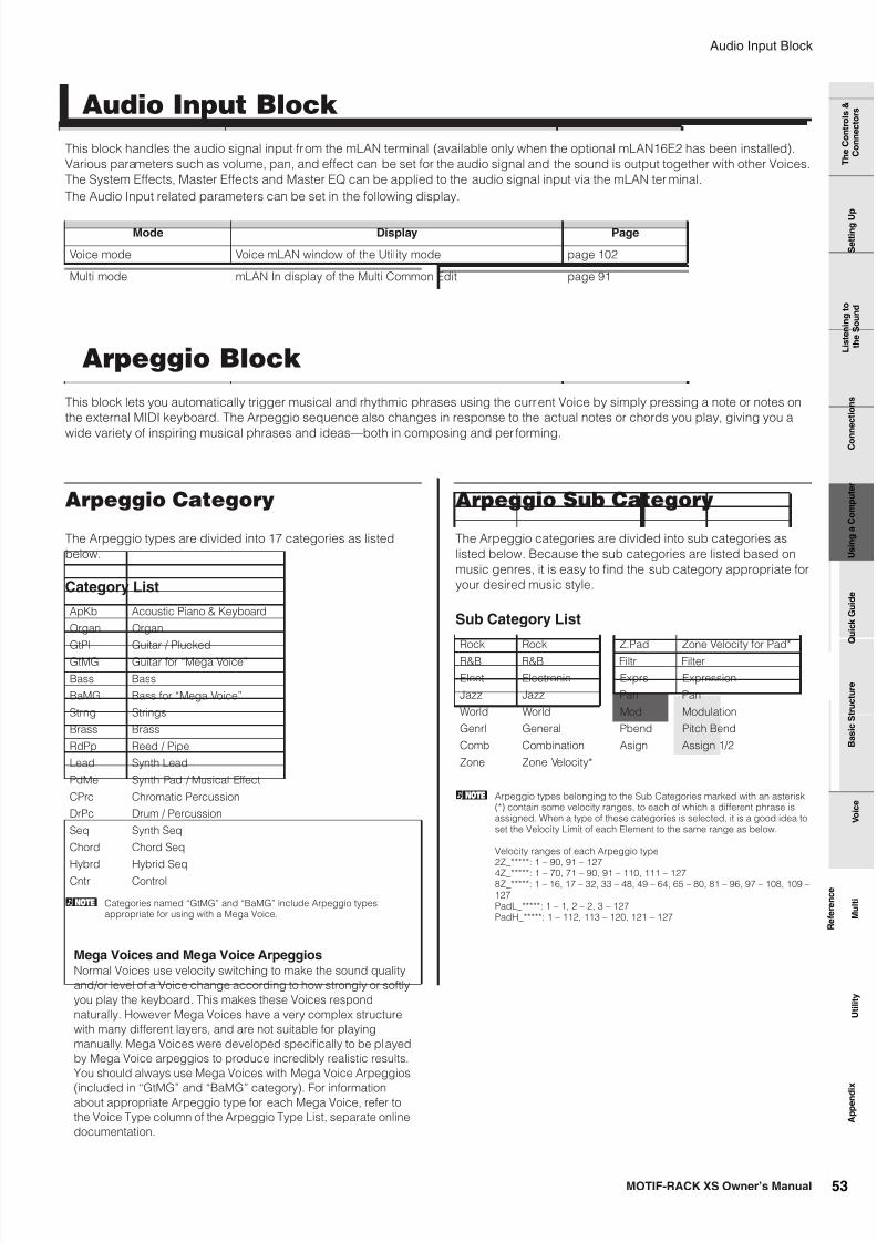
7/14/2019 Yamaha Motif XS Rack
http://slidepdf.com/reader/full/yamaha-motif-xs-rack 53/118
Audio Input Block
MOTIF-RACK XS Owner’s Manual 53
B a s i c S t r u c t u r e
V o i c e
M u l t i
U t i l i t y
R e f e r e n c e
T h e C o n t r o l s &
C o n n e c t o r s
S e t t i n g U
p
L i s t e n i n g t o
t h e S o u n d
C o n
n e c t i o n s
U s i n g a C o m p u t e r
Q u i c k G u i d e
A p p e n d i x
This block handles the audio signal input from the mLAN terminal (available only when the optional mLAN16E2 has been installed).
Various parameters such as volume, pan, and effect can be set for the audio signal and the sound is output together with other Voices.
The System Effects, Master Effects and Master EQ can be applied to the audio signal input via the mLAN ter minal.
The Audio Input related parameters can be set in the following display.
This block lets you automatically trigger musical and rhythmic phrases using the current Voice by simply pressing a note or notes on
the external MIDI keyboard. The Arpeggio sequence also changes in response to the actual notes or chords you play, giving you a
wide variety of inspiring musical phrases and ideas—both in composing and per forming.
Arpeggio Category
The Arpeggio types are divided into 17 categories as listed
below.
Category List
n Categories named “GtMG” and “BaMG” include Arpeggio typesappropriate for using with a Mega Voice.
Arpeggio Sub Category
The Arpeggio categories are divided into sub categories as
listed below. Because the sub categories are listed based on
music genres, it is easy to find the sub category appropriate for
your desired music style.
Sub Category List
n Arpeggio types belonging to the Sub Categories marked with an asterisk(*) contain some velocity ranges, to each of which a different phrase isassigned. When a type of these categories is selected, it is a good idea toset the Velocity Limit of each Element to the same range as below.
Velocity ranges of each Arpeggio type2Z_*****: 1 – 90, 91 – 127
4Z_*****: 1 – 70, 71 – 90, 91 – 110, 111 – 1278Z_*****: 1 – 16, 17 – 32, 33 – 48, 49 – 64, 65 – 80, 81 – 96, 97 – 108, 109 –127PadL_*****: 1 – 1, 2 – 2, 3 – 127PadH_*****: 1 – 112, 113 – 120, 121 – 127
Audio Input Block
Mode Display Page
Voice mode Voice mLAN window of the Utility mode page 102
Multi mode mLAN In display of the Multi Common Edit page 91
Arpeggio Block
ApKb Acoustic Piano & Keyboard
Organ Organ
GtPl Guitar / Plucked
GtMG Guitar for “Mega Voice”
Bass Bass
BaMG Bass for “Mega Voice”
Strng Strings
Brass Brass
RdPp Reed / Pipe
Lead Synth Lead
PdMe Synth Pad / Musical Effect
CPrc Chromatic Percussion
DrPc Drum / Percussion
Seq Synth Seq
Chord Chord Seq
Hybrd Hybrid Seq
Cntr Control
Mega Voices and Mega Voice ArpeggiosNormal Voices use velocity switching to make the sound quality
and/or level of a Voice change according to how strongly or softly
you play the keyboard. This makes these Voices respond
naturally. However Mega Voices have a very complex structure
with many different layers, and are not suitable for playing
manually. Mega Voices were developed specifically to be played
by Mega Voice arpeggios to produce incredibly realistic results.
You should always use Mega Voices with Mega Voice Arpeggios
(included in “GtMG” and “BaMG” category). For informationabout appropriate Arpeggio type for each Mega Voice, refer to
the Voice Type column of the Arpeggio Type List, separate online
documentation.
Rock Rock Z.Pad Zone Velocity for Pad*
R&B R&B Filtr Filter
Elect Electronic Exprs Expression
Jazz Jazz Pan Pan
World World Mod Modulation
Genrl General Pbend Pitch Bend
Comb Combination Asign Assign 1/2
Zone Zone Velocity*

7/14/2019 Yamaha Motif XS Rack
http://slidepdf.com/reader/full/yamaha-motif-xs-rack 54/118
Arpeggio Block
MOTIF-RACK XS Owner’s Manual54
R ef er en c e
T h
C
t
l
&
L it
i
t
Arpeggio Type Name
The Arpeggio Types are named according to certain rules and
abbreviations. Once you understand these rules and
abbreviations, you’ll find it easy to browse through and select
the desired Arpeggio Types.
Arpeggio type with “_ES” at the end of the typename (example: HipHop1_ES)These Arpeggios created for use of Normal Voices will be
played back matching the played notes (page 55).
Arpeggio type with “_XS” at the end of the typename (example: Rock1_XS)These Arpeggios created for Normal Voices use a newly
developed chord recognition technology to determine what
notes should be played back by the Arpeggio.
Arpeggio type with a normal name (example:UpOct1)In addition to the above types, there are three other playback
types: the Arpeggios created for use of Normal Voices and
played back using only the played notes and their octave notes
(page 55), the Arpeggios created for use of Drum Voices (page
55), and Arpeggios containing mainly non-note events (page
56).
How to use the Arpeggio Type List
The Arpeggio Type list (separate online documentation)
contains the following columns.
n Note that this list is for illustration purposes only. For a complete listing ofthe Arpeggio Types, refer to the Arpeggio Type list (separate onlinedocumentation).
1 Main Category
Indicates an Arpeggio Category.
2 Sub CategoryIndicates an Arpeggio Sub Category.
3 ARP No. (Arpeggio Number)Indicates the Arpeggio Type Number.
4 ARP NameIndicates the Arpeggio Name.
5 Time SignatureIndicates the time signature or meter of the Arpeggio type.
6 LengthIndicates the data length (amount of measures) of the Arpeggio
type. When the Loop parameter (*) is set to “off,” the Arpeggio
plays back for this length and stops.
7 Original TempoIndicates the appropriate tempo value of the Arpeggio type.
Note that this tempo is not set automatically when selecting an
Arpeggio type.
8 AccentThe circle indicates that the Arpeggio uses the Accent Phrase
feature (page 55).
9 Random SFXThe circle indicates that the Arpeggio uses the SFX feature
(page 55).
) Voice TypeIndicates the voice type appropriate for the Arpeggio Type.
When the Voice With Arpeggio parameter (page 96) is set to
“on” in the Multi mode, the voice of this type is automaticallyselected.
* The “Loop” parameter can be set in the Arp Edit display (pages 66 and 96) ofVoice Common Edit and Multi Part Edit.
Arpeggio related settings
There are several methods for triggering and stopping the
Arpeggio playback. In addition, you can set whether or not SFX
sounds and special Accent Phrases are triggered along with the
normal sequence data. This section covers the Arpeggio relatedparameters which can be set in the Voice and Multi modes.
The following three settings are available for turning the
Arpeggio playback on/off.
The “Hold” parameter and “Trigger Mode” parameter can be set
in the Arp Edit display (pages 66 and 96) of Voice Common Edit
and Multi Part Edit.
n When receiving the MIDI sustain message (control change #64) with the“Arp Sw” set to “on,” you can obtain the same result by setting the “ArpHold” to “on.”
MainCategory
SubCategory
ARPNo.
ARP NameTime
SignatureLength
OriginalTempo
AccentRandom
SFXVoice Type
ApKb Rock 1 70sRockB 4 / 4 2 130 Acoustic Piano
ApKb Rock 2 70sRockC 4 / 4 1 130 :
ApKb Rock 3 70sRockD 4 / 4 2 130
ApKb Rock 4 70sRockE 4 / 4 4 130
ApKb Rock 5 70sRockF 4 / 4 2 130
ApKb Rock 6 70sRockG 4 / 4 1 130
ApKb Rock 7 70sRockH 4 / 4 1 130
1 2 3 4 5 6 7 8 9 )
Turning Arpeggio playback on/off
To play the Arpeggio only when
the note is pressed:
Set the “Hold” parameter to “off”
and the “Trigger mode” to
“gate.”
To continue the Arpeggio even ifthe note is released:
Set the “Hold” parameter to“on.”
To toggle the Arpeggio
playback on/off whenever the
note is pressed:
Set the “Trigger mode” to
“toggle.” The “Hold” parameter
can be set to either “on” or “off.”

7/14/2019 Yamaha Motif XS Rack
http://slidepdf.com/reader/full/yamaha-motif-xs-rack 55/118
B a s i c S t r u c t u r e
V o i c e
M u l t i
U t i l i t y
R e f e r e n c e
T h e C o n t r o l s &
C o n n e c t o r s
S e t t i n g U
p
L i s t e n i n g t o
t h e S o u n d
C o n
n e c t i o n s
U s i n g a C o m p u t e r
Q u i c k G u i d e
A p p e n d i x
Arpeggio Block
MOTIF-RACK XS Owner’s Manual 55
When the lowest lamp is turned on by pressing the [SELECT]
button a few times, you can control Arpeggio playback tempo
by turning the right end knob as illustrated below. Try this out
and listen for the changes in the tempo.
n When you wish to control Arpeggio playback tempo by turning the knobson the MOTIF-RACK XS, make sure to set “MIDI Sync” of the Utility MIDI
window to “Internal.”
Accent Phrases are composed of sequence data included in
some Arpeggio types, sounding only when you play notes (on
an external MIDI keyboard) at a velocity higher (stronger) than
that specified in the Accent Velocity Threshold parameter. If it is
hard to play at velocities necessary to trigger the Accent Phrase,
set the Accent Velocity Threshold parameter to a lower value.
n The Accent Velocity Threshold parameter can be set in the Arp Edit display(pages 66 and 96) of Voice Common Edit and Multi Part Edit.
n For information on Arpeggio types that use this function, refer to the
Arpeggio Type List in the Arpeggio Type List (PDF) documentation,available from the online Yamaha Manual Library.
Some Arpeggio types feature a Random SFX function which will
trigger special sounds (such as guitar fret noises) when the note
is released. The following parameters affecting Random SFX are
provided.
n The Random SFX, SFX Vel Offset and SFX Key on Ctrl parameters can beset in the Arp Edit display (pages 66 and 96) of Voice Common Edit andMulti Part Edit.
n For information on Arpeggio types that use this function, refer to theArpeggio Type List in the Arpeggio Type List (PDF) documentation,available from the online Yamaha Manual Library.
Arpeggio playback types
The Arpeggio playback features three main playback types as
described below.
Arpeggio types (belonging to the categories except for the
DrPC and Cntr) created for use of Normal Voices have the
following three playback types.
Playback only of the played notesThe Arpeggio is played back using only the played note and its
octave notes.
Playback of a programmed sequence according tothe played notesThese Arpeggio types have the several sequences each of
which is suited for a cer tain chord type. Even if you press only
one note, the Arpeggio is played back using the programmed
sequence—meaning that notes other than the ones you play
may be sounded. Pressing another note triggers the transposed
sequence regarding the pressed note as a root note. Adding
notes to those already held changes the sequence accordingly.
An Arpeggio with such a playback type has “_ES” at the end of
the type name.
Playback of a programmed sequence according tothe played chord typeThese Arpeggio types created for use with Normal Voices are
played back to match the chord type determined by detectingthe notes you play on the keyboard. An Arpeggio with such a
playback type has “_XS” at the end of the type name.
n When the Key Mode parameter is set to “sort” or “sort+direct,” the samesequence is played back no matter what order you play the notes. Whenthe Key Mode parameter is set to “thru” or “thru+direct,” a differentsequence is played back depending on the order you play the notes.
n Since these types are programmed for Normal Voices, using them withDrum Voices may not give musically appropriate results.
These arpeggio types are programmed specifically for use with
Drum Voices, giving you instant access to various rhythm
patterns. Three different playback types are available.
Playback of a drum patternPressing any note(s) will trigger the same rhythm pattern.
Playback of a drum pattern, plus additional playednotes (assigned drum instruments)Pressing any note will trigger the same rhythm pattern. Adding
notes to the one already held produces additional sounds(assigned drum instruments) for the drum pattern.
Controlling Arpeggio tempo by using aknob
Accent Phrase
Random SFX
For turning the Random SFX on/
off:
Random SFX parameter
For setting the volume of the
SFX sound:
Random SFX Velocity Offset
parameter
For determining whether or not
the volume of the SFX sound is
controlled by velocity:
Random SFX Key On Control
parameter
Press this button a
few times so that the
lowest lamp lights.
The lamp is turned on. Turn this knob to
control the tempo of
Arpeggio playback
Arpeggio Types for Normal Voices
Arpeggio Types for Drum Voices
(Category: DrPc)

7/14/2019 Yamaha Motif XS Rack
http://slidepdf.com/reader/full/yamaha-motif-xs-rack 56/118
Arpeggio Block
MOTIF-RACK XS Owner’s Manual56
R ef er en c e
T h
C
t
l
&
L it
i
t
Playback only of the played notes (assigned druminstruments)Playing a note or notes will trigger a rhythm pattern using only
the notes played (assigned drum instruments). Keep in mind
that even if you play the same notes, the triggered rhythm
pattern differs depending on the order of the notes played. This
gives you access to different rhythm patterns using the same
instruments simply by changing the order in which you play the
notes when the Key Mode parameter is set to “thru” or“thru+direct.”
n The three playback types above are not distinguished by category nameor type name. You’ll have to actually play the types and hear the difference.
n Since these types are programmed for Drum Voices, using them withNormal Voices may not give musically appropriate results.
These arpeggio types are programmed primarily with Control
Change and Pitch Bend data. They are used to change the tone
or pitch of the sound, rather than play specific notes. In fact,
some types contain no note data at all. When using a type of this
category, set the Key Mode parameter to “direct,” “thru+direct,”
or “sort+direct.”
n The Key Mode parameter can be set in the Arp Edit display (pages 66 and96) of Voice Common Edit and Multi Part Edit.
Arpeggio Types containing mainly non-note events (Category: Cntr)
Tips for Arpeggio playback The Arpeggio function is useful for creating original songs as well
as a creative aid in your live performance, allowing you to
automatically trigger high-quality MIDI sequence phrases that
match the selected Voice or your desired music genre.For details about how to use this function, refer to page 40 in the
Quick Guide section.

7/14/2019 Yamaha Motif XS Rack
http://slidepdf.com/reader/full/yamaha-motif-xs-rack 57/118
Controller Block
MOTIF-RACK XS Owner’s Manual 57
B a s i c S t r u c t u r e
V o i c e
M u l t i
U t i l i t y
R e f e r e n c e
T h e C o n t r o l s &
C o n n e c t o r s
S e t t i n g U
p
L i s t e n i n g t o
t h e S o u n d
C o n
n e c t i o n s
U s i n g a C o m p u t e r
Q u i c k G u i d e
A p p e n d i x
This block generates the MIDI events then transmits them to the tone generator block.
On synthesizers such as the MOTIF XS, this block consists of the keyboard, Pitch Bend and Modulation Wheels, Ribbon Controller,
Knobs, Sliders and panel buttons. On the MOTIF-RACK XS, this block consists of only the five knobs and panel buttons. Controlling the
knobs while playing the external MIDI keyboard adjusts the Voice parameters such as tonal characteristics and volume in real time.
For details on using knobs, see page 29 in the Quick Guide section.
This block applies effects to the output of the tone generator block, and audio input block, processing and enhancing the sound.
Effects are applied in the final stages of editing, letting you change the sound of the created Voice as desired.
Effect structure
System Effects are applied to the overall sound. With System
Effects, the sound of each Part is sent to the effect according to
the effect Send Level for each Part. The processed sound
(referred to as “wet”) is sent back to the mixer, according to the
Return Level, and output—after being mixed with the
unprocessed “dry” sound. This arrangement lets you prepare an
optimum balance of the effect sound and the original sound of
the Parts.
Insertion Effects can be applied individually to each Part.
Insertion Effects are mainly used to directly process a single
Part, or Voice. A insertion effect has two units, A and B. Different
effect types can be set for each unit (Insertion Effects A and B).
The Insertion Effect can be specified in the effect parameter
display of Voice Edit (page 72). This instrument features eight
sets of Insertion Effects (each set has two units, A and B). They
can be applied to a maximum of eight Parts in the Multi mode.
This block applies effects to the final stereo output signal of the
entire sound.
The Element EQ is applied to each element of the Normal Voice
and each key of the Drum Voice. You can specify which shape is
used among five types, such as shelving and peaking. The
Element EQ parameters can be set only on the MOTIF-RACK XS
Editor.
The Part EQ, the 3-band parametric EQ, is applied to each part
of the Multi. The high band and low band are the shelving type.
The middle band is the peaking type. The Common EQ
parameters offset the settings of the Part EQ parameters.
Master EQ is applied to the final (post-effect), overall sound of
the instrument. In this EQ, all five bands can be set to peaking,
or the lowest and highest bands can also be set to shelving.
Controller Block
Effect Block
System Effects—Reverb and Chorus
Insertion Effect
Master Effect
Element EQ
Common EQ/Part EQ
Master EQ

7/14/2019 Yamaha Motif XS Rack
http://slidepdf.com/reader/full/yamaha-motif-xs-rack 58/118
Effect Block
MOTIF-RACK XS Owner’s Manual58
R ef er en c e
T h
C
t
l
&
L it
i
t
Effect connection in each mode
1 Element EQ applied to each Element (for a NormalVoice) and each Key (for a Drum Voice)
Can be set on the MOTIF-RACK XS Editor. See pages 81 and
86.
2 Common EQ applied to all the Elements and Keys
Can be set in the 3 Band EQ display (page 71) of Voice
Common Edit.
3 Selection which Insertion Effect, A or B is applied toeach Element/Key
Can be set on the MOTIF-RACK XS Editor. See page 72.
4 Insertion Effect A/B related parameters
Can be set in the Effect Parameter display (page 72) for “Ins
A” and “Ins B” of Voice Common Edit.
5 Reverb and Chorus related parameters
Can be set in the Effect Parameter display (page 72) for
“Reverb” and “Chorus” of Voice Common Edit.
6 Master Effect related parameters
Can be set in the Voice MEF window (page 102) of Utility.
7 Master EQ related parameters
Can be set in the Voice MEQ window (page 103) of Utility.
n Regarding the Audio Input signal from the mLAN terminal in the Voicemode, when the “Output Select” parameter (page 102) is set to something
other than “L&R,” the signal can be applied at only 1 – 4 settings asshown above and output.
1 Part EQ applied to each Part
Can be set in the Part EQ display (page 96) of Multi Part Edit.
2 Selection to which Parts the Insertion Effect is applied
Can be set in the Fx Send display (page 97) of the Multi Part
Edit and the Effect display of Multi Common Edit on the
MOTIF-RACK XS Editor.
3 Reverb and Chorus related parameters
Can be set in the Effect Parameter display (page 93) for“Reverb” and “Chorus” of Multi Common Edit and the Fx
Send display (page 97) of Multi Part Edit.
4 Master Effect related parameters
Can be set in the Effect Parameter display (page 93) for
“Master” of Multi Common Edit.
5 Master EQ related parameters
Can be set in the MEQ display (page 92) of Multi Common
Edit.
n The Effect settings of 1, 3, and 4 in the Voice mode illustrated onpage 58 are available for up to eight parts for which the Insertion Effectis turned on.
n The audio signals of the parts for which the “Output Select” parameter(page 95) is set to something other than “L&R” can be applied only atthe 1 and 2 settings as shown above and output.
In the Voice mode
1 23
4
5
6 7Voice
Common
EQ
Element or Drum Key
Element EQ
Insertion A
Insertion B
Element 1 – 8
Reverb
Chorus
Master Effect Master EQ
Return Level
Send LevelChorus to
Reverb
In the Multi mode
1
3
2
4 5Multi
Part
Part EQ
Part 1 – 16
Voice
Insertion A/B
SendLevel
ReturnLevel
Reverb
Chorus ToReverb
Chorus
Master Effect Master EQ

7/14/2019 Yamaha Motif XS Rack
http://slidepdf.com/reader/full/yamaha-motif-xs-rack 59/118
B a s i c S t r u c t u r e
V o i c e
M u l t i
U t i l i t y
R e f e r e n c e
T h e C o n t r o l s &
C o n n e c t o r s
S e t t i n g U
p
L i s t e n i n g t o
t h e S o u n d
C o n
n e c t i o n s
U s i n g a C o m p u t e r
Q u i c k G u i d e
A p p e n d i x
Effect Block
MOTIF-RACK XS Owner’s Manual 59
Effect Types divided into EffectCategories
The MOTIF-RACK XS provides such a wide and extensive
variety of Effect types that it may be difficult to find the desired
Effect type out of the great number that are available. This is why
all the Effect types are divided into convenient Effect categories.
This section explains the Effect categories and their types. The
Effect Type list described below for each category contains the
columns: Rev (Reverb), Cho (Chorus), Ins (Insertion) and Mas
(Master Effect). The checkmarks indicated in these columns
means the Effect Type is available for each block. These Effect
types (with the checkmarks indicated in each list) can be
selected from the panel controls.
ReverbAlso called “reverberation,” this refers to the sound energy
remaining in a room or closed space after the original sound
stops. Similar to yet different from echo, reverb is the indirect,
diffuse sound of reflections from the walls and ceiling thataccompany the direct sound. The characteristics of this indirect
sound depends on the size of the room or space and the
materials and furnishings in the room. Reverb Effect types use
digital signal processing to simulate these characteristics.
DelayAn effect (or device) that delays an audio signal for ambient or
rhythmic effects.
ChorusDepending on the particular chorus type and parameters,
this can make a voice sound “larger,” as if several identical
instruments were playing in unison, or it can give a voice
greater warmth and depth.
FlangerThis effect creates a swirling, metallic sound.
PhaserCyclically modulates the phase to add modulation to the sound.
Effect Type Rev Cho Ins Description
REV-X HALL ✔ – – Reverb emulating theacoustics of a concert hallusing REV-X technology.
R3 HALL ✔ – – Reverb emulating theacoustics of a concert hallusing an algorithm derivedfrom the Yamaha ProR3.
SPX HALL ✔ ✔ ✔ Reverb emulating theacoustics of a concert hallderived from the YamahaSPX1000.
REV-X ROOM ✔ – – Reverb emulating theacoustics of a room usingthe REV-X technology.
R3 ROOM ✔ – – Reverb emulating theacoustics of a room usingan algorithm derived fromthe Yamaha ProR3.
SPX ROOM ✔ ✔ ✔ Reverb emulating theacoustics of a room derivedfrom the Yamaha SPX1000.
R3 PLATE ✔ – – Reverb emulating a metalplate using an algorithm
derived from the YamahaProR3.
SPX STAGE ✔ ✔ ✔ Reverb designed forenhancing solo instruments,derived from the YamahaSPX1000.
SPACESIMULATOR
✔ – – Reverb which lets you setthe space size by specifyingthe width, height, and depth.
Effect Type Rev Ins Mas Description
CROSS DELAY ✔ ✔ – The feedback of the twodelayed sounds is crossed.
TEMPO CROSSDELAY
✔ ✔ – Cross delay synchronizedwith the tempo.
TEMPO DELAYMONO
✔ ✔ – Mono delay synchronizedwith the tempo.
TEMPO DELAYSTEREO
✔ ✔ – Mono delay synchronizedwith the tempo.
CONTROLDELAY
– ✔ – Delay with delay timecontrollable in real time.
DELAY LR ✔ ✔ – Produces two delayedsounds: L and R.
DELAY LCR ✔ ✔ – Produces three delayedsounds: L, R and C (center).
DELAY LR(Stereo)
✔ ✔ ✔ Produces two delayedsounds in stereo: L and R.
Effect Type Cho Ins Description
G CHORUS ✔ ✔ This chorus effect produces aricher and more complexmodulation than conventionalchorus.
2 MODULATOR ✔ ✔ This chorus effect consists of pitchmodulation and amplitudemodulation.
SPX CHORUS ✔ ✔ This effect uses a 3-phase LFO toadd modulation and spaciousnessto the sound.
SYMPHONIC ✔ ✔ A multi-stage version of SPXCHORUS modulation.
ENSEMBLEDETUNE
✔ ✔ Chorus effect without modulation,created by adding a slightly pitch-shifted sound.
Effect Type Cho Ins Description
VCM FLANGER ✔ ✔ Flanger with VCM technologyproducing a vintage sound.
CLASSICFLANGER
✔ ✔ Conventional type of flanger.
TEMPOFLANGER
✔ ✔ Tempo-synchronized flanger.
DYNAMICFLANGER
– ✔ Dynamically controlled flanger.
Effect Type Cho Ins Description
VCM PHASERMONO
✔ ✔ Mono phaser with VCM technologyproducing a vintage sound.
VCM PHASERSTEREO
✔ ✔ Stereo phaser with VCM technologyproducing a vintage sound.
TEMPOPHASER
✔ ✔ Tempo-synchronized phaser.
DYNAMICPHASER
– ✔ Dynamically controlled phaseshifter.
Effect Type Rev Ins Mas Description

7/14/2019 Yamaha Motif XS Rack
http://slidepdf.com/reader/full/yamaha-motif-xs-rack 60/118
Effect Block
MOTIF-RACK XS Owner’s Manual60
R ef er en c e
T h
C
t
l
&
L it
i
t
Tremolo & RotaryThe tremolo effect cyclically modulates the volume. The Rotary
Speaker effect simulates the characteristic vibrato effect of a
rotary speaker.
DistortionThis type can be used mainly for guitar, adding distortion with an
edge to the sound.
CompressorCompressor is an effect commonly used to limit and compress
the dynamics (softness/loudness) of an audio signal. For signals
that vary widely in dynamics, such as vocals and guitar parts, it
“squeezes” the dynamic range, effectively making soft sounds
louder and loud sounds softer. When used with gain to boost theoverall level, this creates a more powerful, more consistently
high-level sound. Compression can be used to increase sustain
for electric guitar, smooth out the volume of a vocal, or bring a
drum kit or rhythm pattern further up-front in the mix.
WahThis Effect cyclically modulates the tone brightness (cutoff
frequency of a filter). Auto Wah modulates the tone via LFO,
Touch Wah modulates the tone via volume (note on velocity) and
Pedal Wah modulates the tone via pedal control (foot controller).
Lo-FiThis effect intentionally degrades the audio quality of the input
signal via several methods, including lowering of the sampling
frequency.
TechThis effect radically changes the tonal characteristics by using a
filter and modulation.
MISCThis category includes effect types not included in the other
categories.
Effect Type Ins Description
AUTO PAN ✔ An effect which cyclically moves the soundleft/right and front/back.
TREMOLO ✔ An effect which cyclically modulates thevolume.
ROTARYSPEAKER
✔ Simulation of a rotary speaker.
Effect Type Ins Mas Description
AMPSIMULATOR 1
✔ – A simulation of a guitar amp.
AMPSIMULATOR 2
✔ – A simulation of a guitar amp.
COMPDISTORTION
✔ – Since a Compressor is included inthe first stage, steady distortion canbe produced regardless ofchanges in input level.
COMPDISTORTIONDELAY
✔ ✔ Compressor, Distortion and Delayare connected in series.
Effect Type Ins Mas Description
VCMCOMPRESSOR376
✔ ✔ Compressor with VCM technology.
CLASSICCOMPRESSOR
✔ – Conventional type of compressor.
MULTI BANDCOMP
✔ ✔ 3-band type compressor.
Effect Type Ins Description
VCM AUTO WAH ✔ Modulates the tone via the LFO.
VCM TOUCH WAH ✔ Modulates the tone via the volume(note on velocity).
VCM PEDAL WAH ✔ Modulates the tone via the pedalcontrol. For best results, assign thePedal Control parameter of this
Effect type to the Foot Controller inthe Controller Set display, then usethe Foot Controller to control thiseffect in real time.
Effect Type Ins Mas Description
LO-FI ✔ ✔ Degrades the audio quality of theinput signal for a lo-fi sound.
NOISY ✔ – Adds noise to the current sound.
DIGITALTURNTABLE
✔ – Simulates the noise, scratches andpops of a vinyl record.
Effect Type Ins Mas Description
RINGMODULATOR
✔ ✔ An effect that modifies the pitch byapplying amplitude modulation tothe frequency of the input.
DYNAMIC RINGMODULATOR
✔ – Dynamically controlled ringmodulation.
DYNAMICFILTER
✔ ✔ Dynamically controlled filter.
AUTO SYNTH ✔ – Processes the input signal into asynthesizer-type sound.
ISOLATOR ✔ ✔ Controls the level of a specifiedfrequency band of the input signal.
SLICE ✔ ✔ Cuts the Voice sound into separatesegments for special rhythmiceffects.
TECHMODULATION
✔ – Adds a unique feeling ofmodulation similar to ringmodulation.
Effect Type Cho Ins Description
VCM EQ 501 – ✔ Vintage 5-band parametric EQ withVCM technology.
HARMONICENHANCER
– ✔ Adds new harmonics to the inputsignal to make the sound stand out.
TALKINGMODULATOR
– ✔ Adds a vowel sound to the inputsignal.
DAMPERRESONANCE
– ✔ Simulates the resonance producedwhen the damper pedal of thepiano is pressed.
PITCHCHANGE –✔
Changes the pitch of the inputsignal.
EARLYREFLECTION
✔ ✔ This effect isolates only the earlyreflection components of thereverb.

7/14/2019 Yamaha Motif XS Rack
http://slidepdf.com/reader/full/yamaha-motif-xs-rack 61/118
B a s i c S t r u c t u r e
V o i c e
M u l t i
U t i l i t y
R e f e r e n c e
T h e C o n t r o l s &
C o n n e c t o r s
S e t t i n g U
p
L i s t e n i n g t o
t h e S o u n d
C o n
n e c t i o n s
U s i n g a C o m p u t e r
Q u i c k G u i d e
A p p e n d i x
Effect Block
MOTIF-RACK XS Owner’s Manual 61
VCM is a technology that authentically models the elements in
analog circuitry (such as resistors and capacitors). Effect types
using the VCM technology produce the uniquely warm
characteristics of vintage processing gear.
VCM Compressor 376This effect emulates the characteristics of analog compressors,
used as standard effects in recording studios. It frames and
thickens the sound, and is suitable for drum and bass sounds.
VCM Equalizer 501This effect emulates the characteristics of analog equalizers
used in 1970s. It adds drive to the sound by reproducing
distortion typical of analog circuits. It consists of two shelving-
type filters and three peaking-type filters.
VCM FlangerThis effect emulates the characteristics of analog flanger used in
the 1970s, recreating a warm, high-quality flanger effect.
VCM Phaser Mono, VCM Phaser StereoThese effect emulate the characteristics of analog phasers used
in the 1970s, recreating a warm, high-quality phaser effect.
VCM Auto Wah, VCM Touch Wah, VCM Pedal WahThese effects emulate the characteristics of analog Wah used in
the 1970s, recreating a warm, high-quality wah-wah effect.
REV-X is a reverb algorithm developed by Yamaha. It provides a
high-density, richly reverberant sound quality, with smooth
attenuation, spread and depth that work together to enhance the
original sound. The MOTIF-RACK XS features two types of REV-
X effects: REV-X Hall and REV-X Room.
Effect Parameters
Each of the Effect Types has parameters that determine how the
Effect is applied to the sound. A variety of sounds can be
obtained from a single effect type by setting these parameters.
For information about the Effect parameters, see below.
Preset settings for parameters of each effect type are provided
as templates and can be selected by the “Preset” parameter in
the Effect Type selection display. To get a desired effect sound,
try first selecting one of the Presets close to your imagined
sound, then change the parameters as necessary. For details
about the preset settings of each effect type, refer to the
separate Data List booklet.
Effect Parameters making up the affect of the Effect Type are
listed here in alphabetical order.
n Each name of the parameters listed below is indicated with its full orcomplete spelling, although it is indicated with the abbreviated spelling onthe LCD. The discrepancy in the name may make it difficult to find thedesired parameter. In such a case, confirm the parameters belonging tothe Effect Type you want to edit by referring to the Effect Parameter List inthe separate Data List booklet.
n Some parameters below may appear in different effect types with the samename, but actually have different functions depending on the particulareffect type. For these parameters, two or three types of explanations aregiven.
VCM (Virtual Circuitry Modeling)
REV-X
Preset settings for Effect parameters
Effect parameters
Parameter name Description
AEG Phase Offsets the phase of the AEG.
AM Depth Determines the depth of the amplitude modulation.
AM Inverse R Determines the phase of the ampli tude modulat ion for the Rchannel.
AM Speed Determines the amplitude modulation speed.
AM Wave Determines the wave of the amplitude modulation.
AMP Type Selects the amplifier type to be simulated.
Analog Feel Adds the character ist ics of an analog flanger to the sound.
Attack Determines the amount of time that elapses between theplaying of a key and the start of the compressor effect.
Attack Offset Determines the amount of time that elapses between theplaying of a key and the start of the wah effect.
Attack Time Determines the attack t ime of the enve lope fo llower.
Bit Assign Determines how the Word Length i s applied to the sound.
Bottom*1 Determines the minimum value of the wah filter.
Click Densi ty Determines the frequency at which the cl ick sounds.
Click Level Determines the click level.
Color*2 Determines the fixed phase modulation.
Common Release This is a parameter of “Multi Band Comp.” This parameterdetermines the amount of time that elapses between thereleasing of a note and the end of the effect.
Compress Determines the minimum input level at which the compressoreffect is applied.
Control Type This is a parameter of “Control Delay.” When set to “Normal,”the delay effect is always applied to the sound. When set to“Scratch,” the delay effect is not applied if both the DelayTime and Delay Time Offset are set to “0.”
Damper Control When the half-damper compatible FC3 footswitch isconnected to the SUSTAIN jack, the Damper Controlparameter is controlled by the FC3 over a range of 0 – 127,allowing for partial damper effects, such as is available on anactual grand piano.
Decay Controls how the reverb sound decays.
Delay Level C Determines the level of the delayed sound for the centerchannel.
Delay Mix Determines the level of the delayed mixed sound whenmultiple effects are applied.
Delay Offset Determines the offset va lue of the delay modulat ion.
Delay T ime Determines the de lay o f the sound in note value or abso lutetime.
Delay Time C, L, R Determines the delay time for each channel: center, left and
right.Delay Time L>R Determines the amount of time between the moment the
sound is input from the L channel and the moment the soundis output to the R channel.
Delay Time Ofst R Determines the delay time for the R channel as offset.
Delay Time R>L Determines the amount of time between the moment thesound is input from the R channel and the moment the soundis output to the L channel.
Delay Transition Rate Determines the speed (rate) at which the delay time ischanged from the current value to the specified new value.
Density When the Reverb effect is selected, this determines thedensity of the reverberations.
When the Early Reflection is selected, this determines thedensity of the reflections.
Depth When “Space Simulator” is selected, this parameterdetermines the depth of the simulated room.
When “VCM Flanger” is selected, this parameter determinesthe amplitude of the LFO wave which controls the cyclic
change of the delay modulation.When the phaser type is selected, this parameter determinesthe amplitude of the LFO wave which controls the cyclicchange of the phase modulation.
Detune Determines the amount of pitch to be detuned.

7/14/2019 Yamaha Motif XS Rack
http://slidepdf.com/reader/full/yamaha-motif-xs-rack 62/118
Effect Block
MOTIF-RACK XS Owner’s Manual62
R ef er en c e
T h
C
t
l
&
L it
i
t
Device Selects the device for changing how to distort the sound.
Diffusion Determines the spread of the selected effect.
Direction Determines the direction of the modulation controlled by theenvelope follower.
Divide Freq High Determines the high frequency for dividing the entire soundinto three bands.
Divide Freq Low Determines the low frequency for dividing the entire soundinto three bands.
Divide Min Level Determines the minimum level of the portions extracted viathe slice effect.
Divide Type Determines how the sound (wave) is sliced by the notelength.
Drive When one of the distortion, noisy and slice effects isselected, this parameter determines the extent to which thesound is distorted.
When one of the misc effects is selected, this parameterdetermines the extent to which the enhancer is applied.
Drive Horn Determines the depth of the modulation generated via therotation of the horn.
Drive Rotor Determines the depth o f the modulat ion generated via therotation of the rotor.
Dry Level Determines the level of the dry sound (to which the effect isnot applied).
Dry LPF CutoffFrequency
Determines the cutoff frequency of the low pass filter appliedto the dry sound.
Dry Mix Level Determines the level of the dry sound (to which the effect is
not applied).Dry Send to Noise Determines the level of the dry signal sent to the noise effect.
Dry/Wet Balance Determines the balance of the dry sound and effect sound.
Dyna Level Offset Determines the offset value added to the output from theenvelope follower.
Dyna Threshold Level Determines the minimum level at which the envelope followerstarts.
Edge Sets the curve that determines how the sound is distorted.
Emphasis Determines the change of the characteristics in highfrequencies.
EQ Frequency Determines the center frequency for each band of the EQ.
EQ Gain Determines the level gain of the EQ center frequency foreach band.
EQ High Frequency Determines the center frequency of the high EQ band that isattenuated/boosted.
EQ High Gain Determines the amount of boost or attenuation applied to thehigh EQ band.
EQ Low Frequency Determines the center frequency of the low EQ band that isattenuated/boosted.
EQ Low Gain Determines the amount of boost or at tenuation appl ied to thelow EQ band.
EQ Mid Frequency Determines the center frequency of the middle EQ band thatis attenuated/boosted.
EQ Mid Gain Determines the amount of boost or at tenuation appl ied to themiddle EQ band.
EQ Mid Width Determines the width of the middle EQ band.
EQ Width Determines the width of the EQ band.
ER/Rev Balance Determines the level balance of the early reflection andreverb sound.
F/R Depth This parameter of “Auto Pan” (available when PAN Directionis set to “L turn” and “R turn”) determines the depth of the F/ R (front/rear) pan.
FB Hi Damp Ofst R Determines the amount of decay in high frequencies for the Rchannel as offset.
FB Level Ofst R Determines the feedback level for the R channel as offset.
Feedback Determines the level of the sound signal output from theeffect block and returned to its own input.
Feedback High Damp Determines how the high frequencies of the feedback sounddecay.
Feedback Level When one of the reverb and early reflection effects isselected, this parameter determines the feedback level of theinitial delay.
When one of the delay, chorus, flanger, comp distortiondelay, and TEC effects is selected, this parameterdetermines the feedback level output from the delay andreturned to the input.
When “Tempo Phaser” or “Dynamic Phaser” is selected, thisparameter determines the feedback level output from thephaser and returned to the input.
Feedback Level 1, 2 Determines the feedback level of the delayed sound in eachof the 1st and 2nd series.
Feedback Time Determines the delay time of the feedback.
Feedback Time 1, 2, L, R Determines the time of the feedback delay 1, 2, L and R.
Parameter name Description
Filter Type When “Lo-Fi” is selected, this parameter selects the tonalcharacteristic type.
When “Dynamic Filter” is selected, this parameter determinesthe filter type.
Fine 1, 2 Determines the pi tch finely for each of the 1st series and 2ndseries.
Gate Time Determines the gate time of the sliced portion.
Height Determines the height of the simulated room.
Hi Resonance Adjusts the resonance of the high f requencies.High At tack Determines the amount of t ime f rom the moment a note is
pressed to the moment the compressor is applied to the highfrequencies.
High Gain Determines the output gain for the high frequencies.
High Level Determines the level of the high frequencies.
High Mute Switches the mute status of the high frequencies.
High Ratio When “REV-X Hal l” or “REV-X Room” is selected, thisparameter determines the ratio of the high frequencies.
When “Multi Band Comp” is selected, this parameterdetermines the ratio of the compressor for the highfrequencies.
High Threshold Determines the minimum input level at which the effect isapplied to the high frequencies.
Horn Speed Fast Determines the speed of the horn when the slow/fast switchis set to “fast.”
Horn Speed Slow Determines the speed of the horn when the slow/fast switchis set to “slow.”
Ini tial Delay Determines the amount of t ime that elapses between thedirect, original sound and the initial reflections.
Initial Delay 1, 2 Determines the delay time until the initial reflection for each ofthe 1st series and 2nd series.
Initial Delay Lch, Rch Determines the amount of time that elapses between thedirect, original sound and the initial reflections (echoes) thatfollow it for each of R and L channels.
Input Level Determines the input level of the signal to which thecompressor is applied.
Input Mode Selects mono or s tereo configurat ion for the input sound.
Input Select Selects an input channel.
L/R Depth Determines the depth of the L/R pan effect.
L/R Diffusion Determines the spread of the sound.
Lag Determines the lagging time additionally applied to thedelayed sound specified via a note length.
LFO Depth When one of “SPX Chorus,” “Symphonic,” “Classic Flanger,”
and “Ring Modulator” is selected, this parameter determinesthe depth of the modulation.
When “Tempo Phase” is selected, this parameter determinesthe frequency of the phase modulation.
LFO Phase Difference Determines the L/R phase difference of the modulated wave.
LFO Phase Reset Determines how to reset the initial phase of the LFO.
LFO Speed When one of the chorus e ffects, flanger e ffects, t remolo andring modulator is selected, this parameter determines thefrequency of the modulation.
When “Tempo Flanger” or “Tempo Phaser” is selected, thisparameter determines the modulation speed via a note type.
When “Auto Pan” is selected, this parameter determines thefrequency of the Auto Pan.
LFO Wave When any of the flanger effects or “Ring Modulator” isselected, this parameter selects the wave for modulation.
When “Auto Pan” is selected, this parameter determines thepanning curve.
When “VCM Auto Wah” is selected, this parameter selectsthe wave, sine or square.
Liveness Determines the decay characteristic of Ear ly Reflection.
Low Attack Determines the amount of time from the moment a note ispressed to the moment the compressor is applied to the lowfrequencies.
Low Gain Determines the output gain for the low frequencies.
Low Level Determines the output level for the low frequencies.
Low Mute Determines whether the low frequency band is off or on.
Low Ratio When “REV-X Hall” or “REV-X Room” is selected, thisparameter determines the ratio of the low frequencies.
When “Multi Band Comp” is selected, this parameterdetermines the ratio of the compressor for the lowfrequencies.
Low Threshold Determines the minimum input level at which the effect isapplied to the low frequencies.
LPF Resonance Determines the resonance of the low pass filter for the input
sound.
Parameter name Description

7/14/2019 Yamaha Motif XS Rack
http://slidepdf.com/reader/full/yamaha-motif-xs-rack 63/118
B a s i c S t r u c t u r e
V o i c e
M u l t i
U t i l i t y
R e f e r e n c e
T h e C o n t r o l s &
C o n n e c t o r s
S e t t i n g U
p
L i s t e n i n g t o
t h e S o u n d
C o n
n e c t i o n s
U s i n g a C o m p u t e r
Q u i c k G u i d e
A p p e n d i x
Effect Block
MOTIF-RACK XS Owner’s Manual 63
*1 The Bottom parameter is available only when the value is less than that of the Top parameter.*2 The Color parameter may not be effective depending on the values of the Mode and Stage
parameters.
*3 The Top parameter is available only when the value is more than that of the Bottom parameter.
Manual When “VCM Flanger” is selected, this parameter determinesthe offset value of the delay modulation.
When “VCM Phaser mono” or “VCM Phaser stereo” isselected, this parameter determines the offset value of thephase modulation.
Meter Changes the meter.
Mic L-R Angle Determines the L/R angle of the microphone.
Mid Attack Determines the amount of time from the moment a note ispressed to the moment the compressor is applied to the mid
frequencies.
Mid Gain Determines the output gain for the mid frequencies.
Mid Level Determines the output level for the mid frequencies.
Mid Mute Switches the mute status of the mid frequencies.
Mid Ratio Determines the ratio of the compressor for the midfrequencies.
Mid Threshold Determines the minimum input level at which the effect isapplied for the mid frequencies.
Mix Determines the volume of the effect sound.
Mix Level Determines the level of the effect sound mixed to the drysound.
Mod Depth Determines the depth of the modulation.
Mod Depth Ofst R Determines the depth of the modulation for R channel asoffset.
Mod Feedback Determines the feedback level for the modulat ion.
Mod Gain Determines the gain of the modulation.
Mod LPF CutoffFrequency
Determines the cutoff frequency of the low pass filter appliedto the modulated sound.
Mod LPF Resonance Determines the resonance of the low pass filter for themodulated Sound.
Mod Mix Balance When “Noisy” is selected, this parameter determines the mixlevel of the modulated element.
When “Tech Modulation” is selected, this parameterdetermines the volume of the modulated sound.
Mod Speed Determines the modulation speed.
Mod Wave Type Selects the wave type for modulat ion.
Mode Determines the phaser type, or more specifically, the factorfor forming the phaser effect.
Modulation Phase Determines the L/R phase difference of the modulated wave.
Move Speed Determines how long i t takes to move the sound f rom thecurrent status to the sound specified via the Vowelparameter.
Noise Level Determines the noise level.
Noise LPF CutoffFrequency
Determines the cutoff frequency of the low pass filter appliedto the noise.
Noise LPF Q Determines the resonance of the low pass fi lter appl ied to thenoise.
Noise Mod Depth Determines the depth of the noise modulation.
Noise Mod Speed Determines the speed of the noise modulation.
Noise Tone Determines the characteristics of the noise.
On/Off Switch Turns the isolator on or off.
OSC Frequency Coarse Determines the frequency at which the sine wave modulatesthe amplitude of the input wave.
OSC Frequency Fine Determines the frequency finely at which the sine wavemodulates the amplitude of the input wave.
Output Determines the level of the signal output from the effectblock.
Output Gain
Output Level
Output Level 1, 2 Determines the level of the signal output from the 1st blockand 2nd block respectively.
Over Dr ive Determines the degree and character of the distortion effect .
Pan 1, 2 Determines the pan for each of the 1st series and 2nd series.
Pan AEG Min Level This parameter of the Slice effect determines the minimumlevel of the AEG applied to the panned sound.
Pan AEG Type This parameter of the Slice effect determines the type of theAEG applied to the panned sound.
Pan Depth Determines the depth of the pan effect.
Pan Direction Determines the direction toward which the stereo panposition of the sound moves.
Pan Type Determines the pan type.
Pedal Control When “VCM PEDAL WAH” is selected, this parameterdetermines the cutoff frequency of the wah filter. For bestresults, assign this parameter to the Foot Controller in theController Set display, then use the Foot Controller to controlthis parameter.
Pedal Response Determines how the sound responds to the change of thedamper control.
Phase Shift Offset Determines the offset value of the phase modulation.
Parameter name Description
Pitch 1, 2 Determines the pitch in semitones for each of the 1st seriesand 2nd series.
PM Depth Determines the depth of the pitch modulation.
Pre Mod HPF CutoffFrequency
Determines the Cutoff frequency of the High Pass Filterbefore the modulation.
Pre-LPF CutoffFrequency
Determines the Cutoff frequency of the Low Pass Filter beforethe modulation.
Pre-LPF Resonance Determines the Resonance of the Low Pass Filter for theinput sound.
Presence This parameter of the guitar amp effect controls highfrequencies.
Ratio Determines the ratio of the compressor.
Release Determines the amount of time that elapses between thereleasing of a key and the end of the compressor effect.
Release Curve Determines the release curve of the envelope follower.
Release Time Determines the release time of the envelope fol lower.
Resonance Determines the resonance of the filter.
Resonance Offset Determines the resonance as offset.
Reverb Delay Determines the delay t ime from the early reflections until thereverberations.
Reverb Time Determines the reverb time.
Room Size Determines the size of the room in which the instrumentsounds.
Rotor Speed Fast Determines the speed of the rotor when the slow/fast switchis set to “fast.”
Rotor Speed Slow Determines the speed of the rotor when the slow/fast switchis set to “slow.”
Rotor/Horn Balance Determines the volume balance of the horn and rotor.
Sampling Freq. Control Controls the sampling frequency.
Sensi tivity When one of “Dynamic Flanger,” “Dynamic Phaser,” and theTEC effects is selected, this parameter determines thesensitivity of the modulation applied to the input change.
When one of the VCM Touch Wah effects is selected, thisparameter determines the sensitivity of the wah filter’schange applied to the input change.
Slow-Fast Time of Horn Determines how long it takes for the rotation speed of thehorn to change from the current speed (slow or fast) to theother one (fast or slow) when the rotation speed is switched.
Slow-Fast Time of Rotor Determines how long it takes for the rotation speed of therotor to change from the current speed (slow or fast) to theother one (fast or slow) when the rotation speed is switched.
Space Type Selects the type of space simulation.
Speaker Type When “VCM Auto Wah” is selected, th is parameterdetermines the speed of the LFO.
Speed When “VCM Flanger” is selected, this parameter determinesthe frequency of the LFO wave which controls the cyclicchange of the delay modulation.
When any of the phaser types is selected, this parameterdetermines the frequency of the LFO wave which controls thecyclic change of the phase modulation.
When “VCM Auto Wah” is selected, this parameterdetermines the speed of the LFO.
Speed Control Switches the rotary speed.
Spread Determines the spread of the sound.
Stage Determines the step number of the phase shifter.
Threshold Determines the minimum input level at which the effect isapplied.
Top*3 Determines the maximum value of the wah filter.
Type When “VCM Flanger” is selected, this parameter determines
the flanger type.When any of the wah effects is selected, this parameterdetermines the type of the Auto Wah.
When “Early Reflection” is selected, this parameterdetermines the type of the reflection sound.
Vowel Selects a vowel type.
Wal l Vary Determines the wall status of the simulated room. Highersettings produces more diffuse reflections.
Width Determines the width of the simulated room.
Word Length Determines the degree of sound roughness.
Parameter name Description

7/14/2019 Yamaha Motif XS Rack
http://slidepdf.com/reader/full/yamaha-motif-xs-rack 64/118
MOTIF-RACK XS Owner’s Manual64
R ef er en c e
T h
C
t
l
&
L it
i
t
ReferenceThis section of the manual covers in detail all of the parameters and settings available on the MOTIF-RACK XS and the MOTIF-
RACK XS Editor. Some Common Edit parameters and all Element/Key Edit parameters can only be edited in the MOTIF-RACK
XS Editor. When the editing is synchronized between the MOTIF-RACK XS Editor and the MOTIF-RACK XS instrument, editing a
parameter on the MOTIF-RACK XS Editor affects the same parameter on the MOTIF-RACK XS instrument and vice versa. In
other words, any editing you do on either the software Editor or the hardware is automatically reflected on both. This provides a
smooth, seamless interface, and makes it very easy to create and edit your data. For details about how to synchronize databetween the two, refer to the owner's manual of the MOTIF-RACK XS Editor.
For detailed instructions on accessing each Edit display, refer to page 25 of the Quick Guide.
About the marksIn the Reference section, the parameters shown in only the MOTIF-RACK XS Editor are marked with marks.
Normal Voice EditA Normal Voice, which contains pitched musical instrument-type sounds that can be played over the range of a keyboard, can
consist of up to eight Elements. There are two types of Normal Voice Edit displays: those for Common Edit to edit the settings
common to all Elements, and those for Element Edit to edit individual Elements.
In this section, we’ll cover the Normal Voice parameters.
Common EditThese parameters are for making global (or common) edits to all eight Elements of the selected Normal Voice.
How to use the Edit display
(Example)
1 These marks mean that up (▲) or down (▼) additional hidden pages. The next orprevious page is displayed by pressing the Cursor [L]/[M] buttons to move the cursorin the display.
2 This indicates the name of the Edit display that is currently selected for your edit
operations.
3 This number means the currently displayed page number of the selected Edit display.For example, the symbol “2/4” indicates that the currently selected Edit display hasfour pages, and the second page is displayed.
4 (Multi mode only) This indicates the currently selected part. When left indicator (E)/ right indicator (F) are displayed, you can change the part with the Cursor [<]/[>]buttons.
5 The currently editable parameters are displayed. You can select the desired parameterfor editing by using the Cursor [L]/[M]/[<]/[>] buttons and change the settings with theEncoders.
Voice Mode
Procedure [VOICE]➝ select Normal Voice➝ [EDIT]➝ select the desired display in the Voice Edit Select display ➝ [ENTER]➝ Edit display
Voice Play display Voice Edit Select display(Normal Voice)
Edit display(example: Name display)

7/14/2019 Yamaha Motif XS Rack
http://slidepdf.com/reader/full/yamaha-motif-xs-rack 65/118
Voice Mode
MOTIF-RACK XS Owner’s Manual 65
B a s i c S t r u c t u r e
V o i c e
M u l t i
U t i l i t y
R e f e r e n c e
T h e C o n t r o l s &
C o n n e c t o r s
S e t t i n g U
p
L i s t e n i n g t o
t h e S o u n d
C o n
n e c t i o n s
U s i n g a C o m p u t e r
Q u i c k G u i d e
A p p e n d i x
1 Name
Name Enters the desired name for the Voice. When you move the cursor to “Name,” pressing the [ENTER]button calls up the Naming dialog, allowing you to enter the desired name. The Voice name cancontain up to 20 characters. For detailed instructions on naming, refer to page 47 in the QuickGuide.
Main 1 Ctgry (Main Category 1) Determines the two Main Categories and their Sub Categories to which the Voice belongsrespectively. “Category” can be used as a keyword representing the characteristics of the Voice.
The appropriate setting makes it easy to find the desired Voice from a variety of Voices. There are 16Main Categories which indicate types of instruments. There are up to five Sub Categories for eachMain Category, indicating more detailed types of instruments.
Settings: Refer to the Category List on page 87.
Sub 1 Ctgry (Sub Category 1)
Main 2 Ctgry (Main Category 2)
Sub 2 Ctgry (Sub Category 2)
2 Play Mode
Volume Determines the output level of the Voice. Set this parameter to adjust the balance between thecurrent Voice and other Voices. This parameter can be changed directly via the Knob.
Settings: 0 – 127
Pan Determines the stereo pan position of the Voice. This parameter can be changed directly via theKnob.
Settings: L63 (far left) – C (center) – R63 (far right)
n Note that this Part Pan parameter may have little or no audible effect if the Pan for a specific Element is set to the
left position and the Pan for another Element is set to the right position.
Note Shift Determines the transpose setting for the amount (in semitones) by which the pitch is raised orlowered.
Settings: 24 – +0 – +24
PB Range Upper
(Pitch Bend Range Upper)
Determines the maximum Pitch Bend range in semitones. Setting the Upper parameter to +12 wouldresult in a maximum pitch rise of one octave when the Pitch Bend wheel is moved upwards. On theother hand, a Lower setting of -12 would result in the pitch being lowered up to a maximum of oneoctave (12 semitones) when the Pitch Bend wheel is moved downwards.
Settings: -48 semi – +0 semi – +24 semi
PB Range Lower
(Pitch Bend Range Lower)
Mono/Poly Determines the playback method of the Voice: monophonic (single Note Only) or polyphonic(multiple notes).
Settings: mono, poly
mono ................................. When set to “mono,” the selected Voice is played back monophonically (only a single note is
played back simultaneously). For many instrument sounds (such as bass and synth lead), thisallows a more natural and smooth sounding legato performance than when this parameter is setto “poly.”
poly.................................... When set to “poly,” the selected Voice is played back polyphonically (multiple notes can beplayed back simultaneously or a chord is played back).
Key Assign Mode This is useful when two or more instances of the same note are received nearly simultaneously, orwithout a corresponding Note Off message.
Settings: single, multi
single................................. When this is set to “single” and double playback of the same note are transmitted to the internaltone generator, the first note will be stopped then the next note will be sounded.
multi................................... When this is set to “multi” and double playback of the same note are transmitted to the internaltone generator, all the notes are sounded simultaneously.
Porta Sw
(Portamento Switch)
Determines whether Portamento is applied to the current Voice or not. This parameter can bechanged directly via the Knob.
Settings: off, on
Porta Time
(Portamento Time)
Determines the pitch transition time when Portamento is applied. The effect of the parameter differsdepending on the settings of the “Portamento Time Mode.” Higher values result in a longer pitchchange time, or a slow speed. This parameter can be changed directly via the Knob.
Settings: 0 – 127
Porta Mode
(Portamento Mode)
Determines how Portamento is applied to your keyboard performance.
Settings: fingered, fulltime
fingered ..............................Portamento is only applied when you play legato (playing the next note before releasing theprevious one).
fulltime ............................... Portamento is applied to all notes.
Porta Time Mode
(Portamento Time Mode)
Determines how the pitch changes in time.
Settings: rate1, time1, rate2, time2
rate1 .................................. Pitch changes at the specified rate.
time1.................................. Pitch changes in the specified time.
rate2 ................................. Pitch changes at the specified rate within a octave.
time2.................................. Pitch changes in the specified time within a octave.

7/14/2019 Yamaha Motif XS Rack
http://slidepdf.com/reader/full/yamaha-motif-xs-rack 66/118
Voice Mode
MOTIF-RACK XS Owner’s Manual66
R ef er en c e
T h
C
t
l
&
L it
i
t
Porta Lgt Slope
(Portamento Legato Slope)
When the Mono/Poly is set to “mono,” legato playing may produce an unnatural attack depending onthe waveform assigned to the selected Voice. To solve such a problem, you can use this parameterto adjust the attack of the Voice. Normally, this should be set to a low value for waveforms with shortattack times, and should be set to a high value for waveforms with long attack times.
Settings: 0 – 7
Micro Tune Bank
(Micro Tuning Bank)
Determines the Micro Tuning Bank.
Settings: preset, user
preset ................................ Contains the 13 preset Micro Tuning types.
user .....................................Contains your original Micro Tuning types created in the Micro Tune display (page 102) of theUtility mode.
Micro Tune No.
(Micro Tuning Number)
Determines the Micro Tuning number. The Preset Bank provides 13 types, including equaltemperament, which is the most commonly used tuning system. For details about Micro Tuning, referto the “Micro Tuning” (page 87) section in the Supplementary information.
Settings: Preset Bank: 1 – 13 (See the Micro Tuning list on page 87)User Bank: 1 – 8
Micro Tune Root
(Micro Tuning Root)
Sets the base note for each scale. For some scales this setting may not be necessary.
Settings: C – B
Audition No.
(Audition Phrase Number)
Selects the type of the Audition phrase.
Settings: 001 – 285
Audition Note Shift
(Audition Phrase Note Shift)
Adjusts the pitch in semitone increments.
Settings: -24 – +0 – +24
Audition Vel Shift
(Audition Phrase Velocity Shift)
Determines the offset value by which the Audition Phrase will be shifted from their original velocities.
Settings: -64 – +0 – +63
3 Arp Select (Arpeggio Select)Determines whether the item being edited will commonly affect all five Arpeggios assigned to each Voice (“Arp Edit”), or affect only theselected Arpeggio (“Arp 1 – 5 Type”).
Arp Sw
(Arpeggio Switch)
Determines whether Arpeggio playback is on or off. You can also turn this on or off from the frontpanel with the [AUDITION] button when the “Audition Button” (page 99) in the Utility General windowis set to “arpeggio sw.”
Settings: off, on
Arp Select
(Arpeggio Select)
Select the desired Arpeggio from Arpeggios 1 – 5. The 8th note icon shown in the settings indicatessome Arpeggio Type (other than “off”) is selected in the Arpeggio.
Settings: Arp 1 – Arp 5
Arp Edit (Arpeggio Edit)Common settings for the five Arpeggios assigned to each Voice.
Arp Sw
(Arpeggio Switch)
Determines whether Arpeggio playback is on or off. This is the same function as the “Arp Sw” in theArp Select display.
Settings: off, on
Arp Hold
(Arpeggio Hold)
When this is set to “on,” the Arpeggio cycles automatically, even if Note Off message is received,and it continues to cycle until the next Note On message is received.
Settings: sync-off, off, on
sync-off.............................. When set to “sync-off,” the Arpeggio playback continues to run silently, even when Note Offmessage is received. Receiving a Note On message turns the Arpeggio playback on again.
n When receiving the MIDI sustain message (contro l change #64) with “Arp Sw” set to “on,” you can obtain the sameresult by setting “Arp Hold” to “on.”
Arp Tempo
(Arpeggio Tempo)
Determines the Arpeggio Tempo. This parameter can be changed directly via the Knob.
Settings: 5 – 300
n If you are using this instrument with an external sequencer, DAW software, or MIDI device, and you want tosynchronize it with that device, set the “MIDI Sync” parameter in the Utility MIDI window ( page 99) to “external” or“auto.” When “MIDI Sync” is set to “auto” (only when MIDI clock is transmitted continuously) or “external,” theTempo parameter here indicates “external” and cannot be changed.
Velocity Rate Determines how much the velocity of the Arpeggio playback is offset from the original value. Asetting of 100% means the original velocities are used. Settings below 100% will reduce thevelocities of the Arpeggio notes, whereas settings above 100% will increase them. If the resultantvelocity value is less than zero it will be set to 1, and if the resultant velocity is greater than 128 it willbe set to 127.
Settings: 0 – 200%
Gate Time Rate Determines how much the Gate Time (length) of the Arpeggio notes is offset from the original value.A setting of 100% means the original gate times are used. Settings below 100% will shorten the gate
times of the Arpeggio notes, whereas settings above 100% will lengthen them. The Gate Timecannot be decreased beyond its normal minimum of 1; any values outside that range willautomatically be limited to the minimum.
Settings: 0 – 200%

7/14/2019 Yamaha Motif XS Rack
http://slidepdf.com/reader/full/yamaha-motif-xs-rack 67/118
Voice Mode
MOTIF-RACK XS Owner’s Manual 67
B a s i c S t r u c t u r e
V o i c e
M u l t i
U t i l i t y
R e f e r e n c e
T h e C o n t r o l s &
C o n n e c t o r s
S e t t i n g U
p
L i s t e n i n g t o
t h e S o u n d
C o n
n e c t i o n s
U s i n g a C o m p u t e r
Q u i c k G u i d e
A p p e n d i x
Unit Multiply Adjusts the Arpeggio playback time based on tempo. By using this parameter, you can create adifferent Arpeggio type from the original one. For example, if you set a value of 200%, the playbacktime will be doubled and the tempo halved. On the other hand, if you set a value of 50%, theplayback time will be halved and the tempo doubled. Normal playback time is 100%.
Settings: 50%, 66%, 75%, 100%, 133%, 150%, 200%
Quantize Value Determines to what beats the note data in the Arpeggio will be aligned, or to what beats in theArpeggio the swing is applied. The number shown at right of each value indicates the lengthassumes that the quarter-note resolution is 480.
Settings:260 (32nd note),6380 (16th note triplet),6120 (16th note),83160 (8th note triplet),8240 (8th note),43320 (1/4 note triplet),4480 (1/4 note)
Quantize Strngth
(Quantize Strength)
Sets the “strength” by which note events are pulled toward the nearest quantize beats. A setting of100% produces exact timing set via the “Quantize Value” parameter above. A setting of 0% resultsin no quantization. A setting of 50% result that the note events are pulled to the half point betweenthe 0% and 100%.
Settings: 0% – 100%
Swing Delays notes on even-numbered beats (backbeats) to produce a swing feel. Settings above 1 delaythe Arpeggio notes, whereas settings below -1 advance them. A setting of 0 produces exact timingset via the “Quantize Value.” resulting in no swing. Judicious use of this setting lets you create swingrhythms and triplet feels, such as shuffle and bounce.
Settings: -120 – +120
n When a triplet quantize value is used, the last note of each triplet will become the target for the swing.
Octave Range Specifies the maximum Arpeggio range in octaves. Positive value settings increase the octaverange of the Arpeggio playback upward, whereas negative value settings increase it downward.
Settings: -3 – +0 – +3
Change Timing Determines the actual timing at which the Arpeggio type is switched when you select another typeduring Arpeggio playback. When set to “realtime,” the Arpeggio type is switched immediately. Whenset to “measure,” the Arpeggio type is switched at the top of the next measure.
Settings: realtime, measure
Velocity Mode Adjusts the velocity of the Arpeggio notes when receiving the Note On message.
Settings: original, thru
original............................... The Arpeggio plays back at the preset velocities included in the Arpeggio sequence data.
thru .................................... The Arpeggio plays back according to the velocity of the received Note On message.
Key Mode Determines how the Arpeggio plays back when receiving Note On messages.
Settings: sort, thru, direct, sort+direct, thru+direct
sort .................................... When the MOTIF-RACK XS receives specific Note On messages (for example, the notes of a
chord), the same sequence plays, no matter what order it the Note On messages are received.
thru .................................... When the MOTIF-RACK XS receives Note On messages (for example, the notes of a chord), theresulting sequence differs depending on the order of the Note On messages received.
direct ................................. Note events of the Arpeggio sequence do not play; only the received Note On messages areheard. When the Arpeggio plays back, events such as Pan and Brightness are applied to thesound of your tone generator performance. Use this setting when the Arpeggio types includesnon-note data or when the Category type “Ctrl” is selected.
sort+direct......................... The Arpeggio is played back according to the “sort” setting here, and the received Note Onmessages are also sounded.
thru+direct......................... The Arpeggio is played back according to the “thru” setting here, and the received Note Onmessages are also sounded.
n Some Arpeggio types belonging to the “Cntr” Category may not have note events ( page 56). When such anArpeggio type is selected and the Key Mode is set to “sort” or “thru,” no sound is produced even if the MOTIF-RACK XS receives Note On messages.
Note Limit Lo/Hi Determines the lowest and highest notes in the Arpeggio’s note range. Notes received in this rangetrigger the Arpeggio. If you specify the highest note first and the lowest note second, for example“C5 to C4,” then the note range covered will be “C -2 to C4” and “C5 to G8.”
Settings: C -2 – G8
Velocity Limit Lo/Hi Determines the lowest and highest velocity which can trigger the Arpeggio playback. Arpeggio willonly playback for notes received within its specified velocity range. If you specify the maximumvalue first and the minimum value second, for example “93 to 34,” there will be a velocity “hole” andthe velocity range covered will be “1 to 34” and “93 to 127.”
Settings: 1 – 127
Octave Shift Shifts the pitch of the Arpeggio up or down in octaves.
Settings: -10 – +10
Loop When this is set to “on,” the Arpeggio cycles while notes are held. When this is set to “off,” theArpeggio plays only once even if notes are held.
Settings: off, on

7/14/2019 Yamaha Motif XS Rack
http://slidepdf.com/reader/full/yamaha-motif-xs-rack 68/118
Voice Mode
MOTIF-RACK XS Owner’s Manual68
R ef er en c e
T h
C
t
l
&
L it
i
t
Trigger Mode When this is set to “gate,” receiving a Note On message starts Arpeggio playback and receiving aNote Off message stops it. When this is set to “toggle,” receiving a Note On message starts/stopsArpeggio playback and receiving a Note Off message does not affect Arpeggio playback. Normally,this parameter should be set to “gate.”
Settings: gate, toggle
n The Trigger Mode “toggle” setting overrides the Hold “on” setting in the Arp Edit display (page 66). In other words,even when the Hold parameter is set to “on,” receiving a Note On message start/stops Arpeggio playback whenthe Trigger Mode is set to “toggle.”
Accnt Vel Th(Accent Velocity Threshold)
Some preset Arpeggio types include special sequence data called “Accent Phrase,” which will beplayed back only when the velocities higher than a specified value are received. This parameterdetermines the minimum velocity that will trigger the Accent Phrase.
Settings: off, 1 – 127
Accnt Strt Qtz
(Accent Start Quantize)
Determines the start timing of the Accent Phrase when the Velocity specified in “Accent Vel Th”above is received. When set to off, the Accent Phrase starts as soon as the Velocity is received.When set to on, the Accent Phrase starts on the beat specified for each Arpeggio type after theVelocity is received.
Settings: off, on
Random SFX Some Arpeggio types feature a Random SFX function which will trigger special sounds (such asguitar fret noises) when the Note Off message is received. This parameter determines whether theRandom SFX is active or not.
Settings: off, on
SFX Vel Offset
(Random SFX Velocity Offset)
Determines the offset value by which the Random SFX notes will be shifted from their originalvelocities. If the resultant velocity value is less than zero it will be set to 1, and if the resultant velocityis greater than 128 it will be set to 127.
Settings: -64 – +0 – +63
SFX Key on Ctrl
(Random SFX Key on Control)
When this is set to “off,” the Random SFX special sound is played with the pre-programmed velocity.When this is set to “on,” the Random SFX special sound is played with the velocity generated whenthe Note On message is received.
Settings: off, on
Arp 1 – 5 Type (Arpeggio 1 – 5 Type)Specific settings for a selected Arpeggio in the Arp Select display.
Main Ctgry (Main Category)
Sub Ctgry (Sub Category)
Determines the Arpeggio Main Category and Sub Category including the desired Arpeggio type.
Settings: See “Category List” in the Basic Structure (page 53).
Type Determines the desired Arpeggio Type number from the specified Category. The number and nameof the selected Arpeggio Type is shown at the second line from the top of the display. Refer to theArpeggio Type List in “Arpeggio Type List” (separate online documentation), described on page 8.
n For details about how to use the “Arpeggio Type List,” see page 53.
Vel Rate
(Velocity Rate Offset)
Determines the offset value by which the Arpeggio notes will be shifted from their original velocities.If the resultant velocity value is less than zero it will be set to 1, and if the resultant velocity is greaterthan 128 it will be set to 127.
Settings: -100% – +0% – +100%
GTime Rate
(Gate Time Rate Offset)
Determines the Gate Time (length) of the Arpeggio notes. The Gate Time cannot be decreasedbeyond its normal minimum of 1; any values outside that range will automatically be limited to theminimum.
Settings: -100% – +0% – +100%
4 Filter
Filter parameter settings common to all elements of the Voice.
Cutoff Determines the common offset value of filter Cutoff Frequencies for all Elements (page 76). Thisparameter can be changed directly via the Knob.
Settings: -64 – +0 – +63
Resonance Determines the common offset value of filter Resonance/Width for all Element (page 76). Thisparameter can be changed directly via the Knob.
Settings: -64 – +0 – +63
5 EGUsing the AEG and FEG, you can control the sound transition from the moment the sound starts to the moment the sound stops. The EGsettings commonly affect all Elements.
FEG Attack
FEG Decay
FEG Release
FEG Depth
Determines the FEG (Filter Envelope Generator) parameters for each Part. Using the FEG, you cancontrol the transition in tonal color (Cutoff Frequency) from the moment the sound starts to themoment the sound stops. The settings made here will be applied to the same parameters in the FEG(page 77) of Element Edit as offset. “FEG Sustain” is not available here. “FEG Depth” can bechanged directly via the Knob.
Settings: -64 – +0 – +63

7/14/2019 Yamaha Motif XS Rack
http://slidepdf.com/reader/full/yamaha-motif-xs-rack 69/118
Voice Mode
MOTIF-RACK XS Owner’s Manual 69
B a s i c S t r u c t u r e
V o i c e
M u l t i
U t i l i t y
R e f e r e n c e
T h e C o n t r o l s &
C o n n e c t o r s
S e t t i n g U
p
L i s t e n i n g t o
t h e S o u n d
C o n
n e c t i o n s
U s i n g a C o m p u t e r
Q u i c k G u i d e
A p p e n d i x
AEG Attack
AEG Decay
AEG Sustain
AEG Release
These can be used to control the change in volume from the moment a note is played to the momentthe sound stops. The settings made here will be applied to the same parameters in the AEG (page80) of Element Edit as offset. Each parameter can be changed directly via the Knob.
Settings: -64 – +0 – +63
6 LFO (Common LFO)Determines how the vibrato, tremolo and wah effect are produced by using the LFO (Low Frequency Oscillator). The Common LFOparameter settings commonly affect all elements of the Voice.
Wave Selects the Wave and determines how the LFO waveform vibrates.
Settings: triangle, triangle+, saw up, saw down, squ1/4, squ1/3, square, squ2/3, squ3/4, trapezoid, S/H1, S/H2, user
user ................................... You can use your original LFO wave by selecting this as the LFO wave. The LFO wave can becreated only on the MOTIF-RACK XS Editor. For details about setting, see USER LFOparameters (page 71).
Play Mode Determines whether the LFO cycles repeatedly (loop) or only once (one shot).
Settings: loop, one shot
Speed Determines the speed of the LFO Wave. The higher the value, the faster the speed. This parametercannot be set when “Tempo Sync” is set to “on.”
Settings: 0 – 63
Phase Determines the starting phase point for the LFO Wavewhen it is reset.
Settings: 0°, 90°, 120°, 180°, 240°, 270°
Tempo Sync Determines whether or not the LFO speed is synchronized to the tempo of the Arpeggio.
Settings: off (not synchronized), on (synchronized)
n When this parameter is set to “on” and “MIDI Sync” in the MIDI display of the Utility (page 99) is set to “external” or“auto,” the LFO speed is synchronized with the external clock.
Tempo Speed This parameter is available only when Tempo Sync above has been set to “on.” It allows you to makedetailed note value settings that determine how the LFO pulses in sync with the Arpeggio.
Settings: 16th, 8th/3 (eighth-note triplets), 16th. (dotted sixteenth note), 8th (eighth note), 4th/3 (quarter-note triplets), 8th
(dotted 8th note), 4th (quarter notes), 2nd/3 (half-note triplets), 4th. (dotted quarter notes), 2nd (half notes),whole/ 3 (whole-note triplets), 2nd. (dotted half note), 4thx4 (quarter-note quadruplets; four quarter notes to thebeat), 4thx5 (quarter-note quintuplets; five quarter notes to the beat), 4thx6 (quarter-note sextuplets; six quarternotes to the beat), 4thx7 (quarter-note septuplets; seven quarter notes to the beat), 4thx8 (quarter-note octuplets;eight quarter notes to the beat), 4thx16 (sixteen quarter notes to the beat), 4thx32 (32 quarter notes to the beat),4thx64 (64 quarter notes to the beat)
n The note type setting above is synchronized with the tempo of the Arpeggio playback.
Key on Reset Determines whether or not the LFO is reset each time a Note On message is received. The followingthree settings are available.
Settings: off, each-on, 1st-on
offThe LFO cycles freely with no key synchronization. Receiving a Note Onmessage starts the LFO wave at whatever phase the LFO happens to be at thatpoint.
each-onThe LFO resets with each received Note On message and starts a waveform atthe phase specified by the Phase parameter (above).
1st-onThe LFO resets with each received Note On message and starts a waveform atthe phase specified by the Phase parameter (above). If a second Note Onmessage is received while the first is being held, the LFO continues cyclingaccording to the same phase as triggered by the first note. In other words, theLFO only resets if the first Note Off message is received before the secondNote On message is received.
n The starting phase is determined by the “Phase” parameter althoughthe starting phase is shown as 0 in the illustration.
Random Speed Determines the degree to which the LFO speed changes randomly. A setting of “0” results in theoriginal speed. Higher values result in a larger degree of random speed change.This parameter cannot be set when “Tempo Sync” is set to on.
Settings: 0 – 127
0° 90°120° 240°
180° 270°Phase
Time
Key On
Time
Key On
(first note)
Key On
(second note)
Time
Key On
(first note)
Key On
(second note)
Time

7/14/2019 Yamaha Motif XS Rack
http://slidepdf.com/reader/full/yamaha-motif-xs-rack 70/118
Voice Mode
MOTIF-RACK XS Owner’s Manual70
R ef er en c e
T h
C
t
l
&
L it
i
t
Delay Time Determines the delay time between the moment a Note On message is received and the moment theLFO takes effect. A higher value results in a longer delay time.
Settings: 0 – 127
Fade in Time Determines the amount of time for the LFO effect to fade in after the Delay time has elapsed. Ahigher value results in a slower fade-in. When set to “0,” the LFO effect will not fade in and reach themaximum level immediately after the Delay time has elapsed.
Settings: 0 – 127
Hold Time Determines the length of time for which theLFO is held at its maximum level. A highervalue results in a longer Hold time. Asetting of hold produces no fade out.
Settings: 0 – 126, hold
Fade out Time Determines the amount of time for the LFO effect to fade out (after the Hold time has elapsed). Ahigher value results in a slower fade-out.
Settings: 0 – 127
LFO Set 1 – 3 Dest
(LFO Set 1 – 3 Destination)
Determines the parameters which are to be controlled (modulated) by the LFO Wave. ThreeDestinations can be assigned, and you can choose from several parameters per Destination.
Settings: insA1 – insA16, insB1 – insB16, A mod, P mod, F mod, reso, pan, LFOspd
insA1 – insA16, insB1 – insB16, (Effect parameters)Each parameter of the selected Effect type is modulated cyclically. When one of those parameters is selected, thecorresponding parameter name of the selected Effect type is shown in the display.
A mod (Amplitude Modulation Depth)A tremolo effect produced by cyclically modulating the volume.
P mod (Pitch Modulation Depth)A vibrato effect produced by cyclically modulating the pitch.
F mod (Filter Modulation Depth)A wah effect produced by cyclically modulating the tonal brightness.
reso (Resonance)A special wah effect produced by cyclically modulating the resonance.
panAn effect produced by cyclically modulating the stereo pan position.
LFOspd (Element LFO Speed)When this is selected, the Common LFO speed cyclically modulates the Element LFO speed.
n If one or more “LFO Set 1 – 3 Element Sw” is set to “off” in the one set on the MOTIF-RACK XS Editor and thisparameter is set to something other than one of the effect parameters, “!” indications are shown at right of the “LFOSet 1 – 3 Dest” and “LFO Set 1 – 3 Depth” settings. This “!” mark indicates that the settings do not apply to allElements.
LFO Set 1 – 3 Depth Determines the LFO Wave Depth for each set.
Settings: 0 – 127
LFO Set 1 – 3 Element Sw Determines whether or not each Element is to be affected by the LFO on the MOTIF-RACK XS Editor.When some buttons are set to “on”, the appropriate Elements are to be affected by the LFO.
LFO Set 1 – 3 Depth Offset Determines the offset values of the “LFO Set 1 – 3 Depth” parameter (above) for the respectiveElements on the MOTIF-RACK XS Editor. If the resultant “LFO Set 1 – 3 Depth” value is less than zeroit will be set to 0, and if the resultant “LFO Set 1 – 3 Depth” value is greater than 127 it will be set to127.
Settings: 0 – 127
LFO Phase Offset Determines the offset values of the “Phase”parameter in the Wave for the respective
Elements on the MOTIF-RACK XS Editor.Settings: 0°, 90°, 120°, 180°, 240°, 270°
User LFO Cycle Determines the amount of steps for creating the wave on the MOTIF-RACK XS Editor.
Settings: 2, 3, 4, 6, 8, 12, 16
User LFO Slope Determines the slope or ramp characteristics of the LFO wave on the MOTIF-RACK XS Editor.
Settings: off, up, down, up&down
off ...................................... Creates no slope.
up ...................................... Creates an upward slope.
down.................................. Creates a downward slope.
up&down ........................... Creates an upward then downward slope.
Fade inMax
Time
a e outHold
0° 90°120° 240°
180° 270°Phase
Time

7/14/2019 Yamaha Motif XS Rack
http://slidepdf.com/reader/full/yamaha-motif-xs-rack 71/118
Voice Mode
MOTIF-RACK XS Owner’s Manual 71
B a s i c S t r u c t u r e
V o i c e
M u l t i
U t i l i t y
R e f e r e n c e
T h e C o n t r o l s &
C o n n e c t o r s
S e t t i n g U
p
L i s t e n i n g t o
t h e S o u n d
C o n
n e c t i o n s
U s i n g a C o m p u t e r
Q u i c k G u i d e
A p p e n d i x
User LFO Template You can select a pre-programmed template for the LFO wave on the MOTIF-RACK XS Editor.
Settings: all -64, all 0, all +63, saw up, saw down, even step, odd step
all 0.................................... Values of all the steps are set to 0.
all -64................................. Values of all the steps are set to -64.
all +63 ............................... Values of all the steps are set to +63.
saw up............................... Creates a saw shaped upward wave.
saw down .......................... Creates a saw shaped downward wave.
even step........................... Values of all odd steps are set to +63, and values of all even steps are set to -64.
odd step ............................ Values of all even steps are set to +63, and values of all odd steps are set to -64.
random .............................. Creates a base wave at random. Each time you click the random button, a different LFO waveappears on the display randomly.
User LFO Step Value 1 – 16 Determines the value for each step on the MOTIF-RACK XS Editor.
Settings: -64 – +0 – +63
7 3 Band EQ
Low Freq
Low Gain
Mid Freq
Mid Gain
Mid Q
High Freq
High Gain
This is a parametric EQ featuring three bands (High, Mid and Low). You can attenuate or boost thelevel of each frequency band (High, Mid, Low) to change the Voice sound. For the Mid band, youcan also set the Q (Bandwidth). Each parameter except for “Low Freq” and “High Freq” can bechanged directly via the Knob.
Frequency ......................... Determines the frequency for each frequency band. Set the value to the frequency aroundwhich you wish to attenuate or boost.
Settings: Low: 50.1Hz – 2.00kHzMid: 139.7Hz – 10.1kHzHigh: 503.8Hz – 14.0kHz
Gain................................... Determines the level gain for the Frequency (set above), or the amount the selected frequencyband is attenuated or boosted. The higher the value, the greater the Gain. The lower the value,the lesser the Gain.
Settings: -12.00 dB – +0.00 dB – +12.00 dB
Q (Bandwidth) ................... Determines the Q (bandwidth) for the Mid band. The higher the value, the smaller thebandwidth. The lower the value, the wider the bandwidth.
Settings: 0.7 – 10.3
n The Q setting is available only for the Mid band, which is a Peaking type EQ. Peaking(referring to the “peak” shape) lets you attenuate/boost a specific frequency and allowsyou to control how wide or narrow the bandwidth is. On the other hand, the EQ shapeof the High and Low band is the Shelving type which lets you attenuate/boost thesignal at frequencies above or below the specified Frequency setting.
8 Control
Assign 1 Value
Assign 2 Value
Determines the offset value by which the functions assigned to the Assign 1/2 will be shifted fromtheir original settings. Each parameter can be changed directly via the Knob.
Settings: -64 – +0 – +63n The functions assigned to the Assign 1/2 Knobs can be set in “Ctrl Set 1 – 6 Dest” of “Ctrl Set 1 – 6 Src” (below) to
which “Assign 1” or “Assign 2” are assigned.
Ctrl Set 1 – 6 Src
(Controller Set 1 – 6 Source)
Determines which panel controller is to be assigned and used for the selected Set. You can alsoassign multiple functions to a controller.
Settings: PitchBend, ModWheel, AfterTch (Aftertouch), FootCtrl1 (Foot Controller1), FootSw (Footswitch), Ribbon, Breath,Assign1, Assign2, FootCtrl2 (Foot Controller2), A. Func 1 (Assignable Function 1), A. Func 2 (Assignable Func-tion 2)
n The Control Change number for the assignable controllers are set in the Utility Controller window ( page 101).
n You can determine the degree to which the Pitch Bend wheel affects the Destination parameter (below) by settingthe “PB Range Upper (Pitch Bend Range Upper)” and “PB Range Lower (Pitch Bend Range Lower)” in the PlayMode display (page 65).
Ctrl Set 1 – 6 Dest
(Controller Set 1 – 6 Destination)
Determines the parameter that is controlled by the Source controller (above). You can select aparameter for each controller from the 69 parameters, such as volume, pitch and LFO depth.
Settings: Refer to the Control List in the separate Data List booklet.
n Regarding “Insertion Effect A Parameter 1 – 16” and “Insertion Effect B Parameter 1 – 16” described in the ControlList, the actual parameter names of the selected Effect type are shown on the display. If “insA/B---(Prm 1 - 16)” isshown, no function is assigned to that parameter.
n If one or more “Controller Set 1 – 6 Element Sw” is set to “off” in the one set on the MOTIF-RACK XS Editor and thisparameter is set to a function related to Elements, “!” indications are shown at right of the “Ctrl Set 1 – 6 Src,” “CtrlSet 1 – 6 Dest” and “Ctrl Set 1 – 6 Depth” settings. This “!” mark indicates that the settings do not apply to allElements.
Ctrl Set 1 – 6 Depth
(Controller Set 1 – 6 Depth)
Determines the degree to which the Source controller affects the Destination parameter. Fornegative values, the controller operation is reversed; maximum controller settings produce minimumparameter changes.
Settings: -64 – +0 – +63
Controller Set 1 – 6 Element Sw Determines whether or not the selected controller affects each individual element on the MOTIF-RACK XS Editor. This parameter is disabled when the “Ctrl Set 1 – 6 Dest” described above is set toa parameter unrelated to the Voice Elements. When some buttons are set to “on,” the correspondingElements are to be affected by the selected controller.

7/14/2019 Yamaha Motif XS Rack
http://slidepdf.com/reader/full/yamaha-motif-xs-rack 72/118
Voice Mode
MOTIF-RACK XS Owner’s Manual72
R ef er en c e
T h
C
t
l
&
L it
i
t
9 Effect
n This display can be called up by pressing and holding the [EFFECT] button on the front panel.
1 Insertion Connection From this display you can set the effect routing for Insertion Effects A and B. The setting changes areshown on the diagram in the display, giving you a clear picture of how the signal is routed. Fordetails, see page 58.
Settings: parallel, ins A > B, ins B > A
parallel............................... Signals processed with the Insertion Effect A and B block will be sent to the Reverb, Chorus,Master Effect and Master EQ blocks.
ins A > B............................ Signals processed with Insertion Effect A will be sent to Insertion Effect B and signalsprocessed with Insertion Effect B are sent to the Reverb, Chorus, Master Effect and Master EQblocks.
ins B > A............................ Signals processed with Insertion Effect B will be sent to Insertion Effect A and signalsprocessed with Insertion Effect A are sent to the Reverb, Chorus, Master Effect and Master EQblocks.
2 Chorus Send Adjusts the chorus send level. The higher the value, the more pronounced the Chorus. Thisparameter can be changed directly via the Knob.
Settings: 0 – 127
3 Chorus To Reverb Determines the Send level of the signal sent from the Chorus Effect to the Reverb Effect. The higherthe value, the deeper the Reverb that is applied to the Chorus-processed signal.
Settings: 0 – 127
4 Chorus Return Determines the Return level of the Chorus Effect.
Settings: 0 – 127
5 Chorus Pan Determines the pan position of the Chorus effect sound.
Settings: L63 (far left) – C (center) – R63 (far right)
6 Reverb Send Adjusts the reverb send level. The higher the value, the more pronounced the Reverb. Thisparameter can be changed directly via the Knob.
Settings: 0 – 127
7 Reverb Return Determines the Return level of the Reverb Effect.
Settings: 0 – 127
8 Reverb Pan Determines the pan position of the Reverb effect sound.
Settings: L63 (far left) – C (center) – R63 (far right)
Element Out 1 – 8 Determines which Insertion Effect (A or B) is used to process each individual Element on the MOTIF-RACK XS Editor. The “thru” setting lets you bypass the Insertion Effects for the specified element.
Settings: thru (through), insA (insertion A), insB (insertion B)
9 Ins A (Insertion Effect A)
) Ins B (Insertion Effect B)
! Chorus
@ Reverb
When the cursor is located here, pressing the [ENTER] button or the Encoder knob calls up theEffect Parameter display.
Effect Parameters
Switch This parameter is available only for Master Effect. The value cannot be changed here.
Category
Type
From the Category column, you can select one of the Effect Categories, each of which containssimilar Effect types. From the Type column, you can select one of the Effect Types listed in theselected Category.
Settings: Details about the Effect categories and the Effect types are described on page 59.
n The “Category” is not edited in the Reverb effect parameter display because there is only one Reverb category.
Preset This lets you call up pre-programmed settings for each Effect Type, designed to be used for specificapplications and situations.
n For details about “Preset” settings, refer to the separate Data List booklet.
Effect Parameter 1 – 16 The effect parameter differs depending on the currently selected effect type. Refer to page 61 fordetails about the Effect parameters. Refer to the separate Data List booklet for information on theparameters for each Effect type.
52 !9 43
1
8@ 7) 6

7/14/2019 Yamaha Motif XS Rack
http://slidepdf.com/reader/full/yamaha-motif-xs-rack 73/118
Voice Mode
MOTIF-RACK XS Owner’s Manual 73
B a s i c S t r u c t u r e
V o i c e
M u l t i
U t i l i t y
R e f e r e n c e
T h e C o n t r o l s &
C o n n e c t o r s
S e t t i n g U
p
L i s t e n i n g t o
t h e S o u n d
C o n
n e c t i o n s
U s i n g a C o m p u t e r
Q u i c k G u i d e
A p p e n d i x
Element Edit If you wish to edit the sounds that make up a Voice and the detailed parameters that determine the sound, such as Oscillator,
Pitch, Filter, Amplitude, and EG (Envelope Generator), use the MOTIF-RACK XS Editor to edit the parameters of the individual
Elements. These parameters can be edited only on the MOTIF-RACK XS Editor, and not the device itself. For details on each
parameter setting window, refer to the MOTIF-RACK XS Editor Owner’s Manual.
OSC (Oscillator)Element Switch 1 – 8 Determines whether each Element is on or off. When this is set to off, the corresponding Elements
will not sound.
Settings: off (inactive), on (active)
Wave Bank
Category
Number
Name
Determines the Waveform assigned to the Element. Preset Banks are available for the WaveformBank. For details about Preset Waveforms, see the Waveform list in the separate Data List.
XA Control
(Expanded Articulation Control)
Expanded Articulation (XA) is a special feature of the MOTIF-RACK XS that provides greaterperformance flexibility and realism. This parameter determines how the XA feature of the Elementworks. Try setting this parameter referring to the five types of XA Control described in the BasicStructure on page 51. You can obtain the desired sound and expressive control depending on yourperformance articulation by assigning the same Element Group to those Elements having the sametype of XA Control.
Settings: normal, legato, key off sound, wave cycle, wave random, all AF off, AF 1 on, AF 2 on
normalWhen this is selected, the Element will sound normally each time a Note On message is received.
legatoWhen this is selected and the Mono mode is selected, an alternate Element (different from the one used when XA Control isset to “normal”) will be played when you play an external keyboard in legato fashion (playing the next note of a single-noteline or melody before releasing the previous note).
key off soundWhen this is selected, the Element will sound each time a Note Off message is received.
wave cycleWhen this is selected for multiple Elements, each Element sounds alternately according to its numerical order each time aNote On message is received. (In other words, receiving the first Note On message will sound Element 1, the second NoteOn message Element 2, and so on.)
wave randomWhen this is selected for multiple Elements, each Element will sound randomly each time a Note On message is received.
all AF offWhen this is selected, the Element will sound when both of the A, Func [1] and [2] buttons (ASSIGNABLE FUNCTIONbuttons) are turned off.
AF 1 onWhen this is selected, the Element will sound when the A. Func [1] button (ASSIGNABLE FUNCTION [1] button) is turned on.
AF 2 onWhen this is selected, the Element will sound when the A. Func [2] button (ASSIGNABLE FUNCTION [2] button) is turned on.
Elm Group
(Element Group)
Determines the XA Control group so that the Elements of the same group are called up in order orrandomly. Assign the same group number to the Elements having the same type of XA Control. Thesetting here is not available when the XA Control parameters of all Elements are set to “normal.”
Settings: 1 – 8
Key on Delay Determines the time (delay) between the moment that a Note On message is received and the pointat which the sound is played. The higher the value, the longer the delay time.
Settings: 0 – 127
Tempo Sync
(Delay Tempo Sync)
Determines whether or not the Key On Delay parameter is synchronized to the tempo of the
Arpeggio.Settings: off (not synchronized), on (synchronized)
Tempo
(Delay Tempo)
Determines the timing of the Key On Delay only when Tempo Sync is set to “on.”
Settings: 16th, 8th/3 (eighth-note triplets), 16th. (dotted sixteenth notes), 8th, 4th/3 (quarter-note triplets), 8th. (dottedeighth notes), 4th (quarter notes), 2nd/3 (half-note triplets), 4th. (dotted quarter notes), 2nd (half notes), whole/3(whole-note triplets), 2nd. (dotted half notes), 4th x 4 (quarter-note quadruplets; four quarter notes to the beat),4th x 5 (quarter-note quintuplets; five quar ter notes to the beat), 4th x 6 (quar ter-note sextuplets; six quarter notesto the beat), 4th x 7 (quarter-note septuplets; seven quarter notes to the beat), 4th x 8 (quarter-note octuplets;eight quarter notes to the beat)
Vel Cross Fade
(Velocity Cross Fade)
This determines how gradually the sound of an Element decreases in volume in proportion to thedistance of velocity changes outside the Velocity Limit setting. A setting of 0 produces no soundoutside the Velocity Limit. The higher the value, the more gradual the level decreases. The practicalapplication of this parameter is to create natural-sounding velocity cross fades, in which differentElements (Waveforms) change gradually depending on how strongly or softly you play.
Settings: 0 – 127

7/14/2019 Yamaha Motif XS Rack
http://slidepdf.com/reader/full/yamaha-motif-xs-rack 74/118
Voice Mode
MOTIF-RACK XS Owner’s Manual74
R ef er en c e
T h
C
t
l
&
L it
i
t
Velocity Limit Determines the minimum and maximum values of the velocity range within which each Element willrespond. Each Element will only sound for Note On messages within the specified velocity rangereceived. If you specify the maximum value first and the minimum value second, for example “93 to34,” then the velocity range covered will be “1 to 34” and “93 to 127.”
Settings: 1 – 127
Note Limit Determines the lowest and highest notes of a keyboard range for each Element. The selectedElement will sound only when Note On messages within this range are received.
Settings: C -2 – G8
Tune
Coarse
(Coarse Tuning)
Determines the pitch of each Element in semitones.
Settings: -48semi – +0semi – +48semi
Fine
(Fine Tuning)
Determines the pitch of each Element in cents.
Settings: -64 cent – +0 cent – +63 cent
Vel Sens
(Pitch Velocity Sensitivity)
Determines how the pitch of the Element responds to velocity. Positive settings will cause the pitchto rise the more strongly you play an external keyboard and negative settings will cause it to fall. Asetting of 0 results in no change in pitch. Negative settings will cause the pitch to rise the more softlyyou play.
Settings: -64 – +0 – +63
Fine Scaling
(Fine Scaling Sensitivity)
Determines the degree to which the notes (specifically, their position or octave range) affect the
pitch in fine tuning (set above) of the selected Element, assuming C3 as the basic pitch. A positivesetting will cause the pitch of lower notes to change lower and that of higher notes to change higher.Negative values will have the opposite effect.
Settings: -64 – +0 – +63
Random This lets you randomly vary the pitch of the Element for each time a Note On message is received.The higher the value, the greater the pitch variation. A value of “0” results in no pitch change.
Settings: 0 – 127
Pitch Key Follow Center Key Determines the central note number for Pitch Key Follow. The note number set here is the samepitch as normal regardless of the Pitch Key Follow setting.
Settings: C -2 – G8
Pitch Key Follow
(Pitch Key Follow Sensitivity)
Determines the sensitivity of the Key Follow effect(the pitch interval of adjacent notes), assumingthe pitch of the “Pitch Key Follow Center Key” as
standard. At +100% (the normal setting), adjacentnotes are pitched one semitone (100 cents) apart.At 0%, all notes are the same pitch specified asthe Center Key. For negative values, the settingsare reversed.
Settings: -200% – +0% – +200%
n This parameter is useful for creating alternatetunings, or for use with sounds that do not need to bespaced in semitones, such as pitched drum soundsin a Normal Voice.
PEG (Pitch EG)
Time Determines the Time settings for Pitch EG. The
Time parameters let you set the time between theadjoining points of the Level parameters below. Ahigher value results in a longer time until reachingthe next level.
Settings: 0 – 127
Hold TimeDetermines the time between the moment a Note Onmessage is received and the moment the envelope starts torise.
Attack TimeDetermines the speed of attack from the initial pitch (HoldLevel) to the normal pitch (Attack Level) of the Voice after thehold time has elapsed.
Decay 1 TimeDetermines how fast the envelope falls from the normal pitch(Attack Level) of the Voice to the pitch specified as the Decay 1 Level.
Decay 2 TimeDetermines how fast the envelope falls from the pitch specified as the Decay 1 Level to the pitch specified as the Decay 2
Level.Release TimeDetermines how fast the envelope falls to the pitch specified as the Release Level when a Note Off message is received.
+
–
Large
SmallAmount ofpitch change
Center Key Higher rangeLower range
Pitch Key Follow and Center Key
When Pitch Key Follow is set to 100
0
Pitch
HoldLevel
Attack Level
Decay1
LevelDecay2Level
ReleaseLevel
HoldTime
AttackTime
Decay1Time
Decay2Time
ReleaseTime
Time
Pressing a key (Note On) Releasing a key (Note Off)

7/14/2019 Yamaha Motif XS Rack
http://slidepdf.com/reader/full/yamaha-motif-xs-rack 75/118
Voice Mode
MOTIF-RACK XS Owner’s Manual 75
B a s i c S t r u c t u r e
V o i c e
M u l t i
U t i l i t y
R e f e r e n c e
T h e C o n t r o l s &
C o n n e c t o r s
S e t t i n g U
p
L i s t e n i n g t o
t h e S o u n d
C o n
n e c t i o n s
U s i n g a C o m p u t e r
Q u i c k G u i d e
A p p e n d i x
Level Determines the Level settings for the Pitch EG. The Level parameters let you set the amount of thepitch deviation based on the standard pitch specified at the Coarse (Coarse Tuning) and Fine (FineTuning) parameters in the Tune (page 74) section for each envelope point.
Settings: -128 – +0 – +127
Hold LevelDetermines the initial pitch at the moment a Note On message is received.
Attack LevelDetermines the normal pitch reached when the envelope is changed from the Hold Level for the first time.
Decay 1 Level
Determines the pitch level to which the sound changes from the Attack Level after the Decay 1 Time elapses.Decay 2 LevelDetermines the sustain-level pitch which will be maintained while a note is held.
Release LevelDetermines the final pitch reached after a Note Off message is received.
Time Velocity Sens
(EG Time Velocity Sensitivity)
Determines how the PEG transition time (speed) responds to velocity, or the strength with which thenote is pressed. When this is set to a positive value, high velocities result in a fast PEG transitionspeed while low velocities result in a slow speed, as shown below. When this is set to a negativevalue, high velocities result in a slow AEG transition speed while low velocities result in a fast speed.When this is set to 0, the amplitude transition speed does not change, no matter what the velocity.
Settings: -64 – +0 – +63
Segment
(EG Time Velocity Sensitivity
Segment)
Determines the part of the Pitch EG affected by the EG Time Velocity Sens parameter.
Settings: attack, atk+dcy, decay, atk+rls, all
attack Time Vel Sens affects the Attack Time and Hold Time.
atk+dcy (attack+decay)Time Vel Sens affects the Attack Time, Decay 1 Time, and Hold Time.
decayTime Vel Sens affects the Decay 1/2 Time.
atk+rls (attack+release)Time Vel Sens affects the Attack Time, Release Time, and Hold Time.
allTime Vel Sens affects all the Pitch EG Time parameters.
EG Depth Determines the range over which the pitch envelope changes. A setting of 0 will cause the pitch notto change. The farther from 0 the value is, the larger the pitch range. For negative values, the pitch
change is reversed.Settings: -64 – +0 – +63
EG Depth Vel Sens
(EG Depth Velocity Sensitivity)
Determines how the pitch range of the Element responds to velocity. When this is set to a positivevalue, high velocities cause the pitch range to expand and low velocities cause it to contract, asshown below. When this is set to a negative value, the opposite effect is produced: High velocitiescause the pitch range to contract and low velocities cause it to expand. When this is set to 0, thepitch envelope does not change no matter what the velocity.
Settings: -64 – +0 – +63
EG Depth Curve
(EG Depth Velocity Sensitivity
Curve)
The five curves determine how the pitch range will be
generated according to the velocity (strength) with whichyou play notes on an external keyboard. The selected curveis indicated by the graphic at the right of this parameter onthe window. The horizontal axis of the graph representsvelocity, and the vertical axis represents pitch range.
Settings: Curve 0 – 4
Fast pitch transition
High Velocity
Slow pitch transition
Low Velocity
Large range
High Velocity
Small range
Low Velocity
Pitch Change
Velocity
High
LowHighLow

7/14/2019 Yamaha Motif XS Rack
http://slidepdf.com/reader/full/yamaha-motif-xs-rack 76/118
Voice Mode
MOTIF-RACK XS Owner’s Manual76
R ef er en c e
T h
C
t
l
&
L it
i
t
Time Key Follow Center Key
(EG Time Key Follow Sensitivity
Center Key)
Determines the central note for EG Time KeyFollow. When the Center Key note is played ona keyboard, the PEG behaves according to itsactual settings.
Settings: C -2 – G8
Time Key Follow
(EG Time Key Follow Sensitivity)
Determines the degree to which the notes (specifically, their position or octave range) affect thepitch EG times of the selected Element. When this is set to a positive value, high notes result in ahigh pitch EG transition speed while low notes result in a slow speed. When this is set to a negativevalue, the opposite effect is produced: High notes result in a slow pitch EG transition speed whilelow notes result in a high speed. When this is set to 0, the pitch EG transition speed does not changeno matter what note number is received as a Note On message.
Settings: -64 – +0 – +63
Filter Type
Type Determines the Filter Type for the current Element. For details about each type, refer to “Filter TypeList” in the Supplementary information (page 88).
Settings: LPF24D, LPF24A, LPF18, LPF18s, LPF12, LPF6, HPF24D, HPF12, BPF12D, BPFw, BPF6, BEF12, BEF6, Dual LPF,Dual HPF, Dual BPF, Dual BEF, LPF12+BPF6, thru
Cutoff The Cutoff Frequency is the center frequency at which unwanted frequencies of the audio are cut.This determines the Cutoff Frequency for the Filter to adjust the Filter effect. The tonal characteristicsof the Voice and function of the Cutoff Frequency differ depending on which Filter type is selected.Set this parameter while confirming the Filter graph shown on the window.
Settings: 0 – 255
Cutoff Velocity Sens
(Cutoff Velocity Sensitivity)
Determines how the Cutoff Frequency (specified in Cutoff above) responds to velocity, or thestrength with which you play notes. Positive settings will cause the Cutoff Frequency to rise the morestrongly you play an external keyboard. A setting of 0 will cause the Cutoff Frequency not to changeno matter what velocity you play. Negative settings will cause the Cutoff Frequency to rise the moresoftly you play.
Settings: -64 – +0 – +63
Distance Determines the distance between the two Cutoff frequencies, for the Dual Filter types (which featuretwo identical filters combined in parallel), and the LPF12 + BPF6 type. When any of other filter typesis selected, this parameter is not available.
Settings: -128 – +0 – +127
Resonance/Width This parameter’s function varies according to the selected Type. If the selected filter is an LPF, HPF,BPF (excluding the BPFw), or BEF, this parameter is used to set the Resonance. For the BPFw, it isused to adjust the frequency bandwidth. Resonance is used to set the amount of Resonance(harmonic emphasis) applied to the signal at the cutoff frequency. This can be used in combinationwith the cutoff frequency parameter to add further character to the sound. The Width parameter isused to adjust the width of the band of signal frequencies passed by the filter with the BPFw. Whenthe Filter Type is set to “LPF6” or “thru,” this parameter is not available.
Settings: 0 – 127
Resonance Velocity Sens
(Resonance Velocity Sensitivity)
Determines the degree to which resonance responds to velocity, or the strength with which you playnotes. For positive values, the higher the velocity, the greater the resonance. A setting of 0 results inno change of the Resonance value. For negative values, the lower the velocity, the greater theresonance.
Settings: -64 – +0 – +63
Gain Determines the Gain of the signal sent to the filter. The lower the value, the lower the Gain. The tonalcharacteristics generated by the filter differ depending on the value set here.
Settings: 0 – 255
Center Key
(Cutoff Key Follow Center Key /
HPF Key Follow Center Key)
This indicates that the central note for Cutoff Key Follow and HPF Key Follow above is C3. Keep inmind that this is for display purposes only; the value cannot be changed.
+63
+30
-40
Positive value
Negative value Fasterspeed
Higher rangeLower range
Slower speed
Center key

7/14/2019 Yamaha Motif XS Rack
http://slidepdf.com/reader/full/yamaha-motif-xs-rack 77/118
Voice Mode
MOTIF-RACK XS Owner’s Manual 77
B a s i c S t r u c t u r e
V o i c e
M u l t i
U t i l i t y
R e f e r e n c e
T h e C o n t r o l s &
C o n n e c t o r s
S e t t i n g U
p
L i s t e n i n g t o
t h e S o u n d
C o n
n e c t i o n s
U s i n g a C o m p u t e r
Q u i c k G u i d e
A p p e n d i x
Cutoff Key Follow
(Cutoff Key Follow Sensitivity)
Determines the degree to which the notes(specifically, their position or octave range) affectthe “Cutoff” (set above) of the selected Element,assuming C3 as the basic pitch. A positive settingwill lower the Cutoff frequency for lower notes andraise it for higher notes. A negative setting will havethe opposite effect.
Settings: -200% – +0% – +200%
HPF Cutoff
(High Pass Filter Cutoff Frequency)
Determines the central frequency for the Key Follow parameter (below) of the HPF. This parameter isavailable only when filter types LPF12 or LPF6 are selected.
Settings: 0 – 255
HPF Key Follow
(High Pass Filter Cutoff Key Follow
Sensitivity)
Determines the degree to which the notes (specifically, their position or octave range) affect the“Cutoff” (set above) of the HPF. A positive setting will lower the Cutoff frequency for lower notes andraise it for higher notes. A negative setting will have the opposite effect. A setting of 0 will result in nochange in the note. This parameter is available only when filter types LPF12 or LPF6 are selected.
Settings: -200% – +0% – +200%
FEG (Filter EG)
Time Determines the time settings for the Filter EG. TheTime parameters let you set the time between theadjoining points of the level parameters below.When the current Level setting is the same as thenext, the corresponding Time indicates the length oftime for which the Level is held at the currentsetting. A higher value results in a longer time untilreaching the next level.
Settings: 0 – 127
Hold TimeDetermines the time between the moment a Note On messageis received and the moment the envelope starts to rise.
Attack Time
Determines the speed of attack from the initial cutoff frequency(Hold Level) to the maximum level (Attack Level) of the Voice after the hold time has elapsed.
Decay 1 TimeDetermines how fast the envelope falls from the maximum cutoff frequency (Attack Level) to the cutoff frequency specifiedas the Decay 1 Level.
Decay 2 TimeDetermines how fast the envelope falls from the cutoff frequency specified as the Decay 1 Level to the cutoff frequencyspecified as the Decay 2 Level.
Release TimeDetermines how fast the envelope falls to the cutoff frequency specified as the Release Level when a Note Off message isreceived.
Level Determines the level settings for the Filter EG. The Level parameters let you set the amount of thefilter change at each point based on the cutoff frequency specified in the Filter Type (page 76).
Settings: -128 – +0 – +127
Hold LevelDetermines the initial cutoff frequency at the moment a Note On message is received.
Attack Level
Determines the maximum cutoff frequency which the envelope reaches after a Note On message is received.Decay 1 LevelDetermines the cutoff frequency to which the sound changes from the Attack Level after the Decay 1 Time elapses.
Decay 2 LevelDetermines the cutoff frequency which will be maintained while a note is held.
Release LevelDetermines the final pitch reached after a Note Off message is received.
Time Velocity Sens
(EG Time Velocity Sensitivity)
Determines how the FEG transition time (speed) responds to velocity, or the strength with which thenote is pressed. When this is set to a positive value, high velocities result in a fast FEG transitionspeed while low velocities result in a slow speed, as shown below. When this is set to a negativevalue, the opposite effect is produced: High velocities result in a slow FEG transition speed while lowvelocities result in a fast speed. When this is set to 0, the FEG transition speed does not change nomatter what the velocity.
Settings: -64 – +0 – +63
+
–
Large
SmallAmount of cutofffrequency change
Center Key = C3 Higher rangeLower range
Cutoff Key Follow and Center Key
When Center Key Follow is set to 100
0
CutoffFrequency
HoldLevel
Attack Level
Decay1Level
Decay2Level Release
Level
Hold
Time
AttackTime
Decay1Time
Decay2Time
ReleaseTime
Time
Pressing a key (Note On) Releasing a key (Note Off)
Fast speed
Playing hard(High velocity)
Slow speed
Playing softly(Low velocity)

7/14/2019 Yamaha Motif XS Rack
http://slidepdf.com/reader/full/yamaha-motif-xs-rack 78/118
Voice Mode
MOTIF-RACK XS Owner’s Manual78
R ef er en c e
T h
C
t
l
&
L it
i
t
Segment
(EG Time Velocity Sensitivity Segment)
Determines the part of the Filter EG affected by the Time Velocity Sens parameter.
Settings: attack, atk+dcy, decay, atk+rls, allFor details on the above settings, see “Segment” (page 75) in the “PEG.”
EG Depth Determines the range over which the cutoff frequency of the Filter EG changes. A setting of 0 willresult in no change in the cutoff frequency. The farther from 0 the value is, the larger the range of thecutoff frequency. For negative values, the change of the cutoff frequency is reversed.
Settings: -64 – +0 – +63
EG Depth Vel Sens(EG Depth Velocity Sensitivity)
Determines how the range of the cutoff frequency responds to velocity. When this is set to a positivevalue, high velocities cause the Filter EG range to expand and low velocities cause it to contract, asshown below. When this is set to a negative value, the opposite effect is produced: High velocitiescause the Filter EG range to contract and low velocities cause it to expand. When this is set to 0, theFilter EG range does not change no matter what the velocity.
Settings: -64 – +0 – +63
EG Depth Curve
(EG Depth Velocity Sensitivity
Curve)
The five curves determine how the FEG transition rangechanges according to the velocity (strength) with which youplay notes on an external keyboard. The selected curve isindicated by the graphic at the right of this parameter on the
window. The horizontal axis of the graph represents velocity,and the vertical axis represents Cutoff Frequency range.
Settings: Curve 0 – 4
Time Key Follow Center Key
(EG Time Key Follow Sensitivity
Center Key)
Determines the central note for the Time KeyFollow parameter. When the Center Key note isplayed on a keyboard, the FEG behavesaccording to its actual settings.
Settings: C -2 – G8
Time Key Follow
(EG Time Key Follow Sensitivity)
Determines the degree to which the notes (specifically, their position or octave range) affect theFilter EG times of the selected Element. When this is set to a positive value, high notes result in a fastFilter EG transition speed while low notes result in a slow speed. When this is set to a negative value,the opposite effect is produced: High velocities result in a slow Filter EG transition speed while lownotes result in a fast speed. When this is set to 0, the Filter EG transition speed does not change nomatter what note number is received as a Note On message.
Settings: -64 – +0 – +63
Filter Scale
Break Point 1 – 4 Determines the four Break Points by specifying the respective note numbers.Settings: C -2 – G8
n Break Point 1 to Break Point 4 will be automatically be arranged in ascending order across the keyboard.
Cutoff Offset 1 – 4 Determines the offset value to the Cutoff parameter at each Break Point. For details about FilterScaling, refer to “Setting example of Filter Scaling” (page 90) of the Supplementary information.
Settings: -128 – +0 – +127
n Regardless of the size of these Offsets, the minimum and maximum Cutoff limits (values of 0 and 127, respectively)cannot be exceeded.
n Any note played below the Break Point 1 note results in the Break Point 1 Level setting. Likewise, any note playedabove the Break Point 4 note results in the Break Point 4 Level setting.
AMP Level/Pan
Level Determines the output level of the Element.
Settings: 0 – 127
Large range
High Velocity
Small range
Low Velocity
FEG transition
range
Velocity
High
LowHighLow
+63
+30
-40
Positive value
Negative value Fasterspeed
Higher rangeLower range
Slower speed
Center key
EG Time Key Follow and Center Key

7/14/2019 Yamaha Motif XS Rack
http://slidepdf.com/reader/full/yamaha-motif-xs-rack 79/118
Voice Mode
MOTIF-RACK XS Owner’s Manual 79
B a s i c S t r u c t u r e
V o i c e
M u l t i
U t i l i t y
R e f e r e n c e
T h e C o n t r o l s &
C o n n e c t o r s
S e t t i n g U
p
L i s t e n i n g t o
t h e S o u n d
C o n
n e c t i o n s
U s i n g a C o m p u t e r
Q u i c k G u i d e
A p p e n d i x
Level Velocity Sens
(Level Velocity Sensitivity)
Determines how the output level of the Element responds to velocity. Positive settings will cause theoutput level to rise the harder you play an external keyboard. A setting of 0 will cause the output levelnot to change. Negative settings will produce the opposite effect, causing the output level to rise themore softly you play.
Settings: -64 – +0 – +63
Level Velocity Curve
(Level Velocity Sensitivity Curve)
The five curves determine how the actual velocity will begenerated according to the velocity (strength) with which youplay notes on an external keyboard. The selected curve is
indicated by the graphic at the right of this parameter on thewindow. The horizontal axis of the graph represents velocity, andthe vertical axis represents volume range.
Settings: Curve 0 – 4
Level Velocity Offset
(Level Velocity Sensitivity Offset)
Raises or lowers the level specified in Level Velocity Sens above. A setting of 64 results in theoriginal Level Velocity Sens values being used. Settings above 64 will raise the level specified inLevel Velocity Sensitivi ty.
Settings: 0 – 127
Level Key Follow Center Key
(Level Key Follow Sensitivity Center
Key)
This indicates that the central note for Level Key Follow above is C3. Keep in mind that this is fordisplay purposes only; the value cannot be changed.
Level Key Follow Determines the degree to which the notes(specifically, their position or octave range) affectthe amplitude level (set above) of the selectedElement, assuming C3 as the basic pitch. A positivesetting will lower the output level for lower notes andraise it for higher notes. A setting of 0 will cause theoutput level not to change. A negative setting willhave the opposite effect.
Settings: -200% – +0% – +200%
Pan Adjusts the stereo pan position of the sound.Settings: L63 (far left) – C (center) – R63 (far right)
Alternate Pan Determines the amount by which the sound is panned alternately left and right for each receivedNote On message, assuming the pan position set above as center. Higher values increase the widthof the Pan range.
Settings: L63 – C – R63
Random Pan Determines the amount by which the sound of the selected Element is panned randomly left andright for each received Note On message. The Pan setting (above) is used as the Center Panposition.
Settings: 0 – 127
Scaling Pan Determines the degree to which the notes (specifically, their position or octave range) affect the Panposition (set above), left and right, of the selected Element. At note C3, the main Pan setting (above)is used for the basic Pan position. A positive setting will move the pan position leftward for lower
notes and move it rightward for higher notes. A setting of 0 will cause the pan position not to change.A negative setting will have the opposite effect.
Settings: -64 – +0 – +63
Volume
Playing strength (velocity)
High
LowStrongSoft
+
–
Large
SmallAmount ofAEG level change
Center Key = C3 Higher rangeLower range
Level Key Follow and Center KeyWhen Level Key Follow is set to 100

7/14/2019 Yamaha Motif XS Rack
http://slidepdf.com/reader/full/yamaha-motif-xs-rack 80/118
Voice Mode
MOTIF-RACK XS Owner’s Manual80
R ef er en c e
T h
C
t
l
&
L it
i
t
AEG (Amplitude EG)
Time Determines the AEG transition time. The Timeparameters let you set the time between the adjoiningpoints of the Level parameters below. A higher valueresults in a longer time until reaching the next level.
Settings: 0 – 127
Attack TimeDetermines how quickly the sound reaches its maximum level
after a Note On message is received.Decay 1 TimeDetermines how fast the envelope falls from the Attack Level to theDecay 1 Level.
Decay 2 TimeDetermines how fast the envelope falls from the Decay1 Level tothe Decay 2 Level (sustain level).
Release TimeDetermines how fast the volume falls from the sustain level to zero when a Note Off message is received.
Level Determines the Level settings for the Amplitude EG. The Level parameters let you set the amount ofvolume transition at each point based on the level specified in the AMP Level/Pan parameter (page78).
Settings: 0 – 127
Initial Level ........................ Determines the initial level at the moment a Note On message is received.
Attack Level....................... Determines the maximum level which the envelope reaches after a Note On message isreceived.
Decay 1 Level ................... Determines the level which the envelope reaches from the Attack Level after the Decay 1 Time
elapses.Decay 2 Level ................... Determines the level which will be maintained while a note is held from the Decay 1 Level.
Time Vel Sens
(EG Time Velocity Sensitivity)
Determines how the AEG transition time (speed) responds to velocity, or the strength with which thenote is pressed. When this is set to a positive value, high velocities result in a fast AEG transitionspeed while low velocities result in a slow speed, as shown below. When this is set to a negativevalue, the opposite effect is produced: High velocities result in a slow AEG transition speed whilelow velocities result in a fast speed. When this is set to 0, the amplitude transition speed does notchange no matter what the velocity.
Settings: -64 – +0 – +63
Segment(EG Time Velocity Sensitivity
Segment)
Determines the part of the Amplitude EG affected by the Time Vel Sens parameter.Settings: attack, atk+dcy, decay, atk+rls, all
attack................................. Time Vel Sens affects the Attack Time.
atk+dcy (attack+decay).... Time Vel Sens affects the Attack Time and Decay 1 Time.
decay ................................ Time Vel Sens affects the Decay 1/2 Time.
atk+rls (attack+release) .... Time Vel Sens affects the Attack Time and Release Time.
all....................................... Time Vel Sens affects all the Amplitude EG Time parameters.
Half Damper
(Half Damper Switch)
When the Half Damper Switch is set to on, you can produce a “half-pedal” effect just as on a realacoustic piano by using the external Controller assigned to control change number 64.
Settings: off, on
Half Damper Time Determines how quickly the sound decays to silence after a Note Off message is received whilemaximizing the effect by using the external Controller assigned to control change number 64 withthe Half Damper parameter turned on.
Settings: 0 – 127
Time Key Follow Center Key
(EG Time Key Follow Sensitivity
Center Key)
Determines the central note for the “Time KeyFollow.” When the Center Key note is played,the AEG behaves according to its actualsettings.
Settings: C -2 – G8
0
Level (Volume)
Time
Pressing a key (Note On) Releasing a key (Note Off)
Attack Level
Decay1Level
Decay2Level
AttackTime
Decay1Time
Decay2Time
Release
Time
Initial
Level
Faster speed
High Velocity
Slower speed
Low Velocity
+63
+30
-40
Positive value
Negative value Fasterspeed
Higher rangeLower range
Slower speed
Center key

7/14/2019 Yamaha Motif XS Rack
http://slidepdf.com/reader/full/yamaha-motif-xs-rack 81/118
Voice Mode
MOTIF-RACK XS Owner’s Manual 81
B a s i c S t r u c t u r e
V o i c e
M u l t i
U t i l i t y
R e f e r e n c e
T h e C o n t r o l s &
C o n n e c t o r s
S e t t i n g U
p
L i s t e n i n g t o
t h e S o u n d
C o n
n e c t i o n s
U s i n g a C o m p u t e r
Q u i c k G u i d e
A p p e n d i x
Time Key Follow
(EG Time Key Follow Sensitivity)
Determines the degree to which the notes (specifically, their position or octave range) affect theAmplitude EG times of the selected Element. When this is set to a positive value, high notes result ina fast Amplitude EG transition speed while low notes result in a slow speed. When this is set to anegative value, the opposite effect is produced: High notes result in a slow Amplitude EG transitionspeed while low notes result in a fast speed. When this is set to 0, the Amplitude EG transition speeddoes not change no matter what the pressed note.
Settings: -64 – +0 – +64
AMP Scale (Amplitude Scale)
Break Point 1 – 4 Determines the four Break Points by specifying the respective note numbers.
Settings: C -2 – G8
n Break Point 1 to Break Point 4 will be automatically be arranged in ascending order across the keyboard.
Level Offset 1 – 4 Determines the offset value to the level at each Break Point. For details about Amplitude Scaling,refer to “Setting example of Amplitude Scaling” (page 90) in the Supplementary information.
Settings: -128 – +0 – +127
LFO (Low Frequency Oscillator)
LFO Wave Selects the Wave and determines how the LFO waveform modulates the sound.
Settings: saw, triangle, square
Speed Determines the speed of the LFO Wave.
Settings: 0 – 63
Key on Reset When this is set to on, the LFO waveform is reset every time a Note On message is received.
Settings: off, on
off ...................................... The LFO cycles freely with no key synchronization. Receiving a Note On message starts theLFO wave at whatever phase the LFO happens to be at that point.
on ...................................... The LFO resets with each received note and starts a waveform at the phase specified by thePhase parameter (page 69).
Delay Determines the delay time between the moment a Note On message is received to the moment theLFO comes into effect. A higher value results in a longer delay time.
Settings: 0 – 127
Fade in Time Determines the amount of time for the LFO effect to fade in after the Delay time has elapsed. Ahigher value results in a slower fade-in. When set to “0,” the LFO effect will not fade in and reach themaximum level immediately after the Delay time has elapsed.
Settings: 0 – 127
P Mod(Pitch Modulation)
Determines the amount (depth) by which the LFO wave varies (modulates) the pitch of the sound.The higher the setting, the greater the depth of control.
Settings: 0 – 127
F Mod
(Filter Modulation)
Determines the amount (depth) by which the LFO wave varies (modulates) the Filter Cutofffrequency. The higher the setting, the greater the depth of control.
Settings: 0 – 127
A Mod
(Amplitude Modulation)
Determines the amount (depth) by which the LFO wave varies (modulates) the amplitude or volumeof the sound. The larger the setting, the greater the depth of control.
Settings: 0 – 127
EQ
Type
(EQ Type)
Determines the EQ Type. The number of parameters and values available differs depending on theselected EQ type.
Settings: 2 Band (2 Band EQ), P.EQ (Parametric EQ), Boost 6 (Boost +6dB), Boost 12 (Boost +12dB), Boost18 (Boost+18dB), thru
2 Band............................... This is a “shelving” equalizer, which combines separate high and low frequency bands.
P.EQ................................... The Parametric EQ for the single band is used to attenuate or boost signal levels (gain) aroundthe Low Freq according to the settings of Low Gain. Determines the bandwidth with which thesound will be boosted or cut in the “Q” parameter.
Boost 6, Boost 12, Boost18
.......................................... Boosts the entire band of the selected Element by +6dB, +12dB, and +18dB respectively.These settings have no adjustable parameters.
thru .................................... If you select this, the equalizers are bypassed and the entire signal is unaffected.
Low Freq This parameter is available only when the Type (EQ Type) parameter is set to “2 Band” or “P.EQ.”When setting to “2 Band,” this determines the center frequency of the lower EQ band. When settingto “P.EQ,” this determines the center frequency.
Settings: When the Type is set to “2 Band”... 50.1Hz – 2.00kHz, When the Type is set to “P.EQ”... 139.7Hz – 12.9kHz
High Freq This parameter is available only when the Type (EQ Type) parameter is set to “2 Band.” This
determines the center frequency of the high EQ band.Settings: 503.8Hz – 10.1kHz

7/14/2019 Yamaha Motif XS Rack
http://slidepdf.com/reader/full/yamaha-motif-xs-rack 82/118
Voice Mode
MOTIF-RACK XS Owner’s Manual82
R ef er en c e
T h
C
t
l
&
L it
i
t
Low Gain This parameter is available only when the Type (EQ Type) parameter is set to “2 Band” or “P.EQ.”When setting to “2 Band,” this determines the amount by which signals below the “Low Freq” will beboosted/attenuated. When setting to “P.EQ,” this determines the amount by which signals in the areaof the center frequency will be boosted/attenuated.
Settings: -12.00dB – +0.00dB – +12.00dB
High Gain This parameter is available only when the Type (EQ Type) parameter is set to “2 Band.” Thisdetermines the amount by which signals above the “High Freq” will be boosted/attenuated.
Settings: -12.00dB – +0.00dB – +12.00dB
Q This parameter is available only when the Type (EQ Type) parameter is set to “P.EQ.” Thisdetermines the Q (bandwidth) for the band. The lower the setting, the greater the bandwidth. Thehigher the setting, the smaller the bandwidth.
Settings: 0.7 – 10.3

7/14/2019 Yamaha Motif XS Rack
http://slidepdf.com/reader/full/yamaha-motif-xs-rack 83/118
Voice Mode
MOTIF-RACK XS Owner’s Manual 83
B a s i c S t r u c t u r e
V o i c e
M u l t i
U t i l i t y
R e f e r e n c e
T h e C o n t r o l s &
C o n n e c t o r s
S e t t i n g U
p
L i s t e n i n g t o
t h e S o u n d
C o n
n e c t i o n s
U s i n g a C o m p u t e r
Q u i c k G u i d e
A p p e n d i x
Drum Voice EditEach Drum Voice can consist of up to 73 Drum Keys, assigned to notes (C0 to C6). There are two types of Drum Voice Edit:
those for Common Edit to edit the settings common to all keys, and those for Key Edit to edit individual keys. In this section, we’ll
cover the Drum Voice parameters.
Common EditThese parameters are for making global (or common) edits to all keys of the selected Drum Voice.
Procedure [VOICE]➝ select desired Drum Voice➝ [EDIT]➝ select desired display in the Voice Edit Select display ➝ [ENTER]➝ Edit display
1 NameThis is the same as the Name display in Normal Voice Common Edit (page 65).
2 Play ModeThis is the same as the Play Mode display in Normal Voice Common Edit (page 65). The following settings are not available for Drum Voice:Note Shift settings, Mono/Poly settings, Key Assign mode settings, Portamento settings, Micro tuning settings.
3 Arp Select (Arpeggio Select)This is the same as the Arp Select display in Normal Voice Common Edit (page 66).
4 FilterThis is the same as the Filter display in Normal Voice Common Edit (page 68).
5 EGThis is the same as the EG display in Normal Voice Common Edit (page 68). The following parameters are not available for Drum Voice: FEGAttack Time, FEG Decay Time, FEG Release Time, FEG Depth, AEG Sustain Level, AEG Release Time.
6 3 Band EQThis is the same as the 3 Band EQ display in Normal Voice Common Edit (page 71).
7 ControlThis is the same as the Control display in Normal Voice Common Edit (page 71). The Element Switch parameters on the MOTIF-RACK XSEditor are not available for Drum Voice.
8 EffectThis is the same as the Effect in Normal Voice Common Edit (page 72). The main difference is that the Insertion Effect Out parameter on the
MOTIF-RACK XS Editor is set for each Drum Key. In addition to that, four parameters are available. In this section, we’ll describe only thoseparameters which are different from the Normal Voice.
Key Out (Drum Key Out) Determines which Insertion Effect (A or B) is used to process each individual Drum Key, and whichis bypassed (thru). This Parameter can be set for each Drum Key selected in the Key parameter.
Settings: thru (through), Ins A (Insertion A), Ins B (Insertion B)
Key Determines the Drum Key to be edited. You can select the key by clicking the keyboard on theMOTIF-RACK XS Editor. The parameters Key Out, Reverb Send (Key Reverb Send) and ChorusSend (Key Chorus Send) can be set for each Drum Key.
Settings: C0 – C6
Chorus Send
(Key Chorus Send)
Determines the level of the Drum Key sound (the bypassed signal) that is sent to Chorus effect. Thesetting here is available only when the Key Out parameter is set to “thru.”
Settings: 0 – 127
Reverb Send(Key Reverb Send)
Determines the level of the Drum Key sound (the bypassed signal) that is sent to Reverb effect. Thesetting here is available only when the Key Out parameter is set to “thru.”
Settings: 0 – 127
Voice Play display Voice Edit Select display(Drum Voice)
Edit display(example: Name display)

7/14/2019 Yamaha Motif XS Rack
http://slidepdf.com/reader/full/yamaha-motif-xs-rack 84/118
Voice Mode
MOTIF-RACK XS Owner’s Manual84
R ef er en c e
T h
C
t
l
&
L it
i
t
Key EditIf you wish to edit the sounds that make up a Voice and the detailed parameters that determine the sound, such as Oscillator,
Pitch, Filter, Amplitude, and EG (Envelope Generator), call up the Key Edit display. These parameters can be edited only on the
MOTIF-RACK XS Editor, and not the device itself. For details on each parameter setting window, refer to the MOTIF-RACK XS
Editor Owner’s Manual.
Chorus Ins Send
(Insertion Chorus Send)
When the Key Out parameter is set to “Ins A” or “Ins B,” this determines the level of the Drum Keysound (output from Insertion Effect A or B) that is sent to the Chorus effect.
Settings: 0 – 127
Reverb Ins Send
(Insertion Reverb Send)
When the Key Out parameter is set to “Ins A” or “Ins B,” this determines the level of the Drum Keysound (output from Insertion Effect A or B) that is sent to the Reverb effect.
Settings: 0 – 127
OSC (Oscillator)
Key Determines the desired drum key. You can also select the key by clicking the keyboard on theMOTIF-RACK XS Editor.
Settings: C0 – C6
Key Sw
(Key Switch)
Determines whether the currently selected Key is used or not. When this is set to off, the currentlyedited Key will not sound.
Settings: off (inactive), on (active)
Wave Bank
Category
Number
Name
Determines the Waveform assigned to the Drum Key. Only Preset Banks are available for theWaveform Bank. For details about Preset Waveforms, see the Waveform list in the separate DataList.
Assign Mode This is useful when two or more instances of the same note are received nearly simultaneously, orwithout a corresponding Note Off message. To allow playback of each instance of the same note,set this to “multi.” In general, you should probably set this to “multi”—especially for tambourine andcymbal sounds that you would want to ring out to their full decay, when playing them multiple timesin succession. Please keep in mind that the “multi” setting consumes the overall polyphony and itmay cause sounds to be cut off.Settings: single, multi
single................................. When this is set to “single” and double playback of the same note are transmitted to the internaltone generator, the first note will be stopped before the next note is sounded.
multi................................... When this is set to “multi” and double playback of the same note are transmitted to the internaltone generator, all notes are sounded simultaneously.
Receive Note Off Determines whether MIDI Note Off messages are received by each Drum Key. This should be set toon when the selected Drum Key has a sustained, non-decaying sound (such as a snare roll), so thatyou can stop the sound by releasing the note.
Settings: off, on
Alternate Group Sets the Alternate Group to which the Wave is assigned. In a real drum kit, some drum soundscannot physically be played simultaneously, such as open and closed hi-hats. You can prevent keysfrom playing back simultaneously by assigning them to the same Alternate Group. You can alsoselect “off” here if you wish to allow the simultaneous playback of sounds.
Settings: off, 1 – 127
Ins Effect Output
(Insertion Effect Output)
Determines which Insertion Effect (A or B) is used to process each individual Drum Key, and whichis bypassed (thru). This parameter is same as Key Out (page 83) in the Effect section in Drum VoiceCommon Edit. Making a setting here automatically changes the setting of that parameter as well.
Settings: thru (through), Ins A (Insertion A), Ins B (Insertion B)
Reverb Send
(Key Reverb Send)
Determines the level of the Drum Key sound (the bypassed signal) that is sent to Reverb effect. Thesetting here is available only when the “Ins Effect Output” parameter is set to “thru.” This parameteris same as Reverb Send (page 83) in the Effect section in Drum Voice Common Edit. Making asetting here automatically changes the setting of that parameter as well.
Settings: 0 – 127
Chorus Send
(Key Chorus Send)
Determines the level of the Drum Key sound (the bypassed signal) that is sent to Chorus effect. Thesetting here is available only when the “Ins Effect Output” parameter is set to “thru.” This parameteris same as Chorus Send (page 83) in the Effect section in Drum Voice Common Edit. Making asetting here automatically changes the setting of that parameter as well.
Settings: 0 – 127

7/14/2019 Yamaha Motif XS Rack
http://slidepdf.com/reader/full/yamaha-motif-xs-rack 85/118
Voice Mode
MOTIF-RACK XS Owner’s Manual 85
B a s i c S t r u c t u r e
V o i c e
M u l t i
U t i l i t y
R e f e r e n c e
T h e C o n t r o l s &
C o n n e c t o r s
S e t t i n g U
p
L i s t e n i n g t o
t h e S o u n d
C o n
n e c t i o n s
U s i n g a C o m p u t e r
Q u i c k G u i d e
A p p e n d i x
Output Select Determines the specific output(s) for the individual Drum key signal. You can assign each individualDrum key sound to be output from a specific hardware output jack on the rear panel. This parameteris useful when you wish to apply a connected external effect to a specific drum instrument. Thesetting here is available only when the “Ins Effect Output” parameter is set to “thru.”
Settings: For details, refer to the “Output Select List” (page 90) of the Supplementary information.
Tune
Coarse
(Coarse Tuning)
Determines the pitch of each Drum Key in semitones.
Settings: -48semi – +0semi – +48semi
Fine
(Fine Tuning)
Determines the pitch of each Drum Key in cents.
Settings: -64 cents – +0 cent – +63 cents
Vel Sens
(Pitch Velocity Sensitivity)
Determines how the pitch of the Drum Key responds to velocity. Positive settings will cause the pitchto rise the more strongly you play an external keyboard and negative settings will cause it to fall. Asetting of 0 results in no change in pitch.
Settings: -64 – +0 – +63
Filter Type
Cutoff Raises or lowers the cutoff frequency of the low pass filter to adjust the tone brilliance. The soundcan be brightened by raising the cutoff frequency, and darkened or muffled by lowering it.
Settings: 0 – 255
Cutoff Vel Sens(Cutoff Velocity Sensitivity)
Determines how the Cutoff Frequency responds to velocity, or the strength with which you playnotes. Positive settings will cause the Cutoff Frequency to rise the harder you play an externalkeyboard. A setting of 0 will cause the Cutoff Frequency not to change depending on velocity.Negative settings will cause the Cutoff Frequency to rise the more softly you play.
Settings: -64 – +0 – +63
Resonance Determines the emphasis given to the Cutoff Frequency to add further character to the sound.Higher values result in a more pronounced effect. This can be used in combination with the cutofffrequency parameter to add further character to the sound.
Settings: 0 – 127
HPF Cutoff
(High Pass Filter Cutoff Frequency)
Determines the Cutoff Frequency of the High Pass Filter. The sound can be brightened by raising thecutoff frequency, and darkened or muffled by lowering it.
Settings: 0 – 255
AMP Level/Pan
Level Determines the output level of the Drum Key.
Settings: 0 – 127
Velocity Sens
(Level Velocity Sensitivity)
Determines how the output level of the Drum Key responds to velocity. Positive settings will causethe output level to rise the harder you play an external keyboard. A setting of 0 will cause the outputlevel not to change. Negative settings will cause the output level to rise the more softly you play anexternal keyboard.
Settings: -64 – +0 – +63
Pan Adjusts the stereo pan position of the sound.
Settings: L63 (far left) – C (center) – R63 (far right)
Alternate Pan Determines the amount by which the sound is panned alternately left and right for each receivedNote On message, assuming the pan position set above as center. Higher values increase the widthof the Pan range.
Settings: L63 – C – R63
Random Pan Determines the amount by which the sound of the selected Drum Key is panned randomly left andright for each received Note On message. The Pan setting (above) is used as the Center Panposition.
Settings: 0 – 127

7/14/2019 Yamaha Motif XS Rack
http://slidepdf.com/reader/full/yamaha-motif-xs-rack 86/118
Voice Mode
MOTIF-RACK XS Owner’s Manual86
R ef er en c e
T h
C
t
l
&
L it
i
t
AEG (Amplitude EG)
Time Determines the AEG transition time. A highervalue results in a longer time until reaching thenext level.
Settings: 0 – 127 (0 – 126, hold for Decay 2 Time)
Attack (Attack Time)Determines how quickly the sound reaches its maximumlevel after a Note On message is received.
Decay 1 (Decay 1 Time)Determines how fast the envelope falls from the AttackLevel to the Decay 1 Level.
Decay 2 (Decay 2 Time)Determines how quickly the sound decays from the Decay1 Level to silence after a Note Off message is received.
Level Determines the Level settings for the Amplitude EG. The Level parameters let you set the amount ofthe transition at each point based on the level specified in the AMP Level/Pan parameter (page 85).
Settings: 0 – 127
Decay 1 LevelDetermines the level which the AEG reaches from the Attack Level after the Decay 1 Time elapses.
EQFrom this display, you can set the EQ parameters for each Drum Key. This is the same as the EQ section in Normal Voice Element Edit (page
81).
0
Level(Volume) Attack
Level
Decay1
Level
AttackTime
Decay1Time
Decay2Time
Pressing a key (Note On) Releasing a key (Note Off)
Time

7/14/2019 Yamaha Motif XS Rack
http://slidepdf.com/reader/full/yamaha-motif-xs-rack 87/118
Voice Mode
MOTIF-RACK XS Owner’s Manual 87
B a s i c S t r u c t u r e
V o i c e
M u l t i
U t i l i t y
R e f e r e n c e
T h e C o n t r o l s &
C o n n e c t o r s
S e t t i n g U
p
L i s t e n i n g t o
t h e S o u n d
C o n
n e c t i o n s
U s i n g a C o m p u t e r
Q u i c k G u i d e
A p p e n d i x
Supplementary information
Category ListThis is the list of the Main Categories and their Sub Categories to which the respective Voices of the MOTIF-RACK XS belong.
Micro TuningIn the sections that follow, we'll explain in detail about the “Micro Tune” parameter in the Play Mode display (page 66) of the
Voice Common Edit parameters.
What is Micro Tuning?This function lets you change the keyboard scale from normal tuning (equal temperament) to one of a variety of special scales.
You can determine the scale type for each voice by simply selecting a Tuning number. You can also use original Micro Tuning
types that you’ve created in the Micro Tune display (page 102) of the Utility parameters.
Micro Tuning List
Main Category Sub Category
Piano (Acoustic Piano) APno (Acoustic Piano) Layer Modrn (Modern) Vintg (Vintage) Arp (Arpeggio)
Keys (Keyboard) EP (Electric Piano) FM (FM Piano) Clavi Synth Arp
Organ Tn Whl (Tone Wheel) Combo Pipe Synth Arp
Guitar A. Gtr (Acoustic Guitar) E.Cln (Electric Clean) E. Dst (Electric Distortion) Synth Arp
Bass ABass (Acoustic Bass) EBass (Electric Bass) SynBs (Synth Bass) Arp (Arpeggio) —
String (Strings) Solo Ensem (Ensemble) Pizz (Pizzicato) Synth Arp
Brass Solo BrsEn (Brass Ensemble) Orche (Orchestra) Synth Arp
SaxWW (Sax / Woodwind) Sax (Saxophone) Flute WWind (Woodwind) RPipe (Reed / Pipe) Arp
SynLd (Synth Lead) Analg (Analog) Digtl (Digital) H Hop (Hip Hop) Dance Arp
Pads (Synth Pad/Choir) Analg (Analog) Warm Brite (Bright) Choir Arp
SyCmp (Synth Comp) Analg (Analog) Digtl (Digital) Fade Hook Arp
CPerc (Chromatic Percussion) Malet (Mallet Percussion) Bell SynBl (Synth Bell) PDrum (Pitched Drum) Arp
Dr / Pc (Drum / Percussion) Drums Perc (Percussion) Synth Arp (Arpeggio) —
S.EFX (Sound Effect) Move (Moving) Ambie (Ambient) Natur (Nature) SciFi (Sci-Fi) Arp
M. EFX (Musical Effect) Move Ambie Sweep Hit Arp
Ethnc (Ethnic) Bowed Pluk (Plucked) Struk (Struck) Blown Arp
MicroTuning No.
Type Micro Tuning Root Comments
1
Equal
—
The “compromise” tuning used for most of the last 200 years of Western music, and found on most
electronic keyboards. Each half step is exactly 1/12 of an octave, and music can be played in any key with
equal ease. However, none of the intervals are perfectly in tune.
2
PureMajor
C – B
This tuning is designed so that most of the intervals (especially the major third and perfect fifth) in the major
scale are pure. This means that other intervals will be correspondingly out of tune. You need to specify the
key (C – B) you will be playing in.
3 PureMinor C – B The same as Pure Major, but designed for the minor scale.
4Werckmeist
C – BAndreas Werckmeister, a contemporary of Bach, designed this tuning so that keyboard instruments could
be played in any key. Each key has a unique character.
5Kirnberger
C – BJohann Philipp Kirnberger, an 18th century composer, created this tempered scale to allow performances
in any key.
6Vallot&Yng
C – BFrancescatonio Vallotti and Thomas Young (both mid-1700s) devised this adjustment to the Pythagorean
tuning, in which the first six fifths are lowered by the same amount.
7 1/4 Shift — This is the normal equal tempered scale shi fted up 50 cents.
8 1/4 tone — Twenty-four equally spaced notes per octave. (Play twenty-four notes to move one octave.)
9 1/8 tone — Forty-eight equally spaced notes per octave. (Play forty-eight notes to move one octave.)
10 Indian — Usually observed in Indian music (white keys only).
11 Arabic 1
C – B
Usually observed in Arabic music.
12 Arabic 2
13 Arabic 3

7/14/2019 Yamaha Motif XS Rack
http://slidepdf.com/reader/full/yamaha-motif-xs-rack 88/118
Voice Mode
MOTIF-RACK XS Owner’s Manual88
R ef er en c e
T h
C
t
l
&
L it
i
t
Setting examples of the DestinationIn this section, we’ll show you some useful examples how to set the “Ctrl Set 1 – 6 Dest (Controller Set Destination)” assignments
of the Control display in the Voice Common Edit parameters (page 71).
Concerning *1 – *4, the following settings are necessary in addition to the above setting.
*1• Select the “LFO” in the Voice Edit Select display ➝ [ENTER]➝ “Play Mode” = “loop”• Select the “LFO” in the Voice Edit Select display ➝ [ENTER]➝ “LFO Set 1 – 3 Dest” = “P mod”
*2Controller Set in the Voice Common Edit on the MOTIF-RACK XS Editor ➝ “SW (Element Switch)” = “on”
*3• Select the “Effect” in the Voice Common Select display➝ [ENTER]➝ select the “Ins A/B”➝ [ENTER]➝ “Type” = “Rotary Speaker”• Effect in the Voice Common Edit on the MOTIF-RACK XS Editor ➝ “Element Out” / “Key Out” = ins A/B (assigned to “Rotary Speaker” type)
*4• Select the “Effect” in the Voice Common Select display➝ [ENTER]➝ select the “Ins A/B”➝ [ENTER]➝ “Type” = “VCM Pedal Wah”• Effect in the Voice Common Edit on the MOTIF-RACK XS Editor ➝ “Element Out” / “Key Out” = ins A/B (assigned to “VCM Pedal Wah”)
Filter Type ListIn the sections that follow, we'll explain the Filter Type
specified in the Filter Type display of the Voice Element Edit.
LPF (Low Pass Filter)
This is a Filter type that only passes signals below the Cutoff
Frequency. The sound can be brightened by raising the
cutoff frequency of the filter. On the other hand, the sound
can be darkened by lowering the cutoff frequency of the
filter. You can then use Resonance to add further character
to the sound. This filter type is most popular and useful for
producing classic synthesizer sounds.
LPF24DCompared to the LPF24A type (below), this filter can
produce a more pronounced resonance effect.
LPF24AA digital dynamic low-pass filter with characteristics similar
to a 4-pole analog synthesizer filter.
LPF183-pole 18 dB/oct low-pass filter.
LPF18s
3-pole 18 dB/oct low-pass filter. This filter has a smoothercutoff slope than the LPF18 type.
HPF (High Pass Filter)This is a Filter type that only passes signals above the Cutoff
Frequency. You can then use the Resonance to add further
character to the sound.
HPF24D
A dynamic 24 dB/oct high-pass filter with a characteristicdigital sound. This filter can produce a pronounced
resonance effect.
HPF1212 dB/oct dynamic high-pass filter.
BPF (Band Pass Filter)This Filter type is a combination of a LPF and HPF. When this
Filter Type is selected, you can set the Cutoff Frequency
around which the audio signal is passed.
BPF12DThe combination of a -12 dB/oct HPF and LPF with a
characteristic digital sound.
To control the volume: Volume (volume)
To apply vibrato to the Voice: Common LFO Depth1 – 3 (C-LFO dpth1 – 3) *1
To change the pitch: Element Pitch (coarse tune) *2
To control the brightness of the Voice: Element Filter Frequency (cutoff) *2
To change the speed of the Rotary Speaker: Insertion A/B Parameter 1 (ins A/B Rotor Slow) *3
To apply wah pedal effect to the Voice: Insertion A/B Parameter 1 (ins A/B Pedal Ctrl) *4
Level These frequencies are“passed” by the filter.
Resonance
Cutoff Frequency Frequency
Cutoff range
Level These frequencies are“passed” by the filter.
Resonance
Cutoff Frequency Frequency
Cutoff range
Level
Resonance
Frequency
Cutoff range Cutoff range
Range passed

7/14/2019 Yamaha Motif XS Rack
http://slidepdf.com/reader/full/yamaha-motif-xs-rack 89/118
Voice Mode
MOTIF-RACK XS Owner’s Manual 89
B a s i c S t r u c t u r e
V o i c e
M u l t i
U t i l i t y
R e f e r e n c e
T h e C o n t r o l s &
C o n n e c t o r s
S e t t i n g U
p
L i s t e n i n g t o
t h e S o u n d
C o n
n e c t i o n s
U s i n g a C o m p u t e r
Q u i c k G u i d e
A p p e n d i x
BPF6The combination of a -6 dB/oct HPF and LPF.
BPFwA 12 dB/oct BPF that combines HPF and LPF filters to allow
wider bandwidth settings.
BEF (Band Elimination Filter)When this Filter Type is selected, you can set the Cutoff
Frequency around which the audio signal is muted or
eliminated. The Band Elimination Filter has an opposite effect
on the sound compared to the Band Pass Filter.
BEF12
BEF6
Dual Type Filter
This type is a combination of two same filter types. You can
edit the distance between the two Cutoff Frequencies.
Dual LPFTwo 12 dB/oct low-pass filters connected in parallel.
Dual HPFTwo -12 dB/oct high-pass filters connected in parallel.
Dual BPFTwo -6 dB/oct band-pass filters connected in parallel.
Dual BEFTwo -6 dB/oct band-elimination filters connected in parallel.
Combination Type FilterThis type is a combination of two different filter types. You
can edit the distance between the two Cutoff Frequencies.
LPF12+HPF12A combination of a -12 dB/oct low-pass filter and high-pass
filter. When this Fil ter Type is selected, HPF Cutoff and HPFKey Follow can be set. Only the LPF graph is shown on the
window.
LPF6+HPF6A combination of a -6 dB/oct low-pass filter and high-pass
filter. When this Fil ter Type is selected, HPF Cutoff and HPF
Key Follow can be set. Only the LPF graph is shown on the
window.
LPF12+BPF6A combination of a low-pass filter and band-pass filter. You
can edit the distance between the two Cutoff Frequencies.
Level
Resonance
Frequency
Cutoff range Cutoff range
Range passed
Level
Width
Frequency
Cutoff range Cutoff range
Range passedCutoff
FrequencyCutoff
FrequencyCutoff
Frequency
Level
Range passed Cutoff range
Cutoff FrequencyFrequency
Range passed
Level
Frequency
Distance
Cutoff Frequency Cutoff Frequency
Only the lower cutoff frequency is setdirectly on the window.
Cutoff rangeRange passed
Level
Frequency
Distance
Cutoff Frequency Cutoff Frequency
Only the lower cutoff frequency is setdirectly on the window.
Cutoff rangeRange passed
Level
Frequency
Distance
Cutoff Frequency Cutoff Frequency
Only the lower cutoff frequency is setdirectly on the window.
Cutoff rangeRange passed

7/14/2019 Yamaha Motif XS Rack
http://slidepdf.com/reader/full/yamaha-motif-xs-rack 90/118
Voice Mode
MOTIF-RACK XS Owner’s Manual90
R ef er en c e
T h
C
t
l
&
L it
i
t
Setting example of Filter ScalingHere we'll show you the setting example of Filter Scaling in Filter Scale (page 78) of the Voice Element Edit parameters. For the
settings shown in the example below, the basic Cutoff frequency value is 127, and the various Cutoff Offset values at the
selected Break Point settings change that basic value accordingly. The specific changes to the Cutoff frequency are shown in
the diagram below. The Cutoff frequency changes in a linear fashion between successive Break Points across the keyboard as
shown.
Setting example of Amplitude ScalingHere we'll show you an example Amplitude Scaling setting in AMP Scale (page 81) of the Voice Element Edit parameters. For
the settings shown in the example below, the basic Amplitude (volume) value for the selected Element is 80, and the various
Level Offset values at the selected Break Point settings change that basic value accordingly. The Amplitude changes in a linearfashion between successive Break Points across the keyboard as shown.
Output Select ListIn the sections that follow, we'll explain the Output Select settings that let you determine the output assignments for the signals.
Output Select is specified in several different places: OSC (Oscillator) of the Drum Key Edit parameters (page 85) on the
MOTIF-RACK XS Editor, the mLAN In display of the Multi Common Edit parameter (page 92), the Play Mode display of the Multi
Part Editor parameters (page 95), and the Voice mLAN display of the Utility parameters.
*About “drum” setting, see below.The “drum” setting can be selected in the Multi Part Edit display of the Parts assigned to the Drum Voice. When “drum” is selected and the Drum Voice is assigned
to the edited Part, the sound will be output via the destination set in the Drum Key Edit window as the “Output Select” parameter.
n The mLAN Inputs (m1 – m14) are available only when an optional mLAN16E2 has been installed.
1 2 3 4Break Point C#1 D#2 C3 C4
Cutoff Offset -4 +10 +17 +4
1 2 3 4
Break Point C1 C2 C3 C4
Level Offset -4 +10 +17 +4
LCD Output jacks Stereo/Mono
L&R OUTPUT L and R Stereo
asL&R ASSIGNABLE OUTPUT L and R Stereo
m1&2 mLAN OUTPUT 1 and 2 Stereo (1: L, 2: R)
m3&4 mLAN OUTPUT 3 and 4 Stereo (3: L, 4: R)
m5&6 mLAN OUTPUT 5 and 6 Stereo (5: L, 6: R)
m7&8 mLAN OUTPUT 7 and 8 Stereo (7: L, 8: R)
m9&10 mLAN OUTPUT 9 and 10 Stereo (9: L, 10: R)
m11&12 mLAN OUTPUT 11 and 12 Stereo (11: L, 12: R)
m13&14 mLAN OUTPUT 13 and 14 Stereo (13: L, 14: R)
asL ASSIGNABLE OUTPUT L Mono
asR ASSIGNABLE OUTPUT R Mono
m1 mLAN OUTPUT 1 Mono
: : :
m14 mLAN OUTPUT 14 Mono
drum See below* See below*
123
137
144
131
Cutoff
frequency
NoteBreakPoint 1
C#1
BreakPoint 2
D#2
BreakPoint 3
C3
BreakPoint 4
A4
123
137
144
131
Amplitude
NoteBreakPoint 1
C1
BreakPoint 2
C2
BreakPoint 3
C3
BreakPoint 4
C4

7/14/2019 Yamaha Motif XS Rack
http://slidepdf.com/reader/full/yamaha-motif-xs-rack 91/118
Multi Mode
MOTIF-RACK XS Owner’s Manual 91
B a s i c S t r u c t u r e
V o i c e
M u l t i
U t i l i t y
R e f e r e n c e
T h e C o n t r o l s &
C o n n e c t o r s
S e t t i n g U
p
L i s t e n i n g t o
t h e S o u n d
C o n
n e c t i o n s
U s i n g a C o m p u t e r
Q u i c k G u i d e
A p p e n d i x
Multi EditThis section covers the Multi Edit parameters. Multi Edit consists of the Common Edit parameters for editing the settings
common to all Parts, and Part Edit parameters for editing the individual Parts.
Common EditCommon Edit lets you edit the parameters common to all Parts of the selected Multi.
Multi Mode
Procedure[MULTI]➝ Select Multi programs➝ [EDIT]➝ Select the “Common” in the Multi Edit Select display➝ [ENTER]➝ Select the desired display in the Multi Common Edit Select display➝ [ENTER]➝ Edit display
1 Name
Name
(Multi Name)
Determines the name of the current edited Multi. When you move the cursor to “Name,” pressing the[ENTER] button calls up the Naming dialog, allowing you to enter the desired name. The Multi namecan contain up to 20 characters. For detailed instructions on naming, refer to page 47 in the QuickGuide.
2 Arpeggio
Arp Common Sw
(Arpeggio Common Switch)
Determines whether Arpeggio playback is on or off. You can also turn this on or off from the frontpanel with the [AUDITION] button when the “Audition Button” (page 99) in the Utility General windowis set to “arpeggio sw.”
Settings: off, on
Arp 1 – 5 Select
(Arpeggio 1 – 5 Select)
Select the desired Arpeggio from Arpeggios 1 – 5. This parameter is same as the “Arp Select” on theArp Select display in the Multi Part Edit. The 8th note icon shown in the settings indicates that one ofthe Arpeggio Types (other than “off”) is selected for the Arpeggio.
Settings: Arp 1 – Arp 5
Arp Tempo
(Arpeggio Tempo)
Determines the Arpeggio Tempo. This parameter can be changed directly via the Knob.
Settings: 5 – 300
n If you are using this instrument with an external sequencer, DAW software, or MIDI device, and you want to
synchronize it with that device, set the MIDI Sync parameter in the Utility MIDI window ( page 99) to “external” or“auto.” When MIDI Sync is set to “auto” (only when MIDI clock is transmitted continuously) or “exter nal,” the Tempoparameter here indicates “external” and cannot be changed.
Sync Qntz Val
(Sync Quantize Value)
Determines the actual timing at which the next Arpeggio playback starts when you trigger it whilethe Arpeggio of a certain Part is played back. When set to “off,” the next Arpeggio starts as soon asyou trigger it. The number shown at right of each value indicates the length assumes that thequarter-note resolution is 480.
Settings: off,260 (32nd note),6380 (16th note triplet),6120 (16th note),83160 (8th note triplet),8240 (8th note),43320 (1/4 note triplet),4480 (1/4 note)
3 mLAN In
These parameters let you make audio input settings for the mLAN terminal.
Volume Determines the output level of the Audio Input Part.
Settings: 0 – 127
Pan Determines the stereo pan position of the Audio Input Part.Settings: L63 (far left) – C (center) – R63 (far right)
Multi Play display Multi Edit Select display Multi Common Edit Select display Edit display(example: Arpeggio display)

7/14/2019 Yamaha Motif XS Rack
http://slidepdf.com/reader/full/yamaha-motif-xs-rack 92/118
Multi Mode
MOTIF-RACK XS Owner’s Manual92
R ef er en c e
T h
C
t
l
&
L it
i
t
Mono / Stereo Determines the signal configuration for the Audio Input Part, or how the signal or signals are routed(stereo or mono).
Settings: L mono, R mono, L+R mono, stereo
L mono ..................Only the L channel of the audio input is used.
R mono ..................Only the R channel of the audio input is used.
L+R mono..............The L and R channels of the audio input are mixed and processed in mono.
stereo ....................Both the L and R channels of the audio input are used.
Output Select Determines the specific output(s) for the Audio Input Part signal.
Settings: For details, refer to Output Select List (page 90) of the Supplementary information.
Chorus Send
(Key Chorus Send)
Determines the Send level of the Audio Input Part signal sent to the Chorus effect. The higher thevalue, the more pronounced the Chorus. This parameter can be set only when “Output Select” is setto “L&R.”
Settings: 0 – 127
Reverb Send
(Key Reverb Send)
Determines the Send level of the Audio Input Part signal sent to the Reverb effect. The higher thevalue, the more pronounced the Reverb. This parameter can be set only when “Output Select” is setto “L&R.”
Settings: 0 – 127
Dry Level Determines the level of the Audio Input Part which has not been processed with the System Effects(Reverb, Chorus). This parameter can be set only when “Output Select” is set to “L&R.”
Settings: 0 – 127
4 MEQ (Master EQ)From this display you can apply five-band equalization to all parts of theselected Multi.
Shape Enables you to select one of two equalizer shapes: shelving or peaking. This parameter is availablefor Low and High.
Settings: shelv (shelving type), peak (peaking type)
shelv
This type of EQ shape lets you attenuate/boost the signal at frequencies above or below the specified Frequency setting.
peak
This type of EQ shape lets you attenuate/boost the signal at the specified Frequency setting.
Freq
(Frequency)
Frequencies around this point are attenuated /boosted by the “Gain” setting below.
Settings:
LowWhen the Shape is set to “shelv”: 32Hz – 2.0kHzWhen the Shape is set to “peak”: 63Hz – 2.0kHz
Lo-Mid, Mid, Hi-Mid100 Hz – 10.0 kHz
High500 Hz – 16.0 kHz
Low HighHi-MidMidLo-Mid
–
+
0
Gain Q (frequency bandwidth)
5 bands
Frequency
–
+
0
–
+
0
GainEQ Low
Frequency
GainEQ High
Frequency
Frequency Frequency
–
+
0
Gain
Frequency
Frequency

7/14/2019 Yamaha Motif XS Rack
http://slidepdf.com/reader/full/yamaha-motif-xs-rack 93/118
Multi Mode
MOTIF-RACK XS Owner’s Manual 93
B a s i c S t r u c t u r e
V o i c e
M u l t i
U t i l i t y
R e f e r e n c e
T h e C o n t r o l s &
C o n n e c t o r s
S e t t i n g U
p
L i s t e n i n g t o
t h e S o u n d
C o n
n e c t i o n s
U s i n g a C o m p u t e r
Q u i c k G u i d e
A p p e n d i x
Gain Determines the level gain for the Frequency (set above), or the amount the selected frequency bandis attenuated or boosted.
Settings: -12.00 dB – +0.00 dB – +12.00 dB
Q
(Bandwidth)
This varies the signal level at the Frequency settingto create various frequency curve characteristics.The higher the setting the smaller the Q (Bandwidth).The lower the setting, the greater the Q (Bandwidth).
Settings: 0.1 – 12.0
n When the Shape parameters of the Low and High areset to “shelv,” the “Q” parameters of Low and High arenot available.
5 Control
Assign 1 Value
Assign 2 Value
Determines the offset value by which the functions assigned to the Assign 1/2 knobs will be shiftedfrom their original settings. Each parameter can be changed directly via the Knob.
Settings: -64 – +0 – +63
n The functions assigned to the Assign 1/2 Knobs can be set in “Ctrl Set 1 – 6 Src” (page 71) of the Control display.
6 Effect
n This display can be called up by pressing and holding the [EFFECT] button on the front panel.
1 Chorus To Reverb Determines the Send level of the signal sent from the Chorus Effect to the Reverb Effect. The higherthe value, the deeper the Reverb that is applied to the Chorus-processed signal.
Settings: 0 – 127
2 Chorus Return Determines the Return level of the Chorus Effect.Settings: 0 – 127
3 Chorus Pan Determines the pan position of the Chorus effect sound.
Settings: L63 (far left) – C (center) – R63 (far right)
4 Reverb Return Determines the Return level of the Reverb Effect.
Settings: 0 – 127
5 Reverb Pan Determines the pan position of the Reverb effect sound.
Settings: L63 (far left) – C (center) – R63 (far right)
6 Chorus
7 Reverb
8 Master
When the cursor is located here, pressing the [ENTER] button or the Encoder knob calls up theEffect Parameter display.
Effect Parameters
Switch This parameter is available only for Master Effect.
Settings: off, on
Category
Type
From the Category column, you can select one of the Effect Categories, each of which containssimilar Effect types. From the Type column, you can select one of the Effect Types listed in theselected Category.
Settings: Details about the Effect categories and the Effect types are described on page 59.
n The “Category” is not edited in the Reverb and the Master effect parameter display because there is only oneReverb/Master category.
Preset This lets you call up pre-programmed settings for each Effect Type, designed to be used for specificapplications and situations.
n For details about “Preset” settings, refer to the separate Data List booklet.
Effect Parameter 1 – 16 The effect parameter differs depending on the currently selected effect type. Refer to page 61 fordetails about the Effect parameters. Refer to the separate Data List booklet for information on theparameters for each Effect type.
–
+
0
Frequency
Frequency
12.0
0.1
2
5 87 4
6 1 3

7/14/2019 Yamaha Motif XS Rack
http://slidepdf.com/reader/full/yamaha-motif-xs-rack 94/118
Multi Mode
MOTIF-RACK XS Owner’s Manual94
R ef er en c e
T h
C
t
l
&
L it
i
t
Part EditPart Edit lets you edit the parameters of the individual Parts that make up a Multi.
Procedure[MULTI]➝ Select Multi programs➝ [EDIT]➝ Select the desired Part “1” – “16” in the Multi Edit Select display➝ [ENTER]➝Select the desired display in the Multi Part Edit Select display➝ [ENTER]➝ Edit display
1 Voice
Bank
Number
Determines the Voice assigned to the current Part by specifying the Voice Bank and Number.
Param. with Voice
(Parameter with Voice)
Determines whether or not the following parameter settings of the selected Voice are copied fromthe Voice to the current Part when you change a Voice for the current Part individually.• Arpeggio settings• Filter Cutoff Frequency• Filter Resonance• Amplitude EG• Filter EG• Pitch Bend Range (Upper/Lower)• Note Shift
n Regardless of the Parameter with Voice setting, the following settings are always copied when a Normal Voice isselected: Mono/Poly, Porta Sw (Portamento Part Switch), Porta Time (Portamento Time) and Porta Mode(Portamento Mode).
Settings: off (not copied), on (copied)
Receive Ch(Receive Channel)
Determines the MIDI receive channel for the selected Part. Since MIDI data may be coming frommany channels at once, you should set this to match the particular channel over which the desiredcontrolling data is being sent. The MIDI transmit channel for the real-time changing of the Knob-controlled data is the same as this parameter setting.
Settings: 01 – 16, off
2 Play Mode
Volume Determines the volume for each Part. Use this parameter to adjust the balance between the currentPart and other Parts. This parameter can be changed directly via the Knob.
Settings: 0 – 127
Pan Determines the stereo pan position for the Part. This parameter can be changed directly via theKnob.
Settings: L63 (far left) – C (center) – R63 (far right)
n Note that this Part Pan parameter may have little or no audible effect if the Pan for a specific Element is set to the
left position and the Pan for another Element is set to the right position.
Voice Elm Pan
(Voice Element Pan)
Determines whether the individual pan settings for each Element (of the Voice assigned to theselected Part) are applied or not. When this is set to “off,” the pan position for the each Element isset to center in the Part.
Settings: on, off
Note Shift Adjusts the pitch of the Part in semitones.
Settings: 24 – +0 – +24
Detune Adjusts the tuning of the Part in cent increments.
Settings: -12.8Hz – +0Hz – +12.7Hz
PB Range Upper
(Pitch Bend Range Upper)
PB Range Lower
(Pitch Bend Range Lower)
Determines the maximum Pitch Bend range in semitones. Setting the Upper parameter to +12 wouldresult in a maximum pitch rise of one octave when the Pitch Bend wheel is moved upwards. On theother hand, a Lower setting of -12 would result in the pitch being lowered up to a maximum of oneoctave (12 semitones) when the Pitch Bend wheel is moved downwards.
Settings: -48 semi – +0 semi – +24 semi
Multi Play display Multi Edit Select display Multi Part Edit Select display Edit display(example: Voice display)

7/14/2019 Yamaha Motif XS Rack
http://slidepdf.com/reader/full/yamaha-motif-xs-rack 95/118
Multi Mode
MOTIF-RACK XS Owner’s Manual 95
B a s i c S t r u c t u r e
V o i c e
M u l t i
U t i l i t y
R e f e r e n c e
T h e C o n t r o l s &
C o n n e c t o r s
S e t t i n g U
p
L i s t e n i n g t o
t h e S o u n d
C o n
n e c t i o n s
U s i n g a C o m p u t e r
Q u i c k G u i d e
A p p e n d i x
Mono/Poly Determines the playback method of the Voice for each Part: monophonic (single note only) orpolyphonic (multiple notes).
Settings: mono, poly
mono .....................When set to “mono,” the selected Voice is played back monophonically (only a single note is playedback simultaneously). For many instrument sounds (such as bass and synth lead), this allows a morenatural and smooth sounding legato performance than when this parameter is set to “poly.”
poly........................When set to “poly,” the selected Voice is played back polyphonically (multiple notes can be playedback simultaneously or a chord is played back).
Note Limit Lo/Hi Determines the lowest and highest notes of the keyboard range for each Part. Each Part will only
sound for notes played within its specified range. For example, setting a Note Limit of “C5 – C4” letsyou play the Element from two separate ranges: C -2 to C4 and C5 to G8. Notes played between C4and C5 do not play the selected Element.
Settings: C -2 – G8
Velocity Limit Lo/Hi Determines the minimum and maximum values of the velocity range within which each Part willrespond. Each Part will only sound for notes played within its specified velocity range. If you specifythe maximum value first and the minimum value second, for example “93 to 34,” there will be avelocity “hole” and the velocity range covered will be “1 to 34” and “93 to 127.”
Settings: 1 – 127
Porta Sw
(Portamento Switch)
Determines whether Portamento is applied to the current Part or not. This parameter can bechanged directly via the Knob.
Settings: off, on
Porta Time
(Portamento Time)
Determines the pitch transition time when Portamento is applied. Higher values result in a longer
pitch change time, or a slow speed. This parameter can be changed directly via the Knob.Settings: 0 – 127
Porta Mode
(Portamento Mode)
Determines how Portamento is applied to your keyboard performance.
Settings: fingered, fulltime
fingered .................Portamento is only applied when you play legato (playing the next note before releasing the previousone).
fulltime ...................Portamento is applied to all notes.
Output Select Determines the specific output(s) for the individual Part signal. You can assign each individual Partsound to be output from a specific hardware output jack on the rear panel.
Settings: For details, refer to Output Select List (page 90) of the Supplementary information.
Vel Sens Depth
(Velocity Sensitivity Depth)
Determines the degree to which theresulting volume of the tone generatorresponds to your playing strength. Thehigher the value, the more the volumechanges in response to your playingstrength (as shown at the right). When thisis set to 0, the volume remains the same nomatter how strongly or softly you play. Thiswould be useful, for example, for authenticplaying of an Organ Voice.
Settings: 0 – 127
Vel Sens Offset
(Velocity Sensitivity Offset)
Determines the amount bywhich played velocities areadjusted for the actualresulting velocity effect. Thislets you raise or lower allvelocities by the same
amount—allowing you toautomatically compensate forplaying too strongly or toosoftly. If the result is 1 or less,the value is set to 1. If the resultis higher than 127, the value isset to 127.
Settings: 0 – 127
127
0 127
When Offset (below) is set to 64:
Actual resulting velocity(affecting the tone
generator)
Played velocity
Depth = 127Depth = 64
Depth = 32
Depth = 0
127
0 12764
12764
12764
127
0
127
0
When Depth (above)
= 64 and Offset = 32
When Depth (above)
= 64 and Offset = 64
When Depth (above)
= 64 and Offset = 96
Actualresulting
velocity(affectingthe tone
generator)
Actualresulting
velocity(affectingthe tone
generator)
Actualresultingvelocity
(affectingthe tone
generator)
Played velocity Played velocity
Played velocity

7/14/2019 Yamaha Motif XS Rack
http://slidepdf.com/reader/full/yamaha-motif-xs-rack 96/118
Multi Mode
MOTIF-RACK XS Owner’s Manual96
R ef er en c e
T h
C
t
l
&
L it
i
t
3 Arp Select (Arpeggio Select)
Determines whether the item being edited will commonly affect all five Arpeggios assigned to each Voice (“Arp Edit”), or affect only theselected Arpeggio (“Arp 1 – 5 Type”). The parameters other than the parameters listed below are same as the corresponding parameters inthe Arp Select display (page 66) in Voice Common Edit.
n The Arpeggio tempo can be set in the Arpeggio display (page 91) of Multi Common Edit.
Arp Edit (Arpeggio Edit)
Arp MIDI Out Sw
(Arpeggio MIDI Output Switch)
Determines whether Arpeggio playback data is output to the external devices as MIDI messages.
When this is set to on, the data is output.Settings: off (not output), on (output)
Arp Transmit Ch
(Arpeggio Transmit Channel)
Determines the MIDI transmit channel for Arpeggio playback data. When this is set to “rcv ch(receive channel),” Arpeggio playback data is output via the same MIDI channel (transmit) set in theReceive Ch parameter (page 94) in the Voice display of Multi Part Edit.
Settings: 1 – 16, rcv ch (receive channel)
Voice with Arp
(Voice with Arpeggio)
Each Arpeggio type is assigned a specific Voice best suited to the type. This parameter determineswhether or not the appropriate Voice registered to each Arpeggio type is assigned to the editedPart. When set to “on,” the appropriate Voice is assigned to the edited Part in place of the currentlyassigned Voice. When set to “off,” the appropriate Voice is not assigned to the edited Part. Thecurrently assigned Voice is maintained.
Settings: off (not copied), on (copied)
Arp 1 – 5 Type (Arpeggio 1 – 5 Type)
When the Voice with Arp parameter set to “on” in the Arp Edit display of Multi Part Edit, changing the Main Category, Sub Category, and Typeparameters in this display result in displaying the resultant Bank, Number, Name of the Part Voice as popup window.
4 Filter
The settings made here will be applied as offsets to the Filter settings of each Element set for each Part Voice.
Cutoff Determines the common offset value of filter Cutoff Frequencies for all Elements set to each PartVoice. This parameter can be changed directly via the Knob.
Settings: -64 – +0 – +63
Resonance This parameter’s function varies according to the selected Filter Type. If the selected filter is an LPF,HPF, BPF (excluding the BPFw), or BEF, this parameter is used to set the Resonance. If the selectedfilter is a BPFw, this parameter is used to adjust the frequency bandwidth. Resonance is used to setthe amount of Resonance (harmonic emphasis) applied to the signal at the cutoff frequency. Thiscan be used in combination with the cutoff frequency parameter to add further character to thesound. The Width parameter is used to adjust the width of the band of signal frequencies passed bythe filter with the BPFw. The settings made here will be applied as offsets to the same parameters inthe Filter display (page 68) of Voice Common Edit. This parameter can be changed directly via theKnob.
Settings: -64 – +0 – +63
5 EG
FEG Attack
FEG Decay
FEG Release
FEG Depth
AEG Attack
AEG Decay
AEG Sustain
AEG Release
Determines the basic EG settings, both volume and filter, for the selected Part. The parametervalues offset the same parameters of the assigned Element set in Voice Element Edit. For detailsabout AEG/FEG, refer to the EG display (page 68) in Voice Common Edit. However in the case of theDrum Voices, only AEG Attack and AEG Decay are available. Each of the AEG parameters and FEGDepth can be changed directly via the Knob.
Settings: -64 – +0 – +63
6 Part EQ
You can apply 3-band parametric EQ to each Part to adjust the sound. The parameter values here offset the same parameters of theassigned Element set in Voice Element Edit. The EQ shapes for Low and High are fixed as shelving types.
Freq Determines the center frequency. Frequencies around this point are attenuated/boosted by the Gainsetting below. Higher values produce higher frequencies. The Mid Freq parameter can be changeddirectly via the Knob.
Settings:
Low........................50.1Hz – 2.00kHz
Mid ........................139.7Hz – 10.1kHz
High.......................503.8Hz – 14.0kHz
Gain Determines the level gain for the Frequency (set above), or the amount the selected frequency bandis attenuated or boosted. This parameter can be changed directly via the Knob.
Settings: -12.00 dB – +0.00 dB – +12.00 dB

7/14/2019 Yamaha Motif XS Rack
http://slidepdf.com/reader/full/yamaha-motif-xs-rack 97/118
Multi Mode
MOTIF-RACK XS Owner’s Manual 97
B a s i c S t r u c t u r e
V o i c e
M u l t i
U t i l i t y
R e f e r e n c e
T h e C o n t r o l s &
C o n n e c t o r s
S e t t i n g U
p
L i s t e n i n g t o
t h e S o u n d
C o n
n e c t i o n s
U s i n g a C o m p u t e r
Q u i c k G u i d e
A p p e n d i x
Mid Q (Middle Q) This varies the signal level at the “Freq” (Frequency)setting to create various frequency curvecharacteristics. The higher the setting the smaller theQ (Bandwidth). The lower the setting, the greater theQ (Bandwidth). This parameter can be changeddirectly via the Knob.
Settings: 0.7 – 10.3
7 Rcv Sw (Receive Switch)
From this display you can set how each individual Part responds to various MIDI data, such as Control Change messages. When therelevant parameter is set to “on,” the corresponding Part responds to the appropriate MIDI data. Each of the Controller names in this displayindicates the MIDI data generated by using the corresponding Controller.
n For Parts to which the Drum Voice is assigned, Sustain is not available.
n When the Bank Select Sw/Prg Change Sw is set to “off” in the Utility MIDI window, Bank Select/Program Change here is not available.
n If “Control Change” here is set to “off,” Control Change related parameters are not available.
Settings: off, on
8 Fx Send (Effect Send)
Chorus Send Determines the Send level of the selected Part signal sent to the Chorus effect. The higher the value,the more pronounced the Chorus. This parameter can be changed directly via the Knob.
Settings: 0 – 127
Reverb Send Determines the Send level of the selected Part signal sent to the Reverb effect. The higher the value,the more pronounced the Reverb. This parameter can be changed directly via the Knob.
Settings: 0 – 127
Dry Level Determines the level of the selected Part which has not been processed with the System Effects(Reverb, Chorus).
Settings: 0 – 127
Ins Effect Sw
(Insertion Effect Switch)
Determines the Parts available for the Insertion Effect. When this switch is set to on, the InsertionEffect of the Voice assigned to the Part is enabled. Make sure that this parameter is set to on for anyParts/Voices to which you need to apply Insertion Effects. The MOTIF-RACK XS features eightInsertion effect systems, letting you set this parameter to on for up to eight Parts. If eight Parts arealready turned on, the parameter cannot be turned on for additional Parts.
Settings: off, on
–
+
0
“Freq”
Frequency
0.7
10.3

7/14/2019 Yamaha Motif XS Rack
http://slidepdf.com/reader/full/yamaha-motif-xs-rack 98/118
Utility
MOTIF-RACK XS Owner’s Manual98
R ef er en c e
T h
C
t
l
&
L it
i
t
In the Utility parameters, you can set parameters that apply to the entire system of the MOTIF-RACK XS. Pressing the [UTILITY]
button in the Voice or Multi mode calls up the relevant Utility parameters of the current mode. Pressing the [EXIT] button returns
to the original display.
Utility
Procedure [UTILITY]➝ Select the desired window in the Utility Select window ➝ [ENTER]➝ Edit window
1 General
Volume Determines the overall volume of the instrument.
Settings: 0 – 127
Note Shift Determines the amount (in semitones) by which the pitch of all notes is shifted.
Settings: -24semi – +0semi – +24semi
Tune Determines the tuning of the MOTIF-RACK XS’s overall sound. You can adjust the tuning in centincrements.
Settings: -102.4cents [414.7Hz] – +0cents [440.0Hz] – +102.3cents [466.8Hz]
mLAN monitor
(mLAN monitor switch)
Determines the audio signal flow for monitoring the sound when using the MOTIF-RACK XS withDAW software installed on a computer connected to the MOTIF-RACK XS via an IEEE1394 cable.
n You will need to properly set up the DAW software in addition to making the settings here. For details, see the“Connecting to a Computer and MIDI device” on page 17.
Settings: stand alone, with PC, with PC (Mntr)
stand alone............When this is selected, the audio signal of the MOTIF-RACK XS will be output directly via the OUTPUT L/ MONO and R jacks normally. This should be selected when you are using the MOTIF-RACK XS alone orare not using the DAW software even with a computer connected to the MOTIF-RACK XS via anIEEE1394 cable.
with PC ..................When this is selected, the audio signal of the MOTIF-RACK XS will be output to the DAW software on acomputer via an IEEE1394 cable, merged and mixed with the DAW sound, returned back to the MOTIF-RACK XS, then output via the OUTPUT L/MONO and R jacks. This should be selected when you areusing the MOTIF-RACK XS as an audio device with the DAW software. Selecting this allows you to applyVST Effects within the DAW software to the MOTIF-RACK XS sound.
with PC (Mntr)........The audio signal of the MOTIF-RACK XS will be output directly via the OUTPUT L/MONO and R jackswith the audio signal sent from the DAW software via an IEEE1394 cable. This should be selected whenrecording the MOTIF-RACK XS sound to the DAW software on the computer. Keep in mind that the RecMonitor of the DAW software should be set to “off” in order to prevent “double” sound from occurring.
n When “with PC” is selected, there may be a short delay between when you play an external keyboard and whenyou hear the resulting sound.
Power on Mode This determines the default power-on mode (and memory bank)—letting you select which conditionis automatically called up when you turn the power on.
Settings: multi, voice (USR1), voice (PRE1), voice (GM)
multi.......................When turning the power on next time, the Multi mode is entered and the first program number (USR:001) is selected automatically.
voice (USR1) .........When turning the power on next time, the Voice mode is entered and the first program number of theUser Voices (USR: 001) is selected automatically.
voice (PRE1)..........When turning the power on next time, the Voice mode is entered and the first program number of thePreset Voices (PRE1: 001) is selected automatically.
voice (GM).............When turning the power on next time, the Voice mode is entered and the first program number of theGM Voices (GM: 001) is selected automatically.
Layer 1-4 Parts
(Layer 1 – 4 Parts Switch)
Determines whether or not the Part 1 – 4 voices of the selected Multi are sounded simultaneously asa single Part. If this parameter is set to “on,” the receive channels of the Parts 1 – 4 will automatically
be set to the same value as the Receive Ch (Basic Receive Channel) parameter in the Utility VoiceMIDI display of the Voice Mode. For details on the procedure, refer to the Quick Guide on page 40.
Settings: off, on
n If this parameter is set to “on,” the actual “Receive Ch” settings of the Part 1 – 4 will not be updated from the lastsettings.
Utility Select window(when entering from the Voice mode)
Edit window(example: General window)

7/14/2019 Yamaha Motif XS Rack
http://slidepdf.com/reader/full/yamaha-motif-xs-rack 99/118
Utility
MOTIF-RACK XS Owner’s Manual 99
B a s i c S t r u c t u r e
V o i c e
M u l t i
U t i l i t y
R e f e r e n c e
T h e C o n t r o l s &
C o n n e c t o r s
S e t t i n g U
p
L i s t e n i n g t o
t h e S o u n d
C o n
n e c t i o n s
U s i n g a C o m p u t e r
Q u i c k G u i d e
A p p e n d i x
IEEE1394 Driver When an optional mLAN16E2 has been installed, this selects the driver for operating the mLAN16E2.On the AI Driver, set this parameter to “mLAN.” For details about this parameter setting, refer to theinformation about the IEEE1394 Firmware contained in the MOTIF-RACK XS page at the followingweb site:http://www.yamahasynth.com/download/ To enable the changed setting, you will need to restart the MOTIF-RACK XS after storing the Utilitysettings.
Knob Disp Time
(Knob Display Time)
Determines whether turning one of the Knobs 1 – 5 will cause the Knob popup window (page 29) to
appear.Settings: off, 1 sec, 1.5 sec, 2 sec, 3 sec, 4 sec, 5 sec, keep
off ..........................The popup window appears only when the Knob is pressed.
1 sec – 5 sec .........Pressing or turn ing the Knob will cause the popup window to appear for 1 – 5 seconds, and then thewindow will automatically be closed.
keep ......................P ressing or turning the Knob will cause the popup window to appear. When the popup window is open,calling up a different display/dialog/popup window or pressing the Knob/ [ENTER] button/ [EXIT] buttonwill cause it to close.
Knob Sel Disp Sw
(Knob Select Display Switch)
Determines whether pressing the [SELECT] button will cause the Knob Select popup window (page29) to appear.Unlike with the Knob popup window (page 29), it is not possible to set the time to display thewindow.
Settings: off, on
Audition Button
(Audition Button Function)
Changes the function of the [AUDITION] button. When this parameter is set to “audition sw,”pressing the [AUDITION] button turns Audition playback on or off. When this parameter is set to
“arpeggio sw,” pressing the [AUDITION] button turns Arpeggio playback on or off. When set to“arpeggio sw,” the [AUDITION] button functions in the same manner as the “Arp Sw” of the ArpSelect display (page 66) in Voice Common Edit or the Arpeggio display (page 91) in Multi CommonEdit.
Settings: audition sw, arpeggio sw
Bank/Part Wrap
(Bank/Part Wrap Around)
When using the cursor [<]/[>] buttons to change the Bank/Part of the Voice/Multi mode, thisdetermines whether pressing the cursor [>] button alternately moves continuously and changesfrom the last Bank/Part to the first Bank/Part and vice versa (first to last). When this parameter is setto “on,” continuous change is available.
Settings: off, on
LCD Contrast Sets the LCD for optimum legibility.
Settings: 1 – 16
n To do this, simultaneously hold down the [UTILITY] button and turn the Encoder knob.
L&R Gain Determines the output gain of the OUTPUT L/MONO and R jacks.Settings: +0dB, +6dB
Assign L&R Gain Determines the output gain of the ASSIGNABLE OUT L and R jacks.
Settings: +0dB, +6dB
mLAN Gain Determines the output gain of the mLAN terminal.
Settings: +0dB, +6dB
2 MIDI
MIDI In/Out Determines which physical output/input terminal(s) will be used for transmitting/receiving MIDI data.
Settings: MIDI, USB, mLAN (when the optional mLAN16E2 has been installed to the MOTIF-RACK XS)
n When a USB cable is not connected to the MOTIF-RACK XS, the MIDI terminal will be automatically used fortransmitting/receiving MIDI data, even if this parameter is set to “USB.”
MIDI Sync Determines whether Arpeggio playback will be synchronized to the instrument’s internal clock or anexternal MIDI clock.
Settings: internal, external, auto
internal...................Synchronization to internal clock. You can use this setting when this tone generator is to be used aloneor as the master clock source for other equipment.
external..................Synchronization to a MIDI clock received from an external MIDI instrument via MIDI. You can use thissetting when the external device is to be used as master.
auto .......................When MIDI clock is transmitted continuously from an external MIDI device or computer, the internalclock of the MOTIF-RACK XS is not effective and the MOTIF-RACK XS is synchronized with the externalclock. This setting is useful when you wish to alternate between external clock and internal clock.
n When setting the MOTIF-RACK XS so that Arpeggio playback is synchronized to an external MIDI clock, makesure to set the devices so that the MIDI clock from the DAW software/ external MIDI device is properly transmittedto the MOTIF-RACK XS from the DAW software/ external MIDI devices. For details on this setting, refer to page 21.
Clock Out Determines whether MIDI clock (F8H) messages will be transmitted via MIDI.
Settings: off, on
n When “MIDI Sync” is set to “external,” MIDI clock of the MOTIF-RACK XS is not transmitted.

7/14/2019 Yamaha Motif XS Rack
http://slidepdf.com/reader/full/yamaha-motif-xs-rack 100/118
Utility
MOTIF-RACK XS Owner’s Manual00
R ef er en c e
T h
C
t
l
&
L it
i
t
Local Control This determines whether or not the tone generator of the instrument responds to turning Knobs 1 – 5.If you set “Local Control” to “off,” the Knobs are internally disconnected from the tone generator.Even if this is set to “off,” the data will be transmitted via MIDI. Also, the internal tone generator willrespond to messages received via MIDI.
Settings: off (disconnect), on (connect)
Device No.
(Device Number)
Determines the MIDI Device Number. This number must match the Device Number of the DAWsoftware or the external MIDI device when transmitting/receiving Bulk Dump data, parameterchanges or other System Exclusive messages.
Settings: 1 – 16, all, offall...........................When this is selected, System Exclusive messages for all MIDI device numbers are received. When
System Exclusive messages such as Bulk Dump are transmitted from the MOTIF-RACK XS with thissetting, the MOTIF-RACK XS is recognized as Device Number 1.
off ..........................When this is selected, System Exclusive messages such as Bulk Dump and parameter change cannotbe transmitted or received. When you try executing transmission or reception of System Exclusivemessages, an error message appears.
Bank Select Sw
(Bank Select Switch)
Determines whether or not Bank Select messages are transmitted or received. When this is set to“on,” this tone generator responds to incoming Bank Select messages, and it also transmitsappropriate Bank Select messages (when using the panel). When this is set to “off,” Bank Selectmessages cannot be transmitted/received.
Settings: off, on
Prg Change Sw
(Program Change Switch)
Determines whether or not Program Change messages are transmitted or received. When this is setto “on,” this tone generator responds to incoming Program Change messages, and it also transmitsappropriate Program Change messages (when using the panel). When this is set to “off,” Program
Change messages cannot be transmitted/ received.Settings: off, on
Receive Bulk Determines whether or not Bulk Dump data from the DAW software or the external MIDI devices canbe received.
Settings: protect (not received), on (received)
Controller Reset Determines the status of the controllers (Modulation Wheel, Aftertouch, Foot Controller, BreathController, Knobs, etc.) when switching between voices. When this is set to “hold,” the controllers arekept at the current setting. When this is set to “reset,” the controllers are reset to the default states(below).
Settings: hold, reset
If you select “reset,” the controllers will be reset to the following states/positions:Pitch Bend: Center; Modulation Wheel: Minimum; Aftertouch: Minimum; Foot Controller: Maximum; Foot switch: Off; RibbonController: Center; Breath Controller: Maximum; Assignable Function: Off; Expression: Maximum; Sustain: Off
Bulk Interval Determines the interval time of the Bulk Dump transmission when the Bulk Dump function is used or
the Bulk Dump Request is received. The Bulk Dump function lets you save the current Voice/Multidata in the Edit buffer (DRAM) and transmit as Bulk data (System Exclusive message) to the DAWsoftware on a computer or an external MIDI instrument.
Settings: 0, 10ms, 20ms, 30ms
MIDI Soft Thru
(MIDI Soft Thru Switch)
Determines whether received MIDI data is re-transmitted (as well as via which output) when the“MIDI In/Out” is set to “MIDI.” If you have not connected a USB cable to the MOTIF-RACK XS, evenif “MIDI In/Out” is set to “USB,” this setting will be available since the MIDI terminal will beautomatically used for transmitting/receiving MIDI data.
Settings: off, on
n If you want to re-transmit received MIDI Clock messages (F8) via the MIDI OUT (Soft Thru) jack, set this parameterto “on,” and also set the Clock Out parameter (above) to “off” so that transmission of MIDI Clock messages of theMOTIF-RACK XS is disabled.
Quick Setup When the cursor is located here, pressing the [ENTER] button or the Encoder knob calls up theQuick Setup dialog (page 101). MOTIF-RACK XS has three combinations of the following parametersettings as appropriate for basic operations: Local Control, MIDI Sync, Clock Out, Arp MIDI Out Sw.These combinations can be selected and executed at the Quick Setup dialog, letting you instantlychange all settings depending on your particular application or intended use. The threecombinations can be changed by setting the following parameters in this Utility MIDI window.
QS 1 – 3 Local Control
(Quick Setup 1 – 3 Local Control)
QS 1 – 3 MIDI Sync
(Quick Setup 1 – 3 MIDI Sync)
QS 1 – 3 Clock Out
(Quick Setup 1 – 3 Clock Out)
QS 1 – 3 Arp MIDI Out Sw
(Quick Setup 1 – 3 Arpeggio MIDI
Out Switch)
Changes each parameter settings of the Quick Setup 1 – 3.
Settings:
Local Control ........off, on
MIDI Sync...............internal, external, auto
Clock Out ............. .off, on
Arp MIDI Out Sw ...all off, all on

7/14/2019 Yamaha Motif XS Rack
http://slidepdf.com/reader/full/yamaha-motif-xs-rack 101/118
Utility
MOTIF-RACK XS Owner’s Manual 101
B a s i c S t r u c t u r e
V o i c e
M u l t i
U t i l i t y
R e f e r e n c e
T h e C o n t r o l s &
C o n n e c t o r s
S e t t i n g U
p
L i s t e n i n g t o
t h e S o u n d
C o n
n e c t i o n s
U s i n g a C o m p u t e r
Q u i c k G u i d e
A p p e n d i x
Quick Setup dialogThis dialog allows you to execute the Quick Setup by selecting the Quick Setup Number and pressing the [ENTER] button.
1 Quick Setup NumberThis parameter lets you select three types of settings registered to Quick Setup.
Three types of the Initial Settings are shown below.
Settings: 1 – 3
2 Quick Setup parameters (indication only)
Displays the parameters for Quick Setup.
3 Current settings for each parameter (indication only)
4 New settings after executing Quick Setup for each parameter (indication only)
Quick
Setup
Number
Application Parameters Other Settings
1
When recording performance data other thanArpeggio data to a DAW software on acomputer.
Local control: offMIDI: autoClock Out: offArp MIDI Out Sw: all off
Make sure that Echo Back (MIDI Thru) on theDAW software is set to “on.”
2
When recording performance data includingArpeggio data to a DAW software on acomputer.
Local control: onMIDI: autoClock Out: offArp MIDI Out Sw: all on
Make sure that Echo Back (MIDI Thru) on theDAW software is set to “off.”
3
When using the MOTIF-RACK XS as a stand-alone device, without connecting to a DAWsoftware or other MIDI devices.
Local control: onMIDI: internalClock Out: onArp MIDI Out Sw: all off
—
3 ControllerDetermines Controller Assign settings common to the entire system of the MOTIF-RACK XS. You can assign MIDI Control Change Numbersto the knobs on the front panel and the external controllers. For example, you could use the ASSIGN 1 and 2 knobs to control effect depth fortwo different effects, while using the Foot Controller to control modulation. These Control Change Number assignments are known as“Controller Assign.”
RB Ctrl No.
(Ribbon Control Number)
Determines the Control Change number corresponding to a Ribbon Controller on an external deviceconnected to the MOTIF-RACK XS.
Settings: off, 1 – 95
FC 1 Ctrl No.
(Foot Controller 1 Control Number)
FC 2 Ctrl No.
(Foot Controller 2 Control Number)
Determines the Control Change number corresponding to a Foot Controller on an external deviceconnected to the MOTIF-RACK XS.
Settings: off, 1 – 95
FS Ctrl No.
(Foot Switch Control Number)
Determines the Control Change number corresponding to a Foot Switch on an external deviceconnected to the MOTIF-RACK XS.
Settings: off, 1 – 95
AS 1 Ctrl No.
(Assign 1 Control Number)
AS 2 Ctrl No.
(Assign 2 Control Number)
Determines the Control Change number corresponding to the ASSIGN1 knob and ASSIGN2 knob(when the lamp of bottom row is lit).
Settings: off, 1- 95

7/14/2019 Yamaha Motif XS Rack
http://slidepdf.com/reader/full/yamaha-motif-xs-rack 102/118
Utility
MOTIF-RACK XS Owner’s Manual02
R ef er en c e
T h
C
t
l
&
L it
i
t
A. Func 1 Ctrl No.
(Assign Function 1 Control Number)
A. Func 2 Ctrl No.
(Assign Function 2 Control Number)
Determines the Control Change number generated when you use an ASSIGNABLE FUNCTION [1]/ [2] button on the MOTIF-RACK XS Editor or an external device connected to the MOTIF-RACK XS.
Settings: off, 1 – 95
BC Ctrl No.
(Breath Controller Control Number)
Determines the Control Change number generated when you use a Breath Controller on an externaldevice connected to the MOTIF-RACK XS.
Settings: off, 1 – 95
Arp Sw Ctrl No.
(Arpeggio Switch Control Number)
Determines the Control Number that controls on/off for Arpeggio playback.
Settings: off, 1 – 95
Arp Hold Ctrl No.
(Arpeggio Hold Control Number)
Determines the Control Number that controls on/off for the Arp Hold parameter in the Arp Editdisplay (page 66).
Settings: off, 1 – 95
Arp 1 – 5 Ctrl No.
(Arpeggio 1 – 5 Control Number)
Determines the Control Number for switching among Arpeggios 1 – 5, stored to each Voice/Multi.
Settings: off, 1 – 95
Arp Assign Mode
(Arpeggio Assign Mode)
Determines the mode for switching among Arpeggios 1 – 5, stored to each Voice/ Multi.
Settings: inc, direct
inc..........................Each time the MOTIF-RACK XS receives a message via the selected Control Change number,Arpeggios 1 – 5 can be switched. The actual Control Change data value does not matter.
direct .....................You can select the Arpeggio corresponding to the value of the selected Control Change number: 0 – 25(Arpeggio 1), 26 – 50 (Arpeggio 2), 51 – 76 (Arpeggio 3), 77 – 101 (Arpeggio 4), 102 – 127 (Arpeggio 5)
3 Micro Tune (User Micro Tuning)From this window, you can create your original Micro Tuning in the User Bank. Tuning one octave will affect the notes of all octaves fromC -2 to G8.
Number
(Micro Tuning Number)
Determines 1-4Parts” to which the created Micro Tuning setting is stored.
Settings: 1 – 8
Name
(Micro Tuning Name)
Enters the desired name for the Micro Tuning. When the cursor is located here, pressing the[ENTER] button or the Encoder knob calls up the Naming dialog, where you can enter the desiredname. The Micro Tuning name can contain up to 20 characters. For detailed instructions on enteringcharacters, refer to “Voice/ Multi Name settings (Entering Characters)” in the Quick Guide (page 47).
C – B
(C Tuning Offset – B Tuning Offset)
Lets you tune the individual notes in cents to create your original Micro Tuning.
Settings: -99 cents – +0 cents – +99 cents
5 Voice MIDIDetermines the MIDI-related parameters. This window is available only when entering Utility from the Voice mode.
Receive Ch
(Basic Receive Channel)
Determines the MIDI receive channel when the MOTIF-RACK XS is set to Voice mode.
Settings: 1 – 16, omni, off
omni.......................When this is selected, all channel messages are received.
n In the Multi mode, each Part receives MIDI data according to its assigned MIDI receive channel. The receivechannel for each Part can be set in the Voice display of the Receive Ch parameter ( page 94). However, when the“Layer 1 – 4 Parts” parameter of the Utility General display ( page 98) is set to “on,” the receive channels of Parts 1– 4 in the Multi mode are automatically set to the same value as this Receive Ch (Basic Receive Channel)parameter.
Transmit Ch
(Basic Transmit Channel)
Determines the MIDI channel over which the MOTIF-RACK XS sends MIDI data generated byoperating Knobs 1 – 5 (to an external sequencer, tone generator, or other device). This parameter isavailable in the Voice mode.
Settings: 1 – 16, off
Arp MIDI Out Sw
(Arpeggio MIDI Output Switch)
Determines whether Arpeggio playback data in the Voice mode is output to the external devices asMIDI messages. When this is set to on, the data is output.
Settings: off, on
Arp Transmit Ch
(Arpeggio Transmit Channel)
Determines the MIDI transmit channel through which Arpeggio playback data will be sent to theexternal devices as MIDI messages. (When the Switch parameter above is set to on.)
Settings: 1 – 16
6 Voice mLANDetermines various parameters of the Audio Input signal sent from the mLAN terminal in the Voice mode, such as Output jacks, Volume,Pan, and Effect depth. Keep in mind this applies only when an optional mLAN16E2 has been installed. This window is available only whenentering Utility from the Voice mode. The parameters are the same as those in the mLAN In display in Multi Common Edit (page 91).
7 Voice MEFDetermines Master Effect parameters in the Voice mode. The settings here affect all Voices. This window is available only when entering
Utility from the Voice mode.

7/14/2019 Yamaha Motif XS Rack
http://slidepdf.com/reader/full/yamaha-motif-xs-rack 103/118
Utility
MOTIF-RACK XS Owner’s Manual 103
B a s i c S t r u c t u r e
V o i c e
M u l t i
U t i l i t y
R e f e r e n c e
T h e C o n t r o l s &
C o n n e c t o r s
S e t t i n g U
p
L i s t e n i n g t o
t h e S o u n d
C o n
n e c t i o n s
U s i n g a C o m p u t e r
Q u i c k G u i d e
A p p e n d i x
Switch Determines whether the Master Effect is applied to the Voice or not. When this is set to “on,” theMaster Effect will be applied.
Settings: off, on
Type Selects an Effect type. For details about the Effect type, refer to the “Basic Structure” on page 59.
Preset This lets you call up pre-programmed settings for each Effect type, designed to be used for specificapplications and situations. You can change how the sound is affected by the selected pre-programmed settings. For details about the pre-programmed settings of each Effect type, refer to
the separate Data List.
Effect Parameters The Effect parameter differs depending on the currently selected Effect type. Refer to page 61 fordetails about the Effect parameters. Refer to the separate Data List booklet for information on theparameters for each Effect type.
8 Voice MEQThis window lets you set Master EQ parameters in the Voice mode, allowing you to control EQ over five independent frequency bands. Thesettings here affect all Voices. This window is available only when entering Utility from the Voice mode. The parameters are the same asthose in the MEQ display in Multi Common Edit (page 92).
9 Fctry Set (Factory Set)You can restore this tone generator’s User memory (page 46) to the factory default settings (Factory Set). Please note that the setting of thePower On Auto Factory Set on this window will be stored automatically by executing Factory Set. For instructions on executing Factory Set,refer to the “Restoring the Initial Factory Settings” in the Quick Guide (page 48).
When you restore the factory default settings, the User memory data (all the User Voices, Multis, and system settings in the Utilityyou created) will be overwritten with the factory defaults. Make sure you are not overwriting any important data. You should back upany important data to your computer beforehand using the Bulk Dump function (page 47).
Auto Factory Set
(Power On Auto Factory Set)
When this parameter is set to “on,” turning the power on will restore the User memory to the factorydefault settings. If you change this setting, make sure to execute the Factory Set function to finalizethe change.
Settings: off, on
When setting Auto Factory Set to “on” and executing Factory Set, the Factory Set function willautomatically be executed each time you turn the power on. For this reason, this normallyshould be set to “off.”
CAUTION
CAUTION

7/14/2019 Yamaha Motif XS Rack
http://slidepdf.com/reader/full/yamaha-motif-xs-rack 104/118
MOTIF-RACK XS Owner’s Manual04
R ef er en c e
T h
C
t
l
&
L it
i
t
Appendix
Display Messages
Messages Description
All data is initialized upon power-on.
Continue?
Confirms whether you want to execute a specified operation or not. If you press “YES,” turning the power onnext time will reset all User data to the default initial settings (factory settings).
Are you sure? Confirms whether you want to execute a specified operation or not.
Bulk data protected. Bulk data cannot be received because of the setting in the Utility parameters. For details, see page 100.
Completed. The specified load, save, format, or other Job has been completed.
Device number is off. Bulk data cannot be transmitted/received since the device number is off.
Device number mismatch. Bulk data cannot be received since the device numbers don’t match.
Executing... Never attempt to turn off the power while data is being written to internal memory. Turning the power off inthis state results in loss of all user data and may cause the system to freeze.
Illegal bulk data. An error occurred while receiving the Bulk data or Bulk Request message.
MIDI buffer full. process the MIDI data because too much data was received at one time.
MIDI checksum error. An error occurred when receiving bulk data.
MIDI data error. An error occurred when receiving MIDI data. Try again.
Mixing Voice full. The Mixing Voice cannot be stored because the number of Voices already stored has exceeded themaximum capacity.
Now executing Factory set... Indicates that the factory-programmed settings are currently being restored.
Now receiving MIDI bulk data... Indicates that this instrument is receiving MIDI bulk data.
Now transmitting MIDI bulk data... Indicates that this instrument is transmitting MIDI bulk data.
Please keep power on. The data is being written to Flash ROM. Never attempt to turn off the power while data is being written toFlash ROM. Turning the power off while this message is shown results in loss of all user data and may causethe system to freeze (due to corruption of data in the Flash ROM). This may also result in the MOTIF-RACK
XS being unable to properly start up the next time the power is turned on.
The received MIDI bulk data’s type is
not compatible with the current mode/
voice type.
This message appears when the MOTIF-RACK XS receives the bulk data for a mode different from thecurrent mode. Set the MOTIF-RACK XS to the mode same as the one for the bulk data. (If the Bulk data is forthe Voice mode, for example, set the MOTIF-RACK XS to the Voice mode.)This message appears also when the Voice type (Normal Voice or Drum Voice) of the bulk data is differentfrom that of the currently selected Voice. Match the Voice type.
The setting is available upon next
power-on after storing Utility.
This message appears when the value of the IEEE1394 Driver parameter has been changed and stored,indicating that the setting will be active when the power is turned on next time.

7/14/2019 Yamaha Motif XS Rack
http://slidepdf.com/reader/full/yamaha-motif-xs-rack 105/118
About MIDI
MOTIF-RACK XS Owner’s Manual 105
B a s i c S t r u c t u r e
V o i c e
M u l t i
U t i l i t y
R e f e r e n c e
T h e C o n t r o l s &
C o n n e c t o r s
S e t t i n g U
p
L i s t e n i n g t o
t h e S o u n d
C o n
n e c t i o n s
U s i n g a C o m p u t e r
Q u i c k G u i d e
A p p e n d i x
MIDI (Musical Instrument Digital Interface) is a standard which allows electronic musical instruments to communicate with each other,
by sending and receiving compatible Note, Control Change, Program Change and various other types of MIDI data, or messages. This
instrument can control other MIDI devices by transmitting note related data and various types of controller data. It can also be
controlled by incoming MIDI messages which automatically determine the tone generator mode, select MIDI channels, voices and
effects, change parameter values, and of course play the voices specified for the various Parts.
Many MIDI messages are expressed in hexadecimal or binary numbers. Hexadecimal numbers may include the letter “H” as a suffix.
The letter “n” indicates a certain whole number.
MIDI channels
MIDI performance data is assigned to one of sixteen MIDI
channels. Using these channels, 1 – 16, the performance data
for sixteen different instrument parts can be simultaneously sent
over one MIDI cable. Think of the MIDI channels as TV channels.
Each TV station transmits its broadcasts over a specific channel.
Your home TV set receives many different programs
simultaneously from several TV stations and you select the
appropriate channel to watch the desired program.
MIDI operates on the same basic principle.
The transmitting instrument sends MIDI data on a specific MIDIchannel (MIDI Transmit Channel) via a single MIDI cable to the
receiving instrument. If the receiving instrument’s MIDI channel
(MIDI Receive Channel) matches the Transmit Channel, the
receiving instrument will sound according to the data sent by the
transmitting instrument. For information on how to set the MIDI
transmit channel and the MIDI receive channel, see page 21.
MIDI data is assigned to one of sixteen channels. However, we
can overcome the sixteen-channel limit by using separate MIDI
“ports,” each supporting sixteen channels. For details, see page
18.
MIDI Messages Transmitted/ Recognized
MIDI messages can be divided into two groups: Channel
messages and System messages. Below is an explanation of
the various types of MIDI messages which this tone generator
can recognize/transmit. The messages transmitted/recognized
by this instrument are shown in the MIDI Data Format and MIDIImplementation Chart of the separate Data List.
Channel messages contain data related to the performance on
the keyboard for the specific channel.
■ Note On/Note Off (Key On/Key Off)Messages which are generated when the keyboard is played.
Reception note range = C-2 (0) – G8 (127), C3 = 60 Velocity
range = 1 – 127 (Only the Note On velocity is received)
Note On: Generated when a key is pressed.
Note Off: Generated when a key is released.
Each message includes a specific note number which
corresponds to the key which is pressed, plus a velocity value
based on how hard the key is struck.
■ Control ChangeControl Change messages let you select a Voice bank, control
volume, panning, modulation, portamento time, brightness and
various other controller parameters, through specific Control
Change numbers which correspond to each of the various
parameters.
Bank Select MSB (Control #0)Bank Select LSB (Control #32)
Messages which select variation Voice bank numbers by
combining and sending the MSB and LSB from an external
device. The functions of MSB and LSB messages differ
depending on the tone generator mode. MSB numbers select
Voice type (Normal Voice or Drum Voice), and LSB numbers
select Voice banks. (For more information about Banks and
Programs, see Voice List in the separate Data List.) A new bank
selection will not become effective until the next Program
Change message is received.
Modulation Wheel (Control #1)
Messages which control vibrato depth using the Modulation
Wheel. Setting the value to 127 produces maximum vibrato and
0 results in vibrato off.
About MIDI
MIDI channels and MIDI ports
1
2
2
WeatherReport
News
MIDIcable
MIDI Transmit channel 2 MIDI Receive channel 2
Channel Messages

7/14/2019 Yamaha Motif XS Rack
http://slidepdf.com/reader/full/yamaha-motif-xs-rack 106/118
About MIDI
MOTIF-RACK XS Owner’s Manual06
R ef er en c e
T h
C
t
l
&
L it
i
t
Portamento Time (Control #5)
Messages which control the duration of portamento, or a
continuous pitch glide between successively played notes.
When the parameter Portamento Switch (Control #065) is set to
on, the value set here can adjust the speed of pitch change.
Setting the value to 127 produces maximum portamento time
and 0 results in minimum portamento time.
Data Entry MSB (Control #6)Data Entry LSB (Control #38)
Messages which set the value for the parameter specified by
RPN MSB/LSB. Parameter value is determined by combining the
MSB and LSB.
Main Volume (Control #7)
Messages which control the volume of each Part. Setting the
value to 127 produces maximum volume and 0 results in volume
off.
Pan (Control #10)
Messages which control the stereo panning position of each
Part (for stereo output). Setting the value to 127 positions thesound to the far right and 0 positions the sound to the far left.
Expression (Control #11)
Messages which control intonation expression of each Part
during performance. Setting the value to 127 produces
maximum volume and 0 results in volume off.
Hold1 (Control #64)
Messages which control sustain on/off. Setting the value
between 64 – 127 turns the sustain on, between 0 – 63 turns the
sustain off.
Portamento Switch (Control #65)
Messages which control portamento on/off. Setting the value
between 64 -127 turns the portamento on, between 0 – 63 turns
the portamento off.
Sostenuto (Control #66)
Messages which control sostenuto on/off. Holding specific notes
and then pressing and holding the sostenuto pedal will sustain
those notes as you play subsequent notes, until the pedal is
released. Setting the value between 64 -127 turns the sostenuto
on, between 0 – 63 turns the sostenuto off.
Harmonic Content (Control #71)
Messages which adjust the filter resonance set for each Part.
The value set here is an offset value which will be added to orsubtracted from the Voice data. Higher values will result in a
more characteristic, resonant sound. Depending on the Voice,
the effective range may be narrower than the range available for
adjustment.
Release Time (Control #72)
Messages which adjust the AEG release time set for each Part.
The value set here is an offset value which will be added to or
subtracted from the Voice data.
Attack Time (Control #73)
Messages which adjust the AEG attack time set for each Part.
The value set here is an offset value which will be added to or
subtracted from the Voice data.
Brightness (Control #74)
Messages which adjust the filter cutoff frequency set for each
Part. The value set here is an offset value which will be added to
or subtracted from the Voice data. Lower values result in a softer
sound. Depending on the Voice, the effective range may be
narrower than the range available for adjustment.
Decay Time (Control #75)
Messages which adjust the AEG decay time set for each Par t.The value set here is an offset value which will be added to or
subtracted from the Voice data.
Effect1 Depth (Reverb Send Level) (Control #91)
Messages which adjust the send level for the Reverb effect.
Effect3 Depth (Chorus Send Level) (Control #93)
Messages which adjust the send level for the Chorus effect.
Data Increment (Control #96)
Data Decrement (Control #97)
Messages which increase or decrease the MSB value of pitch
bend sensitivity, fine tune, or coarse tune in steps of 1. You willneed to assign one of those parameters using the RPN in the
external device in advance. The data byte is ignored. When the
maximum value or minimum value is reached, the value will not
be incremented or decremented further. (Incrementing the fine
tune will not cause the coarse tune to be incremented.)
RPN (Registered Parameter Number) LSB (Control #100)
RPN (Registered Parameter Number) MSB (Control #101)
Messages which offset, or add or subtract values from a Part's
pitch bend sensitivity, tuning, or other parameter settings. First
send the RPN MSB and RPN LSB to specify the parameter
which is to be controlled. Then use Data Increment/Decrement
(page 94) to set the value of the specified parameter. Note that
once the RPN has been set for a channel, subsequent dataentry will be recognized as the same RPN’s value change.
Therefore after you use the RPN, you should set a Null (7FH,
7FH) value to avoid unexpected results. The following RPN
numbers can be received.
■ Channel Mode MessagesThe following Channel Mode Messages can be received.
All Sounds Off (Control #120)
Clears all sounds currently sounding on the specified channel.
However, the status of channel messages such as Note On andHold On is maintained.
RPN MSB RPN LSB PARAMETER
00 00 Pitch Bend Sensitivity
00 01 Fine Tune
00 02 Coarse Tune
7F 7F Null
2nd BYTE 3rd BYTE MESSAGE
120 0 All Sounds Off
121 0 Reset All Controllers
123 0 All Notes Off
126 0 – 16 Mono
127 0 Poly

7/14/2019 Yamaha Motif XS Rack
http://slidepdf.com/reader/full/yamaha-motif-xs-rack 107/118
About MIDI
MOTIF-RACK XS Owner’s Manual 107
B a s i c S t r u c t u r e
V o i c e
M u l t i
U t i l i t y
R e f e r e n c e
T h e C o n t r o l s &
C o n n e c t o r s
S e t t i n g U
p
L i s t e n i n g t o
t h e S o u n d
C o n
n e c t i o n s
U s i n g a C o m p u t e r
Q u i c k G u i d e
A p p e n d i x
Reset All Controllers (Control #121)
The values of the following controllers will be reset to the
defaults.
All Notes Off (Control #123)
Clears all notes currently on for the specified channel. However,
if Hold1 or Sostenuto is on, notes will continue sounding until
these are turned off.
Mono (Control #126)
Performs the same function as when an All Sounds Off message
is received, and if the 3rd byte (mono number) is in the range of
0 – 16, it sets the corresponding channel to Mono Mode (Mode
4: m = 1).
Poly (Control #127)
Performs the same function as when an All Sounds Off message
is received, and sets the corresponding channel to Poly Mode.
■ Program ChangeMessages that determine which Voice to select for each Part.
With a combination of Bank Select, you can select not only basic
Voice numbers, but also variation Voice bank numbers. For a list
of the Voices, see the separate Data List.
n When you specify a program change as a number in the range of 0 – 127,specify a number that is one less than the program number listed in theVoice List of the separate Data List booklet. For example, to specifyprogram number 128, you would actually enter program change 127.
■ Pitch BendPitch Bend messages are continuous controller messages that
allow the pitch of designated notes to be raised or lowered by aspecified amount over a specified duration.
■ Channel AftertouchMessages which let you control the sounds by the pressure you
apply to the keys after the initial striking of the keys, over the
entire channel.
■ Polyphonic AftertouchThis message is generated when pressure is applied to a key
after the note is played. Unlike the Channel Aftertouch event,
however, individual data is provided for each key.
System messages are the data related to the overall system of
the device.
■ System Exclusive MessagesSystem Exclusive messages control various functions of this
instrument, including master volume and master tuning, tonegenerator mode, effect type and various other parameters.
General MIDI (GM) System On
When a “General MIDI system on” message is received, the
instrument will receive MIDI messages which are compatible
with GM System Level 1, and consequently will not receive Bank
Select messages. When the instrument receives the GM System
On, each receive channel of Parts 1 – 16 (in a Multi) will be
assigned to “1 – 16.”
F0 7E 7F 09 01 F7 (Hexadecimal)
n Make sure that the interval between this message and the first note data ofthe song is at least a quarter note or greater in length.
MIDI Master VolumeWhen received, the Volume MSB will be effective for the System
Parameter.
* mm (MSB) = appropriate volume value, ll (LSB) = ignoredF0 7F 7F 04 01 ll mm F7 (Hexadecimal)
Mode Change
When received, the mode of the MOTIF-RACK XS will be
switched.
* n = Device Number (page 100)* m = 0 – 6, (0: Voice, 1 – 4: not used, 5: Multi, 6: Demo)F0 43 1n 7F 03 0A 00 01 0m F7 (Hexadecimal)
■ System Realtime MessagesActive Sensing (FEH)
Once FEH (Active Sensing) has been received, if no MIDI data is
subsequently received for longer than an interval of
approximately 300 msec, this instrument will perform the same
function as when All Sounds Off, All Notes Off, and Reset All
Controllers messages are received, and will then return to a
status in which FEH is not monitored.
Timing Clock (F8H)
This message is transmitted with a fixed interval (24 times per
quarter note) to synchronize connected MIDI instruments. You
can select whether this instrument uses the internal Timing
Clock, or external Timing Clock messages received via MIDI IN
by setting the MIDI Sync parameter: [UTILITY]→ MIDI window
→ “MIDI Sync.”
CONTROLLER VALUE
Pitch Bend Change 0 (center)
Aftertouch 0 (off)
Polyphonic Aftertouch 0 (off)
Modulation 0 (off)
Expression 127 (max)
Hold1 0 (off)
Portamento 0 (off)
Sostenuto 0 (off)
Soft Pedal 0 (off)
Portamento Control Cancels the Portamento source key number
RPN Number not specified; internal data will not change
NRPN Number not specified; internal data will not change
System Exclusive Messages

7/14/2019 Yamaha Motif XS Rack
http://slidepdf.com/reader/full/yamaha-motif-xs-rack 108/118

7/14/2019 Yamaha Motif XS Rack
http://slidepdf.com/reader/full/yamaha-motif-xs-rack 109/118
Troubleshooting
MOTIF-RACK XS Owner’s Manual 109
B a s i c S t r u c t u r e
V o i c e
M u l t i
U t i l i t y
R e f e r e n c e
T h e C o n t r o l s &
C o n n e c t o r s
S e t t i n g U
p
L i s t e n i n g t o
t h e S o u n d
C o n
n e c t i o n s
U s i n g a C o m p u t e r
Q u i c k G u i d e
A p p e n d i x
The following table provides troubleshooting hints and page
references for some common problems. Most problems may be
simply the result of incorrect settings. Before contacting your
Yamaha dealer or service center, refer to the troubleshooting
advice below to see if you can find and correct the cause of theproblem. In particular, when you have trouble getting sound out
of the MOTIF-RACK XS, check the points below as you try to
pinpoint the cause of the trouble.
1. Connect a set of headphones to check whether theMOTIF-RACK XS is properly producing sound. If youcan hear the sound in the headphones but not fromyour connected audio system, you can assume thatthe problem is in the cable connections to the audiosystem.
2. If no sound can be heard through the headphones,try selecting different Voices or Multis to see whether
the problem persists or not. If selecting anotherVoice or Multi clears up the problem, you canassume that the settings of the original Voice or Multiwere at fault.
n When song data settings, such as volume or expression cause adecrease in volume, selecting a different Voice or Multi will restorethe volume.
3. If the problem still persists even after changing theVoice or Multi, check the master volume setting ofthe MOTIF-RACK XS.
4. If still no sound is output after step 3 above, theproblem may be in the Utility settings of the MOTIF-
RACK XS, the settings of any connected MIDIdevice, and/or the connecting MIDI cable.
No Sound
Volume:
● Have you made all the appropriate level settings—including the Master Volume on the MOTIF-RACK XS andthe volume settings on any connected externalequipment? ..............................................pages 10 and 14
Certain settings:
● Is the volume or level setting appropriate?
Check the following parameters:[VOICE]→ [EDIT]→ select “Play Mode” → [ENTER]→ Volume.... page 65
[MULTI] → [EDIT] → select any part→ [ENTER]→ select “Play Mode”→
[ENTER]→ Volume ......................................................................... page 94
On the MOTIF-RACK XS Editor, turn [Voice] on → select any Element or
Key→ select “Amplitude”→ “Level”...................................page 80 and 85
● On the MOTIF-RACK XS Editor, are any Elements or Partsmuted?For details, refer to the manual of the MOTIF-RACK XSEditor.
● On the MOTIF-RACK XS Editor, have any of the ElementSwitch parameters been set to off?
On the MOTIF-RACK XS Editor, turn [VOICE] on → turn each Element
Switch/Key Switch on ....................................................… pages 73 and 84
● On the MOTIF-RACK XS Editor, have the Element/Drumfilters been set so that they cut off almost all the sound?...............................................................................page 76
● Is the FEG Depth parameter set too low?
[VOICE] → [EDIT] → select “EG”→ [ENTER]→ “FEG Depth” ....... page 68
[MULTI]→ [EDIT]→ select any Part→ [ENTER]→ select “EG”→ [ENTER]
→ “FEG Depth”............................................................................... page 96
● Are the Effect settings appropriate?....... pages 33 and 38
● Are the velocity sensitivity settings set appropriately?
[MULTI]→ [EDIT]→ select any Part → [ENTER]→ select “Play Mode” →
[ENTER] → “Vel Sens Depth” or “Vel Sens Offset” .......................... page 95
● Are the note limit and velocity limit of each Part setappropriately?
[MULTI]→ [EDIT]→ select any Part → [ENTER]→ select “Play Mode” →
[ENTER] → “Note Limit Lo/Hi” or “Velocity Limit Lo/Hi” ...................page 95
On the MOTIF-RACK XS Editor, turn [VOICE] on → select any Element/Key
→ “Oscillator/Pitch”→ “Note Limit” and “Velocity Limit”................. page 74
● Have the MIDI receive channels been set correctly?
[VOICE] → [UTILITY]→ select “Voice MIDI”→ [ENTER]→ “Receive Ch”
....................................................................................................... page 102[MULTI]→ [EDIT]→ select any Part → [ENTER]→ select “Voice”→
[ENTER] → “Receive Ch” ................................................................ page 94
● Has the output of each Part been set appropriately?
[MULTI]→ [EDIT]→ select any Part → select “Play Mode” [ENTER] →
“Output Select”................................................................................ page 95
● With the Arpeggio active, has the Arpeggio Categoryparameter been set to “Cntr” and the Key Modeparameter set to something other than “direct”?
[VOICE] → [EDIT] → select “Arpeggio”→ [ENTER] → select “Arp Edit” →
[ENTER] → “Key Mode” .................................................................. page 67
[VOICE] → [EDIT] → select “Arpeggio”→ [ENTER] → set the “Arp Select”
to “ARP1” – “ARP5” → select “Arp 1 Type” – “Arp 5 Type” → [ENTER]→
“Main Ctgry” .................................................................................... page 68
[MULTI]→ [EDIT]→ select any Part → [ENTER]→ select “Arpeggio”→ [ENTER] → select “Arp Edit” → [ENTER]→ “Key Mode” ............... page 67
[MULTI]→ [EDIT]→ select any Part → [ENTER]→ select “Arpeggio”→
[ENTER] → select any of “ARP1” – “ARP5” → select “Arp 1 Type” – “Arp 5
Type” → [ENTER]→ “Main Ctgry”...................................................page 68
● When the arpeggio produces no sound, are the note limitand velocity limit set appropriately?
[VOICE] → [EDIT] → select “Arpeggio”→ [ENTER] → select “Arp Edit”→
[ENTER] → Note Limit Lo/Hi or Velocity Limit Lo/Hi ........................page 67
[MULTI]→ [EDIT]→ select any Part → [ENTER]→ select “Arpeggio”→
[ENTER] → select “Arp Edit” → [ENTER]→ Note Limit Lo/Hi or Velocity
Limit Lo/Hi ........................................................................................ page 96
● When the Element for which the XA Control parameter isset to “legato” in the Oscillator on the MOTIF-RACK XS
Editor produces no sound, is the Mono/Poly parameter setto “mono”?Also, does the Element for which the XA Controlparameter is set to a value other than “legato” belong tothe same Element Group?....................... pages 65 and 73
● When the Element for which the XA Control parameter isset to “key off sound” produces no sound, have youreleased the note (sending Note Off message to the tonegenerator) at the same time the AEG level of the sameElement Group decreases?The Element for which the XA Control parameter is set to“key off sound” will produce sound with the AEG level ofthe previous Element of the same Group. Make sure torelease the note at the moment the AEG level is not toolow, or assign the “key off sound” Element to the differentGroup .................................................................... page 73
Troubleshooting

7/14/2019 Yamaha Motif XS Rack
http://slidepdf.com/reader/full/yamaha-motif-xs-rack 110/118
Troubleshooting
MOTIF-RACK XS Owner’s Manual10
R ef er en c e
T h
C
t
l
&
L it
i
t
● When the Element for which the XA Control parameter isset to “AF 1 on,” “AF 2 on” or “all AF off” on the MOTIF-RACK XS Editor does not produce any sound, have youoperated the Controller to which the A.Func [1] or [2]button is assigned?..............................................page 101
System settings (Utility):
● Have the MIDI receive channels been set correctly?
[VOICE]→ [UTILITY]→ select “Voice MIDI” → [ENTER]→ “Receive Ch
....................................................................................................... page 102
● Is the MIDI IN/OUT setting appropriate?
[VOICE]→ [UTILITY]→ select “MIDI”→ [ENTER] → “MIDI In/Out”
........................................................................................................ page 99
External Device or Sequencer settings:
● When playing this MOTIF-RACK XS using an externalMIDI sequencer, have the transmit channels for eachsequencer track and the receive channels for each Part inthe Multi been set correctly?
[MULTI]→ [EDIT]→ select any Part → [ENTER]→ select “Voice”→
[ENTER]→ “Receive Ch” ................................................................ page 94
● Are the MIDI “echo” settings (MIDI through) setappropriately?For details, refer to the manual of your DAW software.
● When playing back a song data using an externalsequencer or computer, have the volume and expressionparameters been set appropriately?
External audio devices or cables:
● Has the audio equipment been connected correctly?
.............................................................................. page 13
● Are any of the MIDI cables damaged?
● Is the volume of the external device set to an appropriatelevel?
Distorted sound
● Are the effect settings appropriate?Use of an effect at certain settings may produce distortion............................................................pages 33, 38 and 57
● Are the filter settings appropriate?
Excessively high filter resonance settings can causedistortion..................................................................pages 76 and 88
● Is the MASTER VOLUME set so high that clipping isoccurring?................................................pages 65 and 91Is the volume of each Element in the Voice mode or thevolume of each Part in the Multi mode set too high?.................................................................pages 65 and 94
Sound is very quiet.
● Has the MIDI volume or MIDI expression been set too
low?
● Is the cutoff frequency of the filters set too low?.................................................................pages 76 and 77
Playback continues without stopping.
● When the [AUDITION] button is turned on, press it againso that its lamp turns off.
The pitch is wrong.
● Is the tune setting appropriate?
[UTILITY]→ select “General”→ [ENTER]→ “Tune” ...................... page 98
● Is the “Note Shift” setting appropriate?
[UTILITY]→ select “General”→ [ENTER]→ “Note Shift” ............... page 98
● Have the micro tuning parameters been set to anunconventional scale?
[VOICE] → [EDIT] → select “Play Mode”→ [ENTER]→ Micro Tune No.
.....................................................................................................… page 66
● Have the pitch related parameters been setappropriately? ......................................... pages 74 and 85
● On the MOTIF-RACK XS Editor, has the Pitch Modulation
Depth been set too high?...................................... page 81● Have the following parameters been set to values other
than “0”?
[MULTI]→ [EDIT]→ select any Part → [ENTER]→ select “Play Mode” →
[ENTER] → “Note Shift” or “Detune”............................................... page 94
On the MOTIF-RACK XS Editor, turn [Voice] on → select any Element/Key
→ “Oscillator/Pitch”→ “Coarse” or “Fine” ...................................... page 74
[UTILITY]→ select “General”→ [ENTER]→ “Note Shift” .............. page 98
Sound is choppy and intermittent.
● Are you exceeding the maximum polyphony of theinstrument?............................................................ page 52
Only single notes are sounded (no chords).
● Has the “Mono/Poly” parameter been set to “mono”?
[VOICE] → [EDIT] → select “Play Mode”→ [ENTER]→ “Mono/Poly”
........................................................................................................ page 65
[MULTI]→ [EDIT]→ select any Part → [ENTER]→ select “Play Mode” →
[ENTER] → “Mono/Poly”.................................................................. page 95
No effects are applied.
● Have the parameters in the Effect Dialog been setappropriately? ....................................................... page 34
● Have any or all of the effect types been set to “thru” or “NoEffect” (in the Effect display of the Voice Common Editmode)?On the MOTIF-RACK XS Editor, have any or all of theElements’ Effect Output parameters been set to “thru”?..............................................................................page 72
● Has the Insertion Effect Switch for each Part been set toon?......................................................................... page 97

7/14/2019 Yamaha Motif XS Rack
http://slidepdf.com/reader/full/yamaha-motif-xs-rack 111/118
Troubleshooting
MOTIF-RACK XS Owner’s Manual 111
B a s i c S t r u c t u r e
V o i c e
M u l t i
U t i l i t y
R e f e r e n c e
T h e C o n t r o l s &
C o n n e c t o r s
S e t t i n g U
p
L i s t e n i n g t o
t h e S o u n d
C o n
n e c t i o n s
U s i n g a C o m p u t e r
Q u i c k G u i d e
A p p e n d i x
Cannot call up the Play display and the dialog.
● This situation occurs when the instrument is in theCompare mode. Press the [EDIT] button to exit from theCompare mode to enable you to perform the operation.
Data communication between the computer and theMOTIF-RACK XS does not work properly.
● Check whether the Port setting on the computer isappropriate or not. ...................................pages 18 and 20
● Is the “MIDI IN/OUT”” setting appropriate?
[UTILITY]→ select “MIDI” → “MIDI In/Out”
If the MIDI IN/OUT terminals are used, set this parameter to “MIDI.” If the
USB terminal is used, set this parameter to “USB.” If the mLAN terminal
(only when the optional mLAN16E2 has been installed) is used, set this
parameter to “mLAN.” .....................................................................page 99
Data communication between the MIDI instrumentand the MOTIF-RACK XS does not work properly.
● Is the “MIDI In/Out” setting to “MIDI”?
[UTILITY]→ select “MIDI” → “MIDI In/Out”=”MIDI” ........................ page 99
The MOTIF-RACK XS does not sound properly evenwhen playing back the song data on the computeror the MIDI instrument connected to the MOTIF-RACK XS
● Is the MOTIF-RACK XS set to the Multi mode?The Voice mode may not produce the proper sound evenwhen playing back the Song data on the MIDI instrument
or the computer connected to the MOTIF-RACK XS.Likewise, setting the “Layer 1 – 4 Parts” parameter to “on”may not produce the proper sound even when the MOTIF-RACK XS is in the Multi mode. ..............................page 98
Cannot receive bulk data.
● Is the Device Number setting correct?If the data was saved with the Bulk Dump function of theMOTIF-RACK XS, you need to set the Device Number tothe same number before Bulk Dump transmission.
[UTILITY]→ select “MIDI” → [ENTER] → “Device No.” ................ page 100
● Is the MIDI IN/OUT setting appropriate?[UTILITY]→ select “MIDI” → [ENTER] → “MIDI In/Out”................. page 99
● Has the Receive Bulk Switch parameter been set to“protect”?
[UTILITY]→ select “MIDI” → [ENTER] → “Receive Bulk”............. page 100
● Are any of the MIDI cables damaged?
n For information about the problems when the optional mLAN16E2 hasbeen installed and the computer is connected to the MOTIF-RACK XS via amLAN cable, refer to the manual of the Driver you are using.
n For information on problems with use of the MOTIF-RACK XS Editor,accessory DAW software and USB-MIDI Driver, refer to the Manual orInstallation Guide of the relevant software.

7/14/2019 Yamaha Motif XS Rack
http://slidepdf.com/reader/full/yamaha-motif-xs-rack 112/118
Specifications
MOTIF-RACK XS Owner’s Manual12
R ef er en c e
T h
C
t
l
&
L it
i
t
* Specifications and descriptions in this owner’s manual are for information purposes only. Yamaha Corp. reserves the right to change or modify productsor specifications at any time without prior notice. Since specifications, equipment or options may not be the same in every locale, please check with yourYamaha dealer.
Note on source code distribution
For three years after the final factory shipment, you may request from Yamaha the source code for any portions of the product which arelicensed under the GNU General Public License by writing to the following address:
DE Group Marketing Department Digital Musical Instruments Division, YAMAHA Corporation10-1 Nakazawa-cho, Naka-ku, Hamamatsu, 430-8650, JAPAN
The source code will be provided at no charge; however, we may require you to reimburse Yamaha for the cost of delivering the source
code to you.
• Note that we shall bear no responsibility whatsoever for any damage arising from changes (additions/ deletions) made to the software for this
product by a third party other than Yamaha (or party authorized by Yamaha).
• Note that re-use of source code released to the public domain by Yamaha is unguaranteed, and Yamaha shall not bear any responsibil ity
whatsoever for the source code.
• The source code can be downloaded from the following address:
http://www.yamahasynth.com/download/source/motif-rxs
• About GNU General Public License, refer to the separate Data List booklet.
Specifications
Tone Generator Tone Generator AWM2, with Expanded Articulation
Polyphony 128 notes
Wave 355MB (when converted to 16-bit linear format), 2,670 waveforms
Voice Preset: 1,024 Normal Voices + 64 Drum KitsGM: 128 Normal Voices + 1 Drum KitUser: 128 x 3 Normal Voices + 32 Drum Kits (Both of the User Voices are selected and copiedfrom Preset bank)
Multi User: 128 Multis
Effects Reverb 9 types
Chorus 22 types
Insertion A 53 types (up to 8 blocks available in the Multi mode)
Insertion B 53 types (up to 8 blocks available in the Multi mode)
Master Effect 9 types
Master EQ 5 bands (High, High Mid, Mid, Low Mid, Low)
Part EQ 3 bands (High, Mid, Low)
Arpeggio Arpeggio Type 6,633 types* MIDI Sync, MIDI transmit/receive channel, Velocity Limit, and Note Limit can be set.
Controls VOLUME knob, Encoder knob, Cursor buttons, AUDITION button, STORE button, ENTERbutton, EXIT button, VOICE button, EFFECT button, EDIT button, MULTI button, SELECTbutton, UTILITY button, Knobs 1 – 5
Jacks and
Terminals
Front Panel PHONES
Rear Panel USB TO HOST, MIDI IN/OUT, DIGITAL OUTPUT, ASSIGNABLE OUTPUT L and R, OUTPUT L/ MONO and R, DC/IN, mLAN (when the mLAN16E2 has been installed)
Others Display 160 x 64-dot graphic backlit LCD
Supplied Accessories AC Power adaptor (PA-301, PA-300B or an equivalent recommended by Yamaha), Owner'smanual (this book), Data List, Disk x 1 (containing DAW software)
Power Consumption When the AC power adaptor is connected to both the MOTIF-RACK XS and the AC outlet, andthe VOLUME knob is in the STANDBY position: 0.3 WWhen the power is turned on: 15WWhen the power is turned on and the optional mLAN16E2 has been installed: 20W
Digital Output(COAXIAL)
44.1kHz, 24bit
Dimensions 480 (W) x 379.4 (D) x 44 (H) mm
Weight 4.2kg

7/14/2019 Yamaha Motif XS Rack
http://slidepdf.com/reader/full/yamaha-motif-xs-rack 113/118
SOFTWARE LICENSE AGREEMENT
MOTIF-RACK XS Owner’s Manual 113
B a s i c S t r u c t u r e
V o i c e
M u l t i
U t i l i t y
R e f e r e n c e
T h e C o n t r o l s &
C o n n e c t o r s
S e t t i n g U
p
L i s t e n i n g t o
t h e S o u n d
C o n
n e c t i o n s
U s i n g a C o m p u t e r
Q u i c k G u i d e
A p p e n d i x
ATTENTION
PLEASE READ THIS SOFTWARE LICENSE AGREEMENT
(“AGREEMENT”) CAREFULLY BEFORE USING THIS SOFTWARE. YOU
ARE ONLY PERMITTED TO USE THIS SOFTWARE PURSUANT TO THE
TERMS AND CONDITIONS OF THIS AGREEMENT. THIS AGREEMENT ISBETWEEN YOU (AS AN INDIVIDUAL OR LEGAL ENTITY) AND YAMAHA
CORPORATION (“YAMAHA”).
BY BREAKING THE SEAL OF THIS PACKAGE YOU ARE AGREEING TO
BE BOUND BY THE TERMS OF THIS LICENSE. IF YOU DO NOT AGREE
WITH THE TERMS, DO NOT INSTALL, COPY, OR OTHERWISE USE THIS
SOFTWARE.
THIS AGREEMENT PROVIDES YOUR USE-CONDITIONS ABOUT THE
“DAW” SOFTWARE OF STEINBERG MEDIA TECHNOLOGIES
GMBH(“STEINBERG”) WHICH IS BUNDLED WITH THIS PRODUCT.
SINCE THE END-USER SOFTWARE LICENSE AGREEMENT (EUSLA)
SHOWN ON YOUR PC-DISPLAY IN YOUR INSTALLING THE “DAW”
SOFTWARE IS REPLACED BY THIS AGREEMENT, YOU SHOULD
DISREGARD THE EUSLA. THAT IS, IN THE INSTALLING PROCESS, YOU
SHOULD SELECT “AGREE” WITH THE EUSLA, WITHOUT YOUR
JUDGMENT THERETO, SO AS TO PROCEED TO THE NEXT PAGE.
1. GRANT OF LICENSE AND COPYRIGHTYamaha hereby grants you the right to use one copy of the software
program(s) and data (“SOFTWARE”) accompanying this Agreement. The
term SOFTWARE shall encompass any updates to the accompanying
software and data. The SOFTWARE is owned by STEINBERG, and is
protected by relevant copyright laws and all applicable treaty provisions.
Yamaha has acquired the sublicense right to license you to use the
SOFTWARE. While you are entitled to claim ownership of the data
created with the use of SOFTWARE, the SOFTWARE will continue to be
protected under relevant copyrights.
• You may use the SOFTWARE on a single computer.
• You may make one copy of the SOFTWARE in machine-readable
form for backup purposes only, if the SOFTWARE is on mediawhere such backup copy is permitted. On the backup copy, youmust reproduce Yamaha’s copyright notice and any otherproprietary legends that were on the original copy of theSOFTWARE.
• You may permanently transfer to a third party all your rights in theSOFTWARE only when you transfer this product together, providedthat you do not retain any copies and the recipient reads andagrees to the terms of this Agreement.
2. RESTRICTIONS• You may not engage in reverse engineering, disassembly,
decompilation or otherwise deriving a source code form of theSOFTWARE by any method whatsoever.
• You may not reproduce, modify, change, rent, lease, or distributethe SOFTWARE in whole or in part, or create derivative works of
the SOFTWARE.• You may not electronically transmit the SOFTWARE from one
computer to another or share the SOFTWARE in a network withother computers.
• You may not use the SOFTWARE to distribute illegal data or datathat violates public pol icy.
• You may not initiate services based on the use of the SOFTWAREwithout permission by Yamaha Corporation.
• Copyrighted data, including but not limited to MIDI data for songs,obtained by means of the SOFTWARE, are subject to the followingrestrictions which you must observe.
• Data received by means of the SOFTWARE may not be used forany commercial purposes without permission of the copyrightowner.
• Data received by means of the SOFTWARE may not beduplicated, transferred, or distributed, or played back orperformed for listeners in public without permission of thecopyright owner.
• The encryption of data received by means of the SOFTWARE maynot be removed nor may the electronic watermark be modifiedwithout permission of the copyright owner.
3. TERMINATIONThis Agreement becomes effective on the day that you receive the
SOFTWARE and remains effective until terminated. If any copyright law or
provisions of this Agreement is violated, the Agreement shall terminateautomatically and immediately without notice from Yamaha. Upon such
termination, you must immediately destroy the licensed SOFTWARE, any
accompanying written documents and all copies thereof.
4. LIMITED WARRANTY ON MEDIAAs to SOFTWARE sold on tangible media, Yamaha warrants that the
tangible media on which the SOFTWARE is recorded will be free from
defects in materials and workmanship under normal use for a period of
fourteen (14) days from the date of receipt, as evidenced by a copy of
the receipt. Yamaha’s entire liability and your exclusive remedy will be
replacement of the defective media if it is returned to Yamaha or an
authorized Yamaha dealer within fourteen days with a copy of the receipt.
Yamaha is not responsible for replacing media damaged by accident,
abuse or misapplication. TO THE FULLEST EXTENT PERMITTED BY
LAW, YAMAHA EXPRESSLY DISCLAIMS ANY IMPLIED WARRANTIES ONTHE TANGIBLE MEDIA, INCLUDING THE IMPLIED WARRANTIES OF
MERCHANTABILITY AND FITNESS FOR A PARTICULAR PURPOSE.
5. DISCLAIMER OF WARRANTY ON SOFTWAREYou expressly acknowledge and agree that use of the SOFTWARE is at
your sole risk. The SOFTWARE and related documentation are provided
“AS IS” and without warranty of any kind. NOTWITHSTANDING ANY
OTHER PROVISION OF THIS AGREEMENT, YAMAHA EXPRESSLY
DISCLAIMS ALL WARRANTIES AS TO THE SOFTWARE, EXPRESS, AND
IMPLIED, INCLUDING BUT NOT LIMITED TO THE IMPLIED
WARRANTIES OF MERCHANTABILITY, FITNESS FOR A PARTICULAR
PURPOSE AND NON-INFRINGEMENT OF THIRD PARTY RIGHTS.
SPECIFICALLY, BUT WITHOUT LIMITING THE FOREGOING, YAMAHA
DOES NOT WARRANT THAT THE SOFTWARE WILL MEET YOUR
REQUIREMENTS, THAT THE OPERATION OF THE SOFTWARE WILL BEUNINTERRUPTED OR ERROR-FREE, OR THAT DEFECTS IN THE
SOFTWARE WILL BE CORRECTED.
6. LIMITATION OF LIABILITYYAMAHA’S ENTIRE OBLIGATION HEREUNDER SHALL BE TO PERMIT
USE OF THE SOFTWARE UNDER THE TERMS HEREOF. IN NO EVENT
SHALL YAMAHA BE LIABLE TO YOU OR ANY OTHER PERSON FOR
ANY DAMAGES, INCLUDING, WITHOUT LIMITATION, ANY DIRECT,
INDIRECT, INCIDENTAL OR CONSEQUENTIAL DAMAGES, EXPENSES,
LOST PROFITS, LOST DATA OR OTHER DAMAGES ARISING OUT OF
THE USE, MISUSE OR INABILITY TO USE THE SOFTWARE, EVEN IF
YAMAHA OR AN AUTHORIZED DEALER HAS BEEN ADVISED OF THE
POSSIBILITY OF SUCH DAMAGES. In no event shall Yamaha’s total
liability to you for all damages, losses and causes of action (whether in
contract, tort or otherwise) exceed the amount paid for the SOFTWARE.
7. GENERALThis Agreement shall be interpreted according to and governed by
Japanese law without reference to principles of conflict of laws. Any
dispute or procedure shall be heard before the Tokyo District Court in
Japan. If for any reason a court of competent jurisdiction finds any
portion of this Agreement to be unenforceable, the remainder of this
Agreement shall continue in full force and effect.
8. COMPLETE AGREEMENTThis Agreement constitutes the entire agreement between the parties
with respect to use of the SOFTWARE and any accompanying written
materials and supersedes all prior or contemporaneous understandings
or agreements, written or oral, regarding the subject matter of this
Agreement. No amendment or revision of this Agreement will be bindingunless in writing and signed by a fully authorized representative of
Yamaha.
SOFTWARE LICENSE AGREEMENT

7/14/2019 Yamaha Motif XS Rack
http://slidepdf.com/reader/full/yamaha-motif-xs-rack 114/118
Index
MOTIF-RACK XS Owner’s Manual14
R ef er en c e
T h
C
t
l
&
L it
i
t
Numerics1/4 Shift.................................................................87
1/4 tone.................................................................871/8 tone.................................................................87
3 Band EQ ......................................................71, 83
AA Mod (Amplitude Modulation) ............................81
A. Func 1 Ctrl No.(Assign Function 1 Control Number)..................102
A. Func 2 Ctrl No.(Assign Function 2 Control Number).................102
Accent Phrase......................................................55
Accnt Strt Qtz (Accent Start Quantize).................68
Accnt Vel Th (Accent Velocity Threshold)............68
Active Sensing (FEH) .........................................107
AEG (Amplitude EG) ......................................80, 86
AEG Attack.....................................................69, 96AEG Decay.....................................................69, 96
AEG Release ..................................................69, 96
AEG Sustain ...................................................69, 96
AI Driver................................................................18
All Notes Off (Control #123) ...............................107
All Sounds Off (Control #120).............................106
Alternate Group ....................................................84
Alternate Pan ..................................................79, 85
AMP Level/Pan ...............................................78, 85
AMP Scale (Amplitude Scale) ..............................81
Amplitude .............................................................52
Amplitude Scaling setting example......................90
Arabic 1/2/3 ..........................................................87
Arp 1 – 5 Ctrl No.
(Arpeggio 1 – 5 Control Number) .......................102Arp 1 – 5 Select (Arpeggio 1 – 5 Select) ..............91
Arp 1 – 5 Type (Arpeggio 1 – 5 Type) ............68, 96
Arp Assign Mode (Arpeggio Assign Mode) .......102
Arp Common Sw(Arpeggio Common Switch) .................................91
Arp Edit (Arpeggio Edit) .................................66, 96
Arp Hold (Arpeggio Hold) ....................................66
Arp Hold Ctrl No.(Arpeggio Hold Control Number).......................102
Arp MIDI Out Sw(Arpeggio MIDI Output Switch)....................96, 102
Arp Select (Arpeggio Select) ...................66, 83, 96
Arp Sw (Arpeggio Switch) ....................................66
Arp Sw Ctrl No.(Arpeggio Switch Control Number)....................102
Arp Tempo (Arpeggio Tempo).......................66, 91
Arp Transmit Ch(Arpeggio Transmit Channel).......................96, 102
Arpeggio.........................................................40,91
Category.....................................................53
Sub Category............................................. 53
Type Name................................................. 54
Arpeggio Block.....................................................53
Arpeggio tempo .............................................43, 55
Arpeggio Type
Drum Voice.................................................55
Non-note event........................................... 56
Normal Voice.............................................. 55
Arpeggio Type List ...........................................8, 54
AS 1 Ctrl No. (Assign 1 Control Number)...........101
AS 2 Ctrl No. (Assign 2 Control Number)...........101ASSIGN 1 (Assign 1 value) ..................................30
Assign 1 Value................................................71, 93
ASSIGN 2 (Assign 2 value) ..................................30
Assign 2 Value................................................71, 93
Assign L&R Gain ..................................................99
Assign Mode.........................................................84
ASSIGNABLE OUTPUT L and R jacks .................12
ATTACK (AEG Attack Time) .................................30Attack Time (Control #73)...................................106
Audio Channel......................................................20
Audio Input Block .................................................53
[AUDITION] button ...............................................10
Audition Button (Audition Button Function) ..........99
Audition No. (Audition Phrase Number) ...............66
Audition Note Shift (Audition Phrase Note Shift)...66
Audition Phrase ....................................................16
Audition Vel Shift(Audition Phrase Velocity Shift) ...........................66
Auto Factory Set(Power On Auto Factory Set) ..............................103
AWM2 (Advanced Wave Memory 2) ....................49
BBank......................................................................94
Bank Select LSB (Control #32) ...........................105
Bank Select MSB (Control #0) ............................105
Bank Select Sw (Bank Select Switch).................100
Bank/Part Wrap (Bank/Part Wrap Around)...........99
BC Ctrl No.(Breath Controller Control Number)....................102
BEF (Band Elimination Filter) ................................89
BPF (Band Pass Filter)..........................................88
Break Point 1 – 4.............................................78, 81
Brightness (Control #74).....................................106
Bulk Dump............................................................47
Bulk Interval........................................................100
CC – B (C Tuning Offset – B Tuning Offset)..........102
Cable Clip.......................................................12, 13
Category.............................................72,73, 84, 93
Category Search...................................................28
Center Key(Cutoff Key Follow Center Key / HPF Key FollowCenter Key)...........................................................76
Change Timing .....................................................67
Channel Aftertouch.............................................107
Channel Messages.............................................105
Channel Mode Messages...................................106
Character list ........................................................47
Chorus ................................................57, 59, 72, 93
CHORUS (Chorus Send) ......................................30Chorus Ins Send (Insertion Chorus Send)............84
Chorus Pan.....................................................72, 93
Chorus Return.................................................72, 93
Chorus Send...................................................72, 97
Chorus Send (Key Chorus Send).............83, 84, 92
Chorus To Reverb...........................................72, 93
Clock...............................................................21, 43
Clock Out..............................................................99
Coarse (Coarse Tuning) .................................74, 85
Combination Type Filter........................................89
Common Edit ................................31, 36, 64, 83, 91
Common EQ .........................................................57
Compare Function................................................31
Compressor..........................................................60
Control ......................................................71, 83, 93Control Change ..............................42, 45, 101, 105
Control numbers...................................................45
Controller ............................................................101
Controller Block ................................................... 57
Controller Reset ................................................. 100
Controller Set ....................................................... 44
Controller Set 1 – 6 Element Sw .......................... 71Ctrl Set 1 – 6 Depth(Controller Set 1 – 6 Depth)................................. 71
Ctrl Set 1 – 6 Dest(Controller Set 1 – 6 Destination)......................... 71
Ctrl Set 1 – 6 Src(Controller Set 1 – 6 Source) ............................... 71
Cursor [L] / [M] / [<] / [>] buttons....................... 10
CUTOFF............................................................... 30
Cutoff ................................................. 68, 76, 85, 96
Cutoff Key Follow(Cutoff Key Follow Sensitivity) ............................. 77
Cutoff Offset 1 – 4................................................ 78
Cutoff Velocity Sens(Cutoff Velocity Sensitivity) ............................ 76, 85
DData Decrement (Control #97) .......................... 106
Data Entry LSB (Control #38) ............................ 106
Data Entry MSB (Control #6) ............................. 106
Data Increment (Control #96)............................ 106
Data List................................................................. 8
DAW (digital audio workstation) .......................... 22
DC IN terminal ............................................... 12, 13
DECAY (AEG Decay Time).................................. 30
Decay Time (Control #75).................................. 106
Delay.............................................................. 59, 81
Delay Time........................................................... 70
Demo Song.......................................................... 15
Destination........................................................... 45
Setting examples........................................88Detune ................................................................. 94
Device No. (Device Number) ............................ 100
DIGITAL OUTPUT terminal .................................. 12
Distance............................................................... 76
Distortion.............................................................. 60
DRAM .................................................................. 48
Drum Key............................................................. 51
Drum Voice .............................................. 27, 50, 52
Drum Voice Edit............................................. 31, 83
Dry Level........................................................ 92, 97
Dual BEF.............................................................. 89
Dual BPF.............................................................. 89
Dual HPF.............................................................. 89
Dual LPF .............................................................. 89
Dual Type Filter.................................................... 89
E[E] (Edit) Indicator ............................................... 31
Edit Buffer ............................................................ 48
[EDIT] button ....................................................... 11
Effect........................................................ 72, 83, 93
Effect Block.......................................................... 57
[EFFECT] button .................................................. 11
Effect Category.................................................... 59
Effect connection
Multi mode..................................................58
Voice mode ................................................58
Effect Parameter.............................. 61, 72, 93, 103
Effect Parameter 1 – 16 ................................. 72, 93
Effect Types......................................................... 59
Effect1 Depth(Reverb Send Level) (Control #91).................... 106
Index

7/14/2019 Yamaha Motif XS Rack
http://slidepdf.com/reader/full/yamaha-motif-xs-rack 115/118
Index
MOTIF-RACK XS Owner’s Manual 115
B a s i c S t r u c t u r e
V o i c e
M u l t i
U t i l i t y
R e f e r e n c e
T h e C o n t r o l s &
C o n n e c t o r s
S e t t i n g U
p
L i s t e n i n g t o
t h e S o u n d
C o n
n e c t i o n s
U s i n g a C o m p u t e r
Q u i c k G u i d e
A p p e n d i x
Effect3 Depth(Chorus Send Level) (Control #93).....................106
EG.............................................................68,83, 96
EG Depth........................................................75, 78
EG Depth Curve(EG Depth Velocity Sensitivity Curve) ...........75, 78
EG Depth Vel Sens(EG Depth Velocity Sensitivity).......................75, 78
Element.....................................................31,50, 51
Element Edit ...................................................32, 73
Element EQ...........................................................57
Element Out 1 – 8 .................................................72
Element Switch 1 – 8 ............................................73
Elm Group (Element Group) .................................73
Encoder knob .......................................................10
[ENTER] button.....................................................10
EQ...................................................................81,86
EQ HIGH (EQ High Gain) .....................................30
EQ LOW (EQ Low Gain) .......................................30
EQ MID (EQ Middle Gain) ....................................30
EQ MID F (EQ Middle Frequency) .......................30
EQ MID Q (EQ Middle Q) .....................................30
Equal ....................................................................87
[EXIT] button...................................................10, 26
Expanded Articulation (XA) ..................................51
Expression (Control #11) ....................................106
Extensions for Steinberg DAW .............................24
External controller.................................................44
FF Mod (Filter Modulation) .....................................81
Factory Set ...................................................48, 103
Fade in Time...................................................70, 81
Fade out Time.......................................................70
Favorite Category .................................................29
FC 1 Ctrl No.(Foot Controller 1 Control Number) ....................101
FC 2 Ctrl No.(Foot Controller 2 Control Number) ....................101
Fctry Set (Factory Set) ........................................103FEG (Filter EG) .....................................................77
FEG Attack .....................................................68, 96
FEG Decay .....................................................68, 96
FEG Depth......................................................68, 96
FEG DEPTH (Filter EG Depth) ..............................30
FEG Release...................................................68, 96
Filter....................................................51,68, 83, 96
Filter Scale............................................................78
Filter Scaling setting example ..............................90
Filter Type.......................................................76, 85
Filter Type List ......................................................88
Fine (Fine Tuning)...........................................74, 85
Fine Scaling (Fine Scaling Sensitivity)..................74
Flanger .................................................................59
Flash ROM............................................................48Freq (Frequency)............................................92, 96
FS Ctrl No. (Foot Switch Control Number)..........101
Fx Send (Effect Send) ..........................................97
GGain..........................................................76, 93, 96
Gate Time Rate .....................................................66
General.................................................................98
General MIDI (GM) System On ..........................107
GM Bank...............................................................27
GM Voice..............................................................27
GTime Rate (Gate Time Rate Offset)....................68
HHalf Damper (Half Damper Switch)......................80
Half Damper Time ................................................80
Harmonic Content (Control #71) ........................106
High Freq........................................................71, 81
High Gain........................................................71, 82
Hold Time .............................................................70
Hold1 (Control #64) ............................................106
HPF (High Pass Filter) ..........................................88
HPF Cutoff(High Pass Filter Cutoff Frequency) ...............77, 85
HPF Key Follow(High Pass Filter Cutoff Key Follow Sensitivity)..............................................................................77
IIEEE1394..............................................................19
IEEE1394 Driver....................................................99
Indian....................................................................87
initialize...........................................................11,36
Input Channel .......................................................20
Ins A (Insertion Effect A).......................................72
Ins B (Insertion Effect B).......................................72
Ins Effect Output (Insertion Effect Output) ...........84
Ins Effect Sw (Insertion Effect Switch) ..................97
Insertion Connection.............................................72
Insertion Effect......................................................57
KKey..................................................................83, 84
Key Assign Mode .................................................65
Key Edit ..........................................................32, 84
Key Mode .............................................................67
Key on Delay ........................................................73
Key on Reset ..................................................69, 81
Key On/Key Off ...................................................105
Key Out (Drum Key Out).......................................83
Key Sw (Key Switch).............................................84
Kirnberger.............................................................87
Knob Disp Time (Knob Display Time)..................99
Knob Sel Disp Sw(Knob Select Display Switch) ...............................99
Knobs 1 – 5.........................................11, 29, 30, 36
LL&R Gain ..............................................................99
Layer 1-4 Parts (Layer 1 – 4 Parts Switch) ...........98
LCD (Liquid Crystal Display) ................................10
LCD Contrast........................................................99
legato....................................................................51
Level .......................................75, 77, 78, 80, 85, 86
Level Key Follow...................................................79
Level Key Follow Center Key(Level Key Follow Sensitivity Center Key) ............79
Level Offset 1 – 4 ..................................................81
Level Velocity Curve(Level Velocity Sensitivity Curve)..........................79
Level Velocity Offset(Level Velocity Sensitivity Offset)..........................79
Level Velocity Sens(Level Velocity Sensitivity) ....................................79
LFO (Common LFO) .............................................69
LFO (Low Frequency Oscillator).....................52, 81
LFO Phase Offset .................................................70
LFO Set 1 – 3 Depth .............................................70
LFO Set 1 – 3 Depth Offset...................................70
LFO Set 1 – 3 Dest(LFO Set 1 – 3 Destination)...................................70
LFO Set 1 – 3 Element Sw ....................................70
LFO Wave.............................................................81
Local Control ......................................................100
Lo-Fi......................................................................60
Loop......................................................................67Low Freq.........................................................71, 81
Low Gain.........................................................71, 82
LPF (Low Pass Filter)............................................88
LPF12+BPF6.........................................................89
MMain 1 Ctgry (Main Category 1) .......................... 65
Main 2 Ctgry (Main Category 2) .......................... 65
Main Ctgry (Main Category) ................................ 68
Main Volume (Control #7) .................................. 106
Master.................................................................. 93
Master Effect........................................................ 57
Master EQ............................................................ 57
Mega Voice.......................................................... 53Mega Voice Arpeggio.......................................... 53
MEQ (Master EQ) ................................................ 92
Micro Tune (User Micro Tuning)........................ 102
Micro Tune Bank (Micro Tuning Bank)................ 66
Micro Tune No. (Micro Tuning Number).............. 66
Micro Tune Root (Micro Tuning Root).................. 66
Micro Tuning List ................................................. 87
Mid Freq .............................................................. 71
Mid Gain .............................................................. 71
Mid Q................................................................... 71
MIDI ............................................................. 99, 105
MIDI channel ......................................... 18, 35, 105
MIDI In/Out .......................................................... 99
MIDI IN/OUT terminal .......................................... 12
MIDI Master Volume .......................................... 107MIDI port........................................................ 18, 35
MIDI Receive Channel......................................... 21
MIDI Soft Thru (MIDI Soft Thru Switch).............. 100
MIDI Sync ............................................................ 99
MIDI terminal ....................................................... 18
MIDI Transmit Channel ................................ 21, 102
MISC.................................................................... 60
mLAN (IEEE1394) terminal 1, 2 ........................... 12
mLAN expansion board (mLAN16E2)......... 12, 108
mLAN Gain .......................................................... 99
mLAN In............................................................... 91
mLAN monitor (mLAN monitor switch) ................ 98
Mode Change.................................................... 107
Modulation Wheel (Control #1).......................... 105
Mono (Control #126).......................................... 107Mono / Stereo ...................................................... 92
Mono/Poly...................................................... 65, 95
MOTIF-RACK XS Editor ....................................... 23
Multi ..................................................................... 52
[MULTI] button..................................................... 11
Multi Edit ........................................................ 36, 91
Multi Effect Edit.................................................... 38
Multi mode..................................................... 35, 91
Multi Name........................................................... 47
NName ..................................... 47, 65, 73, 83, 84, 91
Name (Micro Tuning Name) .............................. 102
Name (Multi Name).............................................. 91Normal Voice ........................................... 27, 50, 52
Normal Voice Edit.......................................... 31, 64
Note Limit............................................................. 74
Note Limit Lo/Hi ............................................. 67, 95
Note On/Note Off............................................... 105
Note Shift ................................................. 65, 94, 98
Number.................................................... 73, 84, 94
Number (Micro Tuning Number) ....................... 102
OOctave Range...................................................... 67
Octave Shift ......................................................... 67
OSC (Oscillator)............................................. 73, 84
Oscillator.............................................................. 51
Output Channel ................................................... 20
OUTPUT L/MONO and R jacks ..................... 12, 13
Output Select........................................... 85, 92, 95
Output Select List ................................................ 90

7/14/2019 Yamaha Motif XS Rack
http://slidepdf.com/reader/full/yamaha-motif-xs-rack 116/118
Index
MOTIF-RACK XS Owner’s Manual16
R ef er en c e
T h
C
t
l
&
L it
i
t
PP Mod (Pitch Modulation) .....................................81
PAN ......................................................................30
Pan ...............................................65, 79, 85, 91, 94
Pan (Control #10) ...............................................106
Param. with Voice (Parameter with Voice) ...........94
Part .......................................................................37
Part Edit ..........................................................36, 94
Part EQ ...........................................................57, 96PB Range Lower(Pitch Bend Range Lower) .............................65, 94
PB Range Upper(Pitch Bend Range Upper) .............................65, 94
PEG (Pitch EG) .....................................................74
Phase....................................................................69
Phaser ..................................................................59
PHONES jack .................................................10, 13
Pitch......................................................................51
Pitch Bend..........................................................107
Pitch Key Follow(Pitch Key Follow Sensitivity)................................74
Pitch Key Follow Center Key ................................74
Play Mode...........................................65, 69, 83, 94
Poly (Control #127).............................................107
Polyphonic Aftertouch ........................................107
Porta Lgt Slope (Portamento Legato Slope).........66
Porta Mode (Portamento Mode).....................65, 95
Porta Sw (Portamento Switch)........................65, 95
Porta Time (Portamento Time)........................65, 95
Porta Time Mode (Portamento Time Mode) .........65
PORTAMENTO .....................................................30
Portamento Switch (Control #65)........................106
Portamento Time (Control #5) ............................106
Power on Mode ....................................................98
Preset .....................................................72, 93, 103
Preset Bank ..........................................................27
Prg Change Sw (Program Change Switch)........100
Program Change ................................................107
PureMajor .............................................................87
PureMinor .............................................................87
QQ (Bandwidth) ................................................82, 93
QS 1 – 3 Arp MIDI Out Sw(Quick Setup 1 – 3 Arpeggio MIDI Out Switch)............................................................................100
QS 1 – 3 Clock Out(Quick Setup 1 – 3 Clock Out)............................100
QS 1 – 3 Local Control(Quick Setup 1 – 3 Local Control) ......................100
QS 1 – 3 MIDI Sync(Quick Setup 1 – 3 MIDI Sync) ...........................100
Quantize Strngth (Quantize Strength) ..................67
Quantize Value .....................................................67
Quick Setup........................................................100Quick Setup dialog.............................................101
RRandom................................................................74
Random Pan...................................................79, 85
Random SFX...................................................55, 68
Random Speed ....................................................69
RB Ctrl No. (Ribbon Control Number)................101
Rcv Sw (Receive Switch)......................................97
Receive Bulk.......................................................100
Receive Ch (Basic Receive Channel) ................102
Receive Ch (Receive Channel) ............................94
Receive Note Off ..................................................84
RELEASE (AEG Release Time) ............................30Release Time (Control #72) ................................106
Reset ....................................................................48
Reset All Controllers (Control #121)...................107
RESONANCE........................................................30
Resonance..........................................68,76, 85, 96
Resonance Velocity Sens(Resonance Velocity Sensitivity)...........................76
Reverb ................................................57, 59, 72, 93
REVERB (Reverb Send)........................................30
Reverb Ins Send (Insertion Reverb Send)............84
Reverb Pan.....................................................72, 93
Reverb Return.................................................72, 93
Reverb Send...................................................72, 97Reverb Send (Key Reverb Send).............83, 84, 92
REV-X....................................................................61
RPN (Registered Parameter Number)................106
SScaling Pan...........................................................79
Segment(EG Time Velocity Sensitivity Segment)..................................................................75, 78, 80
[SELECT] button...................................................11
SFX Key on Ctrl(Random SFX Key on Control)..............................68
SFX Vel Offset(Random SFX Velocity Offset) ..............................68
Shape ...................................................................92single timbre.........................................................50
Sostenuto (Control #66)......................................106
Source ..................................................................45
Speed .............................................................69, 81
Store .....................................................................46
[STORE] button.....................................................10
Store Compare .....................................................46
Studio Connections ..............................................24
Studio Manager V2 ...............................................23
Sub 1 Ctgry (Sub Category 1) ..............................65
Sub 2 Ctgry (Sub Category 2) ..............................65
Sub Ctgry (Sub Category) ....................................68
SUSTAIN (AEG Sustain Level)..............................30
Swing....................................................................67
Switch .....................................................72, 93, 103Sync Qntz Val (Sync Quantize Value) ..................91
Synchronize..........................................................21
System Effects......................................................57
System Exclusive Messages ..............................107
System Realtime Messages ...............................107
TTech......................................................................60
TEMPO (Arpeggio Tempo) ...................................30
Tempo (Delay Tempo)..........................................73
Tempo Speed.......................................................69
Tempo Sync..........................................................69
Tempo Sync (Delay Tempo Sync) ........................73
Thru Port ...............................................................18Time....................................................74, 77, 80, 86
Time Key Follow(EG Time Key Follow Sensitivity)..............76, 78, 81
Time Key Follow Center Key(EG Time Key Follow Sensitivity Center Key)..................................................................76, 78, 80
Time Vel Sens (EG Time Velocity Sensitivity) .......80
Time Velocity Sens(EG Time Velocity Sensitivity) .........................75, 77
Timing Clock (F8H).............................................107
Tone Generator Block...........................................50
Transmit Ch (Basic Transmit Channel)...............102
tremolo..................................................................52
Tremolo & Rotary..................................................60
Trigger Mode........................................................68
Troubleshooting..................................................109Tune..........................................................74,85, 98
Type............................................68,72, 76, 93, 103
Type (EQ Type) ....................................................81
UUnit Multiply ......................................................... 67
USB TO HOST terminal ........................... 12, 17, 18
USB-MIDI driver................................................... 17
User Bank...................................................... 27, 35
User LFO Cycle ................................................... 70
User LFO Slope ................................................... 70
User LFO Step Value 1 – 16 ................................ 71
User LFO Template ............................................. 71User Memory ....................................................... 48
Utility .................................................................... 98
[UTILITY] button .................................................. 11
VVallot&Yng ........................................................... 87
VCM (Virtual Circuitry Modeling) ......................... 61
Vel Cross Fade (Velocity Cross Fade)................. 73
Vel Rate (Velocity Rate Offset) ............................ 68
Vel Sens (Pitch Velocity Sensitivity)............... 74, 85
Vel Sens Depth (Velocity Sensitivity Depth) ........ 95
Vel Sens Offset (Velocity Sensitivity Offset)......... 95
Velocity Limit........................................................ 74
Velocity Limit Lo/Hi ........................................ 67, 95
Velocity Mode ...................................................... 67
Velocity Rate........................................................ 66
Velocity Sens (Level Velocity Sensitivity)............. 85
vibrato.................................................................. 52
Voice........................................................ 27, 50, 94
[VOICE] button .................................................... 11
Voice Edit............................................................. 31
Voice Effect Edit .................................................. 33
Voice Elm Pan (Voice Element Pan) .................... 94
Voice MEF.......................................................... 102
Voice MEQ......................................................... 103
Voice MIDI ......................................................... 102
Voice mLAN....................................................... 102
Voice mode.............................................. 27, 50, 64
Voice Name ......................................................... 47
Voice with Arp (Voice with Arpeggio).................. 96
VOLUME.............................................................. 30
Volume............................................... 65, 91, 94, 98
[VOLUME] knob............................................. 10, 14
WWah................................................................ 52, 60
Wave.................................................................... 69
Wave Bank..................................................... 73, 84
Werckmeist.......................................................... 87
Width.................................................................... 76
X
XA Control (Expanded Articulation Control)........ 73

7/14/2019 Yamaha Motif XS Rack
http://slidepdf.com/reader/full/yamaha-motif-xs-rack 117/118
For details of products, please contact your nearest Yamaharepresentative or the authorized distributor listed below.
Pour plus de détails sur les produits, veuillez-vous adresser à Yamaha ouau distributeur le plus proche de vous figurant dans la liste suivante.
Die Einzelheiten zu Produkten sind bei Ihrer unten aufgeführtenNiederlassung und bei Yamaha Vertragshändlern in den jeweiligenBestimmungsländern erhältlich.
Para detalles sobre productos, contacte su tienda Yamaha más cercanao el distribuidor autorizado que se lista debajo.
CANADAYamaha Canada Music Ltd.135 Milner Avenue, Scarborough, Ontario,M1S 3R1, Canada
Tel: 416-298-1311U.S.A.
Yamaha Corporation of America6600 Orangethorpe Ave., Buena Park, Calif. 90620,U.S.A.Tel: 714-522-9011
MEXICOYamaha de México S.A. de C.V.Calz. Javier Rojo Gómez #1149,Col. Guadalupe del MoralC.P. 09300, México, D.F., MéxicoTel: 55-5804-0600
BRAZILYamaha Musical do Brasil Ltda.Rua Joaquim Floriano, 913 - 4' andar, Itaim Bibi,CEP 04534-013 Sao Paulo, SP. BRAZILTel: 011-3704-1377
ARGENTINAYamaha Music Latin America, S.A.Sucursal de ArgentinaOlga Cossettini 1553, Piso 4 NorteMadero Este-C1107CEKBuenos Aires, ArgentinaTel: 011-4119-7000
PANAMA AND OTHER LATINAMERICAN COUNTRIES/ CARIBBEAN COUNTRIES
Yamaha Music Latin America, S.A.Torre Banco General, Piso 7, Urbanización Marbella,Calle 47 y Aquilino de la Guardia,Ciudad de Panamá, PanamáTel: +507-269-5311
THE UNITED KINGDOM/IRELANDYamaha Music U.K. Ltd.Sherbourne Drive, Tilbrook, Milton Keynes,MK7 8BL, EnglandTel: 01908-366700
GERMANYYamaha Music Europe GmbHSiemensstraße 22-34, 25462 Rellingen, GermanyTel: 04101-3030
SWITZERLAND/LIECHTENSTEINYamaha Music Europe GmbHBranch Switzerland in ZürichSeefeldstrasse 94, 8008 Zürich, SwitzerlandTel: 01-383 3990
AUSTRIAYamaha Music Europe GmbH Branch AustriaSchleiergasse 20, A-1100 Wien, AustriaTel: 01-60203900
CZECH REPUBLIC/SLOVAKIA/ HUNGARY/SLOVENIA
Yamaha Music Europe GmbH Branch AustriaSchleiergasse 20, A-1100 Wien, AustriaTel: 01-602039025
POLAND/LITHUANIA/LATVIA/ESTONIAYamaha Music Europe GmbHBranch Sp.z o.o. Oddzial w Polsceul. 17 Stycznia 56, PL-02-146 Warszawa, PolandTel: 022-868-07-57
THE NETHERLANDS/ BELGIUM/LUXEMBOURG
Yamaha Music Europe Branch BeneluxClarissenhof 5-b, 4133 AB Vianen, The NetherlandsTel: 0347-358 040
FRANCEYamaha Musique FranceBP 70-77312 Marne-la-Vallée Cedex 2, FranceTel: 01-64-61-4000
ITALYYamaha Musica Italia S.P.A.Combo DivisionViale Italia 88, 20020 Lainate (Milano), ItalyTel: 02-935-771
SPAIN/PORTUGALYamaha Música Ibérica, S.A.Ctra. de la Coruna km. 17, 200, 28230Las Rozas (Madrid), SpainTel: 91-639-8888
GREECEPhilippos Nakas S.A. The Music House
147 Skiathou Street, 112-55 Athens, GreeceTel: 01-228 2160
SWEDENYamaha Scandinavia ABJ. A. Wettergrens Gata 1, Box 30053S-400 43 Göteborg, SwedenTel: 031 89 34 00
DENMARKYS Copenhagen Liaison OfficeGeneratorvej 6A, DK-2730 Herlev, Denmark Tel: 44 92 49 00
FINLANDF-Musiikki OyKluuvikatu 6, P.O. Box 260,SF-00101 Helsinki, FinlandTel: 09 618511
NORWAYNorsk filial av Yamaha Scandinavia ABGrini Næringspark 1, N-1345 Østerås, NorwayTel: 67 16 77 70
ICELANDSkifan HFSkeifan 17 P.O. Box 8120, IS-128 Reykjavik, IcelandTel: 525 5000
RUSSIAYamaha Music (Russia)Office 4015, entrance 2, 21/5 KuznetskiiMost street, Moscow, 107996, RussiaTel: 495 626 0660
OTHER EUROPEAN COUNTRIESYamaha Music Europe GmbHSiemensstraße 22-34, 25462 Rellingen, GermanyTel: +49-4101-3030
Yamaha Corporation,Asia-Pacific Sales & Marketing GroupNakazawa-cho 10-1, Naka-ku, Hamamatsu,Japan 430-8650Tel: +81-53-460-2313
TURKEY/CYPRUSYamaha Music Europe GmbHSiemensstraße 22-34, 25462 Rellingen, GermanyTel: 04101-3030
OTHER COUNTRIESYamaha Music Gulf FZELOB 16-513, P.O.Box 17328, Jubel Ali,Dubai, United Arab EmiratesTel: +971-4-881-5868
THE PEOPLE’S REPUBLIC OF CHINAYamaha Music & Electronics (China) Co.,Ltd.2F, Yunhedasha, 1818 Xinzha-lu, Jingan-qu,Shanghai, China
Tel: 021-6247-2211HONG KONG
Tom Lee Music Co., Ltd.11/F., Silvercord Tower 1, 30 Canton Road,Tsimshatsui, Kowloon, Hong KongTel: 2737-7688
INDIAYamaha Music India Pvt. Ltd.5F Ambience Corporate Tower Ambience Mall ComplexAmbience Island, NH-8, Gurgaon-122001, Haryana, IndiaTel: 0124-466-5551
INDONESIAPT. Yamaha Music Indonesia (Distributor)PT. NusantikGedung Yamaha Music Center, Jalan Jend. GatotSubroto Kav. 4, Jakarta 12930, IndonesiaTel: 21-520-2577
KOREAYamaha Music Korea Ltd.8F, 9F, Dongsung Bldg. 158-9 Samsung-Dong,Kangnam-Gu, Seoul, KoreaTel: 080-004-0022
MALAYSIAYamaha Music Malaysia, Sdn., Bhd.Lot 8, Jalan Perbandaran, 47301 Kelana Jaya,Petaling Jaya, Selangor, MalaysiaTel: 3-78030900
PHILIPPINESYupangco Music Corporation339 Gil J. Puyat Avenue, P.O. Box 885 MCPO,Makati, Metro Manila, PhilippinesTel: 819-7551
SINGAPOREYamaha Music Asia Pte., Ltd.#03-11 A-Z Building
140 Paya Lebor Road, Singapore 409015Tel: 747-4374
TAIWANYamaha KHS Music Co., Ltd.3F, #6, Sec.2, Nan Jing E. Rd. Taipei.Taiwan 104, R.O.C.Tel: 02-2511-8688
THAILANDSiam Music Yamaha Co., Ltd.4, 6, 15 and 16th floor, Siam Motors Building,891/1 Rama 1 Road, Wangmai,Pathumwan, Bangkok 10330, ThailandTel: 02-215-2626
OTHER ASIAN COUNTRIESYamaha Corporation,Asia-Pacific Sales & Marketing GroupNakazawa-cho 10-1, Naka-ku, Hamamatsu,
Japan 430-8650Tel: +81-53-460-2313
AUSTRALIAYamaha Music Australia Pty. Ltd.Level 1, 99 Queensbridge Street, Southbank,Victoria 3006, AustraliaTel: 3-9693-5111
NEW ZEALANDMusic Works LTDP.O.BOX 6246 Wellesley, Auckland 4680,New ZealandTel: 9-634-0099
COUNTRIES AND TRUSTTERRITORIES IN PACIFIC OCEAN
Yamaha Corporation,
Asia-Pacific Sales & Marketing GroupNakazawa-cho 10-1, Naka-ku, Hamamatsu,Japan 430-8650Tel: +81-53-460-2313
NORTH AMERICA
CENTRAL & SOUTH AMERICA
EUROPE
AFRICA
MIDDLE EAST
ASIA
OCEANIA
HEAD OFFICE Yamaha Corporation, Digital Musical Instruments DivisionNakazawa-cho 10-1, Naka-ku, Hamamatsu, Japan 430-8650Tel: +81-53-460-2432
SY53

7/14/2019 Yamaha Motif XS Rack
http://slidepdf.com/reader/full/yamaha-motif-xs-rack 118/118