yale e813 gdp3.5-5.5mj lift truck (europe) service repair manual
TRANSCRIPT

GLP/GDP3.5-5.5LJ/MJ (E813)SERVICE MANUAL CONTENTS
SECTIONPART
NUMBERYRM
NUMBERREV
DATEFRAME............................................................................................................................ 524173800 0100 YRM 0726 02/07OPERATORS CAB......................................................................................................... 524173801 0100 YRM 0778 06/04GM ENGINES.................................................................................................................. 524153897 0600 YRM 0590 04/14PERKINS DIESEL ENGINE 1104 (RE)........................................................................... 524201517 0600 YRM 1070 06/07COOLING SYSTEM........................................................................................................ 524173802 0700 YRM 0740 02/04LPG FUEL SYSTEM....................................................................................................... 524173803 0900 YRM 0745 09/03ELEC. CONT. LPG/GAS FUEL SYS GM 3.0/4.3L EPA COMP. ENG........................... 524208004 0900 YRM 1088 05/06ELECTRONIC CONTROLLED LPG FUEL SYSTEM (GM 4.3L ENGINES).................. 524282949 0900 YRM 1217 07/062-SPEED POWERSHIFT TRANSMISSION DESCRIPTION AND OPERATION........... 524173804 1300 YRM 0727 06/042-SPEED POWERSHIFT TRANSMISSION REPAIR..................................................... 524173805 1300 YRM 0728 08/06HYDROSTATIC TRANSMISSION.................................................................................. 524153601 1300 YRM 0800 03/04HYDROSTATIC TRANSMISSION.................................................................................. 524153606 1300 YRM 0801 03/04DRIVE AXLE................................................................................................................... 524173806 1400 YRM 0731 09/03STEERING CONTROL UNIT.......................................................................................... 524153904 1600 YRM 0732 10/03STEERING AXLE............................................................................................................ 524173807 1600 YRM 0733 09/03BRAKE SYSTEM............................................................................................................ 524173808 1800 YRM 0734 05/05HYDRAULIC SYSTEM.................................................................................................... 524153909 1900 YRM 0743 06/05HYDRAULIC GEAR PUMP............................................................................................. 524173809 1900 YRM 0753 09/03MAIN CONTROL VALVE................................................................................................ 524153910 2000 YRM 0754 12/03TILT CYLINDERS........................................................................................................... 524173810 2100 YRM 0735 11/04ALTERNATOR................................................................................................................ 524150791 2200 YRM 0002 12/04CARBURETED ENGINE MANAGEMENT SYSTEM...................................................... 524173811 2200 YRM 0744 09/03STARTER........................................................................................................................ 524153913 2200 YRM 0755 10/03INSTRUMENT PANEL GAUGES AND SENDERS........................................................ 524153915 2200 YRM 0756 02/07ECM DIAG. TROUBLESHOOTING GM 3.0L/4.3L EPA COMP. ENG........................... 524208009 2200 YRM 1090 04/05HIGH VOLTAGE SWITCH (HVS) IGNITION.................................................................. 524208014 2200 YRM 1097 05/14ELECTRONIC CONTROL MODULE (ECM) DIAGNOSTIC TROUBLESHOOTING
(GM 4.3L ENGINES).................................................................................................. 524283094 2200 YRM 1219 07/06MASTS............................................................................................................................ 524153920 4000 YRM 0736 07/10LIFT CYLINDER.............................................................................................................. 524153919 4000 YRM 0741 03/05METRIC AND INCH (SAE) FASTENERS....................................................................... 524150797 8000 YRM 0231 10/13PERIODIC MAINTENANCE............................................................................................ 524173814 8000 YRM 0737 03/11CAPACITIES AND SPECIFICATIONS........................................................................... 524173815 8000 YRM 0738 05/04DIAGRAMS..................................................................................................................... 524173816 8000 YRM 0757 11/08
Service information for Cummins diesel engines can be ordered through the Hyster Literature Distribution Center.PART NO. 524208470 (05/14)

100 YRM 726 Counterweight Repair
GeneralThis section has the description and repair procedures for the frame and connected parts. Included in this sectionare the frame, counterweight, hood, hydraulic and fuel tanks, radiator, exhaust system, and cab assembly. Alsoincluded are the instructions for removal and installation of the engine.
DescriptionThe frame is a one-piece weldment and has mounts for the counterweight, overhead guard, operator’s module,engine and transmission, axles, and other parts. The hydraulic tank and fuel tank are part of the frame.
Counterweight RepairREMOVE
WARNINGThe lift truck must be put on blocks for some typesof maintenance and repair. The removal of thefollowing assemblies will cause large changes inthe center of gravity: mast, drive axle, engine andtransmission, and counterweight. When the lifttruck is put on blocks, put additional blocks in thefollowing positions to maintain stability:a. Before removing the mast and drive axle, put
blocks under the counterweight so the lift truckcannot fall backward.
b. Before removing the counterweight, put blocksunder the mast assembly so the lift truck cannotfall forward.
The surface must be solid, even, and level when thelift truck is put on blocks. Make sure that any blocksused to support the lift truck are solid, one-pieceunits.
WARNINGMake sure that the lifting device used has thecorrect lift capacity for the counterweight beingremoved. See Table 1.
1. If installed, remove the overhead exhaust pipe fromthe counterweight. See Figure 1.
Table 1. Weight of Counterweights
Lift Truck Weight (kg) Weight (lb)
GLP/GDP3.50LJ(GP/GLP/GDP70LJ)
1782 to 1838 3929 to 4052
GLP/GDP4.00LJ(GP/GLP/GDP80LJ)
2068 to 2132 4559 to 4700
GLP/GDP4.00LJ(GP/GLP/GDP90LJ)
2355 to 2425 5192 to 5346
GLP/GDP4.50MJ(GP/GLP/GDP100MJ)
2660 to 2740 5864 to 6041
GLP/GDP5.00MJ(GP/GLP/GDP110MJ)
2906 to 2994 6407 to 6601
GLP/GDP5.50MJ(GP/GLP/GDP120MJ)
3152 to 3248 6949 to 7161
2. Remove cover between counterweight and hood.Remove tow pin.
3. Install two eyebolts into the counterweight liftingholes and attach a lifting device to the eyebolts.
CAUTIONWhen lifting the counterweight from the lift truck,be careful not to bend the exhaust pipe.
4. Remove two capscrews, washers, and lockwash-ers. Remove counterweight from lift truck.
1

Hood Repair 100 YRM 726
1. COUNTERWEIGHT2. LIFTING DEVICE3. LIFTING EYE
4. WASHER5. LOCKWASHER6. MOUNTING BOLT
Figure 1. Counterweight
INSTALL
1. Install counterweight in place on the lift truck.See Figure 1. Install two lockwashers, washers,and capscrews. Tighten capscrews to 555 N•m(409 lbf ft).
2. Remove eyebolts from counterweight lifting holes.
3. Install tow pin. Install cover between hood andcounterweight.
4. If removed, install the overhead exhaust pipe in thecounterweight. Tighten the capscrews to 38 N•m(28 lbf ft).
Hood RepairREMOVE
WARNINGThe lift truck must be put on blocks for some typesof maintenance and repair. The removal of the fol-lowing assemblies will cause large changes in thecenter of gravity: mast, drive axle, engine, trans-mission, and counterweight. When the lift truck isput on blocks, put additional blocks in the followingpositions to maintain stability:a. Before removing the mast and drive axle, put
blocks under the counterweight so the lift truckcannot fall backward.
b. Before removing the counterweight, put blocksunder the mast assembly so the lift truck cannotfall forward.
The surface must be solid, even, and level when thelift truck is put on blocks. Make sure that any blocks
used to support the lift truck are solid, one-pieceunits.
1. Raise the hood and disconnect the two gas-assistcylinders at the hood. Disconnect the park brakealert wiring harness.
2. Remove the pins that hold the hood hinges to theoperator’s module crossmember. Remove thehood.
INSTALL
1. Install the hood in position on the lift truck. Installthe pins that hold the hood hinges to the operator’smodule crossmember.
2. Connect the two gas-assist cylinders to the hood.Connect the park brake alert wiring harness.
2
100 YRM 726 Hood Repair
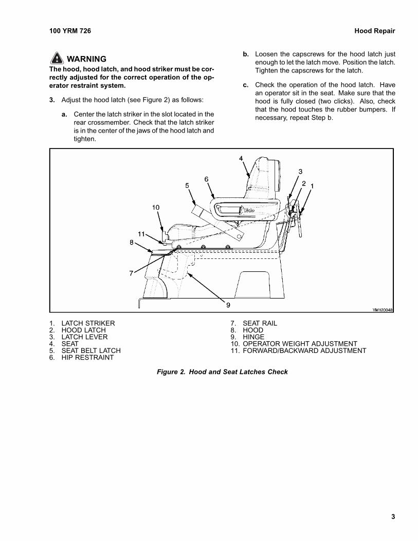
WARNINGThe hood, hood latch, and hood striker must be cor-rectly adjusted for the correct operation of the op-erator restraint system.
3. Adjust the hood latch (see Figure 2) as follows:
a. Center the latch striker in the slot located in therear crossmember. Check that the latch strikeris in the center of the jaws of the hood latch andtighten.
b. Loosen the capscrews for the hood latch justenough to let the latch move. Position the latch.Tighten the capscrews for the latch.
c. Check the operation of the hood latch. Havean operator sit in the seat. Make sure that thehood is fully closed (two clicks). Also, checkthat the hood touches the rubber bumpers. Ifnecessary, repeat Step b.
1. LATCH STRIKER2. HOOD LATCH3. LATCH LEVER4. SEAT5. SEAT BELT LATCH6. HIP RESTRAINT
7. SEAT RAIL8. HOOD9. HINGE10. OPERATOR WEIGHT ADJUSTMENT11. FORWARD/BACKWARD ADJUSTMENT
Figure 2. Hood and Seat Latches Check
3

Overhead Guard Repair 100 YRM 726
Overhead Guard RepairREMOVE
WARNINGThe lift truck must be put on blocks for some typesof maintenance and repair. The removal of thefollowing assemblies will cause large changes inthe center of gravity: mast, drive axle, engine andtransmission, and counterweight. When the lifttruck is put on blocks, put additional blocks in thefollowing positions to maintain stability:a. Before removing the mast and drive axle, put
blocks under the counterweight so that the lifttruck cannot fall backward.
b. Before removing the counterweight, put blocksunder the mast assembly so that the lift truckcannot fall forward.
The surface must be solid, even, and level when thelift truck is put on blocks. Make sure that any blocksused to support the lift truck are solid, one-pieceunits.
WARNINGDo not operate the lift truck without the overheadguard correctly fastened to the lift truck.
Do not make changes to the overhead guard bywelding. Changes that are made by welding, or bydrilling holes that are too big in the wrong location,can reduce the strength of the overhead guard.See the instructions for Changes to the OverheadGuard in the Periodic Maintenance section includedwith this lift truck.
Connect a lifting device to the top of the overheadguard. Remove the capscrews that hold the overheadguard to the frame. Remove the capscrews that holdthe overhead guard to the cowl and module. Lift theoverhead guard from the lift truck.
INSPECT
Inspect the condition of the mount isolators located atthe rear legs of the overhead guard for any damage.Replace if damaged.
INSTALL
1. Connect a lifting device to the top of the overheadguard. Put the overhead guard in position on the lifttruck.
2. Install the capscrews at the rear of the overheadguard. Tighten the capscrews to 90 N•m (67 lbf ft).Install the capscrews that hold the overhead guardto the cowl. Tighten the capscrews to 90 N•m(67 lbf ft).
LED BACKUP AND BRAKE LIGHTS,REPLACE
NOTE: Newer models of lift trucks are equipped withLED (Light Emitting Diode) backup and brake tail lights.These light assemblies are non-repairable and must bereplaced as a complete unit. See the Parts Manual forreplacement LED lights.
Remove
1. Disconnect negative terminal of battery and, re-move the key.
2. Disconnect the LED light from the chassis light har-ness.
3. Remove LED light assembly and harness frommounting bracket. See Figure 3.
4. If the LED mounting bracket must be removed fromthe overhead guard leg, remove the plug, screwand bracket from the overhead guard leg.
Install
1. If the mounting bracket was removed, install it ontothe overhead guard leg. Insert the plug and screwto attach mounting bracket to overhead guard leg.See Figure 3.
2. Install the LED light assembly and harness on themounting bracket.
3. Connect the LED light to the chassis light harness.
4. Connect the negative terminal of battery and closethe hood.
4

100 YRM 726 Operator Restraint System Repair
Figure 3. LED Backup and Brake Lights Assembly
Legend for Figure 3
A. LED ASSEMBLY WITH STANDARD EXHAUSTB. LED ASSEMBLY WITH OVERHEAD EXHAUST
1. LED LIGHT2. SCREW3. WASHER4. LOCK NUT5. MOUNTING BRACKET6. GROMMET7. PLUG8. SCREW9. OVERHEAD GUARD LEG
Operator Restraint System Repair
WARNINGThe lift truck must be put on blocks for some typesof maintenance and repair. The removal of thefollowing assemblies will cause large changes inthe center of gravity: mast, drive axle, engine andtransmission, and counterweight. When the lifttruck is put on blocks, put additional blocks in thefollowing positions to maintain stability:a. Before removing the mast and drive axle, put
blocks under the counterweight so the lift truckcannot fall backward.
b. Before removing the counterweight, put blocksunder the mast assembly so the lift truck cannotfall forward.
The surface must be solid, even, and level when thelift truck is put on blocks. Make sure that any blocks
used to support the lift truck are solid, one-pieceunits.
The seat belt, hip restraint brackets, seat and mounting,hood, and latches are all part of the operator restraintsystem. Each item must be checked to make sure itis attached securely, functions correctly, and is in goodcondition. See Figure 2.
AUTOMATIC LOCKING RETRACTOR (ALR)
NOTE: Lift trucks produced before November 2005 areequipped with the ALR type seat belts.
The seat belt must fasten securely. Make sure the seatbelt extends and retracts smoothly and is not frayed ortorn. If the seat belt is damaged or does not operateproperly, it must be replaced. See Figure 4.
5

Operator Restraint System Repair 100 YRM 726
EMERGENCY LOCKING RETRACTOR(ELR)
NOTE: Lift trucks produced after November 2005 areequipped with the Emergency Locking Retractor (ELR)style seat belt.
When the ELR style seat belt is properly buckled acrossthe operator, the belt will permit slight operator reposi-tioning without activating the locking mechanism. If thetruck tips, travels off a dock, or comes to a sudden stop,the locking mechanism will be activated and hold theoperator’s lower torso in the seat.
A seat belt that is damaged worn or does not operateproperly will not give protection when it is needed. Theend of the belt must fasten correctly in the latch. Theseat belt must be in good condition. Replace the seatbelt if damage or wear is seen. See Figure 4.
The following seat belt operation checks must be per-formed:• With the hood closed and in the locked position, pull
the seat belt slowly from the retractor assembly. Makesure the seat belt pulls out and retracts smoothly. if
the seat belt cannot be pulled from the retractor as-sembly or the belt will not retract, replace the seat beltassembly.
• With the hood closed and in the locked position, pullthe seat belt with a sudden jerk. Make sure the seatbelt will not pull from the retractor assembly. If theseat belt can be pulled from the retractor, when it ispulled with a sudden jerk, replace the seat belt as-sembly.
• With the hood in the open position, make sure theseat belt will not pull from the retractor assembly. Ifthe seat belt can be pulled from the retractor, withthe hood in the open position, replace the seat beltassembly.
Make sure the seat rails and latch striker are not loose.The seat rails must lock securely in position but movefreely when unlocked. The seat rails must be securelyattached to the mounting surface. The hood must befully closed. Lift the hood to make sure it is closed andwill not move.
Adjust hood, hood latch, and latch striker when any ofthe parts of the operator restraint system are installed orreplaced. See the section Hood Repair in this manualfor the adjustment procedures for the hood.
NOTE: SWIVEL SEAT IS AN OPTIONAL FEATURE
A. AUTOMATIC LOCKING RETRACTOR B. EMERGENCY LOCKING RETRACTOR
1. FORWARD/BACKWARD ADJUSTMENT2. SWIVEL ADJUSTMENT3. OPERATOR WEIGHT ADJUSTMENT
4. SEAT POSITION ADJUSTMENT (SEAT RAIL)5. SEAT BELT
Figure 4. Operator Restraint System (Swivel Seat Shown)
6

100 YRM 726 Radiator Repair
Radiator RepairREMOVE
WARNINGThe lift truck must be put on blocks for some typesof maintenance and repair. The removal of thefollowing assemblies will cause large changes inthe center of gravity: mast, drive axle, engine andtransmission, and counterweight. When the lifttruck is put on blocks, put additional blocks in thefollowing positions to maintain stability:a. Before removing the mast and drive axle, put
blocks under the counterweight so the lift truckcannot fall backward.
b. Before removing the counterweight, put blocksunder the mast assembly so the lift truck cannotfall forward.
The surface must be solid, even, and level when thelift truck is put on blocks. Make sure that any blocksused to support the lift truck are solid, one-pieceunits.
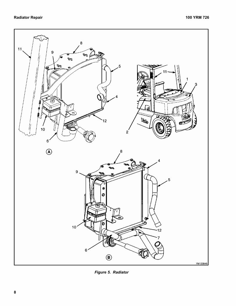
1. Remove the cover between the hood and counter-weight. See Figure 5.
WARNINGDisposal of coolant must be in accordance with lo-cal regulations.
NOTE: To aid in the draining of coolant from the radiator,remove the radiator cap.
2. Drain the coolant from the radiator.
3. Disconnect the upper and lower coolant hoses fromthe radiator.
4. Disconnect the hydraulic hoses from the radiatorand install plugs in the hoses.
5. On the GM-powered lift truck, remove the clampand hose from the bottom of the radiator.
6. Remove the top radiator support plate.
7. Disconnect the coolant recovery reservoir hosefrom the radiator.
8. Remove the coolant recovery reservoir from theoverhead guard leg.
9. Remove the upper and lower fan shroud halvesfrom the radiator.
10. Remove the radiator from the lower radiator mount-ing plate.
INSTALL
1. Install the rubber isolators on the lower radiator lo-cating studs. See Figure 5.
2. Install the radiator on the lower radiator mountingplate.
3. Install the upper and lower fan shroud halves on theradiator.
4. Install the coolant recovery reservoir on the over-head guard leg.
5. Connect the coolant recovery reservoir hose to theradiator.
6. Install the rubber isolators on the upper radiator lo-cating studs.
7. Install the top radiator support plate. Tighten theouter screws to 66 N•m (49 lbf ft). Tighten the innerscrews to 38 N•m (28 lbf ft).
8. On the GM-powered lift truck, install the hose andclamp on the bottom of the radiator.
9. Connect the upper and lower coolant hoses to theradiator.
10. Connect the hydraulic hoses to the radiator.
CAUTIONTo prevent possible damage to the engine, makesure the engine is running at idle speed while per-forming Step 11.
11. Add coolant to the system until the entire coolingsystem is full.
12. Install the cover between the hood and counter-weight.
7
Radiator Repair 100 YRM 726
Figure 5. Radiator
8

100 YRM 726 Exhaust System Repair
Legend for Figure 5
A. PERKINS DIESEL 1004.42 B. GM 4.3L V-6
1. COVER2. HOOD3. COUNTERWEIGHT4. RADIATOR5. HOSE6. HOSE
7. CLAMP8. RADIATOR SUPPORT PLATE9. COOLANT RECOVERY RESERVOIR HOSE10. COOLANT RECOVERY RESERVOIR11. OVERHEAD GUARD LEG12. LOWER RADIATOR MOUNTING PLATE
Exhaust System RepairMUFFLER
Remove
WARNINGThe lift truck must be put on blocks for some typesof maintenance and repair. The removal of thefollowing assemblies will cause large changes inthe center of gravity: mast, drive axle, engine andtransmission, and counterweight. When the lifttruck is put on blocks, put additional blocks in thefollowing positions to maintain stability:a. Before removing the mast and drive axle, put
blocks under the counterweight so the lift truckcannot fall backward.
b. Before removing the counterweight, put blocksunder the mast assembly so the lift truck cannotfall forward.
The surface must be solid, even, and level when thelift truck is put on blocks. Make sure that any blocksused to support the lift truck are solid, one-pieceunits.
1. Remove the overhead exhaust pipe from the coun-terweight. See Figure 6 or Figure 7.
2. Remove the counterweight. See CounterweightRepair, Remove in this YRM.
3. Remove the lower exhaust pipe from the mufflerand disconnect the upper exhaust pipe from themuffler.
4. Remove the muffler from the mounting bracket.
Install
1. Install the muffler on the mounting bracket. Tightenbolts until all clearance has been removed; thentighten one additional turn. See Figure 6 or Fig-ure 7.
2. Connect the upper exhaust pipe to the muffler andinstall the lower exhaust pipe on the muffler.
3. Install the counterweight on the lift truck. See Coun-terweight Repair, Install in this YRM.
4. Install the overhead exhaust pipe in the counter-weight. Tighten the capscrews to 38 N•m (28 lbf ft).
9

Exhaust System Repair 100 YRM 726
1. LEFT ENGINE EXHAUST PIPE2. RIGHT ENGINE EXHAUST PIPE3. UPPER EXHAUST PIPE4. MUFFLER5. SEAL6. FLANGE7. HEX HEAD BOLT8. SPRING9. CLAMP10. OVERHEAD EXHAUST11. LOWER EXHAUST PIPE12. COUNTERWEIGHT EXHAUST PIPE13. HEAT SHIELD14. CLAMP
15. HEAT SHIELD SLEEVE16. HEAT SHIELD SLEEVE17. INTERMEDIATE UPPER EXHAUST PIPE18. MUFFLER MOUNTING BRACKET19. ISOLATOR20. WASHER21. HEX HEAD BOLT22. WASHER23. NUT24. HEX HEAD BOLT25. LOCKWASHER26. RIGHT-SIDE EXHAUST MANIFOLD27. LEFT-SIDE EXHAUST MANIFOLD
Figure 6. LPG/GAS Exhaust System (Without Low Emissions) Early Model Lift Trucks
10

100 YRM 726 Exhaust System Repair
Figure 7. LPG/GAS Exhaust System (Without Low Emissions) Later Model Lift Trucks
11

Exhaust System Repair 100 YRM 726
Legend for Figure 7
1. LEFT ENGINE EXHAUST PIPE2. RIGHT ENGINE EXHAUST PIPE3. UPPER EXHAUST PIPE4. MUFFLER5. COUNTERWEIGHT EXHAUST PIPE6. SEAL7. FLANGE8. HEX HEAD BOLT9. SPRING10. CLAMP11. OVERHEAD EXHAUST PIPE
12. LOWER EXHAUST PIPE13. HEAT SHIELD14. HEAT SHIELD SLEEVE15. LOCKWASHER16. INTERMEDIATE UPPER EXHAUST PIPE17. NUT18. MUFFLER MOUNTING BRACKET19. ISOLATOR20. WASHER21. PLUG
LPG/GAS ENGINE EXHAUST PIPE - LIFTTRUCKS WITHOUT LOW EMISSIONS
Remove
NOTE: If the lift truck does not have an overhead ex-haust, perform Step 2 and Step 4 through Step 8. Ifthe lift truck has an overhead exhaust, perform Step 1through Step 3 and Step 5 through Step 8.
1. Remove the overhead exhaust pipe from the coun-terweight. See Figure 6 and Figure 7.
2. Remove the counterweight. See CounterweightRepair, Remove in this YRM.
3. Remove the lower exhaust pipe from the right sideof the muffler and disconnect the upper exhaustpipe from the left side of the muffler.
4. Remove the counterweight exhaust pipe from theright side of the muffler and disconnect the upperexhaust pipe from the left side of the muffler.
5. Disconnect upper exhaust pipe from the intermedi-ate upper exhaust pipe and disconnect the interme-diate upper exhaust pipe from the left-side engineexhaust pipe.
6. On early model lift trucks only, remove the metalheat shield from the left and right engine exhaustpipes.
7. Disconnect the left and right engine exhaust pipesfrom each other.
8. Remove the left and right engine exhaust pipesfrom the engine exhaust manifolds.
Install
NOTE: If the lift truck does not have an overhead ex-haust perform Step 1 through Step 5, and Step 7. If
the lift truck has an overhead exhaust perform Step 1through Step 4 and Step 6 through Step 8.
1. Install the left and right engine exhaust pipes on theengine exhaust manifolds. See Figure 6.
2. Connect the left and right engine exhaust pipes toeach other.
3. On early model lift trucks only, install the metal heatshield on the left and right engine exhaust pipes.
4. Connect the intermediate upper exhaust pipe to theleft-side engine exhaust pipe and connect the up-per exhaust pipe to the intermediate upper exhaustpipe.
5. Connect the upper exhaust pipe to the left side ofthe muffler and install the counterweight exhaustpipe on the right side of the muffler.
6. Connect the upper exhaust pipe to the left side ofthe muffler and connect the lower exhaust pipe tothe right side of the muffler.
7. Install the counterweight. See Counterweight Re-pair, Install in this YRM.
8. Install the overhead exhaust pipe in the counter-weight. Tighten the capscrews to 38 N•m (28 lbf ft).
EPA COMPLIANT LPG/GAS ENGINEEXHAUST SYSTEM
Remove
NOTE: If the lift truck does not have an overhead ex-haust, perform Step 2 and Step 4 through Step 8. Ifthe lift truck has an overhead exhaust, perform Step 1through Step 3 and Step 5 through Step 8.
1. Remove the overhead exhaust pipe from the coun-terweight. See Figure 8.
12

100 YRM 726 Exhaust System Repair
Figure 8. EPA Compliant LPG/GAS Exhaust System
13

Exhaust System Repair 100 YRM 726
Legend for Figure 8
1. GASKET2. HEX HEAD BOLT3. SPRING4. SEAL5. UPPER EXHAUST PIPE6. LEFT ENGINE EXHAUST PIPE7. CLAMP8. RIGHT ENGINE EXHAUST PIPE9. HEAT SHIELD SLEEVE10. WIRE HARNESS (CLOSED LOOP)11. HEAT SHIELD
12. MUFFLER13. WASHER14. NUT15. MUFFLER MOUNTING BRACKET16. COUNTERWEIGHT EXHAUST PIPE17. ISOLATOR18. PLUG19. OXYGEN SENSOR20. LOWER EXHAUST PIPE21. OVERHEAD EXHAUST PIPE22. CAPSCREW
2. Remove the counterweight. See CounterweightRepair, Remove in this YRM.
3. Remove the lower exhaust pipe from the right sideof the muffler and the upper exhaust pipe from theleft side of the muffler.
4. Remove the counterweight exhaust pipe from theright side of the muffler and the upper exhaust pipefrom the left side of the muffler.
5. Disconnect upper exhaust pipe from the left andright-side engine exhaust pipes.
6. Remove the metal heat shield from the left and rightengine exhaust pipes.
7. Disconnect the electrical connector from the oxy-gen sensor. Remove oxygen sensor from the en-gine exhaust pipes. Inspect oxygen sensor and if itis damaged or broken, replace with new sensor.
8. Remove the left and right engine exhaust pipesfrom the engine exhaust manifolds. See Figure 8.
Install
NOTE: If the lift truck does not have an overhead ex-haust, perform Step 1 through Step 5 and Step 7. Ifthe lift truck has an overhead exhaust, perform Step 1through Step 4 and Step 6 through Step 8.
1. Install the left and right engine exhaust pipes to theengine exhaust manifolds. See Figure 8.
2. Before installing the oxygen sensor, apply a smallamount of antiseize compound. Install the oxygensensor to the engine exhaust pipes. Tighten sensorto 39 N•m (29 lbf ft). Connect the electrical connec-tor to the oxygen sensor.
3. Install the metal heat shield to the engine exhaustpipes.
4. Connect upper exhaust pipe to the left and right-side engine exhaust pipes.
5. Connect the upper exhaust pipe to the left side ofthe muffler and install the counterweight exhaustpipe on the right side of the muffler.
6. Connect the lower exhaust pipe from the right sideof the muffler and the upper exhaust pipe from theleft side of the muffler.
7. Install the counterweight. See Counterweight Re-pair, Install in this YRM.
8. Install the overhead exhaust pipe in the counter-weight. Tighten the capscrews to 38 N•m (28 lbf ft).
DIESEL ENGINE EXHAUST PIPE
Remove
NOTE: If the lift truck does not have an overhead ex-haust, perform Step 2 and Step 4 through Step 7. Ifthe lift truck has an overhead exhaust, perform Step 1through Step 3 and Step 5 through Step 7.
1. Remove the overhead exhaust pipe from the coun-terweight. See Figure 9.
2. Remove the counterweight. See CounterweightRepair, Remove in this YRM.
3. Remove the lower exhaust pipe from the right sideof the muffler and disconnect the upper exhaustpipe from the left side of the muffler.
4. Remove the counterweight exhaust pipe from theright side of the muffler and disconnect the upperexhaust pipe from the left side of the muffler.
5. Remove the heat shield from the upper exhaustpipe and intermediate upper exhaust pipe. Removethe upper exhaust pipe from the intermediate ex-haust pipe.
14

100 YRM 726 Exhaust System Repair
6. Remove the intermediate exhaust pipe from the en-gine exhaust pipe.
7. Remove the engine exhaust pipe from the exhaustmanifold.
1. MUFFLER2. LOWER EXHAUST PIPE3. CLAMP4. UPPER EXHAUST PIPE5. INTERMEDIATE EXHAUST PIPE6. ENGINE EXHAUST PIPE7. ADAPTER8. OVERHEAD EXHAUST PIPE9. HEX HEAD BOLT10. SPRING11. SEAL
12. HEAT SHIELD SLEEVE13. COUNTERWEIGHT EXHAUST PIPE14. BRACKET15. HEX HEAD BOLT16. WASHER17. ISOLATOR18. NUT19. WASHER20. HEX HEAD BOLT21. WASHER22. ENGINE EXHAUST MANIFOLD
Figure 9. Diesel Exhaust System
15

Engine Repair 100 YRM 726
Install
NOTE: If the lift truck does not have an overhead ex-haust, perform Step 1 through Step 4 and Step 6. Ifthe lift truck has an overhead exhaust, perform Step 1through Step 4 and Step 6 and Step 7.
1. Install the engine exhaust pipe on the exhaust man-ifold. See Figure 9.
2. Connect the intermediate exhaust pipe to the en-gine exhaust pipe.
3. Connect the upper exhaust pipe to the intermediateexhaust pipe. Install the heat shield on the upperexhaust pipe and intermediate exhaust pipe.
4. Connect the upper exhaust pipe to the left side ofthe muffler and install the counterweight exhaustpipe on the right side of the muffler.
5. Connect the upper exhaust pipe to the left side ofthe muffler. Connect the lower exhaust pipe to theright side of the muffler.
6. Install the counterweight. See Counterweight Re-pair, Install in this YRM.
7. If removed, install the overhead exhaust pipe on thecounterweight. Tighten the capscrews to 38 N•m(28 lbf ft).
Engine RepairREMOVE
1. Remove the overhead guard. Remove the floorplates.
2. Disconnect the cables at the battery. Remove thebattery and the battery tray.
3. Disconnect the fuel lines at the engine. Disconnectthe throttle linkage at the engine. Disconnect thewires and wiring harnesses at the engine.
4. Disconnect the hydraulic line between the maincontrol valve and the hydraulic oil tank.
5. Remove the engine only as described in the follow-ing steps:
a. Remove the brake pedal assembly as follows(see Figure 10): Disconnect the wires at thebrake switch. Disconnect the brake lines at thebrake booster/master cylinder and put plugsand caps on the openings. Disconnect theinching link at the transmission. Remove thespring from the inching link. Remove the returnspring from the inching pedal. Remove the fourcapscrews at the top of the pedal bracket. Re-move the pedal assembly from the lift truck.
b. Disconnect the wiring harness and throttle ca-ble for the accelerator or Foot Directional Con-trol pedal. Remove the pedal assembly fromthe frame.
c. Remove the capscrews for the universal jointsfrom the hydraulic pump drive line at the crank-shaft and move the drive line out of the way.
d. Disconnect the engine wiring harness from themain wiring harness.
e. Disconnect the exhaust pipe from the muffler.Remove the air filter housing from the frame.
f. Connect a lifting device to the engine. Makesure the lifting device has a capacity of at least450 kg (992 lb).
g. Support the transmission by placing a jack-stand under the transmission housing.
h. Remove the engine mount capscrews andwashers at the fan end of the engine.
NOTE: The bolts being removed in Step i are a one-time usage type of bolt and must be discarded whenremoved.
i. Bar the engine over at the crankshaft andremove and discard the torque converter flexplate bolts. When all of the bolts have beenremoved, move the engine forward just enoughto break the engine loose from the transmis-sion.
j. Carefully lift the engine from the frame. Makesure all the connections have been removedand that the torque converter does not comeout at the same time as the engine.
16

100 YRM 726 Engine Repair
1. FOOT DIRECTIONAL CONTROL PEDAL2. ACCELERATOR PEDAL3. PEDAL BRACKET4. BRAKE BOOSTER/MASTER CYLINDER
ASSEMBLY
5. INCHING LINKAGE6. RETURN SPRING7. INCHING CRANK RETURN SPRING8. INCH/BRAKE PEDAL
Figure 10. Pedal Assembly
17

Engine Repair 100 YRM 726
6. Remove the engine and powershift transmission asdescribed in the following steps:
a. Remove the radiator, fan, and fan shroud. SeeRadiator Repair, Remove in this section. Dis-connect the exhaust pipe from the muffler. Re-move the air filter housing from the frame.
b. Put the lift truck on blocks. See the OperatingManual for the correct procedures to put the lifttruck on blocks.
NOTE: Tag hydraulic hoses and fittings as they are dis-connected to aid in reconnecting the hoses.
c. Disconnect the hydraulic hoses from the steer-ing control unit. Install caps on the steeringcontrol unit and plugs on the hydraulic hoses.
d. Disconnect the horn wire at the steering col-umn. Remove the capscrews that hold thesteering column and steering control unit to theoperator’s module. Remove the steering col-umn assembly.
e. Disconnect the wiring harness and throttle ca-ble for the accelerator or Foot Directional Con-trol pedal. Remove the pedal assembly fromthe frame.
f. Remove the brake pedal assembly as follows(see Figure 10): Disconnect the wires at thebrake switch. Disconnect the brake lines atthe master cylinder and put plugs and caps onthe openings. Disconnect the inching link atthe transmission. Remove the spring from theinching link. Remove the return spring from theinching pedal. Remove the four capscrews atthe top of the pedal bracket. Remove the pedalassembly from the lift truck.
g. Remove the transmission oil filter. Drain the oilfrom the transmission.
h. Disconnect the linkages at the transmission.Disconnect the wires at the transmission. Dis-connect the transmission oil lines from thetransmission.
i. Remove the axle shafts from the drive axle.
j. Connect a lifting device to the engine. Makesure the lifting device has a capacity of at least700 kg (1500 lb).
k. Remove the capscrews that hold the transmis-sion to the differential housing. Remove the en-gine mount capscrews at the fan end of the en-gine.
l. Carefully lift the engine from the frame. As theengine is being lifted from the frame, make sureall connections have been disconnected.
m. Remove the powershift transmission from theengine as described in the section Two-SpeedPowershift Transmission, Troubleshootingand Repairs 1300 YRM 728 or Single-SpeedPowershift Transmission, Troubleshootingand Repair 1300 YRM 752.
INSTALL
1. Install the engine and powershift transmission asfollows:
a. See the section Two-Speed PowershiftTransmission, Troubleshooting and Re-pairs 1300 YRM 728 and install the powershifttransmission on the engine.
b. Connect a lifting device to the engine. Makesure the lifting device has a capacity of 700 kg(1500 in.).
c. Install the engine assembly in the lift truck. In-stall the capscrews and washers for the enginemounts. Tighten the capscrews to the correcttorque values as shown in Figure 11.
d. Install the capscrews that mount the transmis-sion to the drive axle. Tighten the capscrew to66 N•m (49 lbf ft).
e. Connect the transmission oil lines to the trans-mission. Connect the transmission wiring har-ness to the transmission. Connect the linkagesto the transmission.
f. Install the transmission oil filter and fill thetransmission with oil specified in Capacitiesand Specifications 8000 YRM 738.
g. Install the brake pedal assembly as follows (seeFigure 10): Install the pedal assembly on thelift truck. Install the four capscrews at the topof the pedal bracket. Install the return springon the inching pedal. Install the spring on theinching link. Connect the inching link to thetransmission. Connect the brake lines to the
18

100 YRM 726 Engine Repair
master cylinder. Connect the wires to the brakeswitch.
NOTE: A = 165 N•m (122 lbf ft).
A. ENGINE MOUNTS (DIESEL SHOWN)B. ENGINE MOUNT (GAS/LPG SHOWN)
1. CAPSCREW2. WASHER3. WASHER4. SNUBBING CUP5. ISOLATOR6. ENGINE MOUNT7. NUT
8. REBOUNDWASHER
9. BUMPER10. SPACER11. FRAME12. SHIM*
*ROTATE ENGINE AROUND DRIVE AXLE CENTER-LINE UNTIL LH OR RH MOUNT CONTACTS. USE AMAXIMUM OF THREE SHIMS (12), ON THE OTHERSIDE TO LESS THAN 1.0 mm (0.03937 in.).
Figure 11. Engine Mounts
h. Install the Foot Directional Control or accelera-tor pedal to the frame. Connect the wiring har-ness and throttle cable for the Foot DirectionalControl pedal or accelerator.
i. Install the steering wheel or install the steeringcolumn and steering control unit to the bracket
on the frame. Connect the four hydraulic hosesto the steering control unit as noted during re-moval. Connect the horn wire at the steeringcolumn.
j. Connect the hydraulic hoses as noted duringremoval to the steering control unit.
k. Remove the lift truck from the blocks.
2. Install the engine only as described in the followingsteps:
a. Connect a lifting device to the engine. Makesure the lifting device has a capacity of at least450 kg (1000 lb).
b. Carefully install the engine in the frame.
c. Bar the engine over at the crankshaft and installnew torque converter flex plate bolts. Tightenbolts to 38 N•m (28 lbf ft).
d. Install the engine mount capscrews and wash-ers at the fan end of the engine. Tighten thecapscrews to the correct torque values asshown in Figure 11.
e. Connect the exhaust pipe to the muffler. Installthe air filter housing on the frame.
f. Connect the engine wiring harness to the mainwiring harness.
g. Install the capscrews for the universal jointsfrom the hydraulic pump drive line at the crank-shaft.
h. Install the pedal assembly for the acceleratoror Foot Directional Control pedal in the frame.Connect the wiring harness and throttle cable.
i. Install the brake pedal assembly as follows (seeFigure 10): Install the pedal assembly in thelift truck. Install the four capscrews at the topof the pedal bracket. Install the return springon the inching pedal. Install the spring fromthe inching link. Connect the inching link atthe transmission. Connect the brake lines atthe brake booster/master cylinder. Connect thewires at the brake switch.
3. Connect the hydraulic line between the main controlvalve and the hydraulic oil tank.
19

Throttle Pedal Adjustment 100 YRM 726
4. Connect the fuel lines at the engine. Connect thethrottle linkage at the engine. Connect the wiresand wiring harnesses at the engine.
5. Install the air filter housing on the frame. Connectthe exhaust pipe to the muffler. Install the radiator,fan, and fan shroud. See Radiator Repair, Install inthis section.
6. Install the alternator on units with a diesel engine.Install the battery and the battery tray. Connect thecables to the battery.
7. Install the overhead guard.
8. Check all of the fluid levels and fill as necessary.Install the floor plates and covers. Connect the ca-bles at the battery.
Throttle Pedal AdjustmentPERKINS 1104C-44(RE) DIESEL ENGINE
NOTE: The procedures below are for lift trucksequipped with the Perkins 1104C-44(RE) DieselEngine. If your lift truck has either a gas or LPG en-gine, see the section LPG Fuel System 900 YRM 745for the procedures to adjust the throttle linkage.
Lift Trucks With an Accelerator Pedal
1. Adjust the cable adjustment nuts to allow for a3.0 mm (0.12 in.) maximum of free play on the
throttle cable length. See Figure 12. Secure cablelength by tightening cable lock nuts.
2. Depress the accelerator pedal until the diesel injec-tor pump is in the full power position (the injectionpump lever is touching the lever stop in Figure 13).
3. Turn capscrew stop (see Figure 12) clockwise untilit contacts the pedal. Continue for another 1/4 turnuntil the capscrew height is 12.0 mm (0.50 in.).
4. Tighten capscrew stop with jam nut.
1. ACCELERATOR PEDAL2. DIESEL INJECTOR PUMP3. CABLE ADJUSTMENT NUTS
4. CABLE LOCK NUTS5. CAPSCREW STOP6. JAM NUT
Figure 12. Accelerator Pedal Adjustment
20

100 YRM 726 Throttle Pedal Adjustment
NOTE: DIESEL INJECTOR PUMP IS SHOWN IN THEIDLE POSITION.
1. INJECTION PUMP LEVER2. LEVER STOP
Figure 13. Diesel Injector Pump
Lift Trucks With a Foot Directional ControlPedal
1. Adjust the cable adjustment nuts to allow for a3.0 mm (0.12 in.) maximum of free play on thethrottle cable length. See Figure 14. Secure cablelength by tightening cable lock nuts.
2. Set pedal stop to 35 ±2 mm (1.40 ±0.08 in.). Securein place with pedal stop jam nuts.
3. With the pedal against the stop, adjust the throttlecable to ensure that the diesel injector pump is atfull power (the injection pump lever is touching thelever stop in Figure 13).
4. Release the throttle pedal and adjust the up posi-tion pedal stop until the tension is removed from thecable when the injection pump lever is returned tothe idle position (see Figure 13). Tighten up posi-tion pedal stop with capscrew. See Figure 14.
21

Throttle Pedal Adjustment 100 YRM 726
1. MONOTROL PEDAL2. DIESEL INJECTOR PUMP3. CABLE ADJUSTMENT NUTS4. CABLE LOCK NUTS
5. PEDAL STOP JAM NUTS6. PEDAL STOP7. UP POSITION PEDAL STOP8. CAPSCREW
Figure 14. Foot Directional Control Pedal Adjustment
22

100 YRM 726 Fuel and Hydraulic Tanks Repair
Fuel and Hydraulic Tanks RepairINSPECT
Make a visual inspection of all sides of the tank. Inspectthe welds for cracks and leakage. Check for wet areas,accumulation of dirt, and loose or missing paint causedby leakage. Areas of the tank that are not easily seencan be checked with an inspection mirror and a light thatis approved for locations with flammable vapors.
SMALL LEAKS, REPAIR
Use the following procedure to repair small leaks:
WARNINGDo not use tools that can make sparks, heat, orstatic electricity. The vapors in the tank can causean explosion.
1. Use steam to clean the area around the leak. Re-move all paint and dirt around the leak.
2. Apply Loctite® 290 to the leak. Follow the instruc-tions of the manufacturer.
LARGE LEAKS, REPAIR
1. Use one of the procedures described under Cleanto clean and prepare the tank for repairs.
2. Use acceptable welding practices to repair thetank. See the American National Standard SafetyIn Welding and Cutting AWS Z 49.1 - 1999.
CLEAN
WARNINGSpecial procedures must be followed when largeleaks or other repairs need welding or cutting. Allwork must be done by authorized personnel. If thetank is cleaned inside a building, make sure there isenough ventilation. See the following manuals foradditional information:• Safe Practices For Welding And Cutting Contain-
ers That Have Held Combustibles by the Ameri-can Welding Society, F4.1 - 1999.
• Safety In Welding And Cutting American NationalStandard, AWS Z 49.1 - 1999.
When cleaning the tank, do not use solutions thatmake dangerous gases at normal temperatures orwhen heated. Wear eye and face protection. Protectthe body from burns.
When cleaning with steam, use a hose with a minimumdiameter of 19 mm (0.75 in.). Control the pressure ofthe steam by a valve installed at the nozzle of the hose.If a metal nozzle is used, it must be made of a materialthat does not make sparks. Make an electrical connec-tion between the nozzle and the tank. Connect a groundwire to the tank to prevent static electricity.
Steam Method
Use the following procedure to clean the tank withsteam:
1. Remove all the parts from the tank. Install the drainplug.
2. Fill the tank 1/4 full with a solution of water andsodium bicarbonate or sodium carbonate. Mix0.5 kg (1 lb) per 4 liter (1 gal) of water.
3. Mix the solution in the tank using air pressure.Make sure all the surfaces on the inside of the tankare flushed with the solution. Drain the tank.
4. Put steam into the tank until the tank does not haveodors and the metal is hot. Steam vapors mustcome from all the openings.
5. Flush the inside of the tank with boiling water. Makesure all the loose material is removed from the in-side of the tank.
6. Make an inspection of the inside of the tank. If itis not clean, repeat Step 4 and Step 5 and makeanother inspection. When making inspections, usea light that is approved for locations with flammablevapors.
7. Put plugs in all the openings in the tank. Wait 15minutes; then remove the inlet and outlet plugs.Test a sample of the vapor with a special indicatorfor gas vapors. If the amount of flammable vapors isabove the lower flammable limit, repeat the clean-ing procedures.
Chemical Solution Method
If the tank cannot be cleaned with steam, use the fol-lowing procedure:
1. Mix a solution of water and trisodium phosphate ora cleaning compound with an alkali base. Followthe instructions given by the manufacturer.
23

Safety Labels 100 YRM 726
WARNINGCompressed air can move particles so that theycause injury to the user or to other personnel.Make sure that the path of the compressed air isaway from all personnel. Wear protective gogglesor a face shield to prevent injury to the eyes.
2. Fill the tank with the cleaning solution. Use com-pressed air to mix the solution in the tank.
3. Drain the tank. Flush the inside of the tank withhot (boiling) water. Make sure all the cleaning com-pound is removed.
4. Make an inspection of the inside of the tank. If thetank is not clean, repeat Step 1 through Step 3.Make another inspection of the tank. When mak-ing inspections, use a light that is approved for lo-cations with flammable vapors.
5. Check the tank for flammable vapors using aspecial indicator for gas vapors. If the amount offlammable vapors is not below the lower flammablelimit, repeat the cleaning procedures.
OTHER PREPARATION METHODS FORREPAIR
• If nitrogen gas or carbon dioxide gas is available, pre-pare the tank for welding using these gases. Seethe manual Safe Practices For Welding and CuttingContainers That Have Held Combustibles AmericanWelding Society, F4.1 - 1999. If these gases are notavailable, another method using water can be usedas follows:
• Fill the tank with water to just below the point wherethe work will be done. Make sure the space abovethe level of the water has a vent.
Safety Labels
WARNINGSafety labels are installed on the lift truck to giveinformation about operation and possible hazards.It is important that all safety labels are installed onthe lift truck and can be read.
DO NOT add to or modify the lift truck. Any changeto the lift truck, its tires, or its equipment canchange the lifting capacity. The lift truck must berated as equipped, and the nameplate must showthe new capacity rating. Contact your dealer forYale lift trucks for a replacement nameplate.
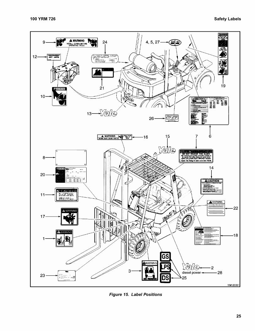
If necessary, install new and correct labels as follows(see Figure 15):
WARNINGCleaning solvents can be flammable and toxic andcan cause skin irritation. When using cleaning sol-vents, always follow the recommendations of themanufacturer.
1. Make sure the surface is dry and has no oil orgrease. Do not use solvent on new paint. Cleanthe surface of old paint using a cleaning solvent.
2. Remove the paper from the back of the label. Donot touch the adhesive surface.
3. Carefully hold the label in the correct position abovethe surface. The label cannot be moved after ittouches the surface. Put the label on the surface.Make sure that all air is removed from under thelabel and the corners and edges are tight.
24
100 YRM 726 Safety Labels
Figure 15. Label Positions
25

Safety Labels 100 YRM 726
Legend for Figure 15
1. MAST WARNING2. YALE LABEL3. NO RIDERS4. HOIST HANDLE LABEL5. TILT HANDLE LABEL6. PATENTS AND TRADEMARKS7. IMPACT WARNING LABEL8. NAMEPLATE COVER9. FAN WARNING10. FAN WARNING (PICTORIALLY)11. PARK BRAKE WITHOUT SEAT BRAKE12. ANTIFREEZE LABEL13. YALE LABEL14. DRIVETRAIN PROTECTION15. YALE LABEL
16. MAST WARNING17. PINCH POINT WARNING18. OPERATOR WARNING19. OPERATOR RESTRAINT LABEL20. NAMEPLATE21. FLAMMABLE LP GAS LABEL22. RADIAL TIRE WARNING (OPTIONAL) LABEL23. UL FUEL-TYPE WARNING LABEL24. LPG TANK LABEL25. FIRE SAFETY LABELS26. BATTERY DISCONNECT LABEL27. AUXILIARY FUNCTION LABEL28. DIESEL POWER LABEL (DIESEL TRUCKS
ONLY)
26

100 YRM 778 General
GeneralA fully-enclosed operator cab can be installed on thelift truck as an option. See Figure 1. When installed,the cab has doors, windows, window wipers, heatersystem, and an optional circulation fan. The overheadguard is an integral part of the operator cab. The oper-ator cab is installed on a platform above the main frame
members. Step plates on both sides of the lift truck giveaccess to the operator cab. The operator cab is a sep-arate unit and can be removed as a complete unit fromthe module and frame of the lift truck.
Figure 1. Operator Cab
1

Cab Repair 100 YRM 778
Cab RepairREMOVE
To remove the operator cab from the frame, do the fol-lowing:
1. Remove the retaining screws from the dash and thecowl panel.
2. Lift up the dash and remove the cowl panel.
3. Disconnect the main wiring harness, the front lightharness, and the rear light harness between the lifttruck and the operator cab. Stow front light harnessin the cab leg before removing the cab from the lifttruck.
4. Disconnect the water tube and the wiper motor har-ness connection to the windshield wipers.
5. Disconnect the air filter hose from the lower left cor-ner of the cab frame.
6. Disconnect the water hoses to the heater and dis-connect the heater wire harness.
7. Remove the cab front attaching hardware. See Fig-ure 2.
1. CAPSCREW (2)2. WASHER (4)
3. SHIM (ASREQUIRED)
4. LEFT FRONT LEG
Figure 2. Front Attaching Hardware
8. Remove the cab rear attaching hardware (1, 2, and3, Figure 3).
1. FLAT WASHER2. LOCKWASHER3. CAPSCREW4. CAPSCREW5. LOCKWASHER
6. FLAT WASHER7. RING WASHER8. ISOLATOR9. ISOLATOR10. ISOLATOR CUP
Figure 3. Rear Attaching Hardware
9. Remove the rear isolator hardware and inspect forwear or damage. Replace if necessary. See Fig-ure 3.
10. To prevent damage to the cab doors, remove thembefore attaching a lifting device.
WARNINGMake sure that the lifting device has a minimum ca-pacity to lift 500 kg (1100 lb).
11. Connect a lifting device to a spreader bar or liftstrap, that is through the door openings at the top ofthe operator cab (under the overhead guard struc-ture). Put material that will be a cushion at the topof the door openings to prevent damage. Operatethe lifting device just enough to correctly positionthe spreader bar or lift strap on the operator cab.
2

100 YRM 778 Switch Panel
CAUTIONLift the operator cab carefully. Check that all elec-trical wires and attachments are disconnected cor-rectly and are not damaged.
12. Carefully lift the cab away from the lift truck. Setthe cab assembly in a suitable storage area and putblocks under the unit to make it stable and preventdamage to parts still attached.
INSTALL
If the operator cab was removed for repair or replace-ment, install it as follows:
1. Connect a lifting device to a spreader bar or liftstrap, that is through the door openings at the top ofthe operator cab (under the overhead guard struc-ture). Put material that will be a cushion at the topof the door openings to prevent damage. Operatethe lifting device just enough to correctly positionthe spreader bar or lift strap on the operator cab.
2. Make sure that the bottom half of the isolators arein place.
3. Install the operator cab on the mounts making surethat the isolator is correctly positioned through thehole in the cab frame mount. See Figure 3.
4. Install the rubber isolators, washers, nuts, and boltsfor the mounts. Make sure that the isolators arecorrectly positioned.
5. Install the rear attaching hardware to the frame andtighten finger-tight only.
6. Install the front attaching hardware. Install theshims as required and bend the tabs as necessary.Tighten finger-tight only.
7. Connect the wiring harnesses and wires to the com-ponents in the operator cab.
8. Connect the wiring harness to the heater.
9. Connect the air filter hose to the left rear leg of thecab frame.
10. Tighten the cab mounting bolts as follows:a. Front bolts - 90 N•m (66 lbf)b. Rear bolts - 90 N•m (66 lbf)
11. Connect the water tube and the wiper motor har-ness connection to the windshield wipers.
12. Connect the main wiring harness and the front andrear light harness between the lift truck and the op-erator cab.
13. Install the cowl cover.
14. Install the dash over the cowl cover and install theretaining screws.
15. Install the cab doors.
Switch PanelThe switch panel for the front and rear window wipersand the heater fan is located in the upper right rear ofthe cab. See Figure 4.
Gauges and switches that are not an integral part of thecab are covered in Instrument Panel Indicators andSenders 2200 YRM 756.
1. FRONT WIPER/WASHER2. REAR WIPER/WASHER3. HEATER FAN
Figure 4. Cab Switches
3

Window Wipers Replacement 100 YRM 778
Window Wipers ReplacementTwo window wiper motor assemblies are installed in theoperator cab. The front window motor assembly hastwo wiper arms connected to a single wiper blade. Therear window has a wiper motor assembly that has onewiper arm attached to a single wiper blade.
FRONT WIPER ASSEMBLY
1. To replace the front motor assembly, remove the re-taining nuts and lockwashers from the wiper arms.Remove the wiper arm and blade from the outside.See Figure 5.
2. Remove the nuts, lockwashers, and flat washersfrom the two threaded shafts that pass through themetal frame (cowl) of the operator cab.
3. Remove the water tube and disconnect the wiringharness.
4. Repair or replace defective parts and install thefront wiper assembly as shown in Figure 5.
5. Install the water tube and connect the wiring har-ness.
REAR WIPER ASSEMBLY
1. To replace the rear motor assembly, remove theretaining nut and lockwasher from the wiper arm.Remove the wiper arm and blade from the outside.See Figure 6.
1. WIPER ARM (2)2. RETAINING NUT (2)3. LOCKWASHER (2)4. NUT (2)5. LOCK NUT (2)
6. FLAT WASHER (2)7. WIPER MOTOR8. ELECTRICAL CONNECTOR9. WATER TUBE10. HEATER
11. COVER12. CHECK VALVE13. GROMMET
Figure 5. Front Window Wiper System
4

100 YRM 778 Window Wipers Replacement
1. MOUNTING STUD2. WASHER (2)3. GROMMET (2)4. GLASS5. WIPER MOTOR6. WASHER (2)7. NUT (2)8. COVER9. WATER TUBE10. CONNECTOR
11. RESERVOIR12. SPRAY NOZZLE MOUNTING STUD13. GROMMET14. WASHER15. RETAINER16. NUT17. HARDWARE COVER18. NUT19. WASHER20. WIPER ARM
Figure 6. Rear Window Wiper System
5

Door Handle Assembly 100 YRM 778
2. Remove the hardware covers, nuts, retainers, andflat washers from the threaded shafts that passthrough the glass of the operator cab.
3. Remove the wiper motor cover by pulling backward.The cover is held in place by plastic tabs on theinside of the cover.
4. Remove the water tube and disconnect the wiringharness connector.
5. From inside the cab, on the wiper motor, removethe nuts and washers from the mounting studs thatpass through the glass from the back side.
6. Repair or replace any defective parts and install therear wiper assembly as shown in Figure 6.
NOTE: One of the mounting studs is also the spray noz-zle for the window washer.
7. Install the water tubes and connect the electricalwires harness.
Door Handle AssemblyThe door handle assemblies are made up of three com-ponents: an outside handle with lock, an inside lever-type handle and latch mechanism, and the striker. SeeFigure 7. The outside door handle is fastened to thedoor by three screws installed through access holesfrom the inside of the door. The inside door handle isfastened to the door by a capscrew and washer at thebottom end of the handle and attaching hardware at themechanism. The handle assembly has a latch mecha-nism that contacts the striker. The striker is threadedand is installed on the forward door post. Adjust thestriker so that it mates with the latch mechanism.
1. DOOR FRAME2. INSIDE HANDLE3. COVER
4. STRIKERHARDWARE
5. SEAL6. OUTSIDE HANDLE
Figure 7. Door Handle Assembly
6

100 YRM 778 Heater Assembly
Fuse PanelThe fuse panel with the fuses for the window wipers,lights, fan, and heater system are inside the operatorcab. This fuse panel is located in the upper right rearcorner of the cab. The fuse arrangement is shown inFigure 8.
The fuse panel can be pulled away or removed from themount by loosening two capscrews, then disconnectingthe fuse panel from the wire harness.
1. WIPERFRONT/REAR
2. DOMELIGHT
3. FAN/RADIO4. HEATER/BLOWER
Figure 8. Fuse Panel
Heater AssemblyREMOVE
WARNINGIf the truck has been run for awhile, the heater hoseswill be hot and the water can cause severe burns.Make sure that the hoses are cool before removal.
CAUTIONWhen the engine heater hoses must be replacedin the cab, make sure to use heater hoses of thecorrect material and size. Order Yale part num-ber 504323758 for the engine supply hose and504323755 for the return hose.
All hoses must conform to SAE Specification 20R3Class C or 20R3 Class D-2.
NOTE: If the heater fails, replace the heater assemblyas a complete unit.
1. Disconnect the two preformed heater hoses fromthe heater. See Figure 9.
2. Disconnect the heater electrical connector.
3. Open the right-hand cab door and remove the twoscrews that fasten the heater duct to the bracket.
4. Remove the four screws that fasten the heater tothe bracket and remove the heater assembly.
INSTALL
1. Attach the heater assembly to the mounting bracketwith four screws and washers. See Figure 9.
2. Attach the heater duct to the mounting bracket withtwo screws and washers. Make sure that the ductmates with the heater input opening.
3. Make sure that the seal on the door side of the ductis installed correctly.
4. Connect the heater electrical connector.
5. Connect the two preformed heater hoses to theheater. See Figure 9.
7

Heater Assembly 100 YRM 778
1. HEAT DUCT2. SEAL3. HEATER4. BRACKET5. SCREW (4)
6. WASHER (4)7. HEATER HOSE CONNECTIONS8. PREFORMED HEATER HOSE (RETURN)9. PREFORMED HEATER HOSE (SUPPLY)
Figure 9. Heater Assembly
8

100 YRM 778 Window Replacement
Window Replacement
WARNINGAll windows installed in the cab are made of tem-pered glass. The overhead skylight is made ofLexan®. All replacement windows must be made ofthe correct material and thickness as the windowsfurnished with the lift truck. See Table 1 for windowspecifications.
The front window is a single unit held in place by screwsthrough the glass. See Figure 10. The rear and lower
door windows are replaced as single units held in thewindow openings by a rubber seal. The slider windowsand frames in the doors must be replaced as a unit.The top window is a single piece of curved Lexan andis fastened by an adhesive.
In the event of breakage, cracking, or other damageto any of the cab windows, it is recommended that allwindows be repaired or replaced by your Yale dealer orother qualified glazier.
Table 1. Material Specifications for Cab Windows
ThicknessLocation ofWindow
Yale PartNumber
Material Specification
mm inch
Front 580014760 5.9 to 7.5 0.23 to 0.29
Rear 580014770
Tinted Tempered Safety Glass per ANSIZ26.1 AS1 Requirements 5.6 to 6.8 0.22 to 0.27
Doors
Upper RH 580014007
Upper LH 580014006
Tinted Tempered Safety Glass per ANSIZ26.1 AS2 Requirements
4.5 to 5.0 0.18 to 0.2
Lower, R/L 524140139 Tinted Tempered Safety Glass per ANSIZ26.1 AS2 Requirements
4.5 to 5.0 0.18 to 0.2
Top 580025892 Tinted Lexan® MR 5004-310351 3.0 0.12
9

Window Replacement 100 YRM 778
1. FRONT WINDOW2. SEAL3. ATTACHING HARDWARE4. CLAMP WITH HARDWARE
5. SKYLIGHT6. REAR WINDOW7. LOWER DOOR WINDOW8. UPPER DOOR WINDOW
Figure 10. Operator Cab Assembly Glass
10

100 YRM 778 Options
OptionsThere are several options available for the cab. Seeyour Yale dealer for the full range of available options.
REAR STROBE LIGHTS
In addition to the standard overhead driving lights, thecab can be equipped with a rear-mounted strobe lightwith either a high or low mounting fixture. See Fig-ure 11. The strobe light is normally configured to op-erate continuously. It can be optionally configured toactivate when the lift truck is put into reverse gear. SeeFigure 12.
HEAVY-DUTY AIR CLEANER
In environments with very dirty conditions, the lift truckcan be equipped with a heavy-duty air cleaner whichprecleans the air before it enters the standard air filter.This precleaner is mounted on the rear of the cab inplace of the air vent. See Figure 11.
Clean or replace the heavy-duty precleaner as neces-sary. Inspect the canister, the hose, and the moldedport for excessive wear, cracks, or damage.
1. LOW MOUNT OR HIGH MOUNT STROBE2. HEAVY-DUTY AIR CLEANER3. ADDITIONAL MIRROR
Figure 11. Operator Cab Options
11

Electrical Schematics 100 YRM 778
Label Replacement
WARNINGLabels that have WARNINGS or CAUTIONS must bereplaced if they are damaged. If a mast of a differ-ent size or an accessory carriage is installed, thecapacity rating can change. Changes in drive tires
can change the capacity rating. See a Yale lift trucksdealer for a replacement nameplate. The nameplateinformation is a safety item and must be correct forthe equipment and configuration of the lift truck.
Refer to Frame 100 YRM 726 for label placement.
Electrical SchematicsThe electrical schematic for the cab is included in this manual for the users convenience. See Figure 12 and Fig-ure 13. Refer to Diagrams 8000 YRM 757 for the lift truck electrical schematics.
12

Thank you very much for your reading.
Please Click Here Then Get More Information.