xv250v - cyclechaos · important manual information eau10150 particularly important information is...
TRANSCRIPT

2UJ-28199-23
XV250V
OWNER’S MANUAL

U2UJ23E0.book Page 2 Wednesday, May 11, 2005 11:30 AM

INTRODUCTIONEAU10100
Welcome to the Yamaha world of motorcycling!As the owner of the XV250V, you are benefiting from Yamaha’s vast experience and newest technology regarding the designand manufacture of high-quality products, which have earned Yamaha a reputation for dependability.Please take the time to read this manual thoroughly, so as to enjoy all advantages of your XV250V. The owner’s manualdoes not only instruct you in how to operate, inspect and maintain your motorcycle, but also in how to safeguard yourself andothers from trouble and injury.In addition, the many tips given in this manual will help keep your motorcycle in the best possible condition. If you have anyfurther questions, do not hesitate to contact your Yamaha dealer.The Yamaha team wishes you many safe and pleasant rides. So, remember to put safety first!
U2UJ23E0.book Page 1 Wednesday, May 11, 2005 11:30 AM

IMPORTANT MANUAL INFORMATIONEAU10150
Particularly important information is distinguished in this manual by the following notations:
NOTE:� This manual should be considered a permanent part of this motorcycle and should remain with it even if the motorcycle
is subsequently sold.� Yamaha continually seeks advancements in product design and quality. Therefore, while this manual contains the most
current product information available at the time of printing, there may be minor discrepancies between your motorcycleand this manual. If you have any questions concerning this manual, please consult your Yamaha dealer.
WARNINGEWA10030
PLEASE READ THIS MANUAL CAREFULLY AND COMPLETELY BEFORE OPERATING THIS MOTORCYCLE.
The Safety Alert Symbol means ATTENTION! BECOME ALERT! YOUR SAFETY IS INVOLVED!
Failure to follow WARNING instructions could result in severe injury or death to the motorcycle operator, a bystander, or a person inspecting or repairing the motor-cycle.
A CAUTION indicates special precautions that must be taken to avoid damage to the motorcycle.
A NOTE provides key information to make procedures easier or clearer.
WARNING
CAUTION:
NOTE:
U2UJ23E0.book Page 1 Wednesday, May 11, 2005 11:30 AM

IMPORTANT MANUAL INFORMATION
EAU10200
XV250VOWNER’S MANUAL
©2005 by Yamaha Motor Co., Ltd.1st edition, April 2005
All rights reserved.Any reprinting or unauthorized use without the written permission of
Yamaha Motor Co., Ltd. is expressly prohibited.
Printed in Japan.
U2UJ23E0.book Page 2 Wednesday, May 11, 2005 11:30 AM

TABLE OF CONTENTSSAFETY INFORMATION ..................1-1
Location of important labels ............1-5
DESCRIPTION ..................................2-1Left view ..........................................2-1Right view ........................................2-2Controls and instruments.................2-3
INSTRUMENT AND CONTROL FUNCTIONS .......................................3-1
Main switch .....................................3-1Indicator lights ................................3-1Speedometer unit ...........................3-2Handlebar switches ........................3-2Clutch lever .....................................3-3Shift pedal .......................................3-4Brake lever .....................................3-4Brake pedal ....................................3-4Fuel tank cap ..................................3-5Fuel .................................................3-5Fuel cock ........................................3-6Starter (choke) lever .......................3-7Steering lock ...................................3-8Rider seat .......................................3-8Helmet holder .................................3-9Adjusting the shock absorber
assemblies ..................................3-9Sidestand ......................................3-10Ignition circuit cut-off system ........3-11
PRE-OPERATION CHECKS ............. 4-1Pre-operation check list .................. 4-2
OPERATION AND IMPORTANT RIDING POINTS................................. 5-1
Starting and warming up a cold engine ......................................... 5-1
Starting a warm engine .................. 5-2Shifting ........................................... 5-2Tips for reducing fuel
consumption ............................... 5-3Engine break-in .............................. 5-3Parking ........................................... 5-4
PERIODIC MAINTENANCE AND MINOR REPAIR ................................. 6-1
Owner’s tool kit ............................... 6-1Periodic maintenance and
lubrication chart .......................... 6-2Removing and installing the
panel ........................................... 6-5Checking the spark plugs ............... 6-5Engine oil and oil filter element ...... 6-7Cleaning the air filter element ........ 6-9Adjusting the carburetor ............... 6-11Adjusting the engine idling
speed ........................................ 6-11Checking the throttle cable
free play .................................... 6-12Valve clearance ............................ 6-12Tires ............................................. 6-12
Spoke wheels .............................. 6-14Adjusting the clutch lever
free play .................................... 6-14Adjusting the brake lever
free play .................................... 6-15Adjusting the brake pedal position
and free play ............................. 6-16Adjusting the rear brake light
switch ....................................... 6-17Checking the front brake pads
and rear brake shoes ............... 6-18Checking the front brake fluid
level .......................................... 6-18Changing the brake fluid .............. 6-19Drive chain slack .......................... 6-20Cleaning and lubricating the
drive chain ................................ 6-22Checking and lubricating the
cables ....................................... 6-22Checking and lubricating the
throttle grip and cable ............... 6-23Checking and lubricating the
brake and shift pedals .............. 6-23Checking and lubricating the
brake and clutch levers ............ 6-23Checking and lubricating the
sidestand .................................. 6-24Lubricating the swingarm
pivots ........................................ 6-24Checking the front fork ................. 6-24Checking the steering .................. 6-25
U2UJ23E0.book Page 1 Wednesday, May 11, 2005 11:30 AM
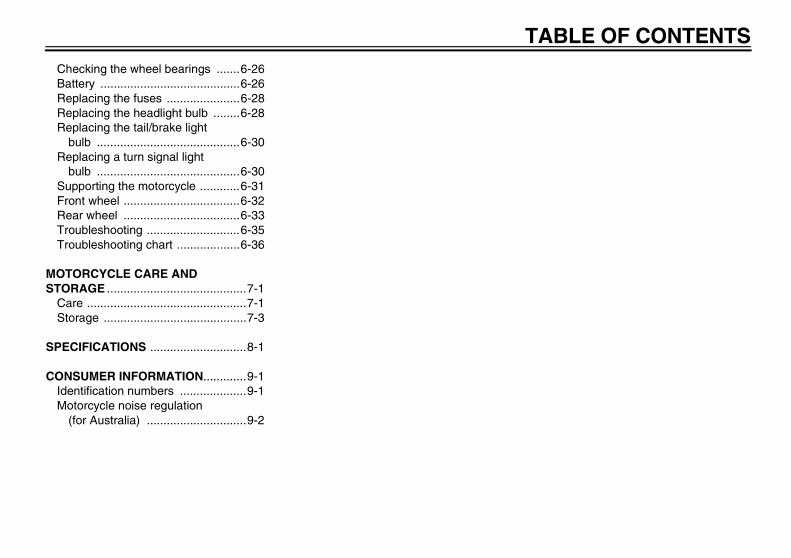
TABLE OF CONTENTSChecking the wheel bearings .......6-26Battery ..........................................6-26Replacing the fuses ......................6-28Replacing the headlight bulb ........6-28Replacing the tail/brake light
bulb ...........................................6-30Replacing a turn signal light
bulb ...........................................6-30Supporting the motorcycle ............6-31Front wheel ...................................6-32Rear wheel ...................................6-33Troubleshooting ............................6-35Troubleshooting chart ...................6-36
MOTORCYCLE CARE AND STORAGE ..........................................7-1
Care ................................................7-1Storage ...........................................7-3
SPECIFICATIONS .............................8-1
CONSUMER INFORMATION.............9-1Identification numbers ....................9-1Motorcycle noise regulation
(for Australia) ..............................9-2
U2UJ23E0.book Page 2 Wednesday, May 11, 2005 11:30 AM
1-1
1
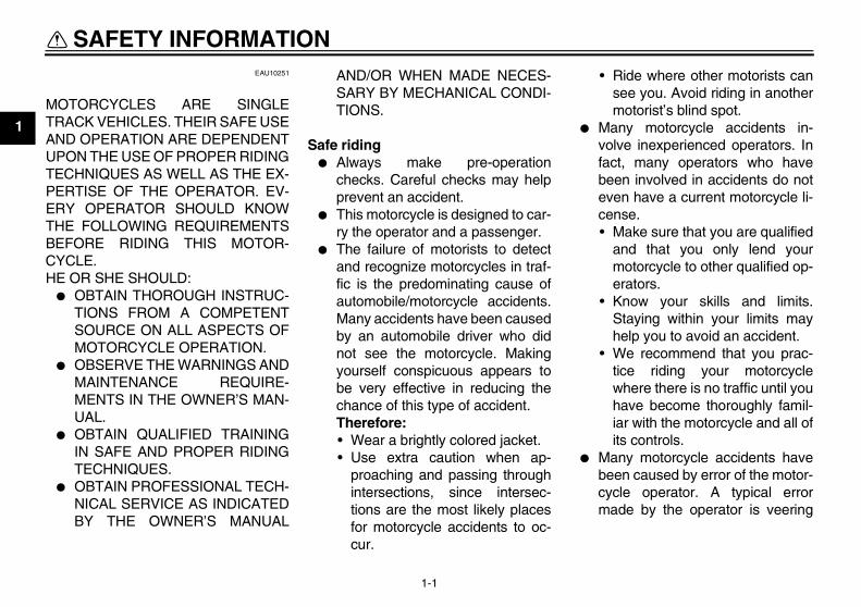
SAFETY INFORMATION EAU10251
MOTORCYCLES ARE SINGLETRACK VEHICLES. THEIR SAFE USEAND OPERATION ARE DEPENDENTUPON THE USE OF PROPER RIDINGTECHNIQUES AS WELL AS THE EX-PERTISE OF THE OPERATOR. EV-ERY OPERATOR SHOULD KNOWTHE FOLLOWING REQUIREMENTSBEFORE RIDING THIS MOTOR-CYCLE.HE OR SHE SHOULD:
� OBTAIN THOROUGH INSTRUC-TIONS FROM A COMPETENTSOURCE ON ALL ASPECTS OFMOTORCYCLE OPERATION.
� OBSERVE THE WARNINGS ANDMAINTENANCE REQUIRE-MENTS IN THE OWNER’S MAN-UAL.
� OBTAIN QUALIFIED TRAININGIN SAFE AND PROPER RIDINGTECHNIQUES.
� OBTAIN PROFESSIONAL TECH-NICAL SERVICE AS INDICATEDBY THE OWNER’S MANUAL
AND/OR WHEN MADE NECES-SARY BY MECHANICAL CONDI-TIONS.
Safe riding� Always make pre-operation
checks. Careful checks may helpprevent an accident.
� This motorcycle is designed to car-ry the operator and a passenger.
� The failure of motorists to detectand recognize motorcycles in traf-fic is the predominating cause ofautomobile/motorcycle accidents.Many accidents have been causedby an automobile driver who didnot see the motorcycle. Makingyourself conspicuous appears tobe very effective in reducing thechance of this type of accident.Therefore:• Wear a brightly colored jacket.• Use extra caution when ap-
proaching and passing throughintersections, since intersec-tions are the most likely placesfor motorcycle accidents to oc-cur.
• Ride where other motorists cansee you. Avoid riding in anothermotorist’s blind spot.
� Many motorcycle accidents in-volve inexperienced operators. Infact, many operators who havebeen involved in accidents do noteven have a current motorcycle li-cense.• Make sure that you are qualified
and that you only lend yourmotorcycle to other qualified op-erators.
• Know your skills and limits.Staying within your limits mayhelp you to avoid an accident.
• We recommend that you prac-tice riding your motorcyclewhere there is no traffic until youhave become thoroughly famil-iar with the motorcycle and all ofits controls.
� Many motorcycle accidents havebeen caused by error of the motor-cycle operator. A typical errormade by the operator is veering
U2UJ23E0.book Page 1 Wednesday, May 11, 2005 11:30 AM
SAFETY INFORMATION
1-2
1
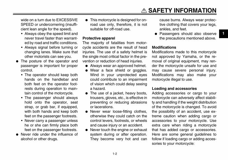
wide on a turn due to EXCESSIVESPEED or undercornering (insuffi-cient lean angle for the speed).• Always obey the speed limit and
never travel faster than warrant-ed by road and traffic conditions.
• Always signal before turning orchanging lanes. Make sure thatother motorists can see you.
� The posture of the operator andpassenger is important for propercontrol.• The operator should keep both
hands on the handlebar andboth feet on the operator foot-rests during operation to main-tain control of the motorcycle.
• The passenger should alwayshold onto the operator, seatstrap, or grab bar, if equipped,with both hands and keep bothfeet on the passenger footrests.
• Never carry a passenger unlesshe or she can firmly place bothfeet on the passenger footrests.
� Never ride under the influence ofalcohol or other drugs.
� This motorcycle is designed for on-road use only, therefore, it is notsuitable for off-road use.
Protective apparelThe majority of fatalities from motor-cycle accidents are the result of headinjuries. The use of a safety helmet isthe single most critical factor in the pre-vention or reduction of head injuries.
� Always wear an approved helmet.� Wear a face shield or goggles.
Wind in your unprotected eyescould contribute to an impairmentof vision which could delay seeinga hazard.
� The use of a jacket, heavy boots,trousers, gloves, etc., is effective inpreventing or reducing abrasionsor lacerations.
� Never wear loose-fitting clothes,otherwise they could catch on thecontrol levers, footrests, or wheelsand cause injury or an accident.
� Never touch the engine or exhaustsystem during or after operation.They become very hot and can
cause burns. Always wear protec-tive clothing that covers your legs,ankles, and feet.
� Passengers should also observethe precautions mentioned above.
ModificationsModifications made to this motorcyclenot approved by Yamaha, or the re-moval of original equipment, may ren-der the motorcycle unsafe for use andmay cause severe personal injury.Modifications may also make yourmotorcycle illegal to use.
Loading and accessoriesAdding accessories or cargo to yourmotorcycle can adversely affect stabili-ty and handling if the weight distributionof the motorcycle is changed. To avoidthe possibility of an accident, use ex-treme caution when adding cargo oraccessories to your motorcycle. Useextra care when riding a motorcyclethat has added cargo or accessories.Here are some general guidelines tofollow if loading cargo or adding acces-sories to your motorcycle:
U2UJ23E0.book Page 2 Wednesday, May 11, 2005 11:30 AM

SAFETY INFORMATION
1-3
1
LoadingThe total weight of the operator, pas-senger, accessories and cargo mustnot exceed the maximum load limit.
When loading within this weight limit,keep the following in mind:
� Cargo and accessory weightshould be kept as low and close tothe motorcycle as possible. Makesure to distribute the weight asevenly as possible on both sides ofthe motorcycle to minimize imbal-ance or instability.
� Shifting weights can create a sud-den imbalance. Make sure that ac-cessories and cargo are securelyattached to the motorcycle beforeriding. Check accessory mountsand cargo restraints frequently.
� Never attach any large or heavyitems to the handlebar, front fork,or front fender. These items, in-cluding such cargo as sleeping
bags, duffel bags, or tents, cancreate unstable handling or slowsteering response.
AccessoriesGenuine Yamaha accessories havebeen specifically designed for use onthis motorcycle. Since Yamaha cannottest all other accessories that may beavailable, you must personally be re-sponsible for the proper selection, in-stallation and use of non-Yamahaaccessories. Use extreme cautionwhen selecting and installing any ac-cessories.Keep the following guidelines in mind,as well as those provided under “Load-ing” when mounting accessories.
� Never install accessories or carrycargo that would impair the perfor-mance of your motorcycle. Care-fully inspect the accessory beforeusing it to make sure that it doesnot in any way reduce groundclearance or cornering clearance,
limit suspension travel, steeringtravel or control operation, or ob-scure lights or reflectors.• Accessories fitted to the handle-
bar or the front fork area cancreate instability due to improperweight distribution or aerody-namic changes. If accessoriesare added to the handlebar orfront fork area, they must be aslightweight as possible andshould be kept to a minimum.
• Bulky or large accessories mayseriously affect the stability ofthe motorcycle due to aerody-namic effects. Wind may at-tempt to lift the motorcycle, orthe motorcycle may become un-stable in cross winds. These ac-cessories may also causeinstability when passing or beingpassed by large vehicles.
• Certain accessories can dis-place the operator from his orher normal riding position. Thisimproper position limits the free-dom of movement of the opera-
Maximum load:196 kg (432 lb)
U2UJ23E0.book Page 3 Wednesday, May 11, 2005 11:30 AM

SAFETY INFORMATION
1-4
1
tor and may limit control ability,therefore, such accessories arenot recommended.
� Use caution when adding electri-cal accessories. If electrical acces-sories exceed the capacity of themotorcycle’s electrical system, anelectric failure could result, whichcould cause a dangerous loss oflights or engine power.
Gasoline and exhaust gas� GASOLINE IS HIGHLY FLAMMA-
BLE:• Always turn the engine off when
refueling.• Take care not to spill any gaso-
line on the engine or exhaustsystem when refueling.
• Never refuel while smoking or inthe vicinity of an open flame.
� Never start the engine or let it runfor any length of time in a closedarea. The exhaust fumes are poi-sonous and may cause loss ofconsciousness and death within ashort time. Always operate yourmotorcycle in an area that has ad-equate ventilation.
� Always turn the engine off beforeleaving the motorcycle unattendedand remove the key from the mainswitch. When parking the motor-cycle, note the following:• The engine and exhaust system
may be hot, therefore, park themotorcycle in a place where pe-destrians or children are not like-ly to touch these hot areas.
• Do not park the motorcycle on aslope or soft ground, otherwise itmay fall over.
• Do not park the motorcycle neara flammable source (e.g. a kero-sene heater, or near an openflame), otherwise it could catchfire.
� When transporting the motorcyclein another vehicle, make sure thatit is kept upright and that the fuelcock is turned to “ON” or “RES” (forvacuum type) / “OFF” (for manualtype). If it should lean over, gaso-line may leak out of the carburetoror fuel tank.
� If you should swallow any gaso-line, inhale a lot of gasoline vapor,or allow gasoline to get into your
eyes, see your doctor immediately.If any gasoline spills on your skinor clothing, immediately wash theaffected area with soap and waterand change your clothes.
U2UJ23E0.book Page 4 Wednesday, May 11, 2005 11:30 AM

SAFETY INFORMATION
1-5
1
EAU10381
Location of important labels Please read the following important labels carefully before operating this vehicle.
2
U2UJ23E0.book Page 5 Wednesday, May 11, 2005 11:30 AM

SAFETY INFORMATION
1-6
1
2
Cold tire normal pressure should be setas follows.
225 2.25 33
200 2.00 29
200 2.00 29
175 1.75 25
3CK-21668-A1
1Before you operate this vehicle, read the owner’s manual.Prima di usare il veicolo,leggete il manuale di istruzioni.Lire le manuel du propriétaireavant d’utiliser ce véhicule.Lesen Sie die Bedienungsanleitung bevor Sie dieses Fahrzeug fahren.Antes de conducir este vehículo,lea el Manual del Propietario.
5RU-21568-00
U2UJ23E0.book Page 6 Wednesday, May 11, 2005 11:30 AM

DESCRIPTION
2-1
2
EAU10410
Left view
1. Headlight (page 6-28)2. Steering lock (page 3-8)3. Fuel tank (page 3-5)4. Battery (page 6-26)5. Fuses (page 6-28)6. Helmet holder (page 3-9)7. Shock absorber assembly spring preload adjusting ring (page 3-9)8. Main switch (page 3-1)9. Fuel cock (page 3-6)
10.Shift pedal (page 3-4)
U2UJ23E0.book Page 1 Wednesday, May 11, 2005 11:30 AM
DESCRIPTION
2-2
2
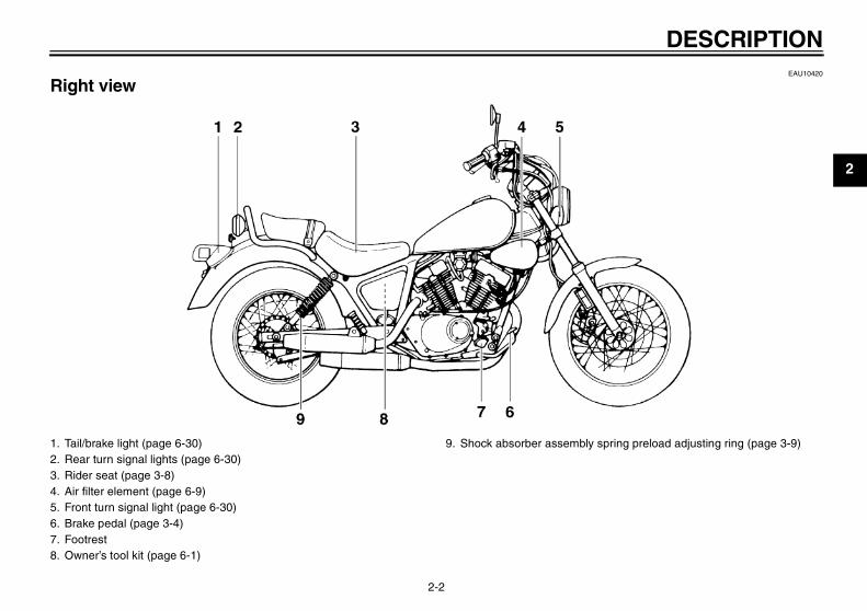
EAU10420
Right view
1. Tail/brake light (page 6-30)2. Rear turn signal lights (page 6-30)3. Rider seat (page 3-8)4. Air filter element (page 6-9)5. Front turn signal light (page 6-30)6. Brake pedal (page 3-4)7. Footrest8. Owner’s tool kit (page 6-1)
9. Shock absorber assembly spring preload adjusting ring (page 3-9)
U2UJ23E0.book Page 2 Wednesday, May 11, 2005 11:30 AM

DESCRIPTION
2-3
2
EAU10430
Controls and instruments
1. Clutch lever (page 3-3)2. Left handlebar switches (page 3-2)3. Speedometer unit (page 3-2)4. Indicator lights (page 3-1)5. Right handlebar switches (page 3-2)6. Brake lever (page 3-4)7. Throttle grip (page 6-12)8. Fuel tank cap (page 3-5)
U2UJ23E0.book Page 3 Wednesday, May 11, 2005 11:30 AM

INSTRUMENT AND CONTROL FUNCTIONS
3-1
3
EAU10450
Main switch
The main switch controls the ignitionand lighting systems. The various mainswitch positions are described below.
EAU10480
ONAll electrical systems are supplied withpower, and the headlight, meter lightingand taillight come on, and the enginecan be started. The key cannot be re-moved.
EAU10660
OFFAll electrical systems are off. The keycan be removed.
EAU10980
Indicator lights
EAU11040
Turn signal indicator light “TURN” This indicator light flashes when theturn signal switch is pushed to the left orright.
EAU11070
Neutral indicator light “NEUTRAL” This indicator light comes on when thetransmission is in the neutral position.
EAU11090
High beam indicator light “HIGH BEAM” This indicator light comes on when thehigh beam of the headlight is switchedon.
1. High beam indicator light “HIGH BEAM”2. Neutral indicator light “NEUTRAL”3. Turn signal indicator light “TURN”
U2UJ23E0.book Page 1 Wednesday, May 11, 2005 11:30 AM
INSTRUMENT AND CONTROL FUNCTIONS
3-2
3
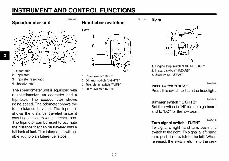
EAU11630
Speedometer unit
The speedometer unit is equipped witha speedometer, an odometer and atripmeter. The speedometer showsriding speed. The odometer shows thetotal distance traveled. The tripmetershows the distance traveled since itwas last set to zero with the reset knob.The tripmeter can be used to estimatethe distance that can be traveled with afull tank of fuel. This information will en-able you to plan future fuel stops.
EAU12343
Handlebar switches
Left
Right
EAU12360
Pass switch “PASS” Press this switch to flash the headlight.
EAU12410
Dimmer switch “LIGHTS” Set the switch to “HI” for the high beamand to “LO” for the low beam.
EAU12440
Turn signal switch “TURN” To signal a right-hand turn, push thisswitch to the right. To signal a left-handturn, push this switch to the left. Whenreleased, the switch returns to the cen-
1. Odometer2. Tripmeter3. Tripmeter reset knob4. Speedometer
1. Pass switch “PASS”2. Dimmer switch “LIGHTS”3. Turn signal switch “TURN”4. Horn switch “HORN”
1. Engine stop switch “ENGINE STOP”2. Hazard switch “HAZARD”3. Start switch “START”
U2UJ23E0.book Page 2 Wednesday, May 11, 2005 11:30 AM

INSTRUMENT AND CONTROL FUNCTIONS
3-3
3
ter position. To cancel the turn signallights, push the switch in after it has re-turned to the center position.
EAU12510
Horn switch “HORN” Press this switch to sound the horn.
EAU12650
Engine stop switch “ENGINE STOP” Set this switch to “RUN” before startingthe engine. Set this switch to “OFF” tostop the engine in case of an emergen-cy, such as when the vehicle overturnsor when the throttle cable is stuck.
EAU12690
Start switch “START” Push this switch to crank the enginewith the starter.
CAUTION:ECA10050
See page 5-1 for starting instruc-tions prior to starting the engine.
EAU12751
Hazard switch “HAZARD” With the key in the “ON” position, usethis switch to turn on the hazard light(simultaneous flashing of all turn signallights).The hazard light is used in case of anemergency or to warn other driverswhen your vehicle is stopped where itmight be a traffic hazard.
CAUTION:ECA10061
Do not use the hazard lights for anextended length of time with the en-gine not running, otherwise the bat-tery may discharge.
EAU12820
Clutch lever
The clutch lever is located at the lefthandlebar grip. To disengage theclutch, pull the lever toward the handle-bar grip. To engage the clutch, releasethe lever. The lever should be pulledrapidly and released slowly for smoothclutch operation.The clutch lever is equipped with aclutch switch, which is part of the igni-tion circuit cut-off system. (See page3-11.)
1. Clutch lever
U2UJ23E0.book Page 3 Wednesday, May 11, 2005 11:30 AM

INSTRUMENT AND CONTROL FUNCTIONS
3-4
3
EAU12870
Shift pedal
The shift pedal is located on the leftside of the engine and is used in com-bination with the clutch lever whenshifting the gears of the 5-speed con-stant-mesh transmission equipped onthis motorcycle.
EAU12890
Brake lever
The brake lever is located at the righthandlebar grip. To apply the frontbrake, pull the lever toward the handle-bar grip.
EAU12941
Brake pedal
The brake pedal is on the right side ofthe motorcycle. To apply the rearbrake, press down on the brake pedal.
1. Shift pedal 1. Brake lever 1. Brake pedal
U2UJ23E0.book Page 4 Wednesday, May 11, 2005 11:30 AM

INSTRUMENT AND CONTROL FUNCTIONS
3-5
3
EAU13040
Fuel tank cap
To open the fuel tank capInsert the key into the lock and turn it1/4 turn clockwise. The lock will be re-leased and the fuel tank cap can beopened.
To close the fuel tank cap1. Push the fuel tank cap into position
with the key inserted in the lock.2. Turn the key counterclockwise to
the original position, and then re-move it.
NOTE:The fuel tank cap cannot be closed un-less the key is in the lock. In addition,the key cannot be removed if the cap isnot properly closed and locked.
WARNINGEWA11090
Make sure that the fuel tank cap isproperly closed before riding.
EAU13210
Fuel
Make sure that there is sufficient fuel inthe tank. Fill the fuel tank to the bottomof the filler tube as shown.
WARNINGEWA10880
� Do not overfill the fuel tank, oth-erwise it may overflow when thefuel warms up and expands.
� Avoid spilling fuel on the hot en-gine.
1. Fuel tank cap2. Unlock.
1. Fuel tank filler tube2. Fuel level
U2UJ23E0.book Page 5 Wednesday, May 11, 2005 11:30 AM

INSTRUMENT AND CONTROL FUNCTIONS
3-6
3
CAUTION:ECA10070
Immediately wipe off spilled fuelwith a clean, dry, soft cloth, sincefuel may deteriorate painted surfac-es or plastic parts.
EAU13330
CAUTION:ECA11400
Use only unleaded gasoline. The useof leaded gasoline will cause severedamage to internal engine parts,such as the valves and piston rings,as well as to the exhaust system.
Your Yamaha engine has been de-signed to use regular unleaded gaso-line with a research octane number of91 or higher. If knocking (or pinging) oc-curs, use a gasoline of a different brand
or premium unleaded fuel. Use of un-leaded fuel will extend spark plug lifeand reduce maintenance costs.
EAU13580
Fuel cock This model is equipped with a negativepressure fuel cock. The fuel cock sup-plies fuel from the tank to the carburetorwhile also filtering it.The fuel cock lever positions are ex-plained as follows and shown in the il-lustrations.
ON
With the fuel cock lever in this position,fuel flows to the carburetor when theengine is running. Turn the fuel cock le-ver to this position when starting the en-gine and riding.
Recommended fuel:UNLEADED GASOLINE ONLY
Fuel tank capacity:9.5 L (2.51 US gal) (2.09 Imp.gal)
Fuel reserve amount:2.6 L (0.69 US gal) (0.57 Imp.gal)
1. Arrow mark positioned over “ON”
U2UJ23E0.book Page 6 Wednesday, May 11, 2005 11:30 AM
INSTRUMENT AND CONTROL FUNCTIONS
3-7
3
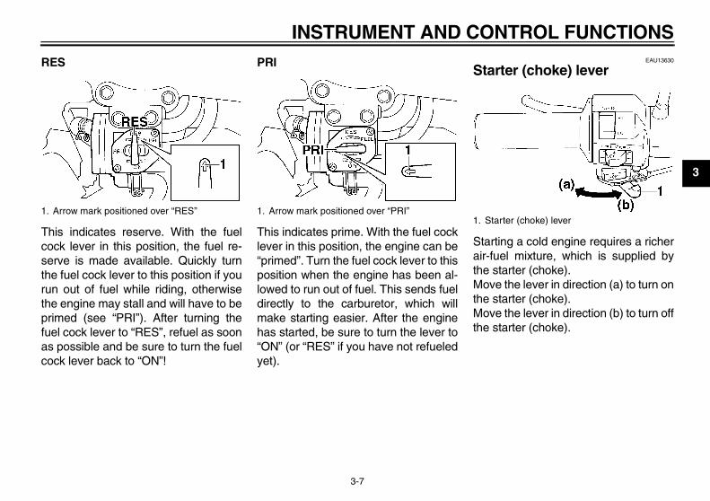
RES
This indicates reserve. With the fuelcock lever in this position, the fuel re-serve is made available. Quickly turnthe fuel cock lever to this position if yourun out of fuel while riding, otherwisethe engine may stall and will have to beprimed (see “PRI”). After turning thefuel cock lever to “RES”, refuel as soonas possible and be sure to turn the fuelcock lever back to “ON”!
PRI
This indicates prime. With the fuel cocklever in this position, the engine can be“primed”. Turn the fuel cock lever to thisposition when the engine has been al-lowed to run out of fuel. This sends fueldirectly to the carburetor, which willmake starting easier. After the enginehas started, be sure to turn the lever to“ON” (or “RES” if you have not refueledyet).
EAU13630
Starter (choke) lever
Starting a cold engine requires a richerair-fuel mixture, which is supplied bythe starter (choke).Move the lever in direction (a) to turn onthe starter (choke).Move the lever in direction (b) to turn offthe starter (choke).
1. Arrow mark positioned over “RES” 1. Arrow mark positioned over “PRI”1. Starter (choke) lever
U2UJ23E0.book Page 7 Wednesday, May 11, 2005 11:30 AM

INSTRUMENT AND CONTROL FUNCTIONS
3-8
3
EAU13730
Steering lock
To lock the steering1. Turn the handlebar all the way to
the right.2. Open the steering lock cover, and
then insert the key.3. Turn the key 1/8 turn counterclock-
wise, push it in while turning thehandlebar slightly to the left, andthen turn the key 1/8 turn clock-wise.
4. Check that the steering is locked,remove the key, and then close thelock cover.
To unlock the steering1. Open the steering lock cover, and
then insert the key.2. Push the key in, turn it 1/8 turn
counterclockwise so that it movesout, and then release it.
3. Remove the key, and then closethe lock cover.
EAU14220
Rider seat
To remove the rider seatRemove the bolts, and then pull the rid-er seat off.
To install the rider seat1. Insert the projection on the front of
the rider seat into the seat holderas shown.
1. Steering lock
1. Bolt
U2UJ23E0.book Page 8 Wednesday, May 11, 2005 11:30 AM

INSTRUMENT AND CONTROL FUNCTIONS
3-9
3
2. Place the rider seat in the originalposition, and then tighten the bolts.
NOTE:Make sure that the rider seat is properlysecured before riding.
EAU14281
Helmet holder
To open the helmet holder, insert thekey into the lock, and then turn the keyas shown.To lock the helmet holder, place it in theoriginal position, and then remove thekey.
WARNINGEWA10160
Never ride with a helmet attached tothe helmet holder, since the helmetmay hit objects, causing loss of con-trol and possibly an accident.
EAU14880
Adjusting the shock absorber assemblies
Each shock absorber assembly isequipped with a spring preload adjust-ing ring.
CAUTION:ECA10100
Never attempt to turn an adjustingmechanism beyond the maximum orminimum settings.
1. Projection2. Seat holder
1. Helmet holder2. Unlock. 1. Spring preload adjusting ring
2. Position indicator
U2UJ23E0.book Page 9 Wednesday, May 11, 2005 11:30 AM
INSTRUMENT AND CONTROL FUNCTIONS
3-10
3
WARNINGEWA10210
Always adjust both shock absorberassemblies equally, otherwise poorhandling and loss of stability mayresult.
Adjust the spring preload as follows.To increase the spring preload andthereby harden the suspension, turnthe adjusting ring on each shock ab-sorber assembly in direction (a). To de-crease the spring preload and therebysoften the suspension, turn the adjust-ing ring on each shock absorber as-sembly in direction (b).
NOTE:Align the appropriate notch in the ad-justing ring with the position indicatoron the shock absorber.
EAU15301
Sidestand The sidestand is located on the left sideof the frame. Raise the sidestand orlower it with your foot while holding thevehicle upright.
NOTE:The built-in sidestand switch is part ofthe ignition circuit cut-off system, whichcuts the ignition in certain situations.(See further down for an explanation ofthe ignition circuit cut-off system.)
WARNINGEWA10240
The vehicle must not be ridden withthe sidestand down, or if the side-stand cannot be properly moved up(or does not stay up), otherwise thesidestand could contact the groundand distract the operator, resultingin a possible loss of control.Yamaha’s ignition circuit cut-offsystem has been designed to assistthe operator in fulfilling the respon-sibility of raising the sidestand be-fore starting off. Therefore, checkthis system regularly as described
below and have a Yamaha dealer re-pair it if it does not function proper-ly.
Spring preload setting:Minimum (soft):
1Standard:
2Maximum (hard):
5
U2UJ23E0.book Page 10 Wednesday, May 11, 2005 11:30 AM
INSTRUMENT AND CONTROL FUNCTIONS
3-11
3
EAU15311
Ignition circuit cut-off system The ignition circuit cut-off system (com-prising the sidestand switch, clutchswitch and neutral switch) has the fol-lowing functions.
� It prevents starting when the trans-mission is in gear and the side-stand is up, but the clutch lever isnot pulled.
� It prevents starting when the trans-mission is in gear and the clutch le-ver is pulled, but the sidestand isstill down.
� It cuts the running engine when thetransmission is in gear and the sid-estand is moved down.
Periodically check the operation of theignition circuit cut-off system accordingto the following procedure.
WARNINGEWA10250
If a malfunction is noted, have aYamaha dealer check the system be-fore riding.
U2UJ23E0.book Page 11 Wednesday, May 11, 2005 11:30 AM

INSTRUMENT AND CONTROL FUNCTIONS
3-12
3
With the engine turned off:1. Move the sidestand down.2. Make sure that the engine stop switch is turned on.3. Turn the key on. 4. Shift the transmission into the neutral position.5. Push the start switch.Does the engine start?
With the engine still running:6. Move the sidestand up.7. Keep the clutch lever pulled.8. Shift the transmission into gear.9. Move the sidestand down.Does the engine stall?
After the engine has stalled:10. Move the sidestand up.11. Keep the clutch lever pulled.12. Push the start switch.Does the engine start?
The system is OK. The motorcycle can be ridden.
This check is most reliable if performed witha warmed-up engine.
The neutral switch may be defective.The motorcycle should not be ridden untilchecked by a Yamaha dealer.
The sidestand switch may be defective.The motorcycle should not be ridden untilchecked by a Yamaha dealer.
The clutch switch may be defective.The motorcycle should not be ridden untilchecked by a Yamaha dealer.
YES NO
YES NO
YES NO
NOTE:
U2UJ23E0.book Page 12 Wednesday, May 11, 2005 11:30 AM

PRE-OPERATION CHECKS
4-1
4
EAU15591
The condition of a vehicle is the owner’s responsibility. Vital components can start to deteriorate quickly and unexpectedly,even if the vehicle remains unused (for example, as a result of exposure to the elements). Any damage, fluid leakage or lossof tire air pressure could have serious consequences. Therefore, it is very important, in addition to a thorough visual inspec-tion, to check the following points before each ride.
NOTE:Pre-operation checks should be made each time the vehicle is used. Such an inspection can be accomplished in a very shorttime; and the added safety it assures is more than worth the time involved.
WARNINGEWA11150
If any item in the Pre-operation check list is not working properly, have it inspected and repaired before operatingthe vehicle.
U2UJ23E0.book Page 1 Wednesday, May 11, 2005 11:30 AM

PRE-OPERATION CHECKS
4-2
4
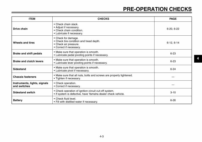
EAU15603
Pre-operation check list ITEM CHECKS PAGE
Fuel• Check fuel level in fuel tank.• Refuel if necessary.• Check fuel line for leakage.
3-5
Engine oil• Check oil level in engine.• If necessary, add recommended oil to specified level.• Check vehicle for oil leakage.
6-7
Front brake
• Check operation.• If soft or spongy, have Yamaha dealer bleed hydraulic system.• Check lever free play.• Adjust if necessary.• Check brake pads for wear.• Replace if necessary.• Check fluid level in reservoir.• If necessary, add recommended brake fluid to specified level.• Check hydraulic system for leakage.
6-15, 6-18, 6-18
Rear brake• Check operation.• Check pedal free play.• Adjust if necessary.
6-16, 6-18
Clutch
• Check operation.• Lubricate cable if necessary.• Check lever free play.• Adjust if necessary.
6-14
Throttle grip
• Make sure that operation is smooth.• Check cable free play.• If necessary, have Yamaha dealer adjust cable free play and lubricate cable and
grip housing.
6-12, 6-23
Control cables • Make sure that operation is smooth.• Lubricate if necessary. 6-22
U2UJ23E0.book Page 2 Wednesday, May 11, 2005 11:30 AM
PRE-OPERATION CHECKS
4-3
4
Drive chain
• Check chain slack.• Adjust if necessary.• Check chain condition.• Lubricate if necessary.
6-20, 6-22
Wheels and tires
• Check for damage.• Check tire condition and tread depth.• Check air pressure.• Correct if necessary.
6-12, 6-14
Brake and shift pedals • Make sure that operation is smooth.• Lubricate pedal pivoting points if necessary. 6-23
Brake and clutch levers • Make sure that operation is smooth.• Lubricate lever pivoting points if necessary. 6-23
Sidestand • Make sure that operation is smooth.• Lubricate pivot if necessary. 6-24
Chassis fasteners • Make sure that all nuts, bolts and screws are properly tightened.• Tighten if necessary. —
Instruments, lights, signals and switches
• Check operation.• Correct if necessary. —
Sidestand switch • Check operation of ignition circuit cut-off system.• If system is defective, have Yamaha dealer check vehicle. 3-10
Battery • Check fluid level.• Fill with distilled water if necessary. 6-26
ITEM CHECKS PAGE
U2UJ23E0.book Page 3 Wednesday, May 11, 2005 11:30 AM
OPERATION AND IMPORTANT RIDING POINTS
5-1
5
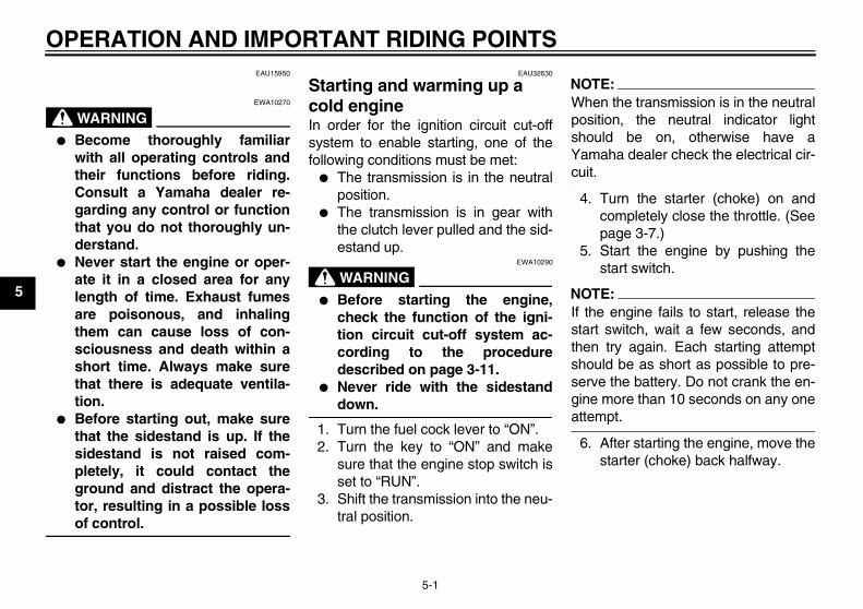
EAU15950
WARNINGEWA10270
� Become thoroughly familiarwith all operating controls andtheir functions before riding.Consult a Yamaha dealer re-garding any control or functionthat you do not thoroughly un-derstand.
� Never start the engine or oper-ate it in a closed area for anylength of time. Exhaust fumesare poisonous, and inhalingthem can cause loss of con-sciousness and death within ashort time. Always make surethat there is adequate ventila-tion.
� Before starting out, make surethat the sidestand is up. If thesidestand is not raised com-pletely, it could contact theground and distract the opera-tor, resulting in a possible lossof control.
EAU32630
Starting and warming up a cold engine In order for the ignition circuit cut-offsystem to enable starting, one of thefollowing conditions must be met:
� The transmission is in the neutralposition.
� The transmission is in gear withthe clutch lever pulled and the sid-estand up.
WARNINGEWA10290
� Before starting the engine,check the function of the igni-tion circuit cut-off system ac-cording to the proceduredescribed on page 3-11.
� Never ride with the sidestanddown.
1. Turn the fuel cock lever to “ON”.2. Turn the key to “ON” and make
sure that the engine stop switch isset to “RUN”.
3. Shift the transmission into the neu-tral position.
NOTE:When the transmission is in the neutralposition, the neutral indicator lightshould be on, otherwise have aYamaha dealer check the electrical cir-cuit.
4. Turn the starter (choke) on andcompletely close the throttle. (Seepage 3-7.)
5. Start the engine by pushing thestart switch.
NOTE:If the engine fails to start, release thestart switch, wait a few seconds, andthen try again. Each starting attemptshould be as short as possible to pre-serve the battery. Do not crank the en-gine more than 10 seconds on any oneattempt.
6. After starting the engine, move thestarter (choke) back halfway.
U2UJ23E0.book Page 1 Wednesday, May 11, 2005 11:30 AM

OPERATION AND IMPORTANT RIDING POINTS
5-2
5
CAUTION:ECA11130
For maximum engine life, alwayswarm the engine up before startingoff. Never accelerate hard when theengine is cold!
7. When the engine is warm, turn thestarter (choke) off.
NOTE:The engine is warm when it respondsnormally to the throttle with the starter(choke) turned off.
EAU16640
Starting a warm engine Follow the same procedure as for start-ing a cold engine with the exceptionthat the starter (choke) is not requiredwhen the engine is warm.
EAU16671
Shifting
Shifting gears lets you control theamount of engine power available forstarting off, accelerating, climbing hills,etc.The gear positions are shown in the il-lustration.
NOTE:To shift the transmission into the neu-tral position, press the shift pedal downrepeatedly until it reaches the end of itstravel, and then slightly raise it.
1. Shift pedal2. Neutral position
U2UJ23E0.book Page 2 Wednesday, May 11, 2005 11:30 AM
OPERATION AND IMPORTANT RIDING POINTS
5-3
5
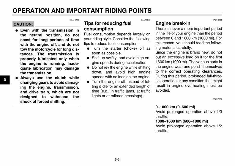
CAUTION:ECA10260
� Even with the transmission inthe neutral position, do notcoast for long periods of timewith the engine off, and do nottow the motorcycle for long dis-tances. The transmission isproperly lubricated only whenthe engine is running. Inade-quate lubrication may damagethe transmission.
� Always use the clutch whilechanging gears to avoid damag-ing the engine, transmission,and drive train, which are notdesigned to withstand theshock of forced shifting.
EAU16800
Tips for reducing fuel consumption Fuel consumption depends largely onyour riding style. Consider the followingtips to reduce fuel consumption:
� Turn the starter (choke) off assoon as possible.
� Shift up swiftly, and avoid high en-gine speeds during acceleration.
� Do not rev the engine while shiftingdown, and avoid high enginespeeds with no load on the engine.
� Turn the engine off instead of let-ting it idle for an extended length oftime (e.g., in traffic jams, at trafficlights or at railroad crossings).
EAU16841
Engine break-in There is never a more important periodin the life of your engine than the periodbetween 0 and 1600 km (1000 mi). Forthis reason, you should read the follow-ing material carefully.Since the engine is brand new, do notput an excessive load on it for the first1600 km (1000 mi). The various parts inthe engine wear and polish themselvesto the correct operating clearances.During this period, prolonged full-throt-tle operation or any condition that mightresult in engine overheating must beavoided.
EAU17021
0–1000 km (0–600 mi)Avoid prolonged operation above 1/3throttle.1000–1600 km (600–1000 mi)Avoid prolonged operation above 1/2throttle.
U2UJ23E0.book Page 3 Wednesday, May 11, 2005 11:30 AM
OPERATION AND IMPORTANT RIDING POINTS
5-4
5
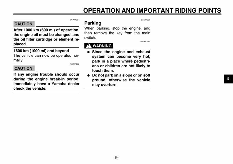
CAUTION:ECA11281
After 1000 km (600 mi) of operation,the engine oil must be changed, andthe oil filter cartridge or element re-placed.
1600 km (1000 mi) and beyondThe vehicle can now be operated nor-mally.
CAUTION:ECA10270
If any engine trouble should occurduring the engine break-in period,immediately have a Yamaha dealercheck the vehicle.
EAU17200
Parking When parking, stop the engine, andthen remove the key from the mainswitch.
WARNINGEWA10310
� Since the engine and exhaustsystem can become very hot,park in a place where pedestri-ans or children are not likely totouch them.
� Do not park on a slope or on softground, otherwise the vehiclemay overturn.
U2UJ23E0.book Page 4 Wednesday, May 11, 2005 11:30 AM
PERIODIC MAINTENANCE AND MINOR REPAIR
6-1
6
EAU17240
Safety is an obligation of the owner. Pe-riodic inspection, adjustment and lubri-cation will keep your vehicle in thesafest and most efficient condition pos-sible. The most important points of in-spection, adjustment, and lubricationare explained on the following pages.The intervals given in the periodicmaintenance and lubrication chartshould be simply considered as a gen-eral guide under normal riding condi-tions. However, DEPENDING ON THEWEATHER, TERRAIN, GEOGRAPHI-CAL LOCATION, AND INDIVIDUALUSE, THE MAINTENANCE INTER-VALS MAY NEED TO BE SHORT-ENED.
WARNINGEWA10320
If you are not familiar with mainte-nance work, have a Yamaha dealerdo it for you.
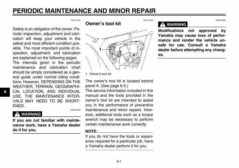
EAU17340
Owner’s tool kit
The owner’s tool kit is located behindpanel A. (See page 6-5.)The service information included in thismanual and the tools provided in theowner’s tool kit are intended to assistyou in the performance of preventivemaintenance and minor repairs. How-ever, additional tools such as a torquewrench may be necessary to performcertain maintenance work correctly.
NOTE:If you do not have the tools or experi-ence required for a particular job, havea Yamaha dealer perform it for you.
WARNINGEWA10350
Modifications not approved byYamaha may cause loss of perfor-mance and render the vehicle un-safe for use. Consult a Yamahadealer before attempting any chang-es.
1. Owner’s tool kit
U2UJ23E0.book Page 1 Wednesday, May 11, 2005 11:30 AM

PERIODIC MAINTENANCE AND MINOR REPAIR
6-2
6
EAU17705
Periodic maintenance and lubrication chart
NOTE:� The annual checks must be performed every year, except if a kilometer-based maintenance is performed in-
stead.� From 50000 km, repeat the maintenance intervals starting from 10000 km.� Items marked with an asterisk should be performed by a Yamaha dealer as they require special tools, data and technical
skills.
NO. ITEM CHECK OR MAINTENANCE JOBODOMETER READING (× 1000 km) ANNUAL
CHECK1 10 20 30 40
1 * Fuel line • Check fuel and vacuum hoses for cracks or damage. √ √ √ √ √
2 Spark plugs• Check condition.• Clean and regap. √ √
• Replace. √ √
3 * Valves • Check valve clearance.• Adjust. √ √ √ √
4 Air filter element• Clean. √ √
• Replace. √ √
5 * Battery • Check electrolyte level and specific gravity.• Make sure that the breather hose is properly routed. √ √ √ √ √
6 Clutch • Check operation.• Adjust. √ √ √ √ √
7 * Front brake• Check operation, fluid level and vehicle for fluid leakage. √ √ √ √ √ √
• Replace brake pads. Whenever worn to the limit
8 * Rear brake• Check operation and adjust brake pedal free play. √ √ √ √ √ √
• Replace brake shoes. Whenever worn to the limit
U2UJ23E0.book Page 2 Wednesday, May 11, 2005 11:30 AM

PERIODIC MAINTENANCE AND MINOR REPAIR
6-3
6
9 * Brake hose• Check for cracks or damage. √ √ √ √ √
• Replace. Every 4 years
10 * Wheels • Check runout, spoke tightness and for damage.• Tighten spokes if necessary. √ √ √ √
11 * Tires
• Check tread depth and for damage.• Replace if necessary.• Check air pressure.• Correct if necessary.
√ √ √ √ √
12 * Wheel bearings • Check bearing for looseness or damage. √ √ √ √
13 * Swingarm• Check operation and for excessive play. √ √ √ √
• Lubricate with lithium-soap-based grease. Every 50000 km
14 Drive chain• Check chain slack, alignment and condition.• Adjust and lubricate chain with a special O-ring chain lu-
bricant thoroughly.
Every 1000 km and after washing the motorcycle or riding in the rain
15 * Steering bearings• Check bearing play and steering for roughness. √ √ √ √ √
• Lubricate with lithium-soap-based grease. Every 20000 km
16 * Chassis fasteners • Make sure that all nuts, bolts and screws are properly tightened. √ √ √ √ √
17 Sidestand • Check operation.• Lubricate. √ √ √ √ √
18 * Sidestand switch • Check operation. √ √ √ √ √ √
19 * Front fork • Check operation and for oil leakage. √ √ √ √
20 * Shock absorber assem-blies • Check operation and shock absorbers for oil leakage. √ √ √ √
NO. ITEM CHECK OR MAINTENANCE JOBODOMETER READING (× 1000 km) ANNUAL
CHECK1 10 20 30 40
U2UJ23E0.book Page 3 Wednesday, May 11, 2005 11:30 AM

PERIODIC MAINTENANCE AND MINOR REPAIR
6-4
6
EAU18660
NOTE:� The air filter needs more frequent service if you are riding in unusually wet or dusty areas.� Hydraulic brake service
• Regularly check and, if necessary, correct the brake fluid level.• Every two years replace the internal components of the brake master cylinder and caliper, and change the brake fluid.• Replace the brake hoses every four years and if cracked or damaged.
21 *Rear suspension relay arm and connecting arm pivoting points
• Check operation. √ √ √ √
• Lubricate with lithium-soap-based grease. √ √
22 * Carburetor • Check starter (choke) operation.• Adjust engine idling speed. √ √ √ √ √ √
23 Engine oil • Change.• Check oil level and vehicle for oil leakage. √ √ √ √ √ √
24 Engine oil filter element • Replace. √ √ √
25 * Front and rear brake switches • Check operation. √ √ √ √ √ √
26 Moving parts and ca-bles • Lubricate. √ √ √ √ √
27 * Throttle grip housing and cable
• Check operation and free play.• Adjust the throttle cable free play if necessary.• Lubricate the throttle grip housing and cable.
√ √ √ √ √
28 * Lights, signals and switches
• Check operation.• Adjust headlight beam. √ √ √ √ √ √
NO. ITEM CHECK OR MAINTENANCE JOBODOMETER READING (× 1000 km) ANNUAL
CHECK1 10 20 30 40
U2UJ23E0.book Page 4 Wednesday, May 11, 2005 11:30 AM
PERIODIC MAINTENANCE AND MINOR REPAIR
6-5
6
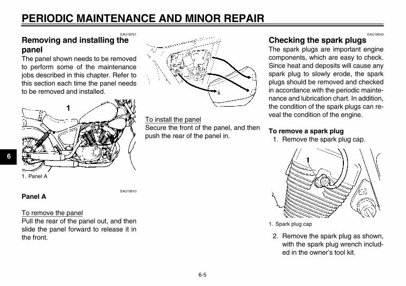
EAU18751
Removing and installing the panel The panel shown needs to be removedto perform some of the maintenancejobs described in this chapter. Refer tothis section each time the panel needsto be removed and installed.
EAU19510
Panel A
To remove the panelPull the rear of the panel out, and thenslide the panel forward to release it inthe front.
To install the panelSecure the front of the panel, and thenpush the rear of the panel in.
EAU19543
Checking the spark plugs The spark plugs are important enginecomponents, which are easy to check.Since heat and deposits will cause anyspark plug to slowly erode, the sparkplugs should be removed and checkedin accordance with the periodic mainte-nance and lubrication chart. In addition,the condition of the spark plugs can re-veal the condition of the engine.
To remove a spark plug1. Remove the spark plug cap.
2. Remove the spark plug as shown,with the spark plug wrench includ-ed in the owner’s tool kit.
1. Panel A
1. Spark plug cap
U2UJ23E0.book Page 5 Wednesday, May 11, 2005 11:30 AM

PERIODIC MAINTENANCE AND MINOR REPAIR
6-6
6
To check the spark plugs1. Check that the porcelain insulator
around the center electrode oneach spark plug is a medium-to-light tan (the ideal color when thevehicle is ridden normally).
2. Check that all spark plugs installedin the engine have the same color.
NOTE:If any spark plug shows a distinctly dif-ferent color, the engine could be defec-tive. Do not attempt to diagnose suchproblems yourself. Instead, have aYamaha dealer check the vehicle.
3. Check each spark plug for elec-trode erosion and excessive car-bon or other deposits, and replaceit if necessary.
To install a spark plug1. Measure the spark plug gap with a
wire thickness gauge and, if nec-essary, adjust the gap to specifica-tion.
2. Clean the surface of the spark pluggasket and its mating surface, andthen wipe off any grime from thespark plug threads.
3. Install the spark plug with thespark plug wrench, and then tight-en it to the specified torque.
NOTE:If a torque wrench is not available wheninstalling a spark plug, a good estimateof the correct torque is 1/4–1/2 turnpast finger tight. However, the sparkplug should be tightened to the speci-fied torque as soon as possible.
4. Install the spark plug cap.
1. Spark plug wrench
Specified spark plug:NGK/C6HSADENSO/U20FS-U
1. Spark plug gap
Spark plug gap:0.6–0.7 mm (0.024–0.028 in)
Tightening torque:Spark plug:
12.5 Nm (1.25 m·kgf, 9.0 ft·lbf)
U2UJ23E0.book Page 6 Wednesday, May 11, 2005 11:30 AM

PERIODIC MAINTENANCE AND MINOR REPAIR
6-7
6
EAU19751
Engine oil and oil filter element The engine oil level should be checkedbefore each ride. In addition, the oilmust be changed and the oil filter ele-ment replaced at the intervals specifiedin the periodic maintenance and lubri-cation chart.
To check the engine oil level1. Place the vehicle on a level sur-
face and hold it in an upright posi-tion.
NOTE:Make sure that the vehicle is positionedstraight up when checking the oil level.A slight tilt to the side can result in afalse reading.
2. Start the engine, warm it up forseveral minutes, and then turn itoff.
3. Wait a few minutes until the oil set-tles, and then check the oil levelthrough the check window locatedat the bottom-right side of thecrankcase.
NOTE:The engine oil should be between theminimum and maximum level marks.
4. If the engine oil is below the mini-mum level mark, add sufficient oilof the recommended type to raiseit to the correct level.
To change the engine oil (with orwithout oil filter element replace-ment)
1. Start the engine, warm it up forseveral minutes, and then turn itoff.
2. Place an oil pan under the engineto collect the used oil.
3. Remove the engine oil filler capand drain bolt to drain the oil fromthe crankcase.
1. Engine oil level check window2. Maximum level mark3. Minimum level mark
1. Engine oil filler cap
1. Engine oil drain bolt
U2UJ23E0.book Page 7 Wednesday, May 11, 2005 11:30 AM
PERIODIC MAINTENANCE AND MINOR REPAIR
6-8
6
NOTE:Skip steps 4–6 if the oil filter element isnot being replaced.
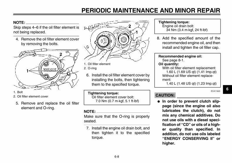
4. Remove the oil filter element coverby removing the bolts.
5. Remove and replace the oil filterelement and O-ring.
6. Install the oil filter element cover byinstalling the bolts, then tighteningthem to the specified torque.
NOTE:Make sure that the O-ring is properlyseated.
7. Install the engine oil drain bolt, andthen tighten it to the specifiedtorque.
8. Add the specified amount of therecommended engine oil, and theninstall and tighten the oil filler cap.
CAUTION:ECA11620
� In order to prevent clutch slip-page (since the engine oil alsolubricates the clutch), do notmix any chemical additives. Donot use oils with a diesel speci-fication of “CD” or oils of a high-er quality than specified. Inaddition, do not use oils labeled“ENERGY CONSERVING II” orhigher.
1. Bolt2. Oil filter element cover
1. Oil filter element2. O-ring
Tightening torque:Oil filter element cover bolt:
7.0 Nm (0.7 m·kgf, 5.1 ft·lbf)
Tightening torque:Engine oil drain bolt:
34 Nm (3.4 m·kgf, 24 ft·lbf)
Recommended engine oil:See page 8-1.
Oil quantity:With oil filter element replacement:
1.60 L (1.69 US qt) (1.41 Imp.qt)Without oil filter element replace-ment:
1.40 L (1.48 US qt) (1.23 Imp.qt)
U2UJ23E0.book Page 8 Wednesday, May 11, 2005 11:30 AM

PERIODIC MAINTENANCE AND MINOR REPAIR
6-9
6
� Make sure that no foreign mate-rial enters the crankcase.
9. Start the engine, and then let it idlefor several minutes while checkingit for oil leakage. If oil is leaking, im-mediately turn the engine off andcheck for the cause.
10. Turn the engine off, and thencheck the oil level and correct it ifnecessary.
EAU32743
Cleaning the air filter element The air filter element should be cleanedat the intervals specified in the periodicmaintenance and lubrication chart.Clean the air filter element more fre-quently if you are riding in unusuallywet or dusty areas.
1. Remove the bolts and loosen theair filter case joint clamp screw.
2. Disconnect the hoses from the airfilter case, and then remove the airfilter case.
1. Bolt
1. Air filter joint clamp screw2. Air filter case cover3. Air filter case
1. Hose2. Air filter case
U2UJ23E0.book Page 9 Wednesday, May 11, 2005 11:30 AM

PERIODIC MAINTENANCE AND MINOR REPAIR
6-10
6
3. Remove the air filter case cover byremoving the screws.
4. Remove the air filter element byremoving the wing nut.
5. Remove the sponge material fromthe air filter element frame, clean itwith solvent, and then squeeze theremaining solvent out.
6. Apply oil of the recommended typeto the entire surface of the spongematerial, and then squeeze the ex-cess oil out.
NOTE:The air filter element should be wet butnot dripping.
7. Pull the sponge material over theair filter element frame.
8. Insert the element into the air filtercase, and then tighten the wingnut.
CAUTION:ECA10480
� Make sure that the air filter ele-ment is properly seated in theair filter case.
� The engine should never be op-erated without the air filter ele-ment installed, otherwise thepiston(s) and/or cylinder(s) maybecome excessively worn.
9. Install the air filter case cover by in-stalling the screws.
10. Connect the hoses to the air filtercase.
11. Install the air filter case onto the airfilter case joint, and then tightenthe clamp screw.
12. Install the bolts.
1. Screw
1. Wing nut2. Air filter element
1. Sponge material2. Air filter element frame
Recommended oil:Foam air filter oil
U2UJ23E0.book Page 10 Wednesday, May 11, 2005 11:30 AM
PERIODIC MAINTENANCE AND MINOR REPAIR
6-11
6
EAU21280
Adjusting the carburetor The carburetor is an important part ofthe engine and requires very sophisti-cated adjustment. Therefore, most car-buretor adjustments should be left to aYamaha dealer, who has the neces-sary professional knowledge and expe-rience. The adjustment described in thefollowing section, however, may be ser-viced by the owner as part of routinemaintenance.
CAUTION:ECA10550
The carburetor has been set and ex-tensively tested at the Yamaha fac-tory. Changing these settingswithout sufficient technical knowl-edge may result in poor perfor-mance of or damage to the engine.
EAU21340
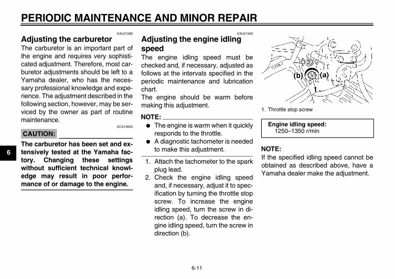
Adjusting the engine idling speed The engine idling speed must bechecked and, if necessary, adjusted asfollows at the intervals specified in theperiodic maintenance and lubricationchart.The engine should be warm beforemaking this adjustment.
NOTE:� The engine is warm when it quickly
responds to the throttle.� A diagnostic tachometer is needed
to make this adjustment.
1. Attach the tachometer to the sparkplug lead.
2. Check the engine idling speedand, if necessary, adjust it to spec-ification by turning the throttle stopscrew. To increase the engineidling speed, turn the screw in di-rection (a). To decrease the en-gine idling speed, turn the screw indirection (b).
NOTE:If the specified idling speed cannot beobtained as described above, have aYamaha dealer make the adjustment.
1. Throttle stop screw
Engine idling speed:1250–1350 r/min
U2UJ23E0.book Page 11 Wednesday, May 11, 2005 11:30 AM

PERIODIC MAINTENANCE AND MINOR REPAIR
6-12
6
EAU21381
Checking the throttle cable free play
The throttle cable free play should mea-sure 3.0–5.0 mm (0.12–0.20 in) at thethrottle grip. Periodically check thethrottle cable free play and, if neces-sary, have a Yamaha dealer adjust it.
EAU21401
Valve clearance The valve clearance changes with use,resulting in improper air-fuel mixtureand/or engine noise. To prevent thisfrom occurring, the valve clearancemust be adjusted by a Yamaha dealerat the intervals specified in the periodicmaintenance and lubrication chart.
EAU32771
Tires To maximize the performance, durabil-ity, and safe operation of your motor-cycle, note the following pointsregarding the specified tires.
Tire air pressureThe tire air pressure should be checkedand, if necessary, adjusted before eachride.
WARNINGEWA10500
� The tire air pressure must bechecked and adjusted on coldtires (i.e., when the temperatureof the tires equals the ambienttemperature).
� The tire air pressure must be ad-justed in accordance with theriding speed and with the totalweight of rider, passenger, car-go, and accessories approvedfor this model.
1. Throttle cable free play
U2UJ23E0.book Page 12 Wednesday, May 11, 2005 11:30 AM

PERIODIC MAINTENANCE AND MINOR REPAIR
6-13
6WARNING
EWA10510
Proper loading of your vehicle is im-portant for several characteristics ofyour vehicle, such as handling,braking, performance and safety. Donot carry loosely packed items thatcan shift. Securely pack your heavi-est items close to the center of thevehicle, and distribute the weightevenly from side to side. Properlyadjust the suspension for your load,and check the condition and pres-sure of your tires. NEVER OVER-
LOAD YOUR VEHICLE. Make surethat the total weight of the cargo, rid-er, passenger, and accessories(cowling, saddlebags, etc. if ap-proved for this model) does not ex-ceed the maximum load of thevehicle. Operation of an overloadedvehicle could cause tire damage, anaccident, or even injury.
Tire inspection
Always check the tires before operatingthe motorcycle. If a tire tread showscrosswise lines (minimum tread depth),if the tire has a nail or glass fragments
in it, or if the sidewall is cracked, con-tact a Yamaha dealer immediately andhave the tire replaced.
NOTE:The tire tread depth limits may differfrom country to country. Always complywith the local regulations.
WARNINGEWA10560
� It is dangerous to ride with aworn-out tire. When a tire treadbegins to show crosswise lines,have a Yamaha dealer replacethe tire immediately.
� The replacement of all wheel-and brake-related parts, includ-ing the tires, should be left to aYamaha dealer, who has thenecessary professional knowl-edge and experience.
� It is not recommended to patcha punctured tube. If unavoid-able, however, patch the tube
Tire air pressure (measured on cold tires):
0–90 kg (0–198 lb):Front:
175 kPa (25 psi) (1.75 kgf/cm²)Rear:
200 kPa (29 psi) (2.00 kgf/cm²)90–196 kg (198–432 lb):
Front:200 kPa (29 psi) (2.00 kgf/cm²)
Rear:225 kPa (33 psi) (2.25 kgf/cm²)
Maximum load*:196 kg (432 lb)
* Total weight of rider, passenger, car-go and accessories
1. Tire sidewall2. Tire wear indicator3. Tire tread depth
Minimum tire tread depth (front and rear):
1.0 mm (0.04 in)
U2UJ23E0.book Page 13 Wednesday, May 11, 2005 11:30 AM
PERIODIC MAINTENANCE AND MINOR REPAIR
6-14
6
very carefully and replace it assoon as possible with a high-quality product.
Tire informationThis motorcycle is equipped with spokewheels and tube tires.
WARNINGEWA10460
� The front and rear tires shouldbe of the same make and de-sign, otherwise the handlingcharacteristics of the vehiclecannot be guaranteed.
� After extensive tests, only thetires listed below have been ap-proved for this model byYamaha Motor Co., Ltd.
EAU21940
Spoke wheels To maximize the performance, durabil-ity, and safe operation of your motor-cycle, note the following pointsregarding the specified wheels.
� The wheel rims should be checkedfor cracks, bends or warpage, andthe spokes for looseness or dam-age before each ride. If any dam-age is found, have a Yamahadealer replace the wheel. Do notattempt even the smallest repair tothe wheel. A deformed or crackedwheel must be replaced.
� The wheel should be balancedwhenever either the tire or wheelhas been changed or replaced. Anunbalanced wheel can result inpoor performance, adverse han-dling characteristics, and a short-ened tire life.
� Ride at moderate speeds afterchanging a tire since the tire sur-face must first be “broken in” for itto develop its optimal characteris-tics.
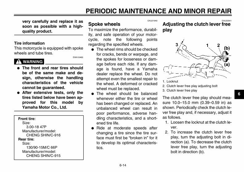
EAU22041
Adjusting the clutch lever free play
The clutch lever free play should mea-sure 10.0–15.0 mm (0.39–0.59 in) asshown. Periodically check the clutch le-ver free play and, if necessary, adjust itas follows.
1. Loosen the locknut at the clutch le-ver.
2. To increase the clutch lever freeplay, turn the adjusting bolt in di-rection (a). To decrease the clutchlever free play, turn the adjustingbolt in direction (b).
Front tire:Size:
3.00-18 47PManufacturer/model:
CHENG SHIN/C-916Rear tire:
Size:130/90-15M/C 66P
Manufacturer/model:CHENG SHIN/C-915
1. Locknut2. Clutch lever free play adjusting bolt3. Clutch lever free play
U2UJ23E0.book Page 14 Wednesday, May 11, 2005 11:30 AM

PERIODIC MAINTENANCE AND MINOR REPAIR
6-15
6
NOTE:If the specified clutch lever free playcould be obtained as described above,tighten the locknut and skip the rest ofthe procedure, otherwise proceed asfollows.
3. Fully turn the adjusting bolt at theclutch lever in direction (a) to loos-en the clutch cable.
4. Loosen the locknut at the crank-case.
5. To increase the clutch lever freeplay, turn the adjusting nut in direc-tion (a). To decrease the clutch le-ver free play, turn the adjusting nutin direction (b).
6. Tighten the locknut at the clutch le-ver and the crankcase.
EAU22092
Adjusting the brake lever free play
The brake lever free play should mea-sure 2.0–5.0 mm (0.08–0.20 in) asshown. Periodically check the brake le-ver free play and, if necessary, adjust itas follows.
1. Loosen the locknut at the brake le-ver.
2. To increase the brake lever freeplay, turn the adjusting screw in di-rection (a). To decrease the brakelever free play, turn the adjustingscrew in direction (b).
3. Tighten the locknut.
1. Locknut2. Clutch lever free play adjusting nut (crank-
case)
1. Locknut2. Brake lever free play adjusting screw3. Brake lever free play
U2UJ23E0.book Page 15 Wednesday, May 11, 2005 11:30 AM

PERIODIC MAINTENANCE AND MINOR REPAIR
6-16
6
WARNINGEWA10630
� After adjusting the brake leverfree play, check the free playand make sure that the brake isworking properly.
� A soft or spongy feeling in thebrake lever can indicate thepresence of air in the hydraulicsystem. If there is air in the hy-draulic system, have a Yamahadealer bleed the system beforeoperating the motorcycle. Air inthe hydraulic system will dimin-ish the braking performance,which may result in loss of con-trol and an accident.
EAU22201
Adjusting the brake pedal position and free play
WARNINGEWA10670
It is advisable to have a Yamahadealer make these adjustments.
Brake pedal positionThe top of the brake pedal should bepositioned approximately 60.0 mm(2.36 in) above the top of the footrest asshown. Periodically check the brakepedal position and, if necessary, adjustit as follows.
1. Loosen the locknut at the brakepedal.
2. To raise the brake pedal, turn theadjusting bolt in direction (a). Tolower the brake pedal, turn the ad-justing bolt in direction (b).
3. Tighten the locknut.
WARNINGEWA11230
After adjusting the brake pedal posi-tion, the brake pedal free play mustbe adjusted.
1. Footrest2. Distance between brake pedal and footrest3. Brake pedal free play
1. Locknut2. Brake pedal position adjusting bolt
U2UJ23E0.book Page 16 Wednesday, May 11, 2005 11:30 AM

PERIODIC MAINTENANCE AND MINOR REPAIR
6-17
6
Brake pedal free playThe brake pedal free play should mea-sure 20.0–30.0 mm (0.79–1.18 in) atthe brake pedal end. Periodically checkthe brake pedal free play and, if neces-sary, adjust it as follows.To increase the brake pedal free play,turn the adjusting nut at the brake rod indirection (a). To decrease the brakepedal free play, turn the adjusting nut indirection (b).
WARNINGEWA10680
� After adjusting the drive chainslack or removing and installingthe rear wheel, always check thebrake pedal free play.
� If proper adjustment cannot beobtained as described, have aYamaha dealer make this ad-justment.
� After adjusting the brake pedalfree play, check the operation ofthe brake light.
EAU22270
Adjusting the rear brake light switch
The rear brake light switch, which is ac-tivated by the brake pedal, is properlyadjusted when the brake light comeson just before braking takes effect. Ifnecessary, adjust the brake light switchas follows.Turn the adjusting nut while holding therear brake light switch in place. Tomake the brake light come on earlier,turn the adjusting nut in direction (a). Tomake the brake light come on later, turnthe adjusting nut in direction (b).
1. Brake pedal free play adjusting nut
1. Rear brake light switch2. Rear brake light switch adjusting nut
U2UJ23E0.book Page 17 Wednesday, May 11, 2005 11:30 AM

PERIODIC MAINTENANCE AND MINOR REPAIR
6-18
6
EAU22380
Checking the front brake pads and rear brake shoes The front brake pads and the rear brakeshoes must be checked for wear at theintervals specified in the periodic main-tenance and lubrication chart.
EAU22420
Front brake pads
Each front brake pad is provided with awear indicator groove, which allowsyou to check the brake pad wear with-out having to disassemble the brake.To check the brake pad wear, checkthe wear indicator groove. If a brakepad has worn to the point that the wear
indicator groove has almost disap-peared, have a Yamaha dealer replacethe brake pads as a set.
EAU22540
Rear brake shoes
The rear brake is provided with a wearindicator, which allows you to check thebrake shoe wear without having to dis-assemble the brake. To check thebrake shoe wear, check the position ofthe wear indicator while applying thebrake. If a brake shoe has worn to thepoint that the wear indicator reachesthe wear limit line, have a Yamahadealer replace the brake shoes as aset.
EAU32343
Checking the front brake fluid level
Insufficient brake fluid may allow air toenter the brake system, possibly caus-ing it to become ineffective.Before riding, check that the brake fluidis above the minimum level mark andreplenish if necessary. A low brake fluidlevel may indicate worn brake padsand/or brake system leakage. If thebrake fluid level is low, be sure to checkthe brake pads for wear and the brakesystem for leakage.Observe these precautions:
1. Brake pad wear indicator groove
1. Brake shoe wear indicator2. Brake shoe wear limit line
1. Minimum level mark
U2UJ23E0.book Page 18 Wednesday, May 11, 2005 11:30 AM

PERIODIC MAINTENANCE AND MINOR REPAIR
6-19
6
� When checking the fluid level,make sure that the top of the mas-ter cylinder is level by turning thehandlebars.
� Use only the recommended qualitybrake fluid, otherwise the rubberseals may deteriorate, causingleakage and poor braking perfor-mance.
� Refill with the same type of brakefluid. Mixing fluids may result in aharmful chemical reaction andlead to poor braking performance.
� Be careful that water does not en-ter the master cylinder when refill-ing. Water will significantly lowerthe boiling point of the fluid andmay result in vapor lock.
� Brake fluid may deteriorate paint-ed surfaces or plastic parts. Al-ways clean up spilled fluidimmediately.
� As the brake pads wear, it is nor-mal for the brake fluid level to grad-ually go down. However, if the
brake fluid level goes down sud-denly, have a Yamaha dealercheck the cause.
EAU22720
Changing the brake fluid Have a Yamaha dealer change thebrake fluid at the intervals specified inthe NOTE after the periodic mainte-nance and lubrication chart. In addition,have the oil seals of the brake mastercylinder and caliper as well as thebrake hose replaced at the intervalslisted below or whenever they are dam-aged or leaking.
� Oil seals: Replace every twoyears.
� Brake hose: Replace every fouryears.
Recommended brake fluid:DOT 4
U2UJ23E0.book Page 19 Wednesday, May 11, 2005 11:30 AM
PERIODIC MAINTENANCE AND MINOR REPAIR
6-20
6
EAU22760
Drive chain slack The drive chain slack should bechecked before each ride and adjustedif necessary.
EAU22771
To check the drive chain slack1. Place the motorcycle on the side-
stand.
NOTE:When checking and adjusting the drivechain slack, there should be no weighton the motorcycle.
2. Shift the transmission into the neu-tral position.
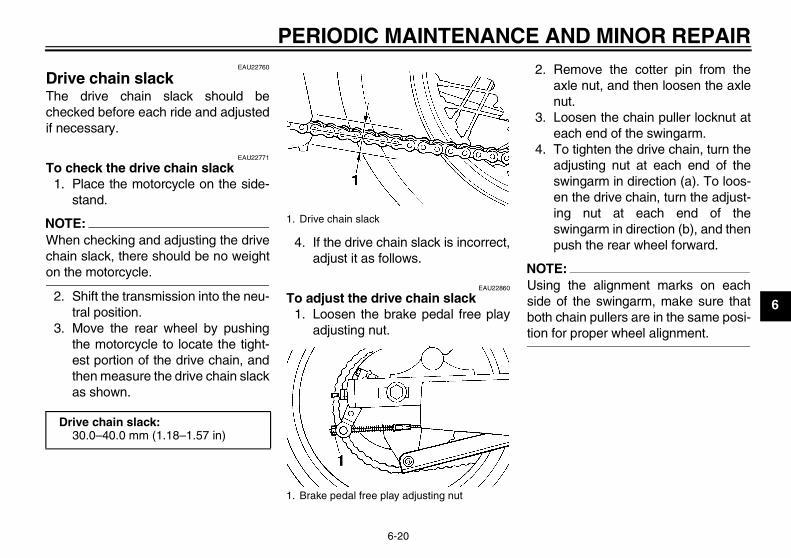
3. Move the rear wheel by pushingthe motorcycle to locate the tight-est portion of the drive chain, andthen measure the drive chain slackas shown.
4. If the drive chain slack is incorrect,adjust it as follows.
EAU22860
To adjust the drive chain slack1. Loosen the brake pedal free play
adjusting nut.
2. Remove the cotter pin from theaxle nut, and then loosen the axlenut.
3. Loosen the chain puller locknut ateach end of the swingarm.
4. To tighten the drive chain, turn theadjusting nut at each end of theswingarm in direction (a). To loos-en the drive chain, turn the adjust-ing nut at each end of theswingarm in direction (b), and thenpush the rear wheel forward.
NOTE:Using the alignment marks on eachside of the swingarm, make sure thatboth chain pullers are in the same posi-tion for proper wheel alignment.
Drive chain slack:30.0–40.0 mm (1.18–1.57 in)
1. Drive chain slack
1. Brake pedal free play adjusting nut
U2UJ23E0.book Page 20 Wednesday, May 11, 2005 11:30 AM

PERIODIC MAINTENANCE AND MINOR REPAIR
6-21
6CAUTION:
ECA10570
Improper drive chain slack will over-load the engine as well as other vitalparts of the motorcycle and can leadto chain slippage or breakage. Toprevent this from occurring, keepthe drive chain slack within thespecified limits.
5. Tighten the locknuts, and thentighten the axle nut to the specifiedtorque.
6. Insert a new cotter pin into the axlenut, and then bend its ends asshown.
NOTE:Make sure that two notches in the axlenut are aligned with the hole throughthe wheel axle, otherwise further tight-en the axle nut until they are.
WARNINGEWA10700
Always use a new cotter pin for theaxle nut.
7. Adjust the brake pedal free play.(See page 6-16.)
WARNINGEWA10660
After adjusting the brake pedal freeplay, check the operation of thebrake light.
1. Axle nut2. Cotter pin3. Chain puller locknut4. Drive chain slack adjusting nut5. Alignment marks
Tightening torque:Axle nut:
104 Nm (10.4 m·kgf, 75 ft·lbf)
1. Cotter pin
U2UJ23E0.book Page 21 Wednesday, May 11, 2005 11:30 AM

PERIODIC MAINTENANCE AND MINOR REPAIR
6-22
6
EAU23022
Cleaning and lubricating the drive chain The drive chain must be cleaned andlubricated at the intervals specified inthe periodic maintenance and lubrica-tion chart, otherwise it will quickly wearout, especially when riding in dusty orwet areas. Service the drive chain asfollows.
CAUTION:ECA10581
The drive chain must be lubricatedafter washing the motorcycle andriding in the rain.
1. Clean the drive chain with kero-sene and a small soft brush.
CAUTION:ECA11120
To prevent damaging the O-rings, donot clean the drive chain with steamcleaners, high-pressure washers orinappropriate solvents.
2. Wipe the drive chain dry.3. Thoroughly lubricate the drive
chain with a special O-ring chainlubricant.
CAUTION:ECA11110
Do not use engine oil or any other lu-bricants for the drive chain, as theymay contain substances that coulddamage the O-rings.
EAU23100
Checking and lubricating the cables The operation of all control cables andthe condition of the cables should bechecked before each ride, and the ca-bles and cable ends should be lubricat-ed if necessary. If a cable is damagedor does not move smoothly, have aYamaha dealer check or replace it.
WARNINGEWA10720
Damage to the outer sheath may in-terfere with proper cable operationand will cause the inner cable torust. Replace a damaged cable assoon as possible to prevent unsafeconditions.
Recommended lubricant:Engine oil
U2UJ23E0.book Page 22 Wednesday, May 11, 2005 11:30 AM
PERIODIC MAINTENANCE AND MINOR REPAIR
6-23
6
EAU23111
Checking and lubricating the throttle grip and cable The operation of the throttle grip shouldbe checked before each ride. In addi-tion, the cable should be lubricated atthe intervals specified in the periodicmaintenance chart.
EAU23131
Checking and lubricating the brake and shift pedals The operation of the brake and shiftpedals should be checked before eachride, and the pedal pivots should be lu-bricated if necessary.
EAU23140
Checking and lubricating the brake and clutch levers The operation of the brake and clutchlevers should be checked before eachride, and the lever pivots should be lu-bricated if necessary.
Recommended lubricant:Lithium-soap-based grease (all-pur-pose grease)
Recommended lubricant:Lithium-soap-based grease (all-pur-pose grease)
U2UJ23E0.book Page 23 Wednesday, May 11, 2005 11:30 AM

PERIODIC MAINTENANCE AND MINOR REPAIR
6-24
6
EAU23200
Checking and lubricating the sidestand The operation of the sidestand shouldbe checked before each ride, and thesidestand pivot and metal-to-metalcontact surfaces should be lubricated ifnecessary.
WARNINGEWA10730
If the sidestand does not move upand down smoothly, have a Yamahadealer check or repair it.
EAUM1650
Lubricating the swingarm pivots The swingarm pivots must be lubricat-ed at the intervals specified in the peri-odic maintenance and lubrication chart.
EAU23271
Checking the front fork The condition and operation of the frontfork must be checked as follows at theintervals specified in the periodic main-tenance and lubrication chart.
To check the condition
WARNINGEWA10750
Securely support the vehicle so thatthere is no danger of it falling over.
Check the inner tubes for scratches,damage and excessive oil leakage.
To check the operation1. Place the vehicle on a level sur-
face and hold it in an upright posi-tion.
2. While applying the front brake,push down hard on the handlebarsseveral times to check if the frontfork compresses and reboundssmoothly.
Recommended lubricant:Lithium-soap-based grease (all-pur-pose grease)
Recommended lubricant:Lithium-soap-based grease
U2UJ23E0.book Page 24 Wednesday, May 11, 2005 11:30 AM

PERIODIC MAINTENANCE AND MINOR REPAIR
6-25
6
CAUTION:ECA10590
If any damage is found or the frontfork does not operate smoothly,have a Yamaha dealer check or re-pair it.
EAU23280
Checking the steering Worn or loose steering bearings maycause danger. Therefore, the operationof the steering must be checked as fol-lows at the intervals specified in the pe-riodic maintenance and lubricationchart.
1. Place a stand under the engine toraise the front wheel off theground.
WARNINGEWA10750
Securely support the vehicle so thatthere is no danger of it falling over.
2. Hold the lower ends of the frontfork legs and try to move them for-ward and backward. If any freeplay can be felt, have a Yamahadealer check or repair the steering.
U2UJ23E0.book Page 25 Wednesday, May 11, 2005 11:30 AM

PERIODIC MAINTENANCE AND MINOR REPAIR
6-26
6
EAU23290
Checking the wheel bearings The front and rear wheel bearings mustbe checked at the intervals specified inthe periodic maintenance and lubrica-tion chart. If there is play in the wheelhub or if the wheel does not turnsmoothly, have a Yamaha dealer checkthe wheel bearings.
EAU23310
Battery A poorly maintained battery will corrodeand discharge quickly. The electrolytelevel, battery lead connections andbreather hose routing should bechecked before each ride and at the in-tervals specified in the periodic mainte-nance and lubrication chart.
To check the electrolyte level1. Place the vehicle on a level sur-
face and hold it in an upright posi-tion.
NOTE:Make sure that the vehicle is positionedstraight up when checking the electro-lyte level.
2. Check the electrolyte level in thebattery.
NOTE:The electrolyte should be between theminimum and maximum level marks.
3. If the electrolyte is at or below theminimum level mark, add distilledwater to raise it to the maximumlevel mark.
WARNINGEWA10770
� Electrolyte is poisonous anddangerous since it contains sul-furic acid, which causes severeburns. Avoid any contact withskin, eyes or clothing and al-ways shield your eyes whenworking near batteries. In caseof contact, administer the fol-lowing FIRST AID.• EXTERNAL: Flush with plenty
of water.
1. Maximum level mark2. Minimum level mark
U2UJ23E0.book Page 26 Wednesday, May 11, 2005 11:30 AM
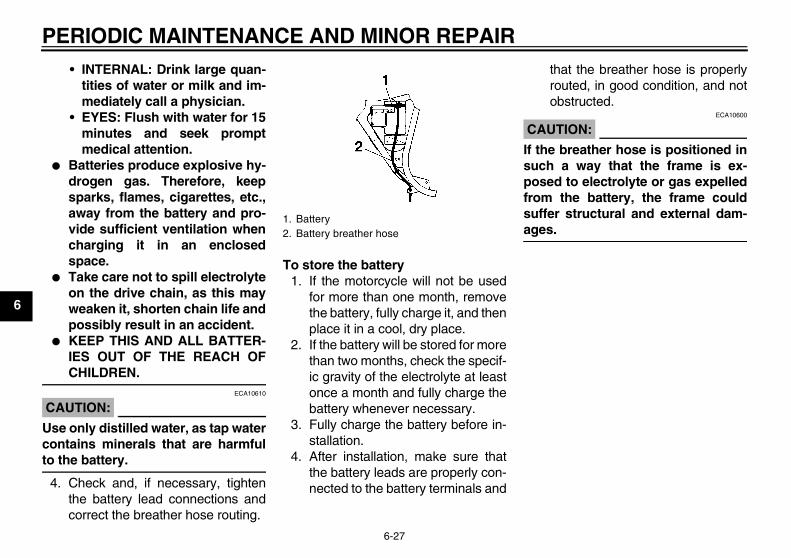
PERIODIC MAINTENANCE AND MINOR REPAIR
6-27
6
• INTERNAL: Drink large quan-tities of water or milk and im-mediately call a physician.
• EYES: Flush with water for 15minutes and seek promptmedical attention.
� Batteries produce explosive hy-drogen gas. Therefore, keepsparks, flames, cigarettes, etc.,away from the battery and pro-vide sufficient ventilation whencharging it in an enclosedspace.
� Take care not to spill electrolyteon the drive chain, as this mayweaken it, shorten chain life andpossibly result in an accident.
� KEEP THIS AND ALL BATTER-IES OUT OF THE REACH OFCHILDREN.
CAUTION:ECA10610
Use only distilled water, as tap watercontains minerals that are harmfulto the battery.
4. Check and, if necessary, tightenthe battery lead connections andcorrect the breather hose routing.
To store the battery1. If the motorcycle will not be used
for more than one month, removethe battery, fully charge it, and thenplace it in a cool, dry place.
2. If the battery will be stored for morethan two months, check the specif-ic gravity of the electrolyte at leastonce a month and fully charge thebattery whenever necessary.
3. Fully charge the battery before in-stallation.
4. After installation, make sure thatthe battery leads are properly con-nected to the battery terminals and
that the breather hose is properlyrouted, in good condition, and notobstructed.
CAUTION:ECA10600
If the breather hose is positioned insuch a way that the frame is ex-posed to electrolyte or gas expelledfrom the battery, the frame couldsuffer structural and external dam-ages.
1. Battery2. Battery breather hose
U2UJ23E0.book Page 27 Wednesday, May 11, 2005 11:30 AM
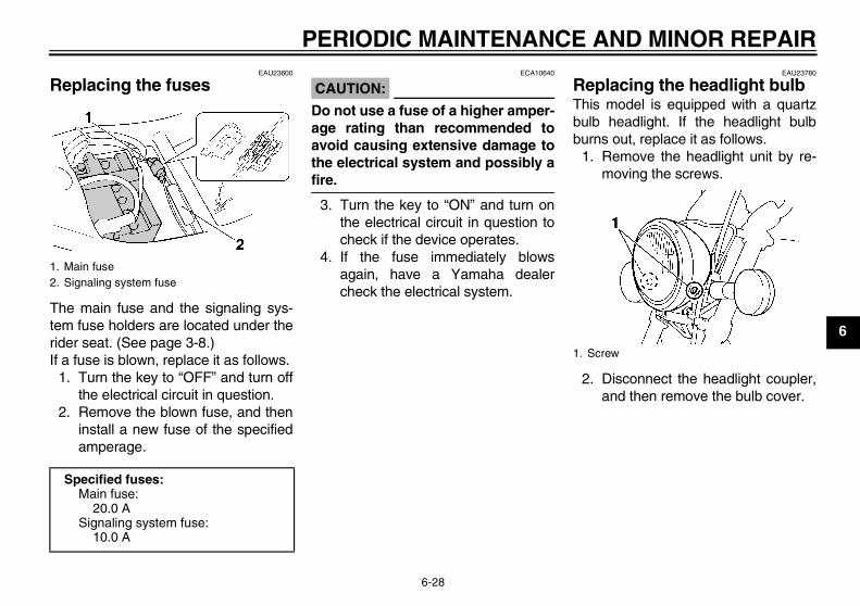
PERIODIC MAINTENANCE AND MINOR REPAIR
6-28
6
EAU23600
Replacing the fuses
The main fuse and the signaling sys-tem fuse holders are located under therider seat. (See page 3-8.)If a fuse is blown, replace it as follows.
1. Turn the key to “OFF” and turn offthe electrical circuit in question.
2. Remove the blown fuse, and theninstall a new fuse of the specifiedamperage.
CAUTION:ECA10640
Do not use a fuse of a higher amper-age rating than recommended toavoid causing extensive damage tothe electrical system and possibly afire.
3. Turn the key to “ON” and turn onthe electrical circuit in question tocheck if the device operates.
4. If the fuse immediately blowsagain, have a Yamaha dealercheck the electrical system.
EAU23780
Replacing the headlight bulb This model is equipped with a quartzbulb headlight. If the headlight bulbburns out, replace it as follows.
1. Remove the headlight unit by re-moving the screws.
2. Disconnect the headlight coupler,and then remove the bulb cover.
1. Main fuse2. Signaling system fuse
Specified fuses:Main fuse:
20.0 ASignaling system fuse:
10.0 A
1. Screw
U2UJ23E0.book Page 28 Wednesday, May 11, 2005 11:30 AM

PERIODIC MAINTENANCE AND MINOR REPAIR
6-29
6
3. Remove the headlight bulb holderby turning it counterclockwise, andthen remove the defective bulb.
WARNINGEWA10790
Headlight bulbs get very hot. There-fore, keep flammable products awayfrom a lit headlight bulb, and do nottouch the bulb until it has cooleddown.
4. Place a new headlight bulb into po-sition, and then secure it with thebulb holder.
CAUTION:ECA10660
Do not touch the glass part of theheadlight bulb to keep it free fromoil, otherwise the transparency ofthe glass, the luminosity of the bulb,and the bulb life will be adversely af-fected. Thoroughly clean off any dirtand fingerprints on the headlightbulb using a cloth moistened with al-cohol or thinner.
5. Install the headlight bulb cover,and then connect the coupler.
6. Install the headlight unit by install-ing the screws.
7. Have a Yamaha dealer adjust theheadlight beam if necessary.
1. Headlight coupler2. Headlight bulb cover
1. Headlight bulb holder
1. Do not touch the glass part of the bulb.
U2UJ23E0.book Page 29 Wednesday, May 11, 2005 11:30 AM
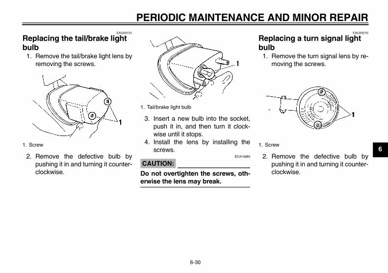
PERIODIC MAINTENANCE AND MINOR REPAIR
6-30
6
EAU24131
Replacing the tail/brake light bulb
1. Remove the tail/brake light lens byremoving the screws.
2. Remove the defective bulb bypushing it in and turning it counter-clockwise.
3. Insert a new bulb into the socket,push it in, and then turn it clock-wise until it stops.
4. Install the lens by installing thescrews.
CAUTION:ECA10680
Do not overtighten the screws, oth-erwise the lens may break.
EAU24210
Replacing a turn signal light bulb
1. Remove the turn signal lens by re-moving the screws.
2. Remove the defective bulb bypushing it in and turning it counter-clockwise.
1. Screw
1. Tail/brake light bulb
1. Screw
U2UJ23E0.book Page 30 Wednesday, May 11, 2005 11:30 AM

PERIODIC MAINTENANCE AND MINOR REPAIR
6-31
6
3. Insert a new bulb into the socket,push it in, and then turn it clock-wise until it stops.
4. Install the lens by installing thescrews.
CAUTION:ECA10680
Do not overtighten the screws, oth-erwise the lens may break.
EAU24350
Supporting the motorcycle Since this model is not equipped with acenterstand, follow these precautionswhen removing the front and rearwheel or performing other maintenancerequiring the motorcycle to stand up-right. Check that the motorcycle is in astable and level position before startingany maintenance. A strong woodenbox can be placed under the engine foradded stability.
To service the front wheel1. Stabilize the rear of the motorcycle
by using a motorcycle stand or, ifan additional motorcycle stand isnot available, by placing a jack un-der the frame in front of the rearwheel.
2. Raise the front wheel off theground by using a motorcyclestand.
To service the rear wheelRaise the rear wheel off the ground byusing a motorcycle stand or, if a motor-cycle stand is not available, by placing
a jack either under each side of theframe in front of the rear wheel or undereach side of the swingarm.
1. Turn signal light bulb
U2UJ23E0.book Page 31 Wednesday, May 11, 2005 11:30 AM

PERIODIC MAINTENANCE AND MINOR REPAIR
6-32
6
EAU24360
Front wheel
EAU24600
To remove the front wheel
WARNINGEWA10820
� It is advisable to have a Yamahadealer service the wheel.
� Securely support the motor-cycle so that there is no dangerof it falling over.
1. Disconnect the speedometer ca-ble from the front wheel.
2. Loosen the front wheel axle pinchbolt, then the wheel axle.
3. Lift the front wheel off the groundaccording to the procedure onpage 6-31.
4. Pull the wheel axle out, and thenremove the wheel.
CAUTION:ECA11070
Do not apply the brake after thewheel has been removed togetherwith the brake disc, otherwise thebrake pads will be forced shut.
EAU24932
To install the front wheel1. Install the speedometer gear unit
into the wheel hub so that the pro-jections mesh with the slots.
2. Lift the wheel up between the forklegs.
NOTE:Make sure that there is enough spacebetween the brake pads before insert-ing the brake disc and that the slot inthe speedometer gear unit fits over theretainer on the fork leg.
1. Speedometer cable
1. Wheel axle2. Front wheel axle pinch bolt
1. Speedometer gear unit
U2UJ23E0.book Page 32 Wednesday, May 11, 2005 11:30 AM
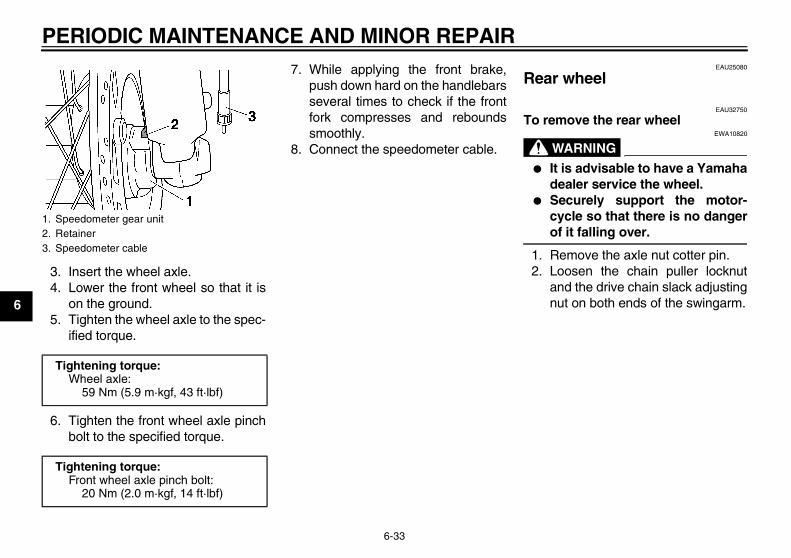
PERIODIC MAINTENANCE AND MINOR REPAIR
6-33
6
3. Insert the wheel axle.4. Lower the front wheel so that it is
on the ground.5. Tighten the wheel axle to the spec-
ified torque.
6. Tighten the front wheel axle pinchbolt to the specified torque.
7. While applying the front brake,push down hard on the handlebarsseveral times to check if the frontfork compresses and reboundssmoothly.
8. Connect the speedometer cable.
EAU25080
Rear wheel
EAU32750
To remove the rear wheel
WARNINGEWA10820
� It is advisable to have a Yamahadealer service the wheel.
� Securely support the motor-cycle so that there is no dangerof it falling over.
1. Remove the axle nut cotter pin.2. Loosen the chain puller locknut
and the drive chain slack adjustingnut on both ends of the swingarm.
1. Speedometer gear unit2. Retainer3. Speedometer cable
Tightening torque:Wheel axle:
59 Nm (5.9 m·kgf, 43 ft·lbf)
Tightening torque:Front wheel axle pinch bolt:
20 Nm (2.0 m·kgf, 14 ft·lbf)
U2UJ23E0.book Page 33 Wednesday, May 11, 2005 11:30 AM

PERIODIC MAINTENANCE AND MINOR REPAIR
6-34
63. Loosen the axle nut and the braketorque rod nut at the brake shoeplate.
4. Lift the rear wheel off the groundaccording to the procedure onpage 6-31.
5. Remove the brake pedal free playadjusting nut, and then disconnectthe brake rod at the brake cam-shaft lever.
6. Disconnect the brake torque rodfrom the brake shoe plate by re-moving the nut and the bolt.
7. Push the wheel forward, and thenremove the drive chain from therear sprocket.
NOTE:The drive chain does not need to bedisassembled in order to remove andinstall the rear wheel.
8. Remove the axle nut.9. Pull the wheel axle out, and then
remove the wheel.
EAU32760
To install the rear wheel1. Install the drive chain onto the rear
sprocket, and then install thewheel by inserting the wheel axlefrom the right-hand side.
2. Install the brake rod onto the brakecamshaft lever, and then install thebrake pedal free play adjusting nutonto the brake rod.
3. Connect the brake torque rod tothe brake shoe plate by installingthe bolt and nut, and then tightenthe bolt to the specified torque.
4. Adjust the drive chain slack. (Seepage 6-20.)
5. Install the axle nut, and then lowerthe rear wheel so that it is on theground.
6. Tighten the axle nut to the speci-fied torque, and then insert a newcotter pin into the axle nut.
1. Axle nut2. Axle nut cotter pin3. Chain puller locknut4. Drive chain slack adjusting nut5. Alignment marks
1. Brake torque rod2. Brake torque rod bolt and nut3. Brake rod4. Brake pedal free play adjusting nut5. Brake camshaft lever
Tightening torque:Brake torque rod bolt:
23 Nm (2.3 m·kgf, 17 ft·lbf)
U2UJ23E0.book Page 34 Wednesday, May 11, 2005 11:30 AM

PERIODIC MAINTENANCE AND MINOR REPAIR
6-35
6
WARNINGEWA10700
Always use a new cotter pin for theaxle nut.
7. Adjust the brake pedal positionand free play. (See page 6-16.)
WARNINGEWA10660
After adjusting the brake pedal freeplay, check the operation of thebrake light.
EAU25850
Troubleshooting Although Yamaha motorcycles receivea thorough inspection before shipmentfrom the factory, trouble may occur dur-ing operation. Any problem in the fuel,compression, or ignition systems, forexample, can cause poor starting andloss of power.The following troubleshooting chartrepresents a quick and easy procedurefor checking these vital systems your-self. However, should your motorcyclerequire any repair, take it to a Yamahadealer, whose skilled technicians havethe necessary tools, experience, andknow-how to service the motorcycleproperly.Use only genuine Yamaha replace-ment parts. Imitation parts may look likeYamaha parts, but they are often inferi-or, have a shorter service life and canlead to expensive repair bills.
Tightening torque:Axle nut:
104 Nm (10.4 m·kgf, 75 ft·lbf)
U2UJ23E0.book Page 35 Wednesday, May 11, 2005 11:30 AM

PERIODIC MAINTENANCE AND MINOR REPAIR
6-36
6
EAU25931
Troubleshooting chart
WARNINGEWA10840
Keep away open flames and do not smoke while checking or working on the fuel system.
Check the fuel level inthe fuel tank.
1. FuelThere is enough fuel.
There is no fuel.
Check the compression.
Supply fuel.
Operate the electric starter.
2. CompressionThere is compression.
There is no compression.
Check the ignition.
Have a Yamaha dealercheck the vehicle.
Remove the spark plugsand check the electrodes.
3. IgnitionWet
Dry
Wipe off with a dry cloth and correct the spark plug gaps, or replace the spark plugs.
Have a Yamaha dealer check the vehicle. The engine does not start.Check the battery.
Open the throttle halfway and operatethe electric starter.
Operate the electric starter.
4. Battery The engine turns over quickly.
The engine turns over slowly.
The battery is good.
Check the electrolyte and batterylead connections, and charge thebattery if necessary.
The engine does not start. Have a Yamaha dealer check the vehicle.
The engine does not start. Check the compressoin.
U2UJ23E0.book Page 36 Wednesday, May 11, 2005 11:30 AM

MOTORCYCLE CARE AND STORAGE
7-1
7
EAU26040
Care While the open design of a motorcyclereveals the attractiveness of the tech-nology, it also makes it more vulnera-ble. Rust and corrosion can developeven if high-quality components areused. A rusty exhaust pipe may go un-noticed on a car, however, it detractsfrom the overall appearance of a motor-cycle. Frequent and proper care doesnot only comply with the terms of thewarranty, but it will also keep yourmotorcycle looking good, extend its lifeand optimize its performance.
Before cleaning1. Cover the muffler outlets with plas-
tic bags after the engine hascooled down.
2. Make sure that all caps and coversas well as all electrical couplersand connectors, including thespark plug caps, are tightly in-stalled.
3. Remove extremely stubborn dirt,like oil burnt onto the crankcase,with a degreasing agent and abrush, but never apply such prod-
ucts onto seals, gaskets, sprock-ets, the drive chain and wheelaxles. Always rinse the dirt and de-greaser off with water.
Cleaning
CAUTION:ECA10770
� Avoid using strong acidic wheelcleaners, especially on spokedwheels. If such products areused on hard-to-remove dirt, donot leave the cleaner on the af-fected area any longer than in-structed. Also, thoroughly rinsethe area off with water, immedi-ately dry it, and then apply a cor-rosion protection spray.
� Improper cleaning can damagewindshields, cowlings, panelsand other plastic parts. Use onlya soft, clean cloth or spongewith mild detergent and water toclean plastic.
� Do not use any harsh chemicalproducts on plastic parts. Besure to avoid using cloths orsponges which have been incontact with strong or abrasive
cleaning products, solvent orthinner, fuel (gasoline), rust re-movers or inhibitors, brake flu-id, antifreeze or electrolyte.
� Do not use high-pressure wash-ers or steam-jet cleaners sincethey cause water seepage anddeterioration in the following ar-eas: seals (of wheel and swing-arm bearings, fork and brakes),electric components (couplers,connectors, instruments,switches and lights), breatherhoses and vents.
� For motorcycles equipped witha windshield: Do not use strongcleaners or hard sponges asthey will cause dulling orscratching. Some cleaning com-pounds for plastic may leavescratches on the windshield.Test the product on a small hid-den part of the windshield tomake sure that it does not leaveany marks. If the windshield isscratched, use a quality plasticpolishing compound afterwashing.
U2UJ23E0.book Page 1 Wednesday, May 11, 2005 11:30 AM

MOTORCYCLE CARE AND STORAGE
7-2
7
After normal useRemove dirt with warm water, a milddetergent, and a soft, clean sponge,and then rinse thoroughly with cleanwater. Use a toothbrush or bottlebrushfor hard-to-reach areas. Stubborn dirtand insects will come off more easily ifthe area is covered with a wet cloth fora few minutes before cleaning.
After riding in the rain, near the sea oron salt-sprayed roadsSince sea salt or salt sprayed on roadsduring winter are extremely corrosive incombination with water, carry out thefollowing steps after each ride in therain, near the sea or on salt-sprayedroads.
NOTE:Salt sprayed on roads in the winter mayremain well into spring.
1. Clean the motorcycle with cold wa-ter and a mild detergent, after theengine has cooled down.
CAUTION:ECA10790
Do not use warm water since it in-creases the corrosive action of thesalt.
2. After drying the motorcycle, applya corrosion protection spray on allmetal, including chrome- and nick-el-plated, surfaces to prevent cor-rosion.
After cleaning1. Dry the motorcycle with a chamois
or an absorbing cloth.2. Immediately dry the drive chain
and lubricate it to prevent it fromrusting.
3. Use a chrome polish to shinechrome, aluminum and stainless-steel parts, including the exhaustsystem. (Even the thermally in-duced discoloring of stainless-steel exhaust systems can be re-moved through polishing.)
4. To prevent corrosion, it is recom-mended to apply a corrosion pro-tection spray on all metal,including chrome- and nickel-plat-ed, surfaces.
5. Use spray oil as a universal clean-er to remove any remaining dirt.
6. Touch up minor paint damagecaused by stones, etc.
7. Wax all painted surfaces.8. Let the motorcycle dry completely
before storing or covering it.
WARNINGEWA10930
� Make sure that there is no oil orwax on the brakes or tires. Ifnecessary, clean the brakediscs and brake linings with aregular brake disc cleaner or ac-etone, and wash the tires withwarm water and a mild deter-gent.
� Before operating the motor-cycle test its braking perfor-mance and cornering behavior.
U2UJ23E0.book Page 2 Wednesday, May 11, 2005 11:30 AM

MOTORCYCLE CARE AND STORAGE
7-3
7
CAUTION:ECA10800
� Apply spray oil and wax spar-ingly and make sure to wipe offany excess.
� Never apply oil or wax to anyrubber and plastic parts, buttreat them with a suitable careproduct.
� Avoid using abrasive polishingcompounds as they will wearaway the paint.
NOTE:Consult a Yamaha dealer for advice onwhat products to use.
EAU26211
Storage
Short-termAlways store your motorcycle in a cool,dry place and, if necessary, protect itagainst dust with a porous cover.
CAUTION:ECA10810
� Storing the motorcycle in apoorly ventilated room or cover-ing it with a tarp, while it is stillwet, will allow water and humid-ity to seep in and cause rust.
� To prevent corrosion, avoiddamp cellars, stables (becauseof the presence of ammonia)and areas where strong chemi-cals are stored.
Long-termBefore storing your motorcycle for sev-eral months:
1. Follow all the instructions in the“Care” section of this chapter.
2. Turn the fuel cock lever to “ON”.
3. Drain the carburetor float cham-bers by loosening the drain bolts;this will prevent fuel deposits frombuilding up. Pour the drained fuelinto the fuel tank.
4. Fill up the fuel tank and add fuelstabilizer (if available) to preventthe fuel tank from rusting and thefuel from deteriorating.
5. Perform the following steps to pro-tect the cylinders, piston rings, etc.from corrosion.a. Remove the spark plug caps
and spark plugs.b. Pour a teaspoonful of engine oil
into each spark plug bore.c. Install the spark plug caps onto
the spark plugs, and then placethe spark plugs on the cylinderhead so that the electrodes aregrounded. (This will limit spark-ing during the next step.)
d. Turn the engine over severaltimes with the starter. (This willcoat the cylinder walls with oil.)
e. Remove the spark plug capsfrom the spark plugs, and theninstall the spark plugs and thespark plug caps.
U2UJ23E0.book Page 3 Wednesday, May 11, 2005 11:30 AM

MOTORCYCLE CARE AND STORAGE
7-4
7
WARNINGEWA10950
To prevent damage or injury fromsparking, make sure to ground thespark plug electrodes while turningthe engine over.
6. Lubricate all control cables and thepivoting points of all levers andpedals as well as of the side-stand/centerstand.
7. Check and, if necessary, correctthe tire air pressure, and then liftthe motorcycle so that both of itswheels are off the ground. Alterna-tively, turn the wheels a little everymonth in order to prevent the tiresfrom becoming degraded in onespot.
8. Cover the muffler outlets with plas-tic bags to prevent moisture fromentering them.
9. Remove the battery and fullycharge it. Store it in a cool, dryplace and charge it once a month.Do not store the battery in an ex-cessively cold or warm place [lessthan 0 °C (30 °F) or more than 30
°C (90 °F)]. For more informationon storing the battery, see page6-26.
NOTE:Make any necessary repairs beforestoring the motorcycle.
U2UJ23E0.book Page 4 Wednesday, May 11, 2005 11:30 AM

SPECIFICATIONS
8-1
8
Dimensions:Overall length:
2190 mm (86.2 in)Overall width:
815 mm (32.1 in)Overall height:
1140 mm (44.9 in)Seat height:
685 mm (27.0 in)Wheelbase:
1490 mm (58.7 in)Ground clearance:
145 mm (5.71 in)Minimum turning radius:
2800 mm (110.2 in)Weight:
With oil and fuel:147.0 kg (324 lb)
Engine:Engine type:
Air cooled 4-stroke, SOHCCylinder arrangement:
V-type 2-cylinderDisplacement:
249.0 cm³ (15.19 cu.in)Bore × stroke:
49.0 × 66.0 mm (1.93 × 2.60 in)Compression ratio:
10.00 :1Starting system:
Electric starterLubrication system:
Wet sump
Engine oil:Type:
SAE10W30 or SAE10W40 or SAE15W40 or SAE20W40 or SAE20W50
Recommended engine oil grade:API service SE, SF, SG type or higher
Engine oil quantity:Without oil filter element replacement:
1.40 L (1.48 US qt) (1.23 Imp.qt)With oil filter element replacement:
1.60 L (1.69 US qt) (1.41 Imp.qt)Air filter:
Air filter element:Wet element
Fuel:Recommended fuel:
Unleaded gasoline onlyFuel tank capacity:
9.5 L (2.51 US gal) (2.09 Imp.gal)Fuel reserve amount:
2.6 L (0.69 US gal) (0.57 Imp.gal)
Carburetor:Manufacturer:
MIKUNIType × quantity:
BDS26 x 1Spark plug (s):
Manufacturer/model:NGK/C6HSA
Manufacturer/model:DENSO/U20FS-U
Spark plug gap:0.6–0.7 mm (0.024–0.028 in)
Clutch:Clutch type:
Wet, multiple-discTransmission:
Primary reduction system:Spur gear
Primary reduction ratio:72/23 (3.130)
Secondary reduction system:Chain drive
Secondary reduction ratio:45/16 (2.813)
Transmission type:Constant mesh 5-speed
Operation:Left foot operation
Gear ratio:1st:
37/14 (2.643)2nd:
32/19 (1.684)
-20 -10 0 10 20 30 40 50 ˚C
SAE 10W-30
SAE 15W-40
SAE 20W-40
SAE 20W-50
SAE 10W-40
U2UJ23E0.book Page 1 Wednesday, May 11, 2005 11:30 AM
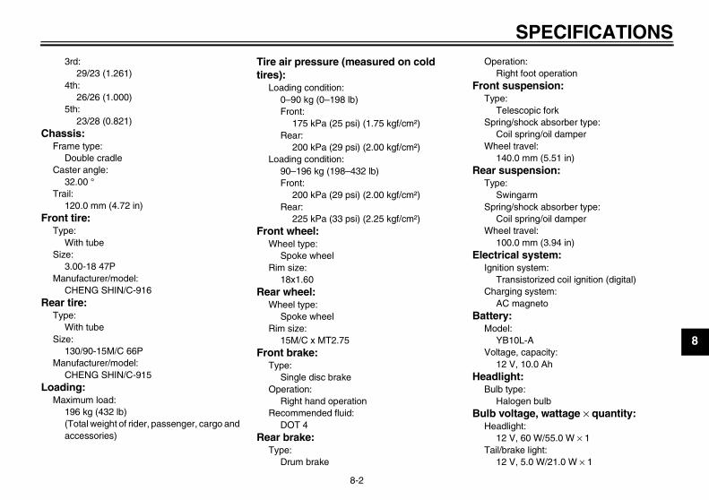
SPECIFICATIONS
8-2
8
3rd:29/23 (1.261)
4th:26/26 (1.000)
5th:23/28 (0.821)
Chassis:Frame type:
Double cradleCaster angle:
32.00 °Trail:
120.0 mm (4.72 in)Front tire:
Type:With tube
Size:3.00-18 47P
Manufacturer/model:CHENG SHIN/C-916
Rear tire:Type:
With tubeSize:
130/90-15M/C 66PManufacturer/model:
CHENG SHIN/C-915Loading:
Maximum load:196 kg (432 lb)(Total weight of rider, passenger, cargo and accessories)
Tire air pressure (measured on cold tires):
Loading condition:0–90 kg (0–198 lb)Front:
175 kPa (25 psi) (1.75 kgf/cm²)Rear:
200 kPa (29 psi) (2.00 kgf/cm²)Loading condition:
90–196 kg (198–432 lb)Front:
200 kPa (29 psi) (2.00 kgf/cm²)Rear:
225 kPa (33 psi) (2.25 kgf/cm²)Front wheel:
Wheel type:Spoke wheel
Rim size:18x1.60
Rear wheel:Wheel type:
Spoke wheelRim size:
15M/C x MT2.75Front brake:
Type:Single disc brake
Operation:Right hand operation
Recommended fluid:DOT 4
Rear brake:Type:
Drum brake
Operation:Right foot operation
Front suspension:Type:
Telescopic forkSpring/shock absorber type:
Coil spring/oil damperWheel travel:
140.0 mm (5.51 in)Rear suspension:
Type:Swingarm
Spring/shock absorber type:Coil spring/oil damper
Wheel travel:100.0 mm (3.94 in)
Electrical system:Ignition system:
Transistorized coil ignition (digital)Charging system:
AC magnetoBattery:
Model:YB10L-A
Voltage, capacity:12 V, 10.0 Ah
Headlight:Bulb type:
Halogen bulbBulb voltage, wattage × quantity:
Headlight:12 V, 60 W/55.0 W × 1
Tail/brake light:12 V, 5.0 W/21.0 W × 1
U2UJ23E0.book Page 2 Wednesday, May 11, 2005 11:30 AM

SPECIFICATIONS
8-3
8
Front turn signal light:12 V, 21.0 W × 2
Rear turn signal light:12 V, 21.0 W × 2
Meter lighting:14 V, 3.0 W × 1
Neutral indicator light:14 V, 3.0 W × 1
High beam indicator light:12 V, 1.7 W × 1
Turn signal indicator light:14 V, 3.0 W × 1
Fuses:Main fuse:
20.0 ASignaling system fuse:
10.0 A
U2UJ23E0.book Page 3 Wednesday, May 11, 2005 11:30 AM

CONSUMER INFORMATION
9-1
9
EAU26351
Identification numbers Record the key identification number,vehicle identification number and mod-el label information in the spaces pro-vided below for assistance whenordering spare parts from a Yamahadealer or for reference in case the vehi-cle is stolen.KEY IDENTIFICATION NUMBER:
VEHICLE IDENTIFICATION NUMBER:
MODEL LABEL INFORMATION:
EAU26390
Key identification number
The key identification number isstamped into the key. Record this num-ber in the space provided and use it forreference when ordering a new key.
EAU26400
Vehicle identification number
The vehicle identification number isstamped into the steering head pipe.Record this number in the space pro-vided.
NOTE:The vehicle identification number isused to identify your motorcycle andmay be used to register your motor-cycle with the licensing authority in yourarea.
1. Key identification number 1. Vehicle identification number
U2UJ23E0.book Page 1 Wednesday, May 11, 2005 11:30 AM
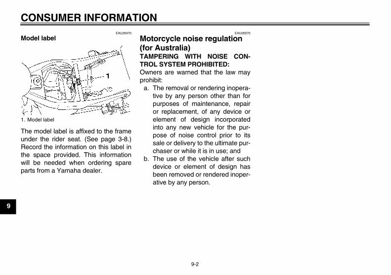
CONSUMER INFORMATION
9-2
9
EAU26470
Model label
The model label is affixed to the frameunder the rider seat. (See page 3-8.)Record the information on this label inthe space provided. This informationwill be needed when ordering spareparts from a Yamaha dealer.
EAU26570
Motorcycle noise regulation (for Australia) TAMPERING WITH NOISE CON-TROL SYSTEM PROHIBITED:Owners are warned that the law mayprohibit:
a. The removal or rendering inopera-tive by any person other than forpurposes of maintenance, repairor replacement, of any device orelement of design incorporatedinto any new vehicle for the pur-pose of noise control prior to itssale or delivery to the ultimate pur-chaser or while it is in use; and
b. The use of the vehicle after suchdevice or element of design hasbeen removed or rendered inoper-ative by any person.
1. Model label
U2UJ23E0.book Page 2 Wednesday, May 11, 2005 11:30 AM
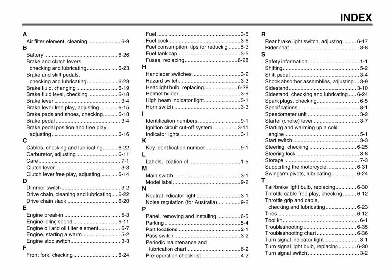
INDEXA
Air filter element, cleaning ...................... 6-9B
Battery .................................................. 6-26Brake and clutch levers,
checking and lubricating..................... 6-23Brake and shift pedals,
checking and lubricating..................... 6-23Brake fluid, changing ............................ 6-19Brake fluid level, checking .................... 6-18Brake lever ............................................. 3-4Brake lever free play, adjusting ............ 6-15Brake pads and shoes, checking.......... 6-18Brake pedal ............................................ 3-4Brake pedal position and free play,
adjusting ............................................. 6-16C
Cables, checking and lubricating.......... 6-22Carburetor, adjusting ............................ 6-11Care........................................................ 7-1Clutch lever............................................. 3-3Clutch lever free play, adjusting ........... 6-14
DDimmer switch ........................................ 3-2Drive chain, cleaning and lubricating.... 6-22Drive chain slack .................................. 6-20
EEngine break-in ...................................... 5-3Engine idling speed .............................. 6-11Engine oil and oil filter element............... 6-7Engine, starting a warm.......................... 5-2Engine stop switch.................................. 3-3
FFront fork, checking .............................. 6-24
Fuel .........................................................3-5Fuel cock.................................................3-6Fuel consumption, tips for reducing ........5-3Fuel tank cap...........................................3-5Fuses, replacing....................................6-28
HHandlebar switches.................................3-2Hazard switch..........................................3-3Headlight bulb, replacing.......................6-28Helmet holder..........................................3-9High beam indicator light.........................3-1Horn switch .............................................3-3
IIdentification numbers .............................9-1Ignition circuit cut-off system.................3-11Indicator lights .........................................3-1
KKey identification number........................9-1
LLabels, location of ...................................1-5
MMain switch .............................................3-1Model label..............................................9-2
NNeutral indicator light ..............................3-1Noise regulation (for Australia)................9-2
PPanel, removing and installing ................6-5Parking ....................................................5-4Part locations ..........................................2-1Pass switch .............................................3-2Periodic maintenance and
lubrication chart.....................................6-2Pre-operation check list...........................4-2
RRear brake light switch, adjusting ......... 6-17Rider seat ............................................... 3-8
SSafety information................................... 1-1Shifting.................................................... 5-2Shift pedal............................................... 3-4Shock absorber assemblies, adjusting ... 3-9Sidestand.............................................. 3-10Sidestand, checking and lubricating ..... 6-24Spark plugs, checking............................. 6-5Specifications.......................................... 8-1Speedometer unit ................................... 3-2Starter (choke) lever ............................... 3-7Starting and warming up a cold
engine................................................... 5-1Start switch ............................................. 3-3Steering, checking ................................ 6-25Steering lock ........................................... 3-8Storage ................................................... 7-3Supporting the motorcycle .................... 6-31Swingarm pivots, lubricating ................. 6-24
TTail/brake light bulb, replacing .............. 6-30Throttle cable free play, checking ......... 6-12Throttle grip and cable,
checking and lubricating ..................... 6-23Tires...................................................... 6-12Tool kit .................................................... 6-1Troubleshooting .................................... 6-35Troubleshooting chart ........................... 6-36Turn signal indicator light ........................ 3-1Turn signal light bulb, replacing ............ 6-30Turn signal switch ................................... 3-2
U2UJ23E0.book Page 1 Wednesday, May 11, 2005 11:30 AM

INDEXV
Valve clearance .................................... 6-12Vehicle identification number .................. 9-1
WWheel bearings, checking..................... 6-26Wheel (front) ......................................... 6-32Wheel (rear) .......................................... 6-33Wheels .................................................. 6-14
U2UJ23E0.book Page 2 Wednesday, May 11, 2005 11:30 AM

U2UJ23E0.book Page 3 Wednesday, May 11, 2005 11:30 AM

PRINTED ON RECYCLED PAPER YAMAHA MOTOR CO., LTD.
PRINTED IN JAPAN2005.06-0.3×1 CR
(E)