xuri cell expansion system w25 - cytiva
TRANSCRIPT


Table of Contents
1 Introduction ........................................................................................................ 51.1 Important user information ....................................................................................................................... 61.2 About this manual ......................................................................................................................................... 81.3 Associated documentation ....................................................................................................................... 91.4 Abbreviations .................................................................................................................................................. 10
2 System description ............................................................................................ 112.1 System overview ............................................................................................................................................ 122.2 Xuri Cell Expansion System W25 rocker .............................................................................................. 162.3 Xuri Cell Expansion W25 CBCU ............................................................................................................... 242.4 Xuri Cell Expansion W25 Pump ............................................................................................................... 272.5 Cellbag bioreactor ........................................................................................................................................ 292.6 UNICORN software overview .................................................................................................................... 32
2.6.1 General UNICORN operation .................................................................................................................. 332.6.2 UNICORN help ............................................................................................................................................... 34
3 The UNICORN software ...................................................................................... 363.1 Administration ................................................................................................................................................ 373.2 System control ................................................................................................................................................ 383.3 Methods in UNICORN .................................................................................................................................. 46
3.3.1 Method editor ................................................................................................................................................. 473.3.2 Method creation ............................................................................................................................................ 493.3.3 Work with methods ..................................................................................................................................... 533.3.4 Text instructions ........................................................................................................................................... 593.3.5 Save a method ............................................................................................................................................... 673.3.6 Scouting ............................................................................................................................................................ 713.3.7 Method queues .............................................................................................................................................. 77
3.4 Evaluation in UNICORN .............................................................................................................................. 823.4.1 Evaluation ........................................................................................................................................................ 833.4.2 Open and view results ................................................................................................................................ 853.4.3 Run documentation ..................................................................................................................................... 893.4.4 Generate and print a predefined report format .............................................................................. 943.4.5 Create a new report format ...................................................................................................................... 963.4.6 Edit an existing report format ................................................................................................................. 105
4 System control description ............................................................................... 1074.1 Single and dual operation modes ............................................................................................................ 1084.2 Temperature measurement and control .............................................................................................. 1094.3 pH and DO measurement and control .................................................................................................. 110
4.3.1 pH and DO measurement principles .................................................................................................... 1114.3.2 pH and DO control principles ................................................................................................................... 113
4.4 pH control ......................................................................................................................................................... 1154.4.1 pH control schemes ..................................................................................................................................... 1164.4.2 CO2 control mode ........................................................................................................................................ 1184.4.3 Acid/Base control mode ............................................................................................................................ 1204.4.4 pH control transition delays ..................................................................................................................... 125
4.5 DO control ........................................................................................................................................................ 1264.5.1 DO control schemes .................................................................................................................................... 127
Table of Contents
2 Xuri Cell Expansion System W25 User Manual 29064622 AD

4.5.2 O2 control mode ........................................................................................................................................... 1284.5.3 Speed control mode .................................................................................................................................... 1304.5.4 O2/Speed control scheme ........................................................................................................................ 131
4.6 Media control .................................................................................................................................................. 1324.6.1 Weight measurement ................................................................................................................................ 1334.6.2 Media addition ............................................................................................................................................... 1344.6.3 Perfusion .......................................................................................................................................................... 1354.6.4 Deviation alarm ............................................................................................................................................. 1394.6.5 Media control inactivation ........................................................................................................................ 140
4.7 Recommended operating conditions .................................................................................................... 1414.8 System verification ....................................................................................................................................... 143
5 Operation ............................................................................................................ 1485.1 Set up the system .......................................................................................................................................... 149
5.1.1 Select the tray and Cellbag bioreactor ............................................................................................... 1505.1.2 Attach and detach tray .............................................................................................................................. 1515.1.3 Prepare pH and DO sensors ..................................................................................................................... 1545.1.4 Attach the Cellbag bioreactor ................................................................................................................ 1575.1.5 Prepare the pump ........................................................................................................................................ 1595.1.6 Connect gas to the system ....................................................................................................................... 1645.1.7 Connect the filter heater to the rocker ................................................................................................ 168
5.2 Start and configure the system ................................................................................................................ 1695.2.1 Start the system and log on to UNICORN ......................................................................................... 1705.2.2 Connect to the system ............................................................................................................................... 1715.2.3 Configure system properties ................................................................................................................... 1735.2.4 Configure system settings ........................................................................................................................ 1755.2.5 Start a run ........................................................................................................................................................ 181
5.3 Prepare for cultivation ................................................................................................................................. 1865.3.1 Inflate the Cellbag bioreactor ................................................................................................................. 1875.3.2 Adjust pump parameters .......................................................................................................................... 1885.3.3 Final checks before cultivation ............................................................................................................... 1895.3.4 Add and equilibrate culture medium ................................................................................................... 1905.3.5 Prepare the sensors .................................................................................................................................... 193
5.4 Perform cultivation ....................................................................................................................................... 1965.4.1 Inoculate the culture ................................................................................................................................... 1975.4.2 Monitor and control the run ..................................................................................................................... 1985.4.3 End a run ........................................................................................................................................................... 205
6 Maintenance ....................................................................................................... 2076.1 Calibration ........................................................................................................................................................ 2086.2 Pump calibration ............................................................................................................................................ 2106.3 Cleaning ............................................................................................................................................................ 213
7 Troubleshooting ................................................................................................. 2147.1 Xuri Cell Expansion System W25 ............................................................................................................. 2157.2 Xuri Cell Expansion System W25 rocker .............................................................................................. 2167.3 Xuri Cell Expansion W25 CBCU ............................................................................................................... 2207.4 Xuri Cell Expansion W25 Pump ............................................................................................................... 2327.5 Cellbag bioreactor ........................................................................................................................................ 2337.6 Software problems ........................................................................................................................................ 235
7.6.1 Troubleshooting Method editor .............................................................................................................. 2367.6.2 UNICORN System Control ........................................................................................................................ 238
Table of Contents
Xuri Cell Expansion System W25 User Manual 29064622 AD 3

7.6.3 Troubleshooting Evaluation ..................................................................................................................... 241
8 Reference information ....................................................................................... 2428.1 System specifications .................................................................................................................................. 2438.2 Component specifications ......................................................................................................................... 2448.3 Client computer specifications ................................................................................................................ 2478.4 Chemical resistance ..................................................................................................................................... 2498.5 Control settings .............................................................................................................................................. 250
8.5.1 Rocking control .............................................................................................................................................. 2518.5.2 Heating control .............................................................................................................................................. 2548.5.3 Gas flow control ............................................................................................................................................. 2558.5.4 CO2 mix control ............................................................................................................................................. 2578.5.5 O2 mix control ................................................................................................................................................ 2588.5.6 Pump control .................................................................................................................................................. 2598.5.7 pH measurement ......................................................................................................................................... 2618.5.8 pH control ........................................................................................................................................................ 2638.5.9 DO measurement ......................................................................................................................................... 2708.5.10 DO control ........................................................................................................................................................ 2728.5.11 Media control ................................................................................................................................................. 276
8.6 Digital and analog I/O connections ......................................................................................................... 2798.7 Ordering information .................................................................................................................................. 282
Index ........................................................................................................................... 284
Table of Contents
4 Xuri Cell Expansion System W25 User Manual 29064622 AD
1 Introduction
About this chapterThis chapter includes important user information, intended use of the system, and listsof important concepts and user documentation.
In this chapter
Section See page
1.1 Important user information 6
1.2 About this manual 8
1.3 Associated documentation 9
1.4 Abbreviations 10
1 Introduction
Xuri Cell Expansion System W25 User Manual 29064622 AD 5

1.1 Important user information
Read the Operating Instructionsbefore operating the product
All users must read the entire separate Operating Instructions before instal-ling, operating, or maintaining the product.
Always keep the Operating Instructions at hand when operating the product.
Do not operate the product in any other way than described in the user documenta-tion. If you do, you may be exposed to hazards that can lead to personal injury and youmay cause damage to the equipment.
Intended useXuri™ Cell Expansion System W25 is intended to be used as laboratory and manufac-turing equipment for cell cultivation. The system shall not be used for clinical or diag-nostic purposes.
PrerequisitesIn order to operate Xuri Cell Expansion System W25 in the way it is intended:
• you have a general understanding of how the client computer and Microsoft®Windows® operating systems work.
• you are acquainted with the use of general laboratory equipment and with handlingof biological materials.
• you have read and understood the Safety instructions chapter in the OperatingInstructions .
• the system is installed according to the instructions in the Operating Instructions.
• a user account has been created according to UNICORN Administration andTechnical manual .
Safety noticesThis user documentation contains safety notices (WARNING, CAUTION, and NOTICE)concerning the safe use of the product. See definitions below.
1 Introduction1.1 Important user information
6 Xuri Cell Expansion System W25 User Manual 29064622 AD

WARNING
WARNING indicates a hazardous situation which, if not avoided,could result in death or serious injury. It is important not to proceeduntil all stated conditions are met and clearly understood.
CAUTION
CAUTION indicates a hazardous situation which, if not avoided,could result in minor or moderate injury. It is important not toproceed until all stated conditions are met and clearly understood.
NOTICE
NOTICE indicates instructions that must be followed to avoiddamage to the product or other equipment.
1 Introduction1.1 Important user information
Xuri Cell Expansion System W25 User Manual 29064622 AD 7

1.2 About this manual
Purpose of this manual
The Xuri Cell Expansion System W25 User Manual provides you with instructions andinformation how to run Xuri Cell Expansion System W25. It also includes relevant guid-ance for practical handling and maintenance of the system units.
Scope of this document
This manual covers Xuri Cell Expansion System W25, including the rocker, CBCU,pump, UNICORN™ software and accessories.
Typographical conventionsSoftware items are identified in the text by bold italic text.
Hardware items are identified in the text by bold text.
In electronic format, references in italics are clickable hyperlinks.
Notes and tipsNote: A note is used to indicate information that is important for trouble-free and
optimal use of the product.
Tip: A tip contains useful information that can improve or optimize your proce-dures.
1 Introduction1.2 About this manual
8 Xuri Cell Expansion System W25 User Manual 29064622 AD

1.3 Associated documentation
Introduction
This section describes the user documentation that is delivered with the product, andhow to find related literature that can be downloaded or ordered from Cytiva.
User documentation for Xuri CellExpansion System W25
The table below describes the user documentation for Xuri Cell Expansion SystemW25, which is available from the Help menu in UNICORN or on the user documenta-tion CD.
Document Main contents
Xuri Cell Expansion SystemW25 Operating Instructions(29064612)
Instructions needed to install, operate and main-tain Xuri Cell Expansion System W25 in a safe way.Includes basic UNICORN 7.x system control func-tions.
Xuri Cell Expansion SystemW25 User Manual(29064622)
Detailed system descriptions and instructions onhow to run, maintain and troubleshoot Xuri CellExpansion System W25. Includes UNICORN 7.xsystem control functions, method creation andhandling, together with evaluation and presenta-tion of data.
Xuri Cell Expansion SystemW25 Cue Card (29087822)
Brief instructions providing an overview of how torun the system.
UNICORN Quick InstallationGuide (29414475)
Guide for installation of UNICORN.
UNICORN Administrationand Technical manual
Overview and detailed description of networksetup and complete software installation. Admin-istration of UNICORN and the UNICORN database.
UNICORN Online Help Dialog descriptions for UNICORN 7.x.
User Documentation CD CD containing the listed manuals and translatedversions of Xuri Cell Expansion System W25Operating Instructions.
1 Introduction1.3 Associated documentation
Xuri Cell Expansion System W25 User Manual 29064622 AD 9

1.4 Abbreviations
Introduction
This section explains abbreviations that appear in the user documentation for thisproduct.
AbbreviationsConcepts and abbreviations used in this manual are explained in the table below.
Concept/abbreviation Explanation
Cellbag™ bioreactor The disposable container in which the cells arecultured.
DO Dissolved oxygen.
DO sensor Optical sensor for measurement of dissolvedoxygen. Attached to DO configured Cellbagbioreactors.
Single mode Operating mode with one Cellbag bioreactor onthe rocker.
Dual mode Operating mode with two Cellbag bioreactors onthe same rocker. Cultivation is monitored andcontrolled independently in the two bioreactors.
pH sensor Optical sensor for pH measurement. Attached topH configured Cellbag bioreactors.
Xuri Cell Expansion W25CBCU
Control unit for gas mixing, pH and DO control.
Xuri Cell Expansion W25Pump
The pump unit.
Xuri Cell Expansion SystemW25 rocker
The rocker.
Tray Tray for Cellbag, mounted on the rocker. Differenttray sizes are available for different culture capaci-ties.
Bioreactor system The entire system, including rocker, CBCU, andpump, together with Cellbag bioreactor and filterheater.
UNICORN The software used for controlling and monitoringthe system.
1 Introduction1.4 Abbreviations
10 Xuri Cell Expansion System W25 User Manual 29064622 AD

2 System description
About this chapterThis chapter gives an overview of Xuri Cell Expansion System W25 and describes thedifferent bioreactor system units.
In this chapter
Section See page
2.1 System overview 12
2.2 Xuri Cell Expansion System W25 rocker 16
2.3 Xuri Cell Expansion W25 CBCU 24
2.4 Xuri Cell Expansion W25 Pump 27
2.5 Cellbag bioreactor 29
2.6 UNICORN software overview 32
2 System description
Xuri Cell Expansion System W25 User Manual 29064622 AD 11

2.1 System overview
IntroductionXuri Cell Expansion System W25 is intended for cell cultivation.
A disposable Cellbag bioreactor is placed on a rocker and filled with gas, partially filledwith culture medium, and inoculated with cells. Gas transfer and mixing of culture isaccomplished by wave-induced agitation, performed by the rocker unit.
The cell culture volume range per Cellbag bioreactor is 0.3 to 25 L depending onbioreactor size, and working volume may be expanded up to 10 times during one culti-vation.
The system, composed of the rocker, Xuri Cell Expansion W25 CBCU and Xuri CellExpansion W25 Pump , enables measurement and control of pH, DO, weight and mediadistribution, and provides different gas flow and gas mixing possibilities.
• In single mode , the system supports culture in one Cellbag bioreactor at one time.The rocker is connected to one Xuri Cell Expansion W25 CBCU and up to three XuriCell Expansion W25 Pump units.
• In dual mode , the system supports culture in two Cellbag bioreactors placed onthe same tray. The rocker is connected to up to two Xuri Cell Expansion W25 CBCUunits and up to three Xuri Cell Expansion W25 Pump units for independent controlof culture conditions in the two bioreactors.
The system is controlled from a PC running UNICORN software version 7 or later. Thesystem can also be controlled from a supervisory control and data acquisition (SCADA)system, such as the DeltaV™ control system, using the integrated OPC server. ContactCytiva for instructions and guidance for OPC.
2 System description2.1 System overview
12 Xuri Cell Expansion System W25 User Manual 29064622 AD

Illustration of the systemThe illustration below shows the main system units for use in single mode with one XuriCell Expansion W25 Pump . Dual mode uses two Xuri Cell Expansion W25 CBCU unitsfor controlling the two Cellbag bioreactors independently. Both single and dual modescan support up to three Xuri Cell Expansion W25 Pump units.
Part Description
1 Hatch
2 Filter heater
3 Cellbag bioreactor
4 Xuri Cell Expansion W25 Pump
5 Xuri Cell Expansion W25 CBCU
6 Xuri Cell Expansion System W25 rocker
7 Tray
8 Lid
2 System description2.1 System overview
Xuri Cell Expansion System W25 User Manual 29064622 AD 13

Illustration of wave motion
12
43
Stage Description
1 Inflowing gas from the CBCU enters the Cellbag bioreactor through theinlet vent filter. The gas flow inflates the bag and oxygenates the culture.
2 Metabolic waste gases leave the Cellbag bioreactor through the outletvent filter. The pressure control valve maintains a constant overpressureinside the Cellbag bioreactor.
3 The rocking mechanism sets the rocking platform in motion.
4 Wave motions are induced by the rocking. The culture is cautiouslymixed, and gases are transferred into the culture.
2 System description2.1 System overview
14 Xuri Cell Expansion System W25 User Manual 29064622 AD

Available controlled parametersThe table below describes the controlled parameters for the fully configured bioreactorsystem. The controlled parameters of your configuration may vary from the list below.In dual mode, all parameters except rocking speed, angle and motion may becontrolled independently in the two Cellbag bioreactors.
Parameter Description
Temperature The system can control temperature between room temperatureplus 5°Cand 40°C.
Rockingspeed
Rocking speed can be set between 2 and 40 rpm.
Rockingangle
Rocking angle can be set between 2 and 12 degrees.
Rockingmotion
Rocking motion can be set between 15% and 100%, and is bydefault set to 30%. A rocking motion of 15% gives a uniformmotion with almost constant angular velocity throughout themovement, and 100% gives a smooth, completely sinusoidalmotion.
Gas flow The system can control the gas flow into the cellbag between 0.02and 1.00 lpm.
Mediadistribution
The system can control culture medium addition and removal.Two different modes exist, media addition and perfusion.
pH pH is measured and controlled between pH 6 and pH 8. Threedifferent modes of pH regulation exist, with CO2, CO2/base, andacid/base.
DO DO is measured between 0% and 250% and controlled between0% and 100% air saturation. Three different modes of DO regula-tion exist, with O2, speed, and O2/speed.
CO2 CO2 concentration in gas mix can be controlled between 0% and15% and measured between 0% and 20%.
O2 O2 concentration in gas mix can be measured between 0% and50%, and controlled between 0%and 50% with N2 and between21% and 50% with air.
2 System description2.1 System overview
Xuri Cell Expansion System W25 User Manual 29064622 AD 15

2.2 Xuri Cell Expansion System W25 rocker
IntroductionThe rocker is the main unit of the system. Through the rocker, weight is measured, andtemperature, rocking speed, rocking angle and rocking motion are controlled.
The rocker contains four load cells for monitoring the weight of the Cellbag bioreactorand content. The placement of the load cells allows independent weight measurementof the two Cellbag bioreactors in dual mode.
The rocker also contains an embedded microprocessor, which allows the system to becontrolled independently of the performance of the connected network and clientcomputer.
For rocker specifications, see Rocker specifications, on page 244.
Rocking parametersThe adjustable rocking parameters are rocking speed, rocking angle and rockingmotion. These factors, in combination with the cell culture volume, have a directimpact on the oxygen transfer rate and mixing time in the Cellbag bioreactor.
The rocking motion sets how large part of the rocking cycle that has a sinusoidalangular velocity. It can be adjusted to be more or less sinusoidal. The minimum value,15%, gives a uniform motion with almost constant angular velocity throughout themovement, resulting in a step-wise rocking. The maximum value, 100%, gives a sinus-oidal motion with slower angular velocity in the end positions and faster in the middleof the movement, resulting in a smoother rocking.
Front view of the rockerThe illustration below shows the front view of the rocker.
2 System description2.2 Xuri Cell Expansion System W25 rocker
16 Xuri Cell Expansion System W25 User Manual 29064622 AD

Part Description
1 Rocker platform
2 Temperature sensors
3 Rocker base
4 Power button
5 Location of adjustable foot
Power button
The Power button indicates the status of the rocker according to the list below.
Light indicator Image Description
No light The power is OFF.
Green flashing light The rocker is starting up.
Green steady light The power is ON and the rocker isoperational.
Red flashing light The rocker failed to connect to othercomponents in the system.
Red steady light Indicates an error of the rocker.
Adjustable foot
The adjustable foot is placed in the front right corner of the rocker base when viewedfrom the front. It is used to distribute weight evenly over the four rocker feet.
Use the supplied adjustable foot wrench to adjust the foot.
2 System description2.2 Xuri Cell Expansion System W25 rocker
Xuri Cell Expansion System W25 User Manual 29064622 AD 17
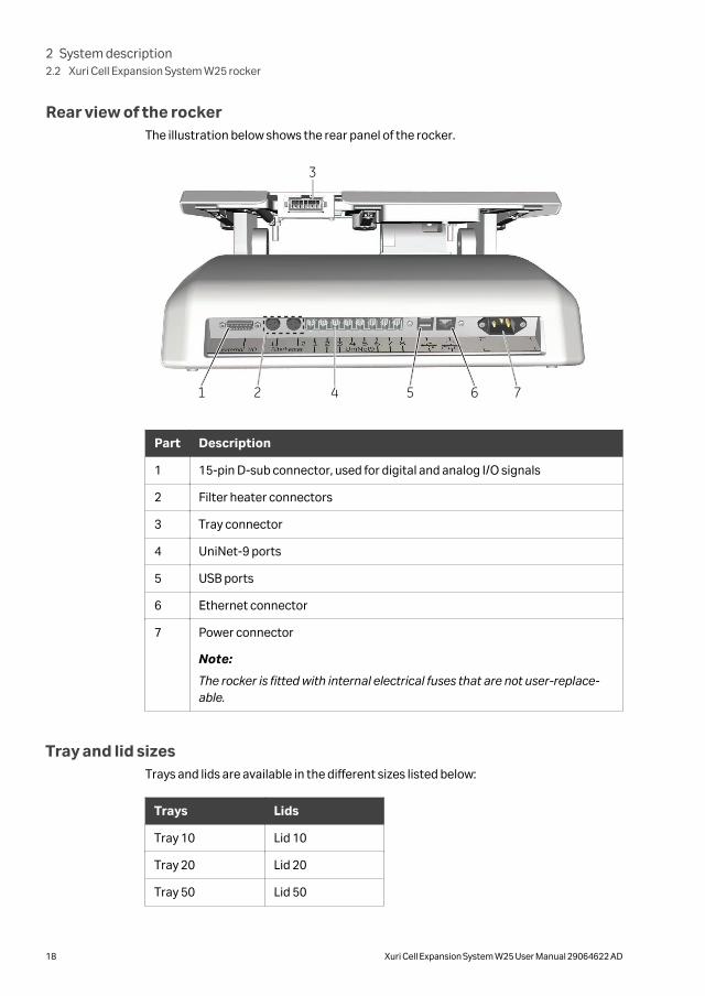
Rear view of the rockerThe illustration below shows the rear panel of the rocker.
1 2 4
3
5 6 7
Part Description
1 15-pin D-sub connector, used for digital and analog I/O signals
2 Filter heater connectors
3 Tray connector
4 UniNet-9 ports
5 USB ports
6 Ethernet connector
7 Power connector
Note:
The rocker is fitted with internal electrical fuses that are not user-replace-able.
Tray and lid sizesTrays and lids are available in the different sizes listed below:
Trays Lids
Tray 10 Lid 10
Tray 20 Lid 20
Tray 50 Lid 50
2 System description2.2 Xuri Cell Expansion System W25 rocker
18 Xuri Cell Expansion System W25 User Manual 29064622 AD

Illustrations of tray and lidThe illustration below shows the rocker with Tray 50 attached.
Part Description
1 Bag clamp (upper)
2 Bag clamp opener (one in each upper corner)
3 Bag clamp opener (one in each lower corner)
4 Bag clamp (lower)
The illustration below shows the rocker with Tray 50 and Lid 50 mounted.
2 System description2.2 Xuri Cell Expansion System W25 rocker
Xuri Cell Expansion System W25 User Manual 29064622 AD 19

54
3
2
1
Xuri™ Cell Expansion System W25
Part Description
1 Rocker base
2 Lid
3 Tray
4 Tubing exit
5 Hatch
2 System description2.2 Xuri Cell Expansion System W25 rocker
20 Xuri Cell Expansion System W25 User Manual 29064622 AD

Prepare for tiltWhen the system enters END mode, the tray prepares for tilt if System Settings→Rocker →Prepare for tilt at END is set to Yes. This moves the rocker to themechanical end position, which is 14 degrees from horizontal. This position can also beset by executing the manual instruction Rocker →Prepare for tilt. See illustrationbelow.
Xuri™ Cell Expansion System W25
Tilt position
In order to facilitate tray change in system setup and sampling and harvest during andafter cell cultivation, it is possible to position the tray with the attached Cellbagbioreactor(s) into an upright position called tilt position. Follow the instructions belowto put the tray into tilt position.
The tray is shown without attached Cellbag bioreactor in the images below.
NOTICE
Take care when tilting the rocker tray with full Cellbag bioreactor(s)attached.
Step Action
1 Prepare for tilt as described above or select the largest possible angle inUNICORN. Do not tilt the tray from an angle lower than 12°.
2 System description2.2 Xuri Cell Expansion System W25 rocker
Xuri Cell Expansion System W25 User Manual 29064622 AD 21
Step Action
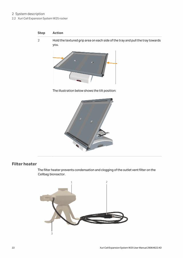
2 Hold the textured grip area on each side of the tray and pull the tray towardsyou.
The illustration below shows the tilt position:
Filter heaterThe filter heater prevents condensation and clogging of the outlet vent filter on theCellbag bioreactor.
1 2
3
2 System description2.2 Xuri Cell Expansion System W25 rocker
22 Xuri Cell Expansion System W25 User Manual 29064622 AD

Part Description
1 Filter heater
2 Connector for connection to the rocker
3 Filter heater stand
2 System description2.2 Xuri Cell Expansion System W25 rocker
Xuri Cell Expansion System W25 User Manual 29064622 AD 23

2.3 Xuri Cell Expansion W25 CBCU
IntroductionThe control unit, Xuri Cell Expansion W25 CBCU, is connected to the rocker via aUniNet-9 connector. The full configuration mixes air/N2, O2, and CO2 gas, and containsO2 and CO2 sensors, a mass flow controller, an optical pH sensor reader, and an opticalDO sensor reader. Three configurations are available:
• Xuri Cell Expansion W25 CBCU pH: CO2, O2 and pH.
• Xuri Cell Expansion W25 CBCU DO : CO2, O2 and DO.
• Xuri Cell Expansion W25 CBCU Full: CO2, O2, pH and DO.
For CBCU specifications, see Xuri Cell Expansion W25 CBCU specifications, on page245.
Front view of Xuri Cell Expansion W25CBCU
The illustration below shows the front panel of a fully configured CBCU. The configura-tion of your CBCU may vary from the configuration shown below.
Part Component Description
1 pH port Connector for pH sensor fiber cable.
2 GAS MIX OUT Gas outlet for connection to Cellbag bioreactor.
3 Status LED Indicates the CBCU operating status.
4 DO port Connector for DO sensor fiber cable.
Status LED
The status LED indicates the CBCU operating status according to the following table.
2 System description2.3 Xuri Cell Expansion W25 CBCU
24 Xuri Cell Expansion System W25 User Manual 29064622 AD
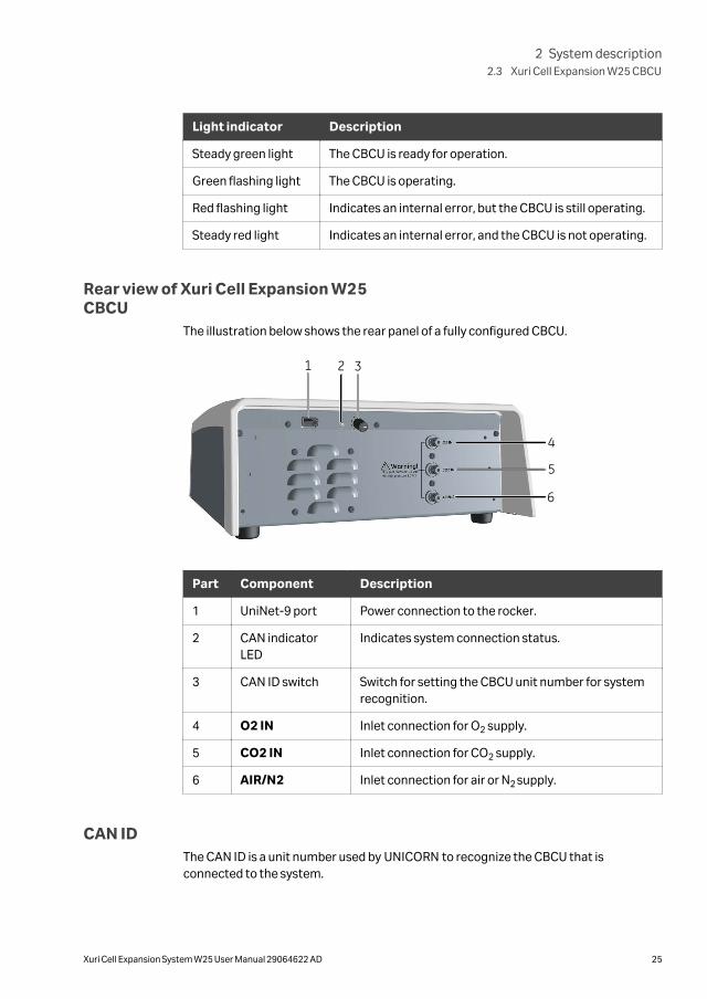
Light indicator Description
Steady green light The CBCU is ready for operation.
Green flashing light The CBCU is operating.
Red flashing light Indicates an internal error, but the CBCU is still operating.
Steady red light Indicates an internal error, and the CBCU is not operating.
Rear view of Xuri Cell Expansion W25CBCU
The illustration below shows the rear panel of a fully configured CBCU.
1 2 3
6
5
4
Part Component Description
1 UniNet-9 port Power connection to the rocker.
2 CAN indicatorLED
Indicates system connection status.
3 CAN ID switch Switch for setting the CBCU unit number for systemrecognition.
4 O2 IN Inlet connection for O2 supply.
5 CO2 IN Inlet connection for CO2 supply.
6 AIR/N2 Inlet connection for air or N2 supply.
CAN IDThe CAN ID is a unit number used by UNICORN to recognize the CBCU that isconnected to the system.
2 System description2.3 Xuri Cell Expansion W25 CBCU
Xuri Cell Expansion System W25 User Manual 29064622 AD 25

The CAN ID is set by turning a switch on the CBCU rear panel (see illustration above).The CAN ID should always be set to position 1 for use in single mode. For dual mode, setthe CAN ID to 1 for the CBCU connected to the left Cellbag bioreactor, and to 2 for theCBCU connected to the right Cellbag bioreactor.
Tubing and connectorsTubing and connectors for gas flow as listed below are delivered with the Xuri CellExpansion W25 CBCU. Tubing and connectors for liquid flow must be obtained sepa-rately.
Tubing
Item Inner diameter Outer diameter Length
Tygon™ E3603 1/8" (3.2 mm) 1/4" (6.4 mm) 147.6" (375 cm)
Silicone 3/16" (4.8 mm) 3/8" (9.5 mm) 7.9" (20 cm)
Connectors
Item Inner diameter
Reducer connector, gas tubing 1/8" to 3/16" (3.2 to 4.8 mm)
Connector, CBCU 1/8" (3.2 mm)
2 System description2.3 Xuri Cell Expansion W25 CBCU
26 Xuri Cell Expansion System W25 User Manual 29064622 AD

2.4 Xuri Cell Expansion W25 Pump
IntroductionXuri Cell Expansion W25 Pump is a peristaltic pump unit that includes two rollerpumps. It pumps fluid for feed, harvest/waste, and pH control with acid and base.
For specifications of the pump, see Xuri Cell Expansion W25 Pump specifications, onpage 246 or the data file for Xuri Cell Expansion System W25, available for downloadfrom cytiva.com.
Front view of the pumpThe illustration below shows the front panel of the pump.
1
2 3
Part Description
1 Pump head flip top
2 Pump head
3 Status LEDs for pumping function per pump head
Status LEDs
The status LEDs indicate the pumping function status according to the following table.
Light indicator Description
Steady green light The pumping function is ready for operation.
Green flashing light Pumping is ongoing.
Red flashing light Indicates an internal error, but the pump is still operating.
Steady red light Indicates an internal error, and the pump is not operatingproperly.
2 System description2.4 Xuri Cell Expansion W25 Pump
Xuri Cell Expansion System W25 User Manual 29064622 AD 27
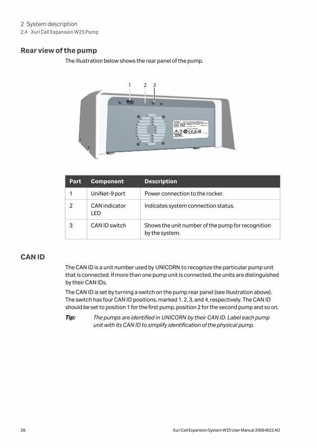
Rear view of the pumpThe illustration below shows the rear panel of the pump.
1 2 3
Part Component Description
1 UniNet-9 port Power connection to the rocker.
2 CAN indicatorLED
Indicates system connection status.
3 CAN ID switch Shows the unit number of the pump for recognitionby the system.
CAN IDThe CAN ID is a unit number used by UNICORN to recognize the particular pump unitthat is connected. If more than one pump unit is connected, the units are distinguishedby their CAN IDs.
The CAN ID is set by turning a switch on the pump rear panel (see illustration above).The switch has four CAN ID positions, marked 1, 2, 3, and 4, respectively. The CAN IDshould be set to position 1 for the first pump, position 2 for the second pump and so on.
Tip: The pumps are identified in UNICORN by their CAN ID. Label each pumpunit with its CAN ID to simplify identification of the physical pump.
2 System description2.4 Xuri Cell Expansion W25 Pump
28 Xuri Cell Expansion System W25 User Manual 29064622 AD

2.5 Cellbag bioreactor
IntroductionCell cultivation is performed inside the Cellbag bioreactor. The Cellbag bioreactor isdelivered gamma irradiated and ready for use. It is intended for single use only andshould be discarded after use.
Cellbag bioreactor optionsThe Cellbag bioreactors are available in different configurations, of varying sizes andequipped with various ports. Cellbag bioreactors with internal cell retention filters areavailable for perfusion culture. If required, it is possible to customize the Cellbagbioreactors. The following bag sizes are available for Xuri Cell Expansion System W25:
• 2 L
• 10 L
• 20 L (single mode only)
• 50 L (single mode only)
Illustration of Cellbag bioreactorThe illustration shows a general Cellbag bioreactor. The configuration of your Cellbagbioreactor may vary from the configuration shown below.
1
678
5432
9
Part Component Description
1 pH bagsensor port
The pH bag sensor port is located on the underside ofthe bag and holds an optical sensor for online pHcontrol of the cell culture.
2 System description2.5 Cellbag bioreactor
Xuri Cell Expansion System W25 User Manual 29064622 AD 29

Part Component Description
2 Outlet ventfilter withpressurecontrol valve
The filter prevents contamination of the bag contentsby airborne particles of 0.2 µm or larger.
The pressure control valve maintains a constant over-pressure inside the Cellbag bioreactor.
3 Inlet ventfilter
The filter removes airborne particles of 0.2 µm or largerfrom the gas flow before it enters the Cellbagbioreactor.
4 Addition port Addition port equipped with a Luer quick connector.
5 DO bagsensor port
The DO bag sensor is located on the underside of thebag and holds an optical sensor for online dissolvedoxygen control of the cell culture.
6 Cellbag rod The Cellbag rod fixes the Cellbag bioreactor to the tray.
7 Clave™sampling port
Sampling port equipped with a self-sealing Luer fitting.
8 Addition port Addition port equipped with a Luer quick connector.
9 Addition/harvest port
Addition/harvest port equipped with a MPC quickconnector.
Note: The inlet and outlet vent filters are distinguished by the pressure controlvalve on the outlet filter.
pH and DO sensorsThe Cellbag bioreactor may be equipped with optical sensors for monitoring pH anddissolved oxygen (DO). The sensors are light sensitive and should be protected fromexcessive light. The sensors are located in the center of a sensor port on the Cellbagbioreactor and must be coupled to a sensor adapter, see table below.
2 System description2.5 Cellbag bioreactor
30 Xuri Cell Expansion System W25 User Manual 29064622 AD

Part Description
Bag sensorport
The sensor port is located on the underside of the Cellbagbioreactor. The actual sensor (white/yellow for pH, pink/black for DOis located in the center (1) of the sensor port, see image below.
The sensor adapter is attached to the sensor port by the four pins(2).
1
2
Sensoradapter
The sensor adapter is located at one end of an optical fiber cable.The optical lens of the fiber cable is located in the center of thesensor adapter. The fiber cable is connected to a sensor reader inthe CBCU. The fiber cable is connected to the pH or DO port on theCBCU front panel.
2 System description2.5 Cellbag bioreactor
Xuri Cell Expansion System W25 User Manual 29064622 AD 31

2.6 UNICORN software overview
About this sectionThis section gives an overview of the general operation of the UNICORN software: acomplete package for control, supervision and evaluation of cell cultivation runs. It alsodescribes how to access the help utility that is included in UNICORN. Refer to Chapter 3The UNICORN software, on page 36 for more information.
Note: Software illustrations in these instructions are examples, and may differfrom your software in some details.
In this section
Section See page
2.6.1 General UNICORN operation 33
2.6.2 UNICORN help 34
2 System description2.6 UNICORN software overview
32 Xuri Cell Expansion System W25 User Manual 29064622 AD

2.6.1 General UNICORN operation
UNICORN modules overviewUNICORN consists of four modules: System Control, Evaluation, Administrationand Method Editor.
The main functions of the modules are described in the table below.
Module Main functions
System Control Start, view and control runs.
Evaluation Open results, evaluate runs and create reports.
Administration Perform user and system setup, system log and data-base administration.
Method Editor Create and edit methods.
Enter a UNICORN moduleTo enter a module:
• click the Taskbar button of the module of interest,
or
• choose the module of interest in the Tools menu in any of the other softwaremodules.
The illustration below shows the Tools menu of the Evaluation module.
2 System description2.6 UNICORN software overview
2.6.1 General UNICORN operation
Xuri Cell Expansion System W25 User Manual 29064622 AD 33

2.6.2 UNICORN help
Access the help utilityA comprehensive help utility is included in the UNICORN software. The table belowdescribes how to access the different parts of the help utility.
If you want to... then...
find information abouta UNICORN module
select Help →Help for... in the UNICORN module ofinterest
find information aboutthe item currentlyselected and in focus(e.g., a pane, a dialog, ora method phase)
• press the F1 key with the item of interest selectedand in focus
or
• click the Help icon in the open dialog
navigate the onlinehelp
• select Help →Help for... in any of the UNICORNmodules (see illustration above)
• in the TOC (Table of contents) pane, expand theheadings of interest to navigate the content struc-ture
• click the heading of interest to open a section
search for a specificterm in the online help
• select Help →Help for... in any of the UNICORNmodules (see illustration above)
• in the Search pane, enter the term of interest in theinput field
• click the Search button
2 System description2.6 UNICORN software overview
2.6.2 UNICORN help
34 Xuri Cell Expansion System W25 User Manual 29064622 AD

If you want to... then...
access manuals in PDFformat
• select Help →Help for... in any of the UNICORNmodules (see illustration above)
• in the TOC pane, expand the heading UNICORN 7.xonline documentation portal and select Docu-mentation overview
• in the PDF manuals section, click one of the text links
find information aboutan instruction
In the Method Editor module:
• open a method
• select the instruction of interest in the Instructionbox in the Text instruction pane
• press the F1 key
In the System Control module:
• select Manual →Execute Manual Instructions
• expand a heading and select the instruction ofinterest
• press the F1 key
or
click the Help icon in the dialog
2 System description2.6 UNICORN software overview
2.6.2 UNICORN help
Xuri Cell Expansion System W25 User Manual 29064622 AD 35

3 The UNICORN software
About this chapterThis chapter gives an overview of how to work with the four UNICORN modules.Detailed information about the UNICORN software is available in the UNICORN userdocumentation and in the UNICORN Online Help.
In this chapter
Section See page
3.1 Administration 37
3.2 System control 38
3.3 Methods in UNICORN 46
3.4 Evaluation in UNICORN 82
3 The UNICORN software
36 Xuri Cell Expansion System W25 User Manual 29064622 AD
3.1 Administration
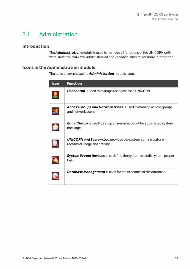
IntroductionThe Administration module is used to manage all functions of the UNICORN soft-ware. Refer to UNICORN Administration and Technical manual for more information.
Icons in the Administration moduleThe table below shows the Administration module icons.
Icon Function
User Setup is used to manage user access to UNICORN.
Access Groups and Network Users is used to manage access groupsand network users.
E-mail Setup is used to set up an e-mail account for automated systemmessages.
UNICORN and System Log provides the system administrator withrecords of usage and activity.
System Properties is used to define the system and edit system proper-ties.
Database Management is used for maintenance of the database.
3 The UNICORN software3.1 Administration
Xuri Cell Expansion System W25 User Manual 29064622 AD 37

3.2 System control
IntroductionThe System Control module is used to start, view, and control a manual or methodrun.
System Control panesAs illustrated below, two tabs are available in the System Control module by default.The Process Picture tab allows manual interactions with the system and providesfeedback on run parameters. The Chart tab shows a graphical presentation of datathroughout the run. Process picture, charts, run logs, and run data can be displayedeither as separate tabs or as docked panes in the same window.
More details of how to work with the process picture may be found in the sectionslisted in the table below:
Section Content
Section 5.4 Perform cultivation, on page196
Information on how to perform a run.
Section 5.4.2 Monitor and control the run,on page 198
Working with the process pictureduring a run.
Refer to Section 5.4 Perform cultivation, on page 196 for information on how to performa run.
Tip: To get more information than is shown in the Process Picture, select View→Run Data to open the Run Data pane which presents current data innumerical values.
3 The UNICORN software3.2 System control
38 Xuri Cell Expansion System W25 User Manual 29064622 AD

Items in the process picture reflect the components included in the system (forexample, the illustration above shows a system in single mode equipped with threepumps).
In dual mode, the process picture shows two Cellbag bioreactors on the rocker picture,with separate control icons for the individually controlled parameters in eachbioreactor. Icons for the left-hand bioreactor are in the upper half of the processpicture and icons for the right-hand bioreactor in the lower half.
3 The UNICORN software3.2 System control
Xuri Cell Expansion System W25 User Manual 29064622 AD 39
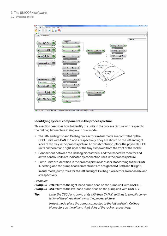
Identifying system components in the process picture
This section describes how to identify the units in the process picture with respect tothe Cellbag bioreactors in single and dual mode.
• The left- and right-hand Cellbag bioreactors in dual mode are controlled by theCBCU units with CAN ID 1 and 2 respectively. They are shown on the left and rightsides of the tray in the process picture. To avoid confusion, place the physical CBCUunits on the left and right sides of the tray as viewed from the front of the rocker.
• Connections between the Cellbag bioreactor(s) and the respective monitor andactive control units are indicated by connection lines in the process picture.
• Pump units are identified in the process picture as 1, 2 or 3 according to their CANID setting, and the pump heads on each unit are designated A (left) and B (right).
In dual mode, pump roles for the left and right Cellbag bioreactors are labelled L andR respectively.
Examples:Pump 25 →1B refers to the right-hand pump head on the pump unit with CAN ID 1.Pump 25 →2A refers to the left-hand pump head on the pump unit with CAN ID 2.
Tip: Label the CBCU and pump units with their CAN ID settings to simplify corre-lation of the physical units with the process picture.
In dual mode, place the pumps connected to the left and right Cellbagbioreactors on the left and right sides of the rocker respectively.
3 The UNICORN software3.2 System control
40 Xuri Cell Expansion System W25 User Manual 29064622 AD

Actions in the Process Picture paneIt is possible to interact with the Process Picture pane in the following ways:
If you want to... then...
Activate or deactivatepH and DO measure-ment and control
Hold the cursor over the right-hand side of the button,and turn Reading and/or Control on or off as required.You can only switch the Control setting if Reading ison, and you cannot turn Reading off if Control is on.
Activate or deactivateother functions
Click on the right-hand side of the button. The text onthe button shows the current value of the function.
Open the settings for afunction
Click on the left-hand side of the button.
The example below shows the settings for dissolvedoxygen, DO.
Adjust the settings Enter appropriate values in the Settings dialog and clickOK or press enter.
3 The UNICORN software3.2 System control
Xuri Cell Expansion System W25 User Manual 29064622 AD 41

System Control toolbar iconsThe table below shows the System Control toolbar icons that are referred to in thisUser Manual.
Icon Function
Open Method Navigator: Opens the Method Navigator where avail-able methods are listed.
Run: Starts a method run.
Hold: Suspends the method run.
Continue: Resumes a process, for example, a method run that is on hold.
End: Permanently ends the method run.
Customize: Opens the Customize dialog where curve settings, run datagroups and run log contents can be set.
Connect to Systems: Opens the Connect to Systems dialog wheresystems can be connected, and currently connected users are displayed.
Curves
Monitor signals and instrument settings are shown in the chart as curves. The curvesare also saved in a result file, which can be opened in the Evaluation module. Thedefault view shows the most commonly used curves. The user may customize whichcurves to display and the color and style of the displayed curves.
Note: All curves are saved in the result file regardless of the curves displayed.
Note: The complete ranges of the signals are saved in the result file regardless offactors such as scaling and zooming that are used during the run.
Follow the instructions below to customize which curves to show in the chart. Refer tothe online help for further information about the tabs in the Customize dialog.
3 The UNICORN software3.2 System control
42 Xuri Cell Expansion System W25 User Manual 29064622 AD

Step Action
1 In the System Control module:
• click the Customize icon
or
• select Tools →Customize...
Result:
The Customize dialog opens.
2 Select the Curves tab.
3 Check the boxes for the curves you want to show in the chart and then clickOK.
System settings
Each installed instrument has a set of default parameter values, called system settings.The System Settings dialog in System Control is used to view and edit the systemsetting for the currently selected instrument before the run is started. Follow theinstructions below to change the System Settings.
Available settings are described in Section 8.5 Control settings, on page 250.
3 The UNICORN software3.2 System control
Xuri Cell Expansion System W25 User Manual 29064622 AD 43
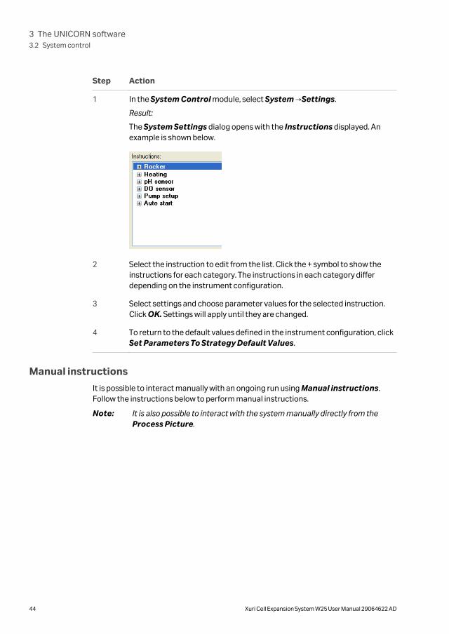
Step Action
1 In the System Control module, select System →Settings.
Result:
The System Settings dialog opens with the Instructions displayed. Anexample is shown below.
2 Select the instruction to edit from the list. Click the + symbol to show theinstructions for each category. The instructions in each category differdepending on the instrument configuration.
3 Select settings and choose parameter values for the selected instruction.Click OK. Settings will apply until they are changed.
4 To return to the default values defined in the instrument configuration, clickSet Parameters To Strategy Default Values.
Manual instructions
It is possible to interact manually with an ongoing run using Manual instructions.Follow the instructions below to perform manual instructions.
Note: It is also possible to interact with the system manually directly from theProcess Picture.
3 The UNICORN software3.2 System control
44 Xuri Cell Expansion System W25 User Manual 29064622 AD

Step Action
1 In the System Control module:
• select Manual →Execute Manual Instructions
or
• use the shortcut Ctrl+M.
Result:
The Manual instructions dialog opens.
2 In the Manual instructions dialog:
a. Click the + symbol to show the instructions for the instruction group thatyou want to modify.
b. Select the instruction that you want to modify.
c. Enter the new values for the instruction.
3 To execute several instructions at the same breakpoint, select and edit aninstruction and click Insert. Repeat for several instructions.
Note:
To update parameter fields during run, check the Auto update... box.
4 To perform the instructions, click Execute.
Run dataThe Run Data pane shows the current values of some parameters, for example rockingmotion and accumulated time. To change the Run Data display, select View →RunData, right click in the Run Data pane and:
• select Run Data Groups →Detailed to show more details
or
• select Customize to customize the appearance of the Run Data pane.
3 The UNICORN software3.2 System control
Xuri Cell Expansion System W25 User Manual 29064622 AD 45

3.3 Methods in UNICORN
About this sectionThis section describes how to create methods and work with predefined methods andtext instructions. For information about dialogs in the Method Editor that are notdescribed in this manual, refer to the online help.
In this section
Section See page
3.3.1 Method editor 47
3.3.2 Method creation 49
3.3.3 Work with methods 53
3.3.4 Text instructions 59
3.3.5 Save a method 67
3.3.6 Scouting 71
3.3.7 Method queues 77
3 The UNICORN software3.3 Methods in UNICORN
46 Xuri Cell Expansion System W25 User Manual 29064622 AD

3.3.1 Method editor
IntroductionIn the UNICORN software, the instructions to control a bioreactor run can be defined ina method. The Method Editor module is used to create or edit such methods.
User defined methods and phasesA method consists of a number of phases, and each phase consists on turn of a numberof instructions.
Refer to the UNICORN Online Help for more information about methods and phasesand how to create a method.
Method Editor panesAs illustrated below, three panes are shown in the Method Editor by default. The avail-able User Defined phase is found in the Phase Library (1), and an overview of thephases included in the active method is displayed in a Method Outline (2). Informa-tion about the method is presented in the right pane (3), containing the two tabs PhaseProperties and Text Instructions.
Method Editor toolbar iconsThe table below shows the Method Editor toolbar icons that are referred to in thisUser Manual.
3 The UNICORN software3.3 Methods in UNICORN
3.3.1 Method editor
Xuri Cell Expansion System W25 User Manual 29064622 AD 47

Icon Function
New Method: Opens the New Method dialog where methods can becreated.
Open Method Navigator: Opens the Method Navigator where avail-able methods are listed.
Save: Saves the active method.
Print: Opens the Print dialog from where a method can be printed.
Start protocol: Opens the Start Protocol dialog, where settings for thestart protocol can be made.
Method notes: Opens the Method Notes dialog, where notes can beadded to the method.
Scouting: Opens the Scouting Variables dialog, which is used to repeata series of method runs.
New method queue: Opens the Method Queue dialog.
3 The UNICORN software3.3 Methods in UNICORN
3.3.1 Method editor
48 Xuri Cell Expansion System W25 User Manual 29064622 AD

3.3.2 Method creation
Predefined method
Follow the instructions below to create a new method using a predefined method astemplate:
3 The UNICORN software3.3 Methods in UNICORN
3.3.2 Method creation
Xuri Cell Expansion System W25 User Manual 29064622 AD 49
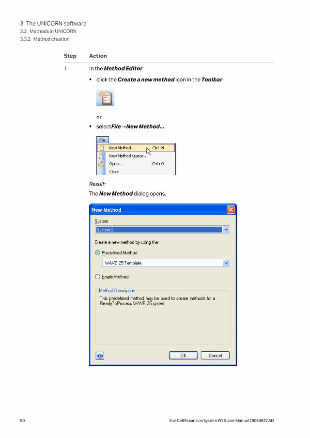
Step Action
1 In the Method Editor:
• click the Create a new method icon in the Toolbar
or
• selectFile →New Method...
Result:
The New Method dialog opens.
3 The UNICORN software3.3 Methods in UNICORN
3.3.2 Method creation
50 Xuri Cell Expansion System W25 User Manual 29064622 AD

Step Action
2 In the New Method dialog:
a. select a System
b. select a Predefined Method
c. click OK
Result:
The Method Outline pane shows the mandatory Method Settings phasefor the chosen method and the Text Instructions pane shows all theinstructions that defines the method. The Phase Properties pane showsthe default settings for the currently highlighted phase.
Empty method
Follow the instructions below to create a new empty method:
Step Action
1 In the Method Editor:
• click the Create a new method icon in the Toolbar
or
• selectFile →New Method...
Result:
The New Method dialog opens.
3 The UNICORN software3.3 Methods in UNICORN
3.3.2 Method creation
Xuri Cell Expansion System W25 User Manual 29064622 AD 51

Step Action
2
In the New Method dialog:
a. select a System
b. select the Empty Method radio button
c. click OK
Result:
An empty method that consists of the mandatory Method Settingsphase is created.
3 The UNICORN software3.3 Methods in UNICORN
3.3.2 Method creation
52 Xuri Cell Expansion System W25 User Manual 29064622 AD

3.3.3 Work with methods
Open a method
Follow the instructions below to open an existing method in the database.
Note: The Method Editor illustrated in diagrams can be used for single mode ofoperation only.
Step Action
1 In the Method Editor:
• Click the Open Method Navigator icon in the Toolbar
or
• select File →Open...
or
• select View →Method Navigator
Result:
The Method Navigator is displayed.
3 The UNICORN software3.3 Methods in UNICORN
3.3.3 Work with methods
Xuri Cell Expansion System W25 User Manual 29064622 AD 53

Step Action
2 Select the method to be opened in the Folder name column.
3 To open the method,
• Click the Open button located in the toolbar of the Method Navigatorpane
or
• double-click the selected method
or
• right-click on the method name and select Open from the context menu.
Result:
The method is opened and displayed in the Method Outline pane withincluded phases. You can continue to edit the phases of the method usingPhase Properties, or manually text edit the method in the Text Instruc-tions pane".
Add a user defined phase to themethod outline using drag-and-drop
Follow the instructions below to add a user defined phase to the method outline usingdrag-and-drop:
Step Action
1 Select the User Defined phase in the Phase Library pane and drag-and-drop the phase to the requested position in the Method Outline pane.
Result:
The phase is included in the method at the requested position.
3 The UNICORN software3.3 Methods in UNICORN
3.3.3 Work with methods
54 Xuri Cell Expansion System W25 User Manual 29064622 AD

Step Action
2 When the User Defined phase has been added to the Method Outline, thephase name is enabled for editing.
Type a name for the phase and press the Return keyboard key.
Note:
The User Defined phase is marked with the letter T, meaning that it is textedited. This phase contains only Base and End_Block instructions, so anyfunctional instructions must be added by hand. To include instructions forthe User Defined phase, select the Text Instructions tab. The PhaseProperties tab will only show the variables used in this phase. See Section3.3.4 Text instructions, on page 59 for information about how to work withinstructions in the Text Instructions pane.
3 The UNICORN software3.3 Methods in UNICORN
3.3.3 Work with methods
Xuri Cell Expansion System W25 User Manual 29064622 AD 55

Rearrange phases within a method
Follow the instructions below to rearrange phases within a method:
Step Action
1 Select the phase to be moved in the Method Outline pane.
2 • Drag-and-drop the phase to the requested position in the MethodOutline pane.
Result:The phase is moved to the requested position.
or
• Right-click the phase and select Move up or Move down.
Result:The phase is moved one step up or down in the Method Outline.
Set up a Start Protocol
Follow the instructions below to set up a Start Protocol to be displayed before themethod run starts.
3 The UNICORN software3.3 Methods in UNICORN
3.3.3 Work with methods
56 Xuri Cell Expansion System W25 User Manual 29064622 AD

Step Action
1 In the Method Editor:
• click the Start Protocol icon
or
• select Tools →Start Protocol...
or
• click the Method Settings phase and click the Start Protocol... buttonin the Phase Properties tab
Result:
The Start Protocol dialog opens.
2 In the Start Protocol dialog:
a. Select items to display at method start. When selecting a method item, adescription is shown to the right. Result Name and Location is selectedby default.
b. Click OK to confirm and close the dialog.
Add/edit Method Notes
Follow the instructions below to add notes to a method or edit existing notes.
3 The UNICORN software3.3 Methods in UNICORN
3.3.3 Work with methods
Xuri Cell Expansion System W25 User Manual 29064622 AD 57

Step Action
1 In the Method Editor:
• click the Method Notes icon
or
• select Edit →Method Notes...
or
• click the Method Settings phase and click the Method Notes... buttonin the Phase Properties tab
Result:
The Method Notes dialog opens.
2
In the Method Notes dialog:
a. Enter/edit notes about the method. If notes already have been entered, itis possible to search for specific words using the Find... button.
b. Click OK to confirm and close the dialog.
3 The UNICORN software3.3 Methods in UNICORN
3.3.3 Work with methods
58 Xuri Cell Expansion System W25 User Manual 29064622 AD

3.3.4 Text instructions
IntroductionWhen a user defined phase in the Method Editor is selected, the corresponding phaseblock is selected in Text Instructions when changing to the Text Instructions tab.
Changes made in the Phase Properties pane are automatically updated in the TextInstructions pane.
Text editing a methodAdding, editing or deleting any blocks or instructions in a phase in the Text Instruc-tions area means text editing of the method. When a method has been text edited, oneor several of the phases displayed in the Method Editor window are affecteddepending on the type of editing performed.
The letter T next to the phase name in the Method Editor window indicates that thephase has been text edited.
Help for the instructions
It is possible to display help for the text instructions in the Instruction Box.
Follow the steps below to display the help text for an instruction:
Step Action
1 In the Instruction Box, select the appropriate instruction for which todisplay help.
2 Press F1 on the keyboard.
Result:
A dialog with help text for the selected instruction will be displayed.
Insert a new instruction
Follow the steps below to insert a new text instruction in the Text Instructions area:
Step Action
1 Select a block and display the instructions within the block.
2 Select the instruction in the block after which you want to add the newinstruction.
3 The UNICORN software3.3 Methods in UNICORN
3.3.4 Text instructions
Xuri Cell Expansion System W25 User Manual 29064622 AD 59

Step Action
3 Open the Instruction Box if it is hidden. Do the following:
a. Set the appropriate breakpoint in the Breakpoint box.
Note:
A Breakpoint defines when an instruction will be executed. The time setis relative to the start of the block.
b. Choose the instruction type and the instruction in the Instructions field.For basic help on each instruction, select the instruction and press F1.
c. Type values for instruction parameters in the Parameters text boxes.
The allowed range is shown in brackets beside the text box. If a scroll barappears at the right side of the Parameters field, additional parametersare available.
4 Click the Insert button.
Result:
The instruction will be inserted in the block:
• at the position of the breakpoint of the new instruction, if there are noother instructions at that breakpoint
• immediately after the currently highlighted instruction, if the highlight isat the same breakpoint as the new instruction
• as the first or last instruction, if none of the instructions at the desiredbreakpoint is highlighted. The insertion point depends on the breakpointvalue of the currently selected instruction. For example, if the breakpointfor the current instruction is lower than that for the new instruction it isinserted as the first instruction at that breakpoint.
3 The UNICORN software3.3 Methods in UNICORN
3.3.4 Text instructions
60 Xuri Cell Expansion System W25 User Manual 29064622 AD

Define new variables
Only one variable that affects block length (breakpoint) may be defined within eachblock. However, any number of parameters may be defined as variables within a block.Follow the instructions below to define a new variable.
Step Action
1 Select the instruction where you want to define the variable in the TextInstructions area.
Result:
The parameters for the instruction are shown in the Instruction Box.
2 a. Locate the breakpoint or the required parameter in the Instruction box.
b. Click the Var... button.
Result:
The New Variable dialog opens.
3 The UNICORN software3.3 Methods in UNICORN
3.3.4 Text instructions
Xuri Cell Expansion System W25 User Manual 29064622 AD 61
Step Action
3 a. Type a name for the variable.
b. Select the Visible in details only checkbox if you want to set the vari-able as a detailed variable. Detailed variables become visible in the Vari-able List if the Show details checkbox is selected. This option can beused to simplify the workflow later.
c. Click OK.
Result:
The Var... button changes to VAR... to confirm the new variable.
Note:
If a breakpoint is defined as a variable, changing the variable value in theVariable List tab when the method run is started will shift other instructionbreakpoints accordingly.
4 Click Change.
Result:
The variable is saved and displayed in the Text Instructions area.
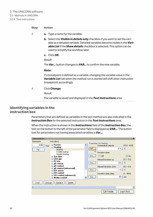
Identifying variables in theinstruction box
Parameters that are defined as variables in the text method are also indicated in theInstruction Box for the selected instruction in the Text Instructions area.
When the instruction is shown in the Instructions field of the Instruction Box, thetext on the button to the left of the parameter field is displayed as VAR.... The buttontext for parameters not having associated variables is Var....
3 The UNICORN software3.3 Methods in UNICORN
3.3.4 Text instructions
62 Xuri Cell Expansion System W25 User Manual 29064622 AD
Edit variablesEditing a variable includes renaming and deleting the variable and choosing whetherthe variable should be a detailed variable or not.
Edit a variable using the Edit variable button
Follow the instructions below to edit a variable using the Edit Variable button:
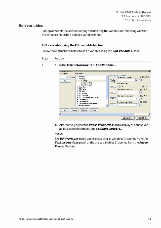
Step Action
1 a. In the Instruction Box, click Edit Variable....
b. Alternatively select the Phase Properties tab to display the phase vari-ables, select the variable and click Edit Variable....
Result:
The Edit Variable dialog opens displaying all variables (if opened from theText Instructions pane) or the phase variables (if opened from the PhaseProperties tab).
3 The UNICORN software3.3 Methods in UNICORN
3.3.4 Text instructions
Xuri Cell Expansion System W25 User Manual 29064622 AD 63

Step Action
2 Select the variable to be edited (if not already selected). Do one or several ofthe following as appropriate:
a. Type in a new name in the New name field and click Rename.
b. Check the Set visible in details only if the variable should be a detailedvariable. Uncheck the box to set it to a normal variable.
c. Click Delete to delete the variable.
Confirm that you want to delete the variable in the dialog that appears.
3 Click Close to close the dialog.
Edit a variable using the VAR.. button in the Instruction Box
Follow the instructions below to edit a variable using the Instruction Box:
3 The UNICORN software3.3 Methods in UNICORN
3.3.4 Text instructions
64 Xuri Cell Expansion System W25 User Manual 29064622 AD

Step Action
1 Select the instruction containing the variable to be edited in the TextInstructions area.
Result:
The parameters for the instruction are shown in the Instruction Box.
2 Click the VAR... button for the appropriate variable.
Result:
The Edit Variable dialog opens.
3 The UNICORN software3.3 Methods in UNICORN
3.3.4 Text instructions
Xuri Cell Expansion System W25 User Manual 29064622 AD 65

Step Action
3 Do one or several of the following as appropriate:
a. Type in a new name in the Variable name field.
b. Check the Visible in details only if the variable should be a detailedvariable. Uncheck the box to set it to a normal variable.
c. Click Clear to delete the variable.
4 Click OK.
5 To save the changes, click Change in the Instruction Box.
Result:
The text instruction is updated.
3 The UNICORN software3.3 Methods in UNICORN
3.3.4 Text instructions
66 Xuri Cell Expansion System W25 User Manual 29064622 AD
3.3.5 Save a method
IntroductionMethods and phases are saved in the UNICORN database.
Individual, edited phases may be saved to the Phase Library for later use in othermethods on systems having the same instrument configuration and componentconfiguration.
Save a method
Follow the instructions below to save a method in UNICORN.
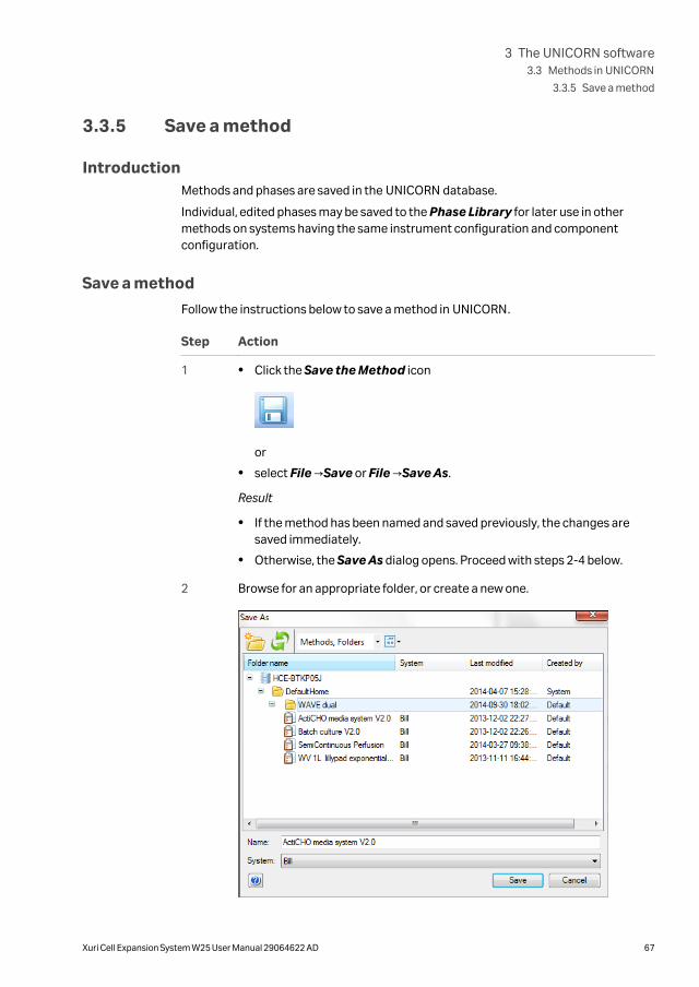
Step Action
1 • Click the Save the Method icon
or
• select File →Save or File →Save As.
Result
• If the method has been named and saved previously, the changes aresaved immediately.
• Otherwise, the Save As dialog opens. Proceed with steps 2-4 below.
2 Browse for an appropriate folder, or create a new one.
3 The UNICORN software3.3 Methods in UNICORN
3.3.5 Save a method
Xuri Cell Expansion System W25 User Manual 29064622 AD 67

Step Action
3 a. Select the folder in which to save the method.
b. Enter a method Name.
c. Select for which System to save the method
4 Click Save.
Result:
The method is saved in the database.
Note:
For some systems an error message will appear if you are trying to save themethod for:
• a system using another instrument configuration and/or another compo-nent configuration than the method originally was created for
and
• the settings in the method depend on the component configuration.
It will still be possible to save the method but the phases in the method will bemarked with an error symbol. In order to be able to subsequently run themethod, either the method must be text edited or the component configura-tion of the system changed in the Administration module.
Save a phase
Follow the instructions below to save a phase to the Phase Library:
Step Action
1 Select the phase to be saved in the method outline.
Note:
A Method Settings phase cannot be saved as a separate phase with a newname. If properties for the Method Settings phase are changed, thechanges will be saved with the method.
3 The UNICORN software3.3 Methods in UNICORN
3.3.5 Save a method
68 Xuri Cell Expansion System W25 User Manual 29064622 AD

Step Action
2 • click the Save Phase... button below the Method Outline pane
or
• select Phases →Save Phase...
or
• right-click the phase and select Save Phase...
Result:The Save Phase to Phase Library dialog opens.
3 • Type a Phase name
or
• Choose a phase from the Phase name drop-down list. This phase will bereplaced by the phase with the new settings.
3 The UNICORN software3.3 Methods in UNICORN
3.3.5 Save a method
Xuri Cell Expansion System W25 User Manual 29064622 AD 69

Step Action
4 In the For system field, the system that was selected when the currentmethod was set up will be displayed by default. To save the phase for anothersystem, choose the appropriate system from the For system drop-downlist.
Note:
Only systems using the same instrument configuration and componentconfiguration as the system that was selected when the current method wasset up will be displayed in the For system field.
5 a. Select if the phase shall be Global (available for all users) or Personal(for your own use only).
b. Click OK.
Result:
The phase is saved and is available in the Global Phases or PersonalPhases panel of the Phase Library.
3 The UNICORN software3.3 Methods in UNICORN
3.3.5 Save a method
70 Xuri Cell Expansion System W25 User Manual 29064622 AD

3.3.6 Scouting
IntroductionScouting is used to repeat a series of method runs automatically using differentsettings or with predetermined changes in the values for one or more Variables. AScouting scheme is defined as part of the method. This chapter gives an overview ofscouting and the scouting workflow and describes how to set up and edit a Scoutingscheme. Scouting is ideal for relatively simple variable combinations.
Set up a scouting scheme
Follow the instructions below to set up a Scouting scheme where a variable is varied.In this example, the rocking speed is varied.
Note: The Start protocol will only be displayed before the first run in theScouting experiment.
Step Action
1 Create a method and decide appropriate run parameters to be varied in theexperiment. The run parameters to be varied should be defined as Variablesin your method.
See Section 3.3.2 Method creation, on page 49 for information about how tocreate methods.
See subsection Edit variables in section Section 3.3.4 Text instructions, onpage 59 for information about how to define new variables.
3 The UNICORN software3.3 Methods in UNICORN
3.3.6 Scouting
Xuri Cell Expansion System W25 User Manual 29064622 AD 71

Step Action
2 In the Method Editor:
• Click the Scouting icon in the toolbar
or
• SelectTools →Scouting
Result:
The Scouting dialog opens with the Scouting Variables dialog displayedon top.
Note:
When editing a scouting scheme, only the Scouting dialog is displayed.
3 The UNICORN software3.3 Methods in UNICORN
3.3.6 Scouting
72 Xuri Cell Expansion System W25 User Manual 29064622 AD
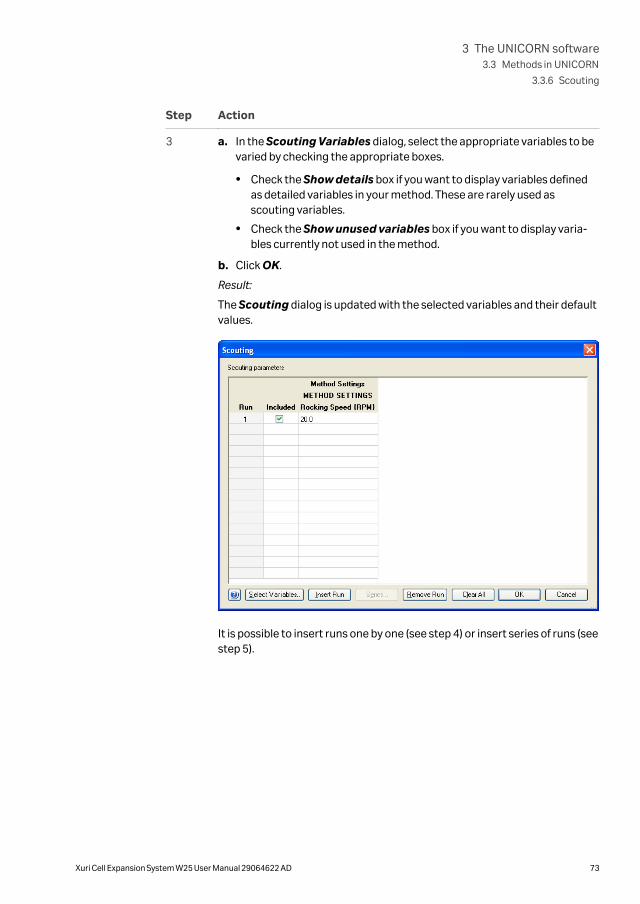
Step Action
3 a. In the Scouting Variables dialog, select the appropriate variables to bevaried by checking the appropriate boxes.
• Check the Show details box if you want to display variables definedas detailed variables in your method. These are rarely used asscouting variables.
• Check the Show unused variables box if you want to display varia-bles currently not used in the method.
b. Click OK.
Result:
The Scouting dialog is updated with the selected variables and their defaultvalues.
It is possible to insert runs one by one (see step 4) or insert series of runs (seestep 5).
3 The UNICORN software3.3 Methods in UNICORN
3.3.6 Scouting
Xuri Cell Expansion System W25 User Manual 29064622 AD 73

Step Action
4 To insert runs one by one:
a. In the Scouting dialog, select a row in the Scouting parameters table
and click .
Result:
A new row is added below the selected run. The variable value from theselected row is copied to the new run. Each chosen variable is displayedin a separate column.
b. In this example, click in the Rocking Speed {RPM} column for the appro-priate run and edit the rocking speed value.
Note:
Changing variable values in the scouting scheme does not change thevalues in the Variable List in the Duration and Variables dialogaccessed from the Method Editor or in the text instructions. The actualvariable values used for each run in the scouting scheme are saved in theresult file. To change the default values, the variable values must beedited in the Phase Properties pane.
c. Repeat until all runs are included using the correct variable values.
Note:
The scouting scheme can also be edited just prior to starting the methodrun in the Start Protocol. Here variable values can be changed and indi-vidual runs included or excluded.
3 The UNICORN software3.3 Methods in UNICORN
3.3.6 Scouting
74 Xuri Cell Expansion System W25 User Manual 29064622 AD

Step Action
5 To insert a series of runs:
a. Click in the appropriate variable column in the Scouting parameters
table and click . This button is activated for variables withcontinuous values, such as flow rates or pressure limits.
Result:
The Insert Series dialog for the selected variable opens.
6 In the Insert Series dialog:
a. Enter Start value:, Step by: and Number of runs:. In this example, 20, 2and 5.
b. Click OK.
Result:
The Scouting parameters table is updated.
3 The UNICORN software3.3 Methods in UNICORN
3.3.6 Scouting
Xuri Cell Expansion System W25 User Manual 29064622 AD 75

Step Action
7 Alternatively, to enter either consecutive or non-consecutive integer values:
a. Check the Set as integer values box in the Insert Series dialog.
Result:
The following alternative Insert Series dialog for the selected variableopens.
b. Enter the appropriate range, for example: 20-23,25-28
c. Click OK.
Result:
The Scouting parameters table is updated.
8 Click OK in the Scouting dialog to save the scouting scheme.
Save the method.
3 The UNICORN software3.3 Methods in UNICORN
3.3.6 Scouting
76 Xuri Cell Expansion System W25 User Manual 29064622 AD

3.3.7 Method queues
IntroductionThis section describes how to create and edit method queues in UNICORN. For infor-mation on how to create and edit individual methods, see Section 3.3.2 Method crea-tion, on page 49.
A method queue in UNICORN is a linked set of methods to be run. The method queuecan contain methods to be run on up to three different systems. Each system may haveup to ten methods queued.
Create a method queue
Follow the instructions below to create a method queue.
Step Action
1 In the Method Editor:
• click the New Method Queue icon in the Toolbar
or
• Select File →New Method Queue...
Result:
The Method Queue dialog opens.
3 The UNICORN software3.3 Methods in UNICORN
3.3.7 Method queues
Xuri Cell Expansion System W25 User Manual 29064622 AD 77

Step Action
2 In the Method Queue dialog, choose the Number of included systemsfrom the drop down list.
Result:
A separate method queue block will be added to the dialog for each addi-tional system if required.
3 Choose a system for each method queue block from the System drop downlist.
4 Choose a Method to add to a method queue by pressing the browse button.
Result:
The Select Method dialog opens.
3 The UNICORN software3.3 Methods in UNICORN
3.3.7 Method queues
78 Xuri Cell Expansion System W25 User Manual 29064622 AD

Step Action
5 In the Select Method dialog, browse to the required method and click OK.
Result:
The method is added to the method queue.
Note:
For reasons of system compatibility, the individual methods should be savedfor the system on which they are queued.
3 The UNICORN software3.3 Methods in UNICORN
3.3.7 Method queues
Xuri Cell Expansion System W25 User Manual 29064622 AD 79

Step Action
6 Select a Start Condition for the method from the drop-down list.
a. At queue start
The method will begin at the start of the method queue. Only availablefor the first method for each system.
b. Immediately after the previous method has ended
The method will start when the previous has ended on the queue for thatsystem.
c. Wait...
The method will start after a specified Wait time has elapsed since theprevious method in the queue for the system has ended. A separatedialog will open where the Wait time can be specified in Hours andMinutes. The delay time will be shown in the Method Queue dialogonce entered.
d. At ready command...
The method will start when a Ready instruction in a method on anothersystem has been executed. Using this start condition it is possible toconnect methods running on different systems. A separate dialog willopen where the System and Method can be chosen.
Note:
The first Method for the first System will always have its Start Conditionset to At queue start.
Available Start Conditions are:
7 Repeat steps 4 to 6 to add further methods to the Method list for eachrequired system.
3 The UNICORN software3.3 Methods in UNICORN
3.3.7 Method queues
80 Xuri Cell Expansion System W25 User Manual 29064622 AD

Step Action
8 Click Save or Save As to save the completed method queue.
Note:
An error dialog will be displayed if any of the methods are incompatible withthe system on which they are queued.
3 The UNICORN software3.3 Methods in UNICORN
3.3.7 Method queues
Xuri Cell Expansion System W25 User Manual 29064622 AD 81

3.4 Evaluation in UNICORN
About this sectionThe Evaluation module in UNICORN 7.x includes the basic functionality needed toevaluate the results of a run. How to use the Evaluation module is described in theintegrated Getting Started view and in tool tips in the software.
This section describes how to use the Evaluation Classic module which includes addi-tional features and requires a separate license.
In this section
Section See page
3.4.1 Evaluation 83
3.4.2 Open and view results 85
3.4.3 Run documentation 89
3.4.4 Generate and print a predefined report format 94
3.4.5 Create a new report format 96
3.4.6 Edit an existing report format 105
3 The UNICORN software3.4 Evaluation in UNICORN
82 Xuri Cell Expansion System W25 User Manual 29064622 AD

3.4.1 Evaluation
IntroductionThe Evaluation module is used to evaluate the results from bioreactor runs. Evalua-tion is described in detail in this manual and in UNICORN Online Help.
Evaluation panesAs illustrated below, the Evaluation module contains two panes. When a result isopened from the Result Navigator (1) the Chart pane (2) is displayed. In the Evalua-tion module it is also possible to view the complete documentation of the results, andto generate reports. Refer to the UNICORN Online Help for more information aboutresult evaluation.
Evaluation toolbar iconsThe table below shows the Evaluation toolbar icons that are referred to in this UserManual.
Icon Function
Open Result Navigator: Opens the Result Navigator where availableresults are listed.
3 The UNICORN software3.4 Evaluation in UNICORN
3.4.1 Evaluation
Xuri Cell Expansion System W25 User Manual 29064622 AD 83

Icon Function
Save: Saves the changes made to the current result.
Print: Opens the Print charts dialog from where a chart can be printed.
Report: Opens the Create report dialog where a report of the result canbe created.
View Documentation: Opens the Documentation dialog that containsthe complete documentation for a manual or a method run.
Customize: Opens the Customize dialog where for example curvesettings can be set.
3 The UNICORN software3.4 Evaluation in UNICORN
3.4.1 Evaluation
84 Xuri Cell Expansion System W25 User Manual 29064622 AD

3.4.2 Open and view results
IntroductionAll contents of the result files are opened in the Evaluation module where you cananalyze the results and compile reports. The Evaluation module user interface andtoolbar icons are described in Section 3.4.1 Evaluation, on page 83.
This section also describes how to highlight curves in a chart, read curve values using amarker and save curve data as a Snapshot.
Open a result in the Evaluationmodule
Click the Open Result Navigator icon to access the result files that are located infolders accessible to you.
There are four ways to open a result from the Result Navigator:
• Select a result and click the Enter key
or
• Double-click a result
or
• Right-click a result and choose Open from the shortcut menu
or
• Select a result and click the Open toolbar icon in the Result Navigator.
ResultThe result is opened in the chart pane.
Only one result at a time may be opened this way. If you open a new result, the previousresult will automatically close. However, you may open several charts from differentresults using File →Open to Compare. Refer to Online help for furhter information.
Note: When working in a network environment, it is not possible to edit the sameresult file from two different locations simultaneously. If the result is alreadyopen at another network workstation, you can only open it in read-onlymode. A message similar to the illustration below will open.
3 The UNICORN software3.4 Evaluation in UNICORN
3.4.2 Open and view results
Xuri Cell Expansion System W25 User Manual 29064622 AD 85

Highlight or select a curveYou can highlight or select an individual curve in the chart. The table below describesthe differences:
If you... Then...
hold your mousepointer over a curvesegment
a pop-up box will display the curve name.
hold your mousepointer over a curvename
the curve and the short line segment in front of the curvename become bold.
click a curve segmentor a curve name
the Y-axis shows the values for this specific curve.
Insert a vertical markerThe vertical marker is used to measure the values for a specific curve position. Right-click in the chart and choose Vertical marker. Move the marker along the X-axis andread the X-axis and Y-axis values of the selected curve in the box in the top left cornerof the chart.
Note: The marker will measure the curve that currently is selected if severalcurves are displayed in the chart. The marker will have the same color as theselected curve.
Set marker reference
You can use the vertical marker for more measurements than just the readings from aspecific curve position. Follow the instructions below to use the marker to determineDelta and Mean Y-axis values.
3 The UNICORN software3.4 Evaluation in UNICORN
3.4.2 Open and view results
86 Xuri Cell Expansion System W25 User Manual 29064622 AD

Step Action
1 a. Position the marker where you want to begin the measurement.
b. Right-click and choose Set vertical marker reference point.
Result:
The reference point is set to the position shown in the box in the top leftcorner of the chart.
2 a. Drag the marker to the point where you want the measurement to end.
Result:
The measured area is colored as illustrated below:
3 a. Read the Delta and Mean values from the box:
Snapshots
Follow the instructions below to take a Snapshot of all the curve values at the markerposition.
3 The UNICORN software3.4 Evaluation in UNICORN
3.4.2 Open and view results
Xuri Cell Expansion System W25 User Manual 29064622 AD 87

Step Action
1 a. Insert a vertical marker where you want to take the Snapshot.
b. Right-click and choose Snapshot from the shortcut menu.
Result:
The Snapshot dialog opens.
2 • Click the Save button to save the Snapshot
Result: The Save As dialog opens and you can save the Snapshot as atext file.
or
• Click the Print button to print the Snapshot
Result: The Print dialog opens and you can print the Snapshot using theselected printer.
Note:
Snapshots taken during the method run are saved directly to the result andcan be accessed by clicking the Snapshot sub-tab in the Result Informa-tion tab of the Documentation dialog.
3 Click the Close button to close the Snapshot dialog.
Note: The snaphot will record only the values of curves that are displayed. Curvesthat are filtered will not be recorded.
3 The UNICORN software3.4 Evaluation in UNICORN
3.4.2 Open and view results
88 Xuri Cell Expansion System W25 User Manual 29064622 AD

3.4.3 Run documentation
IntroductionThe full documentation for a run is stored in the result. This section contains:
• an instruction how to view and print the run documentation,
• a list and short descriptions of the contents of the run documentation,
• an instruction how to save the text instructions from a method run as a newmethod.
View and print the rundocumentation
Follow the instructions below to view and print the run documentation.
Step Action
1 Open a result in the Evaluation module.
2 • Choose View →Documentation
or
• Click the view Documentation icon.
Result: The Documentation dialog opens.
See further information about the tabs and contents below.
3 a. Click the Print button.
Result:
The Print dialog opens.
3 The UNICORN software3.4 Evaluation in UNICORN
3.4.3 Run documentation
Xuri Cell Expansion System W25 User Manual 29064622 AD 89

Step Action
4 a. Select the documentation items you want to print.
Note:
Items that do not contain any information cannot be selected. If youselect a group heading (e.g., Result information) all sub-headings thatcontain information will automatically be selected.
5 Click the OK button to print the selected items.
The documentation tabsThe table below describes the contents of the Run Documentation tabs. Refer to theonline help for more information about each tab.
Note: Some of the items listed below may be excluded from the Run Documen-tation. Tabs will be shown only for items that have been included in themethod.
Documentation tab Contents
Result Information The Result Information tab contains general informa-tion about the result.
3 The UNICORN software3.4 Evaluation in UNICORN
3.4.3 Run documentation
90 Xuri Cell Expansion System W25 User Manual 29064622 AD

Documentation tab Contents
Method Information The Method Information tab shows the general Prop-erties of the method:
• Name
• When and by whom the method was created
• When and by whom the method was last modified
• The system and Instrument Configuration that themethod was created for
Click the Details button to view comprehensive infor-mation about the Instrument Configuration.
The Method Information tab also contains a listing ofall the electronic signatures that have been added to themethod, under the sub-tab Signatures.
Start Protocol The Start Protocol tab shows the method items thatwere included in the Start Protocol at the start of themethod run.
System Information The System Information tab shows the systemsettings during the method run, for example
• Heating settings
• pH and DO sensor settings
• Pump setup
Calibration The Calibration tab shows a calibration report for thesystem.
Run Log The Run Log tab shows selected log entries and feed-back.
Evaluation Log The Evaluation Log tab lists all of the evaluation opera-tions that have been performed for the result during allsessions, including at the end of the method run. The logalso shows when the result has been accessed withoutediting after the end of the method run.
Variable List The Variable List tab shows all the method variablesand corresponding values, listed by the method blockwhere they appear.
The list can show detail and/or unused variables. At thisstage, the variable values are no longer possible to edit.
Scouting The Scouting tab shows the scouting parametersettings. This tab corresponds to the Scouting settingsin the Method Editor.
3 The UNICORN software3.4 Evaluation in UNICORN
3.4.3 Run documentation
Xuri Cell Expansion System W25 User Manual 29064622 AD 91

Documentation tab Contents
Text Instructions The Text Instructions tab shows all the text methodinstructions from the method.
These instructions can be saved as a new method. This isdescribed in Save the method used for the run as a newmethod, on page 93 in this section.
Notes The Notes tab shows all notes that have been maderegarding the method, the method run and the subse-quent evaluation. The notes are divided into thefollowing sub-tabs:
• Method Notes
• Start Notes
• Run Notes
• Evaluation Notes
You can add new notes on the Evaluation Notes sub-tab.
Note:
Click the Find button to search for specific text in theNotes.
Search for log entries
The table below describes how to find specific text in the logs.
Step Action
1 Select the log tab where you want to perform your search.
2 a. Click the Find button.
Result:
The Find dialog opens.
3 The UNICORN software3.4 Evaluation in UNICORN
3.4.3 Run documentation
92 Xuri Cell Expansion System W25 User Manual 29064622 AD

Step Action
3 a. Type the text you want to locate in the Find what: textbox.
Note:
Your previous search text may be shown in this box if you have used thesearch function before.
b. Select additional search criteria:
• Match whole word only
• Match case
• Search Up
• Search Down
4 a. Click the Find Next button.
Result:
The first log entry where the search text is found is marked.
Save the method used for the run as anew method
Follow the instructions below to save the method with the variables that were used forthe run as a new method.
Step Action
1 Select the Text Instructions tab.
2 a. Click the Save as button.
Result:
The Save As dialog box opens.
3 a. Select the appropriate destination folder.
b. Type a name in the Name text box.
c. Select a system from the System droplist.
4 a. Click OK.
Result:
The method is saved.
3 The UNICORN software3.4 Evaluation in UNICORN
3.4.3 Run documentation
Xuri Cell Expansion System W25 User Manual 29064622 AD 93

3.4.4 Generate and print a predefined report format
IntroductionThis section describes how to generate and print a report using a format that has beendefined and saved.
Should you need to store your reports in an electronic format you can also save themas PDF files. This section describes how to do this.
Generate and print the report
Follow the instructions below to select a format and print the report:
Step Action
1 • Choose File →Report.
or
• Click the Report icon.
Result: The Generate Report dialog opens.
2 a. Select a Format for the report.
Note:
Global report formats are noted by the text Global before the reportformat name in this list.
3 The UNICORN software3.4 Evaluation in UNICORN
3.4.4 Generate and print a predefined report format
94 Xuri Cell Expansion System W25 User Manual 29064622 AD

Step Action
3 • Click the Preview button to view the report in the Customize Reportwindow and click the Print icon
or
• Click the Print button.
Result: The Print dialog opens.
4 a. Select a printer from the Printer droplist.
b. Select a Print Range, all pages or just selected pages.
c. Select a number of copies.
5 a. Click the OK button.
Result:
The report is printed on the selected printer.
Note: Select Edit mode in Customize Report to change the layout. You caneither print the edited format from this mode and exit Customize Reportwithout saving the changes or save the edits when you exit.
Save the report in PDF format
Follow the instructions below to save the generated report as a PDF file.
Step Action
1 Perform steps 1 to 2 in the Generate and print the report, on page 94 instruc-tion above.
2 Click the Preview button to view the report in the Customize Reportwindow
3 Select File →Save As PDF.
Result:
The Save As dialog opens.
4 a. Browse for a folder and File name for the report.
b. Click Save.
Result:
The report is created as a PDF file and saved in the location specified in thedialog.
3 The UNICORN software3.4 Evaluation in UNICORN
3.4.4 Generate and print a predefined report format
Xuri Cell Expansion System W25 User Manual 29064622 AD 95

3.4.5 Create a new report format
IntroductionThis section describes how to create a new, customized report format. You can choosefrom a variety of objects to include in a report, including charts, methods, documenta-tion, free text and more. You can also place, align and size the objects as you please.
Note: Click the Preview/Edit mode button to toggle between the Preview modewhich is for view only, and the Edit mode where you can edit the reportitems. The editing actions in this section are only available in the Edit mode.
Open the Customize Report window
Follow the instructions below to open the Customize Report in Edit mode to create anew report format.
Step Action
1 Open a result in the Evaluation module.
2 • Select File →Report.
or
• Click the Report icon.
Result: The Generate Report dialog box opens.
3 a. Click the New button.
Result:
The Customize Report window opens in Edit mode.
3 The UNICORN software3.4 Evaluation in UNICORN
3.4.5 Create a new report format
96 Xuri Cell Expansion System W25 User Manual 29064622 AD

The Edit mode windowThe illustration below shows the Customize Report window in Edit mode with ablank report open:
Toolbar commands in the CustomizeReport window
The table below describes the different functions of the toolbar command buttons inthe Customize Report window:
Toolbar button Function
Preview/Edit mode This button toggles between a print preview of thereport and the Edit mode.
Prev Page This button displays the previous page or pair of pages (ifthere is more than one page).
Next Page This button displays the next page or pair of pages (ifthere is more than one page).
One Page/Two Pages This button toggles between single page view and pairsof pages view (if there is more than one page).
3 The UNICORN software3.4 Evaluation in UNICORN
3.4.5 Create a new report format
Xuri Cell Expansion System W25 User Manual 29064622 AD 97
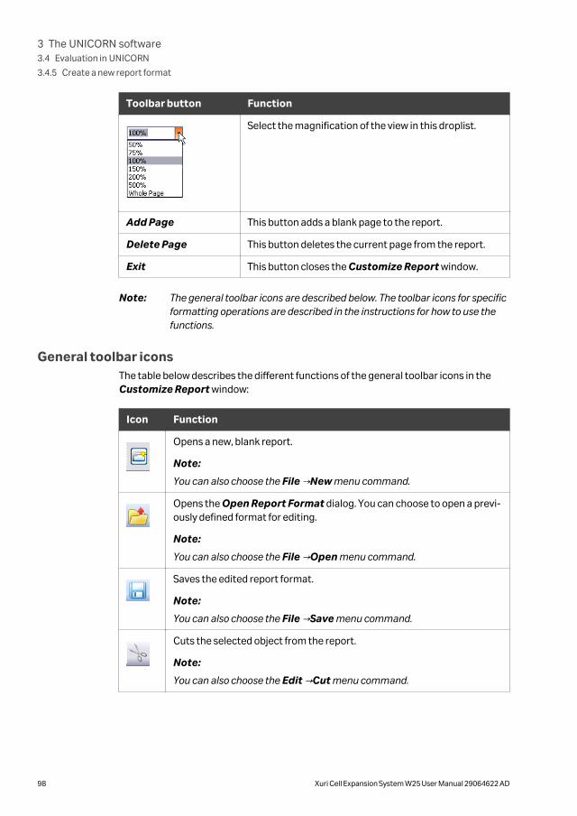
Toolbar button Function
Select the magnification of the view in this droplist.
Add Page This button adds a blank page to the report.
Delete Page This button deletes the current page from the report.
Exit This button closes the Customize Report window.
Note: The general toolbar icons are described below. The toolbar icons for specificformatting operations are described in the instructions for how to use thefunctions.
General toolbar iconsThe table below describes the different functions of the general toolbar icons in theCustomize Report window:
Icon Function
Opens a new, blank report.
Note:
You can also choose the File →New menu command.
Opens the Open Report Format dialog. You can choose to open a previ-ously defined format for editing.
Note:
You can also choose the File →Open menu command.
Saves the edited report format.
Note:
You can also choose the File →Save menu command.
Cuts the selected object from the report.
Note:
You can also choose the Edit →Cut menu command.
3 The UNICORN software3.4 Evaluation in UNICORN
3.4.5 Create a new report format
98 Xuri Cell Expansion System W25 User Manual 29064622 AD

Icon Function
Copies the selected object in the report.
Note:
You can also choose the Edit →Copy menu command.
Pastes a copied or cut object from the clipboard into the report.
Note:
You can also choose the Edit →Paste menu command.
Change the page layout
The page layout is changed in the Page Setup dialog. Follow the instructions below toset up the page layout:
Step Action
1 • Double-click anywhere on the report page (not on an object)
or
• Right-click (not on an object) and choose Properties from the shortcutmenu
or
• Choose the Edit →Page setup menu command.
Result: The Page Setup dialog box opens.
3 The UNICORN software3.4 Evaluation in UNICORN
3.4.5 Create a new report format
Xuri Cell Expansion System W25 User Manual 29064622 AD 99

Step Action
2 a. Type new values for the Margins if necessary.
b. Select the appropriate Settings and Unit.
Note:
An extra Header tab will appear if you de-select the option to have the sameheader on all pages. The First Header tab is used for the first page headeronly, and the Header tab is used for all subsequent pages.
3 a. Click the First Header tab.
b. Select all the items you want to include in the header from the SelectItems list.
c. Click the Font button to change the font for all items if necessary.
4 a. Type header text in the Free text box and click the Font button to alterthe default font if necessary. This text will be placed on top of the header.
b. Type the report title in the Report title box and click the Font button toalter the default font if necessary. The title is centered immediatelyabove the page contents.
5 If you want to have a line under or over the header, select the appropriateoption in the Layout field.
6 a. Repeat steps 3 to 5 on the Footer tab and the subsequent pagesHeader tab.
Note:
All Header and Footer tabs contain the same options. You can have allinformation in either the header or footer or split information between theheader and footer as required.
7 Click OK to apply the changes.
Report items toolbar iconsThe table below describes the different functions of the report items toolbar icons inthe Customize Report window:
Icon Function
Adds free text.
Adds a picture.
3 The UNICORN software3.4 Evaluation in UNICORN
3.4.5 Create a new report format
100 Xuri Cell Expansion System W25 User Manual 29064622 AD

Icon Function
Adds a chart.
Includes a method.
Adds documentation.
Adds an evaluation log.
Add objects to the report
Follow the instructions below to add objects to the report.
Step Action
1 • Click the appropriate icon in the Report items toolbar.
or
• Choose an object from the Insert menu.
2 a. Press and hold the left mouse button on the report page, and drag out abox to the size of the item you want to insert.
Note:
The mouse pointer shows a symbol for the type of item you have selected.
b. Release the mouse button.
Result:
A Setup dialog opens. The dialog is specific to the type of item that you wantto insert. For more information about the setup dialogs for each object, referto the online help.
3 a. Select the desired Settings, for example Start on new page, and clickOK.
Result:
The object is inserted onto the page.
Note: • If you want to edit an object later, double-click the object box.
• The size of the object in Edit mode does not always correspond to thesize in the printed report. Click Preview in the toolbar for a print preview.
3 The UNICORN software3.4 Evaluation in UNICORN
3.4.5 Create a new report format
Xuri Cell Expansion System W25 User Manual 29064622 AD 101

Move and resize objects freelyThe table below describes how to select, move and resize objects freely:
If you want to... then...
select a single object, • click the Select icon,
• click the object of interest.
select several objects, • click the Select icon,
• press and hold the Ctrl key while you click theobjects.
move the selectedobject(s),
click on the objects, hold down the left mouse buttonand drag the object(s) to the new position.
resize the selectedobject(s),
click one of the object border anchors, either in thecorners or in the middle of a border, and drag the box tothe new size.
Note:
Some Text objects cannot be resized.
Alignment toolbar icon functionsObjects can be placed in exact positions and sized in relation to other objects. The tablebelow describes the function of the Alignment toolbar icons in the Report Editor:
Icon Function
Align left
Matches the left alignment of all selected objects to that of the high-lighted object.
Align right
Matches the right alignment of all selected objects to that of the high-lighted object.
Align top
Matches the top alignment of all selected objects to that of the high-lighted object.
3 The UNICORN software3.4 Evaluation in UNICORN
3.4.5 Create a new report format
102 Xuri Cell Expansion System W25 User Manual 29064622 AD
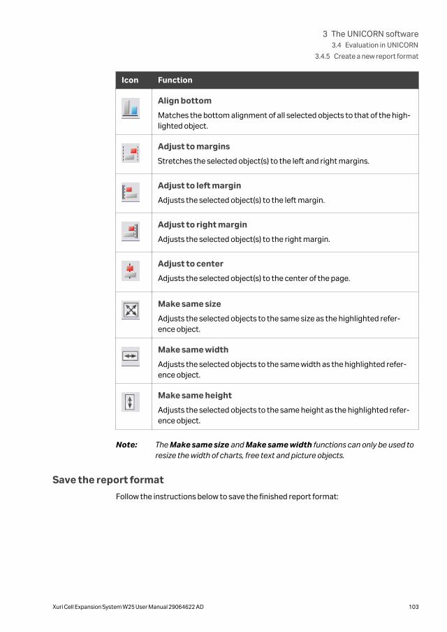
Icon Function
Align bottom
Matches the bottom alignment of all selected objects to that of the high-lighted object.
Adjust to margins
Stretches the selected object(s) to the left and right margins.
Adjust to left margin
Adjusts the selected object(s) to the left margin.
Adjust to right margin
Adjusts the selected object(s) to the right margin.
Adjust to center
Adjusts the selected object(s) to the center of the page.
Make same size
Adjusts the selected objects to the same size as the highlighted refer-ence object.
Make same width
Adjusts the selected objects to the same width as the highlighted refer-ence object.
Make same height
Adjusts the selected objects to the same height as the highlighted refer-ence object.
Note: The Make same size and Make same width functions can only be used toresize the width of charts, free text and picture objects.
Save the report format
Follow the instructions below to save the finished report format:
3 The UNICORN software3.4 Evaluation in UNICORN
3.4.5 Create a new report format
Xuri Cell Expansion System W25 User Manual 29064622 AD 103

Step Action
1 • Choose File →Save.
or
• Click the Save icon.
Result: The Save Report Format dialog box opens.
2 a. Type a name for the format.
b. Select if you want to save the format for global use.
c. Select if you want to save the format as default.
Note:
The name for the default format will automatically be changed to
DEFAULT.
3 a. Click OK to save the format.
3 The UNICORN software3.4 Evaluation in UNICORN
3.4.5 Create a new report format
104 Xuri Cell Expansion System W25 User Manual 29064622 AD

3.4.6 Edit an existing report format
IntroductionThis section describes how to edit an existing report format.
Note: Click the Preview/Edit mode button to toggle between a print preview ofthe report and an editing mode. The editing actions are only available in theEdit mode.
Edit a saved report format
Follow the instructions below to edit a saved report format in the Evaluation module.
Step Action
1 Open a result file.
2 • Select File →Report
or
• Click the Report icon.
Result: The Generate Report dialog opens.
3 a. Select a report format to edit.
b. Click the Edit button.
Result:
The Customize Report window opens.
4 a. Make the necessary changes to the report format.
Note:
Once you have made a change, the title bar of the window will add theword Modified to the report format name.
5 • Select File →Save
or
• Click the Save icon.
Result: The edited format is saved.
3 The UNICORN software3.4 Evaluation in UNICORN
3.4.6 Edit an existing report format
Xuri Cell Expansion System W25 User Manual 29064622 AD 105

Step Action
6 To return to the Evaluation module window:
• Select File →Exit
or
• Click the Exit button.
7 • Click the Close button to close the Generate Report dialog.
or
• Select another report format to edit.
Note: See Section 3.4.5 Create a new report format, on page 96 for instructionsabout how to add or edit report items. You can also select File →Save As inthe Customize Report window, to save the edited format under anothername and keep the original report format unchanged.
3 The UNICORN software3.4 Evaluation in UNICORN
3.4.6 Edit an existing report format
106 Xuri Cell Expansion System W25 User Manual 29064622 AD
4 System control description
About this chapterThis chapter describes important differences between single and dual mode, togetherwith details of pH, DO and media control. It also contains recommended operatingconditions and verification procedures for the system functions.
In this chapter
Section See page
4.1 Single and dual operation modes 108
4.2 Temperature measurement and control 109
4.3 pH and DO measurement and control 110
4.4 pH control 115
4.5 DO control 126
4.6 Media control 132
4.7 Recommended operating conditions 141
4.8 System verification 143
4 System control description
Xuri Cell Expansion System W25 User Manual 29064622 AD 107

4.1 Single and dual operation modes
IntroductionXuri Cell Expansion System W25 supports cell cultivation in single and dual modes:
• In single mode, the system supports culture in one Cellbag bioreactor at one time.The rocker is connected to one Xuri Cell Expansion W25 CBCU and up to three XuriCell Expansion W25 Pump units.
• In dual mode, the system supports culture in two Cellbag bioreactors placed on thesame tray. The rocker is connected to up to two Xuri Cell Expansion W25 CBCU unitsand up to three Xuri Cell Expansion W25 Pump units for independent control ofculture conditions in the two bioreactors.
Select an operation modeTo configure the system for single or dual mode, access the system properties asdescribed in Section 5.2.3 Configure system properties, on page 173 and uncheck orcheck Dual respectively.
4 System control description4.1 Single and dual operation modes
108 Xuri Cell Expansion System W25 User Manual 29064622 AD
4.2 Temperature measurement and control
DescriptionHeating is provided by the tray heater plate, and controlled through sensors integratedin the rocker. The heater power output is automatically adjusted according to theCellbag bioreactor size and media volume, to provide accurate, stable and fasttemperature control. To minimize the risk for overheating, heating is only active whenthe rocker is in motion.
When using a Cellbag bioreactor that only covers half the tray in single mode (forexample, a 10 L bag on Tray 20), place the bioreactor on the left-hand side of the tray.
In dual mode, different temperature setpoints can be used for the two Cellbag bioreac-tors, provided they are not too widely separated. A difference of 10°C between thesetpoints can be maintained at an ambient temperature of 21°C. The difference isreduced by 1°C for every °C increase in the ambient temperature (for example, a differ-ence of 6°C can be maintained at ambient temperature 25°C).
4 System control description4.2 Temperature measurement and control
Xuri Cell Expansion System W25 User Manual 29064622 AD 109

4.3 pH and DO measurement and control
About this sectionThis section describes the pH and DO measurement and control principles of Xuri CellExpansion System W25.
In this section
Section See page
4.3.1 pH and DO measurement principles 111
4.3.2 pH and DO control principles 113
4 System control description4.3 pH and DO measurement and control
110 Xuri Cell Expansion System W25 User Manual 29064622 AD

4.3.1 pH and DO measurement principles
IntroductionIn order to monitor and control pH and DO of a culture using Xuri Cell ExpansionSystem W25, it is necessary to use Cellbag bioreactors equipped with optical pH andDO sensors. The optical pH and DO sensors comprise a luminophoric dye immobilizedon a substrate that is integrated into the Cellbag bioreactor. Pulses of light from a LEDon the pH monitor produce a responsive light signal from the sensor that indicates thepH or DO surrounding the sensor. An optical fiber cable transfers the light signals.
Light and temperature sensitivityThe optical sensors are subject to photobleaching, which means its properties areaffected by light. This includes ambient light as well as the light from the LED. To reducephotobleaching avoid unnecessary exposure of the Cellbag bioreactor to light. Forexample:
• Keep the Cellbag in its protective black bag until shortly before use.
• Use the Rocker lid.
The LED output is automatically regulated to provide suitable amplitude for optimalperformance and life time of the sensor. The sensor is also temperature sensitive. ThepH and DO modules include temperature compensation for use within a few ºC aroundthe calibration temperature as printed on the Cellbag label.
Sensor calibrationCalibration parameters for the pH and DO sensors are printed on the Cellbag label. Thecalibration principles are described in pHOPT calibration values, on page 261 and DOOPT calibration values, on page 270. Calibration should be adjusted before each runas described in Section 5.3.5 Prepare the sensors, on page 193.
DO air saturation and atmosphericpressure
DO is measured as percent air saturation. 100% air saturation represents the oxygencontent of a certain solution at the current temperature and atmospheric pressurewhen it has been equilibrated in an environment of air. Air saturation is a relative meas-urement. The oxygen content measured in for example mg/L depends on factors suchas the composition of the solution, temperature and atmospheric pressure due todifferent weather conditions or altitude.
If a DO sensor is calibrated for 100% air saturation under equilibrated conditions at oneatmospheric pressure, such as 950 mbar, it will not show 100% air if the same contentis later equilibrated at another atmospheric pressure, say 1050 mbar. The difference isapproximately 1% air saturation/10 mbar.
4 System control description4.3 pH and DO measurement and control
4.3.1 pH and DO measurement principles
Xuri Cell Expansion System W25 User Manual 29064622 AD 111
At delivery, the DO configured Cellbag bioreactors have sensors that are factory cali-brated at a certain atmospheric pressure. This pressure is stated on the DO label asCalp and shall be entered together with the other calibration values for DO. Tocompensate for differences in atmospheric pressure from where the bag was cali-brated to where the cell culture will be performed, it is possible to adjust the DO cali-bration. To do this select System →Calibrate →DO sensor in UNICORN.
O2 measurement and altitudeThe O2 sensor measures the relative O2 concentration in terms of volume percent (vol%). The O2 concentration in the atmosphere is 21 vol% independently of altitude abovesea level and weather conditions. Since the most relevant parameter from a cell culti-vation perspective is the dissolved oxygen expressed as mg/L, different cell growthconditions will be obtained depending on the ambient pressure.
For instance, at 2000 m above sea level the ambient pressure is 0.8 bar (800 hPa). Therelative O2 concentration is 21 vol%, but compared to the conditions at sea level,where the ambient pressure is 1.013 bar (1013 hPa), the absolute O2 concentration inambient air at 2000 m corresponds to (800/1013) × 21 = 16.6 vol% of that at sea level.
Different growth conditions will therefore be obtained at high altitudes as compared tosea level.
4 System control description4.3 pH and DO measurement and control
4.3.1 pH and DO measurement principles
112 Xuri Cell Expansion System W25 User Manual 29064622 AD

4.3.2 pH and DO control principles
IntroductionpH and DO can be regulated through different control schemes as described in this
section. Each control mode can be either automatic or manual.
The reading and control cycleThe reading cycle time is the time between two consecutive measurements.
The reading Cycle time is set from the Process Picture under Settings →pH andSettings →DO, or with the manual instructions Set pH reading cycle time or Set DOreading cycle time.
When the control is off, the reading cycle time setting defines time between measure-ments. When the control is on, the reading cycle time will be overridden by the controlcycle time.
Note: Using DO reading with a short cycle time will shorten the lifetime of thesensor. For cultivations lasting more than 3 days, a cycle time of at least 60 sis recommended.
Measurements and control actions are synchronized. When a control is started, themeasurement cycle time is set by the control and overrides any previously enteredreading cycle time. The control is executed after each new measurement.
When the pH control executes, it sets the CO2 setpoint for the next control cycle (CO2mode), or starts the acid or base pump (Acid/Base mode) for a limited time (0%-75%of the next control cycle).
When the DO control executes, it sets the O2 setpoint for the next control cycle (O2mode), or sets the rocking speed setpoint for the next control cycle (Speed mode).
Automatic and manual modeThe pH and DO control software automatically calculates the following parameterssuitable for the actual control case, taking into account the bag size and gas flowsetpoint:
• Cycle time
• PID parameters
4 System control description4.3 pH and DO measurement and control
4.3.2 pH and DO control principles
Xuri Cell Expansion System W25 User Manual 29064622 AD 113
• Acid and base flow for pH control
• Transition delay time between CO2 and base in the CO2/Base control scheme andO2 and speed in the O2/Speed control scheme
The automatic parameters can be overridden with manually entered values. If any ofthe automatically computed values are overridden, a hand symbol ( ) appears close tothe relevant icon in the Process Picture. A tool tip shows which parameters are over-ridden when the cursor is placed over the symbol.
Deviation alarmsIf the reading has been outside the specified deviation limits of the setpoint for acertain time, a deviation alarm is activated by default.
The deviation alarm can be deactivated from the process picture using the checkboxunder the pH or DO settings or with the manual instruction pH control (general) orDO control (general).
After a change of the setpoint, the deviation alarm check is inactive until the reading iswithin the deviation limits of the new setpoint. If the interval within the deviation limitsis not reached within a time limit computed by the pH or DO control, the deviationalarm is triggered.
In the pH control CO2 mode, the time limit is equal to 40 times the automaticallycomputed control cycle time. In Acid/Base mode, the time limit is equal to 90 minutes.
In the DO control O2 mode, the time limit is equal to 40 times the automaticallycomputed control cycle time. In Speed mode, the time limit is equal to 180 minutes.
InactivationIf any of the conditions for running the pH or DO control is not fulfilled, the control willbe stopped. In this state the control remains inactive until all the necessary conditionsare fulfilled.
If the control is stopped, a red or orange frame will be visible around the pH/DO icon inthe process picture, and a message dialog will show why the control is inactive.
• An orange frame indicates that the inactivation is due to a user or system action,like entering sampling mode or feed/harvest auto calibration.
• A red frame indicates that the inactivation is due to an error.
4 System control description4.3 pH and DO measurement and control
4.3.2 pH and DO control principles
114 Xuri Cell Expansion System W25 User Manual 29064622 AD
4.4 pH control
About this sectionXuri Cell Expansion System W25 has automated pH control. In general, PID parametersand cycle times do not need to be entered or tuned, acid and base flow rates do notneed to be calibrated or tuned. Refer to Section 8.5.7 pH measurement, on page 261and Section 8.5.8 pH control, on page 263 for information about pH control settings.
In this section
Section See page
4.4.1 pH control schemes 116
4.4.2 CO2 control mode 118
4.4.3 Acid/Base control mode 120
4.4.4 pH control transition delays 125
4 System control description4.4 pH control
Xuri Cell Expansion System W25 User Manual 29064622 AD 115
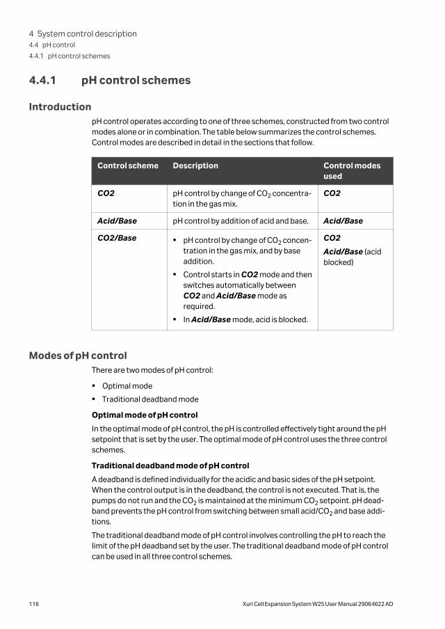
4.4.1 pH control schemes
IntroductionpH control operates according to one of three schemes, constructed from two controlmodes alone or in combination. The table below summarizes the control schemes.Control modes are described in detail in the sections that follow.
Control scheme Description Control modesused
CO2 pH control by change of CO2 concentra-tion in the gas mix.
CO2
Acid/Base pH control by addition of acid and base. Acid/Base
CO2/Base • pH control by change of CO2 concen-tration in the gas mix, and by baseaddition.
• Control starts in CO2 mode and thenswitches automatically betweenCO2 and Acid/Base mode asrequired.
• In Acid/Base mode, acid is blocked.
CO2
Acid/Base (acidblocked)
Modes of pH controlThere are two modes of pH control:
• Optimal mode
• Traditional deadband mode
Optimal mode of pH control
In the optimal mode of pH control, the pH is controlled effectively tight around the pHsetpoint that is set by the user. The optimal mode of pH control uses the three controlschemes.
Traditional deadband mode of pH control
A deadband is defined individually for the acidic and basic sides of the pH setpoint.When the control output is in the deadband, the control is not executed. That is, thepumps do not run and the CO2 is maintained at the minimum CO2 setpoint. pH dead-band prevents the pH control from switching between small acid/CO2 and base addi-tions.
The traditional deadband mode of pH control involves controlling the pH to reach thelimit of the pH deadband set by the user. The traditional deadband mode of pH controlcan be used in all three control schemes.
4 System control description4.4 pH control
4.4.1 pH control schemes
116 Xuri Cell Expansion System W25 User Manual 29064622 AD

Select pH control mode
Select the mode of pH control in deadband before starting a run.
Follow the steps below to select the mode of pH control in deadband:
Step Action
1 Select System →Settings in the System Control module.
2 Select pH control from the list and click the + symbol to view the availablealternatives.
3 Click on alternative pH control deadband mode.
4 Click one of the radio buttons Optimal or Traditional to select mode.
Note:The selected mode of deadband cannot be changed during a run.
5 Click OK to confirm the selection.
4 System control description4.4 pH control
4.4.1 pH control schemes
Xuri Cell Expansion System W25 User Manual 29064622 AD 117

4.4.2 CO2 control mode
IntroductionAt every execution of the CO2 control, a PID regulator computes the CO2 setpoint forthe next control cycle. The CO2 setpoint is by default limited to the range 0.0% to15.0%. This range can be narrowed using the manual instruction pH control (CO2).
Note: If CO2 is delivered by a source with pulsed supply, the resulting variations ininlet pressure to the CBCU may lead to fluctuations in the CO2 mix. Forexample, with a CO2 setpoint of 7.5%, the actual CO2 levels may fluctuatebetween 7% and 8%.
PID parameters and cycle timeThe control dynamics vary with Cellbag bioreactor size and depend on the gas flowrate. The PID-parameters and the cycle time are therefore automatically computedwith respect to the bag size and gas flow setpoint.
To optimize the control behavior, the automatic PID parameters are not the samewhen approaching a new setpoint as when keeping the setpoint. The automatic Dparameter is always zero.
Tuning PID parameters and cycletime
If further tuning of PID parameters and/or cycle time is needed, follow these steps:
Step Action
1 Open Tools →Customize and select the tab Run Data Groups.
Select the Auto pH CO2 P, Auto pH CO2 I and Auto pH CO2 D and clickOK.
Result:
The automatic PID parameters are shown as Run Data.
2 Register the values both when approaching the new setpoint, and whenkeeping the setpoint.
Tip:
The automatically computed values are a good starting point for the tuning.
4 System control description4.4 pH control
4.4.2 CO2 control mode
118 Xuri Cell Expansion System W25 User Manual 29064622 AD

Step Action
3 Open the manual instruction pH control (advanced) →pH control(advanced CO2) and select Manual PID parameter mode and/or Cycletime mode and enter the applicable values.
When elaborating with a manual I parameter, remember that increasing theI parameter will reduce the integrating effect and vice versa.
Click Execute.
4 System control description4.4 pH control
4.4.2 CO2 control mode
Xuri Cell Expansion System W25 User Manual 29064622 AD 119

4.4.3 Acid/Base control mode
IntroductionAt every control execution in Acid/Base control mode, a PI regulator computes thepump run time. The pump run time is given in percent of the cycle time in the range -75to 75, where the negative part corresponds to the acid pump, and the positive partcorresponds to the base pump. When using the CO2/Base control scheme, thecontrol output range is restricted to 0 to 75, to only allow base.
In the Acid/Base control mode, the flow rates of the acid and base pumps are adaptiveto the actual control case. They are automatically and individually set by the software,based on the weight of the content in the Cellbag bioreactor and the molarity of theacid and base. The flow rate is further discussed below.
PI parameters and cycle timeThe automatically computed PI-parameters are static in the Acid/Base control mode.They can be seen as default parameters. The same holds for the automatic cycle time.These automatic values should be good enough for most cases, and no tuning isexpected to be needed.
In the acid/base controller, the I-part of the output is only updated when the pH meas-urement is close to the setpoint. When elaborating with a manual I-parameter,remember that increasing the I-parameter will reduce the integrating effect and viceversa.
Tuning of PI parameters and cycletime
If tuning of the PI parameters or cycle time is needed, follow these steps:
Step Action
1 Open Tools →Customize and select the tab Run Data Groups.
Select the Auto pH acid/base P and Auto pH acid/base I and click OK.
Result:
The automatic PI parameters are shown as Run Data.
2 Open the manual instruction pH control (advanced) →pH control(advanced acid/base) and select Manual PID parameter mode and/orCycle time mode and enter the applicable values.
Click Execute.
Flow rateXuri Cell Expansion System W25 automatically computes flow rates for acid and base.There is no need for calibration or tuning of acid/base flow rates.
To make this automation work, the following input data needs to be correct:
4 System control description4.4 pH control
4.4.3 Acid/Base control mode
120 Xuri Cell Expansion System W25 User Manual 29064622 AD

• The molarity of the acid and base used, entered as equivalents of HCl or NaOHconcentrations. If weaker acids or bases are used, enter the estimated equivalentmolarity of HCl or NaOH.
• The weight measurement, corresponding to the weight of the content of theCellbag. Make sure the scale is tared correctly.
• The inner diameter of the acid and base tubing, allowing the flow rate to beconverted to pump speed in rpm. A pump calibration will make the relation moreprecise, but entering the tube diameter is normally sufficient for pH acid/basecontrol.
If the automatically computed flow rate is outside the range that can be achieved withthe entered tube diameter, the pH control software will inform the user that a differenttubing size is required for optimal control.
If desired, manual flow rates for acid and base can be entered using the manual instruc-tion pH control (advanced acid/base). This will override the automaticallycomputed flow rates.
DeadbandA deadband is defined for acid and base individually. When the control output is in thedeadband, the pumps will not run. pH deadband prevents the pH control fromswitching between small acid and base additions.
Optimal mode of pH control
32-75% 0% 75%
5
1
4
4 System control description4.4 pH control
4.4.3 Acid/Base control mode
Xuri Cell Expansion System W25 User Manual 29064622 AD 121

Number Description
1 pH setpoint
2 Control output
3 Acid deadband
4 Acid
5 Base
In the optimal mode of pH control, the deadband removes all acid/base additions with apump run time less than or equal to a given percentage of the cycle time. The defaultdeadband is set to 2.0%. This means that only pump run times larger than 2.0% of thecycle time are executed. The deadband prevents the control from switching betweensmall acid and base additions. Using deadband values close to zero gives a precisecontrol, but also risk unnecessary switching between acid and base. Increasing thedeadband values results in less precise control, and may in extreme cases lead to thesetpoint never being reached. The default value of 2.0% is found to be a good compro-mise. The deadband can be changed in System →Manual Instructions →pH control(optimal acid/base).
4 System control description4.4 pH control
4.4.3 Acid/Base control mode
122 Xuri Cell Expansion System W25 User Manual 29064622 AD

Traditional deadband mode of pHcontrol
The user can set a pH deadband in traditional deadband mode, which is defined interms of pH units having an upper pH limit and a lower pH limit. For example, if pH setpoint is 7.0 and the user defined deadband is ± 0.2, then pH control is inactive from 6.8to 7.2.
2 4 53
1
pH=0 pH=7 pH=14
Number Description
1 pH setpoint
2 (Acid) pH control on
3 Acid or CO2 deadband
4 Base deadband
5 Base pH control on
The implementation of traditional pH deadband is common in a wide range of bioreac-tors. The traditional pH deadband is operational in all three pH control schemes.
An upper limit and a lower limit of the deadband can be set by the user. The defaultupper and lower deadband values are set to 0.1. The deadband can be set between0.1% to 2 pH units on each sitde of the setpoint.
While residing in traditional deadband, in the CO2 and the CO2/Base scheme ofcontrol, the minimum CO2 % that is set by the user is maintained.
4 System control description4.4 pH control
4.4.3 Acid/Base control mode
Xuri Cell Expansion System W25 User Manual 29064622 AD 123

For examples of process pictures for the different pH control schemes, see Processpicture when in traditional deadband mode, on page 199.
The help text for the traditional deadband mode provides valuable information. Click
the symbol with the question mark in the blue square in the left corner of thescreen to launch the help text.
4 System control description4.4 pH control
4.4.3 Acid/Base control mode
124 Xuri Cell Expansion System W25 User Manual 29064622 AD
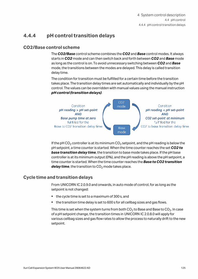
4.4.4 pH control transition delays
CO2/Base control schemeThe CO2/Base control scheme combines the CO2 and Base control modes. It alwaysstarts in CO2 mode and can then switch back and forth between CO2 and Base modeas long as the control is on. To avoid unnecessary switching between CO2 and Basemode, the transitions between the modes are delayed. This delay is called transitiondelay time.
The condition for transition must be fulfilled for a certain time before the transitiontakes place. The transition delay times are set automatically and individually by the pHcontrol. The values can be overridden with manual values using the manual instructionpH control (transition delays).
If the pH CO2 controller is at its minimum CO2 setpoint, and the pH reading is below thepH setpoint, a time counter is started. When the time counter reaches the set CO2 tobase transition delay time, the transition to base mode takes place. If the pH basecontroller is at its minimum output (0%), and the pH reading is above the pH setpoint, atime counter is started. When the time counter reaches the Base to CO2 transitiondelay time, the transition to CO2 mode takes place.
Cycle time and transition delays
From UNICORN IC 2.0.9.0 and onwards, in auto mode of control, for as long as thesetpoint is not changed:
• the cycle time is set to a maximum of 300 s, and
• the transition time delay is set to 600 s for all cellbag sizes and gas flows.
This time is set when the system turns from both CO2 to Base and Base to CO2. In caseof a pH setpoint change, the transition times in UNICORN IC 2.0.8.0 will apply forvarious cellbag sizes and gas flow rates to allow the process to naturally drift to the newsetpoint.
4 System control description4.4 pH control
4.4.4 pH control transition delays
Xuri Cell Expansion System W25 User Manual 29064622 AD 125

4.5 DO control
About this sectionXuri Cell Expansion System W25 has automated DO control using O2. In general, PIDparameters and cycle times do not need to be entered or tuned. Refer to Section 8.5.9DO measurement, on page 270 and Section 8.5.10 DO control, on page 272 for informa-tion about DO control settings.
In this section
Section See page
4.5.1 DO control schemes 127
4.5.2 O2 control mode 128
4.5.3 Speed control mode 130
4.5.4 O2/Speed control scheme 131
4 System control description4.5 DO control
126 Xuri Cell Expansion System W25 User Manual 29064622 AD
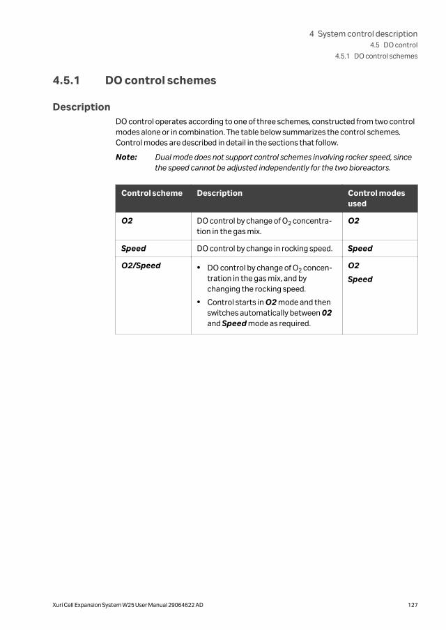
4.5.1 DO control schemes
DescriptionDO control operates according to one of three schemes, constructed from two controlmodes alone or in combination. The table below summarizes the control schemes.Control modes are described in detail in the sections that follow.
Note: Dual mode does not support control schemes involving rocker speed, sincethe speed cannot be adjusted independently for the two bioreactors.
Control scheme Description Control modesused
O2 DO control by change of O2 concentra-tion in the gas mix.
O2
Speed DO control by change in rocking speed. Speed
O2/Speed • DO control by change of O2 concen-tration in the gas mix, and bychanging the rocking speed.
• Control starts in O2 mode and thenswitches automatically between 02and Speed mode as required.
O2
Speed
4 System control description4.5 DO control
4.5.1 DO control schemes
Xuri Cell Expansion System W25 User Manual 29064622 AD 127

4.5.2 O2 control mode
IntroductionAt every execution of the O2 control, a PID regulator computes the O2 setpoint for thenext control cycle. There are two different O2 setpoint ranges. If compressed air isselected as gas source to the CBCU the range is 21% to 50%, if N2 is selected, the rangeis 0% to 50%.
PID parameters and cycle timeThe control dynamics differ between the different bag sizes and depend on the rate ofgas flow. The PID-parameters and the cycle time are therefore automaticallycomputed with respect to the bag size and gas flow setpoint.
To optimize the control behavior, the automatic PID parameters are not the samewhen approaching a new setpoint as when keeping the setpoint. The automatic Dparameter is always zero.
Tuning PID parameters and cycletime
If further tuning of PID parameters and/or cycle time is needed, follow these steps:
Step Action
1 Open Tools →Customize and select the tab Run Data Groups.
Select the Auto DO O2 P, Auto DO O2 I and Auto DO O2 D and click OK.
Result:
The automatic PID parameters are shown as Run Data.
2 Register the values both when approaching the new setpoint, and whenkeeping the setpoint.
Tip:
These automatic values are a good starting point for the tuning.
4 System control description4.5 DO control
4.5.2 O2 control mode
128 Xuri Cell Expansion System W25 User Manual 29064622 AD

Step Action
3 Open the manual instruction DO control (advanced) →DO control(advanced O2) and select Manual PID parameter mode and/or Cycletime mode and enter the desired values.
When adjusting a Manual I parameter, remember that increasing the Iparameter will reduce the integrating effect and vice versa.
Click Execute.
4 System control description4.5 DO control
4.5.2 O2 control mode
Xuri Cell Expansion System W25 User Manual 29064622 AD 129

4.5.3 Speed control mode
IntroductionAt every execution of the speed control, the DO reading is compared with the DOsetpoint. If the DO reading is below the DO setpoint, the rocking speed setpoint isincreased. If the DO reading is above the DO setpoint, the rocking speed setpoint isdecreased.
The settings of the DO speed mode can be set from the Process Picture or by usingthe manual instruction DO control (speed).
Speed control cannot be used in dual mode.
Speed stepThe Speed step parameter defines the size of the change of the rocking speedsetpoint.
Maximum and minimum rockingspeed
The Max and Min speed parameters define the interval in which the DO controller canset the rocking speed setpoint.
DeadbandThe upper and lower deadband parameters defines the deadband interval around theDO setpoint. When the DO reading is in that interval, no change of the rocking speedsetpoint will take place.
Cycle timeThe cycle time parameter sets the cycle time of the DO speed control. This cycle timewill override the DO reading cycle time when the DO control is on.
4 System control description4.5 DO control
4.5.3 Speed control mode
130 Xuri Cell Expansion System W25 User Manual 29064622 AD

4.5.4 O2/Speed control scheme
DescriptionThe O2/Speed control scheme combines the O2 and Speed control modes. It alwaysstarts in O2 mode and can then switch back and forth between O2 and Speed mode aslong as the control is on. To avoid unnecessary switching between O2 and Speedmode, the transitions between the modes are delayed. This delay is called transitiondelay time.
The O2/Speed control cannot be used in dual mode.
Transition delaysThe condition for transition must be fulfilled for a certain time before the transitiontakes place. The transition delay times are set automatically and individually by the DOcontrol. The values can be overridden with manual values using the manual instructionDO control (advanced) →DO control (transition delays).
If the DO O2 controller is at its maximum O2 setpoint 50%, and the DO reading is belowthe DO setpoint, a time counter is started. When the time counter reaches the set O2to speed transition delay time, the transition to Speed mode takes place. If the DOspeed controller is at its minimum rocking speed setpoint, and the DO reading is abovethe DO setpoint, a time counter is started. When the time counter reaches the Speedto O2 transition delay time, the transition to O2 mode takes place.
Cycle time and transition delays
From UNICORN IC 2.0.9.0 and onwards, in auto mode of control, for as long as thesetpoint is not changed:
• the cycle time is set to a maximum of 300 s, and
• the transition time delay is set to 600 s for all cellbag sizes and gas flows.
This time is set when the system turns from both O2 to Speed and Speed to O2. In caseof a pH setpoint change, the transition times in UNICORN IC 2.0.8.0 will apply forvarious cellbag sizes and gas flow rates to allow the process to naturally drift to the newsetpoint.
4 System control description4.5 DO control
4.5.4 O2/Speed control scheme
Xuri Cell Expansion System W25 User Manual 29064622 AD 131
4.6 Media control
About this sectionThe media control has two modes: Media addition and Perfusion, as described in thefollowing sections. A complete description of all settings and output data is found in Section 8.5.11 Media control, on page 276.
Media control can be used in dual mode, but the accuracy will be lower than in singlemode (see Section 4.6.1 Weight measurement, on page 133).
In this section
Section See page
4.6.1 Weight measurement 133
4.6.2 Media addition 134
4.6.3 Perfusion 135
4.6.4 Deviation alarm 139
4.6.5 Media control inactivation 140
4 System control description4.6 Media control
132 Xuri Cell Expansion System W25 User Manual 29064622 AD

4.6.1 Weight measurement
Introduction
Media control relies on continuous measurement of the weight of the bioreactorcontents, and maintains the weight at the setpoint by controlled addition of mediausing the feed pump.
Principles of weight measurementCellbag bioreactor and cell culture weights are measured by four load cells, placed atthe corners of the rocker unit. In dual mode, the separate weight of each Cellbagbioreactor is calculated from the weight distribution between the load cells. It is impor-tant for correct weight measurements that the rocker is placed on a flat stable surface,and that the measurements are tared before each cultivation. See Tare the scale, onpage 190 for instructions on how to tare the weight measurement.
The load cells are temperature-sensitive. It is important that a constant ambienttemperature is maintained for the duration of a run.
Limitations in dual modeIn single mode, all four load cells contribute to the weight measurement of the singleCellbag bioreactor. In dual mode, the separate weights of the two bioreactors arecalculated from the weight distribution between the load cells, with a predominantcontribution from two of the load cells for each bioreactor. The accuracy of the totalweight measurement is the same as in single mode, but the accuracy of separateCellbag weights is slightly reduced.
Dual weight measurements are primarily used to support regulation of temperatureand pH, and the reduced accuracy is adequate for this purpose. Media control ofculture in dual mode will have somewhat reduced accuracy compared with singlemode.
The left and right bioreactor weights are displayed in the process picture with a resolu-tion of 0.1 kg. This is useful, for example, when filling the bioreactor with medium, butcultivation in single mode or the use of an external scale is recommended if highweighing accuracy is required.
The accuracy of separate weight measurements also depends on the position of theCellbag bioreactors on the tray. A sideways displacement of a bioreactor by 10 mmmay add about 3% of the load to the weighing error. Since the bioreactor may moveduring rocking, it is important to make sure that the bench (and therefore the rocker) isstable and horizontal.
4 System control description4.6 Media control
4.6.1 Weight measurement
Xuri Cell Expansion System W25 User Manual 29064622 AD 133
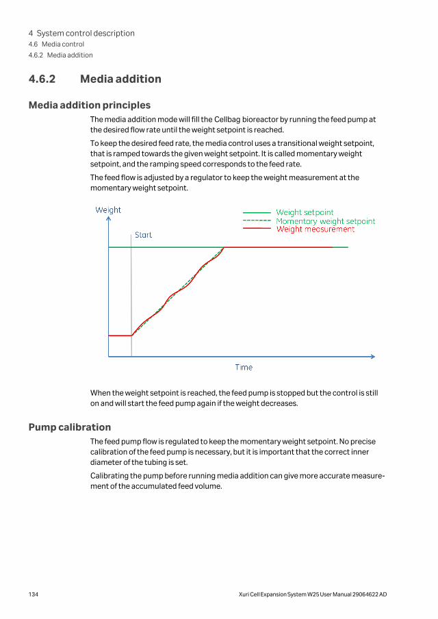
4.6.2 Media addition
Media addition principlesThe media addition mode will fill the Cellbag bioreactor by running the feed pump atthe desired flow rate until the weight setpoint is reached.
To keep the desired feed rate, the media control uses a transitional weight setpoint,that is ramped towards the given weight setpoint. It is called momentary weightsetpoint, and the ramping speed corresponds to the feed rate.
The feed flow is adjusted by a regulator to keep the weight measurement at themomentary weight setpoint.
When the weight setpoint is reached, the feed pump is stopped but the control is stillon and will start the feed pump again if the weight decreases.
Pump calibrationThe feed pump flow is regulated to keep the momentary weight setpoint. No precisecalibration of the feed pump is necessary, but it is important that the correct innerdiameter of the tubing is set.
Calibrating the pump before running media addition can give more accurate measure-ment of the accumulated feed volume.
4 System control description4.6 Media control
4.6.2 Media addition
134 Xuri Cell Expansion System W25 User Manual 29064622 AD

4.6.3 Perfusion
IntroductionIn perfusion mode the feed pump will add medium at a desired flow, and the harvest/waste pump flow is controlled by a regulator to keep the given weight setpoint.
The true feed flow is dependent of how well the feed pump is calibrated. To make thecalibration more convenient and to compensate for tubing wear out, auto calibrationof the feed and harvest/waste pumps is enabled by default.
Perfusion principlesWhen starting the media control, the feed or harvest/waste pump will run alone untilthe weight setpoint is reached. When the setpoint is reached, "normal perfusion" startsand both pumps will run. If the weight setpoint is changed while in "normal perfusion",one of the pumps will run alone until the new setpoint is reached.
The figure below shows a run where the control is started with the measured weightbelow the weight setpoint. After a while, the setpoint is decreased.
Pump calibrationIn perfusion mode, the actual feed flow rate depends on the accuracy of pump calibra-tion.
When auto calibration is not used, at least the feed pump must be calibrated manually.It is however recommended to also calibrate the harvest/waste pump, since unneces-sary warnings for harvest/waste filter clogging might be given otherwise. The accumu-lated volume will be more precisely computed if the pump is calibrated.
4 System control description4.6 Media control
4.6.3 Perfusion
Xuri Cell Expansion System W25 User Manual 29064622 AD 135

For a detailed description of pump calibration see Section 6.2 Pump calibration, onpage 210.
Auto calibration
Auto calibration is a convenient and precise way of letting the system calibrate thefeed and harvest/waste pumps automatically. The system runs the feed and harvest/waste pumps one at the time, carefully measures the weight before and after runningthe pump, and then computes the weight difference used as calibration input to thepump.
The auto calibration function provides a convenient and precise option for automaticcalibration of the feed and harvest pumps. The steps in auto calibration are listedbelow.
Step Action
1 A message is sent to inform the user that auto calibration has started.
2 The pumps stop.
3 The system pauses for 15 seconds.
4 Weight measurements are averaged over a period of 30 seconds.
5 The harvest/waste pump runs at the perfusion flow rate setpoint for 2 to 30minutes depending on the setpoint value.
6 The system pauses for 15 seconds.
7 Weight measurements are averaged over a period of 30 seconds.
8 A calibration command is sent to the harvest/waste pump, estimating thepumped volume by the measured weight difference between the secondand the first weight average.
9 The feed pump runs at the perfusion flow rate setpoint for 2 to 30 minutesdepending on the setpoint value.
10 Weight measurements are averaged over a period of 30 seconds.
11 A calibration command is sent to the feed pump, calculating the pumpedvolume from the measured weight difference between the third and thesecond weight average (assuming a density equal to 1).
12 The results of auto calibration can be seen in the feed and harvest calibra-tion factor curves in the curve data chart.
An advantage of auto calibration compared with manual procedures is that it isperformed on the system as set up for the run, with no open tubing ends or manualmeasurement of pumped volume.
4 System control description4.6 Media control
4.6.3 Perfusion
136 Xuri Cell Expansion System W25 User Manual 29064622 AD

Auto calibration calculates volume flow rates from measured weight using a liquiddensity equal to 1. If the density of the medium differs from 1, the flow rate given inL/day should be read as kg/day instead.
If perfusion is running at the weight setpoint with both pumps operating and the autocalibration disabled, enabling auto calibration will trigger an immediate auto calibra-tion.
Note: During auto calibration, it is important that the weight measurements arenot disturbed by external influences such as touching the system or insta-bility of the bench. If an auto-calibration is disturbed, disable and re-enablethe function to trigger a new auto calibration.
The accuracy of auto calibration may be slightly lower in dual mode than insingle mode (see Limitations in dual mode, on page 133).
Auto calibration cycle
The figure below shows auto calibrations during a perfusion run. The first auto calibra-tion is done when the weight setpoint is reached. This calibration replaces the manualcalibration needed before starting if auto calibration is disabled. After that, the autocalibration is repeated with the interval given in the manual instruction Media control(general). When changing the flow rate or the weight setpoint, a new auto calibrationwill be done. Thereafter they will continue with the given frequency.
Auto calibration criteriaThe calibration volume is depending on the flow rate, and is computed to make anoptimal compromise between pump time and accuracy. The pump calibration run timeis limited between 2 and 30 minutes for each pump. A low flow rate will give a long cali-bration time and a high flow rate will give a short calibration time.
4 System control description4.6 Media control
4.6.3 Perfusion
Xuri Cell Expansion System W25 User Manual 29064622 AD 137

If the flow rate setpoint is below 3.43 L/day, no auto calibration can be done, sinceachieving a volume large enough to get the desired accuracy would demand a pumprun time longer than 30 minutes.
If auto calibration is enabled, and the criteria above cannot be fulfilled, the mediacontrol cannot start unless the flow rate is increased or the auto calibration is disabled.
Recommended weight setpointsThe media control will not start if the weight setpoint is outside the possible rangeshown in the table below.
Cellbag size(L)
Recommended weightsetpoint (kg)
Permitted weight setpoint(kg) (SW limited)
2 0.5 to 1.0 0.2 to 1.0
10 2.5 to 5.0 1.0 to 5.0
20 5.0 to 10.0 2.0 to 10.0
22 5.0 to 10.0 2.0 to 10.0
50 12.5 to 25.0 5.0 to 25.0
For the perfusion to work satisfactory, it is important to ensure that the harvest/wastefilter and harvest/waste out-port is completely covered by liquid through the wholerocking cycle.
If the harvest/waste out-port is not always covered by liquid, unnecessary warnings forharvest/waste filter clogging might be given. If auto calibration is used, it will not cali-brate the harvest/waste pump correctly.
Emergency stop of pumpsTo avoid overfilling or draining the Cellbag due to for example lack of feed media,harvest/waste filter clogging or tubing error, the feed or harvest/waste pump will stopwhen the weight measurement deviates more than 10% from the weight setpoint. Thestopped pump will start again when the setpoint is reached.
4 System control description4.6 Media control
4.6.3 Perfusion
138 Xuri Cell Expansion System W25 User Manual 29064622 AD

4.6.4 Deviation alarm
Alarm conditionsBy default, a deviation alarm is activated. It will send a message when the weightreading has been outside the specified toleration limits of the weight setpoint for acertain time.
The deviation alarm can be deactivated using the manual instruction Media control(general).
During media addition, the deviation alarm is acting on the momentary weightsetpoint.
During perfusion, the deviation alarm is active only in normal perfusion when bothpumps are running.
4 System control description4.6 Media control
4.6.4 Deviation alarm
Xuri Cell Expansion System W25 User Manual 29064622 AD 139

4.6.5 Media control inactivation
DescriptionIf any of the conditions for running the Media control is suddenly not fulfilled whenrunning the control, the control will turn into inactive state. In this state the control isnot doing anything until all the necessary conditions are fulfilled again. Then thecontrol will then start again.
When the control inactivate, a red or orange frame will be visible around the Mediacontrol icon in the process picture. A message dialog will show why the control is inac-tive.
• An orange frame indicates that the inactivation is due to sampling mode.
• A red frame indicates that the inactivation is due to an error.
4 System control description4.6 Media control
4.6.5 Media control inactivation
140 Xuri Cell Expansion System W25 User Manual 29064622 AD

4.7 Recommended operating conditions
IntroductionThis section includes recommendations for gas flow, rocking speed and rocking angle.Suitable settings for temperature, pH, DO, CO2 and O2 are selected depending on theapplication and system configuration. For more information about rocker controlsettings, refer to Section 8.5.1 Rocking control, on page 251.
Rocking speed and angleThe optimal agitation for a process is determined by the cell culture oxygen demandand the cellular shear sensitivity. Rocking speed and angle should be set so that suffi-cient mixing and oxygen transfer is provided without excessive foaming.
Note: Cells cultivated at low rocking speed and angle may form a sediment on thesensors in the Cellbag bioreactor, reducing the reliability of the sensors.
• The culture volume affects mixing and oxygen transfer rate. Lower volumes givefaster oxygen transfer and mixing.
• Increasing the rocking speed and angle will result in faster oxygen transfer andmixing.
• If no clear wave appears inside the Cellbag bioreactor, increase the rocking speed.(If the speed is limited by other parameters, try decreasing the speed slightly.)
• For cultures with high oxygen demand, such as a suspension CHO cells, rockingspeed and angle can be increased up to for example 30 rpm and 8 degrees, respec-tively.
• For shear sensitive cells, such as adherent cells on microcarriers, rocking speedand/or angle can be decreased down to 10 rpm and 4 degrees, if sufficient oxygentransfer and mixing is maintained.
Each new cell line and process requires optimization of operating conditions. The tablebelow shows typical rocking speed and gas flow settings for suspension cell culture.
Cellbagbioreactorsize (L)
Culturevolume (L)
Rockingspeed (rpm)
Rockingangle (°)
Gas flow(Lpm)
2 0.3 10 to 20 2 to 4 0.05 to 0.2
1 20 to 30 6 to 8 0.05 to 0.2
10 0.5 10 to 20 2 to 4 0.1 to 0.3
5 20 to 30 6 to 8 0.1 to 0.3
20 1 10 to 20 2 to 4 0.2 to 0.5
10 20 to 30 6 to 8 0.2 to 0.5
4 System control description4.7 Recommended operating conditions
Xuri Cell Expansion System W25 User Manual 29064622 AD 141

Cellbagbioreactorsize (L)
Culturevolume (L)
Rockingspeed (rpm)
Rockingangle (°)
Gas flow(Lpm)
50 5 10 to 20 2 to 4 0.5 to 1.0
25 20 to 30 6 to 8 0.5 to 1.0
Note: When cultivating in a 50 L Cellbag bioreactor at maximum working volumeof 25 L, rocking speed and angle multiplied should not exceed 240 rpmdegrees. For example, if the rocking angle is set to 8 degrees, the rockingspeed should not be set higher than 30 rpm.
Rocking motionThe rocking motion factor determines how much of the rocking cycle is used for accel-erating and decelerating the rocker motion at the turning points. For example, with thedefault setting of 30%, 15% of the rocking cycle is used for accelerating after theturning point and 15% for decelerating before the turning point. The rocking speed isconstant for the remaining 70% of the cycle. The rocking motion factor can be setbetween 15% and 100%. A lower factor will give slightly higher oxygen transfer rateand mixing capacity whereas higher factors profiles can reduce shear forces, which isespecially important when cultivating adherent cells on microcarriers.
Gas flowThe gas flow rate has little effect on oxygen transfer and can therefore be keptconstant throughout the entire run.
When setting the gas flow rate the following should be taken into consideration:
• A high gas flow can cause unnecessary evaporation
• A low gas flow can slow down pH and DO control when using CO2 and O2 gas.
• A too low gas flow can lead to insufficient inflation of the Cellbag bioreactor.
Refer to the table in Rocking speed and angle, on page 141 for recommendations onsuitable gas flow rates.
Recommendations to reducefoaming
To reduce foaming, the following should be taken into consideration:
• Higher agitation rates can contribute to excessive foaming. This can be reduced byadding antifoam, or by decreasing the rocking speed and/or angle.
• Excessive foaming occurs if the Cellbag bioreactor is not rigidly inflated. Check thatthe gas flow is sufficient and that the pressure relief valve is functioning.
4 System control description4.7 Recommended operating conditions
142 Xuri Cell Expansion System W25 User Manual 29064622 AD
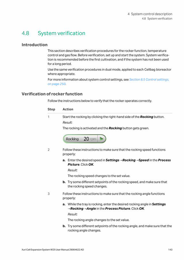
4.8 System verification
IntroductionThis section describes verification procedures for the rocker function, temperaturecontrol and gas flow. Before verification, set up and start the system. System verifica-tion is recommended before the first cultivation, and if the system has not been usedfor a long period.
Use the same verification procedures in dual mode, applied to each Cellbag bioreactorwhere appropriate.
For more information about system control settings, see Section 8.5 Control settings,on page 250.
Verification of rocker function
Follow the instructions below to verify that the rocker operates correctly.
Step Action
1 Start the rocking by clicking the right-hand side of the Rocking button.
Result:
The rocking is activated and the Rocking button gets green.
2 Follow these instructions to make sure that the rocking speed functionsproperly:
a. Enter the desired speed in Settings →Rocking →Speed in the ProcessPicture. Click OK.
Result:
The rocking speed changes to the set value.
b. Try some different setpoints of the rocking speed, and make sure thatthe rocking speed changes.
3 Follow these instructions to make sure that the rocking angle functionsproperly:
a. While the tray is rocking, enter the desired rocking angle in Settings→Rocking →Angle in the Process Picture. Click OK.
Result:
The rocking angle changes to the set value.
b. Try some different setpoints of the rocking angle, and make sure that therocking angle changes.
4 System control description4.8 System verification
Xuri Cell Expansion System W25 User Manual 29064622 AD 143
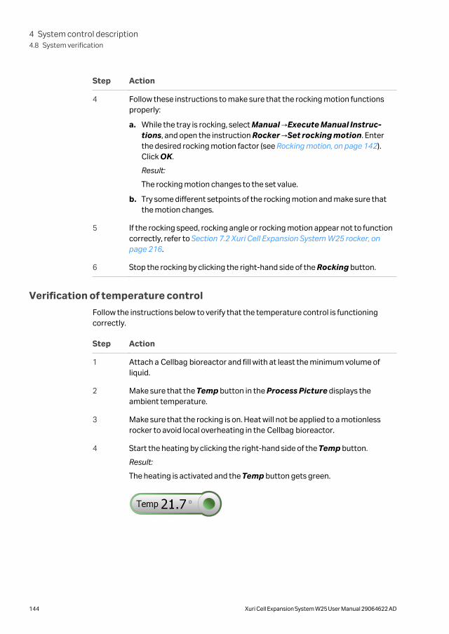
Step Action
4 Follow these instructions to make sure that the rocking motion functionsproperly:
a. While the tray is rocking, select Manual →Execute Manual Instruc-tions, and open the instruction Rocker →Set rocking motion. Enterthe desired rocking motion factor (see Rocking motion, on page 142).Click OK.
Result:
The rocking motion changes to the set value.
b. Try some different setpoints of the rocking motion and make sure thatthe motion changes.
5 If the rocking speed, rocking angle or rocking motion appear not to functioncorrectly, refer to Section 7.2 Xuri Cell Expansion System W25 rocker, onpage 216.
6 Stop the rocking by clicking the right-hand side of the Rocking button.
Verification of temperature control
Follow the instructions below to verify that the temperature control is functioningcorrectly.
Step Action
1 Attach a Cellbag bioreactor and fill with at least the minimum volume ofliquid.
2 Make sure that the Temp button in the Process Picture displays theambient temperature.
3 Make sure that the rocking is on. Heat will not be applied to a motionlessrocker to avoid local overheating in the Cellbag bioreactor.
4 Start the heating by clicking the right-hand side of the Temp button.
Result:
The heating is activated and the Temp button gets green.
4 System control description4.8 System verification
144 Xuri Cell Expansion System W25 User Manual 29064622 AD

Step Action
5 Enter the temperature 40.0 in Settings →Temp →Setpoint in the ProcessPicture. Click OK.
Result:
The temperature starts to increase to the set temperature value.
CAUTION
To avoid overheating, do not operate the heater withoutliquid in the Cellbag bioreactor on the tray.
6 Select the Chart tab and make sure that the temperature curve shows theincrease in temperature.
7 If the temperature control appears not to function correctly, refer to Section7.2 Xuri Cell Expansion System W25 rocker, on page 216.
8 Stop the heating by clicking the right-hand side of the Temp button.
9 Stop the rocking by clicking the right-hand side of the Rocking button.
Verification of gas flow
Follow the instructions below to verify that the gas flow is functioning correctly.
Step Action
1 Make sure that the desired gas supplies are connected to the system. Referto Section 5.1.6 Connect gas to the system, on page 164.
2 In the Process Picture, click the Compressed Air button to selectcompressed air, or the N2 button to select N2.
3 Enter the gas flow setpoint 0.50 in Settings →Gas control →Gas flow→Setpoint in the Process Picture. Click OK.
4 Start the gas flow by clicking the right-hand side of the Gas flow button.
Result:
The gas flow starts to increase to the gas flow setpoint.
4 System control description4.8 System verification
Xuri Cell Expansion System W25 User Manual 29064622 AD 145

Step Action
5 Verify that the overpressure alarm is functioning by blocking the gas flow inthe Gas mix tubing.
Result:
After about 5 seconds an overpressure alarm should be activated and thegas flow should stop automatically.
If the gas flow appears not to function correctly, refer to Section 7.3 Xuri CellExpansion W25 CBCU, on page 220.
6 Stop the gas flow by clicking the right-hand side of the Gas flow button.
Verification of CO2
Follow the instructions below to verify that CO2 is functioning correctly.
Step Action
1 Start the gas flow by clicking the right-hand side of the Gas flow button.
2 Enter a gas flow setpoint, for example 0.2 L/min, in Settings →Gas control→Gas flow →Setpoint. Click OK.
3 Enter a CO2 setpoint, for example 5%, in Settings →Gas control →CO2→Setpoint. Click OK.
4 Wait for a few minutes and verify that the Process Picture shows a correctmeasurement.
If the gas flow appears not to function correctly, refer to Section 7.3 Xuri CellExpansion W25 CBCU, on page 220.
Verification of O2
Follow the instructions below to verify that O2 is functioning correctly.
Step Action
1 Enter an O2 setpoint, for example 30%, in Settings →Gas control →O2→Setpoint. Click OK.
2 Wait for a few minutes and verify that the Process Picture shows a correctmeasurement.
If the gas flow appears not to function correctly, refer to Section 7.3 Xuri CellExpansion W25 CBCU, on page 220.
Verification of fast fill function
Follow these instructions to make sure that the Fast fill functions properly:
4 System control description4.8 System verification
146 Xuri Cell Expansion System W25 User Manual 29064622 AD

Step Action
1 Open Settings →Gas control →Gas flow from the Process Picture inSystem Control.
2 Set Fast fill to On.
3 Start the gas flow by clicking the right-hand side of the Gas flow button inthe Process Picture.
Result:
The gas flow is maximized to 3 L/min for 20 minutes or until Fast fill ismanually turned off. The cellbag is inflated.
4 Stop the gas flow when the cellbag has been fully inflated, by clicking theright-hand side of the Gas flow button.
4 System control description4.8 System verification
Xuri Cell Expansion System W25 User Manual 29064622 AD 147

5 Operation
About this chapterThis chapter describes how to operate Xuri Cell Expansion System W25.
In this chapter
Section See page
5.1 Set up the system 149
5.2 Start and configure the system 169
5.3 Prepare for cultivation 186
5.4 Perform cultivation 196
5 Operation
148 Xuri Cell Expansion System W25 User Manual 29064622 AD

5.1 Set up the system
About this sectionThis section describes how to prepare the bioreactor system for cell cultivation. Forillustrations and descriptions of the system, refer to Chapter 2 System description, onpage 11.
In this section
Section See page
5.1.1 Select the tray and Cellbag bioreactor 150
5.1.2 Attach and detach tray 151
5.1.3 Prepare pH and DO sensors 154
5.1.4 Attach the Cellbag bioreactor 157
5.1.5 Prepare the pump 159
5.1.6 Connect gas to the system 164
5.1.7 Connect the filter heater to the rocker 168
5 Operation5.1 Set up the system
Xuri Cell Expansion System W25 User Manual 29064622 AD 149

5.1.1 Select the tray and Cellbag bioreactor
Select the Cellbag bioreactor size and corresponding tray according to applicationrequirements and system configuration. See the table below for guidelines.
Culture volume/bioreactor (L)
Cellbagbioreactor size (L)
Tray
Single mode Dual mode
0.3 to 1 2 Tray 10, Tray 20 Tray 20
0.5 to 5 10 Tray 10, Tray 20 Tray 20
1 to 10 20 Tray 20 N/A
1 to 10 22 Tray 50 Tray 50
5 to 25 50 Tray 50 N/A
Note: To use a 20 L or 50 L Cellbag bioreactor, the system must be configured forsingle mode.
Note: Depending on application and configuration it might be possible to cultivatebelow the recommended minimum volume. However, it is highly recom-mended to stay above this volume for applications that require high agita-tion, and pH and DO control. The temperature, pH, and DO sensors need tobe submerged in liquid throughout the complete rocking cycle to functioncorrectly.
5 Operation5.1 Set up the system
5.1.1 Select the tray and Cellbag bioreactor
150 Xuri Cell Expansion System W25 User Manual 29064622 AD

5.1.2 Attach and detach tray
IntroductionThis section describes how to attach and detach a tray to and from the rocker platform.These operations should preferably be performed without a Cellbag bioreactor on thetray.
CAUTION
Due to the size and weight of Tray 50, at least two persons arerecommended for installing the tray.
Attach tray
The tray can be attached to the rocker platform in tilt position and in normal position.Tilt position is recommended, as described in the instructions below.
Step Action
1 Tilt the rocker platform by pulling the upper edge towards you.
2 Lift the tray into the same angle as the rocker platform.
5 Operation5.1 Set up the system
5.1.2 Attach and detach tray
Xuri Cell Expansion System W25 User Manual 29064622 AD 151

Step Action
3 Fit the tray on to the rocker platform. The attachment pins on the trayengage with the holes in the platform. Attach the pins on the upper edgefirst, then slide the tray down making sure that the lower pins engage withthe respective holes.
Note:
Make sure that the holes for the temperature sensors on the rocker platformfit into the holes in the tray.
4 Make sure that the connector on the tray is plugged into the tray connectoron the back of the rocker platform.
Detach tray
The tray can be detached from the rocker platform in tilt position and in normal posi-tion. Tilt position is recommended, as described in the instructions below.
5 Operation5.1 Set up the system
5.1.2 Attach and detach tray
152 Xuri Cell Expansion System W25 User Manual 29064622 AD
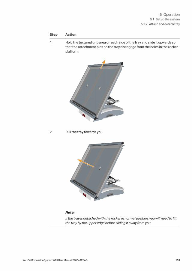
Step Action
1 Hold the textured grip area on each side of the tray and slide it upwards sothat the attachment pins on the tray disengage from the holes in the rockerplatform.
2 Pull the tray towards you.
Note:
If the tray is detached with the rocker in normal position, you will need to liftthe tray by the upper edge before sliding it away from you.
5 Operation5.1 Set up the system
5.1.2 Attach and detach tray
Xuri Cell Expansion System W25 User Manual 29064622 AD 153

5.1.3 Prepare pH and DO sensors
Instructions
Follow the instructions below to connect the sensor adapters to the pH and DO bagsensor ports.
NOTICE
Be careful to connect the sensors to the correct ports on Xuri CellExpansion W25 CBCU. Identification stickers are provided to labelthe connectors.
NOTICE
In dual mode, be careful to connect the sensors for the left andright Cellbag bioreactors to the correct Xuri Cell Expansion W25CBCU. This is easier if the respective Xuri Cell Expansion W25CBCU units are placed on the left and right sides of the rockerrespectively.
Step Action
1 Remove the Cellbag bioreactor from its protective cover bag.
NOTICE
Exposure to intense light will cause deterioration of theoptical sensors on the Cellbag bioreactor. To avoidunnecessary light exposure, remove the protectivecover bag just prior to use.
2 Place the Cellbag bioreactor on a steady surface with the bag sensor portsfacing upwards.
The optical sensor spots have different colors. The spot on the pH sensor bagport is white/yellow and the spot on the DO sensor port is pink/black. If bothpH and DO sensors are used, a separate fiber cable is needed for eachsensor.
5 Operation5.1 Set up the system
5.1.3 Prepare pH and DO sensors
154 Xuri Cell Expansion System W25 User Manual 29064622 AD

Step Action
3 Attach the sensor adapter, with the optical lens facing the sensor port, byinserting the four pins of the port into the corresponding holes of theadapter.
Note:
The sensor adapter can be fastened in any of four orthogonal directions.Select the most convenient direction.
4 Rotate the sensor adapter clockwise to fix the pins on the sensor port to theadapter. A distinct "click" will indicate that the adapter is securely fastened.
Note:
When rotating the sensor adapter, make sure not to exert any force on thefiber cable.
5 Operation5.1 Set up the system
5.1.3 Prepare pH and DO sensors
Xuri Cell Expansion System W25 User Manual 29064622 AD 155

Step Action
5 Place the Cellbag bioreactor on the tray with the optical sensors facingdownwards.
NOTICE
Make sure that the optical fiber cables are not placedbetween the Cellbag bioreactor and the temperaturesensor on the tray. This could lead to erroneous temper-ature reading and control, resulting in overheating.
6 To keep track of the optical fiber cables, mark the cables with the suppliedstickers.
7 Bundle the optical fiber cables on one side of the tray. Fit the lid and makesure the tubing and cables are placed in the tubing exit. See Illustrations oftray and lid, on page 19.
8 Connect the pH sensor cable to the pH port on the CBCU front panel.
9 Connect the DO sensor cable to the DO port on the CBCU front panel.
5 Operation5.1 Set up the system
5.1.3 Prepare pH and DO sensors
156 Xuri Cell Expansion System W25 User Manual 29064622 AD

5.1.4 Attach the Cellbag bioreactor
Instructions
Follow the instructions below to attach the Cellbag bioreactor to the tray.
Note: When using a Cellbag bioreactor that only covers half of the tray in singlemode, such as a 10 L bag on Tray 20, position the bag on the left side of thetray.
Note: In dual mode, ensure that each Cellbag bioreactor is centrally positioned onthe respective grey heating pad. Weight measurement resolution will becompromised if the bioreactor is not correctly placed.
Step Action
1 Push the bag clamp openers in the upper corners of the tray downwards.This opens the upper bag clamps.
Note:
For a Cellbag bioreactor that covers the whole tray, open both bag clamps. Indual mode or with a bioreactor that covers only half the tray, only one clampneeds to be opened.
2 Insert the upper Cellbag rod into the opened bag clamp.
5 Operation5.1 Set up the system
5.1.4 Attach the Cellbag bioreactor
Xuri Cell Expansion System W25 User Manual 29064622 AD 157

Step Action
3 If the clamp does not close automatically, gently push the bag clamp openerupwards to secure the upper end of the Cellbag bioreactor. Do not use force.Gently pull on the bioreactor to make sure it is attached.
4 Repeat the above steps to attach the lower Cellbag rod to completelysecure the Cellbag bioreactor on the tray.
5 Mount the lid on top of the tray.
NOTICE
Keep the Cellbag bioreactor covered with the lidthroughout the cultivation to protect the optical sensorsfrom excessive light exposure.
5 Operation5.1 Set up the system
5.1.4 Attach the Cellbag bioreactor
158 Xuri Cell Expansion System W25 User Manual 29064622 AD

5.1.5 Prepare the pump
Tubing holder positionsThe pump head has two different holder positions to accommodate tubing withdifferent sizes. The inner position is for small tubing and the outer position is for largetubing (see Pump tubing sizes, on page 159).
Inner position for small tubing. Outer position for large tubing
Pump tubing sizesThe table below lists tubing sizes supported by Xuri Cell Expansion W25 Pump , withthe range of flow rates provided by each size. The wall thickness of the tubing should be1.6 mm (1/16").
Note: Pump tubing is not supplied with the system. Suitable tubing must bepurchased separately.
5 Operation5.1 Set up the system
5.1.5 Prepare the pump
Xuri Cell Expansion System W25 User Manual 29064622 AD 159
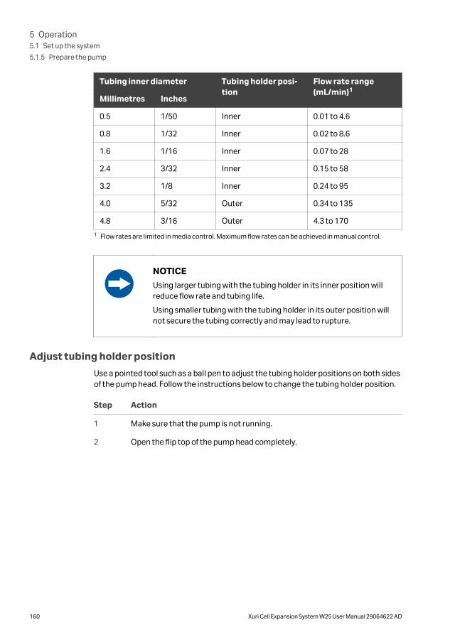
Tubing inner diameter Tubing holder posi-tion
Flow rate range(mL/min)1
Millimetres Inches
0.5 1/50 Inner 0.01 to 4.6
0.8 1/32 Inner 0.02 to 8.6
1.6 1/16 Inner 0.07 to 28
2.4 3/32 Inner 0.15 to 58
3.2 1/8 Inner 0.24 to 95
4.0 5/32 Outer 0.34 to 135
4.8 3/16 Outer 4.3 to 170
1 Flow rates are limited in media control. Maximum flow rates can be achieved in manual control.
NOTICE
Using larger tubing with the tubing holder in its inner position willreduce flow rate and tubing life.
Using smaller tubing with the tubing holder in its outer position willnot secure the tubing correctly and may lead to rupture.
Adjust tubing holder position
Use a pointed tool such as a ball pen to adjust the tubing holder positions on both sidesof the pump head. Follow the instructions below to change the tubing holder position.
Step Action
1 Make sure that the pump is not running.
2 Open the flip top of the pump head completely.
5 Operation5.1 Set up the system
5.1.5 Prepare the pump
160 Xuri Cell Expansion System W25 User Manual 29064622 AD

Step Action
3 Place the pointed tool in the small depression in the tubing holder on oneside of the pump head.
4 Press down and move the tubing holder to the required position until it clicksinto place.
5 Release the pressure. The tubing holder rises into the new position.
6 Repeat the above steps to adjust the tubing holder on the other side of thepump head.
NOTICE
Make sure that the tubing holder position is the same on both sidesof the pump head.
5 Operation5.1 Set up the system
5.1.5 Prepare the pump
Xuri Cell Expansion System W25 User Manual 29064622 AD 161

NOTICE
Make sure that the tubing holder position is not caught in betweenthe inner or outer position, as this may cause erroneous flow ratesand abnormal tube wear.
Load tubing
Follow the instructions below to load tubing in the pump head and connect tubing tothe Cellbag bioreactor.
Step Action
1 Make sure that the pump is switched off.
2 Open the flip top of the pump head completely.
3 Check that the tubing holder is adjusted to the correct position for your sizeof tubing. See instructions above.
5 Operation5.1 Set up the system
5.1.5 Prepare the pump
162 Xuri Cell Expansion System W25 User Manual 29064622 AD

Step Action
4 Place the tubing between the rotor rollers and the track, pressed against theinner wall of the pump head.
5 Lower the flip top until it clicks into its fully closed position.
6 Connect inlet and outlet tubing to the Cellbag bioreactor, for example acid,base, feed and harvest/waste.
Note: The pumping direction is indicated by the arrow on the pump head.
5 Operation5.1 Set up the system
5.1.5 Prepare the pump
Xuri Cell Expansion System W25 User Manual 29064622 AD 163
5.1.6 Connect gas to the system
Gas mixThe Cellbag bioreactor requires gas flow to stay inflated and to provide ventilation. TheCBCU enables different gas mixing possibilities. Compressed air or N2 can be mixedwith CO2 and/or O2 to obtain the desired gas mix.
Compressed air or N2 is connected to AIR/N2 on the CBCU. CO2 and O2 are connectedto CO2 IN and O2 IN, respectively, on the CBCU rear panel.
NOTICE
In dual mode, be careful to connect the air and gas for the left andright Cellbag bioreactors to the correct CBCU. This is easier if therespective CBCU units are placed on the left and right sides of therocker respectively.
Set up aeration and gas supply
Follow the instructions below to connect gas to the bioreactor system.
5 Operation5.1 Set up the system
5.1.6 Connect gas to the system
164 Xuri Cell Expansion System W25 User Manual 29064622 AD

Step Action
1 Attach the filter heater to the outlet vent filter of the Cellbag bioreactor. Indual mode, make sure that the filter heaters are correctly placed withrespect to the left and right bioreactors.
Note:
The inlet and outlet vent filters are distinguished by the pressure controlvalve on the outlet filter (indicated by an arrow in the illustration below). Donot attach the filter heater to the inlet vent filter.
The image below shows the filter heater mounted on the stand on theCellbag bioreactor.
5 Operation5.1 Set up the system
5.1.6 Connect gas to the system
Xuri Cell Expansion System W25 User Manual 29064622 AD 165
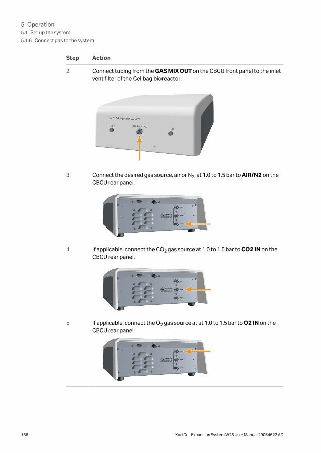
Step Action
2 Connect tubing from the GAS MIX OUT on the CBCU front panel to the inletvent filter of the Cellbag bioreactor.
3 Connect the desired gas source, air or N2, at 1.0 to 1.5 bar to AIR/N2 on theCBCU rear panel.
4 If applicable, connect the CO2 gas source at 1.0 to 1.5 bar to CO2 IN on theCBCU rear panel.
5 If applicable, connect the O2 gas source at at 1.0 to 1.5 bar to O2 IN on theCBCU rear panel.
5 Operation5.1 Set up the system
5.1.6 Connect gas to the system
166 Xuri Cell Expansion System W25 User Manual 29064622 AD

NOTICE
Make sure to keep the inlet pressures within the stated limits (1.0to 1.5 bar). Excessive pressure may cause internal tubing to loosen.
NOTICE
An unsteady inlet pressure will affect the speed of the gas flow andalso the gas mix.
5 Operation5.1 Set up the system
5.1.6 Connect gas to the system
Xuri Cell Expansion System W25 User Manual 29064622 AD 167

5.1.7 Connect the filter heater to the rockerFollow the steps below to connect the filter heater(s) to the rocker.
Step Action
1 Connect the filter heater cable to the filter heater port on the rocker rearpanel.
2 Attach the filter heater to the outlet vent filter of the cellbag bioreactor.
In Single mode for Bag 20 L and Bag 50 L, Filter heater (L) is enabled bydefault. To use two filter heaters during single mode, Filter heater (R) mustbe enabled.
3 Activate Filter Heater (R) in Single mode, if applicable.
a. Select System settings.
b. Click Rocker.
c. Click Enable Filter heater (R).
5 Operation5.1 Set up the system
5.1.7 Connect the filter heater to the rocker
168 Xuri Cell Expansion System W25 User Manual 29064622 AD
5.2 Start and configure the system
About this sectionThis section describes how to start the system, log on to UNICORN, connect thesystem to UNICORN and configure the system in the software.
In this section
Section See page
5.2.1 Start the system and log on to UNICORN 170
5.2.2 Connect to the system 171
5.2.3 Configure system properties 173
5.2.4 Configure system settings 175
5.2.5 Start a run 181
5 Operation5.2 Start and configure the system
Xuri Cell Expansion System W25 User Manual 29064622 AD 169

5.2.1 Start the system and log on to UNICORNFollow the instructions below to start the system and log on to UNICORN. The worksta-tion must have a valid e-license.
For more information about e-licenses, refer to UNICORN Quick Installation Guide(29414475).
Step Action
1 Switch on the client computer.
2 Start the UNICORN software.
3 Provide your User Name and Password to log on to UNICORN. Accesscredentials are assigned by your UNICORN administrator. According to theproperties of your user account, you may be able to select an Access Group.
Note:
If Use Windows Authentication is checked, you may log on using yourWindows username and password.
4 Press the Power switch to start the rocker.
Result:
The Power button flashes green during start-up, and then lights steadilywhen the rocker is operational.
Xuri™ Cell Expansion System W25
5 Operation5.2 Start and configure the system
5.2.1 Start the system and log on to UNICORN
170 Xuri Cell Expansion System W25 User Manual 29064622 AD
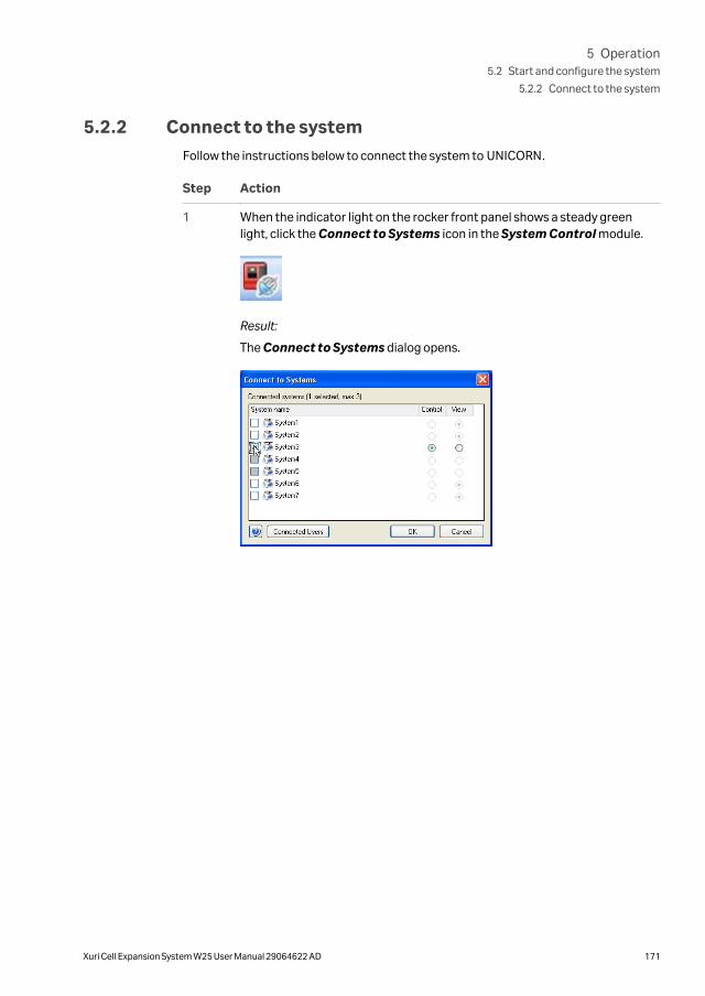
5.2.2 Connect to the systemFollow the instructions below to connect the system to UNICORN.
Step Action
1 When the indicator light on the rocker front panel shows a steady greenlight, click the Connect to Systems icon in the System Control module.
Result:
The Connect to Systems dialog opens.
5 Operation5.2 Start and configure the system
5.2.2 Connect to the system
Xuri Cell Expansion System W25 User Manual 29064622 AD 171
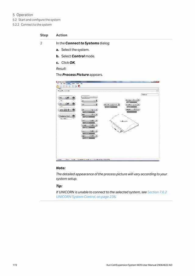
Step Action
2 In the Connect to Systems dialog:
a. Select the system.
b. Select Control mode.
c. Click OK.
Result:
The Process Picture appears.
Note:
The detailed appearance of the process picture will vary according to yoursystem setup.
Tip:
If UNICORN is unable to connect to the selected system, see Section 7.6.2UNICORN System Control, on page 238.
5 Operation5.2 Start and configure the system
5.2.2 Connect to the system
172 Xuri Cell Expansion System W25 User Manual 29064622 AD

5.2.3 Configure system propertiesEdit the system properties whenever the configuration of the system is changed, forexample:
• to switch between single and dual modes.
• to change the system setup, for example if a CBCU or pump has been added orremoved.
• to change the Instrument Configuration of the system.
The Instrument Configuration is the system specific control software. It isprovided on a DVD with the system, and is also available for download. Contact yourCytiva representative if you need help to download the Instrument Configura-tion.
Follow the instructions below to edit the system properties.
Step Action
1 Open the Administration module in the Tools menu.
Click System Properties.
2 Select your system in the System Properties dialog and click Edit.
Note:
Only systems that are switched on and connected to the computer can beedited.
5 Operation5.2 Start and configure the system
5.2.3 Configure system properties
Xuri Cell Expansion System W25 User Manual 29064622 AD 173

Step Action
3 All available components are shown in the Component selection list.
a. Click the check-boxes to select or de-select components.
b. Make sure the components selected match the units connected to thesystem.
4 Click OK to apply the changes.
5 Operation5.2 Start and configure the system
5.2.3 Configure system properties
174 Xuri Cell Expansion System W25 User Manual 29064622 AD

5.2.4 Configure system settings
Introduction
In System Settings, system parameters are defined, such as:
• pump roles, which need to be assigned to the individual pump heads before startinga run;
• whether heating should be automatically enabled when the rocking starts (IC2.0.4.0 and lower versions);
• whether heating should be automatically disabled when the rocking starts (IC2.0.5.1 and higher versions);
• whether calibration values for pH and/or DO sensors should be reset at the end ofthe run;
• whether rocking, gas mix and temperature control should be resumed on restartafter power loss;
• whether voltage or current should be used for analog inputs.
Assignment of pump roles to pumpheads
Pump roles need to be assigned to the individual pump heads before starting a run.Follow the instructions below to assign pump roles. See System settings, on page 43 forgeneral instructions on how to configure the system settings.
Step Action
1 Select System →Settings in the System Control module.
2 Select Pump setup from the list and click the + symbol to view the availablepump heads.
5 Operation5.2 Start and configure the system
5.2.4 Configure system settings
Xuri Cell Expansion System W25 User Manual 29064622 AD 175

Step Action
3 Assign roles to pump heads according to the requirements of the cultivationprocess.
In single mode, available roles are Acid, Base, Feed1, Harvest, Feed2,Feed3 and Feed4.
In dual mode, available roles are Acid, Base, Feed1, Harvest, Feed2,Feed3 for the left and right functions separately, identified by the suffix Land R.
Note:
Media addition in media control and perfusion mode uses only Feed1 of theavailable Feed roles. Do not select other Feed roles for pump headsintended for these purposes.
Examples:
a. For pH control using acid and base in single mode, assign Acid to onepump head and Base to another.
b. For pH control using acid and base in dual mode, assign Acid L andBase L to separate pump heads for the left Cellbag bioreactor, andAcid R and Base R to separate pump heads for the right bioreactor.
c. For media addition in dual mode, assign Feed1 L to a pump head for theleft Cellbag bioreactor, and Feed1 R to a pump head for the rightbioreactor.
4 A given pump role cannot be assigned to more than one pump head. If a rolethat is already assigned to a pump head is given to a second pump head, thesecond assignation will apply and the first pump head will be set to Notdefined.
Check the assignment of all pump heads to make sure that there are noconflicts before clicking OK.
5 To return to the default values defined in the instrument configuration, clickSet Parameters To Strategy Default Values.
Select mode of pH control indeadband
Follow the instructions below to select the mode of pH control in deadband.
Step Action
1 Select System →Settings in the System Control module.
2 Select pH control from the list and click the + symbol to view the availablealternatives.
5 Operation5.2 Start and configure the system
5.2.4 Configure system settings
176 Xuri Cell Expansion System W25 User Manual 29064622 AD

Step Action
3 Click on alternative pH control deadband mode.
4 Click one of the radio buttons Optimal or Traditional to select mode.
Note:The selected mode of deadband cannot be changed during a run.
5 Click OK to confirm the selection.
Select upper and lower limits oftraditional deadband
Follow the instructions below to select the upper and lower limits of traditional dead-band before starting a run.
Step Action
1 Select System →Manual Instructions in the System Control module.
2 Select pH control (advanced) from the list and click the + symbol to viewthe available alternatives..
3 Click on alternative pH control (deadband).
4 In the Upper dead band field, select the upper limit by clicking the smallarrows to the right of the field. The limits are selected in the range of 0.10 to2.00 pH units.
5 Operation5.2 Start and configure the system
5.2.4 Configure system settings
Xuri Cell Expansion System W25 User Manual 29064622 AD 177
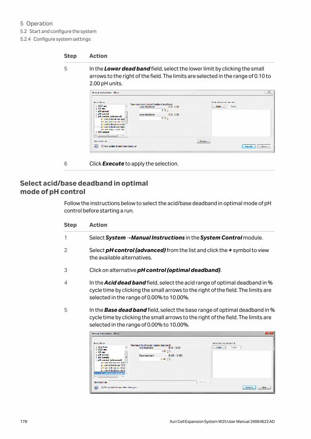
Step Action
5 In the Lower dead band field, select the lower limit by clicking the smallarrows to the right of the field. The limits are selected in the range of 0.10 to2.00 pH units.
6 Click Execute to apply the selection.
Select acid/base deadband in optimalmode of pH control
Follow the instructions below to select the acid/base deadband in optimal mode of pHcontrol before starting a run.
Step Action
1 Select System →Manual Instructions in the System Control module.
2 Select pH control (advanced) from the list and click the + symbol to viewthe available alternatives.
3 Click on alternative pH control (optimal deadband).
4 In the Acid dead band field, select the acid range of optimal deadband in %cycle time by clicking the small arrows to the right of the field. The limits areselected in the range of 0.00% to 10.00%.
5 In the Base dead band field, select the base range of optimal deadband in %cycle time by clicking the small arrows to the right of the field. The limits areselected in the range of 0.00% to 10.00%.
5 Operation5.2 Start and configure the system
5.2.4 Configure system settings
178 Xuri Cell Expansion System W25 User Manual 29064622 AD

Step Action
6 Click Execute to apply the selection.
Select transition delays in CO2/Basein optimal mode of pH control
Follow the instructions below to select the transition delays in Auto/Manual modebefore starting a run.
Step Action
1 Select System →Manual Instructions in the System Control module.
2 Select pH control (advanced) from the list and click the + symbol to viewthe available alternatives.
3 Click on alternative pH control (transition delays).
4 Click one of the radio buttons Auto or Manual to select mode.
Note:In the Manual mode of DO control, the transition delay may be changed toranges mentioned in the respective tabs for both CO2 to Speed and Speed toCO2 transitions.
5 In the Manual CO2 to base delay and Manual base to CO2 delay fields,select the transition delays by clicking the small arrows to the right of thefield. The limits are selected in the range of 0 to 500 minutes.
The transition delay times set in the Auto mode of DO control (advanced)can be visualized under the CO2 to Speed and Speed to CO2 tabs.
6 Click Execute to apply the selection.
Select transition delays in DO Control
Follow the instructions below to select the transition delays in DO/Speed mode beforestarting a run.
5 Operation5.2 Start and configure the system
5.2.4 Configure system settings
Xuri Cell Expansion System W25 User Manual 29064622 AD 179
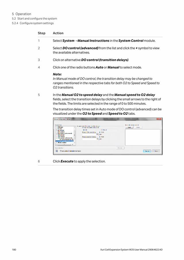
Step Action
1 Select System →Manual Instructions in the System Control module.
2 Select DO control (advanced) from the list and click the + symbol to viewthe available alternatives.
3 Click on alternative DO control (transition delays).
4 Click one of the radio buttons Auto or Manual to select mode.
Note:In Manual mode of DO control, the transition delay may be changed toranges mentioned in the respective tabs for both O2 to Speed and Speed toO2 transitions.
5 In the Manual O2 to speed delay and the Manual speed to O2 delayfields, select the transition delays by clicking the small arrows to the right ofthe fields. The limits are selected in the range of 0 to 500 minutes.
The transition delay times set in Auto mode of DO control (advanced) can bevisualized under the O2 to Speed and Speed to O2 tabs.
6 Click Execute to apply the selection.
5 Operation5.2 Start and configure the system
5.2.4 Configure system settings
180 Xuri Cell Expansion System W25 User Manual 29064622 AD

5.2.5 Start a run
IntroductionThis section describes how to start a manual or method-controlled run. Data collectionbegins when the run starts.
For further information on methods, refer to Section 3.3 Methods in UNICORN, on page46.
Note: Pressing the Power button on the rocker while the rocker is switched onshuts down the system and stops any ongoing run.
Start a manual run
Follow the instructions below to start a manual run.
5 Operation5.2 Start and configure the system
5.2.5 Start a run
Xuri Cell Expansion System W25 User Manual 29064622 AD 181

Step Action
1 Change the Cellbag settings as required. In dual mode, make sure thesettings are correctly entered for both bioreactors.
a. Click the Cellbag icon. In dual mode, click the appropriate side of theicon.
b. If pH and/or DO control will be used, enter the appropriate calibrationdata (printed on the Cellbag label).
c. Click OK.
Result:
The Start Protocol dialog for the manual run opens.
5 Operation5.2 Start and configure the system
5.2.5 Start a run
182 Xuri Cell Expansion System W25 User Manual 29064622 AD

Step Action
2 On the displayed page in the Start Protocol:
a. Type the Result name and click 'Browse to change the Location ofwhere the result is saved if necessary.
b. Select the correct Bag size (two sizes are listed in dual mode).
c. Click OK.
Result:
The manual run starts.
Start a method run
To start a run, perform one of the following tasks:
• select one of the predefined method templates provided, or
• select from the saved methods in the system, or
• follow the instructions below to create a new method using a predefined method astemplate.
Step Action
1 In Method Editor do either of the following:
• click the Create a new method icon in the Toolbar
or
• select File:New Method
Result:The New Method dialog opens.
5 Operation5.2 Start and configure the system
5.2.5 Start a run
Xuri Cell Expansion System W25 User Manual 29064622 AD 183

Step Action
2 In the New Method dialog, select a System.
3 Select one of the predefined method templates.
4 Click OK.
Result:The Method Outline pane shows the mandatory Method Settings phasefor the chosen method. The Text Instructions pane shows all the instruc-tions that define the method. The Phase Properties pane shows the defaultsettings for the currently highlighted phase.
Hold or stop the runTo interrupt a method during a run you may use the Hold or End icons in SystemControl. A held method run can be resumed by using the Continue icon. See theinstructions in the table below.
At the end of a method the run stops automatically. All functions stop, includingrocking and data logging, and an acoustic end signal sounds and End is displayed in theRun Log. This also applies when ending a manual run.
Tip: In System Settings, it is possible to set Prepare for Tilt at END.
5 Operation5.2 Start and configure the system
5.2.5 Start a run
184 Xuri Cell Expansion System W25 User Manual 29064622 AD

If you want to... then...
temporarily hold the method click the Hold icon.
Note:
When a method is put on hold, the systemcontrol is maintained, but no new instructionsare given.
resume a method run click the Continue icon.
Note:
An ended method cannot be continued.
resume a method run or a manualrun after the system has enteredthe Error and Alarm state
click the Continue icon.
permanently end the run click the End icon.
Note: When you end a method run prematurely, you will be prompted to save ordiscard the partial result.
5 Operation5.2 Start and configure the system
5.2.5 Start a run
Xuri Cell Expansion System W25 User Manual 29064622 AD 185

5.3 Prepare for cultivation
About this sectionThis section describes the how to prepare the system for cell cultivation. For illustra-tions and descriptions of the system, refer to Chapter 2 System description, on page 11.
In this section
Section See page
5.3.1 Inflate the Cellbag bioreactor 187
5.3.2 Adjust pump parameters 188
5.3.3 Final checks before cultivation 189
5.3.4 Add and equilibrate culture medium 190
5.3.5 Prepare the sensors 193
5 Operation5.3 Prepare for cultivation
186 Xuri Cell Expansion System W25 User Manual 29064622 AD

5.3.1 Inflate the Cellbag bioreactorFollow the instructions below to inflate the Cellbag bioreactor.
Step Action
1 Make sure that all ports on the Cellbag bioreactor are closed and that inletand outlet filters are open.
2 Open Settings →Gas control →Gas flow from the Process Picture inSystem Control.
3 Enable Fast fill. This will maximize the gas flow during the first 20 minutes.
Note:
Fast fill is disabled in the illustration below.
4 Turn on Gas flow from the Process Picture by pressing the right-hand sideof the Gas flow button.
Result:
The Cellbag is inflated.
5 Operation5.3 Prepare for cultivation
5.3.1 Inflate the Cellbag bioreactor
Xuri Cell Expansion System W25 User Manual 29064622 AD 187
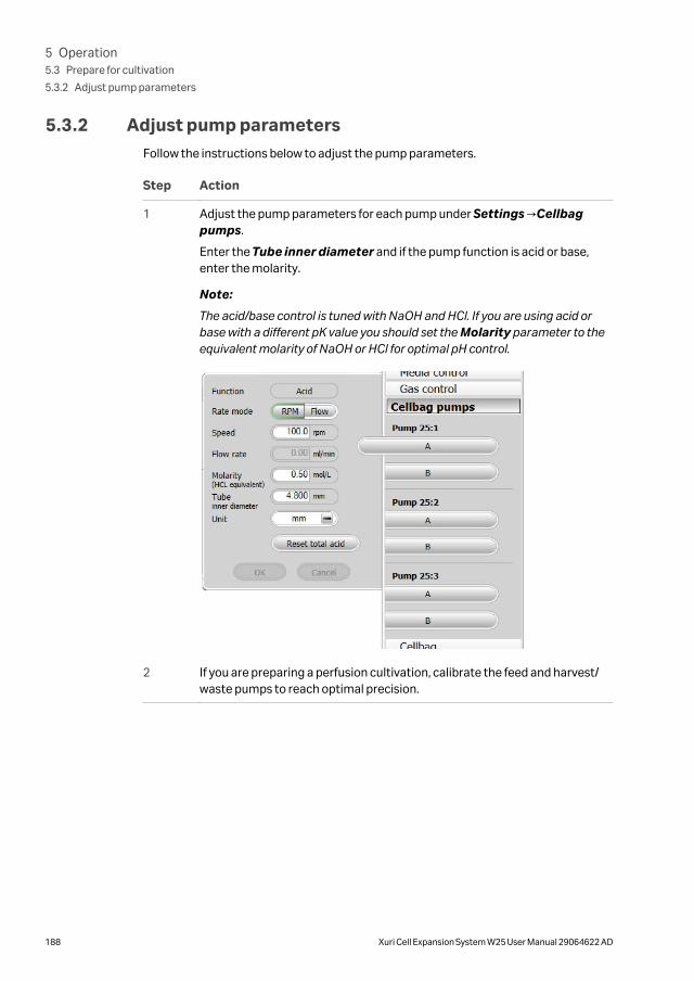
5.3.2 Adjust pump parametersFollow the instructions below to adjust the pump parameters.
Step Action
1 Adjust the pump parameters for each pump under Settings →Cellbagpumps.
Enter the Tube inner diameter and if the pump function is acid or base,enter the molarity.
Note:
The acid/base control is tuned with NaOH and HCl. If you are using acid orbase with a different pK value you should set the Molarity parameter to theequivalent molarity of NaOH or HCl for optimal pH control.
2 If you are preparing a perfusion cultivation, calibrate the feed and harvest/waste pumps to reach optimal precision.
5 Operation5.3 Prepare for cultivation
5.3.2 Adjust pump parameters
188 Xuri Cell Expansion System W25 User Manual 29064622 AD

5.3.3 Final checks before cultivation
Final checks before cultivation
Follow the instructions below to verify the system before filling the Cellbag bioreactorwith medium.
Step Action
1 Verify that the tray is correctly attached to the rocker platform.
2 Verify that the lid is mounted on the tray to protect the optical sensors onthe Cellbag bioreactor from excessive light.
3 If using both pH and DO sensors, verify that the optical fiber cables are notmixed up. Mark the cables with the supplied stickers.
4 Verify that the pH or DO sensor cables are not positioned betweeen thetemperature sensor and the Cellbagbioreactor.
5 Verify that the pH and DO sensor adaptors are connected correctly.
6 Verify that the filter heater is connected.
7 Verify that the Cellbag bioreactor is firmly inflated and secured to the tray.The Cellbag bioreactor should be taut but not creased.
8 Verify that gas flow is released through the outlet pressure relief valve. Thismay be done by attaching a piece of tubing with one end submerged in abeaker of water to the pressure relief valve. Formation of gas bubbles in thewater will confirm the relief valve function.
5 Operation5.3 Prepare for cultivation
5.3.3 Final checks before cultivation
Xuri Cell Expansion System W25 User Manual 29064622 AD 189

5.3.4 Add and equilibrate culture medium
Tare the scale
Tare the scale with all the equipment on the tray, such as lid, Cellbag bioreactor, andfilter heater before starting a run. For optimal control, the measured weight should bethe same as the weight of the culture. The weight measurement is used as input for theregulation of temperature, pH, and media control.
In dual mode, it is important for correct weight measurement to tare the scale, even ifthe weight distribution appears to be even.
Note: Load cells are temperature-sensitive. Keep the ambient temperatureconstant to minimize effects on weight measurement.
Follow the instructions below to tare the scale.
Step Action
1 Set the rocker stop angle to 0° and check that the tray is in a horizontal posi-tion.
2 Open Settings →Weight from the Process Picture in System Control.
In dual mode, the weights of the two bioreactors are displayed separately.
3 Check that the weight distribution is even by reading the weight percentagevalues for the rocker feet. The values should not differ more than ±5%, andthe optimal weight distribution is 25% on each load cell. Turn the adjustablefoot if necessary, see Figure 2.1, on page 17.
4 Make sure that the lid and all other equipment that will be used during therun is placed on the tray, and that no tubing weighs down the tray.
5 Click Tare.
5 Operation5.3 Prepare for cultivation
5.3.4 Add and equilibrate culture medium
190 Xuri Cell Expansion System W25 User Manual 29064622 AD

Add culture medium
Follow the instructions below to fill the Cellbag bioreactor with culture medium.
Note: The high pressure alarm may be triggered as the bioreactor is filled,depending on gas and liquid flow rates. The alarm may be ignored providedthat it is no longer active when filling is complete.
Step Action
1 Open Rocking from the Process Picture.
Set the Stop Angle to 12.0 and click OK.
Note:
The risk that air bubbles are trapped by the optical sensors is minimized withthe tray at an angle. The angle can be adjusted to make sure that themedium reaches all optical sensors during filling. Using medium at roomtemperature or culture temperature reduces the risk of air bubble formation.
2 Slowly transfer the desired volume of medium into the Cellbag bioreactorusing a pump or gravity flow.
Tip:
To automatically fill the bag to a desired weight, use Media Addition fromSettings →Media control in the Process Picture.
3 Check if there are visible gas bubbles on the optical sensors. See pH readingand DO reading, respectively, in Section 7.3 Xuri Cell Expansion W25 CBCU,on page 220 for advice on how to remove bubbles.
Note:
Such bubbles may be difficult to see. For the pH sensor, an indication of gasbubbles is that the initial pH reading deviates more than about 0.5 units froma reference measurement.
Equilibrate to operating conditions
Follow the instructions below to equilibrate the medium to operating conditions.
For recommendations on operating conditions, refer to Section 4.7 Recommendedoperating conditions, on page 141.
5 Operation5.3 Prepare for cultivation
5.3.4 Add and equilibrate culture medium
Xuri Cell Expansion System W25 User Manual 29064622 AD 191

Step Action
1 Set the desired rocking speed and angle in Settings →Rocking in theProcess Picture. Start the rocking by clicking the right-hand side of theRocking button.
Note:
When using Tray 50, the value of rocking speed multiplied by rocking anglemay not exceed 240 (e.g., with a rocking angle of 12° the rocking speed islimited to 20 rpm).
2 Set the desired gas flow in Settings →Gas control →Gas flow in theProcess Picture. Start the gas flow by clicking the right-hand side of theGas flow button.
3 If applicable, turn on CO2 mixing by clicking the right-hand side of the CO2button in the Process Picture.
4 Set the required temperature setpoint.
5 Click the right-hand side of the Temp button to start heating.
6 Equilibrate the medium for at least 2 hours.
5 Operation5.3 Prepare for cultivation
5.3.4 Add and equilibrate culture medium
192 Xuri Cell Expansion System W25 User Manual 29064622 AD

5.3.5 Prepare the sensors
ImportantDo not start pH or DO reading until the medium is fully equilibrated to operating condi-tions. The sensors do not give reliable measurements until then.
Equilibrate the culture medium with 100% air to calibrate DO sensors for 100% airsaturation. If you use air mixed with 0% to 10% CO2, the sensors can be calibrated overthe range 100% to 90% air saturation.
Do not calibrate DO sensors for 100% air saturation if N2 is used instead of air.
Note: CO2 regulation is slow, so it takes some time before the CO2 concentrationreaches the setpoint.
NOTICE
Do not move the rocker during a run, since this could damage thescale function and disturb the weight measurement.
Prepare the DO sensor
Follow the instructions below to prepare the DO sensor.
Note: In dual mode, adjust the sensor calibration on each Cellbag bioreactorseparately.
Step Action
1 When the medium is equilibrated to operating conditions, move the cursorover the DO sensor icon in the Process Picture, and set Reading On in themenu that appears.
Wait until the value is stable.
2 Select System →Calibrate in System Control.
3 Select DO sensor in the Monitor to calibrate drop down menu.
4 Enter percentage of air saturation (90% to 100% depending on CO2 concen-tration) in the Enter reference DO field.
5 Click Calibrate.
6 Close the Calibration dialog.
7 Select Settings →DO in the Process Picture.
8 Enter the desired values for Control and Setpoint. Check the DeviationAlarm and set the alarm limits if desired.
5 Operation5.3 Prepare for cultivation
5.3.5 Prepare the sensors
Xuri Cell Expansion System W25 User Manual 29064622 AD 193

Step Action
9 Click OK.
Prepare the pH sensor
Follow the instructions below to prepare the pH sensor.
Note: In dual mode, adjust the sensor calibration on each Cellbag bioreactorseparately.
Step Action
1 When the medium is equilibrated to operating conditions, move the cursorover the pH sensor icon in the Process Picture, and set Reading On in themenu that appears.
Wait until the value is stable.
2 Click the right-hand side of the Sampling button to prepare for sampling.
Result:
The system will enter sampling mode.
Note:
The system will be in sampling mode as many minutes as set in Settings→Rocking →Sampling →Pause and at an angle set in Settings →Rocking→Sampling →Stop angle in the Process Picture.
3 Take a sample to verify that the pH value shown by the system matches thepH measured with a calibrated reference instrument. If the deviation islarger than approximately 0.5 pH units, make sure that no air bubble ispresent.
For instructions on how to remove air bubbles, see pH reading, on page 225.
4 Continue with the calibration adjustment only if the deviation is less than 0.5pH units.
5 Select System →Calibrate in System Control.
6 Select pH sensor in the Monitor to calibrate drop down menu.
7 Enter the actual pH value in the Enter reference pH field.
8 Click Calibrate.
9 Close the Calibration dialog.
10 Select Settings →pH in the Process Picture.
11 Enter the desired values for Control and Setpoint. Check the DeviationAlarm and set the alarm limits if desired.
5 Operation5.3 Prepare for cultivation
5.3.5 Prepare the sensors
194 Xuri Cell Expansion System W25 User Manual 29064622 AD

Step Action
12 Click OK.
5 Operation5.3 Prepare for cultivation
5.3.5 Prepare the sensors
Xuri Cell Expansion System W25 User Manual 29064622 AD 195

5.4 Perform cultivation
About this sectionThis section describes the basics of performing a cultivation. During the cultivation, keyparameters are monitored and the settings can be adjusted.
In this section
Section See page
5.4.1 Inoculate the culture 197
5.4.2 Monitor and control the run 198
5.4.3 End a run 205
5 Operation5.4 Perform cultivation
196 Xuri Cell Expansion System W25 User Manual 29064622 AD

5.4.1 Inoculate the culture
Instructions
Follow the instructions below to inoculate the Cellbag bioreactor.
Note: Make sure that the key culture parameters pH, DO and temperature arestable before inoculation.
Step Action
1 Make sure that the inlet tubing and the tubing connected to the inoculumcontainer are clamped.
2 Using sterile techniques, connect tubing from the inoculum container to theinlet tubing, using e.g. tube fusing equipment or a ReadyMate™ connector.
3 Unclamp the inlet tubing and inoculum container tubing.
4 Transfer the desired volume of inoculum into the bag using a pump orgravity flow.
5 Operation5.4 Perform cultivation
5.4.1 Inoculate the culture
Xuri Cell Expansion System W25 User Manual 29064622 AD 197

5.4.2 Monitor and control the run
IntroductionYou may follow and control the ongoing run in the System Control module. Thecurrent system status is shown in the System state panel in the Run Data pane. Forexample, it may show Ready, Manual Run or Method Run, whether optimal or tradi-tional deadband is used for pH control.
Process pictureThe Process Picture displays the real-time process parameters during a run, and canbe used to control the run. An example of the Process Picture is shown in the illustra-tion below. Details vary according to the system configuration.
The button colors indicate the current state of the respective function as shown in thetable below.
5 Operation5.4 Perform cultivation
5.4.2 Monitor and control the run
198 Xuri Cell Expansion System W25 User Manual 29064622 AD
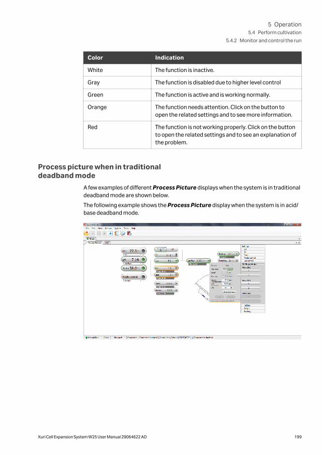
Color Indication
White The function is inactive.
Gray The function is disabled due to higher level control
Green The function is active and is working normally.
Orange The function needs attention. Click on the button toopen the related settings and to see more information.
Red The function is not working properly. Click on the buttonto open the related settings and to see an explanation ofthe problem.
Process picture when in traditionaldeadband mode
A few examples of different Process Picture displays when the system is in traditionaldeadband mode are shown below.
The following example shows the Process Picture display when the system is in acid/base deadband mode.
5 Operation5.4 Perform cultivation
5.4.2 Monitor and control the run
Xuri Cell Expansion System W25 User Manual 29064622 AD 199

The following example shows the Process Picture display when the system is in CO2
deadband mode.
The following example shows the Process Picture display when the system is in CO2/Base deadband mode.
Sample the culture
Samples may be taken several times during the run using the same samplingconnector. Before taking a sample, make sure that the sampling connector is firmlyattached to the luer-lock coupling of the cellbag bioreactor by screwing it clockwise.
Follow the instruction below to take samples from the Cellbag bioreactor.
Step Action
1 Stop the rocking motion from the Process Picture.
5 Operation5.4 Perform cultivation
5.4.2 Monitor and control the run
200 Xuri Cell Expansion System W25 User Manual 29064622 AD

Step Action
2 Click the right-hand side of the Sampling button to prepare for sampling.
Result:
The system will enter sampling mode.
Note:
The system will remain in sampling mode for the number of minutes set inSettings →Rocking →Sampling →Pause, at an angle set in Settings→Rocking →Sampling →Stop angle. The time remaining in sampling modeis displayed in a countdown timer.
Note:
For small culture volumes, it may be necessary to position the tray into tiltposition during sampling.
3 Remove the cap from the blue sampling connector.
5 Operation5.4 Perform cultivation
5.4.2 Monitor and control the run
Xuri Cell Expansion System W25 User Manual 29064622 AD 201
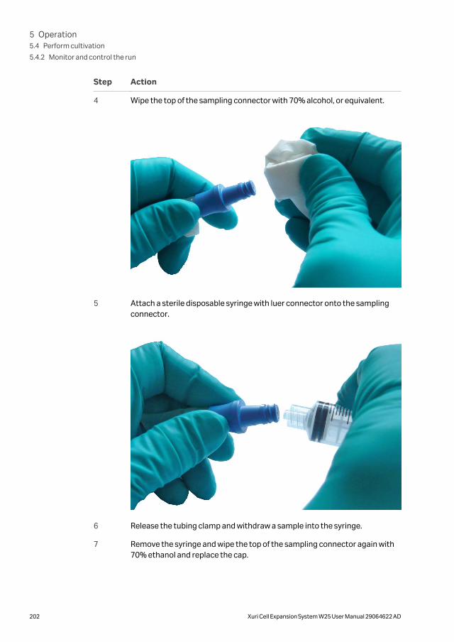
Step Action
4 Wipe the top of the sampling connector with 70% alcohol, or equivalent.
5 Attach a sterile disposable syringe with luer connector onto the samplingconnector.
6 Release the tubing clamp and withdraw a sample into the syringe.
7 Remove the syringe and wipe the top of the sampling connector again with70% ethanol and replace the cap.
5 Operation5.4 Perform cultivation
5.4.2 Monitor and control the run
202 Xuri Cell Expansion System W25 User Manual 29064622 AD

Step Action
8 Pinch the sampling connector tubing a few times to ensure that any liquid inthe tubing drains back into the Cellbag bioreactor.
9 Close the tubing clamp. Sampling mode duration is set from Settings→Rocking →Sampling →Pause in the Process Picture.
Scale up cultivation
Cellbag bioreactors have a large range in operating volume. This allows efficient scale-up and eliminates tedious sequential transfers. Start at low volume and add freshmedium to the Cellbag bioreactor as the cells grow. Up to a 1:10 expansion is possiblein one single bag.
An example of an inoculum expansion sequence is described below.
Step Action
1 Start with 300 mL medium in a 2 L Cellbag bioreactor. Add inoculum.
2 When cells reach approximately 3 × 10⁶ cells/mL, add culture medium up toa volume of 1 liter.
3 When the cells again reach 3 × 10⁶ cells/mL, transfer using a tube-fuser to a20 L Cellbag bioreactor containing 2 liters of culture medium.
4 When the cells in the 20 L Cellbag bioreactor reach 3 × 10⁶ cells/mL, addculture medium up to a volume of 10 liters and continue cultivation.
Exchange culture medium
Follow the instructions below to exchange culture medium in the Cellbag bioreactor,for example when working with microcarriers.
Note: To avoid oxygen depletion, the culture medium exchange should beperformed in less than one hour.
Step Action
1 Stop the gas flow by clicking the right-hand side of the Gas flow button inthe Process Picture.
2 Stop the rocking by clicking the right-hand side of the Rocking button in theProcess Picture.
3 Clamp off the inlet and outlet vent filters.
4 Select Manual →Execute Manual Instructions, and send the instructionRocker →Prepare for tilt.
5 Operation5.4 Perform cultivation
5.4.2 Monitor and control the run
Xuri Cell Expansion System W25 User Manual 29064622 AD 203

Step Action
5 Hold the textured grip area on each side of the tray, and pull the trayupwards and against you to position the tray into tilt position.
6 Allow particulates (including cells and microcarriers, if applicable) 10 to 15minutes to settle.
7 Connect tubing to the harvest port on the Cellbag bioreactor. The other endof the tubing should be connected to a sterile harvest vessel.
8 Using a pump or gravity flow, remove the desired amount of supernatantculture liquid by manually manipulating the flexible wall of the Cellbagbioreactor.
9 Disconnect the tubing and reconnect fresh culture medium to refill theCellbag bioreactor.
10 Open the inlet and outlet vent filter clamps.
11 Start the rocking by clicking the right-hand side of the Rocking button in theProcess Picture.
12 Start the gas flow by clicking the right-hand side of the Gas flow button inthe Process Picture.
Perfusion cultureDuring perfusion culture, cell-free harvest/waste is withdrawn and fresh medium isadded continuously.
Requirements
• Cellbag bioreactors with internal perfusion filter or connected to external retentionfilters
• Harvest/waste and feed pump
See Section 4.6.3 Perfusion, on page 135 for information on perfusion mode. Contact aCytiva application specialist for advice on setting up perfusion culture.
5 Operation5.4 Perform cultivation
5.4.2 Monitor and control the run
204 Xuri Cell Expansion System W25 User Manual 29064622 AD

5.4.3 End a run
End cultivation and harvest theculture
Follow the instructions below to end the run and harvest the culture.
Step Action
1 Prepare the harvest vessel.
2 Click the stop button in the toolbar in System Control to stop the run.
When asked if you want to end the run, click OK.
Note:
By default, the tray will prepare for tilt at the end of the run. This setting canbe changed in System Settings →Rocker →Prepare for tilt at END.
3 Hold the textured grip area on each side of the tray, and in one movement,pull the tray upwards and against you to position the tray into tilt position.
4 Connect tubing from the Cellbag bioreactor to the harvest vessel.
5 Empty the Cellbag bioreactor using a pump or gravity flow.
6 Disconnect the tubing from the Cellbag bioreactor to the harvest vessel.
Procedures after harvest
Follow the instructions below when the cultivation is finished and the culture isharvested.
Step Action
1 Clamp off the inlet and outlet vent filters of the Cellbag bioreactor.
2 Disconnect the tubing from the inlet vent filter on the Cellbag bioreactor.
3 Disconnect any other tubing and cables still connected to the Cellbagbioreactor.
4 Release and remove the empty Cellbag bioreactor from the tray by pressingdown the bag clamp opener.
5 Operation5.4 Perform cultivation
5.4.3 End a run
Xuri Cell Expansion System W25 User Manual 29064622 AD 205

Step Action
5 Follow applicable national and/or local regulations for disposal of theCellbag bioreactor.
6 Turn off all gas supplies.
Shut down the system
Follow the instructions below to shut down the system.
Step Action
1 Disconnect the software from the system in UNICORN.
2 Press the Power button on the rocker front panel. The light flashes greenwhile shutting down.
Note:
If the rocker fails to shut down, press and hold the Power button pressed formore than 4 seconds to force a shutdown.
3 Clean the bioreactor system units.
5 Operation5.4 Perform cultivation
5.4.3 End a run
206 Xuri Cell Expansion System W25 User Manual 29064622 AD

6 Maintenance
About this chapterThis chapter describes the required maintenance procedures for Xuri Cell ExpansionSystem W25. It also gives an overview of the calibration procedures needed for thesystem to function properly.
In this chapter
Section See page
6.1 Calibration 208
6.2 Pump calibration 210
6.3 Cleaning 213
Maintenance managerThe maintenance manager in UNICORN keeps track of the usage of different compo-nents and shows alerts when it is time for maintenance and service. For detailed infor-mation about the maintenance manager, refer to UNICORN Administration and Tech-nical manual.
6 Maintenance
Xuri Cell Expansion System W25 User Manual 29064622 AD 207
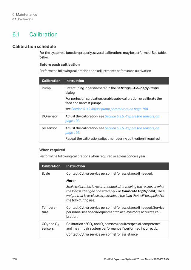
6.1 Calibration
Calibration scheduleFor the system to function properly, several calibrations may be performed. See tablesbelow.
Before each cultivation
Perform the following calibrations and adjustments before each cultivation
Calibration Instruction
Pump Enter tubing inner diameter in the Settings →Cellbag pumpsdialog.
For perfusion cultivation, enable auto-calibration or calibrate thefeed and harvest pumps.
see Section 5.3.2 Adjust pump parameters, on page 188.
DO sensor Adjust the calibration, see Section 5.3.5 Prepare the sensors, onpage 193.
pH sensor Adjust the calibration, see Section 5.3.5 Prepare the sensors, onpage 193.
Repeat the calibration adjustment during cultivation if required.
When required
Perform the following calibrations when required or at least once a year.
Calibration Instruction
Scale Contact Cytiva service personnel for assistance if needed.
Note:
Scale calibration is recommended after moving the rocker, or whenthe load is changed considerably. For Calibrate High point, use aweight that is as close as possible to the load that will be applied tothe tray during use.
Tempera-ture
Contact Cytiva service personnel for assistance if needed. Servicepersonnel use special equipment to achieve more accurate cali-bration.
CO2 and O2
sensorsCalibration of CO2 and O2 sensors requires special competenceand may impair system performance if performed incorrectly.
Contact Cytiva service personnel for assistance.
6 Maintenance6.1 Calibration
208 Xuri Cell Expansion System W25 User Manual 29064622 AD

Calibration instruction
Follow the instructions below to perform a calibration. The example is a scale calibra-tion.
Note: For OPC users, calibration can be accessed from the manual instructiondialog by selecting the OPC component.
Step Action
1 Select System →Calibrate in System Control.
Result:
The Calibration dialog opens.
2 Select the appropriate monitor in the Monitor to calibrate drop downmenu.
3 Follow the instructions in the right-hand field and enter the correct values inthe Calibration procedure field, and click Calibrate for each value.
4 Close the Calibration dialog.
6 Maintenance6.1 Calibration
Xuri Cell Expansion System W25 User Manual 29064622 AD 209

6.2 Pump calibration
IntroductionPump calibration is normally not necessary for pH and media control purposes,provided that the inner diameter of the pump tubing is correctly set. Calibration ishowever recommended if high precision is required or when running perfusion withauto calibration disabled.
Tube inner diameterAlways set the tube inner diameter correctly. If the tube inner diameter is not setcorrectly, the following can happen:
• The requested flow may be out of range for the given tube diameter. This willprevent the media control from starting and result in warnings in pH control.
• The pH and media control performance may deteriorate.
• It may not be possible to calibrate the pump, since the calibration result will be toofar from the expected value.
Pump calibration procedure
The pumps can be calibrated at a desired flow or RPM. Before calibration, the pumphead must be set in desired rate mode (flow or RPM), and the flow or RPM setpoint beset to desired value.
Follow the instructions below to calibrate a pump. Parameters may be set either in theprocess picture or using manual instructions.
Step Action
1 Enter the inner diameter of tubing used.
2 Set Rate mode to Flow or rpm. Calibration will be performed in terms offlow rate or pump speed according to this setting.
3 Enter the desired setpoint (as flow rate or rpm according to the Rate modesetting).
4 Click Settings →Calibrate and choose which pump to calibrate.
5 Enter the desired calibration run time and click Start pump. Run the calibra-tion for sufficient time to collect a reliably measurable volume of liquid.
6 When the pump stops, enter the collected volume and click Finish calibra-tion.
6 Maintenance6.2 Pump calibration
210 Xuri Cell Expansion System W25 User Manual 29064622 AD

Calibration of acid and base pumps
The acid and base pumps can be calibrated at desired flow or RPM. Before calibration,the pump head must be set in desired rate mode (flow or RPM), and the flow or RPMset-point be set to desired value.
Follow the instructions below to calibrate a pump. Parameters may be set either in theprocess picture or using manual instructions.
Step Action
1 Enter the inner diameter of tubing used.
2 Set Rate to Flow or rpm. Calibration will be performed in terms of flow rateor pump speed according to this setting.
3 Enter the desired setpoint (as flow rate or rpm according to the setting).
4 Click Settings →Calibrate and choose which pump to calibrate.
5 Enter the desired calibration run time and click Start pump. Run the calibra-tion for sufficient time to collect a reliably measurable volume of liquid.
6 When the pump stops, enter the collected volume and click Finish calibra-tion.
Calibration of feed and harvest/wastepumps
The feed and harvest/waste pumps are calibrated at the flow entered as the mediacontrol flow rate setpoint.
• Make sure that the flow rate set-point is entered correctly before calibrating thefeed or harvest/waste pump.
Media addition mode
No calibration is needed in media addition mode, since the correct flow is ensured by atransitional weight set-point (see Section 4.6.2 Media addition, on page 134).
Perfusion mode
The pumps are calibrated automatically by the system. However, when running at a lowflow rate (below 3.43 L/day), auto calibration is not available and manual calibration isneeded (see Section 4.6.3 Perfusion, on page 135).
Perfusion is not supported in dual mode.
Calibration factorAfter calibrating a pump (manually or using auto calibration), the calibration factor isrecomputed. The calibration factor is the relation between the expected flow to rpmconversion for the selected tube diameter and the result of the calibration. For feedand harvest/waste pumps, this value can be observed in the curve data chart.
6 Maintenance6.2 Pump calibration
Xuri Cell Expansion System W25 User Manual 29064622 AD 211

Warning and rejection limitsThe pumps will give a warning if the observed calibration volume is outside the range-30% to 10% of the expected value. The calibration will be rejected if the observed cali-bration volume is outside the range -60% to 30% of the expected value.
6 Maintenance6.2 Pump calibration
212 Xuri Cell Expansion System W25 User Manual 29064622 AD

6.3 Cleaning
Cleaning procedureTo prevent microbial or cross contamination, Xuri Cell Expansion System W25 shouldbe cleaned after each cultivation. The system must be turned off and unplugged beforecleaning.
• Clean the exterior of the system units with a damp cloth and a suitable cleaningagent.
• Make sure to clean the temperature sensor arms on the underside of the rockerplatform. If dirt accumulates in these arms, they may not function properly, whichcould cause incorrect temperature regulation.
Recommended cleaning agentsAll system units can be cleaned with ethanol, isopropanol and Virkon™ at suitableconcentrations. Refer to Section 8.4 Chemical resistance, on page 249.
6 Maintenance6.3 Cleaning
Xuri Cell Expansion System W25 User Manual 29064622 AD 213

7 Troubleshooting
This chapter describes troubleshooting and corrective actions for Xuri Cell ExpansionSystem W25.
If the suggested actions in this guide do not solve the problem or if the problem is notcovered by this guide, contact your Cytiva representative for advice.
In this chapter
Section See page
7.1 Xuri Cell Expansion System W25 215
7.2 Xuri Cell Expansion System W25 rocker 216
7.3 Xuri Cell Expansion W25 CBCU 220
7.4 Xuri Cell Expansion W25 Pump 232
7.5 Cellbag bioreactor 233
7.6 Software problems 235
7 Troubleshooting
214 Xuri Cell Expansion System W25 User Manual 29064622 AD

7.1 Xuri Cell Expansion System W25
Alarm messagesFor many of the problems that may occur, UNICORN displays an alarm message on thescreen. Follow the instruction shown to resolve the problem.
System units not recognized
Error symptom Possible cause Corrective action
CBCU not recognizedby UNICORN.
Incorrect CBCU CANID.
Check and if necessary change CAN ID using theswitch on the CBCU rear panel. See CAN ID, onpage 25 for details. The system must be switchedoff before the CAN ID is changed, and thenrestarted.
CBCU is not selectedas a component.
Click Edit in System Properties in the Admin-istration module and add the CBCU as a compo-nent.
Pump not recognizedby UNICORN.
Incorrect pump CANID.
Check and if necessary change CAN ID using theswitch on the pump rear panel. See CAN ID, onpage 28 for details. Each pump must have aunique CAN ID value. The system must beswitched off before the CAN ID is changed, andthen restarted.
Pump is not selectedas a component.
Click Edit in System Properties in the Admin-istration module and add the pump as a compo-nent.
CBCU and/or pumpnot recognized byUNICORN.
Gap between occu-pied UniNet-9 ports onthe rocker rear panel.
Reposition the connectors or insert jumpers inthe unused positions between the occupiedports.
One or moreconnected pumps isnot defined inUNICORN.
Read the displayed message when you connectto the system in System Control. Make sure allavailable components are selected for thesystem. See Section 5.2.3 Configure system prop-erties, on page 173.
7 Troubleshooting7.1 Xuri Cell Expansion System W25
Xuri Cell Expansion System W25 User Manual 29064622 AD 215

7.2 Xuri Cell Expansion System W25 rocker
Rocking
Error symptom Possible cause Corrective action
Rocker does not initi-alize properly.
Faulty safety fuses. Try to restart the system a few times.
If the system still does not initialize properly, shutit down and contact Cytiva service personnel.
When starting the run,the rocker moves tooslowly during the firstcycle.
It takes a while for therocker to initializeafter turning on thepower.
None. This is normal.
Rocker is not rocking. Rocker is in an errorstate.
• Check the current alarms.
• Reset power to the unit.
• If you still get motor alarms, contact Cytivaservice personnel.
Tray is in tilt position. • Make sure that the tray is in normal position.
• If this does not help, contact Cytiva servicepersonnel.
Rocker stops rocking. Rocker is mechanicallyrestricted frommoving.
Locate and remove the restricting object.
Incorrect rockingangle.
Rocking speed varies. DO control usingspeed is enabled. If theDO deviates from thesetpoint, the rockingspeed changes.
This is normal when DO control is enabled. If notrequired, disable DO control from the processpicture.
Power button flashesred.
Rocker does not haveany connection to theUNICORN database.
Verify the connection between the rocker andthe client computer or network.
System units such asCBCU or pump definedin the system setup inUNICORN are notconnected to therocker.
Disable the missing components in UNICORN.See Section 5.2.3 Configure system properties, onpage 173.
Connect the missing components to the rocker.
7 Troubleshooting7.2 Xuri Cell Expansion System W25 rocker
216 Xuri Cell Expansion System W25 User Manual 29064622 AD

Error symptom Possible cause Corrective action
An internal error hasoccured in theembedded computerof the rocker.
Read any warning message carefully and followthe instructions. If problem persists, contactCytiva service personnel.
System does not shutdown when the powerbutton is pressed.
The embeddedcomputer of therocker fails to shutdown.
• Wait one minute. If the system still does notshut down, keep pressing the power button toforce system shut down.
• If problem persists, contact Cytiva servicepersonnel.
Rocking starts whensending anothercommand than Startrocking.
At the first commandsent to the system, thesystem enters Runstate and the rocker isinitialized and makes afew movements.
None. This is normal.
Temperature
Error symptom Possible cause Corrective action
No heating althoughheating is enabled inUNICORN. Framearound the tempera-ture button is orange.
Rocker is not rocking. Make sure that the rocker is rocking. The heateris automatically turned off when rocking isturned off.
The tray size is notrecognized.
Contact Cytiva service personnel.
Bag size is not set. Set the bag size in Settings →Cellbag in theProcess Picture.
The heater is in anerror state.
Contact Cytiva service personnel.
Too slow or too fastheating.
Bag size setting isincorrect.
Check and if necessary reset the bag size setting.When changing the bag size, the rocking must beturned off.
Incorrect weightmeasurement.
• Make sure that the rocker is placed in a hori-zontal position.
• Check that the weight shown in the ProcessPicture matches the actual weight of theculture medium. If not, tare the scale with theweight of the content in the Cellbag enteredas Net Weight.
7 Troubleshooting7.2 Xuri Cell Expansion System W25 rocker
Xuri Cell Expansion System W25 User Manual 29064622 AD 217

Error symptom Possible cause Corrective action
Temperature controlis not functioning ordisplayed tempera-ture appears to beincorrect.
Temperature sensor isnot in contact with theculture medium.
• Make sure that there is enough culturemedium in the Cellbag bioreactor to cover thetemperature sensor, also when the rocker isrocking.
• Check that no crease with resulting air pockethas formed on the Cellbag bioreactor filmcovering the sensor.
• Make sure that the pH or DO cables are not incontact with the temperature sensor.
Temperature sensorneeds calibration.
Calibrate the temperature sensor. See Section6.1 Calibration, on page 208. If needed,contactCytiva service personnel.
Weight
Error symptom Possible cause Corrective action
No weight reading. Scale does not func-tion properly.
Contact Cytiva service personnel.
Incorrect weightdisplayed.
The weight distribu-tion on the rocker feetis not even.
Use the tare functionality and even the weightdistribution according to the instructions in Section 5.3.4 Add and equilibrate culturemedium, on page 190.
The rocker is notplaced on a horizontalsurface.
Place the rocker on a horizontal surface.
The tare was not donebefore adding the load(Cellbag bioreactoretc.).
Enter correct net weight and press tare. If correctweight is unknown remove all load (Cellbagbioreactor etc.) from tray and tare (zero) thescale.
Mechanical obstruc-tions to the rocker.
• Check that the tray is firmly locked in position.
• Check that no tubing is pulling on the Cellbagbioreactor during rocking.
• Check that the movement of the rocker is notobstructed.
Scale needs calibra-tion.
Calibrate the scale. See Section 6.1 Calibration,on page 208. If needed, contactCytiva servicepersonnel.
7 Troubleshooting7.2 Xuri Cell Expansion System W25 rocker
218 Xuri Cell Expansion System W25 User Manual 29064622 AD

Error symptom Possible cause Corrective action
Incorrect readings indual mode.
Cellbag bioreactorsnot centred on therespective halves ofthe tray.
Check bioreactor placement.
Tare omitted or incor-rectly performed.
Tare the scale before or after filling the Cellbagbioreactors. See Tare the scale, on page 190.
Weight reading fluctu-ates or drifts.
Rocker supportunstable.
Check that the table is rigid, flat and horizontal.
7 Troubleshooting7.2 Xuri Cell Expansion System W25 rocker
Xuri Cell Expansion System W25 User Manual 29064622 AD 219

7.3 Xuri Cell Expansion W25 CBCU
General
Error symptom Possible cause Corrective action
Status LED flashes red. An internal error hasoccurred, but theCBCU is still operating.
Check any warning message and follow theinstruction. If problem persists, contact Cytivaservice personnel.
Status LED shows asteady red light.
An internal error hasoccurred, and theCBCU is not operating.
Check any warning message and follow theinstruction. If problem persists, contact Cytivaservice personnel.
CAN indicator LEDflashes.
An internal error hasoccurred, and theCBCU is not operatingproperly.
Note:
This is normal the firstseconds during powerup.
Contact Cytiva service personnel.
Gas flow
Error symptom Possible cause Corrective action
No gas flow, or fluctu-ating gas flow, and ahigh pressure alarm isactivated.
Gas flow has shutdown or is restricteddue to high pressurecaused by blockage ingas tubing or ventfilters.
• Make sure that all inlet and outlet lines areopen.
• Disconnect the N2/Air and Gas mix outtubing and locate the blockage.
Clogged Cellbagbioreactor outlet ventfilter.
• Check that the Filter heater functions prop-erly.
• If the outlet gas flow is blocked by foam,reduce the rocking angle or decrease therocking speed.
• If problem persists, transfer the contents toanother Cellbag bioreactor.
External gas source isconnected but the gasflow shows zero.
Blocked gas tubing. Disconnect the N2/Air and Gas mix out tubingand locate the blockage.
7 Troubleshooting7.3 Xuri Cell Expansion W25 CBCU
220 Xuri Cell Expansion System W25 User Manual 29064622 AD

Error symptom Possible cause Corrective action
External gas source isconnected but thetube regulator is notopened.
Open the external gas tube regulator.
CO2 mix
Error symptom Possible cause Corrective action
No CO2 reading or thecommunication withthe CO2 sensor doesnot work.
CO2 sensor is broken. Contact Cytiva service personnel.
No immediateresponse when CO2
mix is started or whensetpoint is changed.
It takes up to severalminutes for the CO2
control to reach thenew setpoint.
This is normal. Wait 5 to 10 minutes.
Display shows a CO2
concentration in airwhich deviates fromthe expected value(0.0%).
Minor deviations canappear, for exampledue to temperaturevariations.
If the deviation is large, the offset CO2 concen-tration can be adjusted. Contact Cytiva servicepersonnel.
CO2 reading keepsdrifting down.
CO2 gas supply pres-sure is too low.
Check that the CO2 supply pressure is between1.0 and 1.5 bar.
Erratic CO2 control. CO2 supply is notproperly connected.
Check that the CO2 gas is properly connectedand at the correct pressure (between 1.0 and 1.5bar).
Connections for CO2,O2, N2 or air have beenmixed up.
Incorrect setpoint. Check the setpoint.
O2 mix
Error symptom Possible cause Corrective action
No O2 reading. O2 sensor is broken. Contact Cytiva service personnel.
7 Troubleshooting7.3 Xuri Cell Expansion W25 CBCU
Xuri Cell Expansion System W25 User Manual 29064622 AD 221

Error symptom Possible cause Corrective action
Display shows an O2
concentration in airwhich deviates fromthe expected value(21.0%).
Minor deviations canappear, for exampledue to temperaturevariations.
If the deviation is large, the O2 offset can beadjusted, contact Cytiva service personnel.
O2 reading keepsdrifting down.
O2 gas supply pressureis too low.
Check that the O2 supply pressure is between 1.0and 1.5 bar.
Erratic O2 control. O2 supply is not prop-erly connected.
Check that the O2 gas is properly connected andat the correct pressure (between 1.0 and 1.5 bar).
Incorrect setpoint. Check the setpoint.
Incorrect gas supply(air or N2) isconnected.
Check that the gas supply chosen in UNICORNmatches the connected gas supply (air or N2).
O2 sensor is broken. Contact Cytiva service personnel.
pH control
Error symptom Possible cause Corrective action
pH control does notstart.
Some of the criteria forstarting the pH controlare not fulfilled.
Read the message in the pop-up dialog. Ifpossible, take action according to the informa-tion and try again.
pH control using CO2
seems to react tooslow or too fast(undershooting/over-shooting).
The bag size setting isincorrect which willoptimize the controlfor another gasvolume.
Set the bag size to the correct value.
The control is usingmanually enteredcontrol parametersnot optimal for theactual case.
Use the manual instruction pH control(advanced) →pH control (advanced CO2) toset PID parameter mode and Cycle timemode to Auto. See Manual instructions, on page44.
The CO2 range is toonarrow.
Use the manual instruction pH control →pHcontrol (CO2) to set the desired CO2 range forpH control.
7 Troubleshooting7.3 Xuri Cell Expansion W25 CBCU
222 Xuri Cell Expansion System W25 User Manual 29064622 AD

Error symptom Possible cause Corrective action
The automaticallyselected controlparameters are notoptimal for the actualcase.
Use the manual instruction pH control(advanced) →pH control (advanced CO2). SetPID parameter mode and/or Cycle time modeto Manual, and enter desired values for PIDparameters and cycle time. See Manual instruc-tions, on page 44.
To get an initial suggestion of the PID parame-ters, look at the automatically selected parame-ters by selecting them as run data under Tools→Customize.
pH control using acidor base seems to reacttoo slow or too fast(undershooting/over-shooting).
The molarity of acid orbase is not enteredcorrectly.
Enter the correct molarity of the acid and baseused. See Flow rate, on page 120 and Section5.3.2 Adjust pump parameters, on page 188 formore information.
The inner diameter ofthe tubing used foracid and base is notentered correctly.
Enter the correct inner diameter of the tubingused for acid and base.
The weight measuredby the system is notcorresponding to theweight of the cellculture medium.
Make sure that the rocker scale is tared, so thatthe measured weight corresponds to the weightof the cell culture medium. See Section 5.3.4 Addand equilibrate culture medium, on page 190 formore information.
The control is usingmanually enteredcontrol parametersnot optimal for theactual case.
Use the manual instruction pH control(advanced) →pH control (advanced acid/base) to set PID parameter, cycle time and flowmode to Auto. See Manual instructions, on page44.
The automaticallyselected controlparameters are notoptimal for the actualcase.
Use the manual instruction pH control(advanced) →pH control (advanced acid/base). Set PID parameter mode, Cycle timemode and/or Flow mode to Manual, and enterdesired values for PID parameters, cycle timeand flow. See Manual instructions, on page 44.
To get an initial suggestion of the PID parame-ters, look at the automatically selected parame-ters by selecting them as run data under Tools→Customize.
7 Troubleshooting7.3 Xuri Cell Expansion W25 CBCU
Xuri Cell Expansion System W25 User Manual 29064622 AD 223

Error symptom Possible cause Corrective action
pH control using acidor base is doing toomany small injectionsinstead of doing largerones more seldom.
The deadband is settoo low.
Check what the actual deadband values are byselecting them as run data under Tools→Customize. Use the manual instruction pHcontrol (advanced) →pH control (advancedacid/base). Increase the deadband value foracid and/or base. See Manual instructions, onpage 44.
pH control using acidor base is doing largeinjections with longtime distance, insteadof doing smaller onesmore often.
The deadband is settoo high.
Check what the actual deadband values are byselecting them as run data under Tools→Customize. Use the manual instruction pHcontrol (advanced) →pH control (advancedacid/base). Decrease the deadband value foracid and/or base. See Manual instructions, onpage 44.
In control schemeCO2/Base, the transi-tions between CO2
and base are longer orshorter than desired.
The automaticallycomputed transitiondelay time is notoptimal for the actualcell culture.
Check what the actual trasition delay time valuesare by selecting them as run data under Tools→Customize. Use the manual instruction pHcontrol (advanced) →pH control (transitiondelay). Set CO2/Base transition delay modeto Manual and enter desired values for transitiondelays. See Manual instructions, on page 44.
The control is using amanually enteredtransition delay timenot optimal for theactual case.
Use the manual instruction pH control(advanced) →pH control (transition delay).Set CO2/Base transition delay mode to Auto.See Manual instructions, on page 44.
pH control is inactive. Some of the criteria forrunning the pH controlare no longer fulfilled.
Read the message in the pop-up dialog. Ifpossible, take action according to the informa-tion and make sure that the control turns activeagain.
Rocker is in samplingmode.
None. If the pH control is using acid or base, it isinactive while the rocker is in sampling mode.
Auto calibration offeed and harvest/waste pumps is active.
None. If the pH control is using acid or base, it isinactive during auto calibration.
7 Troubleshooting7.3 Xuri Cell Expansion W25 CBCU
224 Xuri Cell Expansion System W25 User Manual 29064622 AD

pH reading
Error symptom Possible cause Corrective action
No pH reading (Off isdisplayed).
pH reading is notstarted.
Open Settings →pH from the Process Picture,and set Reading to On.
pH reading is inactive(0.0 is displayed, andthe frame around theProcess Picturebutton is red).
Repeated errors fromthe the sensor hasturned the readinginto an inactive state.New reading attemptsare made with askedreading frequencyuntil a valid reading isreturned, or thereading is stopped.
Read the warning messages for more informa-tion. Check the possible causes and correctiveactions below.
pH sensor cable is notconnected properly oris defective.
Check both ends of the cable. Make sure that allfour pins of the sensor port is gripping the sensoradapter and that the fiber cable is properlyconnected to the PH port on the CBCU frontpanel.
If both pH and DO sensors are used, check thatthe sensor cables are not mixed up. If so, correctthe connections of the pH and DO sensors. Notethat it may take one reading cycle before correctvalues are shown.
Check that the correct calibration values asstated on the Cellbag have been entered. See Section 5.3.4 Add and equilibrate culturemedium, on page 190 for more information.
Note:
The value CpH0 may have changed after recali-bration. This is normal.
Temperature of theculture medium hasnot reached processtemperature.
Turn off the pH reading until the culture mediumis equilibrated.
pH inside the Cellbagbioreactor is outsidethe readable range(appr. pH 5 to 9).
If possible, adjust the Cellbag bioreactor condi-tions to a pH within the working range.
Note:
It is a risk that the pH sensor has been damaged,especially if the pH has been above pH 10.
7 Troubleshooting7.3 Xuri Cell Expansion W25 CBCU
Xuri Cell Expansion System W25 User Manual 29064622 AD 225

Error symptom Possible cause Corrective action
Initial pH reading isunstable and/or devi-ates considerably (i.e.,more than approxi-mately 0.5 pH unitsfrom an offline meas-urement).
A gas bubble may betrapped on the pHsensor.
Tap the pH sensor from the underside to removethe bubble. This may require forceful manipula-tion, and the Cellbag bioreactor may need to bepartly disconnected from the tray.
Note:
The gas bubble may be very difficult to see.
Fluctuating pH.
Variation in pH causedby the rocking shouldbe less than 0.05 pHunits.
The rocking disturbsthe pH readings.
Check that the fiber cables are not pinched ormoving excessively. Place all the fiber cables inthe tubing exit. Stop the rocking and observe thepH readings.
Check that the volume in the Cellbag bioreactoris not less than the specified minimum volume.
Incorrect pH reading. Entered pH calibrationvalues are not correctfor the bag used.
Check the pH label on the bag, enter the correctvalues and perform an offset calibration.
The pH sensor isdegraded due to longuse, light exposure orpresence ofsubstances that areharmful to the sensor,like strong bases orethanol.
The sensor is no longer useful for pH measure-ment. Automatic pH control can no longer beperformed.
A gas bubble may betrapped on the pHsensor.
Tap the pH sensor from the underside to removethe bubble. This may require forceful manipula-tion, and the Cellbag bioreactor may need to bepartly disconnected from the tray.
Note:
The gas bubble may be very difficult to see.
DO control
Error symptom Possible cause Corrective action
DO control does notstart.
Some of the criteria forstarting the DOcontrol are notfulfilled.
Read the message in the pop-up dialog. Ifpossible, take action according to the informa-tion and try again.
7 Troubleshooting7.3 Xuri Cell Expansion W25 CBCU
226 Xuri Cell Expansion System W25 User Manual 29064622 AD

Error symptom Possible cause Corrective action
DO control using O2
seems to react tooslow or too fast(undershooting/over-shooting).
The bag size setting isincorrect which willoptimize the controlfor another gasvolume.
Set the bag size to the correct value.
The control is usingmanually enteredcontrol parametersnot optimal for theactual case.
Use the manual instruction DO control(advanced) →DO control (advanced O2) toset PID parameter mode and Cycle timemode to Auto. See Manual instructions, on page44.
The automaticallyselected controlparameters are notoptimal for the actualcase.
Use the manual instruction DO control(advanced) →DO control (advanced O2). SetPID parameter mode and Cycle time mode toManual, and enter desired vaules for PID param-eters and cycle time. See Manual instructions, onpage 44.
To get an initial suggestion of the PID parame-ters, look at the automatically selected parame-ters by selecting them as run data under Tools→Customize.
A gas bubble might bepresent on the DOsensor.
Tap the DO sensor from the underside to removethe bubble. This may require forceful manipula-tion, and the Cellbag bioreactor may need to bepartly disconnected from the tray.
Note:
The gas bubble may be very difficult to see.
DO control using O2 isnot using O2 concen-trations below 21% tolower the DO,although N2 isconnected to CBCU.
The setting for gassource is not set to N2.
Select N2 as gas source so that the DO controlcan handle O2 setpoints below 21%.
DO control usingspeed seems to reacttoo slow or too fast(undershooting/over-shooting).
The entered parame-ters for cycle time,speed step, max/minspeed and deadbandare not optimal for theactual case.
Laborate with the parameters. There is no auto-matical parameter mode for DO control usingspeed.
7 Troubleshooting7.3 Xuri Cell Expansion W25 CBCU
Xuri Cell Expansion System W25 User Manual 29064622 AD 227

Error symptom Possible cause Corrective action
A gas bubble might bepresent on the DOsensor.
Tap the DO sensor from the underside to removethe bubble. This may require forceful manipula-tion, and the Cellbag bioreactor may need to bepartly disconnected from the tray.
Note:
The gas bubble may be very difficult to see.
In control scheme O2/Speed, the transitionsbetween O2 and speedare longer or shorterthan desired.
The automaticallycomputed transitiondelay time is notoptimal for the actualcell culture.
Check what the actual transition delay timevalues are by selecting them as run data underTools →Customize. Use the manual instructionDO control (advanced) →DO control (transi-tion delay). Set O2/Speed transition delaymode to Manual and enter desired values fortransition delays. See Manual instructions, onpage 44.
The control is using amanually enteredtransition delay timenot optimal for theactual case.
Use the manual instructionDO control(advanced) →DO control (transition delay).Set O2/Speed transition delay mode to Auto.See Manual instructions, on page 44.
DO control is inactive. Some of the criteria forrunning the DOcontrol are no longerfulfilled.
Read the message in the pop-up dialog. Ifpossible, take action according to the informa-tion and make sure that the control turns activeagain.
DO reading
Error symptom Possible cause Corrective action
No DO reading (Off isdisplayed).
DO reading is notstarted.
Open Settings →DO from the Process Picture,and set Reading to On.
DO reading is inactive(0.0 is displayed, andthe frame around theProcess Picturebutton is orange).
Repeated errors fromthe the sensor hasturned the readinginto an inactive state.New reading attemptsare made with askedreading frequencyuntil a valid reading isreturned, or thereading is stopped.
Read the warning messages for more informa-tion. Check the possible causes and correctiveactions below.
7 Troubleshooting7.3 Xuri Cell Expansion W25 CBCU
228 Xuri Cell Expansion System W25 User Manual 29064622 AD

Error symptom Possible cause Corrective action
Temperature of theculture medium hasnot reached processtemperature.
Turn off the DO reading until the culture mediumis equilibrated.
DO fiber optical cableis not connected prop-erly or is defective.
Check that the correct calibration values asstated on the Cellbag have been entered. See Section 5.3.4 Add and equilibrate culturemedium, on page 190 for more information.
Note:
The value Clhp and Clht may have changed afterrecalibration.
The initial DO readingis much higher thanexpected (approxi-mately 300% air satu-ration when 100% airsaturation isexpected).
DO fiber optical cableis not connected prop-erly or is defective.
Check both ends of the fiber cable. Make surethat all four pins of the sensor port is gripping thesensor adapter and that the fiber cable is prop-erly connected to the DO port on the CBCU frontpanel.
If both pH and DO sensors are used, check thatthe fiber cables are not mixed up. If so, correctthe connections of the pH and DO sensors. Notethat it may take one reading cycle before correctvalues are shown.
Check that the correct calibration values asstated on the Cellbag have been entered. See Section 5.3.4 Add and equilibrate culturemedium, on page 190 for more information.
Note:
The value Clhp and Clht may have changed afterrecalibration.
The initial DO readingdeviates from what isexpected, error is typi-cally around 10% airsaturation.
This is normal and maybe caused by differ-ences in temperature,atmospheric pressureand composition ofthe gas.
1. Check that the correct calibration valueshave been entered.
2. If problem persists, perform an offset calibra-tion.
Note:
If for example 5% CO2 is added to air flowingthrough the Cellbag the DO will be reduced withapproximately the same percentage value.
7 Troubleshooting7.3 Xuri Cell Expansion W25 CBCU
Xuri Cell Expansion System W25 User Manual 29064622 AD 229

Error symptom Possible cause Corrective action
Incorrect DO reading. A gas bubble may betrapped on the DOOPTII sensor.
Tap the DOOPT II sensor from the underside toremove the bubble. This may require forcefulmanipulation, and the Cellbag bioreactor mayneed to be partly disconnected from the tray.
Media control
Error symptom Possible cause Corrective action
Media control doesnot start.
Some of the criteria forstarting the Mediacontrol are notfulfilled.
Read the message in the pop-up dialog. Ifpossible, take action according to the informa-tion and try again.
Media control is inac-tive.
Rocker is in samplingmode.
None. The media control is inactive while therocker is in sampling mode.
Some of the criteria forrunning the Mediacontrol are no longerfulfilled.
Read the message in the pop-up dialog. Ifpossible, take action according to the informa-tion and make sure that the control turns activeagain.
In Perfusion mode,only the feed pump isrunning.
The weight is belowthe setpoint when themedia control isstarted.
None. This is normal. The harvest/waste pumpwill start when the setpoint is reached.
Auto calibration isenabled, and the feedpump is calibrating.
None. This is normal.
The measured weightis more than 10%below the weightsetpoint.
None. This is normal. The harvest/waste pumpwill start when the setpoint is reached.
In Perfusion mode,only the harvest/wastepump is running.
The weight is abovethe setpoint when themedia control isstarted.
None. This is normal. The feed pump will startwhen the setpoint is reached.
Auto calibration isenabled, and theharvest/waste pump iscalibrating.
None. This is normal.
7 Troubleshooting7.3 Xuri Cell Expansion W25 CBCU
230 Xuri Cell Expansion System W25 User Manual 29064622 AD

Error symptom Possible cause Corrective action
The measured weightis more than 10%above the weightsetpoint.
None. This is normal. The feed pump will startwhen the setpoint is reached.
In Perfusion mode, nopump is running.
Auto calibration isenabled, and pumpsare stopped for theauto calibration algo-rithm to measure theweight.
None. This is normal.
Auto calibration isset to On, but no autocalibration takesplace.
The weight setpointhas not yet beenreached.
Wait for the setpoint to be reached, then the autocalibration will start.
Media additon isselected as controlmode.
Auto calibration is only done in perfusion mode.
The second auto cali-bration does not seemto occur.
The Auto calibrationcycle is set to a longcycle time that has notyet elapsed.
Check what the actual Auto calibration cycleis, by selecting it as run data under Tools→Customize. Use the manual instruction Mediacontrol →Media control (general) and setAuto calibration cycle to desired value.
Also select Auto calibration cycle timer as rundata under Tools →Customize to see how manyhours that are left to the next auto calibration.
After auto calibration,the flow of one or bothof the pumps is nolonger correct.
The weight measure-ments done by theauto calibrationroutine might havebeen disturbed bysomething, forexample strechedtubing, or someonetouching the system.
Recalibrate the pump/pumps by first disabling,then enabling the auto calibration in theProcess Picture. A new auto calibration willthen start. During the auto calibration, be surethat nothing interfers with the system.
The media control isautomatically turnedoff.
None of the pumpsstarted by the mediacontrol are no longerrunning.
Start media control again.
7 Troubleshooting7.3 Xuri Cell Expansion W25 CBCU
Xuri Cell Expansion System W25 User Manual 29064622 AD 231

7.4 Xuri Cell Expansion W25 Pump
Error symptom Possible cause Corrective action
Pump flow appears todiffer from set flow.
Incorrect pump holderposition for the tubingused.
Check and adjust pump holder position. See Section 5.1.5 Prepare the pump, on page 159.
The setting for tubinginner diameter isincorrect.
Reset the tubing inner diameter to correct value.
Pump needs calibra-tion.
Calibrate the pump. See Section 6.1 Calibration,on page 208.
Status LED on thepump rear panel isblinking red.
An internal error hasoccurred, but thepump is still operating.
Check any warning message and follow theinstruction. If problem persists, contact Cytivaservice personnel.
Status LED on thepump rear panelshows a steady redlight.
An internal error hasoccurred, and thepump is not operating.
Check any warning message and follow theinstruction. If problem persists, contact Cytivaservice personnel.
CAN indicator LED isblinking
An internal error hasoccurred, and theCBCU is not operatingproperly.
Note:
This is normal the firstseconds during powerup.
Contact Cytiva service personnel.
7 Troubleshooting7.4 Xuri Cell Expansion W25 Pump
232 Xuri Cell Expansion System W25 User Manual 29064622 AD

7.5 Cellbag bioreactor
Overinflation
Error symptom Possible cause Corrective action
Cellbag bioreactorappears to be overin-flated.
Too high gas flow. Check that the gas flow to the Cellbag bioreactordoes not exceed 1 Lpm and that the Fast fillfunction is turned off.
Faulty relief valve. Check that gas flows through the pressurecontrol valve:
• Attach a short length of tubing to the outletvalve.
• Place the tubing end into water to 1 cm depth.
Result:Bubbles indicate flow.
• If no bubbles are observed, remove the pres-sure control valve.
The pressure control valve may be blocked andremoving it may allow continued operation.
Outlet filter is closedoff or blocked.
• Make sure that the outlet filter is not closedoff or blocked.
• If the outlet filter is clogged with foam, takeaction to reduce the foam. Decrease therocking speed and/or rocking angle, add anti-foam and/or slightly increase the gas flowrate.
Faulty Cellbagbioreactor.
If the Cellbag bioreactor continues to overinflate,transfer the contents to another Cellbagbioreactor.
Underinflation
Error symptom Possible cause Corrective action
The Cellbagbioreactor appears tobe underinflated.
Too low gas flow. Check that there is sufficient gas flow to theCellbag bioreactor.
Inlet gas supply incor-rectly connected.
Check that you have connected the inlet gassupply to the inlet filter (does not have the pres-sure control valve).
7 Troubleshooting7.5 Cellbag bioreactor
Xuri Cell Expansion System W25 User Manual 29064622 AD 233

Error symptom Possible cause Corrective action
Missing pressurecontrol valve.
Check that the pressure control valve is presenton the outlet filter.
The Cellbagbioreactor is underin-flated and an alarmmessage in the pop-updialog indicatesblockage of gas flow.
Clogged inlet filter. Check that the gas inlet flow path is unob-structed.
Tip:
A small amount of condensate in the inlet filter isnormal. However, if excessive condensate isformed:
• Decrease the gas flow.
• Insulate the tubing to the pressure controlvalve.
7 Troubleshooting7.5 Cellbag bioreactor
234 Xuri Cell Expansion System W25 User Manual 29064622 AD

7.6 Software problems
About this sectionThis section describes troubleshooting and corrective actions for UNICORN 7.x. Referto UNICORN Administration and Technical manual for more troubleshooting.
In this section
Section See page
7.6.1 Troubleshooting Method editor 236
7.6.2 UNICORN System Control 238
7.6.3 Troubleshooting Evaluation 241
7 Troubleshooting7.6 Software problems
Xuri Cell Expansion System W25 User Manual 29064622 AD 235

7.6.1 Troubleshooting Method editor
Instructions in a method are markedwith a red dot
Red instructions (instructions marked with a red dot) in a method are syntax errors andmay have several causes. A phase containing syntax errors is marked in the methodoutline with an error symbol (a white cross on a red, circular background). The tablebelow describes some solutions to syntax error problems.
Problem description Solution
The method instructions do not corre-spond to the components you havechosen for your system.
Check your system components under System Propertiesin the Administration module and that the correct instru-ment configuration is selected.
Syntax errors are not corrected bychanging the component configura-tion.
Close and reopen the method.
Syntax errors appear because themethod was connected to the wrongsystem. That is, the instrumentconfiguration of the system is incom-patible with the method.
• Edit the method so it can be run on the currently chosensystem.
• Save the method for a system that has all componentsinstalled.
Note:
The red instructions must be replaced or removed.
• Reselect the required component under System Prop-erties in the Administration module (if the componentis actually present on the system). Reopen the methodand replace the red instructions with the correspondinginstruction for the added component.
Syntax errors appear because thesystem's instrument configurationhas been updated with a new instru-ment configuration that differs in theinstruction set.
Select the red instruction and either delete it or replace itwith a corresponding instruction (if available) from theInstruction box. Repeat this for all red instructions beforesaving the method.
Export of a method to a network drivefails
Problem description Solution
Export of a method to a network drivefails.
Ensure that the destination network drive is mapped andthat you have the appropriate access rights.
7 Troubleshooting7.6 Software problems
7.6.1 Troubleshooting Method editor
236 Xuri Cell Expansion System W25 User Manual 29064622 AD

Method cannot be created after newInstrument Configurationinstallation
Problem description Solution
A new instrument configuration is installed. After this, itis still impossible to create a new method.
The Method Editor must be restartedafter importing the new instrumentconfiguration.
7 Troubleshooting7.6 Software problems
7.6.1 Troubleshooting Method editor
Xuri Cell Expansion System W25 User Manual 29064622 AD 237

7.6.2 UNICORN System Control
User Access
Problem description Solution
Username and passwordnot accepted.
• The UNICORN administrator should check if the user account islocked (for example after too many unsuccessful log on attempts).
• The UNICORN administrator can try to set a new password.
• If a password reset does not work, the user profile may have to bedeleted and a new profile created.
The log on dialog is inac-tive and a passwordcannot be entered.
1. Verify that no UNICORN window or module is opened.
2. Log off from Windows and log on again.
Access to UNICORN functions
Problem description Solution
The Execute manual instruction menucommand in the System Control module isgray. This means that you can establish aconnection but cannot control the system.
• Check that no other user has a control modeconnection.
• Check that you have access rights to control thesystem manually.
The help viewer cannot be opened using helpbuttons or the F1 key.
1. Open the MadCap help viewer from the Windowsdesktop icon. This is described in The help viewerapplication in UNICORN Administration andTechnical manual .
2. Try the help button or F1 key again.
The Microsoft Office Document Image Writercauses UNICORN to terminate.
This writer application will not work. Choose anotheroption, for example a PDF writer application.
A user without access to the functionMethod End may still end a method using aTimer instruction.
Access to the Timer instruction must also be disa-bled if users are not allowed access to the MethodEnd function.
7 Troubleshooting7.6 Software problems
7.6.2 UNICORN System Control
238 Xuri Cell Expansion System W25 User Manual 29064622 AD
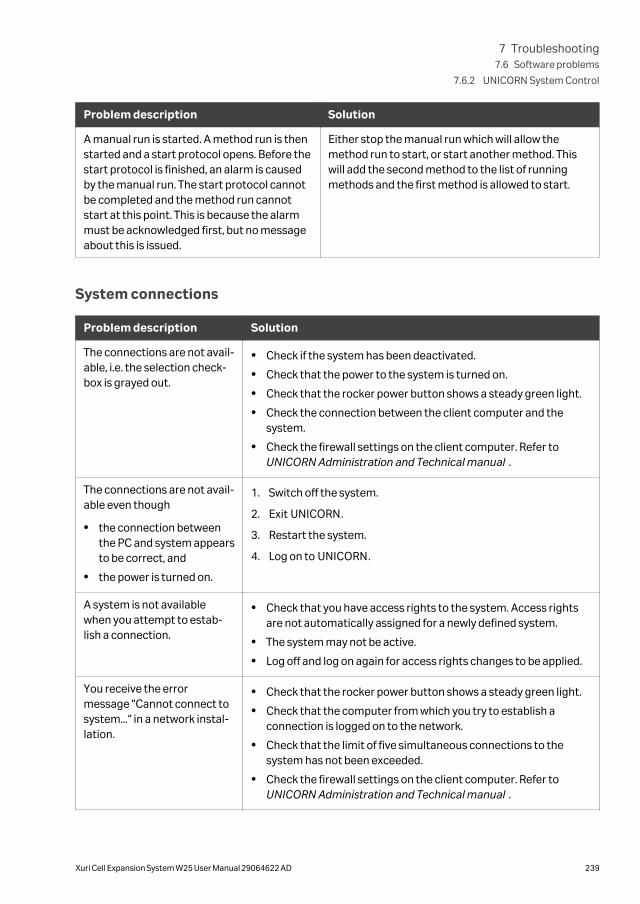
Problem description Solution
A manual run is started. A method run is thenstarted and a start protocol opens. Before thestart protocol is finished, an alarm is causedby the manual run. The start protocol cannotbe completed and the method run cannotstart at this point. This is because the alarmmust be acknowledged first, but no messageabout this is issued.
Either stop the manual run which will allow themethod run to start, or start another method. Thiswill add the second method to the list of runningmethods and the first method is allowed to start.
System connections
Problem description Solution
The connections are not avail-able, i.e. the selection check-box is grayed out.
• Check if the system has been deactivated.
• Check that the power to the system is turned on.
• Check that the rocker power button shows a steady green light.
• Check the connection between the client computer and thesystem.
• Check the firewall settings on the client computer. Refer toUNICORN Administration and Technical manual .
The connections are not avail-able even though
• the connection betweenthe PC and system appearsto be correct, and
• the power is turned on.
1. Switch off the system.
2. Exit UNICORN.
3. Restart the system.
4. Log on to UNICORN.
A system is not availablewhen you attempt to estab-lish a connection.
• Check that you have access rights to the system. Access rightsare not automatically assigned for a newly defined system.
• The system may not be active.
• Log off and log on again for access rights changes to be applied.
You receive the errormessage “Cannot connect tosystem...” in a network instal-lation.
• Check that the rocker power button shows a steady green light.
• Check that the computer from which you try to establish aconnection is logged on to the network.
• Check that the limit of five simultaneous connections to thesystem has not been exceeded.
• Check the firewall settings on the client computer. Refer toUNICORN Administration and Technical manual .
7 Troubleshooting7.6 Software problems
7.6.2 UNICORN System Control
Xuri Cell Expansion System W25 User Manual 29064622 AD 239

Problem description Solution
You receive the errormessage "Warning, systemoccupied" when trying toconnect.
This error message is displayed if a system is defined and active intwo different UNICORN database instances and is alreadyconnected in the other instance. It is not recommended to have asystem defined and active in more than one UNICORN databaseinstance.
7 Troubleshooting7.6 Software problems
7.6.2 UNICORN System Control
240 Xuri Cell Expansion System W25 User Manual 29064622 AD
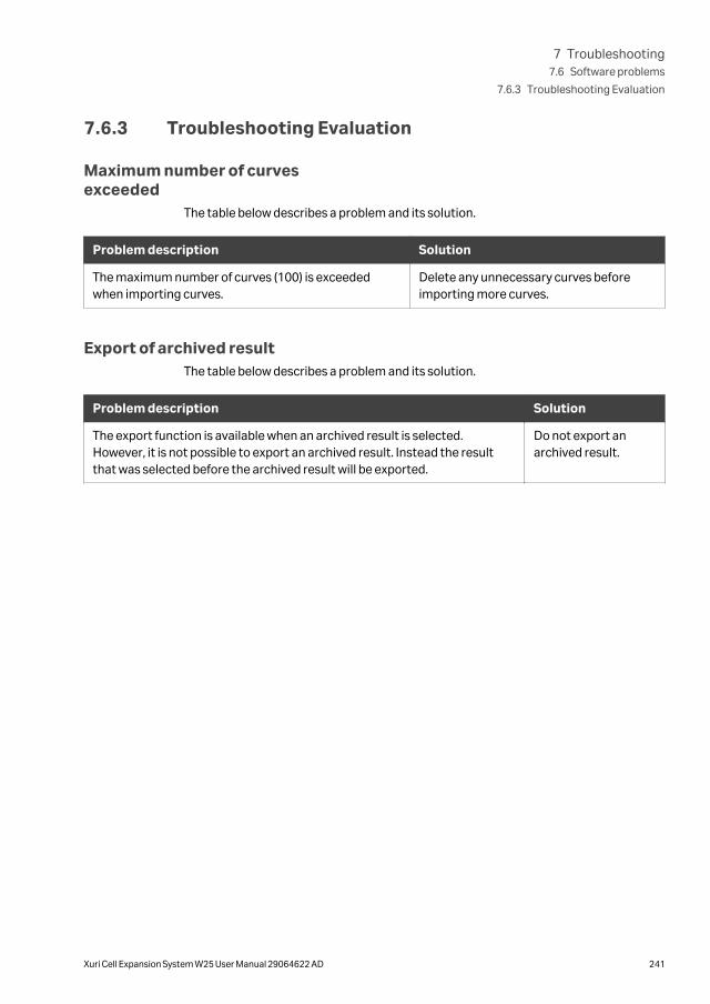
7.6.3 Troubleshooting Evaluation
Maximum number of curvesexceeded
The table below describes a problem and its solution.
Problem description Solution
The maximum number of curves (100) is exceededwhen importing curves.
Delete any unnecessary curves beforeimporting more curves.
Export of archived resultThe table below describes a problem and its solution.
Problem description Solution
The export function is available when an archived result is selected.However, it is not possible to export an archived result. Instead the resultthat was selected before the archived result will be exported.
Do not export anarchived result.
7 Troubleshooting7.6 Software problems
7.6.3 Troubleshooting Evaluation
Xuri Cell Expansion System W25 User Manual 29064622 AD 241
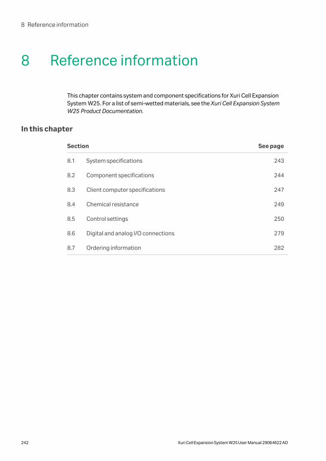
8 Reference information
This chapter contains system and component specifications for Xuri Cell ExpansionSystem W25. For a list of semi-wetted materials, see the Xuri Cell Expansion SystemW25 Product Documentation.
In this chapter
Section See page
8.1 System specifications 243
8.2 Component specifications 244
8.3 Client computer specifications 247
8.4 Chemical resistance 249
8.5 Control settings 250
8.6 Digital and analog I/O connections 279
8.7 Ordering information 282
8 Reference information
242 Xuri Cell Expansion System W25 User Manual 29064622 AD

8.1 System specifications
The table below lists the system specifications of Xuri Cell Expansion System W25.
Parameter Data
System configuration Benchtop system, external computer
Control system UNICORN 7 or higher version
Rocker embedded PC operating system Windows embedded standard 7
Connection between PC and instru-ment
Ethernet or network
Power supply 100 to 240 V ~, 50 to 60 Hz
Note:
The rocker is fitted with internal elec-trical fuses that are not user-replace-able.
Power consumption Maximum 1500 VA
Enclosure protective class IP 21
External air supply (per CBCU) 1.0 to 1.5 bar
Normal use: 1.3 L/min
Fast fill: 3.5 L/min
External CO2 supply (per CBCU) 1.0 to 1.5 bar
Normal use: 0.2 L/min
Fast fill: 0.5 L/min
External O2 supply (per CBCU) 1.0 to 1.5 bar
Normal use: 0.7 L/min
Fast fill: 1.7 L/min
Operating ambient temperature range 15°C to 32°C
Operating humidity range 20% to 80% relative humidity (noncon-densing)
8 Reference information8.1 System specifications
Xuri Cell Expansion System W25 User Manual 29064622 AD 243

8.2 Component specifications
Equipment dimensions and weightThe table below lists the outer dimensions and weights of the bioreactor system units.
System unit Dimensions, W x H x D (mm) Weight (kg)
Rocker 404 x 205 x 560 24.0
CBCU 276 x 117 x 360 4.8
Pump 275 x 115 x 280 3.8
Tray 10 475 x 60 x 43 4.5
Tray 20 740 x 70 x 480 7.3
Tray 50 800 x 70 x 610 9.5
Lid 10 475 x 230 x 430 1.7
Lid 20 740 x 245 x 480 3.3
Lid 50 800 x 260 x 610 3.9
Rocker specificationsThe table below lists the system specifications of the Rocker.
Parameter Data
Rocking speed control range1 2 to 40 rpm
Rocking angle control range1 2° to 12°
Rocking speed profile range 15% to 100%
The % value refers to the fraction of theangular displacement function that issinusoidally shaped
15% gives an almost constant angularvelocity
100% gives a sinusoidal rocking
Media weight control range 0.5 to 25 kg
Scale, absolute accuracy (single mode) ±(0.050 + 1% of load) kg
Scale, left/right absolute accuracy (dualmode)
±(0.1 + 6% of load) kg
8 Reference information8.2 Component specifications
244 Xuri Cell Expansion System W25 User Manual 29064622 AD

Parameter Data
Temperature sensor Pt100 Class A
Temperature measurement range 2°C to 50°C
Temperature setpoint difference (dualmode)
Max 10°C at ambient 21°C
Setpoint difference reduced by 1°C foreach °C increase in ambient tempera-ture (e.g., at ambient 25°C, max setpointdifference is 6°C)
Temperature control range (Ambient temperature + 5°C) to 40°C
Temperature control accuracy (excl.measurement error)
±0.2°C
1 For Tray 50, the product of rocking speed and rocking angle should not exceed 240 (e.g., with a rockingangle of 12° the rocking speed should not exceed 20 rpm).
Xuri Cell Expansion W25 CBCUspecifications
The table below lists the primary system specifications of the CBCU.
Parameter Data
Gas flow control range 50 to 1000 mL/min
Total gas flow accuracy (reference flow -setpoint)
±(10 + 3% of read value) mL/min
Fast fill flow ~3 L/min
CO2 control range 0% to 15% CO2
CO2 measurement accuracy at 5% CO2 ±0.5% CO2 when mixed only with air/N2
CO2 control accuracy (versus setpoint) ±0.4% CO2
O2 control range 0% to 50% O2 when mixed with N2
21% to 50% O2 when mixed with air
O2 measurement accuracy ±(0.6 + 1% of read value) within 0% to50% O2, when mixed only with air/N2
O2 control accuracy (versus setpoint) ±0.6% O2
pH measurement range pH 4.5 to 8.5
pH control range pH 6.0 to 8.0
8 Reference information8.2 Component specifications
Xuri Cell Expansion System W25 User Manual 29064622 AD 245

Parameter Data
pH measurement accuracy ±0.05 pH within ±0.25 pH from offsetcalibration pH
±0.1 pH within 0.25 to 0.5 pH from offsetcalibration pH
pH control accuracy (versus setpoint) ±0.05 pH
DO measurement range 0% to 250% air saturation
DO measurement accuracy ±5% air saturation, excluding atmos-pheric pressure variations
DO control range 0% to 100% air saturation
Xuri Cell Expansion W25 Pumpspecifications
The table below lists the system specifications of Xuri Cell Expansion W25 Pump .
Note: Different tubing dimensions are required to cover the full flow rate range ofthe pump (see Pump tubing sizes, on page 159). Pump tubing is not suppliedwith the system and must be purchased separately.
Parameter Data
Pump flow rate range 0.1 to 144 L /day (0.07 to 100 mL/min)
Pump flow rate accuracy ±(0.1 + 5% of read value) mL/min aftercalibration
Accumulated pumped volume accuracy ±10% of measured volume
Supported tubing dimensions Inner diameter: 0.5 to 4.8 mm (1/50" to3/16")
Wall thickness: 1.6 mm (1/16")
8 Reference information8.2 Component specifications
246 Xuri Cell Expansion System W25 User Manual 29064622 AD

8.3 Client computer specifications
IntroductionThe table below lists client computer specifications for a UNICORN 7.x system for usewith Xuri Cell Expansion System W25.
Xuri Cell Expansion System W25 is supplied with UNICORN 7.x, which requiresWindows 7. If you wish to use Xuri Cell Expansion System W25 with an earlier version ofUNICORN, contact Cytiva for assistance.
General computer specifications
Installation is supported for Windows 7 Professional, 32-bit or 64-bit, with Service Pack1 or Windows 10 Professional 64-bit.
For information about compatibility between UNICORN versions and the supportedoperating systems and database versions see the UNICORN compatibility matrix athttp://www.cytiva.com/UNICORNcompatibility.
UNICORN Client Database Server Workstationinstallation
E-LicenseServer
Min. free diskspace
16 GB 10 GB 27 GB 500 MB
Min. availableRAM
4 GB 4 GB 4 GB 2 GB
Disc format NTFS NTFS NTFS NTFS
Architecture Quad-coreprocessor or 4logical processor
Quad-coreprocessor or 4logical processor
Quad-coreprocessor or 4logical processor
Multi-coreprocessor
Note: • UNICORN is tested using the English (U.S.) Code 1033 operating systemlanguage version. Using other language versions of the operating systemmay cause errors.
• A screen resolution of 1280x1024 or higher is recommended. Parts of theUNICORN user interface may not be displayed properly using a lowerresolution.
• Changing the default font and changing the font size from 100% inWindows may cause problems in the UNICORN user interface.
• The Windows basic color scheme is recommended1.
• Using the Windows 7 Aero color scheme is not recommended.
• Windows power save features should be turned off to avoid conflicts withsystem operations.
1 UNICORN must be closed when the color scheme is changed.
8 Reference information8.3 Client computer specifications
Xuri Cell Expansion System W25 User Manual 29064622 AD 247

• UNICORN is not compatible with the Windows 7 feature High DPI Aware-ness, which allows the graphic user interface to be scaled. The interfacescale must remain at 100% to avoid issues with clipping and misaligningof parts of the UNICORN user interface. Normally, the scale is set at100% by default.
8 Reference information8.3 Client computer specifications
248 Xuri Cell Expansion System W25 User Manual 29064622 AD

8.4 Chemical resistanceThe chemicals listed below have been approved for use with the bioreactor system.
Chemical Concentra-tion
Use CAS no./EC no.
Alconox N/A Cleaning/Disinfection N/A
DesiDos N/A Cleaning/Disinfection N/A
Ethanol 70% Cleaning/Disinfection 75-08-1/200-837-3
Hydrochloric acid 1 M pH control 7647-01-0/231-595-7
Isopropanol 70% Cleaning/Disinfection 67-63-0/200-661-7
Klercide N/A Cleaning/Disinfection N/A
PBS solution 10× Testing N/A
Sodium bicarbonate 7.5% pH control 144-55-8/205-633-8
Sodium carbonate 1 M pH control 497-19-8/207-838-8
Sodium chloride 5 M Testing 7647-14-5/231-598-3
Sodium hydroxide 1 M pH control 1310-73-2/215-185-5
Sodium hypochlorite 1% Cleaning/Disinfection 7681-52-9/231-668-3
Virkon 1% Cleaning/Disinfection N/A
8 Reference information8.4 Chemical resistance
Xuri Cell Expansion System W25 User Manual 29064622 AD 249

8.5 Control settingsThis section lists the different control settings that can be made in UNICORN.
In this section
Section See page
8.5.1 Rocking control 251
8.5.2 Heating control 254
8.5.3 Gas flow control 255
8.5.4 CO2 mix control 257
8.5.5 O2 mix control 258
8.5.6 Pump control 259
8.5.7 pH measurement 261
8.5.8 pH control 263
8.5.9 DO measurement 270
8.5.10 DO control 272
8.5.11 Media control 276
8 Reference information8.5 Control settings
250 Xuri Cell Expansion System W25 User Manual 29064622 AD

8.5.1 Rocking control
Rocking control settingsThe following table shows general settings used for rocking control.
Setting Description Set from View from
PP MI PP RD CD
Speedsetpoint
The number of rocking cycles per minute. Settings:Rocking
Rocker:Rocking
Y - -
Anglesetpoint
The maximum angle between the tray andthe horizontal plane during a rockingcycle.
Settings:Rocking
Rocker:Rocking
Y - Y
Stopangle
The angle between tray and horizontalplane the tray will settle at when therocking is stopped. At a positive stopangle, the tray will lean towards the frontside of the rocker and vice versa.
Settings:Rocking
Rocker:Rocking
Y - -
Samplingmodeduration
The number of minutes the rocker will stayin sampling mode, before it automaticallystarts to rock again. See help text forEnter sampling mode instruction tolearn more about sampling mode.
Settings:Rocking
Rocker:Rocking
Y - -
Cellbagsize (totalvolume)
The Cellbag size defined in total volume(liquid and head space).
Settings:Cellbag
Rocker:Cellbag size
Y - -
Digitaloutput
Sets the outputs of the digital outputports.
- Rocker:Digital output
- Y -
Rockingmotion
Defines the share of the rocking cyclewhere the speed curve is sinusoid. Thelowest value (15%) provides a rockingmotion similar to the Wave 20/50 system.The highest value (100%) will give acompletely sinusoidal speed curve.
- Rocker:Set rockingmotion
- Y -
Auto startmode
By setting this parameter to Not resumeactivity, rocking or heating will not startautomatically at startup of the system atany time. When the parameter is set toResume activity, rocking and heating willstart automatically at startup, if it was onwhen the system was shut down withoutgiven an END command.
- System settings→Auto start→Rocker
- - -
Preparefor tilt atEND
If No the rocking platform will not preparefor tilt at system END, if Yes, the rockingplatform will prepare for tilt at systemEND.
- System settings→Rocker
- - -
8 Reference information8.5 Control settings
8.5.1 Rocking control
Xuri Cell Expansion System W25 User Manual 29064622 AD 251

Setting Description Set from View from
PP MI PP RD CD
Analoginput 1inputmode
Defines how signals from the analog 1input port shall be interpreted. The inputsignal will be converted to a percentage [0to 100]. To be able to select the two ‘mA’options, the input port hardware must bereconfigured by Service.
System settings→Rocker
- - -
Analoginput 2inputmode
Defines how signals from the analog 2input port shall be interpreted. The inputsignal will be converted to a percentage [0to 100]. To be able to select the two ‘mA’options, the input port hardware must bereconfigured by Service.
System settings→Rocker
- - -
Note: The following abbreviations are used in the table: PP = Process Picture; MI= Manual instruction; RD = Run data; CD = Curve data; Y = Yes; - = No orNot applicable.
Rocking control output data
Data Description View from
PP RD CD
Rocking speed meas-urement
The actual rocking speed, measured by the rocker. Y - Y
Time left in samplingmode
The time left until the rocker starts to rock when in sampling mode. Unit [s]. - Y -
Weight The weight measured by the rocker. If tared correctly, it should correspond tothe weight of the content of the Cellbag.
Y Y Y
Weight L Shows the weight of the left Cellbag content in dual mode. The bags must becentered on each half of the tray and a tare must be performed to ensureaccuracy of this measurement.
Y Y Y
Weight R Shows the weight of the right Cellbag content in dual mode. The bags mustbe centered on each half of the tray and a tare must be performed to ensureaccuracy of this measurement.
Y Y Y
Detected tray type Shows the tray type detected by the rocker. - Y -
Weight share front left Percentage of the weight load on the front left load cell. Y - -
Weight share frontright
Percentage of the weight load on the front right load cell. Y - -
Weight share rear left Percentage of the weight load on the rear left load cell. Y - -
Weight share rearright
Percentage of the weight load on the rear right load cell. Y - -
Digital input 1 Shows if the digital input 1 is 0 or 1. - Y -
Digital input 2 Shows if the digital input 2 is 0 or 1. - Y -
8 Reference information8.5 Control settings
8.5.1 Rocking control
252 Xuri Cell Expansion System W25 User Manual 29064622 AD

Data Description View from
PP RD CD
Digital input 3 Shows if the digital input 3 is 0 or 1. - Y -
Digital input 4 Shows if the digital input 4 is 0 or 1. - Y -
Analog input 1 Shows the analog input 1 in percent. - Y Y
Analog input 2 Shows the analog input 2 in percent. - Y Y
Note: The following abbreviations are used in the table: PP = Process Picture; RD= Run data; CD = Curve data; Y = Yes; - = No or Not applicable.
8 Reference information8.5 Control settings
8.5.1 Rocking control
Xuri Cell Expansion System W25 User Manual 29064622 AD 253

8.5.2 Heating control
Heating control settingsThe following table shows general settings used for heating control.
Setting Description Set from View from
PP MI PP RD CD
Tempera-turesetpoint
The temperature setpoint of the liquid inthe Cellbag.
Settings:Temp
Heating:Heating
Y - Y
Deviationalarm
Enables or disables the deviation alarm. Settings:Temp
Heating:Heating
Y - -
Alloweddeviationup
Sets the extent to which the temperaturecan vary above the setpoint without trig-gering the deviation alarm.
Settings:Temp
Heating:Heating
Y - -
Alloweddeviationdown
Sets the extent to which the temperaturecan vary below the setpoint without trig-gering the deviation alarm.
Settings:Temp
Heating:Heating
Y - -
Deviationalarmdelay
Sets the time for which the temperaturemust be outside the defined alarm limitsbefore the deviation alarm is triggered.The timer is reset if the temperature fallsback within the limits before the alarm istriggered.
- Heating:Heating
- Y -
Heatenabling
When set to Enabled, the heating will beon when the rocking is on. When set toDisabled, the heating will be off.
- System settings→Heating→Heaterenabling
- - -
Note: The following abbreviations are used in the table: PP = Process Picture; MI= Manual instruction; RD = Run data; CD = Curve data; Y = Yes; - = No orNot applicable.
Heating control output data
Data Description View from
PP RD CD
Temperature meas-urement
The measured Cellbag temperature. Y - Y
Note: The following abbreviations are used in the table: PP = Process Picture; RD= Run data; CD = Curve data; Y = Yes; - = No or Not applicable.
8 Reference information8.5 Control settings
8.5.2 Heating control
254 Xuri Cell Expansion System W25 User Manual 29064622 AD

8.5.3 Gas flow control
Gas flow control settingsThe following table shows general settings used for gas flow control.
Setting Description Set from View from
PP MI PP RD CD
Gas flowsetpoint
The gas flow controller setpoint to theCellbag.
Settings:Gas control:Gas flow
Gas flow:Gas flow
Y - Y
Deviationalarm
Enables or disables the deviation alarm. Settings:Gas control:Gas flow
Gas flow:Gas flow
Y - -
Alloweddeviationup
Sets the extent to which the gas flow canvary above the setpoint without triggeringthe deviation alarm.
Settings:Gas control:Gas flow
Gas flow:Gas flow
Y - -
Alloweddeviationdown
Sets the extent to which the gas flow canvary below the setpoint without triggeringthe deviation alarm.
Settings:Gas control:Gas flow
Gas flow:Gas flow
Y - -
Deviationalarmdelay
Sets the time for which the gas flow mustbe outside the defined alarm limits beforethe deviation alarm is triggered. The timeris reset if the gas flow falls back within thelimits before the alarm is triggered.
- Gas flow:Gas flow
- Y -
Air source If set to Compressed air, compressed airshall be connected to the inlet on the backof the CBCU. If set to N2, pressurizednitrogen shall be connected to the inlet onthe back of the CBCU.
- Gas flow:Air source
Y - -
Auto startmode
By setting this parameter to Not resumeactivity gas mixing will not start automat-ically at startup of the system at any time.When the parameter is set to Resumeactivity, the gas mixing will start auto-matically at start-up, if it was on when thesystem was shut down (without first goingto END).
- System settings→Auto start→CBCU
- - -
Note: The following abbreviations are used in the table: PP = Process Picture; MI= Manual instruction; RD = Run data; CD = Curve data; Y = Yes; - = No orNot applicable.
8 Reference information8.5 Control settings
8.5.3 Gas flow control
Xuri Cell Expansion System W25 User Manual 29064622 AD 255

Gas flow control output data
Data Description View from
PP RD CD
Gas flow measure-ment
The measured gas flow from the CBCU. Y - Y
Note: The following abbreviations are used in the table: PP = Process Picture; RD= Run data; CD = Curve data; Y = Yes; - = No or Not applicable.
8 Reference information8.5 Control settings
8.5.3 Gas flow control
256 Xuri Cell Expansion System W25 User Manual 29064622 AD

8.5.4 CO2 mix control
CO2 mix control settingsThe following table shows general settings used for CO2 mix control.
Setting Description Set from View from
PP MI PP RD CD
CO2 Mixsetpoint
The gas mixer target CO2 concentrationsetpoint.
Settings →Gascontrol →CO2
CO2 mix:CO2 mix
Y - Y
Deviationalarm
Enables or disables the deviation alarm. Settings →Gascontrol →CO2
CO2 mix:CO2 mix
Y - -
Alloweddeviationup
Sets the extent to which the CO2 concen-tration delivered to the Cellbag can varyabove the setpoint without triggering thedeviation alarm.
Settings →Gascontrol →CO2
CO2 mix:CO2 mix
Y - -
Alloweddeviationdown
Sets the extent to which the CO2 concen-tration delivered to the Cellbag can varybelow the setpoint without triggering thedeviation alarm.
Settings →Gascontrol →CO2
CO2 mix:CO2 mix
Y - -
Deviationalarmdelay
Sets the time for which the CO2 concen-tration must be outside the defined alarmlimits before the deviation alarm is trig-gered. The timer is reset if the CO2
concentration falls back within the limitsbefore the alarm is triggered.
- CO2 mix:CO2 mix
- Y -
Note: The following abbreviations are used in the table: PP = Process Picture; MI= Manual instruction; RD = Run data; CD = Curve data; Y = Yes; - = No orNot applicable.
CO2 mix control output data
Data Description View from
PP RD CD
CO2 measurement The measured CO2 concentration from the CBCU. Y - Y
Note: The following abbreviations are used in the table: PP = Process Picture; RD= Run data; CD = Curve data; Y = Yes; - = No or Not applicable.
8 Reference information8.5 Control settings
8.5.4 CO2 mix control
Xuri Cell Expansion System W25 User Manual 29064622 AD 257

8.5.5 O2 mix control
O2 mix control settingsThe following table shows general settings used for O2 mix control.
Setting Description Set from View from
PP MI PP RD CD
O2 Mixsetpoint
The gas mixer target O2 concentrationsetpoint.
Settings →Gascontrol →O2
O2 mix:O2 mix
Y - Y
Deviationalarm
Enables or disables the deviation alarm. Settings →Gascontrol →O2
O2 mix:O2 mix
Y - -
Alloweddeviationup
Sets the extent to which the O2 concentra-tion delivered to the Cellbag can varyabove the setpoint without triggering thedeviation alarm.
Settings →Gascontrol →O2
O2 mix:O2 mix
Y - -
Alloweddeviationdown
Sets the extent to which the O2 concentra-tion delivered to the Cellbag can varybelow the setpoint without triggering thedeviation alarm.
Settings →Gascontrol →O2
O2 mix:O2 mix
Y - -
Deviationalarmdelay
Sets the time for which the O2 concentra-tion must be outside the defined alarmlimits before the deviation alarm is trig-gered. The timer is reset if the O2 concen-tration falls back within the limits beforethe alarm is triggered.
- O2 mix:O2 mix
- Y -
Note: The following abbreviations are used in the table: PP = Process Picture; MI= Manual instruction; RD = Run data; CD = Curve data; Y = Yes; - = No orNot applicable.
O2 mix control output data
Data Description View from
PP RD CD
O2 measurement The measured O2 concentration from the CBCU. Y - Y
Note: The following abbreviations are used in the table: PP = Process Picture; RD= Run data; CD = Curve data; Y = Yes; - = No or Not applicable.
8 Reference information8.5 Control settings
8.5.5 O2 mix control
258 Xuri Cell Expansion System W25 User Manual 29064622 AD

8.5.6 Pump control
General pump settingsThe following table shows general settings used for pump control.
Setting Description Set from View from
PP MI PP RD CD
Pump 25 →1Arole
Assigns pumphead 1A to Acid,Base, Feed or Harvest/Waste
- System settings →Set Pump 25→1A role
Y - -
Pump 25 →1Brole
Assigns pumphead 1B to Acid,Base, Feed or Harvest/Waste
- System settings →Set Pump 25→1B role
Y - -
Pump 25 →2Arole
Assigns pumphead 2A to Acid,Base, Feed or Harvest/Waste
- System settings →Set Pump 25→2A role
Y - -
Pump 25 →2Brole
Assigns pumphead 2B to Acid,Base, Feed or Harvest/Waste
- System settings →Set Pump 25→2B role
Y - -
Note: The following abbreviations are used in the table: PP = Process Picture; MI= Manual instruction; RD = Run data; CD = Curve data; Y = Yes; - = No orNot applicable.
Note: All system settings are sent when any setting is sent. Therefore, check therole assigned to all pump heads before sending a 'role' command, to ensurethat conflicting roles are not assigned to the different pump heads.
Settings for manually running thepumps
The pump settings in this section (except the tubing inner diameter) are only validwhen the pumps are started manually. When the pumps are used by pH or mediacontrol, these settings have no effect. Setting apply individually to each pump head.
Setting Description Set from View from
PP MI PP RD CD
Time mode If Limited is selected the pumpwill run as long as given by Dura-tion. If Continuous is selected,the pump will run until stopped.
Always Contin-uous when startedfrom PP.
Pump control:Start pump
- - -
Duration The time for which the pump willrun, if Time mode is set toLimited. Otherwise this param-eter has no effect.
- Pump control:Start pump
- - -
Rate mode Sets whether the flow or RPMsetpoint will be used when thepump is started manually.
Settings:Cellbag pumps
Pump control:Rate mode
Y - -
8 Reference information8.5 Control settings
8.5.6 Pump control
Xuri Cell Expansion System W25 User Manual 29064622 AD 259

Setting Description Set from View from
PP MI PP RD CD
Pump RPM The RPM at which the pump willrun if started manually in RPMmode.
Settings:Cellbag pumps
Pump control:Pump RPM
Y1 - -
Pump flow The flow rate at which the pumpwill run if started manually in flowmode.
Settings:Cellbag pumps
Pump control:Pump flow
Y2 - -
Tube inner diam-eter
The inner diameter of the tubingfitted to the pump.
Settings:Cellbag pumps
Pump control:Pump flow
Y - -
1 Not shown in process picture when pump is used by pH or Media control, or in flow mode.2 Not shown in process picture when pump is used by pH or Media control, or in RPM mode.
Note: The following abbreviations are used in the table: PP = Process Picture; MI= Manual instruction; RD = Run data; CD = Curve data; Y = Yes; - = No orNot applicable.
Pump control output dataOutput data is available separately for each pump head.
Data Description View from
PP RD CD
Actual flow The estimated flow rate of the pump. Y1 - -
Actual speed The pump rpm, obtained from the pump itself. Y2 - -
Accumulatedvolume
The estimated total volume since last reset. Y - -
Time left of actualshot
This counter shows the remaining running time when the pump isrunning for a limited time. This is the case when the pump is startedmanually for a limited time, during calibration or when used as acid/basepump by pH control.
Y - -
Max possible flow The maximum flow rate obtainable with the currently installed tubing. -3 - -
Min possible flow The minimum flow rate obtainable with the currently installed tubing. -3 - -
Calibration factor The current calibration factor for the pump. - - Y
1 Only shown in process picture when pump is running manually in RPM mode.2 Only shown in process picture when pump is used by pH or Media control, or is running manually in flow mode.3 Shown as tool-tip when entering flow.
Note: The following abbreviations are used in the table: PP = Process Picture; RD= Run data; CD = Curve data; Y = Yes; - = No or Not applicable.
8 Reference information8.5 Control settings
8.5.6 Pump control
260 Xuri Cell Expansion System W25 User Manual 29064622 AD

8.5.7 pH measurement
pHOPT calibration valuesThe pH surrounding the pH sensor is calculated from a measured variable called “thephase angle”. The calculation is based on a transfer equation programmed in thepHOPT monitor. This transfer equation is defined by a set of constants, or, morecorrectly, a set of values that are specific for the mixture of the substances forming theluminophoric dye. This means that the dye properties, and consequently the transferequation, may differ between different dye batches.
The constants for each batch (after gamma irradiation) are determined at the factoryand are printed on the pHOPT label of the Cellbag as calibration values: cmin, cmax,cpH0, and cdpH.
The interpretation of the calibration values on the transfer equation is illustrated in thegraph below:
A fifth calibration value, ctemp, is also necessary. It is not directly included in thetransfer equation, but since the sensor is temperature dependent, the ctemp value isused for fine tuning the pH against the actual temperature.
SettingsThe following table shows pH measurement related settings.
Setting Description Set from View from
PP MI PP RD CD
cmin Calibration value, high pH end ofthe sensor range.
Settings:Cellbag
pH sensor calibrationvalues
Y - -
cmax Calibration value, low pH end ofthe sensor range.
Settings:Cellbag
pH sensor calibrationvalues
Y - -
8 Reference information8.5 Control settings
8.5.7 pH measurement
Xuri Cell Expansion System W25 User Manual 29064622 AD 261

Setting Description Set from View from
PP MI PP RD CD
cpH0 Calibration value, related tooffset calibration.
Settings:Cellbag
pH sensor calibrationvalues
Y - -
cdpH Calibration value, related toresolution.
Settings:Cellbag
pH sensor calibrationvalues
Y - -
ctemp Calibration value, calibrationtemperature.
Settings:Cellbag
pH sensor calibrationvalues
Y - -
Readingcycle time
The reading cycle when pHcontrol is off.
Settings→pH
Set pH reading cycletime
Viewedwhen pHcontrol is off
- -
Reset cali-brationvalues atEND
A System setting that defines ifthe pH calibration values shall bereset or not when the systemgoes to END.
- System settings→pH sensor →Resetcalibration valuesat END
- - -
Note: The following abbreviations are used in the table: PP = Process Picture; MI= Manual instruction; RD = Run data; CD = Curve data; Y = Yes; - = No orNot applicable.
Output data
Data Description View from
PP RD CD
pH measurementtimer
The time left to next pH measurement. - Y -
pH measurementcycle time
The actual measurement cycle time. This value is set by the user whenpH control is off, and by pH control when the pH control is on.
Y - -
pH measurement The latest measured pH value. Y - Y
pH amplitude A measure of the strength of the responsive pH signal received by the pHmonitor.
- - Y
Note: The following abbreviations are used in the table: PP = Process Picture; RD= Run data; CD = Curve data; Y = Yes; - = No or Not applicable.
8 Reference information8.5 Control settings
8.5.7 pH measurement
262 Xuri Cell Expansion System W25 User Manual 29064622 AD

8.5.8 pH control
IntroductionThe following tables describe settings and parameters that can be used for pH control.
General settingsThe following table shows general settings used for pH control.
Setting Description Set from View from
PP MI PP RD CD
Control scheme Select CO2/Base for a combina-tion of CO2 and base as actuators,where the control always starts inCO2 mode. Select Acid/Base fora combination of acid and base asactuators. Select CO2 for usingonly CO2 as actuator.
Settings →pH pH control(general)
Y - -
pH setpoint The pH target value. Settings →pH pH control(general)
Y - Y
Deviation alarm Enables or disables the deviationalarm.
Settings →pH pH control(general)
Y - -
Allowed devia-tion up
Sets the extent to which the pHcan vary above the setpointwithout triggering the deviationalarm.
Settings →pH pH control(general)
Y - -
Allowed devia-tion down
Sets the extent to which thetemperature can vary below thesetpoint without triggering thedeviation alarm.
Settings →pH pH control(general)
Y - -
Deviation alarmdelay
Sets the time for which the pHmust be outside the defined alarmlimits before the deviation alarm istriggered. The timer is reset if thepH falls back within the limitsbefore the alarm is triggered.
- pH control(general)
- Y -
Note: The following abbreviations are used in the table: PP = Process Picture; MI= Manual instruction; RD = Run data; CD = Curve data; Y = Yes; - = No orNot applicable.
CO2 control mode settingsThe following table shows CO2 control mode settings used for pH control.
8 Reference information8.5 Control settings
8.5.8 pH control
Xuri Cell Expansion System W25 User Manual 29064622 AD 263

Setting Description Set from View from
PP MI PP RD CD
Max CO2concentra-tion
The maximum CO2 concentration setpointallowed for the pH control.
- pH control (CO2) - Y -
Min CO2concentra-tion
The minimum CO2 concentration setpointallowed for the pH control.
- pH control (CO2) - Y -
PID param-eter mode
When Auto is selected, the system will auto-matically set the PID parameters. WhenManual is selected, the system will use themanual PID parameters set by this instruc-tion.
- pH control(advanced CO2)
A hand symbolis shown if setto Manual
Y -
Manual P The P-parameter used if PID parametermode is set to Manual.
- pH control(advanced CO2)
- Y -
Manual I The I-parameter used if PID parametermode is set to Manual. Note, that increasingthe I-parameter will reduce the integratingeffect and vice versa.
- pH control(advanced CO2)
- Y -
Manual D The D-parameter used if PID parametermode is set to Manual.
- pH control(advanced CO2)
- Y -
Cycle timemode
When Auto is selected, the system will auto-matically set the cycle time. When Manual isselected, the system will use Manual cycletime.
- pH control(advanced CO2)
A hand symbolis shown if setto Manual
Y -
Manual cycletime
The cycle time used if Cycle time mode is setto Manual.
- pH control(advanced CO2)
- Y -
Note: The following abbreviations are used in the table: PP = Process Picture; MI= Manual instruction; RD = Run data; CD = Curve data; Y = Yes; - = No orNot applicable.
CO2 control mode output data
Data Description View from
PP RD CD
Auto pH CO2 P The P-parameter used if PID parameter mode is set to Auto. - Y -
Auto pH CO2 I The I-parameter used if PID parameter mode is set to Auto. - Y -
Auto pH CO2 D The D-parameter used if PID parameter mode is set to Auto. - Y -
Auto pH CO2 Cycletime
The cycle time used if Cycle time mode is set to Auto. - Y -
Note: The following abbreviations are used in the table: PP = Process Picture; RD= Run data; CD = Curve data; Y = Yes; - = No or Not applicable.
8 Reference information8.5 Control settings
8.5.8 pH control
264 Xuri Cell Expansion System W25 User Manual 29064622 AD

Acid/Base control mode settingsThe following table shows Acid/Base control mode settings used for pH control.
Setting Description Set from View from
PP MI PP RD CD
Acidmolarity
The molarity of theacid used expressedas equivalent HClconcentration(mol/L). If thestrength (pKa) of theselected acid differsfrom that of HCl,estimate the equiva-lent molarity.Entering lowermolarity will result inaddition of largervolumes by the pHcontrol, and viceversa.
Settings:Cellbag pumps
pH control(acid)
Y - -
Basemolarity
The molarity of thebase used expressedas equivalent NaOHconcentration(mol/L). If thestrength (pKb) of theselected acid differsfrom that of NaOH,estimate the equiva-lent molarity.Entering lowermolarity will result inaddition of largervolumes by the pHcontrol, and viceversa.
Settings:Cellbag pumps
pH control(base)
Y - -
PIDparametermode
When Auto isselected, the systemwill automaticallyset the PID parame-ters. When Manualis selected, thesystem will use themanual PID parame-ters set by thisinstruction.
- pH control(advancedacid/base)
A hand symbolis shown if setto Manual
X -
Manual P The P-parameterused if PID param-eter mode is set toManual.
- pH control(advancedacid/base)
- Y -
8 Reference information8.5 Control settings
8.5.8 pH control
Xuri Cell Expansion System W25 User Manual 29064622 AD 265
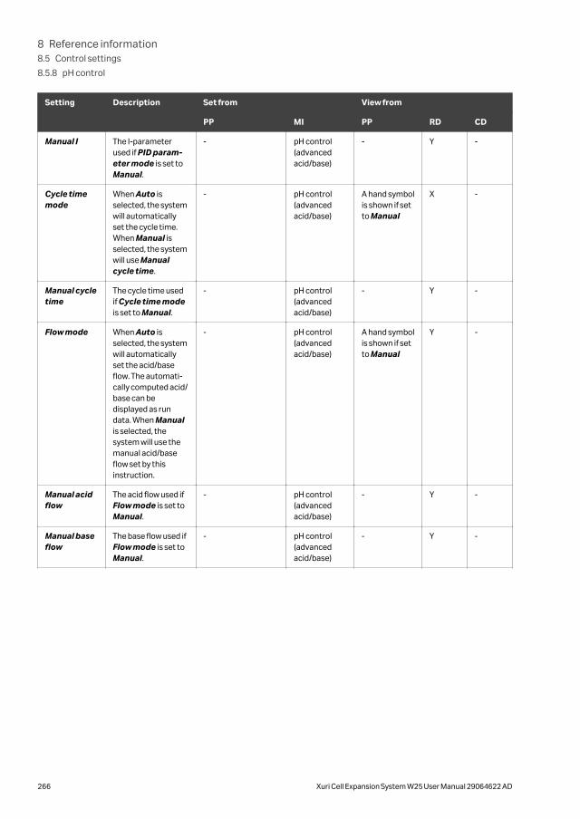
Setting Description Set from View from
PP MI PP RD CD
Manual I The I-parameterused if PID param-eter mode is set toManual.
- pH control(advancedacid/base)
- Y -
Cycle timemode
When Auto isselected, the systemwill automaticallyset the cycle time.When Manual isselected, the systemwill use Manualcycle time.
- pH control(advancedacid/base)
A hand symbolis shown if setto Manual
X -
Manual cycletime
The cycle time usedif Cycle time modeis set to Manual.
- pH control(advancedacid/base)
- Y -
Flow mode When Auto isselected, the systemwill automaticallyset the acid/baseflow. The automati-cally computed acid/base can bedisplayed as rundata. When Manualis selected, thesystem will use themanual acid/baseflow set by thisinstruction.
- pH control(advancedacid/base)
A hand symbolis shown if setto Manual
Y -
Manual acidflow
The acid flow used ifFlow mode is set toManual.
- pH control(advancedacid/base)
- Y -
Manual baseflow
The base flow used ifFlow mode is set toManual.
- pH control(advancedacid/base)
- Y -
8 Reference information8.5 Control settings
8.5.8 pH control
266 Xuri Cell Expansion System W25 User Manual 29064622 AD
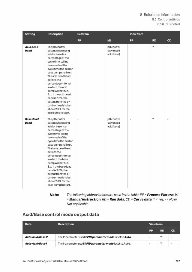
Setting Description Set from View from
PP MI PP RD CD
Acid deadband
The pH controloutput when usingacid or base is apercentage of thecycle time, tellinghow much of thecycle time the acid orbase pump shall run.The acid dead banddefines thepercentage intervalin which the acidpump will not run.E.g., if the acid deadband is 2.0%, theoutput from the pHcontrol needs to beabove 2.0% for theacid pump to start.
- pH control(advancedacid/base)
- Y -
Base deadband
The pH controloutput when usingacid or base, is apercentage of thecycle time, tellinghow much of thecycle time the acid orbase pump shall run.The base dead banddefines thepercentage intervalin which the basepump will not run.E.g., if the base deadband is 2.0%, theoutput from the pHcontrol needs to beabove 2.0% for thebase pump to start.
- pH control(advancedacid/base)
- Y -
Note: The following abbreviations are used in the table: PP = Process Picture; MI= Manual instruction; RD = Run data; CD = Curve data; Y = Yes; - = No orNot applicable.
Acid/Base control mode output data
Data Description View from
PP RD CD
Auto Acid/Base P The P-parameter used if PID parameter mode is set to Auto. - Y -
Auto Acid/Base I The I-parameter used if PID parameter mode is set to Auto. - Y -
8 Reference information8.5 Control settings
8.5.8 pH control
Xuri Cell Expansion System W25 User Manual 29064622 AD 267

Data Description View from
PP RD CD
Auto pH acid/basecycle time
The cycle time used if Cycle time mode is set to Auto. - Y -
pH acid/base regu-lator output
The output of the acid/base control, expressed as pump run time in % ofthe cycle time. Negative values shall be interpreted as acid, positivevalues as base.
- Y Y
Note: The following abbreviations are used in the table: PP = Process Picture; RD= Run data; CD = Curve data; Y = Yes; - = No or Not applicable.
Transition delay settingsThe following table shows the transition delay settings used for pH control.
Setting Description Set from View from
PP MI PP RD CD
CO2/Base tran-sition delaymode
When Auto is selected,the system will automat-ically set the transitiondelay time. The automat-ically computed transi-tion delay times can bedisplayed as run data.When Manual isselected, the system willuse the manual transi-tion delay times set bythis instruction.
- pH control (tran-sition delays)
A handsymbol isshown ifset toManual
Y -
Manual CO2 tobase delay
The transition delay timefrom CO2 to base controlused if CO2/Base tran-sition delay mode is setto Manual.
- pH control (tran-sition delays)
- Y -
Manual base toCO2 delay
The transition delay timefrom base to CO2 controlused if CO2/Base tran-sition delay mode is setto Manual.
- pH control (tran-sition delays)
- Y -
Transition delay output data
Data Description View from
PP RD CD
Auto CO2 to basetransition delay
The CO2 to base transition delay time used if pH CO2/base transitiondelay mode is set to Auto.
- Y -
8 Reference information8.5 Control settings
8.5.8 pH control
268 Xuri Cell Expansion System W25 User Manual 29064622 AD

Data Description View from
PP RD CD
Auto base to CO2transition delay
The base to CO2 transition delay time used if pH CO2/base transitiondelay mode is set to Auto.
- Y -
Note: The following abbreviations are used in the table: PP = Process Picture; RD= Run data; CD = Curve data; Y = Yes; - = No or Not applicable.
8 Reference information8.5 Control settings
8.5.8 pH control
Xuri Cell Expansion System W25 User Manual 29064622 AD 269

8.5.9 DO measurement
DOOPT calibration valuesThe DO surrounding the DO sensor is calculated from a measured variable called “thephase angle”. The calculation is based on a transfer equation programmed in theDOOPT monitor. This transfer equation is defined by a set of constants, or, morecorrectly, a set of values that are specific for the mixture of the substances forming theluminophoric dye. This means that the dye properties, and consequently the transferequation, may differ between different dye batches.
The constants for each batch (after gamma irradiation) are determined at the factoryand are printed on the DOOPT label of the Cellbag as calibration values: clhp, and clzp.
The interpretation of the calibration values on the transfer equation is illustrated in thegraph below:
The calibration values clht and clzt are temperatures recorded during the factory cali-bration. They are used by the DO monitor for temperature compensation.
The calibration value calp is the atmospheric pressure during the factory calibration. Itis not used by the DO monitor, but is kept for informative purpose.
8 Reference information8.5 Control settings
8.5.9 DO measurement
270 Xuri Cell Expansion System W25 User Manual 29064622 AD
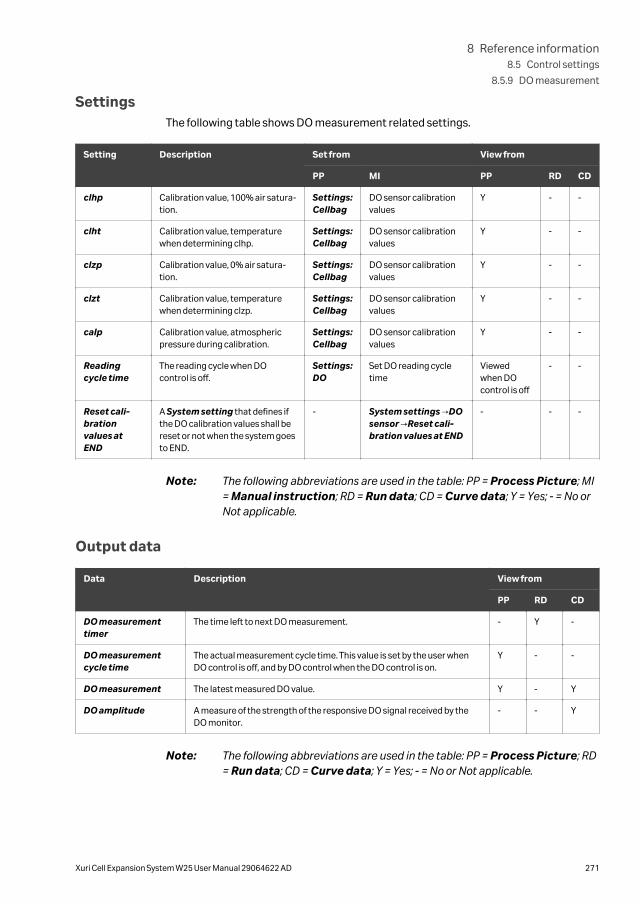
SettingsThe following table shows DO measurement related settings.
Setting Description Set from View from
PP MI PP RD CD
clhp Calibration value, 100% air satura-tion.
Settings:Cellbag
DO sensor calibrationvalues
Y - -
clht Calibration value, temperaturewhen determining clhp.
Settings:Cellbag
DO sensor calibrationvalues
Y - -
clzp Calibration value, 0% air satura-tion.
Settings:Cellbag
DO sensor calibrationvalues
Y - -
clzt Calibration value, temperaturewhen determining clzp.
Settings:Cellbag
DO sensor calibrationvalues
Y - -
calp Calibration value, atmosphericpressure during calibration.
Settings:Cellbag
DO sensor calibrationvalues
Y - -
Readingcycle time
The reading cycle when DOcontrol is off.
Settings:DO
Set DO reading cycletime
Viewedwhen DOcontrol is off
- -
Reset cali-brationvalues atEND
A System setting that defines ifthe DO calibration values shall bereset or not when the system goesto END.
- System settings →DOsensor →Reset cali-bration values at END
- - -
Note: The following abbreviations are used in the table: PP = Process Picture; MI= Manual instruction; RD = Run data; CD = Curve data; Y = Yes; - = No orNot applicable.
Output data
Data Description View from
PP RD CD
DO measurementtimer
The time left to next DO measurement. - Y -
DO measurementcycle time
The actual measurement cycle time. This value is set by the user whenDO control is off, and by DO control when the DO control is on.
Y - -
DO measurement The latest measured DO value. Y - Y
DO amplitude A measure of the strength of the responsive DO signal received by theDO monitor.
- - Y
Note: The following abbreviations are used in the table: PP = Process Picture; RD= Run data; CD = Curve data; Y = Yes; - = No or Not applicable.
8 Reference information8.5 Control settings
8.5.9 DO measurement
Xuri Cell Expansion System W25 User Manual 29064622 AD 271
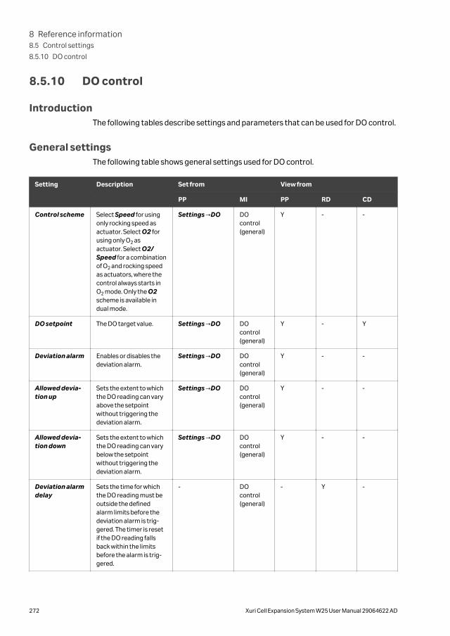
8.5.10 DO control
IntroductionThe following tables describe settings and parameters that can be used for DO control.
General settingsThe following table shows general settings used for DO control.
Setting Description Set from View from
PP MI PP RD CD
Control scheme Select Speed for usingonly rocking speed asactuator. Select O2 forusing only O2 asactuator. Select O2/Speed for a combinationof O2 and rocking speedas actuators, where thecontrol always starts inO2 mode. Only the O2scheme is available indual mode.
Settings →DO DOcontrol(general)
Y - -
DO setpoint The DO target value. Settings →DO DOcontrol(general)
Y - Y
Deviation alarm Enables or disables thedeviation alarm.
Settings →DO DOcontrol(general)
Y - -
Allowed devia-tion up
Sets the extent to whichthe DO reading can varyabove the setpointwithout triggering thedeviation alarm.
Settings →DO DOcontrol(general)
Y - -
Allowed devia-tion down
Sets the extent to whichthe DO reading can varybelow the setpointwithout triggering thedeviation alarm.
Settings →DO DOcontrol(general)
Y - -
Deviation alarmdelay
Sets the time for whichthe DO reading must beoutside the definedalarm limits before thedeviation alarm is trig-gered. The timer is resetif the DO reading fallsback within the limitsbefore the alarm is trig-gered.
- DOcontrol(general)
- Y -
8 Reference information8.5 Control settings
8.5.10 DO control
272 Xuri Cell Expansion System W25 User Manual 29064622 AD

Note: The following abbreviations are used in the table: PP = Process Picture; MI= Manual instruction; RD = Run data; CD = Curve data; Y = Yes; - = No orNot applicable.
O2 control mode settingsThe following table shows O2 control mode settings used for DO control.
Setting Description Set from View from
PP MI PP RD CD
Max O2concentra-tion
The maximum O2 concentration allowed for theDO control.
- DO control(O2)
- Y -
Min O2concentra-tion
The minimum O2 concentration allowed for theDO control.
- DO control(O2)
- Y -
PID param-eter mode
When Auto is selected, the system will auto-matically set the PID parameters. When Manualis selected, the system will use the manual PIDparameters set by this instruction.
- DO control(advanced O2)
A hand symbolis shown if setto Manual
Y -
Manual P The P-parameter used if PID parameter modeis set to Manual.
- DO control(advanced O2)
- Y -
Manual I The I-parameter used if PID parameter modeis set to Manual. Note, that increasing the I-parameter will reduce the integrating effect andvice versa.
- DO control(advanced O2)
- Y -
Manual D The D-parameter used if PID parameter modeis set to Manual.
- DO control(advanced O2)
- Y -
Cycle timemode
When Auto is selected, the system will auto-matically set the cycle time. When Manual isselected, the system will use Manual cycletime.
- DO control(advanced O2)
A hand symbolis shown if setto Manual
Y -
Manual cycletime
The cycle time used if Cycle time mode is set toManual.
- DO control(advanced O2)
- Y -
Note: The following abbreviations are used in the table: PP = Process Picture; MI= Manual instruction; RD = Run data; CD = Curve data; Y = Yes; - = No orNot applicable.
O2 control mode output data
Data Description View from
PP RD CD
Auto DO O2 P The P-parameter used if PID parameter mode is set to Auto. - Y -
Auto DO O2 I The I-parameter used if PID parameter mode is set to Auto. - Y -
8 Reference information8.5 Control settings
8.5.10 DO control
Xuri Cell Expansion System W25 User Manual 29064622 AD 273

Data Description View from
PP RD CD
Auto DO O2 D The D-parameter used if PID parameter mode is set to Auto. - Y -
Auto DO O2 Cycletime
The cycle time used if Cycle time mode is set to Auto. - Y -
Note: The following abbreviations are used in the table: PP = Process Picture; RD= Run data; CD = Curve data; Y = Yes; - = No or Not applicable.
Speed control mode settingsThe following table shows Speed control mode settings used for DO control. Speedcontrol settings are not available in dual mode.
Setting Description Set from View from
PP MI PP RD CD
Max speed The maximum rockingspeed setpoint allowedfor the DO control.
- DO control(speed)
Y - -
Min speed The minimum rockingspeed setpoint allowedfor the DO control.
- DO control(speed)
Y - -
Speed step The change of rockingspeed setpoint at eachcontrol action when DOreading is outside deadband.
- DO control(speed)
Y - -
Control cycle The cycle time of the DOspeed control, i.e., thetime between eachcontrol action.
- DO control(speed)
Y - -
Upper deadband
When DO reading isbetween DO setpointand DO setpoint + upperdead band, there will beno control actions.
- DO control(speed)
- Y -
Lower deadband
When DO reading isbetween DO setpointand DO setpoint – lowerdead band, there will beno control actions.
- DO control(speed)
- Y -
Note: The following abbreviations are used in the table: PP = Process Picture; MI= Manual instruction; RD = Run data; CD = Curve data; Y = Yes; - = No orNot applicable.
8 Reference information8.5 Control settings
8.5.10 DO control
274 Xuri Cell Expansion System W25 User Manual 29064622 AD

Transition delay settingsThe following table shows the transition delay settings used for DO control. Transitiondelay settings are not available in dual mode.
Setting Description Set from View from
PP MI PP RD CD
O2/Speedtransitiondelay mode
When Auto is selected, the system will automat-ically set the transition delay time. The automati-cally computed transition delay times can bedisplayed as run data. When Manual is selected,the system will use the manual transition delaytimes set by this instruction.
- DO control(transition delays)
A handsymbol isshown if setto Manual
Y -
Manual O2 tospeed delay
The transition delay time from O2 to speedcontrol used if O2/Speed transition delaymode is set to Manual.
- DO control(transition delays)
- Y -
Manual speedto O2 delay
The transition delay time from speed to O2
control used if O2/Speed transition delaymode is set to Manual.
- DO control(transition delays)
- Y -
Transition delay output dataTransition delay output data is not available in dual mode.
Data Description View from
PP RD CD
Auto O2 to speedtransition delay
The O2 to speed transition delay time used if O2/speed transitiondelay mode is set to Auto.
- Y -
Auto speed to O2transition delay
The speed to O2 transition delay time used if O2/speed transitiondelay mode is set to Auto.
- Y -
Note: The following abbreviations are used in the table: PP = Process Picture; RD= Run data; CD = Curve data; Y = Yes; - = No or Not applicable.
8 Reference information8.5 Control settings
8.5.10 DO control
Xuri Cell Expansion System W25 User Manual 29064622 AD 275

8.5.11 Media control
Media control settingsThe following table shows general settings used for media control.
Setting Description Set from View from
PP MI PP RD CD
Media controlmode
If Media addition isselected, the feed pumpwill run with the flowgiven by parameter Flowrate, until the weightsetpoint is reached. IfPerfusion is selected,the feed or harvest/waste pump will run withthe flow given by param-eter Flow rate, until theweight setpoint isreached. Then both feedand harvest/wastepumps will run together,keeping the weightsetpoint.
Settings:Media control
Mediacontrol(general)
Y - -
Weightsetpoint
The weight target value. Settings:Media control
Mediacontrol(general)
Y - Y
Weight devia-tion alarm
Enables or disables thedeviation alarm.
Settings:Media control
Mediacontrol(general)
Y - -
Allowed devia-tion up
Sets the extent to whichthe weight can varyabove the setpointwithout triggering thedeviation alarm.
Settings:Media control
Mediacontrol(general)
Y - -
Allowed devia-tion down
Sets the extent to whichthe weight can varyabove the setpointwithout triggering thedeviation alarm.
Settings:Media control
Mediacontrol(general)
Y - -
Deviation alarmdelay
Sets the time for whichthe weight must beoutside the definedalarm limits before thedeviation alarm is trig-gered. The timer is resetif the weight falls backwithin the limits beforethe alarm is triggered.
- Mediacontrol(general)
- Y -
8 Reference information8.5 Control settings
8.5.11 Media control
276 Xuri Cell Expansion System W25 User Manual 29064622 AD

Setting Description Set from View from
PP MI PP RD CD
Flow rate The flow of the feedpump when mediacontrol is on. In perfu-sion, the harvest/wastepump will also start atthis flow rate, and thendo minor flow adjust-ments to keep theweight set-point.
Settings:Media control
Mediacontrol(general)
Y - -
Auto calibra-tion
Select On to activate theauto calibration, and Offto deactivate it. Mediacontrol mode alsoneeds to be set to Perfu-sion, since no auto cali-bration will take place inMedia addition. Whenauto calibration is on, thefeed and harvest/wastepumps will be calibratedautomatically by thesystem when the weightSP is reached, then withthe time interval given byAuto calibration cycle.If an extra auto calibra-tion is wanted, selectOff, and then On again.
Settings:Media control
Mediacontrol(general)
Y - -
Auto calibra-tion cycle
If auto calibration is on,this parameter definesthe time intervalbetween the auto cali-brations.
- Mediacontrol(general)
- Y -
Note: The following abbreviations are used in the table: PP = Process Picture; MI= Manual instruction; RD = Run data; CD = Curve data; Y = Yes; - = No orNot applicable.
Media control output data
Data Description View from
PP RD CD
Momentary/instantweight setpoint
In Media addition mode, the weight setpoint is ramped towards theuser set weight setpoint. This output data shows the current value of theramped setpoint.
- Y Y
Auto calibrationcycle timer
The time left to start of next auto calibration (hours). - Y -
8 Reference information8.5 Control settings
8.5.11 Media control
Xuri Cell Expansion System W25 User Manual 29064622 AD 277

Note: The following abbreviations are used in the table: PP = Process Picture; RD= Run data; CD = Curve data; Y = Yes; - = No or Not applicable.
8 Reference information8.5 Control settings
8.5.11 Media control
278 Xuri Cell Expansion System W25 User Manual 29064622 AD

8.6 Digital and analog I/O connectionsThe rear panel of the rocker has a 15-pin male D-SUB connector, providing four digitalinputs, four digital outputs and two analog inputs for connection to external equip-ment. This section describes the pinout specifications of this connector and details ofthe signals. Contact Cytiva if you require further details of the I/O specifications.
Pinout specificationsThe illustration below shows the pin arrangement for the male D-SUB connector.
Signal Pin Function Normaloperation
Comments
AIN1_P 1 Analog In 1 Positive,0 to 10 V/ to 1 to 20mA (optional)
-0.5 to 11 V Accuracy ±(0.5%reading + 1 digit)
Rin ~50 kΩ (0 to 10 V)
Rin ~500 Ω (0 to 20 mA)AIN1_N 9 Analog In 1 Nega-tive
-0.5 to 1.0 V
AIN2_P 11 Analog In 2 Positive,0 to 10 V/1 to 20 mA(optional)
-0.5 to 11 V
AIN2_N 12 Analog In 2 Nega-tive
-0.5 to 1.0 V
DIN1 15 Digital In 1 < 0.8 V = Off> 2 V = On
relative toDIN_COM
Rin ~1 kΩ
DIN2 8 Digital In 2
DIN3 14 Digital In 3
DIN4 6 Digital In 4
DIN_COM
7 Digital In Common/negative
-0.5 to 32 V
DOUT1 2 Digital Out 1 -0.5 to 32 V Solid state relayoutputs supportingmax 100 mA. Can sinkor source.
DOUT2 3 Digital Out 2
DOUT3 5 Digital Out 3
DOUT4 10 Digital Out 4
8 Reference information8.6 Digital and analog I/O connections
Xuri Cell Expansion System W25 User Manual 29064622 AD 279
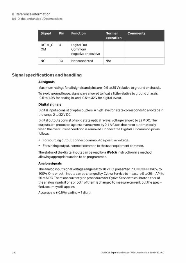
Signal Pin Function Normaloperation
Comments
DOUT_COM
4 Digital OutCommon/negative or positive
NC 13 Not connected N/A
Signal specifications and handling
All signals
Maximum ratings for all signals and pins are -0.5 to 35 V relative to ground or chassis.
To avoid ground loops, signals are allowed to float a little relative to ground chassis:-0.5 to 1.0 V for analog in, and -0.5 to 32 V for digital in/out.
Digital signals
Digital inputs consist of optocouplers. A high level/on state corresponds to a voltage inthe range 2 to 32 V DC.
Digital outputs consist of solid state optical relays, voltage range 0 to 32 V DC. Theoutputs are protected against overcurrent by 0.1 A fuses that reset automaticallywhen the overcurrent condition is removed. Connect the Digital Out common pin asfollows:
• For sourcing output, connect common to a positive voltage.
• For sinking output, connect common to the user equipment common.
The status of the digital inputs can be read by a Watch instruction in a method,allowing appropriate action to be programmed.
Analog signals
The analog input signal voltage range is 0 to 10 V DC, presented in UNICORN as 0% to100%. One or both inputs can be changed by Cytiva Service to measure 0 to 20 mA/4 to20 mA DC. There are currently no procedures for Cytiva Service to calibrate either ofthe analog inputs if one or both of them is changed to measure current, but the speci-fied accuracy still applies.
Accuracy is ±(0.5% reading + 1 digit).
8 Reference information8.6 Digital and analog I/O connections
280 Xuri Cell Expansion System W25 User Manual 29064622 AD
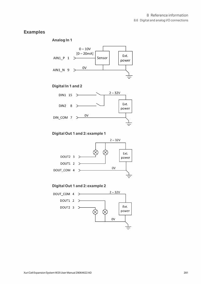
Examples
Analog In 1
Digital In 1 and 2
Digital Out 1 and 2: example 1
Digital Out 1 and 2: example 2
8 Reference information8.6 Digital and analog I/O connections
Xuri Cell Expansion System W25 User Manual 29064622 AD 281
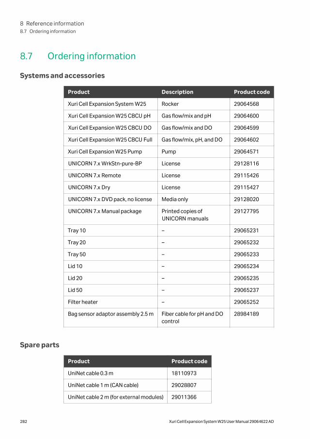
8.7 Ordering information
Systems and accessories
Product Description Product code
Xuri Cell Expansion System W25 Rocker 29064568
Xuri Cell Expansion W25 CBCU pH Gas flow/mix and pH 29064600
Xuri Cell Expansion W25 CBCU DO Gas flow/mix and DO 29064599
Xuri Cell Expansion W25 CBCU Full Gas flow/mix, pH, and DO 29064602
Xuri Cell Expansion W25 Pump Pump 29064571
UNICORN 7.x WrkStn-pure-BP License 29128116
UNICORN 7.x Remote License 29115426
UNICORN 7.x Dry License 29115427
UNICORN 7.x DVD pack, no license Media only 29128020
UNICORN 7.x Manual package Printed copies ofUNICORN manuals
29127795
Tray 10 – 29065231
Tray 20 – 29065232
Tray 50 – 29065233
Lid 10 – 29065234
Lid 20 – 29065235
Lid 50 – 29065237
Filter heater – 29065252
Bag sensor adaptor assembly 2.5 m Fiber cable for pH and DOcontrol
28984189
Spare parts
Product Product code
UniNet cable 0.3 m 18110973
UniNet cable 1 m (CAN cable) 29028807
UniNet cable 2 m (for external modules) 29011366
8 Reference information8.7 Ordering information
282 Xuri Cell Expansion System W25 User Manual 29064622 AD

Product Product code
Mains cable (UK) 18110013
Mains cable, 120 V 19244701
Mains cable, 220 V 19244801
O-ring 5.1 × 1.6 mm, EPDM INDEX 100 18110767
Rubber feet kit 29052858
Tray handle, Cellbag locking handle 29091966
Jumper 1 IEC 1394 29956489
Adjustable foot wrench 29112525
Tubing kit CBCU 29112187
Ethernet cable 28400123
For ordering information for Cellbag bioreactors and accessories, see the Cellbag datafile, product code 28951136.
8 Reference information8.7 Ordering information
Xuri Cell Expansion System W25 User Manual 29064622 AD 283

Index
A
Acid/Base control mode, 120, 121Dead band, 121Flow rate, 120
Adjustable foot, 17Description, 17
Administration module, 37description, 37icons, 37
Alarm, 114, 139Deviation, 114, 139
Assign pump roles, 175Auto calibration, 136, 137
Criteria, 137Pumps, 136
B
Bioreactor, 157Attach, 157
Bioreactor system, 12, 13, 215Description, 12Illustration, 13Troubleshooting, 215
C
CAN ID , 25, 28Description, 25, 28Pump, 28
CBCU, 24, 220Description, 24Status LED, 24Troubleshooting, 220
CBCU specifications, 245Cell cultivation, 141
Tips, 141Cellbag bioreactor, 29, 150, 233
Description, 29Illustration, 29Size selection guide, 150Troubleshooting, 233
Chromatograms, 86Insert a marker for measure-ments, 86
Measure using marker refer-ences, 86
CO2, 146Function verification, 146
CO2 mix control settings, 257Component specification,244–246
CBCU specifications, 245equipment dimensions, 244equipment weight, 244Pump 25 specifications, 246Rocker specifications, 244
Computer specifications, 247Control cycle, 113Control mode, 116, 127Control parameters, 15Control scheme, 116, 127Curves, 86
Highlight in a chromatogram,86Measure using a markerreference, 86
Cycle time, 118, 120, 128, 130Acid/base control, 120CO2 control, 118O2 control, 128Speed control, 130Tuning, 118, 128
D
Deviation alarm, 114DO, 113, 127
Control mode, 127Control scheme, 127Reading cycle, 113
DO control, 128, 130, 131Cycle time and transitiondelays, 131O2 control mode, 128Speed control mode, 130Transition delays, 131
DO control settings, 272–275general, 272O2 control mode, 273Speed control mode, 274transition delay, 275
Index
284 Xuri Cell Expansion System W25 User Manual 29064622 AD

DO measurement, 111principles, 111
DO mesurement settings, 271DO sensor, 30, 154
Connect, 154Description, 30
Documentation, 9Dual mode, 10
E
Edit, 57, 63Method notes, 57Variables, 63
Emergency stop, 138Pumps, 138
Equipment dimensions, 244Equipment weight, 244Evaluation module, 83
description, 83icons, 83
F
Fast fill, 146Function verification, 146
Feed pump, 136Auto calibration, 136
Filter heater, 168Connect to the rocker, 168
Foaming, 142Reduction, 142
G
Gas flow, 142, 145Function verification, 145Operating conditions, 142
Gas flow control settings, 255Gas mix, 164
Connect, 164Description, 164
H
Harvest pump, 136Auto calibration, 136
Harvest/waste pump, 136Auto calibration, 136
Heating control settings, 254Help, 59
Text instructions, 59
Help utility, 34
I
Instrument, 236Components, 236Instrument configuration,236
L
Lid, 18Size, 18
Load cells, 16Log on, 170
UNICORN, 170
M
Manual instructions, 44Media addition mode, 134
Principles, 134Media control, 134, 135
Media addition mode, 134Perfusion mode, 135
Media control settings, 276Method Editor, 67, 68
Saving a method, 67Saving a phase, 68
Method Editor module, 47description, 47icons, 47
Method notes, 57Add to method, 57Edit, 57
Method queues, 77, 78Create, 77Mulitple systems, 78
Methods, 49, 51, 53, 56, 57, 67, 68,236, 237
Add notes, 57Create empty method, 51Create new method, 49Edit notes, 57Open a method, 53Saving, 67Saving a phase, 68Start protocol, setup, 56Syntax errors in, 236unable to create predefinedmethod, 237
Index
Xuri Cell Expansion System W25 User Manual 29064622 AD 285

unable to export mehod tonetwork drive, 236
N
Notes, 57Method notes, 57
Notes and tips, 8
O
O2, 146Function verification, 146
O2 mix control settings, 258Operating conditions, 141Output data, 260, 275
DO control, transition delay,275Pump control, 260
P
Perfusion mode, 135Principles, 135
pH, 113, 116Control mode, 116Control scheme, 116Reading cycle, 113
pH control, 116–118, 120, 121,123, 125
Acid/Base control mode, 120CO2 control mode, 118Optimal mode, 116, 121Select pH control mode, 117Traditional deadband mode,116, 123Transition delays, 125
pH control settings, 263, 265, 268Acid/base control mode, 265CO2 control mode, 263general, 263transition delay, 268
pH measurement, 111principles, 111
pH mesurement settings, 261pH sensor, 30, 154
Connect, 154Description, 30
Phases, 236Syntax errors in, 236
PI parameters, 120Acid/Base control, 120
Tuning, 120PID parameters, 118, 128
CO2 control, 118O2 control, 128Tuning, 118, 128
Power switch, 17Prepare for tilt, 21Prepare the system, 170
Start UNICORN, 170Process picture, 198–200
acid/base deadband mode,199CO2 deadband mode, 200CO2/Base mode, 200
Pump, 27, 232Description, 27Status LEDs, 27Troubleshooting, 232
Pump 25 specifications, 246Pump control, 259
general settings, 259manual run settings, 259
Pump roles, 175Pumps, 138
Emergency stop, 138Purpose of this manual, 8
R
Reading cycle, 113Reports, 94–103, 105
Add objects to a report, 101Alignment toolbar icons inCustomize Report, 102Change the page setup, 99Create a new report format,96Customize Report - generaltoolbar icon functions, 98,100Customize Report toolbarcommand buttons, 97Edit an existing reportformat, 105Generate and print a prede-fined format, 94Save a new report format,103Save a report in PDF format,95
Result files, 85Open a result, 85
Index
286 Xuri Cell Expansion System W25 User Manual 29064622 AD

Rocker, 16, 18, 22, 143, 216Description, 16Filter heater, 22Front view, 16Function verification, 143Rear view, 18Rocking parameters, 16Troubleshooting, 216
Rocker specifications, 244Rocking angle, 141
Operating conditions, 141Rocking control settings, 251Rocking motion, 142
Operating conditions, 142Rocking speed, 141
Operating conditions, 141Run, 181
start, 181Run documentation, 89, 90, 92, 93
Documentation tabs,description, 90Print, 89Save the used method as anew method, 93Search for log entry text, 92View, 89
S
Safety notices, 6Scouting, 71, 74
Change variable values, 74Overview, 71Scouting scheme, 71
Single mode, 10Snapshots, 87
Take a Snapshot of curvevalues in a result, 87
Software overview, 32, 33software modules, 33
Speed control mode, 130Dead band, 130
Speed step, 130Start protocol, 56
Set up start protocol, 56Status LED, 24
CBCU, 24Status LEDs, 27
Pump, 27Syntax errors, 236
In methods, 236In phases, 236
In text instructions, 236System, 236
Components, 236Instrument configuration,236
System Control module, 38,42–45, 198
curves, 42description, 38icons, 42manual instructions, 44process picture, 198run data, 45system settings, 43
System properties, 173edit a definition, 173
System recommendations, 247computer specifications, 247
System settings, 43, 175System specifications, 243
T
Temperature control, 144Function verification, 144
Text editing, 59Help texts, 59Text instructions, 59
Text instructions, 59, 236Add a new instruction, 59Help, 59Syntax errors in, 236Text editing a method, 59
Tilt position, 21Transition delays, 125, 131Tray, 18, 151, 152
Attach, 151Detach, 152Size, 18
Troubleshooting, 238–241access to functions, 238, 239export of archived result, 241maximum number of curvesexceeded, 241system or computer connec-tions, 239, 240user access, 238
Tubing, 159, 162Load tubing, 162Tubing holder position, 159
Typographical conventions, 8
Index
Xuri Cell Expansion System W25 User Manual 29064622 AD 287

U
UNICORN, 32, 37, 38, 47, 83, 170,171
Administration module, 37connect to system, 171Evaluation module, 83Log on, 170Method Editor module, 47Start, 170System Control module, 38
V
Variables, 61–63Breakpoints or gradientlengths, 62Defining, 61Deleting, 63Identification in text instruc-tions, 62Renaming, 63
W
Wave motion, 14Illustration, 14
Index
288 Xuri Cell Expansion System W25 User Manual 29064622 AD

Page intentionally left blank

cytiva.com
Cytiva and the Drop logo are trademarks of Global Life Sciences IP Holdco LLC or an affiliate.
Cellbag, ReadyMate, UNICORNand Xuri are trademarks of Global Life Sciences Solutions USA LLC oran affiliate doing business as Cytiva.
Clave is a trademark of ICU medical Inc, DeltaV is a trademark of one of the Emerson ProcessManagement group of companies, Microsoft and Windows are registered trademarks of MicrosoftCorporation, Tygon is a trademark of Saint-Gobain Performance Plastics, Virkon is a trademark of E. I.du Pont de Nemours and Company or its affiliates.
All other third-party trademarks are the property of their respective owners.
Cellbag bioreactors with integrated optical sensors are sold under a sublicense from Sartorius StedimBiotech under US patent numbers 7,041,493 and/or its foreign equivalents, and please visitwww.pall.com/patents.
© 2020 Cytiva
Any use of UNICORN is subject to Cytiva Standard Software End-User License Agreement for LifeSciences Software Products. A copy of this Standard Software End-User License Agreement is availableon request.
All goods and services are sold subject to the terms and conditions of sale of the supplying companyoperating within the Cytiva business. A copy of those terms and conditions is available on request.Contact your local Cytiva representative for the most current information.
For local office contact information, visit cytiva.com/contact
29064622 AD V:7 07/2020