xtctm transmitters - siemens · the units for t are °c, v are ft lbm 3 and h btu/lbm. the...
TRANSCRIPT

USER'S MANUAL
MOORE PRODUCTS CO., Spring House, PA 19477-0900 An ISO 9001 registered company.
UM340S-1 Rev. 2
July 1997
XTCTM Transmitters
Model 340S SteaMeterTM
H
IMPORTANT Read this User’s Manual before reading UM340-1.


UM340S-1 Contents
July 1997 i
TABLE OF CONTENTS SECTION AND TITLE PAGE 1.0 INTRODUCTION................................................................................................................................. 1
1.1 PRODUCT DESCRIPTION............................................................................................................. 1
2.0 MODEL 275 UNIVERSAL HART COMMUNICATOR ................................................................. 3
3.0 COMMISSIONING AND BENCH TESTING................................................................................... 4
4.0 INSTALLATION.................................................................................................................................. 4
5.0 POST-INSTALLATION CHECKOUT .............................................................................................. 4
6.0 ON-LINE CONFIGURATION AND OPERATION ......................................................................... 4 6.1.3 Quick Access Key Functions..................................................................................................... 4
6.1.3.1 XMTR Variables ............................................................................................................... 4 6.1.3.2 Status ................................................................................................................................. 5 6.1.3.3 Totalizer Control ............................................................................................................... 5 6.1.3.5 Range XMTR .................................................................................................................... 5
6.2.1 SmartDisplay Functionality....................................................................................................... 6
7.0 CALIBRATION AND MAINTENANCE........................................................................................... 6 7.1.2 Zero Trim................................................................................................................................... 6
8.0 CIRCUIT DESCRIPTION................................................................................................................... 6
9.0 DESIGNATORS AND SPECIFICATIONS ....................................................................................... 6 9.1 MODEL DESIGNATIONS............................................................................................................... 7 9.2 ACCESSORIES................................................................................................................................. 7 9.3 SPECIFICATIONS............................................................................................................................ 9
9.3.1 Mechanical Specifications......................................................................................................... 9 9.3.2 Electrical Specifications ............................................................................................................ 9 9.3.3 Performance and Functional Specifications ............................................................................ 10 9.3.4 Hazardous Area Classifications............................................................................................... 12
A.0 APPENDIX A - FUNCTION BLOCKS ........................................................................................... 13 A.1 WRITE PROTECT BLOCK........................................................................................................... 13 A.2 SENSOR INPUT BLOCK.............................................................................................................. 13 A.3 CHARACTERIZER ....................................................................................................................... 14 A.4 TOTALIZER .................................................................................................................................. 14 A.5 OPERATOR DISPLAY BLOCK ................................................................................................... 15 A.6 TRANSMITTER ID ....................................................................................................................... 16 A.7 OUTPUT......................................................................................................................................... 17 A.8 STEAM SETTINGS ....................................................................................................................... 17
B.0 APPENDIX B - HAZARDOUS AREA INSTALLATION ............................................................. 18
C.0 TRANSMITTER CONFIGURATION DOCUMENTATION....................................................... 18
D.0 ELEVATION AND SUPPRESSION CORRECTIONS ................................................................. 20

Contents UM340S-1
July 1997 ii
LIST OF FIGURES
FIGURE AND TITLE PAGE 1-1 Model 340S Transmitter ........................................................................................................................ 2 2-1 Configuration Map for Model 340S Used With a Model 275 HART Communicator .......................... 3 9-1 Dimensions, Model 340S SteaMeter ................................................................................................... 11
CHANGES FOR REVISON 2 Significant changes for Revision 2 are listed below and are indicated in text by change bars in the page margins. Section 1 .......................In Section 1.1 Product Description, ‘equivalent water mass flow range’ added to
the list of required configuration parameters. Section 9 .......................In Section 9.3.4 Hazardous Area Classifications, the reference to screened core
cable was removed. Appendix A...................In A.3 Characterizer the values of X and Y were revised. In A.5 Operator
Display Block, raw flow parameters corrected. Text under paragraph title ‘Model 340S Raw Flow Lo, Hi, Units’ revised.
Appendix C ...................Characterizer Block X and Y values revised. Operator Display Block parameters
corrected. FAX Request.................Page added.

UM340S-1 Installation, Configuration, and Maintenance
July 1997 1
1.0 INTRODUCTION Use this manual when installing, configuring, or servicing a Moore Products Co. Model 340S SteaMeterTM. Two User’s Manuals are included in a Model 340S shipment:
• UM340S-1, this manual, contains Model 340S specific information and references to sections in the accompanying UM340-1. The section numbers and titles in this manual are assigned to agree with the equivalent sections in UM340-1 and, therefore, are not sequential (e.g., Section 7.0 is followed by Section 7.1.2). Skipped section numbers and related information will be found in UM340-1. UM340-1 page numbers are for Issue 1 and may be slightly different in later issues.
• UM340-1, User’s Manual, XTC Transmitters, Series 340 Pressure Transmitter-Controllers contains information that applies to all Series 340 Transmitters, such as:
• Product support options (Section 1.4) • Installation wiring diagrams (Section 4) • Configuration procedures using the Model 275 Universal HART Communicator and the local
magnetic switches (Section 6) • Troubleshooting techniques (Section 7)
Read UM340S-1 first since it contains the Model 340S specific information and refers to UM340-1 where appropriate.
IMPORTANT
Save this User’s Manual for installing, configuring, operating, and servicing a Model 340S transmitter.
1.1 PRODUCT DESCRIPTION The Model 340S SteaMeter is a differential pressure type flowmeter capable of measuring saturated steam mass flow. It can calculate and communicate mass flow, energy flow or volumetric flow using a standard 4-20 mA output signal. SteaMeter can also use the HART protocol to communicate static pressure, mass flow total and energy flow total. Figure 1-1 shows the instrument. Mass flow is calculated with few inputs from the user. Required configuration parameters include:
• Differential pressure and mass flow range (for scaling the 4-20 mA output) • Equivalent water mass flow range • Steam quality • Steam reference specific volume
The transmitter measures the static and differential pressure using a single sensor. A mounting pressure correction is applied to correct the static pressure signal to 14.696 psia at atmospheric pressure. The static pressure is then used as an input to the built-in steam tables to produce the steam temperature, v fg , v f ,
hfg , and hf as outputs. The units for T are °C, v are ft lbm3 and h BTU/lbm.
The transmitter also corrects the differential pressure signal for thermal effects on the elements in direct contact with the steam. The equation for correcting the normalized differential pressure is:

Installation, Configuration, and Maintenance UM340S-1
July 1997 2
FIGURE 1-1 Model 340S Transmitter
Vent/Drain Plug(Side Vent Options -
Top, Bottom, or Both)
Enclosure RotationSet Screw
Vent/Drain Plug
7/16-20 TappedHole, 8 Places
Process Connection1/4 NPT
Tapped Hole
Electrical Entrance,1/2-14 NPT or
M20 X 1.5 TappedHole, 2 Places
Electronics Module andOptional Smart Display
EnclosureRotation
120º
120º
Nameplate
Embossed ArrowIndicates HighPressure Port
End Cap
X03024S1
Process ConnectionBlock, 1/2 NPTTapped Hole(See Note 1)
H
Loop Terminalsand Isolated Tie
Point
Notes:
1. Process Connection Blocks can be rotated 180º to give the following connection centers: 2.00 (50.1), 2.13 (54.1), or 2.25 (57.2). Dimensions are in inches (millimeters).
EnclosureGroundScrew
MagneticSwitches: Zero Damping Full Scale
+TIE
_

UM340S-1 Installation, Configuration, and Maintenance
July 1997 3
dp = dp - E • (T - T )• dpn t steam ref n where Tref is 20°C and Et is the user-configurable Thermal Factor. The default value for the Thermal Factor is 0.0019. Next the transmitter calculates the raw, uncompensated volumetric flow f(dp) by passing the differential pressure through the square root extractor, characterizer, or both. The raw flow is then converted into the equivalent mass flow rate Qe and the energy flow rate E using the following equations: Qe = f(dp)• v / vE = Qe • hv = v + x • vh = h + x • h
r x
x
x f fg
x f fg
2.0 MODEL 275 UNIVERSAL HART COMMUNICATOR Model 340S Device Descriptions are available for the Model 275 HART Communicator and other HART host devices. See Figure 2-1 for a Model 340S configuration map. Configuration and operation details for using the Model 275 HART Communicator are found in UM340-1, Section 2.
On-Line
ConfigureTransmitter
LoopOverride
WriteProtect
Sensor InputBlock
TotalizerBlock
CharacterizerBlock
Operator DisplayBlock
TransmitterID Block
Output Block
Steam Settings
Set DP Range,Damping, Sqrt
Set Display,Steam Units
Set Tag, PollAddress
Set Failsafe,4-20mA Switch
4 mA
20 mA
Other
End
Variables
Status
Totalizer
Range
View General Readings, Mass Flow, Energy Flow
View Errors, Alarms, etc.
Start, Stop, Reset
Set Range, Eng. Units
Calibrate/Test
Calibrate
Self Test
Zero TrimSP TrimDAC
QuickAccess
FIGURE 2-1 Configuration Map for Model 340S used with a Model 275 HART Communicator

Installation, Configuration, and Maintenance UM340S-1
July 1997 4
3.0 COMMISSIONING AND BENCH TESTING Pre-installation commissioning and bench test procedures are described in UM340-1, Section 3. Guidelines are provided for testing communications, verifying the configuration and testing the transmitter output.
4.0 INSTALLATION Complete mechanical and electrical installation recommendations can be found in UM340-1, Section 4. The Model 340S is identical to the Model 340D with respect to size, shape and physical appearance. Use the following table to quickly find the appropriate information. FIGURE UM340-1 REFERENCE Differential Flow Measurement Piping for Gas and Liquid Figure 4-1, page 4-5 Point-To-Point Network (Analog Mode) Figure 4-6, page 4-11 2" Pipe Mount Bracket Figure 4-10, page 4-23 Universal Mounting Bracket Figure 4-12, page 4-26
5.0 POST-INSTALLATION CHECKOUT Post-installation checkout is described in UM340-1, Section 5. Instructions are included for verifying the electrical network installation.
6.0 ON-LINE CONFIGURATION AND OPERATION General procedures for configuring Series 340 transmitters from a Model 275 HART Communicator are found in UM340-1, Section 6. The Model 340S is configured in the same manner as any other XTC Transmitter. The only difference is that the Model 340S has a subset of function blocks for saturated steam flow measurement. The following sub-sections replace those in UM340-1.
6.1.3 Quick Access Key Functions The next few paragraphs describe use of the factory-supplied Quick Access Key options. User-selected options can be added to the Quick Access Key menu as described in UM340-1, Section 2.6.1. To access the Quick Access Key functions, press the Quick Access Key (1) to power-up the communicator or (2) from any on-line menu when connected to a transmitter. The four Quick Access Key options provided with the Model 340S Transmitters are:
• XMTR Variables • Status • Totalizer Control • Range XMTR
6.1.3.1 XMTR Variables The XMTR Variables Quick Access Key offers three sub-menus: General Readings, Mass Flow and Energy Flow. The parameters and functions within these three menus are shown below. These parameters are “live” read-only parameters being supplied continuously from the transmitter. MENU ITEM NUMBER PARAMETER DESCRIPTION General Readings ----- ----- 1 % Range Percent of Output (0-100%) 2 M Measured Variable 3 I Current in mA

UM340S-1 Installation, Configuration, and Maintenance
July 1997 5
MENU ITEM NUMBER PARAMETER DESCRIPTION 4 Static Pressure Static Pressure in PSIA 5 Sensor Temp Sensor Temperature in °C 6 Char Output Characterizer Output in percent Mass Flow ----- ----- 1 Mass Flow Mass Flow in steam units 2 Mass Tot x10,000 Upper Mass Flow Total 3 Mass Total Lower Mass Flow Total 4 Steam Units Steam Units Energy Flow ----- ----- 1 Energy Flow Energy Flow in steam units 2 E Tot x10,000 Upper Energy Flow Total 3 E Total Lower Energy Flow Total 4 Steam Flow Steam Units
6.1.3.2 Status The Status menu provides data about the connected transmitter, as follows:
MENU ITEM NUMBER PARAMETER DESCRIPTION 1 Model Number Model number and other identification data. 2 Errors Check for errors and report. 3 Totalizer Status Report on totalizer interrupts.
The Model Number selection provides access to the following parameters:
• 1 Device Tag • 2 Model Number • 3 Software Revision • 4 Sensor Serial Number • 5 Upper Sensor Limit • 6 Lower Sensor Limit
View any of these parameters by pressing the corresponding number button on the Model 275 keypad. The Errors selection will check for and report on any errors which may be present. Error codes are listed in UM340-1 Section 7.3.3. The Totalizer Status selection will report on the status of the totalizer, whether it is running, stopped or interrupted.
6.1.3.3 Totalizer Control The Totalizer Control menu indicates if the totalizer is running or stopped and allows the user to stop, start and reset the totalizer.
6.1.3.5 Range XMTR The Range XMTR menu allows quick access to configuration ranging parameters. Parameters available through this Quick Access Key option include:
• MV Units • MV Lo • MV Hi • Raw Volumetric Flow Units

Installation, Configuration, and Maintenance UM340S-1
July 1997 6
• Raw Volumetric Flow Lo • Raw Volumetric Flow Hi • Transfer Function
These parameters are all read/write providing a quick method for transmitter calibration without the need to use the Configuration menus of the Model 275.
6.2.1 SmartDisplay Functionality The Model 340S SmartDisplay is designed specifically for saturated steam mass flow measurement and is shown to the right. The #, kg, BTU or kJ indicator along with the /hour indicator will be lit while the transmitter displays the mass and energy flow. When the flow rate is above 199.99 units per hour, the K indicator will light and the value displayed must be multiplied by one thousand to obtain the actual flow rate. For example, 10,000 #/hour would display as 10.00 with the K indicator lit. When the transmitter is displaying either the mass or energy total the /hour indicator will dim and the TOTal indicator will light. Each totalizer is a 9-digit totalizer and is displayed using an upper and lower display. The lower totalizer is displayed first indicating 0 to 9999 counts. The upper totalizer is displayed next indicating 0 to 199.99 million counts. The M indicator is lit during display of the upper totalizer indicating the value is millions of counts. The % indicator lights whenever the transmitter displays the percent output. The pb indicates whenever one of the magnetic pushbuttons is activated. The display can indicate any of the following variables: mass flow, energy flow, percent output, mass total, energy total. The local magnetic pushbuttons can be used to manually step through these variables as described in UM340-1, Section 6.2.2. The display can also automatically toggle through these variables, see UM340-1, Section 6.1.1.4 and Appendix A of this document.
7.0 CALIBRATION AND MAINTENANCE Complete calibration, maintenance, preventative maintenance and troubleshooting techniques are described in UM340-1, Section 7. The following information supplements Section 7.1.2. in UM340-1.
7.1.2 Zero Trim In the Model 340S transmitter, position induced errors affect the static pressure sensor as well as the differential pressure sensor. Two separate zero trim calibrations are provided. Use the Zero Trim routine to calibrate the differential pressure sensor for position induced errors. Use the SP Zero Trim routine to calibrate the static pressure sensor for position induced errors. Both routines operate as described in UM340-1, Section 7.1.2.1.
8.0 CIRCUIT DESCRIPTION Section 8 in UM340-1 describes the circuit operation of all Model 340 Transmitter-Controllers including the Model 340S.
9.0 DESIGNATORS AND SPECIFICATIONS This section contains the model designation table, a list of accessories, functional and performance specifications, and hazardous area classifications for the Model 340S SteaMeter.
# kg BTU kJ /hourTOTKM % pb
-188.88
UM340S-1 Installation, Configuration, and Maintenance
July 1997 7
IMPORTANT
Before installing, calibrating, troubleshooting or servicing a transmitter review this section carefully for applicable specifications and hazardous are classifications.
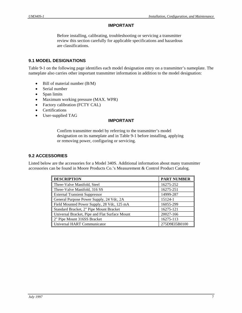
9.1 MODEL DESIGNATIONS Table 9-1 on the following page identifies each model designation entry on a transmitter’s nameplate. The nameplate also carries other important transmitter information in addition to the model designation:
• Bill of material number (B/M) • Serial number • Span limits • Maximum working pressure (MAX. WPR) • Factory calibration (FCTY CAL) • Certifications • User-supplied TAG
IMPORTANT
Confirm transmitter model by referring to the transmitter’s model designation on its nameplate and in Table 9-1 before installing, applying or removing power, configuring or servicing.
9.2 ACCESSORIES Listed below are the accessories for a Model 340S. Additional information about many transmitter accessories can be found in Moore Products Co.’s Measurement & Control Product Catalog.
DESCRIPTION PART NUMBER Three-Valve Manifold, Steel 16275-252 Three-Valve Manifold, 316 SS 16275-251 External Transient Suppressor 14999-287 General Purpose Power Supply, 24 Vdc, 2A 15124-1 Field Mounted Power Supply, 28 Vdc, 125 mA 16055-299 Standard Bracket, 2" Pipe Mount Bracket 16275-121 Universal Bracket, Pipe and Flat Surface Mount 20027-166 2" Pipe Mount 316SS Bracket 16275-113 Universal HART Communicator 275D9EI5B0100

Installation, Configuration, and Maintenance UM340S-1
July 1997 8
TABLE 9-1 Model 340S SteaMeterTM Basic Model Number 340S Differential Pressure SteaMeterTM Input Range: Span Limits Min/Max D 10/450 inH20 (2.5/112.5 kPa) Output B 4-20 mAdc with HART Protocol (1) C 4-20 mAdc with HART Protocol & Integral Transient Suppressor Process Diaphragm H Hastelloy-C276 Body Parts Wetted Vent/Drain Process Connection AA 316SS End 1/2 NPT (1) AB 316SS Side (top) 1/2 NPT AC 316SS Side (bottom) 1/2 NPT AD 316SS Side (dual) 1/2 NPT AE 316SS End 1/4 NPT AF 316SS Side (top) 1/4 NPT AG 316SS Side (bottom) 1/4 NPT AH 316SS Side (dual) 1/4 NPT Fill Fluid B Silicone DC200 Output Indicator 5 4 1/2 Digit Digital SmartDisplay™ N Not Required Standard Options Y Special Features (2) N Not Required Mounting Bracket 1 2" Pipe Mount Bracket with SS Hardware 2 Universal Bracket 3 2" Pipe Mount 316SS Bracket N Not Required Housing 1 Aluminum 1/2-14 NPT 2 Aluminum M20 x 1.5 (3) Hazardous Area Classifications 3 FM/CSA All (1) M CENELEC EExd (4) R SAA All and ABS Type Approved L CENELEC EExia and BASEEFA Type N N Non-Approved W FM/CSA All and ABS Type Approved
340SD B H AA B 5 N 1 1 3 Sample Model Number Notes: (1) Standard for all ranges. (2) Please describe the modification or provide a quotation reference number. (3) Not available with FM/CSA Approved units. (4) CENELEC EExd units are only available with OUTPUT code “B”.

UM340S-1 Installation, Configuration, and Maintenance
July 1997 9
9.3 SPECIFICATIONS
The following specifications are for the Model 340S SteaMeter.
9.3.1 Mechanical Specifications
PARAMETER MODEL 340S Transmitter Dimensions Figure 9-1 2" Pipe Bracket, CS or SS UM340-1, Figure 4-10 Universal Bracket UM340-1, Figure 4-12 Weight, Approximate 7 lb. (4.5 kg) 2" Pipe Bracket, CS or SS 2 lb. (3.1 kg) Universal Bracket 2.5 lb. (3.9 kg) Electronics Housing .............................................Epoxy Powder Coated, Low Copper Cast Aluminum NEMA 4X/6P (IP66/68) Electrical Conduit Entrances................................ (2) ½ - 14 NPT, M20 x 1.5 optional Process Wetted Parts Diaphragm.....................................................Hastelloy C-276 Wetted ...........................................................316 SS Gasket............................................................Teflon Process Connections ............................................ (2) ¼ NPTF with vent/drains (½ NPTF with process adapters provided)
9.3.2 Electrical Specifications Power Supply Requirements - (contact the factory for EExd [ia] requirements) Terminal-to-Terminal Compliance Voltage ..+10 Vdc minimum Terminal-to-Terminal Voltage ......................+42 Vdc maximum Maximum Load .............................................RL = (50)(VS) - 500 ohms Local Indication ...................................................Optional 4½ Digit SmartDisplay Surge Protection (with optional transient suppressor) Clamping Voltage (either terminal to case)...DC: 68 V maximum 100 kV/µS surge: 70 Vp 1000 kV/µS surge: 120 Vp Recommended Wire Type ...................................< 5000 ft (1524m): Belden 8641, 24 AWG > 5000 ft (1524m): Belden 8762, 20 AWG

Installation, Configuration, and Maintenance UM340S-1
July 1997 10
9.3.3 Performance and Functional Specifications Reference conditions: zero-based spans, ambient temperature 28º C, D/A trim values equal span end points, silicone fill, hastelloy-C diaphragms, 1 second damping. Accuracy - includes combined effects of linearity, hysteresis and repeatability. Range D Analog Output For URL/Span < 10 (10:1 Turndown) .......... ±0.1% of calibrated span For URL/Span >10 (10:1-45:1 Turndown)... ±(0.028 + 0.0072 (URL/Span))% of calibrated span Range D Digital Output....................................... ±0.1% of URL Ambient Temperature Effect ...............................±(0.075% of URL + 0.075% of calibrated span) per 28º
C (50º F) Temperature Limits..............................................Sensor Assembly: -40 to 125º C (-40 to 257º F) Electronics: -40 to 85º C (-40 to 185º F) Stability ................................................................Zero: ±0.1% of URL for 12 months Span: no measurable span drift Humidity ..............................................................0-100% relative humidity, non-condensing Vibration Effect ...................................................Less than ±0.05% of URL per G for 0-60 Hz in any axis
up to 2 Gs maximum Power Supply Effect ............................................Less than ±0.005% of output span per volt EMI/RFI Susceptibility........................................Less than ±0.025% of URL at 30 V/m, 30 mHz to 1 GHz ESD Susceptibility ............................................... IEC Severity level 4, 15kV Range and Sensor Limits RANGE MINIMUM SPAN LRL/URL MWP D 10 inH2O (2.49 kPa) -450/450 inH2O (-112/112 kPa) ± 2000 PSI (13.8 MPa) Zero Elevation and Suppression
Range may be set anywhere between the LRL and URL of the transmitter, as long as the calibrated span does not exceed the minimum allowable span (see Range and Sensor Limits table). Zero and span are non-interactive.
Electronic Damping (Digital Filter) .....................Adjustable between 0 and 30 seconds Transmitter Outputs Analog ...........................................................Two-wire 4-20mA can be set to transmit differential
pressure, mass flow or energy flow Digital............................................................HART Communications can be used to read static pressure, mass total and energy total. Optional Transient Suppressor

UM340S-1 Installation, Configuration, and Maintenance
July 1997 11
FIGURE 9-1 Dimensions, Model 340S SteaMeter
X03061S1
Notes:
1. Dimensions are in inches (millimeters).
2. Process Connection Blocks, not shown, provide a 1/2 NPT process connection and can be rotated 180° to give the following connection centers: 2.00 (50.1) 2.13 (54.1) 2.25 (57.2)
3. Terminal Board with isolated TIE terminal shown with enclosure end cap removed.
Vent/Drain Plug(Side Vent Options -Top, Bottom or Both)
7/16"-20 TappedHole, 8 Places
End Cap, 1/4 NPTTapped Hole,See Note 2
Electrical Entrance1/2-14 NPT or
M20 X 1.5 TappedHole, 2 Places
Vent/DrainPlug 6.43
(163.3)
3.60(91.44)
1.00(25.4)
3.50(88.9)Dia
0.50(12.7)
1.75 (44.4)Req'd to
Remove Cap
0.75 (19.1)
4.39(111.5)
5.46(138.68)
5.21(132.3)
2.13(54.1)
See Note 2
Terminal Board,See Note 3
+TIE
_
Installation, Configuration, and Maintenance UM340S-1
July 1997 12
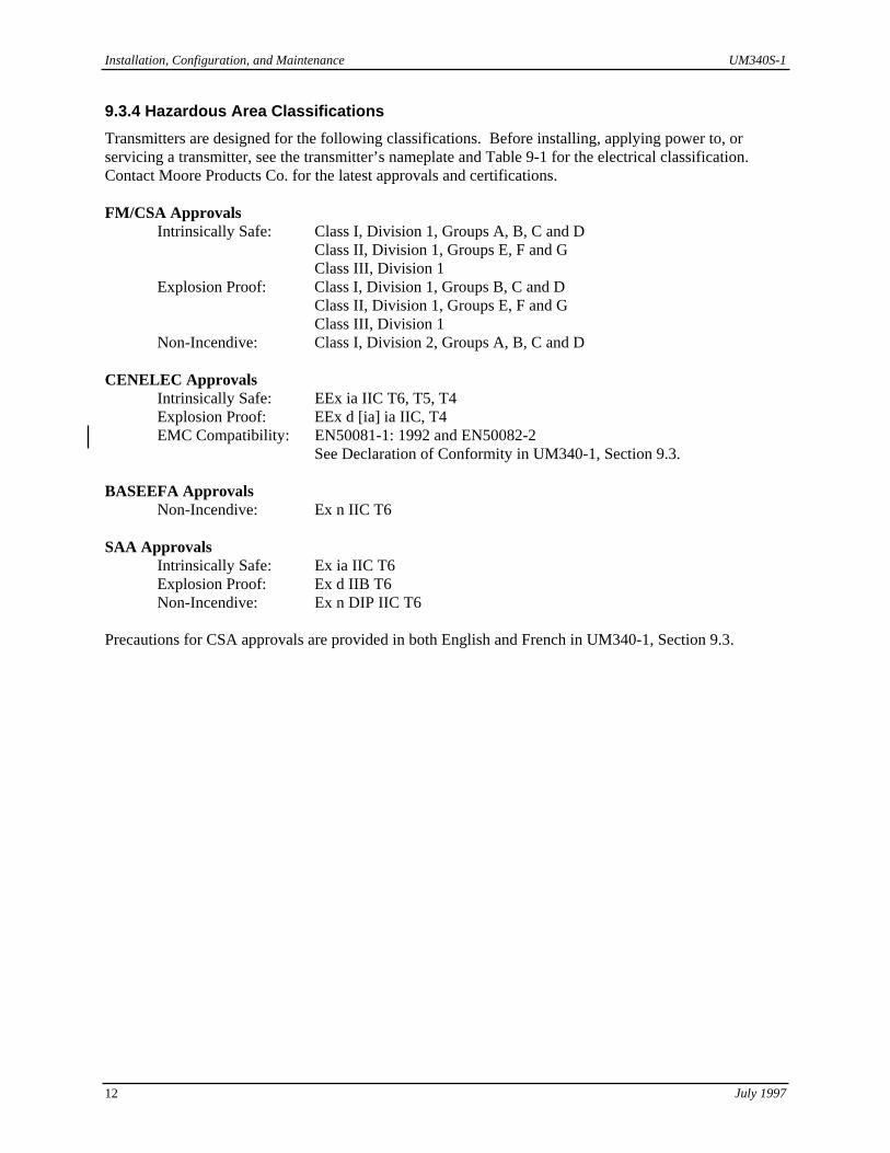
9.3.4 Hazardous Area Classifications Transmitters are designed for the following classifications. Before installing, applying power to, or servicing a transmitter, see the transmitter’s nameplate and Table 9-1 for the electrical classification. Contact Moore Products Co. for the latest approvals and certifications. FM/CSA Approvals Intrinsically Safe: Class I, Division 1, Groups A, B, C and D Class II, Division 1, Groups E, F and G Class III, Division 1 Explosion Proof: Class I, Division 1, Groups B, C and D Class II, Division 1, Groups E, F and G Class III, Division 1 Non-Incendive: Class I, Division 2, Groups A, B, C and D CENELEC Approvals Intrinsically Safe: EEx ia IIC T6, T5, T4 Explosion Proof: EEx d [ia] ia IIC, T4 EMC Compatibility: EN50081-1: 1992 and EN50082-2 See Declaration of Conformity in UM340-1, Section 9.3. BASEEFA Approvals Non-Incendive: Ex n IIC T6 SAA Approvals Intrinsically Safe: Ex ia IIC T6 Explosion Proof: Ex d IIB T6 Non-Incendive: Ex n DIP IIC T6 Precautions for CSA approvals are provided in both English and French in UM340-1, Section 9.3.

UM340S-1 Appendix
July 1997 13
A.0 APPENDIX A - FUNCTION BLOCKS This section provides a detailed description of each function block in a Model 340S Transmitter. Default configuration information can be found in Appendix C.
A.1 WRITE PROTECT BLOCK The write protect parameter, when configured as “on,” blocks all HART commands from writing to the transmitter’s database. A Model 275 HART Communicator or other HART master will have “read only” access to the transmitter. For example, if write protect is “on,” the transmitter can not be re-ranged. To enable write commands, configure the write protect parameter as “off.”
A.2 SENSOR INPUT BLOCK The Sensor Input Block allows configuration of those parameters which pertain to the pressure sensor. Sensor Input Block parameters are listed below; a description of each parameter then follows.
Measured Variable Units ...........inH2O, inHg, ftH2O, mmH2O, mmHg PSI, BAR, mBAR, g/sq cm, kg/sq cm, PA, kPa, Torr, Atm
Measured Variable Range Lo .................................................................-999999 to 999999
Measured Variable Range Hi..................................................................-999999 to 999999
Damping Time Constant ..............................................................................0 to 30 Seconds
Transfer Function................................................................................................ Linear, x1/2
Transfer Function Cutoff ........................................................................................0 to 30%
Zero Dropout...........................................................................................................0 to 30%
Active Input ................................................................................................................... N/A Measured Variable Units These are the recognized pressure units within the HART Protocol. Pressure units are selected from a pre-configured list. Other pressure units must be converted to one of these 14 units. Measured Variable Lo (MV Lo) & Measured Variable Hi (MV Hi) These two parameters determine the input range of the transmitter. The MV Lo parameter represents the pressure that will cause the Sensor Input Block to output 0%. The MV Hi parameter represents the pressure that will cause the Sensor Input Block to output 100%. These two parameters are non-interactive. Changing one does not effect the other. Furthermore, these parameters can be configured to make the transmitter forward acting or reverse acting, that is, the MV Hi parameter does not have to be configured for a higher pressure than the MV Lo parameter. The actual limits for the MV Lo and Hi parameters, as well as the span, are determined by the particular sensor range at hand. The Upper Sensor Limit (USL) and Lower Sensor Limit (LSL) are listed in the Quick Access Status/Model Number menu; otherwise, check the transmitter model number against the model designation list in Section 9 for these limits. Damping Use the Damping parameter to configure the time constant for the transmitter. Damping is used to quiet noisy process signals; however, when configuring this parameter remember that it takes 4-5 time constants to respond to 99.9% of a step input change. The default damping value is one second. Transfer Function

Appendix UM340S-1
July 1997 14
The transmitter has a built in square root (x1/2) extractor for use with orifice plates, venturi tubes and other primary flow elements. If the transmitter is not being used with one of these flow elements, simply select a linear transfer function. Transfer Function Cutoff The square root transfer function has high gain near 0% input. To prevent small input changes (noise) from being amplified excessively, a linear segment is used on the low end of the curve. The point at which this linear segment ends and the actual square root transfer function begins is the Transfer Function Cutoff. This is user configurable between 0% and 30% of input. Zero Dropout The Zero Dropout parameter can be used in conjunction with the Transfer Function Cutoff parameter. This parameter is a value below which the transmitter’s output will be 0%. This can be used with extremely noisy process signals where the linear approximation method does produce the desired results. This is user configurable between 0% and 30% of input. Active Input Active Input is not a parameter but a tool to configure the MV Lo and Hi parameters. If desired, the measured variable range may be configured against a precision pressure source in place of simply typing the range into the MV Lo and Hi parameters. The Active Input feature will show the “live” input pressure and the MV Lo and Hi parameters. The user then applies zero and span pressures from a precision pressure standard and copies those values directly into both the MV Lo and Hi parameters. This procedure allows the HART Communicator to mimic the operation of the local magnetic switches. For information on using the Active Input feature or the local magnetic switches, see UM340-1, Section 6.
A.3 CHARACTERIZER The Characterizer Block is a 14-segment, user-configurable transfer function. This function block can be used to linearize unusual flow elements. Characterizer Block parameters are listed below, with descriptions following.
Characterizer ..............................................................................................................On/Off
X0 . . . X14............................................................................................... -10.0% to 110.0%
Y0 . . . Y14............................................................................................... -10.0% to 110.0% Characterizer This parameter is used to turn the characterizer on or off. X0…X14 and Y0…Y14 These parameters specify the values for the 15 x-y coordinates that make up the 14 characterizer segments. The coordinates are always specified in percent.
A.4 TOTALIZER The Totalizer Block is used to totalize the mass flow and energy flow. At power-up the totalizer begins counting. The Quick Access Key menu of the HART Communicator can be used to start, stop, or reset the totalizer at any time. Totalizer Block parameters are listed below, with a description of each following.
Fullscale Value.................................................................................................. 199999984

UM340S-1 Appendix
July 1997 15
Time Base ................................................................................................................... Hour
Multiplier .................................................................................................... 0.001 to 19999
Zero Dropout................................................................................................... 0.0 to 30.0% Multiplier The Mulitplier parameter allows the input signal to the totalizer block to be scaled. The fullscale value is fixed at 200 million counts for both totalizers. Scaling the input will allow extremely low or high flows to be totalized more easily. The units for the totalizers are either English (lbm, BTU) or Metric (kg, kJ) per hour according to the configuration of the Steam Units in the Operator Display Block. Zero Dropout The Zero Dropout parameter is used to force the totalizer to stop counting when the measured variable falls below the configured value. There is no deadband associated with the zero dropout feature. The Totalizer Block zero dropout feature is independent of the Sensor Input Block zero dropout feature.
A.5 OPERATOR DISPLAY BLOCK The Operator Display Block is used to configure the operation of the local SmartDisplay. Operator Display Block parameters are listed below; a description of each parameter then follows.
Raw Flow Units ......................................................................................4-Character ASCII
Raw Flow Lo ..................................................................-999999997952 to 999999995904
Raw Flow Hi ...................................................................-999999997952 to 999999995904
Steam Units................................................................................................... English/Metric
Steam Lo .........................................................................-999999997952 to 999999995904
Steam Hi .........................................................................-999999997952 to 999999995904
Local Display ............................................................................. Steam Values or % Output
Auto Toggle ...............................................................................................................Off/On
Toggle Time.....................................................................................................1-30 Seconds Model 340S Raw Flow Lo, Hi, Units The raw flow signal is the equivalent mass flow rate in water. This variable is a required intermediate step in attaining the desired steam mass flow. This variable can NOT be shown on the local display. To calculate this range use the following equation to calculate both the Raw Flow Lo and Raw Flow Hi parameters. MASSwater = MASSsteam/SQRT(vwater/vsteam) The Raw Flow Units parameter should be ignored. The units for the Raw Flow range will be the same as that of the Steam Flow range. vwater and vsteam are the specific volumes of the water and steam under operating conditions. These can be found in the ASME Steam Tables. Alternatively, a Microsoft Excel 5.0 spreadsheet with formulas to perform these calculations is available. Use the FAX request form at the back of this manual to request a copy on diskette or download a free copy from our web site at www.mooreproducts.com. Model 340S Steam Flow Lo, Hi, Units

Appendix UM340S-1
July 1997 16
The steam flow units are fixed as lbm (mass) and BTU (energy) for english units, and kg (mass) and kJ (energy) for metric units. Only english or metric units need be specified. The lo and hi parameters configure the output range for the mass or energy flow rate when the Output Switch parameter found in the Output Block is configured as mass or energy flow. If mass flow is selected as the output of the transmitter, this range should be set as the desired zero and span mass flow. If energy flow is selected as the output of the transmitter, this range should be set as the desired zero and span energy flow. Regardless of which variable is selected as the transmitter output, or the configuration of the steam lo and hi parameters, both the mass and energy flow rate will always be available at the local SmartDisplay. Model 340S Local Display Code The local display can indicate either the steam values or % output as shown in the following table. LOCAL DISPLAY CODE VARIABLES AVAILABLE ON LOCAL DISPLAY Steam Values Mass Flow, Energy Flow, Mass Total, Energy Total % Output % output
A.6 TRANSMITTER ID The Transmitter ID Block can be used to maintain identification information about the transmitter. Transmitter ID Block parameters are listed below; a description of each parameter then follows.
Tag ..........................................................................................................8-Character ASCII
Descriptor..............................................................................................16-Character ASCII
Message ................................................................................................32-Character ASCII
Date.................................................................................................................. DD/MM/YY
Device Serial Number.................................................................................... 0 to 16777215
Polling Address..............................................................................................................0-15 Tag, Descriptor, and Message These three parameters are ASCII text and have no bearing on transmitter output. Up to an 8-character Tag, 16-character Descriptor and 32-character Message may be entered for the transmitter. Date The Date parameter uses the international DD/MM/YY format. This date can be selected by the user to indicate any date or event, such as date of installation or last date of service. Device Serial Number The 8-digit Device Serial Number is factory configured to match the serial number on the transmitter nameplate. It should not be changed. Polling Address The Polling Address is used to place the transmitter in either analog or digital mode. A Polling Address of 0 indicates that the transmitter is in analog mode and will output a 4-20 mA current according to its calibrated range. In analog mode, a single transmitter is connected to a Point-to-Point Network.

UM340S-1 Appendix
July 1997 17
A Polling Address between 1 and 15 indicates the transmitter is in digital mode and will output a constant 4 mA current. In digital mode, up to 15 transmitters can be connected in a Multi-Drop Network using a single twisted pair cable. For more information on Multi-Drop networks, see Section 4.
A.7 OUTPUT
The Output Block converts the internal digital signal it receives into a 4-20 mA analog output signal. In digital mode the transmitter output is a constant 4 mA. The Output Block parameter is listed below and then described.
Failsafe Level...................................................................................... Lo, Hi, or Last Value
Output Switch ............................................................ Raw Flow, Mass Flow, Energy Flow
Failsafe Level This parameter specifies the value to which the transmitter output will go if an error is detected while the transmitter is performing its self-test program. This value may be set at Lo (3.85mA), Hi (22.5mA), or Last Value (transmitter output immediately before entering failsafe mode). Output Switch This parameter is used to set the variable which scales the 4-20 mA output. Choices include the raw volumetric flow (uncompensated), the mass flow or the energy flow.
A.8 STEAM SETTINGS The Model 340S SteaMeter is specifically used for measuring saturated steam flow. This function block calculates the mass and energy flow by using a differential pressure and static pressure sensor as well as built-in steam tables. The only user-configurable parameters required are the Steam Reference Specific Volume, Steam Quality and the Thermal Factor.
Reference Volume ( vr ) ............................................................................. 0.000001 to 10.0
Quality (x) .............................................................................................................. 0.0 to 1.0
Thermal Factor (Et) ........................................................................................................in %
Steam Units................................................................................................... English/Metric Reference Volume, vr This parameter is the reference specific volume of the steam. The units are lbs/cuft or kg/cum depending on the configuration of the steam units parameter, english or metric. This should be entered at a reference temperature of 20°C. Quality (Dryness Factor), x The quality or steam dryness factor should be entered: 1.0 is dry, 0.0 is wet. Thermal Factor, Et The thermal factor allows for correction of thermal effects associated with the elements in contact with the steam. The value should be entered as % correction / % input degree C. Steam Units

Appendix UM340S-1
July 1997 18
This is a repeat of the steam units found in the Operator Display block. Configure this parameter as english or metric.
B.0 APPENDIX B - HAZARDOUS AREA INSTALLATION Barrier recommendations for installation in a hazardous area are listed in UM340-1, Appendix B.
C.0 TRANSMITTER CONFIGURATION DOCUMENTATION HOW TO USE APPENDIX C Use this appendix to document a transmitter configuration. The transmitter may be on-site or be a pending purchase. Make additional copies of this appendix as necessary. Clearly record the needed data as follows: On-Site Transmitter Configuration Record 1. Copy transmitter nameplate information onto the simulated nameplate on the next page. 2. Enter Customer Name and P.O. Number information in the box at the bottom of the next page. 3. Record the transmitter’s configuration data in the last column of the table on pages 19 and 20. Data for Factory Configuration at Time of Purchase 1. Write the transmitter model number and tag on the simulated nameplate on the next page. Other
information is factory supplied at the time of manufacture. 2. Enter Customer Name and P.O. Number in the box at the bottom of the next page. 3. Record the desired configuration data on the following pages. 4. Attach a copy of these pages to your purchase order. Keep a copy for your files.
MOOREMODEL
B/MSERIAL#
SPAN LIMITSMWP
FCTRY CALTAG
Approvals and Certifications Area
X03068S0
XTCTRANSMITTER-CONTROLLER
TM

UM340S-1 Appendix
July 1997 19
PARAMETER RANGE OF VALUES DEFAULT
VALUE DESIRED VALUE
Write Protect Disable, Enable Disable Sensor Input Block ----- ----- ----- Measured Variable Units inH2O, inHg, ftH2O, mmH2O,
mmHg, PSI, BAR, mBAR, g/sq cm, kg/sq cm, PA, kPa, Torr, ATM
inH2O
Measured Variable Range Lo
-999999 to 999999 0
Measured Variable Range Hi
-999999 to 999999 100
Damping Time Constant 0 to 30 seconds 1 Transfer Function Linear, Square Root Linear Transfer Function Cutoff 0 to 30% 4% Zero Dropout 0 to 30% 0% Active Input Non-Configurable Totalizer Block ----- ----- ----- Fullscale Value 199999984 199999984 Non-Configurable Time Base Hour Hour Non-Configurable Multiplier 0.001 to 19999 1.0 Zero Dropout 0-30% 0.5% Characterizer Block ----- ----- ----- Characterizer Off, On Off X0 -10.0 to 110.0% 0.00% Y0 -10.0 to 110.0% 0.00% X1 -10.0 to 110.0% 7.14 Y1 -10.0 to 110.0% 7.14 X2 -10.0 to 110.0% 14.29 Y2 -10.0 to 110.0% 14.29 X3 -10.0 to 110.0% 21.43 Y3 -10.0 to 110.0% 21.43 X4 -10.0 to 110.0% 28.57 Y4 -10.0 to 110.0% 28.57 X5 -10.0 to 110.0% 35.71 Y5 -10.0 to 110.0% 35.71 X6 -10.0 to 110.0% 42.86 Y6 -10.0 to 110.0% 42.86 X7 -10.0 to 110.0% 50.00 Y7 -10.0 to 110.0% 50.00 X8 -10.0 to 110.0% 57.14 Y8 -10.0 to 110.0% 57.14 X9 -10.0 to 110.0% 64.29 Y9 -10.0 to 110.0% 64.29 X10 -10.0 to 110.0% 71.43 Y10 -10.0 to 110.0% 71.43 X11 -10.0 to 110.0% 78.57

Appendix UM340S-1
July 1997 20
PARAMETER RANGE OF VALUES DEFAULT VALUE
DESIRED VALUE
Y11 -10.0 to 110.0% 78.57 X12 -10.0 to 110.0% 85.71 Y12 -10.0 to 110.0% 85.71 X13 -10.0 to 110.0% 92.86 Y13 -10.0 to 110.0% 92.86 X14 -10.0 to 110.0% 100.00 Y14 -10.0 to 110.0% 100.00 Operator Display Block ----- ----- ----- Raw Flow Units 4-Character ASCII PRCT Raw Flow Range Lo -999999997952 to
999999995904 0
Raw Flow Range Hi -999999997952 to 999999995904
100
Steam Units English/Metric English Steam Flow Range Lo -999999997952 to
999999995904 0
Steam Flow Range Hi -999999997952 to 999999995904
100,000
Local Display Code Steam Units, % Output Steam Units Auto Toggle Off, On Off Toggle Time 1-30 Seconds 5 Transmitter ID ----- ----- ----- Tag 8-Character ASCII FT Descriptor 16-Character ASCII XTC Transmitter Message 32-Character ASCII Moore Products
Co.
Date [Date transmitter manufactured]
Device Serial Number (8-digit)
0 to16777215 [Device S/N on nameplate]
Do not change.
Polling Address 0-15 0 Output Block ----- ----- ----- Failsafe Lo, Hi, Last Value Last Value Output Switch Raw Flow, Mass Flow, Energy
Flow Mass Flow
Steam Settings ----- ----- ----- Reference Volume 0.00001 to 10.0 1.0 Quality (Dryness Factor) 0.7 to 1.0 1.0 Thermal Factor 0.0019% Steam Units English/Metric English
D.0 ELEVATION AND SUPPRESSION CORRECTIONS This section in UM340-1 does not apply to the Model 340S SteaMeter.
�