xpr300™ - koike.com club/cutting machines/plasm… · sophie-scholl-platz 5 63452 hanau germany...
TRANSCRIPT

XPR300™Cut charts
Instruction Manual809830 | Revision 0 | English

XPR300, HyDefinition, True Hole, Sensor THC, EasyConnect, LongLife, Arc Response Technology, OptiMix, VWI, and Hypertherm are trademarks of Hypertherm Inc. and may be registered in the United States and other countries. All other trademarks are the property of their respective holders.
Environmental stewardship is one of Hypertherm’s core values, and it is critical to our success and our customers’ success. We are striving to reduce the environmental impact of everything we do. For more information: www.hypertherm.com/environment.
© 2017 Hypertherm Inc.

XPR300
Instruction Manual
809830Revision 0
EnglishOriginal instructions
June 2017
Hypertherm Inc.Hanover, NH 03755 USA
www.hypertherm.com

Hypertherm Inc.Etna Road, P.O. Box 5010Hanover, NH 03755 USA603-643-3441 Tel (Main Office)603-643-5352 Fax (All Departments)[email protected] (Main Office Email)800-643-9878 Tel (Technical Service)[email protected] (Technical Service Email)800-737-2978 Tel (Customer Service)[email protected] (Customer Service Email)866-643-7711 Tel (Return Materials Authorization)877-371-2876 Fax (Return Materials Authorization)[email protected] (RMA email)
Hypertherm México, S.A. de C.V.Avenida Toluca No. 444, Anexo 1,Colonia Olivar de los PadresDelegación Álvaro ObregónMéxico, D.F. C.P. 0178052 55 5681 8109 Tel52 55 5683 2127 [email protected] (Technical Service Email)
Hypertherm Plasmatechnik GmbHSophie-Scholl-Platz 563452 Hanau Germany00 800 33 24 97 37 Tel00 800 49 73 73 29 Fax31 (0) 165 596900 Tel (Technical Service)00 800 4973 7843 Tel (Technical Service)[email protected] (Technical Service Email)
Hypertherm (Singapore) Pte Ltd.82 Genting LaneMedia CentreAnnexe Block #A01-01Singapore 349567, Republic of Singapore65 6841 2489 Tel65 6841 2490 Fax [email protected] (Marketing Email)[email protected] (Technical Service Email)
Hypertherm Japan Ltd.Level 9, Edobori Center Building2-1-1 Edobori, Nishi-kuOsaka 550-0002 Japan81 6 6225 1183 Tel81 6 6225 1184 [email protected] (Main Office Email)[email protected] (Technical Service Email)
Hypertherm Europe B.V.Vaartveld 9, 4704 SE Roosendaal, Nederland31 165 596907 Tel31 165 596901 Fax31 165 596908 Tel (Marketing)31 (0) 165 596900 Tel (Technical Service)00 800 4973 7843 Tel (Technical Service)[email protected] (Technical Service Email)
Hypertherm (Shanghai) Trading Co., Ltd.B301, 495 ShangZhong RoadShanghai, 200231PR China86-21-80231122 Tel86-21-80231120 Fax86-21-80231128 Tel (Technical Service)[email protected] (Technical Service Email)
South America & Central America: Hypertherm Brasil Ltda.Rua Bras Cubas, 231 – Jardim MaiaGuarulhos, SP – BrasilCEP 07115-03055 11 2409 2636 [email protected] (Technical Service Email)
Hypertherm Korea Branch#3904. APEC-ro 17. Heaundae-gu. Busan.Korea 4806082 (0)51 747 0358 Tel82 (0)51 701 0358 [email protected] (Marketing Email)[email protected] (Technical Service Email)
Hypertherm Pty LimitedGPO Box 4836 Sydney NSW 2001, Australia61 (0) 437 606 995 Tel61 7 3219 9010 [email protected] (Main Office Email)[email protected] (Technical Service Email)
Hypertherm (India) Thermal Cutting Pvt. LtdA-18 / B-1 Extension,Mohan Co-Operative Industrial Estate,Mathura Road, New Delhi 110044, India91-11-40521201/ 2/ 3 Tel91-11 40521204 [email protected] (Main Office Email)[email protected] (Technical Service Email)
1/28/16

Contents
Cut Charts ............................................................................................................................................. 9Overview ................................................................................................................................................................. 9
Pierce delay time....................................................................................................................................... 9Pierce height and transfer height ........................................................................................................ 10Kerf compensation.................................................................................................................................. 10Cut category............................................................................................................................................. 10Arc voltage................................................................................................................................................ 10HyDefinition® inox (HDi) vented processes....................................................................................... 10
How to use cut charts........................................................................................................................................ 11Standard-position cutting, marking, and piercing cut charts........................................................ 11Process core thickness (PCT) ............................................................................................................. 11Process categories................................................................................................................................. 11Bevel cutting ............................................................................................................................................ 12Arc voltage................................................................................................................................................ 12Pierce settings ......................................................................................................................................... 13
Process selection................................................................................................................................................ 14How to use process IDs to access optimal settings ...................................................................... 14
Cut charts for ferrous (mild steel) processes – above water ................................................................... 15Mild steel – 30 A – O2 Plasma / O2 Shield – above water (CoreTM, VWITM, OptiMixTM).......... 15Mild steel – 80 A – O2 Plasma / Air Shield – above water (Core, VWI, OptiMix)................... 17Mild steel – 130 A – O2 Plasma / Air Shield – above water (Core, VWI, OptiMix) ................ 19Mild steel – 170 A O2 Plasma / Air Shield – above water (Core, VWI, OptiMix).................... 21Mild steel – 300 A – O2 Plasma / Air Shield – above water (Core, VWI, OptiMix) ................ 23
XPR300 Instruction Manual 809830 5

Cut charts for non-ferrous (stainless steel) processes – above water .................................................. 25Stainless steel – 40 A – N2 Plasma / N2 Shield – above water (Core, VWI, OptiMix) .......... 25Stainless steel – 60 A – N2 Plasma / N2 Shield – above water (Core, VWI, OptiMix) .......... 27Stainless steel – 60 A – N2 Plasma / H2O Shield – above water (VWI, OptiMix) .................. 29Stainless steel – 60 A – F5 Plasma / N2 Shield – above water (VWI, OptiMix)...................... 30Stainless steel – 80 A – N2 Plasma / N2 Shield – above water (Core, VWI, OptiMix) .......... 32Stainless steel – 80 A – N2 Plasma / H2O Shield – above water (VWI, OptiMix) .................. 34Stainless steel – 80 A – F5 Plasma / N2 Shield – above water (VWI, OptiMix)...................... 35Stainless steel – 130 A – N2 Plasma / N2 Shield – above water (Core, VWI, OptiMix)........ 37Stainless steel – 130 A – N2 Plasma / H2O Shield – above water (VWI and OptiMix)......... 39Stainless steel – 130 A – Mixed-fuel gas Plasma / N2 Shield – above water (OptiMix) ....... 40Stainless steel – 170 A – N2 Plasma / N2 Shield – above water (Core, VWI, OptiMix)........ 42Stainless steel – 170 A – N2 Plasma / H2O Shield – above water (VWI, OptiMix)................ 44Stainless steel – 170 A – Mixed-fuel gas Plasma / N2 Shield – above water (OptiMix) ....... 45Stainless steel – 300 A – N2 Plasma / N2 Shield – above water (Core, VWI, OptiMix)........ 47Stainless steel – 300 A – N2 Plasma / H2O Shield – above water (VWI, OptiMix)................ 49Stainless steel – 300 A – Mixed-fuel gas Plasma / N2 Shield – above water (OptiMix) ....... 51
Cut charts for non-ferrous (aluminum) processes – above water........................................................... 53Aluminum – 40 A – Air Plasma / Air Shield – above water (Core, VWI, OptiMix) .................. 53Aluminum – 40 A – N2 Plasma / N2 Shield – above water (Core).............................................. 55Aluminum – 60 A – Air Plasma / Air Shield – above water (Core, VWI, OptiMix) .................. 57Aluminum – 60 A – N2 Plasma / N2 Shield – above water (Core, VWI, OptiMix) ................... 58Aluminum – 60 A – N2 Plasma / H2O Shield – above water (VWI, OptiMix) ........................... 60Aluminum – 80 A – Air Plasma / Air Shield – above water (Core, VWI, OptiMix) .................. 61Aluminum – 80 A – N2 Plasma / N2 Shield – above water (Core, VWI, OptiMix) ................... 62Aluminum – 80 A – N2 Plasma / H2O Shield – above water (VWI, OptiMix) ........................... 64Aluminum – 130 A – N2 Plasma / N2 Shield – above water (Core, VWI, OptiMix)................. 66Aluminum – 130 A – N2 Plasma / H2O Shield – above water (VWI, OptiMix) ........................ 68Aluminum – 130 A – Mixed-fuel gas Plasma / N2 Shield – above water (OptiMix)................ 69Aluminum – 170 A – Air Plasma / Air Shield – above water (Core, VWI, OptiMix)................ 71Aluminum – 170 A – N2 Plasma / N2 Shield – above water (Core, VWI, OptiMix)................. 73Aluminum – 170 A – N2 Plasma / H2O Shield – above water (VWI, OptiMix) ........................ 75Aluminum – 170 A – Mixed-fuel gas Plasma / N2 Shield – above water (OptiMix)................ 76Aluminum – 300 A – N2 Plasma / N2 Shield – above water (Core, VWI, OptiMix)................. 78Aluminum – 300 A – N2 Plasma / H2O Shield – above water (VWI, OptiMix) ........................ 80Aluminum – 300 A – Mixed-fuel gas Plasma / N2 Shield – above water (OptiMix)................ 82
Cut charts for ferrous (mild steel) processes – underwater ..................................................................... 84Mild steel – 80 A – O2 Plasma / Air Shield (Core, VWI, OptiMix) .............................................. 84Mild steel – 130 A – O2 Plasma / Air Shield – underwater (Core, VWI, OptiMix).................. 86Mild steel – 170 A O2 Plasma / Air Shield – underwater (Core, VWI, OptiMix) ..................... 88Mild steel – 300 A – O2 Plasma / Air Shield – underwater (Core, VWI, OptiMix).................. 89
6 809830 Instruction Manual XPR300

Cut charts for non-ferrous (stainless steel) processes – underwater .................................................... 90Stainless steel – 80 A – N2 Plasma / N2 Shield – underwater (Core, VWI, OptiMix) ............ 90Stainless steel – 80 A – N2 Plasma / H2O Shield – underwater (VWI, OptiMix) .................... 92Stainless steel – 130 A – N2 Plasma / N2 Shield – underwater (Core, VWI, OptiMix).......... 93Stainless steel – 130 A – N2 Plasma / H2O Shield – underwater (VWI and OptiMix) .......... 94Stainless steel – 170 A – N2 Plasma / H2O Shield – underwater (VWI, OptiMix) ................. 95Stainless steel – 170 A – N2 Plasma / N2 Shield – underwater (Core, VWI, OptiMix).......... 96Stainless steel – 300 A – N2 Plasma / N2 Shield – underwater (Core, VWI, OptiMix).......... 97Stainless steel – 300 A – N2 Plasma / H2O Shield – underwater (VWI, OptiMix) ................. 98
Torch geometry for bevel cutting..................................................................................................................... 99
XPR300 Instruction Manual 809830 7

8 809830 Instruction Manual XPR300

Cut Charts
Overview
The cut charts in this manual are for reference purposes. See the electronic cut charts that are on your CNC or web interface for the most reliable process-selection options.
Graphics in this section are for reference only.
Hypertherm’s cut charts are designed to give the best quality with minimal dross. However, because of differences in cutting system installations and materials, it can be necessary to adjust the settings to get the results that you want.
If you have questions about how to make adjustments to process settings and consumable choices, contact your cutting machine supplier or regional Hypertherm Technical Service team.
Pierce delay time
The pierce delay times that are in the cut charts are estimated with moderately worn consumables. If your consumable parts have more or less wear, it can be necessary to adjust the settings to get the results that you want.
Consumables naturally deteriorate and become worn from use. As this occurs, the time necessary to pierce the workpiece increases.
XPR300 Instruction Manual 809830 9

Cut Charts
Pierce height and transfer height
For most processes, the torch transfers the arc to the workpiece from the pierce height and then moves to cut height after the pierce-delay time expires. For some of the thickest materials that can be pierced, the transfer height is used to position the torch closer to the workpiece. This creates a more reliable arc. After arc transfer, the torch moves to pierce height for piercing, followed by cut height for cutting.
Kerf compensation
All cut charts include kerf compensation values. You can use these values with a controller to offset the cut path and produce a part to the desired size. The kerf compensation values that are in the cut charts are estimated with new consumables. If your consumable parts have more wear, it may be necessary to change the kerf compensation setting to get the results you want.
Cut category
Use the cut category in the cut charts to help you choose the process that matches your needs for cut quality and speed based on material type and thickness.
Edge starts are recommended for processes that have a cut category of 4 or 5.
Arc voltage
The arc voltage that is in the cut charts is for reference and estimated on an average cutting system configuration. Lead length can affect actual arc voltage. If the leads for your XPRTM cutting system are shorter or longer than average, it can be necessary to adjust the settings to get the results that you want.
HyDefinition® inox (HDi) vented processes
Cut charts for HyDefinition vented processes are developed on SAE grade 304L stainless steel. When cutting other grades of stainless steel, adjustments can be necessary to get the best cut quality.
If you decide that it is necessary to adjust a pre-programmed setting, use offset commands to make incremental changes to the original value. Manual selection of process settings is not recommended.
Cut charts for HyDefinition vented processes are listed by amperage.
10 809830 Instruction Manual XPR300

Cut Charts
How to use cut charts
Electronic cut charts are available on the cut chart screen of your CNC or XPR web interface.
For information about how to find electronic cut charts, see the instruction manual that came with your CNC.
Hard copy cut charts are available in this manual. They start on page 15.
The cut charts in this manual are for reference purposes. Always use the electronic cut charts that appear on your CNC or XPR web interface for the most complete and accurate process-selection information.
Standard-position cutting, marking, and piercing cut charts
Use the cut charts for guidance about process selection, especially if the default process ID settings are not satisfactory for your application.
The pre-programmed settings that come with a process ID are designed to give the best balance between quality and productivity with consumables that are in average condition.
The results that you want from a process can influence process selection. In some cases, cut quality is important. In other cases, speed is important. Often, the best choice balances these requirements (See Process selection on page 14.)
Process core thickness (PCT)
The cut chart for every cutting process contains a range of possible thicknesses. Process engineers work to optimize a range of thicknesses (usually in the middle of the overall range of thicknesses). This optimized range is called the process core thicknesses (PCT). Thicknesses greater and less than the PCT can have varied results relative to cut quality, cut speed, and piercing capability.
Process categories
The XPR cut charts have up to 5 process categories. Each category has a unique process category number (1 – 5) that correlates to the performance that you can expect when you select this process. The process category number for the process that you choose changes the quality-speed balance.
For best results, Hypertherm recommends that you select process category number 1 whenever possible. Category 1 represents an optimized thickness (or PCT) for that cut process with the overall best balance of cut quality and cut speed.
Table 1 on page 13 describes the results that you can expect with different process category numbers.
XPR300 Instruction Manual 809830 11

Cut Charts
Bevel cutting
All consumable processes are capable of up to 52º bevel cuts. Choose bevel cutting settings (such as speed) from the cut chart, based on the effective thickness of the actual bevel cut through the material. Note that arc voltages may need to compensate for the actual effective cut height.
For more information, see Torch geometry for bevel cutting on page 99.
Hypertherm recommends a clearance of 2.5 mm (0.098 in.) between the torch and the workpiece during bevel cutting.
Arc voltage
Arc voltages provided in the cut charts are for reference only. Actual arc voltages will vary with system configuration.
12 809830 Instruction Manual XPR300
Cut Charts
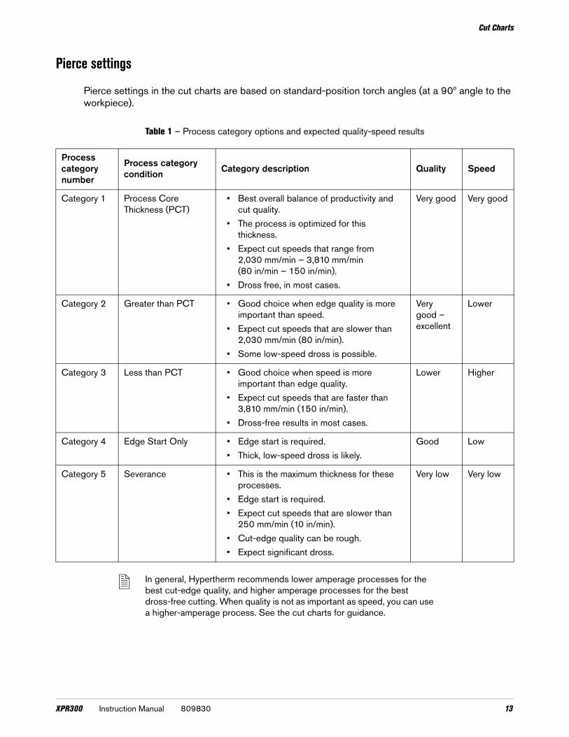
Pierce settings
Pierce settings in the cut charts are based on standard-position torch angles (at a 90º angle to the workpiece).
Table 1 – Process category options and expected quality-speed results
In general, Hypertherm recommends lower amperage processes for the best cut-edge quality, and higher amperage processes for the best dross-free cutting. When quality is not as important as speed, you can use a higher-amperage process. See the cut charts for guidance.
Process category number
Process category condition Category description Quality Speed
Category 1 Process Core Thickness (PCT)
• Best overall balance of productivity and cut quality.
• The process is optimized for this thickness.
• Expect cut speeds that range from 2,030 mm/min – 3,810 mm/min (80 in/min – 150 in/min).
• Dross free, in most cases.
Very good Very good
Category 2 Greater than PCT • Good choice when edge quality is more important than speed.
• Expect cut speeds that are slower than 2,030 mm/min (80 in/min).
• Some low-speed dross is possible.
Very good – excellent
Lower
Category 3 Less than PCT • Good choice when speed is more important than edge quality.
• Expect cut speeds that are faster than 3,810 mm/min (150 in/min).
• Dross-free results in most cases.
Lower Higher
Category 4 Edge Start Only • Edge start is required.• Thick, low-speed dross is likely.
Good Low
Category 5 Severance • This is the maximum thickness for these processes.
• Edge start is required.• Expect cut speeds that are slower than
250 mm/min (10 in/min).• Cut-edge quality can be rough.• Expect significant dross.
Very low Very low
XPR300 Instruction Manual 809830 13

Cut Charts
Process selection
All of the XPR cutting processes have a unique process identification (process ID) number. Each process ID aligns with a specific set of pre-programmed values in the cut chart database in the plasma power supply memory.
Processes in the database can be selected by:
Material type and thickness
Cutting current
Plasma and shield gas types
Process category
When you select a process ID from the CNC or the Operate screen in the XPR web interface, the cutting system automatically activates the pre-programmed settings for that process based on the values in the database.
On-screen lists of process options let you select, monitor, and control processes directly from the CNC or the Operate screen in the XPR web interface.
Manual selection of process settings is not necessary in most cases. However, you can adjust some pre-programmed settings with override or offset commands, within limits. For information about how to do this, refer to the XPR300 Instruction Manual (809480).
How to use process IDs to access optimal settings
When you select a process ID from the CNC or XPR web interface, you automatically get the optimized settings that Hypertherm recommends for that process.
The pre-programmed settings come from Hypertherm’s extensive laboratory tests. Because of differences in cutting systems, materials, and consumables, it is sometimes necessary to adjust the settings. However, in most cases, you can expect the best results when you use the default settings that come with a process ID.
14 809830 Instruction Manual XPR300

Cut Charts
Cut charts for ferrous (mild steel) processes – above water
Mild steel – 30 A – O2 Plasma / O2 Shield – above water (CoreTM, VWITM, OptiMixTM)
Shield retaining cap Shield Nozzle retaining cap Nozzle Swirl ring Electrode Water tube420200 420228 420365 420225 420407 420222 420368
Flow rate (lpm/scfh)N2 O2
Pre flow 20/43 19/40Pierce flow 20/43 19/40Cut flow – 27/58
Metric
Material thickness Cut
category
SYSTEM SETTINGS CNC SETTINGS
XPR Process ID
Shield pierce setting
Cutflow Cut speed
Arc voltage
Transfer height
Pierce height
Pierce delay
Cut height Kerf compensation
mm Plasma gas Shield gas mm/min volts mm mm seconds mm mm
0.5
3
1051 28 76 24
5348 106
2.54 2.54
0.1
1.27
1.50.8 4217 107 0.2 1.51 3604 108
0.31.6
1.2 2847 109 1.51.5 2198 111 1.62 1490 116
3.05 3.050.4
1.52
1.72.5 1325 116 1.73 1 1153 117 0.5 1.84
2908 120 3.37 3.37 0.6 1.9
5 521 123 3.88 3.88 0.7 1.54 2.0
XPR300 Instruction Manual 809830 15
Cut Charts
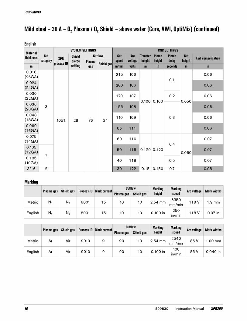
Mild steel – 30 A – O2 Plasma / O2 Shield – above water (Core, VWI, OptiMix) (continued)
English
Material thickness Cut
category
SYSTEM SETTINGS CNC SETTINGS
XPR process ID
Shield pierce setting
Cutflow Cut speed
Arc voltage
Transfer height
Pierce height
Pierce delay
Cut height Kerf compensation
Plasma gas Shield gasin in/min volts in in seconds in in
0.018(26GA)
3
1051 28 76 24
215 106
0.100 0.100
0.1
0.050
0.06
0.024(24GA) 200 106 0.06
0.030(22GA) 170 107 0.2 0.06
0.036(20GA) 155 108
0.3
0.06
0.048(18GA) 110 109 0.06
0.060(16GA) 85 111 0.06
0.075(14GA) 60 116
0.120 0.1200.4
0.060
0.07
0.105(12GA)
150 116 0.07
0.135(10GA) 40 118 0.5 0.07
3/16 2 30 122 0.15 0.150 0.7 0.08
Marking
Plasma gas Shield gas Process ID Mark currentCutflow Marking
heightMarking speed Arc voltage Mark widths
Plasma gas Shield gas
Metric N2 N2 8001 15 10 10 2.54 mm 6350mm/min 118 V 1.9 mm
English N2 N2 8001 15 10 10 0.100 in 250in/min 118 V 0.07 in
Plasma gas Shield gas Process ID Mark currentCutflow Marking
heightMarking speed Arc voltage Mark widths
Plasma gas Shield gas
Metric Ar Air 9010 9 90 10 2.54 mm 2540mm/min 85 V 1.00 mm
English Ar Air 9010 9 90 10 0.100 in 100in/min 85 V 0.040 in
16 809830 Instruction Manual XPR300

Cut Charts
Mild steel – 80 A – O2 Plasma / Air Shield – above water (Core, VWI, OptiMix)
Shield retaining cap Shield Nozzle retaining cap Nozzle Swirl ring Electrode Water tube420200 420246 420365 420243 420242 420240 420368
Flow rate (lpm/scfh)N2 O2 Air
Pre flow 38/80 – 49/105Pierce flow – 38/80 49/105Cut flow – 38/80 46/98
Metric
Material thickness Cut
category
SYSTEM SETTINGS CNC SETTING
XPR process ID
Shield pierce setting
Cutflow Cut speed Arc voltage
Transfer height
Pierce height
Pierce delay
Cut height Kerf compensation
Plasma gas Shield gas mm mm/min volts mm mm seconds mm mm
33
1001
18 82
72 5582 114
4.06 4.06
0.2
2.03
1.84
1002 684303 114 1.8
5 3774 114 1.86
11003 56
3048 1160.3
1.87 2648 117 1.98
1004 522417 118 0.4 2.0
9 2081 1190.5
2.110
2 1005 461807 121 4.37 4.37 2.1
12 1405 123 5.08 5.08 0.7 2.3
XPR300 Instruction Manual 809830 17

Cut Charts
Mild steel – 80 A – O2 Plasma / Air Shield – above water (Core, VWI, OptiMix) (continued)
English
Material thickness
Cut
category
SYSTEM SETTINGS CNC SETTINGS
XPR process ID
Shield pierce setting
Cutflow Speed Arc voltage
Transfer height
Pierce height
Pierce delay
Cut height Kerf compensation
Plasma gas
Shield gas in in/min volts in in seconds in in
0.135(10GA) 3
1001
18 82
72 180 114
0.160 0.160
0.2
0.080
0.07
3/16 1002 68 155 114 0.071/4
11003 56 110 117 0.3 0.08
5/16 1004 52 96 118 0.4 0.083/8
1005 4675 120 0.5 0.08
1/2 2 55 123 0.200 0.200 0.7 0.09
Marking
Plasma gas Shield gas Process ID Mark currentCutflow Marking
heightMarking speed Arc voltage Mark width
Plasma gas Shield gas
Metric N2 N2 8001 15 10 10 2.54 mm 6350 mm/min 118 V 1.9 mm
English N2 N2 8001 15 10 10 0.100 in 250 in/min 118 V 0.07 in
Plasma gas Shield gas Process ID Mark currentCutflow Marking
heightMarking speed Arc voltage Mark width
Plasma gas Shield gas
Metric Ar Air 9001 15 50 10 3.05 mm 2540 mm/min 78 V 1.4 mm
English Ar Air 9001 15 50 10 0.120 in 100 in/min 78 V 0.06 in
18 809830 Instruction Manual XPR300

Cut Charts
Mild steel – 130 A – O2 Plasma / Air Shield – above water (Core, VWI, OptiMix)
Shield retaining cap Shield Nozzle retaining cap Nozzle Swirl ring Electrode Water tube420200 420255 420365 420252 420242 420249 420368
Flow rate (lpm/scfh)N2 O2 Air
Pre flow 33 / 69 – 85 / 180Pierce flow – 31 / 65 82 / 173Cut flow – 31 / 65 92 / 195
Metric
Material thickness Cut
category
SYSTEM SETTINGS CNC SETTINGS
XPR process
ID
Shield pierce setting
Cutflow Cut speed Arc voltages
Transfer height
Pierce height
Pierce delay Cut height Kerf
compensationPlasma gas
Shield gasmm mm/min volts mm mm seconds mm mm
33 1101
37 92
456502 134 5.08 5.08 0.1 2.54 2.2
4 5557 134 5.30 5.30 0.1 2.65 2.25 4681 134
5.59 5.590.2
2.79
2.36
1
1102 27 4036 1350.3
2.37
1103 823602 134 5.80 5.80 2.3
8 3282 134 6.10 6.10 2.410 1104 77 2680 136 6.25 6.25 0.4 2.512
1105 72
2200 137 6.60 6.60 0.5 2.615
21665 142
7.62 7.620.7
3.812.8
20 1044 149 1.1 3.325 546 162 1.8 4.03 4.030
4 1106 58434 165
Edge start 0.3 4.574.4
32 398 165 4.638 5 1107 50 256 174 5.7
XPR300 Instruction Manual 809830 19

Cut Charts
Mild steel – 130 A – O2 Plasma / Air Shield – above water (Core, VWI, OptiMix) (continued)
English
Material thickness Cut
category
SYSTEM SETTINGS CNC SETTINGS
XPR process
ID
Shield pierce setting
Cutflow Cut speed Arc voltage
Transfer height
Pierce height
Pierce delay Cut height Kerf
compensationPlasma gas
Shield gas in in/min volts in in seconds in in
0.135(10GA) 3 1101
37 92
45240 134 0.200 0.200 0.1 0.100 0.09
3/16 190 1340.220 0.220
0.2
0.110
0.091/4
1
1102 27 150 1350.3
0.095/16 1103 82 130 134
0.240 0.2400.09
3/8 1104 77 110 136 0.101/2
1105 72
80 138 0.260 0.260 0.5 0.105/8
260 144
0.300 0.3000.7
0.1500.11
3/4 45 147 1.0 0.121 20 164 1.8 0.160 0.16
1-1/4 4 1106 58 16 165Edge start 0.3 0.180
0.181-1/2 5 1107 50 10 174 0.23
Marking
Plasma gas Shield gas Process ID Mark currentCutflow Marking
height Speed Arc voltage Mark widthsPlasma gas Shield gas
Metric N2 N2 8001 15 10 10 2.54 mm 6350 mm/min 118 V 1.9 mm
English N2 N2 8001 15 10 10 0.100 in 250 in/min 118 V 0.07 in
Plasma gas Shield gas Process Id Mark currentCutflow Marking
height Speed Arc voltage Mark widthsPlasma gas Shield gas
Metric Ar Air 9001 15 50 10 3.05 mm 2540 mm/min 78 V 1.4 mm
English Ar Air 9001 15 50 10 0.120 in 100 in/min 78 V 0.06 in
20 809830 Instruction Manual XPR300

Cut Charts
Mild steel – 170 A O2 Plasma / Air Shield – above water (Core, VWI, OptiMix)
Shield retaining cap Shield Nozzle retaining cap Nozzle Swirl ring Electrode Water tube420200 420513 420365 420261 420260 420258 420368
Flow rate (lpm/scfh)N2 O2 Air
Pre flow 23 / 49 – 78 / 165Pierce flow – 33 / 69 96 / 202Cut flow – 33 / 69 50 / 105
Metric
Material thickness Cut
category
SYSTEM SETTINGS CNC SETTINGS
XPR process ID
Shield pierce setting
Cutflow Cut speed Arc voltage
Transfer height
Pierce height
Pierce delay Cut height Kerf compensation
Plasma gas Shield gasmm mm/min volts mm mm seconds mm mm
63 1151
45 78
79
5080 126
6.60 6.600.3
2.79
2.77 4768 127 2.78 4288 128 2.710
11152 3461 128 2.8
12
1153 77
3061 129 0.5 2.815 2277 133
8.13 8.130.6
4.062.8
20
2
1575 138 0.8 3.325 1175 142
10.16 10.161.0 4.32 3.6
30
1155 74
867 144 2.53.81
4.332 752 145 3.0 4.638
4512 151
Edge start0.3
4.31 4.740 462 153
4.325.0
441156 71
366 157 5.450 5 267 162 0.5 5.9
XPR300 Instruction Manual 809830 21

Cut Charts
Mild steel – 170 A O2 Plasma / Air Shield – above water (Core, VWI, OptiMix) (continued)
English
Material thickness Cut
category
SYSTEM SETTINGS CNC SETTINGS
XPR process ID
Shield pierce setting
Cutflow Cut speed Arc voltage
Transfer height
Pierce height
Pierce delay Cut height Kerf compensation
Plasma gas Shield gas in in/min volts in in seconds in in
1/4 3 1151
45 78
79200 127
0.260 0.2600.3
0.110
0.115/16 3 1151 170 128 0.113/8
11152 140 128 0.11
1/21153 77
115 129 0.5 0.105/8 80 135
0.320 0.3200.6
0.1600.11
3/4 2 65 137 0.8 0.131
21153 77 45 142
0.400 0.4001.0 0.170 0.14
1-1/41155 74
30 145 3.0 0.150 0.181-1/2
420 151
Edge start0.3
0.1700.19
1-3/41156 71
14 157 0.222 5 10 163 0.5 0.24
Marking
Plasma gas Shield gas Process ID Mark currentCutflow Marking
heightMarking speed Arc voltage Mark widths
Plasma gas Shield gas
Metric N2 N2 8001 15 10 10 2.54 mm 6350 mm/min 118 V 2.0 mm
English N2 N2 8001 15 10 10 0.100 in 250 in/min 118 V 0.08 in
Plasma gas Shield gas Process ID Mark currentCutflow Marking
heightMarking speed Arc voltage Mark width
Plasma gas Shield gas
Metric Ar Air 9008 18 15 15 2.50 mm 2540 mm/min 79 V 1.9 mm
English Ar Air 9008 18 15 15 0.100 in 100 in/min 79 V 0.08 in
22 809830 Instruction Manual XPR300

Cut Charts
Mild steel – 300 A – O2 Plasma / Air Shield – above water (Core, VWI, OptiMix)
Shield retaining cap Shield Nozzle retaining cap Nozzle Swirl ring Electrode Water tube420200 420491 420365 420279 420406 420276 420368
Flow rate (lpm/scfh)N2 O2 Air Ar
Pre flow 21 / 45 – 57 / 122 –Pierce flow – 45 / 95 57 / 122 75 / 155†Cut flow 56 / 120* 45 / 95 57 / 122 –
Metric
Material thickness Cut
category
SYSTEM SETTINGS CNC SETTINGS
XPR process ID
Shield pierce setting
Cutflow Cut speed Arc voltage
Transfer height
Pierce height
Pierce delay
Cut height Kerf compensation
Plasma gas Shield gasmm mm/min volts mm mm seconds mm mm
12*3
1202
30
85 22 3940 147
9.50
9.500.4 3.80
4.715
120190
263440 148 3.6
201
2550 153 0.63.30
4.225 1950 155 9.50 0.8 4.430
21203 34 34
1530 157 12.50 1.5 5.140 940 166 16.50 3.2 4.50 5.8
50* † 1205
30 85 14
560 175 33.00 8.0 6.40 6.350*
41204
560 175
Edge start 1.54.50
6.360* 385 183 6.670*
5250 192
3.308.0
80* 165 204 9.5
* N2 used as shield gas.
† VWI and OptiMix only.
XPR300 Instruction Manual 809830 23

Cut Charts
Mild steel – 300 A – O2 Plasma / Air Shield – above water (Core, VWI, OptiMix) (continued)
English
Material thickness Cut
category
SYSTEM SETTINGS CNC SETTINGS
XPR process ID
Shield pierce setting
Cutflow Cut speed Arc voltage
Transfer height
Pierce height
Pierce delay
Cut height Kerf compensation
Plasma gas Shield gasin in/min volts in in seconds in in
1/2* 3 1202
30
85 22 155 147
0.380
0.380
0.4 0.150 0.195/8
1 120190
26
130 151 0.5
0.130
0.153/4 105 154
0.70.16
7/8 90 154 0.191 75 156 1.0 0.18
1-1/4
21203 34 34
55 163 0.500 1.80.180
0.201-1/2 40 165 0.650 3.0 0.221-3/4 1204
30 85 14
30 170 0.850 4.5 0.222* † 1205 21 175 1.300 8.0
0.2500.24
2*4
1204
21 175
Edge start 1.5
0.242-1/4* 17 181
0.180
0.262-1/2* 14 185 0.272-3/4*
510 192 0.31
3* 7 195 0.38
* N2 used as shield gas.
† VWI and OptiMix only.
Marking
Plasma gas Shield gas Process ID Mark currentCutflow Marking
heightMarking speed Arc voltage Mark widths
Plasma gas Shield gas
Metric N2 N2 8007 16 10 10 2.54 mm 6350 mm/min 130 V 2.8 mm
English N2 N2 8007 16 10 10 0.100 in 250 in/min 130 V 0.11 in
Plasma gas Shield gas Process ID Mark currentCutflow Marking
heightMarking speed Arc voltage Mark widths
Plasma gas Shield gas
Metric Ar Air 9007 18 25 30 3.00 mm 2540 mm/min 70 V 1.8 mm
English Ar Air 9007 18 25 30 0.110 in 100 in/min 70 V 0.07 in
24 809830 Instruction Manual XPR300

Cut Charts
Cut charts for non-ferrous (stainless steel) processes – above water
Stainless steel – 40 A – N2 Plasma / N2 Shield – above water (Core, VWI, OptiMix)
Shield retaining cap Shield Nozzle retaining cap Nozzle Swirl ring Electrode Water tube420200 420291 420365 420288 420314 420303 420368
Flow rate (lpm/scfh)N2
Pre flow 49 / 103Pierce flow 57 / 120Cut flow 71 / 152
Metric
Material thickness Cut
category
SYSTEM SETTINGS CNC SETTINGS
XPR process
ID
Shield pierce setting
Cutflow Cut speed Arc voltage
Transfer height
Pierce height Pierce delay Cut height Kerf
compensationPlasma gas Shield gasmm mm/min volts mm mm seconds mm mm
0.8
3 2015
30
75 85
6100 124
5.00 5.00
0.2
3.60 1.41 5715 124 3.50 1.3
1.2 5345 124 3.40 1.31.5 4818 122 3.30 1.22 4014 127 3.10 1.2
2.51 2014
90
683302 129
0.3
2.90 1.23 2683 130 2.80 1.34
22013 64 1724 129 2.60 1.3
52012 55
1136 1292.50
1.36 918 132 0.6 1.4
XPR300 Instruction Manual 809830 25

Cut Charts
Stainless steel – 40 A – N2 Plasma / N2 Shield – above water (Core, VWI, OptiMix) (continued)
English
Material thickness Cut
category
SYSTEM SETTINGS CNC SETTINGS
XPR process
ID
Shield pierce setting
Cutflow Cut speed Arc voltage
Transfer height
Pierce height Pierce delay Cut height Kerf
compensationPlasma gas Shield gasin in/min volts in in seconds in in
0.036 (20GA)
3 2015
30
75 85
240 124
0.200 0.200
0.2
0.1400.05
0.048(18GA) 210 124 0.05
0.06(16GA) 180 122
0.120
0.05
0.075(14GA) 160 127 0.05
0.105(12GA)
12014
90
68 120 130
0.3
0.05
0.135(10GA) 2013 64 85 130
0.1000.05
3/162 2012 55
60 128 0.051/4 32 133 0.6 0.06
Marking
Plasma gas Shield gas Process ID Mark currentCutflow Marking
heightMarking speed Arc voltage Mark widths
Plasma gas Shield gas
Metric N2 N2 8001 15 10 10 2.54 mm 6350 mm/min 118 V 2.10 mm
English N2 N2 8001 15 10 10 0.100 in 250 in/min 118 V 0.082 in
Plasma gas Shield gas Process ID Mark currentCutflow Marking
heightMarking speed Arc voltage Mark widths
Plasma gas Shield gas
Metric Ar N2 9002 9 90 10 2.50 mm 6350 mm/min 67 V 1.00 mm
English Ar N2 9002 9 90 10 0.100 in 150 in/min 67 V 0.04 in
26 809830 Instruction Manual XPR300
Cut Charts
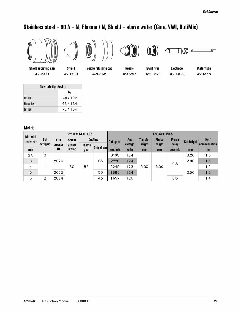
Stainless steel – 60 A – N2 Plasma / N2 Shield – above water (Core, VWI, OptiMix)
Shield retaining cap Shield Nozzle retaining cap Nozzle Swirl ring Electrode Water tube420200 420309 420365 420297 420323 420303 420368
Flow rate (lpm/scfh)N2
Pre flow 48 / 102Pierce flow 63 / 134Cut flow 72 / 154
Metric
Material thickness Cut
category
SYSTEM SETTINGS CNC SETTINGS
XPR process
ID
Shield pierce setting
Cutflow Cut speed Arc voltage
Transfer height
Pierce height
Pierce delay Cut height Kerf
compensationPlasma gas Shield gasmm mm/min volts mm mm seconds mm mm
2.5 32026
30 8265
3105 124
5.00 5.000.3
3.20 1.53
12776 124 2.80 1.5
4 2245 1232.50
1.55 2025 55 1886 124 1.56 2 2024 45 1697 126 0.6 1.4
XPR300 Instruction Manual 809830 27

Cut Charts
Stainless steel – 60 A – N2 Plasma / N2 Shield – above water (Core, VWI, OptiMix) (continued)
English
Material thickness Cut
category
SYSTEM SETTINGS CNC SETTINGS
XPR Process
ID
Shield pierce setting
Cutflow Cut speed Arc voltage
Transfer height
Pierce height
Pierce delay Cut height Kerf
compensationPlasma gas Shield gasin in/min volts in in seconds in in
0.105(12GA) 3
202630 82
65120 124
0.200 0.2000.3
0.120 0.06
0.135(10GA) 1
95 1230.100
0.06
3/16 2025 55 80 124 0.061/4 2 2024 45 65 126 0.6 0.06
Marking
Plasma gas Shield gas Process ID Mark currentCutflow Marking
heightMarking speed Arc Volt Mark widths
Plasma gas Shield gas
Metric N2 N2 8002 15 25 5 2.50 mm 6350 mm/min 120 V 1.8 mm
English N2 N2 8002 15 25 5 0.100 in 250 in/min 120 V 0.07 in
Plasma gas Shield gas Process ID Mark currentCutflow Marking
heightMarking speed Arc voltage Mark widths
Plasma gas Shield gas
Metric Ar N2 9009 11 90 10 2.50 mm 3810 mm/min 69 V 1.1 mm
English Ar N2 9009 11 90 10 0.100 in 150 in/min 69 V 0.04 in
28 809830 Instruction Manual XPR300

Cut Charts
Stainless steel – 60 A – N2 Plasma / H2O Shield – above water (VWI, OptiMix)
Shield retaining cap Shield Nozzle retaining cap Nozzle Swirl ring Electrode Water tube420200 420300 420365 420296 420323 420303 420368
Flow rate (lpm/scfh)N2 H2O
Pre flow 27 / 57 0.21 / 3*Pierce flow 34 / 72 0.21 / 3*Cut flow 20 / 42 0.4 / 7*
*Gallons per hour (gph)
Metric
Material thickness Cut
category
SYSTEM SETTINGS CNC SETTINGS
XPR process
ID
Shield pierce setting
Cutflow Cut speed Arc voltage
Transfer height
Pierce height
Pierce delay Cut height Kerf
compensationPlasma gas Shield gas mm mm/min volts mm mm seconds mm mm
31
2028 10 80 30
3065 140
5.00 5.000.3
2.50
1.54 2062 138 1.65 1516 136 1.76 2 1179 132 0.6 1.9
English
Material thickness Cut
category
SYSTEM SETTINGS CNC SETTINGS
XPR process
ID
Shield pierce setting
Cutflow Cut speed Arc voltage
Transfer height
Pierce height
Pierce delay Cut height Kerf
compensationPlasma gas Shield gasin in/min volts in in seconds in in
0.105(12GA) 3
2028 10 80 30
120 120
0.200 0.200
0.3 0.120 0.06
0.135(10GA) 1
100 1240.3
0.1000.06
3/16 80 129 0.061/4
250 132 0.6 0.07
3/8 20 144 0.8 0.120 0.09
XPR300 Instruction Manual 809830 29

Cut Charts
Stainless steel – 60 A – F5 Plasma / N2 Shield – above water (VWI, OptiMix)
Shield retaining cap Shield Nozzle retaining cap Nozzle Swirl ring Electrode Water tube420200 420309 420365 420297 420323 420303 420368
Flow rate (lpm/scfh)F5 N2
Pre flow – 55 / 117Pierce flow 40 / 84 53 / 114Cut flow 29 / 62 88 / 188
Metric
Material thickness Cut
category
SYSTEM SETTINGS CNC SETTINGS
XPR process ID
Shield pierce setting
Cutflow Cut speed Arc voltage
Transfer height
Pierce height
Pierce delay Cut height Kerf
compensationPlasma gas Shield gasmm mm/min volts mm mm seconds mm mm
2.5 32023
30 82
553177 132
5.00 5.00
0.2 3.20 1.43
12763 132
0.33.10 1.4
4 2022 45 2217 132 3.00 1.45 2021 40 1869 132 0.5 2.90 1.46
2 2020 35
1626 1330.6
2.80 1.47 1445 133 2.60 1.48 1305 133 0.7 2.50 1.410 1100 134 0.8 2.30 1.4
30 809830 Instruction Manual XPR300
Cut Charts
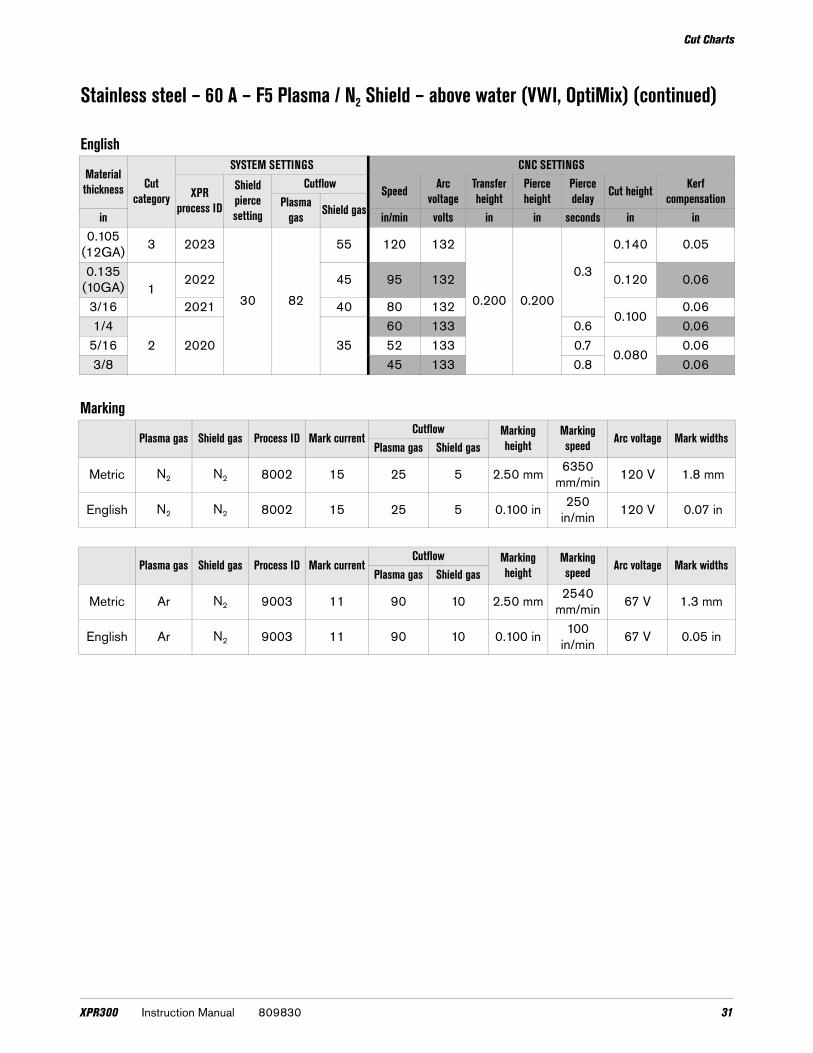
Stainless steel – 60 A – F5 Plasma / N2 Shield – above water (VWI, OptiMix) (continued)
English
Material thickness Cut
category
SYSTEM SETTINGS CNC SETTINGS
XPR process ID
Shield pierce setting
Cutflow Speed Arc voltage
Transfer height
Pierce height
Pierce delay Cut height Kerf
compensationPlasma gas Shield gasin in/min volts in in seconds in in
0.105(12GA) 3 2023
30 82
55 120 132
0.200 0.200
0.3
0.140 0.05
0.135(10GA) 1
2022 45 95 132 0.120 0.06
3/16 2021 40 80 1320.100
0.061/4
2 2020 3560 133 0.6 0.06
5/16 52 133 0.70.080
0.063/8 45 133 0.8 0.06
Marking
Plasma gas Shield gas Process ID Mark currentCutflow Marking
heightMarking speed Arc voltage Mark widths
Plasma gas Shield gas
Metric N2 N2 8002 15 25 5 2.50 mm 6350 mm/min 120 V 1.8 mm
English N2 N2 8002 15 25 5 0.100 in 250 in/min 120 V 0.07 in
Plasma gas Shield gas Process ID Mark currentCutflow Marking
heightMarking speed Arc voltage Mark widths
Plasma gas Shield gas
Metric Ar N2 9003 11 90 10 2.50 mm 2540 mm/min 67 V 1.3 mm
English Ar N2 9003 11 90 10 0.100 in 100 in/min 67 V 0.05 in
XPR300 Instruction Manual 809830 31

Cut Charts
Stainless steel – 80 A – N2 Plasma / N2 Shield – above water (Core, VWI, OptiMix)
Shield retaining cap Shield Nozzle retaining cap Nozzle Swirl ring Electrode Water tube420200 420309 420365 420306 420323 420303 420368
Flow rate (lpm/scfh)N2
Pre flow 51 / 108Pierce flow 67 / 143Cut flow 68 / 144
Metric
Material thickness Cut
category
SYSTEM SETTINGS CNC SETTINGS
XPR process
ID
Shield pierce setting
Cutflow Cut speed Arc voltage Transfer height
Pierce height
Pierce delay Cut height Kerf
compensationPlasma gas Shield gasmm mm/min volts mm mm seconds mm mm
33
2006
30 80
453820 118
5.00 5.00
0.3 2.501.5
4 3220 118 1.65
2007 40
2692 1180.5
2.00
1.66
1
2237 116 1.57 1853 117 1.58 1543 118
0.61.6
9 1304 119 1.610 2 1138 121 1.6
32 809830 Instruction Manual XPR300

Cut Charts
Stainless steel – 80 A – N2 Plasma / N2 Shield – above water (Core, VWI, OptiMix) (continued)
English
Material thickness Cut
category
SYSTEM SETTINGS CNC SETTINGS
XPR process
ID
Shield pierce setting
Cutflow Cut speed Arc voltage Transfer height Cut height Pierce
heightPierce delay
Kerf compensationPlasma
gas Shield gasin in/min volts in in in seconds in0.135
(10GA) 3 2006
30 80
45140 118
0.200 0.200
0.30.100 0.061
3/16 110 118
0.080
0.0641/4
1 2007 4084 116 0.5 0.060
5/16 60 1180.6
0.0313/8 48 120 0.064
Marking
Plasma gas Shield gas Process ID Mark currentCutflow Marking
speedMarking height Arc voltage Mark widths
Plasma gas Shield gas
Metric N2 N2 8002 15 25 5 6350 mm/min 2.50 mm 120 V 1.6 mm
English N2 N2 8002 15 25 5 250 in/min 0.100 in 120 V 0.06 in
Plasma gas Shield gas Process ID Mark currentCutflow Marking
speedMarking height Arc voltage Mark widths
Plasma gas Shield gas
Metric Ar N2 9003 11 90 10 2540 mm/min 2.50 mm 67 V 1.3 mm
English Ar N2 9003 11 90 10 100 in/min 0.100 in 67 V 0.05 in
XPR300 Instruction Manual 809830 33

Cut Charts
Stainless steel – 80 A – N2 Plasma / H2O Shield – above water (VWI, OptiMix)
Shield retaining cap Shield Nozzle retaining cap Nozzle Swirl ring Electrode Water tube420200 420300 420365 420290 420323 420303 420368
Flow rate (lpm/scfh)N2 H2O
Pre flow 30 / 64 0.2 / 3*Pierce flow 37 / 79 0.2 / 3*Cut flow 24 51 0.4 / 6*
*Gallons per hour (gph)
Metric
Material thickness Cut
category
SYSTEM SETTINGS CNC SETTINGS
XPR process
ID
Shield pierce setting
Cutflow Cut speed Arc voltage
Transfer height
Pierce height
Pierce delay Cut height Kerf
compensationPlasma gas Shield gas mm mm/min volts mm mm seconds mm mm
33
201010 86 30
3820 118
5.00 5.00
0.3
2.00
1.84 3216 121 1.75 2677 123
0.51.8
61
2203 126 1.87 1794 128 1.98 1450 130
0.62.0
102
956 134 2.112 2011 722 137 0.8 2.1
English
Material thickness Cut
category
SYSTEM SETTINGS CNC SETTINGS
XPR process
ID
Shield pierce setting
Cutflow Cut speed Arc voltage
Transfer height
Pierce height
Pierce delay Cut height Kerf
compensationPlasma gas Shield gas in in/min volts in in seconds in in
0.135(10GA) 3
2010110
8030
140 120
0.200 0.200
0.3
0.080
0.07
3/16 110 123 0.071/4
180 124 0.5 0.07
5/16 60 1320.6
0.083/8 40 134 0.087/16
22010 31 136
0.80.08
1/2 2011 86 28 138 0.08
34 809830 Instruction Manual XPR300

Cut Charts
Stainless steel – 80 A – F5 Plasma / N2 Shield – above water (VWI, OptiMix)
Shield retaining cap Shield Nozzle retaining cap Nozzle Swirl ring Electrode Water tube420200 420309 420365 420306 420323 420303 420368
Flow rate (lpm/scfh)F5 N2
Pre flow – 52 / 110Pierce flow 44 / 93 23 / 49Cut flow 38 / 81 39 / 82
Metric
Material thickness Cut
category
SYSTEM SETTINGS CNC SETTINGS
XPR process
ID
Shield pierce setting
Cutflow Cut speed Arc voltage Transfer height
Pierce height
Pierce delay Cut height Kerf
compensationPlasma gas Shield gasmm mm/min volts mm mm seconds mm mm
33
2005
3080
554248 125
5.00 5.00
0.33.00
1.74 3052 123 1.75
2004 452362 122
2.501.7
61
1916 124 0.5 1.88 2003 35 1376 128
0.62.00
1.810
22002 28 28 1065 134 1.7
12 2001 20 86 20 864 135 0.8 1.8
XPR300 Instruction Manual 809830 35

Cut Charts
Stainless steel – 80 A – F5 Plasma / N2 Shield – above water (VWI, OptiMix) (continued)
English
Material thickness Cut
category
SYSTEM SETTINGS CNC SETTINGS
XPR process
ID
Shield pierce setting
Cutflow Cut speed Arc voltage Transfer height
Pierce height
Pierce delay Cut height Kerf
compensationPlasma gas Shield gasin in/min volts in in seconds in in
0.135(10GA) 3 2005
3080
55140 124
0.200 0.200
0.30.120 0.07
3/16 105 1220.100
0.071/4
12004 45 70 124 0.5 0.07
5/16 2003 35 55 1290.6
0.080
0.073/8
2002 28 2840 132 0.07
7/162
36 1350.8
0.071/2 2001 20 86 20 34 134 0.07
Marking
Plasma gas Shield gas Process ID Mark currentCutflow Marking
heightMarking speed Arc voltage Mark widths
Plasma gas Shield gas
Metric N2 N2 8002 15 25 5 2.50 mm 6350 mm/in 120 V 1.6 mm
English N2 N2 8002 15 25 5 0.100 in 250 in/min 120 V 0.06 in
Plasma gas Shield gas Process ID Mark currentCutflow Marking
heightMarking speed Arc voltage Mark widths
Plasma gas Shield gas
Metric Ar N2 9003 11 90 10 2.50 mm 2540 mm/min 67 V 1.3 mm
English Ar N2 9003 11 90 10 0.100 in 100 in/min 67 V 0.05 in
36 809830 Instruction Manual XPR300

Cut Charts
Stainless steel – 130 A – N2 Plasma / N2 Shield – above water (Core, VWI, OptiMix)
Shield retaining cap Shield Nozzle retaining cap Nozzle Swirl ring Electrode Water tube420200 420318 420365 420315 420314 420356 420368
Flow rate (lpm/scfh)N2
Pre flow 92 / 195Pierce flow 150 / 320Cut flow 150 / 320
Metric
Material thickness Cut
category
SYSTEM SETTINGS CNC SETTINGS
XPR process
ID
Shield pierce setting
Cutflow Cut speed Arc voltage
Transfer height
Pierce height
Pierce delay Cut height Kerf
compensationPlasma gas Shield gasmm mm/min volts mm mm seconds mm mm
63
2051 52 90 52
2413 163
6.10 6.10
0.4
2.54
2.37 2257 162 2.38 2017 160
0.52.4
101
1613 159 2.412 1453 161 0.6 2.415
21029 171 0.7
3.052.5
20 559 180 1.3 2.8
XPR300 Instruction Manual 809830 37

Cut Charts
Stainless steel – 130 A – N2 Plasma / N2 Shield – above water (Core, VWI, OptiMix) (continued)
English
Material thickness Cut
category
SYSTEM SETTINGS CNC SETTINGS
XPR process
ID
Shield pierce setting
Cutflow Cut speed Arc voltages
Transfer height
Pierce height
Pierce delay Cut height Kerf
compensationPlasma gas Shield gasin in/min volts in in seconds in in
1/43
2051 52 90 52
95 163
0.240 0.240
0.4
0.100
0.095/16 80 161
0.50.09
3/81
65 158 0.101/2 55 162 0.6 0.095/8
235 175 0.7
0.1200.10
3/4 25 178 1.2 0.11
Marking
Plasma gas Shield gas Process ID Mark currentCutflow Marking
heightMarking speed Arc voltage Mark widths
Plasma gas Shield gas
Metric N2 N2 8004 18 20 15 2.50 mm 6350 mm/min 145 V 1.7 mm
English N2 N2 8004 18 20 15 0.100 in 250 in/min 145 V 0.07 in
Plasma gas Shield gas Process ID Mark currentCutflow Marking
heightMarking speed Arc voltage Mark widths
Plasma gas Shield gas
Metric Ar N2 9004 20 65 15 2.50 mm 3810 mm/min 101 V 2.0 mm
English Ar N2 9004 20 65 15 0.100 in 150 in/min 101 V 0.08 in
38 809830 Instruction Manual XPR300

Cut Charts
Stainless steel – 130 A – N2 Plasma / H2O Shield – above water (VWI and OptiMix)
Shield retaining cap Shield Nozzle retaining cap Nozzle Swirl ring Electrode Water tube420200 420469 420365 420315 420314 420356 420368
Flow rate (lpm/scfh)N2 H2O
Pre flow 38 / 80 0.42 / 6.5*Pierce flow 97 / 205 0.5 / 8*Cut flow 97 / 205 0.5 / 8*
* Gallons per hour (gph)
Metric
Material thickness Cut
category
SYSTEM SETTINGS CNC SETTINGS
XPR process
ID
Shield pierce setting
Cutflow Cut speed Arc voltage
Transfer height
Pierce height
Pierce delay Cut height Kerf
compensationPlasma gas Shield gasmm mm/min volts mm mm seconds mm mm
63
2052 25 90 25
2413 159
5.08 5.08
0.2 2.50 2.37 2257 161 0.3
2.54
2.38 2017 163 0.4 2.410
11613 167 0.5 2.4
12 1453 169 0.6 2.515
2937 171
6.35 6.350.7
3.052.8
20 457 179 1.3 3.6
English
Material thickness Cut
category
SYSTEM SETTINGS CNY SETTINGS
XPR process
ID
Shield pierce setting
Cutflow Cut speed Arc voltage
Transfer height
Pierce height
Pierce delay Cut height Kerf
compensationPlasma gas Shield gasin in/min volts in in seconds in in
1/43
2052 25 90 25
95 159
0.200 0.200
0.2
0.100
0.095/16 80 163 0.4 0.093/8
165 167 0.5 0.09
1/2 55 170 0.6 0.105/8
230 172
0.250 0.2500.8
0.1200.12
3/4 20 177 1.3 0.14
XPR300 Instruction Manual 809830 39

Cut Charts
Stainless steel – 130 A – Mixed-fuel gas Plasma / N2 Shield – above water (OptiMix)
Shield retaining cap Shield Nozzle retaining cap Nozzle Swirl ring Electrode Water tube420200 420318 420365 420315 420323 420356 420368
Flow rate (lpm/scfh)H2 Ar N2
Pre flow – – 103 / 220Pierce flow 8 / 17 12 / 25 150 / 320Cut flow 8 / 17 12 / 25 150 / 320
Metric
Material thickness Cut
category
SYSTEM SETTINGS CNC SETTINGS
XPR process
ID
Shield pierce setting
CutflowCut speed Arc
voltageTransfer height
Pierce height
Pierce delay Cut height Kerf
compensationPlasma gas Shield gasmm 1 2 3 mm/min volts mm mm seconds mm mm
63 2060 52 4 12
2452
2413 163
5.08 5.08
0.3
2.54
2.67 1954 163 2.68 1834 164 0.4 2.610
1 2053 53 6 10 531613 166 0.5 2.6
12 1453 168 0.6 2.615
2 2061 50 8 12 20 521121 172 6.10 6.10 0.7 3.05 2.7
20 737 175 7.62 7.62 1.5 3.81 2.9
40 809830 Instruction Manual XPR300

Cut Charts
Stainless steel – 130 A – Mixed-fuel gas Plasma / N2 Shield – above water (OptiMix) (continued)
English
Material thickness
Cut category
SYSTEM SETTINGS CNC SETTINGS
XPR process
ID
Shield pierce setting
CutflowCut speed Arc
voltageTransfer height
Pierce height
Pierce delay Cut height Kerf
compensationPlasma gas Shield gasin H2 Ar N2 in/min volts in in seconds in in
1/43 2060 52 4 12
2452
80 163
0.200 0.200
0.3
0.100
0.105/16 73 164 0.4 0.103/8
1 2053 53 6 10 5365 165 0.5 0.10
1/2 55 169 0.6 0.105/8
2 2061 50 8 12 20 5240 173 0.240 0.240 0.8 0.120 0.11
3/4 30 174 0.300 0.300 1.5 0.150 0.11
Marking
Plasma gas Shield gas Process ID Mark currentCutflow Marking
speedMarking height Arc voltage Mark widths
Plasma gas Shield gas
Metric N2 N2 8004 18 20 15 6350 mm/min 2.50 mm 145 V 1.7 mm
English N2 N2 8004 18 20 15 250 in/min 0.100 in 145 V 0.06 in
Plasma gas Shield gas Process ID Mark currentCutflow Marking
speedMarking height Arc voltage Mark widths
Plasma gas Shield gas
Metric Ar N2 9004 20 65 15 3810 mm/min 2.50 mm 101 V 2.0 mm
English Ar N2 9004 20 65 15 150 in/min 0.100 in 101 V 0.08 in
XPR300 Instruction Manual 809830 41

Cut Charts
Stainless steel – 170 A – N2 Plasma / N2 Shield – above water (Core, VWI, OptiMix)
Shield retaining cap Shield Nozzle retaining cap Nozzle Swirl ring Electrode Water tube420200 420327 420365 420324 420314 420356 420368
Flow rate (lpm/scfh)N2
Pre flow 99 / 210Pierce flow 168 / 355Cut flow 168 / 355
Metric
Material thickness Cut
category
SYSTEM SETTINGS CNC SETTINGS
XPR process ID
Shield pierce setting
Cutflow Cut speed Arc voltage
Transfer height
Pierce height
Pierce delay Cut height Kerf
compensationPlasma gas Shield gasmm mm/min volts mm mm seconds mm mm
10 3
2057 54 90 54
1994 1656.10 6.10
0.32.54
2.712
11834 165 0.4 2.6
15 1226 168 0.6 2.820
2705 177
7.627.62 2.5 3.43 3.2
25 405 189 15.24 4.03.81
3.630 4 289 194 Edge start 0.5 3.6
42 809830 Instruction Manual XPR300

Cut Charts
Stainless steel – 170 A – N2 Plasma / N2 Shield – above water (Core, VWI, OptiMix) (continued)
English
Material thickness Cut
category
SYSTEM SETTINGS CNC SETTINGS
XPR process ID
Shield pierce setting
Cutflow Cut speed Arc voltage
Transfer height
Pierce height
Pierce delay Cut height Kerf
compensationPlasma gas Shield gasin in/min volts in in seconds in in
3/8 3
2057 54 90 54
80 1650.240 0.240
0.30.100
0.111/2
170 165 0.4 0.10
5/8 40 169 0.7 0.113/4
230 175
0.3000.300 2.5 0.120 0.12
1 15 190 0.600 4.00.150
0.141-1/4 4 10 196 Edge start 0.7 0.14
Marking
Plasma gas Shield gas Process ID Mark CurrentCutflow Marking
heightMarking speed Arc voltage Mark widths
Plasma gas Shield gas
Metric N2 N2 8005 18 20 15 2.50 mm 6350 mm/min 121 V 2.0 mm
English N2 N2 8005 18 20 15 0.100 in 250 in/min 121 V 0.08 in
Plasma gas Shield gas Process ID Mark currentCutflow Marking
heightMarking speed Arc voltage Mark widths
Plasma gas Shield gas
Metric Ar N2 9005 18 55 15 2.50 mm 3810 mm/min 96 V 2.0 mm
English Ar N2 9005 18 55 15 0.100 in 150 in/min 96 V 0.08 in
XPR300 Instruction Manual 809830 43

Cut Charts
Stainless steel – 170 A – N2 Plasma / H2O Shield – above water (VWI, OptiMix)
Shield retaining cap Shield Nozzle retaining cap Nozzle Swirl ring Electrode Water tube420200 420472 420365 420324 420314 420356 420368
Flow rate (lpm/scfh)N2 H2O
Pre flow 19 / 40 0.4 / 6*Pierce flow 47 / 100 0.5 / 8*Cut flow 47 / 100 0.5 / 8*
* Gallons per hour (gph)
Metric
Material thickness Cut
category
SYSTEM SETTINGS CNC SETTINGS
XPR process ID
Shield pierce setting
Cutflow Cut speed Arc voltage
Transfer height
Pierce height
Pierce delay Cut height Kerf compensation
Plasma gas Shield gasmm mm/min volts mm mm seconds mm mm
10 3
2058 30 90 30
1975 1685.08 5.08
0.4
2.54
2.812
11735 172
0.52.8
15 1375 170 3.020
2978 174
7.627.62 1.5 3.2
25 778 183 15.24 4.0 3.05 4.130
4633 189
Edge start0.5
3.814.4
32 578 191 0.6 4.538 434 195 0.8 4.7
English
Material thickness Cut
category
SYSTEM SETTINGS CNC SETTINGS
XPR process ID
Shield pierce setting
Cutflow Cut speed Arc voltage
Transfer height
Pierce height
Pierce delay Cut height Kerf compensation
Plasma gas Shield gasin in/min volts in in seconds in in
3/8 3
2058 30 90 30
80 1670.200 0.200
0.4
0.100
0.111/2
165 173
0.50.11
5/8 50 169 0.123/4
240 172
0.3000.300 1.0 0.12
1 30 184 0.600 4.0 0.120 0.161-1/4
423 191
Edge start0.5
0.1500.18
1-1/2 17 195 0.8 0.19
44 809830 Instruction Manual XPR300

Cut Charts
Stainless steel – 170 A – Mixed-fuel gas Plasma / N2 Shield – above water (OptiMix)
Shield retaining cap Shield Nozzle retaining cap Nozzle Swirl ring Electrode Water tube420200 420327 420365 420324 420323 420356 420368
Flow rate (lpm/scfh)H2 Ar N2
Pre flow – – 101 / 215Pierce flow 8 / 17 12 / 25 162 / 345Cut flow 8 / 17 12 / 25 162 / 345
Metric
Material thickness Cut
category
SYSTEM SETTINGS CNC SETTINGS
XPR process
ID
Shield pierce setting
CutflowCut speed Arc
voltageTransfer height
Pierce height
Pierce delay Cut height Kerf
compensationPlasma gas Shield gasmm H2 Ar N2 mm/min volts mm mm seconds mm mm
10 32059
54
68 26
54
1975 1695.08 5.08
0.4
2.54
2.912
11735 174
0.52.9
15 1375 169 2.920
2
2062 10 24 940 183
7.62
7.62 1.4 3.625 2063
8
6 26 540 19215.24
3.8 3.05 4.030
2064 12 20398 198 4.7
4.574.2
32 352 200 5.0 4.438 4 256 206 Edge start 0.5 4.7
XPR300 Instruction Manual 809830 45

Cut Charts
Stainless steel – 170 A – Mixed-fuel gas Plasma / N2 Shield (OptiMix) (continued)
English
Material thickness Cut
category
SYSTEM SETTINGS CNC SETTINGS
XPR process
ID
Shield pierce setting
CutflowCut speed Arc
voltageTransfer height
Pierce height
Pierce delay Cut height Kerf
compensationPlasma gas Shield gas in H2 Ar N2 in/min volts in in seconds in in
3/8 32059
54
68 26
54
80 1680.200 0.200
0.4
0.100
0.121/2
165 176
0.50.11
5/8 50 167 0.123/4
22062 10 24 40 181
0.3000.300 1.0 0.14
1 20638
6 26 20 1930.600
4.00.120
0.161-1/4
2064 12 2014 200 5.0 0.17
1-1/2 4 10 206 Edge start 0.5 0.19
Marking
Plasma gas Shield gas Process ID Mark currentCutflow Marking
heightMarking speed Arc voltage Mark widths
Plasma gas Shield gas
Metric N2 N2 8005 18 20 15 2.50 mm 6350 mm/min 121 V 0.08 mm
English N2 N2 8005 18 20 15 0.100 in 250 in/min 121 V 2.0 in
Plasma gas Shield gas Process ID Mark currentCutflow Marking
heightMarking speed Arc voltage Mark widths
Plasma gas Shield gas
Metric Ar N2 9005 18 55 15 2.50 mm 3810 mm/min 96 V 0.07 mm
English Ar N2 9005 18 55 15 0.100 in 150 in/min 96 V 1.8 in
46 809830 Instruction Manual XPR300

Cut Charts
Stainless steel – 300 A – N2 Plasma / N2 Shield – above water (Core, VWI, OptiMix)
Shield retaining cap Shield Nozzle retaining cap Nozzle Swirl ring Electrode Water tube420200 420362 420365 420359 420323 420356 420368
Flow rate (lpm/scfh)N2
Pre flow 106 / 225Pierce flow 181 / 385Cut flow 181 / 385
Metric
Material thickness Cut
category
SYSTEM SETTINGS CNC SETTINGS
XPR process ID
Shield pierce setting
Cutflow Cut speed Arc voltage
Transfer height
Pierce height
Pierce delay
Cut height Kerf compensation
Plasma gas
Shield gasmm mm/min volts mm mm seconds mm mm
123
2054
54 90
54
2997 168
7.620
7.620.4
4.323.1
15 2666 168 0.5 3.120
11829 172 0.9
5.01
3.525 1429 177 12.70 1.5 3.430
21084 180
15.242.0 4.0
32 947 182 2.2 4.238
42100 58
515 194
Edge start0.8
4.240 455 196 4.144 343 201 0.9
6.353.9
50 5 264 204 1.0 6.0
XPR300 Instruction Manual 809830 47

Cut Charts
Stainless steel – 300 A – N2 Plasma / N2 Shield – above water (Core, VWI, OptiMix) (continued)
English
Material thickness Cut
category
SYSTEM SETTINGS CNC SETTINGS
XPR process ID
Shield pierce setting
Cutflow Cut speed Arc voltage
Transfer height
Pierce height
Pierce delay
Cut height Kerf compensation
Plasma gas
Shield gasin in/min volts in in seconds in in
1/23
2054
54 90
54
118 168
0.3000.300
0.40.170
0.125/8 100 168 0.5 0.123/4
175 171 0.8
0.200
0.141 55 177 0.500 1.5 0.14
1-1/4 2 38 181 0.600 2.2 0.171-1/2
42100 58
20 194Edge start
0.5 0.171-3/4 13 201 0.8
0.2500.15
2 5 10 205 1.0 0.25
Marking
Plasma gas Shield gas Process ID Mark currentCutflow Marking
heightMarking speed Arc voltage Mark widths
Plasma gas Shield gas
Metric N2 N2 8006 18 15 25 2.50 mm 2540 mm/min 135 V 1.5 mm
English N2 N2 8006 18 15 25 0.100 in 100 in/min 135 V 0.06 in
Plasma gas Shield gas Process ID Mark currentCutflow Marking
heightMarking speed Arc voltage Mark widths
Plasma gas Shield gas
Metric Ar N2 9006 22 55 15 2.50 mm 2540 mm/min 92 V 2.80 mm
English Ar N2 9006 22 55 15 0.100 in 100 in/min 92 V 0.11 in
48 809830 Instruction Manual XPR300
Cut Charts
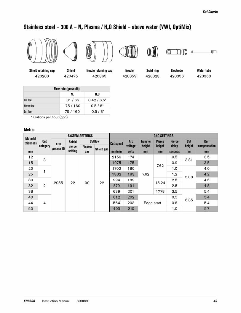
Stainless steel – 300 A – N2 Plasma / H2O Shield – above water (VWI, OptiMix)
Shield retaining cap Shield Nozzle retaining cap Nozzle Swirl ring Electrode Water tube420200 420475 420365 420359 420323 420356 420368
Flow rate (lpm/scfh)N2 H2O
Pre flow 31 / 65 0.42 / 6.5*Pierce flow 75 / 160 0.5 / 8*Cut flow 75 / 160 0.5 / 8*
* Gallons per hour (gph)
Metric
Material thickness Cut
category
SYSTEM SETTINGS CNC SETTINGS
XPR process ID
Shield pierce setting
Cutflow Cut speed Arc voltage
Transfer height
Pierce height
Pierce delay
Cut height
Kerf compensationPlasma
gas Shield gasmm mm/min volts mm mm seconds mm mm12
3
2055 22 90 22
2159 174
7.62
7.62
0.53.81
3.515 1975 175 0.9 3.520
11702 180 1.0
5.08
4.025 1302 183 1.2 4.230
2994 189
15.242.5 4.6
32 879 191 2.8 4.838 639 201 17.78 3.5
6.35
5.440
4612 202
Edge start0.5 5.4
44 564 203 0.6 5.450 403 210 1.0 5.7
XPR300 Instruction Manual 809830 49

Cut Charts
Stainless steel – 300 A – N2 Plasma / H2O Shield – above water (VWI, OptiMix) (continued)
English
Material thickness Cut
category
SYSTEM SETTINGS CNC SETTINGS
XPR process ID
Shield pierce setting
Cutflow Cut speed Arc voltage
Transfer height
Pierce height
Pierce delay
Cut height
Kerf compensationPlasma
gas Shield gas in in/min volts in in seconds in in1/2
3
2055 22 90 22
85 174
0.3000.300
0.50.150
0.145/8 75 176
1.00.14
3/41
70 1800.200
0.151 50 183 1.2 0.17
1-1/42
35 191 0.600 2.8 0.191-1/2 25 201 0.700 3.5
0.2500.21
1-3/44
22 203Edge start
0.5 0.212 15 211 1.0 0.23
50 809830 Instruction Manual XPR300
Cut Charts
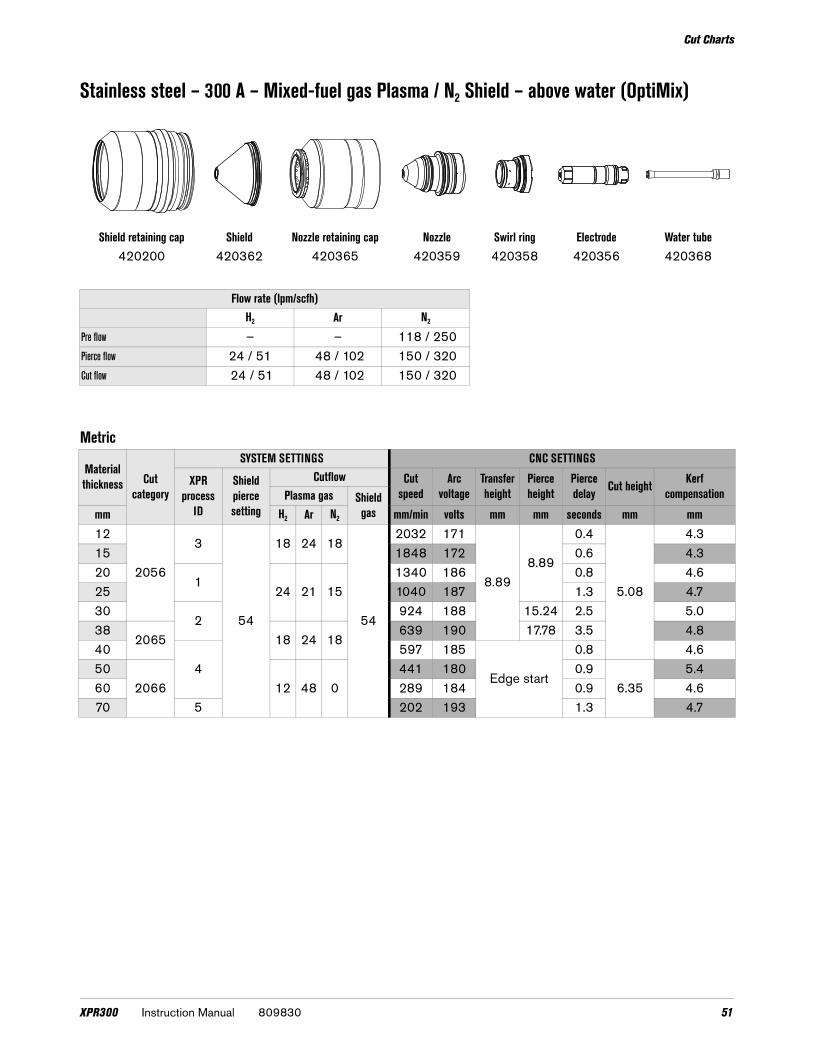
Stainless steel – 300 A – Mixed-fuel gas Plasma / N2 Shield – above water (OptiMix)
Shield retaining cap Shield Nozzle retaining cap Nozzle Swirl ring Electrode Water tube420200 420362 420365 420359 420358 420356 420368
Flow rate (lpm/scfh)H2 Ar N2
Pre flow – – 118 / 250Pierce flow 24 / 51 48 / 102 150 / 320Cut flow 24 / 51 48 / 102 150 / 320
Metric
Material thickness Cut
category
SYSTEM SETTINGS CNC SETTINGS
XPR process
ID
Shield pierce setting
Cutflow Cut speed
Arc voltage
Transfer height
Pierce height
Pierce delay Cut height Kerf
compensationPlasma gas Shield gasmm H2 Ar N2 mm/min volts mm mm seconds mm mm
12
2056
3
54
18 24 18
54
2032 171
8.898.89
0.4
5.08
4.315 1848 172 0.6 4.320
124 21 15
1340 186 0.8 4.625 1040 187 1.3 4.730
2924 188 15.24 2.5 5.0
382065 18 24 18
639 190 17.78 3.5 4.840
4597 185
Edge start
0.8 4.650
2066 12 48 0441 180 0.9
6.355.4
60 289 184 0.9 4.670 5 202 193 1.3 4.7
XPR300 Instruction Manual 809830 51

Cut Charts
Stainless steel – 300 A – Mixed-fuel gas Plasma / N2 Shield – above water (OptiMix) (continued)
English
Material thickness
Cut category
SYSTEM SETTINGS CNC SETTINGS
XPR process
ID
Shield pierce setting
Cutflow Cut speed
Arc voltage
Transfer height
Pierce height
Pierce delay Cut height Kerf
compensationPlasma gas Shield gasN2 Ar N2 mm/min volts mm mm seconds mm mm
1/23
2056
54
18 24 18
54
80 171
0.3500.350
0.4
0.200
0.175/8 70 173 0.7 0.173/4
124 21 15
55 186 0.8 0.181 40 187 1.2 0.19
1-1/42
35 189 0.600 2.8 0.201 -1/2 2065 18 24 18 25 190 0.700 3.5 0.191-3/4
4
2066 12 48 0
20 172
Edge start
0.80.17
2 17 181
0.250
0.222-1/4 13 183 0.9 0.192-1/2
510 185 1.0 0.17
2-3/4 8 193 1.3 0.183 6 200 1.5 0.20
Plasma gas Shield gas Process ID Mark currentCutflow Marking
heightMarking speed Arc Volt Mark widths
Plasma gas Shield gas
Metric N2 N2 8006 18 25 15 2.50 mm 2540 mm/min 135 V 1.50 mm
English N2 N2 8006 18 25 15 0.100 100 in/min 135 V 0.06 in
Plasma gas Shield gas Process ID Mark currentCutflow Marking
heightMarking speed Arc voltage Mark widths
Plasma gas Shield gas
Metric Ar N2 9006 22 55 15 2.50 mm 2540 mm/min 92 V 2.80 mm
English Ar N2 9006 22 55 15 0.100 in 100 in/min 92 V 0.11 in
52 809830 Instruction Manual XPR300

Cut Charts
Cut charts for non-ferrous (aluminum) processes – above water
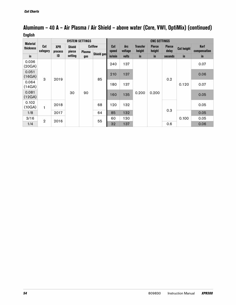
Aluminum – 40 A – Air Plasma / Air Shield – above water (Core, VWI, OptiMix)
Shield retaining cap Shield Nozzle retaining cap Nozzle Swirl ring Electrode Water tube420200 420291 420365 420288 420314 420294 420368
Flow rate (lpm/scfh)N2 Air
Pre flow 17 / 35 32 / 67Pierce flow – 54 / 115Cut flow – 66 / 141
Metric
Material thickness Cut
category
SYSTEM SETTINGS CNC SETTINGS
XPR process
ID
Shield pierce setting
Cutflow Cut speed
Arc voltage
Transfer height
Pierce height
Pierce delay Cut height Kerf
compensationPlasma gas Shield gasmm mm/min volts mm mm seconds mm mm
1.53 2019
30 90
854799 137
5.00 5.00
0.23.00
1.52 3964 135 1.4
2.51 2018 68
3230 133
0.3
1.33 2596 132 2.70 1.34
22017 64 1632 131
2.501.2
52016 55
1070 131 1.36 911 135 0.6 1.4
XPR300 Instruction Manual 809830 53
Cut Charts
Aluminum – 40 A – Air Plasma / Air Shield – above water (Core, VWI, OptiMix) (continued)English
Material thickness Cut
category
SYSTEM SETTINGS CNC SETTINGS
XPR process
ID
Shield pierce setting
Cutflow Cut speed
Arc voltage
Transfer height
Pierce height
Pierce delay Cut height Kerf
compensationPlasma gas Shield gasin in/min volts in in seconds in in
0.036(20GA)
3 2019
30 90
85
240 137
0.200 0.200
0.20.120
0.07
0.051(16GA) 210 137 0.06
0.064(14GA) 180 137 0.07
0.081(12GA) 160 135 0.05
0.102(10GA) 1
2018 68 120 1320.3
0.05
1/8 2017 64 85 1320.100
0.053/16
2 2016 5560 130 0.05
1/4 32 137 0.6 0.06
54 809830 Instruction Manual XPR300

Cut Charts
Aluminum – 40 A – N2 Plasma / N2 Shield – above water (Core)
Shield retaining cap Shield Nozzle retaining cap Nozzle Swirl ring Electrode Water tube420200 420291 420365 420288 420314 420303 420368
Flow rate (lpm/scfh)N2
Pre flow 49 / 103Pierce flow 57 / 120Cut flow 71 / 152
Metric
Material thickness Cut
category
SYSTEM SETTINGS CNC SETTINGS
XPR process ID
Shield pierce setting
Plasma gas Cut speed
Arc voltage
Transfer height
Pierce height
Pierce delay Cut height Kerf
compensationPlasma gas Shield gasmm mm/min volts mm mm seconds mm mm
1.53 2015
30
75 854781 131
5.00 5.00
0.23.00
1.32 3494 132 1.3
2.51 2014
90
682740 132
0.3
1.33 2246 131 2.70 1.34
22013 64 1641 130
2.501.2
52012 55
1287 131 1.26 1055 137 0.6 1.3
XPR300 Instruction Manual 809830 55

Cut Charts
Aluminum – 40 A – N2 Plasma / N2 Shield – above water (Core) (continued)
English
Material thickness Cut
category
SYSTEM SETTINGS CNC SETTINGS
XPR process ID
Shield pierce setting
Cutflow Cut speed
Arc voltage
Transfer height
Pierce height
Pierce delay Cut height Kerf
compensationPlasma gas Shield gasin in/min volts in in seconds in in
0.036(20GA)
3 2019
30 90
85
240 137
0.200 0.200
0.20.120
0.07
0.051(16GA) 210 137 0.06
0.06(14GA) 180 137 0.07
0.081(12GA) 160 135 0.05
0.102(10GA) 1
2018 68 120 1320.3
0.05
1/8 2017 64 85 1320.100
0.053/16
2 2016 5560 130 0.05
1/4 32 137 0.6 0.06
Marking
Plasma gas Shield gas Process ID Mark currentCutflow Marking
heightMarking speed Arc voltage Mark widths
Plasma gas Shield gas
Metric N2 N2 8002 15 25 5 2.50 mm 6350 mm/min 120 V 2.1 mm
English N2 N2 8002 15 25 5 0.100 in 250 in/min 120 V 0.08 in
Plasma gas Shield gas Process ID Mark currentCutflow Marking
heightMarking speed Arc voltage Mark widths
Plasma gas Shield gas
Metric Ar N2 9011 12 90 10 2.50 mm 2540 mm/min 76 V 0.8 mm
English Ar N2 9011 12 90 10 0.100 in 100 in/min 76 V 0.03 in
56 809830 Instruction Manual XPR300

Cut Charts
Aluminum – 60 A – Air Plasma / Air Shield – above water (Core, VWI, OptiMix)
Shield retaining cap Shield Nozzle retaining cap Nozzle Swirl ring Electrode Water tube420200 420309 420365 420297 420323 420294 420368
Flow rate (lpm/scfh)N2 Air
Pre flow 24 / 51 24 / 50Pierce flow – 91 / 193Cut flow – 56 / 120
Metric
Material thickness Cut
category
SYSTEM SETTINGS CNC SETTINGS
XPR process ID
Shield pierce setting
Cutflow Cut speed Arc voltage Transfer height
Pierce height
Pierce delay Cut height Kerf
compensationPlasma gas Shield gasmm mm/min volts mm mm seconds mm mm
31
2027 30 80 45
2688 130
5.00 5.00 0.3 2.50
1.74 2229 130 1.65 1928 131 1.66 2 1713 131 1.5
English
Material thickness Cut
category
SYSTEM SETTINGS CNC SETTINGS
XPR process ID
Shield pierce setting
Cutflow Cut speed Arc voltage Transfer height
Pierce height
Pierce delay Cut height Kerf
compensationPlasma gas Shield gasin in/min volts in in seconds in in
0.102(10GA) 3
2027 30 80 45
120 130
0.200 0.200 0.3 0.100
0.070
1/81
95 130 0.0603/16 80 129 0.0601/4 2 65 132 0.061
XPR300 Instruction Manual 809830 57

Cut Charts
Aluminum – 60 A – N2 Plasma / N2 Shield – above water (Core, VWI, OptiMix)
Shield retaining cap Shield Nozzle retaining cap Nozzle Swirl ring Electrode Water tube420200 420309 420365 420297 420323 420303 420368
Flow rate (lpm/scfh)N2
Pre flow 48 / 102Pierce flow 63 / 134Cut flow 72 / 154
Metric
Material thickness Cut
category
SYSTEM SETTINGS CNC SETTINGS
XPR process
ID
Shield pierce setting
Cutflow Cut speed Arc voltage
Transfer height
Pierce height
Pierce delay Cut height Kerf
compensationPlasma gas Shield gasmm mm/min volts mm mm seconds mm mm
31
202630 82
652776 123
5.00 5.000.3
3.20 1.64 2245 124
2.501.5
5 2025 55 1886 125 1.56 2 2024 45 1697 125 0.6 1.4
English
Material thickness Cut
category
SYSTEM SETTINGS CNC SETTINGS
XPR process
ID
Shield pierce setting
Cutflow Cut speed Arc voltage
Transfer height
Pierce height
Pierce delay Cut height Kerf
compensationPlasma gas Shield gasin in/min volts in in seconds in in
0.102(10GA) 30
202630 82
65 120 131
0.200 0.2000.3
0.1200.07
0.1251
65 100 128 0.063/16 2025 55 80 131
0.1000.06
1/4 2 2024 45 60 132 0.6 0.06
58 809830 Instruction Manual XPR300

Cut Charts
Aluminum – 60 A – N2 Plasma / N2 Shield – above water (Core, VWI, OptiMix) (continued)
Marking
Plasma gas Shield gas Process ID Mark currentCutflow Marking
heightMarking speed Arc voltage Mark widths
Plasma gas Shield gas
Metric N2 N2 8002 15 25 5 2.50 mm 6350 mm/min 120 V 1.8 mm
English N2 N2 8002 15 25 5 0.100 in 250 in/min 120 V 0.07 in
Plasma gas Shield gas Process ID Mark currentCutflow Marking
heightMarking speed Arc voltage Mark widths
Plasma gas Shield gas
Metric Ar N2 9012 14 90 20 2.50 mm 2540 mm/min 77 V 1.3 mm
English Ar N2 9012 14 90 20 0.100 in 100 in/min 77 V 0.05 in
XPR300 Instruction Manual 809830 59

Cut Charts
Aluminum – 60 A – N2 Plasma / H2O Shield – above water (VWI, OptiMix)
Shield retaining cap Shield Nozzle retaining cap Nozzle Swirl ring Electrode Water tube420200 420300 420365 420296 420323 420303 420368
Flow rate (lpm/scfh)N2 H2O
Pre flow 27 / 57 0.2 / 3*Pierce flow 34 / 72 0.2 / 3*Cut flow 20 / 42 0.4 / 7*
*Gallons per hour (gph)
Metric
Material thickness Cut
category
SYSTEM SETTINGS CNC SETTINGS
XPR Process
ID
Shield pierce setting
Cutlow Cut speed Arc voltage
Transfer height
Pierce height
Pierce delay
Cut height
Kerf compensationPlasma
gas Shield gasmm mm/min volts mm mm seconds mm mm3
12028 10 80 30
2754 122
5.00 5.000.3
2.50 1.44 2402 124
2.001.4
5 2050 126 1.46 2 1698 128 0.6 2.50 1.5
English
Material thickness Cut
category
SYSTEM SETTINGS CNC SETTINGS
XPR Process
ID
Shield pierce setting
Cutlow Cut speed Arc voltage
Transfer height
Pierce height
Pierce delay
Cut height
Kerf compensationPlasma
gas Shield gasin in/min volts in in seconds in in0.102
(10GA) 3
2028 10 80 30
120 126
0.200 0.2000.3
0.120 0.05
1/81
100 1220.100
0.063/16 80 122 0.061/4
265 124 0.6 0.05
3/8 18 138 0.8 0.120 0.06
60 809830 Instruction Manual XPR300

Cut Charts
Aluminum – 80 A – Air Plasma / Air Shield – above water (Core, VWI, OptiMix)
Shield retaining cap Shield Nozzle retaining cap Nozzle Swirl ring Electrode Water tube420200 420309 420365 420306 420323 420294 420368
Flow rate (lpm/scfh)N2 Air
Pre flow 51 / 107 –Pierce flow 23 / 48 43 / 91Cut flow – 69 / 147
Metric
Material thickness Cut
category
SYSTEM SETTINGS CNC SETTINGS
XPR process
ID
Shield pierce setting
Cutflow Cut speed Arc voltage
Transfer height
Pierce height
Pierce delay
Cut height
Kerf compensationPlasma
gas Shield gasmm mm/min volts mm mm seconds mm mm3
32008
30 80
553874 128
5.00 5.00
0.3
2.00
1.74 3143 129 1.65
2009 40
2520 129 1.56
12005 127 0.5 1.5
8 1297 1280.6
1.610 2 1019 131 1.7
English
Material thickness Cut
category
SYSTEM SETTINGS CNC SETTINGS
XPR process
ID
Shield pierce setting
Cutflow Cut speed Arc voltage
Transfer height
Pierce height
Pierce delay
Cut height
Kerf compensationPlasma
gas Shield gasin in/min volts in in seconds in in3/16 3 2008
30 80
55 100 130
0.200 0.200
0.3
0.080
0.061/4
1 2009 4070 126 0.5 0.06
5/16 55 1280.6
0.063/8 40 130 0.07
XPR300 Instruction Manual 809830 61

Cut Charts
Aluminum – 80 A – N2 Plasma / N2 Shield – above water (Core, VWI, OptiMix)
Shield retaining cap Shield Nozzle retaining cap Nozzle Swirl ring Electrode Water tube420200 420309 420365 420306 420323 420303 420368
Flow rate (lpm/scfh)N2
Pre flow 51 / 108Pierce flow 67 / 143Cut flow 68 / 114
Metric
Material thickness Cut
category
SYSTEM SETTINGS CNC SETTINGS
XPR process
ID
Shield pierce setting
Cutflow Cut speed Arc voltage
Transfer height
Pierce height
Pierce delay Cut height Kerf
compensationPlasma gas Shield gas mm mm/min volts mm mm seconds mm mm
33
2006
30 80
453820 120
5.00 5.00
0.32.500
1.74 3220 119 1.65
2007 40
2692 118
2.000
1.56
12237 120 0.5 1.6
8 1543 1220.6
1.710 2 1138 125 1.7
62 809830 Instruction Manual XPR300

Cut Charts
Aluminum – 80 A – N2 Plasma / N2 Shield – above water (Core, VWI, OptiMix) (continued)
English
Material thickness Cut
category
SYSTEM SETTINGS CNC SETTINGS
XPR process
ID
Shield pierce setting
Cutflow Cut speed Arc voltage
Transfer height
Pierce height
Pierce delay Cut height Kerf
compensationPlasma gas Shield gas in in/min volts in in seconds in in
1/8 3 2006
30 80
45140 120
0.200 0.200
0.30.100 0.07
3/16 3 2006 110 118
0.080
0.061/4
1 2007 4084 120 0.5 0.06
5/16 64 1220.6
0.073/8 48 124 0.07
Marking
Plasma gas Shield gas Process ID Mark currentCutflow Marking
heightMarking speed Arc voltage Mark widths
Plasma gas Shield gas
Metric N2 N2 8002 15 25 5 2.50 mm 6350 mm/min 120 V 1.6 mm
English N2 N2 8002 15 25 5 0.100 in 250 in/min 120 V 0.06 in
Plasma gas Shield gas Process ID Mark currentCutflow Marking
heightMarking speed Arc voltage Mark widths
Plasma gas Shield gas
Metric Ar N2 9013 16 90 20 2.50 mm 2540 mm/min 78 V 1.5 mm
English Ar N2 9013 16 90 20 0.100 in 100 in/min 78 V 0.58 in
XPR300 Instruction Manual 809830 63

Cut Charts
Aluminum – 80 A – N2 Plasma / H2O Shield – above water (VWI, OptiMix)
Shield retaining cap Shield Nozzle retaining cap Nozzle Swirl ring Electrode Water tube420200 420300 420365 420290 420323 420303 420368
Flow rate (lpm/scfh)N2 H2O
Pre flow 30 / 64 0.2 / 3*Pierce flow 37 / 79 0.2 / 3*Cut flow 24 / 51 0.4 / 6*
*Gallons per hour (gph)
Metric
Material thickness Cut
category
SYSTEM SETTINGS CNC SETTINGS
XPR process ID
Shield pierce setting
Cutflow Cut speed Arc voltage
Transfer height
Pierce height
Pierce delay Cut height Kerf
compensationPlasma gas Shield gas mm mm/min volts mm mm seconds mm mm
33
2010 10 80 30
3820 121
5.00 5.00
0.3
2.00
1.74 3216 122 1.75 2677 124 1.66
12203 126
0.51.6
7 1794 128 1.68 1450 129
0.61.7
10 2 956 133 1.8
64 809830 Instruction Manual XPR300

Cut Charts
Aluminum – 80 A – N2 Plasma / H2O Shield – above water (VWI, OptiMix) (continued)
English
Material thickness Cut
category
SYSTEM SETTINGS CNC SETTINGS
XPR process ID
Shield pierce setting
Cutflow Cut speed Arc voltage
Transfer height
Pierce height
Pierce delay Cut height Kerf
compensationPlasma gas Shield gas mm mm/min volts mm mm seconds mm mm
1/83
201010
80
30
140 120
0.200 0.200
0.3
0.080
0.073/16
86
110 122 0.061/4
180 126 0.5 0.06
5/16 60 1290.6
0.073/8 40 132 0.077/16
231 134
0.80.07
1/2 2011 28 135 0.06
XPR300 Instruction Manual 809830 65

Cut Charts
Aluminum – 130 A – N2 Plasma / N2 Shield – above water (Core, VWI, OptiMix)
Shield retaining cap Shield Nozzle retaining cap Nozzle Swirl ring Electrode Water tube420200 420318 420365 420315 420314 420356 420368
Flow rate (lpm/scfh)N2
Pre flow 92 / 195Pierce flow 150 / 320Cut flow 150 / 320
Metric
Material thickness Cut
category
SYSTEM SETTINGS CNC SETTINGS
XPR process ID
Shield pierce setting
Cutflow Cut speed Arc voltage
Transfer height
Pierce height
Pierce delay Cut height Kerf
compensationPlasma gas Shield gasmm mm/min volts mm mm seconds mm mm
63
2051 52 90 52
2413 154
6.07 6.07
0.4
2.54
2.57 2358 168 2.58 2078 169
0.52.5
101
1594 171 2.512 1354 174 0.6 2.515
21178 178 0.7
3.042.4
20 635 182 1.3 2.7
66 809830 Instruction Manual XPR300

Cut Charts
Aluminum – 130 A – N2 Plasma / N2 Shield – above water (Core, VWI, OptiMix) (continued)
English
Material thickness Cut
category
SYSTEM SETTINGS CNC SETTINGS
XPR process ID
Shield pierce setting
Cutflow Cut speed Arc voltage
Transfer height
Pierce height
Pierce delay Cut height Kerf
compensationPlasma gas Shield gasin in/min volts in in seconds in in
1/43
2051 52 90 52
100 168
0.240 0.240
0.50.100
0.105/16 83 169 0.103/8
165 170 0.10
1/2 50 175 0.6 0.105/8
245 179 0.7
0.1200.09
3/4 30 181 1.2 0.10
Marking
Plasma gas Shield gas Process ID Mark currentCutflow Marking
heightMarking speed Arc voltage Mark widths
Plasma gas Shield gas
Metric N2 N2 8004 18 15 20 2.50 mm 6350 mm/min 145 V 1.3 mm
English N2 N2 8004 18 15 20 0.100 in 250 in/min 145 V 0.05 in
Plasma gas Shield gas Process ID Mark currentCutflow Marking
heightMarking speed Arc voltage Mark widths
Plasma gas Shield gas
Metric Ar N2 9014 24 65 15 2.50 mm 2540 mm/min 88 V 2.0 mm
English Ar N2 9014 24 65 15 0.100 in 100 in/min 88 V 0.08 in
XPR300 Instruction Manual 809830 67

Cut Charts
Aluminum – 130 A – N2 Plasma / H2O Shield – above water (VWI, OptiMix)
Shield retaining cap Shield Nozzle retaining cap Nozzle Swirl ring Electrode Water tube420200 420469 420365 420315 420314 420356 420368
Flow rate (lpm/scfh)N2 H2O
Pre flow 38 0.42 / 6.5*Pierce flow 97 0.5 / 8*Cut flow 97 0.5 / 8*
* Gallons per hour (gph)
Metric
Material thickness Cut
category
SYSTEM SETTINGS CNC SETTINS
XPR process ID
Shield pierce setting
Cutflow Cut speed Arc voltage
Transfer height
Pierce height
Pierce delay Cut height Kerf
compensationPlasma gas Shield gas mm mm/min voltage mm mm seconds mm mm
63
2052 25 90 25
2413 154
6.10 6.10
0.4
2.54
2.58 2083 156 0.5 2.510
11702 158 0.6 2.5
12 1382 160 0.8 2.515
21178 164 1.0
3.052.8
20 762 170 1.3 3.2
English
Material thickness Cut
category
SYSTEM SETTINGS CNC SETTINS
XPR process ID
Shield pierce setting
Cutflow Cut speed Arc voltage
Transfer height
Pierce height
Pierce delay Cut height Kerf
compensationPlasma gas Shield gas in in/min voltage in in seconds in in
1/43
2052 25 90 25
95 154
0.240 0.240
0.4
0.100
0.105/16 83 156 0.5 0.103/8
170 157 0.6 0.10
1/2 50 161 0.8 0.105/8
245 165 1.0
0.1200.11
3/4 35 168 1.2 0.12
68 809830 Instruction Manual XPR300

Cut Charts
Aluminum – 130 A – Mixed-fuel gas Plasma / N2 Shield – above water (OptiMix)
Shield retaining cap Shield Nozzle retaining cap Nozzle Swirl ring Electrode Water tube420200 420318 420365 420315 420323 420356 420368
Flow rate (lpm/scfh)H2 Ar N2
Pre flow – – 103 / 220Pierce flow 8 / 17 12 / 25 150 / 320Cut flow 8 / 17 12 / 25 150 / 320
Metric
Material thickness Cut
category
SYSTEM SETTINGS CNC SETTINS
XPR process
ID
Shield pierce setting
CutflowCut speed Arc
voltageTransfer height
Pierce height
Pierce delay
Cut height
Kerf compensationPlasma gas Shield
gasmm H2 Ar N2 mm/min volts mm mm seconds mm mm6
3 2060 52 4 1224
52
2413 163
5.08 5.08
0.3
2.54
2.47 2205 164 2.48 1885 165 0.4 2.510
1 2053 53 6 101340 167 0.5 2.6
12 53 1100 169 0.6 2.515
2 2061 50 8 12 20 521016 172
6.10 6.100.7
3.052.6
20 813 175 1.5 2.9
XPR300 Instruction Manual 809830 69

Cut Charts
Aluminum – 130 A – Mixed-fuel gas Plasma / N2 Shield – above water (OptiMix) (continued)
English
Material thickness Cut
category
SYSTEM SETTINGS CNC SETTINS
XPR process
ID
Shield pierce setting
CutflowCut speed Arc
voltageTransfer height
Pierce height
Pierce delay
Cut height
Kerf compensationPlasma gas Shield
gasin H2 Ar N2 in/min volts in in seconds in in1/4
3 2060 52 4 1224
5295 163
0.200 0.200
0.3
0.100
0.095/16 75 165 0.4 0.103/8
1 2053 53 6 10 5355 166 0.5 0.10
1/2 40 170 0.6 0.105/8
2 2061 50 8 12 20 5240 173
0.240 0.2400.8
0.1200.10
3/4 35 174 1.5 0.10
Marking
Plasma gas Shield gas Process ID Mark currentCutflow Marking
heightMarking speed Arc voltage Mark widths
Plasma gas Shield gas
Metric N2 N2 8001 15 10 10 2.54 mm 6350 mm/min 118 V 1.3 mm
English N2 N2 8001 15 10 10 0.100 in 250 in/min 118 V 0.05 in
Plasma gas Shield gas Process ID Mark currentCutflow Marking
heightMarking speed Arc voltage Mark widths
Plasma gas Shield gas
Metric Ar N2 9014 24 65 15 2.50 mm 2540 mm/min 88 V 2.0 mm
English Ar N2 9014 24 65 15 0.100 in 100 in/min 88 V 0.08 in
70 809830 Instruction Manual XPR300

Cut Charts
Aluminum – 170 A – Air Plasma / Air Shield – above water (Core, VWI, OptiMix)
Shield retaining cap Shield Nozzle retaining cap Nozzle Swirl ring Electrode Water tube420200 420513 420365 420524 420260 420258 420368
Flow rate (lpm/scfh)N2 Air
Pre flow 25 / 52 78 / 166Pierce flow – 120 / 255Cut flow – 120 / 255
Metric
Material thickness Cut
category
SYSTEM SETTINGS CNC SETTINGS
XPR process
ID
Shield pierce setting
Cutflow Cut speed Arc voltage
Transfer height
Pierce height
Pierce delay Cut height Kerf
compensationPlasma gas Shield gasmm mm/min volts mm mm seconds mm mm
6
3
2101 40 78 77
4826 136
5.59 5.590.3
2.79
3.07 4566 136 2.98 4166 136
0.42.9
10 3385 136 2.812 1 2665 138 5.58 5.88 0.6 2.715 1 1769 145
7.62 7.620.7
3.812.5
202
1086 151 1.0 2.925 786 155 1.2 3.030
4486 162
Edge start 0.3 4.573.1
32 376 165 3.138 256 172 3.4
XPR300 Instruction Manual 809830 71

Cut Charts
Aluminum – 170 A – Air Plasma / Air Shield – above water (Core, VWI, OptiMix) (continued)
English
Material thickness Cut
category
SYSTEM SETTINGS CNC SETTINGS
XPR process
ID
Shield pierce setting
Cutflow Cut speed Arc voltage
Transfer height
Pierce height
Pierce delay Cut height Kerf compensation
Plasma gas Shield gasin in/min volts in in seconds in in
1/43
2101 40 78 77
190 136
0.220 0.220
0.3
0.110
0.125/16 165 136
0.40.11
3/8 140 136 0.111/2
195 139 0.6 0.10
5/8 60 1470.300 0.300
0.80.150
0.103/4
245 150 1.0 0.11
1 30 155 1.2 0.121-1/4
415 165
Edge start 0.3 0.1800.12
1-1/2 10 172 0.14
72 809830 Instruction Manual XPR300

Cut Charts
Aluminum – 170 A – N2 Plasma / N2 Shield – above water (Core, VWI, OptiMix)
Shield retaining cap Shield Nozzle retaining cap Nozzle Swirl ring Electrode Water tube420200 420327 420365 420324 420314 420356 420368
Flow rate (lpm/scfh)N2
Pre flow 99 / 210Pierce flow 168 / 355Cut flow 168 / 355
Metric
Material thickness Cut
category
SYSTEM SETTINGS CNC SETTINGS
XPR process
ID
Shield pierce setting
Cutflow Cut speed Arc voltage
Transfer height
Pierce height
Pierce delay Cut height Kerf
compensationPlasma gas
Shield gas mm mm/min volts mm mm seconds mm mm
63
2057 54 90 54
5969 204
6.10 6.10
0.30
2.54
2.47 5735 195 0.32 2.48
15375 180 0.35 2.3
10 4560 159 0.45 2.215
22220 166 0.92 3.00 2.3
20 1156 178 1.583.81
2.625 4 556 187 Edge start 1.97 2.8
XPR300 Instruction Manual 809830 73

Cut Charts
Aluminum – 170 A – N2 Plasma / N2 Shield – above water (Core, VWI, OptiMix) (continued)
English
Material thickness Cut
category
SYSTEM SETTINGS CNC SETTINGS
XPR process
ID
Shield pierce setting
Cutflow Cut speed Arc voltage
Transfer height
Pierce height
Pierce delay Cut height Kerf
compensationPlasma gas
Shield gas in in/min volts in in seconds in in
1/43
2057 54 90 54
235 204
0.24 0.24
0.30.100
0.103/8 190 158 0.4 0.101/2
1120 163 0.7 0.09
5/8 75 167 1.0 0.120 0.093/4 2 50 176 1.5
0.1500.10
1 4 20 188 Edge start 2.0 0.11
Marking
Plasma gas Shield gas Process ID Mark currentCutflow Marking
heightMarking speed Arc voltage Mark widths
Plasma gas Shield gas
Metric N2 N2 8005 18 20 15 2.50 mm 6350 mm/min 121 V 1.8 mm
English N2 N2 8005 18 20 15 0.100 in 250 in/min 121 V 0.07 in
Plasma gas Shield gas Process ID Mark currentCutflow Marking
heightMarking speed Arc voltage Mark widths
Plasma gas Shield gas
Metric Ar N2 9015 24 55 15 2.50 mm 3810 mm/min 97 V 1.7 mm
English Ar N2 9015 24 55 15 0.100 in 150 in/min 97 V 0.07 in
74 809830 Instruction Manual XPR300

Cut Charts
Aluminum – 170 A – N2 Plasma / H2O Shield – above water (VWI, OptiMix)
Shield retaining cap Shield Nozzle retaining cap Nozzle Swirl ring Electrode Water tube420200 420472 420365 420324 420314 420356 420368
Flow rate (lpm/scfh)N2 H2O
Pre flow 19 / 40 0.4 / 6*Pierce flow 47 / 100 0.5 / 8*Cut flow 47 / 100 0.5 / 8*
* Gallons per hour (gph)
Metric
Material thickness Cut
category
SYSTEM SETTINGS CNC SETTINGS
XPR process
ID
Shield pierce setting
Cutflow Cut speed Arc voltage Transfer height
Pierce height
Pierce delay Cut height Kerf
compensationPlasma gas
Shield gasmm mm/min volts mm mm seconds mm mm
10 3
2058 30 90 30
1994 168
7.62 7.62
0.4
2.54
2.712
11834 170 0.6 2.8
15 1502 174 0.9 2.820
2978 180 2.3 3.0
25 778 185 4.0 3.330
4642 189
Edge start0.3 3.4
32 590 190 0.4 3.438 5 434 195 0.5 3.6
English
Material thickness Cut
category
SYSTEM SETTINGS CNC SETTINGS
XPR process
ID
Shield pierce setting
Cutflow Cut speed Arc voltage Transfer height
Pierce height
Pierce delay Cut height Kerf
compensationPlasma gas
Shield gasin in/min volts in in seconds in in
3/8 3
2058 30 90 30
80 168
0.300 0.300
0.4
0.100
0.111/2
170 171 0.6 0.11
5/8 55 175 1.0 0.113/4
240 179 2.0 0.12
1 30 185 4.0 0.131-1/4 4 23 190
Edge start0.3 0.14
1-1/2 5 17 195 0.5 0.14
XPR300 Instruction Manual 809830 75

Cut Charts
Aluminum – 170 A – Mixed-fuel gas Plasma / N2 Shield – above water (OptiMix)
Shield retaining cap Shield Nozzle retaining cap Nozzle Swirl ring Electrode Water tube420200 420327 420365 420324 420323 420356 420368
Flow rate (lpm/scfh)H2 Ar N2
Pre flow – – 101 / 215Pierce flow 8 / 17 12 / 25 162 / 345Cut flow 8 / 17 12 / 25 162 / 345
Metric
Material thickness Cut
category
SYSTEM SETTINGS CNC SETTINGS
XPR process
ID
Shield pierce setting
CutflowCut speed Arc
voltageTransfer height
Pierce height
Pierce delay
Cut height
Kerf compensationPlasma gas Shield
gasH2 Ar N2mm mm/min volts mm mm seconds mm mm10 3
2059
54
68 26
54
3334 1725.08 5.08
0.4
2.54
2.512
12934 179 0.6 2.5
15 2150 179 0.7 2.520
22062 10 24 1213 192
7.627.62 1.1 2.9
25 2063
8
6 26 913 196 15.24 1.9 3.05 3.230
4 2064 12 20650 198
Edge start 0.5 4.573.2
32 552 199 3.338 384 202 3.3
76 809830 Instruction Manual XPR300

Cut Charts
Aluminum – 170 A – Mixed-fuel gas Plasma / N2 Shield – above water (OptiMix) (continued)
English
Material thickness Cut
category
SYSTEM SETTINGS CNC SETTINGS
XPR process
ID
Shield pierce
pressure
CutflowCut speed Arc
voltageTransfer height
Pierce height
Pierce delay
Cut height
Kerf compensationPlasma gas Shield
gasH2 Ar N2in in/min volts in in seconds in in3/8 3
2059
54
68 26
54
135 1710.200 0.200
0.4
0.100
0.101/2
1110 181 0.6 0.10
5/8 75 178 0.8 0.103/4
22062 10 24 50 191
0.3000.300 1.0 0.11
1 20638
620
35 196 0.600 2.0 0.120 0.131-1/4
4 2064 1222 199
Edge start 0.5 0.1800.13
1-1/2 15 202 0.13
Marking
Plasma gas Shield gas Process ID Mark currentCutflow Marking
heightMarking speed Arc voltage Mark widths
Plasma gas Shield gas
Metric N2 N2 8005 18 20 15 2.50 mm 6350 mm/min 121 V 1.8 mm
English N2 N2 8005 18 20 15 0.100 in 250 in/min 121 V 0.07 in
Plasma gas Shield gas Process ID Mark currentCutflow Marking
heightMarking speed Arc voltage Mark widths
Plasma gas Shield gas
Metric Ar N2 9015 24 55 15 2.50 mm 3810 mm/min 97 V 1.7 mm
English Ar N2 9015 24 55 15 0.100 in 150 in/min 97 V 0.07 in
XPR300 Instruction Manual 809830 77

Cut Charts
Aluminum – 300 A – N2 Plasma / N2 Shield – above water (Core, VWI, OptiMix)
Shield retaining cap Shield Nozzle retaining cap Nozzle Swirl ring Electrode Water tube420200 420362 420365 420359 420323 420356 420368
Flow rate (lpm/scfh)N2
Pre flow 106 / 225Pierce flow 181 / 385 Cut flow 181 / 385
Metric
Material thickness Cut
category
SYSTEM SETTINGS CNC SETTINGS
XPR process ID
Shield pierce setting
Cutflow Cut speed Arc voltage Transfer height
Pierce height
Pierce delay Cut height Kerf
compensationPlasma gas Shield gasmm mm/min volts mm mm seconds mm mm
103
2054
54 90
54
5182 168
7.627.62
0.43.81
3.412 4542 170 3.415 3582 172 0.5 3.420
12064 181 0.9
5.083.7
25 1564 185 12.70 1.5 3.830
4
1248 191
Edge start
0.5
6.35
4.238
2100 58
643 2010.6
4.840 559 205 4.844 399 212 0.8 4.850 5 270 218 1.0 5.0
78 809830 Instruction Manual XPR300

Cut Charts
Aluminum – 300 A – N2 Plasma / N2 Shield – above water (Core, VWI, OptiMix) (continued)
English
Material thickness Cut
category
SYSTEM SETTINGS CNC SETTINGS
XPR process ID
Shield pierce setting
Cutflow Cut speed Arc voltage Transfer height
Pierce height
Pierce delay Cut height Kerf
compensationPlasma gas Shield gasin in/min volts in in seconds in in
3/83
2054
54 90
54
210 168
0.3000.300
0.40.150
0.141/2 170 171 0.135/8 130 172 0.5 0.133/4
185 180 0.8
0.250
0.151 60 185 0.500 1.5 0.15
1-1/44
45 193
Edge start0.5
0.171-1/2
2100 5825 201 0.19
1-3/4 15 213 0.8 0.1902 5 10 219 1.0 0.192
Marking
Plasma gas Shield gas Process ID Mark currentCutflow Marking
heightMarking speed Arc voltage Mark widths
Plasma gas Shield gas
Metric N2 N2 8005 18 20 15 2.50 mm 6350 mm/min 121 V 0.7 mm
English N2 N2 8005 18 20 15 0.100 in 250 in/min 121 V 0.03 in
Plasma gas Shield gas Process ID Mark currentCutflow Marking
heightMarking speed Arc voltage Mark widths
Plasma gas Shield gas
Metric Ar N2 9015 24 55 15 2.50 mm 3810 mm/min 97 V 1.4 mm
English Ar N2 9015 24 55 15 0.100 in 150 in/min 97 V 0.06 in
XPR300 Instruction Manual 809830 79

Cut Charts
Aluminum – 300 A – N2 Plasma / H2O Shield – above water (VWI, OptiMix)
Shield retaining cap Shield Nozzle retaining cap Nozzle Swirl ring Electrode Water tube420200 420475 420365 420359 420323 420356 420368
Flow rate (lpm/scfh)N2 H2O
Pre flow 31 / 65 0.42 / 6.5*Pierce flow 75 / 160 0.5 / 8*Cut flow 75 / 160 0.5 / 8*
* Gallons per hour (gph)
Metric
Material thickness Cut
category
SYSTEM SETTINGS CNC SETTINGS
XPR process ID
Shield pierce setting
Cutflow Cut speed Arc voltage
Transfer height
Pierce height
Pierce delay Cut height Kerf
compensationPlasma gas Shield gasmm mm/min volts mm mm seconds mm mm
123
2055 22 90 22
2286 179
7.62
7.620.5
3.813.8
15 2010 180 0.7 4.020
11702 184 8.89 1.2
5.08
4.025 1302 188 15.24 1.9 4.230
21086 192
17.783.1 4.4
32 1006 194 3.6 4.538
4
766 200
Edge start0.4
6.35
4.740 724 200 4.844 644 200 5.050 524 200 1.0 5.0
80 809830 Instruction Manual XPR300

Cut Charts
Aluminum – 300 A – N2 Plasma / H2O Shield – above water (VWI, OptiMix) (continued)
English
Material thickness Cut
category
SYSTEM SETTINGS CNC SETTINGS
XPR process ID
Shield pierce setting
Cutflow Cut speed Arc voltage
Transfer height
Pierce height
Pierce delay Cut height Kerf
compensationPlasma gas Shield gasin in/min volts in in seconds in in
1/23
2055 22 90 22
90 179
0.3000.300
0.50.150
0.155/8 75 180 0.8 0.153/4
170 183 1.0
0.2000.16
1 50 188 0.600 2.0 0.161-1/2
430 200
Edge start0.4
0.2500.19
2 20 200 1.0 0.21
XPR300 Instruction Manual 809830 81

Cut Charts
Aluminum – 300 A – Mixed-fuel gas Plasma / N2 Shield – above water (OptiMix)
Shield retaining cap Shield Nozzle retaining cap Nozzle Swirl ring Electrode Water tube420200 420362 420365 420359 420358 420356 420368
Flow rate (lpm/scfh)H2 Ar N2
Pre flow – – 118 / 250Pierce flow 24 / 51 48 / 102 150 / 320Cut flow 24 / 51 48 / 102 150 / 320
Metric
Material thickness Cut
category
SYSTEM SETTINGS CNC SETTINGS
XPR process
ID
Shield pierce setting
CutflowCut speed Arc
voltageTransfer height
Pierce height
Pierce delay
Cut height
Kerf compensationPlasma gas Shield
gasmm H2 Ar N2 mm/min volts mm mm seconds mm mm12
3 2065
54
18 24 18
54
3810 171
8.89
8.89
0.4
5.08
4.015 3442 175 0.6 4.020
12056 24 21 15
2356 182 0.9 4.225 2056 188 1.2 4.230
21480 192
12.701.9 4.6
32 1245 194 2.3 4.738
2065 18 24 18645 202 15.24 4.0
6.35
5.440
4582 197
Edge start 0.55.5
442066 12 48 0
470 185 5.850 391 187 6.0
82 809830 Instruction Manual XPR300

Cut Charts
Aluminum – 300 A – Mixed-fuel gas Plasma / N2 Shield – above water (OptiMix) (continued)
English
Material thickness Cut
category
SYSTEM SETTINGS CNC SETTINGS
XPR process
ID
Shield pierce setting
CutflowCut speed Arc
voltageTransfer height
Pierce height
Pierce delay
Cut height
Kerf compensationPlasma gas Shield
gasin H2 Ar N2 in/min volts in in seconds in in1/2
3 2065
54
18 24 18
54
150 171
0.3500.350
0.4
0.200
0.165/8 130 176 0.6 0.163/4
12056 24 21 15
95 181 0.8 0.171 80 188 1.2 0.17
1-1/42
50 194 0.500 2.2 0.191-1/2 2065 18 24 18 25 202 0.600 4.0 0.211-3/4
4 2066 12 48 018 184
Edge start 0.5 0.2500.23
2 15 187 0.24
Marking
Plasma gas Shield gas Process ID Mark currentCutflow Marking
heightMarking speed Arc voltage Mark widths
Plasma gas Shield gas
Metric N2 N2 8006 18 25 15 2.50 mm 2540 mm/min 135 V 0.7 mm
English N2 N2 8006 18 25 15 0.100 in 100 in/min 135 V 0.03 in
Plasma gas Shield gas Process ID Mark currentCutflow Marking
heightMarking speed Arc voltage Mark widths
Plasma gas Shield gas
Metric Ar N2 9017 28 35 15 2.50 mm 2540 mm/min 77 V 1.4 mm
English Ar N2 9017 28 35 15 0.100 in 100 in/min 77 V 0.06 in
XPR300 Instruction Manual 809830 83

Cut Charts
Cut charts for ferrous (mild steel) processes – underwater
Mild steel – 80 A – O2 Plasma / Air Shield (Core, VWI, OptiMix)
Shield retaining cap Shield Nozzle retaining cap Nozzle Swirl ring Electrode Water tube420200 420246 420365 420243 420242 420240 420368
Flow rate (lpm/scfh)N2 O2 Air
Pre flow 38/80 – 49/105Pierce flow – 38/80 49/105Cut flow – 38/80 46/98
Metric
Material thickness Cut
category
SYSTEM SETTINGS CNC SETTINGS
XPR process ID
Shield pierce setting
CutflowCut speed
Arc voltage Transfer height
Pierce height
Pierce delay Cut height Kerf
compensationPlasma gas Shield gasmm volts mm mm seconds mm mm
33
1001
18 82
72 5023 118
4.06 4.06
0.2
2.03
1.84
1002 683878 118 1.8
5 3367 120 1.86
11003 56
2529 1240.3
1.97 2121 123 1.98
1004 521939 121 0.4 2.0
9 1667 1220.5
2.010
2 1005 461494 123 4.37 4.37 2.0
12 1338 125 5.08 5.08 0.7 2.2
84 809830 Instruction Manual XPR300

Cut Charts
Mild steel – 80 A – O2 Plasma / Air Shield – underwater (Core, VWI, OptiMix) (continued)
English
Material thickness Cut
category
SYSTEM SETTINGS CNC SETTINGS
XPR process ID
Shield pierce setting
CutflowCut speed
Arc voltage Transfer height
Pierce height
Pierce delay Cut height Kerf
compensationPlasma gas Shield gasin volts in in seconds in in
0.105(12GA)
31001
18 82
72203 118
0.160 0.160
0.1
0.080
0.07
0.135(10GA) 162 118
0.20.07
3/16 1002 68 140 119 0.071/4
11003 56 88 125 0.3 0.08
5/16 1004 52 77 121 0.4 0.083/8
1005 4660 123 0.5 0.08
1/2 2 50 126 0.200 0.200 0.7 0.09
XPR300 Instruction Manual 809830 85

Cut Charts
Mild steel – 130 A – O2 Plasma / Air Shield – underwater (Core, VWI, OptiMix)
Shield retaining cap Shield Nozzle retaining cap Nozzle Swirl ring Electrode Water tube420200 420255 420365 420252 420242 420249 420368
Flow rate (lpm/scfh)N2 O2 Air
Pre flow 33 / 69 – 85 / 180Pierce flow – 31 / 65 82 / 173Cut flow – 31 / 65 92 / 195
Metric
Material thickness Cut
category
SYSTEM SETTINGS CNC SETTINGS
XPR process ID
Shield pierce setting
Cutflow Cut speed Arc voltage
Transfer height
Pierce height
Pierce delay Cut height Kerf
compensationPlasma gas Shield gasmm mm/min volts mm mm seconds mm mm
3
3 1101
37 92
455842 132 5.08 5.08
0.12.54 2.2
4 5002 133 5.30 5.30 2.65 2.35 4158 134
5.59 5.590.2
2.79
2.36
1
1102 27 3336 1370.3
2.47
1103 823017 136 5.80 5.80 2.4
8 2943 134 6.10 6.10 2.410 1104 77 2144 138 6.25 6.25 0.4 2.612
1105 72
1760 141 6.60 6.60 0.5 2.615
21499 145
7.62 7.620.7
3.812.8
20 973 152 1.1 3.125 502 158 1.7 4.03 3.7
86 809830 Instruction Manual XPR300

Cut Charts
Mild steel – 130 A – O2 Plasma / Air Shield – underwater (Core, VWI, OptiMix) (continued)
English
Material thickness Cut
category
SYSTEM SETTINGS CNC SETTINGS
XPR process ID
Shield pierce setting
Cutflow Cut speed Arc voltage
Transfer height
Pierce height
Pierce delay Cut height Kerf
compensationPlasma gas Shield gasin in/min volts in in seconds in in
0.135(10GA) 3 1101
37 92
45216 132 0.200 0.200 0.1
0.110
0.09
3/16 171 1340.220 0.220
0.2 0.091/4
1
1102 27 120 13800.3
0.095/16 1103 82 117 134
0.240 0.2400.09
3/8 1104 77 88 138 0.101/2
1105 72
64 142 0.260 0.260 0.5 0.115/8
254 147
0.300 0.3000.7
0.1500.11
3/4 41 151 1.0 0.121 18 159 1.8 0.160 0.15
XPR300 Instruction Manual 809830 87

Cut Charts
Mild steel – 170 A O2 Plasma / Air Shield – underwater (Core, VWI, OptiMix)
Shield retaining cap Shield Nozzle retaining cap Nozzle Swirl ring Electrode Water tube420200 420513 420365 420261 420260 420258 420368
Flow rate (lpm/scfh)N2 O2 Air
Pre flow 23 / 49 – 78 / 165Pierce flow – 33 / 69 96 / 202Cut flow – 33 / 69 50 / 105
Metric
Material thickness Cut
category
SYSTEM SETTINGS CNC SETTINGS
XPR process
ID
Shield pierce setting
Cutflow Cut speed Arc voltage Transfer height
Pierce height
Pierce delay Cut height Kerf
compensationPlasma gas Shield gasmm mm/min volts mm mm seconds mm mm
63 1151
45 78
79
4623 126
6.60 6.60 0.3 2.79
2.67 4335 127 2.68 3898 128 2.610
11152 3146 129 2.7
151153 77
2070 1368.13 8.13
0.64.06
2.920
21432 139 0.8 3.2
25 1068 145 10.16 10.16 1.0 4.32 3.5
English
Material thickness Cut
category
SYSTEM SETTINGS CNC SETTINGS
XPR process
ID
Shield pierce setting
Cutflow Cut speed Arc voltage Transfer height
Pierce height
Pierce delay Cut height Kerf
compensationPlasma gas Shield gasin in/min volts in in seconds in in
1/4 3 1151
45 78
79182 126
0.260 0.2600.3
0.1100.10
3/81
1152 127 129 0.111/2
1153 77
105 132 0.5 0.115/8 73 138
0.320 0.3200.6
0.1600.12
3/42
59 138 0.8 0.131 41 145 0.400 0.400 1.0 0.170 0.14
88 809830 Instruction Manual XPR300
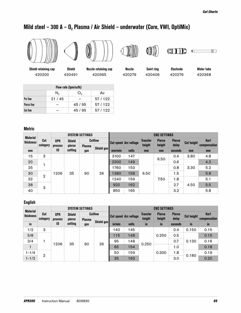
Cut Charts
Mild steel – 300 A – O2 Plasma / Air Shield – underwater (Core, VWI, OptiMix)
Shield retaining cap Shield Nozzle retaining cap Nozzle Swirl ring Electrode Water tube420200 420491 420365 420279 420406 420276 420368
Flow rate (lpm/scfh)N2 O2 Air
Pre flow 21 / 45 – 57 / 122Pierce flow – 45 / 95 57 / 122Cut flow – 45 / 95 57 / 122
Metric
Material thickness Cut
category
SYSTEM SETTINGS CNC SETTINGS
XPR process
ID
Shield pierce setting
Cutflow Cut speed Arc voltage Transfer height
Pierce height
Pierce delay Cut height Kerf
compensationPlasma gas Shield gasmm mm/min volts mm mm seconds mm mm
15 3
1206 35 90 26
3100 147
6.50
6.500.4 3.80 4.8
201
2300 149 0.63.30
4.225 1760 153
7.50
0.8 5.230
21380 158 1.5 5.8
32 1240 159 1.84.50
5.138
3920 162 2.7 5.5
40 850 165 3.2 5.8
English
Material thickness Cut
category
SYSTEM SETTINGS CNC SETTINGS
XPR process
ID
Shield pierce setting
Cutflow Cut speed Arc voltage Transfer height
Pierce height
Pierce delay Cut height Kerf
compensationPlasma gas Shield gasin in/min volts in in seconds in in
1/2 3
1206 35 90 26
140 145
0.250
0.2500.4 0.150 0.15
5/81
115 148 0.50.130
0.153/4 95 148 0.7 0.161 65 154
0.3001.0 0.18
1-1/42
50 159 1.80.180
0.191-1/2 35 163 3.0 0.20
XPR300 Instruction Manual 809830 89

Cut Charts
Cut charts for non-ferrous (stainless steel) processes – underwater
Stainless steel – 80 A – N2 Plasma / N2 Shield – underwater (Core, VWI, OptiMix)
Shield retaining cap Shield Nozzle retaining cap Nozzle Swirl ring Electrode Water tube420200 420309 420365 420306 420323 420303 420368
Flow rate (lpm/scfh)N2
Pre flow 51 / 108Pierce flow 67 / 134Cut flow 68 / 144
Metric
Material thickness
SYSTEM SETTINGS CNC SETTINGS
Cut category
XPR process ID
Shield pierce setting
Cutflow Cut speed Arc voltage
Transfer height
Pierce height
Pierce delay Cut height Kerf
compensationPlasma gas Shield gasmm mm/min volts mm mm seconds mm mm
33
2006
30 80
453400 119
5.00 5.00
0.32.50
1.64 2861 119 1.55
2007 40
2388 120
2.00
1.56
11983 118
0.51.6
7 1644 120 1.68 1371 124
0.61.6
10 2 2007 30 80 40 1027 128 2.00 1.8
90 809830 Instruction Manual XPR300

Cut Charts
Stainless steel – 80 A – N2 Plasma / N2 Shield – underwater (Core, VWI, OptiMix) (continued)
English
Material thickness Cut
category
SYSTEM SETTINGS CNC SETTINGS
XPR process ID
Shield pierce setting
Cutflow Cut speed Arc voltage
Transfer height
Pierce height
Pierce delay Cut height Kerf
compensationPlasma gas Shield gasin in/min volts in in seconds in in
0.135(10GA) 3 2006
30 80
45124 119
0.200 0.200
0.3
0.080
0.06
3/16 99 120 0.061/4
1 2007 4073 118 0.5 0.06
5/16 54 1240.6
0.073/8 43 127 0.07
XPR300 Instruction Manual 809830 91

Cut Charts
Stainless steel – 80 A – N2 Plasma / H2O Shield – underwater (VWI, OptiMix)
Shield retaining cap Shield Nozzle retaining cap Nozzle Swirl ring Electrode Water tube420200 420300 420365 420290 420323 420303 420368
Flow rate (lpm/scfh)N2 H2O
Pre flow 30 / 64 0.2 / 3*Pierce flow 37 / 79 0.2 / 3*Cut flow 24 / 51 0.4 / 6*
* Gallons per hour (gph)
Metric
Material thickness Cut
category
SYSTEM SETTINGS CNC SETTINGS
XPR process
ID
Shield pierce setting
Cutflow Cut speed Arc voltage Transfer height
Pierce height
Pierce delay Cut height Kerf
compensationPlasma gas Shield gasmm mm/min volts mm mm seconds mm mm
33
201010
8030
3404 120
5.00 5.00
0.3
2.00
1.64 2866 124 1.55 2387 126 0.5 1.56
11969 129
0.61.6
7 1609 130 1.88 1310 132 2.010
2889 135
0.82.0
12 2011 86 706 137 1.8
English
Material thickness Cut
category
SYSTEM SETTINGS CNC SETTINGS
XPR process
ID
Shield pierce setting
Cutflow Cut speed Arc voltage Transfer height
Pierce height
Pierce delay Cut height Kerf
compensationPlasma gas Shield gasin in/min volts in in seconds in in
0.135(10GA) 3
201010
8030
124 122
0.200 0.200
0.3
0.080
0.06
3/16 99 124 0.061/4
172 131 0.5 0.07
5/16 54 1330.6
0.083/8 36 134 0.081/2 2 2011 86 28 137 0.8 0.07
92 809830 Instruction Manual XPR300

Cut Charts
Stainless steel – 130 A – N2 Plasma / N2 Shield – underwater (Core, VWI, OptiMix)
Shield retaining cap Shield Nozzle retaining cap Nozzle Swirl ring Electrode Water tube420200 420318 420365 420315 420314 420356 420368
Flow rate (lpm/scfh)N2
Pre flow 92 / 195Pierce flow 150 / 320Cut flow 150 / 320
Metric
Material thickness Cut
category
SYSTEM SETTINGS CNC SETTINGS
XPR process
ID
Shield pierce setting
Cutflow Cut speed Arc voltage
Transfer height
Pierce height
Pierce delay Cut height Kerf
compensationPlasma gas Shield gasmm mm/min volts mm mm seconds mm mm
63
2051 52 90 52
2184 160
6.10 6.10
0.4
2.54
2.27 2052 161 2.28 1834 163
0.52.3
101
1466 166 2.312 1321 167 0.6 2.315
2935 168 0.7
3.052.4
20 533 180 1.3 2.8
English
Material thickness Cut
category
SYSTEM SETTINGS CNC SETTINGS
XPR process
ID
Shield pierce setting
Cutflow Cut speed Arc voltage
Transfer height
Pierce height
Pierce delay Cut height Kerf
compensationPlasma gas Shield gasin in/min volts in in seconds in in
1/43
2051 52 90 52
86 160
0.240 0.240
0.4
0.100
0.095/16 73 163
0.50.09
3/81
59 166 0.091/2 50 167 0.6 0.095/8
232 169 0.7
0.1200.09
3/4 23 175 1.2 0.10
XPR300 Instruction Manual 809830 93

Cut Charts
Stainless steel – 130 A – N2 Plasma / H2O Shield – underwater (VWI and OptiMix)
Shield retaining cap Shield Nozzle retaining cap Nozzle Swirl ring Electrode Water tube420200 420469 420365 420315 420314 420356 420368
Flow rate (lpm/scfh)N2 H2O
Pre flow 38 0.42 / 6.5*Pierce flow 97 0.5 / 8*Cut flow 97 0.5 / 8*
* Gallons per hour (gph)
Metric
Material thickness Cut
category
SYSTEM SETTINGS CNC SETTINGS
XPR process ID
Shield pierce setting
Cutflow Cut speed Arc voltage
Transfer height
Pierce height
Pierce delay Cut height Kerf
compensationPlasma gas Shield gasmm mm/min volts mm mm seconds mm mm
63
2052 25 90 25
2184 166
5.08 5.08
0.2
2.54
2.27 2057 168 0.3 2.38 1846 172 0.4 2.510
11486 178 0.5 2.7
12 1326 177 0.6 2.615
2852 181
6.35 6.350.8
3.053.0
20 406 184 1.3 3.6
English
Material thickness Cut
category
SYSTEM SETTINGS CNC SETTINGS
XPR process ID
Shield pierce setting
Cutflow Cut speed Arc voltage
Transfer height
Pierce height
Pierce delay Cut height Kerf
compensationPlasma gas Shield gasin in/min volts in in seconds in in
1/43
2052 25 90 25
86 166
0.200 0.200
0.2
0.100
0.095/16 73 172 0.4 0.103/8
160 178 0.5 0.11
1/2 50 177 0.6 0.105/8
227 183
0.250 0.2500.8
0.1200.13
3/4 18 183 1.3 0.13
94 809830 Instruction Manual XPR300

Cut Charts
Stainless steel – 170 A – N2 Plasma / H2O Shield – underwater (VWI, OptiMix)
Shield retaining cap Shield Nozzle retaining cap Nozzle Swirl ring Electrode Water tube420200 420472 420365 420324 420314 420356 420368
Flow rate (lpm/scfh)N2 H2O
Pre flow 19 / 40 0.4 / 6*Pierce flow 47 / 100 0.5 / 8*Cut flow 47 / 100 0.5 / 8*
* Gallons per hour (gph)
Metric
Material thickness Cut
category
SYSTEM SETTINGS CNC SETTINGS
XPR process
ID
Shield pierce setting
Cutflow Cut speed Arc voltage Transfer height
Pierce height
Pierce delay Cut height Kerf
compensationPlasma gas Shield gasmm mm/min volts mm mm seconds mm mm
10 3
2058 30 90 30
1799 1755.080 5.08
0.4
2.54
2.812
11595 177
0.52.9
15 1256 178 3.020
2869 185
7.6207.62 1.5 3.4
25 582 191 15.24 4.0 3.05 3.9
English
Material thickness Cut
category
SYSTEM SETTINGS CNC SETTINGS
XPR process
ID
Shield pierce setting
Cutflow Cut speed Arc voltage Transfer height
Pierce height
Pierce delay Cut height Kerf
compensationPlasma gas Shield gasin in/min volts in in seconds in in
3/8 3
2058 30 90 30
73 1750.200 0.200
0.4
0.100
0.111/2
160 178
0.50.11
5/8 45 178 0.123/4
236 184
0.3000.300 1.0 0.13
1 22 192 0.600 4.0 0.120 0.15
XPR300 Instruction Manual 809830 95

Cut Charts
Stainless steel – 170 A – N2 Plasma / N2 Shield – underwater (Core, VWI, OptiMix)
Shield retaining cap Shield Nozzle retaining cap Nozzle Swirl ring Electrode Water tube420200 420327 420365 420324 420314 420356 420368
Flow rate (lpm/scfh)N2
Pre flow 99 / 210Pierce flow 168 / 355Cut flow 168 / 355
Metric
Material thickness Cut
category
SYSTEM SETTINGS CNC SETTINGS
XPR process
ID
Shield pierce setting
Cutflow Cut speed Arc voltage Transfer height
Pierce height
Pierce delay Cut height Kerf
compensationPlasma gas Shield gasmm mm/min volts mm mm seconds mm mm
10 3
2057 54 90 54
1813 164
6.10 6.10
0.32.54
2.612
11667 164 0.4 2.5
15 1115 169 0.6 2.820
2641 177 1.3 3.05 3.1
25 368 186 1.7 3.81 3.6
English
Material thickness Cut
category
SYSTEM SETTINGS CNC SETTINGS
XPR process
ID
Shield pierce setting
Cutflow Cut speed Arc voltage Transfer height
Pierce height
Pierce delay Cut height Kerf
compensationPlasma gas Shield gasin in/min volts in in seconds in in
3/83
2057 54 90 54
73 164
0.240 0.240
0.3
0.100
0.107/16 68 164
0.40.10
1/21
64 164 0.109/16 50 168 0.6 0.105/8 36 171 0.7 0.113/4
227 175 1.2 0.120 0.12
7/8 20 181 1.5 0.135 0.131 14 187 1.7 0.150 0.14
96 809830 Instruction Manual XPR300

Cut Charts
Stainless steel – 300 A – N2 Plasma / N2 Shield – underwater (Core, VWI, OptiMix)
Shield retaining cap Shield Nozzle retaining cap Nozzle Swirl ring Electrode Water tube420200 420362 420365 420359 420323 420356 420368
Flow rate (lpm/scfh)N2
Pre flow 106 / 225Pierce flow 181 / 385Cut flow 181 / 385
Metric
Material thickness Cut
category
SYSTEM SETTINGS CNC SETTINGS
XPR process ID
Shield pierce setting
Cutflow Cut speed Arc voltage
Transfer height
Pierce height
Pierce delay Cut height Kerf compensation
Plasma gas Shield gasmm mm/min volts mm mm seconds mm mm
123
2054 54 90 54
2997 168
7.62
7.620.4
4.323.1
15 2424 174 0.5 3.220
11663 179 0.9
5.08
3.425 1299 182 12.70 1.5 3.530
2986 185
15.242.0 3.6
32 889 186 2.2 3.6
English
Material thickness Cut
category
SYSTEM SETTINGS CNC SETTINGS
XPR process ID
Shield pierce setting
Cutflow Cut speed Arc voltage
Transfer height
Pierce height
Pierce delay Cut height Kerf compensation
Plasma gas Shield gasmm mm/min volts mm mm seconds mm mm
1/23
2054 54 90 54
107 172
0.3000.300
0.40.170
0.125/8 91 175 0.5 0.133/4
168 178 0.8
0.2000.14
1 50 182 0.500 1.5 0.141-1/4 2 35 186 0.600 2.2 0.14
XPR300 Instruction Manual 809830 97

Cut Charts
Stainless steel – 300 A – N2 Plasma / H2O Shield – underwater (VWI, OptiMix)
Shield retaining cap Shield Nozzle retaining cap Nozzle Swirl ring Electrode Water tube420200 420475 420365 420359 420323 420356 420368
Flow rate (lpm/scfh)N2 H2O
Pre flow 31 / 65 0.42 / 6.5*Pierce flow 75 / 160 0.5 / 8*Cut flow 75 / 160 0.5 / 8*
* Gallons per hour (gph)
Metric
Material thickness Cut
category
SYSTEM SETTINGS CNC SETTINGS
XPR process ID
Shield pierce setting
Cutflow Cut speed Arc voltage
Transfer height
Pierce height
Pierce delay Cut height Kerf
compensationPlasma gas Shield gasmm mm/min volts mm mm seconds mm mm
123
2055 22 90 22
1956 174
7.6207.62
0.53.81
3.515 1795 182 0.9 3.520
11547 188 1.0
5.08
3.725 1184 191 1.2 3.930
2904 193
15.242.5 4.0
32 813 194 3.0 4.7
English
Material thickness Cut
category
SYSTEM SETTINGS CNC SETTINGS
XPR process ID
Shield pierce setting
Cutflow Cut speed Arc voltage
Transfer height
Pierce height
Pierce delay Cut height Kerf
compensationPlasma gas Shield gasin in/min volts in in seconds in in
1/23
2055 22 90 22
77 181
0.3000.300
0.50.150
0.145/8 68 182
1.00.14
3/41
64 1880.200
0.151 45 191 1.2 0.15
1-1/4 2 32 194 0.600 3.0 0.16
98 809830 Instruction Manual XPR300

Cut Charts
Torch geometry for bevel cutting
The XPR 300 consumable parts are designed to maintain a nearly-constant tool center point. Torch length and shield-face diameter vary with cutting current, as shown in Table 2.
Refer to Table 2 to see the bevel geometry that you can expect with XPR torches during ferrous (mild steel) and non-ferrous (stainless steel/aluminum) consumables.
Table 2 – Bevel geometries for sample ferrous and non-ferrous processes
Tool center point
Torch length
Cone angle
Shield face diameter
Bevel geometry* for ferrous (mild steel) processes
Mild steel process Cone angle
Shield face diameter Torch length Tool center point
300 A mild steel76°
8.64 mm(0.340 in.)
128.27 mm(5.050 in.)
133.81 mm (5.268 in.)
170 A mild steel76°
7.24 mm(0.285 in.)
128.45 mm (5.057 in.)
133.07 mm(5.239 in.)
130 A mild steel76°
6.73 mm (0.265 in.)
129.21 mm (5.087 in.)
133.53 mm(5.257 in.)
80 A mild steel76°
6.10 mm(0.240 in.)
129.92 mm(5.115 in.)
133.83 mm (5.269 in.)
30 A mild steel76°
5.46 mm (0.215 in.)
130.23 mm (5.127 in.)
133.73 mm(5.265 in.)
XPR300 Instruction Manual 809830 99

Cut Charts
* Bevel geometries are based on the torch dimensions and features described in XPR300 Instruction Manual (809480).
Bevel geometry* for non-ferrous (stainless steel and aluminum) processes
Non-ferrous process Cone angle Shield face diameter Torch length Tool center point
300 A non-ferrous76°
8.00 mm(0.315 in.)
128.85 mm(5.073 in.)
133.99 mm(5.275 in.)
170 A non-ferrous76°
7.25 mm (0.285 in.)
128.96 mm(5.077 in.)
133.58 mm(5.259 in.)
130 A non-ferrous76°
6.60 mm(0.260 in.)
129.06 mm(5.081 in.)
133.27 mm(5.247 in.)
80 A non-ferrous, dry76°
6.10 mm(0.240 in.)
129.36 mm(5.093 in.)
133.27 mm(5.247 in.)
80 A non-ferrous, wet76°
6.10 mm(0.240 in.)
129.41 mm(5.095 in.)
133.32 mm(5.249 in.)
60 A non-ferrous, dry76°
6.10 mm(0.240 in.)
129.36 mm(5.093 in.)
133.27 mm(5.247 in.)
60 A non-ferrous, wet76°
6.10 mm(0.240 in.)
129.41 mm(5.095 in.)
133.32 mm(5.249 in.)
40 A non-ferrous, dry76°
6.10 mm(0.240 in.)
129.36 mm(5.093 in.)
133.27 mm(5.247 in.)
100 809830 Instruction Manual XPR300