xpic vs xpd
TRANSCRIPT
PATHLOSS VERSION 4.0 - MAY 2001 PROGRAM BUILD
The following new features are incorporated in the May 2001 program build:
MAP GRIDA new map grid module has been introduced. This operates in parallel with the existing networkmodule and is functionally identical. The display supports backdrops in TIF or windows BMPformat and dynamic on screen profile generation. The map grid module is available as part of themicrowave interference option.
MULTIPATH AND RAIN FADE CORRELATIONThe interference fade margin / threshold degradation has been split into two separate componentsfor rain and multipath. Default correlation values can be assigned for cases where the main andinterference paths are spatially correlated. A correlation editor is provided which graphicallydisplays each interference case in the network module. This feature is available as part of themicrowave interference option. ITU-T G.826SESR, BBER and ESR performance calculations for SDH radio links is implemented. Toaccommodate the additional radio data required for G.826 calculations. The format of thefollowing files has been changed." Pathloss data files (pl4)" Microwave radio data files (raf and mrs)" Microwave radio lookup tables (mrd)The May 2001 build program can read these data files and all previous versions. Pathlossprograms prior to the May 2001 build will not be able to read the new files.
ITU-R P.530-8 EQUIPMENT SIGNATURE - DIVERSITY IMPROVEMENTSelective outage calculations using the equipment signature parameters and the space andfrequency diversity improvement factors in strict accordance with P.530-8 have beenimplemented
ITU-R P.530-8 COCHANNEL OPERATIONPerformance degradation due to cochannel operation for radios equipped with XPIC devices hasbeen implemented.

Pathloss 4.0 May 2001 Program Build
Page 1 of 27
MAP GRID . . . . . . . . . . . . . . . . . . . . . . . . . . . . . . . . . . . . . . . . . . . . . . . . . . . . . . . . . . . . . . . . . . . . . . . . . . . . 3
OVERVIEW . . . . . . . . . . . . . . . . . . . . . . . . . . . . . . . . . . . . . . . . . . . . . . . . . . . . . . . . . . . . . . . . . . . . . . . . . . . 3
BACKDROP DEFINITION . . . . . . . . . . . . . . . . . . . . . . . . . . . . . . . . . . . . . . . . . . . . . . . . . . . . . . . . . . . . . . . 3Set Directory . . . . . . . . . . . . . . . . . . . . . . . . . . . . . . . . . . . . . . . . . . . . . . . . . . . . . . . . . . . . . . . . . . . . . 4Image File Index . . . . . . . . . . . . . . . . . . . . . . . . . . . . . . . . . . . . . . . . . . . . . . . . . . . . . . . . . . . . . . . . . . 4
Import List . . . . . . . . . . . . . . . . . . . . . . . . . . . . . . . . . . . . . . . . . . . . . . . . . . . . . . . . . . . . . . . . . 4GeoTIF File . . . . . . . . . . . . . . . . . . . . . . . . . . . . . . . . . . . . . . . . . . . . . . . . . . . . . . . . . . . . . . . . 5New List . . . . . . . . . . . . . . . . . . . . . . . . . . . . . . . . . . . . . . . . . . . . . . . . . . . . . . . . . . . . . . . . . . . 5
TIF to Bit Map Array . . . . . . . . . . . . . . . . . . . . . . . . . . . . . . . . . . . . . . . . . . . . . . . . . . . . . . . . . . . . . . . 5Elevation File Index . . . . . . . . . . . . . . . . . . . . . . . . . . . . . . . . . . . . . . . . . . . . . . . . . . . . . . . . . . . . . . . . 6
Import List . . . . . . . . . . . . . . . . . . . . . . . . . . . . . . . . . . . . . . . . . . . . . . . . . . . . . . . . . . . . . . . . . 6Elevation File Conversion . . . . . . . . . . . . . . . . . . . . . . . . . . . . . . . . . . . . . . . . . . . . . . . . . . . . . . . . . . . 6Datum – Ellipsoid Selection . . . . . . . . . . . . . . . . . . . . . . . . . . . . . . . . . . . . . . . . . . . . . . . . . . . . . . . . . 6
Local Datums . . . . . . . . . . . . . . . . . . . . . . . . . . . . . . . . . . . . . . . . . . . . . . . . . . . . . . . . . . . . . . . 7Global Datums . . . . . . . . . . . . . . . . . . . . . . . . . . . . . . . . . . . . . . . . . . . . . . . . . . . . . . . . . . . . . . 7
Map Projection . . . . . . . . . . . . . . . . . . . . . . . . . . . . . . . . . . . . . . . . . . . . . . . . . . . . . . . . . . . . . . . . . . . . 8Other Considerations . . . . . . . . . . . . . . . . . . . . . . . . . . . . . . . . . . . . . . . . . . . . . . . . . . . . . . . . . . . . . . . 8
CURSOR MODES . . . . . . . . . . . . . . . . . . . . . . . . . . . . . . . . . . . . . . . . . . . . . . . . . . . . . . . . . . . . . . . . . . . . . . 9Pan and Zoom Controls . . . . . . . . . . . . . . . . . . . . . . . . . . . . . . . . . . . . . . . . . . . . . . . . . . . . . . . . . . . . . 9Link Mode Cursor . . . . . . . . . . . . . . . . . . . . . . . . . . . . . . . . . . . . . . . . . . . . . . . . . . . . . . . . . . . . . . . . . 9
VISIBILITY TESTS and PROFILE GENERATION . . . . . . . . . . . . . . . . . . . . . . . . . . . . . . . . . . . . . . . . . . . 10
ELEVATION DISPLAYS . . . . . . . . . . . . . . . . . . . . . . . . . . . . . . . . . . . . . . . . . . . . . . . . . . . . . . . . . . . . . . . . 10
ADD SITE and MOVE SITE . . . . . . . . . . . . . . . . . . . . . . . . . . . . . . . . . . . . . . . . . . . . . . . . . . . . . . . . . . . . . . 11
DEFINITIONS – GLOSSARY . . . . . . . . . . . . . . . . . . . . . . . . . . . . . . . . . . . . . . . . . . . . . . . . . . . . . . . . . . . . 12
REFERENCES . . . . . . . . . . . . . . . . . . . . . . . . . . . . . . . . . . . . . . . . . . . . . . . . . . . . . . . . . . . . . . . . . . . . . . . . 13
INTERFERENCE AND DESIRED PATH FADE CORRELATION . . . . . . . . . . . . . . . . . . . . . . . . . . . 14
OVERVIEW . . . . . . . . . . . . . . . . . . . . . . . . . . . . . . . . . . . . . . . . . . . . . . . . . . . . . . . . . . . . . . . . . . . . . . . . . . 14
ADJACENT CHANNEL FADE CORRELATION . . . . . . . . . . . . . . . . . . . . . . . . . . . . . . . . . . . . . . . . . . . . 14
ATPC CONSIDERATIONS . . . . . . . . . . . . . . . . . . . . . . . . . . . . . . . . . . . . . . . . . . . . . . . . . . . . . . . . . . . . . . 15
DEFAULT PROGRAM SETTINGS . . . . . . . . . . . . . . . . . . . . . . . . . . . . . . . . . . . . . . . . . . . . . . . . . . . . . . . . 15

Pathloss 4.0 May 2001 Program Build
Page 2 of 27
EDITING CORRELATION . . . . . . . . . . . . . . . . . . . . . . . . . . . . . . . . . . . . . . . . . . . . . . . . . . . . . . . . . . . . . . 16
ITU-T G.826 ERROR PERFORMANCE OBJECTIVES . . . . . . . . . . . . . . . . . . . . . . . . . . . . . . . . . . . . . 17
SESR BIT ERROR RATE . . . . . . . . . . . . . . . . . . . . . . . . . . . . . . . . . . . . . . . . . . . . . . . . . . . . . . . . . . . . . . . . 17
MULTIPATH . . . . . . . . . . . . . . . . . . . . . . . . . . . . . . . . . . . . . . . . . . . . . . . . . . . . . . . . . . . . . . . . . . . . . . . . . . 18
RAIN . . . . . . . . . . . . . . . . . . . . . . . . . . . . . . . . . . . . . . . . . . . . . . . . . . . . . . . . . . . . . . . . . . . . . . . . . . . . . . . . 18
UNAVAILABILITY - SESR TRANSITION. . . . . . . . . . . . . . . . . . . . . . . . . . . . . . . . . . . . . . . . . . . . . . . . . . 18
PATHLOSS PROGRAM DATA REQUIREMENTS . . . . . . . . . . . . . . . . . . . . . . . . . . . . . . . . . . . . . . . . . . . 19Radio Data File (RAF - MRS) Changes . . . . . . . . . . . . . . . . . . . . . . . . . . . . . . . . . . . . . . . . . . . . . . . 19Microwave Worksheet Radio Data Entry Forms . . . . . . . . . . . . . . . . . . . . . . . . . . . . . . . . . . . . . . . . . 21Radio Lookup Tables . . . . . . . . . . . . . . . . . . . . . . . . . . . . . . . . . . . . . . . . . . . . . . . . . . . . . . . . . . . . . . 21
ITU P.530-8 SELECTIVE OUTAGE AND DIVERSITY IMPROVEMENT FACTORS . . . . . . . . . . . 21
SELECTIVE FADING OUTAGE . . . . . . . . . . . . . . . . . . . . . . . . . . . . . . . . . . . . . . . . . . . . . . . . . . . . . . . . . . 22
SPACE DIVERSITY IMPROVEMENT . . . . . . . . . . . . . . . . . . . . . . . . . . . . . . . . . . . . . . . . . . . . . . . . . . . . . 23
FREQUENCY DIVERSITY IMPROVEMENT . . . . . . . . . . . . . . . . . . . . . . . . . . . . . . . . . . . . . . . . . . . . . . . 24
QUAD DIVERSITY IMPROVEMENT . . . . . . . . . . . . . . . . . . . . . . . . . . . . . . . . . . . . . . . . . . . . . . . . . . . . . 24
COCHANNEL OPERATION . . . . . . . . . . . . . . . . . . . . . . . . . . . . . . . . . . . . . . . . . . . . . . . . . . . . . . . . . . . 25
XPD DEGRADATION DUE TO MULTIPATH . . . . . . . . . . . . . . . . . . . . . . . . . . . . . . . . . . . . . . . . . . . . . . 25

Pathloss 4.0 May 2001 Program Build
Page 3 of 27
MAP GRIDOVERVIEW
An new site network display module named “Map Grid” has been added in the May 2001 program build. Thisoperates in parallel with the existing network module. The network module uses a Transverse Mercatorprojection to display the sites. The longitude origin of this projection is set to the mid point of the east - westextents of the sites. This produces a display with symmetrical latitude and longitude lines.. If a new site isadded which changes the extents of the display, a new longitude origin is calculated. As such, this variableprojection will not accommodate backdrops such as maps and ortho-photos.
The map grid module uses fixed projections to display the network sites with both backdrops and elevations.The backdrops can be in either a TIF or window bit map (BMP) format. The elevations must be in theOdyssey - Planet BIL format. The map grid elevation database setup is independent of the terrain databasesetup under Configure - Terrain data base. At this time, the same projection must be used for the both thebackdrop and the elevations.
BACKDROP DEFINITION
Select Site Data - Backdrop to access the backdrop definition dialog. A backdrop definition consists of the

Pathloss 4.0 May 2001 Program Build
Page 4 of 27
following steps for both the image and elevation files. The procedure is identical for each.
" specify the directory containing the image /elevation files" create an index for the image /elevation files" specify the map projection used by the image /elevation files" specify the datum or reference ellipsoid for the image /elevation files
Set Directory
Click the set directory button and point to the directory containing the image files. All image files must belocated in this directory.
Image File Index
Click the Index button to access the grid data entry form. The following fields are available:Image file name 95 characters maximumShow any image file can be temporarily switched offType At this time only TIF and bitmap (bmp) image files are supported.West, south east and north edges – These are expressed in kilometers and must correspond to the selectedmap projection. Cell size optional entry (not used)
The data can be manually entered using the procedures described in the General Program Operation orimported from a list or GeoTIF file.
Import List
Select Files – Import List. Specify the locations of the fields in thefile to be imported.
Two default options are provided for Planet and Odyssey image files.
Specify the units of the edges, click Ok and open the file containingthe index information.
Pathloss 4.0 May 2001 Program Build
Page 5 of 27
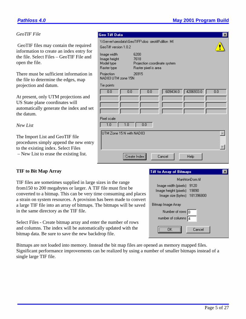
GeoTIF File
GeoTIF files may contain the requiredinformation to create an index entry forthe file. Select Files – GeoTIF File andopen the file.
There must be sufficient information inthe file to determine the edges, mapprojection and datum.
At present, only UTM projections andUS State plane coordinates willautomatically generate the index and setthe datum.
New List
The Import List and GeoTIF fileprocedures simply append the new entryto the existing index. Select Files – New List to erase the existing list.
TIF to Bit Map Array
TIF files are sometimes supplied in large sizes in the rangefrom150 to 200 megabytes or larger. A TIF file must first beconverted to a bitmap. This can be very time consuming and placesa strain on system resources. A provision has been made to converta large TIF file into an array of bitmaps. The bitmaps will be savedin the same directory as the TIF file.
Select Files - Create bitmap array and enter the number of rowsand columns. The index will be automatically updated with thebitmap data. Be sure to save the new backdrop file.
Bitmaps are not loaded into memory. Instead the bit map files are opened as memory mapped files.Significant performance improvements can be realized by using a number of smaller bitmaps instead of asingle large TIF file.
Pathloss 4.0 May 2001 Program Build
Page 6 of 27
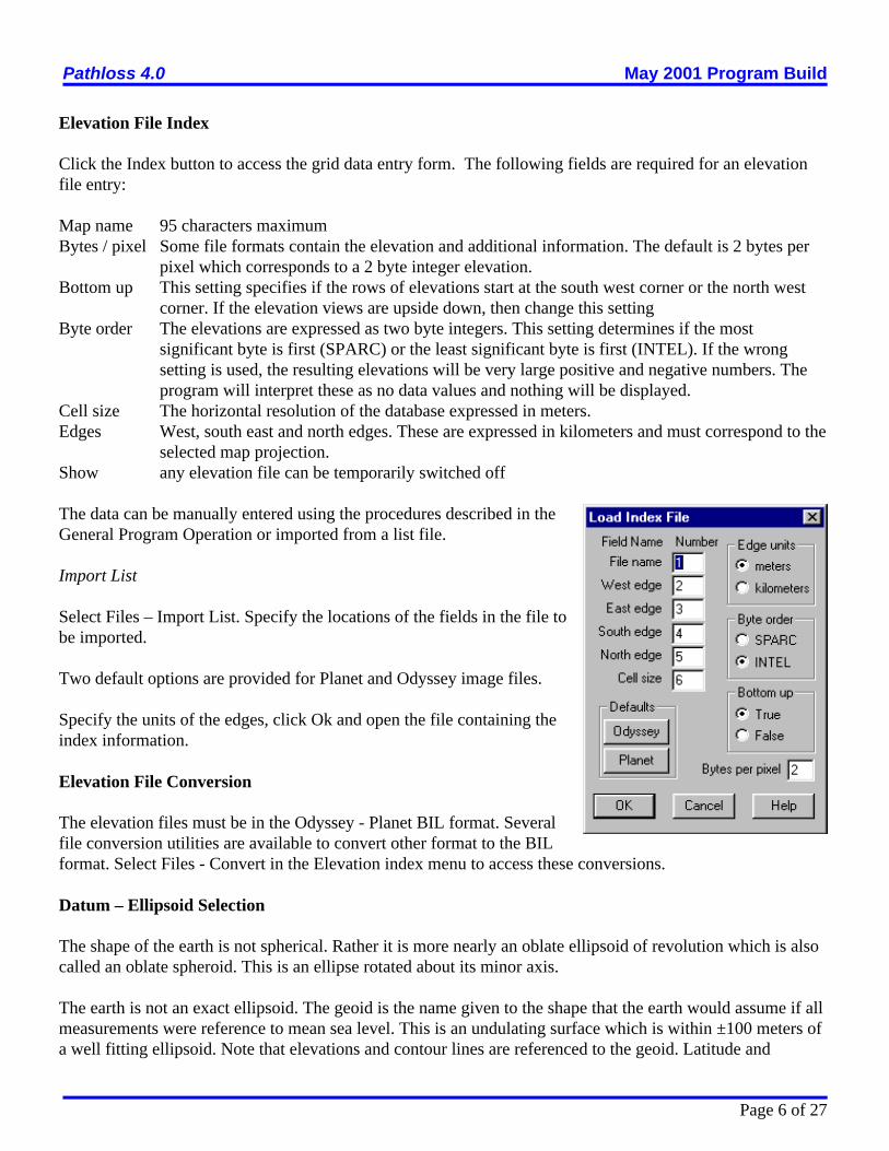
Elevation File Index
Click the Index button to access the grid data entry form. The following fields are required for an elevationfile entry:
Map name 95 characters maximumBytes / pixel Some file formats contain the elevation and additional information. The default is 2 bytes per
pixel which corresponds to a 2 byte integer elevation.Bottom up This setting specifies if the rows of elevations start at the south west corner or the north west
corner. If the elevation views are upside down, then change this settingByte order The elevations are expressed as two byte integers. This setting determines if the most
significant byte is first (SPARC) or the least significant byte is first (INTEL). If the wrongsetting is used, the resulting elevations will be very large positive and negative numbers. Theprogram will interpret these as no data values and nothing will be displayed.
Cell size The horizontal resolution of the database expressed in meters.Edges West, south east and north edges. These are expressed in kilometers and must correspond to the
selected map projection. Show any elevation file can be temporarily switched off
The data can be manually entered using the procedures described in theGeneral Program Operation or imported from a list file.
Import List
Select Files – Import List. Specify the locations of the fields in the file tobe imported.
Two default options are provided for Planet and Odyssey image files.
Specify the units of the edges, click Ok and open the file containing theindex information.
Elevation File Conversion
The elevation files must be in the Odyssey - Planet BIL format. Severalfile conversion utilities are available to convert other format to the BILformat. Select Files - Convert in the Elevation index menu to access these conversions.
Datum – Ellipsoid Selection
The shape of the earth is not spherical. Rather it is more nearly an oblate ellipsoid of revolution which is alsocalled an oblate spheroid. This is an ellipse rotated about its minor axis.
The earth is not an exact ellipsoid. The geoid is the name given to the shape that the earth would assume if allmeasurements were reference to mean sea level. This is an undulating surface which is within ±100 meters ofa well fitting ellipsoid. Note that elevations and contour lines are referenced to the geoid. Latitude and

Pathloss 4.0 May 2001 Program Build
Page 7 of 27
B ' A @ recf & 1recf
longitude and all grid coordinate systems are referenced to the ellipsoid.
The ellipsoid is defined by the semi major and semi minor axis. Alternately this can be expressed as thesemimajor axis and the flattening or eccentricity as defined by the equation below:
whereA major axisB minor axisrecf reciprocal flattening
Local Datums
Initially ellipsoids were fitted to the mean sea level surface over a particular region or country. These wererelated to an initial point on the surface of the earth to produce a local datum. This initial point is assigned alatitude, longitude, an elevation above the ellipsoid and an azimuth to some point. This initial point becomesthe triangulation station Principio to which all ground control measurements will be referenced. The latitudeand longitude and elevation of all control points in the area are computed relative to this initial point and theellipsoid.
An example of a local datum is the North American Datum of 1927 (NAD27) with the following parameters:
reference ellipsoid Clark 1866semi major axis 6378206.4 kminverse flattening 294.9786982origin Meades Ranch in Kansas
Global Datums
Global datums use ellipsoids determined from satellite based survey methods and define a coordinate systemused for the entire earth.. The center of the reference ellipsoid is located at the mass center of the earth. Anexample of a global datum is the World Geodetic System of 1984 (WGS 84)
reference ellipsoid WGS 84semi major axis 6378137.0 kminverse flattening 298.257223563origin mass center of the earth
In the Pathloss program, either a datum or ellipsoid can be selected. Selecting a datum indirectly defines thereference ellipsoid and since all conversions between geodetic and rectangular coordinates and the distanceand azimuth calculations are based on the reference ellipsoid, the two choices may seem redundant.
A datum in the Pathloss program includes additional data to allow the transformation of geodetic coordinatesbetween datums. In local datums, it is necessary to subdivide the area covered by the datum into smallerregions to improve the accuracy of the coordinate transformation.

Pathloss 4.0 May 2001 Program Build
Page 8 of 27
Some local map projections do not have a corresponding datum. Several examples are:Swiss National Grid - reference ellipsoid - Bessel 1841Irish National grid - reference ellipsoid - modified airy.
In these cases, an ellipse must be specified and there will be no provision to transform coordinates. Forexample geodetic coordinates in the WGS84 coordinates cannot be transformed to Swiss National gridcoordinates; however the WG84 coordinates could be transformed to the European Datum of 1950Note that in the current program build, the map projection and the datum / ellipsoid must be specified for boththe image files and the elevation files. This generality will allow additional flexibility in a future build byallowing coordinate transformation between datums. The errors in these transformation will certainly begreater that the imagery / elevation data resolution and it will be necessary to provide procedures to match theimagery and elevation data.
Map Projection
Select one of the map projections in the drop down list. The following projections are currently supported:" UTM - Universal Transverse Mercator - The UTM zone must be specified." Swiss National grid *" UK Ordnance grid *" Irish National grid *" New Zealand grid *" Gauss Kruger" US State Plane grid *
The selection of any of the projections marked with an *, will automatically select the correct datum orellipsoid.
The default projection is the same as that used in the network module. This is a Transverse Mercatorprojection referenced to a central meridian located at the center of the east - west extents of the sites. Thisselection effectively inhibits all of the imagery and elevation procedures in the Map Grid module.
Other Considerations
When the backdrop definition is complete, save the file using the file menu in this dialog box. Click OK to close the backdrop definition dialog. The image files are loaded into memory and displayed. Ifthe file loading is cancelled, then it will be necessary to recall the backdrop definition dialog and close it withthe OK button again.
The current backdrop definition file will be automatically loaded again when the program is started again and
The datum or reference ellipsoid selection must be the same for the site data, image , andelevation files.The same map projection must be used for the image and elevation files
Pathloss 4.0 May 2001 Program Build
Page 9 of 27
the map grid module is entered.
If a network file whose extents are separated by 10 degrees from the extents of the imagery data, is loaded,then the map projection is automatically set to the default and the imagery and elevation features areinhibited.
CURSOR MODES
Pan and Zoom Controls
Click the button to set the cursor to the pan mode. Hold the left mouse button down and drag the displayto the new location. The display can also be moved with the cursor keys at any time.
Click the button to set the cursor to the zoom mode. A left button click magnifies the display a presetamount and centers the display at the cursor location. A right button click reduces and centers the display. Tozoom a specific area, hold down the left mouse button and drag the mouse to define the desired area. Threeadditional buttons affect the display as follows:
the backdrop image is displayed from the upper left corner with the same resolution as the image file.
the extents of the site data is displayed
the extents of the image files is displayed.
the elevation view is switched off an on by clicking this button
Link Mode Cursor
Click the button to set the cursor to the link mode. This is the default cursor mode in the network moduleand is used to access the design modules, create links between two sites, and selectively set the link and siteattributes.
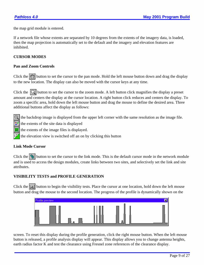
VISIBILITY TESTS and PROFILE GENERATION
Click the button to begin the visibility tests. Place the cursor at one location, hold down the left mousebutton and drag the mouse to the second location. The progress of the profile is dynamically shown on the
screen. To reset this display during the profile generation, click the right mouse button. When the left mousebutton is released, a profile analysis display will appear. This display allows you to change antenna heights,earth radius factor K and test the clearance using Fresnel zone references of the clearance display.

Pathloss 4.0 May 2001 Program Build
Page 10 of 27
You can add this link to the site data list and save the data as a Pathloss pl4 file. If the two end locations werenot between existing sites, you should change the site names from the default Site 1 and Site 2 names. To exitthe profile generation mode, close the profile preview display, click the button again or change the cursormode to the pan, zoom or link modes.
ELEVATION DISPLAYS
An elevation display can be generated at any zoom level which will overlay the image backdrop. The extentsof the display always corresponds to the current display extents.
Select Site Data – Elevation view - CreateThe display is useful to resolve small elevation differences whichmay not be apparent from the image display.
An elevation legend is available under the same menu.
The elevation display will remain until it is reset
Several display options are available. Select Elevation - View -Options
Pathloss 4.0 May 2001 Program Build
Page 11 of 27
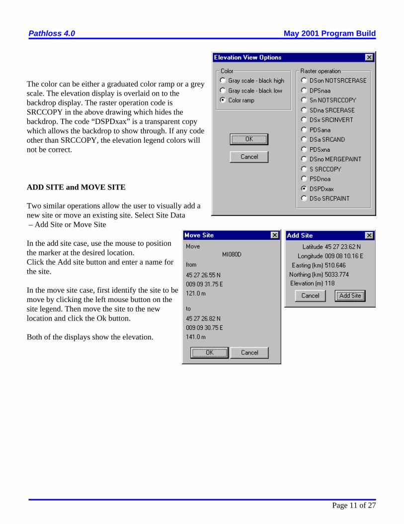
The color can be either a graduated color ramp or a greyscale. The elevation display is overlaid on to thebackdrop display. The raster operation code isSRCCOPY in the above drawing which hides thebackdrop. The code “DSPDxax” is a transparent copywhich allows the backdrop to show through. If any codeother than SRCCOPY, the elevation legend colors willnot be correct.
ADD SITE and MOVE SITE
Two similar operations allow the user to visually add anew site or move an existing site. Select Site Data – Add Site or Move Site
In the add site case, use the mouse to positionthe marker at the desired location.Click the Add site button and enter a name forthe site.
In the move site case, first identify the site to bemove by clicking the left mouse button on thesite legend. Then move the site to the newlocation and click the Ok button.
Both of the displays show the elevation.

Pathloss 4.0 May 2001 Program Build
Page 12 of 27
DEFINITIONS – GLOSSARY
Datum – Any numerical or geometrical quantity or set of such quantities specifying the reference coordinatesystem used for geodetic control in the calculation of coordinates of points on the earth. Datums may beeither global or local in extent. A local datum defines a coordinate system that is used only over a region oflimited extent. A global datum specifies the center of the reference ellipsoid to be located at the earth’s centerof mass and defines a coordinate system used for the entire earth.
Ellipsoid – The surface generated by an ellipse rotating about one of its axes.
Geocentric Coordinates – Cartesian coordinates (X, Y, Z) that define the position of a point with respect tothe center of mass of the earth.
Geodetic Coordinates – The quantities of latitude and longitude that define the position of a point on thesurface of the earth with respect to the reference ellipsoid. Also, imprecisely called geographic coordinates.
Geodetic Height – The height above the reference ellipsoid, measured along the ellipsoidal normal throughthe point in question. The geodetic height is positive if the point is outside the ellipsoid. Also known asellipsoidal height, h.
Geodetic Latitude – The angle between the plane of the equator and the normal to the ellipsoid through thecomputation point. Geodetic latitude is positive north of the equator and negative south of the equator.
Geodetic Longitude – The angle between the plane of a meridian and the plane of the prime meridian. Alongitude can be measured from the angle formed between the local and prime meridians at the pole ofrotation of the reference ellipsoid, or by the arc along the equator intercepted by these meridians.
Geoid – The equipotential surface of the earth’s gravity field approximated by undisturbed mean sea level fothe oceans. The direction of gravity passing through a given point on the geoid is perpendicular to thisequipotential surface.
Geoid Separation – The distance between the geoid and the mathematical reference ellipsoid as measuredalong the ellipsoidal normal. This distance is positive outside, or negative inside, the reference ellipsoid. Also called geoidal height; undulation of the geoid.
Horizontal Datum – A horizontal datum specifies the coordinate system in which latitude and longitude ofpoints are located. The latitude and longitude of an initial point, the azimuth of a line from that point, and thesemi-major axis and flattening of the ellipsoid that approximates the surface of the earth in the region ofinterest define a horizontal datum.
Reference Ellipsoid – An ellipsoid whose dimensions closely approach the dimensions of the geoid; theexact dimensions are determined by various considerations of the section of the earth’s surface concerned. Usually a bi-axial ellipsoid of revolution.
Vertical Datum – A vertical datum is the surface to which elevations are referred. A local vertical datum is acontinuous surface, usually mean sea level, at which elevations are assumed to be zero throughout the area of

Pathloss 4.0 May 2001 Program Build
Page 13 of 27
interest.
WGS 72 – World Geodetic System 1972. WGS 72 was the previous DoD standard earth-centered, earth-fixedworld geodetic system. It was superceded by WGS 84
WGS 84 – World Geodetic System 1984. A world geodetic system provides the basic reference frame,geometric figure and gravimetric model for the earth, and provides the means for relating positions on variouslocal geodetic systems to an earth-centered, earth-fixed coordinate system. WGS 84 is the current DoDstandard earth-centered, earth-fixed world geodetic system.
REFERENCES
(1) Topographic Engineering Center, TEC-SR-7, Handbook for transformation of DATUMS, PROJECTIONS, GRIDS, AND COMMON COORDINATESYSTEMS, January 1996.
(2) Department of Defense, MIL-HDBK-850, Military Handbook – Glossary of Mapping, Charting, andGeodetic Terms, 21 January 1994.

Pathloss 4.0 May 2001 Program Build
Page 14 of 27
INTERFERENCE AND DESIRED PATH FADE CORRELATION
OVERVIEW
If an interfering signal follows the same path as the desired signal, the twosignals can be considered to be correlated to some degree. The interferingsignal will experience fading at the same time as the desired signal; therebyreducing the effect of the interference.This is the case for both rain and multipath fades; however, the degree ofcorrelation for these two conditions will be different. In the case of a multipathfade, it is realistically assumed that only one fade will exist at any instance intime in an area due to the characteristics of deep fading. Multipath fades areshort in duration and highly localized in an area. Rain fades on the other handare of longer duration, are relatively frequency independent in a given bandand can extend over a wide area. To handle this fade correlation, the May 2001 program build considers theinterference fade margin and threshold degradation for both rain and multipath separately under theassumption that rain and multipath fading are mutually exclusive events.Provision is made to edit the rain - multipath fade correlation and to assigndefault values for this correlation at the start of an interference calculation.
An example of a correlated fade would a multi hop two frequency plan systemwith sites designated as A, B and C. The receiver at site A whose associated transmitter is located at site B,will be interfered by the transmitter also at site B transmitting to site C. The carrier to interference ratio iscompletely determined by the front to back ratio of the interfering transmit antenna. Since both the desiredand interfering signals follow the path from B to A, the following considerations can be made." Rain will attenuate the desired and interfering signal equally if the polarizations are the same for both
signals. The polarization of the interfering signal is indeterminate off boresight and can be consideredto be circular at discrimination angles greater than 90 degrees. Therefore, the fading could beconsidered as completely correlated and the case could be ignored.
" The degree of correlation between the desired and interfering signal fades due to multipath willdepend on the antenna heights of the desired and interfering transmitters at site B Polarization willaffect the correlation to a lesser degree. For equal antenna heights, the fading can be considered to becorrelated; otherwise a partial correlation situation exists.
ADJACENT CHANNEL FADE CORRELATION
A one for N systems is a specialized case of correlation. From a multipath standpoint, the frequencydifference between the desired signal and the adjacent channel interferer, is small enough to offer somemultipath fading correlation. This correlation combined with the filter improvement is usually sufficient to
The base interference calculation is always carried out and retained.The effect of rain and multipath correlation does not change the basecalculation.
Pathloss 4.0 May 2001 Program Build
Page 15 of 27
clear the case. At frequency separations of two or more adjacent channels, the filter improvement is sufficientto ignore the interference.From a rain fade standpoint, the interfering and desired paths are completely correlated and the interferencecan be ignored.
ATPC CONSIDERATIONS
An interference detail report shows the carrier to interference ratio. Prior to the May 2001 build, the C/I wasalways calculated with the receive signal at the maximum power and the interfering signal at the minimumpower when ATPC was specified. The C to I calculation now depends on the spacial correlation as followsUncorrelated minimum receive signal - minimum interfering signalCorrelated minimum receive signal - maximum interfering signal
DEFAULT PROGRAM SETTINGS
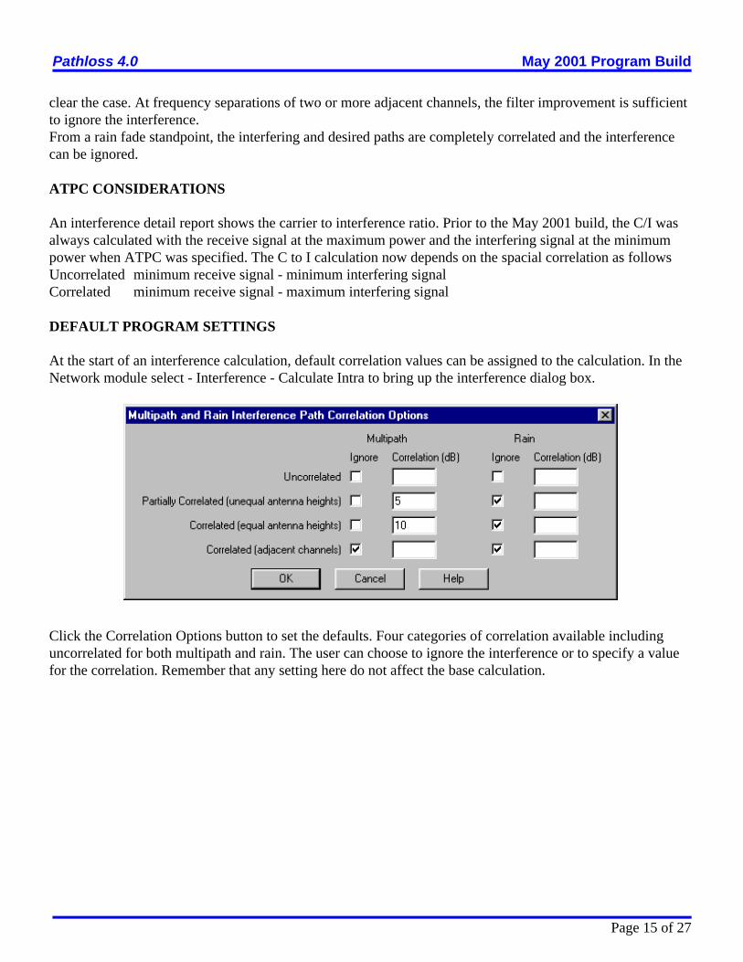
At the start of an interference calculation, default correlation values can be assigned to the calculation. In theNetwork module select - Interference - Calculate Intra to bring up the interference dialog box.
Click the Correlation Options button to set the defaults. Four categories of correlation available includinguncorrelated for both multipath and rain. The user can choose to ignore the interference or to specify a valuefor the correlation. Remember that any setting here do not affect the base calculation.

Pathloss 4.0 May 2001 Program Build
Page 16 of 27
EDITING CORRELATION
The correlation can be edited on a case by case basis in theModify Interference Parameters dialog. This can be accessedfrom the case detail report under the Modify menu selection.The antenna heights are shown under the designations:itx interfering transmitteratx victim receiver adjacent site transmitter
The correlation can also be edited directly in the Networkdisplay. Select Interference - Edit Correlation. Theorganization is the same as that used in the case detail report.Each receiver is a case. Each interferer into that receiver is asub case. The interference path is shown on the networkdisplay which helps to assign values to the correlation. Thearrows on the left changes the receiver (case) and the arrowson the right change the interfering transmitter (sub case)
The frequencies and polarization are shownalong with the antenna heights using the samenomenclature as described above. In additionthe following parameters are given:v-i victim to interferer path lengthang the discrimination angle at the victim
receiver ifl interfering signal leveltd threshold degradation
The button allows the user to go to a
specific case number. The cross referencereport can be used as an overall index

Pathloss 4.0 May 2001 Program Build
Page 17 of 27
BERSES '0.458 @a1
bits per block
m 'RXthresholdBER10 3 & RXthresholdBER10 6
3
RXthresholdBERSES ' RXthresholdBER10 6 % m @ log10 BERSES %6
ITU-T G.826 ERROR PERFORMANCE OBJECTIVES
ITU-T G.826 defines performance of SDH radio systems in terms of the following parameters.
Severely Errored Seconds Radio (SESR)Background Block Error Rate (BBER)Errored Seconds Ratio (ESR)This section describes the Pathloss implementation of this recommendation.
SESR BIT ERROR RATE
A modified bit error rate is first determined as follows:
BERses for various SDH paths and MS sections
Path type Bit rate BERses(Notes 1 and 2)
Block per second(Note 2)
Bits per Block(Note 2)
VC-11 1.5 5.4 × 10⁻⁴ a 2000 832
VC-12 2 4.0 × 10⁻⁴ a 2000 1120
VC-2 6 1.3 × 10⁻⁴ a 2000 3424
VC-3 34 6.5 × 10⁻⁵ a 8000 6120
VC-4 140 2.1 × 10⁻⁵ a 8000 18792
STM-1 155 2.3 × 10⁻⁵ a1.3 × 10-5 a + 2.2
8000192000
19940801
NOTE 1 a = 1 indicates a Poisson distribution of errors.NOTE 2 The blocks/s are defined in ITU-T G.826 for SDH path, in ITU-T G.829 for SDH sections.
Some STM-1 equipment might be designed with 8000 blocks/s (19 940 bits/block), but ITU-T G.829 defines the block rate and size to be 192 000 blocks/s and 801 bits/block,respectively.
The value of the BERSES will lie between the 10-3 and 10-6 BER. Determine the RX threshold level at theBERSES as follows:

Pathloss 4.0 May 2001 Program Build
Page 18 of 27
m ' /0000/0000
log10 RBER & log10 BERSES
log10 PtR & log10 PtSES
BBER ' SESR @a1
2.8 @a2 @ m&1%
NB @RBER
a3
ESR ' SESR @m
n %n @NB @RBER
a3
MULTIPATH
The severely errored seconds ratio is the worst month multipath fade probability at the BERSES receiverthreshold.
SESR = PtSES = Pt(BERSES)
Determine the fade probability in the worst month at the residual bit error rate receive threshold level. Theresidual BER (RBER) is in the range from 1 × 10⁻¹⁰ to 1 × 10-13 . PtR = Pt(RBER)
Calculate the slope of the BER distribution curve on a log - log scale for BER in the range BERSES to RBER
The background bock error rate (BBER) is then given by:
wherea1 10 to 30, number of errors per burst for the BER in the range from 1 × 10⁻³ to BERSES. a2 1 to 10, number of errors per burst for the BER in the range from BERSES to RBERa3 1, number of errors per burst for the BER lower than RBERNB number of bits per block from the above table
The errored second ratio (ESR) is given by:
wheren number of blocks per second from the above table
RAIN
Calculate the unavailability due to rain, PaR in the worst month at the BERSES receiver threshold level. TheBBER and ESR values for rain are obtained by substituting PaR for SESR in the multipath calculation.
UNAVAILABILITY - SESR TRANSITION.
ITU-T G.826 considers unavailable time as the accumulation of all SES states lasting longer than 10consecutive seconds. SESR time is the accumulation of all SES states lasting less than 10 consecutiveseconds. It is assumed that rain fades will always last longer than 10 consecutive seconds and therefore rainfades are classed as unavailability. ITU-R P.530-8 states that multipath fades will always be less than 10consecutive seconds and therefore will be classed as severely errored seconds. Under this definition rain fadesare assigned to unavailability and multipath fades are assigned to SESR.

Pathloss 4.0 May 2001 Program Build
Page 19 of 27
In the case of multipath fading, this is only true for large fade margins. In the Pathloss implementation of ITUG.821, the multipath fade duration statistics were considered and multipath fades lasting longer than 10consecutive seconds were assigned to unavailability; the balance were assigned to severely errored seconds.This convention is used in the current implementation of G.826
PATHLOSS PROGRAM DATA REQUIREMENTS
The following additional radio data is required to calculate G.826 error performance:
residual bit error rateRX threshold at the residual bit error rateRX threshold at the 10-3 bit error rateSES bit error rate (optional - can be program calculated)RX threshold at the SES bit error rate (optional - can be program calculated)a1 - number of errors per burst for the BER in the range from 1 × 10⁻³ to BERSES. a2 - number of errors per burst for the BER in the range from BERSES to RBERa3 - number of errors per burst for the BER lower than RBERnumber of bits per blocknumber of blocks per second
The following additional radio data is required to calculate the selective fade probability using the equipmentsignature instead of the dispersive fade margin.
signature delay (nanoseconds)signature width (MHz)signature depth - minimum phase (dB)signature depth - non minimum phase (dB)
The following parameters have been added to handle the P.530-8 performance calculations for cochanneloperation using XPIC devices and IF combining on space diversity systems:
IF combiner gain (dB)IF combiner selective fading improvement factorXPIF - cross polarized improvement factorXPDXPIC - cross polarized discrimination of the XPIC device.
Radio Data File (RAF - MRS) Changes
To accommodate these new data requirements, the radio data file formats have been expanded with thefollowing new entries and several equipment /calculation options.
DIGRADIO_TYPE SDH // PDH, SDH or NB_DIGITAL narrow band digitalSD_OPERATION IFC // BBS or IFC baseband switch or IF combinerCOCHANNEL_OPERATION YES // YES or NOUSE_SIGNATURE YES // YES or NO use equipment signature
XPIF 17 // Cochannel XPD improvement factor

Pathloss 4.0 May 2001 Program Build
Page 20 of 27
XPD_XPI 42 // XPD of the XPIC device
IF_COMB_GAIN 3 // IF combiner gainLCOMB_FACTOR 10 // IF combiner selective fading improvement factor
BITS_BLOCK 19940 // bits per block (SDH only)BLOCKS_SEC 8000 // blocks per second (SDH only)ALPHA1 20 // (SDH only)ALPHA2 5 // (SDH only)ALPHA3 1 // (SDH only)
SIGNATURE_DELAY_10-3 6.3 // signature delay (ns) at BER 10-3SIGNATURE_WIDTH_10-3 28 // signature width (MHz) at BER 10-3SIGNATURE_MINPH_10-3 23.4 // signature depth - minimum phase (dB) at BER 10-3SIGNATURE_NONMINPH_10-3 23.4 // signature depth - non minimum phase (dB) at BER 10-3
SIGNATURE_DELAY_10-6 6.3 // signature delay (ns) at BER 10-6SIGNATURE_WIDTH_10-6 21.7 // signature width (MHz) at BER 10-6SIGNATURE_MINPH_10-6 21.7 // signature depth - minimum phase (dB) at BER 10-6SIGNATURE_NONMINPH_10-6 28.3 // signature depth - non minimum phase (dB) at BER 10-6
SIGNATURE_DELAY_SES // signature delay (ns) at BER SESSIGNATURE_WIDTH_SES // signature width (MHz) at BER SESSIGNATURE_MINPH_SES // signature depth - minimum phase (dB) at BER SESSIGNATURE_NONMINPH_SES // signature depth - non minimum phase (dB) at BER SES
RESIDUAL_BER 1.E-10 // residual bit error rate - scientific notationRXTHRESH_RBER -66 // RX threshold at RBER (dBm)SES_BER // SES bit error rate - scientific notationRXTHRESH_SES_BER // RX threshold at BERses (dBm)
The new mnemonics can be placed any where in the file following the header and before the curve data.Blank lines are allowed and comments starting with a double forward slash // can be used.
Several equipment / calculation options have been included:DIGRADIO_TYPE SDH Permissible values are PDH, SDH or NB_DIGITAL( narrow band digital). These options only affect theformatting of the data entry forms in the microwave worksheet. For example, signature data or the dispersivefade margin cannot be accessed with the NB_DIGITAL radio type set.
SD_OPERATIONPermissible values are IFC for IF combining and BBS for baseband switching. This option automatically setthe space diversity improvement calculation to IF combining or baseband switching. The default value isbaseband switching.
COCHANNEL_OPERATIONPermissible values are YES or NO. This sets the Cochannel operation option in the Reliability Options dialogbox. The default value is NO.
USE_SIGNATUREPermissible options are YES for selective fading calculations using the equipment signature or NO to use thedispersive fade margin and dispersive fade occurrence factor. Note that this options has the effect ofcalculating diversity improvement is strict accordance with P.530-8.
Pathloss 4.0 May 2001 Program Build
Page 21 of 27
Microwave Worksheet Radio Data Entry Forms
All of the new radio data can be accessed in the radio data entry forms in the microwave worksheet. Theformat of these forms have been modified to include all of the new data.
Radio Lookup Tables
All of the radio data is included in a lookup entry; however, the following data items cannot be edited:
residual bit error rateRX threshold at the residual bit error rateRX threshold at the 10-3 bit error rateSES bit error rate (optional - can be program calculated)RX threshold at the SES bit error rate (optional - can be program calculated)a1 - number of errors per burst for the BER in the range from 1 × 10⁻³ to BERSES. a2 - number of errors per burst for the BER in the range from BERSES to RBERa3 - number of errors per burst for the BER lower than RBERnumber of bits per blocknumber of blocks per secondIF combiner gain (dB)IF combiner selective fading improvement factorXPIF - cross polarized improvement factorXPDXPIC - cross polarized discrimination of the XPIC device
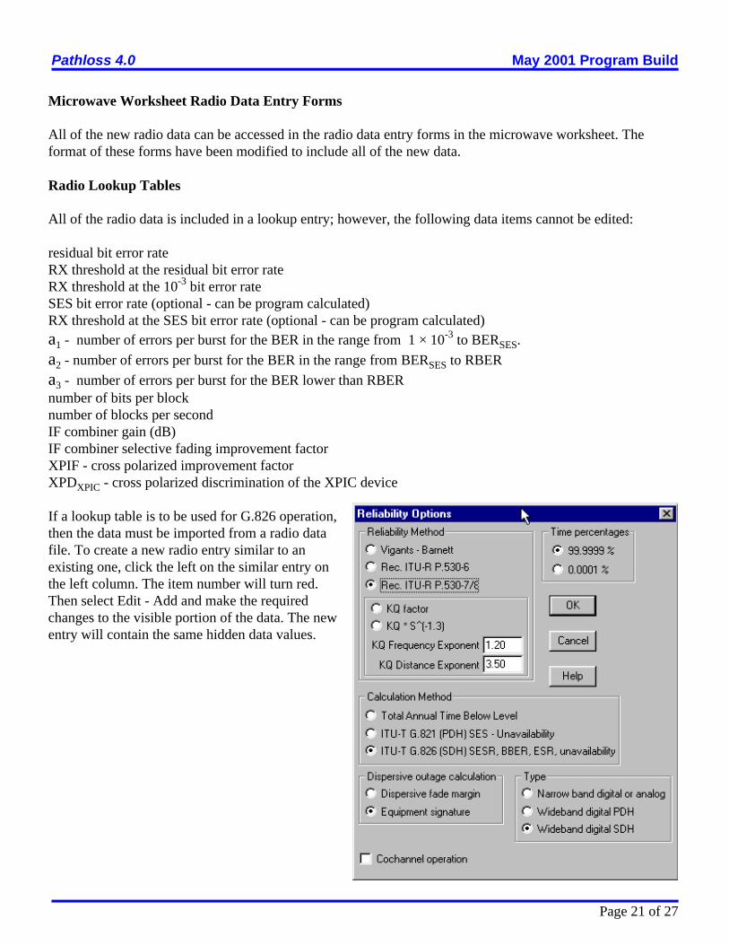
If a lookup table is to be used for G.826 operation,then the data must be imported from a radio datafile. To create a new radio entry similar to anexisting one, click the left on the similar entry onthe left column. The item number will turn red.Then select Edit - Add and make the requiredchanges to the visible portion of the data. The newentry will contain the same hidden data values.

Pathloss 4.0 May 2001 Program Build
Page 22 of 27
Ps 'n2@
W @ bN&bM
tr @103@ u 2 % v 2
n ' 1 & e &0.2 @P 0.750
bN '1
1 & 10&
BN
20
bM ' 1 & 10&
BM
20
u ' 0.7 @ D50
v 2 ' 0.49 @ D50
ITU P.530-8 SELECTIVE OUTAGE AND DIVERSITY IMPROVEMENT FACTORS
The Reliability options includes a selection to use the dispersive fade margin or the equipment signature fordispersive outage calculations.
If the equipment signature option is selected, all diversity improvement (space, frequency and quad) will becarried out in accordance with P.530-8.
This specifics of each calculation are given in the following sections.
SELECTIVE FADING OUTAGE
The outage probability is defined as the probability that the BER exceeds a given threshold as defined by theBER of the signature data.
where BN non minimum phase signature depthBM minimum phase signature depthW signature width (MHz)n multipath activity factortr reference delay (ns)u mean echo delay time (ns)v2 standard deviation of the delay timeD path length (km)P0 fade occurrence factor

Pathloss 4.0 May 2001 Program Build
Page 23 of 27
Isdns ' 1 & exp &3.34 @10&4 @S 0.87 @ f &0.12 @d 0.48 @P &1.040 @10
A&dG% Icomb
10
Isdns ' 1.2 @10&3 @ fd@S 2 @v 2 @10
A10
k 2ns ' 1 &
Ins @Pns
n
SPACE DIVERSITY IMPROVEMENT
The non selective space diversity improvement factor is given by:
where P0 fade occurrence factordG absolute value of the difference of the main and diversity antenna gainsA flat fade marginS vertical separation between main and diversity antennas (m center to center)d path length (km)Icomb IF combiner gain dB (0 for baseband switching applications)
The corresponding Vigants space diversity improvement factor is given by:
It is always interesting to compare different methods:Assuming equal main and diversity antenna gains dG = 0, v = 1 and Icomb = 0, a system with the followingparameters:P0 1.62524 path length 51.925 kilometersfrequency 5.8825 GHzS 18 metersA 34.5 dB
would produce a non selective space diversity improvement factor of 37 using the ITU method versus 124for the Vigants method. Here the same value for P0 is used for both methods. The ITU fade occurrence factortends to be much smaller than Vigants and this tends to offset the differences.
The selective outage probability is calculated as follows:
Calculate the square of the non selective correlation coefficient, kns
whereIns non selective space diversity improvement factor Pns probability of a non selective outagen multipath activity factor
Calculate the square of the selective correlation coefficient, ks

Pathloss 4.0 May 2001 Program Build
Page 24 of 27
k 2s ' 0.8238 for rw # 0.5
k 2s ' 1 & 0.195 @ 1&rw
0.109&0.13 @ log10(1&rw)for 0.5 < rw # 0.9628
k 2s ' 1 & 0.3957 @ 1&rw
0.5136 for rw > 0.9628
rw ' 1 & 0.9746 @ 1&k 2ns
2.170for k 2
ns # 0.26
rw ' 1 & 0.6921 @ 1&k 2ns
1.034for k 2
ns > 0.26
Ifdns '80f @d
@ dff@10
A10
Psds '
Ps
Lcomb
2
n @ 1 & k 2s
The non selective outage probability is given by Psdns 'Pns
Isdns
The selective outage probability is given by
where Lcomb is the selective improvement factor due to the combiner.
The total outage probability is then given by Psd ' P 0.75sdns % P 0.75
sds1.33
FREQUENCY DIVERSITY IMPROVEMENT
The non selective frequency diversity improvement is essentially the same as the Vigants formula:
The Vigants method assumes that this improvement factor is valid for non selective and selective fades. TheITU method calculates the selective outage exactly as in the case of space diversity above using Icomb = 0 andLcomb = 1.
QUAD DIVERSITY IMPROVEMENT
The non selective quad diversity improvement factor is the sum of the space and frequency diversity factors
Iqd ns = Isd ns + Ifd ns
The square of the non selective correlation coefficient is given bykns = kns sd × kns fdThe selective outage is calculated exactly as in the case of space diversity using Icomb = 0 and Lcomb = 1 forbaseband switching applications.
Pathloss 4.0 May 2001 Program Build
Page 25 of 27
XPD0 ' XPDg % 5 for XPDg # 35
XPD0 ' 40 for XPDg > 35
n ' 1 & e&0.2 @P 0.75
0
Q ' &10@log10
Kxp @n
P0
COCHANNEL OPERATION
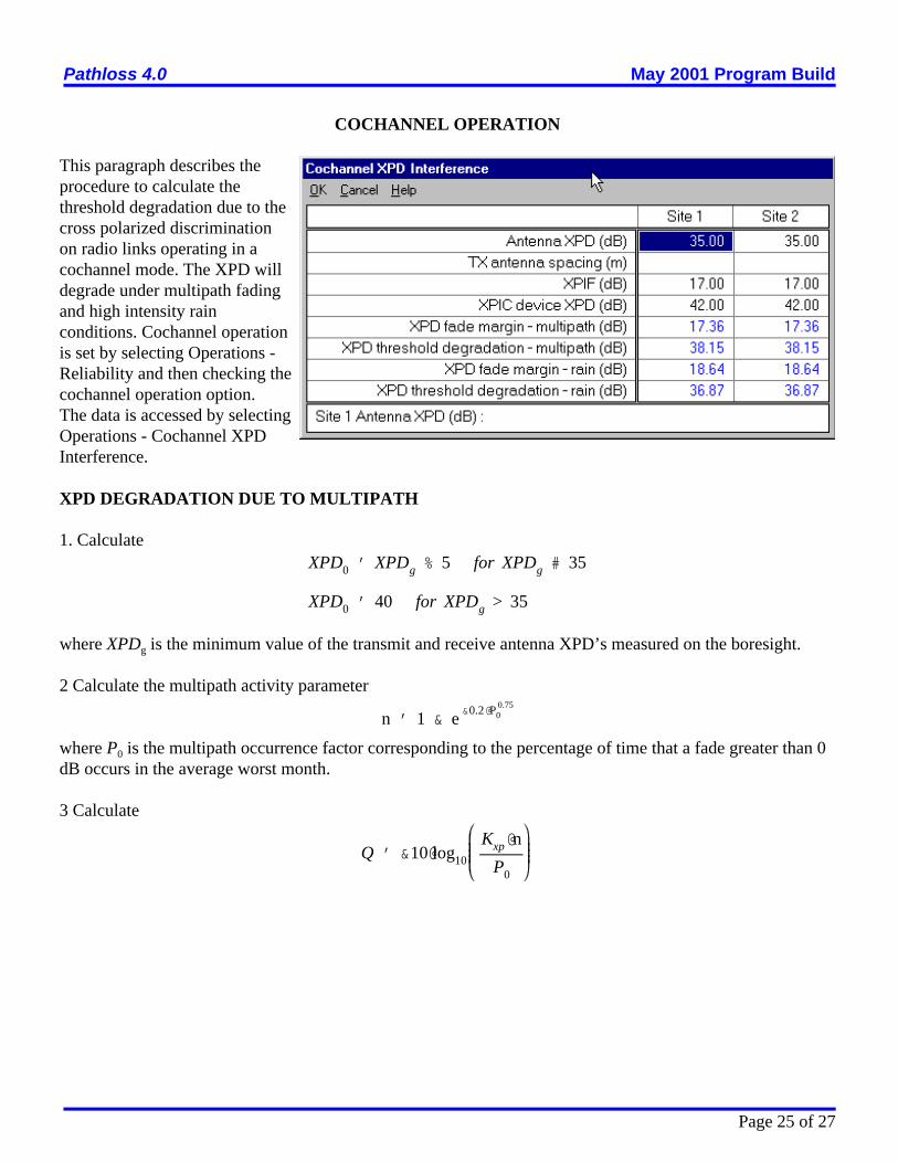
This paragraph describes theprocedure to calculate thethreshold degradation due to thecross polarized discriminationon radio links operating in acochannel mode. The XPD willdegrade under multipath fadingand high intensity rainconditions. Cochannel operationis set by selecting Operations -Reliability and then checking thecochannel operation option.The data is accessed by selectingOperations - Cochannel XPDInterference.
XPD DEGRADATION DUE TO MULTIPATH
1. Calculate
where XPDg is the minimum value of the transmit and receive antenna XPD’s measured on the boresight.
2 Calculate the multipath activity parameter
where P0 is the multipath occurrence factor corresponding to the percentage of time that a fade greater than 0dB occurs in the average worst month.
3 Calculate

Pathloss 4.0 May 2001 Program Build
Page 26 of 27
KXP ' 0.7 for one transmit antenna
KXP ' 1 & 0.3 @exp &4 @10&6 @st
ë
2
for two transmit antennas
C ' XPD0 % Q
C0
Icoch
' &10 @ log10 10&
XPDGTX
10 % 10&
XPDGRX
10 % 10&
C&A10 % 2
C0
Icoch mpth
' &10 @ log10 10&
XPDxpic
10 % 10&
XPDGTX %XPIF
10 % 10&
XPDGRX %XPIF
10 % 10&
C%XPIF&A10
XPDRAIN ' 15 % 30 @ log10 fGHz & 12.8 @ f 0.19GHz @ log10 A for fGHz # 20 GHz
XPDRAIN ' 15 % 30 @ log10 fGHz & 22.6 @ log10 A for fGHz > 20 GHz
C0
Icoch rain
' &10 @ log10 10&
XPDGTX
10 % 10&
XPDGRX
10 % 10&
XPDRAIN
10 % 2
where
Calculate
The carrier to cochannel interference ratio is then given by:
for radios not equipped with an XPIC device and by the following equation for XPIC equipped radios..
whereXPIF is the improvement due to the XPIC deviceXPDG is the coss polarized discrimination of the antennasXPDxpic is the XPD of the XPIC deviceA is the fade margin including the effects of interference due to other transmitters
The 2 dB improvement in the non XPIC case is due to the Gaussian properties of the interfering crosspolarsignal. This figure is included in the XPIF for XPIC equipped radios.
XPD Degradation due to Rain
The XPD reduction factor due to high intensity rain is given by the equation
The corresponding carrier to cochannel interference ratio is then given by:

Pathloss 4.0 May 2001 Program Build
Page 27 of 27
C0
Icoch rain
' &10 @ log10 10&
XPDxpic
10 % 10&
XPDGTX %XPIF
10 % 10&
XPDGRX %XPIF
10 % 10&
XPDRAIN%XPIF
10
where the parameters are the same as defined above.