xors in the air: practical wireless network coding · xors in the air: practical wireless network...
TRANSCRIPT

XORs in The Air: Practical Wireless Network Coding
Sachin Katti† Hariharan Rahul† Wenjun Hu� Dina Katabi† Muriel Medard† Jon Crowcroft�†MIT CSAIL
�Univ. of Cambridge
ABSTRACTThis paper proposes COPE, a new architecture for wireless meshnetworks. In addition to forwarding packets, routers mix (i.e., code)packets from different sources to increase the information contentof each transmission. We show that intelligently mixing packetsincreases network throughput. Our design is rooted in the theoryof network coding. Prior work on network coding is mainly theo-retical and focuses on multicast traffic. This paper aims to bridgetheory with practice; it addresses the common case of unicast traf-fic, dynamic and potentially bursty flows, and practical issues facingthe integration of network coding in the current network stack. Weevaluate our design on a 20-node wireless network, and discuss theresults of the first testbed deployment of wireless network coding.The results show that COPE largely increases network throughput.The gains vary from a few percent to several folds depending on thetraffic pattern, congestion level, and transport protocol.
Categories and Subject DescriptorsC.2.2 [Computer Systems Organization]: Computer-Communications Networks
General TermsAlgorithms, Design, Performance, Theory
KeywordsNetwork Coding, Wireless Networks
1. INTRODUCTIONWireless networks are indispensable; they provide the means for
mobility, city-wide Internet connectivity, distributed sensing, andoutdoor computing. Current wireless implementations, however,suffer from a severe throughput limitation and do not scale to denselarge networks.
This paper presents COPE, a new forwarding architecture thatsubstantially improves the throughput of wireless networks. COPEinserts a coding shim between the IP and MAC layers, which iden-tifies coding opportunities and benefits from them by forwardingmultiple packets in a single transmission.
Permission to make digital or hard copies of all or part of this work forpersonal or classroom use is granted without fee provided that copies arenot made or distributed for profit or commercial advantage and that copiesbear this notice and the full citation on the first page. To copy otherwise, torepublish, to post on servers or to redistribute to lists, requires prior specificpermission and/or a fee.SIGCOMM’06, September 11–15, 2006, Pisa, Italy.Copyright 2006 ACM 1-59593-308-5/06/0009 ...$5.00.
(a) Current Approach
(b) COPE
Figure 1—A simple example of how COPE increases the throughput. Itallows Alice and Bob to exchange a pair of packets using 3 transmissionsinstead of 4 (numbers on arrows show the order of transmission).
To give the reader a feel for how COPE works, we start with afairly simple example. Consider the scenario in Fig. 1, where Aliceand Bob want to exchange a pair of packets via a router. In currentapproaches, Alice sends her packet to the router, which forwardsit to Bob, and Bob sends his packet to the router, which forwardsit to Alice. This process requires 4 transmissions. Now considera network coding approach. Alice and Bob send their respectivepackets to the router, which XORs the two packets and broadcaststhe XOR-ed version. Alice and Bob can obtain each other’s packetby XOR-ing again with their own packet. This process takes 3 trans-missions instead of 4. Saved transmissions can be used to send newdata, increasing the wireless throughput.
In fact, COPE leads to larger bandwidth savings than are apparentfrom this example. COPE exploits the shared nature of the wirelessmedium which, for free, broadcasts each packet in a small neighbor-hood around its path. Each node stores the overheard packets for ashort time. It also tells its neighbors which packets it has heard byannotating the packets it sends. When a node transmits a packet, ituses its knowledge of what its neighbors have heard to perform op-portunistic coding; the node XORs multiple packets and transmitsthem as a single packet if each intended nexthop has enough infor-mation to decode the encoded packet. This extends COPE beyondtwo flows that traverse the same nodes in reverse order (as in theAlice-and-Bob example), and allows it to XOR more than a pair ofpackets.
COPE’s design is based on two key principles.
• COPE disposes of the point-to-point abstraction and embracesthe broadcast nature of the wireless channel. Network design-ers typically abstract the wireless channel as a point-to-point link,

then adapt forwarding and routing techniques designed for wirednetworks for wireless. In contrast, COPE exploits the broadcastproperty of radios instead of hiding it under an artificial abstrac-tion.
• COPE employs network coding. Our work is rooted in the theoryof network coding, which allows the routers to mix the informa-tion content in the packets before forwarding them. Prior workon network coding is mainly theoretical and focuses on multicasttraffic [2, 26, 20, 24, 17, 18, 27, 11]. Ours bridges theory withpractice; it addresses the common case of unicast traffic, dynamicand potentially bursty flows, and practical issues facing the inte-gration of network coding in the current network stack.
We have introduced the idea of opportunistic wireless networkcoding in an invited paper in Allerton 2005 [23]. This paper departsfrom our previous paper and all prior work on network coding inthree main ways:(1) This paper presents the first system architecture for wireless net-work coding. It articulates a full-fledged design that integrates seam-lessly into the current network stack, works with both TCP and UDPflows, and runs real applications.(2) The paper also implements the design in the Linux kernel and theRoofnet platform [1]. The implementation is deployed on a 20-nodewireless testbed, creating the first deployment of network coding ina wireless network.(3) The paper studies the performance of COPE, and reveals its in-teractions with the wireless channel, routing, and higher layer pro-tocols. Our findings can be summarized as follows:
• Network coding does have practical benefits, and can substan-tially improve wireless throughput.
• When the wireless medium is congested and the traffic consists ofmany random UDP flows, COPE increases the throughput of ourtestbed by 3-4x.
• If the traffic does not exercise congestion control (e.g., UDP),COPE’s throughput improvement may substantially exceed theexpected theoretical coding gain. This additional gain occurs be-cause coding makes a router’s queue smaller, reducing the prob-ability that a congested downstream router will drop packets thathave already consumed network resources.
• For a mesh network connected to the Internet via an access point,the throughput improvement observed with COPE varies depend-ing on the ratio between total download and upload traffic travers-ing the access point, and ranges from 5% to 70%.
• Hidden terminals create a high collision rate that cannot bemasked even with the maximum number of 802.11 retransmis-sions. In these environments, TCP does not send enough to utilizethe medium, and thus does not create coding opportunities. Withno hidden terminals, TCP’s throughput increases by an average of38% in our testbed.
2. BACKGROUND AND RELATED WORKThe idea underlying network coding is usually illustrated using
the famous butterfly example [2]. Consider the network in Fig. 2,where source S1 wants to deliver the stream of messages ai to bothR1 and R2, and source S2 wants to send the stream of messages bi
to the same two receivers. Assume all links have a capacity of onemessage per unit of time. If routers only forward the messages theyreceive, the middle link will be a bottleneck, which for every timeunit, can either deliver ai to R1 or bi to R2. In contrast, if the routerfeeding the middle link XORs the two messages and sends ai ⊕ bi
(or any linear combination of ai and bi), as shown in the figure, bothreceivers obtain two messages in every time unit. Thus, network
Figure 2—A simple scenario showing how network coding improvesthroughput. All links have a capacity of one message per unit of time.By sending the XOR of ai and bi on the middle link, we can deliver twomessages per unit of time to both receivers.
Term DefinitionNative Packet A non-encoded packetEncoded or XOR-edPacket
A packet that is the XOR of multiple nativepackets
Nexthops of an En-coded Packet
The set of nexthops for the native packetsXOR-ed to generate the encoded packet
Packet Id A 32-bit hash of the packet’s IP source ad-dress and IP sequence number
Output Queue A FIFO queue at each node, where it keepsthe packets it needs to forward
Packet Pool A buffer where a node stores all packets heardin the past T seconds
Coding Gain The ratio of the number of transmissions re-quired by the current non-coding approach, tothe number of transmissions used by COPE todeliver the same set of packets.
Coding+MAC Gain The expected throughput gain with COPEwhen an 802.11 MAC is used, and all nodesare backlogged.
Table 1—Definitions of terms used in this paper.
coding, i.e., allowing the routers to mix the bits in forwarded mes-sages, can increase network throughput.
Work on network coding started with a pioneering paper byAhlswede et al. [2], who showed that having the routers mix infor-mation in different messages allows the communication to achievemulticast capacity. This was soon followed by the work of Li etal., who showed that, for multicast traffic (e.g., the butterfly sce-nario), linear codes are sufficient to achieve the maximum capacitybounds [26]. Koetter and Medard [24] presented polynomial timealgorithms for encoding and decoding, and Ho et al. extended theseresults to random codes [17]. Some recent work studied wirelessnetwork coding [11, 31]. In particular, Lun et al. studied networkcoding in the presence of omni-directional antennae and showed thatthe problem of minimizing the communication cost can be formu-lated as a linear program and solved in a distributed manner [28].All of this work is primarily theoretical and assumes multicast traf-fic. A few papers study specific unicast topologies showing that,for the studied scenario, network coding results in better throughputthan pure forwarding [39, 16, 37]. This paper aims to bridge the gapbetween the theory of network coding and practical network designand provide an operational protocol for general unicast traffic.
Finally, a rich body of systems research has tackled the problemof improving the throughput of wireless networks. The proposedsolutions range from designing better routing metrics [10, 5, 12]to tweaking the TCP protocol [33], and include improved routingand MAC protocols [6, 22, 15]. Our work builds on these founda-tions but adopts a fundamentally different approach; it explores theutility of network coding in improving the throughput of wirelessnetworks.

(a) B can code packets it wants to send (b) Nexthops of packets in B’s queue (c) Possible coding options
Figure 3—Example of Opportunistic Coding; Node B has 4 packets in its queue, whose nexthops are listed in (b). Each neighbor of B has storedsome packets as depicted in (a). Node B can make a number of coding decisions (as shown in (c)), but should select the last one because it maximizesthe number of packets delivered in a single transmission.
3. COPE OVERVIEWWe introduce COPE, a new forwarding architecture for wireless
mesh networks. It inserts a coding layer between the IP and MAClayers, which detects coding opportunities and exploits them to for-ward multiple packets in a single transmission. Before delving intodetails, we refer the reader to Table 1, which defines the terms usedin the rest of the paper.
COPE incorporates three main techniques:
(a) Opportunistic Listening: Wireless is a broadcast medium, cre-ating many opportunities for nodes to overhear packets when theyare equipped with omni-directional antennae. COPE sets the nodesin promiscuous mode, makes them snoop on all communicationsover the wireless medium and store the overheard packets for a lim-ited period T (the default is T = 0.5s).
In addition, each node broadcasts reception reports to tell itsneighbors which packets it has stored. Reception reports are sentby annotating the data packets the node transmits. A node that hasno data packets to transmit periodically sends the reception reportsin special control packets.
(b) Opportunistic Coding: The key question is what packets tocode together to maximize throughput. A node may have multipleoptions, but it should aim to maximize the number of native packetsdelivered in a single transmission, while ensuring that each intendednexthop has enough information to decode its native packet.
The above is best illustrated with an example. In Fig. 3(a), nodeB has 4 packets in its output queue p1, p2, p3, and p4. Its neighborshave overheard some of these packets. The table in Fig 3(b) showsthe nexthop of each packet in B’s queue. When the MAC permits Bto transmit, B takes packet p1 from the head of the queue. Assumingthat B knows which packets each neighbor has, it has a few codingoptions as shown in Fig. 3(c). It could send p1 ⊕ p2. Since node Chas p1 in store, it could XOR p1 with p1 ⊕ p2 to obtain the nativepacket sent to it, i.e., p2. However, node A does not have p2, and socannot decode the XOR-ed packet. Thus, sending p1 ⊕ p2 would bea bad coding decision for B, because only one neighbor can benefitfrom this transmission. The second option in Fig. 3(c) shows a bettercoding decision for B. Sending p1 ⊕ p3 would allow both neighborsC and A to decode and obtain their intended packets from a singletransmission. Yet the best coding decision for B would be to sendp1 ⊕ p3 ⊕ p4, which would allow all three neighbors to receive theirrespective packets all at once.
The above example emphasizes an important coding issue. Pack-ets from multiple unicast flows may get encoded together at someintermediate hop. But their paths may diverge at the nexthop, atwhich point they need to be decoded. If not, unneeded data will
be forwarded to areas where there is no interested receiver, wastingmuch capacity. The coding algorithm should ensure that all nex-thops of an encoded packet can decode their corresponding nativepackets. This can be achieved using the following simple rule:
To transmit n packets, p1, ..., pn, to n nexthops, r1, ..., rn,a node can XOR the n packets together only if eachnext-hop ri has all n − 1 packets pj for j �= i.
This rule ensures that each nexthop can decode the XOR-ed versionto extract its native packet. Whenever a node has a chance to trans-mit a packet, it chooses the largest n that satisfies the above rule tomaximize the benefit of coding.
(c) Learning Neighbor State: But how does a node know whatpackets its neighbors have? As explained earlier, each node an-nounces to its neighbors the packets it stores in reception reports.However, at times of severe congestion, reception reports may getlost in collisions, while at times of light traffic, they may arrive toolate, after the node has already made a suboptimal coding decision.Therefore, a node cannot rely solely on reception reports, and mayneed to guess whether a neighbor has a particular packet.
To guess intelligently, we leverage the routing computation.Wireless routing protocols compute the delivery probability betweenevery pair of nodes and use it to identify good paths. For e.g.,the ETX metric [10] periodically computes the delivery probabili-ties and assigns each link a weight equal to 1/(delivery probability).These weights are broadcast to all nodes in the network and used bya link-state routing protocol to compute shortest paths. We lever-age these probabilities for guessing. In the absence of deterministicinformation, COPE estimates the probability that a particular neigh-bor has a packet as the delivery probability of the link between thepacket’s previous hop and the neighbor.
Occasionally, a node may make an incorrect guess, which causesthe coded packet to be undecodable at some nexthop. In this case,the relevant native packet is retransmitted, potentially encoded witha new set of native packets.
4. UNDERSTANDING COPE’S GAINSHow beneficial is COPE? Its throughput improvement depends
on the existence of coding opportunities, which themselves dependon the traffic patterns. This section provides some insight into theexpected throughput increase and the factors affecting it.
4.1 Coding GainWe defined the coding gain as the ratio of the number of transmis-
sions required by the current non-coding approach, to the minimum

n0 n1 n2 nN-1 nN
(a) Chain topology; 2 flows in reverse directions.
(b) “X” topology (c) Cross topology2 flows intersecting at n2. 4 flows intersecting at n2
(d) Wheel topology; many flows intersecting at the center node.
Figure 4—Simple topologies to understand COPE’s Coding and Cod-ing+MAC Gains.
number of transmissions used by COPE to deliver the same set ofpackets. By definition, this number is greater than or equal to 1.
In the Alice-and-Bob experiment, as described in §1, COPE re-duces the number of transmissions from 4 to 3, thus producing acoding gain of 4
3 = 1.33.But what is the maximum achievable coding gain, i.e., what is
the theoretical capacity of a wireless network that employs COPE?The capacity of general network coding for unicast traffic is stillan open question for arbitrary graphs [38, 16]. However, we ana-lyze certain basic topologies that reveal some of the factors affectingCOPE’s coding gain. Our analysis assumes identical nodes, omni-directional radios, perfect hearing within some radius, and the signalis not heard at all outside this radius, and if a pair of nodes can heareach other the routing will pick the direct link. Additionally, weassume that the flows are infinite and we only consider the steadystate.
THEOREM 4.1. In the absence of opportunistic listening,COPE’s maximum coding gain is 2, and it is achievable.
We prove the theorem by showing that the coding gain of the chainin Fig. 4(a) tends to 2 as the number of intermediate nodes increases.The complete proof is in Appendix A.
While we do not know the maximum gain for COPE with op-portunistic listening, there do exist topologies where opportunisticlistening adds to the power of COPE. For example, consider the“X”-topology shown in Fig. 4(b). This is the analogy of the Alice-and-Bob topology, but the two flows travel along link-disjoint paths.COPE without opportunistic listening cannot achieve any gains on
this topology. But with opportunistic listening and guessing, themiddle node can combine packets traversing in opposite directions,for a coding gain of 4
3 = 1.33. This result is important, becausein a real wireless network, there might be only a small number offlows traversing the reverse path of each other a la Alice-and-Bob,but one would expect many flows to intersect at a relay, and thus canbe coded together using opportunistic listening and guessing.
The “X” and Alice-and-Bob examples can be combined to furtherimprove the benefits of coding, as in the cross topology of Fig. 4(c).Without coding, 8 transmissions are necessary for each flow to sendone packet to its destination. However, assuming perfect overhear-ing (n4 and n5 can overhear n1 and n3, and vice versa), n2 can XOR4 packets in each transmission, thus reducing the number of trans-missions from 8 to 5, producing a coding gain of 8
5 = 1.6.We observe that while this section has focused on theoretical
bounds, the gains in practice tend to be lower due to the availabilityof coding opportunities, packet header overheads, medium losses,etc. However, it is important to note that COPE increases the actualinformation rate of the medium far above the bit rate, and hence itsbenefits are sustained even when the medium is fully utilized. Thiscontrasts with other approaches to improving wireless throughput,such as opportunistic routing [6], which utilize the medium betterwhen it is not fully congested, but do not increase its capacity.
4.2 Coding+MAC GainWhen we ran experiments with COPE, we were surprised to see
that the throughput improvement sometimes greatly exceeded thecoding gain for the corresponding topology. It turns out that theinteraction between coding and the MAC produces a beneficial sideeffect that we call the Coding+MAC gain.
The Coding+MAC gain is best explained using the Alice-and-Bobscenario. Because it tries to be fair, the MAC divides the bandwidthequally between the 3 contending nodes: Alice, Bob, and the router.Without coding, however, the router needs to transmit twice as manypackets as Alice or Bob. The mismatch between the traffic the routerreceives from the edge nodes and its MAC-allocated draining ratemakes the router a bottleneck; half the packets transmitted by theedge nodes are dropped at the router’s queue. COPE allows the bot-tleneck router to XOR pairs of packets and drain them twice as fast,doubling the throughput of this network. Thus, the Coding+MACgain of the Alice-and-Bob topology is 2.
The Coding+MAC gain assumes all nodes continuously havesome traffic to send (i.e., backlogged), but are limited by their MAC-allocated bandwidth. It computes the throughput gain with COPEunder such conditions. For topologies with a single bottleneck,like the Alice-and-Bob’s, the Coding+MAC gain is the ratio of thebottleneck’s draining rate with COPE to its draining rate withoutCOPE.
Similarly, for the “X” and cross topologies, the Coding+MACgain is higher than the coding gain. For the “X”, the Coding+MACgain is 2 since the bottleneck node is able to drain twice as manypackets, given its MAC allocated rate. For the cross topology, theCoding+MAC gain is even higher at 4. The bottleneck is able tosend 4 packets out in each transmission, hence it is able to drainfour times as many packets compared to no coding. This begs thequestion: what is the maximum Coding+MAC gain? The maxi-mum possible Coding+MAC gains with and without opportunisticlistening are properties of the topology and the flows that exist ina network. Here we prove some upper bounds on Coding+MACgains.
THEOREM 4.2. In the absence of opportunistic listening,COPE’s maximum Coding+MAC gain is 2, and it is achievable.

Topology Coding Gain Coding+MAC GainAlice-and-Bob 1.33 2
“X” 1.33 2Cross 1.6 4
Infinite Chain 2 2Infinite Wheel 2 ∞
Table 2—Theoretical gains for a few basic topologies.
The proof is in Appendix B.
THEOREM 4.3. In the presence of opportunistic listening,COPE’s maximum Coding+MAC gain is unbounded.
The proof, detailed in Appendix C, uses the wheel topology inFig. 4(d). Assuming N edge nodes, with COPE the bottleneck node,in the center of the wheel, XORs N packets together, and conse-quently drains its queue N times faster than without COPE. As thenumber of edge nodes increases, i.e., N → ∞, the gain becomes in-finite. While the previous example is clearly artificial, it does illus-trate the potential of COPE with opportunistic listening to producea several-fold improvement in throughput, as in §7.3.
Table 2 lists the gains for a few basic topologies.
5. MAKING IT WORKIn order to integrate COPE effectively within the current network
stack, we need to address some important system issues.
5.1 Packet Coding AlgorithmTo build the coding scheme, we have to make a few design deci-
sions. First, we design our coding scheme around the principle ofnever delaying packets. When the wireless channel is available, thenode takes the packet at the head of its output queue, checks whichother packets in the queue may be encoded with this packet, XORsthose packets together, and broadcasts the XOR-ed version. If thereare no encoding opportunities, our node does not wait for the arrivalof a matching codable packet. COPE therefore lets the node oppor-tunistically overload each transmission with additional informationwhen possible, but does not wait for additional codable packets toarrive.
Second, COPE gives preference to XOR-ing packets of similarlengths, because XOR-ing small packets with larger ones reducesbandwidth savings. Empirical studies show that the packet-sizedistribution in the Internet is bimodal with peaks at 40 and 1500bytes [29]. We can therefore limit the overhead of searching forpackets with the right sizes by distinguishing between small andlarge packets. We might still have to XOR packets of different sizes.In this case, the shorter packets are padded with zeroes. The receiv-ing node can easily remove the padding by checking the packet-sizefield in the IP header of each native packet.
Third, notice that COPE will never code together packets headedto the same nexthop, since the nexthop will not be able to decodethem. Hence,while coding, we only need to consider packets headedto different nexthops. COPE therefore maintains two virtual queuesper neighbor; one for small packets and another for large packets(The default setting uses a threshold of 100 bytes). When a newpacket is added to the output queue, an entry is added to the appro-priate virtual queue based on the packet’s nexthop and size.
Searching for appropriate packets to code is efficient due to themaintenance of virtual queues. When making coding decisions,COPE first dequeues the packet at the head of the FIFO outputqueue, and determines if it is a small or a large packet. Dependingon the size, it looks at the appropriate virtual queues. For example,if the packet dequeued is a small packet, COPE first looks at thevirtual queues for small packets. COPE looks only at the heads of
the virtual queues to limit packet reordering. After exhausting thevirtual queues of a particular size, the algorithm then looks at theheads of virtual queues for packets of the other size. Thus for find-ing appropriate packets to code COPE has to look at 2M packets inthe worst case, where M is the number of neighbors of a node.
Another concern is packet reordering. We would like to limit re-ordering packets from the same flow because TCP mistakes it as acongestion signal. Thus, we always consider packets according totheir order in the output queue. Still, reordering may occur becausewe prefer to code packets of the same size. In practice, this reorder-ing is quite limited because most data packets in a TCP flow are largeenough to be queued in the large-packet queue, and thus be consid-ered in order. We will see in §5.4, however, that reordering mightarise from other reasons, particularly the need to retransmit a packetthat has been lost due to a mistake in guessing what a neighbor candecode. Thus, we choose to deal with any reordering that might hap-pen inside the network at the receiver. COPE has a module that putsTCP packets in order before delivering them to the transport layeras explained in §5.5.
Finally, we want to ensure that each neighbor to whom a packetis headed has a high probability of decoding its native packet. Thus,for each packet in its output queue, our relay node estimates theprobability that each of its neighbors has already heard the packet.Sometimes the node can be certain about the answer, for example,when the neighbor is the previous hop of the packet, or when thereception reports from the neighbor state so. When neither of theabove is true, the node leverages the delivery probabilities computedby the routing protocol; it estimates the probability the neighbor hasthe packet as the delivery probability between the packet’s previoushop and that neighbor. The node then uses this estimate to ensurethat encoded packets are decodable by all of their nexthops withhigh probability.
In particular, suppose the node encodes n packets together. Letthe probability that a nexthop has heard packet i be Pi. Then, theprobability, PD, that it can decode its native packet is equal to theprobability that it has heard all of the n − 1 native packets XOR-edwith its own, i.e.,
PD = P1 × P2 × . . . × Pn−1.
Consider an intermediate step while searching for coding candi-dates. We have already decided to XOR n − 1 packets together,and are considering XOR-ing the nth packet with them. The codingalgorithm now checks that, for each of the n nexthops, the decod-ing probability PD, after XOR-ing the nth packet with the rest staysgreater than a threshold G (the default value G = 0.8). If the aboveconditions are met, each nexthop can decode its packet with at leastprobability G. Finally, we note that for fairness we iterate over theset of neighbors according to a random permutation.
Formally, each node maintains the following data structures.
• Each node has a FIFO queue of packets to be forwarded, whichwe call the output queue.
• For each neighbor, the node maintains two per-neighbor virtualqueues, one for small packets (e.g., smaller than 100 bytes), andthe other for large packets. The virtual queues for a neighbor Acontain pointers to the packets in the output queue whose nexthopis A.
• Additionally, the node keeps a hash table, packet info, that iskeyed on packet-id. For each packet in the output queue, the tableindicates the probability of each neighbor having that packet.
Whenever the MAC signals a sending opportunity, the node executesthe procedure illustrated in Alg. 1.

1 Coding ProcedurePick packet p at the head of the output queue.Natives = {p}Nexthops = {nexthop(p)}if size(p) > 100 bytes then
which queue = 1else
which queue = 0end iffor Neighbor i = 1 to M do
Pick packet pi, the head of virtual queue Q(i, which queue)if ∀n ∈ Nexthops ∪{i}, Pr[n can decode p ⊕ pi] ≥ G then
p = p ⊕ piNatives = Natives ∪{pi}Nexthops = Nexthops ∪{i}
end ifend forwhich queue = !which queuefor Neighbor i = 1 to M do
Pick packet pi, the head of virtual queue Q(i, which queue)if ∀n ∈ Nexthops ∪{i}, Pr[n can decode p ⊕ pi] ≥ G then
p = p ⊕ piNatives = Natives ∪{pi}Nexthops = Nexthops ∪{i}
end ifend forreturn p
5.2 Packet DecodingPacket decoding is simple. Each node maintains a Packet Pool, in
which it keeps a copy of each native packet it has received or sentout. The packets are stored in a hash table keyed on packet id (seeTable 1), and the table is garbage collected every few seconds. Whena node receives an encoded packet consisting of n native packets,the node goes through the ids of the native packets one by one, andretrieves the corresponding packet from its packet pool if possible.Ultimately, it XORs the n − 1 packets with the received encodedpacket to retrieve the native packet meant for it.
5.3 Pseudo-broadcastThe 802.11 MAC has two modes: unicast and broadcast. Since
COPE broadcasts encoded packets to their next hops, the naturalapproach would be to use broadcast. Unfortunately, this does notwork because of two reasons: poor reliability and lack of backoff.
Specifically, in the 802.11 unicast mode, packets are immediatelyack-ed by their intended nexthops. The 802.11 protocol ensures re-liability by retransmitting the packet at the MAC layer for a fixednumber of times until a synchronous ack is received. Lack of anack is interpreted as a collision signal, to which the sender reacts bybacking off exponentially, thereby allowing multiple nodes to sharethe medium.
In contrast, 802.11 broadcast lacks both reliability and backoff. Abroadcast packet has many intended receivers, and it is unclear whoshould ack. In the absence of the acks, the broadcast mode offersno retransmissions and consequently very low reliability. Addition-ally, a broadcast source cannot detect collisions, and thus does notback off. If multiple backlogged nodes share the broadcast channel,and each of them continues sending at the highest rate, the resultingthroughput is therefore very poor, due to high collision rates.
Our solution is pseudo-broadcast, which piggybacks on 802.11unicast and benefits from its reliability and backoff mechanism.Pseudo-broadcast unicasts packets that are meant for broadcast. Thelink-layer destination field is set to the MAC address of one of theintended recipients. An XOR-header is added after the link-layerheader, listing all nexthops of the packet, Since all nodes are set inthe promiscuous mode, they can overhear packets not addressed to
them. When a node receives a packet with a MAC address differentfrom its own, it checks the XOR-header to see if it is a nexthop. Ifso, it processes the packet further, else it stores the packet in a bufferas an opportunistically received packet. As all packets are sent using802.11 unicast, the MAC can detect collisions and backoff properly.
Pseudo-broadcast is also more reliable than simple broadcast. Thepacket is retransmitted multiple times until its designated MAC re-ceiver receives the packet and acks it, or the number of retries is ex-ceeded. A desirable side effect of these retransmissions is that nodesthat are promiscuously listening to this packet have more opportu-nities to hear it. Pseudo-broadcast, however, does not completelysolve the reliability problem, which we address in the next section.
5.4 Hop-by-hop ACKs and Retransmissions(a) Why hop-by-hop acks? Encoded packets require all nexthopsto acknowledge the receipt of the associated native packet for tworeasons. First, encoded packets are headed to multiple nexthops, butthe sender gets synchronous MAC-layer acks only from the nexthopthat is set as the link layer destination of the packet (as explained inthe previous section). There is still a probability of loss to the othernexthops from whom it does not get synchronous acks. Second,COPE may optimistically guess that a nexthop has enough informa-tion to decode an XOR-ed packet, when it actually does not.
The standard solution to wireless losses is to mask error-induceddrops by recovering lost packets locally through acknowledgmentsand retransmissions [3, 19]. COPE too addresses this problem usinglocal retransmissions; the sender expects the nexthops of an XOR-ed packet to decode the XOR-ed packet, obtain their native packet,and ack it. If any of the native packets is not ack-ed within a cer-tain interval, the packet is retransmitted, potentially encoded withanother set of native packets.
(b) Asynchronous Acks and Retransmissions: How should weimplement these hop-by-hop acks? For non-coded packets, we sim-ply leverage the 802.11 synchronous acks. Unfortunately, extendingthis synchronous ack approach to coded packets is highly inefficient,as the overhead incurred from sending each ack in its own packetwith the necessary IP and WiFi headers would be excessive. Thus,in COPE encoded packets are ack-ed asynchronously.
When a node sends an encoded packet, it schedules a retransmis-sion event for each of the native packets in the encoded packet. Ifany of these packets is not ack-ed within Ta seconds, the packet isinserted at the head of the output queue and retransmitted. (Ta isslightly larger than the round trip time of a single link.) Retrans-mitted packets may get encoded with other packets according to thescheme in §5.1.
A nexthop that receives an encoded packet decodes it to obtainits native packet, and immediately schedule an ack event. Beforetransmitting a packet, the node checks its pending ack events andincorporates the pending acks in the COPE header. If the node hasno data packets to transmit, it sends the acks in periodic controlpackets–the same control packets used to send reception reports.
5.5 Preventing TCP Packet ReorderingAsynchronous acks can cause packet reordering, which may be
confused by TCP as a sign of congestion. Thus, COPE has an or-dering agent, which ensures that TCP packets are delivered in order.The agent ignores all packets whose final IP destinations differ fromthe current node, as well as non-TCP packets. These packets areimmediately passed to the next processing stage. For each TCP flowending at the host, the agent maintains a packet buffer and recordsthe last TCP sequence number passed on to the network stack. In-coming packets that do not produce a hole in the TCP sequence

Figure 5—COPE Header. The first block identifies the native pack-ets XOR-ed and their nexthops. The second block contains receptionreports. Each report identifies a source, the last IP sequence number re-ceived from that source, and a bit-map of most recent packets seen fromthat source. The third block contains asynchronous acks. Each entryidentifies a neighbor, an end point for the ACK map, and a bit-map ofack-ed packets.
Encoded?
Can send
yes
no
Schedule retransmissions
Add reception reports
To wireless device
Add acks to header
Dequeue head of Output Queue
Encode if possible
Encoded?
Packet arrival
yes
no
Decode and schedule acks
Extract acks meant for me Update retransmission events
yes no
Enqueue in Output Queue
Deliver to host
Extract Reception Reports Update Neighbor’s State
Am I nexthop?
Decodable?
Am I destination?
yes
yes
Add to Packet Pool
Add to Packet Pool
(a) Sender side (b) Receiver side
Figure 6—Flow chart for our COPE Implementation.
stream are immediately dispatched to the transport layer, after up-dating the sequence number state. Otherwise, they are withheld inthe buffer till the gap in the sequence numbers is filled, or until atimer expires.
6. IMPLEMENTATION DETAILSCOPE adds special packet headers and alters the control flow of
the router to code and decode packets. This section describes bothparts.
6.1 Packet FormatCOPE inserts a variable-length coding header in each packet, as
shown in Fig. 5. If the routing protocol has its own header (e.g.,Srcr [5]), COPE’s header sits between the routing and the MACheaders. Otherwise, it sits between the MAC and IP headers. Onlythe shaded fields in Fig. 5 are required in every COPE header. Thecoding header contains the following 3 blocks.
(a) Ids of the coded native packets: The first block records meta-data to enable packet decoding. It starts with ENCODED NUM,the number of native packets XOR-ed together. For each nativepacket, the header lists its ID, which is a 32-bit hash of the packet’ssource IP address and IP sequence number. This is followed bythe MAC address of the native packet’s Nexthop. When a nodehears an XOR-ed packet, it checks the list of Nexthops to deter-mine whether it is an intended recipient for any of the native packetsXOR-ed together, in which case it decodes the packet, and processesit further.
(b) Reception reports: Reception reports constitute the secondblock in the XOR header, as shown in Fig. 5. The block startswith the number of the reports in the packet, REPORT NUM. Eachreport specifies the source of the reported packets SRC IP. Thisis followed by the IP sequence number of the last packet heardfrom that source Last PKT, and a bit-map of recently heard pack-ets. For example, a report of the form {128.0.1.9, 50,10000001} means that the last packet this node has heard fromsource 128.0.1.9 is packet 50, and it has also heard packets 42and 49 from that source but none in between. The above representa-tion for reception reports has two advantages: compactness and ef-fectiveness. In particular, the bit-map allows the nodes to report eachpacket multiple times with minimal overhead. This guards againstreception reports being dropped at high congestion.
(c) Expressing asynchronous acks compactly and robustly: Toensure ack delivery with minimum overhead, we use cumulativeacks. Since they implicitly repeat ack information, cumulative acksare robust against packet drops. Each node maintains a per-neighbor16-bit counter, called Neighbor Seqno Counter. Wheneverthe node sends a packet to that neighbor, the counter is incrementedand its value is assigned to the packet as a local sequence number,Local PKT SEQ NUM. The two neighbors use this sequence num-ber to identify the packet. Now, a node can use cumulative acks ona per-neighbor basis. Each coded packet contains an ack header asshown in Fig. 5. The ack block starts with the number of ack entries,followed by the packet local sequence number. Each ack entry startswith a neighbor MAC address. This is followed by a pointer to tellthe neighbor where the cumulative acks stop, and a bit-map indicat-ing previously received and missing packets. For example, an entryof {A, 50, 01111111} acks packet 50, as well as the sequence43-49, from neighbor A. It also shows that packet 42 is still missing.Note that though we use cumulative acks, we do not guarantee relia-bility at link layer. In particular, each node retransmits a lost packeta few times (default is 2), and then gives up.
6.2 Control FlowFig. 6 abstracts the architecture of COPE. On the sending side,
(shown in Fig. 6(a)), whenever the MAC signals an opportunity tosend, the node takes the packet at the head of its output queue andhands it to the coding module (§5.1). If the node can encode mul-tiple native packets in a single XOR-ed version, it has to scheduleasynchronous retransmissions. Either way, before the packet canleave the node, pending reception reports and acks are added.
On the receiving side, (shown in Fig. 6(b)), when a packet arrives,the node extracts any acks sent by this neighbor to the node. It alsoextracts all reception reports and updates its view of what packets itsneighbor stores. Further processing depends on whether the packetis intended for the node. If the node is not a nexthop for the packet,the packet is stored in the Packet Pool. If the node is a nexthop, itthen checks if the packet is encoded. If it is, the node tries to decodeby XOR-ing the encoded packet with the native packets it stores inits Packet Pool. After decoding it acks this reception to the previous

Figure 7—Node locations for one floor of the testbed.
hop and stores the decoded packet in the Packet Pool. The node nowchecks if it is the ultimate destination of the packet, if so it hands thepacket off to the higher layers of the network stack. If the node isan intermediate hop, it pushes the packet to the output queue. If thereceived packet is not encoded, the packet is simply stored in thePacket Pool and processed in the same fashion as a decoded packet.
7. EXPERIMENTAL RESULTSThis section uses measurements from a 20-node wireless testbed
to study both the performance of COPE and the interaction of net-work coding with the wireless channel and higher-layer protocols.Our experiments reveal the following findings.
• When the wireless medium is congested and the traffic consists ofmany random UDP flows, COPE delivers a 3-4x increase in thethroughput of our wireless testbed.
• When the traffic does not exercise congestion control (e.g., UDP),COPE’s throughput improvement substantially exceeds the ex-pected coding gain and agrees with the Coding+MAC gain.
• For a mesh network connected to the Internet via a gateway, thethroughput improvement observed with COPE varies dependingon the ratio of download traffic to upload traffic at the the gateway,and ranges from 5% to 70%.
• Hidden terminals create a high loss rate that cannot be maskedeven with the maximum number of 802.11 retransmissions. Inthese environments, TCP does not send enough to utilize themedium and does not create coding opportunities. In environ-ments with no hidden terminals, TCP’s throughput improvementwith COPE agrees with the expected coding gain.
7.1 Testbed(a) Characteristics: We have a 20-node wireless testbed that spanstwo floors in our building connected via an open lounge. Thenodes of the testbed are distributed in several offices, passages, andlounges. Fig. 7 shows the locations of the nodes on one of the floors.Paths between nodes are between 1 and 6 hops in length, and theloss rates of links on these paths range between 0 and 30%. Theexperiments described in this paper run on 802.11a with a bit-rateof 6Mb/s. Running the testbed on 802.11b is impractical because ofa high level of interference from the local wireless networks.
(b) Software: Nodes in the testbed run Linux. COPE is imple-mented using the Click toolkit [25]. Our implementation runs as auser space daemon, and sends and receives raw 802.11 frames fromthe wireless device using a libpcap-like interface. The implementa-tion exports a network interface to the user that can be treated likeany other network device (e.g., eth0). Applications interact with
the daemon as they would with a standard network device providedby the Linux kernel. No modifications to the applications are there-fore necessary. The implementation is agnostic to upper and lowerlayer protocols, and can be used by various protocols including UDPand TCP.
(c) Routing: Our testbed nodes run the Srcr implementation [5], astate-of-the-art routing protocol for wireless mesh networks. Theprotocol uses Djikstra’s shortest path algorithm on a database oflink weights based on the ETT metric [5]. Router output queue isbounded at 100 packets.(d) Hardware: Each node in the testbed is a PC equipped with an802.11 wireless card attached to an omni-directional antenna. Thecards are based on the NETGEAR 2.4 & 5 GHz 802.11a/g chipset.They transmit at a power level of 15 dBm, and operate in the 802.11ad hoc mode, with RTS/CTS disabled.
(e) Traffic Model: We use a utility program called udpgen [35] togenerate UDP traffic, and ttcp [34] to generate TCP traffic. We ei-ther use long-live flows, or many shorter flows that match empiricalstudies of Internet traffic [30, 9], i.e., they have Poisson arrivals, anda Pareto file size with the shape parameter set to 1.17.
7.2 MetricsOur evaluation uses the following metrics.
• Network Throughput: the measured total end-to-end throughput,i.e., the sum of the throughput of all flows in the network as seenby their corresponding applications.
• Throughput Gain: the ratio of the measured network throughputswith and without COPE. We compute the throughput gain fromtwo consecutive experiments, with coding turned on, then off.
7.3 COPE in gadget topologiesWe would like to compare COPE’s actual throughput gain with
the theoretical gains described in §4, and study whether it is af-fected by higher layer protocols. We start by looking at a few toytopologies with good link quality (medium loss rate after MAC re-tries < 1%), and no hidden terminals.
7.3.1 Long-Lived TCP FlowsWe run long-lived TCP flows over 3 toy topologies: Alice-and-
Bob, the “X”, and the cross topologies depicted in Figs. 1 and 4.Fig. 8 plots the CDFs of the TCP throughput gain measured over 40different runs. For the Alice-and-Bob topology the gain, shown inFig. 8(a), is close to the theoretical coding gain of 1.33. The differ-ence of 5 − 8% is due to the overhead of COPE’s headers, as wellas asymmetry in the throughput of the two flows, which preventsthe router from finding a codemate for every packet. Similarly, forthe “X”-topology, the gain in Fig. 8(b) is comparable to the optimalcoding gain of 1.33. Finally, Fig. 8(c) shows the throughput gain forthe cross topology with TCP. The gains are slightly lower than theexpected coding gain of 1.6 because of header overhead, imperfectoverhearing, and a slight asymmetry in the throughputs of the fourflows.
The above experimental results reveal that when the traffic ex-ercises congestion control, the throughput gain corresponds to thecoding gain, rather than the Coding+MAC gain. The congestioncontrol protocol, built into TCP, naturally matches the input rate atthe bottleneck to its draining rate. When multiple long-lived TCPflows get bottlenecked at the same router, the senders back off andprevent excessive drops, leaving only pure coding gains.
7.3.2 UDP FlowsWe repeat the above experiments with UDP and evaluate the
0
0.2
0.4
0.6
0.8
1
1 1.1 1.2 1.3 1.4 1.5
Cum
ulat
ive
Fra
ctio
n
Throughput Gain
0
0.2
0.4
0.6
0.8
1
1 1.1 1.2 1.3 1.4 1.5
Cum
ulat
ive
Fra
ctio
n
Throughput Gain
0
0.2
0.4
0.6
0.8
1
1.2 1.3 1.4 1.5 1.6 1.7
Cum
ulat
ive
Fra
ctio
n
Throughput Gain
(a) TCP gain in the Alice-and-Bob topology (b) TCP gain in the X-topology (c) TCP gain in the cross topology
Figure 8—CDF of throughput gains obtained with COPE, for long-lived TCP flows.
0
0.2
0.4
0.6
0.8
1
1.2 1.4 1.6 1.8 2 2.2
Cum
ulat
ive
Fra
ctio
n
Throughput Gain
0
0.2
0.4
0.6
0.8
1
1.2 1.4 1.6 1.8 2 2.2
Cum
ulat
ive
frac
tion
Throughput Gain
0
0.2
0.4
0.6
0.8
1
1 2 3 4 5 6
Cum
ulat
ive
Fra
ctio
n
Throughput Gain
(a) UDP gain in the Alice-and-Bob topology (b) UDP gain in the X-topology (c) UDP gain in the cross topology
Figure 9—CDF of throughput gains obtained with COPE, for UDP flows.
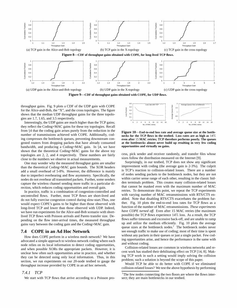
throughput gains. Fig. 9 plots a CDF of the UDP gain with COPEfor the Alice-and-Bob, the “X”, and the cross topologies. The figureshows that the median UDP throughput gains for the three topolo-gies are 1.7, 1.65, and 3.5 respectively.
Interestingly, the UDP gains are much higher than the TCP gains;they reflect the Coding+MAC gains for these toy topologies. Recallfrom §4 that the coding gain arises purely from the reduction in thenumber of transmissions achieved with COPE. Additionally, cod-ing compresses the bottleneck queues, preventing downstream con-gested routers from dropping packets that have already consumedbandwidth, and producing a Coding+MAC gain. In §4, we haveshown that the theoretical Coding+MAC gains for the above toytopologies are 2, 2, and 4 respectively. These numbers are fairlyclose to the numbers we observe in actual measurements.
One may wonder why the measured throughput gains are smallerthan the theoretical Coding+MAC gain bounds. The XOR headersadd a small overhead of 5-8%. However, the difference is mainlydue to imperfect overhearing and flow asymmetry. Specifically, thenodes do not overhear all transmitted packets. Further, some senderscapture the wireless channel sending more traffic in a particular di-rection, which reduces coding opportunities and overall gain.
In practice, traffic is a combination of congestion-controlled anduncontrolled flows. Further, most TCP flows are short-lived anddo not fully exercise congestion control during slow-start.Thus, onewould expect COPE’s gains to be higher than those observed withlong-lived TCP and lower than those observed with UDP. Indeed,we have run experiments for the Alice-and-Bob scenario with short-lived TCP flows with Poisson arrivals and Pareto transfer size. De-pending on the flow inter-arrival times, the measured throughputgains vary between the coding gain and the Coding+MAC gain.
7.4 COPE in an Ad Hoc NetworkHow does COPE perform in a wireless mesh network? We have
advocated a simple approach to wireless network coding where eachnode relies on its local information to detect coding opportunities,and when possible XORs the appropriate packets. However, it isunclear how often such opportunities arise in practice, and whetherthey can be detected using only local information. Thus, in thissection, we run experiments on our 20-node testbed to gauge thethroughput increase provided by COPE in an ad hoc network.
7.4.1 TCPWe start with TCP flows that arrive according to a Poisson pro-
0
0.1
0.2
0.3
0.4
0.5
0 2 4 6 8 10 12 14 16
Loss
Fra
ctio
nNo. of MAC retries
Loss rate with TCP
0
0.5
1
1.5
2
0 2 4 6 8 10 12 14 16
Ave
rage
Que
ue S
ize
No. of MAC retries
Average Queue Size at bottleneck
Figure 10—End-to-end loss rate and average queue size at the bottle-necks for the TCP flows in the testbed. Loss rates are as high as 14%even after 15 MAC retries; TCP therefore performs poorly. The queuesat the bottlenecks almost never build up resulting in very few codingopportunities and virtually no gains.
cess, pick sender and receiver randomly, and transfer files whosesizes follow the distribution measured on the Internet [9].
Surprisingly, in our testbed, TCP does not show any significantimprovement with coding (the average gain is 2-3%). The culpritis TCP’s reaction to collision-related losses. There are a numberof nodes sending packets to the bottleneck nodes, but they are notwithin carrier sense range of each other, resulting in the classic hid-den terminals problem. This creates many collision-related lossesthat cannot be masked even with the maximum number of MACretries. To demonstrate this point, we repeat the TCP experimentswith varying number of MAC retransmissions with RTS/CTS en-abled. Note that disabling RTS/CTS exacerbates the problem fur-ther. Fig. 10 plots the end-to-end loss rates for TCP flows as afunction of the number of MAC retransmissions. These experimentshave COPE turned off. Even after 15 MAC retries (the maximumpossible) the TCP flows experience 14% loss. As a result, the TCPflows suffer timeouts and excessive back-off, and are unable to rampup and utilize the medium efficiently. Fig. 10 plots the averagequeue sizes at the bottleneck nodes.1 The bottleneck nodes neversee enough traffic to make use of coding; most of their time is spentwithout any packets in their queues or just a single packet. Few cod-ing opportunities arise, and hence the performance is the same withand without coding.
Collision-related losses are common in wireless networks and re-cent work has studied their debilitating effect on TCP [14, 8]. Mak-ing TCP work in such a setting would imply solving the collisionproblem; such a solution is beyond the scope of this paper.
Would TCP be able to do better with COPE if we eliminatedcollision-related losses? We test the above hypothesis by performing
1The few nodes connecting the two floors are where the flows inter-sect; they are main bottlenecks in our testbed.

0.6
0.8
1
1.2
1.4
1.6
1.8
2
1 1.5 2 2.5 3
TC
P G
oodp
ut in
Mb/
s
Offered load in Mb/s
With COPEWithout COPE
Figure 11—COPE provides 38% increase in TCP goodput when thetestbed topology does not contain hidden terminals.
0
1
2
3
4
5
6
0 2 4 6 8 10 12 14 16 18 20 22 24
Net
wor
k T
hrou
ghpu
t in
Mb/
s
Offered load in Mb/s
With COPEWithout COPE
Figure 12—COPE can provide a several-fold (3-4x) increase in thethroughput of wireless Ad hoc networks. Results are for UDP flows withrandomly picked source-destination pairs, Poisson arrivals, and heavy-tail size distribution.
the following experiment. We compress the topology of the testbedby bringing the nodes closer together, so that they are within carriersense range. We artificially impose the routing graph and inter-nodeloss rates of the original testbed. The intuition is that the nodes arenow within carrier sense range and hence can avoid collisions. Thiswill reduce the loss rates and enable TCP to make better use of themedium. We repeat the above experiment with increasing levels ofcongestion obtained by decreasing the inter-arrival times of the TCPflows. Fig. 11 plots the network TCP goodput with and withoutCOPE as a function of the demand. For small demands, COPE of-fers a slight improvement since coding opportunities are scarce. Asthe demands increase, network congestion and coding opportunitiesincrease, leading to higher goodput gains. As congestion increasesbeyond a certain level, the throughput levels off, reflecting the factthat the network has reached its capacity and cannot sustain addi-tional load. At its peak, COPE provides 38% improvement over nocoding. The medium loss rates after retransmissions are negligible.The TCP flows are therefore able to use the medium efficiently, pro-viding coding opportunies which result in throughput gains.
7.4.2 UDPWe repeat the large scale testbed experiments with UDP. The
flows again arrive according to a Poisson process, pick sender andreceiver randomly, and transfer files whose sizes follow the distri-bution measured on the Internet [9]. We vary the arrival rates of thePoisson process to control the offered load. For each arrival rate, werun 10 trials, with coding on and then off (for a total of 500 experi-ments), and compute the network throughput in each case.
0
20
40
60
80
100
0 4 8 12 16 20 24
Per
cent
age
Offered Load (Mb/s)
Packets coded due to Guessing
Figure 13—Percentage of packets coded in the testbed due to guessing,as a function of offered load, for the set of experiments in Fig. 12.
0
10
20
30
40
50
60
1 2 3 4 5 6
Per
cent
age
No. of packets coded together
Coded packets
Figure 14—Distribution of number of packets coded together in thetest bed at the peak point of Fig. 12.
Fig. 12 shows that COPE greatly improves the throughput ofthese wireless networks, by a factor of 3-4x on average. The fig-ure plots the aggregate end-to-end throughput as a function of thedemands, both with COPE and without. At low demands (below2Mb/s), coding opportunities are scarce, and COPE performs sim-ilarly to no coding. As demands increase, both network conges-tion and the number of coding opportunities increase. In such densenetworks, the performance without coding deteriorates because ofthe high level of contention and consequent packet loss due to col-lisions. In contrast, coding reduces the number of transmissions,alleviates congestion, and consequently yields higher throughput.
It is interesting to examine how much of the coding is due toguessing, as opposed to reception reports. Fig. 13 plots the per-centage of packets that have been coded because of guessing for theexperiments in Fig.12. It is calculated as follows: If n packets arecoded together, and at most k packets could be coded using recep-tion reports alone, then n − k packets are considered to be codeddue to guessing. The figure shows that the benefit of guessing varieswith demands. At low demands, the bottleneck nodes have smallqueues, leading to a short packet wait time. This increases depen-dence on guessing because reception reports could arrive too late,after the packets have been forwarded. As demands increase, thequeues at the bottlenecks increase, resulting in longer wait times,and consequently allowing more time for reception reports to arrive.Hence, the importance of guessing decreases. As demands surgeeven higher, the network becomes significantly congested, leadingto high loss rates for reception reports. Hence, a higher percentageof the coding decisions is again made based on guessing.
Let us now examine in greater detail the peak point in Fig. 12,which occurs when demands reach 5.6 Mb/s. Fig. 14 shows the PDFof the number of native packets XOR-ed at the bottleneck nodes(i.e., the nodes that drop packets). The figure shows that, on aver-age, nearly 3 packets are getting coded together. Due to the highcoding gain, packets are drained much faster from the queues of thebottleneck nodes. The result is an average throughput gain of 3-4x.
7.5 COPE in a Mesh Access NetworkThere is growing interest in providing cheap Internet access using

0.9 1
1.1 1.2 1.3 1.4 1.5 1.6 1.7 1.8
0.1 0.2 0.3 0.4 0.5 0.6 0.7 0.8 0.9 1
Thr
ough
put G
ain
Ratio of uplink to downlink traffic
Throughput Gain
Figure 15—COPE’s throughput gain as a function of the ratio of up-link to downlink traffic at in a congested mesh access network.
multi-hop wireless networks that connect to the rest of the Internetvia one or more gateways/access points [1, 4, 32, 36]. We evaluateCOPE in such a setting, where traffic is flowing to and from theclosest gateway. We divide the nodes in the testbed into 4 sets. Eachset communicates with the Internet via a specific node that plays therole of a gateway. We use UDP flows,2 and control the experimentsby changing the ratio of upload traffic to download traffic. Fig. 15plots the throughput gains as a function of this ratio.
The throughput gain increases as the fraction of uplink traffic in-creases. When the amount of uplink traffic is small, gains are cor-respondingly modest; around 5 − 15%. As uplink traffic increases,gains increase to 70%. COPE’s throughput gain relies on codingopportunities, which depend on the diversity of the packets in thequeue of the bottleneck node. For example, in the Alice-and-Bobtopology, if only 10% of the packets in the bottleneck queue arefrom Alice and 90% from Bob, then coding can at best sneak Al-ice’s packets out on Bob’s packets. Hence, as the ratio of uplinktraffic increases, the diversity of the queues at bottlenecks increases,more coding opportunities arise, and consequently higher through-put gains are obtained.
7.5.1 FairnessThe access network experiment above illuminates the effect fair-
ness has on coding opportunities. An important source of unfairnessin wireless networks is the comparative quality of the channels fromthe sources to the bottleneck, usually referred to as the capture ef-fect. For example, in the Alice and Bob experiment, if the channelbetween Alice and the router is worse than that between Bob andthe router, Alice might be unable to push the same amount of trafficas Bob. Although the 802.11 MAC should give a fair allocation toall contenders, the sender with the better channel (here Bob) usuallycaptures the medium for long intervals. The routing protocol triesto discount the capture effect by always selecting the stronger links;but in practice, capture always happens to some degree.
We study the effect of capture on COPE by intentionally stressingthe links in the Alice and Bob topology. We set it up such that bothAlice and Bob are equidistant from the router, and compute the totalnetwork throughput. We then gradually move Alice’s node awayfrom the router, and repeat the experiment and the measurements.
Fig. 16 shows the network throughput as a function of the ratio ofAlice’s and Bob’s distance to the router. It also shows the percent-age of coded packets and the fairness index, computed as the ratio ofAlice’s throughput to Bob’s. As Alice moves further away, Bob in-creasingly captures the channel, reducing fairness, coding opportu-nities, and the aggregate network throughput. Interestingly, withoutcoding, fairness and efficiency are conflicting goals; throughput in-creases if the node with the better channel captures the medium and
2As mentioned earlier, in the uncompressed testbed, TCP backs offexcessively because of collision-based losses from hidden terminals,and does not send enough to fully utilize the medium.
1.8
2
2.2
2.4
2.6
2.8
3
3.2
0 1 2 3 4 5 6
Thro
ughput (M
b/s
)
Ratio of distances of edge nodes from the relay
Throughput(Mb/s) 0
0.2
0.4
0.6
0.8
1
0 1 2 3 4 5 6
Fra
ction
Ratio of distances of edge nodes from the relay
Fairness indexFraction of coded packets
Figure 16—Effect of unequal channel qualities on coding opportunitiesand throughput gain in the Alice-and-Bob topology. COPE aligns thefairness and efficiency objectives. Increased fairness increases codingopportunities and hence improves the aggregate throughput.
sends at full blast. Coding, however, aligns these two objectives;increasing fairness increases the overall throughput of the network.
8. DISCUSSION AND CONCLUSIONFinally, we would like to comment on the scope of COPE. The
present design targets stationary wireless mesh networks, where thenodes are not resource-constrained. More generally, COPE can beused in multi-hop wireless networks that satisfy the following:
• Memory: COPE’s nodes need to store recently heard packets forfuture decoding. Only packets in flight are used in coding; thereis no need to store packets that have already reached their desti-nation. Consequently, the storage requirement should be slightlyhigher than a delay-bandwidth product. (For e.g., an 11 Mb/s net-work with a 50ms RTT has a delay-bandwidth product of 70 KB.)
• Omni-directional antenna: Opportunistic listening requiresomni-directional antennas to exploit the wireless broadcast prop-erty.
• Power requirements: Our current design of COPE does not opti-mize power usage and assumes the nodes are not energy limited.
The ideas in COPE may be applicable beyond WiFi mesh net-works. Note that COPE can conceptually work with a variety ofMAC protocols including WiMax and TDMA. One may envisionmodifying COPE to address the needs of sensor networks. Such amodification would take into account that only a subset of the sen-sor nodes is awake at any point of time and can participate in oppor-tunistic listening. Sensor nodes may also trade-off saved transmis-sions for reduced battery usage, rather than increased throughput.Additionally, COPE may be useful for cellular relays. Deployingcellular base stations is usually expensive. A cheap way to increasecoverage is to deploy relay nodes that intervene between the mobiledevice and the base station [13], creating a multi-hop cellular back-bone. COPE would allow cellular relays to use the bandwidth moreefficiently. Indeed, after the publication of COPE, we have learnedthat Ericsson has independently proposed a design for cellular re-lays with a subset of COPE’s functionality, where the cellular relayXORs only duplex flows, as in the Alice-and-Bob scenario [13].This scheme can be extended to make full usage of the ideas em-bedded in COPE.
Our community knows a few fundamental approaches that canimprove wireless throughput, including more accurate congestioncontrol, better routing, and efficient MAC protocols. We believethat COPE is an important step forward in our understanding of thepotential of wireless networks because it presents a new orthogonalaxis that can be manipulated to extract more throughput; namely,how to maximize the amount of data delivered in a single transmis-sion. This is coding, which is an old theme, traditionally used at thephysical and application layers. But COPE and a few other recentprojects [7, 21] introduce coding to the networking community asa practical tool that can be integrated with forwarding, routing, andreliable delivery.

AcknowledgmentsWe thank Szymon Chachulski, John Bicket, Sanjit Biswas, and our shep-herds, John Byers and Scott Shenker, for their insightful comments, andLeo for providing pleasurable distractions during many long nights of work.Katti and Katabi are supported by a NSF Career Award CNS-0448287, whileRahul is supported by an Intel gift. The opinions and findings in this paperare those of the authors and do not necessarily reflect the views of NSF orIntel.
9. REFERENCES[1] D. Aguayo, J. Bicket, S. Biswas, G. Judd, and R. Morris. Link-level
measurements from an 802.11b mesh network. In ACM SIGCOMM, 2004.[2] R. Ahlswede, N. Cai, S. R. Li, and R. W. Yeung. Network Information Flow. In
IEEE Transactions on Information Theory, 2000.[3] H. Balakrishnan, V. N. Padmanabhan, S. Seshan, and R. H. Katz. A comparison
of mechanisms for improving TCP performance over wireless links.[4] P. Bhagwat, B. Raman, and D. Sanghi. Turning 802.11 inside-out. In HotNets,
2003.[5] J. Bicket, D. Aguayo, S. Biswas, and R. Morris. Architecture and evaluation of
an unplanned 802.11b mesh network. In ACM MobiCom, 2005.[6] S. Biswas and R. Morris. Opportunistic routing in multi-hop wireless networks.
ACM SIGCOMM, 2005.[7] S. Chachulski, M. Jennings, S. Katti, and D. Katabi. More: Exploiting spatial
diversity with network coding. In MIT CSAIL Technical Report, 2006.[8] C. cheng Chen, E. Seo, H. Kim, and H. Luo. Self-learning collision avoidance
for wireless networks. In Proceedings of IEEE INFOCOM, 2006.[9] M. E. Crovella, M. S. Taqqu, and A. Bestavros. Heavy-tailed probability
distributions in the World Wide Web. In R. J. Adler, R. E. Feldman, and M. S.Taqqu, editors, A Practical Guide To Heavy Tails, chapter 1, pages 3–26.Chapman and Hall, New York, 1998.
[10] D. S. J. De Couto, D. Aguayo, J. Bicket, and R. Morris. A high-throughput pathmetric for multi-hop wireless routing. In ACM MobiCom ’03, San Diego,California, September 2003.
[11] S. Deb, M. Effros, T. Ho, D. R. Karger, R. Koetter, D. S. Lun, M. Medard, andN. Ratnakar. Network coding for wireless applications: A brief tutorial. InIWWAN, 2005.
[12] R. Draves, J. Padhye, and B. Zill. Comparison of Routing Metrics for Multi-HopWireless Networks. In Proceedings of ACM SIGCOMM, 2004.
[13] Definition and assessment of relay based cellular deployment concepts for futureradio scenarios considering 1st protocol characteristics. Chapter 5.https://www.ist-winner.org/DeliverableDocuments/D3.4.pdf.
[14] Z. Fu, P. Zerfos, H. Luo, S. Lu, L. Zhang, and M. Gerla. The impact of multihopwireless channel on tcp throughput and loss. In INFOCOM 2003.
[15] M. Heusse, F. Rousseau, R. Guillier, and A. Duda. Idle sense: an optimal accessmethod for high throughput and fairness in rate diverse wireless lans. In ACMSIGCOMM, 2005.
[16] T. Ho and R. Koetter. Online incremental network coding for multiple unicasts.In DIMACS Working Group on Network Coding, 2005.
[17] T. Ho, R. Koetter, M. Medard, D. Karger, and M. Effros. The Benefits of Codingover Routing in a Randomized Setting. In ISIT, 2003.
[18] T. Ho, B. Leong, Medard, R. Koetter, Y. Chang, and M. Effros. The Utility ofNetwork Coding in Dynamic Environments. In IWWAN, 2004.
[19] p. a. IEEE 802.11 WG. Wireless lan medium access control (mac) and physicallayer (phy) specifications. Standard Specification,IEEE, 1999.
[20] S. Jaggi, P. Sanders, P. A. Chou, M. Effros, S. Egner, K. Jain, and L. Tolhuizen.Polynomial time algorithms for multicast network code construction. IEEETransactions on Information Theory, 2003.
[21] A. Kamra, J. Feldman, V. Misra, and D. Rubenstein. Growth codes: Maximizingsensor network data persistence. In ACM SIGCOMM, 2006.
[22] B. Karp. Geographic Routing for Wireless Networks. PhD thesis, HarvardUniversity, 2000.
[23] S. Katti, D. Katabi, W. Hu, H. S. Rahul, and M. Medard. The importance ofbeing opportunistic: Practical network coding for wireless environments, 2005.
[24] R. Koetter and M. Medard. An algebraic approach to network coding.IEEE/ACM Transactions on Networking, 2003.
[25] E. Kohler, R. Morris, B. Chen, J. Jannotti, and M. F. Kaashoek. The clickmodular router. ACM Transactions on Computer Systems, August 2000.
[26] S. R. Li, R. W. Yeung, and N. Cai. Linear network coding. In IEEE Transactionson Information Theory, 2003.
[27] D. S. Lun, M. Medard, R. Koetter, and M. Effros. Further results on coding forreliable communication over packet networks. In IEEE International Symposiumon Information Theory (ISIT 05), 2005.
[28] D. S. Lun, N. Ratnakar, R. Koetter, M. Medard, E. Ahmed, and H. Lee.Achieving Minimum-Cost Multicast: A Decentralized Approach Based onNetwork Coding. In IEEE INFOCOM, 2005.
[29] Internet packet size distributions: Some observations.http://netweb.usc.edu/ rsinha/pkt-sizes/.
[30] V. Paxson and S. Floyd. Wide-area traffic: the failure of poisson modeling. InIEEE/ACM Transactions on Networking, 3(3):226–244, 1995.
[31] A. Ramamoorthy, J. Shi, and R. Wesel. On the capacity of network coding forwireless networks. In 41st Annual Allerton Conference on CommunicationControl and Computing, Oct. 2003.
[32] Nokia rooftop wireless routing. White Paper.[33] P. Sinha, T. Nandagopal, N. Venkitaraman, R. Sivakumar, and V. Bharghavan.
WTCP: A reliable transport protocol for wireless wide-area networks. WirelessNetworks, 8(2-3):301–316, 2002.
[34] ttcp. http://ftp.arl.mil/ftp/pub/ttcp/.[35] udpgen. http://pdos.csail.mit.edu/click/ex/udpgen.html.[36] Wireless Community Network List.
http://www.toaster.net/wireless/community.html.[37] Y. Wu, P. A. Chou, and S. Y. Kung. Information Exchange in Wireless Networks
with Network Coding and Physical-layer Broadcast. MSR-TR-2004-78.[38] Z. Li and B. Li. Network Coding in Undirected Networks. In CISS 04, 2004.[39] Z. Li and B. Li. Network coding: The case for multiple unicast sessions. In
Allerton Conference on Communications, 2004.
APPENDIX
A. PROOF OF THEOREM 4.1PROOF. We first prove the upper bound of 2. Note that if the interme-
diate node codes N native packets together, these packets have to be to Ndifferent next-hops, by the coding rule of §3(b). In the absence of oppor-tunistic listening, the only neighbor that has a packet is the previous hop ofthat packet. Suppose the intermediate hop codes ≥ 2 packets from the sameneighbor. All other neighbors must have ≤ N − 2 packets in the encodedpacket, which violates the coding rule. As a result, the intermediate hop cancode at most one packet from a neighbor. Without opportunistic listening,this is the only native packet in the encoded packet that this neighbor has.Invoking the coding rule, this implies that the intermediate hop can code atmost 2 packets together. This implies that the total number of transmissionsin the network can at most be halved with coding, for a coding gain of 2.
Indeed, this gain is achievable in the chain of N links in Fig. 4(a). Thistopology is an extension of the Alice-and-Bob example where N = 2. Theno-coding case requires a total of 2N transmissions to deliver a packet fromAlice to Bob, and vice-versa. On the other hand, in the presence of coding,each of the N − 1 intermediate nodes on the path can transmit informationsimultaneously to neighbors on either side by coding the two packets travers-ing in opposite directions, for a total of N+1 transmissions. The coding gainin this case is 2N
N+1 , which tends to 2 as the chain length grows.
B. PROOF OF THEOREM 4.2PROOF. As proved above, in the absence of opportunistic listening, a
node can code atmost 2 packets together. Hence, a bottleneck node can drainits packets atmost twice as fast, bounding the Coding+MAC gain at 2. Thisgain is achieved even in the simple Alice-and-Bob experiment as explainedabove (longer chains result in the same Coding+MAC gain).
C. PROOF OF THEOREM 4.3PROOF. Consider the wheel topology with radius r in Fig. 4(d) with N
nodes uniformly placed on the circumference, and one node at the centerof the circle. Assume that when a node transmits, all other nodes in thecircle overhear this transmission, except for the diametrically opposed node(i.e., the radio range is 2r − ε, where ε ≈ 0). Suppose now that there areflows between every pair of diametrically opposed nodes. Note that nodes oneither end of a diameter cannot communicate directly, but can communicateusing a two-hop route through the middle node. In fact, this route is thegeographically shortest route between these nodes. In the absence of coding,a single flow requires 1 transmission from an edge node, and 1 transmissionfrom the middle node. This adds to a total of 1 transmission per edge node,and N transmissions for the middle node, across all packets. Since the MACgives each node only a 1
N+1 share of the medium, the middle node is thebottleneck in the absence of coding. However, COPE with opportunisticlistening allows the middle node to code all the N incoming packets andfulfill the needs of all flows with just one transmission, thereby matching itsinput and output rates. Hence, the Coding+MAC gain is N, which growswithout bound with the number of nodes.