xn120 - telephone systems birmingham | helpdesk …€¦ · the main unit is labelled ip2at-924m...
TRANSCRIPT

This guide explains the installation, configuration and operation of the XN120 Expansion Unit including the exchange line and telephone connections. Further information will be supplied with any optional equipment that you have purchased. Please keep all information supplied for future reference. Regulatory Notice. Refer to the Getting Started Guide (991409-5) supplied with the XN120 Main Unit for the Declaration of Conformity related to the product. Warning: This is a class A product. In a domestic environment this product may cause radio interference in which case the user may be required to take adequate measures.
XN120Expansion Unit Guide Rev 1.0 (January 2005) 991443-5

Contents
2 XN120 Expansion Unit Guide
What is the XN120 Expansion Unit .....................................................................................................................3
System Capacities..............................................................................................................................................3 Identifying the Expansion Unit............................................................................................................................3
System Connection Diagram...............................................................................................................................4 Installation Procedure ..........................................................................................................................................5 1- Unpack the System. .........................................................................................................................................6 2- Expanding an XN120 System ..........................................................................................................................7 3- Wall Mount the XN120 Expansion Unit...........................................................................................................8
Example installations..........................................................................................................................................9 4- Connecting the Expansion Units to the EXIFU card...................................................................................11 5- Connect the Telephones................................................................................................................................12
Connecting the XN120 System Phones...........................................................................................................12 Connecting the Normal Phones .......................................................................................................................14 Connecting the 64 Button Consoles.................................................................................................................15
6- Connect the Exchange Lines ........................................................................................................................17 7- Connect the Power & System Start Up ........................................................................................................18
If you are installing the expansion unit as part of a new installation ................................................................18 If you are adding the expansion unit to an existing XN120 system .................................................................19
8- Ports Assigned ...............................................................................................................................................20 9- Test the System ..............................................................................................................................................22 10- Install Optional Equipment..........................................................................................................................24 11- Configure the XN120 ....................................................................................................................................25
Telephone Ringing Assignment. ......................................................................................................................28 Outgoing Exchange Line Access .....................................................................................................................31 Caller ID............................................................................................................................................................33 Department Groups..........................................................................................................................................35 Create an Internal Paging Group .....................................................................................................................38
12- Power Fail Options.......................................................................................................................................39 Power Fail Options when the 64 Button Console is also Installed...................................................................40

XN120 Expansion Unit
XN120 Expansion Unit Guide 3
What is the XN120 Expansion Unit The XN120 expansion unit is connected to the XN120 main unit to increase the capacity of the system. The XN120 main unit must have the Applications Card (EXIFU-A1) installed before you can connect an expansion unit. The system will allow up to 2 expansion units to be connected to the XN120 main unit. The expansion unit is supplied with three exchange lines and eight telephone ports. The quantity of ports can be increased by adding optional expansion cards. The expansion unit does not have the external music input/external page output socket; this is only on the XN120 main unit. Additional external audio devices are connected via the 2PGDU cards that can be installed into any unit. It can also accommodate optional parts to connect ISDN BRI lines. Separate guides are supplied with the optional equipment. System Capacities The maximum capacities of the XN120 system are shown below. Other factors may limit the maximum quantity; refer to the individual guides supplied with each item. Description Maximum
Quantity Comments
XN120 Main unit 1 XN120 Expansion unit 2 Exchange lines 51 27 Analogue lines
40 BRI lines (20 circuits) Telephones 72 System phones, normal phones and 64 button consoles 24 Button Add On console 72 Connects to a Vision phone 64 Button console 9 Connects to port 8 of each unit/card Door phone unit 6 2 per 2PGDU card External paging zones External music inputs
6 2 connections per 2PGDU card and 1 on the XN120 main unit
Identifying the Expansion Unit The expansion unit looks identical to the main unit when the covers are fitted. The units can be identified by the label on the left side of the unit. The main unit is labelled IP2AT-924M KSU The expansion unit is labelled IP2AT-924ME KSU

System Connection Diagram
4 XN120 Expansion Unit Guide
System Connection Diagram The diagram shows the maximum size of the XN120 system with two expansion units connected to the main unit. The main unit must have the Applications Card installed (EXIFU-A1) to provide the connections for the expansion units. The table shows the maximum capacities of each unit within a one, two or three unit system. Refer to the system capacity table on the previous page for any additional limitations.
Optional Items 008 Expansion Card 8 Extension ports Installed onto the main board in the XN120 expansion unit. 308 Expansion card 3 Exchange lines + 8 Extension ports Installed onto the main board in the XN120 expansion unit. 2PGDU card 2 Door phone units with relay contacts 2 Audio ports (External MOH and Paging) DSPDB Voice Mail and Voice response unit. EXIFU Serial, Ethernet, Expansion unit connection and compact flash socket. There is also an EXIFU with only the serial port.
2OPBOX For ISDN BRIU cards. 2 slots available per unit. Plugs onto the right side of the XN120 expansion unit. BRIU Card ISDN Basic Rate cards (2 or 4 circuits available) can be installed in the 2OPBOX. 64 Button DSS console Provides 64 programmable keys and 14 fixed feature keys. Gives operator type functionality. 24 Button Add On console Provides 24 additional function keys for the XN120 Vision phones.
9 analogue lines 24 Telephones 8 BRI circuits 1 2OPBOX 1 2PGDU card
9 analogue lines 24 Telephones 8 BRI circuits 1 2OPBOX 1 2PGDU card
9 analogue lines 24 Telephones 8 BRI circuits 1 2OPBOX 1 2PGDU card
9 analogue lines 24 Telephones 8 BRI circuits 1 2OPBOX 1 2PGDU card 1 EXIFU card 1 DSPDB
9 analogue lines 24 Telephones 8 BRI circuits 1 2OPBOX 1 2PGDU card 1 EXIFU card 1 DSPDB
9 analogue lines 24 Telephones 8 BRI circuits 1 2OPBOX 1 2PGDU card 1 EXIFU card 1 DSPDB
Main unit only
Main unit plus one expansion unit
Main unit plus two expansion units
XN120 Expansion Unit
XN120 Expansion Unit
XN120 Main Unit Power cable
Power cable
Power cable

Installation Procedure
XN120 Expansion Unit Guide 5
Installation Procedure
1 Unpack all items.
2
Are you expanding an installed XN120 system or installing a new system?
If you are expanding an installed XN120 system you will need to power the system off before installing the expansion unit. If you are installing a new system refer to the XN120 Getting Started Guide supplied with the main unit for the basic XN120 installation information.
3
Mount the XN120 expansion unit on the wall.
! Within suitable cabling distance from the exchange lines. ! Within suitable distance from a power socket and Earth point. ! Within suitable distance for the RJ45 connecting cables. ! Check the other installation considerations in section 3. ! If you have any optional parts to install please check any installation considerations in the documentation supplied with each item.
4 Connect the telephones.
5 Connect the exchange lines.
8 Connect the power and
switch on the XN120.
9 Test the system.
10 Install any optional
equipment. You can install each item in turn and test it before you install the next item.
11 Configure the XN120 to the
customer’s requirements.
12 Consider the operation
during power failure
! Important Ensure that you can make/receive calls in the event of a power cut or system failure.

Unpack the System
6 XN120 Expansion Unit Guide
1- Unpack the System. 1 x XN120 expansion unit 1 x Wall mounting template 1 x Power cord 4 x Fixing screws 3 x Exchange line cables (3 metre RJ11 to bare wire) 8 x Telephone cables (3 metre RJ11 to bare wire) 1 x RJ45 connection cable (1.25 metre RJ45 to RJ45 straight through cable) XN120 Expansion Unit Guide Additional Items Required: �� Cross head screwdriver. �� 4 Wall fixing plugs suitable for the type of wall. �� Solid wire for extending telephone cabling:
Recommended cable type: Twisted pair (CW1308 or similar specification) Conductor diameter: 0.4 to 0.6 mm Maximum cable length: (with 0.5 mm diameter cable)
XN120 system telephone – 300 metres Normal telephone – 1500 metres
If you need to extend the exchange line cables: �� Solid wire for exchange line cables: �� Recommended cable type: Twisted pair (CW1308 or similar specification) �� Conductor diameter: 0.4 to 0.6 mm

Expanding an XN120 System
XN120 Expansion Unit Guide 7
2- Expanding an XN120 System If you are expanding your existing XN120 system we recommend that you check the following. �� Do not disconnect the lines or extensions from your existing XN120 system. If for any reason you have
problems installing the XN120 expansion unit you will need your existing system in working order to continue your business.
�� Ensure there is sufficient wall space to install the expansion unit before you start. Do not use a longer RJ45 connecting cable – use the cable supplied.

Wall Mount the XN120 system
8 XN120 Expansion Unit Guide
3- Wall Mount the XN120 Expansion Unit Installation Considerations:
�� To avoid electric shock or damage do not plug in or turn on the system power before completing the installation.
�� Avoid working with the system during electrical storms. �� Use the power cord supplied with the product. �� Do not bundle power cords together, the cords may overheat. �� Ensure the system has a suitable Earth Ground connection.
Environmental Considerations – Be sure the system is not: �� In direct sunlight or in hot, cold or humid places. �� In dusty areas or in areas where sulfuric gasses are produced. �� In places where shocks or vibrations are frequent or strong. �� In places where water or other fluids may come into contact with the equipment. �� In areas near electric welders or machines that emit high frequency radiation. �� Near computers, microwaves, air conditioners etc. �� Near radio antennas (including shortwave).
�� If you are installing the optional 2OPBOX or an additional expansion unit ensure there is sufficient wall
space and ventilation. Refer to the wall mounting diagrams below.
1 The expansion unit is 360mm x 279mm (W x H). It can be installed in any position near the XN120 main unit within the length of the RJ45 connecting cable supplied. See the examples below. ! You will need more space if you are installing the optional 2OPBOX. Refer to the installation instructions supplied with the unit.
Use the wall mount template supplied to mark the four screw locations. Ensure that you use the correct wall plugs for the type of wall. Leave approximately 3~5mm of the screw protruding from the wall.
Have 200mm below the unit for other cables connected to the system.
Have 100mm on the left side of the unit for the power cable.
Have 200 mm above the unit for ventilation.
Have 100mm on the right side. ! additional 146mm for the 2OPBOX

Wall Mount the XN120 System
XN120 Expansion Unit Guide 9
Example installations The XN120 expansion unit can be installed in any position near the XN120 Main Unit within the length of the RJ45 connecting cable supplied. The following diagrams show some examples. Measurements shown are the minimum recommended for ventilation and cable access. ! Ensure the RJ45 connecting cables will reach from the main unit to each expansion unit before you decide on the final positions. Units installed side by side Expansion units arranged to the side and above the main unit
100mm100mm 100mm 100mm
200mm
200mm
Main unit Expansion unit Expansion unit
100mm
200mm
100mm
100mm 100mmMain unit
Expansion unit
Expansion unit
200mm
Wall Mount the XN120 system
10 XN120 Expansion Unit Guide
2
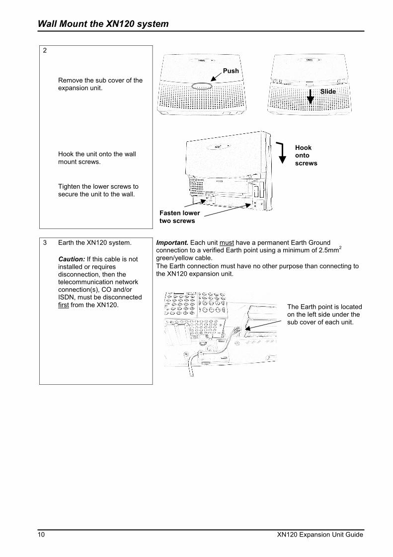
Remove the sub cover of the expansion unit. Hook the unit onto the wall mount screws. Tighten the lower screws to secure the unit to the wall.
3 Earth the XN120 system.
Caution: If this cable is not installed or requires disconnection, then the telecommunication network connection(s), CO and/or ISDN, must be disconnected first from the XN120.
Important. Each unit must have a permanent Earth Ground connection to a verified Earth point using a minimum of 2.5mm2 green/yellow cable. The Earth connection must have no other purpose than connecting to the XN120 expansion unit.
The Earth point is located on the left side under the sub cover of each unit.
Push
Slide
Hook onto screws
Fasten lower two screws

Wall Mount the XN120 System
XN120 Expansion Unit Guide 11
4- Connecting the Expansion Units to the EXIFU card Each expansion unit must be connected to the EXIFU card within the XN120 main unit. If you are installing one expansion unit connect to the EXIFU socket labelled EXP1. If you are installing two expansion units connect to the EXIFU sockets labelled EXP1 and EXP2. The EXPCN socket on the expansion unit is located to the right of the ST sockets on the main board.
Expansion unit 1
XN120 Main Unit
Expansion unit 2
EXP
2 EX
P 1
LAN
EXPCN
EXPCN
EXIFU-A1 connections
Connect the Telephones
12 XN120 Expansion Unit Guide
5- Connect the Telephones Precautions for Cabling:
�� Do not run the cable with a power cable, computer cable etc. �� Do not run the cable near any high frequency generating equipment. �� Use cable protectors if the cables are run on the floor. �� Aerial distribution wiring is not allowed.
Connecting the XN120 System Phones
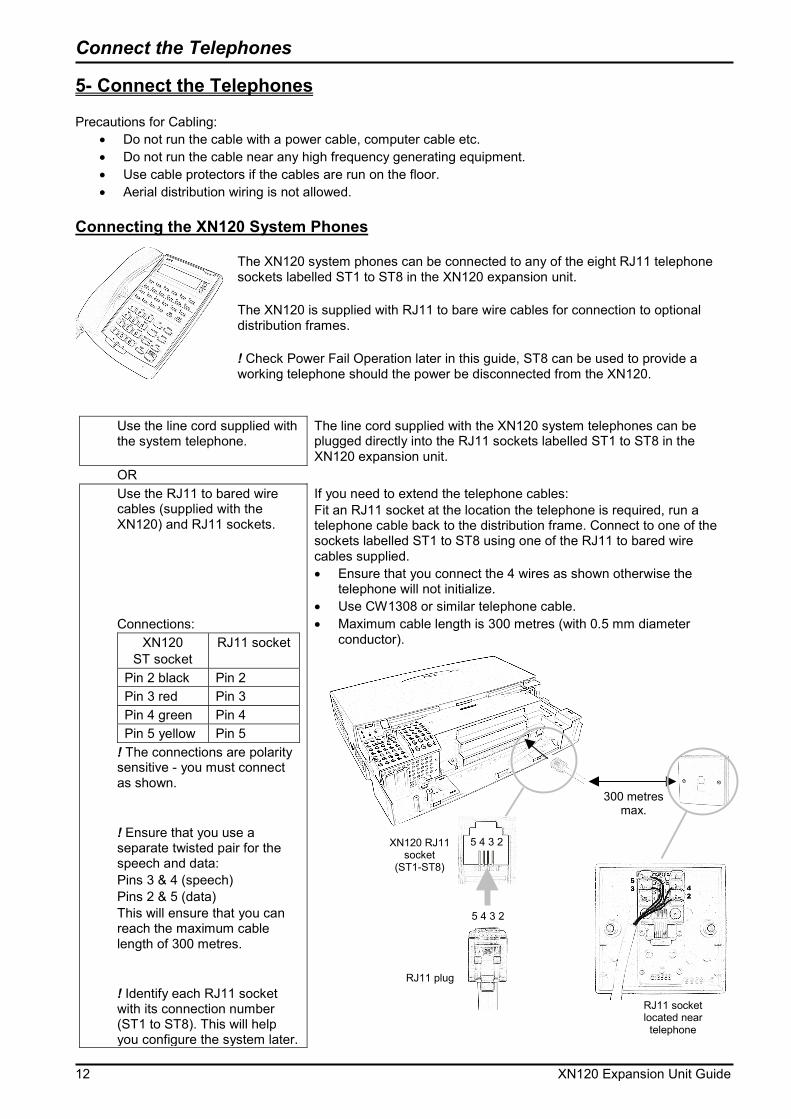
The XN120 system phones can be connected to any of the eight RJ11 telephone sockets labelled ST1 to ST8 in the XN120 expansion unit. The XN120 is supplied with RJ11 to bare wire cables for connection to optional distribution frames. ! Check Power Fail Operation later in this guide, ST8 can be used to provide a working telephone should the power be disconnected from the XN120.
Use the line cord supplied with the system telephone.
The line cord supplied with the XN120 system telephones can be plugged directly into the RJ11 sockets labelled ST1 to ST8 in the XN120 expansion unit.
OR Use the RJ11 to bared wire
cables (supplied with the XN120) and RJ11 sockets. Connections:
XN120 ST socket
RJ11 socket
Pin 2 black Pin 2 Pin 3 red Pin 3 Pin 4 green Pin 4 Pin 5 yellow Pin 5
! The connections are polarity sensitive - you must connect as shown. ! Ensure that you use a separate twisted pair for the speech and data: Pins 3 & 4 (speech) Pins 2 & 5 (data) This will ensure that you can reach the maximum cable length of 300 metres. ! Identify each RJ11 socket with its connection number (ST1 to ST8). This will help you configure the system later.
If you need to extend the telephone cables: Fit an RJ11 socket at the location the telephone is required, run a telephone cable back to the distribution frame. Connect to one of the sockets labelled ST1 to ST8 using one of the RJ11 to bared wire cables supplied. �� Ensure that you connect the 4 wires as shown otherwise the
telephone will not initialize. �� Use CW1308 or similar telephone cable. �� Maximum cable length is 300 metres (with 0.5 mm diameter
conductor).
300 metres max.
RJ11 socket located near telephone
5 4 3 2
5 4 3 2
RJ11 plug
XN120 RJ11 socket
(ST1-ST8)
Connect the Telephones
XN120 Expansion Unit Guide 13
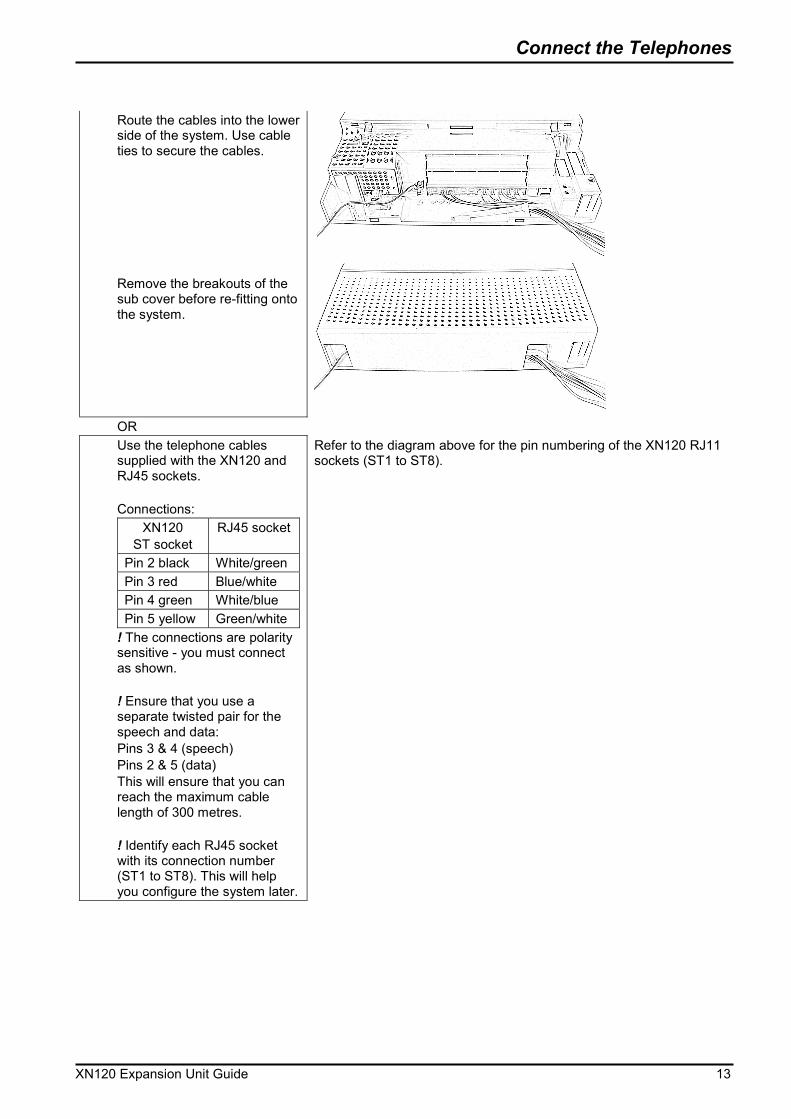
Route the cables into the lower
side of the system. Use cable ties to secure the cables. Remove the breakouts of the sub cover before re-fitting onto the system.
OR Use the telephone cables
supplied with the XN120 and RJ45 sockets. Connections:
XN120 ST socket
RJ45 socket
Pin 2 black White/green Pin 3 red Blue/white Pin 4 green White/blue Pin 5 yellow Green/white
! The connections are polarity sensitive - you must connect as shown. ! Ensure that you use a separate twisted pair for the speech and data: Pins 3 & 4 (speech) Pins 2 & 5 (data) This will ensure that you can reach the maximum cable length of 300 metres. ! Identify each RJ45 socket with its connection number (ST1 to ST8). This will help you configure the system later.
Refer to the diagram above for the pin numbering of the XN120 RJ11 sockets (ST1 to ST8).
Connect the Telephones
14 XN120 Expansion Unit Guide
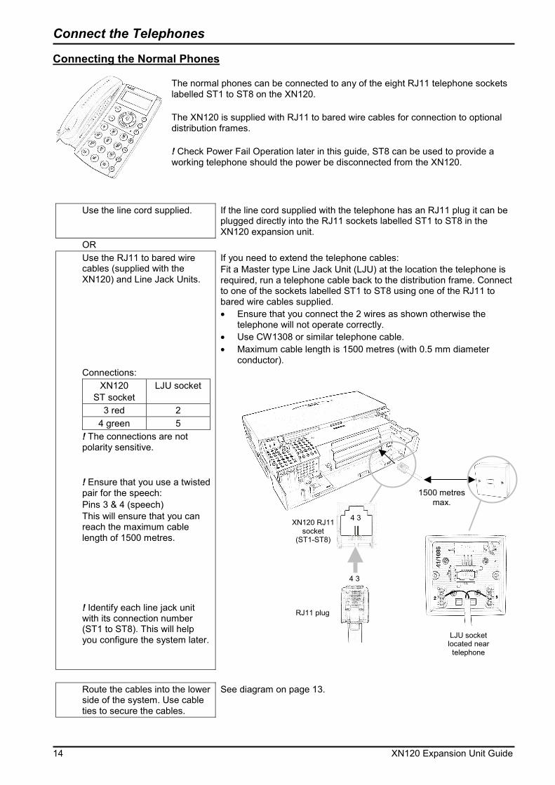
Connecting the Normal Phones The normal phones can be connected to any of the eight RJ11 telephone sockets labelled ST1 to ST8 on the XN120. The XN120 is supplied with RJ11 to bared wire cables for connection to optional distribution frames. ! Check Power Fail Operation later in this guide, ST8 can be used to provide a working telephone should the power be disconnected from the XN120.
Use the line cord supplied. If the line cord supplied with the telephone has an RJ11 plug it can be plugged directly into the RJ11 sockets labelled ST1 to ST8 in the XN120 expansion unit.
OR Use the RJ11 to bared wire
cables (supplied with the XN120) and Line Jack Units. Connections:
XN120 ST socket
LJU socket
3 red 2 4 green 5
! The connections are not polarity sensitive. ! Ensure that you use a twisted pair for the speech: Pins 3 & 4 (speech) This will ensure that you can reach the maximum cable length of 1500 metres. ! Identify each line jack unit with its connection number (ST1 to ST8). This will help you configure the system later.
If you need to extend the telephone cables: Fit a Master type Line Jack Unit (LJU) at the location the telephone is required, run a telephone cable back to the distribution frame. Connect to one of the sockets labelled ST1 to ST8 using one of the RJ11 to bared wire cables supplied. �� Ensure that you connect the 2 wires as shown otherwise the
telephone will not operate correctly. �� Use CW1308 or similar telephone cable. �� Maximum cable length is 1500 metres (with 0.5 mm diameter
conductor).
Route the cables into the lower
side of the system. Use cable ties to secure the cables.
See diagram on page 13.
1500 metres max.
4 3
RJ11 plug
XN120 RJ11 socket
(ST1-ST8)
4 3
LJU socket located near telephone
Connect the Telephones
XN120 Expansion Unit Guide 15
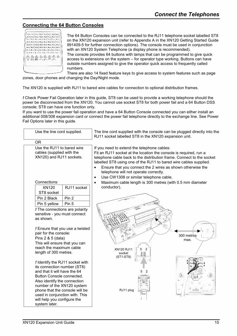
Connecting the 64 Button Consoles The 64 Button Consoles can be connected to the RJ11 telephone socket labelled ST8 on the XN120 expansion unit (refer to Appendix A in the XN120 Getting Started Guide 991409-5 for further connection options). The console must be used in conjunction with an XN120 System Telephone (a display phone is recommended). The console provides 64 buttons with lamps that can be programmed to give quick access to extensions on the system – for operator type working. Buttons can have outside numbers assigned to give the operator quick access to frequently called numbers. There are also 14 fixed feature keys to give access to system features such as page
zones, door phones and changing the Day/Night mode. The XN120 is supplied with RJ11 to bared wire cables for connection to optional distribution frames. ! Check Power Fail Operation later in this guide, ST8 can be used to provide a working telephone should the power be disconnected from the XN120. You cannot use socket ST8 for both power fail and a 64 Button DSS console; ST8 can have one function only. If you want to use the power fail operation and have a 64 Button Console connected you can either install an additional 008/308 expansion card or connect the power fail telephone directly to the exchange line. See Power Fail Options later in this guide.
Use the line cord supplied. The line cord supplied with the console can be plugged directly into the RJ11 socket labelled ST8 in the XN120 expansion unit.
OR Use the RJ11 to bared wire
cables (supplied with the XN120) and RJ11 sockets. Connections:
XN120 ST8 socket
RJ11 socket
Pin 2 Black Pin 2 Pin 5 yellow Pin 5
! The connections are polarity sensitive - you must connect as shown. ! Ensure that you use a twisted pair for the console: Pins 2 & 5 (data) This will ensure that you can reach the maximum cable length of 300 metres. ! Identify the RJ11 socket with its connection number (ST8) and that it will have the 64 Button Console connected. Also identify the connection number of the XN120 system phone that the console will be used in conjunction with. This will help you configure the system later.
If you need to extend the telephone cables: Fit an RJ11 socket at the location the console is required, run a telephone cable back to the distribution frame. Connect to the socket labelled ST8 using one of the RJ11 to bared wire cables supplied. �� Ensure that you connect the 2 wires as shown otherwise the
telephone will not operate correctly. �� Use CW1308 or similar telephone cable. �� Maximum cable length is 300 metres (with 0.5 mm diameter
conductor).
300 metres max.
5 2
5 2
RJ11 plug
XN120 RJ11 socket
(ST1-ST8)
Connect the Telephones
16 XN120 Expansion Unit Guide
OR Use the telephone cables
supplied with the XN120 and RJ45 sockets. Connections:
XN120 ST socket
RJ45 socket
Pin 2 black White/green Pin 5 yellow Green/white
! The connections are polarity sensitive - you must connect as shown. ! Ensure that you use a twisted pair for the console: Pins 2 & 5 (data) This will ensure that you can reach the maximum cable length of 300 metres. ! Identify the RJ45 socket with its connection number (ST8) and that it will have the 64 Button Console connected. Also identify the connection number of the XN120 system phone that the console will be used in conjunction with. This will help you configure the system later.
Refer to the diagram above for the pin numbering of the XN120 RJ11 socket (ST8).
Note.
The 64 Button console uses pins 2 and 5 (data pair) on the XN120. You will not cause any damage if the console is plugged into an RJ11 socket that also has the speech pair connected (pins 3 and 4 of the RJ11 socket).
Refer to the separate section
within the XN120 Getting Started Guide for all other information related to the 64 Button Consoles.
Refer to Appendix A – 64 Button Consoles in the XN120 Getting Started Guide 991409-5

Connect the Telephones
XN120 Expansion Unit Guide 17
6- Connect the Exchange Lines The exchange lines can be connected to any of the three RJ11 sockets labelled CO1 to CO3. Make a note of each exchange line number (i.e. the number dialed to ring the line) and its CO connection to the XN120. You will need this when you configure the XN120.
XN120 CO number
Exchange line dialing number (e.g. 01509 643100)
CO1 CO2 CO3
! Check Power Fail Operation later in this guide, CO1 can be used to provide a working telephone should the power be disconnected from the XN120. Precautions for Cabling:
�� Do not run the cable with a power cable, computer cable etc. �� Do not run the cable near any high frequency generating equipment. �� Use cable protectors if the cables are run on the floor. �� Aerial distribution wiring is not allowed. �� Use lightning protectors for each exchange line.
Use the cables supplied with
the XN120.
The exchange line cables supplied with the XN120 can be used to connect to the lines supplied by your Network Provider. ! Ensure each line has a lightning protection device included.
OR Use pre-formed telephone
cables (not supplied). Connections:
XN120 CO socket
LJU socket
3 red 2 4 green 5
! The connections are not polarity sensitive.
If the exchange lines are terminated with an LJU you can use a separate pre-formed cable to connect each line to a CO socket of the XN120 expansion unit. �� Ensure that you connect the 2 wires as shown otherwise the line
will not operate correctly. �� Use CW1308 or similar telephone cable. �� Fit lightning protectors to each line.
4 3
XN120 RJ11 socket
(CO1-CO3)
4 3
5 2 RJ11 plug
431A telephone
plug
Exchange line point
Connect the Power & Start Up
18 XN120 Expansion Unit Guide
7- Connect the Power & System Start Up The power cable is plugged into the left side of the unit via an IEC-C13 socket using the cable supplied with the XN120 expansion unit. Before connecting the power:
�� Ensure the power switch on the left side of the unit is OFF. �� Ensure the power is switched off at the source.
If you are installing the expansion unit as part of a new installation System Start Up – First Time ! The first time you start up the XN120 it is important to clear the system memory. This will ensure that the system is set to the default configuration.
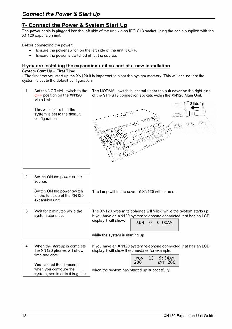
1 Set the NORMAL switch to the OFF position on the XN120 Main Unit. This will ensure that the system is set to the default configuration.
The NORMAL switch is located under the sub cover on the right side of the ST1-ST8 connection sockets within the XN120 Main Unit.
2 Switch ON the power at the
source. Switch ON the power switch on the left side of the XN120 expansion unit.
The lamp within the cover of XN120 will come on.
3 Wait for 2 minutes while the
system starts up. The XN120 system telephones will ‘click’ while the system starts up. If you have an XN120 system telephone connected that has an LCD display it will show: while the system is starting up.
4 When the start up is complete
the XN120 phones will show time and date. You can set the time/date when you configure the system, see later in this guide.
If you have an XN120 system telephone connected that has an LCD display it will show the time/date, for example: when the system has started up successfully.
SUN 0 0 00AM
MON 13 9:34AM 200 EXT 200
Slide
Connect the Power & Start Up
XN120 Expansion Unit Guide 19
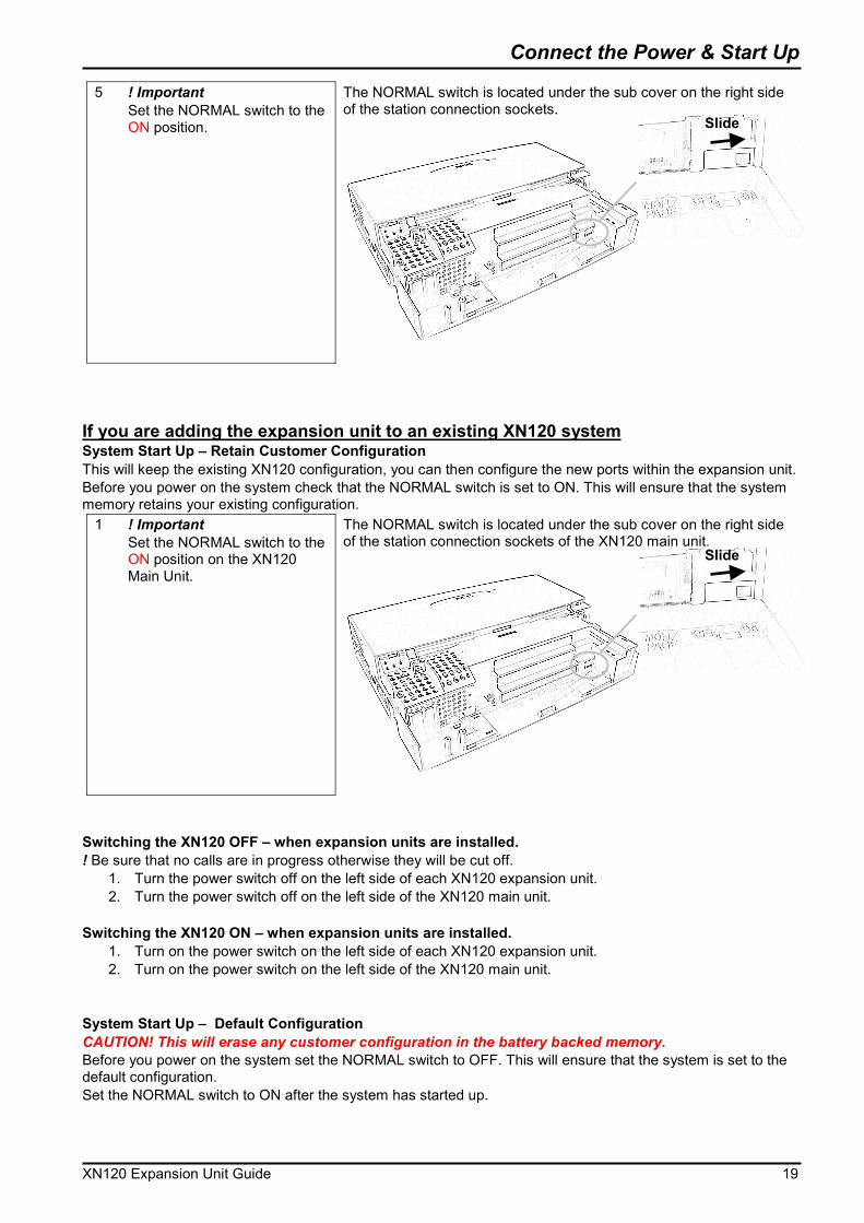
5 ! Important Set the NORMAL switch to the ON position.
The NORMAL switch is located under the sub cover on the right side of the station connection sockets.
If you are adding the expansion unit to an existing XN120 system System Start Up – Retain Customer Configuration This will keep the existing XN120 configuration, you can then configure the new ports within the expansion unit. Before you power on the system check that the NORMAL switch is set to ON. This will ensure that the system memory retains your existing configuration.
1 ! Important Set the NORMAL switch to the ON position on the XN120 Main Unit.
The NORMAL switch is located under the sub cover on the right side of the station connection sockets of the XN120 main unit.
Switching the XN120 OFF – when expansion units are installed. ! Be sure that no calls are in progress otherwise they will be cut off.
1. Turn the power switch off on the left side of each XN120 expansion unit. 2. Turn the power switch off on the left side of the XN120 main unit.
Switching the XN120 ON – when expansion units are installed.
1. Turn on the power switch on the left side of each XN120 expansion unit. 2. Turn on the power switch on the left side of the XN120 main unit.
System Start Up – Default Configuration CAUTION! This will erase any customer configuration in the battery backed memory. Before you power on the system set the NORMAL switch to OFF. This will ensure that the system is set to the default configuration. Set the NORMAL switch to ON after the system has started up.
Slide
Slide

Ports Assigned to the Expansion Unit
20 XN120 Expansion Unit Guide
8- Ports Assigned The exchange line (CO) and telephone (ST) ports are assigned automatically when the system is powered on. The ports assigned depend on the configuration of the system before the new expansion unit was installed. If you have installed more than one expansion unit then the system will assign port numbers to the units in the following order: Expansion unit 1 then Expansion unit 2 You can confirm the ports assigned with Program 10-03-01. Refer to ‘Configure the Expansion Units’ for instructions to access configuration mode.
1 Program 10-03-01 Determine the port numbers assigned to the expansion units. This will show the ports assigned to each expansion unit. Refer to the 008/308 Guide or BRIU Guide to determine the ports assigned to the cards that are installed in expansion units. Record the settings on the Configuration sheet below. Note the ST port numbers on the configuration sheet on the next page. Note the CO port numbers on the configuration sheet on the next page.
��Select the expansion unit’s slot number with the Vol.� � keys. ��Press HOLD to confirm the slot number and display the first
telephone (ST) port number of the expansion unit. You cannot change the port number as it is automatically assigned.
��Press FLASH twice to move the curser to the HBI number. ��Enter 09 and press HOLD. The first exchange line (CO) port
number of the expansion unit will be shown. You cannot change the port number as it is automatically assigned.
��Press Vol.� � to step to the next slot number and repeat the steps above to show the telephone and exchange line port numbers for the other expansion unit.
When you are finished: ��Press DC several times when you are done to return to the
Program Mode. (Press SPK to save changes and exit if you are finished).
XN120 expansion unit 2
XN120 expansion unit 1
XN120 main unit
Program 10-03-01. The main unit will be slot 1.
Program 10-03-01. Expansion unit 1 will be slot 7.
Program 10-03-01. Expansion unit 2 will be slot 13.
10-03-01 SlotNo 7 HBI01 Type 2
Press FLASH to move the curser to the port number (1-11)
10-03-02 SlotNo 7 HBI01 Port 25
Press Vol.� � keys to select the slot number EXP1 is slot 7 EXP2 is slot 13
10-03-02 SlotNo 7 HBI09 Port 10
First telephone port number.
First exchange line port number.

Connect the Power & Start Up
XN120 Expansion Unit Guide 21
Configuration sheet: Expansion Unit Port Assignment (base board ports) Each expansion unit has 8 telephone (ST) ports and 3 exchange line (CO) ports.
XN120 unit Slot
number in Program 10-03-01
Telephone port
numbers. ST Sockets.
Exchange Line port numbers.
CO Sockets. Slot 1 Base board 1-8 1-3
Main unit
Slot 7 Base board
Expansion
1 Slot 13 Base board
Expansion
2
Test the System
22 XN120 Expansion Unit Guide
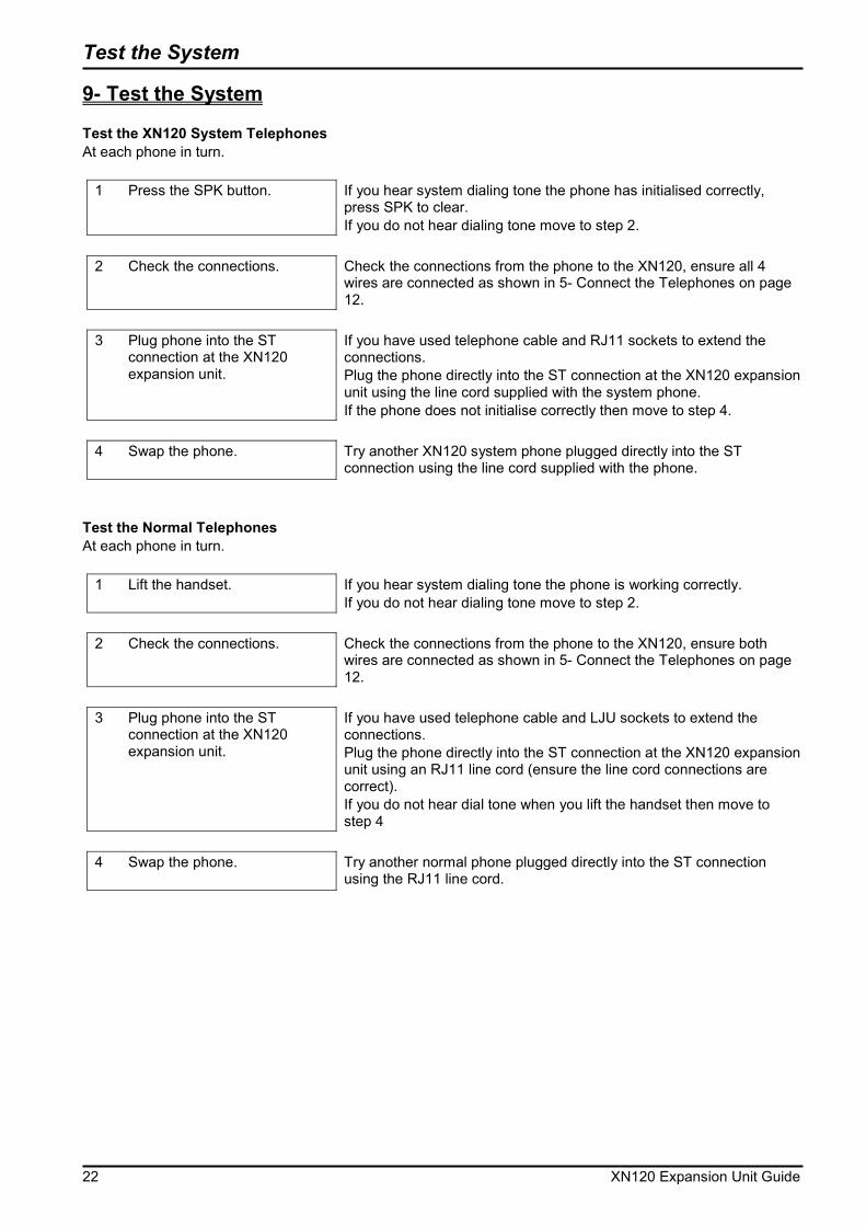
9- Test the System Test the XN120 System Telephones At each phone in turn.
1 Press the SPK button. If you hear system dialing tone the phone has initialised correctly, press SPK to clear. If you do not hear dialing tone move to step 2.
2 Check the connections. Check the connections from the phone to the XN120, ensure all 4
wires are connected as shown in 5- Connect the Telephones on page 12.
3 Plug phone into the ST
connection at the XN120 expansion unit.
If you have used telephone cable and RJ11 sockets to extend the connections. Plug the phone directly into the ST connection at the XN120 expansion unit using the line cord supplied with the system phone. If the phone does not initialise correctly then move to step 4.
4 Swap the phone. Try another XN120 system phone plugged directly into the ST
connection using the line cord supplied with the phone.
Test the Normal Telephones At each phone in turn.
1 Lift the handset. If you hear system dialing tone the phone is working correctly. If you do not hear dialing tone move to step 2.
2 Check the connections. Check the connections from the phone to the XN120, ensure both
wires are connected as shown in 5- Connect the Telephones on page 12.
3 Plug phone into the ST
connection at the XN120 expansion unit.
If you have used telephone cable and LJU sockets to extend the connections. Plug the phone directly into the ST connection at the XN120 expansion unit using an RJ11 line cord (ensure the line cord connections are correct). If you do not hear dial tone when you lift the handset then move to step 4
4 Swap the phone. Try another normal phone plugged directly into the ST connection
using the RJ11 line cord.
Test the System
XN120 Expansion Unit Guide 23
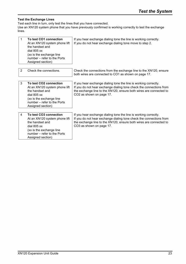
Test the Exchange Lines Test each line in turn, only test the lines that you have connected. Use an XN120 system phone that you have previously confirmed is working correctly to test the exchange lines.
1 To test CO1 connection At an XN120 system phone lift the handset and dial 805 xx (xx is the exchange line number – refer to the Ports Assigned section)
If you hear exchange dialing tone the line is working correctly. If you do not hear exchange dialing tone move to step 2.
2 Check the connections. Check the connections from the exchange line to the XN120, ensure
both wires are connected to CO1 as shown on page 17. 3 To test CO2 connection
At an XN120 system phone lift the handset and dial 805 xx (xx is the exchange line number – refer to the Ports Assigned section)
If you hear exchange dialing tone the line is working correctly. If you do not hear exchange dialing tone check the connections from the exchange line to the XN120, ensure both wires are connected to CO2 as shown on page 17.
4 To test CO3 connection
At an XN120 system phone lift the handset and dial 805 xx (xx is the exchange line number – refer to the Ports Assigned section)
If you hear exchange dialing tone the line is working correctly. If you do not hear exchange dialing tone check the connections from the exchange line to the XN120, ensure both wires are connected to CO3 as shown on page 17.

Install Optional Equipment
24 XN120 Expansion Unit Guide
10- Install Optional Equipment When the expansion unit is installed and working you can install any additional equipment such as 008/308 cards, 2PGDU card, 2OPBOX and BRIU cards. Refer to the guides supplied with each item for installation instructions. If you are not familiar with the XN120 system we recommend that you install the additional parts one at a time; this will make testing each part easier. If you are familiar with the system then install all the optional parts at the same time. ! Ensure you power off all XN120 units before you add any optional parts.

Configure the Expansion Unit
XN120 Expansion Unit Guide 25
11- Configure the XN120 The getting started guide will cover the most frequently used configuration options. For advanced configuration please refer to the XN120 Programming Manual 991435-5. Before you configure your system it is important that you:
�� Ensure the power will not be turned off to the XN120, otherwise you will lose any changes you have made that were not previously saved to battery backed memory.
�� Ensure that the NORMAL switch is set to ON before you commence, otherwise you could lose your entire configuration. Refer to System Start Up for information.
�� Have a diagram of your exchange lines and telephones. �� Plan your requirements before you start.
While you configure your system it is important that you:
�� Exit configuration mode periodically, this will save your changes into battery backed memory. They will not be lost if the power is removed.
�� Fill out the configuration sheets as you go so that you have a record of your configuration. �� Make small changes, exit configuration mode and test the changes. Do not make all your changes at
once as this can make testing very difficult. �� Record your changes as you can only ‘undo’ them by re-entering the previous values. �� Do not unplug the phone. If it is unplugged by mistake then plug it back in, wait for the display to show
time and date and then press HOLD to return to the configuration mode. Your changes will not be lost. The XN120 consists of exchange lines and telephones connected to the expansion units you have installed. Within the XN120 configuration the exchange lines are referred to as trunks and the telephones as extensions. When the XN120 is started up as shown in this guide all the equipment will operate, it is not necessary to make any changes to the system configuration. With the default settings:
�� Each telephone will function and is assigned an extension number. �� Calls received on the exchange lines will ring at telephone number 200. �� Each telephone can make exchange line calls by dialing 9. �� Each exchange line is presented at a Function Key with busy lamp indication.
How to change the XN120’s Configuration The configuration is stored in battery backed memory within the XN120. You can change the configuration via any XN120 system phone that has an LCD display. When you have made your changes the XN120 will automatically save the configuration into memory. Check the User Guide for other options There are some options that are set via normal service codes, for example: System Phone Book – with service code 853. Telephone Names – with service code 800.
Configure the Expansion Unit
26 XN120 Expansion Unit Guide
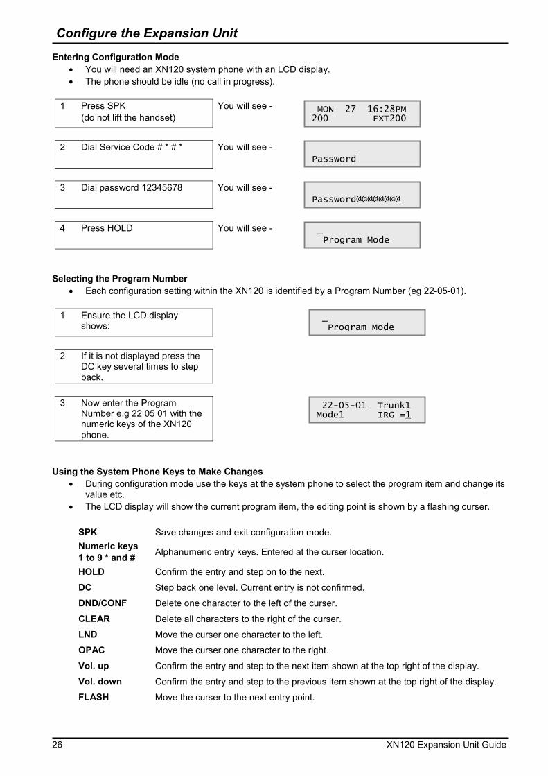
Entering Configuration Mode �� You will need an XN120 system phone with an LCD display. �� The phone should be idle (no call in progress).
1 Press SPK
(do not lift the handset) You will see -
2 Dial Service Code # * # * You will see -
3 Dial password 12345678 You will see -
4 Press HOLD You will see -
Selecting the Program Number
�� Each configuration setting within the XN120 is identified by a Program Number (eg 22-05-01).
1 Ensure the LCD display shows:
2 If it is not displayed press the
DC key several times to step back.
3 Now enter the Program
Number e.g 22 05 01 with the numeric keys of the XN120 phone.
Using the System Phone Keys to Make Changes
�� During configuration mode use the keys at the system phone to select the program item and change its value etc.
�� The LCD display will show the current program item, the editing point is shown by a flashing curser.
SPK Save changes and exit configuration mode. Numeric keys 1 to 9 * and # Alphanumeric entry keys. Entered at the curser location.
HOLD Confirm the entry and step on to the next. DC Step back one level. Current entry is not confirmed. DND/CONF Delete one character to the left of the curser. CLEAR Delete all characters to the right of the curser. LND Move the curser one character to the left. OPAC Move the curser one character to the right. Vol. up Confirm the entry and step to the next item shown at the top right of the display. Vol. down Confirm the entry and step to the previous item shown at the top right of the display. FLASH Move the curser to the next entry point.
MON 27 16:28PM 200 EXT200
Password
Password@@@@@@@@
_ Program Mode
_ Program Mode
22-05-01 Trunk1 Mode1 IRG =1
Configure the Expansion Unit
XN120 Expansion Unit Guide 27
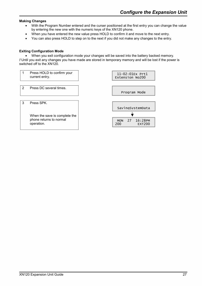
Making Changes �� With the Program Number entered and the curser positioned at the first entry you can change the value
by entering the new one with the numeric keys of the XN120 phone. �� When you have entered the new value press HOLD to confirm it and move to the next entry. �� You can also press HOLD to step on to the next if you did not make any changes to the entry.
Exiting Configuration Mode
�� When you exit configuration mode your changes will be saved into the battery backed memory. ! Until you exit any changes you have made are stored in temporary memory and will be lost if the power is switched off to the XN120.
1 Press HOLD to confirm your current entry.
2 Press DC several times.
3 Press SPK.
When the save is complete the phone returns to normal operation.
11-02-01Ex Prt1 Extension No200
Program Mode
SavingSystemData
MON 27 16:28PM 200 EXT200
Configure the Expansion Unit
28 XN120 Expansion Unit Guide
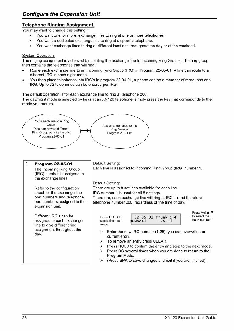
Telephone Ringing Assignment. You may want to change this setting if:
�� You want one, or more, exchange lines to ring at one or more telephones. �� You want a dedicated exchange line to ring at a specific telephone. �� You want exchange lines to ring at different locations throughout the day or at the weekend.
System Operation: The ringing assignment is achieved by pointing the exchange line to Incoming Ring Groups. The ring group then contains the telephones that will ring. �� Route each exchange line to an Incoming Ring Group (IRG) in Program 22-05-01. A line can route to a
different IRG in each night mode. �� You then place telephones into IRG’s in program 22-04-01, a phone can be a member of more than one
IRG. Up to 32 telephones can be entered per IRG. The default operation is for each exchange line to ring at telephone 200. The day/night mode is selected by keys at an XN120 telephone, simply press the key that corresponds to the mode you require.
1 Program 22-05-01 The Incoming Ring Group (IRG) number is assigned to the exchange lines. Refer to the configuration sheet for the exchange line port numbers and telephone port numbers assigned to the expansion unit. Different IRG’s can be assigned to each exchange line to give different ring assignment throughout the day.
Default Setting: Each line is assigned to Incoming Ring Group (IRG) number 1. Default Setting: There are up to 8 settings available for each line. IRG number 1 is used for all 8 settings. Therefore, each exchange line will ring at IRG 1 (and therefore telephone number 200, regardless of the time of day.
��Enter the new IRG number (1-25), you can overwrite the current entry.
��To remove an entry press CLEAR. ��Press HOLD to confirm the entry and step to the next mode. ��Press DC several times when you are done to return to the
Program Mode. ��(Press SPK to save changes and exit if you are finished).
22-05-01 Trunk 9 Mode1 IRG =1
Press Vol � � to select the trunk number
Press HOLD to select the next mode
Route each line to a Ring Group.
You can have a different Ring Group per night mode.
Program 22-05-01
Assign telephones to the
Ring Groups. Program 22-04-01

Configure the Expansion Unit
XN120 Expansion Unit Guide 29
2 Program 22-04-01 The telephones are placed into ring groups (IRG’s).
Default Setting: Telephone number 200 is a member of IRG number 1.
��Enter the new telephone number, you can overwrite the current entry.
��To remove an entry press CLEAR. ��Press HOLD to confirm the entry and step to the next member.��Press DC several times when you are done to return to the
Program Mode. ��(Press SPK to save changes and exit if you are finished).
3 Program 20-07-01
Turn on the day/night mode option.
Default Setting: Day/night modes cannot be changed by any telephones.
��Enter 1 to enable the option, you can overwrite the current
entry. ��Press HOLD to confirm the entry and step to the next option. ��Press DC several times when you are done to return to the
Program Mode. ��(Press SPK to save changes and exit if you are finished).
4 Assign a key to each
mode Choose a telephone that will be able to change the mode. The keys are set at the telephone itself.
Default Setting: There are no keys set to day/night modes on any of the telephones.
1. At the telephone press SPK.
2. Dial service code 851
3. Press the Key you want to set (Its current setting is shown if you have an LCD display).
4. Dial 09 followed by the mode number 1 to 8.
5. Repeat steps 3. and 4. for further keys/modes.
See also: Outgoing Exchange Line Access to give a telephone a dedicated line for outgoing calls.
20-07-01 F-Cls 1 SW Man NT serv 0
Enter 1 to enable Day/night mode option
22-04-01 INC Gr1 Memb.01= 200
Press Vol � � to select the IRG number
Press HOLD to select the next member
Configure the Expansion Unit
30 XN120 Expansion Unit Guide
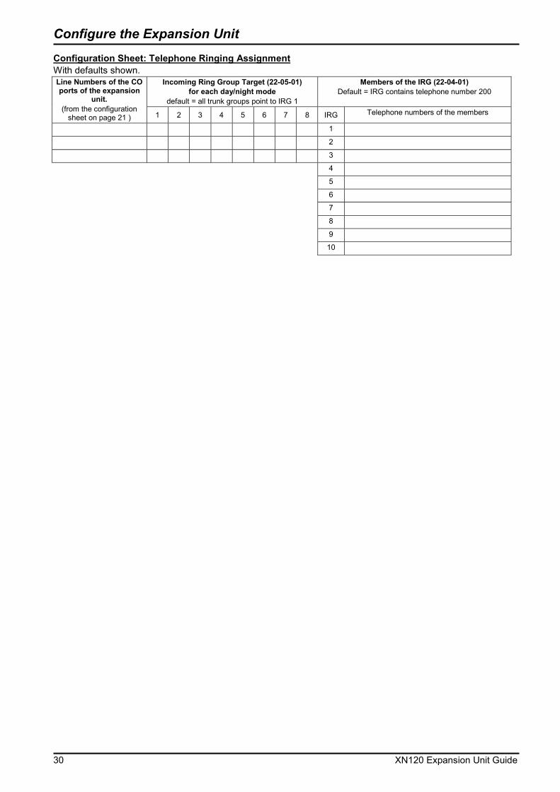
Configuration Sheet: Telephone Ringing Assignment With defaults shown.
Incoming Ring Group Target (22-05-01) for each day/night mode
default = all trunk groups point to IRG 1
Members of the IRG (22-04-01) Default = IRG contains telephone number 200
Line Numbers of the CO ports of the expansion
unit. (from the configuration
sheet on page 21 ) 1 2 3 4 5 6 7 8 IRG Telephone numbers of the members
1 2 3 4 5 6 7 8 9 10

Configure the Expansion Unit
XN120 Expansion Unit Guide 31
Outgoing Exchange Line Access You may want to change this setting if:
�� You want a dedicated exchange line for one of the telephones. System Operation: Each telephone is assigned a Trunk Access Map (TAM) number. The TAM number is then given the access properties for each of the exchange lines. The default operation is that all telephones have access to any exchange line.
1 Program 15-06-01 Give the telephone a TAM number. You can specify a different TAM number for each day/night mode. See Changing the Telephone Ringing Assignment for the modes you may be using.
Default Setting: All telephones have TAM number 1.
��Enter the TAM number (1-51) for each mode (1-8), you can overwrite the current entry.
��Press HOLD to confirm the entry and step to the next mode. ��Press DC several times when you are done to return to the
Program Mode. ��(Press SPK to save changes and exit if you are finished).
2 Program 14-07-01
Give each exchange line the access properties for the TAM number.
Default Setting: Each exchange line has full access (Property type 7) for TAM number 1. Therefore every telephone can access any of the trunks.
��Enter the access properties (0-7) for each trunk, you can overwrite the current entry. 0 – No access 1 – Outgoing only 2 – Incoming only 3 – Retrieve held call only 4 – Outgoing and retrieve held call 5 – Incoming and retrieve held call 6 – Incoming and outgoing 7 – Incoming, outgoing and retrieve held call
��Press HOLD to confirm the entry and step to the next mode. ��Press DC several times when you are done to return to the
Program Mode. ��(Press SPK to save changes and exit if you are finished).
See Also: Changing the Telephone Ringing Assignment.
15-06-01 Tel 200 Mode1 Acc-Map 1
Press Vol � � to select the telephone number
Press HOLD to select the next mode
14-07-01 Acs.Ma1 Trk01 = 7
Press Vol � � to select the TAM number
Press HOLD to select the next trunk
Configure the Expansion Unit
32 XN120 Expansion Unit Guide
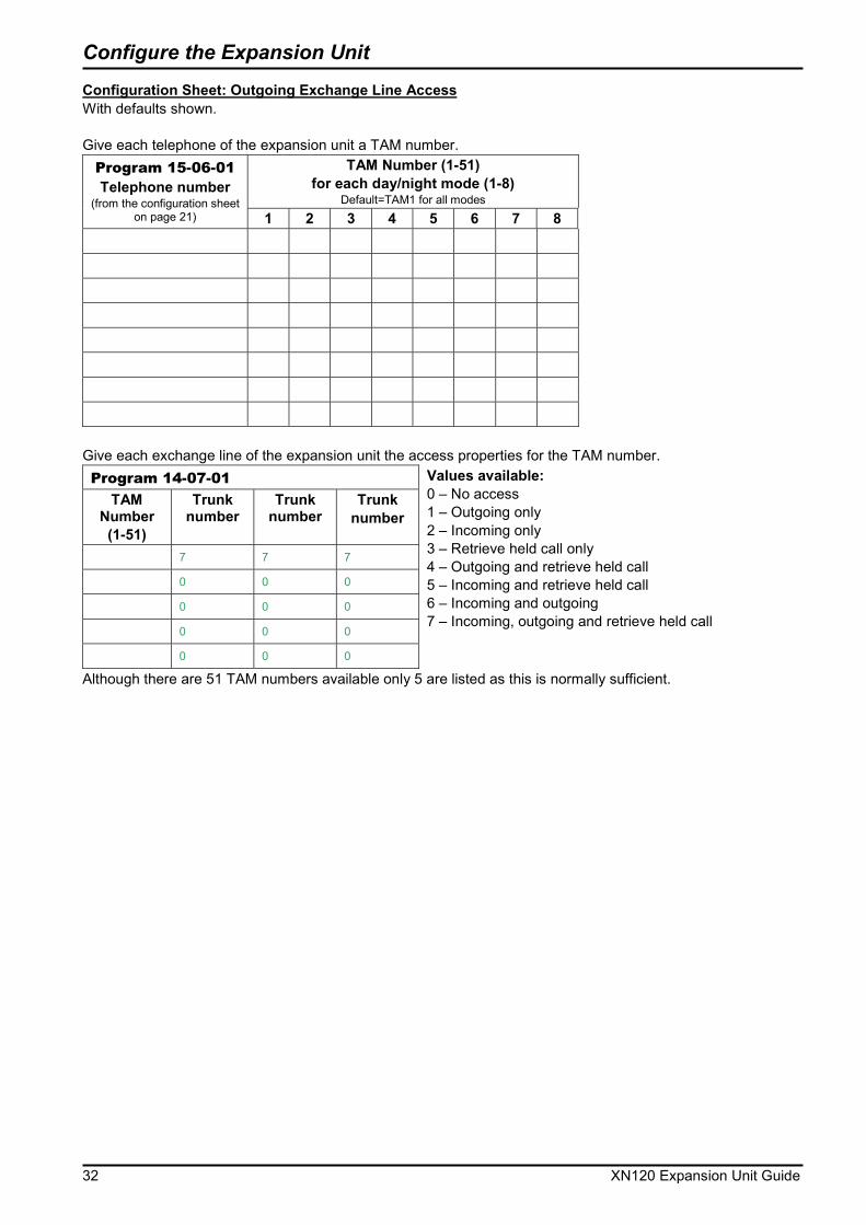
Configuration Sheet: Outgoing Exchange Line Access With defaults shown. Give each telephone of the expansion unit a TAM number.
TAM Number (1-51) for each day/night mode (1-8)
Default=TAM1 for all modes
Program 15-06-01 Telephone number
(from the configuration sheet on page 21) 1 2 3 4 5 6 7 8
Give each exchange line of the expansion unit the access properties for the TAM number. Program 14-07-01
TAM Number (1-51)
Trunk number
Trunk number
Trunk number
7 7 7
0 0 0
0 0 0
0 0 0
0 0 0
Values available: 0 – No access 1 – Outgoing only 2 – Incoming only 3 – Retrieve held call only 4 – Outgoing and retrieve held call 5 – Incoming and retrieve held call 6 – Incoming and outgoing 7 – Incoming, outgoing and retrieve held call
Although there are 51 TAM numbers available only 5 are listed as this is normally sufficient.

Configure the Expansion Unit
XN120 Expansion Unit Guide 33
Caller ID You will need to enable this setting if:
�� You have Caller ID service supplied on your outside lines. �� You have normal telephones that are Caller ID compatible.
The XN120 can detect the Caller ID and display it on the LCD display of the XN120 system phones. It can also be available at a normal phone that is Caller ID compatible. System Operation: You will need turn on the Caller ID detection for each trunk that it will be received on. You will also need to turn on Caller ID for each of the normal telephones that are Caller ID compatible.
Program 14-02-10 Turn on Caller ID for each trunk.
Default Setting: 14-02-10 is set to 0 (Caller ID is turned off) for each trunk.
��For each trunk enter 1 to turn on Caller ID, you can overwrite the current entry.
��Press HOLD to confirm the entry and step to the next option. ��Press DC several times when you are done to return to the
Program Mode. ��(Press SPK to save changes and exit if you are finished).
Program 15-03-09
Turn on Caller ID for each normal telephone that is Caller ID compatible. You do not need to change this option for the XN120 system phones.
Default Setting: 15-03-09 is set to 0 (Caller ID is turned off) for each telephone.
��For each telephone enter 1 to turn on Caller ID, you can overwrite the current entry.
��Press HOLD to confirm the entry and step to the next option. ��Press DC several times when you are done to return to the
Program Mode. ��(Press SPK to save changes and exit if you are finished).
See Also: There are no other related settings.
14-02-10 Trunk 1 Caller ID 0
Press Vol � � to select the trunk number
15-03-09 Tel 200 Ext No Display 0
Press Vol � � to select the telephone number
Configure the Expansion Unit
34 XN120 Expansion Unit Guide
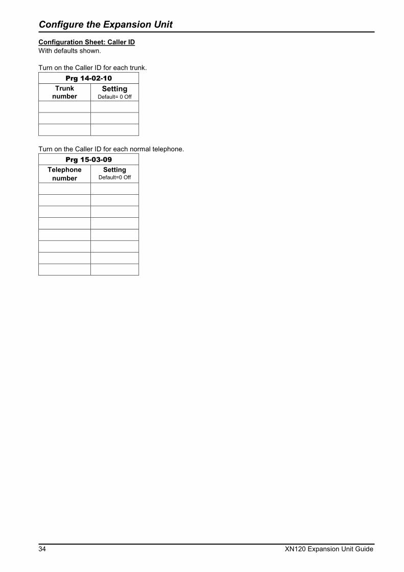
Configuration Sheet: Caller ID With defaults shown. Turn on the Caller ID for each trunk.
Prg 14-02-10
Trunk number
Setting Default= 0 Off
Turn on the Caller ID for each normal telephone.
Prg 15-03-09 Telephone
number Setting
Default=0 Off

Configure the Expansion Unit
XN120 Expansion Unit Guide 35
Department Groups You may want to change this setting if:
�� You have people that work within a group and you want to be able to call anyone within the group. The call will ring at anyone that is available within the group. If they do not answer, the call will step to the next member.
System Operation: The telephones are placed into Department groups. There are 32 groups available. The group is given a number (pilot number) that you dial to reach the group. You can choose the following options for each group. �� How the calls will ring around the group – either in a set order of priority or randomly at any telephone. �� Try each telephone once or keep hunting – your call can ring at each available telephone in the group and
if not answered stay at the last member or keep trying each member. �� How long each member rings before the call will step on to the next one available.
Program 16-02-01 Place the telephones into a department group. A telephone can be a member of one group. Priority is in order 1-99 (high-low)
Default Setting: All telephones are in department group 1
��For each telephone enter the group number (1-32) that it is a member of, you can overwrite the current entry.
��Press HOLD to confirm the entry and step to the priority option.
��For each telephone enter the priority number (1-99), you can overwrite the current entry.
��Press HOLD to confirm the entry and step to the next telephone.
��Press DC several times when you are done to return to the Program Mode.
��(Press SPK to save changes and exit if you are finished).
16-02-01 TEL 200 Extension Grp 1
Press Vol � � to select the telephone number
16-02-02 TEL 200 Priority 1
Press Vol � � to select the telephone number
Call to a Department
Group

Configure the Expansion Unit
36 XN120 Expansion Unit Guide
Program 16-01-02 Select how calls ring around the department group.
Default Setting: Calls ring in priority order within the department group.
��For each group select the ring mode, you can overwrite the current entry. 0 = Priority order 1 = Random order
��Press HOLD to confirm the entry and step to the next option. ��Press DC several times when you are done to return to the
Program Mode. ��(Press SPK to save changes and exit if you are finished).
Program 16-01-04
Select how many times the calls try each member of the department group.
Default Setting: Calls try each telephone once.
��For each group select the hunting mode, you can overwrite the current entry. 0 = Calls try each telephone once 1 = Calls continue trying the telephones
��Press HOLD to confirm the entry and step to the next option. ��Press DC several times when you are done to return to the
Program Mode. ��(Press SPK to save changes and exit if you are finished).
Program 16-01-09
Select how long calls ring at each member of the department group. You can use this option to turn off the step on operation by setting the time to 0 seconds.
Default Setting: Calls ring each member for 15 seconds.
��For each group select the ring duration (0-64800 seconds), you can overwrite the current entry. 0 seconds will stop the call stepping on.
��Press HOLD to confirm the entry and step to the next option. ��Press DC several times when you are done to return to the
Program Mode. ��(Press SPK to save changes and exit if you are finished).
16-01-02 TEL Gr1 Pilot call 0
Press Vol � � to select the group number
16-01-04 TEL Gr1 Hunting Mode 0
Press Vol � � to select the group number
16-01-09 TEL Gr1 Call N/A TM 15
Press Vol � � to select the group number

Configure the Expansion Unit
XN120 Expansion Unit Guide 37
Program 11-07-01 Give the department group a pilot number. Try to use a number that is easy to remember. For example use: Pilot number 501 for group 1 Pilot number 502 for group 2 etc.
Default Setting: There are no pilot numbers assigned.
��For each group enter the pilot number (3 digits required) you will dial to reach the group.
��Press HOLD to confirm the entry and step to the next group. If you duplicate a number you will see Duplicate Data, the entry will be removed and you can enter a new number.
��Press DC several times when you are done to return to the Program Mode.
��(Press SPK to save changes and exit if you are finished).
See Also: There are no related settings. Configuration Sheet: Department Groups With defaults shown.
Telephone number
Department Group
number 16-02-01 default=1
Priority number 16-02-02
Department
Group number
1-32
Pilot Number 11-07-01
Ring order, priority/random
16-01-02 default=0 Priority
Try once or continually
16-01-04 default=0 Once
Ring time before step on
16-01-09 default=15 seconds
There are 32 groups available, only 8 are listed, as this is usually sufficient.
11-07-01 TEL Gr1 Ext Grp No. _
Press Vol � � to select the group number
Configure the Expansion Unit
38 XN120 Expansion Unit Guide
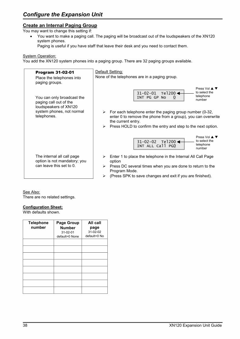
Create an Internal Paging Group You may want to change this setting if:
�� You want to make a paging call. The paging will be broadcast out of the loudspeakers of the XN120 system phones. Paging is useful if you have staff that leave their desk and you need to contact them.
System Operation: You add the XN120 system phones into a paging group. There are 32 paging groups available.
Program 31-02-01 Place the telephones into paging groups. You can only broadcast the paging call out of the loudspeakers of XN120 system phones, not normal telephones. The internal all call page option is not mandatory; you can leave this set to 0.
Default Setting: None of the telephones are in a paging group.
��For each telephone enter the paging group number (0-32, enter 0 to remove the phone from a group), you can overwrite the current entry.
��Press HOLD to confirm the entry and step to the next option.
��Enter 1 to place the telephone in the Internal All Call Page option
��Press DC several times when you are done to return to the Program Mode.
��(Press SPK to save changes and exit if you are finished).
See Also: There are no related settings. Configuration Sheet: With defaults shown.
Telephone number
Page Group Number 31-02-01
default=0 None
All call page
31-02-02 default=0 No
31-02-01 Tel200 INT PG GP No 0
Press Vol � � to select the telephone number
31-02-02 Tel200 INT ALL Call PG0
Press Vol � � to select the telephone number
Power Fail Options
XN120 Expansion Unit Guide 39
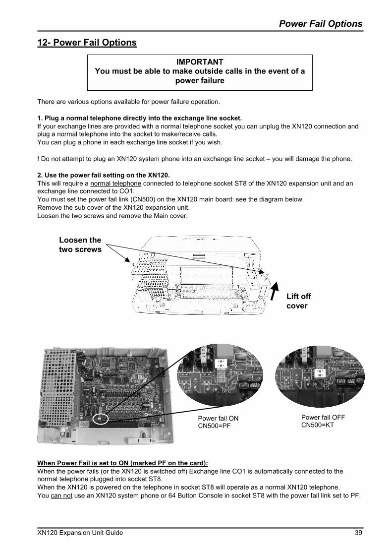
12- Power Fail Options There are various options available for power failure operation. 1. Plug a normal telephone directly into the exchange line socket. If your exchange lines are provided with a normal telephone socket you can unplug the XN120 connection and plug a normal telephone into the socket to make/receive calls. You can plug a phone in each exchange line socket if you wish. ! Do not attempt to plug an XN120 system phone into an exchange line socket – you will damage the phone. 2. Use the power fail setting on the XN120. This will require a normal telephone connected to telephone socket ST8 of the XN120 expansion unit and an exchange line connected to CO1. You must set the power fail link (CN500) on the XN120 main board: see the diagram below. Remove the sub cover of the XN120 expansion unit. Loosen the two screws and remove the Main cover. When Power Fail is set to ON (marked PF on the card): When the power fails (or the XN120 is switched off) Exchange line CO1 is automatically connected to the normal telephone plugged into socket ST8. When the XN120 is powered on the telephone in socket ST8 will operate as a normal XN120 telephone. You can not use an XN120 system phone or 64 Button Console in socket ST8 with the power fail link set to PF.
IMPORTANTYou must be able to make outside calls in the event of a
power failure
Loosen the two screws
Lift off cover
Power fail ON CN500=PF
Power fail OFF CN500=KT
Power Fail Options
40 XN120 Expansion Unit Guide
When Power Fail is set to OFF (marked KT on the card): When the power fails (or the XN120 is switched off) Exchange line CO1 is not automatically connected to socket ST8. When the XN120 is powered on the telephone in socket ST8 will operate as a either a normal XN120 telephone or XN120 system phone, depending on which type is plugged in. You can use an XN120 system phone in socket ST8 with the power fail link set to KT. Power Fail Options when the 64 Button Console is also Installed �� The 64 Button Console must be connected to socket ST8 of the XN120 unit. �� You must ensure the power fail link (CN500) is set to KT for the console to work correctly. �� You cannot use socket ST8 for power fail operation when the 64 Button Console is connected to ST8. If you have a 64 Button Console installed �� You can use the power fail operation of the optional 308 expansion card, if you have one installed.
There must be an exchange line connected to the first CO port of the 308 expansion card. �� You can connect the normal telephone directly into the exchange line socket – See instruction above.