xml to annotations mapping definition with patterns · xml to annotations mapping definition with...
TRANSCRIPT

Computer Science and Information Systems 11(4):1455–1477 DOI: 10.2298/CSIS130920049N
XML to Annotations Mapping Definition with Patterns
Milan Nosál’ and Jaroslav Porubän
Department of Computers and Informatics,Faculty of Electrical Engineering and Informatics,
Technical University of KošiceLetná 9, 042 00, Košice, Slovakia
[email protected], [email protected]
Abstract. Currently, the most commonly created formal languages are configura-tion languages. So far source code annotations and XML are the leading notationsfor configuration languages. In this paper, we analyse the correspondence betweenthese two formats. We show that there are typical XML to annotations mapping so-lutions (mapping patterns) that indicate a correspondence between embedded andexternal metadata formats in general. We argue that mapping patterns facilitate cre-ating configuration tools and we use a case study to show how they can be used todevise a mapping between these two notations.
Keywords: Mapping Patterns, Language Design, Source Code Annotations, Attribu-te-oriented Programming, XML.
1. Introduction
Usually, a programmer associates the term formal language with compiler/interpreter,maybe parser generators, concrete and abstract syntax, etc.. Therefore when he is askedwhether he had already designed a language himself, if he did not work with any of suchabstractions and tools, he is going to answer that he did not. However, that would almostdefinitely be false. Formal languages that are designed and implemented on a daily basisare configuration languages. A configuration language is a language that defines what canbe customized in a software system. Nowadays each non-trivial system is customizable.User interface style, size and type of font, etc.; even small utilities that programmersimplement to help themselves do their everyday work have some options that can be set.Even command line arguments are tiny languages. Such a language may have multiplenotations, even graphical, as we argue in our earlier work [11].
This paper concentrates on software system configuration formats. We will use theterm software system metadata for the total sum (everything) of what one can say aboutany program element, in a machine or human understandable representation. This defini-tion complies with the understanding of software system metadata in Guerra et al. [7].
By the association model (Duval et al. [4]) there are two types of metadata.– Embedded metadata are metadata that share the source file with the target data.
Embedded metadata use in-place binding, they are associated with the target data bytheir position.
– External metadata are metadata that are stored in different source files than thetarget data. They use navigational binding where metadata includes references to thetarget data.

1456 Milan Nosál’ and Jaroslav Porubän
A metadata format is a case of a generic language [1] that can be used to host anyformal domain-specific language that conforms to some syntactic restrictions. A genericlanguage is not a language itself; it rather provides a syntactic skeleton that can be usedas a basis for the design and implementation of a new language (usually domain specificlanguages [3]). A generic language restricts the concrete and abstract syntax of the hostedlanguage and in return provides a generic parser that can be used to parse the sentencesof the hosted language. The same way, metadata formats provide means to easily definean abstract syntax and a concrete syntax of a language. The configuration module of asystem is the implementation of the configuration language semantics. Currently in theindustry the most popular embedded and external metadata formats are attribute-orientedprogramming and XML respectively. Kollár [8] even experiments with an XML formatas an intermediate format in language parsing.
Attribute-oriented programming (@OP) is a program level marking technique. Thisdefinition shared by many works in the field [10, 15] is a basis for classifying @OP asa form of embedded metadata. A source code annotation (shortly: an annotation) is aconcrete mark annotating a program element.
XML on the other hand is a classic form of external metadata [5, 18, 11]. XML allowsstructuring metadata and storing them externally to the source code.
The popularity of these formats can be illustrated by many frameworks and systemsthat use them. For example, Java EE uses both formats in many technologies such asthe Java Persistence API (JPA) or Enterprise Java Beans (EJB). The .NET frameworkextensively uses both XML formats (e.g., in the Enterprise Library) and .NET attributes.
XML and annotations are both generic languages. They both allow "borrowing" theirsyntax for language design and provide standard parsers (often called processors). Theircorrespondence in this sense is outlined in Figure 1. The scheme explains that the mappingbetween them works on two levels – language sentences, and language definitions. AnXML document corresponds to annotations where an XML document is a sentence ofan XML language and annotations are a sentence of an annotation-based language. Onthe level of language definition, an annotation-based language is defined using annotationtypes, which correspond to the XML language definition. In Figure 1, we chose the mostpopular XML definition language, XML schema.
XML schema Annotation
type
XML documents
Annotations
instances of instances of
corresponds
corresponds
Language definition
Language sentences
Fig. 1. Correspondence between XML and source code annotations
XML to Annotations Mapping Definition with Patterns 1457
The similarities between annotations and XML allow for mapping a configurationlanguage to both formats (as many frameworks do). An example is a mapping of an XMLelement to an annotation and XML subelements and attributes to annotation parameters.In the XML language, a sequence of the same XML elements is a common structure. Inannotations, a sequence can be represented by an array.
The two formats do not correspond in all aspects. So far the implementations of sourcecode annotations provide some restrictions that impair full correspondence to XML. InXML, there can be a tree of elements of infinite depth. Current implementations of an-notations do not allow that. Even between implementations there are some discrepancies.For example, .NET attributes allow multiple occurrences of the same annotation types toannotate the same program element. Java annotations do not support that. Therefore, it issometimes useful to look at annotations and XML as complementing notations and notjust as interchangeable.
In our research we have analysed the potential correspondence between these two for-mats. The hypothesis of this research was our assumption that there are typical mappingsolutions between annotations and XML that can be found across multiple frameworksthat support configuration through both annotations and XML.
2. XML to Annotations Mapping
Why would anyone want to map a language in one notation to the other? There are char-acteristics of these notations that make them complement each other. In some situations,annotations are better; sometimes XML documents are advantageous.
2.1. Related Work
Fernandes et al. [5] present a case study that compares three forms of configuration meta-data – annotations, databases and XML. They compare these formats according to threecriteria: the ability to change metadata during runtime of a system; the ability to usemultiple configurations for the same program elements; and support for the definition ofcustom metadata. Tilevich et al. [18] compare annotations and XML in few aspects suchas programmability, reusability, maintainability, and understandability.
Annotations’ association model and their native support in a language is the reasonwhy Tansey et al. [17] talk about annotations as a tool for more robust and less verbosesoftware system metadata. The XML navigational binding is more fragile during refac-toring and evolution of the program than in-place binding [16, 18]. Annotations’ com-pactness and simplicity is a consequence of native support in a language, that lowers theredundancy of structural information [13]. Since the annotations are a part of a host lan-guage, changes in annotations need recompilation. If runtime changes of configurationsare a requirement, external metadata are a viable solution [7, 11].
The fact that annotations are scattered in the code puts a programmer into a situationwhen he/she needs to search the whole source code to understand a configuration [18, 11].On the other hand, when examining only one program component a programmer can seethe component code and configuration in one place [18]. Since annotations are embeddedthey are a perfect tool for recording design decisions and semantic properties of the sourcecode to provide means for concern-oriented projections of source code [14].

1458 Milan Nosál’ and Jaroslav Porubän
All these arguments show that the use of both annotations and XML have their senseand meaning. Therefore, we think that there are situations when one language notation isno longer the better and there is a need to map one configuration language to the other. Ifit is expected that there will be situations in which annotations are more adequate and alsosituations in which XML is better, then it is useful to support two notations for a config-uration language, one annotation-based and one XML-based. This we consider the mainmotivation for a mapping definition. An interesting related work that deals with findingmappings between XML and object-oriented notations is a comprehensive discussion ofXML to objects mapping by Lämmel et al. [9].
2.2. Mapping Usage Scenarios
Above we have presented a motivation for finding a mapping definition. In this section wewant to consider the scenarios that require mapping definition. The mapping definition isneeded in the following scenarios:
– Rewriting an existing system from one configuration format to another – a systemauthor decides to change the configuration notation from XML to annotations or viceversa. He/she has to map the old configuration to a new one to make the new config-uration language easily usable by the users of the system.
– Adding a new configuration notation to an existing system – in this situation a systemsupports XML or annotations but not both. A system author wants to support a newconfiguration notation in order to gain benefits of supporting multiple configurationformats. Again a mapping definition is needed.
– Building a new system supporting multiple configuration notations – a mapping isneeded even when the two configuration notations for the language are designed si-multaneously from scratch. It is similar to adding a notation to an existing system.However, in this situation it may be a little easier since a programmer can adapt onenotation (concrete syntax) to the capabilities of the other thus creating two balancednotations. During the addition of a new notation the old one is usually frozen to keepbackward compatibility.These situations can be abstracted and are summarised in Figure 2. In short, there is
a need to define mappings between annotations and XML to define configurations bothwith XML and annotations. If the case is that configurations are moving from one formatto another, then mappings are needed to reuse domain knowledge from the old language.
2.3. XML to @OP Mapping Patterns
Our research of the correspondence of XML and annotations started with our prototypicaltool that abstracts the information from concrete notations (XML or annotations, or bothcomplementing each other to form a full piece of information). The system’s author is thenrelieved of the additional effort needed to deal with multiple formats. Our first prototypegenerated an XML configuration file from annotated sources using simple and straightfor-ward mapping. However, first experiments with industrial configuration formats showedus that supporting only one straightforward mapping is insufficient in practice. There aremultiple different ways of mapping a language from XML to annotations and the bestchoice depends on a situation.

XML to Annotations Mapping Definition with Patterns 1459
System
Partial configuration in
annotations
Partial configuration in
XML
Abstract representation of the configuration
are mixed
is used to configure
Fig. 2. XML and annotation-based configurations
A new version of the tool was built upon a notion of a metamodel. A metamodel de-fines an abstract syntax of a configuration language and its mapping to multiple concretesyntaxes. We designed a metamodel for annotations and XML (we describe it in detail in[11]). It allowed us to define arbitrary mappings between annotations and XML.
However, new experiments showed us that although we could map configuration lan-guages from all chosen industrial frameworks, suddenly even a simple and straightforwardmapping required a significant effort (because of the metamodel generality). Even in stan-dard situations a user had to define the mapping in detail. The final effort was comparablewith implementing a processor of both formats in adhoc manner. We have realised thatif there were typical mapping solutions we could use them to implement a mapping DSLthat would significantly reduce mapping definition efforts for most common cases. A DSLwould be transformed to a metamodel. Considering the number of frameworks using bothannotations and XML as configuration formats we assumed that there should be typicalmapping solutions. We took the second prototype and designed a new configuration inter-face to it built upon an annotation-based mapping DSL. A parsed sentence resulted in ametamodel instance that could be modified programatically if there was a need for somespecific mapping.
By analysing mappings from industrial systems we discovered multiple typical map-ping solutions that we call XML to @OP mapping patterns (shortly: mapping patterns). Acatalogue of discovered patterns is presented in Section 3. Most of the discovered patternsfound their place in the prototypes’s configuration interface, some of them were discov-ered later and are to be implemented in the future. These patterns prove our hypothesisabout typical mapping solutions. There are three consequences of their discovery.
First, mapping patterns indicate a correspondence between embedded and externalmetadata. Even with these essentially different format types we can see that most of thelanguages can interchangeably use annotation-based and XML-based notations.
Second, mapping patterns are beneficial for creating configuration interfaces of soft-ware systems including tools for transformation between different formats. This conse-quence is illustrated in detail by a case study presented in Section 4.
Third, the fact that patterns cover common mapping solutions also helps with con-figuration comprehension. New users who already worked with some other configurablesystems can understand a mapping definition based on patterns faster and easier. And therecognized patterns can be used in a documentation, too. Instead of explaining all the
1460 Milan Nosál’ and Jaroslav Porubän
notions of the mapping definition a programmer can just refer to a concrete pattern. Thisreduces documentation costs since it is easier and faster to just refer to the pattern than toexplain how the mapping works for a particular case.
3. Patterns Catalogue
In this paper, we will focus on mapping definition construction. We will present shortenedversion of the mapping patterns catalogue where some details and examples are omitted.For a detailed version of the catalogue we refer the reader to [12]. The patterns are cate-gorized into structural mapping patterns and program element binding patterns.
The following describes a pattern’s description elements.– The Motivation presents a problem context in which the pattern’s solution is suitable.– The Problem states the question to which a pattern provides an answer.– Forces lists conflicting forces that the pattern should help balance.– The Solution describes the mapping pattern.– Consequences list the possible positive/negative consequences of pattern application.– Known Uses list selected known uses of the described pattern.
3.1. Structural Mapping Patterns
The first group of patterns are structural patterns. They aim to show the fundamental map-pings between XML and annotations. They do not deal with the relationship of a configu-ration to the program structure, they deal only with the structural mappings between XMLand annotations.
An example when these patterns can be applied without target element binding pat-terns are global configurations that are not configurations of some program element butof a system as a whole. In case of configurations through annotations this means that thebinding of configuration annotations to program elements does not have to be significant.Probably the best case would be if they could just annotate a system as a whole. However,currently the source code annotations do not support annotating a whole system. In Java,there are package annotations that are usually used for this purpose. In the .NET frame-work, there is an option to annotate assemblies. Another solution may be annotating anarbitrary class or a class that is significant for configuration.
Direct Mapping Pattern
Motivation. The first and basic problem when mapping a language from XML to anno-tations (or vice versa) is the question of how to represent language constructs from onelanguage in another. For example, if there is an annotation-based configuration languageand the new language is supposed to be built on XML, there has to be a simple and directway to match constructs from one language to another to have a starting point.Problem. What is the most straightforward way to map annotations’ constructs to XMLand vice versa?Forces.
– An annotation-based and an XML-based language need to be able to represent thesame configuration information.
– Both languages do not have to conform to any special rules.

XML to Annotations Mapping Definition with Patterns 1461
Solution. The most common and straightforward way is to use the Direct Mapping pat-tern. By default, the Direct Mapping pattern proposes to map annotation types to XMLelement types with the same name. Annotation type parameters are mapped to elementtypes with the same name, too. An annotation is then mapped to an XML element. Fromthe point of view of XML an XML element is by default mapped to an annotation that hasits simple name identical to the corresponding XML element’s name. XML attributes aremapped to annotation type parameters of the same name.
There are pattern variations concerning the name mapping and XML attribute/elementmapping choice. Naming pattern variation allows different names (in this context we canspeak of keywords) for mapped constructs in both languages. It allows keeping nam-ing conventions in both formats, identifiers starting with uppercase for Java annotationtypes and identifiers starting with lowercase in XML. For some language constructs inannotation-based languages it might be interesting to use XML attributes instead of el-ements. This concerns only marker annotations (see [19]) and annotation members thathave as return type a primitive, string or a class (if its canonical name is sufficient inXML). For example, arrays are excluded since XML attributes are of simple type andthere cannot be more than one attribute with the same name. The scheme of the DirectMapping pattern with both variations is shown in Figure 3.
@Element(
attribute="value1",
subelement="value2"
)
<element
attribute="value1">
<subelement>value2</subelement>
</element>
naming variation
attribute variation
Fig. 3. Direct Mapping pattern scheme
Consequences.[+] Simple XML structures can be mapped to annotations and vice versa.[+] Naming parameterization allows different names in annotations and in XML.[+] In some cases element/attribute choice parameterization allows more convenient XMLnotation, because XML attributes are less verbose than XML elements.[–] More complex mappings cannot be realised with this pattern.Known Uses.
– JAX-WS’s mapping of the serviceName parameter of the @WebService anno-tation to wsdl:service element of WSDL language.
– JSF’s maps the @ManagedBean annotation to managed-bean element.– JPA also uses this pattern, see the case study in Section 4.1.
Nested Annotations Pattern
Motivation. Another structural problem of mapping is handling the XML tree structure inannotations. The tree structure of XML is usually significant.Problem. How to preserve an XML tree structure in annotation-based languages?

1462 Milan Nosál’ and Jaroslav Porubän
Forces.– XML allows to structure configuration information to trees of element nodes and their
attributes.– The meaning of the tree structure is significant and therefore it has to be preserved in
some form in annotations.Solution. The Nested Annotations pattern nests annotations in order to model a tree struc-ture. The root of the tree in XML is modelled by an annotation type and its direct descen-dants (in XPath the children axis of the XML element) are modelled by the parameters ofthe annotation type. This pattern can be applied recursively. If one of the descendants haschildren itself, its type will be an annotation type, too. The children of the descendant willbecome annotation type parameters. Figure 4 shows a scheme of the Nested Annotationspattern. However, the Nested Annotations pattern is still rather limited as it cannot be usedin several situations, like in .NET or for modelling cyclic XML structures.
@Root(
simpleLeaf1="value1",
subtree=@Subtree(
simpleLeaf2="value2"
)
)
<root>
<simpleLeaf1>value1</simpleLeaf1>
<subtree>
<simpleLeaf2>value2</simpleLeaf2>
</subtree>
</root> modeling tree structure
Fig. 4. Nested Annotations pattern scheme
Consequences.[+] XML tree structures can be mapped to annotations.[–] Currently available annotations’ implementations do not support cyclic nesting. If theXML language has an element that can have itself as a descendant, this pattern cannotbe used. XML allows modelling arbitrary trees, e.g., there can be a node XML elementwith child elements of the same type. The same is not allowed in annotations.[–] The sequence of annotation members is not preserved during the compilation; there-fore if the order is significant, this approach will fail. The only way of preserving the orderof the elements in annotations is the use of an array as an annotation parameter type.[–] In programming languages that do not support annotation nesting at all (e.g., .NET)the pattern is not applicable.[–] All nested annotations inherit the target program element from the root annotation.Therefore, the modelled XML tree has to apply to the same target program element.Known Uses.
– In JPA there is a @Table annotation with the parameter uniqueConstraintsthat is of the type array of @Unique annotations. The @Table is mapped to tableelement and uniqueConstraints are mapped to its unique-constraintsubelement with its own children.
– EJB and their @MessageDriven annotation with the activationConfig pa-rameter that is of type array of @ActivationConfigProperty annotations.This models a branch from XML, where the @MessageDriven annotation is map-

XML to Annotations Mapping Definition with Patterns 1463
ped to the message-driven element and the parameter activationConfigto the activation-config-property element.
– The @WebFilter annotation in the Java Servlets technology uses the Nested Anno-tations pattern. Its parameter initParams is an array of @WebInitParam anno-tations. The @WebFilter is mapped to the filter XML element and the config-uration branch represented by the initParams annotation parameter is mapped toan XML subtree init-param (or in fact multiple subtrees, since the initParamsparameter is an array).
Enumeration Pattern
Motivation. Sometimes there is a piece of configuration information represented by a setof mutually exclusive marker annotations. Designing an XML language with "marker"XML elements might seem a little too verbose and it increases the complexity of XMLinstance documents.Problem. How to elegantly map a set of mutually exclusive marker annotations to XML?Forces.
– There is a configuration property that is in annotation represented by a set of mutuallyexclusive marker annotations.
– The Direct Mapping pattern makes the XML language too complex.Solution. The Enumeration pattern proposes to map a set of mutually exclusive markerannotations to XML element values instead of elements themselves. Each of the markerannotations is mapped to an enumeration value.
This pattern can be extended by allowing more occurrences of the enumeration ele-ment tu support also marker annotations that are not mutually exclusive. Custom valueparameterization allows to have one annotation with a parameter (such as in case of JSFmanaged beans) that is mapped to XML element’s values that are not part of the enumer-ation. In Figure 5 there is a scheme of the Enumeration pattern including also a customvalue parameterization.
@EnumValue1
@EnumValue2
@Custom("customValue")
<element>enumValue1</element>
...
<element>enumValue2</element>
...
<element>customValue</element>
XML values are mapped to annotations
custom value variation
Fig. 5. Enumeration pattern scheme
Consequences.[+] The XML language can be more compact and comprehensible.[+] At the same time marker annotations are more compact regarding readability.[–] An indirect mapping may make mixing configurations from XML and annotationsmore complex.

1464 Milan Nosál’ and Jaroslav Porubän
Known Uses.– The JSF technology uses this pattern to specify the scope of their managed beans. The
JSF scoping annotations (e.g., @RequestScoped) are mapped to a single XML el-ement – the managed-bean-scope element. The @CustomScoped annotationhas a parameter that is mapped to the managed-bean-scope value thus imple-menting custom value pattern parameterization.
– EJB use @Stateless, @Stateful and @Singleton annotations to configuresession beans. These three annotations are mapped to the session-type XMLelement’s value in the XML deployment descriptor.
Wrapper Pattern
Motivation. In some situations there may be an implicit grouping property in annota-tions that has to be mapped to XML. An example may be a grouping of some pieces ofconfiguration information according to their bound target elements. In annotations, thisstructuring is implicit according to their usage, for example they annotate the members ofthe same class.Problem. How to represent grouping in XML that is based on some implicit property ofannotations?Forces.
– Annotations use some implicit grouping property that does not have an appropriatelanguage construct that could be mapped to XML.
– Grouping is closed on branches and depth – grouping is defined strictly on one branchin a tree and it groups only constructs on the same level in the tree.
Solution. The Wrapper pattern proposes to map implicit groupings from annotations toso called wrapper XML elements. A Wrapper XML element is an element that groupstogether elements according to some property. A Wrapper XML element does not haveits counterpart in annotations, at least not an explicit language construct like an annotationor an annotation parameter. The Wrapper pattern is usually just a notation enhancement.For example, binding to the members of the same class can be recovered from targetprogram element specifications. The Wrapper pattern structurally enhances the notationin XML, for example, for design reasons. To increase comprehensibility we recommendusing a naming convention for the Wrapper XML element so that its name will refer to thecommon property of wrapped information. For example, when annotations annotate thefields of the same class the Wrapper XML element should be named fields. Anotherviable option is to use a domain-specific term. In the same example if the class representsan entity and its fields the entity attributes then attributes Wrapper element wouldbe good, too.Consequences.[+] XML can model some implicit properties of the annotations or the target program.[+] The Wrapper pattern may increase the readability of the XML configuration language.[+] Wrapper pattern is used to overcome the problem of annotating the program elementwith more annotations of the same type (Vectorial Annotation idiom from [6]).[–] Since the Wrapper pattern proposes a use of a language construct in one language thatdoes not have a corresponding counterpart in the other, this may increase the complexityof mixing the configuration.

XML to Annotations Mapping Definition with Patterns 1465
public class SomeClass {
@Element
private String field1;
@Element
private String field2;
@AnotherElement
private String field3;
...
<wrapper>
<element field="field1"/>
<element field="field2"/>
<anotherElement field="field3"/>
</wrapper>
no explicit
equivalent
in @OP
X
X
Fig. 6. Wrapper pattern scheme
Known Uses.– JPA uses the attributes Wrapper XML element, for details see the case study in
Section 4.1.– JPA also uses the @NamedQueries vectorial annotation that is a Wrapper for an ar-
ray of @NamedQuery annotations. In XML, the @NamedQueries annotation doesnot have an equivalent, the named-query XML elements (that are mapped to the@NamedQuery annotations) are directly situated in the root entity-mappingselement.
– The @MessageDriven annotation from EJB has a parameter that is of type array of@ActivationConfigProperty. The XML activation-config wrapperelement wraps activation-config-property elements representing@ActivationConfigProperty annotations.
Distribution Pattern
Motivation. Sometimes the same configuration information is supposed to be distributedin one configuration language differently than in another. There may be some configu-ration information that in XML, due to design reasons, is separated from its logical treestructure, but it still has to be somehow associated together as a logic unit. An examplemay be dealing with so called Fat Annotation annotations’ bad smell (Correia et al. in [2]).While an XML element with many children elements might be good, overparameterizedannotations might increase code complexity and reduce code readability.Problem. How to handle different distributions of configuration information in XML andannotations?Forces.
– Due to design decisions one or more constructs in the first language are mapped to oneor more constructs in the second language, while the mapping is not straightforward.
– Distributed constructs need to be tied together to form a logical unit.– Logical units in both languages need unambiguous mapping to their counterparts.
Solution. The Distribution pattern proposes to group distributed constructs by sharing aunique identifier. This identifier is unique in the language sentence. The complete modelfor the corresponding configuration information is built up from all the constructs withthe same identifier. This unique identifier may even be a target program element, as incase of mapping one XML element to multiple simple annotations. The unique identifieris shared between both languages and is used to bind together logical units. In Figure 7,

1466 Milan Nosál’ and Jaroslav Porubän
there is a simple scheme of the distribution pattern, where the information from one an-notation is distributed to two elements in XML. However, the Distribution pattern signif-icantly increases the complexity of the mapping and therefore its use should be carefullyconsidered.
@Annotation(
id="identifier",
info1="value1",
info2="value2"
)
public class SomeClass {
...
<element>
<id>identifier</id>
<info1>value1</info1>
</element>
...
<anotherElement>
<id>identifier</id>
<info2>value2</info2>
</anotherElement>
bound with identifier
Fig. 7. Distribution pattern scheme
Consequences.[+] More complicated tree structures of configuration languages are possible that do nothave to strictly follow each other.[–] The pattern may require adding an identifier to the pre-existing configuration notationin the scenario of converting from one configuration language to the other.[–] Differences in the notations increase the complexity and readability of the mapping.Known Uses.
– The Java Servlets technology uses the @WebServlet annotation to annotate a serv-let implementation and through parameters specify a servlet’s name and its URL map-pings. XML configurations distribute these pieces of information to the servletXML element, that specifies the servlet and binds it to its implementation, and topossibly multiple servlet-mapping XML elements (one for each URL mappingin annotations). The servlet-mapping and the servlet elements are tied to-gether by the servlet’s name, which is the servlet’s identifier.
– Java Servlets use the same approach with the @WebFilter annotations.
3.2. Program Element Binding Patterns
Structural patterns are fundamental for mapping between annotations and XML. How-ever, in practice they are combined with program element binding patterns. That is be-cause most of the configuration usually directly concerns program elements. Annotationsdeal with this easily because annotations by definition annotate program elements. Theyare a form of embedded metadata and they bind themselves to program elements us-ing in-place bindings. Annotations are written before (they annotate) program elements.Metadata of an annotated program element are enriched with the metadata represented byits annotation. This of course raises a question of how to take into account this binding toprogram structure in an XML-based language. This group of patterns deals with this issueand shows how XML structures can be bound to their target program elements.

XML to Annotations Mapping Definition with Patterns 1467
Target Pattern
Motivation. @OP is a form of embedded metadata. Annotations are always bound toprogram elements. XML elements that carry the configuration information have to bebound to program elements, too.Problem. How to bind XML elements and/or attributes to program elements?Forces.
– XML does not have in-place program element binding as embedded metadata do.– XML elements/attributes have to be bound to the same program elements as their
corresponding annotation constructs.Solution. The Target pattern proposes to use a special dedicated XML element or attributeto set a target program element for an XML element. An attribute is preferred to make thenotation more compact. The name of the dedicated element/attribute has to be unique in agiven context for the node to be distinguishable from other nodes used to carry configura-tion information. By default the generic name is used (e.g., "class" for binding elementsto class definitions). By means of parameterization a special name can be used, that maysuit better for the language. Another reason may be preventing name clashes if the lan-guage already defines a node with the same name that is used to represent configurationinformation. To make the notation shorter, the target program element is inherited in XMLbranches, analogously to XML namespaces. Thus, by default a whole branch is bound tothe same target program element. Figure 8 shows a scheme of the Target pattern.
@Element()
public class SomeClass {
...
<element
class="pckg.SomeClass"/>
bound with target’s canonical name
Fig. 8. Target pattern scheme
A more structured approach can be used as well. The reference can be structured tomultiple XML elements/attributes. For example, a canonical name of the class membercan be split to the class name and to the simple name of the member. This can be usefulwhen there is a need to use both of these pieces of configuration information. Then thecanonical name does not have to be parsed every time the configuration is read. EJB usesthis approach in the example mentioned in Known Uses.Consequences.[+] XML elements and attributes can be bound to target program elements.[–] Navigational binding using the names of target program elements is error-prone due tothe absence of code refactoring that would take into account the composition of languages.If a programmer changes the name of a method, thanks to in-place binding, annotationswill still be valid while XML will need manual refactoring or a respective tool.Known Uses.
– The JSF technology uses the Target pattern in the managed-bean XML element tobind it to the program element, to which its counterpart – the @ManagedBean an-notation, is bound. The managed-bean element has the managed-bean-classchild element that states the target program element’s canonical name.
1468 Milan Nosál’ and Jaroslav Porubän
– Servlets have the XML servlet element with a child servlet-class elementthat binds the servlet to its implementation.
– EJB use the resource-refXML element as an equivalent to the @Resource an-notation. The resource-ref element is bound to its target program element by theinjection-targetXML element, that has two descendants, injection-target-class specifying the target class, and injection-target-name identi-fies the actual field to be injected (a structured variation of the pattern).
– JPA also uses this pattern, see the case study in Subsection 4.1.
Parent Pattern
Motivation. Sometimes the Nested Annotations pattern is not suitable for modelling theXML tree. In case of the object-relational mapping tools such as JPA the columns ofthe database table belong to the table. In XML, this is modelled by putting the columnelement into the table element. Using the Nested Annotations pattern this would be mod-elled by a single annotation @Table with a member that would have the type of arrayof @Column annotations. But these annotations have a different target program elementthan the @Table that annotates the class. They should annotate the class members. Ac-cording to the Target element pattern, in the Nested Annotations pattern, the parameters ofannotations are bound to the same target program element as the annotations themselves.Problem. How to model an XML tree structure in annotations when the descendants ofthe branch root element belong to a different target program element than the branch root?Forces.
– XML allows to group elements by their meaning and to create trees of element nodes.– The meaning of the structure is significant and therefore it has to be preserved in some
form in annotations.– Some of the XML elements or attributes in the branch belong to different target pro-
gram elements than the branch root.Solution. The Parent pattern proposes to define parent-child relationships between an-notation types. This relationship defines two roles, parent and its children. Parent-childrelationships can be used to define logical tree structures consisting of annotations. Meta-data carried by annotations in the children role are considered to be on the same level asthe parent’s parameters.
The matching of child annotations with their parents has to be unambiguous. Usually,a matching based on program structure axes is sufficient. For example, in the Java lan-guage a program structure is built from packages, classes and class members. The mostcommonly used axis is the descendant axis, where the children annotations annotate de-scendants of the target program element of their parent. A concrete example of using thisaxis can be found in the example section of this pattern. Another example can be the selfaxis. In this case all children annotations annotate the same program element as their par-ent. However, on the self axis the children have the same target program element as theparent. Therefore the self axis does not deal with the problem of different target programelements. The Parent pattern on the self axis is merely an notational alternative to theNested Annotations pattern. The Parent pattern on the self-axis is shorter than the NestedAnnotations pattern since the annotation parameter name is not stated (see the scheme inFigure 9). On the other hand, if the relationship between the parent and the child is signifi-cant it might be better to choose the Nested Annotations pattern since with that pattern the

XML to Annotations Mapping Definition with Patterns 1469
relationship will stay explicit in annotations too (annotation as parent and its parameteras child). That makes the annotation-based notation more comprehensible.
@Parent(child1="value1")
public class SomeClass {
@Child2(element="value2")
private String field;
...
<parent
class="pckg.SomeClass">
<child1>value1</child1>
<child2 field="field">
<element>value2</element>
</child2>
</parent>
mapped to logical relationship
Fig. 9. A scheme of the Parent pattern on the descendant-axis (using relative naming)
In the XML tree the new target program element of some of the descendants can bespecified both using its absolute name – the full canonical name of the program element;or using a relative name, specifying the identifier relative to the current target elementcontext1.
This pattern allows to override the inherited target program element in XML by ex-plicitly specifying a new target program element. Annotations have to define a logicalrelationship to preserve the desired structure from XML and to still properly annotatedifferent target program elements.Consequences.[+] XML tree structures can be mapped to annotations.[+] Different target program elements of the configuration information in the tree arepreserved in the annotation’s concrete syntax.[+] In programming languages that do not support annotation nesting this pattern cansubstitute the nested annotations pattern (using the self axis).[–] Using unnatural or complicated matching algorithms may decrease annotation-basedlanguage’s understandability and usability. We believe the direct descendant axis can beunderstood most easily.Known Uses.
– JSF uses the Parent pattern on the self axis with annotations @ManagedBean andscope annotations, such as @RequestScoped or @SessionScoped. Scope an-notations are logical descendants of the @ManagedBean annotation.
– JPA also uses this pattern, see the case study in Section 4.1.
Mixing Point Pattern
Motivation. If the system supports both XML and annotations, there has to be a mech-anism to recognize whether some configuration information is in both annotations andXML or just in one of the formats. The common situation may be using an annotation-based configuration language to define a default configuration and an XML-based lan-
1 E.g., if the current context is the tuke.Person class then instead oftuke.Person.surname we can use just the relative name of the field, the surnameidentifier.

1470 Milan Nosál’ and Jaroslav Porubän
guage to override the default configuration. In such a situation processing only one con-figuration format based on users choice is not sufficient, finer granularity in mixing isrequired than just on the root construct level. The languages should not only be substi-tutable but rather be able to complement each other.Problem. How to provide finer granularity for duplicity checking in XML and annotation-based configuration languages?Forces.
– The annotation-based and XML-based configuration languages can both be used todefine the configuration.
– Some pieces of the configuration are duplicated in either XML and annotations.– Both the XML and annotation-based configurations are incomplete, a complete con-
figuration is a combination of both.Solution. The Mixing Point pattern proposes to define so called mixing points in a treestructure of the languages. A mixing point node has to be unambiguously identified, e.g.,by its name and target program element. These two properties are represented in bothformats using the Direct Mapping and the Target pattern. When a node in a tree is amixing point, the checks for duplication on its level must be performed in both annotationand XML-based trees and the configuration information is mixed from both sources. If anode is not a mixing point, no mixing is performed and the information is taken from thelanguage with higher priority. The Mixing Point pattern varies in the priority parameter.In case of duplication the configuration in notation with highest priority is used. A rootnode is by default a mixing point. Figure 10 shows the scheme of the pattern.
@Element(child="value1")
private String field1;
@Element(child="value2")
private String field2;
@Element(child="value3")
private String field3;
<element field="field1">
<child>value1</child>
</element>
<element field="field2">
<child>value2</child>
</element>
<element field="field3">
<child>value3</child>
</element>
duplication
used from @OP
used from XML
Fig. 10. Mixing Point pattern scheme
Consequences.[+] A finer granularity of combining two partial configurations in XML and annotations.[–] Sometimes even this granularity is too coarse-grained. Components of array annota-tion members share the same name and target element. To combine two arrays withoutduplicates, a different duplication detection approach must be used (e.g., based on values).Known Uses.
– The Spring framework supports mixing of both annotations and XML configuration.An example may be using both approaches to configure dependency injection. TheXML configuration can be complemented by annotations (@Autowired annotationis one of the mixing points). XML has the higher priority in the Spring framework.

XML to Annotations Mapping Definition with Patterns 1471
– Hibernate (JPA compliant ORM framework) supports mixing, too. However, as mix-ing points there are classes and not fields. It is possible to configure one class throughannotations and one through XML, but not to configure one class by mixing bothformats. The annotations have higher priority in the Hibernate framework.
4. JPA Configuration Case Study
In this section we will look closer at how mapping patterns presented in the cataloguework together and how they can be used to efficiently define a mapping between anno-tations and XML. Instead of designing a new configuration language we decided to takean existing technology and study the mapping of its configuration notations. We chosethe Java Persistence API (JPA) that is an object-relational mapping specification for Java.It uses a configuration language to specify mappings between entities’ representations inthe code and their representations in a relational database.
In Table 1 there is a short summary of the patterns. It can be used for better orientationin choosing the appropriate patterns according to the problem that needs to be solved.
Name Problem
Structural Direct Mapping How to map XML to annotations to keep the map-ping straightforward?
Nested Annotations How to preserve the XML tree structure inannotation-based languages?
Enumeration How to reduce the effort of mapping a set of mutu-ally exclusive marker annotations to XML?
Wrapper How to represent grouping in XML that is based onan implicit property of annotations?
Distribution How to handle a different distribution of configura-tion information in XML and annotations?
Element Binding Target How to bind XML elements to program elements?
Parent How to model the XML tree structure with multipletarget elements in annotation-based language?
Mixing Point How to provide finer granularity for mixing XMLand annotations?
Table 1. Summary table of patterns
4.1. The JPA Configuration Language
We will not work with the complete JPA configuration language but we will rather lookjust at its most commonly used part – the definition of mappings for the entity classes. Wewill present the case study on a simple Person entity class shown in Source 1.

1472 Milan Nosál’ and Jaroslav Porubän
Source 1. A simple Person entity class
public class Person {private int id;private String lastName;...
}
This entity class will be mapped to a table named TABLEPERSON in a relationaldatabase. The table will have columns corresponding to the fields of the Person class.The correct JPA object-relational mapping using XML and annotations is shown in Source2 (there may be more basic attributes).
Source 2. Correct equivalent JPA mappings of the Person entity using XML and @OP
<entity class="Person" name="Person">|@Entity(name = "Person")<table name="TABLEPERSON"/> |@Table(name = "TABLEPERSON")
|public class Person {<attributes> |
<id name="id"> | @Id<column name="ID"/> | @Column(name = "ID")
</id> | private int id;|
<basic name="lastName"> | @Column(name = "LASTNAME")<column name="LASTNAME"/> | private String lastName;
</basic> |</attributes> |...
</entity> |}
4.2. Patterns Application
We will devise an annotation-based notation for an existing XML notation. This transitionhas become more common in practice after the introduction of annotations on the Javaplatform since until then the most favourite configuration notation was XML. So in thispoint we assume that the XML notation shown in Source 2 already exists.
We will start with the most straightforward mapping. Which pattern uses straight-forward mapping? According to Table 1 it is the Direct Mapping pattern. In this caseit means that every XML element would be mapped to an annotation, while its subele-ments and attributes would be mapped to parameters of the corresponding annotation. Tokeep the Java conventions of upper camel case notation for annotation types’ names (e.g.,@Entity instead of @entity) we used the naming variation of the Direct Mappingpattern (highlighted in blue in Figure 11). However, just the Direct Mapping pattern willnot suffice because the XML tree is deeper than just two levels. The problem here is tomap an XML tree structure to the annotations. Again, the solution according to Table 1 isthe Nested Annotations pattern. If a subelement is an XML subtree, instead of a param-eter of a primitive type the parameter will be an annotation representing the subtree. TheNested Annotations pattern will be applied recursively until the leaves (highlighted in redin Figure 11). So far the binding to program elements is done by referencing analogouslyto the XML notation. The annotation in this version can annotate any program element,however, probably the best would be to annotate the package with entity classes.

XML to Annotations Mapping Definition with Patterns 1473
Direct Mapping
Nested Annotations
@Entity(name="Person",
class="Person",
table=@Table(
name="TABLEPERSON"),
attributes=@Attributes(
id=@Id(
name="id",
column=@Column(name="ID")
)
basic={
@Basic(
name="lastName",
column=@Column(
name="LASTNAME")
)
}
)
)
<entity name="Person"
class="Person">
<table
name="TABLEPERSON"/>
<attributes>
<id
name="id">
<column name="ID"/>
</id>
<basic
name="lastName">
<column
name="LASTNAME"/>
</basic>
</attributes>
</entity>
array for multiple elements of the same type
Fig. 11. First mapping version with the Direct Mapping and Nested Annotations patterns
The most significant deficiency of the annotation-based notation in figure 11 is that wedo not use the natural relation between annotations and program elements. An annotationhas to annotate a program element, thus indicating a close relation between the metadatain annotations and the program elements. As a result of using the Direct Mapping patternthere are still annotation parameters referring to program elements. The problem here isto naturally represent the binding of annotations to program elements. So the next step isusing the Target pattern and removing the explicit links to the source code (highlighted inblue in Figure 12). In our example we can remove the class parameter of the @Entityand express this relation by annotating the proper entity class.
The same way we would like to remove links from @Id and @Basic that navigateto class fields. Here the problem is to model an XML tree that has multiple target pro-gram elements – a candidate for the Parent pattern. The @Entity annotation will havethe parent role and the @Id and @Basic annotations will be its children. It is easy todetermine an axis on which the relationship will be defined. Because we need to move thechild annotations to fields of the entity class, the pattern will be on the descendant axis ofthe program element tree. In practice this means that @Id and @Basic annotations canonly annotate the fields of a class that is annotated by a parent @Entity annotation. Thechildren are highlighted in green in Figure 12.
The next question is what to do with the @Attributes annotation. It was used togroup @Id and @Basic annotations but since those will be separated now it looses itsfunction. This is in fact an instance of the Wrapper pattern. The attributes XMLelement in the configuration was used to group elements that represented attributes of theentity class. In the source code the entity class attributes are its fields indeed. Therefore,an attribute XML element is a wrapper that represents this relationship in XML. As

1474 Milan Nosál’ and Jaroslav Porubän
a consequence, we can omit the attributes parameter from the @Entity annotation(highlighted in red in Figure 12).
Target
Wrapper
Parent
@Entity(
name="Person",
table=@Table(name="TABLEPERSON"))
class Person {
@Id(
column=@Column(name="ID"))
int id;
@Basic(
column=@Column(
name="LASTNAME"))
String lastName;
...
}
@Entity(class="Person",
name="Person",
table=@Table(name="TABLEPERSON"),
attributes=@Attributes(
id=@Id( name="id",
column=@Column(name="ID"))
basic={
@Basic( name="lastName",
column=@Column(
name="LASTNAME"))
}
)
)
Fig. 12. Second mapping version with the Target, Parent and Wrapper patterns
We were able to significantly reduce redundancy and fragility by using the Targetpattern. Using links to code may cause inconsistencies in case of changing the code. Nowrelationships are expressed by annotating proper program elements.
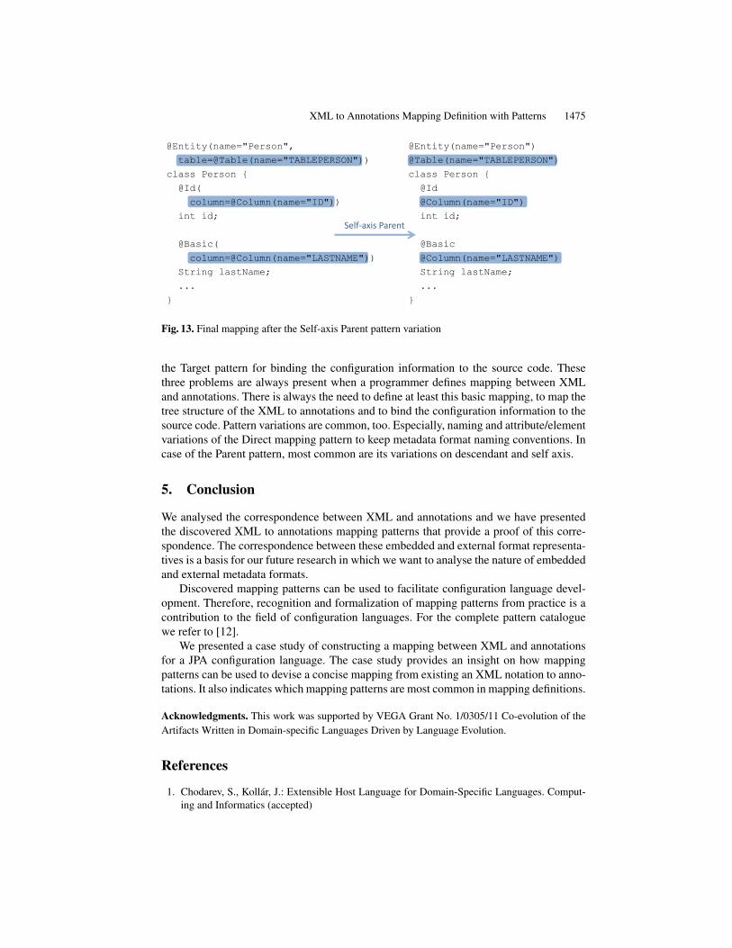
We can make this notation even shorter and more concise by using the Parent patternon the self-axis. For example, considering the @Id and the @Column annotations if the@Column was a child on the self-axis the notation would become shorter by removingthe need of using the parameter assigment "column=". This makes the notation shorterand does not impair comprehension since the information that the field id is a column isnot bound to the information that it is an identifier. An id field is an identifier and it is acolumn (not an identifier and therefore a column). Therefore, the @Id and the @Columnmay be both used as two distinct annotations. The same can be done with the @Entityand the @Table annotations and with the @Basic and the @Column annotations. Afterapplying the Self-axis Parent pattern variation the mapping will look like in Figure 13.
The reader can notice that now the notation is shorter but still readable and com-prehensible. This notation is a valid JPA configuration. It differs from the example fromSection 4 because there were no @Basic annotations. There the authors of the JPA spec-ification used the default value technique. By default every column attribute of an entityclass is considered to be basic if not specified otherwise. @Basic annotations are optionalunless some of their attributes differs from default (then they need be stated explicitly).
4.3. Summary
The case study indicates which of the mapping patterns are most common. We have used5 of the total 8 patterns. The most important are the Direct Mapping pattern for basicmapping, the Nested Annotations and Parent patterns for tree-like structure mapping and
XML to Annotations Mapping Definition with Patterns 1475
@Entity(name="Person",
table=@Table(name="TABLEPERSON"))
class Person {
@Id(
column=@Column(name="ID"))
int id;
@Basic(
column=@Column(name="LASTNAME"))
String lastName;
...
}
@Entity(name="Person")
@Table(name="TABLEPERSON")
class Person {
@Id
@Column(name="ID")
int id;
@Basic
@Column(name="LASTNAME")
String lastName;
...
}
Self-axis Parent
Fig. 13. Final mapping after the Self-axis Parent pattern variation
the Target pattern for binding the configuration information to the source code. Thesethree problems are always present when a programmer defines mapping between XMLand annotations. There is always the need to define at least this basic mapping, to map thetree structure of the XML to annotations and to bind the configuration information to thesource code. Pattern variations are common, too. Especially, naming and attribute/elementvariations of the Direct mapping pattern to keep metadata format naming conventions. Incase of the Parent pattern, most common are its variations on descendant and self axis.
5. Conclusion
We analysed the correspondence between XML and annotations and we have presentedthe discovered XML to annotations mapping patterns that provide a proof of this corre-spondence. The correspondence between these embedded and external format representa-tives is a basis for our future research in which we want to analyse the nature of embeddedand external metadata formats.
Discovered mapping patterns can be used to facilitate configuration language devel-opment. Therefore, recognition and formalization of mapping patterns from practice is acontribution to the field of configuration languages. For the complete pattern cataloguewe refer to [12].
We presented a case study of constructing a mapping between XML and annotationsfor a JPA configuration language. The case study provides an insight on how mappingpatterns can be used to devise a concise mapping from existing an XML notation to anno-tations. It also indicates which mapping patterns are most common in mapping definitions.
Acknowledgments. This work was supported by VEGA Grant No. 1/0305/11 Co-evolution of theArtifacts Written in Domain-specific Languages Driven by Language Evolution.
References
1. Chodarev, S., Kollár, J.: Extensible Host Language for Domain-Specific Languages. Comput-ing and Informatics (accepted)

1476 Milan Nosál’ and Jaroslav Porubän
2. Correia, D.A.A., Guerra, E.M., Silveira, F.F., Fernandes, C.T.: Quality Improvement in Anno-tated Code. CLEI Electron. J. 13(2) (2010)
3. Demirkol, S., Challenger, M., Getir, S., Kosar, T., Kardas, G., Mernik, M.: A DSL for theDevelopment of Software Agents working within a Semantic Web Environment. ComputerScience and Information Systems 10(4), 1525–1556 (2013)
4. Duval, E., Hodgins, W., Sutton, S.A., Weibel, S.: Metadata Principles and Practicalities. D-LibMagazine 8(4) (2002)
5. Fernandes, C., Ribeiro, D., Guerra, E., Nakao, E.: XML, Annotations and Database: a Compar-ative Study of Metadata Definition Strategies for Frameworks. In: Proceedings of XATA 2010:XML, Associated Technologies and Applications. pp. 115–126. XATA 2010 (2010)
6. Guerra, E., Cardoso, M., Silva, J., Fernandes, C.: Idioms for Code Annotations in the JavaLanguage. In: Proceedings of the 17th Latin-American Conference on Pattern Languages ofPrograms. pp. 1–14. SugarLoafPLoP (2010)
7. Guerra, E., Fernandes, C., Silveira, F.F.: Architectural Patterns for Metadata-based FrameworksUsage. In: Proceedings of the 17th Conference on Pattern Languages of Programs. pp. 1–14.PLoP2010 (2010)
8. Kollár, J.: From XSL Transformation to Automated Software Evolution. Journal of ComputerScience and Control Systems 6(1), 52–57 (2013)
9. Lämmel, R., Meijer, E.: Revealing the X/O impedance mismatch: changing lead into gold.In: Proceedings of the 2006 international conference on Datatype-generic programming. pp.285–367. SSDGP’06, Springer-Verlag, Berlin, Heidelberg (2007)
10. Noguera, C., Pawlak, R.: AVal: an extensible attribute-oriented programming validator for Java:Research Articles. J. Softw. Maint. Evol. 19(4), 253–275 (Jul 2007)
11. Nosál’, M., Porubän, J.: Supporting multiple configuration sources using abstraction. CentralEuropean Journal of Computer Science 2(3), 283–299 (Oct 2012)
12. Nosál’, M., Porubän, J.: XML to Annotations Mapping Patterns. In: Leal, J.P., Rocha, R.,Simões, A. (eds.) 2nd Symposium on Languages, Applications and Technologies. OpenAccessSeries in Informatics (OASIcs), vol. 29, pp. 97–113 (2013)
13. Pawlak, R.: Spoon: Compile-time Annotation Processing for Middleware. IEEE DistributedSystems Online 7(11), 1– (Nov 2006)
14. Porubän, J., Nosál, M.: Leveraging Program Comprehension with Concern-oriented SourceCode Projections. In: Pereira, M.J.V., Leal, J.P., Simões, A. (eds.) 3rd Symposium on Lan-guages, Applications and Technologies. OpenAccess Series in Informatics (OASIcs), vol. 38,pp. 35–50 (2014)
15. Rouvoy, R., Merle, P.: Leveraging Component-Oriented Programming with Attribute-OrientedProgramming. In: Proceedings of the 11th International ECOOP Workshop on Component-Oriented Programming. WCOP’06, Karlsruhe University (Jul 2006)
16. Song, M., Tilevich, E.: Metadata invariants: checking and inferring metadata coding conven-tions. In: Proceedings of the 2012 International Conference on Software Engineering. pp. 694–704. ICSE 2012, IEEE Press, Piscataway, NJ, USA (2012)
17. Tansey, W., Tilevich, E.: Annotation refactoring: inferring upgrade transformations for legacyapplications. SIGPLAN Not. 43(10), 295–312 (Oct 2008)
18. Tilevich, E., Song, M.: Reusable enterprise metadata with pattern-based structural expressions.In: Proceedings of the 9th International Conference on Aspect-Oriented Software Develop-ment. pp. 25–36. AOSD ’10, ACM, New York, NY, USA (2010)
19. Wada, H., Takada, S.: Leveraging Metamodeling and Attribute-Oriented Programming to Builda Model-driven Framework for Domain Specific Languages. In: Proc. of the 8th JSSST Con-ference on Systems Programming and its Applications (2005)
Milan Nosál’ is a PhD. student at the Department of Computers and Informatics, Tech-nical University of Košice, Slovakia. He received his MSc. in Informatics in 2011 for his

XML to Annotations Mapping Definition with Patterns 1477
work in the field of configuration formats and attribute-oriented programming. Currentlyhis research focuses on attribute-oriented programming, metaprogramming, domain-specificlanguages and projectional programming.
Jaroslav Porubän is Associate professor and the Head of Department of Computers andInformatics, Technical university of Košice, Slovakia. He received his MSc. in ComputerScience in 2000 and his PhD. in Computer Science in 2004. Since 2003 he is the memberof the Department of Computers and Informatics at Technical University of Košice. Cur-rently the main subject of his research is the computer language engineering concentratingon design and implementation of domain specific languages and computer language com-position and evolution.
Received: September 20, 2013; Accepted: June 7, 2014.