xm power supply solutions - rockwell...
TRANSCRIPT

XM Power Supply Solutions
Patrick Carle
The power requirements for an XM® system can vary significantly based on application. In addition to power (amps), other issues such as temperature range, hold-up time, and over-current protection, as well as system considerations such as redundant power, API-670 compliance, or use in hazardous areas, must be considered. It is therefore critical that when planning a system that an appropriate power solution be defined. This document is intended to aid in the proper design a selection of power solutions for XM systems that satisfy these requirements.
Regarding power, an overriding rule must be followed:
All connections to an XM System must be powered from a source compliant with the following:
This means that the same power source must power any device(s) to which the module is connected via its side connector(1) or any of its non-isolated circuits which include: Power, DeviceNet(2), 4-20mA Outputs and the Set Point Multiplier circuit(3).
This requirement is necessary to ensure that the XM system satisfies the conditions of its CSA approval, and that it meets the requirements of the Low Voltage Directive. Satisfying CSA and the LVD requirements are also a prerequisite to the UL/CSA and ATEX hazardous area certifications.
1 Power transmission across the XM module side connector is limited to 3A.
2 The DeviceNet circuit of the XM-124 Standard Dynamic Measurement module (1440-SDM02-01RA) is fully isolated. This means that for systems that include
ONLY XM-124s, that an independent DeviceNet power supply may be used, and that other independently powered DeviceNet devices may be connected to the
XM-124.
3 These circuits are all functionally isolated, but do not have adequate insulation to satisfy the isolation requirements of some electrical safety standards. Therefore
the ground requirements for the circuits, specified in the individual user’s manuals, must still be applied.
A Listed Class 2 power supply, or a Listed ITE Safety Extra Low Voltage (SELV) power supply with fuse kit 1440-5AFUSEKIT (specified later in this document), or a Protected Extra Low Voltage (PELV) power supply certified to 60950 with fuse kit 1440-5AFUSEKIT.
2 | XM Power Solutions
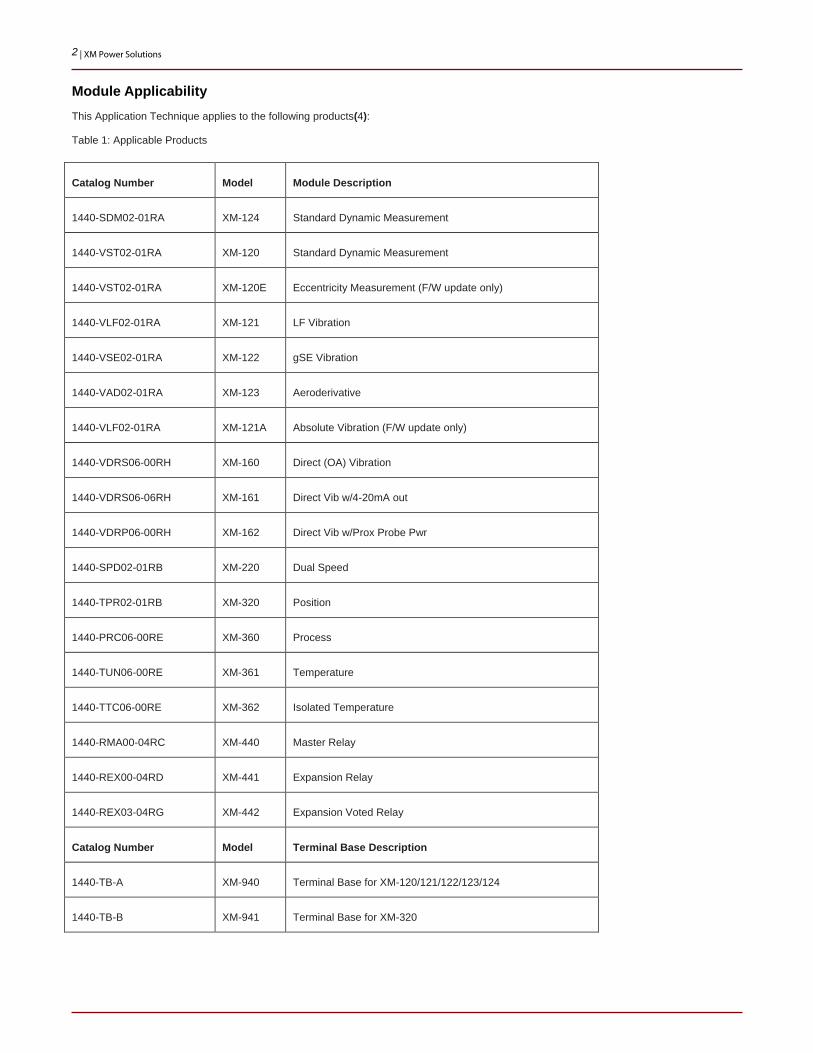
Module Applicability This Application Technique applies to the following products(4):
Table 1: Applicable Products
Catalog Number Model Module Description
1440-SDM02-01RA XM-124 Standard Dynamic Measurement
1440-VST02-01RA XM-120 Standard Dynamic Measurement
1440-VST02-01RA XM-120E Eccentricity Measurement (F/W update only)
1440-VLF02-01RA XM-121 LF Vibration
1440-VSE02-01RA XM-122 gSE Vibration
1440-VAD02-01RA XM-123 Aeroderivative
1440-VLF02-01RA XM-121A Absolute Vibration (F/W update only)
1440-VDRS06-00RH XM-160 Direct (OA) Vibration
1440-VDRS06-06RH XM-161 Direct Vib w/4-20mA out
1440-VDRP06-00RH XM-162 Direct Vib w/Prox Probe Pwr
1440-SPD02-01RB XM-220 Dual Speed
1440-TPR02-01RB XM-320 Position
1440-PRC06-00RE XM-360 Process
1440-TUN06-00RE XM-361 Temperature
1440-TTC06-00RE XM-362 Isolated Temperature
1440-RMA00-04RC XM-440 Master Relay
1440-REX00-04RD XM-441 Expansion Relay
1440-REX03-04RG XM-442 Expansion Voted Relay
Catalog Number Model Terminal Base Description
1440-TB-A XM-940 Terminal Base for XM-120/121/122/123/124
1440-TB-B XM-941 Terminal Base for XM-320

3 | XM Power Solutions
Catalog Number Model Module Description
1440-TB-C XM-942 Terminal Base for XM-440
1440-TB-D XM-943 Terminal Base for XM-441
1440-TB-E XM-944 Terminal Base for XM-360/361/362
1440-TB-G XM-946 Terminal Base for XM-442
1440-TB-H XM-947 Terminal Base for XM-160/161/162
4 This Application Technique supplements the installation requirements and instructions provided in the Installation Guide and User Manuals for the products
listed in table 1.
4 | XM Power Solutions
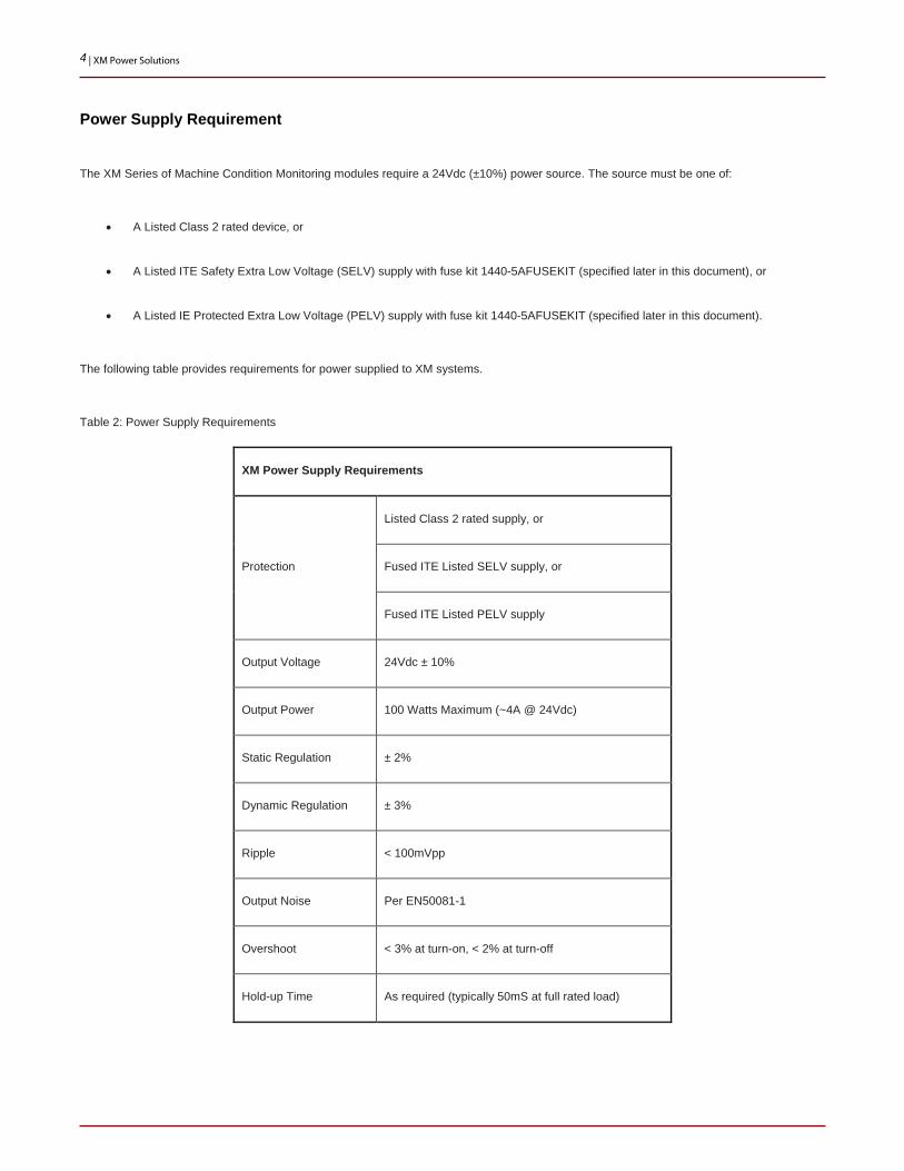
Power Supply Requirement
The XM Series of Machine Condition Monitoring modules require a 24Vdc (±10%) power source. The source must be one of:
• A Listed Class 2 rated device, or
• A Listed ITE Safety Extra Low Voltage (SELV) supply with fuse kit 1440-5AFUSEKIT (specified later in this document), or
• A Listed IE Protected Extra Low Voltage (PELV) supply with fuse kit 1440-5AFUSEKIT (specified later in this document).
The following table provides requirements for power supplied to XM systems.
Table 2: Power Supply Requirements
XM Power Supply Requirements
Protection
Listed Class 2 rated supply, or
Fused ITE Listed SELV supply, or
Fused ITE Listed PELV supply
Output Voltage 24Vdc ± 10%
Output Power 100 Watts Maximum (~4A @ 24Vdc)
Static Regulation ± 2%
Dynamic Regulation ± 3%
Ripple < 100mVpp
Output Noise Per EN50081-1
Overshoot < 3% at turn-on, < 2% at turn-off
Hold-up Time As required (typically 50mS at full rated load)

5 | XM Power Solutions
Powering XM
The XM system must be powered by a single limited power source.
Figure 1: XM System Power Source
While it is possible for this source to be supplied by a customer’s instrument power or other source, in most cases it will be provided by specific AC/DC Power Supplies or DC/DC Converters as described in the following.
6 | XM Power Solutions
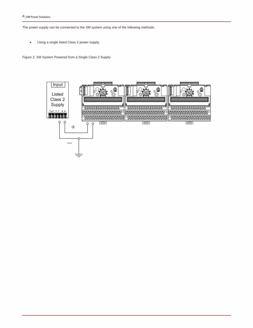
The power supply can be connected to the XM system using one of the following methods:
• Using a single listed Class 2 power supply.
Figure 2: XM System Powered from a Single Class 2 Supply

7 | XM Power Solutions
• Using a listed SELV or PELV with the 5A current limiting fuse specified later in this document.
Figure 3: XM System Powered from a Fused SELV Supply

8 | XM Power Solutions
Powering an XM System
Regardless of how power is provided, the “system” must be inclusive of all non-isolated devices, such that only this single power source is used (Figure 4). This means that all non-isolated devices connected to the system’s DeviceNet(5), 4-20mA, SPM, or power circuits must be powered by this same source.
5 The DeviceNet connection of the XM-124 module is fully isolated. Therefore, when connected to an XM-124, an independently powered DeviceNet network is
allowed (Figure 6).
Figure 4: Powering DeviceNet in a Legacy XM System (1)
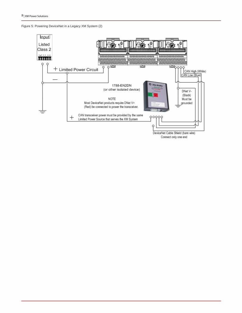
Allen-Bradley products such as the 1788-EN2DN, 1756-DNB, and PanelView products include isolated DeviceNet circuits and therefore can be used with an XM system, even if the device is powered by another source.
However, the CAN transceiver for these devices, which is powered from the devices’ DeviceNet V+ connection, must be powered from the same limited power source as the XM system, except when the XM System is comprised of XM-124 modules only (Page 10).
9 | XM Power Solutions
Figure 5: Powering DeviceNet in a Legacy XM System (2)
10 | XM Power Solutions
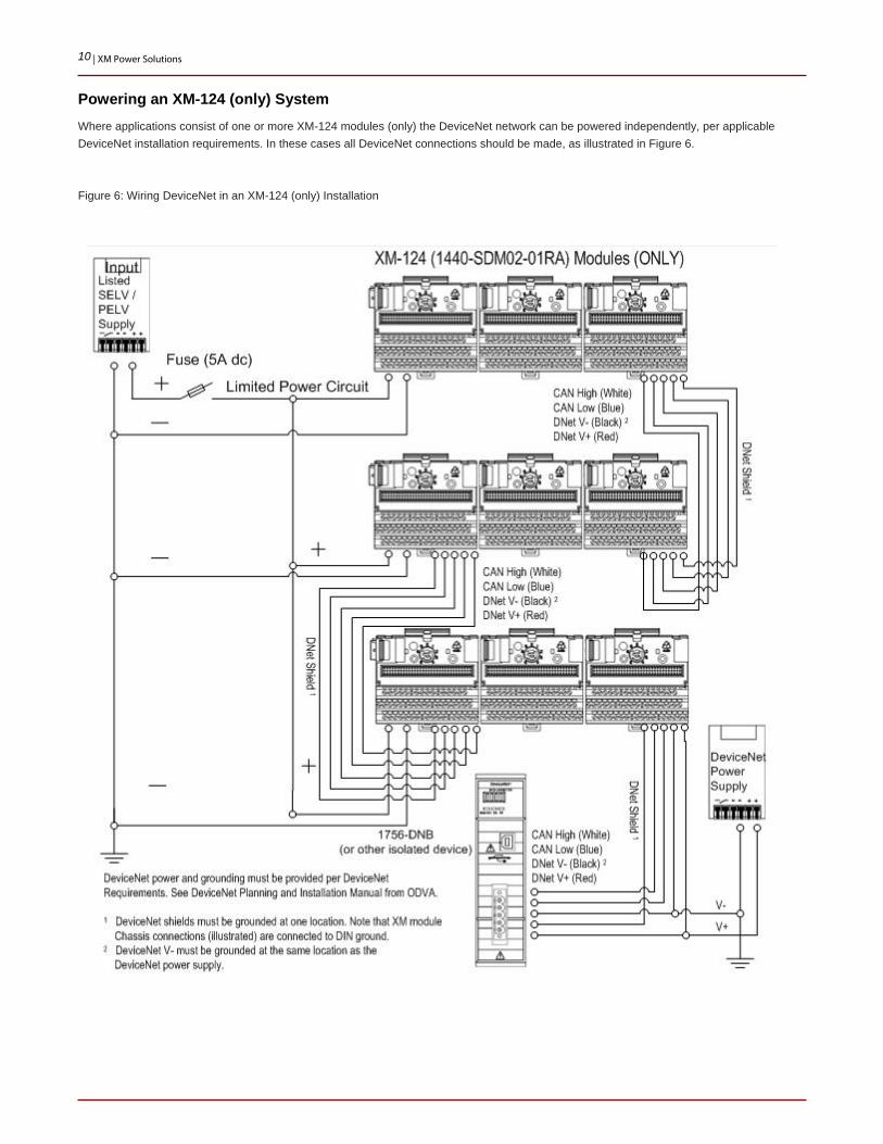
Powering an XM-124 (only) System Where applications consist of one or more XM-124 modules (only) the DeviceNet network can be powered independently, per applicable DeviceNet installation requirements. In these cases all DeviceNet connections should be made, as illustrated in Figure 6.
Figure 6: Wiring DeviceNet in an XM-124 (only) Installation

11 | XM Power Solutions
Powering Multiple XM Systems
Where applications require multiple XM systems that include legacy XM modules (if XM-124s only, see Figure 8) a single high-capacity power source can be used (Figure 7). However, the power supply must still satisfy the requirements stated above; each system must be independently protected by its own fuse. The systems cannot be connected in any way.
Figure 7: Powering Multiple Legacy XM Systems

12 | XM Power Solutions
Powering Multiple XM-124 (only) Systems Where applications require multiple XM systems a single high capacity power source can be used (Figure 7). However, the power supply must still satisfy the requirements stated above. Note though that if the systems are comprised exclusively of XM-124 modules, then the DeviceNet network can be powered independently, and can connect to both systems (Figure 8).
Figure 8: Powering Multiple XM-124 (only) Systems

13 | XM Power Solutions
Grounding Requirement
Although the above illustrations indicate multiple different ground connections, all grounds in the system must be tied to the same point of the same grounding electrode system(6).
The key requirement is that in no case should the grounds be at different potentials relative to the power source.
The grounding electrode system is a method by which the neutral and grounding conductors are connected to the common "earth" reference. Requirements of these are specified by NEC and other standards organizations.
6 If the system is comprised of XM-124 modules (only) then DeviceNet power may be provided independently, in which case DeviceNet V- will be tied to ground
at the same location as DeviceNet power.
Solutions for Redundant Power
Many applications require redundant power be provided to assure higher system availability. There are two methods available for implementing a redundant power solution.

14 | XM Power Solutions
Redundant / Decoupler Module
The preferred method of providing redundancy is to install a Redundant/Decoupler module after the power supplies (Figure 9). Rockwell Automation offers several redundancy modules including the 1606-XLRED20-30, 1606-XLRED40, 1606-XLSRED, 1606-XLPRED and 1606-XLERED. These decoupling and redundancy modules can be used to configure highly reliable and true redundant power supply systems.
Figure 9: Redundant Power using a Redundancy Module
Recommendations for building redundant power systems:
• Use separate input fuses for each power supply.
• Monitor the individual power supply units to report a faulty unit. Depending on the specific power supplies and redundancy modules used, DC-ok lamps and DC-ok contacts will be included in either the power supplies or the redundancy module.
• When possible, connect each power supply to different phases or circuits.

15 | XM Power Solutions
Parallel Supplies
The simplest way to achieve redundancy is to wire two power supplies(7) in parallel (Figure 10). In the event one power supply fails, the other one automatically assumes the load current without any interruption.
Figure 10: Redundant Power using Parallel Supplies
Only supplies designed and listed specifically for redundant operation are allowed for use in an XM system.
7 Not all power supplies can be operated in parallel. Consult the specific power supply technical data and installation guides before wiring any supplies in parallel.
16 | XM Power Solutions
Paralleling Redundant Power Supplies
Rockwell Automation offers three supplies that are specifically designed for parallel redundant application(8). Using these supplies avoids the disadvantages of simply paralleling common power supplies.
The 1606-XL60DR, XL120DR and XL240DR are enhanced versions of the standard power supplies designed specifically for parallel use. Each device has internal diodes which provide isolation against DC bus problems corrupting working supplies. These devices provide "DC OK" output relay to allow remote monitoring of DC power status. When redundancy is required, and the capabilities of the 1606-XL60/120/240DR supplies can serve the requirement, then these are recommended for use with XM.
8 Rockwell Automation offers other supplies that are capable of redundant use but are not designed specifically for redundant applications (below).
Paralleling Redundant Capable Power Supplies
Besides the DR modules above, all 1606 XLS series supplies allow parallel operation while providing a DC-ok Relay Contact and LED that are independent of a return voltage from a parallel supply. Other supplies, such as the 1606-XLP100E, also protect the DC-ok LED and/or relay from being powered by a paralleled supply.
However, many supplies, such as the XLE series, do not support redundant operation and/or do not protect the supplies’ DC-okay indication from reverse power. Only supplies that have an independent output voltage monitor, such as the 1606 XLS series, are recommended for use with an XM system.

17 | XM Power Solutions
Figure 11: Power Supply Independent Power Monitor Circuit
Faulted Redundant Supply Indication
In many (most) redundant power applications, an additional requirement exists which specifies that indication of a faulted supply be provided. In some cases “indication” can be served by a simple LED, while other cases require that a relay be provided. What is available depends on which series of power supply are used, and what redundancy solution is applied. Not all supplies in every series have identical capabilities. Users should always consult the power supply selection guide and power supply technical literature to insure that any specific supply includes the features required.
1606-XLERED Redundant/Decoupler Module
The redundancy module 1606-XLERED has monitoring circuitry included. Two LEDs and two relay contacts signal when one of the two DC-input voltages is not in range due to a non-functioning or disconnected power supply.

18 | XM Power Solutions
Figure 12: 1606-XLERED Functional Diagram

19 | XM Power Solutions
1606-XLS Series Supplies
Each supply in the XLS series is equipped with a DC-OK LED and relay.
Figure 13: XLS Series Functional Diagram

20 | XM Power Solutions
1606-XLP Series Supplies
Each supply in the XLP series is equipped with a DC-OK LED indication (but no relay).
Figure 14: XLP Series Functional Diagram
1606-XL Series Redundant Supplies
The 1606-XL60DR, XL120DR, and XL240DR include a "DC OK" output relay to allow remote monitoring of DC power status.
Hazardous Area Solutions
When the XM system must be installed in a hazardous area any power supplies or converters used must be rated appropriately for the area. Additionally, the 1440-5AFUSEKIT fuse kit must be used with any supply other than a listed Class 2 supply.
21 | XM Power Solutions
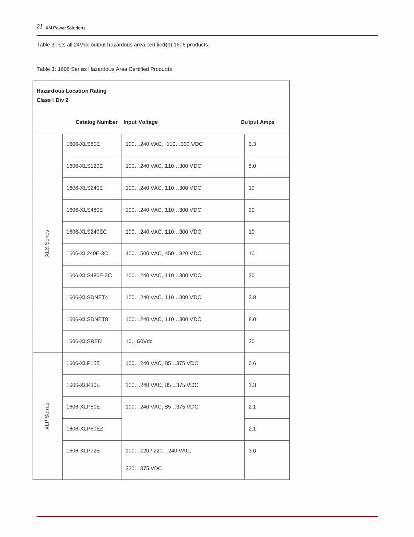
Table 3 lists all 24Vdc output hazardous area certified(9) 1606 products.
Table 3: 1606 Series Hazardous Area Certified Products
Hazardous Location Rating Class I Div 2
Catalog Number Input Voltage Output Amps
XLS
Ser
ies
1606-XLS80E 100…240 VAC, 110…300 VDC 3.3
1606-XLS120E 100…240 VAC, 110…300 VDC 5.0
1606-XLS240E 100…240 VAC, 110…300 VDC 10
1606-XLS480E 100…240 VAC, 110…300 VDC 20
1606-XLS240EC 100…240 VAC, 110…300 VDC 10
1606-XL240E-3C 400…500 VAC, 450…820 VDC 10
1606-XLS480E-3C 100…240 VAC, 110…300 VDC 20
1606-XLSDNET4 100…240 VAC, 110…300 VDC 3.8
1606-XLSDNET8 100…240 VAC, 110…300 VDC 8.0
1606-XLSRED 10…60Vdc 20
XLP
Ser
ies
1606-XLP15E 100…240 VAC, 85…375 VDC 0.6
1606-XLP30E 100…240 VAC, 85…375 VDC 1.3
1606-XLP50E 100…240 VAC, 85…375 VDC 2.1
1606-XLP50EZ 2.1
1606-XLP72E 100…120 / 220…240 VAC,
220…375 VDC
3.0

22 | XM Power Solutions
Catalog Number Input Voltage Output Amps
1606-XLP95E 100…120/ 220…240 VAC,
220…375 VDC
3.9
1606-XLP100E 4.2
1606-XLPRED 10…60Vdc 10
XL
1606-XLDC92D 14…32.4VDC 4.0
1606-XL240E 100…240 VAC,
240…375 VDC
10
1606-XL240EP 10
9 The only ATEX EX certified 1606 product is the 1606-XLDC92D DC/DC converter.

23 | XM Power Solutions
API-670 Solutions
Requirements
The American Petroleum Institutes Standard 670, Fourth Edition, December 2000, specifies power requirements in its section 5.4.1.7. Table 4 illustrates that section with comments as to how each paragraph may be addressed in an XM system.
Note that in the 1606 family of power supplies only a limited number of XLP and XLS series supplies fully satisfy the requirements of section 5.4.1.7.
Table 4: API-670 Power Requirements
Power Supplies Comments
The monitor system components shall be capable of meeting the
accuracy requirements specified in Table 1 with input voltage to
the power supply of 90 to 132 volts AC rms or 180 to 264 volts
AC rms, switch selectable, with a line frequency of 50-60 hertz.
When specified, the following power supply options may be used:
• 19 to 32 volts DC
• 14 to 70 volts DC
• 90 to 140 volts DC
In most cases the offered XM System will include AC/DC
power supplies that will satisfy this requirement. In cases
where the client requires the system be connected to DC
sources, such as instrument power, DC to DC converters,
such as the 1606-XLDC92DC are available.
The monitor system power supply(ies) shall be capable of
supplying power to all components of the machinery protection
system as defined in 3.38.
Note: Non-integral displays are excepted from this requirement
and may be powered by external supplies.
If the power required for the system exceeds 4 amps then the
system must be split into multiple segments as necessary to
satisfy the power requirements as stated in this document.
The output voltage to all oscillator-demodulators shall be –24
volts DC with sufficient regulation and ripple suppression to meet
the accuracy requirements specified in Table 1.
XM modules are fully capable of satisfying this requirement.
All power supplies shall be capable of sustaining a short circuit of
indefinite duration across their outputs without damage. Output
voltages shall return to normal when an overload or short circuit is
removed.
1606-XLP and 1606-XLS series supplies satisfy this
requirement.
The transducer power source shall be designed to prevent a fault
condition in one transducer circuit from affecting any other
channel.
XM modules are fully capable of satisfying this requirement.
24 | XM Power Solutions
Power Supplies Comments
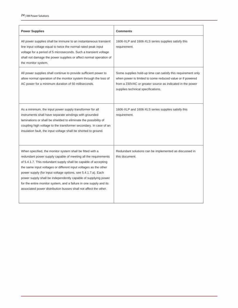
All power supplies shall be immune to an instantaneous transient
line input voltage equal to twice the normal rated peak input
voltage for a period of 5 microseconds. Such a transient voltage
shall not damage the power supplies or affect normal operation of
the monitor system.
1606-XLP and 1606-XLS series supplies satisfy this
requirement.
All power supplies shall continue to provide sufficient power to
allow normal operation of the monitor system through the loss of
AC power for a minimum duration of 50 milliseconds.
Some supplies hold-up time can satisfy this requirement only
when power is limited to some reduced value or if powered
from a 230VAC or greater source as indicated in the power
supplies technical specifications.
As a minimum, the input power supply transformer for all
instruments shall have separate windings with grounded
laminations or shall be shielded to eliminate the possibility of
coupling high voltage to the transformer secondary. In case of an
insulation fault, the input voltage shall be shorted to ground.
1606-XLP and 1606-XLS series supplies satisfy this
requirement.
When specified, the monitor system shall be fitted with a
redundant power supply capable of meeting all the requirements
of 5.4.1.7. This redundant supply shall be capable of accepting
the same input voltages or different input voltages as the other
power supply (for input voltage options, see 5.4.1.7.a). Each
power supply shall be independently capable of supplying power
for the entire monitor system, and a failure in one supply and its
associated power distribution busses shall not affect the other.
Redundant solutions can be implemented as discussed in
this document.

25 | XM Power Solutions
Conformal Coating Requirement
API-670 section 5.4.1.3 paragraph g states the following.
In applications where the system will be installed in a benign environment the customer may agree to an exception to this requirement. However, if no exception is allowed, then the following conformal coated power supplies(10) are available in the 1606 series.
See “Selecting a Power Supply Solution” later in this document.
10 While the above conformal coated power supplies are available, there are no conformal coated redundancy modules. As API-670 also requires redundant power,
an exception to the conformal coating requirement will be required for both the power supplies and the redundancy module, or for just the redundancy module.
26 | XM Power Solutions
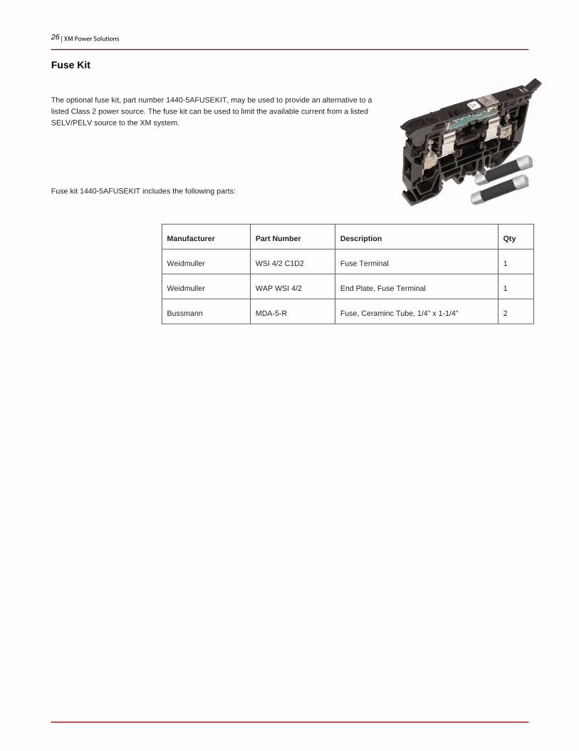
Fuse Kit
The optional fuse kit, part number 1440-5AFUSEKIT, may be used to provide an alternative to a listed Class 2 power source. The fuse kit can be used to limit the available current from a listed SELV/PELV source to the XM system.
Fuse kit 1440-5AFUSEKIT includes the following parts:
Manufacturer Part Number Description Qty
Weidmuller WSI 4/2 C1D2 Fuse Terminal 1
Weidmuller WAP WSI 4/2 End Plate, Fuse Terminal 1
Bussmann MDA-5-R Fuse, Ceraminc Tube, 1/4” x 1-1/4” 2

27 | XM Power Solutions
XM Module Power Requirements
The following table provides the maximum rated power requirement for each XM Series module. Use these values in calculating the total power requirement for an XM system. For the power requirements of non-XM devices such as a 1788-EN2DN, consult that product’s technical data.
Table 5: XM Module Power Requirements
Catalog Number Model Description Amps
Dynamic Measurement
1440-SDM02-01RA XM-124 Standard Dynamic 0.35
1440-VST02-01RA XM-120 Standard Dynamic 0.30
1440-VLF02-01RA XM-121 Low Frequency Dynamic 0.30
1440-VSE02-01RA XM-122 gSE Vibration 0.30
1440-VAD02-01RA XM-123 Aeroderivative 0.30
1440-VDRS06-00RH XM-160 Direct (OA) Vibration 0.40
1440-VDRS06-06RH XM-161 Direct (OA) Vibration w/4-20mA Outputs 0.40
1440-VDRP06-00RH XM-162 Direct (OA) Vibration /w Prox-Probe Power 0.40
Speed Measurement
1440-SPD02-01RB XM-220 Dual Speed 0.30
Process Measurement
1440-TPS02-01RB XM-320 Position 0.20
1440-TPR06-00RE XM-360 Process 0.25
1440-TUN06-00RE XM-361 Universal Temperature 0.25
1440-TTC06-00RE XM-362 Isolated TC Temperature 0.25
Relays
1440-RMA00-04RC XM-440 Master Relay 0.14
1440-REX00-04RD XM-441 Expansion Relay 0.12
1440-REX03-04RG XM-442 Voted EODS Relay 0.12
28 | XM Power Solutions
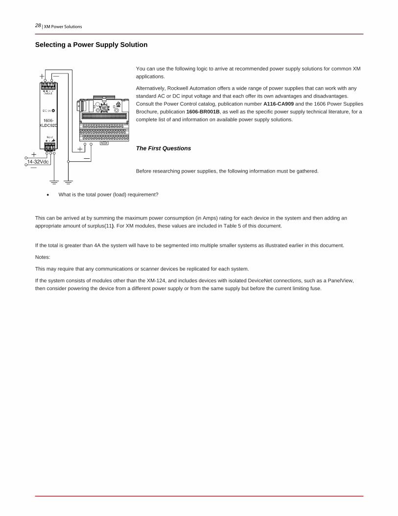
Selecting a Power Supply Solution
You can use the following logic to arrive at recommended power supply solutions for common XM applications.
Alternatively, Rockwell Automation offers a wide range of power supplies that can work with any standard AC or DC input voltage and that each offer its own advantages and disadvantages. Consult the Power Control catalog, publication number A116-CA909 and the 1606 Power Supplies Brochure, publication 1606-BR001B, as well as the specific power supply technical literature, for a complete list of and information on available power supply solutions.
The First Questions
Before researching power supplies, the following information must be gathered.
• What is the total power (load) requirement?
This can be arrived at by summing the maximum power consumption (in Amps) rating for each device in the system and then adding an appropriate amount of surplus(11). For XM modules, these values are included in Table 5 of this document.
If the total is greater than 4A the system will have to be segmented into multiple smaller systems as illustrated earlier in this document.
Notes:
This may require that any communications or scanner devices be replicated for each system.
If the system consists of modules other than the XM-124, and includes devices with isolated DeviceNet connections, such as a PanelView, then consider powering the device from a different power supply or from the same supply but before the current limiting fuse.

29 | XM Power Solutions
• Is the customer’s power supply AC or DC and what is the voltage?
If the customer’s supply is 24Vdc, then the solution will be the 1606-XLDC92D(12).
Figure 15: Selecting a Power Solution (1)
11 Typical surplus power calculations use multipliers of 1.3 to 1.5 (30% to 50%) over the sum of the component loads. This is to allow for some future growth of the
system, and to insure long life for the power supplies selected.
12 If the solution must satisfy API-670 then an exception may be required as the 1606-XLDC92D and 1606-XLERED are not conformal coated as required per
paragraph 5.4.1.3 g.

30 | XM Power Solutions
Hazardous Area Certification Not Required
The supply does not require hazardous location rating.
• Does the customer require that the system satisfy the requirements of API-670?
If so, then must the power supply be conformal coated per section 5.4.1.3 paragraph g?
• Must the power supply solution be redundant?
Figure 16: Selecting a Power Solution (2)

31 | XM Power Solutions
Hazardous Area Certification Required
The supply must be rated for use in a hazardous area (Class 1 Div 2).
• Does the customer require that the system satisfy the requirements of API-670?
• If so, then must the power supply be conformal coated per section 5.4.1.3 paragraph g?
• Must the power supply solution be redundant?

32 | XM Power Solutions
Figure 17: Selecting a Power Solution (3)

33 | XM Power Solutions
Best Practices
Once an appropriate power supply solution is defined, consideration should be given to the wiring solution. For a “Best Practices” installation the following recommendations should be considered:
• Breaker per Power Supply
Always place a DIN mounted breaker, such as the 1492-SP1D050 (5 Amp) breaker, in front of each power supply. Typically a single pole breaker that isolates only the hot side of the supply is adequate.
• System Breaker
If redundant power supplies are included, or if power is routed to other components in the cabinet before the 24Vdc power supply (and its breaker), then add a breaker that isolates the entire system. Typically an adequate solution can be provided by a single pole breaker such as the 1492-SP1D100 (10 Amp).
• Terminal Blocks
In almost any system terminal blocks such as the 1492-J4 should be used to simplify the wiring solution.

34 | XM Power Solutions
• Ground Blocks
XM modules make a chassis ground connection through the DIN rail. Therefore every DIN rail must be connected to ground using either a DIN grounding block, such as the 1492-JG4, or by connecting the ground wire directly to the DIN rail (Figure 18).
Figure 18: XM System DIN Rail Grounding
.
Publication ICM-AP005B-EN-P – May 2013 Copyright ©2013 Rockwell Automation, Inc. All Rights Reserved. Printed in USA