xilinx ise webpack vhdl tutorial - digilent inc
TRANSCRIPT
IEEE Transactions on VLSI Systems, 2002
1
Configuration Relocation and Defragmentation forRun-Time Reconfigurable Computing
Katherine Compton, Zhiyuan Li, James Cooley, Stephen KnolNorthwestern University
Evanston, IL [email protected]
Scott HauckUniversity of Washington
Seattle, WA [email protected]
AbstractDue to its potential to greatly accelerate a wide variety of applications, reconfigurable computing has become asubject of a great deal of research. By mapping the compute-intensive sections of an application to reconfigurablehardware, custom computing systems exhibit significant speedups over traditional microprocessors. However, thispotential acceleration is limited by the requirement that the speedups provided must outweigh the considerable costof reconfiguration. The ability to relocate and defragment configurations on an FPGA can dramatically decreasethe overall reconfiguration overhead incurred by the use of the reconfigurable hardware. We therefore presenthardware solutions to provide relocation and defragmentation support with a negligible area increase over ageneric partially reconfigurable FPGA, as well as software algorithms for controlling this hardware. This results infactors of 8 to 12 improvement in the configuration overheads displayed by traditional serially programmed FPGAs.
IntroductionReconfigurable computing allows designers to harness the power of hardware while still providing the flexibility of software.These systems use Field Programmable Gate Arrays (FPGAs) or similar hardware to accelerate algorithm execution bymapping compute-intensive calculations onto a reconfigurable substrate. These hardware resources are frequently coupledwith a general-purpose microprocessor that is responsible for controlling the reconfigurable logic and executing programcode that cannot be efficiently accelerated. The programmable hardware itself can be comprised of one or morecommercially available FPGAs, or can be a custom device designed specifically for reconfigurable computing[Compton00b].
Run-time reconfiguration (RTR) expands upon the idea of reconfigurability by providing the ability to change thereconfigurable hardware not only between applications, but also within a single application. Over the course of programexecution different configurations can be loaded into the FPGA to perform different hardware-optimized computations atdifferent points in time, essentially providing a method for virtual hardware. Using RTR, applications that may not have beenable to fit completely onto the fabric can be partitioned and executed on this virtual hardware. This potentially allows a largerpercentage of a program to be accelerated in hardware than could be accelerated without RTR, increasing the benefits of run-time reconfiguration [Wirthlin97]. However, the cost of reconfiguration can be quite high. In some situations, configurationoverhead can comprise over 98.5% of execution time [Smith99]. This amount of overhead has the potential to eclipse thebenefits gained through use of the reconfigurable hardware in RTR applications. Therefore, in order to reap the benefits ofRTR, it is essential to minimize configuration overheads.
The programming architecture of an FPGA can have a significant effect on the configuration overheads encountered in RTRapplications. One of the primary configuration architecture designs is the partially reconfigurable FPGA. This FPGA formpermits selective programmability of its resources in an addressable fashion. In this paper we show that this design has amuch lower configuration overhead for run-time reconfigurable applications than the traditional serially programmed single-context design that, with few exceptions, dominates the FPGA market. We also present two improvements to the partiallyreconfigurable structure to further reduce the overhead: relocation and defragmentation. The principle of relocation allowsthe final placement of a configuration within the FPGA to be determined at runtime, while defragmentation provides amethod to consolidate unused area within an FPGA during runtime without unloading useful configurations from the array.
We consider the possibility of adding these features to the Xilinx 6200 [Xilinx96], a commercial partially reconfigurableFPGA. However, as we show, this architecture is less than ideal for these two programming architecture modifications. Wetherefore have designed a new FPGA programming architecture that includes hardware support for both relocation and
2
defragmentation. Furthermore, we present software algorithms to control the configuration loading onto this new design.Using these algorithms, we compare the overheads incurred by the new designs to the overheads of the three most prevalentconfiguration architectures. The new programming architecture design has a considerably lower configuration overhead withonly a very minor increase in total chip area.
Basic Programming ArchitecturesBefore introducing new architecture variants, we must first consider existing systems. Traditional FPGA structures haveprimarily been serially programmed single-context devices, allowing only one configuration to be loaded at a time. This typeof FPGA is programmed using a serial stream of configuration information, requiring a full reconfiguration if any change isrequired. Designers of reconfigurable systems have found this style of configuration to be too limiting to efficientlyimplement run-time reconfigurable systems.
In some cases, configurations do not occupy the full reconfigurable hardware, or only a part of a configuration requiresmodification. In both of these situations a partial reconfiguration of the array is desired, rather than the full reconfigurationsupported by the serial device mentioned above. In a partially reconfigurable FPGA, the underlying programming layeroperates like a RAM device. Using addresses to specify the target location of the configuration data allows for selectivereconfiguration of the array. Frequently, the undisturbed portions of the array may continue execution, allowing the overlapof computation with reconfiguration. When configurations do not require the entire area available within the array, a numberof different configurations may be loaded into otherwise unused areas of the hardware. Partially run-time reconfigurablearchitectures can allow for complete reconfiguration flexibility such as the Xilinx 6200 [Xilinx96], or may require an fullcolumn of configuration information to be reconfigured at once, as in the Xilinx Virtex FPGA [Xilinx99].
In contrast, a multi-context FPGA includes multiple memory bits for each programming bit location. These memory bits canbe thought of as multiple planes of configuration information [DeHon96, Trimberger97]. Only one plane of configurationinformation can be active at a given moment, but the device can quickly switch between different planes, or contexts, ofalready-programmed configurations. In this manner, the multi-context device can be considered a multiplexed set of single-context devices, which requires that a context be fully reprogrammed to perform any modification to the configuration data.However, this requires a great deal more area than the other structures, given that there must be as many storage units perprogramming location as there are contexts.
Performance Comparison
As a baseline to our study, we quantify the impact of the three architectures on configuration overhead. In order to comparethe costs vs. benefits, we must compute the performance of each design given a fixed area. We have therefore created areamodels composed of small tileable structures that together form the major components of each architecture. These tileablestructures were created by hand using the Magic VLSI layout program, and their sizes in λ2 were used to calculate the totalprogramming architecture area. Because the area requirements of each programming model differ, the number ofprogramming bits which can fit within the fixed area vary with the architecture. A more complete discussion of the areamodels used appears elsewhere [Compton00a]. Once we have the area function quantified, we can set the area to a fixed sizeand compute the number of programming bits that will fit within that area for a given programming architecture. The serialdesign is based on a two-phase shift chain of programming bits, while the partial is formed of column and row decoders, withfive-transistor SRAM cells. The multi-context design is based on a previously published design [Trimberger97].
To measure performance, caching algorithms were designed to control when configurations should be swapped in and out ofthe array for each of the FPGA programming architectures, and lower bound algorithms were also developed [Li00].Together, these algorithms define a range of performance inside of which all realistic algorithms must fall. The configurationoverheads incurred by the different FPGA types given a fixed area resource were calculated by simulating 8 differentbenchmark programs, and calculating the mean overhead encountered. These benchmarks include several compiled for theGarp system [Hauser97], and a number created for the Chimaera System [Hauck97]. The base area for this comparison wascomputed to be slightly larger than the largest configuration in order to ensure that each configuration would fit within thearray. The effect as more resources are available was also measured.
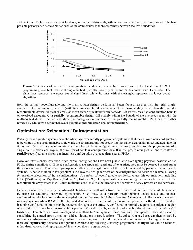
A normalized graph of configuration overheads vs. area is shown in Figure 1. The results using both the lower bound andreal-time algorithms are given. These boundaries give an idea of what performance is feasible with each of the configuration
3
architectures. Performance can be at least as good as the real-time algorithms, and no better than the lower bound. The bestpossible performance achievable for each of the architectures is then somewhere between the two boundaries.
0
0.2
0.4
0.6
0.8
1
1.2
1 1.25 1.5 1.75 2
Normalized Chip Area
Nor
mal
ized
Con
figur
atio
n O
verh
eads
SerialPartialMulti-4
Figure 1: A graph of normalized configuration overheads given a fixed area resource for the different FPGAprogramming architectures: serial single-context, partially reconfigurable, and multi-context with 4 contexts. Theplain lines represent the upper bound algorithms, while the lines with the triangles represent the lower boundalgorithms.
Both the partially reconfigurable and the multi-context designs perform far better for a given area than the serial single-context. The multi-context device (with four contexts for this comparison) performs slightly better than the partiallyreconfigurable device for smaller areas, as it can switch quickly between contexts. At larger areas, the configuration boundson overhead encountered in partially reconfigurable designs fall entirely within the bounds of the overheads seen with themulti-context device. As we will show, the configuration overhead of the partially reconfigurable FPGA can be furtherlowered by adding two further hardware optimizations: relocation and defragmentation.
Optimization: Relocation / DefragmentationPartially reconfigurable systems have the advantage over serially programmed systems in that they allow a new configurationto be written to the programmable logic while the configurations not occupying that same area remain intact and available forfuture use. Because these configurations will not have to be reconfigured onto the array, and because the programming of asingle configuration can require the transfer of far less configuration data than the programming of an entire context, apartially reconfigurable system can incur less configuration overhead than a serial FPGA.
However, inefficiencies can arise if two partial configurations have been placed onto overlapping physical locations on theFPGA during compilation. If these configurations are repeatedly used one after another, they must be swapped in and out ofthe array each time. This type of ping-pong conflict could negate much of the benefit achieved by partially reconfigurablesystems. A better solution to this problem is to allow the final placement of the configurations to occur at run-time, allowingfor run-time relocation of those configurations. A number of reconfigurable architectures use this optimization, includingDISC [Wirthlin95] and PipeRench [Cadambi98, Goldstein99]. Using relocation, a new configuration may be placed onto thereconfigurable array where it will cause minimum conflict with other needed configurations already present on the hardware.
Even with relocation, partially reconfigurable hardware can still suffer from some placement conflicts that could be avoidedby using an additional hardware optimization. Over time, as a partially reconfigurable device loads and unloadsconfigurations, the location of the unoccupied area on the array is likely to become fragmented, similar to what occurs inmemory systems when RAM is allocated and de-allocated. There could be enough empty area on the device to hold anincoming configuration, but it may be scattered throughout the array. A configuration normally requires a contiguous regionof the chip, so it may have to overwrite a portion of a valid configuration in order to be placed onto the reconfigurablehardware. Therefore we have investigated a method to "defragment" these scattered free spaces. This allows us toconsolidate the unused area by moving valid configurations to new locations. The collected unused area can then be used byincoming configurations, potentially without overwriting any of the defragmented configurations. Defragmentation cantherefore significantly decrease configuration overhead by allowing currently programmed configurations to be retained,rather than removed and reprogrammed later when they are again needed.
4
Modifying a Current ArchitectureIn order to determine the architectural requirements for relocation and defragmentation, we first examined the possibility ofconverting a commercial partially reconfigurable FPGA, the Xilinx 6200 [Xilinx96], to have these capabilities. This FPGAwas chosen primarily due to its partially reconfigurable nature, but also because the cell layout and local routing of thisFPGA are chiefly regular. Each cell has the same abilities, regardless of location. These cells are arranged in an island-stylelayout, with local routing in the form of nearest-neighbor connections.
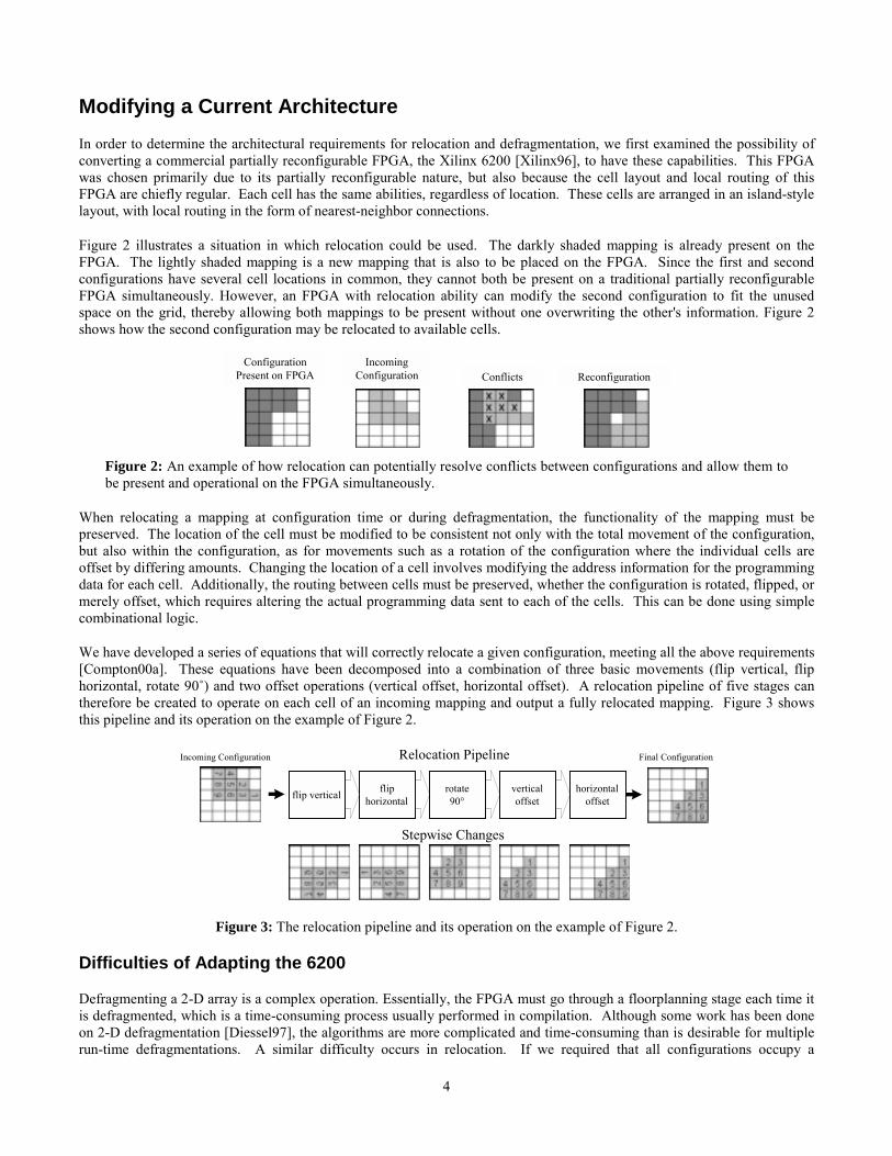
Figure 2 illustrates a situation in which relocation could be used. The darkly shaded mapping is already present on theFPGA. The lightly shaded mapping is a new mapping that is also to be placed on the FPGA. Since the first and secondconfigurations have several cell locations in common, they cannot both be present on a traditional partially reconfigurableFPGA simultaneously. However, an FPGA with relocation ability can modify the second configuration to fit the unusedspace on the grid, thereby allowing both mappings to be present without one overwriting the other's information. Figure 2shows how the second configuration may be relocated to available cells.
ConfigurationPresent on FPGA
IncomingConfiguration Conflicts Reconfiguration
Figure 2: An example of how relocation can potentially resolve conflicts between configurations and allow them tobe present and operational on the FPGA simultaneously.
When relocating a mapping at configuration time or during defragmentation, the functionality of the mapping must bepreserved. The location of the cell must be modified to be consistent not only with the total movement of the configuration,but also within the configuration, as for movements such as a rotation of the configuration where the individual cells areoffset by differing amounts. Changing the location of a cell involves modifying the address information for the programmingdata for each cell. Additionally, the routing between cells must be preserved, whether the configuration is rotated, flipped, ormerely offset, which requires altering the actual programming data sent to each of the cells. This can be done using simplecombinational logic.
We have developed a series of equations that will correctly relocate a given configuration, meeting all the above requirements[Compton00a]. These equations have been decomposed into a combination of three basic movements (flip vertical, fliphorizontal, rotate 90˚) and two offset operations (vertical offset, horizontal offset). A relocation pipeline of five stages cantherefore be created to operate on each cell of an incoming mapping and output a fully relocated mapping. Figure 3 showsthis pipeline and its operation on the example of Figure 2.
Relocation Pipeline
fliphorizontal
rotate90°
verticaloffset
horizontaloffsetflip vertical
Incoming Configuration Final Configuration
Stepwise Changes
Figure 3: The relocation pipeline and its operation on the example of Figure 2.
Difficulties of Adapting the 6200
Defragmenting a 2-D array is a complex operation. Essentially, the FPGA must go through a floorplanning stage each time itis defragmented, which is a time-consuming process usually performed in compilation. Although some work has been doneon 2-D defragmentation [Diessel97], the algorithms are more complicated and time-consuming than is desirable for multiplerun-time defragmentations. A similar difficulty occurs in relocation. If we required that all configurations occupy a
5
rectangular area, we could find free locations without a great deal of difficulty by keeping a list of free rectangles sorted bysize. However, odd-shaped configurations would make the search for available space an examination of the FPGA contentson a cell-by-cell basis, which would need to be performed each time a configuration required relocation.
Another consideration is that of I/O. At compile time, the placement and routing tools connect logic blocks to pins for inputand output. The pin locations must remain fixed despite relocation because of the board-level connections to the FPGA.Therefore, each time a configuration is moved, the connections between it and the I/O pins it uses need to be re-routed. Asrouting is an expensive step in the compilation process, it is unlikely that this could be effectively done at run-time.Alternately, we could use the concept of virtualized I/O, which is a bus-based input/output structure that provides a location-independent communication method (this concept is studied in more depth later). However, for two-dimensional virtualizedI/O, we would need to provide I/O access from every logic block to each pin in the FPGA, which is not practical given thelarge number of both pins and logic blocks.
A further limitation placed on relocation by the actual 6200 design is that we are not able to make arbitrary movements ofmappings. Although the 4-cell spanning routing (N4, E4, etc.) does add some distance routing capability to the 6200 array, itcan only be written to near the borders of a 4x4 grouping of cells. This severely limits where we can and cannot movemappings. If a mapping contains 4x4 routing, we are limited to horizontal and vertical movements in multiples of four topreserve this routing. A similar phenomenon occurs at the border of a 16x16 grouping of cells, and so on up to a finalgrouping that is the size of the entire chip.
Despite initial appearances, the partially reconfigurable 6200 is not well suited for relocation and defragmentation for thereasons that we have mentioned above. While partial reconfigurability is essential to the concept of relocation anddefragmentation, it does not suffice on its own. The next sections describe a number of other important ideas and how theywere used in the design of a new architecture created specifically to support run-time relocation and defragmentation.
New Relocation / Defragmentation ArchitectureWe propose a new architecture designed specifically to exploit the benefits of run-time relocation and defragmentation. Wewill refer to this architecture as the R/D (Relocation / Defragmentation) FPGA. First we examine the guidelines used for thedesign creation, and then we discuss the details of the actual architecture. Next we show a few examples of the operation ofthis new FPGA. We also examine a few possible extensions to the R/D architecture. Finally, we give performance resultscomparing the configuration overhead incurred by our new architecture to that encountered using the serial, partiallyreconfigurable, and multi-context FPGAs for a given area.
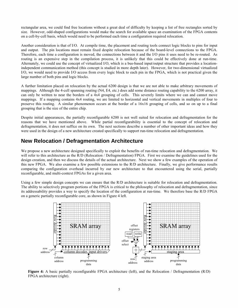
Using a few simple design concepts we can ensure that the R/D architecture is suitable for relocation and defragmentation.The ability to selectively program portions of the FPGA is critical to the philosophy of relocation and defragmentation, sinceits addressability provides a way to specify the location of the configuration at run-time. We therefore base the R/D FPGAon a generic partially reconfigurable core, as shown in Figure 4 left.
column decoder, input drivers
programmingdata
Row
decoder
rowaddress
SRAM array
columnaddress
staging area
programmingdata
Row
decoder
rowaddress
SRAM array
staging areaaddress
offsetselect
read write
offsetregisters
Figure 4: A basic partially reconfigurable FPGA architecture (left), and the Relocation / Defragmentation (R/D)FPGA architecture (right).
6
Another important idea is that of homogeneity. If each cell in the structure is identical, there are no functional obstacles tomoving a configuration from one location to any other location within the boundaries of the array. In the same manner,requiring the routing structure to be homogenous removes any placement limitations for routing reasons. This removes thedifficulty that the hierarchical routing structure presents in the 6200. Most commercial FPGAs, including the Xilinx 4000[Xilinx94] and Xilinx Virtex [Xilinx99], are homogeneous in structure, indicating that this is not an unreasonable constraint.Beyond requiring homogeneity, the actual logic blocks and routing structure of the FPGA are not inhibited, making thisprogramming structure quite flexible and able to support a wide variety of computational architectures.
The third concept is virtualized I/O. Using a bus-based input/output structure provides us with a location-independentmethod to read in and write out data from the individual configurations. Configurations are therefore not limited by I/Oconstraints to be placed near the FPGA pins and the I/O routing remains unchanged when the configuration is mapped to anew location. Several architectures already support this, including Chimaera [Hauck97], PipeRench [Cadambi98,Goldstein99], and Garp [Hauser97]. Alternately, virtualized I/O can be supported without the use of custom hardwareprovided that all mappings include bus structures such that adjacent mappings have connected busses [Hutchings97].
LogicCell
input lines output linesrow
outputenable
LogicCell
input lines output lines
rowoutputenable
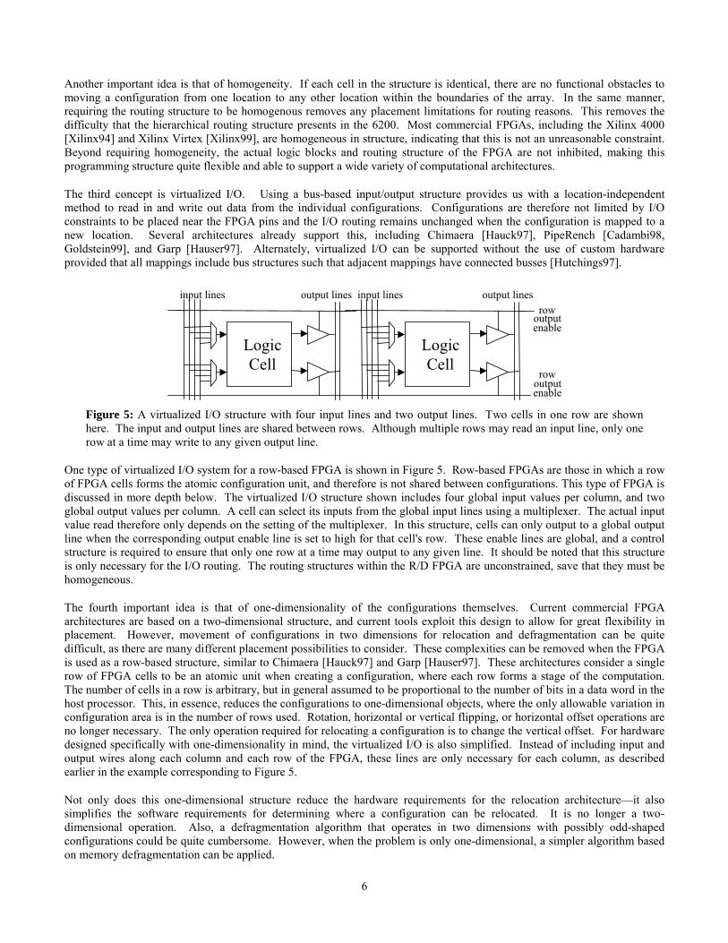
Figure 5: A virtualized I/O structure with four input lines and two output lines. Two cells in one row are shownhere. The input and output lines are shared between rows. Although multiple rows may read an input line, only onerow at a time may write to any given output line.
One type of virtualized I/O system for a row-based FPGA is shown in Figure 5. Row-based FPGAs are those in which a rowof FPGA cells forms the atomic configuration unit, and therefore is not shared between configurations. This type of FPGA isdiscussed in more depth below. The virtualized I/O structure shown includes four global input values per column, and twoglobal output values per column. A cell can select its inputs from the global input lines using a multiplexer. The actual inputvalue read therefore only depends on the setting of the multiplexer. In this structure, cells can only output to a global outputline when the corresponding output enable line is set to high for that cell's row. These enable lines are global, and a controlstructure is required to ensure that only one row at a time may output to any given line. It should be noted that this structureis only necessary for the I/O routing. The routing structures within the R/D FPGA are unconstrained, save that they must behomogeneous.
The fourth important idea is that of one-dimensionality of the configurations themselves. Current commercial FPGAarchitectures are based on a two-dimensional structure, and current tools exploit this design to allow for great flexibility inplacement. However, movement of configurations in two dimensions for relocation and defragmentation can be quitedifficult, as there are many different placement possibilities to consider. These complexities can be removed when the FPGAis used as a row-based structure, similar to Chimaera [Hauck97] and Garp [Hauser97]. These architectures consider a singlerow of FPGA cells to be an atomic unit when creating a configuration, where each row forms a stage of the computation.The number of cells in a row is arbitrary, but in general assumed to be proportional to the number of bits in a data word in thehost processor. This, in essence, reduces the configurations to one-dimensional objects, where the only allowable variation inconfiguration area is in the number of rows used. Rotation, horizontal or vertical flipping, or horizontal offset operations areno longer necessary. The only operation required for relocating a configuration is to change the vertical offset. For hardwaredesigned specifically with one-dimensionality in mind, the virtualized I/O is also simplified. Instead of including input andoutput wires along each column and each row of the FPGA, these lines are only necessary for each column, as describedearlier in the example corresponding to Figure 5.
Not only does this one-dimensional structure reduce the hardware requirements for the relocation architecture—it alsosimplifies the software requirements for determining where a configuration can be relocated. It is no longer a two-dimensional operation. Also, a defragmentation algorithm that operates in two dimensions with possibly odd-shapedconfigurations could be quite cumbersome. However, when the problem is only one-dimensional, a simpler algorithm basedon memory defragmentation can be applied.
7
Architecture Specifics of the R/D FPGA
We created the design for the R/D FPGA by using each of the guidelines of the previous section. This section describes themajor components of this new FPGA programming model. While this design is similar to the partially reconfigurable FPGAin a number of ways that we will discuss, it also has several additional architectural features.
Similar to the partially reconfigurable FPGA, the memory array of the R/D FPGA is composed of an array of SRAM bits.These bits are read/write enabled by the decoded row address for the programming data. However, the column decoder,multiplexer, and input tri-state drivers have been replaced with a structure we term the "staging area", as shown in Figure 4right.
This staging area is a small SRAM buffer—essentially a set of memory cells equal in number to one full row of programmingbits in the FPGA memory array. Note that a row of logic cells may contain several of these rows of configuration bits. Thestaging area is filled in an addressable fashion one word at a time. Once the information for the row is complete in the stagingarea, the entire staging area is written in a single operation to the FPGA's programming memory at the row location indicatedby the row address. In this manner the staging area acts as a small buffer between the master CPU and the reprogrammablelogic. This is similar in function to a structure proposed by Xilinx [Trimberger95] and present in their Virtex FPGA[Xilinx99].
In the staging area of the R/D FPGA, there is a small decoder that enables addressable writes/reads. This column decoderdetermines which of the words in the staging area is being referenced at a given moment. No row decoder is requiredbecause we construct the staging area such that although the staging area is several word-sized columns wide, there is onlyone row. An output tri-state driver is provided to allow the CPU to read individual word-sized columns from the stagingarea.
The chip row decoder includes a slight modification, namely the addition of two registers, a 2:1 multiplexer to choosebetween the two registers, and an adder, where these structures are all equal in width to the row address. This allows avertical offset loaded into one or more of the registers to be added to the incoming row address, resulting in the new relocatedrow address. One of the two offset registers is the "write" offset register, which holds the relocation offset used when writinga configuration. The other offset register is the "read" register, which is used during defragmentation for reading a relocatedconfiguration off of the array. The original row address supplied to the reconfiguration hardware is simply the row addressof that particular row within the configuration. Therefore, all configurations are initially “located” starting at address 0 at thetop of the array.
A basic partially reconfigurable FPGA requires a column decoder to determine which data word within a row should beaccessed for reading or writing. However, a column decoder between the staging area and the array is not necessary in theR/D design. The staging area is equal in width to the array, and therefore each bit of the staging area is sent out on exactlyone column. This provides for a high degree of parallelism when reading from the FPGA configuration memory to thestaging area or writing from the staging area to the FPGA memory, as a full row is read or written in a single operation.
Finally, as we have stated above, the specifics of the logic and routing structures are not dictated by the memory designbeyond requiring homogeneity. The particular design is unrestricted because the actual architectures do not influence thediscussion of the philosophy and operation of the configuration aspect of the R/D FPGA.
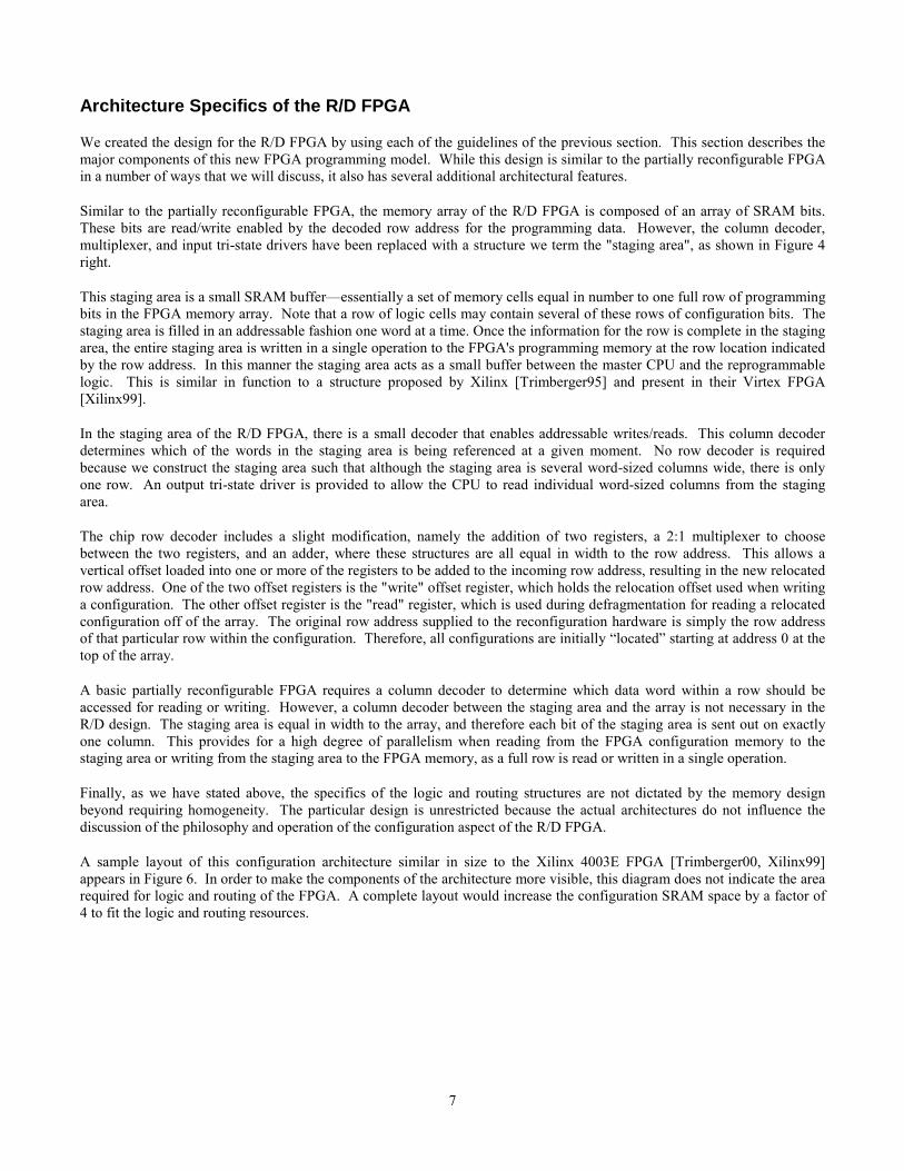
A sample layout of this configuration architecture similar in size to the Xilinx 4003E FPGA [Trimberger00, Xilinx99]appears in Figure 6. In order to make the components of the architecture more visible, this diagram does not indicate the arearequired for logic and routing of the FPGA. A complete layout would increase the configuration SRAM space by a factor of4 to fit the logic and routing resources.
8
Figure 6: A sample layout of the programming architecture of an R/D FPGA.
Example of R/D Operation
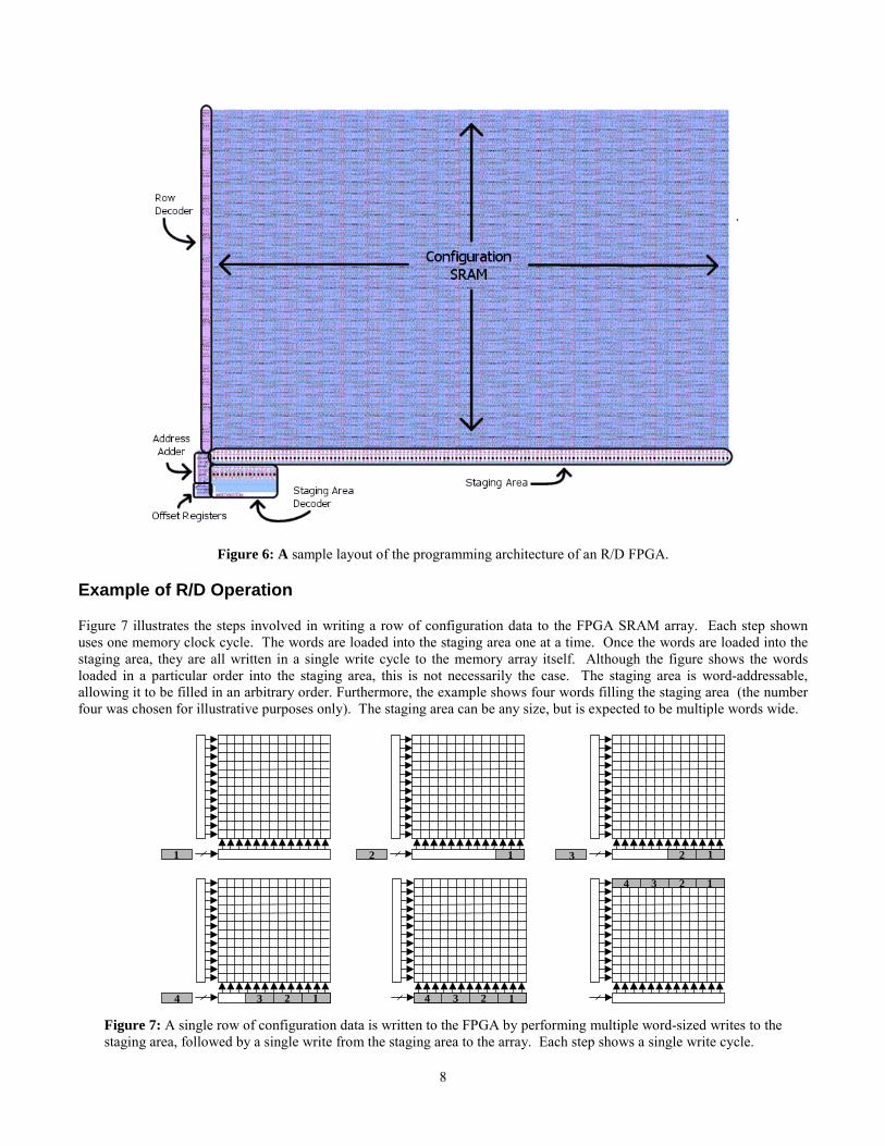
Figure 7 illustrates the steps involved in writing a row of configuration data to the FPGA SRAM array. Each step shownuses one memory clock cycle. The words are loaded into the staging area one at a time. Once the words are loaded into thestaging area, they are all written in a single write cycle to the memory array itself. Although the figure shows the wordsloaded in a particular order into the staging area, this is not necessarily the case. The staging area is word-addressable,allowing it to be filled in an arbitrary order. Furthermore, the example shows four words filling the staging area (the numberfour was chosen for illustrative purposes only). The staging area can be any size, but is expected to be multiple words wide.
1 12 123
1234 1234
1234
Figure 7: A single row of configuration data is written to the FPGA by performing multiple word-sized writes to thestaging area, followed by a single write from the staging area to the array. Each step shows a single write cycle.
9
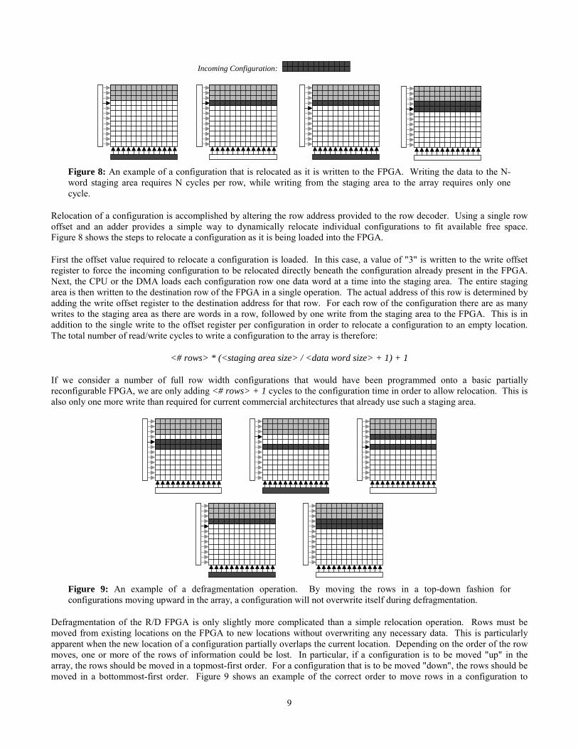
Incoming Configuration:
Figure 8: An example of a configuration that is relocated as it is written to the FPGA. Writing the data to the N-word staging area requires N cycles per row, while writing from the staging area to the array requires only onecycle.
Relocation of a configuration is accomplished by altering the row address provided to the row decoder. Using a single rowoffset and an adder provides a simple way to dynamically relocate individual configurations to fit available free space.Figure 8 shows the steps to relocate a configuration as it is being loaded into the FPGA.
First the offset value required to relocate a configuration is loaded. In this case, a value of "3" is written to the write offsetregister to force the incoming configuration to be relocated directly beneath the configuration already present in the FPGA.Next, the CPU or the DMA loads each configuration row one data word at a time into the staging area. The entire stagingarea is then written to the destination row of the FPGA in a single operation. The actual address of this row is determined byadding the write offset register to the destination address for that row. For each row of the configuration there are as manywrites to the staging area as there are words in a row, followed by one write from the staging area to the FPGA. This is inaddition to the single write to the offset register per configuration in order to relocate a configuration to an empty location.The total number of read/write cycles to write a configuration to the array is therefore:
<# rows> * (<staging area size> / <data word size> + 1) + 1
If we consider a number of full row width configurations that would have been programmed onto a basic partiallyreconfigurable FPGA, we are only adding <# rows> + 1 cycles to the configuration time in order to allow relocation. This isalso only one more write than required for current commercial architectures that already use such a staging area.
Figure 9: An example of a defragmentation operation. By moving the rows in a top-down fashion forconfigurations moving upward in the array, a configuration will not overwrite itself during defragmentation.
Defragmentation of the R/D FPGA is only slightly more complicated than a simple relocation operation. Rows must bemoved from existing locations on the FPGA to new locations without overwriting any necessary data. This is particularlyapparent when the new location of a configuration partially overlaps the current location. Depending on the order of the rowmoves, one or more of the rows of information could be lost. In particular, if a configuration is to be moved "up" in thearray, the rows should be moved in a topmost-first order. For a configuration that is to be moved "down", the rows should bemoved in a bottommost-first order. Figure 9 shows an example of the correct order to move rows in a configuration to
10
prevent loss of data when the configuration is being moved "up" in the array. Because each of these movements is of entirerows of configuration information, defragmentation is performed very quickly.
Both of the offset registers are used for a defragmentation operation. The read register is used to store the offset of theoriginal location of the configuration. The write register holds the offset of the new configuration location. First, using a rowaddress of 0 and a read offset of 4, the top row of information for the second configuration is read back into the staging area.The row is then written back out to the new location using the same row address, but a write offset of 3. The address sent tothe row decoder is incremented (although the contents of the two registers remain unchanged), and the procedure continueswith the next row.
Using two registers instead of one allows each row to be moved with a single read and a single write, because the currentposition (read) and destination (write) offsets are stored separately instead of having to time-share one location. A 1-bitsignal controls the 2:1 multiplexer that chooses between the two offsets. There are also two cycles necessary to initialize thetwo registers. The total number of read/write cycles required to move a configuration is:
<# rows> * 2 + 2
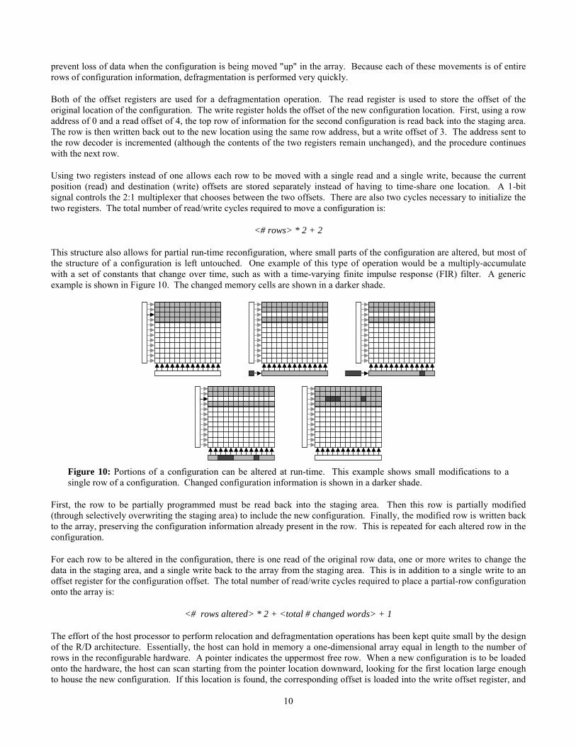
This structure also allows for partial run-time reconfiguration, where small parts of the configuration are altered, but most ofthe structure of a configuration is left untouched. One example of this type of operation would be a multiply-accumulatewith a set of constants that change over time, such as with a time-varying finite impulse response (FIR) filter. A genericexample is shown in Figure 10. The changed memory cells are shown in a darker shade.
Figure 10: Portions of a configuration can be altered at run-time. This example shows small modifications to asingle row of a configuration. Changed configuration information is shown in a darker shade.
First, the row to be partially programmed must be read back into the staging area. Then this row is partially modified(through selectively overwriting the staging area) to include the new configuration. Finally, the modified row is written backto the array, preserving the configuration information already present in the row. This is repeated for each altered row in theconfiguration.
For each row to be altered in the configuration, there is one read of the original row data, one or more writes to change thedata in the staging area, and a single write back to the array from the staging area. This is in addition to a single write to anoffset register for the configuration offset. The total number of read/write cycles required to place a partial-row configurationonto the array is:
<# rows altered> * 2 + <total # changed words> + 1
The effort of the host processor to perform relocation and defragmentation operations has been kept quite small by the designof the R/D architecture. Essentially, the host can hold in memory a one-dimensional array equal in length to the number ofrows in the reconfigurable hardware. A pointer indicates the uppermost free row. When a new configuration is to be loadedonto the hardware, the host can scan starting from the pointer location downward, looking for the first location large enoughto house the new configuration. If this location is found, the corresponding offset is loaded into the write offset register, and
11
the configuration is loaded onto the hardware as detailed earlier. The pointer is then updated. If there are no locations largeenough to handle the incoming configuration, but there are enough free rows (a count is maintained during the scan), then adefragmentation operation must be performed. The host processor moves through the array, starting from the top. When aconfiguration is reached that is located below the highest free row, the configuration is moved up to the higher position asindicated by the example of Figure 9. After the configuration is moved, the scan continues from the bottom of the movedconfiguration until the end of the array is reached. When the array is fully defragmented, the incoming configuration isloaded into the uppermost free location using the proper offsets. If, however, there are not enough free rows in thereconfigurable hardware to accommodate the new configuration, one of the replacement algorithms described earlier isemployed to create enough free area. Then new configuration is loaded, potentially after a defragmentation. These stepsrequire considerably less calculation than the floorplanning or placement operations required in a 2D architecture.
R/D Model Area
We modeled the sizes of a basic partially reconfigurable FPGA and the R/D FPGA using the same structures discussedearlier. We used small modifications to the hardware of the partially reconfigurable FPGA design to create our R/D FPGAdesign.
The column decoder of the partially reconfigurable system was unnecessary in the R/D version because the staging area isexactly the width of the memory array, and was therefore removed for the R/D size model. There were also several additionsto the partially reconfigurable FPGA design to create the R/D FPGA. The staging area structure includes the addition ofstaging area SRAM, output drivers to allow the CPU to read the staging area, and the small decoder for writing to it.Additionally, the main row decoder for the array was augmented with two registers, a 2:1 multiplexer for choosing betweenthe registers, and an adder to sum the offset from one of the registers with the incoming row address. The area of thevirtualized I/O was not considered for this area model. The area impact would depend on the number of input and outputlines at each column of the array.
We compared the sizes of the base partially reconfigurable FPGA and the R/D FPGA, each modeled with a megabit (220 bits)of configuration data in a square layout (# rows = # 1 bit columns). There are 1024 rows, addressed using 10 bits. For thecolumns there are 32 32-bit columns, addressed by five bits. The area of the partially reconfigurable array was calculated tobe 8.547 X 10⁹ λ2 while the area of the R/D FPGA was calculated to be 8.549 x 10⁹ λ2, a difference of .0234%. According tothis comparison, an R/D FPGA with the same number of programming bits has only a negligible size increase over a basicpartially reconfigurable FPGA.
Control Algorithms for R/D FPGAFor the R/D FPGA, the replacement policies have a great impact on reducing the reconfiguration overhead due to the highflexibility available for choosing victim RFUOPs (configurations) to remove when a reconfiguration is required. Withrelocation, a configuration can be dynamically remapped and loaded to an arbitrary position. With defragmentation, a neededconfiguration can be loaded provided enough free rows are available, regardless of their locations since the otherconfigurations on the chip can be moved to consolidate the free area. We include details of the lower bound algorithm andone run-time algorithm. A general off-line algorithm integrating the Belady [Belady66] algorithm and a least-recently-usedrun-time algorithm were also created [Li00].
Lower Bound Algorithm
The major difficulty in determining an optimal solution for configuration caching is the fact that the different configurationshave different sizes and loading latencies. Generally, the loading latency of a configuration is proportional to the size of theconfiguration. The Belady [Belady66] algorithm gives the optimal replacement for the case that the memory access string isknown and the data transfer unit is uniform. Given the configuration sequence, we can therefore achieve a lower bound ofour problem if we assume that discrete portions of any configuration (i.e., rows of information) can be transferred. Underthis assumption, when a reconfiguration occurs, only a portion of a configuration might be replaced while the rest remains onthe chip. When the removed configuration is once again needed, only the missing portion (which in some cases couldpossibly be the whole configuration) is loaded, rather than automatically loading the entire configuration each time. Wetherefore present a lower bound algorithm as follows:
12
1. If a required configuration is not on the chip:
1.1. Find the missing portion of the configuration. While the size of the missing portion is greater than the free space onthe chip:
1.1.1. For all configurations that are currently on the chip, a victim is identified such that in the configurationsequence its next appearance is later than the appearance of all others.
1.1.2. Remove as much of the victim configuration as needed, possibly removing the entire configuration.
1.2. Load the missing portion of the demanded RFUOP into the free space.
In our algorithm, we assumed that a portion of a configuration can be retained on the chip, and during reconfiguration onlythe missing portion of the needed configuration will be loaded. This can be viewed as loading multiple atomic configurationunits. Therefore, this problem is essentially a general caching problem, with the atomic configuration unit as the data transferunit. Since the Belady algorithm provides the optimal replacement for the general caching problem, it also provides thelowest configuration overhead for the R/D FPGA.
Run-Time Algorithm
For the run-time caching algorithm for the R/D FPGA, we first considered the Least-Recently-Used (LRU) paradigm.However, this algorithm is not ideal for run-time reconfiguration because it does not make allowances for the differing sizesof configurations. For example, consider a configuration sequence 1 2 3 1 2 3 1 2 3 …, configurations 1, 2 and 3 have sizesof 1000, 10 and 10 programming bits respectively. Suppose also that the size of the chip is 1010 programming bits.According to the LRU algorithm, the configurations are replaced in the same order as they are used in the sequence.However, the configuration overhead will be much smaller if RFUOP 1 is always kept on the chip. But always keepinglarger configurations on the chip is not a good solution, because they may have a very low reload frequency.
Instead, both size and frequency factors should be considered in the algorithm. Therefore, we use a variable “credit”[Young94] to determine the victim configuration, as shown in the following penalty-oriented algorithm:
1. If a demanded configuration is currently on the chip, set its credit equal to its size. Otherwise:
1.1. While there is not enough room to load the required RFUOP:
1.1.1. For all configurations on the chip:
1.1.1.1. Replace the one with the smallest credit
1.1.1.2. Decrease the credit of all other configurations by that value.
1.2. Load the demanded RFUOP and set its credit equal to its size.
R/D Performance
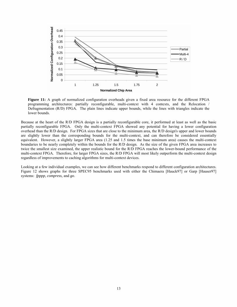
Figure 11 compares the performance of the R/D FPGA to the partially reconfigurable and the multi-context designs of thesame area. The benchmarks used for this comparison are the same as used for the graph appearing earlier in the paper,including several compiled for the Garp system [Hauser97], and a number created for the Chimaera System [Hauck97]. TheR/D FPGA had the best lower-bound results of any of the programming architectures—nearly a factor of 12 improvement inone case over the serially programmed FPGA. It also had the best results for the realistic algorithms for FPGA sizes at least1.5 times the area of the largest configuration in a benchmark. The R/D FPGA shows less than half the overhead of thepartially reconfigurable FPGA in the lower bound cases, and in fact the R/D upper bound realistic results are less than thelower bound partially reconfigurable results at all areas. For the multi-context design, as the available FPGA area increases,the results of the R/D FPGA using the realistic algorithm approaches and surpasses the lower bound results of the multi-context device.
13
0
0.05
0.1
0.15
0.20.25
0.3
0.35
0.4
0.45
1 1.25 1.5 1.75 2
Normalized Chip Area
Nor
mal
ized
Con
figur
atio
n O
verh
ead
PartialMulti-4R / D
Figure 11: A graph of normalized configuration overheads given a fixed area resource for the different FPGAprogramming architectures: partially reconfigurable, multi-context with 4 contexts, and the Relocation /Defragmentation (R/D) FPGA. The plain lines indicate upper bounds, while the lines with triangles indicate thelower bounds.
Because at the heart of the R/D FPGA design is a partially reconfigurable core, it performed at least as well as the basicpartially reconfigurable FPGA. Only the multi-context FPGA showed any potential for having a lower configurationoverhead than the R/D design. For FPGA sizes that are close to the minimum area, the R/D design's upper and lower boundsare slightly lower than the corresponding bounds for the multi-context, and can therefore be considered essentiallyequivalent. However, a slightly larger FPGA area (1.25 and 1.5 times the base minimum area) causes the multi-contextboundaries to be nearly completely within the bounds for the R/D design. As the size of the given FPGA area increases totwice the smallest size examined, the upper realistic bound for the R/D FPGA reaches the lower-bound performance of themulti-context FPGA. Therefore, for larger FPGA sizes, the R/D FPGA will most likely outperform the multi-context designregardless of improvements to caching algorithms for multi-context devices.
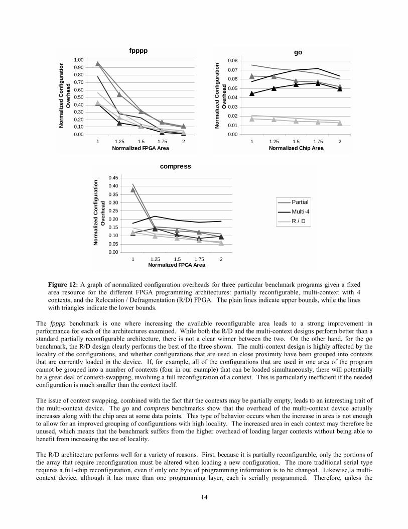
Looking at a few individual examples, we can see how different benchmarks respond to different configuration architectures.Figure 12 shows graphs for three SPEC95 benchmarks used with either the Chimaera [Hauck97] or Garp [Hauser97]systems: fpppp, compress, and go.
14
fpppp
0.000.100.200.300.400.500.600.700.800.901.00
1 1.25 1.5 1.75 2Normalized FPGA Area
Nor
mal
ized
Con
figur
atio
nO
verh
ead
go
0.00
0.01
0.02
0.03
0.04
0.05
0.06
0.07
0.08
1 1.25 1.5 1.75 2Normalized Chip Area
Nor
mal
ized
Con
figur
atio
nO
verh
ead
compress
0.000.05
0.100.150.20
0.250.300.35
0.400.45
1 1.25 1.5 1.75 2Normalized FPGA Area
Nor
mal
ized
Con
figur
atio
nO
verh
ead Partial
Multi-4R / D
Figure 12: A graph of normalized configuration overheads for three particular benchmark programs given a fixedarea resource for the different FPGA programming architectures: partially reconfigurable, multi-context with 4contexts, and the Relocation / Defragmentation (R/D) FPGA. The plain lines indicate upper bounds, while the lineswith triangles indicate the lower bounds.
The fpppp benchmark is one where increasing the available reconfigurable area leads to a strong improvement inperformance for each of the architectures examined. While both the R/D and the multi-context designs perform better than astandard partially reconfigurable architecture, there is not a clear winner between the two. On the other hand, for the gobenchmark, the R/D design clearly performs the best of the three shown. The multi-context design is highly affected by thelocality of the configurations, and whether configurations that are used in close proximity have been grouped into contextsthat are currently loaded in the device. If, for example, all of the configurations that are used in one area of the programcannot be grouped into a number of contexts (four in our example) that can be loaded simultaneously, there will potentiallybe a great deal of context-swapping, involving a full reconfiguration of a context. This is particularly inefficient if the neededconfiguration is much smaller than the context itself.
The issue of context swapping, combined with the fact that the contexts may be partially empty, leads to an interesting trait ofthe multi-context device. The go and compress benchmarks show that the overhead of the multi-context device actuallyincreases along with the chip area at some data points. This type of behavior occurs when the increase in area is not enoughto allow for an improved grouping of configurations with high locality. The increased area in each context may therefore beunused, which means that the benchmark suffers from the higher overhead of loading larger contexts without being able tobenefit from increasing the use of locality.
The R/D architecture performs well for a variety of reasons. First, because it is partially reconfigurable, only the portions ofthe array that require reconfiguration must be altered when loading a new configuration. The more traditional serial typerequires a full-chip reconfiguration, even if only one byte of programming information is to be changed. Likewise, a multi-context device, although it has more than one programming layer, each is serially programmed. Therefore, unless the
15
configuration can be completely background loaded (not always possible, depending on execution order and replacementpolicy), a multi-context FPGA may still encounter a large number of stall cycles for a reconfiguration of a small area.
Even partially reconfigurable devices without relocation features encounter difficulties when two different configurationsoccupy the same physical address space. An FPGA with relocation (such as the R/D design) provides the ability to placeconfigurations at different locations so as not to conflict with other configurations already loaded. The defragmentationcapability of the R/D FPGA also allows configurations already programmed onto the chip to be rearranged to consolidate themaximum amount of free space. This helps to avoid unnecessary unloading and reloading of useful configurations.
Relocation and defragmentation provide mechanisms to combat many of the problems causing configuration overhead incurrent FPGA designs. The R/D FPGA design has the greatest potential among those studied to lower configurationoverhead through the programming structure itself. This is particularly true as FPGAs continue to increase in area.
ConclusionRun-time reconfiguration provides a method to accelerate a greater portion of a given application by allowing theconfiguration of the hardware to change over time. Apart from the benefits of added capacity through the use of virtualhardware, run-time reconfiguration also allows application circuits to be optimized based on run-time conditions. In thismanner, performance of a reconfigurable system can approach or even surpass that of an ASIC. However, the benefits ofrun-time reconfiguration may be decreased due to the heavy penalty of reconfiguration. The use of relocation anddefragmentation greatly reduces the configuration overhead encountered in run-time reconfigurable computing. While partialreconfiguration can improve the configuration overhead by just over a factor of 7 over the serially programmed FPGA, theability to perform relocation and defragmentation of configurations increased this to nearly a factor of 12 for the lowerbound, and just under a factor of 8 for the realistic upper bound.
We then presented a new architecture design based on the ideas of relocation and defragmentation. The R/D FPGA exploitsthe virtues of relocation and defragmentation in order to reduce the overhead of configuration, which is a great concern inrun-time reconfigurable applications. The architecture is designed to require little additional run-time effort on the part of theCPU, and requires only a negligible area increase over a basic partially reconfigurable FPGA. Furthermore, the design sharessome key physical features with commercial FPGAs, in particular the Xilinx Virtex [Xilinx99]. While the Virtex is notspecifically designed to handle relocation and defragmentation, it is partially reconfigurable, and includes a structure similarto the staging area concept presented earlier.
In comparison to the basic partially reconfigurable architecture, the R/D FPGA requires a negligible increase in chip area,and the introduction of a virtual I/O mechanism. However, as a result we achieve as much as 35% improvement inreconfiguration times in these devices for realistic run-time algorithms. Given that several devices already include virtualI/O, as well as the trend towards integrating FPGAs with CPUs, we believe virtual I/O will be a worthwhile compromise.
Compared to a multi-context device the R/D FPGA provides equal performance in a very space-constrained device, going upto an improvement of nearly 50% as more resources are available. The R/D FPGA also avoids the issues of powerconsumption and clock synchronization during context switches. Also, for applications that do not use multipleconfigurations, an R/D device has a factor of 6.5 greater capacity than a four-context multi-context device of the samephysical area because the extra contexts of a multi-context device will be wasted.
Because of the advantages of this configuration technology compared to current commercial and research architectures, andits relatively limited restrictions on FPGA architecture, we believe it is a compelling next step in the advancement of FPGAprogramming architectures.
AcknowledgmentsThis research was funded by grants from Motorola, Inc and DARPA. Katherine Compton was supported by an NSFFellowship. Scott Hauck was supported in part by an NSF CAREER award.
16
References[Belady66] L. A. Belady "A Study of Replacement Algorithms for Virtual Storage Computers," IBM Systems Journal
5, 2, 78-101, 1966.
[Cadambi98] S. Cadambi, J. Weener, S. C. Goldstein, H. Schmit, D. E. Thomas, “Managing Pipeline-ReconfigurableFPGAs”, ACM/SIGDA International Symposium on FPGAs, 1998.
[Compton00a] K. Compton, J. Cooley, S. Knol, S. Hauck, “Configuration Relocation and Defragmentation forReconfigurable Computing”, Northwestern University Technical Report,http://www.ece.nwu.edu/~kati/publications.html, 2000.
[Compton00b] K. Compton, S. Hauck, "Reconfigurable Computing: A Survey of Systems and Software", submitted toACM Computing Surveys, 2000.
[DeHon96] A. DeHon, "DPGA Utilization and Application", ACM/SIGDA International Symposium on FPGAs, 1996.
[Diessel97] O. Diessel, H. ElGindy, “Run-Time Compaction of FPGA Designs”, Lecture Notes in Computer Science1304—Field-Programmable Logic and Applications. W. Luk, P. Y. K. Cheung, M. Glesner, Eds. Berlin,Germany: Springer-Verlag, pp. 131-140, 1997.
[Goldstein99] S. C. Goldstein, H. Schmit, M. Moe, M. Budiu, S. Cadambi, R. R. Taylor, R. Laufer, "PipeRench: ACoprocessor for Streaming Multimedia Acceleration", Proceedings of the 26th Annual InternationalSymposium on Computer Architecture, June 1999.
[Hauck97] S. Hauck, T. W. Fry, M. M. Hosler, J. P. Kao, "The Chimaera Reconfigurable Functional Unit", IEEESymposium on Field-Programmable Custom Computing Machines, 1997.
[Hauser97] J. R. Hauser, J. Wawrzynek, "Garp: A MIPS Processor with a Reconfigurable Coprocessor", IEEESymposium on Field-Programmable Custom Computing Machines, 1997.
[Hutchings97] B. L. Hutchings, “Exploiting Reconfigurability Through Domain-Specific Systems”, Lecture Notes inComputer Science 1304—Field-Programmable Logic and Applications. W. Luk, P. Y. K. Cheung, M.Glesner, Eds. Berlin, Germany: Springer-Verlag, pp. 193-202, 1997.
[Li00] Z. Li, K. Compton, S. Hauck, “Configuration Caching for FPGAs”, IEEE Symposium on Field-Programmable Custom Computing Machines, 2000.
[Smith99] W. H. Mangione-Smith, “ATR from UCLA”, Personal Communications, 1999.
[Trimberger95] S. Trimberger, "Field Programmable Gate Array with Built-In Bitstream Data Expansion", U.S. Patent5,426,379, issued June 20, 1995.
[Trimberger97] S. Trimberger, D. Carberry, A. Johnson, J. Wong, "A Time-Multiplexed FPGA", IEEE Symposium onField-Programmable Custom Computing Machines, 1997.
[Trimberger00] S. Trimberger, "Arrangement of Programming Bits in the Xilinx 4000 Series FPGA", PersonalCommunications, 2000.
[Wirthlin95] M. J. Wirthlin, B. L. Hutchings, "A Dynamic Instruction Set Computer", IEEE Symposium on Field-Programmable Custom Computing Machines, 1995.
[Wirthlin97] M. J. Wirthlin, "Improving Functional Density Through Run-Time Circuit Reconfiguration", PhD Thesis,Electrical and Computer Engineering Department, Brigham Young University, 1997.
[Xilinx96] XC6200: Advance Product Specification, Xilinx, Inc., San Jose, CA: 1996.
[Xilinx99] VirtexTM Configuration Architecture Advanced Users’ Guide, Xilinx, Inc., San Jose, CA: 1999.
[Young94] N. E. Young. “The k-server dual and loose competitiveness for paging”, Algorithmica, 11(6), 535-541,June 1994.