xie, w., yang, y., meng, s., peng, t., yuan, j. , scarpa
TRANSCRIPT

Xie, W., Yang, Y., Meng, S., Peng, T., Yuan, J., Scarpa, F., Xu, C., &Jin, H. (Accepted/In press). Probabilistic Reliability Analysis ofCarbon/Carbon Composite Nozzle Cones with Uncertain Parameters.Journal of Spacecraft and Rockets. https://doi.org/10.2514/1.A34392
Peer reviewed versionLicense (if available):OtherLink to published version (if available):10.2514/1.A34392
Link to publication record in Explore Bristol ResearchPDF-document
This is the accepted author manuscript (AAM). The final published version (version of record) is available onlinevia ARC at https://doi.org/10.2514/1.A34392 . Please refer to any applicable terms of use of the publisher.
University of Bristol - Explore Bristol ResearchGeneral rights
This document is made available in accordance with publisher policies. Please cite only thepublished version using the reference above. Full terms of use are available:http://www.bristol.ac.uk/red/research-policy/pure/user-guides/ebr-terms/

Probabilistic reliability analysis of carbon-carbon composite nozzle
exit cone with uncertain parameters
Weihua Xie *, Yuanjian Yang † and Songhe. Meng *,
Science and Technology on Advanced Composites in Special Environment Laboratory, Harbin Institute
of Technology, Harbin, China, 150080
Tao Peng ‡
STAR UAV Systems co., Ltd., Chengdu, China, 610200
Jie Yuan ※
Imperial College London, UK, SW7 2AZ
Fabrizio Scarpa §
University of Bristol, Bristol, UK, BS8 1TR
Chenghai Xu ☆, and Hua Jin ☆
Science and Technology on Advanced Composites in Special Environment Laboratory, Harbin Institute
of Technology, Harbin, China, 150080
ABSTRACT: We describe in this paper a methodology to perform the probabilistic and reliability-
based design of a novel carbon/carbon rocket nozzle subjected to operational thermal and
mechanical loads. In this methodology the nozzle is represented by a multiphysics finite element
model capable of predicting the temperature and stress fields of the exit cone. The analysis shows
* Professor, Science and Technology on Advanced Composites in Special Environment Laboratory, Harbin Institute of Technology, No.2 Yikuang Street, Harbin 150080, China. † Ph.D. Student, Science and Technology on Advanced Composites in Special Environment Laboratory, Harbin Institute of Technology, No.2 Yikuang Street, Harbin 150080, China. ‡ Senior engineer, STAR UAV Systems co., Ltd. No.2999 Westport Avenue, Shuangliu District, Chengdu, China. ※ Ph.D. Dynamics Group, Department of Mechanical Engineering, Imperial College London, SW7 2AZ, London, UK. § Professor, Bristol Composites Institute (ACCIS), University of Bristol, BS8 1TR Bristol, UK. ☆ Associate professor, Science and Technology on Advanced Composites in Special Environment Laboratory, Harbin Institute of Technology, No.2 Yikuang Street, Harbin 150080, China.

that the most likely failure modes of the exit cone are related to compressive loading along the axial
and hoop directions, and interlaminar shear. The probabilistic models used in this methodology
account for the uncertainty of the material properties by using uniform and normal distributions and
different variances. The reliability analysis is performed by using surface response methods. A
global sensitivity analysis is also carried out using polynomial expansion chaos surface response
models. A particular novelty of analysis is the use of Sobol indices to rank the importance of the
single uncertain parameters in the models. The methodology provides a high level of confidence
and robustness in determining that the axial thermal conductivity of the carbon/carbon material is
the most critical material property to affect the three main failure modes, while the coefficient of
the thermal expansion and the heat capacity play a very marginal role.
Keywords: Rocket nozzle; Exit cone; Reliability; Carbon/carbon; Uncertainty
Nomenclature
M = performance function
R = the capability
S = the response
R1 = the shear strength, MPa
S12 = the shear stress, MPa
R2 = the axial compressive strength, MPa
S22 = the axial compressive stress, MPa
R3 = the hoop compressive strength, MPa
S33 = the hoop compressive stress, MPa
x1 = thermal expansion coefficient, 1/K
x2 = heat capacity, J/K
x3 = radial thermal conductivity, W/(m·K)

x4 = axial thermal conductivity, W/(m·K)
x5 = axial elastic moduli, MPa
x6 = radial elastic moduli, MPa
x7 = density, kg/m3
1 Introduction
Carbon/carbon (C/C) nozzles constitute one of the more advanced components of Solid Rocket
Motor (SRM) technology developed in recent years. Compared with a nozzle made from
conventional materials, the carbon/carbon version involves a simplified design that produces
a reduction in weight and internal ablation, and also features improved operational reliability.
The operational environment of a solid rocket nozzle is very complex and challenging, with
temperatures usually exceeding 3000°C and the presence of high pressure fields. The internal
part of the nozzle is also subjected to sharp heat flux gradients and erosion. The short time burn
generates some significant temperature gradients, and the complex thermodynamic
environment generated by the presence of high pressures presents a critical challenge to the
structural design of the rocket nozzle. The C/C nozzle exit cone structure is one of the most
critical components in the SRM system, leading to potential failures during use.
Several efforts have been devoted to understanding the behavior of C/C composites at high
temperatures [1-5]. Li et al [1] and Peng et al [2] investigated the microstructure and the
ablation mechanism of C/C composites with scanning electron microscopy. Other research
groups have focused on the effect of the ablative environment on the ablation behavior of C/C
composites and have obtained valuable performance data. For example, Liu et al [3] studied
the ablation characteristics of a C/C composite in a lab-scale solid rocket motor under a flux of

combustion products containing a high content of particulate alumina. Zaman et al [4] reported
on the residual mechanical and thermophysical properties of C/C composites repeatedly ablated
using 3000 °C oxyacetylene flame. From the numerical standpoint, Vignoles et al., [5]
identified an efficient method to simulate the ablation of C/C composites by considering the
bulk transport of reactants and heterogeneous mass transfer conditions. In recent years, several
groups have also started to consider the ablation behavior of ceramic based nozzles doped with
ceramic composition (e.g. ZrB2, ZrC, etc.) for enhanced performance at high temperatures [6,
7]. These works have built on the know-how accumulated on studying traditional C/C nozzles
Other significant activities related to C/C nozzle design have considered various aspects
of heat transfer [8-10]. The analysis of the reliability of C/C composite nozzle exit cone
structures is however scarcely represented in open literature [11, 12]. The reasons behind this
lack of information are mainly related to the significant costs involved in the development and
testing of these composites, and also confidentiality issues related to intellectual property
ownership [13]. The resources involved in obtaining large amounts of experimental data may
be prohibitive, and that justifies the use of reliability-based models to design solid rocket motor
components. The results from system reliability analyses calculated on small data samples are
affected by significant errors. Therefore numerical models have been widely used to simulate
the thermal-structural response of the nozzle and integrate the reliability-based approach [13-
17]. Morozov and de la Beaujardiere [13] developed a finite element method to investigate the
dynamic thermo-structural response of a composite rocket nozzle throat. Goyal et al [16]
developed reliable reduced size models based on 2D plane strain assumptions for SRM
structural analysis. Turchi et al [17] suggested a numerical approach to describe a carbon–

phenolic SRM nozzle model and then investigated the role of the most important uncertainty
parameters affecting the design. Heller et al [11, 12] pioneered a methodology for reliability
analysis of C/C composites, and analyzed the stress state of a cylindrical structure consisting of
multiple layers of C/C composite under thermal and pressure shock by assuming elasticity
within the structure. The reliability of the composite configuration was also calculated. Bozkaya
et al [18, 19] and Akpan and Wong [20] developed some useful and efficient methods for the
sensitivity analysis and reliability calculations [21] based on surface response methods (SRM)
and Monte Carlo simulation techniques.
In this paper we describe a probabilistic design methodology to assess, at the initial design
stage, the reliability of carbon/carbon rocket nozzles under thermal and mechanical load
conditions. The proposed finite element methodology allows the estimation of the reliability
and probability using a combination of surface response methods and sensitivity analysis based
on Sobol’s approach with Polynomial Chaos expansions for the surface responses. A particular
advantage of this approach also consists in the reduction of the computational resources
required to perform the overall analysis.
The paper is organized as follows. In the first section we introduce a numerical multi-
physics (thermal and structural) finite element analysis methodology to design a C/C exit cone
with uncertain parameters, and present a method to estimate the probability of structural failure
by combining the finite element model with response surface methods. In the second part of the
paper the reliability metrics of the exit cone are calculated. Finally, the extent and the influence
of different failure modes on structural reliability are analyzed and discussed. The global

sensitivity of the uncertain parameters to the failure modes is also evaluated through a Sobol
analysis.
2 Thermal stress and failure mode analysis of the C/C exit cone
2.1 Model of the rocket nozzle
The nozzle is represented as an axisymmetric structure (Figure 1). The nozzle consists of a
throat insert, an exit cone, a back wall, the inlet section and a metal flange. The exit cone is
made from 2D needle-punched felt reinforced C/C composites [22, 23]. Carbon-felt reinforced
C/C composites constitute the throat, and carbon cloth phenolic makes its inlet. The back wall
insulation is made of silica cloth phenolic insulation materials, and high-strength alloy steel is
used for the metal flange. The exit cone and the throat insert are bonded together by an adhesive
layer; the exit cone and the back wall are also bonded by a similar adhesive layer (Figure 1). A
gap is present in the connecting section between the throat insert and the exit cone to release
the thermal stress and avoid a deformation mismatch caused by the stress concentration at high
temperatures. The silica cloth phenolic can isolate the hot and cooled substructures, and makes
it possible for the metal flange to stay within its operational temperature range. The main role
of the metal flange is to connect the composite nozzle to the motor casing, and fix the geometry
of the exit cone. The properties of the materials used in the design are listed in Tables 1, 2 and
3. The parameters k, c, α, υ, E, ρ represent the thermal conductivities, heat capacities, thermal
expansion coefficients, Poisson’s ratios, elastic moduli and densities, respectively. The
subscripts 1, 2 and 3 indicate the principal orthotropic directions of the materials (i.e., the radial,
tangential and axial directions in a cylindrical coordinate system) respectively.

Fig. 1. Two-dimensional view of the nozzle structure
Table 1 Thermal properties of the 2D needle-punched felt reinforced C/C
Temperature [°C] α [K-1] c [J/(kg·K)] k [W/(m·K)] k11 k22 =k33
20 1.15E-07 777.6 7.18 16.47 200 6.82E-07 1286.4 9.09 21.05 400 8.64E-07 1660.8 9.95 23.34 600 1.24E-06 1824.0 9.73 22.39 800 1.52E-06 1929.6 9.94 22.36 1000 1.76E-06 1996.8 10.29 22.20 1200 1.97E-06 2054.4 10.47 23.22 1400 2.17E-06 2121.6 10.65 23.70 1600 2.39E-06 2150.4 11.25 24.08 1800 2.70E-06 2208.0 11.66 25.01
Table 2 Mechanical properties of needle-punched felt reinforced C/C
Temperature, °C E11 [GPa] (Out-plane)
E22=E33 [GPa] (In-plane)
υ Density [kg/m3] υ12= υ13 υ 23 20 7.90 29.50 0.1 0.24 1540
1200 / 33.84 / / / 1600 / 31.13 / / /
Table 3 Material properties of other materials other than needle-punched felt reinforced C/C Materials Properties
Silica cloth phenolic insulation Carbon-felt reinforced C/C
Carbon cloth phenolic
Alloy steel 20°C 300°C
k [W/(m·K)] k11 0.61 0.82 80.4
0.84 27.63 k22 0.53 0.74 30.5 k33 0.53 0.74 30.5
c [J/(kg·K)] c11 1013 1705
1200 1189 473.1 c22 1072 1722 c33 1072 1722
α [10-6K-1] α11 12.40 1.01 3.37
8.2 12.92 α22 11.72 1.31 1.45 α33 11.72 1.31 1.45

υ 0.11 0.1 0.26 0.3 E [GPa] 14.5 13.2 11 196
ρ [kg/m3] 1640 1820 1800 7750
The thermal domain (i.e., the transient heat transfer) representing the nozzle is modeled as
axisymmetric because of the rotational symmetry of the nozzle geometry. The gas flow
generates nearly 6MPa pressure [13] and wall shear stresses on the inner wall of the nozzle.
Because the magnitude of the wall shear stress is very small [22], its influence on the nozzle
performance can be therefore neglected. The pressure generated by the gas flow generates the
main mechanical load. The heat transfers between the high-temperature gas and the inner wall
generally can be classified into convective, radiant and conductive. The forced convective heat
is the most significant factor for the heat transfer [23-26].
To simplify the model we impose the following assumptions: (1) only convective heat
transfers between the flow and the nozzle are considered on the inner wall of the nozzle;
radiation and conduction are ignored [23-26]. The mechanical erosion of the material and the
ablation of the inner nozzle wall are also neglected [27, 28]. (2) Only convective heat transfer
between the air and the outer wall of the nozzle is considered, and the radiation heat loss is
neglected [29-32]. (3) The flow field parameters (pressure and temperature) do not change for
a SRM in steady-state operations (4) The thermally induced erosion of the insulation material
is ignored [27, 28].
The temperature profile around the nozzle, the gas pressure and the convective heat
transfer coefficient vary with the axial distance (Fig. 2. (a) and (b)) [32].

Fig. 2. Variations of the flow gas temperature, convective heat transfer coefficient (a) and gas
pressure (b) with the axial position
The following boundary conditions and constraints are used in the numerical analysis of
nozzle: (a) The heat transfer between the outer wall of the exit cone and the ambient air is
represented by natural convection only, with a convective heat transfer coefficient of 5W/
(m2·K) [27, 28]. (b) The body of the nozzle is initially at room temperature (20 °C), which is
representative of ground test conditions. (3) The outside ambient pressure is standard (sea level)
atmospheric pressure, and the ambient temperature is 20 °C. (4) The interfacial shear strength
of the adhesive layer present between the exit cone and throat is 10MPa [32]; a bilinear cohesive
zone model (CZM)[33] is used to simulate the interface state. (5) The metal flange edge is fixed.
(6) The total simulation time is 21 seconds, which represents the typical duration of the test
time of a solid rocket engine [32].
The calculations were performed on a Windows-based machine with a 4.8GHz CPU and
32GB RAM. The coupled-thermal displacement analysis method solver of ABAQUS-Standard
TM (Version, 16.4-2) is used to directly couple the temperature and stress fields of the nozzle
exit cone with the above loads and boundary conditions. In order to guarantee the accuracy of
the initial temperature distribution, the same mesh density was used both for the thermal and
structural models. The thermomechanical coupling element CAX4T (axisymmetric thermal
coupling quadrilateral linear element) was used, and the CAX3T (axisymmetric thermal
coupled triangular linear element) was adopted to mesh the local region. An analysis of different
mesh densities was performed to examine the dependency of the numerical results on the
numbers of elements. After examining the stress distribution from different simulations it was
found that the deviation of the maximum equivalent stress would not exceed 1% when the
element size was less than 0.5×0.5mm. Hoever, local stress concentration regions usea finer
mesh size. For all the other components, the elements side has a constant length of 1mm. The
total number of elements in the multi-physics model is 7023, with 45 elements through the
thickness.
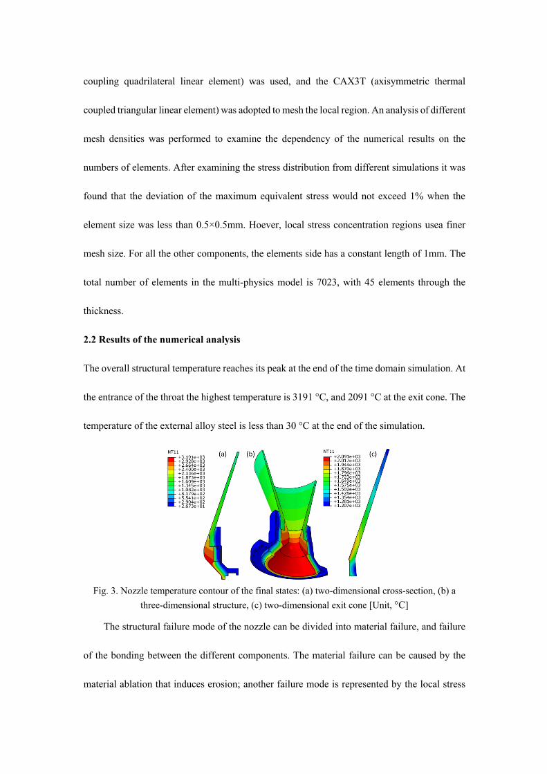
2.2 Results of the numerical analysis
The overall structural temperature reaches its peak at the end of the time domain simulation. At
the entrance of the throat the highest temperature is 3191 °C, and 2091 °C at the exit cone. The
temperature of the external alloy steel is less than 30 °C at the end of the simulation.
Fig. 3. Nozzle temperature contour of the final states: (a) two-dimensional cross-section, (b) a
three-dimensional structure, (c) two-dimensional exit cone [Unit, °C]
The structural failure mode of the nozzle can be divided into material failure, and failure
of the bonding between the different components. The material failure can be caused by the
material ablation that induces erosion; another failure mode is represented by the local stress

that exceeds the strength of the material. Because this analysis is mainly concerned with the
structural response of the system at the initial design stage iteration, effects like the mechanical
and thermal erosion are neglected. The subsequent reliability analysis is therefore performed
by only considering the failure mode represented by the structural stress exceeding the material
strength.
2.2.1 Radial stress of the exit cone
The radial stress field of the exit cone is shown in Fig. 4(a). The maximum radial tensile stress
occurs at point A, which is located at the sharp contact corner of the exit cone and the throat.
During the thermal loading stress concentrations appear at this corner. The maximum radial
tensile stress is 9.8MPa, which is significantly lower than the value of the material tensile
strength (160MPa). While, the stress concentration at sharp corners does not represent the
correct stress magnitude, it must be larger than the actual stress, so he radial tensile stress should
not cause failure of the exit cone. The maximum radial compressive stress occurs at point B,
with the compressive stress being mainly generated by the thermal expansion of the throat. The
maximum radial compressive stress is 60.2MPa, which is again lower than the value of the
material compressive strength (140MPa). The radial compressive stress therefore should not
damage the exit cone.

Fig. 4. The (a) radial, (b) axial, (c) hoop and (d) interlaminar shear stress contours of the exit cone
2.2.2 Axial stress at the exit cone
The axial stress field of the exit cone is shown in Fig. 4(b). The maximum axial tensile stress
occurs at point C, which is located at the contact corner of the exit cone and the back wall. The
maximum axial tensile stress is 28MPa, lower than the value of the material tensile strength.
The maximum axial compressive stress is 75.5MPa after 5.2s. The maximum axial compressive
stress occurs at point A. Because this particular location is close to the throat, it expands before
the other adjacent surfaces. Compressive stresses are generated in this area because of the
thermal expansion mismatch. Because the compressive strength of the material is 90MPa, if

one takes into account potential material uncertainties the axial compressive stress may be a
source of failure for the nozzle.
The time histories of the stresses localized at points A, E, and F are shown in Fig. 5. The
figure shows that the maximum axial compressive stress of the exit cone occurs after 5.2
seconds. At this time the adhesive layer between the exit cone and the throat is gradually
degraded and therefore stress is released. The compressive stresses continue to decrease as time
increases. After 11 seconds the adhesive layer is completely destroyed, and stress cannot be
further released, with consequent leveling off.
Fig. 5. Time histories of the stresses of the exit cone
2.2.3 Hoop stress of the exit cone
The distribution of the hoop stresses is shown in Fig. 4(c). The maximum hoop tensile stress
occurs at point D located at the contact corner between the exit cone and the back wall. The
maximum hoop tensile stress is 14.3MPa after 5.7s, again significantly lower than the material
tensile strength. After 9.2s the hoop compressive stress reaches its maximum (76.2MPa) at
point A. The hoop stress can also be observed in the annular region of the exit cone near point
E. The maximum hoop compressive stress at point E is 75.93MPa at 19.2 sec. This position is

located in the front area of the exit cone, and it is exposed to the combustion flow. Although
the temperature in this region is higher than in other areas, its hoop thermal expansion is
constrained by the presence of the back wall and therefore a large compressive stress is
generated. If uncertainty associated to the material properties is considered the hoop stresses at
points A and E may exceed the compressive strength of the material (90MPa), and therefore
cause failure of the exit cone.
From Fig. 5 it is possible to notice that between the time interval of 7s-10s the hoop
compressive stress at point A is slightly higher than the stress at point E. During the remaining
time the hoop stress at point E is always greater than the stress at point A. From the size of the
pressure distribution area, the hoop stress at point A can only cause partial damage to the corner
of the small area, and will not likely cause the failure of the whole structure. The hoop stress at
point E may, however, induce failure.
2.2.4 Interlaminar shear stress of the exit cone
The interlaminar shear stress of the exit cone is shown in Fig. 4. (d). The figure shows that the
maximum interlaminar shear stress occurs again at point A. The maximum interlaminar shear
stress is 15.6MPa (at 4.1s). Another area of stress concentration is point F, with its maximum
interlaminar shear stress at 12.3MPa. With the interlaminar shear strength equal to 26MPa, if
material uncertainties are considered the interlaminar shear strength of point A and F may
exceed the interlaminar shear strength of the material, and therefore cause failure of the exit
cone. Delamination damage caused by shear failure may also occur in the circular area around
point F.

In summary, the model identified three distinct modes that may lead to the failure of the
exit cone: compressions along the axial and hoop directions, and interlaminar shear. The other
failure modes are less likely to occur.
3 Reliability analysis of the exit cone
The structure of the nozzle is complex. The high combustion temperature and the internal gas
flow velocity create an extremely harsh environment for the nozzle materials. Moreover, size
scale effects given by the discrete nature of the C/C microstructure bring further uncertainties
in determining the overall mechanical performance and directly affect the reliability of the
nozzle structure.
3.1 Quantization of parameter uncertainty
In the probability model, the uncertainty comes from the discretization of the uncertainty
from the variability of the material properties. The material properties are usually measured
through experiments, and the uncertainty includes not only the natural dispersion of the
properties, but also the testing errors. In this paper, the value of the structural strength at failure
is also non-deterministic. For simplicity we assume that the material properties follow a normal
distribution, and the strength has a uniform distribution. In order to facilitate the calculation,
seven main material parameters are normalized as shown in Table 4, and the probability
distribution types of material properties are also specified.
Table 4 uncertainty parameters and the distribution type of material Parameter Symbol Distribution Type Mean Coefficient of
Variation Thermal expansion coefficient x1 Normal Distribution 1.0 15% Heat capacity x2 Normal Distribution 1.0 30% Radial thermal conductivity x3 Normal Distribution 1.0 10% Axial thermal conductivity x4 Normal Distribution 1.0 3% Axial elastic moduli x5 Normal Distribution 1.0 10% Radial elastic moduli x6 Normal Distribution 1.0 10% Density x7 Normal Distribution 1.0 10%

Hoop compressive strength R3 Uniform Distribution 140.0 10% Axial compressive strength R2 Uniform Distribution 90.0 5% Shear strength R1 Uniform Distribution 30.0 11.5%
3.2 Computational process
From the above analysis it is evident that there are three main factors leading to the failure of
exit cone: axial compression, hoop compression and interlaminar shear failures. The maximum
stress failure criterion is used to evaluate the reliability of the exit cone. Failure of the exit cone
is assumed to occur if the stress is greater than the strength along specific directions. The
maximum stress failure criterion does not consider interaction between the failure modes, but
it is a conservative approximation of failure especially for combined tensile/shear/compressive
loading.
Among the most common structural reliability analysis methods, response surfaces and
Monte Carlo simulations are well developed and benchmarked. In this study we combine a
surface response method (SRM) with finite elements, as well as Monte Carlo simulations to
analyze the reliability. We first obtain the structural performance functions for the different
failure modes by response surface approximation. To this end, 300 sample sets used to obtain
the surface response are derived by optimization using Latin Hypercube sampling of the
uncertainty space. Each set is computed independently by fitting higher order polynomials. We
finally obtain a surface response for the three types of failure modes by higher order polynomial
fit, and then the response surface is used for further reliability analysis (see the flowchart in
Figure 6).

Fig. 6. Flowchart of computing process
3.3 Reliability analysis of the nozzle exit cone
3.3.1 Reliability based on probabilistic theory
The structural performance function of the exit cone can be represented by a two-dimensional
function that relates response and capability. If R represents the capability – i.e. strength - and
S is the response (stress), it is possible to denote the performance function as:
(3)
For the three failure modes concerned in this study the corresponding limit state functions
can be presented as follows:
(4)
Where and are, respectively, the shear strength and shear stress; and are
the axial compressive strength and axial compressive stress; and are the hoop
compressive strength and stress, respectively. Using a classical SRM nonlinear quadratic
regressive fit the expressions of the responses are:
M R S= -
12 1 12
22 2 22
33 3 33
M R S
M R S
M R S
= -
= -
= -
R1 S12 R2 S22
R3 S33

(5)
(6)
(7)
The subsequent reliability analyses from Monte Carlo simulations are performed based on these
SRMs in order to reduce the computational expense. The reliability index , failure probability
, and the standard deviation and coefficient of failure probability are calculated using a
Monte Carlo method with 5,000 and 10,000 Monte Carlo simulations respectively (Table 5).
Table 5 Reliability of exit cone based on probability model
Stress Sample Reliability index,
Failure Probability, Stdev( ) CoV( )
Interlaminar shear N=5000 1.9357 0.0529 0.0032 5.98% N=10000 2.0480 0.0406 0.0020 4.86%
Axial compression N=5000 1.5849 0.113 0.0045 3.98% N=10000 1.5853 0.1129 0.0032 2.8%
Hoop compression N=5000 2.7944 0.0052 0.0010 19.56% N=10000 2.6921 0.0071 8.4E-4 11.83%
3.4 The results of the failure probability analysis
The reliability results for the three failure modes are listed in Table 6. The results show that the
axial compression failure is the most likely cause of the structural failure. Failure can also occur
by interlaminar shear, while hoop compression is the least likely of the three to cause failure.
Table 6 The failure probability of different conditions Failure
Interlaminar shear Axial compression Hoop compression 0.0406 0.1129 0.0071
3.5 Global sensitivity analysis
2 2 2 212 6 4 5 6 7 1 3 1 5
1 6 2 3 2 4 2 5 2 6 3 4 3 5 3 7
4 6 5 6
= 207 374 8 10 223 3.5 6 1016 6 5 9.7 10 2.7 5 7.38.3 36
S x x x x x x x x xx x x x x x x x x x x x x x x xx x x x
- + - - - - - -
+ - + - + + + +
+ +
2 2 222 3 4 5 3 4 5 1 2
1 4 1 5 1 6 2 3 3 4 3 5 3 6
= 59.8 6.4 34 7 2 14.4 2.9 1.70.9 2.8 5.4 1.6 20.7 9.4 8.8S x x x x x x x x
x x x x x x x x x x x x x x- - - + + + - +
+ + - - - + +
2 233 2 3 4 5 3 4
2 25 7 1 4 1 5 1 7 2 3
3 4 3 6 4 5 4 6 4 7
=16 15.8 98.8 38.6 36.4 21.6 17.719 12.2 3.6 13 16.9 16.443.8 21.6 20.2 16.3 6.4
S x x x x x xx x x x x x x x x xx x x x x x x x x x
- - - + - -
- - - - + ++ - + + +
β
Pf
β PfPf Pf

Variance based sensitivity analysis, namely Sobol analysis, is a form of global sensitivity
analysis. It decomposes the variance of the output of the model or system into fractions which
can be attributed to inputs or sets of inputs [34]. It would be very useful to identify the most
significant input uncertain parameters that contribute to the variation of the different types of
stress associated to these three failure modes. In this case study, the Sobol analysis method is
used in this case to carry out the global sensitivity analysis [35]. The basis of the method
consists in the decomposing the model output function into a sum of variance terms by using
combinations of input parameters with increasing dimensionality. The variance
decomposition can be expressed as:
𝑉(𝑜𝑢𝑡𝑝𝑢𝑡) = ∑ 𝑉*+*,- + ∑ 𝑉*/+
*0/1+ + ⋯+∑ 𝑉*⋯++*0+
(8)
Where 𝑉(𝑜𝑢𝑡𝑝𝑢𝑡) is the total variance of the model output; 𝑉* defined as the first order
contribution of the ith model parameter; 𝑉*/ is the second order contribution of coupling
effects of the ith and jth parameter; n means the number of model parameters. The importance
of the given input factor is measured by a term defined as the sensitivity index, which is the
fractional contribution to the output variance due to the uncertainties in the inputs. The Sobol
sensitivity index can be expressed as:
𝑆4 = 𝑉*/𝑉(𝑜𝑢𝑡𝑝𝑢𝑡)
(9)
𝑆46 = 𝑉*6/𝑉(𝑜𝑢𝑡𝑝𝑢𝑡)
(10)
𝑆7* = 1 − 𝑉~*/𝑉(𝑜𝑢𝑡𝑝𝑢𝑡)
(11)
𝑆4 is the first order Sobol sensitivity index, 𝑆46 denotes as the second order term and
𝑆7*denotes as the total Sobol sensitivity index corresponding to the ith model parameter. The
resulting Sobol’s sensitivity indices therefore rely on not only the input parameter distribution,
but also the contribution of the input parameter in the mathematical model. The first order Sobol
indices 𝑆4 are used to quantify the separate effect on the failure modes of each input parameter,
while the total Sobol indices 𝑆7* quantify the total effect of the input parameter, which include
both the first order effect and also its interactions with the other input variables [36].
The use of Polynomial Chaos Expansion (PCE) techniques is widely recognized as a quick way
to directly compute the Sobol sensitivity indices. PCE is therefore employed in this case study.
Since the distribution of the input parameters (i.e., the thermal expansion coefficient, heat
capacity, radial thermal conductivity, axial thermal conductivity, axial elastic moduli, radial
elastic moduli and density) are assumed to have normal distributions, the PCE surface response
is generated based on the Gaussian probabilistic distribution by using Hermite orthogonal
polynomials. A linear enumeration strategy is employed to construct the multivariate
orthonormal basis. The multivariate orthonormal basis is then truncated by using a fixed
strategy to build the complete basis with respect to a maximal degree of four [37]. A non-
intrusive method based on least squares minimization is used to optimize the PCE coefficients
using 200 sampling points generated by the FE model. With this PCE response surface model,
the Sobol’s indices can then be computed directly without further Monte Carlo simulations.
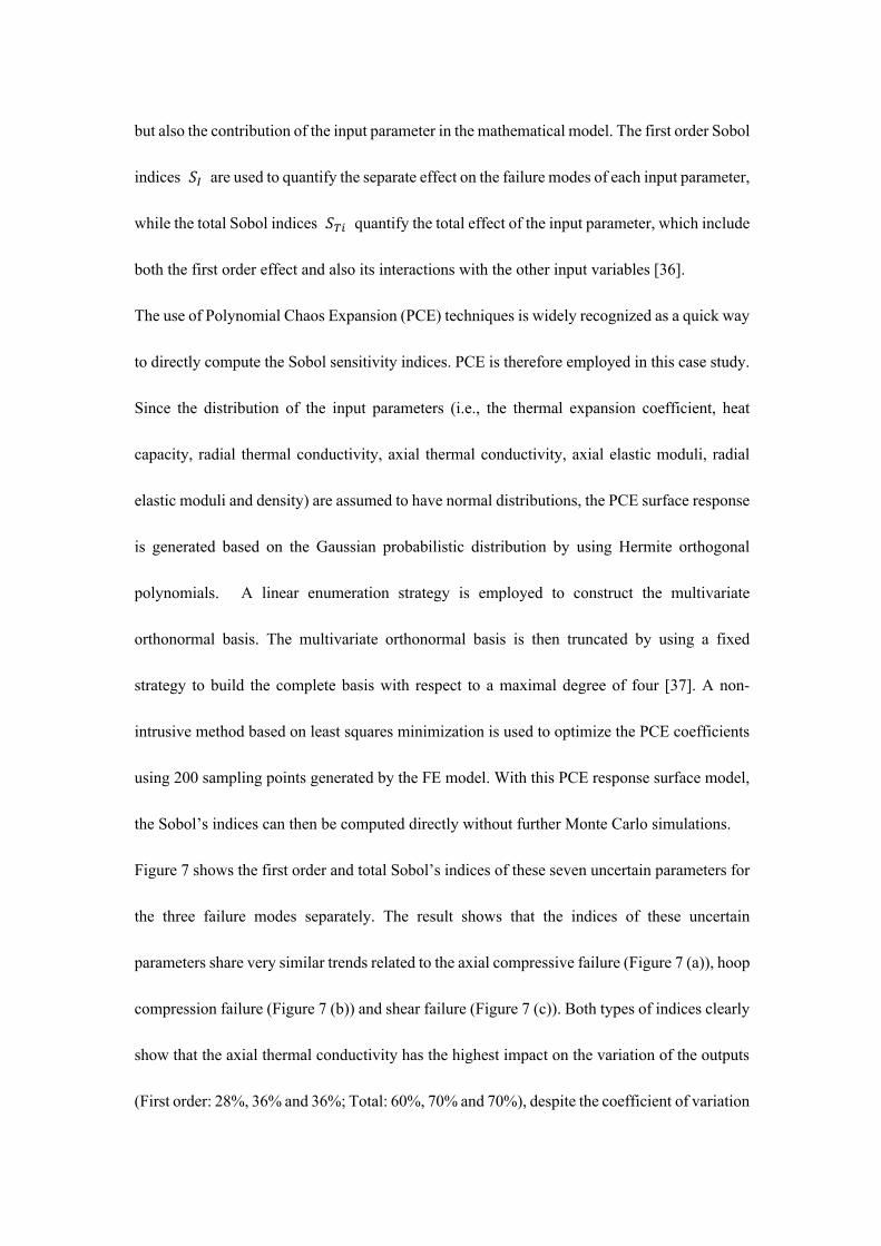
Figure 7 shows the first order and total Sobol’s indices of these seven uncertain parameters for
the three failure modes separately. The result shows that the indices of these uncertain
parameters share very similar trends related to the axial compressive failure (Figure 7 (a)), hoop
compression failure (Figure 7 (b)) and shear failure (Figure 7 (c)). Both types of indices clearly
show that the axial thermal conductivity has the highest impact on the variation of the outputs
(First order: 28%, 36% and 36%; Total: 60%, 70% and 70%), despite the coefficient of variation

(CoV) of its uncertain distribution shown in Table 4 is the smallest among the seven input
variables. The radial thermal conductivity comes second in terms of impact. However, in terms
of total contributions, the second largest influence comes from the elastic moduli for the axial
compression failure (25%). For the hoop compression and shear failures, the radial elastic
moduli and the density equally take the second leading contributions by about 21%. This
suggests that the coupling contribution from the elastic moduli and density is more significant
than the one from the thermal conductivity and the elastic moduli along the radial direction.
The first order Sobol’s indices clearly show that the thermal expansion coefficient and heat
capacity provide negligible contributions to all the three failure modes. These two parameters
could be therefore excluded in future uncertainty analysis.
(a)

(b)
(c)
Figure 7 Sobol’s indices ranking of the input uncertain variables according to their influence on: (a) the axial compressive failure (b) the hoop compression failure and (c) shear failure
4 Conclusions

In this paper we have used a probabilistic model to account for uncertainties in the material
properties of a solid rocket nozzle exit cone made from carbon/carbon composites, adhesive
layers and metal components and simulate the structural response. To this end we combine a
finite element model and a surface response method to compute the structural reliability by
considering three types of failure modes. The methodology here has been developed to provide
a way to calculate the reliability of nozzle-type structures in the case of small sample data
populations. A sequentially coupled thermal/structural analysis shows that under the service
environment conditions reproduced in this study the axial compressive, hoop compressive and
interlaminar shear stresses are close to the material strength, while the stress along other
directions is relatively small. If we ignore local stress concentration in the corners of the exit
cone, the most likely failure region is in the contact area between the exit cone and the throat
induced by the axial compressive stress. Also, another critical area is represented by the front
region of the exit cone exposed to the combustion chamber, which is characterized by the
presence of hoop compressive stresses. The third possible failure mode is the interlaminar shear
failure, which is located at the region of the exit cone far away to the throat.
A global sensitivity analysis also was carried out to identify the most influential input
parameters on these three failure modes. A Sobol analysis was used to rank the impacts of the
input parameters based on the PCE response surface model. The results show that the axial
thermal conductivity has the highest contribution on all the three modes. The contributions from
the thermal expansion coefficient and heat capacity are negligible. The conclusions from this
probabilistic analysis are quite useful to streamline and optimize the outcome of the initial
design stage for these C/C composite nozzles. The importance of the axial thermal conductivity

in this type of structure may lead to a design of C/C composites and their stacking sequences
that favor a strong unidirectional thermal conductivity response for the nozzle configuration. In
a similar manner, the design and materials selection of these types of nozzles can be streamlined
to prevent the axial compression failure, which is the most important failure mode of the system.
Compressive failure in C/C composites can be tailored by fibers architectures or needle-punch
techniques[38], and these approaches could be used to increase the reliability of these carbon-
based nozzle designs.
Acknowledgements
This research is sponsored by the National Natural Science Foundation of China
(11672088) and the National Basic Research Program of China (No. 2015CB655200). The
authors are also grateful for the financial support from National key Laboratory of Science and
Technology on Reliability and Environmental Engineering.
Reference
1. Li, K.-Z., Shen, X.-T., Li, H.-J., Zhang, S.-Y., Feng, T., and Zhang, L.-L. "Ablation of the carbon/carbon composite nozzle-throats in a small solid rocket motor," Carbon Vol. 49, No. 4, 2011, pp. 1208-1215.
2. Peng, L.-n., He, G.-q., Li, J., Wang, L., and Qin, F. "Effect of combustion gas mass flow rate on carbon/carbon composite nozzle ablation in a solid rocket motor," Carbon Vol. 50, No. 4, 2012, pp. 1554-1562.
3. Liu, Y., Pei, J.-q., Li, J., and He, G.-q. "Ablation characteristics of a 4D carbon/carbon composite under a high flux of combustion products with a high content of particulate alumina in a solid rocket motor," New Carbon Materials Vol. 32, No. 2, 2017, pp. 143-150.
4. Zaman, W., Li, K.-z., Ikram, S., and Li, W. "Residual compressive and thermophysical properties of 4D carbon/carbon composites after repeated ablation under oxyacetylene flame of 3000 °C," Transactions of Nonferrous Metals Society of China Vol. 23, 2013, pp. 1661-1667.
5. Vignoles, G., Aspa, Y., and Quintard, M. "Modelling of carbon–carbon composite ablation in rocket nozzles," Composites Science and Technology Vol. 70, No. 9, 2010, pp. 1303-1311.
6. Sciti, D., Zoli, L., Silvestroni, L., Cecere, A., Martino, G. D. D., and Savino, R. "Design, fabrication and high velocity oxy-fuel torch tests of a C f -ZrB 2 - fiber nozzle to evaluate its potential in rocket motors," Materials & Design Vol. 109, 2016, pp. 709-717.
7. Shen, X.-T., Liu, L., Li, W., and Li, K.-Z. "Ablation behaviour of C/C–ZrC composites in a solid rocket
motor environment," Ceramics International Vol. 41, No. Part B, 2015, pp. 11793-11803. 8. Cai, T., and Hou, X. "A simple method for tackling moving boundary in numerical simulation of
temperature response of the solid rocket motor," 26th AIAA Aerospace Sciences Meeting. Vol. 1, 1988.
9. Davis, D. W., and Phelps, L. H. "Thermal analysis of the MC-1 chamber/nozzle," 2001. 10. Wang, Y.-j., Li, J., Qin, F., He, G.-q., and Shi, L. "Study of thermal throat of RBCC combustor based on
one-dimensional analysis," Acta Astronautica Vol. 117, 2015, pp. 130-141. 11. Heller, R. A., Yeo, I., and Thangjitham, S. "A Probabilistic Method to Establish the Reliability of
Carbon-Carbon Rocket Motor Nozzles. Volume 2. Reliability and Failure Analyses of 2-D Carbon-Carbon Structural Components." United States, North America, 1992.
12. Heller, R. A., Thangjitham, S., and Wang, X. "A Probabilistic Method to Establish the Reliability of Carbon-Carbon Rocket Motor Nozzles. Volume 3. Stress and Reliability Analysis of Layered Composite Cylinders Under Thermal Shock." United States, North America, 1992.
13. Morozov, E., and de la Beaujardiere, J. P. "Numerical simulation of the dynamic thermostructural response of a composite rocket nozzle throat," Composite Structures Vol. 91, No. 4, 2009, pp. 412-420.
14. de la Beaujardiere, J.-F. P., Morozov, E. V., and Bright, G. "Numerical Simulation of the Aerothermostructural Response of a Composite Solid Rocket Nozzle During Motor Ignition." 45th AIAA/ASME/SAE/ASEE Joint Propulsion Conference & Exhibit, 2-5 August, 2009. AIAA 2009-4891, 2009.
15. Kumar, R. R., Vinod, G., Renjith, S., Rajeev, G., Jana, M., and Harikrishnan, R. "Thermo-structural analysis of composite structures," Materials Science and Engineering: A Vol. 412, No. 1, 2005, pp. 66-70.
16. Goyal, V., Rome, J., and Schubel, P. "Structural Analysis of Solid Rocket Motors," Aiaa/asme/asce/ahs/asc Structures, Structural Dynamics, and Materials Conference Aiaa/asme/ahs Adaptive Structures Conference 10t. 2013.
17. Turchi, A., Bianchi, D., Nasuti, F., and Onofri, M. "A numerical approach for the study of the gas–surface interaction in carbon–phenolic solid rocket nozzles," Aerospace Science and Technology Vol. 27, No. 1, 2013, pp. 25-31.
18. Bozkaya, K., Kuran, B., Hasanoglu, M., Yildirim, M., and Ak, M. "Effects of Production Variations on the Reliability of a Solid Rocket Motor," Aiaa/asme/sae/asee Joint Propulsion Conference & Exhibit. 2013.
19. Bozkaya, K., Sumer, B., Kuran, B., and Ak, M. A. "Reliability analysis of a solid rocket motor based on response surface method and Monte Carlo simulation," AIAA Vol. 3598, 2005, p. 2005.
20. Akpan, U., and Wong, F. "The Role of Probabilistic Sensitivity Analysis in Assessing the Service Life of Solid Rocket Motors," Aiaa/asme/asce/ahs/asc Structures, Structural Dynamics, and Materials Conference. 2006.
21. Kim, D.-S., Yoo, J., Park, S. H., Choi, J.-H., and Deogyang-gu, G.-s. "Reliability prediction of solid rocket considering uncertainties of failure mode," 3rd International Conference on Materials andReliability. 2015.
22. Tu, C. V., and Wood, D. H. "Wall pressure and shear stress measurements beneath an impinging jet," Experimental Thermal and Fluid Science Vol. 13, No. 4, 1996, pp. 364-373.
23. Dombrovsky, L. A. "Radiation heat transfer in a supersonic nozzle of a solid-propellant rocket engine," Thermopedia. 2011.

24. Back, L. H., Massier, P. F., and Gier, H. L. "Convective heat transfer in a convergent-divergent nozzle," International Journal of Heat and Mass Transfer Vol. 7, No. 5, 1964, pp. 549-568.
25. Ahmad, R. A. "Convective Heat Transfer in the Reusable Solid Rocket Motor of the Space Transportation System," Heat Transfer Engineering Vol. 26, No. 10, 2005, pp. 30-45.
26. Pearce, B. E. "Radiative heat transfer within a solid-propellant rocket motor," Journal of Spacecraft and Rockets Vol. 15, No. 2, 1978, pp. 125-128.
27. Sun, L., Bao, F., Zhao, Y., Hou, L., Hui, W., Zhang, N., and Shi, W. "Crack cause analysis of a graphite nozzle throat insert," Acta Astronautica Vol. 137, No. Supplement C, 2017, pp. 70-77.
28. Sun, L., Bao, F., Zhang, N., Hui, W., Wang, S., Zhang, N., and Deng, H. "Thermo-Structural Response Caused by Structure Gap and Gap Design for Solid Rocket Motor Nozzles," Energies Vol. 9, No. 6, 2016, p. 430.
29. Ren, J., Li, K., Zhang, S., and Yao, X. "Dynamic fatigue of two-dimensional carbon/carbon composites," Materials Science & Engineering A Structural Materials Properties Microstructure & Processing Vol. 570, No. 7, 2013, pp. 123-126.
30. Thakre, P., and Yang, V. "Chemical Erosion of Refractory-Metal Nozzle Inserts in Solid-Propellant Rocket Motors," Journal of Propulsion & Power Vol. 25, No. 25, 2012, pp. 40-50.
31. Kou, G., Guo, L. J., and Li, H. J. "Effect of copper on the heat erosion mechanism of carbon/carbon composites," Journal of Alloys & Compounds, 2017.
32. Peng, T. "Reliability research and sensitivity analysis for carbon/carbon exit cone's material parameters," Mechanics of Engineering. Vol. Master, Harbin Institute of Technology, Harbin, 2015, p. 83.
33. Hibbitt, D. K., B.; Sorensen, P. ABAQUS Standard User's and Reference Manuals (Version 6.14). USA: Johnston, RI, 2014.
34. Prieur, C., and Tarantola, S. "Variance-Based Sensitivity Analysis: Theory and Estimation Algorithms." 2017, pp. 1217-1239.
35. Wan, H., Xia, J., Zhang, L., She, D., Xiao, Y., and Zou, L. Sensitivity and Interaction Analysis Based on Sobol' Method and Its Application in a Distributed Flood Forecasting Model, 2015.
36. Saltelli, A., Annoni, P., Azzini, I., Campolongo, F., Ratto, M., and Tarantola, S. "Variance based sensitivity analysis of model output. Design and estimator for the total sensitivity index," Computer Physics Communications Vol. 181, No. 2, 2010, pp. 259-270 %@ 0010-4655.
37. Gratiet, L. L., Marelli, S., and Sudret, B. "Metamodel-based sensitivity analysis: polynomial chaos expansions and Gaussian processes," Handbook of Uncertainty Quantification, 2016, pp. 1-37 %@ 3319112597.
38. Li, D.-s., Luo, G., Yao, Q.-q., Jiang, N., and Jiang, L. "High temperature compression properties and failure mechanism of 3D needle-punched carbon/carbon composites," Materials Science and Engineering: A Vol. 621, 2015, pp. 105-110.