xgt servo system...xgt servo system xgt servo system(xdl/xml) 2 / 3 xdl/xmlseries features 4 ~ 13...
TRANSCRIPT
XGT Servo SystemXDL/XML Series
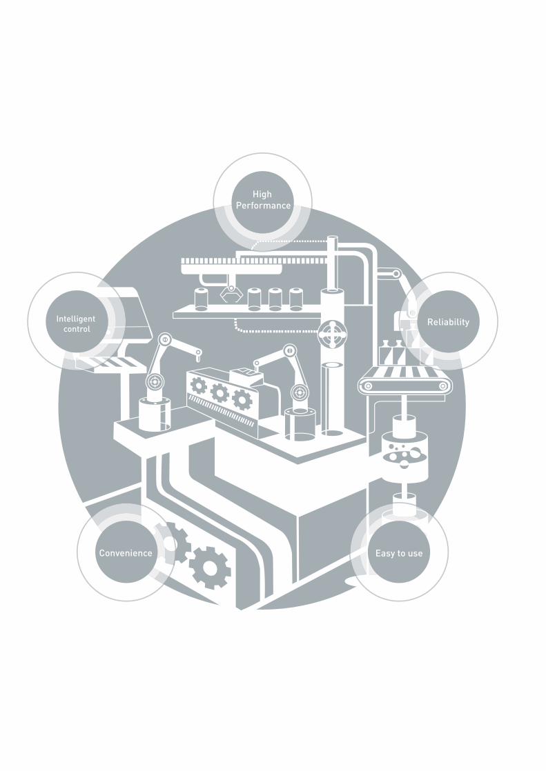
High Performance
Intelligent control
Convenience
Reliability
Easy to use
XGT Servo System
XGT Servo System(XDL/XML) 2 / 3
XDL/XML Series
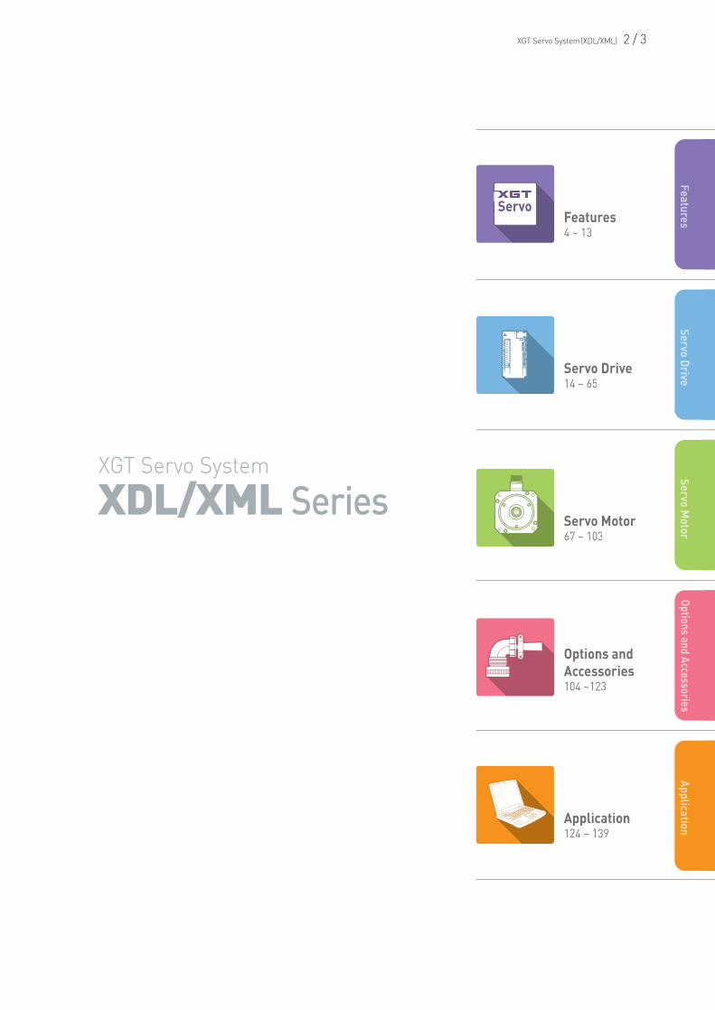
Features4 ~ 13
Servo Drive14 ~ 65
Servo Motor67 ~ 103
Options and Accessories104 ~123
Application124 ~ 139
Servo
FeaturesServo Drive
Servo Motor
Options and AccessoriesApplication
Intro
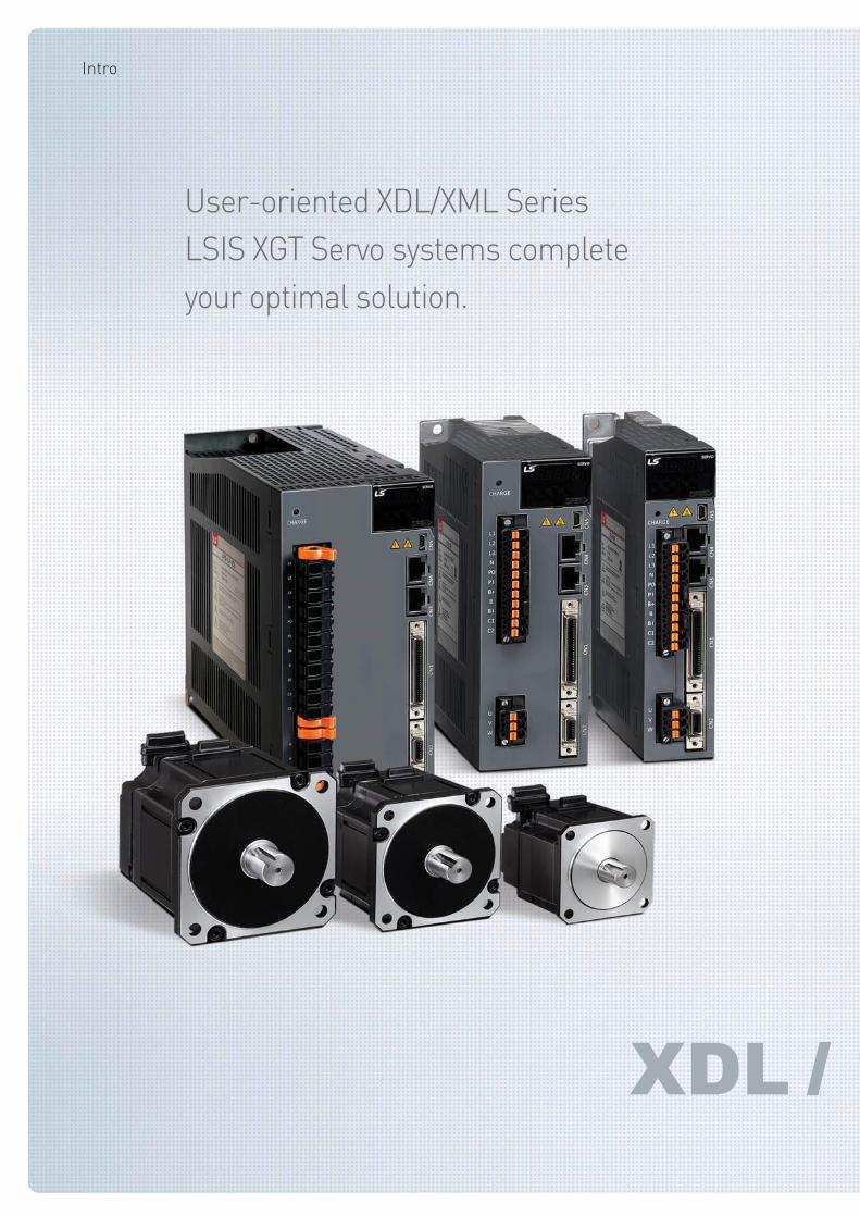
User-oriented XDL/XML Series
LSIS XGT Servo systems complete
your optimal solution.
XGT Servo System(XDL/XML) 4 / 5
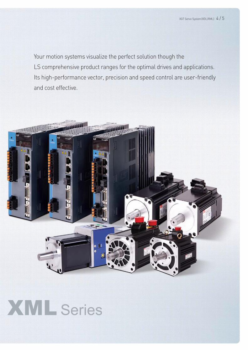
Your motion systems visualize the perfect solution though the
LS comprehensive product ranges for the optimal drives and applications.
Its high-performance vector, precision and speed control are user-friendly
and cost effective.
Features
•Long-life type capacitor applied (2.5 times improvement)
Main capacitor quality improved
•Power connection to DC-link
•Easier wiring and smaller size
compared to 3-phase AC reactor
•Connection for DC input (PI, N)
Convenient DC reactor installable
Stable turn-off function based on the detection
of the control power turn-off
•Triple protection functions for power module
: IPM fault, CL detecting, over current detecting with S/W
•Main power mis-wiring detecting function : Selecting 3 phase
or single phase, and alarm or warning is available
•Protecting overheating with thermal sensor in the drive and motor
•Alarm code grouping and exclusive output contacts
(AL00, AL01, AL02)
•Warning function (digital output, warning output)
: Mis-wiring of power, low voltage for encoder battery, over speed command, over torque command, over load, mis-matched motor and drive
Upgraded protection function(I)
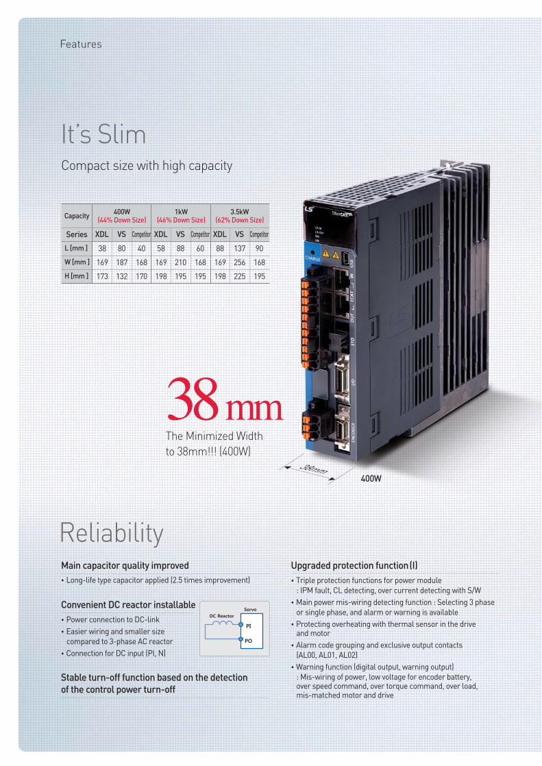
Capacity
Series
400W(44% Down Size)
1kW(46% Down Size)
3.5kW(62% Down Size)
XDL
38
169
173
VS
80
187
132
Competitor
40
168
170
XDL
58
169
198
VS
88
210
195
Competitor
60
168
195
XDL
88
169
198
VS
137
256
225
Competitor
90
168
195
L [mm ]
W [mm ]
H [mm ]
It’s Slim
Reliability
Compact size with high capacity
400W
38mmThe Minimized Width
to 38mm!!! (400W)
XGT Servo System(XDL/XML) 6 / 7
CE, RoHS certificated
•Detecting function for accumulated over load of regenerative resistor
: Protect algorithm is provided with embedded resistor characteristic
: Protection by capacity (P0-11) and resistance (P0-10)
: Providing de-rating factor for radiant heat
•Available continuous overload capacity setting as followed
operating condition
: Protect with separated overload table at stall & operation
: Set overload check level (P0-12)
: Setting warning signal output level is available (P0-13)
Upgraded protection function(II)
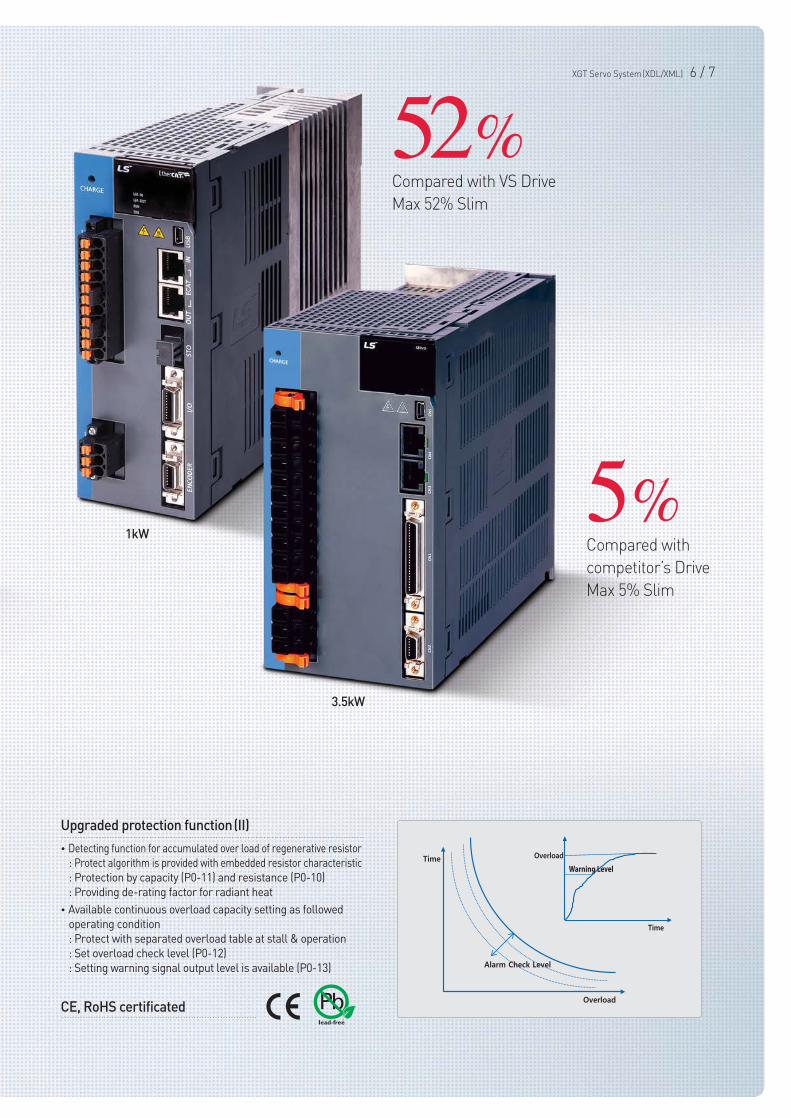
1kW
3.5kW
52%Compared with VS Drive
Max 52% Slim
5%Compared with
competitor’s Drive
Max 5% Slim
•Quick & Accurate Inertia Estimating
•On-Line Tuning: L7NH, L7P
•Off-Line Tuning: L7N, L7S
•Parameter for Estimation (Speed &Distance)
Easy gain tuning with automatic inertia
estimating function
•L7S: Digital input contacts: 10, output contacts: 8 / Analog input contacts: 2 and output contacts: 2
•L7N: Digital input contacts: 6, output contacts: 4 / Analog input contacts: 2 and output contacts: 2
•L7NH: Digital input contacts: 8, output contacts: 4 / Analog input contacts: 1 and output contacts: 2
•L7P: Digital input contacts: 16, output contacts: 8 / Analog input contacts: 2 and output contacts: 2
•PEGASUS: Digital input contacts: 4, output contacts: 2 / Analog input contacts: 1 and output contacts: 1
•Flexible assignment of input/output signals by parameters and contact setting based on the input/output contact type (N.O / N.C contacts)
Sufficient input/output contacts and various functions
•Automatic Identification (Motor ID /Encoder pulse)
•BiSS protocol
•Easy wiring (15 encoder wires→7 encoder wires) and anti-external noise
Encoder with bi-directional high speed serial
communication
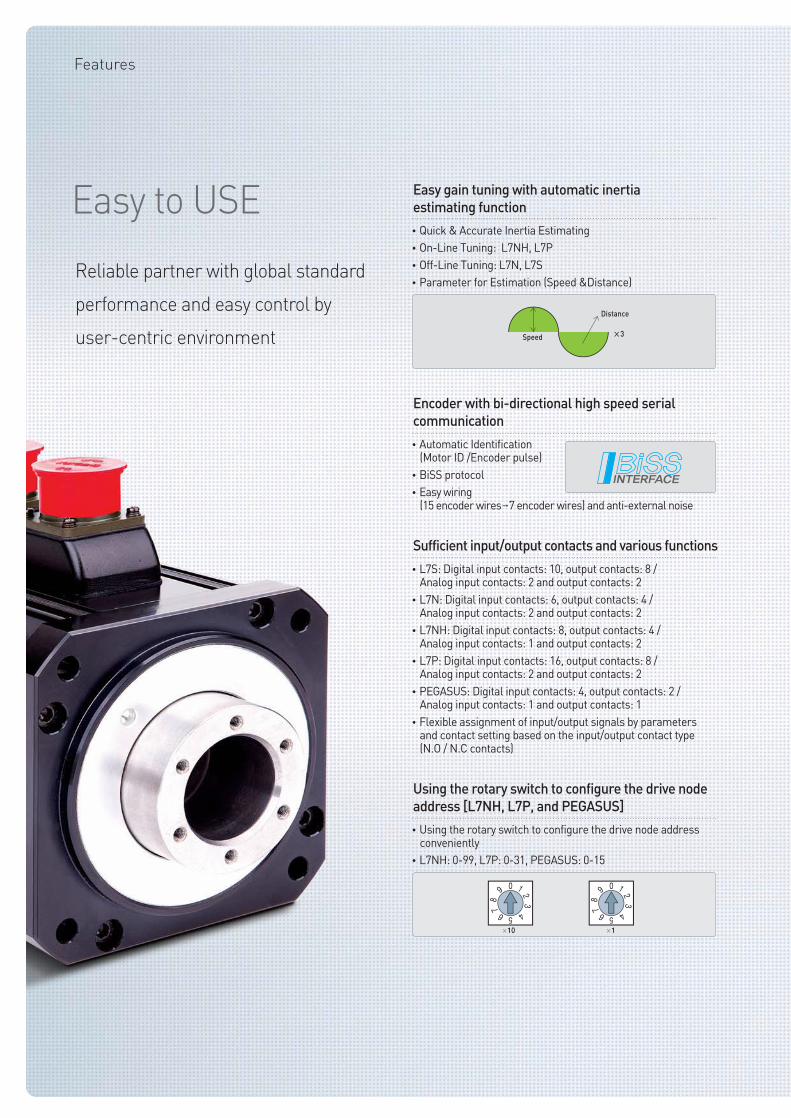
Reliable partner with global standard
performance and easy control by
user-centric environment Speed
Distance
×3
•Using the rotary switch to configure the drive node address conveniently
•L7NH: 0-99, L7P: 0-31, PEGASUS: 0-15
Using the rotary switch to configure the drive node
address [L7NH, L7P, and PEGASUS]
Features
Easy to USE
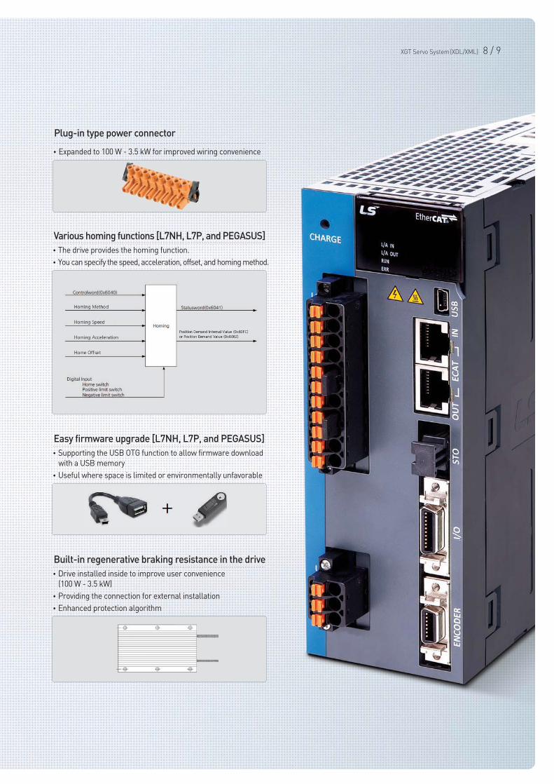
•Expanded to 100 W - 3.5 kW for improved wiring convenience
Plug-in type power connector
•The drive provides the homing function.
•You can specify the speed, acceleration, offset, and homing method.
Various homing functions [L7NH, L7P, and PEGASUS]
•Supporting the USB OTG function to allow firmware download
with a USB memory
•Useful where space is limited or environmentally unfavorable
Easy firmware upgrade [L7NH, L7P, and PEGASUS]
•Drive installed inside to improve user convenience
(100 W - 3.5 kW)
•Providing the connection for external installation
•Enhanced protection algorithm
Built-in regenerative braking resistance in the drive
XGT Servo System(XDL/XML) 8 / 9
XGT Servo series with high speed, incredible performance,
smart and convenience. It’s time to check value of XDL/XML series
Features
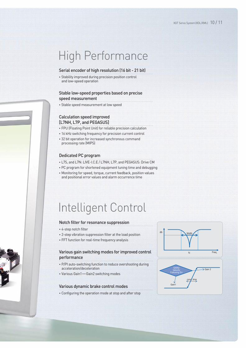
Serial encoder of high resolution (16 bit - 21 bit)
•Stability improved during precision position control and low-speed operation
Stable low-speed properties based on precise
speed measurement
•Stable speed measurement at low speed
Notch filter for resonance suppression
•4-step notch filter
•2-step vibration suppression filter at the load position
•FFT function for real-time frequency analysis
Various gain switching modes for improved control
performance
•P/PI auto-switching function to reduce overshooting during acceleration/deceleration
•Various Gain1↔Gain2 switching modes
Calculation speed improved
[L7NH, L7P, and PEGASUS]
•FPU (Floating Point Unit) for reliable precision calculation
•16 kHz switching frequency for precision current control
•32 bit operation for increased synchronous command processing rate (MIPS)
Dedicated PC program
•L7S, and L7N: LIVE-I.C.E / L7NH, L7P, and PEGASUS: Drive CM
•PC program for shortened equipment tuning time and debugging
•Monitoring for speed, torque, current feedback, position values and positional error values and alarm occurrence time
Various dynamic brake control modes
•Configuring the operation mode at stop and after stop
XGT Servo System(XDL/XML) 10 / 11
High Performance
Intelligent Control
Features
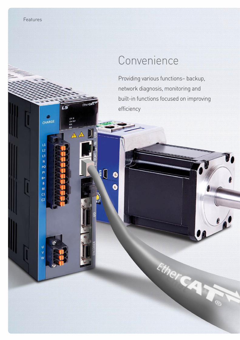
Providing various functions– backup,
network diagnosis, monitoring and
built-in functions focused on improving
efficiency
Convenience
High Performance
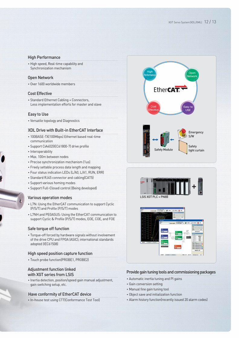
•High speed, Real-time capability and
Synchronization mechanism
Open Network
•Over 1600 worldwide members
Cost Effective
•Standard Ethernet Cabling + Connectors,
Less implementation efforts for master and slave
Various operation modes
•L7N: Using the EtherCAT communication to support Cyclic
(P/S/T) and Profile (P/S/T) modes
•L7NH and PEGASUS: Using the EtherCAT communication to
support Cyclic & Profile (P/S/T) modes, EOE, COE, and FOE
Safe torque off function
•Torque-off forced by hardware signals without involvement
of the drive CPU and FPGA (ASIC); international standards
adopted (IEC61508)
Adjustment function linked
with XGT series from LSIS
•Inertia detection, position/speed gain manual adjustment,
gain switching setup, etc.
Have conformity of EtherCAT device
•In-house test using CTT(Conformance Test Tool)
High speed position capture function
•Touch probe function(PROBE1, PROBE2)
Provide gain tuning tools and commissioning packages
•Automatic inertia tuning and PI gains
•Gain conversion setting
•Manual fine gain tuning tool
•Object save and initialization function
•Alarm history function(recently issued 20 alarm codes)
XDL Drive with Built-in EtherCAT Interface
•100BASE-TX(100Mbps) Ethernet based real-time
communication
•Support CiA402(IEC61800-7) drive profile
•Interoperability
•Max. 100m between nodes
•Precise synchronization mechanism (1us)
•Freely settable process data length and mapping
•Four status indication LEDs (L/A0, L/A1, RUN, ERR)
•Standard RJ45 connector and cabling(CAT5)
•Support various homing modes
•Support Full-Closed control (Being developed)
LSIS XGT PLC + PN8B
+
Emergency
S/W
Safety
light curtainSafety Module
Easy to Use
•Versatile topology and Diagnostics
XGT Servo System(XDL/XML) 12 / 13
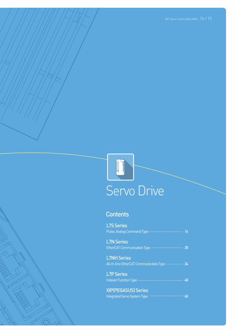
Servo Drive
Contents
L7S SeriesPulse, Analog Command Type 16
L7N SeriesEtherCAT Communication Type 28
L7NH SeriesAll-in-One EtherCAT Communication Type 34
L7P SeriesIndexer Function Type 48
XIP(PEGASUS) SeriesIntegrated Servo System Type 60
XGT Servo System(XDL/XML) 14 / 15
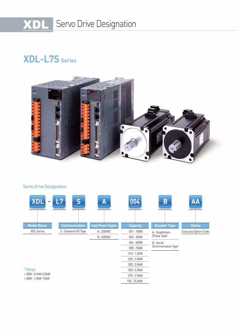
XDL-L7S Series
Model Name Communication Capacity Encoder Type OptionInput Power Supply
XDL Series S : Standard I/O Type A : 200VAC
B : 400VAC
Exclusive Option Code001 : 100W
002 : 200W
004 : 400W
008 : 750W
010 : 1.0kW
020 : 2.0kW
035 : 3.5kW
050 : 5.0kW
075 : 7.5kW
150 : 15.0kW
A : Quadrature(Pulse Type)
B : Serial(Communication Type)
Servo Drive Designation
Servo Drive Designation
* Range•200V : 0.1kW~5.0kW
•400V : 1.0kW~15kW
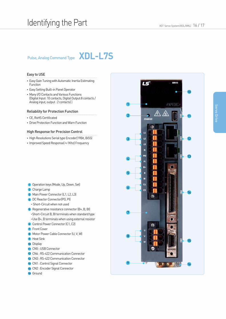
Pulse, Analog Command Type XDL-L7S
Operation keys (Mode, Up, Down, Set)
Charge Lamp
Main Power Connector (L1, L2, L3)
DC Reactor Connector(PO, PI)
Short-Circuit when not used
Regenerative resistance connector (B+, B, BI)
Short-Circuit B, BI terminals when standard type
Use B+, B terminals when using external resistor
Control Power Connector (C1, C2)
Front Cover
Motor Power Cable Connector (U, V, W)
Heat Sink
Display
CN5 : USB Connector
CN4 : RS-422 Communication Connector
CN3 : RS-422 Communication Connector
CN1 : Control Signal Connector
CN2 : Encoder Signal Connector
Ground
1
2
3
4
5
6
7
8
9
10
11
12
13
14
15
16
1
10
11
12
13
14
15
169
2
3
4
5
6
7
8
Identifying the Part XGT Servo System(XDL/XML) 16 / 17
•Easy Gain Tuning with Automatic Inertia Estimating Function
•Easy Setting Built-in Panel Operator
•Many I/O Contacts and Various Functions(Digital Input: 10 contacts, Digital Output:8 contacts / Analog input, output : 2 contacts) ]
Easy to USE
•CE, RoHS Certificated
•Drive Protection Function and Warn Function
Reliability for Protection Function
•High Resolutions Serial type Encoder(19Bit, BiSS)
•Improved Speed Response(≒1Khz) Frequency
High Response for Precision Control
Se
rvo D
rive
Drive Combination Table
* 3,000 P/R
* 1,048 P/R
* 2,048 P/R
* 2,048 P/R
40
40
40
40
60
60
60
80
80
80
80
130
130
130
130
180
180
80
80
80
80
130
130
130
130
180
180
180
220
220
220
130
130
130
130
180
180
180
220
220
220
130
130
130
130
180
180
180
180
220
220
220
220
60
60
60
130
130
130
3,000
2,000
1,500
1,000
3,000
5,000
XLCS-PGS
XLCS-PGS
XLCS-EAS
XLCS-EBS
XLCS-EBS
XLCS-EAS
XLCS-EAS
XLCS-EBS
XLCS-PHS
XLCS-PHS
XLCS-PHS
XLCS-PHS
XLCS-PHS
XLCS-PIS
XLCS-PIS
XLCS-PIS
XLCS-PIS
XLCS-PIS
XLCS-PIS
XLCS-PIS
XLCS-PJS
XLCS-PJS
XLCS-PJS
XLCS-PJS
XLCS-PJS
XLCS-PJS
XLCS-PJS
XLCS-PGS
XLCS-PNB
XLCS-PNB
XLCS-PNB
XLCS-PNB
XLCS-PLB
XLCS-PLB
XLCS-PPB
XLCS-PPB
XLCS-PPB
XLCS-PPB
XLCS-PLB
XLCS-PLB
-
-
XLCS-PKB-
-
-
-
-
-
-
-
XLCS-PKB
XLCS-PSB
XLCS-PSB
XLCS-PSB
3,000
2,700
3,000
3,000
2,700
3,000
1,700
1,700
2,000
2,000
2,000
3,500
SAR3A
SAR5A
SA01A
SA015A
SB01A
SB02A
SB04A
SC04A
SC06A
SC08A
SC10A
SE09A
SE15A
SE22A
SE30A
SF30A
SF50A
SC03D
SC05D
SC06D
SC07D
SE06D
SE11D
SE16D
SE22D
SF22D
LF35D
SF55D
SG22D
LG35D
SG55D
SE05G
SE09G
SE13G
SE17G
SF20G
LF30G
SF44G
SG20G
LG30G
SG44G
SE03M
SE06M
SE09M
SE12M
SF12M
SF20M
LF30M
SF44M
SG12M
SG20M
LG30M
SG44M
HB01A
HB02A
HB04A
HE09A
HE15A
HE30A
L7SA001A
L7SA001A
L7SA001A
L7SA004A
L7SA002A
L7SA002A
L7SA004A
L7SA004A
L7SA008A
L7SA008A
L7SA010A
L7SA008A
L7SA020A
L7SA020A
L7SA035A
L7SA035A
L7SA050A
L7SA004A
L7SA008A
L7SA008A
L7SA008A
L7SA008A
L7SA010A
L7SA020A
L7SA020A
L7SA020A
L7SA035A
L7SA050A
L7SA020A
L7SA035A
L7SA050A
L7SA008A
L7SA010A
L7SA020A
L7SA020A
L7SA035A
L7SA035A
L7SA050A
L7SA020A
L7SA035A
L7SA050A
L7SA004A
L7SA008A
L7SA010A
L7SA020A
L7SA020A
L7SA035A
L7SA035A
L7SA050A
L7SA020A
L7SA035A
L7SA035A
L7SA050A
L7SA002A
L7SA002A
L7SA004A
L7SA008A
L7SA020A
L7SA035A
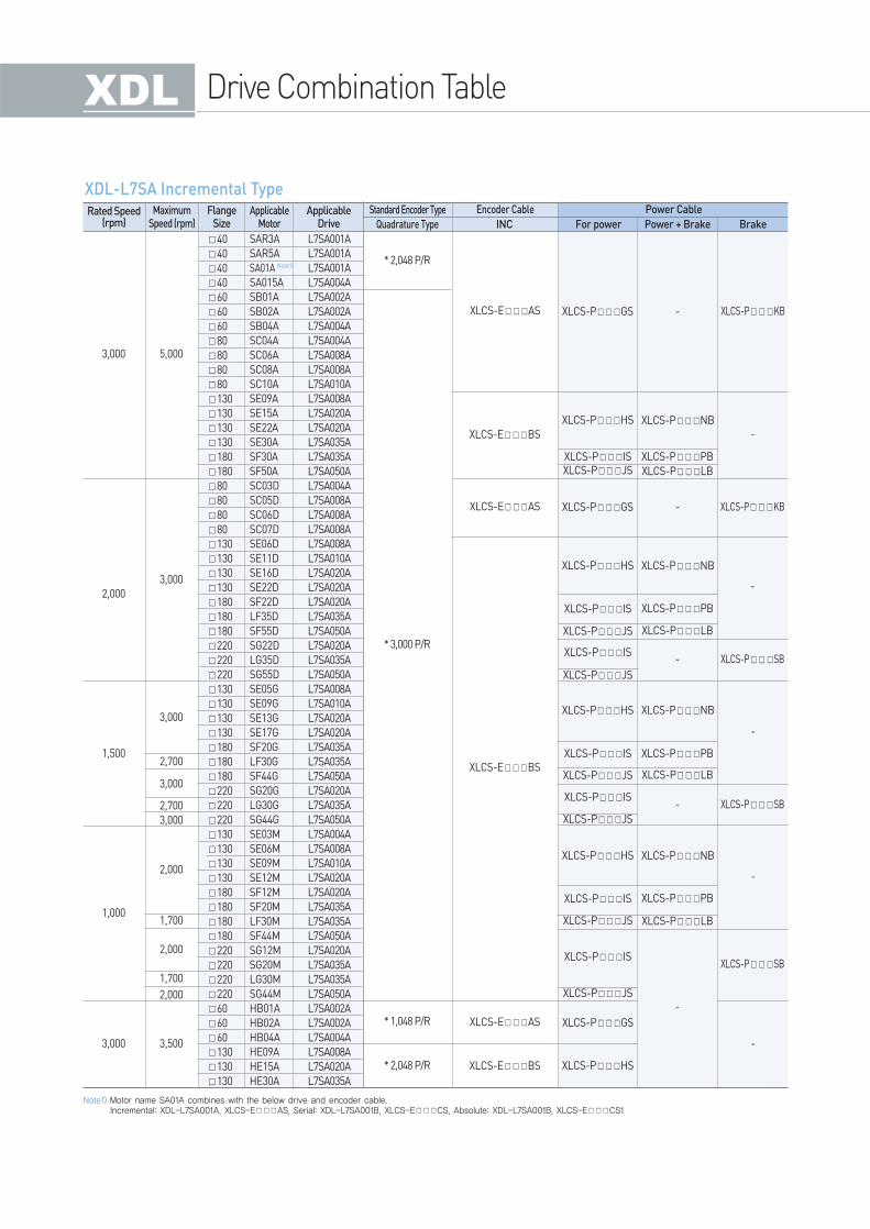
FlangeSize
Rated Speed(rpm)
MaximumSpeed (rpm)
ApplicableMotor
ApplicableDrive Quadrature Type
Standard Encoder Type
INC For power Power + Brake Brake
Encoder Cable Power Cable
XDL-L7SA Incremental Type
Note1)
Note1) Motor name SA01A combines with the below drive and encoder cable.Incremental: XDL-L7SA001A, XLCS-EAS, Serial: XDL-L7SA001B, XLCS-ECS, Absolute: XDL-L7SA001B, XLCS-ECS1
XGT Servo System(XDL/XML) 18 / 19
Se
rvo D
rive
* 19Bit SerialM-TurnAbsolute
* 18Bit SerialM-TurnAbsolute
40
40
40
60
60
60
80
80
80
80
60
60
60
80
80
80
80
130
130
130
130
180
180
80
80
80
80
80
80
80
80
130
130
130
130
180
180
180
220
220
220
130
130
130
130
180
180
180
220
220
220
130
130
130
130
180
180
180
180
220
220
220
220
3,000
2,000
1,500
1,000
5,000
XLCS-PLS
XLCS-PLS
XLCS-PFS
XLCS-PFS
XLCS-PHS
XLCS-PHS
XLCS-PHS
XLCS-PHS
XLCS-PIS
XLCS-PIS
XLCS-PIS
XLCS-PIS
XLCS-PIS
XLCS-PIS
XLCS-PJS
XLCS-PJS
XLCS-PJS
XLCS-PJS
XLCS-PJS
XLCS-PJS
XLCS-PIS
XLCS-PJS
XLCS-PPB
XLCS-PLB
XLCS-EES
XLCS-EDS
XLCS-EDS
XLCS-EES
XLCS-EES1
XLCS-EDS1
XLCS-EDS1
XLCS-EES1
XLCS-PNB
XLCS-PNB
XLCS-PNB
XLCS-PNB
XLCS-PPB
XLCS-PPB
XLCS-PPB
XLCS-PLB
XLCS-PLB
XLCS-PLB
-
XLCS-BQS
XLCS-BQS
XLCS-PSB
XLCS-PSB
XLCS-PSB
-
-
-
-
-
-
-
-
2,700
3,000
2,700
2,700
3,000
3,000
3,000
3,000
2,000
2,000
1,700
1,700
2,000
FALR5A
FAL01A
FAL015A
FBL01A
FBL02A
FBL04A
FCL04A
FCL06A
FCL08A
FCL10A
FB01A
FB02A
FB04A
FC04A
FC06A
FC08A
FC10A
FE09A
FE15A
FE22A
FE30A
FF30A
FF50A
FCL03D
FCL05D
FCL06D
FCL07D
FC03D
FC05D
FC06D
FC07D
FE06D
FE11D
FE16D
FE22D
FF22D
FF35D
FF55D
FG22D
FG35D
FG55D
FE05G
FE09G
FE13G
FE17G
FF20G
FF30G
FF44G
FG20G
FG30G
FG44G
FE03M
FE06M
FE09M
FE12M
FF12M
FF20M
FF30M
FF44M
FG12M
FG20M
FG30M
FG44M
L7SA001B
L7SA001B
L7SA004B
L7SA001B
L7SA002B
L7SA004B
L7SA004B
L7SA008B
L7SA008B
L7SA010B
L7SA001B
L7SA002B
L7SA004B
L7SA004B
L7SA008B
L7SA008B
L7SA010B
L7SA010B
L7SA020B
L7SA020B
L7SA035B
L7SA035B
L7SA050B
L7SA004B
L7SA008B
L7SA008B
L7SA008B
L7SA004B
L7SA008B
L7SA008B
L7SA008B
L7SA008B
L7SA010B
L7SA020B
L7SA020B
L7SA020B
L7SA035B
L7SA050B
L7SA020B
L7SA035B
L7SA050B
L7SA008B
L7SA010B
L7SA020B
L7SA020B
L7SA020B
L7SA035B
L7SA050B
L7SA020B
L7SA035B
L7SA050B
L7SA004B
L7SA008B
L7SA010B
L7SA020B
L7SA020B
L7SA020B
L7SA035B
L7SA050B
L7SA020B
L7SA020B
L7SA035B
L7SA050B
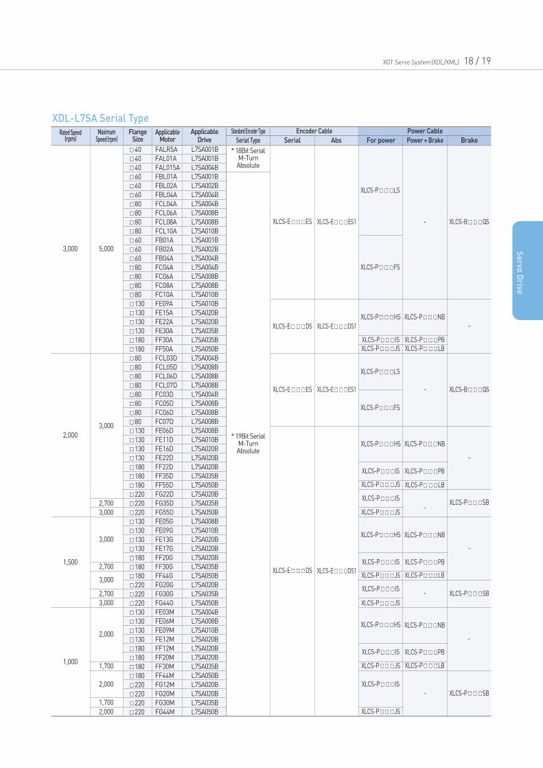
FlangeSize
Rated Speed(rpm)
MaximumSpeed (rpm)
ApplicableMotor
ApplicableDrive Serial Type
Standard Encoder Type
Serial Abs For power Power + Brake Brake
Encoder Cable Power Cable
XDL-L7SA Serial Type
Drive Combination Table
* 19Bit SerialAbsolute XLCS-EDS XLCS-EDS1
130
130
130
130
180
180
130
130
130
130
180
180
180
180
220
220
220
220
220
130
130
130
130
180
180
180
180
180
220
220
220
220
220
220
220
130
130
130
130
180
180
180
180
220
220
220
220
220
3,000
2,000
1,500
1,000
5,000
3,000
3,000
XLCF-PHS
XLCF-PHS
XLCF-PHS
XLCF-PHS
XLCF-PIS
XLCF-PIS
XLCF-PIS
XLCF-PIS
XLCF-PIS
XLCF-PIS
XLCF-PJS
XLCF-PJS
XLCF-PJS
XLCF-PJS
XLCF-PJS
XLCF-PJS
XLCF-PMS
XLCF-PPB
XLCF-PPB
XLCF-PPB
XLCF-PLB
XLCF-PLB
XLCF-PLB
XLCF-PSB
-
-
-
-
-
-
XLCF-PSB
XLCF-PSB
XLCF-PNB
XLCF-PNB
XLCF-PNB
XLCF-PNB
XLCF-PIS
XLCF-PJS
XLCF-PMS
XLCF-PMS
XLCF-PMS
XLCF-PPB
XLCF-PLB
2,500
3,000
2,500
2,000
2,000
1,700
2,000
FEP09A
FEP15A
FEP22A
FEP30A
FFP30A
FFP50A
FEP06D
FEP11D
FEP16D
FEP22D
FFP22D
FFP35D
FFP55D
FFP75D
FGP22D
FGP35D
FGP55D
FGP75D
FGP110D
FEP05G
FEP09G
FEP13G
FEP17G
FFP20G
FFP30G
FFP44G
FFP60G
FFP75G
FGP20G
FGP30G
FGP44G
FGP60G
FGP85G
FGP110G
FGP150G
FEP03M
FEP06M
FEP09M
FEP12M
FFP12M
FFP20M
FFP30M
FFP44M
FGP12M
FGP20M
FGP30M
FGP44M
FGP60M
2,500
2,700
3,000
2,500
2,200
3,000
2,700
3,000
L7SB010B
L7SB020B
L7SB035B
L7SB035B
L7SB035B
L7SB050B
L7SB010B
L7SB010B
L7SB020B
L7SB020B
L7SB020B
L7SB035B
L7SB050B
L7SB075B
L7SB020B
L7SB035B
L7SB050B
L7SB075B
L7SB150B
L7SB010B
L7SB010B
L7SB020B
L7SB020B
L7SB020B
L7SB035B
L7SB050B
L7SB075B
L7SB075B
L7SB020B
L7SB035B
L7SB050B
L7SB075B
L7SB150B
L7SB150B
L7SB150B
L7SB010B
L7SB010B
L7SB010B
L7SB020B
L7SB020B
L7SB020B
L7SB035B
L7SB050B
L7SB020B
L7SB020B
L7SB050B
L7SB050B
L7SB075B
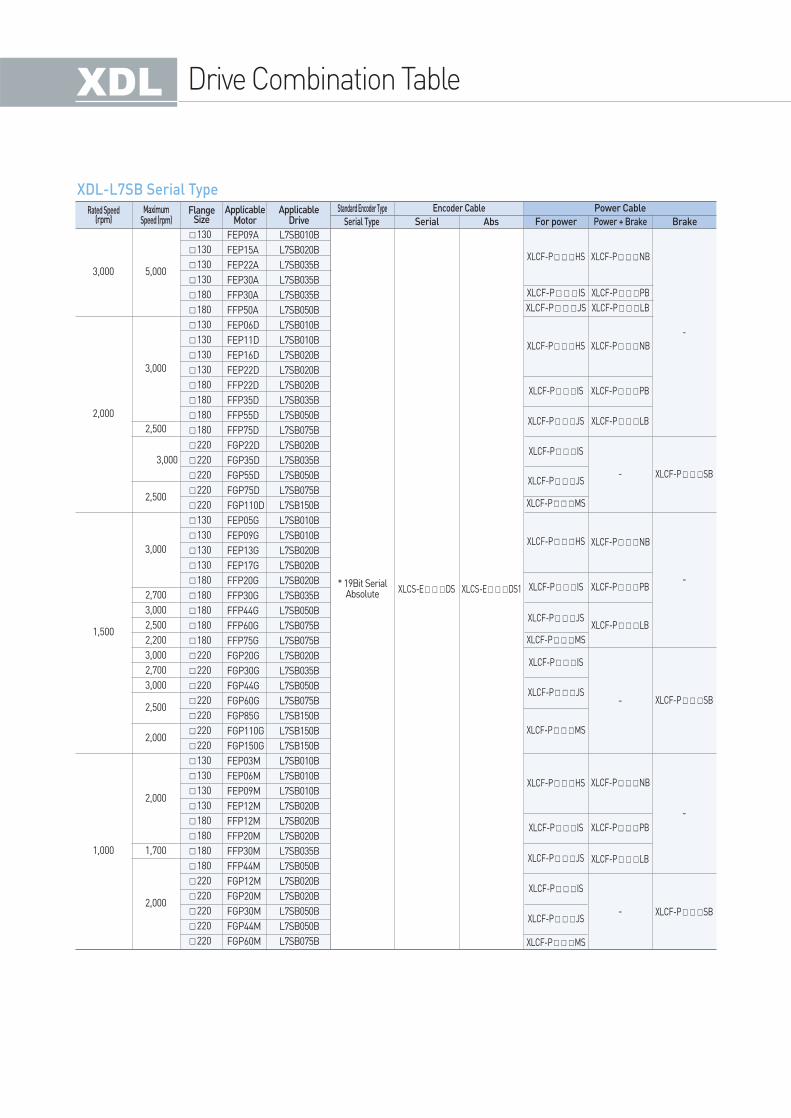
FlangeSize
Rated Speed(rpm)
MaximumSpeed (rpm)
ApplicableMotor
ApplicableDrive Serial Type
Standard Encoder Type
Serial Abs For power Power + Brake Brake
Encoder Cable Power Cable
XDL-L7SB Serial Type
Drive Product Features XGT Servo System(XDL/XML) 20 / 21
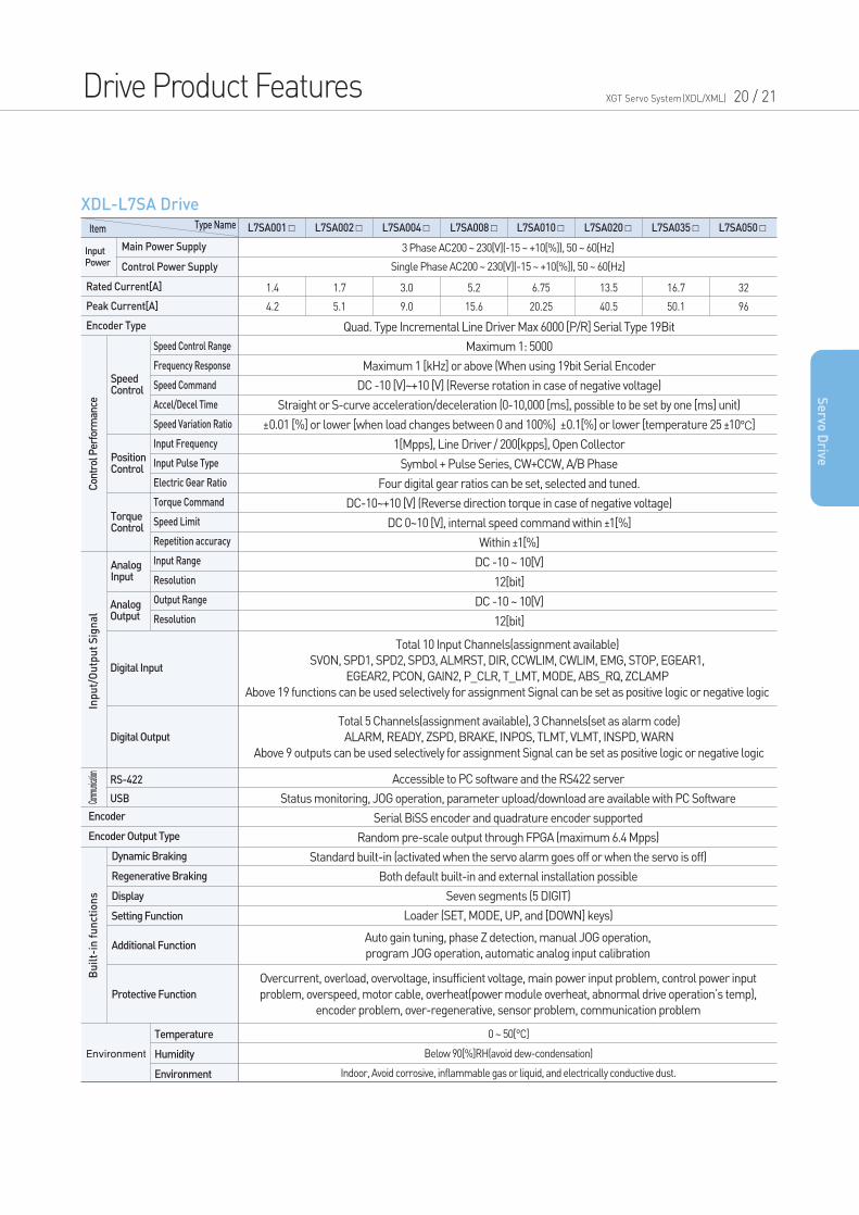
XDL-L7SA Drive
Item
InputPower
Con
trol
Per
form
ance
Inp
ut/
Ou
tpu
t S
ign
al
Bu
ilt-
in f
un
ctio
ns
Type Name
3 Phase AC200 ~ 230[V](-15 ~ +10[%]), 50 ~ 60[Hz]
Single Phase AC200 ~ 230[V](-15 ~ +10[%]), 50 ~ 60[Hz]
Quad. Type Incremental Line Driver Max 6000 [P/R] Serial Type 19Bit
Maximum 1: 5000
Maximum 1 [kHz] or above (When using 19bit Serial Encoder
DC -10 [V]~+10 [V] (Reverse rotation in case of negative voltage)
Straight or S-curve acceleration/deceleration (0-10,000 [ms], possible to be set by one [ms] unit)
±0.01 [%] or lower [when load changes between 0 and 100%] ±0.1[%] or lower [temperature 25 ±10°C]
1[Mpps], Line Driver / 200[kpps], Open Collector
Symbol + Pulse Series, CW+CCW, A/B Phase
Four digital gear ratios can be set, selected and tuned.
DC-10~+10 [V] (Reverse direction torque in case of negative voltage)
DC 0~10 [V], internal speed command within ±1[%]
Within ±1[%]
DC -10 ~ 10[V]
12[bit]
DC -10 ~ 10[V]
12[bit]
Accessible to PC software and the RS422 server
Status monitoring, JOG operation, parameter upload/download are available with PC Software
Serial BiSS encoder and quadrature encoder supported
Random pre-scale output through FPGA (maximum 6.4 Mpps)
Standard built-in (activated when the servo alarm goes off or when the servo is off)
Both default built-in and external installation possible
Seven segments (5 DIGIT)
Loader (SET, MODE, UP, and [DOWN] keys)
0 ~ 50[°C]
Below 90[%]RH(avoid dew-condensation)
Indoor, Avoid corrosive, inflammable gas or liquid, and electrically conductive dust.
Auto gain tuning, phase Z detection, manual JOG operation,
program JOG operation, automatic analog input calibration
Overcurrent, overload, overvoltage, insufficient voltage, main power input problem, control power input
problem, overspeed, motor cable, overheat(power module overheat, abnormal drive operation’s temp),
encoder problem, over-regenerative, sensor problem, communication problem
Total 10 Input Channels(assignment available)
SVON, SPD1, SPD2, SPD3, ALMRST, DIR, CCWLIM, CWLIM, EMG, STOP, EGEAR1,
EGEAR2, PCON, GAIN2, P_CLR, T_LMT, MODE, ABS_RQ, ZCLAMP
Above 19 functions can be used selectively for assignment Signal can be set as positive logic or negative logic
Total 5 Channels(assignment available), 3 Channels(set as alarm code)
ALARM, READY, ZSPD, BRAKE, INPOS, TLMT, VLMT, INSPD, WARN
Above 9 outputs can be used selectively for assignment Signal can be set as positive logic or negative logic
1.4
4.2
1.7
5.1
3.0
9.0
5.2
15.6
6.75
20.25
13.5
40.5
16.7
50.1
32
96
L7SA001 L7SA002 L7SA004 L7SA008 L7SA010 L7SA020 L7SA035 L7SA050
Main Power Supply
Control Power Supply
Rated Current[A]
Peak Current[A]
Encoder Type
Encoder
Encoder Output Type
SpeedControl
PositionControl
TorqueControl
AnalogInput
AnalogOutput
Digital Input
Digital Output
Comm
unicat
ion
Environment
RS-422
USB
Speed Control Range
Frequency Response
Speed Command
Accel/Decel Time
Speed Variation Ratio
Input Frequency
Input Pulse Type
Electric Gear Ratio
Torque Command
Speed Limit
Repetition accuracy
Input Range
Resolution
Output Range
Resolution
Temperature
Humidity
Environment
Dynamic Braking
Regenerative Braking
Display
Setting Function
Additional Function
Protective Function
Se
rvo D
rive
Drive Product Features
Item
InputPower
Type Name
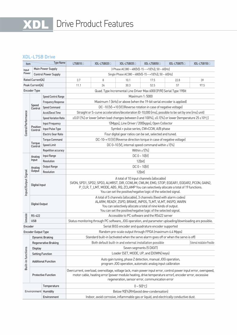
3 Phase AC380 ~ 480[V](-15 ~ +10[%]), 50 ~ 60[Hz]
Single Phase AC380 ~ 480[V](-15 ~ +10[%]), 50 ~ 60[Hz]
Quad. Type Incremental Line Driver Max 6000 [P/R] Serial Type 19Bit
Maximum 1: 5000
Maximum 1 [kHz] or above (when the 19-bit serial encoder is applied)
DC -10 [V]~+10 [V] (Reverse rotation in case of negative voltage)
Straight or S-curve acceleration/deceleration (0-10,000 [ms], possible to be set by one [ms] unit)
±0.01 [%] or lower [when load changes between 0 and 100%], ±0.1[%] or lower [temperature 25 ±10°C]
1[Mpps], Line Driver / 200[kpps], Open Collector
Symbol + pulse series, CW+CCW, A/B phase
Four digital gear ratios can be set, selected and tuned.
DC-10~+10 [V] (Reverse direction torque in case of negative voltage)
DC 0~10 [V], internal speed command within ±1[%]
Within ±1[%]
DC 0 ~ 10[V]
12[bit]
DC 0 ~ 10[V]
12[bit]
Accessible to PC software and the RS422 server
Status monitoring through PC software, JOG operation, and parameter uploading/downloading are possible.
Serial BiSS encoder and quadrature encoder supported
Random pre-scale output through FPGA (maximum 6.4 Mpps)
Standard built-in (activated when the servo alarm goes off or when the servo is off)
Seven segments (5 DIGIT)
Loader (SET, MODE, UP, and [DOWN] keys)
0 ~ 50[°C]
Below 90[%]RH(avoid dew-condensation)
Indoor, avoid corrosive, inflammable gas or liquid, and electrically conductive dust.
Auto gain tuning, phase Z detection, manual JOG operation,
program JOG operation, automatic analog input calibration
Overcurrent, overload, overvoltage, voltage lack, main power input error, control power input error, overspeed,
motor cable, heating error (power module heating, drive temperature error), encoder error, excessive
regeneration, sensor error, communication error
A total of 10 input channels (allocable)
SVON, SPD1, SPD2, SPD3, ALMRST, DIR, CCWLIM, CWLIM, EMG, STOP, EGEAR1, EGEAR2, PCON, GAIN2,
P_CLR, T_LMT, MODE, ABS_RQ, ZCLAMP You can selectively allocate a total of 19 functions.
You can set the positive/negative logic of the selected signal.
A total of 5 channels (allocable), 3 channels (fixed with alarm codes)
ALARM, READY, ZSPD, BRAKE, INPOS, TLMT, VLMT, INSPD, WARN
You can selectively allocate a total of nine kinds of output.
You can set the positive/negative logic of the selected signal.
3.7
11.1
8
24
10.1
30.3
17.5
52.5
22.8
57
39
97.5
L7SB010 XDL-L7SB020 XDL-L7SB035 XDL-L7SB050 XDL-L7SB075 XDL-L7SB150
Main Power Supply
Control Power Supply
Rated Current[A]
Peak Current[A]
Encoder Type
Encoder
Encoder Output Type
SpeedControl
PositionControl
TorqueControl
AnalogInput
AnalogOutput
Digital Input
Digital Output
Environment
RS-422
USB
Speed Control Range
Frequency Response
Speed Command
Accel/Decel Time
Speed Variation Ratio
Input Frequency
Input Pulse Type
Electric Gear Ratio
Torque Command
Speed Limit
Repetition accuracy
Input Range
Resolution
Output Range
Resolution
Temperature
Humidity
Environment
Dynamic Braking
Regenerative Braking
Display
Setting Function
Additional Function
Protective Function
XDL-L7SB Drive
Con
trol
Per
form
ance
Inp
ut/
Ou
tpu
t S
ign
al
Bu
ilt-
in f
un
ctio
ns
Comm
unicat
ion
Extemal installation PossibleBoth default built-in and external installation possible
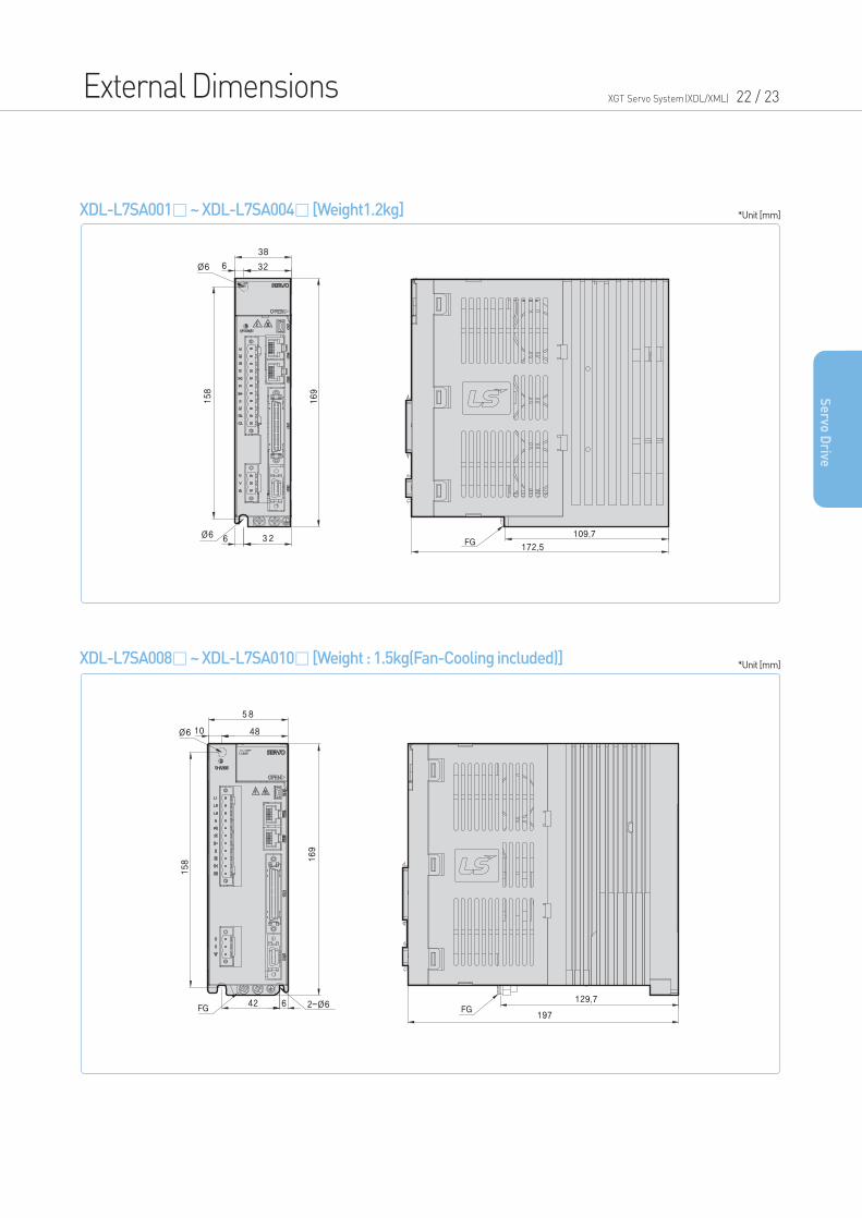
External Dimensions XGT Servo System(XDL/XML) 22 / 23
XDL-L7SA001~ XDL-L7SA004 [Weight1.2kg]
XDL-L7SA008~ XDL-L7SA010 [Weight : 1.5kg(Fan-Cooling included)]
*Unit [mm]
*Unit [mm]
Se
rvo D
rive
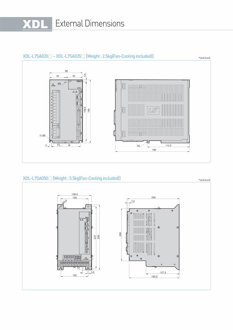
XDL-L7SA020~ XDL-L7SA035 [Weight : 2.5kg(Fan-Cooling included)]
XDL-L7SA050 [Weight : 5.5kg(Fan-Cooling included)]
*Unit [mm]
*Unit [mm]
External Dimensions
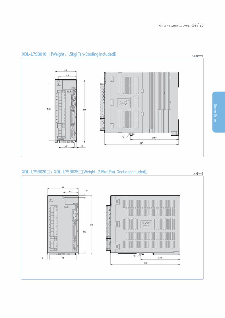
XDL-L7SB010 [Weight : 1.5kg(Fan-Cooling included)]
127.7
197
FG
58
158 169
42 6
48
XDL-L7SB020/ XDL-L7SB035[Weight : 2.5kg(Fan-Cooling included)]
88
5 78
44 44
198
FG112.5
159
169
*Unit [mm]
*Unit [mm]
XGT Servo System(XDL/XML) 24 / 25
Se
rvo D
rive
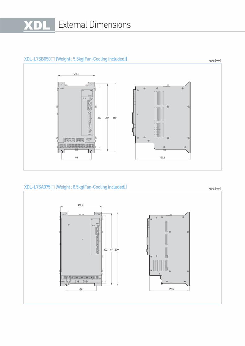
XDL-L7SB050 [Weight : 5.5kg(Fan-Cooling included)]
130.4
105
222 237 250
192.5
XDL-L7SA075 [Weight : 8.5kg(Fan-Cooling included)]
182.4
136
302 317 330
177.5
*Unit [mm]
*Unit [mm]
External Dimensions
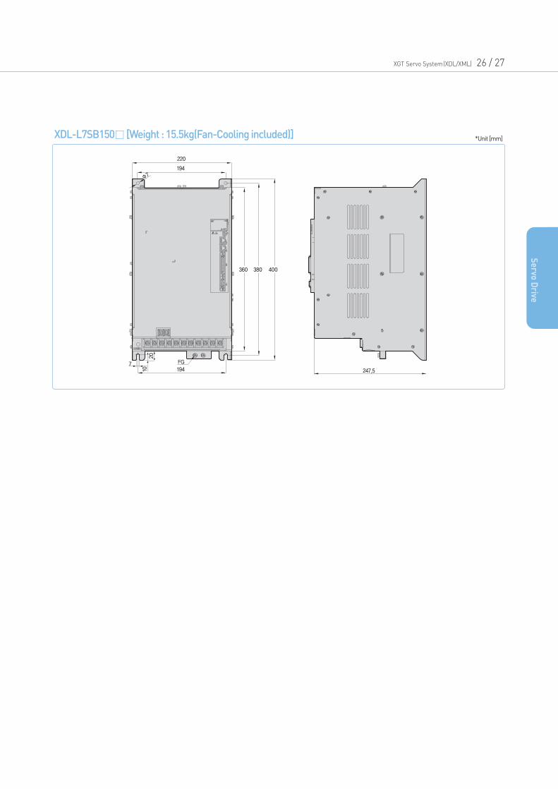
XDL-L7SB150 [Weight : 15.5kg(Fan-Cooling included)]
360 380 400
247.5
Φ7
7 FG
1020
194
220
194
*Unit [mm]
XGT Servo System(XDL/XML) 26 / 27
Se
rvo D
rive
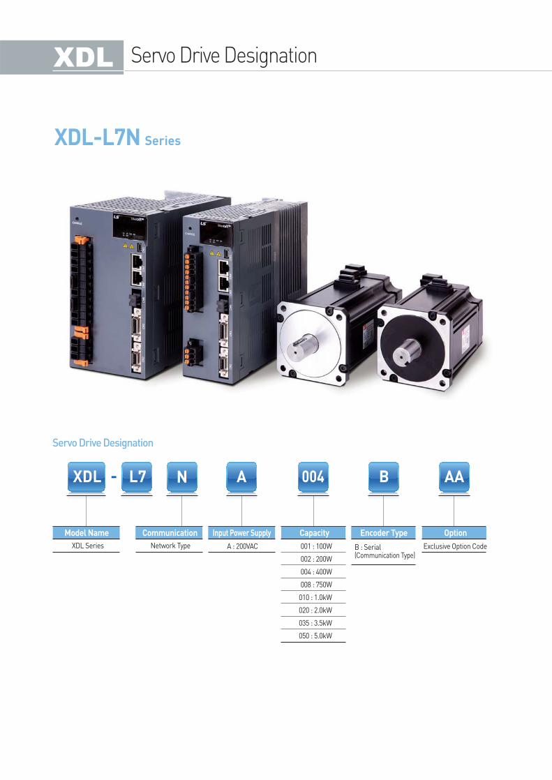
XDL-L7N Series
Model Name Communication Capacity Encoder Type OptionInput Power Supply
XDL Series Network Type A : 200VAC Exclusive Option Code001 : 100W
002 : 200W
004 : 400W
008 : 750W
010 : 1.0kW
020 : 2.0kW
035 : 3.5kW
050 : 5.0kW
B : Serial(Communication Type)
Servo Drive Designation
Servo Drive Designation
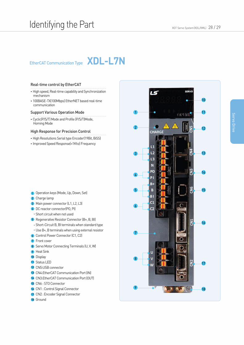
EtherCAT Communication Type XDL-L7N
Identifying the Part XGT Servo System(XDL/XML) 28 / 29
•High speed, Real-time capability and Synchronization mechanism
•100BASE-TX(100Mbps) EtherNET based real-time communication
Real-time control by EtherCAT
•Cyclic(P/S/T) Mode and Profile (P/S/T)Mode, Homing Mode
Support Various Operation Mode
•High Resolutions Serial type Encoder(19Bit, BiSS)
•Improved Speed Response(=1Khz) Frequency
High Response for Precision Control
Se
rvo D
rive
Operation keys (Mode, Up, Down, Set)
Charge lamp
Main power connector (L1, L2, L3)
DC reactor connector(PO, PI)
Short circuit when not used
Regenerative Resistor Connector (B+, B, BI)
Short-Circuit B, BI terminals when standard type
Use B+, B terminals when using external resistor
Control Power Connector (C1, C2)
Front cover
Servo Motor Connecting Terminals (U, V, W)
Heat Sink
Display
Status LED
CN5:USB connector
CN4:EtherCAT Communication Port (IN)
CN3:EtherCAT Communication Port (OUT)
CN6 : STO Connector
CN1 : Control Signal Connector
CN2 : Encoder Signal Connector
Ground
1
2
3
4
5
6
7
8
9
10
11
12
13
14
15
16
17
18
10
11
12
13
14
15
16
17
18
1
9
2
3
4
5
6
7
8
Drive Combination Table
* 19Bit SerialAbsolute
* 18Bit SerialAbsolute
40
40
40
60
60
60
80
80
80
80
60
60
60
80
80
80
80
130
130
130
130
180
180
80
80
80
80
80
80
80
80
130
130
130
130
180
180
180
220
220
220
130
130
130
130
180
180
180
220
220
220
130
130
130
130
180
180
180
180
220
220
220
220
3,000
2,000
1,500
1,000
5,000
XLCS-PLS
XLCS-PLS
XLCS-PFS
XLCS-PFS
XLCS-PHS
XLCS-PHS
XLCS-PHS
XLCS-PIS
XLCS-PIS
XLCS-PIS
XLCS-PIS
XLCS-PIS
XLCS-PIS
XLCS-PJS
XLCS-PJS
XLCS-PJS
XLCS-PJS
XLCS-PJS
XLCS-PJS
XLCS-PHS
XLCS-PIS
XLCS-PJS
XLCS-PPB
XLCS-PLB
XLCS-EES
XLCS-EDS
XLCS-EDS
XLCS-EES
XLCS-EES1
XLCS-EDS1
XLCS-EDS1
XLCS-EES1
XLCS-PNB
XLCS-PNB
XLCS-PNB
XLCS-PPB
XLCS-PNB
XLCS-PPB
XLCS-PPB
XLCS-PLB
-
XLCS-PLB
XLCS-PLB
-
XLCS-BQS
XLCS-BQS
XLCS-PSB
XLCS-PSB
-
-
-
-
-
-
XLCS-PSB
2,700
3,000
2,700
2,700
3,000
1,700
2,000
3,000
3,000
3,000
2,000
1,700
2,000
FALR5A
FAL01A
FAL015A
FBL01A
FBL02A
FBL04A
FCL04A
FCL06A
FCL08A
FCL10A
FB01A
FB02A
FB04A
FC04A
FC06A
FC08A
FC10A
FE09A
FE15A
FE22A
FE30A
FF30A
FF50A
FCL03D
FCL05D
FCL06D
FCL07D
FC03D
FC05D
FC06D
FC07D
FE06D
FE11D
FE16D
FE22D
FF22D
FF35D
FF55D
FG22D
FG35D
FG55D
FE05G
FE09G
FE13G
FE17G
FF20G
FF30G
FF44G
FG20G
FG30G
FG44G
FE03M
FE06M
FE09M
FE12M
FF12M
FF20M
FF30M
FF44M
FG12M
FG20M
FG30M
FG44M
L7NA001B
L7NA001B
L7NA004B
L7NA001B
L7NA002B
L7NA004B
L7NA004B
L7NA008B
L7NA008B
L7NA010B
L7NA001B
L7NA002B
L7NA004B
L7NA004B
L7NA008B
L7NA008B
L7NA010B
L7NA010B
L7NA020B
L7NA020B
L7NA035B
L7NA035B
L7NA050B
L7NA004B
L7NA008B
L7NA008B
L7NA008B
L7NA004B
L7NA008B
L7NA008B
L7NA008B
L7NA008B
L7NA010B
L7NA020B
L7NA020B
L7NA020B
L7NA035B
L7NA050B
L7NA020B
L7NA035B
L7NA050B
L7NA008B
L7NA010B
L7NA020B
L7NA020B
L7NA020B
L7NA035B
L7NA050B
L7NA020B
L7NA035B
L7NA050B
L7NA004B
L7NA008B
L7NA010B
L7NA020B
L7NA020B
L7NA020B
L7NA035B
L7NA050B
L7NA020B
L7NA020B
L7NA035B
L7NA050B
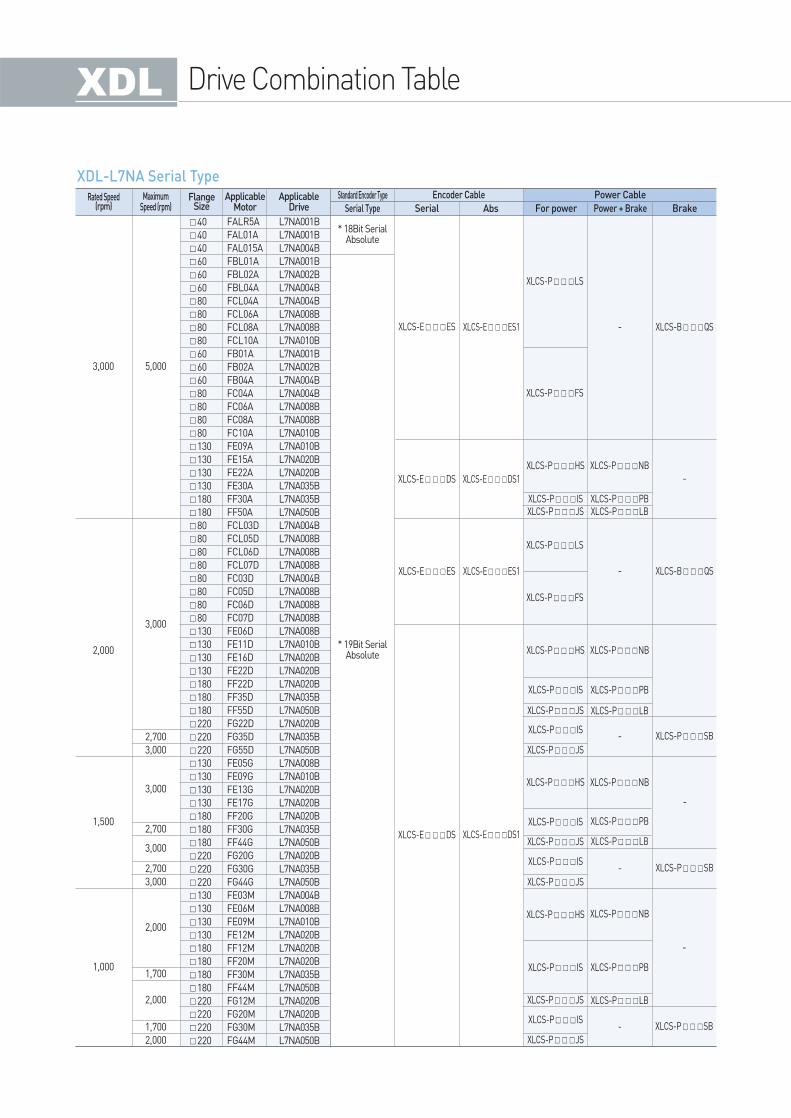
FlangeSize
Rated Speed(rpm)
MaximumSpeed (rpm)
ApplicableMotor
ApplicableDrive Serial Type
Standard Encoder Type
Serial Abs For power Power + Brake Brake
Encoder Cable Power Cable
XDL-L7NA Serial Type
Drive Product Features XGT Servo System(XDL/XML) 30 / 31
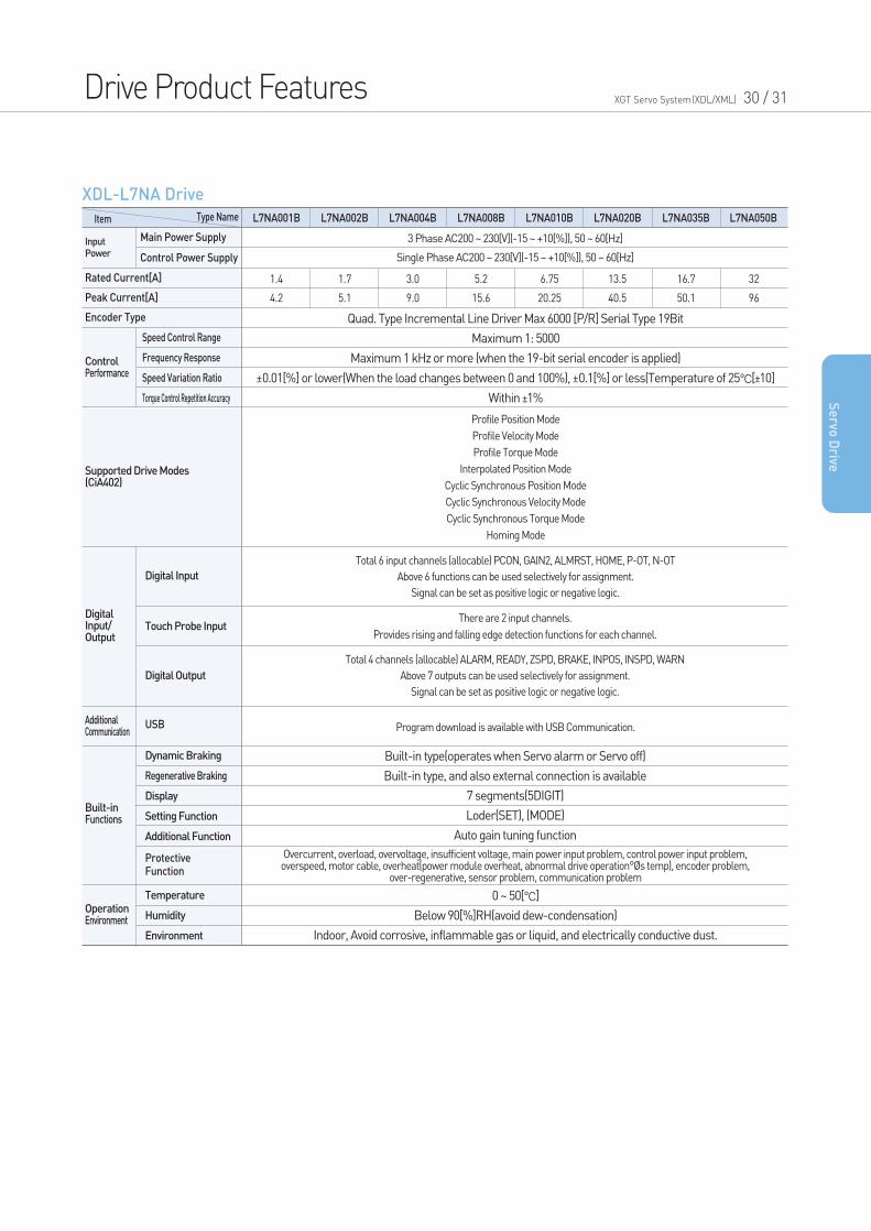
XDL-L7NA Drive
Se
rvo D
rive
Item
InputPower
ControlPerformance
DigitalInput/Output
Type Name
3 Phase AC200 ~ 230[V](-15 ~ +10[%]), 50 ~ 60[Hz]
Single Phase AC200 ~ 230[V](-15 ~ +10[%]), 50 ~ 60[Hz]
Quad. Type Incremental Line Driver Max 6000 [P/R] Serial Type 19Bit
Maximum 1: 5000
Maximum 1 kHz or more (when the 19-bit serial encoder is applied)
±0.01[%] or lower(When the load changes between 0 and 100%), ±0.1[%] or less(Temperature of 25°C[±10]
Within ±1%
Built-in type(operates when Servo alarm or Servo off)
Built-in type, and also external connection is available
7 segments(5DIGIT)
Loder(SET), (MODE)
Auto gain tuning function
0 ~ 50[°C]
Below 90[%]RH(avoid dew-condensation)
Indoor, Avoid corrosive, inflammable gas or liquid, and electrically conductive dust.
Profile Position Mode
Profile Velocity Mode
Profile Torque Mode
Interpolated Position Mode
Cyclic Synchronous Position Mode
Cyclic Synchronous Velocity Mode
Cyclic Synchronous Torque Mode
Homing Mode
Total 6 input channels (allocable) PCON, GAIN2, ALMRST, HOME, P-OT, N-OT
Above 6 functions can be used selectively for assignment.
Signal can be set as positive logic or negative logic.
Total 4 channels (allocable) ALARM, READY, ZSPD, BRAKE, INPOS, INSPD, WARN
Above 7 outputs can be used selectively for assignment.
Signal can be set as positive logic or negative logic.
There are 2 input channels.
Provides rising and falling edge detection functions for each channel.
Overcurrent, overload, overvoltage, insufficient voltage, main power input problem, control power input problem,overspeed, motor cable, overheat(power module overheat, abnormal drive operation°Øs temp), encoder problem,
over-regenerative, sensor problem, communication problem
Program download is available with USB Communication.
1.4
4.2
1.7
5.1
3.0
9.0
5.2
15.6
6.75
20.25
13.5
40.5
16.7
50.1
32
96
L7NA020BL7NA010BL7NA008BL7NA004BL7NA002BL7NA001B L7NA035B L7NA050B
Main Power Supply
Control Power Supply
Rated Current[A]
Peak Current[A]
Encoder Type
Supported Drive Modes(CiA402)
Additional Communication
Built-inFunctions
Digital Input
Touch Probe Input
Digital Output
OperationEnvironment
USB
Speed Control Range
Frequency Response
Speed Variation Ratio
Torque Control Repetition Accuracy
Temperature
Humidity
Environment
Dynamic Braking
Regenerative Braking
Display
Setting Function
Additional Function
ProtectiveFunction
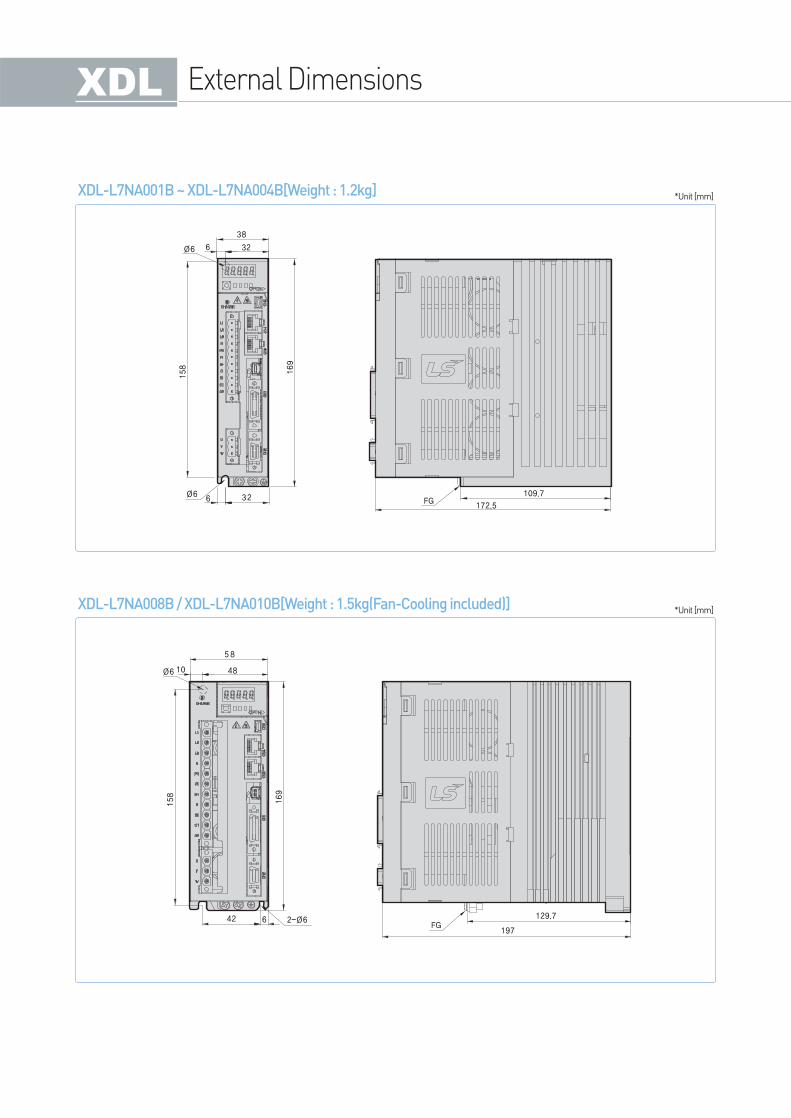
XDL-L7NA001B ~ XDL-L7NA004B[Weight : 1.2kg]
XDL-L7NA008B / XDL-L7NA010B[Weight : 1.5kg(Fan-Cooling included)]
*Unit [mm]
*Unit [mm]
External Dimensions
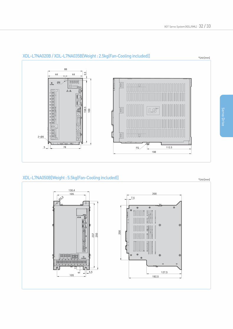
XDL-L7NA020B / XDL-L7NA035B[Weight : 2.5kg(Fan-Cooling included)]
XDL-L7NA050B[Weight : 5.5kg(Fan-Cooling included)]
*Unit [mm]
*Unit [mm]
XGT Servo System(XDL/XML) 32 / 33
Se
rvo D
rive
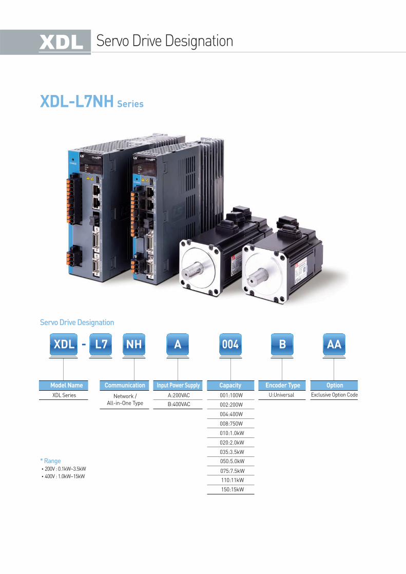
XDL-L7NH Series
NH
U:Universal
110:11kW
075:7.5kW
150:15kW
B:400VAC
Network /
All-in-One Type
Model Name Communication Capacity Encoder Type OptionInput Power Supply
XDL Series Exclusive Option Code
Servo Drive Designation
Servo Drive Designation
* Range•200V : 0.1kW~3.5kW
•400V : 1.0kW~15kW
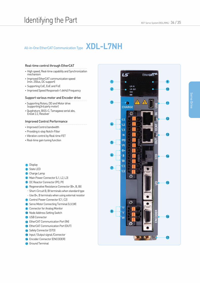
All-in-One EtherCAT Communication Type XDL-L7NH
Identifying the Part XGT Servo System(XDL/XML) 34 / 35
•High speed, Real-time capability and Synchronization mechanism
•Improved EtherCAT communication speed(min. 250us, DC support)
•Supporting CoE, EoE and FoE
•Improved Speed Response(=1.6kHz) Frequency
Real-time control through EtherCAT
•Supporting Rotary, DD and Motor drive (supporting3rd party motor)
•Quadrature, BiSS-C, Tamagawa serial abs, EnDat 2.2, Resolver
Support various motor and Encoder drive
•Improved Control bandwidth
•Providing 4-step Notch-Filter
•Vibration control by Real-time FET
•Real-time gain tuning function
Improved Control Performance
Se
rvo D
rive
Display
State LED
Charge Lamp
Main Power Connector (L1, L2, L3)
DC Reactor Connector (PO, PI)
Regenerative Resistance Connector (B+, B, BI)
Short-Circuit B, BI terminals when standard type
Use B+, B terminals when using external resistor
Control Power Connector (C1, C2)
Servo Motor Connecting Terminal (U,V,W)
Connector for Analog Monitor
Node Address Setting Switch
USB Connector
EtherCAT Communication Port (IN)
EtherCAT Communication Port (OUT)
Safety Connector (STO)
Input / Output signal /Connector
Encoder Connector (ENCODER)
Ground Terminal
1
2
3
4
5
6
7
8
9
10
11
12
13
14
15
16
17
9
10
11
12
13
14
15
16
17
1
2
3
4
5
6
7
8
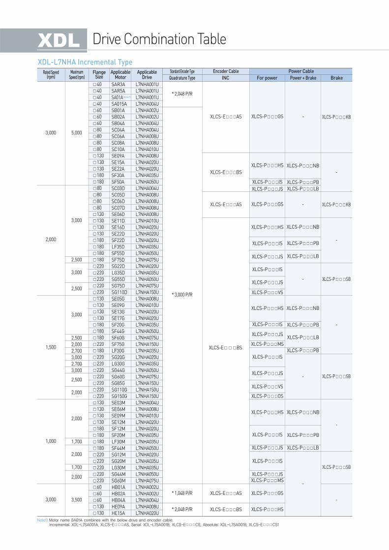
Drive Combination Table
2,500
2,000
2,700
3,000
2,700
3,000
* 3,000 P/R
* 1,048 P/R
* 2,048 P/R
* 2,048 P/R
XLCS-EBS
40
40
40
40
60
60
60
80
80
80
80
130
130
130
180
180
80
80
80
80
130
130
130
130
180
180
180
180
220
220
220
220
220
130
130
130
130
180
180
180
220
180
220
220
220
220
220
220
220
130
130
130
130
180
180
180
180
220
220
220
220
220
60
60
60
130
130
3,000
1,500
2,000
3,000
1,000
5,000
XLCS-PGS
XLCS-PGS
XLCS-POS
XLCS-PMSXLCS-PJS
XLCS-PJS
XLCS-PHS XLCS-PNB
XLCS-PNB
-
-
-
XLCS-PNB
XLCS-PPB
XLCS-PPB
XLCS-PLB
XLCS-PPB
XLCS-PLB
XLCS-PPB
XLCS-PLB
XLCS-PHS
XLCS-PIS
XLCS-PIS
XLCS-PJS
XLCS-PJS
XLCS-PVS
XLCS-PMS
XLCS-PIS
XLCS-PJS
XLCS-PIS
XLCS-PJS
XLCS-PVS
XLCS-PHS
XLCS-PHS
XLCS-PIS
XLCS-PIS
XLCS-PGS
XLCS-PHS
XLCS-PIS
XLCS-PJS
XLCS-EAS
XLCS-EBS
XLCS-EAS
XLCS-EAS
XLCS-EBS
-
XLCS-PKB
XLCS-PKB
XLCS-PSB
XLCS-PSB
XLCS-PSB
-
-
-
-
-
XLCS-PLB
XLCS-PNB
XLCS-PPB
-
3,000
2,500
2,500
3,000
3,000
1,700
1,700
2,500
2,000
2,000
2,000
2,000
3,500
SAR3A
SAR5A
SA01A
SA015A
SB01A
SB02A
SB04A
SC04A
SC06A
SC08A
SC10A
SE09A
SE15A
SE22A
SF30A
SF50A
SC03D
SC05D
SC06D
SC07D
SE06D
SE11D
SE16D
SE22D
SF22D
LF35D
SF55D
SF75D
SG22D
LG35D
SG55D
SG75D
SG110D
SE05G
SE09G
SE13G
SE17G
SF20G
SF44G
SF60G
SF75G
LF30G
SG20G
LG30G
SG44G
SG60G
SG85G
SG110G
SG150G
SE03M
SE06M
SE09M
SE12M
SF12M
SF20M
LF30M
SF44M
SG12M
SG20M
LG30M
SG44M
SG60M
HB01A
HB02A
HB04A
HE09A
HE15A
L7NHA001U
L7NHA001U
L7NHA001U
L7NHA004U
L7NHA002U
L7NHA002U
L7NHA004U
L7NHA004U
L7NHA008U
L7NHA008U
L7NHA010U
L7NHA008U
L7NHA020U
L7NHA020U
L7NHA035U
L7NHA050U
L7NHA004U
L7NHA008U
L7NHA008U
L7NHA008U
L7NHA008U
L7NHA010U
L7NHA020U
L7NHA020U
L7NHA020U
L7NHA035U
L7NHA050U
L7NHA075U
L7NHA020U
L7NHA035U
L7NHA050U
L7NHA075U
L7NHA150U
L7NHA008U
L7NHA010U
L7NHA020U
L7NHA020U
L7NHA035U
L7NHA050U
L7NHA075U
L7NHA150U
L7NHA035U
L7NHA020U
L7NHA035U
L7NHA050U
L7NHA075U
L7NHA150U
L7NHA150U
L7NHA150U
L7NHA004U
L7NHA008U
L7NHA010U
L7NHA020U
L7NHA020U
L7NHA035U
L7NHA035U
L7NHA050U
L7NHA020U
L7NHA035U
L7NHA035U
L7NHA050U
L7NHA075U
L7NHA002U
L7NHA002U
L7NHA004U
L7NHA008U
L7NHA020U
FlangeSize
Rated Speed(rpm)
MaximumSpeed (rpm)
ApplicableMotor
ApplicableDrive Quadrature Type
Standard Encoder Type
INC For power Power + Brake Brake
Encoder Cable Power Cable
XDL-L7NHA Incremental Type
Note1)
Note1) Motor name SA01A combines with the below drive and encoder cable.Incremental: XDL-L7SA001A, XLCS-EAS, Serial: XDL-L7SA001B, XLCS-ECS, Absolute: XDL-L7SA001B, XLCS-ECS1

XGT Servo System(XDL/XML) 36 / 37
Se
rvo D
rive
2,7003,0002,5002,0003,0002,7003,000
* 19Bit SerialAbsolute
* 18Bit SerialAbsolute
40404060606080808080606060808080801301301301301801808080808080808080130130130130180180180180220220220220220130130130130180180180180180220220220220220220220130130130130180180180180220220220220220
3,000
2,000
1,000
1,500
5,000
XLCS-BQSXLCS-EES
XLCS-EES
XLCS-EDS
XLCS-EDS
XLCS-PLS
XLCS-PLS
XLCS-PFS
XLCS-PFS
XLCS-PNB
XLCS-PNB
XLCS-PNB
XLCS-PNB
XLCS-PPBXLCS-PLB
XLCS-PPB
XLCS-PLB
XLCS-PLB
XLCS-PLB
XLCS-PPB
XLCS-PPB
XLCS-PHS
XLCS-PHS
XLCS-PHS
XLCS-PHS
XLCS-PISXLCS-PJS
XLCS-PIS
XLCS-PIS
XLCS-PVS
XLCS-PVS
XLCS-POS
XLCS-PJS
XLCS-PJS
XLCS-PJS
XLCS-PMS
XLCS-PIS
XLCS-PIS
XLCS-PIS
XLCS-PIS
XLCS-PJS
XLCS-PJS
XLCS-PJS
XLCS-PMS
XLCS-EES1
XLCS-EES1
XLCS-EDS1
XLCS-EDS1
XLCS-BQS
XLCS-PSB
XLCS-PSB
XLCS-PSB
XLCS-PSB
-
-
-
-
-
-
-
-
-
3,000
3,000
2,500
3,000
2,500
2,000
2,000
1,700
2,500
1,700
2,000
FALR5AFAL01AFAL015AFBL01AFBL02AFBL04AFCL04AFCL06AFCL08AFCL10AFB01AFB02AFB04AFC04AFC06AFC08AFC10AFE09AFE15AFE22AFE30AFF30AFF50AFCL03DFCL05DFCL06DFCL07DFC03DFC05DFC06DFC07DFE06DFE11DFE16DFE22DFF22DFF35DFF55DFF75DFG22DFG35DFG55DFG75DFG110DFE05GFE09GFE13GFE17GFF20GFF30GFF44GFF60GFF75GFG20GFG30GFG44GFG60GFG85GFG110GFG150GFE03MFE06MFE09MFE12MFF12MFF20MFF30MFF44MFG12MFG20MFG30MFG44MFG60M
L7NHA001UL7NHA001UL7NHA004UL7NHA001UL7NHA002UL7NHA004UL7NHA004UL7NHA008UL7NHA008UL7NHA010UL7NHA001UL7NHA002UL7NHA004UL7NHA004UL7NHA008UL7NHA008UL7NHA010UL7NHA010UL7NHA020UL7NHA020UL7NHA035UL7NHA035UL7NHA050UL7NHA004UL7NHA008UL7NHA008UL7NHA008UL7NHA004UL7NHA008UL7NHA008UL7NHA008UL7NHA008UL7NHA010UL7NHA020UL7NHA020UL7NHA020UL7NHA035UL7NHA050UL7NHA075UL7NHA020UL7NHA035UL7NHA050UL7NHA075UL7NHA150UL7NHA008UL7NHA010UL7NHA020UL7NHA020UL7NHA020UL7NHA035UL7NHA050UL7NHA075UL7NHA075UL7NHA020UL7NHA035UL7NHA050UL7NHA075UL7NHA150UL7NHA150UL7NHA150UL7NHA004UL7NHA008UL7NHA010UL7NHA020UL7NHA020UL7NHA020UL7NHA035UL7NHA050UL7NHA020UL7NHA020UL7NHA035UL7NHA050UL7NHA075U
FlangeSize
Rated Speed(rpm)
MaximumSpeed (rpm)
ApplicableMotor
ApplicableDrive Serial Type
Standard Encoder Type
Serial Abs For power Power + Brake Brake
Encoder Cable Power Cable
XDL-L7NHA Serial Type
Drive Combination Table
*3,000 P/R XLCS-EBS
130
130
130
130
180
180
130
130
130
130
180
180
180
180
220
220
220
220
220
130
130
130
130
180
180
180
180
180
220
220
220
220
220
220
220
130
130
130
130
180
180
180
180
220
220
220
220
220
3,000
2,000
1,500
1,000
5,000
3,000
XLCF-PHS
XLCF-PHS
XLCF-PIS
XLCF-PIS
XLCF-PIS
XLCF-PIS
XLCF-PIS
XLCF-PIS
XLCF-PHS
XLCF-PHS
XLCF-PJS
XLCF-PJS
XLCF-PJS
XLCF-PJS
XLCF-PJS
XLCF-PJS
XLCF-PMS
XLCF-PMS
XLCF-PMS
XLCF-PMS
XLCF-PIS
XLCF-PJS
XLCF-PPB
XLCF-PLB
-
-
-
-
-
-
XLCF-PNB
XLCF-PNB
XLCF-PSB
XLCF-PSB
XLCF-PSB
XLCF-PPB
XLCF-PPB
XLCF-PPB
XLCF-PLB
XLCF-PLB
XLCF-PLB
XLCF-PNB
XLCF-PNB
3,000
3,000
2,500
2,500
2,500
2,000
2,000
1,700
2,000
SEP09A
SEP15A
SEP22A
SEP30A
SFP30A
SFP50A
SEP06D
SEP11D
SEP16D
SEP22D
SFP22D
SFP35D
SFP55D
SFP75D
SGP22D
SGP35D
SGP55D
SGP75D
SGP110D
SEP05G
SEP09G
SEP13G
SEP17G
SFP20G
SFP30G
SFP44G
SFP60G
SFP75G
SGP20G
SGP30G
SGP44G
SGP60G
SGP85G
SGP110G
SGP150G
SEP03M
SEP06M
SEP09M
SEP12M
SFP12M
SFP20M
SFP30M
SFP44M
SGP12M
SGP20M
SGP30M
SGP44M
SGP60M
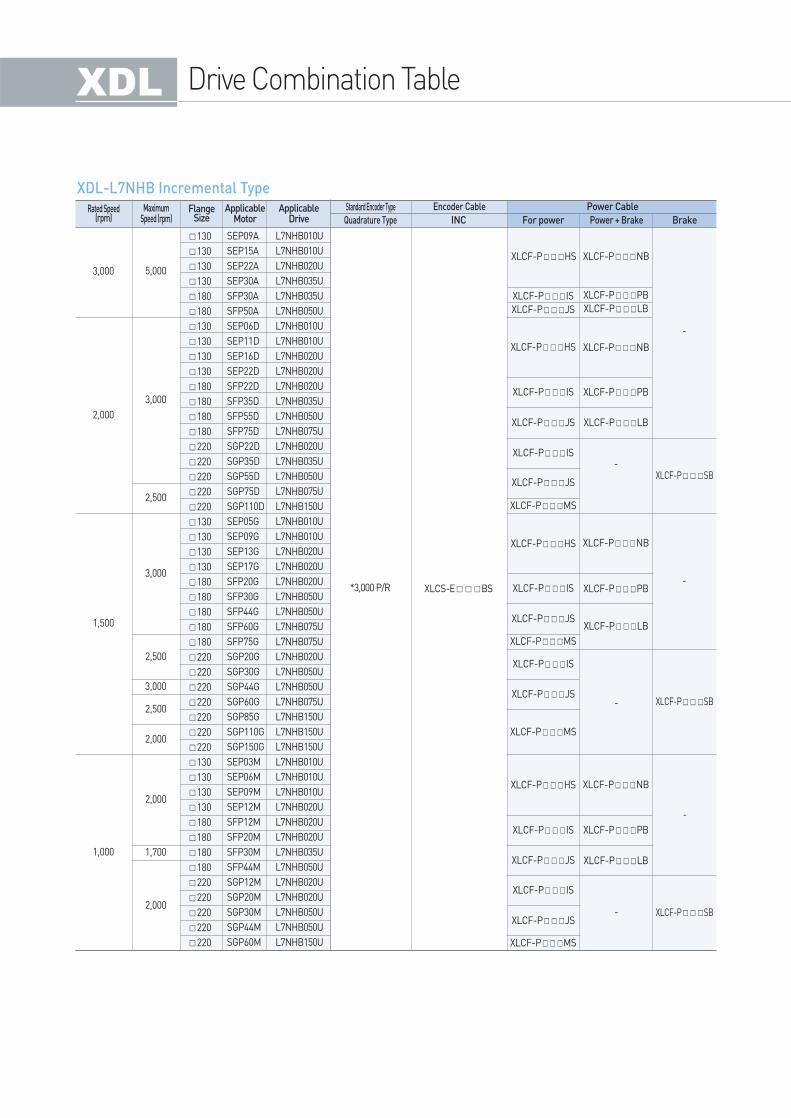
L7NHB010U
L7NHB010U
L7NHB020U
L7NHB035U
L7NHB035U
L7NHB050U
L7NHB010U
L7NHB010U
L7NHB020U
L7NHB020U
L7NHB020U
L7NHB035U
L7NHB050U
L7NHB075U
L7NHB020U
L7NHB035U
L7NHB050U
L7NHB075U
L7NHB150U
L7NHB010U
L7NHB010U
L7NHB020U
L7NHB020U
L7NHB020U
L7NHB050U
L7NHB050U
L7NHB075U
L7NHB075U
L7NHB020U
L7NHB050U
L7NHB050U
L7NHB075U
L7NHB150U
L7NHB150U
L7NHB150U
L7NHB010U
L7NHB010U
L7NHB010U
L7NHB020U
L7NHB020U
L7NHB020U
L7NHB035U
L7NHB050U
L7NHB020U
L7NHB020U
L7NHB050U
L7NHB050U
L7NHB150U
FlangeSize
Rated Speed(rpm)
MaximumSpeed (rpm)
ApplicableMotor
ApplicableDrive Quadrature Type
Standard Encoder Type
INC For power Power + Brake Brake
Encoder Cable Power Cable
XDL-L7NHB Incremental Type
XGT Servo System(XDL/XML) 38 / 39
Se
rvo D
rive
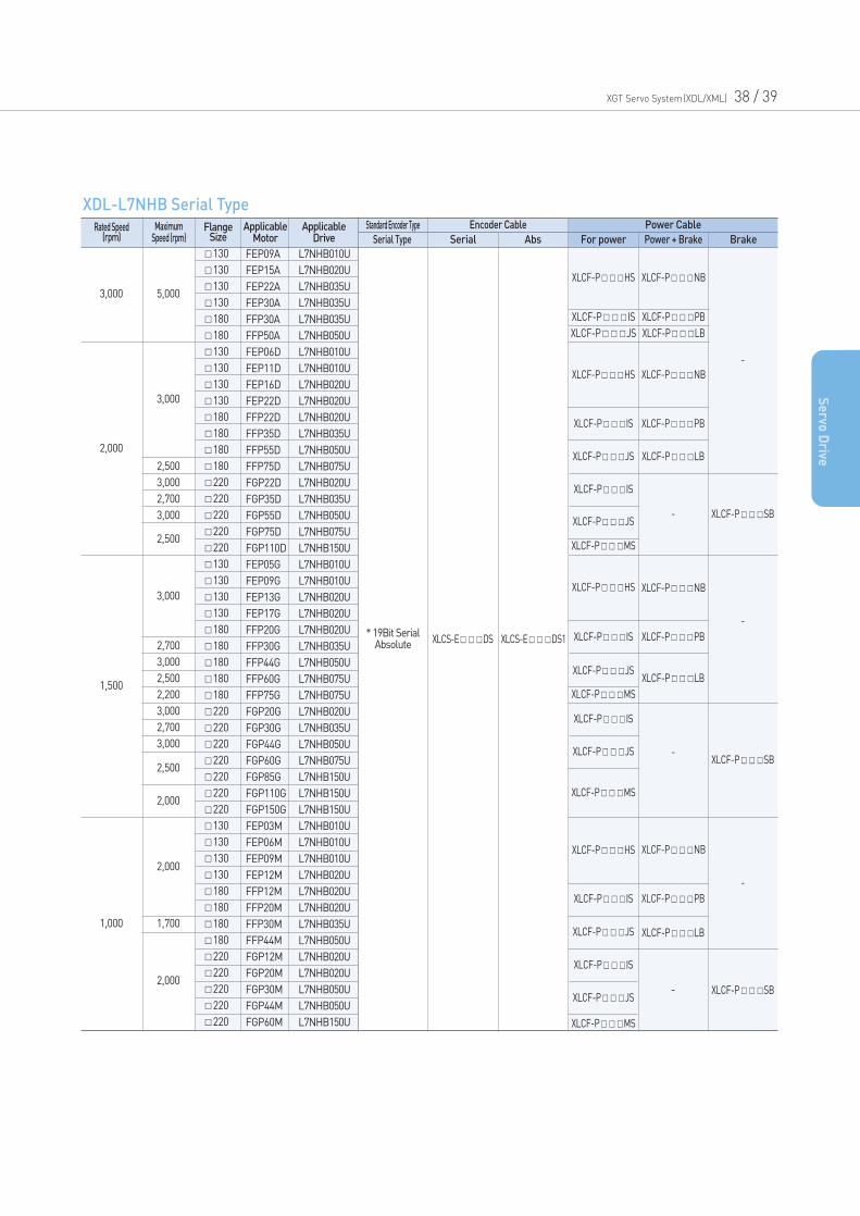
* 19Bit SerialAbsolute XLCS-EDS XLCS-EDS1
130
130
130
130
180
180
130
130
130
130
180
180
180
180
220
220
220
220
220
130
130
130
130
180
180
180
180
180
220
220
220
220
220
220
220
130
130
130
130
180
180
180
180
220
220
220
220
220
3,000
2,000
1,500
1,000
5,000
3,000
XLCF-PHS
XLCF-PHS
XLCF-PHS
XLCF-PHS
XLCF-PIS
XLCF-PIS
XLCF-PIS
XLCF-PIS
XLCF-PIS
XLCF-PIS
XLCF-PJS
XLCF-PJS
XLCF-PJS
XLCF-PJS
XLCF-PJS
XLCF-PJS
XLCF-PMS
XLCF-PPB
XLCF-PPB
XLCF-PPB
XLCF-PLB
XLCF-PLB
XLCF-PLB
XLCF-PSB
-
-
-
-
-
-
XLCF-PSB
XLCF-PSB
XLCF-PNB
XLCF-PNB
XLCF-PNB
XLCF-PNB
XLCF-PIS
XLCF-PJS
XLCF-PMS
XLCF-PMS
XLCF-PMS
XLCF-PPB
XLCF-PLB
2,500
3,000
2,500
2,000
2,000
1,700
2,000
FEP09A
FEP15A
FEP22A
FEP30A
FFP30A
FFP50A
FEP06D
FEP11D
FEP16D
FEP22D
FFP22D
FFP35D
FFP55D
FFP75D
FGP22D
FGP35D
FGP55D
FGP75D
FGP110D
FEP05G
FEP09G
FEP13G
FEP17G
FFP20G
FFP30G
FFP44G
FFP60G
FFP75G
FGP20G
FGP30G
FGP44G
FGP60G
FGP85G
FGP110G
FGP150G
FEP03M
FEP06M
FEP09M
FEP12M
FFP12M
FFP20M
FFP30M
FFP44M
FGP12M
FGP20M
FGP30M
FGP44M
FGP60M
2,700
3,000
2,500
2,200
3,000
2,700
3,000
2,500
3,000
2,700
3,000
L7NHB010U
L7NHB020U
L7NHB035U
L7NHB035U
L7NHB035U
L7NHB050U
L7NHB010U
L7NHB010U
L7NHB020U
L7NHB020U
L7NHB020U
L7NHB035U
L7NHB050U
L7NHB075U
L7NHB020U
L7NHB035U
L7NHB050U
L7NHB075U
L7NHB150U
L7NHB010U
L7NHB010U
L7NHB020U
L7NHB020U
L7NHB020U
L7NHB035U
L7NHB050U
L7NHB075U
L7NHB075U
L7NHB020U
L7NHB035U
L7NHB050U
L7NHB075U
L7NHB150U
L7NHB150U
L7NHB150U
L7NHB010U
L7NHB010U
L7NHB010U
L7NHB020U
L7NHB020U
L7NHB020U
L7NHB035U
L7NHB050U
L7NHB020U
L7NHB020U
L7NHB050U
L7NHB050U
L7NHB150U
FlangeSize
Rated Speed(rpm)
MaximumSpeed (rpm)
ApplicableMotor
ApplicableDrive Serial Type
Standard Encoder Type
Serial Abs For power Power + Brake Brake
Encoder Cable Power Cable
XDL-L7NHB Serial Type
Drive Product Features
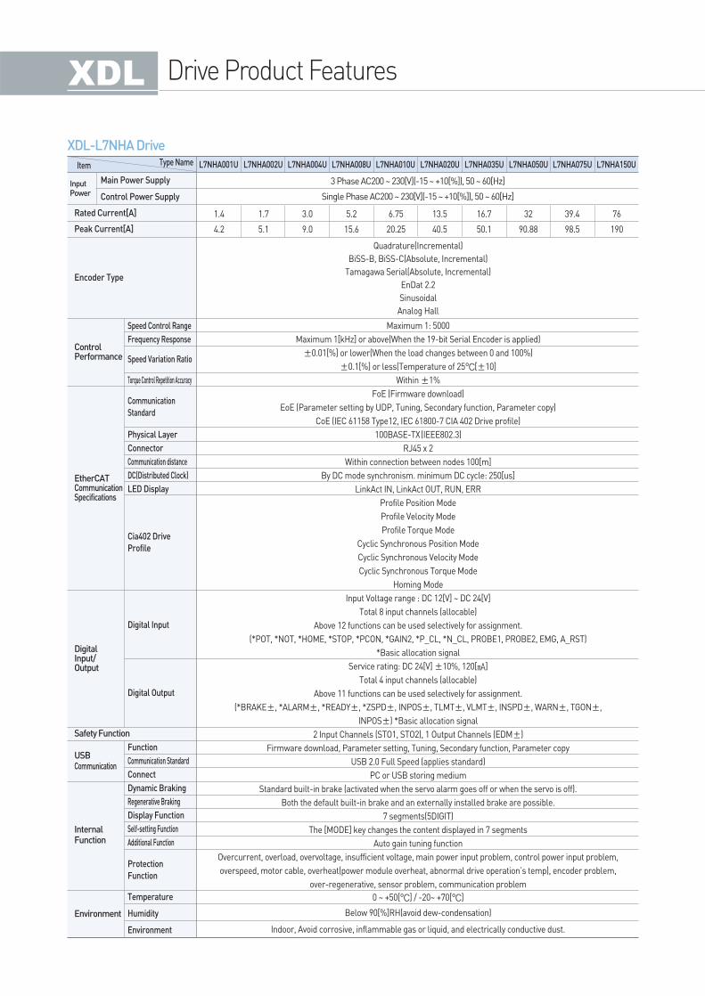
XDL-L7NHA Drive
Item
InputPower
Type Name
3 Phase AC200 ~ 230[V](-15 ~ +10[%]), 50 ~ 60[Hz]
Single Phase AC200 ~ 230[V](-15 ~ +10[%]), 50 ~ 60[Hz]
Maximum 1: 5000
Maximum 1[kHz] or above(When the 19-bit Serial Encoder is applied)
±0.01[%] or lower(When the load changes between 0 and 100%)
±0.1[%] or less(Temperature of 25°C[±10]
Within ±1%
FoE (Firmware download)
EoE (Parameter setting by UDP, Tuning, Secondary function, Parameter copy)
CoE (IEC 61158 Type12, IEC 61800-7 CIA 402 Drive profile)
100BASE-TX(IEEE802.3)
RJ45 x 2
Within connection between nodes 100[m]
By DC mode synchronism. minimum DC cycle: 250[us]
LinkAct IN, LinkAct OUT, RUN, ERR
Profile Position Mode
Profile Velocity Mode
Profile Torque Mode
Cyclic Synchronous Position Mode
Cyclic Synchronous Velocity Mode
Cyclic Synchronous Torque Mode
Homing Mode
Input Voltage range : DC 12[V] ~ DC 24[V]
Total 8 input channels (allocable)
Above 12 functions can be used selectively for assignment.
(*POT, *NOT, *HOME, *STOP, *PCON, *GAIN2, *P_CL, *N_CL, PROBE1, PROBE2, EMG, A_RST)
*Basic allocation signal
Service rating: DC 24[V] ±10%, 120[]
Total 4 input channels (allocable)
Above 11 functions can be used selectively for assignment.
(*BRAKE±, *ALARM±, *READY±, *ZSPD±, INPOS±, TLMT±, VLMT±, INSPD±, WARN±, TGON±,
INPOS±) *Basic allocation signal
2 Input Channels (STO1, STO2), 1 Output Channels (EDM±)
Firmware download, Parameter setting, Tuning, Secondary function, Parameter copy
USB 2.0 Full Speed (applies standard)
PC or USB storing medium
Standard built-in brake (activated when the servo alarm goes off or when the servo is off).
Both the default built-in brake and an externally installed brake are possible.
7 segments(5DIGIT)
The [MODE] key changes the content displayed in 7 segments
Auto gain tuning function
Overcurrent, overload, overvoltage, insufficient voltage, main power input problem, control power input problem,
overspeed, motor cable, overheat(power module overheat, abnormal drive operation’s temp), encoder problem,
over-regenerative, sensor problem, communication problem
0 ~ +50[°C] / -20~ +70[°C]
Below 90[%]RH(avoid dew-condensation)
Indoor, Avoid corrosive, inflammable gas or liquid, and electrically conductive dust.
Quadrature(Incremental)
BiSS-B, BiSS-C(Absolute, Incremental)
Tamagawa Serial(Absolute, Incremental)
EnDat 2.2
Sinusoidal
Analog Hall
1.4
4.2
1.7
5.1
3.0
9.0
5.2
15.6
6.75
20.25
13.5
40.5
16.7
50.1
32
90.88
39.4
98.5
76
190
L7NHA001U L7NHA002U L7NHA004U L7NHA008U L7NHA010U L7NHA020U L7NHA035U L7NHA050U L7NHA075U L7NHA150U
Main Power Supply
Control Power Supply
Rated Current[A]
Peak Current[A]
Encoder Type
ControlPerformance
EtherCATCommunicationSpecifications
DigitalInput/Output
USBCommunication
InternalFunction
Environment
Safety Function
Speed Control Range
Frequency Response
Torque Control Repetition Accuracy
Physical Layer
Connector
Communication distance
DC(Distributed Clock)
LED Display
Function
Communication Standard
Connect
Dynamic Braking
Regenerative Braking
Display Function
Self-setting Function
Additional Function
Temperature
Humidity
Environment
Communication
Standard
Speed Variation Ratio
Cia402 Drive
Profile
Digital Input
Digital Output
Protection
Function
XGT Servo System(XDL/XML) 40 /41
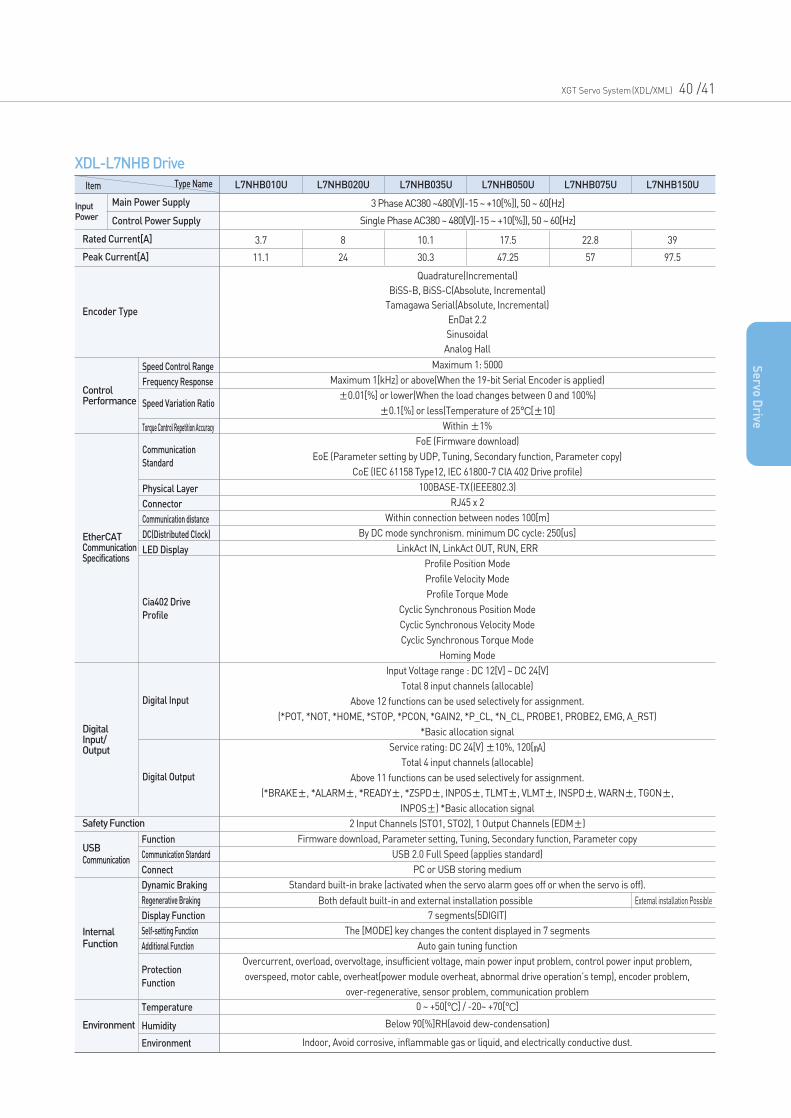
XDL-L7NHB Drive
Item
InputPower
Type Name
3 Phase AC380 ~480[V](-15 ~ +10[%]), 50 ~ 60[Hz]
Single Phase AC380 ~ 480[V](-15 ~ +10[%]), 50 ~ 60[Hz]
Maximum 1: 5000
Maximum 1[kHz] or above(When the 19-bit Serial Encoder is applied)
±0.01[%] or lower(When the load changes between 0 and 100%)
±0.1[%] or less(Temperature of 25°C[±10]
Within ±1%
FoE (Firmware download)
EoE (Parameter setting by UDP, Tuning, Secondary function, Parameter copy)
CoE (IEC 61158 Type12, IEC 61800-7 CIA 402 Drive profile)
100BASE-TX(IEEE802.3)
RJ45 x 2
Within connection between nodes 100[m]
By DC mode synchronism. minimum DC cycle: 250[us]
LinkAct IN, LinkAct OUT, RUN, ERR
Profile Position Mode
Profile Velocity Mode
Profile Torque Mode
Cyclic Synchronous Position Mode
Cyclic Synchronous Velocity Mode
Cyclic Synchronous Torque Mode
Homing Mode
Input Voltage range : DC 12[V] ~ DC 24[V]
Total 8 input channels (allocable)
Above 12 functions can be used selectively for assignment.
(*POT, *NOT, *HOME, *STOP, *PCON, *GAIN2, *P_CL, *N_CL, PROBE1, PROBE2, EMG, A_RST)
*Basic allocation signal
Service rating: DC 24[V] ±10%, 120[]
Total 4 input channels (allocable)
Above 11 functions can be used selectively for assignment.
(*BRAKE±, *ALARM±, *READY±, *ZSPD±, INPOS±, TLMT±, VLMT±, INSPD±, WARN±, TGON±,
INPOS±) *Basic allocation signal
2 Input Channels (STO1, STO2), 1 Output Channels (EDM±)
Firmware download, Parameter setting, Tuning, Secondary function, Parameter copy
USB 2.0 Full Speed (applies standard)
PC or USB storing medium
Standard built-in brake (activated when the servo alarm goes off or when the servo is off).
7 segments(5DIGIT)
The [MODE] key changes the content displayed in 7 segments
Auto gain tuning function
Overcurrent, overload, overvoltage, insufficient voltage, main power input problem, control power input problem,
overspeed, motor cable, overheat(power module overheat, abnormal drive operation’s temp), encoder problem,
over-regenerative, sensor problem, communication problem
0 ~ +50[°C] / -20~ +70[°C]
Below 90[%]RH(avoid dew-condensation)
Indoor, Avoid corrosive, inflammable gas or liquid, and electrically conductive dust.
Quadrature(Incremental)
BiSS-B, BiSS-C(Absolute, Incremental)
Tamagawa Serial(Absolute, Incremental)
EnDat 2.2
Sinusoidal
Analog Hall
Extemal installation PossibleBoth default built-in and external installation possible
3.7
11.1
L7NHB010U
8
24
L7NHB020U
10.1
30.3
L7NHB035U
17.5
47.25
L7NHB050U
22.8
57
L7NHB075U
39
97.5
L7NHB150U
Main Power Supply
Control Power Supply
Rated Current[A]
Peak Current[A]
Encoder Type
ControlPerformance
EtherCATCommunicationSpecifications
DigitalInput/Output
USBCommunication
InternalFunction
Environment
Safety Function
Speed Control Range
Frequency Response
Torque Control Repetition Accuracy
Physical Layer
Connector
Communication distance
DC(Distributed Clock)
LED Display
Communication
Standard
Speed Variation Ratio
Cia402 Drive
Profile
Digital Input
Digital Output
Se
rvo D
rive
Function
Communication Standard
Connect
Dynamic Braking
Regenerative Braking
Display Function
Self-setting Function
Additional Function
Temperature
Humidity
Environment
Protection
Function
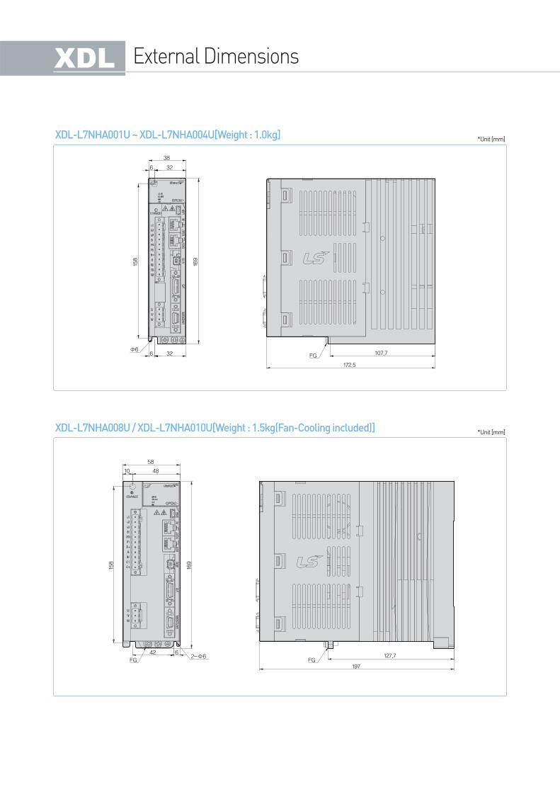
External Dimensions
XDL-L7NHA001U ~ XDL-L7NHA004U[Weight : 1.0kg]
38
32
158
169
6
32 107.7FG
172.5
6Φ6
XDL-L7NHA008U / XDL-L7NHA010U[Weight : 1.5kg(Fan-Cooling included)]
58
4810
158
169
42
FG
62-Φ6
FG197
127.7
*Unit [mm]
*Unit [mm]
XGT Servo System(XDL/XML) 42 / 43
Se
rvo D
rive
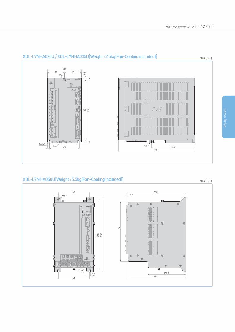
XDL-L7NHA020U / XDL-L7NHA035U[Weight : 2.5kg(Fan-Cooling included)]
8844
FG5 FG
198
112.5
159
169
78
44
2-Φ6
Φ6 5
.5
*Unit [mm]
XDL-L7NHA050U[Weight : 5.5kg(Fan-Cooling included)]
105
237
200
200
127.5
192.5
7.5
105
5.5
13 6
250
Φ5.5
*Unit [mm]
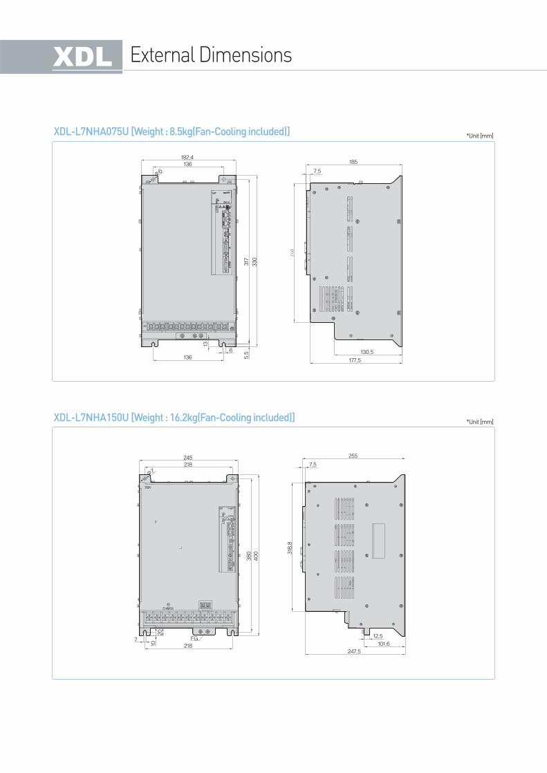
XDL-L7NHA075U [Weight : 8.5kg(Fan-Cooling included)]
182.4185
7.5
130.5
177.51366
5.5
13
136
Φ6
317
330
XDL-L7NHA150U [Weight : 16.2kg(Fan-Cooling included)]
245 255
12.5
101.6
247.5
7.5
7
10
FG
218
20
218
Φ7
380 318.8
400
*Unit [mm]
*Unit [mm]
External Dimensions
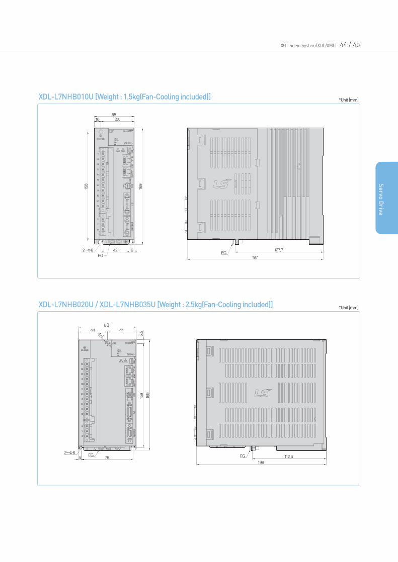
XDL-L7NHB010U [Weight : 1.5kg(Fan-Cooling included)]
5848
42 6
10
158
169
2-Φ6
FGFG
127.7
197
*Unit [mm]
XDL-L7NHB020U / XDL-L7NHB035U [Weight : 2.5kg(Fan-Cooling included)]
8844 44Φ6
159
5.5
169
FGFG785
198
112.52-Φ6
*Unit [mm]
XGT Servo System(XDL/XML) 44 / 45
Se
rvo D
rive
External Dimensions
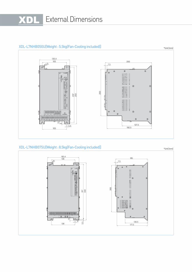
XDL-L7NHB050U[Weight : 5.5kg(Fan-Cooling included)]
130.4
237
250 200
105
Φ5.5
1055.5
13 6200
7.5
127.5
192.5
*Unit [mm]
XDL-L7NHB075U[Weight : 8.5kg(Fan-Cooling included)]
182.4136
Φ6
1366
5.5
13
317
330
185
7.5
268
130.5
177.5
*Unit [mm]
XGT Servo System(XDL/XML) 46 / 47
Se
rvo D
rive
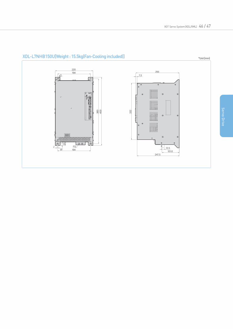
XDL-L7NHB150U[Weight : 15.5kg(Fan-Cooling included)]
220
380
400
FG
1947
10
20
194
Φ7
255
332
7.5
12.5
101.6
247.5
*Unit [mm]
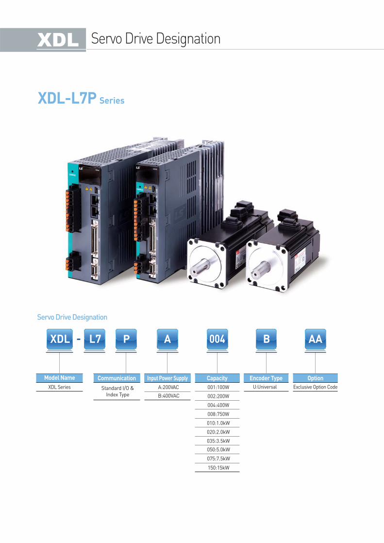
XDL-L7P Series
Servo Drive Designation
Servo Drive Designation
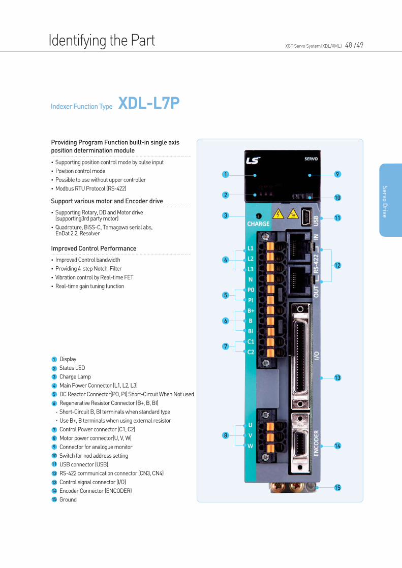
Indexer Function Type XDL-L7P
Identifying the Part XGT Servo System(XDL/XML) 48 /49
•Supporting position control mode by pulse input
•Position control mode
•Possible to use without upper controller
•Modbus RTU Protocol (RS-422)
Providing Program Function built-in single axis
position determination module
•Supporting Rotary, DD and Motor drive (supporting3rd party motor)
•Quadrature, BiSS-C, Tamagawa serial abs, EnDat 2.2, Resolver
Support various motor and Encoder drive
•Improved Control bandwidth
•Providing 4-step Notch-Filter
•Vibration control by Real-time FET
•Real-time gain tuning function
Improved Control Performance
Se
rvo D
rive
Display
Status LED
Charge Lamp
Main Power Connector (L1, L2, L3)
DC Reactor Connector(PO, PI) Short-Circuit When Not used
Regenerative Resistor Connector (B+, B, BI)
Short-Circuit B, BI terminals when standard type
Use B+, B terminals when using external resistor
Control Power connector (C1, C2)
Motor power connector(U, V, W)
Connector for analogue monitor
Switch for nod address setting
USB connector (USB)
RS-422 communication connector (CN3, CN4)
Control signal connector (I/O)
Encoder Connector (ENCODER)
Ground
1
2
3
4
5
6
7
8
9
10
11
12
13
14
15
9
10
11
12
13
14
15
1
2
3
4
5
6
7
8
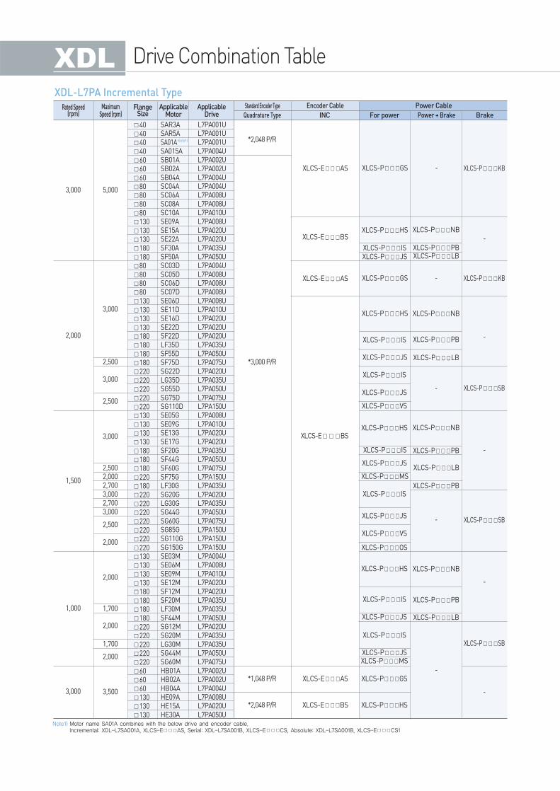
Drive Combination Table
2,5002,0002,7003,0002,7003,000
*3,000 P/R
*1,048 P/R
*2,048 P/R
*2,048 P/R
XLCS-EBS
404040406060608080808013013013018018080808080130130130130180180180180220220220220220130130130130180180180220180220220220220220220220130130130130180180180180220220220220220606060130130130
3,000
1,500
2,000
3,000
1,000
5,000
XLCS-PGS
XLCS-PGS
XLCS-PHS XLCS-PNB
XLCS-PNB
XLCS-PNB
XLCS-PPB
XLCS-PLB
XLCS-PNB
XLCS-PPB
XLCS-PPBXLCS-PLB
XLCS-PPB
XLCS-PLB
XLCS-PPB
-
XLCS-PHS
XLCS-PIS
XLCS-PIS
XLCS-PJS
XLCS-PJS
XLCS-PVS
XLCS-PJS
XLCS-PIS
XLCS-POS
XLCS-PIS
XLCS-PJS
XLCS-PJS
XLCS-PJSXLCS-PMS
XLCS-PVS
XLCS-PMS
XLCS-PHS
XLCS-PHS
XLCS-PIS
XLCS-PIS
XLCS-PGS
XLCS-PHS
XLCS-PISXLCS-PJS
XLCS-EAS
XLCS-EBS
XLCS-EAS
XLCS-EAS
XLCS-EBS
-
-
XLCS-PKB
XLCS-PKB
XLCS-PSB
XLCS-PSB
XLCS-PSB
-
-
-
-
-
XLCS-PLB
-
-
3,000
3,000
2,500
2,500
2,000
3,000
1,700
1,700
2,500
2,000
2,000
2,000
3,500
SAR3ASAR5ASA01ASA015ASB01ASB02ASB04ASC04ASC06ASC08ASC10ASE09ASE15ASE22ASF30ASF50ASC03DSC05DSC06DSC07DSE06DSE11DSE16DSE22DSF22DLF35DSF55DSF75DSG22DLG35DSG55DSG75DSG110DSE05GSE09GSE13GSE17GSF20GSF44GSF60GSF75GLF30GSG20GLG30GSG44GSG60GSG85GSG110GSG150GSE03MSE06MSE09MSE12MSF12MSF20MLF30MSF44MSG12MSG20MLG30MSG44MSG60MHB01AHB02AHB04AHE09AHE15AHE30A
L7PA001UL7PA001UL7PA001UL7PA004UL7PA002UL7PA002UL7PA004UL7PA004UL7PA008UL7PA008UL7PA010UL7PA008UL7PA020UL7PA020UL7PA035UL7PA050UL7PA004UL7PA008UL7PA008UL7PA008UL7PA008UL7PA010UL7PA020UL7PA020UL7PA020UL7PA035UL7PA050UL7PA075UL7PA020UL7PA035UL7PA050UL7PA075UL7PA150UL7PA008UL7PA010UL7PA020UL7PA020UL7PA035UL7PA050UL7PA075UL7PA150UL7PA035UL7PA020UL7PA035UL7PA050UL7PA075UL7PA150UL7PA150UL7PA150UL7PA004UL7PA008UL7PA010UL7PA020UL7PA020UL7PA035UL7PA035UL7PA050UL7PA020UL7PA035UL7PA035UL7PA050UL7PA075UL7PA002UL7PA002UL7PA004UL7PA008UL7PA020UL7PA050U
FlangeSize
Rated Speed(rpm)
MaximumSpeed (rpm)
ApplicableMotor
ApplicableDrive Quadrature Type
Standard Encoder Type
INC For power Power + Brake Brake
Encoder Cable Power Cable
XDL-L7PA Incremental Type
Note1)
Note1) Motor name SA01A combines with the below drive and encoder cable.Incremental: XDL-L7SA001A, XLCS-EAS, Serial: XDL-L7SA001B, XLCS-ECS, Absolute: XDL-L7SA001B, XLCS-ECS1
XGT Servo System(XDL/XML) 50 / 51
Se
rvo D
rive
2,7003,0002,5002,0003,0002,7003,000
* 19Bit SerialAbsolute
* 18Bit SerialAbsolute
40404060606080808080606060808080801301301301301801808080808080808080130130130130180180180180220220220220220130130130130180180180180180220220220220220220220130130130130180180180180220220220220220
3,000
2,000
1,000
1,500
5,000
XLCS-PQSXLCS-EES
XLCS-EES
XLCS-EDS
XLCS-EDS
XLCS-PLS
XLCS-PLS
XLCS-PLS
XLCS-PFS
XLCS-PNB
XLCS-PNB
XLCS-PLB
XLCS-PLB
XLCS-PNB
XLCS-PNB
XLCS-PPBXLCS-PLB
XLCS-PPB
XLCS-PPB
XLCS-PPB
XLCS-PLB
XLCS-PHS
XLCS-PHS
XLCS-PHS
XLCS-PIS
XLCS-PIS
XLCS-PJS
XLCS-PJS
XLCS-PMS
XLCS-PISXLCS-PJS
XLCS-PIS
XLCS-PIS
XLCS-PJS
XLCS-PJS
XLCS-PJS
XLCS-PJS
XLCS-PMS
XLCS-PVS
XLCS-PIS
XLCS-PIS
XLCS-PVS
XLCS-POS
XLCS-PHS
XLCS-EES1
XLCS-EES1
XLCS-EDS1
XLCS-EDS1
XLCS-PQS
XLCS-PSB
XLCS-PSB
XLCS-PSB
XLCS-PSB
-
-
-
-
-
-
-
-
-
3,000
3,000
3,000
2,500
2,000
1,700
1,700
2,000
2,000
2,500
2,500
FALR5AFAL01AFAL015AFBL01AFBL02AFBL04AFCL04AFCL06AFCL08AFCL10AFB01AFB02AFB04AFC04AFC06AFC08AFC10AFE09AFE15AFE22AFE30AFF30AFF50AFCL03DFCL05DFCL06DFCL07DFC03DFC05DFC06DFC07DFE06DFE11DFE16DFE22DFF22DFF35DFF55DFF75DFG22DFG35DFG55DFG75DFG110DFE05GFE09GFE13GFE17GFF20GFF30GFF44GFF60GFF75GFG20GFG30GFG44GFG60GFG85GFG110GFG150GFE03MFE06MFE09MFE12MFF12MFF20MFF30MFF44MFG12MFG20MFG30MFF44MFF60M
L7PA001UL7PA001UL7PA004UL7PA001UL7PA002UL7PA004UL7PA004UL7PA008UL7PA008UL7PA010UL7PA001UL7PA002UL7PA004UL7PA004UL7PA008UL7PA008UL7PA010UL7PA010UL7PA020UL7PA020UL7PA035UL7PA035UL7PA050UL7PA004UL7PA008UL7PA008UL7PA008UL7PA004UL7PA008UL7PA008UL7PA008UL7PA008UL7PA010UL7PA020UL7PA020UL7PA020UL7PA035UL7PA050UL7PA075UL7PA020UL7PA035UL7PA050UL7PA075UL7PA150UL7PA008UL7PA010UL7PA020UL7PA020UL7PA020UL7PA035UL7PA050UL7PA075UL7PA075UL7PA020UL7PA035UL7PA050UL7PA075UL7PA150UL7PA150UL7PA150UL7PA004UL7PA008UL7PA010UL7PA020UL7PA020UL7PA020UL7PA035UL7PA050UL7PA020UL7PA020UL7PA035UL7PA050UL7PA075U
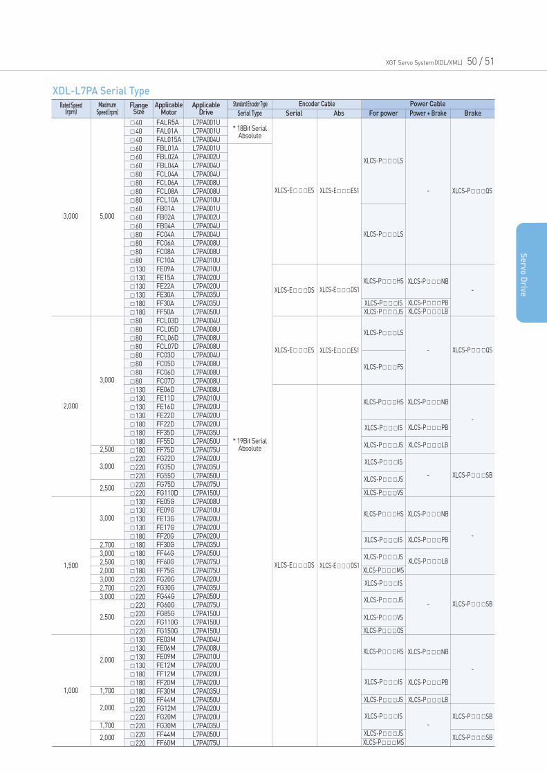
FlangeSize
Rated Speed(rpm)
MaximumSpeed (rpm)
ApplicableMotor
ApplicableDrive Serial Type
Standard Encoder Type
Serial Abs For power Power + Brake Brake
Encoder Cable Power Cable
XDL-L7PA Serial Type
*3,000 P/R XLCS-EBS
130
130
130
130
180
180
130
130
130
130
180
180
180
180
220
220
220
220
220
130
130
130
130
180
180
180
180
180
220
220
220
220
220
220
220
130
130
130
130
180
180
180
180
220
220
220
220
220
3,000
2,000
1,500
1,000
5,000
3,000
XLCF-PHS
XLCF-PHS
XLCF-PIS
XLCF-PIS
XLCF-PIS
XLCF-PIS
XLCF-PIS
XLCF-PIS
XLCF-PHS
XLCF-PHS
XLCF-PJS
XLCF-PJS
XLCF-PJS
XLCF-PJS
XLCF-PJS
XLCF-PJS
XLCF-PMS
XLCF-PMS
XLCF-PMS
XLCF-PMS
XLCF-PIS
XLCF-PJS
XLCF-PPB
XLCF-PLB
-
-
-
-
-
-
XLCF-PNB
XLCF-PNB
XLCF-PSB
XLCF-PSB
XLCF-PSB
XLCF-PPB
XLCF-PPB
XLCF-PPB
XLCF-PLB
XLCF-PLB
XLCF-PLB
XLCF-PNB
XLCF-PNB
3,000
3,000
2,500
2,500
2,500
2,000
2,000
1,700
2,000
SEP09A
SEP15A
SEP22A
SEP30A
SFP30A
SFP50A
SEP06D
SEP11D
SEP16D
SEP22D
SFP22D
SFP35D
SFP55D
SFP75D
SGP22D
SGP35D
SGP55D
SGP75D
SGP110D
SEP05G
SEP09G
SEP13G
SEP17G
SFP20G
SFP30G
SFP44G
SFP60G
SFP75G
SGP20G
SGP30G
SGP44G
SGP60G
SGP85G
SGP110G
SGP150G
SEP03M
SEP06M
SEP09M
SEP12M
SFP12M
SFP20M
SFP30M
SFP44M
SGP12M
SGP20M
SGP30M
SGP44M
SGP60M
L7PB010U
L7PB020U
L7PB020U
L7PB035U
L7PB035U
L7PB050U
L7PB010U
L7PB010U
L7PB020U
L7PB020U
L7PB020U
L7PB035U
L7PB050U
L7PB075U
L7PB020U
L7PB035U
L7PB050U
L7PB075U
L7PB150U
L7PB010U
L7PB010U
L7PB020U
L7PB020U
L7PB020U
L7PB050U
L7PB050U
L7PB075U
L7PB150U
L7PB020U
L7PB050U
L7PB050U
L7PB075U
L7PB150U
L7PB150U
L7PB150U
L7PB010U
L7PB010U
L7PB010U
L7PB020U
L7PB020U
L7PB020U
L7PB050U
L7PB050U
L7PB020U
L7PB020U
L7PB050U
L7PB050U
L7PB150U
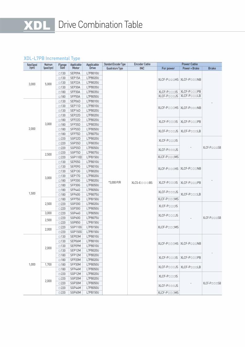
FlangeSize
Rated Speed(rpm)
MaximumSpeed (rpm)
ApplicableMotor
ApplicableDrive Quadrature Type
Standard Encoder Type
INC For power Power + Brake Brake
Encoder Cable Power Cable
XDL-L7PB Incremental Type
Drive Combination Table
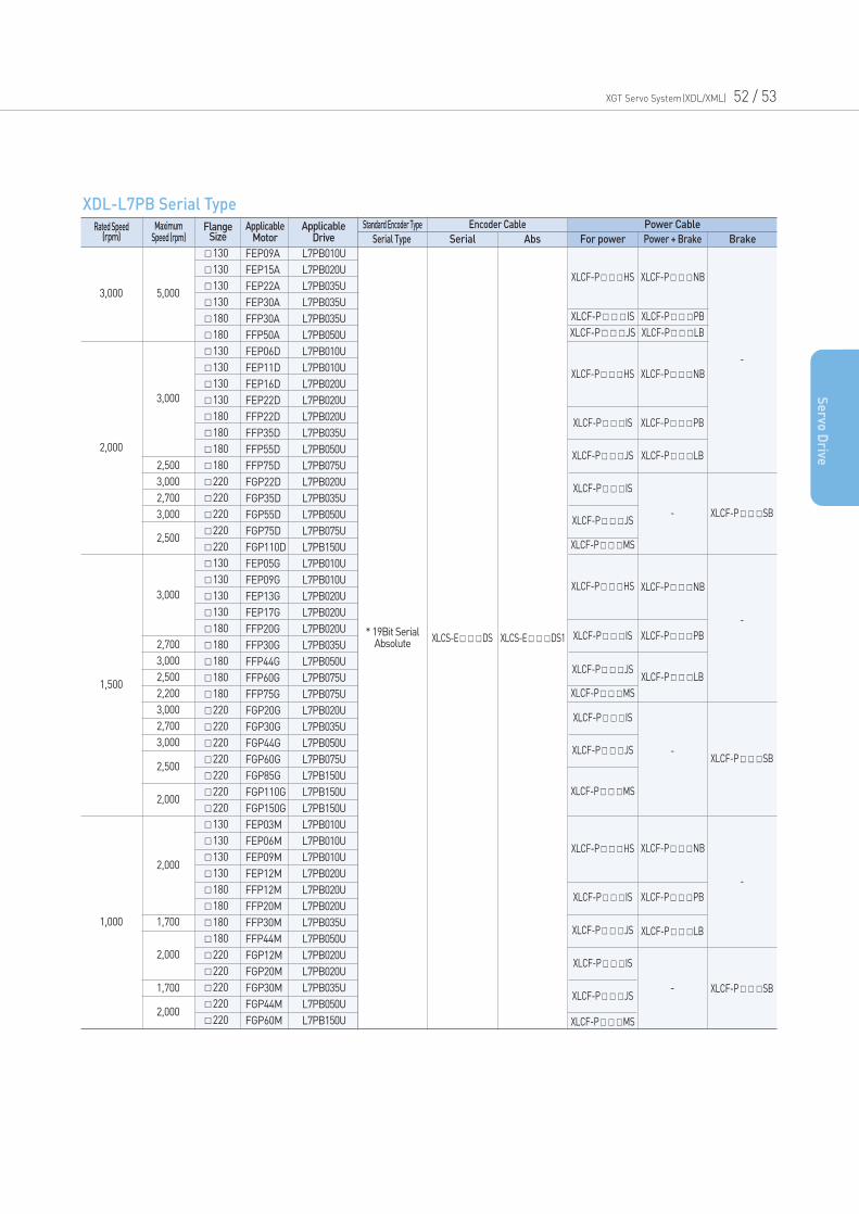
* 19Bit SerialAbsolute XLCS-EDS XLCS-EDS1
130
130
130
130
180
180
130
130
130
130
180
180
180
180
220
220
220
220
220
130
130
130
130
180
180
180
180
180
220
220
220
220
220
220
220
130
130
130
130
180
180
180
180
220
220
220
220
220
3,000
2,000
1,500
1,000
5,000
3,000
XLCF-PHS
XLCF-PHS
XLCF-PHS
XLCF-PHS
XLCF-PIS
XLCF-PIS
XLCF-PIS
XLCF-PIS
XLCF-PIS
XLCF-PIS
XLCF-PJS
XLCF-PJS
XLCF-PJS
XLCF-PJS
XLCF-PJS
XLCF-PJS
XLCF-PMS
XLCF-PPB
XLCF-PPB
XLCF-PPB
XLCF-PLB
XLCF-PLB
XLCF-PLB
XLCF-PSB
-
-
-
-
-
-
XLCF-PSB
XLCF-PSB
XLCF-PNB
XLCF-PNB
XLCF-PNB
XLCF-PNB
XLCF-PIS
XLCF-PJS
XLCF-PMS
XLCF-PMS
XLCF-PMS
XLCF-PPB
XLCF-PLB
2,500
3,000
2,500
2,000
2,000
1,700
1,700
2,000
2,000
FEP09A
FEP15A
FEP22A
FEP30A
FFP30A
FFP50A
FEP06D
FEP11D
FEP16D
FEP22D
FFP22D
FFP35D
FFP55D
FFP75D
FGP22D
FGP35D
FGP55D
FGP75D
FGP110D
FEP05G
FEP09G
FEP13G
FEP17G
FFP20G
FFP30G
FFP44G
FFP60G
FFP75G
FGP20G
FGP30G
FGP44G
FGP60G
FGP85G
FGP110G
FGP150G
FEP03M
FEP06M
FEP09M
FEP12M
FFP12M
FFP20M
FFP30M
FFP44M
FGP12M
FGP20M
FGP30M
FGP44M
FGP60M
2,700
3,000
2,500
2,200
3,000
2,700
3,000
2,500
3,000
2,700
3,000
L7PB010U
L7PB020U
L7PB035U
L7PB035U
L7PB035U
L7PB050U
L7PB010U
L7PB010U
L7PB020U
L7PB020U
L7PB020U
L7PB035U
L7PB050U
L7PB075U
L7PB020U
L7PB035U
L7PB050U
L7PB075U
L7PB150U
L7PB010U
L7PB010U
L7PB020U
L7PB020U
L7PB020U
L7PB035U
L7PB050U
L7PB075U
L7PB075U
L7PB020U
L7PB035U
L7PB050U
L7PB075U
L7PB150U
L7PB150U
L7PB150U
L7PB010U
L7PB010U
L7PB010U
L7PB020U
L7PB020U
L7PB020U
L7PB035U
L7PB050U
L7PB020U
L7PB020U
L7PB035U
L7PB050U
L7PB150U
FlangeSize
Rated Speed(rpm)
MaximumSpeed (rpm)
ApplicableMotor
ApplicableDrive Serial Type
Standard Encoder Type
Serial Abs For power Power + Brake Brake
Encoder Cable Power Cable
XDL-L7PB Serial Type
XGT Servo System(XDL/XML) 52 / 53
Se
rvo D
rive
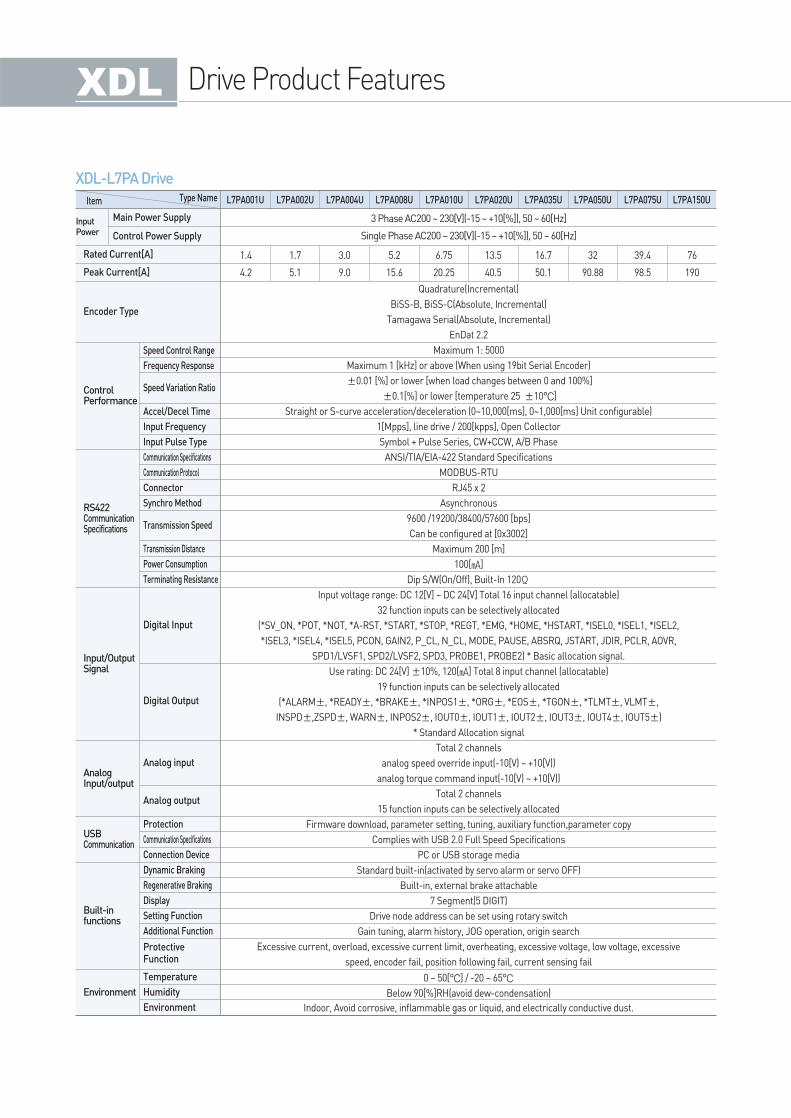
Drive Product Features
XDL-L7PA Drive
Item
InputPower
Type Name
3 Phase AC200 ~ 230[V](-15 ~ +10[%]), 50 ~ 60[Hz]
Single Phase AC200 ~ 230[V](-15 ~ +10[%]), 50 ~ 60[Hz]
Quadrature(Incremental)
BiSS-B, BiSS-C(Absolute, Incremental)
Tamagawa Serial(Absolute, Incremental)
EnDat 2.2
Maximum 1: 5000
Maximum 1 [kHz] or above (When using 19bit Serial Encoder)
±0.01 [%] or lower [when load changes between 0 and 100%]
±0.1[%] or lower [temperature 25 ±10°C]
Straight or S-curve acceleration/deceleration (0~10,000[ms], 0~1,000[ms] Unit configurable)
1[Mpps], line drive / 200[kpps], Open Collector
Symbol + Pulse Series, CW+CCW, A/B Phase
ANSI/TIA/EIA-422 Standard Specifications
MODBUS-RTU
RJ45 x 2
Asynchronous
9600 /19200/38400/57600 [bps]
Can be configured at [0x3002]
Maximum 200 [m]
100[]
Dip S/W(On/Off), Built-In 120Ω
Input voltage range: DC 12[V] ~ DC 24[V] Total 16 input channel (allocatable)
32 function inputs can be selectively allocated
(*SV_ON, *POT, *NOT, *A-RST, *START, *STOP, *REGT, *EMG, *HOME, *HSTART, *ISEL0, *ISEL1, *ISEL2,
*ISEL3, *ISEL4, *ISEL5, PCON, GAIN2, P_CL, N_CL, MODE, PAUSE, ABSRQ, JSTART, JDIR, PCLR, AOVR,
SPD1/LVSF1, SPD2/LVSF2, SPD3, PROBE1, PROBE2) * Basic allocation signal.
Use rating: DC 24[V] ±10%, 120[] Total 8 input channel (allocatable)
19 function inputs can be selectively allocated
(*ALARM±, *READY±, *BRAKE±, *INPOS1±, *ORG±, *EOS±, *TGON±, *TLMT±, VLMT±,
INSPD±,ZSPD±, WARN±, INPOS2±, IOUT0±, IOUT1±, IOUT2±, IOUT3±, IOUT4±, IOUT5±)
* Standard Allocation signal
Total 2 channels
analog speed override input(-10[V) ~ +10[V))
analog torque command input(-10[V) ~ +10[V))
Total 2 channels
15 function inputs can be selectively allocated
Firmware download, parameter setting, tuning, auxiliary function,parameter copy
Complies with USB 2.0 Full Speed Specifications
PC or USB storage media
Standard built-in(activated by servo alarm or servo OFF)
Built-in, external brake attachable
7 Segment(5 DIGIT)
Drive node address can be set using rotary switch
Gain tuning, alarm history, JOG operation, origin search
Excessive current, overload, excessive current limit, overheating, excessive voltage, low voltage, excessive
speed, encoder fail, position following fail, current sensing fail
0 ~ 50[°C] / -20 ~ 65°C
Below 90[%]RH(avoid dew-condensation)
Indoor, Avoid corrosive, inflammable gas or liquid, and electrically conductive dust.
1.4
4.2
1.7
5.1
3.0
9.0
5.2
15.6
6.75
20.25
13.5
40.5
16.7
50.1
32
90.88
39.4
98.5
76
190
L7PA001U L7PA002U L7PA004U L7PA008U L7PA010U L7PA020U L7PA035U L7PA050U L7PA075U L7PA150U
Main Power Supply
Control Power Supply
Rated Current[A]
Peak Current[A]
Encoder Type
ControlPerformance
RS422CommunicationSpecifications
Input/OutputSignal
AnalogInput/output
USBCommunication
Built-infunctions
Environment
Speed Control Range
Frequency Response
Accel/Decel Time
Input Frequency
Input Pulse Type
Communication Specifications
Communication Protocol
Connector
Synchro Method
Transmission Distance
Power Consumption
Terminating Resistance
Protection
Communication Specifications
Connection Device
Dynamic Braking
Regenerative Braking
Display
Setting Function
Additional Function
Temperature
Humidity
Environment
Speed Variation Ratio
Transmission Speed
Digital Input
Digital Output
Analog input
Analog output
Protective Function
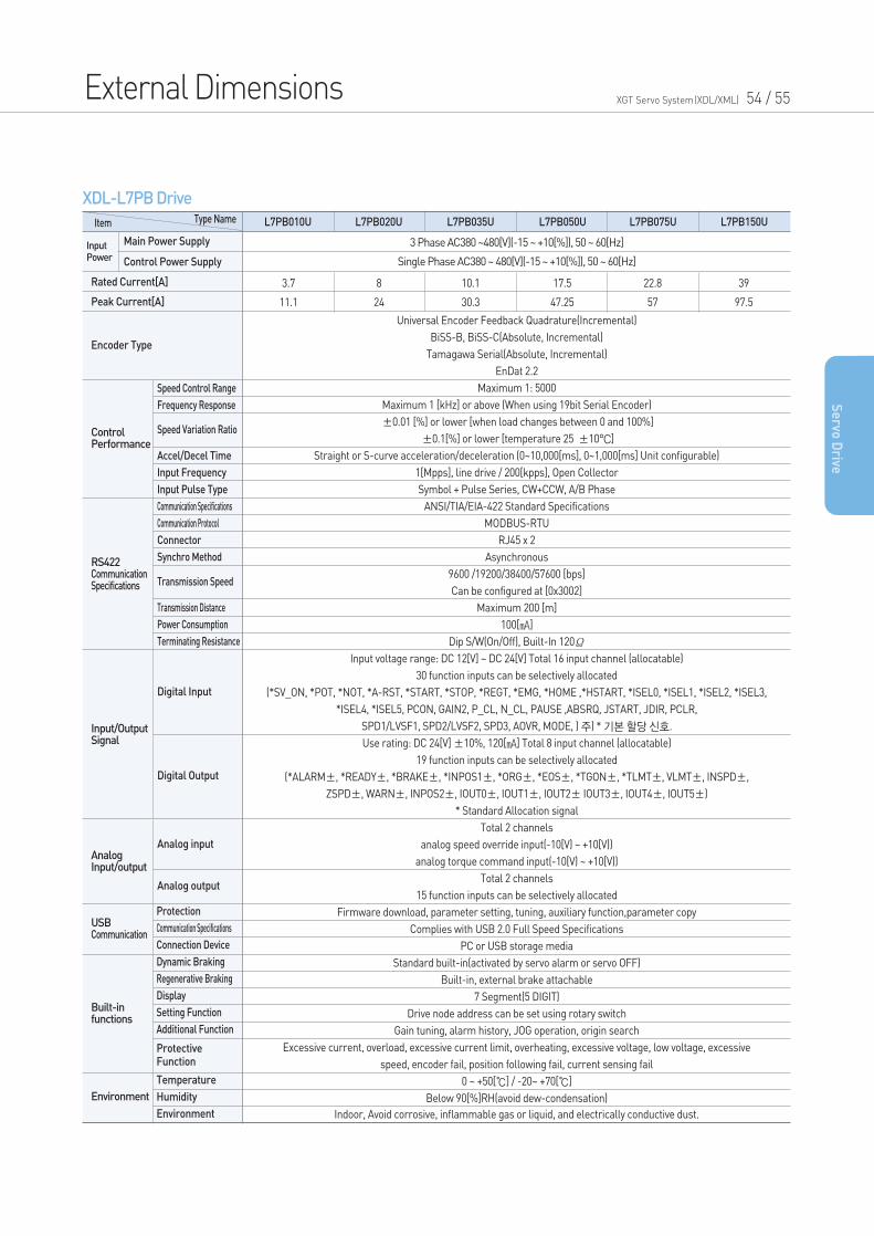
External Dimensions XGT Servo System(XDL/XML) 54 / 55
Se
rvo D
rive
XDL-L7PB Drive
Item
InputPower
Type Name
3 Phase AC380 ~480[V](-15 ~ +10[%]), 50 ~ 60[Hz]
Single Phase AC380 ~ 480[V](-15 ~ +10[%]), 50 ~ 60[Hz]
Universal Encoder Feedback Quadrature(Incremental)
BiSS-B, BiSS-C(Absolute, Incremental)
Tamagawa Serial(Absolute, Incremental)
EnDat 2.2
Maximum 1: 5000
Maximum 1 [kHz] or above (When using 19bit Serial Encoder)
±0.01 [%] or lower [when load changes between 0 and 100%]
±0.1[%] or lower [temperature 25 ±10°C]
Straight or S-curve acceleration/deceleration (0~10,000[ms], 0~1,000[ms] Unit configurable)
1[Mpps], line drive / 200[kpps], Open Collector
Symbol + Pulse Series, CW+CCW, A/B Phase
ANSI/TIA/EIA-422 Standard Specifications
MODBUS-RTU
RJ45 x 2
Asynchronous
9600 /19200/38400/57600 [bps]
Can be configured at [0x3002]
Maximum 200 [m]
100[]
Dip S/W(On/Off), Built-In 120Ω
Input voltage range: DC 12[V] ~ DC 24[V] Total 16 input channel (allocatable)
30 function inputs can be selectively allocated
(*SV_ON, *POT, *NOT, *A-RST, *START, *STOP, *REGT, *EMG, *HOME ,*HSTART, *ISEL0, *ISEL1, *ISEL2, *ISEL3,
*ISEL4, *ISEL5, PCON, GAIN2, P_CL, N_CL, PAUSE ,ABSRQ, JSTART, JDIR, PCLR,
SPD1/LVSF1, SPD2/LVSF2, SPD3, AOVR, MODE, ) 주) * 기본할당신호.
Use rating: DC 24[V] ±10%, 120[] Total 8 input channel (allocatable)
19 function inputs can be selectively allocated
(*ALARM±, *READY±, *BRAKE±, *INPOS1±, *ORG±, *EOS±, *TGON±, *TLMT±, VLMT±, INSPD±,
ZSPD±, WARN±, INPOS2±, IOUT0±, IOUT1±, IOUT2± IOUT3±, IOUT4±, IOUT5±)
* Standard Allocation signal
Total 2 channels
analog speed override input(-10[V) ~ +10[V))
analog torque command input(-10[V) ~ +10[V))
Total 2 channels
15 function inputs can be selectively allocated
Firmware download, parameter setting, tuning, auxiliary function,parameter copy
Complies with USB 2.0 Full Speed Specifications
PC or USB storage media
Standard built-in(activated by servo alarm or servo OFF)
Built-in, external brake attachable
7 Segment(5 DIGIT)
Drive node address can be set using rotary switch
Gain tuning, alarm history, JOG operation, origin search
Excessive current, overload, excessive current limit, overheating, excessive voltage, low voltage, excessive
speed, encoder fail, position following fail, current sensing fail
0 ~ +50[] / -20~ +70[]
Below 90[%]RH(avoid dew-condensation)
Indoor, Avoid corrosive, inflammable gas or liquid, and electrically conductive dust.
3.7
11.1
8
24
10.1
30.3
17.5
47.25
22.8
57
39
97.5
L7PB010U L7PB020U L7PB035U L7PB050U L7PB075U L7PB150U
Main Power Supply
Control Power Supply
Rated Current[A]
Peak Current[A]
Encoder Type
ControlPerformance
RS422CommunicationSpecifications
Input/OutputSignal
AnalogInput/output
USBCommunication
Built-infunctions
Environment
Speed Control Range
Frequency Response
Accel/Decel Time
Input Frequency
Input Pulse Type
Communication Specifications
Communication Protocol
Connector
Synchro Method
Transmission Distance
Power Consumption
Terminating Resistance
Speed Variation Ratio
Digital Input
Transmission Speed
Digital Output
Analog input
Analog output
Protection
Communication Specifications
Connection Device
Dynamic Braking
Regenerative Braking
Display
Setting Function
Additional Function
Temperature
Humidity
Environment
Protective Function
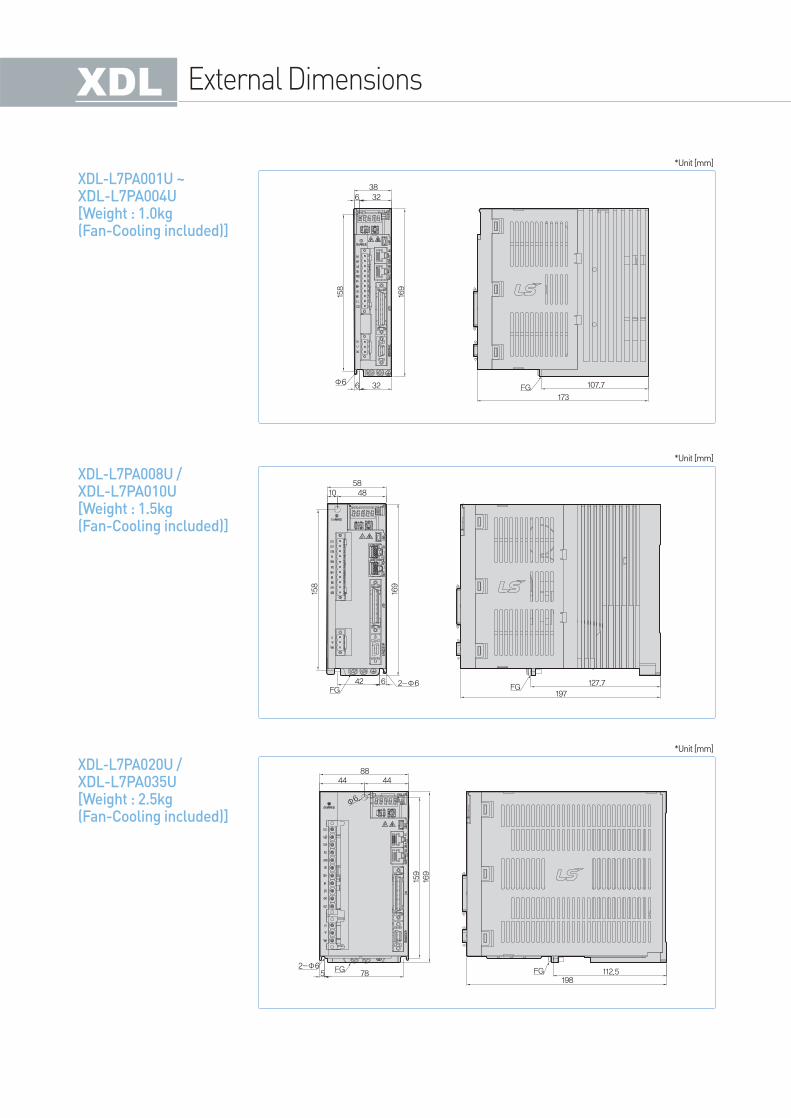
External Dimensions
XDL-L7PA001U ~ XDL-L7PA004U[Weight : 1.0kg(Fan-Cooling included)]
38326
158
169
32 FG 107.7
173
6Φ6
*Unit [mm]
XDL-L7PA008U / XDL-L7PA010U[Weight : 1.5kg(Fan-Cooling included)]
584810
158
169
42 6FG
2-Φ6 FG 127.7
197
*Unit [mm]
XDL-L7PA020U /XDL-L7PA035U[Weight : 2.5kg(Fan-Cooling included)]
8844 44
Φ6
2-Φ65 78
159169
FG FG198
112.5
*Unit [mm]
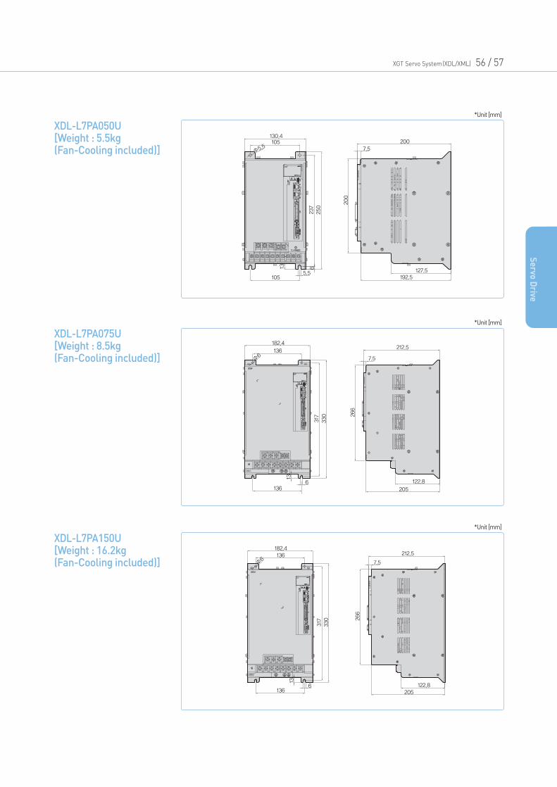
XGT Servo System(XDL/XML) 56 / 57
Se
rvo D
rive
XDL-L7PA050U [Weight : 5.5kg(Fan-Cooling included)]
130.4105
Φ5.5
237
250
200
200
127.5192.5
7.5
1055.5
13 6
*Unit [mm]
XDL-L7PA075U [Weight : 8.5kg(Fan-Cooling included)]
182.4212.5
7.5
136
Φ6
136
13
317
330 266
6 122.8
205
*Unit [mm]
XDL-L7PA150U [Weight : 16.2kg(Fan-Cooling included)]
182.4212.5
7.5
122.8205
136
136
13
Φ6
317 266
330
6
*Unit [mm]
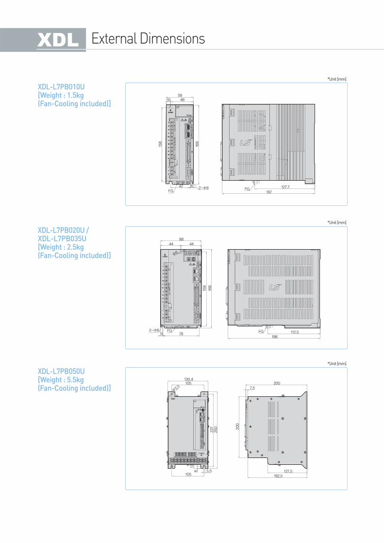
External Dimensions
XDL-L7PB010U [Weight : 1.5kg(Fan-Cooling included)]
58
158
42 6FG FG 127.7
197169
4810
2-Φ6
*Unit [mm]
XDL-L7PB020U / XDL-L7PB035U[Weight : 2.5kg(Fan-Cooling included)]
8844
159
169
44
Φ6
2-Φ65FG FG 112.5
19878
*Unit [mm]
XDL-L7PB050U [Weight : 5.5kg(Fan-Cooling included)]
130.4200
200
7.5
127.5192.5
105
1055.5
136
Φ5.5
237
250
*Unit [mm]
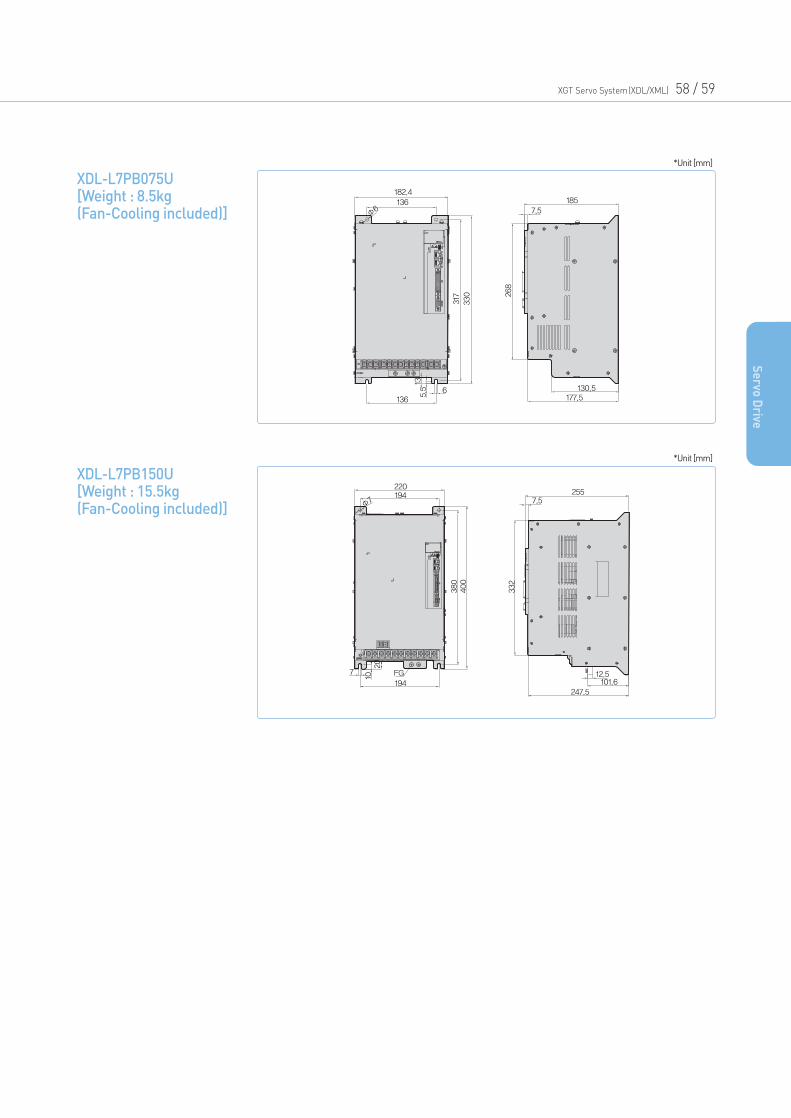
XGT Servo System(XDL/XML) 58 / 59
Se
rvo D
rive
XDL-L7PB075U [Weight : 8.5kg(Fan-Cooling included)]
182.4185
7.5
317
330 268
136
Φ6
136
130.5177.5
6
135.5
*Unit [mm]
XDL-L7PB150U [Weight : 15.5kg(Fan-Cooling included)]
220255
7.5
380
332
400
194
194247.5
101.612.5FG7
1020
Φ7
*Unit [mm]
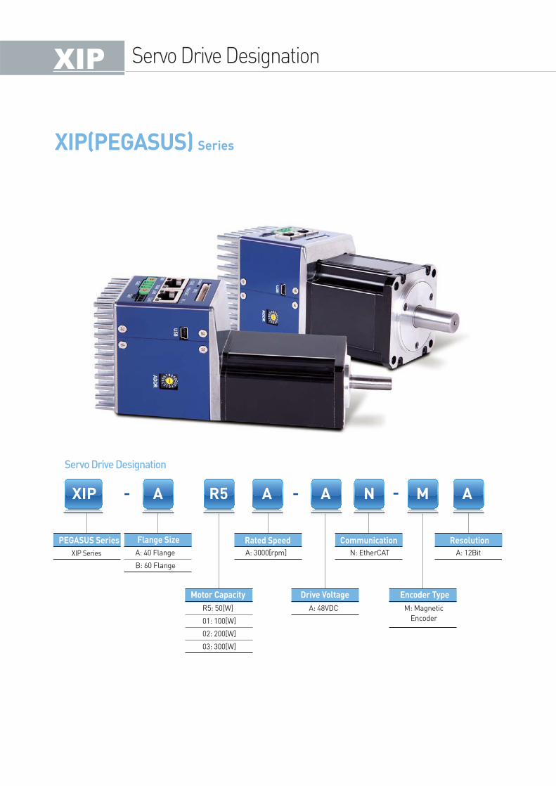
Servo Drive Designation
XIP(PEGASUS) Series
Servo Drive Designation
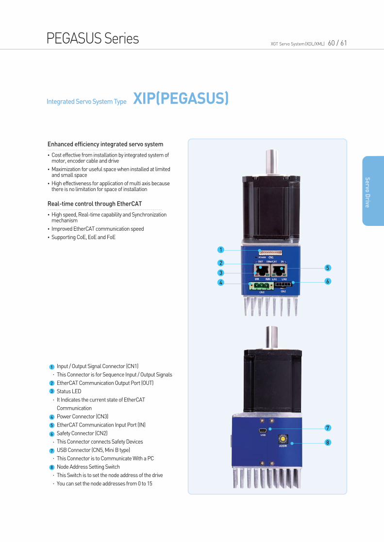
Integrated Servo System Type XIP(PEGASUS)
PEGASUS Series XGT Servo System(XDL/XML) 60 / 61
•Cost effective from installation by integrated system of motor, encoder cable and drive
•Maximization for useful space when installed at limited and small space
•High effectiveness for application of multi axis because there is no limitation for space of installation
Enhanced efficiency integrated servo system
•High speed, Real-time capability and Synchronization mechanism
•Improved EtherCAT communication speed
•Supporting CoE, EoE and FoE
Real-time control through EtherCAT
Se
rvo D
rive
Input / Output Signal Connector (CN1)
This Connector is for Sequence Input / Output Signals
EtherCAT Communication Output Port (OUT)
Status LED
It Indicates the current state of EtherCAT
Communication
Power Connector (CN3)
EtherCAT Communication Input Port (IN)
Safety Connector (CN2)
This Connector connects Safety Devices
USB Connector (CN5, Mini B type)
This Connector is to Communicate With a PC
Node Address Setting Switch
This Switch is to set the node address of the drive
You can set the node addresses from 0 to 15
1
2
3
4
5
6
7
8
5
6
7
8
1
2
3
4
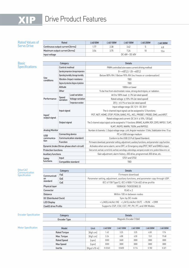
Drive Product Features
Rated 40 50W
1.77
3.54
40 100W
2.38
3.75
60 100W
3.62
7.24
60 200W
5
10
60 300W
6.8
13.6
DC 48V ~ DC 60V
Continuous output current [Arms]
Maximum output current [Arms]
Input voltage
Category Details
PWM controlled sine wave current driving method
0∼+40[] / -20~ +60[]
Below 80% RH / Below 90% RH (no freeze or condensation)
TBD
TBD
1000m or lower
To be free from electrostatic noise, strong electrolysis, or radiation.
At 0 to 100% load: ±3% (at rated speed)
Rated voltage ±10%: 0% (at rated speed)
25: ±0.1% or less (at rated speed)
Input voltage range: DC 12 V - DC 30 V
The 4-channel input signal can be assigned to 12 functions:
POT, NOT, HOME, STOP, PCON, GAIN2, PCL, NCL, PROBE1, PROB2, EMG, and ARST.
Rated voltage and current: DC 24 V ±10%, 120 []
The 2-channel output signal can be assigned to 11 functions: BRAKE, ALARM, RDY, ZSPD, INPOS1, TLMT,
VLMT, INSPD, WARN, TGON, and INPOS2.
Number of channels: 1, Output voltage range: ±4V, Angular resolution: 12 bits, Stabilization time: 15 us
PC or USB storage medium
Conform to the USB 2.0 Full Speed Standard.
Firmware download, parameter setting, adjustment, auxiliary functions, and parameter copy function.
Activates when servo alarm, servo OFF, or Emergency stop (POT, NOT and EMG) is input.
Overcurrent, overload, current limit, overheat, overvoltage, undervoltage, overspeed, encoder error, position follow error, ect.
Gain adjustment, alarm history, JOG drive, programmed JOG drive, etc.
STO1 and STO2
TBD
Firmware download
Parameter setting, adjustment, auxiliary functions, and parameter copy through UDP.
IEC 61158 Type12, IEC 61800-7 CiA 402 drive profile
100BASE-TX(IEEE802.3)
RJ45 x 2
Within 100 m between nodes
Sync by DC mode
•L/A0(Link/Act IN) •L/A1(Link/Act OUT) •RUN •ERR
Supports CSP, CSV, CST, PP, PV, PT, and HM Modes.
Useconditions
Performance
Input/output signal
USBcommunica-tion
Safetyfunctions
Analog Monitor
Dynamic brake (three-phase short-circuit)
Protection functions
Auxiliary functions
Control method
Operating temperature /storage temperature
Operating humidity /storage humidity
Vibration-/impact-resistance
Degree of protection /degree of pollution
Altitude
Other
Connecting device
Communication standard
Function
Input
Compatible standard
Speedvariation
Input signal
Output signal
Load variation
Voltage variation
Temperature variation
Category Details
FoE
EoE
CoE
Model Unit
[Kgf cm]
[Kgf cm]
[rpm]
[rpm]
[Kgx10-4]
40 50W
1.62
3.24
3000
3000
0.0240
40 100W
3.25
4.88
2400
3000
0.0450
60 100W
3.25
6.50
3000
3000
0.114
60 200W
6.50
13.0
3000
3000
0.182
60 300W
9.74
19.48
3000
3000
0.321
Rated Torque
Max. Torque
Rated Speed
Max Speed
Inertia
Rated Values of Servo Drive
Basic Specifications
EtherCATCommunicationSpecification
Motor Specification
Encoder Specification Category Details
Magnetic Encoder (12bit)Encoder Type
Communicationstandard
Physical layer
Connector
Distance
DC (Distributed Clock)
LED Display
Cia402 drive Profile
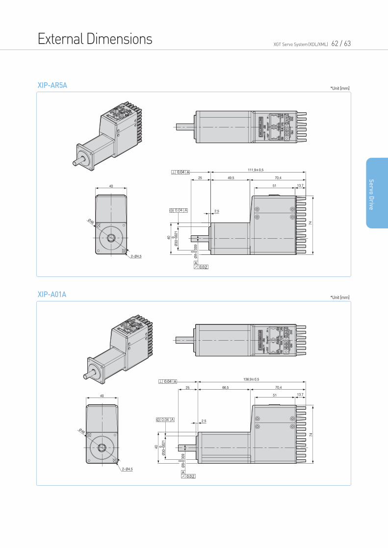
External Dimensions XGT Servo System(XDL/XML) 62 / 63
Se
rvo D
rive
XIP-AR5A
XIP-A01A
*Unit [mm]
*Unit [mm]
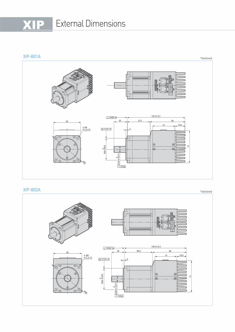
XIP-B01A
XIP-B02A
*Unit [mm]
*Unit [mm]
External Dimensions
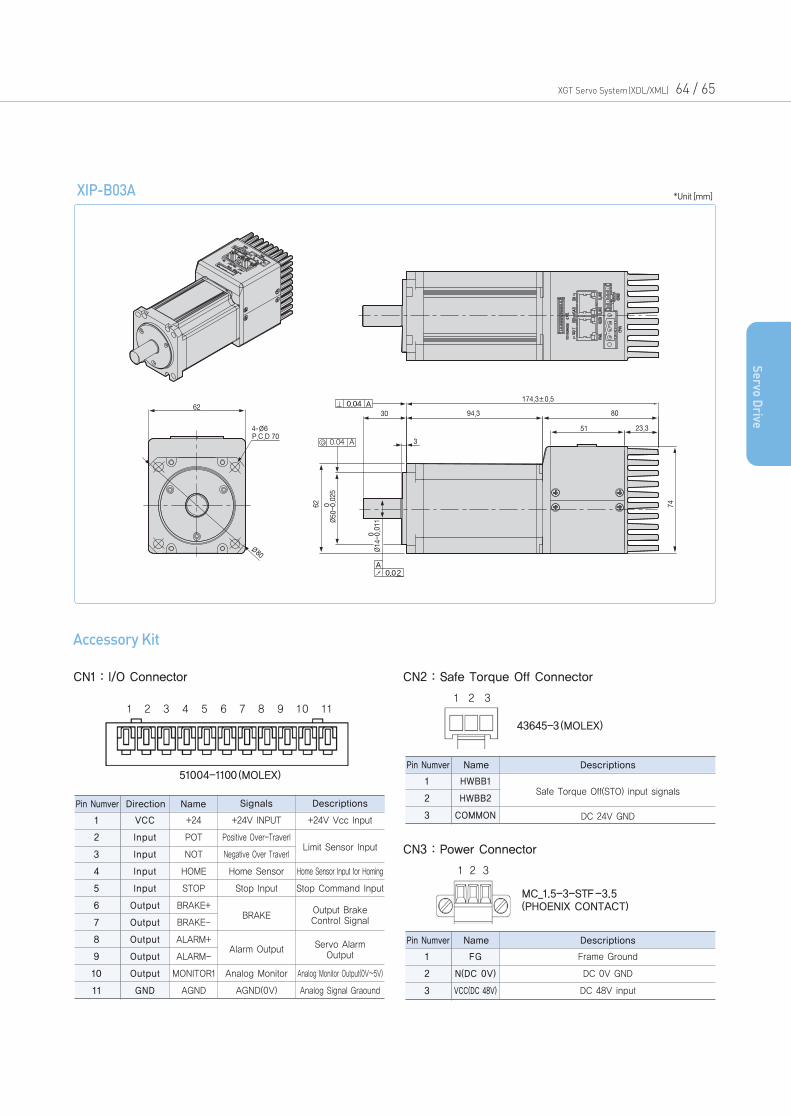
XIP-B03A *Unit [mm]
XGT Servo System(XDL/XML) 64 / 65
Se
rvo D
rive
Pin Numver Direction Name Signals
VCC
Input
Input
Input
Input
Output
Output
Output
Output
Output
GND
+24
POT
NOT
HOME
STOP
BRAKE+
BRAKE-
ALARM+
ALARM-
MONITOR1
AGND
+24V INPUT
Positive Over-Traverl
Negative Over Traverl
Home Sensor
Stop Input
Analog Monitor
AGND(0V)
+24V Vcc Input
Home Sensor Input for Homing
Stop Command Input
Analog Monitor Output(0V~5V)
Analog Signal Graound
BRAKE
Limit Sensor Input
Output Brake Control Signal
Servo Alarm Output
Alarm Output
Descriptions
1
2
3
4
5
6
7
8
9
10
11
Pin Numver Name Descriptions
HWBB1
HWBB2
COMMON
Safe Torque Off(STO) input signals
DC 24V GND
1
2
3
Pin Numver Name Descriptions
FG
N(DC 0V)
VCC(DC 48V)
Frame Ground
DC 0V GND
DC 48V input
1
2
3
Accessory Kit
CN1 : I/O Connector
51004-1100(MOLEX)
43645-3(MOLEX)
MC_1.5-3-STF-3.5(PHOENIX CONTACT)
CN2 : Safe Torque Off Connector
CN3 : Power Connector
1 2 3 4 5 6 7 8 9 10 111 2 3
1 2 3
Servo Motor
F SeriesFlat Type Rotating Servo Motor 68
S SeriesSolid/Hollow Shaft Type Rotating 83
Servo Motor
MDM SeriesDirect-Drive Motor 95
XGT Servo System(XDL/XML) 66 / 67
Contents
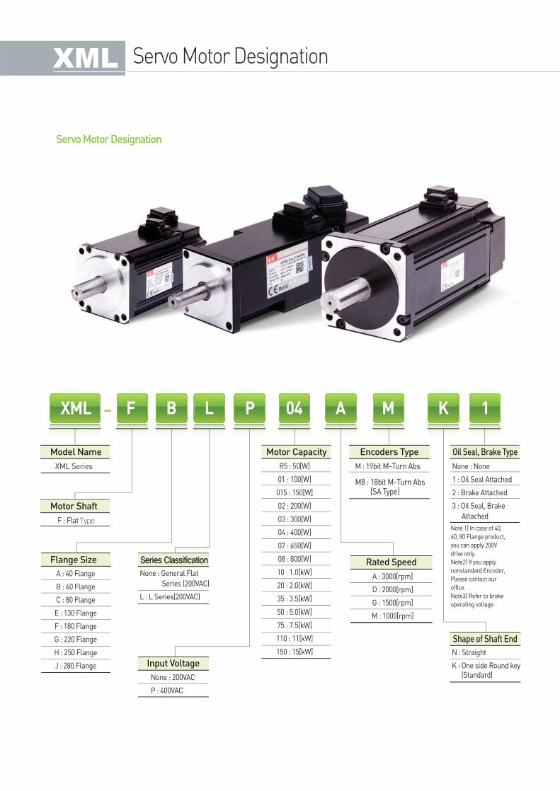
Servo Motor Designation
Servo Motor Designation
Model Name Motor Capacity
Rated Speed
Shape of Shaft End
Encoders Type Oil Seal, Brake Type
XML F B L P 04 A M K 1
A : 40 Flange
B : 60 Flange
C : 80 Flange
E : 130 Flange
F : 180 Flange
G : 220 Flange
H : 250 Flange
J : 280 Flange
R5 : 50[W]
01 : 100[W]
015 : 150[W]
02 : 200[W]
03 : 300[W]
04 : 400[W]
07 : 650[W]
08 : 800[W]
10 : 1.0[kW]
20 : 2.0[kW]
35 : 3.5[kW]
50 : 5.0[kW]
75 : 7.5[kW]
110 : 11[kW]
150 : 15[kW]
M : 19bit M-Turn Abs
M8 : 18bit M-Turn Abs [SA Type]
None : None
1 : Oil Seal Attached
2 : Brake Attached
3 : Oil Seal, Brake
Attached
A : 3000[rpm]
D : 2000[rpm]
G : 1500[rpm]
M : 1000[rpm]
N : Straight
K : One side Round key (Standard)
F : Flat Type
None : General Flat
Series (200VAC)
L : L Series(200VAC)
None : 200VAC
P : 400VAC
Note 1) In case of 40,
60, 80 Flange product,
you can apply 200V
drive only.
Note2) If you apply
nonstandard Encoder,
Please contact our
office.
Note3) Refer to brake
operating voltage
Series Classification
XML Series
Motor Shaft
Flange Size
Input Voltage
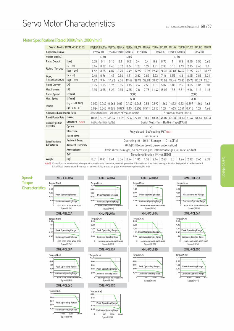
Servo Motor (XML-) FALR5A FAL01A FAL015A FBL01A FBL02A FBL04A FCL04A FCL06A FCL08A FCL10A FCL03D FCL05D FCL06D FCL07D
L7A001 L7A004 L7A002 L7A004 L7A010 L7A004 L7A008L7A008L7A001
40 60 80
Fully closed·Self cooling IP67 Note1)
×
Continuous
Operating : 0 ~ 40[] Storage : -10 ~ 60[]
90[%]RH Below (avoid dew-condensation)
Avoid direct sunlight, no corrosive gas, inflammable gas, oil mist, or dust.
Elevation/vibration 49[m/s2](5G)
3000 2000
5000
30 times of motor inertia 20 times of motor inertia 15 times of motor inertia
0.05
0.16
1.62
0.48
4.87
0.95
2.85
0.1
0.32
3.25
0.96
9.74
1.25
3.75
0.15
0.48
4.87
1.43
14.62
1.76
5.28
0.1
0.32
3.25
0.96
9.74
0.95
2.85
0.2
0.64
6.49
1.91
19.48
1.45
4.35
0.4
1.27
12.99
3.82
38.96
2.6
7.8
0.4
1.27
12.99
3.82
38.98
2.58
7.75
0.6
1.91
19.49
5.73
58.47
3.81
11.42
0.75
2.39
24.36
7.16
73.08
5.02
15.07
1
3.18
32.48
9.55
97.44
5.83
17.5
0.3
1.43
14.62
4.3
43.85
2.5
7.51
0.45
2.15
21.92
6.45
65.77
3.05
9.16
0.55
2.63
26.8
7.88
80.39
3.06
9.18
0.65
3.1
31.67
9.31
95.01
3.83
11.5
0.023
0.024
0.042
0.043
0.063
0.065
0.091
0.093
0.147
0.15
0.248
0.253
0.53
0.541
0.897
0.915
1.264
1.29
1.632
1.665
0.53
0.541
0.897
0.915
1.264
1.29
1.63
1.66
3000
10.55 23.78 35.34 11.09 27.6 27.07 30.6 40.66 45.09 62.08 38.73 51.47 54.56 59.03
Serial Multi-Turn Built-in Type(19bit)Serial Multi-Turn Built-in Type(18bit)
0.31 0.45 0.61 0.56 0.74 1.06 1.52 2.14 2.68 3.3 1.26 2.12 2.66 2.78
Motor Specifications [Rated 3000r/min, 2000r/min]
Torque(N.m)
Peak Operating Range
Continuous Operating Range
Speed(RPM)
Torque(N.m)
Peak Operating Range
Continuous Operating Range
Speed(RPM)
Torque(N.m)
Peak Operating Range
Continuous Operating Range
Speed(RPM)
Torque(N.m)
Peak Operating Range
Continuous Operating Range
Speed(RPM)
Speed-
Torque
Characteristics
XML-FALR5A XML-FAL01A XML-FAL015A XML-FBL01A
Torque(N.m)
Peak Operating Range
Continuous Operating Range
Speed(RPM)
Speed(RPM)
Torque(N.m)
Peak Operating Range
Continuous Operating Range
Speed(RPM)
Torque(N.m)
Peak Operating Range
Continuous Operating Range
Speed(RPM)
Speed(RPM)
XML-FBL02A XML-FBL04A XML-FCL04A
Torque(N.m)
Peak Operating Range
Continuous Operating Range
Speed(RPM)
Speed(RPM)
XML-FCL03D
Torque(N.m)
Peak Operating Range
Continuous Operating Range
Speed(RPM)
Speed(RPM)
XML-FCL06A
Torque(N.m)
Peak Operating Range
Continuous Operating Range
Speed(RPM)
Speed(RPM)
XML-FCL05D
Torque(N.m)
Peak Operating Range
Continuous Operating Range
Speed(RPM)
Speed(RPM)
Torque(N.m)
Peak Operating Range
Continuous Operating Range
Speed(RPM)
Speed(RPM)XML-FCL08A XML-FCL10A
Speed(RPM)
Torque(N.m)
Peak Operating Range
Continuous Operating Range
Speed(RPM)
XML-FCL07D
Torque(N.m)
Peak Operating Range
Continuous Operating Range
Speed(RPM)
Speed(RPM)
XML-FCL06D
Applicable Drive
Flange Size()
Rated Speed
Max. Speed
Rated Current
Max.Current
Specifications& Features
Rated Output [kW]
[N·m]
[kgf·cm]
[N·m]
[kgf·cm]
[A]
[A]
[r/min]
[r/min]
[kg·m2X 10-4]
[gf·cm·s2]
[kW/s]
Standard Note1)
Option
Structure
Rated Time
Ambient Temp
Ambient Humidity
Atmosphere
E/V
[kg]
Rated Power Rate
Weight
Speed/PositionDetector
Rated Torque
Max.Instantaneous
Inertia
Allowable Load Inertia Ratio
Servo Motor Characteristics XGT Servo System(XDL/XML) 68 /69
Se
rvo M
oto
r
Note1) Except for axis penetration, when you attach reducer to the motor, we don’t guarantee IP for reducer. If you bend over specification designated in cable standard,
it is difficult to guarantee IP marked It can be satisfied protection grade when you use private cable only.
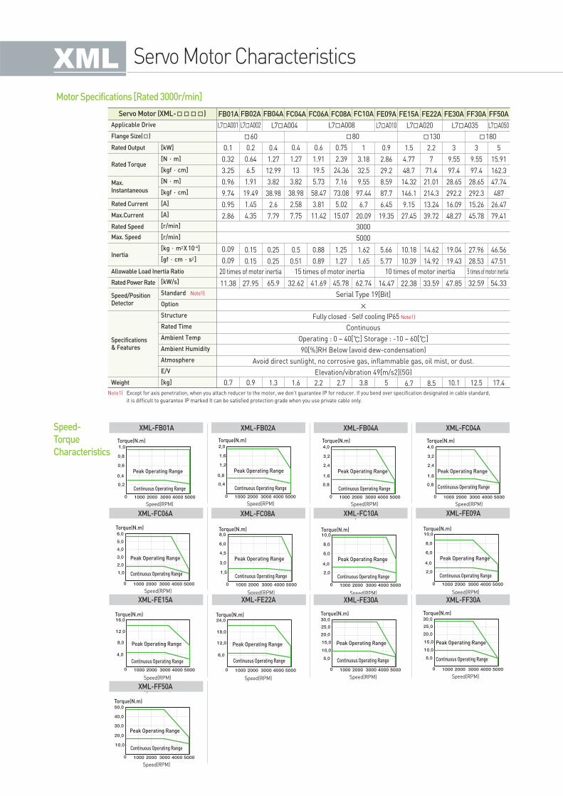
Servo Motor (XML-) FB01A FB02A FB04A FC04A FC06A FC08A FC10A FE09A FE15A FE22A FE30A FF30A FF50A
L7A001 L7A002 L7A004 L7A010 L7A035L7A020 L7A050L7A008
60 80 180130
Fully closed·Self cooling IP65 Note1)
×
Continuous
Operating : 0 ~ 40[] Storage : -10 ~ 60[]
90[%]RH Below (avoid dew-condensation)
Avoid direct sunlight, no corrosive gas, inflammable gas, oil mist, or dust.
Elevation/vibration 49[m/s2](5G)
3000
5000
20 times of motor inertia 15 times of motor inertia 5 times of motor inertia10 times of motor inertia
0.1
0.32
3.25
0.96
9.74
0.95
2.86
0.2
0.64
6.5
1.91
19.49
1.45
4.35
0.4
1.27
12.99
3.82
38.98
2.6
7.79
0.4
1.27
13
3.82
38.98
2.58
7.75
0.6
1.91
19.5
5.73
58.47
3.81
11.42
0.75
2.39
24.36
7.16
73.08
5.02
15.07
1
3.18
32.5
9.55
97.44
6.7
20.09
0.9
2.86
29.2
8.59
87.7
6.45
19.35
1.5
4.77
48.7
14.32
146.1
9.15
27.45
2.2
7
71.4
21.01
214.3
13.24
39.72
3
9.55
97.4
28.65
292.2
16.09
48.27
3
9.55
97.4
28.65
292.3
15.26
45.78
5
15.91
162.3
47.74
487
26.47
79.41
0.09
0.09
0.15
0.15
0.25
0.25
0.5
0.51
0.88
0.89
1.25
1.27
1.62
1.65
5.66
5.77
10.18
10.39
19.04
19.43
27.96
28.53
46.56
47.51
14.62
14.92
11.38 27.95 65.9 32.62 41.69 45.78 62.74 14.47 22.38 33.59 47.85 32.59 54.33
Serial Type 19[Bit]
0.7 0.9 1.3 1.6 2.2 2.7 3.8 5 6.7 8.5 10.1 12.5 17.4
Motor Specifications [Rated 3000r/min]
Torque(N.m)
Peak Operating Range
Continuous Operating Range
Speed(RPM)
Torque(N.m)
Peak Operating Range
Continuous Operating Range
Speed(RPM)
Torque(N.m)
Peak Operating Range
Continuous Operating Range
Speed(RPM)
Torque(N.m)
Peak Operating Range
Continuous Operating Range
Speed(RPM)
Speed-
Torque
Characteristics
XML-FB01A XML-FB02A XML-FB04A XML-FC04A
Torque(N.m)
Peak Operating Range
Continuous Operating Range
Speed(RPM)
Speed(RPM)
Torque(N.m)
Peak Operating Range
Continuous Operating Range
Speed(RPM)
Torque(N.m)
Peak Operating Range
Continuous Operating Range
Speed(RPM)
Speed(RPM)XML-FC06A XML-FC08A XML-FC10A
Speed(RPM)
Torque(N.m)
Peak Operating Range
Continuous Operating Range
Speed(RPM)
XML-FE30A
Torque(N.m)
Peak Operating Range
Continuous Operating Range
Speed(RPM)
Speed(RPM)XML-FE09A
Torque(N.m)
Peak Operating Range
Continuous Operating Range
Speed(RPM)
Speed(RPM)XML-FF30A
Torque(N.m)
Peak Operating Range
Continuous Operating Range
Speed(RPM)
Speed(RPM)
Torque(N.m)
Peak Operating Range
Continuous Operating Range
Speed(RPM)
Speed(RPM)XML-FE15A XML-FE22A
Torque(N.m)
Peak Operating Range
Continuous Operating Range
Speed(RPM)
Speed(RPM)XML-FF50A
Applicable Drive
Flange Size()
Rated Speed
Max. Speed
Rated Current
Max.Current
Specifications& Features
Rated Output [kW]
[N·m]
[kgf·cm]
[N·m]
[kgf·cm]
[A]
[A]
[r/min]
[r/min]
[kg·m2X 10-4]
[gf·cm·s2]
[kW/s]
Standard Note1)
Option
Structure
Rated Time
Ambient Temp
Ambient Humidity
Atmosphere
E/V
[kg]
Rated Power Rate
Weight
Speed/PositionDetector
Rated Torque
Max.Instantaneous
Inertia
Allowable Load Inertia Ratio
Servo Motor Characteristics
Note1) Except for axis penetration, when you attach reducer to the motor, we don’t guarantee IP for reducer. If you bend over specification designated in cable standard,
it is difficult to guarantee IP marked It can be satisfied protection grade when you use private cable only.
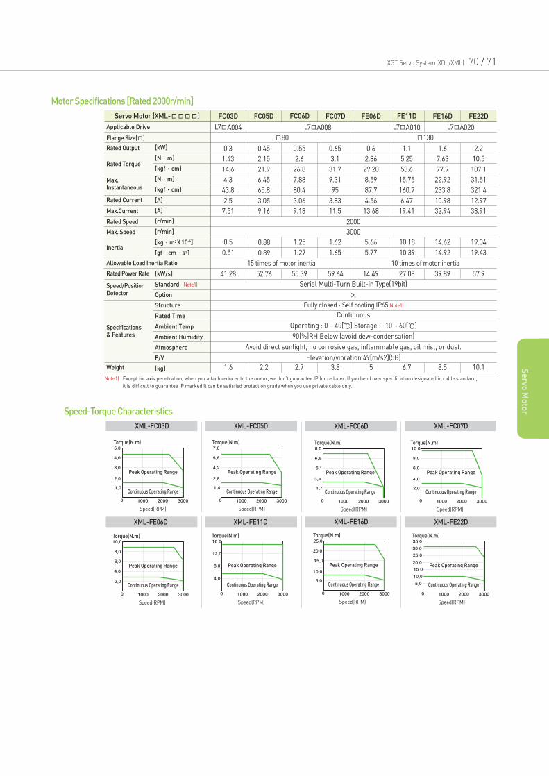
XGT Servo System(XDL/XML) 70 / 71
Se
rvo M
oto
r
Servo Motor (XML-) FC03D FC05D FC06D FC07D FE06D FE11D FE16D FE22D
L7A004 L7A008 L7A010 L7A020
80 130
15 times of motor inertia 10 times of motor inertia
Fully closed·Self cooling IP65 Note1)
×
Continuous
Operating : 0 ~ 40[] Storage : -10 ~ 60[]
90[%]RH Below (avoid dew-condensation)
Avoid direct sunlight, no corrosive gas, inflammable gas, oil mist, or dust.
Elevation/vibration 49[m/s2](5G)
2000
3000
0.3
1.43
14.6
4.3
43.8
2.5
7.51
0.45
2.15
21.9
6.45
65.8
3.05
9.16
0.55
2.6
26.8
7.88
80.4
3.06
9.18
0.65
3.1
31.7
9.31
95
3.83
11.5
0.6
2.86
29.20
8.59
87.7
4.56
13.68
1.1
5.25
53.6
15.75
160.7
6.47
19.41
1.6
7.63
77.9
22.92
233.8
10.98
32.94
2.2
10.5
107.1
31.51
321.4
12.97
38.91
0.5
0.51
0.88
0.89
1.25
1.27
1.62
1.65
5.66
5.77
10.18
10.39
14.62
14.92
19.04
19.43
41.28 52.76 55.39 59.64 14.49 27.08 39.89 57.9
Serial Multi-Turn Built-in Type(19bit)
1.6 2.2 2.7 3.8 5 6.7 8.5 10.1
Motor Specifications [Rated 2000r/min]
Torque(N.m)
Peak Operating Range
Continuous Operating Range
Speed(RPM)
Torque(N.m)
Peak Operating Range
Continuous Operating Range
Speed(RPM)
Torque(N.m)
Peak Operating Range
Continuous Operating Range
Speed(RPM)
Torque(N.m)
Peak Operating Range
Continuous Operating Range
Speed(RPM)
Speed-Torque Characteristics
XML-FC03D XML-FC05D XML-FC06D XML-FC07D
Torque(N.m)
Peak Operating Range
Continuous Operating Range
Speed(RPM)
Torque(N.m)
Peak Operating Range
Continuous Operating Range
Speed(RPM)
Torque(N.m)
Peak Operating Range
Continuous Operating Range
Speed(RPM)
XML-FE06D XML-FE11D XML-FE16D
Torque(N.m)
Peak Operating Range
Continuous Operating Range
Speed(RPM)
XML-FE22D
Applicable Drive
Flange Size()
Rated Speed
Max. Speed
Rated Current
Max.Current
Specifications& Features
Rated Output [kW]
[N·m]
[kgf·cm]
[N·m]
[kgf·cm]
[A]
[A]
[r/min]
[r/min]
[kg·m2X 10-4]
[gf·cm·s2]
[kW/s]
Standard Note1)
Option
Structure
Rated Time
Ambient Temp
Ambient Humidity
Atmosphere
E/V
[kg]
Rated Power Rate
Weight
Speed/PositionDetector
Rated Torque
Max.Instantaneous
Inertia
Allowable Load Inertia Ratio
Note1) Except for axis penetration, when you attach reducer to the motor, we don’t guarantee IP for reducer. If you bend over specification designated in cable standard,
it is difficult to guarantee IP marked It can be satisfied protection grade when you use private cable only.
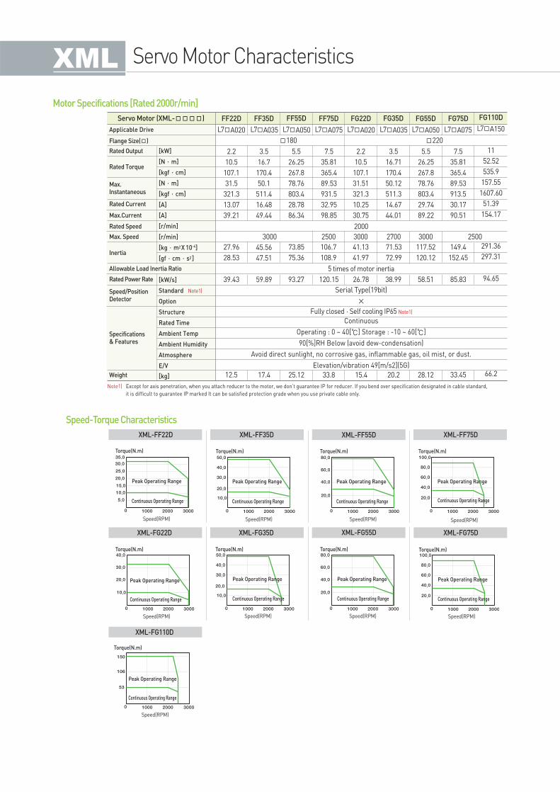
Servo Motor Characteristics
Servo Motor (XML-) FF22D FF35D FF55D FF75D FG22D FG35D FG55D FG75D
L7A020 L7A035 L7A050 L7A075 L7A020 L7A035 L7A050 L7A075
180 220
5 times of motor inertia
Fully closed·Self cooling IP65 Note1)
×
Continuous
Operating : 0 ~ 40[] Storage : -10 ~ 60[]
90[%]RH Below (avoid dew-condensation)
Avoid direct sunlight, no corrosive gas, inflammable gas, oil mist, or dust.
Elevation/vibration 49[m/s2](5G)
2000
3000 2500 25003000 30002700
2.2
10.5
107.1
31.5
321.3
13.07
39.21
3.5
16.7
170.4
50.1
511.4
16.48
49.44
5.5
26.25
267.8
78.76
803.4
28.78
86.34
7.5
35.81
365.4
89.53
931.5
32.95
98.85
2.2
10.5
107.1
31.51
321.3
10.25
30.75
3.5
16.71
170.4
50.12
511.3
14.67
44.01
5.5
26.25
267.8
78.76
803.4
29.74
89.22
7.5
35.81
365.4
89.53
913.5
30.17
90.51
27.96
28.53
45.56
47.51
73.85
75.36
106.7
108.9
41.13
41.97
71.53
72.99
117.52
120.12
149.4
152.45
39.43 59.89 93.27 120.15 26.78 38.99 58.51 85.83
Serial Type(19bit)
12.5 17.4 25.12 33.8 15.4 20.2 28.12 33.45
Motor Specifications [Rated 2000r/min]
Torque(N.m)
Peak Operating Range
Continuous Operating Range
Speed(RPM)
Torque(N.m)
Peak Operating Range
Continuous Operating Range
Speed(RPM)
Torque(N.m)
Peak Operating Range
Continuous Operating Range
Speed(RPM)
Torque(N.m)
Peak Operating Range
Continuous Operating Range
Speed(RPM)
Speed-Torque Characteristics
XML-FF22D XML-FF35D XML-FF55D XML-FF75D
Torque(N.m)
Peak Operating Range
Continuous Operating Range
Speed(RPM)
Torque(N.m)
Peak Operating Range
Continuous Operating Range
Speed(RPM)
Torque(N.m)
Peak Operating Range
Continuous Operating Range
Speed(RPM)
XML-FG22D XML-FG35D XML-FG55D
Torque(N.m)
Peak Operating Range
Continuous Operating Range
Speed(RPM)
XML-FG75D
Torque(N.m)
Peak Operating Range
Continuous Operating Range
Speed(RPM)
XML-FG110D
Applicable Drive
Flange Size()
Rated Speed
Max. Speed
Rated Current
Max.Current
Specifications& Features
Rated Output [kW]
[N·m]
[kgf·cm]
[N·m]
[kgf·cm]
[A]
[A]
[r/min]
[r/min]
[kg·m2X 10-4]
[gf·cm·s2]
[kW/s]
Standard Note1)
Option
Structure
Rated Time
Ambient Temp
Ambient Humidity
Atmosphere
E/V
[kg]
Rated Power Rate
Weight
Speed/PositionDetector
Rated Torque
Max.Instantaneous
Inertia
Allowable Load Inertia Ratio
Note1) Except for axis penetration, when you attach reducer to the motor, we don’t guarantee IP for reducer. If you bend over specification designated in cable standard,
it is difficult to guarantee IP marked It can be satisfied protection grade when you use private cable only.
FG110D
L7A150
11
52.52
535.9
157.55
1607.60
51.39
154.17
291.36
297.31
94.65
66.2
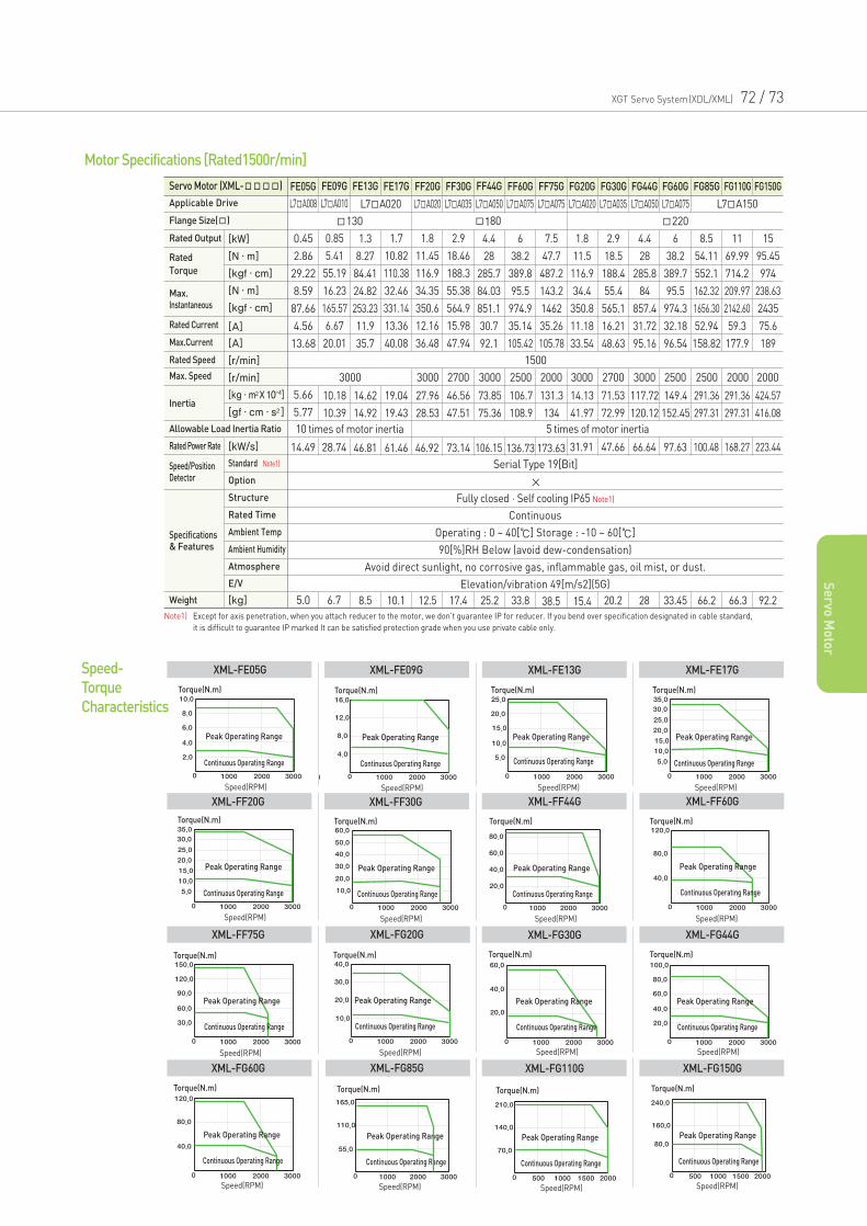
XGT Servo System(XDL/XML) 72 / 73
Se
rvo M
oto
r
Torque(N.m)
Peak Operating Range
Continuous Operating Range
Speed(RPM)
Torque(N.m)
Peak Operating Range
Continuous Operating Range
Speed(RPM)
Torque(N.m)
Peak Operating Range
Continuous Operating Range
Speed(RPM)
Torque(N.m)
Peak Operating Range
Continuous Operating Range
Speed(RPM)
Speed-
Torque
Characteristics
XML-FE05G XML-FE09G XML-FE13G XML-FE17G
Torque(N.m)
Peak Operating Range
Continuous Operating Range
Speed(RPM)
Torque(N.m)
Peak Operating Range
Continuous Operating Range
Speed(RPM)
Torque(N m)
Speed(RPM)
Torque(N.m)
Peak Operating Range
Continuous Operating Range
Speed(RPM)
T (N )
Speed(RPM)XML-FF20G XML-FF30G XML-FF44G
Speed(RPM)
Torque(N.m)
Peak Operating Range
Continuous Operating Range
Speed(RPM)
XML-FG30G
Torque(N.m)
Peak Operating Range
Continuous Operating Range
Speed(RPM)
Speed(RPM)XML-FF60G
Speed(RPM)
Torque(N.m)
Peak Operating Range
Continuous Operating Range
Speed(RPM)
XML-FG44G
Torque(N.m)
Peak Operating Range
Continuous Operating Range
Speed(RPM)
Speed(RPM)
Torque(N.m)
Peak Operating Range
Continuous Operating Range
Speed(RPM)
Speed(RPM)XML-FF75G XML-FG20G
Torque(N.m)
Peak Operating Range
Continuous Operating Range
Speed(RPM)
XML-FG110G
Torque(N.m)
Peak Operating Range
Continuous Operating Range
Speed(RPM)
XML-FG150G
Torque(N.m)
Peak Operating Range
Continuous Operating Range
Speed(RPM)
Speed(RPM)XML-FG85G
Torque(N.m)
Peak Operating Range
Continuous Operating Range
Speed(RPM)
pXML-FG60G
Servo Motor (XML-) FE05G FE09G FE13G FE17G FF20G FF30G FF44G FF60G FF75G FG20G FG30G FG44G FG60G FG85G FG110G FG150G
L7A008 L7A010 L7A020 L7A020 L7A035 L7A050 L7A075 L7A075 L7A020 L7A035 L7A050 L7A075 L7A150
130 180 220
Fully closed·Self cooling IP65 Note1)
×
Continuous
Operating : 0 ~ 40[] Storage : -10 ~ 60[]
90[%]RH Below (avoid dew-condensation)
Avoid direct sunlight, no corrosive gas, inflammable gas, oil mist, or dust.
Elevation/vibration 49[m/s2](5G)
1500
3000 3000 3000 30002500 2500 2500 2000 20002000 30002700 2700
10 times of motor inertia 5 times of motor inertia
0.45
2.86
29.22
8.59
87.66
4.56
13.68
0.85
5.41
55.19
16.23
165.57
6.67
20.01
1.3
8.27
84.41
24.82
253.23
11.9
35.7
1.7
10.82
110.38
32.46
331.14
13.36
40.08
1.8
11.45
116.9
34.35
350.6
12.16
36.48
2.9
18.46
188.3
55.38
564.9
15.98
47.94
4.4
28
285.7
84.03
851.1
30.7
92.1
6
38.2
389.8
95.5
974.9
35.14
105.42
7.5
47.7
487.2
143.2
1462
35.26
105.78
1.8
11.5
116.9
34.4
350.8
11.18
33.54
2.9
18.5
188.4
55.4
565.1
16.21
48.63
4.4
28
285.8
84
857.4
31.72
95.16
6
38.2
389.7
95.5
974.3
32.18
96.54
8.5
54.11
552.1
162.32
1656.30
52.94
158.82
11
69.99
714.2
209.97
2142.60
59.3
177.9
15
95.45
974
238.63
2435
75.6
189
5.66
5.77
10.18
10.39
14.62
14.92
19.04
19.43
27.96
28.53
46.56
47.51
73.85
75.36
106.7
108.9
131.3
134
71.53
72.99
117.72
120.12
149.4
152.45
291.36
297.31
291.36
297.31
424.57
416.08
14.13
41.97
14.49 28.74 46.81 61.46 46.92 73.14 106.15 136.73 173.63 31.91 47.66 66.64 97.63 100.48 168.27 223.44
Serial Type 19[Bit]
5.0 6.7 8.5 10.1 12.5 17.4 25.2 33.8 38.5 15.4 20.2 28 33.45 66.2 66.3 92.2
Motor Specifications [Rated1500r/min]
Applicable Drive
Flange Size()
Rated Speed
Max. Speed
Rated Current
Max.Current
Specifications& Features
Rated Output [kW]
[N·m]
[kgf·cm]
[N·m]
[kgf·cm]
[A]
[A]
[r/min]
[r/min]
[kg·m2X 10-4]
[gf·cm·s2]
[kW/s]
Standard Note1)
Option
Structure
Rated Time
Ambient Temp
Ambient Humidity
Atmosphere
E/V
[kg]
Rated Power Rate
Weight
Speed/PositionDetector
Rated
Torque
Max.Instantaneous
Inertia
Allowable Load Inertia Ratio
Note1) Except for axis penetration, when you attach reducer to the motor, we don’t guarantee IP for reducer. If you bend over specification designated in cable standard,
it is difficult to guarantee IP marked It can be satisfied protection grade when you use private cable only.
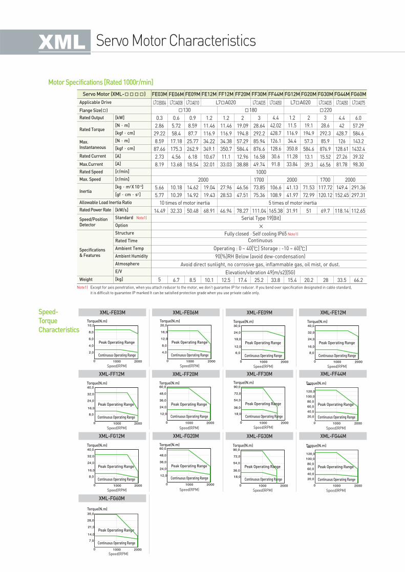
Servo Motor Characteristics
Note1) Except for axis penetration, when you attach reducer to the motor, we don’t guarantee IP for reducer. If you bend over specification designated in cable standard,
it is difficult to guarantee IP marked It can be satisfied protection grade when you use private cable only.
Servo Motor (XML-) FE03M FE06M FE09M FE12M FF12M FF20M FF30M FF44M FG12M FG20M FG30M FG44M
L7A035 L7A035L7B004 L7A008 L7A010 L7A050 L7A050L7A020 L7A075L7A020
130 180 220
10 times of motor inertia 5 times of motor inertia
Fully closed·Self cooling IP65 Note1)
×
Continuous
Operating : 0 ~ 40[] Storage : -10 ~ 60[]
90[%]RH Below (avoid dew-condensation)
Avoid direct sunlight, no corrosive gas, inflammable gas, oil mist, or dust.
Elevation/vibration 49[m/s2](5G)
1000
2000 2000 20001700 1700
0.3
2.86
29.22
8.59
87.66
2.73
8.19
0.6
5.72
58.4
17.18
175.3
4.56
13.68
0.9
8.59
87.7
25.77
262.9
6.18
18.54
1.2
11.46
116.9
34.22
349.1
10.67
32.01
1.2
11.46
116.9
34.38
350.7
11.1
33.03
2
19.09
194.8
57.29
584.4
12.96
38.88
3
28.64
292.2
85.94
876.6
16.58
49.74
4.4
42.02
428.7
126.1
128.6
30.6
91.8
1.2
11.5
116.9
34.4
350.8
11.28
33.84
2
19.1
194.9
57.3
584.6
13.1
39.3
3
28.6
292.3
85.9
876.9
15.52
46.56
4.4
42
428.7
126
128.61
27.26
81.78
5.66
5.77
10.18
10.39
14.62
14.92
19.04
19.43
27.96
28.53
46.56
47.51
73.85
75.36
106.6
108.9
41.13
41.97
71.53
72.99
117.72
120.12
149.4
152.45
14.49 32.33 50.48 68.91 46.94 78.27 111.04 165.38 31.91 51 69.7 118.14
Serial Type 19[Bit]
5 6.7 8.5 10.1 12.5 17.4 25.2 33.8 15.4 20.2 28 33.5
FG60M
6.0
57.29
584.6
143.2
1432.4
39.32
98.30
291.36
297.31
112.65
66.2
Motor Specifications [Rated 1000r/min]
Applicable Drive
Flange Size()
Rated Speed
Max. Speed
Rated Current
Max.Current
Specifications& Features
Rated Output [kW]
[N·m]
[kgf·cm]
[N·m]
[kgf·cm]
[A]
[A]
[r/min]
[r/min]
[kg·m2X 10-4]
[gf·cm·s2]
[kW/s]
Standard Note1)
Option
Structure
Rated Time
Ambient Temp
Ambient Humidity
Atmosphere
E/V
[kg]
Rated Power Rate
Weight
Speed/PositionDetector
Rated Torque
Max.Instantaneous
Inertia
Allowable Load Inertia Ratio
Torque(N.m)
Peak Operating Range
Continuous Operating Range
Speed(RPM)
Torque(N.m)
Peak Operating Range
Continuous Operating Range
Speed(RPM)
Torque(N.m)
Peak Operating Range
Continuous Operating Range
Speed(RPM)
Torque(N.m)
Peak Operating Range
Continuous Operating Range
Speed(RPM)
Speed-
Torque
Characteristics
XML-FE03M XML-FE06M XML-FE09M XML-FE12M
Speed(RPM)
Torque(N.m)
Peak Operating Range
Continuous Operating Range
Speed(RPM)
Torque(N m)
Speed(RPM)
Torque(N.m)
Peak Operating Range
Continuous Operating Range
Speed(RPM)
T (N )
Torque(N.m)
Peak Operating Range
Speed(RPM)
Continuous Operating Range
Speed(RPM)XML-FF12M XML-FF20M XML-FF30M
Torque(N.m)
Peak Operating Range
Speed(RPM)
Continuous Operating Range
Speed(RPM)XML-FG30M
Torque(N.m)
Peak Operating Range
Speed(RPM)
Continuous Operating Range
Speed(RPM)XML-FF44M
Torque(N.m)
Peak Operating Range
Speed(RPM)
Continuous Operating Range
Speed(RPM)XML-FG44MSpeed(RPM)
Torque(N.m)
Peak Operating Range
Continuous Operating Range
Speed(RPM)
Speed(RPM)
Torque(N.m)
Peak Operating Range
Continuous Operating Range
Speed(RPM)
XML-FG12M XML-FG20M
Speed(RPM)
Torque(N.m)
Peak Operating Range
Continuous Operating Range
Speed(RPM)
XML-FG60M
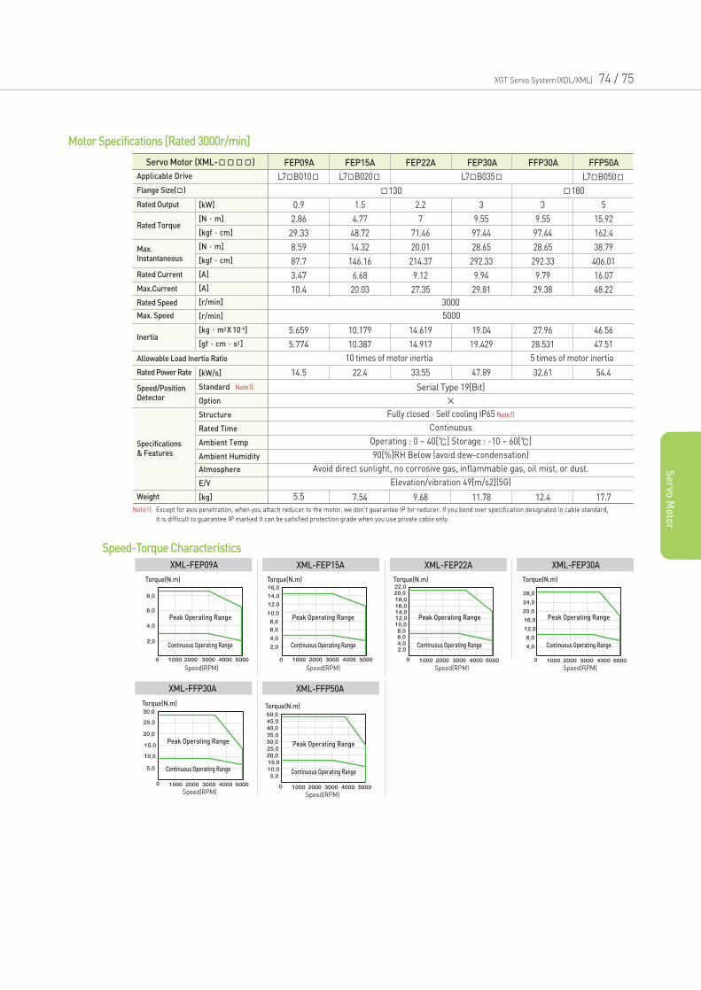
Speed-Torque Characteristics
XGT Servo System(XDL/XML) 74 / 75
Se
rvo M
oto
r
Torque(N.m)
Peak Operating Range
Continuous Operating Range
Speed(RPM)
Torque(N.m)
Peak Operating Range
Continuous Operating Range
Speed(RPM)
Torque(N.m)
Peak Operating Range
Continuous Operating Range
Speed(RPM)
Torque(N.m)
Peak Operating Range
Continuous Operating Range
Speed(RPM)
XML-FEP09A XML-FEP15A XML-FEP22A XML-FEP30A
Torque(N.m)
Peak Operating Range
Continuous Operating Range
Speed(RPM)
Torque(N.m)
Peak Operating Range
Continuous Operating Range
Speed(RPM)
XML-FFP30A XML-FFP50A
Servo Motor (XML-) FEP09A FEP15A FEP22A FEP30A FFP30A FFP50A
L7B010 L7B050L7B035L7B020
130 180
3000
0.9
2.86
29.33
8.59
87.7
3.47
10.4
1.5
4.77
48.72
14.32
146.16
6.68
20.03
2.2
7
71.46
20.01
214.37
9.12
27.35
3
9.55
97.44
28.65
292.33
9.94
29.81
3
9.55
97.44
28.65
292.33
9.79
29.38
5
15.92
162.4
38.79
406.01
16.07
48.22
5.659
5.774
14.5
10.179
10.387
22.4
14.619
14.917
33.55
19.04
19.429
47.89
27.96
28.531
32.61
46.56
47.51
54.4
5.5 7.54 9.68 11.78 12.4 17.7
5000
Serial Type 19[Bit]
×
Fully closed·Self cooling IP65 Note1)
Continuous
Operating : 0 ~ 40[] Storage : -10 ~ 60[]
90[%]RH Below (avoid dew-condensation)
Avoid direct sunlight, no corrosive gas, inflammable gas, oil mist, or dust.
Elevation/vibration 49[m/s2](5G)
Motor Specifications [Rated 3000r/min]
Applicable Drive
Flange Size()
Rated Speed
Max. Speed
Rated Current
Max.Current
Specifications& Features
Rated Output [kW]
[N·m]
[kgf·cm]
[N·m]
[kgf·cm]
[A]
[A]
[r/min]
[r/min]
[kg·m2X 10-4]
[gf·cm·s2]
[kW/s]
Standard Note1)
Option
Structure
Rated Time
Ambient Temp
Ambient Humidity
Atmosphere
E/V
[kg]
Rated Power Rate
Weight
Speed/PositionDetector
Rated Torque
Max.Instantaneous
Inertia
Allowable Load Inertia Ratio
Note1) Except for axis penetration, when you attach reducer to the motor, we don’t guarantee IP for reducer. If you bend over specification designated in cable standard,
it is difficult to guarantee IP marked It can be satisfied protection grade when you use private cable only.
5 times of motor inertia10 times of motor inertia
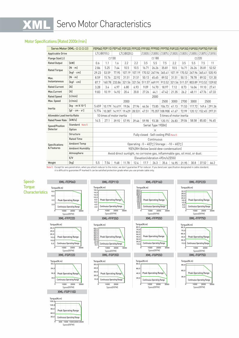
Servo Motor Characteristics
Servo Motor (XML-) FEP06D FEP11D FEP16D FEP22D FFP22D FFP35D FFP55D FFP75D FGP22D FGP35D FGP55D FGP75D FGP110D
L7B010 L7B020 L7B035 L7B050 L7B075 L7B020 L7B035 L7B050 L7B075 L7B150
130 180 220
Fully closed·Self cooling IP65 Note1)
×
Continuous
Operating : 0 ~ 40[] Storage : -10 ~ 60[]
90[%]RH Below (avoid dew-condensation)
Avoid direct sunlight, no corrosive gas, inflammable gas, oil mist, or dust.
Elevation/vibration 49[m/s2](5G)
2000
2000 2500 25003000 2700 3000
10 times of motor inertia 5 times of motor inertia
0.6
2.86
29.23
8.59
87.7
3.28
9.83
1.1
5.25
53.59
15.76
160.78
3.4
10.19
1.6
7.64
77.95
22.92
233.86
4.97
14.92
2.2
10.5
107.19
31.51
321.56
6.80
20.4
2.2
10.5
107.19
31.51
321.56
6.93
20.8
3.5
16.71
170.52
50.13
511.57
9.09
27.26
5.5
26.26
267.96
65.65
669.91
14.70
44.1
7.5
35.81
365.41
89.52
913.52
18.97
47.42
2.2
10.5
107.19
31.51
321.56
7.12
21.35
3.5
16.71
170.52
50.13
511.57
8.73
26.2
5.5
26.26
267.96
78.78
803.89
16.04
48.11
7.5
35.81
365.41
89.52
913.52
19.10
47.76
11
52.52
535.93
131.30
1339.82
27.41
67.33
5.659
5.774
10.179
10.387
14.619
14.917
19.04
19.429
27.96
28.531
46.56
47.51
73.85
75.357
106.73
108.908
41.13
41.67
117.72
120.12
149.4
152.45
291.36
297.31
71.53
72.99
14.5 27.1 39.92 57.95 39.46 59.98 93.38 120.15 26.83 39.04 58.58 85.83 94.65
Serial Type 19[Bit]
5.5 7.54 9.68 11.78 12.4 17.7 26.3 35.6 16.95 21.95 30.8 37.52 66.2
Motor Specifications [Rated 2000r/min]
Torque(N.m)
Peak Operating Range
Continuous Operating Range
Speed(RPM)
Torque(N.m)
Peak Operating Range
Continuous Operating Range
Speed(RPM)
( )
Torque(N.m)
Peak Operating Range
Continuous Operating Range
Speed(RPM)
( )
Torque(N.m)
Peak Operating Range
Continuous Operating Range
Speed(RPM)
Speed-
Torque
Characteristics
XML-FEP06D XML-FEP11D XML-FEP16D XML-FEP22D
Torque(N.m)
Peak Operating Range
Continuous Operating Range
Speed(RPM)
Torque(N.m)
Peak Operating Range
Continuous Operating Range
Speed(RPM)
Torque(N m) Torq e(N m)
Torque(N.m)
Peak Operating Range
Continuous Operating Range
Speed(RPM)
XML-FFP22D XML-FFP35D XML-FFP55D
Torque(N.m)
Peak Operating Range
Continuous Operating Range
Speed(RPM)
XML-FGP55D
Torque(N.m)
Peak Operating Range
Continuous Operating Range
Speed(RPM)
XML-FFP75D
Torque(N.m)
Peak Operating Range
Continuous Operating Range
Speed(RPM)
XML-FGP75D
Torque(N.m)
Peak Operating Range
Continuous Operating Range
Speed(RPM)
Torque(N.m)
Peak Operating Range
Continuous Operating Range
Speed(RPM)
XML-FGP22D XML-FGP35D
Torque(N.m)
Peak Operating Range
Continuous Operating Range
Speed(RPM)
XML-FGP110D
Applicable Drive
Flange Size()
Rated Speed
Max. Speed
Rated Current
Max.Current
Specifications& Features
Rated Output [kW]
[N·m]
[kgf·cm]
[N·m]
[kgf·cm]
[A]
[A]
[r/min]
[r/min]
[kg·m2X 10-4]
[gf·cm·s2]
[kW/s]
Standard Note1)
Option
Structure
Rated Time
Ambient Temp
Ambient Humidity
Atmosphere
E/V
[kg]
Rated Power Rate
Weight
Speed/PositionDetector
Rated Torque
Max.Instantaneous
Inertia
Allowable Load Inertia Ratio
Note1) Except for axis penetration, when you attach reducer to the motor, we don’t guarantee IP for reducer. If you bend over specification designated in cable standard,
it is difficult to guarantee IP marked It can be satisfied protection grade when you use private cable only.
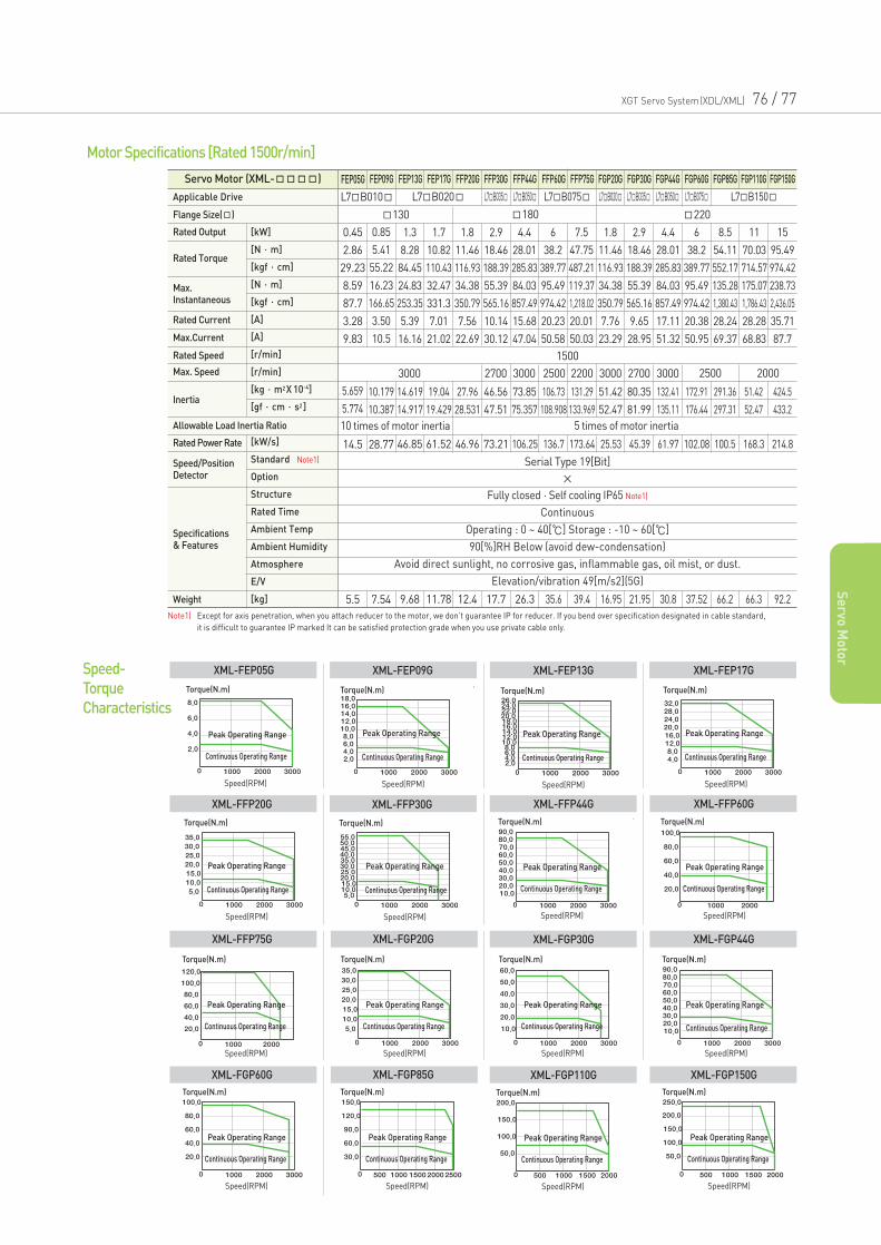
XGT Servo System(XDL/XML) 76 / 77
Se
rvo M
oto
r
Servo Motor (XML-) FEP05G FEP09G FEP13G FEP17G FFP20G FFP30G FFP44G FFP60G FFP75G FGP20G FGP30G FGP44G FGP60G FGP85G FGP110G FGP150G
L7B010 L7B020 L7B035 L7B050 L7B075 L7B020 L7B035 L7B050 L7B075 L7B150
130 180 220
1500
3000 2700 3000 2500 2200 3000 30002700
10 times of motor inertia 5 times of motor inertia
0.45
2.86
29.23
8.59
87.7
3.28
9.83
0.85
5.41
55.22
16.23
166.65
3.50
10.5
1.3
8.28
84.45
24.83
253.35
5.39
16.16
1.7
10.82
110.43
32.47
331.3
7.01
21.02
1.8
11.46
116.93
34.38
350.79
7.56
22.69
2.9
18.46
188.39
55.39
565.16
10.14
30.12
4.4
28.01
285.83
84.03
857.49
15.68
47.04
6
38.2
389.77
95.49
974.42
20.23
50.58
7.5
47.75
487.21
119.37
1,218.02
20.01
50.03
1.8
11.46
116.93
34.38
350.79
7.76
23.29
2.9
18.46
188.39
55.39
565.16
9.65
28.95
4.4
28.01
285.83
84.03
857.49
17.11
51.32
6
38.2
389.77
95.49
974.42
20.38
50.95
8.5
54.11
552.17
135.28
1,380.43
28.24
69.37
11
70.03
714.57
175.07
1,786.43
28.28
68.83
15
95.49
974.42
238.73
2,436.05
35.71
87.7
5.659
5.774
10.179
10.387
14.619
14.917
19.04
19.429
27.96
28.531
46.56
47.51
73.85
75.357
106.73
108.908
131.29
133.969
51.42
52.47
132.41
135.11
172.91
176.44
291.36
297.31
51.42
52.47
424.5
433.2
80.35
81.99
20002500
14.5 28.77 46.85 61.52 46.96 73.21 106.25 136.7 173.64 25.53 45.39 61.97 102.08 100.5 168.3 214.8
5.5 7.54 9.68 11.78 12.4 17.7 26.3 35.6 39.4 16.95 21.95 30.8 37.52 66.2 66.3 92.2
Motor Specifications [Rated 1500r/min]
Torque(N.m)
Peak Operating Range
Continuous Operating Range
Speed(RPM)
Torque(N.m)
Peak Operating Range
Continuous Operating Range
Speed(RPM)
T Torque(N.m)
Peak Operating Range
Continuous Operating Range
Speed(RPM)
Torque(N.m)
Peak Operating Range
Continuous Operating Range
Speed(RPM)
Speed-
Torque
Characteristics
XML-FEP05G XML-FEP09G XML-FEP13G XML-FEP17G
Torque(N.m)
Peak Operating Range
Continuous Operating Range
Speed(RPM)
T Torque(N.m)
Peak Operating Range
Continuous Operating Range
Speed(RPM)
Torque(N.m)
Peak Operating Range
Continuous Operating Range
Speed(RPM)
T
XML-FFP20G XML-FFP30G XML-FFP44G
Torque(N.m)
Peak Operating Range
Continuous Operating Range
Speed(RPM)
p
XML-FGP30G
Torque(N.m)
Peak Operating Range
Continuous Operating Range
Speed(RPM)
XML-FFP60G
Torque(N.m)
Peak Operating Range
Continuous Operating Range
Speed(RPM)
p
XML-FGP44G
Torque(N.m)
Peak Operating Range
Continuous Operating Range
Speed(RPM)
XML-FGP150G
Torque(N.m)
Peak Operating Range
Continuous Operating Range
Speed(RPM)
p
Torque(N.m)
Peak Operating Range
Continuous Operating Range
Speed(RPM)
p
XML-FFP75G XML-FGP20G
Torque(N.m)
Peak Operating Range
Continuous Operating Range
Speed(RPM)
p
XML-FGP110G
Torque(N.m)
Peak Operating Range
Continuous Operating Range
Speed(RPM)
XML-FGP85G
Torque(N.m)
Peak Operating Range
Continuous Operating Range
Speed(RPM)
XML-FGP60G
Applicable Drive
Flange Size()
Rated Speed
Max. Speed
Rated Current
Max.Current
Specifications& Features
Rated Output [kW]
[N·m]
[kgf·cm]
[N·m]
[kgf·cm]
[A]
[A]
[r/min]
[r/min]
[kg·m2X 10-4]
[gf·cm·s2]
[kW/s]
Standard Note1)
Option
Structure
Rated Time
Ambient Temp
Ambient Humidity
Atmosphere
E/V
[kg]
Rated Power Rate
Weight
Speed/PositionDetector
Rated Torque
Max.Instantaneous
Inertia
Allowable Load Inertia Ratio
Note1) Except for axis penetration, when you attach reducer to the motor, we don’t guarantee IP for reducer. If you bend over specification designated in cable standard,
it is difficult to guarantee IP marked It can be satisfied protection grade when you use private cable only.
Serial Type 19[Bit]
×
Fully closed·Self cooling IP65 Note1)
Continuous
Operating : 0 ~ 40[] Storage : -10 ~ 60[]
90[%]RH Below (avoid dew-condensation)
Avoid direct sunlight, no corrosive gas, inflammable gas, oil mist, or dust.
Elevation/vibration 49[m/s2](5G)
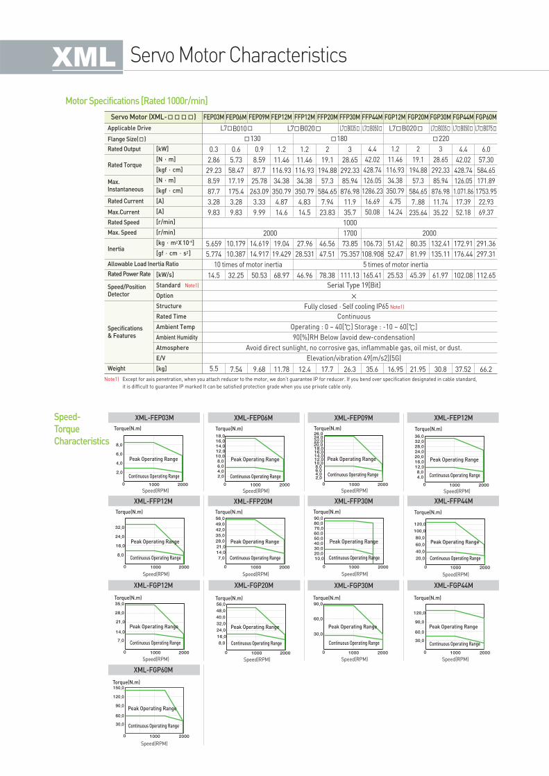
Servo Motor Characteristics
Note1) Except for axis penetration, when you attach reducer to the motor, we don’t guarantee IP for reducer. If you bend over specification designated in cable standard,
it is difficult to guarantee IP marked It can be satisfied protection grade when you use private cable only.
Servo Motor (XML-) FEP03M FEP06M FEP09M FEP12M FFP12M FFP20M FFP30M FFP44M FGP12M FGP20M FGP30M FGP44M
L7B050 L7B050L7B035 L7B035L7B020 L7B075L7B010 L7B020
130 180 220
10 times of motor inertia 5 times of motor inertia
Fully closed·Self cooling IP65 Note1)
×
Continuous
Operating : 0 ~ 40[] Storage : -10 ~ 60[]
90[%]RH Below (avoid dew-condensation)
Avoid direct sunlight, no corrosive gas, inflammable gas, oil mist, or dust.
Elevation/vibration 49[m/s2](5G)
1000
2000 20001700
0.3
2.86
29.23
8.59
87.7
3.28
9.83
0.6
5.73
58.47
17.19
175.4
3.28
9.83
0.9
8.59
87.7
25.78
263.09
3.33
9.99
1.2
11.46
116.93
34.38
350.79
4.87
14.6
1.2
11.46
116.93
34.38
350.79
4.83
14.5
2
19.1
194.88
57.3
584.65
7.94
23.83
3
28.65
292.33
85.94
876.98
11.9
35.7
4.4
42.02
428.74
126.05
1286.23
16.69
50.08
1.2
11.46
116.93
34.38
350.79
4.75
14.24
2
19.1
194.88
57.3
584.65
7..88
235.64
3
28.65
292.33
85.94
876.98
11.74
35.22
4.4
42.02
428.74
126.05
1.071.86
17.39
52.18
5.659
5.774
10.179
10.387
14.619
14.917
19.04
19.429
27.96
28.531
46.56
47.51
73.85
75.357
106.73
108.908
51.42
52.47
80.35
81.99
132.41
135.11
172.91
176.44
14.5 32.25 50.53 68.97 46.96 78.38 111.13 165.41 25.53 45.39 61.97 102.08
Serial Type 19[Bit]
5.5 7.54 9.68 11.78 12.4 17.7 26.3 35.6 16.95 21.95 30.8 37.52
FGP60M
6.0
57.30
584.65
171.89
1753.95
22.93
69.37
291.36
297.31
112.65
66.2
Motor Specifications [Rated 1000r/min]
Applicable Drive
Flange Size()
Rated Speed
Max. Speed
Rated Current
Max.Current
Specifications& Features
Rated Output [kW]
[N·m]
[kgf·cm]
[N·m]
[kgf·cm]
[A]
[A]
[r/min]
[r/min]
[kg·m2X 10-4]
[gf·cm·s2]
[kW/s]
Standard Note1)
Option
Structure
Rated Time
Ambient Temp
Ambient Humidity
Atmosphere
E/V
[kg]
Rated Power Rate
Weight
Speed/PositionDetector
Rated Torque
Max.Instantaneous
Inertia
Allowable Load Inertia Ratio
Speed-
Torque
Characteristics
XML-FEP03M XML-FEP06M XML-FEP09M XML-FEP12M
XML-FFP12M XML-FFP20M XML-FFP30M
XML-FGP30M
XML-FFP44M
XML-FGP44MXML-FGP12M XML-FGP20M
XML-FGP60M
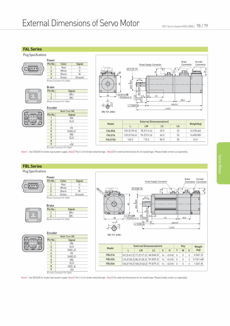
External Dimensions of Servo Motor XGT Servo System(XDL/XML) 78 / 79
Se
rvo M
oto
r
Plug Specifications
Power
Brake
Encoder
Pin No. Color
Red
White
Black
Green
Signal
U
V
W
Ground
1
2
3
4
(Power Connector Pin Table)
(Encoder Connector Pin Table)
Pin No. Signal
BK+
BK-
1
2
(Brake Connector Pin Table)
Note1) Use DC[24V] for brake input power supply. Note2) The ( ) is for brake-attached type. Note3) For external dimensions for oil-sealed type. Please kindly contact us separately.
FAL Series
ModelL LM LC LA
External Dimensions(mm)Weight(kg)
103.2(139.6)
120.2(156.6)
140.2
78.2(114.6)
95.2(131.6)
115.2
49.5
66.5
86.5
23
35
35
0.31(0.66)
0.45(0.80)
0.61
FALR5A
FAL01A
FAL015A
Power
Brake
ModelL LM LC
External Dimensions(mm) Key Weight(kg)
107.2(147.2)
118.2(158.2)
138.2(178.2)
77.2(117.2)
88.2(128.2)
108.2(148.2)
48.5(48.3)
59.5(59.3)
79.5(79.3)
S
14
14
14
H
-0.018
-0.018
-0.018
T
5
5
5
W
5
5
5
0.56(1.3)
0.74(1.48)
1.06(1.8)
U
3
3
3
FBL01A
FBL02A
FBL04A
Pin No. Color
Red
White
Black
Green
Signal
U
V
W
Ground
1
2
3
4
(Power Connector Pin Table)
Pin No. Signal
BK+
BK-
1
2(Brake Connector Pin Table)
Note1) Use DC[24V] for brake input power supply. Note2) The ( ) is for brake-attached type. Note3) For external dimensions for oil-sealed type. Please kindly contact us separately.
Plug Specifications
FBL Series
Pin No.
Multi Turn (M)
MA
SLO
-
OV
SHIELD
MA
SLO
-
+5V
Signal
1
2
3
4
5
6
7
8
9
Encoder
(Encoder Connector Pin Table)
Pin No.
Multi Turn (M)
Signal
MA
SLO
GND_B
OV
SHIELD
MA
SLO
VDD_B
+5V
1
2
3
4
5
6
7
8
9
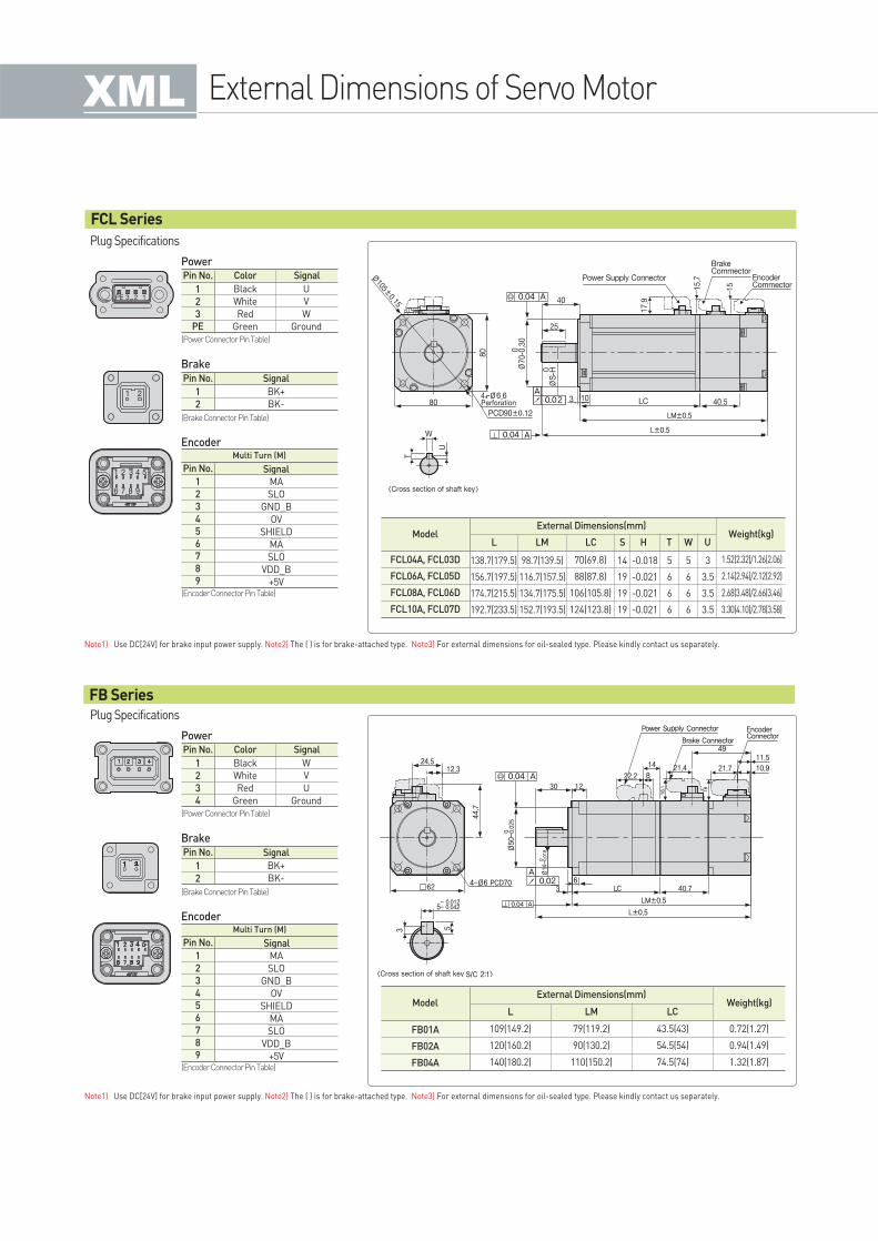
Plug Specifications
Power
Brake
Encoder
Pin No. Color
Black
White
Red
Green
Signal
U
V
W
Ground
1
2
3
PE
(Power Connector Pin Table)
(Encoder Connector Pin Table)
Pin No. Signal
BK+
BK-
1
2
(Brake Connector Pin Table)
Note1) Use DC[24V] for brake input power supply. Note2) The ( ) is for brake-attached type. Note3) For external dimensions for oil-sealed type. Please kindly contact us separately.
FCL Series
FB Series
Pin No.
Multi Turn (M)
Signal
MA
SLO
GND_B
OV
SHIELD
MA
SLO
VDD_B
+5V
1
2
3
4
5
6
7
8
9
Plug Specifications
Power
Brake
Encoder
Pin No. Color
Black
White
Red
Green
Signal
W
V
U
Ground
1
2
3
4
(Power Connector Pin Table)
(Encoder Connector Pin Table)
Pin No. Signal
BK+
BK-
1
2
(Brake Connector Pin Table)
Note1) Use DC[24V] for brake input power supply. Note2) The ( ) is for brake-attached type. Note3) For external dimensions for oil-sealed type. Please kindly contact us separately.
ModelL LM LC
External Dimensions(mm)Weight(kg)
109(149.2)
120(160.2)
140(180.2)
79(119.2)
90(130.2)
110(150.2)
43.5(43)
54.5(54)
74.5(74)
0.72(1.27)
0.94(1.49)
1.32(1.87)
FB01A
FB02A
FB04A
Pin No.
Multi Turn (M)
Signal
MA
SLO
GND_B
OV
SHIELD
MA
SLO
VDD_B
+5V
1
2
3
4
5
6
7
8
9
External Dimensions of Servo Motor
ModelL LM LC
External Dimensions(mm)Weight(kg)
138.7(179.5)
156.7(197.5)
174.7(215.5)
192.7(233.5)
98.7(139.5)
116.7(157.5)
134.7(175.5)
152.7(193.5)
70(69.8)
88(87.8)
106(105.8)
124(123.8)
S
14
19
19
19
H
-0.018
-0.021
-0.021
-0.021
T
5
6
6
6
W
5
6
6
6
1.52(2.32)/1.26(2.06)
2.14(2.94)/2.12(2.92)
2.68(3.48)/2.66(3.46)
3.30(4.10)/2.78(3.58)
U
3
3.5
3.5
3.5
FCL04A, FCL03D
FCL06A, FCL05D
FCL08A, FCL06D
FCL10A, FCL07D
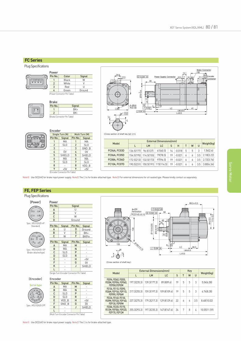
FC Series
Power[Power]
ModelL LM LC
External Dimensions(mm)Weight(kg)
197.3(235.3)
217.3(255.3)
237.3(275.3)
255.3(293.3)
139.3(177.3)
159.3(197.3)
179.3(217.3)
197.3(235.3)
89.8(89.6)
109.8(109.6)
129.8(129.6)
147.8(147.6)
19
19
22
24
5
5
6
7
5
5
6
8
3
3
3.5
4
5.04(6.58)
6.74(8.28)
8.48(10.02)
10.05(11.59)
S T W U
FE09A, FE06D, FE05G,FE03M, FEP09A, FEP06D,
FEP05G,FEP03M
FE15A, FE11D, FE09G,FE06M, FEP15A, FEP11D,
FEP09G, FEP06M
FE22A, FE16D, FE13G,FE09M, FEP22A, FEP16D,
FEP13G, FEP09MFE30A, FE22D, FE17G,
FE12M, FEP30A, FEP22D,FEP17G, FEP12M
Pin No. Signal
U
V
W
Ground
A
B
C
D
Note1) Use DC[24V] for brake input power supply. Note2) The ( ) is for brake-attached type.
Plug Specifications
FE, FEP Series
Encoder[Encoder]
(Multi Turn Encoder Connector Pin Table)
Pin No. Pin No.
MA
MA
SLO
SLO
VOD_B
GND_B
-
-
SignalSignal
-
-
-
-
+5V
0V
SHIELD
A
B
C
D
E
F
K
L
M
N
P
R
H
G
J
(Single Turn Encoder Connector Pin Table)
Pin No. Pin No.
MA
MA
SLO
SLO
-
-
-
-
SignalSignal
-
-
-
-
+5V
0V
SHIELD
A
B
C
D
E
F
K
L
M
N
P
R
H
G
J
Pin No. Pin No.
U
V
W
SignalSignal
Ground
BK+
BKPin
A
B
C
D
E
F
Power
Brake
ModelL LM LC
External Dimensions(mm)Weight(kg)
136.5(177)
154.5(195)
172.5(213)
190.5(231)
96.5(137)
114.5(155)
132.5(173)
150.5(191)
61(60.5)
79(78.5)
97(96.5)
115(114.5)
S
14
19
19
19
H
-0.018
-0.021
-0.021
-0.021
T
5
6
6
6
W
5
6
6
6
1.56(2.6)
2.18(3.22)
2.72(3.76)
3.80(4.34)
U
3
3.5
3.5
3.5
FC04A, FC03D
FC06A, FC05D
FC08A, FC06D
FC10A, FC07D
Pin No. Color
Black
White
Red
Green
Signal
W
V
U
Ground
1
2
3
4
(Power Connector Pin Table)
Pin No. Signal
BK+
BK-
1
2
(Brake Connector Pin Table)
Note1) Use DC[24V] for brake input power supply. Note2) The ( ) is for brake-attached type. Note3) For external dimensions for oil-sealed type. Please kindly contact us separately.
Plug Specifications
Encoder
(Encoder Connector Pin Table)
Pin No. Pin No.
Multi Turn (M)
MA
SLO
-
OV
SHIELD
MA
SLO
-
+5V
SignalSignal
Single Turn (N)
MA
SLO
GND_B
OV
SHIELD
MA
SLO
VDD_B
+5V
1
2
3
4
5
6
7
8
9
1
2
3
4
5
6
7
8
9
XGT Servo System(XDL/XML) 80 / 81
Se
rvo M
oto
r
Key
Spec.: MS3102A20-4P(Standard)
Spec.: MS3102A20-15P(Brake-attached type)
Spec.: MS3102A20-29P
Serial type
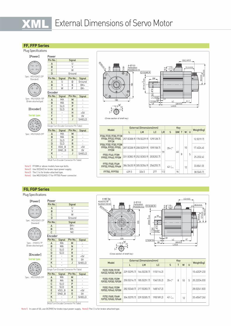
PowerPin No. Signal
U
V
W
Ground
A
B
C
D
Pin No. Signal
A
B
C
BK+
BK-
NC
Spec. : MS3102A22-22P(Standard)
Spec. : 3102A14-7P(Brake-attached type)
Spec. : MS3102A20-29P
Serial type
Plug Specifications
FG, FGP Series
Note1) In case of SG, use DC[90V] for brake input power supply. Note2) The ( ) is for brake-attached type.
ModelL
External Dimensions(mm) KeyWeight(kg)
229.5(295.7)
250.5(316.7)
282.5(348.7)
304.5(370.7)
15.42(29.23)
20.22(34.03)
28.02(41.83)
33.45(47.26)
LM
164.5(230.7)
185.5(251.7)
217.5(283.7)
239.5(305.7)
LC
115(114.2)
136(135.2)
168(167.2)
190(189.2) 12
S T
8
W
10
U
5
Pin No. Pin No.
MA
MA
SLO
SLO
VDD_B
GND_B--
SignalSignal
-
-
-
-
+5V
0V
SHIELD
A
B
C
D
E
F
K
L
M
N
P
R
H
G
J
EncoderPin No. Pin No.
MA
MA
SLO
SLO----
SignalSignal
-
-
-
-
+5V
0V
SHIELD
A
B
C
D
E
F
K
L
M
N
P
R
H
G
J
(Single Turn Encoder Connector Pin Table)
(Multi Turn Encoder Connector Pin Table)
35+0.010
42-00.016
FF, FFP Series
Note1) FF30M or above models have eye bolts.
Note2) Use DC[24V] for brake input power supply.
Note3) The ( ) is for brake-attached type.
Note4) Use MS3102A32-17 for FF75G Power connector.
Power[Power]
[Encoder]
[Power]
[Encoder]
Pin No. Signal
U
V
W
Ground
A
B
C
D
Pin No. Signal Pin No. Signal
U
V
W
A
B
C
Ground
BK+
BK-
D
E
F
Pin No. Pin No.
MA
MA
SLO
SLO
VDD_B
GND_B--
SignalSignal
-
-
-
-
+5V
0V
SHIELD
A
B
C
D
E
F
K
L
M
N
P
R
H
G
J
Spec. : MS3102A22-22P(Standard)
Spec. : MS3102A24-10P(Brake-attached type)
Spec. : MS3102A20-29P
Encoder
Serial type
Pin No. Pin No.
MA
MA
SLO
SLO----
SignalSignal
-
-
-
-
+5V
0V
SHIELD
A
B
C
D
E
F
K
L
M
N
P
R
H
G
J
Plug Specifications
(Single Turn Encoder Connector Pin Table)
(Multi Turn Encoder Connector Pin Table)
ModelL
External Dimensions(mm) KeyWeight(kg)
257.5(308.9)
287.5(338.9)
331.5(382.9)
384.5(435.9)
178.5(229.9)
208.5(259.9)
252.5(303.9)
305.5(356.9)
129(128.7)
159(158.7)
203(202.7)
256(255.7)
439.5 326.5 277 113 96
25.2(32.4)
33.8(41.0)
38.5(45.7)
17.4(24.6)
12.5(19.7)
LM LC LR
79
12
S QW
60
T
8
W
10
U
5
FF30A, FF22D, FF20G, FF12MFFP30A, FFP22D, FFP20G,
FFP12M
FF50A, FF35D, FF30G, FF20MFFP50A, FFP35D, FFP30G,
FFP20M
FF55D, FF44G, FF30MFFP55D, FFP44G, FFP30M
FG22D, FG20G, FG12MFGP22D, FGP20G, FGP12M
FG35D, FG30G, FG20MFGP35D, FGP30G, FGP20M
FG55D, FG44G, FG30MFGP55D, FGP44G, FGP30M
FG75D, FG60G, FG44MFGP75D, FGP60G, FGP44M
FF75D, FF60G, FF44MFFP75D, FFP60G, FFP44M
FF75G, FFP75G
35+0.010
42-00.016
External Dimensions of Servo Motor
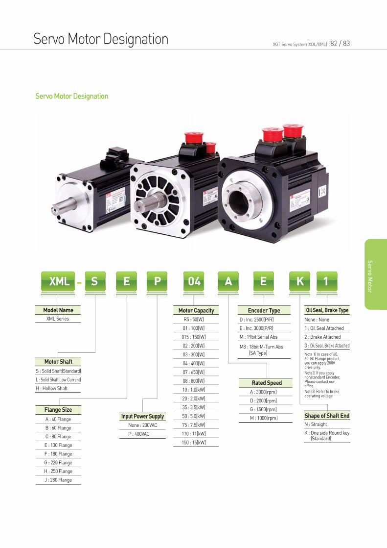
Servo Motor Designation XGT Servo System(XDL/XML) 82 / 83
Se
rvo M
oto
r
Servo Motor Designation
Model Name
Input Power Supply
Motor Capacity Encoder Type
Rated Speed
Oil Seal, Brake Type
Shape of Shaft EndFlange Size
XML S E P 04 A E K 1
A : 40 Flange
B : 60 Flange
C : 80 Flange
E : 130 Flange
F : 180 Flange
G : 220 Flange
H : 250 Flange
J : 280 Flange
R5 : 50[W]
01 : 100[W]
015 : 150[W]
02 : 200[W]
03 : 300[W]
04 : 400[W]
07 : 650[W]
08 : 800[W]
10 : 1.0[kW]
20 : 2.0[kW]
35 : 3.5[kW]
50 : 5.0[kW]
75 : 7.5[kW]
110 : 11[kW]
150 : 15[kW]
D : Inc. 2500[P/R]
E : Inc. 3000[P/R]
M : 19bit Serial Abs
M8 : 18bit M-Turn Abs [SA Type]
None : None
1 : Oil Seal Attached
2 : Brake Attached
3 : Oil Seal, Brake Attached
A : 3000[rpm]
D : 2000[rpm]
G : 1500[rpm]
M : 1000[rpm]N : Straight
K : One side Round key (Standard)
S : Solid Shaft(Standard)
L : Solid Shaft(Low Current)
H : Hollow Shaft
XML Series
None : 200VAC
P : 400VAC
Note 1) In case of 40,60, 80 Flange product,you can apply 200Vdrive only.
Note2) If you applynonstandard Encoder,Please contact ouroffice.
Note3) Refer to brakeoperating voltage
Motor Shaft
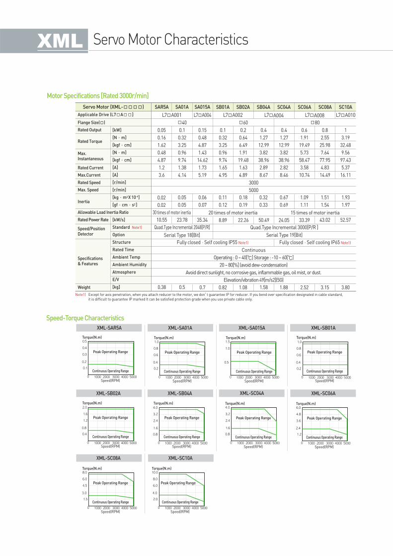
Servo Motor Characteristics
Speed-Torque Characteristics
Servo Motor (XML-) SAR5A
L7A001
40
30 times of motor inertia
Fully closed·Self cooling IP65 Note1)Fully closed·Self cooling IP55 Note1)
Continuous
Operating : 0 ~ 40[] Storage : -10 ~ 60[]
20 ~ 80[%] (avoid dew-condensation)
Avoid direct sunlight, no corrosive gas, inflammable gas, oil mist, or dust.
Elevation/vibration 49[m/s2](5G)
Note1) Except for axis penetration, when you attach reducer to the motor, we don’t guarantee IP for reducer. If you bend over specification designated in cable standard, it is difficult to guarantee IP marked It can be satisfied protection grade when you use private cable only.
20 times of motor inertia 15 times of motor inertia
3000
5000
0.05
0.16
1.62
0.48
4.87
1.2
3.6
0.02
0.02
10.55
Quad.Type Incremental 2048[P/R]
Serial Type 18[Bit]
Quad.Type Incremental 3000[P/R ]
Serial Type 19[Bit]
23.78 35.34 8.89 22.26 50.49 24.05 33.39 43.02 52.57
0.38 0.5 0.7 0.82 1.08 1.58 1.88 2.52 3.15 3.80
0.05
0.05
0.06
0.07
0.11
0.12
0.18
0.19
0.32
0.33
0.67
0.69
1.09
1.11
1.51
1.54
1.93
1.97
0.1
0.32
3.25
0.96
9.74
1.38
4.14
0.15
0.48
4.87
1.43
14.62
1.73
5.19
0.1
0.32
3.25
0.96
9.74
1.65
4.95
0.2
0.64
6.49
1.91
19.48
1.63
4.89
0.4
1.27
12.99
3.82
38.96
2.89
8.67
0.4
1.27
12.99
3.82
38.96
2.82
8.46
0.6
1.91
19.49
5.73
58.47
3.58
10.74
0.8
2.55
25.98
7.64
77.95
4.83
14.49
1
3.19
32.48
9.56
97.43
5.37
16.11
60 80
L7A002L7A004 L7A004 L7A010L7A008
SA01A SA015A SB01A SB02A SB04A SC04A SC06A SC08A SC10A
Applicable Drive (L7A]
Flange Size()
Rated Speed
Max. Speed
Rated Current
Max.Current
Specifications& Features
Rated Output [kW]
[N·m]
[kgf·cm]
[N·m]
[kgf·cm]
[A]
[A]
[r/min]
[r/min]
[kg·m2X 10-4]
[gf·cm·s2]
[kW/s]
Standard Note1)
Option
Structure
Rated Time
Ambient Temp
Ambient Humidity
Atmosphere
E/V
[kg]
Rated Power Rate
Weight
Speed/PositionDetector
Rated Torque
Max.Instantaneous
Inertia
Allowable Load Inertia Ratio
Motor Specifications [Rated 3000r/min]
XML-SAR5A XML-SA01A XML-SA015A XML-SB01A
XML-SB02A XML-SB04A XML-SC04A XML-SC06A
XML-SC08A XML-SC10A
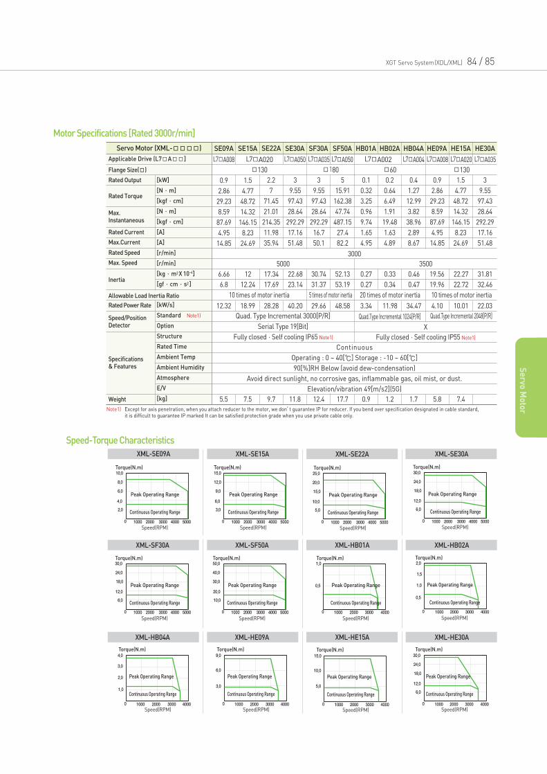
XGT Servo System(XDL/XML) 84 / 85
Se
rvo M
oto
r
Servo Motor (XML-) SE09A SE15A SE22A SE30A SF30A SF50A HB01A HB02A HB04A HE09A HE15A HE30A
L7A008 L7A035 L7A050 L7A004 L7A008 L7A020 L7A035L7A020 L7A050 L7A002
180 60 130130
10 times of motor inertia 20 times of motor inertia 10 times of motor inertia5 times of motor inertia
Fully closed·Self cooling IP55 Note1)Fully closed·Self cooling IP65 Note1)
X
Continuous
Operating : 0 ~ 40[] Storage : -10 ~ 60[]
90[%]RH Below (avoid dew-condensation)
Avoid direct sunlight, no corrosive gas, inflammable gas, oil mist, or dust.
Elevation/vibration 49[m/s2](5G)
3000
5000 3500
0.9
2.86
29.23
8.59
87.69
4.95
14.85
1.5
4.77
48.72
14.32
146.15
8.23
24.69
2.2
7
71.45
21.01
214.35
11.98
35.94
3
9.55
97.43
28.64
292.29
17.16
51.48
3
9.55
97.43
28.64
292.29
16.7
50.1
5
15.91
162.38
47.74
487.15
27.4
82.2
0.1
0.32
3.25
0.96
9.74
1.65
4.95
0.2
0.64
6.49
1.91
19.48
1.63
4.89
0.4
1.27
12.99
3.82
38.96
2.89
8.67
0.9
2.86
29.23
8.59
87.69
4.95
14.85
1.5
4.77
48.72
14.32
146.15
8.23
24.69
3
9.55
97.43
28.64
292.29
17.16
51.48
6.66
6.8
12
12.24
17.34
17.69
22.68
23.14
30.74
31.37
52.13
53.19
0.27
0.27
0.33
0.34
0.46
0.47
19.56
19.96
22.27
22.72
31.81
32.46
12.32 18.99 28.28 40.20 29.66 48.58 3.34 11.98 34.47 4.10 10.01 22.03
Quad. Type Incremental 3000[P/R] Quad.Type Incremental 1024[P/R] Quad.Type Incremental 2048[P/R]
5.5 7.5 9.7 11.8 12.4 17.7 0.9 1.2 1.7 5.8 7.4
Motor Specifications [Rated 3000r/min]
Speed-Torque Characteristics
XML-SE09A XML-SE15A XML-SE22A XML-SE30A
XML-SF30A XML-SF50A XML-HB01A XML-HB02A
Applicable Drive (L7A]
Flange Size()
Rated Current
Max.Current
Rated Speed
Max. Speed
Specifications& Features
Rated Output [kW]
[N·m]
[kgf·cm]
[N·m]
[kgf·cm]
[A]
[A]
[r/min]
[r/min]
[kg·m2X 10-4]
[gf·cm·s2]
[kW/s]
Standard Note1)
Option
Structure
Rated Time
Ambient Temp
Ambient Humidity
Atmosphere
E/V
[kg]
Rated Power Rate
Weight
Speed/PositionDetector
Rated Torque
Max.Instantaneous
Inertia
Allowable Load Inertia Ratio
Serial Type 19[Bit]
XML-HB04A XML-HE09A XML-HE15A XML-HE30A
Note1) Except for axis penetration, when you attach reducer to the motor, we don’t guarantee IP for reducer. If you bend over specification designated in cable standard, it is difficult to guarantee IP marked It can be satisfied protection grade when you use private cable only.
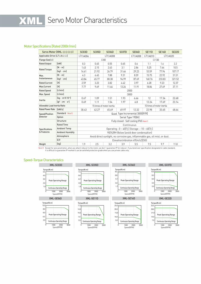
Motor Specifications [Rated 2000r/min]
Servo Motor (XML-) SC03D SC05D SC06D SC07D SE06D SE11D SE16D SE22D
L7A004 L7A008 L7A010
80 130
15 times of motor inertia 10 times of motor inertia
Fully closed·Self cooling IP65 Note1)
Continuous
Operating : 0 ~ 40[] Storage : -10 ~ 60[]
90[%]RH Below (avoid dew-condensation)
Avoid direct sunlight, no corrosive gas, inflammable gas, oil mist, or dust.
Elevation/vibration 49[m/s2](5G)
2000
3000
0.3
1.43
14.61
4.3
43.84
2.59
7.77
0.45
2.15
21.92
6.45
65.77
3.23
9.69
0.55
2.63
26.79
7.88
80.38
3.82
11.46
0.65
3.1
31.66
9.31
94.99
4.42
13.26
0.6
2.86
29.23
8.59
87.69
3.97
11.91
1.1
5.25
53.59
15.75
160.76
6.28
18.84
1.6
7.64
77.94
22.92
233.83
9.23
27.69
2.2
10.5
107.17
31.51
321.52
12.37
37.11
0.67
0.69
1.09
1.11
1.51
1.54
1.93
1.97
6.66
6.8
12
12.24
17.34
17.69
22.68
23.14
30.43 42.27 45.69 49.97 12.32 22.98 33.65 48.64
Quad. Type Incremental 3000[P/R]
Serial Type 19[Bit]
1.9 2.5 3.2 3.9 5.5 7.5 9.7 11.8
L7A008 L7A020
Speed-Torque Characteristics
XML-SC03D XML-SC05D XML-SC06D XML-SC07D
XML-SE06D XML-SE11D XML-SE16D XML-SE22D
Applicable Drive (L7A]
Flange Size()
Rated Speed
Max. Speed
Rated Current
Max.Current
Specifications& Features
Rated Output [kW]
[N·m]
[kgf·cm]
[N·m]
[kgf·cm]
[A]
[A]
[r/min]
[r/min]
[kg·m2X 10-4]
[gf·cm·s2]
[kW/s]
Standard Note1)
Option
Structure
Rated Time
Ambient Temp
Ambient Humidity
Atmosphere
E/V
[kg]
Rated Power Rate
Weight
Speed/PositionDetector
Rated Torque
Max.Instantaneous
Inertia
Allowable Load Inertia Ratio
Note1) Except for axis penetration, when you attach reducer to the motor, we don’t guarantee IP for reducer. If you bend over specification designated in cable standard, it is difficult to guarantee IP marked It can be satisfied protection grade when you use private cable only.
Servo Motor Characteristics
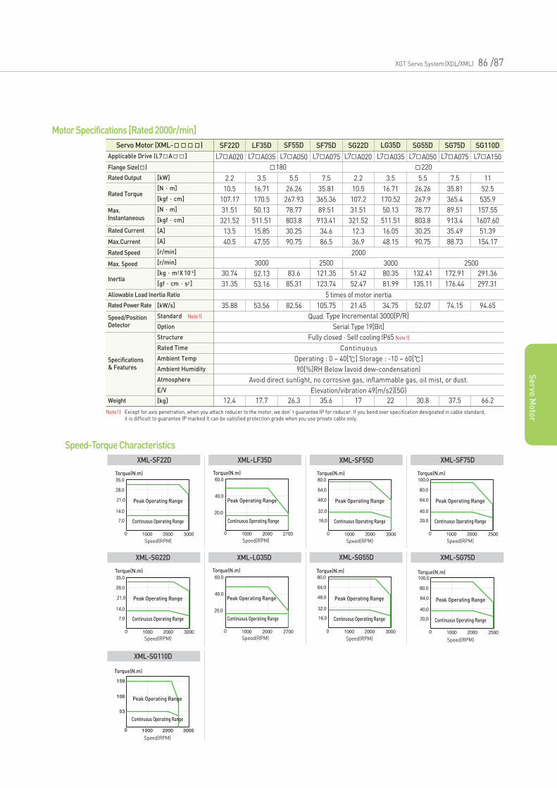
XGT Servo System(XDL/XML) 86 /87
Se
rvo M
oto
r
Servo Motor (XML-) SF22D LF35D SF55D SF75D SG22D LG35D SG55D SG75D
L7A020 L7A035 L7A050 L7A075 L7A020 L7A035 L7A050 L7A075
180 220
5 times of motor inertia
Fully closed·Self cooling IP65 Note1)
Serial Type 19[Bit]
Continuous
Operating : 0 ~ 40[] Storage : -10 ~ 60[]
90[%]RH Below (avoid dew-condensation)
Avoid direct sunlight, no corrosive gas, inflammable gas, oil mist, or dust.
Elevation/vibration 49[m/s2](5G)
2000
3000 30002500 2500
2.2
10.5
107.17
31.51
321.52
13.5
40.5
3.5
16.71
170.5
50.13
511.51
15.85
47.55
5.5
26.26
267.93
78.77
803.8
30.25
90.75
7.5
35.81
365.36
89.51
913.41
34.6
86.5
2.2
10.5
107.2
31.51
321.52
12.3
36.9
3.5
16.71
170.52
50.13
511.51
16.05
48.15
5.5
26.26
267.9
78.77
803.8
30.25
90.75
7.5
35.81
365.4
89.51
913.4
35.49
88.73
30.74
31.35
52.13
53.16
83.6
85.31
121.35
123.74
51.42
52.47
80.35
81.99
132.41
135.11
172.91
176.44
35.88 53.56 82.56 105.75 21.45 34.75 52.07 74.15
Quad. Type Incremental 3000[P/R]
12.4 17.7 26.3 35.6 17 22 30.8 37.5
SG110D
L7A150
11
52.5
535.9
157.55
1607.60
51.39
154.17
291.36
297.31
94.65
66.2
Motor Specifications [Rated 2000r/min]
Torque(N.m)
Peak Operating Range
Continuous Operating Range
Speed(RPM)
Peak Operating Range
Continuous Operating Range
Torque(N.m)
Speed(RPM)
Torque(N.m)
Peak Operating Range
Continuous Operating Range
Speed(RPM)
Torque(N.m)
Peak Operating Range
Continuous Operating Range
Speed(RPM)
Speed-Torque Characteristics
XML-SF22D XML-LF35D XML-SF55D XML-SF75D
Torque(N.m)
Peak Operating Range
Continuous Operating Range
Speed(RPM)
Peak Operating Range
Continuous Operating Range
Torque(N.m)
Speed(RPM)
Torque(N.m)
Peak Operating Range
Continuous Operating Range
Speed(RPM)
XML-SG22D
Torque(N.m)
Speed(RPM)
Peak Operating Range
Continuous Operating Range
XML-SG110D
XML-LG35D XML-SG55D
Torque(N.m)
Peak Operating Range
Continuous Operating Range
Speed(RPM)
XML-SG75D
Applicable Drive (L7A]
Flange Size()
Rated Speed
Max. Speed
Rated Current
Max.Current
Specifications& Features
Rated Output [kW]
[N·m]
[kgf·cm]
[N·m]
[kgf·cm]
[A]
[A]
[r/min]
[r/min]
[kg·m2X 10-4]
[gf·cm·s2]
[kW/s]
Standard Note1)
Option
Structure
Rated Time
Ambient Temp
Ambient Humidity
Atmosphere
E/V
[kg]
Rated Power Rate
Weight
Speed/PositionDetector
Rated Torque
Max.Instantaneous
Inertia
Allowable Load Inertia Ratio
Note1) Except for axis penetration, when you attach reducer to the motor, we don’t guarantee IP for reducer. If you bend over specification designated in cable standard, it is difficult to guarantee IP marked It can be satisfied protection grade when you use private cable only.
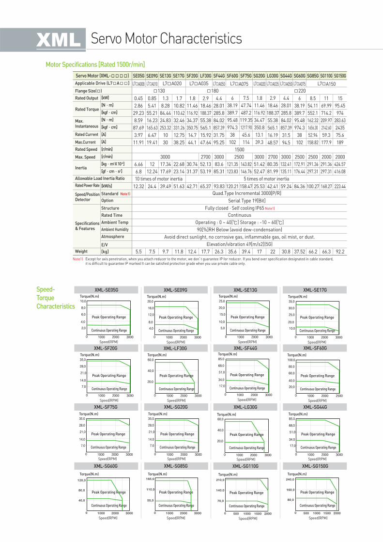
Servo Motor Characteristics
Note1) Except for axis penetration, when you attach reducer to the motor, we don’t guarantee IP for reducer. If you bend over specification designated in cable standard, it is difficult to guarantee IP marked It can be satisfied protection grade when you use private cable only.
Servo Motor (XML-) SE05G SE09G SE13G SE17G SF20G LF30G SF44G SF60G SG20GSF75G LG30G SG44G SG60G
L7A008 L7A010 L7A050 L7A075 L7A020 L7A035 L7A050 L7A075L7A020 L7A035
130 180 220
10 times of motor inertia 5 times of motor inertia
Fully closed·Self cooling IP65 Note1)
Serial Type 19[Bit]
Continuous
Operating : 0 ~ 40[] Storage : -10 ~ 60[]
90[%]RH Below (avoid dew-condensation)
Avoid direct sunlight, no corrosive gas, inflammable gas, oil mist, or dust.
Elevation/vibration 49[m/s2](5G)
1500
3000 2700 27002500 25003000 3000 3000
0.45
2.86
29.23
8.59
87.69
3.97
11.91
0.85
5.41
55.21
16.23
165.63
6.47
19.41
1.3
8.28
84.44
24.83
253.32
10
30
1.7
10.82
110.42
32.46
331.26
12.75
38.25
1.8
11.46
116.92
34.37
350.75
14.7
44.1
2.9
18.46
188.37
55.38
565.1
15.92
47.64
4.4
28.01
285.8
84.02
857.39
31.75
95.25
6
38.19
389.7
95.48
974.3
38
102
1.8
11.46
116.92
34.47
350.8
13.1
39.3
2.9
18.46
188.37
55.38
565.1
16.19
48.57
4.4
28.01
285.8
84.02
857.39
31.5
94.5
6
38.19
389.7
95.48
974.3
38
102
6.66
6.8
12
12.24
17.34
17.69
22.68
23.14
30.74
31.37
52.13
53.19
83.6
85.31
121.35
123.83
51.42
52.47
80.35
81.99
132.41
135.11
172.91
176.44
12.32 24.4 39.49 51.63 42.71 65.37 93.83 120.21 25.53 42.41 59.24 84.36
Quad.Type Incremental 3000[P/R]
5.5 7.5 9.7 11.8 12.4 17.7 26.3 35.6
7.5
47.74
487.2
119.35
1217.90
45.6
114
143.82
146.76
158.47
39.4 17 22 30.8 37.52
SG85G
L7A150
2500
8.5
54.11
552.1
162.32
1656.30
52.94
158.82
291.36
297.31
100.27
66.2
SG110G
2000
11
69.99
714.2
209.97
2142.60
59.3
177.9
291.36
297.31
168.27
66.3
SG150G
2000
15
95.45
974
283.63
2435
75.6
189
424.57
416.08
223.44
92.2
Motor Specifications [Rated 1500r/min]
Applicable Drive (L7A]
Flange Size()
Rated Speed
Max. Speed
Rated Current
Max.Current
Specifications& Features
Rated Output [kW]
[N·m]
[kgf·cm]
[N·m]
[kgf·cm]
[A]
[A]
[r/min]
[r/min]
[kg·m2X10-4]
[gf·cm·s2]
[kW/s]
Standard Note1)
Option
Structure
Rated Time
Ambient Temp
Ambient Humidity
Atmosphere
E/V
[kg]
Rated Power Rate
Weight
Speed/PositionDetector
Rated Torque
Max.Instantaneous
Inertia
Allowable Load Inertia Ratio
Torque(N.m)
Peak Operating Range
Continuous Operating Range
Speed(RPM)
Torque(N.m)
Peak Operating Range
Continuous Operating Range
Speed(RPM)
Torque(N.m)
Peak Operating Range
Continuous Operating Range
Speed(RPM)
Torque(N.m)
Peak Operating Range
Continuous Operating Range
Speed(RPM)
Speed-
Torque
Characteristics
XML-SE05G XML-SE09G XML-SE13G XML-SE17G
Speed(RPM)
Torque(N.m)
Peak Operating Range
Continuous Operating Range
Speed(RPM)
( )
Torque(N.m)
Peak Operating Range
Continuous Operating Range
Speed(RPM)
Speed(RPM)
( )
Torque(N.m)
Peak Operating Range
Continuous Operating Range
Speed(RPM)
Speed(RPM)XML-SF20G XML-LF30G XML-SF44G
Torque(N.m)
Peak Operating Range
Continuous Operating Range
Speed(RPM)
Speed(RPM)XML-LG30G
Torque(N.m)
Peak Operating Range
Continuous Operating Range
Speed(RPM)
Speed(RPM)XML-SF60G
Torque(N.m)
Peak Operating Range
Continuous Operating Range
Speed(RPM)
Speed(RPM)XML-SG44GSpeed(RPM)
Torque(N.m)
Peak Operating Range
Continuous Operating Range
Speed(RPM)
Speed(RPM)
Torque(N.m)
Peak Operating Range
Continuous Operating Range
Speed(RPM)
XML-SF75G XML-SG20G
Peak Operating Range
Continuous Operating Range
Speed(RPM)
Torque(N.m)
XML-SG110G
Peak Operating Range
Continuous Operating Range
Speed(RPM)
Torque(N.m)
XML-SG150G
Peak Operating Range
Continuous Operating Range
Speed(RPM)
Torque(N.m)
XML-SG85G
Peak Operating Range
Continuous Operating Range
Speed(RPM)
Torque(N.m)
XML-SG60G
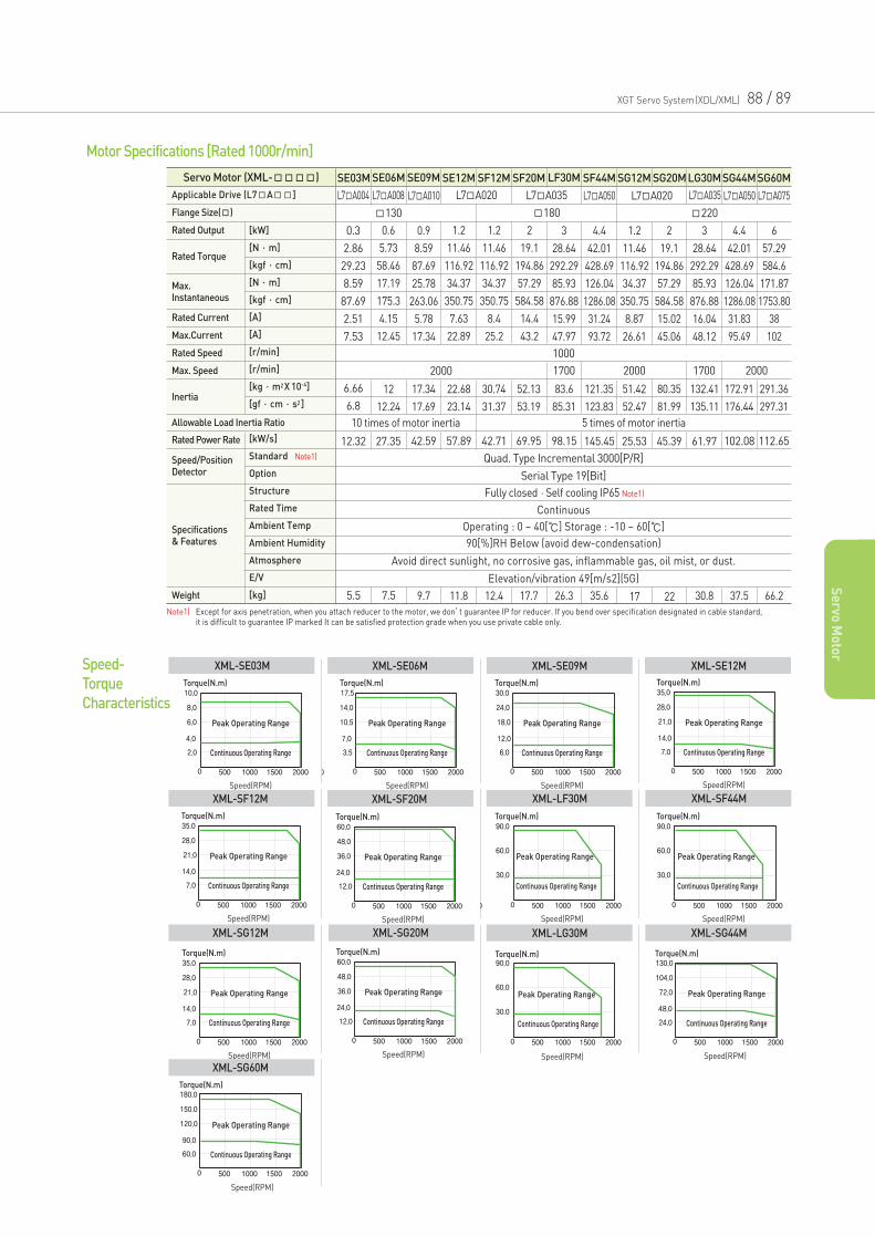
XGT Servo System(XDL/XML) 88 / 89
Se
rvo M
oto
r
Servo Motor (XML-) SE03M SE06M SE09M SE12M SF12M SF20M LF30M SF44M SG12M SG20MLG30MSG44MSG60M
L7A004 L7A008 L7A010 L7A050 L7A020 L7A050 L7A075L7A035L7A020 L7A035
130 180 220
Fully closed·Self cooling IP65 Note1)
Serial Type 19[Bit]
Continuous
Operating : 0 ~ 40[] Storage : -10 ~ 60[]
90[%]RH Below (avoid dew-condensation)
Avoid direct sunlight, no corrosive gas, inflammable gas, oil mist, or dust.
Elevation/vibration 49[m/s2](5G)
1000
2000
10 times of motor inertia 5 times of motor inertia
0.3
2.86
29.23
8.59
87.69
2.51
7.53
0.6
5.73
58.46
17.19
175.3
4.15
12.45
0.9
8.59
87.69
25.78
263.06
5.78
17.34
1.2
11.46
116.92
34.37
350.75
7.63
22.89
1.2
11.46
116.92
34.37
350.75
8.4
25.2
2
19.1
194.86
57.29
584.58
14.4
43.2
3
28.64
292.29
85.93
876.88
15.99
47.97
4.4
42.01
428.69
126.04
1286.08
31.24
93.72
1.2
11.46
116.92
34.37
350.75
8.87
26.61
2
19.1
194.86
57.29
584.58
15.02
45.06
3
28.64
292.29
85.93
876.88
16.04
48.12
4.4
42.01
428.69
126.04
1286.08
31.83
95.49
6
57.29
584.6
171.87
1753.80
38
102
6.66
6.8
12
12.24
17.34
17.69
22.68
23.14
30.74
31.37
52.13
53.19
83.6
85.31
121.35
123.83
51.42
52.47
132.41
135.11
172.91
176.44
291.36
297.31
80.35
81.99
1700 17002000 2000
12.32 27.35 42.59 57.89 42.71 69.95 98.15 145.45 25.53 45.39 61.97 102.08 112.65
Quad. Type Incremental 3000[P/R]
5.5 7.5 9.7 11.8 12.4 17.7 26.3 35.6 17 22 30.8 37.5 66.2
Motor Specifications [Rated 1000r/min]
Torque(N.m)
Peak Operating Range
Continuous Operating Range
Speed(RPM)
Torque(N.m)
Peak Operating Range
Continuous Operating Range
Speed(RPM)
Torque(N.m)
Peak Operating Range
Continuous Operating Range
Speed(RPM)
Torque(N.m)
Peak Operating Range
Continuous Operating Range
Speed(RPM)
Speed-
Torque
Characteristics
XML-SE03M XML-SE06M XML-SE09M XML-SE12M
Torque(N.m)
Peak Operating Range
Continuous Operating Range
Speed(RPM)
Speed(RPM)
Torque(N.m)
Peak Operating Range
Continuous Operating Range
Speed(RPM)
T (N ) ( )
Torque(N.m)
Peak Operating Range
Continuous Operating Range
Speed(RPM)
Speed(RPM)XML-SF12M XML-SF20M XML-LF30M
Speed(RPM)
Torque(N.m)
Peak Operating Range
Continuous Operating Range
Speed(RPM)
XML-LG30M
Torque(N.m)
Peak Operating Range
Continuous Operating Range
Speed(RPM)
Speed(RPM)XML-SF44M
Torque(N.m)
Peak Operating Range
Continuous Operating Range
Speed(RPM)
Speed(RPM)XML-SG44MSpeed(RPM)
Torque(N.m)
Peak Operating Range
Continuous Operating Range
Speed(RPM)
Torque(N.m)
Peak Operating Range
Continuous Operating Range
Speed(RPM)
Speed(RPM)XML-SG12M XML-SG20M
Torque(N.m)
Peak Operating Range
Continuous Operating Range
Speed(RPM)
Speed(RPM)XML-SG60M
Applicable Drive (L7A]
Flange Size()
Rated Speed
Max. Speed
Rated Current
Max.Current
Specifications& Features
Rated Output [kW]
[N·m]
[kgf·cm]
[N·m]
[kgf·cm]
[A]
[A]
[r/min]
[r/min]
[kg·m2X 10-4]
[gf·cm·s2]
[kW/s]
Standard Note1)
Option
Structure
Rated Time
Ambient Temp
Ambient Humidity
Atmosphere
E/V
[kg]
Rated Power Rate
Weight
Speed/PositionDetector
Rated Torque
Max.Instantaneous
Inertia
Allowable Load Inertia Ratio
Note1) Except for axis penetration, when you attach reducer to the motor, we don’t guarantee IP for reducer. If you bend over specification designated in cable standard, it is difficult to guarantee IP marked It can be satisfied protection grade when you use private cable only.
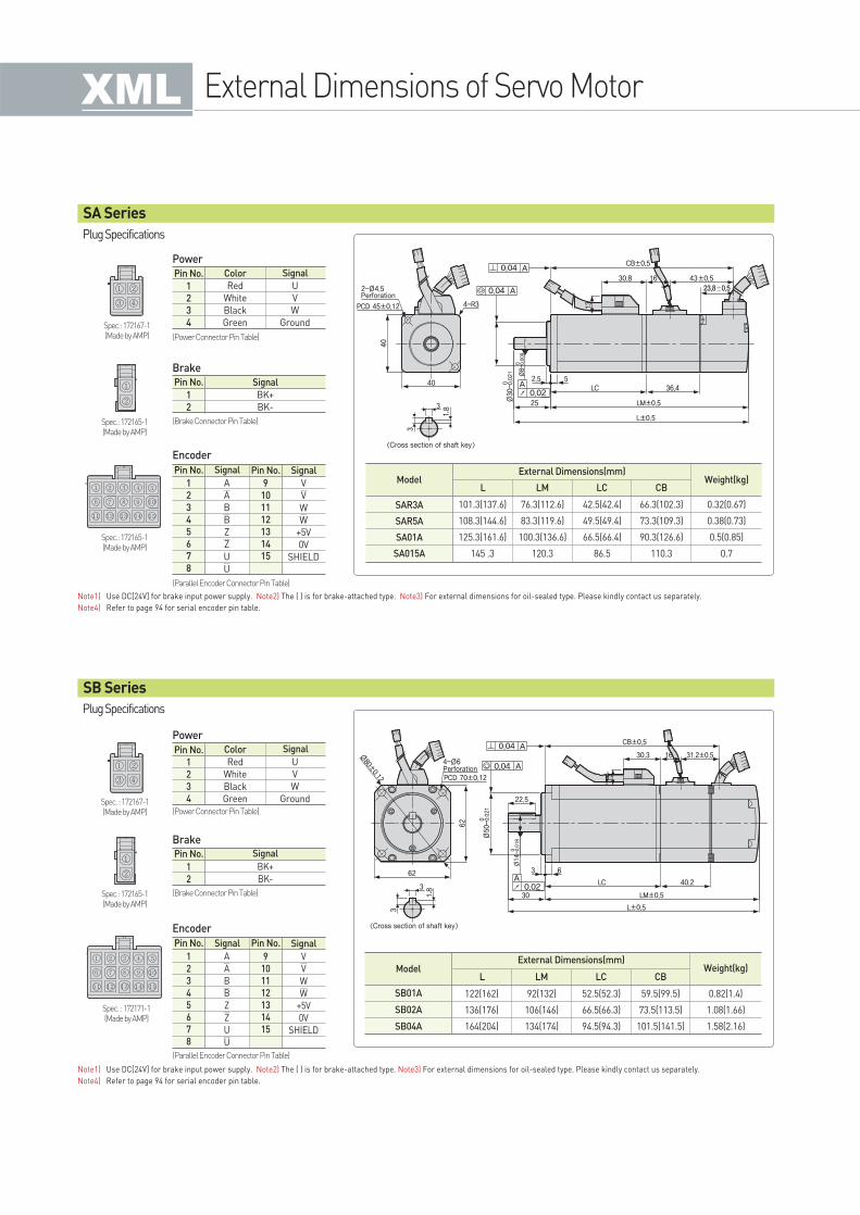
External Dimensions of Servo Motor
Plug Specifications
Plug Specifications
Power
Brake
Encoder
Pin No. Color Signal
Red
White
Black
Green
U
V
W
Ground
1
2
3
4
(Power Connector Pin Table)
Pin No. Pin No.
A
A
B
B
Z
Z
U
U
SignalSignal
V
V
W
W
+5V
0V
SHIELD
1
2
3
4
5
6
7
8
9
10
11
12
13
14
15
(Parallel Encoder Connector Pin Table)
Pin No. Signal
BK+
BK-
1
2
(Brake Connector Pin Table)
Spec.: 172167-1(Made by AMP)
Spec.: 172165-1(Made by AMP)
Spec.: 172165-1(Made by AMP)
Note1) Use DC[24V] for brake input power supply. Note2) The ( ) is for brake-attached type. Note3) For external dimensions for oil-sealed type. Please kindly contact us separately.
Note4) Refer to page 94 for serial encoder pin table.
Power
Brake
Encoder
Pin No. Color
Red
White
Black
Green
Signal
U
V
W
Ground
1
2
3
4
(Power Connector Pin Table)
Pin No. Pin No.
A
A
B
B
Z
Z
U
U
SignalSignal
V
V
W
W
+5V
0V
SHIELD
1
2
3
4
5
6
7
8
9
10
11
12
13
14
15
(Parallel Encoder Connector Pin Table)
Pin No. Signal
BK+
BK-
1
2
(Brake Connector Pin Table)Spec.: 172165-1(Made by AMP)
Spec. : 172171-1(Made by AMP)
Note1) Use DC[24V] for brake input power supply. Note2) The ( ) is for brake-attached type. Note3) For external dimensions for oil-sealed type. Please kindly contact us separately.
Note4) Refer to page 94 for serial encoder pin table.
SA Series
SB Series
ModelL LM LC CB
External Dimensions(mm)Weight(kg)
101.3(137.6)
108.3(144.6)
125.3(161.6)
145 .3
76.3(112.6)
83.3(119.6)
100.3(136.6)
120.3
42.5(42.4)
49.5(49.4)
66.5(66.4)
86.5
66.3(102.3)
73.3(109.3)
90.3(126.6)
110.3
0.32(0.67)
0.38(0.73)
0.5(0.85)
0.7
SAR3A
SAR5A
SA01A
SA015A
ModelL LM LC CB
External Dimensions(mm)Weight(kg)
122(162)
136(176)
164(204)
92(132)
106(146)
134(174)
52.5(52.3)
66.5(66.3)
94.5(94.3)
59.5(99.5)
73.5(113.5)
101.5(141.5)
0.82(1.4)
1.08(1.66)
1.58(2.16)
SB01A
SB02A
SB04A
Spec. : 172167-1(Made by AMP)
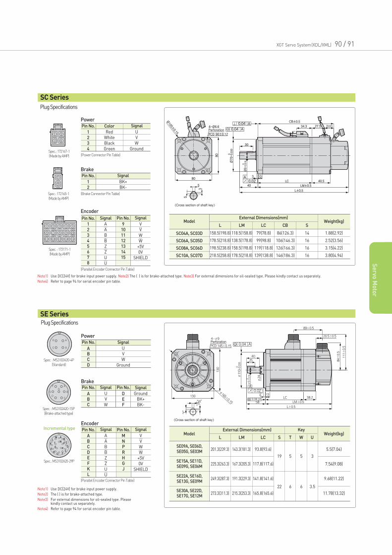
XGT Servo System(XDL/XML) 90 / 91
Se
rvo M
oto
r
Plug Specifications
Power
Brake
Encoder
Pin No. Color
Red
White
Black
Green
Signal
U
V
W
Ground
1
2
3
4
(Power Connector Pin Table)
Pin No. Pin No.
A
A
B
B
Z
Z
U
U
SignalSignal
V
V
W
W
+5V
0V
SHIELD
1
2
3
4
5
6
7
8
9
10
11
12
13
14
15
(Parallel Encoder Connector Pin Table)
(Parallel Encoder Connector Pin Table)
Pin No. Signal
BK+
BK-
1
2
(Brake Connector Pin Table)
Spec.: 172167-1(Made by AMP)
Spec.: 172165-1(Made by AMP)
Note1) Use DC[24V] for brake input power supply. Note2) The ( ) is for brake-attached type. Note3) For external dimensions for oil-sealed type. Please kindly contact us separately.
Note4) Refer to page 94 for serial encoder pin table.
Note1) Use DC[24V] for brake input power supply.
Note2) The ( ) is for brake-attached type.
Note3) For external dimensions for oil-sealed type. Please kindly contact us separately.
Note4) Refer to page 94 for serial encoder pin table.
SC Series
ModelL LM LC CB
External Dimensions(mm)Weight(kg)
158.5(198.8)
178.5(218.8)
198.5(238.8)
218.5(258.8)
118.5(158.8)
138.5(178.8)
158.5(198.8)
178.5(218.8)
79(78.8)
99(98.8)
119(118.8)
139(138.8)
S
14
16
16
16
86(126.3)
106(146.3)
126(166.3)
146(186.3)
1.88(2.92)
2.52(3.56)
3.15(4.22)
3.80(4.94)
SC04A, SC03D
SC06A, SC05D
SC08A, SC06D
SC10A, SC07D
Spec. : 172171-1(Made by AMP)
PowerPin No. Signal
U
V
W
Ground
A
B
C
D
Pin No. Signal Pin No. Signal
U
V
W
A
B
C
Ground
BK+
BK-
D
E
F
Spec. : MS3102A20-4P(Standard)
Spec.: MS3102A20-29P
Encoder
Brake
Incremental type Pin No. Pin No.
A
A
B
B
Z
Z
U
U
SignalSignal
V
V
W
W
+5V
0V
SHIELD
A
B
C
D
E
F
K
L
M
N
P
R
H
G
J
Plug Specifications
SE Series
ModelL
External Dimensions(mm) KeyWeight(kg)
201.3(239.3)
225.3(263.3)
249.3(287.3)
273.3(311.3)
5.5(7.04)
7.54(9.08)
9.68(11.22)
11.78(13.32)
LM
143.3(181.3)
167.3(205.3)
191.3(229.3)
215.3(253.3)
LC
93.8(93.6)
117.8(117.6)
141.8(141.6)
165.8(165.6)
S
19
22
5
6
5
6
3
3.5
T W U
SE09A, SE06D, SE05G, SE03M
SE15A, SE11D, SE09G, SE06M
SE22A, SE16D, SE13G, SE09M
SE30A, SE22D, SE17G, SE12M
Spec. : MS3102A20-15P(Brake-attached type)
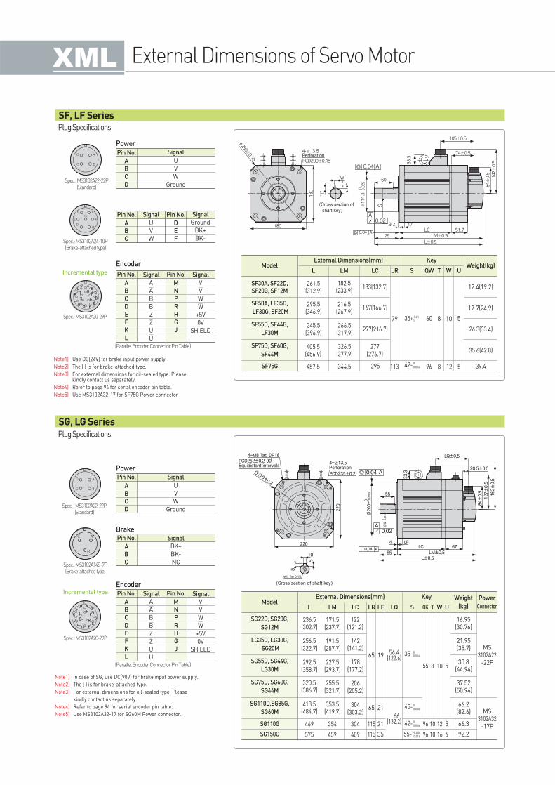
External Dimensions of Servo Motor
Note1) In case of SG, use DC[90V] for brake input power supply.
Note2) The ( ) is for brake-attached type.
Note3) For external dimensions for oil-sealed type. Please
kindly contact us separately.
Note4) Refer to page 94 for serial encoder pin table.
Note5) Use MS3102A32-17 for SG60M Power connector.
Power
ModelL
External Dimensions(mm) KeyWeight(kg)
261.5(312.9)
405.5(456.9)
457.5
266.5(317.9)
326.5(377.9)
344.5
277(216.7)
277(276.7)
295
35.6(42.8)
26.3(33.4)
39.4
295.5(346.9)
345.5(396.9)
216.5(267.9)
167(166.7) 17.7(24.9)
12.4(19.2)
LM
182.5(233.9)
LC LR
133(132.7)
79
113 96 8 12 5
S
35+0.010
42-00.016
QW
60
T
8
W
10
U
5
SF75G
SF30A, SF22D, SF20G, SF12M
SF50A, LF35D,
LF30G, SF20M
SF55D, SF44G,
LF30M
SF75D, SF60G,
SF44M
Pin No. Signal
U
V
W
Ground
A
B
C
D
Pin No. Signal Pin No. Signal
U
V
W
A
B
C
Ground
BK+
BK-
D
E
F
Spec.: MS3102A22-22P(Standard)
Spec.: MS3102A24-10P(Brake-attached type)
Spec.: MS3102A20-29P
Incremental type Pin No. Pin No.
A
A
B
B
Z
Z
U
U
SignalSignal
V
V
W
W
+5V
0V
SHIELD
A
B
C
D
E
F
K
L
M
N
P
R
H
G
J
Power
Brake
Pin No. Signal
U
V
W
Ground
A
B
C
D
Pin No. Signal
A
B
C
BK+
BK-
NC
Spec. : MS3102A22-22P(Standard)
Spec.: MS3102A14S-7P(Brake-attached type)
Spec.: MS3102A20-29P
Encoder
Encoder
Incremental type Pin No. Pin No.
A
A
B
B
Z
Z
U
U
SignalSignal
V
V
W
W
+5V
0V
SHIELD
A
B
C
D
E
F
K
L
M
N
P
R
H
G
J
Plug Specifications
Plug Specifications
SF, LF Series
SG, LG Series
Note1) Use DC[24V] for brake input power supply.
Note2) The ( ) is for brake-attached type.
Note3) For external dimensions for oil-sealed type. Pleasekindly contact us separately.
Note4) Refer to page 94 for serial encoder pin table.
Note5) Use MS3102A32-17 for SF75G Power connector
ModelL
External Dimensions(mm) Key Weight
(kg)
Power
Connector
236.5(302.7)
256.5(322.7)
292.5(358.7)
227.5(293.7)
255.5(321.7)
353.5(419.7)
320.5(386.7)
418.5(484.7)
469 354 304
575 459 409
191.5(257.7)
142(141.2)
178(177.2)
206(205.2)
304(303.2)
21.95(35.7) MS
3102A22-22P
MS3102A32
-17P
30.8(44.94)
37.52(50.94)
66.2(82.6)
66.3
92.2
16.95(30.76)
LM
171.5(237.7)
LC LF
122(121.2)
65
55
96
96
8
10
10
10
12
16
5
5
6
19
65 21
21
35
115
115
LQ QK
56.4(122.6)
66(132.2)
S T W ULR
SG22D, SG20G,
SG12M
SG110G
SG150G
SG110D,SG85G,
SG60M
SG75D, SG60G,
SG44M
SG55D, SG44G,
LG30M
LG35D, LG30G,
SG20M
(Parallel Encoder Connector Pin Table)
(Parallel Encoder Connector Pin Table)
42-00.016
55-+0.000-0.016
45-00.016
35-00.016
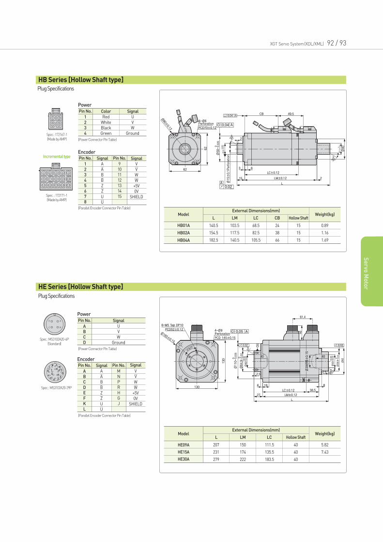
XGT Servo System(XDL/XML) 92 / 93
Se
rvo M
oto
r
Power
Encoder
ModelL LM LC CB
External Dimensions(mm)Weight(kg)
140.5
154.5
182.5
103.5
117.5
140.5
68.5
82.5
105.5
24
38
66
Hollow Shaft
15
15
15
0.89
1.16
1.69
HB01A
HB02A
HB04A
Pin No. Color
Red
White
Black
Green
Signal
U
V
W
Ground
1
2
3
4
(Power Connector Pin Table)
(Power Connector Pin Table)
Pin No. Pin No.
A
A
B
B
Z
Z
U
U
SignalSignal
V
V
W
W
+5V
0V
SHIELD
1
2
3
4
5
6
7
8
9
10
11
12
13
14
15
(Parallel Encoder Connector Pin Table)
(Parallel Encoder Connector Pin Table)
Spec.: 172167-1(Made by AMP)
Spec. : 172171-1(Made by AMP)
ModelL LM LC Hollow Shaft
External Dimensions(mm)Weight(kg)
207
231
279
150
174
222
111.5
135.5
183.5
40
40
40
5.82
7.43
HE09A
HE15A
HE30A
Power
Pin No. Signal
U
V
W
Ground
A
B
C
DSpec.: MS3102A20-4P
(Standard)
Spec.: MS3102A20-29P
EncoderPin No. Pin No.
A
A
B
B
Z
Z
U
U
SignalSignal
V
V
W
W
+5V
0V
SHIELD
A
B
C
D
E
F
K
L
M
N
P
R
H
G
J
Incremental type
Plug Specifications
Plug Specifications
HB Series [Hollow Shaft type]
HE Series [Hollow Shaft type]
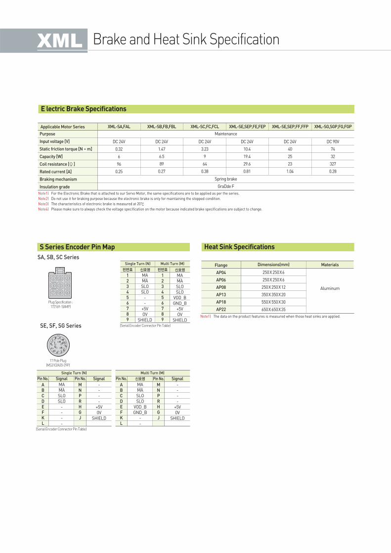
Brake and Heat Sink Specification
Dimensions(mm) Materials
250X 250X6
250X 250X6
250X 250X12
350X 350X20
550X 550X30
650X 650X35
Aluminum
Flange
AP04
AP06
AP08
AP13
AP18
AP22
Note1) The data on the product features is measured when those heat sinks are applied.
SA, SB, SC Series
SE, SF, SG Series
S Series Encoder Pin Map Heat Sink Specifications
XML-SA,FAL XML-SB,FB,FBL XML-SC,FC,FCL XML-SE,SEP,FE,FEP XML-SE,SEP,FF,FFP XML-SG,SGP,FG,FGP
DC 24V
0.32
6
96
0.25
DC 24V
1.47
6.5
89
0.27
DC 24V
3.23
9
64
0.38
Maintenance
Spring brake
GraDde F
DC 24V
10.4
19.4
29.6
0.81
DC 24V
40
25
23
1.04
DC 90V
74
32
327
0.28
Applicable Motor Series
Purpose
Input voltage [V]
Static friction torque [N•m]
Capacity [W]
Coil resistance [Ω]
Rated current [A]
Braking mechanism
Insulation grade
Note1) For the Electronic Brake that is attached to our Servo Motor, the same specifications are to be applied as per the series.
Note2) Do not use it for braking purpose because the electronic brake is only for maintaining the stopped condition.
Note3) The characteristics of electronic brake is measured at 20
Note4) Please make sure to always check the voltage specification on the motor because indicated brake specifications are subject to change.
E lectric Brake Specifications
17 Pole Plug (MS3102A20-29P)
Plug Specification :172169-1(AMP)
(Serial Encoder Connector Pin Table)
(Serial Encoder Connector Pin Table)
핀번호 핀번호
Multi Turn (M)
MA
MA
SLO
SLO
-
-
+5V
OV
SHIELD
신호명신호명
Single Turn (N)
MA
MA
SLO
SLO
VOD_B
GND_B
+5V
OV
SHIELD
1
2
3
4
5
6
7
8
9
1
2
3
4
5
6
7
8
9
Pin No. Pin No.
MA
MA
SLO
SLO
-
-
-
-
SignalSignal
Single Turn (N)
-
-
-
-
+5V
0V
SHIELD
A
B
C
D
E
F
K
L
M
N
P
R
H
G
J
Pin No. Pin No.
MA
MA
SLO
SLO
VOD_B
GND_B
-
-
Signal신호명
Multi Turn (M)
-
-
-
-
+5V
0V
SHIELD
A
B
C
D
E
F
K
L
M
N
P
R
H
G
J
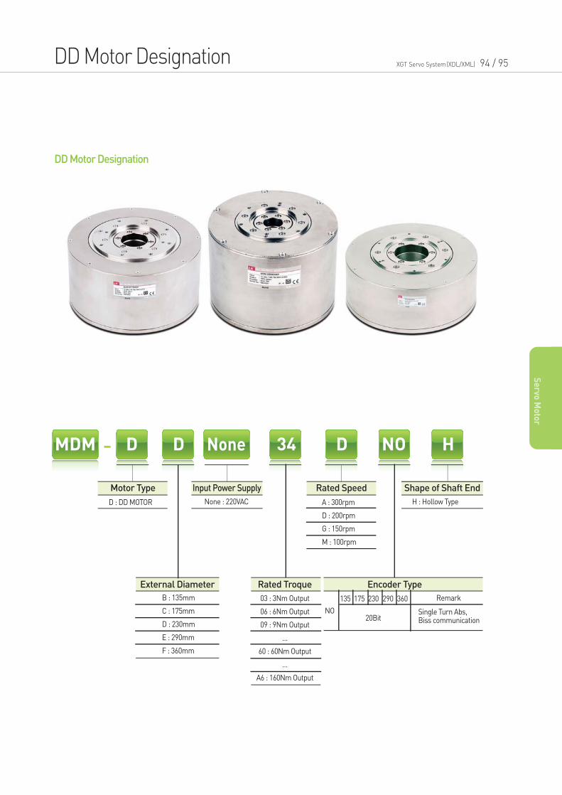
DD Motor Designation XGT Servo System(XDL/XML) 94 / 95
Se
rvo M
oto
r
DD Motor Designation
MDM NoneD D 34 D NO H
D : DD MOTOR
B : 135mm
C : 175mm
D : 230mm
E : 290mm
F : 360mm
NO
Remark135 175 230
20Bit
290 360
A : 300rpm
D : 200rpm
G : 150rpm
M : 100rpm
None : 220VAC
Motor Type Input Power Supply
External Diameter Rated Troque Encoder Type
Rated Speed Shape of Shaft End
H : Hollow Type
Single Turn Abs,Biss communication
03 : 3Nm Output
06 : 6Nm Output
09 : 9Nm Output
…
60 : 60Nm Output
…
A6 : 160Nm Output
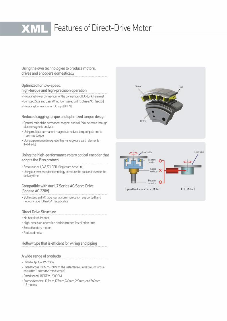
Features of Direct-Drive Motor
Optimized for low-speed,
high-torque and high-precision operation
•Providing Power connection for the connection of DC-Link Terminal
•Compact Size and Easy Wring (Compared with 3 phase AC Reactor)
•Providing Connection for DC Input (PI, N)
Reduced cogging torque and optimized torque design
•Optimal ratio of the permanent magnet and coil / slot selected through electromagnetic analysis
•Using multiple permanent magnets to reduce torque ripple and to maximize torque
•Using a permanent magnet of high-energy rare earth elements (Nd-Fe-B)
Using the high-performance rotary optical encoder that
adopts the Biss protocol
Compatible with our L7 Series AC Servo Drive
(3phase AC 220V)[ DD Motor ][Speed Reducer + Servo Motor]
Direct Drive Structure
Hollow type that is efficient for wiring and piping
•Resolution of 1,048,576 CPR (Single turn Absolute)
•Using our own encoder technology to reduce the cost and shorten the delivery time
Stator Coil
Rotor
Load table
Supportbearing
Load table
Speedreducer
Positiondetector
•Both standard I/O type (serial communication supported) and network type (EtherCAT) applicable
•No backlash impact
•High-precision operation and shortened installation time
•Smooth rotary motion
•Reduced noise
Using the own technologies to produce motors,
drives and encoders domestically
A wide range of products
•Rated output: 63W-.25kW
•Rated torque: 3.0N.m-160N.m (the instantaneous maximum torque should be 3 times the rated torque)
•Rated speed: 150RPM-200RPM
•Frame diameter: 135mm,175mm,230mm,290mm, and 360mm (13 models)
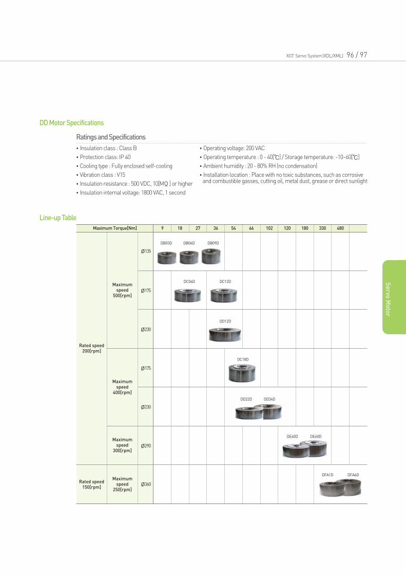
XGT Servo System(XDL/XML) 96 / 97
Se
rvo M
oto
r
Ratings and Specifications
•Insulation class : Class B
•Protection class: IP 40
•Cooling type : Fully enclosed self-cooling
•Vibration class : V15
•Insulation resistance : 500 VDC, 10[MΩ] or higher
•Insulation internal voltage: 1800 VAC, 1 second
•Operating voltage: 200 VAC
•Operating temperature : 0 - 40[] / Storage temperature: -10~60[]
•Ambient humidity : 20 - 80% RH (no condensation)
•Installation location : Place with no toxic substances, such as corrosiveand combustible gasses, cutting oil, metal dust, grease or direct sunlight
DD Motor Specifications
Line-up Table
Maximum Torque[Nm] 9
DC06D DC12D
DD12D
DC18D
DD22D DD34D
DE40D DE60D
DFA1D DFA6D
18 27 36 54 66 102 120 180 330 480
Rated speed200[rpm]
Maximumspeed
500[rpm]
Ø135
Ø175
Ø230
Ø175
Ø230
Ø290
Ø360
Maximumspeed
400[rpm]
Maximumspeed
300[rpm]
Maximumspeed
250[rpm]
Rated speed150[rpm]
DB03D DB06D DB09D
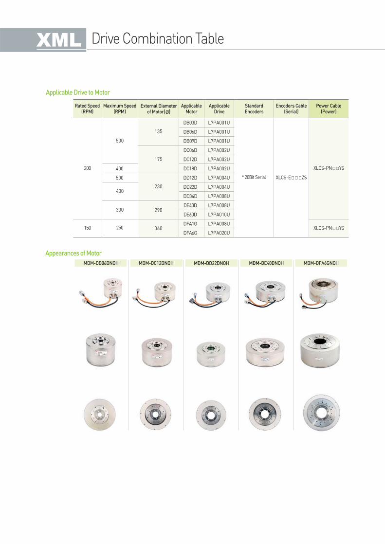
Rated Speed (RPM)
Maximum Speed(RPM)
External Diameterof Motor(Ø)
ApplicableMotor
ApplicableDrive
Power Cable(Power)
Encoders Cable(Serial)
StandardEncoders
L7PA001U
L7PA001U
L7PA001U
L7PA002U
L7PA002U
L7PA002U
L7PA004U
L7PA004U
L7PA008U
L7PA008U
L7PA010U
L7PA008U
L7PA020U
400
500
DB03D
DB06D
DB09D
DC06D
DC12D
DC18D
DD12D
DD22D
DD34D
DE40D
DE60D
DFA1G
DFA6G
500
135
175
230
290
360
400
300
200 XLCS-PNYS
XLCS-PNYS150 250
Applicable Drive to Motor
Appearances of Motor
MDM-DB06DNOH MDM-DC12DNOH MDM-DD22DNOH MDM-DE40DNOH MDM-DFA6GNOH
Drive Combination Table
* 20Bit Serial XLCS-EZS
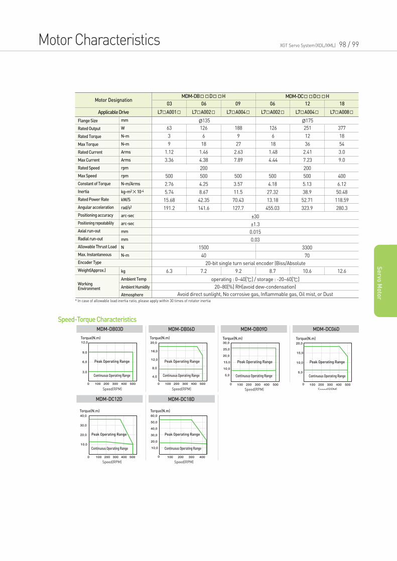
Motor Characteristics XGT Servo System(XDL/XML) 98 / 99
Se
rvo M
oto
r
Speed-Torque Characteristics
Torque(N.m)
Peak Operating Range
Continuous Operating Range
Speed(RPM)
Peak Operating Range
Torque(N.m)
Continuous Operating Range
Speed(RPM)
Peak Operating Range
Torque(N.m)
Continuous Operating Range
Speed(RPM)
Torque(N.m)
Peak Operating Range
Continuous Operating Range
Speed(RPM)
MDM-DB03D MDM-DB06D MDM-DB09D MDM-DC06D
Torque(N.m)
Peak Operating Range
Continuous Operating Range
Speed(RPM)
Torque(N.m)
Peak Operating Range
Continuous Operating Range
Speed(RPM)
MDM-DC12D MDM-DC18D
Applicable Drive
MDM-DBDH MDM-DCDHMotor Designation
L7A001 L7A002 L7A004 L7A002 L7A004 L7A008
03 06 06 12 1809
Ø135 Ø175
200
20-bit single turn serial encoder (Biss/Absolute
200
63
3
9
1.12
3.36
500
2.76
5.74
15.68
191.2
500
4.25
8.67
42.35
141.6
1500
40
6.3 7.2 9.2 8.7 10.6 12.6
500
3.57
11.5
70.43
127.7
500
4.18
27.32
13.18
455.03
500
5.13
38.9
52.71
323.9
3300
70
400
6.12
50.48
118.59
280.3
126
6
18
1.46
4.38
188
9
27
2.63
7.89
126
6
18
1.48
4.44
251
12
36
2.41
7.23
377
18
54
3.0
9.0
operating : 0~40[] / storage : -20~60[]
20~80[%] RH(avoid dew-condensation)
Avoid direct sunlight, No corrosive gas, Inflammable gas, Oil mist, or Dust
±30
±1.3
0.015
0.03
Flange Size
Rated Output
Rated Torque
Max Torque
Rated Current
Max Current
Rated Speed
Max Speed
Constant of Torque
Inertia
Rated Power Rate
Angular acceleration
Positioning accuracy
Positioning repeatability
Axial run-out
Radial run-out
Allowable Thrust Load
Max. Instantaneous
Encoder Type
Weight(Approx.)
WorkingEnvironment
mm
W
N-m
N-m
Arms
Arms
rpm
rpm
N-m/Arms
kg-m2×10-4
kW/S
rad/s2
arc-sec
arc-sec
mm
mm
N
N-m
kg
Ambient Temp
Ambient Humidity
Atmosphere
* In case of allowable load inertia ratio, please apply within 30 times of rotator inertia
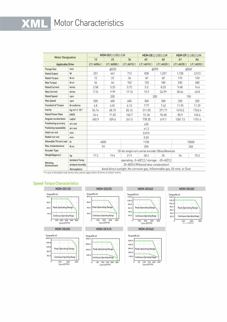
Motor Characteristics
Speed-Torque Characteristics
Torque(N.m)
Peak Operating Range
Continuous Operating Range
Speed(RPM)
Torque(N.m)
Peak Operating Range
Continuous Operating Range
Speed(RPM)
Torque(N.m)
Peak Operating Range
Continuous Operating Range
Speed(RPM)
Torque(N.m)
Peak Operating Range
Continuous Operating Range
Speed(RPM)
MDM-DD12D MDM-DD22D MDM-DD34D MDM-DE40D
Torque(N.m)
Peak Operating Range
Continuous Operating Range
Speed(RPM)
Torque(N.m)
Peak Operating Range
Continuous Operating Range
Speed(RPM)
MDM-DE60D MDM-DFA1G
Torque(N.m)
Peak Operating Range
Continuous Operating Range
Speed(RPM)
MDM-DFA6G
Applicable Drive
MDM-DDDH MDM-DEDH MDM-DFGHMotor Designation
L7A004 L7A008 L7A010 L7A010 L7A020 L7A035L7A020
12 22 40 60 A6A134
Ø230 Ø360Ø290
200
20-bit single turn serial encoder (Biss/Absolute
150200
251
12
36
2.58
7.74
500
4.8
54.14
26.6
450.9
400
6.81
68.15
71.02
309.6
400
6.13
82.16
140.7
241.5
300
7.77
311.55
51.36
778.35
300
7.42
371.71
96.68
619.1
250
11.95
1410.2
85.9
1281.13
250
11.29
1763.4
145.4
1101.4
4000
93
1100
250
17.3 19.6 21.9 28.2 35 54 70.3
15000
350
461
22
66
3.33
9.99
712
34
102
5.72
17.16
838
40
120
5.3
15.9
1,257
60
180
8.33
24.99
1,728
110
330
9.48
28.44
2,513
160
480
14.6
43.8
operating : 0~40[] / storage : -20~60[]
20~80[%] RH(avoid dew-condenation)
Avoid direct sunlight, No corrosive gas, Inflammable gas, Oil mist, or Dust
±30
±1.3
0.015
0.03
Flange Size
Rated Output
Rated Torque
Max Torque
Rated Current
Max Current
Rated Speed
Max Speed
Constant of Torque
Inertia
Rated Power Rate
Angular acceleration
Positioning accuracy
Positioning repeatability
Axial run-out
Radial run-out
Allowable Thrust Load
Max. Instantaneous
Encoder Type
Weight(Approx.)
WorkingEnvironment
mm
W
N-m
N-m
Arms
Arms
rpm
rpm
N-m/Arms
kg-m2×10-4
kW/S
rad/s2
arc-sec
arc-sec
mm
mm
N
N-m
kg
Ambient Temp
Ambient Humidity
Atmosphere
* In case of allowable load inertia ratio, please apply within 30 times of rotator inertia
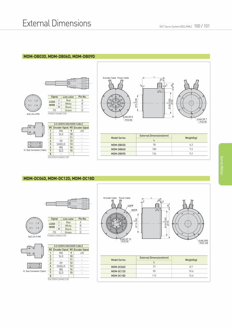
External Dimensions XGT Servo System(XDL/XML) 100 / 101
Se
rvo M
oto
r
MDM-DB03D, MDM-DB06D, MDM-DB09D
ENCODER CONNECTOR
Signal Line color
Red
White
Black
Green
Pin No.
FG
U
V
W
A
B
C
D
LEAD
WIRE
POWER CONNECTOR
Model SeriesL
External Dimensions(mm)Weight(kg)
78
100
124
6.3
7.2
9.2
MDM-DB03D
MDM-DB06D
MDM-DB09D
NO NO
MA
SLO
-
OV
SHIELD
MA
SLO
-
Encoder SignalEncoder Signal
D.D SERVO ENCODER CABLE
+5V
-
-
-
-
-
-
1
2
3
4
5
6
7
8
9
10
11
12
13
14
15
MDM-DC06D, MDM-DC12D, MDM-DC18D
ENCODER CONNECTOR
Signal Line color
Red
White
Black
Green
Pin No.
FG
U
V
W
A
B
C
D
LEAD
WIRE
POWER CONNECTOR
Model SeriesL
External Dimensions(mm)Weight(kg)
77
95
113
8.7
10.6
12.6
MDM-DC06D
MDM-DC12D
MDM-DC18D
NO NO
MA
SLO
-
OV
SHIELD
MA
SLO
-
Encoder SignalEncoder Signal
D.D SERVO ENCODER CABLE
+5V
-
-
-
-
-
-
1
2
3
4
5
6
7
8
9
10
11
12
13
14
15
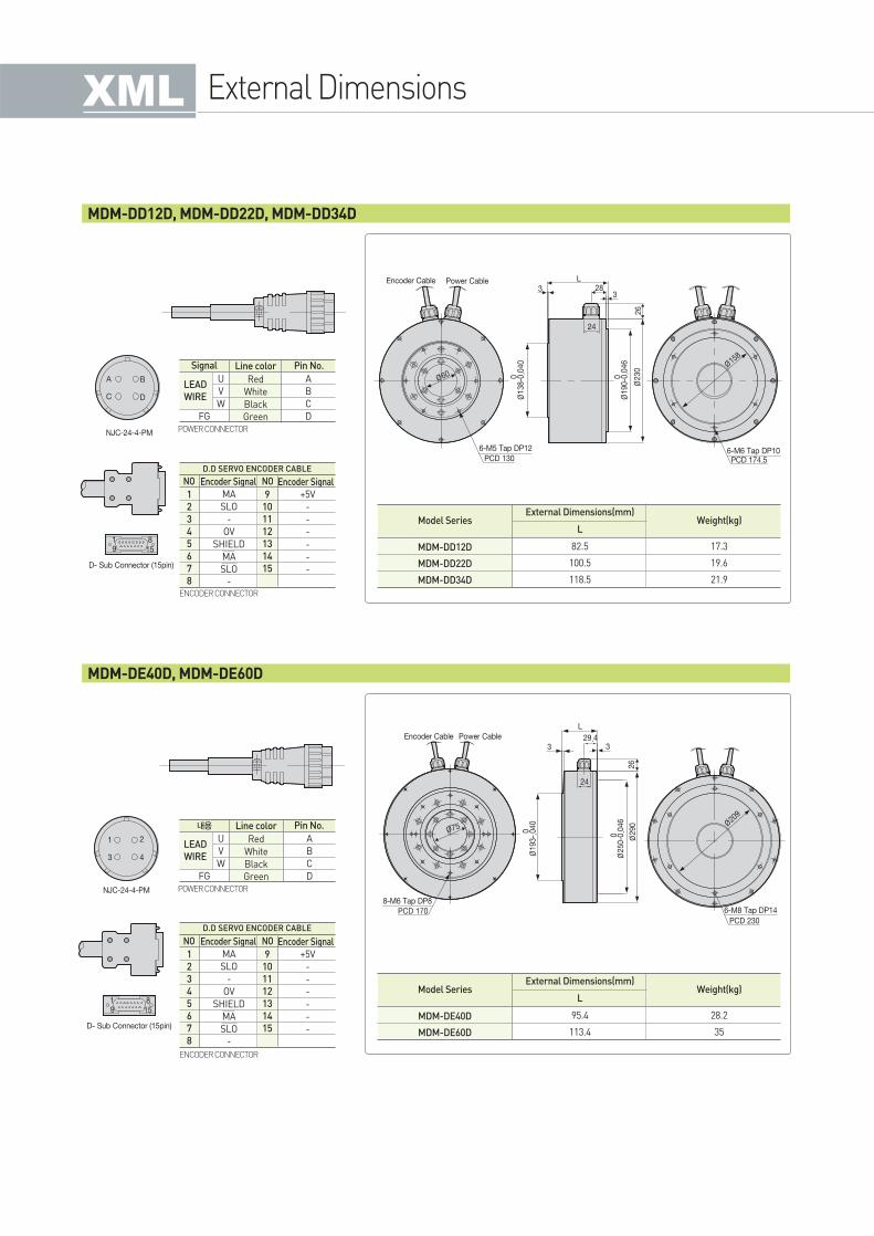
External Dimensions
MDM-DD12D, MDM-DD22D, MDM-DD34D
ENCODER CONNECTOR
Signal Line color
Red
White
Black
Green
Pin No.
FG
U
V
W
A
B
C
D
LEAD
WIRE
POWER CONNECTOR
Model SeriesL
External Dimensions(mm)Weight(kg)
82.5
100.5
118.5
17.3
19.6
21.9
MDM-DD12D
MDM-DD22D
MDM-DD34D
NO NO
MA
SLO
-
OV
SHIELD
MA
SLO
-
Encoder SignalEncoder Signal
D.D SERVO ENCODER CABLE
+5V
-
-
-
-
-
-
1
2
3
4
5
6
7
8
9
10
11
12
13
14
15
MDM-DE40D, MDM-DE60D
ENCODER CONNECTOR
내용 Line color
Red
White
Black
Green
Pin No.
FG
U
V
W
A
B
C
D
LEAD
WIRE
POWER CONNECTOR
Model SeriesL
External Dimensions(mm)Weight(kg)
95.4
113.4
28.2
35
MDM-DE40D
MDM-DE60D
NO NO
MA
SLO
-
OV
SHIELD
MA
SLO
-
Encoder SignalEncoder Signal
D.D SERVO ENCODER CABLE
+5V
-
-
-
-
-
-
1
2
3
4
5
6
7
8
9
10
11
12
13
14
15
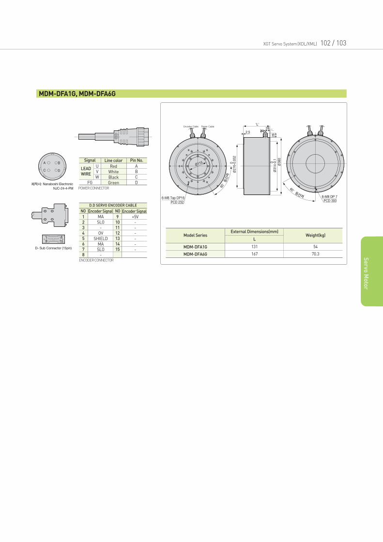
XGT Servo System(XDL/XML) 102 / 103
Se
rvo M
oto
r
MDM-DFA1G, MDM-DFA6G
1Power CableEncoder Cable
ENCODER CONNECTOR
Signal Line color
Red
White
Black
Green
Pin No.
FG
U
V
W
A
B
C
D
LEAD
WIRE
POWER CONNECTOR
Model SeriesL
External Dimensions(mm)Weight(kg)
131
167
54
70.3
MDM-DFA1G
MDM-DFA6G
NO NO
MA
SLO
-
OV
SHIELD
MA
SLO
-
Encoder SignalEncoder Signal
D.D SERVO ENCODER CABLE
+5V
-
-
-
-
-
-
1
2
3
4
5
6
7
8
9
10
11
12
13
14
15
Options and
Accessories
Signal Cable 106
Power Cable 110
DD Motor Signal Cable 118
Option Signal Cable 119
Connector Pin Map 120
Option Connector 121
200V Braking Resistor 122
400V Braking Resistor 123
XGT Servo System(XDL/XML) 104/ 105
Contents
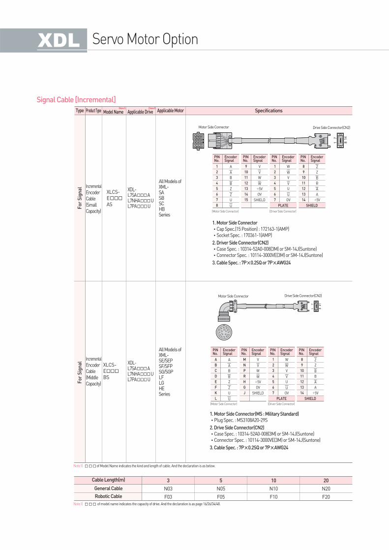
Fo
r S
ign
al
Fo
r S
ign
al
Type Product Type Applicable MotorApplicable DriveModel Name Specifications
Signal Cable [Incremental]
Cable Length(m)
General Cable
Robotic Cable
3
N03
F03
5
N05
F05
10
N10
F10
20
N20
F20
Incremental
Encoder
Cable
(Small
Capacity)
XDL-L7SAAL7NHAUL7PAU
All Models ofXML-SASBSCHBSeries
All Models ofXML-SE/SEPSF/SFPSG/SGPLFLGHESeries
XDL-L7SAAL7NHAUL7PAU
XLCS-
EAS
XLCS-
EBS
Incremental
Encoder
Cable
(Middle
Capacity)
Note1)of Model Name indicates the kind and length of cable. And the declaration is as below.
Note1) of model name indicates the capacity of drive. And the declaration is as page 16/26/34/48.
Servo Motor Option
Motor Side Connector Drive Side Connector(CN2)
[Motor Side Connector] [Driver Side Connector]
1. Motor Side Connector
•Cap Spec.(15 Position) : 172163-1(AMP)
•Socket Spec. : 170361-1(AMP)
2. Driver Side Connector(CN2)
•Case Spec. : 10314-52A0-008(3M) or SM-14J(Suntone)
•Connector Spec. : 10114-3000VE(3M) or SM-14J(Suntone)
3. Cable Spec. : 7P×0.2SQ or 7P×AWG24
PINNo.
1
2
3
4
5
6
7
8
A
A
B
B
Z
Z
U
U
EncoderSignal
PINNo.
9
10
11
12
13
14
15
V
V
W
W
+5V
OV
SHIELD
EncoderSignal
PINNo.
1
2
3
4
5
6
7
W
W
V
V
U
U
OV
EncoderSignal
PLATE
PINNo.
8
9
10
11
12
13
14
Z
Z
B
B
A
A
+5V
EncoderSignal
SHIELD
Motor Side Connector Drive Side Connector(CN2)
[Motor Side Connector] [Driver Side Connector]
1. Motor Side Connector(MS : Military Standard)
•Plug Spec. : MS3108A20-29S
2. Drive Side Connector(CN2)
•Case Spec. : 10314-52A0-008(3M) or SM-14J(Suntone)
•Connector Spec. : 10114-3000VE(3M) or SM-14J(Suntone)
3. Cable Spec. : 7P×0.2SQ or 7P×AWG24
PINNo.
A
B
C
D
E
F
K
L
A
A
B
B
Z
Z
U
U
EncoderSignal
PINNo.
M
N
P
R
H
G
J
V
V
W
W
+5V
OV
SHIELD
EncoderSignal
PINNo.
1
2
3
4
5
6
7
W
W
V
V
U
U
OV
EncoderSignal
PLATE
PINNo.
8
9
10
11
12
13
14
Z
Z
B
B
A
A
+5V
EncoderSignal
SHIELD
(Note1) (Note2)
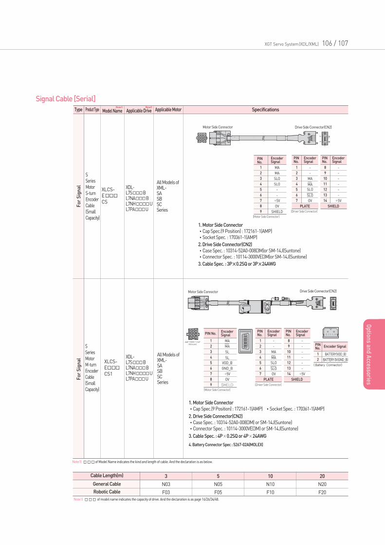
Note1) of model name indicates the capacity of drive. And the declaration is as page 16/26/34/48.
XGT Servo System(XDL/XML) 106 / 107
Op
tions an
d A
ccessories
Type Product Type Applicable MotorApplicable DriveModel Name Specifications
Signal Cable [Serial]
Cable Length(m)
General Cable
Robotic Cable
3
N03
F03
5
N05
F05
10
N10
F10
20
N20
F20
S
Series
Motor
S-turn
Encoder
Cable
(Small
Capacity)
XDL-L7SBL7NABL7NHUL7PAU
All Models ofXML-SASBSCSeries
All Models ofXML-SASBSCSeries
XDL-L7SBL7NABL7NHUL7PAU
XLCS-
ECS
XLCS-
ECS1
S
Series
Motor
M-turn
Encoder
Cable
(Small
Capacity)
Note1)of Model Name indicates the kind and length of cable. And the declaration is as below.
1. Motor Side Connector
•Cap Spec.(9 Position) : 172161-1(AMP)
•Socket Spec. : 170361-1(AMP)
2. Drive Side Connector(CN2)
•Case Spec. : 10314-52A0-008(3M)or SM-14J(Suntone)
•Connector Spec. : 10114-3000VE(3M)or SM-14J(Suntone)
3. Cable Spec. : 3P×0.2SQ or 3P×24AWG
PINNo.
1
2
3
4
5
6
7
8
9
MA
MA
SLO
SLO
-
-
+5V
OV
SHIELD
EncoderSignal
PINNo.
1
2
3
4
5
6
7
-
-
MA
MA
SLO
SLO
OV
EncoderSignal
PLATE
PINNo.
8
9
10
11
12
13
14
-
-
-
-
-
-
+5V
EncoderSignal
SHIELD
Motor Side Connector Drive Side Connector(CN2)
[Motor Side Connector]
[Driver Side Connector]
1. Motor Side Connector
•Cap Spec.(9 Position) : 172161-1(AMP) •Socket Spec. : 170361-1(AMP)
2. Drive Side Connector(CN2)
•Case Spec. : 10314-52A0-008(3M) or SM-14J(Suntone)
•Connector Spec. : 10114-3000VE(3M) or SM-14J(Suntone)
3. Cable Spec. : 4P×0.2SQ or 4P×24AWG
4. Battery Connector Spec : 5267-02A(MOLEX)
PIN No.
1
2
3
4
5
6
7
8
9
MA
MA
SL
SL
VOD_B
GND_B
+5V
OV
SHELD
EncoderSignal
PINNo.
1
2
3
4
5
6
7
-
-
MA
MA
SLO
SLO
OV
EncoderSignal
PLATE
PINNo.
8
9
10
11
12
13
14
-
-
-
-
-
-
+5V
EncoderSignal
SHIELD
PINNo.
1
2
BATTERY(VDD_B)
BATTERY 0V(GND_B)
Encoder Signal
[Motor Side Connector]
[Driver Side Connector]
<Battery Connector>
Motor Side Connector Drive Side Connector(CN2)
(Note1) (Note2)
Fo
r S
ign
al
Fo
r S
ign
al
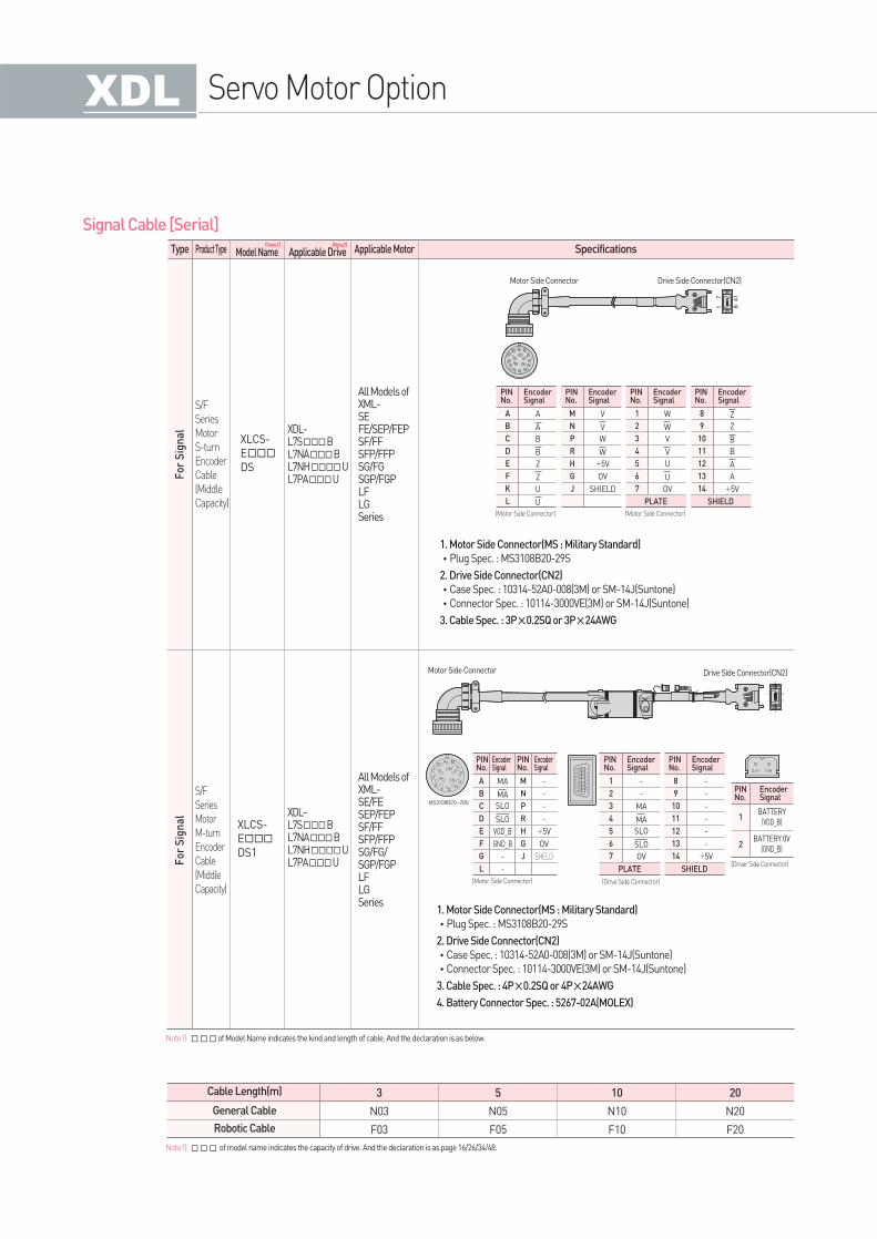
Type Product Type Applicable MotorApplicable DriveModel Name Specifications
Signal Cable [Serial]
Cable Length(m)
General Cable
Robotic Cable
3
N03
F03
5
N05
F05
10
N10
F10
20
N20
F20
S/F
Series
Motor
S-turn
Encoder
Cable
(Middle
Capacity)
XDL-L7SBL7NABL7NHUL7PAU
All Models ofXML-SEFE/SEP/FEPSF/FFSFP/FFPSG/FGSGP/FGPLFLGSeries
All Models ofXML-SE/FESEP/FEPSF/FFSFP/FFPSG/FG/SGP/FGPLFLGSeries
XDL-L7SBL7NABL7NHUL7PAU
XLCS-
EDS
XLCS-
EDS1
S/F
Series
Motor
M-turn
Encoder
Cable
(Middle
Capacity)
Note1)of Model Name indicates the kind and length of cable. And the declaration is as below.
Servo Motor Option
Motor Side Connector Drive Side Connector(CN2)
(Motor Side Connector) (Motor Side Connector)
1. Motor Side Connector(MS : Military Standard)
•Plug Spec. : MS3108B20-29S
2. Drive Side Connector(CN2)
•Case Spec. : 10314-52A0-008(3M) or SM-14J(Suntone)
•Connector Spec. : 10114-3000VE(3M) or SM-14J(Suntone)
3. Cable Spec. : 3P×0.2SQ or 3P×24AWG
PINNo.
A
B
C
D
E
F
K
L
A
A
B
B
Z
Z
U
U
EncoderSignal
PINNo.
M
N
P
R
H
G
J
V
V
W
W
+5V
OV
SHIELD
EncoderSignal
PINNo.
1
2
3
4
5
6
7
W
W
V
V
U
U
OV
EncoderSignal
PLATE
PINNo.
8
9
10
11
12
13
14
Z
Z
B
B
A
A
+5V
EncoderSignal
SHIELD
(Motor Side Connector)
PINNo.
BATTERY(VDD_B)
1
2BATTERY 0V
(GND_B)
EncoderSignal
(Driver Side Connector)
1. Motor Side Connector(MS : Military Standard)
•Plug Spec. : MS3108B20-29S
2. Drive Side Connector(CN2)
•Case Spec. : 10314-52A0-008(3M) or SM-14J(Suntone)
•Connector Spec. : 10114-3000VE(3M) or SM-14J(Suntone)
3. Cable Spec. : 4P×0.2SQ or 4P×24AWG
4. Battery Connector Spec. : 5267-02A(MOLEX)
PINNo.
1
2
3
4
5
6
7
-
-
MA
MA
SLO
SLO
OV
EncoderSignal
PLATE
PINNo.
8
9
10
11
12
13
14
-
-
-
-
-
-
+5V
EncoderSignal
SHIELD
PINNo.
PINNo.
A
B
C
D
E
F
G
L
M
N
P
R
H
G
J
MA
MA
SLO
SLO
VOD_B
GND_B
-
-
-
-
-
-
+5V
OV
SHELD
EncoderSignal
EncoderSignal
(Drive Side Connector)
Motor Side Connector Drive Side Connector(CN2)
Note1) of model name indicates the capacity of drive. And the declaration is as page 16/26/34/48.
(Note1) (Note2)
Fo
r S
ign
al
Fo
r S
ign
al
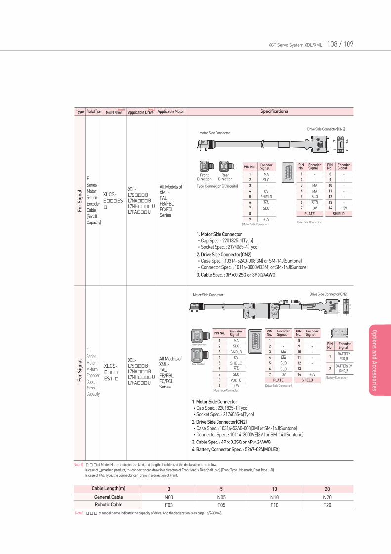
XGT Servo System(XDL/XML) 108 / 109
Op
tions an
d A
ccessories
Type Product Type Applicable MotorApplicable DriveModel Name Specifications
Cable Length(m)
General Cable
Robotic Cable
3
N03
F03
5
N05
F05
10
N10
F10
20
N20
F20
F
Series
Motor
S-turn
Encoder
Cable
(Small
Capacity)
XDL-L7SBL7NABL7NHUL7PAU
All Models ofXML-FALFB/FBLFC/FCLSeries
All Models ofXML-FALFB/FBLFC/FCLSeries
XDL-L7SBL7NABL7NHUL7PAU
XLCS-
EES-
XLCS-
EES1-
F
Series
Motor
M-turn
Encoder
Cable
(Small
Capacity)
Note1) of Model Name indicates the kind and length of cable. And the declaration is as below.
In case ofmarked product, the connector can draw in a direction of Front(load) / Rear(half load).(Front Type : No mark, Rear Type : -R)
In case of FAL Type, the connector can draw in a direction of Front.
1. Motor Side Connector
•Cap Spec. : 2201825-1(Tyco)
•Socket Spec. : 2174065-4(Tyco)
2. Drive Side Connector(CN2)
•Case Spec. : 10314-52A0-008(3M) or SM-14J(Suntone)
•Connector Spec. : 10114-3000VE(3M) or SM-14J(Suntone)
3. Cable Spec. : 3P×0.2SQ or 3P×24AWG
PIN No.
1
2
3
4
5
6
7
8
9
MA
SLO
-
OV
SHIELD
MA
SLO
-
+5V
EncoderSignal
PINNo.
1
2
3
4
5
6
7
-
-
MA
MA
SLO
SLO
OV
EncoderSignal
PLATE
PINNo.
8
9
10
11
12
13
14
-
-
-
-
-
-
+5V
EncoderSignal
SHIELD
Motor Side ConnectorDrive Side Connector(CN2)
Tyco Connector (7Circuits)
Front Direction
RearDirection
(Motor Side Connector)(Drive Side Connector)
1. Motor Side Connector
•Cap Spec. : 2201825-1(Tyco)
•Socket Spec. : 2174065-4(Tyco)
2. Drive Side Connector(CN2)
•Case Spec. : 10314-52A0-008(3M) or SM-14J(Suntone)
•Connector Spec. : 10114-3000VE(3M) or SM-14J(Suntone)
3. Cable Spec. : 4P×0.2SQ or 4P×24AWG
4. Battery Connector Spec. : 5267-02A(MOLEX)
PIN No.
1
2
3
4
5
6
7
8
9
MA
SLO
GND_B
OV
SHELD
MA
SLO
VOD_B
+5V
EncoderSignal
PINNo.
1
2
3
4
5
6
7
-
-
MA
MA
SLO
SLO
OV
EncoderSignal
PLATE
PINNo.
8
9
10
11
12
13
14
-
-
-
-
-
-
+5V
EncoderSignal
SHIELD
PINNo.
BATTERY(VDD_B)
1
2BATTERY 0V
(GND_B)
EncoderSignal
(Motor Side Connector)
(Driver Side Connector)
(Battery Connector)
Motor Side Connector Drive Side Connector(CN2)
Note1) of model name indicates the capacity of drive. And the declaration is as page 16/26/34/48.
(Note1) (Note2)
Fo
r S
ign
al
Fo
r S
ign
al
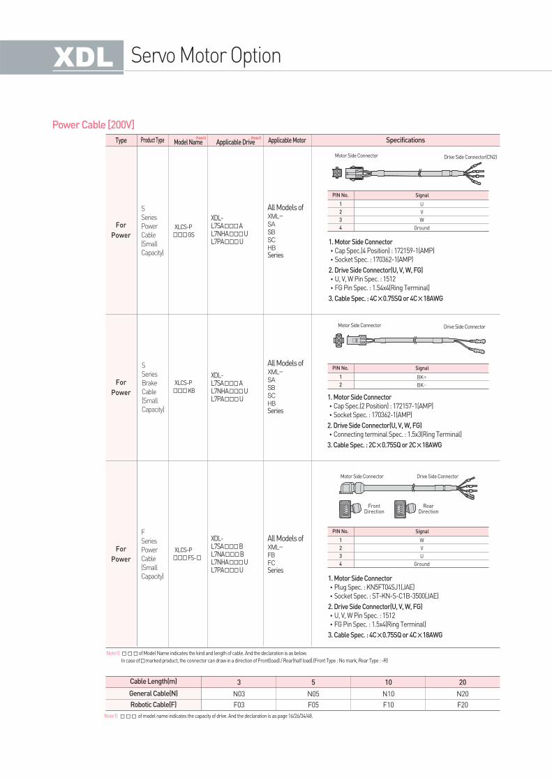
Power Cable [200V]
For
Power
For
Power
Type Product Type
S
Series
Power
Cable
(Small
Capacity)
S
Series
Brake
Cable
(Small
Capacity)
All Models ofXML-SASBSCHBSeries
All Models ofXML-SASBSCHBSeries
XDL-L7SAAL7NHAUL7PAU
XDL-L7SAAL7NHAUL7PAU
XLCS-P
GS
XLCS-P
KB
For
Power
F
Series
Power
Cable
(Small
Capacity)
All Models ofXML-FBFCSeries
XDL-L7SABL7NABL7NHAUL7PAU
XLCS-P
FS-
PIN No.
1
2
3
4
U
V
W
Ground
Signal
1. Motor Side Connector
•Cap Spec.(4 Position) : 172159-1(AMP)
•Socket Spec. : 170362-1(AMP)
2. Drive Side Connector(U, V, W, FG)
•U, V, W Pin Spec. : 1512
•FG Pin Spec. : 1.54x4(Ring Terminal)
3. Cable Spec. : 4C×0.75SQ or 4C×18AWG
PIN No.
1
2
BK+
BK-
Signal
1. Motor Side Connector
•Cap Spec.(2 Position) : 172157-1(AMP)
•Socket Spec. : 170362-1(AMP)
2. Drive Side Connector(U, V, W, FG)
•Connecting terminal Spec. : 1.5x3(Ring Terminal)
3. Cable Spec. : 2C×0.75SQ or 2C×18AWG
PIN No.
1
2
3
4
W
V
U
Ground
Signal
1. Motor Side Connector
•Plug Spec. : KN5FT04SJ1(JAE)
•Socket Spec. : ST-KN-S-C1B-3500(JAE)
2. Drive Side Connector(U, V, W, FG)
•U, V, W Pin Spec. : 1512
•FG Pin Spec. : 1.5x4(Ring Terminal)
3. Cable Spec. : 4C×0.75SQ or 4C×18AWG
Motor Side Connector Drive Side Connector(CN2)
Motor Side Connector Drive Side Connector
Motor Side Connector Drive Side Connector
Front Direction
RearDirection
Cable Length(m)
General Cable(N)
Robotic Cable(F)
3
N03
F03
5
N05
F05
10
N10
F10
20
N20
F20
Note1)of Model Name indicates the kind and length of cable. And the declaration is as below.
In case ofmarked product, the connector can draw in a direction of Front(load) / Rear(half load).(Front Type : No mark, Rear Type : -R)
Servo Motor Option
Note1) of model name indicates the capacity of drive. And the declaration is as page 16/26/34/48.
Applicable Drive Applicable MotorModel Name Specifications(Note1) (Note2)
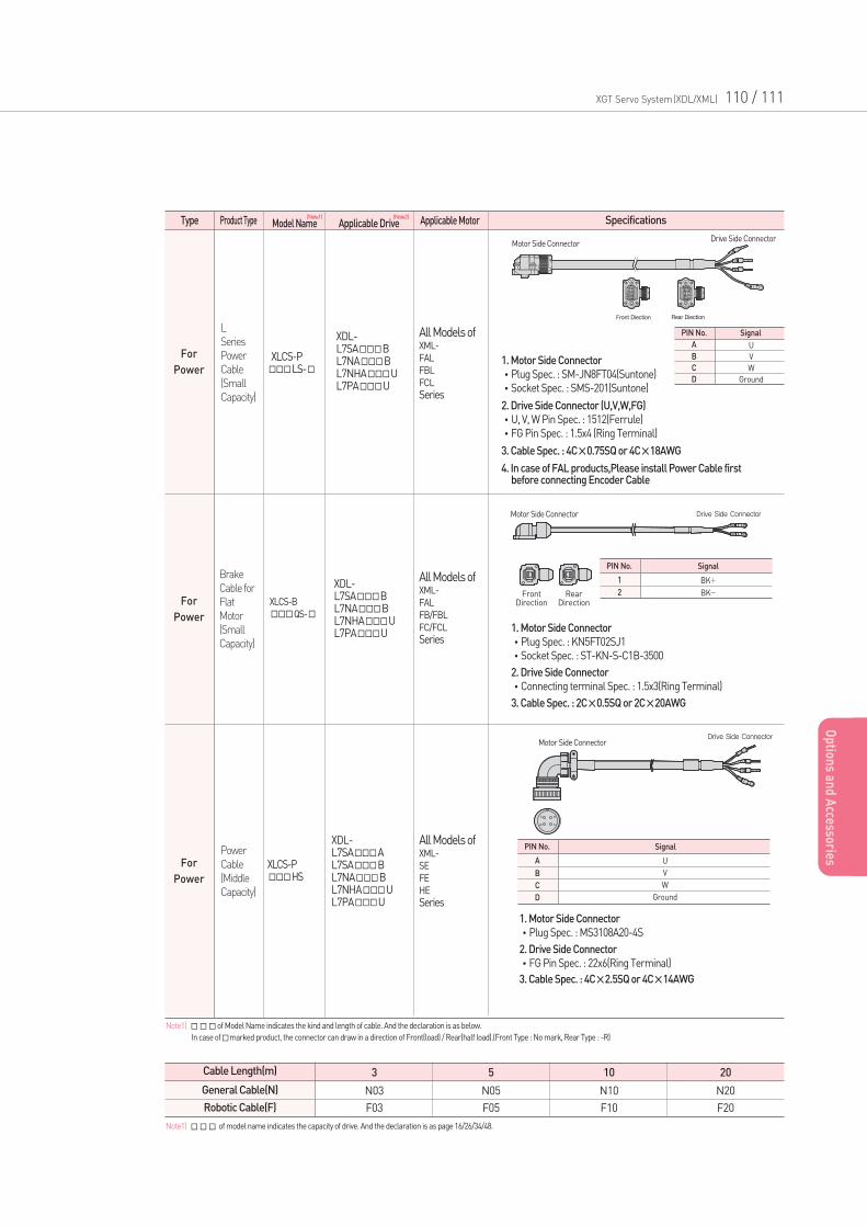
Applicable Drive Applicable MotorModel Name Specifications
PIN No.
1
2
BK+
BK-
Signal
1. Motor Side Connector
•Plug Spec. : KN5FT02SJ1
•Socket Spec. : ST-KN-S-C1B-3500
2. Drive Side Connector
•Connecting terminal Spec. : 1.5x3(Ring Terminal)
3. Cable Spec. : 2C×0.5SQ or 2C×20AWG
PIN No.
A
B
C
D
U
V
W
Ground
Signal
1. Motor Side Connector
•Plug Spec. : SM-JN8FT04(Suntone)
•Socket Spec. : SMS-201(Suntone)
2. Drive Side Connector (U,V,W,FG)
•U, V, W Pin Spec. : 1512(Ferrule)
•FG Pin Spec. : 1.5x4 (Ring Terminal)
3. Cable Spec. : 4C×0.75SQ or 4C×18AWG
4. In case of FAL products,Please install Power Cable first before connecting Encoder Cable
PIN No.
A
B
C
D
U
V
W
Ground
Signal
1. Motor Side Connector
•Plug Spec. : MS3108A20-4S
2. Drive Side Connector
•FG Pin Spec. : 22x6(Ring Terminal)
3. Cable Spec. : 4C×2.5SQ or 4C×14AWG
Motor Side ConnectorDrive Side Connector
Motor Side ConnectorDrive Side Connector
Motor Side Connector
Front Direction
Rear Direction
Drive Side Connector
For
Power
For
Power
Type Product Type
L
Series
Power
Cable
(Small
Capacity)
Brake
Cable for
Flat
Motor
(Small
Capacity)
All Models ofXML-
FAL
FBL
FCL
Series
All Models ofXML-
FAL
FB/FBL
FC/FCL
Series
XDL-L7SABL7NABL7NHAUL7PAU
XDL-L7SABL7NABL7NHAUL7PAU
XLCS-PLS-
XLCS-B
QS-
For
Power
Power
Cable
(Middle
Capacity)
All Models ofXML-
SE
FE
HE
Series
XDL-L7SAAL7SABL7NABL7NHAUL7PAU
XLCS-PHS
Cable Length(m)
General Cable(N)
Robotic Cable(F)
3
N03
F03
5
N05
F05
10
N10
F10
20
N20
F20
Note1)of Model Name indicates the kind and length of cable. And the declaration is as below.
In case ofmarked product, the connector can draw in a direction of Front(load) / Rear(half load).(Front Type : No mark, Rear Type : -R)
XGT Servo System(XDL/XML) 110 / 111
Op
tions an
d A
ccessories
Note1) of model name indicates the capacity of drive. And the declaration is as page 16/26/34/48.
(Note1) (Note2)
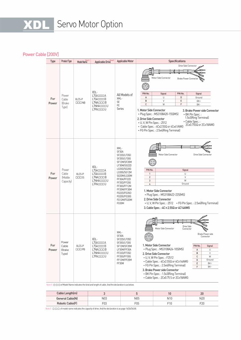
Power Cable [200V]
For
Power
For
Power
Type Product Type Applicable Drive Applicable MotorModel Name Specifications
Power
Cable
(Brake
Type)
Power
Cable
(Middle
Capacity)
All Models ofXML-
SE
FE
Series
XML-
SF30A
SF22D/LF35D
SF20G/LF30G
SF12M/SF20M
LF30M/SG22D
LG35D/SG20G
LG30G/SG12M
SG20M/LG30M
FF30A/FF22D
FF35D/FF20G
FF30G/FF12M
FF20M/FF30M
FG22D/FG35D
FG20G/FG30G
FG12M/FG20M
FG30M
XDL-L7SAAL7SABL7NABL7NHAUL7PAU
XDL-L7SAAL7SABL7NABL7NHAUL7PAU
XLCS-P
NB
XLCS-P
IS
For
Power
Power
Cable
(Brake
Type)
XML-
SF30A
SF22D/LF35D
SF20G/LF30G
SF12M/SF20M
LF30M/FF30A
FF22D/FF35D
FF20G/FF30G
FF12M/FF20M
FF30M
XDL-L7SAAL7SABL7NABL7NHAUL7PAU
XLCS-P
PB
Cable Length(m)
General Cable(N)
Robotic Cable(F)
3
N03
F03
5
N05
F05
10
N10
F10
20
N20
F20
Note1)of Model Name indicates the kind and length of cable. And the declaration is as below.
Servo Motor Option
PIN No. PIN No.
A
B
C
D
E
F
U
V
W
Ground
BK+
BK-
Signal Signal
1. Motor Side Connector
•Plug Spec. : MS3108A20-15S(MS)
2. Drive Side Connector
•U, V, W Pin Spec. : 2512
•Cable Spec. : 4Cx2.5SQ or 4Cx41AWG
•FG Pin Spec. : 2.5x4(Ring Terminal)
3. Brake Power side Connector
•BK Pin Spec. : 1.5x3(Ring Terminal)
•Cable Spec. : 2Cx0.75SQ or 2Cx18AWG
1. Motor Side Connector
•Plug Spec. : MS3108A24-10S(MS)
2. Drive Side Connector
•U, V, W Pin Spec. : F2512
•Cable Spec. : 4Cx2.5SQ or 4Cx14AWG
•FG Pin Spec. : 2.5x4(Ring Terminal)
3. Brake Power side Connector
•BK Pin Spec. : 1.5x3(Ring Terminal)
•Cable Spec. : 2Cx0.75 S or 2Cx18AWG
Motor Side Connector
Drive Side Connector
Brake Power Connector
Motor Side ConnectorDrive SideConnector
Brake Power sideConnector
PIN No.
A
B
C
D
E
F
U
V
W
Ground
BK+
BK-
Signal
PIN No.
1
2
3
4
U
V
W
Ground
Signal
1. Motor Side Connector
•Plug Spec. : MS3108A22-22S(MS)
2. Drive Side Connector
•U, V, W Pin Spec. : 2512 •FG Pin Spec. : 2.5x4(Ring Terminal)
3. Cable Spec. : 4C×2.5SQ or 4C14AWG
Motor Side Connector Drive Side Connector
Note1) of model name indicates the capacity of drive. And the declaration is as page 16/26/34/48.
(Note1) (Note2)
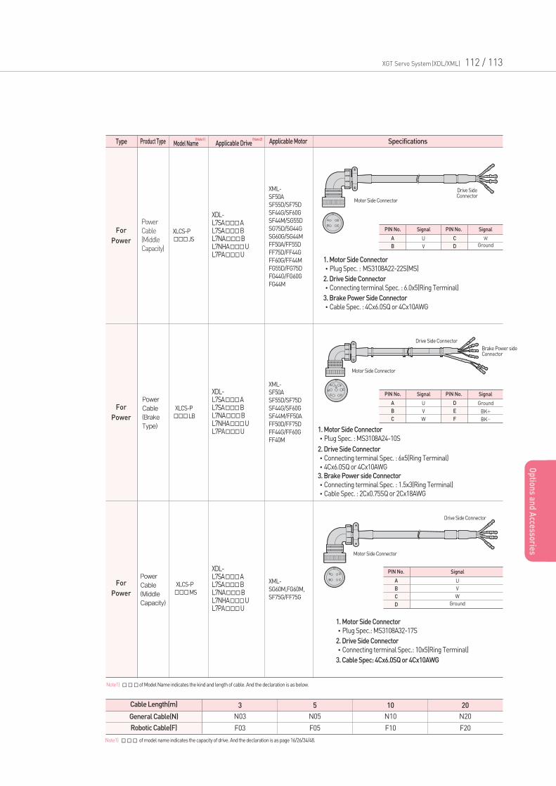
XGT Servo System(XDL/XML) 112 / 113
Op
tions an
d A
ccessories
For
Power
For
Power
Type Product Type Applicable Drive Applicable MotorModel Name Specifications
Power
Cable
(Middle
Capacity)
Power
Cable
(Brake
Type)
XML-
SF50A
SF55D/SF75D
SF44G/SF60G
SF44M/SG55D
SG75D/SG44G
SG60G/SG44M
FF50A/FF55D
FF75D/FF44G
FF60G/FF44M
FG55D/FG75D
FG44G/FG60G
FG44M
XML-
SF50A
SF55D/SF75D
SF44G/SF60G
SF44M/FF50A
FF50D/FF75D
FF44G/FF60G
FF40M
XDL-L7SAAL7SABL7NABL7NHAUL7PAU
XDL-L7SAAL7SABL7NABL7NHAUL7PAU
XLCS-P
JS
XLCS-P
LB
For
Power
Power
Cable
(Middle
Capacity)
XML-
SG60M,FG60M,
SF75G/FF75G
XDL-L7SAAL7SABL7NABL7NHAUL7PAU
XLCS-P
MS
Cable Length(m)
General Cable(N)
Robotic Cable(F)
3
N03
F03
5
N05
F05
10
N10
F10
20
N20
F20
Note1)of Model Name indicates the kind and length of cable. And the declaration is as below.
PIN No. PIN No.
A
B
C
D
U
V
W
Ground
SignalSignal
1. Motor Side Connector
•Plug Spec. : MS3108A22-22S(MS)
2. Drive Side Connector
•Connecting terminal Spec. : 6.0x5(Ring Terminal)
3. Brake Power Side Connector
•Cable Spec. : 4Cx6.0SQ or 4Cx10AWG
PIN No. PIN No.
A
B
C
D
E
F
U
V
W
Ground
BK+
BK-
SignalSignal
Motor Side Connector
Motor Side Connector
Motor Side Connector
Drive SideConnector
Drive Side Connector
Drive Side Connector
Brake Power sideConnector
1. Motor Side Connector
•Plug Spec. : MS3108A24-10S
2. Drive Side Connector
•Connecting terminal Spec. : 6x5(Ring Terminal)
•4Cx6.0SQ or 4Cx10AWG
3. Brake Power side Connector
•Connecting terminal Spec. : 1.5x3(Ring Terminal)
•Cable Spec. : 2Cx0.75SQ or 2Cx18AWG
Note1) of model name indicates the capacity of drive. And the declaration is as page 16/26/34/48.
PIN No.
A
B
C
D
U
V
W
Ground
Signal
1. Motor Side Connector
•Plug Spec.: MS3108A32-17S
2. Drive Side Connector
•Connecting terminal Spec.: 10x5(Ring Terminal)
3. Cable Spec: 4Cx6.0SQ or 4Cx10AWG
(Note1) (Note2)
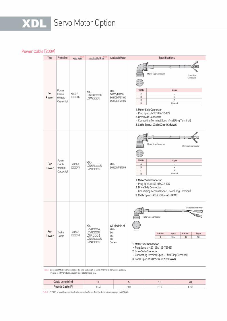
Servo Motor Option
Power Cable [200V]
For
Power
For
Power
Power
Cable
(Middle
Capacity)
Power
Cable
(Middle
Capacity)
XML-
SG85G/FG85G
SG110D/FG110D
SG110G/FG110G
XML-
SG150G/FG150G
XDL-L7NHAUL7PAU
XDL-L7NHAUL7PAU
XLCS-P
OS
XLCS-P
VS
For
Power
Brake
Cable
All Models ofXML-
SG
LG
FG
Series
XDL-L7SAAL7SABL7NABL7NHAUL7PAU
XLCS-P
SB
Cable Length(m)
Robotic Cable(F)
3
F03
5
F05
10
F10
20
F20
Note1)of Model Name indicates the kind and length of cable. And the declaration is as below.
In case of 400V products, you can use Robotic Cable only.
PIN No.
A
B
C
D
U
V
W
Ground
Signal
1. Motor Side Connector
•Plug Spec. : MS3108A 32-17S
2. Drive Side Connector
•Connecting Terminal Spec. : 14x6(Ring Terminal)
3. Cable Spec. : 4Cx2.5SQ or 4Cx3AWG
PIN No.
A
B
C
D
U
V
W
Ground
Signal
1. Motor Side Connector
•Plug Spec. : MS3108A 32-17S
2. Drive Side Connector
•Connecting Terminal Spec. : 14x6(Ring Terminal)
3. Cable Spec. : 4Cx16SQ or 4Cx5AWG
Motor Side ConnectorDrive SideConnector
Motor Side ConnectorDrive Side Connector
PIN No. PIN No.
A BBK+ BK-
SignalSignal
1. Motor Side Connector
•Plug Spec. : MS3108A 14S-7S(MS)
2. Drive Side Connector
•Connecting terminal Spec. : 1.5x3(Ring Terminal)
3. Cable Spec: 2Cx0.75SQ or 2Cx18AWG
Motor Side Connector
Drive Side Connector
Note1) of model name indicates the capacity of drive. And the declaration is as page 16/26/34/48.
Type Product Type Applicable Drive Applicable MotorModel Name Specifications(Note1) (Note2)
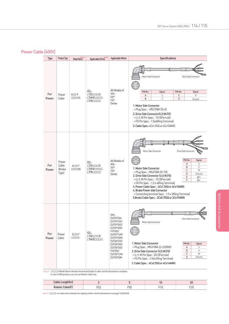
Op
tions an
d A
ccessories
XGT Servo System(XDL/XML) 114 / 115
Op
tions an
d A
ccessories
Power Cable [400V]
For
Power
For
Power
Power
Cable
Power
Cable
(Brake
Type)
All Models ofXML-
SEP
FEP
Series
All Models ofXML-
SEP
FEP
Series
XDL-L7SBBL7NHBUL7PBU
XDL-L7SBBL7NHBUL7PBU
XLCS-P
HS
XLCS-P
NB
For
Power
Power
Cable
XML-
[S/F]FP30A
[S/F]FP22D/
[S/F]FP35D/
[S/F]FP20G/
FFP30G/
[S/F]FP12M/
[S/F]FP20M/
[S/F]GP22D/
[S/F]GP35D/
[S/F]GP20G/
FGP30G/
[S/F]GP12M/
[S/F]GP20M
XDL-L7SBBL7NHBU
XLCS-P
IS
Cable Length(m)
Robotic Cable(F)
3
F03
5
F05
10
F10
20
F20
Note1) of Model Name indicates the kind and length of cable. And the declaration is as below.
In case of 400V products, you can use Robotic Cable only.
PIN No. PIN No.
A
B
C
D
U
V
W
Ground
Signal Signal
1. Motor Side Connector
•Plug Spec. : MS3108A 20-4S
2. Drive Side Connector(U,V,W,FG)
•U, V, W Pin Spec. : 1512(Ferrule)
•FG Pin Spec. : 1.5x4(Ring Terminal)
3. Cable Spec: 4Cx1.5SQ or 4Cx15AWG
Motor Side Connector Drive Side Connector
Motor Side Connector
Drive Side Connector
PIN No.
A
B
C
D
E
F
U
V
W
Ground
BK+
BK-
Signal
PIN No.
A
B
C
D
U
V
W
Ground
Signal1. Motor Side Connector
•Plug Spec. : MS3108A 22-22S(MS)
2. Drive Side Connector (U,V,W,FG)
•U, V, W Pin Spec : 2512(Ferrule)
•FG Pin Spec. : 2.5x4 (Ring Terminal)
3. Cable Spec. : 4Cx2.5SQ or 4Cx14AWG
1. Motor Side Connector
•Plug Spec. : MS3108A 20-15S
2. Drive Side Connector (U,V,W,FG)
•U, V, W Pin Spec. : 1512(Ferrule)
•FG Pin Spec. : 1.5 x 4(Ring Terminal)
3. Power Cable Spec. : 4Cx1.5SQ or 4Cx15AWG
4. Brake Power side Connector
•Connecting terminal Spec. : 1.5 x 3(Ring Terminal)
5.Brake Cable Spec. : 2Cx0.75SQ or 2Cx19AWG
Motor Side Connector Drive Side Connector
Note1) of model name indicates the capacity of drive. And the declaration is as page 16/26/34/48.
Type Product Type Applicable Drive Applicable MotorModel Name Specifications(Note1) (Note2)
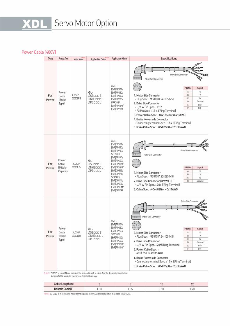
Servo Motor Option
Power Cable [400V]
For
Power
For
Power
Power
Cable
(Brake
Type)
Power
Cable
(Middle
Capacity)
XML-
[S/F]FP30A/
[S/F]FP22D/
[S/F]FP35D/
[S/F]FP20G/
FFP30G/
[S/F]FP12M/
[S/F]FP20M
XML-
[S/F]FP50A/
[S/F]FP55D/
[S/F]FP75D/
SFP30G/
[S/F]FP44G/
[S/F]FP60G/
[S/F]FP30M/
[S/F]FP44M/
[S/F]GP55D/
[S/F]GP75D/
SGP30G/
[S/F]GP44G/
[S/F]GP60G/
[S/F]GP30M/
[S/F]GP44M
XDL-L7SBBL7NHBUL7PBU
XDL-L7SBBL7NHBUL7PBU
XLCS-P
PB
XLCS-P
JS
For
Power
Power
Cable
(Brake
Type)
XML-
[S/F]FP50A/
[S/F]FP55D/
[S/F]FP75D/
SFP30G/
[S/F]FP44G/
[S/F]FP60G/
[S/F]FP30M/
[S/F]FP44M/
XDL-L7SBBL7NHBUL7PBU
XLCS-P
LB
Cable Length(m)
Robotic Cable(F)
3
F03
5
F05
10
F10
20
F20
Note1)of Model Name indicates the kind and length of cable. And the declaration is as below.
In case of 400V products, you can use Robotic Cable only.
Motor Side Connector
Drive Side Connector
PIN No.
A
B
C
D
U
V
W
Ground
Signal
1. Motor Side Connector
•Plug Spec. : MS3108A 22-22S(MS)
2. Drive Side Connector (U,V,W,FG)
•U, V, W Pin Spec. : 4.0x 5(Ring Terminal)
3. Cable Spec. : 4Cx4.0SQ or 4Cx11AWG
PIN No.
A
B
C
D
E
F
U
V
W
Ground
BK+
BK-
Signal
1. Motor Side Connector
•Plug Spec. : MS3108A 24-10S(MS)
2. Drive Side Connector
•U, V, W Pin Spec. : 1512
•FG Pin Spec. : 1.5 x 3(Ring Terminal)
3. Power Cable Spec. : 4Cx1.5SQ or 4Cx15AWG
4. Brake Power side Connector
•Connecting terminal Spec. : 1.5 x 3(Ring Terminal)
5.Brake Cable Spec. : 2Cx0.75SQ or 2Cx18AWG
PIN No.
A
B
C
D
E
F
U
V
W
Ground
BK+
BK-
Signal
1. Motor Side Connector
•Plug Spec. : MS3108A 24-10S(MS)
2. Drive Side Connector
•U, V, W Pin Spec. : 4.0X5(Ring Terminal)
3. Power Cable Spec. :
4Cx4.0SQ or 4Cx11AWG
4. Brake Power side Connector
•Connecting terminal Spec. : 1.5 x 3(Ring Terminal)
5.Brake Cable Spec. : 2Cx0.75SQ or 2Cx18AWG
Motor Side Connector
Motor Side Connector
Drive Side Connector
Drive Side Connector
Note1) of model name indicates the capacity of drive. And the declaration is as page 16/26/34/48.
Type Product Type Applicable Drive Applicable MotorModel Name Specifications(Note1) (Note2)
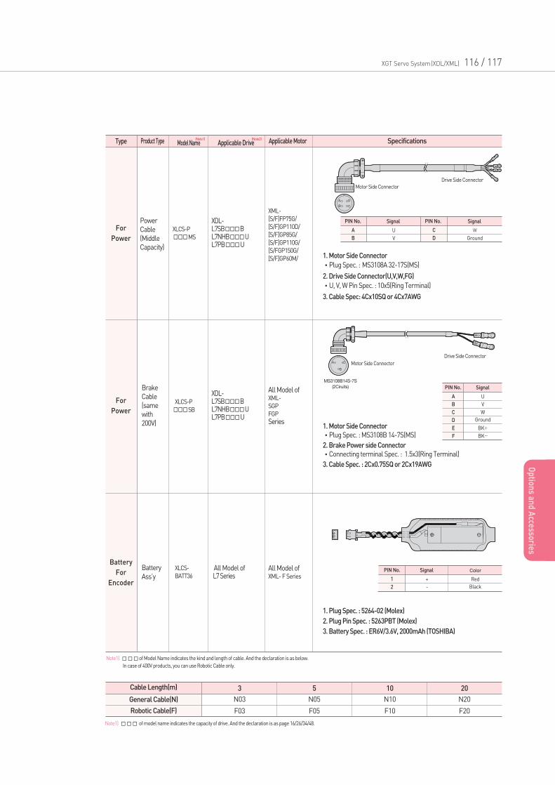
XGT Servo System(XDL/XML) 116 / 117
Op
tions an
d A
ccessories
For
Power
For
Power
Power
Cable
(Middle
Capacity)
Brake
Cable
(same
with
200V)
XML-
[S/F]FP75G/
[S/F]GP110D/
[S/F]GP85G/
[S/F]GP110G/
[S/FGP150G/
[S/F]GP60M/
All Model ofXML-
SGP
FGP
Series
XDL-L7SBBL7NHBUL7PBU
XDL-L7SBBL7NHBUL7PBU
XLCS-P
MS
XLCS-P
SB
Battery
For
Encoder
Battery
Ass’yAll Model ofXML- F Series
All Model ofL7 Series
XLCS-
BATT36
Note1)of Model Name indicates the kind and length of cable. And the declaration is as below.
In case of 400V products, you can use Robotic Cable only.
PIN No. PIN No.
A
B
C
D
U
V
W
Ground
Signal Signal
1. Motor Side Connector
•Plug Spec. : MS3108A 32-17S(MS)
2. Drive Side Connector(U,V,W,FG)
•U, V, W Pin Spec. : 10x5(Ring Terminal)
3. Cable Spec: 4Cx10SQ or 4Cx7AWG
Motor Side Connector
Drive Side Connector
PIN No.
A
B
C
D
E
F
U
V
W
Ground
BK+
BK-
Signal
1. Motor Side Connector
•Plug Spec. : MS3108B 14-7S(MS)
2. Brake Power side Connector
•Connecting terminal Spec. : 1.5x3(Ring Terminal)
3. Cable Spec. : 2Cx0.75SQ or 2Cx19AWG
1. Plug Spec. : 5264-02 (Molex)
2. Plug Pin Spec. : 5263PBT (Molex)
3. Battery Spec. : ER6V/3.6V, 2000mAh (TOSHIBA)
Motor Side Connector
Drive Side Connector
PIN No.
1
2
+
-
Red
Black
ColorSignal
Cable Length(m)
General Cable(N)
Robotic Cable(F)
3
N03
F03
5
N05
F05
10
N10
F10
20
N20
F20
Note1) of model name indicates the capacity of drive. And the declaration is as page 16/26/34/48.
Type Product Type Applicable Drive Applicable MotorModel Name Specifications(Note1) (Note2)
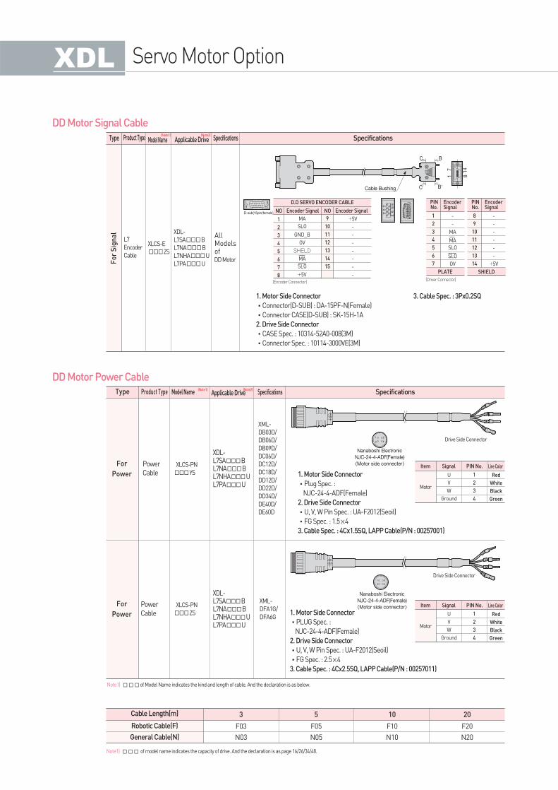
V
U
W
FG
1
3
2
4
V
U
W
FG
1
3
2
4
Servo Motor Option
DD Motor Signal Cable
DD Motor Power Cable
For
Power
Power
Cable
XML-
DB03D/
DB06D/
DB09D/
DC06D/
DC12D/
DC18D/
DD12D/
DD22D/
DD34D/
DE40D/
DE60D
XDL-L7SABL7NABL7NHAUL7PAU
XLCS-E
ZS
AllModelsofDD Motor
XDL-
L7SAB
L7NAB
L7NHAU
L7PAU
L7
Encoder
Cable
XLCS-PN
YS
For
Power
Power
Cable
XML-
DFA1G/
DFA6G
XDL-L7SABL7NABL7NHAUL7PAU
XLCS-PN
ZS
Note1)of Model Name indicates the kind and length of cable. And the declaration is as below.
PIN No. Line Color
1
2
3
4
U
V
W
Ground
Red
White
Black
Green
Motor
SignalItem
PIN No. Line Color
1
2
3
4
U
V
W
Ground
Red
White
Black
Green
Motor
SignalItem
1. Motor Side Connector
•Plug Spec. :
NJC-24-4-ADF(Female)
2. Drive Side Connector
•U, V, W Pin Spec. : UA-F2012(Seoil)
•FG Spec. : 1.5×4
3. Cable Spec. : 4Cx1.5SQ, LAPP Cable(P/N : 00257001)
1. Motor Side Connector
•PLUG Spec. :
NJC-24-4-ADF(Female)
2. Drive Side Connector
•U, V, W Pin Spec. : UA-F2012(Seoil)
•FG Spec. : 2.5×4
3. Cable Spec. : 4Cx2.5SQ, LAPP Cable(P/N : 00257011)
Drive Side Connector
Drive Side Connector
7
4
6
2
513
113
14
12
10
141312
7
1098
4
65
32
1
11
198
1 8
9 15
1. Motor Side Connector
•Connector(D-SUB) : DA-15PF-N(Female)
•Connector CASE(D-SUB) : SK-15H-1A
2. Drive Side Connector
•CASE Spec. : 10314-52A0-008(3M)
•Connector Spec. : 10114-3000VE(3M)
NO
1
2
3
4
5
6
7
8
9
10
11
12
13
14
15
MA
SLO
GND_B
OV
SHELD
MA
SLO
+5V
+5V
-
-
-
-
-
-
-
Encoder Signal
D.D SERVO ENCODER CABLE
NO Encoder Signal
PINNo.
1
2
3
4
5
6
7
-
-
MA
MA
SLO
SLO
OV
EncoderSignal
PLATE
PINNo.
8
9
10
11
12
13
14
-
-
-
-
-
-
+5V
EncoderSignal
SHIELD
(Encoder Connector)(Driver Connector)
Cable Length(m)
Robotic Cable(F)
General Cable(N)
3
F03
N03
5
F05
N05
10
F10
N10
20
F20
N20
Note1) of model name indicates the capacity of drive. And the declaration is as page 16/26/34/48.
Type Product Type Applicable Drive SpecificationsModel Name Specifications
Type Product Type Applicable Drive SpecificationsModel Name Specifications
3. Cable Spec. : 3Px0.2SQ
(Note1) (Note2)
(Note1) (Note2)
Fo
r S
ign
al
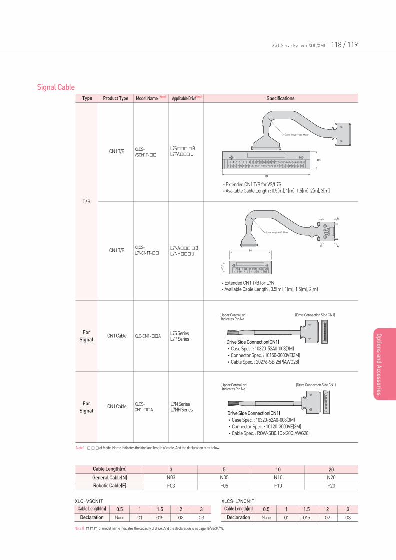
XGT Servo System(XDL/XML) 118 / 119
Op
tions an
d A
ccessories
Signal Cable
T/B
For
Signal
CN1 T/B
CN1 T/B
CN1 Cable
L7SBL7PAU
L7NABL7NHU
L7S SeriesL7P Series
XLCS-
VSCN1T-
XLCS-
L7NCN1T-
For
SignalCN1 Cable
XLC-CN1-A
XLCS-
CN1-AL7N SeriesL7NH Series
Note1)of Model Name indicates the kind and length of cable. And the declaration is as below.
Cable Length(m)
Declaration
0.5
None
1
01
2
02
1.5
015
3
03
XLC-VSCN1T
Cable Length(m)
Declaration
0.5
None
1
01
2
02
1.5
015
3
03
XLCS-L7NCN1T
Note1) of model name indicates the capacity of drive. And the declaration is as page 16/26/34/48.
Cable Length(m)
General Cable(N)
Robotic Cable(F)
3
N03
F03
5
N05
F05
10
N10
F10
20
N20
F20
•Extended CN1 T/B for VS/L7S
•Available Cable Length : 0.5[m], 1[m], 1.5[m], 2[m], 3[m]
•Extended CN1 T/B for L7N
•Available Cable Length : 0.5[m], 1[m], 1.5[m], 2[m]
Drive Side Connection(CN1)
•Case Spec. : 10320-52A0-008(3M)
•Connector Spec. : 10150-3000VE(3M)
•Cable Spec. : 20276-SB 25P(AWG28)
(Upper Controller)Indicates Pin No
(Drive Connection Side CN1)
Drive Side Connection(CN1)
•Case Spec. : 10320-52A0-008(3M)
•Connector Spec. : 10120-3000VE(3M)
•Cable Spec. : ROW-SB0.1C×20C(AWG28)
(Upper Controller)Indicates Pin No
(Drive Connection Side CN1)
Type Product Type Applicable DriveModel Name Specifications(Note1) (Note2)
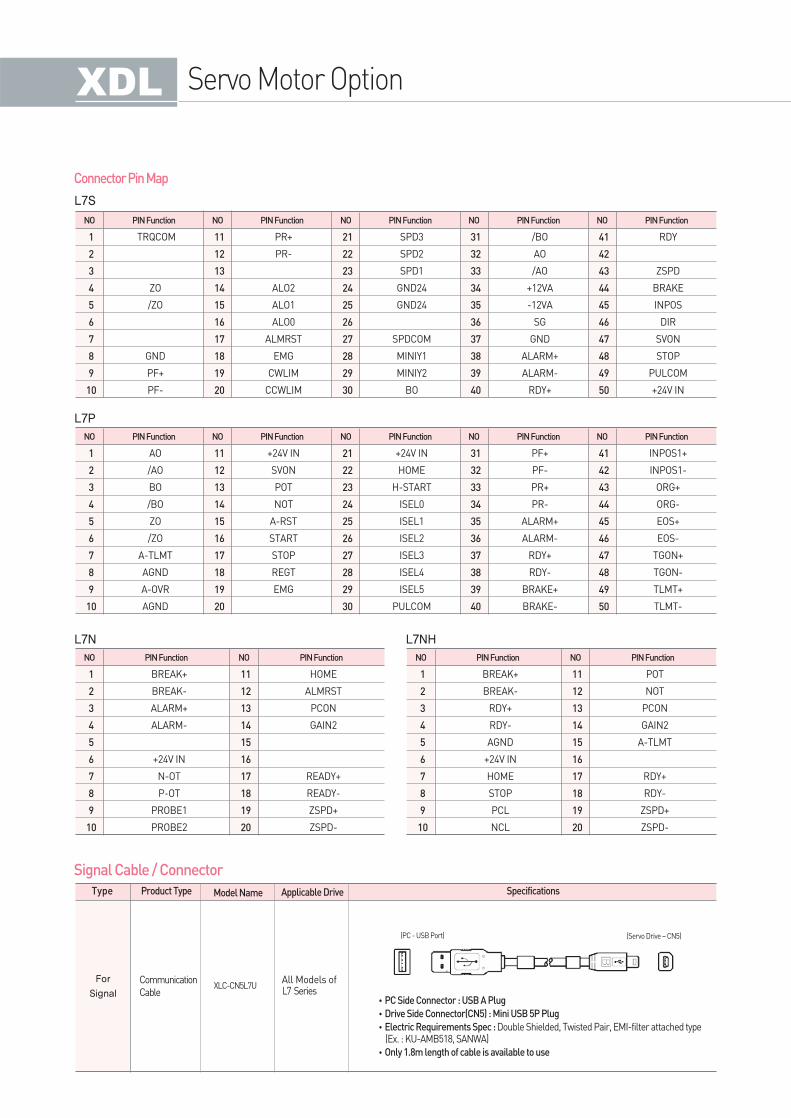
Connector Pin Map
Signal Cable / Connector
NO
L7S
L7P
PIN Function
TRQCOM
ZO
/ZO
GND
PF+
PF-
1
2
3
4
5
6
7
8
9
10
NO PIN Function
PR+
PR-
ALO2
ALO1
ALO0
ALMRST
EMG
CWLIM
CCWLIM
11
12
13
14
15
16
17
18
19
20
NO PIN Function
SPD3
SPD2
SPD1
GND24
GND24
SPDCOM
MINIY1
MINIY2
BO
21
22
23
24
25
26
27
28
29
30
NO PIN Function
/BO
AO
/AO
+12VA
-12VA
SG
GND
ALARM+
ALARM-
RDY+
31
32
33
34
35
36
37
38
39
40
NO PIN Function
RDY
ZSPD
BRAKE
INPOS
DIR
SVON
STOP
PULCOM
+24V IN
41
42
43
44
45
46
47
48
49
50
NO PIN Function
AO
/AO
BO
/BO
ZO
/ZO
A-TLMT
AGND
A-OVR
AGND
1
2
3
4
5
6
7
8
9
10
NO PIN Function
+24V IN
SVON
POT
NOT
A-RST
START
STOP
REGT
EMG
11
12
13
14
15
16
17
18
19
20
NO PIN Function
+24V IN
HOME
H-START
ISEL0
ISEL1
ISEL2
ISEL3
ISEL4
ISEL5
PULCOM
21
22
23
24
25
26
27
28
29
30
NO PIN Function
PF+
PF-
PR+
PR-
ALARM+
ALARM-
RDY+
RDY-
BRAKE+
BRAKE-
31
32
33
34
35
36
37
38
39
40
NO PIN Function
INPOS1+
INPOS1-
ORG+
ORG-
EOS+
EOS-
TGON+
TGON-
TLMT+
TLMT-
41
42
43
44
45
46
47
48
49
50
L7N
NO PIN Function
BREAK+
BREAK-
ALARM+
ALARM-
+24V IN
N-OT
P-OT
PROBE1
PROBE2
1
2
3
4
5
6
7
8
9
10
NO PIN Function
HOME
ALMRST
PCON
GAIN2
READY+
READY-
ZSPD+
ZSPD-
11
12
13
14
15
16
17
18
19
20
L7NH
NO PIN Function
BREAK+
BREAK-
RDY+
RDY-
AGND
+24V IN
HOME
STOP
PCL
NCL
1
2
3
4
5
6
7
8
9
10
NO PIN Function
POT
NOT
PCON
GAIN2
A-TLMT
RDY+
RDY-
ZSPD+
ZSPD-
11
12
13
14
15
16
17
18
19
20
•PC Side Connector : USB A Plug
•Drive Side Connector(CN5) : Mini USB 5P Plug
•Electric Requirements Spec : Double Shielded, Twisted Pair, EMI-filter attached type(Ex. : KU-AMB518, SANWA)
•Only 1.8m length of cable is available to use
Servo Motor Option
For
Signal
Communication
Cable
All Models ofL7 Series
XLC-CN5L7U
Type Product Type Applicable DriveModel Name Specifications
(PC - USB Port) (Servo Drive – CN5)
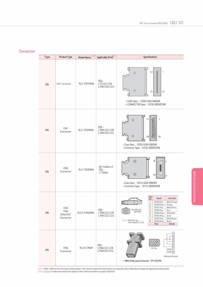
CN1 ConnectorXDL-L7SBL7NHU
XLC-CN1NNA
•CASE Spec. : 10350-52A0-008(3M)
•CONNECTOR Spec. : 10150-3000VE(3M)
XGT Servo System(XDL/XML) 120 / 121
Op
tions an
d A
ccessories
Connector
CN
CN
XDL-L7NABL7NHU
XLC-CN2NNA
CN
All models ofXDL-L7 Series
XDL-L7NABL7NHU
XLC-CN3NNA
CN
CN1
Connector
CN2
Connector
CN3
CN4
EtherCAT
Connector
CN6
Connector
XDL-L7NABL7NHU
XLCS-CN4NNA
Note1) EtherCAT use only 4 Signal(1, 2, 3, 6)
CNXLCS-CN6K
•MINI I/O By-pass Connector: 1971153(TE)
PINNo.
1
2
3
4
5
6
7
8
TX/RX0 Plus
TX/RX0 Minus
TX/RX1 Plus
TX/RX2 Plus
TX/RX2 Minus
TX/RX1 Minus
TX/RX3 Plus
TX/RX3 Minus
White/Orange
Orange
White/Green
Blue
White/Blue
Green
White/Brown
Brown
Signal
Plate SHILDE
Line Color
12345678
•Case Spec. : 10320-52A0-008(3M)
•Connector Spec. : 10120-3000VE(3M)
•Case Spec. : 10314-52A0-008(3M)
•Connector Spec. : 10114-3000VE(3M)
RJ-45PLUG(8-PINS)
OPEN
OPEN
Wireing Schmatic
Pin No.
Note1) 100W~7.5kW has the internal basic braking resistor. If the machine requires short deceleration time frequently, refer to table above and apply the appropriate braking resistor.
Note1) of model name indicates the capacity of drive. And the declaration is as page 16/26/34/48.
Type Product Type Applicable DriveModel Name Specifications(Note1) (Note2)
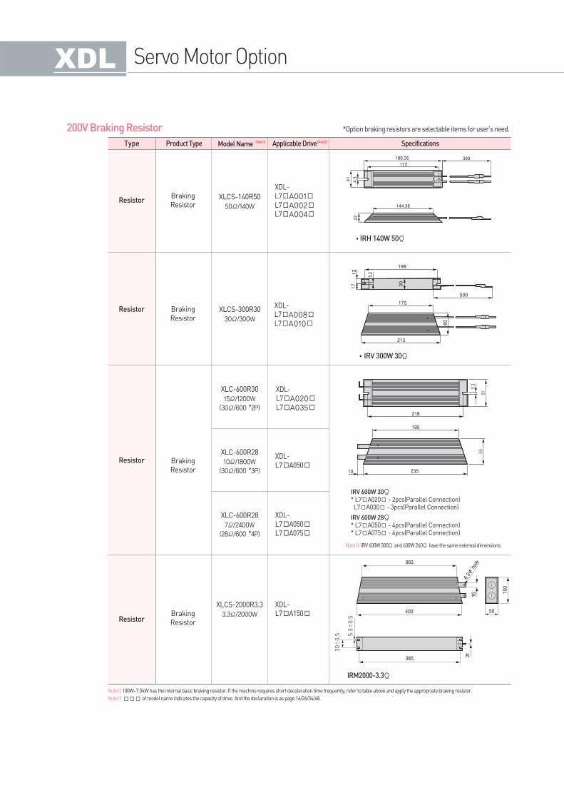
Resistor
200V Braking Resistor
Braking
Resistor
XDL-
L7A001L7A002L7A004
XLCS-140R50
50Ω/140W
•IRH 140W 50Ω
Resistor Braking
Resistor
XDL-
L7A008L7A010
XLCS-300R30
30Ω/300W
•IRV 300W 30Ω
IRV 600W 30Ω* L7A020 - 2pcs(Parallel Connection) L7A030 - 3pcs(Parallel Connection)
IRV 600W 28Ω* L7A050 - 4pcs(Parallel Connection) * L7A075 - 4pcs(Parallel Connection)
Note1) IRV 600W 300Ω and 600W 260Ωhave the same external dimensions.
IRM2000-3.3Ω
Resistor
Resistor
Braking
Resistor
Braking
Resistor
XDL-
L7A020L7A035
XDL-
L7A050
XDL-
L7A050L7A075
XDL-
L7A150
XLC-600R30
15Ω/1200W
(30Ω/600 *2P)
XLC-600R28
10Ω/1800W
(30Ω/600 *3P)
XLC-600R28
7Ω/2400W
(28Ω/600 *4P)
XLCS-2000R3.3
3.3Ω/2000W
188.35 300
172
41
4.3
22
144.36
17 30
60
13
198
500
175
215
5.3
218
195
23510
*Option braking resistors are selectable items for user’s need.
Note1) 100W~7.5kW has the internal basic braking resistor. If the machine requires short deceleration time frequently, refer to table above and apply the appropriate braking resistor.
Note1) of model name indicates the capacity of drive. And the declaration is as page 16/26/34/48.
Servo Motor Option
Type Product Type Applicable DriveModel Name Specifications(Note1) (Note2)
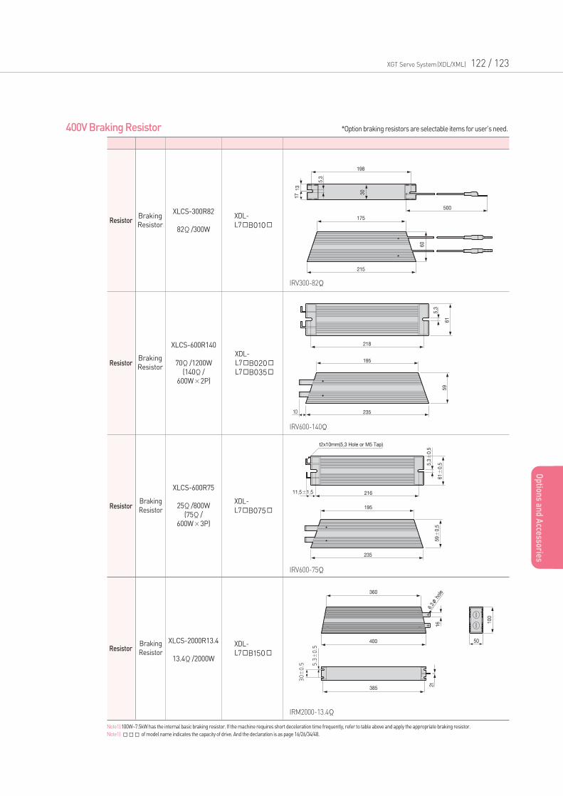
XGT Servo System(XDL/XML) 122 / 123
Op
tions an
d A
ccessories
Resistor
400V Braking Resistor
Braking
Resistor
XDL-
L7B010
XLCS-300R82
82Ω/300W
Resistor
Resistor
Braking
Resistor
XDL-
L7B020L7B035
XLCS-600R140
70Ω/1200W
(140Ω/
600W×2P)
ResistorBraking
Resistor
Braking
ResistorXDL-
L7B075
XDL-
L7B150
IRM2000-13.4Ω
IRV300-82Ω
IRV600-140Ω
IRV600-75Ω
XLCS-600R75
25Ω/800W
(75Ω/
600W×3P)
XLCS-2000R13.4
13.4Ω/2000W
*Option braking resistors are selectable items for user’s need.
Note1) 100W~7.5kW has the internal basic braking resistor. If the machine requires short deceleration time frequently, refer to table above and apply the appropriate braking resistor.
Note1) of model name indicates the capacity of drive. And the declaration is as page 16/26/34/48.
Application
Motion Module [EtherCAT] 126
Positioning Module(EtherCAT) 127
Positioning Module [APM] 128
Positioning Module [XPM] 129
XG-PM 130
Positioning Module/External Device Interface 131
Worldwide Network 140
XGT Servo System(XDL/XML) 124 / 125
Contents
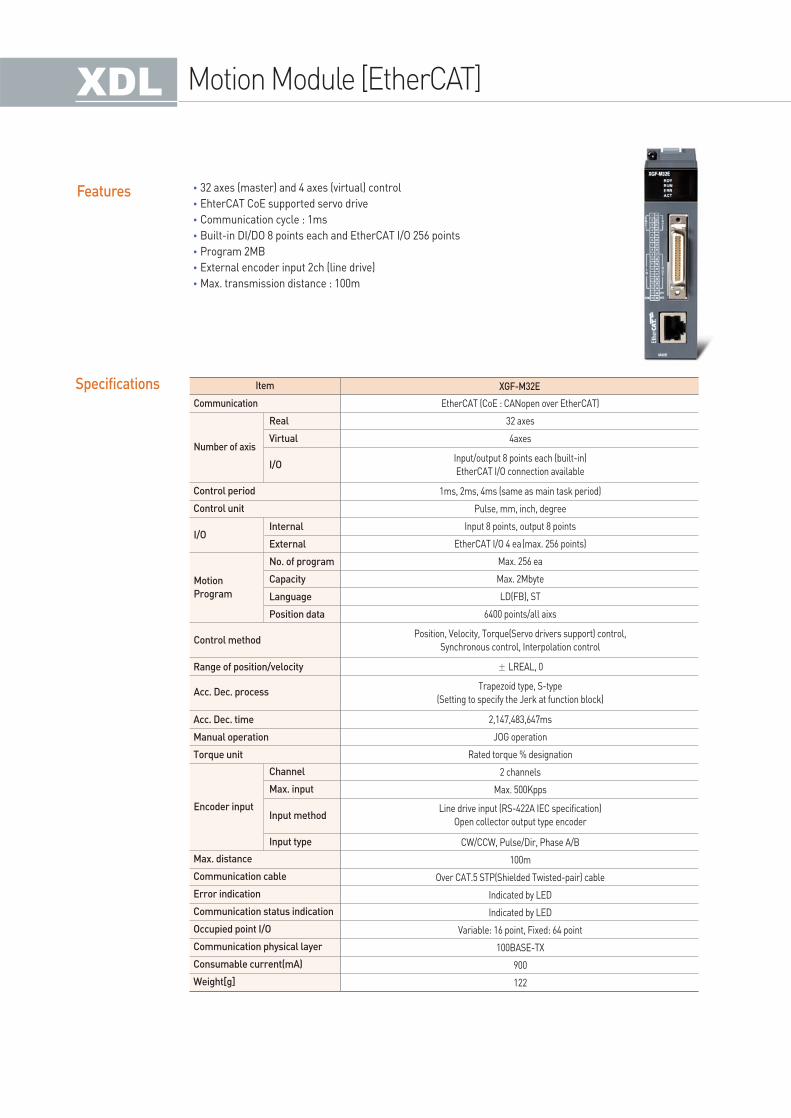
Features •32 axes (master) and 4 axes (virtual) control
•EhterCAT CoE supported servo drive
•Communication cycle : 1ms
•Built-in DI/DO 8 points each and EtherCAT I/O 256 points
•Program 2MB
•External encoder input 2ch (line drive)
•Max. transmission distance : 100m
XGF-M32E
Control period
Control unit
Range of position/velocity
Acc. Dec. time
Manual operation
Torque unit
Max. distance
Communication cable
Error indication
Communication status indication
Occupied point I/O
Communication physical layer
Consumable current(mA)
Weight[g]
Real
Virtual
I/O
Internal
External
No. of program
Capacity
Language
Position data
Channel
Max. input
Input type
Input method
EtherCAT (CoE : CANopen over EtherCAT)
32 axes
4axes
1ms, 2ms, 4ms (same as main task period)
Pulse, mm, inch, degree
Input 8 points, output 8 points
EtherCAT I/O 4 ea(max. 256 points)
Max. 256 ea
Max. 2Mbyte
LD(FB), ST
6400 points/all aixs
± LREAL, 0
2,147,483,647ms
JOG operation
Rated torque % designation
2 channels
Max. 500Kpps
CW/CCW, Pulse/Dir, Phase A/B
100m
Over CAT.5 STP(Shielded Twisted-pair) cable
Indicated by LED
Indicated by LED
Variable: 16 point, Fixed: 64 point
100BASE-TX
900
122
Input/output 8 points each (built-in)
EtherCAT I/O connection available
Position, Velocity, Torque(Servo drivers support) control,
Synchronous control, Interpolation control
Trapezoid type, S-type
(Setting to specify the Jerk at function block)
Line drive input (RS-422A IEC specification)
Open collector output type encoder
ItemSpecificationsCommunication
Number of axis
Control method
Acc. Dec. process
Encoder input
I/O
Motion
Program
Motion Module [EtherCAT]
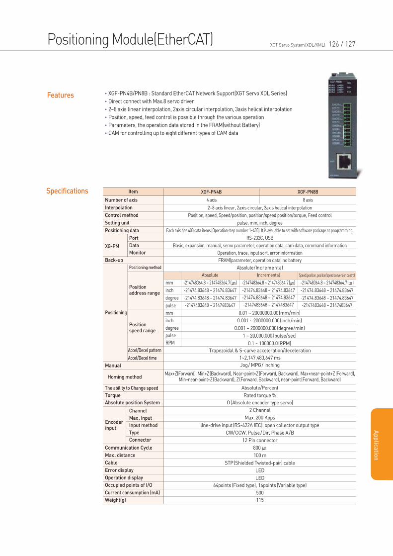
Features •XGF-PN4B/PN8B : Standard EtherCAT Network Support(XGT Servo XDL Series)
•Direct connect with Max.8 servo driver
•2~8 axis linear interpolation, 2axis circular interpolation, 3axis helical interpolation
•Position, speed, feed control is possible through the various operation
•Parameters, the operation data stored in the FRAM(without Battery)
•CAM for controlling up to eight different types of CAM data
XGF-PN8BXGF-PN4B
Number of axis
Interpolation
Control method
Setting unit
Positioning data
Manual
The ability to Change speed
Torque
Absolute position System
Homing method
Port
Data
Monitor
Positioning method
Back-up
Accel/Decel pattern
Accel/Decel time
2~8 axis linear, 2axis circular, 3axis helical interpolation
Position, speed, Speed/position, position/speed position/torque, Feed control
pulse, mm, inch, degree
Each axis has 400 data items (Operation step number 1~400). It is available to set with software package or programming.
RS-232C, USB
Basic, expansion, manual, servo parameter, operation data, cam data, command information
Operation, trace, input sort, error information
FRAM(parameter, operation data) no battery
Absolute/Incremental
Trapezoidal & S-curve acceleration/deceleration
1~2,147,483,647 ms
Jog/ MPG/ inching
Absolute/Percent
Rated torque %
O (Absolute encoder type servo)
2 Channel
Max. 200 Kpps
line-drive input(RS-422A IEC), open collector output type
CW/CCW, Pulse/Dir, Phase A/B
12 Pin connector
800
100 m
STP(Shielded Twisted-pair) cable
LED
LED
64points (Fixed type), 16points (Variable type)
500
115
4 axis 8 axis
ItemSpecifications
Positioning
Encoderinput
XG-PM
Position address range
Position speed range
Max+Z(Forward), Min+Z(Backward), Near-point+Z(Forward, Backward), Max+near-point+Z(Forward), Min+near-point+Z(Backward), Z(Forward, Backward), near-point(Forward, Backward)
Channel
Max. Input
Input method
Type
Connector
Communication Cycle
Max. distance
Cable
Error display
Operation display
Occupied points of I/O
Current consumption (mA)
Weight(g)
mm
inch
degree
pulse
mm
inch
degree
pulse
RPM
Absolute
-214748364.8 ~ 214748364.7()
-21474.83648 ~ 21474.83647
-21474.83648 ~ 21474.83647
-2147483648 ~ 2147483647
Incremental
-214748364.8 ~ 214748364.7()
-21474.83648 ~ 21474.83647
-21474.83648 ~ 21474.83647
-2147483648 ~ 2147483647
Speed/position, position/speed conversion control
-214748364.8 ~ 214748364.7()
-21474.83648 ~ 21474.83647
-21474.83648 ~ 21474.83647
-2147483648 ~ 2147483647
0.01 ~ 20000000.00(mm/min)
0.001 ~ 2000000.000(inch/min)
0.001 ~ 2000000.000(degree/min)
1 ~ 20,000,000 (pulse/sec)
0.1 ~ 100000.0(RPM)
Positioning Module(EtherCAT) XGT Servo System(XDL/XML) 126 / 127
Ap
plica
tion
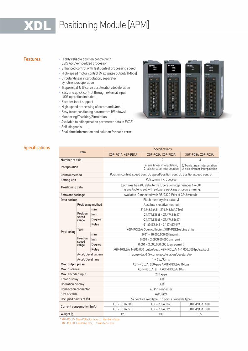
Features
Specifications
•Highly reliable position control with LSIS ASIC-embedded processor
•Enhanced control with fast control processing speed
•High-speed motor control (Max. pulse output: 1Mbps)
•Circular/linear interpolation, separate/synchronous operation
•Trapezoidal & S-curve acceleration/deceleration
•Easy and quick control through external input (JOG operation included)
•Encoder input support
•High-speed processing of command (4ms)
•Easy to set positioning parameters (Windows)
•Monitoring/Tracking/Simulation
•Available to edit operation parameter data in EXCEL
•Self-diagnosis
•Real-time information and solution for each error
* XGF-POO: Open Collector type, : Number of axis
XGF-PDD: Line Drive type, : Number of axis
Item
Positioning method
2-axis linear interpolation, 2-axis circular interpolation
2/3-axis linear interpolation, 2-axis circular interpolation
Accel/Decel pattern
Accel/Decel time
Type
Positionspeedrange
Positionspeedrange
Positioning
Positioning data
Specifications
XGF-PO1A, XGF-PD1A
1 2
Position control, speed control, speed/position control, position/speed control
Pulse, mm, inch, degree
Each axis has 400 data items (Operation step number 1~400).
It is available to set with software package or programming.
Available (Connected with RS-232C Port of CPU module)
Flash memory (No battery)
Absolute / relative method
-214,748,364.8 ~ 214,748,364.7 ()
-21,474.83648 ~ 21,474.83647
-21,474.83648 ~ 21,474.83647
-21,47483,648 ~ 2,147,483,647
XGF-POA: Open collector, XGF-PDA: Line driver
0.01 ~ 20,000,000.00 (/min)
0.001 ~ 2,0000,00.000 (inch/min)
0.001 ~ 2,000,000.000 (degree/min)
XGF-POA: 1~200,000 (pulse/sec), XGF-PDA: 1~1,000,000 (pulse/sec)
Trapezoidal & S-curve acceleration/deceleration
1 ~ 65,535ms
XGF-POA: 200kpps / XGF-PDA: 1Mpps
XGF-POA: 2m / XGF-PDA: 10m
200 kpps
LED
LED
40 Pin connector
AWG #24
64 points (Fixed type), 16 points (Variable type)
3
XGF-PO2A, XGF-PD2A XGF-PO3A, XGF-PD3A
Number of axis
Interpolation
Control method
Setting unit
Software package
Data backup
Max. output pulse
Max. distance
Max. encoder input
Error display
Operation display
Connection connector
Size of cable
Occupied points of I/O
Current consumption (mA)
Weight (g)
mm
Inch
Degree
Pulse
mm
Inch
Degree
Pulse
XGF-PO1A: 340
XGF-PD1A: 510
120
XGF-PO2A: 360
XGF-PD2A: 790
130
XGF-PO3A: 400
XGF-PD3A: 860
135
Positioning Module [APM]
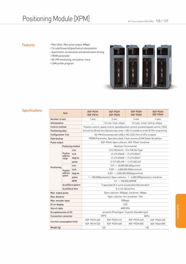
Features •Max 4Axis, Max pulse output 4Mpps
•Circular/linear/ellipse/helical interpolation
•Asymmetric acceleration and deceleration driving
•FRAM parameter
•XG-PM monitoring, simulation, trace
•CAM profile program
XGF-PO1H
XGF-PD1H
XGF-PO2H
XGF-PD2H
XGF-PO3H
XGF-PD3H
XGF-PO4HXGF-PD4H
XGF-PO1H:400
XGF-PD1H:520
XGF-PO2H:410
XGF-PD2H:600
XGF-PO3H:420
XGF-PD3H:850
XGF-PO4H:430
XGF-PD4H:890
Number of axis
Interpolation
Control method
Positioning data
Configuration Tool
Data backup
Pulse output
Max. output pulse
Max. distance
Max. encoder input
Error display
Size of cable
Occupied points of I/O
Connection connector
Current consumption (mA)
Weight (g)
mm
inch
degree
pulse
mm
inch
degree
pulse
RPM
Positioning method
Accel/Decel pattern
Accel/Decel time
Position control, speed control, speed/position control, position/speed control, FEED
XG-PM (Connected with USB or RS-232C Port of CPU module)
FRAM(Parameter, Operation data), Flash memory (CAM Data), No battery
XGF-POxH: Open collector, XGF-PDxH: linedriver
Absolute / Incremental
-214,748,364.8∼ 214,748,364.7()
-21,474.83648 ∼ 21,474.83647
-21,474.83648 ∼ 21,474.83647
-2,147,483,648 ∼ 2,147,483,647
0.01 ∼ 20,000,000.00( /min)
0.001 ∼ 2,000,000.000(inch/min)
0.001 ∼ 2,000,000.000(degree/min)
1 ~ 500,000(pulse/sec): Open collector, 1 ~ 4,000,000(pulse/sec): linedriver
0.1 ∼ 100,000.0(RPM)
Trapezoidal & S-curve acceleration/deceleration
0~2,147,483,647ms
Open collector: 500kpps, linedriver: 4Mpps
Open collector: 5m, linedriver: 10m
500kpps
LED
AWG #24
64 points (Fixed type), 16 points (Variable type)
1 axis 2 axis 3 axis 4 axis
40Pin 80Pin
120 130
- Circular, linear, ellipse
Each axis has 400 data items (Operation step number 1~400). It is available to set with XG-PM or programming.
Circular, linear, helical, ellipse
ItemSpecifications
Positioning
Positionaddressrange
Positionaddressspeed
Positioning Module [XPM] XGT Servo System(XDL/XML) 128 / 129
Ap
plica
tion
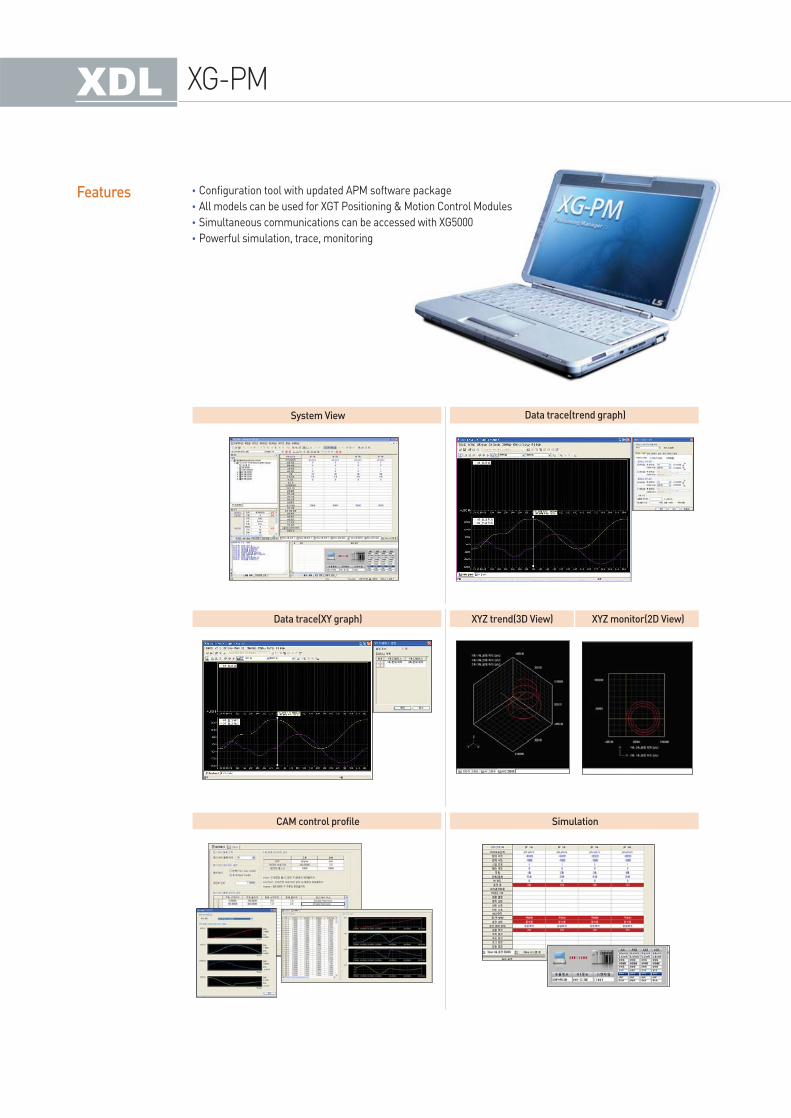
Features •Configuration tool with updated APM software package
•All models can be used for XGT Positioning & Motion Control Modules
•Simultaneous communications can be accessed with XG5000
•Powerful simulation, trace, monitoring
System View Data trace(trend graph)
Data trace(XY graph)
CAM control profile Simulation
XYZ trend(3D View) XYZ monitor(2D View)
XG-PM
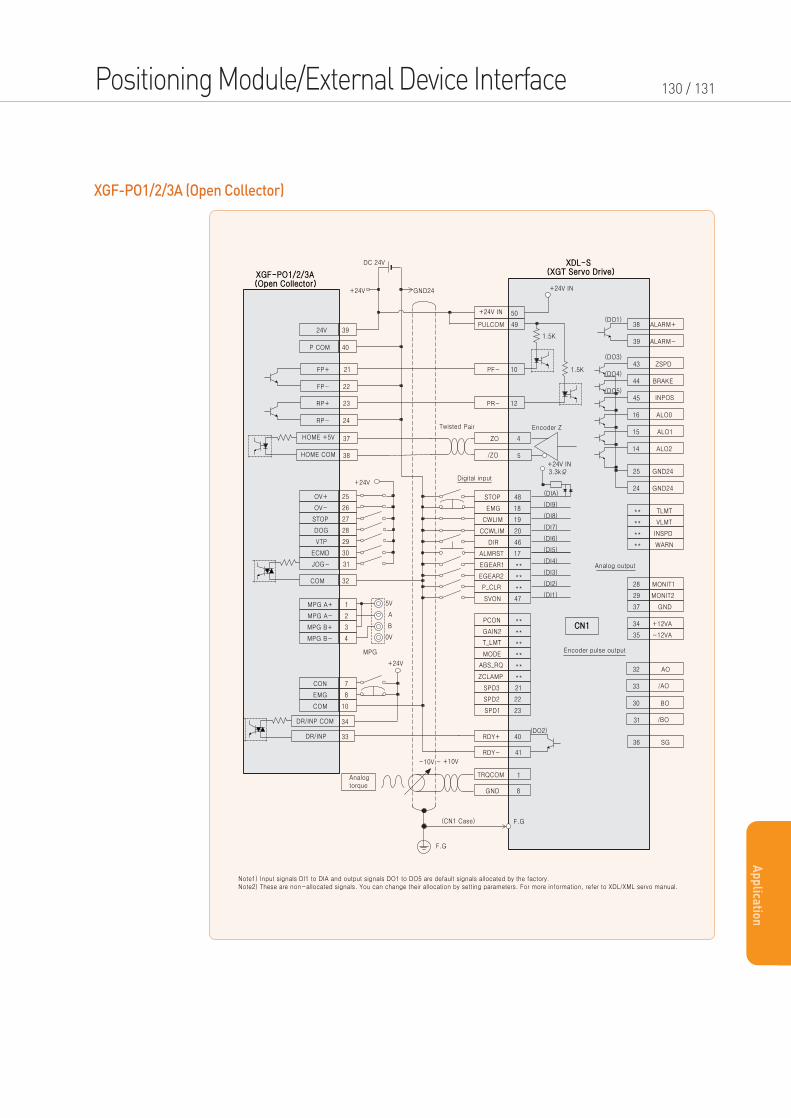
XGF-PO1/2/3A (Open Collector)
Positioning Module/External Device Interface 130 / 131
Ap
plica
tion
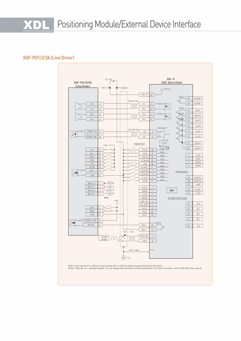
XGF-PD1/2/3A (Line Driver)
Positioning Module/External Device Interface
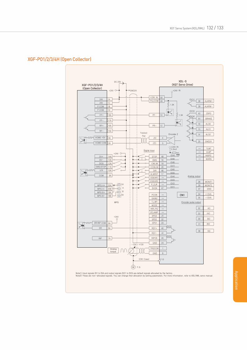
XGF-PO1/2/3/4H (Open Collector)
XGT Servo System(XDL/XML) 132 / 133
Ap
plica
tion
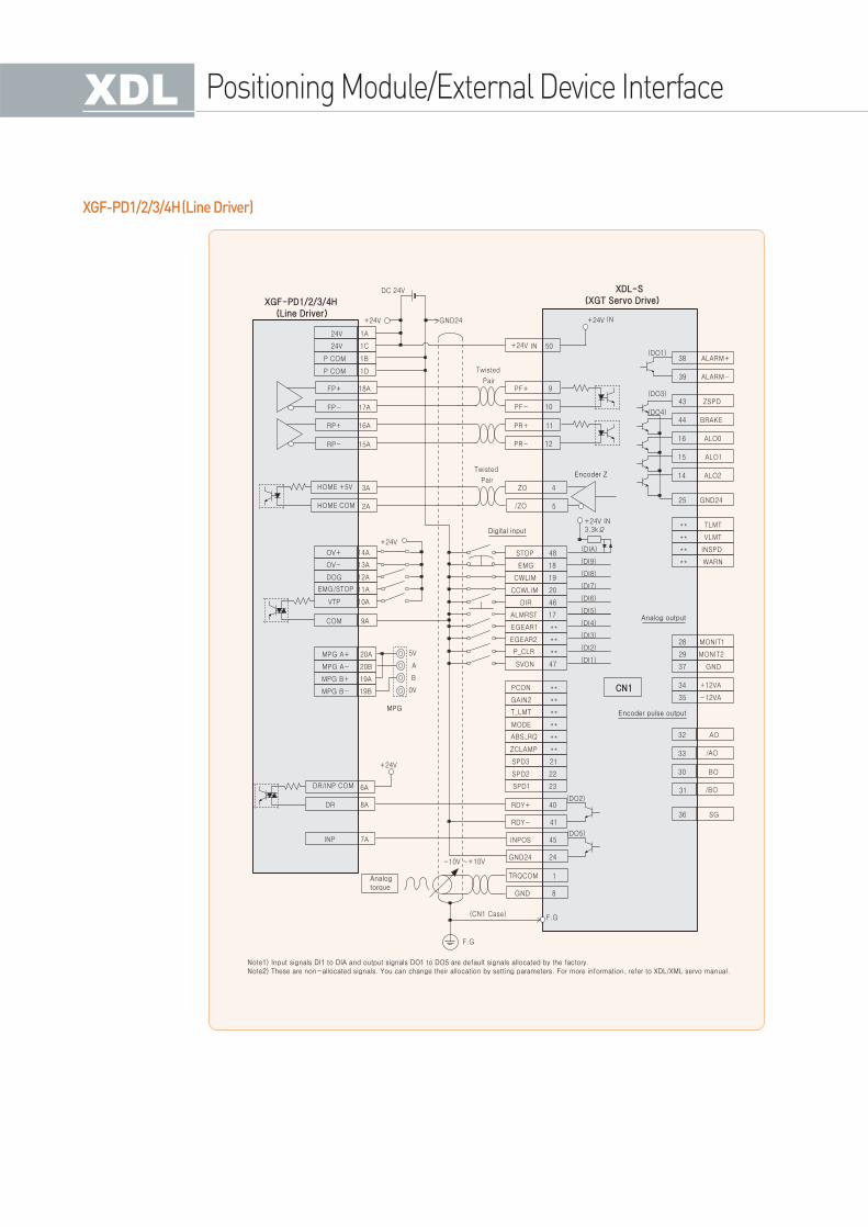
XGF-PD1/2/3/4H(Line Driver)
Positioning Module/External Device Interface
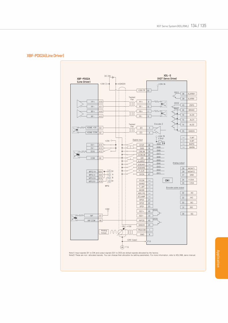
XBF-PD02A(Line Driver)
XGT Servo System(XDL/XML) 134 / 135
Ap
plica
tion
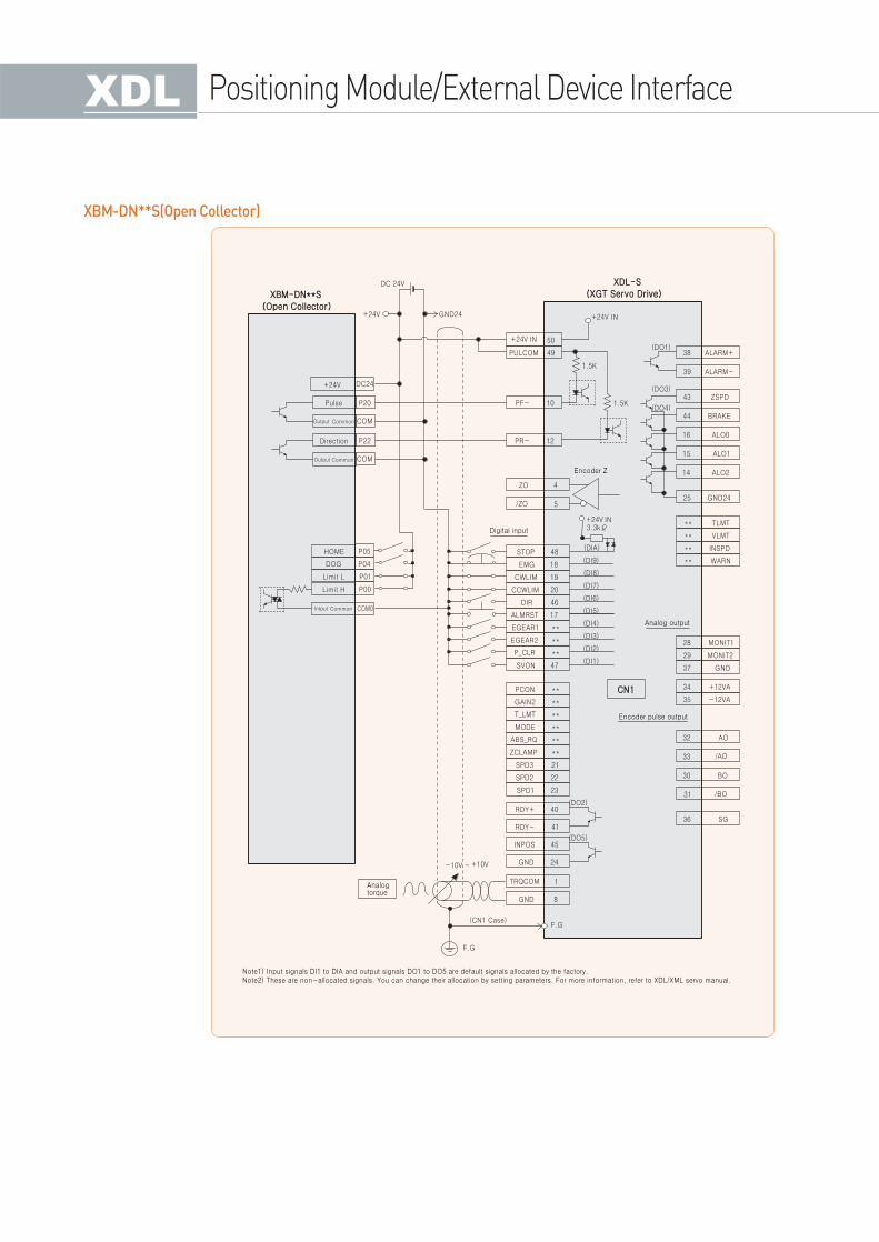
XBM-DN**S(Open Collector)
Positioning Module/External Device Interface
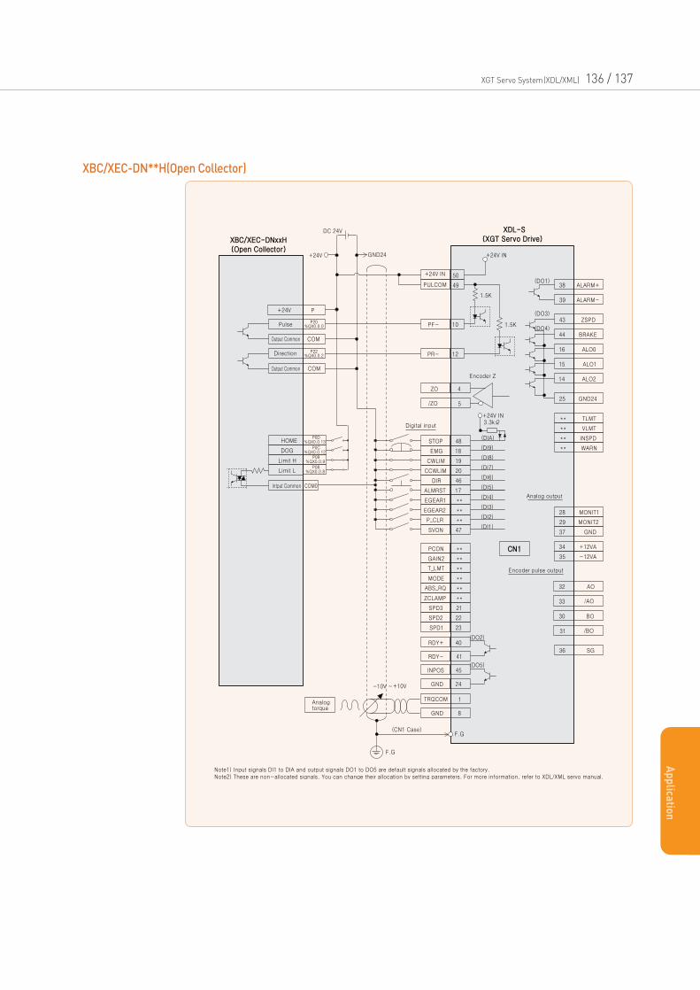
XBC/XEC-DN**H(Open Collector)
XGT Servo System(XDL/XML) 136 / 137
Ap
plica
tion
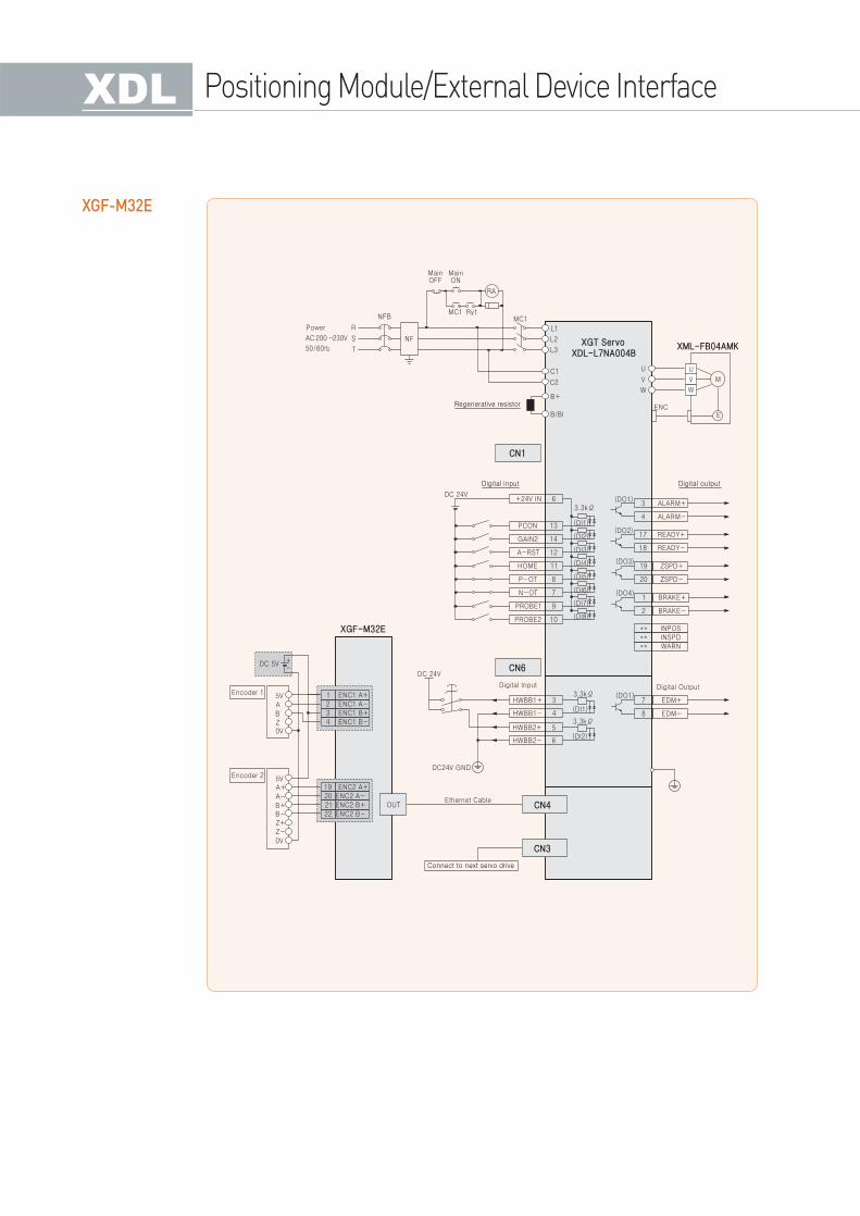
XGF-M32E
Positioning Module/External Device Interface
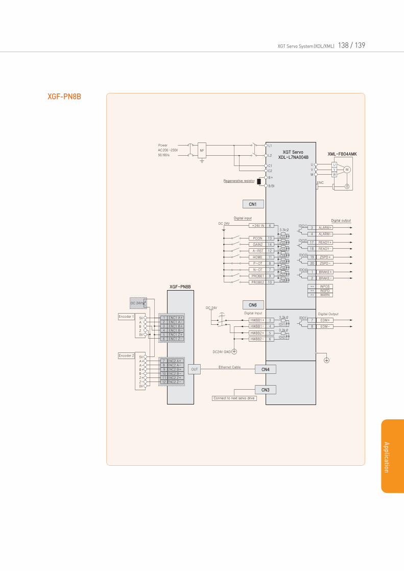
XGF-PN8B
XGT Servo System(XDL/XML) 138 / 139
Ap
plica
tion
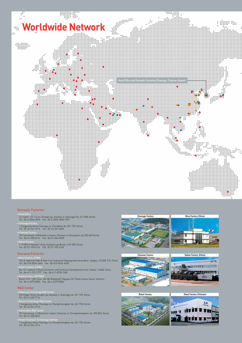
Worldwide Network
Head OfficeLS Tower, 127, LS-ro, Dongan-gu, Anyang-si, Gyeonggi-Do, 431-848, KoreaTel : 82-2-2034-4870 Fax : 82-2-2034-3660-7021
Cheongju Factory1 Songjeong-dong, Cheongju-si, Chungbuk-do, 361-720, KoreaTel : 82-43-261-6114 Fax : 82-43-261-6602
Cheonan Factory181 Samseong-ri,Mokcheon-myeon, Cheonan-si Chungnam-do,330-840 KoreaTel : 82-41-550-8114 Fax : 82-41-566-8408
Busan Factory 1-19 Block Hwajeon-dong, Gangseo-gu,Busan, 618-280, KoreaTel : 82-51-795-6114 Fax : 82-51-795-6169
Domestic Factories
Advanced Technology R&D Center533 Hogye-dong, Dongan-gu, Anyang-si, Gyeonggi-do, 431-749, KoreaTel : 82-31-450-7114
Electro Technology R&D Center1 Songjeong-dong, Cheongju-si, Chungcheongbuk-do, 361-720, KoreaTel : 82-43-261-6114
Automation R&D Center181 Samseong-ri, Mokcheon-myeon, Cheonan-si, Chungcheongnam-do, 330-840, KoreaTel : 82-41-550-8272
Power Testing & Technology Institute1 Songjeong-dong, Cheongju-si, Chungcheongbuk-do, 361-720, KoreaTel : 82-43-261-6114
R&D Center
Wuxi Factory, CHINA 102-A. National High & New Tech Industrial Development Area.Wuxi. Jiangsu. 214028. P.R. ChinaTel : 86-510-8534-6666 Fax : 86-510-8534-4078
Dalian Factory, CHINANo. 15. Liaohexi 3-Road. Economic and Technical Development zone. Dalian 116600. ChinaTel : 86-411-273-7777 Fax : 86-411-8730-7560
Hanoi Factory, VIETNAMRoom 1311, 13th Floor, M3-M4 Building91 Nguyen Chi Thanh street, Hanoi, Vietnam.Tel : 84-4-6275-8055 Fax : 84-4-6275-8056
Overseas Factories
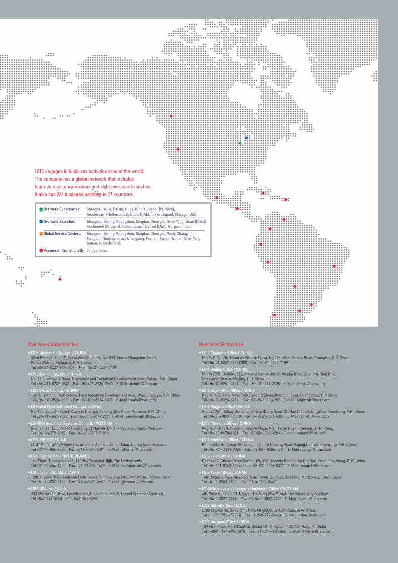
LSIS(Shanghai) Co., Ltd. / CHINA
32nd Room 1~4, 32/F, Great Wall Building, No.3000 North Zhongshan Road,
Putuo District, Shanghai, P.R. China
Tel : 86-21-5237-9977(609) Fax : 86-21-5237-7189
LSIS(Dalian) Co., Ltd. / CHINA
No. 15, Liaohexi 3-Road, Economic and Technical Development zone, Dalian, P.R. China
Tel : 86-411-8731-7542 Fax : 86-411-8730-7560 E-Mail : [email protected]
LSIS(Wuxi) Co., Ltd. / CHINA
102-A, National High & New Tech Industrial Development Area, Wuxi, Jiangsu, P.R. China
Tel : 86-510-8534-6666 Fax : 86-510-8534-4078 E-Mail : [email protected]
LS Hukai Electric(Hubei) Co., Ltd. / CHINA
No. 100, Tanjiahe Road, Dianjun District, Yichang City, Hubei Province, P.R. China
Tel : 86-717-667-7536 Fax : 86-717-667-7222 E-Mail : [email protected]
LS-VINA Industrial Systems Co., Ltd. / VIETNAM
Room 1311, 13th, M3-M4 Building 91 Nguyen Chi Thanh street, Hanoi, Vietnam
Tel : 84-4-6275-8055 Fax : 86-21-5237-7189
LSIS(ME) FZE / U.A.E.
LOB 19-205, JAFZA View Tower, Jebel Ali Free Zone, Dubai, United Arab Emirates
Tel : 971-4-886-5360 Fax : 971-4-886-5361 E-Mail : [email protected]
LSIS Europe B.V. / NETHERLANDS
1st. Floor, Tupolevlaan 48, 1119NZ,Schiphol-Rijk, The Netherlands
Tel : 31-20-654-1420 Fax : 31-20-654-1429 E-Mail : [email protected]
LSIS Japan Co., Ltd. / JAPAN
16th, Higashi-Kan, Akasaka Twin Tower, 2-17-22, Akasaka, Minato-ku, Tokyo, Japan
Tel : 81-3-3582-9128 Fax : 81-3-3582-2667 E-Mail : [email protected]
LSIS USA Inc. / U.S.A.
2000 Millbrook Drive, Lincolnshire, Chicago, IL 60069, United States of America
Tel : 847-941-8240 Fax : 847-941-8259
LSIS Shanghai Office / CHINA
Room E-G, 12th, Huamin Empire Plaza, No.726, West Yan'an Road, Shanghai, P.R. China
Tel : 86-21-5237-9977(702) Fax : 86-21-5237-7189
LSIS Beijing Office / CHINA
Room 2306, Building B Landgent Center, No.24 Middle Road, East 3rd Ring Road,
Chaoyang District, Beijing, P.R. China
Tel : 86-10-5761-3127 Fax : 86-10-5761-3128 E-Mail : [email protected]
LSIS Guangzhou Office / CHINA
Room 1403, 14th, New Poly Tower, 2 Zhongshan Liu Road, Guangzhou, P.R China
Tel : 86-20-8326-6784 Fax : 86-20-8326-6287 E-Mail : [email protected]
LSIS Qingdao Office / CHINA
Room 2001, Galaxy Building, 29 ShanDong Road, ShiNan District, QingDao, ShanDong, P.R. China
Tel : 86-532-8501-6058 Fax : 86-532-8501-6057 E-Mail : [email protected]
LSIS Chengdu Office / CHINA
Room1710, 17/F Huamin Empire Plaza, NO.1 Fuxin Road, Chengdu, P.R. China
Tel : 86-28-8670-3201 Fax : 86-28-8670-3203 E-Mail : [email protected]
LSIS ShenYang Office / CHINA
Room 803, Hongyuan Building, 52 South Nanjing Road,Heping District, Shenyang, P.R. China
Tel : 86-24-2321-9050 Fax : 86-24-8386-7210 E-Mail : [email protected]
LSIS Jinan Office / CHINA
Room 417, Chuangzhan Center, No. 201, Shanda Road, Lixia District, Jinan, Shandong, P. R. China
Tel : 86-531-8263-8026 Fax : 86-531-8263-8027 E-Mail : [email protected]
LSIS Tokyo Office / JAPAN
16th, Higashi-Kan, Akasaka Twin Tower, 2-17-22, Akasaka, Minato-ku, Tokyo, Japan
Tel : 81-3-3582-9128 Fax : 81-3-3582-2667
LS-VINA Industrial Systems Hochiminh Office / VIETNAM
4th, Yoco Building, 41 Nguyen Thi Minh Khai Street, Hochiminh City, Vietnam
Tel : 84-8-3822-7941 Fax : 81-84-8-3822-7942 E-Mail : [email protected]
LSIS Detroit Office / U.S.A.
5700 Crooks Rd, Suite 211, Troy, MI 48098, United States of America
Tel : 1-248-792-2637~8 Fax : 1-248-792-2642t E-Mail : [email protected]
LSIS Gurgaon Office / INDIA
109 First Floor, Park Central, Sector-30, Gurgaon- 122 002, Haryana, India
Tel : +0091-124-493-0070 Fax : 91-1244-930-066 E-Mail : [email protected]
Overseas BranchesOverseas Subsidiaries
LS XGT Servo System XDL/XML Series(E) 2012. 06/ (06) 2016.09 Printed in Korea HumanPower2016. 09
Safety Instructions
•For your safety, please read user's manual thoroughly before operating.
•Contact the nearest authorized service facility for examination, repair, or adjustment.
•Please contact qualified service technician when you need maintenance.
Do not disassemble or repair by yourself !
•Any maintenance and inspection shall be performed by the personnel having expertise concerned.
2008. LSIS Co., Ltd. All Rights Reserved.
LSIS(Shanghai) Co., Ltd. /CHINA
32nd Room 1~4, 32/F, Great Wall Building, No.3000 North Zhongshan Road,
Putuo District, Shanghai, P.R. China
Tel : 86-21-5237-9977(609) Fax : 86-21-5237-7189
LSIS(Dalian) Co., Ltd. /CHINA
No. 15, Liaohexi 3-Road, Economic and Technical Development zone, Dalian, P.R. China
Tel : 86-411-8731-7542 Fax : 86-411-8730-7560 E-Mail : [email protected]
LSIS(Wuxi) Co., Ltd./CHINA
102-A, National High & New Tech Industrial Development Area, Wuxi, Jiangsu, P.R. China
Tel : 86-510-8534-6666 Fax : 86-510-8534-4078 E-Mail : [email protected]
LS Hukai Electric(Hubei) Co., Ltd./CHINA
No. 100, Tanjiahe Road, Dianjun District, Yichang City, Hubei Province, P.R. China
Tel : 86-717-667-7536 Fax : 86-717-667-7222 E-Mail : [email protected]
LS-VINA Industrial Systems Co., Ltd./VIETNAM
Room 1311, 13th, M3-M4 Building 91 Nguyen Chi Thanh street, Hanoi, Vietnam
Tel : 84-4-6275-8055 Fax : 86-21-5237-7189
LSIS(ME) FZE/U.A.E.
LOB 19-205, JAFZA View Tower, Jebel Ali Free Zone, Dubai, United Arab Emirates
Tel : 971-4-886-5360 Fax : 971-4-886-5361 E-Mail : [email protected]
LSIS Europe B.V./NETHERLANDS
1st. Floor, Tupolevlaan 48, 1119NZ,Schiphol-Rijk, The Netherlands
Tel : 31-20-654-1420 Fax : 31-20-654-1429 E-Mail : [email protected]
LSIS Japan Co., Ltd./JAPAN
16th, Higashi-Kan, Akasaka Twin Tower, 2-17-22, Akasaka, Minato-ku, Tokyo, Japan
Tel : 81-3-3582-9128 Fax : 81-3-3582-2667 E-Mail : [email protected]
LSIS USA Inc./U.S.A.
2000 Millbrook Drive, Lincolnshire, Chicago, IL 60069, United States of America
Tel : 847-941-8240 Fax : 847-941-8259 E-Mail : [email protected]
LSIS Shanghai Office/CHINA
Room E-G, 12th, Huamin Empire Plaza, No.726, West Yan'an Road, Shanghai, P.R. China
Tel : 86-21-5237-9977(702) Fax : 86-21-5237-7189
LSIS Beijing Office/CHINA
Room 2306, Building B Landgent Center, No.24 Middle Road, East 3rd Ring Road,
Chaoyang District, Beijing, P.R. China
Tel : 86-10-5761-3127 Fax : 86-10-5761-3128 E-Mail : [email protected]
LSIS Guangzhou Office/CHINA
Room 1403, 14th, New Poly Tower, 2 Zhongshan Liu Road, Guangzhou, P.R China
Tel : 86-20-8326-6784 Fax : 86-20-8326-6287 E-Mail : [email protected]
LSIS Qingdao Office/CHINA
Room 2001, Galaxy Building, 29 ShanDong Road, ShiNan District, QingDao, ShanDong, P.R. China
Tel : 86-532-8501-6058 Fax : 86-532-8501-6057 E-Mail : [email protected]
LSIS Chengdu Office/CHINA
Room1710, 17/F Huamin Empire Plaza, NO.1 Fuxin Road, Chengdu, P.R. China
Tel : 86-28-8670-3201 Fax : 86-28-8670-3203 E-Mail : [email protected]
LSIS ShenYang Office/CHINA
Room 803, Hongyuan Building, 52 South Nanjing Road,Heping District, Shenyang, P.R. China
Tel : 86-24-2321-9050 Fax : 86-24-8386-7210 E-Mail : [email protected]
LSIS Jinan Office/CHINA
Room 417, Chuangzhan Center, No. 201, Shanda Road, Lixia District, Jinan, Shandong, P. R. China
Tel : 86-531-8263-8026 Fax : 86-531-8263-8027 E-Mail : [email protected]
LSIS Tokyo Office/JAPAN
16th, Higashi-Kan, Akasaka Twin Tower, 2-17-22, Akasaka, Minato-ku, Tokyo, Japan
Tel : 81-3-3582-9128 Fax : 81-3-3582-2667
LS-VINA Industrial Systems Hochiminh Office/VIETNAM
4th, Yoco Building, 41 Nguyen Thi Minh Khai Street, Hochiminh City, Vietnam
Tel : 84-8-3822-7941 Fax : 81-84-8-3822-7942 E-Mail : [email protected]
LSIS Detroit Office/U.S.A.
5700 Crooks Rd, Suite 211, Troy, MI 48098, United States of America
Tel : 1-248-792-2637~8 Fax : 1-248-792-2642 E-Mail : [email protected]
LSIS Gurgaon Office/INDIA
109 First Floor, Park Central, Sector-30, Gurgaon- 122 002, Haryana, India
Tel : +0091-124-493-0070 Fax : 91-1244-930-066 E-Mail : [email protected]
Overseas Branches
Overseas Subsidiaries
Specifications in this catalog are subject to change without notice due to continuous product development and improvement.
HEAD OFFICELS Tower, 127, LS-ro, Dongan-gu, Anyang-si, Gyeonggi-Do, 431-848, Korea
Southeast Asia
Europe
Turkey/Israel/CIS
Oceania
North/Latin America
Southwest Asia/Africa
Middle East
+82-2-2034-4888 [email protected] (Charles Hwang)
+82-2-2034-4676 [email protected] (Brian Choi)
+82-2-2034-4879 [email protected] (Daniel Kim)
+82-2-2034-4394 [email protected] (Kendra Cho)
+82-2-2034-4286 [email protected] (Hank Raul Chung)
+82-2-2034-4467 [email protected] (Henry Lee)
+971-4-886-5360 [email protected] (Lambert Choi)