x12 user manual - l-acoustics...welcome welcome thank you for purchasing the l-acoustics x12. this...
TRANSCRIPT
X12user manual (EN)

Document reference: X12 user manual (EN) version 5.0Distribution date: June 15, 2018© 2018 L-Acoustics. All rights reserved.No part of this publication may be reproduced or transmitted in any form orby any means without the express written consent of the publisher.

Contents
Safety................................................................................................................................................................ 5
Instructions................................................................................................................................................5
Symbols................................................................................................................................................... 5
Welcome........................................................................................................................................................... 6
System components.............................................................................................................................................7
Loudspeaker cables...................................................................................................................................8
Technical description........................................................................................................................................... 9
Low-latency preset..................................................................................................................................... 9
Directivity................................................................................................................................................. 9
Monitor angles....................................................................................................................................... 10
Loudspeaker congurations................................................................................................................................11
X12 point source...................................................................................................................................11
X12 point source with LF.........................................................................................................................12
X12 with SB15m...........................................................................................................................12
X12 with SB18............................................................................................................................. 13
X12 stage monitor.................................................................................................................................. 14
X12 stage monitor with LF.......................................................................................................................15
X12 with SB15m...........................................................................................................................15
X12 with SB18............................................................................................................................. 16
Loudspeaker connection.................................................................................................................................... 17
Connectors............................................................................................................................................. 17
Connection to LA4X................................................................................................................................ 18
Connection to LA8.................................................................................................................................. 19
Connection to LA12X.............................................................................................................................. 19
Preset description..............................................................................................................................................21
Recommendation for speaker cables...................................................................................................................22
Maintenance.................................................................................................................................................... 23
Disassembly and Reassembly procedures.................................................................................................. 23
D/R - Grill....................................................................................................................................24
D/R - Coaxial loudspeaker............................................................................................................ 25
D/R - HF diaphragm..................................................................................................................... 26
Acoustical check........................................................................................................................... 27
3

Specications................................................................................................................................................... 31
X12 specications...................................................................................................................................31
SB15m specications...............................................................................................................................33
SB18 specications................................................................................................................................. 35
4
Safety
Safety
Instructions
Inspect the system before any deployment.Perform safety related checks and inspections before any deployment.
Perform preventive maintenance at least once a year.Refer to the preventive maintenance section for a list of actions and their periodicity.Insufcient upkeep of the product can void the warranty.
If any safety issue is detected during inspection, do not use the product before performingcorrective maintenance.
Never incorporate equipment or accessories not approved by L-Acoustics.
Read all the related PRODUCT INFORMATION documents shipped with the products beforeexploiting the system.
Do not store the product on an unstable cart, stand, tripod, bracket, or table.
Beware of sound levels.Do not stay within close proximity of loudspeakers in operation.Loudspeaker systems are capable of producing very high sound pressure levels (SPL) which can instantaneouslylead to permanent hearing damage to performers, production crew and audience members. Hearing damagecan also occur at moderate level with prolonged exposure to sound.Check the applicable laws and regulations relating to maximum sound levels and exposure times.
Intended useThis system is intended for use by trained personnel for professional applications.
Read the RIGGING MANUAL before installing the system.Use the rigging accessories described in the rigging manual and follow the associated procedures.
Read the maintenance section of this document before servicing the product.
Do not expose the product to extreme conditions.Do not expose the product to rain or sea spray.Do not expose the product to moisture (mist, steam, humidity, condensation…) or excessive heat (direct sun,radiator…) for a long period of time.
Contact L-Acoustics for advanced maintenance.Any unauthorized maintenance operation will void the product warranty.
Symbols
The following symbols are used in this document:
This symbol indicates a potential risk of harm to an individual or damage to the product.It can also notify the user about instructions that must be strictly followed to ensure safe installation or operation ofthe product.
This symbol noties the user about instructions that must be strictly followed to ensure proper installation oroperation of the product.
This symbol noties the user about complementary information or optional instructions.
X12 user manual (EN) version 5.0 5
Welcome
Welcome
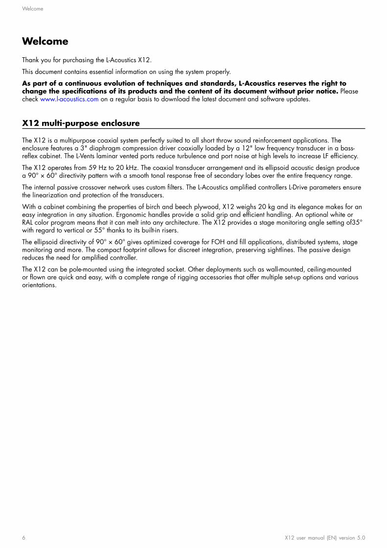
Thank you for purchasing the L-Acoustics X12.
This document contains essential information on using the system properly.
As part of a continuous evolution of techniques and standards, L-Acoustics reserves the right tochange the specications of its products and the content of its document without prior notice. Pleasecheck www.l-acoustics.com on a regular basis to download the latest document and software updates.
X12 multi-purpose enclosure
The X12 is a multipurpose coaxial system perfectly suited to all short throw sound reinforcement applications. Theenclosure features a 3" diaphragm compression driver coaxially loaded by a 12" low frequency transducer in a bass-reex cabinet. The L-Vents laminar vented ports reduce turbulence and port noise at high levels to increase LF efciency.
The X12 operates from 59 Hz to 20 kHz. The coaxial transducer arrangement and its ellipsoid acoustic design producea 90° × 60° directivity pattern with a smooth tonal response free of secondary lobes over the entire frequency range.
The internal passive crossover network uses custom lters. The L-Acoustics amplied controllers L-Drive parameters ensurethe linearization and protection of the transducers.
With a cabinet combining the properties of birch and beech plywood, X12 weighs 20 kg and its elegance makes for aneasy integration in any situation. Ergonomic handles provide a solid grip and efcient handling. An optional white orRAL color program means that it can melt into any architecture. The X12 provides a stage monitoring angle setting of35°with regard to vertical or 55° thanks to its built-in risers.
The ellipsoid directivity of 90° × 60° gives optimized coverage for FOH and ll applications, distributed systems, stagemonitoring and more. The compact footprint allows for discreet integration, preserving sightlines. The passive designreduces the need for amplied controller.
The X12 can be pole-mounted using the integrated socket. Other deployments such as wall-mounted, ceiling-mountedor own are quick and easy, with a complete range of rigging accessories that offer multiple set-up options and variousorientations.
6 X12 user manual (EN) version 5.0

System components
System components
Loudspeaker enclosures
X12 2-way passive coaxial enclosure: 12'' LF + 3'' HF diaphragm
SB15m High power compact subwoofer : 1 x 15''
SB18 High power compact subwoofer: 1 x 18''
SB18 / SB18i / SB18mIn this document, the SB18 term and illustrations refer equally to SB18, SB18i or SB18m.
Powering and driving system
LA4X / LA8 / LA12X Amplied controller with DSP, preset library and networking capabilities
LA-RAK Touring rack containing three LA8 and power, audio and network distribution
LA-RAK II Touring rack containing three LA12X, LA-POWER II for power distribution and LA-PANEL II foraudio and network distribution
Refer to the LA4X / LA8 / LA12X user manual for operating instructions.
Loudspeaker cables
SP cables 4-point speakON loudspeaker cables (4 mm² gauge)
SP cables come in four sizes: SP.7 (0.7 m/2.3 ft), SP5 (5 m/16.4 ft), SP10 (10 m/32.8 ft) andSP25 (25 m/82 ft)
SP-Y1 breakout cable for two passive enclosures (2.5 mm² gauge) provided with a CC4FP adapter
4-point speakON to 2 × 2-point speakON
DO 8-point PA-COM loudspeaker cables (4 mm² gauge)
DO cables come in three sizes: DO.7 (0.7 m/2.3 ft), DO10 (10 m/32.8 ft) and DO25(25 m/82 ft)
DOSUB-LA8 breakout cable for four passive enclosures (4 mm² gauge)
8-point PA-COM to 4 × 2-point speakON
Information about the connection of the enclosures to the LA amplied controllers is given inthis document.Refer to the LA4X / LA8 / LA12X user manual for detailed instructions about the whole cabling scheme, includingmodulation cables and network.
Rigging elements
Rigging elements or procedures are not presented in this document.Refer to the X12 rigging manual.
Software applications
Soundvision 3D acoustical and mechanical modeling software
LA Network Manager Software for remote control and monitoring of amplied controllers
Refer to the Soundvision help.
Refer to the LA Network Manager help.
X12 user manual (EN) version 5.0 7

System components
Loudspeaker cables
0.7 m / 5 m / 10 m / 25 m
CH(1)
CH(2)
1 m
SP.7 / SP5 / SP10 / SP25 SP-Y1
0.7 m / 10 m / 25 m
SPK1
SPK2
SPK3
SPK4
5 m
DO.7 / DO10 / DO25 DOSUB-LA8
8 X12 user manual (EN) version 5.0
Technical description
Technical description
Low-latency preset
A low-latency preset is available for the X12 enclosure used as a monitor ([X12_MO]). It reduces latency from 3.84 msdown to 1.18 ms (LA8) and 0.84 ms (LA4X / LA12X). If the monitor is combined with a subwoofer, a custom preset mustbe used.
Directivity
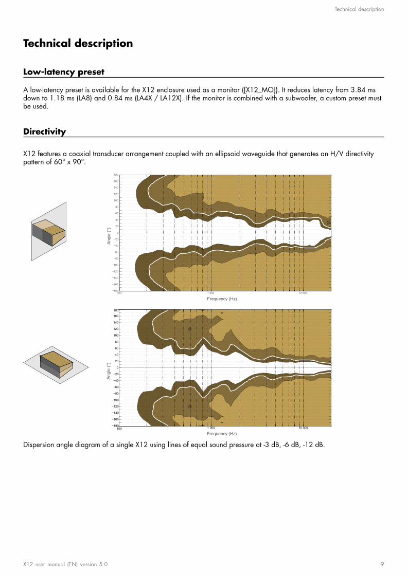
X12 features a coaxial transducer arrangement coupled with an ellipsoid waveguide that generates an H/V directivitypattern of 60° x 90°.
Frequency (Hz)
Angl
e (°
)
100 1 000 10 000−180
−160
−140
−120
−100
−80
−60
−40
−20
0
20
40
60
80
100
120
140
160
180
Frequency (Hz)
Angl
e (°
)
100 1 000 10 000−180
−160
−140
−120
−100
−80
−60
−40
−20
0
20
40
60
80
100
120
140
160
180
Dispersion angle diagram of a single X12 using lines of equal sound pressure at -3 dB, -6 dB, -12 dB.
X12 user manual (EN) version 5.0 9
Technical description
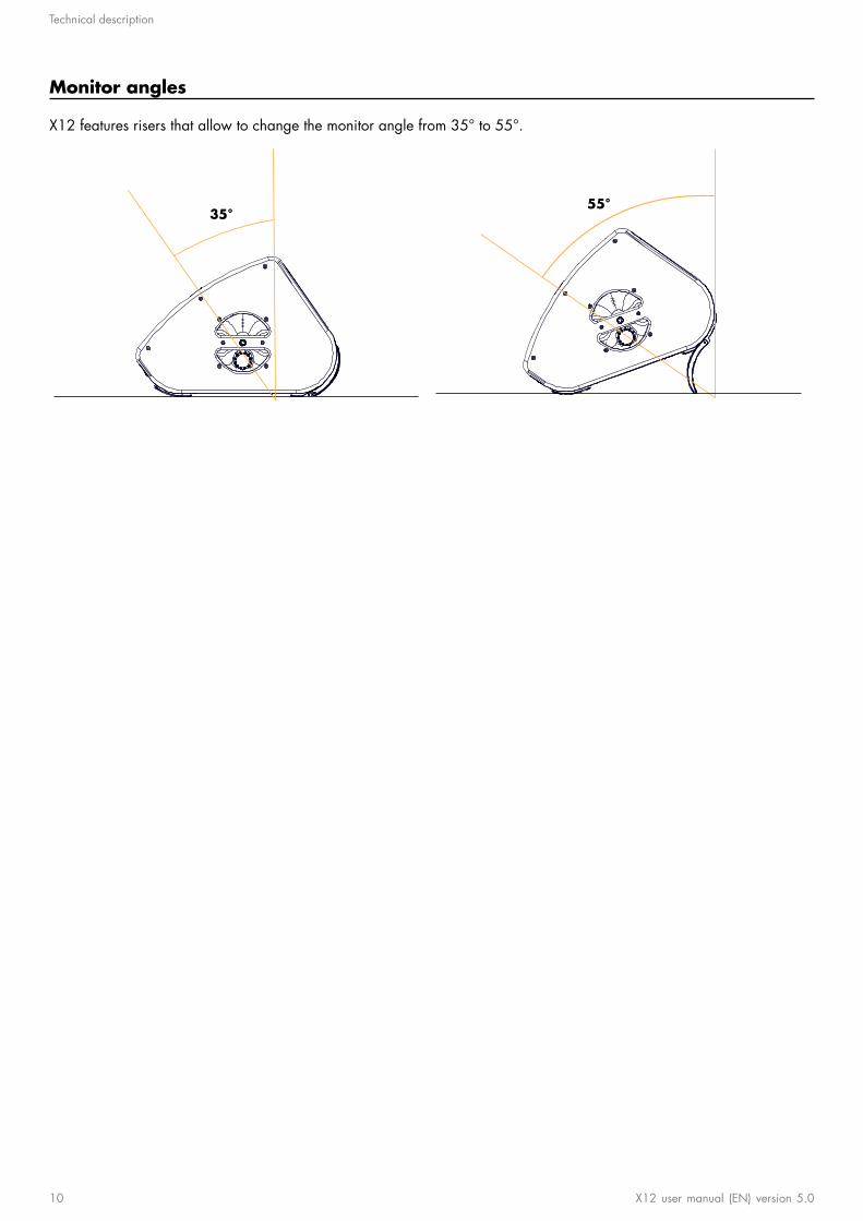
Monitor angles
X12 features risers that allow to change the monitor angle from 35° to 55°.
35° 55°
10 X12 user manual (EN) version 5.0
Loudspeaker congurations
Loudspeaker congurations
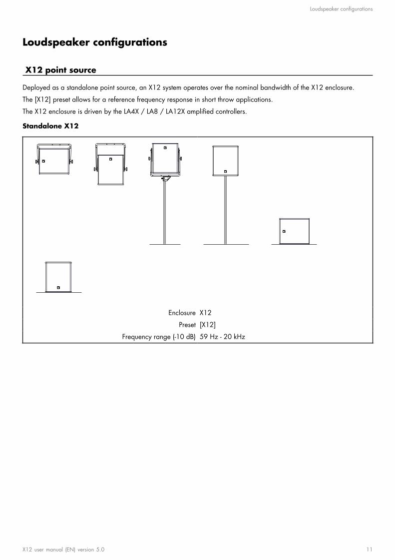
X12 point source
Deployed as a standalone point source, an X12 system operates over the nominal bandwidth of the X12 enclosure.
The [X12] preset allows for a reference frequency response in short throw applications.
The X12 enclosure is driven by the LA4X / LA8 / LA12X amplied controllers.
Standalone X12
Enclosure X12
Preset [X12]
Frequency range (-10 dB) 59 Hz - 20 kHz
X12 user manual (EN) version 5.0 11
Loudspeaker congurations
X12 point source with LF
Deployed as a point source with SB15m or SB18 subwoofers, an X12 system operates with augmented LF resources.
The [X12] preset allows for a reference frequency response in short throw applications.
The [SB15_100] and [SB18_100] presets provide the SB15m and SB18 with an upper frequency limit at 100 Hz for anoptimal frequency coupling with the X12.
The X12, SB15m and SB18 enclosures are driven by the LA4X / LA8 / LA12X amplied controllers.
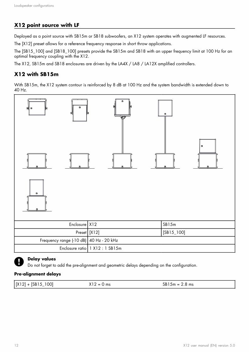
X12 with SB15m
With SB15m, the X12 system contour is reinforced by 8 dB at 100 Hz and the system bandwidth is extended down to40 Hz.
Enclosure X12 SB15m
Preset [X12] [SB15_100]
Frequency range (-10 dB) 40 Hz - 20 kHz
Enclosure ratio 1 X12 : 1 SB15m
Delay valuesDo not forget to add the pre-alignment and geometric delays depending on the conguration.
Pre-alignment delays
[X12] + [SB15_100] X12 = 0 ms SB15m = 2.8 ms
12 X12 user manual (EN) version 5.0
Loudspeaker congurations
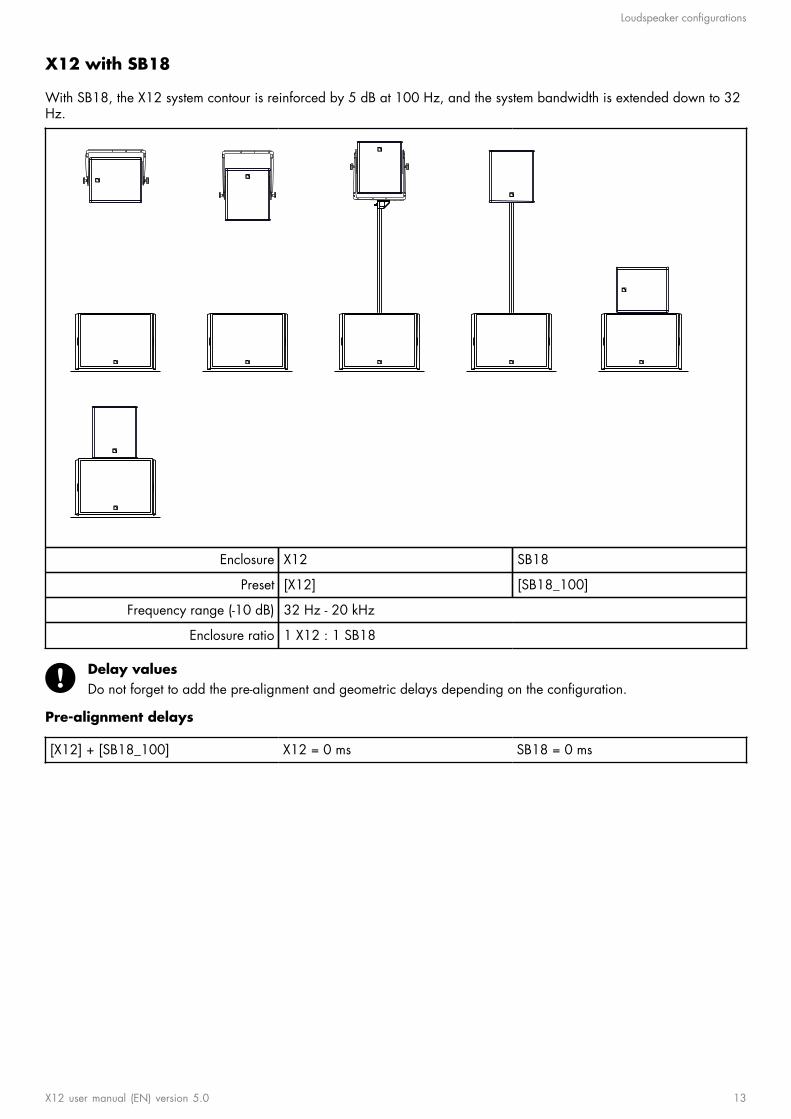
X12 with SB18
With SB18, the X12 system contour is reinforced by 5 dB at 100 Hz, and the system bandwidth is extended down to 32Hz.
Enclosure X12 SB18
Preset [X12] [SB18_100]
Frequency range (-10 dB) 32 Hz - 20 kHz
Enclosure ratio 1 X12 : 1 SB18
Delay valuesDo not forget to add the pre-alignment and geometric delays depending on the conguration.
Pre-alignment delays
[X12] + [SB18_100] X12 = 0 ms SB18 = 0 ms
X12 user manual (EN) version 5.0 13
Loudspeaker congurations
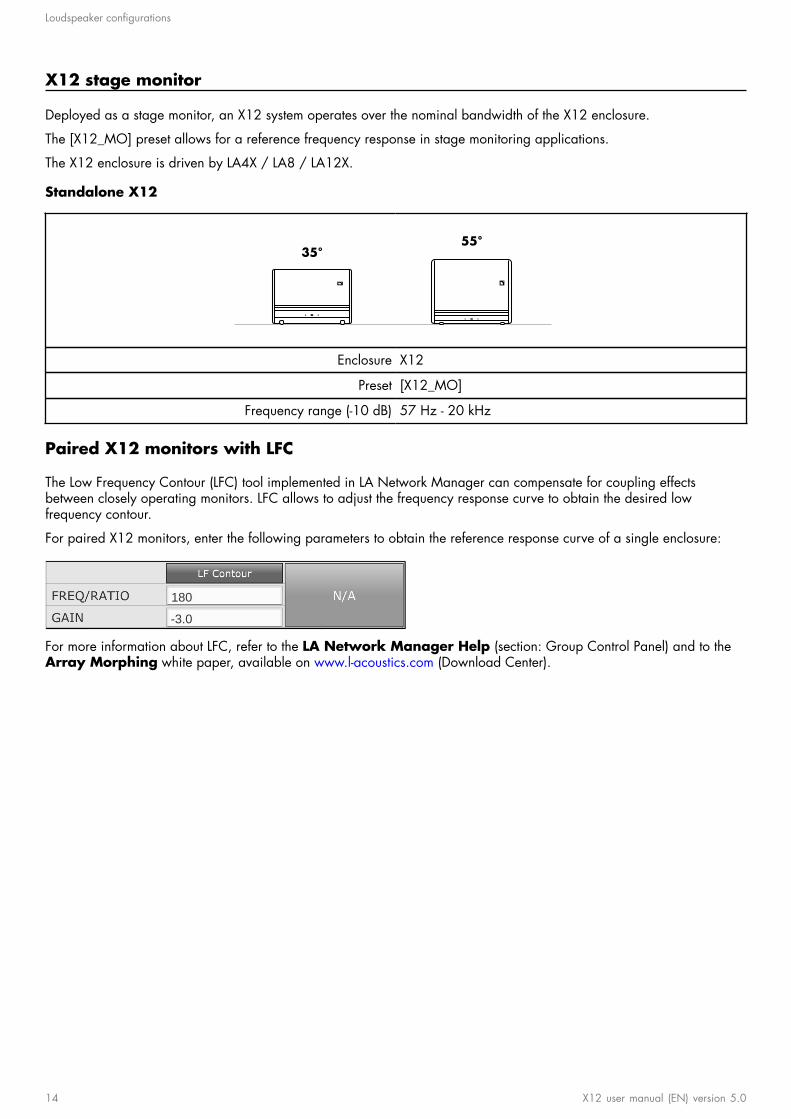
X12 stage monitor
Deployed as a stage monitor, an X12 system operates over the nominal bandwidth of the X12 enclosure.
The [X12_MO] preset allows for a reference frequency response in stage monitoring applications.
The X12 enclosure is driven by LA4X / LA8 / LA12X.
Standalone X12
55°35°
Enclosure X12
Preset [X12_MO]
Frequency range (-10 dB) 57 Hz - 20 kHz
Paired X12 monitors with LFC
The Low Frequency Contour (LFC) tool implemented in LA Network Manager can compensate for coupling effectsbetween closely operating monitors. LFC allows to adjust the frequency response curve to obtain the desired lowfrequency contour.
For paired X12 monitors, enter the following parameters to obtain the reference response curve of a single enclosure:
-3.0
180
For more information about LFC, refer to the LA Network Manager Help (section: Group Control Panel) and to theArray Morphing white paper, available on www.l-acoustics.com (Download Center).
14 X12 user manual (EN) version 5.0
Loudspeaker congurations
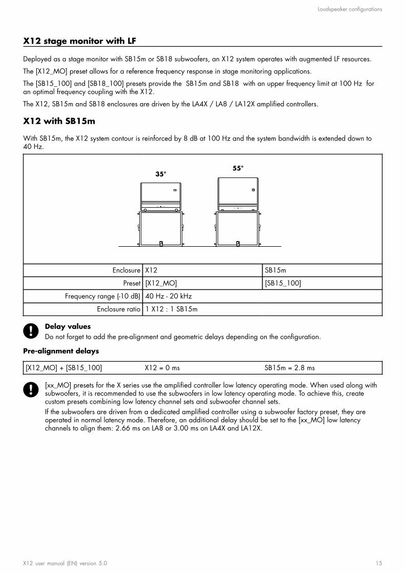
X12 stage monitor with LF
Deployed as a stage monitor with SB15m or SB18 subwoofers, an X12 system operates with augmented LF resources.
The [X12_MO] preset allows for a reference frequency response in stage monitoring applications.
The [SB15_100] and [SB18_100] presets provide the SB15m and SB18 with an upper frequency limit at 100 Hz foran optimal frequency coupling with the X12.
The X12, SB15m and SB18 enclosures are driven by the LA4X / LA8 / LA12X amplied controllers.
X12 with SB15m
With SB15m, the X12 system contour is reinforced by 8 dB at 100 Hz and the system bandwidth is extended down to40 Hz.
55°35°
Enclosure X12 SB15m
Preset [X12_MO] [SB15_100]
Frequency range (-10 dB) 40 Hz - 20 kHz
Enclosure ratio 1 X12 : 1 SB15m
Delay valuesDo not forget to add the pre-alignment and geometric delays depending on the conguration.
Pre-alignment delays
[X12_MO] + [SB15_100] X12 = 0 ms SB15m = 2.8 ms
[xx_MO] presets for the X series use the amplied controller low latency operating mode. When used along withsubwoofers, it is recommended to use the subwoofers in low latency operating mode. To achieve this, createcustom presets combining low latency channel sets and subwoofer channel sets.If the subwoofers are driven from a dedicated amplied controller using a subwoofer factory preset, they areoperated in normal latency mode. Therefore, an additional delay should be set to the [xx_MO] low latencychannels to align them: 2.66 ms on LA8 or 3.00 ms on LA4X and LA12X.
X12 user manual (EN) version 5.0 15

Loudspeaker congurations
X12 with SB18
With SB18, the X12 system contour is reinforced by 5 dB at 100 Hz, and the system bandwidth is extended down to 32Hz.
55°35°
Enclosure X12 SB18
Preset [X12_MO] [SB18_100]
Frequency range (-10 dB) 32 Hz - 20 kHz
Enclosure ratio 1 X12 : 1 SB18
Delay valuesDo not forget to add the pre-alignment and geometric delays depending on the conguration.
Pre-alignment delays
[X12_MO] + [SB18_100] X12 = 0 ms SB18 = 0 ms
[xx_MO] presets for the X series use the amplied controller low latency operating mode. When used along withsubwoofers, it is recommended to use the subwoofers in low latency operating mode. To achieve this, createcustom presets combining low latency channel sets and subwoofer channel sets.If the subwoofers are driven from a dedicated amplied controller using a subwoofer factory preset, they areoperated in normal latency mode. Therefore, an additional delay should be set to the [xx_MO] low latencychannels to align them: 2.66 ms on LA8 or 3.00 ms on LA4X and LA12X.
16 X12 user manual (EN) version 5.0
Loudspeaker connection
Loudspeaker connection
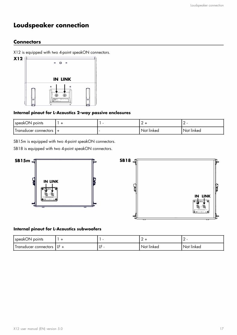
Connectors
X12 is equipped with two 4-point speakON connectors.
LINKIN
X12
Internal pinout for L-Acoustics 2-way passive enclosures
speakON points 1 + 1 - 2 + 2 -
Transducer connectors + - Not linked Not linked
SB15m is equipped with two 4-point speakON connectors.
SB18 is equipped with two 4-point speakON connectors.
IN LINK
SB15m
IN LINK
SB18
Internal pinout for L-Acoustics subwoofers
speakON points 1 + 1 - 2 + 2 -
Transducer connectors LF + LF - Not linked Not linked
X12 user manual (EN) version 5.0 17
Loudspeaker connection
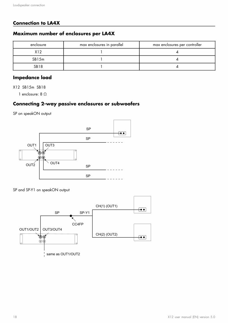
Connection to LA4X
Maximum number of enclosures per LA4X
enclosure max enclosures in parallel max enclosures per controller
X12 1 4
SB15m 1 4
SB18 1 4
Impedance load
X12 SB15m SB18
1 enclosure: 8 Ω
Connecting 2-way passive enclosures or subwoofers
SP on speakON output
SP
SP
SP
SP
OUT1
OUT2
OUT3
OUT4
SP and SP-Y1 on speakON output
OUT1/OUT2 OUT3/OUT4
same as OUT1/OUT2
SP SP-Y1
CC4FP
CH(1) (OUT1)
CH(2) (OUT2)
18 X12 user manual (EN) version 5.0
Loudspeaker connection
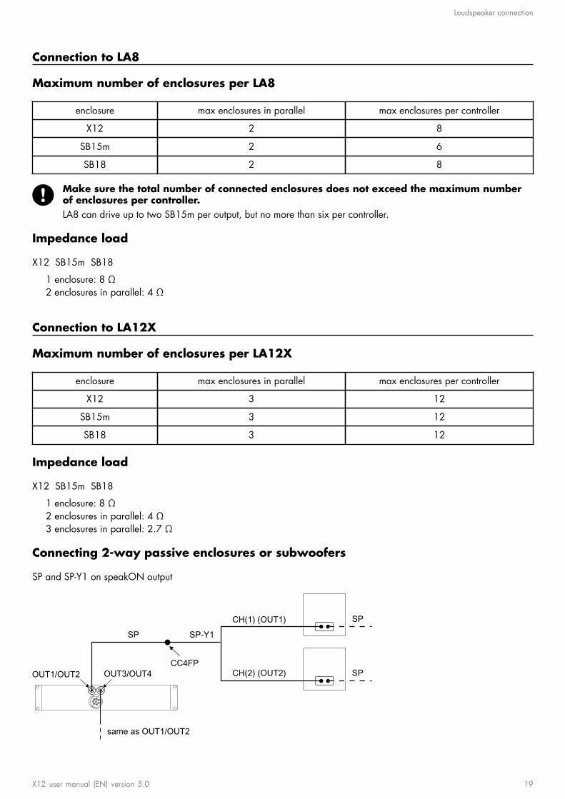
Connection to LA8
Maximum number of enclosures per LA8
enclosure max enclosures in parallel max enclosures per controller
X12 2 8
SB15m 2 6
SB18 2 8
Make sure the total number of connected enclosures does not exceed the maximum numberof enclosures per controller.LA8 can drive up to two SB15m per output, but no more than six per controller.
Impedance load
X12 SB15m SB18
1 enclosure: 8 Ω2 enclosures in parallel: 4 Ω
Connection to LA12X
Maximum number of enclosures per LA12X
enclosure max enclosures in parallel max enclosures per controller
X12 3 12
SB15m 3 12
SB18 3 12
Impedance load
X12 SB15m SB18
1 enclosure: 8 Ω2 enclosures in parallel: 4 Ω3 enclosures in parallel: 2.7 Ω
Connecting 2-way passive enclosures or subwoofers
SP and SP-Y1 on speakON output
OUT1/OUT2 OUT3/OUT4
same as OUT1/OUT2
SP SP-Y1
CC4FP
CH(1) (OUT1)
CH(2) (OUT2)
SP
SP
X12 user manual (EN) version 5.0 19

Loudspeaker connection
DO and DOSUB-LA8 on CA-COM output
CA-COM
DOD
OSU
B-LA
8
SPK1 (OUT1)
SPK2 (OUT2)
SPK3 (OUT3)
SPK4 (OUT4)
SP
20 X12 user manual (EN) version 5.0

Preset description
Preset description
[X12_MO]
outputs channels routing gain delay polarity mute
OUT 1 PA IN A 0 dB 0 ms + ON
OUT 2 PA IN A 0 dB 0 ms + ON
OUT 3 PA IN B 0 dB 0 ms + ON
OUT 4 PA IN B 0 dB 0 ms + ON
[X12]
outputs channels routing gain delay polarity mute
OUT 1 PA IN A 0 dB 0 ms + ON
OUT 2 PA IN A 0 dB 0 ms + ON
OUT 3 PA IN A 0 dB 0 ms + ON
OUT 4 PA IN A 0 dB 0 ms + ON
[SB18_100] [SB15_100]
outputs channels routing gain delay polarity mute
OUT 1 SB IN A 0 dB 0 ms + ON
OUT 2 SB IN A 0 dB 0 ms + ON
OUT 3 SB IN A 0 dB 0 ms + ON
OUT 4 SB IN A 0 dB 0 ms + ON
[SB18_100_C] [SB15_100_C]
loudspeaker elements outputs channels routing gain delay polarity mute
SR OUT 1 SR ON
SB OUT 2 SB ON
SB OUT 3 SB ON
SB OUT 4 SB
IN A 0 dB 0 ms +
ON
X12 user manual (EN) version 5.0 21
Recommendation for speaker cables
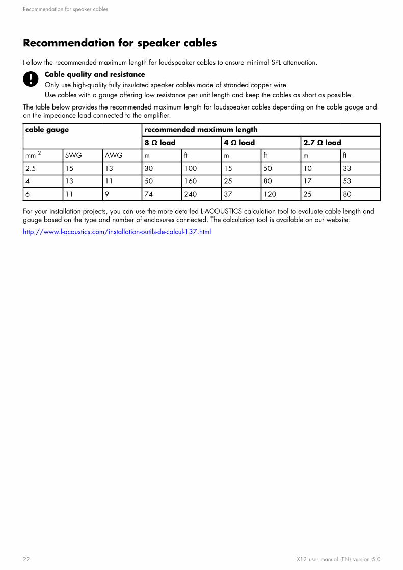
Recommendation for speaker cables
Follow the recommended maximum length for loudspeaker cables to ensure minimal SPL attenuation.
Cable quality and resistanceOnly use high-quality fully insulated speaker cables made of stranded copper wire.Use cables with a gauge offering low resistance per unit length and keep the cables as short as possible.
The table below provides the recommended maximum length for loudspeaker cables depending on the cable gauge andon the impedance load connected to the amplier.
recommended maximum lengthcable gauge
8 Ω load 4 Ω load 2.7 Ω load
mm 2 SWG AWG m ft m ft m ft
2.5 15 13 30 100 15 50 10 33
4 13 11 50 160 25 80 17 53
6 11 9 74 240 37 120 25 80
For your installation projects, you can use the more detailed L-ACOUSTICS calculation tool to evaluate cable length andgauge based on the type and number of enclosures connected. The calculation tool is available on our website:
http://www.l-acoustics.com/installation-outils-de-calcul-137.html
22 X12 user manual (EN) version 5.0
Maintenance
Maintenance
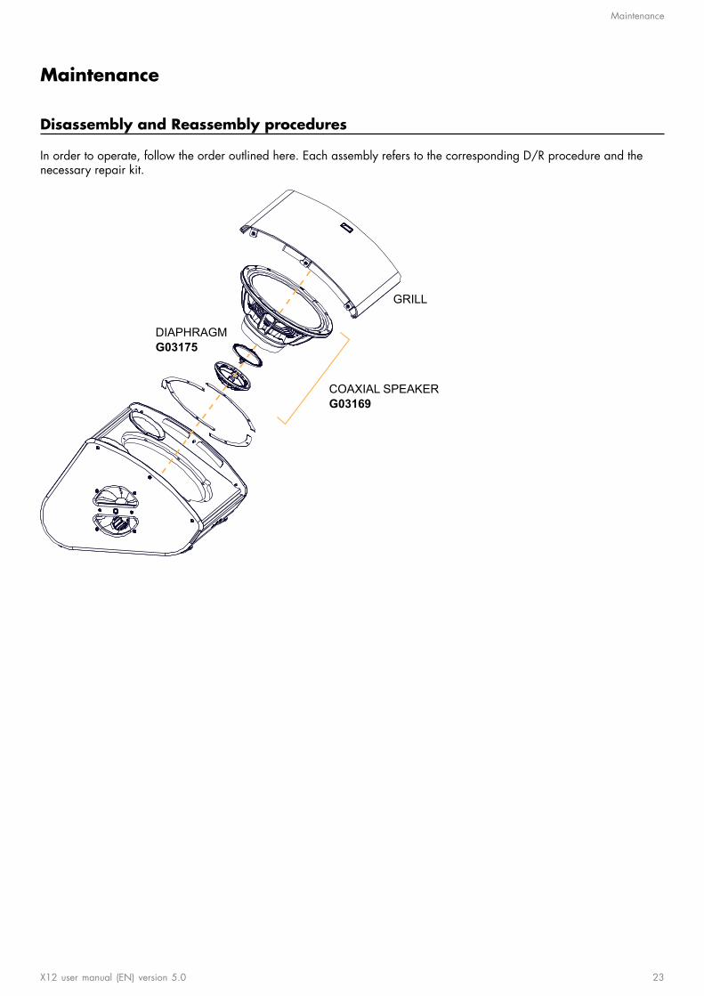
Disassembly and Reassembly procedures
In order to operate, follow the order outlined here. Each assembly refers to the corresponding D/R procedure and thenecessary repair kit.
GRILL
COAXIAL SPEAKERG03169
DIAPHRAGMG03175
X12 user manual (EN) version 5.0 23

Maintenance
D/R - Grill
Tools
• torque screwdriver• T25 Torx bit
Repair kit
G03169 - KR coaxial speaker X12 or
G03175 - KR diaphragm X12
×6
S100033
M5×25 Torx
Exploded view
For safety reasons, always use the new screws and spare parts provided in the KR.If no new screws are available, use blue threadlocker.
Gradually tighten the screws following a star pattern.
Position the logo on the right side.
x6
5 N.m
T25
24 X12 user manual (EN) version 5.0

Maintenance
D/R - Coaxial loudspeaker
Tools
• torque screwdriver• 5 mm hex bit
Repair kit
G03169*
KR coaxial speaker X12
×1 ×4 ×4 ×4
SE HPX12 S100054 100222 1250
12" coaxial speaker - 8ohms
M6×30 hex X12 grill stop screw 12" speaker gasket
* The screws and gaskets are also available in G03175 - KR diaphragm X12 .
Prerequisite
Grill disassembled. See Grill (p.24).
Exploded view
For safety reasons, always use the new screws and spare parts provided in the KR.
Gradually tighten the screws following a star pattern.
If the speaker gasket is damaged, remove and replace it.
5 N.m
5 mm
x4 x4
What to do next
Perform the Acoustical check (p.27) procedures.
X12 user manual (EN) version 5.0 25
Maintenance
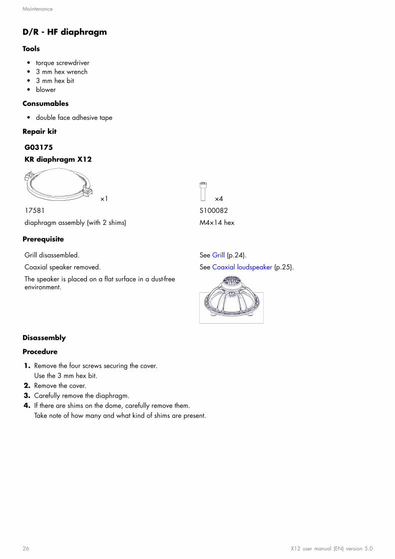
D/R - HF diaphragm
Tools
• torque screwdriver• 3 mm hex wrench• 3 mm hex bit• blower
Consumables
• double face adhesive tape
Repair kit
G03175
KR diaphragm X12
×1 ×4
17581 S100082
diaphragm assembly (with 2 shims) M4×14 hex
Prerequisite
Grill disassembled. See Grill (p.24).
Coaxial speaker removed. See Coaxial loudspeaker (p.25).
The speaker is placed on a at surface in a dust-freeenvironment.
Disassembly
Procedure
1. Remove the four screws securing the cover.Use the 3 mm hex bit.
2. Remove the cover.3. Carefully remove the diaphragm.4. If there are shims on the dome, carefully remove them.
Take note of how many and what kind of shims are present.
26 X12 user manual (EN) version 5.0
Maintenance
Reassembly
About this task
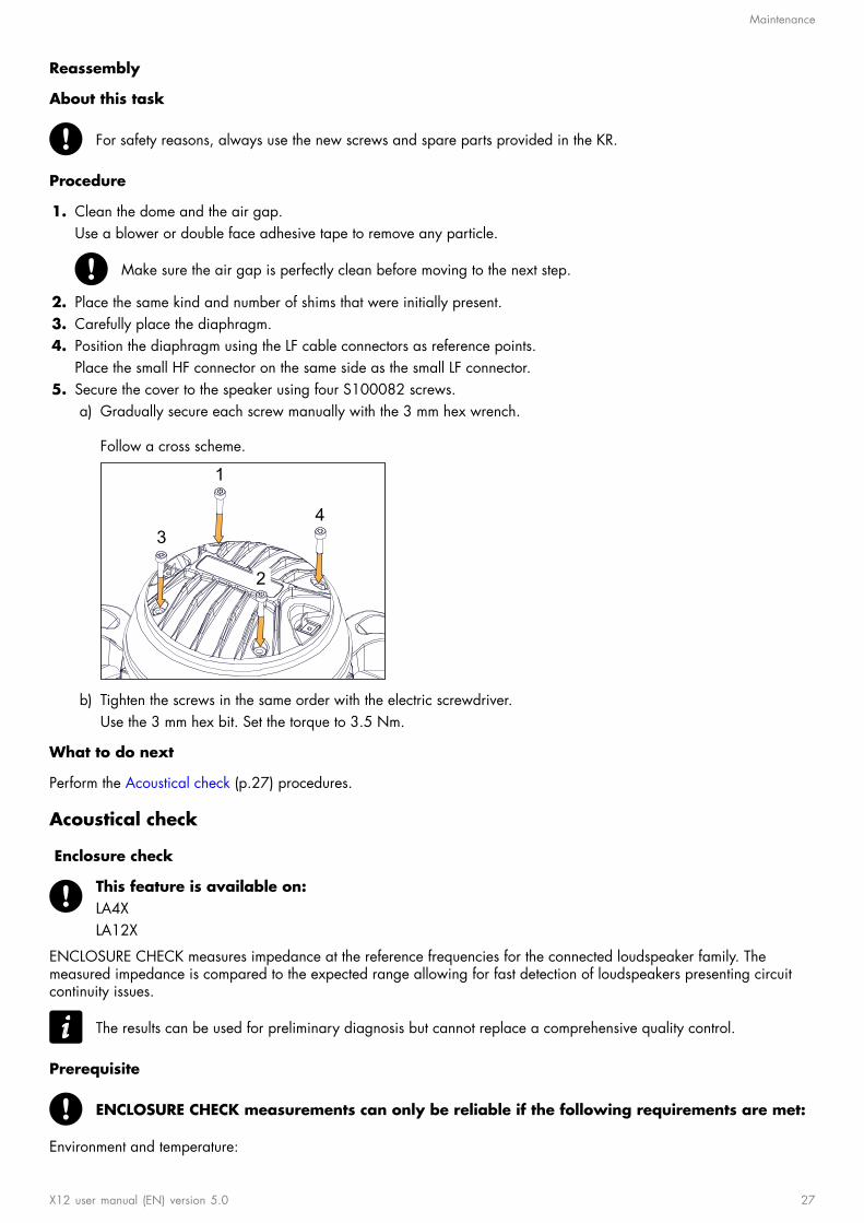
For safety reasons, always use the new screws and spare parts provided in the KR.
Procedure
1. Clean the dome and the air gap.Use a blower or double face adhesive tape to remove any particle.
Make sure the air gap is perfectly clean before moving to the next step.
2. Place the same kind and number of shims that were initially present.3. Carefully place the diaphragm.4. Position the diaphragm using the LF cable connectors as reference points.
Place the small HF connector on the same side as the small LF connector.5. Secure the cover to the speaker using four S100082 screws.
a) Gradually secure each screw manually with the 3 mm hex wrench.
Follow a cross scheme.
1
2
34
b) Tighten the screws in the same order with the electric screwdriver.Use the 3 mm hex bit. Set the torque to 3.5 Nm.
What to do next
Perform the Acoustical check (p.27) procedures.
Acoustical check
Enclosure check
This feature is available on:LA4XLA12X
ENCLOSURE CHECK measures impedance at the reference frequencies for the connected loudspeaker family. Themeasured impedance is compared to the expected range allowing for fast detection of loudspeakers presenting circuitcontinuity issues.
The results can be used for preliminary diagnosis but cannot replace a comprehensive quality control.
Prerequisite
ENCLOSURE CHECK measurements can only be reliable if the following requirements are met:
Environment and temperature:
X12 user manual (EN) version 5.0 27

Maintenance
• Ambient temperature must be comprised between 0 °C / 32 °F and 40 °C / 104 °F. Ideal temperature is 20 °C /68 °F.
• Enclosures must be at room temperature. If warm from a recent high level use or recently moved from a coldenvironment, let the loudspeakers reach room temperature before starting.
Enclosures:• Enclosures must be included in the embedded factory preset library.• Enclosures must be in nominal operating conditions:
• Remove covers or dollies obstructing the loudspeakers or the vents.• Check for obvious physical damage or air leak: visually inspect the grill, gasket, cabinet, and connector plate
for loose, missing or damaged parts.
Connection:• Use only 10 m / 30 ft 4 mm² / AWG 11 speaker cables.• Do not connect enclosures in parallel.
Amplied controllers:• LA4X must run at least rmware version 1.1.0.• LA4X load sensors must be calibrated. Refer to the technical bulletin for more information.• LA4X must warm up for at least 10 minutes after power up. Do not power off, reboot or switch to standby mode to
avoid resetting the countdown.• Load a preset corresponding to the connected loudspeaker's family. Presets from the user memories may be used on
condition they are made of presets supported in the embedded factory preset library.
Procedure
1. Power up the amplied controller. Let LA4X warm up for at least 10 minutes.2. Connect the loudspeaker enclosures to the amplied controller.3. Load a preset from or built from the embedded library corresponding to the connected loudspeaker family.4. On the amplied controller, use the encoder wheel to select MONITORING & INFO. Press the OK key or the
encoder wheel to validate.5. Use the encoder wheel to select ENCLOSURE CHECK.
Beware of sound levels.Although the sound pressure levels generated for the ENCLOSURE CHECK are moderate, do not stay withinclose proximity of the loudspeakers and consider wearing ear protection.
6. Press the OK key or the encoder wheel to launch the ENCLOSURE CHECK.
The amplied controller generates short sinusoidal signals simultaneously for each connected output.
The amplied controller displays the results for each output.7. Depending on the displayed results, follow the instructions in the table.
result interpretation instructions
OK measured impedance is within expected range enclosure is in working order electrically
? unsupported preset family only supported enclosures should be tested
NC Not Connected if cables are connected:
a. inspect the cables and connectionsb. go to step 8 (p.28)
NOK measured impedance is not within expected range
UNDEF measured impedance is undened
a. check that all the prerequisites are met, inparticular that the loaded preset correspondsto the connected speaker's family
b. inspect the cables and connectionsc. go to step 8 (p.28)
8. Under NC, NOK and UNDEF results, press and hold the corresponding OUT key.
The amplied controller displays:
28 X12 user manual (EN) version 5.0

Maintenance
• the tested frequencies,• information on the measured impedance:
• OPEN for open circuit (found in NC results),• SHORT for short circuit (found in NOK results), or• a percentage of variation from the expected range (found in NOK and UNDEF results)
• the number of operational transducers out of the total
Low variations from the expected range are acceptable: displayed percentage can be different from 0 and alltransducers considered operational.
X12 user manual (EN) version 5.0 29
Maintenance
Listening test
Procedure
1. Load the preset on an LA4X / LA8 / LA12X amplied controller.2. Connect a sinus generator to the amplied controller.
Risk of hearing damageSet a low sound level to start and use ear protection to adjust before testing.
3. Scan the bandwidth focusing on the usable range.The sound should remain pure and free of unwanted noise.
Troubleshooting for HF speakers
One or more HF loudspeaker produces high-frequency harmonic distortions, strange vibrations or weak sound.
Possible causes
• There are foreign particles on the air gap.• The screws used for reassembly are too loose.• The diaphragm is damaged.• The number of shims is wrong.
Procedure
1. Perform the diaphragm disassembly procedure.2. Visually inspect the diaphragm and the voice coil.
If any damage is visible, replace the diaphragm.3. Clean the air gap thoroughly.4. Perform the reassembly procedure.
Pay close attention to the number of shims and the position of the diaphragm.Apply the recommended torque.
5. Repeat the listening test.
If a buzzing sound is still audible, it might be necessary to add an extra shim on the air gap.
Troubleshooting for LF speakers
One or more LF loudspeaker produces distorted, buzzing, rubbing, clicking, mufed or weak sound.
Possible causes
• The screws used for reassembly are too loose.• There is an air leak in the gasket.• There is dust on the cone.• The cone is damaged.• The surround is torn or delaminated.• The voice coil and/or the spider is damaged.
Procedure
1. Perform the loudspeaker disassembly procedure.2. Visually inspect the loudspeaker and the cables.
If any damage is visible, replace the loudspeaker.3. Carefully clean the loudspeaker with a dry cloth.4. Perform the reassembly procedure.
Replace the loudspeaker gasket and the screws.Apply the recommended torque.
5. Repeat the listening test.
If the problem persists, replace the loudspeaker.
30 X12 user manual (EN) version 5.0

Specications
Specications
X12 specications
Description 2-way passive coaxial enclosure: 12'' LF + 3'' HF diaphragm, amplied byLA4X / LA8 / LA12X
Usable bandwidth (-10 dB) 59 Hz - 20 kHz ([X12])
Maximum SPL1 136 dB ([X12])
Nominal directivity vertical: symmetric
horizontal: symmetric
Monitoring angle without risers: 35°
with risers: 55°
Transducers LF: 1 × 12"cone driver
HF: 1 × 3"diaphragm compression driver, neodymium
Acoustical load bass-reex, L-Vents, ellipsoidal waveguide
Nominal impedance 8 Ω
Connectors IN: 1 × 4-point speakON
LINK: 1 × 4-point speakON
Rigging and handling 2 × handles
DIN580-compatible M8 threaded insert
4 M10 threaded inserts
1 × 35 mm pole socket
Weight (net) 20 kg / 44.1 lb
Cabinet rst grade Baltic beech and birch plywood
Front steel with anti-corrosion coating
acoustically neutral 3D fabric
Finish dark grey brown Pantone 426C
pure white RAL 9010
custom RAL code on special order
IP IP43
1 Peak level measured at 1 m under free eld conditions using pink noise with crest factor 4 (preset specied in brackets).
X12 user manual (EN) version 5.0 31

Specications
X12 dimensions49
6 m
m / 1
9.5
in
430 mm / 16.9 in
471 mm / 18.5 in500 mm / 19.7 in
341
mm
/ 13.
4 in
403
mm
/ 15.
9 in
375 mm / 14.8 in
32 X12 user manual (EN) version 5.0

Specications
SB15m specications
Description High power compact subwoofer : 1 x 15'' , amplied by LA4X / LA8 / LA12X
Low frequency limit 40 Hz ([SB15_100])
Maximum SPL1 137 dB ([SB15_100])
Directivity standard or cardioid
Transducers 1 x 15"
Acoustical load bass-reex enclosure, L-Vents
Nominal impedance 8 Ω
Connectors IN: 4-point speakON
LINK: 4-point speakON
Rigging and handling 2 handles
2 coupling bars and 2 locking tabs
1 x 35 mm pole socket
Weight (net) 36 kg / 79.4 lb
Cabinet rst grade Baltic birch plywood
Front steel grill with anti-corrosion coating
acoustically neutral 3D fabric
Rigging components high grade steel with anti-corrosion coating
Finish dark grey brown Pantone 426C
pure white RAL 9010
custom RAL code on special order
1 Peak level at 1 m under half space conditions using pink noise with crest factor 4 (preset specied in brackets).
X12 user manual (EN) version 5.0 33

Specications
SB15m dimensions
520 mm / 20.5 in
439
mm
/ 17
.3 in
580 mm / 22.8 in
34 X12 user manual (EN) version 5.0
Specications
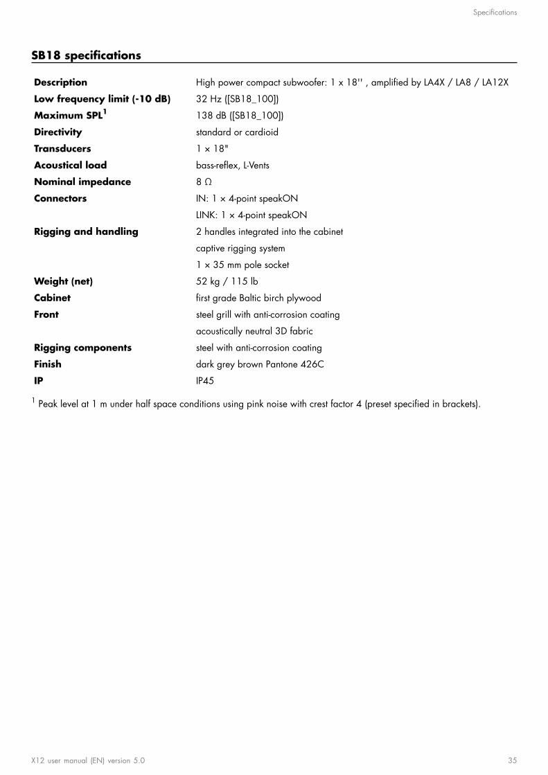
SB18 specications
Description High power compact subwoofer: 1 x 18'' , amplied by LA4X / LA8 / LA12X
Low frequency limit (-10 dB) 32 Hz ([SB18_100])
Maximum SPL1 138 dB ([SB18_100])
Directivity standard or cardioid
Transducers 1 × 18"
Acoustical load bass-reex, L-Vents
Nominal impedance 8 Ω
Connectors IN: 1 × 4-point speakON
LINK: 1 × 4-point speakON
Rigging and handling 2 handles integrated into the cabinet
captive rigging system
1 × 35 mm pole socket
Weight (net) 52 kg / 115 lb
Cabinet rst grade Baltic birch plywood
Front steel grill with anti-corrosion coating
acoustically neutral 3D fabric
Rigging components steel with anti-corrosion coating
Finish dark grey brown Pantone 426C
IP IP45
1 Peak level at 1 m under half space conditions using pink noise with crest factor 4 (preset specied in brackets).
X12 user manual (EN) version 5.0 35

Specications
SB18 dimensions
750 mm / 29.5 in
707 mm / 27.8 in
553
mm
/ 21
.8 in
36 X12 user manual (EN) version 5.0

L-Acoustics, an L-Group Company13 rue Levacher Cintrat - 91460 Marcoussis - France
+33 1 69 63 69 63 - [email protected]
L-Acoustics GmbHSteiermärker Str. 3-5
70469 StuttgartGermany
+49 7 11 89660 323
L-Acoustics Ltd.PO. Box Adler Shine - Aston HouseCornwall Avenue - London N3 1LF
United Kingdom+44 7224 11 234
L-Acoustics Inc.2645 Townsgate Road, Suite 600
Westlake Village, CA 91361USA
+1 805 604 0577
L-GROUP
www.l-group.com