x ray production
TRANSCRIPT
PHYSICS OF MEDICAL IMAGING
1
X-ray Production, X-ray Tubes and Generators
MUHAMMED ANEES.KResident Medical Physicist

5/6/2015 Footer Text 2
The study and use of ionizing radiation in medicine started with three important
discoveries
X rays by Wilhelm Roentgen in 1895. Natural radioactivity by Henri Becquerel in 1896. Radium-226 by Pierre and Marie Curie in 1898.
INTRODUCTION

5/6/2015 Footer Text 3
Roentgen discovered x rays in 1895 while experimentingwith a Crookes “cold cathode” tube.
• Crookes tube is a sealed glass cylinder with two embeddedelectrodes operated with rarefied gas.• The potential difference between the two electrodes producesdischarge in the rarefied gas causing ionization of gas molecules.• Electrons (cathode rays) are accelerated toward the positiveelectrode producing x rays upon striking it.
A bit of History
Photograph of Roentgen’s apparatus

5/6/2015 4
William Roentgen discovered X-rays in 1895 &
determined they had the following properties
1. Travel in straight lines
2. Are exponentially absorbed in matter with the exponent proportional to the mass of the absorbing material
3. Darken photographic plates
4. Make shadows of absorbing material on photosensitive paper
• Roentgen was awarded the Nobel Prize in 1901
• Debate over the wave vs. particle nature of X-rays led the development of relativity and quantum mechanics
A bit of History

5/6/2015 Footer Text 5
The first x-ray photograph:
Roentgen’s wife Bertha’s hand

5/6/2015 Footer Text 6
X-rays are one of the
main diagnostical tools
in medicine since its
discovery by
Wilhelm Roentgen in
1895
Current estimates show
that there are approximately
650 medical and dental X-ray
examinations per
1000 patients per year

“ Internal structures of the body could bemade visible withoutthe necessity of surgery “


5/6/2015 Footer Text 9
To heat the filamentso that electrons are given off
To connect the X-ray tube to a source of high voltageElectrons are accelerated & convert their KE into X-rayswhen impinge on the target of the X- ray tube
To produce X-rays

5/6/2015 Footer Text 10
X-rays characteristics
• Highly penetrating, invisible rays• Electrically neutral• Travel in straight lines.• Travel with the speed of light in vaccum:
300, 000 km/sec or 186, 400 miles/sec.• Ionize matter by removing orbital electrons• Induce fluorescense in some substances. • Fluorescent screen glow after being stricken with photons.• Can't be focused by lenses nor by collimators.

5/6/2015 Footer Text 11
X-ray Imaging System
PRINCIPAL PARTS
Operating Console High-voltage generator X-ray tube
PRIMARY FUNCTION
The system is designed to provide a large number of e- at cathode
with high kinetic energy focused to a small target at anode.

5/6/2015 Footer Text 12
X-ray Tube Construction
Radiographic Equipment

5/6/2015 Footer Text 13
X-ray tube Main voltage supply High tension source Kilo-voltage control Filament circuit and milli-amperage control Timer
Features of X-ray equipment

Main supply Filament CKT including mA control
kV control kV indication
High Tension source
Exposure timing and switching
mA indication
X- Ray Tube
Block Diagram of X-ray equipment

5/6/2015 Footer Text 15
X-ray Tube

5/6/2015 Footer Text 16
How “X-rays” are created ?
Power is sent to x-ray tube via cables
mA is sent to filament on cathode side.
Filament heats up – electrons are produced
Positive voltage (kVp) is applied to anode
Negative electrons are attracted across the tube to the positive anode.
Electrons slow down and finally come to rest
Electron beam is focused from the cathode to the anode target by the
focusing cup

5/6/2015 Footer Text 17
Fundamentals of X ray Production
Bombardment of a thick target with energetic electrons
Electrons undergo a complex sequence of collisions & scattering process
Which results in the production of bremsstrahlung and characteristic
radiation
Bremsstrahlung Radiation
Characteristic X-rays

18
X-ray Production
When Highly Energetic Electrons Interact with Matter &
Convert their Kinetic Energy into X-rays
X - rays

5/6/2015 Footer Text 19
When the electrons from the cathode are accelerated at high voltage to the anode:
• 99% of the energy is dissipated as heat
(anode materials are selected to withstand the high temperatures they are able to withstand)
• 1% is given off as x-rays

5/6/2015 Footer Text 20
BREMSSTRAHLUNG RADIATION
CHARACTERISTIC RADIATION
X-ray Production
Conversion of Electron Kinetic Energy into X-rays

Bremsstrahlung Radiation

5/6/2015 Footer Text 22
If an incoming free electron gets close to the nucleus of a target atom
The strong electric field of the nucleus will attract the electron
Changing direction & speed of the electron
Electron looses energy which will be emitted as an X-ray photon
Energy of this photon depend on the interaction between nucleus and
electron
X-rays originating from this process are called bremsstrahlung.
Bremsstrahlung Radiation

5/6/2015 Footer Text 23
A large voltage is applied between two electrodes in an evacuated envelope
The cathode is negatively charged and is the source of electrons
the anode is positively charged and is the target of electrons
These electrons travel from cathode to anode & they were accelerated
The electrical potential difference between these electrodes attain kinetic energy
Emits Electromagnetic radiation, The name given as bremsstrahlung

5/6/2015 Footer Text 24

5/6/2015 Footer Text 25
A part or all of its energy is dissociated from it
An electron may have one or more bremsstrahlung interactions
Bremsstrahlung photon may have any energy up to the initial energy of the electron
Bremsstrahlung Spectrum

5/6/2015 Footer Text 26
Bremsstrahlung Radiation
Bremsstrahlung is a German word "Strahlung" means “radiation”
"Bremse" means “brake”

5/6/2015 Footer Text 27
The high energy electron can also cause an electron close to the nucleus in a
metal atom to be knocked out from its place.
This vacancy is filled by an electron further out from the nucleus.
The well defined difference in binding energy,
characteristic of the material, is emitted as a monoenergetic photon.
When detected this X-ray photon gives rise to a characteristic X-ray line in the
energy spectrum.
Characteristic X-rays

5/6/2015 Footer Text 28
Characteristic X-rays
• Characteristic radiation are emitted at discrete energies
• hv = Ek-El
• Ek and El are the electron binding energies of the K shell and the L shell


5/6/2015 Footer Text 31
The bremsstrahlung spectrum originates in the x-ray target.
The characteristic line spectra originate in the target and
in any attenuators placed into the x-ray beam.
A typical spectrum of a clinical x-ray beam consists of: • Continuous bremsstrahlung spectrum
• Line spectra characteristic of the target material and superimposed onto the
continuous bremsstrahlung spectrum

5/6/2015 Footer Text 32
X-ray spectra are composed of:
1. Continuous bremsstrahlung spectra
2. In most cases, discrete spectra peaks known as characteristic x-rays.keV

5/6/2015 Footer Text 33
E max
Bremsstrahlung xrays form a continuous energy spectra. The frequency distribution is continuous and shows that the Bremsstrahlung process produces more low energy that higher energy x-rays. The average energy is approximately 1/3 of the Emax.

5/6/2015 Footer Text 34
The Emax or the maximum energy of
the x-rays measured as (keV) is equal
to
voltage applied to the Xray tube
(kilovolt peak or kVp).
E max
For example:An applied voltage of 70 kVp produces an x-ray spectra with Emax of
70 KeV and average energy of about 23 keV.
70KeV
23keV

5/6/2015 Footer Text 35
Filtration
It is the removal of x-rays as the beam passes through a layer of material
Added FiltrationInherent filtration of the tube
Attenuation of the x-ray beam

5/6/2015 Footer Text 36
Includes
the thickness (l to 2 mm) metal insert at the x-ray tube port.
Glass (Si02) and aluminum effectively attenuate all x-rays in
the spectrum below approximately 15 keV:
Inherent filtration
Dedicated mammography tubes,
require beryllium (Z = 4) to improve the transmission of low-energy x-rays

5/6/2015 Footer Text 37
Added Filtration
Added filters attenuate the low-energy x-rays in the spectrum
That’s slow-energy x-rays are absorbed by the filters instead of the patient, The radiation dose is reduced. More uniform x-ray exposure to the detector
Other common filter materials copper and plastic (e.g., acrylic)
Aluminum (Al) is the most common ‘Added Filter material ‘"Bow-tie“
filters are used in CT to reduce dose to the periphery of the patient

5/6/2015 Footer Text 38
Adjust the size and shape of the x-ray
field emerging from the tube port
Collimators
Adjustable parallel-opposed lead
shutters define the x-ray field
Collimation of the x-ray field is identified by the collimator's shadows

5/6/2015 Footer Text 39
X-RAY GENERATOR FUNCTION

5/6/2015 Footer Text 40
Electrical power available to a hospital up to about 480 V
20,000 V to 150,000 V needed for x-ray production
Transformers are principal components of x-ray generators
they convert low voltage into high voltage through a process called
Electromagnetic Induction

5/6/2015 Footer Text 41
Induction of an electrical current in a wire conductor coil
by a moving magnetic field. The direction of the current is dependent on the direction of
the magnetic field motion.
Creation of a magnetic field by the current in a conducting coil. The polarity and magnetic field strength are directly dependent on the amplitude and direction of the current

5/6/2015 Footer Text 42
x-ray generator circuit
Rectifier circuit (AC DC )
Rectifier circuits divert the flow of electrons in the high-voltage circuit
Direct current is established from the cathode to the anode in the x-ray
tube
Despite the alternating current and voltage produced by the
transformer

5/6/2015 Footer Text 43
To avoid back-propagation, the placement of a diode of correct orientation in
the
high-voltage circuit allows electron flow during only .one half of the AC cycle
If an alternating voltage were applied directly to the x-ray tube, Electron back-
propagation could occur and the cathode is positive with respect to the
anode.
If the anode is very hot, electrons can be released by thermionic emission, and
such electron bombardment could rapidly destroy the filament of the x-ray tube.

5/6/2015 Footer Text 44

5/6/2015 Footer Text 45
Single-Phase X-Ray Generator
x-ray generator uses a single-phase input line voltage source (e.g 220 V at 50 A)
Produces either a single-pulse or a two-pulse DC waveform depending on the high-voltage rectifier circuits.
bridge rectifier routes the electron flow so that the electrons always emergefrom the cathode and arrive at the anode.
The x-ray tube current for a specific filament current is nonlinear below 40 kV due to
Space Charge Effect

5/6/2015 Footer Text 46
Single-phase x-ray generator
Single-Phase full-wave rectified
circuit shows the basiccomponents and their
locations in the primary or secondary side of the
generator.

5/6/2015 Footer Text 47
Three-Phase X-Ray Generator
x-ray generators use a three-phase AC line source
Three voltage sources,
each with a single-phase AC waveform oriented one-third of a cycle (120 degrees)
apart from the other two (i.e., at 0, 120, and 240 degrees).
high-powered triode, tetrode, or pentode circuits on the secondary side of the circuit
control the x-ray exposure timing.
Theses witches turn the beam on and off during any phase of the applied voltage
within
extremely short times

5/6/2015 Footer Text 48

5/6/2015 Footer Text 49
beam on / off during any phase
of the applied voltage within
Extremelyshort times
(millisecond or better accuracy)
very short exposure
times

5/6/2015 Footer Text 50

5/6/2015 Footer Text 51
Timing The X-ray Exposure In Radiography
Electronic Timers
Digital timers have largely replaced electronic timersDigital timer circuits have extremely high reproducibility and microsecond accuracy.
The timer activates and terminates a switch on either the primary or the secondary
side of the x-ray tube circuit
Precision and accuracy of the x-ray exposure time depends on the type of exposure
switch employed in the x-ray system X-ray systems
Use a countdown timer to terminate the exposure in timer or exposure switch failure

5/6/2015 Footer Text 52
Phototimers
Phototimers are often used instead of manual exposure time settings in radiography.
Measuring the actual amount of radiation incident on the image receptor
Terminating x-ray production when the proper amount is obtained.
It helps provide a consistent exposure to the image receptor by compensating for
thickness and other variations in attenuation in a particular patient and from patient to
patient

5/6/2015 Footer Text 53

5/6/2015 Footer Text 54
X-ray Tube: Cathode
A filament : small coil of thin thoriated tungsten wire2 mm dia. & 1 to 2 cm long.
(A trace of thorium in the tungsten wire increases the efficiency of the electronemission and prolongs the life of filament)other materials : Molybdenum , Rhenium
The emission of electron from the filament based on thermionic emission- themetal is heated to sufficient temperature (about 2500 degree Celsius) to enablethe free electrons to leave the metal surface. The number of electrons emitteddepends upon the temperature. The higher the temperature, the greater is theemission of electrons.

5/6/2015 Footer Text 55
The amount of thermion emission increases rapidly as the emitter temperature is
raised.
The emission is markedly affected by temperature changes. Doubling the
temperature of an emitter may increase electron emission by more than 107 times.
Small changes in the work function of the emitter can produce enormous effects
on emission.
Low work function, high melting point, High mechanical strength , high emission
Efficiency
Cathode
5/6/2015 Footer Text 56
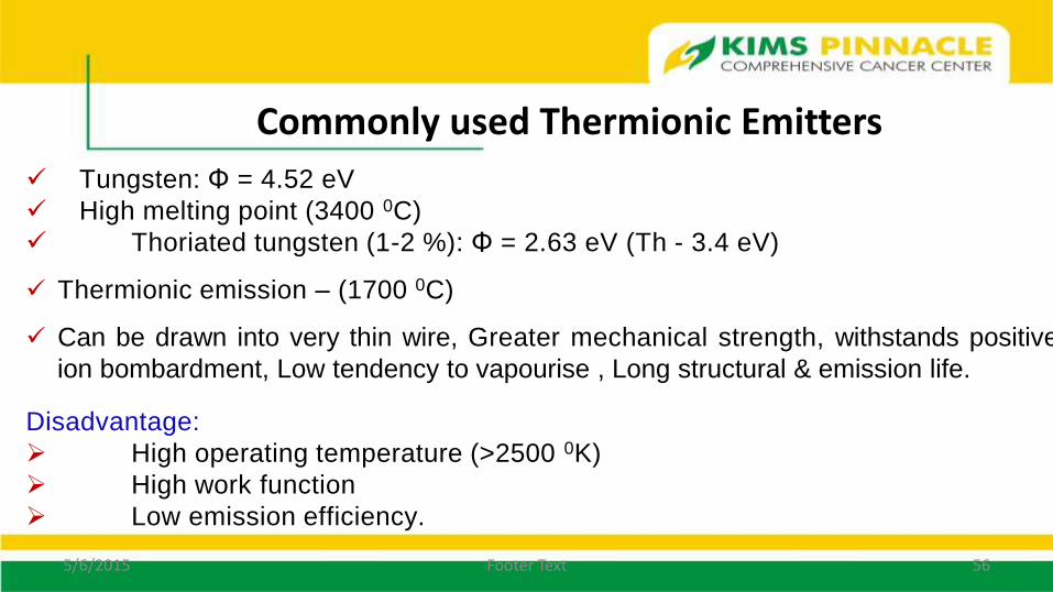
Tungsten: Φ = 4.52 eV
High melting point (3400 0C)
Thoriated tungsten (1-2 %): Φ = 2.63 eV (Th - 3.4 eV)
Thermionic emission – (1700 0C)
Can be drawn into very thin wire, Greater mechanical strength, withstands positive
ion bombardment, Low tendency to vapourise , Long structural & emission life.
Disadvantage:
High operating temperature (>2500 0K)
High work function
Low emission efficiency.
Commonly used Thermionic Emitters

5/6/2015 Footer Text 57
The filament is embedded in a metal shroud called the focusing cup.
All electrons accelerated from cathode to anode are electrically negative, the
beam tends to spread out due to electrostatic repulsion, and some electrons can
even miss the anode completely.
The focusing cup is negatively charged so that it condenses the electron beam to
a small area of the anode.
There can be two filaments with focusing cups, providing
different focal spots on the anode.
Focusing Cup

5/6/2015 Footer Text 58
.
Cathode design determines the size of focal spot
Factors determining the size of focus
1. Size and shape of filament
2. Dimension of focusing cup
3. Depth at which the coil is kept in the slot
4. Electric field associated with focusing cup
Focal spot size determines amount of x-rays falling on image receptor and resolution
(definition) of image
Focusing Cup

5/6/2015 Footer Text 59
Cathode and focusing cup

5/6/2015 Footer Text 60
Cathode: filament + focusing cup Two electrical currents flow in an x-ray tube.
The filament current : It is the flow of electrons throughthe filament to raise its temperature and releaseelectrons.
The electrical current: It is the flow of releasedelectrons from the filament to the anode across the x-ray tube. This current, referred to as the tube current,varies from a few to several hundred milliamperes(mA).
Cathode

5/6/2015 Footer Text 61
Space charge
•Collection of negatively charged electrons in the vicinity of filament when no voltage applied btw cathode and anode – space charge
•Number of electrons in space charge remain constant
•Tendency of space charge to limit the emission of more electrons from the filament is called space charge effect
Filament current → filament temperature → rate of thermionic emission

5/6/2015 Footer Text 62
Space Charge Effect
The two currents (filament and tube current) are separate but interrelated. Oneof the factors that relates them is the concept of “space charge.”
At low tube voltages, electrons are released from the filament more rapidly thanthey are accelerated toward the target.
A cloud of electrons, termed the space charge, accumulates around the filament.This cloud of negative charges opposes the release of additional electrons fromthe filament until they have acquired sufficient thermal energy to overcome theforce caused by the space charge.
At higher tube voltages, space charge cloud is overcome by applied potentialdifference.

5/6/2015 Footer Text 63
At low filament currents, a saturation voltage is reached above which the currentthrough the x-ray tube does not vary with increasing voltage.
Influence of tube voltage and filament current upon tube current
At the saturation voltage, tube current is limited by the rate at which electrons arereleased from the filament.
Above the saturation voltage, tube current can be increased only by raising the filament’stemperature in order to increase the rate of electron emission. In this situation, the tubecurrent is said to be temperature or filament emission limited.
To obtain high tube currents and x-ray energies useful for diagnosis, high filamentcurrents and voltages between 40 and 140 kV must be used.
With high filament currents and lower tube voltages, the space charge limits the tubecurrent, and hence the x-ray tube is said to be space-charge limited.

5/6/2015 Footer Text 64
Space charge cloud
Temperature limited Space charge cloudshield the electric
field for tube voltagesof 40kvp and less
( space charge limited )above 40kvp space
charge cloud isovercome by
voltage applied

5/6/2015 Footer Text 65
Filament current Vs Tube current
• At low tube potential (40kVp and lower), tube current will be space charge limited.
• Space charge places upper limit on tube current (space charge compensation necessaryfor change in tube current)
• At higher tube potential, tube current will be emission limited.
• Emission limited tube current cannot be increased by increase in tube potential.
• Emission limited tube current can be changed only by increasing the filament heating.

5/6/2015 Footer Text 66
Filament current Vs Tube current

5/6/2015 Footer Text 67
.
The anode is provided with positive potential in the x-ray tube
Function of Anode
It serves as a target surface for the highly energetic electrons thereby becoming thesource of X-rays.
Serves as the electrical Conductor. ie, receives electrons emitted by the cathode andconducts them through the tube to the connecting cables and back to the high-voltage section of the x-ray machine.
Provides mechanical support for the target. Serves as the primary thermal conductor.

5/6/2015 Footer Text 68
Anode: TARGETTARGET: The area of electron bombardment is the place where the both
heat and X-rays are produced. SO it should be made of a metal that is
able to withstand high temperatures without melting and is efficient in
the production of X-rays.

5/6/2015 Footer Text 69
Tungsten is chosen as efficient target material because it has
High melting point (33600 C)
High Z element (more bremsstrahlung yield)
Fairly a good conductor of heat. So heat can be passed
reasonably quickly away from the small area where it is
produced and the rise in temperature at that area is prevented
from being too great.
It does not vaporize easily. The presence of metal vapour
inside an
X-ray tube would spoil the vacuum which essential for its proper
operation
It can be machined and made smooth. Smooth anode surface
avoids attenuation of a fraction of X-ray intensity

5/6/2015 Footer Text 70
Focal Spot
Focal spot-the area on the anode, which is bombarded by the electrons. The focal spotbecomes the source of the X-ray in an X-ray tube.
The electron beam produced from an helical filament in a rectangular slot, coversrectangular area. That is focal spot is rectangular. The x-ray tube with rectangular focalspot is described as LINE FOCUS TYPE
Focal spot size depends upon the following factors:
The size and shape of the filament,
The dimension of the focusing cup and the depth of filament in it
Electric field associated with the focusing cup
The spacing between cathode and anode .

5/6/2015 Footer Text 71
Focal Spot
To produce radiographic images with sharp edges the size of the focal spot should besmall. Ie, smaller the focal spot size better the spatial resolution of the image.
But…
As the size of the focal spot decreases, the heating of the target is concentrated in asmall area and damages the target area of X-ray production.

5/6/2015 Footer Text 72
Focal Spot: Line focus principle
The conflicting demands can be facilitated byangling the target.
Sloping the anode face provides a larger area forheating, while maintaining small effectivefocal spot. The principle behind this design iscalled Line-focus principle. Effective size
Actual size

5/6/2015 Footer Text 73
Anode Angle & Effective Focal spot size
Effective focal length =Actual focal length x sin

5/6/2015 Footer Text 74
Angled Target: advantages & disadvantagesAdvantages:
Large actual focal size: more x-ray yield
: better heat dissipation
Small effective focal size: for image sharpness
Disadvantages:
Steeper anode angle restricts the field size
Heel effect

5/6/2015 Footer Text 75
Anode angle and useful beam

5/6/2015 Footer Text 76
Heel Effect
Reduction in the x-ray beam intensity toward the anode side of the x-ray field
X-rays are produced isotropically at depth in the anode structure.
therefore experience more attenuation than those directed toward the cathode side of the field
Photons directed toward the anode side of the field transit a greater thickness of the anode

5/6/2015 Footer Text 77
Heel Effect

5/6/2015 Footer Text 78
Anode Configuration
Two types of anodes:1. Stationary : The simplest type of x-ray tube has a stationary (i.e., fixed) anode. It consists
of a tungsten insert embedded in a copper block. The copper serves a dual role: It supports the tungsten target It removes heat efficiently from the tungsten target . Heat must be conducted away
quickly before it can melt the anode.
Dental x-ray and portable x-ray machines (where high tube current and power are notrequired) use fixed anode tube x-ray tubes.

5/6/2015 Footer Text 79
Types of Anode Rotating Anode:
For most of the diagnostic x-ray application, the rotating anode is used. The purpose ofthe rotating anode is to spread the heat produced during an exposure over a large areaof the anode and consequently higher x-ray output capabilities.
In rotating-anode tubes the entire rotating disc is the target. The rotating anode is a heavy disc mounted on a Molybdenum stem, which functions as
its support. Disc is made up of W-Rh alloy, or Tungsten followed by graphite or Molybdenum base.

5/6/2015 Footer Text 80
Types Of Anodes

5/6/2015 Footer Text 81
Rotating Anode
To compare the target areas of typical stationary-anode and rotating-anodex-ray tubes with 1mm focal spot
(The area on the target that is struck by electrons)
Actual area of the ST is 1 mm x 4 mm = 4 mm2.
Diameter of Rotating anode = 7 cm, r of the target area is approximately 30mm. So Total target area = 754 mm2.

5/6/2015 Footer Text 82
Advantage of Rotating Anode
Higher tube currents and shorter exposure times are possible with rotating anode.
The rotating-anode x-ray tube allows the electron beam to interact with a much largertarget area, and therefore the heating of the anode is not confined to one small spotas in a stationary-anode tube.
Less geometric un-sharpness and movement un-sharpness in the image due to smallerfocal spot and shorter exposure timings.

5/6/2015 Footer Text 83
•Rotated Anode x-ray tube
Conventional X-ray Tube

5/6/2015 Footer Text 84
Conventional X-ray Tubes
•Rotated Anode x-ray tube

5/6/2015 Footer Text 85
Target
The target is the area of the anode struck by the electrons from the cathode.
Tungsten is the material of choice for the target for three main reasons:Atomic number-tungsten’s high atomic number, 74, results in higher-efficiency x-ray production and in higher-energy x-rays.Thermal conductivity-tungsten has a thermal conductivity nearly equal to that of copper. It is therefore an efficient metal for dissipating the heat produced.High melting point-any material, if heated sufficiently, will melt and become liquid. Tungsten has a high melting point (3410 oC compared with 1083 oC for Cu) and therefore can stand up under high tube current without pitting or bubbling
Further It can be machined and made smooth which avoids attenuation of a fraction of x-ray intensity .

5/6/2015 Footer Text 86
Protective Housing The x-ray tube is always mounted inside a lead-lined protective housing designed to
control two serious hazards
Excessive radiation exposure Electric shock
When x-rays are produced, they are emitted isotropically i.e. with equal intensity inall directions.
Only those x-rays are used which are emitted through special section of x-ray tube,called the window.
The thin window serves to allow maximum emission of x-rays with minimumabsorption in the glass envelope.
Conventional X-ray Tube: Parts

5/6/2015 Footer Text 87
A properly designed protective housing reduces the level of leakageradiation to less than 100 mR/hr at 1 m when operated at maximumconditions.
It also provides mechanical support for the x-ray tube and protects the tubefrom damage caused by rough handling.
The protective housing around some x-rays tubes contains oil that serves asboth an electrical insulator and a thermal cushion.
Some protective housings have a cooling fan to air-cool the tube or the oil inwhich the x-ray tube is immersed.
X-ray Tube

5/6/2015 Footer Text 88
The x-ray tube is a special kind of vacuum tube.: 20-35 cm long and 15 cm in diameter.
The glass envelope is made of Pyrex glass to enable it to withstand the tremendous heatgenerated, maintains a vacuum inside the tube.
This vacuum allows for more efficient x-ray production and longer tube life.
The tube is evacuated to pressure less than 10-7 mm Hg If tube becomes glassy, x-ray production will fall off and tube will fail. As glass envelope tube age, some tungsten vaporize and coats the inside of the glass
envelope. This alters the electric potential of the tube, allowing tube current to stray andinteract with the glass envelope; the result is arcing and tube failure.
Glass Envelope

5/6/2015 Footer Text 89
Because of this problem, a recent improvement in tube design incorporates metal rather than glass as part or all of the envelope.
Metal envelope tubes maintain a constant electric potential between the electron of the tube current and the envelope.
Therefore they have longer life and less likely to fail.

5/6/2015 Footer Text 90
There are two primary parts; the cathode and the anode. Each of these is called an
electrode
Any tube with two electrodes is called a diode. An x-ray tube is a special type of
diode.
Conventional X-ray Tube

5/6/2015 Footer Text 91
Those x-rays emitted through the window are called the useful beam.
Other x-rays that escape through the protective housing are leakage radiation –notdesirable.
X-ray Tube

5/6/2015 Footer Text 92
Conventional X-ray Tubes

5/6/2015 Footer Text 93
Factors affecting x-ray beamQuality and Quantity

5/6/2015 Footer Text 94
• The energy of the x-rays is determined by the voltage applied.
• The amount of x-rays is determined by the current.

5/6/2015 Footer Text 95
Factors affecting x-ray beam quality and quantity
• Anode material
• Voltage applied (kVp)
• Tube Current (mA)
• Filters used

5/6/2015 Footer Text 96
Different anode materials will produce different characteristic x-ray spectra and different amounts of bremsstrahlung radiation.
1. Anode material

5/6/2015 Footer Text 97
Note that increasing the applied voltage or kVp will increase the maximal energy, the average energy and the intensity of the x-rays. Characteristic x rays do not change with a change in kVp
40keV 75keV
2. Voltage (kVp)

5/6/2015 Footer Text 98
100 mA
200 mA
75 keV
Increasing the current (ie mA) will not change energy of the beam only the intensity
(i.e. the amount) of x-rays. The quantity of x-rays is directly proportional to the tube
current.
3. Tube current (mA)

5/6/2015 Footer Text 99

5/6/2015 Footer Text 100

5/6/2015 Footer Text 101
Power Ratings
The energy per unit time that can be supplied by the x-ray generator or received by the x-ray tube during operation.
Power delivered by an electric circuit is equal to the product of the voltage and the current
Power = 100 kVp X A max for a O.I-second exposure
Maximum tube current (Amax) for 100 kVp and 0.1-second exposure time
The maximal tube current for high-powered generators can exceed I,OOOmA (I A) for short exposures

5/6/2015 Footer Text 102
Heat Unit (HU)
simple way of expressing
the energy deposition on and dissipation from the anode of an x-ray tube
Energy (HU) = Peak Voltage (kVp) X Tube Current (mA) X Exposure time
For continuous x-ray production (fluoroscopy),
the HU/sec is defined as follows
Energy (HU) = kVp X mA

5/6/2015 Footer Text 103
X-ray Exposure Rating charts
Operational limits of the x-ray tube for single and multiple exposures and the
permissible heat load of the anode and the tube housing.
The single-exposure chart contains the information to determine whether a
proposed
exposure is possible without causing tube damage.
Rating chart is specific to a particular x-ray tube and must not be used for other
tubes.
Charts show the limitations and allowable imaging techniques for safe
operation

5/6/2015 Footer Text 104
A single-exposure rating chart
Multiple-exposure rating charts
Anode heat input and cooling chart
Housing Cooling Chart
X- ray exposure rating chart

5/6/2015 Footer Text 105

5/6/2015 Footer Text 106
Anode heat input and cooling chart

5/6/2015 Footer Text 107
Housing Cooling Chart

5/6/2015 Footer Text 108
Thank you for your attention!!!